WIFI Doorbell Quick Start Guide for Model:LXDB4I-WIFI
Safety Requirements
1
Installation Requirements
•
Comply with all local electrical safety codes and standards when
operating the product.
•
Check if the power supply is correct before operating the product.
•
Follow the electrical requirements to power the product.
Requirements for selecting a power adapter:
•
The power supply must conform to the IEC 60950-1 and IEC
62368-1 standards.
•
The voltage must meet SELV (Safety Extra Low Voltage)
requirements and not exceed ES-1 standards.
•
The power supply must meet LPS requirements and not
exceed PS2.
•
The power supply requirements (such as rated voltage) are
subject to the product label.
•
Do not connect the product to more than two power supplies
unless otherwise specified.
•
The product must be installed in a location only professionals
can access to avoid the risk of non-professionals becoming
injured from accessing the area while the product is in operation.
Professionals must have full knowledge of the safeguards and risks
when using the product.
Operation Requirements
•
Do not open the cover when the product is powered on.
•
Do not touch the heat dissipation component of the product.
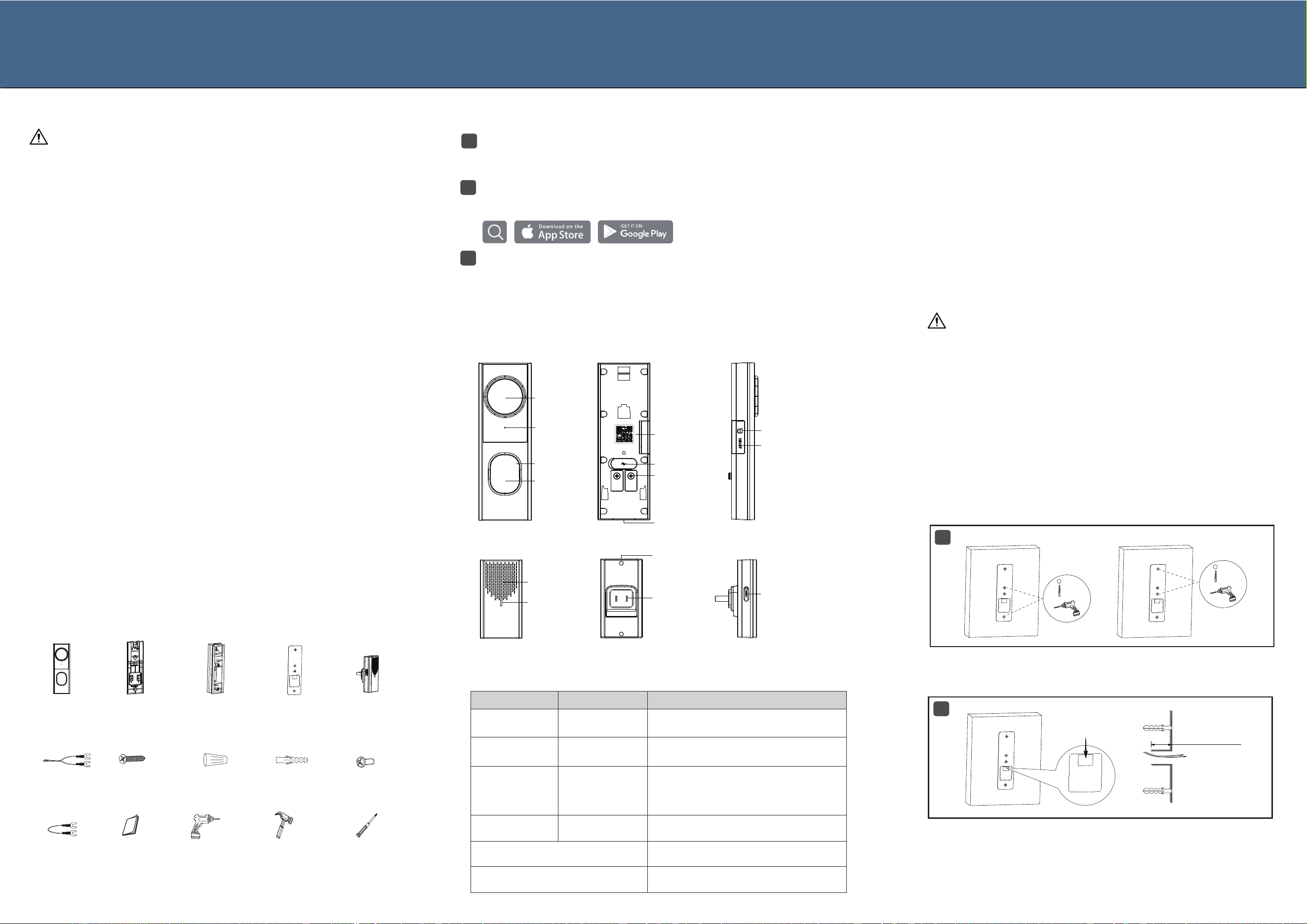
Check the items below to make sure every installation part is included
and in proper condition.
Packing List
Add Devices in App
1
Connect the doorbell to the power supply via the USB Type-C wire and
wait for the indicator light to turn on. Connect the chime to the appropriate
power outlet to power it on.
2
Download and install the App. Open the App and register for a new
account, then log in with your new credentials to begin.
3
Use the App to scan the QR code on the doorbell/chime. Follow the on-
screen instructions to add and configure the devices. You can view the
doorbell screen within the App.
WIFI Doorbell Installation Guide
1 x WIFI
Doorbell
1 x Flat Bracket
(with 2 x
Locking Tab)
1 x Angle-
adjustable
Bracket
2 x Product
Literature
● Installation Position
Choose an appropriate installation location, ensuring that power
supply is available and that the camera can cover the desired
monitoring area. It is recommended to install at a height of 1.2
meters.
Note: If you are unsure about the installation location, you can
power the doorbell and check the live view in the App. Choose a
location where you can see the desired field of view. Once the
doorbell can capture the desired field, you can proceed with the
subsequent installation steps.
Component Introduction
Lens
Microphone
LED Indicator
Call Button
USB Type-C Port
Power Ports
Micro SD Card Slot
Reset
Speaker
Please shut off the power at the circuit breaker before installation.
If you have the existing doorbell system, please remove the doorbell. Pull
the two power supply wires carefully when removing the exsiting doorbell.
Straighten the wire ends if necessary.
● Installation Steps
Follow the instructions below to install the doorbell onto the wall.
We provide an angle-adjustable bracket to help achieve a more
complete view. You can select the angle-adjustable bracket based
on your needs.
Stick the mounting template at the appropriate position on the wall. Make sure it is level.
Then drill 5mm holes at the marked screw hole locations.
1
2
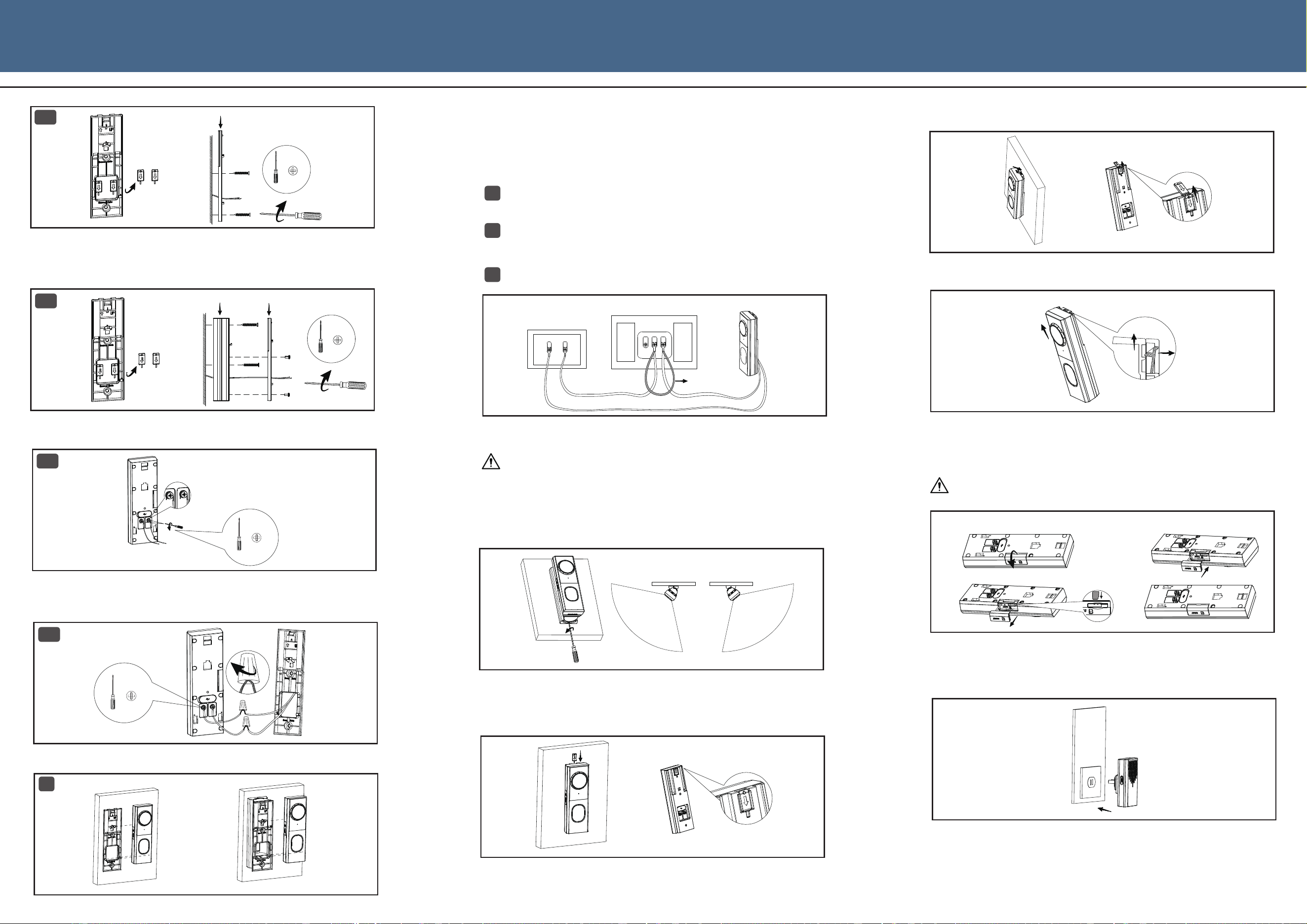
If you choose the flat bracket installation: Remove the two locking tabs from the flat
bracketand keep them safely. Align the flat bracket with the installed wall anchors. Secure
the bracket with the supplied screws.
Follow the mounting template to drill a wiring hole for the power supply wires. Make sure
the length of this hole is at least 20mm. Then firmly tap the wall anchors into the pre-drilled
holes using a hammer, ensuring they are flush with the wall surface.
● Detach the Existing Doorbell
• The suitable temperature for the device is -25°C to +55°C.
• When powered on, please place the device in an environment with
normal temperature and good ventilation.
1 x Extension
Wire
3 x Wire Nut
2 x Wall Anchor
2 x Phillips Head
Screw
2 x Small Phillips
Head Screw
1 x Jumper
Cable
1 x Power Drill
(Not include)
1 x Hammer
(Not Include)
1 x Phillips Head
Screwdriver
(Not Include)
Power Plug
Indicator Light
Speaker
Reset Button
● WIFI Doorbell
● Wireless Chime
QR Code
1 x Wireless
Chime
QR Code
WIFI Doorbell
Description
Solid Red
The device is starting up or there is a
device malfunction.
Flashing Red
The device is unable to connect to the
network.
LED Indicator Status
We recommend using the power adapter provided with the
product (Some products do not come with a power adapter,
please refer to the packing list).
•
Wireless Chime
Solid Blue
The device is operating normally, and
the network is functioning properly.
Solid Green
WARNING
Flashing Blue
and Red
The device firmware is being upgraded.Flashing Green
and Red
1 x Mounting
Template
For Flat Bracket
For Angle-adjustable Bracket
Φ5mm
Φ5mm
Or
Recommended Minimum
Wiring Hole
At Least 20mm[0.79inch]
● Shut off the Power
Flashing Blue
Quickly
●The device is connecting to the network.
Flashing Green
Quickly
●The Doorbell is ringing.
Flashing Blue
Slowly
Flashing Green
Slowly
●The device is in network configuration
mode.
●Someone is answering the call from the
Doorbell.
Working Environment
Remove the chime's cover to expose the terminal connections.
Loosen the terminal screws labeled with "FRONT" and "TRANS".
2
1
If you choose the angle-adjustable bracket installation: Remove the two locking tabs
from the flat bracket and keep them safely. Align the angle-adjustable bracket with the
installed wall anchors and secure the bracket with the supplied screws. Then align the holes
of the flat bracket with the holes of the angle-adjustable bracket and tighten the screws.
4a
If the length of the power supply wires is sufficient: Connect the wires to the terminals on the
back of the doorbell, then tighten the terminal screws.
4b
If the power supply wires are too short: Use wire nuts to connect the extension wires and power
supply wires. Connect the wires to the terminals on the back of the doorbell, then tighten the
terminal screws.
PH1
0.6N·m
3a
3b
5
Slide the doorbell from top to bottom to secure it onto the bracket to finish the installation.
If you need to adjust the view angle of the doorbell, use a screwdriver to loosen the
screws at the bottom of the angle-adjustable bracket, adjust it to the appropriate
angle (Maximum 40° to the left and right) by checking the field of view on the App,
and then tighten the screws.
● Bypass the Existing Chime
This doorbell is not compatible with mechanical chimes or electronic
chimes. If you already installed an existing one, you need to use the
jumper cable in packing list to passby the existing chime.
Connect either end of the jumper cable to the "FRONT" terminal and
the other end to the "TRANS" terminal, then tighten the screws to
secure the jumper cable in place.
2
Wireless Chime Installation Guide
Connect the chime to the appropriate power outlet to power it on.
WIFI Doorbell Quick Start Guide for Model:LXDB4I-WIFI
3
After connecting the jumper cable, put the cover back on the chime.
Turn on the power at the circuit breaker after the Installation is complete.
Angle-adjustable Bracket
PH1
Flat Bracket
Flat Bracket
PH1
REAR TRANS
FRONT
16V 30VA Output
Doorbell Transformer Mechanical / Electronic Chime WIFI Doorbell
Jumper Cable
● Angle Adjustment
After taking off the locking tab, you can slide the doorbell from bottom to top to remove
the doorbell from the flat bracket.
● Restore the Power
PH1
0.6N·m
1
2
40° Left
40° Right
Or
● Lock/Unlock the Doorbell
Lock: Insert a locking tab into the gap between the top of the flat bracket and the
wall (or angle-adjustable bracket).
Unlock: Insert the cylindrical end of another locking tab into the hole of the previous
locking tab, then applying upward force to lift the previous one.
● SD Card Cover Removal and Installation
Removal: Remove the SD Cover from the Doorbell. So that you can remove/install
the SD card or press the RESET button for 5 seconds to reset the Doorbell.
Removal
Installation
1
2
1
2
Installation: Install the SD cover to the Doorbell. Ensure that the safety rope
of the cover is fully retracted, and the cover is installed properly without any
protrusions; otherwise, it will affect the waterproof performance of the doorbell.

3
FCC Warning
Federal Communication Commission Interference Statement
This equipment has been tested and found to comply with the limits for a Class B digital device,
pursuant to Part 15 of the FCC Rules. These limits are designed to provide reasonable protection against
harmful interference in a residential installation. This equipment generates, uses, and can radiate radio
frequency energy and, if not installed and used in accordance with the instructions, may cause harmful
interference to radio communications. However, there is no guarantee that interference will not occur in
a particular installation. If this equipment does cause harmful interference to radio or television
reception, which can be determined by turning the equipment off and on, the user is encouraged to try
to correct the interference by one or more of the following measures:
• Reorient or relocate the receiving antenna.
• Increase the separation between the equipment and receiver.
• Connect the equipment into an outlet on a circuit different from that to which the receiver is
connected.
• Consult the dealer or an experienced radio/TV technician for help.
FCC Caution:
This device complies with Part 15 of the FCC Rules. Operation is subject to the following two conditions:
(1) This device may not cause harmful interference, and (2) this device must accept any interference
received, including interference that may cause undesired operation.
Non-modification Statement:
Changes or modifications not expressly approved by the party responsible for compliance could void the user's authority to operate
the equipment.
FCC Radiation Exposure Statement:
This equipment complies with FCC radiation exposure limits set forth for an uncontrolled environment.
This equipment should be installed and operated with minimum distance 20cm between the radiator &
your body.