Page 1Page 1BR0227-0-1222
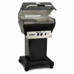
GAS GRILL
CARE & USE / INSTALLATION
Page 2 BR0227-1-0423
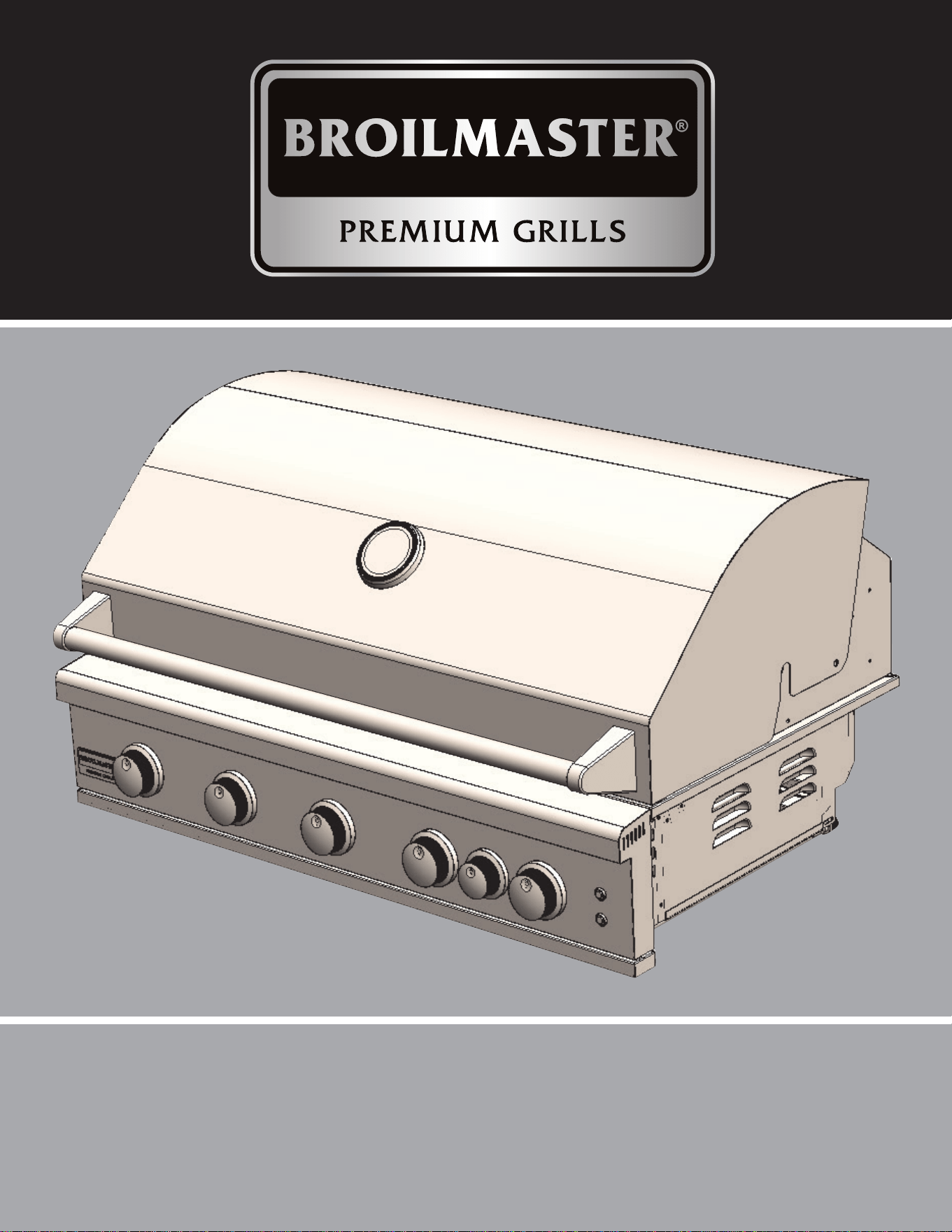
Installation, Care And Use Of Your
BROILMASTER Professional Cooking Product
THIS MANUAL MUST REMAIN WITH THE PRODUCT OWNER FOR FUTURE REFERENCE.
FOR OUT DOOR USE ONLY
IMPROPER INSTALLATION, ADJUSTMENT, ALTERATION, SERVICE OR MAINTENANCE
CAN CAUSE PROPERTY DAMAGE, INJURY OR DEATH. READ THIS MANUAL THOROUGHLY
BEFORE INSTALLATION, USE OR SERVICING OF THIS EQUIPMENT.
NOTE TO INSTALLER
This manual must remain with grill. Check your local building codes for proper method of
installation. In the absence of local codes, this unit should be installed in accordance with
National Fuel Gas Code No. ANSI Z21.58D
-
2002 USA or CAN/CGA-B149.1/.2 Natural Gas/
Propane Code. (Canada) latest edition or the National Electrical Code ANSI/NFPA No. 70 or
the Canadian Electrical Code CGA 1.6b2005 or latest edition.
WARNING
Do not store or use gasoline or other ammable liquids or vapours in the vicinity of
this or any other appliance. An propane cylinder not connected for use shall not be
stored in the vicinity of this or any other appliance.
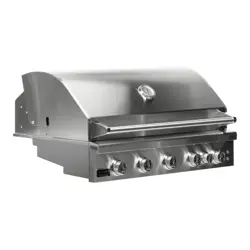
This Manual Covers The Following
BROILMASTER Products
GRILL • BSB324
(
N,P
)-
1
MODELS: • BSB405
(
N,P
)-
1
DANGER
If you smell gas:
1. Shut o gas to the appliance.
2. Extinguish any open ame.
3. Open lid.
4.
If odor continues, keep away from the
appliance and immediately call your
gas supplier or your re department.

BR0227-1-0423 Page 3
TABLE OF CONTENTS
BROILMASTER BBQ Models ........................................................................................................ 2
Product Specications .....................................................................................................................5
Overall Grill Dimensions ..................................................................................................................6
Control Identication ........................................................................................................................7
Warning Instructions ........................................................................................................................8
NOTICE: Commonwealth Of Massachusetts .................................................................................. 9
Grill Location..................................................................................................................................10
Location Of Your Grill (Using Your Grill During In Windy Conditions) ....................................... 11/12
Built-In Grill Dimensions ................................................................................................................ 13
Vent Registers ............................................................................................................................... 14
Built-In Sleeve Dimensions............................................................................................................15
Electrical Requirements & Hook-up...............................................................................................16
Wiring Schematics .........................................................................................................................17
Propane Gas Cylinder Safety ........................................................................................................18
Gas Requirements & Hook-up........................................................................................19/20/21/22
Important Safety Grilling Information .............................................................................................23
Converting Your Gas Grill .........................................................................................................24/25
Converting Your Gas Grill Type ..................................................................................................... 26
Lighting The Burners ..................................................................................................................... 28
Manually Lighting The Grill ............................................................................................................29
Burner Type Identication ..............................................................................................................30
Using The BROILMASTER Grill ....................................................................................................30
Direct Cooking Method ..................................................................................................................31
Indirect Cooking Method................................................................................................................31
Using The Rotisserie ..................................................................................................................... 32
Cooking Tips ..................................................................................................................................33
Burner Cleaning And Adjustment...................................................................................................34
Warnings .......................................................................................................................................35
Grill Cleaning Methods .................................................................................................................. 35
Cleaning The Grill .....................................................................................................................36/37
Light Bulb Replacement ................................................................................................................38
Warranty ........................................................................................................................................ 39
Master Parts Distributor List .......................................................................................................... 40
How To Order Repair Parts ...........................................................................................................40
Contacting Your BROILMASTER Dealer .......................................................................................41
BROILMASTER Parts List .............................................................................................................42
Parts Diagram................................................................................................................................43
Sleeves, Side Burners, And Island Accessories ..................................................................44/45/46

BR0227-1-0423Page 4
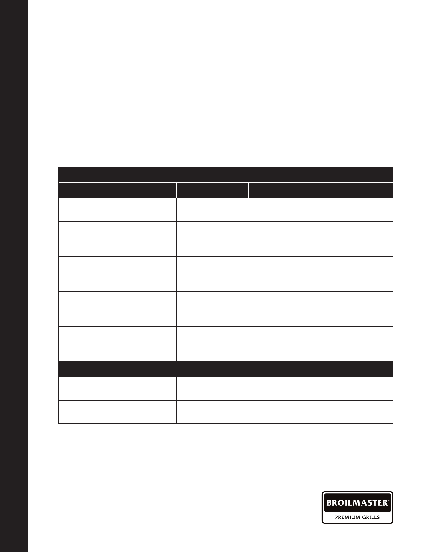
Product Specications
Description
32" BSB324(N,P) 40" BSB405(N,P)
Cooking Area, Sq. In. 524 648
Total Cooking Area Sq. In.
(Includes Warming Rack)
690 853
Gas Type NAT (N) / LP (P) NAT (N) / LP (P)
Conversion Kit, NAT to LP BR0225 (N only) BR0225 (N only)
Conversion Kit, LP to NAT BR0226 (P only) BR0226 (P only)
Main Burner Orices, NAT 4 - 1/16" 5 - 1/16"
Main Burner Orices, LP 4 - #57 DMS 5 - #57 DMS
Rear Burner Orice, NAT 1.60 mm 1.60 mm
Rear Burner Orice, LP 1.10 mm 1.10 mm
Burner Type 4 - Cast SS Straight 5 - Cast SS Straight
Burner BTU's (Each/Total) 14,000 / 56,000 14,000 / 70,000
Cooking Grids
4 - 5/16" SS 5 - 5/16" SS
Vaporizers - Flame Tamers
4 - SS 5 - SS
Heat Zone Dividers 3 - SS (Removable) 4 - SS (Removable)
Rear Rotisserie Burner (BTU)
14,000
15,000
Rotisserie Kit Optional Optional
Lid Assembly
Fully Welded w/Polished
Edges
Fully Welded w/Polished
Edges
Control Panel Fully Welded Fully Welded
Drip Tray Fully Welded Fully Welded
Ignition Type (No Battery)
Push & Turn Flame Thrower Push & Turn Flame Thrower
Warming Rack SS - Shelf SS - Shelf
Temp Gauge Hood Hood
Control Panel Lights LED Blue 12V LED Blue 12V
Interior Work Lights 2 - Halogen 12V 2 - Halogen 12V
Cutout Dimensions For Grill 8
1
/
2
H x 20
1
/
2
D x 31W 8
1
/
2
H x 20
1
/
2
D x 38W
PRODUCT SPECIFICATIONS
OVERALL GRILL DIMENSIONS
BR0227-1-0423 Page 5
PRODUCT SPECIFICATIONS
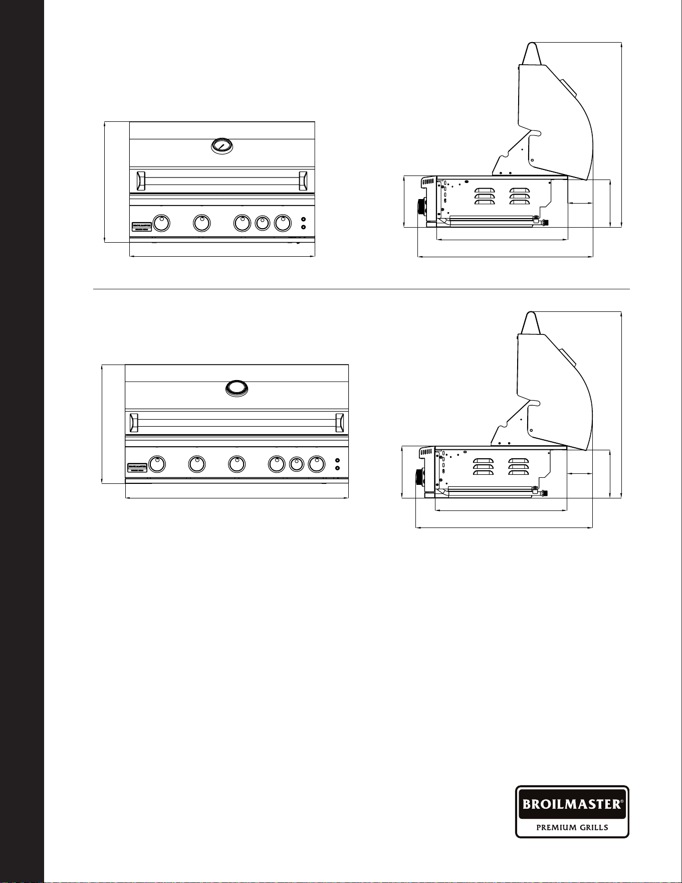
OVERALL GRILL DIMENSIONS
Overall Grill Dimensions
21 3/16”
32 7/16”
21 11/16”
29”
/”
30 5/8”
7 15/16”
8 9/16”
21 3/16”
39 11/16”
21 11/16”
29”
/”
30 5/8”
7 15/16”
8 9/16”
21 3/16”
39 11/16”
21 11/16”
29”
/”
30 5/8”
7 15/16”
8 9/16”
BSB405
21 3/16”
32 7/16”
21 11/16”
29”
/”
30 5/8”
7 15/16”
8 9/16”
BSB324
BR0227-1-0423Page 6
CONTROL IDENTIFICATION
WARNING
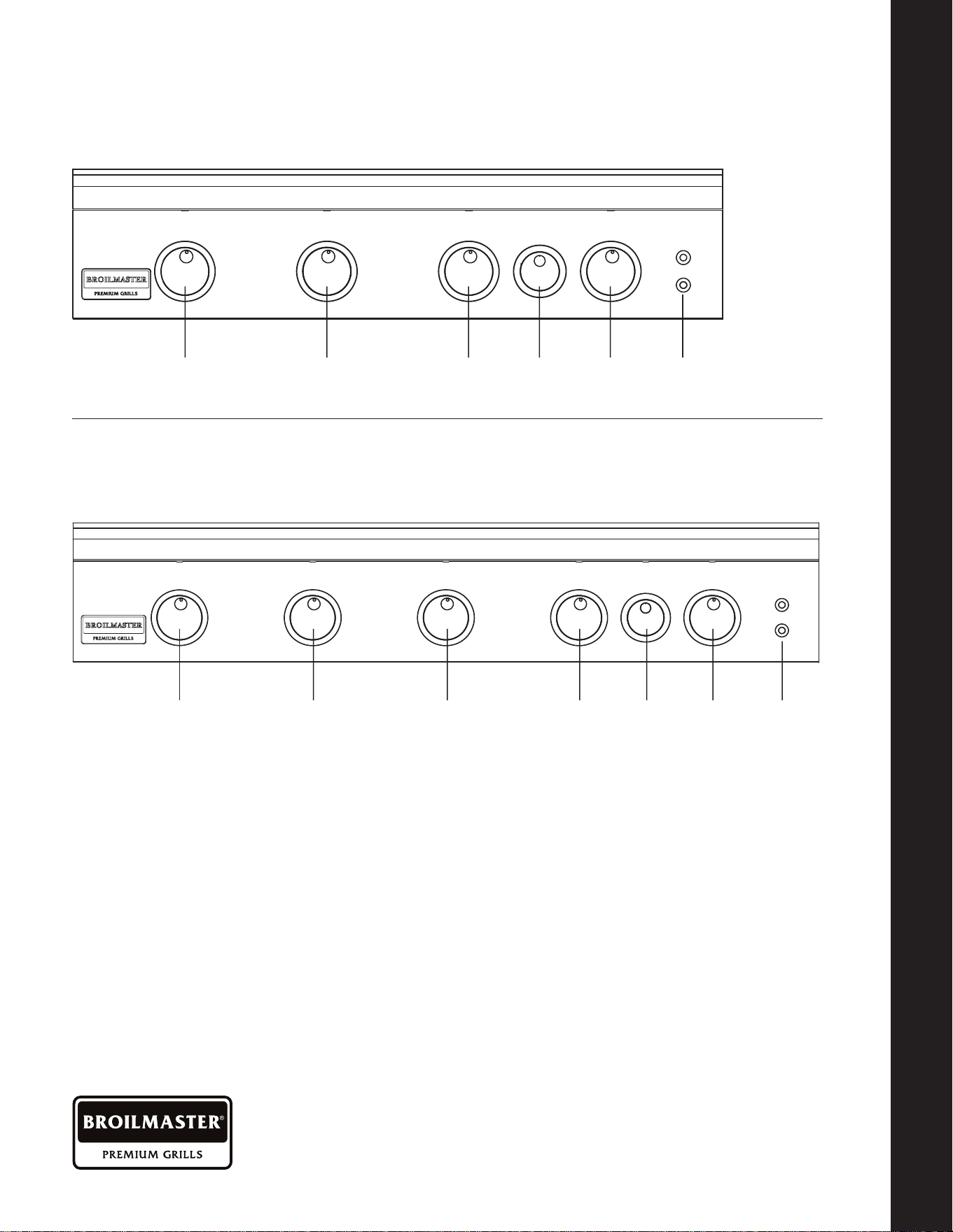
Control Identication
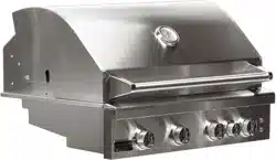
BSB324
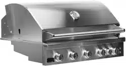
BSB405
GRILL GRILL GRILL ROTIS GRILL LIGHT
SWITCH
GRILL GRILL GRILL GRILL ROTIS GRILL LIGHT
SWITCH

BR0227-1-0423 Page 7
CONTROL IDENTIFICATION
WARNING
• Read this manual carefully and
completely before using your grill, to
reduce the risk of re, burn hazard
or other injury, and to ensure proper
installation and servicing.
• Never use rusted, dented or damaged
propane cylinders. Never store additional
or empty propane cylinders in the grill
cabinet or in the vicinity of this or any
other gas or electrical appliance. Do
not store propane cylinders indoors or
on their sides for gas may escape. Gas
cylinders are highly ammable.
• Any Children should never be left alone
or unattended in an area where a grill
is located. Place your grill well away
from areas where children play. Do not
store items that may interest children in
or around the grill, in the cart, or in the
enclosure or Island.
• Never move the grill when hot. When in
use, portions of the grill are hot enough
to cause severe burns.
• Always maintain the required clearances
from combustibles as detailed. The grill is
designed for outdoor use only. Never use
in a garage, building, shed, breezeway,
or other enclosed area. Do not use this
grill under any unprotected overhead
combustible construction. Combustible
material exposed to heat will catch on re.
• Gas grills are not designed or certied
for and are not to be installed in or on
recreational vehicles, portable trailers,
boats or any other moving installation
including commercial use.
• Always have a Fire Extinguisher
accessible — never attempt to extinguish
a grease re with water or other liquids.
• Store your grill in a well-ventilated area.
If stored indoors, detach and leave L.P.
cylinder outdoors in a well-ventilated
area away from heat and away from
where children may tamper with it.
Always leave tank outdoors.
• Keep any electrical supply cord and the
fuel supply hose away from any heated
surfaces. Electrical cords should be
placed away from walkways to avoid
tripping hazard.
• Do not repair or replace any part of the grill
unless specically recommended in this
manual. Other service should be performed
by a certied and qualied Gas and BBQ
technician.
• If the grill is installed by a professional
installer or technician, be sure that he/
she shows you where your gas supply
shut-o is located. All gas lines must
have a shut-o that is readily and easily
accessible. If you smell gas, check for
gas leaks immediately. Check only with a
soap and water solution. Never check for
gas leaks with an open ame.
• Inspect the L.P. gas supply hose prior to
each use of the grill. If there is evidence
of excessive abrasion or wear, or the
hose is cut, it must be replaced before
using the grill.
• The outdoor cooking gas appliance
and its individual shut-o valve must be
disconnected from the gas supply piping
system during any pressure testing of
that system at test pressures in excess
of 0.5 psi (3.5 kPa).
• The outdoor cooking gas appliance must
be isolated from the gas supply piping
system by closing its individual manual
shut-o valve during any pressure testing
of the gas supply piping system at test
pressures equal to or less
than 1/2 psi (3.5 kPa).
WARNING
! !

BR0227-1-0423Page 8
NOTICE: Commonwealth Of Massachusetts
1. Massachusetts requires all gas be installed using a plumber or gas tter carrying the
appropriate Massachusetts license.
2. All permanently-installed natural gas or propane installations require a “T” handle type
manual gas valve be installed in the gas supply line to this appliance.
3. This does not apply to portable propane installations using a 20 pound cylinder.
WARNING! CALIFORNIA PROPOSITION 65
1. The burning of gas cooking fuel generates some by-products which are on the
list of substances which are known by the State of California to cause cancer or
reproductive harm.
2. California law requires businesses to warn customers of potential exposure to such
substances. To minimize exposure to the substances, always operate this unit
according to the use and care instructions found in this manual. Be certain to provide
adequate ventilation when cooking.
3. WARNING: Handling the brass material on this product exposes you to lead, a
chemical known to the state of California to cause cancer, birth defects or other
reproductive harm. (Wash hands after handling this product.)
4. For more information go to this website: www.p65warning.ca.gov
!
NOTICE: COMMONWEALTH OF MASSACHUSETTS
GRILL LOCATION
BR0227-1-0423 Page 9
NOTICE: COMMONWEALTH OF MASSACHUSETTS
GRILL LOCATION
Grill Location
• Never install this product into a combustible enclosure. Doing so could result in re,
property damage and personal injury. Combustible material is "anything" that can
catch on re.
• Never locate the grill under a roof or overhang, in a building, garage, shed or other
such enclosed area.
• Installation must conform with local codes or, in the absence of local codes, with either
the National Fuel Gas Code, ANSI Z223.1/NFPA 54, Natural Gas and propane Installation
Code, CSA B149.1, or Propane Storage and Handling Code, B149.2, in Canada.
WHERE IS THE WIND COMING FROM?
When selecting a suitable location, consider
important factors such as exposure to the
wind and foot-trac patterns.
If you have a free standing grill, position it
so the prevailing wind blows into the front
control panel (at your back when grilling),
supporting the proper front of BBQ to
rear of BBQ airow. Built-in grills located
in areas with prevailing winds should be
protected by a wind barrier.
Winds hitting the back of the grill directly
may cause problems, as well as wind
blowing along the hood opening
HOW LONG IS YOUR GAS RUN GOING
TO BE?
Keep all gas supply lines as short as
possible because gas lines lose pressure
over distance and with each elbow and tee
that is added. This drop in pressure aects
grill performance.
CHECK THE BBQ IS LEVEL?
Proper leveling during installation is critical.
A grill that is out of level will cause erratic
burner combustion and inecient, uneven
heating. A carpenter’s spirit level should be
used to level the grill both front-to-back and
side-to-side.
If the oor is uneven or has a decided slope,
re-leveling may be required each time you
move a freestanding unit.
WARNING
! !
Be sure wind doesn’t blow into the back of the hood gap.
BR0227-1-0423Page 10
Location Of Your Grill
USING YOUR GRILL IN WINDY
CONDITIONS:
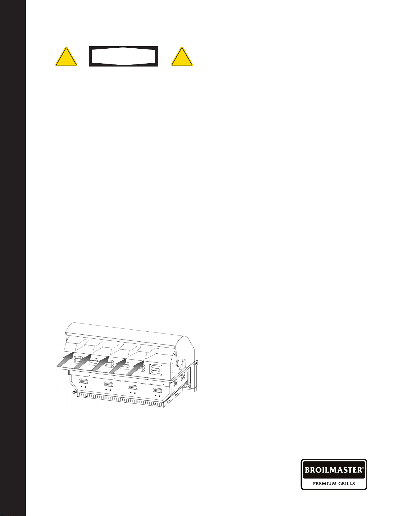
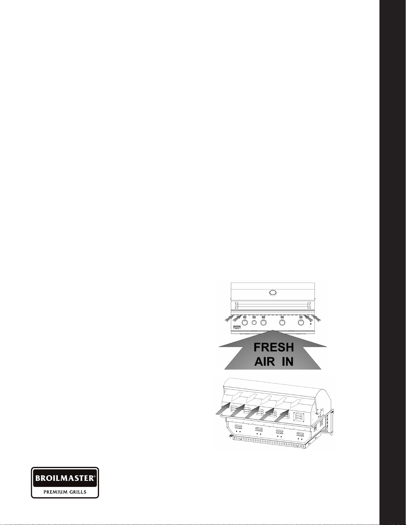
• As a high-performance gas appliance,
your BROILMASTER grill requires
signicant amounts of air to support
the burner combustion process. Your
grill has been engineered to take air
in through the control panel area, and
exhaust the combustion out through the
gap between the front and rear hoods
• Using your grill in windy conditions can
disrupt the proper ow of air through your
grill, leading to reduced performance,
or in certain severe cases, causing heat
buildup in the control panel area. This
can lead to problems such as having
the control knobs getting hot or melting,
or burn hazards when the control panel
surfaces become too hot to touch.
• If you have a freestanding grill, it is best
to position the unit so the prevailing wind
blows into the front control panel (or at
your back), thus supporting the proper
airow. Winds hitting the back of the
grill directly are the most likely to cause
problems, although wind blowing along
the hood gap can also be a problem.
• Please note that damage to your grill
resulting from use in windy conditions,
such as melted knobs or igniter wires,
or control panel discoloration from heat
build-up, are excluded from warranty
coverage.
• Outdoor grilling can create more heat than
indoor kitchen ranges.
BUT THERE ARE A FEW THINGS
YOU CAN DO TO FURTHER PREVENT
THE POSSIBILITY OF IMPROPER
HEAT BUILDUP:
• If you suspect the grill is overheating,
using an heat resistant mitt, open the
front hood. Then adjust the burner
control knob to a lower setting. Do
not grab the knobs without testing the
temperature of them.
• Install your grill with a wind break
behind it. This is a wall, fence or
anything that will disrupt the wind
directly hitting the gas grill.
• Situate the grill so prevailing winds are
not blowing into the rear of the grill.
• On windy days, be careful not to
leave the hood down for more than 15
minutes when the burners are on high.
(Never leave the grill unattended when
in operation)
Wind hitting the back of the grill can disrupt proper exhaust.
LOCATION OF YOUR GRILL
LOCATION OF YOUR GRILL
BR0227-1-0423 Page 11
LOCATION OF YOUR GRILL
LOCATION OF YOUR GRILL
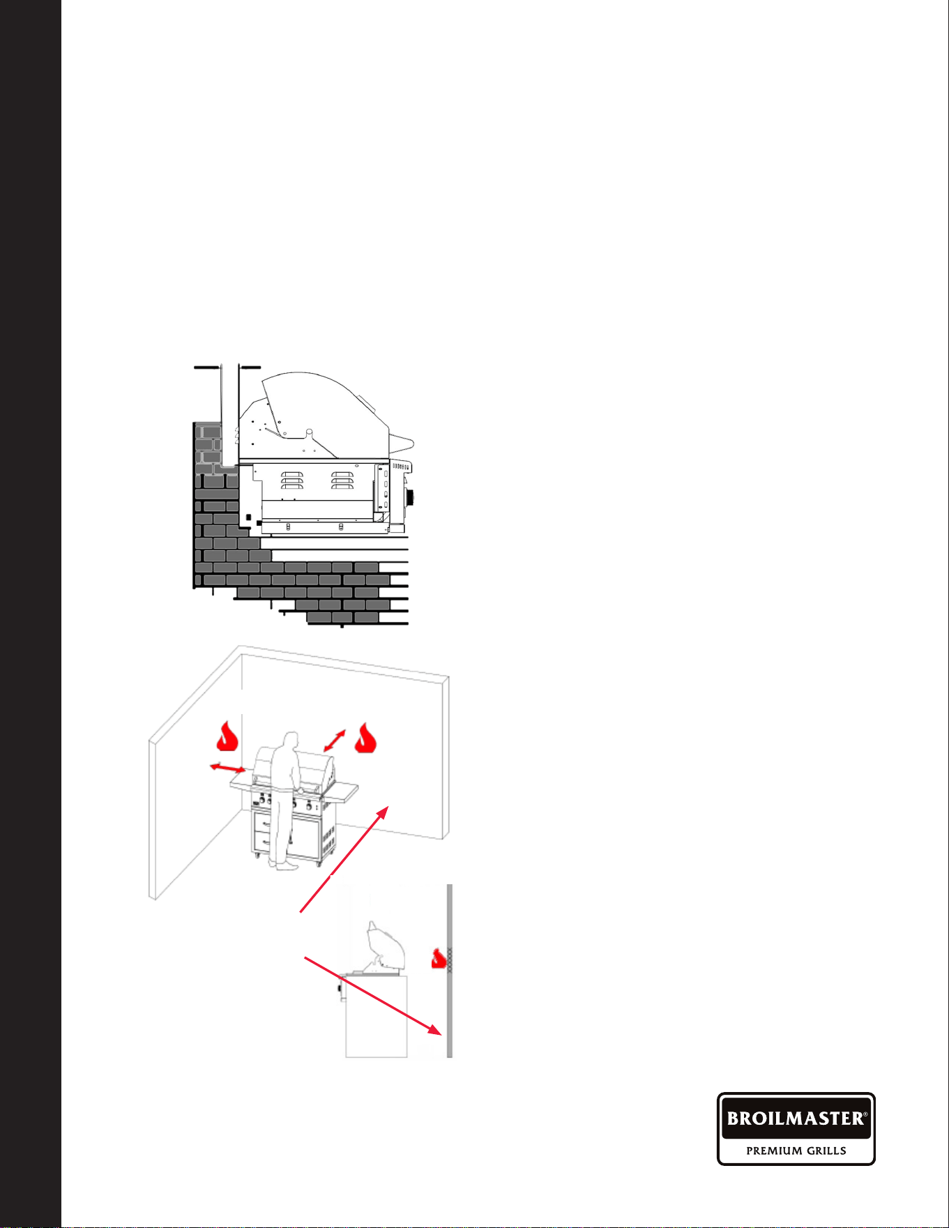
Location Of Your GRILL (Cont'd.)
• The grill drops into the cutout opening
and sits on the sides and back of the
grill. There is no need to fasten the grill
to the island. The gas grill must be able
to be removed for general maintenance
so do not grout sides or fasten in.
• For the hood to open there is a minimum
of 5" clearance behind the hood. There
is a required 12" clearance on each
side of the Gas Grill. Remember that
combustible materials should not be
located behind the grill, because the
5" space doesn't satisfy the distance
required from a combustible surface.
See below clearance to combustibles
.
CLEARANCE TO COMBUSTIBLE
CONSTRUCTION:
Minimum clearance from sides and back of
unit to adjacent combustible construction
below top of unit are 16" from sides and
16" from back. Use your grill at least 16"
away from any wall or surface.
Use your grill 16" or more away from
any combustible objects that can melt or
catch re such as vinyl or wood siding,
fences, overhangs, or any other sources
of ignition; including pilot lights and live
electrical appliances.
Do not use your grill under any overhead
combustible construction. Never use
your gas grill in a garage, porch, shed,
breezeway, or any other enclosed area.
Never use your gas grill on a balcony,
deck, or patio above the ground oor of
your home.
BUILT IN LOCATION:
• The BROILMASTER Built in model is
designed for easy installation into a
non-combustible masonry enclosure.
• The BBQ must be surrounded by
non-combustible material like Brick or
Hardibacker and must not be installed
in an island made of combustible
material.
5"
Hood Clearance
16"
Distance Minimum
16"
16"
Combustible
Materials
BR0227-1-0423Page 12
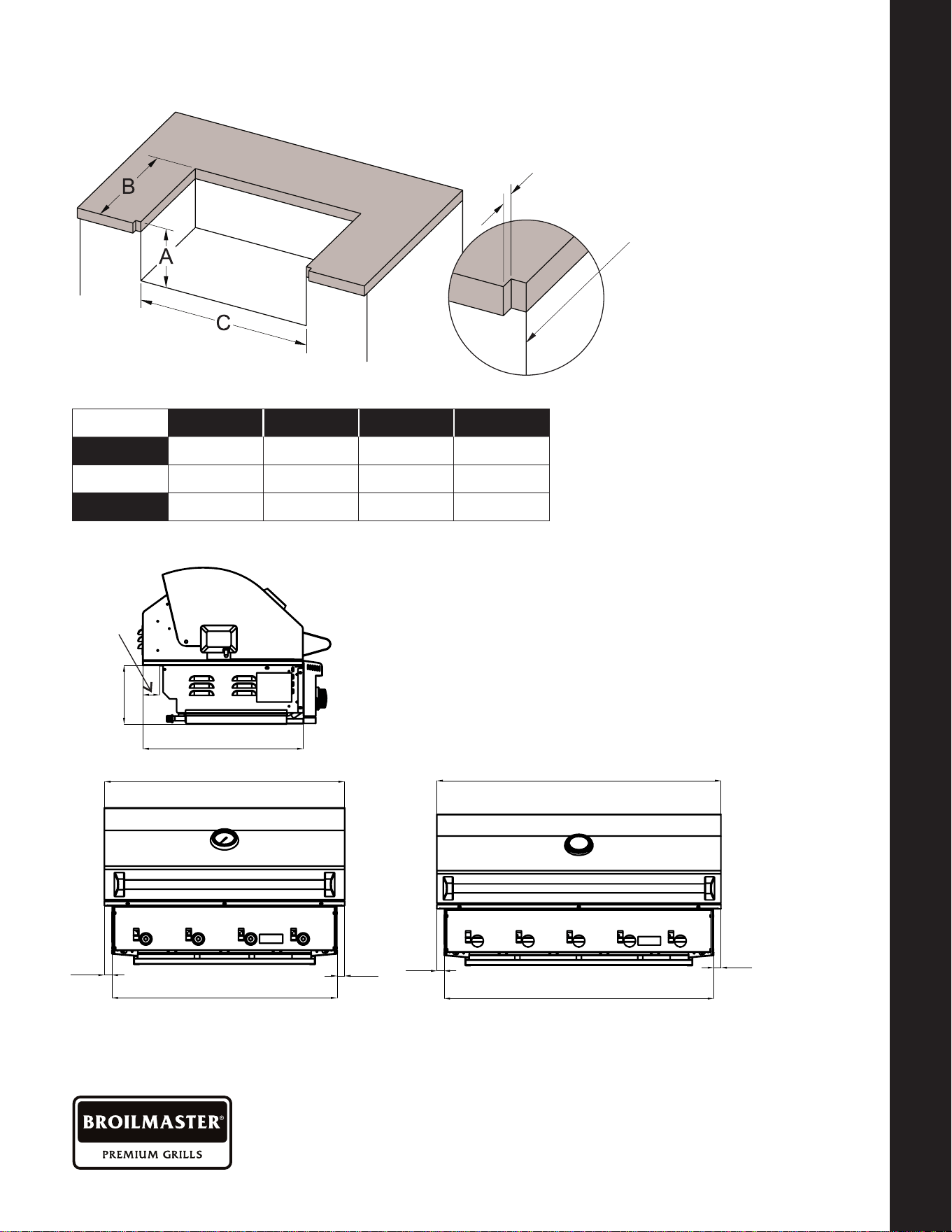
Built In Grill Dimensions
Model # Cutout A Cutout B Cutout C
32" 4 Burner
BSB324(N,P)
8
-
1/2" 20
-
1/2" 31"
40" 5 Burner BSB405(N,P)
8
-
1/2" 20
-
1/2" 38"
Cutout
detail when
countertop
is overhung
7 15/16”
1”
30 7/16”
BSB405
1”
32 7/16”
39 11/16”
21 11/16”
2 1/4
”
1”
1”
37 11/16”
BSB324
7 15/16”
1”
30 7/16”
BSB405
1”
32 7/16”
39 11/16”
21 11/16”
2 1/4”
1”
1”
37 11/16”
BSB324
7 15/16”
1”
30 7/16”
BSB405
1”
32 7/16”
39 11/16”
21 11/16”
2 1/4”
1”
1”
37 11/16”
BSB324
BSB405BSB324
BUILT IN SLEEVE DIMENSIONS
VENT REGISTERS
1
-
3/8"
BR0227-1-0423 Page 13
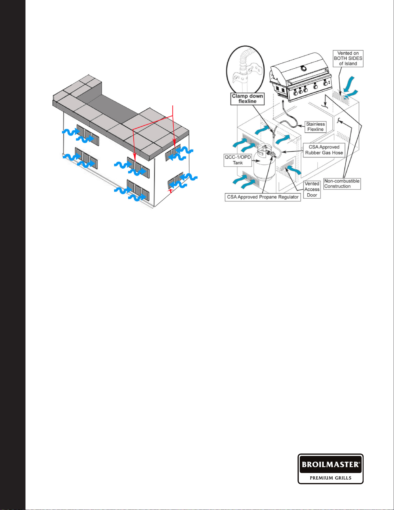
Vent Registers LP Gas
INSULATED SLEEVE INSTALLATION INSTRUCTIONS
IMPORTANT: Before you build the frame, you must take into consideration the total weight
of the sleeve, grill and any nishing materials.
Review the table on the next page for the
proper framing dimensions for the insulation
sleeve. Determine the entry point for both
the gas inlet and electric connections. Make
the 4" square holes for gas and electrical
connections (rear or bottom access) based
on your requirements. Note that the gas and
electrical connections are located on the
right side.
A “Level” should be used to assure that
the framing is level, both front to back and
side to side.
NOTE: Never under any circumstance
should you install the transformer or run
a gas hose in between the grill and the
inside of the insulating sleeve.
SLEEVE INSTALLATION
Position the sleeve into the frame. No part
of the enclosure can protrude above the
top surface or in front of the face surface
of the liner.
GRILL INSTALLATION
Use the proper equipment to support the
grill. Place the grill into the sleeve and
place it over the sleeve lip across the back
and sides. The liner is designed to support
the grill without additional fasteners.
FINISHING
If desired any gap remaining between the
sleeve and the non-combustible enclosure
may be lled with a non-combustible sealant.
REQUIRED WHEN AN LP
GAS TANK IS USED
BUILT IN SLEEVE DIMENSIONS
VENT REGISTERS
10 Square Inch Minimum
Each Register. 2 Per
Side. 1 High And 1 Low
2-1/4" Minimum
Ground To
Vent Bottom
BR0227-1-0423Page 14
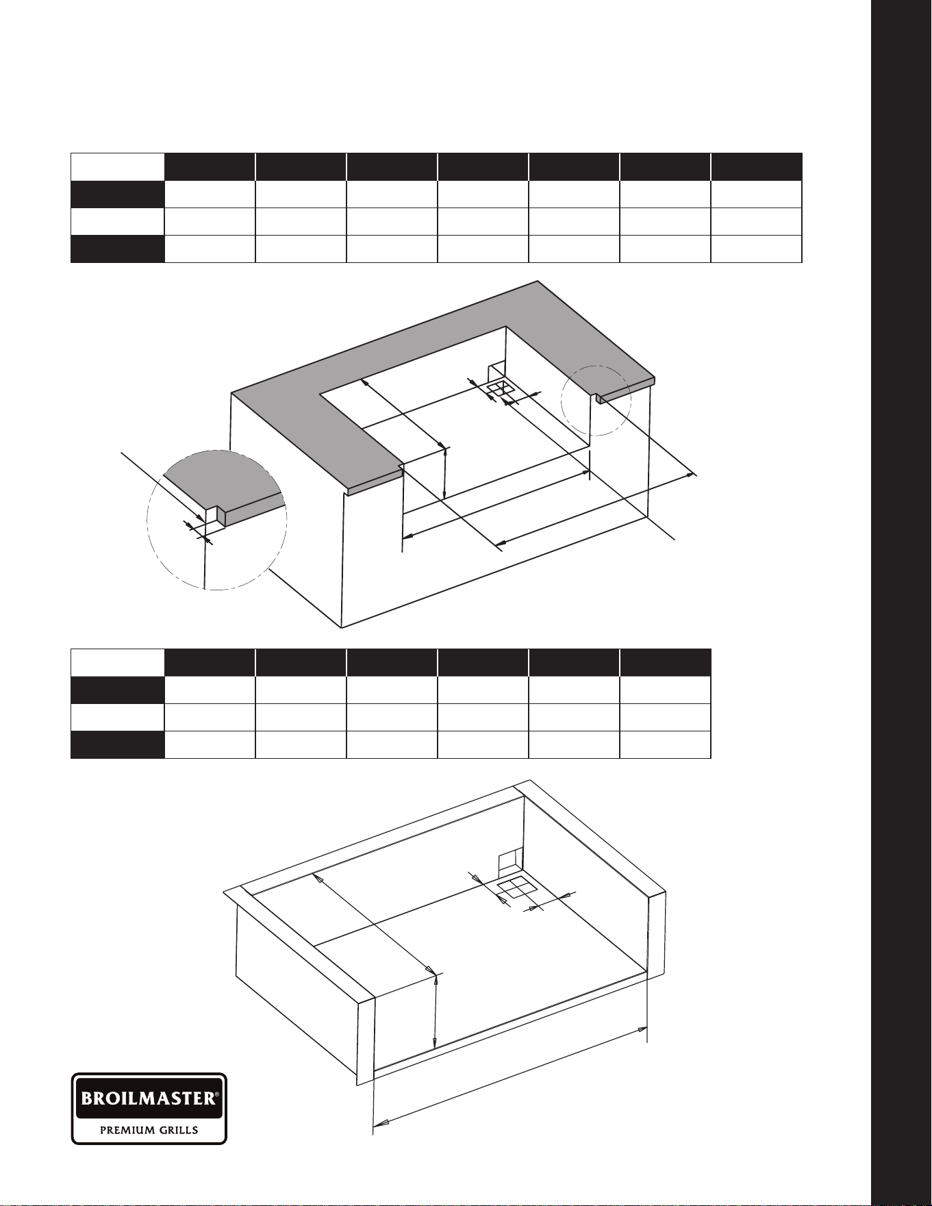
WE SPECIFY NON
-
COMBUSTIBLE ONLY
Built
-
In Sleeve Dimensions (Optional Accessory)
Model # Cutout A Cutout B Cutout C Cutout D Cutout E Cutout F
32" 4 Burner
BSB324(N,P)
31
-
3/16" 20
-
11/16" 8
-
3/8" 2
-
3/16" 2
-
3/16" 33
-
1/16"
40" 5 Burner BSB405(N,P)
38
-
7/16" 20
-
11/16" 8
-
3/8" 2
-
3/16" 2
-
3/16" 40
-
5/16"
Model # Cutout A Cutout B Cutout C Cutout D Cutout E
32" 4 Burner
BSB324(N,P)
31
-
3/16" 20
-
11/16" 8
-
3/8" 2
"
1
-
3/8"
40" 5 Burner BSB405(N,P)
38
-
7/16" 20
-
11/16" 8
-
3/8" 2" 1
-
3/8"
4" square hole for
gas and electrical
connections, rear
or bottom.
B
C
D
E
A
F
1
Cutout
detail when
countertop
is overhung
B
C
D
E
A
F
1
A
A
E
E
D
D
B
B
C
C
BUILT
-
IN SLEEVE DIMENSIONS
ELECTRICAL REQUIREMENTS AND HOOK
-
UP
BR0227-1-0423 Page 15
BUILT
-
IN SLEEVE DIMENSIONS
ELECTRICAL REQUIREMENTS AND HOOK
-
UP
Electrical Requirements And Hook-up
WARNING! ELECTRICAL GROUNDING
• Product installation must meet local electric codes or, in the absence of local codes,
the latest edition of the National Electrical Code ANSI/NFPA No. 70 or the Canadian
Electrical Code CGA 1.6b2005.
• Use only a Ground Fault Interrupter (GFI) protected circuit with this outdoor cooking
gas appliance.
• This grill is equipped with a three prong (grounding) electric plug for your protection
against shock hazard and must be plugged directly into a properly grounded three
prong outlet. Never cut or remove the grounding prong from this plug.
• Use only extension cords with a 3 prong grounding plug, rated for the power of the
equipment, and approved for outdoor use with a “W-A” marking.
• To protect against electric shock, do not immerse any part of the power cord, an
extension cord or any plugs in water or other liquid.
• Unplug the product from the outlet when not in use and before cleaning. Allow it to cool
before putting on or taking o parts.
• Do not let the cord touch hot surfaces.
• Do not use an outdoor cooking gas appliance for purposes other than intended.
• Do not operate any outdoor cooking gas appliance with a damaged cord, plug, or after the
appliance malfunctions or has been damaged in any manner. Contact the dealer for repair.
!
WARNING
! !
This appliance, when installed, must be electrically
grounded in accordance with local codes or, in the
absence of local codes, with the National Electrical
Code, ANSI/NFPA 70, or the Canadian Electrical
Code, CSA C22.1. Keep any electrical supply cord and
the fuel supply hose away from any heated surface.
CAUTION
! !
To protect against shock hazard risk, connect
only to properly Grounded Outlet.
WARNING
! !
CALIFORNIA PROPOSITION 65
The electrical supply cord and plug of the
Rotisserie and Transformer contain chemicals,
including lead, known to the State of California
to cause cancer, and birth defects or other
reproductive harm. Wash hands after handling.
BR0227-1-0423Page 16
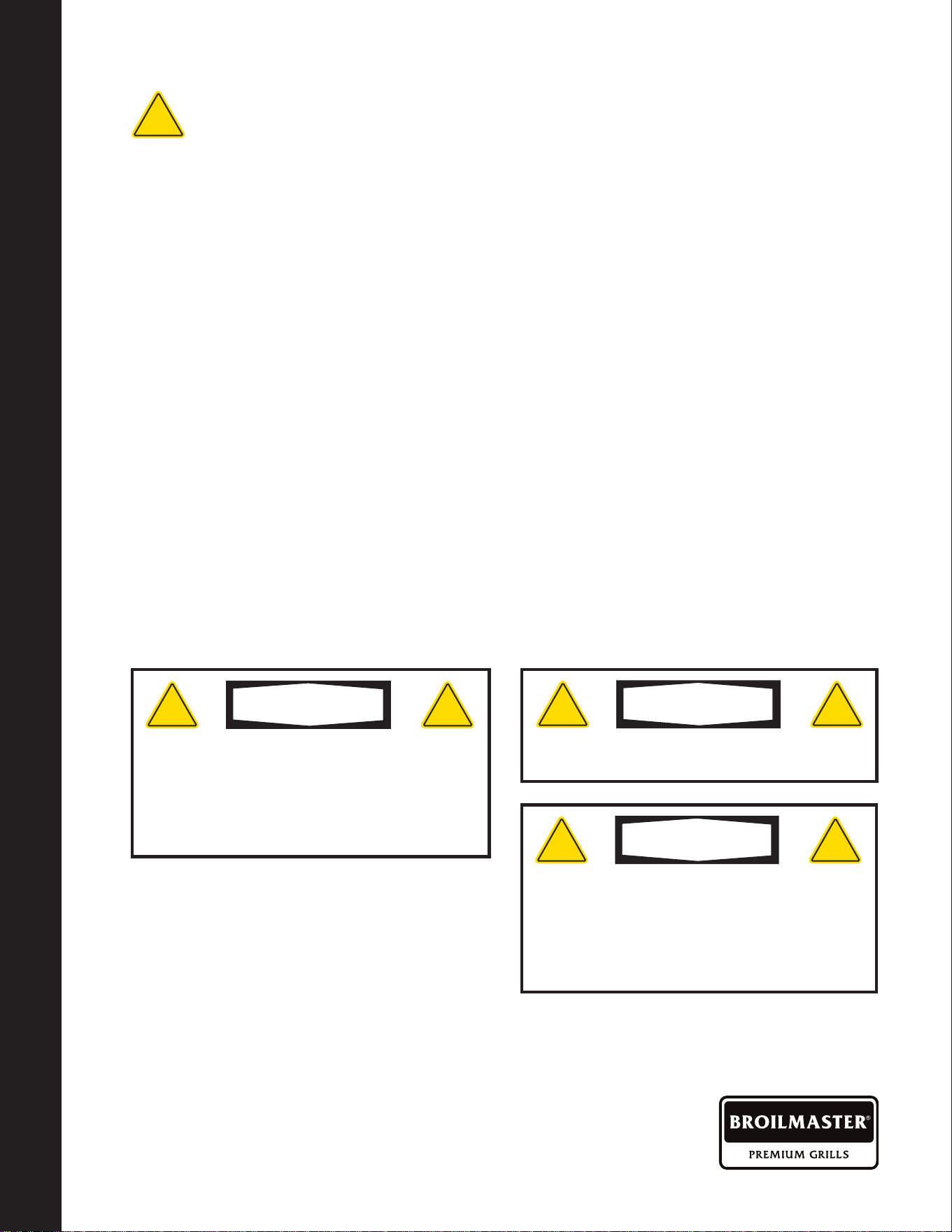
Wiring Schematics
NOTE: This grill uses a transformer to provide power to the LED lights and work lights.
The transformer should be secured to the island walls or cart back wall. Plug only into a
Ground Fault Interrupter (GFI) protected circuit.
WIRING SCHEMATICS
LP GAS CYLINDER SAFETY
FIREBOX LIGHTS,
RIGHT AND LEFT
LED LIGHTS LED SWITCH
FIREBOX
LIGHT SWITCH
TRANSFORMER
BR0227-1-0423 Page 17
WIRING SCHEMATICS
LP GAS CYLINDER SAFETY
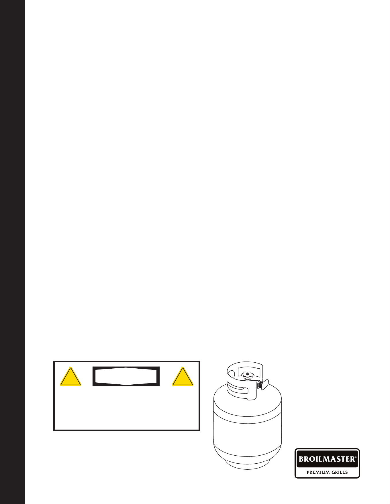
LP Gas grill models are designed for use
with a standard 20lb. Liquid Propane Gas
(LP Gas) tank (sold separately. Never
connect your gas grill to an LP Gas tank
that exceeds this capacity. A tank of
approximately 12 inches in diameter by
18
-
1/2 inches high is the maximum size
LP Gas tank to use. You must use an
"OPD" gas tank which has a listed Overll
Prevention Device. This safety feature
prevents tank from being overlled which
can cause a malfunction of the LP Gas tank.
The LP Gas tank must be constructed
and marked in accordance with the
Specications for LP
-
Gas Cylinders of the
U.S. Department of Transportation (D.O.T.
or the National Standard of Canada, CAN/
CSA
-
B339, Cylinders, Spheres and Tubes
for Transportation of Dangerous Goods,
and Commission; as applicable.
The LP Gas tank must have a shut
-
o valve,
terminating in an LP Gas supply tank valve
outlet, that is compatible with a Type 1 tank
connection device. The LP Gas tank must
also have a safety relief device that has a
direct connection with the vapor space of
the tank. The tank supply system must be
arranged for vapor withdrawal.
The LP Gas tank must have a collar to
protect the tank valve. Never connect an
unregulated LP gas tank to your gas grill.
The gas regulator assembly supplied with
your gas grill is adjusted to have an outlet
pressure of 11" water column (W.C.) for
connection to an LP gas tank. Only use the
regulator and hose assembly supplied with
your gas grill.
Replacement hose and regulator assembly
must be identical to those listed in the parts
list of this Operator's Manual as specied
by BROILMASTER.
Have your LP Gas dealer check the release
valve after every lling to ensure it remains
free of defects. Always keep LP Gas tank in
upright position. Do not subject the LP Gas
tank to excessive heat.
Never store an LP Gas tank indoors. If you
store your gas grill in the garage always
disconnect the LP Gas tank rst and store it
safely outside.
LP Gas tanks must be stored outdoors in a
well-ventilated area and out of the reach of
children. Disconnected LP Gas tanks must
not be stored in a building, garage or any
other enclosed area.
The regulator and hose assembly can be
seen by opening the cart or island doors.
They must be inspected before each use of
the grill. If the hose is damaged in any way, it
must be replaced prior to using the grill again.
The Gas Grill is setup to operate with a
LP Gas Cylinder equipped with an OPD
(Overlling Prevention Device).
LP Gas Cylinder Safety
Do not store a spare LP-Gas tank under or near
this appliance. Never ll the tank beyond 80
percent full; and if the information is not followed
exactly, a re causing death or serious injury
may occur.
WARNING
! !
BR0227-1-0423Page 18
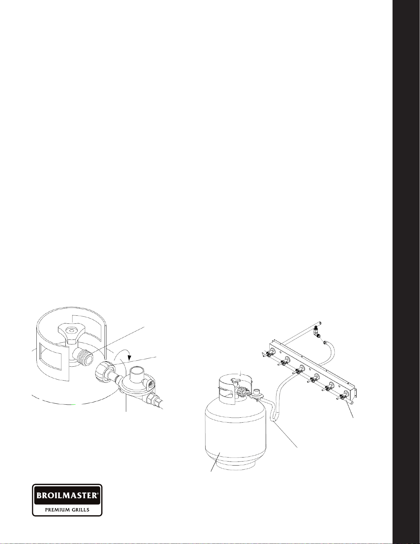
Type 1 connection
per ANSI Z21.58b-2012/
CSA 1.6b-2012
Quick
Coupling
Nut
Gas Requirements And Hook
-
up
LP GAS MODEL ONLY
-
TYPE 1
CONNECTION WITH REGULATOR
AND HOSE TO YOUR LP GAS TANK.
Connect and tighten the swivel nut of the
gas hose to the grill manifold shown below.
Turn all Control Knobs to the OFF
position. Inspect the valve connection
port and regulator assembly for damage
or debris. Remove any debris. Never use
damaged equipment.
Connect the regulator assembly to the tank
valve and HAND TIGHTEN nut clockwise to
a full stop. DO NOT use a wrench to tighten
because it could damage the Quick Coupling
Nut and result in a gas leak /re hazard.
Open the tank valve a full turn
(counterclockwise) and use a soapy water
solution to check all connections for leaks
before attempting to light your grill. See
"Check All Connections for LP Gas Leaks." If
a leak is found, turn the tank valve o and do
not use your grill until the leak is repaired.
CHECK ALL CONNECTIONS
FOR LP GAS LEAKS.
Never test for leaks with an open ame.
Prior to rst use, at the beginning of each
season, or every time your LP Gas tank is
changed, you must check for gas leaks.
FOLLOW THESE THREE STEPS:
1. Make a soap solution by mixing one part
liquid detergent and one part water.
2. Turn the grill Control Knobs to the full OFF
position, then turn the gas ON at source.
3. Apply the soap solution to all gas
connections. If bubbles appear in the
soap solution the connections are not
properly sealed. Check each tting and
tighten or repair as necessary.
LP Gas Tank
Regulator
with Hose
(LPG)
Gas Valve/
Manifold
Assembly
NOTE: No Appliance
Regulator Is Used When
An LP Tank And Type 1
Connector And Regulator
Are Used.
GAS REQUIREMENTS AND HOOK
-
UP
GAS REQUIREMENTS AND HOOK
-
UP
BR0227-1-0423 Page 19
GAS REQUIREMENTS AND HOOK
-
UP
GAS REQUIREMENTS AND HOOK
-
UP
CAUTION: When the appliance is not in use
the gas must be turned o at the tank. Place
dust cap on cylinder valve outlet whenever
the cylinder is not in use. Only install the type
of dust cap on the cylinder valve outlet that
is provided with the cylinder valve. Other
types of caps or plugs may result in leakage
of propane.
DISCONNECTING A LIQUID PROPANE
GAS (LPG) TANK FROM YOUR GRILL
1. Make sure the Burner Valves and LP
Gas tank valve are o. (Turn clockwise
to close.)
2. Detach the hose and regulator
assembly from the LP Gas tank valve
by turning the Quick Coupling Nut
counterclockwise.
3. Do not use a wrench or any tools when
turning the Quick Coupling Nut.
Gas Requirements And Hook-up (Cont'd.)
Failure to read and follow the Use and Care
Instructions could result in a re or explosion
that could cause serious bodily injury, death, or
property damage.
WARNING
! !
If you have a gas leak that cannot be repaired,
turn o the gas at the source and disconnect the
fuel line from your grill. Call your gas supplier or
re department for repair assistance.
WARNING
! !
1. Do not store spare LP cylinder within 10 feet
(3m) of this appliance.
2. Do not store or use gasoline or other
ammable liquids and vapors within 25 feet
(8m) of this appliance.
3. When cooking with oil/grease, do not allow
the oil/grease to get hotter 350°F (177°C).
4. Do not leave oil/grease unattended.
WARNING
! !
BR0227-1-0423Page 20
Gas Requirements And Hook-up (Cont'd.)
Gas
Supply
Inside
Wall
Outside
Wall
Shut-O
Male
Fitting
To Grill
Quick Disconnect
When Using 12ft. Hose
Locking
Shut-O
Flex-Line Or
12" Hose
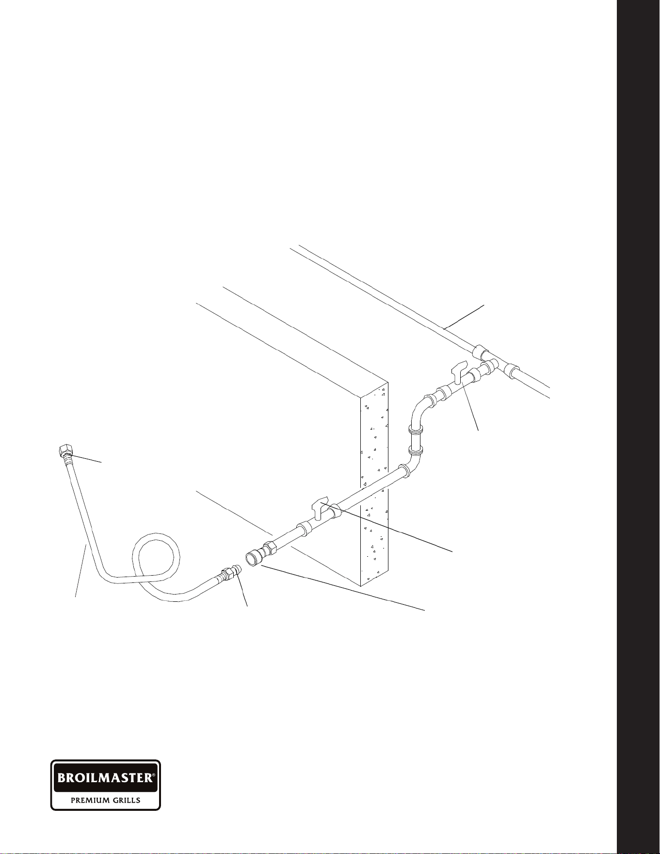
CONNECTING TO A PERMANENTLY
PLUMBED GAS LINE
Follow the diagrams below when
connecting gas to your grill from a natural
gas line or a permanently plumbed hard
piped LP connection.
NOTE: When using a portable cart
mounted grill, the use of a 12ft. Q.C. Hose
is recommended from grill to gas supply.
Whether the grill is built-in to a permanent
structure, the use of a S/S Flex-Line is
recommended from grill to gas supply.
Connect the Swivel nut of the ex-line or
12' Natural Gas Hose to the horizontal
tting of the grill and connect the other
end to the gas supply line from your
home. Read and follow the "Gas Safety
Instructions" on page 22.
GAS REQUIREMENTS AND HOOK
-
UP
GAS REQUIREMENTS AND HOOK
-
UP

BR0227-1-0423 Page 21
GAS REQUIREMENTS AND HOOK
-
UP
GAS REQUIREMENTS AND HOOK
-
UP
GAS SAFETY INSTRUCTIONS
Install a Shut
-
O Valve at the gas supply
source outdoors at a point after the gas
pipe exits the outside wall and before the
ex-line or quick-disconnect hose. Or install
it at the point before the gas line piping
enters the ground.
Pipe sealing compound or pipe thread tape
resistant to the action of natural gas must be
used on all male pipe thread connections.
Disconnect your gas grill from fuel source
when the gas supply is being tested at high
pressures.
This gas grill and its individual shut-o valve
must be disconnected from the gas supply
pipe system during any pressure testing of
that system at pressure in excess of 1/2 psi
(3.5kpa). Turn o your gas grill when the gas
supply is being tested at low pressures. The
grill must be isolated from the gas supply
pipe system by closing its individual manual
shut-o valve during any pressure testing
of the gas supply pipe system at pressures
equal to or less than 1/2 psi (3.5kpa).
CHECK ALL CONNECTIONS
FOR GAS LEAKS
Never test for leaks with an open ame.
Prior to rst use and at the beginning
of each season, you must check for gas
leaks. Follow these three steps:
1. Make a soap solution by mixing one part
liquid detergent and one part water.
2. Turn the grill Control Knobs to their full
OFF positions. Next, turn the gas ON at
the source.
3. Apply the soap solution to all gas
connections. If bubbles appear in the
soap solution the connections are not
properly sealed. Check each tting and
tighten or repair as necessary.
Gas Requirements And Hook-up (Cont'd.)

BR0227-1-0423Page 22
1. ALWAYS ENSURE THAT SOMEONE
IS AT THE GRILL AT ALL TIMES.
2. Prior to using grill ensure that all tie
down wires have been removed from
burners. Never operate the grill in a
windy area.
3. Avoid wearing loose-tting garments or
long sleeves while using the grill. Never
touch the grill racks, hood or immediate
surrounding metal surfaces with your
bare hands as these areas become
extremely hot during use and could
cause burns.
4. Use an insulated glove or mitt when
opening and operating the grill. Open
grill lid slowly to allow heat and smoke
to escape before fully opening.
5. Never lean over hot grill surface or look
directly into the grill when attempting
to light. The grill hood must be fully
opened when lighting.
6. Do not heat unopened food containers
as pressure build-up may cause
container to burst.
7. Do not use aluminum foil to line grill
racks or drip pans. This will alter
combustion airow or trap excessive
heat in the control area. This can result
in melted knobs and ignition modules.
Never cover or block grilling area with
any type of pots and/or pans. These
damages are specically excluded from
your warranty.
8. Never use charcoal in this gas grill.
9. Be aware that cooking excessively
fatty meats and other such products
will cause are ups. Internal res or
damage caused by are-ups or the grill
being left unattended while cooking,
are not the responsibility of Empire
Comfort Systems and any resulting
damage is not covered under the terms
and conditions of our warranty.
10. Never grill without the drip pan in place.
The drip pan must be pushed all the
way to the back of the grill. Without
the drip pan in place, hot grease could
leak downward and produce a re or
explosion hazard.
11. Grease is extremely ammable. Let hot
grease cool down before attempting
to handle or dispose of it. The drip
tray should be cleaned of grease on a
regular basis.
12. Do not use the grill until a leak check
has been performed
13. Do not operate grill under the inuence
of alcohol or drugs
Important Grilling Safety Information
IMPORTANT GRILLING SAFETY INFORMATION
CONVERTING YOUR GAS GRILL

BR0227-1-0423 Page 23
IMPORTANT GRILLING SAFETY INFORMATION
CONVERTING YOUR GAS GRILL
HOW DO I CONVERT MY GRILL
GAS TYPE?
A professional plumber or gas grill
professional should be used to convert
your gas grill. An conversion Orice
kit is included in your grill.
GAS PROFESSIONAL INSTALLERS
Main Burners
1. You must remove all cooking grids,
vaporizors and dividers to see the
main burners in the appliance.
2. On the back rear of each burner is a pin.
Remove pin with a needle nose pliers.
3. To remove burner, pull burner upwards
and slide burner toward the rear of
the appliance. Repeat this process for
each burner.
4. Where the burner was previously
located, sitting over the main valve
orice through the hole in the front
basin should now be empty space
where you can see the orice.
5. Inside the space you will nd the end of
the valve , with an orice (brass tting),
screwed into the end of the valve stem
that can be easily removed.
6. Carefully remove the orice with a 6mm
socket set and extension they are brass
so be cautious not to strip.
7. Once the old orice is removed, replace
it with the new orice provided with
each gas grill.
8. Replace burners and pins making sure
that the orices are inside and centered
in the burner tubes.
9. For converting to LP, attach the provided
brass elbow to the gas manifold tting.
You will need to purchase an LP hose
and regulator (Empire part number
B069756) to connect the LP tank to the
brass elbow.
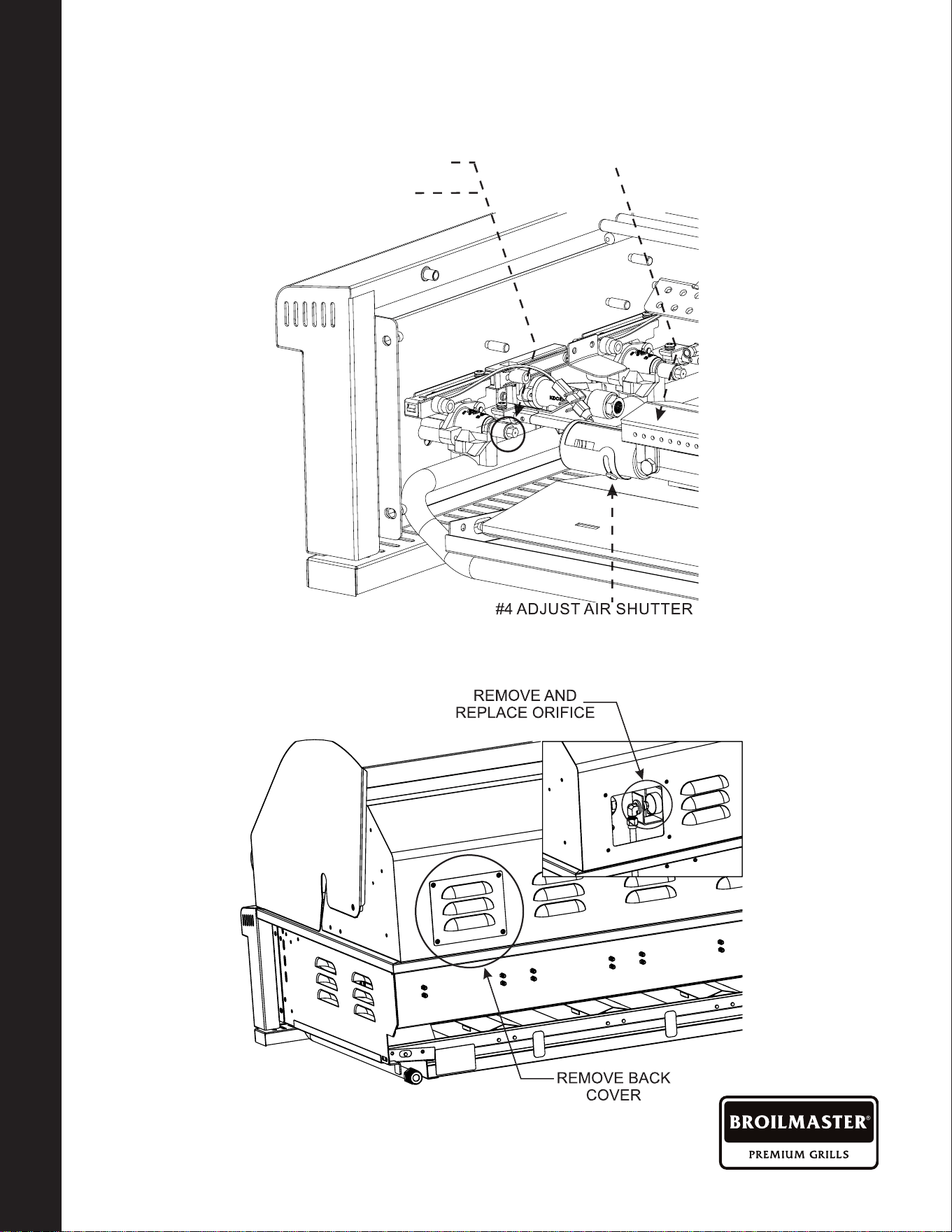
Rear Burner
1. Remove 2 screws on each side of the
cover, then remove the rear cover from
the back of the rebox.
2. Remove the orice.
3. Replace the orice with the new orice
provided with each gas grill. See rating
plate chart for size on page 39.
4. Replace rear cover.
Adjust Main Burner And Air Shutters
1. Light each burner and inspect burners
for proper ame appearance.
2. The best ame appearance is a blue
ame with yellow tip.
3. There is an air shutter found at the end
of the main burner Venturi, which can
be either opened or closed to make
adjustments to the ame's appearance.
The Air Shutter can be adjusted by
loosening the screw and opening the air
shutter, then closing it slowly until the
ame starts to yellow. STOP and turn
back 1/16", then tighten the screw. The
ame should be blue with yellow tips.
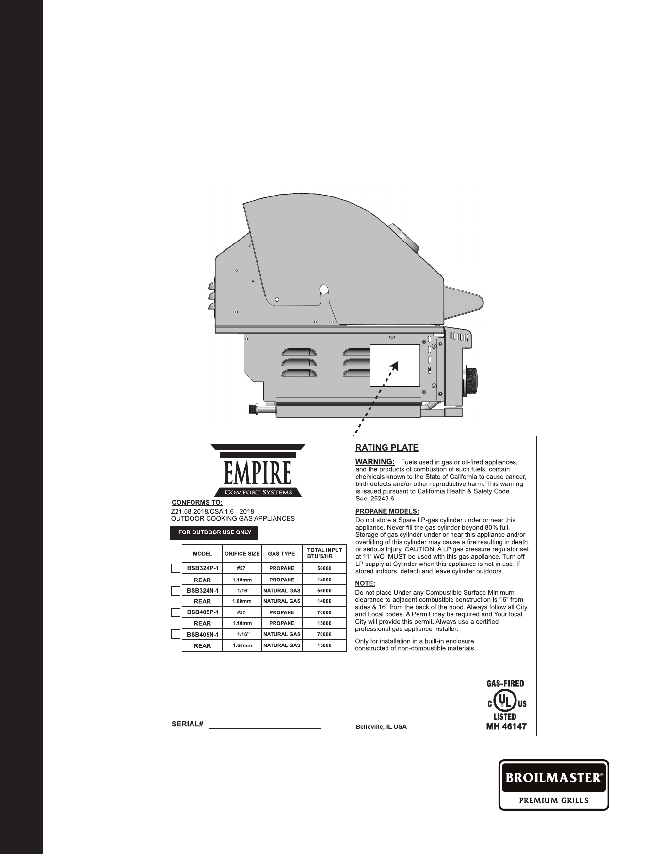
Converting Your Gas Grill
Your BROILMASTER Gas Grill comes equipped to be converted to the opposite gas.
Each grill comes "GAS SPECIFIC", and packed with a gas conversion kit. On the side of
the GAS BBQ there will be a rating plate that species the "GAS TYPE" and orice size as
well as contains your SERIAL NUMBER for your warranty.
BR0227-1-0423Page 24
Converting Your Gas Grill (Cont'd.)
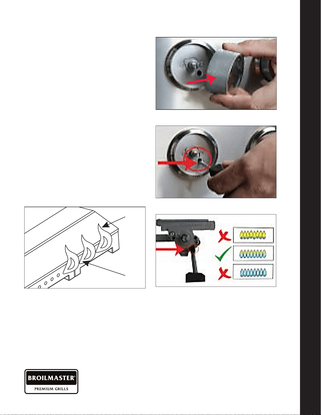
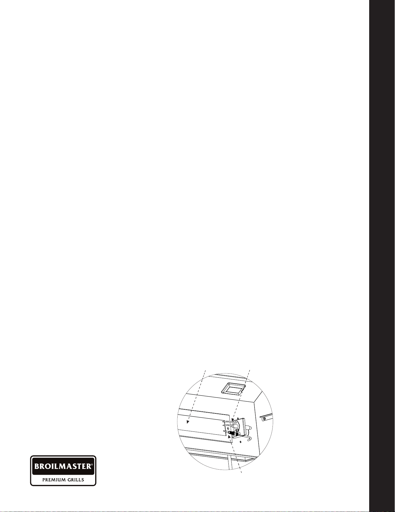
LOW HEAT ADJUSTMENT
The valves on the grill feature an adjustable
low setting. Due to uctuations in gas
pressure, heating value or gas conversion,
you may feel it necessary to adjust gas
ow in the low position. Do not adjust the
infrared rear rotis or optional Sear burner.
When doing this adjustment you will be
wanting a Blue Flame with a Yellow Tip.
Adjust the Valve to obtain this ame.
1. Light the burner.
2. Turn the control knob to the lowest
setting (all the way counterclockwise).
Remove the knob.
3. Insert a small thin at tipped screwdriver
into the adjustment screw hole and
while viewing the burner ame, adjust to
a minimum stable ame. Increase to left
and decrease to right.
CONVERTING YOUR GAS GRILL
CONVERTING YOUR GAS GRILL TYPE
REMOVE
KNOB
LOCATE
SCREW
ADJUST
FLAME
3/8"
Flame
Core
1-1/2"
Flame
Height
A. Remove knob.
A. Remove knob.
B. Locate screw.
C. Adjust ame.
BR0227-1-0423 Page 25
CONVERTING YOUR GAS GRILL
CONVERTING YOUR GAS GRILL TYPE
MAIN BURNER ORIFICE CHANGE
Converting Your Gas Grill Gas Type
REAR BURNER ORIFICE CHANGE
#2 REPLACE GAS ORIFICE
#1 MOVE BURNER
#4 ADJUST AIR SHUTTER
#3 REPLACE BURNER
REMOVE BACK COVER
REMOVE AND
REPLACE ORIFICE
BR0227-1-0423Page 26
LIGHTING THE BURNERS
MANUALLY LIGHTING THE GRILL
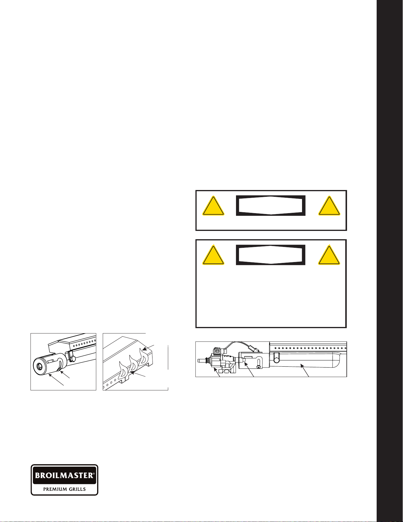
This BROILMASTER Gas Grill has a "ame out"
ignition system located on the rear Burner. This
ignition system will automatically switch the gas supply
o if the burner is blown out in a windy condition.
Allow the ignition Safety Thermocouple to cool down
before trying to relight the back burner.
Note if you are in an extremely windy condition please
try and protect the grill from direct wind to the grill front
and back.
BACK BURNER
IGNITION SYSTEM
AUTOMATIC “FLAME OUT”
SAFETY THERMOCOUPLE
INFRARED BACK BURNER
AUTOMATIC "FLAME OUT"
SAFETY THERMOCOUPLE
BLACK BURNER
IGNITION SYSTEM
INFRARED
BLACK BURNER
Lighting The Burners
LIGHTING THE MAIN GRILL BURNERS:
1. Open BBQ hood . DO NOT ATTEMPT
TO LIGHT GRILL WITH THE HOOD
CLOSED.
2. Check to ensure that all burner control
knobs are set to OFF.
3. Turn on main gas supply.
4. Push burner knob in, turn slowly
counterclockwise until gas begins to
ow and hold for 2 seconds. Continue
turning to the "HIGH" position. You
should hear the "CLICK" and the
burner will ignite. Release knob.
5. If burner does not light, turn knob to
OFF, wait 5 minutes to allow gas to
dissipate, and repeat step 4 above.
LIGHTING THE BACK INFRARED BURNER:
1. Open hood completely. Do not attempt
to light grill with the hood closed.
2. Load food onto skewer, and install
brackets, motor and skewer onto grill
in desired cooking position.
3. Check to ensure that all burner control
knobs are set to OFF.
4. Turn on main gas supply.
5. Push in and turn knob 1/4 turn counter
clockwise to hear the click to ignite the
back burner. When the burner ignites
continue to hold in knob for 30 seconds
and then release.
6. If burner does not light, turn knob to
OFF, wait 5 minutes to allow gas to
dissipate, and repeat step 5 above.
PREHEATING THE GRILL
Before cooking, always preheat the grill for best results. To preheat the grill, light all main
burners and set to HIGH. Close the grill hood and allow to preheat for 10
-
15 minutes, or
until the grill reaches desired temperature.
After preheating, turn o all burners not required, carefully open the hood, and adjust
remaining burners to desired temperature.
Do not leave the grill unattended during the preheat cycle or at any time while the grill
is in use. Do not allow grill to preheat for prolonged periods of time. Overheating the
grill can cause damage to the grill and personal property.
BR0227-1-0423 Page 27
LIGHTING THE BURNERS
MANUALLY LIGHTING THE GRILL
Manually Lighting The Grill
1. Open the hood and wait ve minutes allow any accumulated gas to dissipate.
2. Keep your face as far away from the burners as possible.
3. Light and insert a long-stem match, holding it near the Lighting Tube on the right side.
4. Slowly rotate the burner knob counter-clockwise to the high position.
5. If the burner does not light after ve seconds, turn the control knobs to
the OFF position
and wait ve minutes until the gas clears before attempting to re-light.
6. If the burner does not light after several attempts, immediately close all gas valves and
consult an authorized service technician.
7. To shut o the burners, rotate the knob and turn to OFF.
8. It is normal to hear a popping sound when the burners are turned o.
WARNING
! !
Never lean over the grill cooking area while
lighting your gas grill. Keep your face and body
a safe distance (at least 18 inches) from the front
of grill when lighting your grill by match.
WARNING
! !
Do not use standard matches or cigarette lighters
to perform match-lighting procedures. Serious
burns can occur and lighters can explode.
BR0227-1-0423Page 28
BURNER TYPE IDENTIFICATION
DIRECT COOKING METHOD / INDIRECT COOKING METHOD
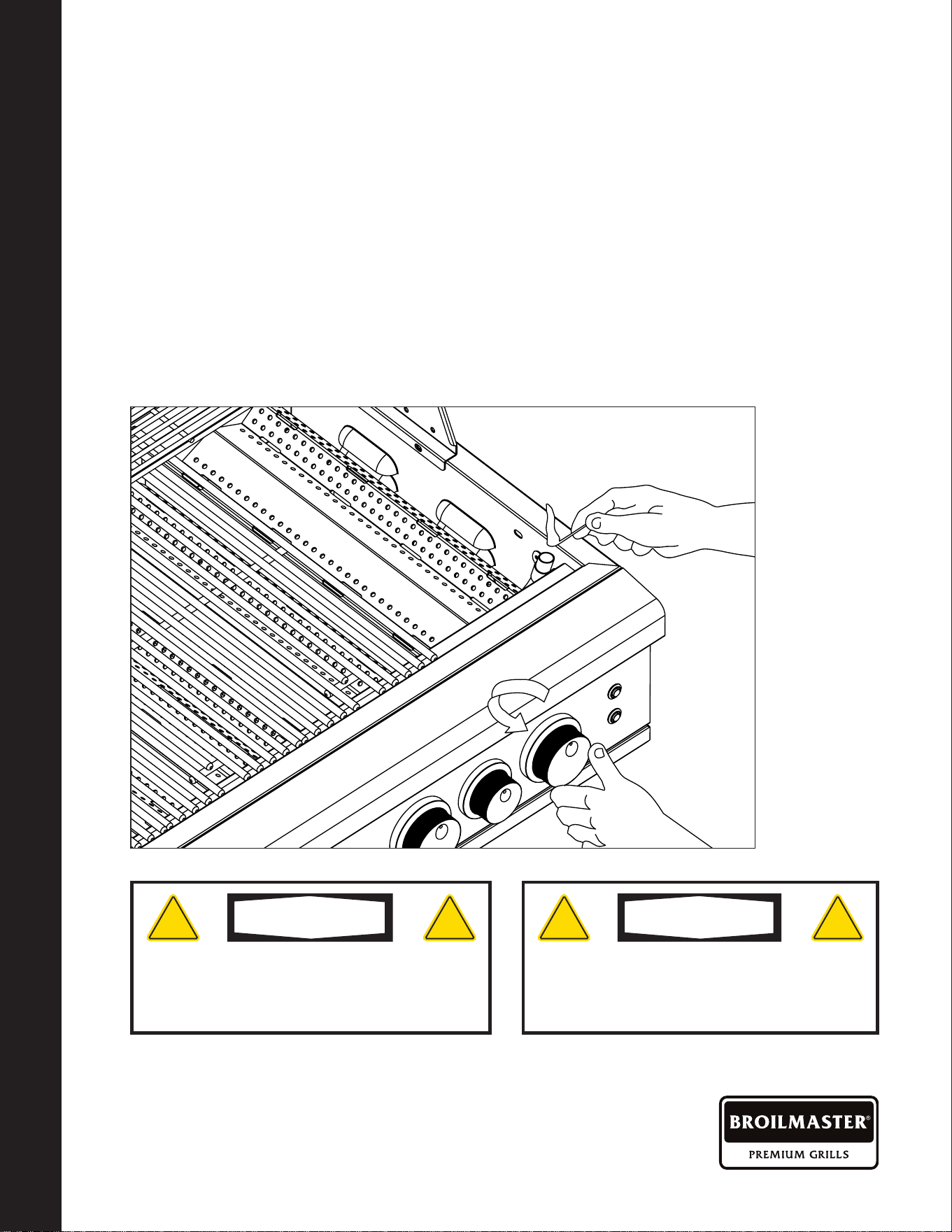
Burner Type Identication
Your BROILMASTER grill comes standard with a Cast Stainless Steel burners and an
infrared rotisserie burner.
Using the BROILMASTER Grill
This BROILMASTER grilling requires high heat for searing and proper browning of your
food. Most direct foods are cooked at the high heat setting for the entire cooking time (with
the lid open). However, when grilling large pieces of meat or poultry, it may be necessary
to turn the heat to a lower setting after the initial browning. This cooks the food through
without burning the outside. Foods cooked for a long time or foods basted with a marinade
may need a lower heat setting near the end of the cooking time.
MAIN BURNER
-
This is the
standard main grill burner
found under the vaporizers.
ROTISS BURNER
-
This is an
infrared burner found in the rear
of the grill above the grill racks.
COOKING GRIDS -
Single
-
Level Cooking Surface
VAPORIZER - Even Heat
Vaporizering System
BR0227-1-0423 Page 29
BURNER TYPE IDENTIFICATION
DIRECT COOKING METHOD / INDIRECT COOKING METHOD
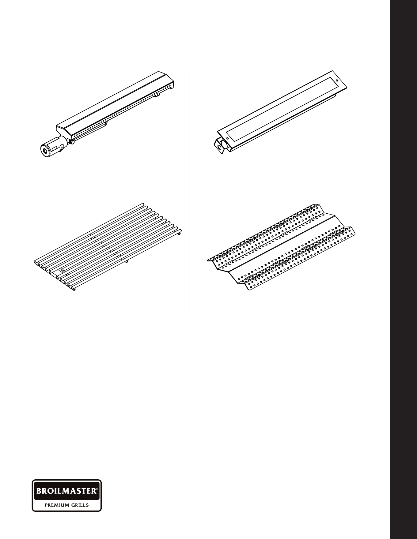
Direct Cooking Method
Direct cooking involves placing food on grates over direct heat Burners. Use this method
for foods that take less than 20 minutes to cook or to sear larger items at the start of the
cooking process that will then be indirectly cooked to nish. Place items on the preheated
surface and leave until they no longer stick. Turning too soon and too often is one of the
most common grilling mistakes. Use a meat thermometer to achieve desired doneness
and remove items one degree below how you would like to enjoy them, as the resting
period before carving or consuming will raise the temperature.
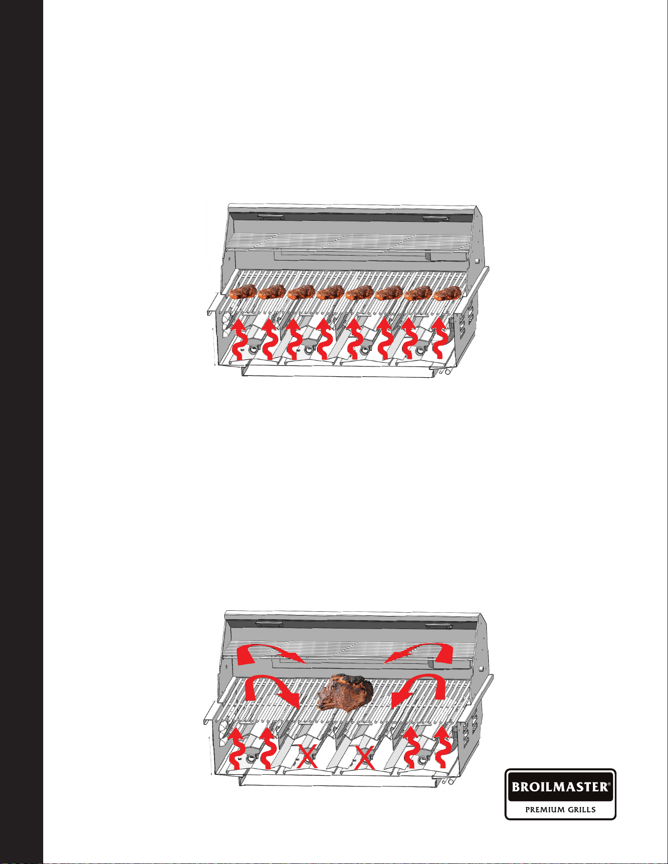
Indirect Cooking Method
Indirect cooking method is a popular alternative to direct heat grilling. Indirect cooking
uses heat from adjacent burners to cook food and, in many cases, reduces the possibility
of overcooked or overly browned food. Foods most appropriate for indirect grilling included
breads, thicker pieces of chicken or roasts. Indirect cooking involves placing the food on
grates where the burners below are not lit and then closing the grill top to create an oven
eect. All the items you usually oven-roast can be grilled to perfection using indirect
heating. Preheat the burners surrounding the food to be cooked. Use your basting pan
below to hold food and add water or marinaid to the pan to prevent the natural juices
from burning or evaporating. Place pan on the vaporizers directly under the food above.
OFF
OFF
Direct cooking involves placing food on grates
over direct heat Burners. Use this method
for foods that take less than 20 minutes to
cook or to sear larger items at the start of the
cooking process that will then be indirectly
cooked to nish. Place items on the preheated
surface and leave until they no longer stick.
Turning too soon and too often is one of the
most common grilling mistakes. Use a meat
thermometer to achieve desired doneness
and remove items one degree below how you
would like to enjoy them, as the resting period
before carving or consuming will raise the
temperature.
Indirect cooking method is a popular
alternative to direct heat grilling. Indirect
cooking uses heat from adjacent burners to
cook food and, in many cases, reduces the
possibility of overcooked or overly browned
food. Foods most appropriate for indirect
grilling included breads, thicker pieces of
chicken or roasts. Indirect cooking involves
placing the food on grates where the burners
below are not lit and then closing the grill
top to create an oven eect. All the items
you usually oven-roast can be grilled to
perfection using indirect heating. Preheat the
burners surrounding the food to be cooked.
Use your basting pan below to hold food
and add water or marinaid to the pan to
prevent the natural juices from burning or
evaporating. Place pan on the vaporizers
directly under the food above.

BR0227-1-0423Page 30
THE BROILMASTER IR rotisserie system
consists of three main parts
-
the motor,
the skewer which holds the food, and the
infrared rotis back burner. The rotisserie
evenly cooks large cuts of meat by turning
them continuously in front of a high heat
burner. The rotis is capable of turning up
to a 25 lb. cut of meat. Make sure the rotis
motor is not straining when turning the meat
/ chicken.
THE MOTOR
-
The rotisserie motor runs on
110 power that has its own power supply.
To power the motor, plug into a 110 power
outlet or use a outdoor extension cord.
Install the motor onto the grill by sliding it
onto the bracket located on the left or right
side of the grill. (Bracket is removable and
universal for each side)
THE SKEWER
-
To load the skewer with
food, slide one of the meat holders onto
the skewer. Push the skewer through the
center of the food, then slide the second
meat holder onto the skewer. Center the
food to be cooked on the skewer then push
the meat holders rmly together. Tighten
the thumb screws (use pliers if necessary).
It may also be necessary to wrap the food
with cooking string to secure any loose
portions.
WARMING RACK
-
Remove the warming
rack and, if needed, remove the grill racks
to gain better clearance. It is normal for the
skewer to ex when cooking large foods.
Place a cooking pan with water or marinaid
beneath the food for basting and to ease
cleaning.
THE INFRARED REAR BURNER
-
The
location of the rotis burner makes it more
susceptible to strong wind conditions (more
so than the main grill burners). For this
reason you should avoid operating the rotis
cooking during windy conditions. As an
added safety feature, the burner is equipped
with an automatic safety valve which will not
allow gas to ow to the rotis burner if it is not
properly lit or goes out.
Using The Rotisserie
(
Optional Accessory
)
USING THE ROTISSERIE (OPTIONAL ACCESSORY)
COOKING TIPS
BR0227-1-0423 Page 31
Cooking Tips
COOK FOOD TO PROPER TEMPERATURES
Cooking food safely requires that you raise the internal temperature of the meat high enough
and for a long enough period of time to kill any food-borne bacteria that may cause illnesses.
Color is not the best indicator that food is safe to eat. Use a high-quality probe thermometer
to be sure your food is properly cooked. Place the tip of an instant-read thermometer into the
center of the thickest part of the food but at least 1/2 inch deep. Read the temperature after
about 10 seconds. Follow the temperature guidelines for the type of food you’re cooking.
The following guidelines are from the U.S. Food and Drug Administration Center for Food
Safety and Applied Nutritio
n.
COOK TO INTERNAL TEMP
Meat And Poultry Medium Rare Medium Well Done
Fresh Beef - Medium Rare 145°F 160°F 170°F
Ground Turkey, Chicken 165°F
Ground Veal, Beef, Lamb, Pork
145°F with 3 minutes of rest and then turn
Fresh Pork - Medium – 160°F 170°F
Chicken - Whole 165°F
Turkey - Whole 165°F
Poultry Breasts, Roast 165°F
Poultry Thighs, Wings 165°F
Stung
(
Cooked Alone Or In Bird
)
165°F
Duck And Goose 180°F
Fresh Veal - Medium Rare 160°F
Fresh Lamb - Medium Rare 145°F 160°F 170°F
Ham - Fresh (Raw) 145°F 160°F 170°F
Ham - Pre-Cooked (Reheat) 140°F
SEAFOOD
Fish
Cook until esh turns opaque and akes easily with a fork.
Shrimp, Lobster, Crab
Cook until shells turn red and esh becomes pearly opaque.
Scallops Should turn milky white or opaque and rm.
Clams, Mussels, Oysters Cook until shells open.
*The above temperature settings are a guide, the temperatures may vary due to wind and
outside ambient temperatures.
USING THE ROTISSERIE (OPTIONAL ACCESSORY)
COOKING TIPS
BR0227-1-0423Page 32
Burner Cleaning And Adjustment
Before removing burners ensure the gas
supply is o and the knobs are in the “o ”
position. Make sure the grill has completely
cooled before proceeding.
TO REMOVE BURNERS:
Remove the grill racks, vaporizers and
zone dividers. Remove the pin holding the
burner in place. Grasp the burner, pull it
up and slightly to the rear of the unit, so
the burner head comes o the brass orice
at the front and remove. Be careful not to
upset the air shutter position.
BURNER CLEANING:
To maximize grill performance, clean
the exterior of the burner with a wire
brush. Clear stubborn scale with a metal
scraper. Clear any clogged ports with
a straightened paper clip. Never use a
wooden toothpick as it may break o
and clog the port. Shake out any debris
through the air shutter. Use a ashlight to
inspect the burner inlet to ensure it is not
blocked. If obstructions can be seen, use
a metal wire coat hanger that has been
straightened out to clean.
BETTER AIR ADJUSTMENT:
Each grill burner is tested and adjusted
at the factory prior to shipment; however,
variations in the local gas supply or a
conversion from one gas to another may
make it necessary to adjust the burners.
The ames of the Grill burners should be
visually checked, adjusting the air shutter by
opening the air shutter and slowly closing
it until the ame starts to yellow. STOP
and turn back 1/16", and tighten the screw.
Flame should be blue with yellow tips when
adjusted correctly.
WARNING
! !
For safe operation, make sure the Orices are
inside the Burner Tubes before using your grill.
(See gure below). If the Orice is not inside
the Burner Tube, lighting the Burner may cause
explosion and/or re resulting in serious bodily
injury and/or property damage.
Please Note that the air mixture for LP gas and NG is
dierent. Your gas BBQ will come preset for your gas type.
If you nd that you are not getting the best ame you can
adjust the air shutter and the O2 mix with gas will change
the ame. The ame coming from your burner is extremely
important. If the ame is not correct you will be able to
adjust the ame as described in the section above.
ORIFICE
GAS VALVE ASSEMBLY
BURNER TUBE
Gas Valve
Assembly
Orice
Burner TubeOrice
BURNER CLEANING AND ADJUSTMENT
WARNING
–
CLEANING METHODS
SET
SCREW
AIR SHUTTER
Air Shutter
1 1/2" Flame
Height Yellow
Tips
3/8" Flame
Core Blue
Base
Set Screw
WARNING
! !
It is critical to center every burner on its orice.
BR0227-1-0423 Page 33
WARNING
! !
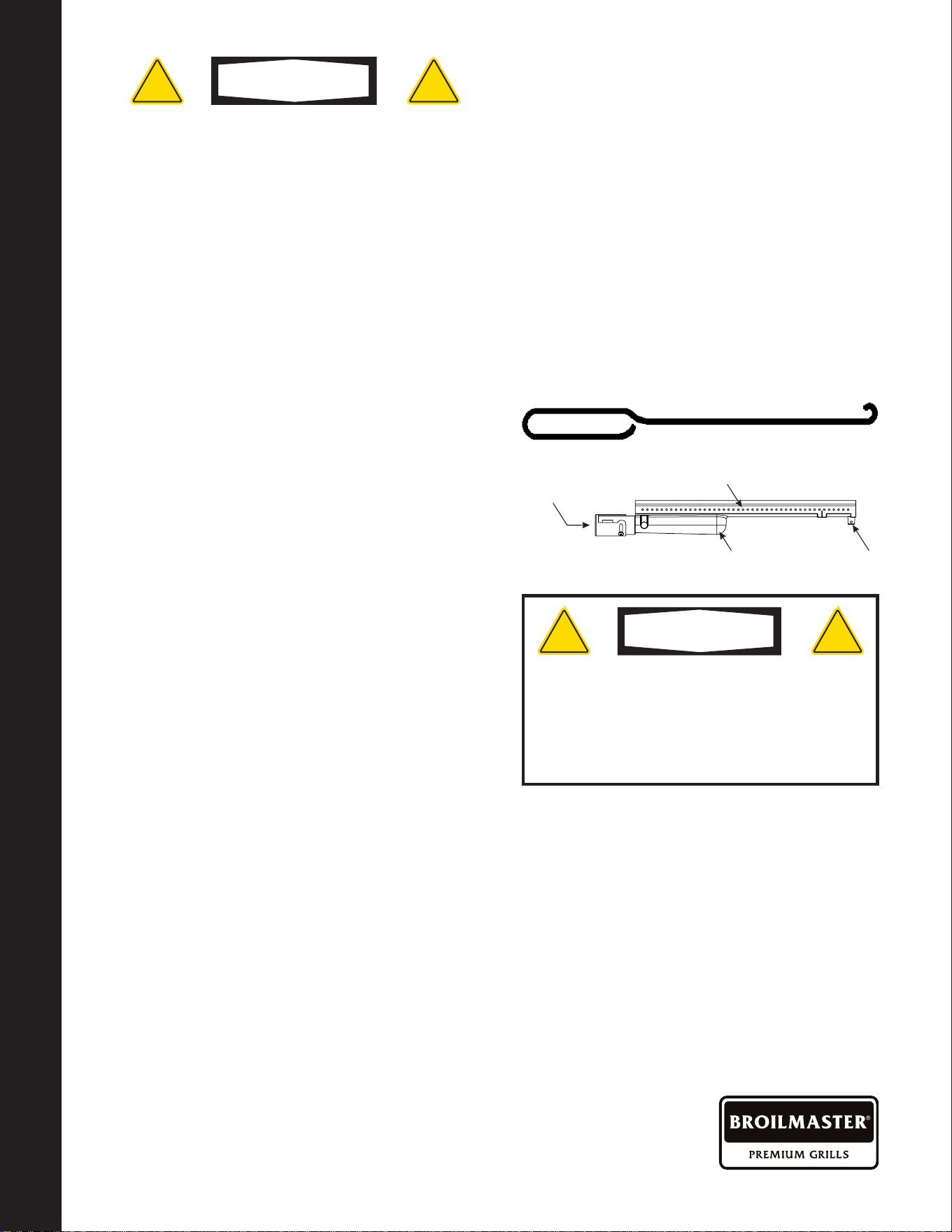
Spiders and small insects can spin webs and nest in the grill burner ventures which can
lead to a gas ow obstruction resulting in a re in and around the burner tubes. This type
of “FLASHBACK FIRE” can cause serious grill damage and create an unsafe operating
condition for the user.
To reduce the chance of FLASHBACK FIRE you must inspect and clean the ventures at
least twice a year in summer and fall or whenever spiders are active in your area, and if
your grill has not been used for an extended period of time.
Remove the pin from the rear of each Main Burner using needle-nose pliers. Carefully lift
each Burner up and away from the Gas Valve Orice. Check and clean Burner/Venturi
Tubes for insects and insect nests. A clogged tube can lead to a re beneath the grill.
BURNER CLEANING AND ADJUSTMENT
WARNING
–
CLEANING METHODS
FOR CLEANING, REFER TO
METHODS 1-3 BELOW:
METHOD 1: Bend a sti wire or wire
coat hanger into a small hook as shown
and run the hook through the Burner
Tube and inside the Burner several times
to remove debris.
METHOD 2: Use a bottle brush with a
exible handle and run the brush through
the Burner Tube and inside the Burner
several times to remove any debris.
METHOD 3: Use an air hose to force air
through each Burner Tube. The forced
air should pass debris or obstructions
through the Burner and out the Ports.
WARNING
! !
For safe operation ensure the Gas Valve Assembly
Orice is inside the Burner Tube before using your
grill. (See gure above). If the Orice is not inside
the Burner Tube, lighting the Burner may cause
explosion and/or re resulting in serious bodily
injury and/or property damage.
To Clean Burner Tube,
Insert Hook Here
Burner Holes
GAS VENTURI
BURNER PIN
BURNER HOLES
TO CLEAN BURNER TUBE,
INSERT HOOK HERE
Gas Venturi Burner Pin

BR0227-1-0423Page 34
Cleaning The Grill
Proper care and maintenance will keep
your grill in top operating condition and
prolong its life. Follow these cleaning
procedures on a timely basis and your grill
will stay clean and operate with minimum
eort. CAUTION: Be sure your grill is OFF
and cool before cleaning.
CLEANING THE COOKING GRIDS
-
Before initial use, and periodically thereafter,
wash your Cooking Grids in a mild soap
and warm water solution. You can use a
wash cloth or vegetable brush to clean your
Cooking Grids.
CLEANING THE FLAME TAMERS
-
You should periodically wash the Flame
Tamers in a soap and warm water solution.
Use a vegetable brush to remove stubborn
burnt-on cooking residue. Dry the Flame
Tamers thoroughly before you reinstall
them into the grill.
CLEANING THE GREASE TRAY
-
To
reduce the chance of re, the Grease Tray
should be visually inspected before each
grill use. Remove any grease and wash
Grease Tray with a mild soap and warm
water solution.
CLEANING THE INSIDE OF THE GRILL
LID
-
Grease can build up on the inside
of the Grill lid over time. This grease can
drip onto your deck or patio when the lid is
opened. Visually inspect the inside of the
Grill Lid before each grill use. Remove any
grease and wash with a mild soap and warm
water solution.
ROUTINE CLEANING OF THE GRILL
INTERIOR
-
Burning-o excess food after
every cookout will keep it ready for instant
use. However, at least every 6 months
you must give the entire grill a thorough
cleaning to minimize your risk of grease
re and keep the grill in top shape.
FOLLOW THESE STEPS:
1. Turn all Control Knobs to the full OFF
position. Turn the LP gas tank valve
to the full OFF position or turn o NAT
gas supply.
2. Remove and clean the Vaporizers,
Cooking Grids, Warming Rack, Zone
Dividers and Grill Burners as above.
3. Scrape out and brush the inside and
bottom of the grill with a scraper and ber
pad or nylon brush and wash with a mild
soap and warm water solution. Rinse
thoroughly and let dry.
4. Check each Orice for obstruction.
5. Replace the Burners and adjust the
Gas Collector Box. The edge of the
collector box should be overlapping
the Burner Port.
6. Replace Burner, Vaporizer, Zone Divider
and Cooking Grids.
7. Reconnect the gas source and observe
the Burner ame for correct operation.
CLEANING THE GRILL
CLEANING THE GRILL

BR0227-1-0423 Page 35
Cleaning The Grill (Cont'd.)
CLEANING EXTERIOR STAINLESS
STEEL SURFACES:
Routine care and maintenance is required
to preserve the appearance and corrosion
resistance of stainless steel. The fact is
stainless steel can corrode, rust and discolor
under certain conditions. Rust is caused when
regular steel particles in the atmosphere
become attached to the stainless steel
surface. Steel particles can also become
attached to your grill if you use steel wool
or sti wire brushes to clean the grill instead
of non-abrasive cloth, sponge or nylon
cleaning tools. In coastal areas rust pits can
develop on stainless surfaces that cannot
be fully removed. Bleach and other chlorine
based solutions used for household and
pool cleaning can also cause corrosion to
stainless steel. Weathering, extreme heat,
smoke from cooking and machine oils used in
the manufacturing process of stainless steel
can cause stainless steel to turn tan in color.
Although there are many factors which can
aect the surface appearance of stainless
steel, they do not aect the integrity of the
steel or the performance of the grill.
TO HELP MAINTAIN THE FINISH OF
STAINLESS STEEL FOLLOW THESE
CLEANING PROCEDURES FOR THE
BEST RESULTS:
1. After every use (after your grill has
cooled down), wipe stainless surfaces
with a soft, soapy cloth or sponge then
rinse with water.
2. Be sure to remove all food particles,
sauces or marinades from stainless
steel because these can be highly acidic
and damaging to stainless surfaces.
Never use abrasive cleaners, scrubbers
or sti wire brushes of any type on your
grill.
3. Use a heat resistant Stainless Steel
Cleaner and rub or wipe in the direction
of the stainless steel grain or polish
lines. Do not polish against the grain.
CLEANING THE GRILL
CLEANING THE GRILL
BR0227-1-0423Page 36
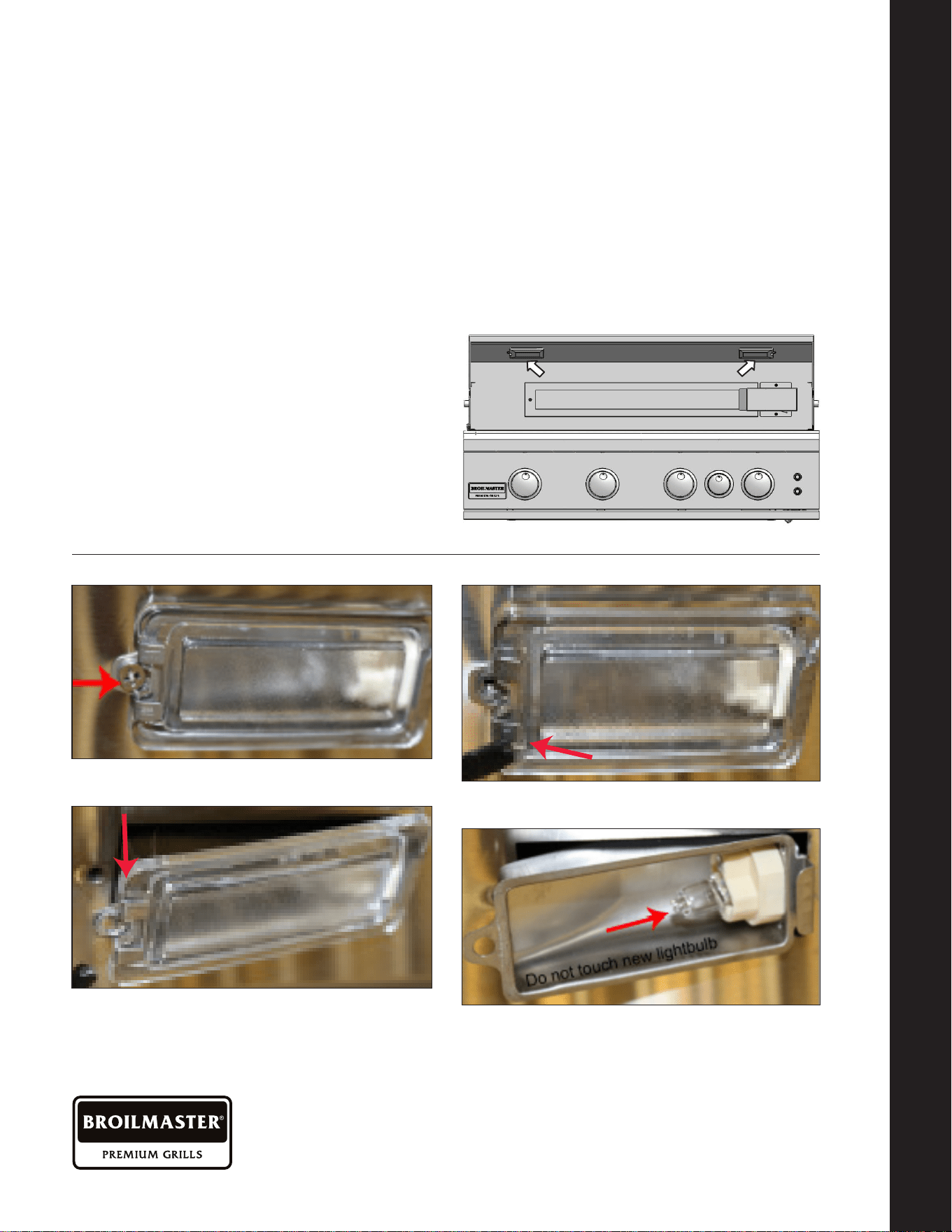
DO NOT TOUCH THE GLASS OF THE
NEW REPLACEMENT BULB.
Replace The Bulb
Replacement bulbs are halogen, 12 volt,
10W max, T3 type with a G4 bi-pin, and are
readily available at most stores. The glass
cover is held in place by two spring tension
tabs. The bulbs are easily removable
without the use of tools.
Simply grasp the glass lens at the outer
corners, near the front tension clips and
push the lens back.
Then, swing the lens down and pull it
loose. You may have to loosen the screw to
remove the lens.
Avoid touching the glass of a new bulb.
Halogen bulbs are very sensitive to the oils
found in human skin. Touching the bulbs
may shorten their life. Pull the bulb straight
out from the socket without twisting. Hold
the bulb using a paper towel or other cloth
and gently press it straight into the socket.
The glass cover should be gently snapped
back into place.
Light Bulb Replacement
LIGHT BULB REPLACEMENT
BROILMASTER LIMITED WARRANTY
1. Remove screw
2. Pull from housing
3. Remove bracket
4. Replace light bulb
5. Reverse process to replace into housing

BR0227-1-0423 Page 37
BROILMASTER Limited Warranty
WARRANTY TERMS FOR EMPIRE COMFORT SYSTEMS INC.
BROILMASTER Stainless Steel Gas Grills
Models: BSB324(N,P), BSB405(N,P)
Empire Comfort Systems Inc. warranties this BROILMASTER stainless steel gas grill to be free from defects at the time of
purchase and for the periods specied below. The grill must be installed by a qualied technician and must be maintained
and operated safely, in accordance with the instructions in the owner's manual. This warranty applies to the original
purchaser only and is not transferable. All warranty repairs must be accomplished by a qualied gas appliance technician.
Limited Lifetime Parts Warranty – Against Rust-Through
If the items listed below fail because of defective workmanship or material, Empire will repair or replace at Empire's option.
The limited lifetime warranty provides one-time replacement of a covered component.
• Stainless Steel Grill Housing
• Stainless Steel Cooking Grids and Stainless Steel Griddles
• Select Stainless Steel Components – Carts, Cast Stainless Steel Bowtie Burners, Stainless Steel Drip Pans, Side
Burners, Side Burner Housings, and Warming Rack
• Stainless Steel Built-In Components – Built-In Sleeves, Access Door and Drawer Kits, Coolers, Sinks, and Vent Register Kits
Limited Five-Year Parts Warranty – Against Rust-Through
If the items listed below fail because of defective workmanship or material, Empire will repair or replace at Empire's option.
Stainless Steel V-Grates, Flame Tamers, and Heat Zone Partitions
Infrared Burners (main and rear rotisserie)
Limited One-Year Parts Warranty
If the items listed below fail because of defective workmanship or material, Empire will repair or replace at Empire's option.
• Valves, knobs, ignitors, labels, hoses, ttings, and all other parts and accessories – including those made from
stainless steel – unless specied above
Duties Of The Owner
The appliance must be installed by a qualied installer and operated in accordance with the instructions furnished with
the appliance
.
A bill of sale, cancelled check, or payment record should be kept to verify purchase date and establish warranty period.
Ready access to the appliance for service
What Is Not Covered
Damages that might result from the use, misuse, or improper installation or storage of this appliance.
Travel, diagnostic costs and freight charges on warranted parts to and from the factory.
Claims that do not involve defective workmanship or materials.
Unauthorized service or parts replacements.
Removal and reinstallation cost.
Inoperable due to improper or lack of maintenance.
The costs of a service call to diagnose a problem and labor for replacement or repairs.
How To Get Service
To make a claim under this warranty, please have your receipt available and contact your installing dealer. Provide the
dealer with the model number, serial number, type of gas, and purchase verication. The installing dealer is responsible for
providing service and will contact the factory to initiate any warranted parts replacements. Empire will make replacement
parts available at the factory. Shipping expenses are not covered.
Your Rights Under The Law
This warranty gives you specic legal rights, and you may also have other rights, which
vary from state to state.
LIGHT BULB REPLACEMENT
BROILMASTER LIMITED WARRANTY

BR0227-1-0423Page 38
MASTER PARTS DISTRIBUTOR LIST
To Order Parts Under Warranty, please contact your local Empire dealer. See the dealer locator at www.
empirecomfort.com. To provide warranty service, your dealer will need your name and address, purchase
date and serial number, and the nature of the problem with the unit. To Order Parts After the Warranty Period,
please contact your dealer or one of the Master Parts Distributors listed below. This list changes from time
to time. For the current list, please click on the Master Parts button at www.empirecomfort.com.
Please note:
Master Parts Distributors are independent businesses that stock the most commonly ordered Original Equipment
repair parts for Heaters, Grills, and Fireplaces manufactured by Empire Comfort Systems Inc.
Parts Not Under Warranty
Parts can be ordered through your Service Person, Dealer, or a Master Parts Distributor. See this page for the Master Parts
Distributors list. For best results, the service person or dealer should order parts through the distributor. Parts can be
shipped directly to the service person/dealer.
Warranty Parts
Warranty parts will need a proof of purchase and can be ordered by your Service Person or Dealer. Proof of purchase is
required for warranty parts.
All parts listed in the Parts List have a Part Number. When ordering parts, rst obtain the Model Number and Serial Number
from the name plate on your equipment. Then determine the Part Number (not the Index Number) and the Description of each
part from the following illustration and part list. Be sure to give all this information . . .
Appliance Model Number ______________________________Part Description ________________________________
Appliance Serial Number _______________________________Part Number __________________________________
Type of Gas (Propane or Natural) _____________________________________________________________________
Do not order bolts, screws, washers or nuts. They are standard hardware items and can be purchased at any local hardware store.
Shipments contingent upon strikes, res and all causes beyond our control.
________________________________________________________________________________________________
Your BROILMASTER Premium Gas Grill is identied by model number, serial number, and gas type. This information is
provided on a product identication label located on the left side of the grill and under the grill's drip tray. For your convenience,
complete this section for future reference when contacting your dealer.
HOW TO ORDER REPAIR PARTS
MASTER PARTS DISTRIBUTOR LIST / HOW TO ORDER REPAIR PARTS
CONTACTING YOUR BROILMASTER DEALER
Dey Distributing
1401 Willow Lake Boulevard
Vadnais Heights, MN 55101
Phone: 651-490-9191
Toll Free: 800-397-1339
Website: www.deydistributing.com
Parts: Heater, Hearth and Grills
F. W. Webb Company
200 Locust Street
Hartford, CT 06114
Phone: 860-722-2433
Toll Free: 800-243-9360
Fax: 860-293-0479
Toll Free Fax: 800-274-2004
Websites: www.fwwebb.com & www.victormfg.com
Parts: Heater, Hearth and Grills
East Coast Energy Products
10 East Route 36
West Long Branch, NJ 07764
Phone: 732-870-8809
Toll Free: 800-755-8809
Fax: 732-870-8811
Website: www.eastcoastenergy.com
Parts: Heater, Hearth and Grills
BR0227-1-0423 Page 39
MASTER PARTS DISTRIBUTOR LIST / HOW TO ORDER REPAIR PARTS
CONTACTING YOUR BROILMASTER DEALER
Before calling your BROILMASTER Dealer,
please make sure you have the following
information:
• Model number
• Date of purchase
• Proof of purchase by the original owner
• Serial number
The serial number can be located on the
rating plate which is located on the left side
of the grill or on the pull-out drip tray lighting
instructions and also on the underside of the
drip tray.
Contacting Your BROILMASTER Dealer
BR0227-1-0423Page 40
BROILMASTER Parts List
BROILMASTER PARTS LIST
PARTS DIAGRAMS
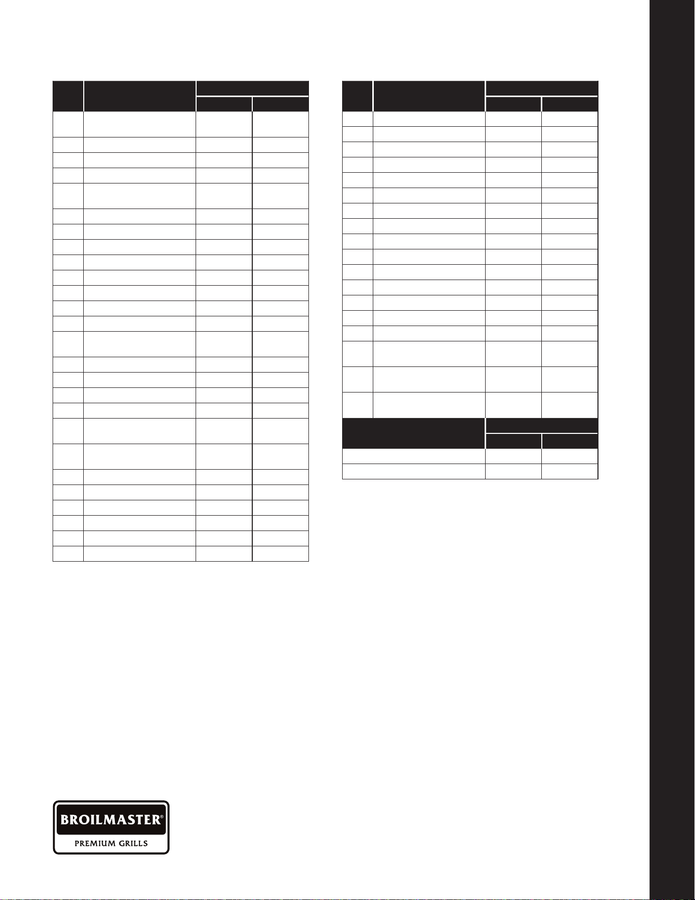
25 Infrared Rear Burner BR0020 BR0021
26 Main Burner BR0202 BR0202
27 Heat Separator BR0203 BR0203
28 Vaporizer BR0204 BR0204
29 Flame Carryover BR0205 BR0205
30 Control Panel BR0206 BR0207
31 Firebox BR0208 BR0209
32 Drip Tray BR0210 BR0211
33 Cooking Grid BR0212 BR0212
34 Gas Manifold BR0213 BR0214
35 LED Heat Shield BR0215 BR0216
36 LED Wiring Harness BR0217 BR0218
37 Lighting Tube BR0219 BR0219
38a Main Orice, NAT, 1/16 BR0221 BR0221
38b Main Orice, LP, #57 BR0222 BR0222
39a
Rear Orice,
NAT, 1.60mm
BR0223 BR0223
39b
Rear Orice,
LP, 1.10mm
BR0050 BR0050
40
Valve Grommet,
Rear Burner
BR0201 BR0201
Conversion Kits
Part Number
BSB324 BSB405
Natural To Propane BR0261 BR0225
Propane To Natural BR0262 BR0226
NOTE: Conversion kits contain 4 (BSB324) or (BSB405) main
burner orices and 1 rear burner orice. LP Conversion kits
contain 1 brass elbow. LP hose and regulator sold separately.
NOTE: When ordering replacement main or rear burner valves,
the corresponding gas orices are included and pre-installed.
Item
No.
Description
Part Number
BSB324 BSB405
Item
No.
Description
Part Number
BSB324 BSB405
1
Temperature
Indicator Assy
BR0001 BR0001
2 Interior Light Assy, Right BR0008 BR0008
3 Ignitor & Wire, 48" BR0013 BR0013
4 Thermocouple, 39" BR0224 BR0224
5
Ignitor/Thermocouple
Cover
BR0200 BR0200
6 BROILMASTER Logo BR0028 BR0028
7 Control Knob BR0029 BR0029
8 Bezel, Main Burner BR0030 BR0030
9 Switch, Push Button BR0194 BR0194
10 LED BR0038 BR0038
11 Power Supply Harness BR0195 BR0195
12a Valve, Main Burner, NAT BR0250 BR0250
12b Valve, Main Burner, LP BR0287 BR0287
13
Valve Grommet,
Main Burner
BR0045 BR0045
14a Valve, Rear Burner, NAT BR0048 BR0048
14b Valve, Rear Burner, LP BR0288 BR0288
15 Transformer BR0051 BR0051
16 Bezel, Rear Burner BR0062 BR0062
17
Control Knob,
Rear Burner
BR0063 BR0063
18
Rear Burner
Orice Cover
BR0068 BR0068
19 Interior Light Assy, Left BR0180 BR0180
20 Gas Line, 1/4" X 43" BR0181 BR0181
21 Hood BR0192 BR0193
22 Hood Handle BR0006 BR0007
23 Back Cover BR0196 BR0197
24 Warming Rack BR0198 BR0199
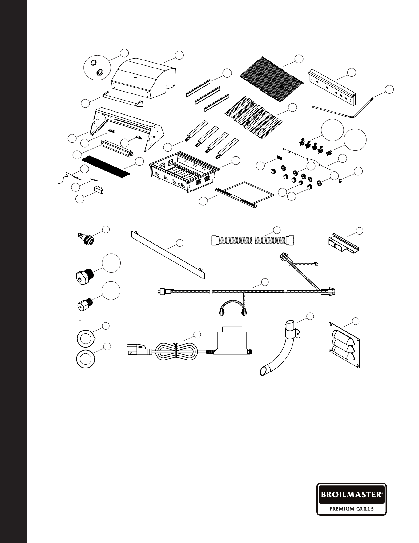
BR0227-1-0423 Page 41
Parts Diagrams
BROILMASTER PARTS LIST
PARTS DIAGRAMS
27
33
30
28
9
26
31
34
12a&b
36
7
17
6
8
16
1
21
24
19
22
23
25
2
3
4
5
32
14a&b
29
20
35
10
11
18
15
37
38a&b
39a&b
13
40
29
20
35
10
11
18
15
37
38a&b
39a&b
13
40
29
20
35
10
11
18
15
37
38a&b
39a&b
13
40
29
20
35
10
11
18
15
37
38a&b
39a&b
13
40
29
20
35
10
11
18
15
37
38a&b
39a&b
13
40
29
20
35
10
11
18
15
37
38a&b
39a&b
13
40
29
20
35
10
11
18
15
37
38a&b
39a&b
13
40
29
20
35
10
11
18
15
37
38a&b
39a&b
13
40
29
20
35
10
11
18
15
37
38a&b
39a&b
13
40
29
20
35
10
11
18
15
37
38a&b
39a&b
13
40
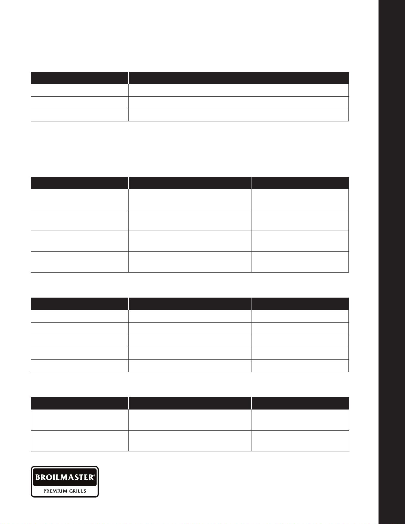
BR0227-1-0423Page 42
Sleeves, Side Burners, Covers
And Island Accessories
SIDE BURNERS
PART NUMBER SIDE BURNER
BSAF12DN Single, 12 Inch, Drop-In With Top Controls
BSABF12N Double, 12 Inch, Slide-In With Front Controls
BSABW16N Power, 16 Inch, Slide-In With Front Controls
*Slide-In burners may be installed without a sleeve in an island made from non-combustible
materials. The BSAF12DN drop-in side burner may be installed only in a grill island made from
non-combustible materials.
SLEEVES, SIDE BURNERS, COVERS AND ISLAND ACCESSORIES
SLEEVES, SIDE BURNERS, COVERS AND ISLAND ACCESSORIES
ACCESSORIES FOR ALL BROILMASTER STAINLESS STEEL GRILLS
PART NUMBER DESCRIPTION FITS
BSAGD12
Griddle, 12-Inch
BSB324, BSB405
BSAMR32
Rotisserie Kit
BSB324
BSAMR40 Rotisserie Kit
BSB405
BSATY Smoker Tray
BSB324, BSB405
NG12 12-Foot Quick Disconnect Hose
BSB324, BSB405
CARTS
PART NUMBER DESCRIPTION FITS
BSACT32
SS Cart With 2 Doors
And Fixed Side Shelves
BSB324 Grill
BSACT40
SS Cart With 2 Doors
And Fixed Side Shelves
BSB405 Grill
BUILT-IN INSULATED SLEEVES (FOR GRILLS AND ACCESSORY BURNERS)
PART NUMBER DESCRIPTION FITS
BSASL32
32" Insulated Sleeve
For Grill
BSG324 Grill
BSASL40
40" Insulated Sleeve
For Grill
BSG405 Grill
BSASL12
12" Insulated Sleeve
For Side Burner
BSABF12 Side Burner
BSASL16
16" Insulated Sleeve
For Power Burner
BSABW16N Power Burner

BR0227-1-0423 Page 43
SLEEVES, SIDE BURNERS, COVERS AND ISLAND ACCESSORIES
SLEEVES, SIDE BURNERS, COVERS AND ISLAND ACCESSORIES
Sleeves, Side Burners, Covers
And Island Accessories (Cont'd)
BAR
PART NUMBER BAR ACCESSORIES
BSACL Insulated Cooler – Slide-In
BSACW3015W Drawer – Storage / Cooler, 30" W x 15" H
BSASF Bar Sink With Faucet – Slide-In
DOORS, DRAWERS
PART NUMBER DOORS AND DRAWERS (STAINLESS STEEL)
BSAD1722 Single Door 17" W x 22" H
BSAD2422 Single Door 24" W x 22" H
BSAD2622D Double Doors 26" W x 22" H (Fits Under 26" Grill In Island)
BSAD3422D Double Doors 34" W x 22" H (Fits Under 34" Grill In Island)
BSAD4222D Double Doors 42" W x 22" H (Fits Under 42" Grill In Island)
BSAW1826R
Drawer For Roll-Out Trash Container, 18" W x 26" H
BSAW1826T
Triple Drawer, 18" W x 26" H
BSAW2022D
Double Drawer, 20" W x 22" H
BSAW2022
Single Drawer – For LP Tank Or Trash Can 20" W x 22" H
BSAW3422SD
Single Door With Double Drawer 34" W x 22" H (Fits Under 34" Grill In Island)
BSAW4222ST
Single Door With Triple Drawer 42" W x 22" H (Fits Under 42" Grill In Island)
BRB-1
S/S Vent Register Kit 10" x 2 1/4" Opening (2 Per Kit)

BR227-1-0423
GAS-FIRED
BROILMASTER
A Division of Empire Comfort Systems, Inc.
Visit our web site at www.broilmaster.com
If you have a general question about
our products, please e-mail us
If you have a service or repair question,
please contact your dealer.