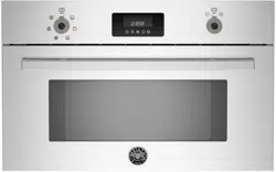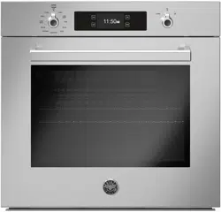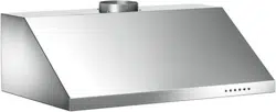

WALL OVENS
SPECIALTY OVENS
GAS RANGETOPS & COOKTOPS
INDUCTION & ELECTRIC COOKTOPS
DESIGN GUIDE
1.2

BUILT-IN COOKING DESIGN GUIDE
Bertazzoni appliances are designed to work together
and create harmony in the kitchen.
The products in our built-in cooking program can
be combined with numerous installation options to
create the ideal setup that suits the kitchen layout
and cooking style of the homeowner.
Versatility is key, with a choice of technologies and
designs that work together seamlessly.
This guide contains up-to-date technical
specifications and dimensions necessary to prepare
the installation of Bertazzoni built-in cooking products
in a kitchen.
All these details are also available online at
bertazzoni.com.
3bertazzoni.com
INTRODUCTION 3
WALL OVENS 4
30” Electric Convection Single Ovens 6
30” Electric Convection Double Ovens 11
24” Electric Convection Oven 15
SPECIALTY OVENS 19
30” Convection Speed Ovens 21
30” Convection Steam Ovens 26
30” Warming Drawer 31
30” Microwave Oven 34
24” Convection Speed Ovens 38
24” Microwave Drawer 43
GAS RANGETOPS & COOKTOPS 46
48” Rangetops 48
36” Rangetops 51
36” Drop-in Cooktops 6 burners 54
36” Drop-in Cooktops 5 burners 57
30” Drop-in Cooktops 60
36” Gas Cooktop Front Control 63
30” Gas Cooktop Front Control 66
24” Gas Cooktop Front Control 69
INDUCTION & ELECTRIC COOKTOPS 72
36” Induction Cooktop 74
30” Induction Cooktop 77
30” Electric Ceramic Cooktop 80
24” Electric Ceramic Cooktop 83
MULTIPLE INSTALLATIONS 86
30” Oven - Wall Configurations 88
24” Oven - Wall Configurations 100
30” Oven and Cooktop - Undercounter Configurations 104
24” Oven and Cooktop - Undercounter Configurations 123
INDEX
4 bertazzoni.com
WALL OVENS
Built-in ovens offer an excellent alternative – or
even complementary choice – to freestanding range,
offering simple elegance. For some, the ability to fit
an oven easily into a compact space makes built-in
ovens their first choice. For others it is the attraction
of flexible design with the option to install the ovens
on top of each other or side-by-side, at eye-level or
undercounter.
All Bertazzoni built-in ovens can be installed proud
or perfectly flush to align with matching convection
steam, speed and microwave ovens as well as
warming drawers.
30” Electric Convection
Single Ovens
24” Electric Convection
Single Ovens
30” Electric Convection
Double Ovens

7bertazzoni.com
30” Electric Convection Single Ovens
Installation requirements
CONVECTION OVENS
INSTALLATION
The oven can be installed in a proud or flush application.
Finish the edges of the opening because they may be visible
when the door is open.
The clearance between the oven and the kitchen units
or other installed appliances must be enough to ensure
sufficient cooling air ventilation.
For instructions and clearance of product combinations
please see the Multiple Installation Sections (page 86).
CABINET REQUIREMENT
To prevent possible damage to cabinets and cabinet finishes,
use only materials and finishes that will not discolor or
delaminate and will withstand temperatures up to 195°F
(90°C).
Installation of the appliance must be performed in accordance
with the provisions of applicable legislation.
BE SURE that support for this appliance is perpendicular to
the front facing of the wall or cabinet before you perform the
installation.
The cabinet base must be flat and capable of supporting the
weight of the oven when in use.
ELECTRICAL REQUIREMENT
The installation must comply with all applicable
electrical codes.
A properly-grounded horizontally- mounted electrical
receptacle should be installed.
Place the electrical supply flush with the back
wall and within the shaded area shown in the illustrations.
Placement within the opening may require additional
cabinet depth.
E
E
5"
127
4"
102
FRONT VIEW
A separate circuit and a circuit breaker servicing only this
appliance is reccomended
Minimum Suggested Load on
Cabinet Base Board
275lb (125kg )
Electrical supply
120/240 V
120/208 V
60 Hz
60 Hz
5500 W
4400 W
Service 30 Amp dedicated circuit
Power Connection METAL CONDUIT – 59” cord
For detailed installation specifications consult the installation manual.
9bertazzoni.com
30” Electric Convection Single Ovens
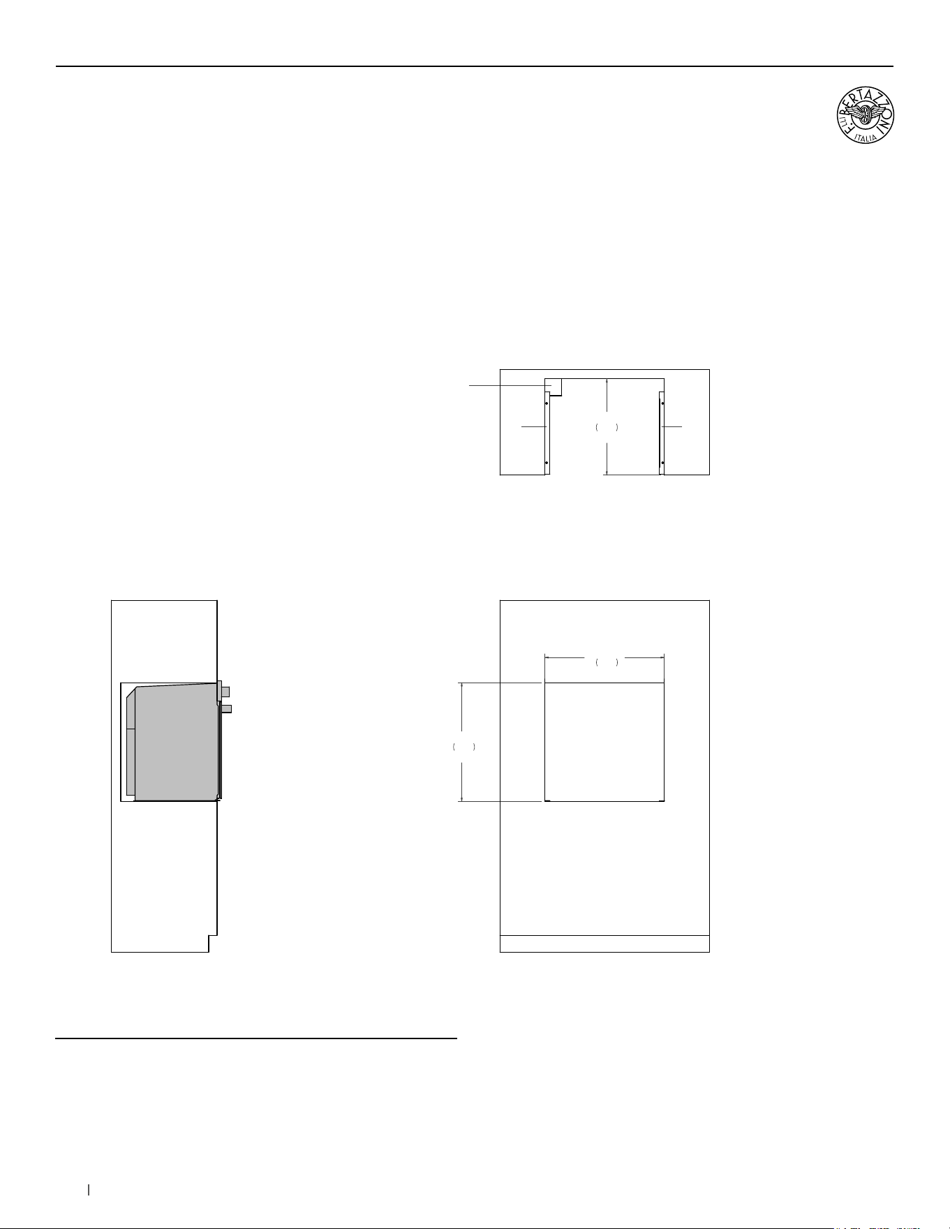
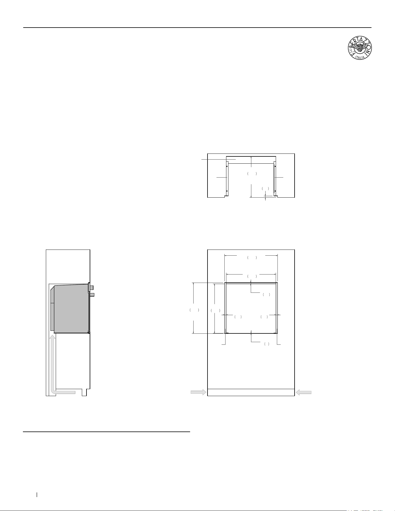
Flush installation non vented
WALL OVENS
SIDE VIEW
FRONT VIEW
TOP VIEW
(a) Spacers – Included with appliance
(b) Visible Area – Match finish to outside cabinet panels
4" x 4"
(102 x 102)
CUT OUT SLOT
FOR POWER CORD
28 1/2"
724
30 7/8"
784
FLUSH INSET
WIDTH
28 3/8"
720
29 3/8"
746
FLUSH INSET
HEIGHT
1 1/8"
30
1 1/8"
30
1/8"
3
7/8"
23
b
b
23 5/8"
600
FLUSH INSET
DEPTH
1"
25
a a
(a) Spacers - Included with appliance
(b) Visible Area - Match finish to outside cabinet panels
10 bertazzoni.com
30” Electric Convection Single Ovens
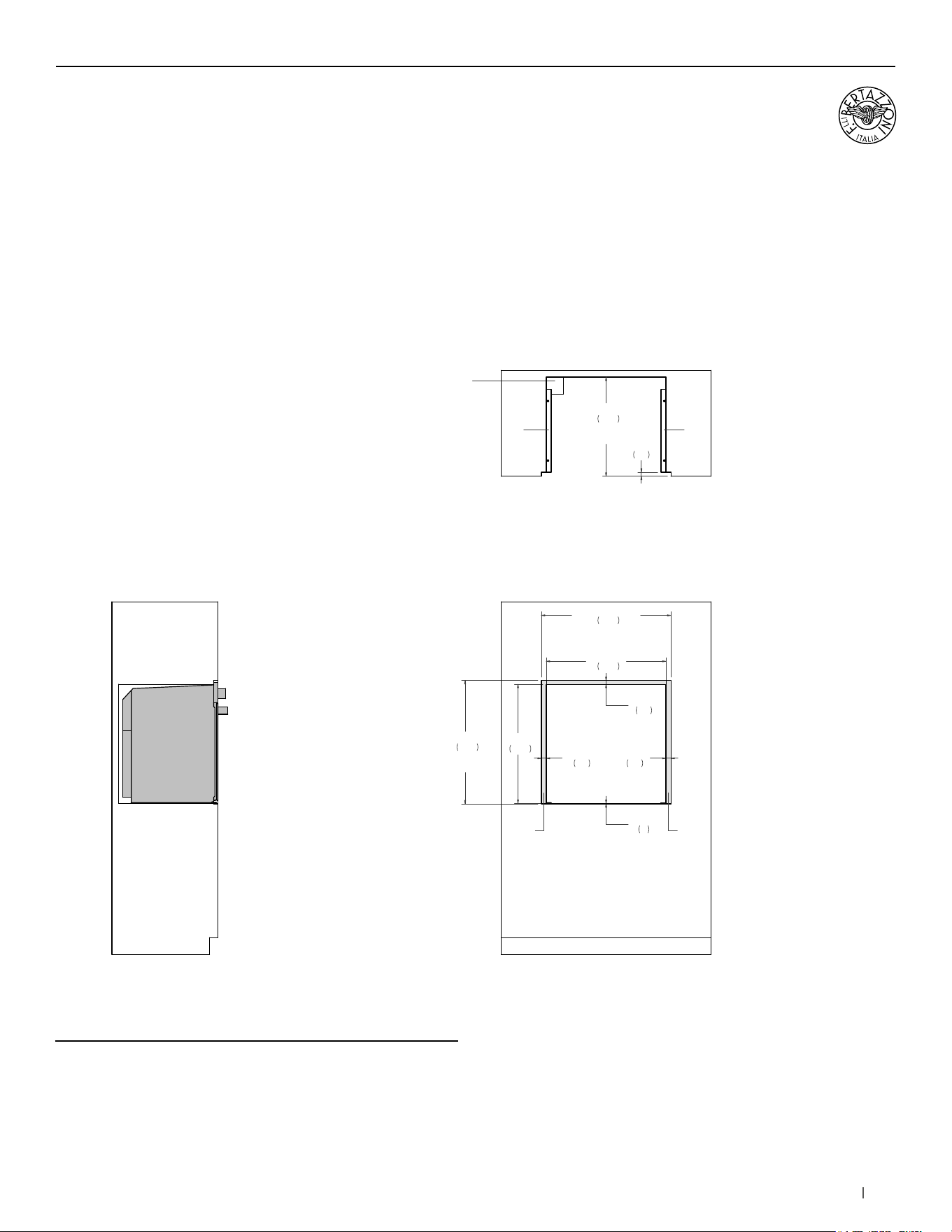
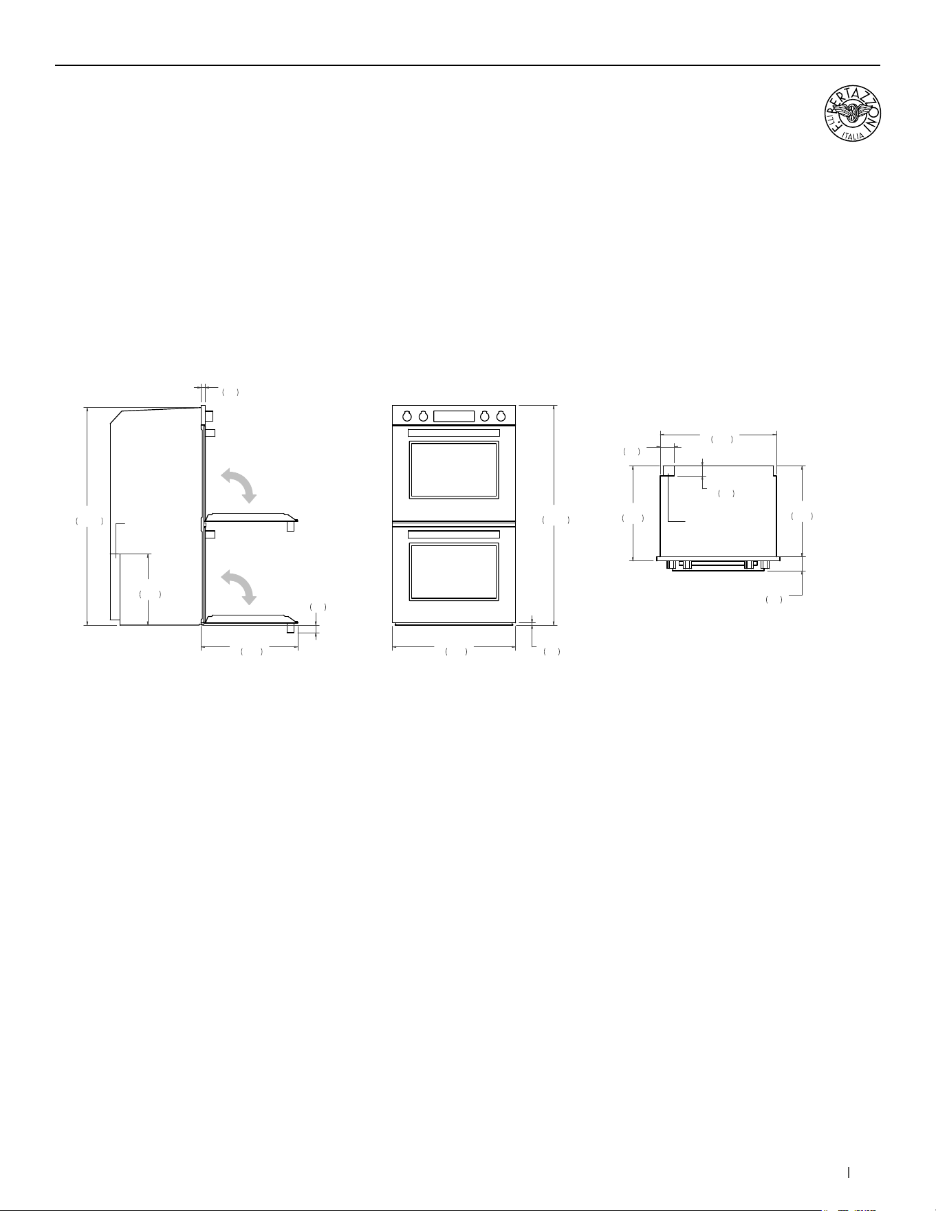
Flush installation vented
WALL OVENS
SIDE VIEW
FRONT VIEW
TOP VIEW
(a) Spacers – Included with appliance
(b) Visible Area – Match finish to outside cabinet panels
AIR INTAKE
28 1/2"
724
30 1/2"
774
FLUSH INSET
WIDTH
28 3/8"
720
29 1/8"
741
FLUSH INSET
HEIGHT
1"
25
1"
25
1/8"
3
3/4"
18
23 5/8"
600
FLUSH INSET
DEPTH
1"
25
b
b
a a
AIR INTAKE
4" x 15"
(102 x 380)
AIR INTAKE
4" x 15"
(102 x 380)
4" x 28 1/2"
(102 x 724)
AIR INTAKE
(a) Spacers - Included with appliance
(b) Visible Area - Match finish to outside cabinet panels
12 bertazzoni.com
30” Electric Convection Double Ovens
Installation requirements
WALL OVENS
INSTALLATION
The oven can be installed in a proud or flush application.
Finish the edges of the opening because they may be visible
when the door is open.
The clearance between the oven and the kitchen units
or other installed appliances must be enough to ensure
sufficient cooling air ventilation.
For instructions and clearance of product combinations
please see the Multiple Installation Sections (page 86).
CABINET REQUIREMENT
To prevent possible damage to cabinets and cabinet finishes,
use only materials and finishes that will not discolor or
delaminate and will withstand temperatures up to 195°F
(90°C). Installation of the appliance must be performed
in accordance with the provisions of applicable legislation.
BE SURE that support for this appliance is perpendicular to
the front facing of the wall or cabinet before you perform the
installation.
The cabinet base must be flat and capable of supporting the
weight of the oven when in use.
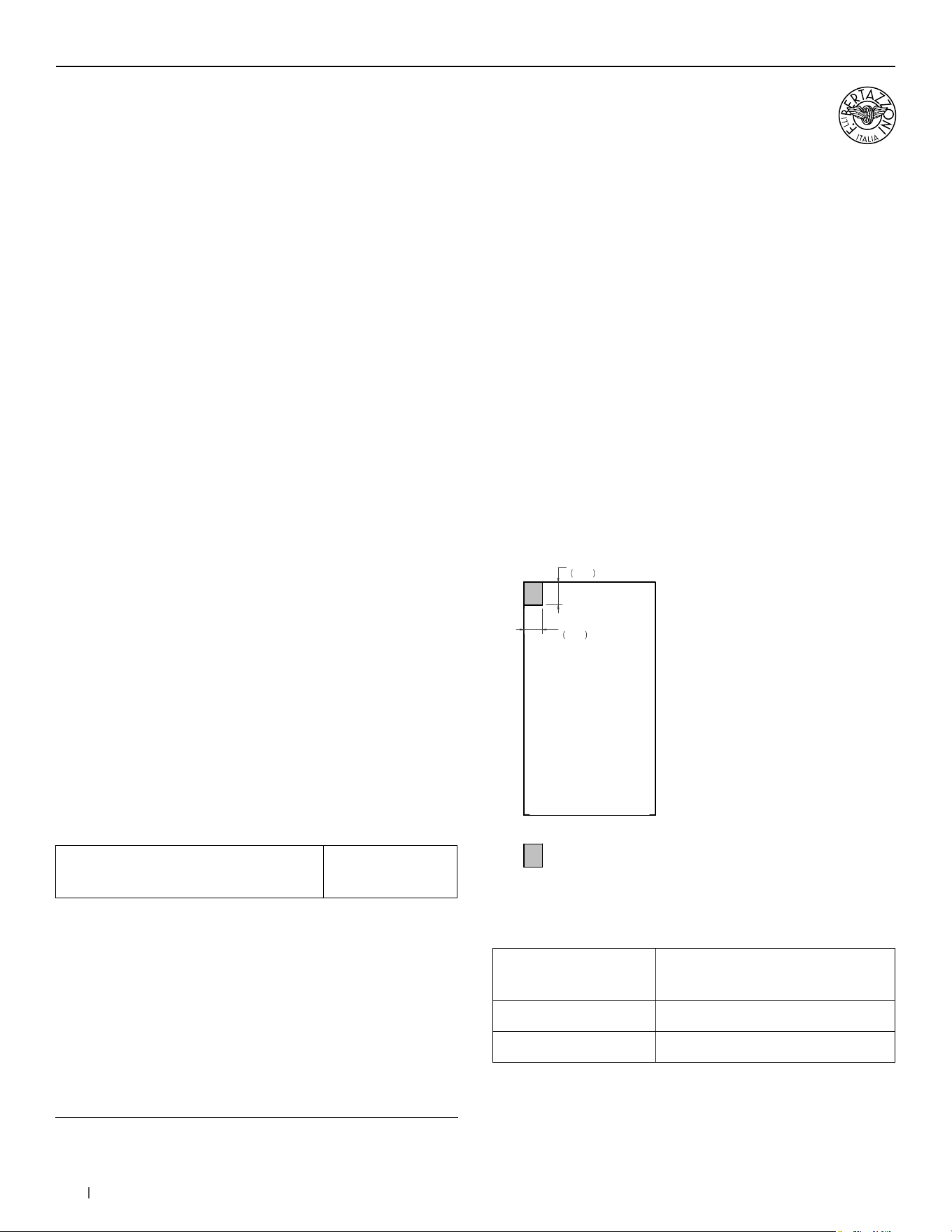
ELECTRICAL REQUIREMENT
The installation must comply with all applicable
electrical codes. A properly-grounded horizontally- mounted
electrical receptacle should be installed.
Place the electrical supply flush with the back
wall and within the shaded area shown in the illustrations.
Placement within the opening may require additional cabinet
depth.
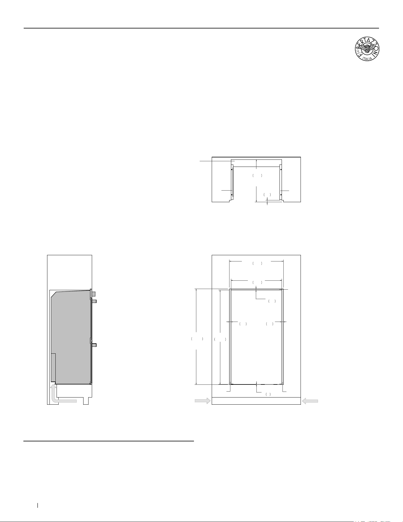
E
E
5"
127
4"
102
FR
O
NT VIEW
A separate circuit and a circuit breaker servicing only this
appliance is reccomended
Minimum Suggested Load on
Cabinet Base Board
485lb (220kg)
Electrical supply
120/240 V
120/208 V
60 Hz
60 Hz
11000 W
8800 W
Service 50 Amp dedicated circuit
Power Connection METAL CONDUIT – 59” cord
For detailed installation specifications consult the installation manual.
14 bertazzoni.com
30” Electric Convection Double Ovens
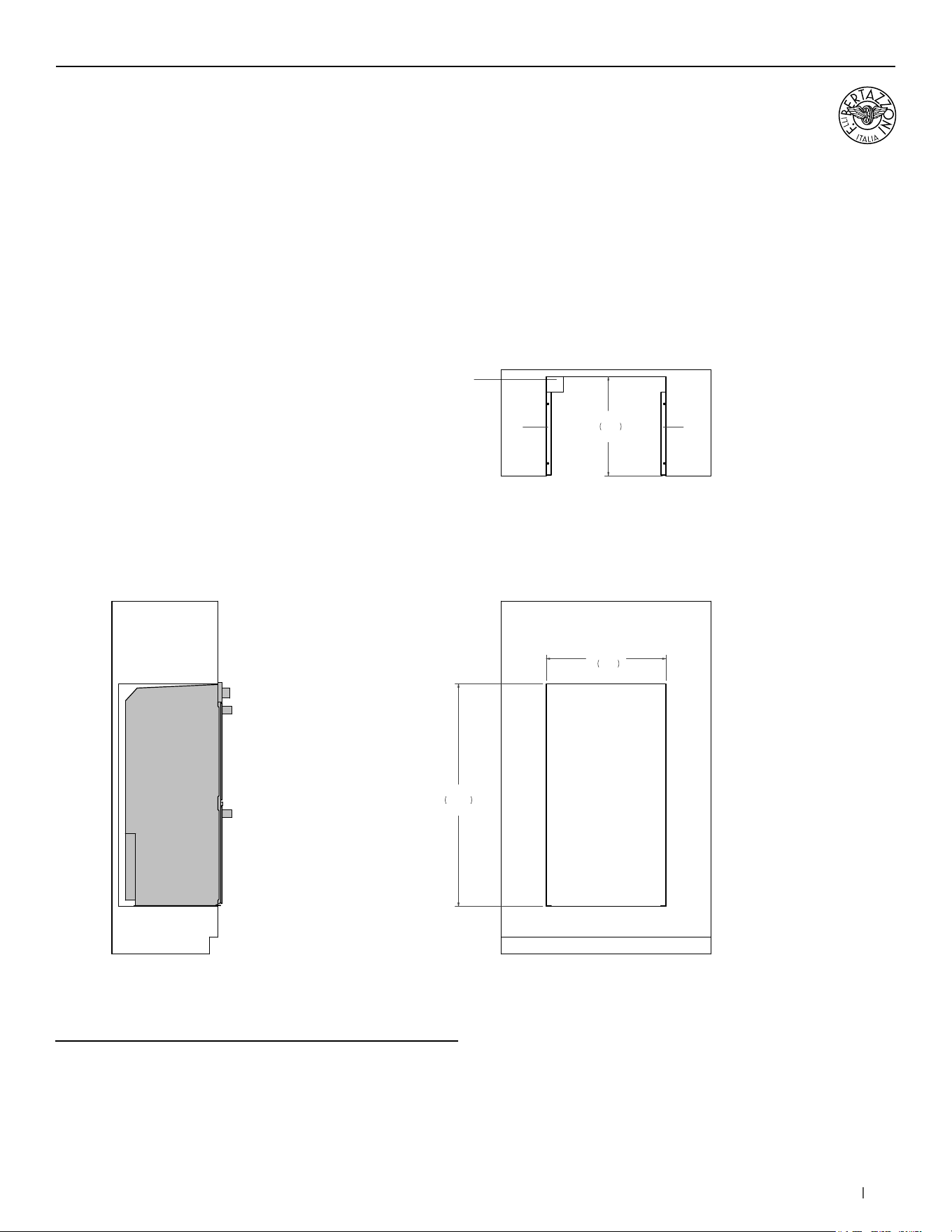
Flush installation vented
WALL OVENS
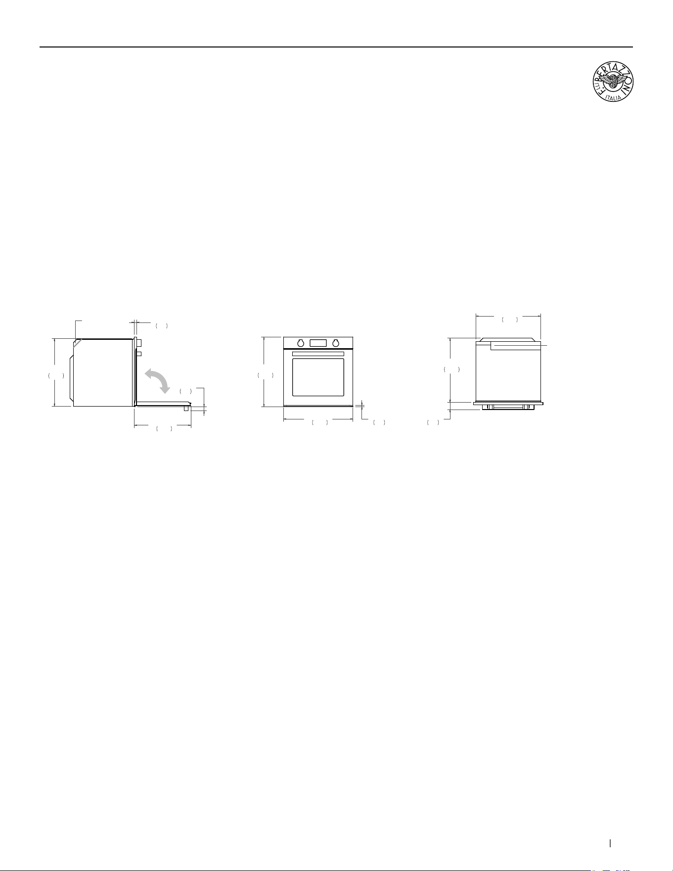
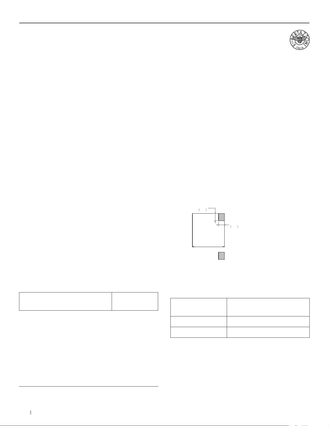
SIDE VIEW
FRONT VIEW
TOP VIEW
(a) Spacers – Included with appliance
(b) Visible Area – Match finish to outside cabinet panels
4" x 28 1/2"
(102 x 724)
AIR INTAKE
a
a
28 1/2"
724
30 1/2"
774
FLUSH INSET
WIDTH
53"
1346
53 7/8"
1367
FLUSH INSET
HEIGHT
1"
25
1"
25
1/8"
3
3/4"
18
b
b
b
23 7/8"
606
FLUSH INSET
DEPTH
1"
25
AIR INTAKE
AIR INTAKE
4" x 15"
(102 x 380)
AIR INTAKE
4" x 15"
(102 x 380)
(a) Spacers - Included with appliance
(b) Visible Area - Match finish to outside cabinet panels
16 bertazzoni.com
24” Electric Convection Single Ovens
Installation requirements
WALL OVENS
INSTALLATION
The oven can be installed in a proud or flush application.
Finish the edges of the opening because they may be visible
when the door is open.
The clearance between the oven and the kitchen units
or other installed appliances must be enough to ensure
sufficient cooling air ventilation.
For instructions and clearance of product combinations
please see the Multiple Installation Sections (page 86).
CABINET REQUIREMENT
To prevent possible damage to cabinets and cabinet finishes,
use only materials and finishes that will not discolor or
delaminate and will withstand temperatures up to 195°F
(90°C). Installation of the appliance must be performed in
accordance with the provisions of applicable legislation.
BE SURE that support for this appliance is perpendicular to
the front facing of the wall or cabinet before you perform the
installation.
The cabinet base must be flat and capable of supporting the
weight of the oven when in use.
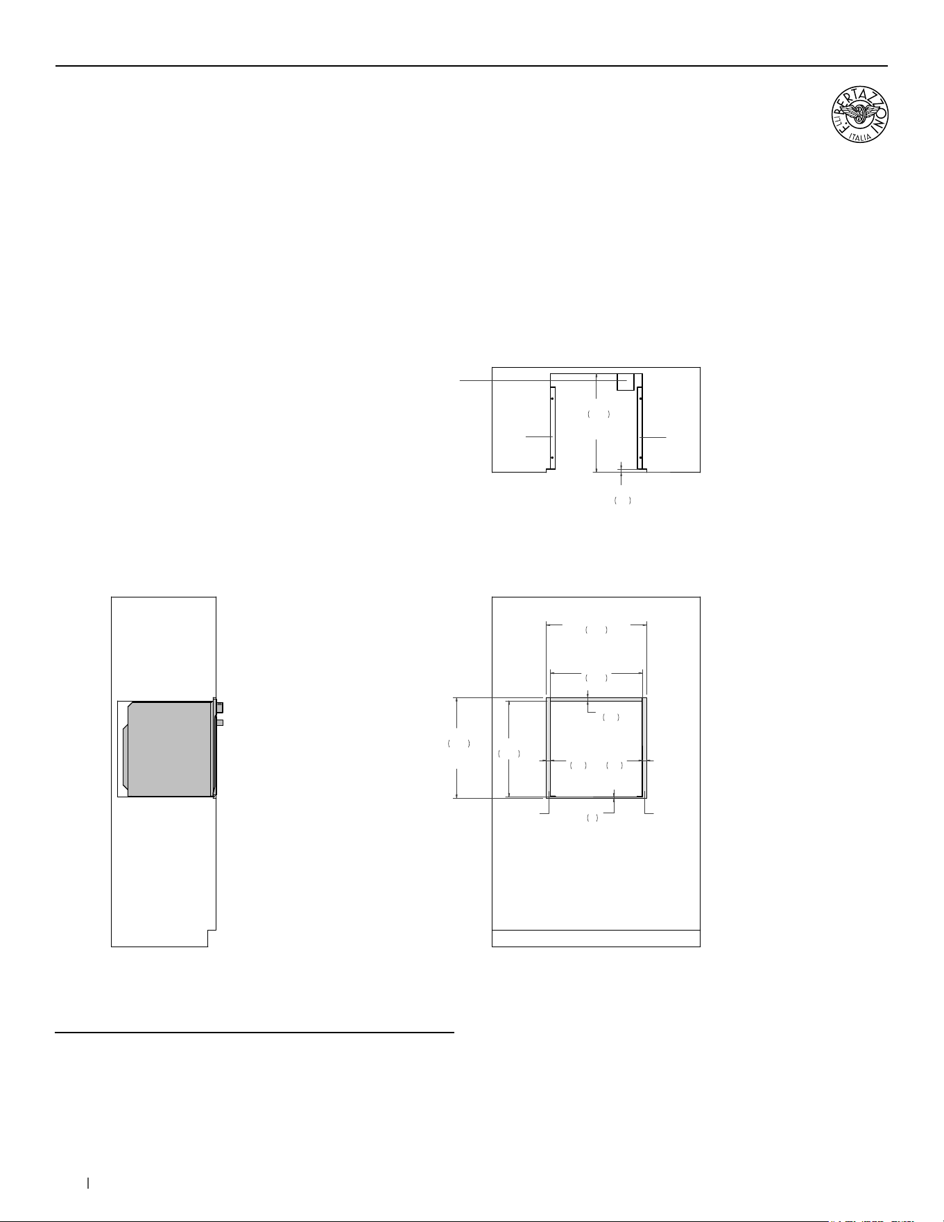
ELECTRICAL REQUIREMENT
The installation must comply with all applicable
electrical codes.
A properly-grounded horizontally- mounted electrical
receptacle should be installed.
Place the electrical supply flush with the back
wall and within the shaded area shown in the illustrations.
Placement within the opening may require additional
cabinet depth.
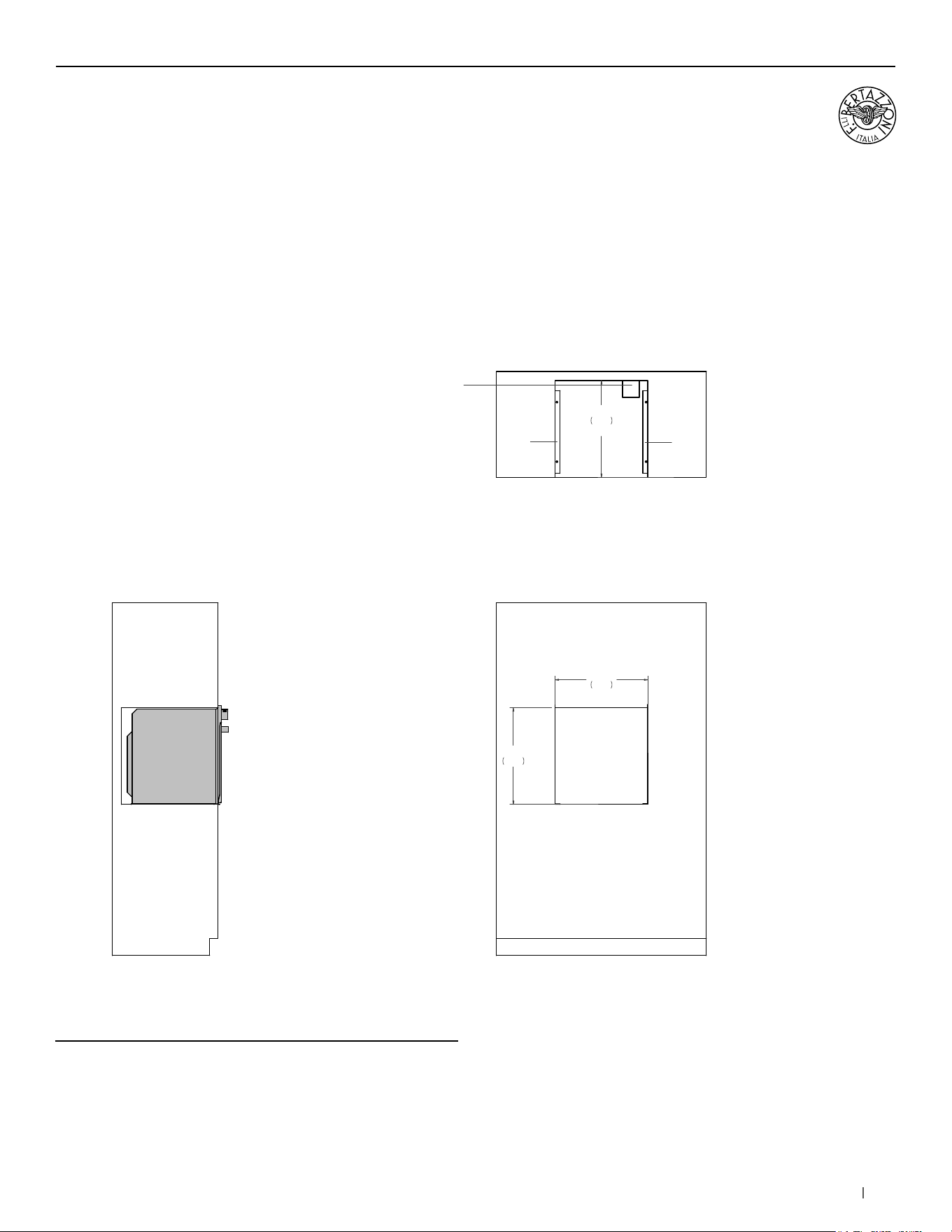
E
E
4"
102
5"
127
FRONT VIEW
A separate circuit and a circuit breaker servicing only this
appliance is reccomended
Minimum Suggested Load on
Cabinet Base Board
155lb (70kg)
Electrical supply
120/240 V
120/208 V
60 Hz
60 Hz
2800 W
2100 W
Service 16 Amp dedicated circuit
Power Connection METAL CONDUIT – 59” cord
For detailed installation specifications consult the installation manual.
18 bertazzoni.com
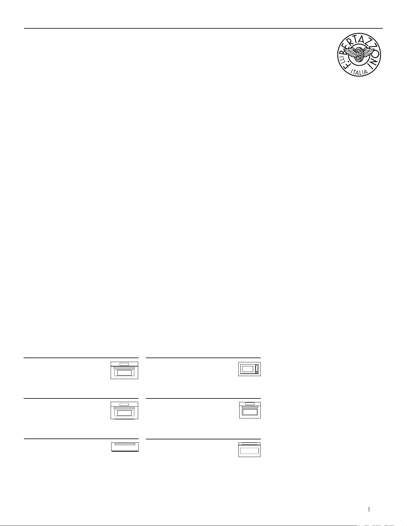
24” Electric Convection Single Ovens
Flush installation non vented
WALL OVENS
SIDE VIEW
FRONT VIEW
TOP VIEW
(a) Spacers – Included with appliance
(b) Visible Area – Match finish to outside cabinet panels
4" x 4"
(102 x 102)
CUT OUT SLOT
FOR POWER CORD
a
a
b b
22"
560
24"
611
FLUSH INSET
WIDTH
23"
585
24 1/8"
614
FLUSH INSET
HEIGHT
23 3/4"
603
FLUSH INSET
DEPTH
3/4"
20
1"
26
1"
26
3/4"
20
3/8"
9
(a) Spacers - Included with appliance
(b) Visible Area - Match finish to outside cabinet panels
19bertazzoni.com
24” Microwave Drawer
SPECIALTY OVENS
Bertazzoni has perfected cooking appliances for
over 100 years. As a result, we understand that
today’s home chefs want a variety of technologies
at their disposal. That means lifestyle-driven speed
cooking without sacrificing flavor, texture or aroma.
Or cooking with steam to retain the food’s natural
nutrients, vitamins and minerals. Bertazzoni built-in
specialty ovens include convection, steam, speed
and powerful microwave technology, along with a
practical warming drawer. Engineered to integrate
perfectly into the vertical and horizontal lines of your
kitchen cabinets, they can be installed stacked or
side by side to create perfect symmetry.
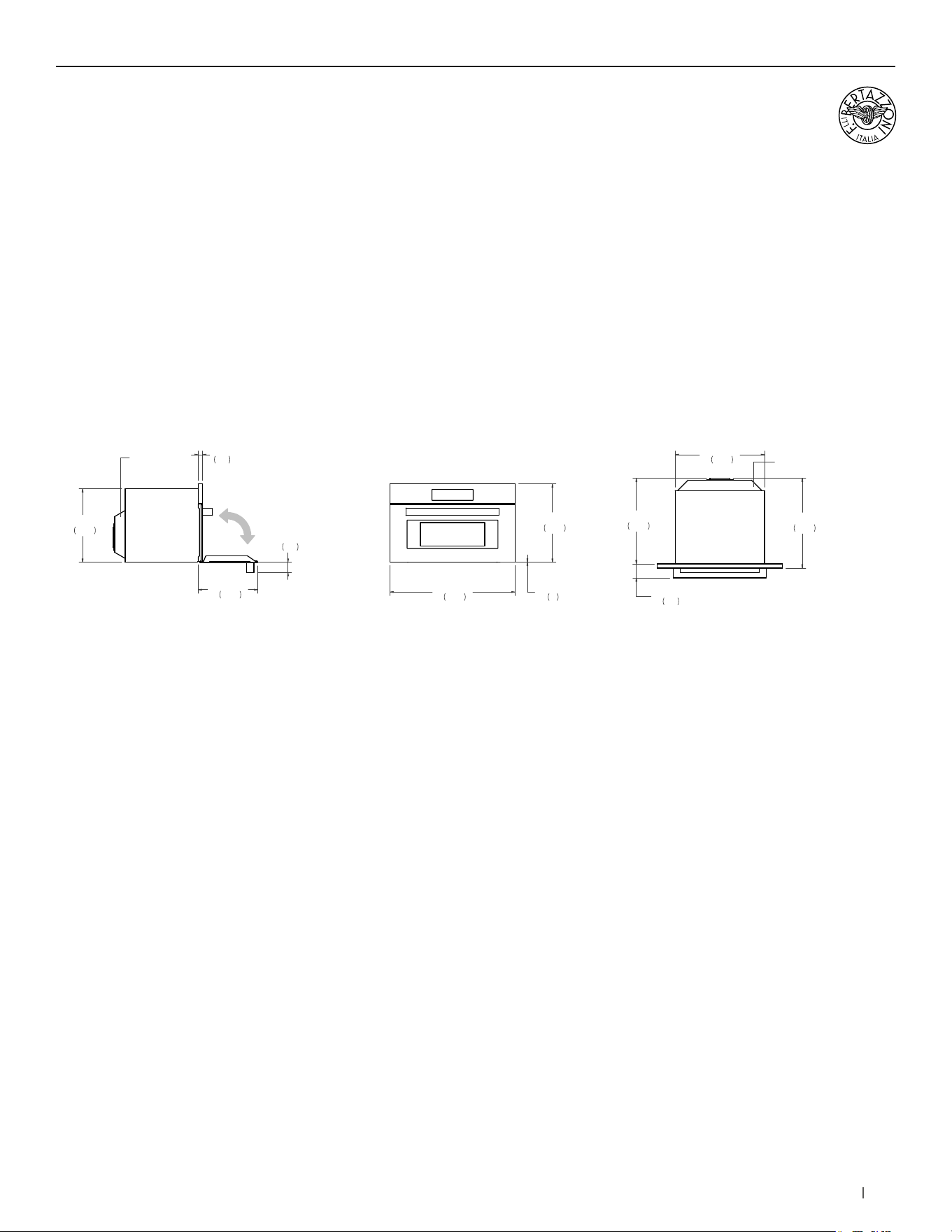
30” Convection
Speed Ovens
30” Convection
Steam Ovens
24” Convection
Speed Oven
30” Microwave Oven
30” Warming Drawers

22 bertazzoni.com
30” Convection Speed Ovens
Installation requirements
SPECIALTY OVENS
INSTALLATION
The oven can be installed in a proud or flush application.
Finish the edges of the opening because they may be visible
when the door is open.
The clearance between the oven and the kitchen units
or other installed appliances must be enough to ensure
sufficient cooling air ventilation.
For instructions and clearance of product combinations
please see the Multiple Installation Sections (page 86).
CABINET REQUIREMENT
To prevent possible damage to cabinets and cabinet finishes,
use only materials and finishes that will not discolor or
delaminate and will withstand temperatures up to 195°F
(90°C). Installation of the appliance must be performed
in accordance with the provisions of applicable
legislation.
BE SURE that support for this appliance is perpendicular to
the front facing of the wall or cabinet before you perform the
installation.
The cabinet base must be flat and capable of
supporting the weight of the oven when in use.
ELECTRICAL REQUIREMENT
The installation must comply with all applicable
electrical codes.
A properly-grounded horizontally- mounted electrical
receptacle should be installed.
Place the electrical supply flush with the back
wall and within the shaded area shown in the illustrations.
Placement within the opening may require additional
cabinet depth.
E
E
4"
102
5"
127
FRONT VIEW
A separate circuit and a circuit breaker servicing only this
appliance is reccomended
Minimum Suggested Load on
Cabinet Base Board
110lb (50kg) Electrical supply 120/240 V 60 Hz 3850 W
Service 16 Amp dedicated circuit
Power Connection METAL CONDUIT – 59” cord
For detailed installation specifications consult the installation manual.
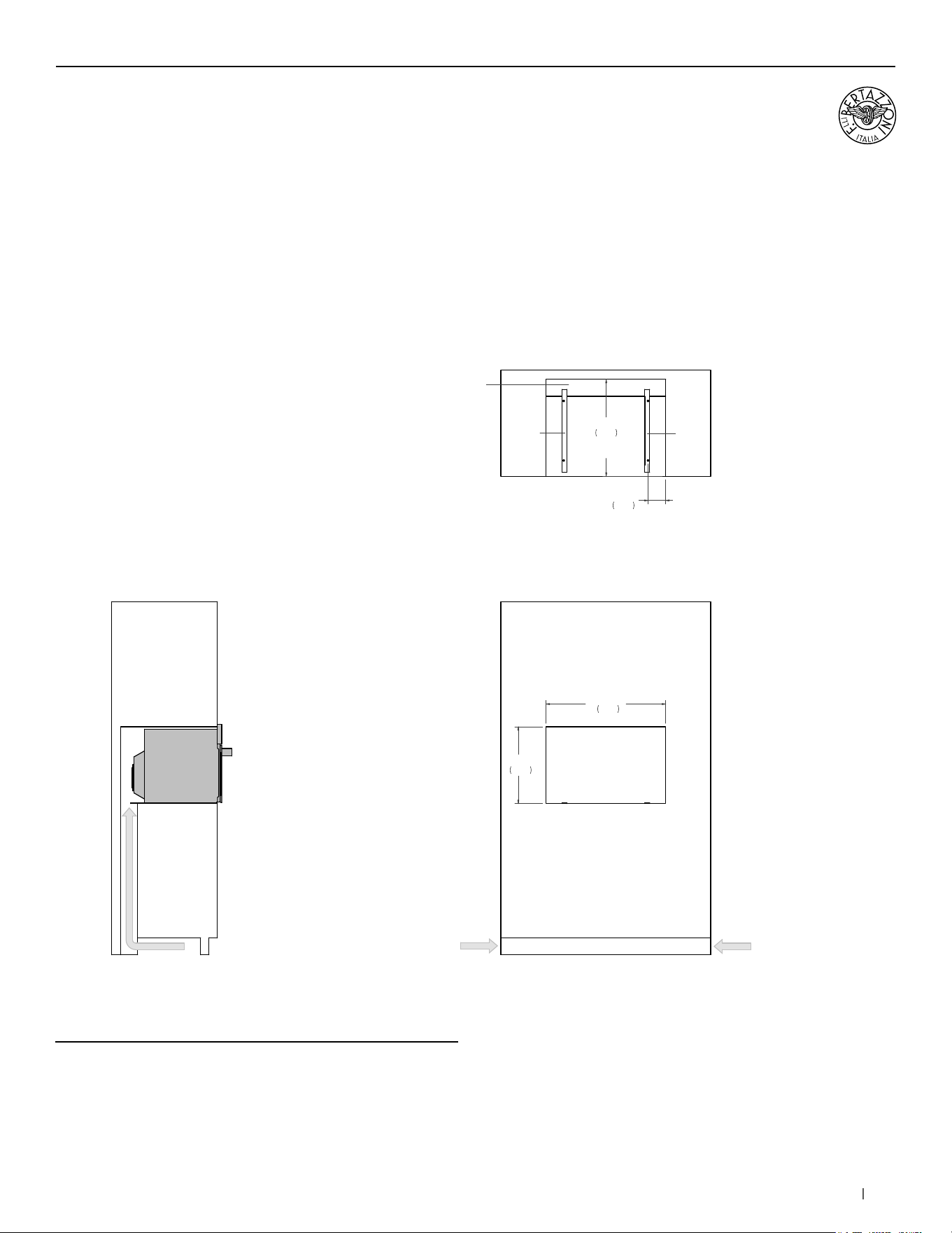
23bertazzoni.com
30” Convection Speed Ovens
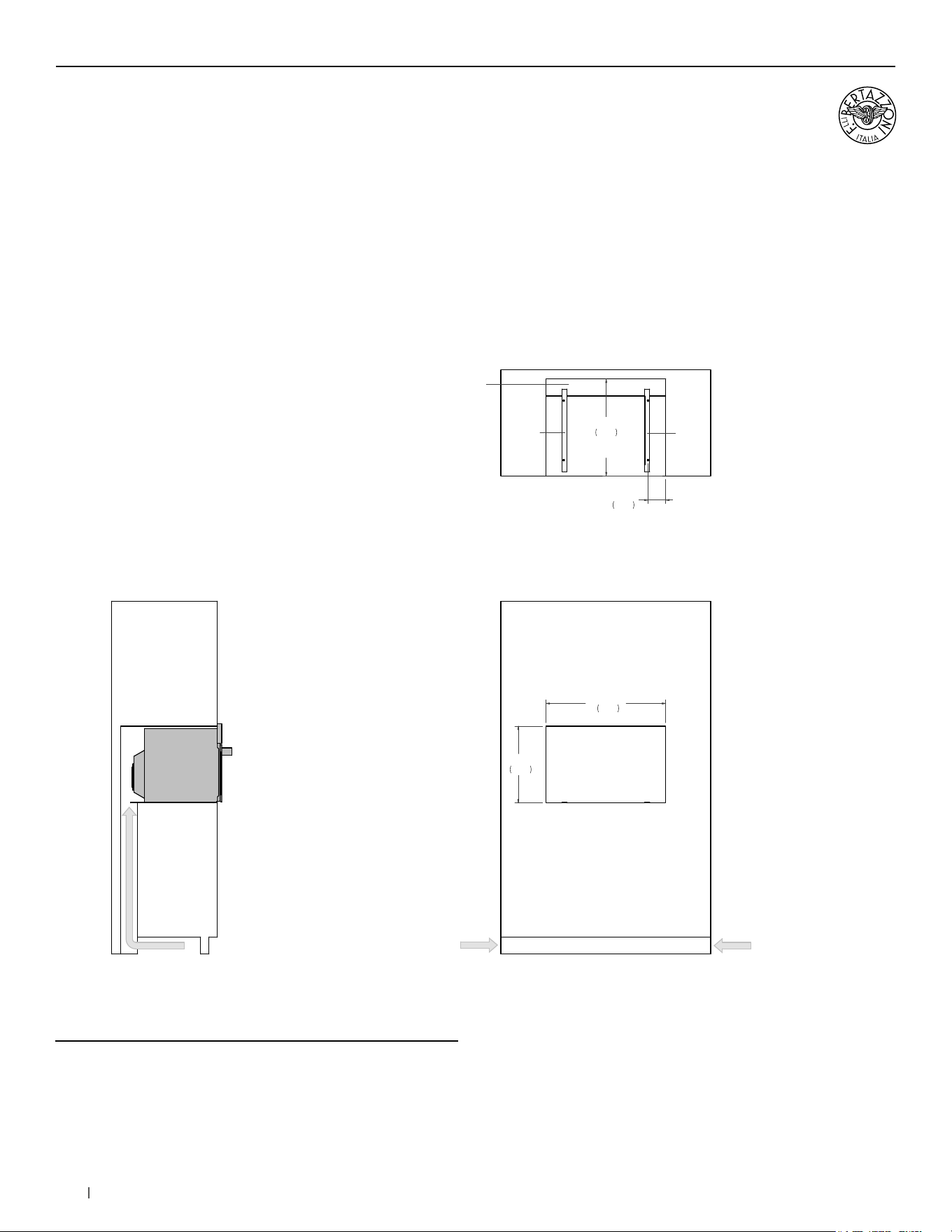
Proud installation
SIDE VIEW
FRONT VIEW
TOP VIEW
(a) Spacers – Included with appliance
AIR INTAKE
28 1/2"
724
18 1/4"
464
23"
585
FLUSH INSET
DEPTH
a
a
AIR INTAKE
4" x 15"
(102 x 380)
AIR INTAKE
4" x 15"
(102 x 380)
4" x 28 1/2"
(102 x 724)
AIR INTAKE
4 1/4"
107
SPECIALTY OVENS
(a) Spacers - Included with appliance
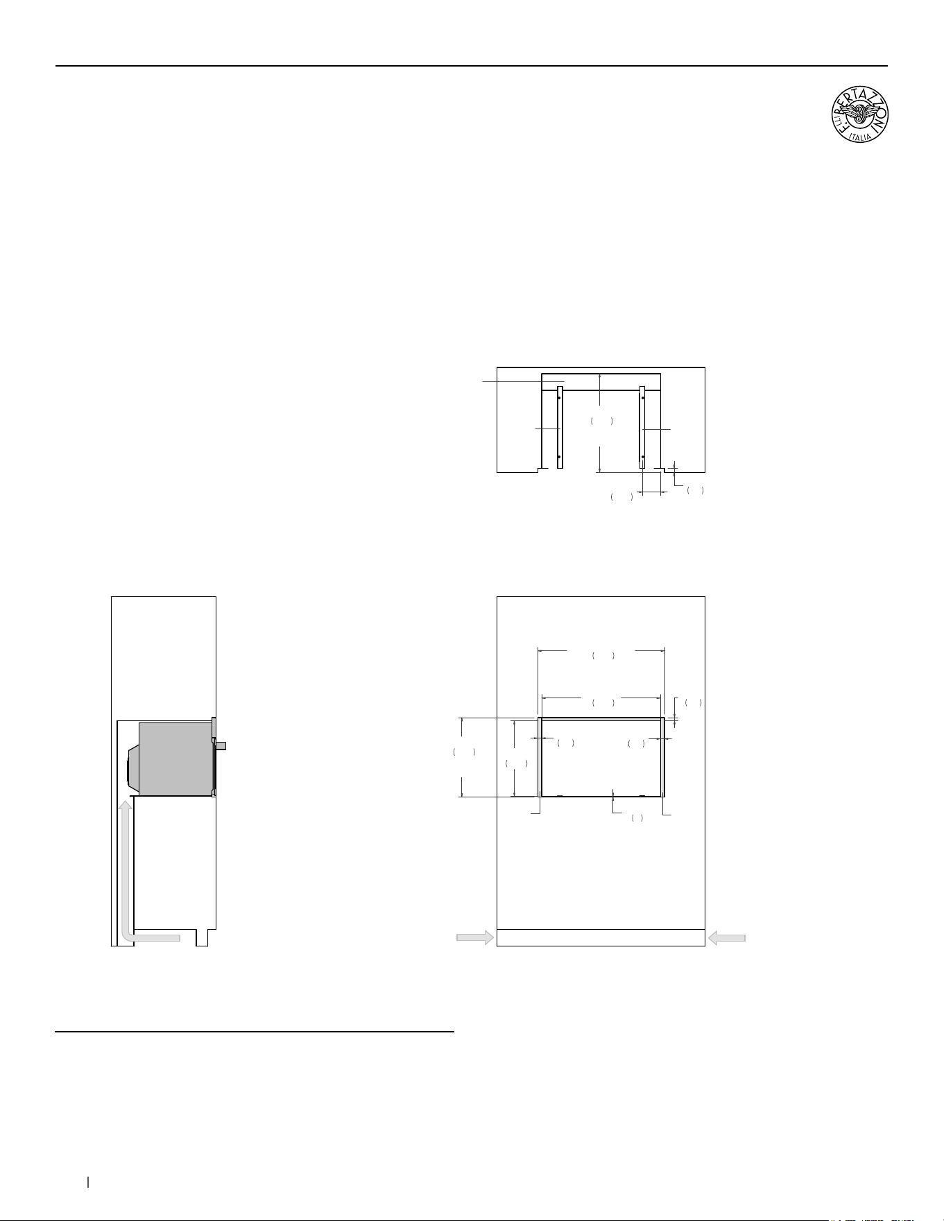
24 bertazzoni.com
30” Convection Speed Ovens
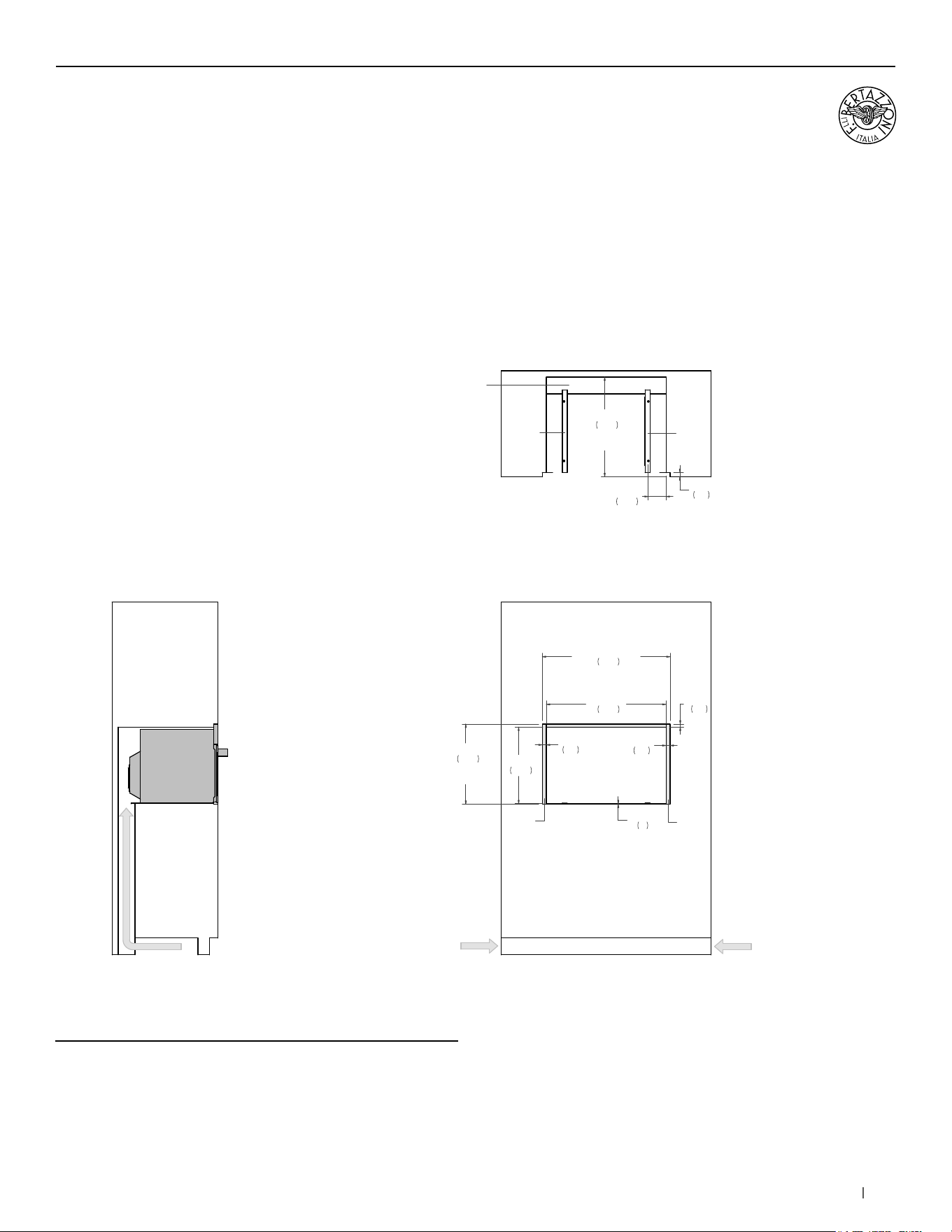
Flush installation
SIDE VIEW
FRONT VIEW
TOP VIEW
(a) Spacers – Included with appliance
(b) Visible Area – Match finish to outside cabinet panels
AIR INTAKE
28 1/2"
724
30 1/2"
774
FLUSH INSET
WIDTH
18 1/4"
464
19 1/8"
485
FLUSH INSET
HEIGHT
1"
25
1"
25
3/4"
18
1/8"
3
23 3/4"
603
FLUSH INSET
DEPTH
1"
25
a
a
b
b
AIR INTAKE
4" x 15"
(102 x 380)
AIR INTAKE
4" x 15"
(102 x 380)
4" x 28 1/2"
(102 x 724)
AIR INTAKE
4 1/4"
107
SPECIALTY OVENS
(a) Spacers - Included with appliance
(b) Visible Area - Match finish to outside cabinet panels
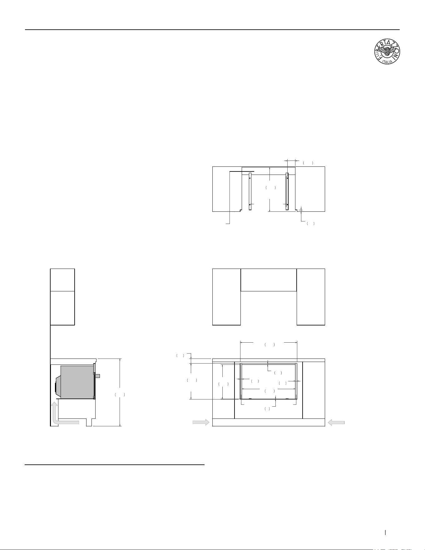
25bertazzoni.com
30” Convection Speed Ovens
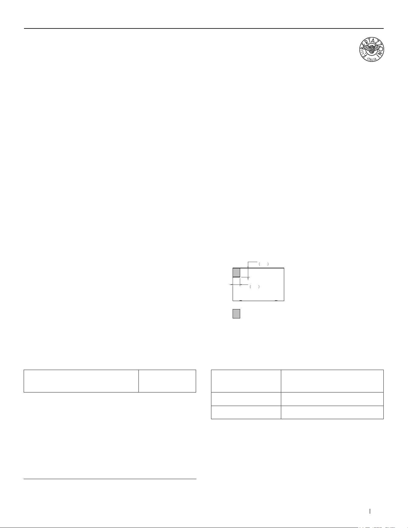
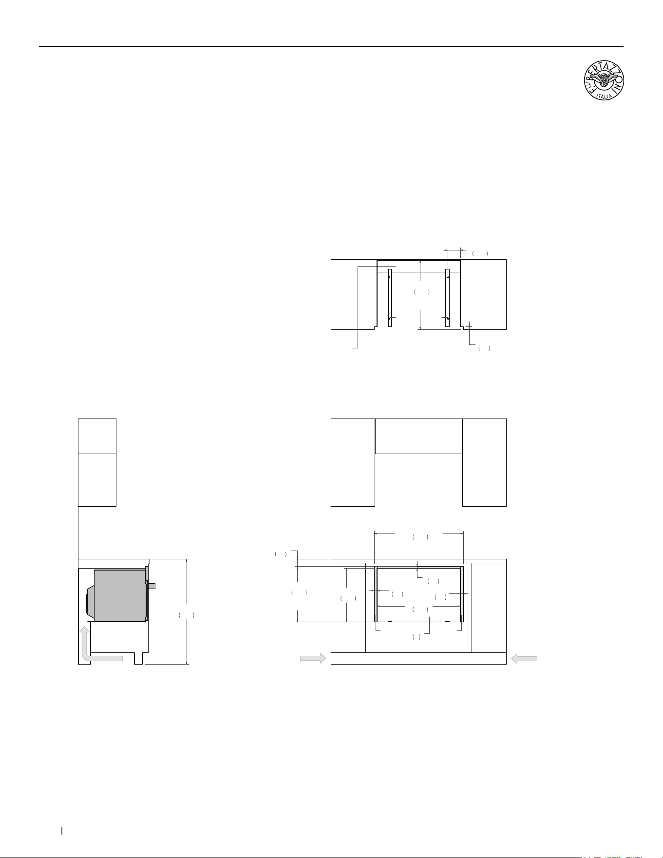
Undercounter installation
SIDE VIEW
FRONT VIEW
(a) Spacers – Included with appliance
(b) Visible Area – Match finish to outside cabinet panels
TOP VIEW
AIR INTAKE
a
36"
914
18 1/4"
464
30 1/2"
774
FLUSH INSET
WIDTH
19 1/8"
485
FLUSH INSET
HEIGHT
1"
25
1"
25
1/8"
3
3/4"
18
28 1/2"
724
23 3/4"
603
FLUSH INSET
DEPTH
a
2 1/2"
62
bb
4 1/4"
107
1"
25
4" x 28 1/2"
(102 x 724)
AIR INTAKE
AIR INTAKE
4" x 15"
(102 x 380)
AIR INTAKE
4" x 15"
(102 x 380)
SPECIALTY OVENS
(a) Spacers - Included with appliance
(b) Visible Area - Match finish to outside cabinet panels
27bertazzoni.com
30” Convection Steam Ovens
Installation requirements
SPECIALTY OVENS
INSTALLATION
The oven can be installed in a proud or flush application.
Finish the edges of the opening because they may be visible
when the door is open.
The clearance between the oven and the kitchen units
or other installed appliances must be enough to ensure
sufficient cooling air ventilation.
For instructions and clearance of product combinations
please see the Multiple Installation Sections (page 86).
CABINET REQUIREMENT
To prevent possible damage to cabinets and cabinet finishes,
use only materials and finishes that will not discolor or
delaminate and will withstand temperatures up to 195°F
(90°C). Installation of the appliance must be performed
in accordance with the provisions of applicable
legislation.
BE SURE that support for this appliance is perpendicular to
the front facing of the wall or cabinet before you perform the
installation.
The cabinet base must be flat and capable of
supporting the weight of the oven when in use.
ELECTRICAL REQUIREMENT
The installation must comply with all applicable
electrical codes.
A properly-grounded horizontally- mounted electrical
receptacle should be installed.
Place the electrical supply flush with the back
wall and within the shaded area shown in the illustrations.
Placement within the opening may require additional
cabinet depth.
E
E
4"
102
5"
127
FRONT VIEW
A separate circuit and a circuit breaker servicing only this
appliance is reccomended
Minimum Suggested Load on
Cabinet Base Board
110lb (50kg) Electrical supply 120/240 V 60 Hz 3200 W
Service 16 Amp dedicated circuit
Power Connection METAL CONDUIT – 59” cord
For detailed installation specifications consult the installation manual.
28 bertazzoni.com
30” Convection Steam Ovens
Proud installation
SPECIALTY OVENS
(a) Spacers - Included with appliance
SIDE VIEW
FRONT VIEW
TOP VIEW
(a) Spacers – Included with appliance
AIR INTAKE
28 1/2"
724
18 1/4"
464
23"
585
FLUSH INSET
DEPTH
a
a
AIR INTAKE
4" x 15"
(102 x 380)
AIR INTAKE
4" x 15"
(102 x 380)
4" x 28 1/2"
(102 x 724)
AIR INTAKE
4 1/4"
107
29bertazzoni.com
30” Convection Steam Ovens
Flush installation
SPECIALTY OVENS
(a) Spacers - Included with appliance
(b) Visible Area - Match finish to outside cabinet panels
SIDE VIEW
FRONT VIEW
TOP VIEW
(a) Spacers – Included with appliance
(b) Visible Area – Match finish to outside cabinet panels
AIR INTAKE
28 1/2"
724
30 1/2"
774
FLUSH INSET
WIDTH
18 1/4"
464
19 1/8"
485
FLUSH INSET
HEIGHT
1"
25
1"
25
3/4"
18
1/8"
3
23 3/4"
603
FLUSH INSET
DEPTH
1"
25
a
a
b
b
AIR INTAKE
4" x 15"
(102 x 380)
AIR INTAKE
4" x 15"
(102 x 380)
4" x 28 1/2"
(102 x 724)
AIR INTAKE
4 1/4"
107
30 bertazzoni.com
30” Convection Steam Ovens
Undercounter installation
SIDE VIEW
FRONT VIEW
(a) Spacers – Included with appliance
(b) Visible Area – Match finish to outside cabinet panels
TOP VIEW
AIR INTAKE
a
36"
914
18 1/4"
464
30 1/2"
774
FLUSH INSET
WIDTH
19 1/8"
485
FLUSH INSET
HEIGHT
1"
25
1"
25
1/8"
3
3/4"
18
28 1/2"
724
23 3/4"
603
FLUSH INSET
DEPTH
a
2 1/2"
62
bb
4 1/4"
107
1"
25
4" x 28 1/2"
(102 x 724)
AIR INTAKE
AIR INTAKE
4" x 15"
(102 x 380)
AIR INTAKE
4" x 15"
(102 x 380)
SPECIALTY OVENS
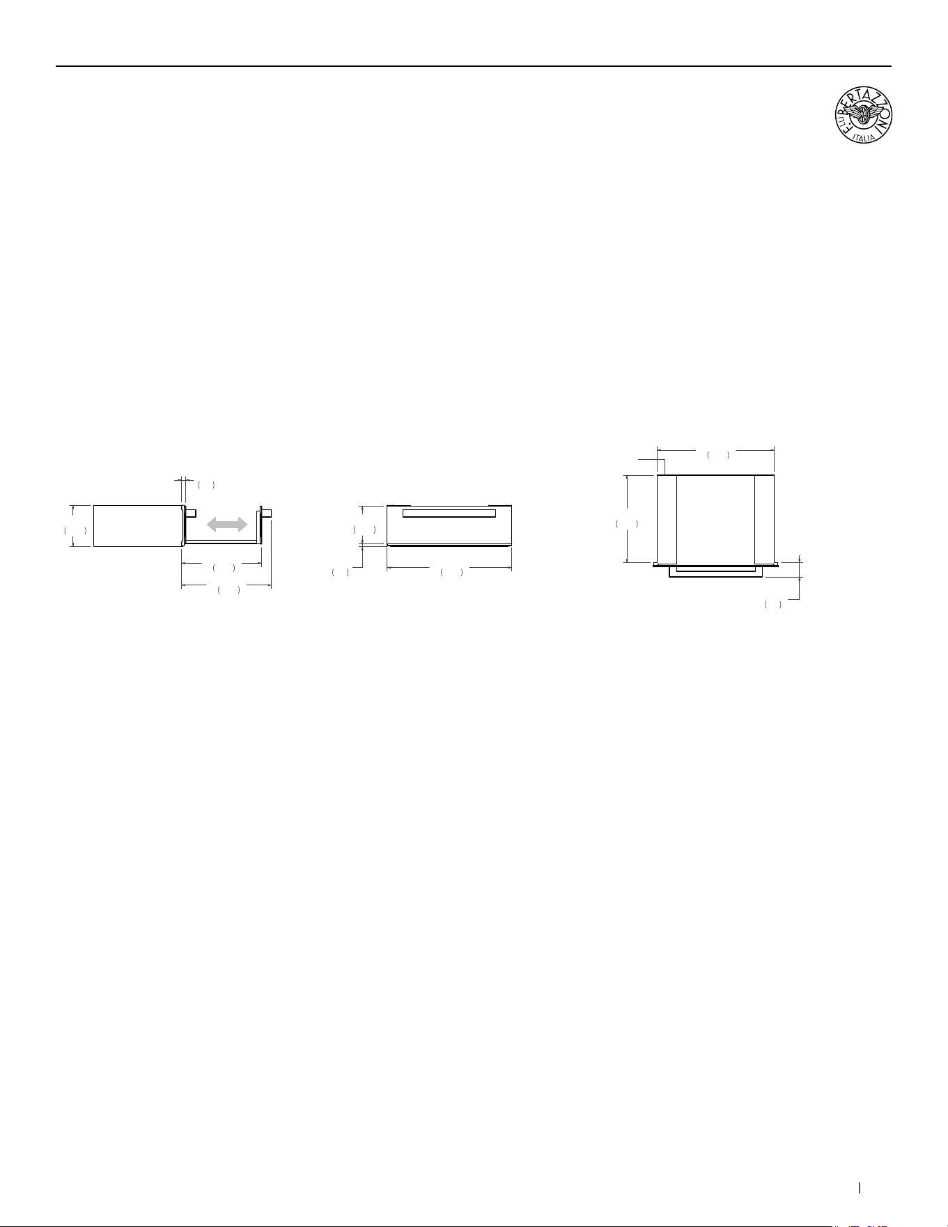
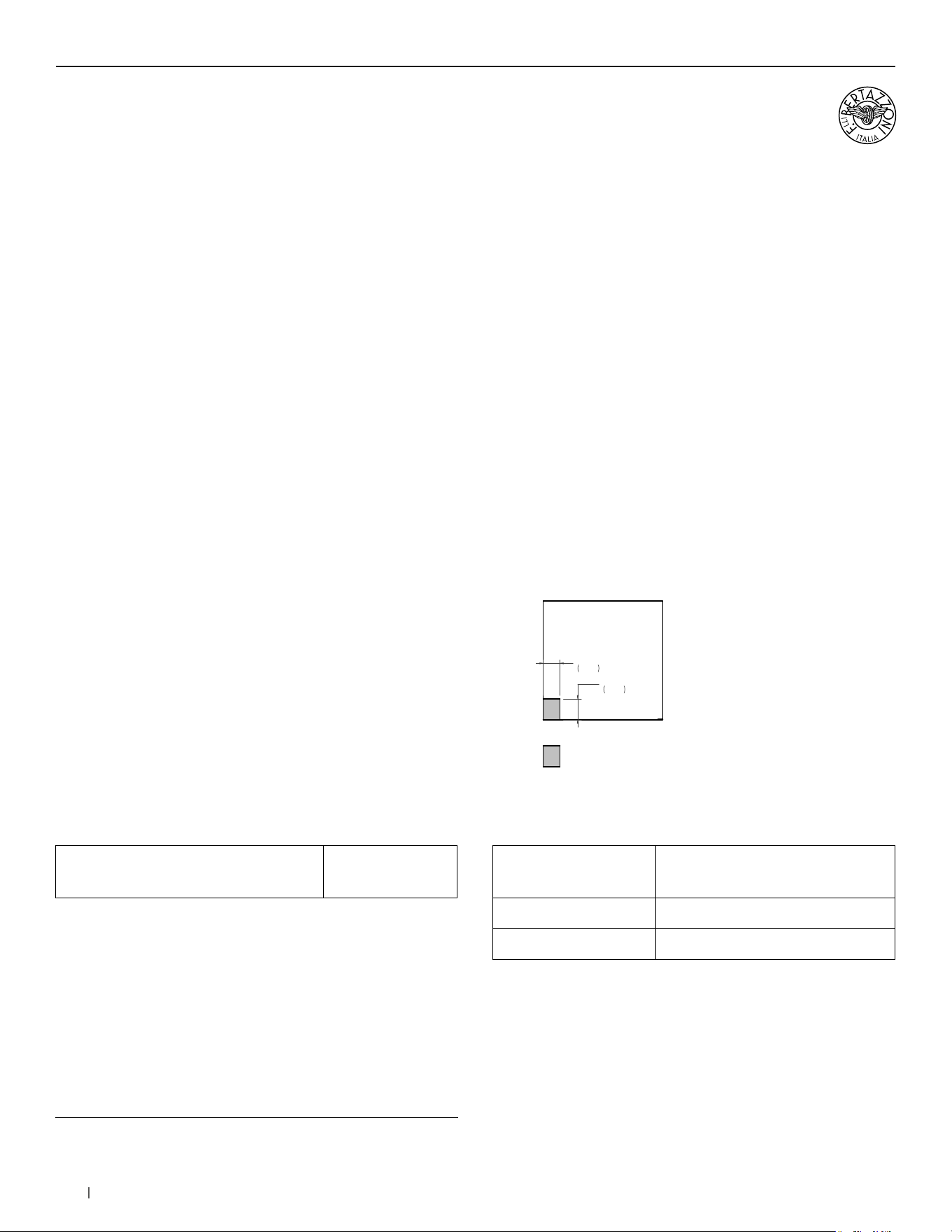
32 bertazzoni.com
30” Warming Drawer
Installation requirements
SPECIALTY OVENS
INSTALLATION
The oven can be installed in a proud or flush application.
Finish the edges of the opening because they may be visible
when the door is open.
The clearance between the oven and the kitchen units
or other installed appliances must be enough to ensure
sufficient cooling air ventilation.
For instructions and clearance of product combinations
please see the Multiple Installation Sections (page 86).
CABINET REQUIREMENT
To prevent possible damage to cabinets and cabinet finishes,
use only materials and finishes that will not discolor or
delaminate and will withstand temperatures up to 195°F
(90°C). Installation of the appliance must be performed
in accordance with the provisions of applicable
legislation.
BE SURE that support for this appliance is perpendicular to
the front facing of the wall or cabinet before you perform the
installation.
The cabinet base must be flat and capable of
supporting the weight of the oven when in use.
ELECTRICAL REQUIREMENT
The installation must comply with all applicable
electrical codes.
A properly-grounded horizontally- mounted electrical
receptacle should be installed.
Place the electrical supply flush with the back
wall and within the shaded area shown in the illustrations.
Placement within the opening may require additional
cabinet depth.
E
E
5"
127
4"
102
FRONT VIEW
Minimum Suggested Load on
Cabinet Base Board
110lb (50kg) Electrical supply 120 V 60 Hz 550 W
Service 5 Amp
Power Connection NEMA 5-15P
For detailed installation specifications consult the installation manual.
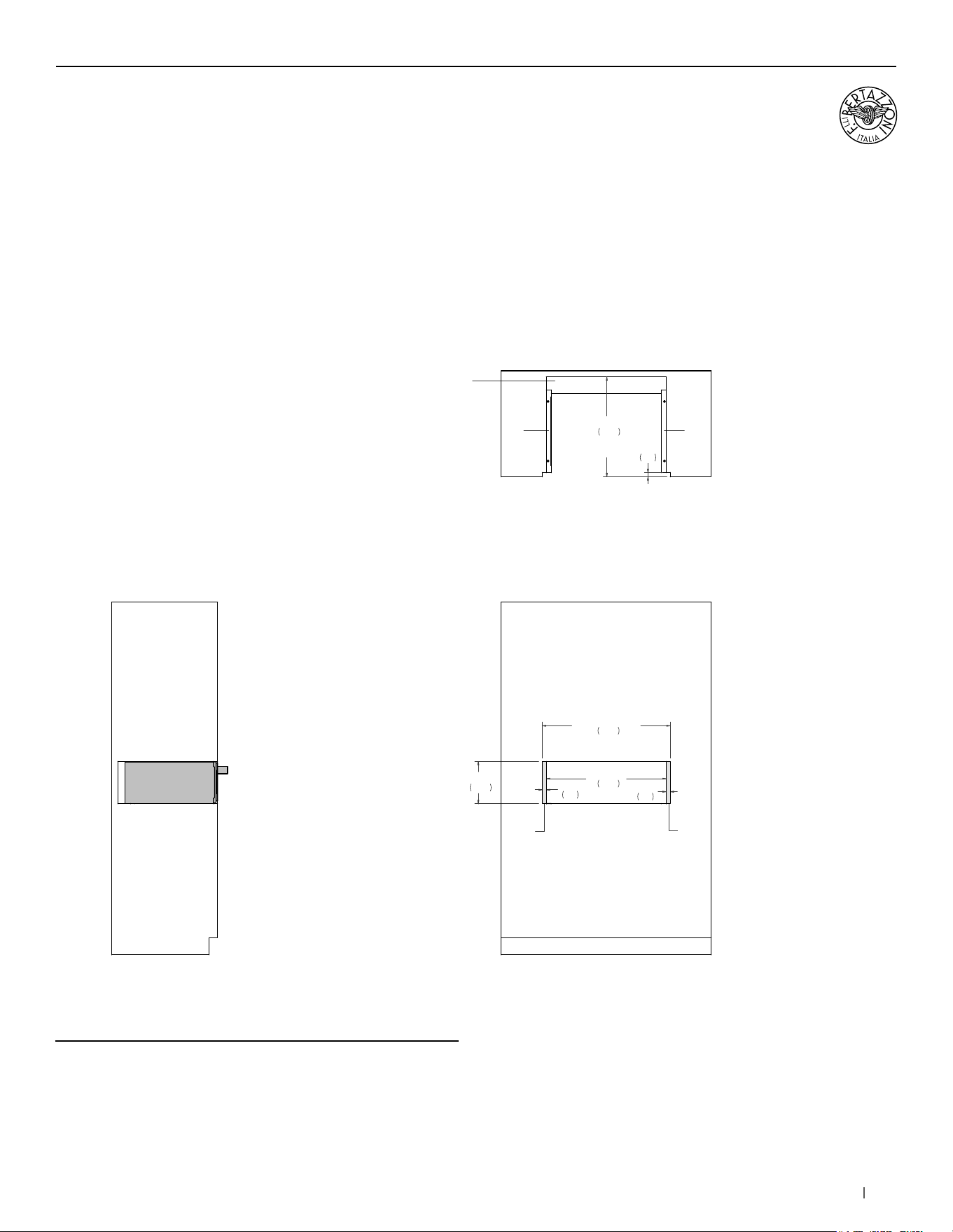
33bertazzoni.com
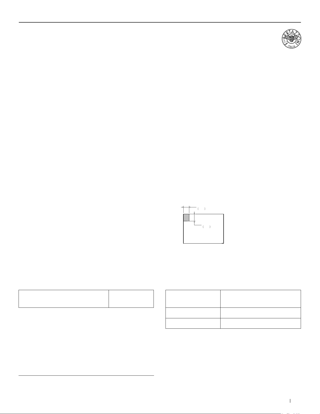
30” Warming Drawer
Flush installation
SIDE VIEW
FRONT VIEW
TOP VIEW
(a) Spacers – Included with appliance
(b) Visible Area – Match finish to outside cabinet panels
4" x 4"
(102 x 102)
CUT OUT SLOT
FOR POWER CORD
b
b
a a
28 1/2"
724
30 1/2"
774
FLUSH INSET
WIDTH
1"
25
10 1/8"
256
1"
25
1"
25
23 3/4"
604
FLUSH INSET
DEPTH
SPECIALTY OVENS
(a) Spacers - Included with appliance
(b) Visible Area - Match finish to outside cabinet panels
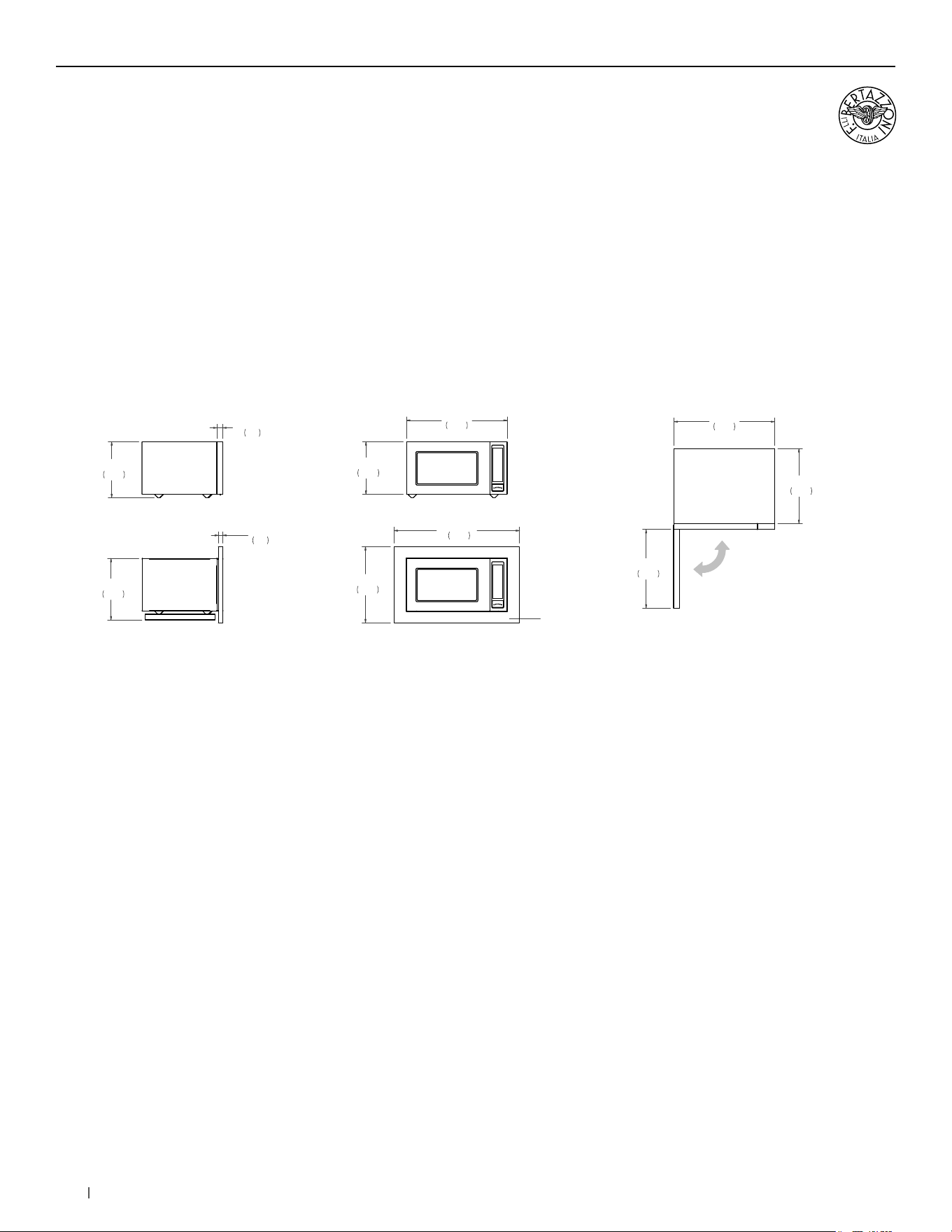
35bertazzoni.com
30” Microwave Oven
Installation requirements
SPECIALTY OVENS
INSTALLATION
The oven can be installed in a proud or flush application.
Finish the edges of the opening because they may be visible
when the door is open.
The clearance between the oven and the kitchen units
or other installed appliances must be enough to ensure
sufficient cooling air ventilation.
For instructions and clearance of product combinations
please see the Multiple Installation Sections (page 86).
CABINET REQUIREMENT
To prevent possible damage to cabinets and cabinet finishes,
use only materials and finishes that will not discolor or
delaminate and will withstand temperatures up to 195°F
(90°C). Installation of the appliance must be performed
in accordance with the provisions of applicable
legislation.
BE SURE that support for this appliance is perpendicular to
the front facing of the wall or cabinet before you perform the
installation.
The cabinet base must be flat and capable of
supporting the weight of the oven when in use.
ELECTRICAL REQUIREMENT
The installation must comply with all applicable
electrical codes.
A properly-grounded horizontally- mounted electrical
receptacle should be installed.
Place the electrical supply flush with the back
wall and within the shaded area shown in the illustrations.
Placement within the opening may require additional
cabinet depth.
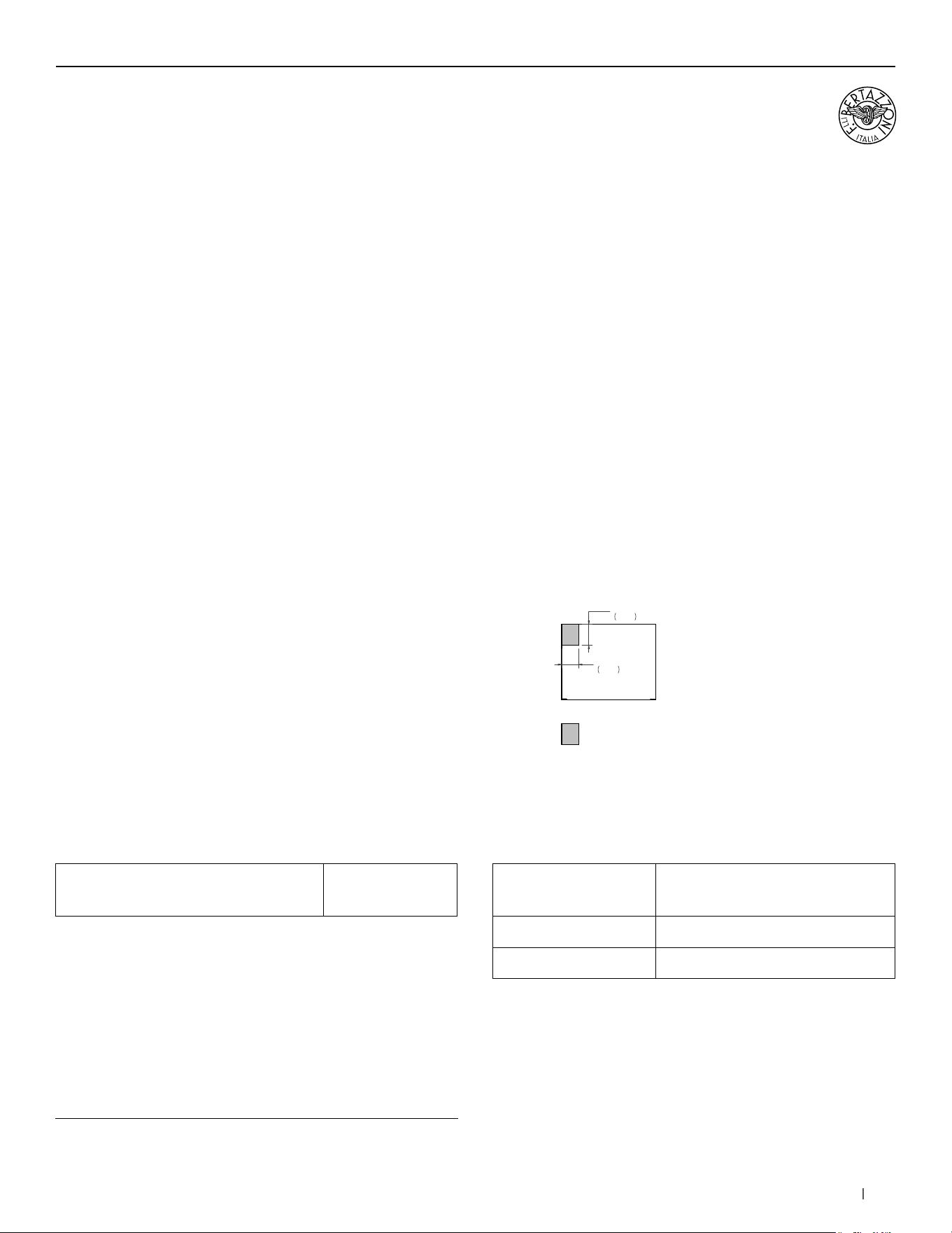
E
E
4"
102
5"
127
FRONT VIEW
A separate circuit and a circuit breaker servicing only this
appliance is reccomended
Minimum Suggested Load on
Cabinet Base Board
110lb (50kg) Electrical supply 120 V 60 Hz 1100 W
Service 10 Amp dedicated circuit
Power Connection NEMA 5-15P plug with 59” cord
For detailed installation specifications consult the installation manual.
37bertazzoni.com
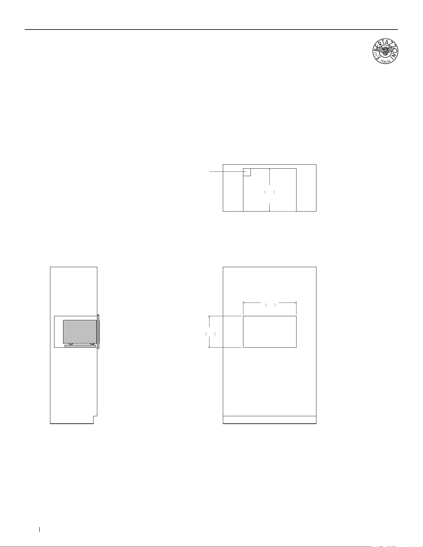
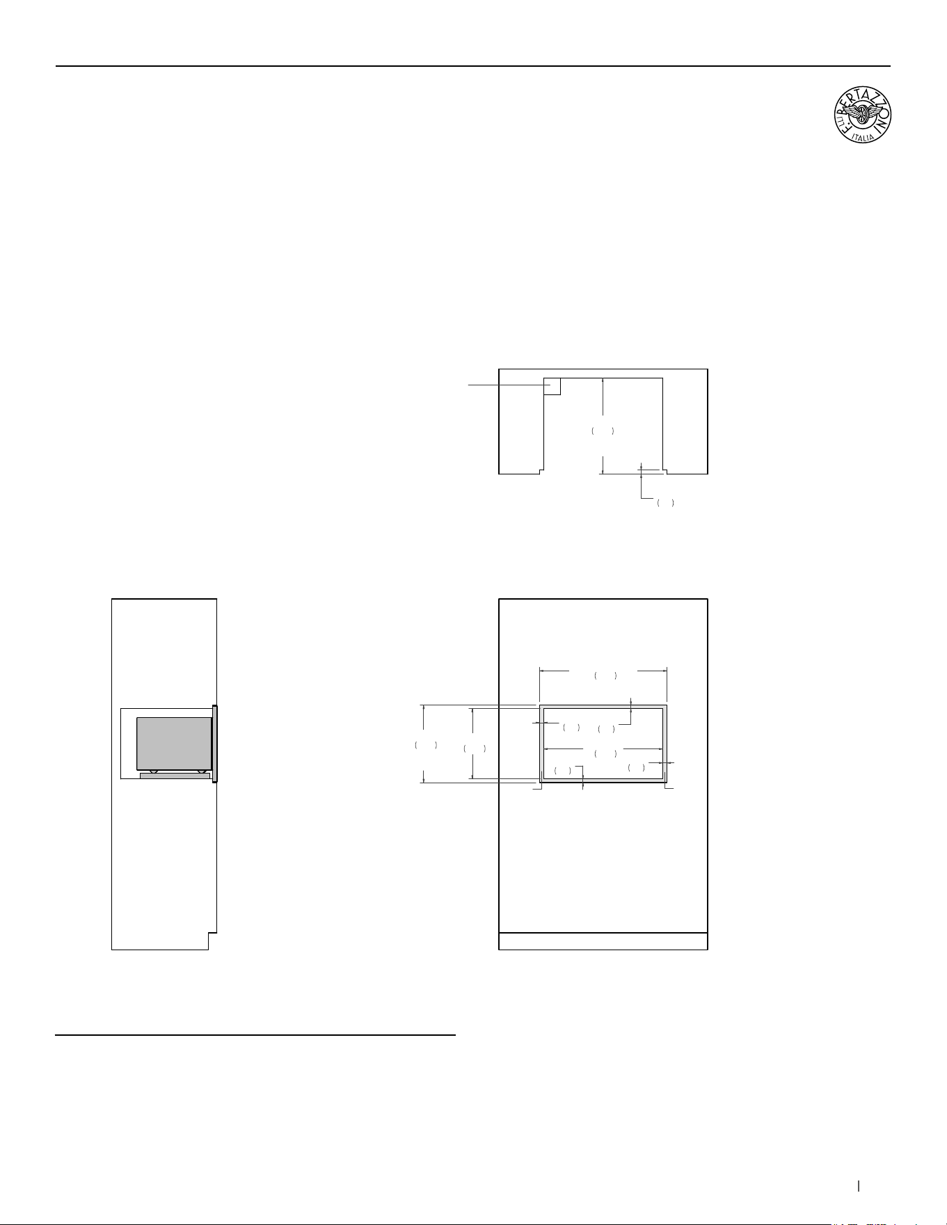
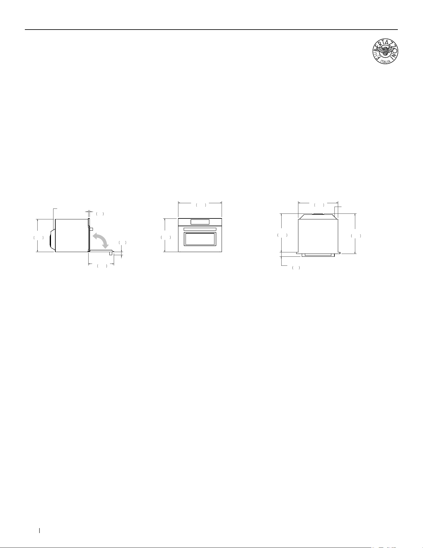
30” Microwave Oven
Flush installation
SPECIALTY OVENS
SIDE VIEW
FRONT VIEW
TOP VIEW
23"
585
FLUSH INSET
DEPTH
28 1/2"
724
4" x 4"
(102 x 102)
CUT OUT SLOT
FOR POWER CORD
18 1/2"
470
FLUSH INSET
HEIGHT
30 1/2"
776
FLUSH INSET
WIDTH
1"
26
3/4"
20
1"
25
a
a
1"
26
7/8"
22
16 7/8"
428
(a) Visible Area - Match finish to outside cabinet panels
39bertazzoni.com
24” Convection Speed Ovens
Installation requirements
SPECIALTY OVENS
INSTALLATION
The oven can be installed in a proud or flush application.
Finish the edges of the opening because they may be visible
when the door is open.
The clearance between the oven and the kitchen units
or other installed appliances must be enough to ensure
sufficient cooling air ventilation.
For instructions and clearance of product combinations
please see the Multiple Installation Sections (page 86).
CABINET REQUIREMENT
To prevent possible damage to cabinets and cabinet finishes,
use only materials and finishes that will not discolor or
delaminate and will withstand temperatures up to 195°F
(90°C). Installation of the appliance must be performed
in accordance with the provisions of applicable
legislation.
BE SURE that support for this appliance is perpendicular to
the front facing of the wall or cabinet before you perform the
installation.
The cabinet base must be flat and capable of
supporting the weight of the oven when in use.
ELECTRICAL REQUIREMENT
The installation must comply with all applicable
electrical codes.
A properly-grounded horizontally- mounted electrical
receptacle should be installed.
Place the electrical supply flush with the back
wall and within the shaded area shown in the illustrations.
Placement within the opening may require additional
cabinet depth.
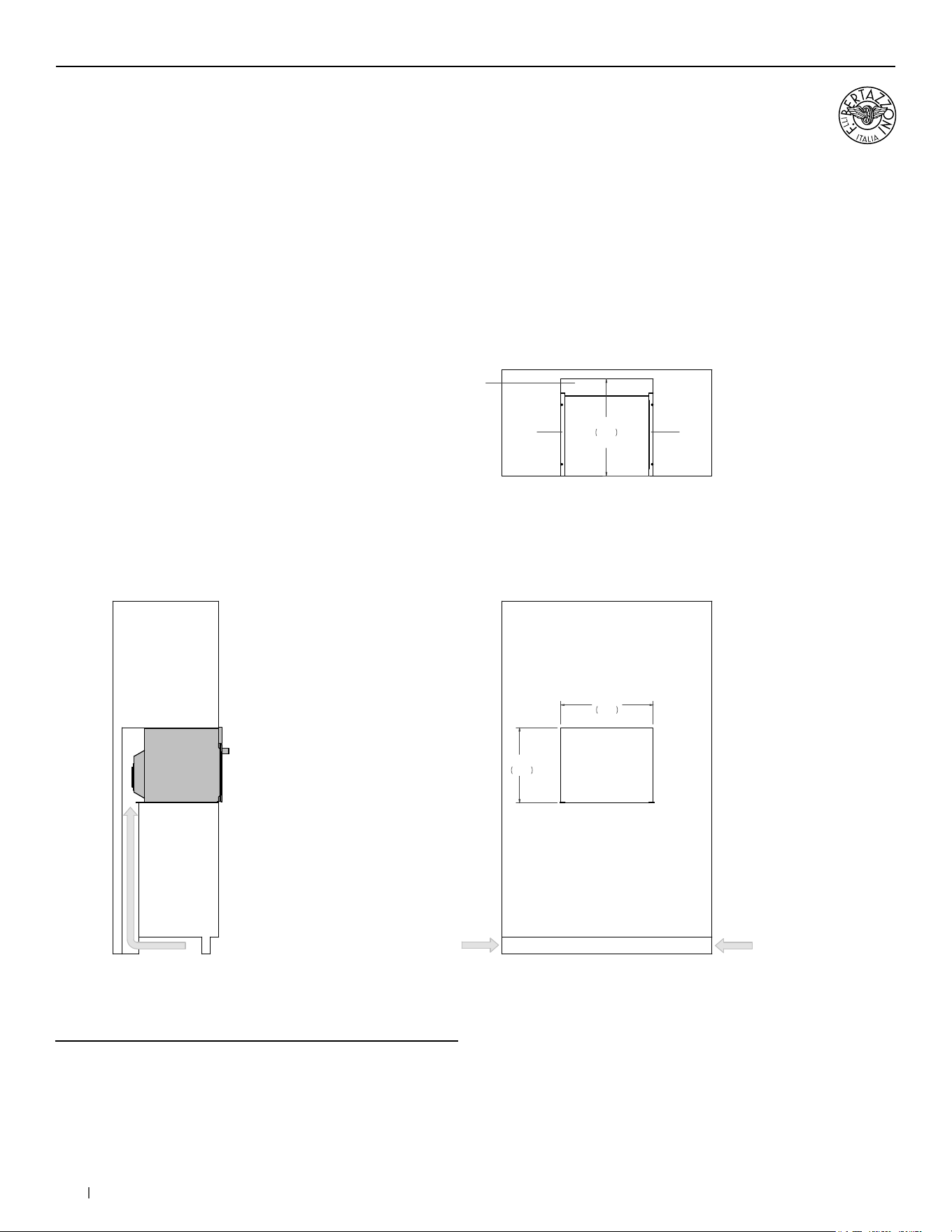
E
E
4"
102
5"
127
FRONT VIEW
A separate circuit and a circuit breaker servicing only this
appliance is reccomended
Minimum Suggested Load on
Cabinet Base Board
110lb (50kg) Electrical supply 120/240 V 60 Hz 3850 W
Service 16 Amp dedicated circuit
Power Connection METAL CONDUIT – 59” cord
For detailed installation specifications consult the installation manual.
40 bertazzoni.com
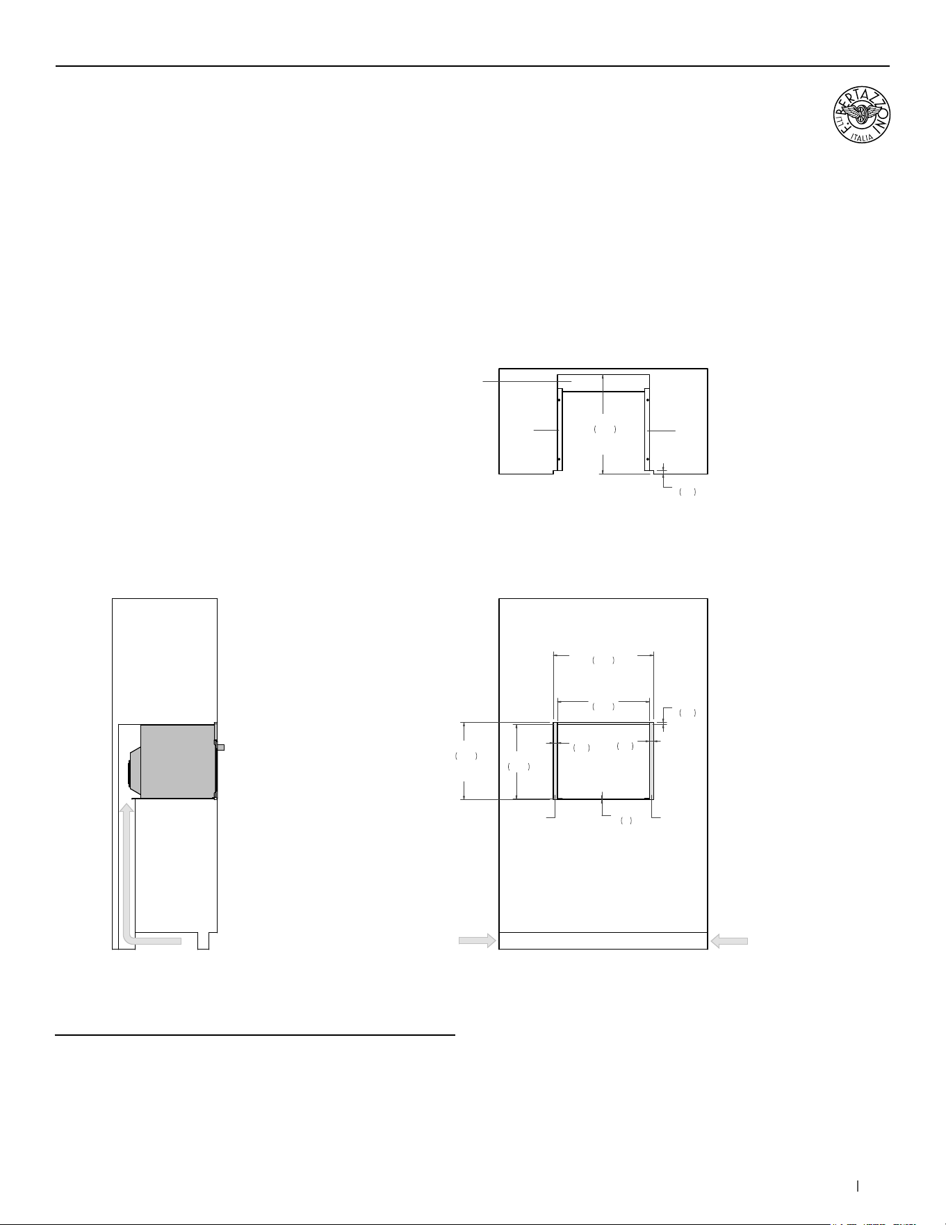
24” Convection Speed Ovens
Proud installation
SIDE VIEW
FRONT VIEW
TOP VIEW
(a) Spacers – Included with appliance
AIR INTAKE
22"
560
17 7/8"
455
23"
585
DEPTH
a
a
AIR INTAKE
4" x 15"
(102 x 380)
AIR INTAKE
4" x 15"
(102 x 380)
4" x 22"
(102 x 560)
AIR INTAKE
SPECIALTY OVENS
(a) Spacers - Included with appliance
41bertazzoni.com
24” Convection Speed Ovens
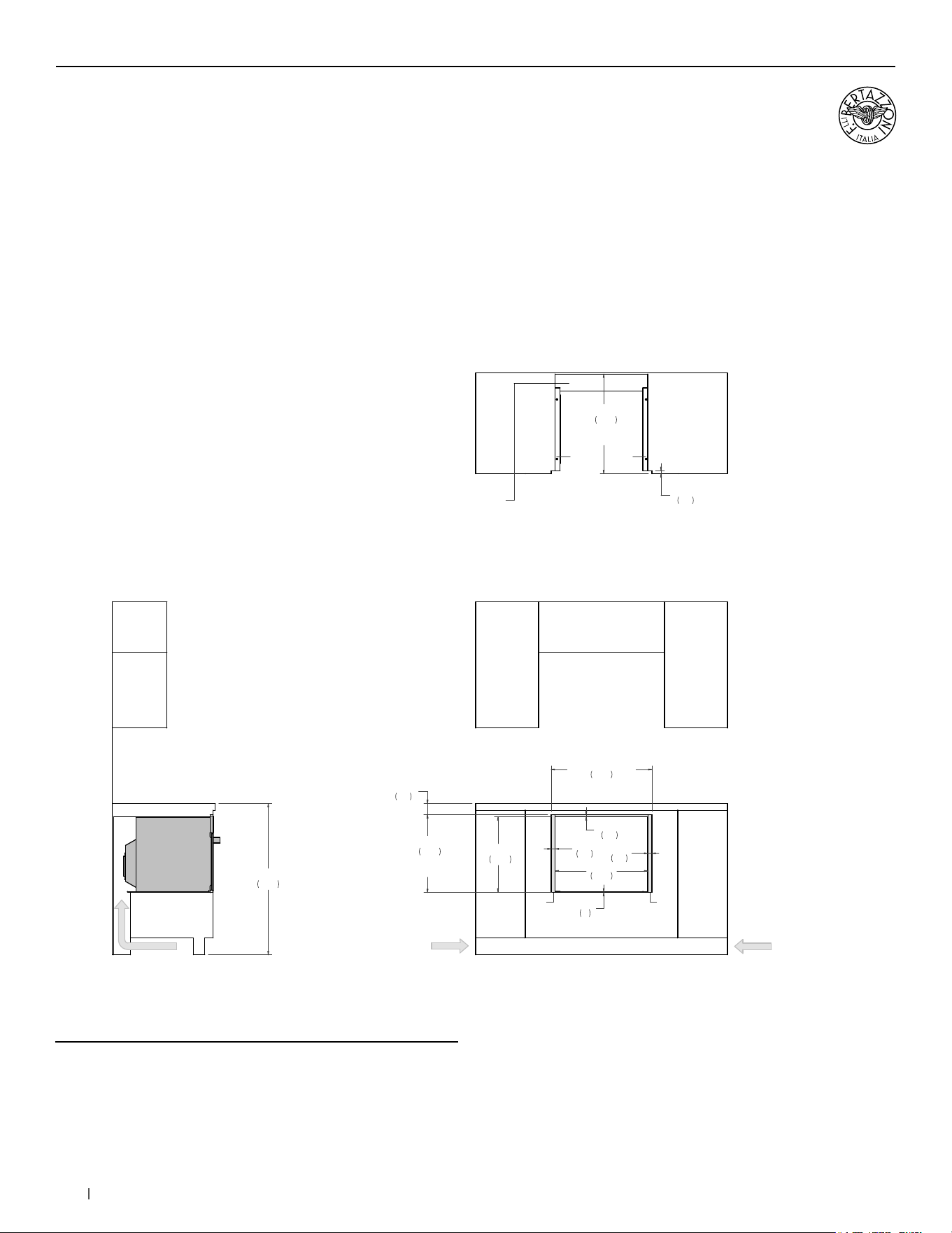
Flush installation
SIDE VIEW
FRONT VIEW
TOP VIEW
(a) Spacers – Included with appliance
(b) Visible Area – Match finish to outside cabinet panels
AIR INTAKE
22"
560
24"
610
FLUSH INSET
WIDTH
17 7/8"
455
18 1/2"
470
FLUSH INSET
HEIGHT
1"
25
1"
25
1/2"
12
1/8"
3
23 3/4"
603
FLUSH INSET
DEPTH
3/4"
20
a
a
b b
AIR INTAKE
4" x 15"
(102 x 380)
AIR INTAKE
4" x 15"
(102 x 380)
4" x 22"
(102 x 560)
AIR INTAKE
SPECIALTY OVENS
(a) Spacers - Included with appliance
(b) Visible Area - Match finish to outside cabinet panels
42 bertazzoni.com
24” Convection Speed Ovens
Undercounter installation
SIDE VIEW
FRONT VIEW
(a) Spacers – Included with appliance
(b) Visible Area – Match finish to outside cabinet panels
TOP VIEW
AIR INTAKE
a
bb
a
36"
914
17 7/8"
455
24"
610
FLUSH INSET
WIDTH
18 1/2"
470
FLUSH INSET
HEIGHT
1"
25
1"
25
1/8"
3
1/2"
12
22"
560
23 3/4"
603
FLUSH INSET
DEPTH
2 5/8"
68
3/4"
19
4" x 22"
(102 x 560)
AIR INTAKE
AIR INTAKE
4" x 15"
(102 x 380)
AIR INTAKE
4" x 15"
(102 x 380)
SPECIALTY OVENS
(a) Spacers - Included with appliance
(b) Visible Area - Match finish to outside cabinet panels
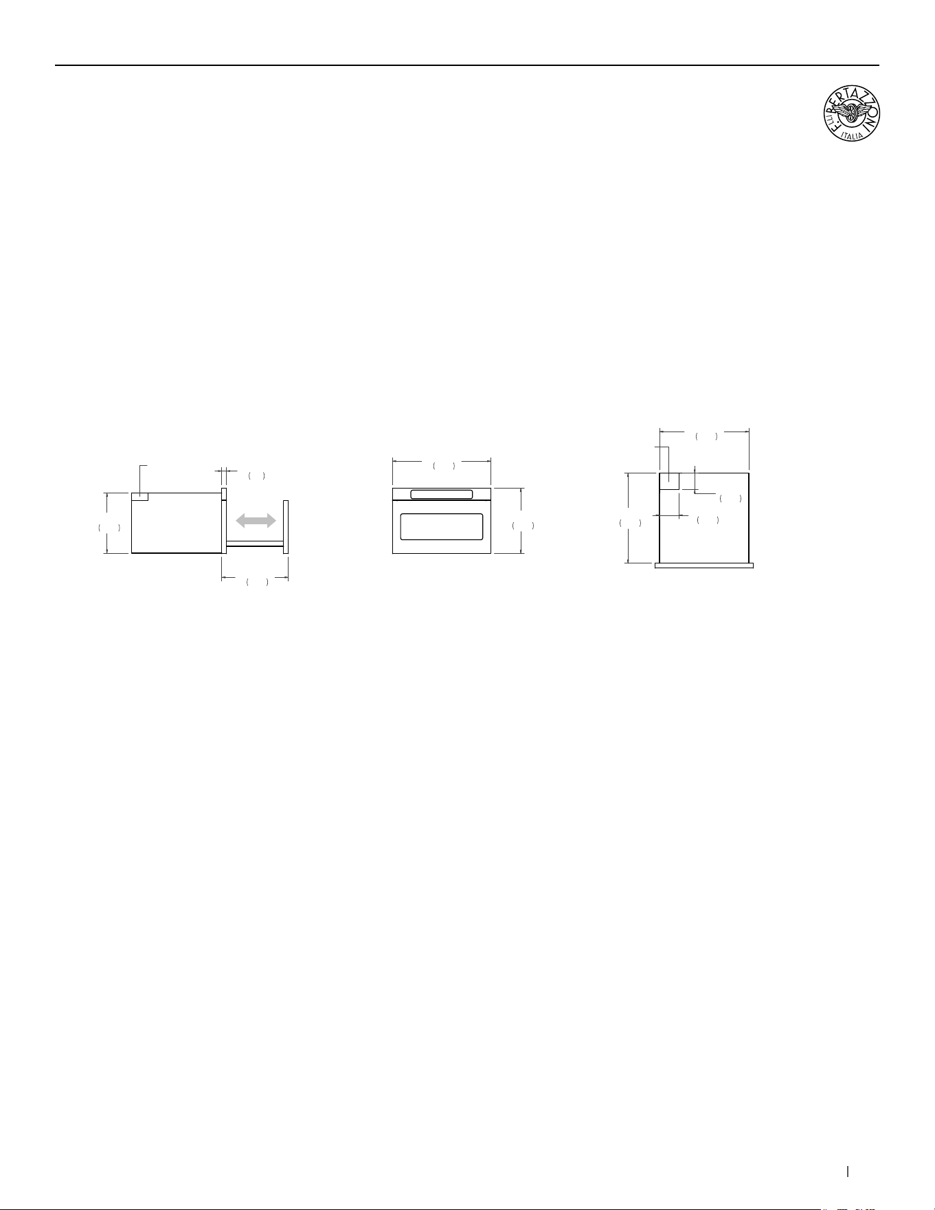
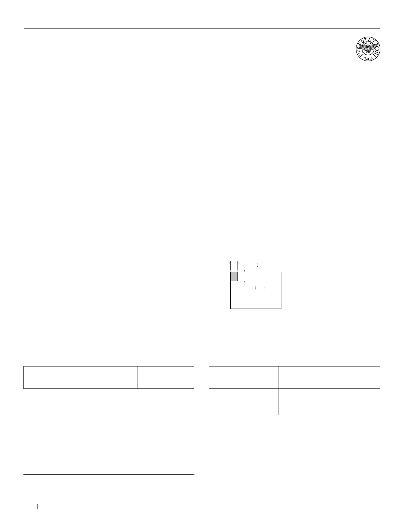
44 bertazzoni.com
24” Microwave Drawer
Installation requirements
SPECIALTY OVENS
INSTALLATION
The oven can be installed in a proud or flush application.
Finish the edges of the opening because they may be visible
when the door is open.
The clearance between the oven and the kitchen units
or other installed appliances must be enough to ensure
sufficient cooling air ventilation.
For instructions and clearance of product combinations
please see the Multiple Installation Sections (page 86).
CABINET REQUIREMENT
To prevent possible damage to cabinets and cabinet finishes,
use only materials and finishes that will not discolor or
delaminate and will withstand temperatures up to 195°F
(90°C). Installation of the appliance must be performed
in accordance with the provisions of applicable
legislation.
BE SURE that support for this appliance is perpendicular to
the front facing of the wall or cabinet before you perform the
installation.
The cabinet base must be flat and capable of
supporting the weight of the oven when in use.
ELECTRICAL REQUIREMENT
The installation must comply with all applicable
electrical codes.
A properly-grounded horizontally- mounted electrical
receptacle should be installed.
Place the electrical supply flush with the back
wall and within the shaded area shown in the illustrations.
Placement within the opening may require additional
cabinet depth.
E
4"
102
5"
127
FRONT VIEW
Minimum Suggested Load on
Cabinet Base Board
110lb (50kg) Electrical supply 120/240 V 60 Hz 1500 W
Service 15 Amp
Power Connection NEMA 5-15P plug with 47” cord
For detailed installation specifications consult the installation manual.
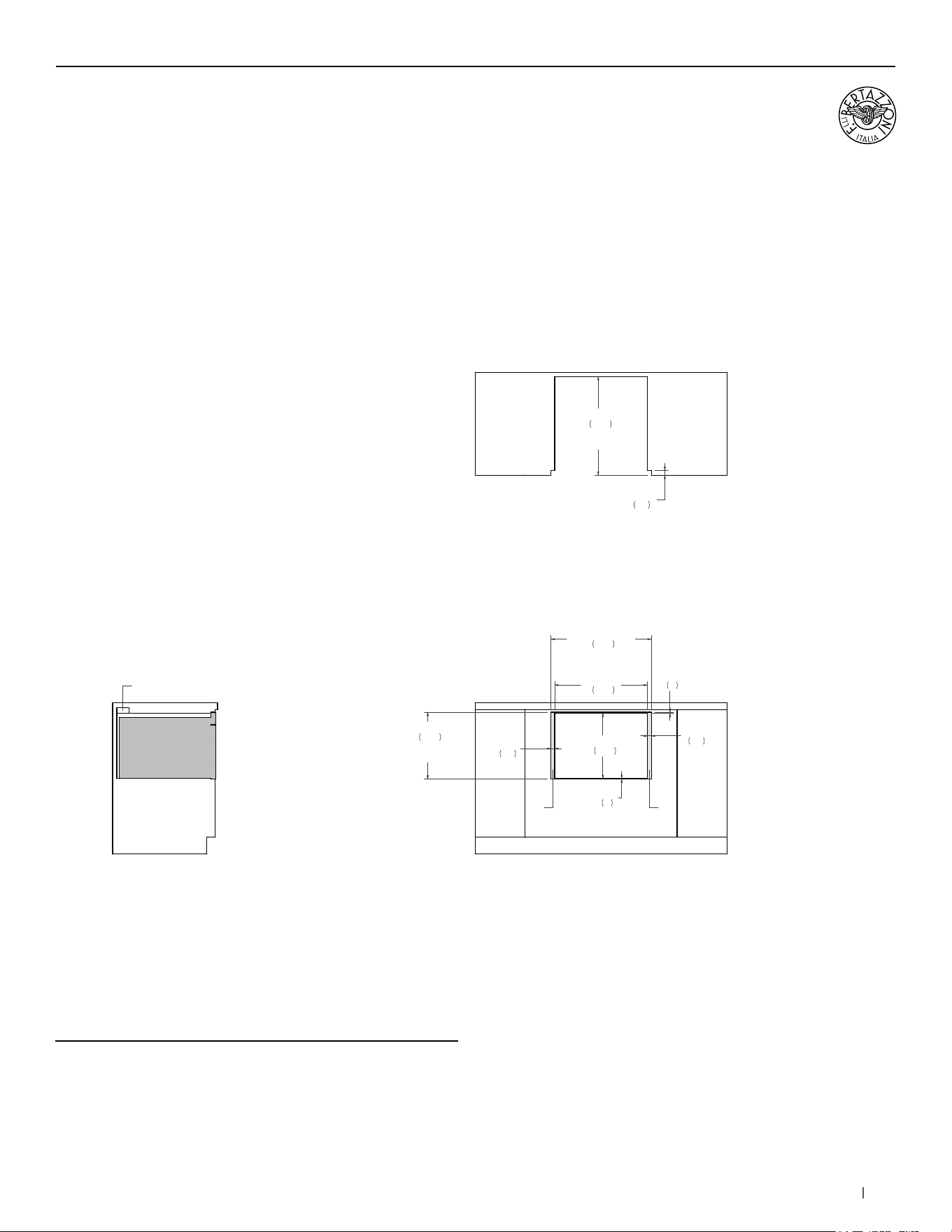
45bertazzoni.com
24” Microwave Drawer
Flush installation
SIDE VIEW
FRONT VIEW
TOP VIEW
(a) Visible area – Match finisch to outside cabinet panels
aa
23 7/8"
608
FLUSH INSET
WIDTH
15 7/8"
404
FLUSH INSET
HEIGHT
7/8"
23
7/8"
23
1/8"
4
22 1/8"
562
1/4"
6
15 1/2"
395
23 1/2"
597
FLUSH INSET
DEPTH
1 1/8"
28
ANTI TIP
SPECIALTY OVENS
(a) Visible Area - Match finish to outside cabinet panels
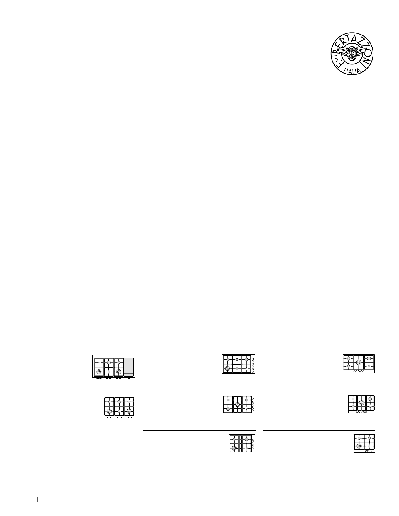
46 bertazzoni.com
GAS RANGETOPS & COOKTOPS
Bertazzoni rangetops and cooktops offer amazing
versatility and feature a maximized cooking surface.
Available in 24”, 30”, 36” and 48” versions, together
with a variety of versatile burner configurations,
these powerful models are the perfect pairing any
Bertazzoni built-in oven.
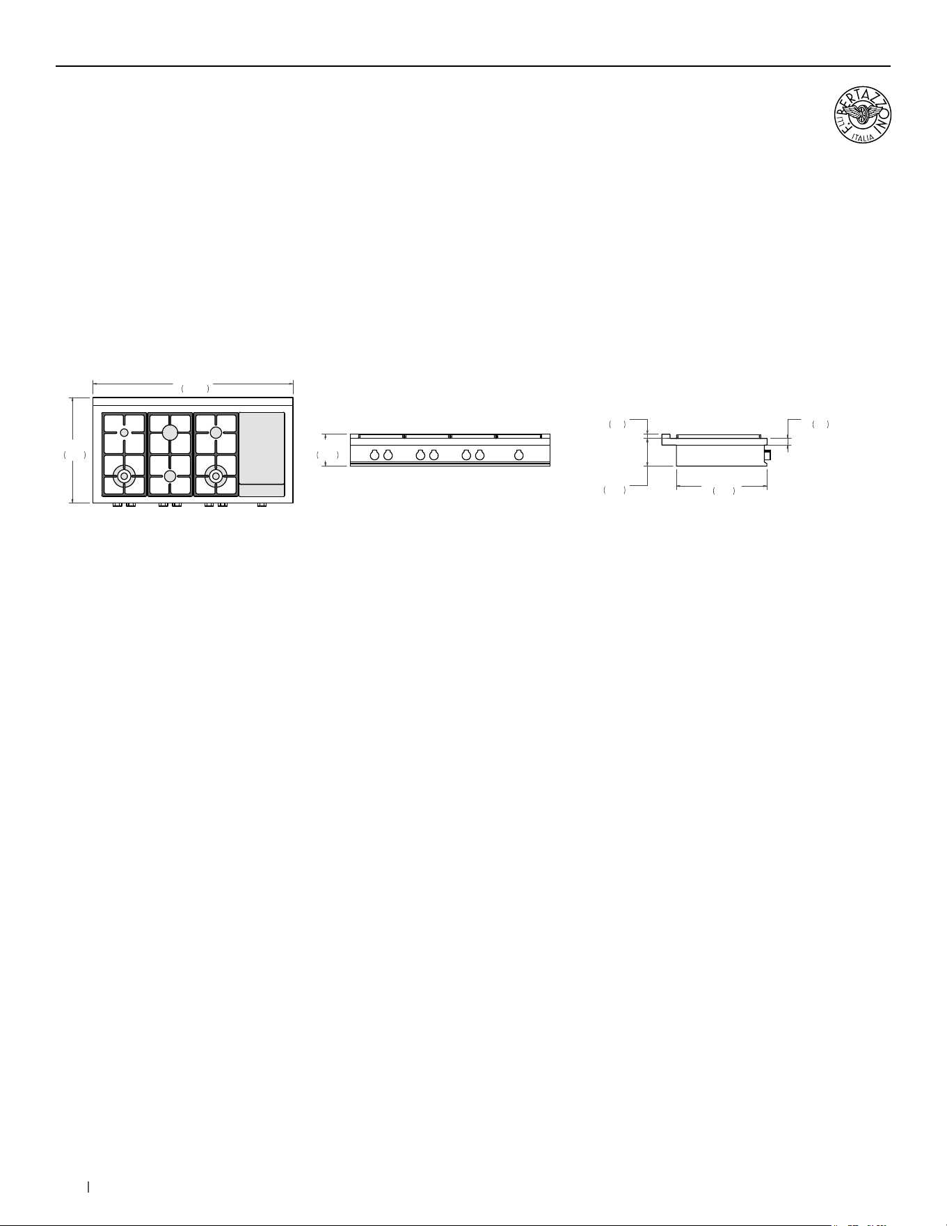
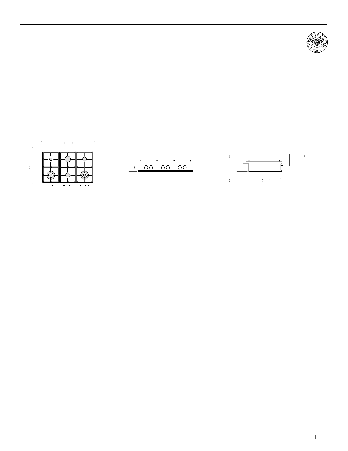
48” Rangetops
36” Rangetops
36” Drop-in Cooktops
6 burners
36” Cooktops
5 burners
30” Drop-in Cooktops
4 burners
36” Drop-in Cooktops
5 burners
30” Cooktops
5 burners
24” Cooktops
4 burners
Rangetops Side control drop-in cooktops Front control built-in cooktops

49bertazzoni.com
48” Rangetops
Installation requirements
INSTALLATION
The gas rangetops can be mounted in a standard installation
sitting on top of the countertop surface.
If a drawer is placed under the appliance, avoid to put into this
drawer flammable objects or not heat-resistant objects.
For installation with an updraft or downdraft hood, refer to the
hood manufacturer’s installation requirements.
For instructions and clearance of product combinations
please see the Multiple Installation Sections (page 86).
CABINET REQUIREMENT
To prevent possible damage to cabinets and cabinet finishes,
the countertop must be able to withstand temperatures up to
300°F (149°C). Installation of the appliance must be performed
in accordance with the provisions of applicable legislation.
BE SURE that support for this appliance is horizontale before
you perform the installation. The cabinet base must be flat and
capable of supporting the weight of the oven when in use.
ELECTRICAL REQUIREMENT
The installation must comply with all applicable electrical codes.
A properly-grounded horizontally- mounted electrical receptacle
should be installed. Place the electrical supply flush with the
back wall and within the shaded area shown in the illustrations.
Placement within the opening may require additional cabinet
depth.
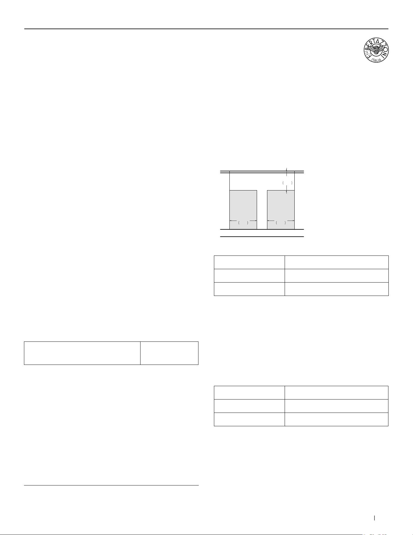
EG
15"
381
15"
381
10 5/8"
270
COUNTERTOP
FRONT VIEW
GAS CONNECTION
The gas rangetops can be used with Natural or LP/Propane
gas. An agency-approved, properly-sized manual shutoff
valve should be installed. To connect gas between shut-off
valve and regulator, use agency-approved, properly sized
flexible or rigid pipe. Check all local code requirements.
Since service pressure may fluctuate with local demand, every
gas cooktop must be equipped with the supplied pressure
regulator on the incoming service line for safe and efficient
operation.
Minimum Suggested Load on
Cabinet Base Board
187lb (85kg)
Electrical supply 120 V 60 Hz 1100 W
Service 10 Amp
Power Connection NEMA 5-15P plug with 59” cord
Gas Inlet 1/2” NPT
Natural Gas 4” iwc (1.00 kPa)
LPG Gas 10” iwc (2.50 kPa)
For detailed installation specifications consult the installation manual.
GAS RANGETOPS & COOKTOPS
50 bertazzoni.com
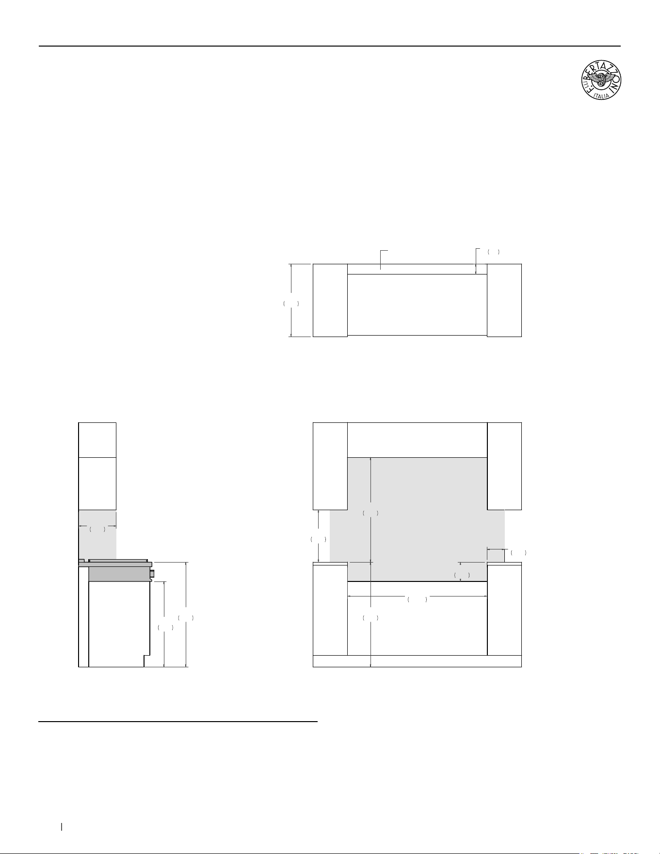
SIDE VIEW
FRONT VIEW
TOP VIEW
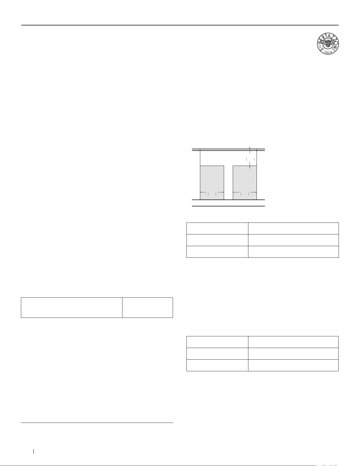
Combustible material cannot be installed within shaded area.
18"
457
36"
915
13"
330
6"
152
48"
1218
6 5/8"
168
25"
635
29 3/8"
746
3 1/2"
90
36"
914
36"
914
AREA FOR ELECTRIC
AND GAS CONNECTION
48” Rangetops
Installation
Combustible material cannot be located within shaded area.
GAS RANGETOPS & COOKTOPS
52 bertazzoni.com
36” Rangetops
Installation requirements
INSTALLATION
The gas rangetops can be mounted in a standard installation
sitting on top of the countertop surface.
If a drawer is placed under the appliance, avoid to put into this
drawer flammable objects or not heat-resistant objects.
For installation with an updraft or downdraft hood, refer to the
hood manufacturer’s installation requirements.
For instructions and clearance of product combinations
please see the Multiple Installation Sections (page 86).
CABINET REQUIREMENT
To prevent possible damage to cabinets and cabinet finishes,
the countertop must be able to withstand temperatures up to
300°F (149°C). Installation of the appliance must be performed
in accordance with the provisions of applicable legislation.
BE SURE that support for this appliance is horizontale before
you perform the installation. The cabinet base must be flat and
capable of supporting the weight of the oven when in use.
ELECTRICAL REQUIREMENT
The installation must comply with all applicable electrical codes.
A properly-grounded horizontally- mounted electrical receptacle
should be installed. Place the electrical supply flush with the
back wall and within the shaded area shown in the illustrations.
Placement within the opening may require additional cabinet
depth.
EG
15"
381
15"
381
10 5/8"
270
COUNTERTOP
FRONT VIEW
GAS CONNECTION
The gas rangetops can be used with Natural or LP/Propane
gas. An agency-approved, properly-sized manual shutoff
valve should be installed. To connect gas between shut-off
valve and regulator, use agency-approved, properly sized
flexible or rigid pipe. Check all local code requirements.
Since service pressure may fluctuate with local demand, every
gas cooktop must be equipped with the supplied pressure
regulator on the incoming service line for safe and efficient
operation.
Minimum Suggested Load on
Cabinet Base Board
165lb (75kg)
Electrical supply 120 V 60 Hz 1 W
Service 1 Amp
Power Connection NEMA 5-15P plug with 59” cord
Gas Inlet 1/2” NPT
Natural Gas 4” iwc (1.00 kPa)
LPG Gas 10” iwc (2.50 kPa)
For detailed installation specifications consult the installation manual.
GAS RANGETOPS & COOKTOPS
53bertazzoni.com
SIDE VIEW
FRONT VIEW
TOP VIEW
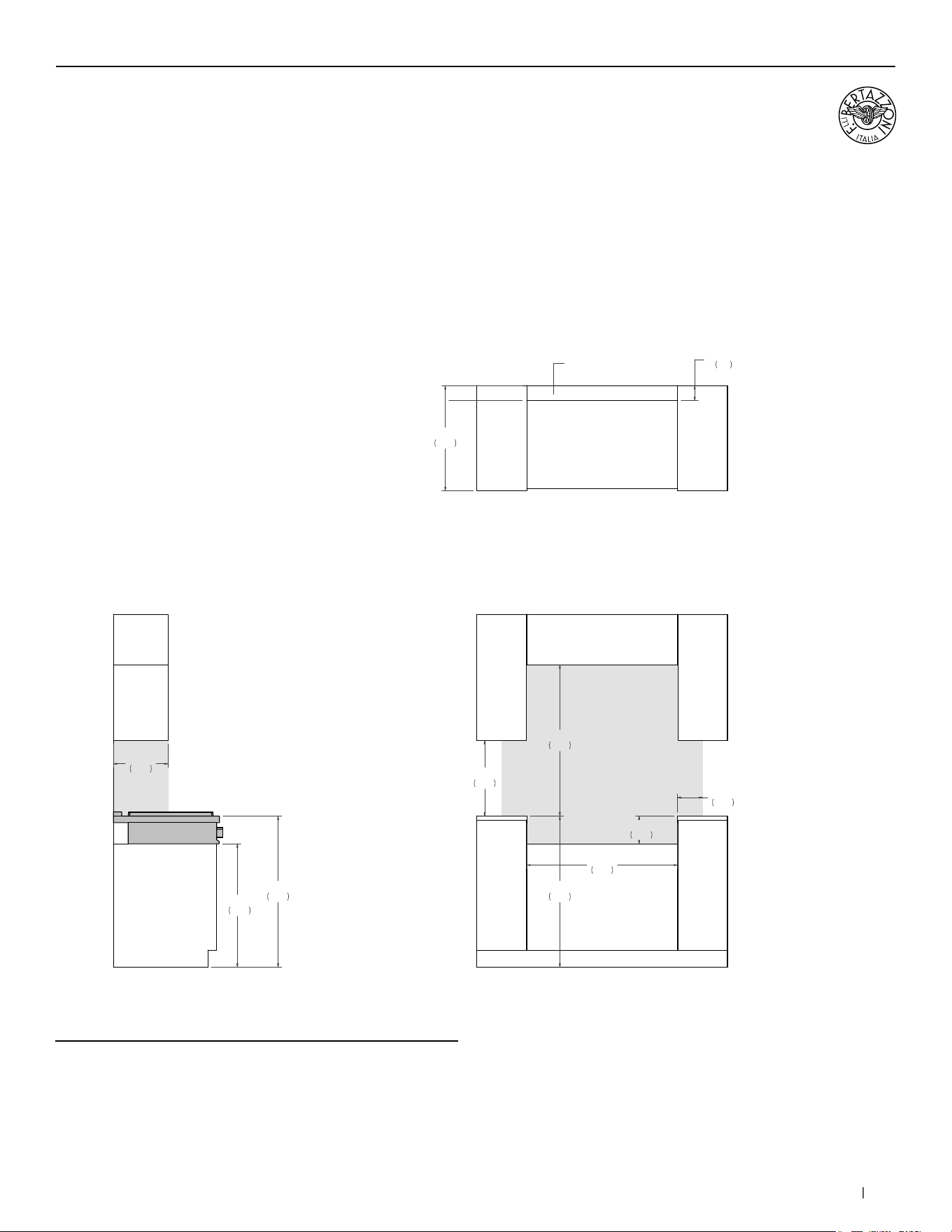
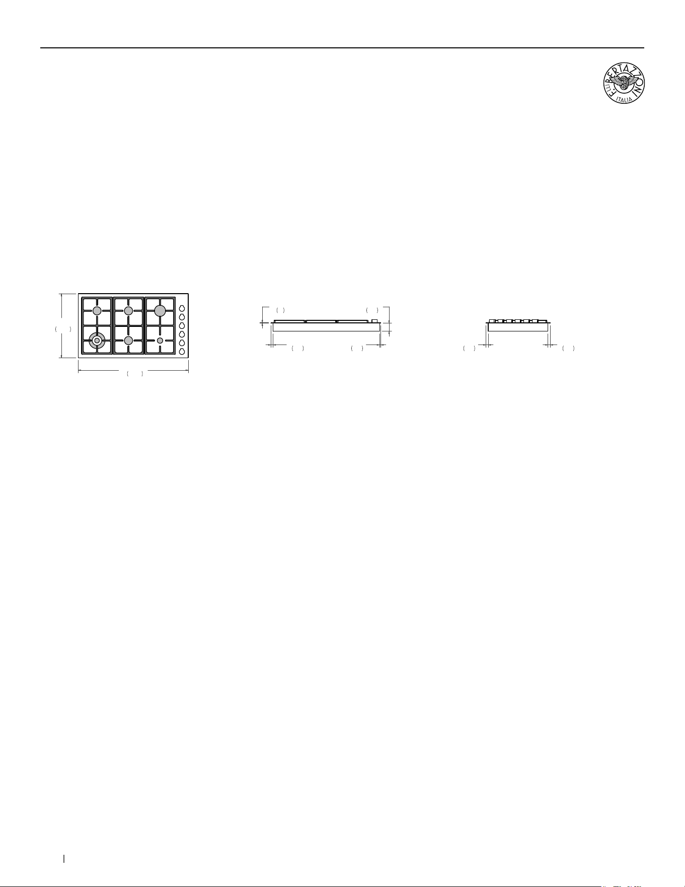
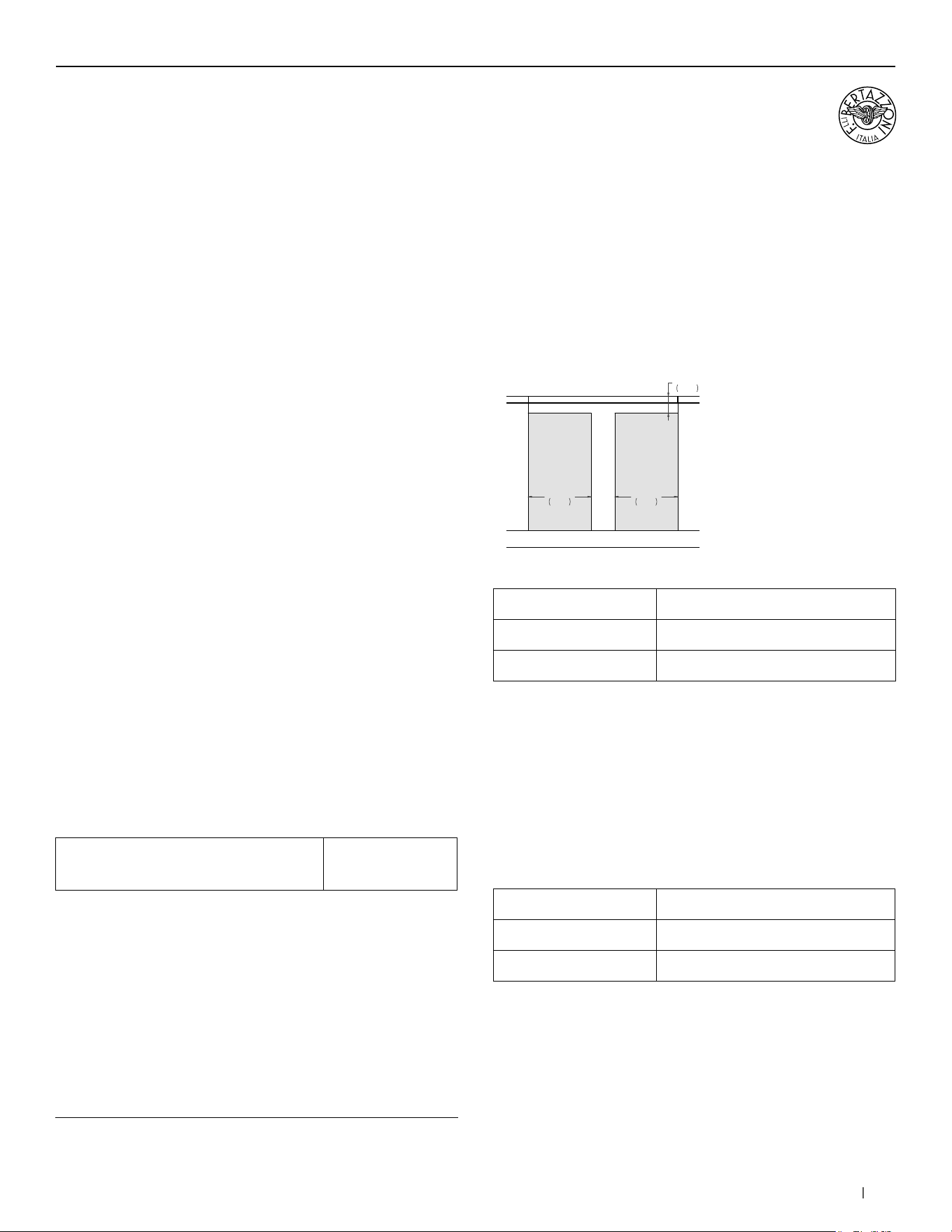
Combustible material cannot be installed within shaded area.
18"
457
36"
915
13"
330
6"
152
36"
913
6 5/8"
168
25"
635
3 1/2"
90
36"
914
29 3/8"
746
36"
915
AREA FOR ELECTRIC
AND GAS CONNECTION
36” Rangetops
Installation
Combustible material cannot be located within shaded area.
GAS RANGETOPS & COOKTOPS
55bertazzoni.com
36” Drop-in Cooktops 6 burners
Installation requirements
INSTALLATION
The gas cooktop can be mounted in a standard installation
sitting on top of the countertop surface.
The clearance between the hob and the kitchen furniture
or other installed appliances must be enough to ensure
sufficient cooling air ventilation.
If a drawer is placed under the work, avoid to put into this
drawer flammable objects or not heat-resistant objects.
For installation with an updraft or downdraft hood as well as
any OTR, refer to the hood/OTR manufacturer’s installation
requirements.
For instructions and clearance of product combinations
please see the Multiple Installation Sections (page 86).
CABINET REQUIREMENT
To prevent possible damage to cabinets and cabinet finishes,
the countertop must be able to withstand temperatures up to
300°F (149°C). Installation of the appliance must be performed
in accordance with the provisions of applicable legislation.
BE SURE that support for this appliance is horizontale before
you perform the installation. The cabinet base must be flat and
capable of supporting the weight of the oven when in use.
ELECTRICAL REQUIREMENT
The installation must comply with all applicable electrical codes.
A properly-grounded horizontally- mounted electrical receptacle
should be installed. Place the electrical supply flush with the
back wall and within the shaded area shown in the illustrations.
Placement within the opening may require additional cabinet
depth.
EG
15"
381
15"
381
4"
102
COUNTERTOP
FRONT VIEW
GAS CONNECTION
The gas cooktop can be used with Natural or LP/Propane
gas. An agency-approved, properly-sized manual shutoff
valve should be installed. To connect gas between shut-off
valve and regulator, use agency-approved, properly sized
flexible or rigid pipe. Check all local code requirements.
Since service pressure may fluctuate with local demand, every
gas cooktop must be equipped with the supplied pressure
regulator on the incoming service line for safe and efficient
operation.
Minimum Suggested Load on
Cabinet Base Board
132lb (60kg)
Electrical supply 120 V 60 Hz 1 W
Service 1 Amp
Power Connection NEMA 5-15P plug with 59” cord
Gas Inlet 1/2” NPT
Natural Gas 4” iwc (1.00 kPa)
LPG Gas 10” iwc (2.50 kPa)
For detailed installation specifications consult the installation manual.
GAS RANGETOPS & COOKTOPS
56 bertazzoni.com
SIDE VIEW
FRONT VIEW
TOP VIEW
Combustible material cannot be installed within shaded area.
35 5/8"
905
CUT-OUT
WIDTH
20 1/2"
520
CUT-OUT
DEPTH
1 3/4"
45
1 3/4"
45
18"
457
36"
915
36 3/8"
925
6"
152
35 5/8"
905
3 1/8"
80
36"
914
13"
330
36” Drop-in Cooktops 6 burners
Installation
Combustible material cannot be installed within shaded area.
GAS RANGETOPS & COOKTOPS
58 bertazzoni.com
36” Drop-in Cooktops 5 burners
Installation requirements
INSTALLATION
The gas cooktop can be mounted in a standard installation
sitting on top of the countertop surface.
The clearance between the hob and the kitchen furniture
or other installed appliances must be enough to ensure
sufficient cooling air ventilation.
If a drawer is placed under the work, avoid to put into this
drawer flammable objects or not heat-resistant objects.
For installation with an updraft or downdraft hood as well as
any OTR, refer to the hood/OTR manufacturer’s installation
requirements.
For instructions and clearance of product combinations
please see the Multiple Installation Sections (page 86).
CABINET REQUIREMENT
To prevent possible damage to cabinets and cabinet finishes,
the countertop must be able to withstand temperatures up to
300°F (149°C). Installation of the appliance must be performed
in accordance with the provisions of applicable legislation.
BE SURE that support for this appliance is horizontale before
you perform the installation. The cabinet base must be flat and
capable of supporting the weight of the oven when in use.
ELECTRICAL REQUIREMENT
The installation must comply with all applicable electrical codes.
A properly-grounded horizontally- mounted electrical receptacle
should be installed. Place the electrical supply flush with the
back wall and within the shaded area shown in the illustrations.
Placement within the opening may require additional cabinet
depth.
EG
15"
381
15"
381
4"
102
COUNTERTOP
FRONT VIEW
GAS CONNECTION
The gas cooktop can be used with Natural or LP/Propane
gas. An agency-approved, properly-sized manual shutoff
valve should be installed. To connect gas between shut-off
valve and regulator, use agency-approved, properly sized
flexible or rigid pipe. Check all local code requirements.
Since service pressure may fluctuate with local demand, every
gas cooktop must be equipped with the supplied pressure
regulator on the incoming service line for safe and efficient
operation.
Minimum Suggested Load on
Cabinet Base Board
125lb (57kg)
Electrical supply 120 V 60 Hz 1 W
Service 1 Amp
Power Connection NEMA 5-15P plug with 59” cord
Gas Inlet 1/2” NPT
Natural Gas 4” iwc (1.00 kPa)
LPG Gas 10” iwc (2.50 kPa)
For detailed installation specifications consult the installation manual.
GAS RANGETOPS & COOKTOPS
59bertazzoni.com
SIDE VIEW
FRONT VIEW
TOP VIEW
Combustible material cannot be installed within shaded area.
35 5/8"
905
CUT-OUT
WIDTH
20 1/2"
520
CUT-OUT
DEPTH
1 3/4"
45
1 3/4"
45
18"
457
36"
915
36 3/8"
925
6"
152
35 5/8"
905
3 1/8"
80
36"
914
13"
330
36” Drop-in Cooktops 5 burners
Installation
Combustible material cannot be installed within shaded area.
GAS RANGETOPS & COOKTOPS
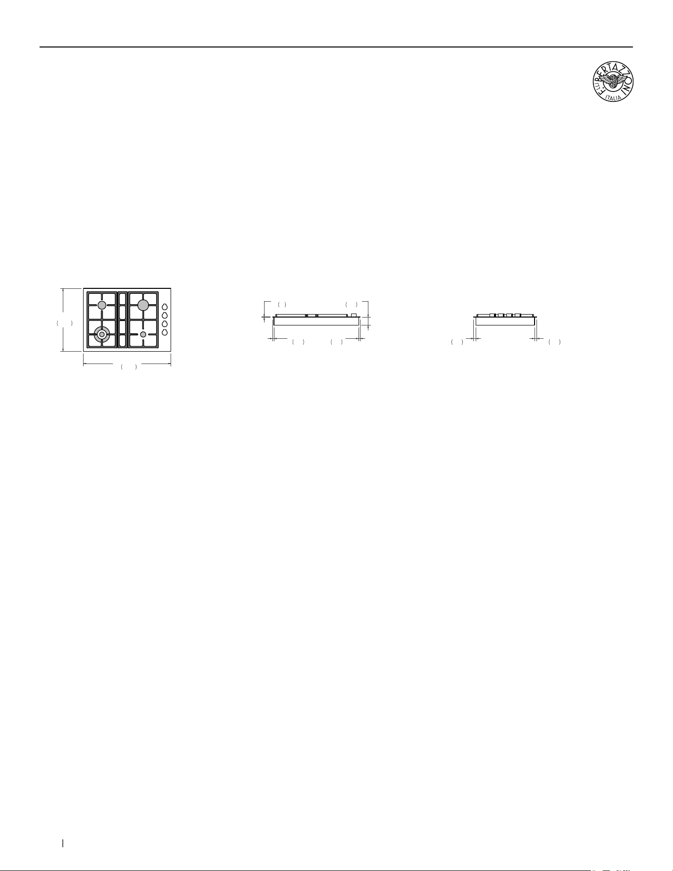
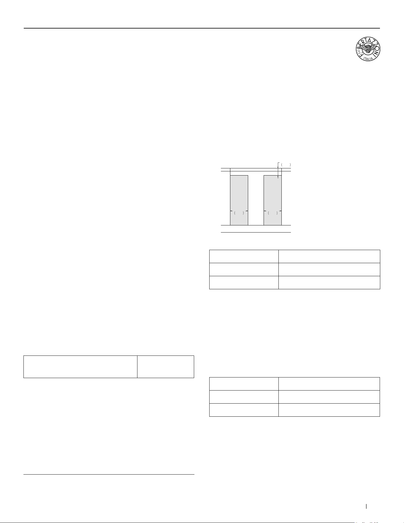
61bertazzoni.com
30” Drop-in Cooktops
Installation requirements
INSTALLATION
The gas cooktop can be mounted in a standard installation
sitting on top of the countertop surface.
The clearance between the hob and the kitchen furniture
or other installed appliances must be enough to ensure
sufficient cooling air ventilation.
If a drawer is placed under the work, avoid to put into this
drawer flammable objects or not heat-resistant objects.
For installation with an updraft or downdraft hood as well as
any OTR, refer to the hood/OTR manufacturer’s installation
requirements.
For instructions and clearance of product combinations
please see the Multiple Installation Sections (page 86).
CABINET REQUIREMENT
To prevent possible damage to cabinets and cabinet finishes,
the countertop must be able to withstand temperatures up to
300°F (149°C). Installation of the appliance must be performed
in accordance with the provisions of applicable legislation.
BE SURE that support for this appliance is horizontale before
you perform the installation. The cabinet base must be flat and
capable of supporting the weight of the oven when in use.
ELECTRICAL REQUIREMENT
The installation must comply with all applicable electrical codes.
A properly-grounded horizontally- mounted electrical receptacle
should be installed. Place the electrical supply flush with the
back wall and within the shaded area shown in the illustrations.
Placement within the opening may require additional cabinet
depth.
EG
10"
254
10"
254
4"
102
COUNTERTOP
FRONT VIEW
GAS CONNECTION
The gas coopktop can be used with Natural or LP/Propane
gas. An agency-approved, properly-sized manual shutoff
valve should be installed. To connect gas between shut-off
valve and regulator, use agency-approved, properly sized
flexible or rigid pipe. Check all local code requirements.
Since service pressure may fluctuate with local demand, every
gas cooktop must be equipped with the supplied pressure
regulator on the incoming service line for safe and efficient
operation.
Minimum Suggested Load on
Cabinet Base Board
110lb (50kg)
Electrical supply 120 V 60 Hz 1 W
Service 1 Amp
Power Connection NEMA 5-15P plug with 59” cord
Gas Inlet 1/2” NPT
Natural Gas 4” iwc (1.00 kPa)
LPG Gas 10” iwc (2.50 kPa)
For detailed installation specifications consult the installation manual.
GAS RANGETOPS & COOKTOPS
62 bertazzoni.com
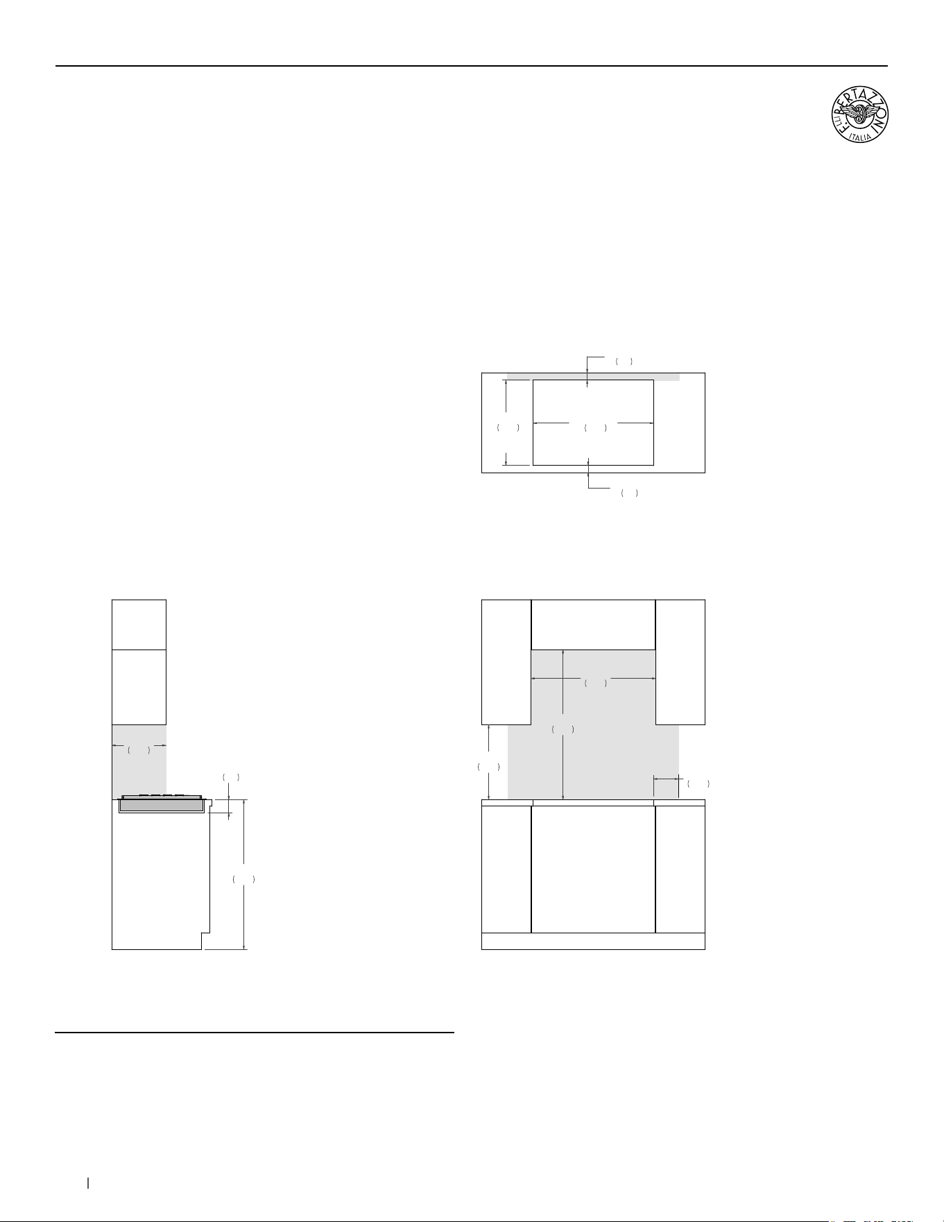
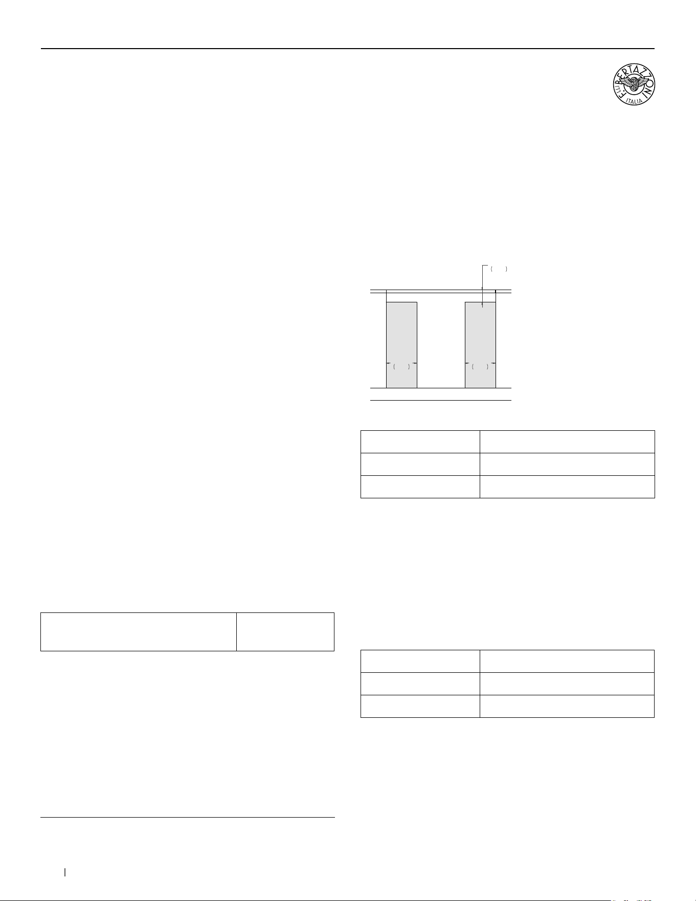
SIDE VIEW
FRONT VIEW
TOP VIEW
Combustible material cannot be installed within shaded area.
28 7/8"
735
CUT-OUT
WIDTH
20 1/2"
520
CUT-OUT
DEPTH
1 3/4"
45
1 3/4"
45
18"
457
36"
915
30"
762
6"
152
3 1/8"
80
36"
914
13"
330
30” Drop-in Cooktops
Installation
Combustible material cannot be installed within shaded area.
GAS RANGETOPS & COOKTOPS
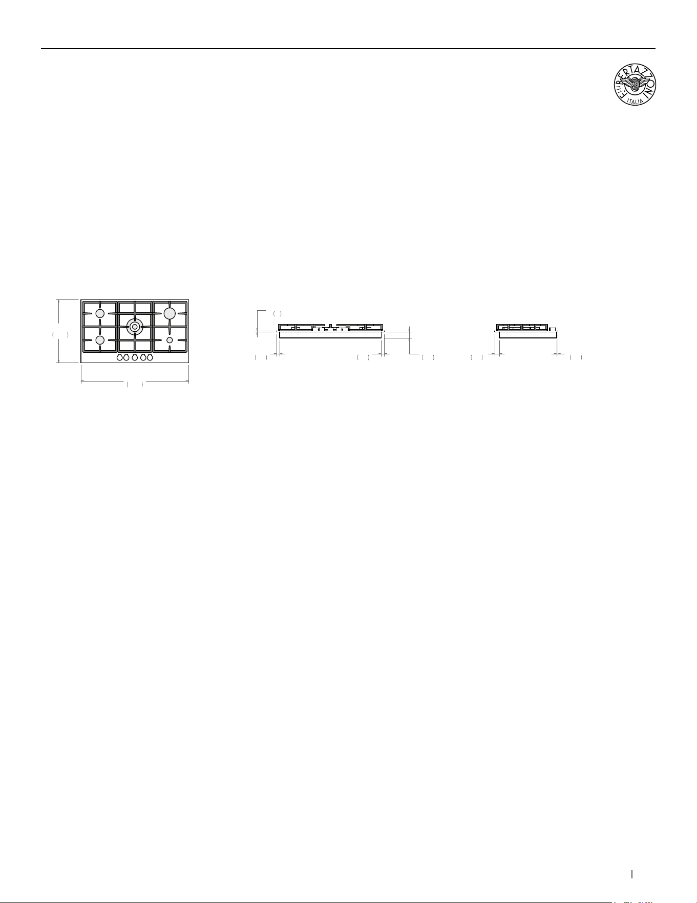
64 bertazzoni.com
36” Gas Cooktop Front Control
Installation requirements
INSTALLATION
The gas cooktop can be mounted in a standard installation
sitting on top of the countertop surface.
The clearance between the hob and the kitchen furniture
or other installed appliances must be enough to ensure
sufficient cooling air ventilation.
If a drawer is placed under the work, avoid to put into this
drawer flammable objects or not heat-resistant objects.
For installation with an updraft or downdraft hood as well as
any OTR, refer to the hood/OTR manufacturer’s installation
requirements.
For instructions and clearance of product combinations
please see the Multiple Installation Sections (page 86).
CABINET REQUIREMENT
To prevent possible damage to cabinets and cabinet finishes,
the countertop must be able to withstand temperatures up to
300°F (149°C). Installation of the appliance must be performed
in accordance with the provisions of applicable legislation.
BE SURE that support for this appliance is horizontale before
you perform the installation. The cabinet base must be flat and
capable of supporting the weight of the oven when in use.
ELECTRICAL REQUIREMENT
The installation must comply with all applicable electrical codes.
A properly-grounded horizontally- mounted electrical receptacle
should be installed. Place the electrical supply flush with the
back wall and within the shaded area shown in the illustrations.
Placement within the opening may require additional cabinet
depth.
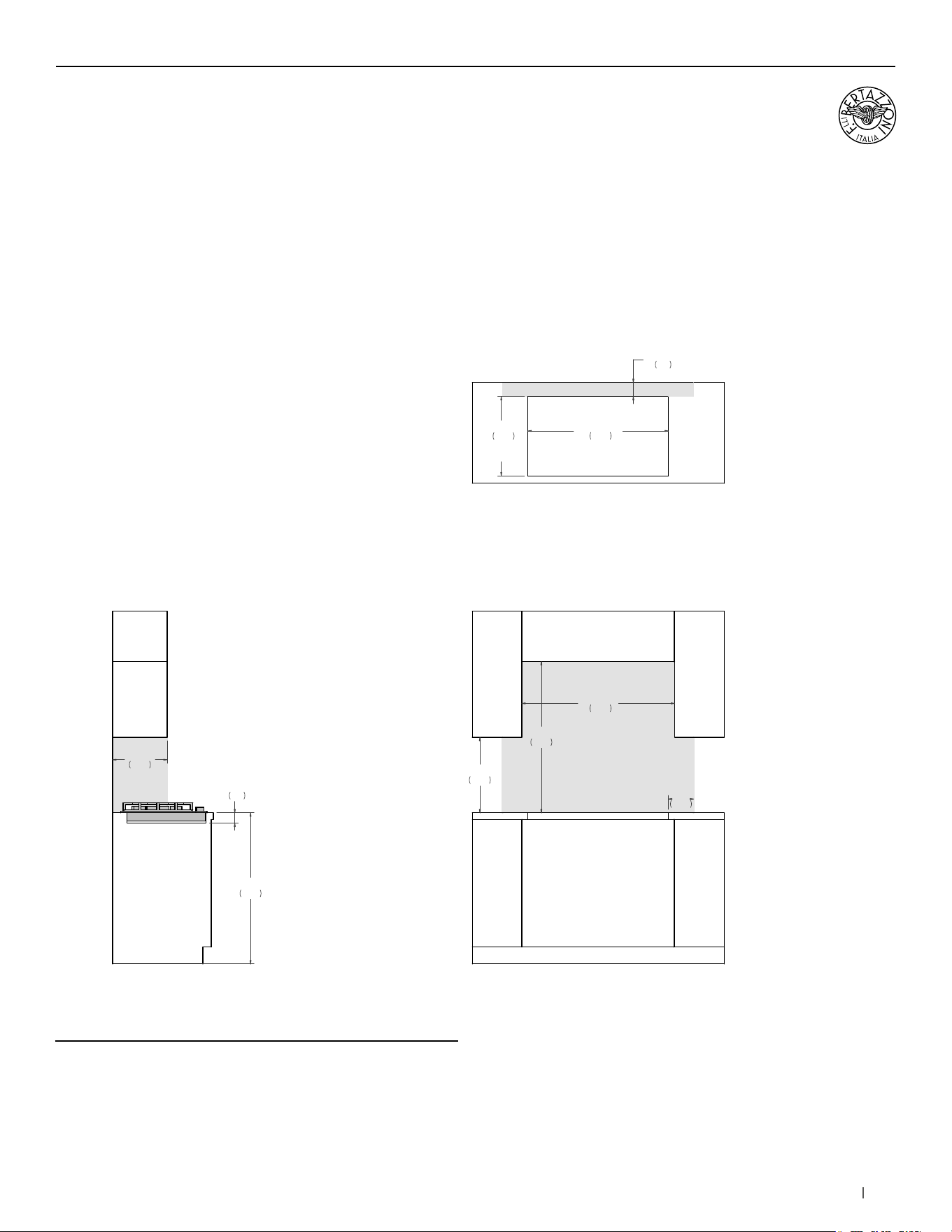
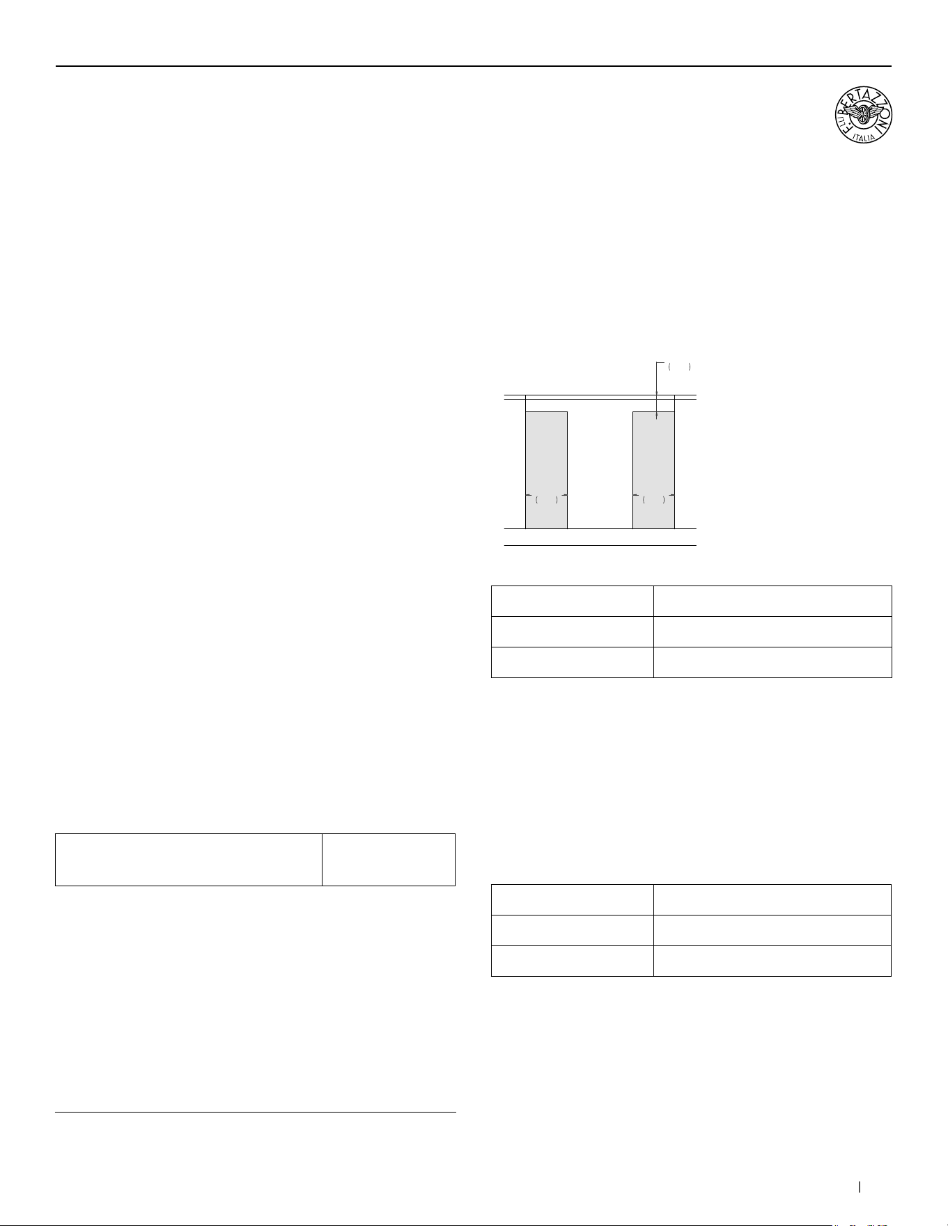
EG
10"
254
10"
254
4"
102
COUNTERTOP
FRONT VIEW
GAS CONNECTION
The gas cooktop can be used with Natural or LP/Propane
gas. An agency-approved, properly-sized manual shutoff
valve should be installed. To connect gas between shut-off
valve and regulator, use agency-approved, properly sized
flexible or rigid pipe. Check all local code requirements.
Since service pressure may fluctuate with local demand, every
gas cooktop must be equipped with the supplied pressure
regulator on the incoming service line for safe and efficient
operation.
Minimum Suggested Load on
Cabinet Base Board
88lb (40kg)
Electrical supply 120 V 60 Hz 1 W
Service 1 Amp
Power Connection NEMA 5-15P plug with 59” cord
Gas Inlet 1/2” NPT
Natural Gas 4” iwc (1.00 kPa)
LPG Gas 10” iwc (2.50 kPa)
For detailed installation specifications consult the installation manual.
GAS RANGETOPS & COOKTOPS
65bertazzoni.com
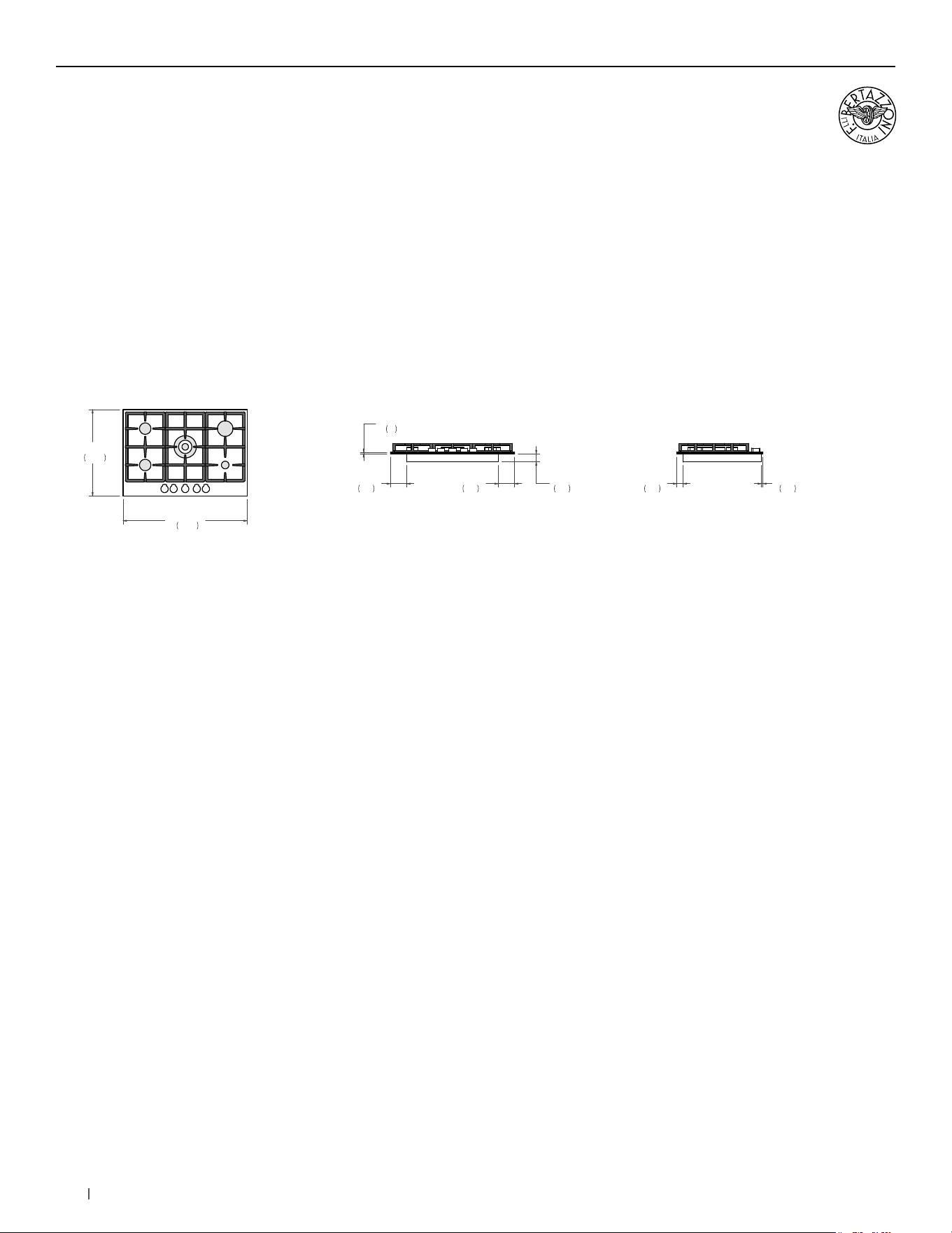
SIDE VIEW
FRONT VIEW
TOP VIEW
Combustible material cannot be installed within shaded area.
36"
915
18"
457
6"
152
2 1/2"
62
36"
914
13"
330
33 1/2"
850
CUT-OUT
WIDTH
18 7/8"
480
CUT-OUT
DEPTH
3 3/8"
85
36 3/8"
925
36” Gas Cooktop Front Control
Installation
Combustible material cannot be installed within shaded area.
GAS RANGETOPS & COOKTOPS
67bertazzoni.com
30” Gas Cooktop Front Control
Installation requirements
INSTALLATION
The gas cooktop can be mounted in a standard installation
sitting on top of the countertop surface.
The clearance between the hob and the kitchen furniture
or other installed appliances must be enough to ensure
sufficient cooling air ventilation.
If a drawer is placed under the work, avoid to put into this
drawer flammable objects or not heat-resistant objects.
For installation with an updraft or downdraft hood as well as
any OTR, refer to the hood/OTR manufacturer’s installation
requirements.
For instructions and clearance of product combinations
please see the Multiple Installation Sections (page 86).
CABINET REQUIREMENT
To prevent possible damage to cabinets and cabinet finishes,
the countertop must be able to withstand temperatures up to
300°F (149°C). Installation of the appliance must be performed
in accordance with the provisions of applicable legislation.
BE SURE that support for this appliance is horizontale before
you perform the installation. The cabinet base must be flat and
capable of supporting the weight of the oven when in use.
ELECTRICAL REQUIREMENT
The installation must comply with all applicable electrical codes.
A properly-grounded horizontally- mounted electrical receptacle
should be installed. Place the electrical supply flush with the
back wall and within the shaded area shown in the illustrations.
Placement within the opening may require additional cabinet
depth.
EG
10"
254
10"
254
4"
102
COUNTERTOP
FRONT VIEW
GAS CONNECTION
The gas cooktop can be used with Natural or LP/Propane
gas. An agency-approved, properly-sized manual shutoff
valve should be installed. To connect gas between shut-off
valve and regulator, use agency-approved, properly sized
flexible or rigid pipe. Check all local code requirements.
Since service pressure may fluctuate with local demand, every
gas cooktop must be equipped with the supplied pressure
regulator on the incoming service line for safe and efficient
operation.
Minimum Suggested Load on
Cabinet Base Board
81lb (37kg)
Electrical supply 120 V 60 Hz 1 W
Service 1 Amp
Power Connection NEMA 5-15P plug with 59” cord
Gas Inlet 1/2” NPT
Natural Gas 4” iwc (1.00 kPa)
LPG Gas 10” iwc (2.50 kPa)
For detailed installation specifications consult the installation manual.
GAS RANGETOPS & COOKTOPS
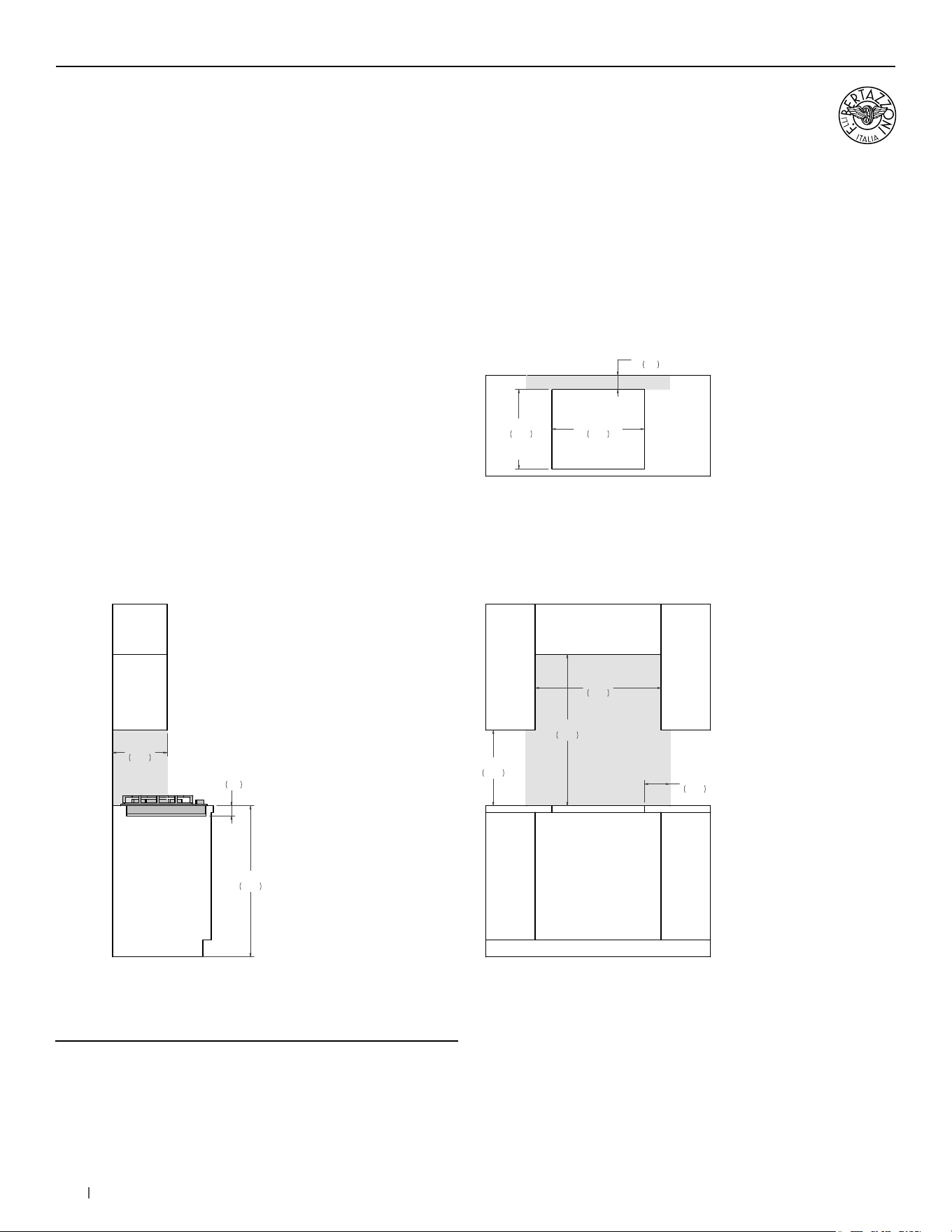
68 bertazzoni.com
SIDE VIEW
FRONT VIEW
TOP VIEW
Combustible material cannot be installed within shaded area.
3 3/8"
85
22"
560
CUT-OUT
WIDTH
18 7/8"
480
CUT-OUT
DEPTH
36"
915
18"
457
36"
914
13"
330
6"
152
2 1/2"
62
30"
762
30” Gas Cooktop Front Control
Installation
Combustible material cannot be installed within shaded area.
GAS RANGETOPS & COOKTOPS
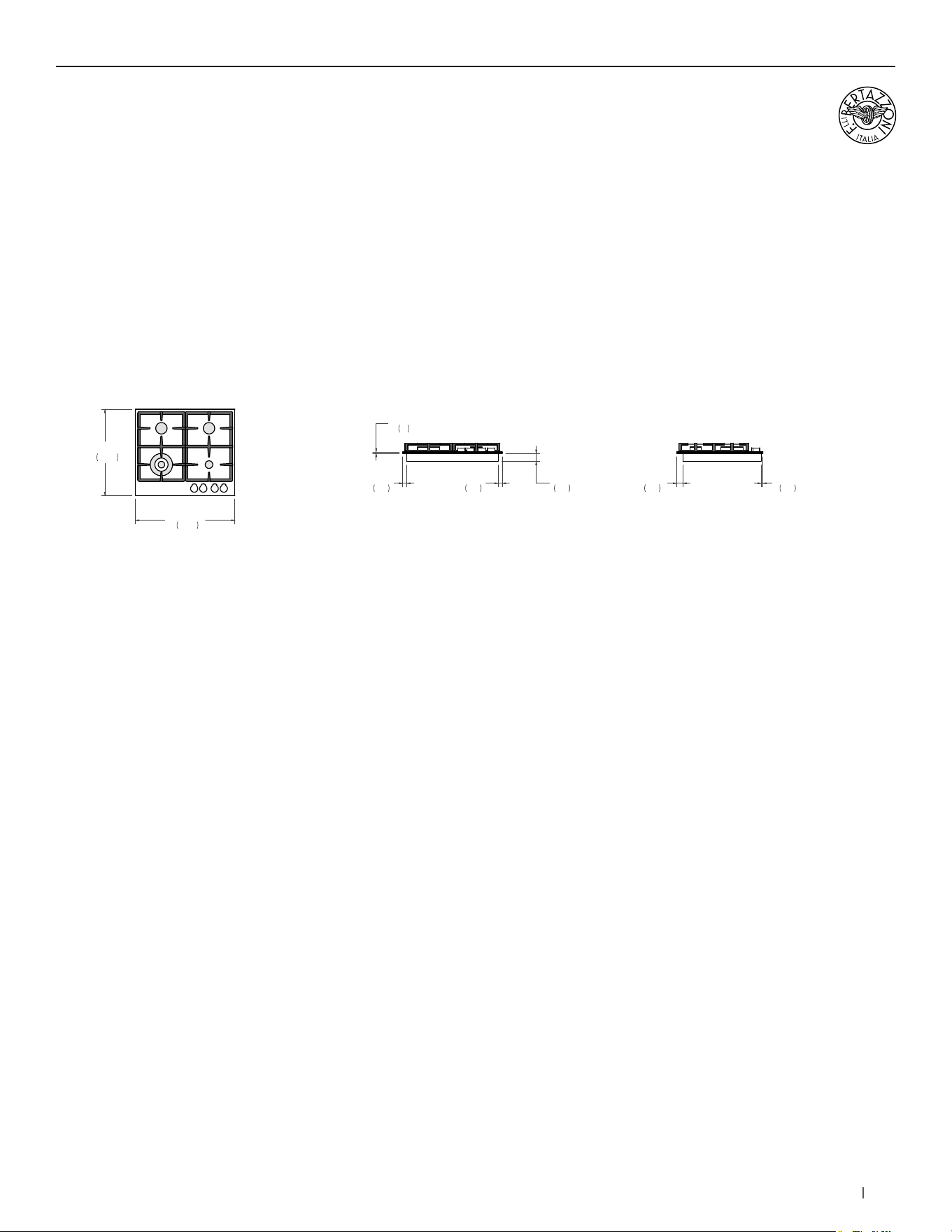
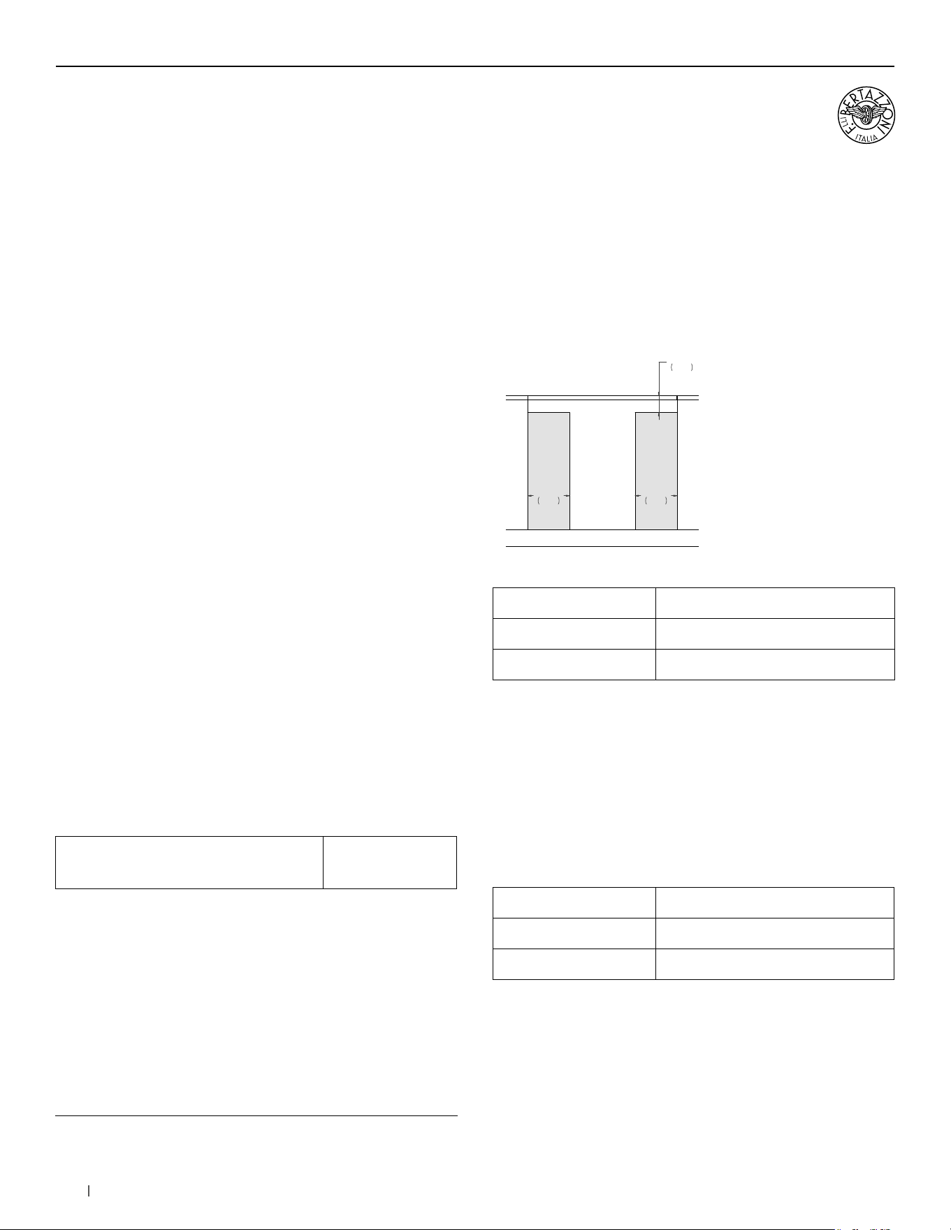
70 bertazzoni.com
24” Gas Cooktop Front Control
Installation requirements
INSTALLATION
The gas cooktop can be mounted in a standard installation
sitting on top of the countertop surface.
The clearance between the hob and the kitchen furniture
or other installed appliances must be enough to ensure
sufficient cooling air ventilation.
If a drawer is placed under the work, avoid to put into this
drawer flammable objects or not heat-resistant objects.
For installation with an updraft or downdraft hood as well as
any OTR, refer to the hood/OTR manufacturer’s installation
requirements.
For instructions and clearance of product combinations
please see the Multiple Installation Sections (page 86).
CABINET REQUIREMENT
To prevent possible damage to cabinets and cabinet finishes,
the countertop must be able to withstand temperatures up to
300°F (149°C). Installation of the appliance must be performed
in accordance with the provisions of applicable legislation.
BE SURE that support for this appliance is horizontale before
you perform the installation. The cabinet base must be flat and
capable of supporting the weight of the oven when in use.
ELECTRICAL REQUIREMENT
The installation must comply with all applicable electrical codes.
A properly-grounded horizontally- mounted electrical receptacle
should be installed. Place the electrical supply flush with the
back wall and within the shaded area shown in the illustrations.
Placement within the opening may require additional cabinet
depth.
EG
10"
254
10"
254
4"
102
COUNTERTOP
FRONT VIEW
GAS CONNECTION
The gas cooktop can be used with Natural or LP/Propane
gas. An agency-approved, properly-sized manual shutoff
valve should be installed. To connect gas between shut-off
valve and regulator, use agency-approved, properly sized
flexible or rigid pipe. Check all local code requirements.
Since service pressure may fluctuate with local demand, every
gas cooktop must be equipped with the supplied pressure
regulator on the incoming service line for safe and efficient
operation.
Minimum Suggested Load on
Cabinet Base Board
84lb (38kg)
Electrical supply 120 V 60 Hz 1 W
Service 1 Amp
Power Connection NEMA 5-15P plug with 59” cord
Gas Inlet 1/2” NPT
Natural Gas 4” iwc (1.00 kPa)
LPG Gas 10” iwc (2.50 kPa)
For detailed installation specifications consult the installation manual.
GAS RANGETOPS & COOKTOPS
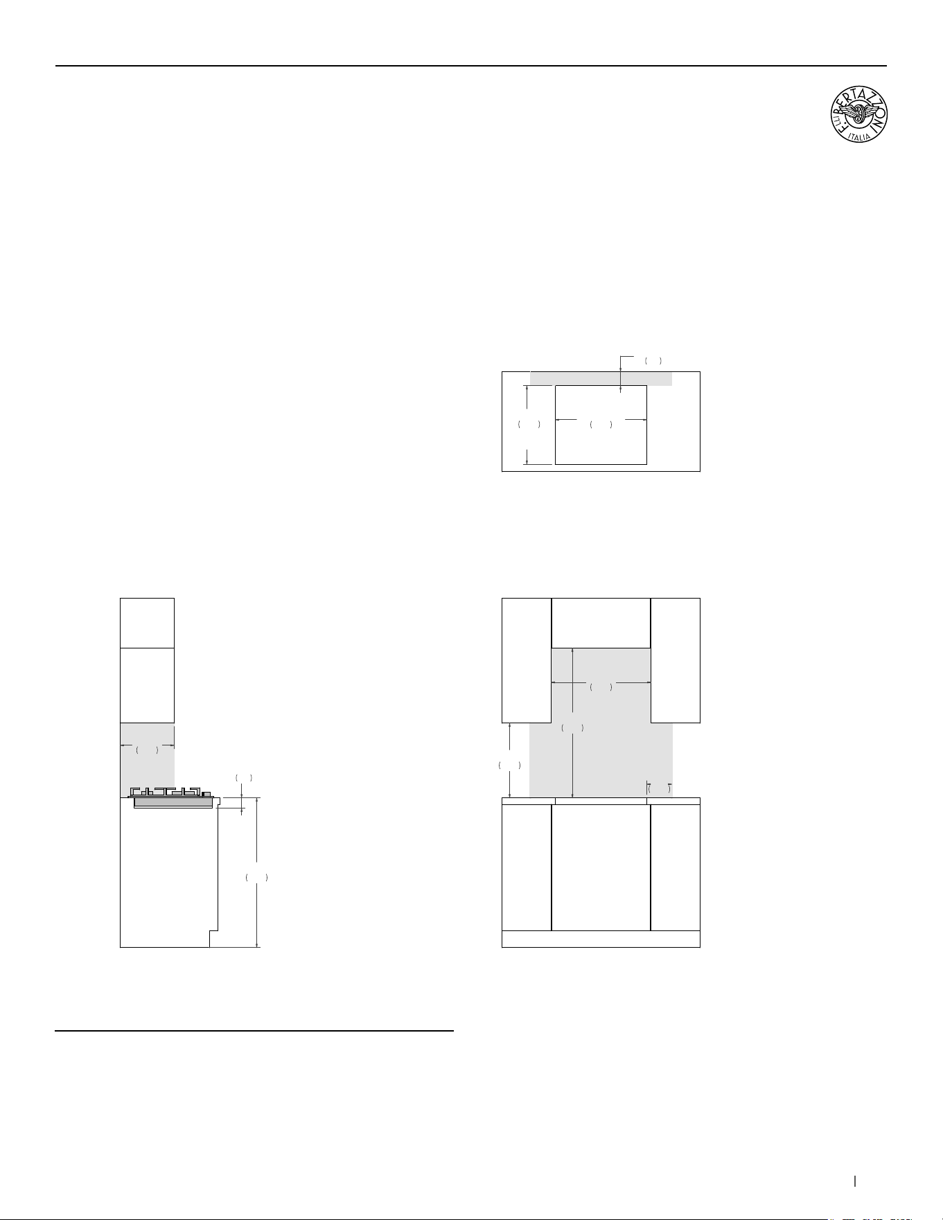
71bertazzoni.com
SIDE VIEW
FRONT VIEW
TOP VIEW
Combustible material cannot be installed within shaded area.
3 3/8"
85
22"
560
CUT-OUT
WIDTH
18 7/8"
480
CUT-OUT
DEPTH
36"
915
18"
457
6"
152
2 1/2"
62
36"
914
13"
330
24"
610
24” Gas Cooktop Front Control
Installation
Combustible material cannot be installed within shaded area.
GAS RANGETOPS & COOKTOPS
72 bertazzoni.com
36” Induction Cooktop
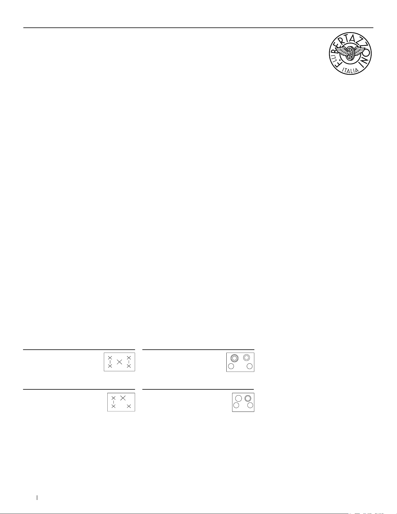
INDUCTION & ELECTRIC COOKTOPS
Electric induction and electric CERAN
®
cooktops
add an elegant and clean look to your kitchen, with
the added advantage of faster induction heating.
On the induction models, precision touch controls
and digital timed cooking functions let you
automatically manage the entire cooking process;
sensor controlled cookware detection means all the
energy is used to heat the exact space instantly from
the moment you turn them on. They make preparing
a wide variety of dishes effortless, with 5 or
4 zones for cooking. And when you’ve finished
cooking, cleaning up is equally straightforward.
30” Induction Cooktop
30” Electric Ceramic
Cooktop
24” Electric Ceramic
Cooktop
Induction CERAN
®

75bertazzoni.com
36” Induction Cooktop
Installation requirement
INSTALLATION
The induction cooktop can be mounted in a standard
installation sitting on top of the countertop surface.
The clearance between the hob and the kitchen furniture or
other installed appliances must be enough to ensure sufficient
cooling air ventilation. For installation with an updraft or
downdraft hood as well as any OTR, refer to thr hood/OTR
manufacturer’s installation requirements.If a drawer is placed
under the worktop, avoid to put into this drawer flammable
objects or not heat-resistant objects.
For instructions and clearance of product combinations
please see the Multiple Installation Sections (page 86).
CABINET REQUIREMENT
To prevent possible damage to cabinets and cabinet finishes,
the countertop must be able to withstand temperatures up to
300°F (149°C).
Installation of the appliance must be performed in accordance
with the provisions of applicable legislation.
BE SURE that support for this appliance is horizontale before
you perform the installation.
The cabinet base must be flat and capable of supporting the
weight of the oven when in use.
ELECTRICAL REQUIREMENT
A properly-grounded horizontally- mounted electrical receptacle
should be installed.
The installation must comply with all applicable electrical codes.
Place the electrical supply flush with the back wall and within
the shaded area shown in the illustrations. Placement within the
opening may require additional cabinet depth.
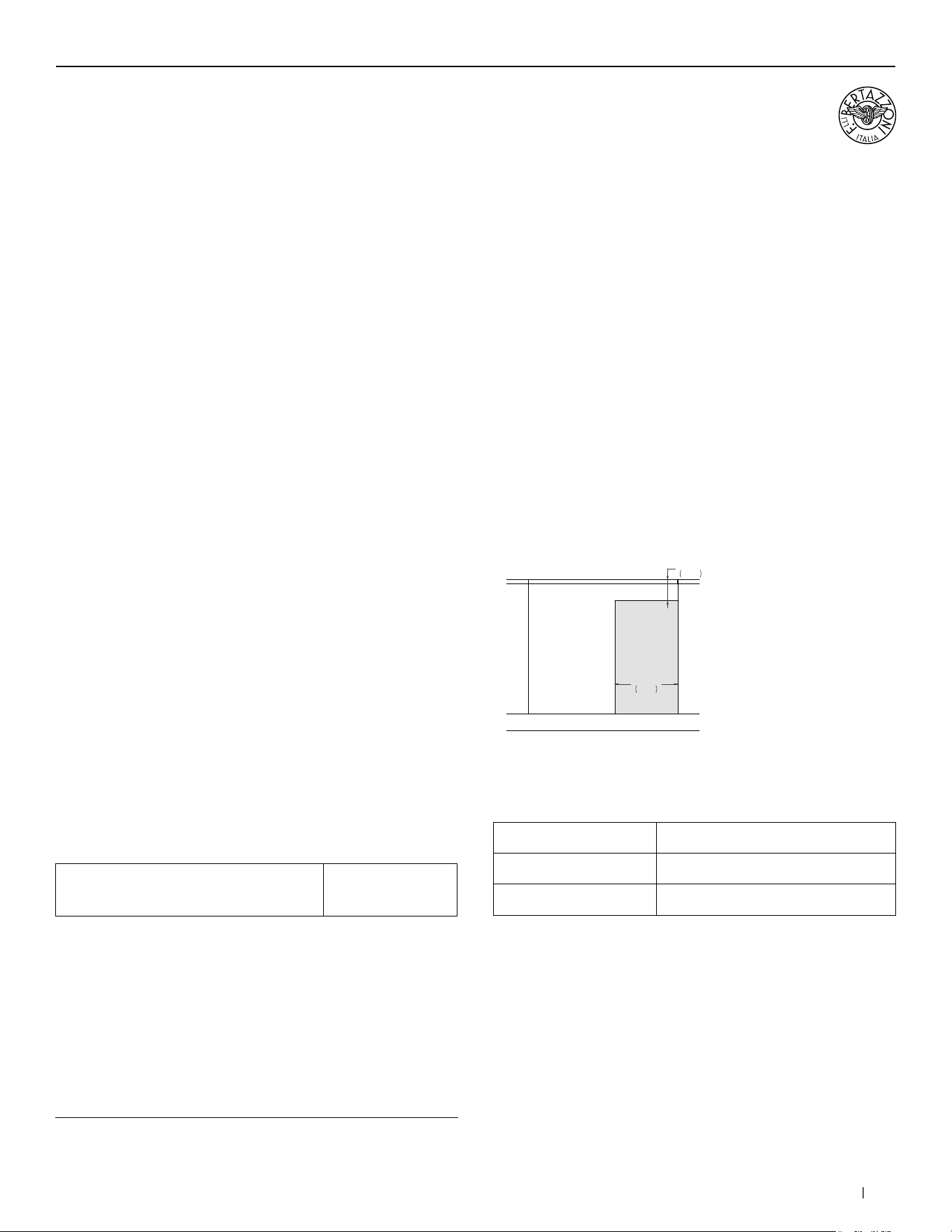
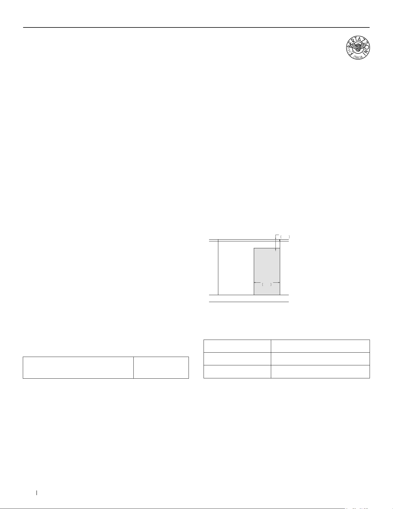
E
15"
381
5"
127
COUNTERTOP
FRONT VIEW
A separate circuit and a circuit breaker servicing only this
appliance is reccomended
Minimum Suggested Load on
Cabinet Base Board
110 lb (50kg)
Electrical supply 208/240 V 60 Hz 11100 W
Service 55 Amp dedicated circuit
Power Connection METAL CONDUIT - 54” cord
For detailed installation specifications consult the installation manual.
INDUCTION & ELECTRIC COOKTOPS
76 bertazzoni.com
36” Induction Cooktop
Installation
Combustible material cannot be installed within shaded area.
INDUCTION & ELECTRIC COOKTOPS
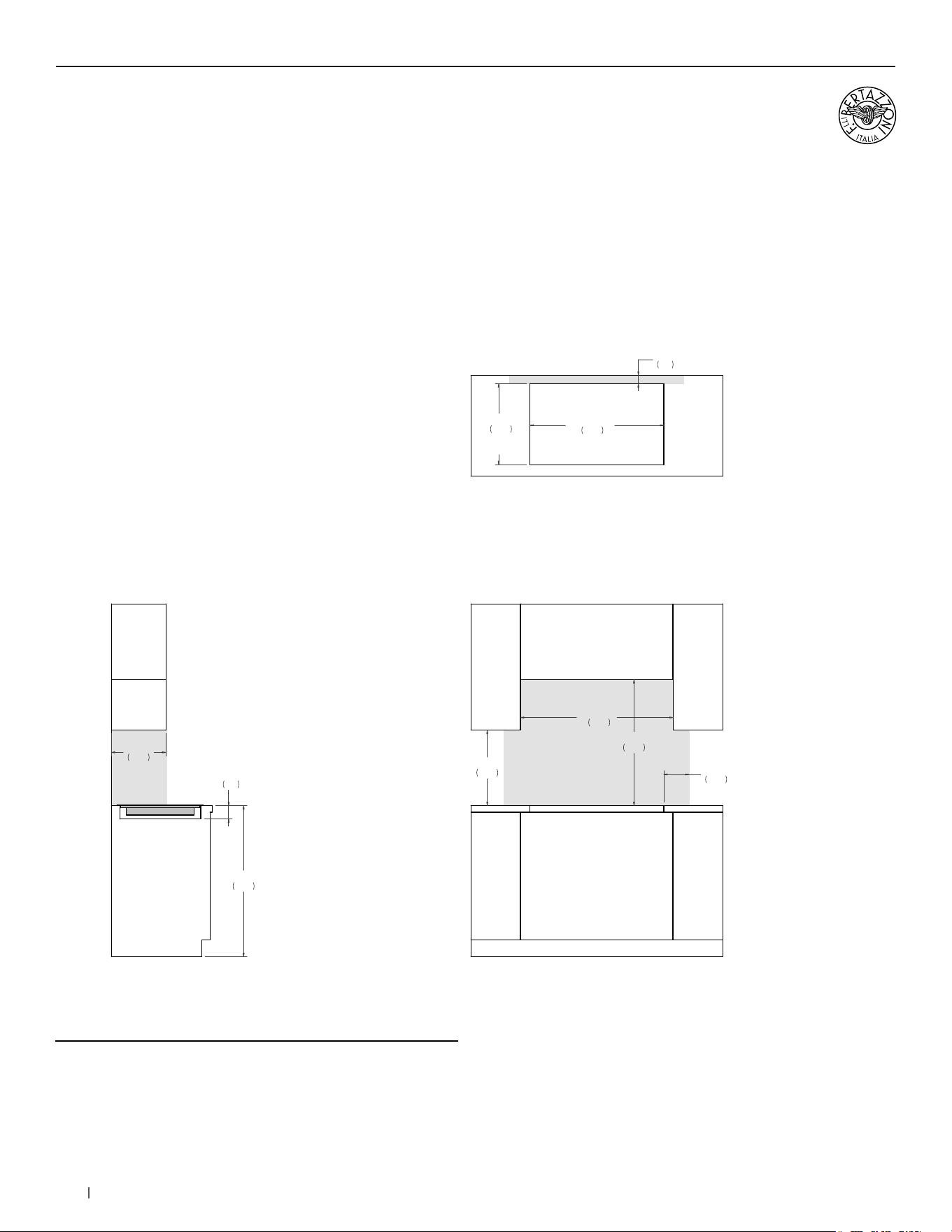
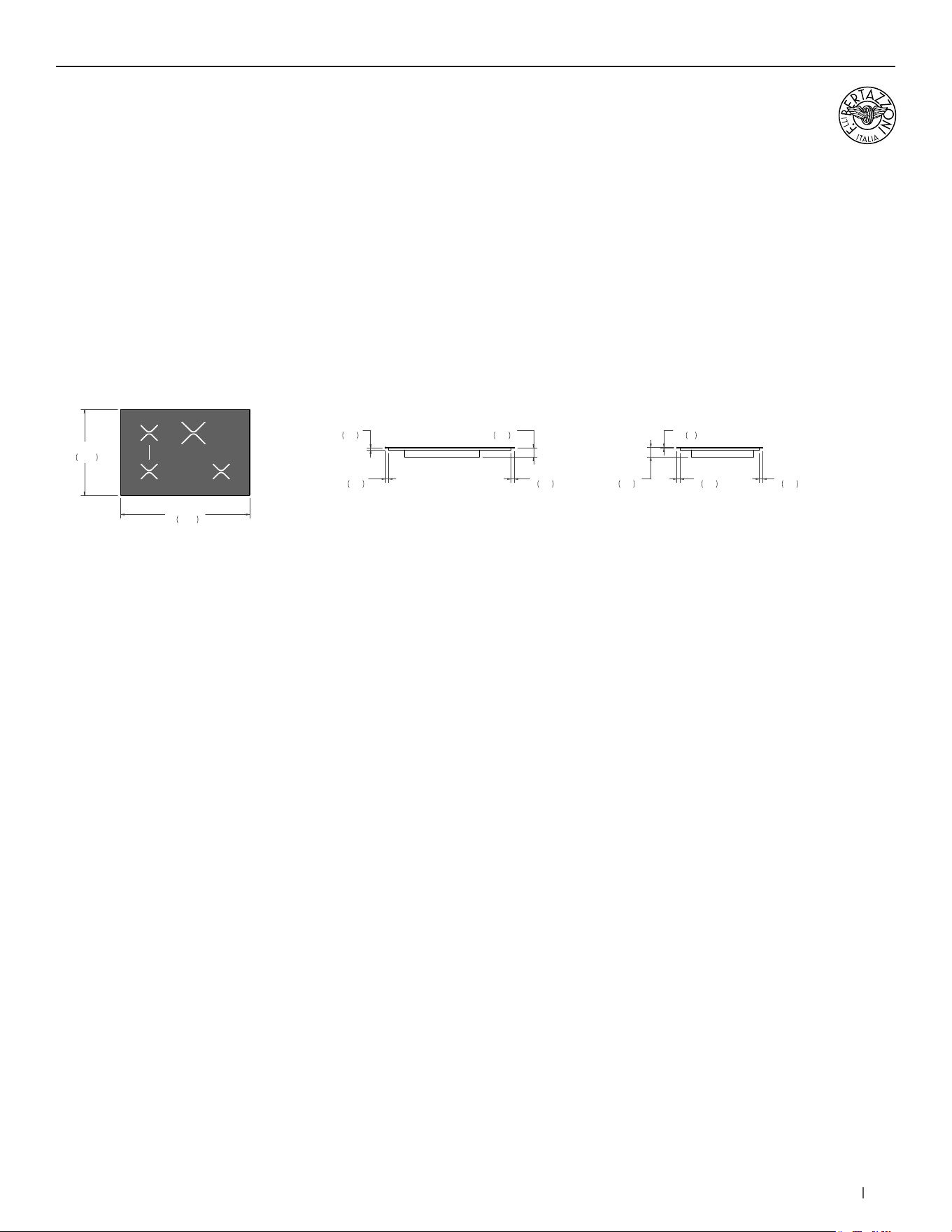
SIDE VIEW
FRONT VIEW
TOP VIEW
Combustible material cannot be installed within shaded area.
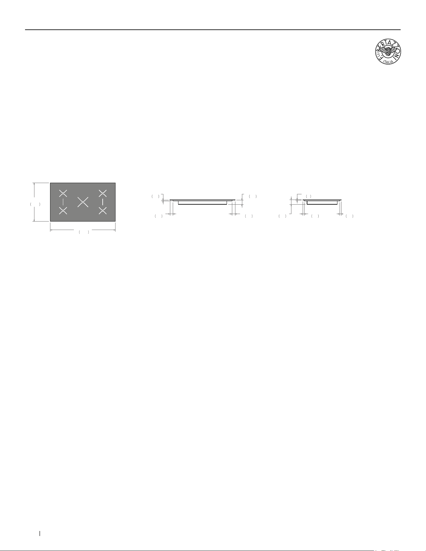
31 7/8"
810
CUT-OUT
WIDTH
19 1/4"
490
CUT-OUT
DEPTH
18"
457
30"
763
2"
51
36"
914
13"
330
36 3/8"
925
6"
152
3 1/8"
80
78 bertazzoni.com
30” Induction Cooktop
Installation requirements
INDUCTION & ELECTRIC COOKTOPS
INSTALLATION
The induction cooktop can be mounted in a standard
installation sitting on top of the countertop surface.
The clearance between the hob and the kitchen furniture or
other installed appliances must be enough to ensure sufficient
cooling air ventilation. For installation with an updraft or
downdraft hood as well as any OTR, refer to thr hood/OTR
manufacturer’s installation requirements.If a drawer is placed
under the worktop, avoid to put into this drawer flammable
objects or not heat-resistant objects.
For instructions and clearance of product combinations
please see the Multiple Installation Sections (page 86).
CABINET REQUIREMENT
To prevent possible damage to cabinets and cabinet finishes,
the countertop must be able to withstand temperatures up to
300°F (149°C).
Installation of the appliance must be performed in accordance
with the provisions of applicable legislation.
BE SURE that support for this appliance is horizontale before
you perform the installation.
The cabinet base must be flat and capable of supporting the
weight of the oven when in use.
ELECTRICAL REQUIREMENT
A properly-grounded horizontally- mounted electrical receptacle
should be installed.
The installation must comply with all applicable electrical codes.
Place the electrical supply flush with the back wall and within
the shaded area shown in the illustrations. Placement within the
opening may require additional cabinet depth.
E
15"
381
5"
127
COUNTERTOP
FRONT VIEW
A separate circuit and a circuit breaker servicing only this
appliance is reccomended
Minimum Suggested Load on
Cabinet Base Board
88lb (40kg)
Electrical supply 208/240 V 60 Hz 7400 W
Service 40 Amp dedicated circuit
Power Connection METAL CONDUIT - 54” cord
79bertazzoni.com
30” Induction Cooktop
Installation
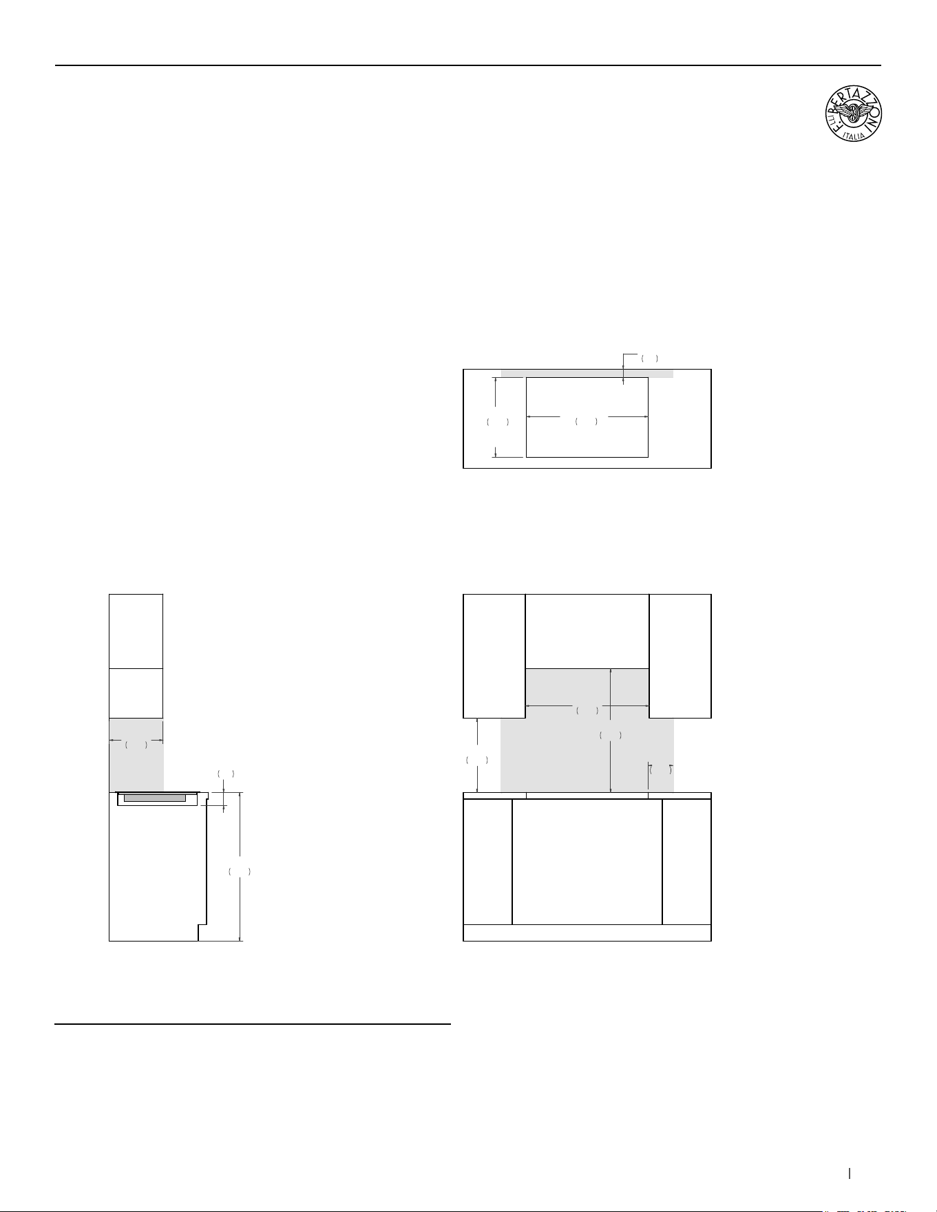
SIDE VIEW
FRONT VIEW
TOP VIEW
Combustible material cannot be installed within shaded area.
29 1/2"
750
CUT-OUT
WIDTH
19 1/4"
490
CUT-OUT
DEPTH
18"
457
30"
763
2"
51
3 1/8"
80
36"
914
13"
330
30"
762
6"
152
Combustible material cannot be installed within shaded area.
INDUCTION & ELECTRIC COOKTOPS
81bertazzoni.com
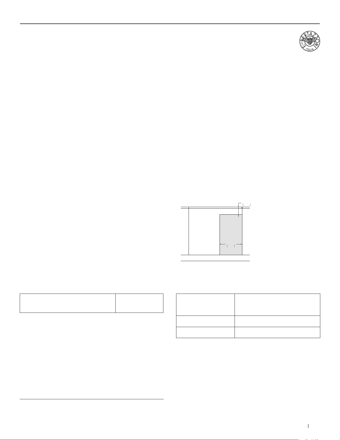
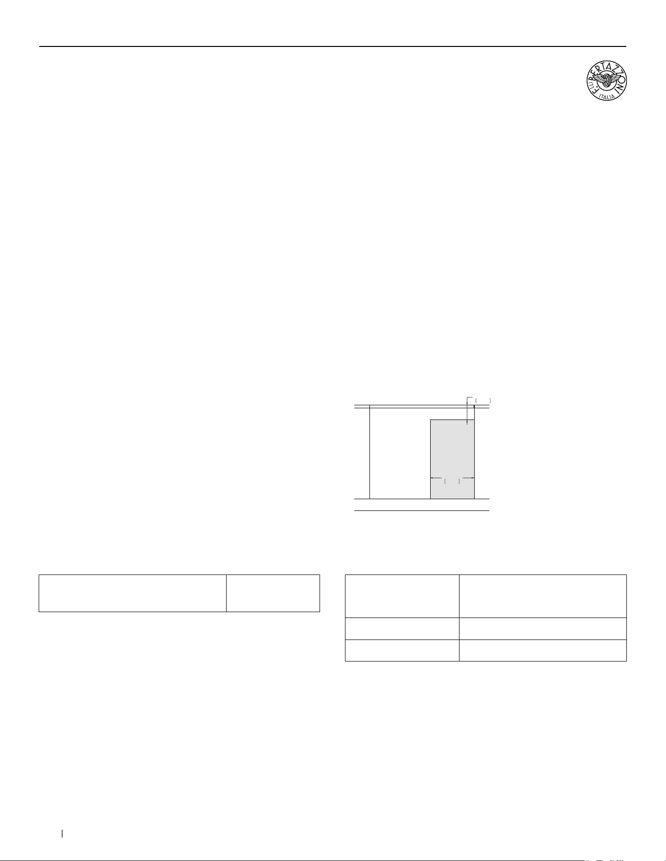
INSTALLATION
The electric cooktop can be mounted in a standard installation
sitting on top of the countertop surface.
The clearance between the hob and the kitchen furniture
or other installed appliances must be enough to ensure
sufficient cooling air ventilation.
If a drawer is placed under the worktop, avoid to put into this
drawer flammable objects or not heat-resistant objects.
For instructions and clearance of product combinations
please see the Multiple Installation Sections.
CABINET REQUIREMENT
To prevent possible damage to cabinets and cabinet finishes,
the countertop must be able to withstand temperatures up to
300°F (149°C).
Installation of the appliance must be performed in accordance
with the provisions of applicable legislation.
BE SURE that support for this appliance is horizontale before
you perform the installation.
The cabinet base must be flat and capable of supporting the
weight of the oven when in use.
ELECTRICAL REQUIREMENT
A properly-grounded horizontally- mounted electrical receptacle
should be installed.
The installation must comply with all applicable electrical codes.
Place the electrical supply flush with the back wall and within
the shaded area shown in the illustrations. Placement within the
opening may require additional cabinet depth.
E
15"
381
5"
127
COUNTERTOP
FRONT VIEW
A separate circuit and a circuit breaker servicing only this
appliance is reccomended
30” Electric Ceramic Cooktop
Installation requirements
For detailed installation specifications consult the installation manual.
INDUCTION & ELECTRIC COOKTOPS
Minimum Suggested Load on
Cabinet Base Board
88lb (40kg))
Electrical supply
240 V
208 V 31 A
60 Hz
60 Hz
6400 W
4800 W
Service 35 Amp dedicated circuit
Power Connection METAL CONDUIT - 54” cord
82 bertazzoni.com
30” Electric Ceramic Cooktop
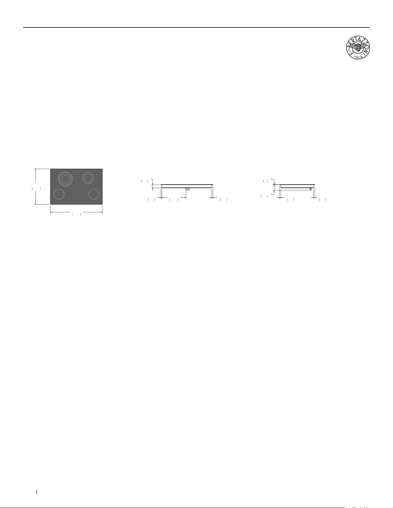
Installation
INDUCTION & ELECTRIC COOKTOPS
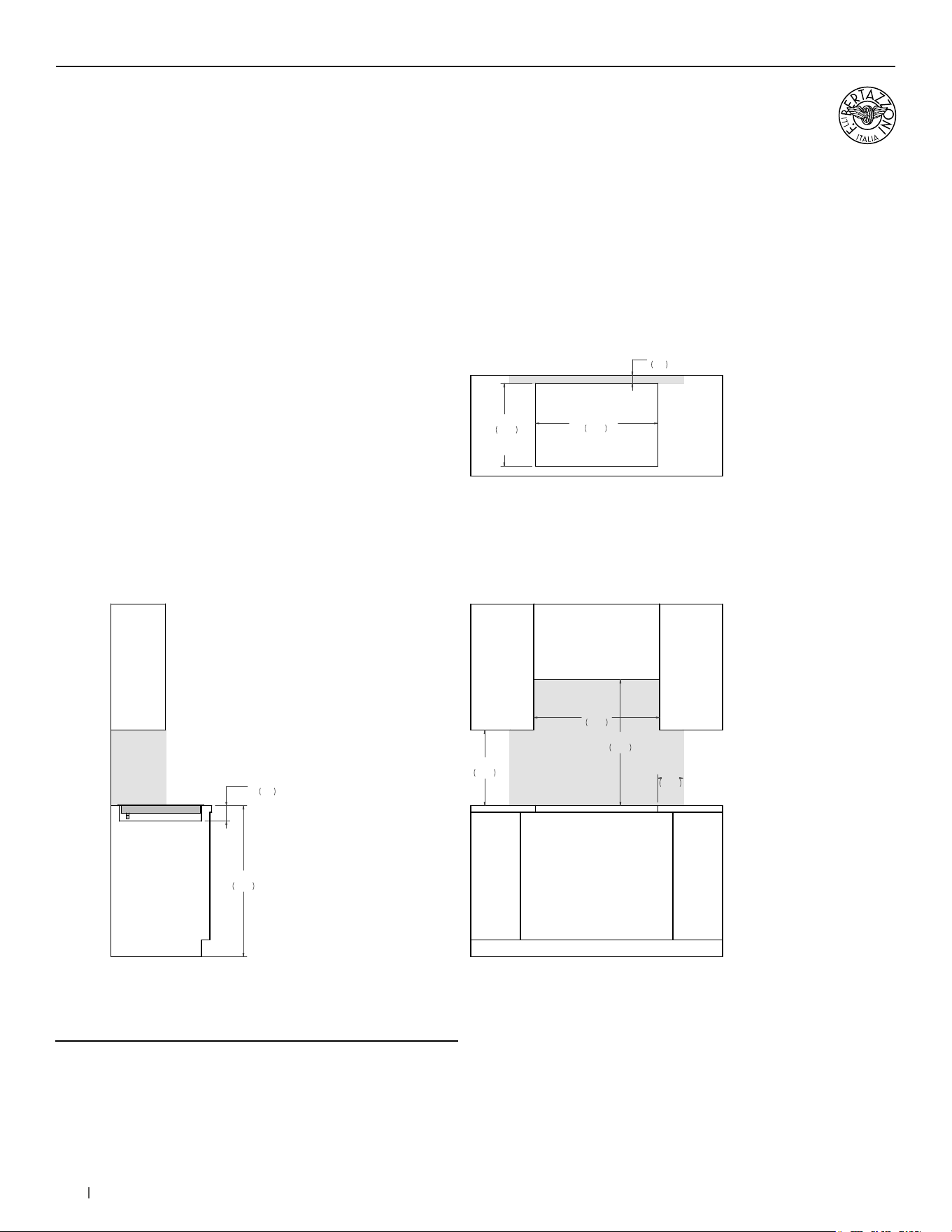
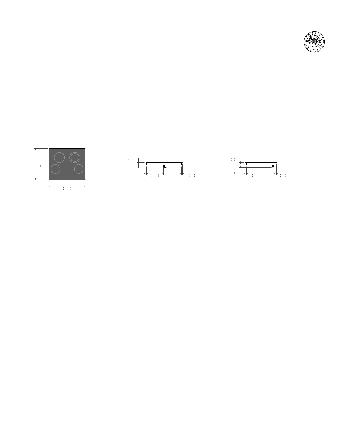
SIDE VIEW
FRONT VIEW
TOP VIEW
Combustible material cannot be installed within shaded area.
29 1/8"
740
CUT-OUT
WIDTH
19 5/8"
500
CUT-OUT
DEPTH
18"
457
30"
763
2"
50
36"
914
13"
330
30"
762
6"
152
3 3/4"
95
Combustible material cannot be installed within shaded area.
84 bertazzoni.com
24” Electric Ceramic Cooktop
Installation requirements
INDUCTION & ELECTRIC COOKTOPS
INSTALLATION
The electric cooktop can be mounted in a standard installation
sitting on top of the countertop surface.
The clearance between the hob and the kitchen furniture
or other installed appliances must be enough to ensure
sufficient cooling air ventilation.
If a drawer is placed under the worktop, avoid to put into this
drawer flammable objects or not heat-resistant objects.
For instructions and clearance of product combinations
please see the Multiple Installation Sections.
CABINET REQUIREMENT
To prevent possible damage to cabinets and cabinet finishes,
the countertop must be able to withstand temperatures up to
300°F (149°C).
Installation of the appliance must be performed in accordance
with the provisions of applicable legislation.
BE SURE that support for this appliance is horizontale before
you perform the installation.
The cabinet base must be flat and capable of supporting the
weight of the oven when in use.
ELECTRICAL REQUIREMENT
A properly-grounded horizontally- mounted electrical receptacle
should be installed.
The installation must comply with all applicable electrical codes.
Place the electrical supply flush with the back wall and within
the shaded area shown in the illustrations. Placement within the
opening may require additional cabinet depth.
E
15"
381
5"
127
COUNTERTOP
FRONT VIEW
A separate circuit and a circuit breaker servicing only this
appliance is reccomended
Minimum Suggested Load on
Cabinet Base Board
84lb (38kg)
Electrical supply
240 V
208 V 28 A
60 Hz
60 Hz
5900 W
4200 W
Service 30 Amp dedicated circuit
Power Connection METAL CONDUIT - 54” cord
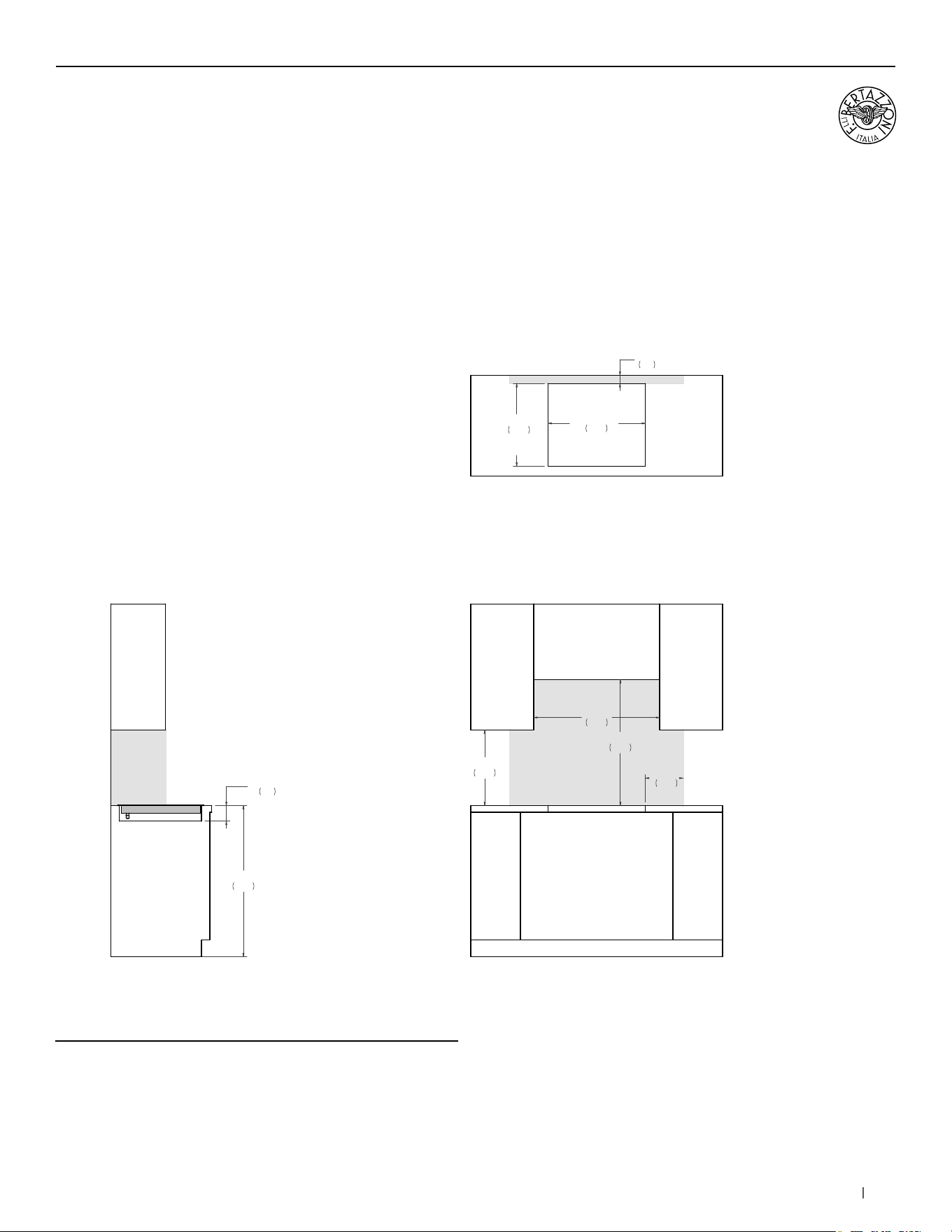
85bertazzoni.com
24” Electric Ceramic Cooktop
Installation
INDUCTION & ELECTRIC COOKTOPS
SIDE VIEW
FRONT VIEW
TOP VIEW
Combustible material cannot be installed within shaded area.
23 1/4"
590
CUT-OUT
WIDTH
19 5/8"
500
CUT-OUT
DEPTH
18"
457
30"
763
2"
50
36"
914
13"
330
30"
762
8 7/8"
227
3 3/4"
95
Combustible material cannot be installed within shaded area.


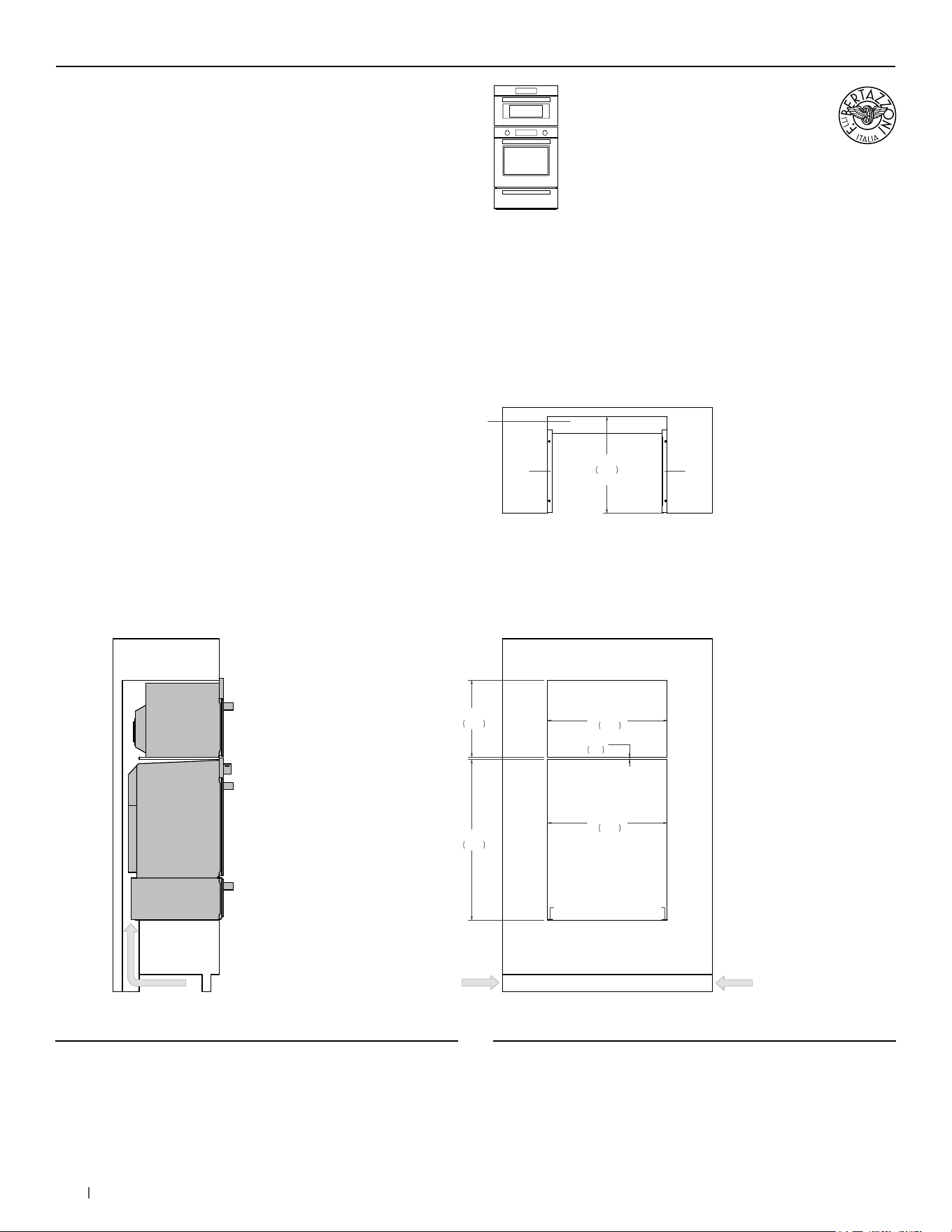
88 bertazzoni.com
30” Specialty Oven +
30” Convection Single Oven +
30” Warming Drawer
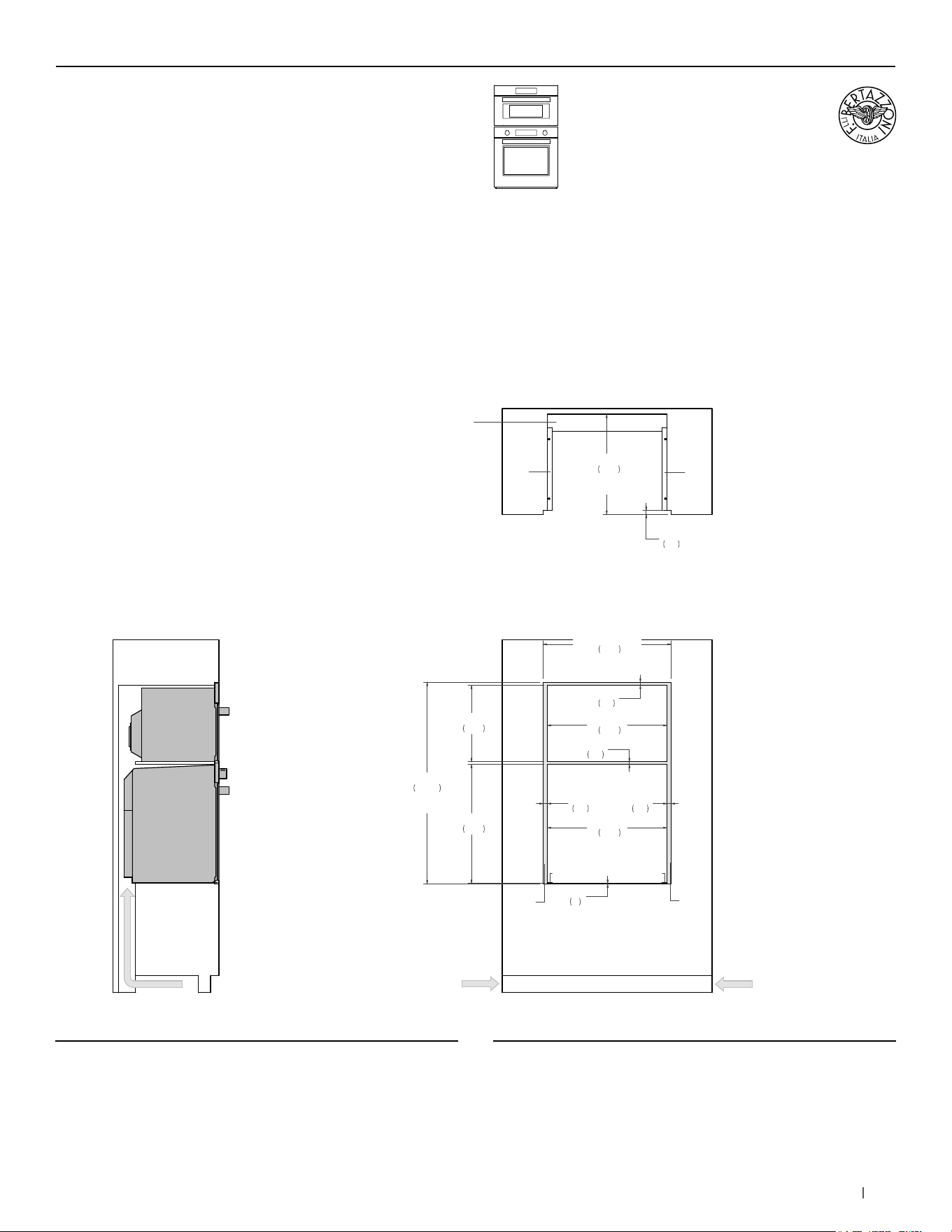
Proud installation
(a) Spacers - Included with appliance
SIDE VIEW
FRONT VIEW
TOP VIEW
(a) Spacers – Included with appliance
AIR INTAKE
28 1/2"
724
28 1/2"
724
18 1/4"
464
38 1/4"
971
5/8"
16
23"
585
DEPTH
a
a
a
a
4" x 28 1/2"
(102 x 724)
AIR INTAKE
AIR INTAKE
4" x 15"
(102 x 380)
AIR INTAKE
4" x 15"
(102 x 380)
MULTIPLE INSTALLATIONS - 30” OVENS WALL CONFIGURATIONS
PROF30SOEX
PROF30CSEX
MAST30SOEX
MAST30CSEX
PROF30FSEXT
PROF30FSEXV
MAST30FSEXT
MAST30FSEXV
PROF30WDEX
MAST30WDEX
For electrical and gas supply please see single installation
requirements. Placement within the opening may require
additional cabinet depth.
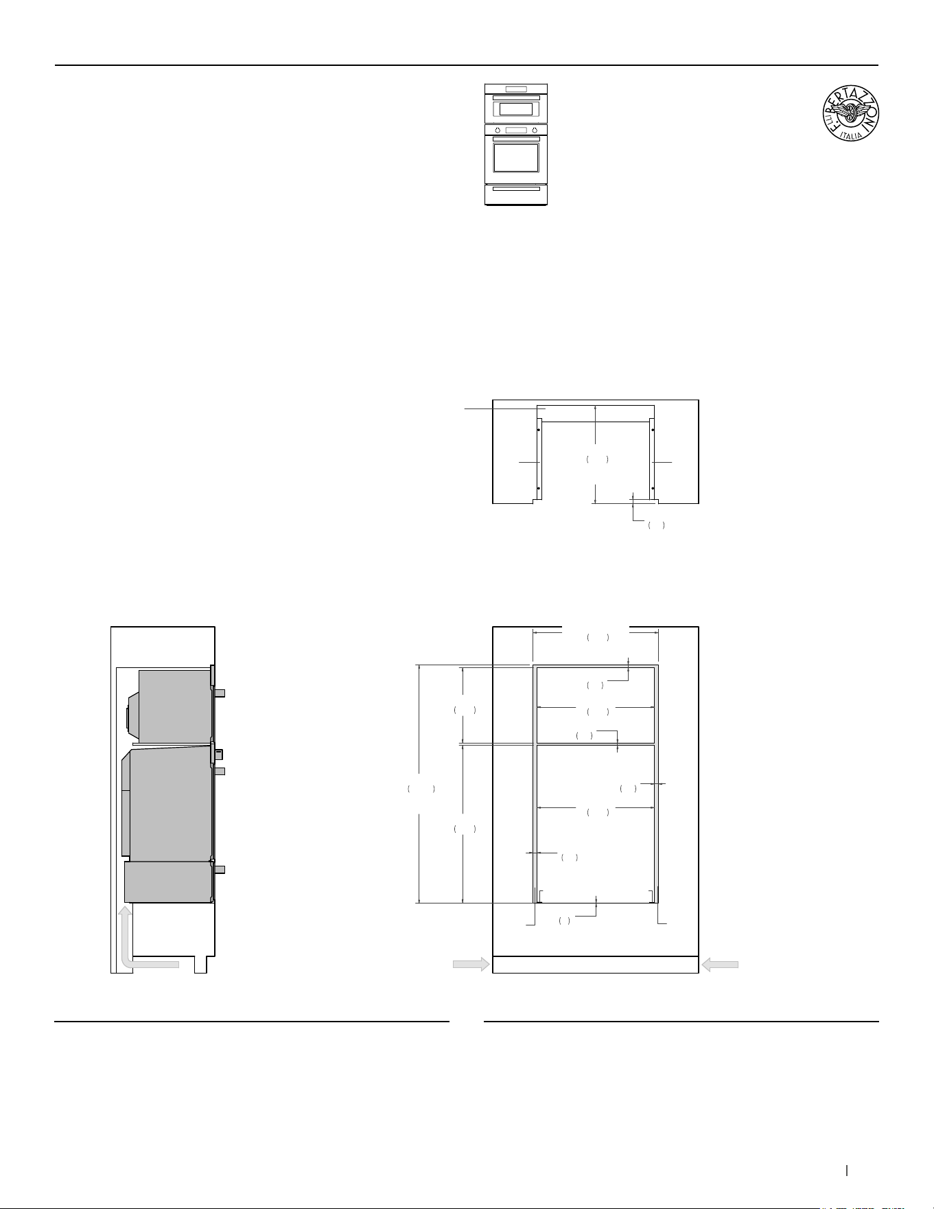
89bertazzoni.com
30” Specialty Oven +
30” Convection Single Oven +
30” Warming Drawer
Flush installation
SIDE VIEW
FRONT VIEW
TOP VIEW
(a) Spacers – Included with appliance
(b) Visible Area – Match finish to outside cabinet panels
AIR INTAKE
28 1/2"
724
28 1/2"
724
30 1/2"
774
FLUSH INSET
WIDTH
57 7/8"
1471
FLUSH INSET
HEIGHT
18 1/4"
464
38 1/4"
971
5/8"
16
1"
25
1"
25
3/4"
18
1/8"
3
23 7/8"
606
FLUSH INSET
DEPTH
a
b
b
(1)
(1)
a
4" x 28 1/2"
(102 x 724)
AIR INTAKE
AIR INTAKE
4" x 15"
(102 x 380)
AIR INTAKE
4" x 15"
(102 x 380)
1"
25
(a) Spacers - Included with appliance
(b) Visible Area - Match finish to outside cabinet panels
MULTIPLE INSTALLATIONS - 30” OVENS WALL CONFIGURATIONS
PROF30SOEX
PROF30CSEX
MAST30SOEX
MAST30CSEX
PROF30FSEXT
PROF30FSEXV
MAST30FSEXT
MAST30FSEXV
PROF30WDEX
MAST30WDEX
For electrical and gas supply please see single installation
requirements. Placement within the opening may require
additional cabinet depth.
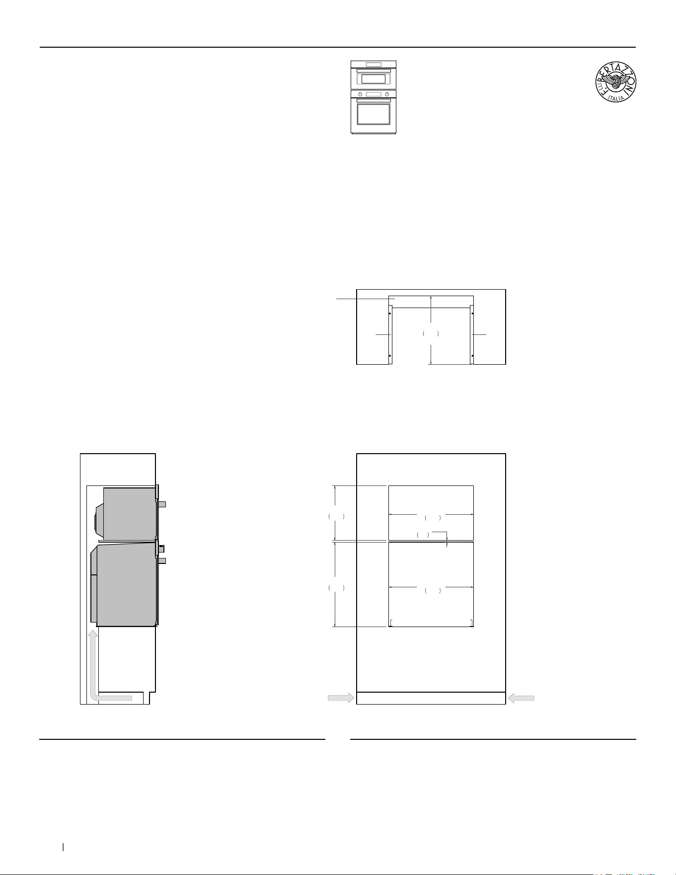
90 bertazzoni.com
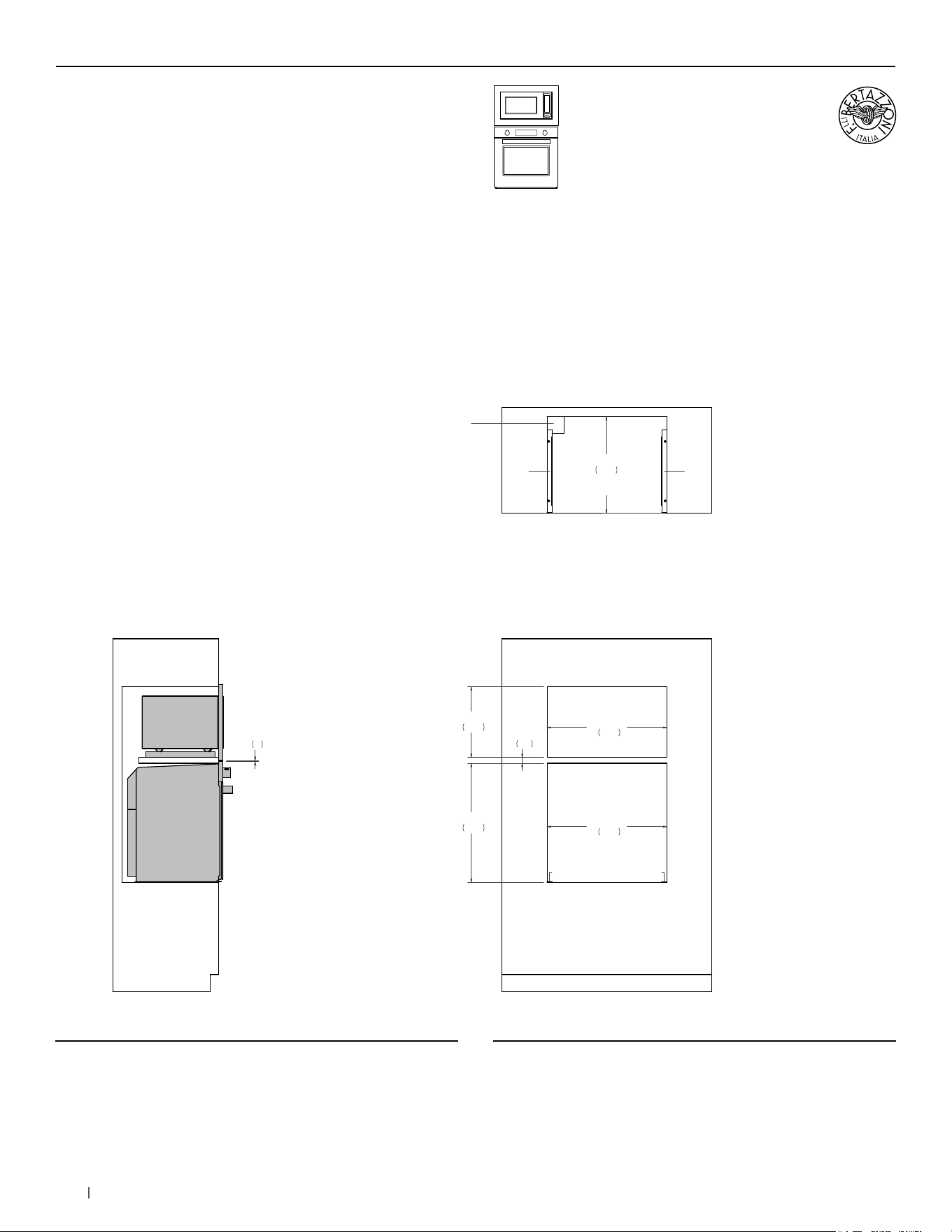
30” Specialty Oven +
30” Convection Single Oven
Proud installation
SIDE VIEW
FRONT VIEW
TOP VIEW
(a) Spacers – Included with appliance
AIR INTAKE
28 1/2"
724
28 1/2"
724
18 1/4"
464
28 3/8"
720
5/8"
16
23"
585
DEPTH
a
a
a a
4" x 28 1/2"
(102 x 724)
AIR INTAKE
AIR INTAKE
4" x 15"
(102 x 380)
AIR INTAKE
4" x 15"
(102 x 380)
(a) Spacers - Included with appliance
MULTIPLE INSTALLATIONS - 30” OVENS WALL CONFIGURATIONS
PROF30SOEX
PROF30CSEX
MAST30SOEX
MAST30CSEX
PROF30FSEXT
PROF30FSEXV
MAST30FSEXT
MAST30FSEXV
For electrical and gas supply please see single installation
requirements. Placement within the opening may require
additional cabinet depth.
91bertazzoni.com
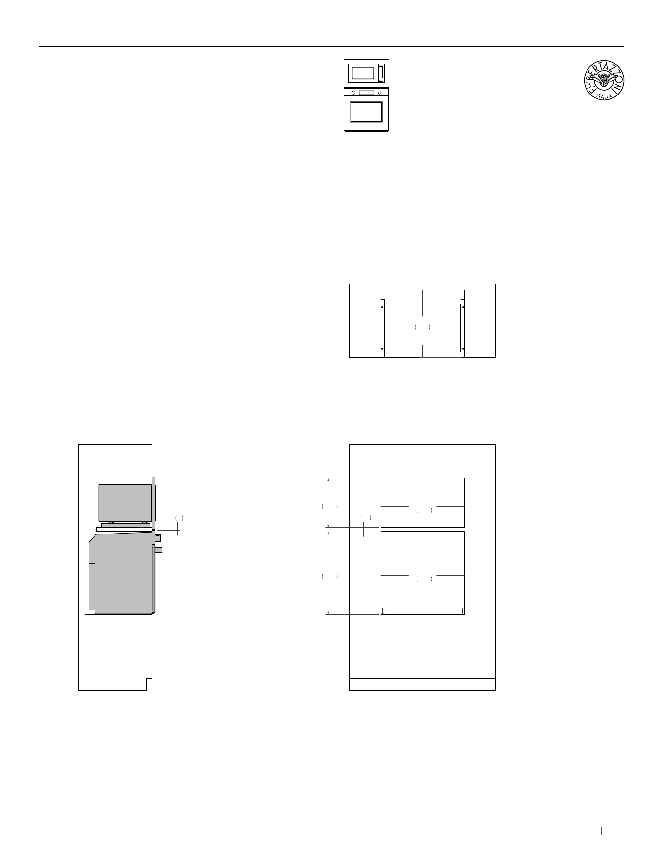
30” Specialty Oven +
30” Convection Single Oven
Flush installation
SIDE VIEW
FRONT VIEW
TOP VIEW
(a) Spacers – Included with appliance
(b) Visible Area – Match finish to outside cabinet panels
AIR INTAKE
28 1/2"
724
28 1/2"
724
30 1/2"
774
FLUSH INSET
WIDTH
48"
1220
FLUSH INSET
HEIGHT
18 1/4"
464
28 3/8"
720
5/8"
16
1"
25
1"
25
3/4"
18
1/8"
3
23 7/8"
606
FLUSH INSET
DEPTH
a
b
b
a
a a
AIR INTAKE
4" x 15"
(102 x 380)
AIR INTAKE
4" x 15"
(102 x 380)
4" x 28 1/2"
(102 x 724)
AIR INTAKE
1"
25
(a) Spacers - Included with appliance
(b) Visible Area - Match finish to outside cabinet panels
MULTIPLE INSTALLATIONS - 30” OVENS WALL CONFIGURATIONS
PROF30SOEX
PROF30CSEX
MAST30SOEX
MAST30CSEX
PROF30FSEXT
PROF30FSEXV
MAST30FSEXT
MAST30FSEXV
For electrical and gas supply please see single installation
requirements. Placement within the opening may require
additional cabinet depth.
92 bertazzoni.com
30” Microwave +
30” Convection Single Oven
Proud installation
SIDE VIEW
FRONT VIEW
TOP VIEW
(a) Spacers – Included with appliance
28 1/2"
724
28 3/8"
720
23"
585
FLUSH INSET
DEPTH
a
a a
a
5/16"
8
16 7/8"
428
1 3/8"
35
28 1/2"
724
4" x 4"
(102 x 102)
CUT OUT SLOT
FOR POWER CORD
(a) Spacers - Included with appliance
MULTIPLE INSTALLATIONS - 30” OVENS WALL CONFIGURATIONS
MO30STANE PROF30FSEXT
PROF30FSEXV
MAST30FSEXT
MAST30FSEXV
For electrical and gas supply please see single installation
requirements. Placement within the opening may require
additional cabinet depth.
93bertazzoni.com
30” Microwave +
30” Convection Single Oven
Flush installation non vented
SIDE VIEW
FRONT VIEW
TOP VIEW
(a) Spacers – Included with appliance
28 1/2"
724
28 3/8"
720
23"
585
FLUSH INSET
DEPTH
a
a a
a
5/16"
8
16 7/8"
428
1 3/8"
35
28 1/2"
724
4" x 4"
(102 x 102)
CUT OUT SLOT
FOR POWER CORD
(a) Spacers - Included with appliance
(b) Visible Area - Match finish to outside cabinet panels
MULTIPLE INSTALLATIONS - 30” OVENS WALL CONFIGURATIONS
MO30STANE PROF30FSEXT
PROF30FSEXV
MAST30FSEXT
MAST30FSEXV
For electrical and gas supply please see single installation
requirements. Placement within the opening may require
additional cabinet depth.
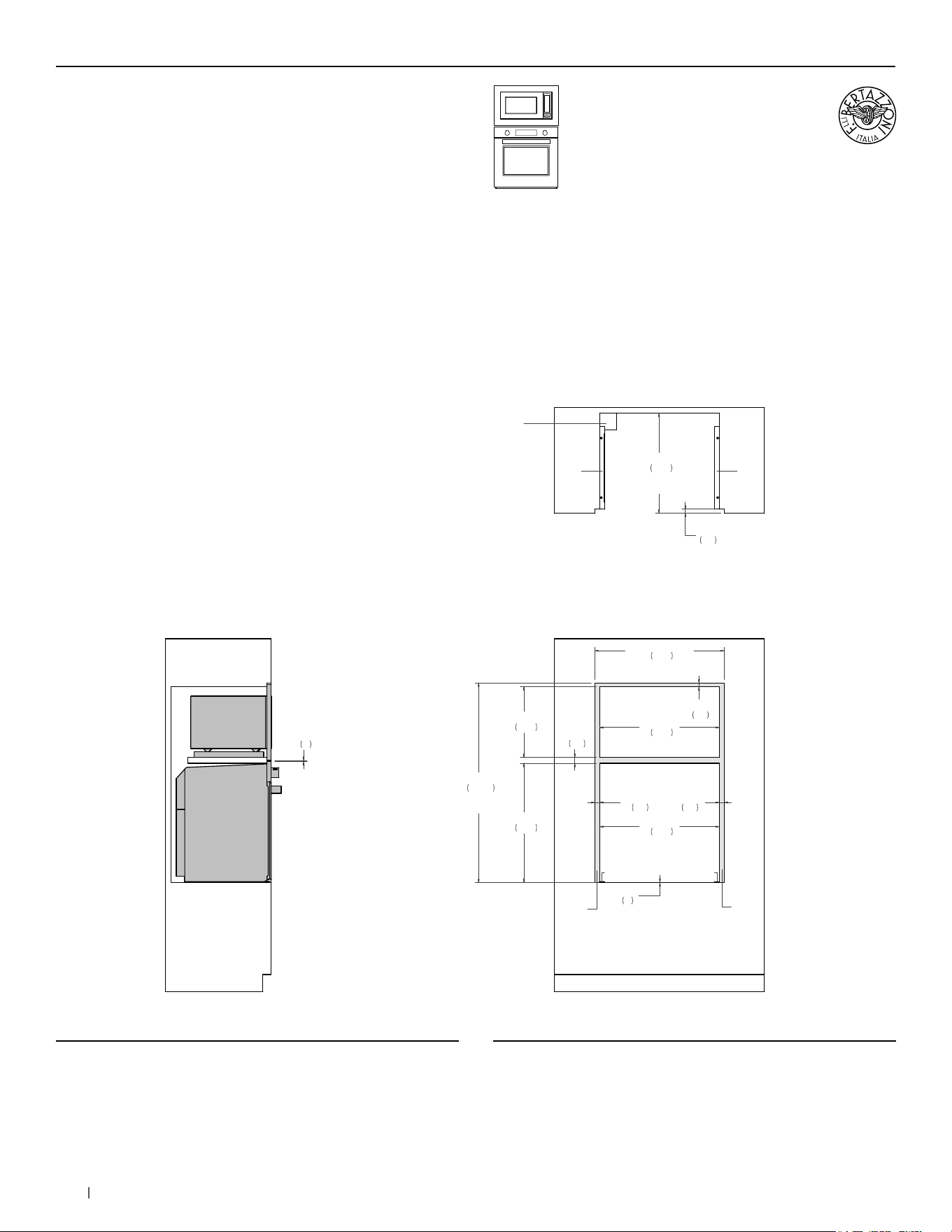
94 bertazzoni.com
30” Microwave +
30” Convection Single Oven
Flush installation vented
(a) Spacers - Included with appliance
(b) Visible Area - Match finish to outside cabinet panels
SIDE VIEW
FRONT VIEW
TOP VIEW
(a) Spacers – Included with appliance
(b) Visible Area – Match finish to outside cabinet panels
28 1/2"
724
30 7/8"
784
FLUSH INSET
WIDTH
47 5/8"
1209
FLUSH INSET
HEIGHT
28 3/8"
720
1 1/8"
30
1 1/8"
30
1/8"
3
23 7/8"
606
FLUSH INSET
DEPTH
a
b
b
a
5/16"
8
16 7/8"
428
7/8"
23
1 3/8"
35
28 1/2"
724
1"
25
a a
4" x 4"
(102 x 102)
CUT OUT SLOT
FOR POWER CORD
MULTIPLE INSTALLATIONS - 30” OVENS WALL CONFIGURATIONS
MO30STANE PROF30FSEXT
PROF30FSEXV
MAST30FSEXT
MAST30FSEXV
For electrical and gas supply please see single installation
requirements. Placement within the opening may require
additional cabinet depth.
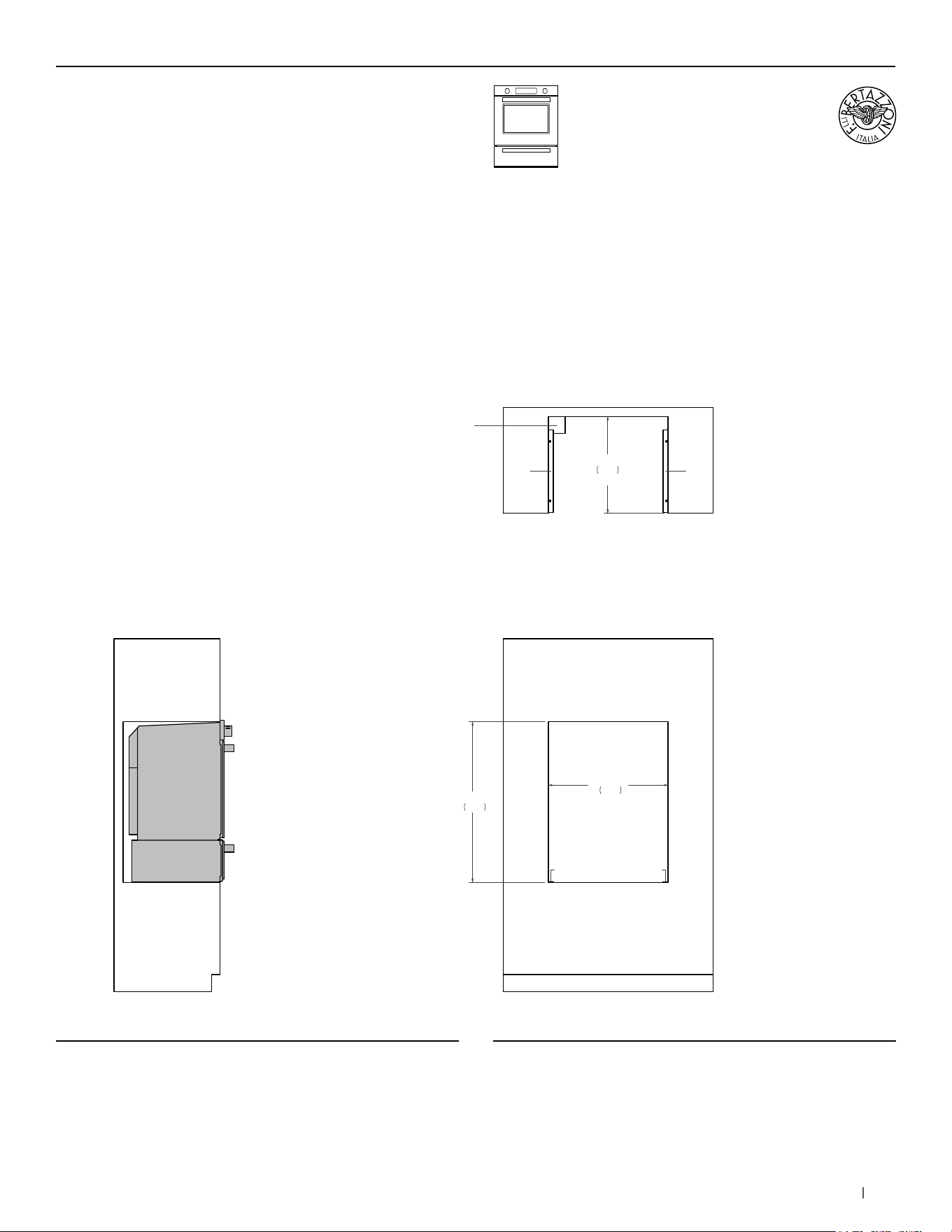
95bertazzoni.com
30” Convection Single Oven +
30” Warming Drawer
Proud installation
SIDE VIEW
FRONT VIEW
TOP VIEW
(a) Spacers – Included with appliance
28 1/2"
724
38 1/4"
971
23"
585
DEPTH
a
a
a
a
4" x 4"
(102 x 102)
CUT OUT SLOT
FOR POWER CORD
(a) Spacers - Included with appliance
MULTIPLE INSTALLATIONS - 30” OVENS WALL CONFIGURATIONS
For electrical and gas supply please see single installation
requirements. Placement within the opening may require
additional cabinet depth.
PROF30FSEXT
PROF30FSEXV
MAST30FSEXT
MAST30FSEXV
PROF30WDEX
MAST30WDEX
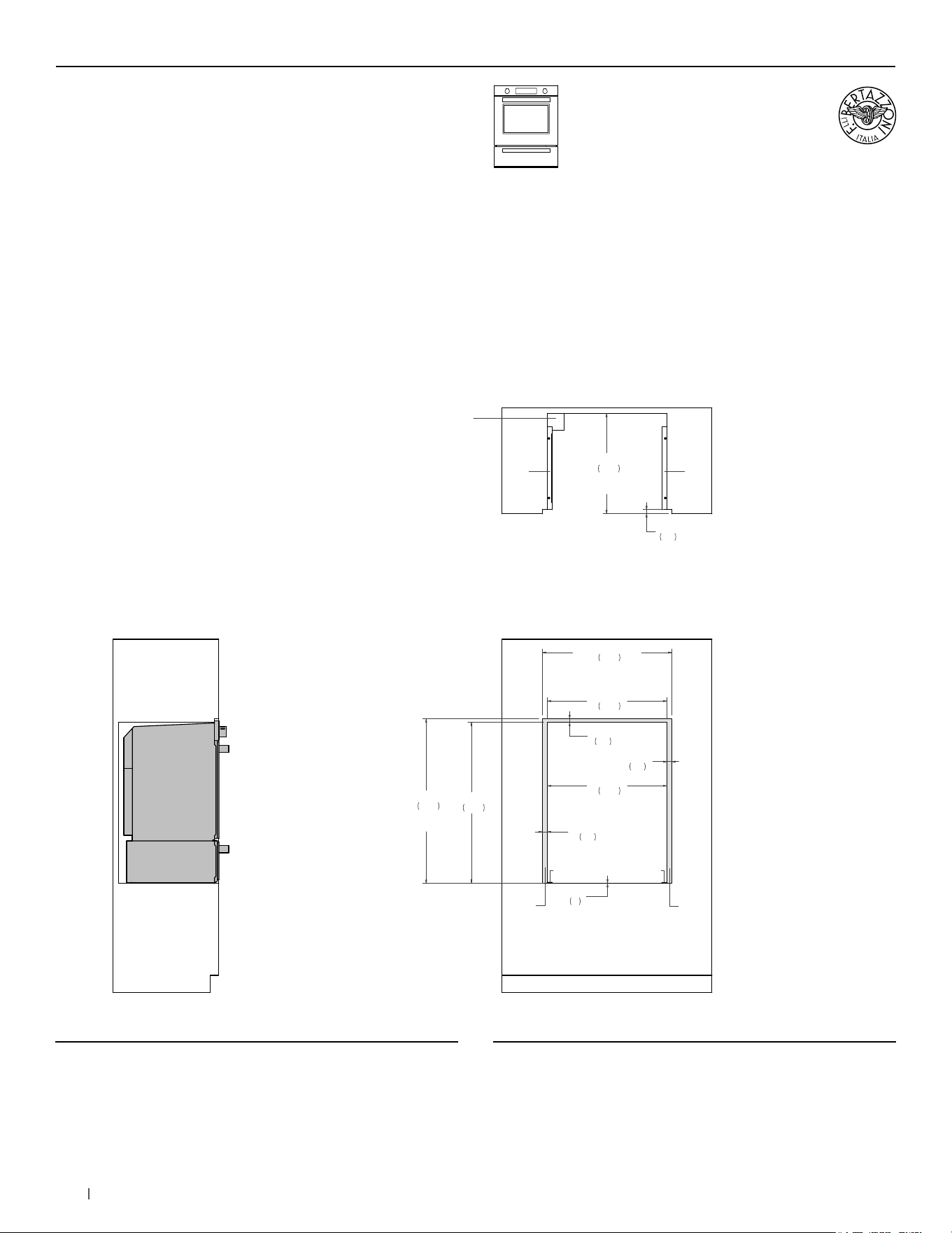
96 bertazzoni.com
30” Convection Single Oven +
30” Warming Drawer
Flush installation non vented
SIDE VIEW
FRONT VIEW
TOP VIEW
(a) Spacers – Included with appliance
(b) Visible Area – Match finish to outside cabinet panels
28 1/2"
724
28 1/2"
724
30 7/8"
784
FLUSH INSET
WIDTH
39 1/4"
997
FLUSH INSET
HEIGHT
38 1/4"
971
1 1/8"
30
1 1/8"
30
1/8"
3
23 7/8"
606
FLUSH INSET
DEPTH
a
b
b
a
a
a
7/8"
23
4" x 4"
(102 x 102)
CUT OUT SLOT
FOR POWER CORD
1"
25
(a) Spacers - Included with appliance
(b) Visible Area - Match finish to outside cabinet panels
MULTIPLE INSTALLATIONS - 30” OVENS WALL CONFIGURATIONS
PROF30FSEXT
PROF30FSEXV
MAST30FSEXT
MAST30FSEXV
PROF30WDEX
MAST30WDEX
For electrical and gas supply please see single installation
requirements. Placement within the opening may require
additional cabinet depth.
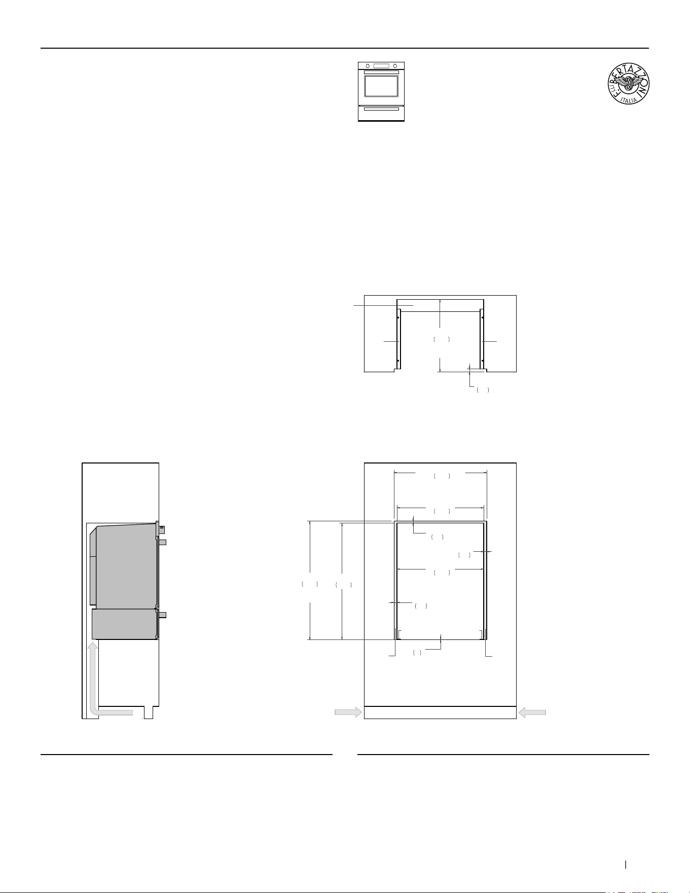
97bertazzoni.com
30” Convection Single Oven +
30” Warming Drawer
Flush installation vented
SIDE VIEW
FRONT VIEW
TOP VIEW
(a) Spacers – Included with appliance
(b) Visible Area – Match finish to outside cabinet panels
AIR INTAKE
28 1/2"
724
28 1/2"
724
30 1/2"
774
FLUSH INSET
WIDTH
39"
992
FLUSH INSET
HEIGHT
38 1/4"
971
1"
25
1"
25
1/8"
3
23 7/8"
606
FLUSH INSET
DEPTH
a
b
b
a
a
a
3/4"
18
AIR INTAKE
4" x 15"
(102 x 380)
AIR INTAKE
4" x 15"
(102 x 380)
4" x 28 1/2"
(102 x 724)
AIR INTAKE
1"
25
(a) Spacers - Included with appliance
(b) Visible Area - Match finish to outside cabinet panels
MULTIPLE INSTALLATIONS - 30” OVENS WALL CONFIGURATIONS
PROF30FSEXT
PROF30FSEXV
MAST30FSEXT
MAST30FSEXV
PROF30WDEX
MAST30WDEX
For electrical and gas supply please see single installation
requirements. Placement within the opening may require
additional cabinet depth.
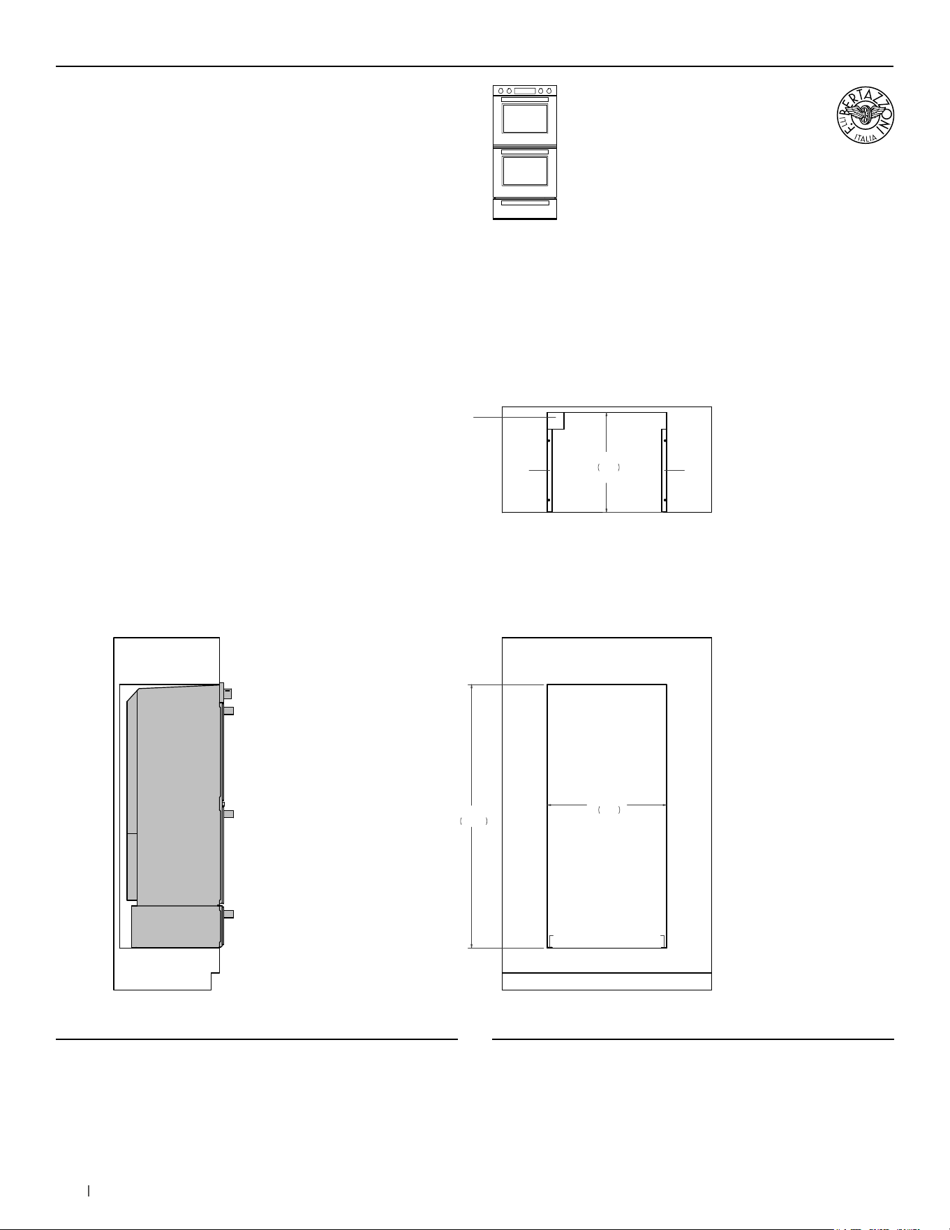
98 bertazzoni.com
30” Convection Double Oven +
30” Warming Drawer
Proud installation
SIDE VIEW
FRONT VIEW
TOP VIEW
(a) Spacers – Included with appliance
28 1/2"
724
62 7/8"
1597
23 7/8"
606
DEPTH
a
a
a
a
4" x 4"
(102 x 102)
CUT OUT SLOT
FOR POWER CORD
(a) Spacers - Parts of standard equipment
MULTIPLE INSTALLATIONS - 30” OVENS WALL CONFIGURATIONS
PROF30FDEXT
PROF30FDEXV
MAST30FDEXT
MAST30FDEXV
PROF30WDEX
MAST30WDEX
For electrical and gas supply please see single installation
requirements. Placement within the opening may require
additional cabinet depth.
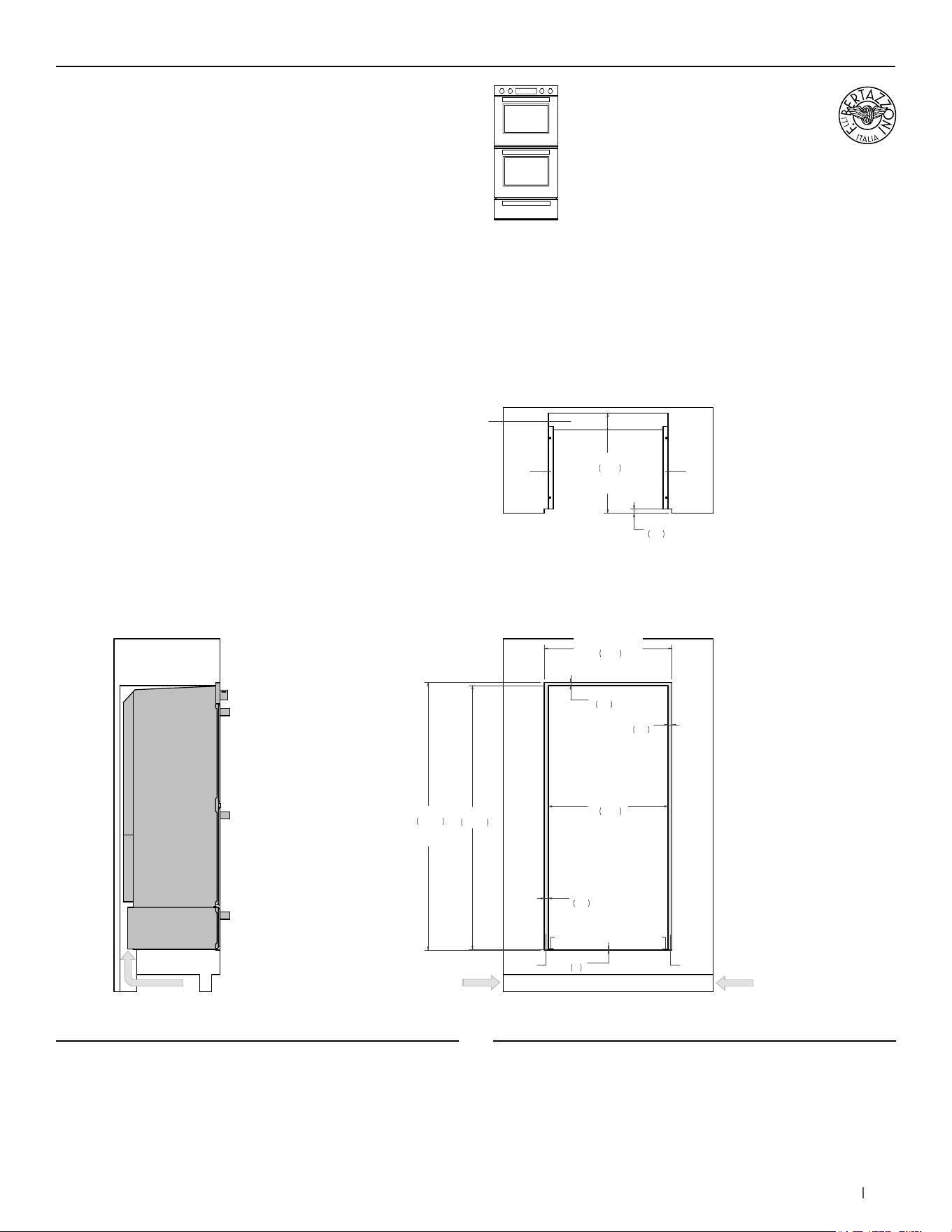
99bertazzoni.com
30” Convection Double Oven +
30” Warming Drawer
Flush installation
SIDE VIEW
FRONT VIEW
TOP VIEW
(a) Spacers – Included with appliance
(b) Visible Area – Match finish to outside cabinet panels
AIR INTAKE
28 1/2"
724
30 1/2"
774
FLUSH INSET
WIDTH
63 3/4"
1618
FLUSH INSET
HEIGHT
62 7/8"
1597
1"
25
1"
25
1/8"
3
23 7/8"
606
FLUSH INSET
DEPTH
a
bb
a
a
a
3/4"
18
AIR INTAKE
4" x 15"
(102 x 380)
AIR INTAKE
4" x 15"
(102 x 380)
4" x 28 1/2"
(102 x 724)
AIR INTAKE
1"
25
(a) Spacers - Included with appliance
(b) Visible Area - Match finish to outside cabinet panels
MULTIPLE INSTALLATIONS - 30” OVENS WALL CONFIGURATIONS
PROF30FDEXT
PROF30FDEXV
MAST30FDEXT
MAST30FDEXV
PROF30WDEX
MAST30WDEX
For electrical and gas supply please see single installation
requirements. Placement within the opening may require
additional cabinet depth.
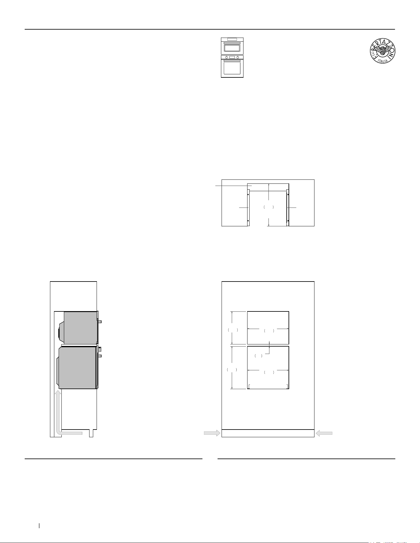
100 bertazzoni.com
24” Specialty Oven +
24” Convection Single Oven
Proud installation
SIDE VIEW
FRONT VIEW
TOP VIEW
(a) Spacers – Included with appliance
AIR INTAKE
a
a
a
a
17 3/4"
451
22 3/8"
568
23"
585
FLUSH INSET
DEPTH
23"
585
1 1/8"
28
4" x 22"
(102 x 560)
AIR INTAKE
AIR INTAKE
4" x 15"
(102 x 380)
AIR INTAKE
4" x 15"
(102 x 380)
22 3/8"
568
(a) Spacers - Included with appliance
MULTIPLE INSTALLATIONS - 24” OVENS WALL CONFIGURATIONS
PROF24SOEX
PROF24FSEXV
For electrical and gas supply please see single installation
requirements. Placement within the opening may require
additional cabinet depth.
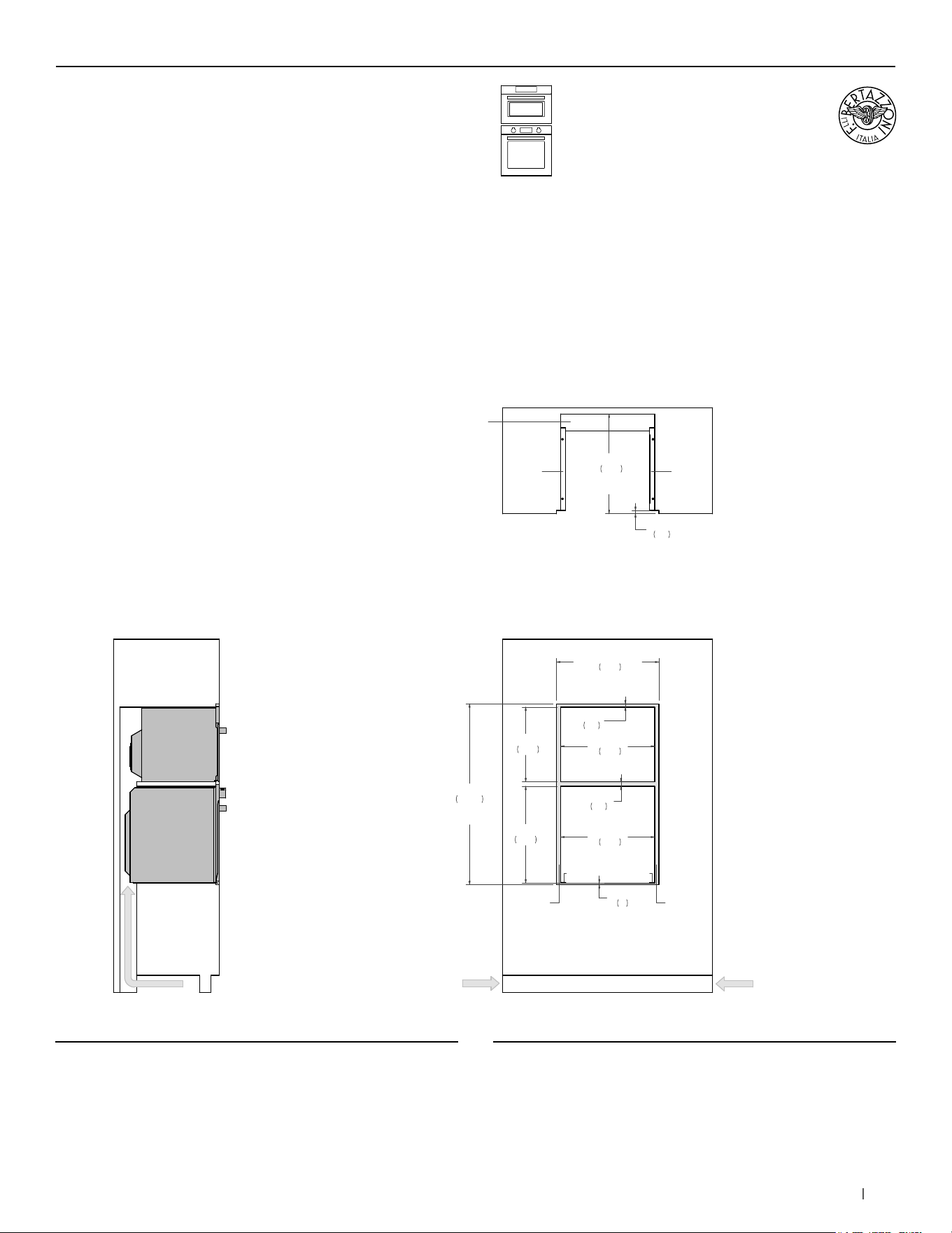
101bertazzoni.com
24” Specialty Oven +
24” Convection Single Oven
Flush installation
SIDE VIEW
FRONT VIEW
TOP VIEW
(a) Spacers – Included with appliance
(b) Visible Area – Match finish to outside cabinet panels
AIR INTAKE
a
b
b
a
a
a
17 3/4"
451
23"
585
1 1/8"
28
22 3/8"
568
3/4"
20
22 3/8"
568
43"
1092
FLUSH INSET
HEIGHT
24 3/8"
619
FLUSH INSET
WIDTH
3/8"
9
23 3/4"
603
FLUSH INSET
DEPTH
3/4"
20
4" x 22"
(102 x 560)
AIR INTAKE
AIR INTAKE
4" x 15"
(102 x 380)
AIR INTAKE
4" x 15"
(102 x 380)
(a) Spacers - Included with appliance
(b) Visible Area - Match finish to outside cabinet panels
MULTIPLE INSTALLATIONS - 24” OVENS WALL CONFIGURATIONS
For electrical and gas supply please see single installation
requirements. Placement within the opening may require
additional cabinet depth.
PROF24SOEX
PROF24FSEXV
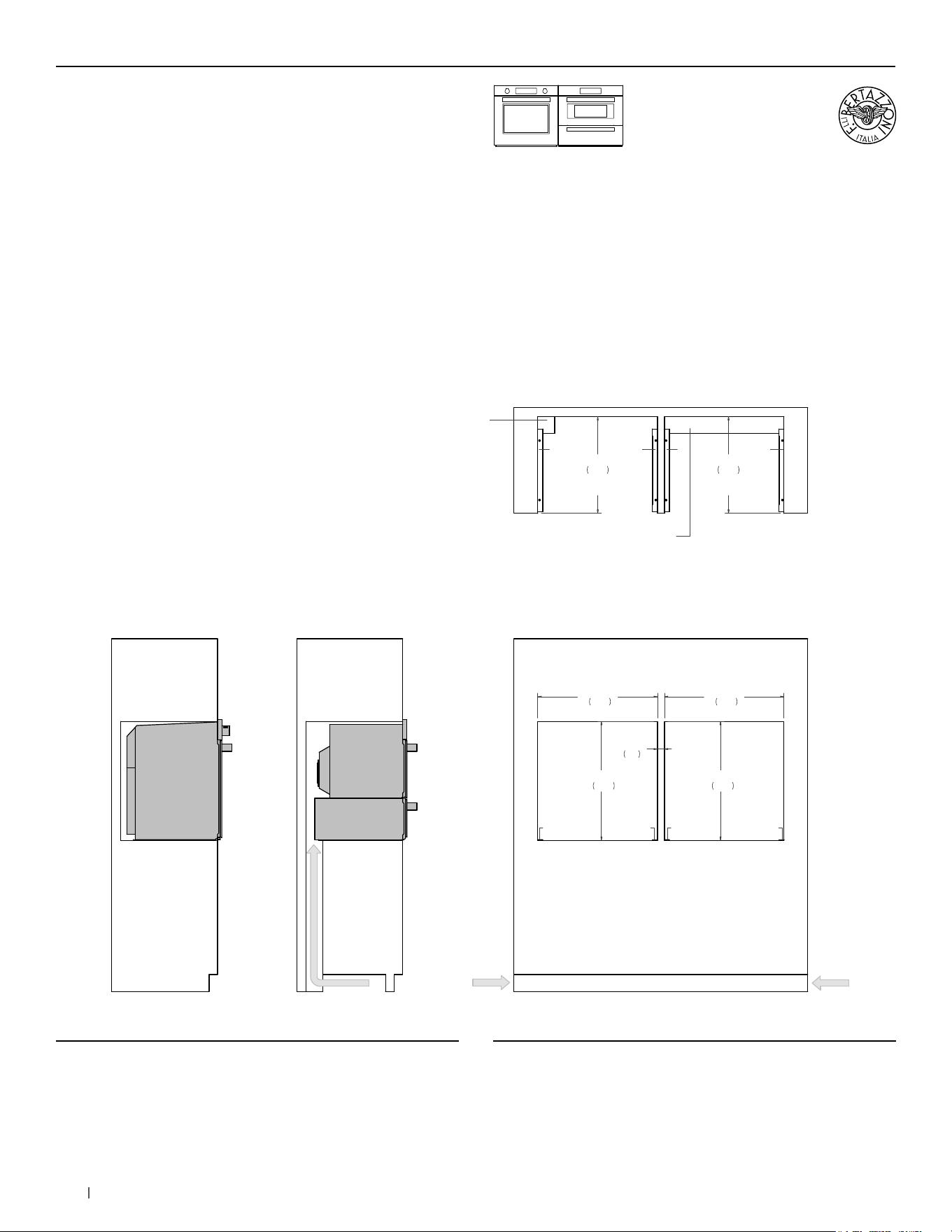
102 bertazzoni.com
Side by Side
30” Convection Single Oven +
30” Specialty Oven +
30” Warming Drawer
Proud installation
FRONT VIEW
TOP VIEW
LEFT CABINET VIEW
RIGHT CABINET VIEW
(a) Spacers – Included with appliance
23"
585
FLUSH INSET
DEPTH
a
a
a
a
AIR INTAKE
28 3/8"
720
1 5/8"
42
a
a
28 1/2"
724
28 1/2"
724
28 3/8"
720
23"
585
FLUSH INSET
DEPTH
a
a
4" x 4"
(102 x 102)
CUT OUT SLOT
FOR POWER CORD
AIR INTAKE
4" x 15"
(102 x 380)
AIR INTAKE
4" x 15"
(102 x 380)
4" x 28 1/2"
(102 x 724)
AIR INTAKE
MULTIPLE INSTALLATIONS
(a) Spacers - Included with appliance
PROF30SOEX
PROF30CSEX
MAST30SOEX
MAST30CSEX
PROF30FSEXT
PROF30FSEXV
MAST30FSEXT
MAST30FSEXV
PROF30WDEX
MAST30WDEX
For electrical and gas supply please see single installation
requirements. Placement within the opening may require
additional cabinet depth.
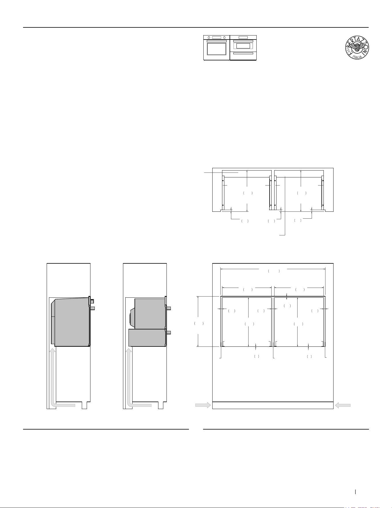
103bertazzoni.com
Side by Side
30” Convection Single Oven +
30” Specialty Oven +
30” Warming Drawer
Flush installation
FRONT VIEW
TOP VIEW
LEFT CABINET VIEW
RIGHT CABINET VIEW
(a) Spacers – Included with appliance
(b) Visible Area – Match finish to outside cabinet panels
AIR INTAKE
60 5/8"
1540
FLUSH INSET
WIDTH
29 1/8"
741
FLUSH INSET
HEIGHT
1"
25
23 7/8"
606
FLUSH INSET
DEPTH
a
b
b
a
a
a
AIR INTAKE
28 3/8"
720
1 5/8"
42
3/4"
18
1/8"
3
b
a
a
1"
25
28 1/2"
724
28 1/2"
724
28 3/8"
720
1/8"
3
23 7/8"
606
FLUSH INSET
DEPTH
1"
25
1"
25
a
a
4" x 28 1/2"
(102 x 724)
AIR INTAKE
AIR INTAKE
4" x 15"
(102 x 380)
AIR INTAKE
4" x 15"
(102 x 380)
4" x 28 1/2"
(102 x 724)
AIR INTAKE
1"
25
MULTIPLE INSTALLATIONS
(a) Spacers - Included with appliance
(b) Visible Area - Match finish to outside cabinet panels
PROF30SOEX
PROF30CSEX
MAST30SOEX
MAST30CSEX
PROF30FSEXT
PROF30FSEXV
MAST30FSEXT
MAST30FSEXV
PROF30WDEX
MAST30WDEX
For electrical and gas supply please see single installation
requirements. Placement within the opening may require
additional cabinet depth.
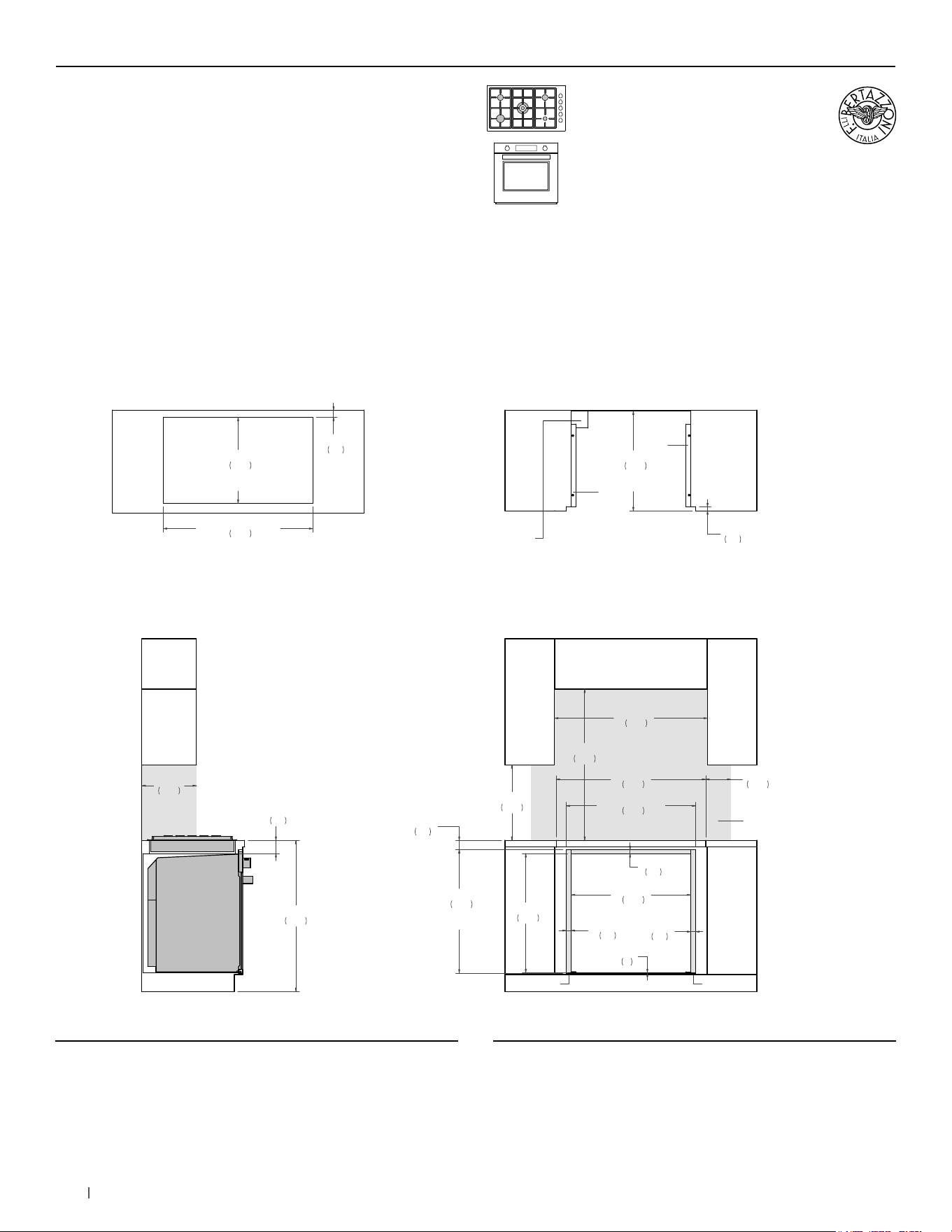
104 bertazzoni.com
30” Convection Oven +
36” Drop-in Cooktop
Flush installation non vented
SIDE VIEW
FRONT VIEW
(a) Spacers – Included with appliance
(b) Visible Area – Match finish to outside cabinet panels
(c) Combustible material cannot be installed within shaded area
TOP VIEW – OVEN DETAIL TOP VIEW – COOKTOP DETAIL
a
b
b
a
18"
457
36"
915
36 3/8"
925
3 1/8"
80
36"
914
13"
330
28 3/8"
720
30 7/8"
784
FLUSH INSET
WIDTH
29 3/8"
746
FLUSH INSET
HEIGHT
1 1/8"
30
1 1/8"
30
1/8"
3
7/8"
23
28 1/2"
724
23 3/4"
603
FLUSH INSET
DEPTH
c
2 1/4"
57
35 5/8"
905
6"
152
4" x 4"
(102 x 102)
CUT-OUT SLOT
FOR POWER-CORD
35 5/8"
905
COOKTOP
CUT-OUT WIDTH
20 1/2"
520
COOKTOP
CUT-OUT DEPTH
1 3/4"
45
1"
25
(a) Spacers - Included with appliance
(b) Visible Area - Match finish to outside cabinet panels
(c) Combustible material cannot be installed within shaded area
MULTIPLE INSTALLATIONS - 30” OVEN AND COOKTOP UNDERCOUNTER CONFIGURATIONS
PROF366QBXT
PROF365QBXT
PROF365QXE
MAST366QBXT
MAST365QBXT
MAST365QXE
For electrical and gas supply please see single installation
requirements. Placement within the opening may require
additional cabinet depth.
MAST30FSEXT
MAST30FSEXV
PROF30FSEXT
PROF30FSEXV
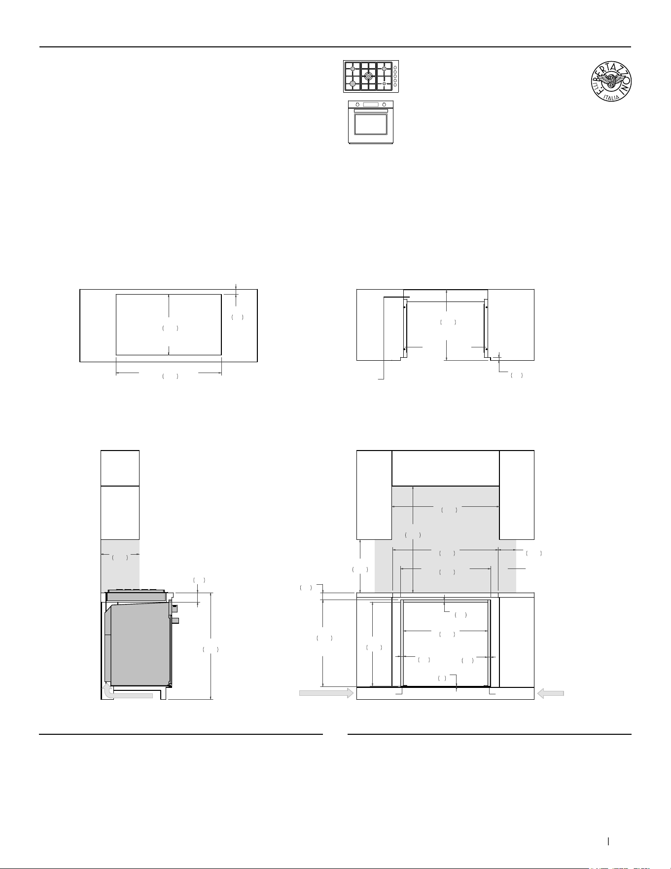
105bertazzoni.com
30” Convection Oven +
36” Drop-in Cooktop
Flush installation vented
SIDE VIEW
FRONT VIEW
TOP VIEW – OVEN DETAIL
(a) Spacers – Included with appliance
(b) Visible Area – Match finish to outside cabinet panels
(c) Combustible material cannot be installed within shaded area
TOP VIEW – COOKTOP DETAIL
AIR INTAKE
a
b
b
a
18"
457
36"
915
36 3/8"
925
6"
152
3 1/8"
80
36"
914
13"
330
28 3/8"
720
30 1/2"
774
FLUSH INSET
WIDTH
29 1/8"
741
FLUSH INSET
HEIGHT
1"
25
1"
25
1/8"
3
3/4"
18
28 1/2"
724
23 3/4"
603
FLUSH INSET
DEPTH
c
2 1/2"
62
35 5/8"
905
4" x 28 1/2"
(102 x 724)
AIR INTAKE
AIR INTAKE
3" x 16"
(77 x 406)
AIR INTAKE
3" x 16"
(77 x 406)
35 5/8"
905
COOKTOP
CUT-OUT WIDTH
20 1/2"
520
COOKTOP
CUT-OUT DEPTH
1 3/4"
45
1"
25
(a) Spacers - Included with appliance
(b) Visible Area - Match finish to outside cabinet panels
(c) Combustible material cannot be installed within shaded area
MULTIPLE INSTALLATIONS - 30” OVEN AND COOKTOP UNDERCOUNTER CONFIGURATIONS
PROF366QBXT
PROF365QBXT
PROF365QXE
MAST366QBXT
MAST365QBXT
MAST365QXE
For electrical and gas supply please see single installation
requirements. Placement within the opening may require
additional cabinet depth.
MAST30FSEXT
MAST30FSEXV
PROF30FSEXT
PROF30FSEXV
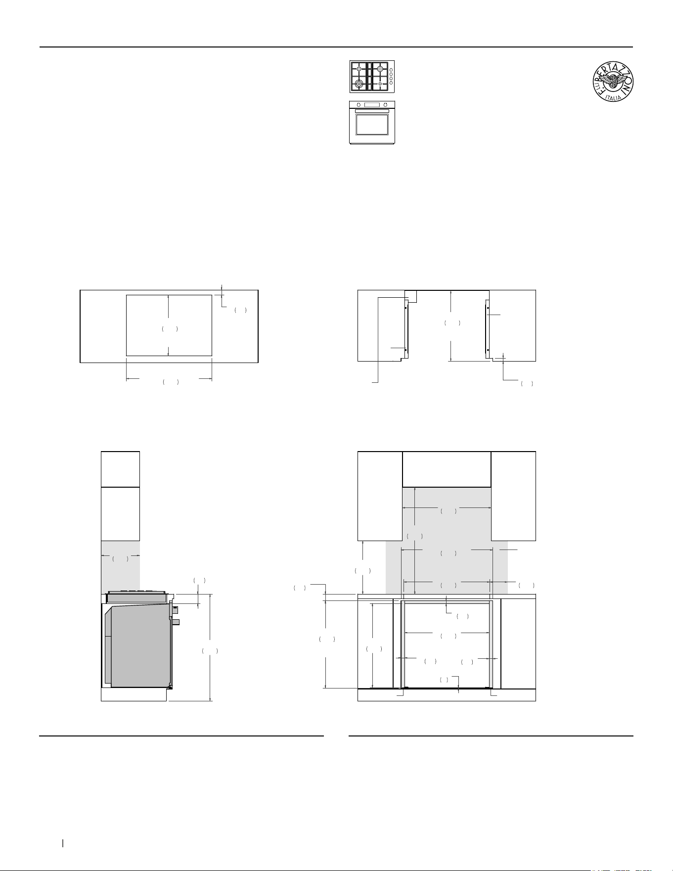
106 bertazzoni.com
30” Convection Oven +
30” Drop-in Cooktop
Flush installation non vented
SIDE VIEW
FRONT VIEW
(a) Spacers – Included with appliance
(b) Visible Area – Match finish to outside cabinet panels
(c) Combustible material cannot be installed within shaded area
TOP VIEW – OVEN DETAIL TOP VIEW – COOKTOP DETAIL
a
b
b
a
18"
457
36"
915
30"
762
3 1/8"
80
36"
914
13"
330
28 3/8"
720
30 7/8"
784
FLUSH INSET
WIDTH
29 3/8"
746
FLUSH INSET
HEIGHT
1 1/8"
30
1 1/8"
30
1/8"
3
7/8"
23
28 1/2"
724
23 3/4"
603
FLUSH INSET
DEPTH
c
2 1/4"
57
28 7/8"
735
6"
152
4" x 4"
(102 x 102)
CUT-OUT SLOT
FOR POWER-CORD
1"
25
28 7/8"
735
COOKTOP
CUT-OUT WIDTH
20 1/2"
520
COOKTOP
CUT-OUT DEPTH
1 3/4"
45
(a) Spacers - Included with appliance
(b) Visible Area - Match finish to outside cabinet panels
(c) Combustible material cannot be installed within shaded area
MULTIPLE INSTALLATIONS - 30” OVEN AND COOKTOP UNDERCOUNTER CONFIGURATIONS
PRO304QBXT
PROF304QXE
MAST304QBXT
MAST304QXE
PROF30FSEXT
PROF30FSEXV
MAST30FSEXT
MAST30FSEXV
For electrical and gas supply please see single installation
requirements. Placement within the opening may require
additional cabinet depth.
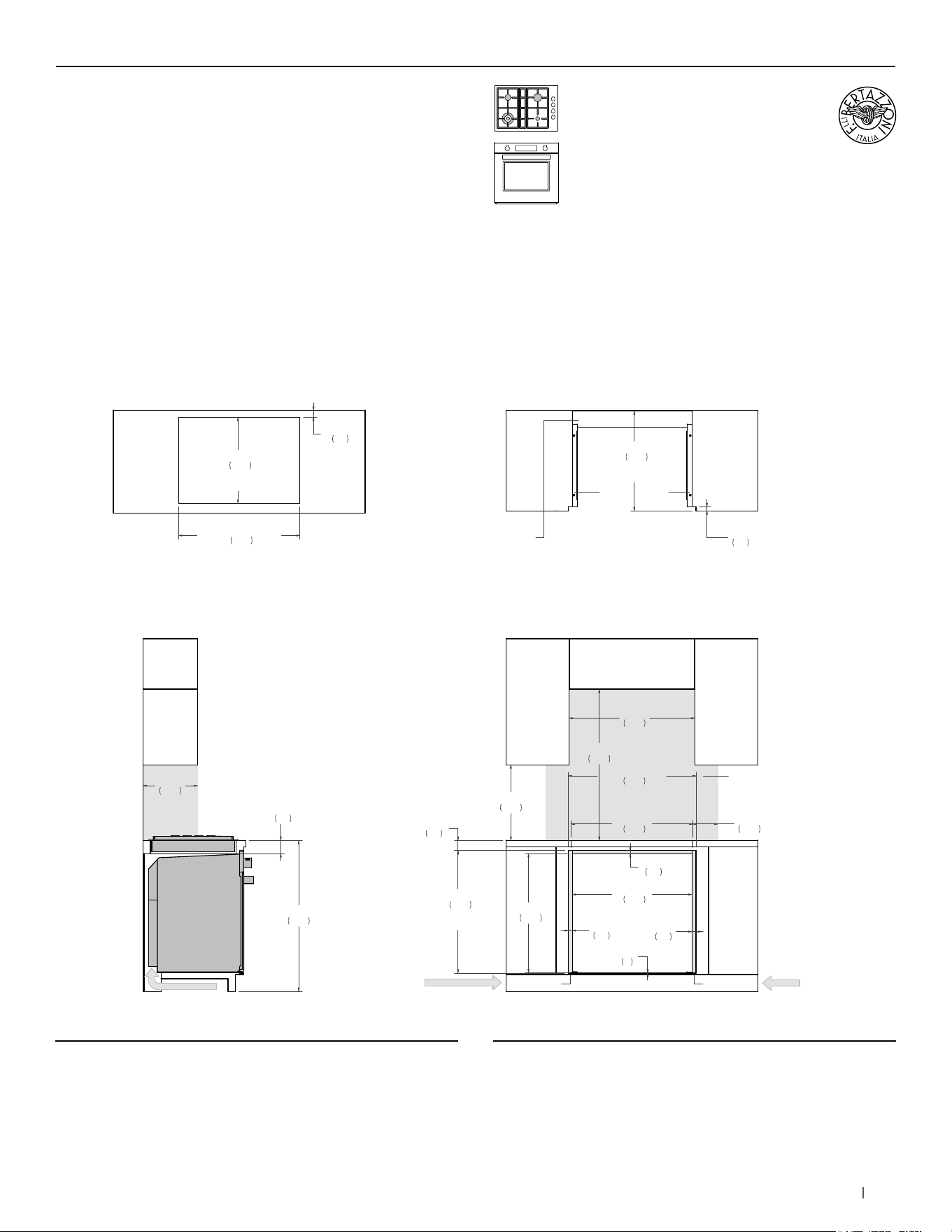
107bertazzoni.com
30” Convection Oven +
30” Drop-in Cooktop
Flush installation vented
SIDE VIEW
FRONT VIEW
(a) Spacers – Included with appliance
(b) Visible Area – Match finish to outside cabinet panels
(c) Combustible material cannot be installed within shaded area
TOP VIEW – OVEN DETAIL TOP VIEW – COOKTOP DETAIL
AIR INTAKE
a
b
b
a
18"
457
36"
915
30"
762
6"
152
3 1/8"
80
36"
914
13"
330
28 3/8"
720
30 1/2"
774
FLUSH INSET
WIDTH
29 1/8"
741
FLUSH INSET
HEIGHT
1"
25
1"
25
1/8"
3
3/4"
18
28 1/2"
724
23 3/4"
603
FLUSH INSET
DEPTH
c
2 1/2"
62
28 7/8"
735
4" x 28 1/2"
(102 x 724)
AIR INTAKE
AIR INTAKE
3" x 16"
(77 x 406)
AIR INTAKE
3" x 16"
(77 x 406)
1"
25
28 7/8"
735
COOKTOP
CUT-OUT WIDTH
20 1/2"
520
COOKTOP
CUT-OUT DEPTH
1 3/4"
45
(a) Spacers - Included with appliance
(b) Visible Area - Match finish to outside cabinet panels
(c) Combustible material cannot be installed within shaded area
MULTIPLE INSTALLATIONS - 30” OVEN AND COOKTOP UNDERCOUNTER CONFIGURATIONS
PRO304QBXT
PROF304QXE
MAST304QBXT
MAST304QXE
PROF30FSEXT
PROF30FSEXV
MAST30FSEXT
MAST30FSEXV
For electrical and gas supply please see single installation
requirements. Placement within the opening may require
additional cabinet depth.
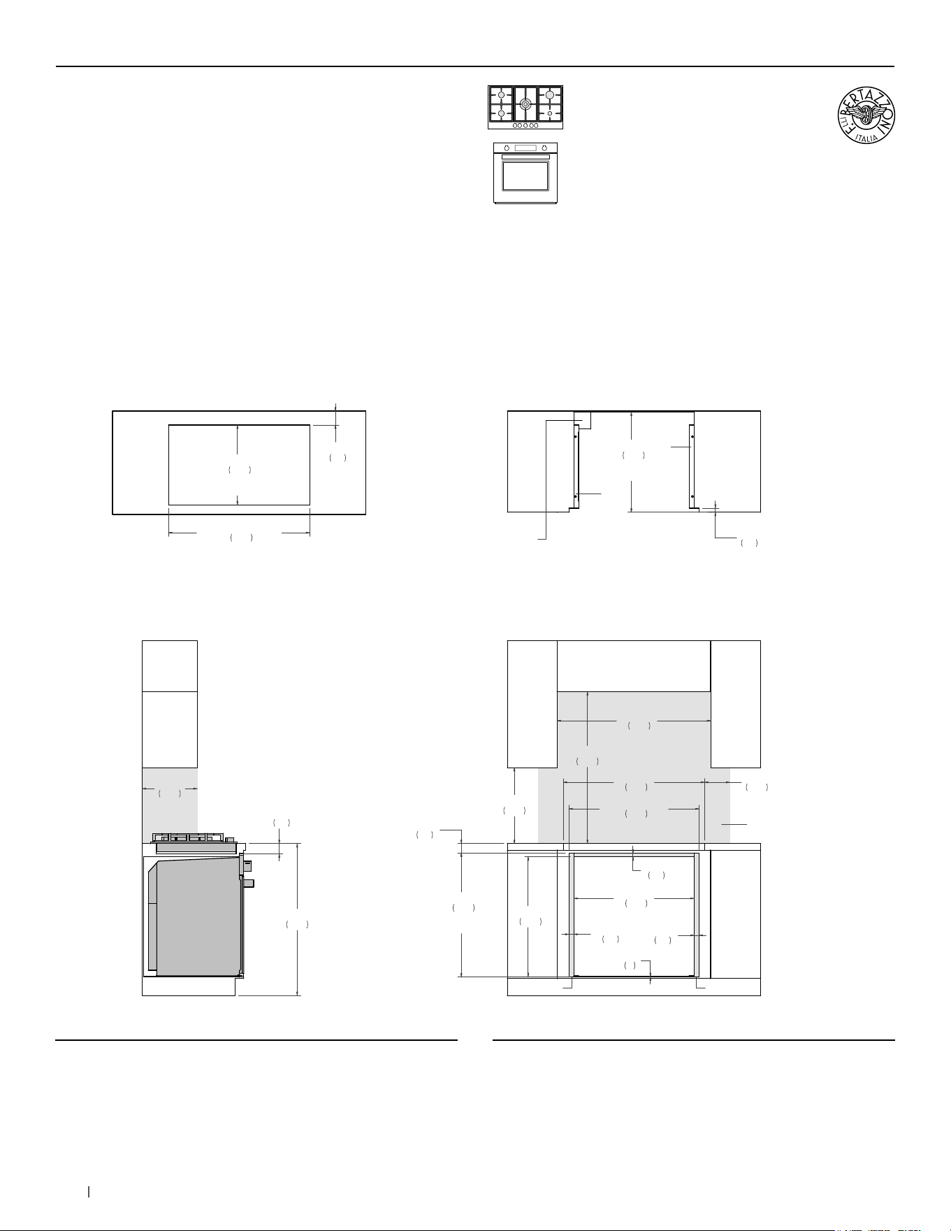
108 bertazzoni.com
30” Convection Oven +
36” Cooktop XV
Flush installation non vented
SIDE VIEW
FRONT VIEW
(a) Spacers – Included with appliance
(b) Visible Area – Match finish to outside cabinet panels
(c) Combustible material cannot be installed within shaded area
TOP VIEW – OVEN DETAIL TOP VIEW – COOKTOP DETAIL
a
b
b
a
18"
457
36"
915
36 3/8"
925
2 1/2"
62
36"
914
13"
330
28 3/8"
720
30 7/8"
784
FLUSH INSET
WIDTH
29 3/8"
746
FLUSH INSET
HEIGHT
1 1/8"
30
1 1/8"
30
1/8"
3
7/8"
23
28 1/2"
724
c
2 1/4"
57
33 1/2"
850
4" x 4"
(102 x 102)
CUT OUT SLOT
FOR POWER CORD
6"
152
23 3/4"
603
FLUSH INSET
DEPTH
1"
25
33 1/2"
850
COOKTOP
CUT-OUT WIDTH
18 7/8"
480
COOKTOP
COUT-OUT DEPTH
3 3/8"
85
(a) Spacers - Included with appliance
(b) Visible Area - Match finish to outside cabinet panels
(c) Combustible material cannot be installed within shaded area
MULTIPLE INSTALLATIONS - 30” OVEN AND COOKTOP UNDERCOUNTER CONFIGURATIONS
PROF365CTV PROF30FSEXT
PROF30FSEXV
MAST30FSEXT
MAST30FSEXV
For electrical and gas supply please see single installation
requirements. Placement within the opening may require
additional cabinet depth.
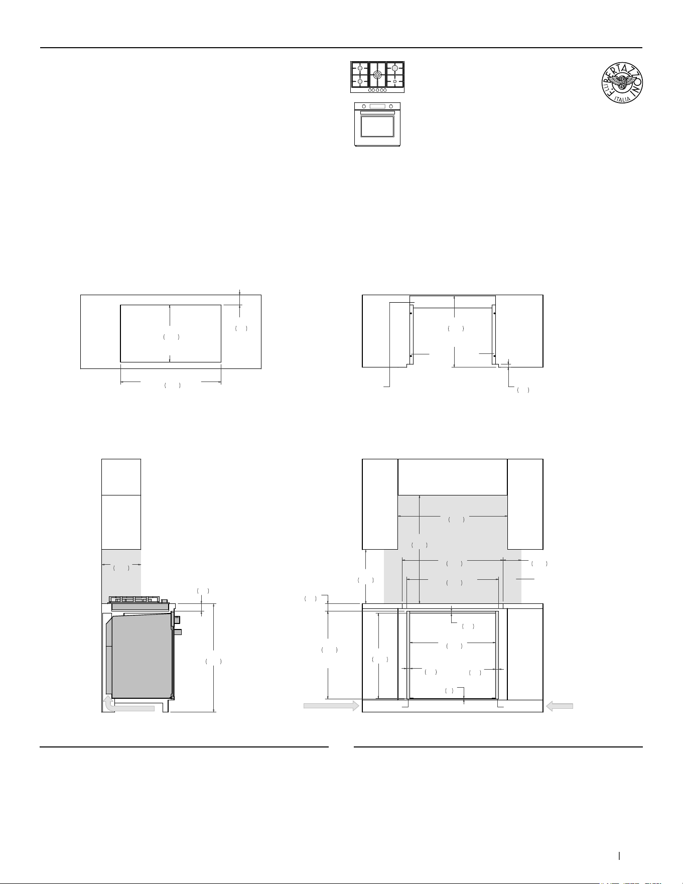
109bertazzoni.com
30” Convection Oven +
36” Cooktop XV
Flush installation vented
SIDE VIEW
FRONT VIEW
(a) Spacers – Included with appliance
(b) Visible Area – Match finish to outside cabinet panels
(c) Combustible material cannot be installed within shaded area
TOP VIEW – OVEN DETAIL TOP VIEW – COOKTOP DETAIL
AIR INTAKE
a
b
b
a
18"
457
36"
915
36 3/8"
925
6"
152
2 1/2"
62
36"
914
13"
330
28 3/8"
720
30 1/2"
774
FLUSH INSET
WIDTH
29 1/8"
741
FLUSH INSET
HEIGHT
1"
25
1"
25
1/8"
3
3/4"
18
28 1/2"
724
23 3/4"
603
FLUSH INSET
DEPTH
c
2 1/2"
62
33 1/2"
850
1"
25
4" x 28 1/2"
(102 x 724)
AIR INTAKE
AIR INTAKE
3" x 16"
(77 x 406)
AIR INTAKE
3" x 16"
(77 x 406)
33 1/2"
850
COOKTOP
CUT-OUT WIDTH
18 7/8"
480
COOKTOP
COUT-OUT DEPTH
3 3/8"
85
(a) Spacers - Included with appliance
(b) Visible Area - Match finish to outside cabinet panels
(c) Combustible material cannot be installed within shaded area
MULTIPLE INSTALLATIONS - 30” OVEN AND COOKTOP UNDERCOUNTER CONFIGURATIONS
PROF365CTV PROF30FSEXT
PROF30FSEXV
MAST30FSEXT
MAST30FSEXV
For electrical and gas supply please see single installation
requirements. Placement within the opening may require
additional cabinet depth.
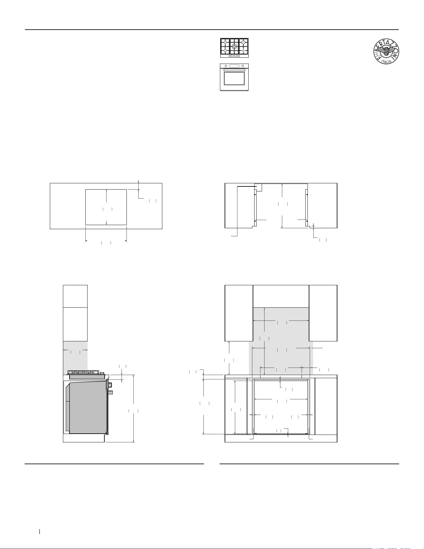
110 bertazzoni.com
30” Convection Oven +
30” Cooktop XV
Flush installation non vented
SIDE VIEW
FRONT VIEW
(a) Spacers – Included with appliance
(b) Visible Area – Match finish to outside cabinet panels
(c) Combustible material cannot be installed within shaded area
TOP VIEW – OVEN DETAIL TOP VIEW – COOKTOP DETAIL
18"
457
36"
915
30"
762
36"
914
13"
330
28 3/8"
720
30 7/8"
784
FLUSH INSET
WIDTH
29 3/8"
746
FLUSH INSET
HEIGHT
1 1/8"
30
1 1/8"
30
1/8"
3
7/8"
23
28 1/2"
724
23 3/4"
603
FLUSH INSET
DEPTH
c
2 1/4"
57
22"
560
4" x 4"
(102 x 102)
CUT OUT SLOT
FOR POWER CORD
6"
152
b
b
a
a
1"
25
2 1/2"
62
18 7/8"
480
COOKTOP
CUT-OUT DEPTH
22"
560
COOKTOP
CUT-OUT WIDTH
3 3/8"
85
(a) Spacers - Included with appliance
(b) Visible Area - Match finish to outside cabinet panels
(c) Combustible material cannot be installed within shaded area
MULTIPLE INSTALLATIONS - 30” OVEN AND COOKTOP UNDERCOUNTER CONFIGURATIONS
PROF305CTXV PROF30FSEXT
PROF30FSEXV
MAST30FSEXT
MAST30FSEXV
For electrical and gas supply please see single installation
requirements. Placement within the opening may require
additional cabinet depth.
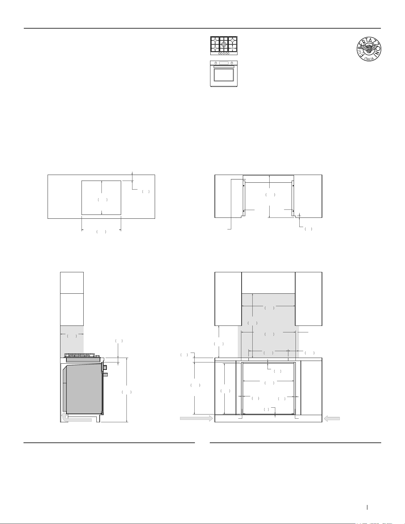
111bertazzoni.com
30” Convection Oven +
30” Cooktop XV
Flush installation vented
SIDE VIEW
FRONT VIEW
(a) Spacers – Included with appliance
(b) Visible Area – Match finish to outside cabinet panels
(c) Combustible material cannot be installed within shaded area
TOP VIEW – OVEN DETAIL TOP VIEW – COOKTOP DETAIL
AIR INTAKE
a
a
18"
457
36"
915
30"
762
6"
152
36"
914
13"
330
28 3/8"
720
30 1/2"
774
FLUSH INSET
WIDTH
29 1/8"
741
FLUSH INSET
HEIGHT
1"
25
1"
25
1/8"
3
3/4"
18
28 1/2"
724
23 3/4"
603
FLUSH INSET
DEPTH
c
2 1/2"
62
22"
560
b b
1"
25
4" x 28 1/2"
(102 x 724)
AIR INTAKE
AIR INTAKE
3" x 16"
(77 x 406)
AIR INTAKE
3" x 16"
(77 x 406)
2 1/2"
62
18 7/8"
480
COOKTOP
CUT-OUT DEPTH
22"
560
COOKTOP
CUT-OUT WIDTH
3 3/8"
85
(a) Spacers - Included with appliance
(b) Visible Area - Match finish to outside cabinet panels
(c) Combustible material cannot be installed within shaded area
MULTIPLE INSTALLATIONS - 30” OVEN AND COOKTOP UNDERCOUNTER CONFIGURATIONS
PROF305CTXV PROF30FSEXT
PROF30FSEXV
MAST30FSEXT
MAST30FSEXV
For electrical and gas supply please see single installation
requirements. Placement within the opening may require
additional cabinet depth.
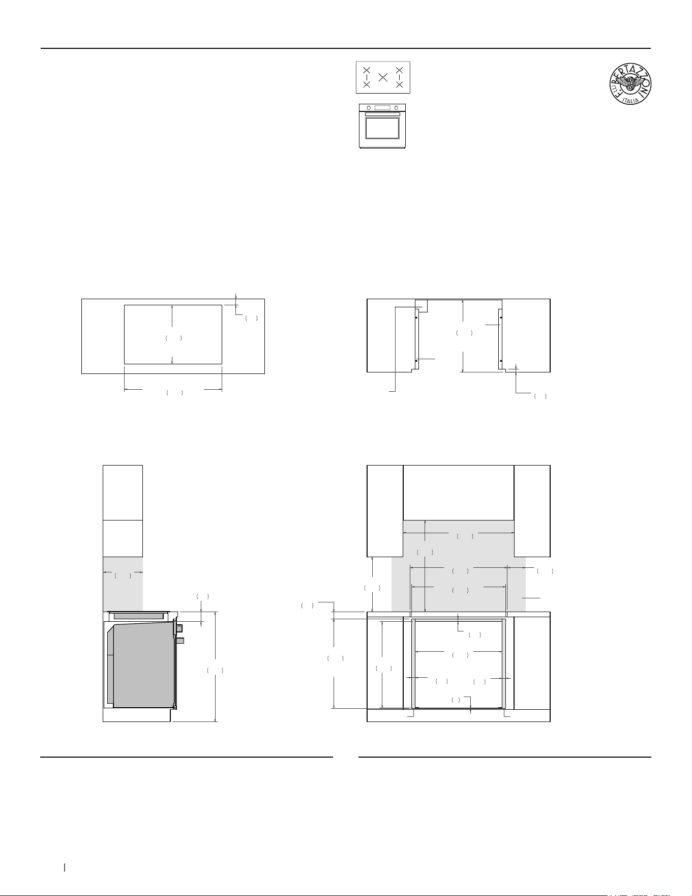
112 bertazzoni.com
30” Convection Oven +
36” Induction Cooktop
Flush installation non vented
SIDE VIEW
FRONT VIEW
(a) Spacers – Included with appliance
(b) Visible Area – Match finish to outside cabinet panels
(c) Combustible material cannot be installed within shaded area
TOP VIEW – OVEN DETAIL TOP VIEW – COOKTOP DETAIL
a
b
b
a
18"
457
30"
763
36 3/8"
925
3 1/8"
80
36"
914
13"
330
28 3/8"
720
30 7/8"
784
FLUSH INSET
WIDTH
29 3/8"
746
FLUSH INSET
HEIGHT
1 1/8"
30
1 1/8"
30
1/8"
3
7/8"
23
28 1/2"
724
23 3/4"
603
FLUSH INSET
DEPTH
c
2 1/4"
57
31 7/8"
810
4" x 4"
(102 x 102)
CUT OUT SLOT
FOR POWER CORD
6"
152
31 7/8"
810
COOKTOP
CUT-OUT WIDTH
19 1/4"
490
COOKTOP
CUT-OUT DEPTH
2"
51
1"
25
(a) Spacers - Included with appliance
(b) Visible Area - Match finish to outside cabinet panels
(c) Combustible material cannot be installed within shaded area
MULTIPLE INSTALLATIONS - 30” OVEN AND COOKTOP UNDERCOUNTER CONFIGURATIONS
P365IAE PROF30FSEXT
PROF30FSEXV
MAST30FSEXT
MAST30FSEXV
For electrical and gas supply please see single installation
requirements. Placement within the opening may require
additional cabinet depth.
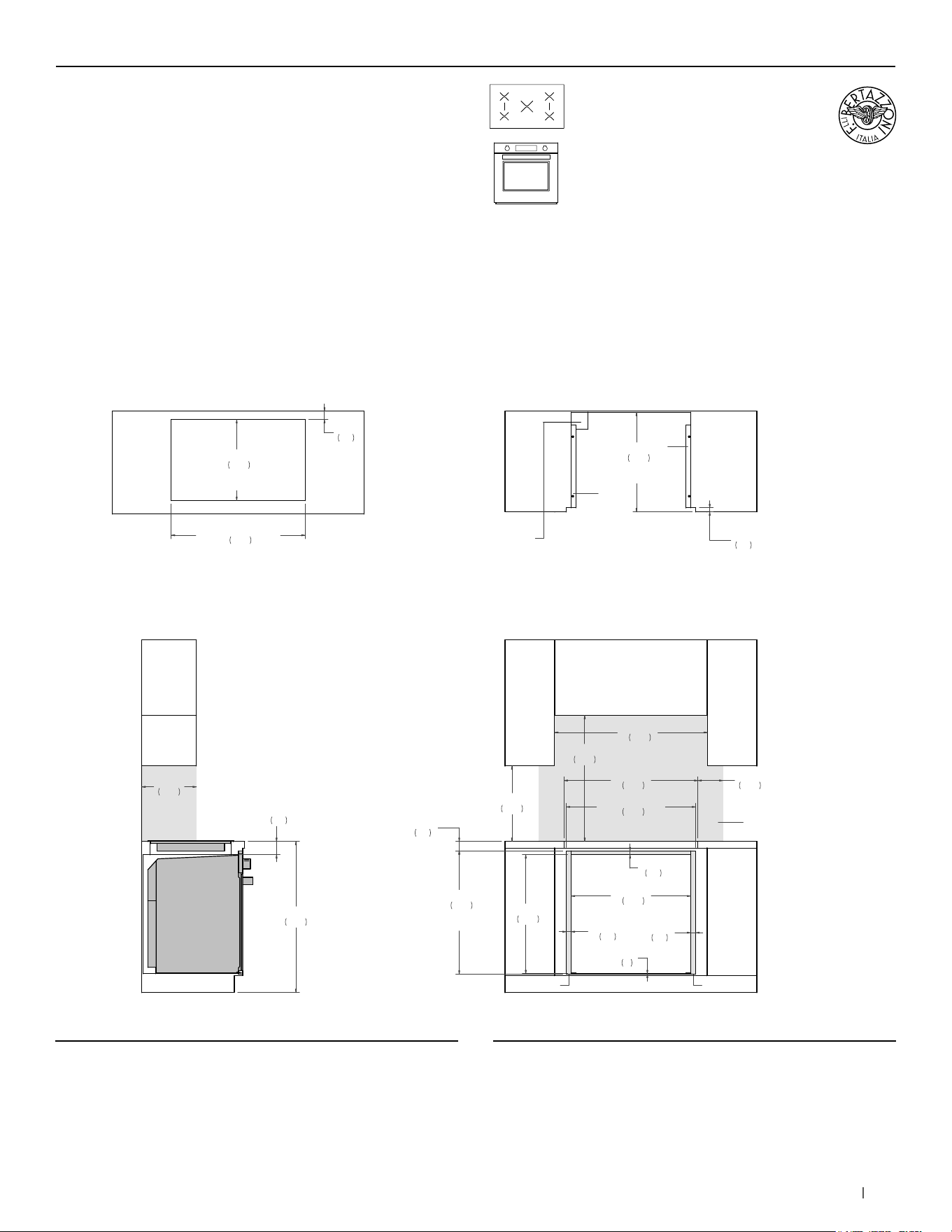
113bertazzoni.com
30” Convection Oven +
36” Induction Cooktop
Flush installation vented
SIDE VIEW
FRONT VIEW
(a) Spacers – Included with appliance
(b) Visible Area – Match finish to outside cabinet panels
(c) Combustible material cannot be installed within shaded area
TOP VIEW – OVEN DETAIL TOP VIEW – COOKTOP DETAIL
a
b
b
a
18"
457
30"
763
36 3/8"
925
3 1/8"
80
36"
914
13"
330
28 3/8"
720
30 7/8"
784
FLUSH INSET
WIDTH
29 3/8"
746
FLUSH INSET
HEIGHT
1 1/8"
30
1 1/8"
30
1/8"
3
7/8"
23
28 1/2"
724
23 3/4"
603
FLUSH INSET
DEPTH
c
2 1/4"
57
31 7/8"
810
4" x 4"
(102 x 102)
CUT OUT SLOT
FOR POWER CORD
6"
152
31 7/8"
810
COOKTOP
CUT-OUT WIDTH
19 1/4"
490
COOKTOP
CUT-OUT DEPTH
2"
51
1"
25
(a) Spacers - Included with appliance
(b) Visible Area - Match finish to outside cabinet panels
(c) Combustible material cannot be installed within shaded area
MULTIPLE INSTALLATIONS - 30” OVEN AND COOKTOP UNDERCOUNTER CONFIGURATIONS
P365IAE PROF30FSEXT
PROF30FSEXV
MAST30FSEXT
MAST30FSEXV
For electrical and gas supply please see single installation
requirements. Placement within the opening may require
additional cabinet depth.
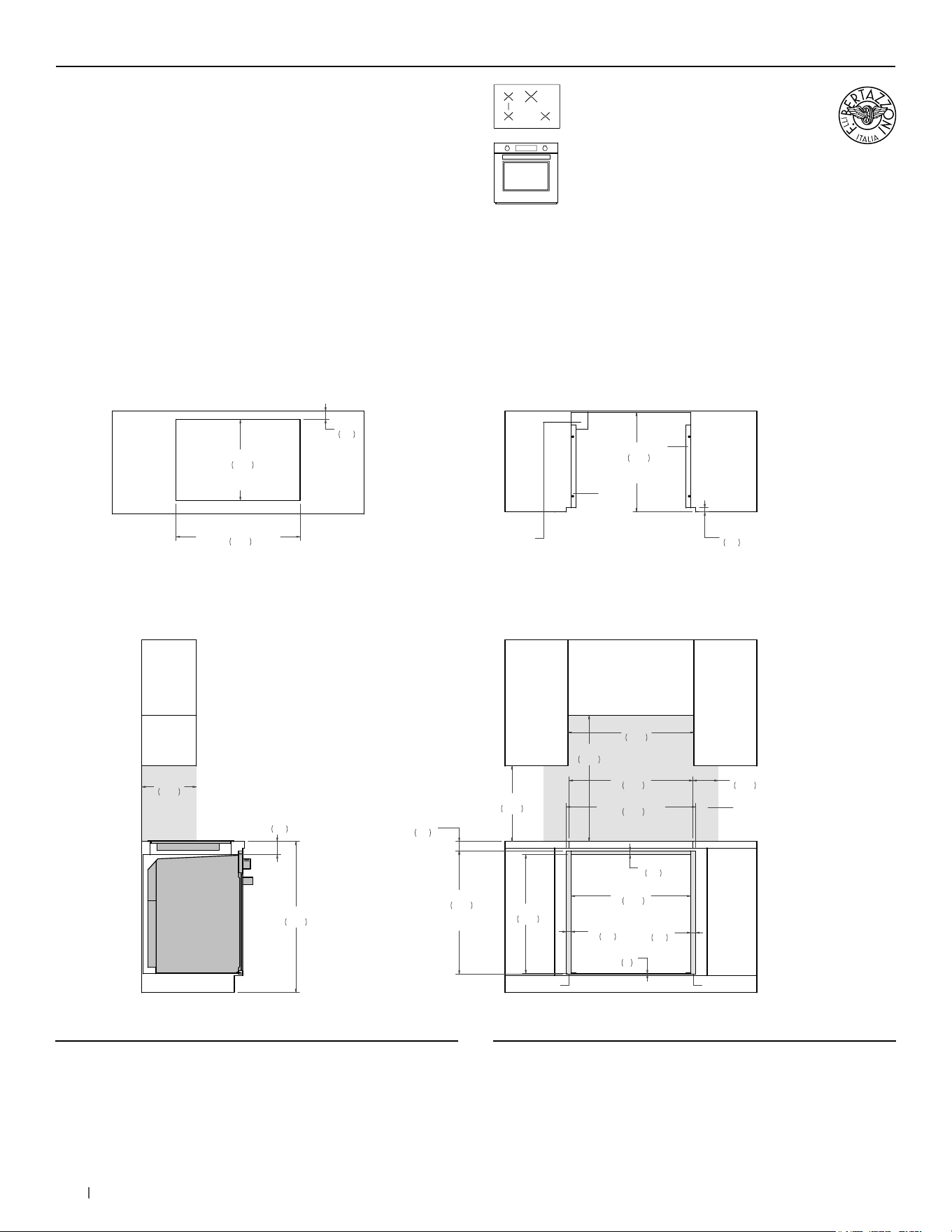
114 bertazzoni.com
30” Convection Oven +
30” Induction Cooktop
Flush installation non vented
SIDE VIEW
FRONT VIEW
(a) Spacers – Included with appliance
(b) Visible Area – Match finish to outside cabinet panels
(c) Combustible material cannot be installed within shaded area
TOP VIEW – OVEN DETAIL TOP VIEW – COOKTOP DETAIL
a
b
b
a
18"
457
30"
763
30"
762
3 1/8"
80
36"
914
13"
330
28 3/8"
720
30 7/8"
784
FLUSH INSET
WIDTH
29 3/8"
746
FLUSH INSET
HEIGHT
1 1/8"
30
1 1/8"
30
1/8"
3
7/8"
23
28 1/2"
724
23 3/4"
603
FLUSH INSET
DEPTH
c
2 1/4"
57
29 1/2"
750
4" x 4"
(102 x 102)
CUT OUT SLOT
FOR POWER CORD
6"
152
19 1/4"
490
COOKTOP
CUT-OUT DEPTH
29 1/2"
750
COOKTOP
CUT-OUT WIDTH
2"
51
1"
25
(a) Spacers - Included with appliance
(b) Visible Area - Match finish to outside cabinet panels
(c) Combustible material cannot be installed within shaded area
MULTIPLE INSTALLATIONS - 30” OVEN AND COOKTOP UNDERCOUNTER CONFIGURATIONS
P304IAE PROF30FSEXT
PROF30FSEXV
MAST30FSEXT
MAST30FSEXV
For electrical and gas supply please see single installation
requirements. Placement within the opening may require
additional cabinet depth.
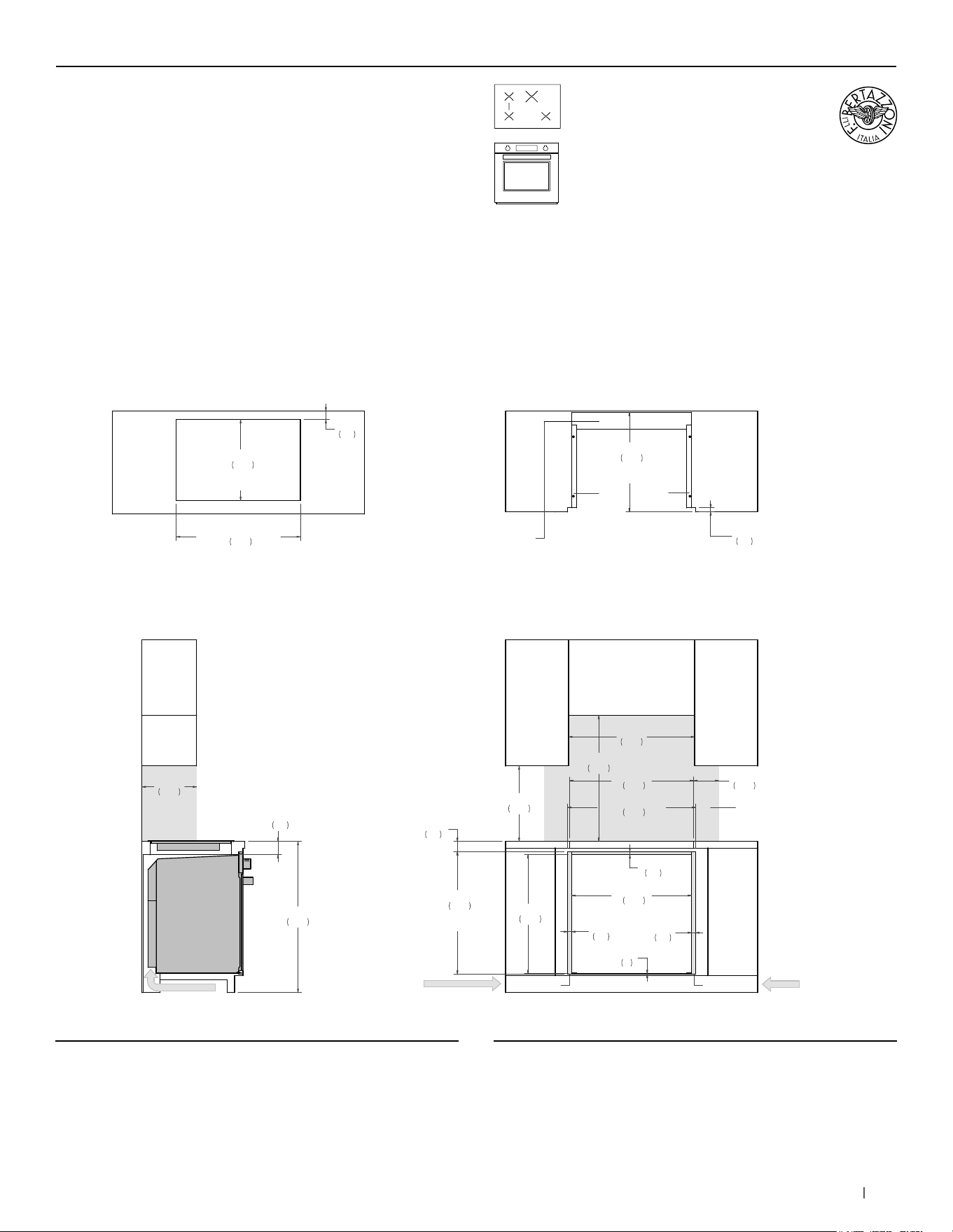
115bertazzoni.com
30” Convection Oven +
30” Induction Cooktop
Flush installation vented
SIDE VIEW
FRONT VIEW
(a) Spacers – Included with appliance
(b) Visible Area – Match finish to outside cabinet panels
(c) Combustible material cannot be installed within shaded area
TOP VIEW – OVEN DETAIL TOP VIEW – COOKTOP DETAIL
AIR INTAKE
a
b
b
a
18"
457
30"
763
30"
762
6"
152
3 1/8"
80
36"
914
13"
330
28 3/8"
720
30 1/2"
774
FLUSH INSET
WIDTH
29 1/8"
741
FLUSH INSET
HEIGHT
1"
25
1"
25
1/8"
3
3/4"
18
28 1/2"
724
23 3/4"
603
FLUSH INSET
DEPTH
c
2 1/2"
62
29 1/2"
750
19 1/4"
490
COOKTOP
CUT-OUT DEPTH
29 1/2"
750
COOKTOP
CUT-OUT WIDTH
2"
51
4" x 28 1/2"
(102 x 724)
AIR INTAKE
1"
25
AIR INTAKE
3" x 16"
(77 x 406)
AIR INTAKE
3" x 16"
(77 x 406)
(a) Spacers - Included with appliance
(b) Visible Area - Match finish to outside cabinet panels
(c) Combustible material cannot be installed within shaded area
MULTIPLE INSTALLATIONS - 30” OVEN AND COOKTOP UNDERCOUNTER CONFIGURATIONS
P304IAE PROF30FSEXT
PROF30FSEXV
MAST30FSEXT
MAST30FSEXV
For electrical and gas supply please see single installation
requirements. Placement within the opening may require
additional cabinet depth.
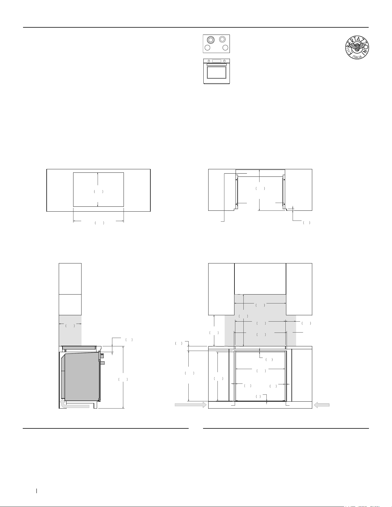
116 bertazzoni.com
SIDE VIEW
FRONT VIEW
(a) Spacers – Included with appliance
(b) Visible Area – Match finish to outside cabinet panels
(c) Combustible material cannot be installed within shaded area
TOP VIEW – OVEN DETAIL TOP VIEW – COOKTOP DETAIL
AIR INTAKE
a
b
b
a
18"
457
30"
763
30"
762
6"
152
36"
914
13"
330
28 3/8"
720
30 1/2"
774
FLUSH INSET
WIDTH
29 1/8"
741
FLUSH INSET
HEIGHT
1"
25
1"
25
1/8"
3
3/4"
18
28 1/2"
724
23 3/4"
603
FLUSH INSET
DEPTH
c
2 5/8"
67
29 1/8"
740
4" x 28 1/2"
(102 x 724)
AIR INTAKE
1"
25
AIR INTAKE
3" x 16"
(77 x 406)
AIR INTAKE
3" x 16"
(77 x 406)
19 5/8"
500
COOKTOP
CUT-OUT DEPTH
29 1/8"
740
COOKTOP
CUT-OUT WIDTH
3 3/8"
85
(a) Spacers - Included with appliance
(b) Visible Area - Match finish to outside cabinet panels
(c) Combustible material cannot be installed within shaded area
MULTIPLE INSTALLATIONS - 30” OVEN AND COOKTOP UNDERCOUNTER CONFIGURATIONS
PE304CER PROF30FSEXT
PROF30FSEXV
MAST30FSEXT
MAST30FSEXV
For electrical and gas supply please see single installation
requirements. Placement within the opening may require
additional cabinet depth.
30” Convection Oven +
30” Electric Ceramic Cooktop
Flush installation vented
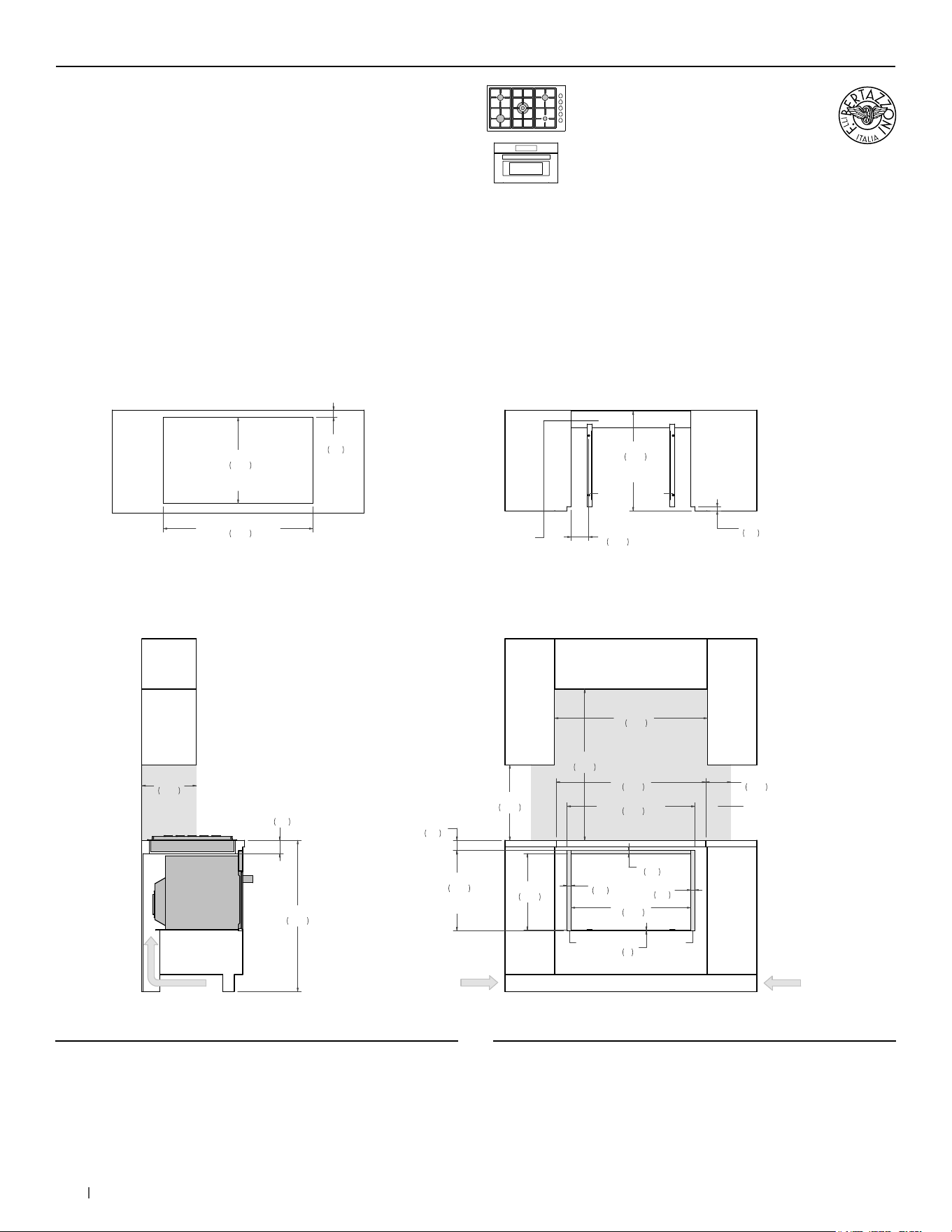
117 bertazzoni.com
30” Specialty Oven +
36” Drop-in Cooktop
Flush installation
SIDE VIEW
FRONT VIEW
(a) Spacers – Included with appliance
(b) Visible Area – Match finish to outside cabinet panels
(c) Combustible material cannot be installed within shaded area
TOP VIEW – OVEN DETAIL TOP VIEW – COOKTOP DETAIL
AIR INTAKE
a
bb
18"
457
36"
915
36 3/8"
925
6"
152
3 1/8"
80
36"
914
13"
330
18 1/4"
464
30 1/2"
774
FLUSH INSET
WIDTH
19 1/8"
485
FLUSH INSET
HEIGHT
1"
25
1"
25
1/8"
3
3/4"
18
28 1/2"
724
23 3/4"
603
FLUSH INSET
DEPTH
a
4 1/4"
107
c
2 1/2"
62
35 5/8"
905
4" x 28 1/2"
(102 x 724)
AIR INTAKE
AIR INTAKE
4" x 15"
(102 x 380)
AIR INTAKE
4" x 15"
(102 x 380)
1"
25
35 5/8"
905
COOKTOP
CUT-OUT WIDTH
20 1/2"
520
COOKTOP
CUT-OUT DEPTH
1 3/4"
45
(a) Spacers - Included with appliance
(b) Visible Area - Match finish to outside cabinet panels
(c) Combustible material cannot be installed within shaded area
MULTIPLE INSTALLATIONS - 30” OVEN AND COOKTOP UNDERCOUNTER CONFIGURATIONS
PROF30SOEX
PROF30CSEX
MAST30SOEX
MAST30CSEX
PROF366QBXT
PROF365QBXT
PRO365QXE
MAST366QBXT
MAST365QBXT
MAST365QXE
For electrical and gas supply please see single installation
requirements. Placement within the opening may require
additional cabinet depth.
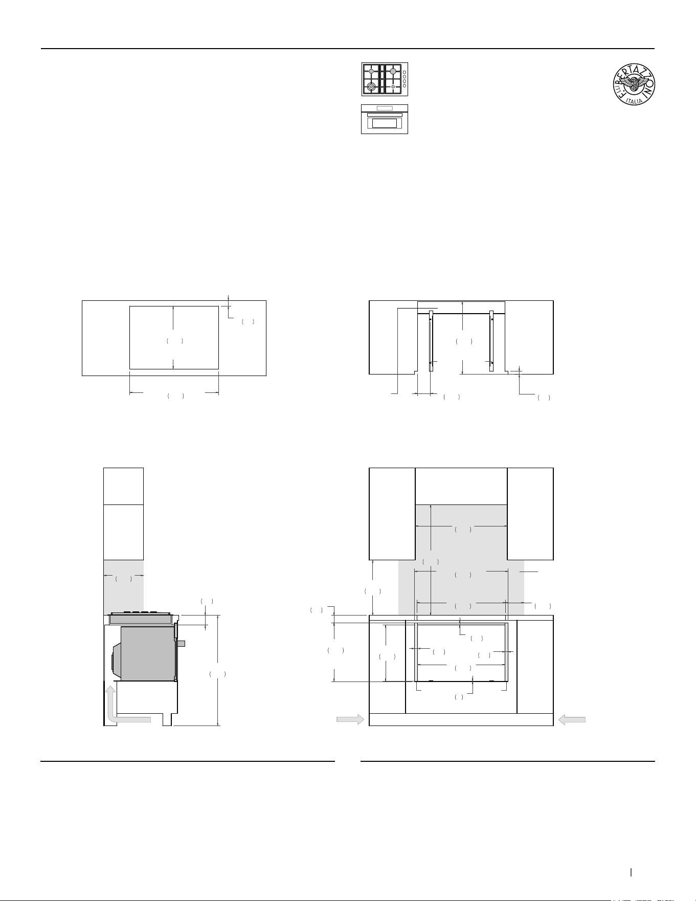
118bertazzoni.com
30” Specialty Oven +
30” Drop-in Cooktop
Flush installation
SIDE VIEW
FRONT VIEW
(a) Spacers – Included with appliance
(b) Visible Area – Match finish to outside cabinet panels
(c) Combustible material cannot be installed within shaded area
TOP VIEW – OVEN DETAIL TOP VIEW – COOKTOP DETAIL
AIR INTAKE
a
bb
18"
457
36"
915
30"
762
6"
152
3 1/8"
80
36"
914
13"
330
18 1/4"
464
30 1/2"
774
FLUSH INSET
WIDTH
19 1/8"
485
FLUSH INSET
HEIGHT
1"
25
1"
25
1/8"
3
3/4"
18
28 1/2"
724
a
4 1/4"
107
c
2 1/2"
62
28 7/8"
735
4" x 28 1/2"
(102 x 724)
AIR INTAKE
AIR INTAKE
4" x 15"
(102 x 380)
AIR INTAKE
4" x 15"
(102 x 380)
23 3/4"
603
FLUSH INSET
DEPTH
1"
25
28 7/8"
735
COOKTOP
CUT-OUT WIDTH
20 1/2"
520
COOKTOP
CUT-OUT DEPTH
1 3/4"
45
(a) Spacers - Included with appliance
(b) Visible Area - Match finish to outside cabinet panels
(c) Combustible material cannot be installed within shaded area
MULTIPLE INSTALLATIONS - 30” OVEN AND COOKTOP UNDERCOUNTER CONFIGURATIONS
PROF30SOEX
PROF30CSEX
MAST30SOEX
MAST30CSEX
PROF304QBXT
PROF304QXE
MAST304QBXT
MAST304QBXE
For electrical and gas supply please see single installation
requirements. Placement within the opening may require
additional cabinet depth.
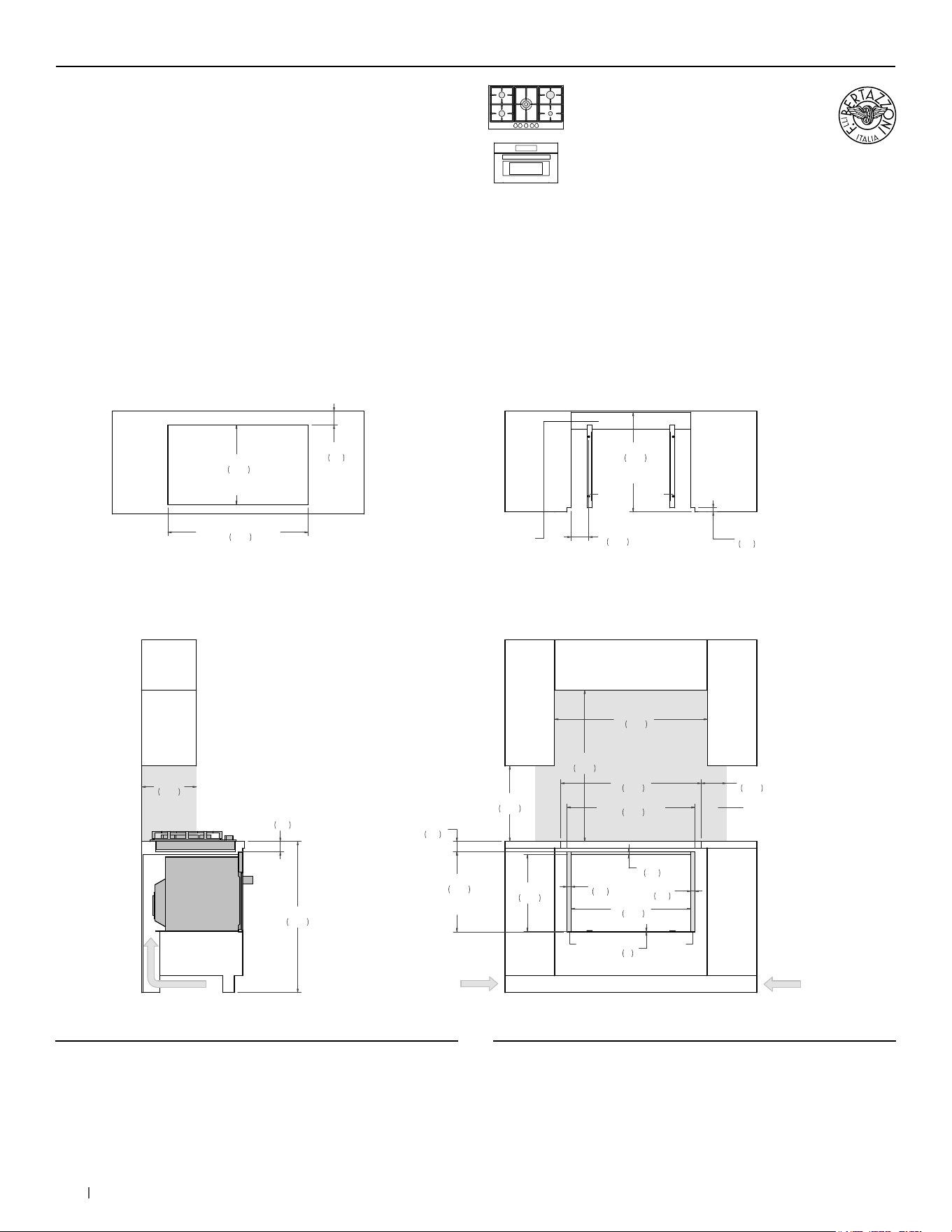
119 bertazzoni.com
30” Specialty Oven +
36” Cooktop XV
Flush installation
SIDE VIEW
FRONT VIEW
(a) Spacers – Included with appliance
(b) Visible Area – Match finish to outside cabinet panels
(c) Combustible material cannot be installed within shaded area
TOP VIEW – OVEN DETAIL TOP VIEW – COOKTOP DETAIL
AIR INTAKE
a
bb
18"
457
36"
915
36 3/8"
925
6"
152
2 1/2"
62
36"
914
13"
330
18 1/4"
464
30 1/2"
774
FLUSH INSET
WIDTH
19 1/8"
485
FLUSH INSET
HEIGHT
1"
25
1"
25
1/8"
3
3/4"
18
28 1/2"
724
23 3/4"
603
FLUSH INSET
DEPTH
a
4 1/4"
107
c
2 1/2"
62
33 1/2"
850
4" x 28 1/2"
(102 x 724)
AIR INTAKE
AIR INTAKE
4" x 15"
(102 x 380)
AIR INTAKE
4" x 15"
(102 x 380)
1"
25
33 1/2"
850
COOKTOP
CUT-OUT WIDTH
18 7/8"
480
COOKTOP
COUT-OUT DEPTH
3 3/8"
85
(a) Spacers - Included with appliance
(b) Visible Area - Match finish to outside cabinet panels
(c) Combustible material cannot be installed within shaded area
MULTIPLE INSTALLATIONS - 30” OVEN AND COOKTOP UNDERCOUNTER CONFIGURATIONS
PROF30SOEX
PROF30CSEX
MAST30SOEX
MAST30CSEX
PROF365CTXV
For electrical and gas supply please see single installation
requirements. Placement within the opening may require
additional cabinet depth.
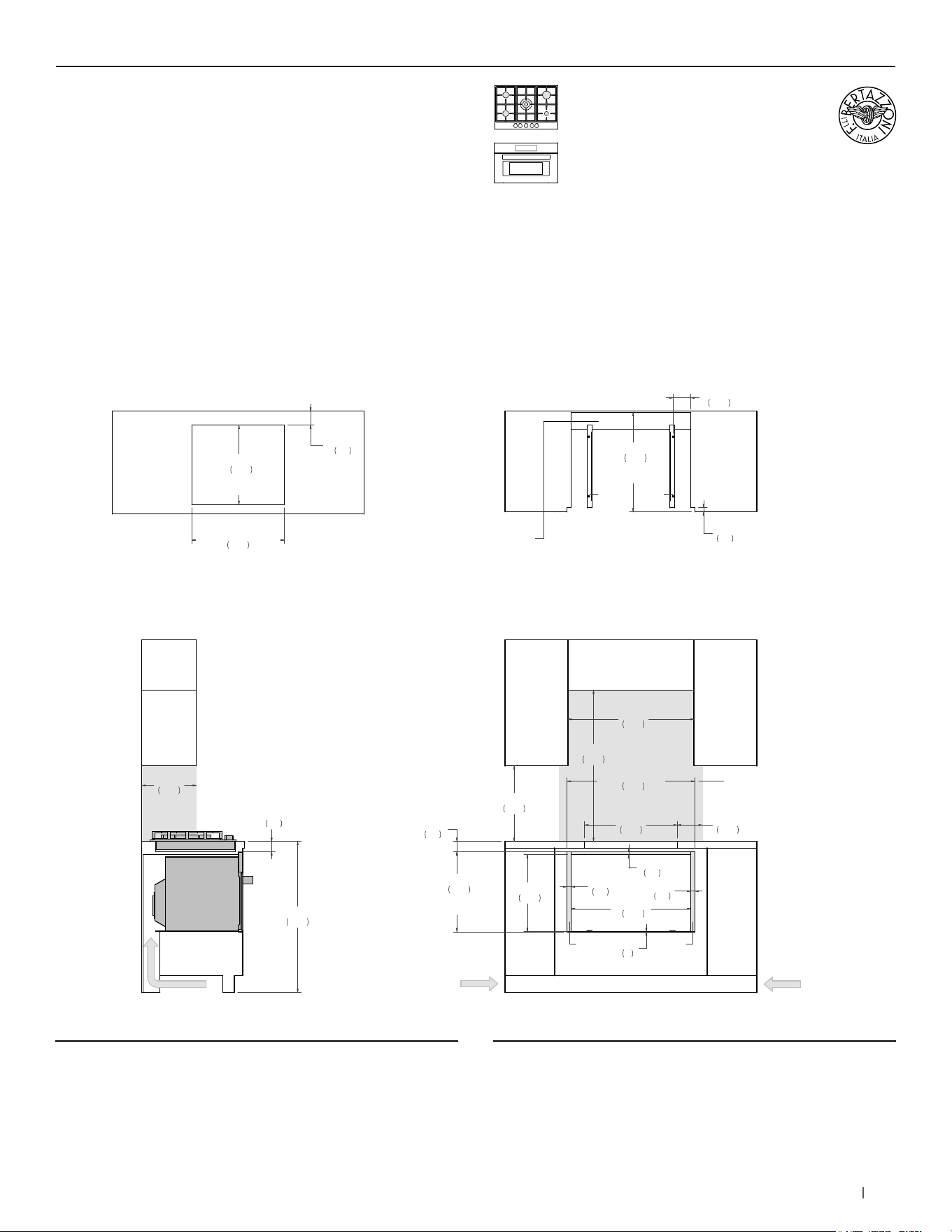
120bertazzoni.com
30” Specialty Oven +
30” Cooktop XV
Flush installation
SIDE VIEW
FRONT VIEW
(a) Spacers – Included with appliance
(b) Visible Area – Match finish to outside cabinet panels
(c) Combustible material cannot be installed within shaded area
TOP VIEW – OVEN DETAIL TOP VIEW – COOKTOP DETAIL
AIR INTAKE
a
18"
457
36"
915
30"
762
6"
152
36"
914
13"
330
18 1/4"
464
30 1/2"
774
FLUSH INSET
WIDTH
19 1/8"
485
FLUSH INSET
HEIGHT
1"
25
1"
25
1/8"
3
3/4"
18
28 1/2"
724
23 3/4"
603
FLUSH INSET
DEPTH
a
c
2 1/2"
62
22"
560
bb
4 1/4"
107
1"
25
4" x 28 1/2"
(102 x 724)
AIR INTAKE
AIR INTAKE
4" x 15"
(102 x 380)
AIR INTAKE
4" x 15"
(102 x 380)
2 1/2"
62
18 7/8"
480
COOKTOP
CUT-OUT DEPTH
22"
560
COOKTOP
CUT-OUT WIDTH
3 3/8"
85
(a) Spacers - Included with appliance
(b) Visible Area - Match finish to outside cabinet panels
(c) Combustible material cannot be installed within shaded area
MULTIPLE INSTALLATIONS - 30” OVEN AND COOKTOP UNDERCOUNTER CONFIGURATIONS
PROF30SOEX
PROF30CSEX
MAST30SOEX
MAST30CSEX
PROF305CTXV
For electrical and gas supply please see single installation
requirements. Placement within the opening may require
additional cabinet depth.
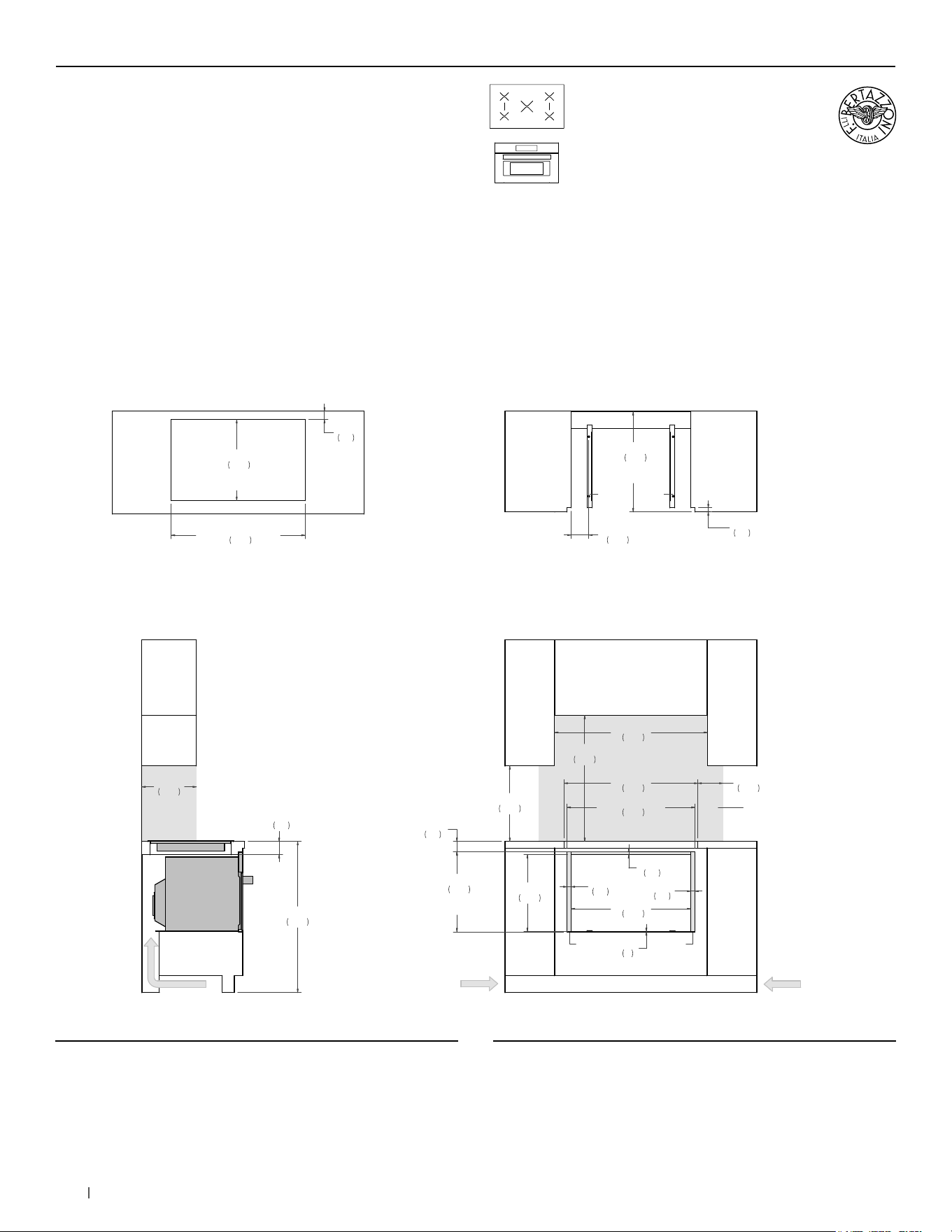
121 bertazzoni.com
30” Specialty Oven +
36” Induction Cooktop
Flush installation
SIDE VIEW
FRONT VIEW
(a) Spacers – Included with appliance
(b) Visible Area – Match finish to outside cabinet panels
(c) Combustible material cannot be installed within shaded area
TOP VIEW – OVEN DETAIL TOP VIEW – COOKTOP DETAIL
AIR INTAKE
a
bb
18"
457
30"
763
36 3/8"
925
6"
152
3 1/8"
80
36"
914
13"
330
18 1/4"
464
30 1/2"
774
FLUSH INSET
WIDTH
19 1/8"
485
FLUSH INSET
HEIGHT
1"
25
1"
25
1/8"
3
3/4"
18
28 1/2"
724
23 7/8"
606
FLUSH INSET
DEPTH
a
4 1/4"
107
c
2 1/2"
62
31 7/8"
810
1"
25
AIR INTAKE
4" x 15"
(102 x 380)
AIR INTAKE
4" x 15"
(102 x 380)
31 7/8"
810
COOKTOP
CUT-OUT WIDTH
19 1/4"
490
COOKTOP
CUT-OUT DEPTH
2"
51
(a) Spacers - Included with appliance
(b) Visible Area - Match finish to outside cabinet panels
(c) Combustible material cannot be installed within shaded area
MULTIPLE INSTALLATIONS - 30” OVEN AND COOKTOP UNDERCOUNTER CONFIGURATIONS
PROF30SOEX
PROF30CSEX
MAST30SOEX
MAST30CSEX
P365IAE
For electrical and gas supply please see single installation
requirements. Placement within the opening may require
additional cabinet depth.
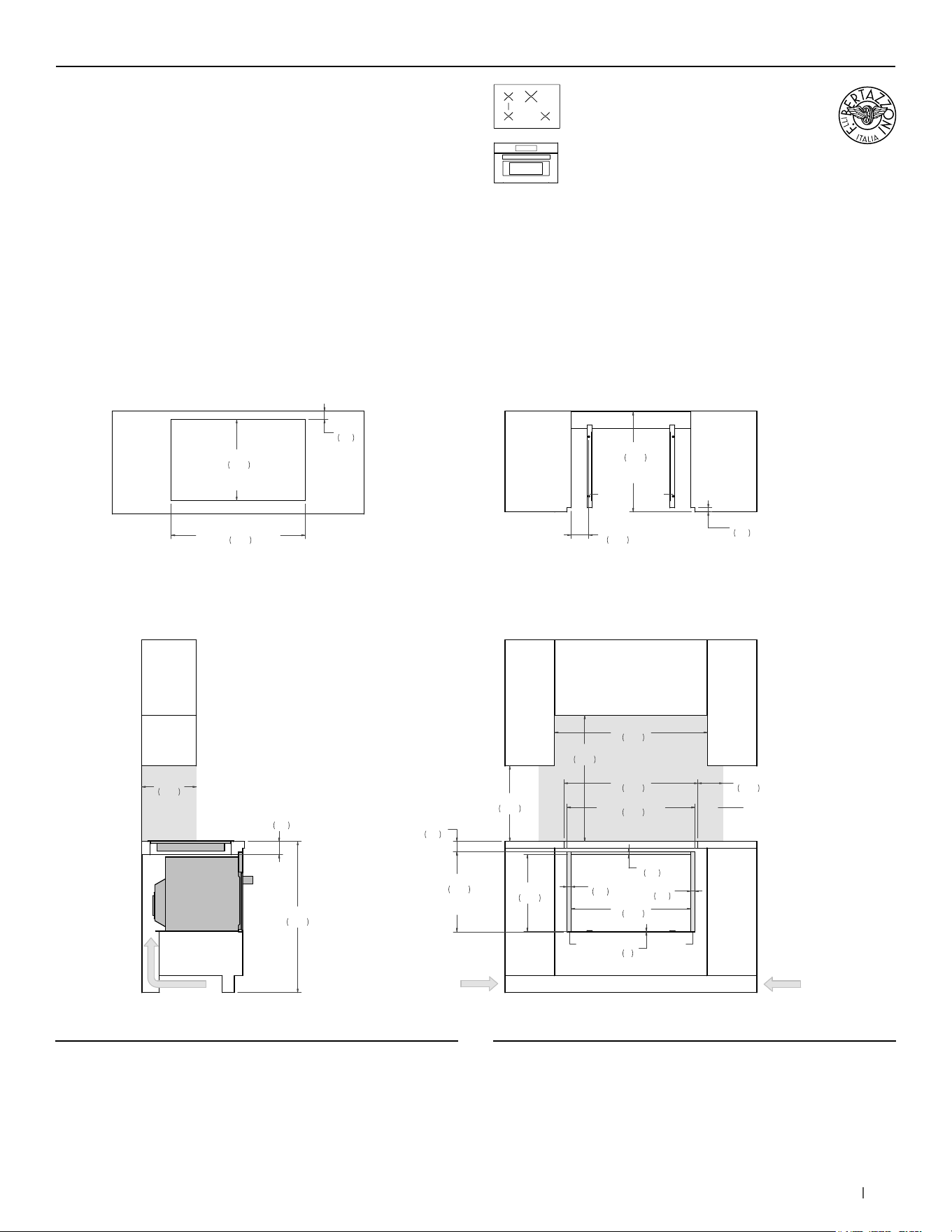
122bertazzoni.com
30” Specialty Oven +
30” Induction Cooktop
Flush installation
SIDE VIEW
FRONT VIEW
(a) Spacers – Included with appliance
(b) Visible Area – Match finish to outside cabinet panels
(c) Combustible material cannot be installed within shaded area
TOP VIEW – OVEN DETAIL TOP VIEW – COOKTOP DETAIL
AIR INTAKE
a
bb
18"
457
30"
763
36 3/8"
925
6"
152
3 1/8"
80
36"
914
13"
330
18 1/4"
464
30 1/2"
774
FLUSH INSET
WIDTH
19 1/8"
485
FLUSH INSET
HEIGHT
1"
25
1"
25
1/8"
3
3/4"
18
28 1/2"
724
23 7/8"
606
FLUSH INSET
DEPTH
a
4 1/4"
107
c
2 1/2"
62
31 7/8"
810
1"
25
AIR INTAKE
4" x 15"
(102 x 380)
AIR INTAKE
4" x 15"
(102 x 380)
31 7/8"
810
COOKTOP
CUT-OUT WIDTH
19 1/4"
490
COOKTOP
CUT-OUT DEPTH
2"
51
(a) Spacers - Included with appliance
(b) Visible Area - Match finish to outside cabinet panels
(c) Combustible material cannot be installed within shaded area
MULTIPLE INSTALLATIONS - 30” OVEN AND COOKTOP UNDERCOUNTER CONFIGURATIONS
PROF30SOEX
PROF30CSEX
MAST30SOEX
MAST30CSEX
P304IAE
For electrical and gas supply please see single installation
requirements. Placement within the opening may require
additional cabinet depth.
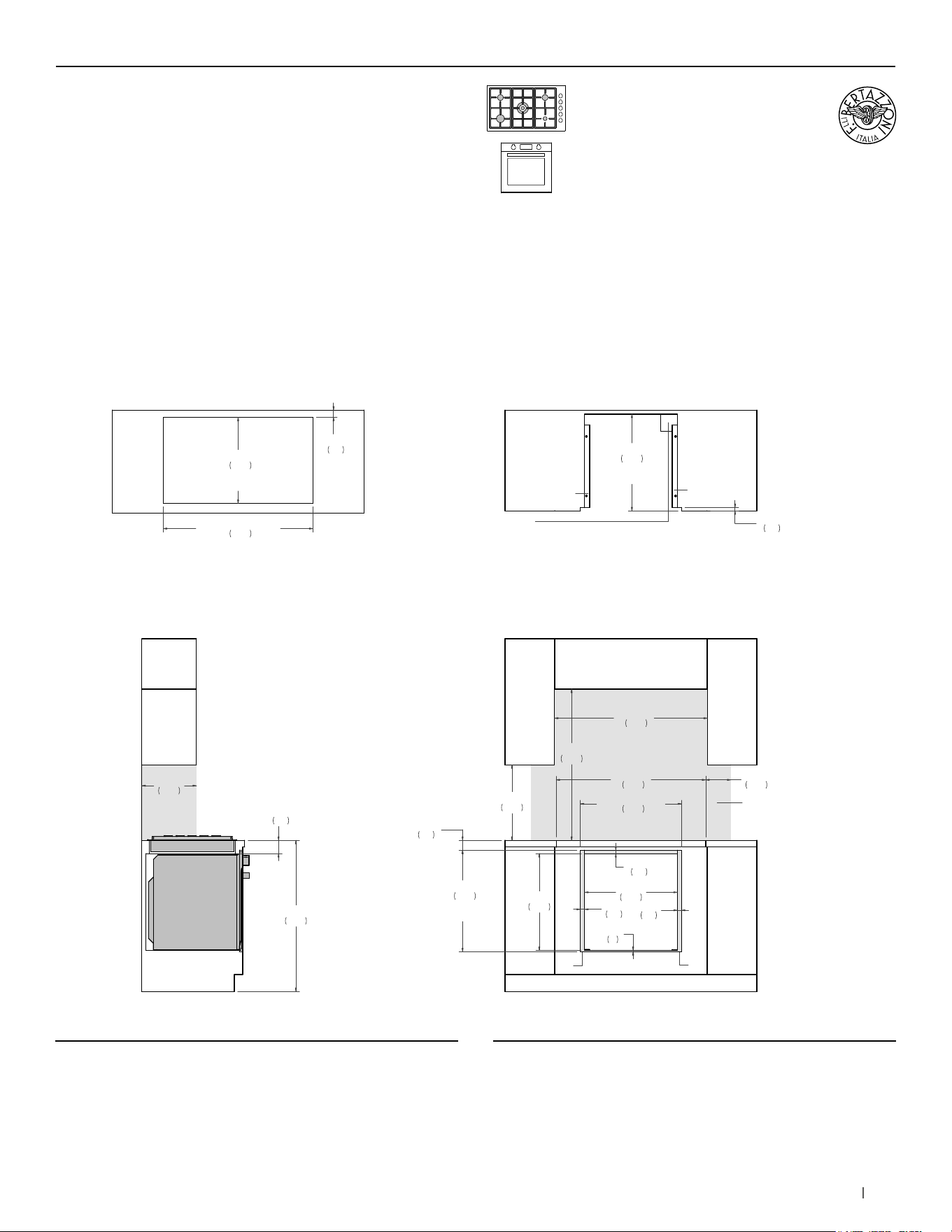
123bertazzoni.com
24” Convection Oven +
36” Drop-in Cooktop
Flush installation
SIDE VIEW
FRONT VIEW
(a) Spacers – Included with appliance
(b) Visible Area – Match finish to outside cabinet panels
(c) Combustible material cannot be installed within shaded area
TOP VIEW – OVEN DETAIL TOP VIEW – COOKTOP DETAIL
a
b
b
a
18"
457
36"
915
36 3/8"
925
6"
152
3 1/8"
80
36"
914
13"
330
23"
585
24 1/8"
612
FLUSH INSET
WIDTH
24 1/8"
614
FLUSH INSET
HEIGHT
1"
26
1"
26
3/8"
9
3/4"
20
22"
560
23"
585
FLUSH INSET
DEPTH
c
2 3/8"
60
35 5/8"
905
4" x 4"
(102 x 102)
CUT OUT SLOT
FOR POWER CORD
3/4"
20
35 5/8"
905
COOKTOP
CUT-OUT WIDTH
20 1/2"
520
COOKTOP
CUT-OUT DEPTH
1 3/4"
45
(a) Spacers - Included with appliance
(b) Visible Area - Match finish to outside cabinet panels
(c) Combustible material cannot be installed within shaded area
MULTIPLE INSTALLATIONS - 24” OVEN AND COOKTOP UNDERCOUNTER CONFIGURATIONS
PROF24FSEXV PROF366QBXT
PROF365QBXT
PRO365QXE
MAST366QBXT
MAST365QBXT
MAST365QXE
For electrical and gas supply please see single installation
requirements. Placement within the opening may require
additional cabinet depth.
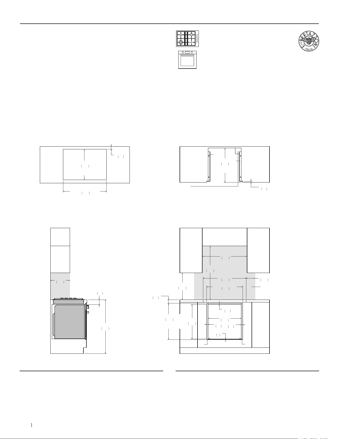
124 bertazzoni.com
24” Convection Oven +
30” Drop-in Cooktop
Flush installation
SIDE VIEW
FRONT VIEW
(a) Spacers – Included with appliance
(b) Visible Area – Match finish to outside cabinet panels
(c) Combustible material cannot be installed within shaded area
TOP VIEW – OVEN DETAIL TOP VIEW – COOKTOP DETAIL
a
b
b
a
18"
457
36"
915
30"
762
6"
152
3 1/8"
80
36"
914
13"
330
23"
585
24 1/8"
612
FLUSH INSET
WIDTH
24 1/8"
614
FLUSH INSET
HEIGHT
1"
26
1"
26
3/8"
9
3/4"
20
22"
560
23"
585
FLUSH INSET
DEPTH
c
2 3/8"
60
28 7/8"
735
3/4"
20
4" x 4"
(102 x 102)
CUT OUT SLOT
FOR POWER CORD
28 7/8"
735
COOKTOP
CUT-OUT WIDTH
20 1/2"
520
COOKTOP
CUT-OUT DEPTH
1 3/4"
45
(a) Spacers - Included with appliance
(b) Visible Area - Match finish to outside cabinet panels
(c) Combustible material cannot be installed within shaded area
MULTIPLE INSTALLATIONS - 24” OVEN AND COOKTOP UNDERCOUNTER CONFIGURATIONS
PROF24SOEX PROF304QBXT
PROF304QXE
MAST304QBXT
MAST304QXE
For electrical and gas supply please see single installation
requirements. Placement within the opening may require
additional cabinet depth.
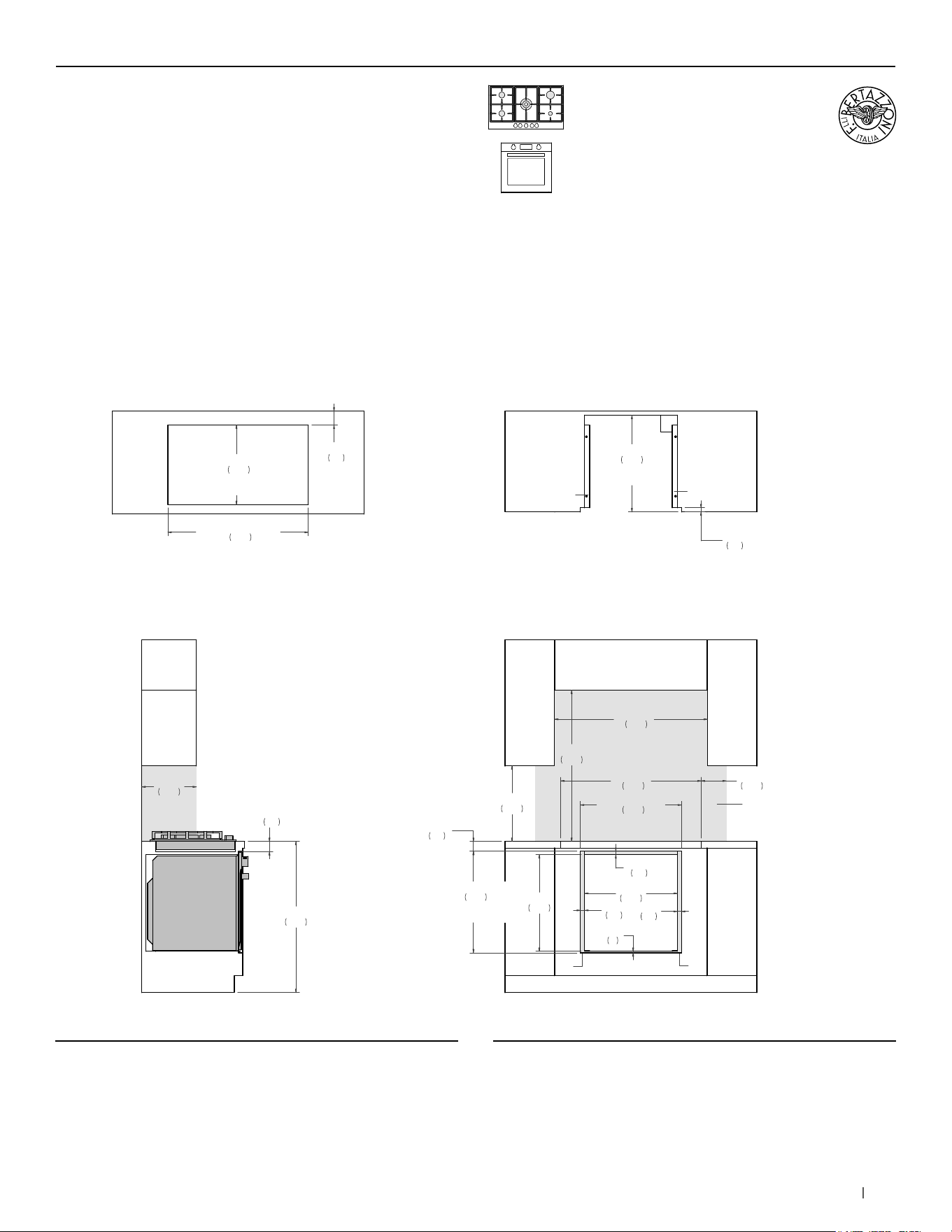
125bertazzoni.com
24” Convection Oven +
36” Cooktop XV
Flush installation
SIDE VIEW
FRONT VIEW
(a) Spacers – Included with appliance
(b) Visible Area – Match finish to outside cabinet panels
(c) Combustible material cannot be installed within shaded area
TOP VIEW – OVEN DETAIL TOP VIEW – COOKTOP DETAIL
a
b
b
a
18"
457
36"
915
36 3/8"
925
6"
152
36"
914
13"
330
23"
585
24 1/8"
612
FLUSH INSET
WIDTH
24 1/8"
614
FLUSH INSET
HEIGHT
1"
26
1"
26
3/8"
9
3/4"
20
22"
560
23"
585
FLUSH INSET
DEPTH
c
2 3/8"
60
33 1/2"
850
1"
25
2 1/2"
62
33 1/2"
850
COOKTOP
CUT-OUT WIDTH
18 7/8"
480
COOKTOP
COUT-OUT DEPTH
3 3/8"
85
(a) Spacers - Included with appliance
(b) Visible Area - Match finish to outside cabinet panels
(c) Combustible material cannot be installed within shaded area
MULTIPLE INSTALLATIONS - 24” OVEN AND COOKTOP UNDERCOUNTER CONFIGURATIONS
PROF24FSEXV PROF365CTXV
For electrical and gas supply please see single installation
requirements. Placement within the opening may require
additional cabinet depth.
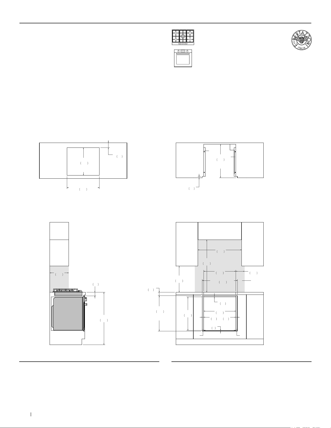
126 bertazzoni.com
24” Convection Oven +
30” Cooktop XV
Flush installation
SIDE VIEW
FRONT VIEW
(a) Spacers – Included with appliance
(b) Visible Area – Match finish to outside cabinet panels
(c) Combustible material cannot be installed within shaded area
TOP VIEW – OVEN DETAIL TOP VIEW – COOKTOP DETAIL
a
a
18"
457
36"
915
30"
762
6"
152
36"
914
13"
330
23"
585
24 1/8"
612
FLUSH INSET
WIDTH
24 1/8"
614
FLUSH INSET
HEIGHT
1"
26
1"
26
3/8"
9
3/4"
20
22"
560
23"
585
FLUSH INSET
DEPTH
c
2 3/8"
60
22"
560
bb
1"
25
2 1/2"
62
18 7/8"
480
COOKTOP
CUT-OUT DEPTH
22"
560
COOKTOP
CUT-OUT WIDTH
3 3/8"
85
(a) Spacers - Included with appliance
(b) Visible Area - Match finish to outside cabinet panels
(c) Combustible material cannot be installed within shaded area
MULTIPLE INSTALLATIONS - 24” OVEN AND COOKTOP UNDERCOUNTER CONFIGURATIONS
PROF24FSEXV PROF305CTXV
For electrical and gas supply please see single installation
requirements. Placement within the opening may require
additional cabinet depth.
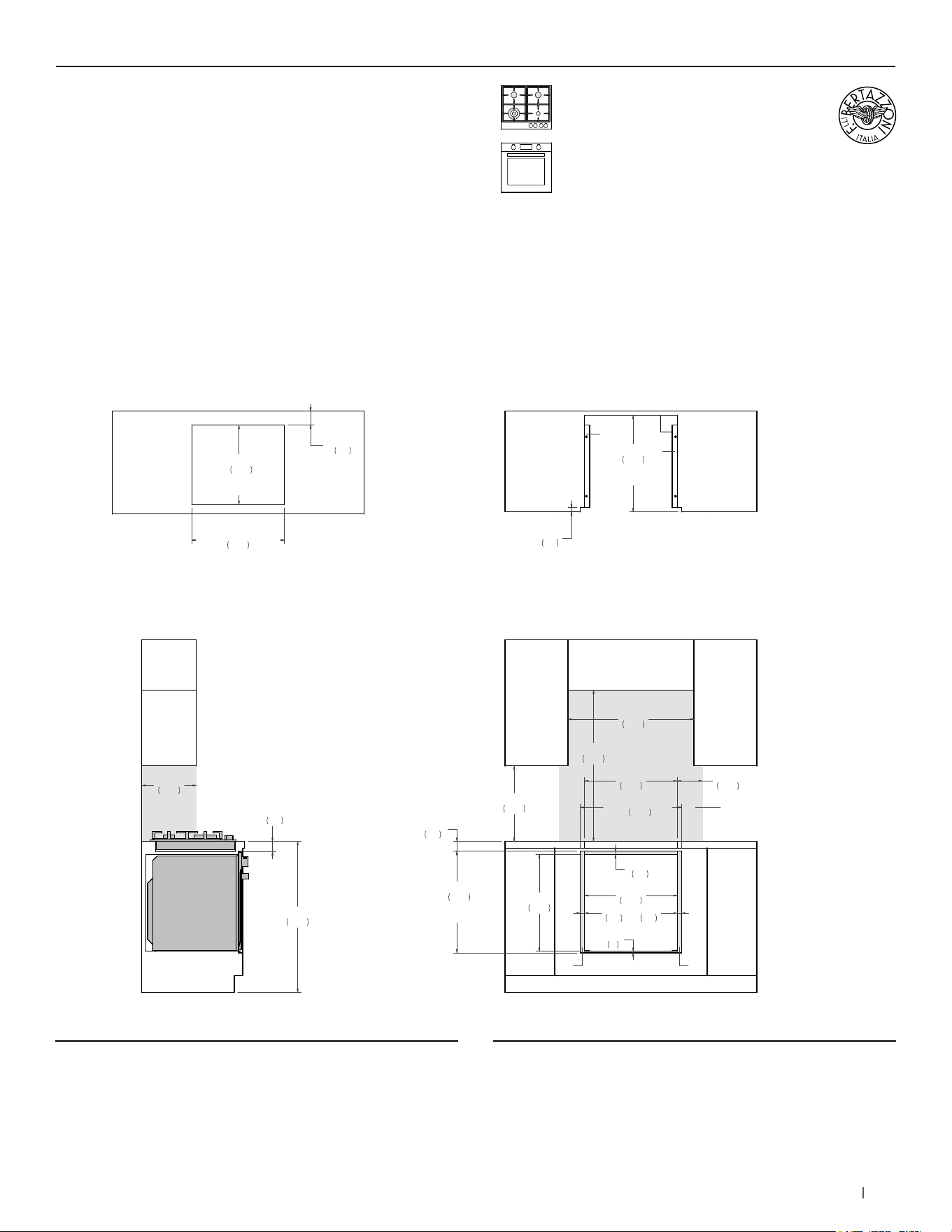
127bertazzoni.com
24” Convection Oven +
24” Cooktop XV
Flush installation
SIDE VIEW
FRONT VIEW
(a) Spacers – Included with appliance
(b) Visible Area – Match finish to outside cabinet panels
(c) Combustible material cannot be installed within shaded area
TOP VIEW – OVEN DETAIL TOP VIEW – COOKTOP DETAIL
a
a
18"
457
36"
915
30"
762
6"
152
36"
914
13"
330
23"
585
24 1/8"
612
FLUSH INSET
WIDTH
24 1/8"
614
FLUSH INSET
HEIGHT
1"
26
1"
26
3/8"
9
3/4"
20
22"
560
23"
585
FLUSH INSET
DEPTH
c
2 3/8"
60
22"
560
bb
1"
25
2 1/2"
62
18 7/8"
480
COOKTOP
CUT-OUT DEPTH
22"
560
COOKTOP
CUT-OUT WIDTH
3 3/8"
85
(a) Spacers - Included with appliance
(b) Visible Area - Match finish to outside cabinet panels
(c) Combustible material cannot be installed within shaded area
MULTIPLE INSTALLATIONS - 24” OVEN AND COOKTOP UNDERCOUNTER CONFIGURATIONS
PROF24FSEXV PROF244CTXV
For electrical and gas supply please see single installation
requirements. Placement within the opening may require
additional cabinet depth.
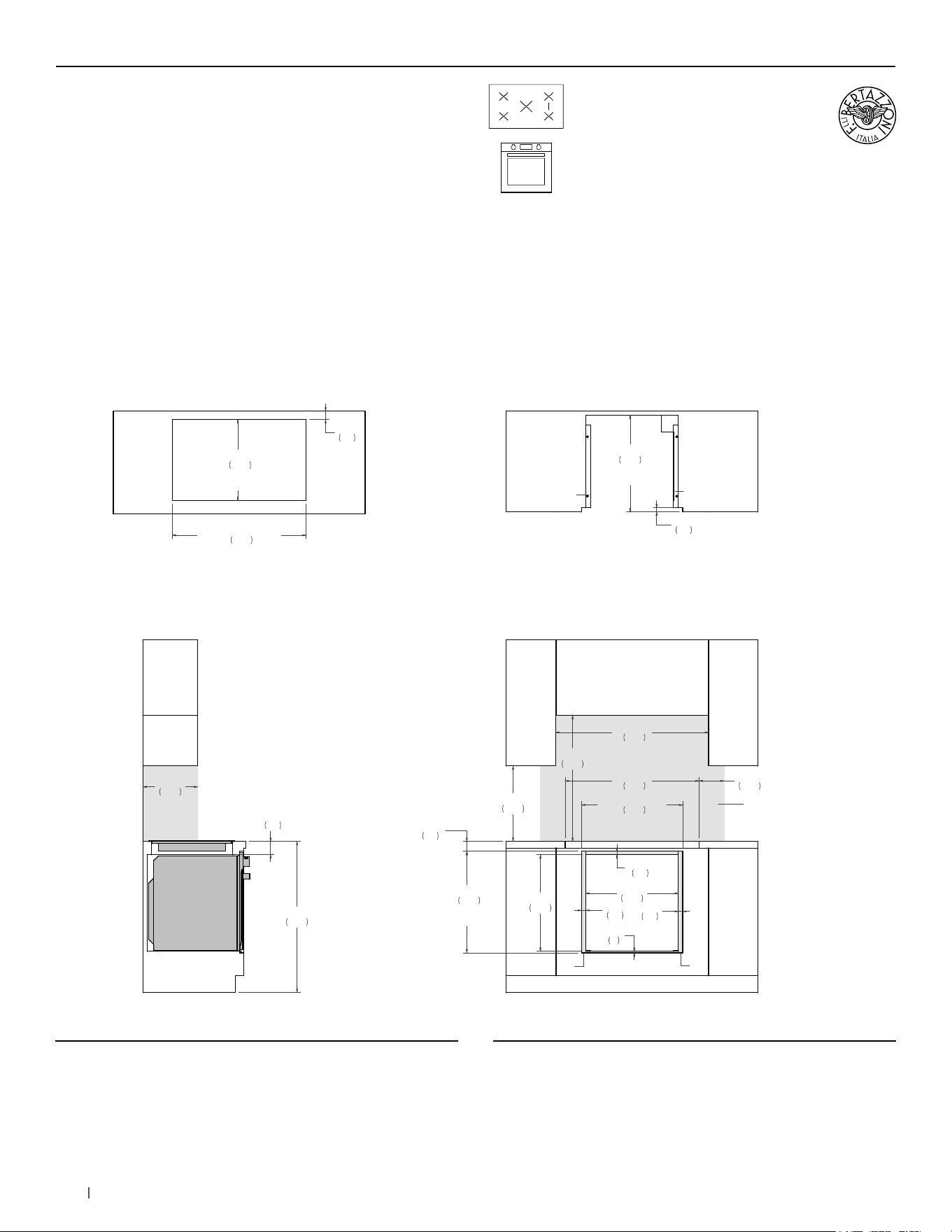
128 bertazzoni.com
24” Convection Oven +
36” Induction Cooktop
Flush installation
SIDE VIEW
FRONT VIEW
(a) Spacers – Included with appliance
(b) Visible Area – Match finish to outside cabinet panels
(c) Combustible material cannot be installed within shaded area
TOP VIEW – OVEN DETAIL TOP VIEW – COOKTOP DETAIL
a
b
b
a
18"
457
30"
763
36 3/8"
925
6"
152
36"
914
13"
330
23"
585
24 1/8"
612
FLUSH INSET
WIDTH
24 1/8"
614
FLUSH INSET
HEIGHT
1"
26
1"
26
3/8"
9
3/4"
20
22"
560
23"
585
FLUSH INSET
DEPTH
c
2 3/8"
60
31 7/8"
810
31 7/8"
810
COOKTOP
CUT-OUT WIDTH
19 1/4"
490
COOKTOP
CUT-OUT DEPTH
2"
51
1"
25
3 1/8"
80
(a) Spacers - Included with appliance
(b) Visible Area - Match finish to outside cabinet panels
(c) Combustible material cannot be installed within shaded area
MULTIPLE INSTALLATIONS - 24” OVEN AND COOKTOP UNDERCOUNTER CONFIGURATIONS
PROF24FSEXV P365IAE
For electrical and gas supply please see single installation
requirements. Placement within the opening may require
additional cabinet depth.
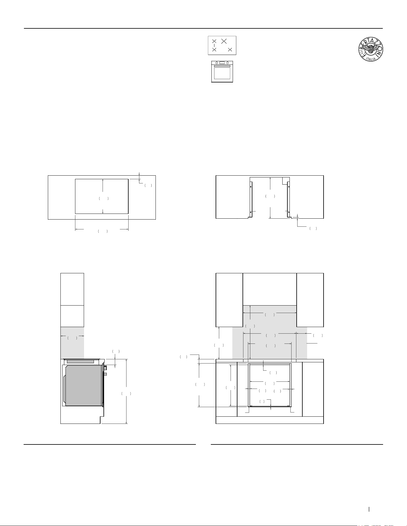
129bertazzoni.com
24” Convection Oven +
30” Induction Cooktop
Flush installation
SIDE VIEW
FRONT VIEW
TOP VIEW – OVEN DETAIL TOP VIEW – COOKTOP DETAIL
(a) Spacers – Included with appliance
(b) Visible Area – Match finish to outside cabinet panels
(c) Combustible material cannot be installed within shaded area
a
b
b
a
18"
457
30"
763
30"
762
6"
152
36"
914
13"
330
23"
585
24 1/8"
612
FLUSH INSET
WIDTH
24 1/8"
614
FLUSH INSET
HEIGHT
1"
26
1"
26
3/8"
9
3/4"
20
22"
560
23"
585
FLUSH INSET
DEPTH
c
2 3/8"
60
29 1/2"
750
19 1/4"
490
COOKTOP
CUT-OUT DEPTH
29 1/2"
750
COOKTOP
CUT-OUT WIDTH
2"
51
3 1/8"
80
3/4"
20
(a) Spacers - Included with appliance
(b) Visible Area - Match finish to outside cabinet panels
(c) Combustible material cannot be installed within shaded area
MULTIPLE INSTALLATIONS - 24” OVEN AND COOKTOP UNDERCOUNTER CONFIGURATIONS
PROF24FSEXV P304IAE
For electrical and gas supply please see single installation
requirements. Placement within the opening may require
additional cabinet depth.
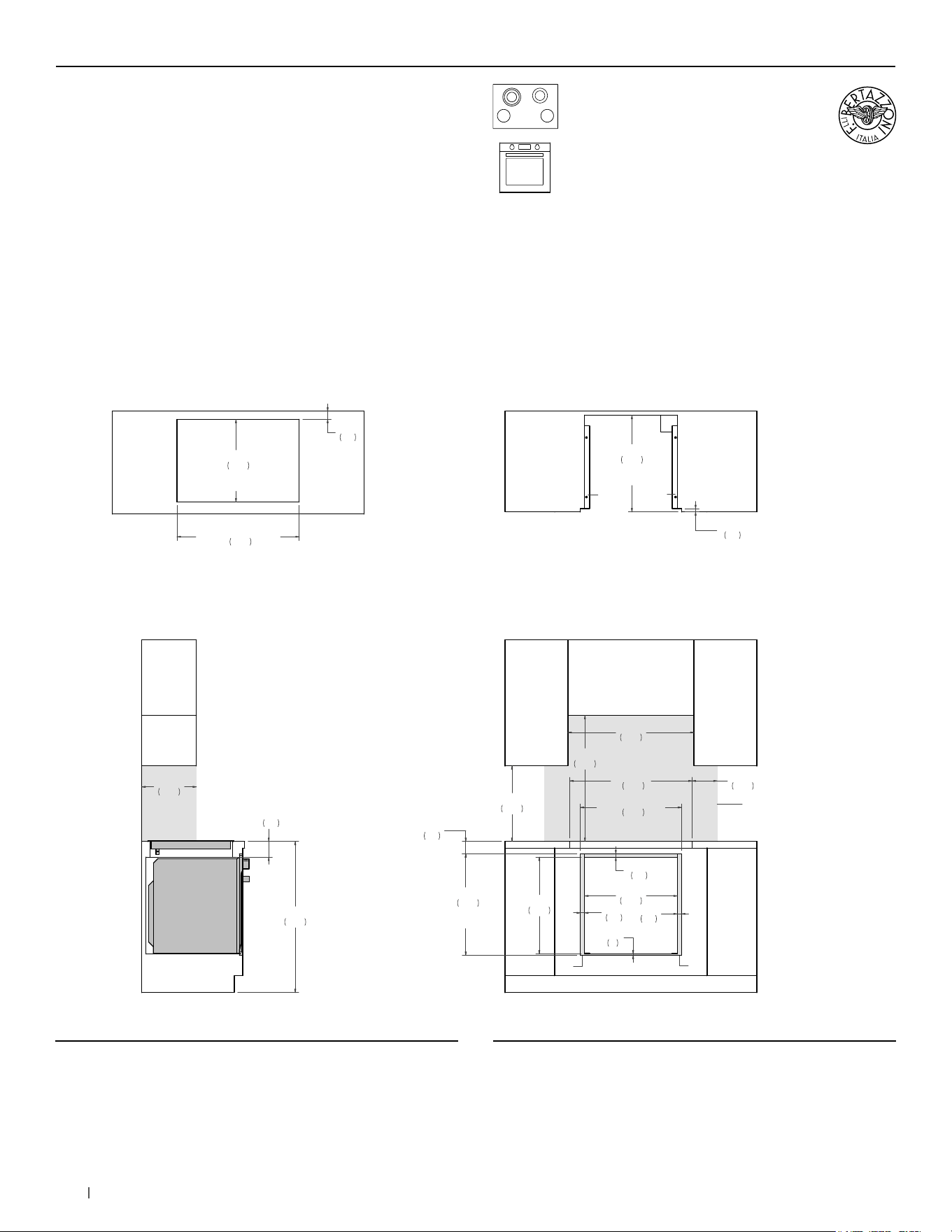
130 bertazzoni.com
24” Convection Oven +
30” Electric Ceramic Cooktop
Flush installation
SIDE VIEW
FRONT VIEW
TOP VIEW – OVEN DETAIL TOP VIEW – COOKTOP DETAIL
(a) Spacers – Included with appliance
(b) Visible Area – Match finish to outside cabinet panels
(c) Combustible material cannot be installed within shaded area
a
b
b
a
18"
457
30"
763
30"
762
6"
152
36"
914
13"
330
23"
585
24 1/8"
612
FLUSH INSET
WIDTH
24 1/8"
614
FLUSH INSET
HEIGHT
1"
26
1"
26
3/8"
9
3/4"
20
22"
560
23"
585
FLUSH INSET
DEPTH
c
3"
75
29 1/8"
740
3 3/4"
95
3/4"
20
19 5/8"
500
COOKTOP
CUT-OUT DEPTH
29 1/8"
740
COOKTOP
CUT-OUT WIDTH
2"
50
(a) Spacers - Included with appliance
(b) Visible Area - Match finish to outside cabinet panels
(c) Combustible material cannot be installed within shaded area
MULTIPLE INSTALLATIONS - 24” OVEN AND COOKTOP UNDERCOUNTER CONFIGURATIONS
PE304CER PROF24FSEXV
For electrical and gas supply please see single installation
requirements. Placement within the opening may require
additional cabinet depth.
131bertazzoni.com
24” Convection Oven +
24” Electric Ceramic Cooktop
Flush installation
SIDE VIEW
FRONT VIEW
TOP VIEW – OVEN DETAIL TOP VIEW – COOKTOP DETAIL
(a) Spacers – Included with appliance
(b) Visible Area – Match finish to outside cabinet panels
(c) Combustible material cannot be installed within shaded area
a
a
18"
457
30"
763
30"
762
6"
152
36"
914
13"
330
23"
585
24 1/8"
612
FLUSH INSET
WIDTH
24 1/8"
614
FLUSH INSET
HEIGHT
1"
26
1"
26
3/8"
9
3/4"
20
22"
560
23"
585
FLUSH INSET
DEPTH
c
3"
75
23 1/4"
590
3 3/4"
95
3/4"
20
23 1/4"
590
COOKTOP
CUT-OUT WIDTH
19 5/8"
500
COOKTOP
CUT-OUT DEPTH
2"
50
b
b
(a) Spacers - Included with appliance
(b) Visible Area - Match finish to outside cabinet panels
(c) Combustible material cannot be installed within shaded area
MULTIPLE INSTALLATIONS - 24” OVEN AND COOKTOP UNDERCOUNTER CONFIGURATIONS
PE244CER PROF24FSEXV
For electrical and gas supply please see single installation
requirements. Placement within the opening may require
additional cabinet depth.
132 bertazzoni.com
24” Specialty Oven +
36” Drop-in Cooktop
Flush installation
SIDE VIEW
FRONT VIEW
(a) Spacers – Included with appliance
(b) Visible Area – Match finish to outside cabinet panels
(c) Combustible material cannot be installed within shaded area
TOP VIEW – OVEN DETAIL TOP VIEW – COOKTOP DETAIL
AIR INTAKE
a
bb
a
18"
457
36"
915
36 3/8"
925
6"
152
3 1/8"
80
36"
914
13"
330
17 7/8"
455
24"
610
FLUSH INSET
WIDTH
18 1/2"
470
FLUSH INSET
HEIGHT
1"
25
1"
25
1/8"
3
1/2"
12
22"
560
23 3/4"
603
FLUSH INSET
DEPTH
c
2 5/8"
68
35 5/8"
905
4" x 22"
(102 x 560)
AIR INTAKE
AIR INTAKE
4" x 15"
(102 x 380)
AIR INTAKE
4" x 15"
(102 x 380)
35 5/8"
905
COOKTOP
CUT-OUT WIDTH
20 1/2"
520
COOKTOP
CUT-OUT DEPTH
1 3/4"
45
3/4"
19
(a) Spacers - Included with appliance
(b) Visible Area - Match finish to outside cabinet panels
(c) Combustible material cannot be installed within shaded area
MULTIPLE INSTALLATIONS - 24” OVEN AND COOKTOP UNDERCOUNTER CONFIGURATIONS
PROF24SOEXV
PROF366QBXT
PROF365QBXT
PROF365QXE
MAST366QBXT
MAST365QBXT
MAST365QXE
For electrical and gas supply please see single installation
requirements. Placement within the opening may require
additional cabinet depth.
133bertazzoni.com
24” Specialty Oven +
30” Drop-in Cooktop
Flush installation
SIDE VIEW
FRONT VIEW
(a) Spacers – Included with appliance
(b) Visible Area – Match finish to outside cabinet panels
(c) Combustible material cannot be installed within shaded area
TOP VIEW – OVEN DETAIL TOP VIEW – COOKTOP DETAIL
AIR INTAKE
a
bb
a
18"
457
36"
915
30"
762
6"
152
3 1/8"
80
36"
914
13"
330
17 7/8"
455
24"
610
FLUSH INSET
WIDTH
18 1/2"
470
FLUSH INSET
HEIGHT
1"
25
1"
25
1/8"
3
1/2"
12
22"
560
23 3/4"
603
FLUSH INSET
DEPTH
c
2 5/8"
68
28 7/8"
735
4" x 22"
(102 x 560)
AIR INTAKE
AIR INTAKE
4" x 15"
(102 x 380)
AIR INTAKE
4" x 15"
(102 x 380)
3/4"
19
28 7/8"
735
COOKTOP
CUT-OUT WIDTH
20 1/2"
520
COOKTOP
CUT-OUT DEPTH
1 3/4"
45
(a) Spacers - Included with appliance
(b) Visible Area - Match finish to outside cabinet panels
(c) Combustible material cannot be installed within shaded area
MULTIPLE INSTALLATIONS - 24” OVEN AND COOKTOP UNDERCOUNTER CONFIGURATIONS
PROF24SOEX PROF304QBXT
PROF304QXE
MAST304QBXT
MAST304QXE
For electrical and gas supply please see single installation
requirements. Placement within the opening may require
additional cabinet depth.
134 bertazzoni.com
24” Specialty Oven +
36” Cooktop XV
Flush installation
SIDE VIEW
FRONT VIEW
(a) Spacers – Included with appliance
(b) Visible Area – Match finish to outside cabinet panels
(c) Combustible material cannot be installed within shaded area
TOP VIEW – OVEN DETAIL TOP VIEW – COOKTOP DETAIL
AIR INTAKE
a
bb
a
18"
457
36"
915
36 3/8"
925
6"
152
2 1/2"
62
36"
914
13"
330
17 7/8"
455
24"
610
FLUSH INSET
WIDTH
18 1/2"
470
FLUSH INSET
HEIGHT
1"
25
1"
25
1/8"
3
1/2"
12
22"
560
23 3/4"
603
FLUSH INSET
DEPTH
c
2 5/8"
68
33 1/2"
850
3/4"
19
4" x 22"
(102 x 560)
AIR INTAKE
AIR INTAKE
4" x 15"
(102 x 380)
AIR INTAKE
4" x 15"
(102 x 380)
33 1/2"
850
COOKTOP
CUT-OUT WIDTH
18 7/8"
480
COOKTOP
COUT-OUT DEPTH
3 3/8"
85
(a) Spacers - Included with appliance
(b) Visible Area - Match finish to outside cabinet panels
(c) Combustible material cannot be installed within shaded area
MULTIPLE INSTALLATIONS - 24” OVEN AND COOKTOP UNDERCOUNTER CONFIGURATIONS
PROF24SOEX PROF365CTXV
For electrical and gas supply please see single installation
requirements. Placement within the opening may require
additional cabinet depth.
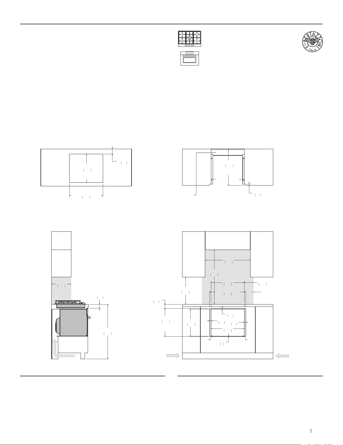
135bertazzoni.com
24” Specialty Oven +
30” Cooktop XV
Flush installation
SIDE VIEW
FRONT VIEW
(a) Spacers – Included with appliance
(b) Visible Area – Match finish to outside cabinet panels
(c) Combustible material cannot be installed within shaded area
TOP VIEW – OVEN DETAIL TOP VIEW – COOKTOP DETAIL
AIR INTAKE
a
bb
a
18"
457
36"
915
30"
762
6"
152
36"
914
13"
330
17 7/8"
455
24"
610
FLUSH INSET
WIDTH
18 1/2"
470
FLUSH INSET
HEIGHT
1"
25
1"
25
1/8"
3
1/2"
12
22"
560
23 3/4"
603
FLUSH INSET
DEPTH
c
2 5/8"
68
22"
560
3/4"
19
4" x 22"
(102 x 560)
AIR INTAKE
AIR INTAKE
4" x 15"
(102 x 380)
AIR INTAKE
4" x 15"
(102 x 380)
2 1/2"
62
18 7/8"
480
COOKTOP
CUT-OUT DEPTH
22"
560
COOKTOP
CUT-OUT WIDTH
3 3/8"
85
(a) Spacers - Included with appliance
(b) Visible Area - Match finish to outside cabinet panels
(c) Combustible material cannot be installed within shaded area
MULTIPLE INSTALLATIONS - 24” OVEN AND COOKTOP UNDERCOUNTER CONFIGURATIONS
PROF24SOEX PROF305CTXV
For electrical and gas supply please see single installation
requirements. Placement within the opening may require
additional cabinet depth.
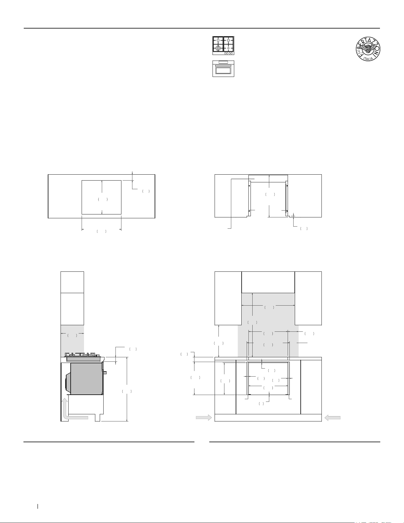
136 bertazzoni.com
24” Specialty Oven +
24” Cooktop XV
Flush installation
SIDE VIEW
FRONT VIEW
(a) Spacers – Included with appliance
(b) Visible Area – Match finish to outside cabinet panels
(c) Combustible material cannot be installed within shaded area
TOP VIEW – OVEN DETAIL TOP VIEW – COOKTOP DETAIL
AIR INTAKE
a
bb
a
18"
457
36"
915
30"
762
6"
152
36"
914
13"
330
17 7/8"
455
24"
610
FLUSH INSET
WIDTH
18 1/2"
470
FLUSH INSET
HEIGHT
1"
25
1"
25
1/8"
3
1/2"
12
22"
560
23 3/4"
603
FLUSH INSET
DEPTH
c
2 5/8"
68
22"
560
3/4"
19
4" x 22"
(102 x 560)
AIR INTAKE
AIR INTAKE
4" x 15"
(102 x 380)
AIR INTAKE
4" x 15"
(102 x 380)
18 7/8"
480
COOKTOP
CUT-OUT DEPTH
22"
560
COOKTOP
CUT-OUT WIDTH
3 3/8"
85
2 1/2"
62
(a) Spacers - Included with appliance
(b) Visible Area - Match finish to outside cabinet panels
(c) Combustible material cannot be installed within shaded area
MULTIPLE INSTALLATIONS - 24” OVEN AND COOKTOP UNDERCOUNTER CONFIGURATIONS
PROF24SOEX PROF244CTXV
For electrical and gas supply please see single installation
requirements. Placement within the opening may require
additional cabinet depth.
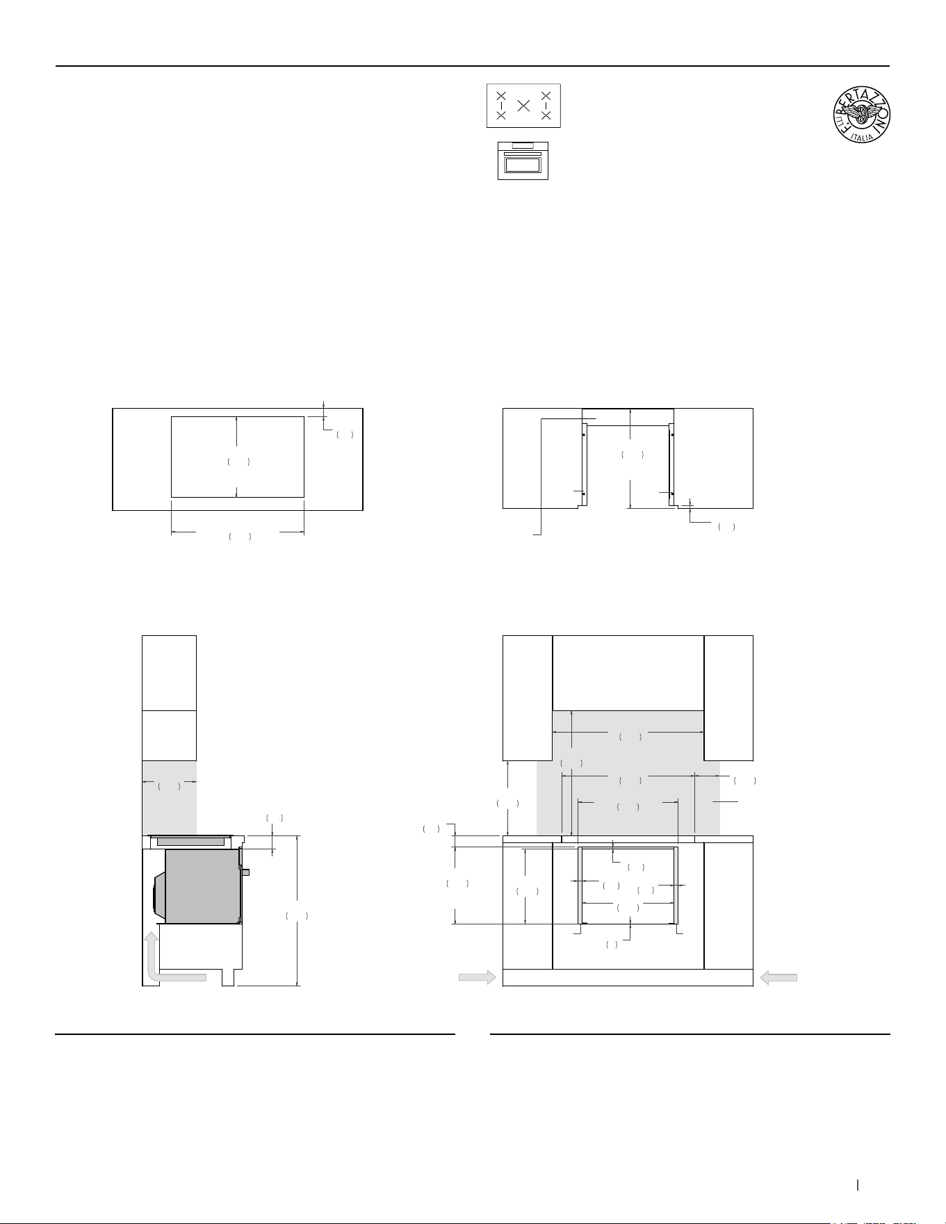
137bertazzoni.com
24” Specialty Oven +
36” Induction Cooktop
Flush installation
SIDE VIEW
FRONT VIEW
TOP VIEW – OVEN DETAIL TOP VIEW – COOKTOP DETAIL
(a) Spacers – Included with appliance
(b) Visible Area – Match finish to outside cabinet panels
(c) Combustible material cannot be installed within shaded area
AIR INTAKE
a
bb
a
18"
457
30"
763
36 3/8"
925
6"
152
3 1/8"
80
36"
914
13"
330
17 7/8"
455
24"
610
FLUSH INSET
WIDTH
18 1/2"
470
FLUSH INSET
HEIGHT
1"
25
1"
25
1/8"
3
1/2"
12
22"
560
23 7/8"
606
FLUSH INSET
DEPTH
c
2 5/8"
68
31 7/8"
810
31 7/8"
810
COOKTOP
CUT-OUT WIDTH
19 1/4"
490
COOKTOP
CUT-OUT DEPTH
2"
51
AIR INTAKE
4" x 15"
(102 x 380)
AIR INTAKE
4" x 15"
(102 x 380)
4" x 22"
(102 x 560)
AIR INTAKE
3/4"
19
(a) Spacers - Included with appliance
(b) Visible Area - Match finish to outside cabinet panels
(c) Combustible material cannot be installed within shaded area
MULTIPLE INSTALLATIONS - 24” OVEN AND COOKTOP UNDERCOUNTER CONFIGURATIONS
PROF24SOEX P365IAE
For electrical and gas supply please see single installation
requirements. Placement within the opening may require
additional cabinet depth.
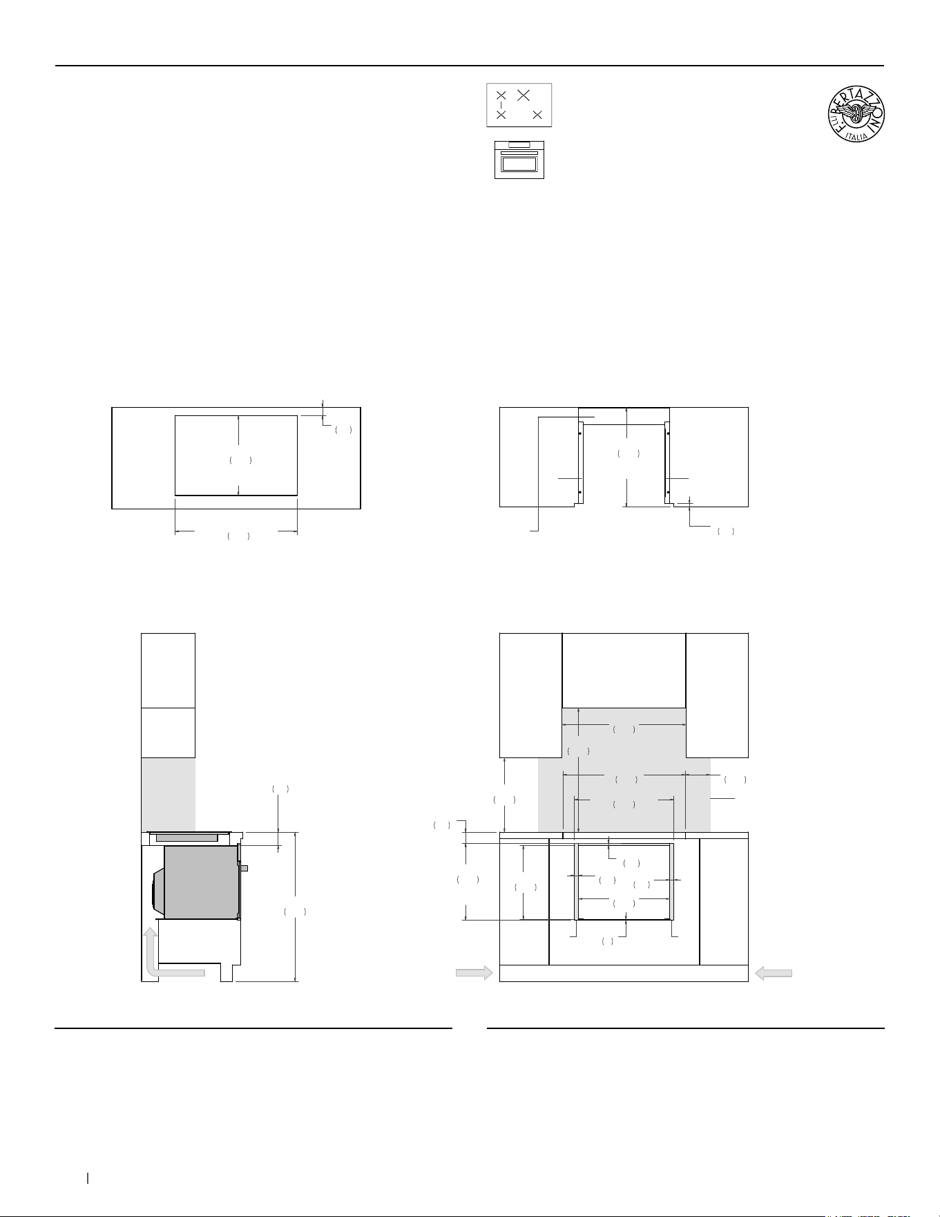
138 bertazzoni.com
SIDE VIEW
FRONT VIEW
(a) Spacers – Included with appliance
(b) Visible Area – Match finish to outside cabinet panels
(c) Combustible material cannot be installed within shaded area
TOP VIEW – OVEN DETAIL TOP VIEW – COOKTOP DETAIL
a
b
b
18"
457
30"
763
30"
762
6"
152
3 1/8"
80
36"
914
13"
330
17 7/8"
455
24"
610
FLUSH INSET
WIDTH
18 1/2"
470
FLUSH INSET
HEIGHT
1"
25
1"
25
1/8"
3
1/2"
12
22"
560
23 7/8"
606
FLUSH INSET
DEPTH
a
c
2 5/8"
68
29 1/2"
750
19 1/4"
490
COOKTOP
CUT-OUT DEPTH
29 1/2"
750
COOKTOP
CUT-OUT WIDTH
2"
51
4" x 22"
(102 x 560)
AIR INTAKE
AIR INTAKE
4" x 15"
(102 x 380)
AIR INTAKE
4" x 15"
(102 x 380)
AIR INTAKE
3/4"
19
(a) Spacers - Included with appliance
(b) Visible Area - Match finish to outside cabinet panels
(c) Combustible material cannot be installed within shaded area
24” Specialty Oven +
30” Induction Cooktop
Flush installation
MULTIPLE INSTALLATIONS - 24” OVEN AND COOKTOP UNDERCOUNTER CONFIGURATIONS
PROF24SOEX P304IAE
For electrical and gas supply please see single installation
requirements. Placement within the opening may require
additional cabinet depth.
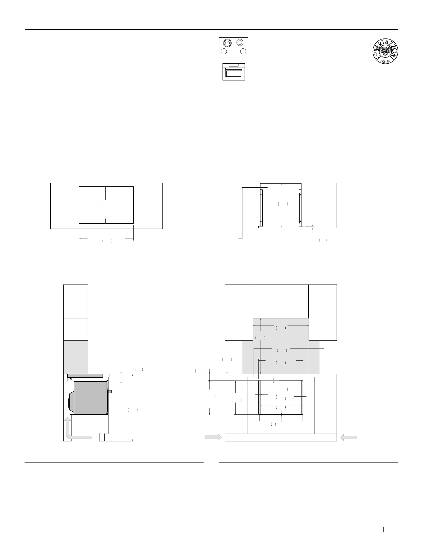
139bertazzoni.com
SIDE VIEW
FRONT VIEW
(a) Spacers – Included with appliance
(b) Visible Area – Match finish to outside cabinet panels
(c) Combustible material cannot be installed within shaded area
TOP VIEW – OVEN DETAIL TOP VIEW – COOKTOP DETAIL
a
b
b
18"
457
30"
763
30"
762
6"
152
36"
914
13"
330
17 7/8"
455
24"
610
FLUSH INSET
WIDTH
18 1/2"
470
FLUSH INSET
HEIGHT
1"
25
1"
25
1/8"
3
1/2"
12
22"
560
23 7/8"
606
FLUSH INSET
DEPTH
a
c
3 1/4"
83
29 1/8"
740
4" x 22"
(102 x 560)
AIR INTAKE
AIR INTAKE
4" x 15"
(102 x 380)
AIR INTAKE
4" x 15"
(102 x 380)
AIR INTAKE
19 5/8"
500
COOKTOP
CUT-OUT DEPTH
29 1/8"
740
COOKTOP
CUT-OUT WIDTH
3 3/4"
95
3/4"
19
(a) Spacers - Included with appliance
(b) Visible Area - Match finish to outside cabinet panels
(c) Combustible material cannot be installed within shaded area
24” Specialty Oven +
30” Electric Ceramic Cooktop
Flush installation
MULTIPLE INSTALLATIONS - 24” OVEN AND COOKTOP UNDERCOUNTER CONFIGURATIONS
P304CER PROF24SOEX
For electrical and gas supply please see single installation
requirements. Placement within the opening may require
additional cabinet depth.
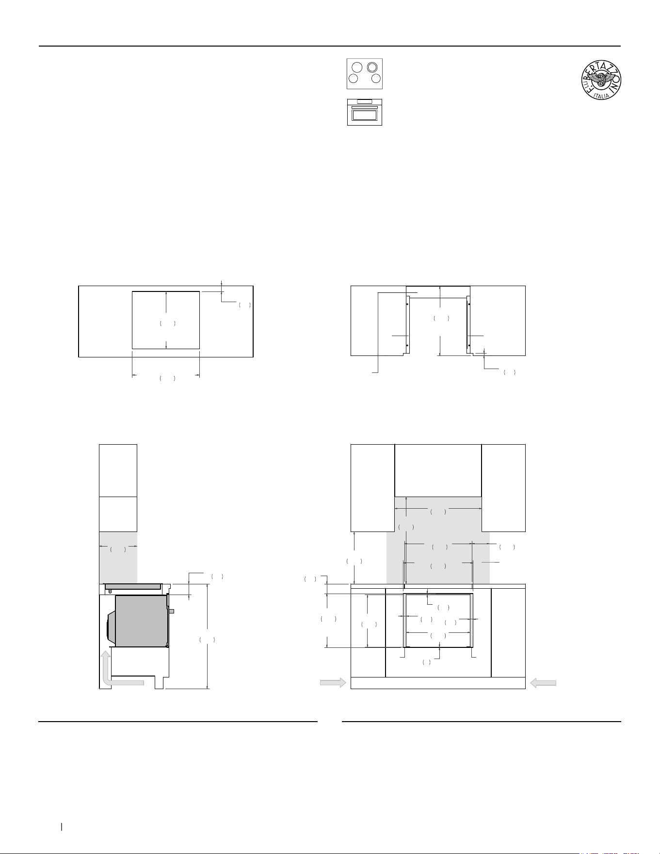
140 bertazzoni.com
SIDE VIEW
FRONT VIEW
(a) Spacers – Included with appliance
(b) Visible Area – Match finish to outside cabinet panels
(c) Combustible material cannot be installed within shaded area
TOP VIEW – OVEN DETAIL TOP VIEW – COOKTOP DETAIL
a
b
b
18"
457
30"
763
30"
762
6"
152
36"
914
17 7/8"
455
24"
610
FLUSH INSET
WIDTH
18 1/2"
470
FLUSH INSET
HEIGHT
1"
25
1"
25
1/8"
3
1/2"
12
22"
560
23 7/8"
606
FLUSH INSET
DEPTH
a
c
3 1/4"
83
23 1/4"
590
4" x 22"
(102 x 560)
AIR INTAKE
AIR INTAKE
4" x 15"
(102 x 380)
AIR INTAKE
4" x 15"
(102 x 380)
AIR INTAKE
3 3/4"
95
23 1/4"
590
COOKTOP
CUT-OUT WIDTH
19 5/8"
500
COOKTOP
CUT-OUT DEPTH
2"
50
13"
330
3/4"
19
(a) Spacers - Included with appliance
(b) Visible Area - Match finish to outside cabinet panels
(c) Combustible material cannot be installed within shaded area
24” Specialty Oven +
24” Electric Ceramic Cooktop
Flush installation
MULTIPLE INSTALLATIONS - 24” OVEN AND COOKTOP UNDERCOUNTER CONFIGURATIONS
PE244CER PROF24SOEX
For electrical and gas supply please see single installation
requirements. Placement within the opening may require
additional cabinet depth.
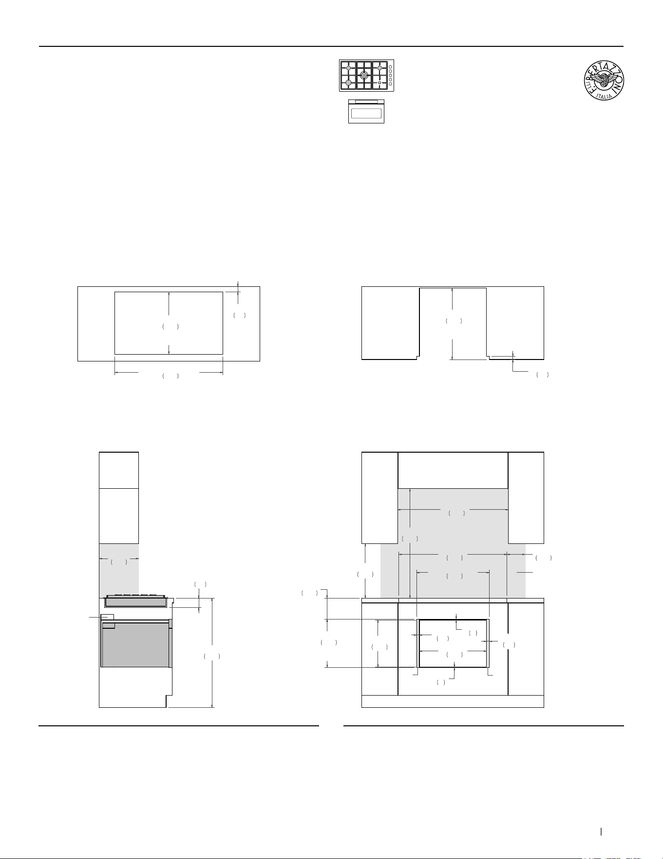
141bertazzoni.com
24” Microwave Drawer +
36” Drop-in Cooktop
Flush installation
SIDE VIEW
FRONT VIEW
(a) Visible Area – Match finish to outside cabinet panels
(b) Combustible material cannot be installed within shaded area
TOP VIEW – OVEN DETAIL TOP VIEW – COOKTOP DETAIL
a
a
18"
457
36"
915
36 3/8"
925
6"
152
3 1/8"
80
36"
914
13"
330
15 1/2"
395
23 7/8"
608
FLUSH INSET
WIDTH
15 7/8"
404
FLUSH INSET
HEIGHT
7/8"
23
7/8"
23
1/8"
3
1/4"
6
22 1/8"
562
23 1/2"
597
FLUSH INSET
DEPTH
b
6 7/8"
176
35 5/8"
905
1 1/8"
28
35 5/8"
905
COOKTOP
CUT-OUT WIDTH
20 1/2"
520
COOKTOP
CUT-OUT DEPTH
1 3/4"
45
ANTI TIP
(a) Visible Area - Match finish to outside cabinet panels
(b) Combustible material cannot be installed within shaded area
MULTIPLE INSTALLATIONS - 24” OVEN AND COOKTOP UNDERCOUNTER CONFIGURATIONS
MD24X
For electrical and gas supply please see single installation
requirements. Placement within the opening may require
additional cabinet depth.
PROF366QBXT
PROF365QBXT
PROF365QXE
MAST366QBXT
MAST365QBXT
MAST365QXE
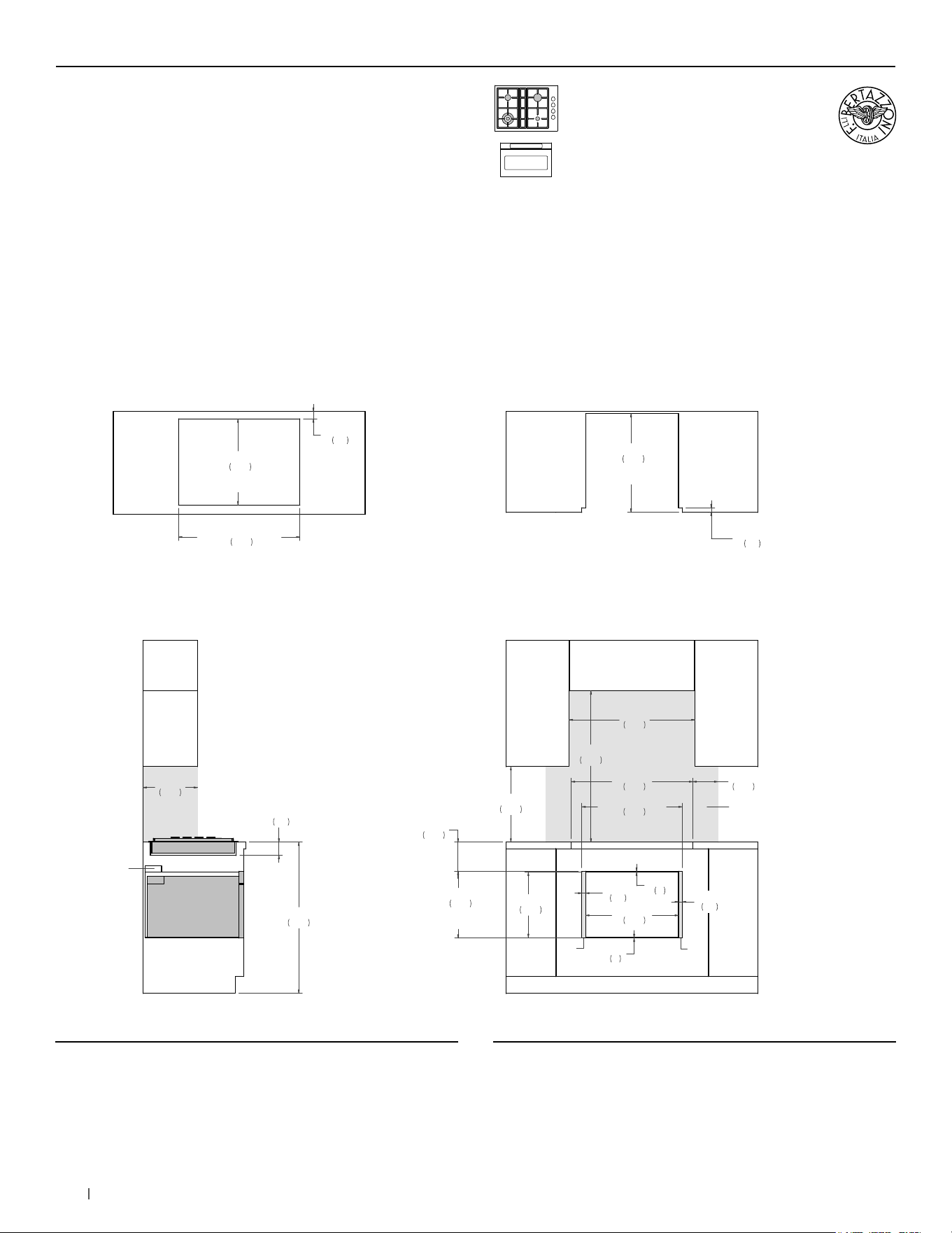
142 bertazzoni.com
SIDE VIEW
FRONT VIEW
(a) Visible Area – Match finish to outside cabinet panels
(b) Combustible material cannot be installed within shaded area
TOP VIEW – OVEN DETAIL TOP VIEW – COOKTOP DETAIL
a
a
18"
457
36"
915
30"
762
6"
152
3 1/8"
80
36"
914
13"
330
15 1/2"
395
23 7/8"
608
FLUSH INSET
WIDTH
15 7/8"
404
FLUSH INSET
HEIGHT
7/8"
23
7/8"
23
1/8"
3
1/4"
6
22 1/8"
562
23 1/2"
597
FLUSH INSET
DEPTH
b
6 7/8"
176
28 7/8"
735
1 1/8"
28
28 7/8"
735
COOKTOP
CUT-OUT WIDTH
20 1/2"
520
COOKTOP
CUT-OUT DEPTH
1 3/4"
45
ANTI TIP
(a) Visible Area - Match finish to outside cabinet panels
(b) Combustible material cannot be installed within shaded area
24” Microwave Drawer +
30” Drop-in Cooktop
Flush installation
MULTIPLE INSTALLATIONS - 24” OVEN AND COOKTOP UNDERCOUNTER CONFIGURATIONS
MD24X
For electrical and gas supply please see single installation
requirements. Placement within the opening may require
additional cabinet depth.
PROF304QBXT
PROF304QXE
MAST304QBXT
MAST304QXE
143bertazzoni.com
SIDE VIEW
FRONT VIEW
(a) Visible Area – Match finish to outside cabinet panels
(b) Combustible material cannot be installed within shaded area
TOP VIEW – OVEN DETAIL TOP VIEW – COOKTOP DETAIL
a
a
18"
457
36"
915
36 3/8"
925
6"
152
36"
914
13"
330
15 1/2"
395
23 7/8"
608
FLUSH INSET
WIDTH
15 7/8"
404
FLUSH INSET
HEIGHT
7/8"
23
7/8"
23
1/8"
3
1/4"
6
22 1/8"
562
23 1/2"
597
FLUSH INSET
DEPTH
b
6 7/8"
176
33 1/2"
850
1 1/8"
28
2 1/2"
62
33 1/2"
850
COOKTOP
CUT-OUT WIDTH
18 7/8"
480
COOKTOP
COUT-OUT DEPTH
3 3/8"
85
ANTI TIP
(a) Visible Area - Match finish to outside cabinet panels
(b) Combustible material cannot be installed within shaded area
24” Microwave Drawer +
36” Cooktop XV
Flush installation
MULTIPLE INSTALLATIONS - 24” OVEN AND COOKTOP UNDERCOUNTER CONFIGURATIONS
PROF365CTXV
For electrical and gas supply please see single installation
requirements. Placement within the opening may require
additional cabinet depth.
MD24X
144 bertazzoni.com
24” Microwave Drawer +
30” Cooktop XV
Flush installation
SIDE VIEW
FRONT VIEW
(a) Visible Area – Match finish to outside cabinet panels
(b) Combustible material cannot be installed within shaded area
TOP VIEW – OVEN DETAIL TOP VIEW – COOKTOP DETAIL
a
a
18"
457
36"
915
30"
762
6"
152
36"
914
13"
330
15 1/2"
395
23 7/8"
608
FLUSH INSET
WIDTH
15 7/8"
404
FLUSH INSET
HEIGHT
7/8"
23
7/8"
23
1/8"
3
1/4"
6
22 1/8"
562
23 1/2"
597
FLUSH INSET
DEPTH
b
6 7/8"
176
22"
560
1 1/8"
28
2 1/2"
62
18 7/8"
480
COOKTOP
CUT-OUT DEPTH
22"
560
COOKTOP
CUT-OUT WIDTH
3 3/8"
85
ANTI TIP
(a) Visible Area - Match finish to outside cabinet panels
(b) Combustible material cannot be installed within shaded area
MULTIPLE INSTALLATIONS - 24” OVEN AND COOKTOP UNDERCOUNTER CONFIGURATIONS
PROF305CTXV
For electrical and gas supply please see single installation
requirements. Placement within the opening may require
additional cabinet depth.
MD24X
145bertazzoni.com
24” Microwave Drawer +
24” Cooktop XV
Flush installation
SIDE VIEW
FRONT VIEW
(a) Visible Area – Match finish to outside cabinet panels
(b) Combustible material cannot be installed within shaded area
TOP VIEW – OVEN DETAIL TOP VIEW – COOKTOP DETAIL
a
a
18"
457
36"
915
30"
762
6"
152
2 1/2"
62
36"
914
13"
330
15 1/2"
395
23 7/8"
608
FLUSH INSET
WIDTH
15 7/8"
404
FLUSH INSET
HEIGHT
7/8"
23
7/8"
23
1/8"
3
1/4"
6
22 1/8"
562
23 1/2"
597
FLUSH INSET
DEPTH
b
6 7/8"
176
22"
560
1 1/8"
28
18 7/8"
480
COOKTOP
CUT-OUT DEPTH
22"
560
COOKTOP
CUT-OUT WIDTH
3 3/8"
85
ANTI TIP
(a) Visible Area - Match finish to outside cabinet panels
(b) Combustible material cannot be installed within shaded area
MULTIPLE INSTALLATIONSMULTIPLE INSTALLATIONS - 24” OVEN AND COOKTOP UNDERCOUNTER CONFIGURATIONS
PROF244CTXV
For electrical and gas supply please see single installation
requirements. Placement within the opening may require
additional cabinet depth.
MD24X
146 bertazzoni.com
24” Microwave Drawer +
36” Induction Cooktop
Flush installation
SIDE VIEW
FRONT VIEW
(a) Visible Area – Match finish to outside cabinet panels
(b) Combustible material cannot be installed within shaded area
TOP VIEW – OVEN DETAIL TOP VIEW – COOKTOP DETAIL
a
a
18"
457
30"
763
36 3/8"
925
6"
152
36"
914
13"
330
15 1/2"
395
23 7/8"
608
FLUSH INSET
WIDTH
15 7/8"
404
FLUSH INSET
HEIGHT
7/8"
23
7/8"
23
1/8"
3
1/4"
6
22 1/8"
562
23 1/2"
597
FLUSH INSET
DEPTH
b
6 7/8"
176
31 7/8"
810
3 1/8"
80
31 7/8"
810
COOKTOP
CUT-OUT WIDTH
19 1/4"
490
COOKTOP
CUT-OUT DEPTH
2"
51
ANTI TIP
1 1/8"
28
(a) Visible Area - Match finish to outside cabinet panels
(b) Combustible material cannot be installed within shaded area
MULTIPLE INSTALLATIONS - 24” OVEN AND COOKTOP UNDERCOUNTER CONFIGURATIONS
P365IAE
For electrical and gas supply please see single installation
requirements. Placement within the opening may require
additional cabinet depth.
MD24X
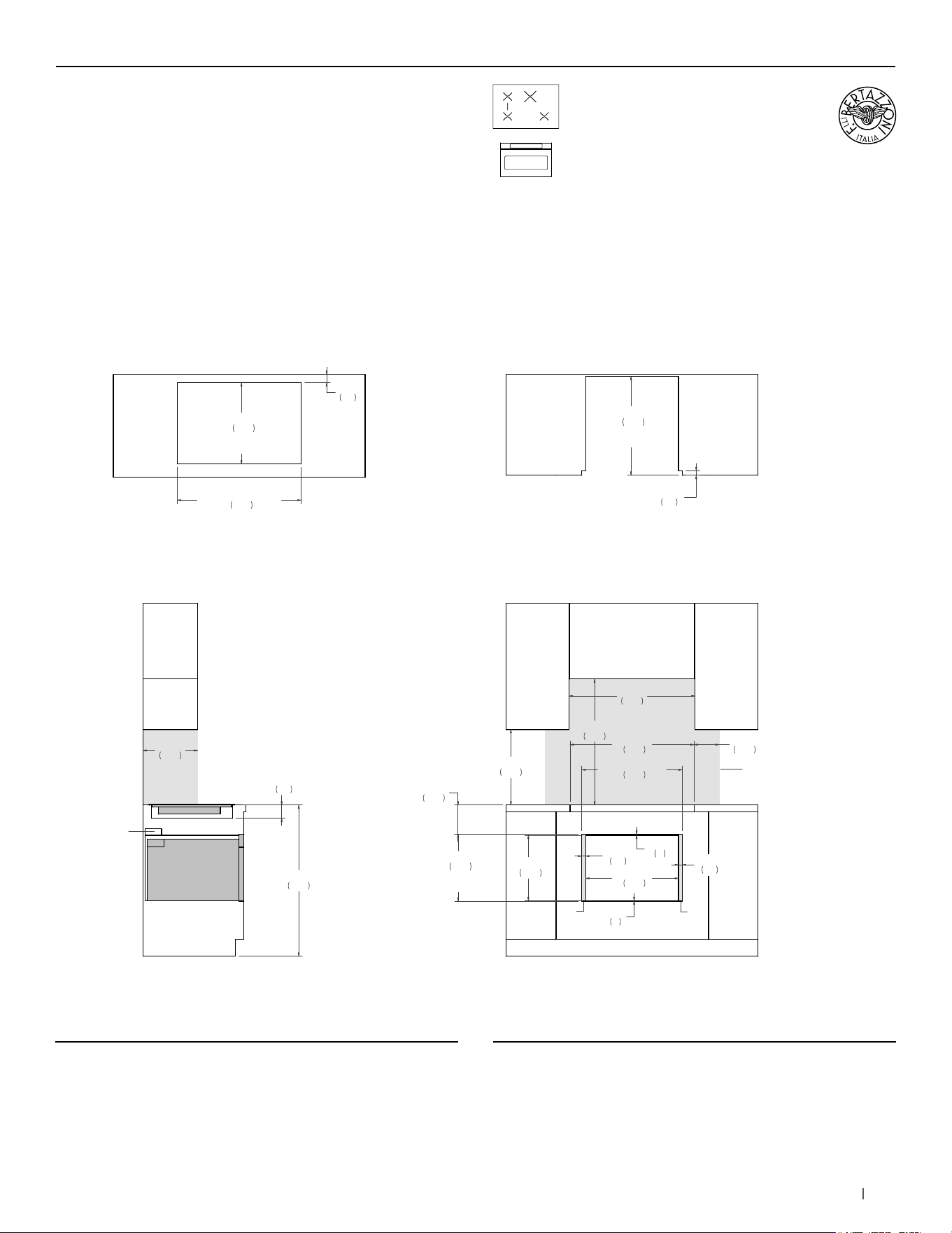
147bertazzoni.com
24” Microwave Drawer +
30” Induction Cooktop
Flush installation
SIDE VIEW
FRONT VIEW
(a) Visible Area – Match finish to outside cabinet panels
(b) Combustible material cannot be installed within shaded area
TOP VIEW – OVEN DETAIL TOP VIEW – COOKTOP DETAIL
a
a
18"
457
30"
763
30"
762
6"
152
36"
914
13"
330
15 1/2"
395
23 7/8"
608
FLUSH INSET
WIDTH
15 7/8"
404
FLUSH INSET
HEIGHT
7/8"
23
7/8"
23
1/8"
3
1/4"
6
22 1/8"
562
23 1/2"
597
FLUSH INSET
DEPTH
b
6 7/8"
176
29 1/2"
750
3 1/8"
80
ANTI TIP
1 1/8"
28
19 1/4"
490
COOKTOP
CUT-OUT DEPTH
29 1/2"
750
COOKTOP
CUT-OUT WIDTH
2"
51
(a) Visible Area - Match finish to outside cabinet panels
(b) Combustible material cannot be installed within shaded area
MULTIPLE INSTALLATIONS - 24” OVEN AND COOKTOP UNDERCOUNTER CONFIGURATIONS
PE304IAE
For electrical and gas supply please see single installation
requirements. Placement within the opening may require
additional cabinet depth.
MD24X
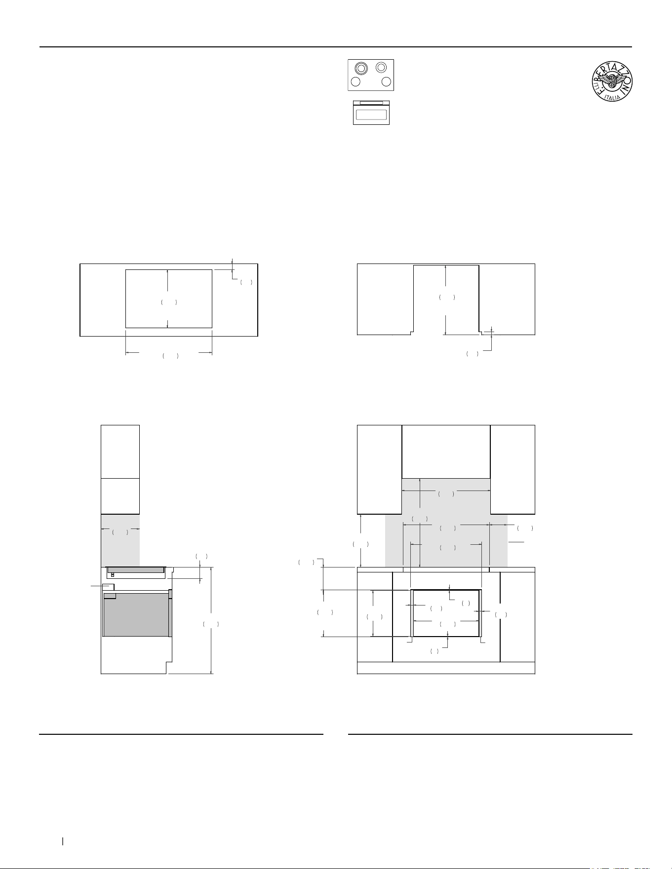
148 bertazzoni.com
24” Microwave Drawer +
30” Electric Ceramic Cooktop
Flush installation
SIDE VIEW
FRONT VIEW
(a) Visible Area – Match finish to outside cabinet panels
(b) Combustible material cannot be installed within shaded area
TOP VIEW – OVEN DETAIL TOP VIEW – COOKTOP DETAIL
a
a
18"
457
30"
763
30"
762
6"
152
36"
914
13"
330
15 1/2"
395
23 7/8"
608
FLUSH INSET
WIDTH
15 7/8"
404
FLUSH INSET
HEIGHT
7/8"
23
7/8"
23
1/8"
3
1/4"
6
22 1/8"
562
23 1/2"
597
FLUSH INSET
DEPTH
b
7 1/2"
191
29 1/8"
740
3 3/4"
95
ANTI TIP
1 1/8"
28
19 5/8"
500
COOKTOP
CUT-OUT DEPTH
29 1/8"
740
COOKTOP
CUT-OUT WIDTH
2"
50
(a) Visible Area - Match finish to outside cabinet panels
(b) Combustible material cannot be installed within shaded area
MULTIPLE INSTALLATIONS - 24” OVEN AND COOKTOP UNDERCOUNTER CONFIGURATIONS
PE304CER
For electrical and gas supply please see single installation
requirements. Placement within the opening may require
additional cabinet depth.
MD24X
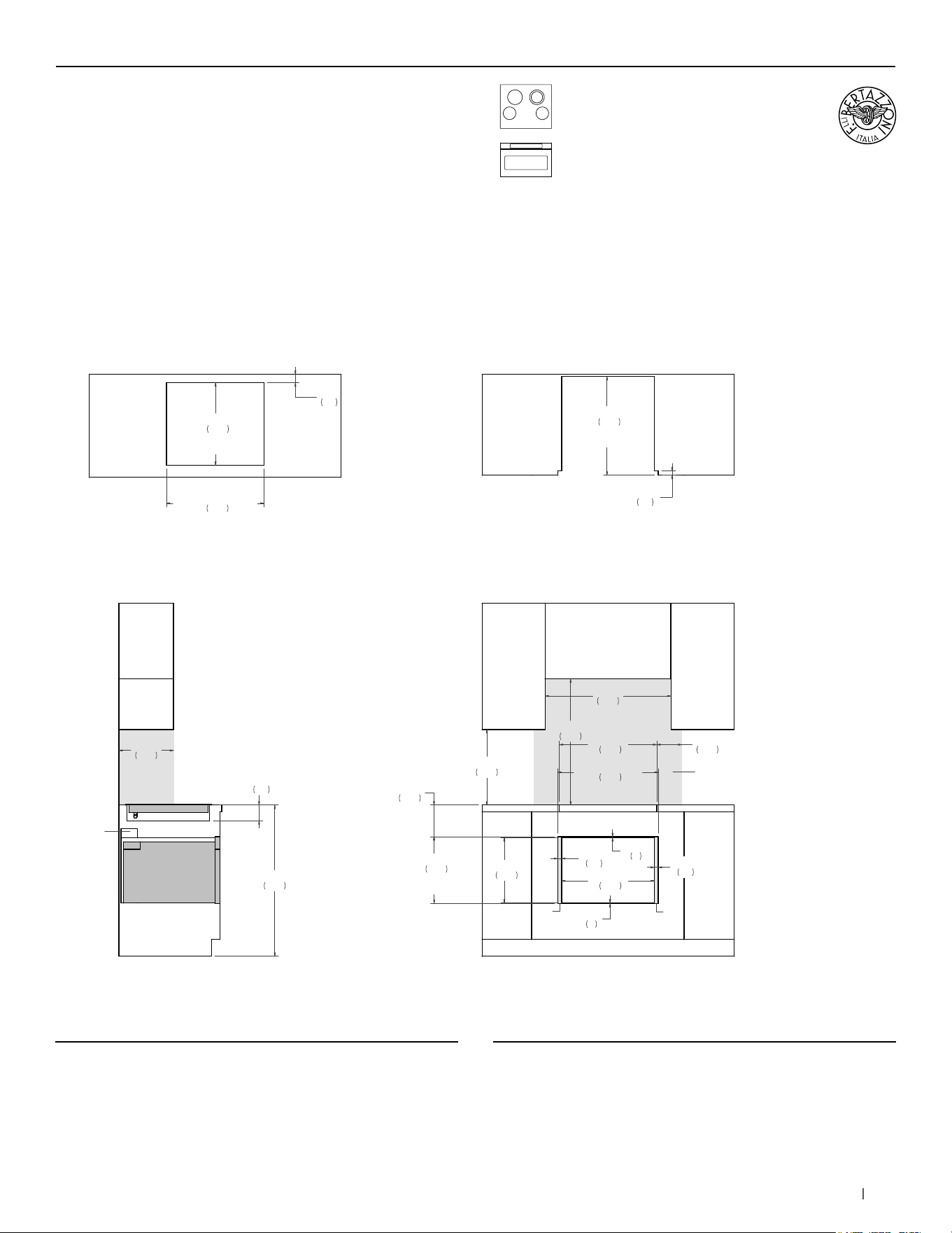
149bertazzoni.com
24” Microwave Drawer +
24” Electric Ceramic Cooktop
Flush installation
(a) Visible Area - Match finish to outside cabinet panels
(b) Combustible material cannot be installed within shaded area
MULTIPLE INSTALLATIONS - 24” OVEN AND COOKTOP UNDERCOUNTER CONFIGURATIONS
PE244CER
For electrical and gas supply please see single installation
requirements. Placement within the opening may require
additional cabinet depth.
MD24X
SIDE VIEW
FRONT VIEW
(a) Visible Area – Match finish to outside cabinet panels
(b) Combustible material cannot be installed within shaded area
TOP VIEW – OVEN DETAIL TOP VIEW – COOKTOP DETAIL
a
a
18"
457
30"
763
30"
762
6"
152
36"
914
13"
330
15 1/2"
395
23 7/8"
608
FLUSH INSET
WIDTH
15 7/8"
404
FLUSH INSET
HEIGHT
7/8"
23
7/8"
23
1/8"
3
1/4"
6
22 1/8"
562
23 1/2"
597
FLUSH INSET
DEPTH
b
7 1/2"
191
23 1/4"
590
3 3/4"
95
ANTI TIP
1 1/8"
28
23 1/4"
590
COOKTOP
CUT-OUT WIDTH
19 5/8"
500
COOKTOP
CUT-OUT DEPTH
2"
50

BERTAZZONI.COM
TO COOK BEAUTIFULLY