Operator's Manual 1
OPERATOR'S MANUAL
TRUCK MOUNT
GASOLINE DRIVEN/BELT DRIVE
COLD WATER PRESSURE WASHERS
CAUTION
RISK OF INJURY!
READ MANUAL BEFORE OPERATING!
THIS MANUAL IS AN IMPORTANT PART OF THE PRESSURE WASHER
AND SHOULD REMAIN WITH THIS UNIT WHEN YOU SELL OR RENT IT.
©Copyright 2024 Form #37-1584-E/S-061424
PARTS LIST

2 Operator's Manual
TABLE OF CONTENTS
INTRODUCTION .........................................................................................................................................3
RISK OF EXPLOSION OR FIRE ....................................................................................................................4
RISK OF ASPHYXIATION .............................................................................................................................4
RISK OF INJECTION OR SEVERE CUTTING INJURY .................................................................................5
RISK OF ELECTROCUTION OR ELECTRICAL SHOCK ...............................................................................5
RISK OF BURNS ..........................................................................................................................................5
RISK OF BURSTING ....................................................................................................................................5
RISK OF BODILY INJURY ............................................................................................................................6
RISK FROM MOVING PARTS.......................................................................................................................7
FEATURES ...................................................................................................................................................8
SAFETY DECALS ........................................................................................................................................9
INSTALLATION & PREPARATION ............................................................................................................10
ATTIRE: .......................................................................................................................................................10
LOCATION: ................................................................................................................................................. 10
SERVICE TRUCK INSTALLATION: .............................................................................................................10
ENGINE FUEL TANK: .................................................................................................................................11
FUEL SYSTEM (3508 MODEL) ................................................................................................................... 11
HIGH PRESSURE GUN / WAND / HOSE ................................................................................................... 13
NOZZLE REVIEW: ....................................................................................................................................13
NOZZLE CONNECTION: ............................................................................................................................ 14
WATER SUPPLY (3005 MODEL): ................................................................................................................14
WATER SUPPLY (3508 MODEL): ................................................................................................................15
UNLOADER: ...............................................................................................................................................16
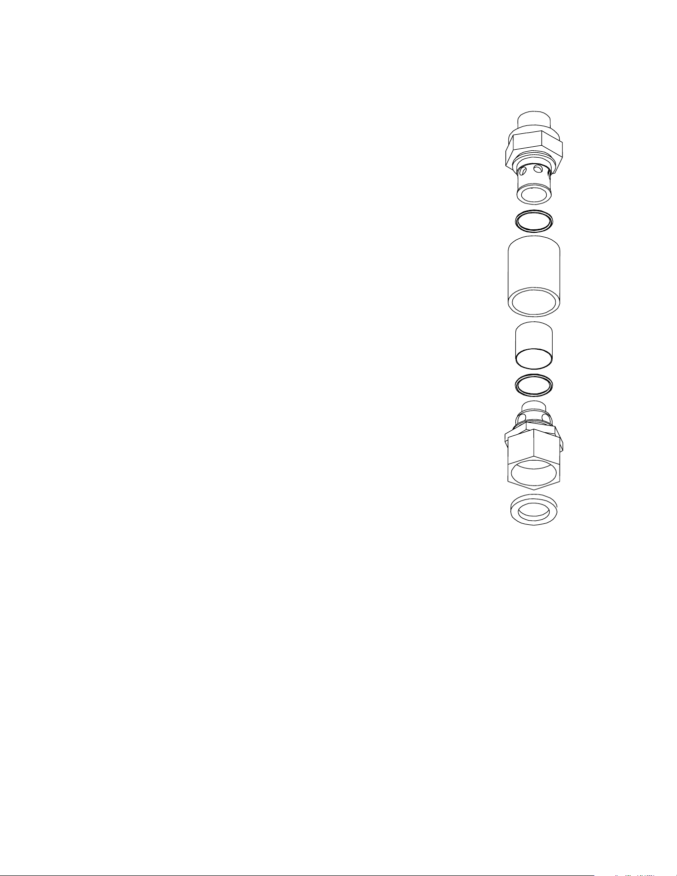
THERMAL RELIEF VALVE: .........................................................................................................................16
PRE-START INSPECTION PROCEDURES:................................................................................................16
ACCESSORIES ..........................................................................................................................................17
GUN AND WAND: .....................................................................................................................................17
HIGH PRESSURE HOSE: .......................................................................................................................... 17
LOW PRESSURE SUPPLY HOSE: ...........................................................................................................17
LOW PRESSURE DETERGENT INJECTOR: .............................................................................................17
OPERATING INSTRUCTIONS ..................................................................................................................19
PRIMING THE PUMP: ................................................................................................................................19
START-UP: .................................................................................................................................................. 19
CLEANING WITH DETERGENTS (OPTIONAL FEATURE): ........................................................................20
SHUTDOWN: ..............................................................................................................................................21
STORAGE & MAINTENANCE ................................................................................................................... 22
SPECIFIC MAINTENANCE: ......................................................................................................................22
WINTERIZING: ............................................................................................................................................22
TROUBLESHOOTING ...............................................................................................................................24
STATEMENT OF WARRANTY ..................................................................................................................25
WARNING: This product can expose you to
chemicals including carbon monoxide, which is
known to the State of California to cause birth
defects or other reproductive harm. For more
information go to www.P65Warnings.ca.gov
WARNING
WARNING: This product can expose you to
chemicals including Lead, which is known to
the State of California to cause cancer and birth
defects or other reproductive harm. For more
information go to www.P65Warnings.ca.gov
WARNING
Operator's Manual 3
INTRODUCTION
Congratulations on the purchase of your new pressure washer! You can be assured your new pressure
washer was constructed and designed with quality and performance in mind. Each component has been
rigorously tested to ensure the highest level of acceptance.
This operator's manual was compiled for your benet. By reading and following the simple safety, installa-
tion, operation, maintenance and troubleshooting steps described in this manual, you will receive years of
trouble-free operation from your new pressure washer. The contents of this manual are based on the latest
product information available at the time of publication. The manufacturer reserves the right to make chang-
es in price, color, materials, equipment, specications or models at any time without notice.
! IMPORTANT !
Safety Warnings that must be followed when operating this pressure washer. Accompanying the Safety
Warnings are "signal words" which designate the degree or level of hazard seriousness. The "signal
words" used in this manual are as follows:
DANGER: INDICATES AN IMMINENTLY HAZARDOUS SITUATION WHICH, IF NOT AVOIDED, WILL
RESULT IN DEATH OR SERIOUS INJURY.
WARNING: INDICATES A POTENTIALLY HAZARDOUS SITUATION WHICH, IF NOT AVOIDED,
COULD RESULT IN DEATH OR SERIOUS INJURY.
CAUTION: INDICATES A POTENTIALLY HAZARDOUS SITUATION WHICH, IF NOT AVOIDED MAY
RESULT IN MINOR OR MODERATE INJURY.
The symbols below this paragraph are "Safety Alert Symbols." These symbols are used to call attention
to items or procedures that could be dangerous to you or other persons using this equipment.
ALWAYS PROVIDE A COPY OF THIS MANUAL TO ANYONE USING THIS EQUIPMENT. READ ALL
INSTRUCTIONS BEFORE OPERATING THIS PRESSURE WASHER AND ESPECIALLY POINT OUT THE
"SAFETY WARNINGS" TO PREVENT THE POSSIBILITY OF PERSONAL INJURY TO THE OPERATOR.
Once the unit has been uncrated, immediately write in the serial number of your unit in the space provided
below.
SERIAL NUMBER_________________________________
Inspect for signs of obvious or concealed freight damage. If damage does exist, le a claim with the trans-
portation company immediately. Be sure that all damaged parts are replaced and that the mechanical
problems are corrected prior to operation of the unit. If you require service, contact your Customer Service
Representative.
CUSTOMER SERVICE
CALL OUR TOLL-FREE NUMBER
for the Sales or Service Center nearest you!
(800) 553-9053
Please have the following information available for all service calls:
1. Model Number
2. Serial Number
3. Date and Place of Purchase
4 Operator's Manual
RISK OF EXPLOSION OR FIRE
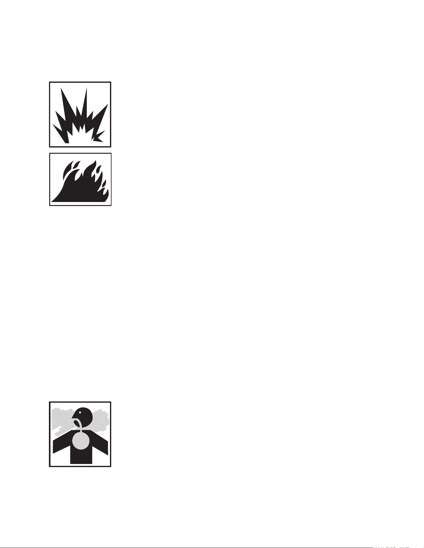
Serious injury or death may occur from normal sparks in the engine ignition
system or engine exhaust/mufer.
Always operate pressure washer in a well ventilated area free of ammable
vapors, combustible dust, gases or other combustible materials.
Do not store the pressure washer near an open ame or any equipment such as
a stove, furnace water heater, etc. which utilizes a pilot light or sparking device.
Serious injury or death may occur as a result of improper fueling.
Do not use this pressure washer to spray ammable material!
Do not smoke while lling engine fuel tank.
Never ll the engine fuel tank while the engine is running or hot. Allow the en-
gine to cool two minutes before refueling.
Do not refuel indoors or in a poorly ventilated area.
Always refuel slowly to avoid the possibility of spilled fuel which may cause a
risk of re.
Gasoline Engine Fuel Tank (Red): Refuel with gasoline only. Do not use diesel or
fuel oil.
Do not operate the unit if gasoline fuel is spilled. Wipe the pressure washer clean
and move it away from the spill. Avoid creating any ignition until the gasoline fuel
has evaporated.
Serious injury or death may occur from the battery when using the Electric
Starter.
When the battery is being activated, hydrogen and oxygen gases in the battery
are extremely explosive. Keep open sparks and ames away from the battery at
all times, especially when charging the battery.
Be certain to disconnect the battery ground terminal before servicing. When
disconnecting the cable from the battery, start with the negative terminal, and
when connecting them, start with the positive one.
When charging the battery, remove the battery vent plugs.
Use only a voltmeter or hydrometer to check a battery charge.
DO NOT jump start the battery unless both batteries are of equal voltage and
amperage.
Serious injury or death may occur from a ground re caused by a mufer
spark.
A spark arrester must be added to the mufer of this engine if it is to be used
on any forest covered, brush covered or grass covered unimproved land. The
arrester must be maintained in effective working order by the operator. In the
state of California, the above is required by law. (Section 4442 of the California
Public Resources Code.) Other states may have similar laws. Federal laws ap-
ply on federal lands.
RISK OF ASPHYXIATION
Serious injury or death may occur from inhaling engine exhaust or dan-
gerous vapors. The engine exhaust from this product contains chemicals
known to the State of California to cause cancer, birth defects, or other
reproductive harm.
This pressure washer was designed for outdoor use only. Never operate
this pressure washer in an enclosed area. Always make certain there is
adequate ventilation (fresh outside air) for breathing and combustion. This
will prevent the buildup of dangerous carbon monoxide gases. Beware of
poorly ventilated areas, or areas with inadequate exhaust fans which can
cause poor air exchange.
Follow all safety instructions provided with the materials you are spraying.
Use of a respirator may be required when working with some materials. Do
not use this pressure washer to dispense hazardous detergents or chemi-
cals.
IMPORTANT SAFETY INSTRUCTIONS
Operator's Manual 5
RISK OF INJECTION OR SEVERE CUTTING INJURY
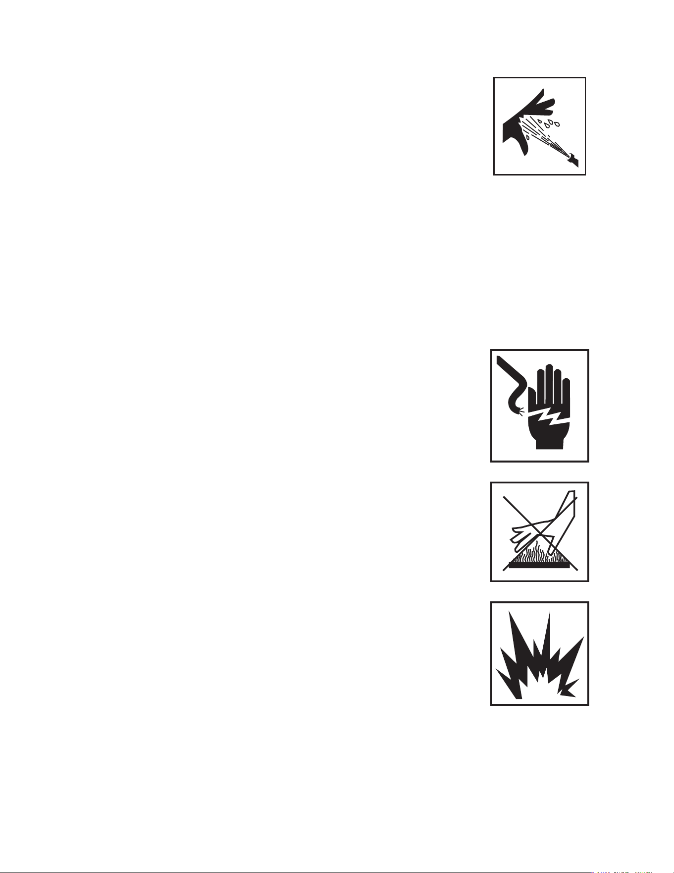
Serious injury or death could occur from high pressure spray penetrating the
skin.
Keep clear of nozzle and spray! Never put your hand, ngers or body di-
rectly over the spray nozzle.
Never point the high pressure discharge spray at yourself or anyone else.
Always keep operating area clear of all persons.
DO NOT allow children to operate this unit.
SEEK EMERGENCY MEDICAL CARE if the spray appears to have penetrat-
ed the skin! DO NOT TREAT AS A SIMPLE CUT!!
High pressure hoses and fuel lines should be inspected daily for signs of
wear. If evidence of failure exists, promptly replace all suspect hoses and
fuel lines to prevent the possibility of injury from the high pressure spray. If
a hose or tting is leaking, NEVER PLACE YOUR HAND DIRECTLY ON THE
LEAK.
NEVER operate the gun with the trigger wired in the open position. To pre-
vent accidental discharge, the trigger gun should be securely locked when
not in use.
Before removing the spray nozzle or servicing the unit, ALWAYS shut off the
unit and trigger the gun to release trapped pressure. (Even after you shut off
the unit, there is high pressure water left in the pump, hose and gun until you
release it by triggering the gun.)
RISK OF ELECTROCUTION OR ELECTRICAL SHOCK
Serious injury or death may occur from contact with electricity.
DO NOT direct spray on or into electrical installations of any kind! This in-
cludes electrical outlets, light bulbs, fuse boxes, transformers, the unit itself,
etc.
DO NOT allow metal components of the pressure washer to come in contact
with live electrical components.
RISK OF BURNS
Serious injury could occur from touching the engine mufer. This area can
remain hot for some time after the pressure washer is shutdown.
Never allow any part of your body to contact the engine mufer or adjacent
areas.
RISK OF BURSTING
Serious injury may occur from a pressure washer malfunction or exploding
accessories if incorrect system components, attachments or accessories
are used.
Never make adjustments to the factory set pressures.
Never exceed manufacturers maximum allowable pressure rating of attach-
ments.
Do not allow any hoses to make contact with the engine mufer or gasoline
engine to prevent the possibility of bursting. Avoid dragging the hoses over
abrasive surfaces such as cement.
Use only manufacturer recommended repair parts for your pressure washer.
Serious injury or death may occur if system safety's are not properly main-
tained.
This pressure washer has a Safety Relief (Burst Disk) device which should
IMPORTANT SAFETY INSTRUCTIONS
6 Operator's Manual
IMPORTANT SAFETY INSTRUCTIONS
never be altered, modied, removed or made inoperative. If the device fails,
replace immediately with only genuine manufacturer replacement part.
Serious injury or death may occur if attempting to start the pressure washer
when the pump is frozen.
In freezing temperatures, the unit must always be warm enough to ensure
there is no ice formation in the pump. Do not start the pressure washer if it
has been transported in an open or underheated vehicle without rst allow-
ing the pump to thaw.
RISK OF BODILY INJURY
Serious injury or death may occur from detergents contacting the skin.
SEEK EMERGENCY MEDICAL CARE if you are using cleaning agents and the
spray appears to have penetrated the skin! DO NOT TREAT AS A SIMPLE
CUT!! Be prepared to tell a physician exactly what kind of detergents you were
using by reading the Material Safety Data Sheet (MSDS) provided with your
detergent.
Never use any solvents or highly corrosive detergents or acid type cleaners with
this pressure washer.
Protective equipment such as rubber suits, gloves and respirators are advis-
able, especially when using cleaning detergents.
Keep all detergents out of the reach of children!
ALWAYS wear protective goggles when operating the unit to shield the eyes
from ying debris and detergents.
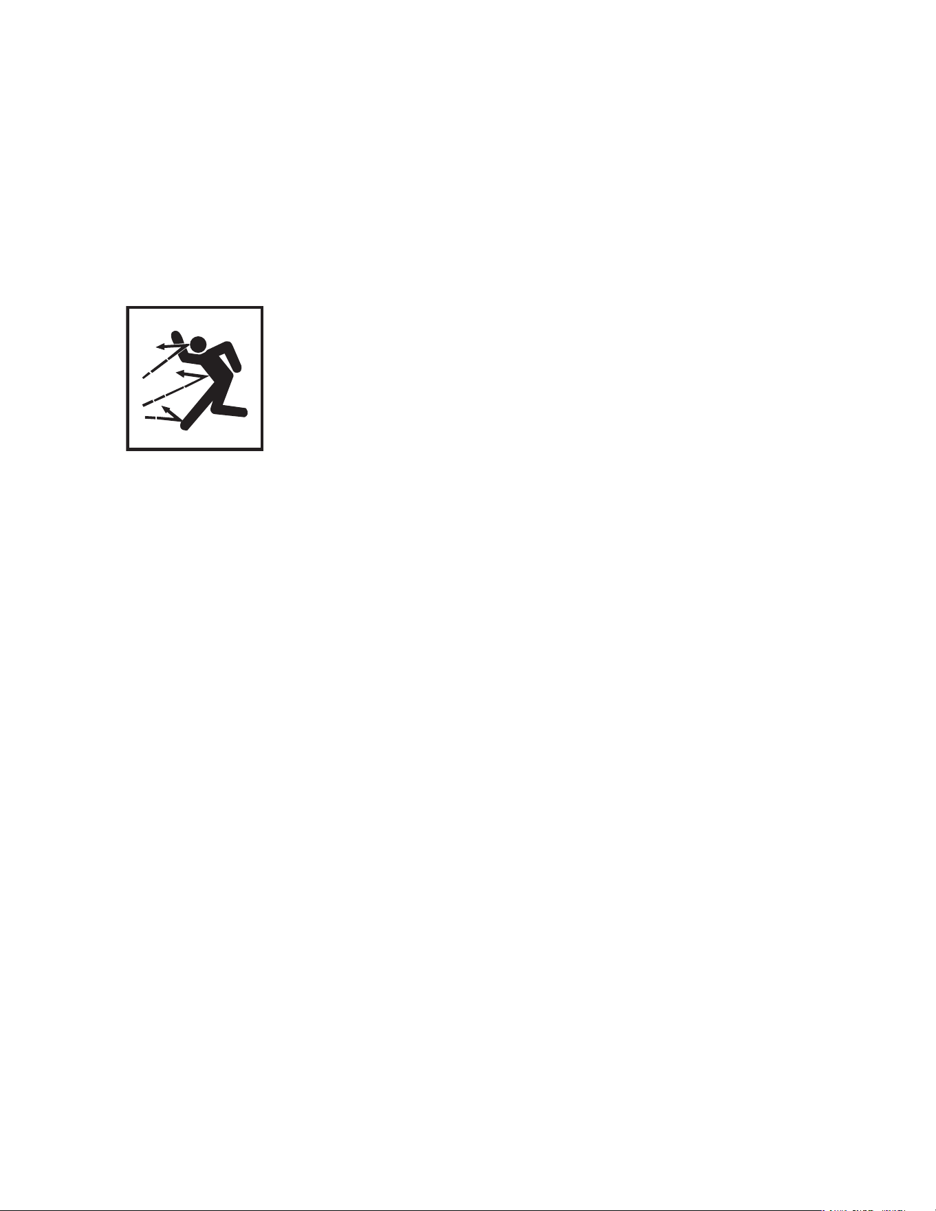
Serious injury can occur from loose debris being propelled at a high speed
from the spray gun.
DO NOT direct spray toward fragile materials such as glass. Shattering could
occur.
Stay alert-watch what you are doing. Do not operate the unit when fatigued or
under the inuence of alcohol or drugs.
NEVER squeeze the trigger unless securely braced.
DO NOT overreach or stand on unstable support.
Wet surfaces can be slippery, wear protective foot gear and keep good footing
and balance at all times.
Injury may occur if the operator loses his balance caused by the thrust of
water traveling through the spray nozzle.
NEVER trigger the gun while on a ladder or roof.
ALWAYS hold on rmly to the gun/lance assembly when starting and operating
the unit. Failure to do so can cause the lance to fall and whip dangerously.
Injury may occur from the pressure washer.
Know how to stop the pressure washer and bleed pressures quickly. Be thor-
oughly familiar with controls.
DO NOT leave pressurized unit unattended. Shut off the pressure washer and
release trapped pressure before leaving.
DO NOT operate the unit if you see any fuel, oil or water leaks from the machine.
DO NOT resume operation until the unit has been inspected and repaired by a
qualied service person.
NEVER run the unit with the governor disconnected or operate at excessive
speeds.
Place unit in a clean, dry, at area for servicing. Before servicing the unit,
turn the unit off, relieve the water pressure from the trigger gun, and allow
the unit to cool down. Service in clean, dry, at area. Block wheels to pre-
vent unit from moving.
Do not move the unit by pulling on the hose.
Operator's Manual 7
IMPORTANT SAFETY INSTRUCTIONS
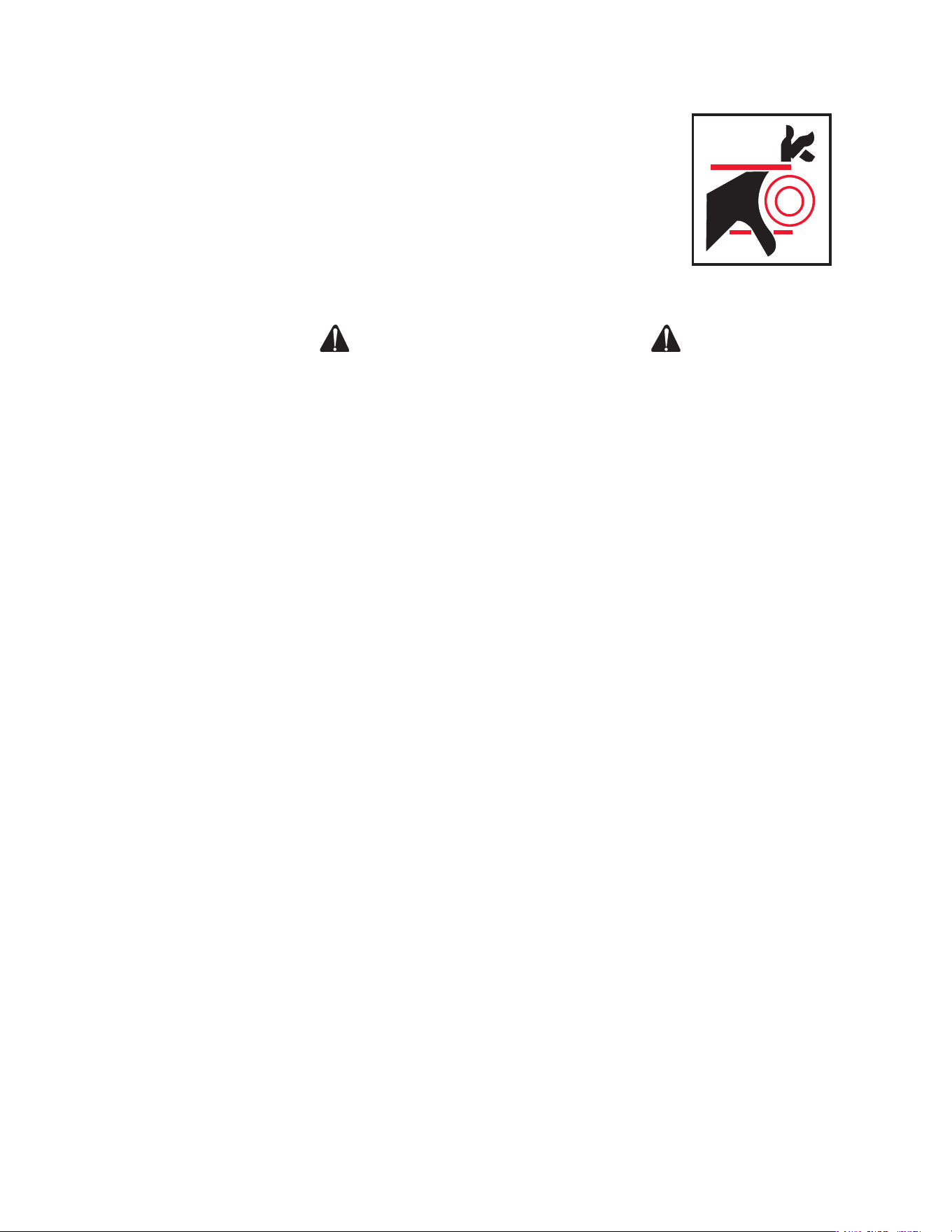
RISK FROM MOVING PARTS
Serious injury may occur to the operator from moving parts on the pressure
washer.
Before making any adjustments, be certain the engine is turned off, ensure
the positive battery cable is disconnected and the ignition cable(s) is re-
moved from the spark plug(s). Turning the machinery over by hand during
adjustment or cleaning might start the engine and machinery with it.
Do not operate the unit without all protective covers in place.
!SAVE THESE INSTRUCTIONS!
8 Operator's Manual
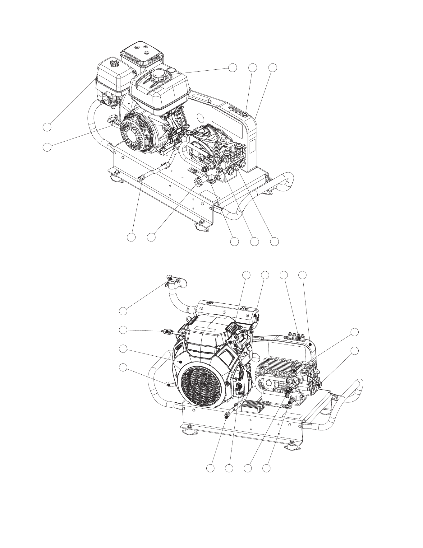
FEATURES
4
3
2
1
13 12 11
9
10
8
75
6
14
CTM-3508-H6G0M FEATURES 061124 CTM-3005-H6G0M FEATURES 050624
9 8
4
5
3
1
2
6
7
10
1 Engine
2 Engine Oil Drain
3 Pump Oil Drain
4 Water Inlet & Strainer
5 Water Outlet
6 Unloader
7 Pump
8 Beltguard
9 Quick Connect Nozzle
10 Engine Fuel Tank Cap
1 Mufer Rain Cap
2 Fuel Filter
3 Engine W/Electric Start
4 Engine Oil Drain Hose
5 Pump Oil Drain Hose
6 Engine Key Switch
7 Water Outlet
8 Water Inlet Hose Barb
9 Pump
10 Unloader
11 Beltguard
12 Nozzle
13 Engine Mufer
14 Vapor Line
CTM-3005-H6G0M
CTM-3508-H6G0M
Operator's Manual 9
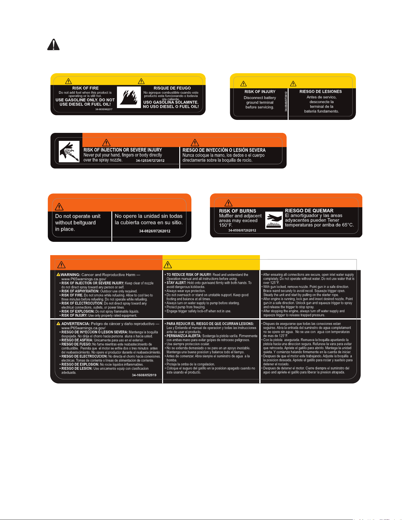
DO NOT REMOVE SAFETY DECALS FROM UNIT UNLESS REPLACING WITH MOST CURRENT
SAFETY DECAL!!!
Decal: Caution-Gasoline Fuel Decal: Caution-Risk of Injury
(Part #34-0835) (Part # 34-0848)
Decal: Warning-Risk of Injection (Part #34-1253)
Decal: Warning-Beltguard in Place Decal: Warning-Mufer Hot
(Part #34-0826) (Part #34-0598)
Decal: Caution/Warning Statements (Part #34-1608)
SAFETY DECALS
RISK OF FIRE
CAUTION
PRECAUCION
Do not add fuel when this product is
operating or is still hot.
USE GASOLINE ONLY. DO NOT
USE DIESEL OR FUEL OIL!
RISQUE DE FEUGO
No agreque combustible cuando este
producto esta funcionando o todavia
sta caliente.
USO GASOLINA SOLAMNTE.
NO USO DIESEL O FUEL OIL!
34-0835/062217
CAUTION
PRECAUCION
RISK OF INJURY
Disconnect battery
ground terminal
before servicing.
RIESGO DE LESIONES
Antes de servico,
desconecte la
terminal de la
batería fundamento.
34-0848/072612
RISK OF INJECTION OR SEVERE INJURY
Never put your hand, fingers or body directly
over the spray nozzle.
34-1253/07272012
RIESGO DE INYECCIÓN O LESIÓN SEVERA
Nunca coloque la mano, los dedos o el cuerpo
directamente sobre la boquilla de rocío.
WARNING
ADVERTENCIA
WARNING/ADVERTENCIA
RISK OF BURNS
Muffler and adjacent
areas may exceed
150°F.
RIESGO DE QUEMAR
El amortiguador y las areas
adyacentes pueden Tener
temperaturas por arriba de 65°C.
34-0598/07262012
WARNING/ADVERTENCIA
34-0826/07262012
No opere la unidad sin todas
la cubierta correa en su sitio.
Do not operate unit
without beltguard
in place.
34-0826/07262012
No opere la unidad sin todas
la cubierta correa en su sitio.
Do not operate unit
without beltguard
in place.
• TO REDUCE RISK OF INJURY: Read and understand the
Operation manual and all instructions before using.
• STAY ALERT: Hold onto gun/wand firmly with both hands. To
avoid dangerous kickbacks.
• Always wear eye protection.
• Do not overreach or stand on unstable support. Keep good
footing and balance at all times.
• Always turn on water supply to pump before starting.
• Protect pump from freezing.
• Engage trigger safety lock-off when not in use.
• After ensuring all connections are secure, open inlet water supply
completely. Do not operate without water. Do not use water that is
over 125°F.
• With gun locked, remove nozzle. Point gun in a safe direction.
Brace wand securely to avoid recoil. Squeeze trigger open.
Steady the unit and start by pulling on the starter rope.
• After engine is running, lock gun and insert desired nozzle. Point
gun in a safe direction. Unlock gun and squeeze trigger to spray
and release the trigger to stop spray.
• After stopping the engine, always turn off water supply and
squeeze trigger to release trapped pressure.
• PARA REDUCIR EL RIESGO DE QUE OCURRAN LESIONS:
Lea y Entienda el manual de operacion y todas las instrucciones
ante de usar el producto.
• PERMANIZCA ALERTA: Sostenga la pistola varilla. Firmenmente
con ambas mano para evitar golpes de retroceso peligrosos.
• Use siempre proteccion ocular.
• No se extienda demasiado o se pare en un apoyo inestable.
Mantenga una buena posicion y balance todo el tiempo.
• Antes de comenzar. Abra sienpre el suminstro de agua a la
bomba.
• Proteja la omba de la congelacion.
• Coloque el suguro del gatillo en la posicion apagado cuando no
este usando el producto.
• Dispues de asegurarse que todas las conexiones estan
seguirse. Abra la entrada del suminstro de agua completament
no se opere sin agua. No se use con agua con temperaturas
de mas de 125°F.
• Con la pistola asegurada. Remueva la boquilla apuntando la
pistola hacia una direccion segura. Refurese la vara para evitar
que retroceda. Apriete el gatillo para abrirlo. Mantega la unidad
quieta. Y comienze halando firmemente en la cuerda de iniciar.
• Despues de que el motor este trabajando. Adjuste la boquilla a
la posicion deseada. Apriete el gatillo para rociar y sueltelo para
detener el rociado.
• Despues de detener el motor. Cierre diempre el suminstro del
aguo and apriete el gatillo para liberar la presion atrapada.
WARNING/ADVERTENCIA
CAUTION/PRECAUCION
OPERATION/OPERACION
34-1608/052919
WARNING: Cancer and Reproductive Harm —
www.P65warnings.ca.gov/
• RISK OF INJECTION OR SEVERE INJURY: Keep clear of nozzle
do not direct spray toward any person or self.
• RISK OF ASPHYXIATION: Outdoor use only required.
• RISK OF FIRE. Do not smoke while refueling. Allow to cool two to
three minutes before refueling. Do not operate while refueling.
• RISK OF ELECTROCUTION: Do not direct spray toward any
electrical connections, outlets, or power lines.
• RISK OF EXPLOSION: Do not spray flammable liquids.
• RISK OF INJURY: Use only properly rated equipment.
ADVERTENCIA: Peligro de cáncer y daño reproductivo —
www.P65warnings.ca.gov/
• RIESGO DE INYECCION O LESION SEVERA: Mantenga la boquilla
despejada. No dirija el chorro hacia persona aluna o hacia usted.
• RIESGO DE ASFIXIA: Unicamente para uso en el exterior.
• RIESGO DE FUEGO: No fume mientras este reabastecimiento de
combustible. Permita que el motor se enfrie dos o tres minutos antes
del reabastecimiento. No opere el productor durante el reabastecimiento.
• RIESGO DE ELECTROCUCION: No directa el chorro hacia conexiones.
electricas. Tomas de corriente o lineas de alimentacion de corriente.
• RIESGO DE EXPLOSION: No rocie liquidos inflammables.
• RIESGO DE LESION: Use unicamente equip con clasificacion
adeduada.
10 Operator's Manual
ATTIRE:
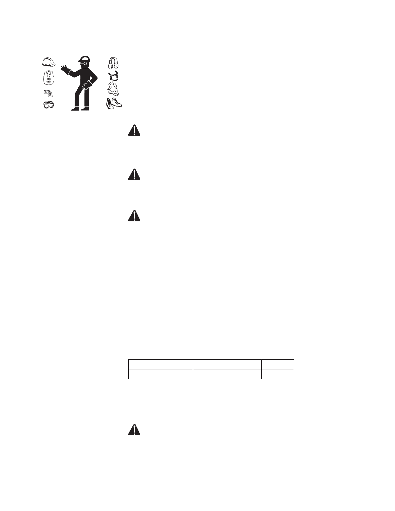
Proper attire is essential to your safety. It is advised to utilize whatever
means necessary to protect eyes, ears, and skin. Additional safety attire
(such as respiratory mask) may be required when using detergent cleaning
agents with this washer.
LOCATION:
In order to avoid damaging the unit, do not incline the unit transversely or
longitudinally more than 10°.
WARNING: RISK OF ASPHYXIATION! DO NOT OPERATE IN AN
ENCLOSED AREA. USE THIS PRODUCT ONLY IN WELL
VENTILATED AREAS! THE EXHAUST FROM THE ENGINE
CONTAINS CARBON MONOXIDE, A POISONOUS, ODORLESS
AND INVISIBLE GAS. BREATHING THE GAS CAN CAUSE
SERIOUS INJURY, ILLNESS AND POSSIBLE DEATH.
WARNING: RISK OF EXPLOSION OR FIRE CAUSING SERIOUS
INJURY OR DEATH! DO NOT ALLOW THE ENGINE OR
MUFFLER TO COME IN CONTACT WITH FLAMMABLE VAPORS,
COMBUSTIBLE DUST, GASES OR OTHER COMBUSTIBLE
MATERIALS. A SPARK MAY CAUSE A FIRE.
WHEN USING THE UNIT FOR SPRAY PAINTING, PLACE THE UNIT
AS FAR AWAY FROM THE WORK AREA AS POSSIBLE, USING
EXTRA AIR HOSES IF NEEDED.
Place unit at least 12 inches away from obstacles that may prevent proper
ventilation. Do not place unit in an area:
- where there is evidence of oil or gas leaks.
- where ammable gas vapors or materials may be present.
- where air temperatures fall below 32°F or exceed 104°F.
- where extremely dirty air or water could be drawn into the unit.
SERVICE TRUCK INSTALLATION:
Installations may vary. Mounting should be done to a rigid frame member.
Installer is responsible for securing the equipment in a safe manner.
Once the mounting location has been determined; verify that the structure
can hold the weight of the unit. When mounted on a vehicle, the unit can
experience up to 3 times its weight in the vertical direction under normal
conditions. When mounted behind the axle, this unit can experience higher
than expected loads. This loading can cause damage to the mounting struc-
ture and unit. Use the following hardware when mounting the unit.
Do not operate unit in an area:
a. with insufcient ventilation.
b. where there is evidence of oil, gas or fuel leaks.
c. where ammable gas vapors may be present.
DANGER: RISK OF EXPLOSION OR FIRE! WHEN CHARGING
BATTERIES, THEY GENERATE A HIGHLY EXPLOSIVE
HYDROGEN GAS. A SPARK COULD CAUSE AN EXPLOSION
OR FIRE! DO NOT JUMP START BATTERY UNLESS BOTH
BATTERIES ARE OF EQUAL VOLTS & AMPS. DO NOT SMOKE
OR ALLOW SPARKS OR FLAMES NEAR THE BATTERY. DO NOT
PLACE UNIT IN AN AREA WHERE FLAMMABLE GAS VAPORS
MAY BE PRESENT. A SPARK COULD CAUSE AN EXPLOSION
OR FIRE.
INSTALLATION & PREPARATION
Bolt Type Torque Spec. Quantity
5/16” Grade 5 17.5 ft-lbs (59.1 Nm) 8
Operator's Manual 11
INSTALLATION & PREPARATION
RISK OF UNIT BURSTING! DO NOT STORE/OPERATE UNIT IN
FREEZING ENVIRONMENTS!
Do not allow the unit to be exposed to snow or freezing temperatures. If any
part of the unit becomes frozen, excessive pressure may build up in the unit
which could cause it to burst or explode-resulting in possible serious injury
to the operator or bystanders.
Pump oil level should be checked before each use. Check the dipstick or
the oil level indicator on the pump crankcase. Make certain the oil is on the
"Full" mark on the dipstick or in the center of the oil sight glass. If the level
appears to be low, ll with 15W20 detergent pump oil.
ENGINE FUEL TANK:
DANGER: RISK OF FIRE! DO NOT SMOKE WHILE FUELING! DO
NOT FILL THE FUEL TANK WHILE UNIT IS RUNNING OR
HOT. ALLOW UNIT & ENGINE TO COOL FOR TWO MINUTES
BEFORE REFUELING. DO NOT FILL FUEL TANK TO POINT
OF OVERFLOWING. ALLOW APPROXIMATELY 1/4" OF TANK
SPACE FOR FUEL EXPANSION.
1. Locate the Safety Decals on your unit and heed their warnings.
WARNING: RISK OF EXPLOSION OR FIRE!
ALWAYS STORE FUEL
AWAY FROM THE WASHER WHILE THE UNIT IS RUNNING OR HOT.
2. Gasoline Engines: When lling tank, gasoline fuel should be a minimum
of 85 octane. DO NOT MIX OIL WITH GASOLINE. Gasoline fuel should
be purchased in quantities that may be used within 30 days. Use of
clean, fresh lead-free gasoline is recommended. Leaded gasoline may
be used if lead-free is unavailable. DO NOT use gasoline containing
methanol or alcohol.
3. Check the engine oil level before starting the engine. (See Engine
Manual.)
4. Refer to the Engine Manual supplied with this unit for proper fueling and
adjustment procedures.
5. Review the Engine Manual accompanying this pressure washer for
correct engine start-up and maintenance procedures.
FUEL SYSTEM (3508 MODEL)
CAUTION: UNAUTHORIZED MODIFICATION, REMOVAL OR
REPLACEMENT OF THE FUEL SYSTEM THAT AFFECTS
EMISSIONS IS PROHIBITED.
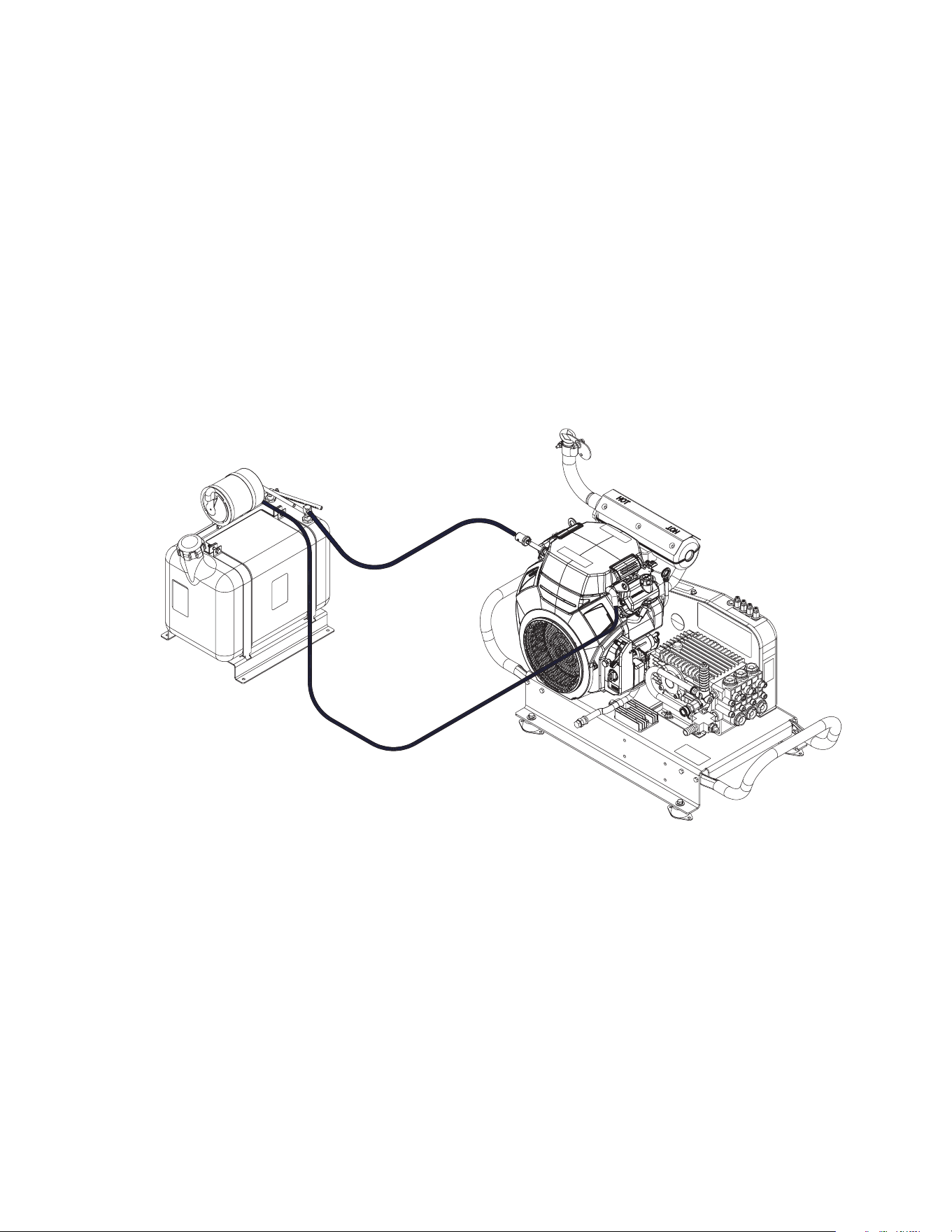
ROUTING HOSES
All fuel hoses should be routed along frame rails to prevent damage from
road debris. Fuel hoses should be routed in such a way that provides easy
access for inspection and maintenance. Properly support fuel hoses to mini-
mize rubbing and contact with sharp edges. NEVER route fuel hoses next to
electrical or exhaust components. To prevent fuel siphoning, ensure all fuel
hoses are located above the top of the fuel tank.
FUEL TANK
This unit requires use of a dedicated fuel tank or separate pickup tube if
installed in an existing fuel tank. When installing a separate pickup tube in
an existing fuel tank ensure that the pickup is mounted higher than that of
the original. Doing so will allow use of the vehicle after the unit has run out
of fuel.
The unit must never be connected to the high pressure vehicle fuel sup-
ply system. Doing so will damage the unit fuel system. Fuel tank must be
12 Operator's Manual
INSTALLATION & PREPARATION
mounted in a location where the fuel pickup is no more than 500mm (19-
5/8") above or below the carburetor of the engine. For applications that do
not meet this requirement a fuel supply pump is required. Pump must be
connected to a switched source that can be turned off when the unit is not
running and must provide no more than 1-2 psi of pressure at the fuel lter
of the engine.
FUEL SUPPLY LINE
Installation of a hose with minimum 1/4” inner diameter is required. The fuel
supply hoses used for the unit requires low permeation fuel hoses which
meet Federal 50 state standards for gasoline evaporative emissions.
CARBON CANISTER AND VAPOR LINE
To meet all EPA and CARB evaporative emissions regulations this unit re-
quires use of a carbon canister. Follow all federal, state and local regulations
when connecting the unit to a new or existing fuel tank. The engine on this
unit is equipped with a 3/16” vapor port located on the air cleaner housing.
BATTERY
The engine and controls in this unit use a 12VDC electrical system. For
stand-alone operation it is recommended that a battery charger is installed.
BATTERY SIZE
For proper starting in all climates a minimum 24Ah (3005 Model) and 45Ah
(3508 Model) battery is recommended.
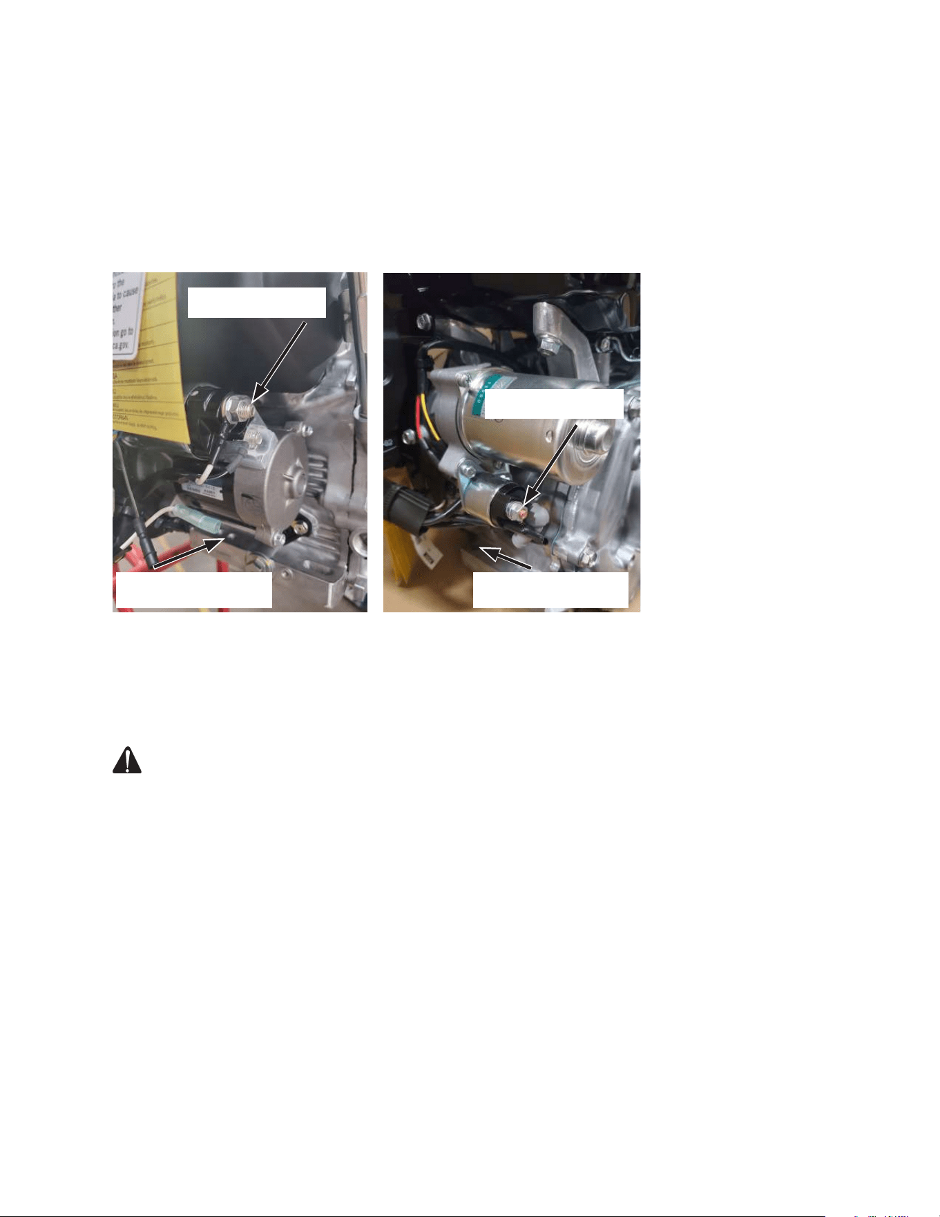
BATTERY CABLES
For typical installations, use no less than 4 AWG battery cable to provide
power from the battery to the unit. For the positive (+) battery cable connec-
tion a 3/8” eyelet must be used. For the negative (-) battery cable connec-
tion a 5/16” eyelet must be used.
All battery cables should be routed along frame rails to prevent damage
from road debris. Battery cables should be routed in such a way that pro-
vides easy access for inspection and maintenance. Properly support battery
3/16" VAPOR
HOSE
1/4" FUEL
SUPPLY HOSE
Operator's Manual 13
INSTALLATION & PREPARATION
cables to minimize rubbing and contact with sharp edges. NEVER route bat-
tery cables next to fuel or hot exhaust.
Select battery cables to avoid greater than 0.5 volt drop in the cable during
starter motor operation.
Battery cable size and length: (Guage x Length)
Positive cable: AWG No. 4 x 1.5 m (5.0 ft. ) maximum
Negative cable: AWG No. 4 x 2.3 m (7.5 ft.) maximum
BATTERY LOCATION
Battery must be mounted in a separate properly ventilated compartment or
box away from unit and fuel components. The gasses produced by the bat-
tery can be ignited by sparks from the unit.
HIGH PRESSURE GUN / WAND / HOSE
!!!ATTENTION!!! UNIT DOES NOT COME EQUIPPED WITH A HIGH
PRESSURE GUN, WAND OR HOSE FROM THE FACTORY
When selecting a hose, a 3/8" high pressure hose with a minimum 3500 PSI
pressure rating and minimum 200°F temperature rating must be used. Hose
should be equipped with a 3/8" male high pressure quick connect for easy
installation on the unit.
When selecting a gun and wand assembly, a minimum 36" long assembly
with 3500 PSI pressure rating, minimum 8 GPM ow rating and minimum
120°F temperature rating should be used. Wand must be equipped with
a 1/4" high pressure quick connect tting to connect to the high pressure
nozzles included with the unit.
NOZZLE REVIEW:
Various nozzles may be quick-connected into the end of the lance to change
the spray pattern or use the detergent feature. When using quick connects
(Q.C.), be certain the connection is securely locked. If not, the high pressure
water may shoot the nozzle from the lance, causing severe injury or serious
damage. To determine spray fan, refer to the actual number stamped on
the nozzle. The rst two digits indicate the spray fan in degrees, i.e.: 00=0°,
15=15°, 25=25°, 40=40°.
NEGATIVE BATTERY
CABLE
POSTIVE BATTERY
CABLE
POSTIVE BATTERY
CABLE
NEGATIVE BATTERY
CABLE
14 Operator's Manual
INSTALLATION & PREPARATION
WARNING RISK OF INJECTION CAUSING SEVERE INJURY!
NEVER LOOK DIRECTLY AT THE NOZZLE UNLESS IT IS DIS-
CONNECTED FROM THE GUN/LANCE ASSEMBLY!
1. The 0° nozzle (RED): This is a blasting nozzle. It delivers a very
concentrated stream of water. Be cautious when using the straight
narrow stream. It is not recommended for use on painted or wood
surfaces or items attached with adhesive backings. Uses: Removing
weeds from sidewalk cracks, stubborn stains from concrete, masonry,
aluminum and steel, caked mud from equipment, and cleaning lawn
mower undersides.
2. The 15° nozzle (YELLOW): This is a chiseling nozzle. The spray should
be directed at a 45° angle to the surface and used like a scraper to
remove paint, grease and dirt. Uses: Surface preparation (removing
mildew stains and paint chips), cleaning gutters and downspouts.
3. The 25° nozzle (GREEN): This is a ushing nozzle. This pattern is best
suited for ushing dirt, mud, and grime. Uses: Wet sweeping leaves
from walks, curbs and driveways, cleaning stable oors, washing
swimming pool bottoms, degreasing engines.
4. The 40° nozzle (WHITE): This is a wash nozzle. This wide spray pattern
disperses the water pressure over a large area and is recommended
for moderate washing. Uses: Washing down aluminum siding, cleaning
windows, washing vehicles, spraying sidewalks, driveways and patios.
NOZZLE CONNECTION:
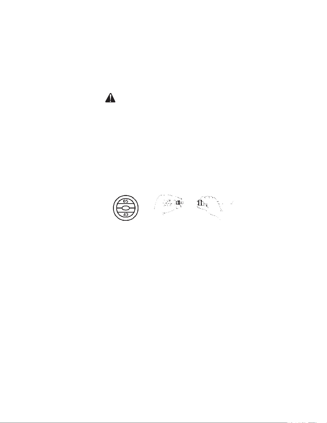
1. Ensure the trigger gun is locked in the OFF position.
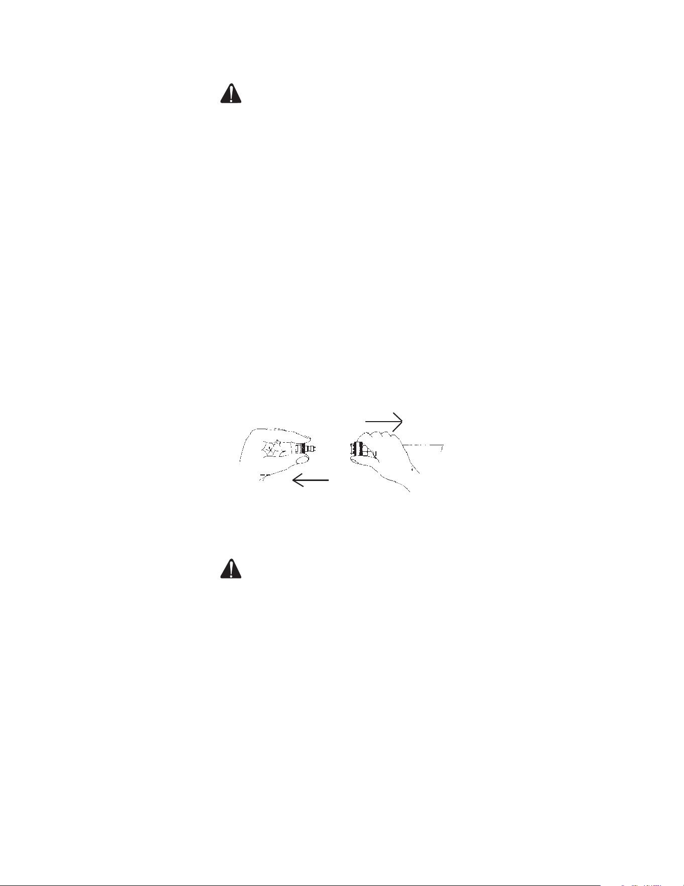
2. The quick-connect nozzle should be disconnected from the gun
assembly at this time. As shown in the drawing below, retract the
locking ring on the quick-connect tting to remove the nozzle.
WARNING: RISK OF SEVERE INJURY! THE TRIGGER GUN SHOULD
ALWAYS BE LOCKED IN THE OFF POSITION WHEN NOT IN
USE!
WATER SUPPLY (3005 MODEL):
1. Select a water supply hose which is a quality grade of garden hose
measuring at least 3/4" ID and no longer than 50 feet.
2. Check the see-through water lter to ensure it is clean and free of any
obstructions. Periodic cleaning of the see-through water lter will help
prevent pump problems. As a lter screen becomes obstructed, it
restricts proper ow of water to the pump. This can result in cavitations
which will cause premature failure of pump packings.
a. Unscrew the garden hose inlet connection from the front of the lter
assembly.
b. Remove the clear plastic cover and clean the lter screen.
3. Connect the hoses:
a. Connect one end of the water supply hose to the water inlet of the unit.
b. Connect the other end of the hose to your pressurized water supply or
Operator's Manual 15
INSTALLATION & PREPARATION
gravity fed tank. When connecting the water inlet to the water supply
mains, local regulations of your water company must be observed.
In some areas, the unit must not be connected directly to the public
drinking water supply. This is to ensure that there is no feedback of
the detergents into the water supply. (Direct connection is permitted if
a back ow preventer is installed.)
c. Quick-connect the high pressure discharge hose to the water outlet of
the unit.
d. Connect the other end of the discharge hose to the gun.
4. Follow the incoming water requirements listed below:
a. When connected to a pressurized water supply, water pressure must
be a minimum of 25 pounds per square inch (PSI) and a maximum of
125 PSI. (A typical outdoor faucet will generally supply this PSI if turned
completely “ON”.)
b. When connected to a gravity fed tank, outlet of tank must be no more
than 12 inches below inlet of pump.
c. Incoming GPM must be approximately one gallon more than the
outgoing GPM stated on the pressure washer nameplate. (You can
check GPM by timing how long it takes to ll a 5 gallon container.)
d. Incoming water temperature must not exceed 125°F. Excessive pump
damage may result if the water temperature exceeds this acceptable
level.
5. Never allow the unit to operate without the incoming water line attached
and the water supply completely turned on.
WATER SUPPLY (3508 MODEL):
1. Select a water supply hose measuring 3/4 id and no longer than 50 feet.
2. Water supply hose must be equiped with minimum 60 mesh inline lter
before inlet tting.
3. Connect the hoses:
a. Connect one end of the water supply hose to the water inlet of the unit.
b. Connect the other end of the hose to your pressurized water supply or
gravity fed tank. When connecting the water inlet to the water supply
mains, local regulations of your water company must be observed.
In some areas, the unit must not be connected directly to the public
drinking water supply. This is to ensure that there is no feedback of
the detergents into the water supply. (Direct connection is permitted if
a back ow preventer is installed.)
c. Quick-connect the high pressure discharge hose to the water outlet of
the unit.
d. Connect the other end of the discharge hose to the gun.
4. Follow the incoming water requirements listed below:
a. When connected to a pressurized water supply, water pressure must
be a minimum of 25 pounds per square inch (PSI) and a maximum of
125 PSI. (A typical outdoor faucet will generally supply this PSI if turned
completely “ON”.)
b. When connected to a gravity fed tank, outlet of tank must be no more
than 12 inches below inlet of pump.
c. Incoming GPM must be approximately one gallon more than the
outgoing GPM stated on the pressure washer nameplate. (You can
check GPM by timing how long it takes to ll a 5 gallon container.)
CHECK WATER
INLET STRAINER

16 Operator's Manual
INSTALLATION & PREPARATION
d. Incoming water temperature must not exceed 125°F. Excessive pump
damage may result if the water temperature exceeds this acceptable
level.
5. Never allow the unit to operate without the incoming water line attached
and the water supply completely turned on.
UNLOADER:
The unloader has been preset at the factory and should only be adjusted by
a trained Service Representative. DO NOT adjust the pressure on your own!
THERMAL RELIEF VALVE:
To ensure the bypass water temperature does not exceed acceptable levels,
never allow the pressure washer to operate in the bypass mode (with the
unit running and the trigger closed) for more than three minutes.
A Thermal Relief Valve has been added to this unit to protect the pump. It
may begin to open and release water if the water temperature in the pump
has exceeded 140° F. This will allow fresh, cool water to enter the system.
PRE-START INSPECTION PROCEDURES:
Before starting the unit, perform the following procedures:
1. Check the oil level in the pump and engine.
2. Inspect the water inlet strainer. Clean or replace if necessary.
3. Check all hose connections to ensure they are securely tightened.
4. Inspect for system water leaks, oil leaks and fuel leaks. If a fuel leak
is found, DO NOT START UNIT! See "Risk of Explosion or Fire" in the
warnings. Be sure that all damaged parts are replaced and that the
mechanical problems are corrected prior to operation of the unit. If you
require service, contact your Customer Service.
5. Inspect high pressure hoses for kinking, cuts and leaks. If a cut or leak
is found, DO NOT USE HOSE! Replace hose before starting unit. See
"Risk of Injection" in the warnings. Be sure that all damaged parts
are replaced and that the mechanical problems are corrected prior to
operation of the unit. If you require service, contact your Customer
Service.
Operator's Manual 17
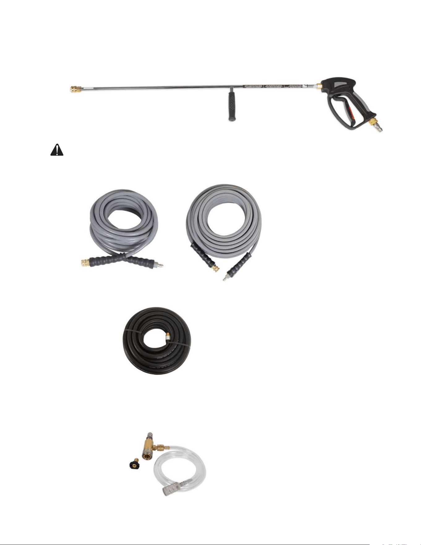
GUN AND WAND: 851-0095
Professional-grade insulated trigger gun with safety lock-off and quick
connects.
HIGH PRESSURE HOSE:
50' - 851-0338
100' - 15-0273
IMPORTANT: DO NOT USE MORE THAN 1 EXTENSION HOSE.
THE HIGHER RESTRICTION WILL CAUSE UNLOADER
VALVE TO FUNCTION ALL THE TIME.
These high pressure hoses are 3/8" i.D., 4,000 PSI, gray, non-marking,
have an R1 rating, and feature quick connects.
LOW PRESSURE SUPPLY HOSE: 15-0006
This low pressure hose is 3/4" i.D., 50' Long, black, with a max pres-
sure of 200 PSI, a max temperature of 212 degrees fahrenheit, and
features screw connects.
LOW PRESSURE DETERGENT INJECTOR:
AW-8400-0023
Easily apply chemicals using this low pressure detergent injector rated
for 5 to 8 (GPM) gallons per minute units. It features adjustable chemi-
cal draw, clear, pliable detergent hose with a strainer, and features a
quick connect for easy connection to the outlet of the pump.
ACCESSORIES

18 Operator's Manual
WARNING
THE FOLLOWING PAGES CONTAIN OPERATING AND MAINTENANCE
INSTRUCTIONS.
DO NOT ATTEMPT TO OPERATE THIS PRESSURE WASHER UNTIL YOU HAVE READ
AND UNDERSTOOD ALL SAFETY PRECAUTIONS AND INSTRUCTIONS LISTED IN
THIS MANUAL.
INCORRECT OPERATION OF THIS UNIT CAN CAUSE SERIOUS INJURY!!
DO NOT ALTER OR MODIFY THIS EQUIPMENT IN ANY MANNER!

Operator's Manual 19
PRIMING THE PUMP:
1. It is essential to prime the pump on initial start-up and each time the
water supply is disconnected from the unit after initial use.
2. Lay the high pressure hose out to remove any loops. (Water ow will
tighten the hose, creating tight loops if the hose is not straight.)
3. Securely connect the gun assembly to the high pressure hose.
NOTE: The quick-connect nozzle should NOT be connected to the gun assembly at this
time. See "Nozzle Connection".
4. With the trigger gun locked in the OFF position, turn the water supply
completely on. Pointing the gun in a safe direction, unlock the trigger
gun and squeeze the trigger.
DANGER: RISK OF INJECTION CAUSING SEVERE INJURY! KEEP
CLEAR OF NOZZLE! NEVER PLACE HAND OR FINGERS IN
FRONT OF NOZZLE! DO NOT DIRECT DISCHARGE STREAM
AT PEOPLE OR PETS! BE CERTAIN THE NOZZLE IS SECURELY
CONNECTED TO THE LANCE TO PREVENT ACCIDENTAL
DISCHARGE!
5. Low pressure water will begin owing from the hose/gun assembly. This
allows the unit to prime and purge any air from the system. The unit is
primed when water ow is uninterrupted by air.
6. Once the unit is primed, release the trigger and lock the gun in the OFF
position. Securely connect the desired quick-connect nozzle. (See
"Nozzle Connection")
START-UP:
1. Refer to the "Safety Warnings" in the warnings section before starting
the unit.
2. Locate the Safety Decals on your unit and heed their warnings.
3. With the gun locked in the OFF position, point the trigger gun away from
yourself or anyone else.
4. Disengage the safety lock-off on the gun and squeeze the trigger. Low
pressure water will begin owing from the nozzle.
5. BE CERTAIN the trigger gun remains in an open position while starting
the engine. Brace yourself as the gun will kickback from the high
pressure created by the pump once the engine has started.
6. Refer to the Engine Manual accompanying this pressure washer for the
correct procedures needed to start the engine.
7. Once the engine has started, perform the following procedures with the
gun open:
a. Inspect for system water leaks, oil leaks and fuel leaks. If a fuel leak is
found, TURN UNIT OFF IMMEDIATELY! See "Risk of Explosion or Fire".
Be sure that all damaged parts are replaced and that the mechanical
problems are corrected prior to operation of the unit. If you require
service, contact your Customer Service.
b. Inspect high pressure hoses for kinking, cuts and leaks. If a cut or
leak is found, DO NOT TOUCH HOSE AT LEAK!!! TURN UNIT OFF
IMMEDIATELY! Replace hose before restarting the unit. See "Risk of
Injection," in the warnings. Be sure that all damaged parts are replaced
and that the mechanical problems are corrected prior to operation of
the unit. If you require service, contact your Customer Service.
8. Be certain to LOCK the trigger gun in the OFF position whenever
changing the quick-connect nozzles. NEVER look directly into the
nozzle! High pressure water creates a risk of severe injury!
OPERATING INSTRUCTIONS
20 Operator's Manual
9. Do not allow unit to operate in bypass mode (with trigger closed) for
more than three minutes without triggering the gun. Failure to follow this
simple rule can cause premature failure of pump packing seals, resulting
in costly pump repair.
10. Because your pressure washer delivers a high pressure spray and a
variety of spray patterns, there are many cleaning jobs that can be
done without the use of detergents. If a cleaning agent is required, see
"Cleaning With Detergents" for the correct procedures.
CAUTION: RISK OF DAMAGE. DO NOT ALLOW SPRAY PATTERN
TO REMAIN ON A FIXED AREA FOR AN EXTENDED PERIOD OF
TIME. POSSIBLE DAMAGE MAY OCCUR TO THE AREA.
CLEANING WITH DETERGENTS (OPTIONAL FEATURE):
1. The Detergent Injection feature is an optional feature on this machine.
2. Refer to "Risk of Bodily Injury,", and the Detergent Injector Manual which
accompanies part #AW-8400-0023. Be certain to wear protective safety
attire as stated in the warnings.
3. Prepare detergent solution according to label directions. Never pump
acids, alkaline, abrasive uids or solvents through the unit. Due to
the unknown and often corrosive characteristics of many detergents
commonly used in the pressure washer cleaning industry, it is
recommended to use only mild detergents with this unit.
4. Connect the Detergent Injector to the unit as directed in the Detergent
Injector Manual.
5. Adjust the amount of detergent desired by locating the adjustment knob
at the end of the clear vinyl hose at the Detergent Injector. Turn the
knob completely counterclockwise to set at the maximum siphon rate.
6. Immerse the strainer into the detergent solution to allow detergent to
siphon.
7. Be certain the water supply is completely turned ON.
8. With the trigger gun locked in the OFF position, securely quick-connect
the detergent spray nozzle (BLACK) into the end of the lance.
NOTE: This injection system is designed to apply detergents under low pressure only.
It will not allow detergent solutions to be introduced into the system unless the
detergent nozzle is installed in the lance.
9. To apply solution, unlock the trigger gun and squeeze the trigger. In
a few moments a detergent/water mixture will exit the low pressure
nozzle. Start spraying the lower portion of the surface being cleaned
and move up, using long overlapping strokes. Applying from the bottom
up helps avoid streaking. Allow to soak briey. (Avoid working on hot
surfaces or in direct sunlight to minimize the chances of the detergent
drying, which may result in damaging painted surfaces.) Be certain to
apply cleaning solution to a small section at a time.
10. To rinse: lock the trigger gun in the OFF position, securely quick-
connect the 40° nozzle into the end of the lance. Unlock the trigger gun
and spray. It will take about 30 seconds to purge all detergent from the
line. For best rinsing results, start at the top and work down.
11. Siphon a gallon of water through the low pressure detergent injection
system after each use. This prevents the possibility of corrosion or
detergent residue causing mechanical problems during the next use.
OPERATING INSTRUCTIONS

Operator's Manual 21
SHUTDOWN:
1. Turn engine OFF as directed in the Engine Manual.
2. Turn the water supply OFF.
3. Pointing the gun in a safe direction, trigger gun momentarily to relieve
any trapped pressure.
4. Once pressure is relieved, disconnect the nozzle assembly.
5. Disconnect and drain gun, lance and hoses.
6. Wipe unit clean and store with gun, lance and hoses in a safe area.
OPERATING INSTRUCTIONS
22 Operator's Manual
SPECIFIC MAINTENANCE:
EVAPORATIVE EMISSION COMPONENTS:
The unit you have purchased includes the following components that are in
compliance with 2024 California Air Resources Board Evaporative Emission
Standards;
1. Fuel Hose
2. Fuel Hose Fittings
These components should be inspected on a daily basis for cracks, leaks,
and abnormal wear. If cracking, leaks or abnormal wear has occurred, the
components should be replaced immediately.
ENGINE: The engine instructions that accompany your unit detail specic
procedures for maintenance of the engine. Following the engine manufac-
turer's recommendations will extend engine work life.
PUMP: Change the pump oil after the rst 50 hours of operation. After
initial change, every 3 months or 250 hour intervals are recommended. If oil
appears dirty or milky, changes may be required in greater frequency. Use
SAE20 or 30 Non-Detergent pump oil and ll only to the center of the oil
sight glass or the "Full" mark on the dipstick. DO NOT OVERFILL.
QUICK COUPLERS: There is an o-ring seal inside the female quick-coupler.
This o-ring will deteriorate or, if the unit is allowed to pump without the high
pressure hose attached, it may be blown out occasionally. Simply insert a
replacement o-ring to correct the leak. (Additional o-rings can be purchased
from your dealer.)
NOZZLES: Water ow through the quick-connect spray nozzle will erode the
orice, making it larger, resulting in a pressure loss. Nozzles should be re-
placed whenever pressure is less than 85% of the maximum. The frequency
of replacement will depend upon such variables as mineral content in the
water and number of hours the nozzle is used.
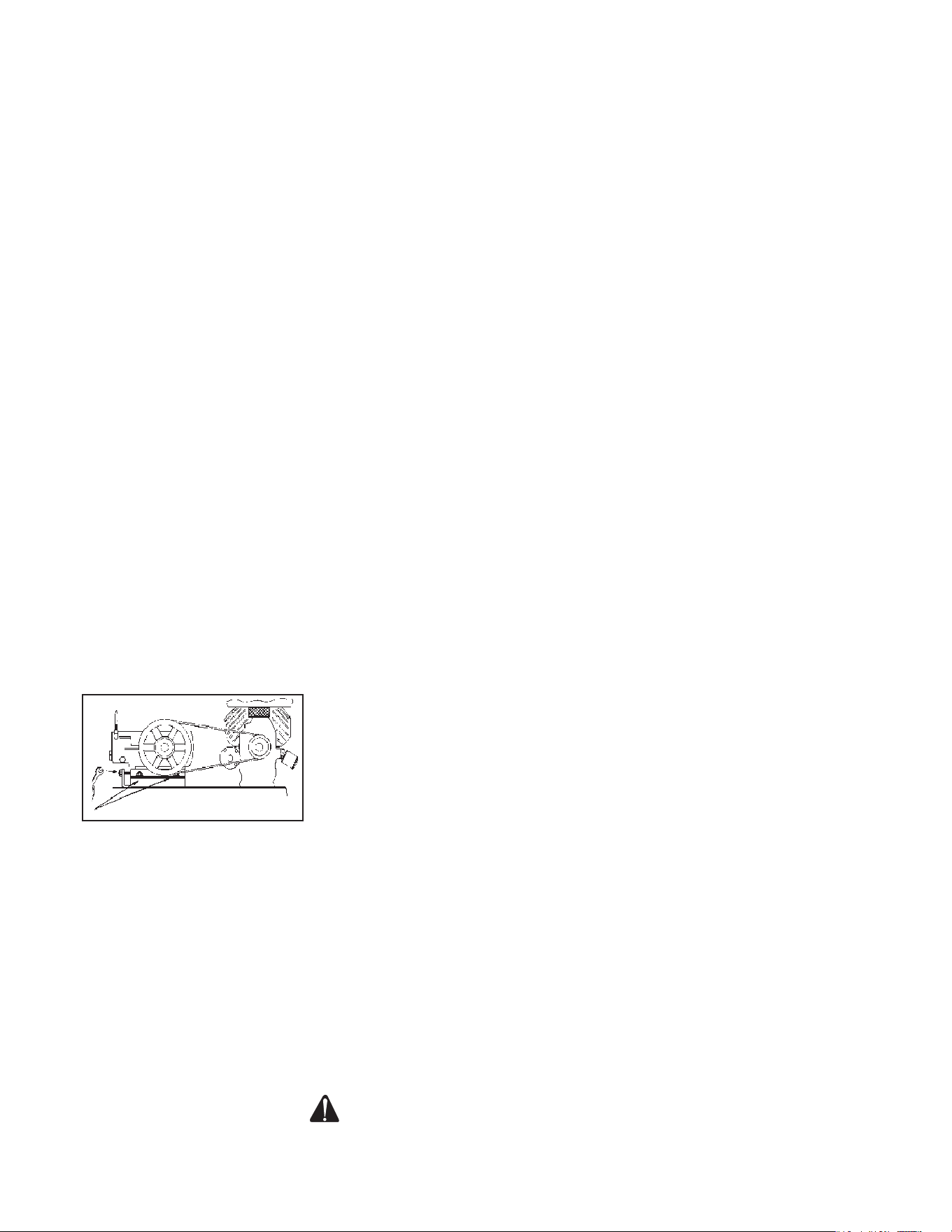
BELT TENSION ADJUSTMENT: To maintain peak performance of your pres-
sure washer, it may be necessary to adjust the belt tension on occasion.
Follow the procedure outlined below.
1. Remove the belt guard and loosen the two nuts on each side of the
pump (Reference A). There are a total of 4 nuts.
2. Turn the cap screw (Reference B) clockwise until a 1/4 inch belt
deection is noticed between the pulleys.
3. Tighten the side nuts (Reference A).
4. Put a straight edge across both pulleys. Pulley alignment is critical for
proper performance and service life. If necessary, loosen one set of
pulley screws and adjust in or out to properly align. Tighten the pulley
screws and check the tension again.
5. Replace the beltguard and tighten the fasteners securely.
WINTERIZING:
For storage and transportation purposes in subfreezing ambient tempera-
tures, it will be necessary to winterize this unit. This unit must be protected
to the lowest incurred temperature for the following reasons:
1. If any part of the pumping system becomes frozen, excessive pressure
may build up in the unit which could cause the unit to burst resulting in
possible serious injury to the operator or bystanders.
WARNING: RISK OF UNIT BURSTING. DO NOT STORE / OPERATE
UNIT IN A FREEZING ENVIRONMENT!
B
A
STORAGE & MAINTENANCE

Operator's Manual 23
STORAGE & MAINTENANCE
2. The pumping system in this unit may be permanently damaged if frozen.
FREEZE DAMAGE IS NOT COVERED BY WARRANTY.
If you must store your unit in an area where the temperature may fall below
32°F, you can protect your unit by following the procedure outlined below.
1. Gather the following items:
a. Two 5 gallon containers.
b. One gallon of antifreeze. (The manufactuer recommends an
environmentally safe antifreeze.)
c. Water supply.
d. Three foot hose, 1/2-3/4 I.D. with a 3/4 inch male garden hose tting.
2. Procedure:
a. Shut off the unit and water supply.
b. Relieve system pressure by pointing the trigger gun in a safe direction
and squeezing the trigger until water ow ceases to exit the nozzle.
c. Lock the trigger gun in an OFF position and remove the nozzle.
d. In one 5 gallon container, mix the antifreeze and water according to
manufacturer's recommendations for the temperature to which you
are winterizing.
NOTE: Proper winterizing is based on the recommended manufacturer's instructions
listed on the "Protection Chart" shown on the back label of most antifreeze con-
tainers.
e. Remove the water supply hose from the unit and attach the 3 foot hose
securely to the inlet connection. Submerge the opposite end into the
antifreeze solution.
f. Point the lance into the empty container and start the unit.
g. Trigger the gun until the antifreeze begins to exit the lance. Release
the trigger for 3 seconds; then, trigger the gun for 3 seconds. Continue
cycling the gun several times until all the antifreeze mixture is siphoned
from the container.
h. Detach the 3 foot hose from the unit and drain any excess antifreeze
back into a 5 gallon container.
i. Disconnect the hose/gun/lance assembly from the unit and drain any
excess antifreeze back into a 5 gallon container.
j. Store the hose, gun and lance with the unit in a safe area.
k. Store antifreeze solution for next use or dispose of according to state
EPA laws.
3. Optional procedure:
a. Shut off the unit and water supply.
b. Relieve system pressure by pointing the trigger gun in a safe direction
and squeezing the trigger until water ow ceases to exit the nozzle.
c. Disconnect and drain the hose, gun and lance.
d. Start the unit and allow it to run until all the water exits the unit. Once
the water has stopped owing from the unit, turn the unit off.
NOTE: When using this procedure, caution should be used as ice chips can form from
drops of water which could cause the unit to burst if starting before completely
thawed.
32˚F 0˚C

24 Operator's Manual
TROUBLESHOOTING
SYMPTOM PROBABLE CAUSE SYMPTOM
Engine will not start. Various engine problems. Refer to the Engine Manual accompanying
your unit.
Unit components are frozen. Allow to thaw. If any part of the unit be-
comes frozen, excessive pressure may
build up in the unit which could cause the
unit to burst resulting in possible serious
injury to the operator or bystanders.
No discharge at nozzle
when trigger mechanism
is squeezed.
Inadequate water supply. Ensure hose is 3/4" diameter and incoming
water supply is turned on.
Kink in water inlet hose. Remove kink.
Low or uctuating pres-
sure..
Kink in high pressure discharge
hose.
Replace kinked high pressure hose.
Water inlet screen obstructed. Remove screen, clean or replace
Pump sucking air (prime eliminated). Tighten all water intake connections. Elimi-
nate leaks in intake line. Re-prime.
Not in high pressure mode. Insert high pressure nozzle.
Obstructed or worn spray nozzle. Remove, clean or replace.
Damaged or obstructed valve assy.
on pump.
Remove, inspect, clean or replace.
Pump packings worn. Replace packings.
Bypass valve not operating correctly. Repair or replace.
Water is leaking from
the "Thermal Relief
Valve".
Water temperature is too high. Do not allow unit to operate the bypass
mode with trigger gun closed) for more
than three minutes.
Defective valve. Replace.
Oil appears milky or
foamy.
Water in oil. Change pump oil. Fill to proper level.
Oil leaking from unit. DO NOT USE. Contact your Customer Service.
Detergent will not siphon
into Low Pressure De-
tergent mode. (Optional
Feature.)
Detergent strainer is not completely
submerged in detergent solution.
Check, submerge if necessary.
Detergent strainer obstructed. Inspect, clean or replace.
Detergent hose cut, obstructed or
kinked.
Inspect, clean or replace.
Detergent adjusting knob turned to
closed position.
Open adjusting knob. Refer to "Cleaning
with Detergents".
Detergent nozzle not being used. Insert 6540° (BLACK) nozzle.
Nozzle assembly is plugged. Clean or replace.
Too many high pressure hose exten-
sions attached to the water outlet.
Use one extension maximum.
Ball & Spring in Venturi stuck. Remove, clean or replace.
Water ows back into
detergent container.
Ball & Spring in Venturi reversed,
missing or corroded.
Remove, clean or replace.
Water ows from the
nozzle when the trigger
gun is locked in the OFF
position.
Gun is malfunctioning. Repair or replace.
Water is leaking at safety
relief.
Safety Relief/ Burst disk is ruptured
caused by an unloader malfunction.
Replace safety Relief/ Burst disk. NEVER
run unit without safety Relief/ Burst disk.
Doing so can cause an explosion!
Detect and correct unloader problem.

Operator's Manual 25
STATEMENT OF WARRANTY
The manufacturer warrants all parts, (except those referred to below), of your new
CWC-Series pressure washer to be free from defects in materials and workmanship
during the following periods:
For Lifetime against freezing and cracking:
Pump Manifold
For Seven (7) Years from the date of original purchase:
High Pressure Pump
For Two (2) Years from the date of original purchase:
Cart Assembly Pulleys
Plumbing
For One (1) Year from the date of original purchase:
GFCI Cord Selector Switch
Starter Contactor Overload
For Ninety (90) Days from the date of original purchase:
Trigger Gun/Wand High Pressure Hose
Unloader Valve Strainer/Filter
Defective parts not subject to normal wear and tear will be repaired or replaced at our
option during the warranty period. In any event, reimbursement is limited to the pur-
chase price paid.
EXCLUSIONS
1. Engine is covered under separate warranty by its respective manufacturer and is
subject to the terms set forth therein.
2. Normal wear parts:
Pump Packings Spray Nozzles Quick Couplings/Screw Connects
Pump Valves O-rings Detergent Valves Belts
3. This warranty does not cover parts damaged due to normal wear, misapplication,
misuse, operation at other than recommended speeds, pressures or temperature.
Parts damaged or worn because of the use of caustic liquids or by operation in
abrasive or corrosive environments or under conditions causing pump cavitation
are not warranted. Failure to follow recommended operating and maintenance
procedures also voids warranty.
4. The use of other than Genuine Repair Parts will void warranty. Parts returned,
prepaid to our factory or to an Authorized Service Center will be inspected and
replaced free of charge if found to be defective and subject to warranty. There are
no warranties which extend beyond the description of the face hereof. Under no
circumstances shall manufacturer bear any responsibility for loss of use of the unit,
loss of time or rental, inconvenience, commercial loss or consequential damages.

26 Operator's Manual
CALIFORNIA EVAPORATIVE EMISSIONS CONTROL WARRANTY STATEMENT
YOUR WARRANTY RIGHTS AND OBLIGATIONS
The California Air Resources Board and the manufacturer are pleased to explain the emission control system’s warranty on your
2024/2025 small off-road engine/equipment (SORE). In California, new equipment that use small off-road engines must be designed,
built and equipped to meet the State’s stringent anti-smog standards. The manufacturer must warrant the evaporative emissions control
system (EECS) on your SOREs for the period listed below provided there has been no abuse, neglect or improper maintenance of your
equipment leading to the failure of the evaporative emission control system.
Your EECS may include parts such as the carburetor, fuel tanks, fuel lines (for liquid fuel and fuel vapors), fuel caps, valves,
canisters, filters, clamps, connectors, and other associated components. Where warrantable conditions exist, the manufacturer will
repair your small off-road engine at no cost to you including diagnosis, parts and labor.
MANUFACTURER’S WARRANTY COVERAGE:
This EECS is warranted for two years. If any evaporative emissions-related part on your small off-road engine/equipment is
defective, the part will be repaired or replaced by the manufacturer.
OWNER’S WARRANTY RESPONSIBILITIES:
-As the SORE owner, you are responsible for performance of the required maintenance listed in your owner’s manual. The
manufacturer recommends that you retain all receipts covering maintenance on your SORE , but the manufacturer cannot deny
warranty coverage solely for the lack of receipts.
-As the SORE owner, you should be aware that the manufacturer may deny you warranty coverage if your SORE or a part has
failed due to abuse, neglect, or improper maintenance or unapproved modifications.
-You are responsible for presenting your SORE to distribution center or service center authorized by the manufaturer, 50 Mi-T-M
Drive, Peosta, IA 52068 (herein Mi-T-M) as soon as the problem exists. The warranty repairs shall be completed in a reasonable
amount of time, not to exceed 30 days.
If you have a question regarding your warranty coverage, you should contact Customer Service Department at 1-800-553-9053 or
by emailing us at corp@mitm.com.
GENERAL EMISSIONS WARRANTY COVERAGE
- CALIFORNIA ONLY -
The manufacturer warrants to the ultimate purchaser and each subsequent purchaser that the SORE (1) has been designed, built
and equipped so as to conform with all applicable regulations; and (2) is free from defects in materials and workmanship that cause the
failure of a warranted part to conform with those regulations as may be applicable to the terms and conditions stated below.
(a) The warranty period begins on the date the engine is delivered to an ultimate purchaser or first placed into service. The warranty
period is two years.
(b) Subject to certain conditions and exclusions as stated below, the warranty on emissions related parts is as follows:
(1) Any warranted part that is not scheduled for replacement as required maintenance in your owner’s manual is warranted for
the warranty period stated above. If the part fails during the period of warranty coverage, the part will be repaired or replaced by
the manufacturer according to subsection (4) below. Any such part repaired or replaced under warranty will be warranted for the
remainder of the period.
(2) Any warranted part that is scheduled only for regular inspection in your owner’s manual is warranted for the warranty period
stated above. Any such part repaired or replaced under warranty will be warranted for the remaining warranty period.
(3) Any warranted part that is scheduled for replacement as required maintenance in your owner’s manual is warranted for the
period of time before the first scheduled replacement date for that part. If the part fails before the first scheduled replacement, the
part will be repaired or replaced by the manufacturer according to subsection (4) below. Any such part repaired or replaced under
warranty will be warranted for the remainder of the period prior to the first scheduled replacement point for the part.
(4) Repair or replacement of any warranted part under the warranty provisions herein must be performed at a warranty station at
no charge to the owner.
(5) Not withstanding the provisions herein, warranty services or repair will be provided at all of our distribution centers that are
franchised to service the subject engines.
(6) The owner must not be charged for diagnostic labor that leads to the determination that a warranted part is in fact defective,
provided that such diagnostic work is performed at a warranty station.
(7) Throughout the engine warranty period stated above, the manufacturer will maintain a supply of warranted parts sufficient to
meet the expected demand for such parts.
(8) Any replacement parts that do not increase the exhaust or evaporative emissions of the engine or evaporative emission
control system must be used in the performance of any warranty maintenance or repairs and must be provided without charge to
the owner. Such use will not reduce the warranty obligations of the manufacturer.
(9) Add-on or modified parts that are not exempted by the Air Resources Board may not be used. The use of any non-exempted
add-on or modified parts by the ultimate purchaser will be grounds for disallowing a warranty claims. The manufacturer will not
be liable to warrant failures of warranted parts caused by the use of a non-exempted add-on or modified part.

Operator's Manual 27
(10) The manufacturer shall provide any documents that describe that the manufacturer’s warranty procedures or policies within
five working days of request by the Executive Officer.
(c) WARRANTED PARTS:
The repair or replacement of any warranted part otherwise eligible for warranty coverage may be excluded from such warranty
coverage if the manufacturer demonstrates that the engine has been abused, neglected, or improperly maintained, and that such
abuse, neglect, or improper maintenance was the direct cause of the need for repair or replacement of the part. That
notwithstanding, any adjustment of a component that has a factory installed, and properly operating, adjustment limiting device is
still eligible for warranty coverage. The following emissions warranty parts list are covered.
(1) Fuel Tank*
(2) Fuel Cap
(3) Fuel Lines (for liquid fuel and fuel vapors)
(4) Fuel Line Fittings
(5) Clamps*
(6) Pressure Relief Valves*
(7) Control Valves*
(8) Control Solenoids*
(9) Electronic Controls*
(10) Vacuum Control Diaphragms*
(11) Control Cables*
(12) Control Linkages*
(13) Purge Valves*
(14) Gaskets*
(15) Liquid/Vapor Separator
(16) Carbon Canister
(17) Canister Mounting Brackets
(18) Carburetor Purge Port Connector
* Note: As they relate to the evaporative emission control system.

28 Manual Del Operador
ADVERTENCIA: Este producto puede expo-
nerle a químicos incluyendo carbon monoxide,
que es conocido por el Estado de California
como causante de defectos de nacimiento u
otros daños reproductivos. Para mayor
información, visite www.P65Warnings.ca.gov.
ADVERTENCIA
ADVERTENCIA: Este producto puede
exponerlo a productos químicos, incluido el
plomo, que el Estado de California conoce a
causar cáncer y defectos congénitos u otros
daños reproductivos. Para obtener más
información, visite www.P65Warnings.ca.gov
ADVERTENCIA
TABLA DE CONTENIDO
INTRODUCCIÓN .......................................................................................................................................29
ADVERTENCIAS DE SEGURIDAD ...........................................................................................................30
RIESGO DE INCENDIO O EXPLOSIÓN......................................................................................................30
RIESGO DE ASFIXIA ..................................................................................................................................30
RIESGO DE INYECCIÓN O LESIÓN POR CORTADURA SEVERA ............................................................31
RIESGO DE ELECTROCUCIÓN O CHOQUE ELÉCTRICO ........................................................................31
RIESGO DE QUEMADURAS ......................................................................................................................31
RIESGO DE EXPLOSIÓN ...........................................................................................................................32
RIESGO POR PARTES EN MOVIMIENTO .................................................................................................32
RIESGO DE LESIONES .............................................................................................................................32
ELEMENTOS Y COMPONENTES ............................................................................................................34
CALCOMANIAS DE SEGURIDAD ............................................................................................................35
INSTALACIÓN Y PREPARACIÓN .............................................................................................................36
VESTIMENTA: ............................................................................................................................................. 36
EMPLACEMENT: ........................................................................................................................................36
INSTALLATION SUR CAMION DE SERVICE: .............................................................................................36
TANQUES DE COMBUSTIBLE DEL MOTOR: ........................................................................................... 37
SISTEMA DE COMBUSTIBLE (MODELO 3508) .........................................................................................37
PISTOLA/ VARA/ MANGUERA DE ALTA PRESION ...................................................................................40
BOQUILLAS DE CONEXION RAPIDA: ......................................................................................................40
CONEXION DE LA BOQUILLA: ..................................................................................................................40
SUMINISTRO DE AGUA (3005 MODELO)..................................................................................................41
SUMINISTRO DE AGUA (3508 MODELO):.................................................................................................41
DESCARGADOR: .......................................................................................................................................42
VÁLVULA PARA DISIPAR CALOR: .............................................................................................................42
PROCEDIMIENTOS DE INSPECCIÓN ANTES DEL ENCENDIDO: ............................................................42
ACCESORIOS ...........................................................................................................................................44
PISTOLA Y VARA: ......................................................................................................................................44
MANGUERA DE ALTA PRESION: ...............................................................................................................44
MANGUERA DE BAJA PRESION: ............................................................................................................. 44
INYECTOR DE DETERGENTE DE BAJA PRESION: ..................................................................................44
INSTRUCCIONES DE OPERACION .........................................................................................................46
CEBADO DE LA BOMBA: ..........................................................................................................................46
ARRANQUE: ............................................................................................................................................... 46
LIMPIEZA CON DETERGENTES (OPCIONAL): .......................................................................................... 47
APAGADO: .................................................................................................................................................48
ALMACENAMIENTO Y MANTENIMIENTO .............................................................................................49
MANTENIMIENTO ESPECÍFICO: ..............................................................................................................49
PREPARACION PARA EL INVIERNO: ........................................................................................................49
LOCALIZACION DE FALLAS .................................................................................................................... 51
DECLARACIÓN DE GARANTÍA ...............................................................................................................53
Manual Del Operador 29
¡Felicitaciones por la compra de su nueva lavadora a presión! Puede estar seguro que su lavadora a presión fue
construida con el nivel más alto de precisión y exactitud. Cada componente ha sido probado rigurosamente por
técnicos para asegurar la calidad, la resistencia y el rendimiento de esta unidad. Con más de veinte años de experi-
encia en la construcción de lavadoras a presión, usted ha tomado una sabia decisión en seleccionar una lavadora a
presión.
Este manual del operador fue compilado para su benecio. Leyendo y siguiendo los pasos simples de seguridad,
instalación, operación, mantenimiento y localización de fallas descritos en este manual ayudará a prolongar aun más
la operación libre de fallas que usted puede esperar de su nueva lavadora a presión. El contenido de este manual
está basado en la información actualizada disponible al momento de la publicación. El fabricante se reserva el
derecho de efectuar cambios en precio, color, materiales, equipo, especicaciones o modelos en cualquier momen-
to sin previo aviso.
¡IMPORTANTE!
Estos párrafos están rodeados por un “Cuadro de Aviso de Seguridad”. Este cuadro se usa para especicar y
enfatizar las advertencias de seguridad que se deberán cumplir al operar esta lavadora a presión. Junto con las
Advertencias de Seguridad se encuentran “palabras claves” que designan el grado o nivel de riesgo. Las “pal-
abras claves” usadas en este manual son las siguientes:
PELIGRO: INDICA UNA SITUACIÓN INMINENTEMENTE PELIGROSA QUE, DE NO EVITARSE, CAUSARÁ
LESIONES GRAVES O FATALES.
ADVERTENCIA: INDICA UNA SITUACIÓN POTENCIALMENTE PELIGROSA QUE, DE NO EVITARSE,
PODRÍA CAUSAR LESIONES GRAVES O FATALES.
PRECAUCIÓN: INDICA UNA SITUACIÓN POTENCIALMENTE PELIGROSA QUE, DE NO EVITARSE,
PODRÍA CAUSAR UNA LESIÓN MENOR O MODERADA.
Los símbolos a la izquierda de este párrafo son “símbolos de aviso de seguridad”. Estos símbolos se usan para
señalar puntos o procedimientos que podrían ser peligrosos para usted o para otras personas que usen este
equipo.
SIEMPRE PROPORCIONE UNA COPIA DE ESTE MANUAL A QUIEN USE ESTE EQUIPO, LEA TODAS LAS
INSTRUCCIONES ANTES DE OPERAR ESTA LAVADORA A PRESIÓN Y ESPECIALMENTE SEÑALE LAS “AD-
VERTENCIAS DE SEGURIDAD” PARA PREVENIR POSIBLES LESIONES AL OPERADOR. ¡SÓLO LOS OPERA-
DORES QUE ESTÉN CAPACITADOS DEBEN USAR ESTE PRODUCTO!
Una vez que haya sacado la unidad de su caja, anote inmediatamente el número de serie en el espacio proporcio-
nado a continuación.
NÚMERO DE SERIE: _____________________
Debe inspeccionar el equipo para determinar si hay señas de daño evidente o oculto ocurrido durante la trans-
portación. Si se encuentra algún daño, presente una queja con la compañía de transportación inmediatamente.
Asegúrese de que todas las partes dañadas sean reemplazadas y que los problemas mecánicos y eléctricos sean
corregidos antes de operar la unidad. Si requiere de servicio, llame a la ocina de servicio a clientes.
Servicio a clientes
¡Llame a nuestro número telefónico de larga distancia gratuita para averiguar cuál es
el centro de ventas o servicio más cercano a usted! (800) 553-9053
Por favor, prepare la siguiente información cada vez que efectúe una llamada de servicio:
1. Número de modelo
2. Número de serie
3. Fecha y lugar de compra
INTRODUCCIÓN
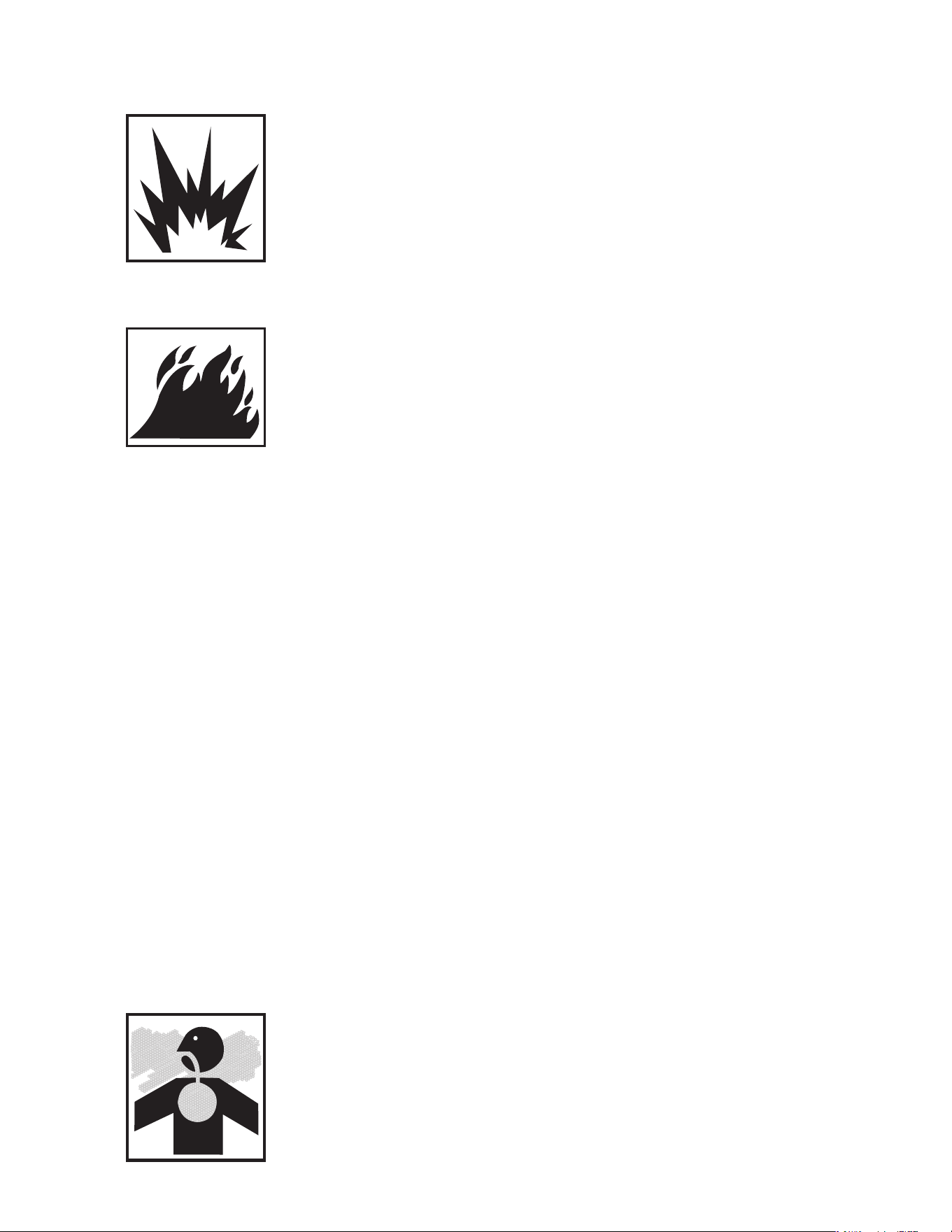
30 Manual Del Operador
RIESGO DE INCENDIO O EXPLOSIÓN
Pueden ocurrir lesiones graves o fatales ocasionadas por chispas normales
en las fuentes de motor ignición sistema o silencer.
Siempre opere la lavadora en una área bien ventilada libre de vapores in-
amables, polvo combustible y gases o materiales combustibles.
No almacene la lavadora a presión cerca de una llama abierta o equipo
como hornos, calefactores, calentadores de agua, etc., que usen una llama
piloto o dispositivo de encendido por chispa.
¡No use esta lavadora a presión para atomizar material inamable!
Pueden ocurrir lesiones graves o fatales como consecuencia de un proced-
imiento inadecuado al reabastecer de combustible.
No fume mientras llene los tanques de combustible.
Nunca llene los tanques de combustible mientras el motor aún esté en
marcha o esté caliente. Permita que el motor se enfríe dos minutos antes de
volver a cargar combustible.
No llene los tanques de combustible en interiores o en una área con poca
ventilación.
Siempre vierta el combustible lentamente para evitar la posibilidad de un
derrame, lo cual podría provocar un incendio.
Tanque de combustible del motor de gasolina (rojo):
Si se usa un motor de gasolina, llene únicamente con gasolina. No use die-
sel ni petróleo o aceite combustible.
Pueden ocurrir lesiones graves o fatales a causa de la batería cuando us-
ando el arranque eléctrico.
No opere la unidad si se derrama gasolina o combustible de diesel. Con
un paño, limpie completamente la lavadora a presión y aléjela del derrame.
Evite crear cualquier ignición hasta que el combustible de gasolina o diesel
se haya evaporado.
Cuando la batería se esté activando, los gases de hidrógeno y oxígeno son
extremadamente explosivos. Mantenga alejadas todas las chispas y amas
de la batería en todo momento, especialmente cuando esté cargando la
batería.
Asegúrese de desconectar la terminal de tierra de la batería antes de un
servicio de mantenimiento. Cuando desconecte el cable de la batería, co-
mience con la terminal negativa, y al conectarlos, comience con la terminal
positiva.
Pueden ocurrir lesiones graves o fatales como consecuencia de un incendio
al ras de tierra ocasionado por una chispa del silenciador.
Cuando cargue la batería, quite los tapones de ventilación de la batería.
Solo use un voltímetro o densímetro para vericar la carga de batería.
NO pase corriente de una batería a otra, a menos que ambas baterías sean
de voltaje y amperaje equivalentes.
Se debe agregar un parachispas al silenciador de este motor si se va a usar
sobre terrenos sin construir de bosques, o cubiertos de maleza o pasto. El
parachispas deberá ser mantenido en buen funcionamiento por el operador.
En el estado de California, lo anterior es obligatorio por ley. (Sección 4442
del Código de Recursos Públicos de California). Otros estados quizá tengan
leyes similares. En terrenos federales se aplican las leyes federales.
RIESGO DE ASFIXIA
Pueden sufrirse lesiones graves o fatales como consecuencia de la inhal-
ación de gases del escape del motor o vapores peligrosos. El gas que ema-
na del escape de este producto contiene substancias químicas identicadas
por el Estado de California como agentes que provocan cáncer, defectos de
nacimiento o daños reproductivos.
ADVERTENCIAS DE SEGURIDAD
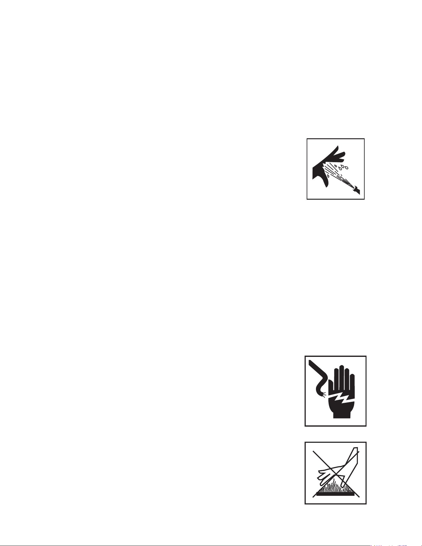
Manual Del Operador 31
ADVERTENCIAS DE SEGURIDAD
Esta lavadora a presión fue diseñada para uso externo únicamente. Nunca
opere esta lavadora a presión en una área cerrada. Siempre asegúrese de
que exista ventilación adecuada (aire externo fresco) para la respiración y la
combustión. Esto impedirá la acumulación de gases peligrosos de monóxi-
do de carbono. Tenga cuidado en las áreas de poca ventilación, o áreas con
ventiladores de extracción que pueden provocar un intercambio deciente
de aire.
Obedezca todas las instrucciones proporcionadas con los materiales que
está rociando. Quizá sea necesario usar un respirador cuando se trabaje
con ciertos materiales. No use esta lavadora a presión para distribuir deter-
gentes peligrosos.
RIESGO DE INYECCIÓN O LESIÓN POR CORTADURA
SEVERA
Pueden sufrirse lesiones graves o fatales debido al contacto con la electric-
idad.
¡Manténgase completamente alejado de la boquilla y el atomizador! Nunca
coloque la mano, los dedos o el cuerpo directamente sobre la boquilla de
rocío.
Nunca apunte el atomizador alta presión hacia usted mismo o hacia otra
persona.
Siempre mantenga el área de trabajo despejada de personas.
NO PERMITA que algún niño opere esta unidad.
¡BUSQUE ATENCIÓN MÉDICA DE EMERGENCIA si parece que el rocío ha
penetrado la piel! ¡No lo trate como una simple cortadura!
Debe inspeccionar diariamente las mangueras de alta presión y las líneas
de combustible para buscar señales de desgaste. Si hay evidencia de falla,
reemplace inmediatamente todas las mangueras y líneas de combustible
sospechosas para prevenir la posibilidad de lesiones por el rocío a alta
presión. Si una manguera o conexión tiene alguna fuga, NO COLOQUE SU
MANO DIRECTAMENTE SOBRE LA FUGA.
NUNCA opere la pistola con el gatillo jado en la posición abierta. Para pre-
venir una descarga accidental, la pistola debe tener bien trabado el seguro
del gatillo cuando no se encuentre en uso.
Antes de retirar la boquilla de rocío o dar servicio a la unidad, apague la uni-
dad y tire del gatillo de la pistola para liberar la presión. (Aun cuando apague
la unidad, todavía quedará agua a alta presión en la bomba, la manguera y
la pistola hasta que la libere jalando el gatillo de la pistola.)
Pueden sufrirse lesiones graves o fatales debido al contacto con la electric-
idad.
RIESGO DE ELECTROCUCIÓN O CHOQUE ELÉCTRICO
¡NO dirija el rocío hacia instalaciones eléctricas de ninguna clase! Esto
incluye tomas eléctricas, lámparas, cajas de fusibles, transformadores, la
unidad misma, etc.
NO permita que los componentes de metal de la lavadora a presión entren
en contacto con componentes eléctricos cargados.
RIESGO DE QUEMADURAS
Pueden producirse lesiones graves si se toca el motor de gasolina, el silen-
ciador. Estas áreas pueden permanecer calientes por algún tiempo después
de que se ha apagado la lavadora a presión.
Nunca permita que ninguna parte de su cuerpo haga contacto con el motor
de gasolina, el silenciador o areas adyacentes.
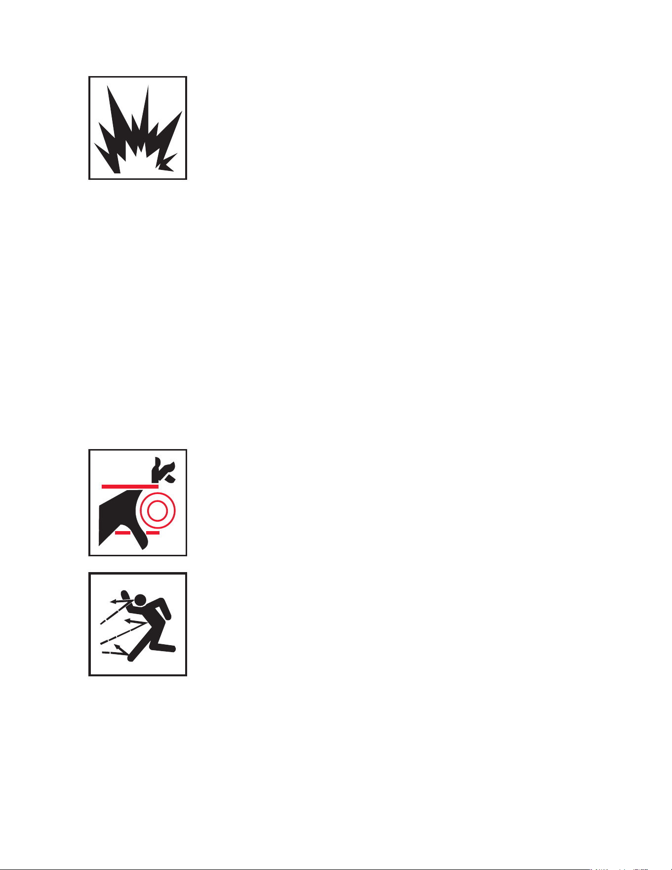
ADVERTENCIAS DE SEGURIDAD
RIESGO DE EXPLOSIÓN
Pueden producirse lesiones graves debido al mal funcionamiento de la
lavadora a presión o la explosión de accesorios si se usan componentes,
aditamentos o accesorios que no correspondan al sistema.
Nunca haga ajustes a las presiones conguradas en la fábrica.
Nunca exceda la máxima graduación de presión de los accesorios permitida
por el fabricante.
No permita que alguna de las mangueras haga contacto con el silenciador
del motor, el motor de gasolina o el intercambiador de calor para prevenir
la posibilidad de explosión. No arrastre las mangueras sobre supercies
abrasivas como el cemento.
Pueden ocurrir lesiones graves o fatales si no se mantienen correctamente
los dispositivos de seguidad del sistema.
Solo use las partes de reparación para su lavadora a presión recomendadas
por el fabricante.
Esta lavadora a presión tiene una dispositivos de seguridad (disco de estal-
lido) que nunca deben ser alterados, modicados, extraídos o desconecta-
dos. Si falla el dispositive, reemplácelo inmediatamente con un repuesto
genuino del fabricante.
Pueden producirse lesiones graves o fatales si se intenta arrancar la lava-
dora a presión cuando esté congelada la bomba.
En temperaturas de congelación, la unidad siempre deberá permanecer lo
sucientemente caliente como para asegurar que no haya formación de
hielo en la bomba. No arranque la lavadora a presión si ha sido transportada
en un vehículo abierto o de calefacción deciente, sin primero permitir que
la bomba se descongele.
RIESGO POR PARTES EN MOVIMIENTO
El operador puede sufrir de lesiones graves si hace contacto con las partes
en movimiento de la lavadora a presión.Antes de hacer cualquier ajuste,
asegúrese de que el motor esté apagado, esté seguro que el cable posi-
tivo de la batería está desconectado.y que el cable o los cables de ignición
estén separados de las bujías de ignición. Al voltear la máquina manual-
mente durante el ajuste o la limpieza puede arrancar el motor y junto con él,
la máquina. No opere la unidad sin que todas las cubiertas protectoras se
encuentren en su lugar.
RIESGO DE LESIONES
Pueden ocurrir lesiones graves o fatales si los detergentes entran en con-
tacto con la piel.
¡BUSQUE ATENCIÓN MÉDICA DE EMERGENCIA si está usando agentes de
limpieza y siente que el rocío ha penetrado la piel! ¡NO LO TRATE COMO
UNA SIMPLE CORTADURA! Lea la hoja de datos de seguridad del mate-
rial (MSDS) proporcionada con su detergente para estar preparado y poder
informar a su médico exactamente qué tipo de detergentes estaba usando.
Nunca use solventes o detergentes altamente corrosivos o limpiadores de
tipo ácido con esta lavadora a presión.
Se aconseja usar equipo protector como trajes de goma, guantes y respira-
dores, especialmente cuando se usen detergentes limpiadores.
¡Mantenga todos los detergentes fuera del alcance de los niños!
SIEMPRE use gafas protectoras cuando opere la unidad para proteger sus
ojos contra residuos y detergentes lanzados al aire.
Pueden ocurrir lesiones graves provocadas por partículas sueltas proyecta-
das a gran velocidad a través la pistola atomizadora.
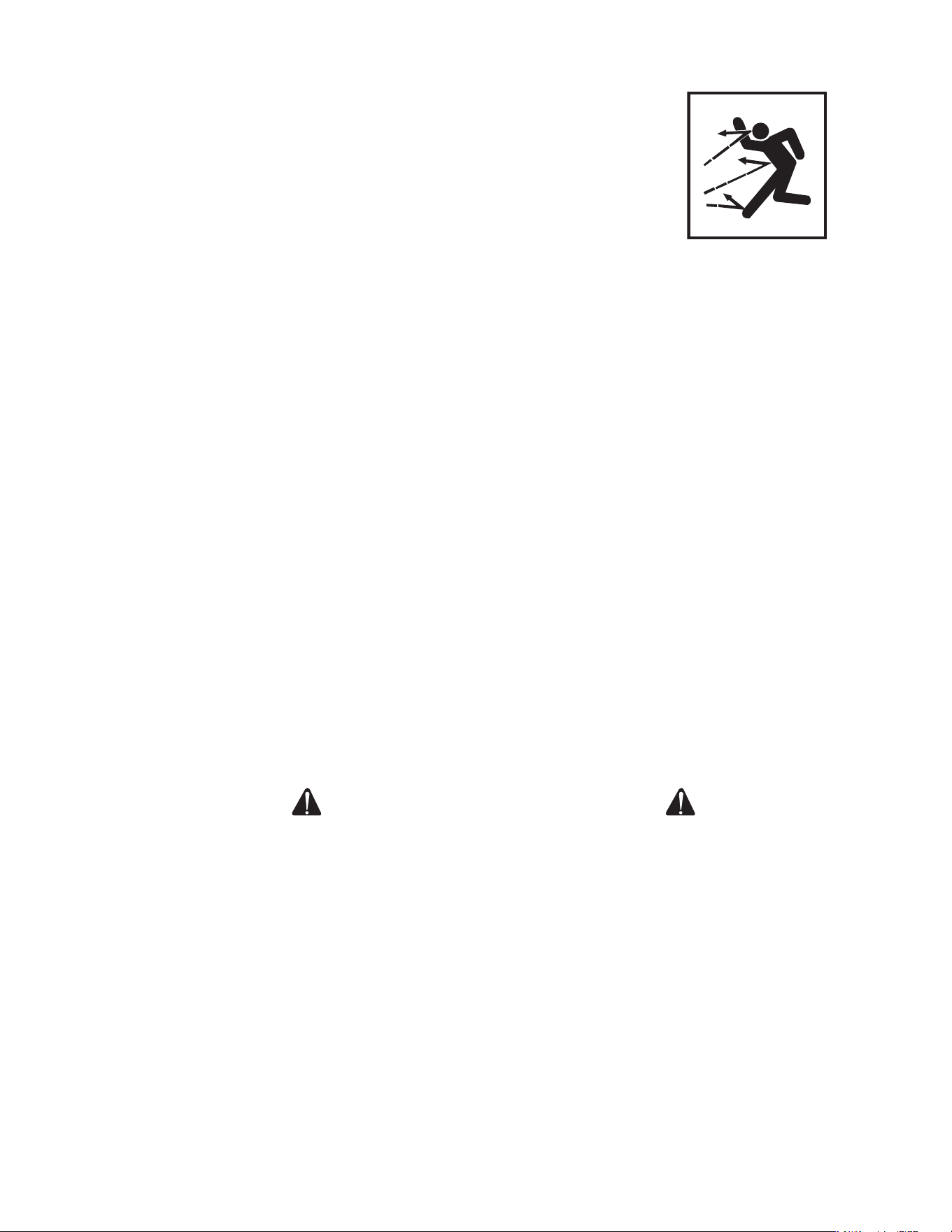
Manual Del Operador 33
NO DIRIJA el atomizador hacia materiales frágiles tales como vidrio, ya que
podría ocasionar su ruptura.
Manténgase alerta — vigile lo que esté haciendo. No opere la unidad cu-
ando esté fatigado o bajo la inuencia de alcohol o drogas.
NUNCA apriete el gatillo a menos de que esté rmemente parado.
NO se estire demasiado ni se pare sobre un soporte inestable.
Pueden ocurrir lesiones si el operador pierde el equilibrio causado por el
impulso del agua que está atravesando la boquilla de rocío.
Las supercies mojadas pueden estar resbaladizas, use equipo protector y
mantenga un punto de apoyo y buen equilibrio en todo momento.
NUNCA accione la pistola mientras se encuentre en una escalera o sobre un
techo.
SIEMPRE sostenga rmemente el conjunto de pistola/varilla cuando ar-
ranque y opere la unidad. No hacerlo podría provocar que la varilla se caiga
y se azote peligrosamente.
Sepa como detener la lavadora a presión y aliviar las presiones rápidam-
ente. Familiarícese por completo con estos controles.
Pueden ocurrir lesiones provocadas por la lavadora a presión.
NO permita que la unidad presurizada permanezca sola. Apague la lavadora
de presión y libere la presión antes de irse.
NO OPERE la unidad si detecta fugas de combustible, aceite o agua de la
máquina. NO reanude la operación hasta que la unidad haya sido inspeccio-
nada y reparada por un técnico capacitado para el servicio.
NUNCA accione la unidad con el regulador desconectado ni opere a veloci-
dades excesivas.
Coloque la unidad sobre una supercie limpia, seca y plana para darle
servicio. Antes de dar mantenimiento a la unidad, apáguela, alivie la presión
de agua apretando el gatillo de la pistola, y permita que la unidad se enfríe.
Realice el mantenimiento en un área limpia, seca y plana. Donde sea nece-
sario, bloquee las ruedas para prevenir el movimiento de la unidad.
No mueva la unidad tirando de la manguera.
¡CONSERVE ESTAS INSTRUCCIONES!
ADVERTENCIAS DE SEGURIDAD
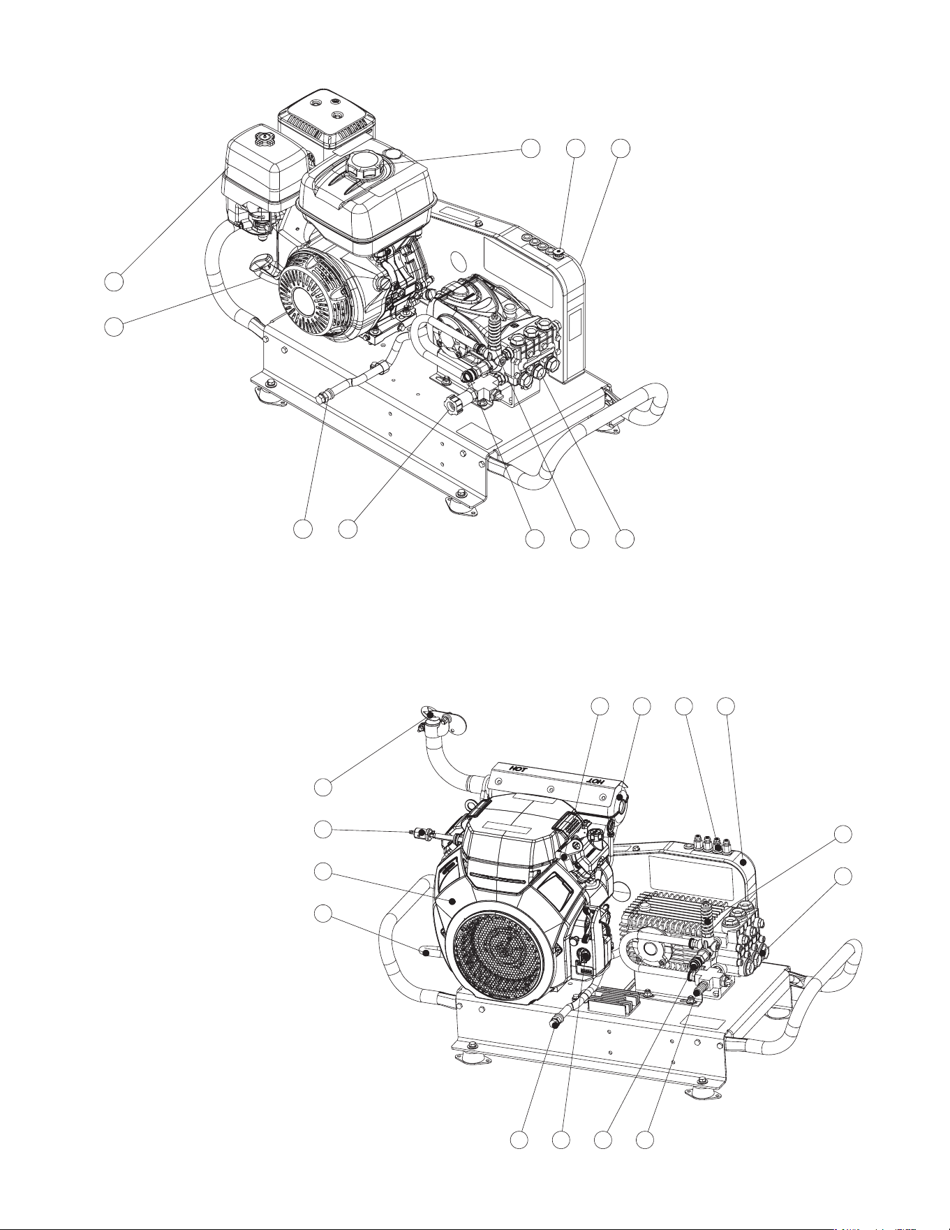
34 Manual Del Operador
ELEMENTOS Y COMPONENTES
4
3
2
1
13 12 11
9
10
8
75
6
14
CTM-3508-H6G0M FEATURES 061124 CTM-3005-H6G0M FEATURES 050624
9 8
4
5
3
1
2
6
7
10
1. Motor
2. Drenaje de Aceite de
Motor
3. Drenaje de Aceite de la
Bomba
4. Entrada de Agua y Filtro
5. Salida de Agua
6. Descargador
7. Bomba
8. Protector de Correa
9. Boquilla de Conexión
Rapida
10. Tapa de Tanque de
Combustible del Motor
1. Tapa para Lluvia del
Silenciador
2. Filtro de Combustible
3. Motor con Arranque Eléctrico
4. Manguera de Drenaje de
Aceite de Motor
5. Manguera de Drenaje de
Aceite de la Bomba
6. Interruptor de Encendido
del Motor
7. Salida de Agua
8. Conexión de Manguera
de Entrada de Agua
9. Bomba
10. Descargador
11. Protector de Correa
12. Boquilla
13. Silenciador del Motor
14. Línea de Vapor
CTM-3005-H6G0M
CTM-3508-H6G0M
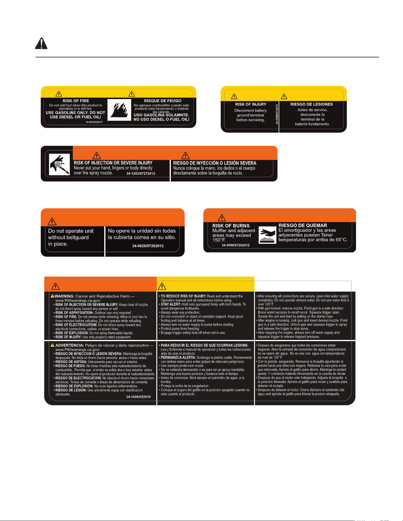
Manual Del Operador 35
Calcomanía- Precaucion: Calcomanía- Precaucion:
Combustible del gasolina (Pieza No. 34-0835) Batería (Pieza no. 34-0848)
Calcomanía-Advertencia: Riesgo de inyección (Pieza No. 34-1253)
Calcomanía- Advertencia: Calcomanía- Advertencia:
Guarda correa en lugar (Pieza No. 34-0826) Silenciador caliente (Pieza No.34-0598)
Calcomanía- Advertencia/ Precaucion (Part #34-1608)
CALCOMANIAS DE SEGURIDAD
NO RETIRE LAS CALCOMANIAS DE SEGURIDAD DE LA UNIDAD A MENOS QUE LAS REEMPLACE POR
LAS CALCOMANIAS DE SEGURIDAD MAS RECIENTES!
RISK OF FIRE
CAUTION
PRECAUCION
Do not add fuel when this product is
operating or is still hot.
USE GASOLINE ONLY. DO NOT
USE DIESEL OR FUEL OIL!
RISQUE DE FEUGO
No agreque combustible cuando este
producto esta funcionando o todavia
sta caliente.
USO GASOLINA SOLAMNTE.
NO USO DIESEL O FUEL OIL!
34-0835/062217
CAUTION
PRECAUCION
RISK OF INJURY
Disconnect battery
ground terminal
before servicing.
RIESGO DE LESIONES
Antes de servico,
desconecte la
terminal de la
batería fundamento.
34-0848/072612
RISK OF INJECTION OR SEVERE INJURY
Never put your hand, fingers or body directly
over the spray nozzle.
34-1253/07272012
RIESGO DE INYECCIÓN O LESIÓN SEVERA
Nunca coloque la mano, los dedos o el cuerpo
directamente sobre la boquilla de rocío.
WARNING
ADVERTENCIA
WARNING/ADVERTENCIA
RISK OF BURNS
Muffler and adjacent
areas may exceed
150°F.
RIESGO DE QUEMAR
El amortiguador y las areas
adyacentes pueden Tener
temperaturas por arriba de 65°C.
34-0598/07262012
WARNING/ADVERTENCIA
34-0826/07262012
No opere la unidad sin todas
la cubierta correa en su sitio.
Do not operate unit
without beltguard
in place.
34-0826/07262012
No opere la unidad sin todas
la cubierta correa en su sitio.
Do not operate unit
without beltguard
in place.
• TO REDUCE RISK OF INJURY: Read and understand the
Operation manual and all instructions before using.
• STAY ALERT: Hold onto gun/wand firmly with both hands. To
avoid dangerous kickbacks.
• Always wear eye protection.
• Do not overreach or stand on unstable support. Keep good
footing and balance at all times.
• Always turn on water supply to pump before starting.
• Protect pump from freezing.
• Engage trigger safety lock-off when not in use.
• After ensuring all connections are secure, open inlet water supply
completely. Do not operate without water. Do not use water that is
over 125°F.
• With gun locked, remove nozzle. Point gun in a safe direction.
Brace wand securely to avoid recoil. Squeeze trigger open.
Steady the unit and start by pulling on the starter rope.
• After engine is running, lock gun and insert desired nozzle. Point
gun in a safe direction. Unlock gun and squeeze trigger to spray
and release the trigger to stop spray.
• After stopping the engine, always turn off water supply and
squeeze trigger to release trapped pressure.
• PARA REDUCIR EL RIESGO DE QUE OCURRAN LESIONS:
Lea y Entienda el manual de operacion y todas las instrucciones
ante de usar el producto.
• PERMANIZCA ALERTA: Sostenga la pistola varilla. Firmenmente
con ambas mano para evitar golpes de retroceso peligrosos.
• Use siempre proteccion ocular.
• No se extienda demasiado o se pare en un apoyo inestable.
Mantenga una buena posicion y balance todo el tiempo.
• Antes de comenzar. Abra sienpre el suminstro de agua a la
bomba.
• Proteja la omba de la congelacion.
• Coloque el suguro del gatillo en la posicion apagado cuando no
este usando el producto.
• Dispues de asegurarse que todas las conexiones estan
seguirse. Abra la entrada del suminstro de agua completament
no se opere sin agua. No se use con agua con temperaturas
de mas de 125°F.
• Con la pistola asegurada. Remueva la boquilla apuntando la
pistola hacia una direccion segura. Refurese la vara para evitar
que retroceda. Apriete el gatillo para abrirlo. Mantega la unidad
quieta. Y comienze halando firmemente en la cuerda de iniciar.
• Despues de que el motor este trabajando. Adjuste la boquilla a
la posicion deseada. Apriete el gatillo para rociar y sueltelo para
detener el rociado.
• Despues de detener el motor. Cierre diempre el suminstro del
aguo and apriete el gatillo para liberar la presion atrapada.
WARNING/ADVERTENCIA
CAUTION/PRECAUCION
OPERATION/OPERACION
34-1608/052919
WARNING: Cancer and Reproductive Harm —
www.P65warnings.ca.gov/
• RISK OF INJECTION OR SEVERE INJURY: Keep clear of nozzle
do not direct spray toward any person or self.
• RISK OF ASPHYXIATION: Outdoor use only required.
• RISK OF FIRE. Do not smoke while refueling. Allow to cool two to
three minutes before refueling. Do not operate while refueling.
• RISK OF ELECTROCUTION: Do not direct spray toward any
electrical connections, outlets, or power lines.
• RISK OF EXPLOSION: Do not spray flammable liquids.
• RISK OF INJURY: Use only properly rated equipment.
ADVERTENCIA: Peligro de cáncer y daño reproductivo —
www.P65warnings.ca.gov/
• RIESGO DE INYECCION O LESION SEVERA: Mantenga la boquilla
despejada. No dirija el chorro hacia persona aluna o hacia usted.
• RIESGO DE ASFIXIA: Unicamente para uso en el exterior.
• RIESGO DE FUEGO: No fume mientras este reabastecimiento de
combustible. Permita que el motor se enfrie dos o tres minutos antes
del reabastecimiento. No opere el productor durante el reabastecimiento.
• RIESGO DE ELECTROCUCION: No directa el chorro hacia conexiones.
electricas. Tomas de corriente o lineas de alimentacion de corriente.
• RIESGO DE EXPLOSION: No rocie liquidos inflammables.
• RIESGO DE LESION: Use unicamente equip con clasificacion
adeduada.
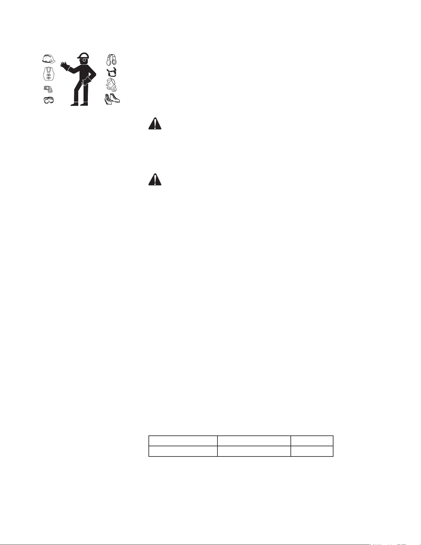
36 Manual Del Operador
VESTIMENTA:
Es importante usar ropa apropiada para su seguridad. Se aconseja usar cu-
alquier medic necesario para proteger los ojos, las orejas y la piel. Posible-
mente requiera equipo adicional de seguridad (como un respirador) cuando
use detergentes limpiadores con esta lavadora.
EMPLACEMENT:
Pour éviter d’abîmer un compresseur lubrié à l’huile, ne pas l’incliner trans-
versalement ou longitudinalement plus de 10°.
AVERTISSEMENT: RISQUE D’ASPHYXIE! NE PAS UTILISER
L’APPAREIL DANS UN LIEU CLOS. UTILISER CE PRODUIT
UNIQUEMENT DANS DES ENDROITS BIEN AÉRÉS!
L’ÉCHAPPEMENT DU MOTEUR CONTIENT DE L’OXYDE
DE CARBONE, UN GAZ INODORE, INVISIBLE ET TOXIQUE.
L’INHALER PRÉSENTERAIT UN RISQUE DE BLESSURES,
MALADIE, OU DE MORT POSSIBLE.
AVERTISSEMENT: RISQUE D’EXPLOSION OU D’INCENDIE
ENTRAÏNANT DES BLESSURES GRAVES OU LA MORT! NE PAS
PERMETTRE AU MOTEUR OU À L’INTERRUPTEUR MOTEUR/
PRESSION D’ENTRER EN CONTACT AVEC DES VAPEURS
INFLAMMABLES, DES GAZ , DE LA POUSSIÈRE OU AUTRES
MATÉRIAUX COMBUSTIBLES. UNE ÉTINCELLE POURRAIT
ENTRAÎNER UN INCENDIE.
QUAND LE COMPRESSEUR SERT À PULVÉRISER DE LA
PEINTURE, LE PLACER AUSSI LOIN QUE POSSIBLE DU
CHAMP DE TRAVAIL, EN UTILISANT DES MANCHES À AIR EN
PLUS AU LIEU DE RALLONGES.
Plaçer le compresseur à une distance d’au moins 12 pouces (30cm) de tout
obstacle qui pourrait nuire à la ventilation. Ne pas placer le compresseur
dans un endroit:
- où il y a des traces de fuite d’huile ou de carburant.
- où des vapeurs ou des substances de gaz inammable peuvent être
présentes.
- où la température de l’air tombe en-dessous de 32°F (0°C) ou dépasse
104°F (40°C).
- où de l’air ou eau très sales pourraient s’inltrer dans le compresseur.
INSTALLATION SUR CAMION DE SERVICE:
L’installation peut varier. L’assemblage doit être effectué sur un support
rigide. L’installateur est responsable pour xer l’équipement d’une manière
sûre.
Una vez que se haya determinado el lugar del montaje; verique que la
estructura pueda soportar el peso de la unidad. Cuando se monte en un
vehículo, la unidad puede experimentar hasta 3 veces su peso en dirección
vertical en condiciones normales. Cuando se monte detrás del eje, esta
unidad puede experimentar cargas de peso más altas de lo esperado. Esta
carga puede causar daños tanto en la estructura de montaje como en la
unidad. Utilice las siguientes especicaciones al montar la unidad.
2. No use esta unidad en un área:
a. sin suciente ventilación
b. donde haya evidencia de fugas de aceite, gas o combustible.
c. donde pueda haber presencia de vapores inamables.
INSTALACIÓN Y PREPARACIÓN
Tipo de Perno Espec. de Torsión Cantidad
5/16” Grado 5 17.5 pie-lb. (59.1 Nm) 8
Manual Del Operador 37
INSTALACION Y PREPARACION
PELIGRO ¡RIESGO DE EXPLOSIÓN O INCENDIO! CUANDO
SE CARGAN BATERÍAS, ÉSTAS GENERAN UN GAS DE
HIDRÓGENO ALTAMENTE EXPLOSIVO. ¡UNA CHISPA PODRÍA
CAUSAR UNA EXPLOSIÓN O UN INCENDIO! NO ARRANQUE
LA BATERÍA CON FUENTE DE ENERGÍA AUXILIAR A MENOS
DE QUE AMBAS BATERÍAS SEAN DE VOLTAJE O AMPERAJE
EQUIVALENTES. NO FUME NI PERMITA QUE HAYA CHISPAS O
LLAMAS CERCA DE LA BATERÍA. NO COLOQUE LA UNIDAD EN
UNA ÁREA DONDE PUEDAN EXISTIR VAPORES INFLAMABLES.
UNA CHISPA PODRÍA PROVOCAR UNA EXPLOSIÓN O UN
INCENDIO.
PELIGRO ¡RIESGO DE LA EXPLOSIÓN DE LA UNIDAD! ¡NO
ALMACENE/OPERE LA UNIDAD EN AMBIENTES DE
CONGELACIÓN!
No permita que la unidad quede expuesta a la lluvia, la nieve o temperatu-
ras de congelación. Si alguna parte de la unidad se congela, es posible que
se acumule una presión excesiva en la unidad, lo cual podría provocar su
estallido y consecuentemente posibles lesiones al operador o las personas
alrededor.
Debe revisarse el nivel de aceite de la bomba debe revisarse antes de cada
aplicación. Revise el palito o indicador de nivel de aceite en el cárter de la
bombas Aceite de detergente 15W20 . Esté seguro que el petróleo está en
la marca “llena” del palito o en el centro del vidrio del petróleo.
TANQUES DE COMBUSTIBLE DEL MOTOR:
PELIGRO ¡RIESGO DE INCENDIO! ¡NO FUME MIENTRAS ESTÉ
CARGANDO COMBUSTIBLE! NO LLENE LOS TANQUES
DE COMBUSTIBLE MIENTRAS LA MÁQUINA ESTÉ EN
FUNCIONAMIENTO O ESTÉ CALIENTE. PERMITA QUE
LA MÁQUINA SE ENFRÍE POR DOS MINUTOS ANTES DE
VOLVER A CARGAR COMBUSTIBLE. NO LLENE DEMASIADO
LOS TANQUES DE COMBUSTIBLE PORQUE SE PUEDEN
DERRAMAR. DEBE QUEDAR UN ESPACIO LIBRE DE 1/4” (6,5
MM) EN EL TANQUE PARA PERMITIR LA EXPANSIÓN DEL
COMBUSTIBLE.
1. Localice las calcomanías de seguridad en su unidad y preste atención a
sus advertencias.
ADVERTENCIA ¡RIESGO DE EXPLOSIÓN O INCENDIO! SIEMPRE
ALMACENE EL COMBUSTIBLE LEJOS DE LA LAVADORA
MIENTRAS LA UNIDAD ESTÉ EN FUNCIONAMIENTO O SE
ENCUENTRE CALIENTE.
2. Motores de gasolina: Cuando llene el tanque (rojo), la gasolina debe
tener un mínimo de 85 de octano. NO MEZCLE ACEITE CON LA
GASOLINA. Debe comprarse solamente la gasolina que se vaya a
consumir en un periodo de 30 días. Se recomienda el uso de gasolina
limpia, libre de plomo. Se puede usar gasolina con plomo si no se
dispone de gasolina sin plomo. NO USE gasolina que contenga metanol
o alcohol.
3. Revise el nivel de aceite del motor antes de arrancarlo. (Vea el manual
del motor).
4. Vea el manual del motor que se ha proporcionado con esta unidad, para
familiarizarse con los procedimientos apropiados de ajuste.
5. Repase el manual del motor que acompaña a esta lavadora a presión
para familiarizarse con los procedimientos correctos de arranque y
mantenimiento.
SISTEMA DE COMBUSTIBLE (MODELO 3508)
PRECAUCION: SE PROHIBE LA MODIFICACION, REMOCION
OR REEMPLAZO NO AUTORIZADO DEL SISTEMA DE
COMBUSTIBLE QUE AFECTA LAS EMISIONES.
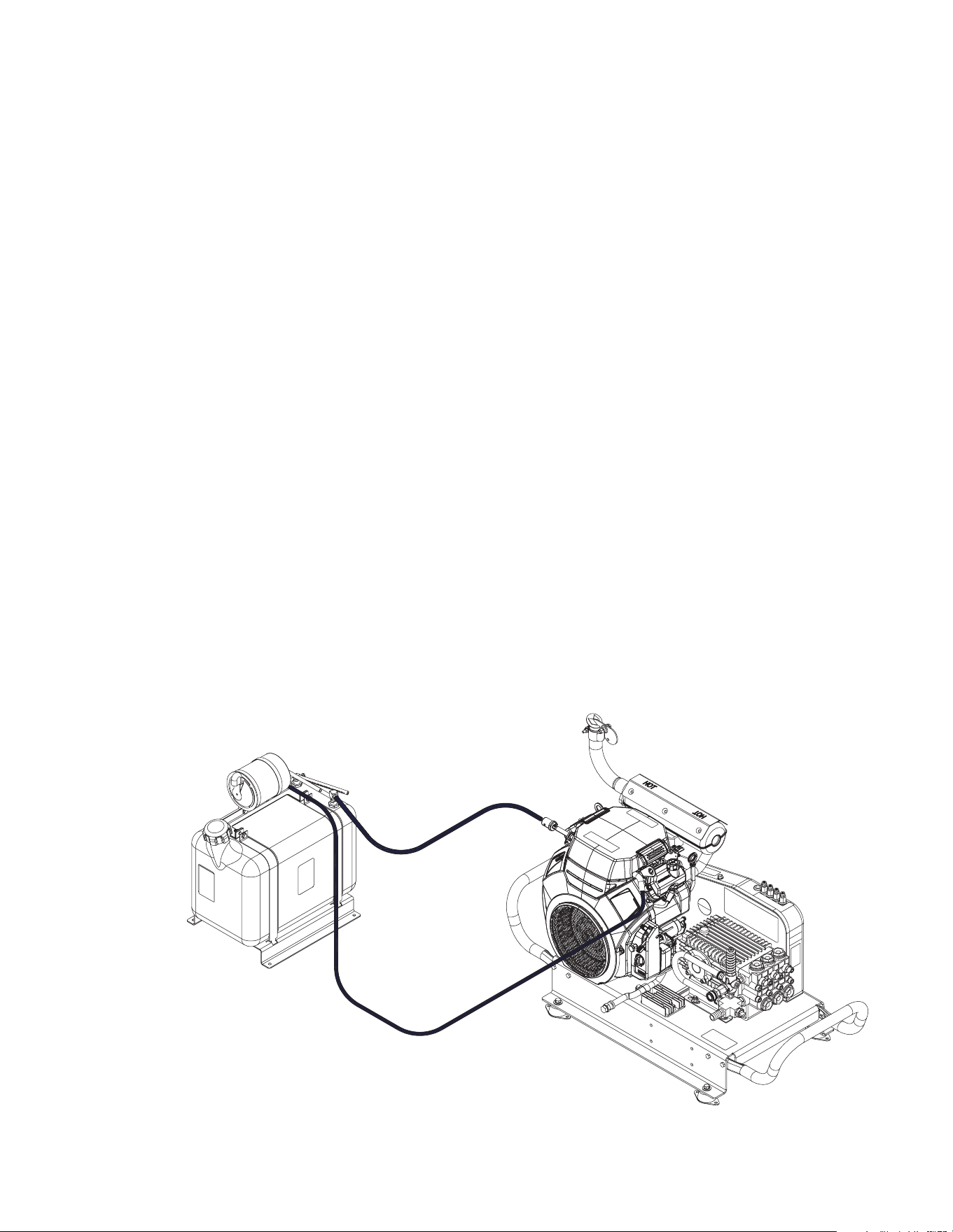
38 Manual Del Operador
TENDIDO DE MANGERAS
Todas las mangueras de combustible deben ser tendidas a lo largo de los
rieles del chasis para evitar daños causados por escombros en la carret-
era. Las mangueras de combustible deben ser tendidas de tal manera que
permita un fácil acceso para inspección y mantenimiento. Soporte adecua-
damente las mangueras de combustible para minimizar el roce y el contacto
con bordes alados. NUNCA tienda las mangueras de combustible junto a
componentes eléctricos o de escape. Para evitar el desvío de combustible,
asegúrese de que todas las mangueras de combustible estén ubicadas por
encima de la parte superior del tanque de combustible.
TANQUE DE COMBUSTIBLE
Esta unidad requiere el uso de un tanque de combustible dedicado o un
tubo de captación separado si se instala en un tanque de combustible exis-
tente. Al instalar un tubo de captación separado en un tanque de combus-
tible existente, asegúrese de que el tubo de captación esté montado más
alto que el original. Haciendo esto permitirá el uso del vehículo después de
que la unidad se quede sin combustible.
La unidad nunca debe estar conectada al sistema de suministro de com-
bustible de alta presión del vehículo. El hacerlo, dañará el sistema de
combustible de la unidad. El tanque de combustible debe estar montado en
un lugar donde la captación de combustible no esté a más de 500 mm (19-
5/8”) por encima o por debajo del carburador del motor. Para aplicaciones
que no cumplan con este requisito, se requiere una bomba de suministro
de combustible. La bomba debe estar conectada a una fuente conmutada
que se pueda apagar cuando la unidad no esté en funcionamiento y debe
proporcionar una presión de no más de 1-2 psi en el ltro de combustible
del motor.
LÍNEA DE SUMINISTRO DE COMBUSTIBLE
Se requiere la instalación de una manguera con un diámetro interno mínimo
de 1/4”. Las mangueras de suministro de combustible utilizadas para la
unidad requieren mangueras de combustible de baja permeabilidad que
cumplan con los estándares federales de los 50 estados para las emisiones
evaporativas de gasolina.
FILTRO DE CARBÓN Y LÍNEA DE VAPOR
Para cumplir con todas las regulaciones de emisiones evaporativas de la
EPA y CARB, este conjunto de unidades requiere el uso de un ltro de car-
INSTALACION Y PREPARACION
Manguera de
Vapor de 3/16’’
Manguera de
Suministro de
Combustible de ¼’’
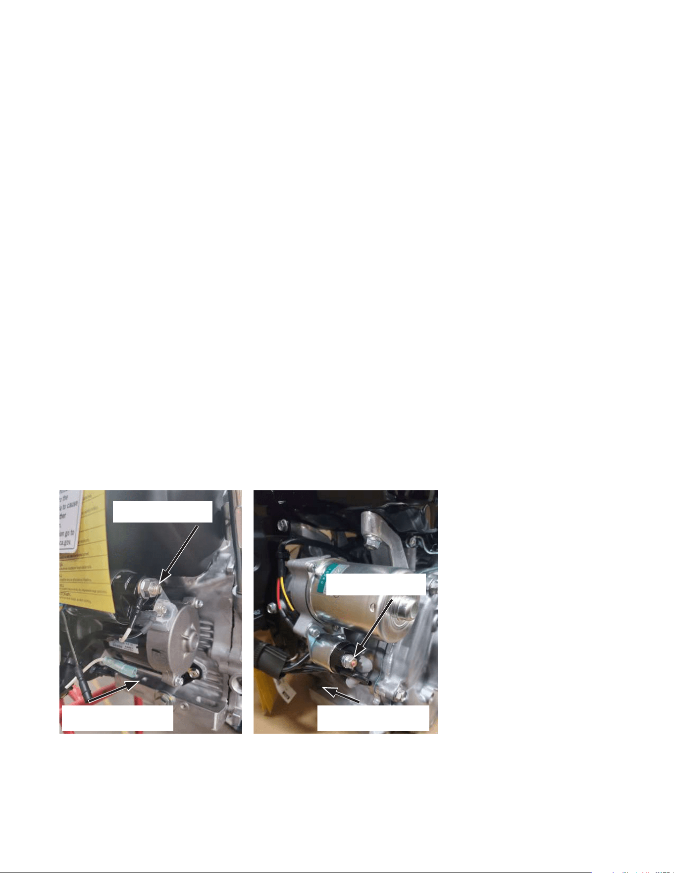
Manual Del Operador 39
bón. Siga todas las regulaciones federales, estatales y locales al conectar la
unidad a un tanque de combustible nuevo o existente. El motor de esta uni-
dad está equipado con un puerto de vapor de 3/16” ubicado en la carcasa
de ltro de aire.
BATERÍA
El motor y controles de esta unidad utilizan un sistema eléctrico de 12VDC.
Para su funcionamiento independiente, se recomienda instalar un cargador
de batería
TAMAÑO DE BATERÍA
Para un arranque adecuado en todos los climas, se recomienda una batería
de al menos 24Ah (modelo 3005) y 45Ah (modelo 3508).
CABLES DE LA BATERÍA
Para instalaciones típicas, utilice cables de al menos 4 AWG para proporcio-
nar energía desde la batería a la unidad. Para la conexión del cable positivo
(+) de la batería, se debe utilizar un terminal de ojal de 3/8”. Para la conex-
ión del cable negativo (-) de la batería, se debe utilizar un terminal de ojal de
5/16”.
Todos los cables de la batería deben ser enrutados a lo largo de los rieles
del chasis para evitar danos causados por escombros en la carretera. Los
cables de la batería deben ser enrutados de tal manera que proporcionen
un fácil acceso para inspección o mantenimiento. Apoye adecuadamente la
batería y los cables para minimizar el roce y el contacto con bordes ala-
dos NUNCA enrute los cables de la batería cerca del combustible o escape
caliente.
Elija cables de batería para evitar una caída de voltaje mayor a 0.5 voltios en
el cable durante la operación del motor de arranque.
Tamaño y longitud de los cables de batería: (Calibre x Longitud)
Cable positivo: AWG No. 4 x 1.5 m (5.0 pies) máximo
Cable negativo: AWG No. 4 x 2.3 m (7.5 pies) máximo
UBICACION DE LA BATERÍA
La batería debe estar montada en un compartimiento o caja separada y cor-
rectamente ventilada, lejos de la unidad y los componentes de combustible.
Los gases producidos por la batería pueden ser encendidos por chispas de
la unidad.
INSTALACION Y PREPARACION
CABLE DE BATERIA
NEGATIVO
CABLE DE BAT-
ERIA POSITIVO
CABLE DE BAT-
ERIA POSITIVO
CABLE DE BATERIA
NEGATIVO
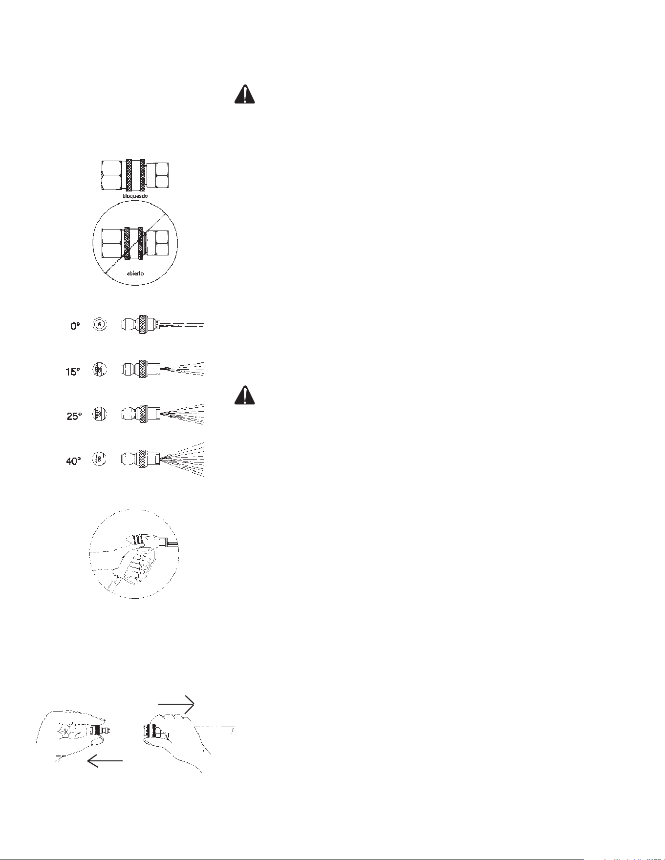
40 Manual Del Operador
PISTOLA/ VARA/ MANGUERA DE ALTA PRESION
!!!ATENCION!!! LA UNIDAD NO VIENE EQUIPADA DE FABRICA CON
PISTOLA, VARA O MANGUERA DE ALTA PRESION.
Al seleccionar una manguera, se debe utilizar una de alta presión de 3/8”
con una calicación mínima de presión de 3500 PSI y una calicación
mínima de temperatura de 200°F. La manguera debe estar equipada con
un conector rápido de alta presión de 3/8” para una fácil instalación de la
unidad.
Al seleccionar un conjunto de pistola y vara, se debe utilizar un conjunto de
al menos 36” de longitud con una calicación de 3500 PSI, una calicación
mínima de ujo de 8 GPM y una calicación mínima de temperatura de
120°F. La vara debe estar equipada con un accesorio de conexión rápida
de alta presión de 1/4” que conecte a las boquillas de alta presión incluidas
con la unidad.
BOQUILLAS DE CONEXION RAPIDA:
Pueden conectarse rápidamente varias boquillas al extremo de la vara para
cambiar el patrón de rociado o para usar la característica de detergente.
Asegúrese que la conexión está seguramente calzada, al usar los conec-
tores rápidos (C.R.). En caso contrario el agua a alta presión puede despe-
dir la boquilla de la vara, causando lesiones graves o daños importantes.
Reérase al número estampado en la boquilla, para determinar el patrón de
abanico del rociado. Los primeros dos dígitos indican el patrón de abanico
del rociado en grados, por ej.: 00=0°, 15=15º, 25=25º.
ADVERTENCIA ¡RIESGO DE INYECCION CAUSANTE DE LESIONES
GRAVES! ¡NUNCA MIRE DIRECTAMENTE AL ORIFICIO DE
LA BOQUILLA A MENOS QUE ESTE DESCONECTADO DEL
CONJUNTO DE LA PISTOLA/VARA!
1. Boquilla de 0º (ROJA): Esta es una boquilla de disparo que emite una
corriente muy concentrada de agua. Debería ejercerse cuidado para
evitar rayar la madera o dañar supercie frágiles. Usos: eliminación
de malas hierbas de las grietas de las aceras, manchas resistentes del
concreto, mampostería, aluminio y acero, lodo endurecido en equipos, y
para limpiar el fondo de las cortadoras de césped.
2. Boquilla de 15º (AMARILLA): Esta es una boquilla biselada. El rociado
debería dirigirse a un ángulo de 45º sobre la supercie y usarse como
un raspador para sacar pintura, grasa y suciedad. Usos: preparación de
supercies (eliminación de manchas de moho y escamas de pintura).
3. Boquilla de 25º (VERDE): Esta es una boquilla de limpieza por descarga
de agua. Este patrón es más apropiado para limpiar suciedad, lodo, y
hollín. Usos: Barrido en mojado de senderos, cordones de las aceras y
entradas de garages, limpieza de suelos de los establos, lavado de los
fondos de las piscinas de natación, desengrasado de motores.
4. Boquilla de 40º (BLANCA): Esta es una boquilla de lavado. Este
patrón de rociado amplio dispersa la presión de agua sobre un área
grande y se recomienda para un lavado moderado Usos: Lavado de
recubrimientos de aluminio de paredes, limpieza de ventanas, lavado de
vehículos, rociado de aceras, entradas de garages, y patios, limpieza de
techos.
CONEXION DE LA BOQUILLA:
1. Asegúrese que la pistola a gatillo esté asegurada en la posición “OFF”
(DESCONECTADO). Vea la ADVERTENCIA, a la derecha.
2. Retraiga el anillo de cierre sobre el adaptador de conexión rápida para
sacar la boquilla.
INSTALACION Y PREPARACION
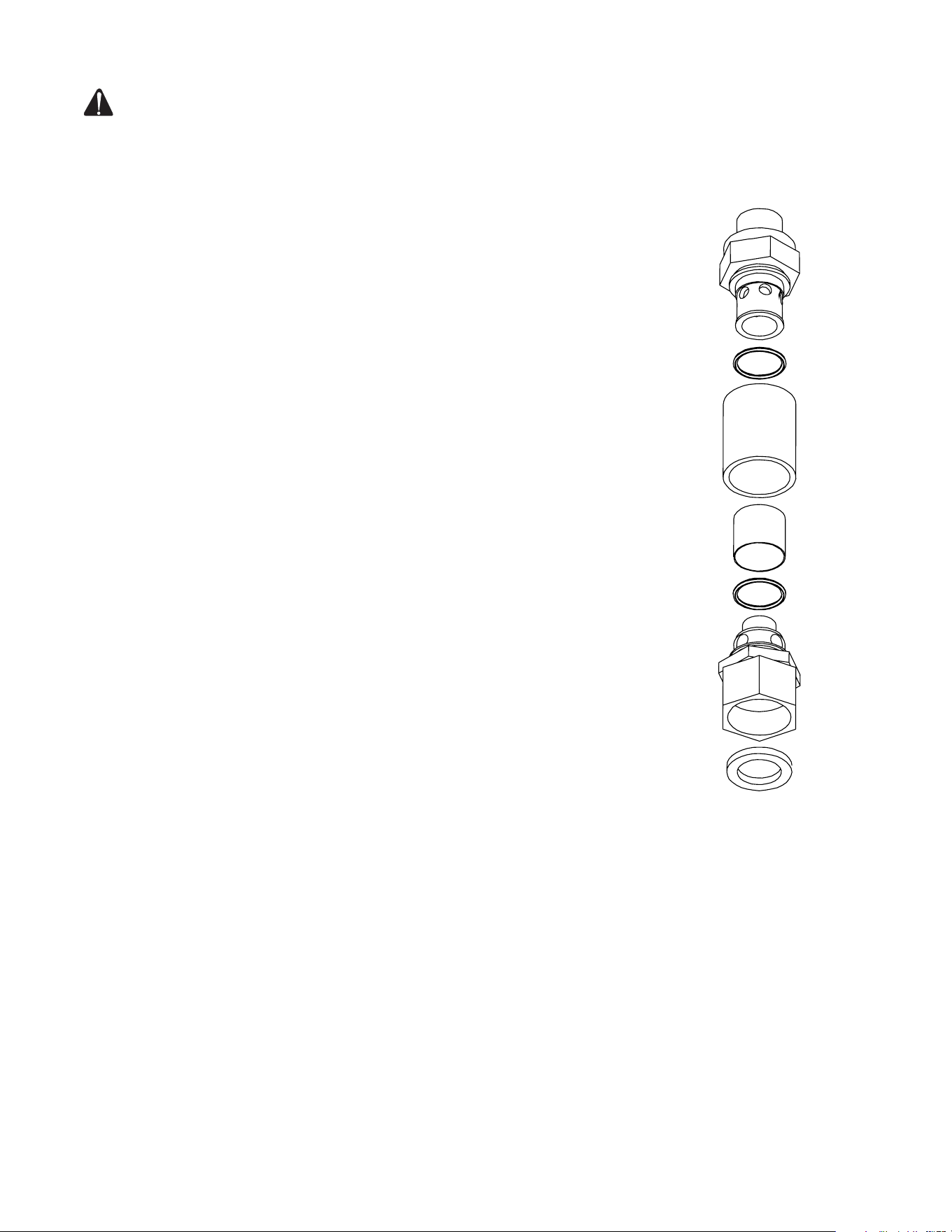
Manual Del Operador 41
ADVERTENCIA ¡RIESGO DE LESIONES GRAVES! ¡CUANDO NO
SE USA, LA PISTOLA A GATILLO DEBERIA ESTAR SIEMPRE
ASEGURADO EN LA POSICION DESCONECTADO!
SUMINISTRO DE AGUA (3005 MODELO)
1. Seleccione una manguera de suministro de agua que sea de calidad de
manguera de jardín que mida 3/4” de DI por lo menos y que no sea más
larga que 50 pies.
2. Inspeccione el tamiz de ltro del agua para asegurar que esté limpio y
libre de obstrucciones. La limpieza periódica del tamiz de agua ayudará
a prevenir problemas con la bomba. El tamiz restringe el ujo apropiado
de agua a la bomba, a medida que se obstruye. Esto puede resultar en
cavitaciones que causarán la falla prematura de los empaques de las
bombas.
a. Desatornille la conexión de la entrada de la manguera del jardín del
frente del montaje de ltro.
b. Quite la cubierta de plástico claro y limpie la pantalla de ltro.
3. Conecte la mangueras:
a. Conecte un extremo de la manguera de suministro de agua a la entrada
de agua de la unidad.
b. Conecte el otro extremo de la manguera a su suministro de agua
a presión o tanque con alimentación de gravedad. Al conectar la
entrada de agua al suministro de agua principal, se deben observar
las regulaciones locales de su compañía de agua. En algunas áreas,
la unidad no debe conectarse directamente al suministro público
de agua potable. Esto es para asegurarse de que no haya perdidas
de detergentes en el suministro de agua. (La conexión directa esta
permitida si se instala un inhibidor de recuperación)
c. Efectúe la conexión de la manguera de descarga de alta presión a la
salida de agua de la unidad.
d. Conecte rmemente el otro extremo de la manguera a la pistola.
4. Siga los requerimientos de agua entrante listados abajo:
a. Cuando se conecta a un suministro de agua a presión, la presión del
agua debe ser al menos de 25 libras por pulgada cuadrada (PSI) y
como máximo de 125 PSI. (Un grifo de exteriores típico generalmente
puede suministrar este PSI si se lo gira completamente a su posición
de encendido, “ON”.)
b. Cuando se conecte a un inhibidor de recuperación, la salida del tanque
no debe estar a más de 12 pulgadas por debajo de la entrada de la
bomba.
c. Los GPM (galones por minuto) entrantes deben ser ser 1 galón más
aproximadamente que los GPM salientes deben indicados en la placa
de nombre de la lavadora a presión. (Usted puede inspeccionar los
GPM observando el tiempo requerido para llenar un recipiente de 5
galones.)
d. La temperatura del agua de entrada no debe exceder 125°F. Puede
resultar un daño excesivo a la bomba si la temperatura del agua excede
este nivel aceptable.
5. Nunca permita que la unidad opere sin que esté conectada la tubería de
agua de entrada y el suministro de agua completamente abierto.
SUMINISTRO DE AGUA (3508 MODELO):
1. Seleccione una manguera de suministro de agua con un diámetro
interno de 3/4 pulgadas y no más larga de 50 pies.
2. La manguera de suministro de agua debe estar equipada con un ltro
de malla lineal de al menos 60 antes de la conexión de entrada.
INSTALACION Y PREPARACION
MALLA FILTRANTE DE LA
ENTRADA DE AGUA.

42 Manual Del Operador
3. Conecte las mangueras:
a. Conecte un extremo de la manguera de suministro de agua a la entrada
de agua de la unidad.
b. Conecte el otro extremo de la manguera a su suministro de agua
a presión o tanque con alimentación de gravedad. Al conectar la
entrada de agua a la red de suministro de agua, se deben observar
las regulaciones locales de su compañía de agua. En algunas áreas,
la unidad no debe estar conectada directamente al suministro público
de agua potable. Esto es para garantizar que no haya perdida de
los detergentes en el suministro de agua. (La conexión directa está
permitida si se instala un inhibidor de recuperación)
c. Haga una conexión rápida de la manguera de descarga de alta presión
a la salida de agua de la unidad.
d. Conecte el otro extremo de la manguera de descarga a la pistola.
4. Siga los requisitos de agua entrante que se enlistan a continuación:
a. Cuando se conecta a un suministro de agua a presión, la presión del
agua debe ser al menos de 25 libras por pulgada cuadrada (PSI) y
como máximo de 125 PSI. (Un grifo de exteriores típico generalmente
puede suministrar este PSI si se lo gira completamente a su posición
de encendido, “ON”.)
b. Cuando se conecte a un inhibidor de recuperación, la salida del tanque
no debe estar a más de 12 pulgadas por debajo de la entrada de la
bomba.
c. El GPM entrante debe ser aproximadamente un galón más al del GPM
saliente indicado en la placa de identicación de la lavadora a presión.
(Usted puede vericar el GPM sincronizando cuánto tiempo se tarda
en llenar un recipiente de 5 galones.)
d. La temperatura de agua entrante no debe superar los 125°F. Puede
ocurrir un daño excesivo a la bomba si la temperatura del agua excede
este nivel de aceptación.
5. Nunca permita que la unidad funcione sin que la línea de agua entrante
esté conectada y el suministro de agua esté completamente abierto.
DESCARGADOR:
El descargador ha sido preajustado en la fábrica y solo deberá ser ajustado
por un Representante de capacitado para servicio.
VÁLVULA PARA DISIPAR CALOR:
Para asegurar que la temperatura del agua derivada no exceda los niveles
aceptables, nunca permita que la lavadora a presión opere en función de
derivación (con la unidad en funcionamiento y el gatillo cerrado) por más de
tres minutos.
Se ha instalado en esta máquina una válvula para disipar el calor y así pro-
teger la bomba. Puede comenzar a abrirse para sacar agua si la temperatu-
ra en la bomba ha excedido los 140º F. Esto permitirá que entre al sistema
un nuevo suministro de agua fría, impidiendo así la falla prematura de los
empaques de la bomba.
PROCEDIMIENTOS DE INSPECCIÓN ANTES DEL
ENCENDIDO:
Antes de encender la unidad, realice los siguientes procedimientos:
1. Revise el nivel de aceite de la bomba.
2. Revise la malla ltrante de la entrada de agua. Limpie o reemplace de
ser necesario. Vea “Suministro de agua”, #2.
3. Revise todas las conexiones de la manguera para asegurarse de que
estén bien ajustadas.
INSTALACION Y PREPARACION

Manual Del Operador 43
4. Inspeccione para asegurarse que no existan fugas de agua, aceite o
combustible del sistema. Si encuentra una fuga de combustible, ¡NO
ENCIENDA LA UNIDAD! Vea la sección de advertencias de “Riesgo de
explosión o incendio”. Asegúrese que se hayan reemplazado todas las
partes dañadas y se hayan corregido los problemas mecánicos, antes
operar de nuevo la unidad. Si requiere servicio, llame a la ocina de
Servicio a clientes.
5. Inspeccione las mangueras de alta presión para asegurarse que no
tengan dobleces, rupturas o fugas. Si se encuentra una ruptura o
fuga, ¡NO USE LA MANGUERA! Reemplace la manguera antes de
encender la unidad. Vea “Riesgo de inyección”. Asegúrese que se
hayan reemplazado todas las partes dañadas y se hayan corregido los
problemas mecánicos, antes operar de nuevo la unidad. Si requiere
servicio, llame a la ocina de Servicio a clientes.
INSTALACION Y PREPARACION
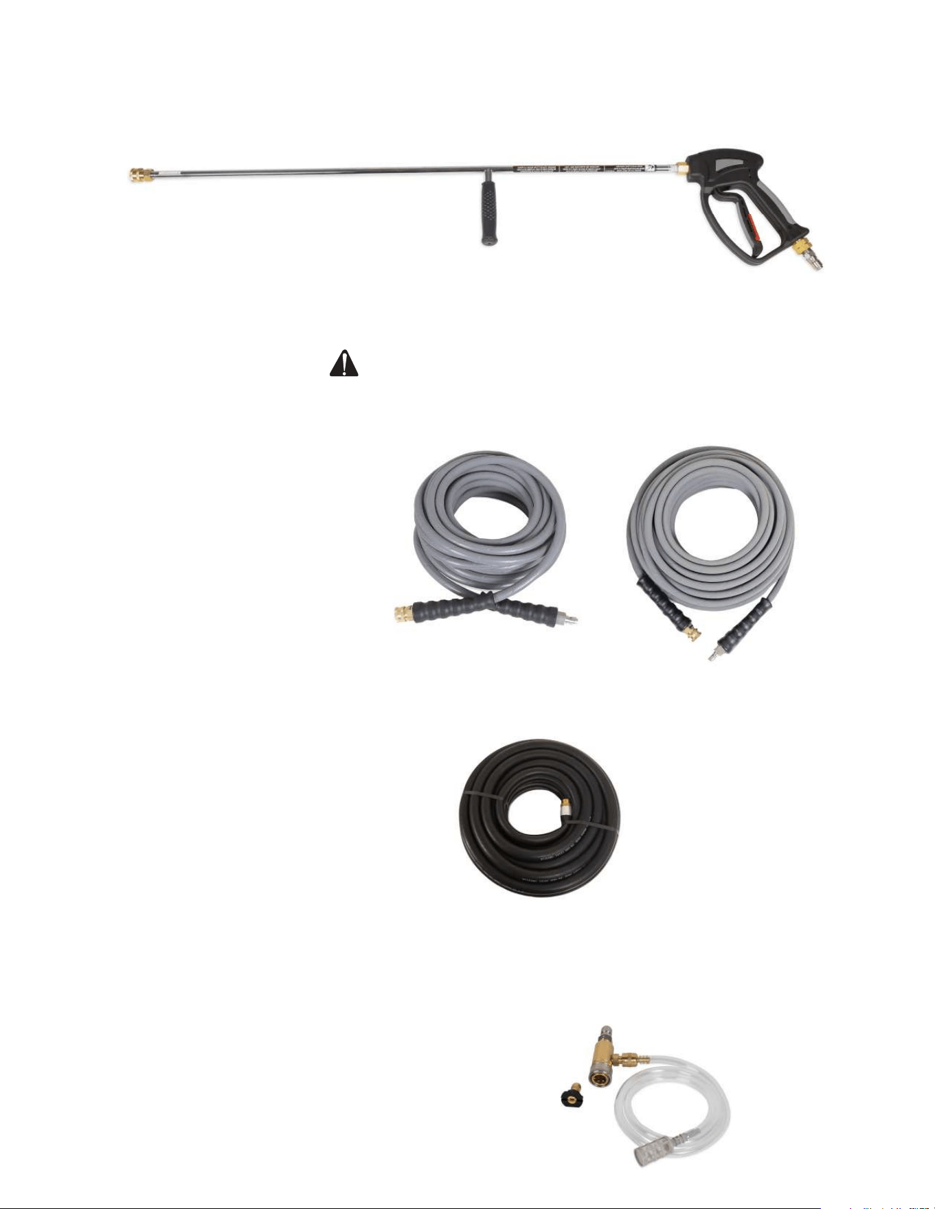
44 Manual Del Operador
ACCESORIOS
PISTOLA Y VARA: 850-0095
Pistola de gatillo aislada de grado profesional con bloqueo de seguridad y
conexiones rápidas.
MANGUERA DE ALTA PRESION:
50' - 851-0338
100' - 15-0273
IMPORTANTE: NO UTILICE MAS DE 1 MANGUERA DE EXTENSION.
LA RESTRICCION ALTA CAUSARA QUE LA VALVULA DEL
DESCARGADOR FUNCIONE TODO EL TIEMPO.
Estas mangueras de alta presión son de 3/8” de diámetro interno, 4,000
PSI, es de color gris, sin marca, con calicación R1, y conexiones rápidas.
MANGUERA DE BAJA PRESION: 15-0006
Esta manguera de baja presión tiene un diámetro interno de 3/4”, una lon-
gitud de 50’, es de color negra, con una presión máxima de 200 PSI, una
temperatura máxima de 212 grados Fahrenheit, con conexiones de rosca.
INYECTOR DE DETERGENTE DE BAJA PRESION:
AW-8400-0023
Aplique fácilmente productos químicos utilizando este inyector de deter-
gente de baja presión calicado para unidades de 5 a 8 (GPM) galones
por minuto. Cuenta con una manguera transparente de extracción química
ajustable, exible, con ltro y dispone de un acoplamiento rápido para una
conexión fácil a la salida de la bomba.

Manual Del Operador 45
ADVERTENCIA
LAS SIGUIENTES PÁGINAS CONTIENEN INSTRUCCIONES SOBRE LA OPERACIÓN Y EL
MANTENIMIENTO.
NO INTENTE OPERAR ESTA LAVADORA A PRESIÓN HASTA QUE HAYA LEÍDO Y
COMPRENDIDO TODAS LAS PRECAUCIONES E INSTRUCCIONES DE SEGURIDAD
SEÑALADAS EN ESTE MANUAL.
¡LA OPERACIÓN INCORRECTA DE ESTA UNIDAD PUEDE CAUSAR LESIONES GRAVES!
¡NO ALTERE NI MODIFIQUE ESTE EQUIPO DE NINGUNA MANERA!

46 Manual Del Operador
CEBADO DE LA BOMBA:
1. Es esencial cebar la bomba en el arranque inicial y cada vez que se
desconecta el suministro de agua de la unidad después del uso inicial.
2. Desplieque la manguera de alta presión para eliminar los dobleces.
(El ujo de agua endurecerá la manguera, creando bucles rígidos si la
manguera no está recta.)
3. Conecte con deguridad el conjunto de la pistola a la manguera de alta
présión.
NOTA: El conjecto de la boquilla NO debería conectarse al conjunto de la pistola en este
momento. Vea “Conexión de la boquilla”.
4. Abra completamente el suministro de agua, con la pistola a gatillo
asegurado en la posición “OFF”. Suelte el seguro de la pistola a gatillo y
accione este último, apuntando la pistola en una dirección segura.
PELIGRO ¡RIESGO DE INYECCION CAUSANTE DE LESIONES
GRAVES! ¡MANTENGASE ALEJADO DE LA BOQUILLA!
¡NUNCA COLOQUE LA MANO NI LOS DEDOS DELANTE DE
LA BOQUILLA! ¡NO DIRIJA LA CORRIENTE DE DESCARGA
HACIA LAS PERSONAS O LOS ANIMALES! ¡ASEGURESE QUE
LA BOQUILLA ESTE SEGURAMENTE CONECTADA A LA VARA
PARA EVITAR UNA DESCARGA ACCIDENTAL!
5. Comenzará a uir agua a baja presión del conjunto de manguera/pistola.
Esto permite que la unidad se cebe y purgue todo el aire del sistema.
Esta unidad está cebada cuando el ujo de agua no esté interrumpido
por el aire.
6. Suelte el gatillo y asegure la pistola en la posición “OFF”, una vez que
la unidad esté cebada. Conecte seguramente el boquilla de conexión
rapida deseada. (Vea “Conexión de la boquilla”)
ARRANQUE:
1. Reérase a las “Precauciones de seguridad”, antes de arrancar la
unidad.
2. Ubique las calcomanías de seguridad en su unidad y obedezca sus
advertencias.
3. Apunte la pistola a gatillo alejado de usted o de cualquier otra persona,
con el mismo asegurado en la posición “OFF”. Asegúrese que el
suminstro de agua esté completamente abierto.
4. Desenganche el seguro de la pistola y accione el gatillo. Comenzará a
uir agua a baja presión de la boquilla.
5. Al arrancar el motor, ASEGURESE que la pistola a gatillo permanezca en
la posición abierta. Afírmese ya que la pistola retrocederá violentamente
a causa de la alta presión causada por la bomba una vez que haya
arrancado el motor.
6. Reérase al manual del motor adjunto a esta lavadora a presión para los
procedimientos correctos requeridos para arrancar el motor.
7. Efectúe los procedimientos siguientes una vez que haya arrancado el
motor con la pistola en la posición abierta:
a. Inspeccione por pérdidas de aceite y combustible del sistema.¡APAGUE
INMEDIATAMENTE LA UNIDAD, si encuentra una pérdida! Vea las
“Riesgo de explosión o fuego”. Antes de operar la unidad, asegúrese
que se hayan reemplazado todas las piezas dañadas y que se hayan
corregido todos los problemas mecánicos. Consulte con el Servicio
al Cliente, si usted requiere servicio.
b. Inspeccione las mangueras de alta presión por dobleces, cortes y
pérdidas.¡¡¡NO TOQUE LA MANGUERA EN LA PERDIDA, si encuentra
un corte o una pérdida!!! ¡APAGUE INMEDIATAMENTE LA UNIDAD!
Antes de arrancar nuevamente la unidad, reemplace la manguera.
Vea las “Riesgo de inyección”. Antes de operar la unidad asegúrese
INSTRUCCIONES DE OPERACION
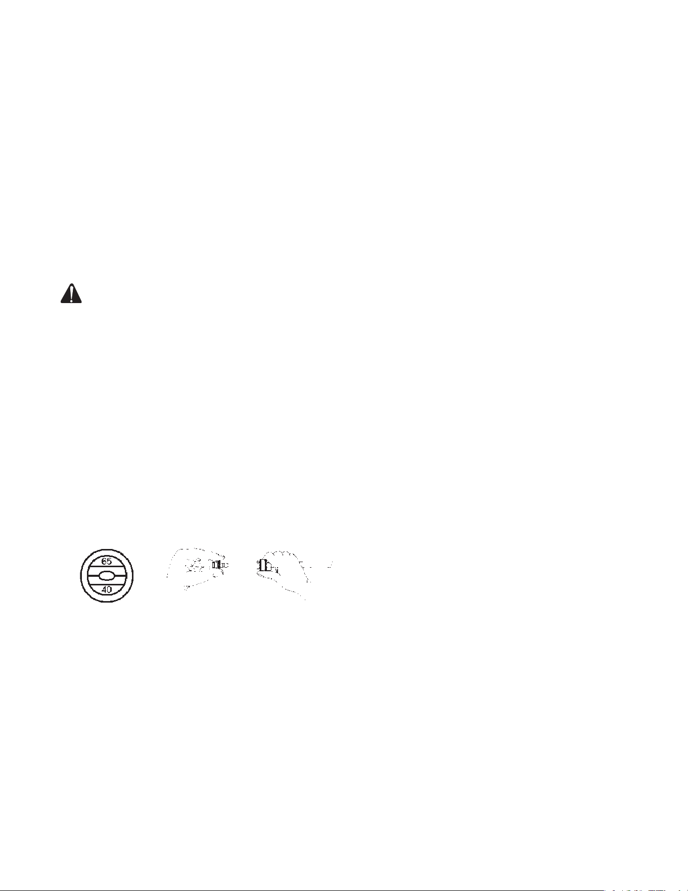
Manual Del Operador 47
que se hayan reemplazado todas las piezas dañadas y que se hayan
corregido todos los problemas mecánicos. Consulte con el Servicio
al Cliente, si usted requiere servicio.
8. ASEGURE la pistola a gatillo en la posición “OFF” siempre que cambie
las boquillas de conexión rápida. ¡NUNCA mire directamente en la
boquilla! ¡El agua a alta presión crea un riesgo de lesiones graves!
9. No permita que la unidad funcione en un modo de derivación (con el
gatillo cerrado) por más de tres minutos sin accionar el gatillo de la
pistola. El no seguir esta simple regla puede causar la falla prematura
de los sellos del empaque de la bomba, resultando en una reparación
costosa a la misma.
10. Puede haber muchas tareas de limpieza que pueden efectuarse sin
el uso de detergentes, a causa que la lavadora a presión suministra
un rociado a alta presión y una variedad de patrones de rociado. Vea
“Limpieza con detergentes”, para los procedimientos correctos, si se
requiere un agente de limpieza.
PRECAUCION RIESGO DE DAÑO NO PERMITA QUE EL PATRON
DE ROCIADO PERMANEZCA EN UNA AREA FIJA DURANTE UN
PERIODO PROLONGADO DE TIEMPO. PUEDE OCURRIR UN
DAÑO POSIBLE AL AREA.
LIMPIEZA CON DETERGENTES (OPCIONAL):
1. En esta maquina, el inyección de detergente está discrecional. Si
qusiera consequir este rasgo asu unidad, pida usted parte #AW-8400-
0023.
2. Mira el “Riesgo del lesión del Cuerpo”, y los instrucciones del inyeccion
de detergente que está con parte #AW-8400-0023. Asegúrese de usar
vestimenta protectora de seguridad según lo mencionado.
3. Prepare la solución de detergente de acuerdo con las instrucciones del
rótulo. Nunca bombee ácidos, alcalinos, uidos abrasivos o solventes
a través de la unidad. Debido a las caracerísticas desconocidas y a
menudo corrosivas de muchos detergentes usados comúnmente en
la industria de lavado a presión, se recomienda únicamente el uso de
detergentes templad con esta unidad.
4. Conecte el inyecciõn de detergente a la unidad como se explica en los
instrucciones del inyecciõn de detergente.
5. Puede poner el detergente que quieve si encuentra ud. el botõn ajuste
al n de la manguera claro y vinyl cerca del inyecciõn de detergente.
Torce el botõn antihorario completemente para poner el rato maximo de
siphõn.
6. Sumerja el tamiz dentro de la solución del detergente para permitir que
este último circule por sifón.
7. Asegúrese que el suminstro de agua esté completamente abierto.
8. Con la pistola a gatillo en la posiciõn OFF, conecte con seguridad el
conjunto de la boquilla de detergente (Negro) dentro de la varilla.
NOTA: Este sistema de inyección está diseñado para aplicar detergentes a baja presión
solamente. No se permitirá los detergentes dentro de la sistema a menos que la
boquilla de detergente esta conectado a la varilla.
9. Desenganche la pistola a gatillo y accione el gatillo, para aplicar la
solución. Una mezcla de detergente/agua saldrá de la boquilla de
baja presión en unos pocos momentos. Comience rociando la porción
inferior de la supercie que está siendo limpiada y muévase hacia arriba
usando pasadas largas superpuestas. El aplicar desde abajo hacia
INSTRUCCIONES DE OPERACION

48 Manual Del Operador
arriba ayuda a evitar el estriado. Permita que se empape brevemente.
(Para minimizar la posibilidad de que se seque el detergente, lo que
puede resultar en daños a las supercies pintadas, evite trabajar sobre
supercies calientes o bajo la luz directa del sol.) Asegúrese de enjuagar
una sección pequeña por vez.
10. Para enjuagar: asegure la pistola a gatillo en la posición “OFF”, y
usando el conector rápido, conecte seguramente la boquilla de alta
presión al extremo de la vara. Desenganche la pistola a gatillo y rocíe.
Llevará 30 segundos aproximadamente purgar todo el detergente de
la tubería. Comience en la parte superior y trabaje hacia abajo, para
obtener los mejores resultados del enjuague.
11. Después de cada uso, extraiga por sifón un galón de agua del sistema
de inyección de detergente a baja presión. Esto evita la posibilidad
de corrosión o de que el residuo de detergente cause problemas
mecánicos durante el próximo uso.
APAGADO:
1. APAGUE el motor según se instruye en el Manual del Motor.
2. CIERRE el suministro de agua.
3. Accione momentáneamente la pistola a gatillo para eliminar toda la
presión interna, apuntando la pistola en una dirección segura.
4. Desconecte el conjunto de la boquilla, una vez que se haya eliminado la
presión.
5. Desconecte y drene la pistola, la vara y las mangueras.
6. Limpie la unidad con un paño y almacene con la pistola, la vara y las
mangueras en un área segura.
INSTRUCCIONES DE OPERACION
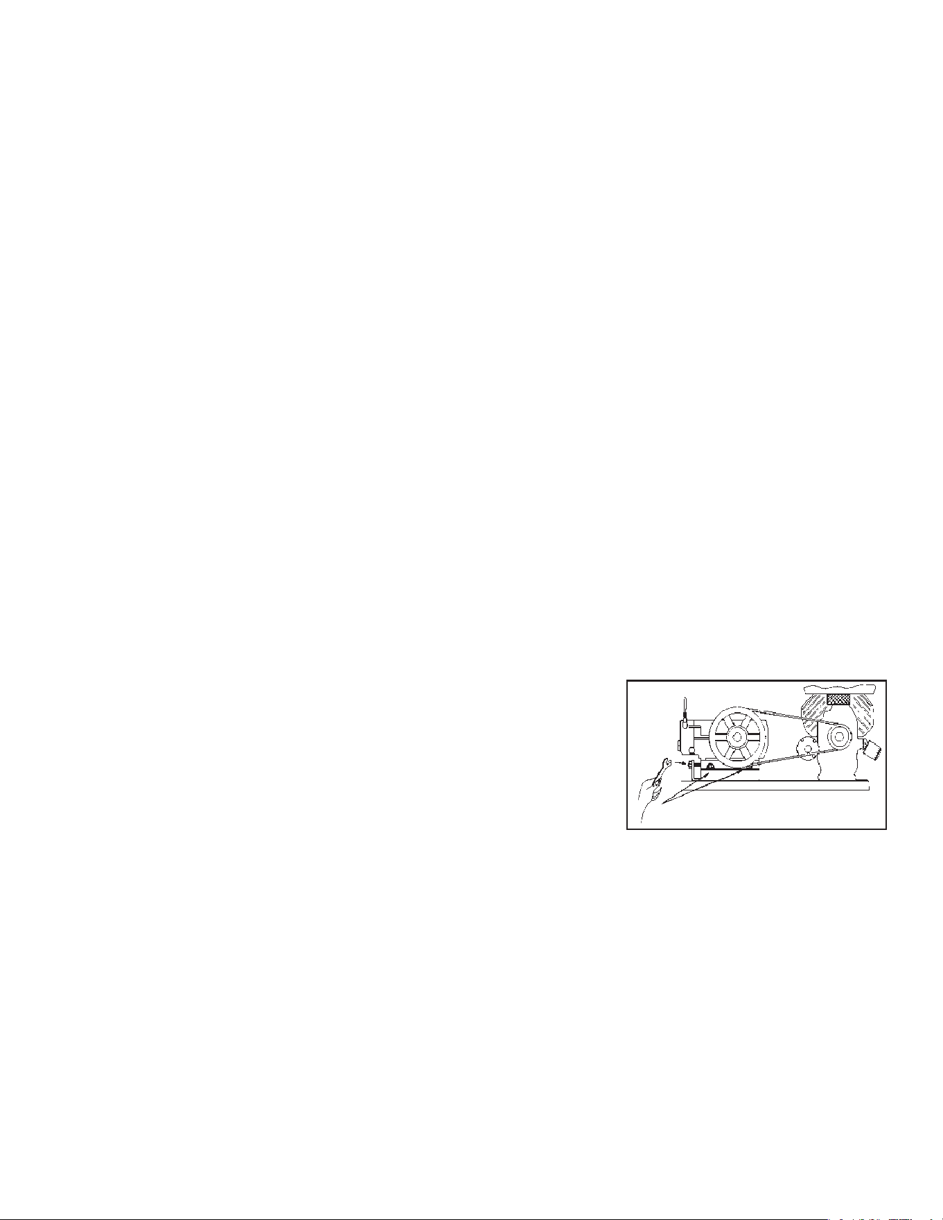
Manual Del Operador 49
MANTENIMIENTO ESPECÍFICO:
COMPONENTES DE EMISIÓN EVAPORADO:
La unidad que compró incluir los components siguentes que son de acu-
erdo con los Estandardes de Emisión Evaporado de California Air Resources
Board de 2024. Estandardes de Emisión:
1. Manguera de combustible
2. Instalaciones de Manguera de combustible
Estos componenetes deben tener inspección en un base diario para grietas,
agujeros y uso abnormal. Si ocurrió las grietas, agujeros o uso abnormal,
reemplace los components inmediatamente.
MOTOR: Las instrucciones del motor que acompañan a su unidad detallan
los procedimientos especícos para el mantenimiento del motor. El obser-
var las recomendaciones del fabricante del motor prolongará la vida útil del
motor.
BOMBA: El aceite de la bomba debe ser cambiado después de las prim-
eras 50 horas de operación en todas las unidades. Se recomienda inter-
valos de 250 horas, después de la carga inicial. Pueden requerirse cambios
con mayor frecuencia, si el aceite parece sucio o lechoso. Use aceite para
bombas de (Pieza 15W20 detergente) y llene sólo hasta la marca en el vid-
rio. NO llene en exceso.
ACOPLES RAPIDOS: Hay un sello del anillo en O dentro de acople rápido
hembra en la salida de agua de su unidad. Este anillo en O se deteriorará,
o se saldrá de lugar si se permite que la unidad bombee sin la manguera
de alta presión. Simplemente inserte un anillo de repuesto para corregir la
pérdida. (Pueden comprarse anillos en O adicionales de su distribuidor).
BOQUILLAS: El agua que uye a través de la boquilla de rociado de con-
exión rápida desgastará y agrandará el oricio, resultando en una pérdida
de presión. Deberían reemplazarse las boquillas siempre que la presión sea
menor que el 85% del máximo. La frecuencia de reemplazo dependerá de
tales variables tales como el contenido mineral en el agua y el número de
horas que se usa la boquilla.
AJUSTE DEL TENSIÒN DE CINTURÓN: Para mantener funciõn alta de su
lavadora a presiõn, puede ser necesario a ajustar la tensiõn de cinturõn a
veces. Siga ud. el procedimiento abajo.
1. Toma ud. la guardia de cinturõn y deja los dos tuercas en cada lado de
la bomba. (dibujo A) Hay cuatro tuercas en total.
2. Torce la capa de tornillo (referencia B) horario hasta 1/4 pulgada correa
desviiõ esta entre las poleas.
3. Apreta lastuercas del cada lado (referencia A).
4. Ponga el lo derecho a través de los dos poleas. Es crítico para
manterner funcion bueno y vidade serviceo, alinear las poleas. Si es
necesario, aoja algunas tuercas de polea y ajuste dentro o fuera para a
linear. Apreta las tuercas y verica la tension otra vez.
5. Reemplece la guardacorrea y apreta los cerrojos seguramente.
PREPARACION PARA EL INVIERNO:
Será necesario preparar esta unidad para el invierno, para nes de Alma-
cenamiento y transporte en temperaturas ambiente inferiores al punto de
congelación. Esta unidad debe protegerse contra la temperatura más baja
incurrida por las siguientes razones:
1. Si se congela cualquier parte del sistema de bombeo puede acumularse
una presión excesiva en la unidad, lo que podría causar que la misma
reviente resultando en lesiones posibles graves al operador o a los
observadores.
2. El sistema de bombeo de esta unidad puede resultar dañado
permanentemente si se congela. LOS DAÑOS POR CONGELACION NO
ESTAN CUBIERTOS POR LA GARANTIA.
ALMACENAMIENTO Y MANTENIMIENTO
B
A
50 Manual Del Operador
Usted puede proteger su unidad siguiendo el procedimiento indicado abajo,
si debe almacenarla en un lugar donde la temperatura puede descender por
debajo de los 32°F.
1. Reúne los artículos siguientes:
a. Dos recipientes de 5 galones.
b. Un galón de anticongelante. (El fabricantere comienda un anticongelante
seguro para el medio ambiente.)
c. Suministro de agua.
d. Una manguera de tres pies de largo con un D.I. de 1/2-3/4 y con un
adaptador macho de manguera de jardín de 3/4 de pulgada.
ADVERTENCIA ¡RIESGO QUE LA UNIDAD REVIENTE! ¡NO
ALMACENE/OPERE LA UNIDAD EN UN AMBIENTE HELADO!
2. Procedimiento:
a. Apague la unidad y corte el suministro de agua.
b. Elimine la presión del sistema apuntando la pistola a gatillo hacia una
dirección segura y accionando el gatillo hasta que el ujo de agua cese
de salir por la boquilla.
c. Asegure la pistola a gatillo en la posición OFF y retire la boquilla.
d. En un recipiente de cinco galones, mezcla el anticon gelante y água
según las recomendaciones del fabricante para la temperatura loque
esta preparando para el invierno.
NOTA: La preparación apropiada para el invierno está basada en las instrucciones
recomendadas del fabricante incluidas en la “Tabla de Protección” mostrada en el
rótulo posterior de la mayoría de los recipientes de anticongelantes.
e. Retire la manguera de suministro de agua de la unidad y fije
seguramente la manguera de 3 pies a la conexiõn de entrada. Ponga
elcabo opuesto dentro del anticongelante.
f. Ponga la lanza dentro del recipiente vacante y enciende la unidad.
g. Accione el gatillo de la pistola hasta que el anticongelante comience a
salir por la vara. Suelte el gatillo por 3 segundos, a continuación accione
el gatillo de la pistola por 3 segundos. Continúe ciclando la pistola
varias veces hasta que toda la mezcla anticongelante es extraída del
recipiente por la acción de sifón.
h. Separe la manguera de 3 pies de la unidad y drene todo el exceso
restante de anticongelante dentro del reciente de 5 galones.
i. Desconecte el conjunto de manguera/pistola/vara de la unidad y drene
todo el exceso restante de anticongelante dentro del recipiente de 5
galones.
j. Almacene la manguera, la pistola y vara junto con la unidad, en un
lugar seguro.
k. Almecene la solución anticongelante para un uso ulterior o descártela
de acuerdo con las leyes de protección del medio ambiente
correspondientes.
3. Procedimiento opcional:
a. Apague la unidad y corte el suministro de agua.
b. Elimine la presión del sistema apuntando la pistola a gatillo hacia una
dirección segura y accionando el gatillo hasta que el ujo de agua cese
de salir por la boquilla.
c. Desconecte y drene la manguera, la pistola y la vara.
d. Arranque la unidad y permita que funcione hasta que toda el agua
salga de la misma. Apague una vez que el agua ha cesado de uir de
la unidad.
NOTA: Debe ejercerse precaución al usar este procedimiento, ya que pueden formarse
plaquitas de hielo de las gotas de agua, lo que podría causar que la unidad revi-
ente si se arranca antes de estar completamente descongelada.
32˚F 0˚C
ALMACENAMIENTO Y MANTENIMIENTO

Manual Del Operador 51
LOCALIZACION DE FALLAS
SINTOMA CAUSA PROBABLE SOLUCION
El motor no arranca. Varios problemas del motor. Reérase al Manual del Motor que acom-
paña a su unidad..
Los componentes de la unidad es-
tán congelados.
Permita que se descongele. Si se con-
gela cualquier parte de la unidad, puede
acumularse una presión excesiva en la
unidad, lo que podría causar que la misma
reviente, resultando en lesiones posibles
graves al operador o a los observadores
No hay descarga de la boquilla
cuando se acciona el mecanis-
mo del gatillo.
Suministro inadecuado de agua. Asegúrese que la manguera tenga 3/4”
de diámetro y que el suministro de agua
entrante esté abierto
Doblez en la manguera de entrada
de agua.
Elimine el doblez.
Presión baja o uctuante Doblez en la manguera de descarga
de alta presión
Reemplace la manguera.
Está obstruido el tamiz de la entrada
de agua.
Saque el tamiz, limpie o reemplace
La bomba absorbe aire (Eliminado el
cebado).
Ajuste todas las conexiones de entrada
de agua. Elimine dobleces en la tubería de
entrada.
No está en el modo de alta presión. Conecte seguramente la boquilla de alta
presión.
La boquilla de rociado está obstru-
ida o gastada
Saque, limpie o reemplace.
El conjunto de la válvula en la
bomba está dañado u obstruido.
Saque, inspeccione, limpie o reemplace.
Los empaques de la bomba están
gastados.
Reemplace los empaques.
Descargador de derivación no opera
correctamente.
Repare o reemplace.
Pérdida de agua de la “Válvula
de descarga térmica”
La temperatura del agua es demasi-
ado elevada.
No permita que la unidad opere en el
modo de derivación (con la pistola a gatillo
cerrado) durante más de tres minutos.
Válvlula defectuosa. Reemplace.
El aceite parece lechosa o
espumosa
Agua en el aceite. Cambie la bomba de aceite. Llene al nivel
apropiado.
Pérdida de aceite de la unidad ¡¡¡¡¡NO LA USE!!!! Llame al Servicio al Cliente

52 Manual Del Operador
LOCALIZACION DE FALLAS
El detergente no uirá por sifón
en el modo de detergente a
baja presión
El tamiz del detergente no está
completamente sumergido en la
solución de detergente.
Inspeccione, sumerja si fuera necesario
El tamiz del detergente está ob-
struido.
Inspeccione, limpie o reemplace
La manguera del detergente está
cortada, obstruida o doblada.
Inspeccione, limpie o reemplace
La perilla de ajuste del detergente
está girada a la posición cerrada.
Abra la perilla de ajuste. Reérase a
“Limpieza con detergentes”.
No está en el modo de baja presión. Inserte la boquilla 6540° (NEGRA).
La boquilla del detergente está
taponada.
Limpie o reemplace.
Hay demasiadas extensiones de las
mangueras de alta presión conecta-
das a la salida de agua
Use una extensión como máximo.
La esfera y el resorte en el Venturi
están atascados.
Limpie o reemplace.
El ujo de agua retrocede al
recipiente del detergente.
La esfera y el resorte en el Venturi
están invertidos, faltan o están des-
gastados.
Saque, limpie le reemplace.
Cuando la pistola de gatillo
está asegurado en la posición
“OFF”, el agua uye desde la
boquilla.
La pistola funciona mal. Retire, limpie o reemplace.
Hay fuga de agua en la valvula
de seguridad para alivio de
presión.
El disco de seguridad en caso de
estallido está roto debido a una falla
de un descargador.
1. Reemplace el disco de seguridad contra
estallidos. NUNCA active la unidad sin
un disco de seguridad. Podría causar una
explosión.!
2. Diagnostique y corrija el problema del
descargador.

Manual Del Operador 53
DECLARACIÓN DE GARANTÍA
Fabricante garantiza que todas las piezas (excepto aquellas a las que se hace referencia
abajo), de su nueva lavadora a presión CWC Series Cestán libres de defectos en mate-
riales y mano de obra durante los periodos siguientes:
Para un curso de la vida contra congelar y agrietarse:
Colector de bomba
Por siete (7) años a partir de la fecha original de compra:
Bomba de Alta Presión
Por dos (2) años a partir de la fecha original de compra:
Cañerías Poleas Carreta unidad
Por uno (1) años a partir de la fecha original de compra:
GCFI Encender de selectivo
Contacto de entrada Sobrecarga
Por noventa (90) días a partir de la fecha original de compra:
Manguera de alta Presión Pistola de Gatillo
Filtro Válvulas de descargar
Las piezas defectuosas que no están sujetas a deterioro causado por el uso serán repa-
radas o reemplazadas a nuestra opción durante el periodo de garantía. En todo caso, el
reembolso está limitado al precio de compra pagado.
EXCLUSIONES
1. El motor está cubierto bajo una garantía separada proporcionada por el fabricante
respectivo y está sujeta a los términos en ella establecidos.
2. Partes de desgaste normal:
Empaques de las Bombas Válvulas de la Bomba
Boquillas Válvulas del Detergente Correas
Círculo Connexión Rapida / El Tornillo Conecta
3. Esta garantía no cubre las piezas dañadas debido al deterioro normal causado por
el uso, mala aplicación, mal uso, operación a velocidades, presiones o temperaturas
diferentes a las recomendadas. Las piezas dañadas o gastadas a causa del uso de
líquidos cáusticos o por la operación en medios ambientes abrasivos o corrosivos o
bajo condiciones que causan cavitación de la bomba no están garantizadas. La falla
en seguir los procedimientos recomendados de operación y mantenimiento también
cancela la garantía.
4. El uso de piezas de repuesto diferentes a las genuinas fabricante cancelará la
garantía. Las piezas devueltas, con franqueo pagado a un Centro de Servicio
Autorizado fabricante serán inspeccionadas y reemplazadas, libre de cargos, si se
determina que están defectuosas y sujetas a la garantía. No existen garantías que
se extiendan más allá de la descripción contenida aquí. Bajo ninguna circunstancia
será responsable por la pérdida de uso de la unidad, pérdida de tiempo,
inconvenientes, pérdida comercial o daños consecuentes.

54 Manual Del Operador
D
D
E
E
C
C
L
L
A
A
R
R
A
A
C
C
I
I
O
O
N
N
D
D
E
E
C
C
O
O
B
B
E
E
R
R
T
T
U
U
R
R
A
A
D
D
E
E
E
E
M
M
I
I
S
S
I
I
O
O
N
N
E
E
S
S
D
D
E
E
C
C
A
A
L
L
I
I
F
F
O
O
R
R
N
N
I
I
A
A
S
S
U
U
S
S
D
D
E
E
R
R
E
E
C
C
H
H
O
O
S
S
D
D
E
E
G
G
A
A
R
R
A
A
N
N
T
T
I
I
A
A
Y
Y
O
O
B
B
L
L
I
I
G
G
A
A
C
C
I
I
O
O
N
N
E
E
S
S
La Tabla de Recursos Aéreos de California y el fabricante están felices para explicar la garantía de sistema de control de emisiones
en su 2024/2025 modelo del pequeño motor todoterreno (PMT). En California, Pequeños Motores Todoterreno (PMTs) nuevos
tienen que ser diseñados, construidos y equipados para conformar a los estándares rigurosos de no-niebla con humo del estado. el
fabricante debe justificar el sistema de control de emisiones en su PMT por los períodos de tiempo indicados abajo a condición que
no ha habido abuso, negligencia ni el mantenimiento impropio de su PMT.
Su sistema de control de emisiones puede incluir partes como el carburador, sistema de inyección de combustible, sistema de
ignición, catalizador, tanques de combustible, líneas de combustible, capas de combustible, válvulas, botes, filtros, mangueras de
vapor, abrazaderas, conectores, y otros componentes asociados relatados a la emisión. Donde existe una condición de la garantía,
el fabricante reparará su PMT en ningún costo a usted, incluyendo diagnóstico, las piezas, y trabajo.
COBERTURA DE GARANTIA DE FABRICANTE
Este sistema de control de emisiones tiene garantía durante dos años. Si cualquier parte que está relacionada a emisiones en su
motor es defectuosa, la parte será reparada o será reemplazada por el fabricante.
RESPONSABILIDADES DE GARANTIA DEL PROPIETARIO
-Como el propietario del Pequeño Motor Todoterreno, usted es responsable de la ejecución del mantenimiento necesario indicado
en su manual de propietario. El fabricante recomienda que usted retenga todos recibos sobre el mantenimiento de su PMT, pero el
fabricante no puede negar de garantía solo para la falta de recibos.
-Como el propietario del Pequeño Motor Todoterreno, usted debe saber que el fabricante puede negar cobertura de garantía si su
Pequeño Motor Todoterreno o una pieza ha fracasada a causa de abuso, negligencia o el mantenimiento impropia o las
modificaciones desaprobadas.
-Usted es responsable de presentar su Pequeño Motor Todoterreno al centro de distribución o centro de reparaciones autorizado
por el fabricante, 50 Mi-T-M Drive, Peosta, IA 52068 (Mi-T-M) en pronto que un problema exista. Las reparaciones de garantía
deben ser completadas en una cantidad razonable de tiempo, no exceder 30 días.
Si usted tiene una pregunta con respecto a su cobertura de garantía, usted debe contactar el Departamento de Servicio para
Clientes en 1-800-553-9053 o por correo electrónico a corp@mitm.com.
C
C
O
O
B
B
E
E
R
R
T
T
U
U
R
R
A
A
G
G
E
E
N
N
E
E
R
R
A
A
L
L
D
D
E
E
G
G
A
A
R
R
A
A
N
N
T
T
I
I
A
A
D
D
E
E
E
E
M
M
I
I
S
S
I
I
O
O
N
N
E
E
S
S
-
-
S
S
ó
ó
l
l
o
o
C
C
a
a
l
l
i
i
f
f
o
o
r
r
n
n
i
i
a
a
-
-
El fabricant ejustifica al último comprador y cada comprador subsiguiente que el Pequeño Motor Todoterreno PMT (1) ha sido
diseñado, construido y equipado para conformarse con todas regulaciones aplicables; y (2) es libre de defectos en materias y
disfraza que causa el fracaso de una pieza garantizado conformarse con esas regula
ciones como puede ser aplicable a los
términos y condiciones que son indicados abajo.
(a) El período de garantía empieza en la fecha que el motor está entregado a un último comprador o cuando está primero puesto en
servicio. El período de garantía es dos años.
(b) Sujeto a ciertas condiciones y exclusiones como indicadas abajo, la garantía de piezas relatadas a emisiones es el siguiente:
(1) Cualquier pieza garantizada que no está programado para el reemplazo como mantenimiento necesario en su manual de
propietario está garantizado para el período de garantía indicado arriba. Si la pieza fracasa durante el período de cobertura
de garantía, la pieza será reparada o será reemplazada por el fabricante según la subdivisión (4) abajo. Cualquiera pieza
reparada o reemplazada bajo la garantía será garantizada para el resto del periodo.
(2) Cualquier pieza garantizada que está programada sólo para inspección regular en su manual de propietario está garantizada
para el período de garantía indicada arriba. Cualquiera pieza reparada o reemplazada bajo la garantía será garantizada por el
resto del período de garantía.
(3) Cualquier pieza garantizada que está programada para el reemplazo como mantenimiento necesario en su manual de
propietario está garantizado para el período del tiempo antes de la primera fecha planificada de reemplazo para esa pieza. Si
la pieza fracasa antes del primer reemplazo planificado, la pieza será reparada o será reemplazada por el fabricante según la
subdivisión (4) abajo. Cualquiera pieza reparada o reemplazada bajo la garantía será garantizada por el resto del período de
garantía antes del primer punto planificado de reemplazo para la pieza.
(4) Reparación o el reemplazo de alguna pieza garantizada bajo las provisiones de garantía en este debe ser realizado en una
estación de garantía sin cargo al propietario.
(5) Sin prejuicio de lo dispuesto en esta, los servicios de garantía y de reparación serán proporcionados en todos nuestros
centros de distribución que tengan la franquicia para atender a los motores sujetos.
(6) El propietario no debe ser cargado para trabajo diagnóstico que lleva a la determinación que una pieza garantizada es de
hecho defectuosa, con tal de que el trabajo diagnóstico sea realizado en una estación de garantía.
(7) A través del período de garantía de motor que está indicado arriba, el fabricante mantendrá un suministro de piezas
garantizadas suficientes para satisfacer la demanda esperada para tales partes.
(8) Cualquier pieza reemplazada puede ser utilizada en la ejecución de cualquier mantenimiento de garantía o reparaciones y
debe ser proporcionado sin cargo al propietario. Tal uso no reducirá las obligaciones de garantía de el fabricante.

Manual Del Operador 55
(9) Las piezas añadidas o modificadas que no están eximidas por la Tabla de Recursos Aéreos no pueden ser utilizadas. El uso
de cualquier pieza a
ñ
adida o modificada que no está eximida por el último comprador será razón para no permitir o aceptar
un reclamo de la garantía. El fabricant eno será responsable a garantizar los fracasos de piezas garantizadas causados por el
uso de una pieza a
ñ
adida o modificada que no está eximida.
(10) el fabricante proporcionará cualquier documento que describa los procedimientos o políticas de garantía de el fabricante
dentro de los cinco días hábiles posteriores a la solicitud del Director Ejecutivo.
(C) Piezas que tienen Garantía
La reparación o el reemplazo de cualquier parte garantizada de otro modo elegible para la cobertura de garantía pueden ser
excluidos de tal cobertura de garantía si el fabricante demuestra que el motor ha sido abusado, descuidado, o mantenido
incorrectamente, y que el abuso, negligencia, o mantenimiento impropio fue el causo directo de la necesidad para la reparación
o reemplaza de la pieza. Sin embargo, cualquier ajuste de un componente que tiene un dispositivo de la limitación de ajuste
que ha sido instalado por la fábrica y está funcionando apropiadamente todavía está elegible para la cobertura de la garantía.
Las siguientes piezas de garantía de emisiones están garantizadas:
(
1) Tanque de Combustible
(2) Tapa de Tanque de Combustible
(3) Líneas de Combustible (para combustible líquido y vapores de combustible)
(4) Accesorios de Líneas de Combustible
(5) Abrazaderas*
(6) Válvulas Limitadoras de Presión*
(7) Válvulas de Control*
(8) Control de Solenoides*
(9) Controles Electrónicos*
(10) Diafragmas de Control de Vacío*
(11) Cables de Control*
(12) Enlaces de Control*
(13) Válvula de Purga*
(14) Juntas*
(15) Separador de Liquido/Vapor
(16) Depósito De Carbón
(17) Depósito de Soporte de Montaje
(18) Conector de Puerto de Purga del Carburador
*Nota: Al estar estos relacionados con el sistema de control de emisiones por evaporación.

56 Manual Del Operador