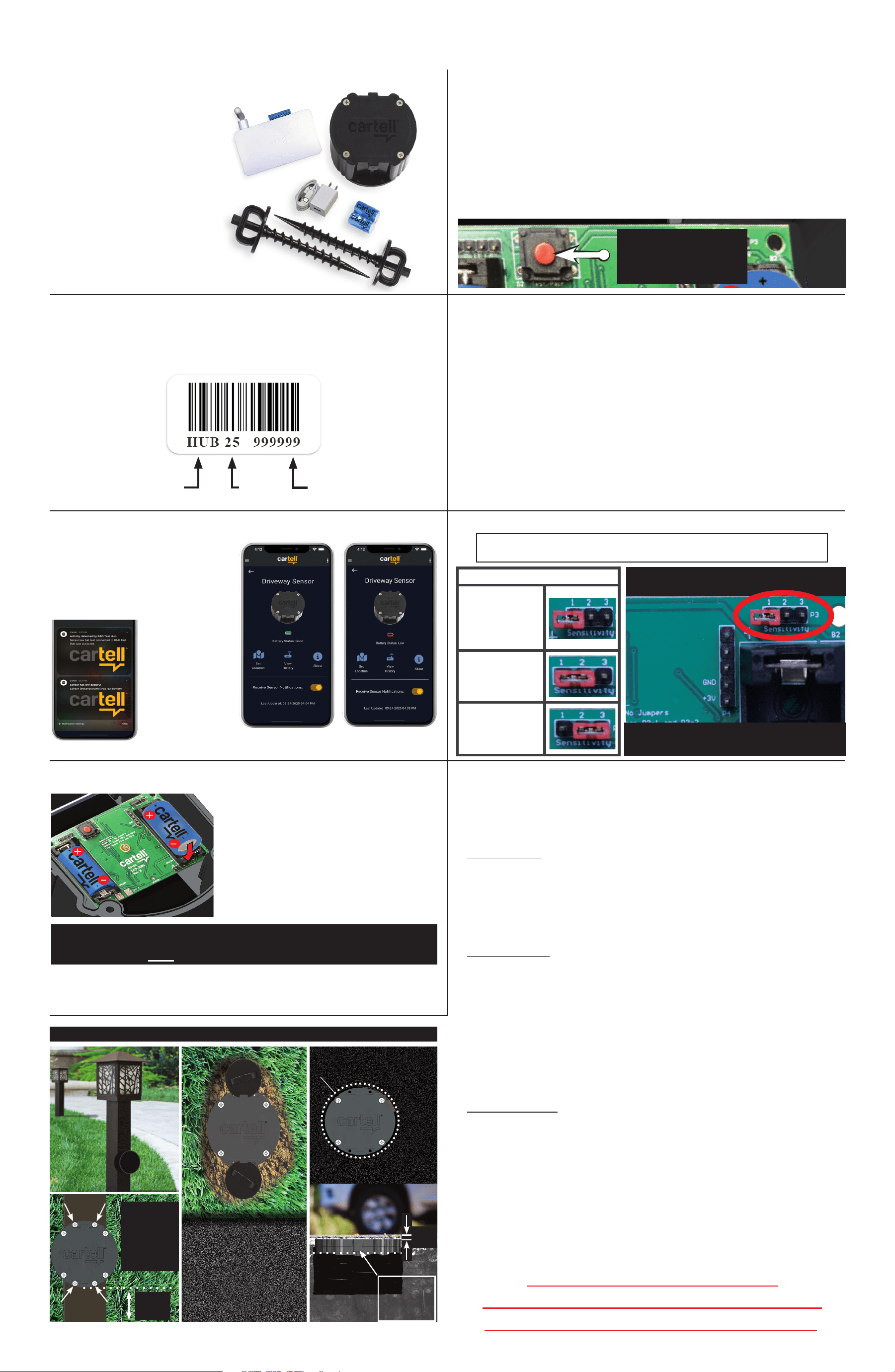
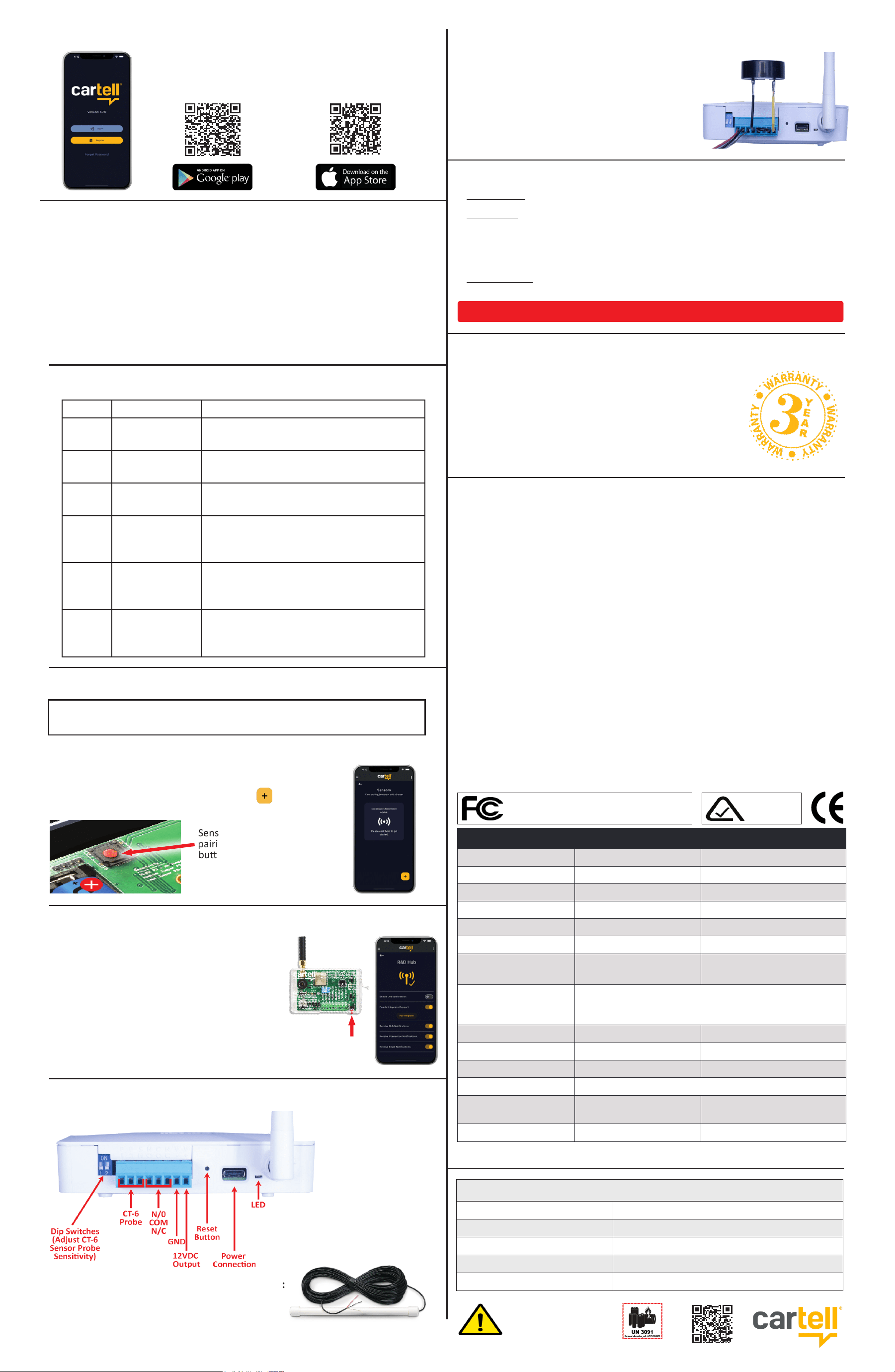
CW-HUB WIRELESS HYBRID DRIVEWAY SYSTEM
1. WHAT’S IN THE BOX
There is a barcode serial number on the back of HUB, boom of puck, and on
product box. When calling to talk about your product, please have one of these
numbers handy.
PRODUCT
CODE
YEAR
MADE
SERIAL
NUMBER
2. SERIAL NUMBER
1. SENSOR “PUCK”
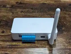
2. HUB
3. AUGER SCREWS (2)
4. USB-C POWER SUPPLY &
CABLE
5. CR123A BATTERIES (2)
3. LOW BATTERY INDICATION (see #9 below)
6. TESTING RANGE
Your system has a radio range of at least 350 feet or over 1000’ line-of- sight.
To determine range in your applicaon, test before nal installaon.
Radio range depends on several variables:
• How the puck is installed (in ground or above ground on post)
• Obstacles blocking radio signal, such as soil, trees, foilage,
buildings, concrete, etc.
To test range:
1. Put HUB near its nal installaon place in the home.
2. You will need to conrm the HUB is receiving the sensor’s signal.
3. Put sensor in test range mode (see #5 above).
4. Look on App or wait for push nocaon from sensor. If you don’t receive
a nocaon, move sensor closer unl you do.
5. Be sure to test again with puck installed in ground.
5. TEST MODE FOR SENSOR PUCK
Test mode allows the sensor puck to be tripped without a vehicle. This is
useful when tesng radio range (see #6 below) and solo installaons.
1. Press and HOLD buon on sensor puck for 5 seconds
2. The red LED will be solid and dim while waing the 5 seconds
3. Once the 5 seconds has expired, the LED will be bright red
4. Test mode is acvated when the buon is released
5. The sensor will trip itself every 15 seconds
6. Test mode will be exited when buon is pressed again
7. Test mode will automacally be exited aer 30 minutes
8. INSTALLING SENSOR PUCK
7. SETTING SENSITIVITY
1
2
3
4
5
NOTE: SENSOR PUCK AND LID ARE KEYED.
WIPE SENSOR LID, LID GASKET, AND SENSOR BRIM WITH
CLEAN CLOTH AND KEY CORRECTLY BEFORE ATTACHING.
Baery status is displayed in the
Cartell App under each sensor. Full
power is indicated by a green color
(see right).
Lack of power is indicated by a red
color (see far right). Replace baeries.
VERSION 2 - JULY 2026
ON AN OBJECT IN THE GROUND IN THE DRIVEWAY
LOOP
SEALANT
Don’t allow
sealant to
touch lid
or bosses
Fill line
Use 4.5” masonry hole saw
Pour
sealant
in hole,
then
install
puck.
Do not
cover
lid or
bosses
with
sealant.
• Put logo parallel to drive
• Put just below surface
• Auger screws secure puck
• Do not cover puck lid
• Pack dirt/grass around
puck
• Keep puck lid clean
min.
6"- 8"
• Use stable
object
• Use 4 deck
screws for
fastening
Bore hole
4.5" x 2.75" deep
0.25”-
0.50”
The sensor puck can be installed in the driveway, in the ground, or on an
immovable object (post, tree, etc.).
NOTE: SENSOR PUCK DETECTS A VEHICLE GOING 5 MPH AFTER IT PASSES.
ON AN OBJECT (see illustraon boom le)
1. Test range (#6 above), then seat lid securely on puck with screws provided,
leaving no gap between lid and puck. Do not over-ghten or strip screws.
2. Find a tree, post, or other object directly beside the driveway.
3. Make sure the object is IMMOVABLE or false alarms will occur.
4. Use the holes on the boom tabs to screw puck to the object.
IN THE GROUND (see illustraon boom le)
1. When range has been tested (see #6 above), seat lid securely on puck with
screws provided. Be careful not to strip screws with screw gun. There should
be no gap between lid and puck.
2. Find a spot directly beside driveway.
3. Dig a hole big enough for puck and auger screws, allowing puck’s lid to be
level with surface of dirt.
4. Secure puck in ground with auger screws, overlapping boom tabs of puck.
If you fail to secure puck, lawn mowers, etc. will pull/suck it up.
5. Pack and tamp dirt around puck, ensuring lid is clean of dirt and all debris.
IN THE DRIVEWAY (see illustraon boom le)
1. When range has been tested (see #6 above), seat lid securely on puck with
screws provided. Be careful not to strip screws with screw gun. There should
be no gap between lid and puck.
Note: If close to cross trac, consider turning sensivity down (see #7 above)
2. Use a 4.5" diameter masonry hole saw to bore a hole for puck. Bore at least
2.75” deep so puck lid will be 0.25”- 0.50” below driveway surface (so it
can’t be pulled up by snow plows, graters, etc.).
3. Pour loop sealant in hole, careful not to overll, and put puck in hole.
4. Hold puck down with weight unl sealant becomes rm.
5. DO NOT pour sealant over puck lid or bosses to gain access to baeries.
WARNING: WIPE CLEAN & DRY THE SENSOR BRIM, LID,
and LID GASKET BEFORE SCREWING LID TO HOUSING.
REPLACE BOTH BATTERIES AT THE SAME TIME.
DO NOT USE RECHARGEABLE BATTERIES!
Push & hold buon
FOR 5 SECONDS to
put in test mode
ONLY ADJUST (LOWER) SENSITIVITY IF PUTTING IN MIDDLE OF
DRIVEWAY (see #8 below). IN ALL OTHER CASES USE DEFAULT.
HIGHEST SENSITIVITY IS DEFAULT
When a vehicle
is detected, a
nocaon will
be pushed to the
App.
This nocaon
will be followed
by a second low
baery noca-
on (see le).
4. INSTALLING BATTERIES
1. Use CR123A baeries and match
polarity with baery terminal in puck.
2. If baeries are put in backwards, they
will not power the unit.
3. Push baeries in place fully to make
contact.
4. Sensor will power up automacally
when baeries are installed.
Note: Puck lid will keep baeries in place.
SENSITIVITY ADJUSTMENT
HIGH (Default)
Detects vehicle
at 5 MPH 12-14’
Jumper on #1
MEDIUM
Detects vehicle at
5 MPH 6-8’
Jumper on #1&2
LOW
Detects vehicle at
5 MPH 2-4’
Jumper on #2&3
NOTE: JUMPER COLOR IS
USUALLY RED, BUT MAY DIFFER.
Copyright © 2026 by Cartell
CONTACT INFORMATION
TECH SUPPORT 717-532-0033, opon 1
EMAIL [email protected]om
ORDERING (Distributors only) Email POs to: order[email protected]om
ADDRESS 510 W King Street, Shippensburg, PA 17257
WEBSITE www.cartell.com
CONSUMER: Contact your installer.
INSTALLER: CALL BEFORE DIGGING UP OR UNINSTALLING
Call (717) 532-0033, opon 1 to troubleshoot and receive a Return
Merchandise Authorizaon (R.M.A.) number. Write R.M.A. number on shipping
box and any correspondence included with defecve product.
DISTRIBUTOR: Send installers directly to Cartell, cing 717-532-0033 (opon
1) as phone number.
9. DOWNLOADING APP
Scan the appropriate QR code below for the
Apple or Google app store, and follow the prompts
to set up an account.
10. INSTALLING HUB
11. HUB LED BLINK CODES
COLOR TIMING EXPLANATION
Blue Solid
WIFI Staon, WIFI Connected Only,
No connecon to server
Green
Blink every 3
seconds
HUB not set up
Green Solid
WIFI Staon, WIFI Connected,
and Connected to Server
Green
then
Blue
On 1 second
O 1 second
Repeat
WIFI Staon
WIFI Disconnected
Blue
On 1 second
O 1 second
Repeat
Sensor/component Pairing Mode
Red
On 100ms
O 100ms
Repeat
Restore Sengs to Factory (Hold in Switch)
This device complies with part 15 of the FCC Rules. Operaon is subject to the following two condions: (1) this device
may not cause harmful interference, and (2) this device must accept any interference received, including interference
that may cause undesired operaon. Any changes or modicaons not expressly approved by the party responsible for
compliance could void the user’s authority to operate the equipment.
NOTE: This equipment has been tested and found to comply with the limits for a Class B digital device, pursuant to Part
15 of the FCC Rules. These limits are designed to provide reasonable protecon against harmful interference in a residenal
installaon. This equipment generates, uses and can radiate radio frequency energy and, if not installed and used in
accordance with the instrucons, may cause harmful interference to radio communicaons. However, there is no guarantee
that interference will not occur in a parcular installaon.
If this equipment does cause harmful interference to radio or television recepon, which can be determined by turning
the equipment o and on, the user is encouraged to try to correct the interference by one or more of the following measures:
– Reorient or relocate the receiving antenna.
– Increase the separaon between the equipment and receiver.
– Connect the equipment into an outlet on a circuit dierent from that of thr receiver.
– Consult the dealer or an experienced radio/TV technician for help.
To maintain compliance with FCC’s RF Exposure guidelines, This equipment should be installed and operated with
minimum distance between 20cm the radiator your body: Use only the supplied antenna.
IC Cauon (Canada): This device complies with Industry Canada licence-exempt RSS standard(s). Operaon is subject
to the following two condions: (1) this device may not cause interference; (2) this device must accept any interference,
including interference that may cause undesired operaon of the device.
This Class [B] digital apparatus complies with Canadian ICE-003.
Le présent appareil est conforme aux CNR d’Industrie Canada applicables aux appareils radio exempts de licence.
L’exploitaon est autorisée aux deux condions suivantes: (1) l’appareil ne doit pas produire de brouillage, et; (2) l’ulisateur
de l’appareil doit accepter tout brouillage radioélectrique subi, même si le brouillage est suscepble d’en compromere le
fonconnement.
Cet appareil numérique de la classe [B] est conforme à la norme NMB-003 du Canada. L’appareil a été évalué pour
répondre aux exigences générales d’exposion RF. L’appareil peut être ulisé dans des condions d’exposion xes /
mobiles. La distance de séparaon minimale est de 20 cm.
The device has been evaluated portable device RF exposure requirements. The device is kept at least 20 cm away from
the user’s body.
1. Power your HUB with the 5V USB-C power supply and cable (included)
2. On power up you should see the LED blink blue, red, green
3. Then the LED should blink green every 3 seconds to show the HUB is in
access point mode
4. USE your app and follow the instrucons to add a HUB. The app will take
you through the process of connecng your hub to a 2.4ghz WIFI network.
5. Once you have successfully added a HUB and driveway sensor(s) to your
HUB, you can trigger a sensor and see a nocaon on your phone.
Technical Specifications
Sensor “Puck” HUB
Power Required
2 - CR123A batteries (6 V) 5V, 1 amp
Stand-By Current
22 Microamps (μA)
—
Alarm Current
130 Milliamps (mA) 40-80 Milliamps (mA)
Relay Time
― 5 seconds
Relay Contacts
― SPDT, N.O. or N.C. (Form C)
Relay Contact
Rating
―
2 amp/24 VDC (1 mA at
5 VDC min. load)
Radio Range
Tested above ground, no obstructions, up to 2,500 ft.*
Tested flush with ground, no obstructions, up to 1,000 ft.*
Use optional Repeater (CW-REP) to increase radio range
Battery Life
1-3 years* ―
Enclosure Rating
IP68 ―
Strength Rating
9.39 ton-force (8514 kgf) –
Temperature Range
-25° F. – +140° F. (-32° C. – 60° C.)
Dimensions
4.5" dia. x 2.5" H
(11.43 cm x 6.35 cm)
3.25" L x 2" H x .875" D
(8.25 cm x 5.08 cm x 2.22 cm)
Weight
2 lbs. (.90 kg) 1 lb. (.45 kg)
* Esmate only. Radio range & baery life depend on many variables. No guarantees.
All Cartell products are warranted against defects in
material and workmanship for three years. This warranty
does not cover defects caused by, but not limited to:
acts of God, improper installaon, abuse, re damage,
electrical surges, integrated system failures, improper
lid/gasket/baery installaon, over-ghtening screws,
and stripping screw holes.
17. THREE YEAR WARRANTY
16. RETURNING MERCHANDISE
WARNING: DO NOT SHIP BATTERIES WHEN RETURNING PRODUCT TO CARTELL.
WARNING: This product can expose you
to chemicals including Acrylonitrile, which
is know to the State of California to cause
cancer. For more information, go to www.
P65Warnings.ca.gov.
18. FCC WARNING
E3957
AUSTRALIA
FCC ID #: 2AUXCCSN & 2AUXCCWHUB (U.S.)
IC#: 25651-CWSN & 25651-CWHUB (Canada)
VIDEO
12. PAIRING HUB TO SENSOR
13. PAIRING HUB TO INTEGRATOR
YOUR SYSTEM HAS BEEN PAIRED AT FACTORY.
THESE DIRECTIONS APPLY WHEN PAIRING ADDITIONAL UNITS
You can pair up to 30 pucks with the HUB
Sensor
pairing
buon
1. Connect red wire to P1
2. Connect black wire to P2
3. Connect ground/shield to SH
TO CONNECT WIRED SENSOR (CT-6) TO THE HUB:
1. Bring sensor close to HUB, power up sensor (#4 above).
2. Open App and click on picture of HUB.
3. In App, click on “Sensors,” hit plus icon boom right.
4. Follow prompts in App.
The HUB is a hybrid
product that will
connect/pair Cartell’s
CT-6 sensor probe
with wired or
wireless sounders
P
1
P
2
N
O
N
C
V
-
V
+
S
H
C
O
*
*Dip Switch CT-6 Sensivity:
High: 1 & 2 o (default)
Medium: 1 on & 2 o
Low: 1 & 2 on
The 12VDC terminal may be used for
powering Cartell wired sounders. See cartell.
com for wiring instrucons.
For Shelly and other smart home devices,
please see the terminal block diagram in the
previous secon (#14).
NOTE: 12VDC terminal supports 100 mA max.
15. USING HUB 12 VDC OUTPUT
14. TERMINAL BLOCK HOOK UP
1. Make sure the Integrator is in operang mode
(blue LED blinks once every 5 seconds).
2. Press and release the red pairing buon on
the Integrator (blue LED will blink rapidly).
3. Open App and click on picture of HUB.
4. In App, click “HUB sengs.”
5. Click “Enable Integrator Support” slider.
6. A “Pair Integrator” buon will appear. Click it.
7. Two beeps from the Integrator will indicate it paired
and Integrator will automacally exit pairing mode
Pairing
buon
Cartell’s legacy CT-6 sensor probe

