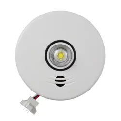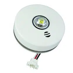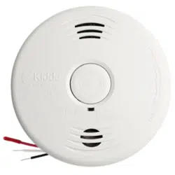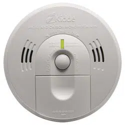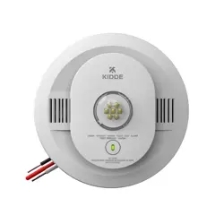
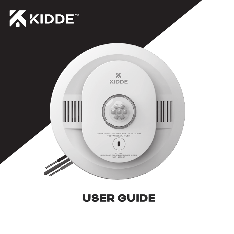
Smoke and Combination Smoke/CO Alarms with LED Strobe
P/N: G-000048-00 EN Rev. A
2
These models utilize standard 120V AC power, as well as a 10 yr sealed battery backup. They also
contain HUSH
TM
to temporarily silence nuisance alarms, an LED strobe, and “self-testing” features (see
Operation and Testing section).
NOTE: Battery backup supplies power to the smoke and carbon monoxide alarm portion only. Strobe
will not work without AC power.
Teach children how to respond to the alarm and that they should never play with the unit. This alarm is a
multi-criteria device which includes a bright LED strobe. Smoke models are designed to detect smoke,
and combination smoke/CO models are designed to detect both smoke and carbon monoxide from any
source of combustion in a residential environment. It is not designed for use in a recreational vehicle
(RV) or boat.
NOTE: Please thoroughly read this user guide and save the document for future reference and to pass
on to any subsequent owner. Images are representative only. Actual product may vary slightly.
The National Fire Protection Association (NFPA) and the manufacturer recommend replacing this alarm
after ten years.
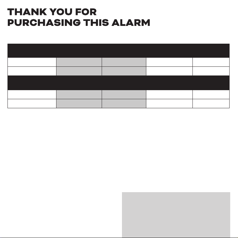
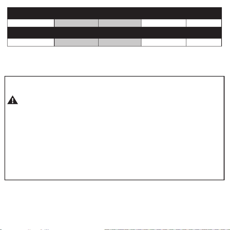
Kidde Model Type 120VAC
10 Yr Sealed
Battery Backup
CO
50SA10-S Smoke/Strobe
Yes Yes
No
50CUA10-S Smoke/CO/Strobe
Yes Yes Yes
Firex Model Type 120VAC
10 Yr Sealed
Battery Backup
CO
SMAC10LEDFEX Smoke/Strobe
Yes Yes
No
CUAC10LEDFEX Smoke/CO/Strobe
Yes Yes Yes
Models included in this User Guide:
Model: _________________
Date Code (on back): _________________
Date of Purchase: _________________
Where Purchased: _________________
Date to Replace: _________________
Product Support: 1-800-880-6788
Please write down the below information
and have this at hand when you call.

3
Contents
1. Smoke Alarm: What To Do When The Alarm Sounds . . . . . . . . .4
2. Other Alarm Visual And Audible Indicators . . . . . . . . . . . .5
3. Troubleshooting Guide . . . . . . . . . . . . . . . . . . . 6
4. Introduction, Product Features And Specifications . . . . . . . . . 7
5. Limitations Of Smoke And Carbon Monoxide Alarms . . . . . . . .10
6. Recommended Locations . . . . . . . . . . . . . . . . . .12
7. Locations To Avoid . . . . . . . . . . . . . . . . . . . .15
8. Alarm Installation . . . . . . . . . . . . . . . . . . . . . 16
9. Operation And Testing . . . . . . . . . . . . . . . . . . .21
10. Recognizing Nuisance Alarms . . . . . . . . . . . . . . . . 23
11. Battery Backup. . . . . . . . . . . . . . . . . . . . . .24
12. Permanently Disable Alarm / Discharge Battery . . . . . . . . . .25
13. Carbon Monoxide Alarm: What To Do When The Alarm Sounds . . . . .26
14. General Carbon Monoxide (CO) Information . . . . . . . . . . .27
15. Cleaning Your Alarm. . . . . . . . . . . . . . . . . . . . 29
16. Good Safety Habits . . . . . . . . . . . . . . . . . . . .31
17
. Service And Warranty . . . . . . . . . . . . . . . . . . .34

4
1. Smoke Alarm: What To Do When The Alarm Sounds
The smoke alarm pattern is three long beeps, a 1.5 second pause, and three long beeps repeating.
The red LED blinks in time with the alarm pattern only on the alarm(s) that detected the hazard
(initiating alarm), and the strobe will flash once every second.
The smoke alarm takes precedence when both smoke and carbon monoxide are present.
(only combination smoke/CO models detect carbon monoxide)
• Alert small children in the home as well as anyone else that might have difficulty recognizing the
importance of the alarm sounding or that might have difficulty leaving the area without help.
• Plan two ways out! Leave immediately by your escape plan. Don’t waste time getting dressed or
picking up valuables.
• While leaving, don’t open any inside door without first feeling its surface. If hot, or if you see
smoke seeping through cracks, don’t open that door! Instead, use your alternate exit. If the inside
of the door is cool, place your shoulder against it, open it slightly and be ready to slam it shut if
heat and smoke rush in.
• If the escape route requires you to go through smoke, stay close to the floor where the air is
cleaner. Crawl if necessary, and breathe shallowly through a cloth, wet if possible.
• Once outside, go to your selected meeting place and make sure everyone is there.
• Call the fire department or 911 from your cell phone outside, or from your neighbor’s home-not
from yours!
• Don’t return to your home until the fire officials say that it is all right to do so.
NOTE: See Section RECOGNIZING NUISANCE ALARMS, for nuisance alarm situations.
5
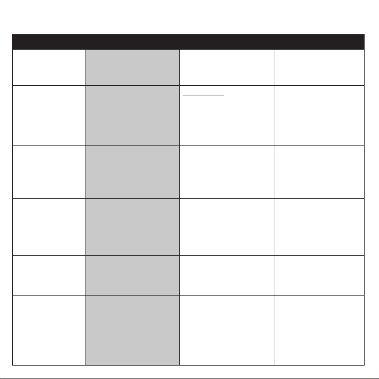
2. Other Alarm Visual And Audible Indicators
Operational Mode
Visual Indications
Audible Indications
Action / Note
Normal (standby) AC power: Green LED on
continuously.
DC power: Green LED blinks
approx every 60 sec.
Test (Test/Hush button
press when no alarm
condition is present)
(Note: Test is very loud,
stand a few feet away.)
Red LED blinks in time with
alarm pattern.
* During test, the strobe will flash
once every second.
Smoke Models:
• Single beep.
•
3 long beeps, pause, 3 long beeps.
Combination Smoke/CO Models:
• Single beep.
• 3 long beeps, pause, 3 long
beeps, 4 quick beeps, pause, 4
quick beeps.
Perform test once per week to
verify proper alarm operation.
Smoke or CO Alarm
Memory (unit has
experienced a smoke or CO
alarm event, or has detected
100ppm CO or greater.) (CO
only on combination smoke/
CO models)
Smoke: Red LED blinks every
15 sec.
CO (combination smoke/CO
models only): 2 red LED blinks
every 15 sec.
None NOTE: Alarm memory is only
retained for 24 hrs.
Push Test/Hush button to clear
Alarm Memory.
Smoke Alarm HUSH
TM
Mode
Red LED blinks every 2 sec.
(only on the initiating alarm)
After Test/Hush button push,
smoke alarm pattern stops.
If there is too much smoke
to allow HUSH, smoke alarm
pattern continues.
This feature is to be used only
when a known alarm condition,
such as smoke from cooking,
activates the alarm. Push Test/
Hush button again during
HUSH to clear HUSH
and
perform a test.
CO Alarm Reset
(combination smoke/CO
models only)
None After Test/Hush button push, CO
alarm pattern stops.
Unit is confirming if CO is
present or if it experienced a
nuisance situation. Re-alarm
means danger. Exit to fresh air
and call 911.
Initiating Alarm
(Multiple Alarms In An
Interconnected System)
Red LED blinks in time with
alarm pattern indicating that this
is the unit initiating the alarm
in an interconnected, multiple
alarm, system. Strobe flashes
once per second.
NOTE: It is possible for more
than one unit to detect a hazard
and become an initiating alarm
unit (Red LED blinking).
Unit in either Smoke or CO alarm
mode.

6
3. Troubleshooting Guide
If you are experiencing a problem with your alarm, or a fault, and are unsure of the next action, please
contact product support at 1-800-880-6788 before discharging the battery or disposing of your alarm. You
may also write us at: Kidde, 1016 Corporate Park Drive, Mebane, NC 27302, or visit our internet address at
www.kidde.com.
Trouble Condition
Visual Indications Audible Indications Action / Note
False Low Battery (AC
power is connected
before backup battery
activated)
Amber LED blinks every
6 sec.
Chirp every 60 sec. * Activate the sealed battery backup.
Low Battery
Amber LED blinks every
6 sec.
Chirp every 60 sec. After Test/Hush
button push, chirps are temporarily
silenced.
*
Push Test/Hush button once to silence for 24 hrs.
(Push Test/Hush button again to clear HUSH
TM
and perform a test.) Note: At some point after
Low Battery begins, the notifications cannot
be silenced (see Battery Backup section for
more info).
* Remove alarm, discharge, dispose unit, and
replace as soon as possible.
Smoke Sensor
Fault
Amber LED blinks every
60 sec.
3 chirps every 60 sec. * See Cleaning Your Alarm section.
* Push Test/Hush button once to attempt to reset
the unit.
* If error continues, remove alarm, discharge,
disposeunit, and replace as soon as possible.
CO Fault
(combination smoke/
CO models only)
Amber LED blinks 2 times
every 60 sec.
3 chirps every 60 sec. * Push Test/Hush button once to attempt to reset
the unit.
* If error continues, remove alarm, discharge,
dispose unit, and replace as soon as possible.
Fatal Fault
Amber LED blinks 3 times
every 60 sec.
3 chirps every 60 sec. * Push Test/Hush button once to attempt to reset
the unit.
* If error continues, remove alarm, discharge,
dispose unit, and replace as soon as possible.
End of Unit Life
Amber LED blinks 2 times
every 60 sec.
2 chirps every 60 sec. After Test/Hush
button push, chirps are temporarily
silenced.
* Push Test/Hush button once to silence for 24 hrs
(Push Test/Hush button again to clear HUSH
and
perform a test.) Note: 7 days after End of Unit Life
begins, the notifications cannot be silenced.
* Remove alarm, discharge, dispose unit, and
replace as soon as possible.
MCU Failure
None Constant Tone
* Remove alarm, discharge, dispose unit, and
replace as soon as possible.
Stuck Test/Hush
Button or Side
Enrollment Button
Amber LED blinks 4
times every 60 sec.
3 chirps every 60 sec.
* Push button to dislodge it from being stuck.
If button cannot be unstuck, remove alarm,
discharge, dispose unit, and replace as soon as
possible.

7
4. Introduction, Product Features And Specifications
Introduction
This alarm detects products of combustion using a photoelectric sensor and carbon monoxide (on
combination smoke/CO models only) using an electrochemical cell. Many times throughout this User
Guide, we will refer to Carbon Monoxide as “CO.”
Ten (10) years after the unit was installed, powered up, and tested, this unit will automatically alert you
that it is time to replace the unit. This is called “End of Unit Life” mode. See Troubleshooting Guide.
To help identify the date to replace the unit, a label has been affixed to the side of the alarm. Write
the “Install date” in the space provided, and then write in the “Replace by” date (10 years from initial
power up) in permanent marker on the label prior to installing the unit. For combination smoke/CO
models, two labels have been provided that have important information on what to do in case of a CO
alarm. Place one label at eye level on a wall near the alarm after it is mounted, and one near a fresh
air source such as a door or window, where you plan to gather after the alarm indicates the presence
of carbon monoxide.
Product Features and Specifications:
• Powered by 120VAC (60 Hz, 2.8A max) wire-in connector with 10 yr sealed battery backup
• Reduced nuisance alarms
• Self-testing (see Operation and Testing section)
• Applications: Primary Direct or Indirect and Supplementary
• LED Strobe with Light Output of 177 Candela minimum (on axis measurement) NOTE: Strobe flash
does not occur without AC power connected and active.
• Strobe synchronization with compatible models
• Easy installation
• Hardwire Interconnectable to other compatible alarms
• Smoke Alarm HUSH
TM
• Smoke Sensor: Photoelectric
• CO Sensor: Electrochemical (combination smoke/CO models only)
• Temperature Operating Range: 40°F (4.4°C) to 100°F (37.8°C)
• Humidity Operating Range: up to 95% (smoke models) and 10 to 95% (combination smoke/CO
models) RH, non-condensing
• Audible Alarm: 85+ dB at 10 ft, 3.0 to 3.5 KHz pulsing

8
AC Wired Interconnect Model Capability
AC models have AC hardwire interconnect capability. When one hardwired interconnect unit sounds an
alarm, all other compatible hardwire or interconnected units will also alarm.
NOTE: AC wiring must be completed properly and the AC quick connector must be attached to the unit
for the hardwire interconnect function to work.
The following models can be interconnected using the standard AC wiring interconnect (Refer to
each model’s user guide for visual and audible indicators):
Models which provide both remote smoke and CO alarms: 20SA10, 20SA10-V, 20SAR, 20SAR-W,
3050-VAS10-A, 3050-VASC10-A, 30CUA10, 30CUA10-V, 30CUAR, 30CUAR-V, 30CUAR-W, 900-CUAR,
900-CUAR-V, i12010S, i12010SCO, KN-COB-IC, KN-COPE-I, KN-COSM-I, KN-COSM-IB, KN-COSM-IBA,
KN-SMFM-I, P4010ACLEDS, P4010ACLEDS-2, P4010ACLEDSCO, P4010ACLEDSCO-2, P4010ACS,
P4010ACSAQ-WF, P4010ACSCO, P4010ACSCOAQ-WF, P4010ACSCO-W, P4010ACSCO-WF,
P4010ACS-W, P4010ACS-WF, P4010LACS-W, RF-SM-ACDC, RGCUAR-RW, RGSAR-RW, SMACFEX,
SMAC10YFEX, CUAFEX, CUAFEX-V, CUAC10YFEX, CUAC10YFEX-V, 50SA10-S, 50CUA10-S,
SMAC10LEDFEX, CUAC10LEDFEX.
Models which provide remote smoke alarms, but not remote CO alarms: HD135F, i12020, i12020A,
i12040, i12040A, i12060, i12060A, i12080, i12080A, i4618A, i4618AC, P12040, PE120, Pi2000, Pi2010.
Models which provide both remote smoke and CO alarms with a Strobe light and no audible
notification: SL177i, SLED177i
SM120X relay module will only activate from interconnect smoke signal.
CO120X relay module will only activate from interconnect CO signal.
STROBE SYNCHRONIZATION
This strobe alarm will automatically synchronize (flash at the same time) with these Kidde strobe
models in your interconnected system: 50SA10-S, 50CUA10-S, SMAC10LEDFEX, CUAC10LEDFEX.
Synchronization will take up to 20 seconds when in alarm. NOTE: The alarms will not synchronize
during test mode.
9
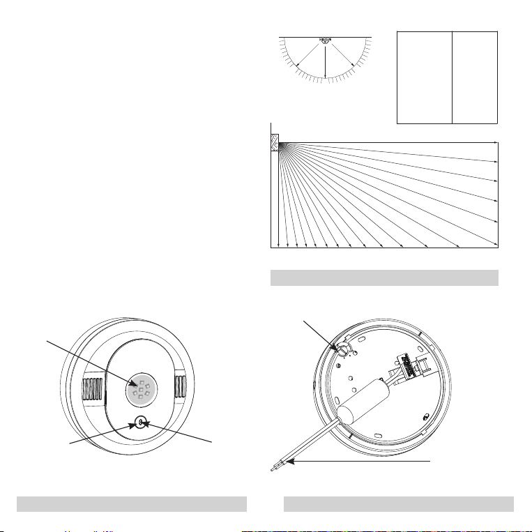
Permanently Disable
Alarm / Discharge
Battery
FCC-Compliant AC
Connector (see page
33 for details).
Product Features and Specifications:
Test / Hush
Button
Flash Lamp
Red Alarm
Light
CEILING
90° 90°
0°
45° 45°
SOURCE
LIGHT
CEILING
90° 90°
0°
45° 45°
SOURCE
LIGHT
25 90
25 85
30 80
30 75
35 70
35 65
40 60
45 55
55 50
75 30-45
90 5-25
100 0
(LIGHT INTENSITY) (IN DEGRE ES)
PERCENT ANGLE
25 90
25 85
30 80
30 75
35 70
35 65
40 60
45 55
55 50
75 30-45
90 5-25
100 0
(LIGHT INTENSITY) (IN DEGRE ES)
PERCENT ANGLE
90° 60 55 50 45 40 35 30
0
ZERO AXIS
WALL
FLOOR
5
10
15
20
25
Front
Back
Figure 4-A
Figure 4-B Figure 4-C
Strobe Location Guide:
Figure 4-A shows that the light intensity
gradually decreases as the viewing angle is
increased. Use this information to determine
the best location for the strobe light.

10
5. Limitations Of Smoke And Carbon Monoxide Alarms
WARNING:
PLEASE READ CAREFULLY AND THOROUGHLY
• Life safety from fire in residential occupancies is based primarily on early notification to occupants of the
need to escape, followed by the appropriate egress actions by those occupants.
• There are situations where a smoke alarm may not be effective to protect against fire as stated in the
NFPA Standard 72. For instance:
a) smoking in bed
b) leaving children home alone
c) cleaning with flammable liquids, such as gasoline
• Fire warning systems for dwelling units are capable of protecting about half of the occupants in
potentially fatal fires. A smoke alarm may not be effective in some situations, such as during incendiary
fires where the fire grows so rapidly that an occupant’s egress is blocked even with properly located
smoke alarms, or when victims are intimate with the fire (for example, when a person’s clothes catch fire
while cooking), too old or young, or physically or mentally impaired such that they cannot escape even
when warned early enough that escape should be possible. For these people, additional strategies
such as protection-in-place or assisted escape or rescue are necessary.*
• This model meets the latest residential smoke alarm standards, which includes enhanced resistance
to nuisance alarms from cooking. Industry experts recommend that both ionization and photoelectric
smoke alarms be installed to help ensure optimal detection of the various types of fires that can occur
within the home. Ionization sensing alarms may detect invisible fire particles (associated with fast flaming
fires) sooner than photoelectric alarms. Photoelectric sensing alarms may detect visible fire particles
(associated with slow smoldering fires) sooner than ionization alarms.
• A battery powered alarm must have a battery of the specified type, in good condition and installed
properly.
• Smoke alarms must be tested regularly to make sure the battery and the alarm circuits are in good
operating condition.
• Smoke alarms cannot provide an alarm if smoke does not reach the alarm. Therefore, smoke alarms may
not sense fires starting in chimneys, within walls, on roofs, on the other side of a closed door or other
obstructions.
• If the alarm is located outside the bedroom or on a different floor, it may not wake up a sound sleeper.

11
• The use of alcohol or drugs may also impair one’s ability to hear the smoke alarm. For optimal detection,
a smoke alarm should be installed in each sleeping area on every level of a home.
* Reference National Fire Protection Association (NFPA) standard 72
WARNING:
PLEASE READ CAREFULLY AND THOROUGHLY
IMPORTANT: Combination smoke/CO alarms are designed to detect carbon monoxide gas from ANY
source of combustion. They are NOT designed to detect any other gas.
CAUTION: Combination smoke/CO alarms will only indicate the presence of carbon monoxide
gas at the sensor. Carbon monoxide gas may be present in other areas. Never restart the source of a
CO problem until it has been fixed. NEVER IGNORE THE ALARM!
WARNING:
COMBINATION SMOKE/CO ALARMS ARE INTENDED FOR USE IN ORDINARY
INDOOR LOCATIONS OF FAMILY LIVING UNITS. THEY ARE NOT DESIGNED TO MEASURE
COMPLIANCE WITH OCCUPATIONAL SAFETY AND HEALTH ADMINISTRATION (OSHA)
COMMERCIAL OR INDUSTRIAL STANDARDS. THEY ARE NOT SUITABLE FOR INSTALLATION
IN HAZARDOUS LOCATIONS AS DEFINED IN THE NATIONAL ELECTRIC CODE. THEY ARE NOT
DESIGNED FOR USE IN A RECREATIONAL VEHICLE (RV) OR BOAT.
• The installation of combination smoke/CO alarms should not be used as a substitute for proper
installation, use, and maintenance of fuel burning appliances, including appropriate ventilation and
exhaust systems.
• Combination smoke/CO alarms do not prevent CO from occurring, nor can they solve any existing
CO problem.
WARNING:
COMBINATION SMOKE/CO ALARMS ARE DESIGNED TO HELP PROTECT
INDIVIDUALS FROM ACUTE EFFECTS OF CARBON MONOXIDE EXPOSURE. THEY WILL NOT
FULLY SAFEGUARD INDIVIDUALS WITH SPECIFIC MEDICAL CONDITIONS. IF IN DOUBT,
CONSULT A MEDICAL PRACTITIONER. INDIVIDUALS WITH MEDICAL PROBLEMS MAY
CONSIDER USING WARNING DEVICES WHICH PROVIDE AUDIBLE AND VISUAL SIGNALS FOR
CARBON MONOXIDE CONCENTRATIONS UNDER 30 PPM. *
• Combination smoke/CO alarms have not been investigated for carbon monoxide detection below
70 PPM.
• This device requires a continuous supply of electrical power from a healthy battery or AC
connection, depending on the model. It will not work without power.
* Reference Underwriters Laboratories (UL) standard 2034.
12
6. Recommended Locations
• For rooms larger than 250 sq. ft. the notification device should be located within 4.88 m (16 ft) of
the pillow when located in a sleeping area.
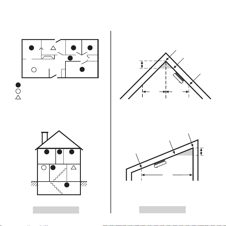
• Locate the first strobe/smoke alarm in the bedroom in which the hearing impaired individual sleeps. Try
to monitor the exit path, as the bedrooms are usually farthest from the exit. Locate the first alarm in the
immediate area of the bedrooms. If more than one sleeping area exists, locate additional alarms in each
sleeping area (Figure 6-B).
• Locate additional strobe lights or combination smoke/strobe alarms in any lived-in room where a hearing
impaired individual would need to be notified of an alarm condition.
• Locate additional alarms in stairways, because stairways act like chimneys for smoke and heat.
• Locate at least one alarm on every floor level.
• Locate an alarm in every bedroom.
• Locate an alarm in every room where electrical appliances are operated (i.e. portable heaters or
humidifiers).
• Locate an alarm in every room where someone sleeps with the door closed. The closed door may
prevent an alarm not located in that room from waking the sleeper.
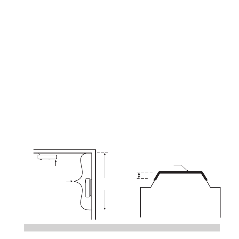
• Smoke, heat, and combustion products rise to the ceiling and spread horizontally. Mounting the
smoke alarm on the ceiling in the center of the room places it closest to all points in the room.
Ceiling mounting is preferred in ordinary residential construction.
ACCEPTABLE
TOP OF ALARM
ACCEPTABLE HERE
CEILING
Note: measurements shown
are to the closest edge
of the alarm.
12’’
(30.5 cm)
MAXIMUM
SIDE
WALL
12”
(30.5 cm)
4”
(102 mm)
4”
(102 mm)
ANYWHERE ALONG
THIS BOLD SURFACE
Locations permitted for smoke
alarms and smoke detectors
on tray-shaped ceilings.
Not within 6 feet of appliances
Smoke Alarms for Required Detection
BEDROOM
BEDROOM
LIVING
ROOM
BASEMENT
BEDROOM
HALL
LIVING ROOM
BEDROOM
KITCHEN
KITCHEN
BEDROOM
BEDROOM
SINGLE FLOOR PLAN
MULTIPLE
FLOOR PLAN
NOT
IN THIS
AREA
NOT
IN THIS
AREA
ANYWHERE
IN THIS
AREA
ANYWHERE
IN THIS AREA
Smoke Alarms for Additional Detection
3’
(0.9 m)
3’
(0.9 m)
3’
(0.9 m)
Figure 6-A
ACCEPTABLE
TOP OF ALARM
ACCEPTABLE HERE
CEILING
Note: measurements shown
are to the closest edge
of the alarm.
12’’
(30.5 cm)
MAXIMUM
SIDE
WALL
12”
(30.5 cm)
4”
(102 mm)
4”
(102 mm)
ANYWHERE ALONG
THIS BOLD SURFACE
Locations permitted for smoke
alarms and smoke detectors
on tray-shaped ceilings.
Not within 6 feet of appliances
Smoke Alarms for Required Detection
BEDROOM
BEDROOM
LIVING
ROOM
BASEMENT
BEDROOM
HALL
LIVING ROOM
BEDROOM
KITCHEN
KITCHEN
BEDROOM
BEDROOM
SINGLE FLOOR PLAN
MULTIPLE
FLOOR PLAN
NOT
IN THIS
AREA
NOT
IN THIS
AREA
ANYWHERE
IN THIS
AREA
ANYWHERE
IN THIS AREA
Smoke Alarms for Additional Detection
3’
(0.9 m)
3’
(0.9 m)
3’
(0.9 m)
13
ACCEPTABLE
TOP OF ALARM
ACCEPTABLE HERE
CEILING
Note: measurements shown
are to the closest edge
of the alarm.
12’’
(30.5 cm)
MAXIMUM
SIDE
WALL
12”
(30.5 cm)
4”
(102 mm)
4”
(102 mm)
ANYWHERE ALONG
THIS BOLD SURFACE
Locations permitted for smoke
alarms and smoke detectors
on tray-shaped ceilings.
Not within 6 feet of appliances
Smoke Alarms for Required Detection
BEDROOM
BEDROOM
LIVING
ROOM
BASEMENT
BEDROOM
HALL
LIVING ROOM
BEDROOM
KITCHEN
KITCHEN
BEDROOM
BEDROOM
SINGLE FLOOR PLAN
MULTIPLE
FLOOR PLAN
NOT
IN THIS
AREA
NOT
IN THIS
AREA
ANYWHERE
IN THIS
AREA
ANYWHERE
IN THIS AREA
Smoke Alarms for Additional Detection
3’
(0.9 m)
3’
(0.9 m)
3’
(0.9 m)
ACCEPTABLE
TOP OF ALARM
ACCEPTABLE HERE
CEILING
Note: measurements shown
are to the closest edge
of the alarm.
12’’
(30.5 cm)
MAXIMUM
SIDE
WALL
12”
(30.5 cm)
4”
(102 mm)
4”
(102 mm)
ANYWHERE ALONG
THIS BOLD SURFACE
Locations permitted for smoke
alarms and smoke detectors
on tray-shaped ceilings.
Not within 6 feet of appliances
Smoke Alarms for Required Detection
BEDROOM
BEDROOM
LIVING
ROOM
BASEMENT
BEDROOM
HALL
LIVING ROOM
BEDROOM
KITCHEN
KITCHEN
BEDROOM
BEDROOM
SINGLE FLOOR PLAN
MULTIPLE
FLOOR PLAN
NOT
IN THIS
AREA
NOT
IN THIS
AREA
ANYWHERE
IN THIS
AREA
ANYWHERE
IN THIS AREA
Smoke Alarms for Additional Detection
3’
(0.9 m)
3’
(0.9 m)
3’
(0.9 m)
ACCEPTABLE
TOP OF ALARM
ACCEPTABLE HERE
CEILING
Note: measurements shown
are to the closest edge
of the alarm.
12’’
(30.5 cm)
MAXIMUM
SIDE
WALL
12”
(30.5 cm)
4”
(102 mm)
4”
(102 mm)
ANYWHERE ALONG
THIS BOLD SURFACE
Locations permitted for smoke
alarms and smoke detectors
on tray-shaped ceilings.
Not within 6ft (1.8m) of appliances
Smoke Alarms for Required Detection
BEDROOM
BEDROOM
LIVING
ROOM
BASEMENT
BEDROOM
HALL
LIVING ROOM
BEDROOM
KITCHEN
KITCHEN
BEDROOM
BEDROOM
SINGLE FLOOR PLAN
MULTIPLE
FLOOR PLAN
NOT
IN THIS
AREA
NOT
IN THIS
AREA
ANYWHERE
IN THIS
AREA
ANYWHERE
IN THIS AREA
Smoke Alarms for Additional Detection
3’
(0.9 m)
3’
(0.9 m)
3’
(0.9 m)
ACCEPTABLE
TOP OF ALARM
ACCEPTABLE HERE
CEILING
Note: measurements shown
are to the closest edge
of the alarm.
12’’
(30.5 cm)
MAXIMUM
SIDE
WALL
12”
(30.5 cm)
4”
(102 mm)
4”
(102 mm)
ANYWHERE ALONG
THIS BOLD SURFACE
Locations permitted for smoke
alarms and smoke detectors
on tray-shaped ceilings.
Not within 6 feet of appliances
Smoke Alarms for Required Detection
BEDROOM
BEDROOM
LIVING
ROOM
BASEMENT
BEDROOM
HALL
LIVING ROOM
BEDROOM
KITCHEN
KITCHEN
BEDROOM
BEDROOM
SINGLE FLOOR PLAN
MULTIPLE
FLOOR PLAN
NOT
IN THIS
AREA
NOT
IN THIS
AREA
ANYWHERE
IN THIS
AREA
ANYWHERE
IN THIS AREA
Smoke Alarms for Additional Detection
3’
(0.9 m)
3’
(0.9 m)
3’
(0.9 m)
Figure 6-B
Figure 6-C
NFPA 72 states: “Smoke alarms in rooms with ceiling slopes greater than 1 ft in 8 ft (0.3m in 2.4 m)
horizontally shall be located on the high side of the room.” NFPA 72 states: “A row of detectors shall be
spaced and located within 3 ft (0.9m) of the peak of the ceiling measured horizontally.”

14
• For mobile home installation, select locations carefully to avoid thermal barriers that may form at
the ceiling. For more details, see MOBILE HOME INSTALLATION section.
• When mounting the alarm on the wall, use an inside wall with the top edge of the alarm at a
maximum of 12” (30.5 cm) below the ceiling.
• Put smoke alarms at both ends of a bedroom hallway or large room if the hallway or room is more
than 30ft (9.1 m) long.
• Install Smoke Alarms on sloped, peaked or cathedral ceilings at or within 3ft (0.9m) of the highest
point (measured horizontally).
• Industry experts recommend a CO alarm be installed on each level of the home-ideally on any
level with fuel burning appliances and outside of sleeping areas.
This equipment should be installed in accordance with the National Fire Protection Association’s 72
(National Fire Protection Association, Batterymarch Park, Quincy, MA 02269).
Mobile Home Installation
Modern mobile homes have been designed and built to be energy efficient. Install smoke alarms
as recommended above. In older mobile homes that are not well insulated compared to present
standards, extreme heat or cold can be transferred from the outside to the inside through poorly
insulated walls and roof. This may create a thermal barrier which can prevent the smoke from reaching
an alarm mounted on the ceiling. In such units, install the smoke alarm on an inside wall with the top
edge of the alarm a maximum of 12” (30.5 cm) below the ceiling.
If you are not sure about the insulation in your mobile home, or if you notice that the outer walls and
ceiling are either hot or cold compared to the room air temperature, install the alarm on an inside wall.
NFPA 72 (National Fire Protection Association) requires smoke alarms be installed in each sleeping
area.
WARNING: TEST YOUR ALARM OPERATION AFTER MOBILE HOME HAS BEEN IN STORAGE OR
UNOCCUPIED, AND AT LEAST ONCE A WEEK DURING USE.

15
7. Locations To Avoid
(See Figures 6-A, 6-B, & 6-C for recommended locations)
• Do not place in direct sunlight or install near high ambient light areas, the bright light may reduce
one’s ability to notice the strobe light.
• In the garage. Products of combustion are present when you start your automobile.
• Normal cooking may cause nuisance alarms. If a kitchen alarm is desired, it should have an alarm
silence feature and should not be installed within 6 ft (1.8m) of cooking appliances.
• Do not install within 6 ft (1.8m) of heating appliances.
• Less than 4” (10cm) from the peak of an “A” frame type ceiling.
• In an area where the temperature may fall below 40 °F (4.4 °C) or rise above 100 °F (37.8 °C), such
as garages and unfinished attics.
• In dusty areas. Dust particles may cause nuisance alarms or a failure to alarm.
• In very humid areas (above 95% RH, non-condensing) as moisture or steam can cause nuisance
alarms.
• In insect-infested areas.
• Smoke alarms should not be installed within 3 ft (0.9m) of the door to a bathroom containing a tub
or shower, forced air supply ducts used for heating or cooling, ceiling or whole house ventilating
fans, or other high air flow areas.
• Near lights. Electronic “noise” generated by the lights may cause nuisance alarms.
• Do not install near vents, flues, or chimneys.
• Do not install near fans, doors, windows or areas directly exposed to the weather.
• Avoid installing where the unit will be exposed to direct sunlight.
NOTE: Smoke alarms are not to be used with detector guards unless the combination (alarm and
detector guard) has been evaluated and found suitable for that purpose.

16
8. Alarm Installation
NOTE: Strobe flash does not function without AC power.
NOTE: A dust cover has been installed on the alarm. Keep the dust cover on until all construction has
been completed for at least 24 hours (drywall, painting, varnishing, mounting plate install, etc). Retain the
dust cover and re-install it to protect the alarm during future construction projects. Construction dust and
chemicals can cause contamination and false alarms.
WARNING: DUST COVER MUST BE REMOVED FOR ALARM TO OPERATE.
NOTE: Single station alarms are units that are not connected to other alarms in any manner, including
hardwire interconnect. Single station alarms (including these models, IF USED as a single station alarm)
CANNOT send or receive alarm signals to other alarms in your home.
STEP 1: Wiring
Wiring Requirements
• AC alarms should be installed on a UL Listed or recognized junction box. All connections should be
made by a qualified electrician and all wiring used shall be in accordance with articles 210 and 300.3(B)
of the U.S. National Electrical Code ANSI/NFPA 70, NFPA 72 and/or any other codes having jurisdiction
in your area. The multiple station interconnect wiring to the alarms must be run in the same raceway or
cable as the AC power wiring. In addition, the resistance of the interconnect wiring shall be a maximum
of 10 ohms.
• The maximum wire run distance between the first and last unit in an interconnected system is 1000 feet.
• The appropriate power source is 120 Volt AC Single Phase supplied from a non-switchable circuit.
• These alarms are not designed, agency tested or certified for recessed mounting and should not be
installed in this manner. Recessed mounting impedes smoke entry into the smoke chamber, which may
prevent the alarm from sounding in a timely manner. This could endanger the lives of occupants in the
residence. These alarms are designed, tested and certified for wall (if applicable) and ceiling surface
mount only.
WARNING: AC ALARMS CANNOT BE OPERATED FROM POWER DERIVED FROM A SQUARE
WAVE, MODIFIED SQUARE WAVE OR MODIFIED SINE WAVE, INVERTER. THESE TYPES OF
INVERTERS ARE SOMETIMES USED TO SUPPLY POWER TO THE STRUCTURE IN OFF GRID
INSTALLATIONS, SUCH AS SOLAR OR WIND DERIVED POWER SOURCES. THESE POWER
SOURCES PRODUCE HIGH PEAK VOLTAGES THAT WILL DAMAGE THE ALARM.
Wiring Instructions for AC Quick Connector Harness (see page 33 for details)
CAUTION: Turn off the main power to the circuit before wiring the alarm.
17
• For alarms that are used as single station, DO NOT CONNECT THE RED WIRE TO ANYTHING. Leave
the red wire insulating cap in place to make certain that the red wire cannot contact any metal parts
or the electrical box.
• When alarms are hardwire interconnected, all interconnected units must be powered from a single circuit.
• A maximum of 24 Kidde Safety devices may be interconnected in a multiple station arrangement.
The interconnect system should not exceed the NFPA interconnect limit of 12 smoke or smoke/CO
combination alarms and/or 18 alarms total (smoke, CO, smoke/CO combination, heat, etc.). With 18
alarms interconnected, it is still possible to interconnect up to a total of 6 remote signaling devices
and/or relay modules.
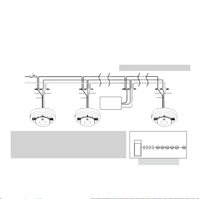
• Figure 8-A illustrates interconnection wiring. Improper connection will result in damage to the alarm,
failure to operate, or a shock hazard.
• Make certain alarms are wired to a continuous (non-switched) power line.
NOTE: Use standard UL Listed household wire (as required by local codes) available at all electrical
supply stores and most hardware stores.
NOTE: AC power should be turned off at this stage.
• For best results to minimize nuisance alarms, interconnected alarms should be on a dedicated
line. If not on a dedicated line, it is suggested that the smoke alarms share a lighting load circuit
Kidde Relay Module
SM120X, CO120X
or both
Wires on alarm harness: Connected to:
Black: Hot side of AC line
White: Neutral side of AC line
Red: Interconnect lines (red wires) of other
units in the multiple station set-up
Service
Panel
Receptacles Interconnected alarms
Wiring practice that has had good results
in preventing nuisance alarms
L
N
FUSE OR CIRCUIT BREAKER
Additional
Alarm
RED
BLACK
WHITE
Additional
Alarm
RED
BLACK
WHITE
RED
BLACK
WHITE
Optional
Accessory
First
Alarm
Figure 8-A, Interconnect Wiring Diagram
Figure 8-B

18
Figure 8-C
USE STANDARD
SCREWDRIVER
ON
PERMANENTLY
DISABLE and
DISCHARGE
ALARM
that does not have a dimmer associated with it. If receptacles must be placed on the same line it is
suggested that they be placed ahead of the smoke alarms (see Figure 8-B). This will prevent large
voltage drops from occurring between the first and last alarm in the circuit.
STEP 2: Activate Battery
One of the following steps must be taken to ensure activation: Battery activation is confirmed with a
beep. Confirm the battery activation beep.
A. Activate the alarm battery by rotating the alarm fully onto the mounting bracket in a clockwise
direction. (reference Figures 8-E and 8-F) To allow for installation, battery will remain active when unit is
removed from mounting bracket.
-- OR --
B. Activate the alarm by locating the red wheel on the back of the
unit - turn the red wheel to the “ON” position using a standard
screwdriver. (see Figure 8-C). Battery will remain active to allow
for installation on mounting bracket.
NOTE: Attaching AC power first, without activating the 10 yr
sealed battery backup, will result in a false low battery trouble
condition chirp (see Troubleshooting Guide). You need to
activate the battery to eliminate the false low battery trouble
condition chirps. Activate the 10 yr sealed battery backup (see
Figure 8-C) to avoid false low battery notification.
NOTE: Activation of the 10 year sealed battery is a one-time operation. After activation, the battery
cannot be turned off, and can only be discharged if needed, i.e., due to fault or end of life condition.
See Permanently Disable Alarm / Discharge Battery section.
STEP 3: Install Mounting Bracket
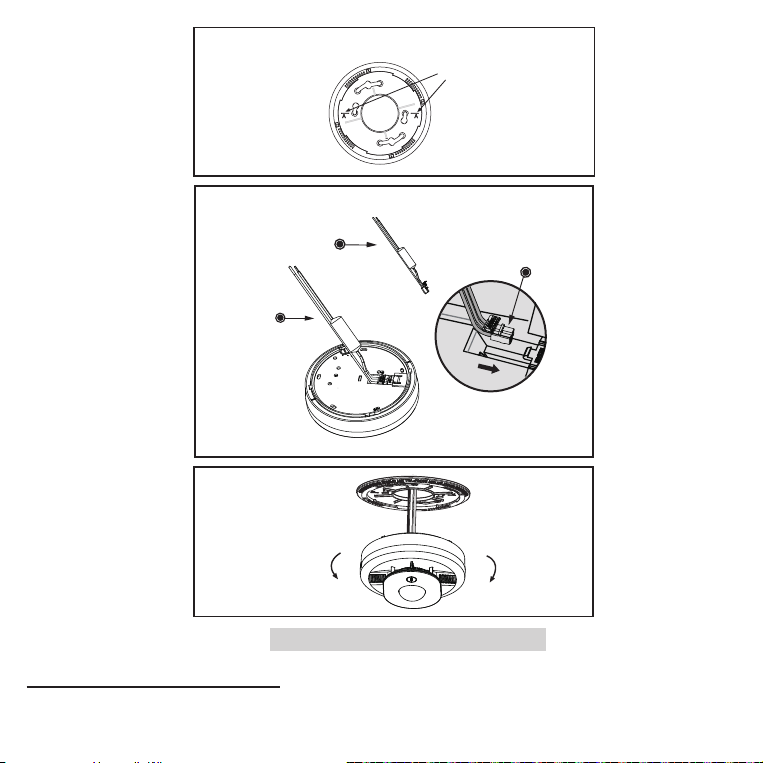
• After selecting the proper location for your alarm, and wiring the AC QUICK CONNECTOR harness as
described previously, attach the mounting bracket to the electrical box using the existing screws or,
if included, the screws provided with this alarm. To ensure aesthetic alignment of the alarm with the
hallway, or wall, the “A” line on the mounting bracket should be parallel with the hallway when ceiling
mounted or horizontal when wall mounted. (See Figure 8-D)
• Pull the AC QUICK CONNECTOR through the center hole in the mounting bracket and secure the
bracket, making sure that the mounting screws are positioned in the small ends of the keyholes
before tightening the screws. (See Figure 8-D)
19
STEP 4: Attach AC Quick Connector
Plug the AC QUICK CONNECTOR into the back of the unit, making sure that the connector snaps into place.
Then push the excess wire back into the electrical box through the hole in the center of the mounting bracket.
Insert the AC
Quick connector
into the slot.
Alignment Marks
(”A” Line) on
Mounting
Bracket
Remove
Install
AC Quick Connector
harness shipped
with product
AC connector
Figure 8-D
20
STEP 5: Install Alarm
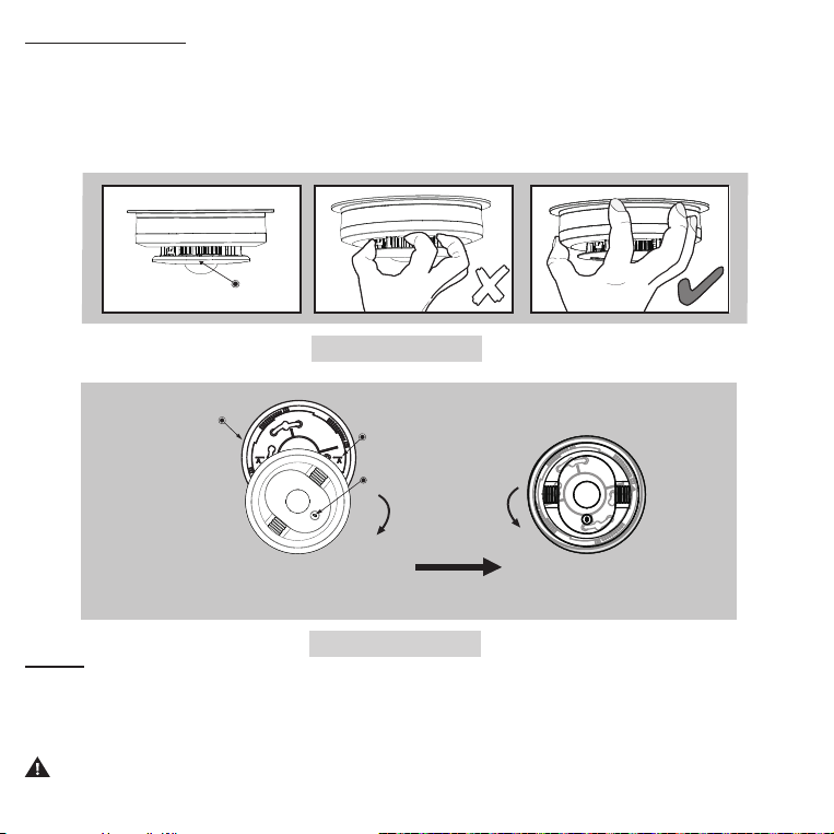
Install the alarm fully on the mounting bracket by rotating the alarm in a clockwise direction (Figure 8-F).
NOTE: The alarm will mount to the bracket in 4 positions (every 90 degrees).
NOTE: Do not grab the shield to install or remove the alarm. Grab the alarm by the outside of the
enclosure (Figure 8-E).
.
STEP 6:
Turn on the AC power. The green LED will illuminate when AC power is applied.
The alarm is now activated! After installation / activation, test your alarm as described in Operation and
Testing section.
WARNING: Failure to properly connect AC power and activate the 10 yr sealed battery will
prevent proper operation of this alarm and will prevent its response to fire and/or CO hazards.
✘
Shield
Figure 8-E
Install
Remove
Mounting Bracket
Note orientation
of "A" line.
LED
To ensure aesthetic alignment, orient
the unit as shown on the mounting
bracket and rotate the unit completely until it stops.
After fully installed
(The button should
be at the bottom.)
Figure 8-F

21
9. Operation And Testing
This model meets the latest residential smoke alarm standards, which includes enhanced resistance to
nuisance alarms from cooking.
Operation
The alarm is operating once it is activated and testing is complete (see “TESTING” below). When
products of combustion (smoke for smoke only models, and smoke or CO for combination smoke/CO
models) are sensed, the unit sounds a loud alarm with strobe flashing. See Sections 1 and 2 for alarm
signal descriptions. In high levels of CO, the unit will go into alarm in a shorter period of time than at
low levels of CO (combination smoke/CO models only).
CO ALARM SENSOR RESPONSE TIMES
(Combination smoke/CO models only)
At 70 PPM, the unit must alarm within 60-240 minutes.
At 150 PPM, the unit must alarm within 10-50 minutes.
At 400 PPM, the unit must alarm within 4-15 minutes.
Testing
WARNING: Do not attempt to test this unit with retail “canned smoke” products. Those
products are intended for use by trained professionals and produce inconsistent results when
misused. Over-application of canned smoke can permanently damage the alarm.
Self-Testing
This model is equipped with internal, self-testing components that are always checking to ensure
the device is operating as expected. (Weekly manual testing is still required. See below.)
Manual Testing
NOTE:
When pushing the Test/Hush button, use only your finger or thumb. Using any other
instrument(s) (such as a broom handle) is strictly prohibited, as it may damage the alarm.
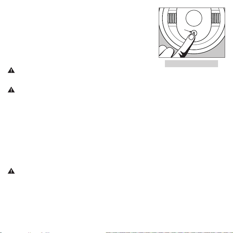
Test your alarm weekly by pressing and releasing the Test/Hush button quickly on the alarm.
22
Figure 9
Test/Hush Button
(Figure 9). A quick beep will confirm the Test/Hush button has been
pushed followed by the test sequence.
See Other Alarm Visual and Audible Indicators table for test sequence
information. The alarm and strobe (and any interconnected units)
will activate if the electronic circuitry, horn, strobe, and battery are
working. If the alarm or strobe does not activate, or gives erratic or
low volume sound, the unit must be replaced.
NOTE:
AC power must
be applied for the strobe flash to activate. See Permanently Disable
Alarm / Discharge Battery section to determine how to prepare the
unit for shipment or disposal.
WARNING: Due to the loudness of the alarm, always stand about
2.5 ft (0.8 m) away from the unit or use ear protection when testing, and
avoid looking at the bright strobe directly, or cover it with your hand.
WARNING:
Do not use an open flame to test your alarm, you could damage the alarm or ignite
combustible materials and start a structure fire.
STROBE SYNCHRONIZATION
This strobe alarm will automatically synchronize (flash at the same time) with other compatible
Kidde strobes that are part of the interconnected system. See the interconnect model list in
Section 4. Synchronization will take up to 20 seconds when in alarm. NOTE: The alarms will
not synchronize during test mode.
Chirping
When End of Unit Life or Low Battery chirping begins, you can temporarily silence these
chirps by pressing the Test/Hush button. See Battery Backup section for more info on the low
battery Hush feature. Other fault /error chirps cannot be silenced. Take appropriate action as
described in the Troubleshooting Guide.
WARNING: REPLACE UNIT AS SOON AS POSSIBLE WHEN IN END OF UNIT LIFE. SEVEN
(7) DAYS AFTER END OF UNIT LIFE BEGINS, THE NOTIFICATIONS CANNOT BE SILENCED,
AND SMOKE AND/OR CO DETECTION CANNOT BE GUARANTEED. REPLACE IMMEDIATELY!

23
10. Recognizing Nuisance Alarms
Smoke Nuisance
This model meets the latest residential smoke alarm standards, which includes enhanced
resistance to nuisance alarms from cooking.
HUSH
TM
:
If you know why the alarm is sounding, and you can verify that it is not a life threatening
situation, you can push the button on the initiating unit (red LED blinking along with strobe flash) to
silence the alarm for 8-10 minutes. If the smoke is not too dense, that unit, and all interconnected units
will silence. After the HUSH time period has elapsed, the smoke alarm will automatically reset and
sound the alarm if particles of combustion are still present. You can use the HUSH function repeatedly
until the air has been cleared of the condition causing the alarm.
NOTE: Dense smoke will override the HUSH function and sound a continuous alarm. If no fire is
present, check to see if one of the reasons listed in “Locations to avoid” may have caused the
alarm. If a fire is discovered, get out and call the fire department or 911.
Cigarette smoke will not normally cause the unit to alarm, unless the smoke is blown directly into the
alarm. Combustion particles from cooking may set off the alarm if it is located too close to a cooking
appliance. Large quantities of combustible particles are generated from spills or when broiling. Using
the fan on a range hood which vents to the outside (non-recirculating type) will also help prevent
nuisance alarms from occurring by removing these combustible products from the kitchen.
Carbon Monoxide (CO) Nuisance (combination smoke/CO models only)
RESET: Pushing the Test/Hush button on a combination smoke/CO unit during CO alarm allows
the unit to reset calculations and double check for the presence of CO. If the unit re-alarms within
6 minutes, it is sensing high levels of CO which can quickly become a dangerous situation. Exit to
fresh air and call 911.
NOTE:
Smoke only models do not detect CO, but will receive and transmit a CO alarm signal from
an interconnected CO or combination smoke/CO alarm. Pushing the button on a smoke only
model when it is transmitting an interconnected CO alarm signal will do nothing.
WARNING: ALTHOUGH RESET FEATURE CAN BE USED FOR CO ALARM EVENTS, IT IS
IMPOSSIBLE TO DETERMINE THE SOURCE OF A CO ALARM USING SIGHT OR SMELL. ALWAYS
CONSIDER A CO ALARM EVENT AS DANGEROUS.

24
11. Battery Backup
These models are powered with AC power, but also contain a sealed lithium battery backup system.
No battery installation or replacement is necessary for the life of the alarm. NOTE: AC power must be
connected to obtain the full 10 year battery and unit life. Constant exposure to high or low humidity
or temperatures may reduce battery life.
NOTE: If AC power is lost, strobe flash features will not function, but the backup battery will still
provide smoke and/or CO detection. (CO on smoke/CO/strobe combination model only)
WARNING: NO SERVICEABLE PARTS INCLUDED. DO NOT ATTEMPT TO OPEN THE ALARM
FOR ANY REASON! DO NOT TRY TO REPAIR THE ALARM YOURSELF.
LOW BATTERY
This alarm is equipped with a low battery monitor circuit. If the battery capacity is nearing the point
where it can no longer provide adequate power for all alarm functions, the low battery condition will
occur. See Troubleshooting Guide.
When low battery notification begins, you can push the Test/Hush button to temporarily silence
the low battery chirps to allow a more convenient time to replace the unit. However, depending
on the environment and battery condition, the Hushable time period can vary and eventually the
low battery notifications cannot be silenced. The unit must be replaced within 7 days of the first
occurrence of the "Low Battery Warning" to provide continuous alarm detection.
CAUTION: THE BATTERY USED IN THIS DEVICE MAY PRESENT A FIRE OR CHEMICAL BURN
HAZARD IF MISTREATED. DO NOT RECHARGE, DISASSEMBLE, HEAT ABOVE 100°C (212°F) OR
DISPOSE OF IN FIRE.
WARNING: Failure to properly connect AC power and activate the 10 yr battery backup, will
prevent proper operation of this alarm and will prevent its response to fire and/or CO hazards.

25
12. Permanently Disable Alarm / Discharge Battery
WARNING: FAILURE TO DISCHARGE ALARM BATTERY AS INSTRUCTED PRIOR TO
DISPOSAL MAY CREATE POTENTIAL FOR LITHIUM BATTERY RELATED FIRE OR HAZARD.
WARNING: DISCHARGING THE ALARM BATTERY IS PERMANENT
• Once the alarm battery has been discharged, it cannot be reactivated!
• Once discharged, the alarm will NO LONGER DETECT SMOKE OR CO. (only combination smoke/CO
models detect CO)
• Once the alarm battery is discharged, the battery is depleted and the alarm will no longer function.
• Once the alarm battery has been discharged, the alarm cannot be mounted onto the mounting
bracket or reactivated.
To Permanently Disable Alarm / Discharge Battery:
• Rotate the alarm counterclockwise to remove it from the mounting
bracket.
• Disconnect AC wiring harness.
• Remove SIDE OF TAB from base.
• After the SIDE OF TAB is removed, use the screwdriver to turn the red
slotted arrow to the “PERMANENTLY DISABLE and DISCHARGE ALARM”
location until it clicks/locks into position. This will disable the alarm, stop
the low battery or end of unit life “chirps” and render the alarm safe for
disposal by draining the battery.
Figures 12-A (top) and 12-B (bottom)
Smoke sensitivity : X.XX +/- X.XX %/ft OBS
177 min Candela (Cd) at 0°
For indoor dry locations only.
Clean annually. See User Guide for more info. Product is sealed with no serviceable parts.
For service return to Kidde,
1016 Corporate Park Drive, Mebane, NC 27302
1-800-880-6788 ©2025 Kidde.
Photoelectric Smoke Alarm w/ LED Strobe & 10 year battery backup. Regulated 120 V AC (102-132 V), 60 Hz,
2.8A max current. Strobe flash 1/sec, 20 ms pulse, 1.5 Watt-sec.
Constant exposures to high or low temperatures or high humidity may reduce battery life.
SMOKE ALARM: 3 Long beeps, repeating. Strobe flashes once per second. NOTE: Not a CO alarm, but can
transmit an interconnected CO ALARM signal: 4 quick beeps, repeating. Strobe flashes once per second.
NOTE: Strobe does not work on DC power.
STANDBY: AC power-green LED on. DC only-green LED blink every 60s.
FAULT: Amber LED blinks 1-4 times with 3 chirps every 60s.
LOW BATTERY: Amber LED blinks every 6s with 1 chirp every 60s.
END OF UNIT LIFE: Amber LED blinks twice with 2 chirps every 60s.
Temp Range: 40 °F (4.4 °C) to 100 °F (37.8 °C)
Humidity Range: Up to 95% relative humidity (RH), non-condensing.
PERMANENTLY
DISABLE and
DISCHARGE
ALARM
ON
Model 50SA10-S
At end of unit life
or low battery:
(1) Remove SIDE OF TAB
(2) Rotate slotted arrow
to DISABLE & DISCHARGE
location
(3) Install new alarm
Smoke sensitivity : X.XX +/- X.XX %/ft OBS
177 min Candela (Cd) at 0°
For indoor dry locations only.
Clean annually. See User Guide for more info. Product is sealed with no serviceable parts.
For service return to Kidde,
1016 Corporate Park Drive, Mebane, NC 27302
1-800-880-6788 ©2025 Kidde.
Photoelectric Smoke Alarm w/ LED Strobe & 10 year battery backup. Regulated 120 V AC (102-132 V), 60 Hz,
2.8A max current. Strobe flash 1/sec, 20 ms pulse, 1.5 Watt-sec.
Constant exposures to high or low temperatures or high humidity may reduce battery life.
SMOKE ALARM: 3 Long beeps, repeating. Strobe flashes once per second. NOTE: Not a CO alarm, but can
transmit an interconnected CO ALARM signal: 4 quick beeps, repeating. Strobe flashes once per second.
NOTE: Strobe does not work on DC power.
STANDBY: AC power-green LED on. DC only-green LED blink every 60s.
FAULT: Amber LED blinks 1-4 times with 3 chirps every 60s.
LOW BATTERY: Amber LED blinks every 6s with 1 chirp every 60s.
END OF UNIT LIFE: Amber LED blinks twice with 2 chirps every 60s.
Temp Range: 40 °F (4.4 °C) to 100 °F (37.8 °C)
Humidity Range: Up to 95% relative humidity (RH), non-condensing.
PERMANENTLY
DISABLE and
DISCHARGE
ALARM
ON
Model 50SA10-S
At end of unit life
or low battery:
(1) Remove SIDE OF TAB
(2) Rotate slotted arrow
to DISABLE & DISCHARGE
location
(3) Install new alarm
26
13. Carbon Monoxide Alarm: What To Do When The Alarm Sounds
NOTE: Smoke only models do not detect carbon monoxide (CO), but will receive and transmit a CO
alarm signal from an interconnected CO or combination smoke / CO alarm.
The carbon monoxide (CO) alarm pattern is four quick beeps repeating every 5 seconds. The red LED blinks in time
with the alarm pattern only on the alarm(s) that detected the hazard (initiating alarm), and the strobe will flash once
every second. On DC power only, after 4 minutes in CO alarm the alarm pattern will only occur every 60s.
WARNING:
CARBON MONOXIDE (CO) IS A COLORLESS,
ODORLESS, POISONOUS GAS. YOU CAN’T TASTE, SEE, OR SMELL
CO, BUT IT CAN KILL IN JUST MINUTES. THIS ALARM WILL SOUND
IN A 4-BEEP PATTERN IF LIFE THREATENING LEVELS OF CO ARE
DETECTED. IF THE ALARM SOUNDS:
1
)
Immediately evacuate all occupants from the space and go outdoors to fresh air.
2) Call emergency responders (911 or fire department) for help; notify the building
or vehicle owner, as necessary.
EMERGENCY PHONE #: _______________________
Always consider a CO alarm to be dangerous. After emergency services responders have arrived, the premises has
been aired out, and your alarm remains in its normal condition, it is important to call a qualified appliance technician
to investigate for sources of CO from fuel burning equipment and appliances and inspect for proper operation of this
equipment. If problems are identified during this inspection, have the equipment serviced immediately. Note any
combustion equipment not inspected by the technician and consult the manufacturer’s instructions or contact the
manufacturer directly for more information about CO safety and this equipment. Make sure that motor vehicles are not
or have not been operating in an attached garage or adjacent to the residence.
NOTE: See Section RECOGNIZING NUISANCE ALARMS, for nuisance alarm situations.
Kidde Model Type 120VAC
10 Yr Sealed
Battery Backup
CO
50CUA10-S Smoke/CO/Strobe
Yes Yes Yes
Firex Model Type 120VAC
10 Yr Sealed
Battery Backup
CO
CUAC10LEDFEX Smoke/CO/Strobe
Yes Yes Yes

27
14. General Carbon Monoxide (CO) Information
Carbon monoxide (CO) is a colorless, odorless, and tasteless poison gas that can be fatal when
inhaled. CO inhibits the blood’s capacity to carry oxygen.
Possible Sources of CO
Inside your home, appliances used for heating and cooking are the most likely sources of CO. Vehicles
and other combustion engines running in an attached garage and using a charcoal/gas grill or hibachi
in an enclosed area are all possible sources of CO. Generators running in enclosed areas, such as
garages or living spaces, will create CO. CO can be produced when burning any fossil fuel: gasoline,
diesel, propane, natural gas, oil and wood. It can be produced by any fuel-burning appliance that
is malfunctioning, improperly installed, or not ventilated correctly, such as: Furnaces/boilers, gas
ranges/stoves, gas clothes dryers, water heaters, portable fuel burning space heaters, fireplaces,
wood-burning stoves and certain swimming pool heaters. Blocked chimneys or flues, back drafting
and changes in air pressure, corroded or disconnected vent pipes, or a loose or cracked furnace heat
exchanger can also release CO into your building.
The following conditions can result in transient CO situations:
Excessive spillage or reverse venting of fuel-burning appliances caused by outdoor ambient
conditions such as: Wind direction and/or velocity, including high gusts of wind, heavy air in the
vent pipes (cold/humid air with extended periods between cycles), negative pressure differential
resulting from the use of exhaust fans, simultaneous operation of several fuel-burning appliances
competing for limited internal air, vent pipe connections vibrating loose from clothes dryers, furnaces/
boilers, or water heaters, obstructions in, or unconventional, vent pipe designs which can amplify the
above situations, extended operation of unvented fuel-burning devices (range, oven, fireplace, etc.),
temperature inversions which can trap exhaust gases near the ground, car idling in an open or closed
attached garage, or near a home.

28
CO Safety Tips
Every year, have the heating system, vents, chimney and flue inspected and cleaned by a qualified
technician. Always install appliances according to manufacturer’s instructions and adhere to
local building codes. Most appliances should be installed by professionals and inspected after
installation. Regularly examine vents and chimneys for improper connections, visible rust, or
stains, and check for cracks in furnace heat exchangers. Verify that the color of flame is blue on
pilot lights and burners. An amber or orange flame is a sign that the fuel is not burning completely
and may be releasing CO. Teach all household members what the alarm sounds like and how
to respond. Fire Departments, most utility companies and HVAC contractors will perform CO
inspections. Some contractors may charge for this service. It’s advisable to inquire about any
applicable fees prior to having the service performed. Kidde will not pay for, or reimburse the
owner or user of this product, for any repair or dispatch calls related to the alarm sounding.
Symptoms of CO Poisoning
Initial carbon monoxide poisoning symptoms are similar to the flu with no fever and can include
dizziness, severe headaches, nausea, vomiting and disorientation. Everyone is susceptible
but experts agree that unborn babies, pregnant women, senior citizens and people with heart
or respiratory problems are especially vulnerable. If symptoms of carbon monoxide poisoning
are experienced seek medical attention immediately. CO poisoning can be determined by a
carboxyhemoglobin test.
The following symptoms are related to CARBON MONOXIDE POISONING and should be discussed
with ALL members of the household:
1. MILD EXPOSURE: Slight headache, nausea, vomiting, fatigue (often described as “Flu-like” symptoms).
2. MEDIUM EXPOSURE: Severe throbbing headache, drowsiness, confusion, fast heart rate.
3. EXTREME EXPOSURE: Unconsciousness, convulsions, cardio respiratory failure and death.
The above levels of exposure relate to healthy adults. Levels differ for those at high risk. Exposure
to high levels of carbon monoxide can be fatal or cause permanent damage and disabilities. Many
cases of reported carbon monoxide poisoning indicate that while victims are aware they are not
feeling well, they become so disoriented they are unable to save themselves by either exiting
the building, or calling for assistance. Also, young children and household pets may be the first
affected. Familiarization with the effects of each level is important.
29
15. Cleaning Your Alarm
Your Alarm Should be Cleaned at Least Once a Year
NOTE: In environments with higher dust levels, such as newly constructed or recently renovated homes,
more frequent cleaning may be required during the first few months of occupancy or after renovation.
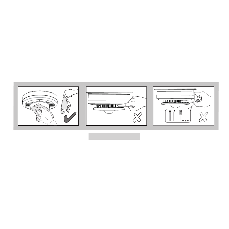
You can clean the interior of your alarm (sensing chamber) by using compressed air or a vacuum cleaner
hose and blowing or vacuuming through the openings around the perimeter of the alarm. The outside
of the alarm can be wiped with a clean, dry cloth. Do not use water, detergents or cleaners as they may
damage the alarm.
NOTE: Do not insert fingers or cleaning items under the shield during cleaning.
If the alarm is in Fault mode, the alarm may be in need of cleaning. After cleaning, press the Test/Hush
button. If the fault does not clear, the alarm needs to be replaced.
• Never use detergent or other solvents to clean the unit.
• Avoid spraying air freshener, hair spray, or other aerosols near the alarm.
• Do not use a hair dryer to clean the alarm, as it may damage the alarm and impact performance.
• Do not paint the unit. Paint will seal the vents and interfere with the sensor’s ability to detect smoke
(smoke only models) or smoke and CO (combination smoke/CO models).
• Never attempt to disassemble the unit to clean inside. This action will void your warranty.
✘
✘
Figure 15

30
For combination smoke/CO models:
The following substances can affect the CO sensor and may cause false readings and damage to the
sensor: Methane, propane, isobutane, iso-propanol, ethyl acetate, hydrogen sulfide, sulfide dioxides,
alcohol based products, paints, thinner, solvents, adhesives, hair spray, aftershave, perfume, and some
cleaning agents. Move the Alarm and place in another location prior to performing any of the following:
Staining or stripping wood floors or furniture
Painting
Wall papering
Using adhesives
Storing the unit in a plastic bag during any of the above projects will protect the sensors from damage.
When household cleaning supplies or similar contaminates are used, the area must be well ventilated.
WARNING:
REINSTALL THE ALARM AS SOON AS POSSIBLE TO ENSURE CONTINUOUS DETECTION.

31
16. Good Safety Habits
Develop and Practice a Plan of Escape
Prepare and practice a home escape plan twice a year, including drills at night. Know two ways out
of every room (door & window) and identify a meeting place outside the home where everyone will
gather once they have exited the residence. When two people have reached the meeting place,
one should leave to call 911 while the second person stays to account for additional family members.
Establish a rule that once you’re out, you never re-enter under any circumstance!
• Make a floor plan indicating all doors and windows and at least two (2) escape routes from each
room. Stories above ground level may need a rope or chain ladder.
• Have a family meeting and discuss your escape plan, showing everyone what to do in case of fire
and where to meet after they leave the house.
• Ensure that small children hear the alarm and wake when it sounds. They must wake up in order to
execute the escape plan. Practice allows all occupants to test your plan before an emergency. You
may not be able to reach your children. It is important they know what to do.
• Familiarize everyone with the sounds of the smoke/CO alarm and train them to leave your home
when they hear it.
• Current studies have shown smoke/CO alarms may not awaken all sleeping individuals, and that it
is the responsibility of individuals in the household that are capable of assisting others to provide
assistance to those who may not be awakened by the alarm sound, or to those who may be
incapable of safely evacuating the area unassisted.
• Install and maintain fire extinguishers on every level of the home and in the kitchen, basement and
garage. Know how to use a fire extinguisher prior to an emergency.

32
Fire Prevention
Never smoke in bed or leave cooking food unattended. Teach children never to play with matches or
lighters! Train everyone in the home to recognize the smoke alarm pattern and to leave the home using
their escape plan when it’s heard. Know how to do “Stop, Drop and Roll” if clothes catch on fire, and
how to crawl low under smoke. Install and maintain fire extinguishers on every level of the home and in
the kitchen, basement and garage.
NFPA (National Fire Protection
Association)
Fire Safety in the Home: NFPA 72 is
intended to provide reasonable safety for
persons in family living units. Reasonable
fire safety can be produced through
the following three-point program: (1)
Minimizing fire hazards (2) Providing
fire-warning equipment (3) Having and
practicing an escape plan.
Smoke Detection – Are More Alarms
Desirable?
The required number of smoke alarms
might not provide reliable early warning
protection for those areas separated by
a door from the areas protected by the
required smoke alarms. For this reason,
it is recommended that the resident
consider the use of additional smoke
alarms for those areas for increased protection. The additional areas include the basement, bedrooms,
dining room, furnace room, utility room, and hallways not protected by the required smoke alarms. The
installation of smoke alarms in attics (finished or unfinished), garages, or within 6 ft (1.8m) of a heating
or cooking appliance is not normally recommended, as these locations occasionally experience
conditions that can result in improper operation. *
* Reference National Fire Protection Association (NFPA) standard 72
For your information, the National Fire Protection
Association’s Standard 72 reads: Where required
by other governing laws, codes, or standards for a
specific type of occupancy, approved single and
multiple-station smoke alarms shall be installed as
follows:
1. In all sleeping rooms and guest rooms
2. Outside of each separate dwelling unit sleeping
area, within 21 ft (6.4 m) of any door to a sleeping
room, with the distance measured along a path
of travel
3. On every level of a dwelling unit, including
basements
4. On every level of a residential board and care
occupancy (small facility), including basements
and excluding crawl spaces and unfinished attics
5. In the living area(s) of a guest suite
6. In the living area(s) of a residential board and
care occupancy (small facility)

33
California State Fire Marshal
Early warning fire detection is best achieved by the installation of fire detection equipment in all rooms
and areas of the household as follows: A smoke alarm installed in each separate sleeping area
(in the vicinity, but outside the bedrooms), heat or smoke detectors in the living rooms, dining rooms,
bedrooms, kitchens, hallways, attics, furnace rooms, closets, utility and storage rooms, basements and
attached garages.
FCC
This device complies with part 15 of the FCC Rules. Operation is subject to the following two
conditions: (1) This device may not cause harmful interference, and (2) this device must accept any
interference received, including interference that may cause undesired operation.
CAUTION: The user is cautioned that changes or modifications not expressly approved by the
party responsible for compliance could void the user's authority to operate the equipment.
NOTE: This equipment has been tested and found to comply with the limits for a Class B digital device,
pursuant to part 15 of the FCC Rules. These limits are designed to provide reasonable protection
against harmful interference in a residential installation. This equipment generates, uses, and can
radiate radio frequency energy and, if not installed and used in accordance with the instructions, may
cause harmful interference to radio communications. However, there is no guarantee that interference
will not occur in a particular installation. If this equipment does cause harmful interference to radio
or television reception, which can be determined by turning the equipment off and on, the user is
encouraged to try to correct the interference by one or more of the following measures:
• Reorient or relocate the receiving antenna.
• Increase the separation between the equipment and receiver.
• Connect the equipment into an outlet on a circuit different from that to which the receiver is
connected.
• Consult the dealer or an experienced radio/TV technician for help.
NOTE: In order to comply with FCC regulations, it is important to use the AC Quick Connector Harness
shipped with your new Strobe alarm, instead of using an existing harness already wired in place.

34
17. Service And Warranty
Ten-Year Limited Warranty
Kidde warrants that the enclosed alarm will be free from defects in material and workmanship or design
under normal use and service for a period of ten years from the date of purchase. The obligation of
Kidde under this warranty is limited to repairing or replacing the alarm or any part which we find to be
defective in material, workmanship or design (part replacement only, no installation), free of charge,
upon receiving the alarm with proof of date of purchase, postage and return postage prepaid, to
Warranty Service Department, Kidde, 1016 Corporate Park Drive, Mebane, NC 27302. Before shipping
the product, please follow the steps in Permanently Disable Alarm / Discharge Battery section.
This warranty shall not apply to the alarm if it has been damaged, modified, abused or altered after the
date of purchase or if it fails to operate due to improper maintenance or inadequate power. Any implied
warranties arising out of this sale, including but not limited to the implied warranties of description,
merchantability and fitness for a particular purpose, are limited in duration to the above warranty
period. In no event shall the Manufacturer be liable for loss of use of this product or for any indirect,
special, incidental or consequential damages, or costs, or expenses incurred by the consumer or any
other user of this product, whether due to a breach of contract, negligence, strict liability in tort or
otherwise.
The Manufacturer shall have no liability for any personal injury, property damage or any special,
incidental, contingent or consequential damage of any kind resulting from gas leakage, smoke, fire
or explosion. Since some states do not allow limitations of the duration of an implied warranty or do
not allow the exclusion or limitation of incidental or consequential damages, the above limitations or
exclusions may not apply to you. While this warranty gives you specific legal rights, you may also have
other rights which vary from state to state.
The above warranty may not be altered except in writing signed by both parties hereto. Your Kidde
Alarm is not a substitute for property, fire, disability, life or other insurance of any kind. Appropriate
insurance coverage is your responsibility. Consult your insurance agent. Opening the unit will void the
warranty. If there are any differences between this printed warranty and the online limited warranty,
then the terms of the online warranty supersede those in this user guide or other printed materials.
Visit www.kidde.com for the latest warranty statement.
QUESTIONS OR FOR MORE INFORMATION
Call Kidde Product Support line at 1-800-880-6788
or contact us at www.kidde.com
Kidde
1016 Corporate Park Drive, Mebane, NC 27302
©2026 Kidde. All Rights Reserved.
Smoke: Conforms to Standards UL 217, UL 1638
Combination Smoke/CO:
Conforms to Standards UL 217, UL 1638,
and UL 2034.