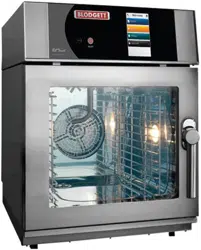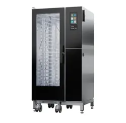
BC-20E AND BC-20G
COMBINATION OVEN STEAMER
INSTALLATION - OPERATION - MAINTENANCE
BLODGETT OVEN COMPANY
www.blodgett.com
44 Lakeside Avenue, Burlington, Vermont 05401 USA Telephone: (802) 658-6600 Fax: (802) 864-0183
PN 53455 Rev Q (3/18)
© 2018 - G.S. Blodgett Corporation

Your Service Agency’s Address:
Model
Serial number
Oven installed by
Installation checked by

TABLE OF CONTENTS
INSTALLATION
The Blodgett Combi-Oven/Steamer ........................................ 4
Description of the Combi-Oven/Steamer ................................... 5
Owner’s Responsibilities .................................................. 2
Location and Ventilation .................................................. 4
Utility Connections - Standards and Codes ................................. 5
Plumbing Connections .................................................... 6
Electrical Connections .................................................... 7
Gas Connection.......................................................... 8
Final Check and Adjustments ............................................ 10
Final Check Lists ........................................................ 11
OPERATION
Safety Information ....................................................... 12
Manual Control ......................................................... 13
MenuSelect™ Control ................................................... 15
MAINTENANCE
Spray Bottle Operating Procedure ........................................ 20
Cleaning and Preventive Maintenance .................................... 21
Flushing the Boiler ...................................................... 22
Deliming ............................................................... 23
IMPORTANT
WARNING: Improper installa-
tion, adjustment, alternation,
service or maintenance can
cause property damage, in-
jury or death. Read the instl-
lation, operation and mainte-
nance instructions thoroughly
before installing or servicing
this equipment.
INSTRUCTIONS TO BE FOL-
LOWED IN THE EVENT THE
USER SMELLS GAS MUST BE
POSTED IN A PROMINENT LO-
CATION. This information may
be obtained by contacting your
local gas supplier.
FOR YOUR SAFETY
Do not store or use gasoline or
other ammable vapors or liq-
uids in the vicinity of this or any
other appliance.
The information contained in this
manual is important for the prop-
er installation, use, and mainte-
nance of this oven. Adherence
to these procedures and instruc-
tions will result in satisfactory
baking results and long, trou-
ble free service. Please read
this manual carefully and retain
it for future reference.
ERRORS: Descriptive, typo-
graphic or pictorial errors are
subject to correction. Speci-
cations are subject to change
without notice.
4
Installation
The Blodgett Combi-Oven/Steamer
The Blodgett Combi-Oven/Steamer oers a completely
new method of cooking. With the Oven/Steamer you have
the choice of two cooking processes: Steam and Hot Air,
either...
• Separately
• Combined, or
• In Sequence
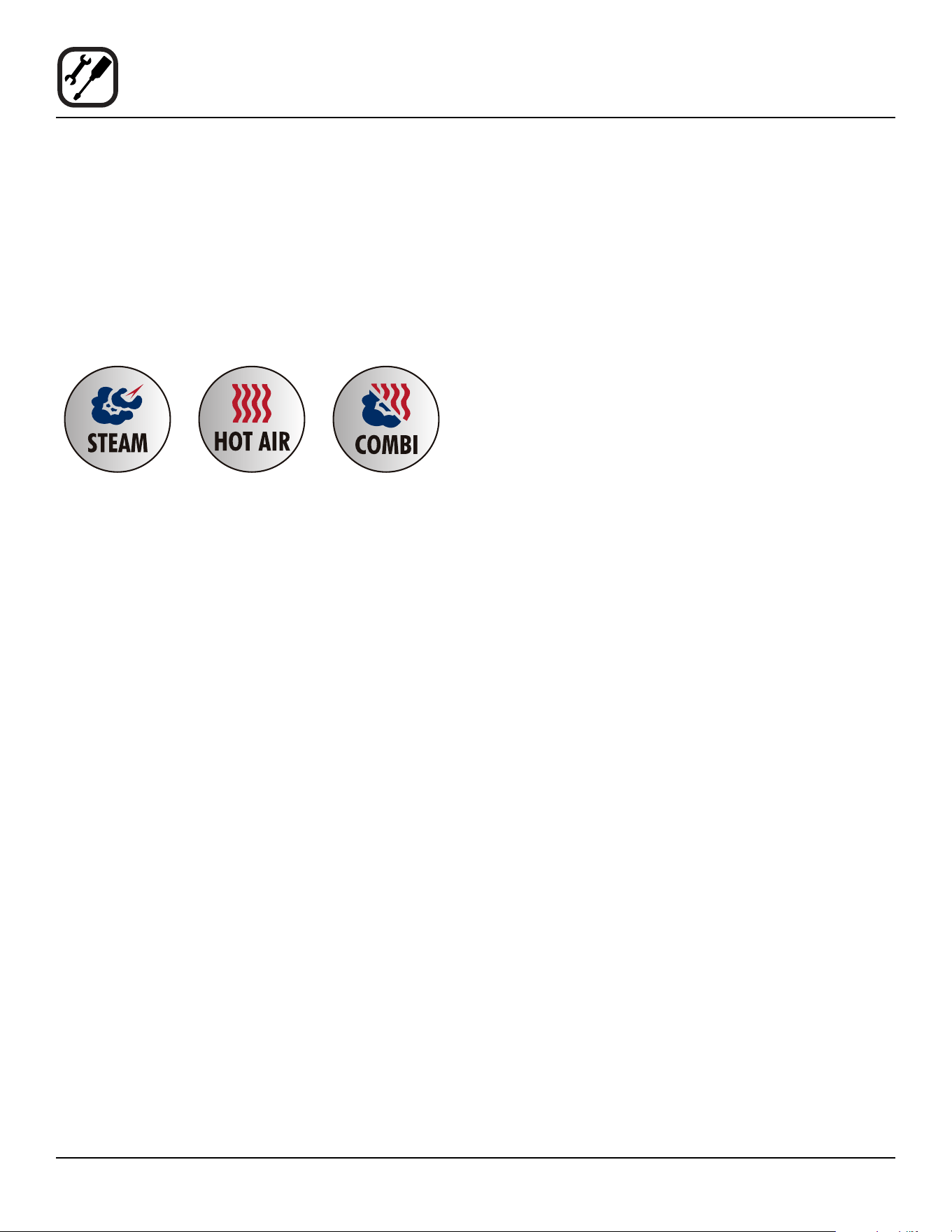
And for easy operation you can choose from three modes:
In the Steam mode you can:
steam reheat reconstitute
stew thaw simmer
blanche preserve braise
poach
In the Hot Air mode you can:
roast bake grill
gratinate broil
In the Combination Steam and Hot Air mode you can:
defrost roast rethermalize
reheat bake forced steam
You can also use two or three functions in sequence
during one cooking process. We call this:
• combi-steaming
• combi-roasting
• combi-baking
The combination of circulating hot air and steam in the
space saving, high performance Combi-Oven/Steamer
leads to improvements in the following areas:
• increased productivity in the kitchen
• a reduction in capital expenditures for multiple equip-
ment replacement
• a wider range of menu choices
• a simplied cleaning process
The work process is simplied since products are pre-
pared on or in steam table pans and trays. Food can be
cooked, stored, and transported with the same pans.
Small amounts of product can be processed eciently;
pre-cooked and convenience foods can be reheated with-
in minutes. Many frozen foods can be processed with-
out pre-thawing. This exibility in preparation reduces the
need for kettles and steam tables since there is no need
for large amounts of food to be kept warm for long periods
of time.
Today the improvement of food quality is more important
than ever. Vegetables are cooked in the Blodgett Combi-
Oven/Steamer without water at the optimal temperature
of just under 100ºC (212ºF), maintaining valuable vita-
mins, minerals, nutrients and trace elements. Cooking
meat in the Combi results in less shrinkage and a rmer,
juicier product. The Blodgett Combi-Oven/Steamer is be-
ing used more and more for baking. Steam and Hot Air
modes make it a general purpose baking appliance.

5
Installation
Description of the Combi-Oven/Steamer
ABOUT THE OVEN/STEAMER
Blodgett Combi-Oven/Steamers are quality produced us-
ing high-grade stainless steel with rst class workman-
ship.
The two speed fan, which is guarded against accidental
nger contact, is driven by a quiet and powerful motor.
The condenser draws out excess steam from the appli-
ance. Condensation and waste water, which result during
steaming and cleaning, are continuously drained.
The use of high quality insulation impedes excessive heat
radiation and saves energy.
The high performance fresh steam generator with its con-
trol system makes it possible to enjoy all of the advantag-
es of a high quality steamer at the ick of a switch. Fresh
steam enters the oven cavity without pressure and is cir-
culated at high speed. This process enables quick and
gentle cooking and ensures high quality food while pro-
viding convenient working methods. The steam generator
is completely automatic and protected from running dry.
OVEN/STEAMER OPERATION
The practical oven door, with a viewing window, has a
wide swing radius and handle which can be operated eas-
ily, even with wet or greasy hands.
Ease of operation is guaranteed through the simple ar-
rangement of the controls. Graphic symbols make the ap-
pliance easy for even inexperienced kitchen sta to oper-
ate. Steam, Hot Air and Combi modes can be selected
with one switch. The Steam On Demand feature allows
the operator to add steam at any time for up to 8 minutes
while operating in either the hot air or Combi modes. This
feature is excellent for baking as well as roasting opera-
tions. A fourth function on the mode selection switch, the
Cool Down mode, allows the oven cavity to cool down
rapidly with the door opened.
The steam on demand function allows the operator the
ability to introduce steam into the cooking process at any
time.
Cleaning is kept to a minimum. The interior is sprayed
with a self-acting cleaning solution which interacts with
steam to easily remove crusts and stains. The oven is
designed for easy care and is welded water tight so that
the internal cooking cavity may be rinsed with a hose after
the steam cleaning process.
2
Installation
Owner’s Responsibilities
PLUMBING SPECIFICATIONS - BC-20E & BC-20G
WATER
Water pressure 40 PSI min/116 PSI max
Water connection 3/4” Hose Fitting, 3/8” ID hose minimum
Water pressure regulator setting 35 PSI Preset
Minimum requirements TDS: 40-125 ppm
Hardness: 35-100 ppm
Chlorides: <25 ppm
Silica: <13 ppm
Chlorine: <0.2 ppm
Chloramine: <0.2 ppm
pH: 7.0-8.5
DRAINAGE
Drain type Atmospheric Vented Drain
Drain connection 2” O.D.
Maximum water drain temperature 140ºF (60ºC)
GAS RATINGS - BC-20G
Gas Input
Steam 90,000 BTU/HR
Hot Air 125,000 BTU/HR
Inlet Pressure to the Unit
Natural Gas 5-14” WC (1.24-3.48 kPa)
Propane 11-14” WC (2.73-3.48 kPa)
Pressure at the Manifold
Natural Gas 3.5” WC (.87 kPa)
Propane 10” WC (2.49 kPa)
3/4” MNPT connector for all US and Canadian installations
1. Oven(s) are uncrated and put in place.
2. The owner/operator must have the following plumb-
ing, gas and electrical requirements met and installed.
NOTE: Refer to the Utility Connection information
provided.
WARNING!!
Improper installation, adjustment, alteration
service or maintenance can cause property
damage, injury or death. Read the installa-
tion, operation and maintenance instruction
thoroughly before installing or servicing this
equipment.
3
Installation
Owner’s Responsibilities
ELECTRICAL RATINGS - BC-20G
VOLTAGE PHASE AMPS RECEPTACLE
115 1 20 Nema 5-20R dedicated receptacle
Blodgett recommends a Pass & Seymore, model 2095, CFCI for this oven
model due to the use of a variable frequency drive
208/240V 1 15 Nema 6-15 dedicated receptacle
ELECTRICAL RATINGS - BC-20E
Total KW Voltage Amps/Line Max Motor
3 Phase 1 Phase
61 208 170 n/a 3/4 hp
61 240 147 n/a 3/4 hp
61 480 74 n/a 3/4 hp
kW by Mode
Steam 45 kW
Hot Air 60 kW
Combi 60 kW

4
Installation
Location and Ventilation
LOCATION
The well planned and proper placement of your appliance
will result in long term operator convenience and satisfac-
tory performance.
The following clearances must be maintained between
the unit and any combustible or non-combustible con-
struction.
BC-20G
• Right side of unit - 6” (15 cm)
• Left side of unit - 6” (15 cm)
• Back of unit - 6” (15 cm)
BC-20E
• Right side of unit - 1” (2.5 cm)
• Left side of unit - 4” (10 cm)
• Back of unit - 6” (15 cm)
The following clearances are recommended, but not re-
quired, for servicing.
All Models
• Left side of unit - 12” (30 cm)
• Back of unit - 12” (30 cm)
Place the unit in an area which is free of drafts and acces-
sible for proper operation and servicing.
Keep the operating area free and clear of all combustibles
such as paper, cardboard, and ammable liquids and sol-
vents.
DO NOT place the unit on a curb base or seal to the wall;
either condition will prevent proper ventilation to the blow-
er motors. Slight unevenness can be corrected with the
adjustable legs.
All motor bearings are permanently lubricated by the
manufacturer; there is no need for additional lubrication
during the operational lifetime of the motors.
• Do not place strong sources of heat such as open
ame ranges, griddles, or charbroilers near the
oven. If such an instance exists, it is highly recom-
mended to purchase a heat shield, available from
Blodgett.
• Note that if temperatures are too high, a safety shut-
down may occur.
• Failure to comply may invalidate the oven warranty.
VENTILATION
The necessity for a properly designed and installed venti-
lation system cannot be over emphasized. The ventilation
system will allow the unit to function properly while remov-
ing unwanted vapors and products of combustion from
the operating area.
The appliance must be vented with a properly designed
mechanically driven exhaust hood. The hood should be
sized to completely cover the equipment plus an over-
hang of at least 6” (15 cm) on all sides not adjacent to a
wall. The capacity of the hood should be sized appropri-
ately and provisions made for adequate makeup air.
WARNING!!
Failure to properly vent the oven can be haz-
ardous to the health of the operator; and will
result in operational problems, unsatisfactory
baking, and possible damage to the equip-
ment. Damage sustained as a direct result of
improper ventilation will not be covered by the
Manufacturer’s warranty.
When installed in the Commonwealth of Massachusetts,
this appliance must be interlocked with the hood exhaust
system so that the appliance may be operated only
when the hood exhaust system is running.
U.S. and Canadian Installations
Refer to your local ventilation codes. In the absence of
local codes, refer to the National ventilation code titled,
“Standard for the Installation of Equipment for the Remov-
al of Smoke and Grease Laden Vapors from Commercial
Cooking Equipment”, NFPA-96- Latest Edition.
General Export Installations
Installation must conform with Local and National instal-
lation standards. Local installation codes and/or require-
ments may vary. If you have any questions regarding the
proper installation and/or operation of your unit, please
contact your local distributor. If you do not have a local
distributor, please call Blodgett Combi at 0011-802-658-
6600.
5
Installation
Utility Connections - Standards and Codes
THE INSTALLATION INSTRUCTIONS CONTAINED
HEREIN ARE FOR THE USE OF QUALIFIED INSTAL-
LATION AND SERVICE PERSONNEL ONLY. INSTAL-
LATION OR SERVICE BY OTHER THAN QUALIFIED
PERSONNEL MAY RESULT IN DAMAGE TO THE OVEN
AND/OR INJURY TO THE OPERATOR.
Qualied installation personnel are individuals, a rm,
a corporation, or a company which either in person or
through a representative are engaged in, and responsible
for:
• the installation or replacement of gas piping and the
connection, installation, repair or servicing of equip-
ment.
• the installation of electrical wiring from the electric
meter, main control box or service outlet to the elec-
tric appliance.
Qualied installation personnel must be experienced in
such work, familiar with all precautions required, and have
complied with all requirements of state or local authorities
having jurisdiction.
U.S. and Canadian installations
The installation must conform with local codes, or in the
absence of local codes, with the National Fuel Gas Code,
ANSI Z223.1/NFPA 54, or the Natural Gas and Propane
Installation Code, CSA B149.1, as applicable.
Installation must conform with local codes, or in the ab-
sence of local codes, with the National Electrical Code,
ANSI/NFPA 70-Latest Edition and/or Canadian National
Electric Code C22.1 as applicable.
Appliance is to be installed with backow prevention in
accordance with applicable federal, province and local
codes.
Australia and general export installations
Instllation must conform with Local and National instal-
lation standards. Local installation codes and/or require-
ments may vary. If you have any questions regarding the
proper installation and/or operation of your Blodgett oven,
please contact your local distributor. If you do not have a
local distributor, please call the Blodgett Oven Company
at 0011-802-658-6600.
6
Installation
Plumbing Connections
WATER CONNECTION
NOTE: Hot water maximizes steam production but is not
required. Cold water may be supplied to both in-
lets if hot water is not available.
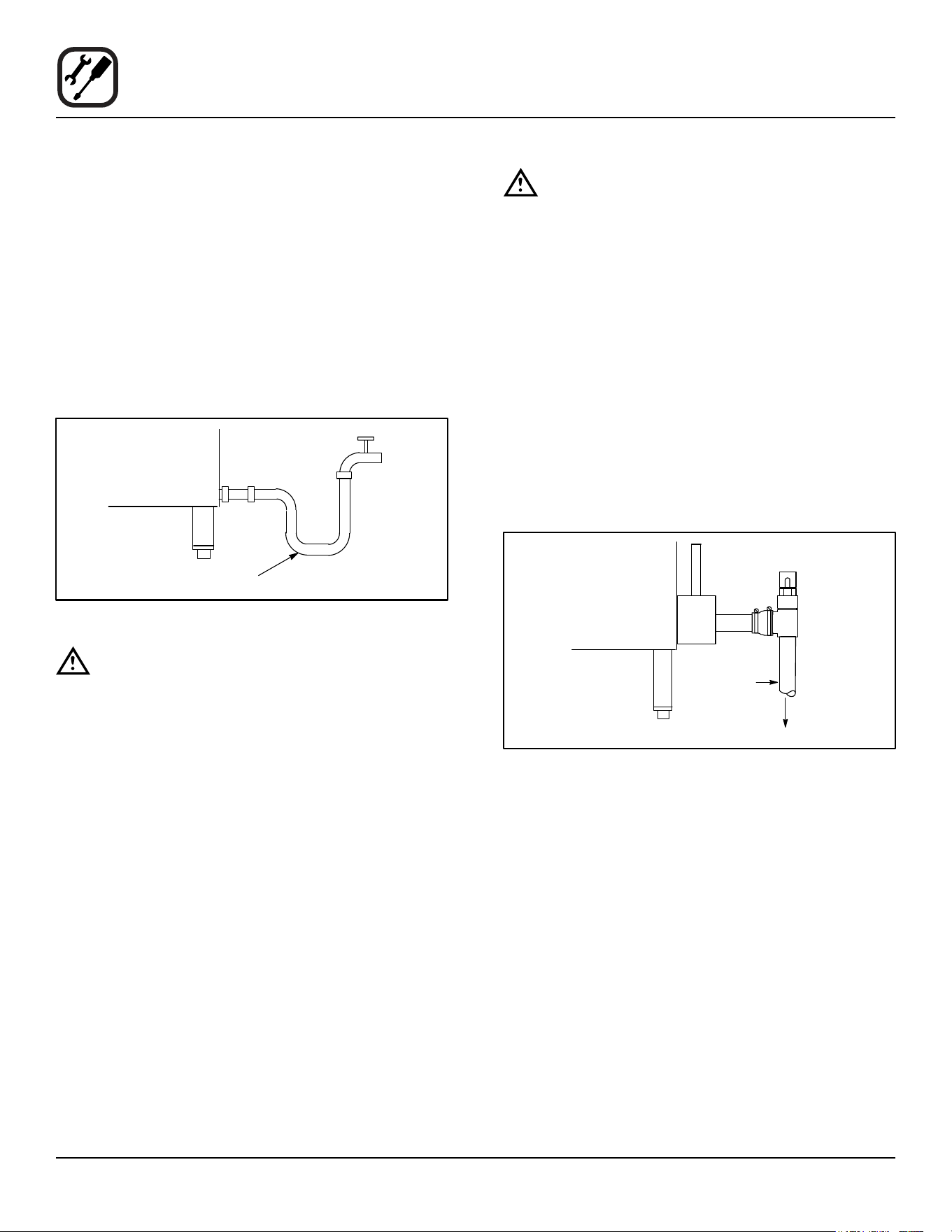
Connect the appliance to quality cold water via a pressure
hose with 3/4” (1/9 cm) couplings. Cold water is connect-
ed to the left solenoid/pressure regulator as viewed from
the rear of the oven. Hot water connection, right solenoid/
pressure regulator, to the boiler is recommended. A shut
o valve must be provided adjacent to the oven.
NOTE: Hot water must not be applied to the cold water
inlet.
1/2” Appliance Hose with 3/4”
Hose Fittings
Figure 1
WARNING!!
The use of poor quality water will invalidate
your warranty.
This product must be installed by a licensed Plumber or
Gas Fitter when installed within the Commonwealth of
Massachusetts.
DRAIN CONNECTION
A 2” (5 cm) copper pipe with standard drain pitch must
be run to an open drain or connected to a standpipe
equipped with a vent.
NOTE: The waste water can also be directed to a nearby
oor drain. Flexible hose which allows trapped
water to accumulate in sagged runs must be
avoided.
NOTE: The drain piping must consist of temperature re-
sistant material, greater than 160°F, and be of
adequate diameter not to cause ow restriction.
Improper materials may deform and cause re-
strictions, thus aecting performance.
WARNING!!
Connection must be carried out by a licensed
plumber, to an open or closed drain. The drain
must never end directly beneath the equip-
ment. The drain should not be located on the
same side the equipment controls are located.
1. Find the drain connection on the lower rear of the unit.
2. Loosen the coupling clamps. Attach a 2” (5 cm) cop-
per drain pipe to the drain connection. Retighten the
coupling clamps.
NOTE: The open end of the drain should be installed
facing the oor. Copper line, used for installation
to an open drain or oor sink, must be supplied
by the installer. Use of a trap inline will cause
drain backup.
2” Drain
Customer
Supplied
To Drain
Oven Drain
Figure 2
Specic water/drain connection for City of Los Angeles
1. Each drain line from the appliance shall be routed
without dips or sags to terminate above the ood level
rim of an approved indirect waste receptor.
2. The appliance shall be installed in accordance with
the manufacturer’s printed instructions and the LAPC
and LAMC, 1999 editions.
3. A backow protection device may be required by lo-
cal codes. If so, install on the potable water system
directly ahead of the appliance. The backow protec-
tion device shall be any of the following: an approved
pressure type vacuum breaker installed at least 12”
above the highest point of use, a double check valve
backow preventer or a reduced pressure principal
backow preventer.

7
Installation
Electrical Connections
Before making any electrical connections to these units,
check that the power supply is adequate for the voltage,
amperage, and phase requirements stated on the rating
name plate mounted on the right side of the unit.
Wiring diagrams are located on the inside of the remov-
able side panel.
NOTE: Disconnect the Power Supply to the unit Before
Servicing!
U.S. and Canadian installation
All units, when installed, must be electrically grounded
in accordance with local codes or in the absence of lo-
cal codes, with the National Electrical Code, ANSI/NFPA
70-Latest Edition and/or Canadian Electrical Code CSA
C22.1 as applicable.
General Export Installations
Installation must conform with Local and National instal-
lation standards. Local installation codes and/or require-
ments may vary. If you have any questions regarding the
proper installation and/or operation of your unit, please
contact your local distributor. If you do not have a local
distributor, please call Blodgett Combi at 0011-802-658-
6600.
WARNING!!
Improper electrical installation will invalidate
your warranty.
BC-20G only
U.S. and Canadian Installations
A power cord (115V or 230V) is supplied with a plug at-
tached. Plug the power cord into the desired receptacle.
This oven model uses a variable frequency inverter
drive. Appliances that use variable frequency inverter
drives produce high frequency noise and require lters
and shielded motor cabling. This causes higher leakage
current toward Earth Ground. Especially, at the moment
of switching ON this can cause an inadvertent trip of the
appliance’s ground fault interrupter (GFCI). Some GF-
CIs are more sensitive than others. Blodgett has quali-
ed the Pass and Seymour brand, part number 2095,
20 A, 125 VAC, 60 Hz, specication grade GFCI duplex
receptacle as being immune to the variable frequency
inverter drive’s noise. Blodgett recommends using this
specic GFCI for this model oven.
WARNING!!
If the supply cord is damaged, it must be re-
placed by a special cord or assembly available
from the manufacturer or its service agent.
8
Installation
Gas Connection
GAS PIPING
A properly sized gas supply system is essential for maxi-
mum oven performance. Piping should be sized to pro-
vide a supply of gas sucient to meet the maximum de-
mand of all appliances on the line without loss of pressure
at the equipment.
Example:
NOTE: BTU values in the following example are for natu-
ral gas.
You purchase a BC-20G to add to your existing cook line.
1. Add the BTU rating of your current appliances.
Pitco Fryer 120,000 BTU
6 Burner Range 60,000 BTU
Deck Oven 50,000 BTU
Total 230,000 BTU
2. Add the BTU rating of the new oven to the total.
Previous Total 230,000 BTU
BC-20G 125,000 BTU
New Total 355,000 BTU
3. Measure the distance from the gas meter to the cook
line. This is the pipe length. Let’s say the pipe length
is 20’ (6m) and the pipe size is 1” (2.54 cm).
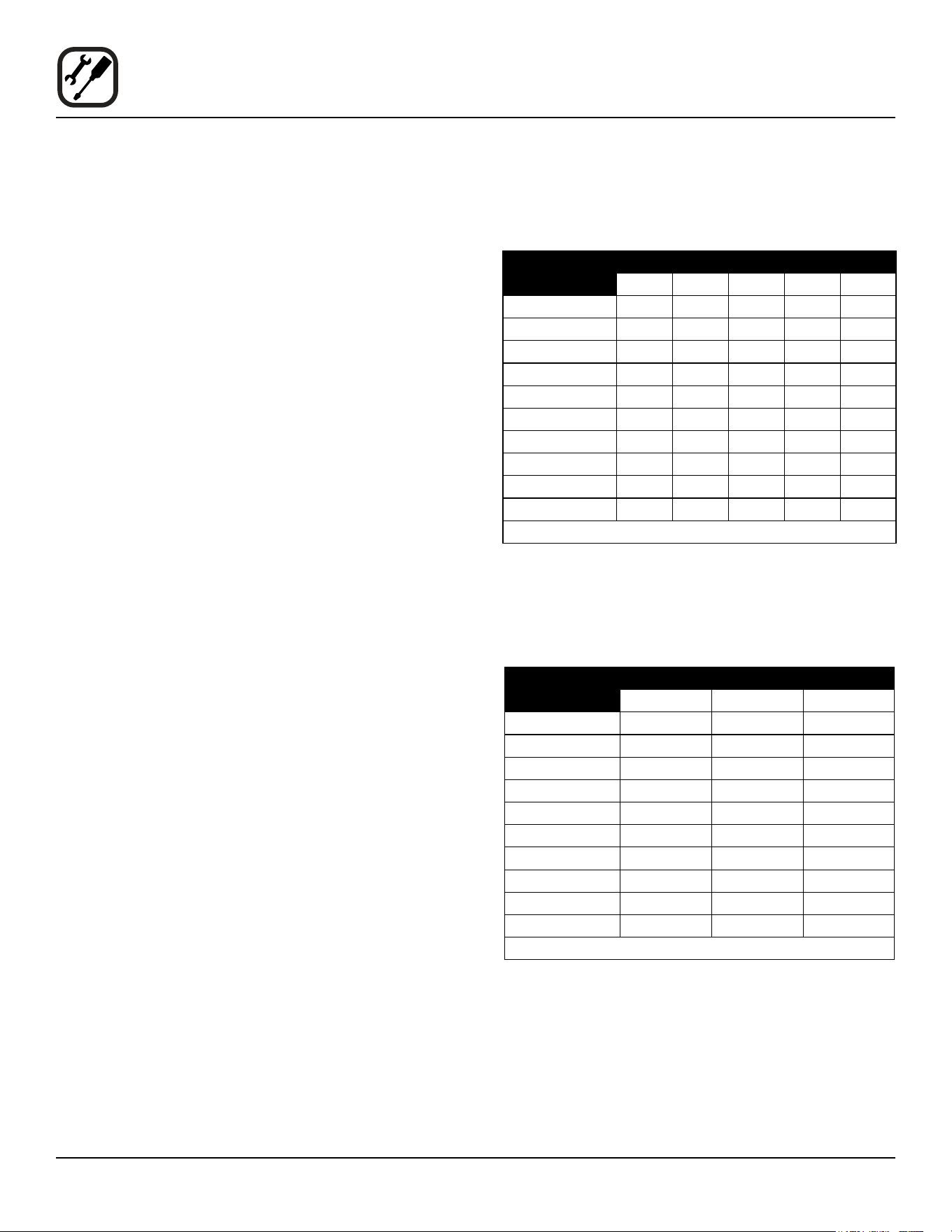
4. Use the appropriate table to determine the total ca-
pacity of your current gas piping.
The total capacity for this example is 465,000 BTU. Since
the total required gas pressure, 355,000 BTU is less than
465,000 BTU, the current gas piping will not have to be
increased.
NOTE: The BTU capacities given in the tables are for
straight pipe lengths only. Any elbows or other t-
tings will decrease pipe capacities. Contact your
local gas supplier if you have any questions.
Maximum Capacity of Iron Pipe in Cubic Feet of
Natural Gas Per Hour
(Pressure drop of 0.5 Inch W.C.)
PIPE
LENGTH (FT)
NOMINAL SIZE, INCHES
3/4” 1” 1-1/4” 1-1/2” 2”
10 360 680 1400 2100 3950
20 250 465 950 1460 2750
30 200 375 770 1180 2200
40 170 320 660 990 1900
50 151 285 580 900 1680
60 138 260 530 810 1520
70 125 240 490 750 1400
80 118 220 460 690 1300
90 110 205 430 650 1220
100 103 195 400 620 1150
From the National Fuel Gas Code Part 10 Table 10-2
Maximum Capacity of Pipe in Thousands of
BTU/hr of Undiluted L.P. Gas at 11” W.C.
(Pressure drop of 0.5 Inch W.C.)
PIPE
LENGTH (FT)
OUTSIDE DIAMETER, INCHES
3/4” 1” 1-1/2”
10 608 1146 3525
20 418 788 2423
30 336 632 1946
40 287 541 1665
50 255 480 1476
60 231 435 1337
70 215 404 1241
80 198 372 1144
90 187 351 1079
100 175 330 1014
From the National Fuel Gas Code Part 10 Table 10-15
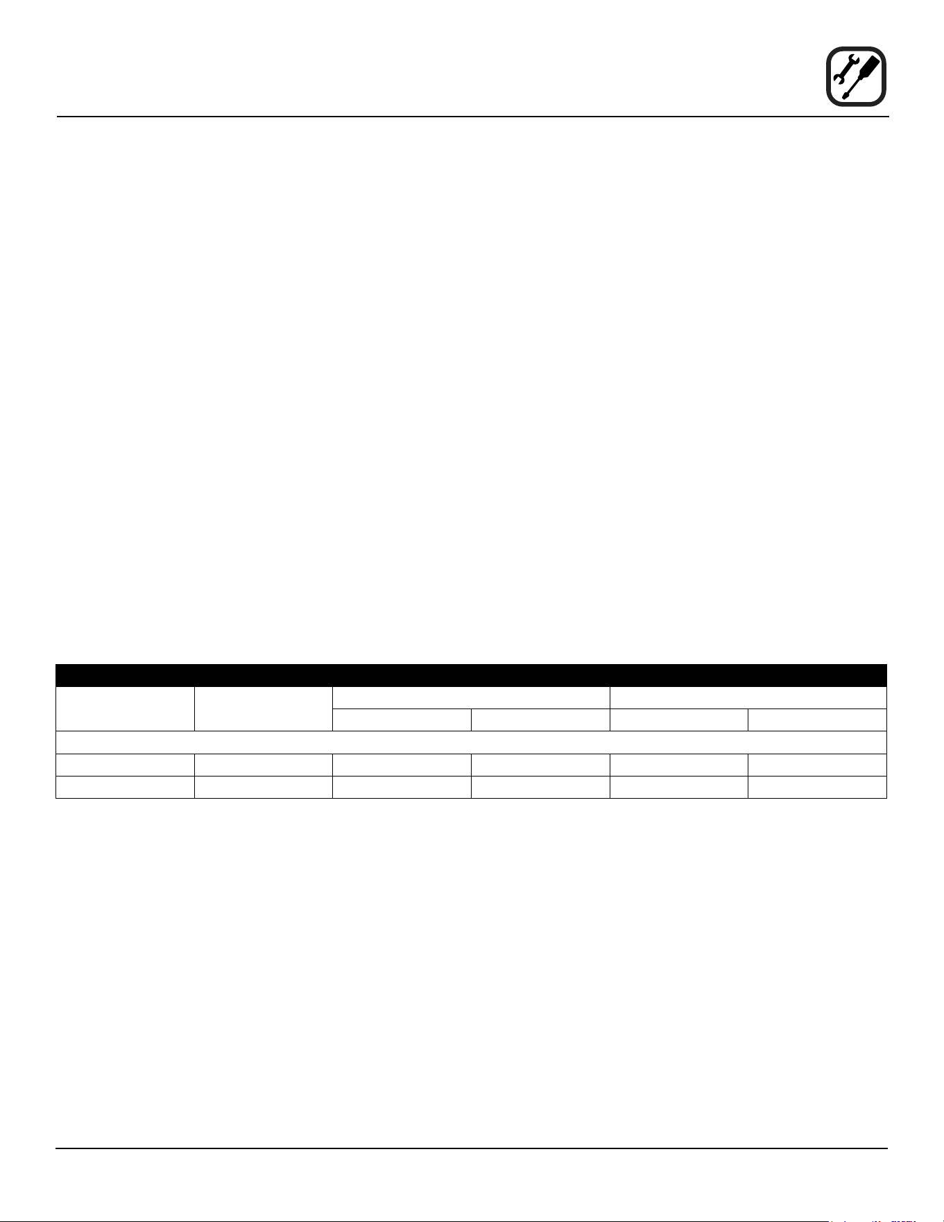
9
Installation
Gas Connection
PRESSURE REGULATION AND TESTING
The gas pressure to the appliance must be rated for each
appliance while the burners are on. A sucient gas pres-
sure must be present at the inlet to satisfy these condi-
tions. Refer to the table below for correct gas pressure.
Each appliance has been adjusted at the factory to oper-
ate with the type of gas specied on the rating plate at-
tached to the right side of the appliance.
Each oven is supplied with a regulator to maintain the
proper gas pressure. The regulator is essential to the
proper operation of the oven and should not be removed.
DO NOT INSTALL AN ADDITIONAL REGULATOR
WHERE THE UNIT CONNECTS TO THE GAS SUPPLY
UNLESS THE INLET PRESSURE IS GREATER THAN
14” W.C. (1/2 PSI) (37mbar).
The oven and its individual shuto valve must be discon-
nected from the gas supply piping system during any
pressure testing of that system at test pressures in ex-
cess of 1/2 psig (3.45kPa).
The oven must be isolated from the gas supply piping
system by closing its individual manual shuto valve dur-
ing any pressure testing of the gas piping system at test
pressures equal or less than 1/2 psig (3.45kPa).
Prior to connecting the appliance, gas lines should be
thoroughly purged of all metal lings, shavings, pipe
dope, and other debris. After connection, the appliance
must be checked for correct gas pressure.
U.S. and Canadian Installations
Installation must conform with local codes, or in the ab-
sence of local codes, with the National Fuel Gas Code,
NFPA54/ANSI Z223.1-Latest Edition, the Natural Gas
and Propane Installation Code CAN/CSA-B149.1.
General Export Installations
Installation must conform with Local and National instal-
lation standards. Local installation codes and/or require-
ments may vary. If you have any questions regarding the
proper installation and/or operation of your appliance,
please contact your local distributor. If you do not have a
local distributor, please call Blodgett Combi at 0011-802-
658-6600.
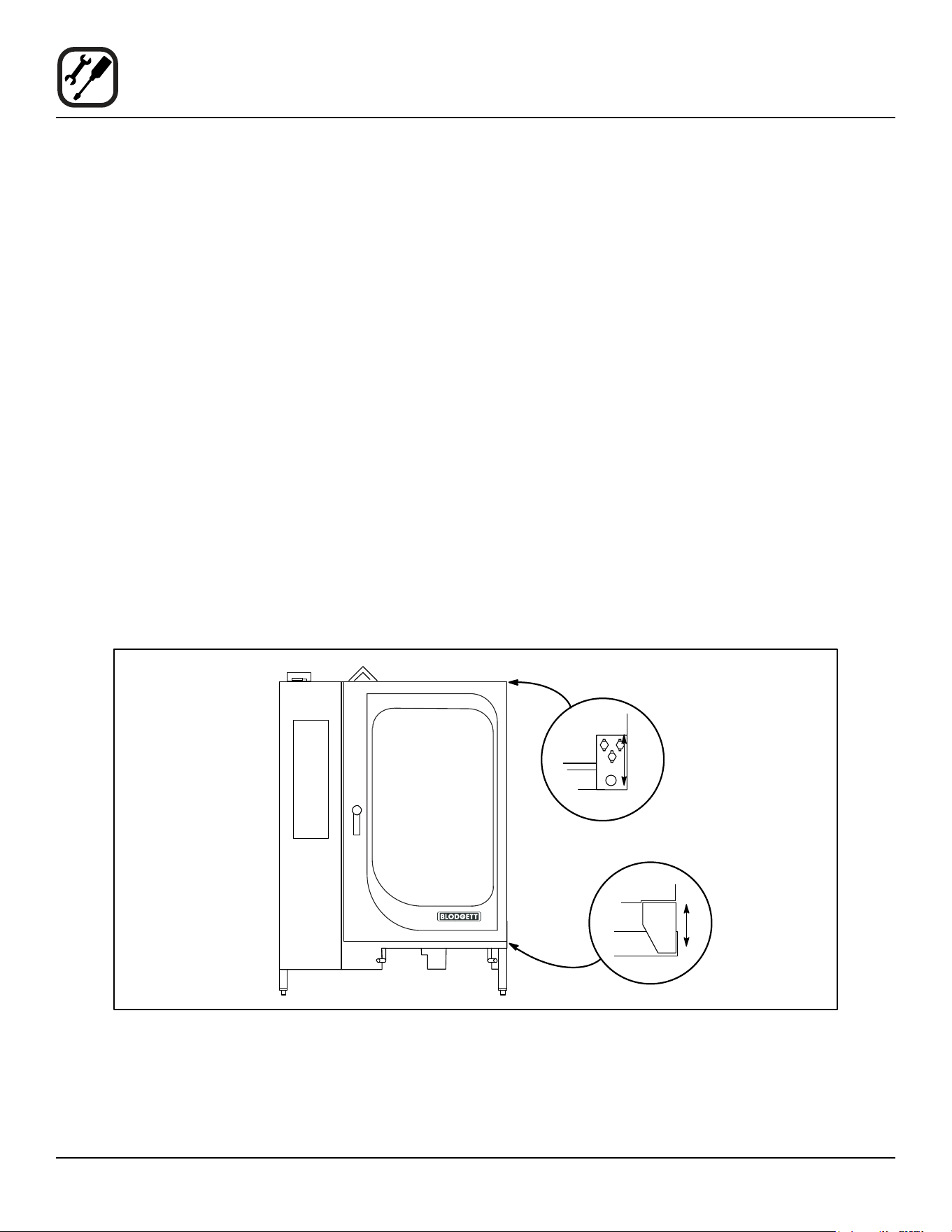
GAS PRESSURE
Gas Type Inlet Pressure Orice Size at Sea Level Manifold Pressure
Hot Air Steam Hot Air Steam
U.S. and Canadian Installations
Natural 5-14” W.C. 1/16”(.0625”) dia #58 .042” dia 3.5” W.C. 3.5” W.C.
Propane 11-14” W.C. #62 .0380” dia #70 .0280” dia 10” W.C. 10” W.C.
10
Installation
Final Check and Adjustments
BEFORE SWITCHING THE APPLIANCE ON
Before applying power to the unit for the rst time, check
for the following conditions:
• The unit is level.
• All electrical safety provisions have been adhered
to and the electrical connections are correct.
• Water is connected, turned on and all of the connec-
tions are water tight.
• Grease lters are in their proper positions
• The transport cart is inserted into the cooking cavity.
When the cart is not inserted into the unit, water can
spill onto the oor causing it to become slippery. If
the door will not close properly, use the following
adjustment procedure.
• BC-20G only - Check gas ttings with leak detection
solution.
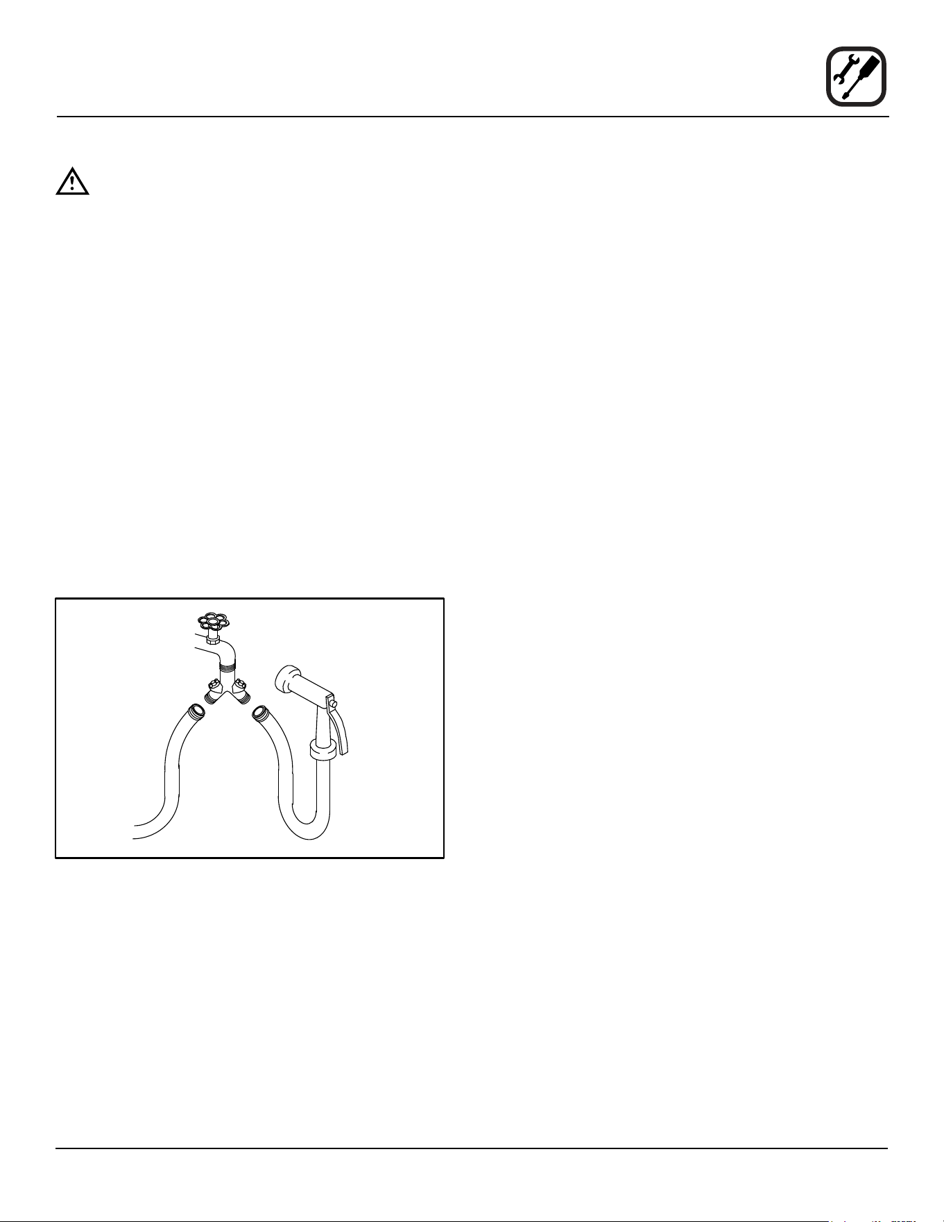
DOOR ADJUSTMENT
The hinges may be adjusted using the following proce-
dure:
1. Adjust the top hinge plate by loosening the three
mounting bolts on the top right corner of the unit.
2. Adjust the bottom hinge pin by loosening the mount-
ing bolt located under the bottom hinge plate on the
lower right corner of the oven.
3. Adjust the hinges so that the door back and the unit
face are parallel.
4. Tighten the bolts so that there is no further movement.
5. The adjustment is correct when the door closes
rmly and no steam leaks from the gasket.
The hinges can also be adjusted as follows:
1. Adjust the door catch by loosening the four mounting
screws located on the inside surface of the oven door.
2. The adjustment is correct when no steam leaks
from the gasket. DO NOT over compress the door
gasket. When closed the door should slightly com-
press the door gasket.
Oven
Door
Oven
Door
Figure 3
11
Installation
Final Check Lists
WARNING!!
Final check list must be performed by a quali-
ed installer only.
ELECTRICAL CONTROL COMPARTMENT
• Voltage to appliance matches rating plate
PLUMBING FINAL CHECK
• Incoming water pressure within appliance specica-
tion.
• Atmospheric vented drain in place.
• Water solenoid properly bracketed and not leaking.
• Water feed lines intact without leaks.
• Ensure proper clearance.
• Delime system has been primed.
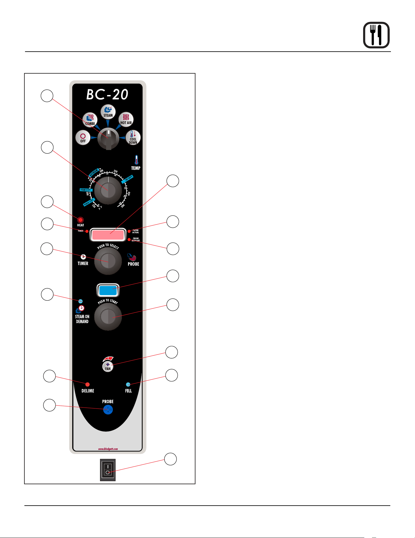
• Optional Spray Hose connected properly. Connect
the optional spray hose to the ll solenoid as shown.
Cold Water
Supply
Hose and Spray
Option
To Oven Fill
Manifold
Figure 4
OVEN OPERATIONAL TESTS
NOTE: Checks to be made by customer or authorized
service agent.
Cool Down Mode
• Check that the fan runs with the door open.
Steam Mode
Place in STEAM mode and set thermostat to 212ºF
(100ºC). Verify the following:
• Heat demand lamp is on.
• Heat demand lamp shuts o at approximately 212ºF
(100ºC).
• Set timer for 1 minute. Be sure the buzzer sounds
when the time expires.
• Unit produces steam, window fogs, door seal does
not leak.
Combi Mode
Place in COMBI mode, set thermostat to 350ºF (177ºC)
and verify:
• Heat demand lamp is on (manual and digital controls
only).
• Oven is heating.
• Heat demand lamp shuts o at 350ºF (177ºC) and
oven maintains 350ºF (177ºC) (manual and digital
controls only).
• Fan shuts o with door open.
Hot Air Mode
Place in HOT AIR mode and set thermostat to 400ºF
(204ºC) and verify:
• Heat demand lamp is on.
• Oven is heating.
• Heat demand lamp shuts o at 400ºF (204ºC) and
oven maintains 400ºF (204ºC).
• Fan shuts o with door open.
Steam On Demand Mode
Place in Hot Air mode. Set Steam On Demand for 1 min-
ute. Press the Steam On Demand button and verify:
• Steam demand lamp is on.
• Steam demand lamp shuts o after approximately 1
minute.
Fan Speed
• Ensure both fan speeds work.

12
Operation
Safety Information
The information contained in this section is provided for
the use of qualied operating personnel. Qualied operat-
ing personnel are those who have carefully read the in-
formation contained in this manual, are familiar with the
functions of the oven and/or have had previous experi-
ence with the operation of the equipment described. Ad-
herence to the procedures recommended herein will as-
sure the achievement of optimum performance and long,
trouble-free service.
Please take the time to read the following safety and op-
erating instructions. They are the key to the successful
operation of your Blodgett oven.
SAFETY TIPS
For your safety read before operating
What to do if you smell gas:
• DO NOT try to light any appliance.
• DO NOT touch any electrical switches.
• Use an exterior phone to call your gas supplier im-
mediately.
• If you cannot reach your gas supplier, call the re
department.
What to do in the event of a power failure:
• Turn all switches to o.
• DO NOT attempt to operate the oven until the power
is restored.
NOTE: In the event of a shut-down of any kind, allow a
ve (5) minute shut o period before attempting to
restart the oven.
General safety tips:
• DO NOT use tools to turn o the gas control. If the
gas cannot be turned o manually do not try to re-
pair it. Call a qualied service technician.
• If the oven needs to be moved for any reason, the
gas must be turned o and disconnected from the
unit before removing the restraint cable. Reconnect
the restraint after the oven has been returned to its
original location.
• DO NOT remove the control panel cover unless the
oven is unplugged.
• The hand shower spray nozzle supplied to wash
down the oven interior is NOT for use with potable
water.
13
Operation
Manual Control
1
3
2
4
5
6
8 7
10
9
11
13
12
15
14
16
Figure 5
CONTROLS IDENTIFICATION
1. MODE SELECTOR SWITCH - turns power to the
oven on or o. Allows selection of Steam, Hot Air,
Combi or Cool Down Modes.
2. DISPLAY - displays time and temperature informa-
tion.
3. TEMPERATURE DIAL - used to set desired cooking
temperature.
4. HEAT LAMP - lights when the oven is calling for heat
5. TIMER LED - lights when the cook time is displayed
6. PROBE ACTUAL LED - lights when the actual probe
temperature is displayed
7. PROBE SETPOINT LED - lights when the core set-
point temperature is displayed
8. TIMER/PROBE KNOB - use to select and set either
cook time or probe temperature
9. STEAM ON DEMAND DISPLAY - displays the steam
on demand time
10. STEAM ON DEMAND LAMP - lights when steam on
demand is activated.
11. STEAM ON DEMAND KNOB - use to set duration for
steam on demand
12. FAN SPEED KEY - used to select fan speed.
13. DELIME LAMP - Flashes when steam generator de-
liming is needed. Remains steady when deliming pro-
cess is active.
14. FILL LAMP - illuminated until the steam generator is
lled with water.
15. PROBE CONNECTION - used to connect the core
temperature probe to the control.
16. GAS/HEAT CONTROL SWITCH - used to turn gas or
heat on or o.

14
Operation
Manual Control
TIMER COOKING
1. Press the TIMER/PROBE KNOB (8) to select the
timer mode. The TIMER LED lights.
2. Turn the MODE SELECTOR Switch (1) to the desired
function.
3. Set the TEMPERATURE DIAL (3) to the desired cook
temperature.
For Steam mode, set the temperature no higher than
212ºF (100ºC).
For poaching, turn the temperature dial to the POACH
position, 180ºF (82ºC).
The optimum temperature for Combi mode is 300-
350ºF (149-177ºC).
4. When the oven has reached the cook temperature,
load the product.
5. Rotate knob to enter the desired cook time in the
display. You can clear the display by rotating counter
clockwise. The timer begins on its own.
6. The temperature, time and mode can be altered at
any time during the cooking process.
7. When the timer reaches 00:00, the buzzer sounds.
Press or rotate the TIMER/PROBE KNOB (8) counter
clockwise to silence the buzzer. Remove the product.
PROBE COOKING
1. Press the TIMER/PROBE knob (8) to select the
probe setpoint mode. The PROBE SETPOINT LED
(7) lights.
2. Rotate the knob to enter the desired nal cook tem-
perature in the display.
3. Insert the core probe into the product. Load product
into the oven and close the door. Be sure that the
terminal end of the core probe is outside of the oven
and clear of the door.
4. Connect the core probe to the PROBE CONNEC-
TION (15) at the bottom of the control.
5. The display gives the actual core probe temperature
by pressing the TIMER/PROBE knob (8) again.
6. When the product reaches the nal cook temperature
the buzzer sounds.
COOL DOWN
NOTE: The unit can be cooled down rapidly for steaming,
cleaning, etc.
1. To cool down the oven cavity, open the door and se-
lect Cool Down on the MODE SELECTOR Switch (1).
STEAM ON DEMAND
How to set the Steam On Demand feature:
While in the Hot Air or Combi mode, the unit can be set
to steam for a timed period. At the end of the timed cycle
the unit reverts back to the original setting. Steam On De-
mand can be used at any time during the cook cycle.
NOTE: Steam On Demand is not available in steam
mode.
1. Turn the STEAM ON DEMAND KNOB (11) to set the
desired length of time. The time is displayed in the
STEAM ON DEMAND DISPLAY (9).
2. Press the STEAM ON DEMAND KNOB (11). The
STEAM ON DEMAND LAMP (10) lights.
Uses for Steam On Demand:
Most of the ideas came from our creative customers. Ex-
periment with this feature on your own and let us know of
any new uses.
• Add a minute or two at the beginning when baking
bread for a shiny crust.
• Kick start large loads such as 20 or more chickens.
By starting large loads with 5 to 8 minutes of steam
you help the oven recover and cut the cooking time
by more than 10%.
• Bake bagels without boiling. By starting raw bagels
with 1 to 2 minutes of steam you can achieve a
beautiful crust.
• Cream caramel is great at 230ºF to 250ºF in the
Combi mode using 2 minutes of on demand steam.
• When cooking chicken wings, try setting the oven
in the Combi mode at 375ºF and use 3 minutes of
Steam On Demand. This method will stop the tips
from burning. Total cooking time is approximately 12
minutes.
• Pork ribs tend to pull o the bone better when using
5 to 8 minutes of Steam On Demand. Try ribs in the
Combi mode at 350ºF.
15
Operation
MenuSelect™ Control
5
6
8
7
3
1
2
4
11
9
10
13
12
14
15
16
17
19
18
20
21
22
Figure 6
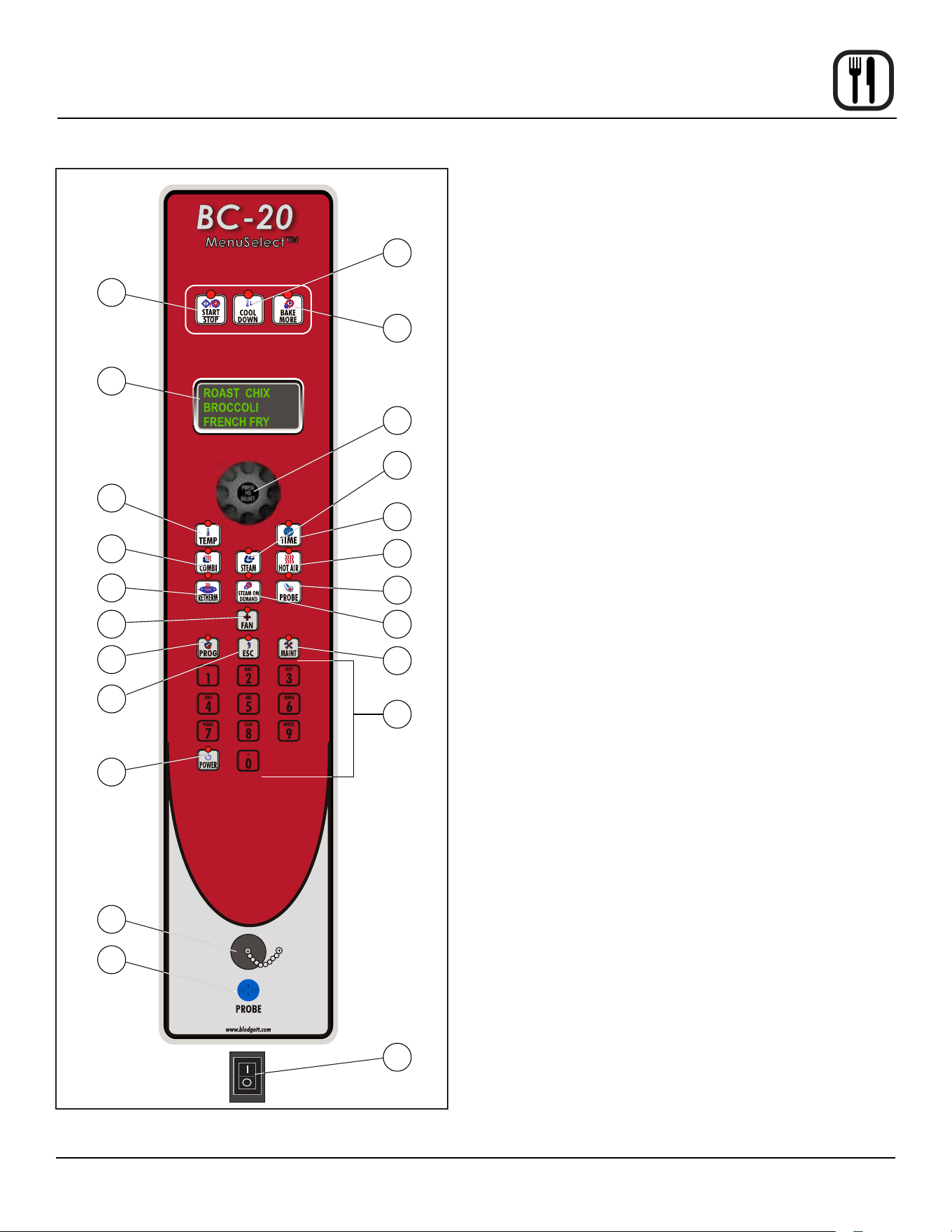
CONTROL DESCRIPTION
1. START/STOP KEY - press to start, cancel or pause
the bake
2. COOL DOWN KEY - initiates oven cool down cycle
3. BAKE MORE KEY - press at the end of a bake cycle
to add additional bake time in one minute increments.
4. DISPLAY - displays time or temperature and other in-
formation related to oven function and/or programming.
5. DIAL - used to enter set points, time, and program-
mable settings. Also used to select the programmed
product.
6. TEMP KEY - used to set or change the bake tempera-
ture
7. TIME KEY - used to set or change the bake time.
8. COMBI KEY - press to enter combi mode
9. STEAM KEY - press to enter steam mode
10. HOT AIR KEY - press to enter hot air mode
11. RETHERM KEY - press to enter retherm mode, this
mode uses steam to reheat frozen or precooked prod-
uct. Retherm has a temperature limit of 250-300ºF.
12. STEAM ON DEMAND KEY - used to initiate steam in-
jection cycle
13. PROBE KEY - press to use core probe cooking
14. FAN KEY - press to select the fan speed
15. PROGRAM KEY - press to enter product programming
and save programmed settings.
16. ESCAPE KEY - press to back up one step during pro-
gramming
17. MAINTENANCE KEY - press to enter manager pro-
gramming and save programmed settings
18. ALPHA/NUMERIC KEYPAD - used to program reci-
pes.
19. POWER KEY - used to place control in and out of
standby mode.
20. OPTIONAL USB PORT - used to upload/download
product recipes
21. CORE PROBE CONNECTION - plug core tempera-
ture probe in here when using probe cooking
22. GAS/HEAT CONTROL SWITCH - used to turn gas or
heat on or o.

16
Operation
MenuSelect™ Control
OVEN STARTUP
1. Be sure the gas shuto switch or circuit breaker
switch below the control panel are in the on position.
The display ashes OFF PRESS POWER KEY TO
START.
NOTE: If the real time clock and auto wake up func-
tions are enabled the display reads PRESS
POWER KEY TO START AUTO START.
2. Press the POWER KEY (19). The display reads
PREHEAT and the oven heats to the last manual set
temperature in the hot air mode. The display ashes
READY / IDLE and the alarm beeps 5 times when the
oven is at temperature and ready to bake.
MANUAL COOKING
1. Turn the DIAL (5) until the display reads MANUAL.
2. Press the TIME KEY (7). Rotate the dial, or use the
alpha/numeric keypad to enter the desired bake time.
Press the center of the dial to set the bake time.
NOTE: Time is set in one minute increments using
the dial. To set time in less than one minute
increments use the alpha/numeric keypad.
3. Press the TEMP KEY (6). Rotate the dial, or use the
alpha/numeric keypad to enter the desired bake tem-
perature. Press the center of the dial to set the bake
temperature. The oven preheats to the new tempera-
ture.
NOTE: Temperature is set in 5 degree increments
using the dial. To set time in less than 5 de-
gree increments use the alpha/numeric key-
pad.
4. Press the desired mode key, combi, steam, hot air or
retherm.
If Combi or Retherm are selected, rotate the dial, or
use the alpha/numeric keypad to enter the desired
percentage of steam.
NOTE: Retherm has a temperature limit of 250-
300ºF.
5. When the display ashes READY / IDLE, open the
door. Load the product.
6. Press the START/STOP KEY (1) to begin the bake
cycle. The timer counts down and the display alter-
nates between the cooking mode and the name of
the product.
PROGRAMMED COOKING
1. Turn the DIAL (1) until the name of the product is
highlighted. Press the center of the dial to select. The
oven preheats to the programmed temperature in the
correct cooking mode. The display ashes READY /
IDLE and the alarm beeps 5 times when the oven is
at temperature and ready to bake.
2. Open the door. Load the product.
3. Press the START/STOP KEY (1) to begin the bake
cycle. The timer counts down and the display alter-
nates between the cooking mode and the name of
the product.
PROBE COOKING
1. Press the PROBE key (13) to select the probe mode.
The display reads CORE PROBE COOK & HOLD.
Turn the dial to select either YES or NO. Press the
center of the dial to select.
If YES is selected, Cook & Hold has been enabled. In
the Cook & Hold mode, the oven cavity lowers to the
product pull temperature as the product cooks.
If NO is selected, Cook & Hold has not been enabled
the cavity maintains the cook temperature.
2. Turn the DIAL to enter the desired product pull tem-
perature in the display. Press the center of the dial to
save the pull temperature.
3. Press the TEMP KEY (6). Rotate the dial, or use the
alpha/numeric keypad to enter the desired bake tem-
perature. Press the center of the dial to set the bake
temperature. The oven preheats to the new tempera-
ture.
NOTE: Temperature is set in 5 degree increments
using the dial. To set time in less than 5 de-
gree increments use the alpha/numeric key-
pad.
4. Press the desired mode key, combi, steam, hot air or
retherm.
If Combi or Retherm are selected, rotate the dial, or
use the alpha/numeric keypad to enter the desired
percentage of steam.
NOTE: Retherm has a temperature limit of 250-
300ºF.
5. Insert the core probe into the product. Load product
into the oven and close the door. Be sure that the
terminal end of the core probe is outside of the oven
and clear of the door.

17
Operation
MenuSelect™ Control
6. Connect the core probe to the PROBE CONNEC-
TION (21) at the bottom of the control.
NOTE: Do not connect the probe before the cook
mode has been selected.
7. The display gives the actual core probe temperature
as well as the oven set temperature.
8. When the product reaches the pull temperature the
buzzer sounds.
9. Press the START/STOP KEY (1) to silence the buzz-
er.
If using Cook & Hold - The cavity temperature contin-
ues to drop to the product pull temperature and the
display counts up, telling the operator long the prod-
uct has been held. Disconnect the core probe and
remove the product when ready.
If not using Cook & Hold - The cavity remains at the
cook temperature. The display does not count up.
Disconnect the core probe and remove the product
when the buzzer sounds.
DURING ANY COOK CYCLE
Steam On Demand
While in the Hot Air, Combi or retherm modes, the unit can
be set to steam for a timed period of up to 20 minutes.
At the end of the timed cycle the unit reverts back to the
original setting. Steam On Demand can be used at any
time during the cook cycle.
1. Press the STEAM ON DEMAND KEY (12).
2. Rotate the dial, or use the alpha/numeric keypad to
enter the desired steam on demand time. Press the
center of the dial to initiate Steam on Demand cycle.
NOTE: Steam on Demand time is set in one minute
increments using the dial. To set time in less
than one minute increments use the alpha/
numeric keypad.
3. The Steam on Demand LED ashes until the steam
time has expired.
Pause a Bake Cycle
1. To pause a cook cycle, press the START/STOP KEY
(1). The LED on the start/stop key ashes. The bake
cycle will pause until the key is pressed again.
Cancel a Cook Cycle
1. To cancel the cook cycle, press and hold the START/
STOP KEY (1).
AT THE END OF ANY COOK CYCLE
1. An alarm sounds, the display reads DONE.
2. If more bake time is desired, press the BAKE MORE
KEY (3). This will add an additional one minute of time
for each press of the key.
3. When you are satised with the bake, press the
START/STOP KEY (1) to silence the alarm. Open the
door to remove the product.
OVEN SHUTDOWN
1. Press the COOL DOWN KEY (2). The display reads
AUTO COOL DOWN ACTUAL TEMP. To speed up
the cool down process, open the door.
2. When the oven has cooled down, the display reads
OFF PRESS POWER KEY TO START.

18
Operation
MenuSelect™ Control
PRODUCT PROGRAMMING
Entering the Program Mode
1. Press the PROGRAM KEY (15). If the control is pass-
word protected, the display reads ENTER CODE.
Use the alpha/numeric keypad to enter the manager
passcode 3124, then press the center of the dial to
enter the program mode.
Naming a Product Recipe
NOTE: Use the following procedure to name a new prod-
uct or edit the name of an existing product.
1. For a new recipe, turn the dial to the rst open prod-
uct. Press the center of the dial to select.
To edit an existing name, rotate the dial to the name
to be changed. Press the center of the dial to select.
2. Use the dial to scroll down to Edit Name. Press the
center of the dial to enter the edit name menu.
3. Turn the dial or use the alpha/numeric keypad to se-
lect the rst character. Press the center of the dial to
advance to the next character. Repeat for all remain-
ing characters.
NOTE: Product names may be up to 10 characters
long and can contain spaces. Use the #1 key
to insert spaces in a recipe name.
NOTE: To select letters using the keypad, press the
appropriate key once if you need the rst let-
ter on the key, twice for the second and three
times for the third. For example to enter the
letter L press the #5 key three times.
4. Press the PROG KEY (15). With SAVE highlighted,
press the dial to save the product name.
Programming a Product Recipe
NOTE: The control can hold 99 recipes. Each recipe may
have up to 6 cooking stages.
1. Turn the dial to highlight the name of the product to
be programmed. Press the center of the dial to select
the product.
2. The display reads PRODUCT NAME: STAGE 1.
Press the center of the dial to select the stage.
3. Rotate the dial, or use the alpha/numeric keypad to
enter the desired bake time. Press the center of the
dial to set the bake time.
NOTE: Time is set in one minute increments using
the dial. To set time in less than one minute
increments use the alpha/numeric keypad.
4. Rotate the dial to select the desired cooking mode.
Choose from combi, steam, hot air or retherm. Press
the center of the dial to set the cook mode.
If Combi or Retherm are selected, rotate the dial, or
use the alpha/numeric keypad to enter the desired
percentage of steam.
5. Rotate the dial, or use the alpha/numeric keypad to
enter the desired cook temperature. Press the center
of the dial to set the bake temperature.
NOTE: Temperature is set in 5 degree increments
using the dial. To set time in less than 5 de-
gree increments use the alpha/numeric key-
pad.
NOTE: Retherm has a temperature limit of 250-
300ºF.
6. Rotate the dial to select the desired fan speed.
Choose from, low, high. Press the center of the dial to
set the fan speed.
7. Use the dial to scroll down to PRODUCT NAME:
STAGE 2. Press the center of the dial to select stage
2.
8. Repeat steps 2-7 for all remaining stages.
9. When all stages have been programmed, press the
PROGRAM KEY (15). To save the programming, use
the dial to scroll to YES. Press the center of the dial.
The control exits the program mode.
USING THE USB PORT
1. With the power on, remove the cover of the USB port
(20) and insert the USB drive.
2. Press the MAINTENANCE KEY (17).
3. Turn the dial to highlight MANAGER PROGRAM.
Press the center of the dial to select.
4. Turn the dial to highlight either COPY RECIPE FROM
USB or COPY RECIPE TO USB, then press the cen-
ter of the dial to select.
5. When the transfer is complete, press any key to re-
turn to the menu.
6. Turn the dial to highlight EXIT. Press the center of
the dial to select. The display returns to the previous
menu.
7. Turn the dial to highlight EXIT. Press the center of the
dial to select.

19
Operation
MenuSelect™ Control
MANAGER PROGRAMMING
Entering the Manager Program Mode
1. Press the MAINTENANCE KEY (17). If the control
is password protected, the display reads ENTER
CODE. Use the alpha/numeric keypad to enter the
manager passcode 3124, then press the center of the
dial to enter the program mode.
2. Turn the dial to highlight OVEN SETUP. Press the
center of the dial to select the product.
Programming Auto Start
NOTE: The Auto Start function enables the oven to turn
on at a programmed time of day and preheat to a
programmed temperature.
1. Turn the dial to highlight AUTO START. Press the
center of the dial to select.
2. Turn the dial to select either ON or OFF. Press the
center of the dial to select.
If ON is selected, the display reads AUTO START 24
HOUR TIME 00:00. Turn the dial to enter the time you
would like the oven to begin preheating. Press the
center of the dial to select.
The display reads AUTO START TEMP XXX. Turn
the dial to enter the desired preheat temperature.
Press the center of the dial to select.
Programming Oven Setup
These menus allow the manager to set up basic oven
functions
1. Turn the dial to highlight OVEN SETUP. Press the
center of the dial to select.
2. Turn the dial to highlight MANAGER PROGRAM.
Press the center of the dial to select.
3. Turn the dial to highlight the oven function you with to
change. Press the center of the dial to select. Choose
from the following functions:
Recipe Password - Select YES or NO to enable
password protection on recipe programming. If YES
is selected the passcode 3124 must be entered to
change recipe programming.
Temp Unit - Select either degrees F or C.
Cool Down Temp - Select the set temperature for the
oven to achieve in Cool Down mode
Temp Disp Rate - Set the rate, in seconds, at which
the display switches between actual and setpoint
temperature
Input Rsp Time - Set the length of time allowed to in-
put each variable when programming recipes before
control automatically exits out
Setback Time - When not used for a period of time,
the oven temperature will automatically reduce to
conserve energy. This variable sets the length of time
the oven remains at the idle temperature before being
lowered.
Ready Beep - Select either ON or OFF. This is the au-
dible alarm that sounds when the oven has reached
the set temperature.
Cook Done Beep - Select either ON or OFF. This is
the audible alarm that sounds when the product cook
time has expired.
Cook Cool Fan - Select either YES or NO. This func-
tion allows the control to display OPEN OVEN DOOR
when you are attempting to lower the set temperature
of the oven.
Restore Manual SE - Select either YES or NO. This
variable enables the oven to remember the last set-
tings used for manual cooking.
Boiler Set Temp Preheat - Select the temperature in
the boiler when it is in stand by
Boiler Set Temp Cook - Select the temperature in
the boiler when steam is being produced
Delime Fill Time - Set the length of time the boiler
continues to ll with deliming solution beyond the
standard water level in order to ensure all of the scale
present in the boiler is removed.
Delime Interval - Set the length of time between de-
liming intervals
Delime Time - Set the time during the day when the
display alerts the user to delime
Flush Interval - Set the length of time between boiler
ushes
Flush Time - Set the time during the day when the
display alerts the user to ush the boiler
4. After editing a function, press the center of the dial to
save.
5. When all desired functions have been edited, turn the
dial to highlight EXIT. Press the center of the dial to
exit the manager programming mode.
20
Maintenance
Spray Bottle Operating Procedure
NOTE: Only use a commercial oven cleaner/degreaser
with the spray bottle. DO NOT use chemicals that
are not intended as oven cleaners. See chemical
manufacturer’s information for intended use.
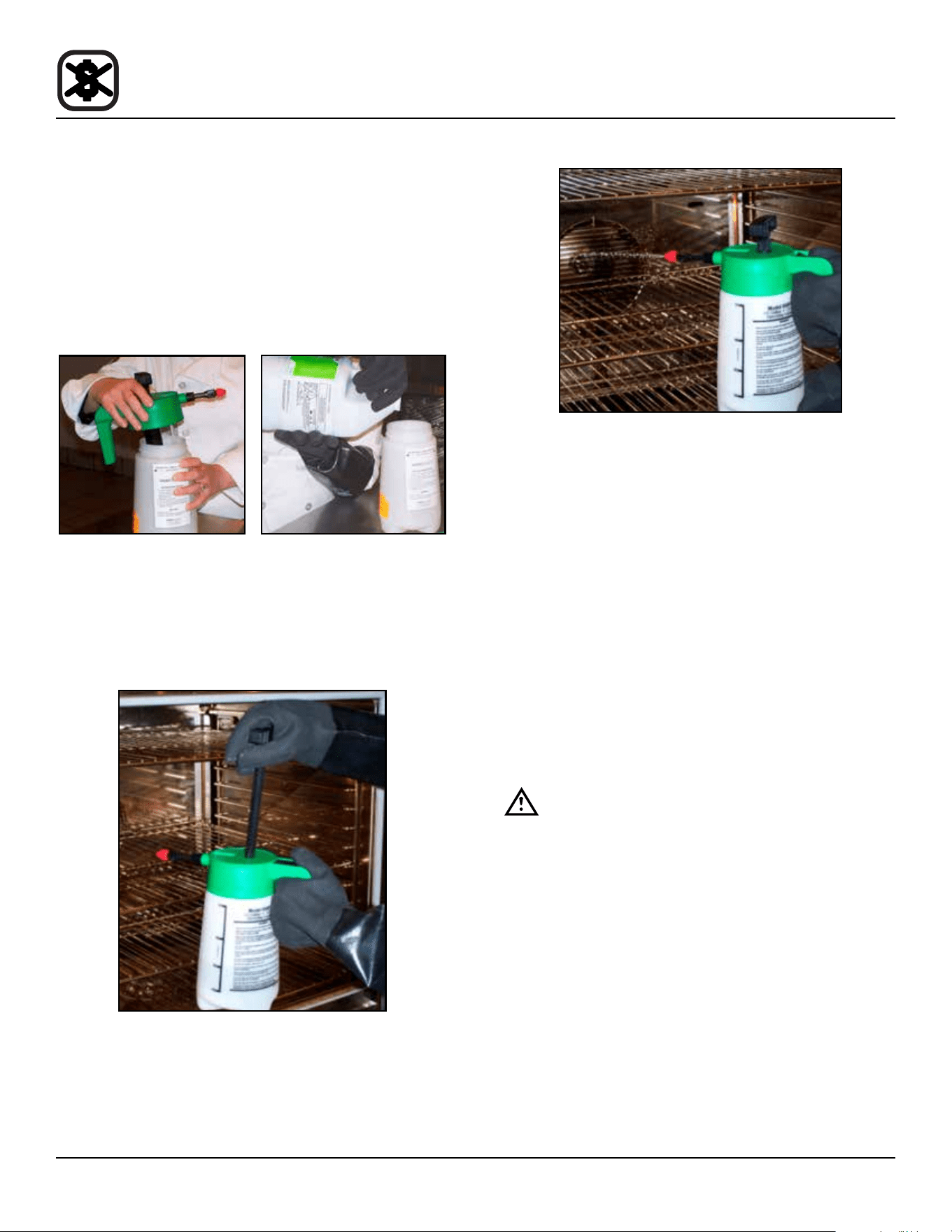
1. Unscrew the sprayer head and ll the container to
the MAX mark. Screw the head assembly on rmly
to ensure an airtight seal. The liquid must be clean
and free from foreign matter. Do not overll - space
must be left for compressing air.
Figure 7
2. To build up pressure, pump approximately 20 full
strokes when the container is lled with liquid. The
higher the pressure, the ner the spray. If the con-
tainer is only partially lled, then more pumping is re-
quired to compress the additional air space.
Figure 8
3. To spray, depress the trigger with your thumb.
Figure 9
4. Adjust spray nozzle for a wide spray pattern.
5. After a period of spraying, the pressure will drop. Re-
store the pressure by operating the air pump.
6. Release pressure after use by inverting the spray
head and depressing the trigger or by slowly un-
screwing the spray head assembly which will allow
air to escape from around the lling aperture.
7. After use, rinse the spray bottle with clean water and
check that the hole in the nozzle is perfectly clean
and clear. Warm water (not hot) used with a house-
hold detergent is a useful cleaning agent for this pur-
pose.
NOTE: Further information can be found in the in-
struction leaet supplied with your spray bot-
tle.
WARNING!!
Protective clothing and eyewear should be
worn while using cleaning and deliming
agents.
To order additional bottles or spray heads use the follow-
ing part numbers:
Complete Spray Bottle - P/N R0006
Spray Head Repair Kit - P/N R6332
21
Maintenance
Cleaning and Preventive Maintenance
DAILY CLEANING
Cleaning the Interior
Daily cleaning of the oven is essential for sanitation, and
to ensure against operational diculties. The stainless
steel cavity may corrode with improper cleaning of the
oven. Use an oven cleaning detergent in conjunction with
the supplied spray bottle.
For dicult cleaning, allow the spray-on oven cleaner to
work longer before rinsing.
1. Open the oven door. Place the oven in cool down
mode. Let the oven cool to below 140ºF (60ºC).
2. Fill the spray bottle with a mild oven detergent. DO
NOT use abrasive cleaners on your Blodgett
Combi. Be sure to follow the MSDS or safety in-
structions on the bottle of your oven cleaner. We
recommend the following cleaners:
Greasecutter Plus by Ecolab
EZ Clean by Cellow
Advance Oven Cleaner by Diversey-Lever
3. Pump the bottle twenty times to build up pressure.
The higher the pressure, the ner the spray. Spray
the oven interior. Turn the nozzle to adjust the spray
pattern.
4. Close the door. Place the oven in steam mode for 10
minutes.
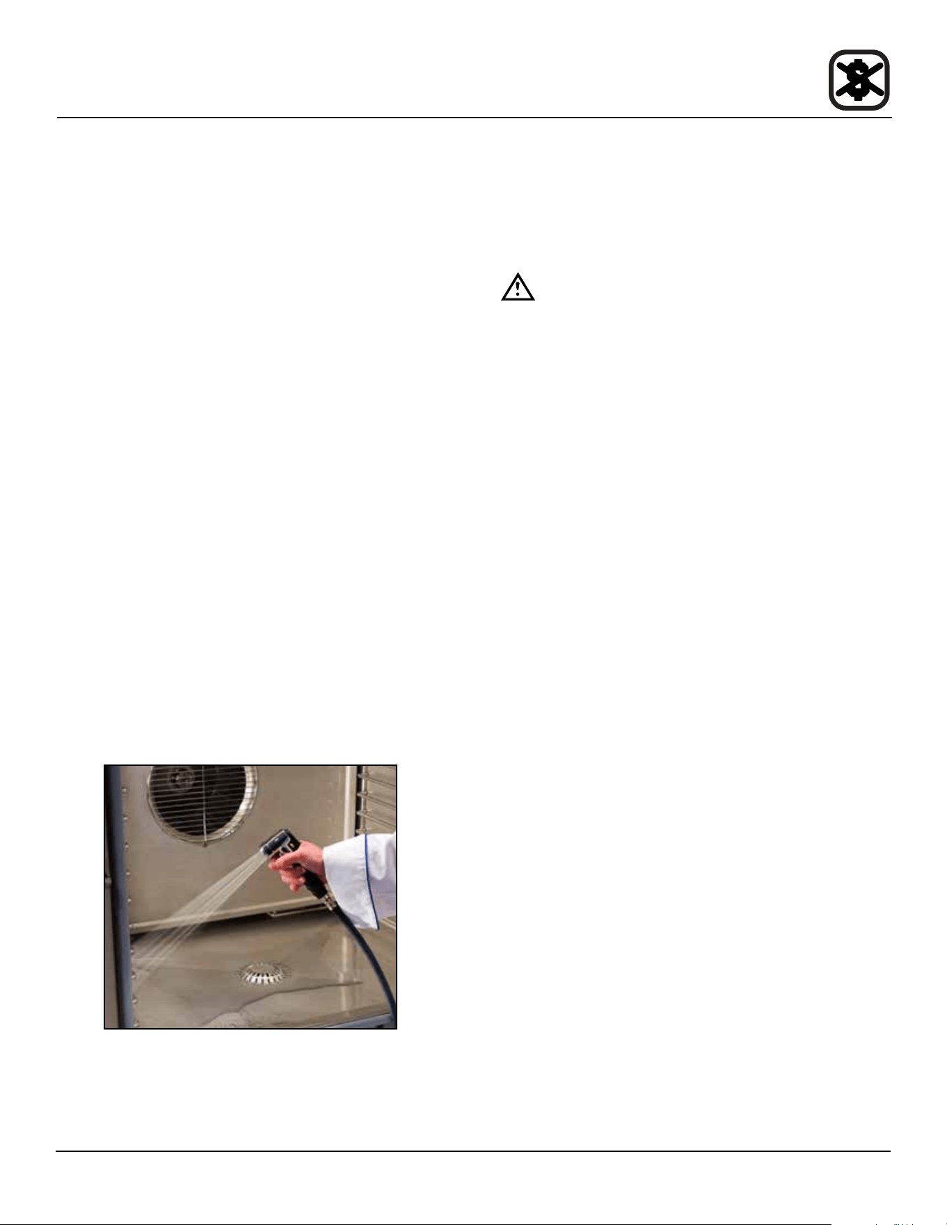
5. When nished steaming, open the door and rinse the
interior with the attached spray hose.
Figure 10
6. Leave the door open overnight to vent the oven. If the
oven will not be used for an extended period of time,
place the oven in hot air mode to dry.
Cleaning the Exterior
The exterior of the appliance may be cleaned and kept in
good condition with a light oil. Saturate a cloth and wipe
the appliance when it is cold; wipe dry with a clean cloth.
WARNING!!
DO NOT spray the outside of the oven with
water or clean with a water jet. Cleaning with
a water jet can impregnate chlorides into the
stainless steel, causing the onset of corro-
sion.
Clean the air intake / cooling fan behind the oven so that
it is free of all lint, grease or other inhibitors of air ow.
Keeping this area free of obstruction will extend the life of
the components.
PREVENTIVE MAINTENANCE
The best preventive maintenance measures are the
proper initial installation of the equipment and a program
for cleaning the appliance routinely. The Oven/Steamer
requires no lubrication. Contact the factory, the factory
representative or a local Blodgett Combi service com-
pany to perform maintenance and repairs should they be
required.
WEEKLY CLEANING - ALL MODELS
In addition to the daily cleaning it is necessary to clean
the air intakes on a weekly basis. Air intakes provide nec-
essary cooling air to the internal components. They are
generally located on the rear and sides of the equipment.

22
Maintenance
Flushing the Boiler
STANDARD CONTROL
A ush of the boiler is required every 24 hours and hap-
pens either automatically or can be initiated at any time.
NOTE: In order to ush the oven, the water and gas sup-
ply must be left on.
• If the mode switch is in the OFF position and a ush
is required, the ush will automatically run.
• If the boiler is too hot to drain, the ush will begin
when the boiler water temperature drops below
140ºF (60ºC).
To manually initiate a ush sequence
1. If the oven is hot, place it in the Cool Down mode with
the door open until the cavity is below 140ºF (60ºC).
2. Close the door, turn the mode switch to the Cool
Down position. Push and hold the timer knob until the
ush begins.
NOTE: If the boiler water temperature is too high, the
ush will start automatically when the water
temperature drops below 140ºF (60ºC).
3. The ush completes in about 25 minutes. When com-
plete, the oven shuts o automatically.
To cancel a ush sequence
1. Push and hold the Steam on Demand knob. The dis-
play reads “FLUSH ABORT NO”.
2. Rotate the timer knob until the display reads “FLUSH
ABORT YES”. Push in the timer knob to cancel the
ush.
If the ush was required and tries to start again, push
and hold the timer knob until 24:00 appears in the
display. Rotate the knob to enter the amount of time
(HH:MM) desired before the next automatic ush se-
quence.
MENUSELECT™ CONTROL
A ush of the boiler is required every 24 hours and hap-
pens either automatically or can be initiated at any time.
NOTE: In order to ush the oven, the water and gas sup-
ply must be left on.
• If the oven is o (the display reads “OFF - PRESS
POWER KEY TO START”) and a ush is required,
the ush will automatically run.
• If the boiler is too hot to drain, the ush will begin
when the boiler water temperature drops below
140ºF (60ºC).
To manually initiate a ush sequence
1. If the oven is hot, place it in the Cool Down mode with
the door open until the cavity is below 100ºF (38ºC).
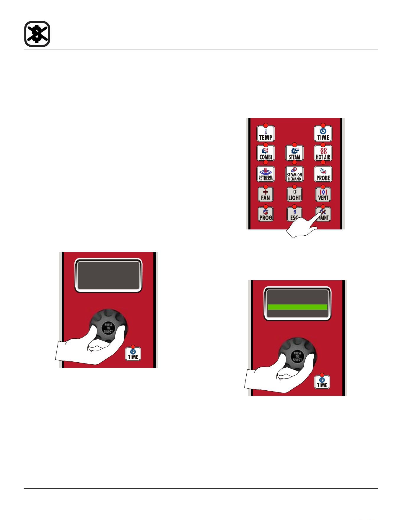
2. Close the door, press the MAINT key, turn the knob
until “FLUSH” is highlighted. Push the knob to select.
3. Scroll to “START FLUSH”. Push the knob to select.
4. The display reads “FLUSH PROGRAMMING - START
FLUSH - NO”. Rotate the knob until the display reads
“FLUSH PROGRAMMING - START FLUSH - YES”.
Push the knob to select.
5. The ush completes in about 25 minutes. When com-
plete, the oven shuts o automatically.
To cancel a ush sequence
1. Press the ESC key. The display reads “NEXT FLUSH
TIME - HH:MM 24:00”. Rotate the knob or use the
keypad to enter the amount of time (HH:MM) desired
before the next automatic ush sequence.

23
Maintenance
Deliming
Deliming of the steam generator is the single most im-
portant preventative maintenance task. Lime will build up
inside the steam generator, reducing eciency and caus-
ing damage to the boiler.
WARNING!!
Problems caused by insucient deliming are
not covered by the warranty.
WARNING!!
Deliming solutions are hazardous and can
cause burns to the skin and eyes. Wear pro-
tective clothing and eyewear.
WARNING!!
DO NOT cook while deliming.
1. Be sure the container delivering the deliming agent to
the appliance is full. Be sure to follow the MSDS or
safety instructions on your deliming agent. Use a
non-diluted deliming agent.
Figure 11
2. Ensure that the deliming pump has been primed. Re-
fer to the Deliming System Connection & Priming if
you are uncertain.
BC WITH STANDARD CONTROL
This control comes equipped with a delime lamp to in-
dicate when the steam generator needs to be delimed.
The delime lamp will ash when the steam generator has
been run for the preset interval. This is a warning only,
the oven can be used all day before deliming. The delime
sequence can be run at anytime regardless of the ashing
delime indicator.
Figure 12
NOTE: Once the deliming process has been started, the
oven cannot be used until deliming is complete,
approximately 45 minutes.
Deliming the Boiler with the Standard Control
1. If the oven is hot, place in the Cool Down mode with
the door open until the cavity is below 140ºF (60ºC).
2. With the mode switch in Cool Down, push and hold
the Steam on Demand knob until the delime lamp
ashes faster. Then release the knob. The display
reads “TO START DELIME TURN MODE SWITCH
TO OFF”.
Figure 13
3. Close the oven door. Turn the oven to the O mode.
The display reads “DELIME STEP 1 OF 14”.
The remainder of the process is automatic. The de-
lime lamp stays lit until deliming is completed.
24
Maintenance
Deliming
4. When the delime lamp goes out, the oven can be
used normally.
To Cancel the Deliming Process
1. To cancel the deliming process, push and hold the
Steam on Demand knob. The display reads “DELIME
ABORT NO”.
2. Rotate the timer knob until the display reads “DELIME
ABORT YES”. Push the timer knob.
If the delime process was not required or chemical
has not been pumped into the boiler yet, the delime
is immediately cancelled.
If chemical is in the boiler, the delime process will ad-
vance to step 9 of the process in order to ush the
chemical from the boiler.
BC WITH MENUSELECT™ CONTROL
When it is time to delime your BCX, the display reads
“DELIME REQUIRED START DELIME YES”. To postpone
the delime, turn the knob until the display reads “DELIME
REQUIRED START DELIME NO”. Push the knob.
DELIME REQUIRED
YES
START
DELIME
Figure 14
The message will return until the unit is delimed. This is a
warning only, the oven can be used all day before delim-
ing. The delime sequence can be run at anytime.
NOTE: Once the deliming process has been started, the
oven cannot be used until deliming is complete,
approximately 45 minutes.
Deliming the Boiler with the MenuSelect™ Control
1. If the oven is hot, place in the Cool Down mode with
the door open until the cavity is below 140ºF (60ºC).
2. After the cool down the unit will automatically turn it-
self o. Close the door. Press the maintenance key.
If a delime is required when the power key is pressed,
the display reads “DELIME REQUIRED START DE-
LIMING YES”. In this case, skip to step 5.
Figure 15
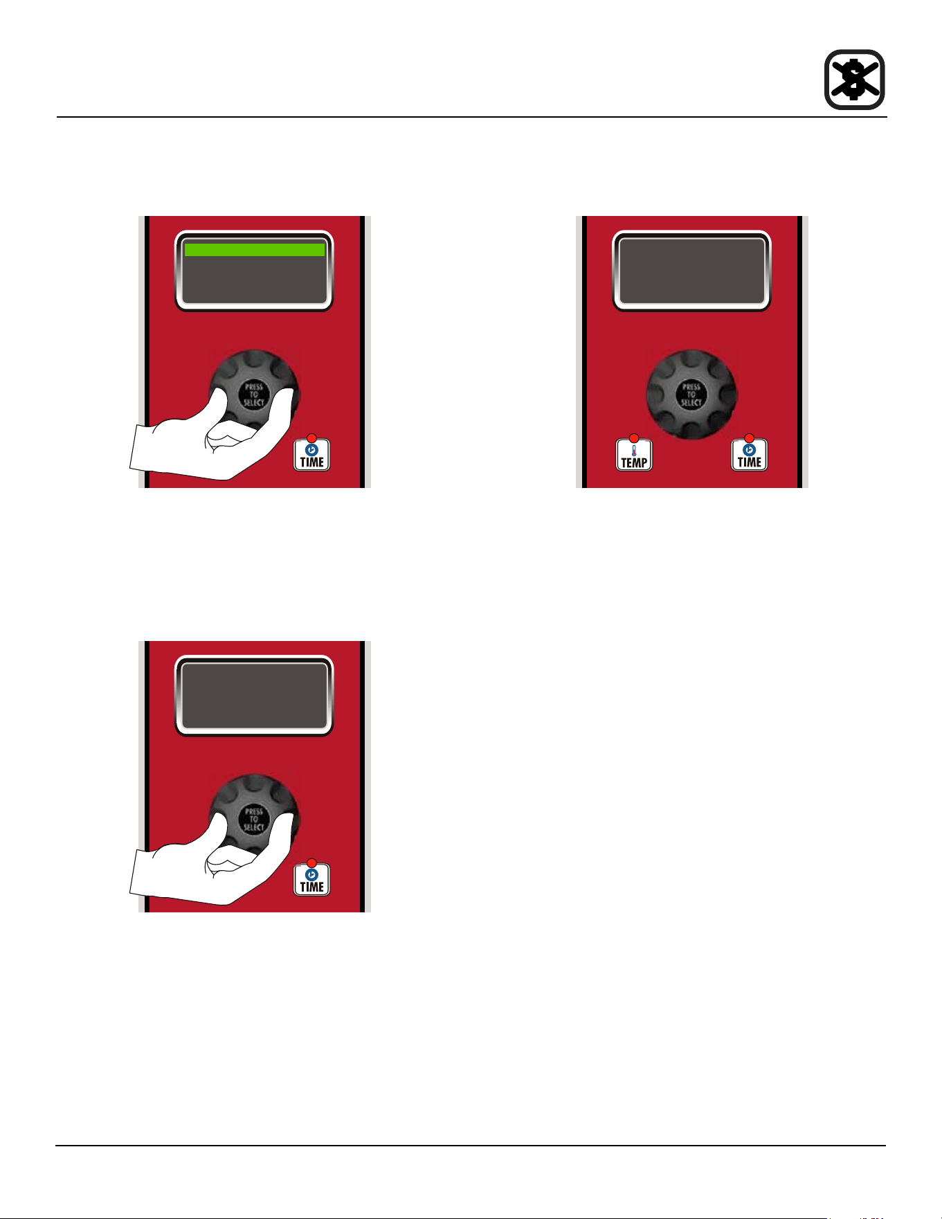
3. Turn the dial to highlight “DELIME”. Press the center
of the dial to select.
1. OVEN SETUP
2. SERVICE
3. DELIME
4. FLUSH
Figure 16
25
Maintenance
4. Turn the dial to highlight “START DELIME”. Press the
center of the dial to select.
1. START DELIME
2. DELIME INT 2 DY
3. NEXT DELIME
4. DELIME TIME
Figure 17
5. Turn the dial to highlight YES, this conrms that you
want to begin the deliming process. Press the center
of the dial to select. The remainder of the process is
automatic. The display shows the step number and
progress by %.
DELIME PROGRAMMING
YES
START
DELIME
Figure 18
6. When the deliming process is complete, the control
will turn itself o. The oven can now be used normally.
ENERGY SAFE MODE
SET TEMP XXXF
Figure 19
To Cancel the Deliming Process
1. To cancel the deliming process, push and hold the
ESC key. The display reads “DELIME ABORT? NO”.
2. Rotate the knob until the display reads “DELIME
ABORT? YES”. Press the knob to select.
3. The control returns to the O mode.
Deliming
26
Maintenance
Deliming
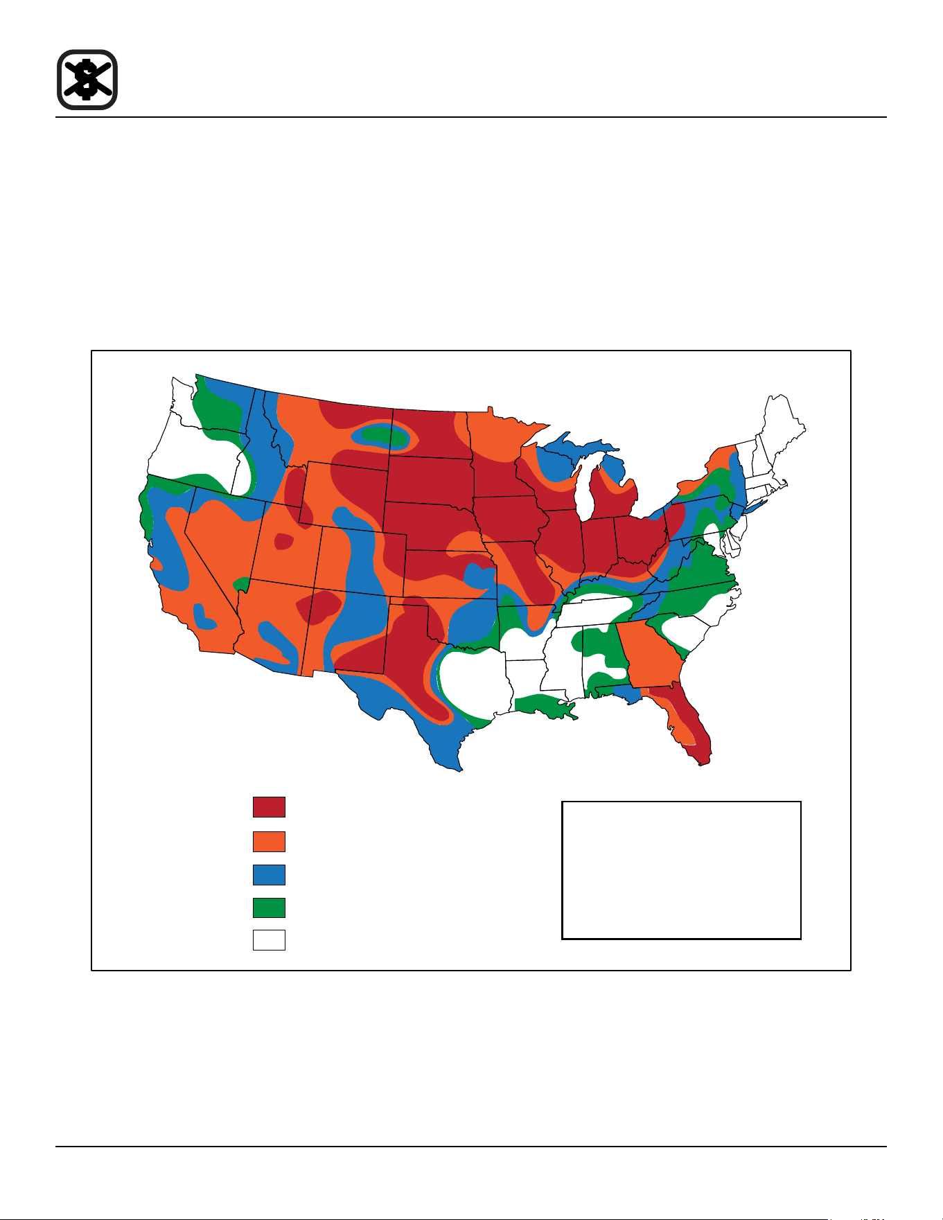
DELIMING INTERVAL SETTING
Refer to gure to determine the correct deliming inter-
val for your appliance. Find your location and the corre-
sponding potentiometer setting. These values are general
and are guidelines only. Your specic water quality may
be harder or softer. Adjust the deliming interval to your
specic water quality.
NOTE: If you have the oven connected to a lter system,
the water hardness may be reduced. Check with
lter supplier for details.
Figure 20
Over 14 gpg
10 to 14 gpg
7 to 10 gpg
3 to 7 gpg
Less than 3 gpg
Extremely Hard Setting A
Very Hard Setting B
Hard Setting B
Moderately Hard Setting C
Slightly Hard Setting C
Canadian Water Quality
Most of Canadian water contains 112
mg/L (8 gpg).
This would place Canada in the hard
water catagory and setting B should be
used. If your water exceeds 196 mg/L
(14 gpg), setting A should be used.