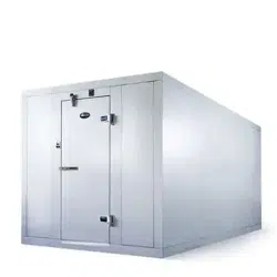
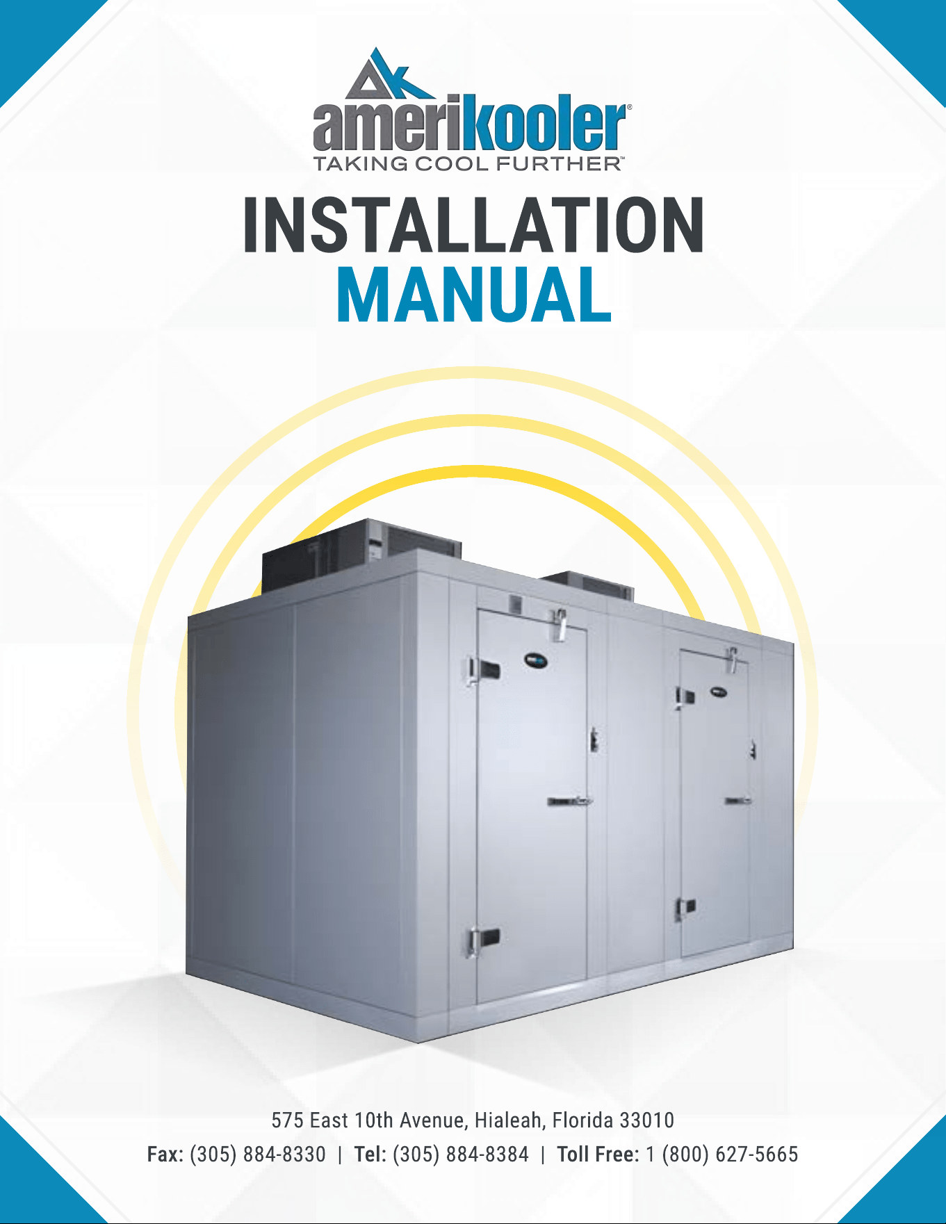
Installatio
MANUAL
575 East 10th Avenue, Hialeah, Florida 3301
Fax: (305) 884-8330 | Tel: (305) 884-8384 | Toll Free: 1 (800) 627-5665
Table of Contents
Introduction 2
Product Safety 3
Certications 4
Types of Units 5-7
Overview 5
Features & Finishes 5-7
Materials and Equipment 8-9
Provided Materials
8
Additional Materials and Equipment 9
Drawings and Panel Labels 10-11
Drawings 10
Panel Labels 11
Shipping Inspection 12-13
Installation Preparation and Unpacking 14-17
Cooler and Freezer Installation 18-27
Overview and Drawings 18-19
Unit Assembly with Floor 20-22
Unit Assembly Floorless 2
3
-27
E
v
aporator and Condenser Installation 28-3
6
Powering the Unit 37-38
Unit Start-Up 39-41
A
dditional Installations 42-51
Installation
B
est Practices 52-53
Troubleshooting
&
F
AQ
54-
6
4
T
roubleshooting 54-58
FA
Q
59-
6
4
1
2
introduction
Welcome to the Amerikooler Installation Manual
Here you will learn the steps to properly install Amerikooler walk-in coolers and freezers.
You will learn about the materials and equipment used for installation, best practices,
common troubleshooting scenarios, and more.
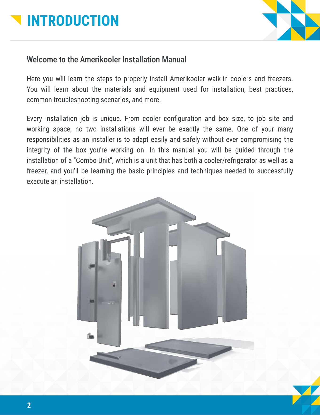
Every installation job is unique. From cooler conguration and box size, to job site and
working space, no two installations will ever be exactly the same. One of your many
responsibilities as an installer is to adapt easily and safely without ever compromising the
integrity of the box you're working on. In this manual you will be guided through the
installation of a "Combo Unit", which is a unit that has both a cooler/refrigerator as well as a
freezer, and you'll be learning the basic principles and techniques needed to successfully
execute an installation.

3
Product Safety
At Amerikooler, we're dedicated to exceeding expectations in product quality and
safety. Here are some of the key factors that set us apart:
Professional Engineering Practices: Utilizing professional engineering principles, we
conduct thorough research, development, and prioritize user safety in the creation of our
products.
Adherence to Industry Standards: Our products are meticulously designed to meet or
surpass industry performance and safety regulations.
Manufacturing Excellence: Our manufacturing process strictly adheres to professional
standards in purchasing, production, and quality control to ensure consistent product
reliability and safety.
Stringent Testing Protocols: Every product undergoes comprehensive reviews and
professional testing, focusing on function, reliability, and overall safety.
Transparent Representation: Information provided in our advertising and product literature
is presented in an informative and factual manner to assist customers in making informed
product selections.
C
o
m
prehensi
v
e
D
ocu
m
entation: Our products come with clear and complete installation,
operation, and maintenance instructions, ensuring prolonged and satisfactory performance.
Safety
C
onsiderations:
Pre
v
ent Slip
H
a
z
ards:
K
eep the walk
-
in
oor free of items that may cause slipping, such as spilled
liquids, food particles, or moisture.
M
aintain a clean and dry
oor surface at all times.
Regular
Inspections:
Regularly inspect non-skid oor strips on ramps and oor surfaces, replacing them
if worn. Check the refrigeration system, door gaskets, and hardware to prevent moisture on the walk-in
oor, ceiling, or walls.
L
i
m
it Entry
D
oor Exposure:
A
void leaving entry doors open for more than
ve minutes, as this can lead to
e
x
cessive condensation.
V
inyl strip curtains can be used to reduce the entry of warm moist air and
mitigate potential issues on the walk
-
in
oor, ceiling, and walls.
W
e reser
v
e the right to enhance and modify our products without prior notice, and without incurring any o
b
ligation for
modi
cations on pre
v
iously manufactured items.
4
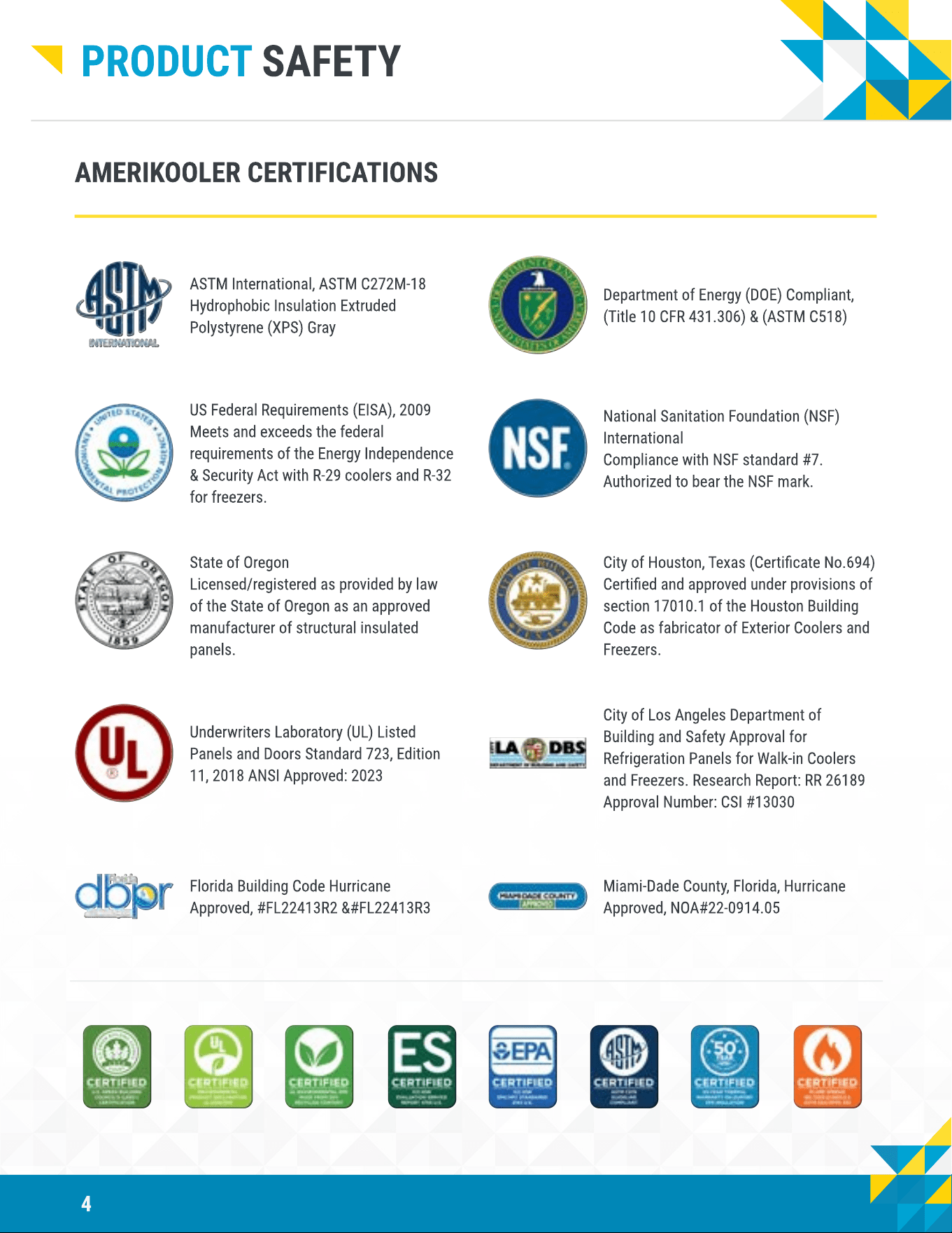
AMERIKOOLER CERTIFICATIONS
ASTM International, ASTM C272M-1
Hydrophobic Insulation Extruded
Polystyrene (XPS) Gray
Florida Building Code Hurricane
Approved,#FL22413R2 &#FL22413R3
City of Houston, Texas (Certicate No.694
Certied and approved under provisions of
section 17010.1 of the Houston Building
Code as fabricator of Exterior Coolers and
Freezers.
Department of Energy (DOE) Compliant,
(Title 10 CFR 431.306) & (ASTM C518)
US Federal Requirements (EISA),200
Meets and exceeds the federal
requirements of the Energy Independence
& Security Act with R-29 coolers and R-32
for freezers.
City of Los Angeles Department of
Building and Safety Approval for
Refrigeration Panels for Walk-in Coolers
and Freezers. Research Report: RR 26189
Approval Number: CSI #13030
Miami-Dade County, Florida, Hurricane
Approved,NOA#22-0914.05
National Sanitation Foundation (NSF)
Internationa
Compliance with NSF standard #7.
Authorized to bear the NSF mark.
State of Orego
Licensed
/
registered as provided by law
of the State of Oregon as an approved
manufacturer of structural insulated
panels.
Underwriters Laboratory (UL) Listed
Panels and Doors Standard 723, Edition
11, 2018 ANSI Approved: 2023
Product
Safety
5
Type of Units
While the complexity and specications of an installation may vary based on the types,
sizes, and customizations of a unit, the basic principles you will learn in this manual will
apply to installing any type of unit.
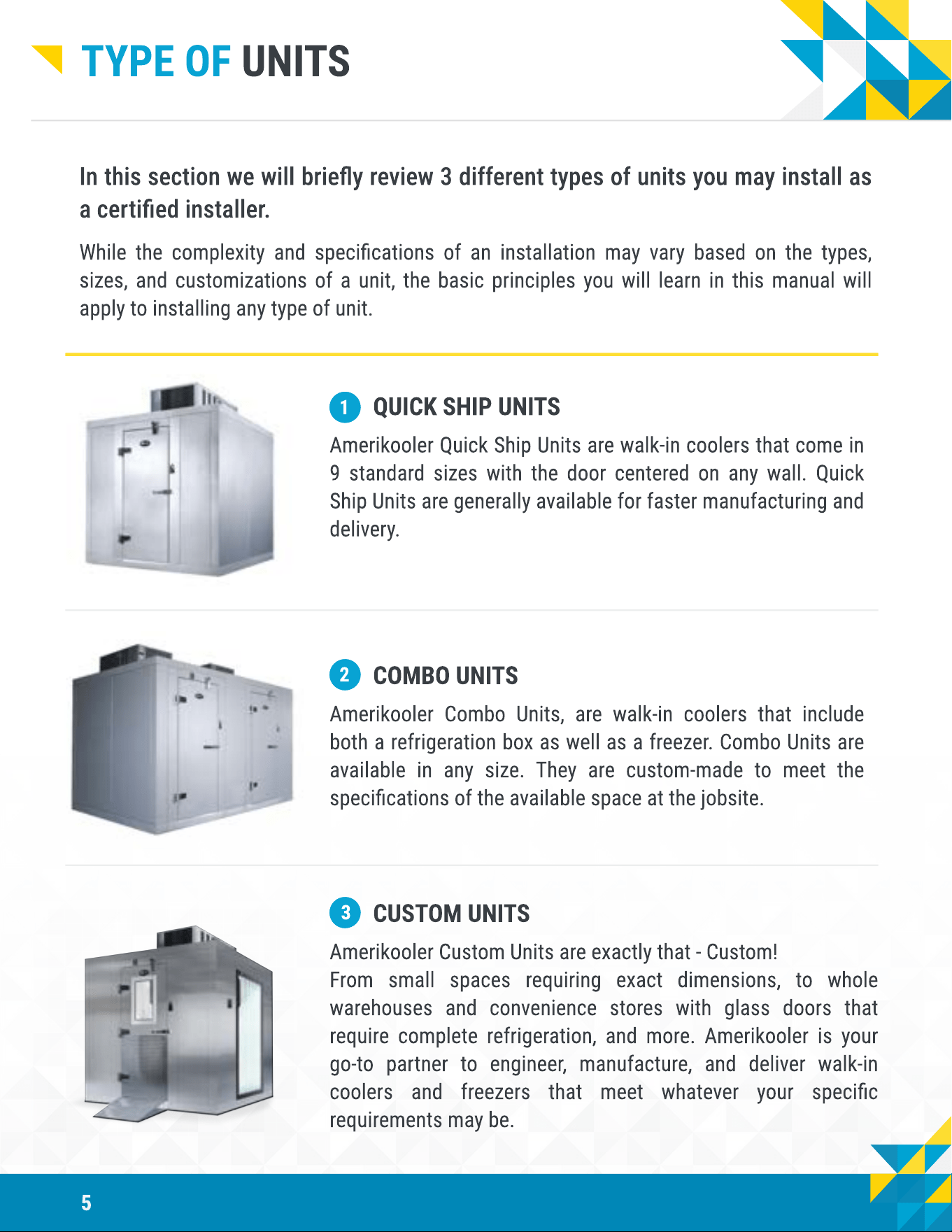
In this section we will briey review 3 different types of units you may install as
a certied installer.
1
Quick Ship Units
Amerikooler Quick Ship Units are walk-in coolers that come in
9 standard sizes with the door centered on any wall. Quick
Ship Units are generally available for faster manufacturing and
delivery.
2
Combo Units
Amerikooler Combo Units, are walk-in coolers that include
both a refrigeration box as well as a freezer. Combo Units are
available in any size. They are custom-made to meet the
specications of the available space at the jobsite.
3
Custom Units
Amerikooler Custom Units are exactly that - Custom
From small spaces requiring exact dimensions, to whole
warehouses and convenience stores with glass doors that
require complete refrigeration, and more. Amerikooler is your
go-to partner to engineer, manufacture, and deliver walk-in
coolers and freezers that meet whatever your specic
requirements may be.
6
Type of Units
standard Features
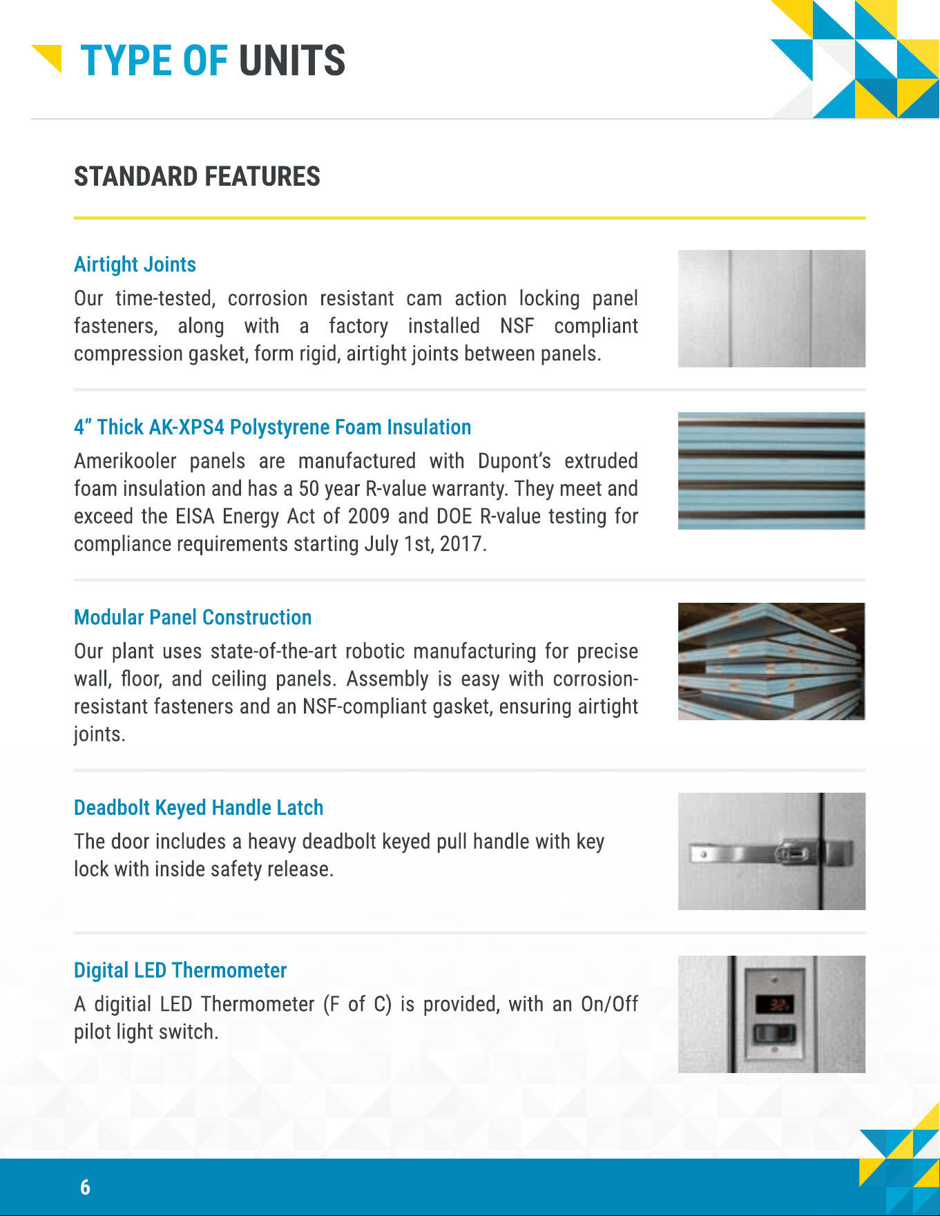
Airtight Joints
Our time-tested, corrosion resistant cam action locking panel
fasteners, along with a factory installed NSF compliant
compression gasket, form rigid, airtight joints between panels.
4” Thick AK-XPS4 Polystyrene Foam Insulation
Amerikooler panels are manufactured with Dupont’s extruded
foam insulation and has a 50 year R-value warranty. They meet and
exceed the EISA Energy Act of 2009 and DOE R-value testing for
compliance requirements starting July 1st, 2017.
Modular Panel Construction
Our plant uses state-of-the-art robotic manufacturing for precise
wall, oor, and ceiling panels. Assembly is easy with corrosion-
resistant fasteners and an NSF-compliant gasket, ensuring airtight
joints.
Deadbolt Keyed Handle Latch
The door includes a heavy deadbolt keyed pull handle with key
lock with inside safety release.
Digital LED Thermometer
A
di
g
itial
LED
Ther
m
o
m
eter
(F
of
C)
is provided
,
with an
O
n
/O
ff
pilot li
g
ht switch.
7
Type of Units
standard Finishes
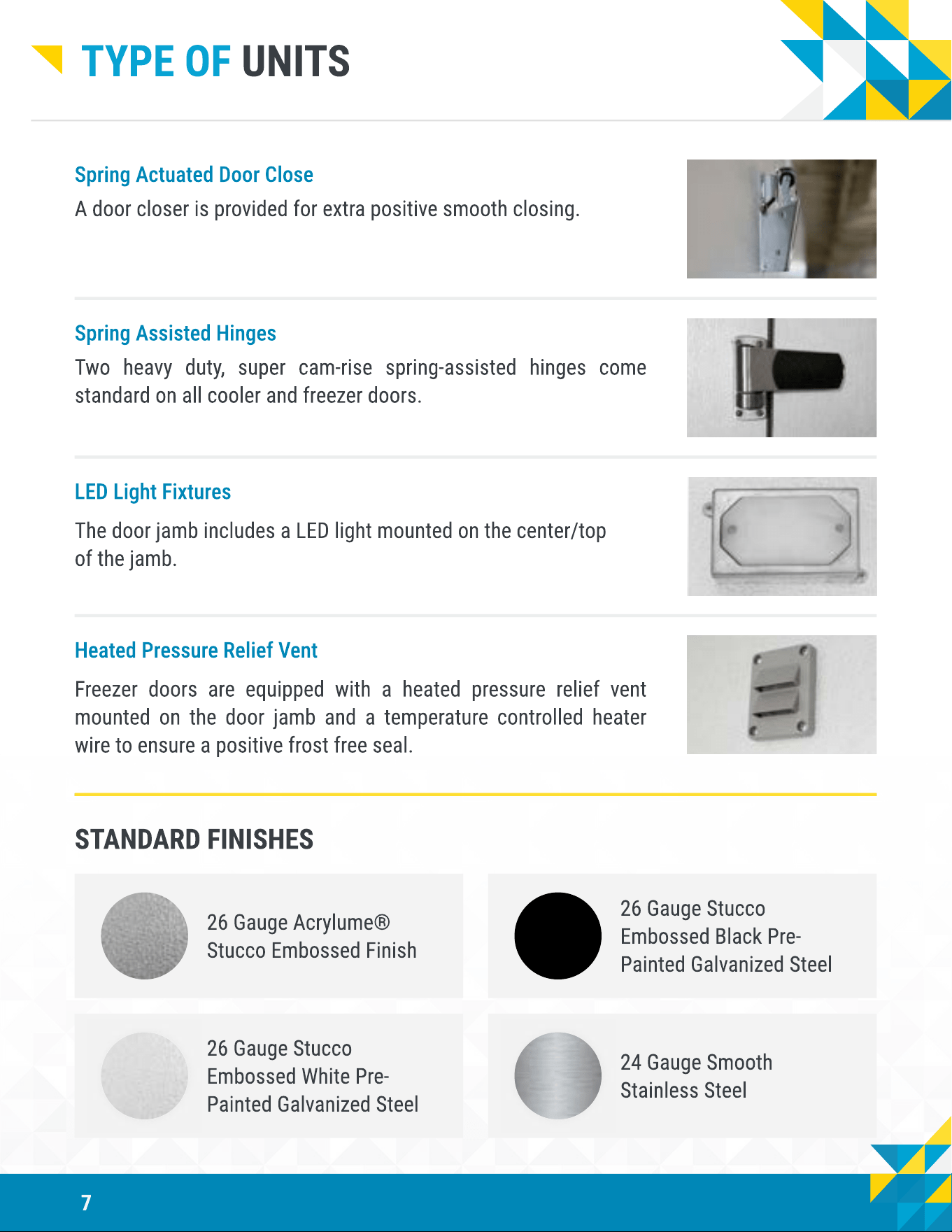
Spring Actuated Door Close
A door closer is provided for extra positive smooth closing.
Spring Assisted Hinges
Two heavy duty, super cam-rise spring-assisted hinges come
standard on all cooler and freezer doors.
LED Light Fixtures
The door jamb includes a LED light mounted on the center/top
of the jamb.
Heated Pressure Relief Vent
Freezer doors are equipped with a heated pressure relief vent
mounted on the door jamb and a temperature controlled heater
wire to ensure a positive frost free seal.
26 Gauge Stucco
Embossed White Pre-
Painted Galvanized Steel
24 Gauge Smooth
Stainless Steel
26 Gauge Acrylume®
Stucco Embossed Finish
26 Gauge Stucco
Embossed
B
lac
k
Pre-
Painted Galvanized Steel
8
Materials And Equipment
installation materials included
Amerikooler provides all of the required installation
materials for each order, but additional materials and
equipment will be needed for each individual installation.
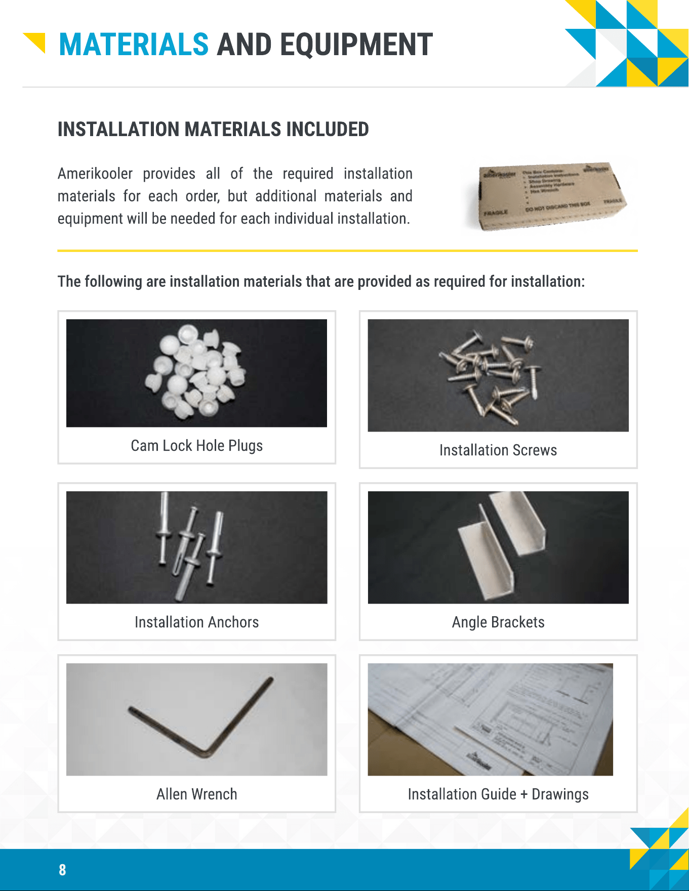
The following are installation materials that are provided as required for installation:
Cam Lock Hole Plugs
Installation Screws
Installation Anchors Angle Brackets
Allen Wrench Installation Guide + Drawings
9
Materials And Equipment
additional materials and equipment
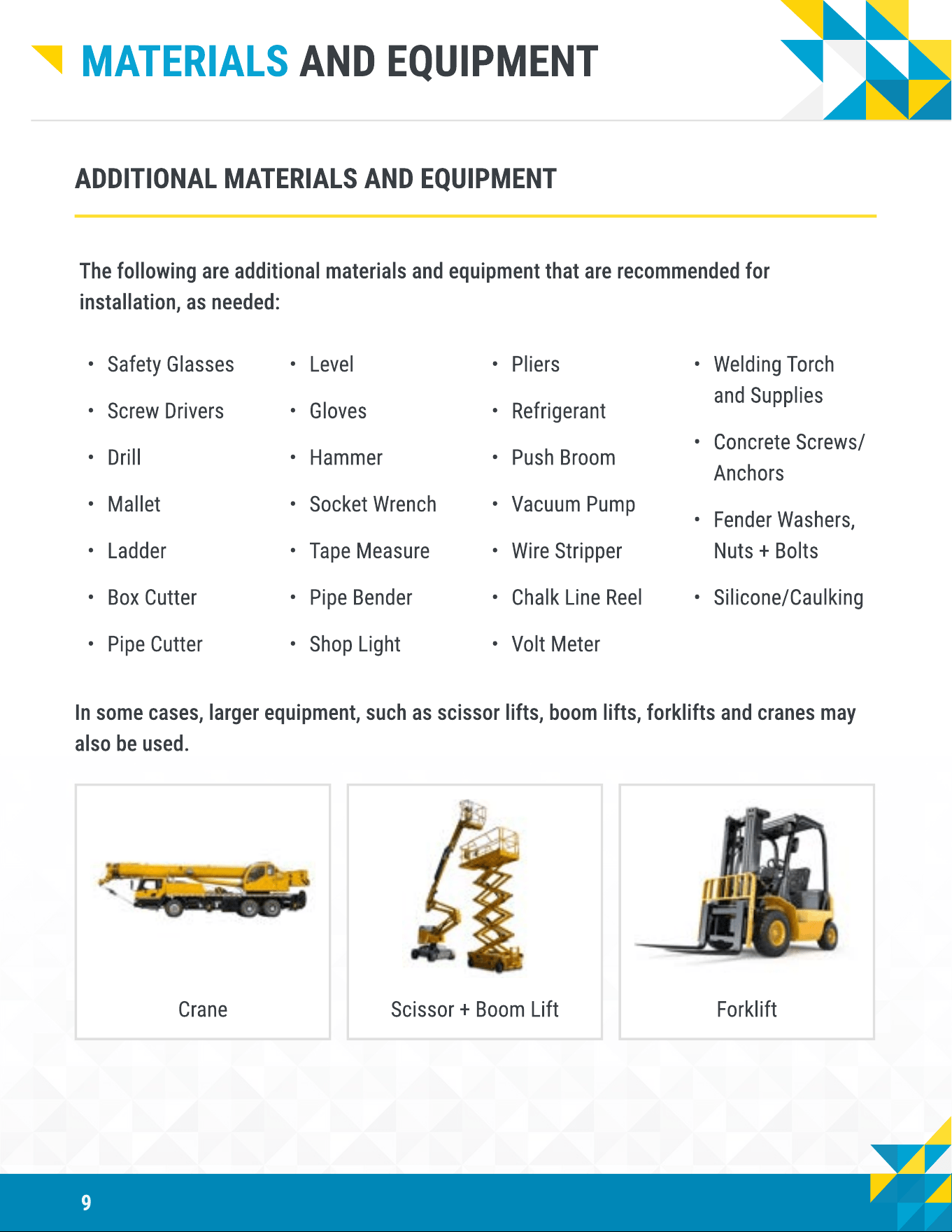
The following are additional materials and equipment that are recommended for
installation, as needed:
Safety Glasses
Screw Drivers
Drill
Mallet
Ladder
Box Cutter
Pipe Cutter
Level
Gloves
Hammer
Socket Wrench
Tape Measure
Pipe Bender
Shop Light
Pliers
Refrigerant
Push Broom
Vacuum Pump
Wire Stripper
Chalk Line Reel
Volt Meter
Welding Torch
and Supplies
Concrete Screws/
Anchors
Fender Washers,
Nuts + Bolts
Silicone/Caulking
I
n some cases, larger equipment, such as scissor lifts,
b
oom lifts, for
k
lifts and cranes ma
y
also
b
e used
.
Crane Scissor
+
Boom Lift
F
orklift
10
Drawings and Panel Labels
Overview
With every Amerikooler installation you will make use of drawings and labels to properly
assemble the unit. Understanding these documents will help to ensure a smooth
installation.
Drawings
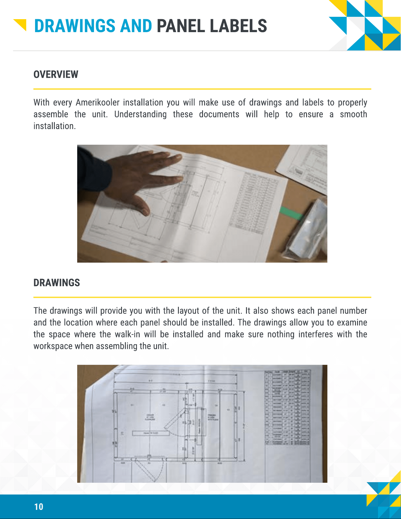
The drawings will provide you with the layout of the unit. It also shows each panel number
and the location where each panel should be installed. The drawings allow you to examine
the space where the walk-in will be installed and make sure nothing interferes with the
workspace when assembling the unit.
11
Drawings and Panel Labels
Panel Labels
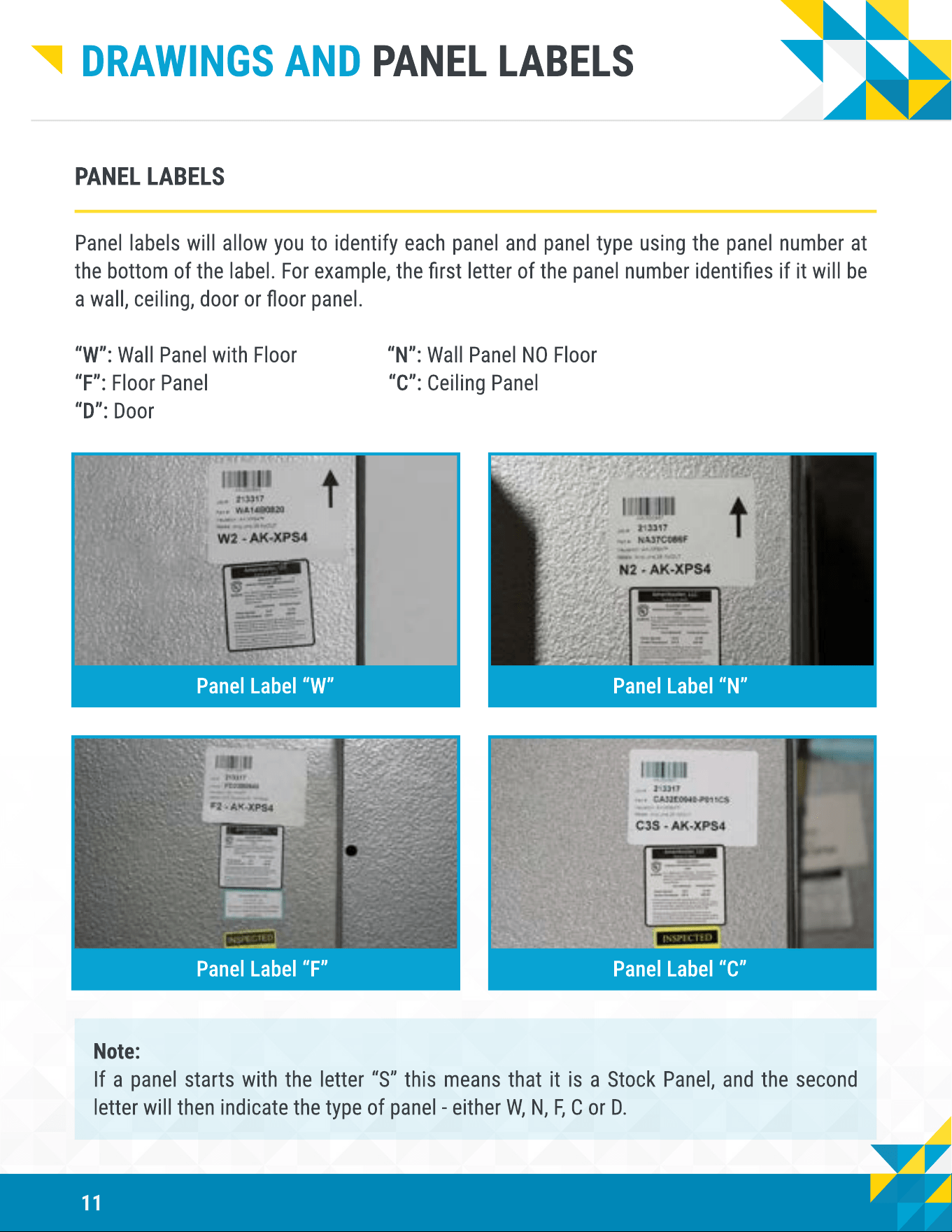
Panel labels will allow you to identify each panel and panel type using the panel number at
the bottom of the label. For example, the rst letter of the panel number identies if it will be
a wall, ceiling, door or oor panel
“W”: Wall Panel with Floor “N”: Wall Panel NO Floo
“F”: Floor Panel “C”: Ceiling Pane
“D”: Door
Panel Label “W” Panel Label “N”
Panel Label “F” Panel Label “C”
Note
If a panel starts with the letter “S” this means that it is a Stock Panel, and the second
letter will then indicate the type of panel - either W, N, F, C or D.
12
Shipment Inspection
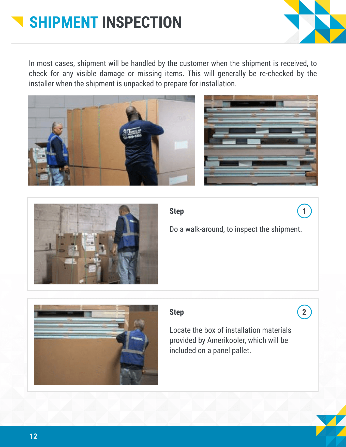
In most cases, shipment will be handled by the customer when the shipment is received, to
check for any visible damage or missing items. This will generally be re-checked by the
installer when the shipment is unpacked to prepare for installation.
Step 1
Do a walk-around, to inspect the shipment.
Step 2
Locate the box of installation materials
provided by Amerikooler, which will be
included on a panel pallet.

13
Shipment Inspection
Step 3
With the installation materials you will
nd your packing list. To ensure that
all panels have been received, compare
the packing list to the shipment by
checking the labels on the panels.
Step 4
If any items are missing or any
damage is found either during the
shipment inspection or while
unpacking the shipment to prepare for
installation, the customer should
contact Amerikooler Customer Service
via email or phone for assistance at
customerservice@amerikooler.net or
(800) 627-5665 Ext. 669.
Note
If shipping boxes or other protective materials are damaged, be sure to inspect the products
inside to determine if the damage may only be supercial.
14
Installation Preparation
And Unpacking
In this section you will learn the steps for installation preparation and unpacking.
Preparation of the area where the unit will be installed is important for proper installation.
The following are steps that should be taken prior to starting the assembly of the unit:
Note
Any electrical congurations seen in this course prior to the section on powering the unit, which
is performed by a licensed electrician, are only temporary for purposes of demonstration later in
the manual.
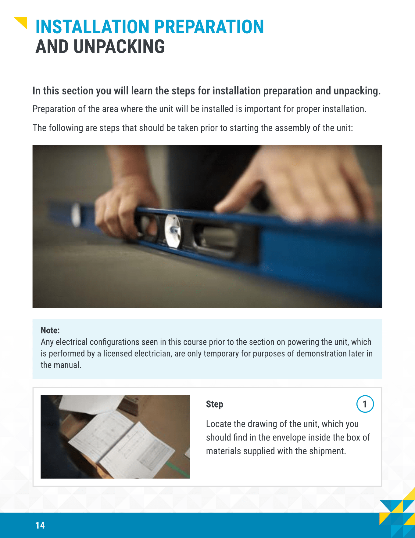
Step 1
Locate the drawing of the unit, which you
should nd in the envelope inside the box of
materials supplied with the shipment.
15
Installation Preparation
And Unpacking
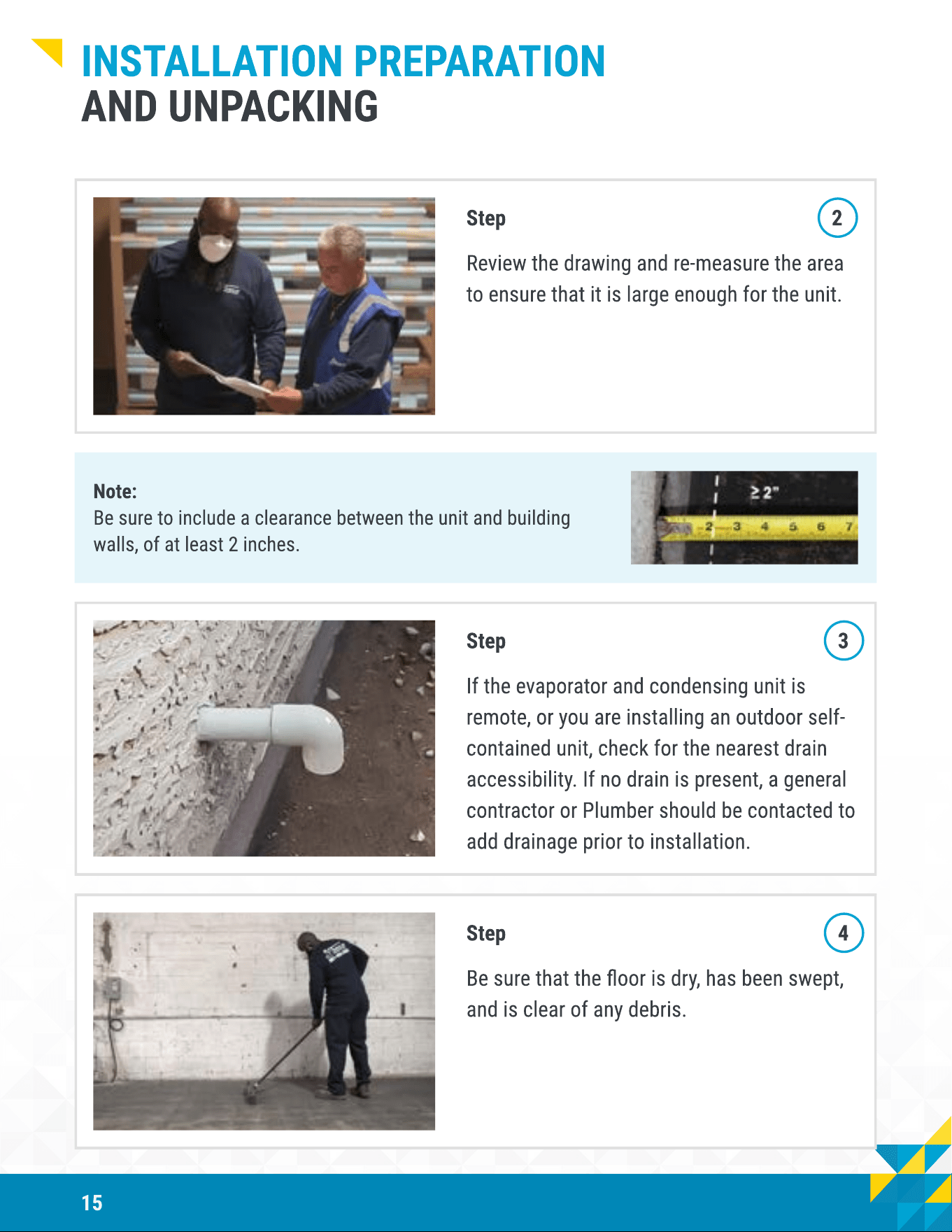
Step 2
Review the drawing and re-measure the area
to ensure that it is large enough for the unit.
Note
Be sure to include a clearance between the unit and building
walls, of at least 2 inches.
Step 3
If the evaporator and condensing unit is
remote, or you are installing an outdoor self-
contained unit, check for the nearest drain
accessibility. If no drain is present, a general
contractor or Plumber should be contacted to
add drainage prior to installation.
Step 4
Be sure that the oor is dry, has been swept,
and is clear of any debris.
16
Installation Preparation
And Unpacking
Step 5
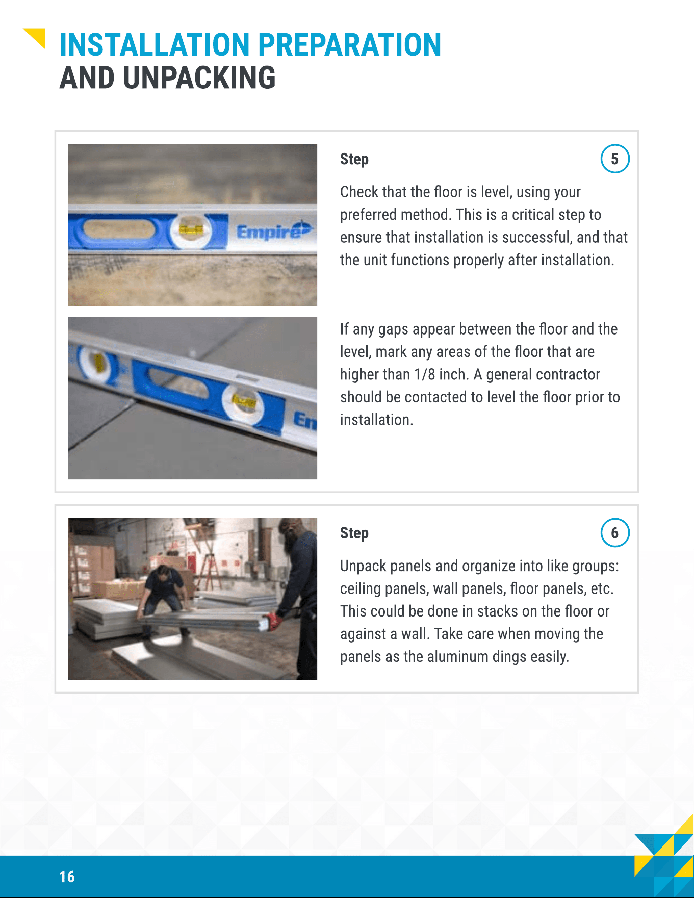
Check that the oor is level, using your
preferred method. This is a critical step to
ensure that installation is successful, and that
the unit functions properly after installation.
If any gaps appear between the oor and the
level, mark any areas of the oor that are
higher than 1/8 inch. A general contractor
should be contacted to level the oor prior to
installation.
Step 6
Unpack panels and organize into like groups:
ceiling panels, wall panels, oor panels, etc.
This could be done in stacks on the oor or
against a wall. Take care when moving the
panels as the aluminum dings easily.
17
Installation Preparation
And Unpacking
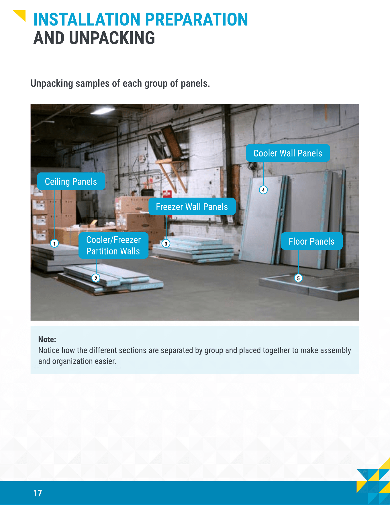
Unpacking samples of each group of panels.
Ceiling Panels
Freezer Wall Panels
Cooler Wall Panels
Floor Panels
Cooler/Freeze
Partition Walls
1 3
4
52
Note
Notice how the different sections are separated by group and placed together to make assembly
and organization easier.
18
Cooler and Freezer Installation
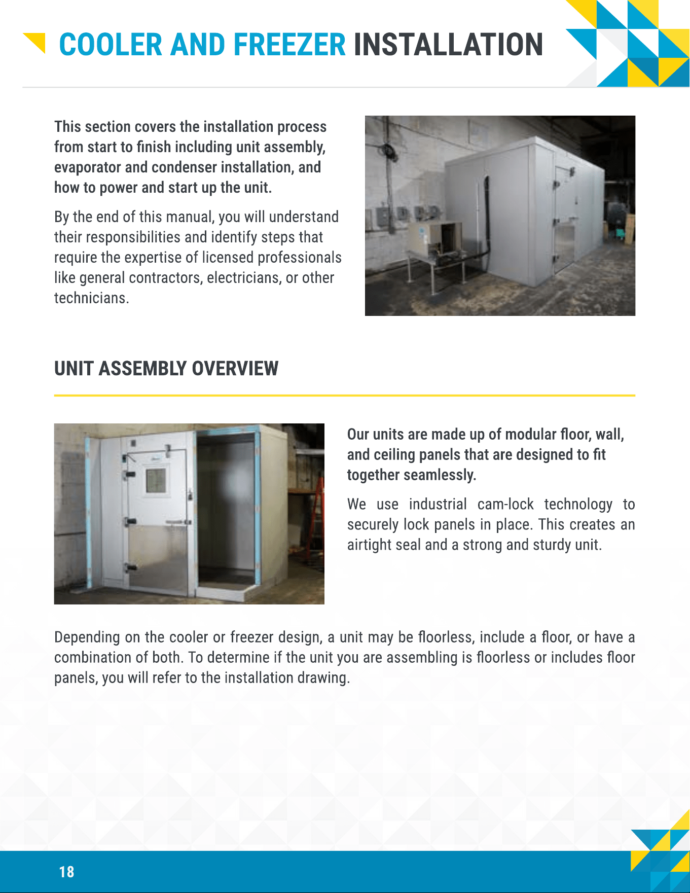
This section covers the installation process
from start to nish including unit assembly,
evaporator and condenser installation, and
how to power and start up the unit.
By the end of this manual, you will understand
their responsibilities and identify steps that
require the expertise of licensed professionals
like general contractors, electricians, or other
technicians.
Unit Assembly Overview
Our units are made up of modular oor, wall,
and ceiling panels that are designed to t
together seamlessly.
We use industrial cam-lock technology to
securely lock panels in place. This creates an
airtight seal and a strong and sturdy unit.
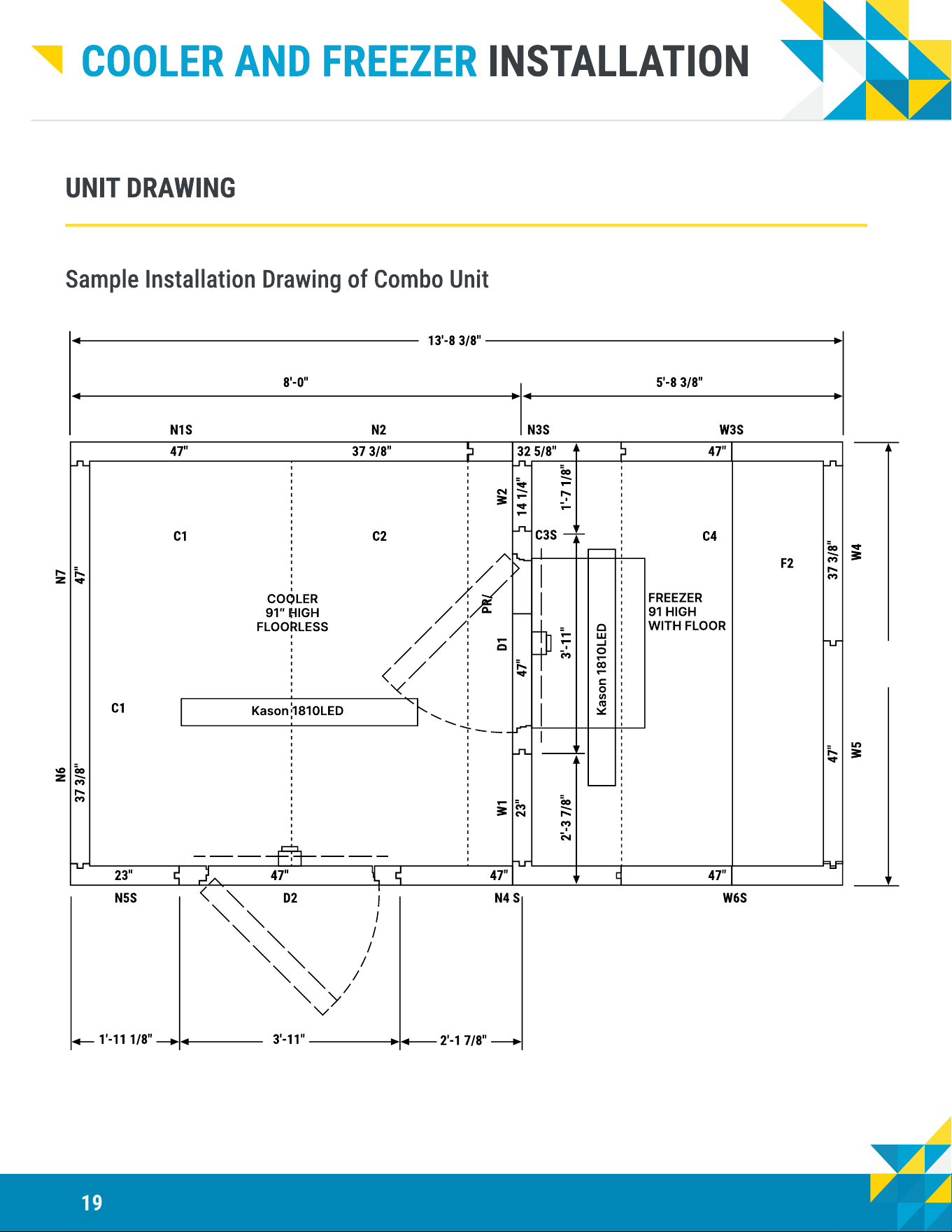
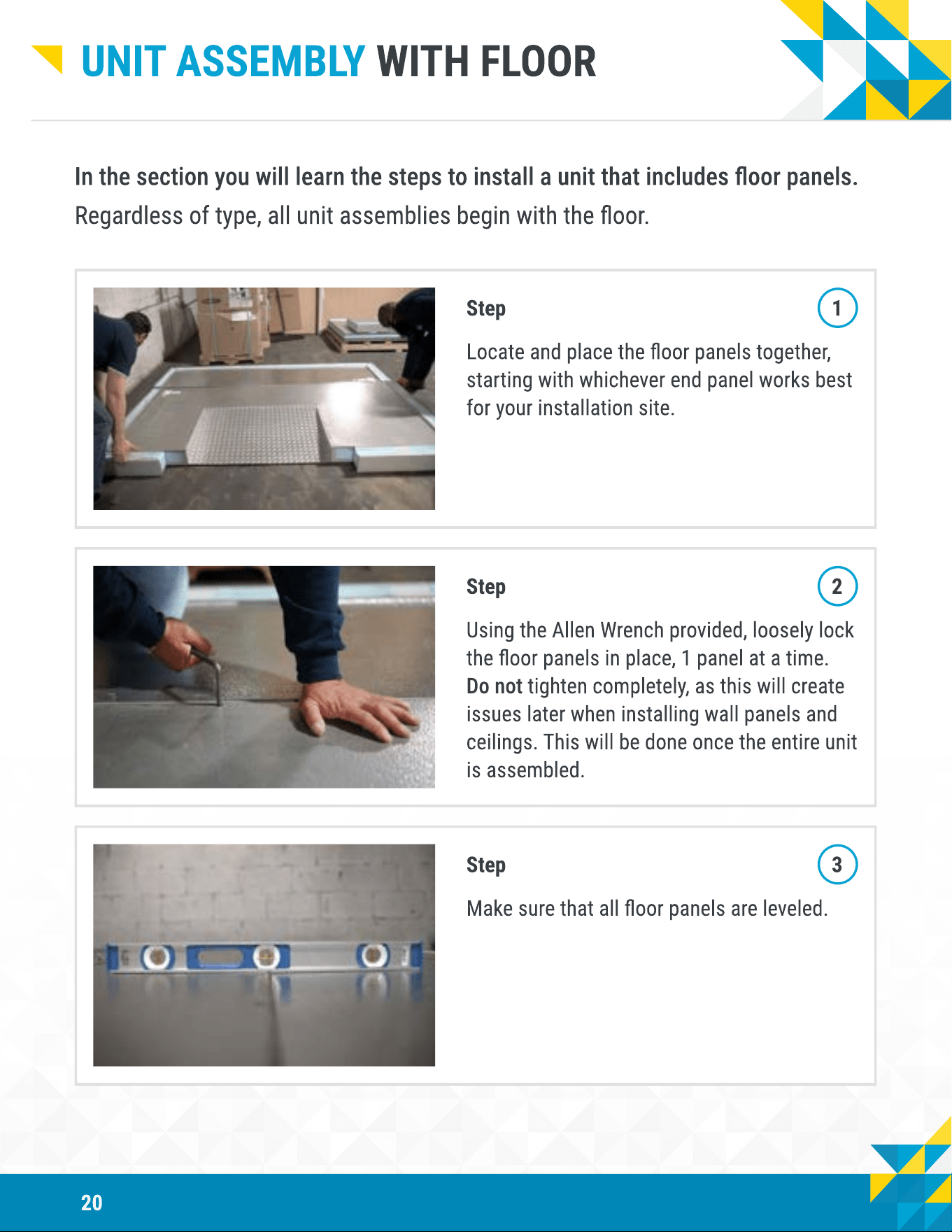
Depending on the cooler or freezer design, a unit may be oorless, include a oor, or have a
combination of both. To determine if the unit you are assembling is oorless or includes oor
panels, you will refer to the installation drawing.
19
1′-11 1/8″
n5s
n1s n2 w3s
23″ 47″
Kason 1810LED
Kason 1810LED
COOLE
91″ HIG
FLOORLESS
FREEZE
91 HIG
WITH FLOOR
47″
23″
47″
3′-11″
14 1/4″
1′-7 1/8″2′-3 7/8″
37 3/8″47″
37 3/8″ 32 5/8″
5′-8 3/8″
13′-8 3/8″
8′-0″
47″
47″
47″
47″37 3/8″
w5 w4
f2
w1 d1
pr/
w2
c2 c4
c3s
c1
c1
n6 n7
d2 w6sn4 s
3′-11″
2′-1 7/8″
n3s
Sample Installation Drawing of Combo Unit
Cooler and Freezer Installation
Unit drawing
20
Unit Assembly With Floor
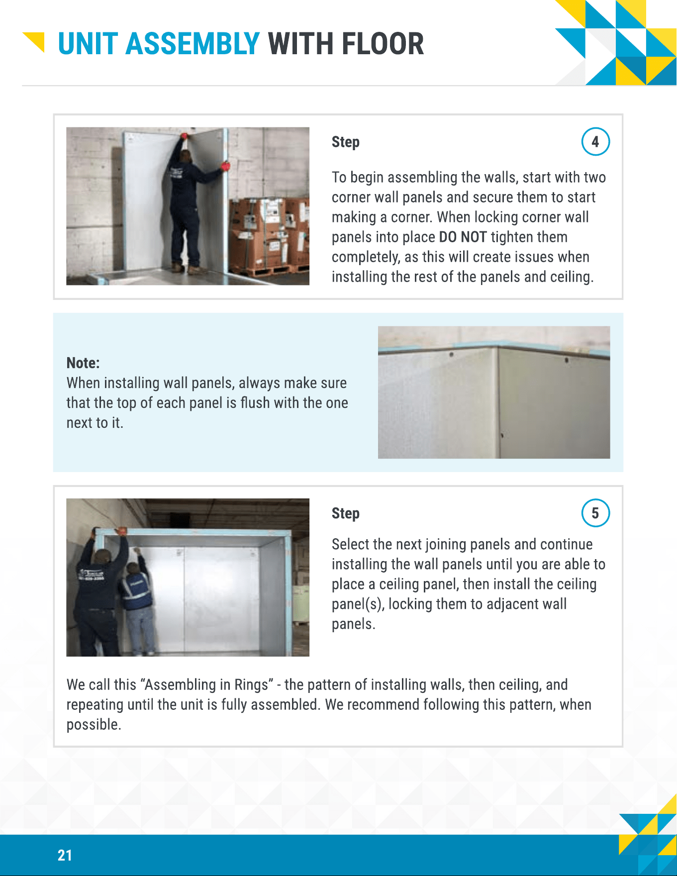
Step 1
Locate and place the oor panels together,
starting with whichever end panel works best
for your installation site.
Step 2
Using the Allen Wrench provided, loosely lock
the oor panels in place, 1 panel at a time.
Do not tighten completely, as this will create
issues later when installing wall panels and
ceilings. This will be done once the entire unit
is assembled.
Step 3
Make sure that all oor panels are leveled.
In the section you will learn the steps to install a unit that includes oor panels.
Regardless of type, all unit assemblies begin with the oor.
21
Unit Assembly With Floor
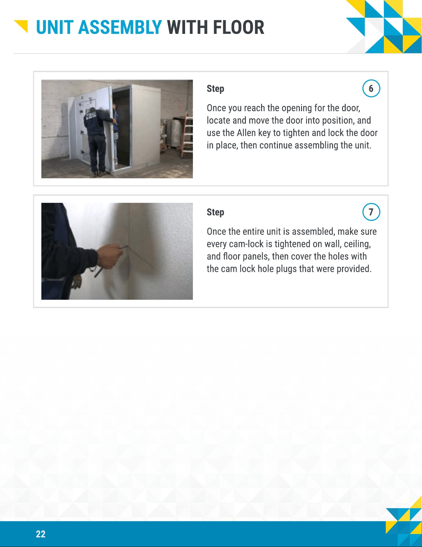
Step 4
To begin assembling the walls, start with two
corner wall panels and secure them to start
making a corner. When locking corner wall
panels into place DO NOT tighten them
completely, as this will create issues when
installing the rest of the panels and ceiling.
Note
When installing wall panels, always make sure
that the top of each panel is ush with the one
next to it.
Step 5
Select the next joining panels and continue
installing the wall panels until you are able to
place a ceiling panel, then install the ceiling
panel(s), locking them to adjacent wall
panels.
We call this “Assembling in Rings” - the pattern of installing walls, then ceiling, and
repeating until the unit is fully assembled. We recommend following this pattern, when
possible.
22
Unit Assembly With Floor
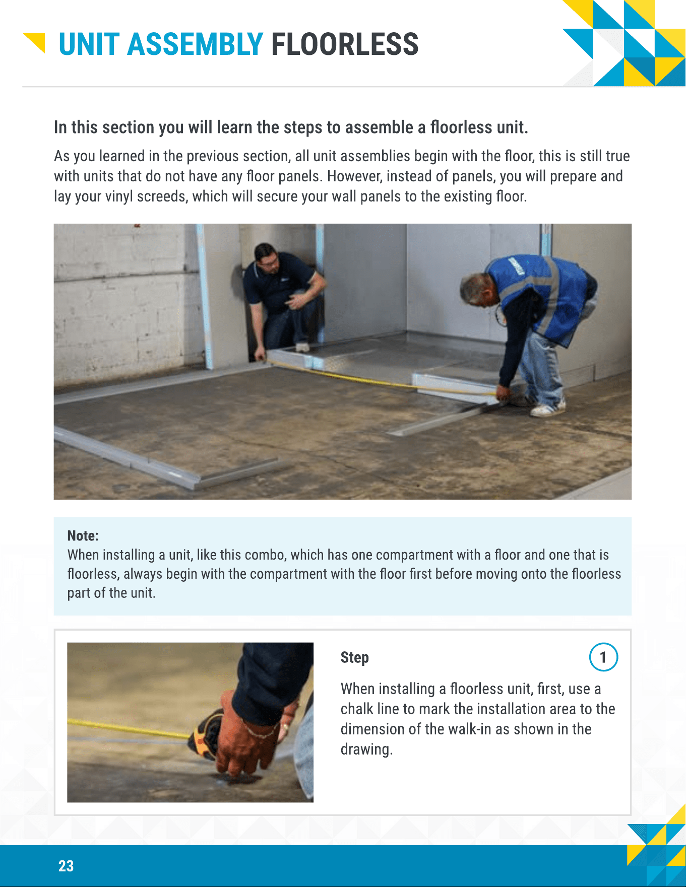
Step 6
Once you reach the opening for the door,
locate and move the door into position, and
use the Allen key to tighten and lock the door
in place, then continue assembling the unit.
Step 7
Once the entire unit is assembled, make sure
every cam-lock is tightened on wall, ceiling,
and oor panels, then cover the holes with
the cam lock hole plugs that were provided.
23
Unit Assembly Floorless
In this section you will learn the steps to assemble a oorless unit.
As you learned in the previous section, all unit assemblies begin with the oor, this is still true
with units that do not have any oor panels. However, instead of panels, you will prepare and
lay your vinyl screeds, which will secure your wall panels to the existing oor.
Note
When installing a unit, like this combo, which has one compartment with a oor and one that is
oorless, always begin with the compartment with the oor rst before moving onto the oorless
part of the unit.
Step 1
When installing a oorless unit, rst, use a
chalk line to mark the installation area to the
dimension of the walk-in as shown in the
drawing.
24
Unit Assembly Floorless
Step 2
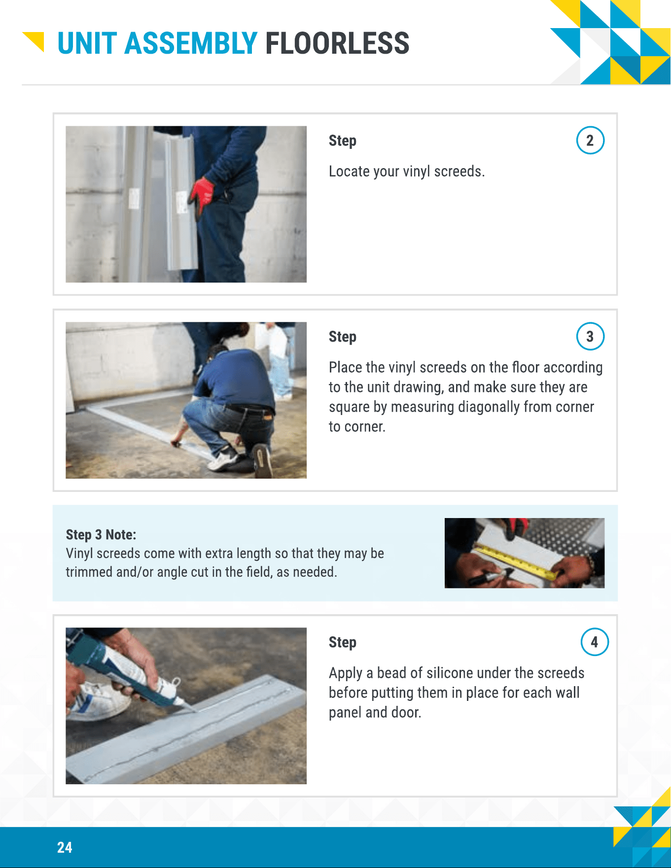
Locate your vinyl screeds.
Step 3
Place the vinyl screeds on the oor according
to the unit drawing, and make sure they are
square by measuring diagonally from corner
to corner.
Step 3 Note
Vinyl screeds come with extra length so that they may be
trimmed and/or angle cut in the eld, as needed.
Step 4
Apply a bead of silicone under the screeds
before putting them in place for each wall
panel and door.
25
Unit Assembly Floorless
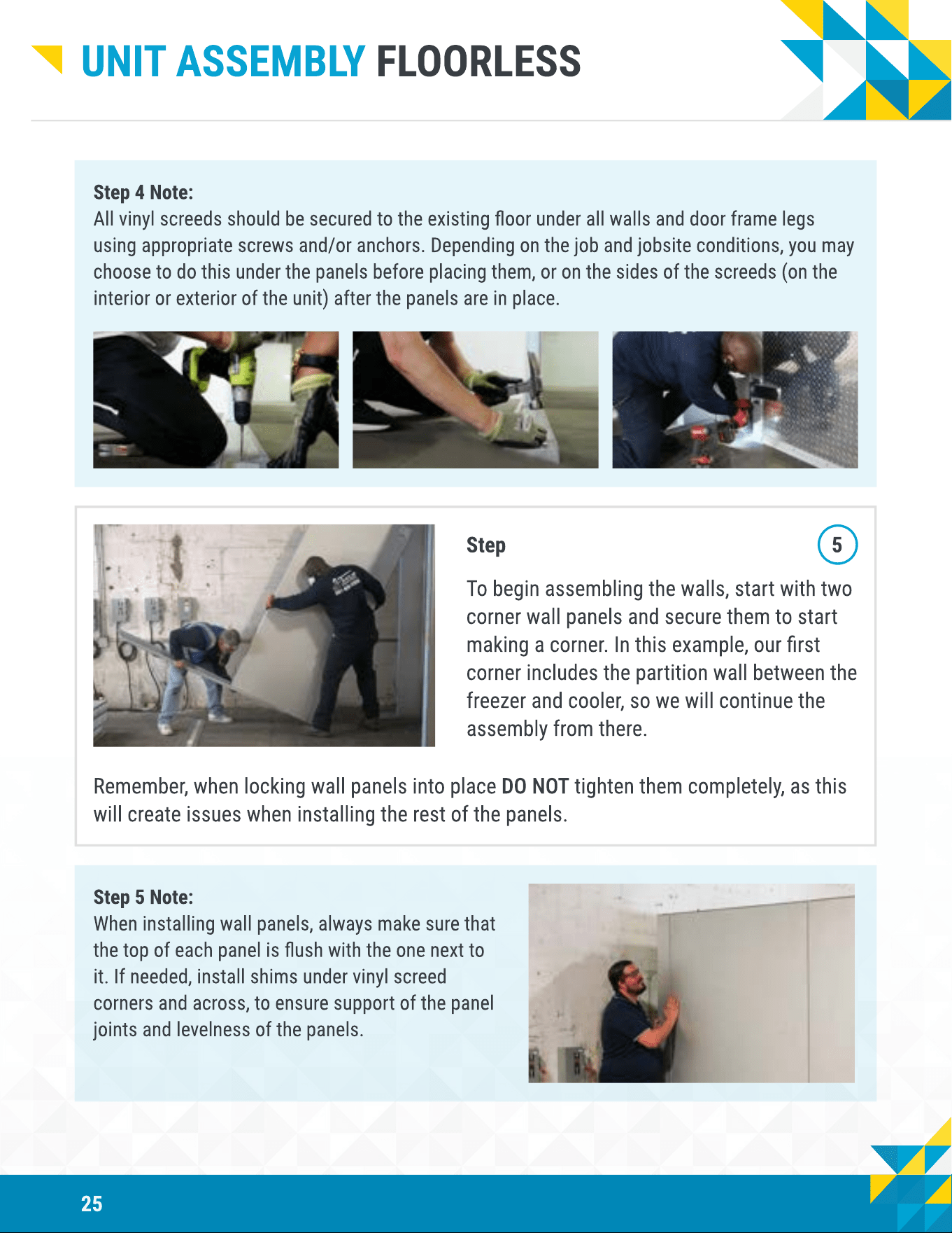
Step 4 Note
All vinyl screeds should be secured to the existing oor under all walls and door frame legs
using appropriate screws and/or anchors. Depending on the job and jobsite conditions, you may
choose to do this under the panels before placing them, or on the sides of the screeds (on the
interior or exterior of the unit) after the panels are in place.
Step 5
To begin assembling the walls, start with two
corner wall panels and secure them to start
making a corner. In this example, our rst
corner includes the partition wall between the
freezer and cooler, so we will continue the
assembly from there.
Remember, when locking wall panels into place DO NOT tighten them completely, as this
will create issues when installing the rest of the panels.
Step 5 Note
When installing wall panels, always make sure that
the top of each panel is ush with the one next to
it. If needed, install shims under vinyl screed
corners and across, to ensure support of the panel
joints and levelness of the panels.
26
Unit Assembly Floorless
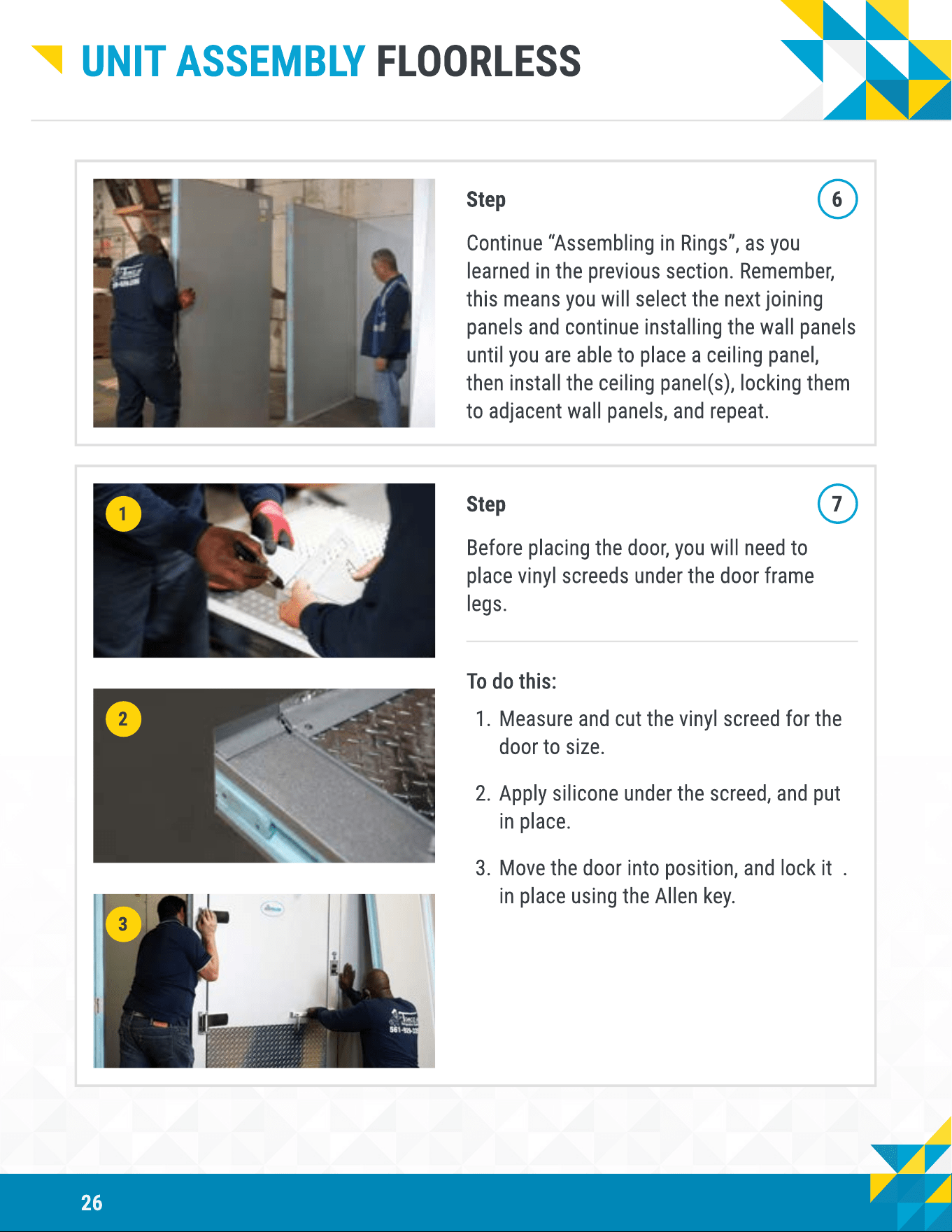
Step 6
Continue “Assembling in Rings”, as you
learned in the previous section. Remember,
this means you will select the next joining
panels and continue installing the wall panels
until you are able to place a ceiling panel,
then install the ceiling panel(s), locking them
to adjacent wall panels, and repeat.
1
2
3
Step 7
Before placing the door, you will need to
place vinyl screeds under the door frame
legs.
To do this:
Measure and cut the vinyl screed for the
door to size
Apply silicone under the screed, and put
in place
Move the door into position, and lock it .
in place using the Allen key.
27
Unit Assembly Floorless
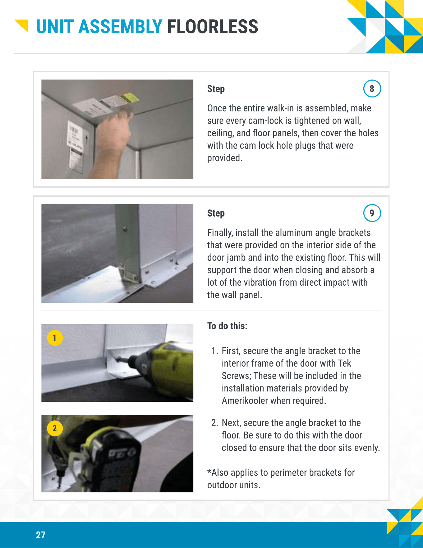
Step 8
Once the entire walk-in is assembled, make
sure every cam-lock is tightened on wall,
ceiling, and oor panels, then cover the holes
with the cam lock hole plugs that were
provided.
Step 9
Finally, install the aluminum angle brackets
that were provided on the interior side of the
door jamb and into the existing oor. This will
support the door when closing and absorb a
lot of the vibration from direct impact with
the wall panel.
1
To do this
First, secure the angle bracket to the
interior frame of the door with Tek
Screws; These will be included in the
installation materials provided by
Amerikooler when required.
2
Next, secure the angle bracket to the
oor. Be sure to do this with the door
closed to ensure that the door sits evenly
*Also applies to perimeter brackets for
outdoor units.
28
Evaporator and Condenser
Installation
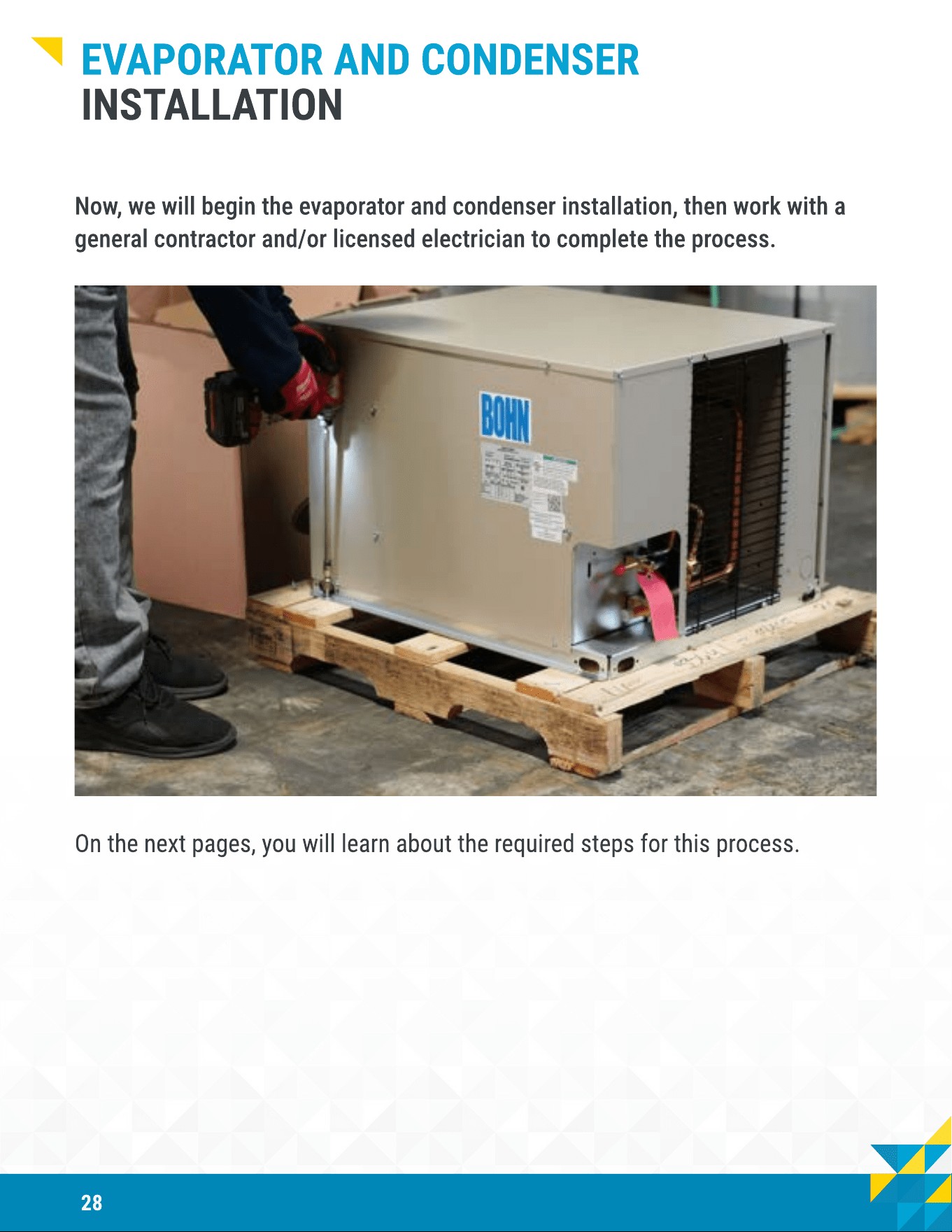
Now, we will begin the evaporator and condenser installation, then work with a
general contractor and/or licensed electrician to complete the process.
On the next pages, you will learn about the required steps for this process.
29
Evaporator and Condenser
Installation
Step 1
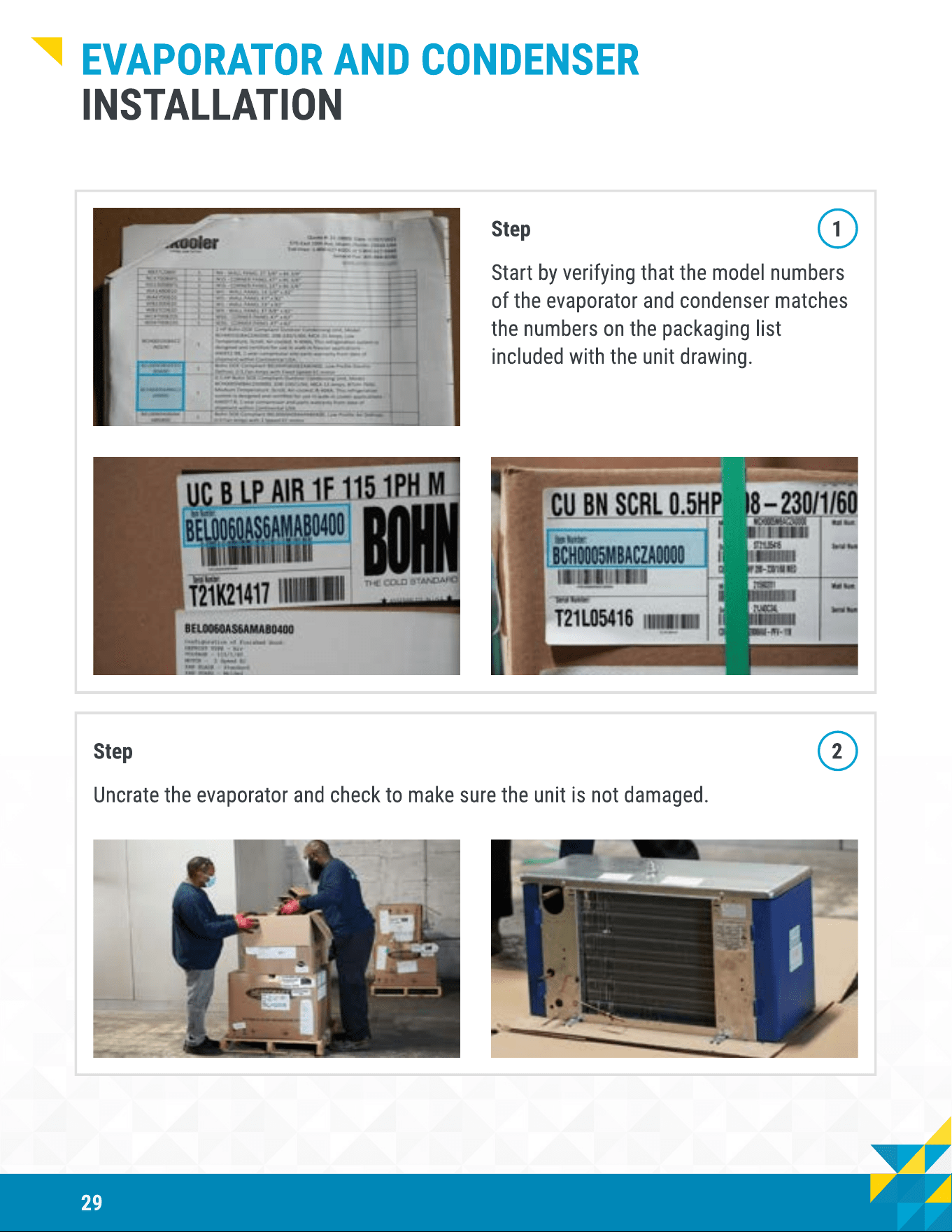
Start by verifying that the model numbers
of the evaporator and condenser matches
the numbers on the packaging list
included with the unit drawing.
Step 2
Uncrate the evaporator and check to make sure the unit is not damaged.
30
Evaporator and Condenser
Installation
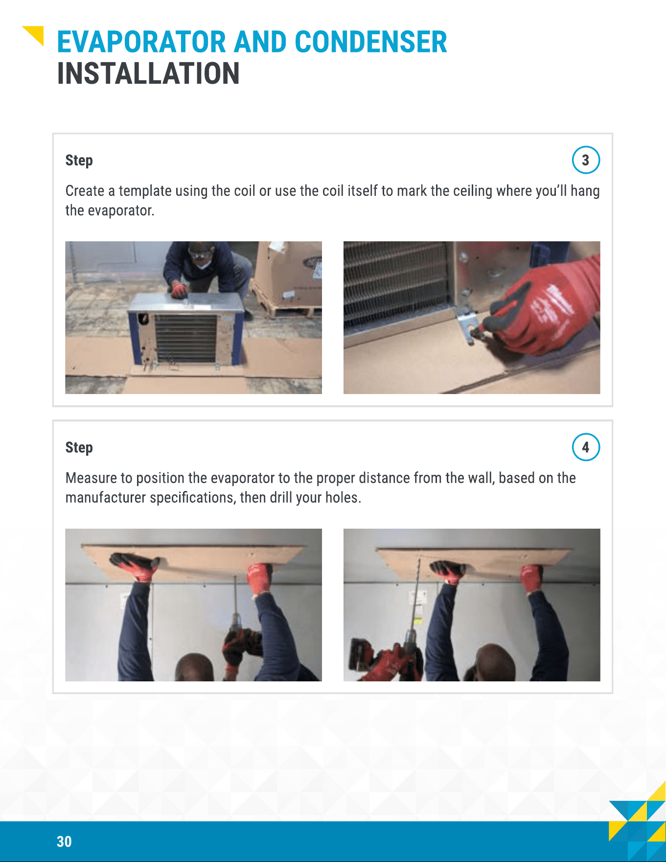
Step 3
Create a template using the coil or use the coil itself to mark the ceiling where you’ll hang
the evaporator.
Step 4
Measure to position the evaporator to the proper distance from the wall, based on the
manufacturer specications, then drill your holes.
31
Evaporator and Condenser
Installation
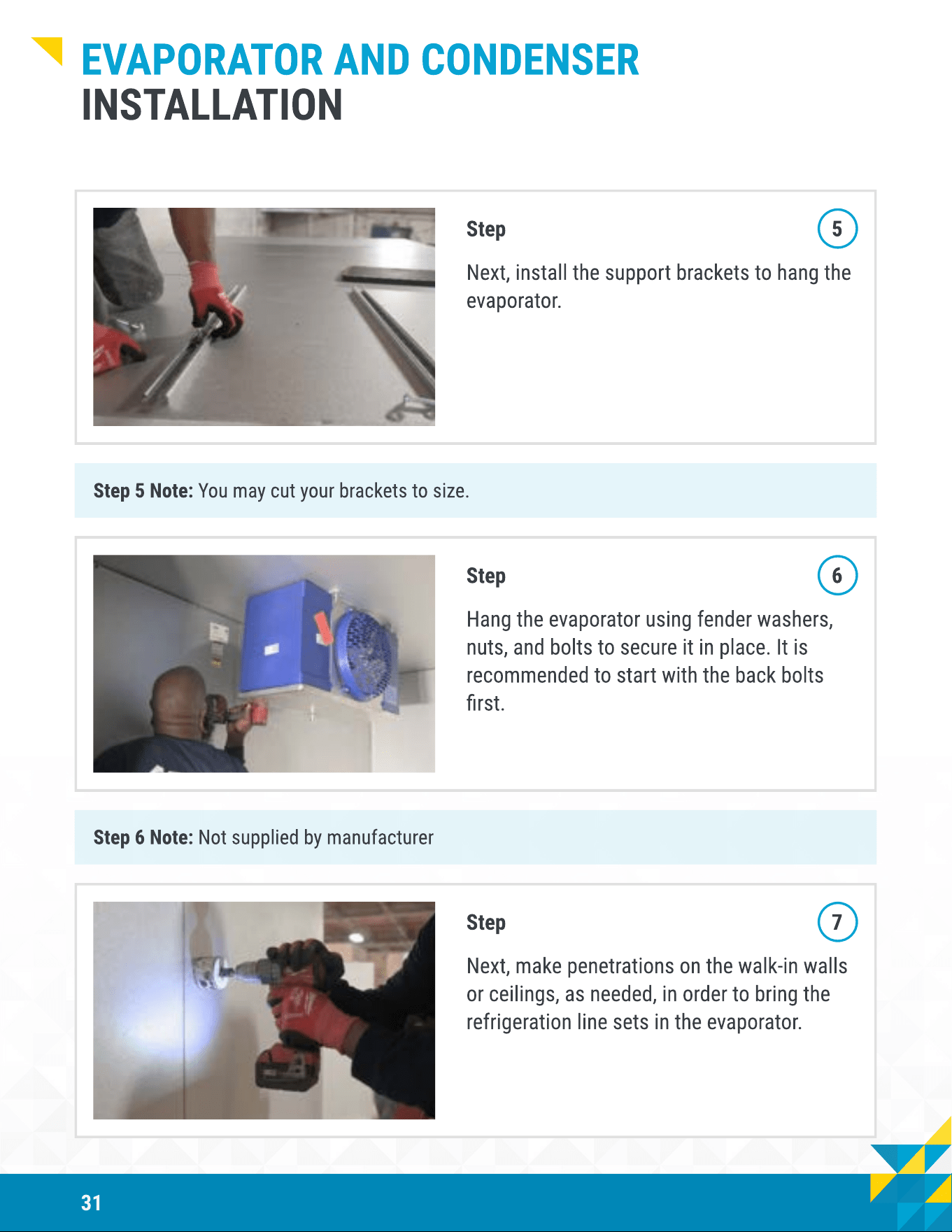
Step 5
Next, install the support brackets to hang the
evaporator.
Step 5 Note: You may cut your brackets to size.
Step 6
Hang the evaporator using fender washers,
nuts, and bolts to secure it in place. It is
recommended to start with the back bolts
rst.
Step 6 Note: Not supplied by manufacturer
Step 7
Next, make penetrations on the walk-in walls
or ceilings, as needed, in order to bring the
refrigeration line sets in the evaporator.
32
Evaporator and Condenser
Installation
Step 8
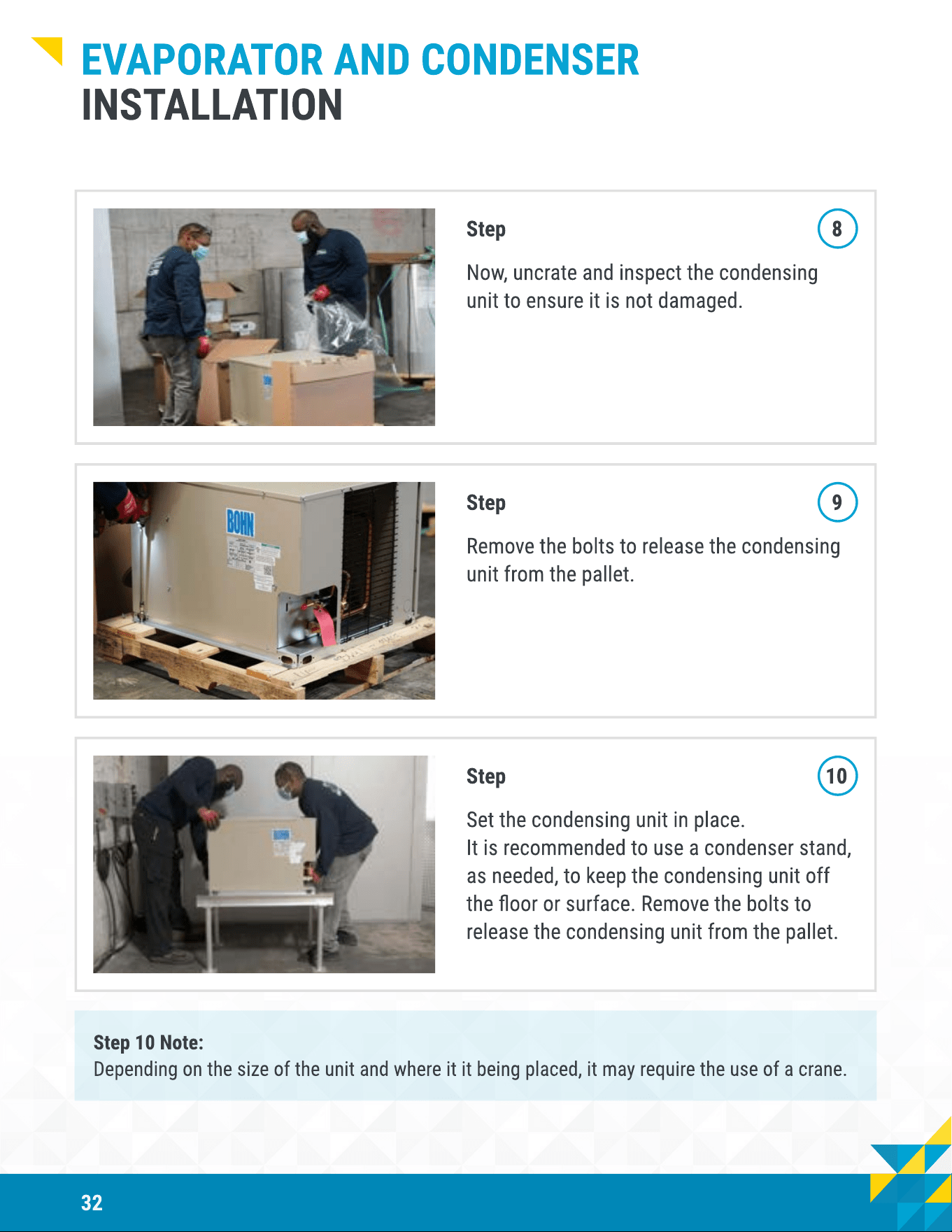
Now, uncrate and inspect the condensing
unit to ensure it is not damaged.
Step 9
Remove the bolts to release the condensing
unit from the pallet.
Step 10
Set the condensing unit in place.
It is recommended to use a condenser stand,
as needed, to keep the condensing unit off
the oor or surface. Remove the bolts to
release the condensing unit from the pallet.
Step 10 Note
Depending on the size of the unit and where it it being placed, it may require the use of a crane.
33
Evaporator and Condenser
Installation
1
2
3
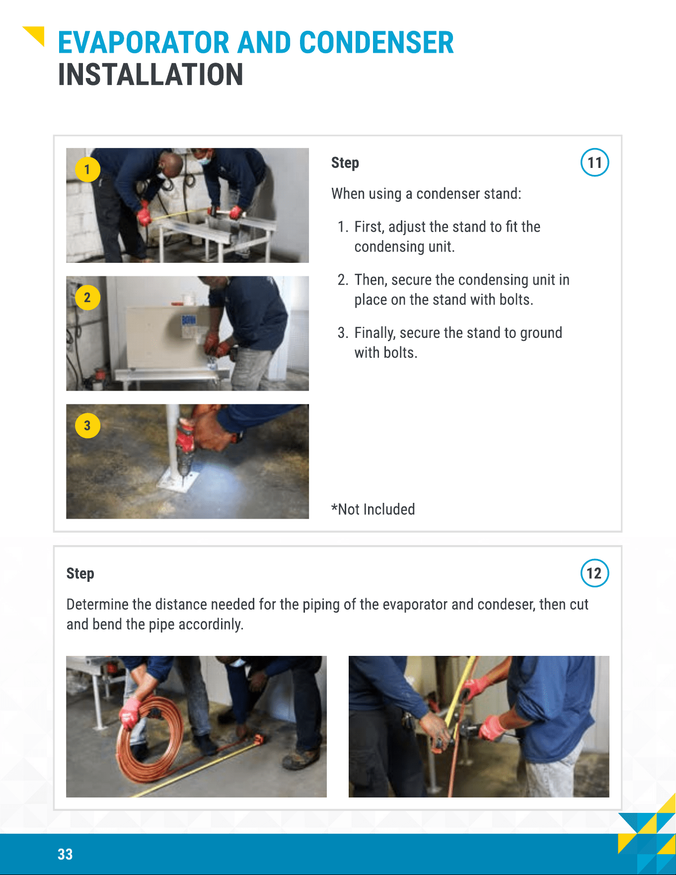
Step 11
When using a condenser stand:
First, adjust the stand to t the
condensing unit.
Then, secure the condensing unit in
place on the stand with bolts.
Finally, secure the stand to ground
with bolts.
*Not Included
Step 12
Determine the distance needed for the piping of the evaporator and condeser, then cut
and bend the pipe accordinly.
34
Evaporator and Condenser
Installation
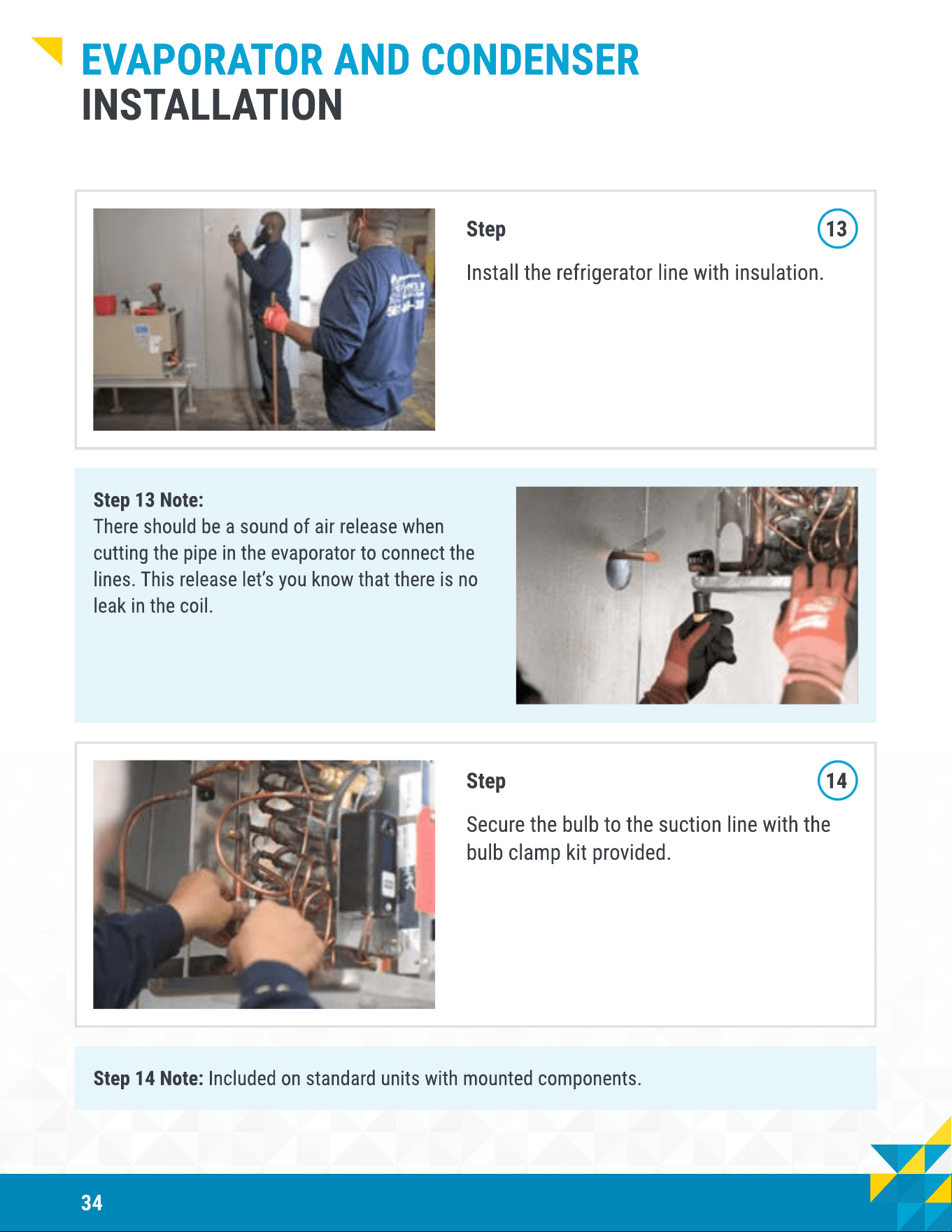
Step 13
Install the refrigerator line with insulation.
Step 13 Note
There should be a sound of air release when
cutting the pipe in the evaporator to connect the
lines. This release let’s you know that there is no
leak in the coil.
Step 14
Secure the bulb to the suction line with the
bulb clamp kit provided.
Step 14 Note: Included on standard units with mounted components.
35
Evaporator and Condenser
Installation
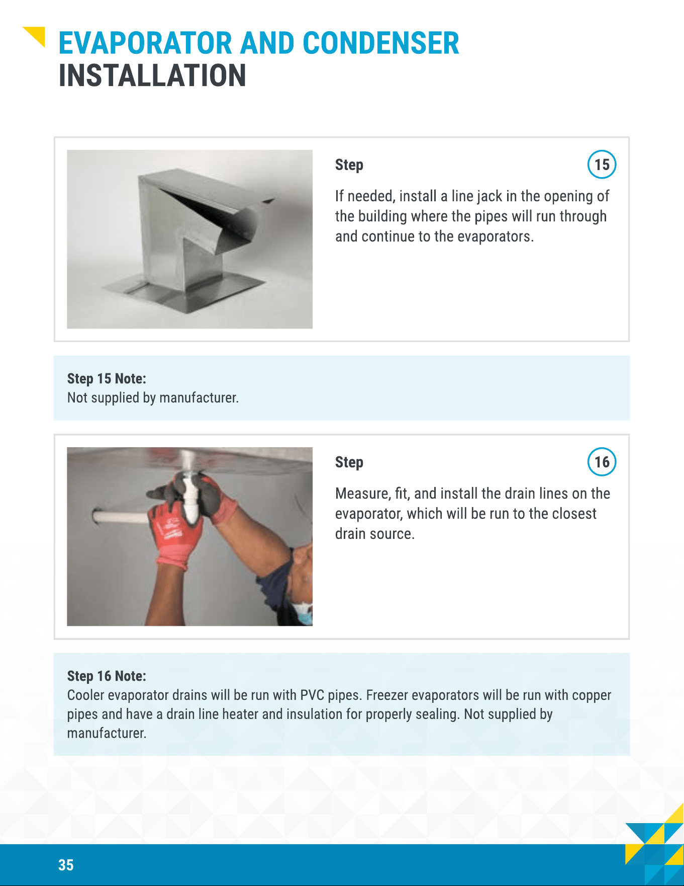
Step 15
If needed, install a line jack in the opening of
the building where the pipes will run through
and continue to the evaporators.
Step 15 Note
Not supplied by manufacturer.
Step 16
Measure, t, and install the drain lines on the
evaporator, which will be run to the closest
drain source.
Step 16 Note
Cooler evaporator drains will be run with PVC pipes. Freezer evaporators will be run with copper
pipes and have a drain line heater and insulation for properly sealing. Not supplied by
manufacturer.
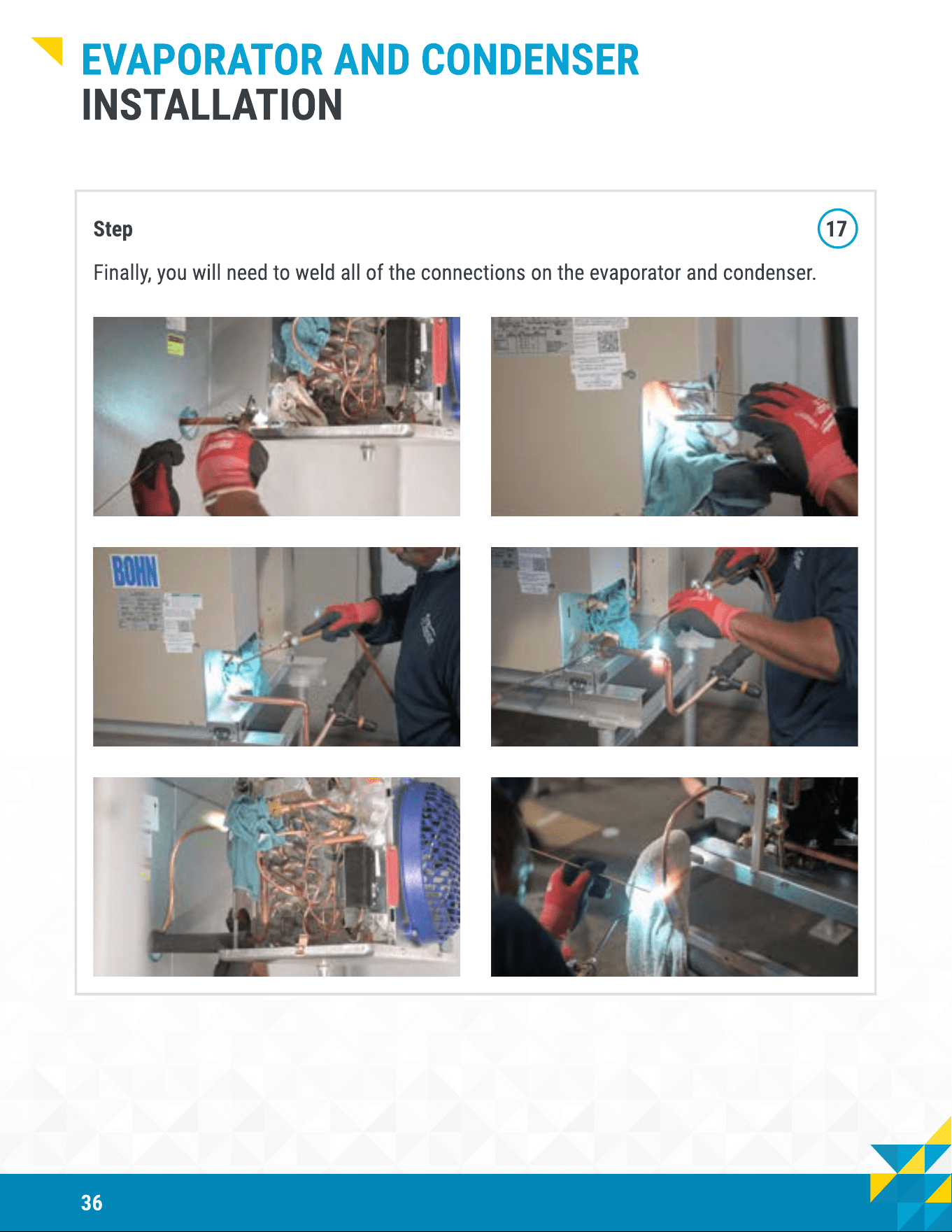
36
Evaporator and Condenser
Installation
Step 17
Finally, you will need to weld all of the connections on the evaporator and condenser.
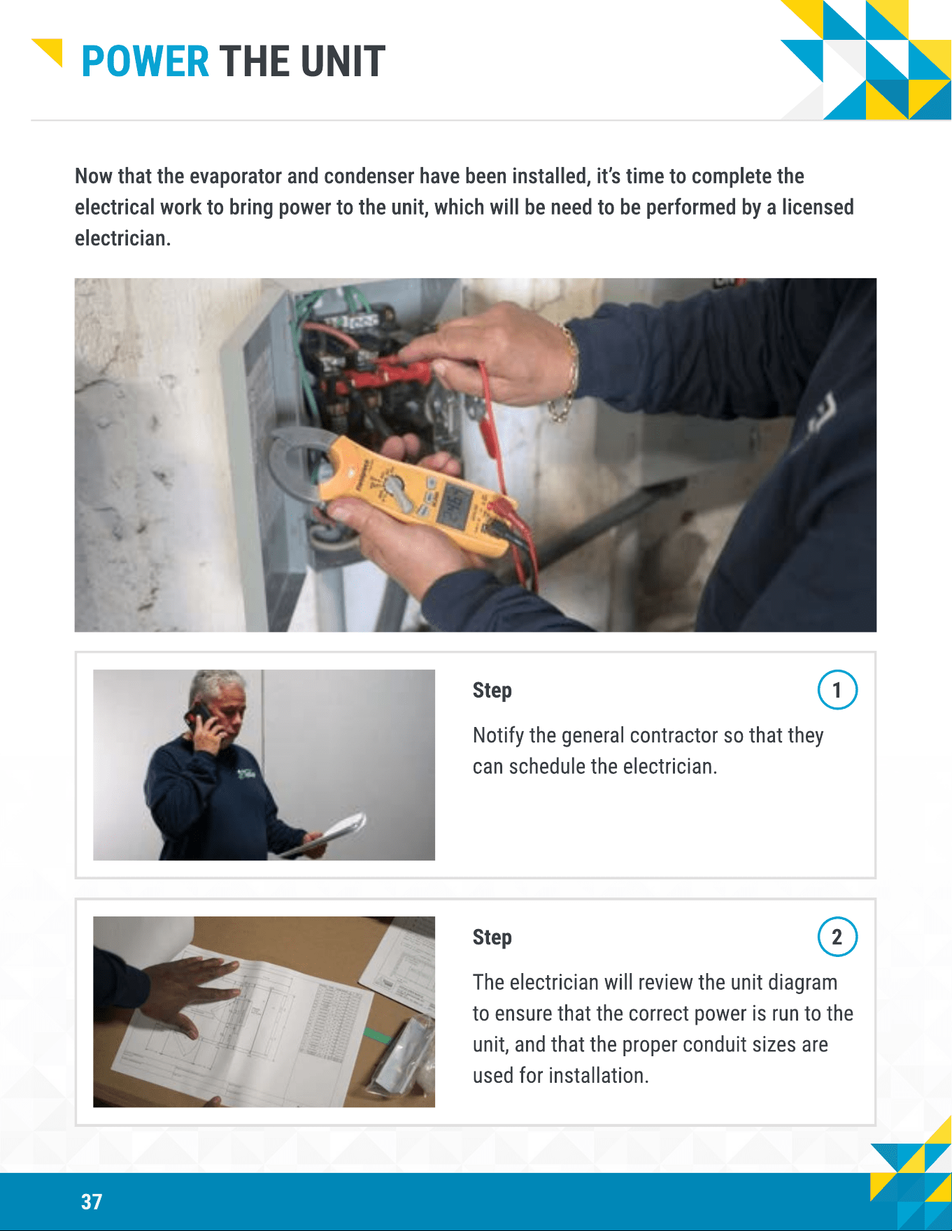
37
Power the unit
Now that the evaporator and condenser have been installed, it’s time to complete the
electrical work to bring power to the unit, which will be need to be performed by a licensed
electrician.
Step 1
Notify the general contractor so that they
can schedule the electrician.
Step 2
The electrician will review the unit diagram
to ensure that the correct power is run to the
unit, and that the proper conduit sizes are
used for installation.
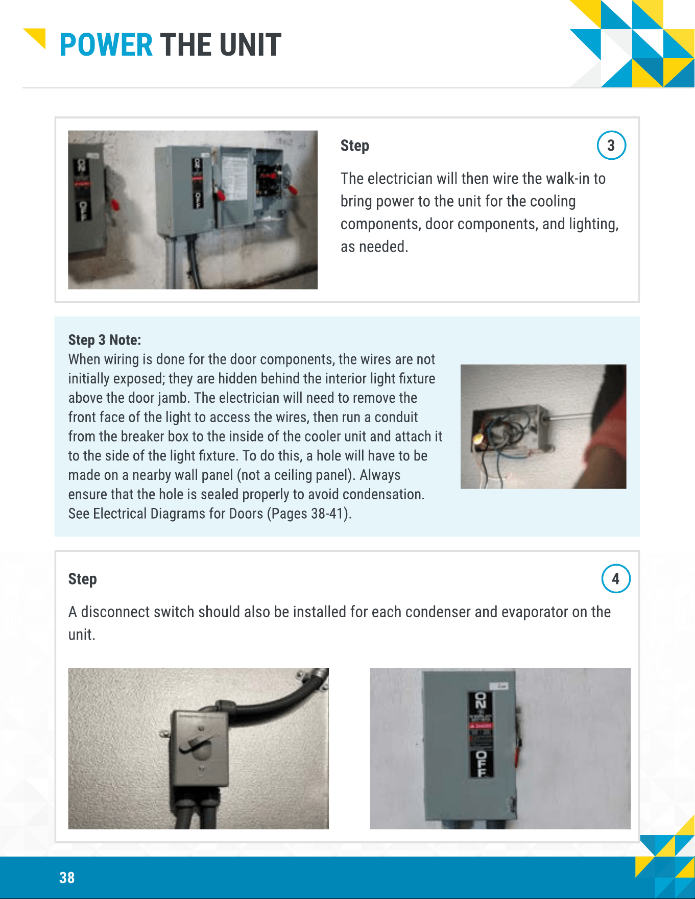
38
Power the unit
Step 3
The electrician will then wire the walk-in to
bring power to the unit for the cooling
components, door components, and lighting,
as needed.
Step 3 Note
When wiring is done for the door components, the wires are not
initially exposed; they are hidden behind the interior light xture
above the door jamb. The electrician will need to remove the
front face of the light to access the wires, then run a conduit
from the breaker box to the inside of the cooler unit and attach it
to the side of the light xture. To do this, a hole will have to be
made on a nearby wall panel (not a ceiling panel). Always
ensure that the hole is sealed properly to avoid condensation.
See Electrical Diagrams for Doors (Pages 38-41).
Step 4
A disconnect switch should also be installed for each condenser and evaporator on the
unit.
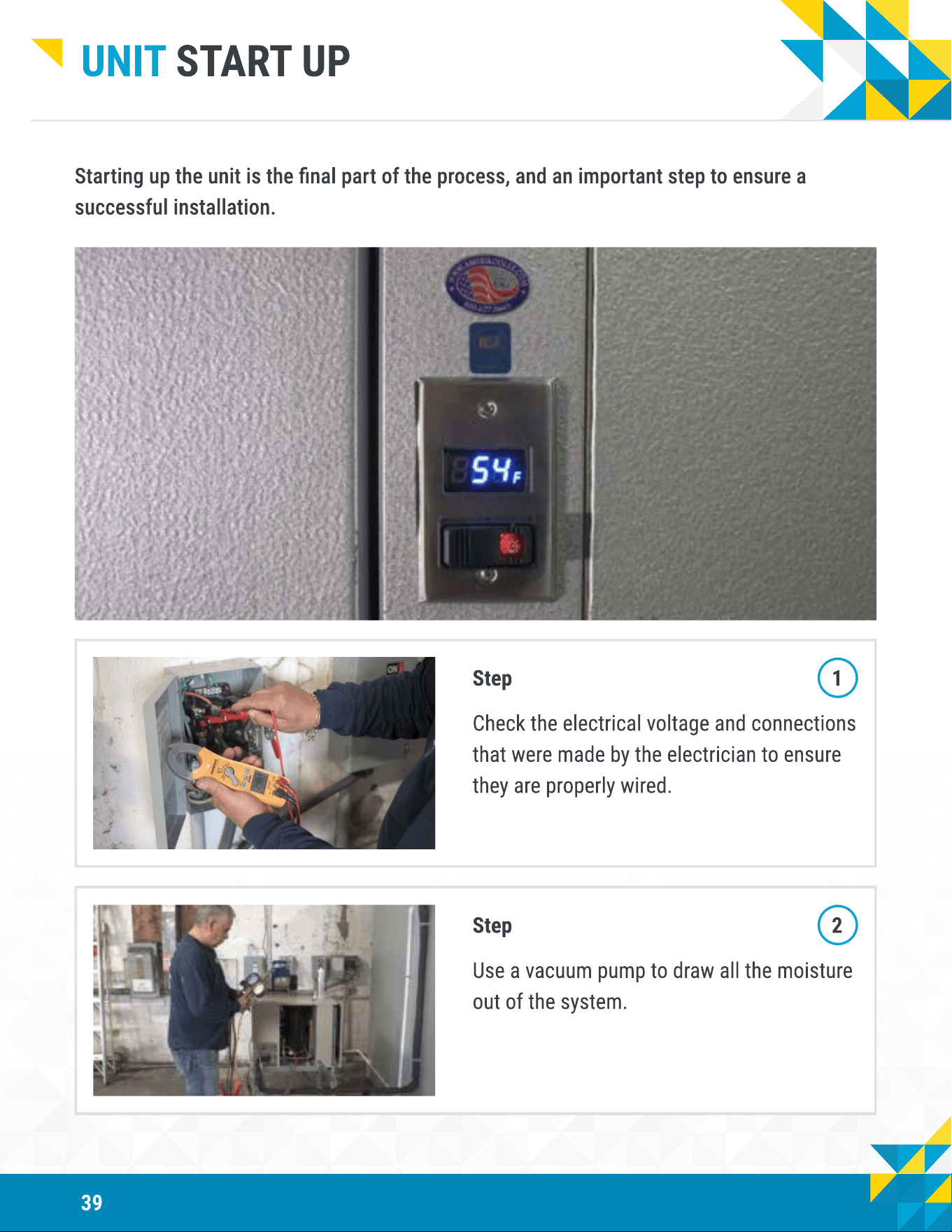
39
unit start up
Starting up the unit is the nal part of the process, and an important step to ensure a
successful installation.
Step 1
Check the electrical voltage and connections
that were made by the electrician to ensure
they are properly wired.
Step 2
Use a vacuum pump to draw all the moisture
out of the system.
40
unit start up
Step 3
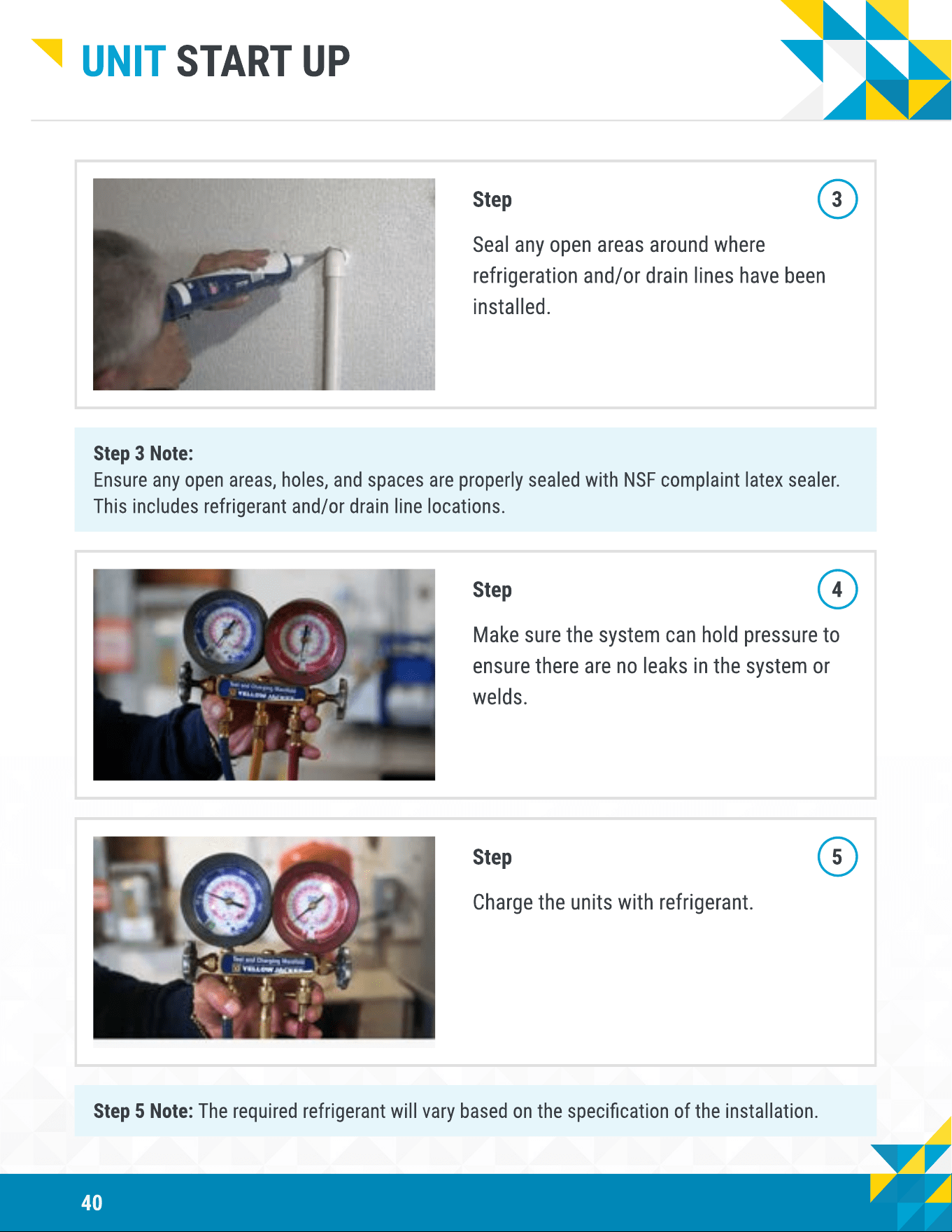
Seal any open areas around where
refrigeration and/or drain lines have been
installed.
Step 3 Note
Ensure any open areas, holes, and spaces are properly sealed with NSF complaint latex sealer.
This includes refrigerant and/or drain line locations.
Step 4
Make sure the system can hold pressure to
ensure there are no leaks in the system or
welds.
Step 5
Charge the units with refrigerant.
Step 5 Note: The required refrigerant will vary based on the specication of the installation.
41
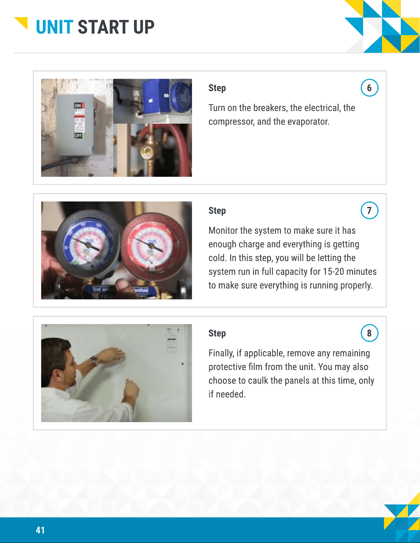
Step 6
Turn on the breakers, the electrical, the
compressor, and the evaporator.
Step 7
Monitor the system to make sure it has
enough charge and everything is getting
cold. In this step, you will be letting the
system run in full capacity for 15-20 minutes
to make sure everything is running properly.
Step 8
Finally, if applicable, remove any remaining
protective lm from the unit. You may also
choose to caulk the panels at this time, only
if needed.
unit start up
42
additional installations
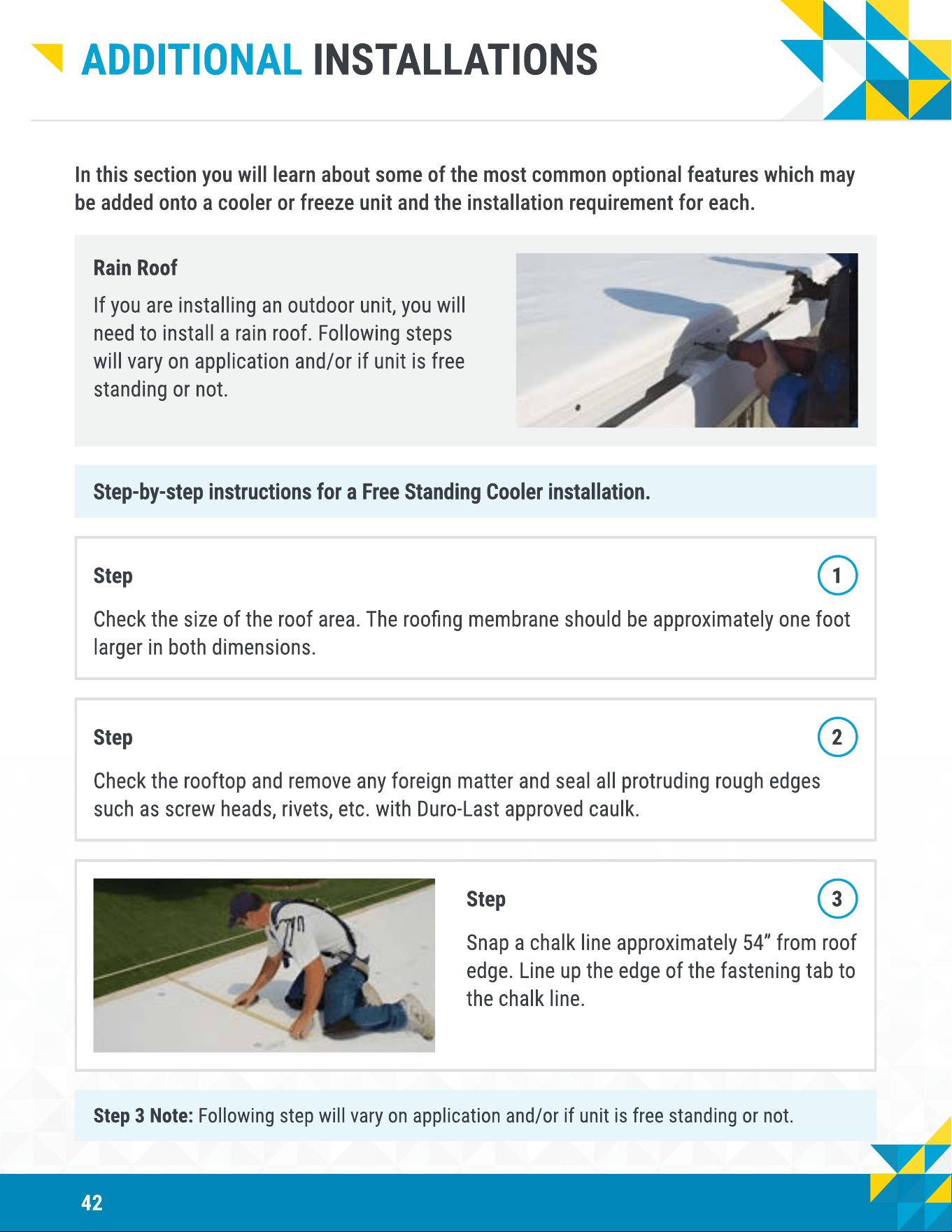
Rain Roof
If you are installing an outdoor unit, you will
need to install a rain roof. Following steps
will vary on application and/or if unit is free
standing or not.
In this section you will learn about some of the most common optional features which may
be added onto a cooler or freeze unit and the installation requirement for each.
Step-by-step instructions for a Free Standing Cooler installation.
Step 1
Check the size of the roof area. The roong membrane should be approximately one foot
larger in both dimensions.
Step 2
Check the rooftop and remove any foreign matter and seal all protruding rough edges
such as screw heads, rivets, etc. with Duro‐Last approved caulk.
Step 3
Snap a chalk line approximately 54” from roof
edge. Line up the edge of the fastening tab to
the chalk line.
Step 3 Note: Following step will vary on application and/or if unit is free standing or not.
43
additional installations
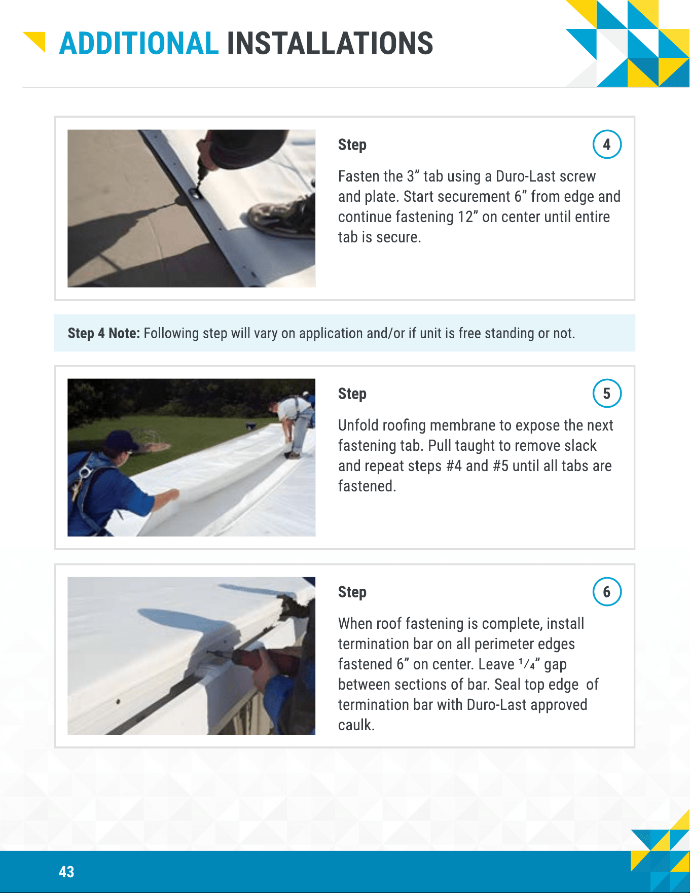
Step 4
Fastenthe3”tabusingaDuro-Last screw
and plate. Start securement 6” from edge and
continue fastening 12” on center until entire
tab is secure.
Step 4 Note: Following step will vary on application and/or if unit is free standing or not.
Step 5
Unfold roong membrane to expose the next
fastening tab. Pull taught to remove slack
and repeat steps #4 and #5 until all tabs are
fastened.
Step 6
When roof fastening is complete, install
termination bar on all perimeter edges
fastened 6” on center. Leave 1⁄4” gap
between sections of bar. Seal top edge of
termination bar with Duro‐Last approved
caulk.
44
additional installations
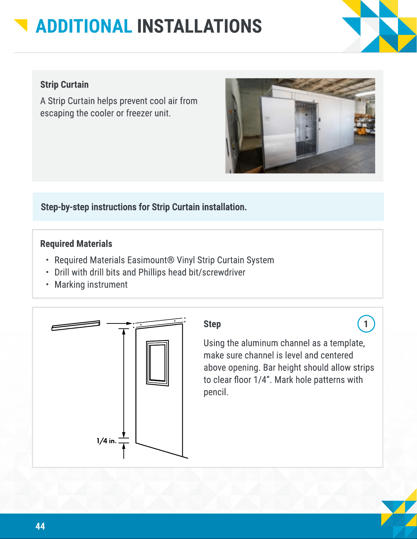
Strip Curtain
A Strip Curtain helps prevent cool air from
escaping the cooler or freezer unit.
Required Materials
Required Materials Easimount® Vinyl Strip Curtain System
Drill with drill bits and Phillips head bit/screwdriver
Marking instrument
Step 1
Using the aluminum channel as a template,
make sure channel is level and centered
above opening. Bar height should allow strips
to clear oor 1/4”. Mark hole patterns with
pencil.
Step-by-step instructions for Strip Curtain installation.
45
additional installations
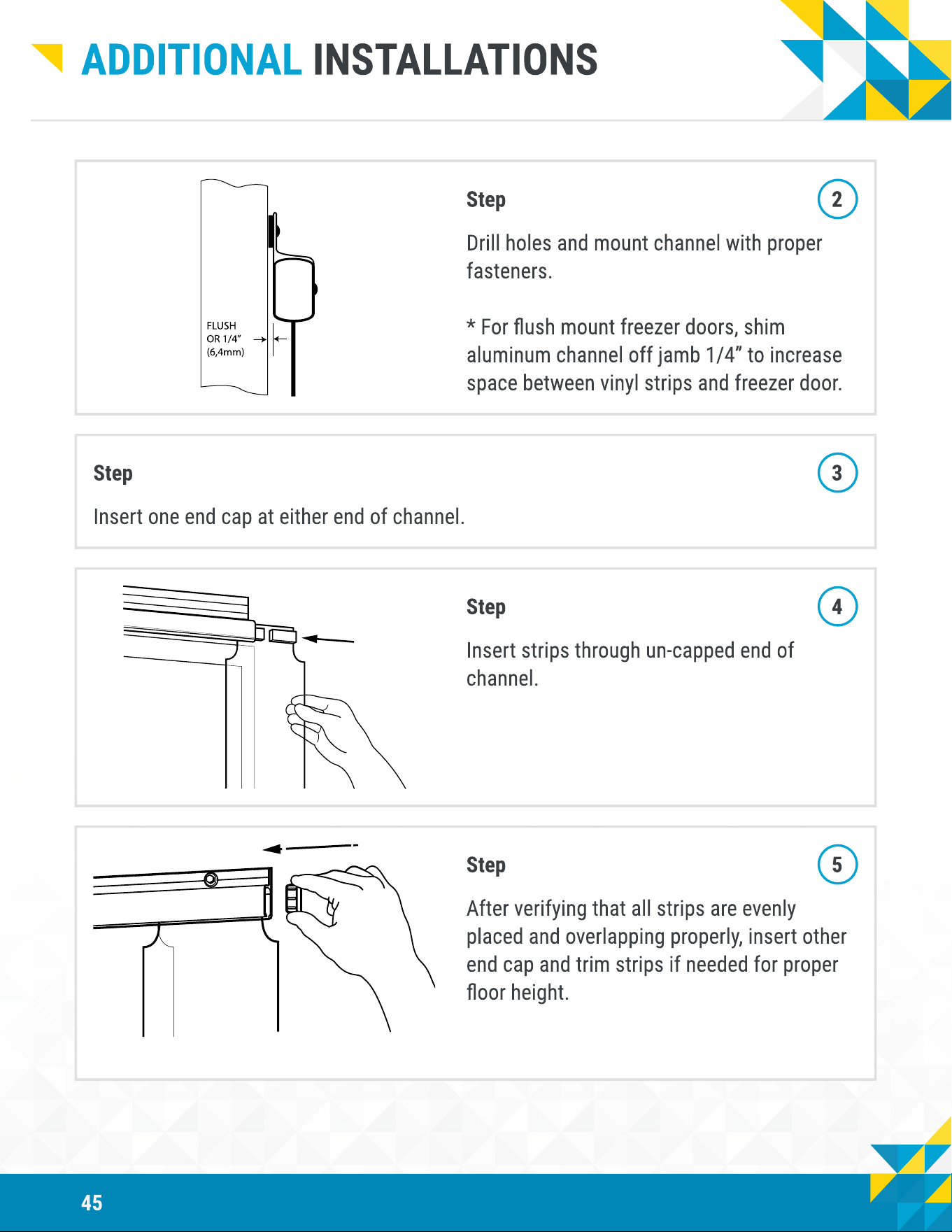
Step 2
Drill holes and mount channel with proper
fasteners.
* For ush mount freezer doors, shim
aluminum channel off jamb 1/4” to increase
space between vinyl strips and freezer door.
Step 3
Insert one end cap at either end of channel.
Step 4
Insert strips through un-capped end of
channel.
Step 5
After verifying that all strips are evenly
placed and overlapping properly, insert other
end cap and trim strips if needed for proper
oor height.
46
additional installations
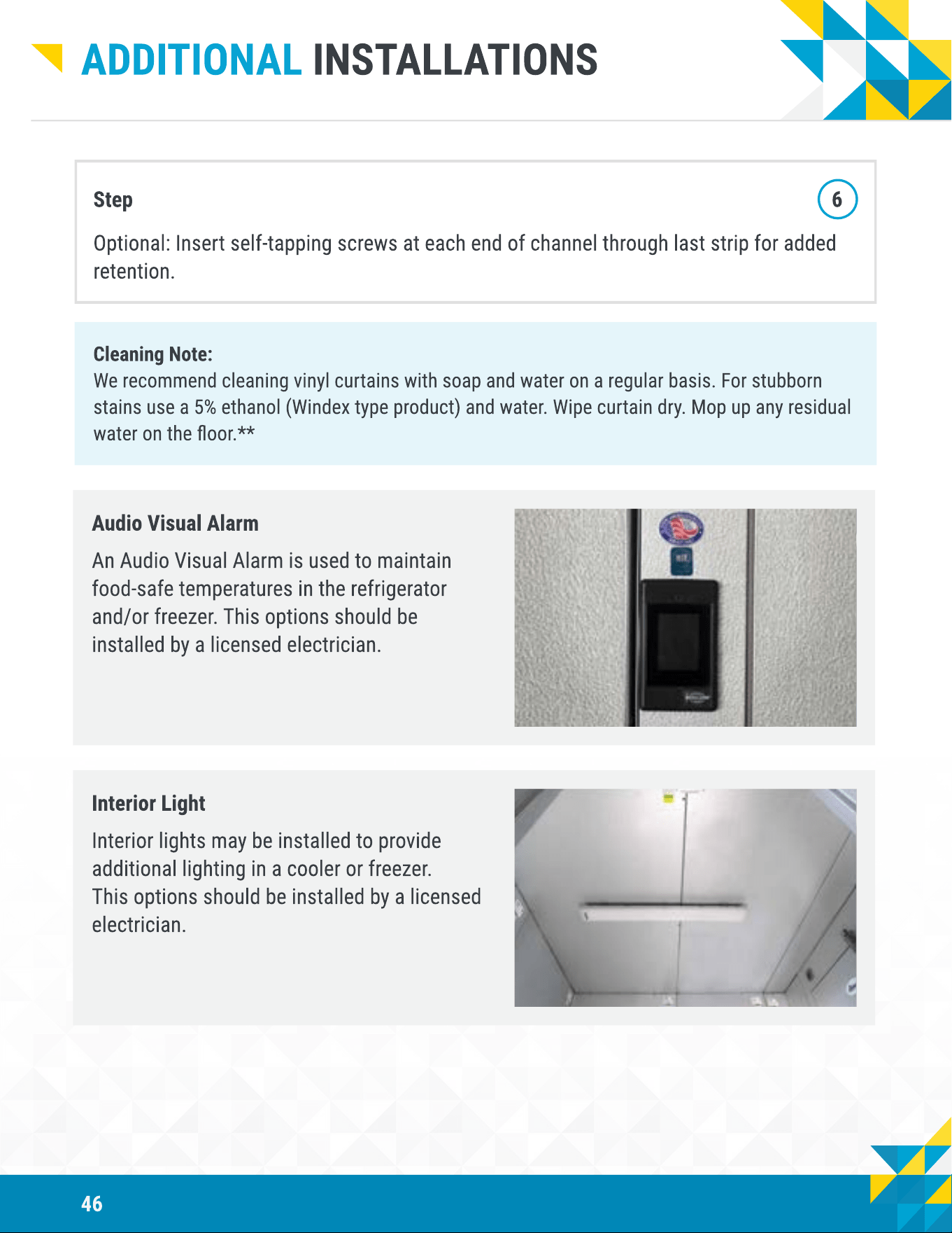
Step 6
Optional: Insert self-tapping screws at each end of channel through last strip for added
retention.
Cleaning Note
We recommend cleaning vinyl curtains with soap and water on a regular basis. For stubborn
stains use a 5% ethanol (Windex type product) and water. Wipe curtain dry. Mop up any residual
water on the oor.**
Audio Visual Alarm
An Audio Visual Alarm is used to maintain
food-safe temperatures in the refrigerator
and/or freezer. This options should be
installed by a licensed electrician.
Interior Light
Interior lights may be installed to provide
additional lighting in a cooler or freezer.
This options should be installed by a licensed
electrician.
47
additional installations
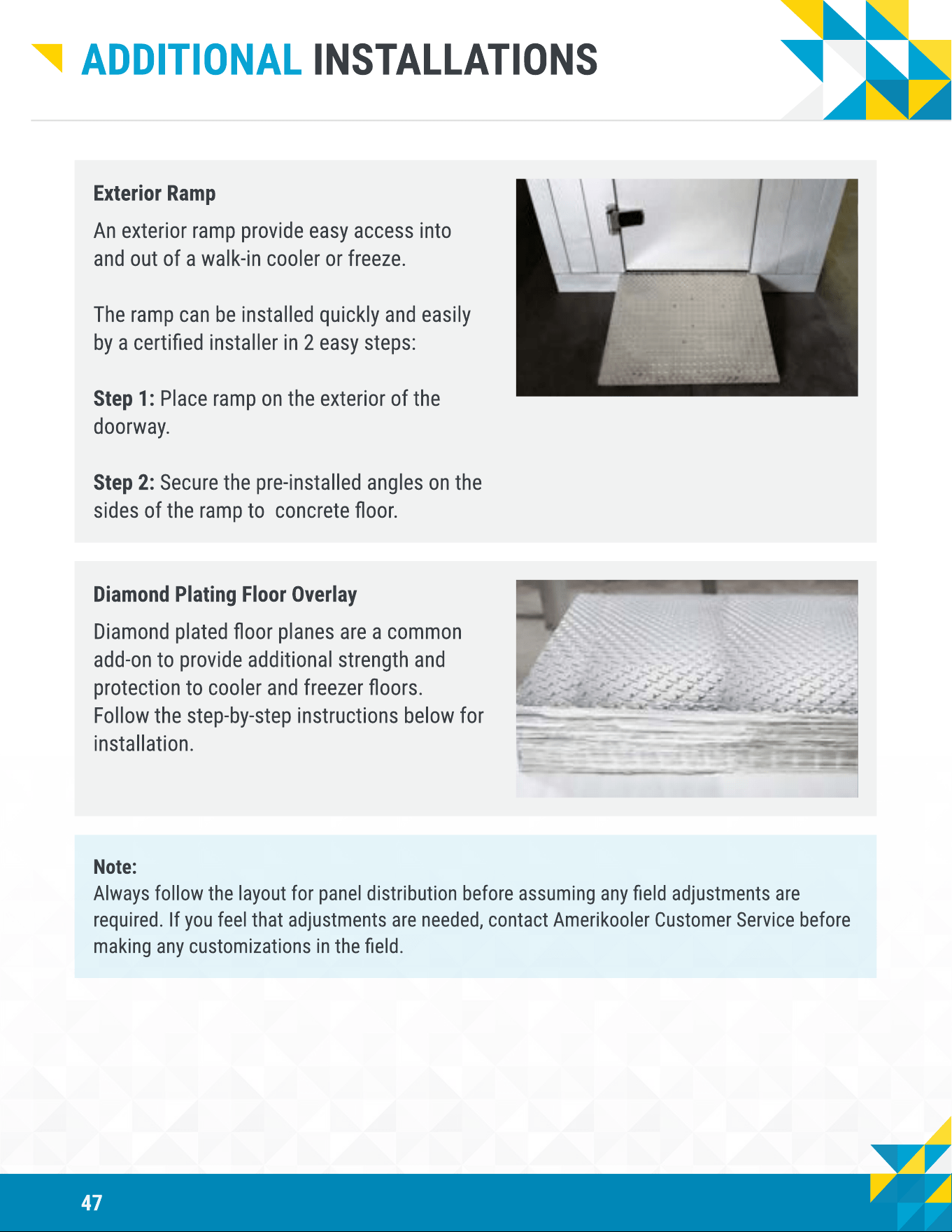
Exterior Ramp
An exterior ramp provide easy access into
and out of a walk-in cooler or freeze.
The ramp can be installed quickly and easily
by a certied installer in 2 easy steps
Step 1: Place ramp on the exterior of the
doorway
Step 2: Secure the pre-installed angles on the
sides of the ramp to concrete oor.
Diamond Plating Floor Overlay
Diamond plated oor planes are a common
add-on to provide additional strength and
protection to cooler and freezer oors.
Follow the step-by-step instructions below for
installation.
Note
Always follow the layout for panel distribution before assuming any eld adjustments are
required. If you feel that adjustments are needed, contact Amerikooler Customer Service before
making any customizations in the eld.
48
additional installations
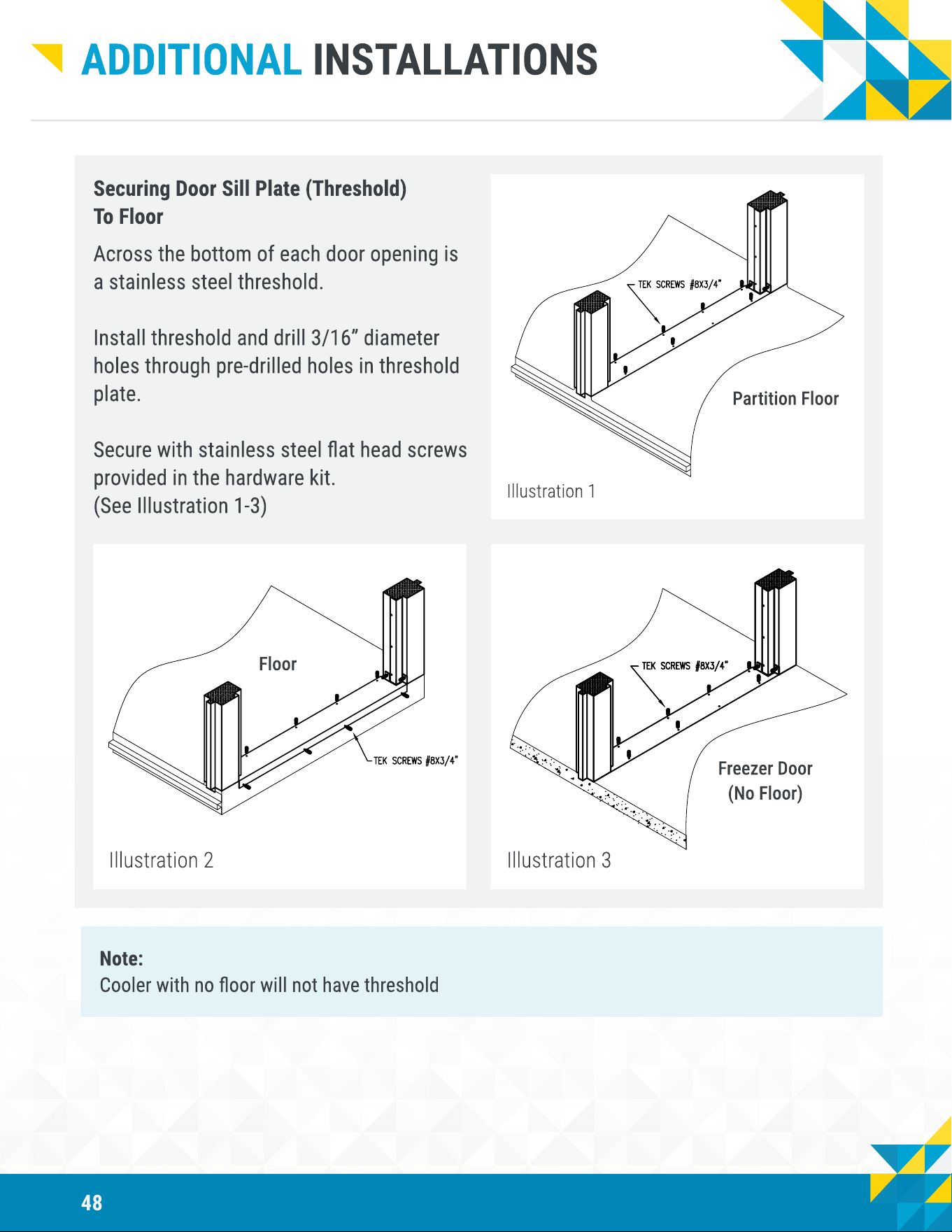
Securing Door Sill Plate (Threshold)
To Floor
Across the bottom of each door opening is
a stainless steel threshold
Install threshold and drill 3/16” diameter
holes through pre-drilled holes in threshold
plate
Secure with stainless steel at head screws
provided in the hardware kit.
(See Illustration 1-3)
Partition Floor
Illustration 1
Illustration 2
Floor
Freezer Doo
(No Floor)
Illustration 3
Note
Cooler with no oor will not have threshold
49
additional installations
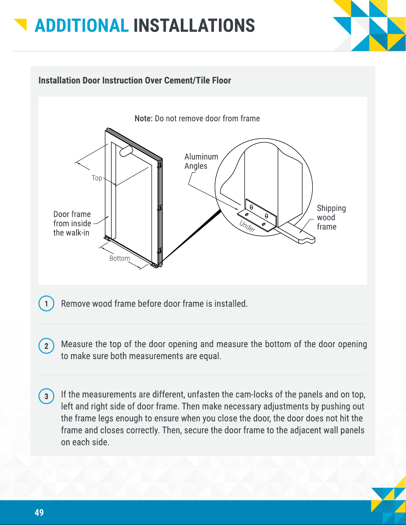
Installation Door Instruction Over Cement/Tile Floor
Note: Do not remove door from frame
Aluminum
Angles
Shipping
wood
frame
Door frame
from inside
the walk-in
Top
Bottom
Under
1
Remove wood frame before door frame is installed.
2
Measure the top of the door opening and measure the bottom of the door opening
to make sure both measurements are equal.
3
If the measurements are different, unfasten the cam-locks of the panels and on top,
left and right side of door frame. Then make necessary adjustments by pushing out
the frame legs enough to ensure when you close the door, the door does not hit the
frame and closes correctly. Then, secure the door frame to the adjacent wall panels
on each side.
50
additional installations
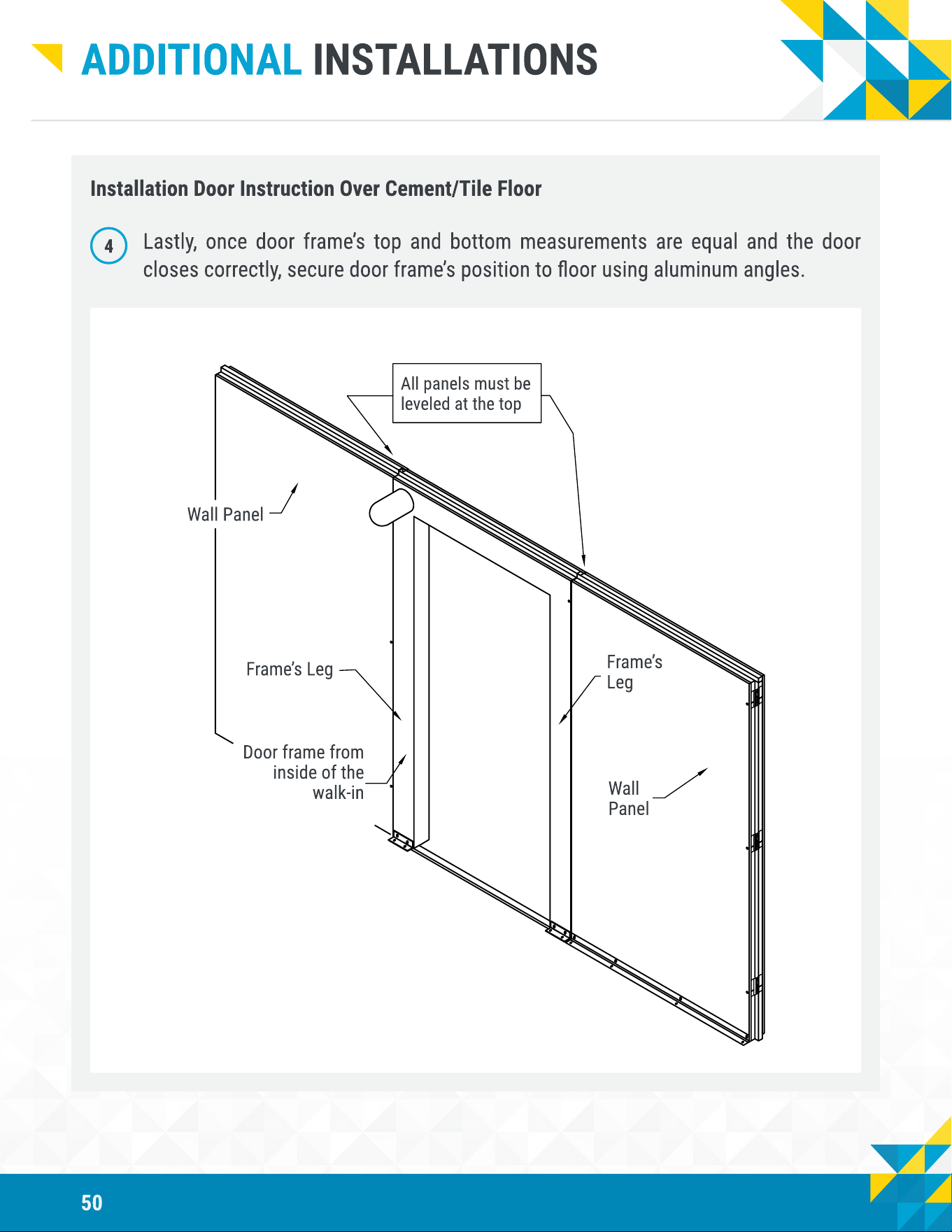
Installation Door Instruction Over Cement/Tile Floor
4
Lastly, once door frame’s top and bottom measurements are equal and the door
closes correctly, secure door frame’s position to oor using aluminum angles.
Wall Panel
Frame’s Leg
Frame’s
Leg
All panels must be
leveled at the top
Door frame from
inside of the
walk-in
Wall
Panel
51
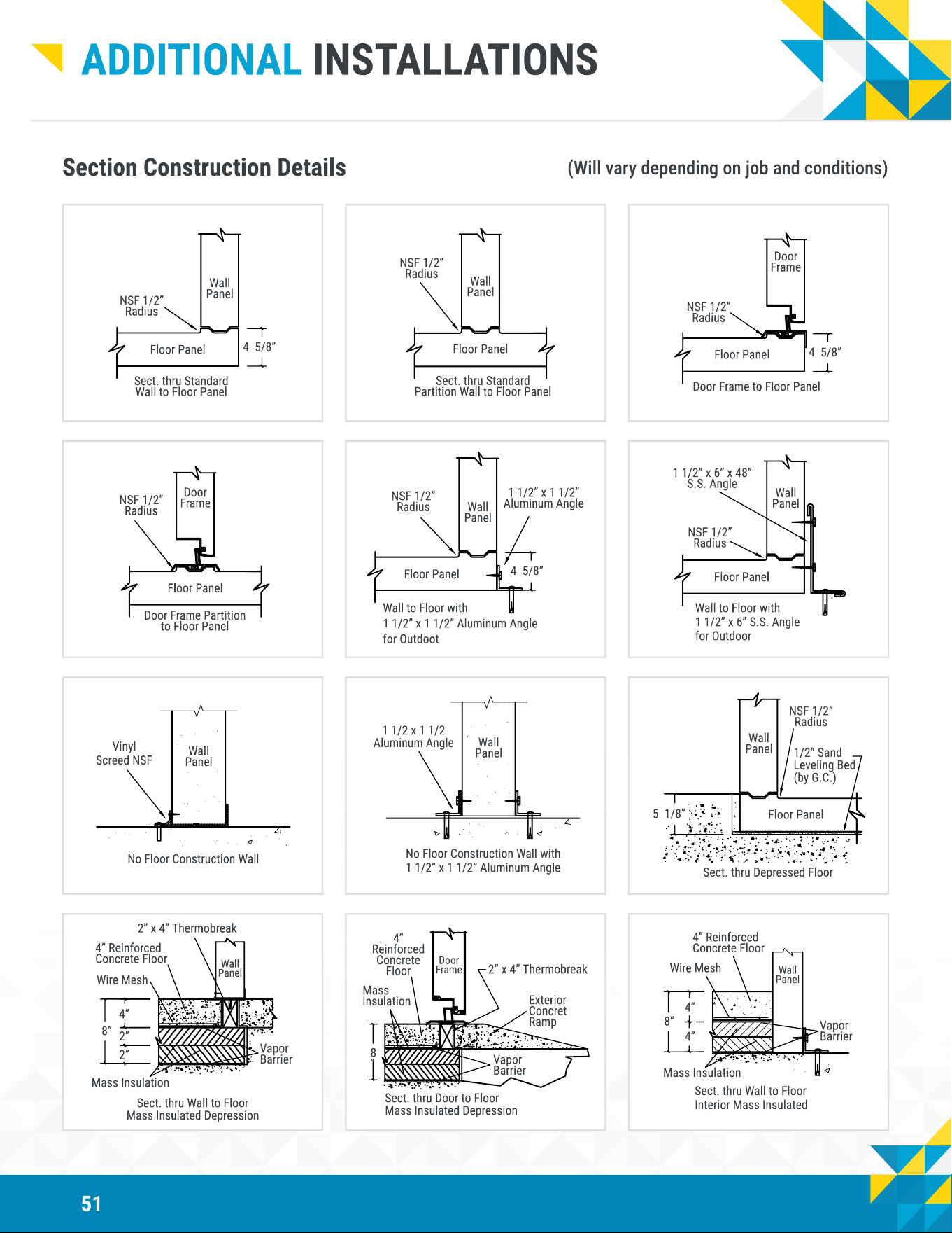
(Will vary depending on job and conditions)
Wal
Panel
Floor Panel
Sect. thru Standard
Wall to Floor Panel
4 5/8”
NSF 1/2”
Radius
NSF 1/2”
Radius
Wal
Panel
Floor Panel
Sect. thru Standard
Partition Wall to Floor Panel
NSF 1/2”
Radius
Wal
Panel
Floor Panel
Sect. thru Standard
Partition Wall to Floor Panel
NSF 1/2”
Radius
Doo
Frame
Floor Panel
4 5/8”
Door Frame to Floor Panel
NSF 1/2”
Radius
Doo
Frame
Floor Panel
Door Frame Partition
to Floor Panel
NSF 1/2”
Radius Wal
Panel
1 1/2” x 1 1/2
Aluminum Angle
Floor Panel
4 5/8”
Wall to Floor wit
1 1/2” x 1 1/2” Aluminum Angle
for Outdoot
NSF 1/2”
Radius Wal
Panel
1 1/2” x 1 1/2
Aluminum Angle
Floor Panel
4 5/8”
Wall to Floor wit
1 1/2” x 1 1/2” Aluminum Angle
for Outdoot
NSF 1/2”
Radius
Wal
Panel
1 1/2” x 6” x 48
S.S. Angle
Floor Panel
Wall to Floor wit
1 1/2” x 6” S.S. Angle
for Outdoor
Vapo
Barrier
4” Reinforce
Concrete Floor
Wire Mesh
8”
Mass Insulation
Sect. thru Wall to Floo
Interior Mass Insulated
4”
4”
Wal
Panel
Doo
Frame
2” x 4” Thermobreak
Exterio
Concret
Ramp
Vapo
Barrier
Sect. thru Door to Floo
Mass Insulated Depression
4”
Reinforce
Concrete
Floor
Mas
Insulation
8
”
Sect. thru Wall to Floo
Mass Insulated Depression
8”
4”
2”
2”
2” x 4” Thermobreak
Vapo
Barrier
Mass Insulation
Wal
Panel
4” Reinforce
Concrete Floor
Wire Mesh
NSF 1/2”
Radius
Sect. thru Depressed Floor
1/2” San
Leveling Be
(by G.C.)
Floor Panel
5 1/8”
Wal
Panel
No Floor Construction Wall with
1 1/2” x 1 1/2” Aluminum Angle
1 1/2 x 1 1/2
Aluminum Angle
Wal
Panel
No Floor Construction Wall with
1 1/2” x 1 1/2” Aluminum Angle
1 1/2 x 1 1/2
Aluminum Angle
Wal
Panel
Vinyl
Screed NSF
No Floor Construction Wall
Wal
Panel
additional installations
Section Construction Details
52
Installation Best Practices
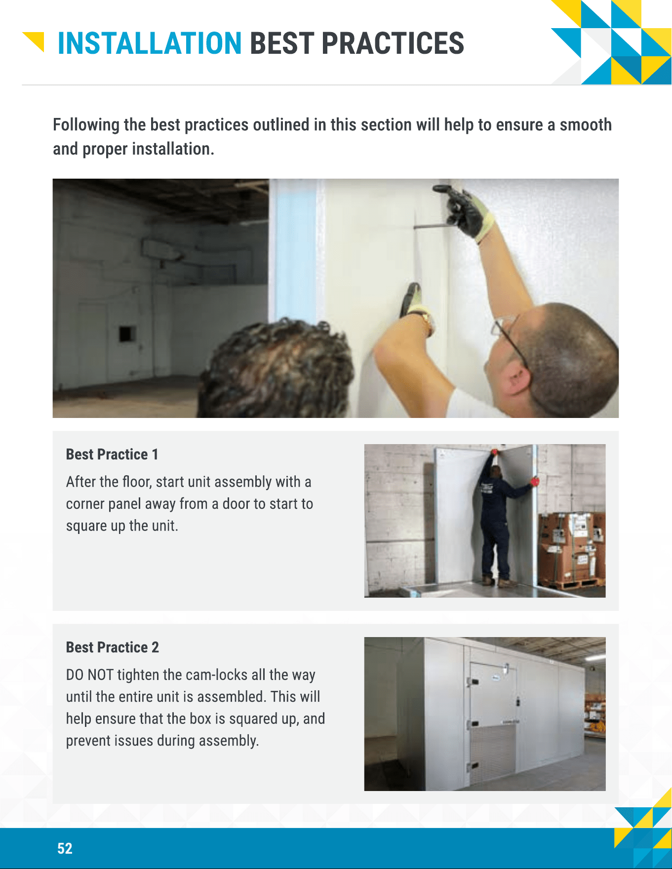
Following the best practices outlined in this section will help to ensure a smooth
and proper installation.
Best Practice 1
After the oor, start unit assembly with a
corner panel away from a door to start to
square up the unit.
Best Practice 2
DO NOT tighten the cam-locks all the way
until the entire unit is assembled. This will
help ensure that the box is squared up, and
prevent issues during assembly.

53
Installation Best Practices
Best Practice 3
Do not forget to add cam-lock plugs to cam-
lock opens.
Best Practice 4
If any panels have protective lm, we
recommend removing the lm from corners/
edges prior to assembling, and removing the
rest of the lm once all installation steps are
completed to prevent any damage to the
panels during installation.
Best Practice 5
Before making any eld corrections during an
installation, reach out to Amerikooler
Customer Service for assistance:
customerservice@amerikooler.net or (800)
627-5665
54
Troubleshooting & FAQ
In this section we will present you some common troubleshooting scenarios and
frequently asked questions and answers.
Understanding this information up front can save you time and energy during your next
installation.
Troubleshooting
Scenario 1: The refrigeration unit is not reaching temperature.
Either the unit is not fully charged, a component of the unit has malfunctioned, or the installer
didn’t set the correct temperature.
If you’re still unable to identify the issue, please email hrpsesweb@lennoxind.com or call
800-537-7775 Ext. 3, and a certied Heat Craft refrigeration expert will advise you in more
detail.
Scenario 2: Panels are not lining up.
Determine if the issue is that oor panels are not lining up, the wall panels are not lining up,
or the ceiling panels are not lining up.
Make sure the surface where the walk-in is being installed is level.
Make sure that during installation you didn’t prematurely tighten the cam-locks on any section
of panels before having all panels in place. If this is the case, please contact
A
merikooler
Customer
S
ervice so we can advise the proper solution for your specic build
:
c
u
stomerser
v
ice@amerikooler.net or
(
800
)
62
7-5
66
5 Ext.
669
.
55
Troubleshooting & FAQ
Scenario 3: Cam-locks are not lining up.
First check if the directional sticker on the panel is mistakenly placed upside-down. If it is, ip
the panel.
If the panels are all facing in their correct directions, please contact
customerservice@amerikooler.net.
Scenario 4: The door is not closing properly.
Do not remove the door from the hinges. You need to adjust the hinges to eliminate the sag.
To adjust the hinges please refer to the Hing regulator adjustment steps below.
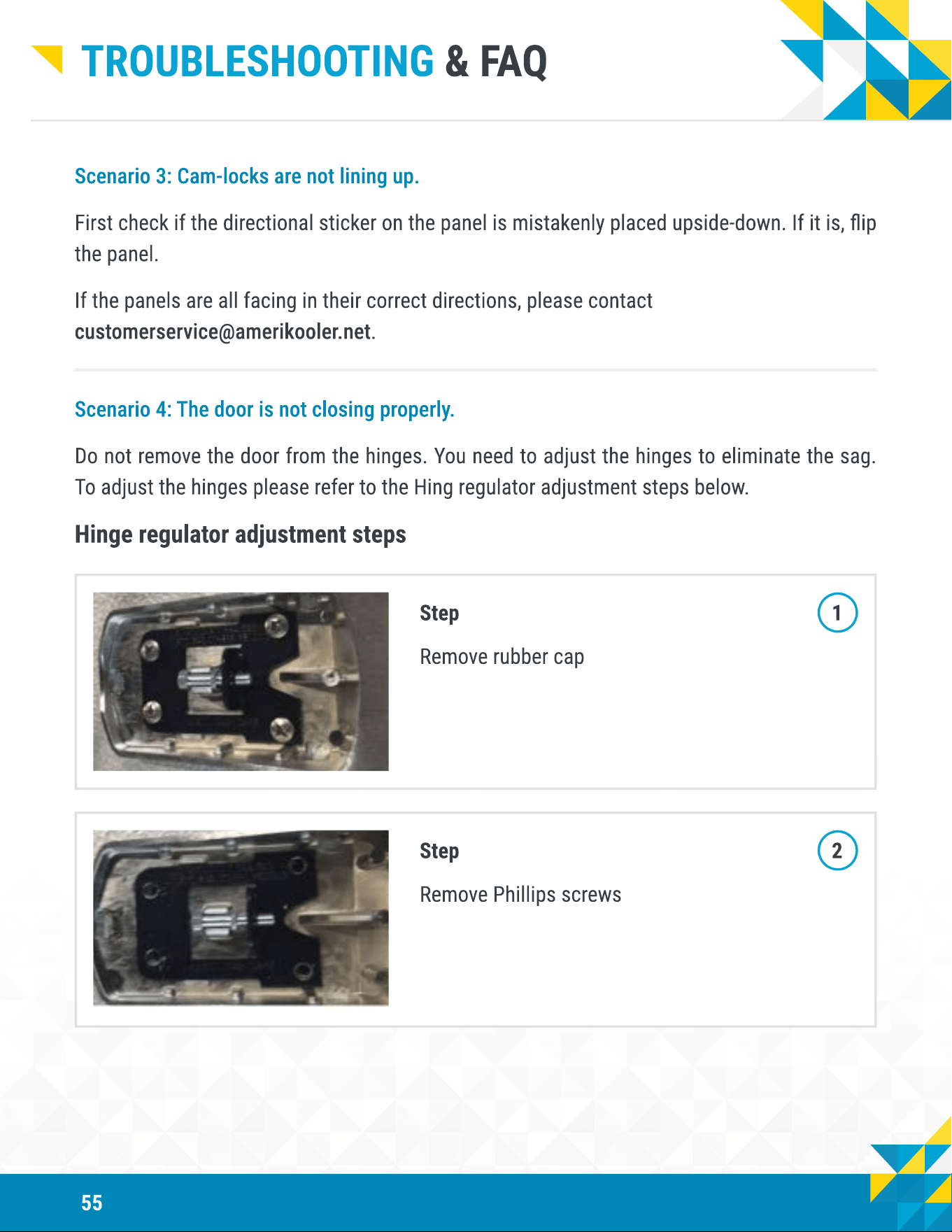
Hinge regulator adjustment steps
Step 1
Remove rubber cap
Step 2
Remove Phillips screws
56
Troubleshooting & FAQ
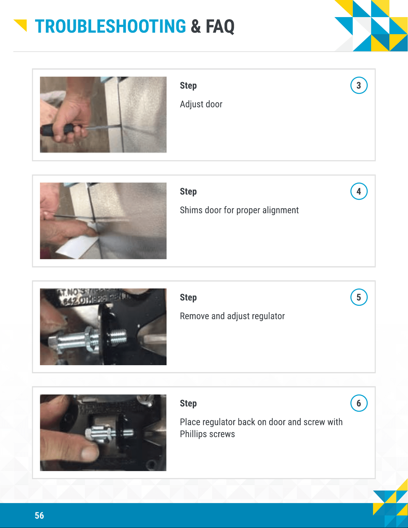
Step 3
Adjust door
Step 4
Shims door for proper alignment
Step 5
Remove and adjust regulator
Step 6
Place regulator back on door and screw with
Phillips screws
57
Troubleshooting & FAQ
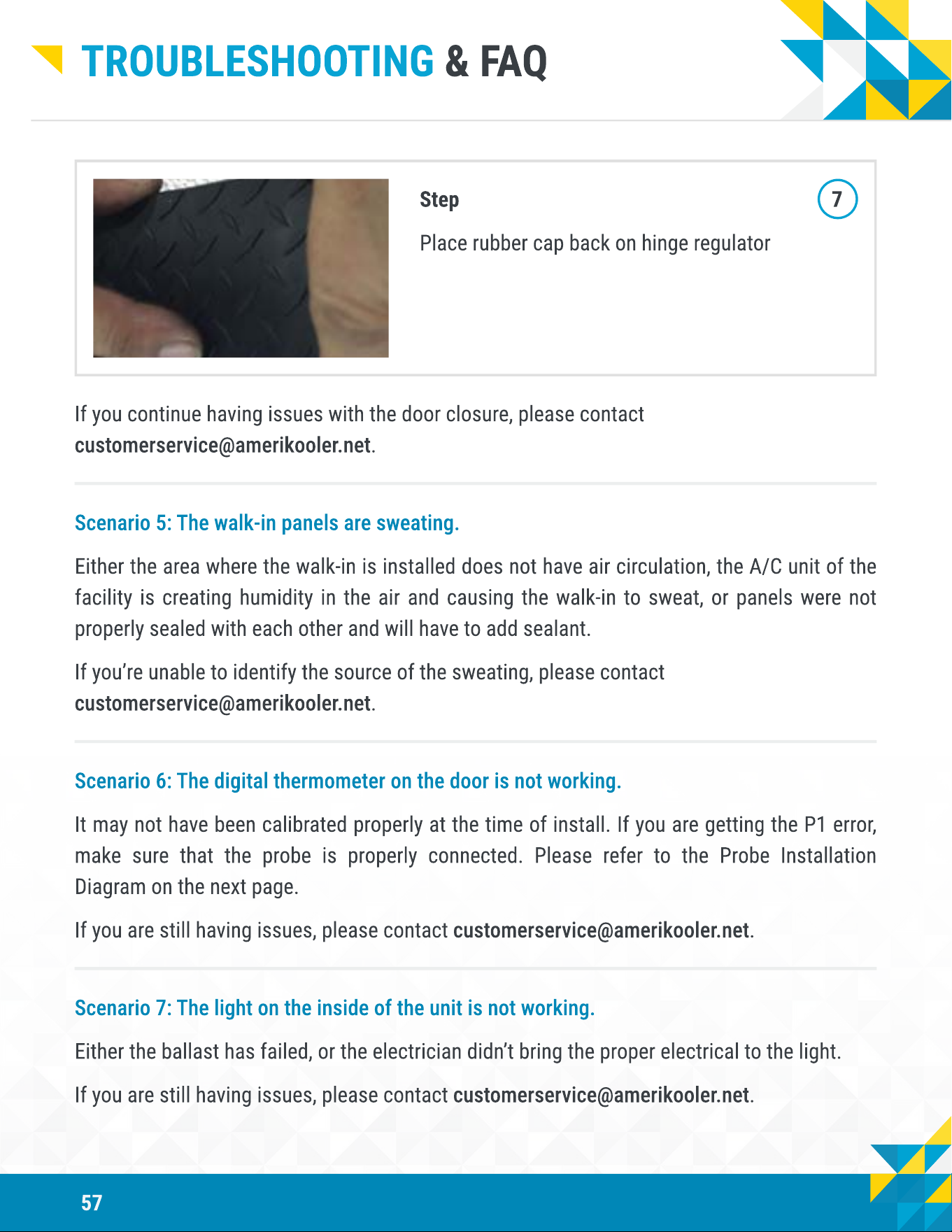
Step 7
Place rubber cap back on hinge regulator
If you continue having issues with the door closure, please contact
customerservice@amerikooler.net.
Scenario 5: The walk-in panels are sweating.
Either the area where the walk-in is installed does not have air circulation, the A/C unit of the
facility is creating humidity in the air and causing the walk-in to sweat, or panels were not
properly sealed with each other and will have to add sealant.
If you’re unable to identify the source of the sweating, please contact
customerservice@amerikooler.net.
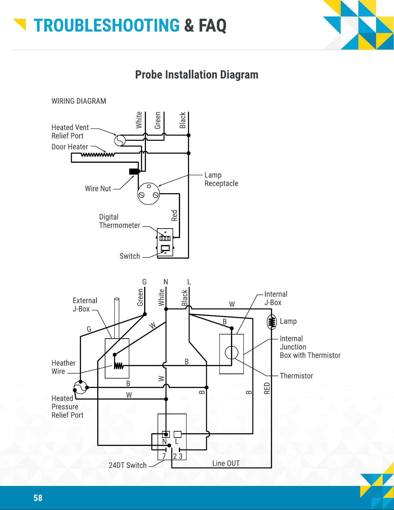
Scenario 6: The digital thermometer on the door is not working.
It may not have been calibrated properly at the time of install. If you are getting the P1 error,
make sure that the probe is properly connected. Please refer to the Probe Installation
Diagram on the next page.
If you are still having issues, please contact customerservice@amerikooler.net.
Scenario 7: The light on the inside of the unit is not working.
Either the ballast has failed, or the electrician didn’t bring the proper electrical to the light.
If you are still having issues, please contact customerservice@amerikooler.net.
58
Troubleshooting & FAQ
Probe Installation Diagram
Green
White
Black
N
N
7 2 3
L
G L
W
B
B
B
W
W
G
B
W
B
RED
Line OUT
Interna
Junctio
Box with Thermistor
Interna
J-Box
Thermistor
Lamp
24DT Switch
Heathe
Wire
Heate
Pressur
Relief Port
Externa
J-Box
Green
White
Black
Red
Heated Ven
Relief Port
Digita
Thermometer
Lam
Receptacle
Switch
Wire Nut
Door Heater
WIRING DIAGRAM
59
Troubleshooting & FAQ
FAQs
Can I hook up the condensing unit and evaporator on the same circuit?
On cooler units, the condensing unit and evaporator will have to be on two separate circuits.
The reason is that the condensing unit voltage is 208-230 and the evaporator coil is 115v. On
Freezer units, the condensing unit will be connected to the circuit and you can feed the
evaporator coil if you like. However, if by any chance the unit malfunctions, you will have to
power down both units to examine the issue.
Can I put the compressor and lights on the same breaker?
No. The reason is that the lights should be independent from the condensing units because if
by any chance a light malfunctions, and it is in the same circuit, it will turn off the unit and
cause it to not work.
Can you send me the build to drawings?
Please email customerservice@amerikooler.net and we will provide you with the build to
drawings. Please include your unit’s serial number in your email, which is located inside the
walk-in, on a metal plate on the frame, always on the opposite side of the hinges.
When will the unit arrive?
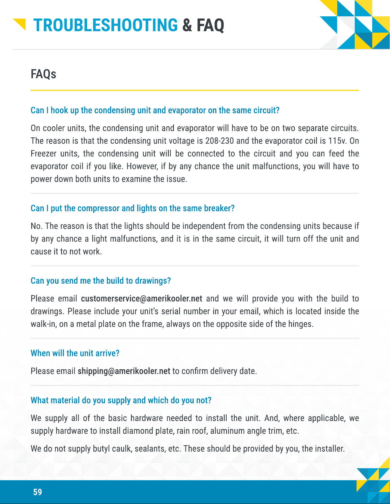
Please email shipping@amerikooler.net to conrm delivery date.
What material do you supply and which do you not?
We supply all of the basic hardware needed to install the unit. And, where applicable, we
supply hardware to install diamond plate, rain roof, aluminum angle trim, etc.
We do not supply butyl caulk, sealants, etc. These should be provided by you, the installer.
60
Troubleshooting & FAQ
How do I wire the freezer or cooler door?
Please refer to the diagram on the frames of the doors. There are wiring schematics there
that identify the wiring instructions for each frame (cooler and/or freezer).
How do I bring the power into the unit to wire the freezer and cooler doors?
After reviewing the cooler/freezer door schematics on the door frame(s), run a conduit from
the breaker to the walk-in wall (not the ceiling).
Note
Running a conduit from the ceiling increases the risk of water leakage and damage to the unit.
Once you’ve determined the best point to run the conduit, drill a circular hole on the wall
panel to bring the conduit (with power) into the walk-in’s junction box which is located behind
the light.
Do we have a wiring diagram for the refrigeration units?
The wiring diagram is located inside the refrigeration unit.
I
f you are still having trouble with
refrigeration unit wiring please email hrpsesweb
@
lenno
x
ind
.
com or call
(800)
537-7775
Ex
t
.
3
and a certi
ed
H
eat
C
raft refrigeration expert will advise you in more detail.
Please refer to the wiring diagrams for the
C
oo
l
e
r
T
h
e
rm
o
m
ete
r
/
On-Off
Swi
t
ch,
LED,
120
V
o
l
t
/1
,
C
oo
l
e
r
T
h
e
rm
o
m
ete
r
/
On-Off
Swi
t
ch,
LED,
220
V
o
l
t
/
1
,
F
r
ee
z
e
r
T
h
e
rm
o
m
ete
r
/
On-Off
Swi
t
ch,
LED,
120
V
o
l
t
/1
and F
r
ee
z
e
r
T
h
e
rm
o
m
ete
r
/
On-Off
Swi
t
ch,
LED,
120
V
o
l
t
/
1
on the next pages.

61
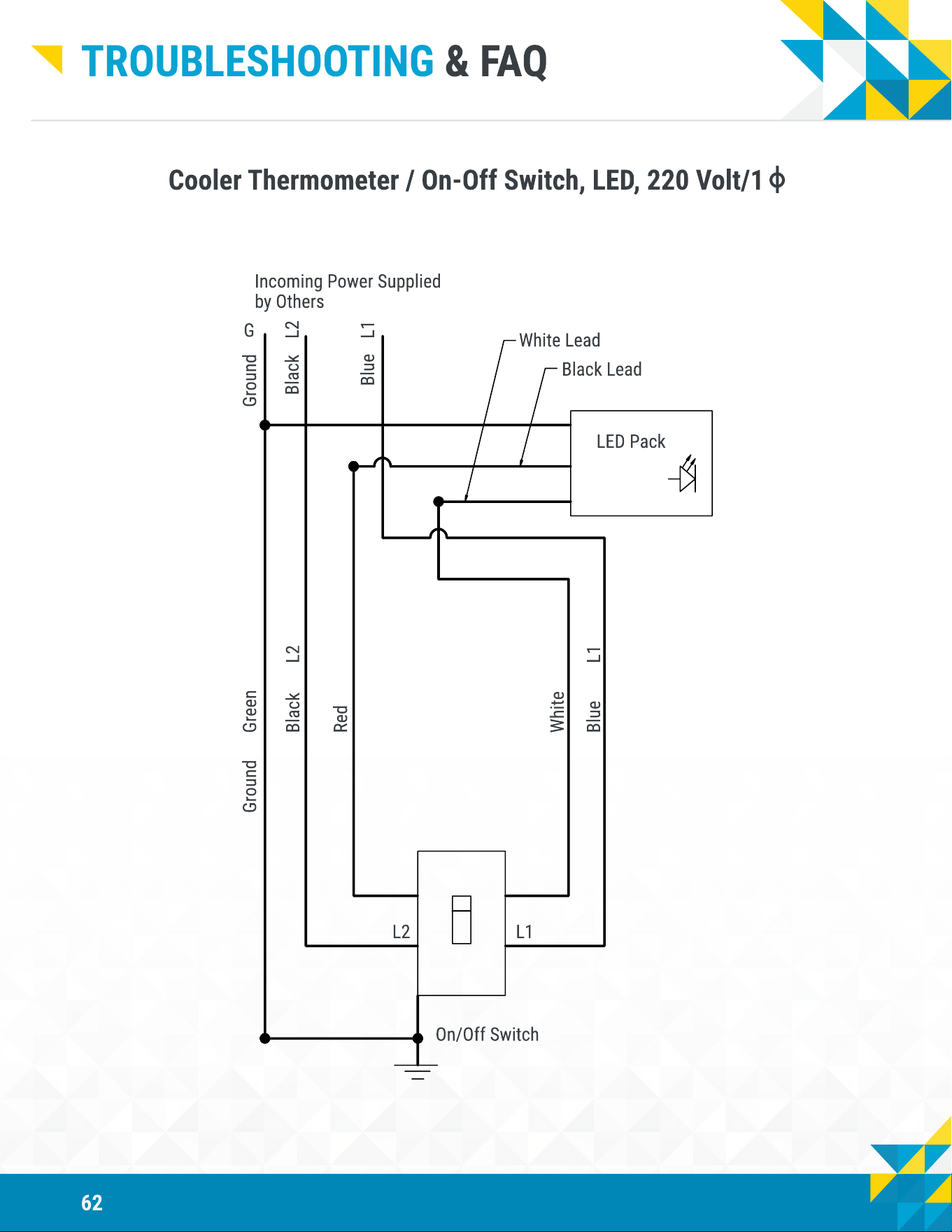
Cooler Thermometer / On-Off Switch, LED, 120 Volt/1
Incoming Power Supplie
by Others
White Lead
Black Lead
LED Pack
N
WG
Ground
Green
White
Black
Black
Red
A
N L
GND
7 2 3
Line OUT
Line IN
On/Off Switch Thermomete
S/S Face Plate
Ground Wire
On/Off Switc
Pilot Light
Stud Welde
to S/S Plate
Section A-A
A
Red
L
B
Troubleshooting & FAQ
62
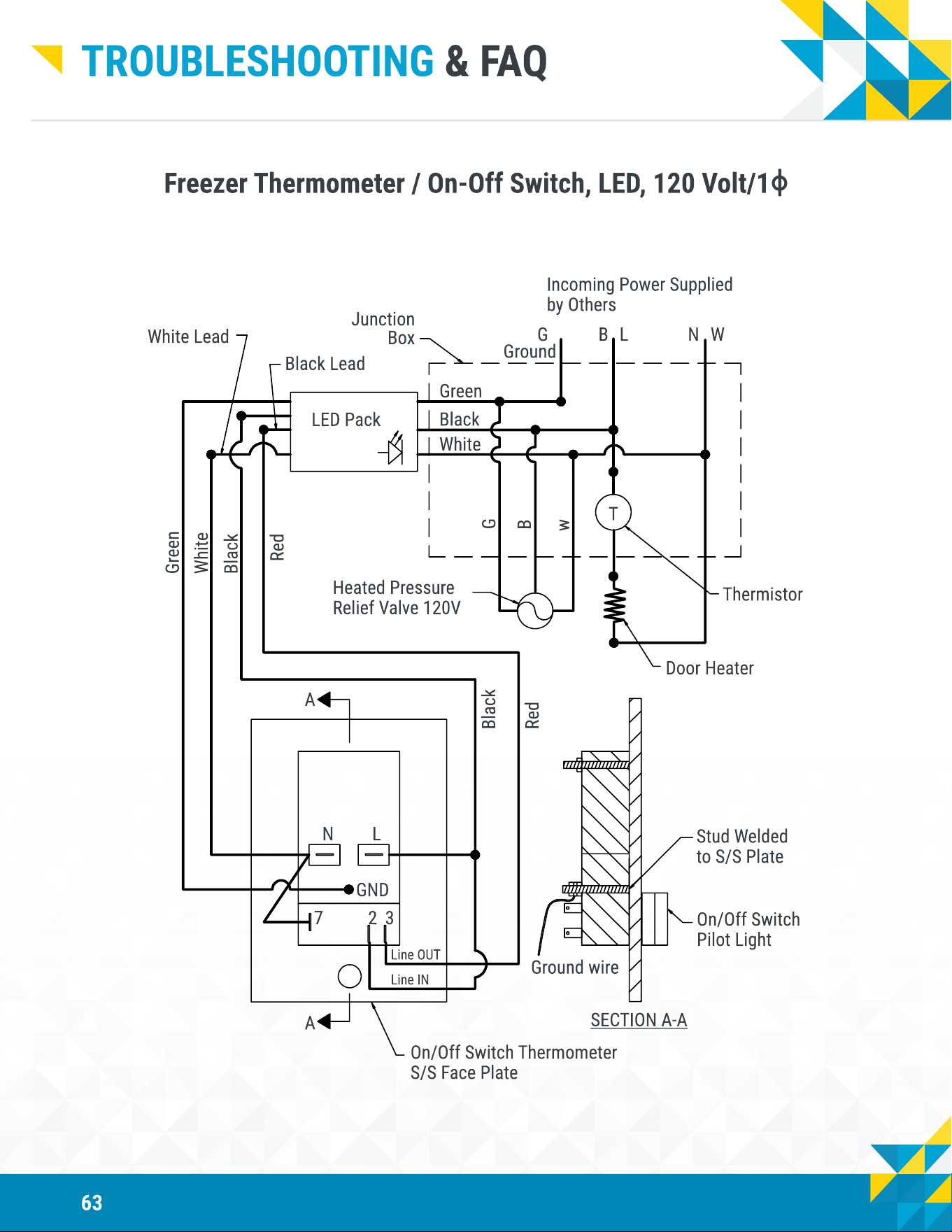
Incoming Power Supplie
by Others
White Lead
Black Lead
LED Pack
G
GroundGround Green
Black
L2
L2 L1
On/Off Switch
L1
Red
White
Blue
Black L2
L1Blue
Cooler Thermometer / On-Off Switch, LED, 220 Volt/1
Troubleshooting & FAQ
63
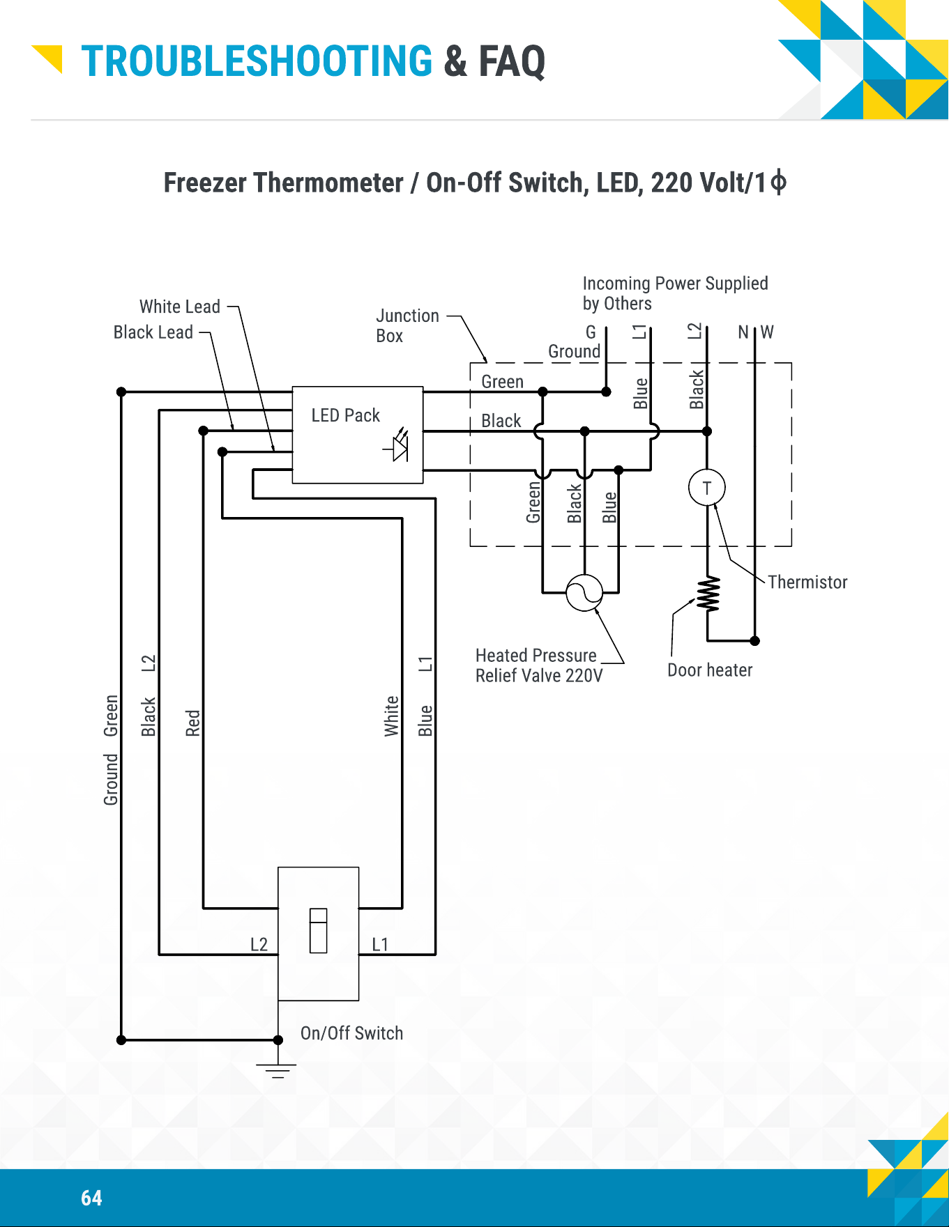
White Lead
Black Lead
LED Pack
Ground
Green
Green
White
Black
Red
Red
Black
Heated Pressur
Relief Valve 120V
Black
White
G
G
B
w
T
Thermistor
Door Heater
Stud Welde
to S/S Plate
On/Off Switc
Pilot Light
Ground wire
On/Off Switch Thermomete
S/S Face Plate
A
A
N L
GND
7 2 3
Line IN
Line OUT
SECTION A-A
B L N W
Junctio
Box
Incoming Power Supplie
by Others
Freezer Thermometer / On-Off Switch, LED, 120 Volt/1
Troubleshooting & FAQ
64
White Lead
Junctio
Box
LED Pack
Incoming Power Supplie
by Others
Ground
Green
Black
Blue
Blue
Black
Green
Black
G N
T
Thermistor
Door heater
Heated Pressur
Relief Valve 220V
On/Off Switch
L1L2
L1Blue
White
Red
Black L2
Ground Green
W
L1
L2
Black Lead
Freezer Thermometer / On-Off Switch, LED, 220 Volt/1
Troubleshooting & FAQ