User's Guide
CMP0443-02 EN

Copyrights and Trademarks
No part of this publication may be reproduced, stored in a retrieval system, or transmitted in any form or by any means, electronic, mechanical,
photocopying, recording, or otherwise, without the prior written permission of Seiko Epson Corporation. The information contained herein is
designed only for use with this Epson printer. Epson is not responsible for any use of this information as applied to other printers.
Neither Seiko Epson Corporation nor its affiliates shall be liable to the purchaser of this product or third parties for damages, losses, costs, or expenses
incurred by the purchaser or third parties as a result of accident, misuse, or abuse of this product or unauthorized modifications, repairs, or alterations
to this product, or (excluding the U.S.) failure to strictly comply with Seiko Epson Corporation's operating and maintenance instructions.
Seiko Epson Corporation shall not be liable for any damages or problems arising from the use of any options or any consumable products other than
those designated as Original Epson Products or Epson Approved Products by Seiko Epson Corporation.
Seiko Epson Corporation shall not be held liable for any damage resulting from electromagnetic interference that occurs from the use of any interface
cables other than those designated as Epson Approved Products by Seiko Epson Corporation.
Microsoft and Windows are trademarks of the Microsoft group of companies.
Apple, Mac, OS X, and Bonjour are registered trademarks of Apple Inc., registered in the U.S. and other countries.
Intel
®
and Intel Core
®
are registered trademarks of Intel Corporation.
Adobe, Illustrator, and Acrobat Reader are either registered trademarks or trademarks of Adobe in the United States and/or other countries.
Copyright © 2021 Adobe Inc. All Rights Reserved.
Chrome, YouTube and the YouTube logo are trademarks of Google LLC.
Firefox is a trademark of the Mozilla Foundation in the U.S. and other countries.
General Notice: Other product names used herein are for identification purposes only and may be trademarks of their respective owners. Epson disclaims
any and all rights in those marks.
©2023-2026 Seiko Epson Corporation
SC-F20000 Series/SC-F11000H Series/SC-F11000 Series/SC-F10000H Series/SC-F10000 Series User's Guide
Copyrights and Trademarks
2

Note for North American and Latin American Users
IMPORTANT: Before using this product, make sure you read the safety instructions in the online Notices.
SC-F20000 Series/SC-F11000H Series/SC-F11000 Series/SC-F10000H Series/SC-F10000 Series User's Guide
Copyrights and Trademarks
3

Contents
Copyrights and Trademarks
Note for North American and Latin American Users 3
Notes on Manuals
Meaning of Symbols........................ 6
Model Names and Target Models............... 6
Screenshots in This Manual................... 6
Illustrations.............................. 6
Manual Organization....................... 6
Viewing Video Manuals..................... 7
Viewing PDF Manuals....................... 8
Introduction
Printer Parts.............................. 9
Front Section........................... 9
Ink supply unit......................... 12
Right view............................ 14
Inside................................ 16
Back................................. 18
Media Feeding Unit (Large Capacity Type). . . . . 20
Auto Take-up Reel Unit (Large Capacity Type). . 22
Control panel.......................... 24
Understanding and Operating the Display. . . . . . . 27
Home screen........................... 27
Menu screen........................... 37
Instructions screen...................... 38
Types of Buttons........................ 38
Notes on Usage and Storage.................. 40
Installation space....................... 40
Notes when using the printer............... 40
Notes when not using the printer............ 41
Notes on handling ink cartridges............ 41
Handling media........................ 42
Introducing the Supplied Software............. 44
Using Epson Edge Dashboard................ 47
Launching the application................. 47
Registering the printer.................... 47
Checking and managing the printer's status. . . . 48
Downloading and copying media settings for
EMX files............................. 50
Editing media settings.................... 54
Exiting procedure....................... 55
Using Epson Edge Print (Windows Only). . . . . . . . 56
Launching the Application................. 56
Acquiring and Registering EMX Files......... 56
Exiting Procedure....................... 56
Using LFP Accounting Tool (Windows Only). . . . . 56
Basic Settings.......................... 56
Screen Layout.......................... 61
Using EPSON Software Updater.............. 64
Checking software update availability......... 64
Receiving update notifications.............. 65
Using Web Config......................... 65
Instructions for starting................... 65
Exiting procedure....................... 65
Uninstalling Software...................... 65
Basic Operations
Workflow for Optimal Printing............... 67
Registering Media Settings to the Printer........ 68
Precautions When Handling Media............ 68
Notes on Loading and Removing Media......... 69
Precautions When Handling Spindles........... 71
Pulling Out Media Manually when Using the
Large Capacity Roll Models/Large Capacity Reel
Models................................. 71
When working from the back side........... 71
When working from the front side........... 72
Media Loading Procedure................... 74
Points To Check In Advance............... 74
Media Loading Procedure by Model.......... 77
Loading Media Into the Media Feeding Unit. . . . . . 81
Loading the standard type Media Feeding Unit. . 81
Loading the large capacity type Media
Feeding Unit........................... 87
Loading Media Into the Auto Take-up Reel Unit. . . 99
Important points for correct take-up......... 99
Loading Media Into the Standard Type Auto
Take-Up Reel Unit...................... 100
Loading Media Into the Large Capacity Type
Auto Take-Up Reel Unit.................. 110
Removing the Take-up Roll................. 130
Setting Information Printing at Media Cut. . . . 130
Cutting Media......................... 130
Removing the Media.................... 132
Removing the Loaded Media................ 134
Removing from the standard type Media
Feeding Unit.......................... 134
SC-F20000 Series/SC-F11000H Series/SC-F11000 Series/SC-F10000H Series/SC-F10000 Series User's Guide
Contents
4

Removing from the large capacity type Media
Feeding Unit.......................... 136
When the Remaining Media Runs Out......... 139
Before Printing.......................... 140
Print Adjustments........................ 140
Automatic Adjustment................... 140
Print Head Alignment................... 141
Media Feed Adjustment.................. 142
Printable Area........................... 145
Width Detection and Media Edge Position. . . . 145
Printable area and image print area. . . . . . . . . 146
Maintenance
When to Perform Various Maintenance
Operations............................. 150
Cleaning............................. 150
Replacing consumables.................. 152
Other maintenance..................... 152
Necessary Items.......................... 154
Precautions Regarding Maintenance........... 154
Cleaning............................... 155
Daily cleaning......................... 155
Using Cleaning liquid................... 159
Cleaning the media cleaners............... 159
Cleaning anti-drying caps................ 160
Cleaning the suction caps................ 163
Cleaning around the print head............ 164
Cleaning the inside light................. 166
Cleaning the front cover................. 167
Replacing Consumables.................... 168
Replacing ink cartridges................. 168
Replacing the wiper roll.................. 173
Disposing of waste ink................... 175
Replacing the media holder............... 177
Other Maintenance....................... 181
Periodic shaking of ink cartridges........... 181
Checking for clogged nozzles.............. 185
Print Head Cleaning.................... 186
Checking the circuit breaker’s performance. . . . 187
Disposing of Used Consumables............. 189
Disposal............................. 189
Control Panel Menu
Menu List.............................. 190
Details of the Menu....................... 201
General Settings menu................... 201
Media Settings menu.................... 209
Maintenance menu..................... 219
Supply Status menu..................... 220
Replacement Part Information menu........ 220
Printer Status menu..................... 221
Problem Solver
When a Message is Displayed................ 222
When an Error Message is Displayed.......... 224
Troubleshooting......................... 225
You cannot print (because the printer does
not work)............................ 225
The printer sounds like it is printing, but
nothing prints......................... 226
The prints are not what you expected........ 226
Media............................... 228
Others.............................. 230
Appendix
Options and Consumable Products........... 231
Ink cartridges......................... 231
Others.............................. 235
Supported Media......................... 237
Moving and Transporting the Printer.......... 237
Moving the printer..................... 237
Transport............................ 253
Using Pressure Roller Spacers................ 253
How to install spacers................... 253
How to remove spacers.................. 254
Parallel Adjustments for the Auto Take-up Reel
Unit and the Media Feeding Unit............. 255
Preparing for parallel adjustments.......... 255
How to adjust......................... 256
Recovering from an Emergency Stop.......... 269
Media Settings List for Each Media Type........ 271
SC-F11000H Series/SC-F11000 Series/SC-
F10000H Series/SC-F10000 Series. . . . . . . . . . 272
SC-F20000 Series. . . . . . . . . . . . . . . . . . . . . . 280
Reading the Signal Lamps.................. 285
System Requirements..................... 287
Epson Edge Dashboard.................. 287
Epson Edge Print....................... 288
Web Config........................... 289
Specifications Table....................... 290
SC-F20000 Series/SC-F11000H Series/SC-F11000 Series/SC-F10000H Series/SC-F10000 Series User's Guide
Contents
5
Notes on Manuals
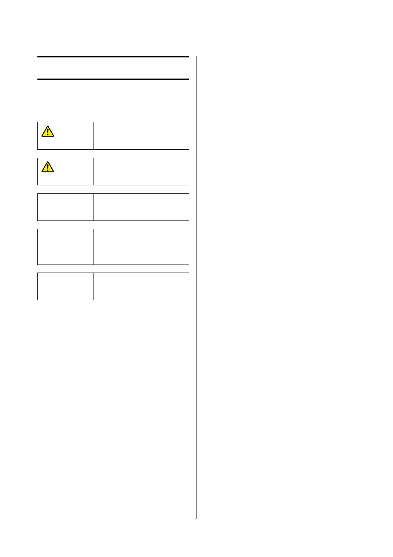
Meaning of Symbols
War ni ng:
Warnings must be followed to
avoid serious bodily injury.
Caution:
Cautions must be followed to
avoid bodily injury.
c
Important:
Important must be followed to
avoid damage to this product.
Note:
Notes contain useful or
additional information on the
operation of this product.
U
Indicates related reference
content.
Model Names and Target
Models
❏ This printer has models with different
combinations of media feeding units and Auto
Take-up Reel Units.
This manual names each model as follows, based
on the combination of media feeding unit and
Auto Take-up Reel Unit.
❏ Standard roll/reel models
Media feeding unit: Standard type
Auto Take-up Reel Unit: Standard type
❏ Large capacity roll models
Media feeding unit: Large capacity type
Auto Take-up Reel Unit: Standard type
❏ Large capacity reel models
Media feeding unit: Large capacity type
Auto Take-up Reel Unit: Large capacity type
See the following for details on the media feeding
unit and Auto Take-up Reel Unit.
U “Printer Parts” on page 9
❏ The explanations for the SC-F11000H Series and
SC-F11000 Series in this manual are also suitable
for models upgraded from SC-F10000H Series or
SC-F10000 Series.
Screenshots in This
Manual
❏ The screenshots in this manual may differ slightly
from the real screens.
❏ The screenshots of the control panel in this
manual are set to have Black backgrounds.
Illustrations
❏ The illustrations in this manual are of the
SC-F20000 Series, SC-F11000 Series, and
SC-F10000 Series, unless otherwise specified.
❏ The illustrations in this manual may differ slightly
from the model you are using.
Manual Organization
North America
To view user manuals, visit:
SC-F20070:
SC-F11070H:
❏ www.epson.com/support/f11070h (U.S.)
❏ www.epson.ca/support/f11070h (Canada)
SC-F11070:
❏ www.epson.com/support/f11070 (U.S.)
❏ www.epson.ca/support/f11070 (Canada)
SC-F10070H:
SC-F20000 Series/SC-F11000H Series/SC-F11000 Series/SC-F10000H Series/SC-F10000 Series User's Guide
Notes on Manuals
6
❏ support.epson.com/f20070
❏ www.epson.com/support/f10070h (U.S.)
❏ www.epson.ca/support/f10070h (Canada)
SC-F10070:
❏ www.epson.com/support/f10070 (U.S.)
❏ www.epson.ca/support/f10070 (Canada)
Latin America
To view user manuals, visit:
SC-F20070:
SC-F11070H:
❏ www.latin.epson.com/support/f11070h
(Caribbean)
❏ www.epson.com.br/suporte/f11070h (Brazil)
❏ www.latin.epson.com/soporte/f11070h (other
regions)
SC-F11070:
❏ www.latin.epson.com/support/f11070
(Caribbean)
❏ www.epson.com.br/suporte/f11070 (Brazil)
❏ www.latin.epson.com/soporte/f11070 (other
regions)
SC-F10070H:
❏ www.latin.epson.com/support/f10070h
(Caribbean)
❏ www.epson.com.br/suporte/f10070h (Brazil)
❏ www.latin.epson.com/soporte/f10070h (other
regions)
SC-F10070:
❏ www.latin.epson.com/support/f10070
(Caribbean)
❏ www.epson.com.br/suporte/f10070 (Brazil)
❏ www.latin.epson.com/soporte/f10070 (other
regions)
Other Regions
The manuals for the product are organized as shown
below.
You can view the PDF manuals using Adobe Acrobat
Reader or Preview (Mac).
Start-Up Guide
(booklet)
This manual explains the safety
precautions and the work
involved with connecting the
printer and the computer and
installing software. Make sure
you read this manual to
perform operations safely.
Epson Support (PDF) Provides information about
Epson Support for each region.
Online Manuals
User's Guide
(this manual)
This manual explains how to
use the printer.
Troubleshooting &
Tips
This manual provides
frequently asked questions and
tips on using the printer.
Epson Video
Manuals
These videos show you how to
load media and perform
maintenance.
Network Guide
(PDF)
This manual provides
information on using the
printer over a network.
Viewing Video Manuals
The video manuals have been uploaded to YouTube.
Click [Epson Video Manuals (video)] on the top page
of the Online Manual, or click the following blue text
to view the manuals.
Epson Video Manuals
SC-F20000 Series/SC-F11000H Series/SC-F11000 Series/SC-F10000H Series/SC-F10000 Series User's Guide
Notes on Manuals
7
❏ support.epson.com/f20070
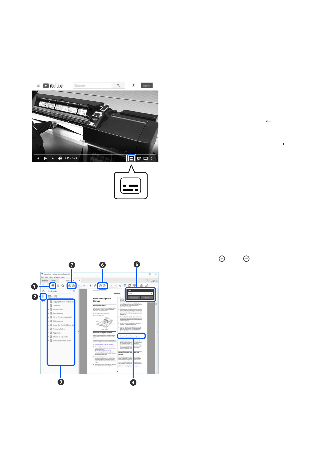
If the subtitles are not displayed when you play the
video, click the subtitles icon shown in the image
below.
Viewing PDF Manuals
This section uses the Adobe Acrobat Reader DC as an
example to explain the basic operations for viewing
the PDF in Adobe Acrobat Reader.
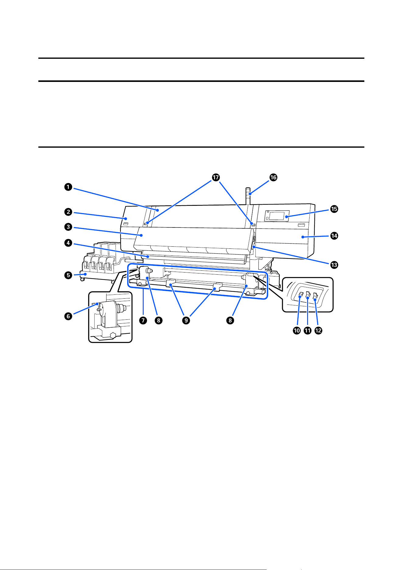
A
Click to print the PDF manual.
B
Each time it is clicked the bookmarks are hidden
or shown.
C
Click the title to open the relevant page.
Click [+] to open the titles lower in the hierarchy.
D
If the reference is in blue text, click the blue text to
open the relevant page.
To return to the original page, do the following.
For Windows
While pressing the Alt key, press the key.
For Mac
While pressing the command key, press the
key.
E
You can input and search for keywords, such as the
names of items you want to confirm.
For Windows
Right click on a page in the PDF manual and select
Find in the menu that is displayed to open the
search toolbar.
For Mac
Select Find in the Edit menu to open the search
toolbar.
F
To enlarge the text in the display that is too small
to see well, click
. Click to reduce the size.
To specify a part of an illustration or screenshot to
enlarge, do the following.
For Windows
Right click on the page in the PDF manual and
select Marquee Zoom in the menu that is
displayed. The pointer changes to a magnifying
glass, use it to specify the range of the place you
want to enlarge.
For Mac
Click View menu - Zoom - Marquee Zoom in this
order to change the pointer to a magnifying glass.
Use the pointer as a magnifying glass to specify the
range of the place you want to enlarge.
G
Opens the previous page or next page.
SC-F20000 Series/SC-F11000H Series/SC-F11000 Series/SC-F10000H Series/SC-F10000 Series User's Guide
Notes on Manuals
8
Introduction
Printer Parts
Illustrations of the SC-F20000 Series, SC-F11000 Series, and SC-F10000 Series are used for these explanations.
Front Section
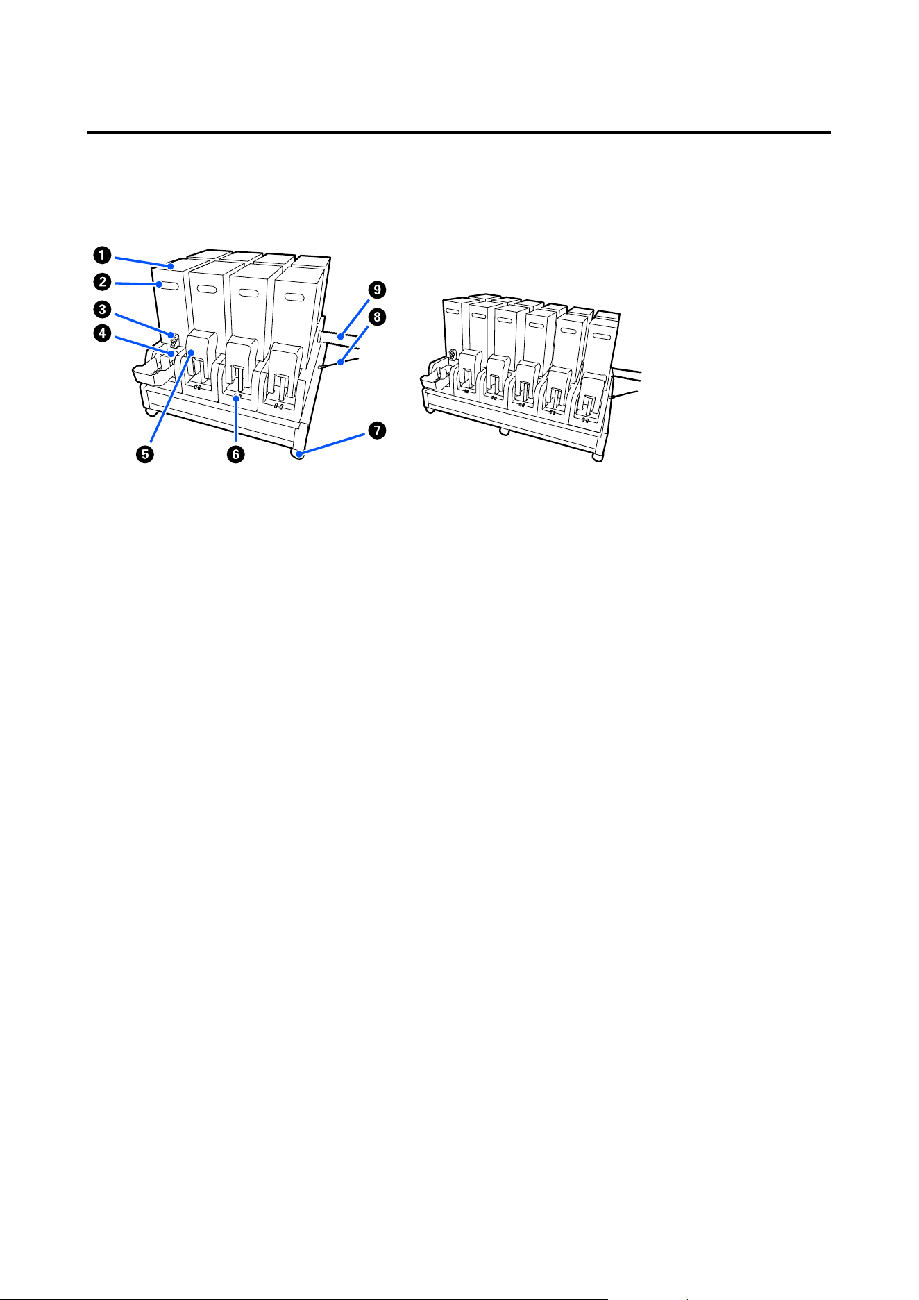
A Front cover
Open when loading media, cleaning the inside of the printer, or removing jammed media. This is normally
closed and locked when using the printer.
B Maintenance cover (left)
Open this cover to clean the area around the caps. This is normally closed when using the printer.
U “Cleaning anti-drying caps” on page 160
C Dryer
The built-in heater and fan quickly dry the ink after printing while circulating the air and maintaining the set
temperature.
It is also possible to turn off the heater and operate only the fan. (Fan)
U “Media Settings screen” on page 33
SC-F20000 Series/SC-F11000H Series/SC-F11000 Series/SC-F10000H Series/SC-F10000 Series User's Guide
Introduction
9

D Media guide bar
The bar maintains tension to prevent the media sagging as it is taken up.
E Ink supply unit
Supplies the printer with ink from the ink cartridges. Holds two ink cartridges for each color.
F Handle
After placing the roll core on the left media holder, rotate the handle and press the media holder into the roll
core.
G Auto Take-up Reel Unit
Automatically takes up printed media.
H Media holder
Place the roll core for media take-up on these holders. The same parts are on both the left and the right sides.
U “Loading Media Into the Auto Take-up Reel Unit” on page 99
I Roll support
Rest media temporarily on these supports when removing the take-up roll. The same parts are on both the left
and the right sides.
J Media feed switch
Feeds/rewinds the media. Because the media feed switch has the same function as the media feed button in the
control panel, you can operate whichever is the easiest to use in your situation. See the explanation for the
media feed button for details about functions.
K Auto switch
Use this switch to select the auto take-up direction. Off is the middle position. Select Off to disable auto
take-up.
L Manual switch
Use this switch for manual take up. The selected option takes effect when the Auto switch is in the Off position.
M Media loading lever
After loading media, lower the media loading lever to keep the media in place. Raise the lever to release the
media prior to removal.
Since there is also a media loading lever on the back, you can operate whichever is the easiest to use in your
situation.
SC-F20000 Series/SC-F11000H Series/SC-F11000 Series/SC-F10000H Series/SC-F10000 Series User's Guide
Introduction
10

N Maintenance cover (right)
Open this cover to clean the area around the print head and the replacement for the wiper roll. This is normally
closed when using the printer.
U “Replacing the wiper roll” on page 173
U “Cleaning around the print head” on page 164
O Control panel
U “Control panel” on page 24
P Signal lamps
Lamps light or flash in 3 colors to notify you of the status of the printer. Basically, the meaning of the lamps'
colors are as follows.
The color of the lamps, in order from top to bottom, are red, yellow, and green.
Red : Printing is not possible due to an error.
Yellow : Printer is operating, such as when there is a notification message or the printer is
paused or doing maintenance.
Green : Printing is possible and the printer is either printing or ready to print.
The printer notifies you about its status in detail with a combination of the lamps' colors and lighting/flashing.
See the following for an explanation of the signal lamp.
U “Reading the Signal Lamps” on page 285
Q Lock levers
The same parts are on both the left and the right sides. When the front cover is open, the left and right levers
move outwards to release the lock. After the front cover is closed, the levers move inward to lock the front
cover.
SC-F20000 Series/SC-F11000H Series/SC-F11000 Series/SC-F10000H Series/SC-F10000 Series User's Guide
Introduction
11
Ink supply unit
The SC-F11000H Series/SC-F10000H Series holds a total of 12
ink cartridges.
A Ink cartridges
Two ink cartridges for each color are inserted. Normally, one ink cartridge continues to be used. Once the ink
cartridge is expended, the printer automatically switches to the other ink cartridge. As a result, even if ink is
expended during printing, the ink cartridge can be replaced without interrupting printing. You can also man‐
ually switch ink cartridges when you want to switch and use them depending on the intended use. The switch‐
ing operation is done from the Home screen.
U “Home screen” on page 27
Colors of ink are available in 2 types of ink cartridges, which hold 10 L or 3 L, so use them according to your
intended use. You can also mix different volumes and install them.
U “Ink cartridges” on page 231
B Handle
Grasp this with your hand to hold the ink cartridge. With new products, the holes are shut, so open the holes by
pressing them with your hand. There are 4 places on the sides of 10 L ink cartridges, and 2 places on the top of
3 L ink cartridges.
C Ink supply outlet
Ink from the ink cartridge comes out of here. Pull this out from inside the new ink cartridge, and then insert
the ink cartridge.
D Connector
Attach this to the ink supply outlet, and then connect the ink supply unit and the ink cartridge.
E Cartridge cover
Prevents accidental contact with the ink cartridge's connector. Normally, this is raised when using the printer.
SC-F20000 Series/SC-F11000H Series/SC-F11000 Series/SC-F10000H Series/SC-F10000 Series User's Guide
Introduction
12

F Cartridge check lamp
Lights or flashes in 2 colors to notify you of the status of the ink cartridge that is inserted. The color of the lamp
on the left side is blue and the color of the lamp on the right side is orange.
Left side (blue) is lit
Ink is being supplied to the printer. Do not remove the ink cartridges.
Left side (blue) is flashing
It is time to shake the ink cartridges. Remove the ink cartridges and shake them.
U “Periodic shaking of ink cartridges” on page 181
Right side (orange) is lit
An error or warning occurred. Check the details of the error or warning on the control panel's
screen.
Entire right side (orange) is flashing
An error that cannot be cleared has occurred. Check the details of the error on the control panel's
screen. Turn the power for the printer off, and then turn it back on.
If the error persists even after turning the power off and on, call for service.
Off
No error. The ink cartridge can be removed, if necessary.
G Casters
There are 6 (SC-F11000H Series/SC-F10000H Series) or 4 (SC-F20000 Series/SC-F11000 Series/SC-F10000
Series) casters on the legs. Always lock these when using the printer.
H Ink supply unit wire
Use with the wire as connected. If you move the ink supply unit while connected to the printer, without con‐
necting them with the wire, the ink supply tube may be damaged.
I Ink supply tube
Supplies the printer with ink from the ink cartridges.
SC-F20000 Series/SC-F11000H Series/SC-F11000 Series/SC-F10000H Series/SC-F10000 Series User's Guide
Introduction
13
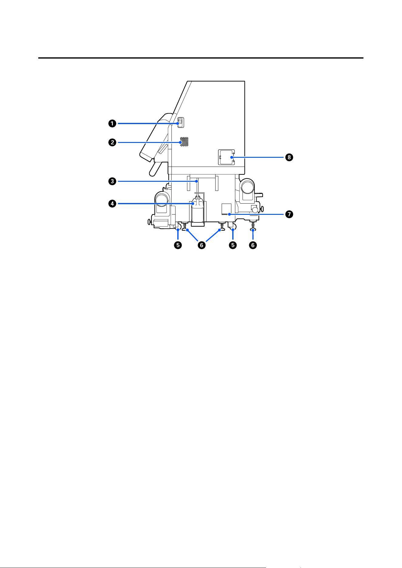
Right view
A Lock release levers
Releases the maintenance cover's locks. The same parts are on both the left and the right sides. When opening
the maintenance cover, open it while lowering the levers. The maintenance cover will automatically lock when
shut.
B Airflow vents
Allows air to flow into the printer. There are multiple airflow vents. Do not obstruct any of the airflow vents.
C Waste ink tube
Tubes for ejecting waste ink. Be sure the end of this tube is in the Waste Ink Bottle while the printer is in use.
D Waste Ink Bottle
Waste ink collects in this bottle.
Replace it with a new Waste Ink Bottle when a message is displayed on the control panel prompting you to do
so.
U “Disposing of waste ink” on page 175
E Casters
There are two casters on each leg.
SC-F20000 Series/SC-F11000H Series/SC-F11000 Series/SC-F10000H Series/SC-F10000 Series User's Guide
Introduction
14

F Levelers
When installing, check the level gauge, use the levelers to adjust the printer to be level, and then fix the printer
in place. Install metallic plates on the bottom to distribute the load.
Keep the printer level after moving it.
U “Moving and Transporting the Printer” on page 237
G Level gauge
Check the horizontal level of the printer.
H Circuit breaker
If an electric current caused by a short circuit is detected, the circuit is automatically cut off to prevent electric
shock. Always keep the breaker switch ON while using the printer. Check the circuit breaker's performance
about once a month.
U “Checking the circuit breaker’s performance” on page 187
SC-F20000 Series/SC-F11000H Series/SC-F11000 Series/SC-F10000H Series/SC-F10000 Series User's Guide
Introduction
15
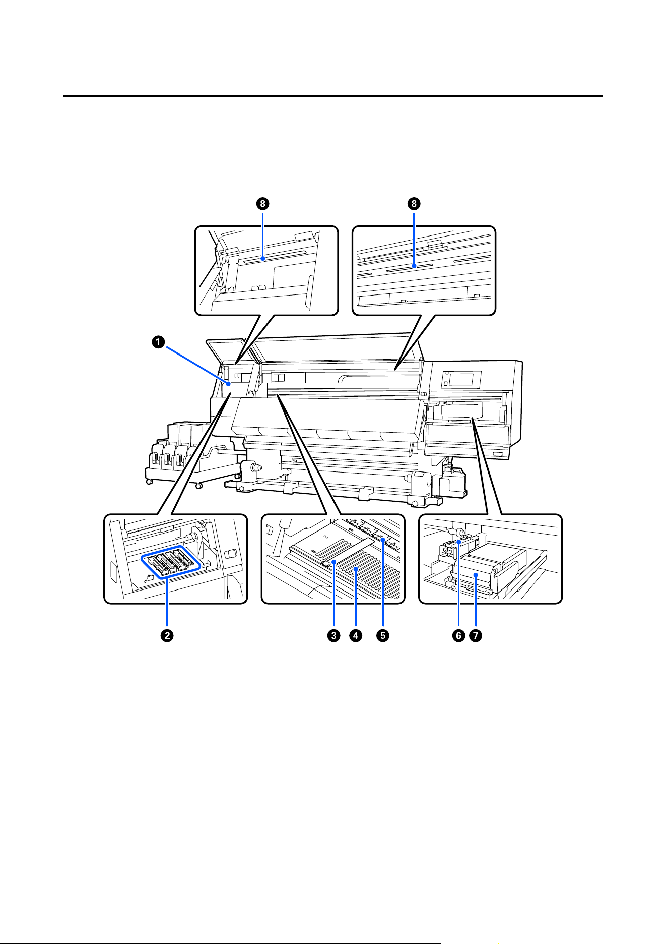
Inside
When the following parts become dirty, they may cause problems with the print results. Regularly clean or
exchange these parts as described in the chapters listed in the reference sections below or by following the
messages on the screen.
A Print head
The print head prints by moving left and right while emitting ink. When print results are dirty, check for dirt
stuck to the print head and clean it, if necessary.
U “Cleaning around the print head” on page 164
SC-F20000 Series/SC-F11000H Series/SC-F11000 Series/SC-F10000H Series/SC-F10000 Series User's Guide
Introduction
16

B Anti-drying caps
There is a row of 8 on the SC-F20000 Series, 6 on the SC-F11000H Series/SC-F10000H Series and 4 on the
SC-F11000 Series/SC-F10000 Series.
Except during printing, these caps cover the print head nozzles to prevent them drying out. Depending on the
dirtiness, a message about cleaning appears on the control panel's screen. Clean according to the message.
U “Cleaning anti-drying caps” on page 160
C Media edge plates
The media edge plates prevent the media riding up and keeps fibers on the cut edge of the media from touching
the print head. Position the plates at either side of the media before printing.
U “Loading Media Into the Media Feeding Unit” on page 81
U “Loading Media Into the Auto Take-up Reel Unit” on page 99
D Platen
This suctions and fixes the media for smooth printing and media feeding.
U “Daily cleaning” on page 155
E Pressure rollers
These rollers press down on the media during printing.
F Suction cap
Ink is drawn out from the print head's nozzle with this cap.
Clean the suction caps before doing Print Head Refresh.
U “Cleaning the suction caps” on page 163
G Wiper unit
The wiper removes ink from the surface of the print head nozzles. The wiper roll that is loaded on the wiper
unit is a consumable item. Replace when a message is displayed on the control panel prompting you to do so.
U “Replacing the wiper roll” on page 173
H Internal lamp
Illuminates the inside of the printer to make it easy to check print results and areas for maintenance. If the
surface becomes dirty due to ink mist, clean it.
U “Cleaning the inside light” on page 166
SC-F20000 Series/SC-F11000H Series/SC-F11000 Series/SC-F10000H Series/SC-F10000 Series User's Guide
Introduction
17
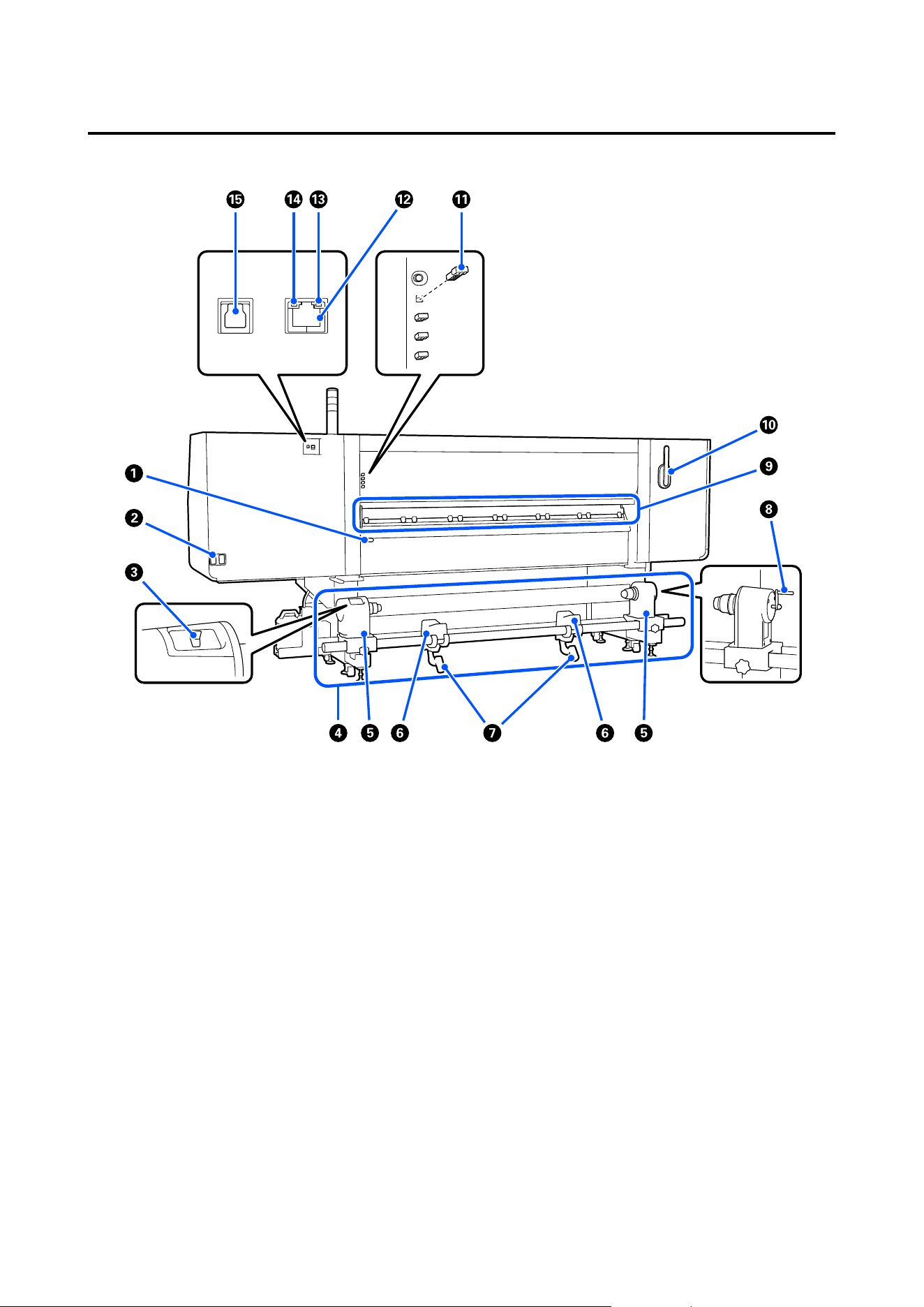
Back
A Media loading lever
After loading media, lower the media loading lever to keep the media in place. Raise the lever to release the
media prior to removal.
Because this media loading lever has the same function as the media loading lever on the front of the printer,
you can operate whichever is the easiest to use in your situation.
B AC inlet #1/AC inlet #2
Connects the power cable. Be sure to connect both cables.
C Drive switch
The drive switch can be used to slacken media while loading it and to take up cut media while replacing it.
D Media Feeding Unit
Loads media to be used for printing.
See the following for supported media.
U “Supported Media” on page 237
SC-F20000 Series/SC-F11000H Series/SC-F11000 Series/SC-F10000H Series/SC-F10000 Series User's Guide
Introduction
18

E Media holder
Place media on these holders. The same parts are on both the left and the right sides.
F Roll support
Rest media on these supports before placing it on the media holders. The same parts are on both the left and the
right sides.
G Lift lever
If the media to be mounted on the media holders seems heavy, use these levers to raise the media easily to the
level of the media holders. The same parts are on both the left and the right sides.
H Handle
After placing media on the right media holder, rotate the handle and press the media holder into the roll core.
I Media cleaner
Wipes off any lint or dust on the media when the media is being fed. If a message appears on the control panel's
screen, use the supplied media cleaner brush for cleaning.
U “Cleaning the media cleaners” on page 159
J Media cleaner brush
Dusts off the dirt on the surface of the media cleaner.
Since the brush's surface has a direction in which to wipe, move it in the direction that wipes off the dirt. You
can switch the direction in which to wipe. If you are not using the media cleaner brush, store it by hanging it on
the hooks on the back of the printer.
K Presser roller spacer
This part fixes the pressure rollers in the open position. Pressure rollers that have spacers inserted do not apply
pressure to the media, even when the media loading lever is lowered. If you use the presser roller spacer when
wrinkles occur on the media end, the wrinkles may be improved.
If you are not using the presser roller spacer, store it by inserting it into its original place.
U “Using Pressure Roller Spacers” on page 253
L LAN port
Connects the LAN cable. Use a shielded twisted pair cable (category 5e or higher).
M Data lamp
The data lamp lights or flashes to indicate the network connection status and whether the printer is receiving
data.
On : Connected.
Flashing : Connected. Receiving data.
SC-F20000 Series/SC-F11000H Series/SC-F11000 Series/SC-F10000H Series/SC-F10000 Series User's Guide
Introduction
19
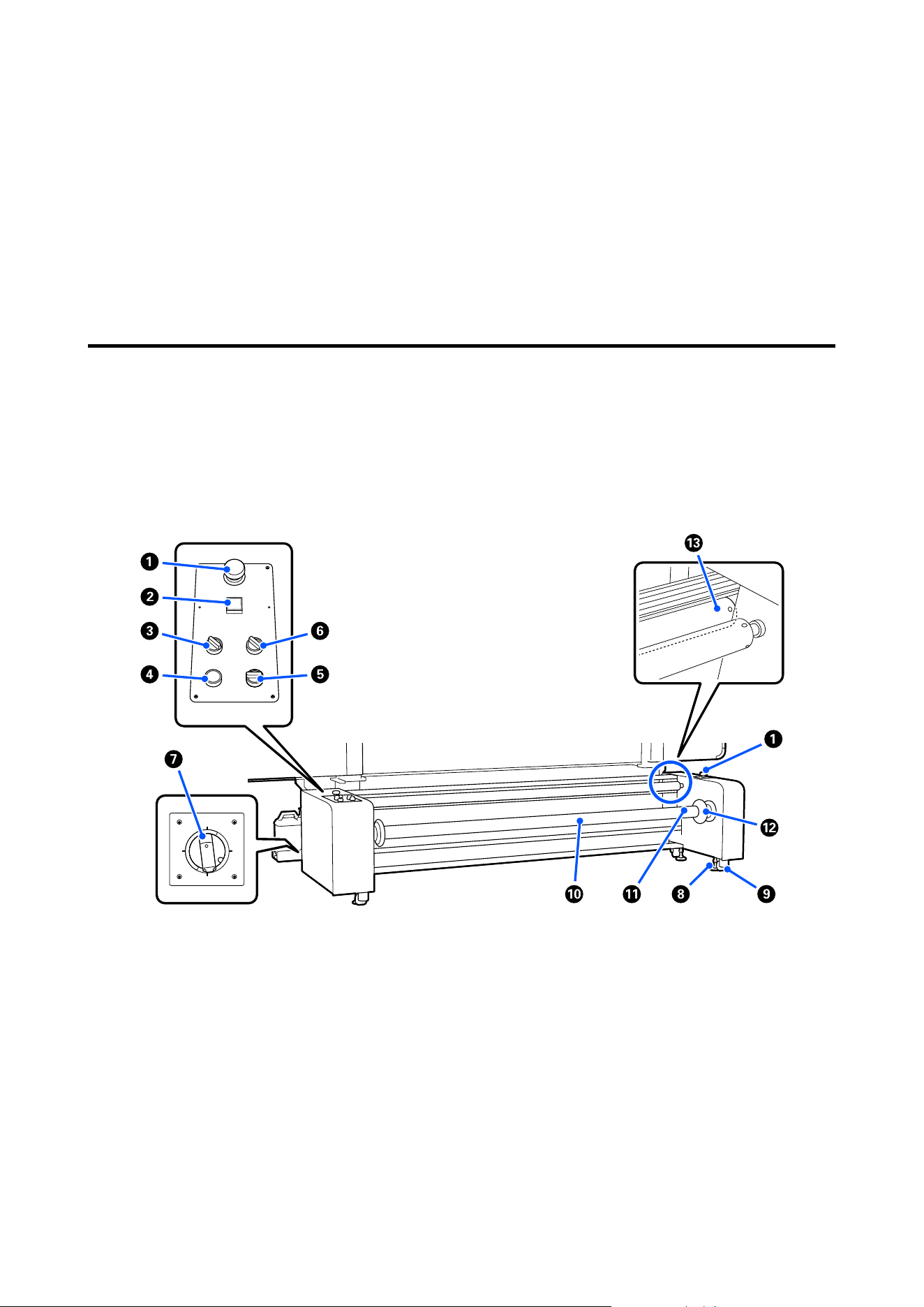
N Status lamp
The color indicates the network's communication speed.
Green : 1000Base-T
O USB port
Connects the USB cable.
Media Feeding Unit (Large Capacity Type)
The large capacity type of Media Feeding Unit is only compatible with the SC-F20000 Series, SC-F11000H Series,
and SC-F11000 Series.
The large capacity type of media feeding unit can be loaded with large capacity media with an outer diameter of up
to 500 mm (19.68 in.) and a weight of up to 300 kg (661.38 lb) so that the machine can be used for long periods of
time without having to replace the media.
A Emergency stop button
There are 2, on the left and right. Press them in an emergency to quickly stop operations.
U “Recovering from an Emergency Stop” on page 269
B
P button (power button)
Turns the power to the Media Feeding Unit on and off. If you are using a large capacity type media feeding unit,
before you turn on the power to the printer, first turn on the power to the media feeding unit, and then turn on
the power to the printer.
When turning off the power, turn off the printer first, and then turn off the media feeding unit.
SC-F20000 Series/SC-F11000H Series/SC-F11000 Series/SC-F10000H Series/SC-F10000 Series User's Guide
Introduction
20

C Load switch
Adjust the tension applied when media is feeding by switching the force of the tension bar pressing on the
media.
For normal usage, set Mid; use Lo to lower the tension and Hi to raise it.
D Release Button
Lift the tension bar and release the tension of the media. Raise the tension bar while loading media.
When the tension bar is raised, pressing this button lowers the tension bar.
E Manual switch
The drive switch can be used to slacken media while loading it and to take up cut media while replacing it.
This functions regardless of the Auto switch setting, so there is no need to turn the Auto switch Off to operate
the Manual switch.
F Auto switch
This switch sets the specifications (whether the printed surface is rolled facing out or in) for taking up the
media that is loaded. Set
to load media with printable side out, and set for printable side in. When set
to Off, it does not operate.
G Circuit breaker (Main Power Switch)
If an overcurrent is detected, the circuit is automatically cut off. Always keep the switch ON while using the
printer.
H Levelers
Extend to the ground to brace the Media Feeding Unit.
After moving the printer, do the needed adjustments and then brace it.
U “Moving and Transporting the Printer” on page 237
I Casters
There are 4, on the legs.
J Spindle
To load media or roll cores on the printer, insert the spindle into the media then load it.
The spindle can be used facing either left or right, but the valve is only on one side, so put the valve where it is
easy to use.
K Valve
Supply air from a commercially available air compressor here to secure media or roll cores to the spindle.
L Handle
Move to lock and release the spindle that is loaded. Also, hold the handle to rotate the spindle manually.
SC-F20000 Series/SC-F11000H Series/SC-F11000 Series/SC-F10000H Series/SC-F10000 Series User's Guide
Introduction
21
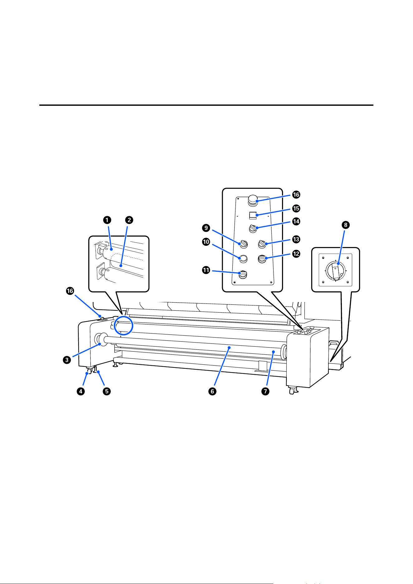
M Tension bar
Move this bar up or down to press on the media and apply tension.
Auto Take-up Reel Unit (Large Capacity Type)
The large capacity type of Auto Take-up Reel Unit is only compatible with the SC-F20000 Series, SC-F11000H
Series, and SC-F11000 Series.
The large capacity type of Auto Take-up Reel Unit can take up media with an outer diameter of up to 500 mm
(19.68 in.) and a weight of up to 300 kg (661.38 lb) so that the machine can be used for long periods of time
without having to replace the media.
A Heating roller
This roller heats the media after printing using a built-in heater. It adjusts the media to an appropriate tempera‐
ture so that it can be taken up correctly.
B Tension bar
Move this bar up or down to press on the media and apply tension.
C Handle
Move to lock and release the spindle that is loaded. Also, hold the handle to rotate the spindle manually.
SC-F20000 Series/SC-F11000H Series/SC-F11000 Series/SC-F10000H Series/SC-F10000 Series User's Guide
Introduction
22

D Casters
There are 4, on the legs.
E Levelers
Extend to the ground to brace the Auto Take-up Reel Unit.
F Spindle
To load media or roll cores on the printer, insert the spindle into the media then load it.
The spindle can be used facing either left or right, but the valve is only on one side, so put the valve where it is
easy to use.
Also, the spindle for the large capacity type of Auto Take-up Reel Unit and the Media Feeding Unit is a standard
part that can be used for either unit.
G Valve
Supply air from a commercially available air compressor here to secure media or roll cores to the spindle.
H Circuit breaker (Main Power Switch)
If an overcurrent is detected, the circuit is automatically cut off. Always keep the switch ON while using the
printer.
I Load switch
Adjust the tension applied when taking up the media by switching the force of the tension bar pressing on the
media.
The tension increases in intensity in the order of Hi, Mid, Lo. Therefore, see the following and adjust according
to the media you are using.
U “Media Settings List for Each Media Type” on page 271
J Release Button
Lift the tension bar and release the tension of the media. Raise the tension bar while loading media.
When the tension bar is raised, pressing this button lowers the tension bar.
K Media feed switch
Feeds/rewinds the media. Because the media feed switch has the same function as the media feed button in the
control panel, you can operate whichever is the easiest to use in your situation. See the explanation for the
media feed button for details about functions.
L Manual switch
Use this switch for manual media take up.
This functions regardless of the Auto switch setting, so there is no need to turn the Auto switch Off to operate
the Manual switch.
SC-F20000 Series/SC-F11000H Series/SC-F11000 Series/SC-F10000H Series/SC-F10000 Series User's Guide
Introduction
23
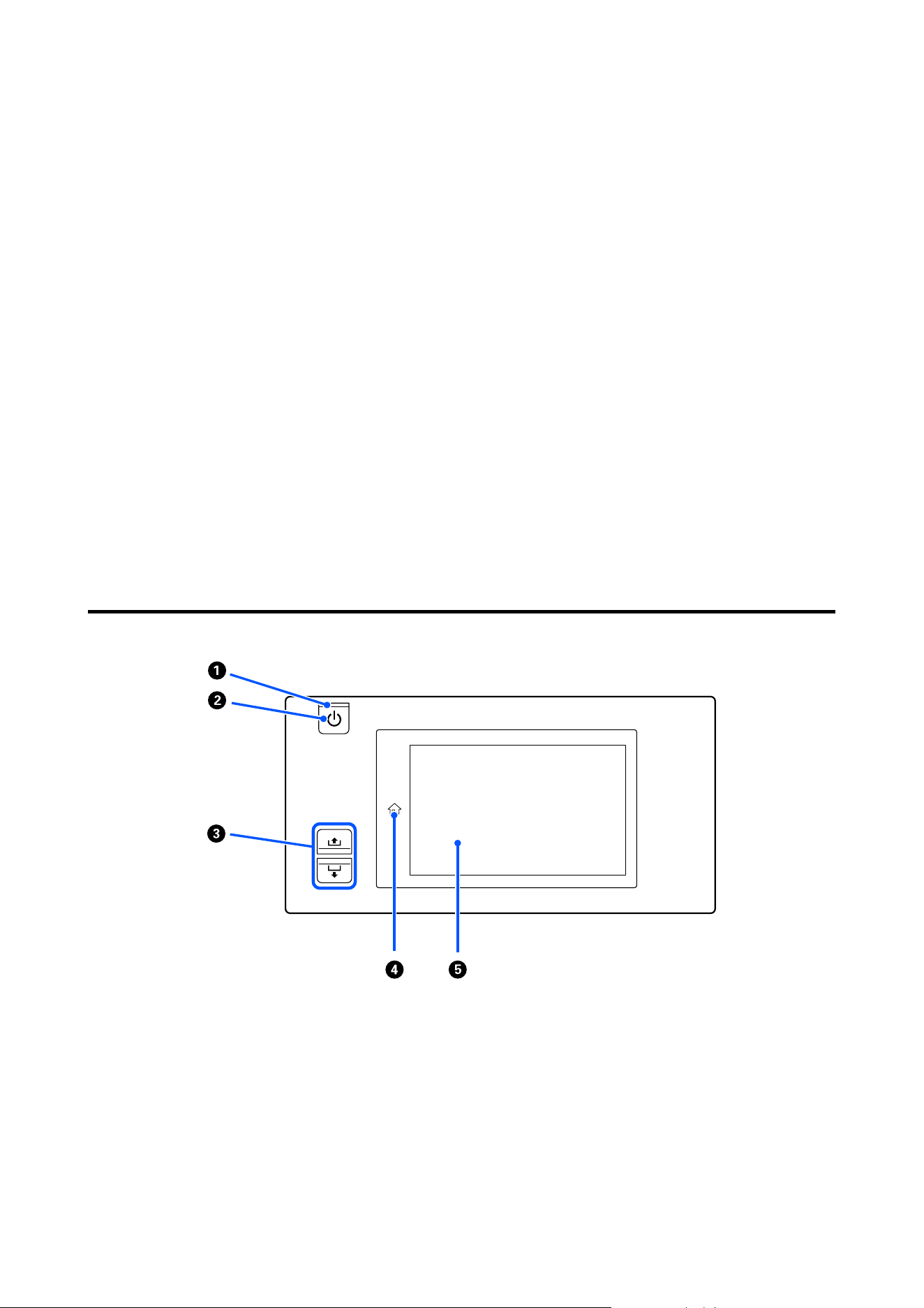
M Auto switch
Use this switch to select the auto take-up direction. Select Off to disable auto take-up.
N Heater switch
Turns the heater for the heat roller on and off.
O
P button (power button)
Turns the power to the Auto Take-up Reel Unit on and off.
If you are using a large capacity type Auto Take-up Reel Unit, before you turn on the power to the printer, first
turn on the power to the Auto Take-up Reel Unit and the media feeding unit.
When turning off the power, turn off the printer first, and then turn off the auto take-up reel unit and the
media feeding unit.
P Emergency stop button
There are 2, on the left and right. Press them in an emergency to quickly stop operations.
U “Recovering from an Emergency Stop” on page 269
Control panel
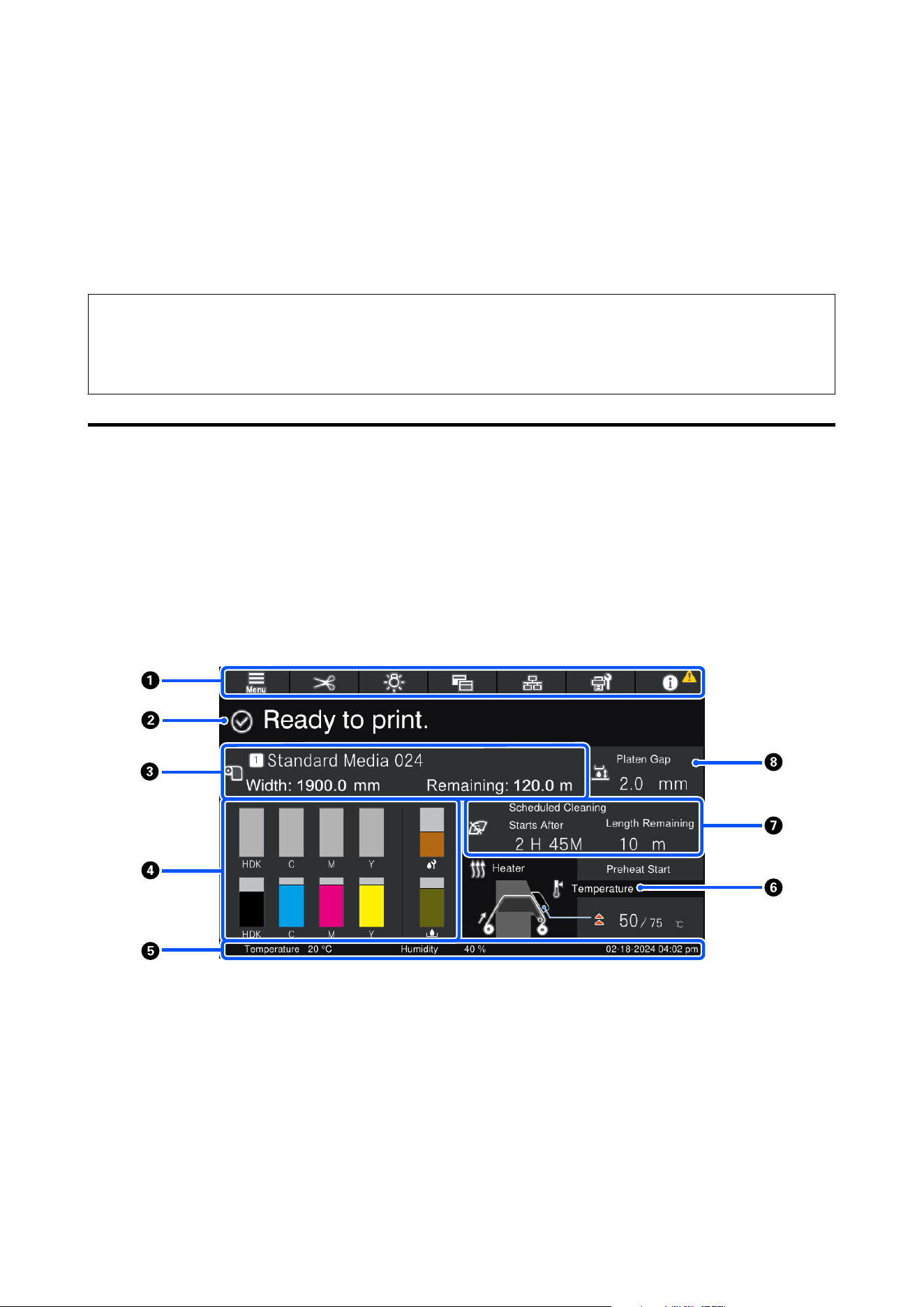
A
P light (power light)
The printer's operational status is indicated by a lit or flashing light.
On : The power is on.
Flashing : The printer is receiving data or performing head cleaning or other operations during
shut-down.
Off : The power is off.
SC-F20000 Series/SC-F11000H Series/SC-F11000 Series/SC-F10000H Series/SC-F10000 Series User's Guide
Introduction
24

B
P button (power button)
Turns the power on and off.
If you are using a large capacity roll model or large capacity reel model, turn on the media feeding unit and
auto take-up reel unit before turning on the printer.
When turning off the power, turn off the printer first, then turn off the media feeding unit and auto take-up
reel unit.
C Media feed button
The operations when the button is pressed differ depending on the media loading lever's status.
-Lever is lowered
The following operations are done, regardless of the loaded media's winding specifications.
button: Rewinds the media.
button: Feeds the media.
When the button is used to rewind, the media stops when its leading edge reaches the print start position.
Rewind can be resumed by releasing the button and then pressing it again.
- Lever is raised
The loaded media is rotated in the following directions.
button: For printable side out, the rewind direction; for printable side in, the feed direction
button: For printable side out, the feed direction; for printable side in, the rewind direction
If you take up media with the lever raised, it may rotate in the feed direction.
U “Loading Media Into the Media Feeding Unit” on page 81
U “Loading Media Into the Auto Take-up Reel Unit” on page 99
You can also do the same operation with the Auto Take-up Reel Unit's media feed switch. Operate whichever is
the easiest to use in your situation.
D button (Home button)
Press this while it is lit when the settings menu, or other such screens, is displayed to return to the Home
screen.
If the Home button cannot be used during operation, the lamp turns off.
E Display
SC-F20000 Series/SC-F11000H Series/SC-F11000 Series/SC-F10000H Series/SC-F10000 Series User's Guide
Introduction
25

This is a touch panel that displays the printer's status, menus, and error messages. You can use your fingers to
lightly press and select menu items and options shown on the screen, or to move your finger while still touching
the screen to scroll the screen.
U “Understanding and Operating the Display” on page 27
SC-F20000 Series/SC-F11000H Series/SC-F11000 Series/SC-F10000H Series/SC-F10000 Series User's Guide
Introduction
26
Understanding and Operating the Display
Screenshots for the SC-F20000 Series, SC-F11000 Series, and SC-F10000 Series are used for these explanations.
This chapter describes how to understand and operate the screen layout, using the Home screen, Menu screen, and
the display for operating procedures screen as an example.
Note:
If the screens for the SC-F11000H Series/SC-F11000 Series and the SC-F10000H Series/SC-F10000 Series are different,
then updating the firmware for SC-F10000H Series/SC-F10000 Series will update the screens for SC-F11000H Series/
SC-F11000 Series.
Home screen
On the Home screen, you can switch between the Status Display screen and the Media Settings screen by pressing
the display switching button.
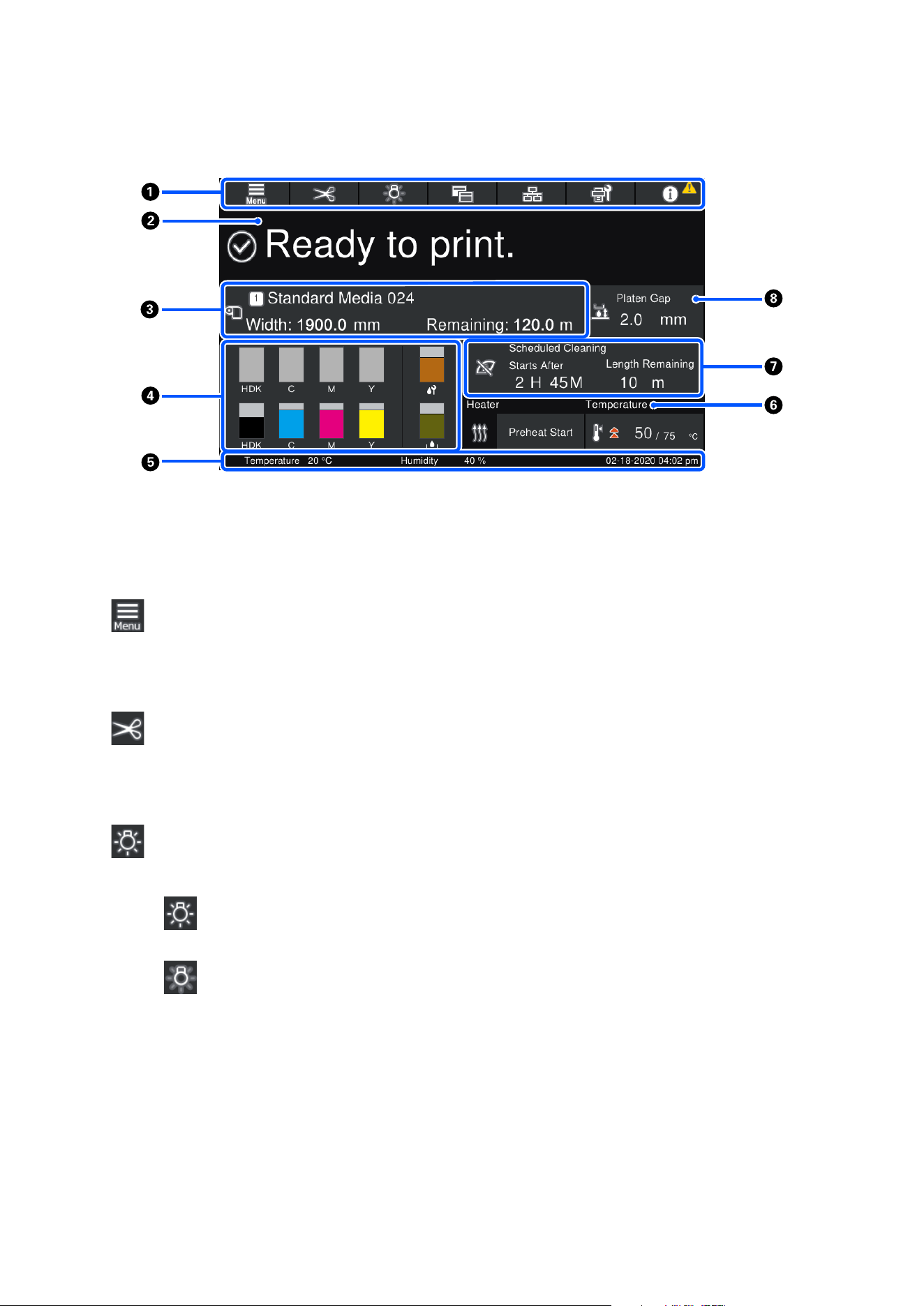
Status Indicator screen
The printer's status can be listed.
SC-F20000 Series/SC-F11000 Series
SC-F20000 Series/SC-F11000H Series/SC-F11000 Series/SC-F10000H Series/SC-F10000 Series User's Guide
Introduction
27
SC-F10000 Series
A Header
Displays the buttons for frequently-used functions. The functions of the buttons are shown below. The header
also appears similarly on other screens.
Menu
Displays the Settings menu.
U “Control Panel Menu” on page 190
Cutting Media
Feeds the media to the cut position when printing is complete and when media has been replaced.
U “Cutting Media” on page 130
Internal lamp
Switches the internal lamp on or off. The display changes as follows, depending on the status.
On
Off
Setting Auto for Inside Light in the Printer Settings, turns the light on automatically when operations
that need light are done, such as while printing, and turns it off when the operation is complete.
However, it may not come on, depending on the condition of the printer. In these cases, the button
changes to gray.
U “General Settings menu” on page 201
SC-F20000 Series/SC-F11000H Series/SC-F11000 Series/SC-F10000H Series/SC-F10000 Series User's Guide
Introduction
28
Switch View
Switches the Status Indicator screen and Media Settings screen.
Switch Connection Status
Changes the Online/Offline state of the computer connected to the printer. Change this when necessa‐
ry, such as changing it to Offline so print jobs are not received while doing printer maintenance.
Maintenance
The Maintenance menu appears on this screen and you can do such maintenance as print head mainte‐
nance and replacement of consumables.
U “Maintenance menu” on page 219
Information
Displays the Printer Status. If there are any notifications, such as about running low on consumables,
the
icon appears at the top right of the screen. The display that appears when you press the button
displays a Message List for matters not yet handled. Instructions appear if you press the items, so fol‐
low the directions to resolve any issues. Once everything is resolved, the
icon disappears.
B Messages
Displays the printer's status and messages that give instructions.
U “When a Message is Displayed” on page 222
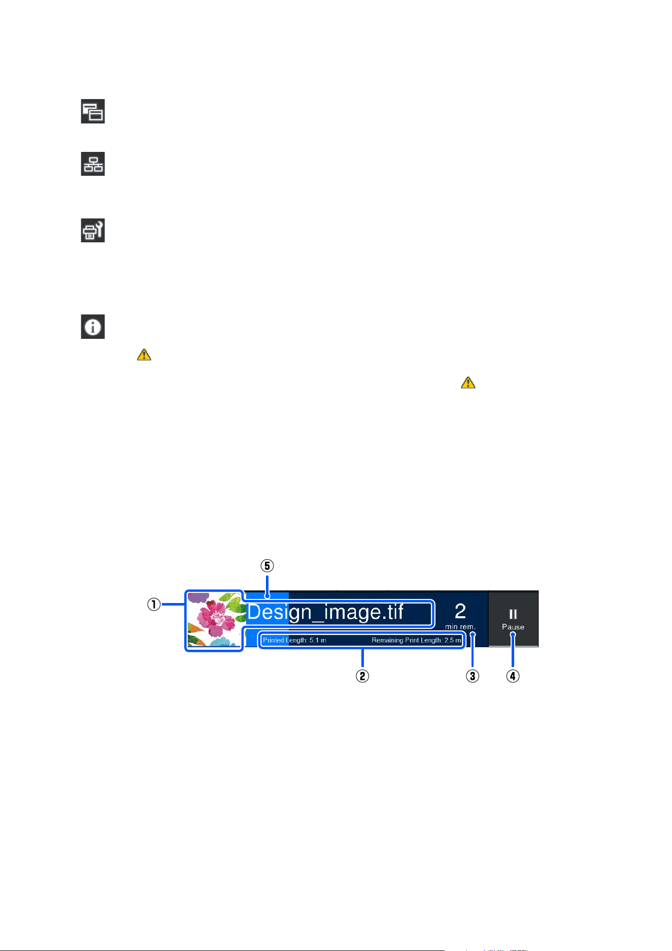
During printing, the display switches, as seen in the illustration, and shows the following information and but‐
tons.
(1) File name and thumbnail of image being printed
A thumbnail image may not be shown, depending on the type of RIP being used.
(2) The media's Printed Length, the media's Remaining Print Length, Time until media replacement,
and Pass Mode
SC-F20000 Series/SC-F11000H Series/SC-F11000 Series/SC-F10000H Series/SC-F10000 Series User's Guide
Introduction
29

Pressing the display area while printing displays the screen to set the display details for (2). Select
up to 2 items that you want to display.
The Time until media replacement shows an estimated time.
(3) Estimate of remaining printing time
(4) Pause (Suspend) button
Appears as the Start button while warming up, until the heater reaches the set temperature.
Pressing this button starts printing, even if the heater temperature is low.
(5) Progress bar
Pausing printing and canceling print jobs
Pressing the Pause button while printing displays a screen for selecting the timing to suspend, press one to
select it.
❏ Immediate pause: Stops printing immediately. When printing is stopped during a print job, printing may be disturbed
when printing is resumed.
❏ Pause between pages: Stops at the end of the page currently printing.
Pressing Resume in the screen during a pause cancels the pause status. Pressing Cancel cancels the print job in
progress and stops printing.
C Media info
Displays information about the media that is loaded. The number indicates the media setting number. When
the remaining amount of media goes below the value set in the Remaining Alert in the Media Settings menu,
appears. Press the display area to show the Media Settings menu.
U “Media Settings menu” on page 209
D Supply Status
Information regarding consumables, such as ink cartridges, are displayed using the following icons and bar
lengths.
Ink cartridge status
Displays the approximate level of remaining ink and the current status. If the amount of ink runs low,
the bar becomes shorter.
The code at the bottom of the bar display indicates the ink color. The bar at the bottom indicates the
front ink cartridge, while the bar at the top indicates the back ink cartridge.
SC-F11000H Series/SC-F10000H Series
FP : Fluorescent Pink
FY : Fluorescent Yellow
SC-F20000 Series/SC-F11000H Series/SC-F11000 Series/SC-F10000H Series/SC-F10000 Series User's Guide
Introduction
30

LC : Light Cyan
LM : Light Magenta
OR : Orange
V:Violet
HDK : High Density Black
C:Cyan
M:Magenta
Y:Yellow
OR and V are compatible with SC-F11000H Series only.
SC-F20000 Series/SC-F11000 Series/SC-F10000 Series
HDK : High Density Black
C:Cyan
M:Magenta
Y:Yellow
The display changes, as shown below, if a warning or error occurs.
The amount of ink is estimated to be low. Once the ink cartridge is expended, the printer
automatically switches to the other ink cartridge.
Confirm that a new ink cartridge is installed on the other side.
❏ Ink is expended. Replace the old ink cartridge with a new one.
❏ More than 30 minutes has elapsed since the ink cartridge connector was disconnected. Immediately
connect the connector, if it is left the way it is, the ink will dry out and the printer may not function
normally.
It is time to shake the ink cartridges. Remove the ink cartridges and shake them.
An ink cartridge's connector is disconnected. Insert the ink cartridge and connect the
connector correctly.
Confirm that all of the cartridge covers are upright, and then follow the on-screen instructions.
SC-F20000 Series/SC-F11000H Series/SC-F11000 Series/SC-F10000H Series/SC-F10000 Series User's Guide
Introduction
31

Waste Ink Bottle status
Displays the approximate amount of space available in the Waste Ink Bottle. If the amount of space
decreases, the bar becomes shorter.
The display changes, as shown below, if a warning occurs.
The Waste Ink Bottle is almost full. Ready a new Waste Ink Bottle.
Wiper Roll status
Displays the guideline for replacement of the wiper roll. As the time for replacement gets closer, the bar
becomes shorter.
The display changes, as shown below, if a warning occurs.
The wiper roll will need to be replaced soon. A new wiper roll needs to be prepared.
Pressing the display area shows the Supply Status screen and you can check the part numbers for consumables.
You can also switch the ink cartridges to be used. (Changing the active slot)
To change the ink cartridge, press the bar display of the one you are not using, confirm the on-screen message,
and then press Start.
E Footer
Displays the current date and time and the temperature and humidity around the printer. If the temperature
and humidity are out of range for the printer's operating environment,
appears. For high-quality printing,
use the printer within the range of the printer's operating environment. The footer also appears similarly on
other screens.
F Dryer/Heating roller information
Heating roller information is displayed only for large capacity reel models.
Dryer information displays the Preheat Start button and temperature. Press the Preheat Start button when you
want to start preheating before receiving a print job after the printer returns from sleep mode. Pressing the
display area for temperature displays the Settings screen.
Heating roller information displays the temperature. Turn the heater for the heating roller on and off using the
heater switch on the Auto Take-up Reel Unit.
The value on the right indicates Set, and the value on the left indicates Current. If the current temperature does
not reach the set value, the following icons are displayed depending on the situation.
Heating
Cooling
SC-F20000 Series/SC-F11000H Series/SC-F11000 Series/SC-F10000H Series/SC-F10000 Series User's Guide
Introduction
32

The illustrations that show screens of the SC-F20000 Series, SC-F11000H Series, and SC-F11000 Series vary
according to the models of the media feeding unit and auto take-up reel unit you are using.
Standard roll/reel models
Large capacity roll models
Large capacity reel models
G Notice on when to do maintenance or periodic cleaning
Displays a notice, in the following situations, about when to do Maintenance Cleaning
*
on the left and when to
do Periodic Cleaning on the right. For Periodic Cleaning, either Print Duration, Print Page, or Print Length
appears, according to the settings.
❏ Maintenance Cleaning: 24 hours in advance
❏ Periodic Cleaning (Print Duration): 1 hour in advance
❏ Periodic Cleaning (Print Length): 20 m in advance
❏ Periodic Cleaning (Print Page): 20 pages in advance
The times these are done change greatly depending on the ambient temperature of the print heads. In addition,
Maintenance Cleaning may be done regardless of the notice display when the power is turned back on.
Pressing the display area shows the screen for cleaning in advance. If you want to print when it is almost time to
implement cleaning, implementing cleaning in advance is effective at preventing printing from being interrup‐
ted midway.
* Maintenance Cleaning is head cleaning that the printer automatically performs after a set period to keep the
print heads in good condition. Set Maintenance Cleaning from the Maintenance Setting menu.
U “General Settings menu” on page 201
H Platen Gap
Displays the setting value for the platen gap. Pressing the display area shows the Settings screen.
Media Settings screen
List of main media settings that you can operate.
The Media Settings can also be changed from the Settings menu. Change to whichever is the easiest to use in your
situation.
U “Control Panel Menu” on page 190
SC-F20000 Series/SC-F11000H Series/SC-F11000 Series/SC-F10000H Series/SC-F10000 Series User's Guide
Introduction
33
SC-F20000 Series/SC-F11000 Series
SC-F10000 Series
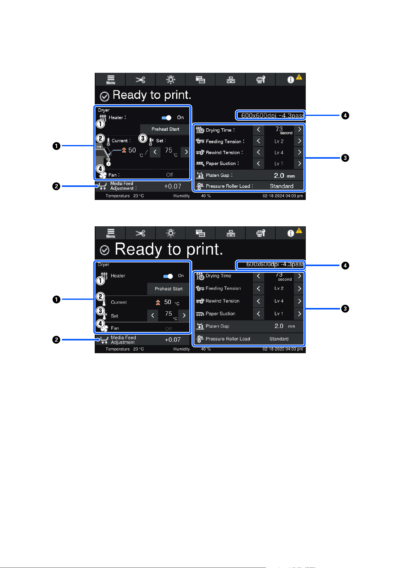
A Dryer/Heating roller information
Heating roller information is displayed only for large capacity reel models.
Turn the heater for the heating roller on and off using the heater switch on the Auto Take-up Reel Unit.
(1) Heater operations
Switching to On/Off starts and stops preheating.
Turn the heater for the heating roller on and off using the heater switch on the Auto Take-up Reel Unit.
(2) Current
Displays icons and the Status Indicator screen at the same time, depending on the situation.
SC-F20000 Series/SC-F11000H Series/SC-F11000 Series/SC-F10000H Series/SC-F10000 Series User's Guide
Introduction
34

(3) Set
Pressing
/ allows you to change the values.
(4) Strength of the Fan mode
The Fan mode is enabled when the heater is Off. Pressing
/ allows you to change the fan's strength.
The illustrations that show screens of the SC-F20000 Series, SC-F11000H Series, and SC-F11000 Series vary
according to the model of the auto take-up reel unit you are using.
Standard roll/reel models, Large capacity roll models
Large capacity reel models
B Media Feed Adjustment information during printing
If you do Media Feed Adjustment while printing, the adjusted values appear. Pressing the display area while
printing displays the Settings screen.
U “Changing settings while printing” on page 35
C Media Settings information
The setting items vary according to the media feeding unit and the Auto Take-up Reel Unit you are using.
Displays the currently set values for each setting item. You can change the values for items other than Platen
Gap and Pressure Roller Load by pressing
/ . Doing so changes the setting values for each item of the
settings for the currently selected media settings. Pressing the buttons for the Platen Gap and Pressure Roller
Load displays the Settings screen.
D Pass Mode
Displays the current Pass Mode.
U “Media Settings menu” on page 209
Changing settings while printing
During printing, you can change the settings in the Media Settings displayed in the Home screen. If a problem,
such as banding or wrinkles, occurs, change the Media Settings to fix it. During printing, you can easily solve
problems because you can check the results you see as you make changes. In addition, you can make quick fixes,
without stopping printing, when problems occur shortly after printing starts.
Changing the settings in the Home screen changes the content of the current Media Settings.
SC-F20000 Series/SC-F11000H Series/SC-F11000 Series/SC-F10000H Series/SC-F10000 Series User's Guide
Introduction
35
For methods to fix problems in print results, see the "Problem Solver" in this manual and "Troubleshooting & Tips"
in the Online Manual.
U “Problem Solver” on page 222
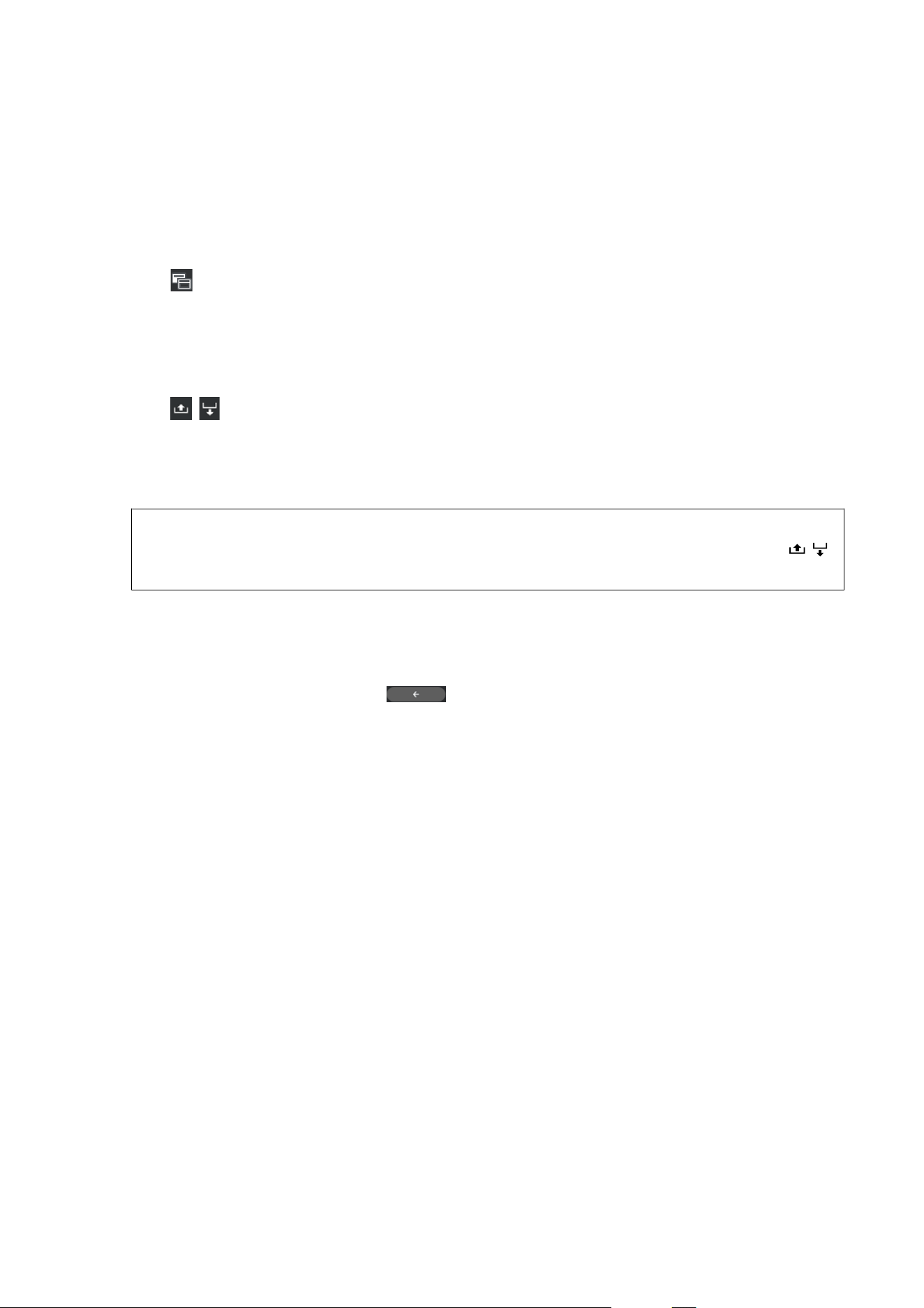
This section explains an example of how to do Media Feed Adjustment to compensate for banding.
A
Press to access the Media Settings screen.
B
Press the Media Feed Adjustment information area.
The settings screen is displayed.
C
Press / to change the values.
If the feed amount is too small, black bands (dark stripes) will appear; adjust the feed amount upwards.
If, in contrast, the feed amount is too large, white bands (pale stripes) will appear; adjust the feed amount
downwards.
Note:
When the settings screen for Media Feed Adjustment is displayed, you can change the values by pressing the
/
buttons on the left side of the screen.
D
Change the values as you check the printing results until the problem is completely fixed.
This updates the setting value of Media Feed Adjustment in the currently selected media settings.
E
When adjustments are complete, press to return to the Home screen.
SC-F20000 Series/SC-F11000H Series/SC-F11000 Series/SC-F10000H Series/SC-F10000 Series User's Guide
Introduction
36
Menu screen
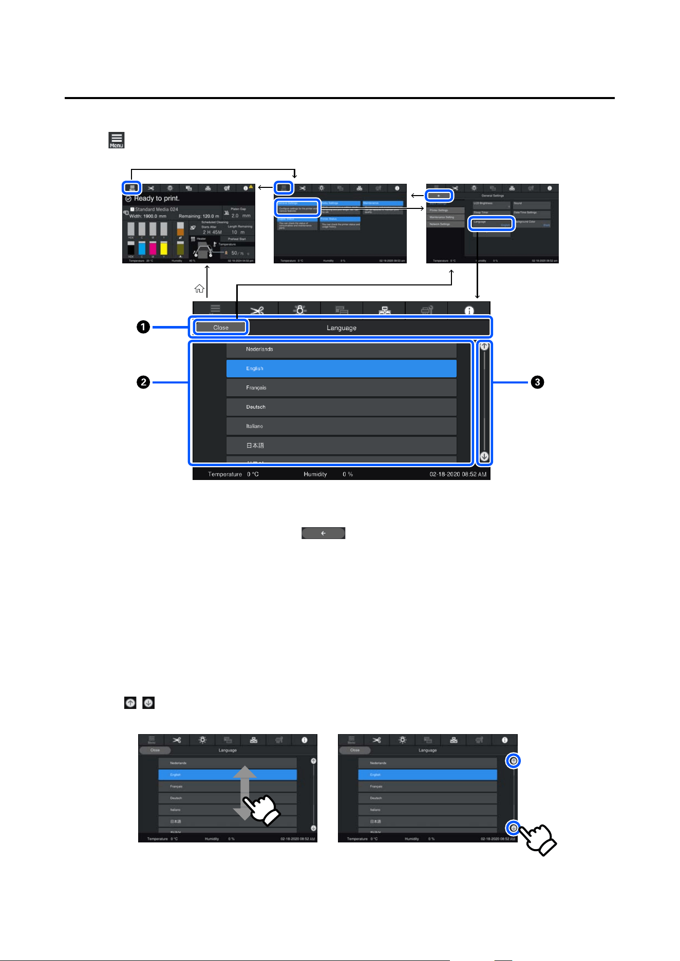
Pressing on the Home screen displays the Menu screen.
A Screen name display area
Displays the screen's name. Pressing Close or returns you to the previous screen.
B Operation area
Displays buttons and other items. The displayed contents vary according to the screen.
C Scroll bar
Appears when all of the buttons, etc., do not fit in the operation area. If the scroll bar is shown, check the
buttons, etc., by scrolling up and down.
You can scroll by pressing and holding the item you want to scroll and moving it up and down (slide), or by
pressing
/ to scroll, as shown in the illustrations below.
SC-F20000 Series/SC-F11000H Series/SC-F11000 Series/SC-F10000H Series/SC-F10000 Series User's Guide
Introduction
37
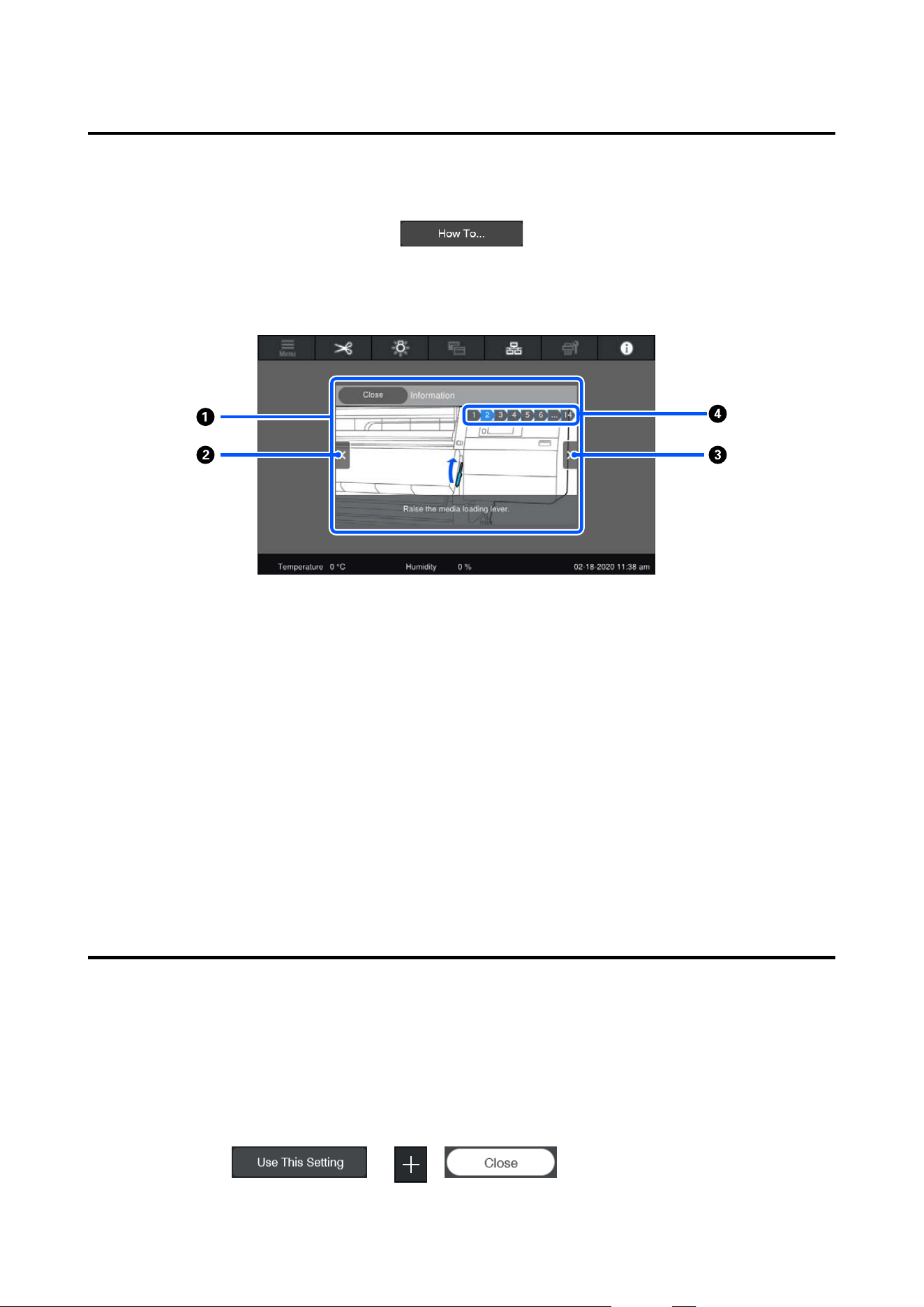
Instructions screen
The following buttons may appear on screens on which a series of operations starts.
The instructions are explained using illustrations for each step to make them easy to understand. Even if you do
not remember the instructions, you can work while looking at the screen.
A Instructions display area
Displays the instructions. Depending on the step, the Instructions screen may display and cycle through
multiple illustrations.
B Previous step button
Displays the previous step.
C Next step button
Displays the next step.
D Step number
Displays the total number of steps. The color of the step that is currently shown changes to blue.
Types of Buttons
Depending on the screen, the following types of buttons appear. Even if they are the same buttons, how they look
may change, depending on the situation.
Standard buttons
These buttons appear the most.
Example:
SC-F20000 Series/SC-F11000H Series/SC-F11000 Series/SC-F10000H Series/SC-F10000 Series User's Guide
Introduction
38
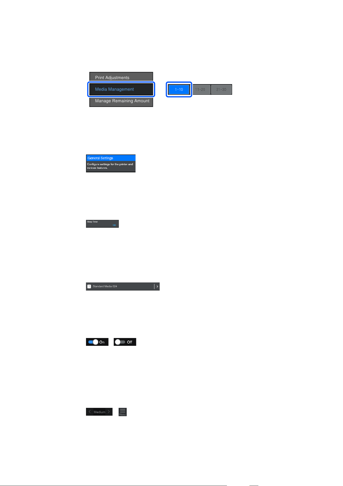
In a list of buttons of selectable items, when a button's text and background colors turn blue, it indi‐
cates that it is selected.
Example:
Buttons that show descriptions
These are buttons that display an item name on top and an explanation of the item on bottom.
Example:
Buttons that show setting values
These are buttons for setting items. The current setting value appears at the bottom-right in blue text.
Example:
Select/change combination button
Pressing the button anywhere except the right end selects an item as normal, but pressing the right end changes the
screen to that items settings.
Example:
Buttons that can be switched on/off
These are buttons for switching settings on and off. Pressing the button switches the setting.
Example:
Buttons that turn gray (gray-out)
This indicates that the button cannot be used. These buttons turn gray only when they cannot be operated for
reasons, such as items not being selectable because of unmet conditions. The conditions for being operable change
depending on the button.
Example:
SC-F20000 Series/SC-F11000H Series/SC-F11000 Series/SC-F10000H Series/SC-F10000 Series User's Guide
Introduction
39
Notes on Usage and
Storage
Installation space
North American and Latin American users: Contact
your dealer for product installation. The product must
be installed by an authorized dealer. Damage to the
product from unauthorized installation will not be
covered by your Epson warranty.
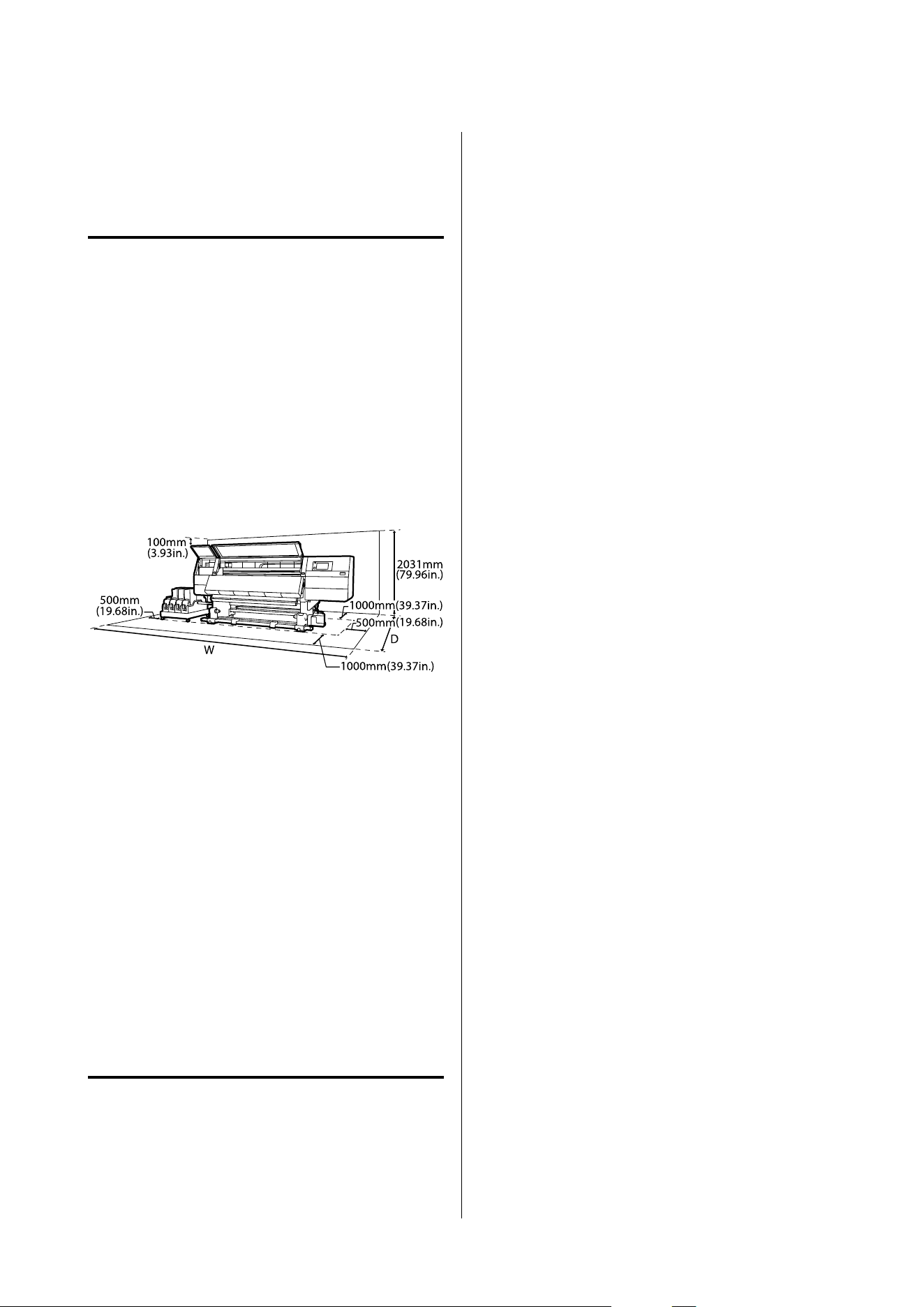
❏ Make sure that you secure the following space,
clear of any other objects, so that paper ejection
and consumable replacement are not obstructed.
See the “Specifications Table” for the external
dimensions of the printer.
U “Specifications Table” on page 290
W
SC-F11000H Series/SC-F10000H Series: 6008 mm
(236.54 in.)
SC-F20000 Series/SC-F11000 Series/SC-F10000
Series: 5607 mm (199.48 in.)
D
Standard roll/reel models: 3303 mm (130.03 in.)
Large capacity roll models: 3839 mm (151.14 in.)
Large capacity reel models: 4494 mm (176.92 in.)
❏ This printer is a precision instrument. Install it in
a dust-free environment. Do not install in rooms
where cutting, sewing, or similar work is
performed.
❏ Place this product on a flat, stable surface that is
larger than this product. This product will not
operate properly if it is tilted or at an angle.
Notes when using the printer
Note the following points when using this printer to
avoid breakdowns, malfunctions, and print quality
decline.
❏ When using the printer, observe the operating
temperature and humidity range described in the
“Specifications Table”. U “Specifications Table”
on page 290
Note, however, that the desired results may not be
achieved if the temperature and humidity are
within the limits for the printer but not within
those for the media. Be sure the operating
conditions suit the media. For more information,
see the documentation supplied with the media.
Also, when operating in dry areas, air conditioned
environment, or under direct sunlight, maintain
the appropriate humidity.
❏ Avoid using the printer in locations with heat
sources or that are exposed to direct draughts
from ventilators or air conditioners. The print
head nozzles could dry out and clog.
❏ Do not bend or tug the waste ink tube. Ink could
spill inside or around the printer.
❏ Maintenance such as cleaning and replacement
must be performed according to usage frequency
or at recommended intervals. Failure to perform
regular maintenance could result in loss of print
quality. In the absence of the appropriate
maintenance, continued use could damage the
print head.
U “Cleaning” on page 150
❏ The print head may not be capped (the print head
may not return to the left side) if the printer is
turned off when the media is jammed or an error
has occurred. Capping is a function for
automatically covering the print head with a cap
(lid) to prevent the print head from drying out. In
this case, turn on the power and wait a while until
capping is performed automatically.
❏ When the power is on, do not remove the power
plug or cut the power at the breaker. The print
head may not be capped properly. In this case,
turn on the power and wait a while until capping
is performed automatically.
❏ When Maintenance Cleaning is On, the print
head is automatically cleaned at a fixed interval
after printing to keep the nozzles from clogging.
Be sure that the Waste Ink Bottle is placed
whenever the printer is on.
❏ As well as being expended during printing, ink is
used during head cleaning and other maintenance
required to keep the print head in working order.
SC-F20000 Series/SC-F11000H Series/SC-F11000 Series/SC-F10000H Series/SC-F10000 Series User's Guide
Introduction
40

❏ To ensure the colors you want to print, maintain a
constant room temperature of 18 to 28 ˚C (64.4 to
82.4 ˚F).
❏ Do not put your hand inside this product or touch
the printer head during printing.
❏ Do not put your hand inside this product or touch
the white flat cable during printing.
Notes when not using the
printer
If you are not using it, note the following points when
storing the printer. If it is not stored correctly, you may
not be able to print properly the next time it is used.
❏ A service engineer must do pre- and
post-maintenance when the printer is not used for
over 6 weeks. Depending on your region, pre- and
post-maintenance may require a fee.
During pre-maintenance, the ink in the ink tubes
is removed, and the inside of the tubes is washed
using the cleaning fluid in the cleaning cartridge,
to prepare for long-term storage. When restarting
use of the printer, recharge the printer with ink.
Moreover, depending on the environment and
length of time stored, repairs may be required
during post-maintenance even if pre-maintenance
is done. If repairs are necessary, they may require
a fee depending on your region.
Contact your dealer or Epson Support.
❏ If you have not used the printer for a long time,
check the print heads for clogging before you start
printing. Clean the heads if the print heads are
clogged.
U “Checking for clogged nozzles” on page 185
❏ The pressure rollers may crease media left in the
printer. The media may also become wavy or
curled, causing jams or resulting in the media
coming into contact with the print head. Remove
the media before putting the printer in storage.
❏ Store the printer after confirming that the print
head has been capped (the print head is
positioned at the far left). If the print head is left
uncapped for a long time, the print quality may
decline.
Note:
If the print head is not capped, turn the printer on, and
then turn it off.
❏ Close all covers before placing the printer in
storage. If you are not using the printer for a long
time, put an anti-static cloth or cover on the
printer to prevent dust. The print head nozzles are
very small, and they can become clogged easily if
fine dust gets on the print head, and you may not
be able to print properly.
❏ When storing the printer, be sure that it is level:
do not store it on an angle, on end, or upside
down.
Notes on handling ink
cartridges
Note the following points when handling ink
cartridges to maintain good print quality.
❏ Extra ink is required to fully charge the print head
nozzles the first time the printer is used;
replacement cartridges will be needed earlier than
usual.
❏ Store ink cartridges at room temperature in a
location that is not exposed to direct sunlight.
❏ To ensure print quality, use all the ink in the
cartridge before the earlier of the following dates:
❏ The expiry date shown on the ink cartridge
packaging
❏ Six months after opening the package of ink
cartridge
❏ If you move ink cartridges from a cold place to a
warm place, leave them at room temperature for
more than 18 hours before using them so the
temperature of the ink can reach room
temperature.
❏ Do not touch the ink cartridge IC chip. You may
not be able to print properly.
SC-F20000 Series/SC-F11000H Series/SC-F11000 Series/SC-F10000H Series/SC-F10000 Series User's Guide
Introduction
41
❏ Do not leave the printer without ink cartridges
installed. The ink in the printer will dry out and
the printer will not function as expected. Leave
ink cartridges installed even when the printer is
not in use.
❏ Because the green IC chip contains the cartridge's
own information such as the remaining ink level,
you can still reinstall and use the ink cartridge
after removing it from the printer.
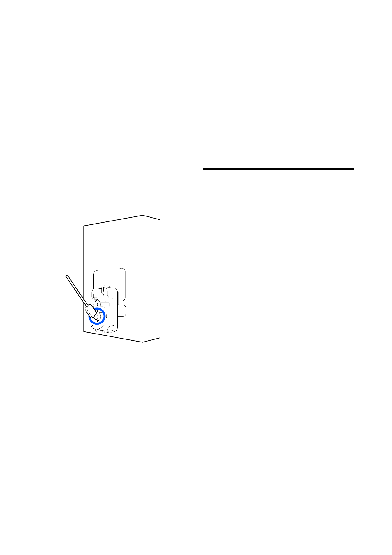
❏ Use a cleaning stick from the supplied Cleaning
Kit to absorb all the ink on the ink supply ports of
cartridges that have been removed from the
printer before all the ink is used. Dried ink on the
supply port may cause ink leaks when the
cartridge is reinserted and used.
Also, replace the cleaning sticks with a new one
for each color.
❏ Store the cartridges that have been removed so as
to keep the ink supply ports free of dust. The ink
supply port has a valve in it so it does not need to
be capped.
❏ Removed ink cartridges may have ink around the
ink supply port, so be careful not to get any ink on
the surrounding area when removing the
cartridges.
❏ To maintain the quality of the print head, this
printer stops printing before ink cartridges are
completely expended.
❏ Although the ink cartridges may contain recycled
materials, this does not effect printer function or
performance.
❏ Do not dismantle or remodel ink cartridges. You
may not be able to print properly.
❏ Do not drop or knock it against hard objects;
otherwise, the ink may leak from the cartridge.
❏ Ink cartridges installed in the printer must be
removed and thoroughly shaken once every week
for HDK, and once every three weeks for other
colors.
Shaking ink cartridges U “Periodic shaking of
ink cartridges” on page 181
Handling media
Note the following when handling or storing media.
Media that are in poor condition will not produce
good quality prints.
Be sure to read the documentation provided with each
type of media.
Notes on Handling
❏ Do not fold the media or damage the printable
surface.
❏ Do not touch the printable surface. Moisture and
oils from your hands can affect print quality.
❏ When handling media, hold it by both edges. We
recommend wearing cotton gloves.
❏ Keep the media dry.
❏ Packaging materials can be used to store media
and should not be thrown away.
❏ Avoid locations that are subject to direct sunlight,
excessive heat, or humidity.
❏ When not in use, media should be removed from
the printer, rewound, and inserted in its original
packaging for storage. Leaving media in the
printer for extended periods may cause it to
deteriorate.
Handling Media After Printing
To maintain long lasting, high quality print results,
note the following points.
SC-F20000 Series/SC-F11000H Series/SC-F11000 Series/SC-F10000H Series/SC-F10000 Series User's Guide
Introduction
42

❏ Do not rub or scratch the printed surface. If they
are rubbed or scratched, the ink may peel off.
❏ Do not touch the printed surface, as this may
remove the ink.
❏ Make sure printouts are completely dry before
folding or stacking, If the printouts are stacked or
taken up without being dried sufficiently, the
print surface may be damaged.
❏ Avoid direct sunlight.
❏ To prevent discoloration, display and store prints
as instructed in the documentation supplied with
the media.
SC-F20000 Series/SC-F11000H Series/SC-F11000 Series/SC-F10000H Series/SC-F10000 Series User's Guide
Introduction
43

Introducing the Supplied Software
North America
An Epson Edge Print CD is included with this printer. Epson Edge Print is a software RIP that can be effortlessly
used with easy-to-understand operations. See the online help for details about functions.
To view and download additional software, visit:
SC-F20070:
❏ support.epson
.com/f20070
SC-F11070H:
❏ www.epson.com/support/f11070h (U.S.)
❏ www.epson.ca/support/f11070h (Canada)
SC-F11070:
❏ www.epson.com/support/f11070 (U.S.)
❏ www.epson.ca/support/f11070 (Canada)
SC-F10070H:
❏ www.epson.com/support/f10070h (U.S.)
❏ www.epson.ca/support/f10070h (Canada)
SC-F10070:
❏ www.epson.com/support/f10070 (U.S.)
❏ www.epson.ca/support/f10070 (Canada)
Latin America
An Epson Edge Print CD is included with this printer. Epson Edge Print is a software RIP that can be effortlessly
used with easy-to-understand operations. See the online help for details about functions.
To view and download additional software, visit:
SC-F20070:
❏ support.epson.com/f20070
SC-F11070H:
SC-F20000 Series/SC-F11000H Series/SC-F11000 Series/SC-F10000H Series/SC-F10000 Series User's Guide
Introduction
44

❏ www.latin.epson.com/support/f11070h (Caribbean)
❏ www.epson.com.br/suporte/f11070h (Brazil)
❏ www.latin.epson.com/soporte/f11070h (other regions)
SC-F11070:
❏ www.latin.epson.com/support/f11070 (Caribbean)
❏ www.epson.com.br/suporte/f11070 (Brazil)
❏ www.latin.epson.com/soporte/f11070 (other regions)
SC-F10070H:
❏ www.latin.epson.com/support/f10070h (Caribbean)
❏ www.epson.com.br/suporte/f10070h (Brazil)
❏ www.latin.epson.com/soporte/f10070h (other regions)
SC-F10070:
❏ www.latin.epson.com/support/f10070 (Caribbean)
❏ www.epson.com.br/suporte/f10070 (Brazil)
❏ www.latin.epson.com/soporte/f10070 (other regions)
Other Regions
The following 2 types of CDs are included with this printer.
❏ Software disc (not included with some models)
See the following section for descriptions of the software that has been supplied.
❏ Epson Edge Print disc
Epson Edge Print is a software RIP that can be effortlessly used with easy-to-understand operations.
See the Start-Up Guide (booklet) for how to install the software.
See the online help for details about functions.
The following applications are available for Windows on the software disc. If your model does not include a
software disc or you are using a Windows PC without a disc drive, you can install the software from https://
epson.sn. If you are using a Mac, you can install Epson Edge Dashboard from Epson's website. Install as required.
For information about these applications, see the Network Guide (Online Manual) or the on-line help for the
application in question.
Note:
Printer drivers are not provided. A software RIP is required for printing. The Epson Software RIP, "Epson Edge Print", is
included with this printer on a separate CD.
The Epson website provides plug-ins for the printer.
SC-F20000 Series/SC-F11000H Series/SC-F11000 Series/SC-F10000H Series/SC-F10000 Series User's Guide
Introduction
45

Software Name Summary
Epson Edge Dashboard When you install Epson Edge Print, it is installed with it.
❏ You can easily acquire the following information provided by Epson on the Internet.
❏ Print settings (EMX) files
*
❏ Update information for the printer firmware (you can update the firmware easily
from Epson Edge Dashboard)
❏ Update information (when update information is available, start EPSON Software
Updater to perform the update) for software and manuals installed from the
supplied software disc and setup navigator.
❏ Information from Epson
❏ With Epson Edge Dashboard installed, you can monitor the status of the printer
connected to a computer over a network or USB connection.
❏ You can easily make and change media settings from a computer and write to the printer.
U “Launching the application” on page 47
U “Exiting procedure” on page 55
EPSON Software Updater (Windows only)
The software checks if new software or update information is available on the Internet and
installs it if it is available. You can also update the manuals, Epson Edge Dashboard, and Epson
Edge Print for this printer.
Epson communications
drivers
(Windows only)
Epson communications drivers are required when using Epson Edge Dashboard, Epson Edge
Print, and when connecting a computer to the printer by USB. Make sure these are installed.
Install Navi (Windows only)
This is the installer. During installation, you can easily use a wizard to set the address settings
for connecting to a network.
EpsonNet Config SE (Windows only)
With this software, you can configure various network settings for the printer from your
computer. This is useful as it allows you to enter addresses and names using the keyboard.
LFP Accounting Tool (Windows only)
Compatible with SC-F10000H Series/SC-F10000 Series only.
The LFP Accounting Tool is not installed automatically. Download it from Epson's website and
install it, if necessary.
This is software that can calculate costs for printed material printed by this printer (cost of
paper, cost of ink, etc.) and can display, total, and output information (in CSV format) about
print jobs. It is useful for cost calculations when you are selling printed material and for
understanding the amount of paper and ink being used.
Web Config This software comes preinstalled in the printer. Start and use it from a Web browser via the
network.
Make network security settings from Web Config. This software also has an email notification
function for notifying you about printer errors and other problems.
*The provided files differ according to the country and region in which you live.
SC-F20000 Series/SC-F11000H Series/SC-F11000 Series/SC-F10000H Series/SC-F10000 Series User's Guide
Introduction
46

Using Epson Edge
Dashboard
Launching the application
Epson Edge Dashboard is a web application.
A
You can launch the application using the
following methods.
Windows
Click the Epson Edge Dashboard icon on the
desktop toolbar, and select Show Epson Edge
Dashboard.
Mac
Click the Epson Edge Dashboard icon
displayed on the menu bar of the desktop, and
select Show Epson Edge Dashboard.
Linux
Click Applications - Other - Epson Edge
Dashboard.
B
Epson Edge Dashboard starts.
For details, see the help for Epson Edge Dashboard.
Registering the printer
The Epson Edge Dashboard can monitor, manage, and
copy media settings to registered printers.
On Windows computers, printers are registered
automatically. This allows you to monitor and manage
them immediately after launching the Epson Edge
Dashboard. If your printer is not automatically
registered, check that you are using it under the
following conditions.
❏ A communication driver provided with the
printer has been installed on a computer
❏ The computer and printer are connected
❏ The printer is on standby
Printers are not automatically registered to Mac or
Linux machines. Register your printer manually from
the Printer Registration screen. This screen is
displayed upon launching the Epson Edge Dashboard
for the first time. For details, see the help for Epson
Edge Dashboard.
SC-F20000 Series/SC-F11000H Series/SC-F11000 Series/SC-F10000H Series/SC-F10000 Series User's Guide
Introduction
47
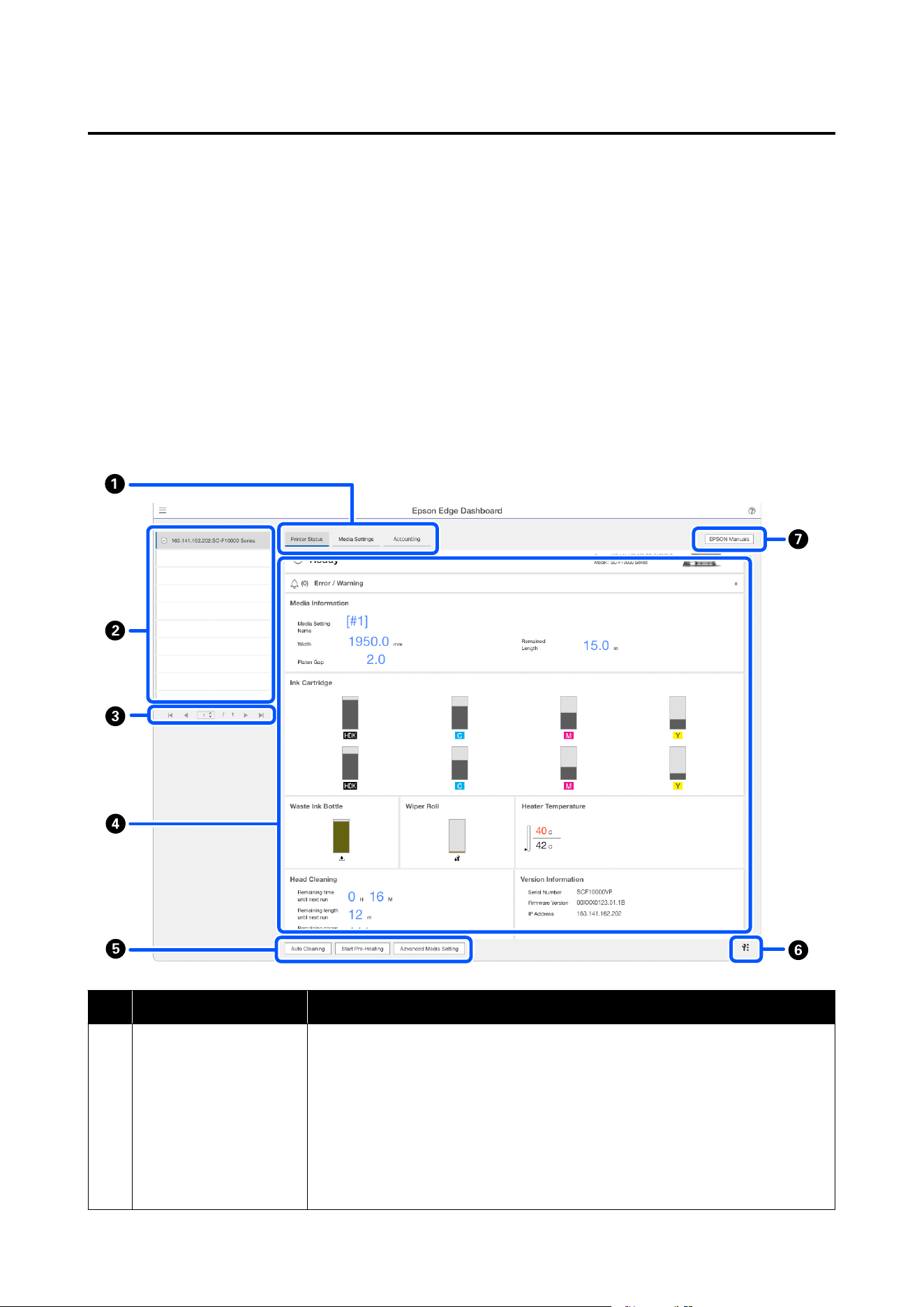
Checking and managing the printer's status
Follow the next steps on the Printer Operation screen to check and manage the printer's status.
The Printer Operation screen provides a view of the same status information as the printer's control panel screen.
It also allows you to perform standard maintenance operations.
A
Select Printer Operation from the menu. Alternatively, on the Home screen, click the area surrounding the
text describing the status of the relevant printer.
The Printer Operation screen is displayed.
B
Make sure that the Printer Status tab is selected.
Screen Layout
Name Functions
A
Tabs for Switching Views Allows you to switch between Printer Status and Media Settings views. Click tab to
switch views. Upon initial screen display, the Printer Status view is shown.
U “Downloading and copying media settings for EMX files” on page 50
The Accounting tab is displayed if the LFP Accounting Tool is installed.
Click the Accounting tab to display the Accounting Tool button. Click the button to
start the LFP Accounting Tool, which allows you to calculate costs for printed material,
and so on.
U “Using LFP Accounting Tool (Windows Only)” on page 56
SC-F20000 Series/SC-F11000H Series/SC-F11000 Series/SC-F10000H Series/SC-F10000 Series User's Guide
Introduction
48
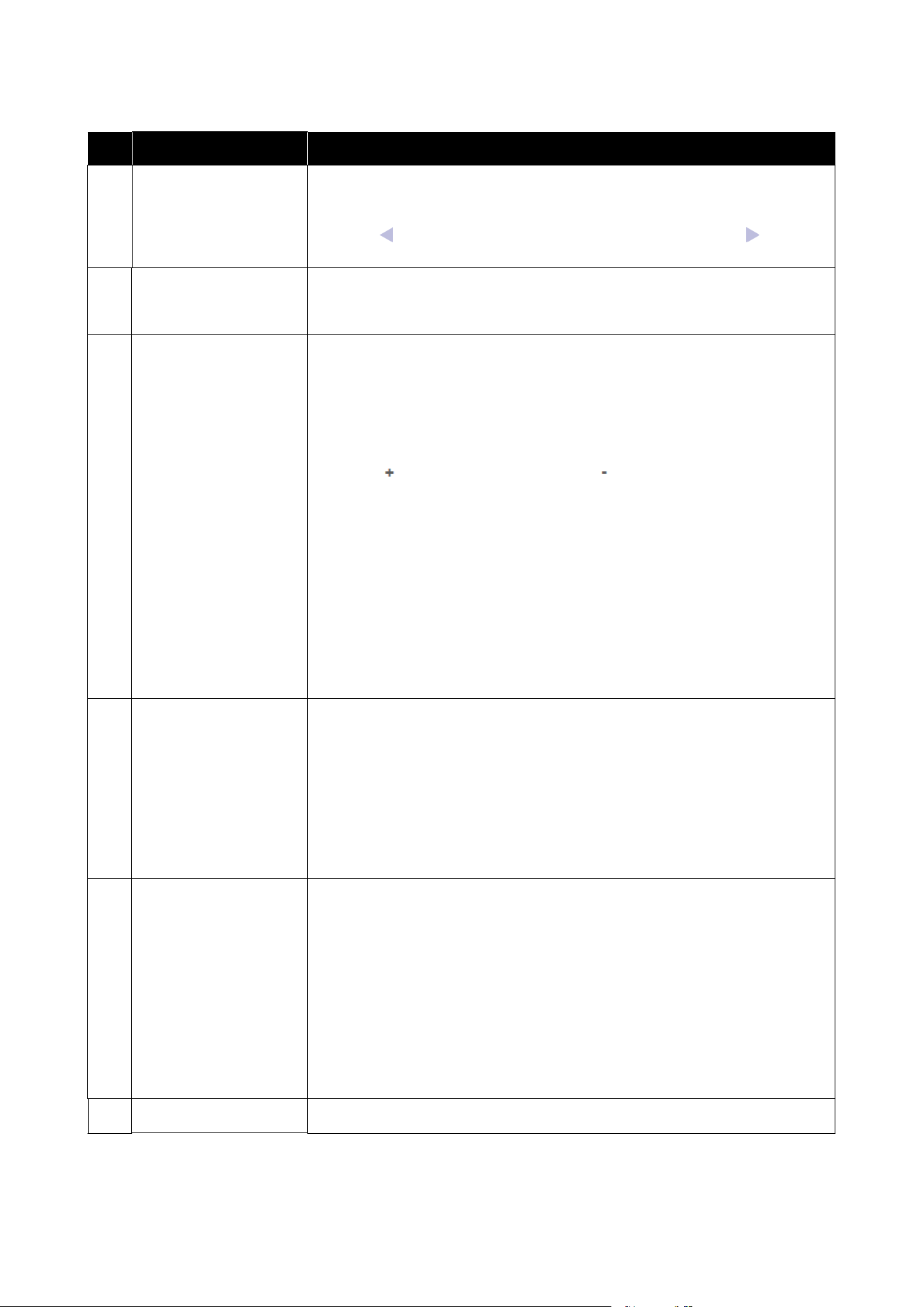
Name Functions
B
List of registered printers Register the printer to view it on this list.
❏ Select the printer to view its status in the printer status display area (D).
❏ Click
on the upper right corner of the list to collapse the list. Click to expand
the list.
C
Page controls If the list of registered printers covers multiple pages, you can specify a page number
to go to, and go to the first page, previous page, next page, or last page by clicking the
icons.
D
Printer status display area Select the printer to view the following information on the list of registered printers
(B).
❏ Printer's current status
❏ Errors/Warnings
Notifies you of errors and warnings that are occurring with the printer. Click the
item you want to check to display more details.
Click
to expand the display area. Click to collapse the display area.
❏ Status
The status is displayed here, described below, and is the same as that displayed on
the printer's control panel screen.
❏ Paper information
Feed adjustment information for media being printed is not displayed.
❏ Information on ink and consumables
❏ Information on heaters
❏ Notice on when to clean the print head
❏ Version Information
E
Function buttons Allow you to perform standard maintenance operations.
❏ Click each button to be able to run the function according to the same procedure
as when using the printer's control panel.
❏ If the printer is not available for maintenance operations, this button is grayed out.
You can perform maintenance when the button is available.
❏ If data is not printed according to its actual length, you can click Advanced Media
Setting to perform detailed feed adjustments. For details, see the help for Epson
Edge Dashboard.
F
Maintenance menu
button
Click to display the menu.
The following items are available on the menu.
❏ Firmware Update
*1, *2
Updates printer firmware to the latest version. For details, see the help for Epson
Edge Dashboard.
❏ Acquire Status Sheet Information
Acquires information from the printer and stores it as a file on the computer. For
details, see the help for Epson Edge Dashboard.
❏ Export Printer Status Data
*1
Do this only when directed by the person in charge of Epson's support.
G
EPSON Manuals Button Click to view your printer’s "Online Manual".
*1 This button is not displayed when accessing and using Epson Edge Dashboard on another computer on the network. For
details, see the help for Epson Edge Dashboard.
*2 This button is not displayed when using this software on a Linux machine.
SC-F20000 Series/SC-F11000H Series/SC-F11000 Series/SC-F10000H Series/SC-F10000 Series User's Guide
Introduction
49
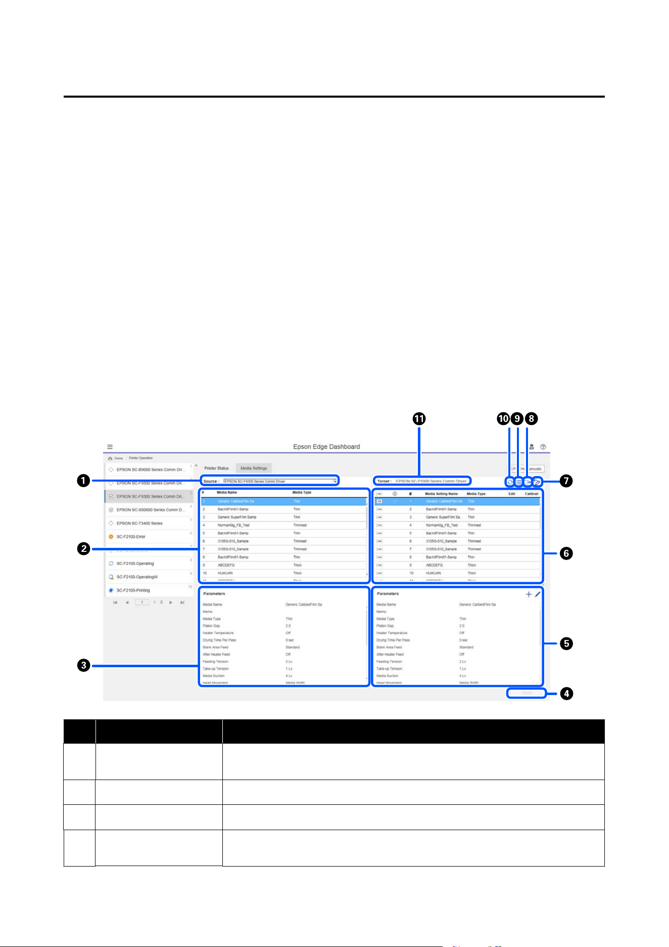
Downloading and copying media settings for EMX files
See the following for more information about EMX files.
U “Registering Media Settings to the Printer” on page 68
Download an EMX file and copy the media setting values in the downloaded EMX file to the printer from the
Media Settings screen of Printer Operation on the Epson Edge Dashboard.
Use the following procedure to view the Media Settings screen of Printer Operation.
A
Select Printer Operation from the menu. Alternatively, on the Home screen, click the area surrounding the
text describing the status of the relevant printer.
The Printer Operation screen is displayed.
B
Click the Media Settings tab.
The Media Settings screen of Printer Operation is displayed.
Screen Layout
Name Functions
A
Source Select the source used to add or change the media settings for the printer selected in
the list of registered printers.
B
Source media settings list Displays a list of the media settings loaded in A.
C
Parameters list (Source) Displays the settings for the media settings clicked in B.
D
Apply Button Click to update media settings for the target printer using the content of the current F
list.
SC-F20000 Series/SC-F11000H Series/SC-F11000 Series/SC-F10000H Series/SC-F10000 Series User's Guide
Introduction
50
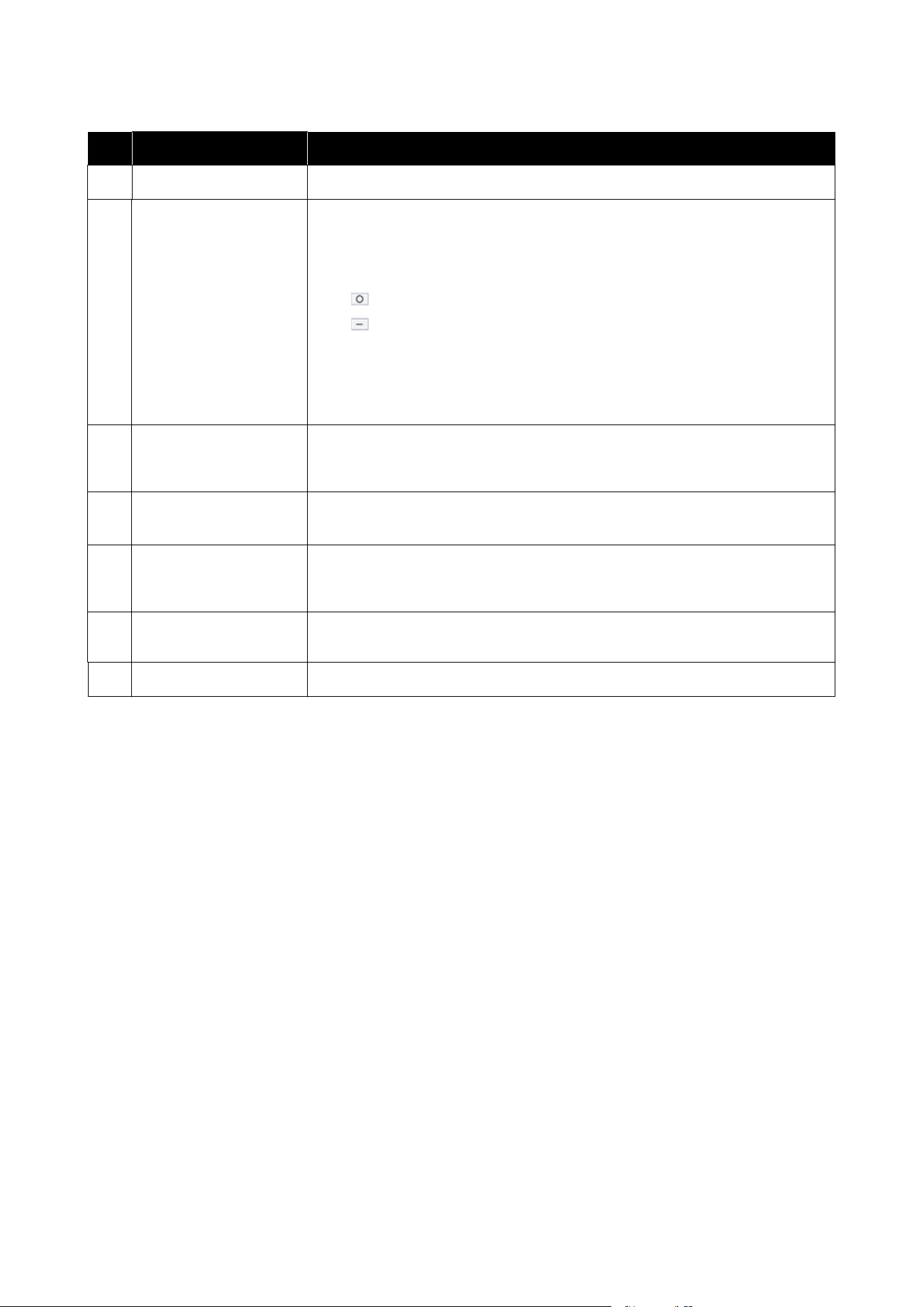
Name Functions
E
Parameters list (Target) Displays the settings for the media settings clicked in F.
F
Target media settings list Displays the media settings registered to the printer selected in the list of registered
printers.
Calibration field indicates the status of color calibration of media settings with the
following icons.
: includes color calibration information.
: does not include color calibration information.
No icon: Media settings you registered for the printer.
Click the icon to display the screen where you can see the list of color calibration
history. You can click EMX File Export within the screen to save an EMX file that
contains information required for color calibration.
G
Clear Button Click to return any changes you made to media settings selected from the list in F to
their previous state. However, you cannot reset the changed items after you click the
Apply button.
H
Write to File Button
*1
Click to collect the media settings displayed in the current list and save them to a
single file on your computer. For details, see the help for Epson Edge Dashboard.
I
Check registered media
settings button
Click to save the list of information for all the media settings currently registered to the
printer selected in the list of registered printers. For details, see the help for Epson Edge
Dashboard.
J
Target media settings list
update button
Click to reflect the settings for the media currently registered to the printer in the
target media settings list.
K
Target Displays the name of the printer selected in the list of registered printers.
*1 This button is not displayed when accessing and using this software from another computer on the network. For details, see
the help for Epson Edge Dashboard.
SC-F20000 Series/SC-F11000H Series/SC-F11000 Series/SC-F10000H Series/SC-F10000 Series User's Guide
Introduction
51
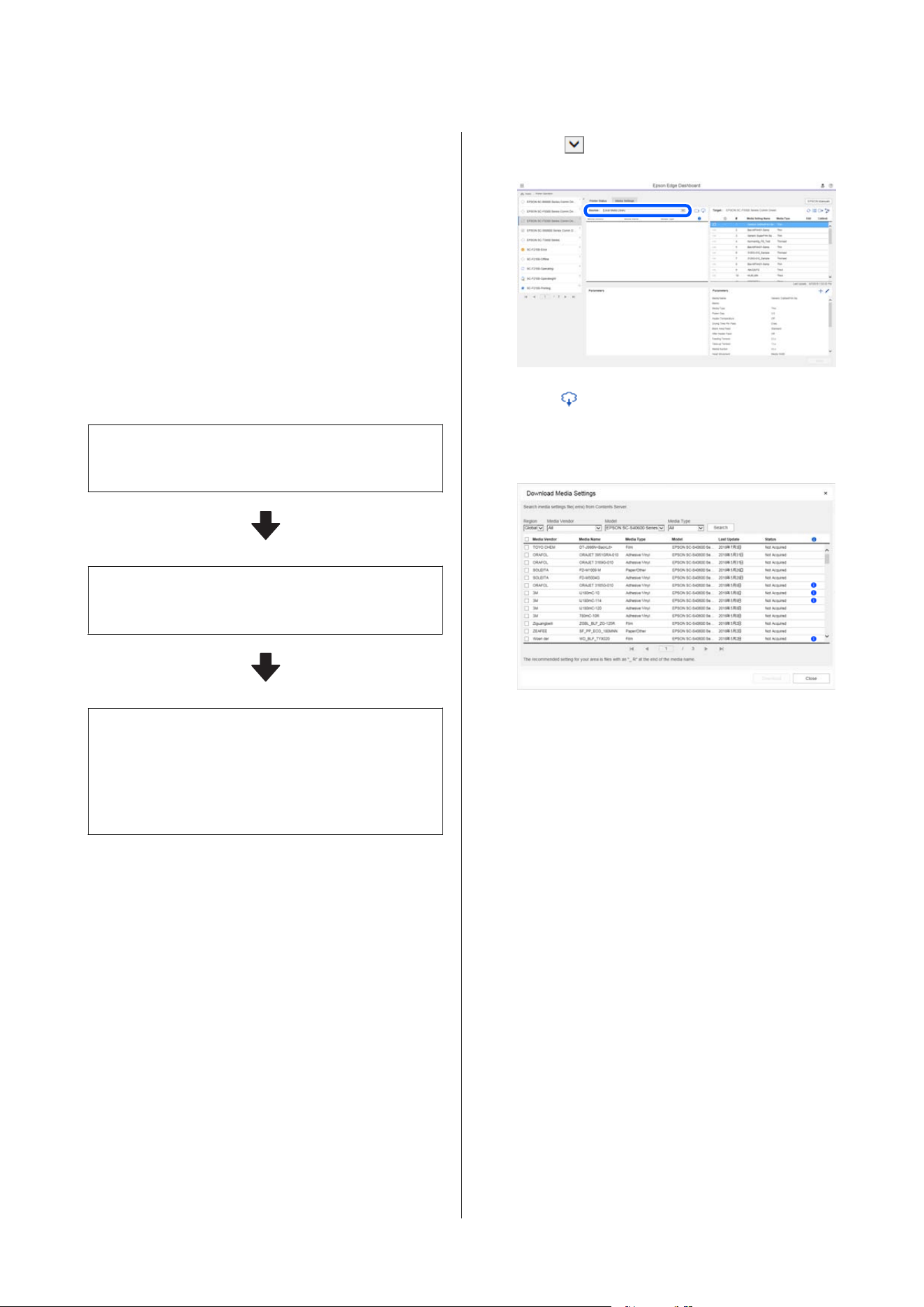
Copy operation flow
To copy media settings to the printer, you can copy the
media settings for another printer instead of copying
the media settings contained in a downloaded EMX
file.
You can copy the media settings for another printer to
share the same settings between multiple printers. For
details on how to copy the media settings of other
printers, see the help for Epson Edge Dashboard.
The following explains the workflow for copying
settings from a downloaded EMX file.
Downloading an EMX file
U “Downloading an EMX file” on page 52
Copy the media settings to the printer
U “Copying media settings to the printer ” on page 53
Do print adjustments on the printer
To optimize the media setting values for your printer's
status, make sure to do print adjustments after copying
the file.
U “Print Adjustments” on page 140
Copying the Media Settings in the
EMX File to the Printer
Downloading an EMX file
You can download only the EMX files corresponding
to the printers you registered on the Epson Edge
Dashboard. In addition, regardless of the printers
selected in the list of registered printers, you can
download all the files corresponding to the registered
printers.
A
Click in the source, and select Local Media
Library.
B
Click .
A list of EMX files for each commercially
available media is displayed in the following
download screen.
At first, the EMX file corresponding to the
printer selected in the list of registered printers
is displayed. If you want to view the file
corresponding to a different printer, select the
desired printer in Model and click Search.
You can narrow the content of the list to only
the necessary EMX files by selecting region,
media vendor, media type, and then clicking
Search.
C
Select the EMX files to download.
Select EMX files by checking the checkbox on
the left of each file. Check the checkbox on the
left of Media Vendor to select all EMX files
displayed on the current page.
You cannot download EMX files with
Acquisition Complete as their Status, for they
have already been downloaded.
EMX files with Update Available as their
Status have been updated since they were
acquired. Downloading such EMX files will
overwrite the Acquisition Complete files.
SC-F20000 Series/SC-F11000H Series/SC-F11000 Series/SC-F10000H Series/SC-F10000 Series User's Guide
Introduction
52
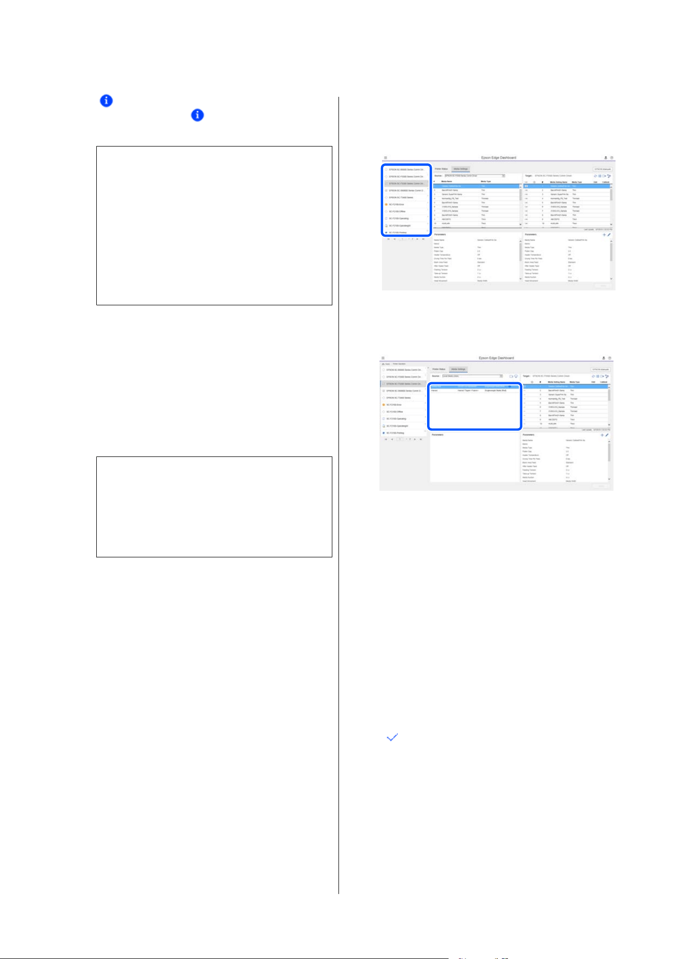
is displayed for EMX files with
information. Click
to display the
information.
c
Important:
If media setting values already registered to
the printer are overwritten by an EMX file
for the same media displayed with Update
Available, the print adjustment setting
values are initialized. If media settings are
overwritten, click the Apply button to register
the media settings to the printer, and then do
print adjustments.
D
Click Download.
The EMX files are saved.
EMX files are downloaded one at a time.
When selecting multiple EMX files, wait until
all files are of Acquisition Complete status.
Click Cancel to cancel EMX file download.
EMX files that are of Acquisition Complete
status at the time of cancellation are stored.
Note:
You cannot change where EMX files are stored. To
copy downloaded EMX files to other computers,
go to the Preferences screen and select Copy
Folder Path to copy the path. For details, see the
help for Epson Edge Dashboard.
E
Click Close to close the Download screen.
Media settings in the EMX files are loaded and
displayed to the source media settings list on
the Media Settings screen.
Only the media settings available to the model
selected on the list of registered printers are
displayed in the source media settings list. To
view the loaded media settings, select the
printer you selected in Step 2 on the list of
registered printers.
Copying media settings to the printer
A
Select the printer on the list of registered
printers.
B
From the source media settings list, select the
media settings that you want to add to or
change on the printer.
If printers of multiple different models are
registered to this software, only the media
settings available to the printer you selected in
Step 1 will be displayed. Media Names are
displayed in English. You can confirm the
display name in the download screen by putting
the mouse pointer over the English name.
You cannot select multiple sources
simultaneously. Copy them one at a time.
C
Check the target media settings list to see which
media settings are registered to the printer.
You can see the name of the settings registered
to the printer in Media Setting Name field.
indicates the currently specified media
settings for printing in the printer.
SC-F20000 Series/SC-F11000H Series/SC-F11000 Series/SC-F10000H Series/SC-F10000 Series User's Guide
Introduction
53
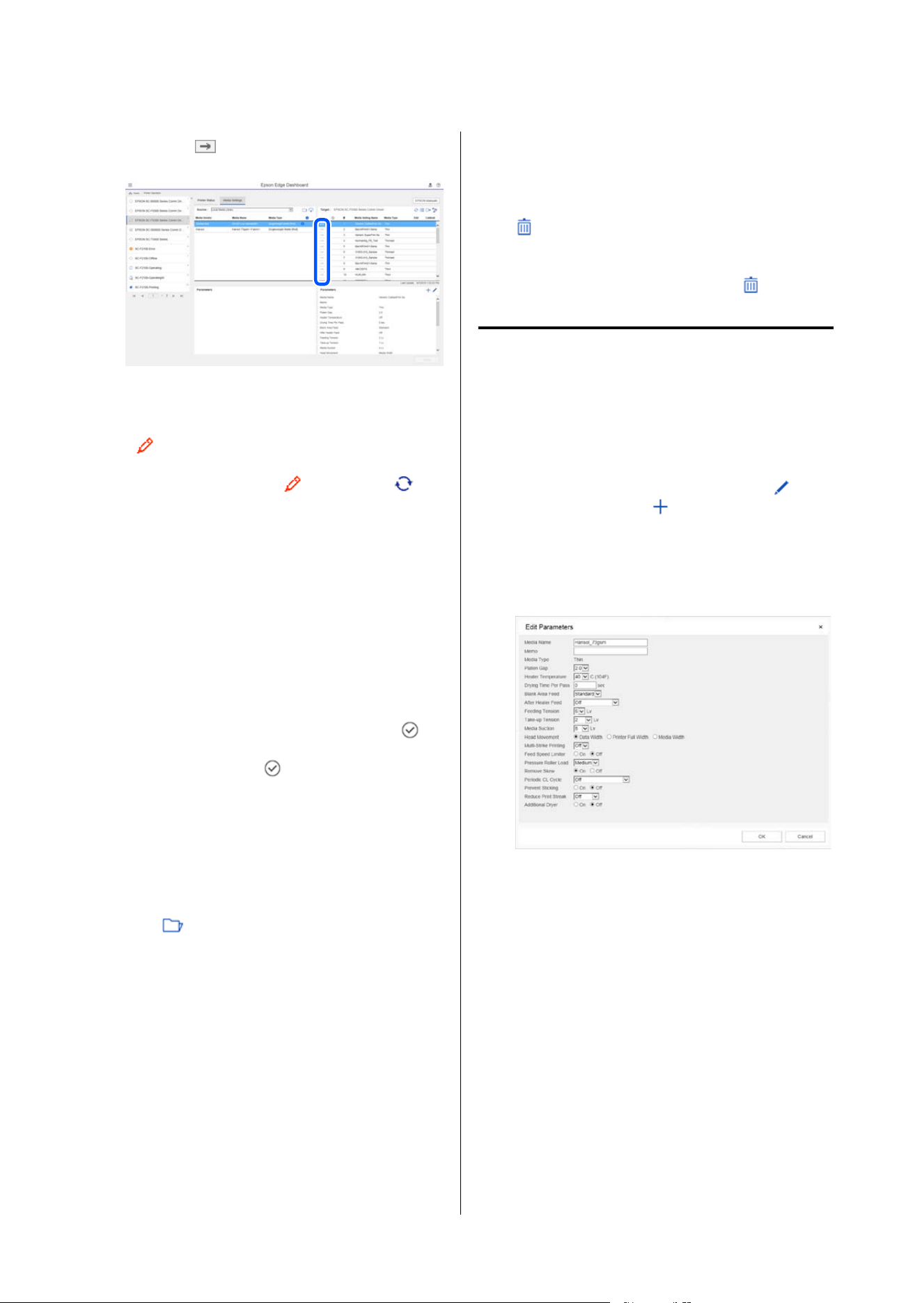
D
Click the of the target media setting
number.
The media settings you selected in the source
media settings list are copied.
indicates media settings copied from the
source media settings list or were changed on
the Edit screen. When
is displayed, is
grayed out and the list cannot be updated until
you click the Apply button.
You can check the Media Name on the
download screen by referring to Media Name
displayed in Memo of the parameters list
(target).
E
Click the Apply button.
Media settings are copied to the printer.
Before clicking the Apply button, check the list
of registered printers and make sure that
is
displayed as the status icon. If the icon is
anything except for
, you cannot update the
printer's media settings.
If the printer is connected via USB, make sure it
is not printing before you click Apply.
Loading EMX files stored to another computer
into the source media settings list
By clicking , you can load EMX files to your source
media settings list, no matter where they have been
copied. When you are using Epson Edge Dashboard
on a computer that cannot download EMX files, you
can load EMX files that were downloaded on a
different computer.
Click the icon to display the file selection screen, select
the EMX files you want to use, and load them.
A maximum of 300 EMX files can be loaded at a time.
The media settings of the files that are loaded are
added to the source media settings list.
Once the files are loaded, going forward, you can
simply select Local Media Library to see them listed.
Editing the source media settings list
Click to delete the EMX files that have been
downloaded. In the source media settings list, select
the EMX files that you no longer need or that you
downloaded by accident, and then click
.
Editing media settings
You can make changes to media settings selected on
the target media settings list. You can also add new
settings. The steps to do this are described below.
A
On the target media settings list, select the
media settings you want to edit. Click
(to
change settings) or
(to create a new
setting).
The Edit Parameters screen is displayed.
B
Change the settings.
The setting items vary according to the model
being used.
You can enter a note in Memo to describe the
content of the media settings. For media
settings copied from EMX files, the media
name is entered in the field.
You can change a setting’s Media Type only
when creating a new setting. When you newly
create a media setting, it is populated with
reference values for the media type you
selected. These values are determined based on
the standard specifications for this media type.
Do edits as needed for the optimum setting
values of your media.
SC-F20000 Series/SC-F11000H Series/SC-F11000 Series/SC-F10000H Series/SC-F10000 Series User's Guide
Introduction
54

C
When you have finished editing, click OK.
The changes are applied, and the previous
screen is displayed.
To discard the changes and return to the
previous page, click the Cancel button.
Exiting procedure
Close the Web browser.
SC-F20000 Series/SC-F11000H Series/SC-F11000 Series/SC-F10000H Series/SC-F10000 Series User's Guide
Introduction
55
Using Epson Edge Print
(Windows Only)
Launching the Application
You can launch the application using one of the
following methods.
❏ Double-click the shortcut icon created on the
desktop.
❏ Click the Windows Start button, and then All
Programs - Epson Software - Epson Edge Print.
For more information, see the Epson Edge Print help.
Acquiring and Registering EMX
Files
To print properly on your media, you need to register
media settings and print information appropriate for
the media you are using to both the printer and Epson
Edge Print.
By using print settings files (EMX files) provided by
Epson, you can easily achieve optimal print quality for
commercially available media (the provided files differ
according to the country and region in which you
live.).
See the following for more information about EMX
files.
U “Registering Media Settings to the Printer” on
page 68
Epson Edge Print allows you to easily perform the
following tasks using a wizard.
❏ Download EMX files
❏ Automatically register print information in Epson
Edge Print
❏ Register media settings to a specified registered
media number on the printer
For details on how to acquire and register EMX files,
see the Epson Edge Print help.
Exiting Procedure
Select Done from File at the top left of the screen.
Using LFP Accounting
Tool (Windows Only)
Basic Settings
You must perform the basic settings in advance for the
LFP Accounting Tool to obtain job information from
the printer for the calculation of costs and so on.
Perform setting in the following order. Follow the
steps described in the following section to perform the
setting.
1. Select the printer
2. Set the unit prices
3. Set the display conditions for job information
4. Set the units you want to summarize
Before doing the settings, check if the computer with
the LFP Accounting Tool is able to print from the
printer.
For details of each setting screen, see the LFP
Accounting Tool help.
Select the printer
Select the printer for which you want to summarize
cost calculations and job information.
This section explains how to select the printer straight
after installing the LFP Accounting Tool.
SC-F20000 Series/SC-F11000H Series/SC-F11000 Series/SC-F10000H Series/SC-F10000 Series User's Guide
Introduction
56
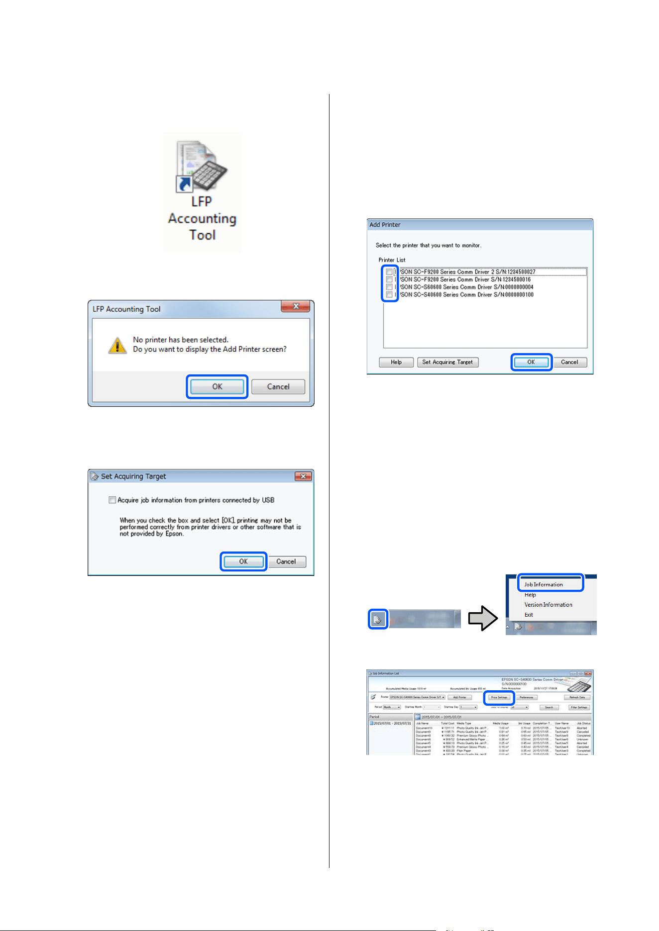
A
Double-click the LFP Accounting Tool shortcut
icon on the desktop.
B
When the following message is displayed, click
OK.
C
When the following message is displayed, check
the content, decide what action to take, and
then click OK.
D
Select the printer from the Add Printer screen,
and then click OK.
If this software cannot communicate with the
printer, it is not displayed in the list. When you
want to summarize cost calculations and job
information for multiple printers, select the
target printers. We recommend setting up to
four printers for monitoring.
When you click OK, this software starts
acquiring job information from the selected
printers.
Set the unit prices
Set the unit prices for the paper and ink being used by
the printer.
A
If Job Information List is not displayed,
right-click the LFP Accounting Tool icon on the
task tray, and then click Job Information.
B
Click Price Settings.
SC-F20000 Series/SC-F11000H Series/SC-F11000 Series/SC-F10000H Series/SC-F10000 Series User's Guide
Introduction
57
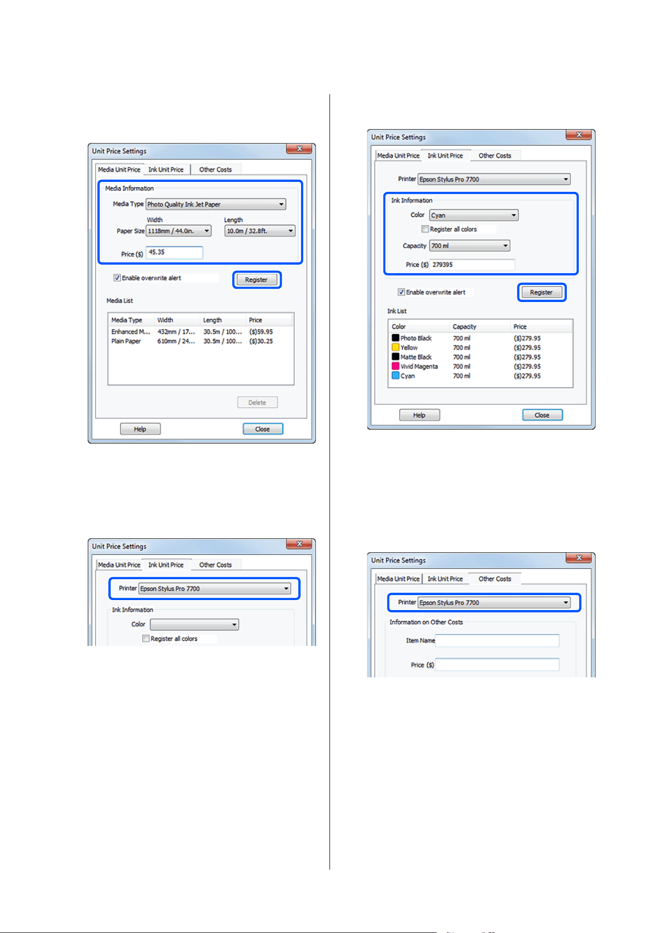
C
Click the Media Unit Price tab, make settings
for all of the Media Information items, and
then click Register.
Registered information is displayed in Media
List.
D
Click the Ink Unit Price tab, and then select the
printer.
E
Make settings for all of the Ink Information
items, and then click Register.
Registered information is displayed in Ink List.
Go to Step 8 if you do not need to make other
cost settings such as administration costs or
utility costs.
F
Click the Other Costs tab, and then select the
printer for which you want to set other costs.
SC-F20000 Series/SC-F11000H Series/SC-F11000 Series/SC-F10000H Series/SC-F10000 Series User's Guide
Introduction
58
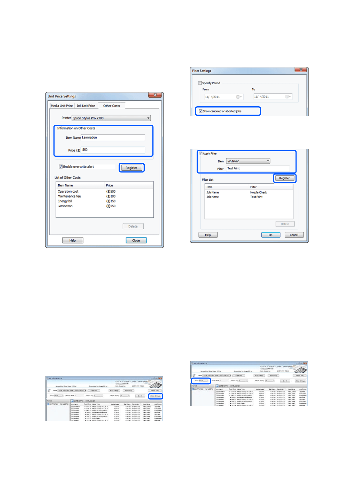
G
Make settings for all of the Information on
Other Costs items, and then click Register.
You can register up to five additional costs for
each job information, such as administration
costs, utility costs, or lamination costs.
Registered information is displayed in List of
Other Costs.
H
When you have finished setting each unit price,
click Close.
Set the display conditions for job
information
Hide jobs that should be skipped when summarizing
job information, such as canceled jobs, test prints, and
jobs by specific users.
A
Click Filter Settings on the Job Information
List screen.
B
To hide canceled jobs, clear Show canceled or
aborted jobs.
C
To hide test prints or jobs by specific users,
select Apply Filter, make settings for the items
you want to hide, and then click Register.
Registered information is displayed in Filter
List.
D
When you have finished setting display
conditions, click OK.
Set the units you want to summarize
Set the start date and units (month, year, and so on)
for the jobs you want to summarize.
A
You c a n s e l e c t Ye a r, Ha l f Ye a r, Q u a r t er, o r
Month as the unit (period) for the jobs you
want to summarize.
SC-F20000 Series/SC-F11000H Series/SC-F11000 Series/SC-F10000H Series/SC-F10000 Series User's Guide
Introduction
59
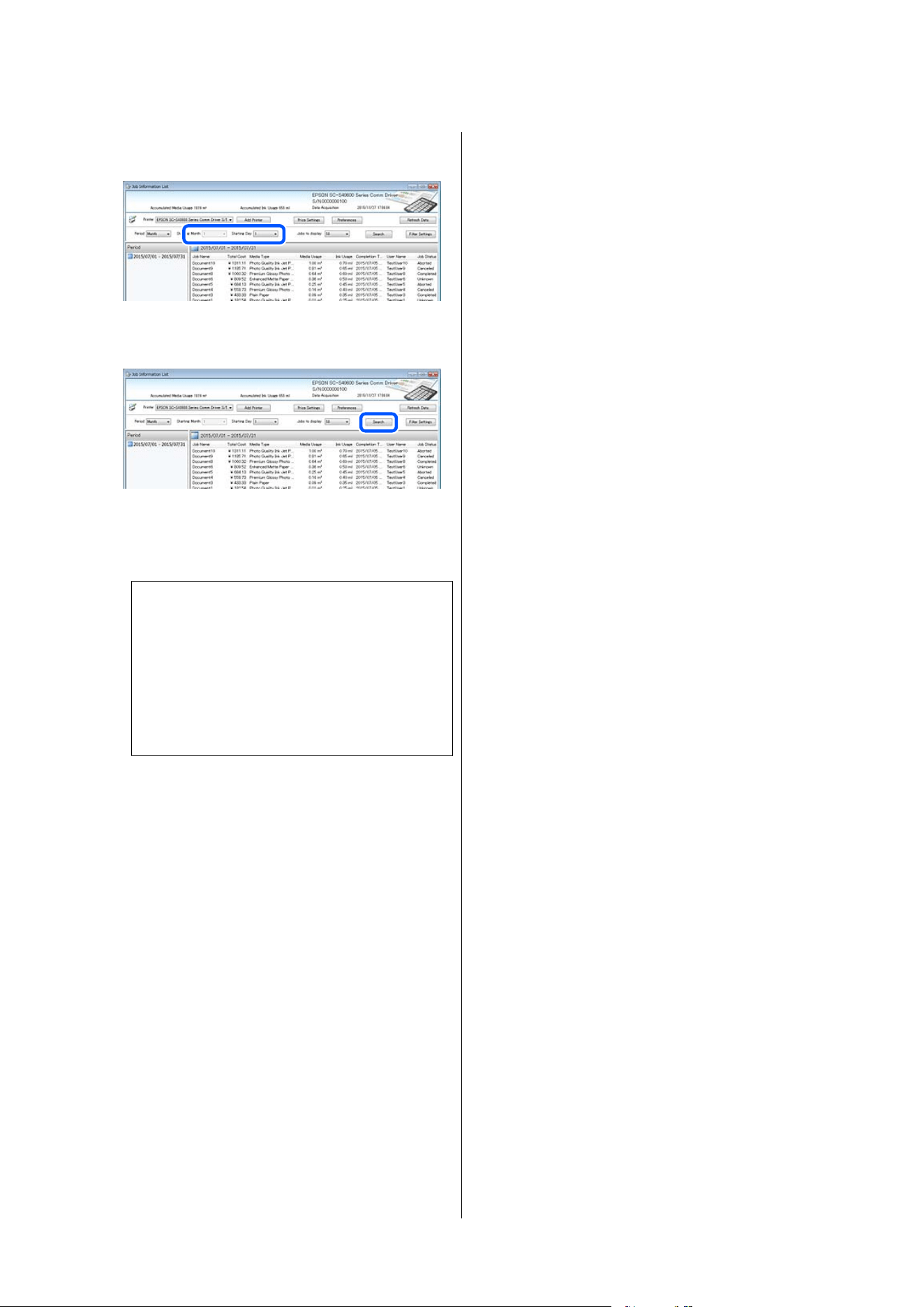
B
Select Starting Month or Starting Day on the
Job Information List screen.
C
Click Search to display jobs that satisfy the
search conditions.
Click Export to CSV to export the summarized
jobs to a CSV file. For details, see the LFP
Accounting Tool help.
Note:
The LFP Accounting Tool automatically
communicates with the printer every five minutes
and acquires job information. You can also click
Refresh Data to acquire the latest job
information collected in the printer. If the printer
has not yet printed any material, you cannot
acquire data as there is no job information.
This completes doing settings.
To continue acquiring job information, make sure the
LFP Accounting Tool is running whenever the printer
is printing.
SC-F20000 Series/SC-F11000H Series/SC-F11000 Series/SC-F10000H Series/SC-F10000 Series User's Guide
Introduction
60
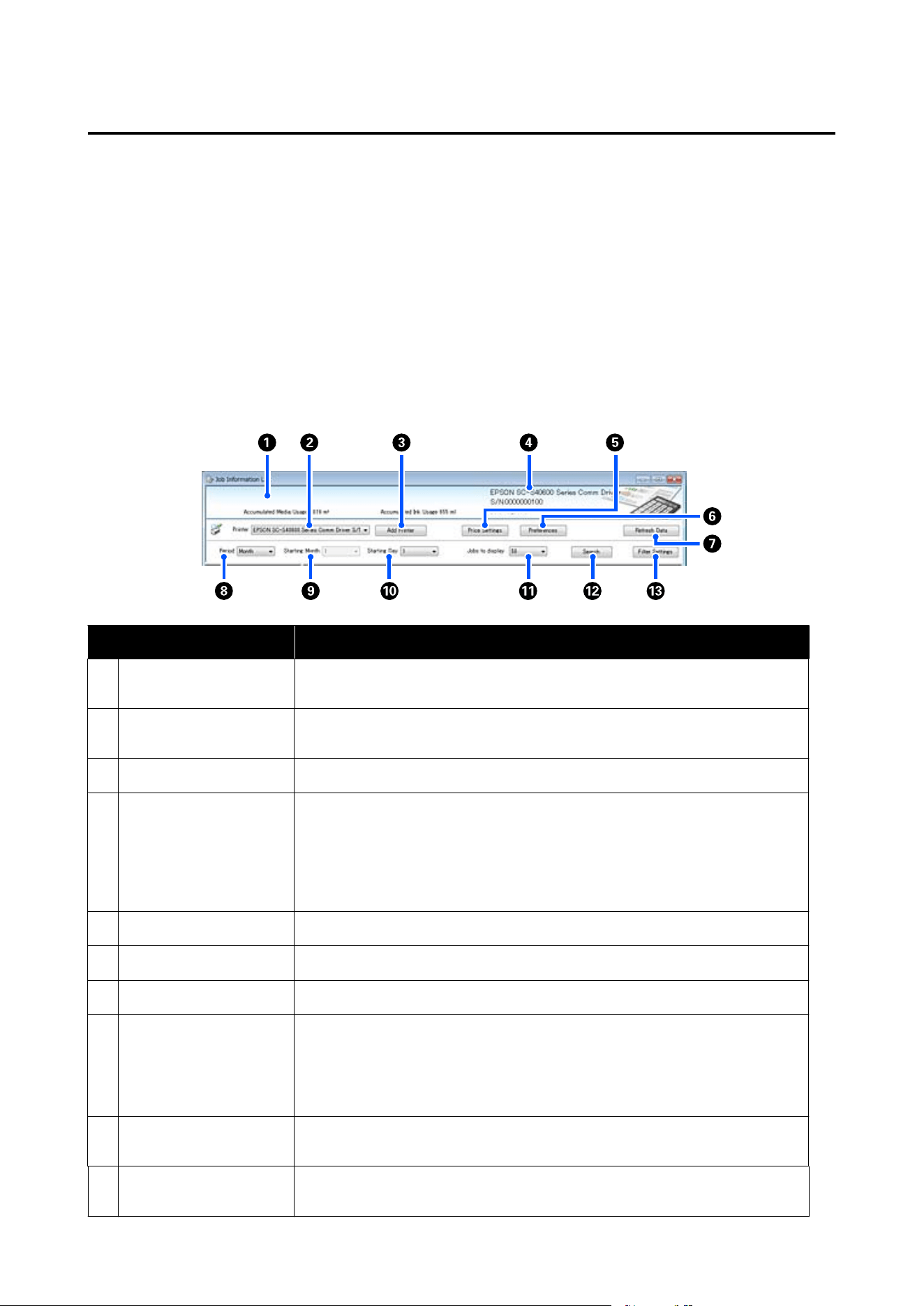
Screen Layout
The job information that is automatically acquired from the printer and collected in the computer is displayed on
the Job Information List screen.
You can display the screen using one of the following methods.
❏ Double-click this software's icon on the task tray
❏ Right-click this software's icon on the task tray, and then click Job Information
❏ In Epson Edge Dashboard, click the LFP Accounting Tool on the Accounting tab of the Printer Operation
screen
For details of other screens, see the LFP Accounting Tool help.
Item Explanation
A
Message display area Displays a message if the job information search results contain a job for which cost
cannot be calculated, or a job for which the unit price has not been set.
B
Printer Select the printer for which you want to display job information.
Displays the list of printers selected on the Add Printer screen.
C
Add Printer button Opens the Add Printer screen.
D
Selected printer
information/Data
Acquisition display area
Displays the product name and serial number for the selected printer, as well as the
date when the latest job information was acquired from the selected printer. At the
bottom of the message display area, Accumulated Ink Usage and Accumulated
Media Usage are also displayed depending on the printer model.
When this software is running and is able to communicate with the selected printer,
it acquires job information every five minutes.
E
Price Settings button Opens the Unit Price Settings screen.
F
Preferences button Opens the Preferences screen.
G
Refresh Data button Click to instantly acquire the latest job information for the selected printer(s).
H
Period Select the time period for the jobs you want to summarize.
You can select Year, Half Year, Quarter, or Month. The default is "---". While nothing is
displayed in Period when the default value is selected, all of the job information for
the selected printer is displayed and summarized in list view.
The date for each selected unit is displayed in Period.
I
Starting Month This is available when Year, Half Year, or Quarter is selected from Period. Select from
1 to 12 as the month to start summarizing.
J
Starting Day This is available when Year, Half Year, or Quarter is selected from Period. Select from
1 to 31 as the day to start summarizing.
SC-F20000 Series/SC-F11000H Series/SC-F11000 Series/SC-F10000H Series/SC-F10000 Series User's Guide
Introduction
61
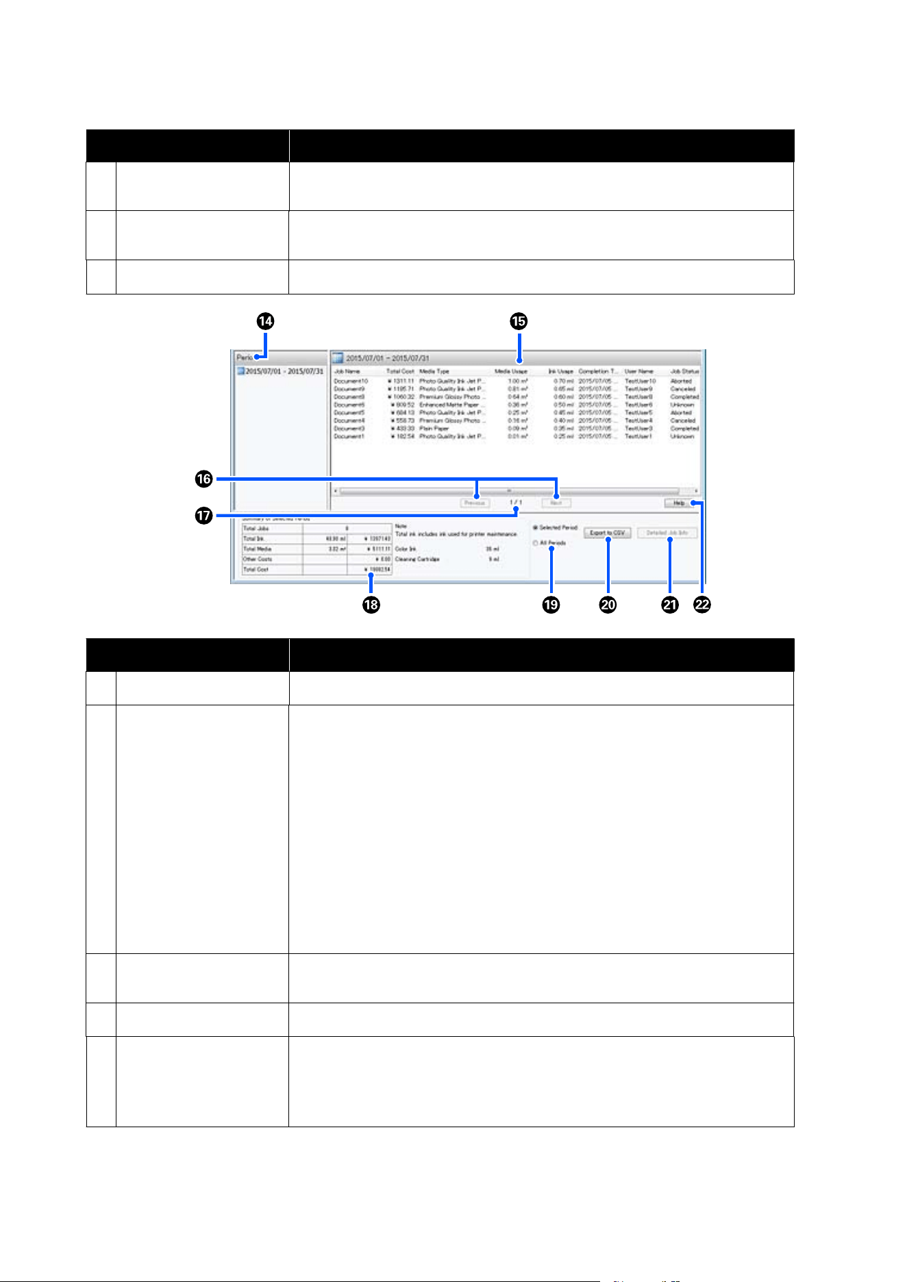
Item Explanation
K
Jobs to display Set the maximum number of jobs displayed in list view. You can select from "50",
"100", or "200".
L
Search button Displays data that matches the search conditions set on the Period or Filter
Settings screens.
M
Filter Settings button Opens the Filter Settings screen.
Item Explanation
N
Period Displays the period set in Period, Starting Month, or Starting Day.
O
List View Displays a list of the job information found using the search conditions set on the
Period or Filter Settings screens. Acquired job information is displayed in
descending order from the latest to the oldest.
"???" is displayed in jobs for which the Media Unit Price or the Ink Unit Price has not
been set. If you click Price Settings while selecting a job for which "???" is displayed,
the Unit Price Settings screen opens with the items that need to be set already
selected.
If more than 10 jobs are sent to the printer while the computer is turned off, this
software cannot acquire job information. From the job information that the software
could not acquire, only ink consumption is reported in the list with the job name
Lost Job. - is displayed for other information that could not be acquired. Depending
on the model being used, you may not be able to acquire ink consumption
information, in which case 0ml is displayed.
P
Previous/Next buttons Use these buttons to navigate between pages when job information for the selected
period is spread over multiple pages.
Q
Current Page Displays the page number for the current page.
R
Summary of Selected
Period
Displays the total value of each item for the job information selected in Period.
Information displayed vary depending on the acquiring target printer.
If a job without a set media unit price or ink unit price is displayed in the list view,
"???" is also displayed in the summary.
SC-F20000 Series/SC-F11000H Series/SC-F11000 Series/SC-F10000H Series/SC-F10000 Series User's Guide
Introduction
62

Item Explanation
S
Selected Period/All
Periods
Set the period for the data to be output to a CSV file.
When you want to output data selected from Period that is displayed in the current
list view, set Selected Period.
You can only select one Period.
To output all information for the selected printer, set All Periods (job information
that has been excluded on the Filter Settings screen is also output).
To output information for the selected printer without the job information items set
on the Filter Settings screen, set Period to "---", and then select Selected Period.
T
Export to CSV button Exports job information for either Selected Period or All Periods to a file.
U
Detailed Job Info button Displays detailed information for the job selected in list view.
V
Help button Displays the Help for this screen.
SC-F20000 Series/SC-F11000H Series/SC-F11000 Series/SC-F10000H Series/SC-F10000 Series User's Guide
Introduction
63

Using EPSON Software
Updater
Note:
EPSON Software Updater is not available in all regions.
North American users:
To check for software updates, visit:
SC-F20070:
❏ support.epson.com/f20070
SC-F11070H:
❏ www.epson.com/support/f11070h (U.S.)
❏ www.epson.ca/support/f11070h (Canada)
SC-F11070:
❏ www.epson.com/support/f11070 (U.S.)
❏ www.epson.ca/support/f11070 (Canada)
SC-F10070H:
❏ www.epson.com/support/f10070h (U.S.)
❏ www.epson.ca/support/f10070h (Canada)
SC-F10070:
❏ www.epson.com/support/f10070 (U.S.)
❏ www.epson.ca/support/f10070 (Canada)
Note:
EPSON Software Updater is not available in all regions.
Latin American users:
To check for software updates, visit:
SC-F20070:
❏ support.epson.com/f20070
SC-F11070H:
❏ www.latin.epson.com/support/f11070h
(Caribbean)
❏ www.epson.com.br/suporte/f11070h (Brazil)
❏ www.latin.epson.com/soporte/f11070h (other
regions)
SC-F11070:
❏ www.latin.epson.com/support/f11070 (Caribbean)
❏ www.epson.com.br/suporte/f11070 (Brazil)
❏ www.latin.epson.com/soporte/f11070 (other
regions)
SC-F10070H:
❏ www.latin.epson.com/support/f10070h
(Caribbean)
❏ www.epson.com.br/suporte/f10070h (Brazil)
❏ www.latin.epson.com/soporte/f10070h (other
regions)
SC-F1007
0:
❏ www.latin.epson.com/support/f10070 (Caribbean)
❏ www.epson.com.br/suporte/f10070 (Brazil)
❏ www.latin.epson.com/soporte/f10070 (other
regions)
Checking software update
availability
A
Check the following status.
❏ The computer is connected to the Internet.
❏ The printer and the computer can
communicate.
SC-F20000 Series/SC-F11000H Series/SC-F11000 Series/SC-F10000H Series/SC-F10000 Series User's Guide
Introduction
64
B
Start EPSON Software Updater.
Windows 8.1/Windows 8
Enter the software name in the search charm,
and select the icon displayed.
Except for Windows 8.1/Windows 8
Click Start > All Programs (or Programs) >
Epson Software > EPSON Software Updater.
Mac
Click Move - Applications - Epson Software -
EPSON Software Updater.
Note:
In Windows, you can also start by clicking the
printer icon on the desktop toolbar and selecting
Software Update.
C
Update the software and manuals.
Follow the on-screen instructions to continue.
c
Important:
Do not turn off the computer or printer while
updating.
Note:
Software that is not displayed in the list cannot be
updated using EPSON Software Updater. Check for the
latest versions of the software from the Epson website.
https://www.epson.com
Receiving update notifications
A
Start EPSON Software Updater.
B
Click Auto update settings.
C
Select an interval for checking for updates on
the printer's Interval to Check box, and then
click OK.
Using Web Config
Instructions for starting
Launch a browser on a computer connected to the
same network as the printer.
A
Check the IP address of the printer.
Press
, and press in order General Settings -
Network Settings - Network Status - Wired
LAN Status.
B
Launch a Web browser on a computer
connected to the printer via a network.
C
Enter the IP address of the printer in the
address bar of the Web browser and press the
Enter or Return key.
Format:
IPv4: https://IP address of printer/
IPv6: https://[IP address of printer]/
Example:
IPv4: https://192.168.100.201/
IPv6: https://[2001:db8::1000:1]/
Exiting procedure
Close the Web browser.
Uninstalling Software
c
Important:
❏ Log in to a "Computer administrator" account
(an account with administrative privileges).
❏ Enter the administrator password when
prompted and then proceed with the
remainder of the operation.
❏ Exit any other applications that may be
running.
This section describes how to uninstall Epson
communications drivers. For uninstallation of other
software, see the software help.
SC-F20000 Series/SC-F11000H Series/SC-F11000 Series/SC-F10000H Series/SC-F10000 Series User's Guide
Introduction
65

A
Turn off the printer, and unplug the interface
cable.
B
Go to the Control Panel and click Uninstall a
program from the Programs category.
C
Click on the name of whichever of the Comm
Drivers listed below corresponds to the model
you are using, and then click on Uninstall/
Change.
❏ EPSON SC-F20000 Series Comm Driver
Printer Uninstall
❏ EPSON SC-F10000H Series FpFy Comm
Driver Printer Uninstall
❏ EPSON SC-F10000H Series LcLm Comm
Driver Printer Uninstall
❏ EPSON SC-F10000H Series OrV Comm
Driver Printer Uninstall
❏ EPSON SC-F10000 Series Comm Driver
Printer Uninstall
D
Select the target printer icon, and then click
OK.
E
Follow the on-screen instructions to continue.
When the delete confirmation message appears,
click Ye s .
If you are reinstalling the Epson communications
drivers, restart the computer.
SC-F20000 Series/SC-F11000H Series/SC-F11000 Series/SC-F10000H Series/SC-F10000 Series User's Guide
Introduction
66
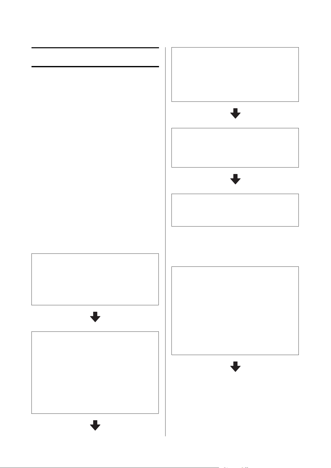
Basic Operations
Workflow for Optimal
Printing
The following conditions must be fulfilled to print
optimally on the printer.
❏ The media settings values appropriate for the
media you are using are registered to the printer,
and the print information is registered to the RIP.
❏ The media is loaded appropriately on the printer.
❏ The print adjustments (print head alignment and
media feed adjustment) are executed using the
media to be used.
❏ The printer is kept in a proper condition.
Follow the steps below to fulfill the conditions.
When using the EMX file with the new media
1. Register media settings.
Use Epson Edge Print or Epson Edge Dashboard to
download the EMX file and register the media settings to
the printer.
U “Registering Media Settings to the Printer” on
page 68
2. Load the media.
Load the media you want to use into the media feeding
unit and auto take-up reel unit on the printer.
When loading media, from the screen of the control
panel, select a number of a media, whose media settings
were registered in advance.
U “Loading Media Into the Media Feeding Unit” on
page 81
U “Loading Media Into the Auto Take-up Reel Unit” on
page 99
3. Execute the Print Adjustments.
Execute the Print Adjustments to optimize the media
settings values to the condition of the machine.
Usually, this is adjusted automatically by executing
Automatic Adjustment.
U “Print Adjustments” on page 140
4. Check the condition of the printer.
Upon starting printing work, inspect the remaining ink
level and the condition of the print head nozzle.
U “Before Printing” on page 140
5. Print.
Start printing from Epson Edge Print.
For details, see the help for Epson Edge Print.
When using a new media by using general media
settings/by using a media type that has already
been registered
1. Load the media.
Load the media you want to use into the media feeding
unit and auto take-up reel unit on the printer.
When using a new media, on the screen of the control
panel, by selecting a Media Type that is close to the
media you are using, you can register the suitable media
settings.
U “Loading Media Into the Media Feeding Unit” on
page 81
U “Loading Media Into the Auto Take-up Reel Unit” on
page 99
SC-F20000 Series/SC-F11000H Series/SC-F11000 Series/SC-F10000H Series/SC-F10000 Series User's Guide
Basic Operations
67
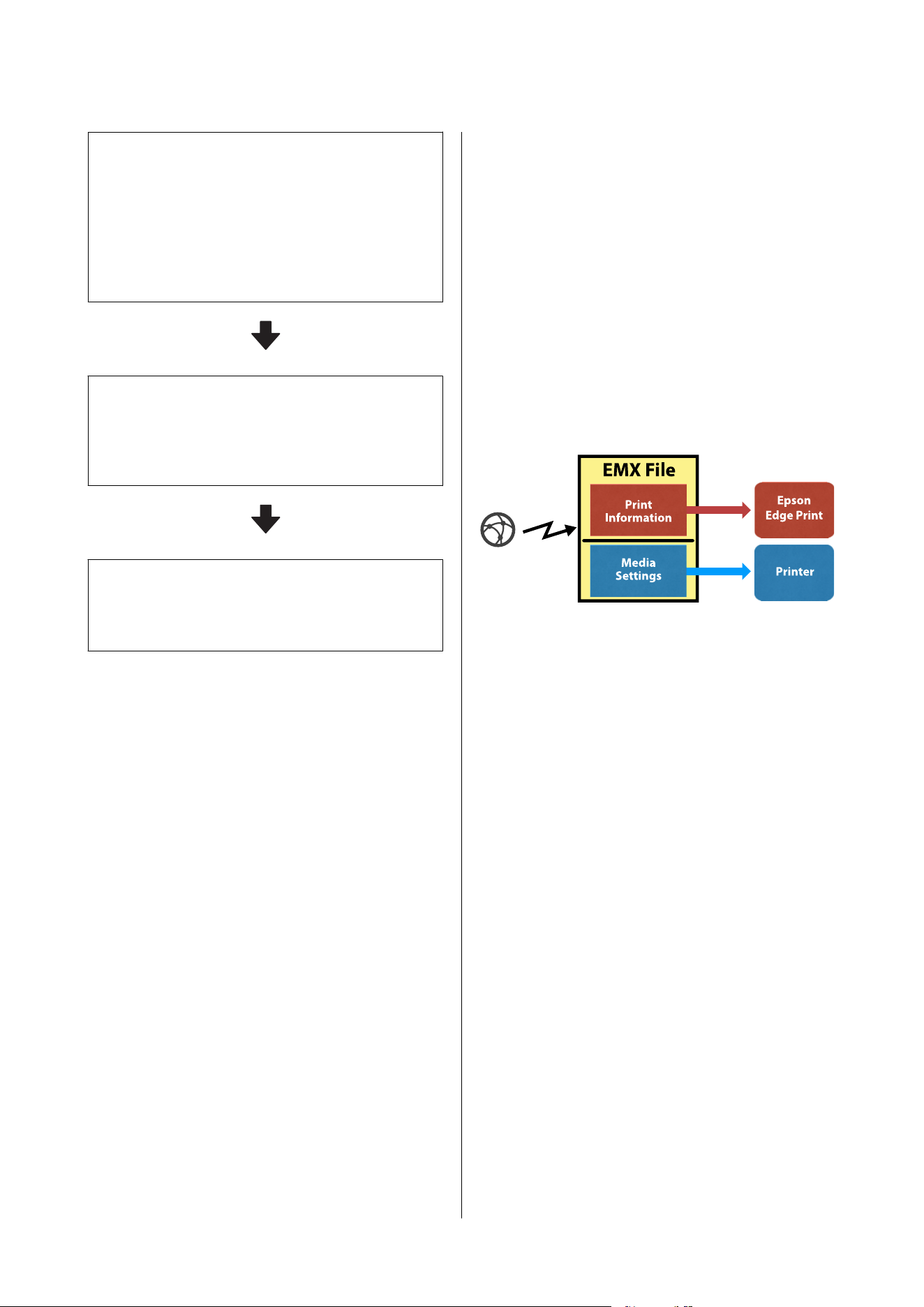
2. Execute the Print Adjustments. (when using
new media)
Execute the Print Adjustments to optimize the media
settings values to the condition of the machine.
Usually, this is adjusted automatically by executing
Automatic Adjustment.
U “Print Adjustments” on page 140
3. Check the condition of the printer.
Upon starting printing work, inspect the remaining ink
level and the condition of the print head nozzle.
U “Before Printing” on page 140
4. Print.
Start printing from Epson Edge Print.
For details, see the help for Epson Edge Print.
Registering Media
Settings to the Printer
Media settings are registered to the printer in one of
the following ways.
Using general media settings that are already
registered to the printer
The printer already has 4 types of Media Type that
correspond to the paper weight of the media. Select a
media type to print with the general media settings
that correspond to various paper weights.
When loading media, view the Media items shown in
the operation panel screen to select a Media Type that
corresponds to the paper weight of the media you are
loading.
U “Loading Media Into the Media Feeding Unit” on
page 81
U “Loading Media Into the Auto Take-up Reel Unit”
on page 99
Downloading an EMX file to register settings
An EMX file supplied by Epson is a single print
settings file containing the following information
necessary to print properly on commercially available
media (the provided files differ according to the
country and region in which you live).
❏ Print Information: Settings for ICC profiles that
are used in RIP, the number of passes, the
resolution, and so on
❏ Media Settings: Registered setting values, such as
a platen gap and feeding tension suitable for the
media being used, that are registered to the
printer for media management
To use Epson Edge Print, the software RIP provided
with the printer, download an EMX file from Epson
Edge Print.
U “Using Epson Edge Print (Windows Only)” on
page 56
To use commercially available software RIP, download
an EMX file by using Epson Edge Dashboard.
U “Using Epson Edge Dashboard” on page 47
Precautions When
Handling Media
If the following points are not observed when
handling media, small amounts of dust and lint may
stick to the media surface and cause ink drops in the
print results or cause the nozzles to clog.
Do not place exposed media directly on the floor.
Media should be rewound and inserted in its original
packaging for storage.
SC-F20000 Series/SC-F11000H Series/SC-F11000 Series/SC-F10000H Series/SC-F10000 Series User's Guide
Basic Operations
68
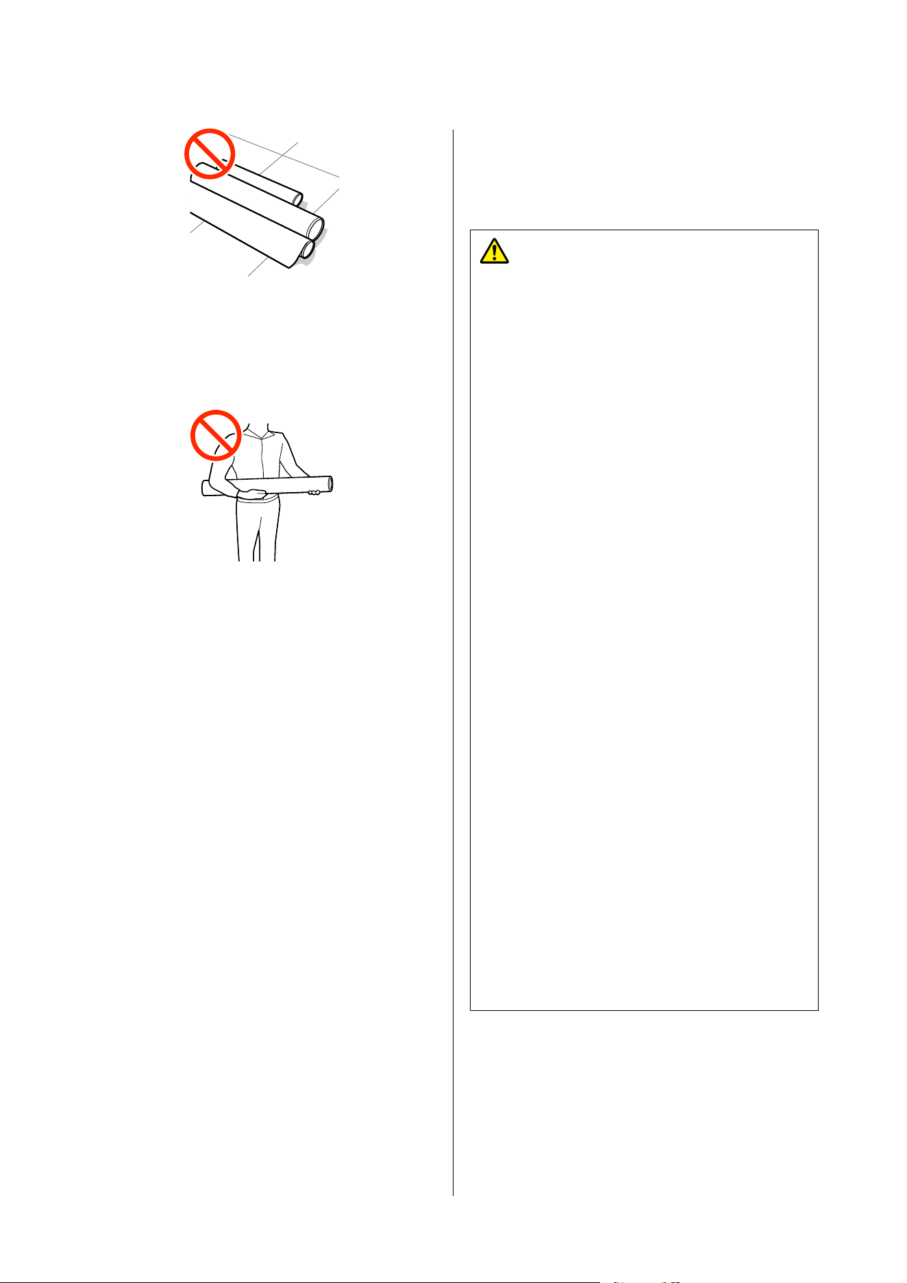
Do not carry media with the media surface pressed
against clothing.
Handle media in its individual packaging until just
before loading the media in the printer.
Notes on Loading and
Removing Media
Caution:
❏ The dryer may be hot; observe all necessary
precautions. Failure to observe the necessary
precautions could result in burns.
❏ Do not put your hand inside the dryer. Failure
to observe the necessary precautions could
result in burns.
❏ Because the media is heavy, it should not be
carried by one person. We recommend using a
lifter for media that weighs over 40 kg (88
lb.) .
❏ Be careful not to trap your hands or fingers
when opening or closing the front cover or the
maintenance cover. Failure to observe these
precautions could result in injury.
❏ Do not rub your hands along the edges of the
media. The edges of the media are sharp and
can cause injury.
❏ Follow the instructions in the manual when
loading media or roll cores or removing media
from the take-up roll. Dropping media, roll
cores, or take-up rolls could result in injury.
❏ Be sure that your hands or hair do not get
caught in the Media Feeding Unit or Auto
Take-up Reel Unit while it is operating.
Failure to observe these precautions could
result in injury.
❏ When cutting media, be careful not to cut
your fingers or hands with the cutter or other
blades.
❏ If the media weighs over 20 kg (44.09 lb.), it
should not be carried by one person. When
loading or removing the media, use at least
two people.
SC-F20000 Series/SC-F11000H Series/SC-F11000 Series/SC-F10000H Series/SC-F10000 Series User's Guide
Basic Operations
69
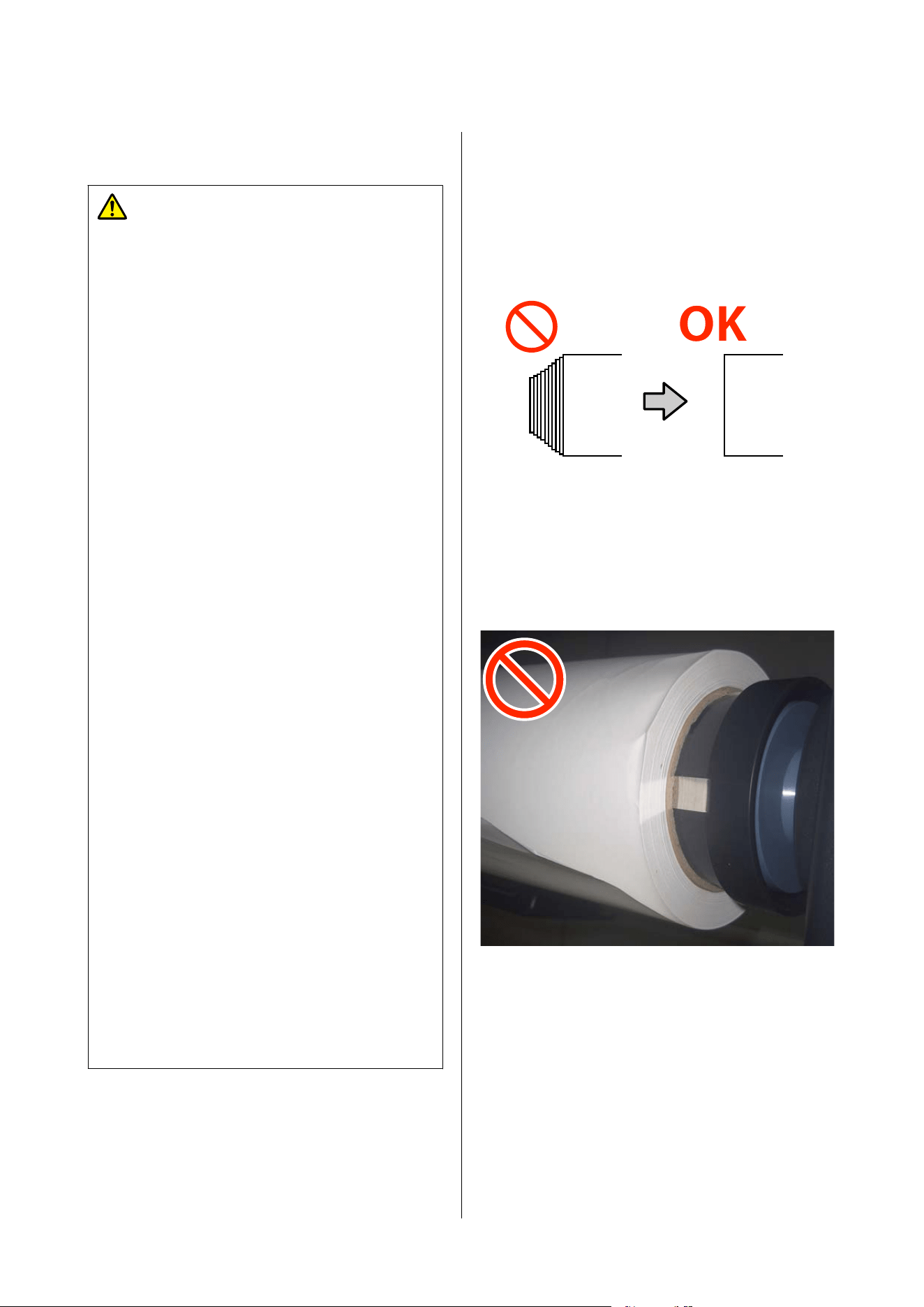
Notes when Using Large Capacity Media
Caution:
❏ When handling media, such as when loading
it, we recommend using a lifter. Failure to use
a lifter may cause the media to fall and result
in injury.
❏ Do not place your hands on the handles when
loading spindles or media rolls on spindles
into the large capacity roll unit or large
capacity reel unit. Doing so may cause your
fingers to be caught and result in injury.
❏ Do not touch rotating spindles or media
during operation. Doing so may cause your
hands, hair, or other body parts to be caught
and result in injury.
❏ Do not work while wearing the following types
of clothing or with the following hairstyles.
Doing so may cause your clothing or hair to be
caught in rotating spindles or media and result
in injury.
❏ Clothing with strings, such as hoodies
❏ Clothing with loose sleeves
❏ Neckties, scarves, or mufflers
❏ Accessories such as bracelets or necklaces
❏ Hairstyles with long, loose hair
❏ When loading or removing media, be careful
of sudden power interruptions such as a
tripped circuit breaker. Sudden power
interruptions may cause the tension bar to
move unexpectedly and result in injury.
❏ Do not touch the tension bar while it is
operating or moving. Doing so may cause your
hands, hair, or other body parts to be caught,
or the tension bar may strike your hands,
head, or other body parts and result in injury.
❏ Do not step over spindles to approach the
printer. Doing so may cause you to trip over
spindles, fall, and result in injury.
Load the media just before printing.
The pressure rollers may crease media left in the
printer. The media may also become wavy or curled,
causing jams or resulting in the media coming into
contact with the print head.
Do not load media if the right and left edges are
uneven.
If media is loaded and the right and left edges of the
roll are uneven, media feeding problems may cause
the media to move around during printing. Either
rewind to align the edges or use a roll without any
issues.
Media that cannot be used
Do not use media that is folded, wrinkled, scuffed,
torn, or dirty. The media could rise up and contact the
printheads and damage them.
Example of media with folds or wrinkles at its edge
SC-F20000 Series/SC-F11000H Series/SC-F11000 Series/SC-F10000H Series/SC-F10000 Series User's Guide
Basic Operations
70
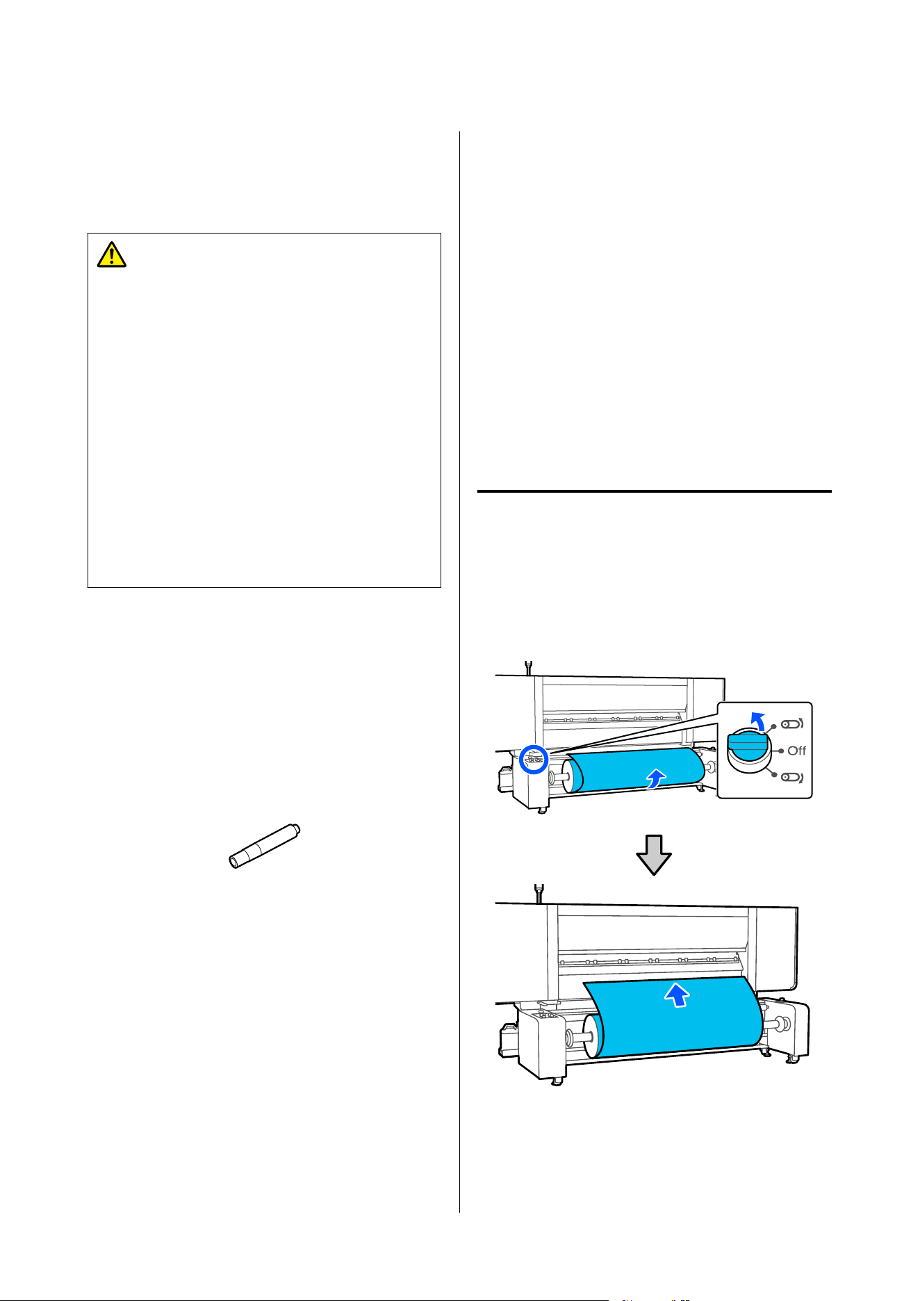
Precautions When
Handling Spindles
Caution:
❏ Because spindles are heavy, they should be
handled by two or more people. Dropping
them, etc., could result in injury.
❏ Because spindles are heavy, wear safety shoes
when handling them. Dropping a spindle may
cause it to land on your feet and result in
injury.
❏ When you carry a roll of media on a spindle,
use compressed air to firmly secure the
spindle. Otherwise, the roll of media or the
spindle could fall and injure your feet. When a
roll of media on a spindle has not been
handled for a long time, use compressed air to
firmly resecure the spindle, if needed.
Use an air compressor suitable for the printer to
secure the media.
❏ Supply air from a commercially available air
compressor from the valve to secure media to the
spindle.
If the nozzle shape of your air compressor does
not fit the valve, use the nozzle included with the
printer. The included nozzle can be attached to an
air tube with an outer diameter of 8 mm.
❏ Set the air pressure of the air compressor within a
range of 0.45 to 1 MPa. There is a risk of
problems, such as the media not being secured, if
the setting is outside the range.
Pulling Out Media
Manually when Using the
Large Capacity Roll
Models/Large Capacity
Reel Models
Let the media slacken before gripping and pulling on
its leading edge to pull it from the roll, such as when
loading media. The media may get torn if it is forcibly
pulled out without slackening. To slacken the media,
follow the steps in the following section to operate the
buttons and switches.
When working from the back
side
Use the Manual switch, on the media feeding unit, to
slacken the media before pulling it by hand.
When the roll is printable side out
SC-F20000 Series/SC-F11000H Series/SC-F11000 Series/SC-F10000H Series/SC-F10000 Series User's Guide
Basic Operations
71
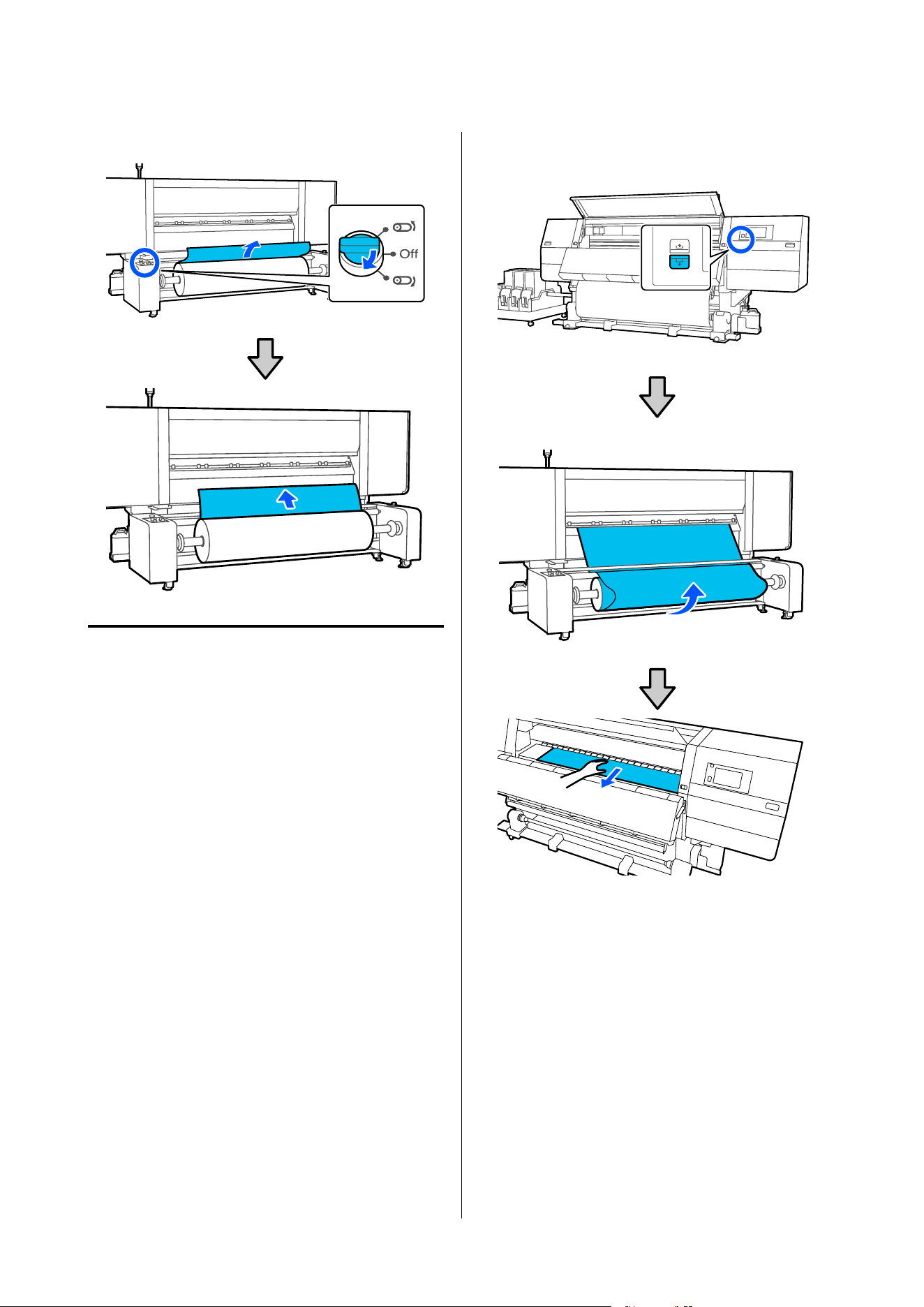
When the roll is printable side in
When working from the front
side
Do the following operations while the media loading
lever is raised.
Use the media feed button or the media feed switch to
slacken the media before pulling it by hand.
When the roll is printable side out
❏ Large capacity roll models
SC-F20000 Series/SC-F11000H Series/SC-F11000 Series/SC-F10000H Series/SC-F10000 Series User's Guide
Basic Operations
72
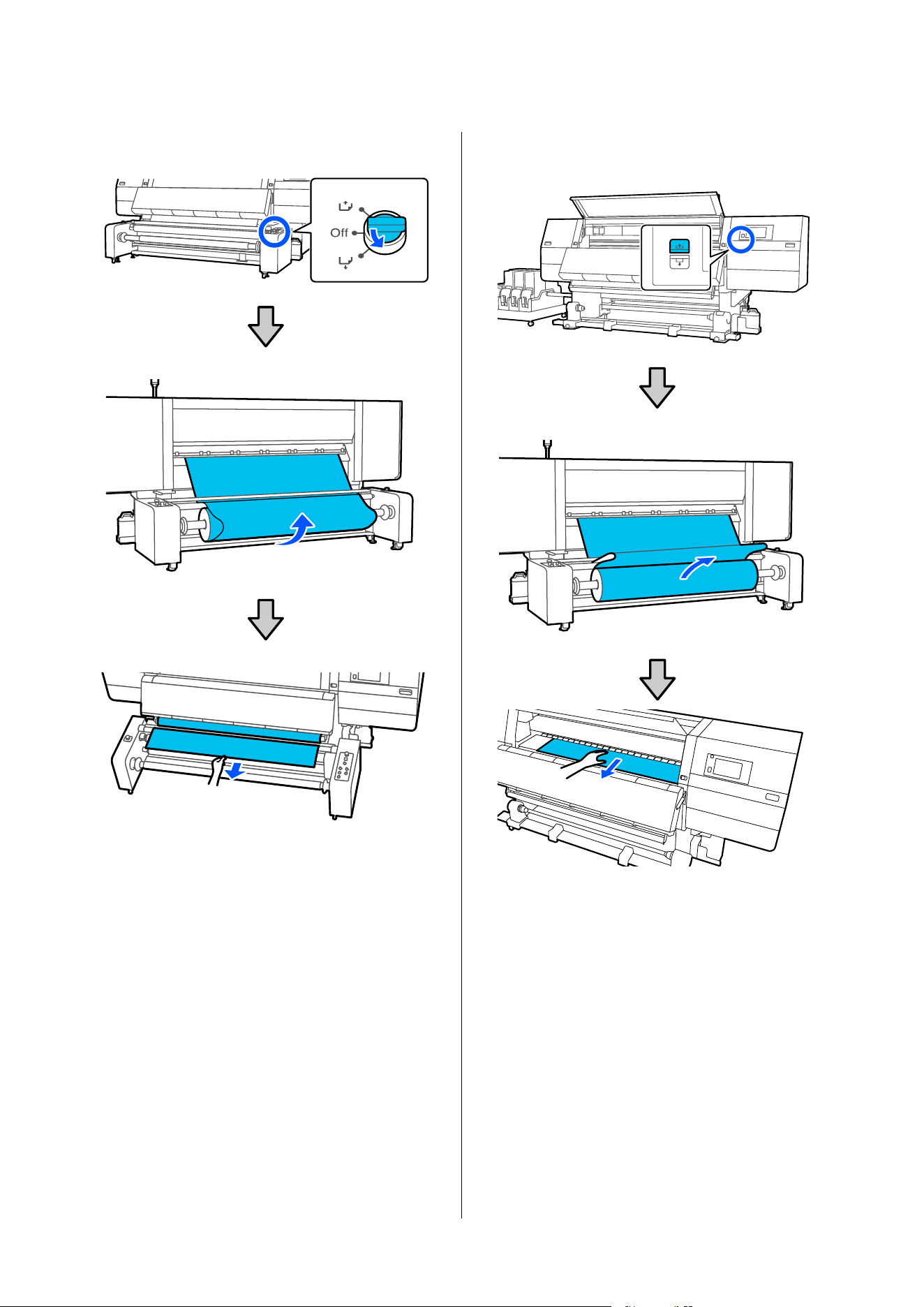
❏ Large capacity reel models
When the roll is printable side in
❏ Large capacity roll models
SC-F20000 Series/SC-F11000H Series/SC-F11000 Series/SC-F10000H Series/SC-F10000 Series User's Guide
Basic Operations
73
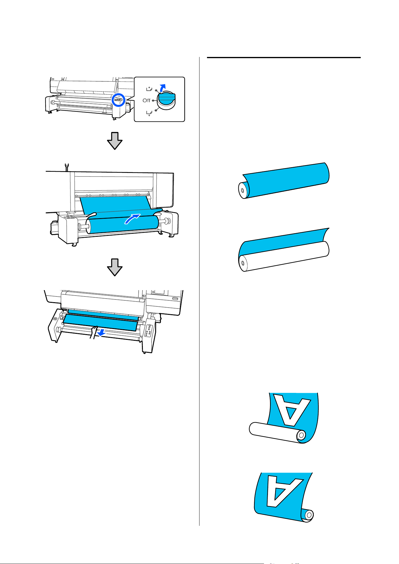
❏ Large capacity reel models
Media Loading Procedure
When loading media into the media feeding unit and
auto take-up reel unit, the loading method varies
depending on your model and the type of media.
Check the points in advance, and then load the media
following the procedure for your model.
Points To Check In Advance
Media winding specifications and
take-up direction
You can load media with either of the following
winding specifications into the media feeding unit on
the printer.
Printable Side Out
Printable Side In
Printable side out means the printable surface is
wound on the outside.
Printable side in means the printable surface is wound
on the inside.
Additionally, the auto take-up reel unit on the printer
can take up printed media in either of the following
directions.
Printed side in
Printed side out
SC-F20000 Series/SC-F11000H Series/SC-F11000 Series/SC-F10000H Series/SC-F10000 Series User's Guide
Basic Operations
74
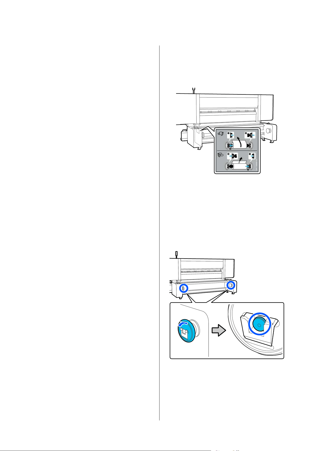
Taking-up with printed side in places the printed
surface on the inside of the roll.
Taking-up with printed side out places the printed
surface on the outside of the roll.
The take-up direction for printed media is specified
separately from the loaded media's winding
specifications. For example, even if the loaded media
is printable side out, you can set the take-up direction
to printable side in.
Because the procedure for loading media differs
depending on the winding specifications of the loaded
media and the take-up direction for printed media,
check this information before starting work.
Normally, load media with the printable side out. We
also recommend taking up printed media with
printable side in.
Normal feed procedure and take-up
feed procedure
There are two ways to load media: The normal feeding
procedure and the take-up feeding procedure.
When media is being loaded, the printer does
operations such as feeding and rewinding the media to
detect its width. When using the normal feeding
procedure at this time, some problems, such as the
media wrinkling on the platen, may occur depending
on the type of media. These problems are caused when
the media gets stuck to the platen.
If these problems occur, follow the take-up feeding
procedure to load the media. In the take-up feeding
procedure, the media is loaded to the Auto Take-up
Reel Unit before feeding, to avoid it getting stuck to
the platen and causing problems.
The take-up feeding procedure is often suitable for
large capacity media, so we recommend following the
take-up feeding procedure.
Models requiring gap adjustment at
the ends of the spindle
For the following models, you need to close the gaps at
the ends of the spindle when loading media to prevent
media skewing or meandering. If you are using one of
these models, follow the procedure to close the gaps at
the ends of the spindle.
❏ Large capacity reel models
❏ Large capacity roll models that have the gap
adjustment label shown in the following
illustration on the media feeding unit
Models that support gap adjustment have type A or
type B gap adjustment screws inside the handles.
Because the tools used for gap adjustment and the
method for turning the screws differ, check the type of
screw inside the handle in advance.
Gap adjustment screw location
Gap adjustment screw types
AB
SC-F20000 Series/SC-F11000H Series/SC-F11000 Series/SC-F10000H Series/SC-F10000 Series User's Guide
Basic Operations
75

SC-F20000 Series/SC-F11000H Series/SC-F11000 Series/SC-F10000H Series/SC-F10000 Series User's Guide
Basic Operations
76
Media Loading Procedure by
Model
Standard roll/reel models
Normal feeding procedure
1. Attach the media to the media feeding unit.
U “Loading the media” on page 81
2. Pull out the leading edge of the media to the
front of the printer.
U “Feeding media to the front” on page 84
3. Set the media information.
U “Setting the media information” on page 87
4. Attach the roll core to the auto take-up reel
unit.
U “Attaching the Roll Core” on page 100
5. Attach the leading edge of the media to the
roll core.
U “Loading using the normal feeding procedure” on
page 103
Take-up feeding procedure
1. Attach the media to the media feeding unit.
U “Loading the media” on page 81
2. Pull out the leading edge of the media to the
front of the printer.
U “Feeding media to the front” on page 84
3. Attach the roll core to the auto take-up reel
unit.
U “Attaching the Roll Core” on page 100
4. Attach the leading edge of the media to the
roll core.
U “Loading using the take-up feeding procedure” on
page 105
5. Set the media information.
U “Setting the media information” on page 110
SC-F20000 Series/SC-F11000H Series/SC-F11000 Series/SC-F10000H Series/SC-F10000 Series User's Guide
Basic Operations
77
Large capacity roll models
Normal feeding procedure
1. Insert the spindle into the media.
U “Preparing the media” on page 88
2. Attach the media to the media feeding unit
and close the gaps at the ends of the spindle.
U “Loading the media and closing the gaps at the ends
of the spindle” on page 90
3. Pass the leading edge of the media between
the rollers of the media feeding unit and pull it
out to the front of the printer.
U “Feeding media to the front” on page 95
4. Set the media information.
U “Setting the media information” on page 98
5. Attach the roll core to the auto take-up reel
unit.
U “Attaching the Roll Core” on page 100
6. Attach the leading edge of the media to the
roll core.
U “Loading using the normal feeding procedure” on
page 103
Take-up feeding procedure
1. Insert the spindle into the media.
U “Preparing the media” on page 88
2. Attach the media to the media feeding unit
and close the gaps at the ends of the spindle.
U “Loading the media and closing the gaps at the ends
of the spindle” on page 90
3. Pass the leading edge of the media between
the rollers of the media feeding unit and pull it
out to the front of the printer.
U “Feeding media to the front” on page 95
4. Attach the roll core to the auto take-up reel
unit.
U “Attaching the Roll Core” on page 100
5. Attach the leading edge of the media to the
roll core.
U “Loading using the take-up feeding procedure” on
page 105
6. Set the media information.
U “Setting the media information” on page 110
SC-F20000 Series/SC-F11000H Series/SC-F11000 Series/SC-F10000H Series/SC-F10000 Series User's Guide
Basic Operations
78
Large capacity reel models
Normal feeding procedure
1. Insert the spindle into the media.
U “Preparing the media” on page 88
2. Attach the media to the media feeding unit
and close the gaps at the ends of the spindle.
U “Loading the media and closing the gaps at the ends
of the spindle” on page 90
3. Pass the leading edge of the media between
the rollers of the media feeding unit and pull it
out to the front of the printer.
U “Feeding media to the front” on page 95
4. Set the media information.
U “Setting the media information” on page 98
5. Insert the spindle into the roll core.
U “Preparing the roll core” on page 111
6. Attach the roll core to the auto take-up reel
unit and close the gaps at the ends of the
spindle.
U “Attaching the roll core and closing the gaps at the
ends of the spindle” on page 111
7. Pull the leading edge of the media to the roll
core.
U “Feeding media to the roll core” on page 114
8. Attach the leading edge of the media to the
roll core.
U “Attaching media to the roll core - Printed side in” on
page 118
U “Attaching media to the roll core - Printed side out”
on page 119
9. Set the load switch and heater temperature.
U “Setting the load switch and heater temperature” on
page 120
SC-F20000 Series/SC-F11000H Series/SC-F11000 Series/SC-F10000H Series/SC-F10000 Series User's Guide
Basic Operations
79
Take-up feeding procedure
1. Insert the spindle into the media.
U “Preparing the media” on page 88
2. Attach the media to the media feeding unit
and close the gaps at the ends of the spindle.
U “Loading the media and closing the gaps at the ends
of the spindle” on page 90
3. Pass the leading edge of the media between
the rollers of the media feeding unit and pull it
out to the front of the printer.
U “Feeding media to the front” on page 95
4. Insert the spindle into the roll core.
U “Preparing the roll core” on page 111
5. Attach the roll core to the auto take-up reel
unit and close the gaps at the ends of the
spindle.
U “Attaching the roll core and closing the gaps at the
ends of the spindle” on page 111
6. Pull the leading edge of the media to the roll
core.
U “Feeding media to the roll core” on page 120
7. Attach the leading edge of the media to the
roll core.
U “Attaching media to the roll core - Printed side in” on
page 124
U “Attaching media to the roll core - Printed side out”
on page 127
8. Set the media information, load switch, and
heater temperature.
U “Setting the media information, load switch, and
heater temperature” on page 129
SC-F20000 Series/SC-F11000H Series/SC-F11000 Series/SC-F10000H Series/SC-F10000 Series User's Guide
Basic Operations
80
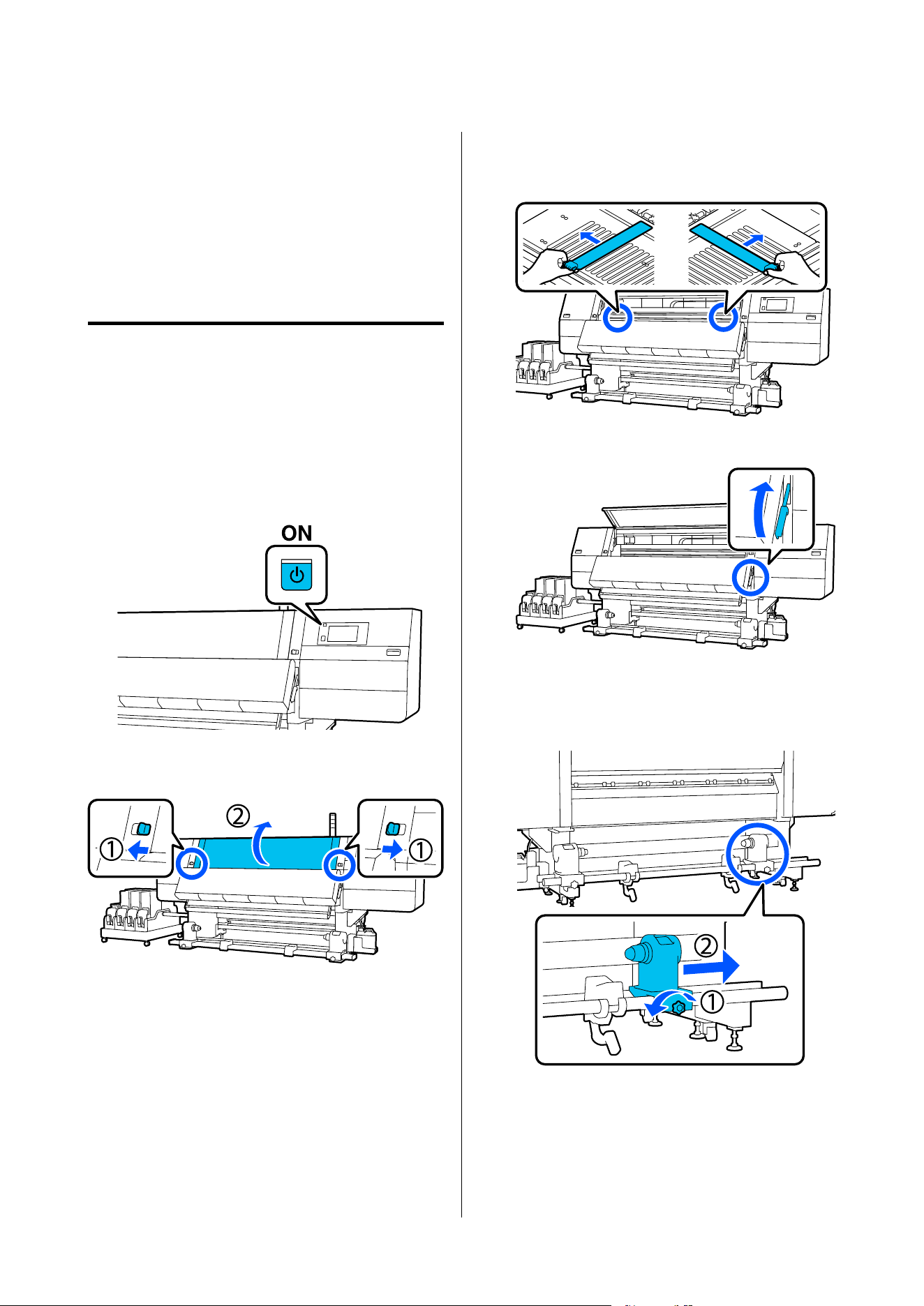
Loading Media Into the
Media Feeding Unit
You can check the procedure in a video on YouTube.
Epson Video Manuals
Loading the standard type
Media Feeding Unit
Loading the media
A
Press the P button and wait until the Home
screen is displayed.
B
Move the lock levers on the left and right side
outwards to open the front cover.
C
While holding the tabs of the media edge plate
on both sides, move the plate out of the way
toward both edges of the platen.
D
Raise the media loading lever.
E
Move to the back side, and loosen the right
media holder fixing screw to move the holder
outwards.
SC-F20000 Series/SC-F11000H Series/SC-F11000 Series/SC-F10000H Series/SC-F10000 Series User's Guide
Basic Operations
81
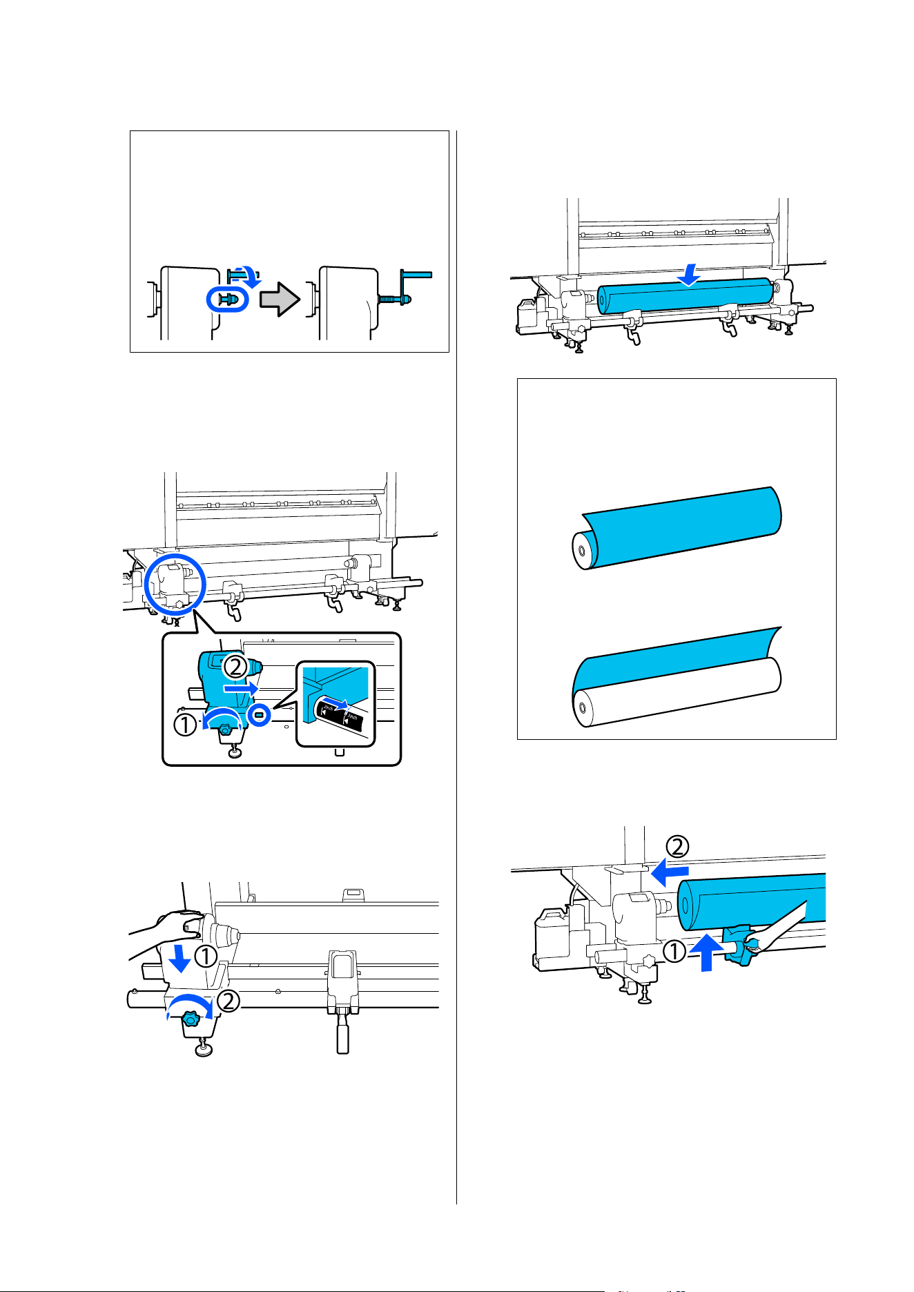
c
Important:
If the right holder handle shaft is not visible,
rotate the handle forward until it stops. The
media can not be properly loaded if the
handle shaft is not visible.
F
Loosen the left media holder fixing screw and
move the media holder to the set position
according to the inner diameter of the roll core
of the media that will be loaded.
G
While pressing from the top of the media
holder, tighten the fixing screw until it no
longer turns.
Tighten it so the media holder does not move.
H
Place the media on the roll support. Have the
roll support moved inward for about 20 cm
(7.87 in.) from the roll end.
Note:
The method of placing varies as follows depending
on how media is rolled.
Printable Side Out
Printable Side In
I
While lifting the lift lever, move the roll support
to the left, and firmly insert the roll core of the
media onto the media holder.
SC-F20000 Series/SC-F11000H Series/SC-F11000 Series/SC-F10000H Series/SC-F10000 Series User's Guide
Basic Operations
82
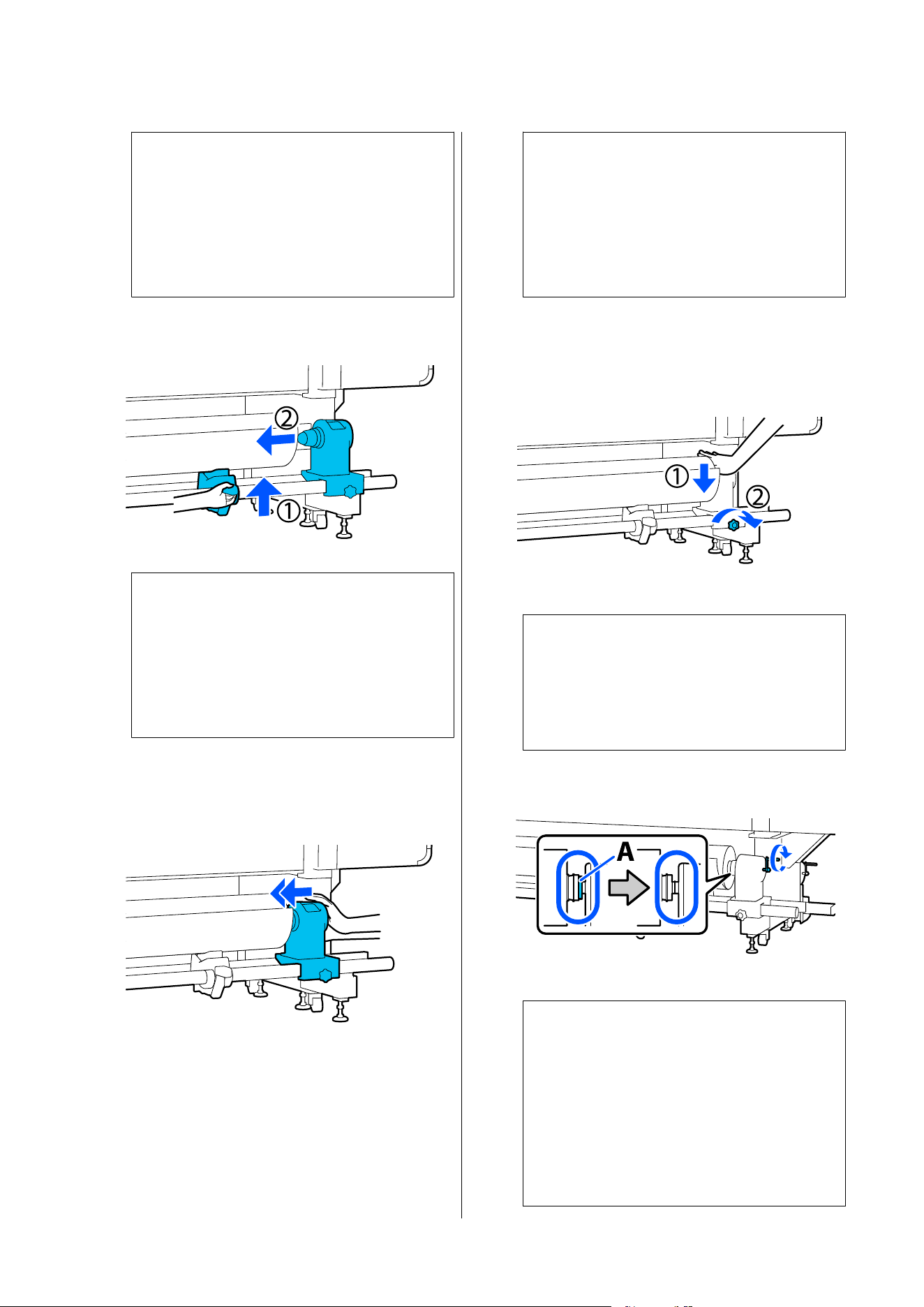
Note:
If the roll of media has an outer diameter that is
less than 140 mm (5.51 in.), the roll core will not
reach the media holder when raised using the lift
lever.
Raise it with your hands, and insert the roll core
into the media holder.
J
While lifting the right lift lever, firmly insert the
media holder onto the roll core of the media.
Note:
If the roll of media has an outer diameter that is
less than 140 mm (5.51 in.), the roll core will not
reach the media holder when raised using the lift
lever.
Raise it with your hands, and insert the roll core
into the media holder.
K
To ensure that the media holder is sufficiently
inserted into the roll core, push the top of the
media holder towards the end of the roll two
times.
c
Important:
If the media holder is inserted into the roll
core insufficiently, media is not fed correctly
during printing because of slippage between
the media holder and roll core.
This may cause banding in the print results.
L
While pressing from the top of the media
holder, tighten the fixing screw until it no
longer turns.
Tighten it so the media holder does not move.
c
Important:
If the media holder screw is loose, the media
holder may move during printing. This could
cause stripes and unevenness in the print
results.
M
Rotate the handle until part A in the illustration
below is fully inserted.
c
Important:
Once part A is hidden, do not turn the
handle any further. Failure to observe this
precaution could damage the media holder.
If part A is still visible even after the handle
has been turned fully, rewind the handle.
Loosen the media holder screw on the right
side, and then restart from Step 5.
SC-F20000 Series/SC-F11000H Series/SC-F11000 Series/SC-F10000H Series/SC-F10000 Series User's Guide
Basic Operations
83
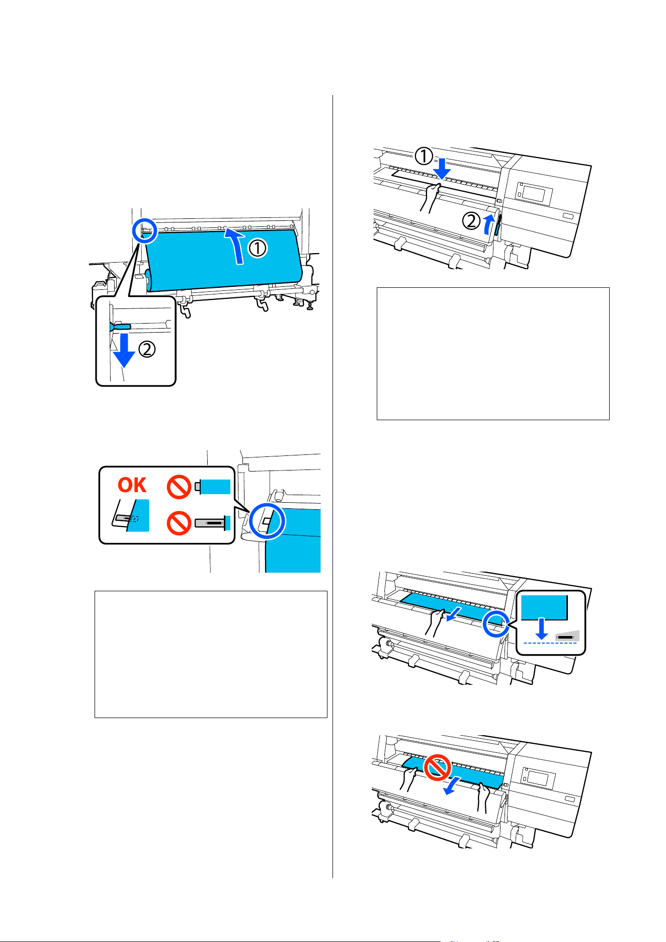
Feeding media to the front
A
Insert the media approximately 20 cm (7.87 in.)
into the opening, then lower the media loading
lever.
The media that you inserted is clamped and
does not fall out.
B
Confirm that the left edge of the media is
within the range of the label's rectangle in the
illustration below.
c
Important:
If the left edge of the media is not within the
black square of the label, do Steps 6 to 15 in
reverse to adjust the position of the media
holder. Do not attempt to reposition the
media holders while they are inserted in the
media.
C
Move to the front side, and while holding the
media to keep it from falling down to the back
side, lift the media loading lever.
Note:
You can change the media suction on the platen
through the screen operation. Increasing the
media suction lowers the possibility of media
falling down.
If it is difficult to pull out the media in the
following procedure, decrease the media suction.
Change as required.
D
Pull out the media to the following position
according to the feeding method suitable for
the media.
Normal feeding procedure
Pull out the media to the near edge of the label
on the platen.
Hold the center of the media in one hand, and
pull it straight out.
Do not pull the media with both hands. This
could cause the media to skew or move around.
SC-F20000 Series/SC-F11000H Series/SC-F11000 Series/SC-F10000H Series/SC-F10000 Series User's Guide
Basic Operations
84
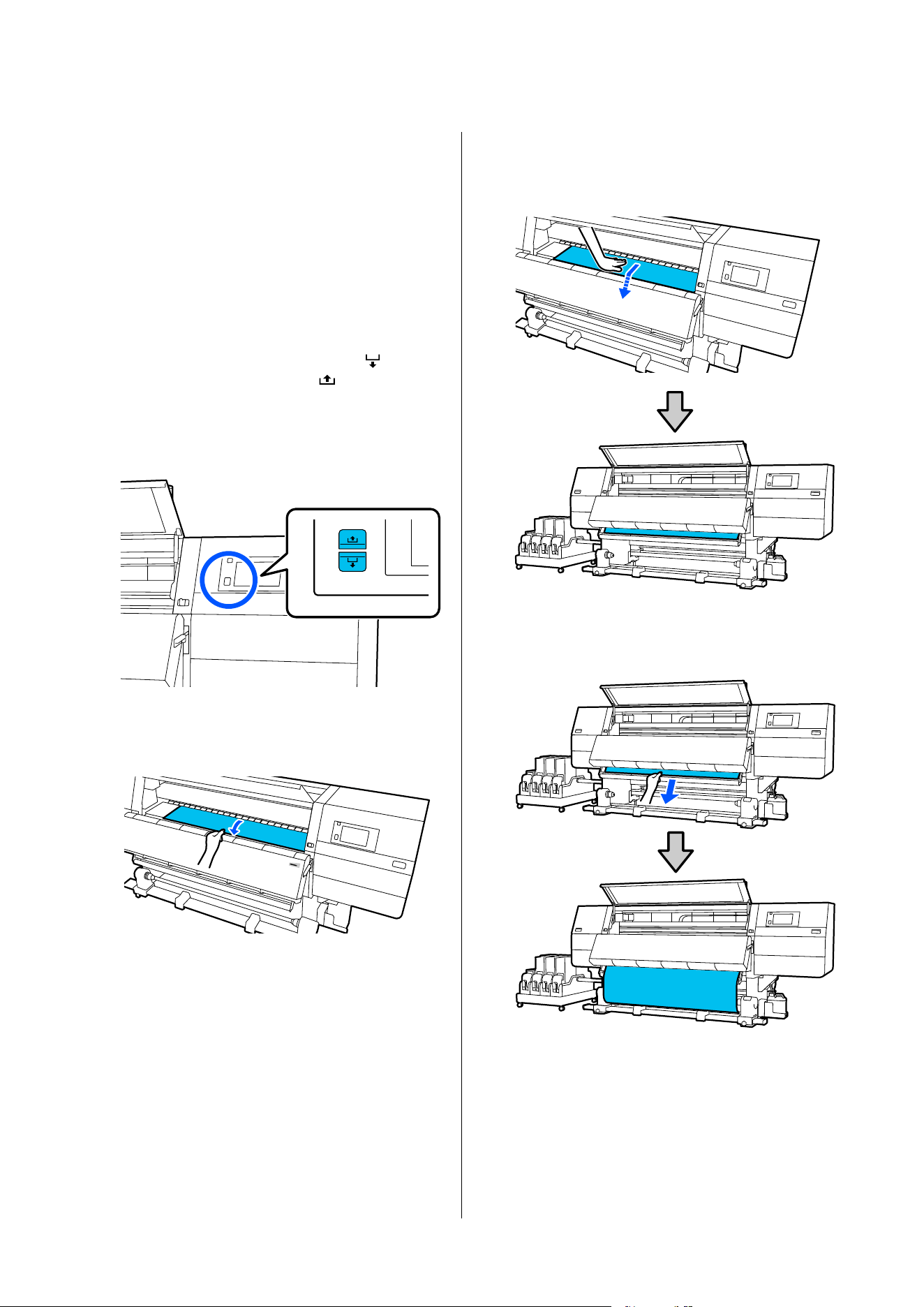
Take-up feeding procedure
Pull out the media until it reaches the media
holder.
Follow the steps below to pull out the media.
For each step given below, be sure to slacken
the media before pulling it out. The media may
get torn if it is forcibly pulled out without
slackening.
To slacken the media, press the media feed
button. When loading media, press
for
printable side out, and press
for printable
side in.
By doing so, the media that is loaded on the
back side will rotate in the feeding direction
and slacken.
a. Hold the center of the media in one hand,
pull it straight out, and insert its edge into the
dryer.
b. While holding the center of the media on the
platen, pull it out by moving it toward yourself,
until its edge comes out from the bottom of the
dryer.
c. Hold the center of the media in one hand,
and pull out the media until its edge reaches the
media holder.
SC-F20000 Series/SC-F11000H Series/SC-F11000 Series/SC-F10000H Series/SC-F10000 Series User's Guide
Basic Operations
85
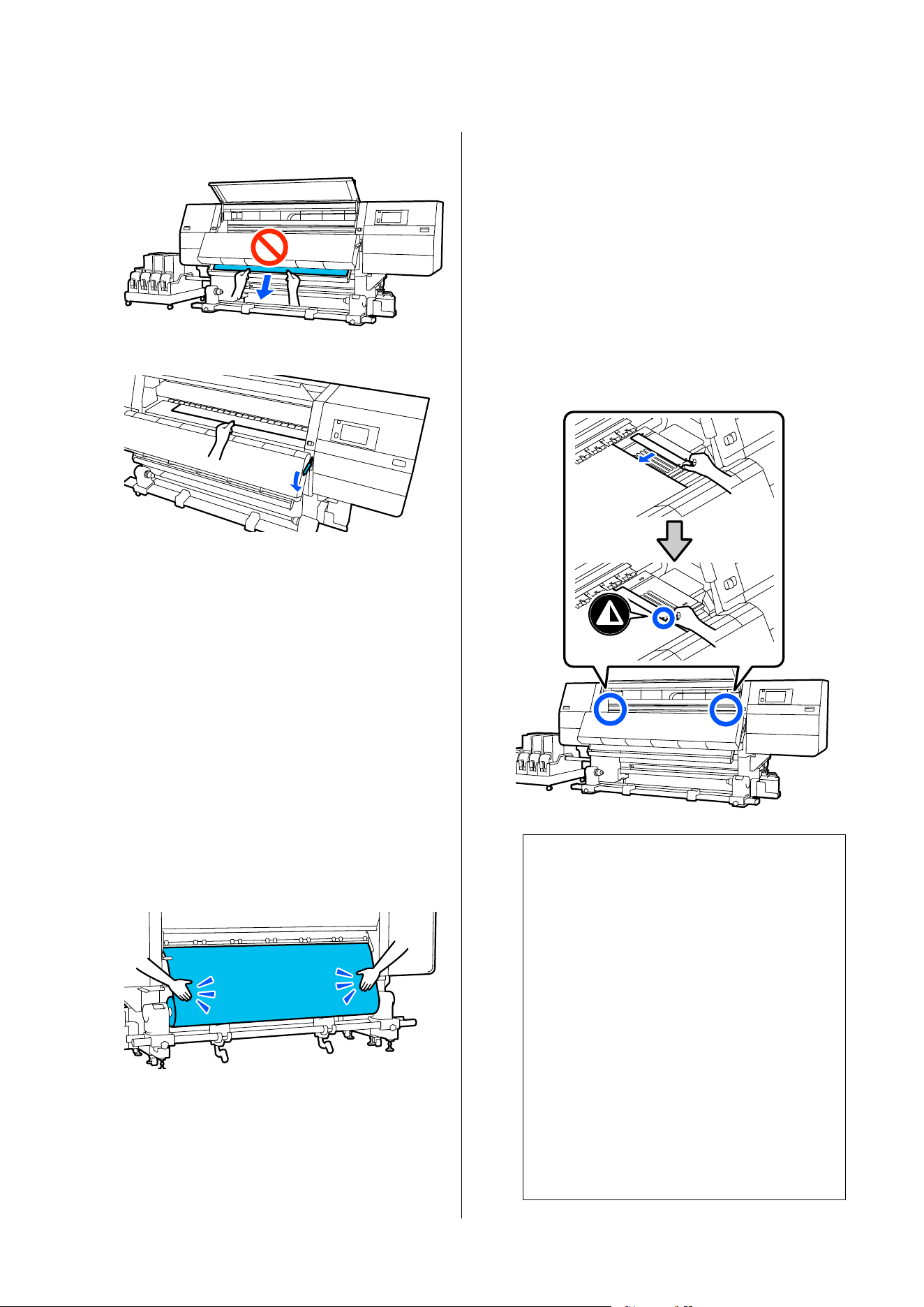
Do not pull the media with both hands. This
could cause the media to skew or move around.
E
Lower the media loading lever.
Normal feeding procedure
After lowering the media loading lever, move
on to the next step.
Take-up feeding procedure
Lower the media loading lever, and then
continue to attach the media to the Auto
Take-up Reel Unit. While the front cover is
open, see the following to attach media to the
Auto Take-up Reel Unit.
U “Loading Media Into the Auto Take-up
Reel Unit” on page 99
F
Move to the back side, tap lightly on both edges
of the media, and check if there is a difference
in tension between the left and right sides.
If there is a difference in tension, the media
becomes loose.
From the front of the printer, raise the media
loading lever, and correct the looseness in the
media.
Once the looseness is corrected, lower the
media loading lever.
G
Move to the front side, and while holding the
tabs of the media edge plate on both sides,
move the plate to the top edge of the media.
Adjust so that the edges of the media are
aligned with the center of the triangular holes
in the media edge plates.
The media edge plates prevent the media from
riding up and keep fibers on the cut edge of the
media from touching the print head. Load
correctly.
c
Important:
❏ Do not use the media edge plates with
media that is 0.4 mm (0.01 in.) or more
thick. The media edge plates could touch
and damage the print head.
❏ Always position the plates so that the
edges of the media are at the centers of
the triangular holes. Incorrect positioning
causes banding (horizontal banding, tint
unevenness, or stripes) during printing.
❏ Move the media edge plates to the left
and right edges of the platen when they
are not in use.
❏ Do not use the media edge plates if the
sides of the printed media are smudged.
SC-F20000 Series/SC-F11000H Series/SC-F11000 Series/SC-F10000H Series/SC-F10000 Series User's Guide
Basic Operations
86
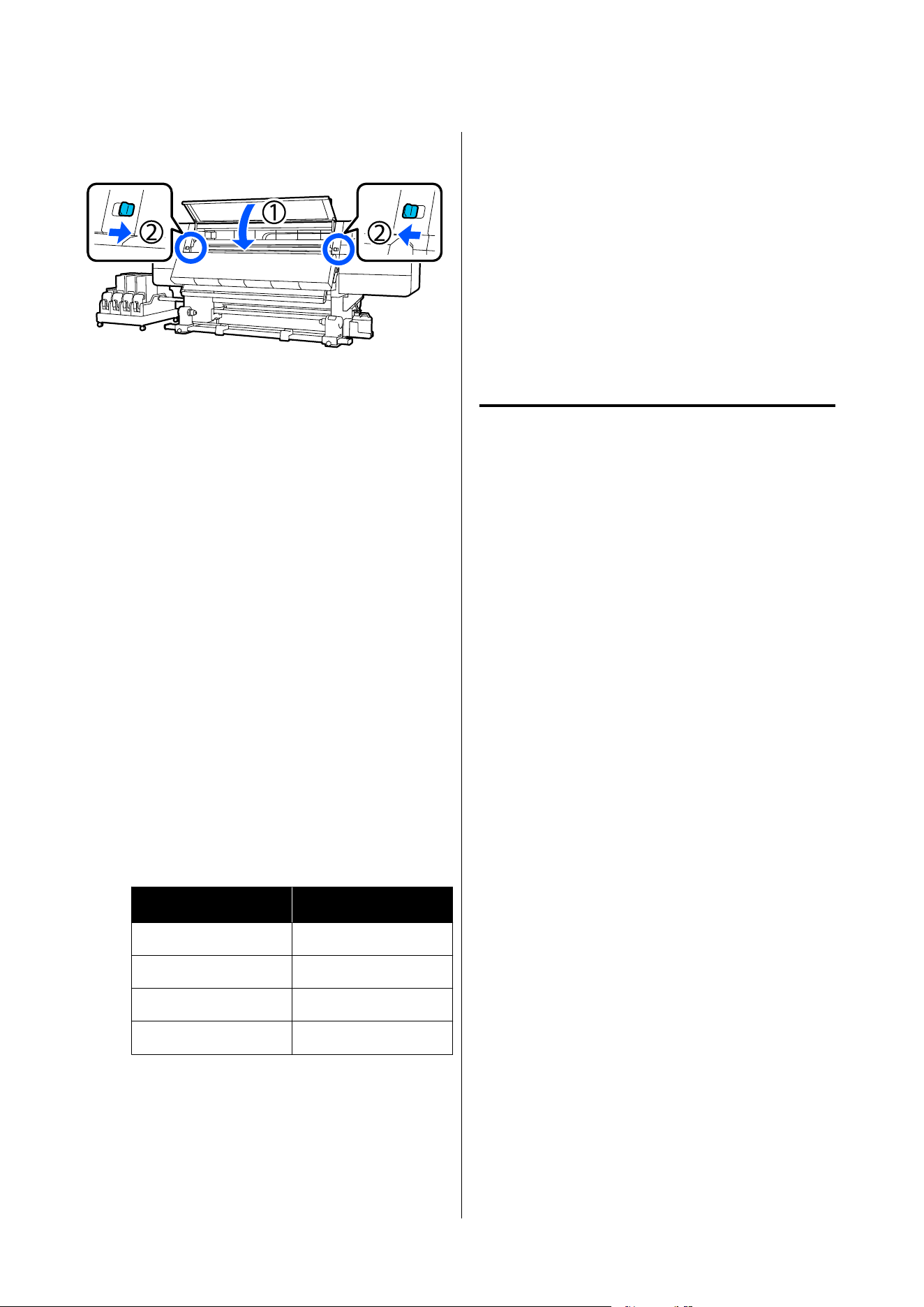
H
Close the front cover, and then move the left
and right lock levers inward.
Setting the media information
A
Set the media information on the screen, and
press OK.
Do the following settings here.
❏ Media: Set the media to use for printing
❏ Roll Winding Direction: How to wind the
loaded media
❏ Media Length: Length of the loaded media
❏ Media Detection: How to detect the width of
the media
Media is set in the following way.
When there are no registered media settings
for the loaded media
First, select an unregistered number.
There is no Media Type set for an unregistered
number, so the screen to select Media Type
appears. Select the Media Type using the paper
weight of the loaded media as a guideline as
shown below. The paper weights of each Media
Type shown in the screen are typical values.
Media Type
Paperweight (g/m
2
)
Ultra-Thin 39 or under
Thin 40 to 56
Med-Thick 57 to 89
Thick 90 or over
When there are registered media
settings/EMX file is downloaded and
registered for the loaded media
Choose a registered media number.
In Media Detection, set Width Detection.
Normally, leave this On.
See the following for details about Media
Detection.
U “General Settings menu” on page 201
B
Press OK.
The printer starts detecting the loaded media
and performing related operations.
C
Follow the on-screen instructions to forward
the edge of the media to the given position as
necessary.
Loading the large capacity type
Media Feeding Unit
We recommend having 2 people work together to load
media. The work is easier to do if they stand so one is
on the left and the other on the right as they pass the
media through the rollers.
Necessary items
Air compressor (available in the market)
Use this to secure media to the spindle. Prepare an air
compressor that can be set to a pressure within a range
of 0.45 to 1 MPa. To make media loading easier, we
recommend keeping the air compressor ready for use
near the printer.
Lifter (available in the market)
Use this to transport media. Prepare a lifter with a
load capacity greater than the combined weight of the
media and spindle to be loaded.
SC-F20000 Series/SC-F11000H Series/SC-F11000 Series/SC-F10000H Series/SC-F10000 Series User's Guide
Basic Operations
87
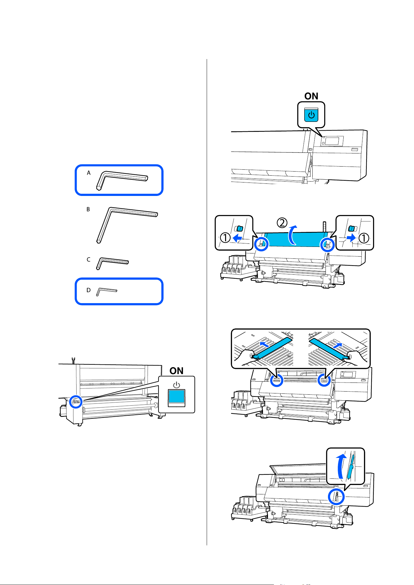
Hex wrench (large) and hex wrench (small)
(included only with models with type B gap
adjustment screws)
Models with type B gap adjustment screws at the ends
of the spindle come with four hex wrenches in the
sizes shown in the illustration, from largest to smallest:
A to D. A is the largest (hex wrench large) and D is the
smallest (hex wrench small). For models with type B
gap adjustment screws, keep these hex wrenches on
hand as they are used when loading media.
Preparing the media
A
Press the P button on the media feeding unit to
turn on the power.
If you are using a large capacity reel model, also
turn on the power for the Auto Take-up Reel
Unit.
B
Press the P button and wait until the Home
screen is displayed.
C
Move the lock levers on the left and right side
outwards to open the front cover.
D
While holding the tabs of the media edge plate
on both sides, move the plate out of the way
toward both edges of the platen.
E
Raise the media loading lever.
SC-F20000 Series/SC-F11000H Series/SC-F11000 Series/SC-F10000H Series/SC-F10000 Series User's Guide
Basic Operations
88
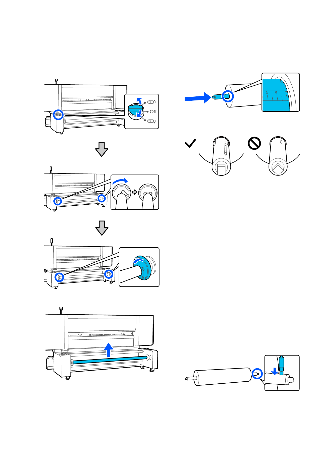
F
Move to the back side, use the Manual switch to
rotate the spindle to face as shown in the
illustration, then lower the handles on both
sides outward.
G
Remove the spindle.
H
Insert the spindle into the paper core up to
about 7 cm on the scale of the spindle (on the
side with the printer's control panel).
Face the spindle as shown in the illustration.
After inserting the spindle, follow the
instructions below according to your model.
❏ Models requiring gap adjustment at the ends
of the spindle
If the air compressor is available near the
printer: Go to step 10.
If the air compressor is not available near the
printer: Go to the next step.
❏ For models that do not require gap
adjustment at the ends of the spindle: Go to
the next step.
I
If the air compressor is not near the printer or if
gap adjustment at the ends of the spindle is not
required, put air into the spindle at this point to
secure the roll core.
Put air into the spindle from the valve until the
air stops going in.
If you have an air compressor handy, there is no
need to supply air at this point as you will add
air in a later step.
SC-F20000 Series/SC-F11000H Series/SC-F11000 Series/SC-F10000H Series/SC-F10000 Series User's Guide
Basic Operations
89
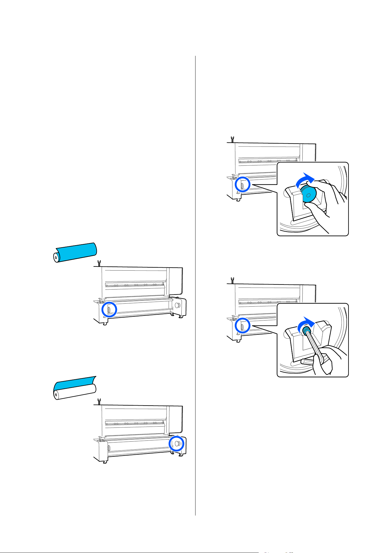
Loading the media and closing the
gaps at the ends of the spindle
If you are using a model that does not require gap
adjustment at the ends of the spindles, start from step
4.
A
Confirm the side to which the spindle should
be moved.
After placing the spindle on the media feeding
unit in a later step, move the spindle to either
the left or right side to eliminate any gap at the
end of the spindle.
The side to which the spindle is moved depends
on the printable surface of the media to be
loaded.
When the roll is printable side out
Move the spindle to the left side toward the
media feeding unit.
When the roll is printable side in
Move the spindle to the right side toward the
media feeding unit.
B
Turn the screw clockwise inside the handle on
the side to which the spindle is to be moved
until it stops.
The following explanation uses media with
printable side out as an example.
Type A gap adjustment screw
Turn the s crew by hand.
Type B gap adjustment screw
Turn the screw using the hex wrench (large).
SC-F20000 Series/SC-F11000H Series/SC-F11000 Series/SC-F10000H Series/SC-F10000 Series User's Guide
Basic Operations
90
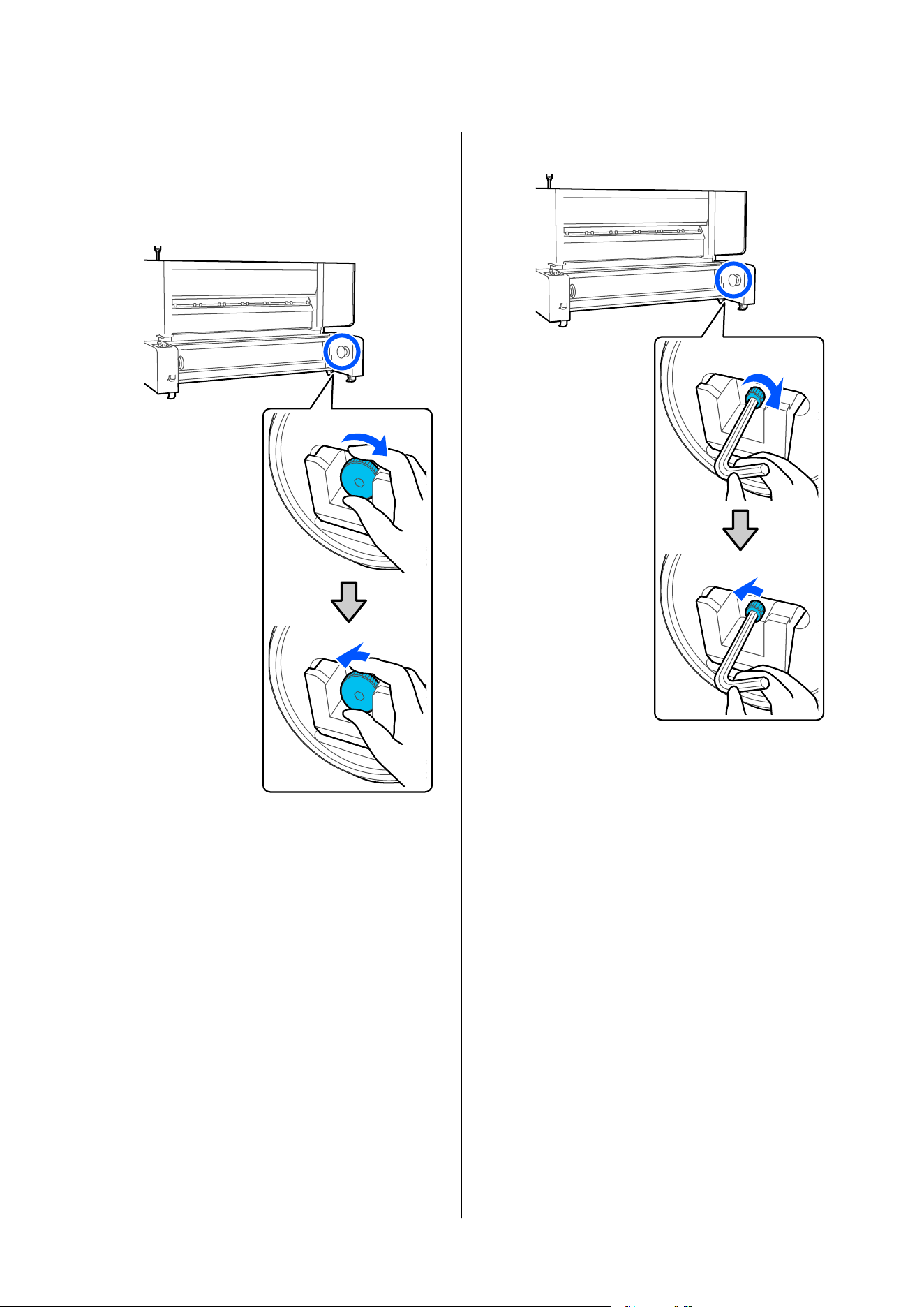
C
Turn the screw clockwise inside the handle on
the opposite side until it stops, then loosen it
slightly.
Type A gap adjustment screw
Type B gap adjustment screw
SC-F20000 Series/SC-F11000H Series/SC-F11000 Series/SC-F10000H Series/SC-F10000 Series User's Guide
Basic Operations
91
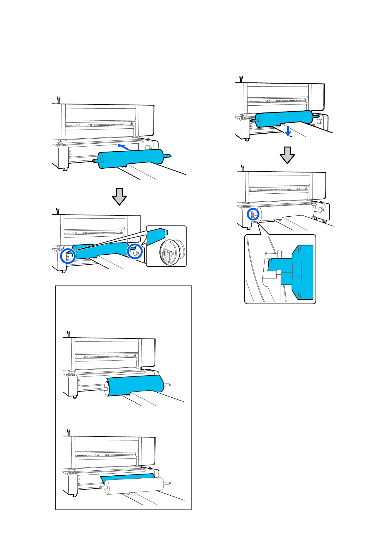
D
Move the media to the position shown in the
illustration.
Be careful that the tip of the lifter does not hit
the unit.
Note:
The method of placing varies as follows depending
on how media is rolled.
Printable Side Out
Printable Side In
E
Lower the media so that both edges of the
spindle fit into the socket.
If you are using a model that does not require
gap adjustment at the ends of the spindles, go to
step 11.
SC-F20000 Series/SC-F11000H Series/SC-F11000 Series/SC-F10000H Series/SC-F10000 Series User's Guide
Basic Operations
92
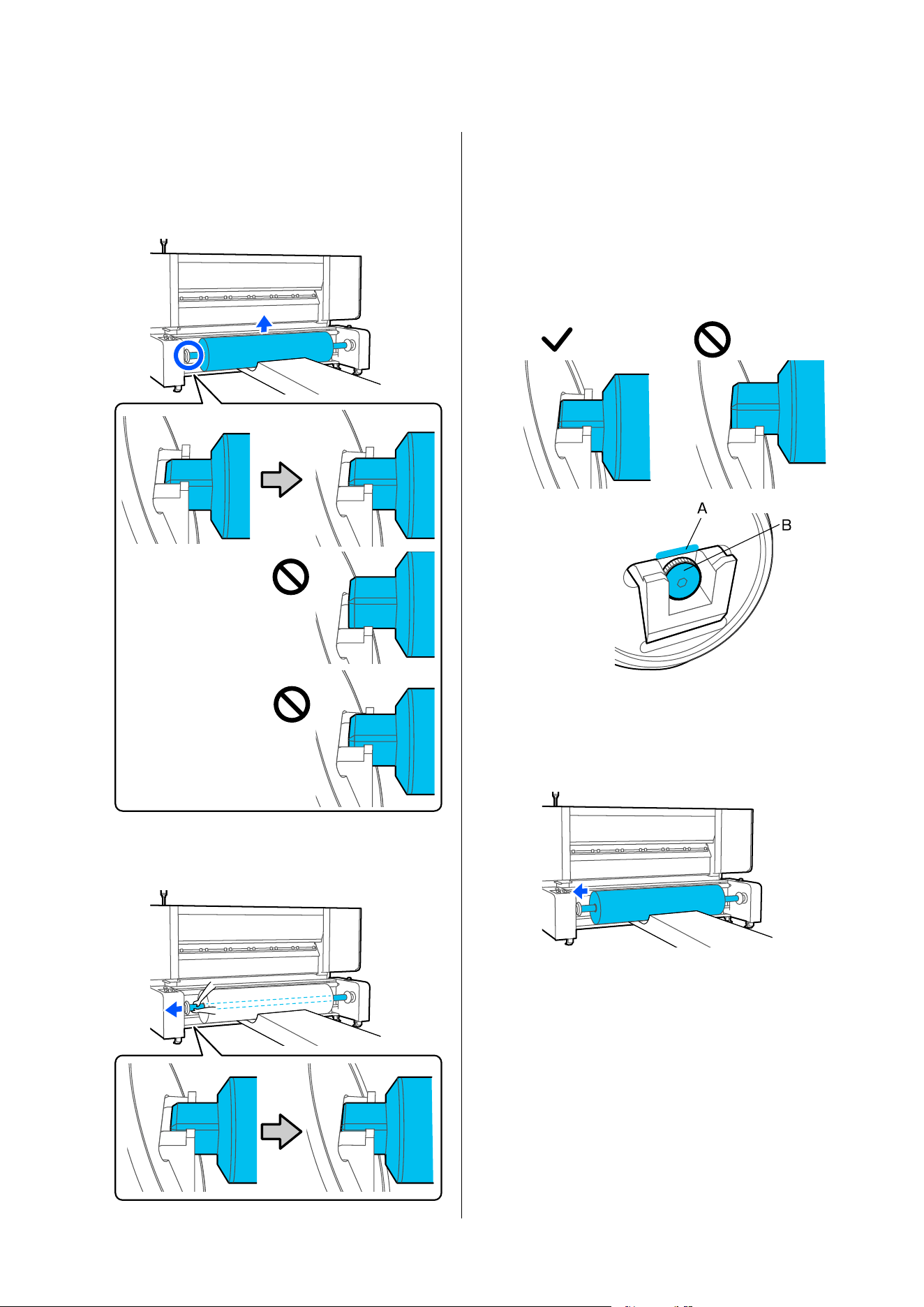
F
Slightly lift the media.
Lift the media only by 2 to 4 mm. Lifting it too
much may prevent you from correctly loading
the media in the procedure below.
G
Slide the spindle by hand until the edge of the
spindle touches the screw inside the handle.
In this operation, confirm that the edge of the
spindle does not touch point A on the handle.
If the media was lifted appropriately in the
previous procedure, the edge of the spindle will
correctly touch surface B of the screw.
Lifting it too much may cause the edge of the
spindle to touch point A on the handle,
resulting in an incorrect spindle position.
If air has already been put into the spindle to
secure the roll core, move the lifter sideways to
move the spindle along with the media to the
handle.
SC-F20000 Series/SC-F11000H Series/SC-F11000 Series/SC-F10000H Series/SC-F10000 Series User's Guide
Basic Operations
93
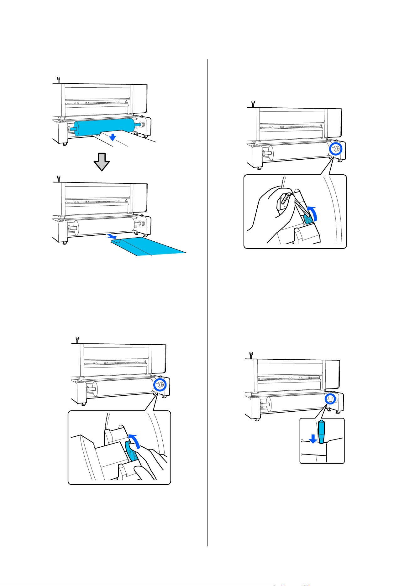
H
Lower the media.
I
Turn the screw counterclockwise inside the
handle on the side opposite to where the
spindle has been moved until the screw touches
the edge of the spindle.
Type A gap adjustment screw
Turn the s crew by hand.
Type B gap adjustment screw
The side of the screw head has a knurled,
non-slip texture with fine ridges and grooves.
Insert a hex wrench into the gap between the
handle and the spindle, and slowly turn the
screw while hooking the tip of the hex wrench
onto the side of the screw head.
After turning the screw, proceed to Step 11 if
air has already been put into the spindle to
secure the roll core.
J
Put air into the spindle from the valve until the
air stops going in.
If air has already been put into the spindle to
secure the roll core, this procedure is not
necessary.
SC-F20000 Series/SC-F11000H Series/SC-F11000 Series/SC-F10000H Series/SC-F10000 Series User's Guide
Basic Operations
94
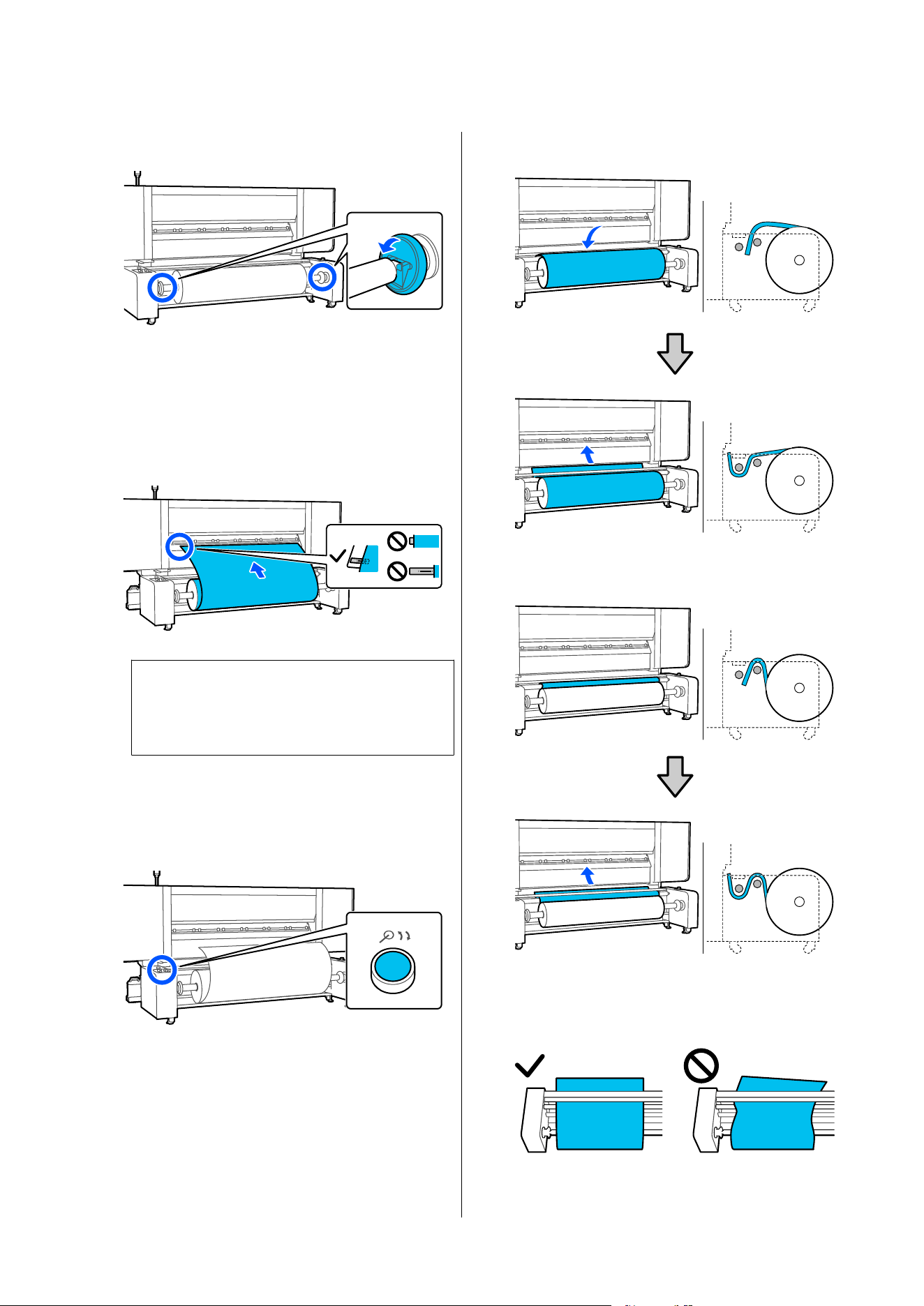
K
Raise the handles on both sides.
L
Pull out a little of the media to confirm that the
left edge of the media is within the range of the
label's rectangle in the illustration below.
U “Pulling Out Media Manually when Using
the Large Capacity Roll Models/Large Capacity
Reel Models” on page 71
c
Important:
If it is outside the range, do the procedure
again from installation of the spindle.
Feeding media to the front
A
Press the Release Button and raise the tension
bar.
B
As you pull out the media, pass it through the
rollers as shown in the illustration.
U “Pulling Out Media Manually when Using
the Large Capacity Roll Models/Large Capacity
Reel Models” on page 71
Printable Side Out
Printable Side In
Pass the media straight through so it does not
skew.
❏ Printable Side Out
SC-F20000 Series/SC-F11000H Series/SC-F11000 Series/SC-F10000H Series/SC-F10000 Series User's Guide
Basic Operations
95
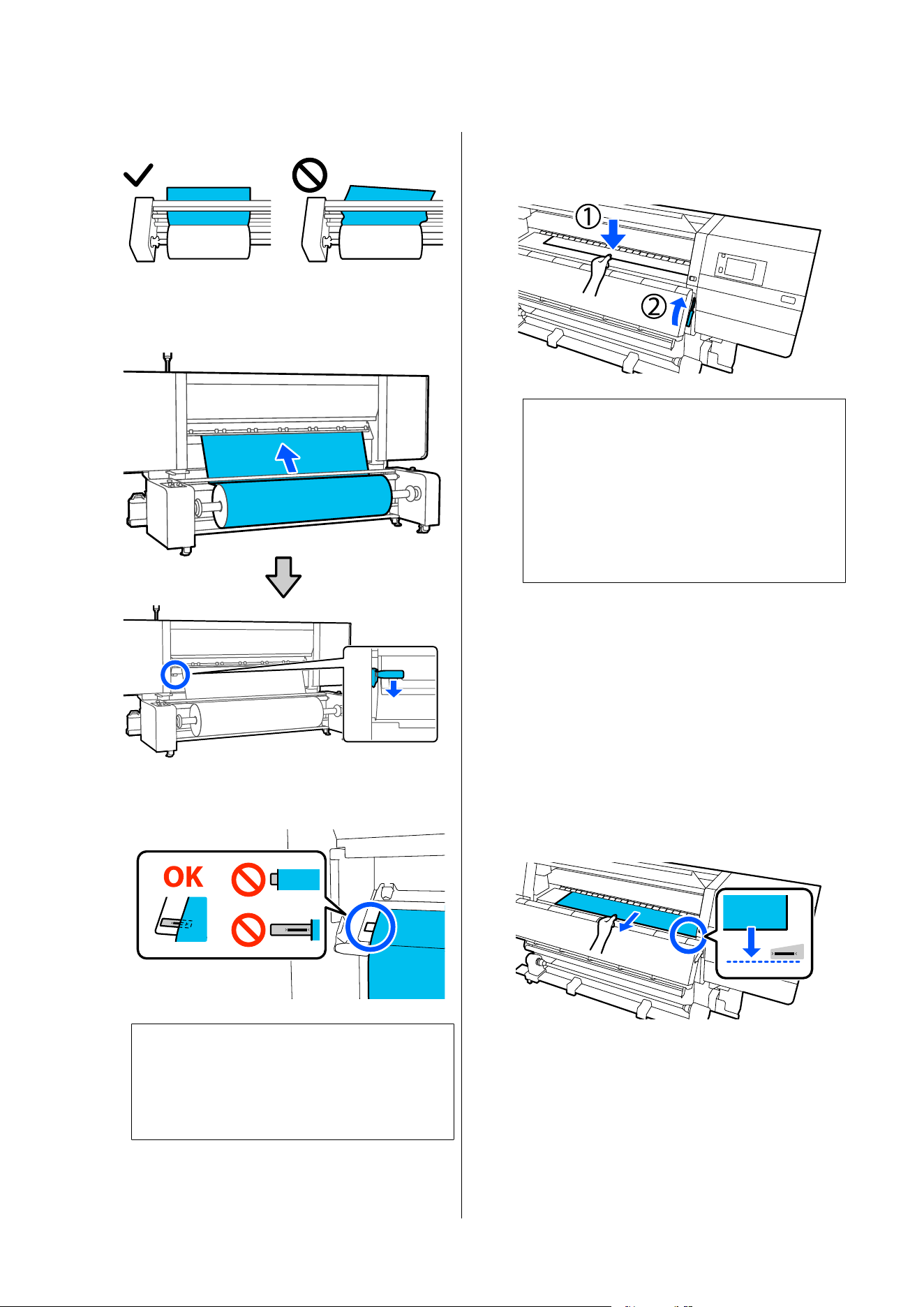
❏ Printable Side In
C
Insert the leading edge of the media
approximately 20 cm into the opening, then
lower the media loading lever.
D
Confirm that the left edge of the media is
within the range of the label's rectangle.
c
Important:
If it is outside the range, do the procedure
again from passing the media through the
rollers.
E
Move to the front side, and while holding the
media to keep it from falling down to the back
side, lift the media loading lever.
Note:
You can change the media suction on the platen
through the screen operation. Increasing the
media suction lowers the possibility of media
falling down.
If it is difficult to pull out the media in the
following procedure, decrease the media suction.
Change as required.
F
Pull out the media to the following position
according to the feeding method suitable for
the media.
U “Pulling Out Media Manually when Using
the Large Capacity Roll Models/Large Capacity
Reel Models” on page 71
Normal feeding procedure
Pull out the media to the near edge of the label
on the platen.
Hold the center of the media in one hand, and
pull it straight out.
SC-F20000 Series/SC-F11000H Series/SC-F11000 Series/SC-F10000H Series/SC-F10000 Series User's Guide
Basic Operations
96
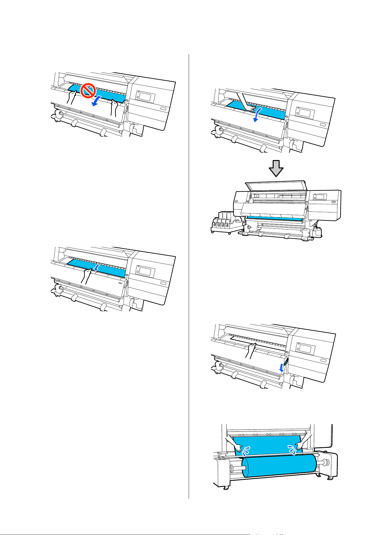
Do not pull the media with both hands. This
could cause the media to skew or move around.
After pulling out the media, move on to the
next step.
Take-up feeding procedure
Pull out the media until it reaches the media
holder.
While slackening the media, follow the steps
below to pull out the media.
a. Hold the center of the media in one hand,
pull it straight out, and insert its edge into the
dryer.
b. While holding the center of the media on the
platen, pull it out by moving it toward yourself,
until its edge comes out from the bottom of the
dryer.
Then, attach the media to the Auto Take-up
Reel Unit. While the front cover is open, see the
following to attach media to the Auto Take-up
Reel Unit.
U “Loading Media Into the Auto Take-up
Reel Unit” on page 99
G
Lower the media loading lever.
H
Move to the back side, tap lightly on both edges
of the media, and check if there is a difference
in tension between the left and right sides.
SC-F20000 Series/SC-F11000H Series/SC-F11000 Series/SC-F10000H Series/SC-F10000 Series User's Guide
Basic Operations
97
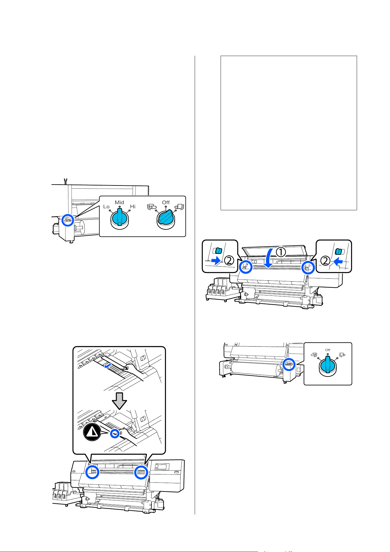
If there is a difference in tension, the media
becomes loose.
From the front of the printer, raise the media
loading lever, and correct the looseness in the
media.
Once the looseness is corrected, lower the
media loading lever.
I
Confirm that the Auto switch and the load
switch are set according to the loaded media.
The load switch is normally set to Mid. Switch
to Hi to increase tension if wrinkles appear in
the media during printing.
J
Move to the front side, and while holding the
tabs of the media edge plate on both sides,
move the plate to the top edge of the media.
Adjust so that the edges of the media are
aligned with the center of the triangular holes
in the media edge plates.
The media edge plates prevent the media from
riding up and keep fibers on the cut edge of the
media from touching the print head. Load
correctly.
c
Important:
❏ Do not use the media edge plates with
media that is 0.4 mm (0.01 in.) or more
thick. The media edge plates could touch
and damage the print head.
❏ Always position the plates so that the
edges of the media are at the centers of
the triangular holes. Incorrect positioning
causes banding (horizontal banding, tint
unevenness, or stripes) during printing.
❏ Move the media edge plates to the left
and right edges of the platen when they
are not in use.
❏ Do not use the media edge plates if the
sides of the printed media are smudged.
K
Close the front cover, and then move the left
and right lock levers inward.
L
Check that the Auto switch on the auto take-up
reel unit is turned Off.
Setting the media information
A
Set the media information on the screen, and
press OK.
Do the following settings here.
❏ Media: Set the media to use for printing
❏ Media Length: Length of the loaded media
❏ Media Detection: How to detect the width of
the media
Media is set in the following way.
SC-F20000 Series/SC-F11000H Series/SC-F11000 Series/SC-F10000H Series/SC-F10000 Series User's Guide
Basic Operations
98
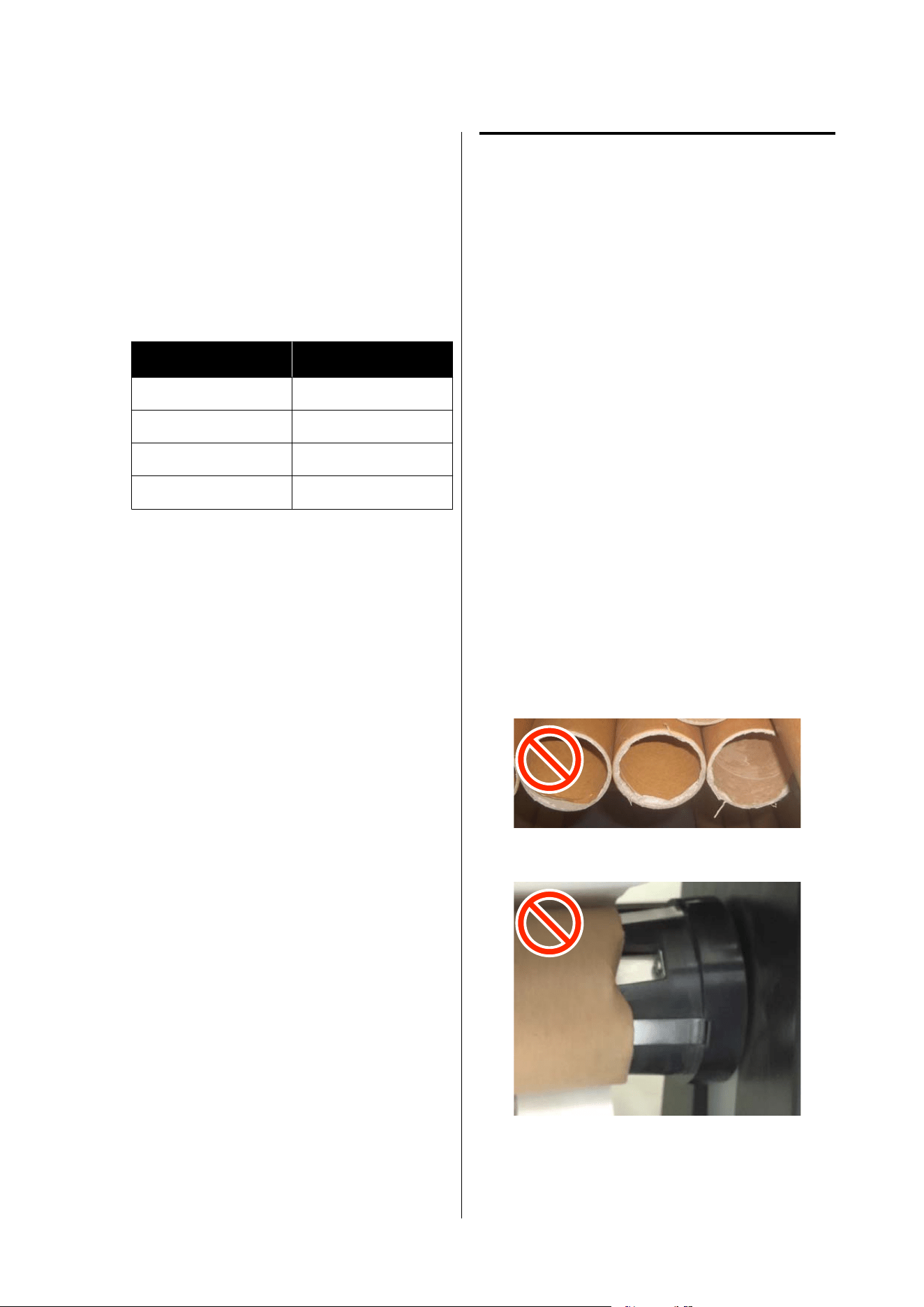
When there are no registered media settings
for the loaded media
First, select an unregistered number.
There is no Media Type set for an unregistered
number, so the screen to select Media Type
appears. Select the Media Type using the paper
weight of the loaded media as a guideline as
shown below. The paper weights of each Media
Type shown in the screen are typical values.
Media Type
Paperweight (g/m
2
)
Ultra-Thin 39 or under
Thin 40 to 56
Med-Thick 57 to 89
Thick 90 or over
When there are registered media
settings/EMX file is downloaded and
registered for the loaded media
Choose a registered media number.
In Media Detection, set Width Detection.
Normally, leave this On.
See the following for details about Media
Detection.
U “General Settings menu” on page 201
B
Press OK.
The printer starts detecting the loaded media
and performing related operations.
C
Follow the on-screen instructions to forward
the edge of the media to the given position as
necessary.
Loading Media Into the
Auto Take-up Reel Unit
The Auto Take-up Reel Unit automatically takes up
media as it is printed, improving the efficiency of
unmanned operations.
You can check the procedure in a video on YouTube.
Epson Video Manuals
Important points for correct
take-up
Observe the following points for correct take-up of
media.
❏ We recommend using a take-up roll core with the
same width as the media. If a take-up roll core of a
different width is used, the take-up roll core may
bend, and the media will be taken up incorrectly.
❏ We recommend “printed side in” for the take-up
of media. “Printed side out” may cause the media
to move around and create a large misalignment
with the roll. When take-up cannot be done
correctly with “printed side out”, do take-up using
“printed side in”.
❏ Media smaller than 36 inches wide may move
around and be taken up incorrectly.
❏ Do not attach take-up roll cores like the ones
shown in the following figure. The take-up
tension will be uneven and the core will spin
loosely. As a result, the paper cannot wind
correctly, which may cause banding in the print
results.
Edges are worn
Deformed
SC-F20000 Series/SC-F11000H Series/SC-F11000 Series/SC-F10000H Series/SC-F10000 Series User's Guide
Basic Operations
99
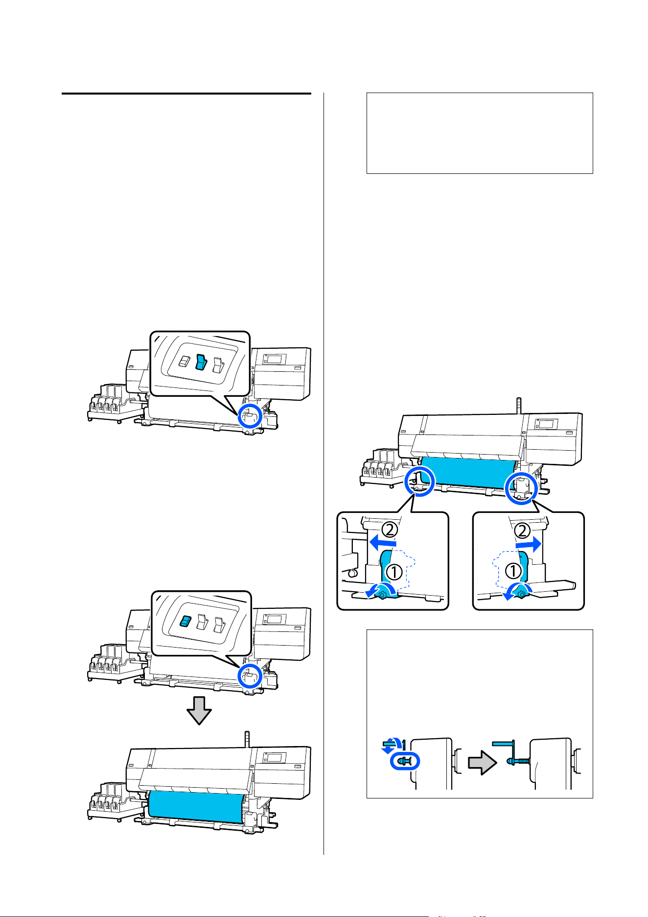
Loading Media Into the
Standard Type Auto Take-Up
Reel Unit
Necessary items
❏ Take-up roll core that is the same width as the
media
❏ Commercially available adhesive tape
Attaching the Roll Core
A
Set the Auto switch to Off.
B
Confirm that the edge of the media is touching
the media holder.
If not, follow the procedure below to have the
edge of the media touch the media holder.
Normal feeding procedure
Hold down the near side of the media feed
switch until the edge of the media reaches the
media holder.
c
Important:
Always press the media feed switch to feed the
media. If the media is pulled by hand, the
media may twist during take-up.
Take-up feeding procedure
Follow steps 3 to 5 in "Feeding media to the
front" to pull out the media until its edge
reaches the media holder.
U “Feeding media to the front” on page 84
C
Loosen the media holder fixing screws on both
sides and adjust the media holders so that the
distance between the two is wider than the
media.
If the roll supports are not positioned evenly,
move them so that they are even.
c
Important:
If the left-side media holder handle's shaft is
not visible, rotate the handle as shown in the
illustration until it stops. The roll core cannot
be properly loaded if the handle's shaft is not
visible.
SC-F20000 Series/SC-F11000H Series/SC-F11000 Series/SC-F10000H Series/SC-F10000 Series User's Guide
Basic Operations
100
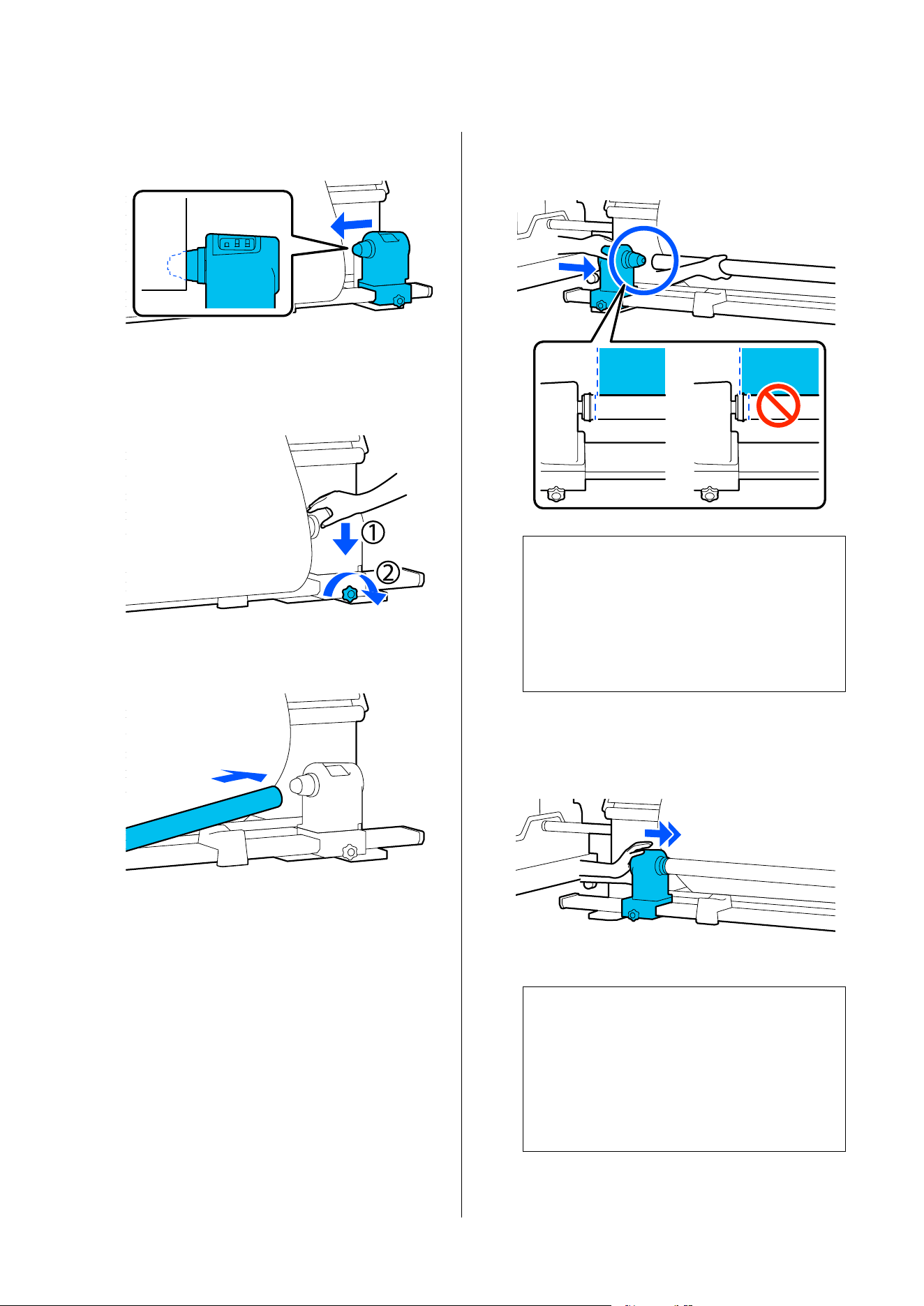
D
Align and move the right-side media holder to
the right edge of the media.
E
While pressing from the top of the media
holder, tighten the fixing screw in place.
F
Insert the roll core onto the right-side media
holder.
G
Check that the left-side media holder is fully
inserted into the roll core and that the roll core
and edges of the media are not misaligned.
c
Important:
If the edges of the media are misaligned, the
media cannot be taken up correctly. If the
edges are misaligned, loosen the fixing screw
for the right-side media holder, and then
restart from Step 4.
H
To ensure that the media holder is sufficiently
inserted into the roll core, push the top of the
media holder towards the end of the roll two
times.
c
Important:
If the media holder is inserted into the roll
core insufficiently, media is not fed correctly
during printing because of slippage between
the media holder and roll core.
This may cause banding in the print results.
SC-F20000 Series/SC-F11000H Series/SC-F11000 Series/SC-F10000H Series/SC-F10000 Series User's Guide
Basic Operations
101
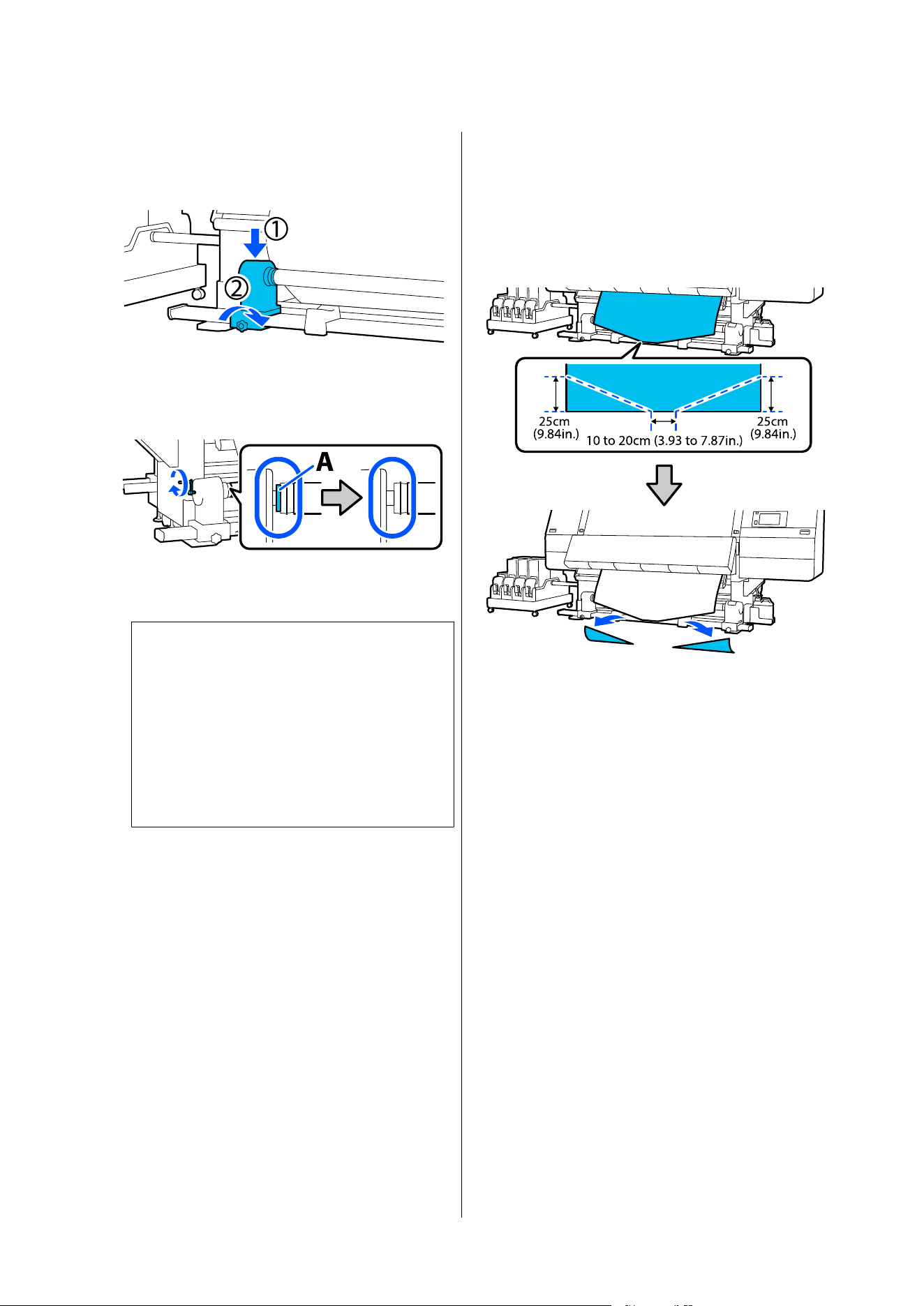
I
While pressing from the top of the media
holder, tighten the fixing screw.
Tighten it so the media holder does not move.
J
Rotate the handle until part A in the illustration
below is fully inserted.
c
Important:
Once part A is hidden, do not turn the
handle any further. Failure to observe this
precaution could damage the media holder.
If part A is still visible even after the handle
has been turned fully, rewind the handle.
Loosen the media holder screw on the right
side, and then restart from Step 5.
K
Leave a 10 to 20 cm (3.93 to 7.87 in.) wide
section in the center of the media, and cut at
least 25 cm (9.84 in.) in height from the left and
right corners of the media.
Cutting the media prevents feeding problems,
such as the left and right corners of media
being folded and caught at the start of take-up.
Next, see the following according to the procedure.
Normal feeding procedure U “Loading using the
normal feeding procedure” on page 103
Take-up feeding procedure U “Loading using the
take-up feeding procedure” on page 105
SC-F20000 Series/SC-F11000H Series/SC-F11000 Series/SC-F10000H Series/SC-F10000 Series User's Guide
Basic Operations
102
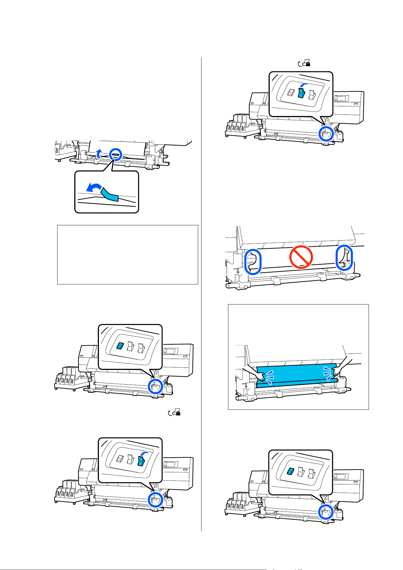
Loading using the normal feeding
procedure
Printed side in
A
While pulling the center of the media straight
down, wrap it around the roll core from back to
front, and affix it using commercially available
adhesive tape.
c
Important:
Affix the media to the take-up roll core with
the media pulled tightly. If media is affixed
loosely, the media may move around during
take-up.
B
Hold down the near side of the media feed
switch to feed enough media for a single wrap
around the take-up roll core.
C
Hold down the Manual switch on the
side to take-up the media for a single wrap
around the core.
D
Flip the Auto switch to .
E
Confirm that the media is attached without any
looseness.
If the tension on the left and right of the media
is different in the areas shown in the illustration
below, the media will not be taken up correctly.
When one side is loose, restart the procedure
from Step 1.
Note:
You can confirm differences in tension by lightly
tapping both edges of the media as shown in the
illustration below.
F
Hold down the near side of the media feed
switch until both edges of the media are taken
up and wrap around the core once or twice.
SC-F20000 Series/SC-F11000H Series/SC-F11000 Series/SC-F10000H Series/SC-F10000 Series User's Guide
Basic Operations
103
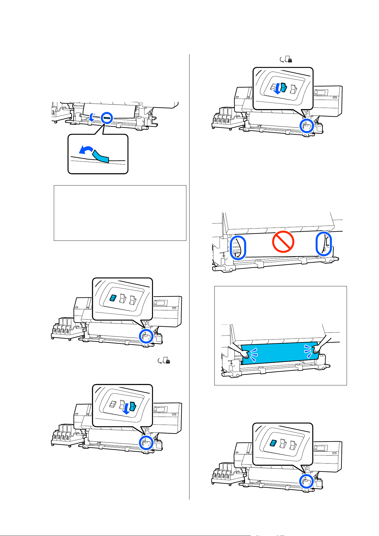
Printed side out
A
While pulling the center section of the media
straight down, affix the media to the take up
roll core with commercially available adhesive
tape.
c
Important:
Affix the media to the take-up roll core with
the media pulled tightly. If media is affixed
loosely, the media may move around during
take-up.
B
Hold down the near side of the media feed
switch to feed enough media for a single wrap
around the take-up roll core.
C
Hold down the Manual switch on the
side to take-up the media for a single wrap
around the core.
D
Flip the Auto switch to .
E
Confirm that the media is attached without any
looseness.
If the tension on the left and right of the media
is different in the areas shown in the illustration
below, the media will not be taken up correctly.
When one side is loose, restart the procedure
from Step 1.
Note:
You can confirm differences in tension by lightly
tapping both edges of the media as shown in the
illustration below.
F
Hold down the near side of the media feed
switch until both edges of the media are taken
up and wrap around the core once or twice.
SC-F20000 Series/SC-F11000H Series/SC-F11000 Series/SC-F10000H Series/SC-F10000 Series User's Guide
Basic Operations
104
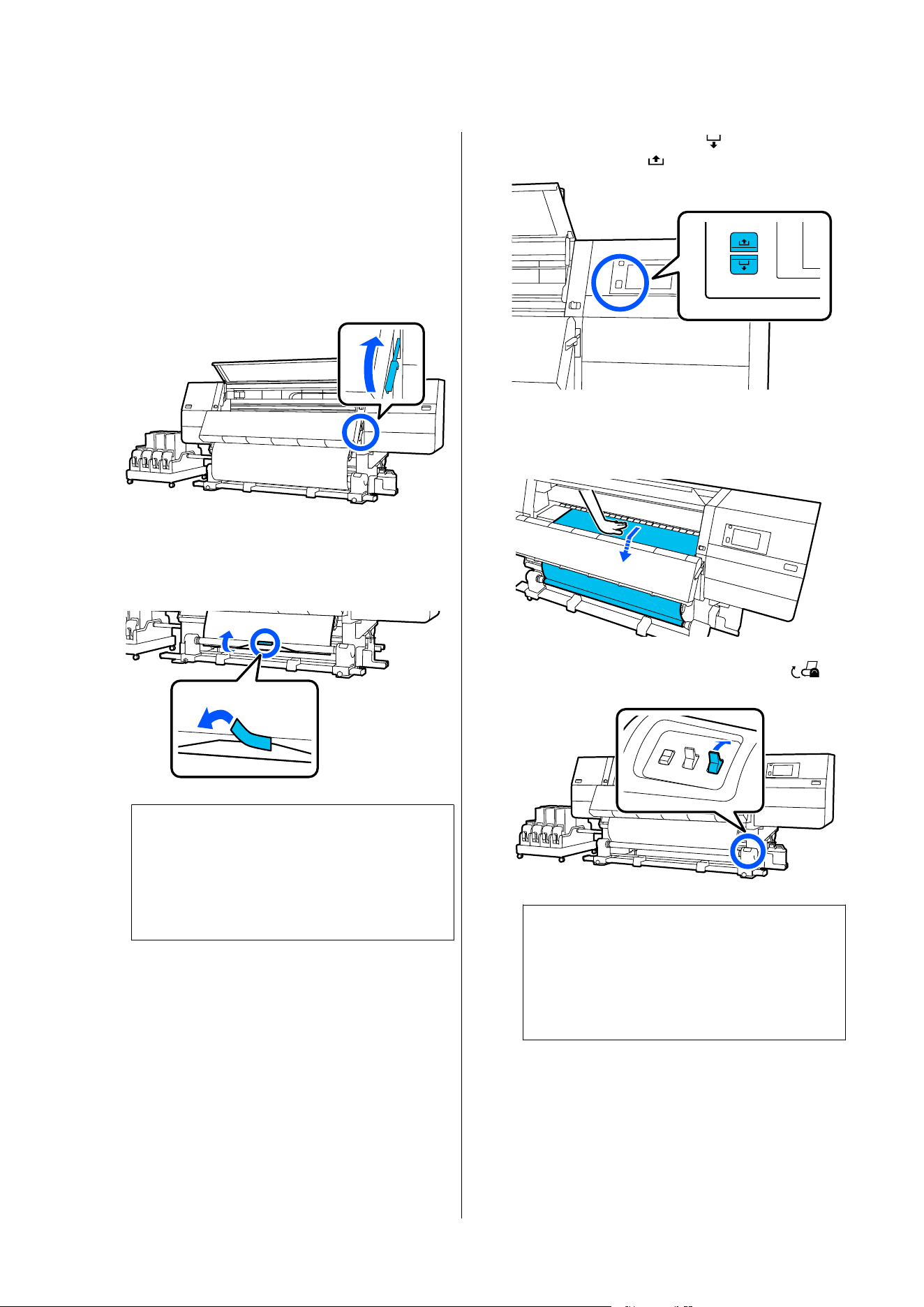
Loading using the take-up feeding
procedure
Printed side in
A
Confirm that the front cover is open.
B
Raise the media loading lever.
C
While pulling the center of the media straight
down, wrap it around the roll core from back to
front, and affix it using commercially available
adhesive tape.
c
Important:
Affix the media to the take-up roll core with
the media pulled tightly. If media is affixed
loosely, the media may move around during
take-up.
D
Repeat the following procedure and take-up the
media for a double wrap around the roll core.
a. Hold the media feed button pressed to
slightly slacken the media at the back side.
When loading media, press for printable
side out, and press
for printable side in.
b. While holding the center of the media on the
platen, pull it out by moving it toward yourself,
and slacken the media at the front.
c. Hold down the Manual switch on the
side to take-up the slack media around the core.
c
Important:
When taking-up the media around the core,
do take-up of only the slackened part. If you
do take-up without slackening, it will cause
problems, such as wrinkles.
SC-F20000 Series/SC-F11000H Series/SC-F11000 Series/SC-F10000H Series/SC-F10000 Series User's Guide
Basic Operations
105
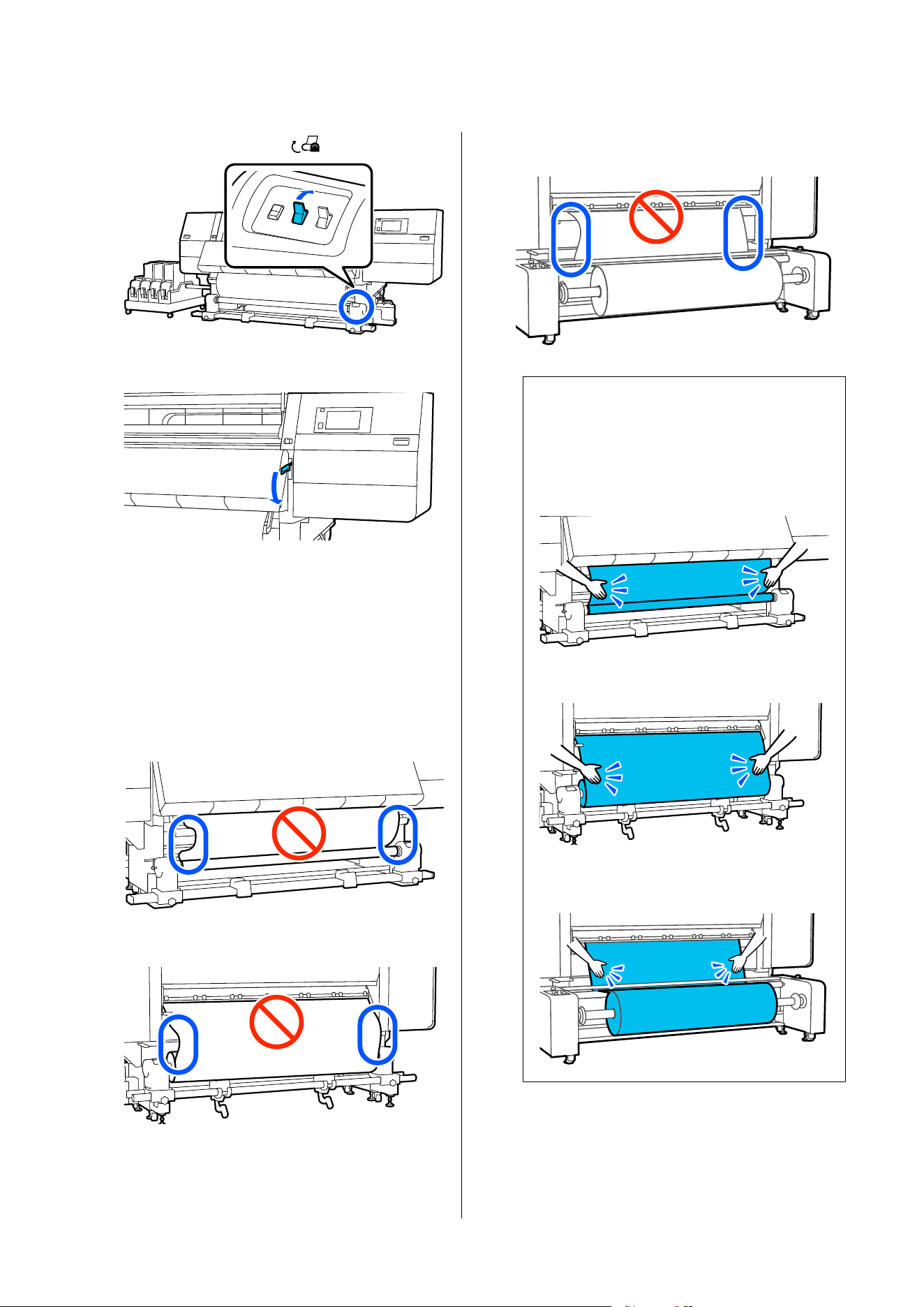
E
Flip the Auto switch to .
F
Lower the media loading lever.
G
Confirm that the media is attached without
looseness on the front and back sides.
If the tension on the left and right of the media
is different in the areas shown in the illustration
below, the media will not be taken up correctly.
When one side is loose, restart the procedure
from Step 2.
Front side
Back side (Standard type Media Feeding Unit)
Back side (Large capacity type Media Feeding
Unit)
Note:
You can confirm differences in tension by lightly
tapping both edges of the media as shown in the
illustration below.
Front side
Back side (Standard type Media Feeding Unit)
Back side (Large capacity type Media Feeding
Unit)
SC-F20000 Series/SC-F11000H Series/SC-F11000 Series/SC-F10000H Series/SC-F10000 Series User's Guide
Basic Operations
106
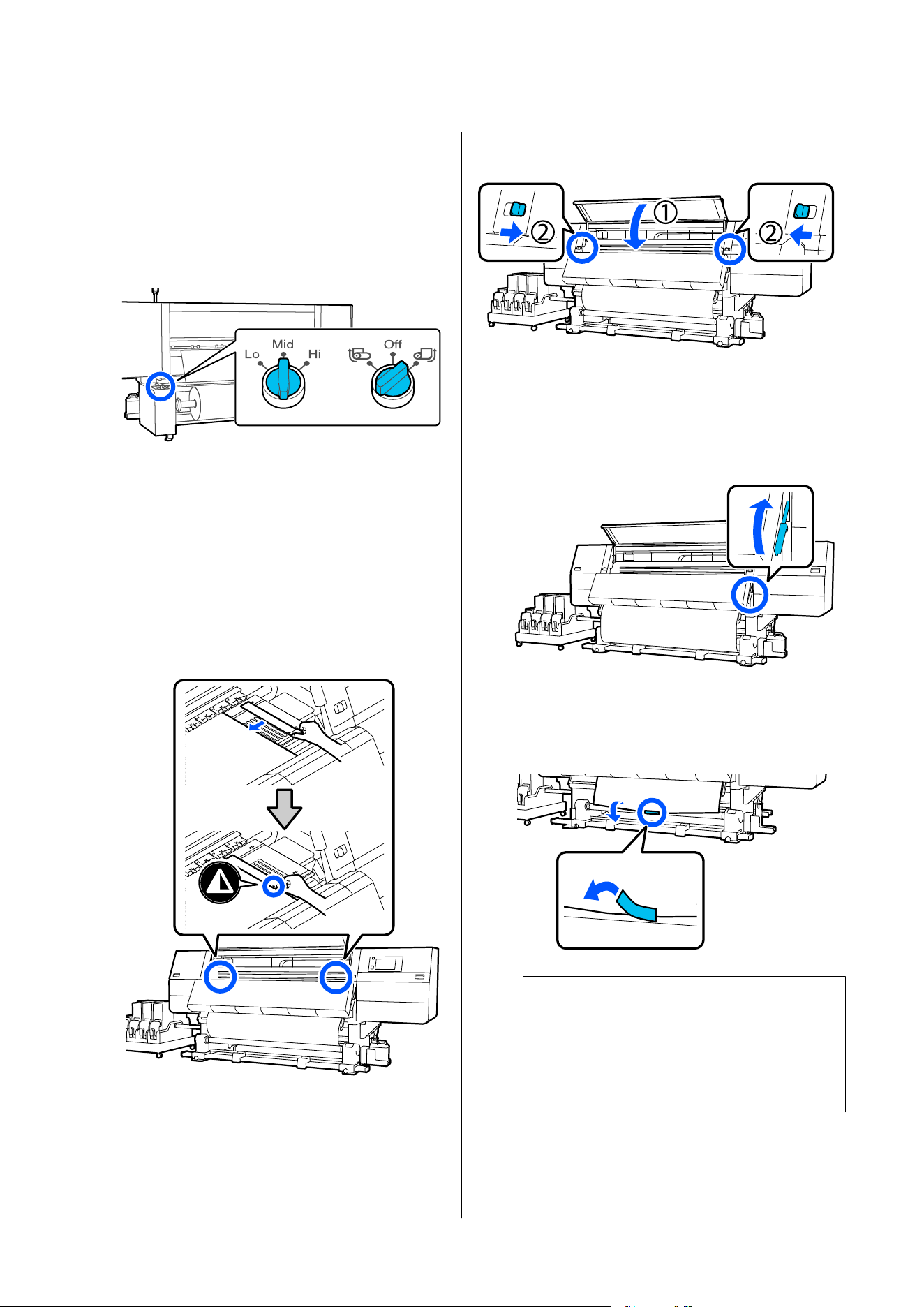
H
If you are using the large capacity type of media
feeding unit, check that the Auto switch and the
load switch are set according to the loaded
media.
The load switch is normally set to Mid. Switch
to Hi to increase tension if wrinkles appear in
the media during printing.
I
Move to the front side, and while holding the
tabs of the media edge plate on both sides,
move the plate to the top edge of the media.
Adjust so that the edges of the media are
aligned with the center of the triangular holes
in the media edge plates.
The media edge plates prevent the media from
riding up and keep fibers on the cut edge of the
media from touching the print head. Load
correctly.
J
Close the front cover, and then move the left
and right lock levers inward.
Printed side out
A
Confirm that the front cover is open.
B
Raise the media loading lever.
C
While pulling the center section of the media
straight down, affix the media to the take up
roll core with commercially available adhesive
tape.
c
Important:
Affix the media to the take-up roll core with
the media pulled tightly. If media is affixed
loosely, the media may move around during
take-up.
SC-F20000 Series/SC-F11000H Series/SC-F11000 Series/SC-F10000H Series/SC-F10000 Series User's Guide
Basic Operations
107
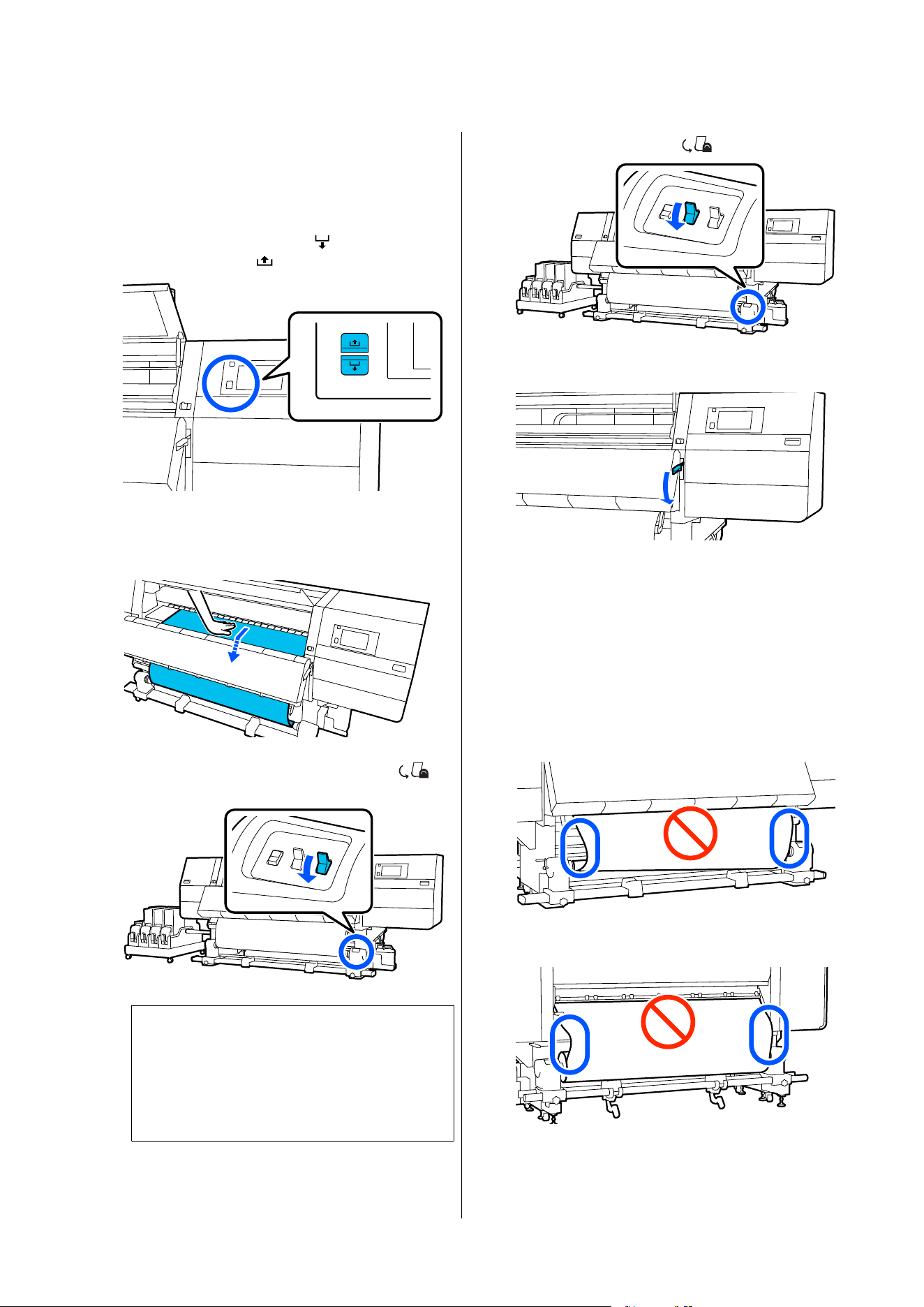
D
Repeat the following procedure and take-up the
media for a double wrap around the roll core.
a. Hold the media feed button pressed to
slightly slacken the media at the back side.
When loading media, press
for printable
side out, and press
for printable side in.
b. While holding the center of the media on the
platen, pull it out by moving it toward yourself,
and slacken the media at the front.
c. Hold down the Manual switch on the
side to take-up the slack media around the core.
c
Important:
When taking-up the media around the core,
do take-up of only the slackened part. If you
do take-up without slackening, it will cause
problems, such as wrinkles.
E
Flip the Auto switch to .
F
Lower the media loading lever.
G
Confirm that the media is attached without
looseness on the front and back sides.
If the tension on the left and right of the media
is different in the areas shown in the illustration
below, the media will not be taken up correctly.
When one side is loose, restart the procedure
from Step 2.
Front side
Back side (Standard type Media Feeding Unit)
SC-F20000 Series/SC-F11000H Series/SC-F11000 Series/SC-F10000H Series/SC-F10000 Series User's Guide
Basic Operations
108
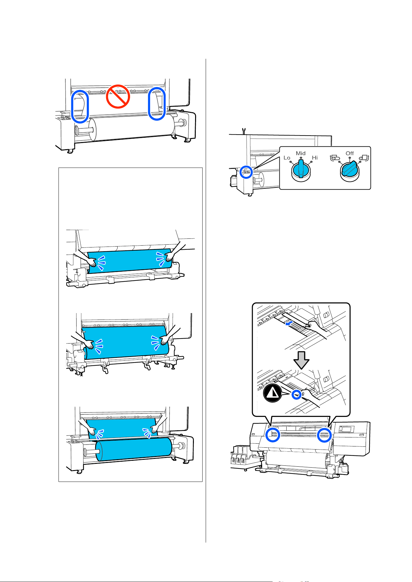
Back side (Large capacity type Media Feeding
Unit)
Note:
You can confirm differences in tension by lightly
tapping both edges of the media as shown in the
illustration below.
Front side
Back side (Standard type Media Feeding Unit)
Back side (Large capacity type Media Feeding
Unit)
H
If you are using the large capacity type of media
feeding unit, check that the Auto switch and the
load switch are set according to the loaded
media.
The load switch is normally set to Mid. Switch
to Hi to increase tension if wrinkles appear in
the media during printing.
I
Move to the front side, and while holding the
tabs of the media edge plate on both sides,
move the plate to the top edge of the media.
Adjust so that the edges of the media are
aligned with the center of the triangular holes
in the media edge plates.
The media edge plates prevent the media from
riding up and keep fibers on the cut edge of the
media from touching the print head. Load
correctly.
SC-F20000 Series/SC-F11000H Series/SC-F11000 Series/SC-F10000H Series/SC-F10000 Series User's Guide
Basic Operations
109
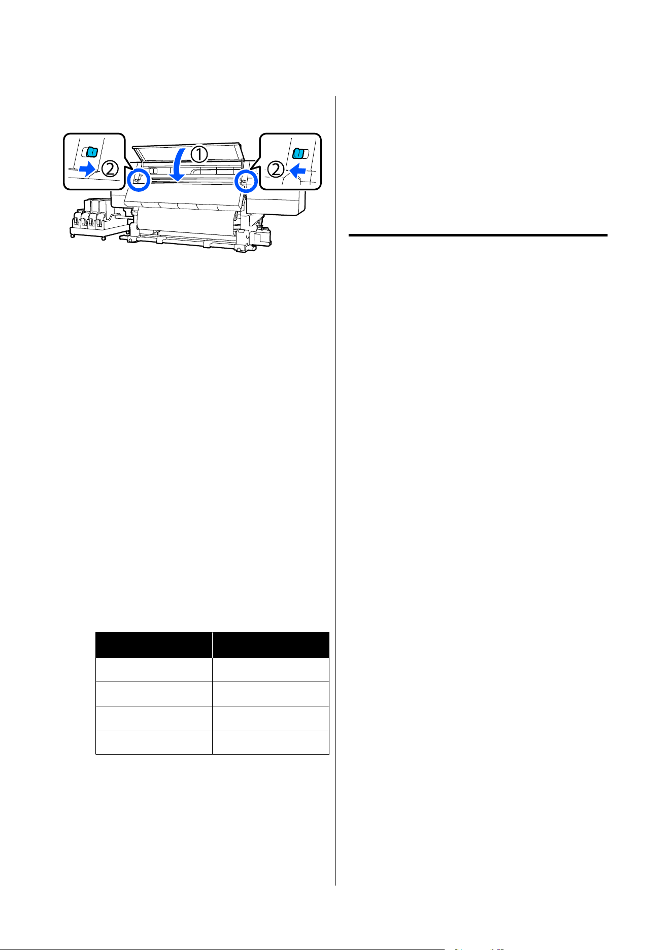
J
Close the front cover, and then move the left
and right lock levers inward.
Setting the media information
A
Set the media information on the screen, and
press OK.
Do the following settings here.
❏ Media: Set the media to use for printing
❏ Roll Winding Direction: How to wind the
loaded media
❏ Media Length: Length of the loaded media
❏ Media Detection: How to detect the width of
the media
Media is set in the following way.
When there are no registered media settings
for the loaded media
First, select an unregistered number.
There is no Media Type set for an unregistered
number, so the screen to select Media Type
appears. Select the Media Type using the paper
weight of the loaded media as a guideline as
shown below. The paper weights of each Media
Type shown in the screen are typical values.
Media Type
Paperweight (g/m
2
)
Ultra-Thin 39 or under
Thin 40 to 56
Med-Thick 57 to 89
Thick 90 or over
When there are registered media
settings/EMX file is downloaded and
registered for the loaded media
Choose a registered media number.
In Media Detection, set Width Detection.
Normally, leave this On.
See the following for details about Media
Detection.
U “General Settings menu” on page 201
B
Press OK.
The printer starts detecting the loaded media
and performing related operations.
Loading Media Into the Large
Capacity Type Auto Take-Up
Reel Unit
We recommend that two people perform the work.
The work is easier to do if they stand so one is on the
left and the other on the right as they pass the media
through the rollers.
Necessary items
❏ Air compressor
❏ Take-up roll core that is the same width as the
media
❏ Commercially available adhesive tape
❏ Hex wrench (large) and hex wrench (small)
(included only with models with type B gap
adjustment screws)
SC-F20000 Series/SC-F11000H Series/SC-F11000 Series/SC-F10000H Series/SC-F10000 Series User's Guide
Basic Operations
110
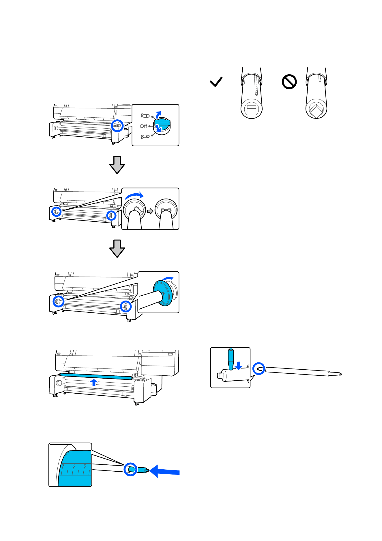
Preparing the roll core
A
Use the Manual switch to rotate the spindle to
face as shown in the illustration, then lower the
handles on both sides outward.
B
Remove the spindle.
C
Insert the spindle into the paper core by up to
about 7 cm on the scale of the spindle.
Face the spindle as shown in the illustration.
After inserting the spindle, follow the
instructions below according to your model.
❏ Models requiring gap adjustment at the ends
of the spindle
- If the air compressor is available near the
printer: Go to the next section, "Attaching the
roll core and closing the gaps at ends of the
spindle".
- If the air compressor is not available near
the printer: Go to the next step.
❏ For models that do not require gap
adjustment at the ends of the spindle: Go to
the next step.
D
If the air compressor is not near the printer or if
gap adjustment at the ends of the spindle is not
required, put air into the spindle at this point to
secure the roll core.
Put air into the spindle from the valve until the
air stops going in.
If you have an air compressor handy, there is no
need to supply air at this point as you will add
air in a later step.
Attaching the roll core and closing
the gaps at the ends of the spindle
A
Confirm the side to which the spindle should
be moved.
After placing the spindle on the Auto Take-up
Reel Unit in a later step, move the spindle to
either the left or right side to eliminate any gap
at the end of the spindle.
The side to which the spindle is moved depends
on the direction in which the media is taken up.
SC-F20000 Series/SC-F11000H Series/SC-F11000 Series/SC-F10000H Series/SC-F10000 Series User's Guide
Basic Operations
111
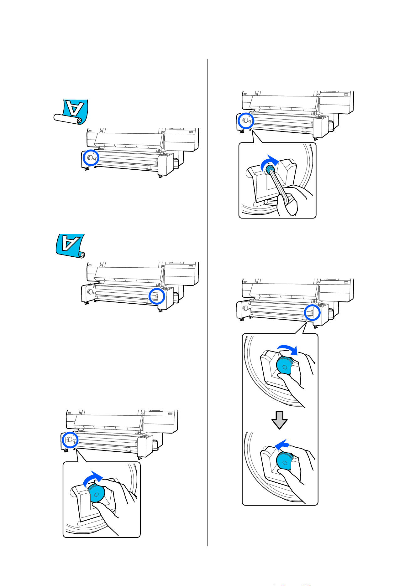
Printed side in
Move the spindle to the left side toward the
Auto Take-up Reel Unit.
Printed side out
Move the spindle to the right side toward the
Auto Take-up Reel Unit.
B
Turn the screw clockwise inside the handle on
the side to which the spindle is to be moved
until it stops.
The following is an example of taking up
printed media with the printed side in.
Type A gap adjustment screw
Turn the s crew by hand.
Type B gap adjustment screw
Turn the screw using the hex wrench (large).
C
Turn the screw clockwise inside the handle on
the opposite side until it stops, then loosen it
slightly.
Type A gap adjustment screw
SC-F20000 Series/SC-F11000H Series/SC-F11000 Series/SC-F10000H Series/SC-F10000 Series User's Guide
Basic Operations
112
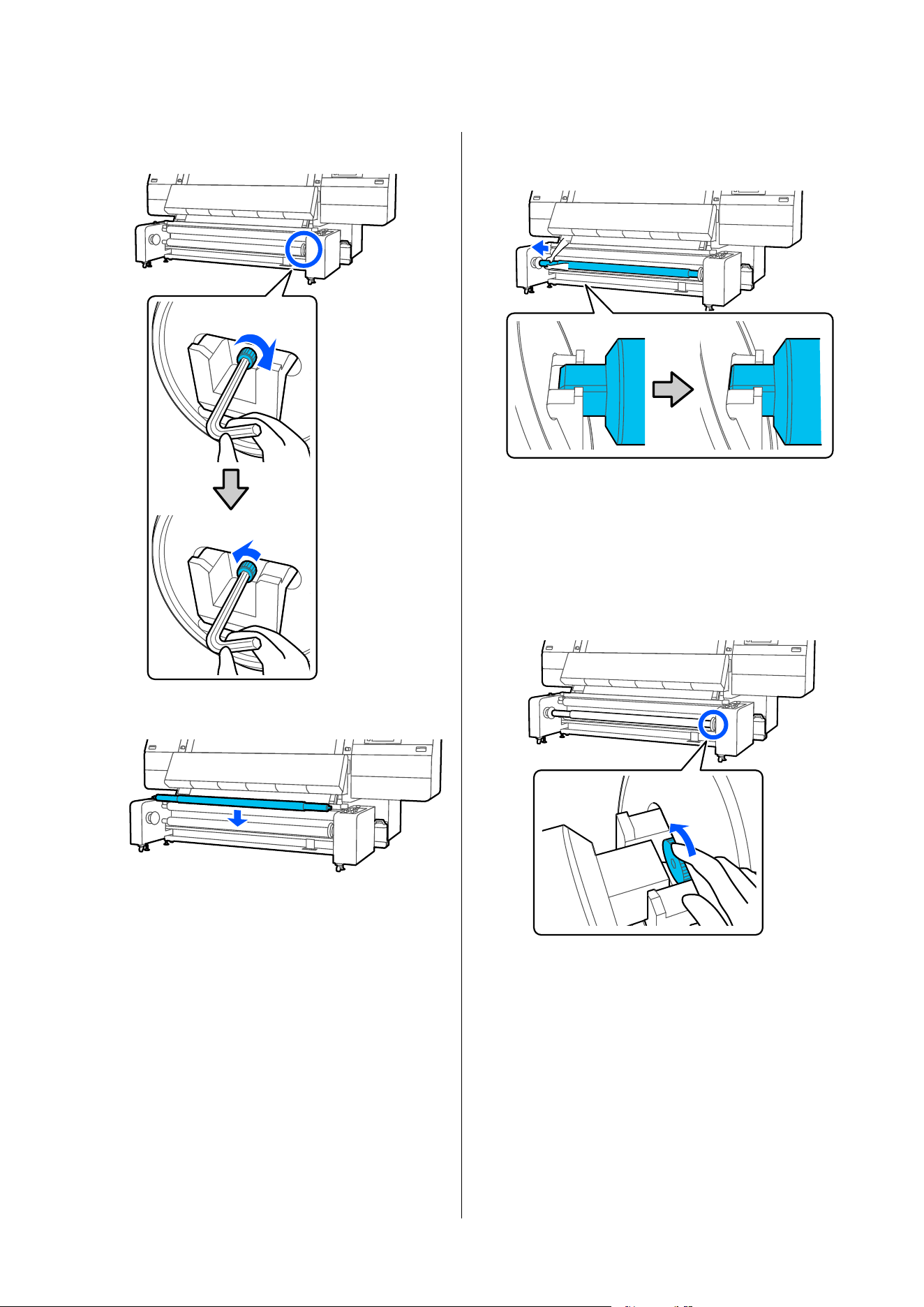
Type B gap adjustment screw
D
Put the spindle in the socket.
E
Slide the spindle by hand until the edge of the
spindle touches the screw inside the handle.
F
Turn the screw counterclockwise inside the
handle on the side opposite to where the
spindle has been moved until the screw touches
the edge of the spindle.
Type A gap adjustment screw
Turn the s crew by hand.
Type B gap adjustment screw
The side of the screw head has a knurled,
non-slip texture with fine ridges and grooves.
SC-F20000 Series/SC-F11000H Series/SC-F11000 Series/SC-F10000H Series/SC-F10000 Series User's Guide
Basic Operations
113
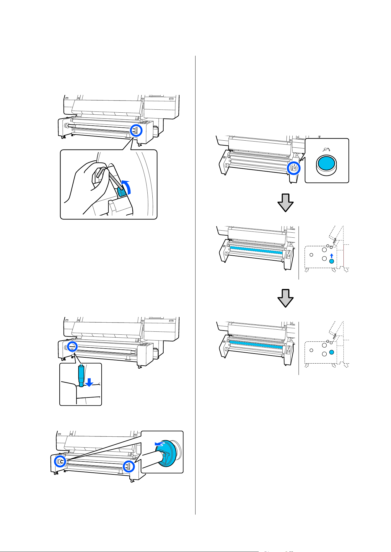
Insert a hex wrench into the gap between the
handle and the spindle, and slowly turn the
screw while hooking the tip of the hex wrench
onto the side of the screw head.
After turning the screw, proceed to step 8 if air
has already been put into the spindle to secure
the roll core.
G
Put air into the spindle from the valve until the
air stops going in.
If air has already been put into the spindle to
secure the roll core, this procedure is not
necessary.
H
Raise the handles on both sides.
Loading using the normal feeding
procedure
Feeding media to the roll core
A
Press the Release button and raise the tension
bar.
The tension bar rises to a medium height.
SC-F20000 Series/SC-F11000H Series/SC-F11000 Series/SC-F10000H Series/SC-F10000 Series User's Guide
Basic Operations
114
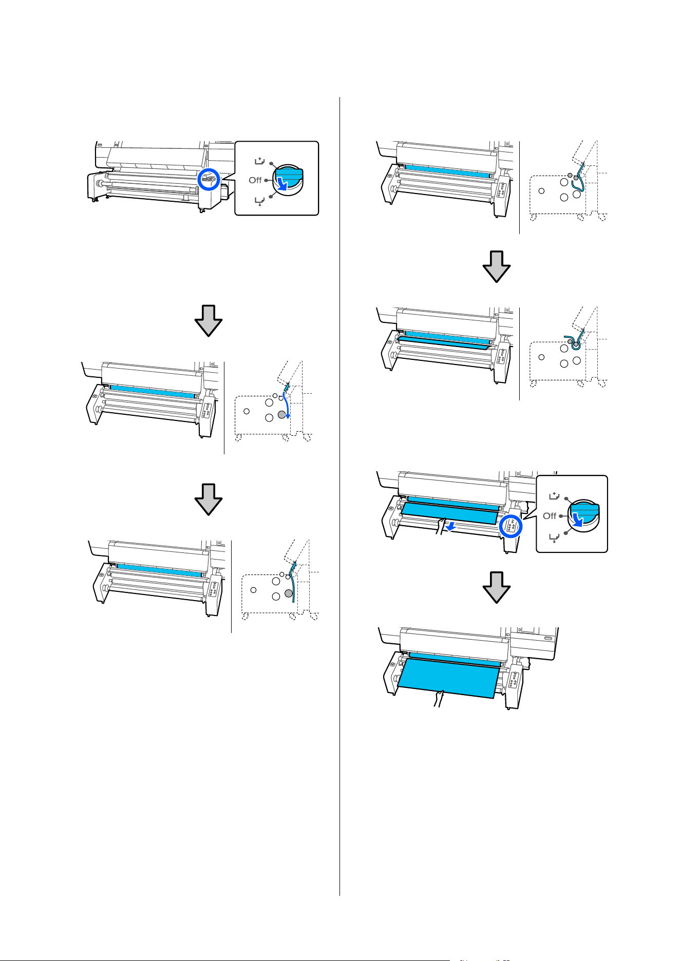
B
Use the media feed switch to feed the media
until the leading edge is below the tension bar.
C
Pass the media between the rollers as shown in
the illustration.
D
Hold the leading edge of the media and use the
media feed switch to feed the media until it is in
front of the spindle.
SC-F20000 Series/SC-F11000H Series/SC-F11000 Series/SC-F10000H Series/SC-F10000 Series User's Guide
Basic Operations
115
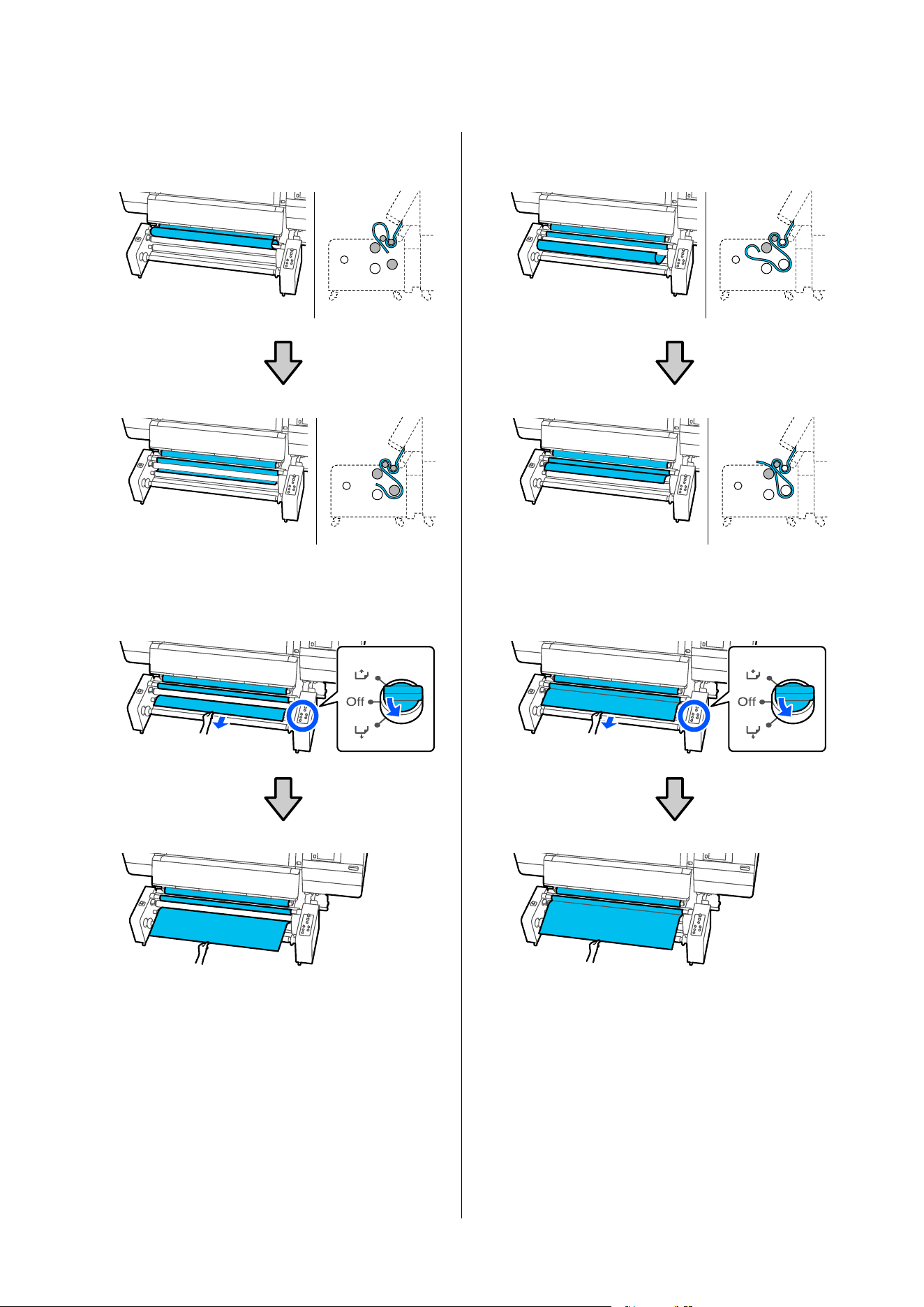
E
Pass the media between the rollers as shown in
the illustration.
F
Hold the leading edge of the media and use the
media feed switch to feed the media until it is in
front of the spindle.
G
Pass the media between the rollers as shown in
the illustration.
H
Hold the leading edge of the media and use the
media feed switch to feed the media until it is in
front of the spindle.
SC-F20000 Series/SC-F11000H Series/SC-F11000 Series/SC-F10000H Series/SC-F10000 Series User's Guide
Basic Operations
116
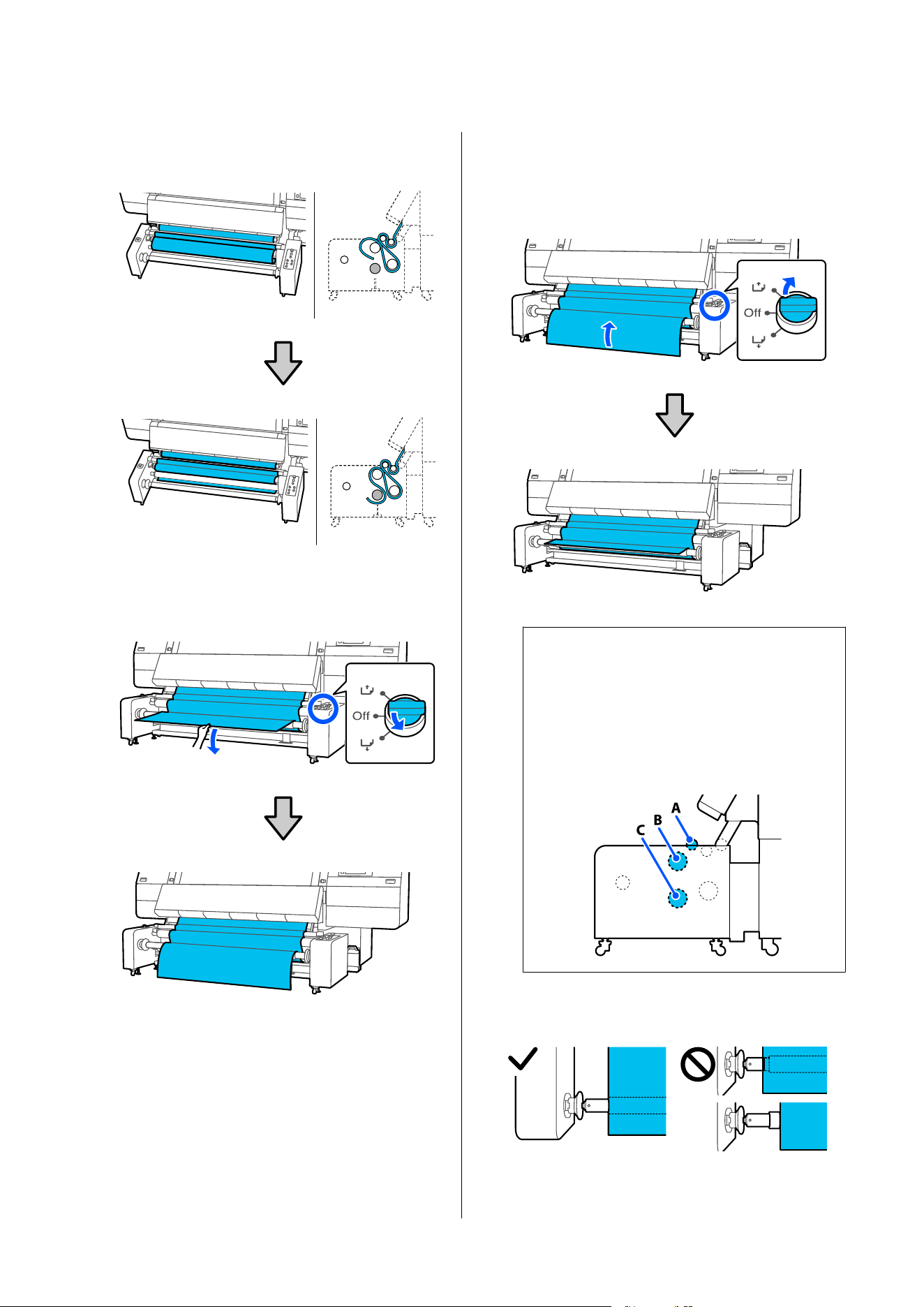
I
Pass the media between the rollers as shown in
the illustration.
J
Hold the leading edge of the media and use the
media feed switch to feed the media until the
leading edge reaches the floor.
K
Use the media feed switch to take up the media
until the leading edge is in front of the spindle.
This operation prevents the media from
skewing.
Note:
If you cannot take-up the media by operating the
switch, you can create a little slack in the media
around the rollers to take it up.
Feed the media further by the amount needed to
create slack, so that it is slack around rollers A, B,
and C as shown in the illustration.
L
Check that the roll core and the edge of the
media are aligned.
SC-F20000 Series/SC-F11000H Series/SC-F11000 Series/SC-F10000H Series/SC-F10000 Series User's Guide
Basic Operations
117
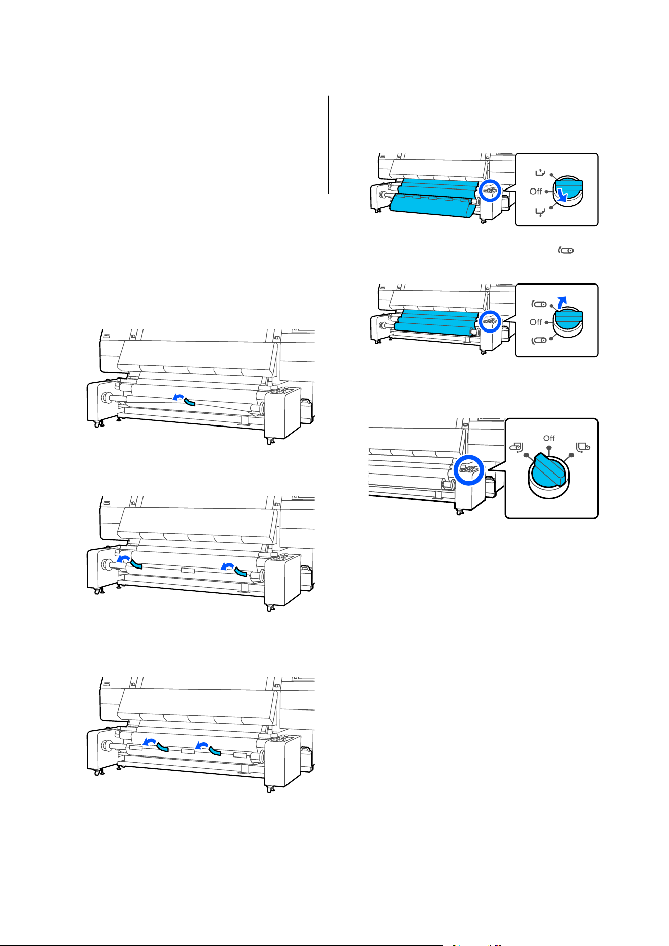
c
Important:
If the edges of the media are misaligned, the
media cannot be taken up correctly. If it is
misaligned, start again from the procedure
for attaching the spindle to the roll core.
Attaching media to the roll core - Printed side
in
A
Wrap the media from the back of the roll core
to the front, and while pulling the center
section of the leading edge of the media, affix it
to the roll core with commercially available
adhesive tape.
B
Attach the left and right ends.
C
Attach the section between the center and the
left and right ends.
D
Use the media feed switch to feed enough
media for approximately two wraps around the
take-up roll core.
E
Hold down the Manual switch on the side
to take-up the slack media around the core.
F
Check that the Auto switch is set according to
the take-up direction.
G
Confirm that the media is attached without any
looseness.
If the tension on the left and right of the media
is different, the media will not be taken up
correctly. If either side is loose, start again from
the procedure for attaching the media to the
roll core.
SC-F20000 Series/SC-F11000H Series/SC-F11000 Series/SC-F10000H Series/SC-F10000 Series User's Guide
Basic Operations
118
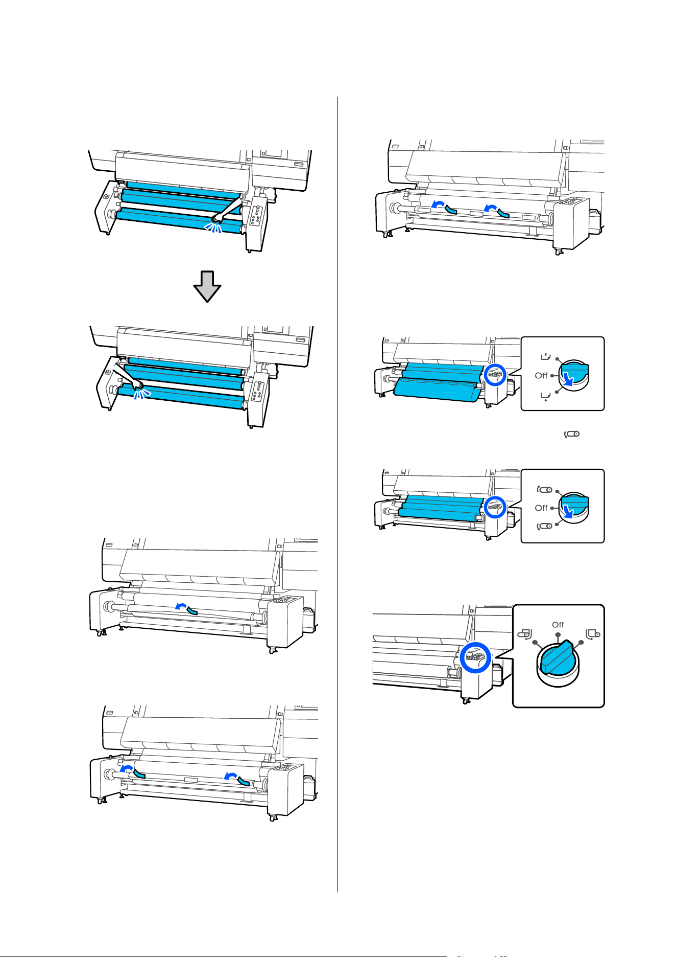
You can confirm differences in tension by
lightly tapping both edges of the media as
shown in the following illustration.
Attaching media to the roll core - Printed side
out
A
Pull the center section of the leading edge of the
media, and affix it to the roll core with
commercially available adhesive tape.
B
Attach the left and right ends.
C
Attach the section between the center and the
left and right ends.
D
Use the media feed switch to feed enough
media for approximately two wraps around the
take-up roll core.
E
Hold down the Manual switch on the side
to take-up the slack media around the core.
F
Check that the Auto switch is set according to
the take-up direction.
G
Confirm that the media is attached without any
looseness.
If the tension on the left and right of the media
is different, the media will not be taken up
correctly. If either side is loose, start again from
the procedure for attaching the media to the
roll core.
SC-F20000 Series/SC-F11000H Series/SC-F11000 Series/SC-F10000H Series/SC-F10000 Series User's Guide
Basic Operations
119
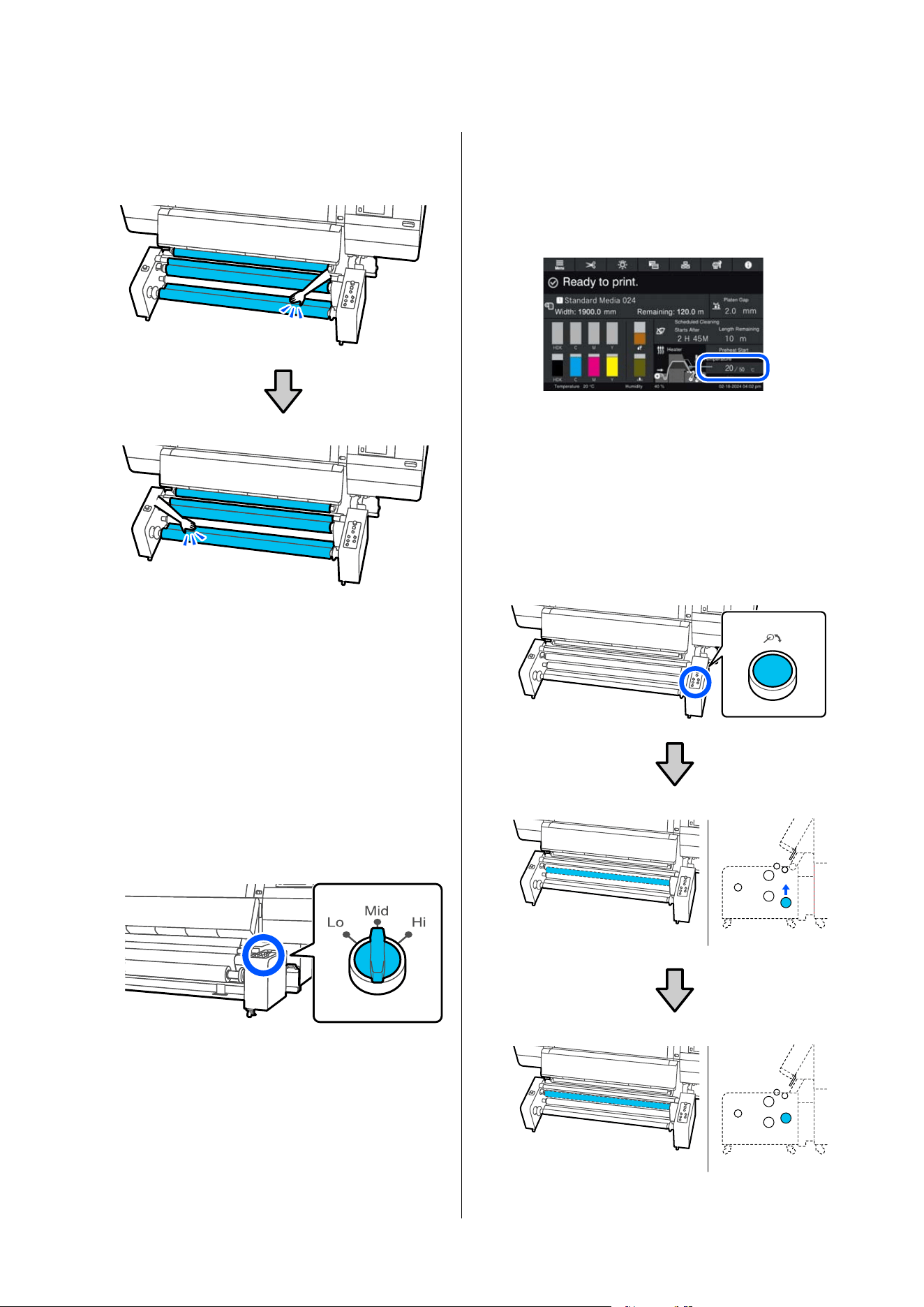
You can confirm differences in tension by
lightly tapping both edges of the media as
shown in the following illustration.
Setting the load switch and heater
temperature
The recommended settings for the load switch and the
temperature when using the large capacity type Auto
Take-up Reel Unit are shown in the following table.
U “Media Settings List for Each Media Type” on
page 271
A
Check the load switch setting.
Check the table and set it according to the
media you are using.
B
Check the heater's temperature setting.
Check the current temperature setting from the
home screen, and if it differs from the
temperature setting in the table, reset it to the
temperature in the table.
Loading using the take-up feeding
procedure
Feeding media to the roll core
A
Press the Release Button and raise the tension
bar.
The tension bar rises to a medium height.
SC-F20000 Series/SC-F11000H Series/SC-F11000 Series/SC-F10000H Series/SC-F10000 Series User's Guide
Basic Operations
120
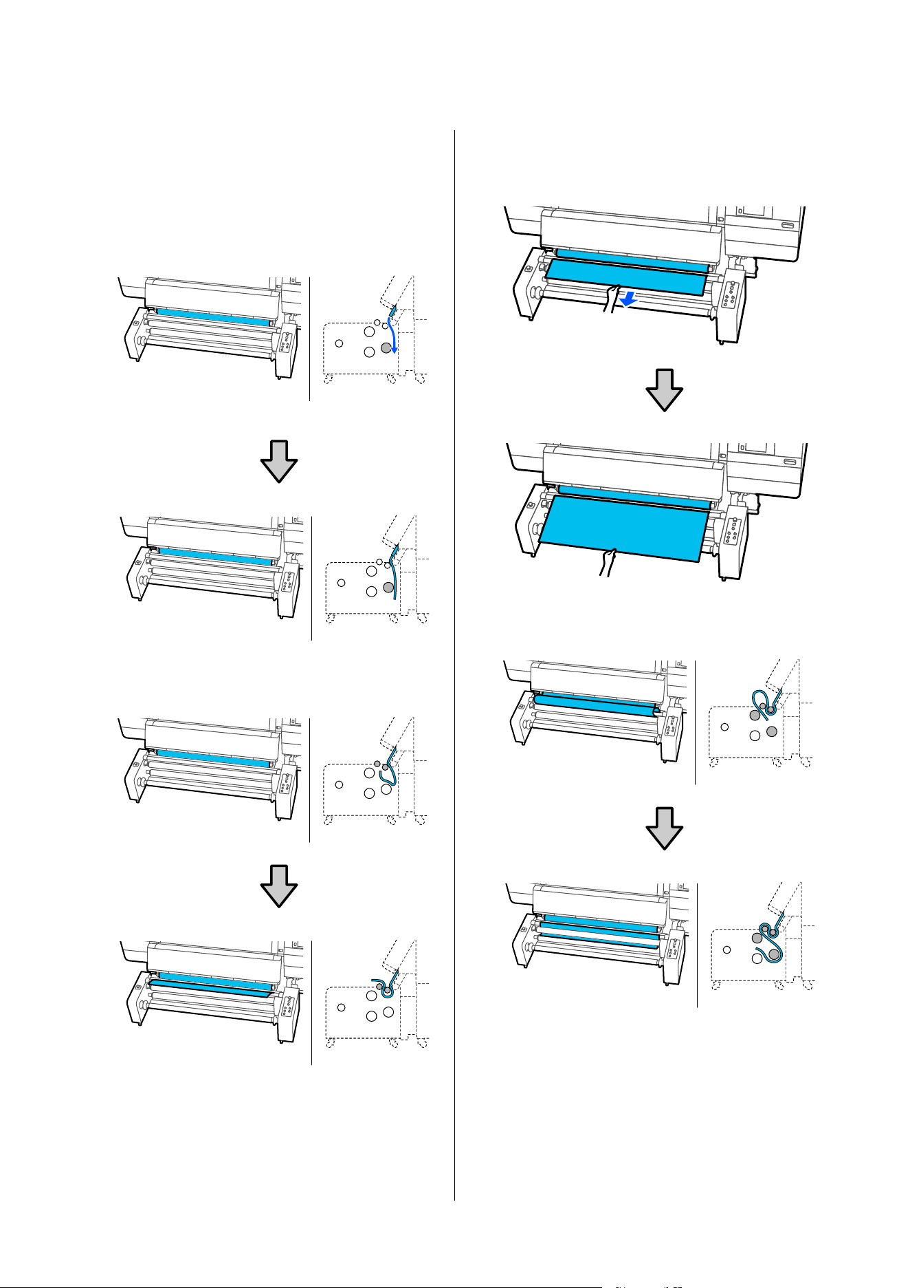
B
Pull out the media by hand while creating slack
until the leading edge of the media is below the
tension bar.
U “Pulling Out Media Manually when Using
the Large Capacity Roll Models/Large Capacity
Reel Models” on page 71
C
Pass the media between the rollers as shown in
the illustration.
D
Hold the leading edge of the media and pull out
the media by hand while creating slack until it
reaches the front of the spindle.
E
Pass the media between the rollers as shown in
the illustration.
SC-F20000 Series/SC-F11000H Series/SC-F11000 Series/SC-F10000H Series/SC-F10000 Series User's Guide
Basic Operations
121
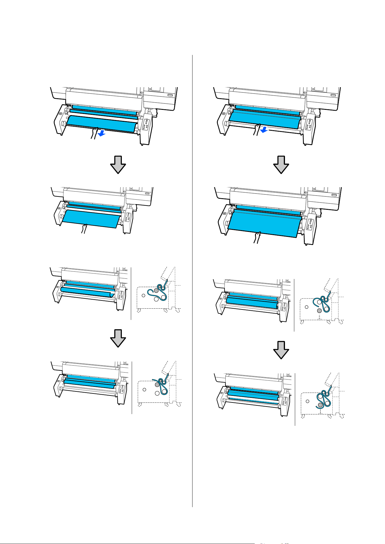
F
Hold the leading edge of the media and pull out
the media by hand while creating slack until it
reaches the front of the spindle.
G
Pass the media between the rollers as shown in
the illustration.
H
Hold the leading edge of the media and pull out
the media by hand while creating slack until it
reaches the front of the spindle.
I
Pass the media between the rollers as shown in
the illustration.
SC-F20000 Series/SC-F11000H Series/SC-F11000 Series/SC-F10000H Series/SC-F10000 Series User's Guide
Basic Operations
122
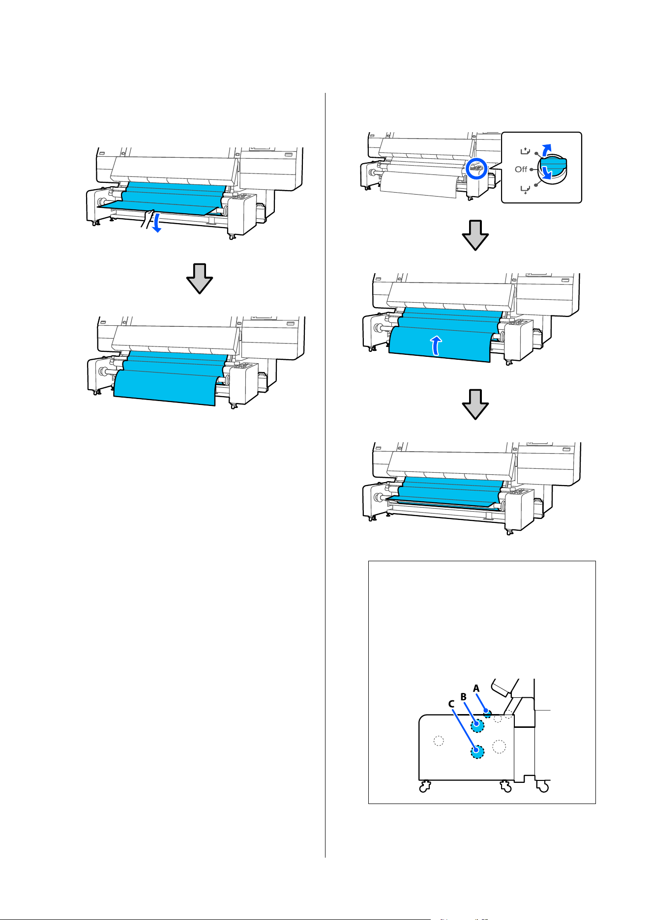
J
Hold the leading edge of the media and pull it
out by hand while creating slack until the
leading edge of the media reaches the floor.
K
Use the media feed switch to take up the media
until the leading edge is in front of the spindle.
Turn the media feed switch in the take-up
direction.
This operation prevents the media from
skewing.
Note:
If you cannot take-up the media by operating the
switch, you can create a little slack in the media
around the rollers to take it up.
Pull out the media further by the amount needed
to create slack, so that it is slack around rollers A,
B, and C as shown in the illustration.
SC-F20000 Series/SC-F11000H Series/SC-F11000 Series/SC-F10000H Series/SC-F10000 Series User's Guide
Basic Operations
123
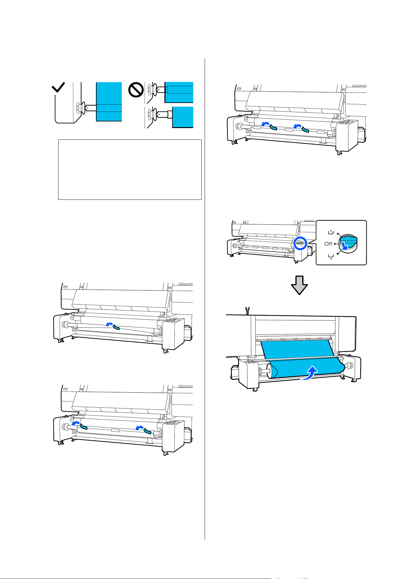
L
Check that the roll core and the edge of the
media are aligned.
c
Important:
If the edges of the media are misaligned, the
media cannot be taken up correctly. If it is
misaligned, start again from the procedure
for attaching the spindle to the roll core.
Attaching media to the roll core - Printed side
in
A
Wrap the media from the back of the roll core
to the front, and while pulling the center
section of the leading edge of the media, affix it
to the roll core with commercially available
adhesive tape.
B
Attach the left and right ends.
C
Attach the section between the center and the
left and right ends.
D
Use the media feed switch to create enough
slack in the media for approximately two wraps
around the take-up roll core.
When the media is printable side in
SC-F20000 Series/SC-F11000H Series/SC-F11000 Series/SC-F10000H Series/SC-F10000 Series User's Guide
Basic Operations
124
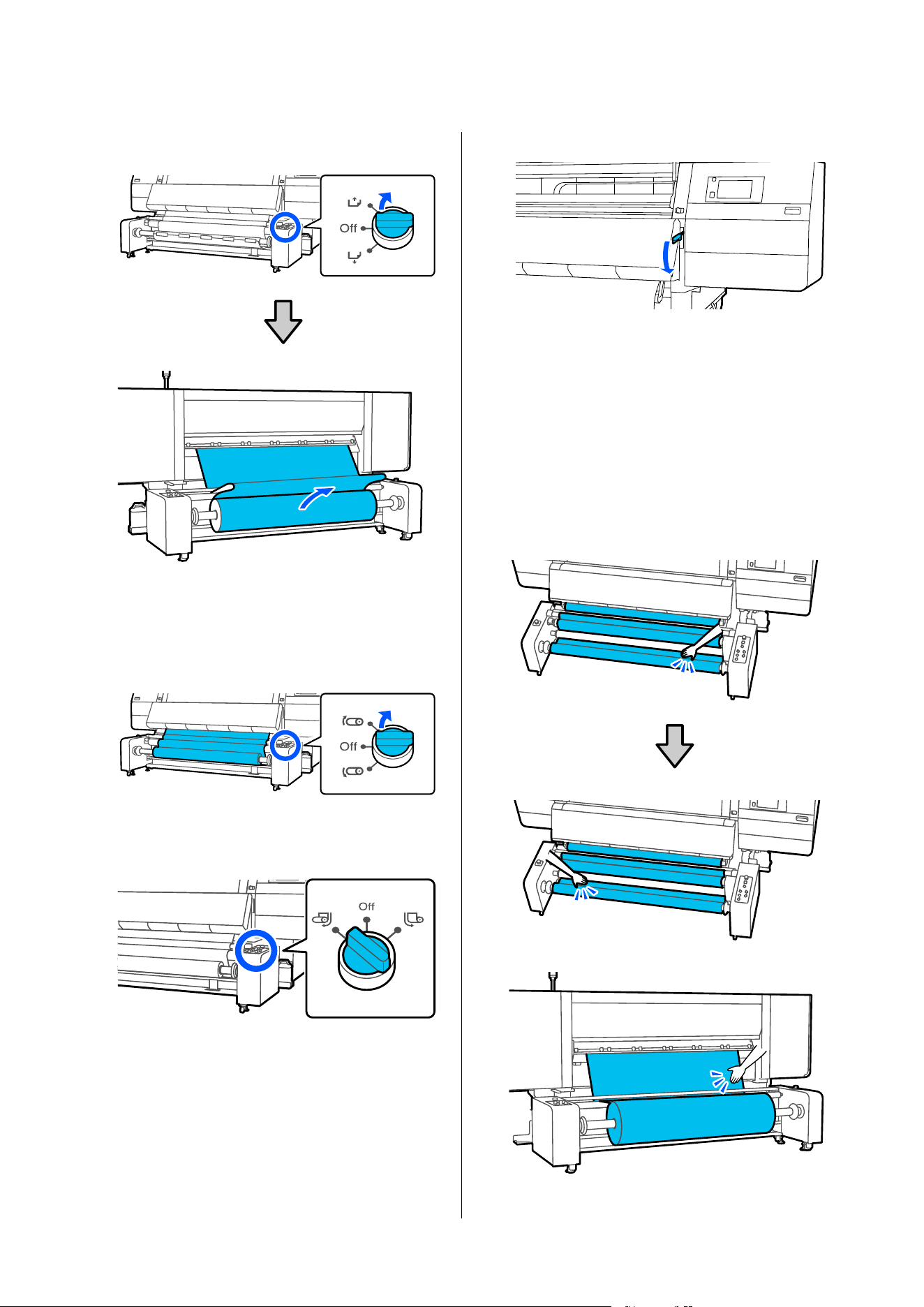
When the media is printable side out
E
Use the Manual switch to take-up the slack
media around the core.
Turn the Manual switch in the take-up
direction.
F
Check that the Auto switch is set according to
the take-up direction.
G
Lower the media loading lever.
H
Confirm that the media is attached without
looseness on the front and back sides.
If the tension on the left and right of the media
is different, the media will not be taken up
correctly. If either side is loose, start again from
the procedure for attaching the media to the
roll core.
You can confirm differences in tension by
lightly tapping both edges of the media as
shown in the following illustration.
SC-F20000 Series/SC-F11000H Series/SC-F11000 Series/SC-F10000H Series/SC-F10000 Series User's Guide
Basic Operations
125
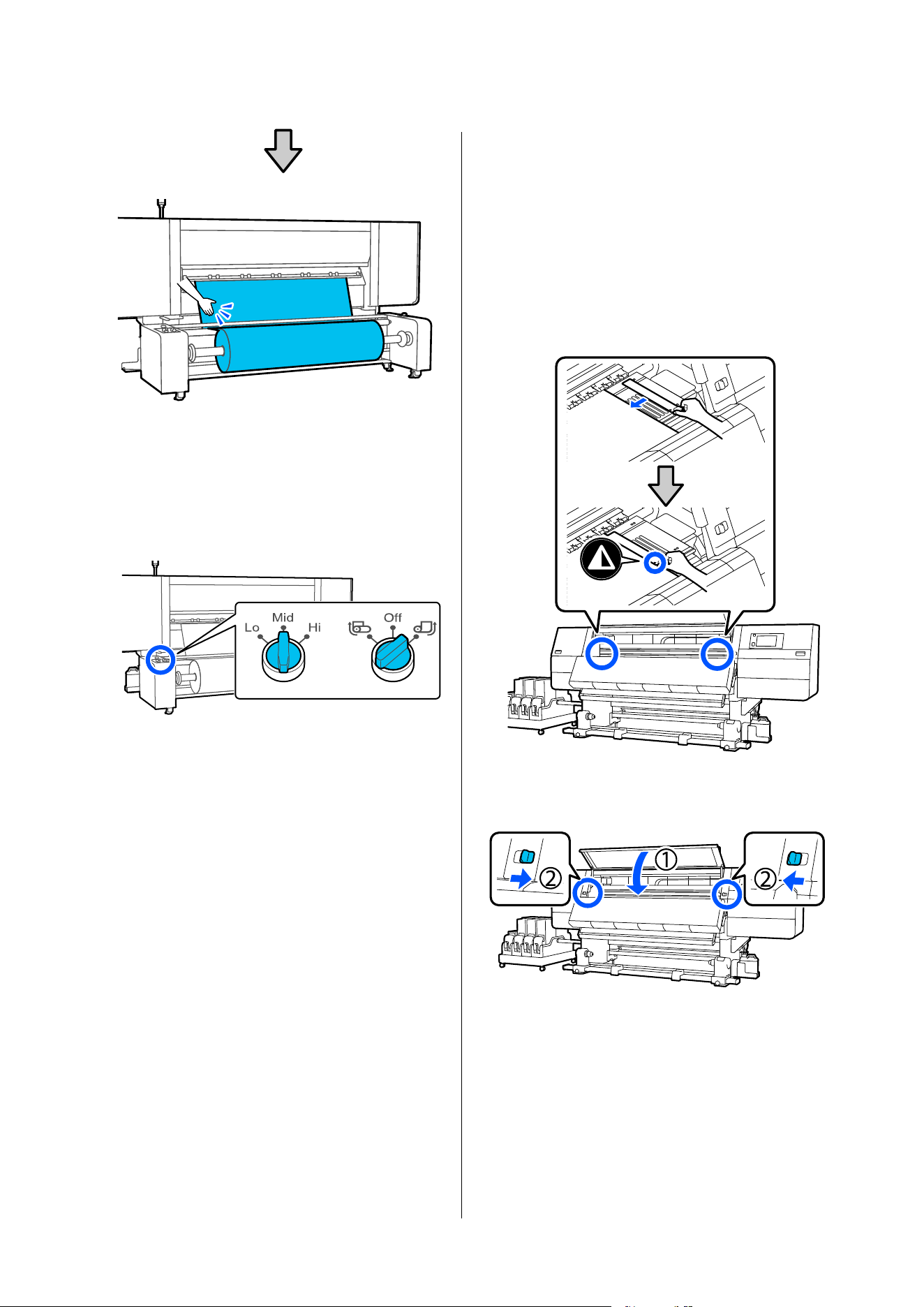
I
Confirm that the Auto switch and the load
switch on the media feeding unit are set
according to the loaded media.
The load switch is normally set to Mid. Switch
to Hi to increase tension if wrinkles appear in
the media during printing.
J
Move to the front side, and while holding the
tabs of the media edge plate on both sides,
move the plate to the top edge of the media.
Adjust so that the edges of the media are
aligned with the center of the triangular holes
in the media edge plates.
The media edge plates prevent the media from
riding up and keep fibers on the cut edge of the
media from touching the print head. Load
correctly.
K
Close the front cover, and then move the left
and right lock levers inward.
SC-F20000 Series/SC-F11000H Series/SC-F11000 Series/SC-F10000H Series/SC-F10000 Series User's Guide
Basic Operations
126
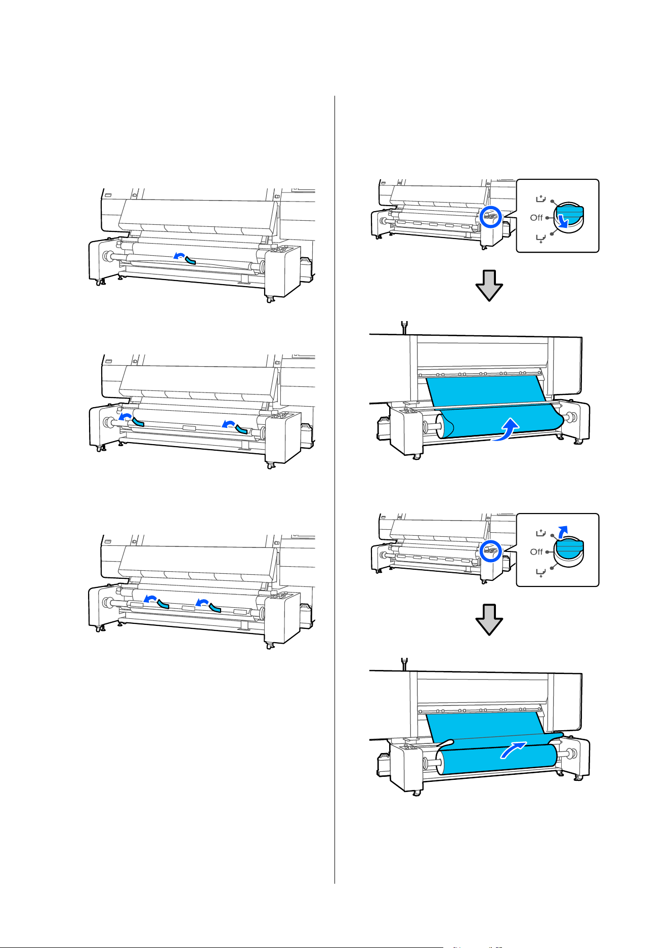
Attaching media to the roll core - Printed side
out
A
Pull the center section of the leading edge of the
media, and affix it to the roll core with
commercially available adhesive tape.
B
Attach the left and right ends.
C
Attach the section between the center and the
left and right ends.
D
Use the media feed switch to create enough
slack in the media for approximately two wraps
around the take-up roll core.
When the media is printable side in
When the media is printable side out
SC-F20000 Series/SC-F11000H Series/SC-F11000 Series/SC-F10000H Series/SC-F10000 Series User's Guide
Basic Operations
127
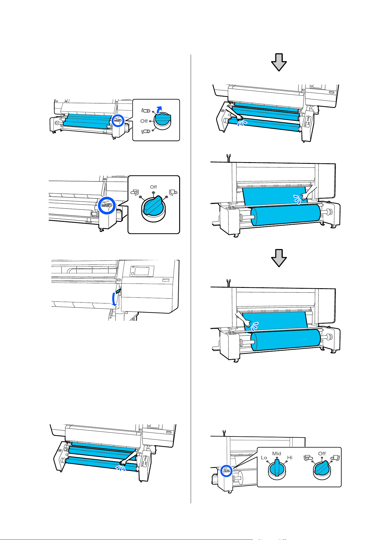
E
Use the Manual switch to take-up the slack
media around the core.
Turn the Manual switch in the take-up
direction.
F
Check that the Auto switch is set according to
the take-up direction.
G
Lower the media loading lever.
H
Confirm that the media is attached without
looseness on the front and back sides.
If the tension on the left and right of the media
is different, the media will not be taken up
correctly. If either side is loose, start again from
the procedure for attaching the media to the
roll core.
You can confirm differences in tension by
lightly tapping both edges of the media as
shown in the following illustration.
I
Confirm that the Auto switch on the media
feeding unit and the load switch are set
according to the loaded media.
The load switch is normally set to Mid. Switch
to Hi to increase tension if wrinkles appear in
the media during printing.
SC-F20000 Series/SC-F11000H Series/SC-F11000 Series/SC-F10000H Series/SC-F10000 Series User's Guide
Basic Operations
128
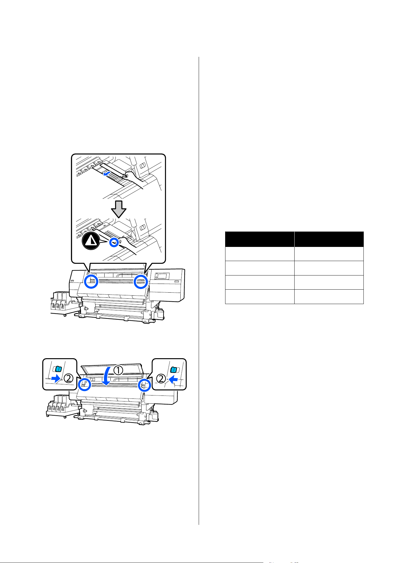
J
Move to the front side, and while holding the
tabs of the media edge plate on both sides,
move the plate to the top edge of the media.
Adjust so that the edges of the media are
aligned with the center of the triangular holes
in the media edge plates.
The media edge plates prevent the media from
riding up and keep fibers on the cut edge of the
media from touching the print head. Load
correctly.
K
Close the front cover, and then move the left
and right lock levers inward.
Setting the media information, load switch,
and heater temperature
The recommended settings for the load switch and the
temperature when using the large capacity type Auto
Take-up Reel Unit are shown in the following table.
U “Media Settings List for Each Media Type” on
page 271
A
Set the media information on the screen.
Do the following settings here.
❏ Media: Set the media to use for printing
❏ Media Length: Length of the loaded media
❏ Media Detection: How to detect the width of
the media
Media is set in the following way.
When there are no registered media settings
for the loaded media
First, select an unregistered number.
There is no Media Type set for an unregistered
number, so the screen to select Media Type
appears. Select the Media Type using the paper
weight of the loaded media as a guideline as
shown below. The paper weights of each Media
Type shown in the screen are typical values.
Media Type
Paperweight (g/m
2
)
Ultra-Thin 39 or under
Thin 40 to 56
Med-Thick 57 to 89
Thick 90 or over
When there are registered media
settings/EMX file is downloaded and
registered for the loaded media
Choose a registered media number.
In Media Detection, set Width Detection.
Normally, leave this On.
See the following for details about Media
Detection.
U “General Settings menu” on page 201
B
Press OK.
The printer starts detecting the loaded media
and performing related operations.
SC-F20000 Series/SC-F11000H Series/SC-F11000 Series/SC-F10000H Series/SC-F10000 Series User's Guide
Basic Operations
129
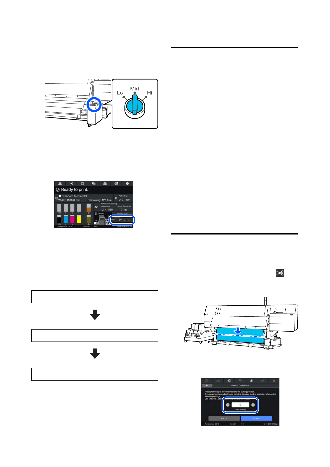
C
Check the load switch setting.
Check the table and set it according to the
media you are using.
D
Set the heater's temperature setting.
Check the current temperature setting from the
home screen, and if it differs from the
temperature setting in the table, reset it to the
temperature in the table.
Removing the Take-up
Roll
Follow the steps below when replacing the media.
1. Set Information Printing at Media Cut.
2. Cut the media.
3. Remove the media.
Setting Information Printing at
Media Cut
Setting Information Printing at Media Cut in
advance is useful because information that is helpful
when managing media is printed whenever media is
cut.
For example, when Paper Remaining Information is
turned On, the length of media that is remaining is
printed. By printing the remaining amount on the
media being removed, you can check this value the
next time the media is loaded and enter the media
length. This is useful for accurate management of the
amount of media remaining.
Additionally, when media cutting information is
printed, lines indicating the cutting position are also
printed, enabling precise cuts.
See the following for details about Information
Printing at Media Cut.
U “General Settings menu” on page 201
Cutting Media
Standard type auto take-up reel unit
A
On the control panel screen, press the and
then Forward.
The media is fed to the cut position.
If you want to adjust the cut position, change
the value of the position.
SC-F20000 Series/SC-F11000H Series/SC-F11000 Series/SC-F10000H Series/SC-F10000 Series User's Guide
Basic Operations
130
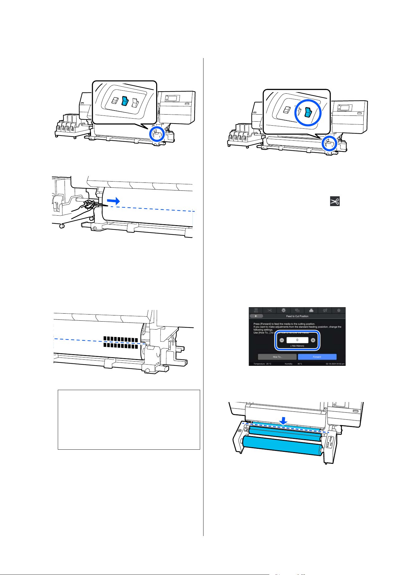
B
Set the Auto switch on the auto take-up reel
unit to Off.
C
Cut the media at the bottom of the media guide
bar using scissors.
When information, such as the remaining
amount of media, is printed, a line is printed at
the cut position. Print Information is printed
on the printed side of the cut position, and
Paper Remaining Information is printed on the
unused side, so cut along that line.
c
Important:
When you cut the media, check that it does
not rise up inside the front cover or has not
come free from the media edge plate before
printing.
D
Take up the cut media completely by operating
the Manual switch according to how the media
is rolled.
Large capacity type Auto Take-up
Reel Unit
A
On the control panel screen, press .
B
When printing media cutting information, set
the cut position to -60 mm on the screen.
If you want to adjust the cut position, change
the value of the position in the field shown in
the screen illustration.
Setting the cut position to -60 feeds the media
to a position where the line indicating the cut
position is easily visible.
C
Press Forward on the screen.
The media is fed to the cut position.
When the media has been fed, set the Auto
switch on the Auto Take-up Reel Unit to Off.
SC-F20000 Series/SC-F11000H Series/SC-F11000 Series/SC-F10000H Series/SC-F10000 Series User's Guide
Basic Operations
131
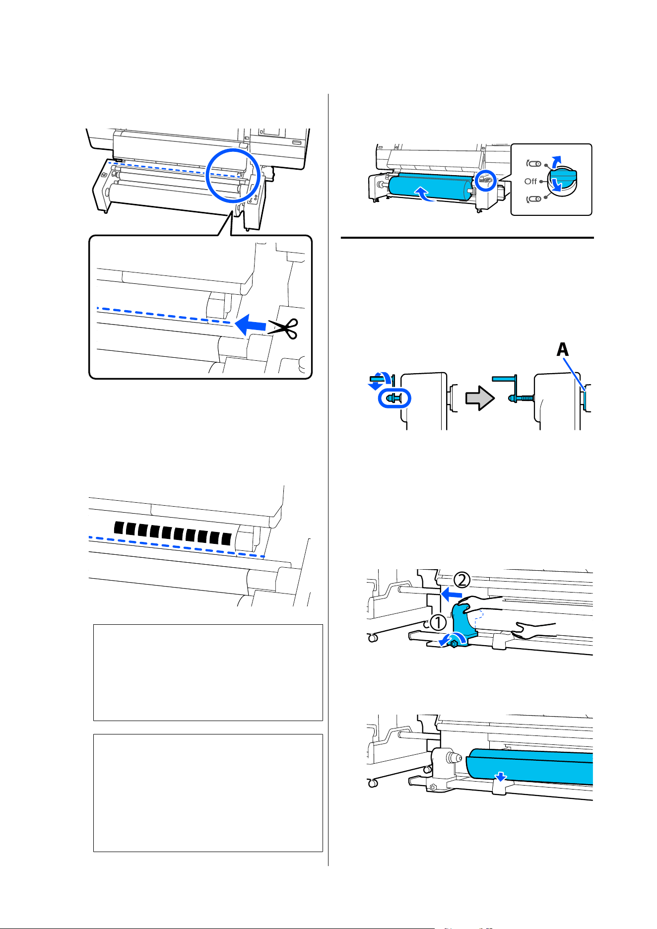
D
Cut the media at the bottom of the media guide
bar using scissors.
When information, such as the remaining
amount of media, is printed, a line is printed at
the cut position. Print Information is printed
on the printed side of the cut position, and
Paper Remaining Information is printed on the
unused side, so cut along that line.
c
Important:
When you cut the media, check that it does
not rise up inside the front cover or has not
come free from the media edge plate before
printing.
Note:
If you use the media feed switch to feed or take-up
the media after feeding it to the cut position, the
tension bar will rise and apply tension to the
media.
In this case, press the Release button to lower the
tension bar before cutting the media.
E
Take up the cut media completely by operating
the Manual switch according to how the media
is rolled.
Removing the Media
Standard type auto take-up reel unit
A
Rotate the left media holder handle to the far
side until it stops.
The part A on the illustration and the shaft of
the handle will be visible.
B
To prevent the media from sliding off the roll,
support the roll at its left end.
C
Loosen the left media holder fixing screw and
remove the media holder.
D
Lower the roll onto the roll support.
SC-F20000 Series/SC-F11000H Series/SC-F11000 Series/SC-F10000H Series/SC-F10000 Series User's Guide
Basic Operations
132
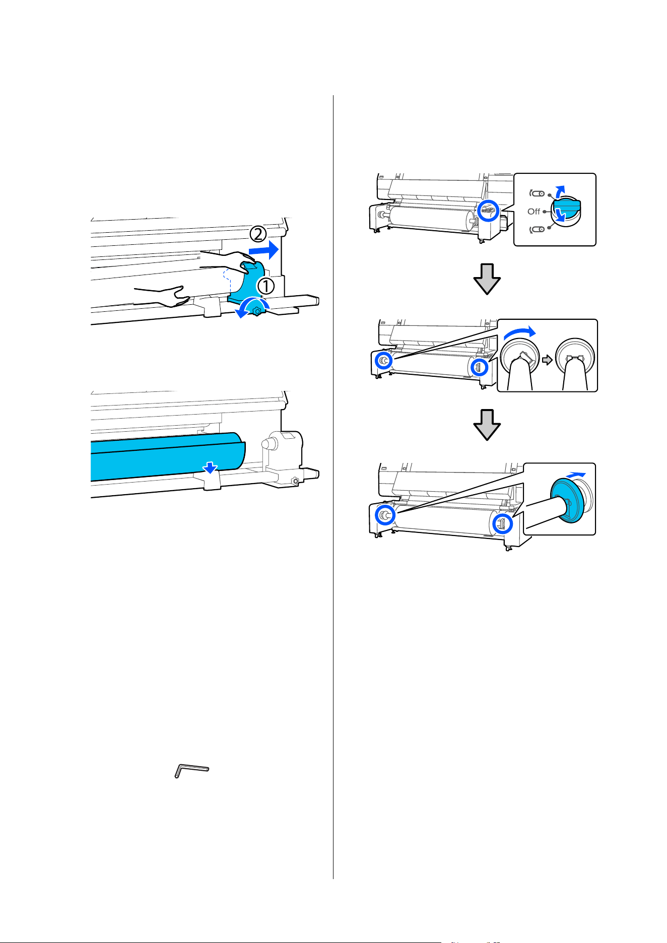
Be careful not to trap your hands between the
roll and the roll support.
E
To prevent the media from sliding off the roll,
support the roll at its right end.
F
Loosen the right media holder fixing screw and
remove the media holder.
G
Lower the roll onto the roll support.
Be careful not to trap your hands between the
roll and the roll support.
Large capacity type Auto Take-up
Reel Unit
Necessary items
Lifter (available in the market)
Use this to transport media. Prepare a lifter with a
load capacity greater than the combined weight of the
media and spindle to be loaded.
Hex wrench (small) (included only with models with
type B gap adjustment screws)
How to remove
A
Use the Manual switch to rotate the spindle to
face as shown in the illustration, then lower the
handles on both sides outward.
If you have not closed the gaps at the ends of
the spindle, go to step 3.
B
If you have closed the gaps at the ends of the
spindle, turn the screw inside the handle on the
opposite side to where the spindle was moved
clockwise until it stops.
The explanation here uses media with printable
side in as an example.
SC-F20000 Series/SC-F11000H Series/SC-F11000 Series/SC-F10000H Series/SC-F10000 Series User's Guide
Basic Operations
133
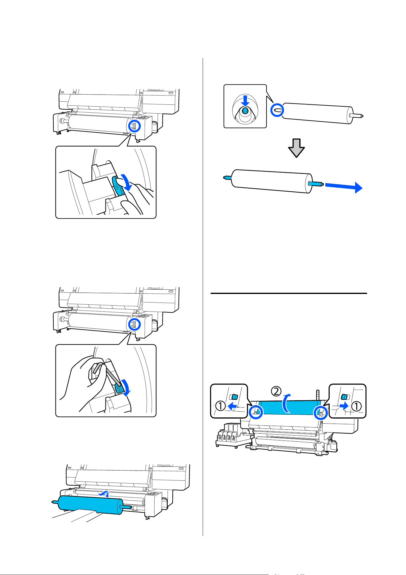
Type A gap adjustment screw
Turn the s crew by hand.
Type B gap adjustment screw
Insert a hex wrench into the gap between the
handle and the spindle, and slowly turn the
screw while hooking the tip of the hex wrench
onto the side of the screw head.
C
Remove the roll.
Make sure the tip of the lifter does not hit the
unit.
D
Press on the center of the valve to release the air
in the spindle, then remove the spindle.
Removing the Loaded
Media
Follow the steps below when removing the media that
is loaded on the back side during replacement and so
on.
Removing from the standard
type Media Feeding Unit
A
Cut the media.
U “Cutting Media” on page 130
B
Move the lock levers on the left and right side
outwards to open the front cover.
SC-F20000 Series/SC-F11000H Series/SC-F11000 Series/SC-F10000H Series/SC-F10000 Series User's Guide
Basic Operations
134
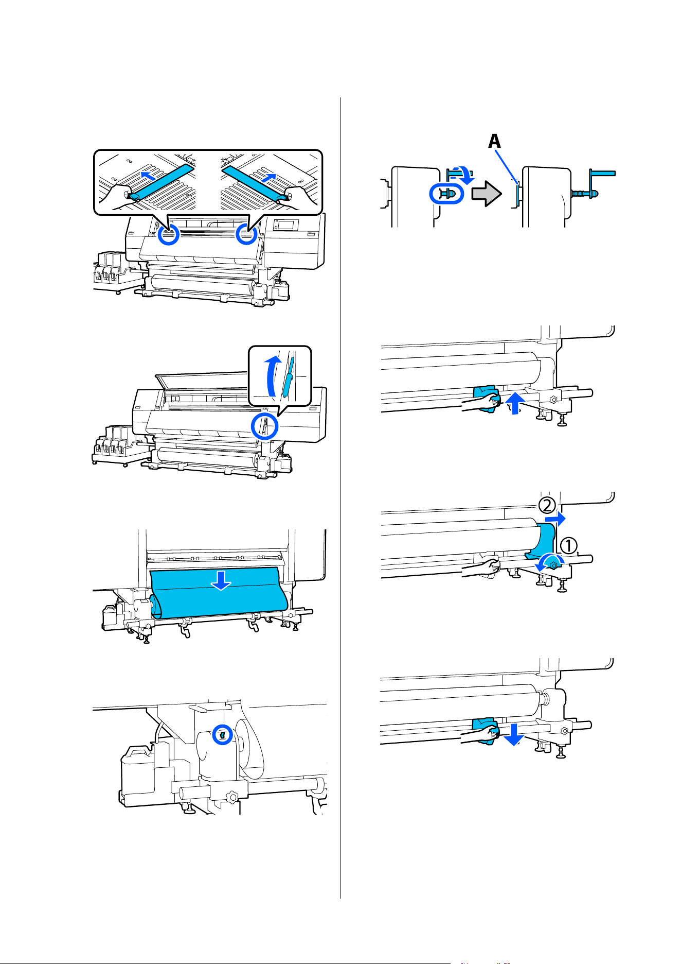
C
While holding the tabs of the media edge plate
on both sides, move the plate out of the way
toward both edges of the platen.
D
Raise the media loading lever.
E
Move to the back side, and remove the media
toward the rear.
F
Take up the media by operating the drive
switch according to how the media is rolled.
G
Rotate the right media holder handle to the
near side until it stops.
The part A on the illustration and the shaft of
the handle will be visible.
H
To prevent the media from dropping, lift up the
right lift lever to support media.
I
Loosen the right media holder fixing screw and
remove the media holder.
J
Lower the lift lever and lower the media onto
the roll support.
SC-F20000 Series/SC-F11000H Series/SC-F11000 Series/SC-F10000H Series/SC-F10000 Series User's Guide
Basic Operations
135
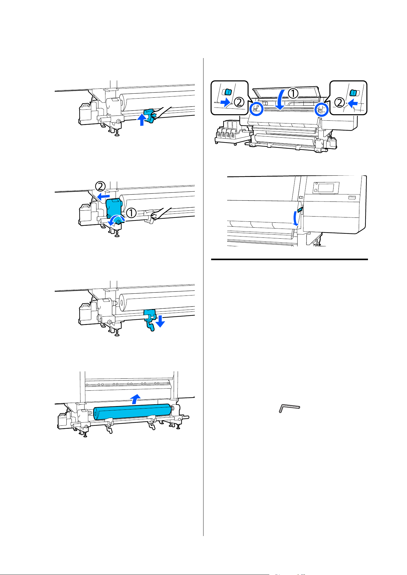
K
To prevent the media from dropping, lift up the
left lift lever to support media.
L
Loosen the left media holder fixing screw and
remove the media holder.
M
Lower the lift lever and lower the media onto
the roll support.
N
Remove the media.
If the weight of the media is 40 kg (88.18 lb.) or
more, then remove it using the lifter.
O
Close the front cover, and then move the left
and right lock levers inward.
P
Lower the media loading lever.
Removing from the large
capacity type Media Feeding
Unit
Necessary items
Lifter (available in the market)
Use this to transport media. Prepare a lifter with a
load capacity greater than the combined weight of the
media and spindle to be loaded.
Hex wrench (small) (included only with models with
type B gap adjustment screws)
How to remove
A
Cut the media.
U “Cutting Media” on page 130
SC-F20000 Series/SC-F11000H Series/SC-F11000 Series/SC-F10000H Series/SC-F10000 Series User's Guide
Basic Operations
136
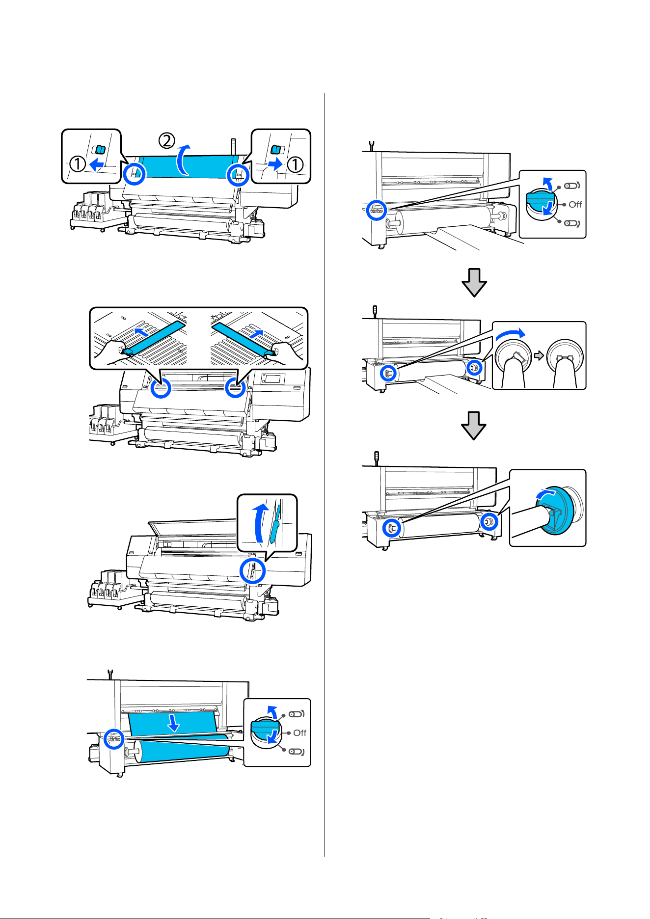
B
Move the lock levers on the left and right side
outwards to open the front cover.
C
While holding the tabs of the media edge plate
on both sides, move the plate out of the way
toward both edges of the platen.
D
Raise the media loading lever.
E
Move to the back side, and take up the media
by operating the Manual switch.
F
Use the Manual switch to rotate the spindle to
face as shown in the illustration, then lower the
handles on both sides outward.
G
If you have closed the gaps at the ends of the
spindle, turn the screw inside the handle on the
opposite side to where the spindle was moved
clockwise until it stops.
The explanation here uses the example of
media with the printable side out.
SC-F20000 Series/SC-F11000H Series/SC-F11000 Series/SC-F10000H Series/SC-F10000 Series User's Guide
Basic Operations
137
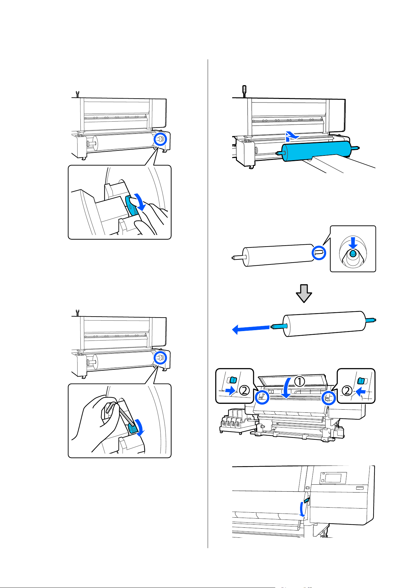
Type A gap adjustment screw
Turn the s crew by hand.
Type B gap adjustment screw
Insert a hex wrench into the gap between the
handle and the spindle, and slowly turn the
screw while hooking the tip of the hex wrench
onto the side of the screw head.
H
Remove the media.
I
Press on the center of the valve to release the air
in the spindle, then remove the spindle.
Use the tip of something hard to press on the
center of the valve.
J
Close the front cover, and then move the left
and right lock levers inward.
K
Lower the media loading lever.
SC-F20000 Series/SC-F11000H Series/SC-F11000 Series/SC-F10000H Series/SC-F10000 Series User's Guide
Basic Operations
138
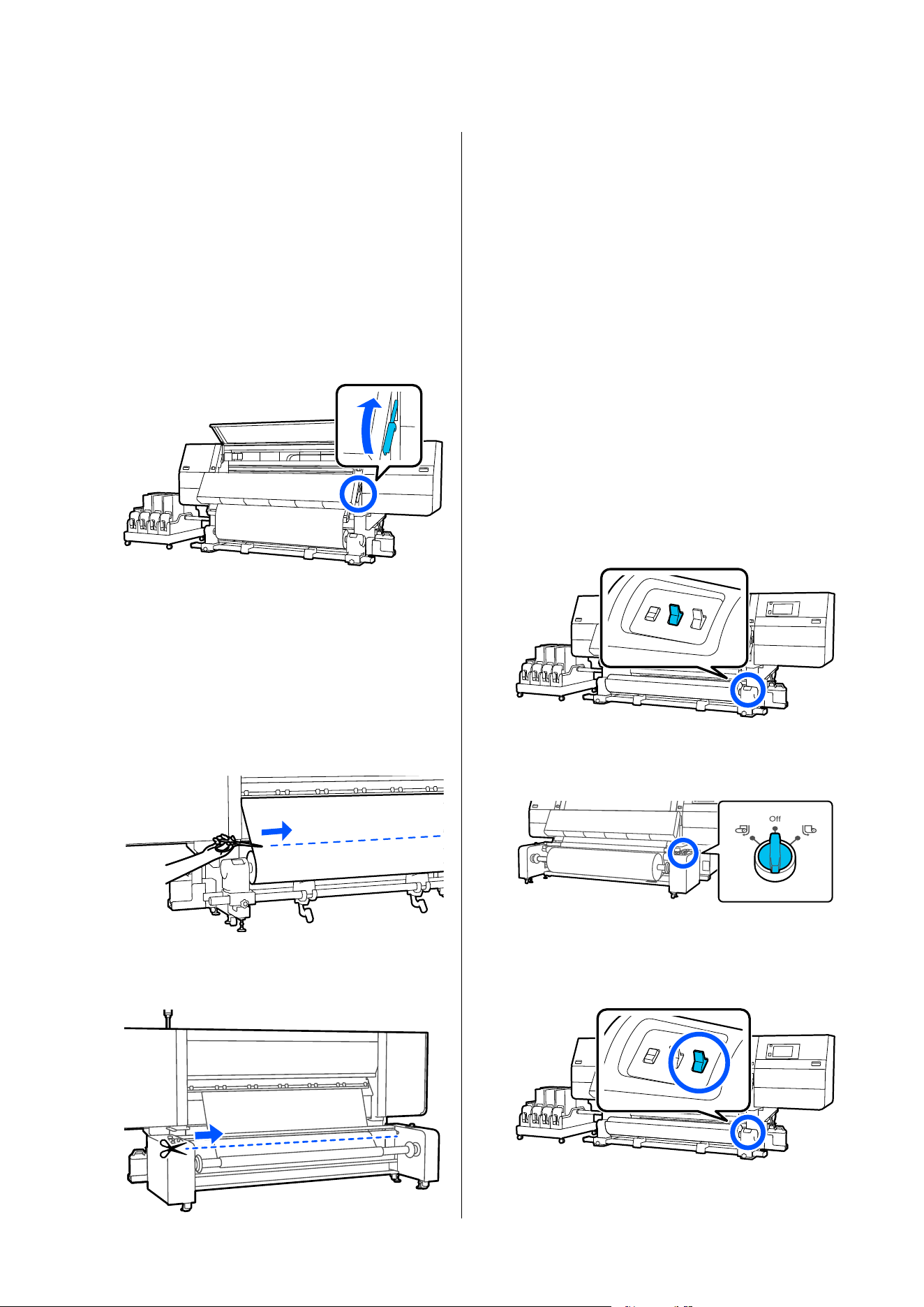
When the Remaining
Media Runs Out
When the remaining media runs out during printing,
a message is displayed on the display screen of the
control panel. Follow the on-screen instructions and
continue printing by replacing the media using the
following procedure.
A
Raise the media loading lever.
B
Move to the back side and check the condition
of the media.
If the media is affixed to the roll core, then cut
it apart using scissors as seen in the illustration,
and move on to the next procedure.
If it is not affixed, then move on to the next
procedure straight away.
For the standard type Media Feeding Unit
For the large capacity type Media Feeding
Unit
C
Follow the procedure below to remove the roll
core.
For the standard type Media Feeding Unit
Steps 6 to 14 in "Removing from the standard
type Media Feeding Unit"
U “Removing from the standard type Media
Feeding Unit” on page 134
For the large capacity type Media Feeding
Unit
Steps 6 to 9 in "Removing from the large
capacity type Media Feeding Unit"
U “Removing from the large capacity type
Media Feeding Unit” on page 136
D
Move to the front, and set the Auto switch on
the auto take-up reel unit to Off.
For the standard type Auto Take-up Reel Unit
For the large capacity Type Auto Take-up
Reel Unit
E
Take up the media completely by operating the
Manual switch as necessary.
For the standard type Auto Take-up Reel Unit
SC-F20000 Series/SC-F11000H Series/SC-F11000 Series/SC-F10000H Series/SC-F10000 Series User's Guide
Basic Operations
139
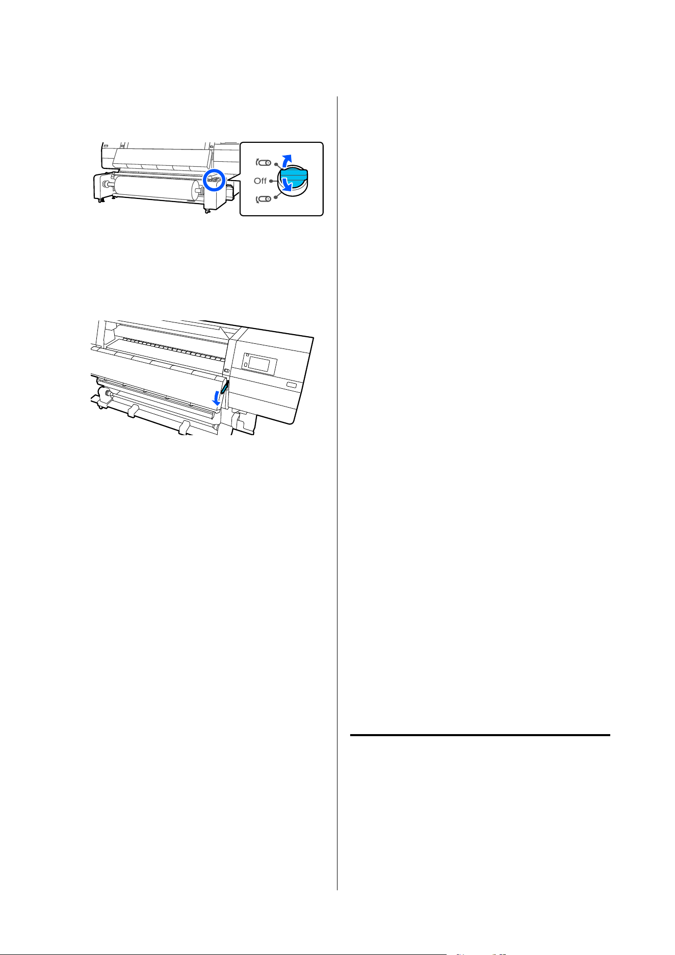
For the large capacity Type Auto Take-up
Reel Unit
F
Follow the procedure on "Removing Media" to
remove the roll.
U “Removing the Media” on page 132
G
Lower the media loading lever.
Follow the on-screen instructions to load a new
media, and attach it to the Auto Take-up Reel Unit to
resume printing.
U “Loading Media Into the Media Feeding Unit” on
page 81
U “Loading Media Into the Auto Take-up Reel Unit”
on page 99
Before Printing
To maintain print quality, perform the following
inspection before starting work each day.
Check the amount of ink remaining:
Check the amount of ink remaining, and replace the
old ink cartridge if ink is expended. If ink is expended
during printing, the printer automatically switches to
the other ink cartridge and continues printing.
You can replace the expended ink cartridge while
printing continues.
You can check the ink level on the Home screen. U
“Understanding and Operating the Display” on
page 27
Replacing Ink Cartridges U “Replacement
procedure” on page 168
Print head nozzle check
Perform a print head nozzle check to check for
clogged nozzles.
Perform print head cleaning if parts of the printed
pattern are faint or missing.
Print head nozzle check U “Printing nozzle check
patterns” on page 186
Head cleaning U “Print Head Cleaning” on page 186
Print Adjustments
Use this menu in the following cases.
Using new media not registered to the printer
Perform Automatic Adjustment after loading media
to the printer.
When banding or graininess is found in the print
results even after Automatic Adjustment is
performed
Perform Print Head Alignment and Media Feed
Adjustment manually.
When changing Advanced Settings after saving
media settings
When switching the load switch on the large
capacity type media feeding unit or auto take-up
reel unit
Automatic Adjustment
Print head position and media feed are adjusted while
printing the pattern.
The approximate maximum length of the media
required to print the test pattern is given below.
SC-F20000 Series/SC-F11000H Series/SC-F11000 Series/SC-F10000H Series/SC-F10000 Series User's Guide
Basic Operations
140

SC-F11000H Series/SC-F11000 Series/SC-F10000H
Series/SC-F10000 Series:
Approx. 600 mm (23.62 in.)
SC-F20000 Series:
Approx. 730 mm (28.74 in.)
A
Check that the printer is ready, and load the
media according to the actual usage conditions.
When using the Auto Take-up Reel Unit, attach
the media to the roll core.
U “Loading Media Into the Media Feeding
Unit” on page 81
U “Loading Media Into the Auto Take-up
Reel Unit” on page 99
B
Press , and then press in the order of Media
Settings - Print Adjustments - Automatic
Adjustment.
C
Press Start.
Auto adjust starts, and an adjustment pattern is
printed. Wait until adjustment is complete.
Print Head Alignment
Auto
The same adjustment as Print Head Alignment of
Automatic Adjustment is performed.
The approximate maximum length of the media
required to print the test pattern is given below.
SC-F11000H Series/SC-F11000 Series/SC-F10000H
Series/SC-F10000 Series:
Approx. 300 mm (11.81 in.)
SC-F20000 Series:
Approx. 430 mm (16.92 in.)
A
Check that the printer is ready, and load the
media according to the actual usage conditions.
When using the Auto Take-up Reel Unit, attach
the media to the roll core.
U “Loading Media Into the Media Feeding
Unit” on page 81
U “Loading Media Into the Auto Take-up
Reel Unit” on page 99
B
Press , and then press in the order of Media
Settings - Print Adjustments - Print Head
Alignment - Auto.
C
Press Start.
Auto adjust starts, and an adjustment pattern is
printed. Wait until adjustment is complete.
Manual
You c a n s e l e c t Manual(Simple) or Manual(Standard)
to make adjustments.
Manual(Simple)
Select this when Auto adjustment has failed or when
you want to perform quick and simple adjustment by
visually inspecting the pattern.
Manual(Standard)
Select this when you want to perform adjustment
equivalent to Auto adjustment by visually inspecting
the pattern.
The approximate maximum length of the media
required to print the test pattern is given below.
Manual(Simple): Approx. 50 mm (1.96 in.)
Manual(Standard): Approx. 150 mm (5.9 in.)
Adjustment Procedure
A
Check that the printer is ready, and load the
media according to the actual usage conditions.
When using the Auto Take-up Reel Unit, attach
the media to the roll core.
U “Loading Media Into the Media Feeding
Unit” on page 81
U “Loading Media Into the Auto Take-up
Reel Unit” on page 99
B
Press , and then press in the order of Media
Settings - Print Adjustments - Print Head
Alignment.
C
Select Manual(Simple) or Manual(Standard),
and then press Start.
An adjustment pattern is printed. Wait until
printing is complete.
SC-F20000 Series/SC-F11000H Series/SC-F11000 Series/SC-F10000H Series/SC-F10000 Series User's Guide
Basic Operations
141
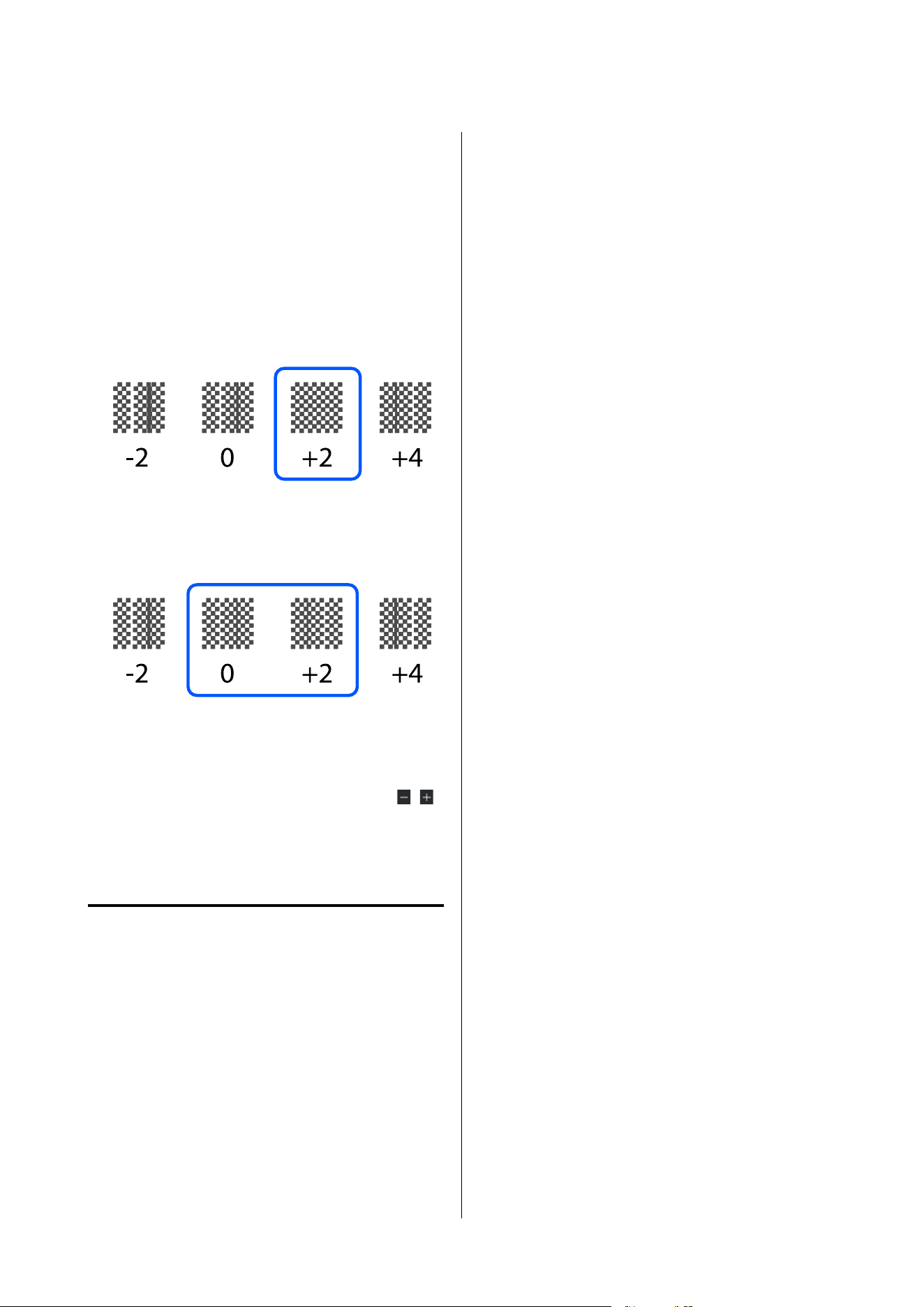
D
Check the printed adjustment pattern.
Adjustment pattern blocks are printed as shown
below according to the type of manual
adjustments.
Manual(Simple): 4 blocks, A to D
Manual(Standard): 31 blocks, A to Z and a to e
Select the pattern with the least tint unevenness
for each block.
Select “+2” in the cases shown below.
If there are patterns where unevenness is the
same, set an intermediate value in Step 5.
Set “+1” in the cases shown below.
E
The screen for entering confirmation results for
the adjustment pattern is displayed.
On the entry screen of each block, set the
number confirmed in Step 4 by pressing
/ ,
and then press OK.
The Media Settings menu is displayed when
you finish the adjustments.
Media Feed Adjustment
This menu is used when banding (horizontal banding,
tint unevenness, or stripes) is detected in printing
results.
You can select Auto or Manual to make adjustments.
Auto
You c a n s e l e c t Auto(Standard) or Auto(Details) to
make adjustments.
Auto(Standard)
Select this when you want to perform quick and
simple adjustment, such as for readjustment before the
roll is used up.
The same adjustment as Media Feed Adjustment of
Automatic Adjustment is performed.
Auto(Details)
Select this when you want to make highly precise
adjustments, such as for improving the print quality of
characters or ruled lines.
The approximate maximum length of the media
required to print the test pattern is given below.
Auto(Standard): Approx. 300 mm (11.81 in.)
Auto(Details):
SC-F11000H Series/SC-F11000 Series/SC-F10000H
Series/SC-F10000 Series:
300x600dpi 1.1pass : Approx. 450 mm
(17.71 in.)
300x600dpi 1.5pass : Approx. 450 mm
(17.71 in.)
300x600dpi 2.1pass : Approx. 300 mm
(11.81 in.)
300x600dpi 3.1pass : Approx. 200 mm
(7.87 in.)
600x600dpi 2.1pass : Approx. 300 mm
(11.81 in.)
600x600dpi 2.5pass : Approx. 250 mm
(9.84 in.)
600x600dpi 3.1pass : Approx. 200 mm
(7.87 in.)
600x600dpi 4.3pass : Approx. 200 mm
(7.87 in.)
600x1200dpi 5.0pass : Approx. 200 mm
(7.87 in.)
600x1200dpi 5.0pass HD : Approx. 200 mm
(7.87 in.)
SC-F20000 Series/SC-F11000H Series/SC-F11000 Series/SC-F10000H Series/SC-F10000 Series User's Guide
Basic Operations
142

1200x1200dpi 9.0pass HD : Approx. 150 mm
(5.90 in.)
SC-F20000 Series:
600x600dpi 1.0passHS : Approx. 450 mm
(17.71 in.)
600x600dpi 1.1passHS : Approx. 450 mm
(17.71 in.)
600x600dpi 1.5passHS : Approx. 450 mm
(17.71 in.)
600x600dpi 2.1passHS : Approx. 300 mm
(11.81 in.)
600x600dpi 1.1pass : Approx. 450 mm
(17.71 in.)
600x600dpi 1.5pass : Approx. 450 mm
(17.71 in.)
600x600dpi 2.1pass : Approx. 300 mm
(11.81 in.)
600x1200dpi 3.1pass : Approx. 200 mm
(7.87 in.)
1200x1200dpi 5.0pass HD : Approx. 200 mm
(7.87 in.)
A
Check that the printer is ready, and load the
media according to the actual usage conditions.
When using the Auto Take-up Reel Unit, attach
the media to the roll core.
U “Loading Media Into the Media Feeding
Unit” on page 81
U “Loading Media Into the Auto Take-up
Reel Unit” on page 99
B
Press , and then press in the order of Media
Settings - Print Adjustments - Media Feed
Adjustment.
C
Select Auto(Standard) or Auto(Details), and
then press Start.
Auto adjust starts, and an adjustment pattern is
printed. Wait until adjustment is complete.
Selecting Auto(Details) displays the pass mode
selection screen. Check that a pass mode to be
used for printing is selected, and then press OK.
Manual
You c a n s e l e c t Manual(Standard) or
Manual(Measurement) to make adjustments.
Manual(Standard)
Make a selection in the following cases.
❏ When Auto adjustment has failed
❏ When you want to perform quick and simple
adjustment by visually inspecting the pattern
Manual(Measurement)
Make a selection in the following cases.
❏ When Auto and Manual(Standard) adjustments
have failed
❏ When banding can be seen in the print results
even after doing the adjustments for
Manual(Standard)
❏ When it is difficult to check the patterns for
Manual(Standard) due to bleeding ink, etc.
❏ When you want to print with accurate length
The approximate maximum length of the media
required to print the test pattern is given below.
Manual(Standard): Approx. 100 mm (3.93 in.)
Manual(Measurement): Approx. 600 mm (23.62 in.)
Adjustment Procedure
A
Check that the printer is ready, and load the
media according to the actual usage conditions.
When using the Auto Take-up Reel Unit, attach
the media to the roll core.
U “Loading Media Into the Media Feeding
Unit” on page 81
U “Loading Media Into the Auto Take-up
Reel Unit” on page 99
SC-F20000 Series/SC-F11000H Series/SC-F11000 Series/SC-F10000H Series/SC-F10000 Series User's Guide
Basic Operations
143
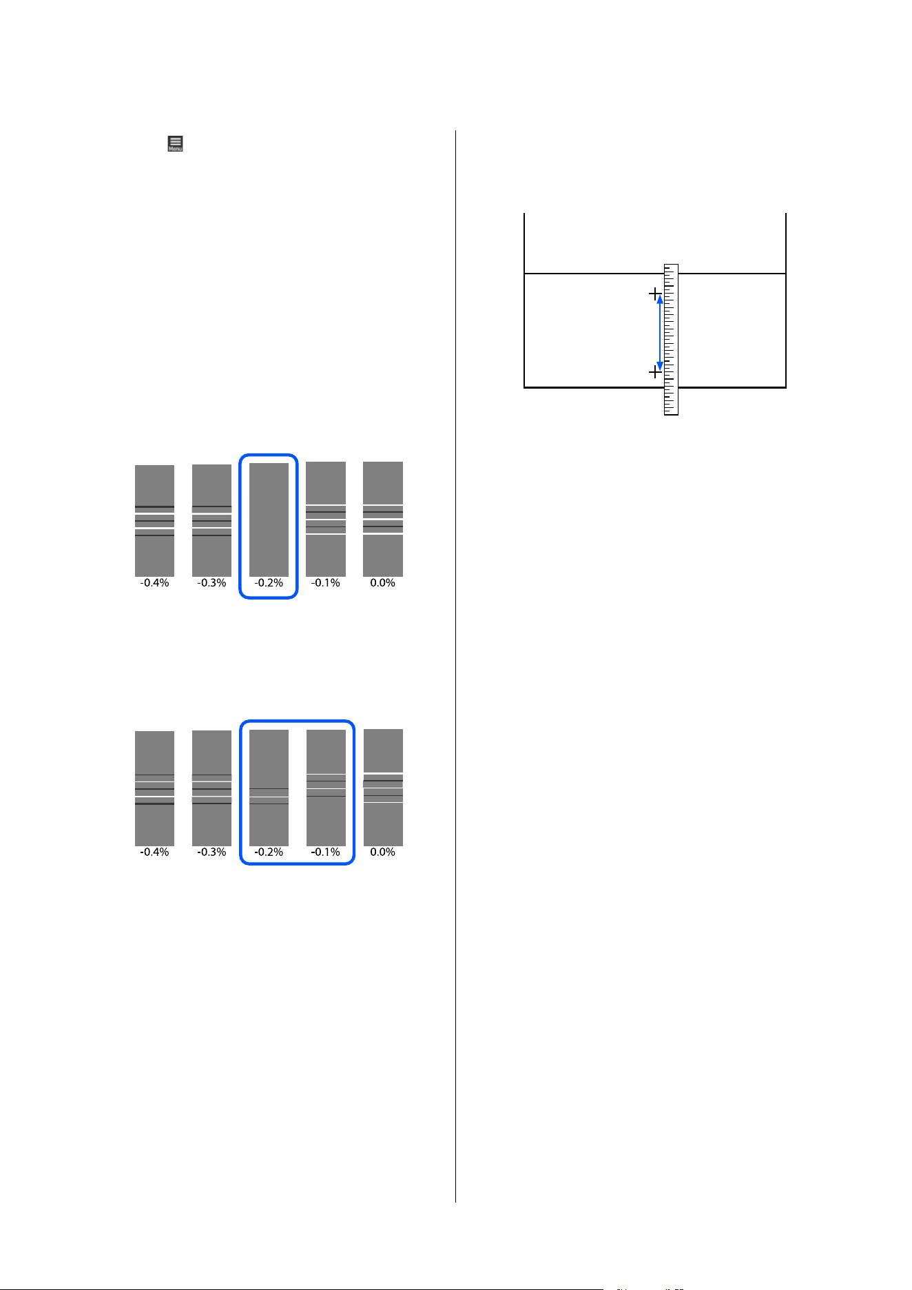
B
Press , and then press in the order of Media
Settings - Print Adjustments - Media Feed
Adjustment - Manual(Standard).
C
Press Start.
An adjustment pattern is printed. Wait until
printing is complete.
D
Check the printed adjustment pattern.
When Manual(Standard) is selected
Two groups of adjustment patterns, A and B,
are printed. Select the pattern with the least
amount of overlapping or gaps for each group.
Select “-0.2%” in the cases shown below.
If there are patterns where the overlapping or
gaps are the same, enter the middle value in
Step 5.
Enter “-0.15%” in the cases shown below.
If all of the adjustment patterns contain
overlaps or gaps, and you cannot narrow it
down to 1, select the pattern with the least
overlaps and gaps. Perform Steps 2 to 5 again,
and repeat them until a pattern with no
overlaps or gaps is printed.
If the pattern is difficult to check, such as if the
ink bleeds, input "0.0%" one time.
In this situation, the media feed is not adjusted.
Do the following steps to complete
Manual(Standard), and then perform
Manual(Measurement) again.
When Manual(Measurement) is selected
Measure the space between patterns using a
scale of up to 0.5 mm (0.02 in.).
E
The screen for entering confirmation results for
the adjustment pattern is displayed.
When Manual(Standard) is selected
Set the values printed under the patterns
selected in A and B, and then press OK.
When Manual(Measurement) is selected
Set the value measured in Step 4, and then press
OK.
When adjustments are complete, the Home
screen is displayed.
SC-F20000 Series/SC-F11000H Series/SC-F11000 Series/SC-F10000H Series/SC-F10000 Series User's Guide
Basic Operations
144
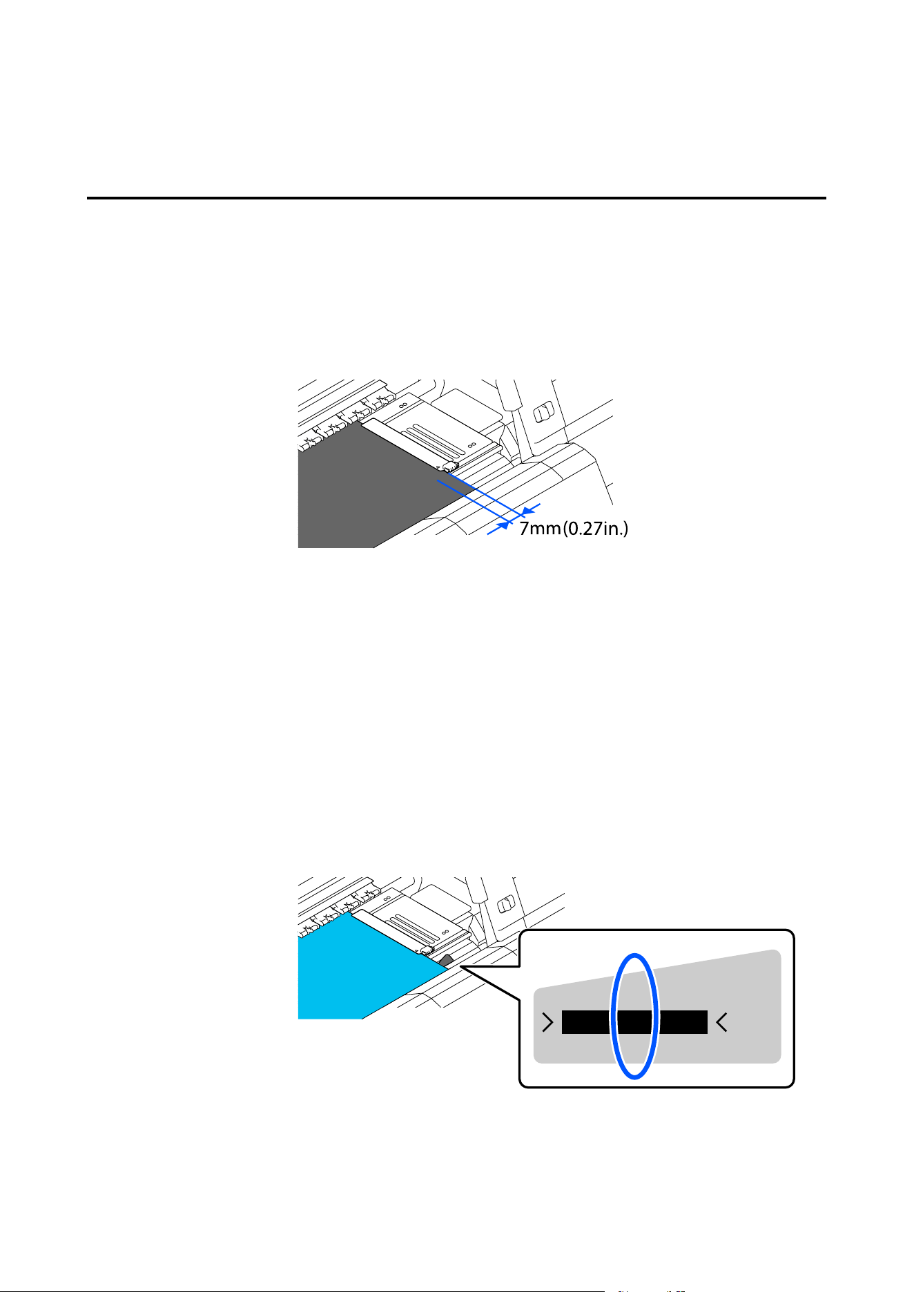
Printable Area
Width Detection and Media Edge Position
The media edge position recognized by the printer differs as follows depending on the Width Detection settings.
Width Detection On : The printer automatically detects the left and right edges of the loaded media.
When media edge plates are attached, the edge of the media is recognized as within 7
mm (0.27 in.) of the left and right edges of the media.
The edges of the media are not detected correctly if the media edge plates are not
attached correctly.
U “Loading Media Into the Media Feeding Unit” on page 81
U “Loading Media Into the Auto Take-up Reel Unit” on page 99
Width Detection Off : The center of the black rectangle on the label in front of the platen (shown in the
illustration below) is recognized as the media edge, which serves as the media width
reference position.
The printer recognizes the position at the value set when Width Detection is set to
Off, measured from the media width reference position, as the media edge for the
media width.
SC-F20000 Series/SC-F11000H Series/SC-F11000 Series/SC-F10000H Series/SC-F10000 Series User's Guide
Basic Operations
145
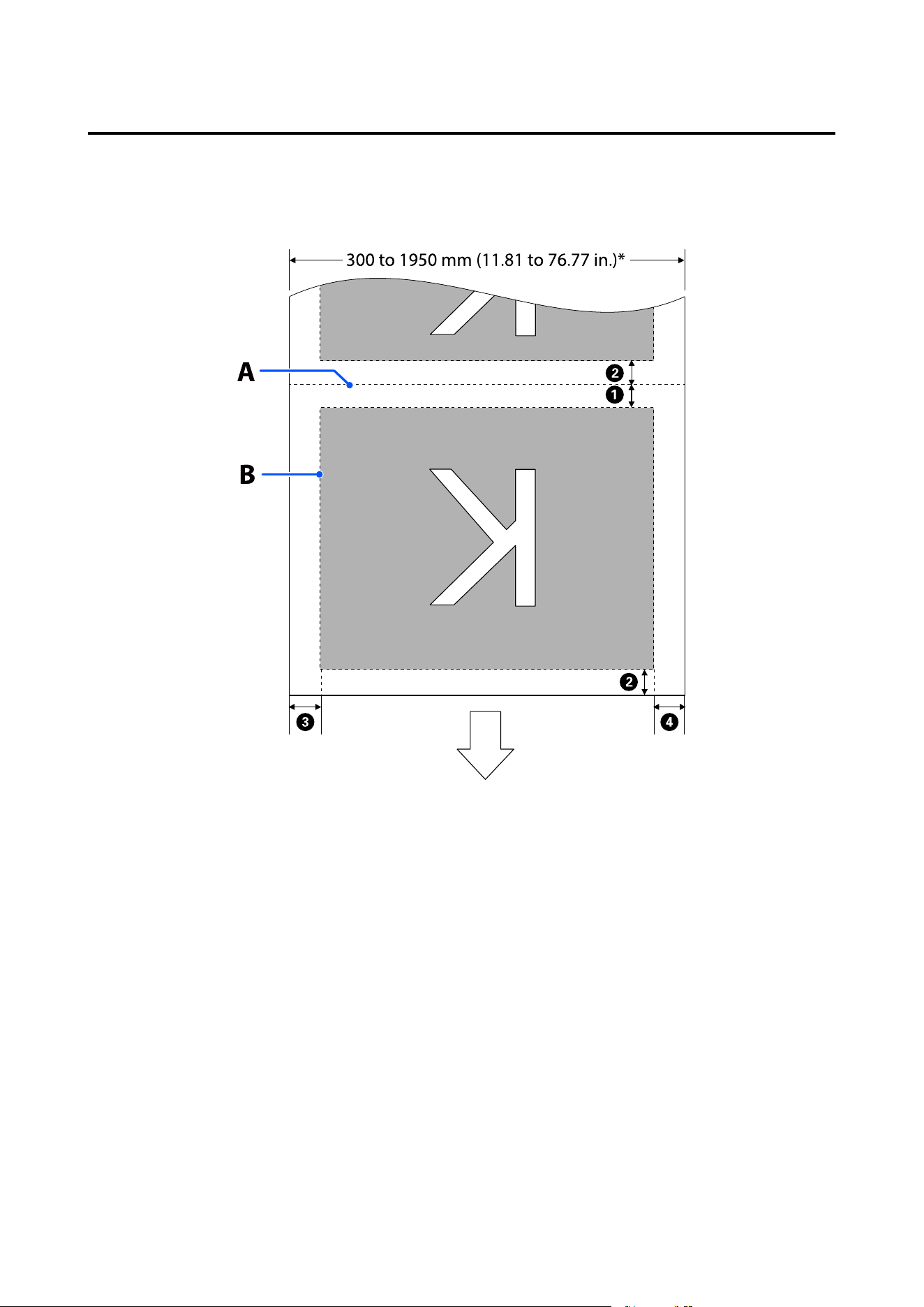
Printable area and image print area
❏ When not using the Information Printing function
As shown in the illustration, the printable area can be used as an image print area for all jobs.
SC-F20000 Series/SC-F11000H Series/SC-F11000 Series/SC-F10000H Series/SC-F10000 Series User's Guide
Basic Operations
146
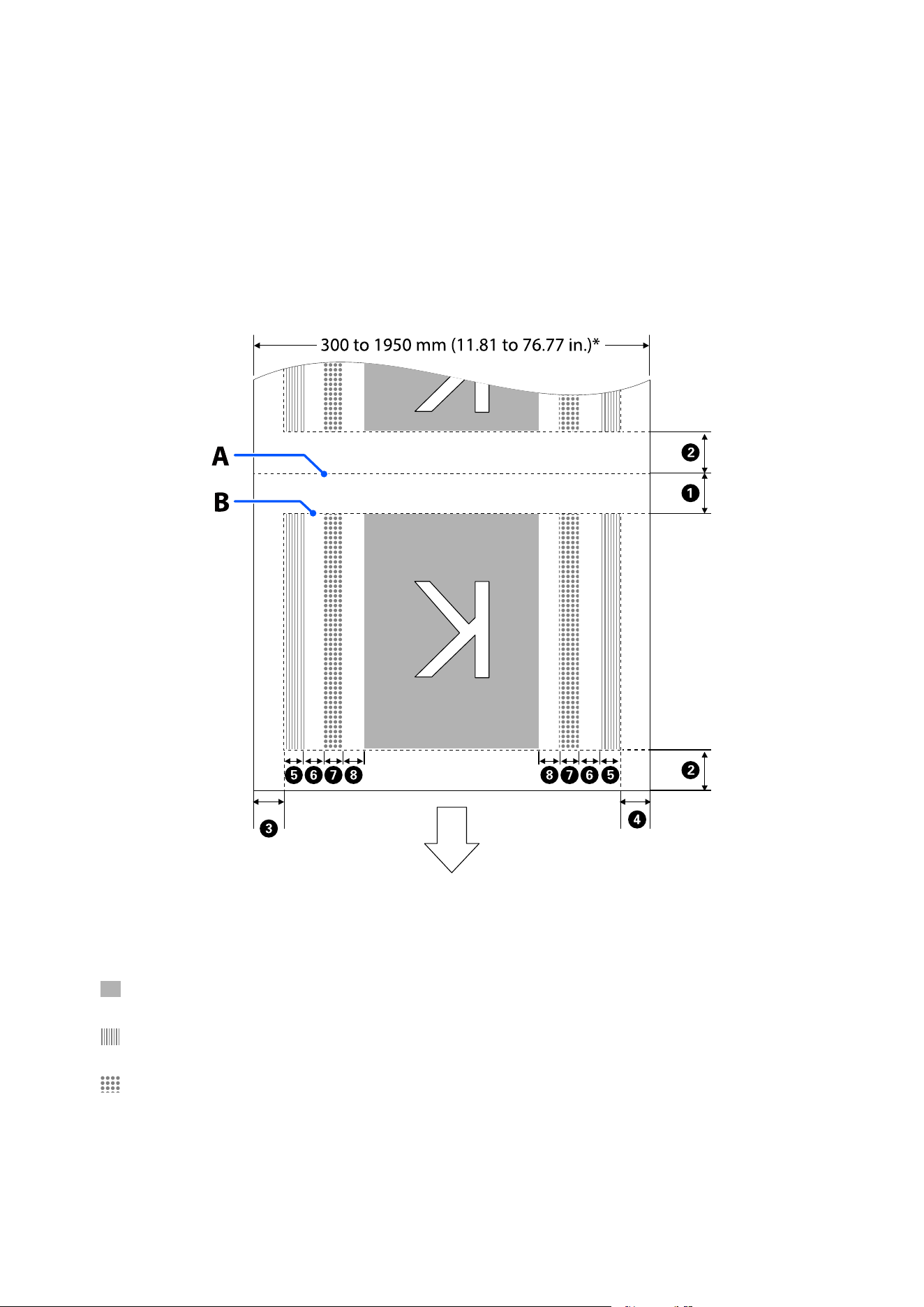
❏ When using the Information Printing function
As shown in the illustration, the size of the left and right sides of the image print area is reduced by the amount
of information to print.
Areas to be used to print information vary according to the settings. Here, an example of the smallest image
print area for the following settings is shown.
❏ Print position for the Event Marking of the Information Printing function: Left and right
❏ Print position for the nozzle check patterns of the Information Printing function: Left and right
A Media cut position
B Printable area
Image print area
Print area of nozzle check patterns
Event Marking area
SC-F20000 Series/SC-F11000H Series/SC-F11000 Series/SC-F10000H Series/SC-F10000 Series User's Guide
Basic Operations
147

*When Width Detection is set to Off, the set value (300 to 1950 mm [11.81 to 76.77 in.]) is applied.
The arrow indicates the feed direction.
The following shows the details for A to H.
Position Explanation Available
Setting
Range
A
*1, *3
Half the value selected for Margin Between Pages in the printer's setup
menu. To maintain media feeding accuracy, if the settings are less than 10
mm (0.39 in.), the settings are switched to 5 mm (0.19 in.).
5 to 499.5 mm
(0.19 to 19.66
in.)
B
*1, *2, *3
Half the value selected for Margin Between Pages.
If the settings are less than 10 mm (0.39 in.), the settings are switched to
“the setting -5”.
When Skip Wrinkled Media is set to On, the settings are switched to 300
mm (11.81 in.) if the settings are less than 600 mm (23.62 in.).
5 mm (0.19 in.)
or more
C
*3, *4
The value selected for Side(Right). The default setting is 7 mm (0.27 in.).
When media edge plates are used, a value to which 7 mm (0.27 in.) is added
is applied as the actual margin since within 7 mm of the edge is recognized
as the media edge.
3 to 25 mm
(0.11 to 0.98
in.)
D
*3, *4
The total of the values selected for Print Start Position and Side(Left).
The default setting for Print Start Position is 0 mm and Side(Left) is 7 mm
(0.27 in.).
When media edge plates are used, a value to which 7 mm (0.27 in.) is added
is applied as the actual margin since within 7 mm of the edge is recognized
as the media edge.
3 to 1025 mm
(0.11 to 40.35
in.)
E Nozzle check pattern printing width
16 mm (0.62 in.) when Normal is selected in Pattern Selection.
4 mm (0.15 in.) when Paper Width Saving is selected.
-
F Space between nozzle check patterns and Event Marking
Fixed to 3 mm (0.11 in.).
-
G Event Marking width
Fixed to 20 mm (0.78 in.).
-
H Space between nozzle check patterns / Event Marking and image
When Print Position is set to Next to the Image, the margin on the right
side of the image represents the value selected for Margin Between
Images.
When it is set to Media End, the value varies according to images and other
settings.
0 to 999 mm (0
to 39.33 in.)
*1 The set margin and the actual print results may differ depending on the RIP being used. Contact the RIP
manufacturer for more information.
*2 With Width Adjustment in the settings menu for the printer, you can adjust the margins in a range between
-10 mm and +10 mm (-0.39 in. and 0.39 in.).
SC-F20000 Series/SC-F11000H Series/SC-F11000 Series/SC-F10000H Series/SC-F10000 Series User's Guide
Basic Operations
148

*3 This may be available in the RIP depending on the RIP software being used. Contact the RIP manufacturer
for more information.
*4 Note the following points when setting margins.
❏ Leave margins of 10 mm (0.39 in.) or more when using media edge plates. Narrower margins could result in printer
printing over the plates.
❏ If the total of the print data width and set left and right margins exceeds the printable area, a portion of the data will
not be printed.
Note:
If the following points are not observed when Width Detection is Off, printing may occur outside the left and right edges
of the media. Ink used outside the edges of the media will stain the inside of the printer.
❏ Ensure that the print data width does not exceed the loaded media width.
❏ When media is loaded shifted toward the center from the media width reference position, set the amount of shift in
Print Start Position.
U “General Settings menu” on page 201
SC-F20000 Series/SC-F11000H Series/SC-F11000 Series/SC-F10000H Series/SC-F10000 Series User's Guide
Basic Operations
149
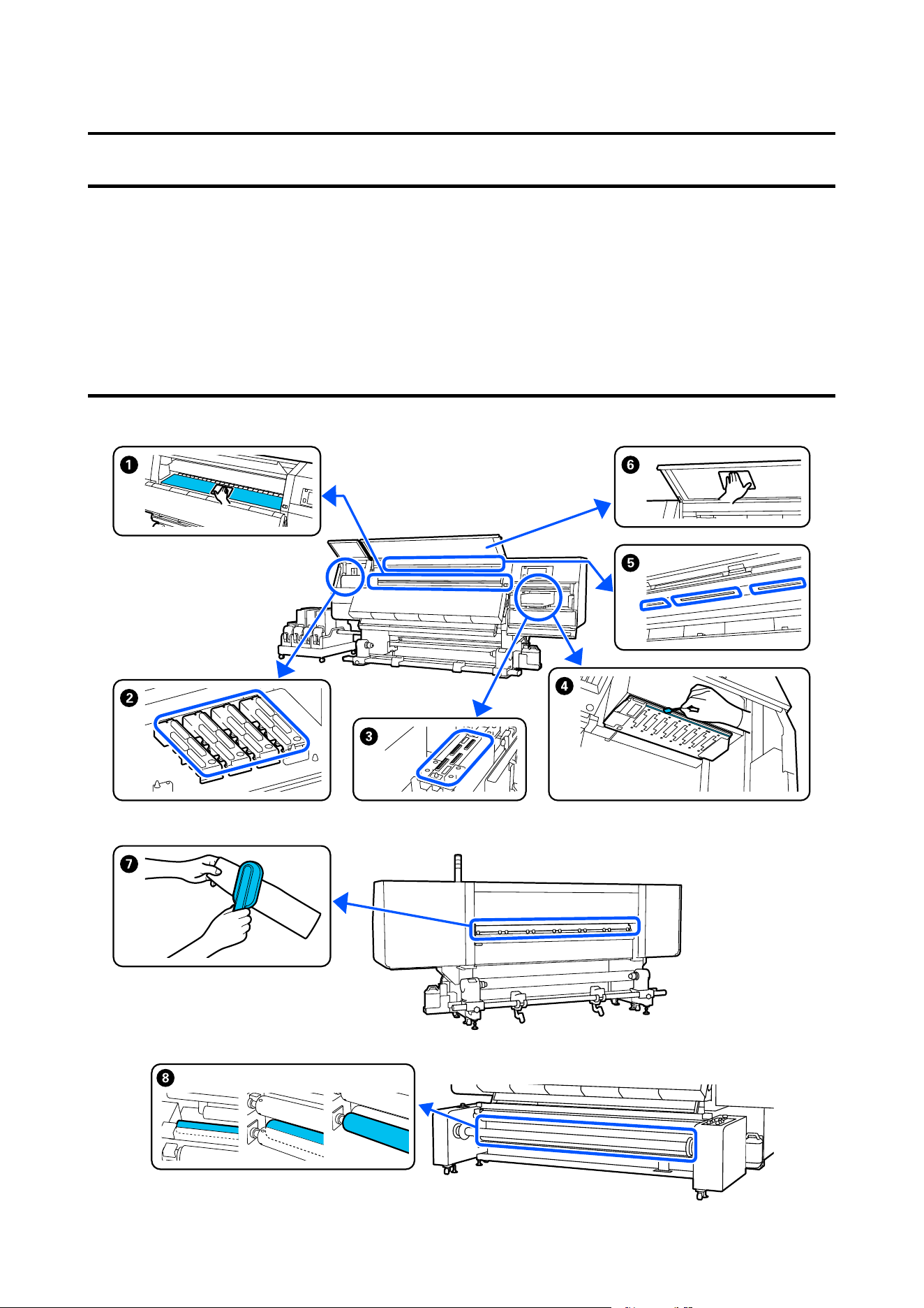
Maintenance
When to Perform Various Maintenance Operations
Cleaning and replacement of consumables must be performed to ensure the print quality of the printer.
Failure to perform appropriate maintenance could result in reduced print quality. Read the following to perform
appropriate maintenance.
Cleaning
SC-F20000 Series/SC-F11000H Series/SC-F11000 Series/SC-F10000H Series/SC-F10000 Series User's Guide
Maintenance
150

When to perform Component to be cleaned
When starting work every day A Platen, media edge plates, around dryer
H Roller
U “Daily cleaning” on page 155
When a cleaning message is displayed on
the control panel
B Anti-drying caps
U “Cleaning anti-drying caps” on page 160
You can check the procedure in a video on YouTube.
Epson Video Manuals
G Media cleaner
U “Cleaning the media cleaners” on page 159
When dirt is found on the print head in
the following cases
❏ Media jams
❏ Print head striking occurs
❏ Print results are dirty
D Around the print head
U “Cleaning around the print head” on page 164
You can check the procedure in a video on YouTube.
Epson Video Manuals
When it is hard to see inside the printer F Front cover
U “Cleaning the front cover” on page 167
When internal lamp seems to be dark E Internal lamp
U “Cleaning the inside light” on page 166
When executing Print Head Refresh C Cleaning suction caps
U “Cleaning the suction caps” on page 163
You can check the procedure in a video on YouTube.
Epson Video Manuals
SC-F20000 Series/SC-F11000H Series/SC-F11000 Series/SC-F10000H Series/SC-F10000 Series User's Guide
Maintenance
151
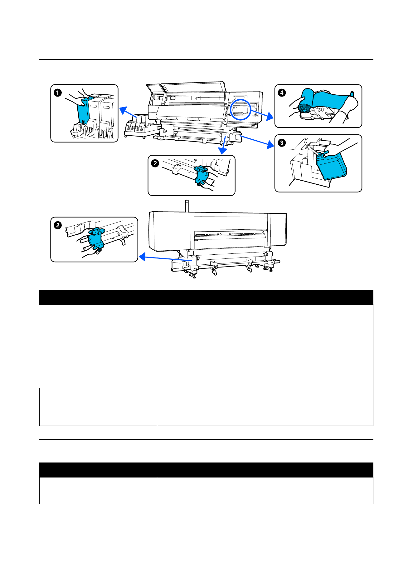
Replacing consumables
When to perform Component to be replaced
When ink low warning is displayed on the
control panel display
A Ink cartridges
U “Replacement procedure” on page 168
When a prepare and replacement
message is displayed on the control
panel screen
C Waste ink bottle
U “Disposing of waste ink” on page 175
D Wiper roll
U “Replacing the wiper roll” on page 173
When a prepare and replacement
message is displayed on the control
panel screen (Standard roll/Reel models,
Large capacity roll models only)
B Media holder
U “Replacing the media holder” on page 177
Other maintenance
When to perform Operation
When a shake message is displayed on
the control panel screen
Shaking ink cartridges
U “Periodic shaking of ink cartridges” on page 181
SC-F20000 Series/SC-F11000H Series/SC-F11000 Series/SC-F10000H Series/SC-F10000 Series User's Guide
Maintenance
152

When to perform Operation
❏ When checking if nozzles are
clogged
❏ When checking which colors are
clogged
❏ Horizontal stripes or tint unevenness
(banding) have appeared
Checking for clogged nozzles
U “Checking for clogged nozzles” on page 185
When a clog is found after checking for
clogged nozzles
Cleaning the print head
U “Print Head Cleaning” on page 186
Once a month Checking the circuit breaker’s performance
U “Checking the circuit breaker’s performance” on page 187
SC-F20000 Series/SC-F11000H Series/SC-F11000 Series/SC-F10000H Series/SC-F10000 Series User's Guide
Maintenance
153
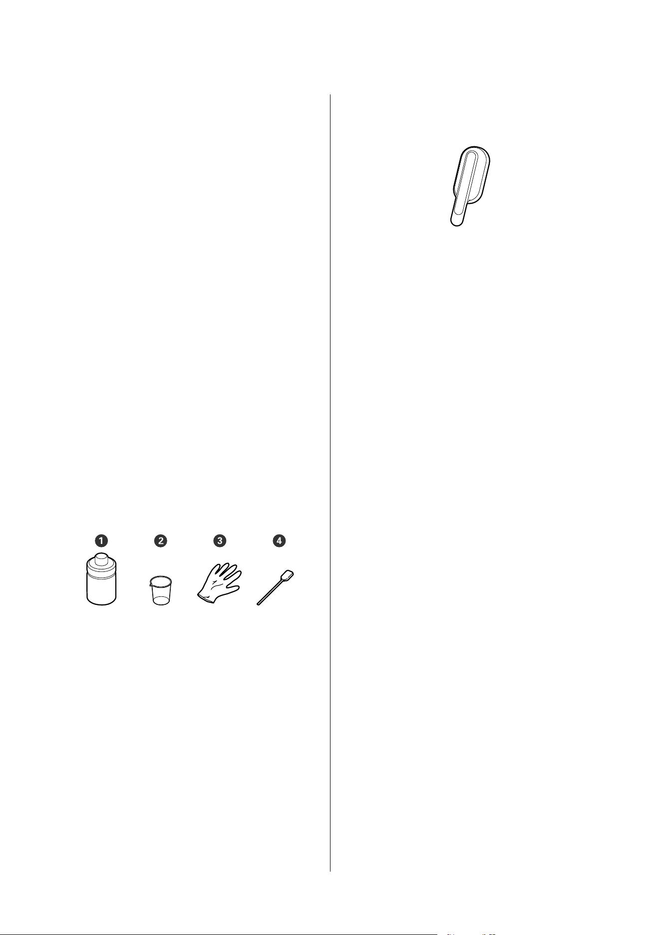
Necessary Items
Ready the following items before beginning cleaning
and replacement.
When the supplied parts have been completely used,
purchase new consumables.
Prepare genuine parts when replacing ink cartridges
or performing maintenance.
U “Options and Consumable Products” on page 231
If your gloves have worn out, prepare commercially
available nitrile gloves.
Protective eyeglasses (available in the market)
Protects your eyes from ink and cleaning fluid.
Mask (available in the market)
Protects your nose and mouth from ink and cleaning
fluid.
Cleaning kit (supplied with the printer)
Use these when wiping up ink stains.
The following accessories are in the kit.
A Cleaning fluid (x1)
B Cup (x1)
C Gloves (x16)
D Cleaning stick (x50)
How to use U “Using Cleaning liquid” on page 159
Metal or plastic (PP or PE) tray (available in the
market)
Use when putting cleaning utensils, removed
consumables, or cleaning fluid moved to the container
supplied with the printer.
Media Cleaner Brush (supplied with the printer)
Use when cleaning with media cleaner.
Soft cloth (available in the market)
Use when cleaning inside the front cover and the
bottom of the dryer. Use material that is not likely to
generate lint or static electricity.
Precautions Regarding
Maintenance
Note the following points when cleaning and replacing
parts.
SC-F20000 Series/SC-F11000H Series/SC-F11000 Series/SC-F10000H Series/SC-F10000 Series User's Guide
Maintenance
154
Caution:
❏ Store ink cartridge, cleaning fluid, and waste
ink in a location out of the reach of children.
❏ During maintenance, wear protective clothing,
including protective eyewear, gloves, and a
mask.
If ink, waste ink, cleaning fluid, or grease
contacts your skin or enters your eyes or
mouth, take the following actions:
❏ If fluid adheres to your skin, immediately
wash it off using large volumes of soapy
water. Consult a physician if the skin
appears irritated or is discolored.
❏ If fluid enters your eyes, rinse immediately
with water. Failure to observe this
precaution could result in bloodshot eyes
or mild inflammation. If problems persist,
consult with a physician.
❏ If fluid enters your mouth, consult a
physician immediately.
❏ If fluid is swallowed, do not force the
person to vomit, and consult with a
physician immediately. If the person is
forced to vomit, fluid may get caught in
the trachea which can be dangerous.
❏ Do not drink the ink.
❏ Remove the media from the printer before
proceeding with cleaning or replacing the media
holder.
❏ Never touch the belts, circuit boards, or any parts
that do not require cleaning. Failure to observe
this precaution could result in malfunction or
reduced print quality.
❏ Use only the supplied cleaning sticks or sticks
contained in a maintenance kit. Other types of
sticks that produce lint will damage the print
head.
❏ Always use fresh cleaning sticks. Re-using sticks
can make stains even harder to remove.
❏ Do not touch the tips of the cleaning sticks. Oil
from your hands could damage the print head.
❏ Do not use anything other than the specified
cleaning fluid when cleaning around the print
head, caps, etc. Using anything else could result in
malfunction or reduced print quality.
❏ Touch a metallic object before starting work to
discharge any static electricity.
Cleaning
Daily cleaning
When lint, dust, or ink adheres to the platen or the
media edge plates, it could cause clogged nozzles or
ink drops to occur.
Dirt on the media path around the dryer could make
the printouts dirty.
To maintain optimum printing quality, we
recommend cleaning before starting work every day.
Caution:
❏ The dryer may be hot; observe all necessary
precautions. Failure to observe the necessary
precautions could result in burns.
❏ Do not put your hand inside the dryer. Failure
to observe the necessary precautions could
result in burns.
❏ Be careful not to trap your hands or fingers
when opening or closing the front cover or the
maintenance cover. Failure to observe these
precautions could result in injury.
A
Make sure the printer is turned off and the
screen has turned off, and then unplug the
power cable from the outlet.
Unplug both power plugs from the printer.
If you are using a large capacity reel model, also
turn off the auto take-up reel unit and unplug
the power plug from the outlet.
B
Wait for one minute after unplugging the power
plug.
SC-F20000 Series/SC-F11000H Series/SC-F11000 Series/SC-F10000H Series/SC-F10000 Series User's Guide
Maintenance
155
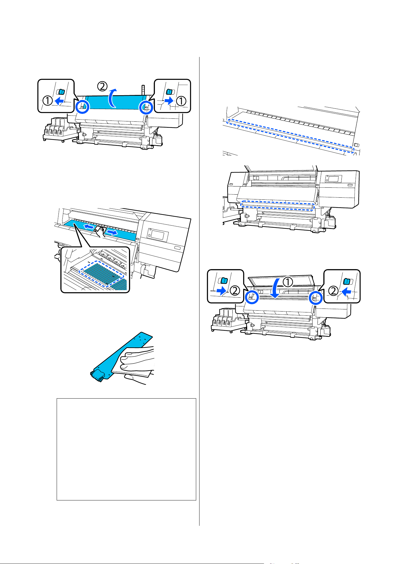
C
Move the lock levers on the left and right side
outwards to open the front cover.
D
Soak a soft cloth in water, wring it out
thoroughly, and then wipe off any ink, lint, or
dust that has adhered to the platen.
Carefully remove lint and dust stuck in the
groove of the platen.
E
Soak a soft cloth in water, wring it out
thoroughly, and then wipe off any lint, or dust
that has adhered to the media edge plates.
c
Important:
When media with glue has been used or
when ink has adhered to the media edge
plates, follow the procedure in the “Cleaning
the media edge plates when media with glue
has been used or when ink has adhered” in
the next section to clean the front and back of
the plates. If you continue printing while glue
is stuck to the rear, it may rub against the
print head.
F
Soak a soft cloth in water, wring it out
thoroughly, and then wipe off any ink, lint, or
dust that has adhered to the upper and lower
parts of the dryer.
Wipe the area shown in the illustration below.
G
After wiping off stains, close the front cover
and move the left and right lock levers inwards.
SC-F20000 Series/SC-F11000H Series/SC-F11000 Series/SC-F10000H Series/SC-F10000 Series User's Guide
Maintenance
156
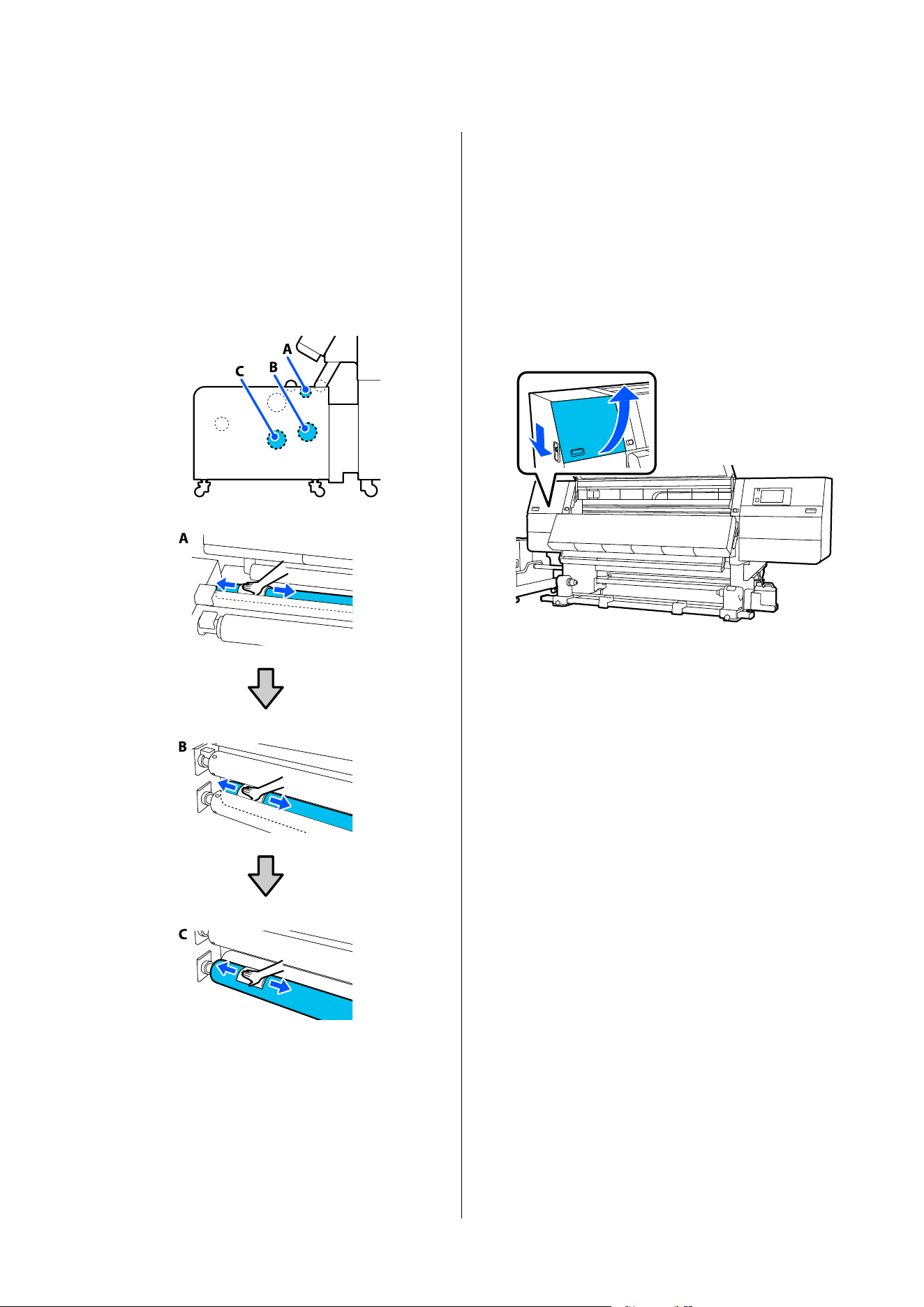
H
If you are using a large capacity reel model,
check that there are no stains on the roller
surfaces at points A, B, and C shown in the
illustration.
If there are stains, soak a soft cloth in water,
wring it out thoroughly, and then wipe away
any stains. When wiping, rotate the rollers by
hand to wipe the dirt from the entire
circumference.
I
Plug all power plugs for the printer into outlets
and turn on the power.
If you are using a large capacity reel model,
turn on the auto take-up reel unit first, and
then turn on the printer.
Cleaning the media edge plates when media with
glue has been used or when ink has adhered
Remove the media edge plates from the printer, and
clean the front and back of the plates using a diluted
neutral detergent.
When stains are removed, attach the plates to their
original positions.
A
Open the left-side maintenance cover while
lowering the lock release levers.
SC-F20000 Series/SC-F11000H Series/SC-F11000 Series/SC-F10000H Series/SC-F10000 Series User's Guide
Maintenance
157
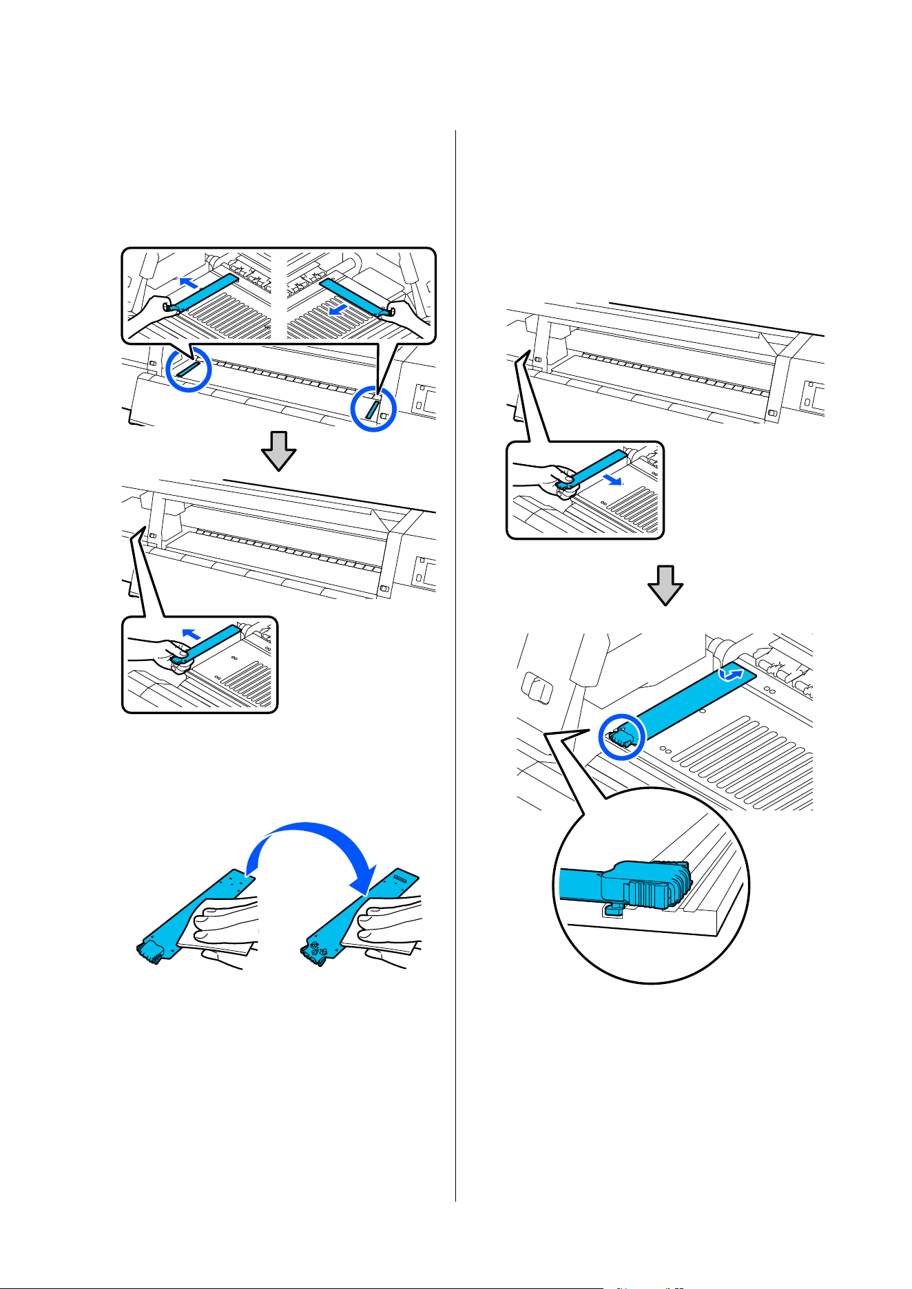
B
While holding the tabs of the media edge plate
on both sides, move the plate to the left edge of
the platen to remove it.
Remove the right media edge plate also from
the left side.
C
Soak a soft cloth in diluted neutral detergent,
wring it out thoroughly, and then wipe off any
glue or ink that has adhered to the front and
back of the media edge plates.
D
After wiping off stains, insert the media edge
plate from the left side of the platen.
Insert the right media edge plate also from the
left side.
When inserting the plate, attach the hooked
sections to the front corner of the platen while
pressing the tip of the metallic plate against the
platen.
E
Check that two hooked sections at the rear of
the media edge plate are securely applied as
shown below and that they are attached with no
gap between the platen and media edge plate.
(1) Hook into the tip: Corners of the platen
SC-F20000 Series/SC-F11000H Series/SC-F11000 Series/SC-F10000H Series/SC-F10000 Series User's Guide
Maintenance
158
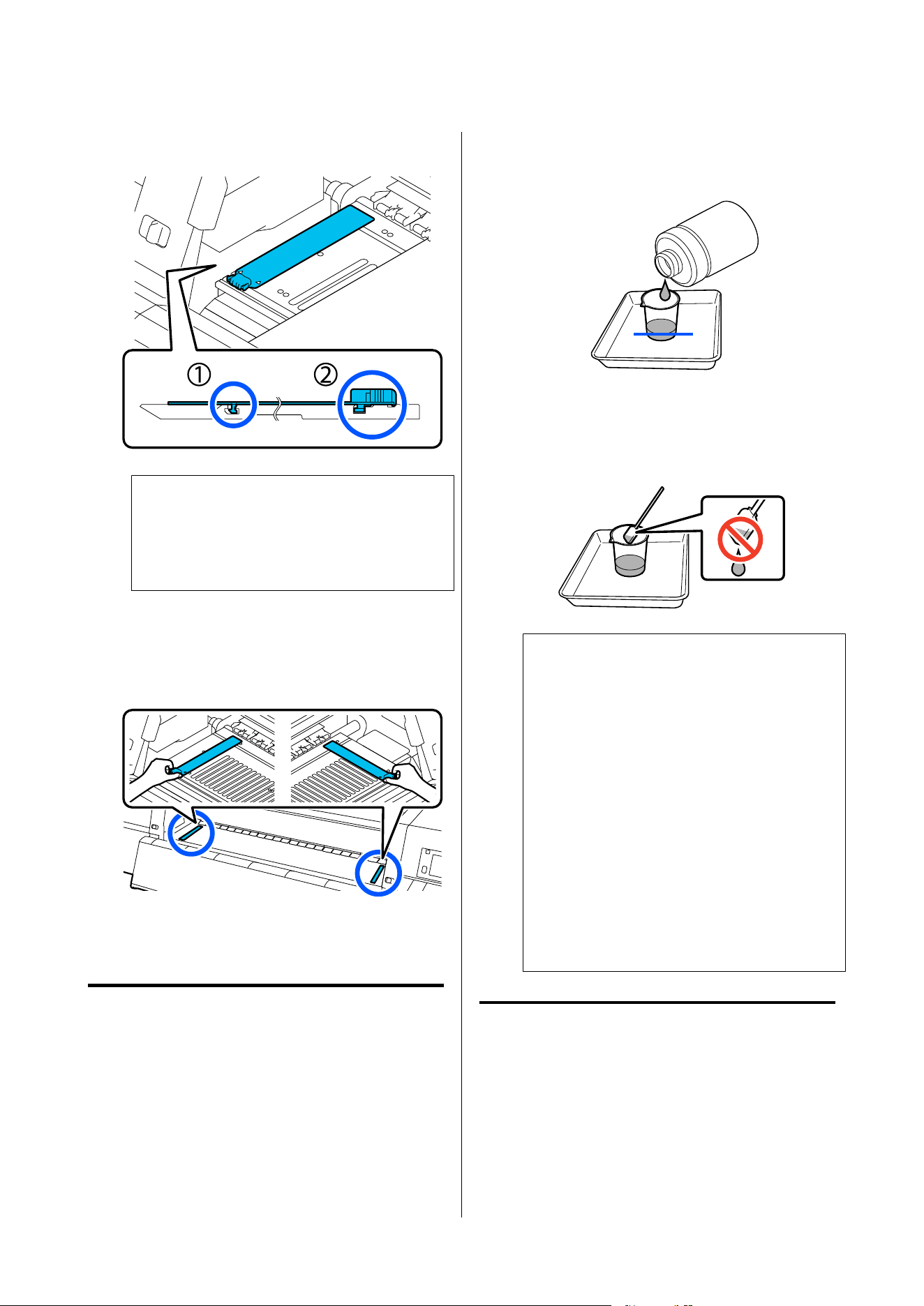
(2) Hook into the rear of tab: Front corner of
the platen
c
Important:
If hooked sections are not positioned correctly,
return to Step 4 to attach them again.
Otherwise, the head may be damaged.
F
While holding the tabs of each media edge plate
on both sides, move both the plates to the left
and right edges of the platen respectively.
Releasing the tab fixes the media edge plate.
G
Close the left-side maintenance cover.
Using Cleaning liquid
Only use Cleaning liquid to clean the parts indicated
in the manual.
Before starting this procedure, be sure to read the
following.
U “Precautions Regarding Maintenance” on
page 154
A
Put the cup supplied with the Cleaning Kit on
the tray, and pour approximately 10 ml of
Cleaning liquid into the cup.
B
Dampen the cleaning stick with Cleaning
liquid.
When doing this, do not allow Cleaning liquid
to drip from the cleaning stick.
c
Important:
❏ Do not use Cleaning liquid that you have
used for cleaning to clean the next time.
Using dirty Cleaning liquid will make
staining worse.
❏ Tightly close the lid of the Cleaning liquid
and store it at room temperature out of
direct sunlight and away from high
temperatures or humidity.
❏ Used Cleaning liquid and cleaning sticks
are industrial waste. Dispose of them in
the same way as for waste inks.
U “Disposing of Used Consumables” on
page 189
Cleaning the media cleaners
If the media cleaners are dirty, they cannot sufficiently
wipe dirt and dust off the surface of the media, so
there is a risk that problems may occur, such as
clogged nozzles.
SC-F20000 Series/SC-F11000H Series/SC-F11000 Series/SC-F10000H Series/SC-F10000 Series User's Guide
Maintenance
159
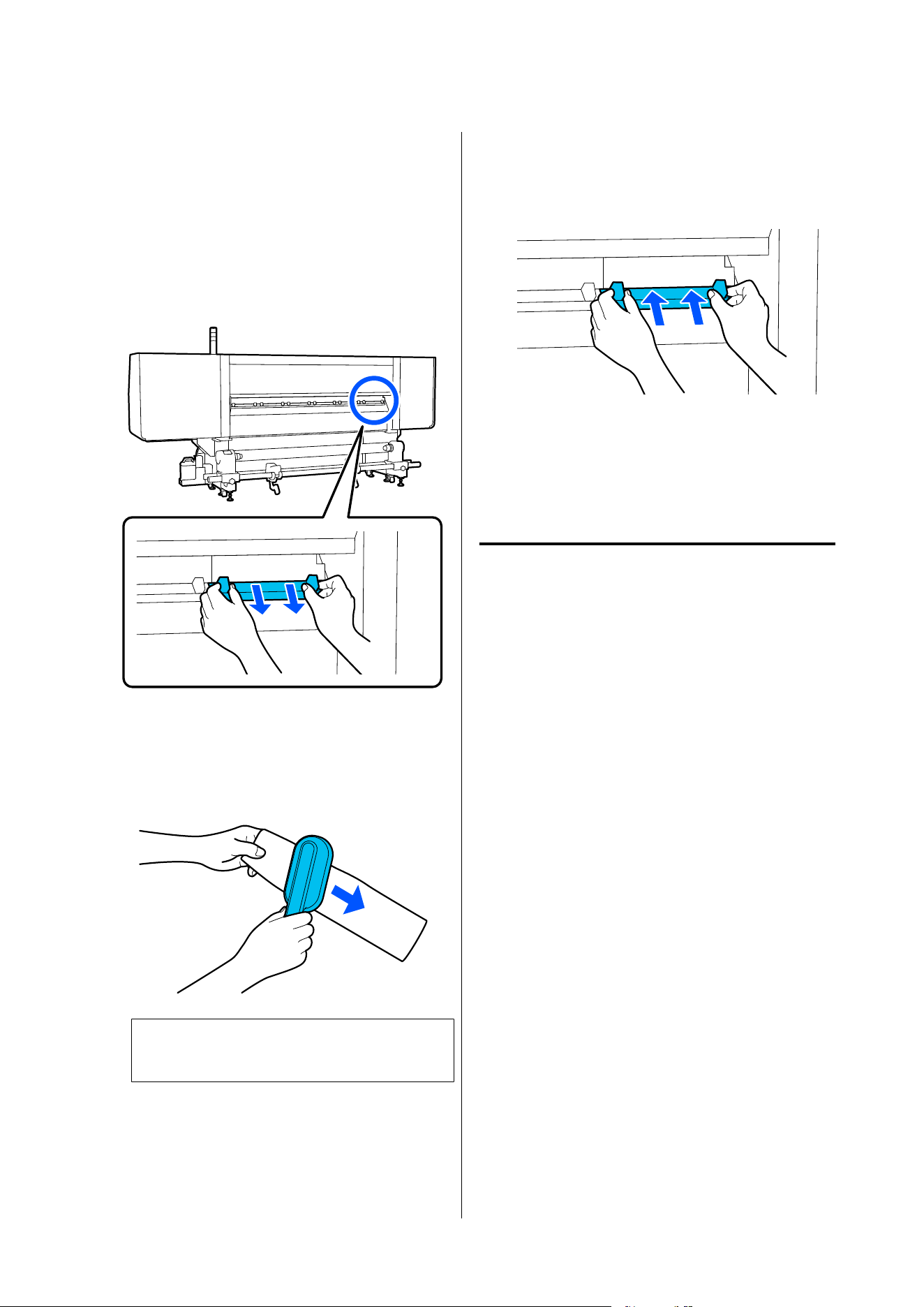
If the Clean the media cleaner. After cleaning is
complete, press [OK]. message appears on the control
panel's screen, use the supplied media cleaner brush to
clean them.
A
Check the on-screen message, move to the
back, and remove the media cleaners.
While pressing the tabs on both sides, pull it
off.
B
Use the supplied brush to wipe dirt and dust
from the surface.
Since the brush's surface has a direction in
which to wipe, move it in the direction that
wipes off the dirt and dust.
Note:
You can switch the direction in which to wipe.
C
When you finish cleaning a media cleaner,
install it to the printer.
Hold the tabs as you insert the media cleaner
until you hear a click.
D
Repeat Steps 2 and 3 to clean all of the media
cleaners.
E
On the screen, press Done.
Cleaning anti-drying caps
When an anti-drying cap needs to be cleaned, the
Cleaning the Anti-Drying Caps. message appears on
the screen, and the cap that needs to be cleaned is
indicated.
When this message is displayed, follow the steps below
to clean only the indicated cap.
Before starting this procedure, be sure to read the
following.
U “Precautions Regarding Maintenance” on
page 154
SC-F20000 Series/SC-F11000H Series/SC-F11000 Series/SC-F10000H Series/SC-F10000 Series User's Guide
Maintenance
160
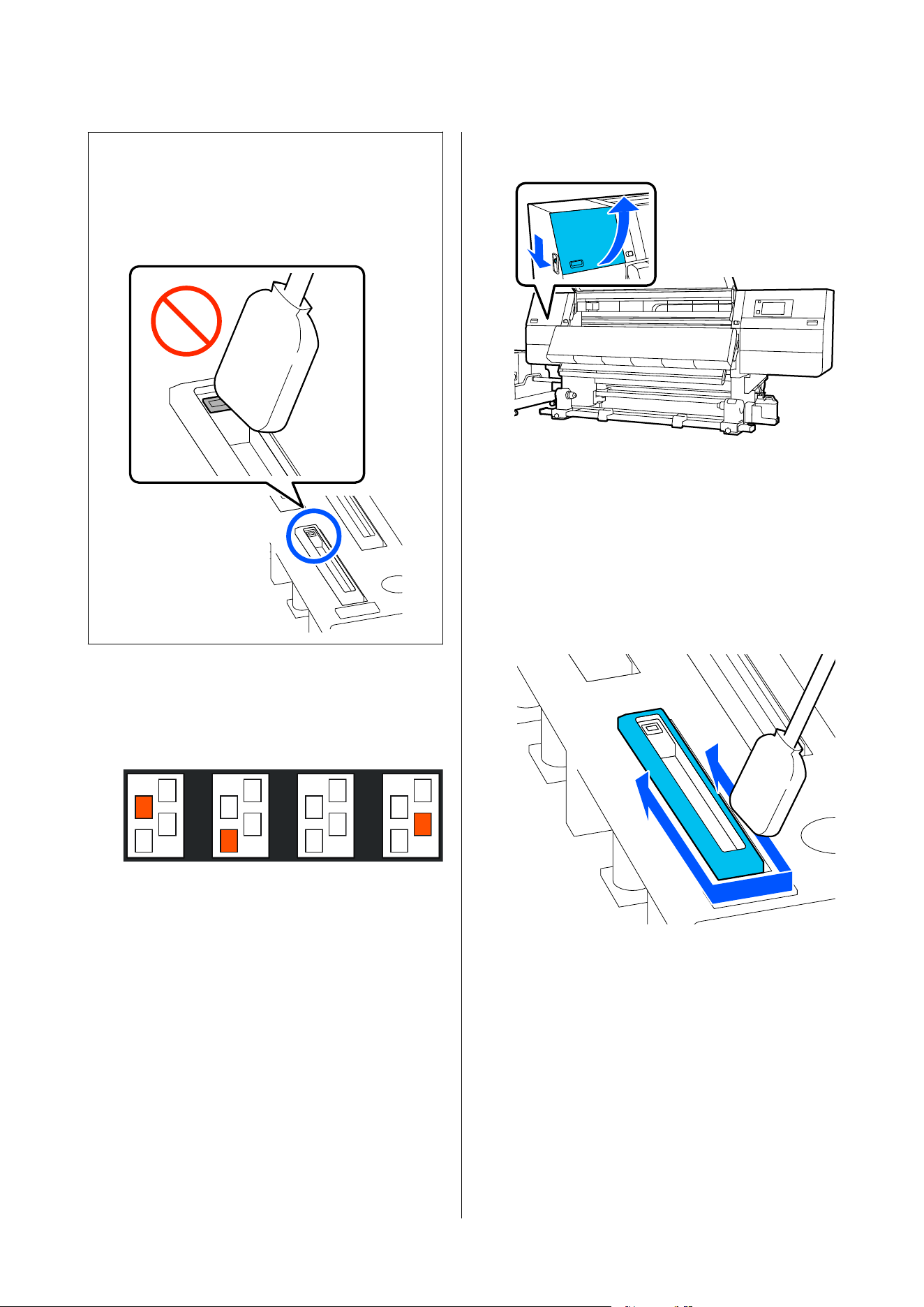
c
Important:
When using a cleaning stick to wipe a cap, do not
wipe the area around the hole inside the cap. The
cleaning fluid may get into the hole, causing the
cap to not function correctly.
A
If Cleaning the Anti-Drying Caps. appears on
screen, confirm which cap to clean.
The cap that needs to be cleaned is highlighted,
as shown in the illustration.
B
Press Start.
The print head moves to the right side.
C
Lower the lock release lever to open the
left-side maintenance cover.
D
Dampen the cleaning stick with cleaning fluid.
U “Using Cleaning liquid” on page 159
E
Hold the cleaning stick in a perpendicular
orientation, and wipe the outer area of the cap
that needs to be cleaned.
While wiping, avoid the area around the hole
inside the cap.
SC-F20000 Series/SC-F11000H Series/SC-F11000 Series/SC-F10000H Series/SC-F10000 Series User's Guide
Maintenance
161
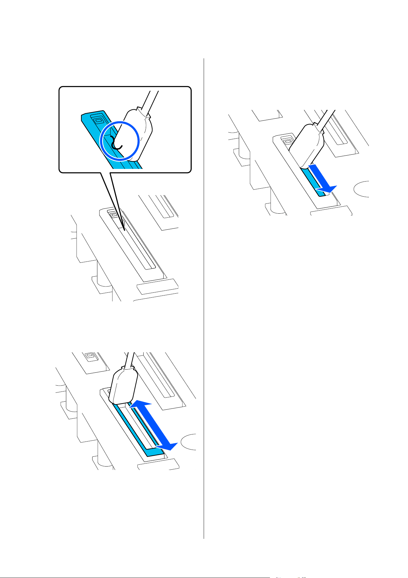
When there is lint or dust on the cap
Remove it by using the tip of the cleaning stick.
F
Hold the cleaning stick flat and wipe the edges
of the cap.
While wiping, avoid the area around the hole
inside the cap.
G
Hold the cleaning stick in a perpendicular
orientation, and wipe the inside of the cap.
While wiping, avoid the area around the hole
inside the cap and move the cleaning stick only
in the direction away from the hole.
SC-F20000 Series/SC-F11000H Series/SC-F11000 Series/SC-F10000H Series/SC-F10000 Series User's Guide
Maintenance
162
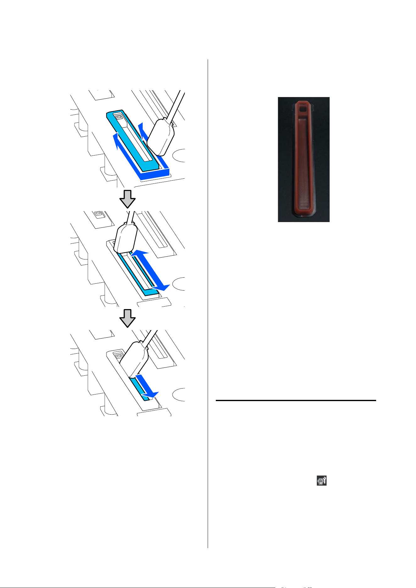
H
Use a new dry cleaning stick to wipe up all the
ink and cleaning fluid on the inside, edges, and
area around the cap.
Wipe up all the ink and cleaning fluid, leaving
no residue, as shown in the illustration below. If
any ink or cleaning fluid is left over, it could
clog the nozzles.
I
Close the maintenance cover, and then press
Done.
The print head returns to its normal position.
When the print head returns to its normal position,
the screen for checking if the print head is dirty
appears.
If necessary, clean the print head.
U “Cleaning around the print head” on page 164
Disposing of used ink cleaner and cleaning sticks
U “Disposing of Used Consumables” on page 189
Cleaning the suction caps
Clean the suction caps before doing Print Head
Refresh. If you do not clean the suction caps, doing
Print Head Refresh is not fully effective. Before doing
Print Head Refresh, use the following procedure to
clean the suction caps.
A
On the Home screen, press , and then press
in the order of Cleaning the Maintenance
Parts - Suction Cap.
B
Check the on-screen message, and then press
Start.
SC-F20000 Series/SC-F11000H Series/SC-F11000 Series/SC-F10000H Series/SC-F10000 Series User's Guide
Maintenance
163
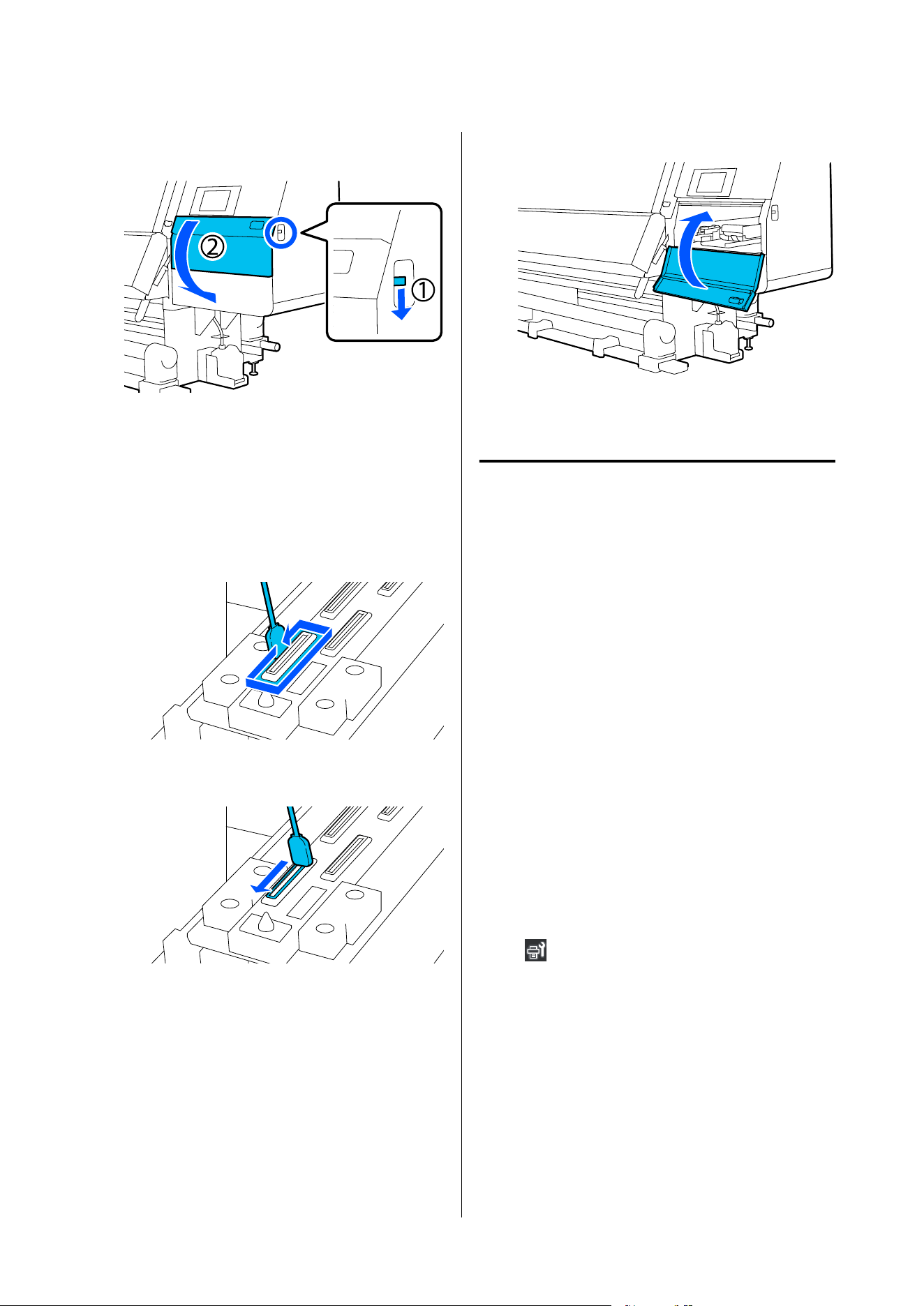
C
Lower the lock release lever to open the
right-side maintenance cover.
D
Dampen the cleaning stick with cleaning fluid.
Use new cleaning sticks and cleaning fluid.
U “Using Cleaning liquid” on page 159
E
Hold the cleaning stick in a perpendicular
orientation, and wipe the outer areas of all the
caps.
F
Hold the cleaning stick flat and wipe the edges
of all the caps.
G
Check that there are no ink stains, lint, or dust
attached to the edges or outer area of the cap.
If they are not dirty, cleaning is complete.
If any dirt remains, repeat Steps 5 and 6 to wipe
off any dirt.
H
Close the maintenance cover.
I
On the control panel screen, press Done.
Cleaning around the print head
If any of the following problems occur, check the print
head and clean it if there are any ink clots, lint, or dust.
❏ Media jams
❏ Print head striking
❏ Print results are dirty
Before starting this procedure, be sure to read the
following.
U “Precautions Regarding Maintenance” on
page 154
A
Move the print head to the cleaning position.
If the media has jammed, remove the jammed
media, and when Open the Maintenance
Cover and clean around the print heads if
they are dirty. appears, press Confirmation.
For problems other than jammed media, press
on the Home screen, and then press in the
order of Cleaning the Maintenance Parts -
Around the Head.
B
Check the on-screen message, and then press
Start.
SC-F20000 Series/SC-F11000H Series/SC-F11000 Series/SC-F10000H Series/SC-F10000 Series User's Guide
Maintenance
164
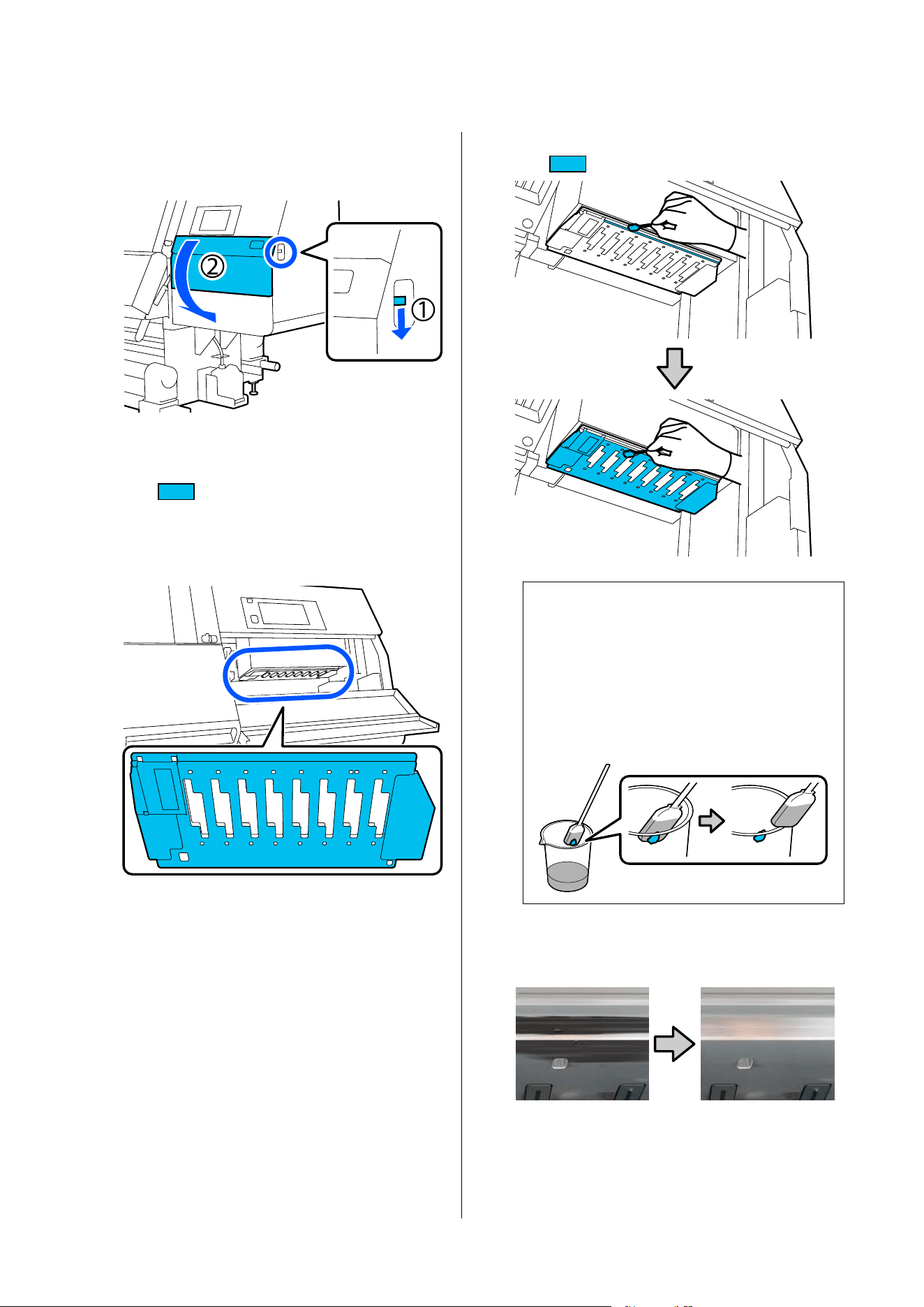
C
Confirm that the print head has moved to the
right side, and then press the lock release lever
to open the right-side maintenance cover.
D
Check for dirt on the print head.
Check that there is no ink, lint, or dust stuck to
the
area shown in the illustration.
If it is dirty, then move on to the next
procedure.
If it is not dirty, then move on to Step 7.
E
Dampen the cleaning stick with cleaning fluid.
Use new cleaning sticks and cleaning fluid.
U “Using Cleaning liquid” on page 159
F
Wipe off any ink, lint, or dust that is stuck to
the
area shown in the illustration.
c
Important:
❏ If the cleaning stick becomes dirty, rinse
it with cleaning fluid as you wipe.
❏ After removing a clot of ink with a
cleaning stick, wipe the cleaning stick
against the edge of the cup to remove the
clot.
Wipe off the ink stains until you can see the
metal surface of the print head, as shown in the
illustration.
SC-F20000 Series/SC-F11000H Series/SC-F11000 Series/SC-F10000H Series/SC-F10000 Series User's Guide
Maintenance
165
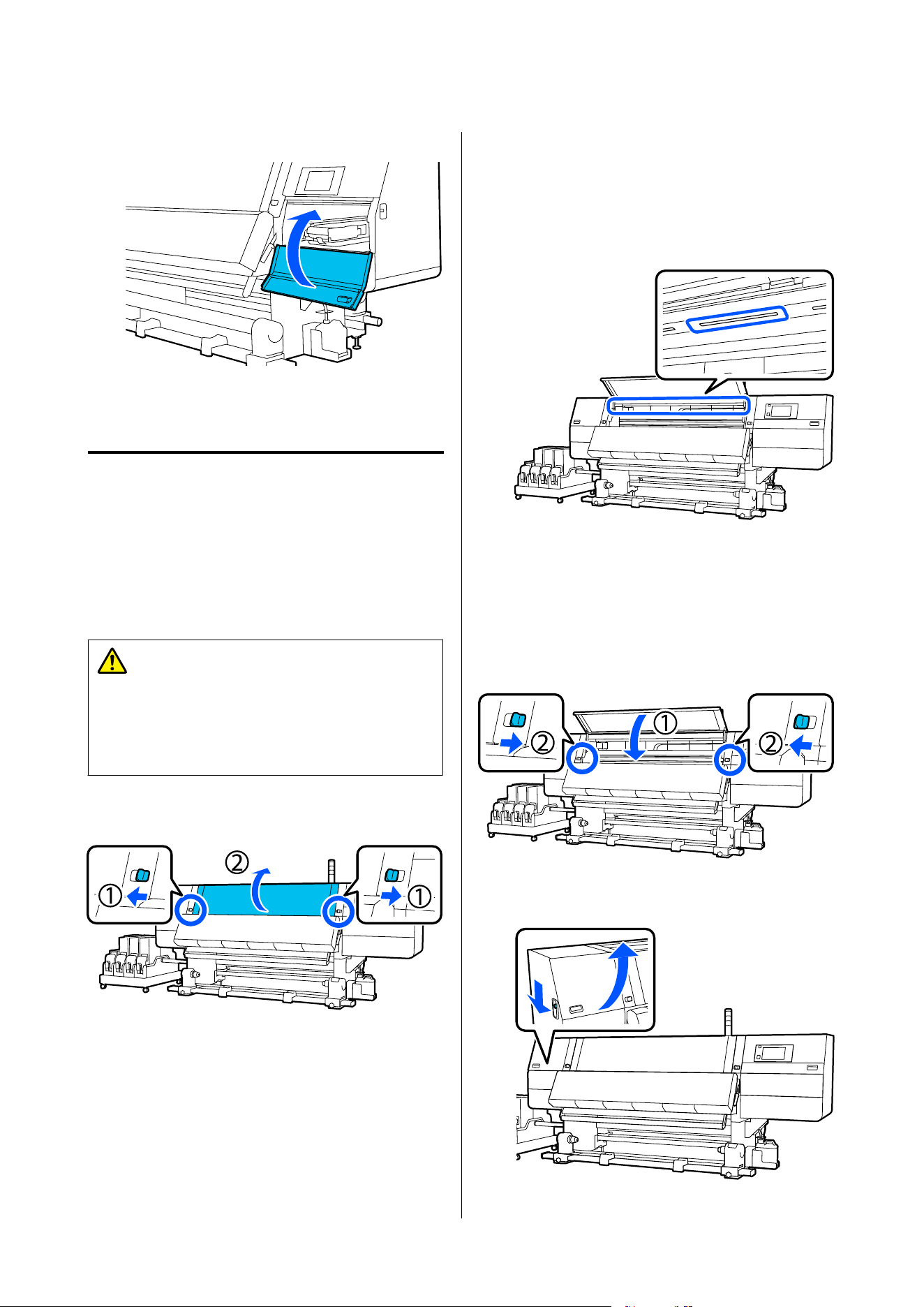
G
Close the maintenance cover.
H
On the control panel screen, press Done.
Cleaning the inside light
The printer has an inside light inside the front cover
and maintenance covers to make it easy to check print
results and areas for maintenance. If ink mist makes
the surface of the inside light dirty, it becomes dim so
checking becomes difficult. If it seems dim, follow the
steps below to clean it.
Caution:
Be careful not to trap your hands or fingers when
opening or closing the front cover or the
maintenance cover. Failure to observe these
precautions could result in injury.
A
Move the lock levers on the left and right side
outwards to open the front cover.
B
Soak a soft cloth in water, wring it out
thoroughly, and then wipe any dirt off the
inside light surfaces shown in the illustration.
There are a total of 4 inside lights inside the
front cover. Wipe the dirt from all these
surfaces.
For anything that cannot be removed with a
damp cloth, dip a cloth in neutral detergent,
squeeze it out, and then wipe the stubborn
stain.
C
After wiping off stains, close the front cover
and move the left and right lock levers inwards.
D
Lower the lock release lever to open the
left-side maintenance cover.
SC-F20000 Series/SC-F11000H Series/SC-F11000 Series/SC-F10000H Series/SC-F10000 Series User's Guide
Maintenance
166
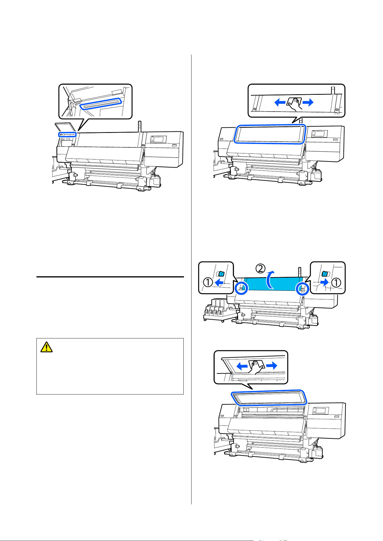
E
Soak a soft cloth in water, wring it out
thoroughly, and then wipe any dirt off of the
inside light surfaces shown in the illustration.
For anything that cannot be removed with a
damp cloth, dip a cloth in neutral detergent,
squeeze it out, and then wipe the stubborn
stain.
F
After wiping off the dirt, close the maintenance
cover.
Cleaning the front cover
The front cover becomes dirty from dust and ink mist,
etc., if you continue to use the printer in this
condition, the inside of the printer becomes difficult
to see. If it is dirty, follow the steps below to clean.
Caution:
Be careful not to trap your hands or fingers when
opening or closing the front cover or the
maintenance cover. Failure to observe these
precautions could result in injury.
A
Make sure the printer is turned off and the
screen has turned off, and then unplug the
power cable from the outlet.
Disconnect both of the power cables.
B
Soak a soft cloth in water, wring it out
thoroughly, and then wipe any dirt off the
window on the front cover.
For anything that cannot be removed with a
damp cloth, dip a cloth in neutral detergent,
squeeze it out, and then wipe the stubborn
stain.
C
Move the lock levers on the left and right side
outwards to open the front cover.
D
Wipe the inside of the window.
SC-F20000 Series/SC-F11000H Series/SC-F11000 Series/SC-F10000H Series/SC-F10000 Series User's Guide
Maintenance
167
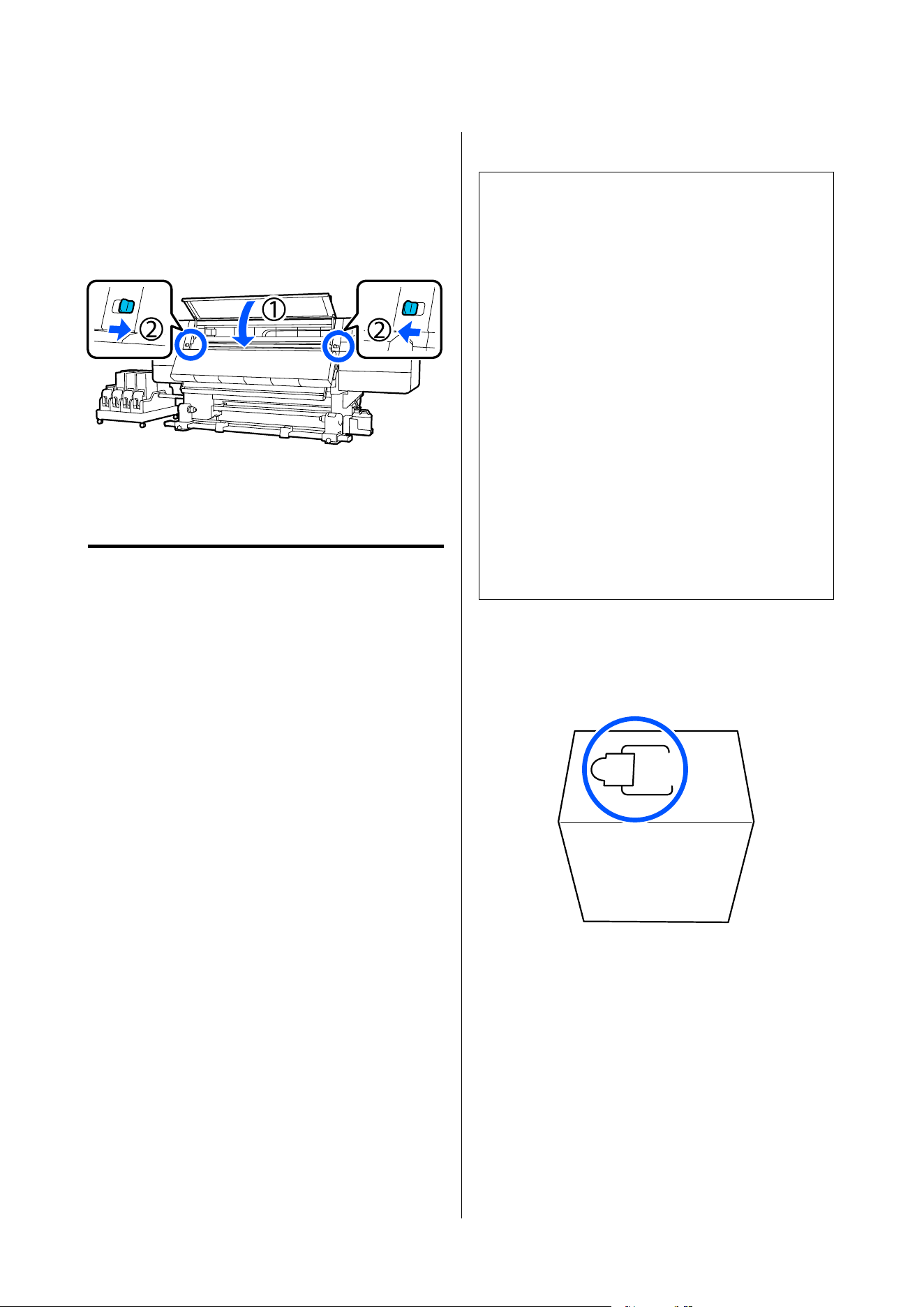
For anything that cannot be removed with a
damp cloth, dip a cloth in neutral detergent,
squeeze it out, and then wipe the stubborn
stain.
E
After wiping off stains, close the front cover
and move the left and right lock levers inwards.
Replacing Consumables
Replacing ink cartridges
If ink is expended, replace the ink cartridge
immediately with a new one. You can check the ink
level on the Home screen.
U “Home screen” on page 27
Two ink cartridges for each color are loaded into the
ink supply unit, so the cartridge not in use can be
replaced during printing.
Replacement procedure
c
Important:
❏ Epson recommends the use of genuine Epson
ink cartridges. Epson cannot guarantee the
quality or reliability of non-genuine ink. The
use of non-genuine ink may cause damage
that is not covered by Epson's warranties, and
under certain circumstances, may cause
erratic printer behavior.
Information about non-genuine ink levels may
not be displayed, and use of non-genuine ink
is recorded for possible use in service support.
❏ Due to ink characteristics, the ink cartridges
of this printer are prone to sedimentation
(components settling to the bottom of the
liquid). If ink settles, tint unevenness and
nozzle clogs occur.
Shake a new ink cartridge before installing it.
After installing it in the printer, remove and
shake it periodically.
Opening and shaking
A
Place a new ink cartridge on a flat surface with
the ink supply outlet slot facing up.
SC-F20000 Series/SC-F11000H Series/SC-F11000 Series/SC-F10000H Series/SC-F10000 Series User's Guide
Maintenance
168
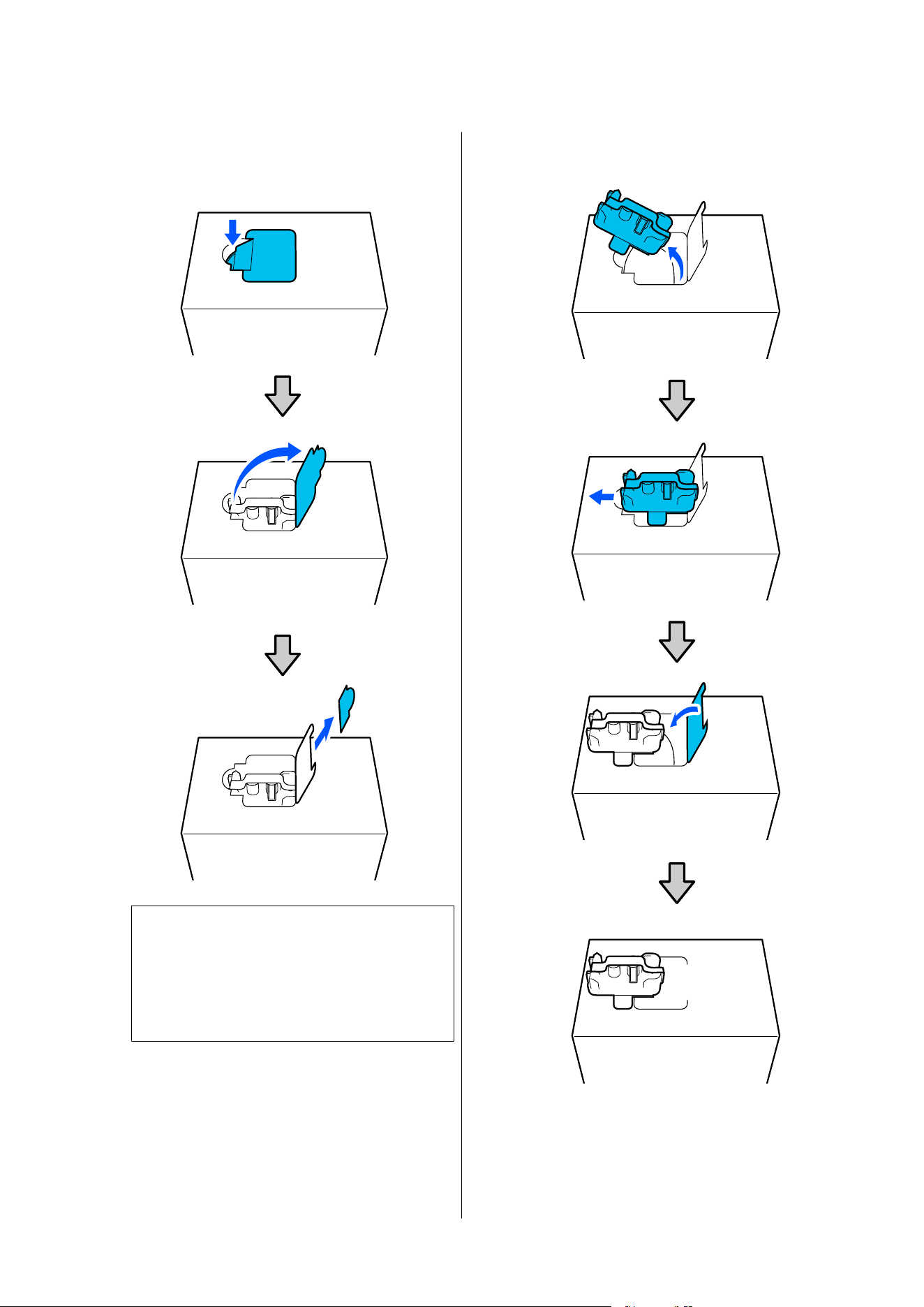
B
Use your hands to cut along the dashed lines of
the slot to remove the portion shown in the
illustration.
c
Important:
Do not use a cutter to cut along the dashed
lines. Failure to observe this precaution could
damage the internal parts and cause ink to
leak.
C
Take out the ink supply outlet from inside and
fix it as shown in the illustration.
SC-F20000 Series/SC-F11000H Series/SC-F11000 Series/SC-F10000H Series/SC-F10000 Series User's Guide
Maintenance
169
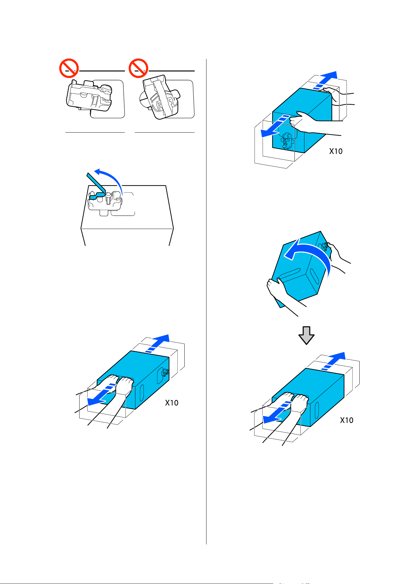
D
Remove tape from the surface of ink supply
outlet.
E
Place the ink cartridge with the ink supply
outlet facing the side, and slide the ink
cartridge back and forth longitudinally within
the range of approximately 10 cm (3.93 in.) for
ten times.
Move the ink cartridge at a rate of one
back-and-forth cycle per second.
❏ When using 10 L ink cartridge
❏ When using 3 L ink cartridge
F
Turn over the ink cartridge and repeat the same
cycle for ten times.
Move the ink cartridge at a rate of one
back-and-forth cycle per second.
❏ When using 10 L ink cartridge
SC-F20000 Series/SC-F11000H Series/SC-F11000 Series/SC-F10000H Series/SC-F10000 Series User's Guide
Maintenance
170
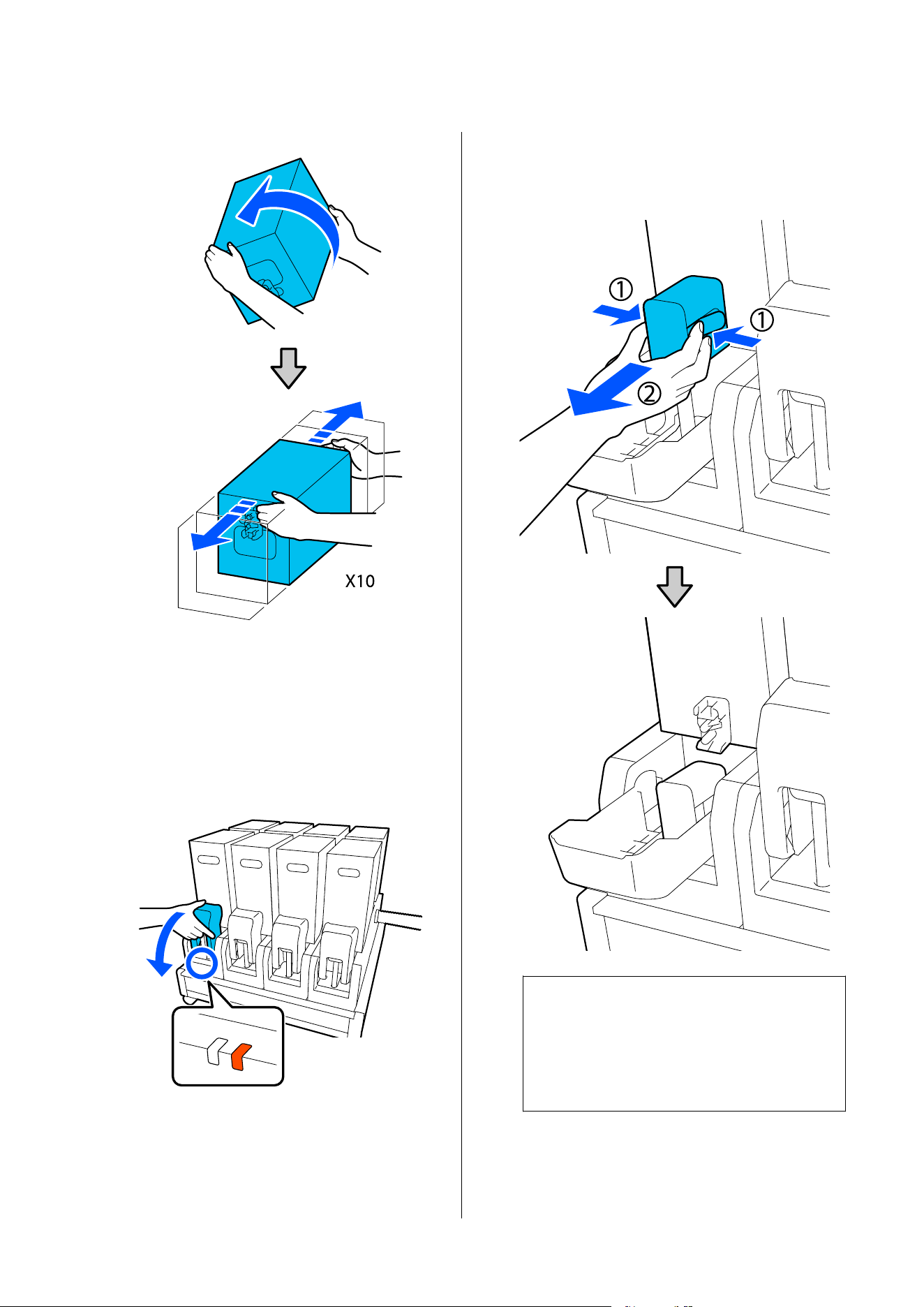
❏ When using 3 L ink cartridge
Replacement
A
Make sure the printer is on, and then lower the
ink cartridge cover of the used ink cartridge
toward you.
The ink cartridge with a lit right (orange) lamp
is the one that needs to be replaced.
B
While pressing the levers on both sides of the
connector, pull the connector toward you to
remove it, and place the connector on the rear
surface of the ink cartridge cover.
c
Important:
Do not leave the connector removed from the
ink cartridge for more than 30 minutes.
Otherwise, the ink will dry out and the
printer may not function as expected.
SC-F20000 Series/SC-F11000H Series/SC-F11000 Series/SC-F10000H Series/SC-F10000 Series User's Guide
Maintenance
171
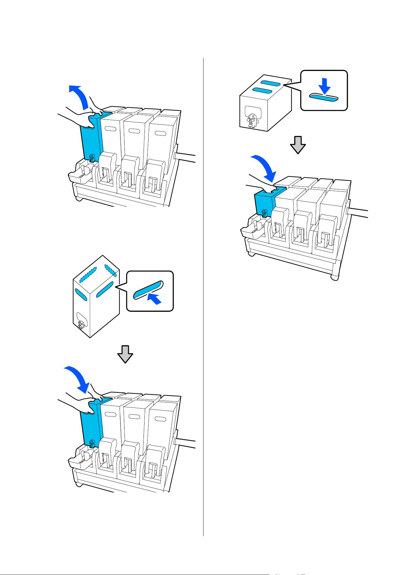
C
Remove the used ink cartridge from the ink
supply unit.
D
Open and hold the handle holes of shaken ink
cartridge and place the ink cartridge such that
the ink supply hole faces the connector.
❏ When using 10 L ink cartridge
❏ When using 3 L ink cartridge
SC-F20000 Series/SC-F11000H Series/SC-F11000 Series/SC-F10000H Series/SC-F10000 Series User's Guide
Maintenance
172
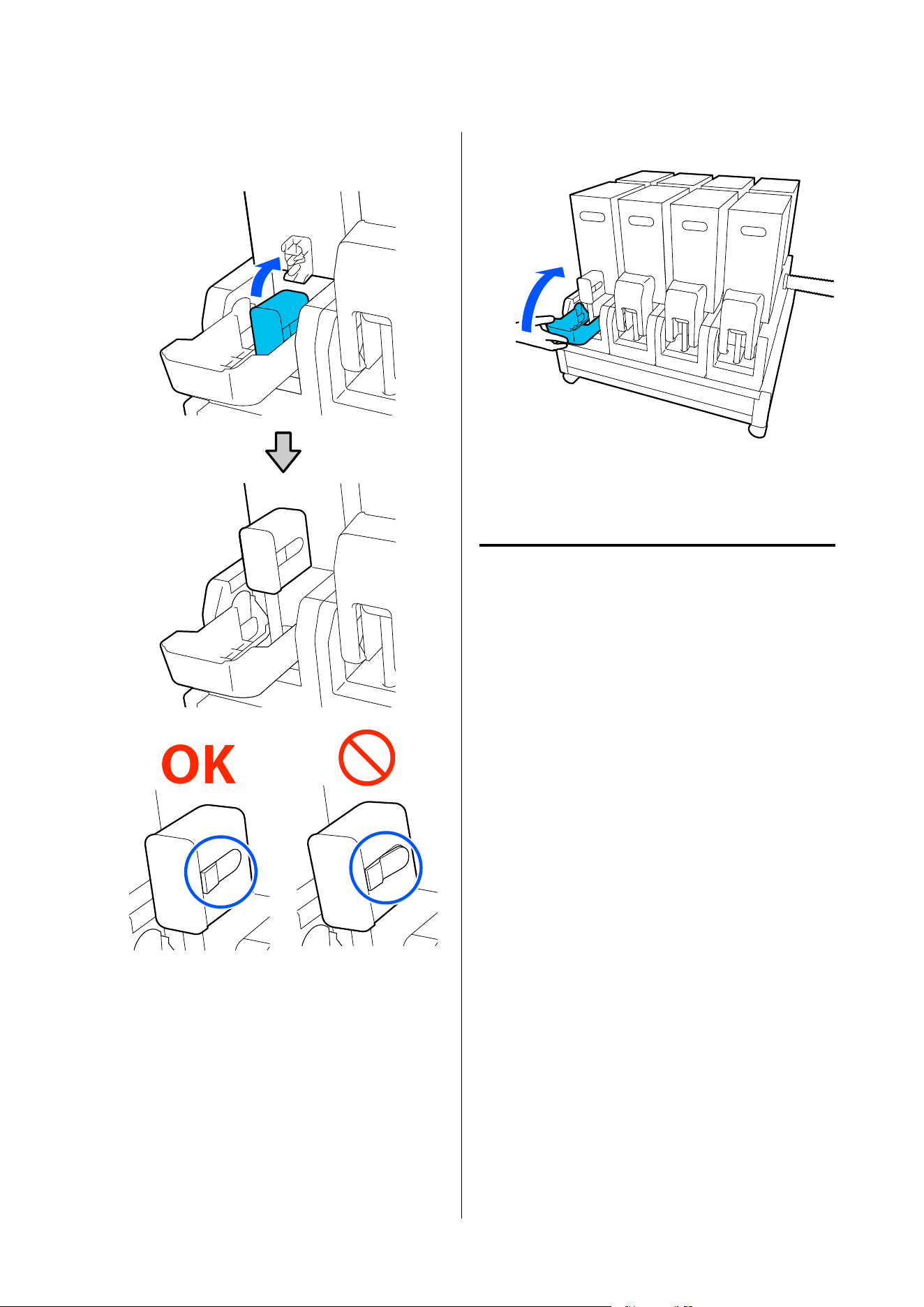
E
Install the connector to the ink supply outlet.
Insert the connector until you hear a click.
F
Raise the ink cartridge cover.
Repeat the opening, shaking and replacement
procedures to replace other ink cartridges.
Replacing the wiper roll
Preparing and Replacement Timing
When a message is displayed indicating the time to
replace the wiper roll is approaching
Prepare a new wiper roll as soon as possible.
When you want to replace the parts at this stage, such
as due to night operations, execute Maintenance -
Replace Maintenance Parts - Replace Wiper Roll,
and then do the replacement work. If you replace it
without selecting Replace Wiper Roll, the wiper roll
counter will not operate correctly.
Maintenance U “Maintenance menu” on page 219
When a message is displayed indicating it is time to
replace the wiper roll
See the following section, and replace the wiper roll.
Printing cannot be performed if the parts are not
replaced.
Make sure you use a replacement wiper roll for this
printer.
U “Options and Consumable Products” on page 231
Before starting this procedure, be sure to read the
following.
SC-F20000 Series/SC-F11000H Series/SC-F11000 Series/SC-F10000H Series/SC-F10000 Series User's Guide
Maintenance
173
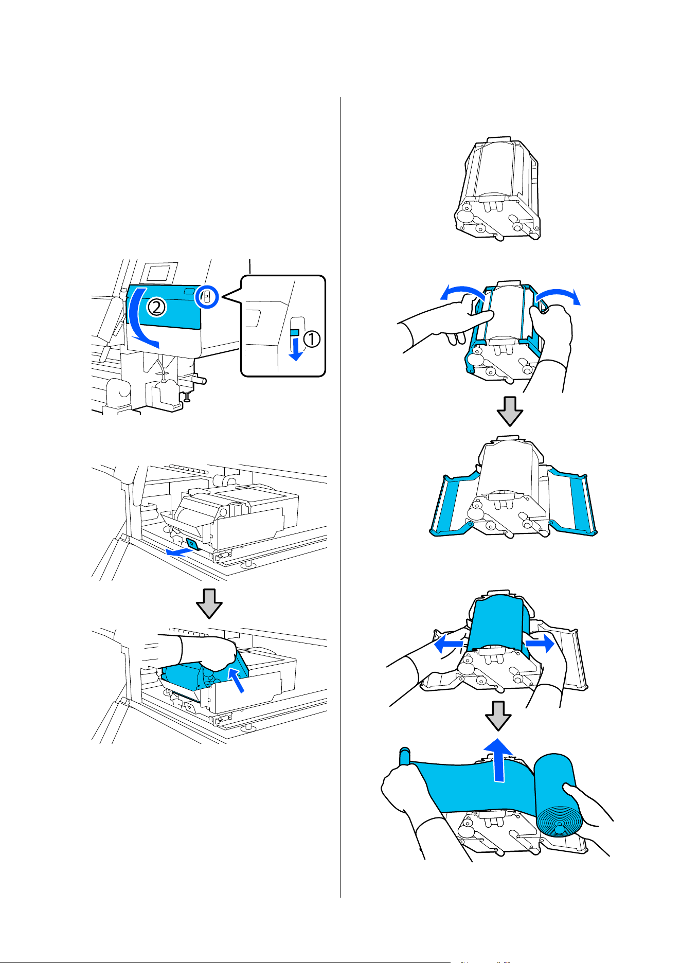
U “Precautions Regarding Maintenance” on
page 154
Replacement procedure
A
Check the on-screen message, and then press
Start.
B
Lower the lock release lever to open the
right-side maintenance cover.
C
Pull the lock lever, and then pull the wiper unit
out at an upward angle.
D
Place the wiper unit on a flat place oriented as
shown in the illustration.
E
Open the left and right covers outwards.
F
Hold the shaft and roll and pull them out, and
remove the wiper roll.
SC-F20000 Series/SC-F11000H Series/SC-F11000 Series/SC-F10000H Series/SC-F10000 Series User's Guide
Maintenance
174
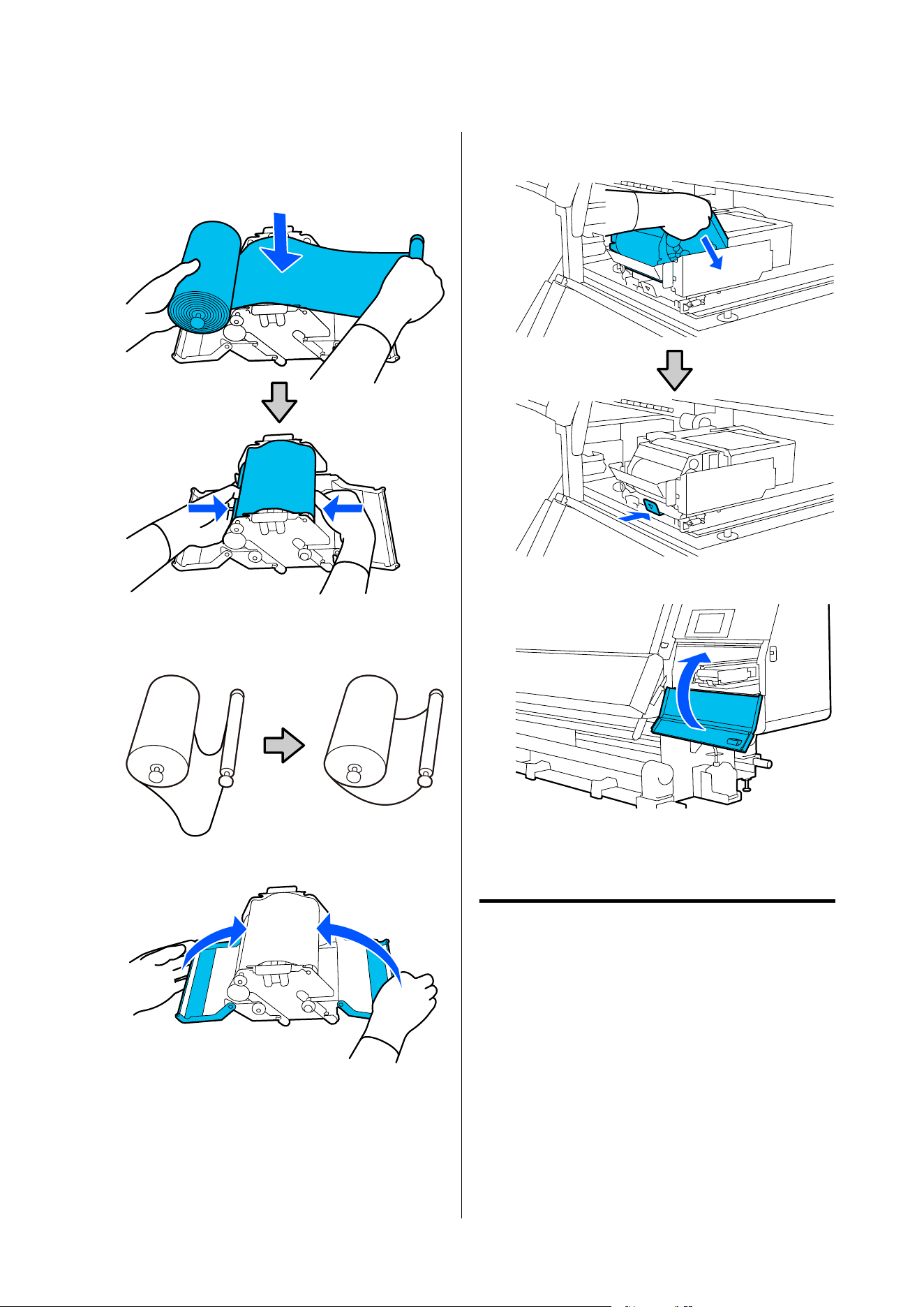
G
Install a new wiper roll.
Insert the shaft into the groove on the wiper
unit, and press inward until you hear a click.
Install the wiper roll so it does not sag.
If it sags excessively, eliminate the sag.
H
Close the left and right covers.
I
Install the wiper unit at an angle from above the
printer, and then press the lock lever.
J
Close the maintenance cover.
K
Check the on-screen message, and then press
Ye s .
Disposing of waste ink
Preparing and Replacement Timing
When a message is displayed indicating the time to
replace the waste ink bottle is approaching
Prepare a new waste ink bottle as soon as possible.
When you want to replace the waste ink bottle at this
stage, such as due to night operations, select Replace
Waste Ink Bottl e from the setup menu, and then
replace the bottle. If you replace it without selecting
Replace Waste Ink Bottle, the waste ink counter will
not operate correctly.
SC-F20000 Series/SC-F11000H Series/SC-F11000 Series/SC-F10000H Series/SC-F10000 Series User's Guide
Maintenance
175
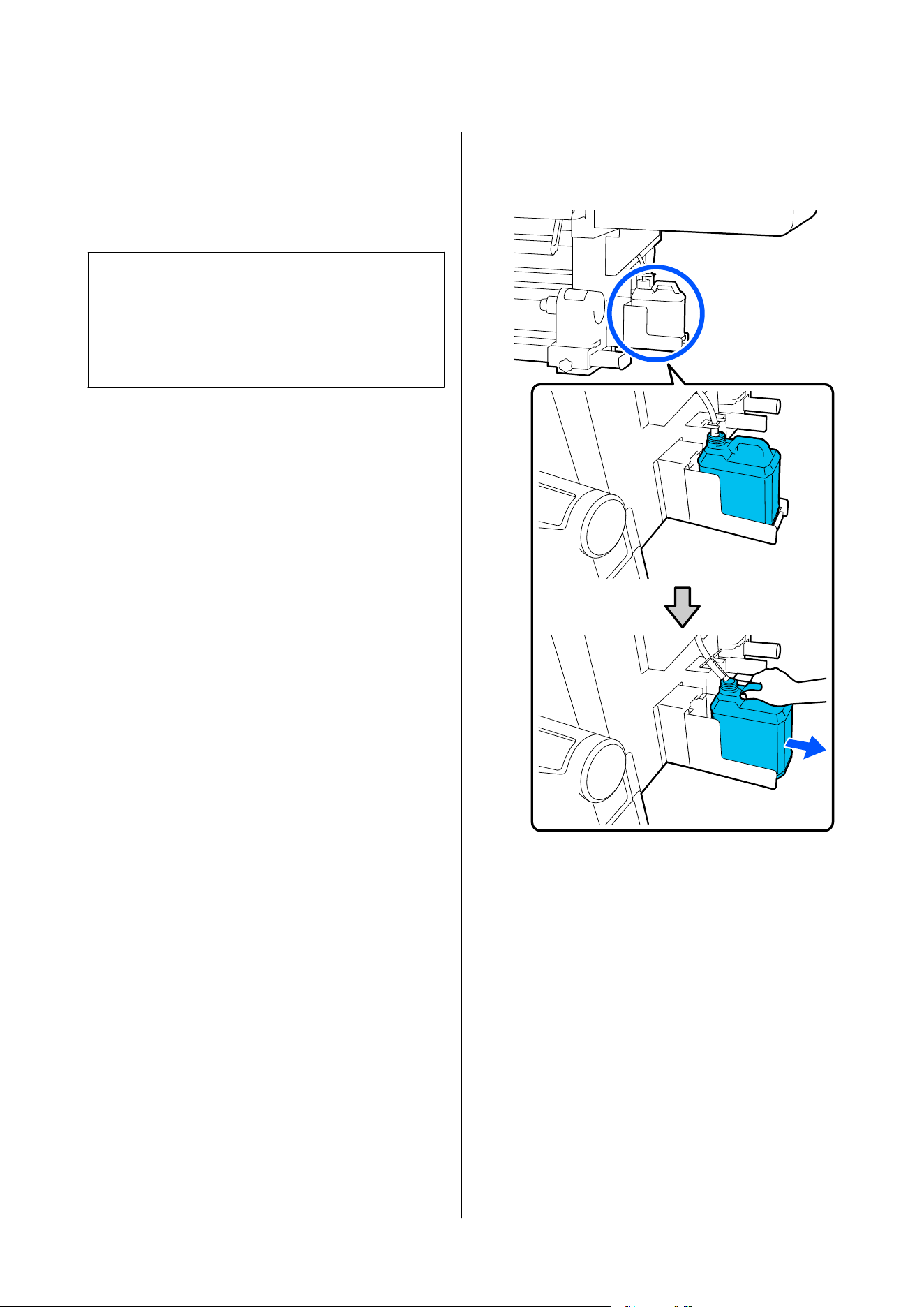
Maintenance menu U “Maintenance menu” on
page 219
Waste ink counter U “Waste ink counter” on
page 176
c
Important:
Never remove the waste ink bottle while printing
or while the heads are being cleaned, unless there
are on-screen instructions. Failure to observe this
precaution could cause ink to leak.
When a message is displayed indicating it is time to
replace the waste ink bottle
Replace the waste ink bottle with a new bottle
immediately.
Replacement procedure U “Replacing the waste ink
bottle” on page 176
Waste ink counter
The printer uses the waste ink counter to track waste
ink and displays a message when the counter reaches
the warning level. Replace the waste ink bottle with a
new one according to the message indicating it is time
to replace the waste ink bottle, and the counter is
cleared automatically.
If you need to replace the waste ink bottle before this
message is displayed, execute Replace Waste Ink
Bottle from the setup menu.
Maintenance menu U “Maintenance menu” on
page 219
Replacing the waste ink bottle
Follow the procedure below to replace the parts.
Before starting this procedure, be sure to read the
following.
U “Precautions Regarding Maintenance” on
page 154
A
Remove the waste ink bottle from the holder.
Remove the waste ink bottle sideways, without
tipping it, as shown in the illustration.
B
Remove the lid of the new waste ink bottle.
SC-F20000 Series/SC-F11000H Series/SC-F11000 Series/SC-F10000H Series/SC-F10000 Series User's Guide
Maintenance
176
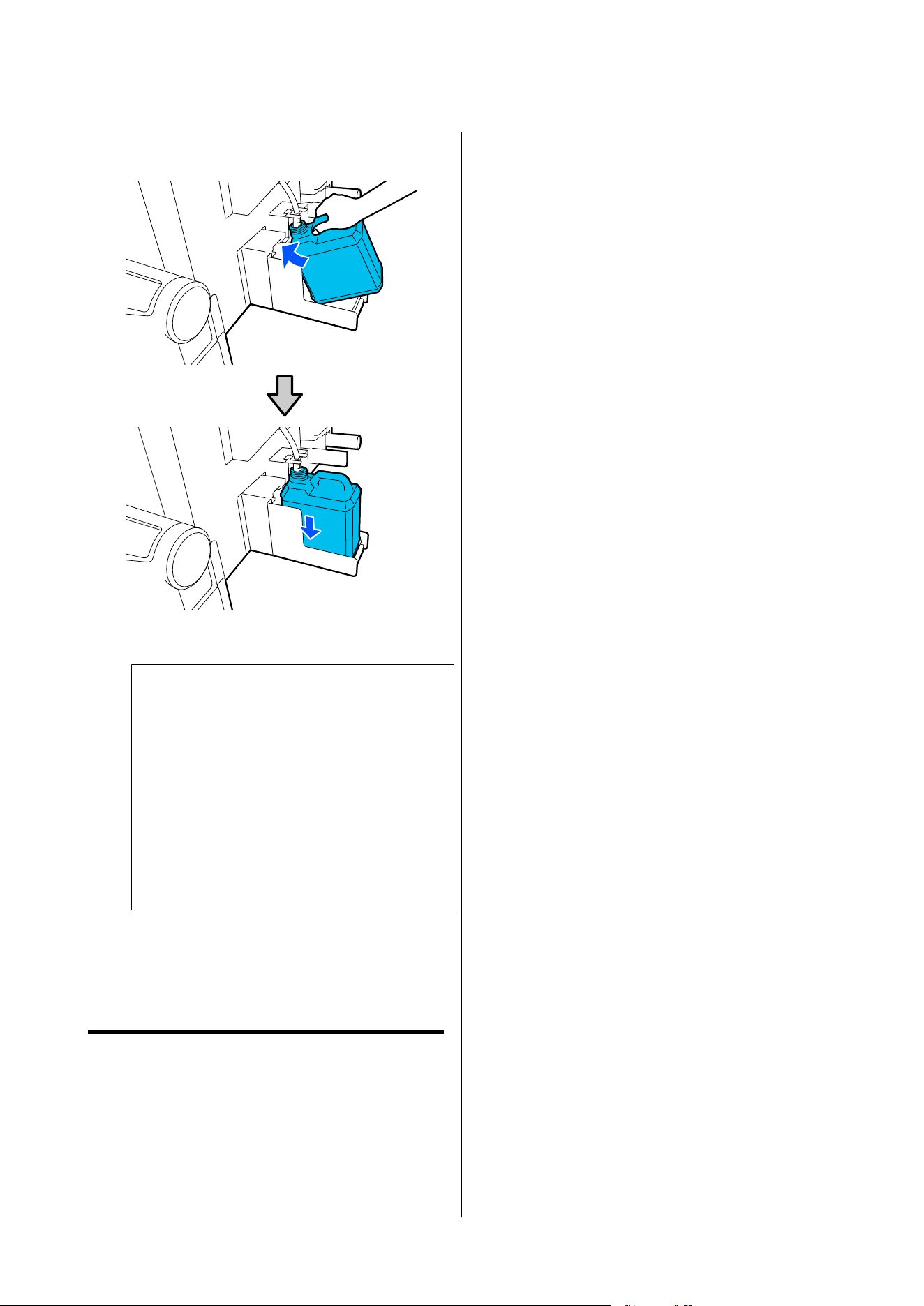
C
Insert the waste ink tube into the mouth of the
new waste ink bottle and place it in the holder.
Tightly seal the lid on the used waste ink bottle.
c
Important:
❏ Be sure to confirm that the waste ink
tube is inserted in the mouth of the waste
ink bottle. Ink will spill onto the
surrounding area if the tube is not
inserted in the bottle.
❏ You will need the lid for the new waste
ink bottle when disposing of waste ink.
Keep the lid in a safe place; do not throw
it out.
D
On the screen, press Done.
Leave the waste ink in the waste ink bottle for
disposal; do not transfer it to another container.
Replacing the media holder
Preparing and Replacement Timing
When a message appears on the control panel screen
indicating the service life of the media holder, prepare
a new media holder, and then replace the media
holder according to the next section.
Replace the media holders that have switches, for
feeding and the media holders for take-up. Make sure
you use a replacement media holder for this printer.
U “Options and Consumable Products” on page 231
Before starting this procedure, be sure to read the
following.
U “Precautions Regarding Maintenance” on
page 154
If you want to replace these parts regardless of the
on-screen messages, execute Maintenance - Replace
Maintenance Parts - Replace Take In Media Holder
or Replace Take Up Media Holder, and then do the
replacement work. If you do a replacement without
executing it from the settings menu, the media holder
counter will not operate correctly.
Necessary items
❏ New media holder
❏ Hex wrench supplied with the printer (when
replacing the Take In Media Holder)
❏ Commercially available Phillips head screwdriver
(when replacing the Take Up Media Holder)
How to replace the Take In Media
Holder
A
Check that no media is loaded on the Media
Feeding Unit.
If any media is loaded, remove it.
U “Removing the Loaded Media” on page 134
SC-F20000 Series/SC-F11000H Series/SC-F11000 Series/SC-F10000H Series/SC-F10000 Series User's Guide
Maintenance
177
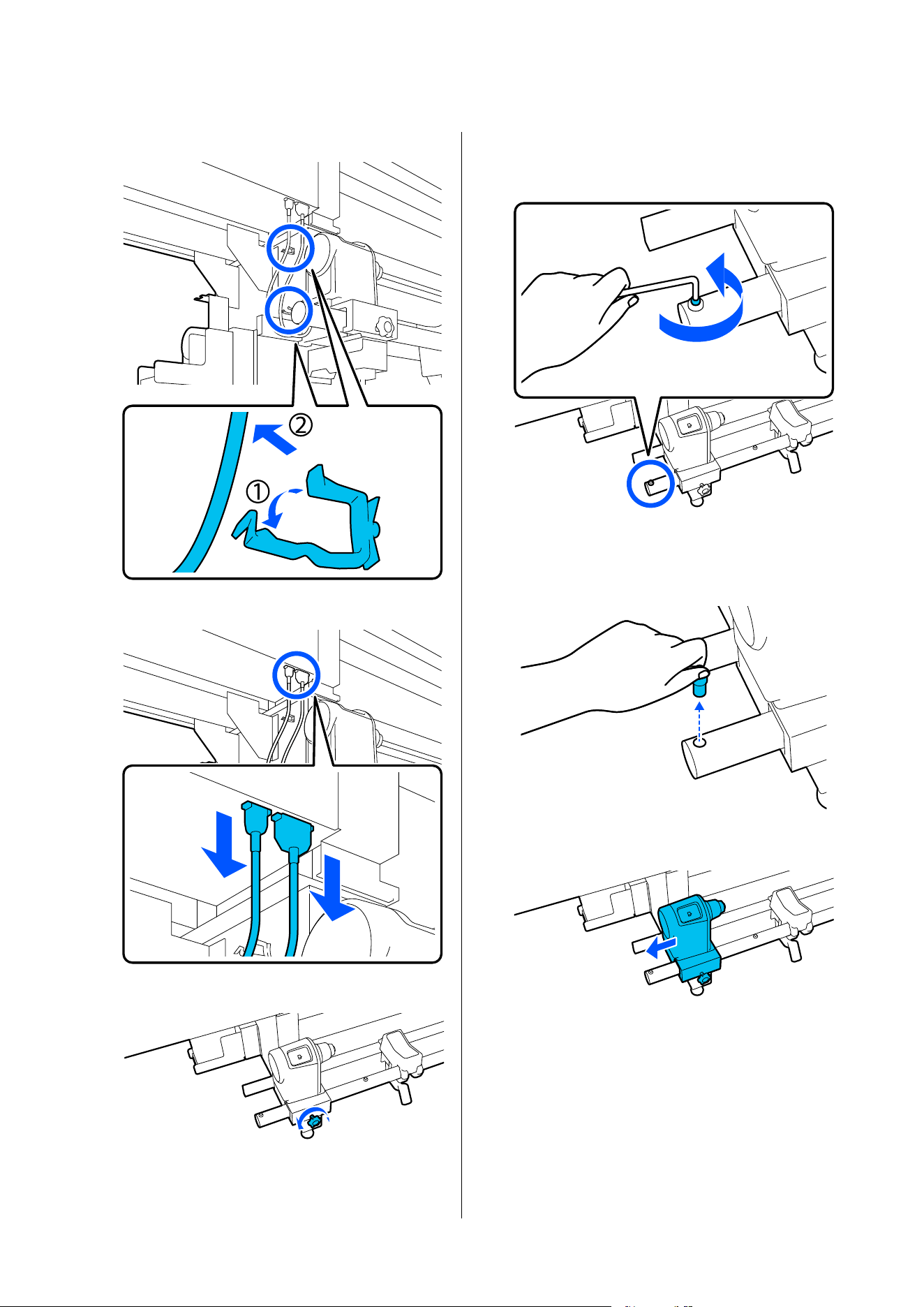
B
Remove the cables from the clamps.
C
Remove the 2 cables from the printer.
D
Loosen the fixing screw on the media holder.
E
Use the hex wrench to loosen the head of the
screw so it rises up about 5 mm (1.96 in.) as
shown in the illustration.
F
Pull the screw out upward together with the
rubber part around it.
G
Pull the media holder toward the outer side.
SC-F20000 Series/SC-F11000H Series/SC-F11000 Series/SC-F10000H Series/SC-F10000 Series User's Guide
Maintenance
178
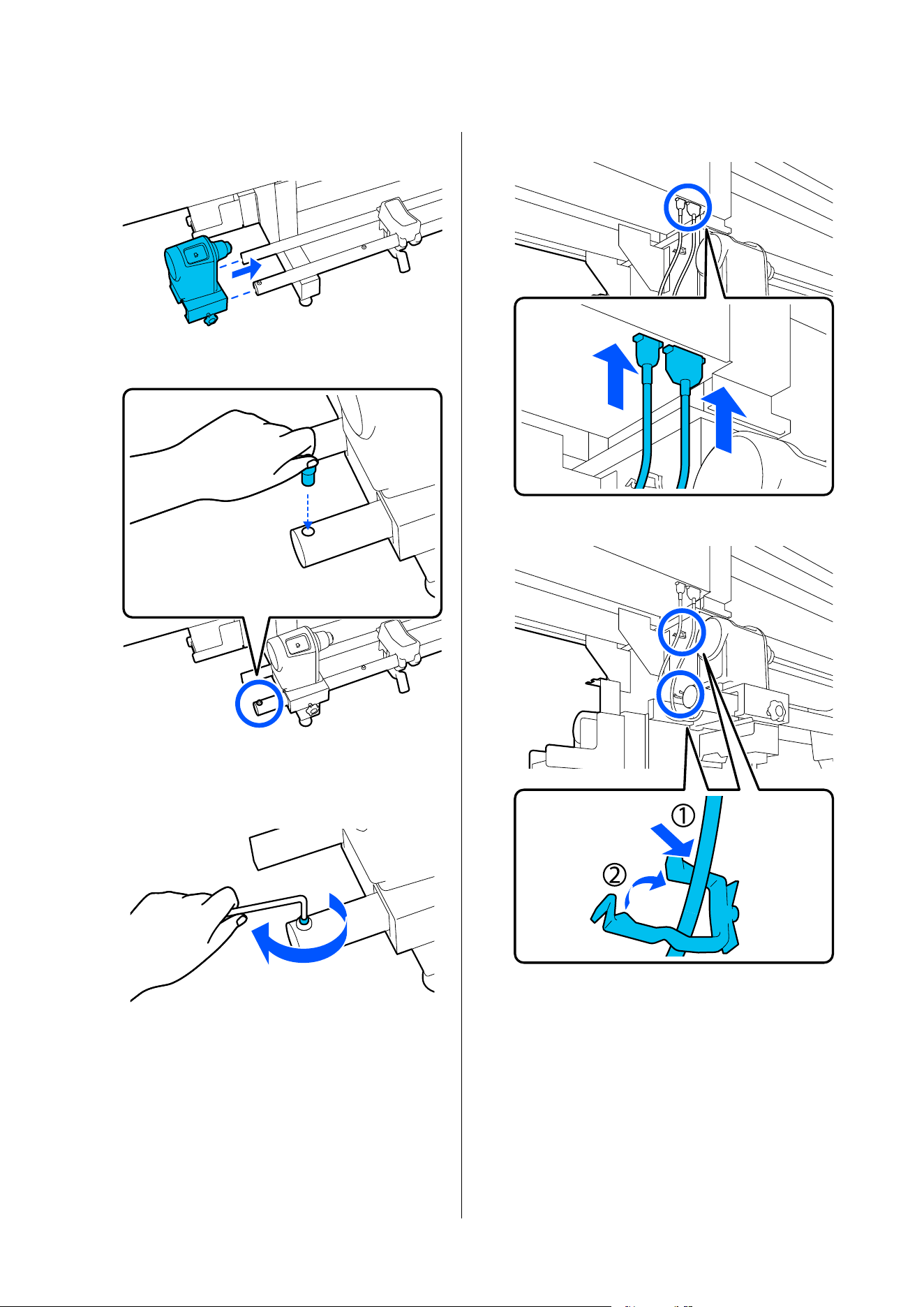
H
Insert the new media holder from the outer
side.
I
Insert the parts you pulled out in Step 6.
J
Use the hex wrench to tighten the screw until
its head is flush.
K
Connect the 2 cables to the printer.
L
Pass the cables through the clamps.
M
On the screen, press Done.
The counter for the media holder is reset.
How to replace the take up media
holder
A
Check that no media is on the auto take-up reel
unit.
If there is any media, remove it.
SC-F20000 Series/SC-F11000H Series/SC-F11000 Series/SC-F10000H Series/SC-F10000 Series User's Guide
Maintenance
179
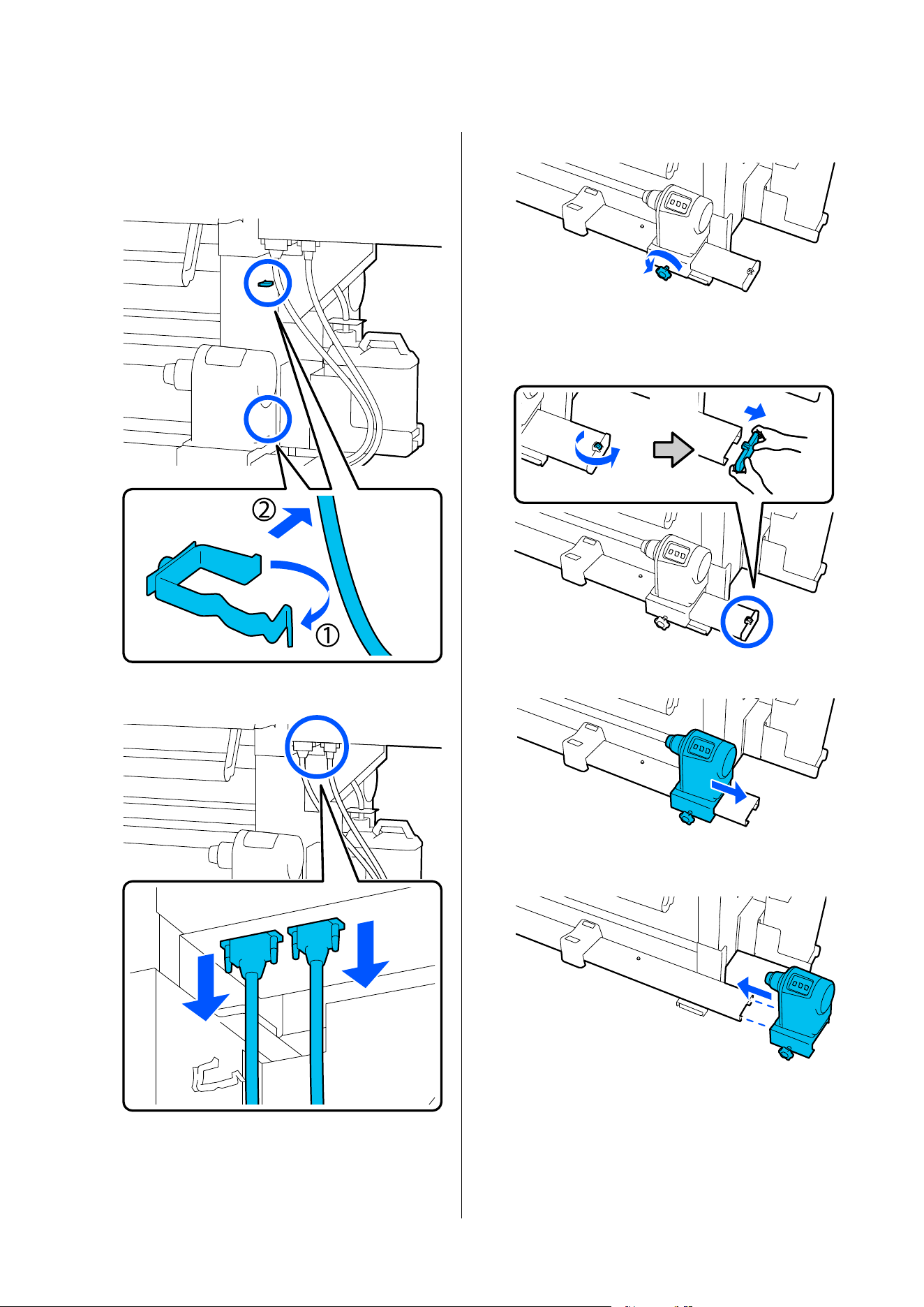
U “Removing the Take-up Roll” on page 130
B
Remove the cables from the clamps.
C
Remove the 2 cables from the printer.
D
Loosen the fixing screw on the media holder.
E
Use a Phillips screwdriver to remove the screw
shown in the illustration, and then remove the
end cover.
F
Pull the media holder toward the outer side.
G
Insert the new media holder from the outer
side.
SC-F20000 Series/SC-F11000H Series/SC-F11000 Series/SC-F10000H Series/SC-F10000 Series User's Guide
Maintenance
180
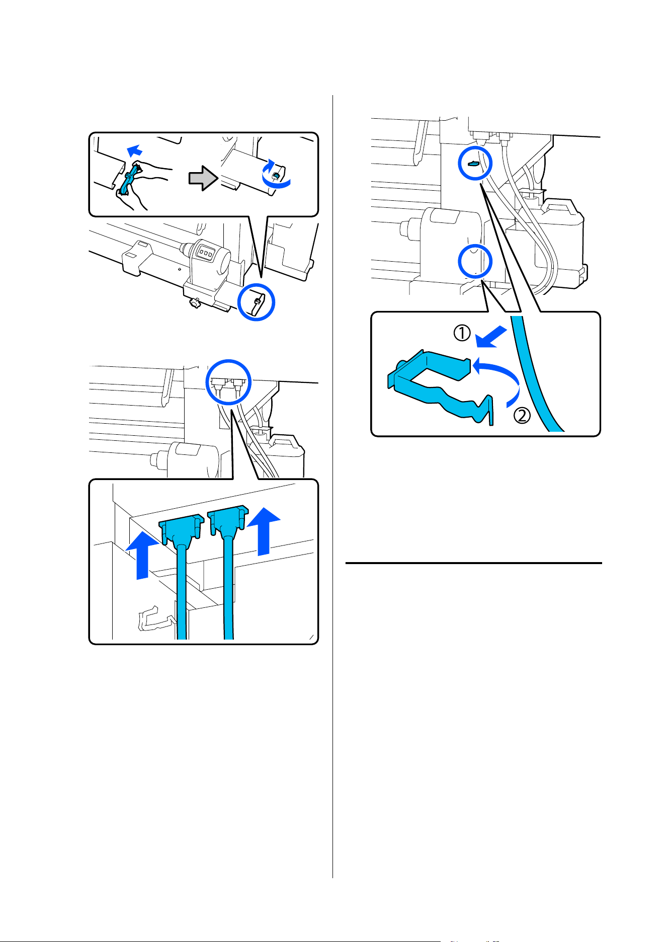
H
Attach the end cover and use a Phillips
screwdriver to tighten the screw.
I
Connect the 2 cables to the printer.
J
Pass the cables through the clamps.
K
On the screen, press Done.
The counter for the media holder is reset.
Other Maintenance
Periodic shaking of ink
cartridges
After installing an ink cartridge in the printer, a shake
message is displayed on the control panel screen at the
following intervals.
❏ High Density Black Ink: Once every week
❏ Other inks: Once every three weeks
If the message appears, remove the ink cartridge
immediately and shake it.
The shaking method to be followed after the
installation differs from that followed when opening
the ink cartridge. Follow the steps below for shaking.
SC-F20000 Series/SC-F11000H Series/SC-F11000 Series/SC-F10000H Series/SC-F10000 Series User's Guide
Maintenance
181
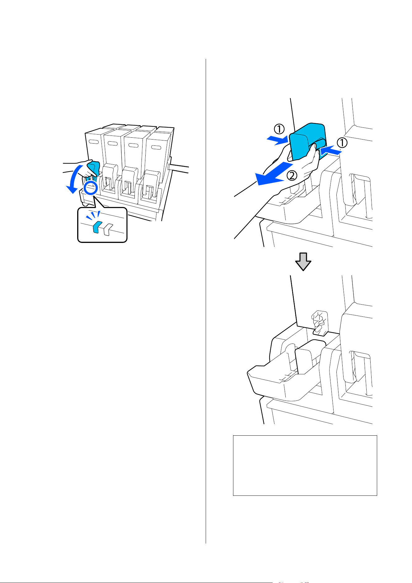
A
Make sure the printer is on, and then lower the
ink cartridge cover of the ink cartridge to be
shaken, toward you.
The ink cartridge with a flashing left (blue)
lamp is the one that needs to be shaken.
B
While pressing the levers on both sides of the
connector, pull the connector toward you to
remove it, and place the connector on the rear
surface of the ink cartridge cover.
c
Important:
Do not leave the connector removed from the
ink cartridge for more than 30 minutes.
Otherwise, the ink will dry out and the
printer may not function as expected.
SC-F20000 Series/SC-F11000H Series/SC-F11000 Series/SC-F10000H Series/SC-F10000 Series User's Guide
Maintenance
182
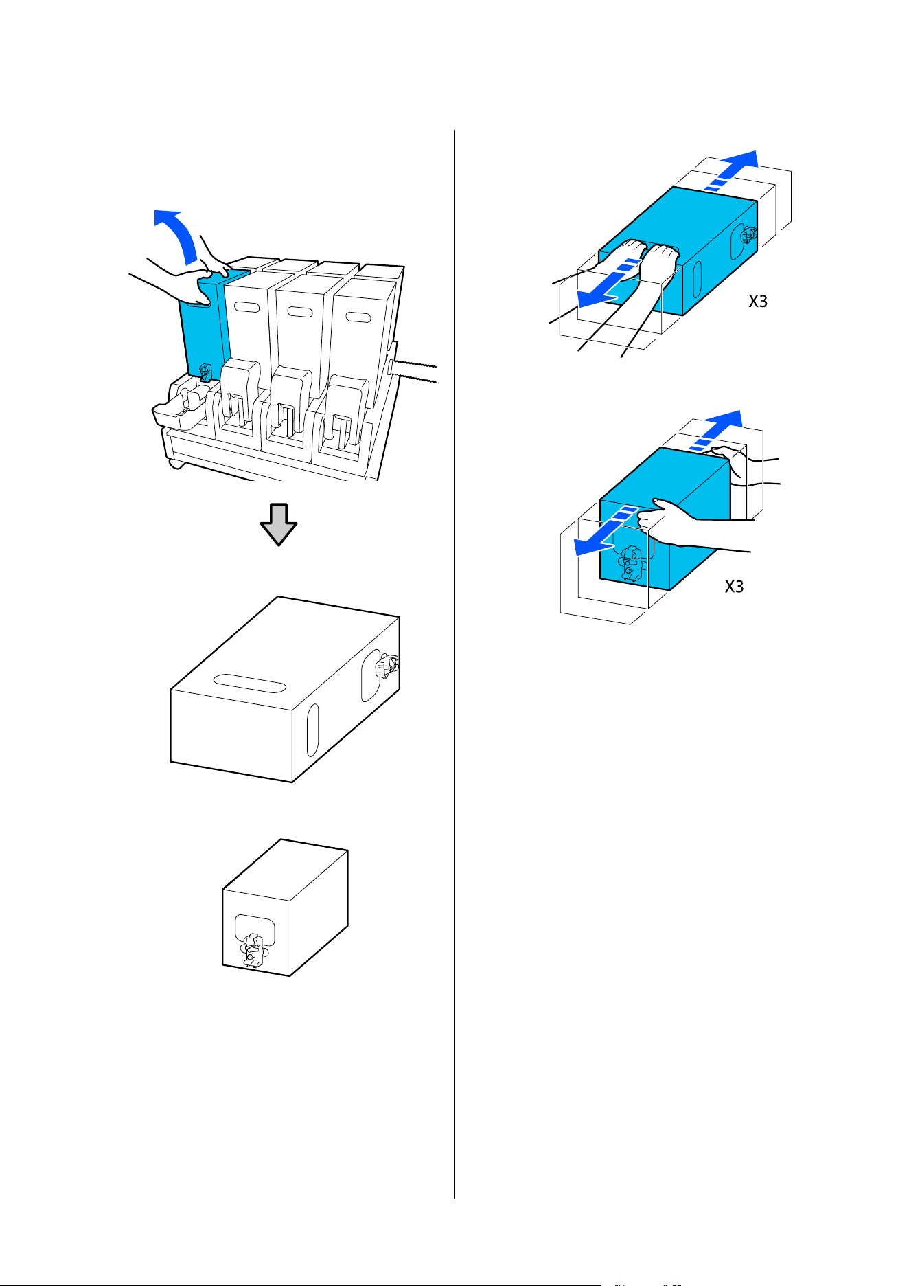
C
Remove the ink cartridge from the ink supply
unit, and place it on a flat surface with the ink
supply outlet facing the side.
❏ When using 10 L ink cartridge
❏ When using 3 L ink cartridge
D
Slide the ink cartridge back and forth
longitudinally within the range of
approximately 10 cm (3.93 in.) for three times.
Move the ink cartridge at a rate of one
back-and-forth cycle per second.
❏ When using 10 L ink cartridge
❏ When using 3 L ink cartridge
E
Turn over the ink cartridge and repeat the same
cycle for three times.
Move the ink cartridge at a rate of one
back-and-forth cycle per second.
SC-F20000 Series/SC-F11000H Series/SC-F11000 Series/SC-F10000H Series/SC-F10000 Series User's Guide
Maintenance
183
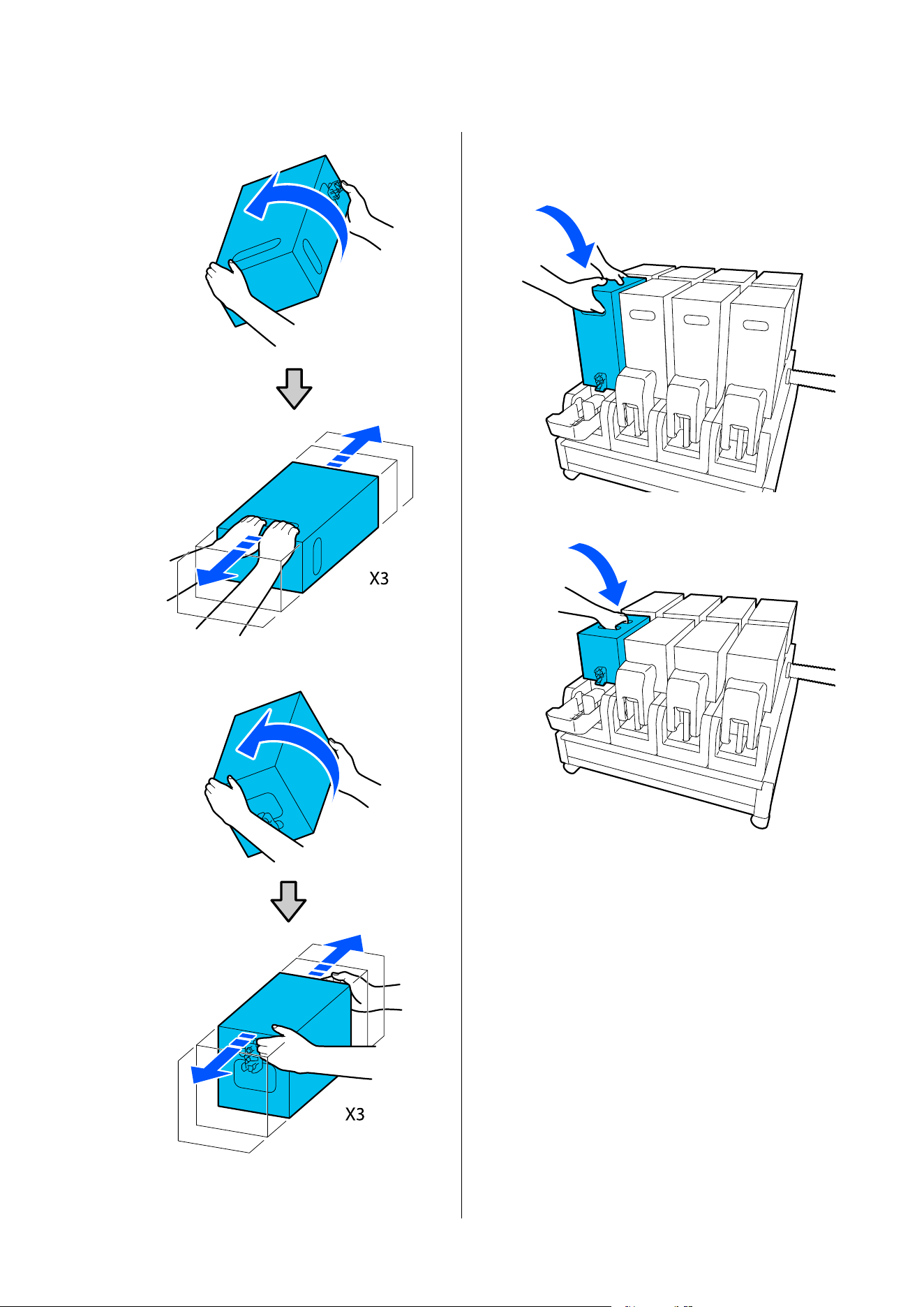
❏ When using 10 L ink cartridge
❏ When using 3 L ink cartridge
F
Place the shaken ink cartridge such that the ink
supply hole faces the connector.
❏ When using 10 L ink cartridge
❏ When using 3 L ink cartridge
SC-F20000 Series/SC-F11000H Series/SC-F11000 Series/SC-F10000H Series/SC-F10000 Series User's Guide
Maintenance
184
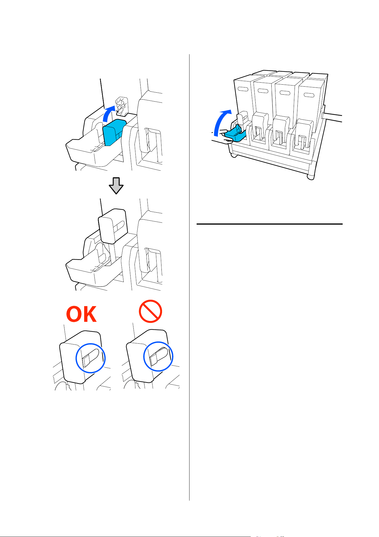
G
Install the connector to the ink supply outlet.
Insert the connector until you hear a click.
H
Raise the ink cartridge cover.
Repeat the same procedure to replace other ink
cartridges.
Checking for clogged nozzles
We recommend that you check the nozzles for clogs
each time you print to ensure quality results.
Ways to Check for Clogs
There are three ways to check for clogs.
On-Demand Nozzle Pattern.
When you want to check that there is no clogging or
stripes and unevenness in print results before printing,
print a nozzle check pattern. Inspect the printed check
pattern visually to determine whether the nozzles are
clogged.
See the following for details.
U “Printing nozzle check patterns” on page 186
Depending on the width of the loaded media, you can
save media by printing additional test patterns in the
space beside an existing pattern:
Set Nozzle Check Pattern for Information Printing.
This prints a check pattern on the left and right edges
of the media during printing. Inspect the check
pattern visually to determine whether nozzles were
clogged during printing.
U “General Settings menu” on page 201
SC-F20000 Series/SC-F11000H Series/SC-F11000 Series/SC-F10000H Series/SC-F10000 Series User's Guide
Maintenance
185
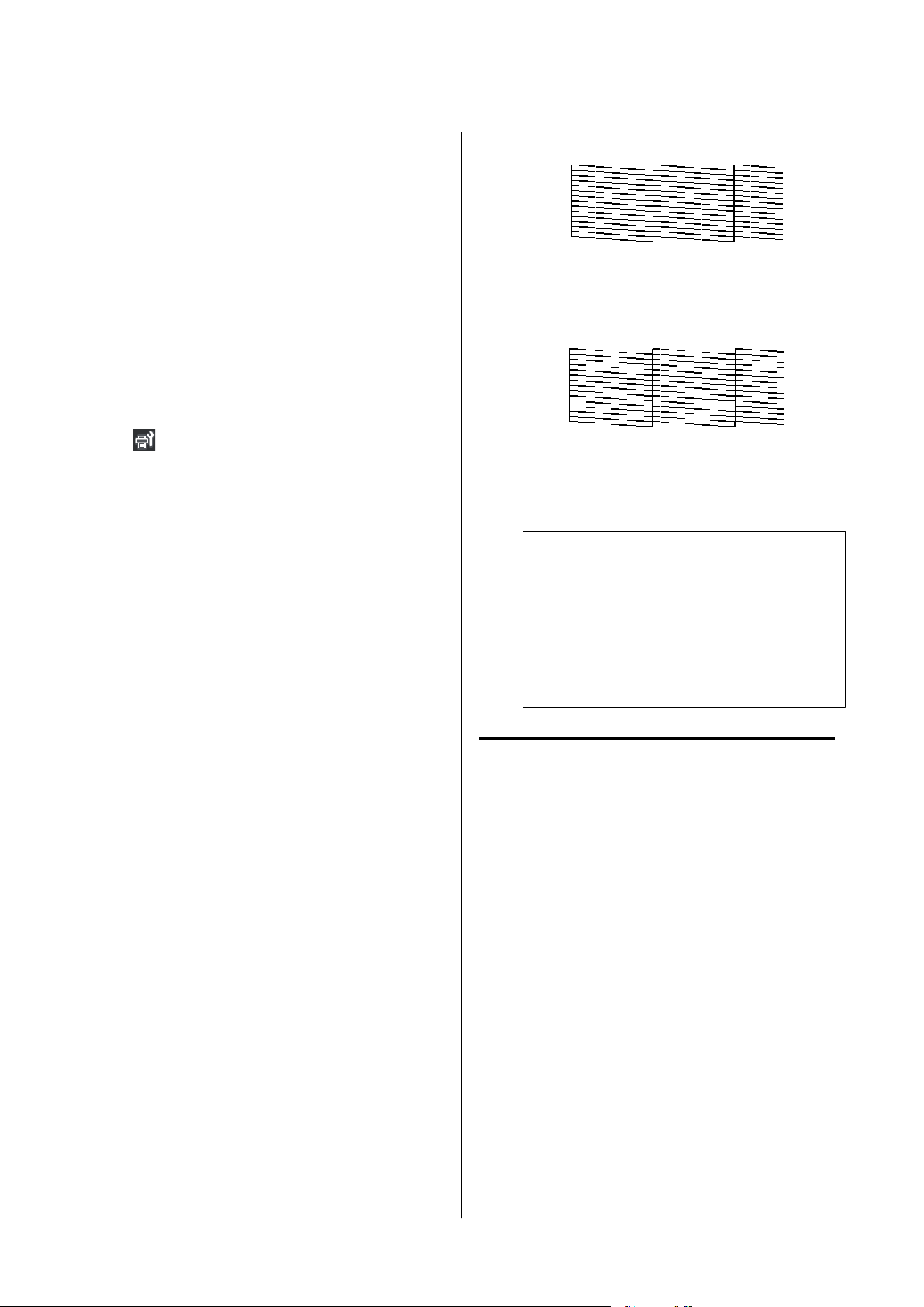
Set Nozzle Check between Pages.
A check pattern is printed according to the Execution
Timing that is set. You can visually inspect the check
pattern to determine whether there may be faint or
missing colors in the preceding or following printout.
You can set one of Print Length, Print Page, or Print
Duration for Execution Timing.
U “General Settings menu” on page 201
Printing nozzle check patterns
A
Check that the printer is ready, and then press
in the Home screen.
The Maintenance menu is displayed.
B
Press Print Head Nozzle Check, set Saving
Mode and Print Position, and then press Start.
Setting Saving Mode to On shortens the printed
length of the check pattern, which reduces the
amount of media that is used.
Depending on the width of the media that is
loaded, the Print Position can be set. By setting
Print Position, you can reduce the amount of
media that is used because you can print the
patterns in line in the margin in which the first
pattern is printed. To print them in line, press
the media feed button to rewind the media to
the position to print the pattern.
The number of patterns that can be printed in a
line varies depending on whether Saving Mode
is set, the width of the media that is loaded, and
the Margins that are set.
Press Start to print the check pattern and feed
the media to a position where the check pattern
is easily visible.
C
Check the printed check pattern.
If the check pattern is still difficult to see, use
the media feed button to feed the media until
the check pattern is easily visible. After
checking the check pattern, the media
automatically rewinds to the print standby
position.
Example of clean nozzles
If no parts of the check pattern are missing,
press OK. The Maintenance screen returns.
Example of clogged nozzles
If parts of the check pattern are missing, press
NG, and then do Print Head Cleaning.
U “Print Head Cleaning” on page 186
c
Important:
Always remove clogs from the nozzles of all
colors before resuming use. If clogged nozzles
(including clogged nozzles for colors that are
not used) remain when printing after
resuming use, the clogs can no longer be
removed.
Print Head Cleaning
Types of Cleaning
Print Head Cleaning is split between the following 3
types.
Perform head cleaning as necessary.
Perform head cleaning if there are faint or missing
parts of the check pattern that was printed.
You can perform head cleaning while printing by
pausing the job. However, printing may be disturbed
when printing is resumed.
See the following for details.
U “Cleaning procedure” on page 187
SC-F20000 Series/SC-F11000H Series/SC-F11000 Series/SC-F10000H Series/SC-F10000 Series User's Guide
Maintenance
186

Set Periodic Cleaning.
In Maintenance Setting, set Periodic Cleaning to On
to do periodic head cleaning as a preventative measure
before clogs actually occur in the nozzles. Set one of
Print Duration, Print Page, or Print Length for the
interval.
U “Maintenance menu” on page 219
Set Maintenance Cleaning.
In Maintenance Setting, setting Maintenance Cleaning
to On cleans the print heads automatically, after a set
period of time has passed, to keep the print heads in
good condition.
U “Maintenance menu” on page 219
Cleaning procedure
Print Head Cleaning has the following three types.
❏ Auto Cleaning
The level is automatically changed, according to
the condition of the clog detected in a nozzle, and
then cleaning is done.
❏ Cleaning(Light), Cleaning(Medium),
Cleaning(Heavy)
Cleaning is done at one of three selected levels.
❏ Print Head Refresh
Powerful cleaning is done with the ink suction
function of the suction caps.
Perform Auto Cleaning first. If the clogs are not
cleared by doing it, then do in the order of
Cleaning(Light), Cleaning(Medium), and
Cleaning(Heavy) until the clogs are cleared.
Execute Print Head Refresh if there are multiple large
clogs, even though you executed Cleaning(Heavy).
When you execute Print Head Refresh, the suction
caps need to be cleaned, because of this, the cleaning
operation takes a long time, so execute it if you have
the problem described above.
A
Check that the printer is ready, and then press
.
The Maintenance menu is displayed.
B
Press Print Head Cleaning.
C
Select a cleaning method.
Select Auto Cleaning first.
For the second and subsequent cleanings, select
in the order of Cleaning(Light),
Cleaning(Medium) and Cleaning(Heavy).
D
Head cleaning starts.
A cleaning result message is displayed when
head cleaning is complete.
E
Check the message and click OK.
If clogging is cleared
Continue with normal operations.
If clogging is not cleared
Go back to Step 1 and do Cleaning(Light).
After executing Cleaning(Light), execute
cleaning at the next higher cleaning level.
If nozzles are still clogged even after
performing Cleaning(Heavy)
The print head or the areas around the
anti-drying caps may be soiled. Clean around
the print head and anti-drying caps. If there are
multiple large clogs, then do Print Head
Refresh at the same time.
U “Cleaning around the print head” on
page 164
U “Cleaning anti-drying caps” on page 160
U “Maintenance menu” on page 219
Checking the circuit breaker’s
performance
The circuit breaker automatically cuts off the electric
circuit when electric leakage has occurred in the
printer. Follow the procedure below to check the
performance of both circuit breakers about once a
month.
The breaker may be changed or removed without
notice. The procedure for operation is the same, even
when slight changes are made to the Trip button or
Test button position or to the description of the
breaker.
SC-F20000 Series/SC-F11000H Series/SC-F11000 Series/SC-F10000H Series/SC-F10000 Series User's Guide
Maintenance
187
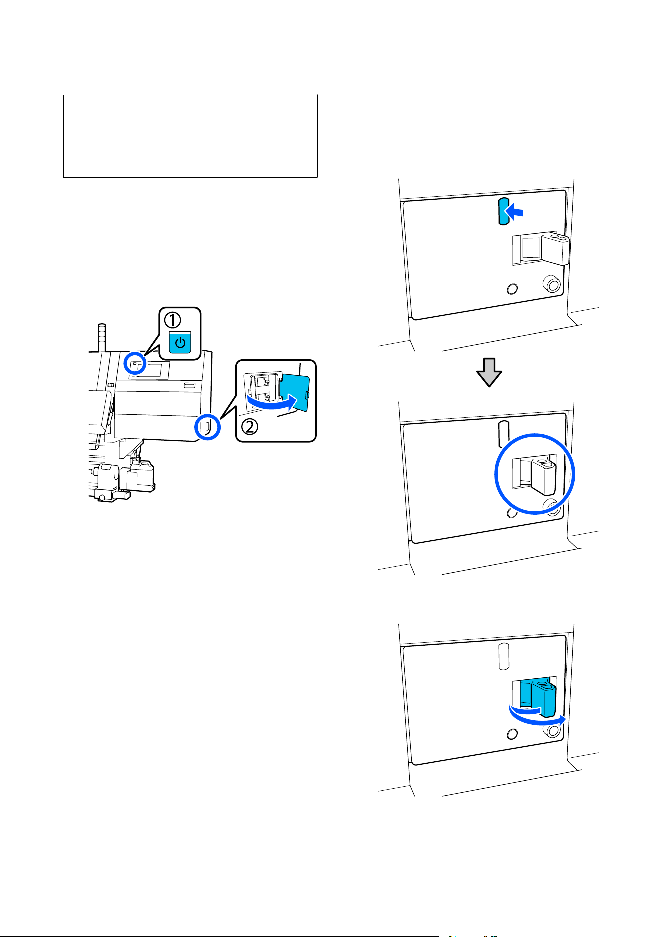
c
Important:
Do not turn off the power by using the circuit
breaker. Otherwise, the printer may not function
as expected.
A
Turn off the printer and open the circuit
breaker cover.
Leave the power plug plugged in. Also, the
ground wire must be connected when checking
the circuit breaker's performance. Check
“Safety Precautions” for details on the ground
wire.
B
Press the Trip button of a circuit breaker with a
fine-tipped tool such as a ball-point pen.
The breaker is working properly if the breaker
switch moves to an intermediate position
between ON and OFF.
C
If the breaker has worked properly, turn OFF
the breaker switch once and turn it back ON.
SC-F20000 Series/SC-F11000H Series/SC-F11000 Series/SC-F10000H Series/SC-F10000 Series User's Guide
Maintenance
188
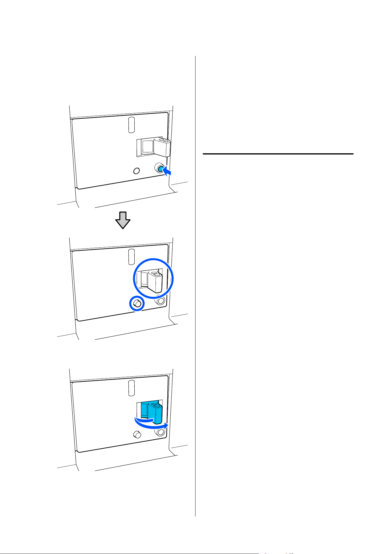
D
Press the Test button.
The breaker is working properly if an electric
leakage check button protrudes and the breaker
switch moves to an intermediate position
between ON and OFF.
E
If the breaker has worked properly, turn OFF
the breaker switch once and turn it back ON.
F
Repeat Steps 2 to 5 to check the performance of
the other circuit breaker.
If any abnormality is found, contact your local
dealer or Epson service call center.
Disposing of Used
Consumables
Disposal
The following used parts with adhered ink are
classified as industrial waste.
❏ Ink cartridges
❏ Cleaning stick
❏ Cleaning fluid
❏ Waste ink
❏ Waste Ink Bott le
❏ Wiper Roll
❏ Media after printing
Dispose of items according to local laws and
regulations. For example, contract a industrial waste
disposal company for disposal. In such cases, submit
the “Safety data sheet” to the industrial waste disposal
company.
You can download it from your local Epson website.
SC-F20000 Series/SC-F11000H Series/SC-F11000 Series/SC-F10000H Series/SC-F10000 Series User's Guide
Maintenance
189
Control Panel Menu
Menu List
The following items and parameters can be set and executed in the Menu. See the reference pages for more details
on each item.
General Settings
For more information on these items, see U “General Settings menu” on page 201
Item Parameter
Basic Settings
LCD Brightness 1 to 9
Sound
Button Press 0 to 3
Alert 0 to 3
Completion Notice 0 to 3
Warning Notice
Volume 0 to 3
Repeat Never, Until Stopped
Error Tone
Volume 0 to 3
Repeat Never, Until Stopped
Sound Type Pattern1, Pattern2
Sleep Timer 1 to 240 minutes
Wake from Sleep
Touch LCD Screen to Wake On, Off, Scheduled
Date/Time Settings
Date/Time
Daylight Saving Time
Off, On (Winter, Summer)
*1
SC-F20000 Series/SC-F11000H Series/SC-F11000 Series/SC-F10000H Series/SC-F10000 Series User's Guide
Control Panel Menu
190
Item Parameter
Time Difference -12:45 to +13:45
Language Japanese, English, French, Italian, German, Portuguese, Spanish,
Dutch, Russian, Turkish, Korean, Simplified Chinese, Traditional
Chinese
Background Color Gray, Black, White
Keyboard QWERTY, AZERTY, QWERTZ
Unit Settings
Length m, ft/in
Temperature ˚C, ˚F
Printer Settings
SC-F20000 Series/SC-F11000H Series/SC-F11000 Series/SC-F10000H Series/SC-F10000 Series User's Guide
Control Panel Menu
191
Item Parameter
Margins
Side(Right) 3 to 25 mm (0.11 to 0.98 in.)
Side(Left) 3 to 25 mm (0.11 to 0.98 in.)
Margin Between Pages 0 to 999 mm (0 to 39.33 in.)
Width Adjustment -10 to +10 mm (-0.39 to 0.39 in.)
Print Start Position 0 to 1000 mm (0 to 39.37 in.)
Skip Wrinkled Media On, Off
Job Connection On, Off
Information Printing
Off
On
Margin Between Images 5 to 999 mm (0.19 to 39.33 in.)
Print Position Next to the Image, Media End
Event Marking
Off
On
Print Position Left, Right, Left and Right
Nozzle Check Pattern
Pattern Selection Do Not Print, Normal, Paper Width Saving
Print Position Left, Right, Left and Right
Ink Density Standard, Dark
Media Detection
Width Detection
On
Off 300.0 to 1950.0 mm (11.81 to 76.77 in.)
SC-F20000 Series/SC-F11000H Series/SC-F11000 Series/SC-F10000H Series/SC-F10000 Series User's Guide
Control Panel Menu
192
Item Parameter
Actions after Media Scuffing Stop Immediately, Stop when Continuously Detected, Ignore
Nozzle Check between Pages
On
Execution Timing
Print Length 1 to 9999 meters (3.28 to 32805.12 ft.)
Print Page Pages 1 to 9999
Print Duration 1 to 9999 minutes
Execution during Job On, Off
Pattern Type Paper Saving, Normal
Off
Information Printing at Media Cut
Paper Remaining Information On, Off
Print Information On, Off
Heater Off Timer 0 to 30 minutes
Internal lamp Auto, Manual
Custom Setting
*2
On, Off
Restore Default Settings Network Settings, Clear All Data and Settings
Maintenance Setting
Cleaning Setting
Threshold Of Clogged Nozzles 1 to 50
Max Retry Cleaning Count 0, 1, 2
Maintenance Schedule Between Jobs, When Detected
Nozzle Compensation On, Off
Periodic Cleaning
On
Print Duration 1 to 9999 minutes
Print Page Pages 1 to 9999
Print Length 1 to 9999 meters (3.28 to 32805.12 ft.)
Off
Actions Beyond the Threshold of Missing Nozzles Stop Printing, Show Alert, Auto Cleaning
Maintenance Cleaning
SC-F20000 Series/SC-F11000H Series/SC-F11000 Series/SC-F10000H Series/SC-F10000 Series User's Guide
Control Panel Menu
193
Item Parameter
On
Interval 1 to 240 hours
Off
Network Settings
Network Status Wired LAN Status, Print Status Sheet
Advanced
Device Name
TCP/IP
Proxy Server
IPv6 Address Enable, Disable
Link Speed & Duplex Auto, 10BASE-T Half Duplex, 10BASE-T Full Duplex, 100BASE-TX
Half Duplex, 100BASE-TX Full Duplex, 1000BASE-T Full Duplex
Redirect HTTP to HTTPS Enable, Disable
Disable IPsec/IP Filtering
Disable IEEE802.1X
*1 Only displayed for the SC-F20070/SC-F11070H/SC-F11070/SC-F10070H/SC-F10070.
*2 Not displayed on the SC-F20000 Series.
Media Settings
For more information on these items, see U. “Media Settings menu” on page 209
Item Parameter
Current Settings
Media 01 XXXXXXXXXX to 50 XXXXXXXXXX
Media Type
Media width
Pass Mode
Advanced Settings
Print Adjustments
Automatic Adjustment
Print Head Alignment Auto, Manual(Simple), Manual(Standard)
Media Feed Adjustment Auto(Standard), Auto(Details), Manual(Standard),
Manual(Measurement)
Media Management
SC-F20000 Series/SC-F11000H Series/SC-F11000 Series/SC-F10000H Series/SC-F10000 Series User's Guide
Control Panel Menu
194
Item Parameter
01 XXXXXXXXXX to 50 XXXXXXXXXX
Change Name
Media Type
Ultra-Thin 30g/m
2
, Thin 50g/m
2
, Med-Thick 70g/m
2
, Thick
120g/m
2
Pass Mode (SC-F11000H Series/SC-F11000 Series/
SC-F10000H Series/SC-F10000 Series)
300x600dpi 1.1pass, 300x600dpi 1.5pass, 300x600dpi 2.1pass,
300x600dpi 3.1pass, 600x600dpi 2.1pass, 600x600dpi 2.5pass,
600x600dpi 3.1pass, 600x600dpi 4.3pass, 600x1200dpi 5.0pass,
600x1200dpi 5.0pass HD, 1200x1200dpi 9.0pass HD
Pass Mode (SC-F20000 Series) 600x600dpi 1.0pass HS, 600x600dpi 1.1pass HS, 600x600dpi
1.5pass HS, 600x600dpi 2.1pass HS, 600x600dpi 1.1pass,
600x600dpi 1.5pass, 600x600dpi 2.1pass, 600x1200dpi 3.1pass,
1200x1200dpi 5.0pass HD
Advanced Settings
Dryer
Heater On, Off
Temperature (SC-F11000H Series/SC-F11000 Series/SC-F10000H Series/SC-F10000 Series)
300x600dpi 1.1pass 50 to 110 ˚C (122 to 230 ˚F)
300x600dpi 1.5pass 50 to 110 ˚C (122 to 230 ˚F)
300x600dpi 2.1pass 50 to 110 ˚C (122 to 230 ˚F)
300x600dpi 3.1pass 50 to 110 ˚C (122 to 230 ˚F)
600x600dpi 2.1pass 50 to 110 ˚C (122 to 230 ˚F)
600x600dpi 2.5pass 50 to 110 ˚C (122 to 230 ˚F)
600x600dpi 3.1pass 50 to 110 ˚C (122 to 230 ˚F)
600x600dpi 4.3pass 50 to 110 ˚C (122 to 230 ˚F)
600x1200dpi 5.0pass 50 to 110 ˚C (122 to 230 ˚F)
600x1200dpi 5.0pass HD 50 to 110 ˚C (122 to 230 ˚F)
1200x1200dpi 9.0pass HD 50 to 110 ˚C (122 to 230 ˚F)
SC-F20000 Series/SC-F11000H Series/SC-F11000 Series/SC-F10000H Series/SC-F10000 Series User's Guide
Control Panel Menu
195
Item Parameter
Temperature (SC-F20000 Series)
600x600dpi 1.0pass HS 50 to 110 ˚C (122 to 230 ˚F)
600x600dpi 1.1pass HS 50 to 110 ˚C (122 to 230 ˚F)
600x600dpi 1.5pass HS 50 to 110 ˚C (122 to 230 ˚F)
600x600dpi 2.1pass HS 50 to 110 ˚C (122 to 230 ˚F)
600x600dpi 1.1pass 50 to 110 ˚C (122 to 230 ˚F)
600x600dpi 1.5pass 50 to 110 ˚C (122 to 230 ˚F)
600x600dpi 2.1pass 50 to 110 ˚C (122 to 230 ˚F)
600x1200dpi 3.1pass 50 to 110 ˚C (122 to 230 ˚F)
1200x1200dpi 5.0pass HD 50 to 110 ˚C (122 to 230 ˚F)
Fan Off, Low, High
Drying Action Auto, Follow Drying Time Setting
Drying Time (SC-F11000H Series/SC-F11000 Series/SC-F10000H Series/SC-F10000 Series)
300x600dpi 1.1pass 0 to 200 sec
300x600dpi 1.5pass 0 to 200 sec
300x600dpi 2.1pass 0 to 200 sec
300x600dpi 3.1pass 0 to 200 sec
600x600dpi 2.1pass 0 to 200 sec
600x600dpi 2.5pass 0 to 200 sec
600x600dpi 3.1pass 0 to 200 sec
600x600dpi 4.3pass 0 to 200 sec
600x1200dpi 5.0pass 0 to 200 sec
600x1200dpi 5.0pass HD 0 to 200 sec
1200x1200dpi 9.0pass HD 0 to 200 sec
SC-F20000 Series/SC-F11000H Series/SC-F11000 Series/SC-F10000H Series/SC-F10000 Series User's Guide
Control Panel Menu
196
Item Parameter
Drying Time (SC-F20000 Series)
600x600dpi 1.0pass HS 0 to 200 sec
600x600dpi 1.1pass HS 0 to 200 sec
600x600dpi 1.5pass HS 0 to 200 sec
600x600dpi 2.1pass HS 0 to 200 sec
600x600dpi 1.1pass 0 to 200 sec
600x600dpi 1.5pass 0 to 200 sec
600x600dpi 2.1pass 0 to 200 sec
600x1200dpi 3.1pass 0 to 200 sec
1200x1200dpi 5.0pass HD 0 to 200 sec
Proceed to Drying after Print Off, On
Platen Gap
1.7
2.0
2.5
Feeding Tension Lv1 to Lv4
Paper Suction Lv0 to Lv10
Media Feed Speed Limitation On, Off
Pressure Roller Load Light, Standard
Remove Skew On, Off
Stick Prevention On, Off
SC-F20000 Series/SC-F11000H Series/SC-F11000 Series/SC-F10000H Series/SC-F10000 Series User's Guide
Control Panel Menu
197
Item Parameter
Rewind Tension (SC-F11000H Series/SC-F11000 Series/SC-F10000H Series/SC-F10000 Series)
300x600dpi 1.1pass Lv1 to Lv9
300x600dpi 1.5pass Lv1 to Lv9
300x600dpi 2.1pass Lv1 to Lv9
300x600dpi 3.1pass Lv1 to Lv9
600x600dpi 2.1pass Lv1 to Lv9
600x600dpi 2.5pass Lv1 to Lv9
600x600dpi 3.1pass Lv1 to Lv9
600x600dpi 4.3pass Lv1 to Lv9
600x1200dpi 5.0pass Lv1 to Lv9
600x1200dpi 5.0pass HD Lv1 to Lv9
1200x1200dpi 9.0pass HD Lv1 to Lv9
Rewind Tension (SC-F20000 Series)
600x600dpi 1.0pass HS Lv1 to Lv9
600x600dpi 1.1pass HS Lv1 to Lv9
600x600dpi 1.5pass HS Lv1 to Lv9
600x600dpi 2.1pass HS Lv1 to Lv9
600x600dpi 1.1pass Lv1 to Lv9
600x600dpi 1.5pass Lv1 to Lv9
600x600dpi 2.1pass Lv1 to Lv9
600x1200dpi 3.1pass Lv1 to Lv9
1200x1200dpi 5.0pass HD Lv1 to Lv9
Print Quality Adjustment Limitation Temperature 0 to 50 ˚C (32 to 122 ˚F)
Manage Remaining Amount
Manage Remaining Amount On, Off
Remaining Amount 1.0 to 9999.9 m (3.3 to 32808.1 ft.)
Remaining Alert 1.0 to 999.5 m (3.3 to 3279.2 ft.)
Print Length Management
Auto Reset Off, After Last Page
Manual Reset
SC-F20000 Series/SC-F11000H Series/SC-F11000 Series/SC-F10000H Series/SC-F10000 Series User's Guide
Control Panel Menu
198
Maintenance
For more information on these items, see U. “Maintenance menu” on page 219
Item Parameter
Print head nozzle check
Saving Mode On, Off
Print Position Right, Center Right, Center Left, Left
Print Head Cleaning Auto Cleaning, Cleaning(Light), Cleaning(Medium),
Cleaning(Heavy), Print Head Refresh
Cleaning the Maintenance Parts Anti-Drying Caps, Around the Head, Suction Cap, Media Cleaner
Print Head Nozzle Limitation On, Off
Replace Waste Ink Bottle
Replace Maintenance Parts Replace Wiper Roll, Replace Take In Media Holder, Replace Take
Up Media Holder
Supply Status
Details on the menu U “Supply Status menu” on page 220
Item Parameter
Ink/Waste Ink Bottle
Others
Replacement Part Information
Details on the menu U “Replacement Part Information menu” on page 220
Item Parameter
SC-F11000H Series/SC-F11000 Series/SC-F10000H Series/SC-F10000 Series:
Ink Supply Pump
Anti-Drying Caps Drive Assembly
Cleaning Pump
Wiper Unit Drive Assembly
Suction Pump
Ink Tube
SC-F20000 Series:
SC-F20000 Series/SC-F11000H Series/SC-F11000 Series/SC-F10000H Series/SC-F10000 Series User's Guide
Control Panel Menu
199
Item Parameter
Ink Supply Pump1
Ink Supply Pump2
Anti-Drying Caps Drive Assembly
Cleaning Pump
Wiper Unit Drive Assembly
Suction Pump
Ink Tube
Printer Status
Details on the menu U “Printer Status menu” on page 221
Item Parameter
Firmware Version
Printer Name
Fatal Error Log
Operation Report Total Print Area, Total Media Feed Length, Total Carriage Pass
SC-F20000 Series/SC-F11000H Series/SC-F11000 Series/SC-F10000H Series/SC-F10000 Series User's Guide
Control Panel Menu
200
Details of the Menu
General Settings menu
* indicates default settings.
Item Parameter Explanation
Basic Settings
LCD Brightness
1 to 9 (9
*
)
Adjusts the brightness of the control panel display.
Sound
Button Press
0 to 3 (1
*
)
Sets the volume of the sounds when the power button and control
panel screen are operated.
Alert
0 to 3 (2
*
)
Sets the volume of the sounds when hardware, such as the covers and
media loading lever, are operated.
Completion Notice
0 to 3 (3
*
)
Sets the volume of the sounds when print jobs or maintenance
operations are finished.
Warning Notice Sets the volume and the repetitions of sounds when it is time to replace
consumables.
Volume
0 to 3 (2
*
)
Repeat
Never
*
Until Stopped
Error Tone Sets the volume and the repetitions of sounds when an error occurs
while printing and printing cannot continue.
Volume
0 to 3 (3
*
)
Repeat Off
Until Stopped
*
Sound Type
Pattern1
*
Sets the type of sounds. Sounds that are easy to hear in the printer's
operating environment can be set.
Pattern2
SC-F20000 Series/SC-F11000H Series/SC-F11000 Series/SC-F10000H Series/SC-F10000 Series User's Guide
Control Panel Menu
201
Item Parameter Explanation
Sleep Timer
1 to 240 (15
*
)
The printer enters sleep mode after a specified time during which no
print jobs are received, no errors are detected, and the heater is off. In
sleep mode, the control panel screen, the internal optical sensors, and
inside lights turn off.
The screen display recovers when you press on the control panel screen.
Sleep mode is canceled and the printer returns to normal when a print
job is received, an operation involving printer hardware is done, such as
operating the media loading lever.
To cancel sleep mode and begin preheating the heater immediately,
press Preheat Start on the Home screen.
Wake from Sleep
Touch LCD Screen
to Wake
On
*
Set this to wake from sleep mode by performing operations on the
touch panel.
To recover by doing screen operations, set On.
To not recover by doing screen operations, but to instead recover by
pressing the power button, set Off.
By setting Scheduled, you can switch between On/Off at specified
times.
Off
Scheduled
Date/Time Settings
Date/Time Set the printer’s built-in clock. The time and date set here are displayed
on the Home screen. It is also used for job logs and the printer's status,
as shown in Epson Edge Dashboard.
Daylight Saving
Time
Off (Winter)
*
Sets daylight saving time.
Winter and Summer are only displayed for the SC-F11070H/SC-F11070/
SC-F10070H/SC-F10070.
On (Summer)
SC-F20000 Series/SC-F11000H Series/SC-F11000 Series/SC-F10000H Series/SC-F10000 Series User's Guide
Control Panel Menu
202
Item Parameter Explanation
Time Difference -12:45 to +13:45 Set the time difference with coordinated universal time (UTC) in 15
minute increments. In network environments with a time difference, set
this as necessary when administrating the printer.
Language Japanese Select the language used in the control panel display.
English
French
Italian
German
Portuguese
Spanish
Dutch
Russian
Turkish
Korean
Simplified Chinese
Traditional Chinese
Background Color Gray Select the color scheme used in the control panel display. You can set a
color scheme that is easy to see in the environment in which the printer
is installed.
Black
*
White
Keyboard
QWERTY
*
Select the keyboard layout for the text input screen that appears, such
as when inputting names to register for media settings.
AZERTY
QWERTZ
Unit Settings
Length
m
*
Choose the units of length used in the control panel display and when
printing test patterns.
ft/in
Temperature
˚C
*
Choose the temperature units used in the control panel display.
˚F
Printer Settings
SC-F20000 Series/SC-F11000H Series/SC-F11000 Series/SC-F10000H Series/SC-F10000 Series User's Guide
Control Panel Menu
203
Item Parameter Explanation
Margins
Side(Right)
3 to 25 mm (7
*
)
(0.11 to 0.98 in.
[0.27
*
])
Set the margin from the right media edge in the media output
direction.
U “Printable Area” on page 145
Side(Left)
3 to 25 mm (7
*
)
(0.11 to 0.98 in.
[0.27
*
])
Set the margin from the left media edge in the media output direction.
U “Printable Area” on page 145
Margin Between Pa-
ges
0 to 999 mm (10
*
) (0
to 39.33 in. [0.39
*
])
Sets the margin between printed pages.
If you want to set it to less than 300 mm (11.81 in.), set Skip Wrinkled
Media to Off.
Width Adjustment
-10 to +10 mm (0
*
)
(-0.39 to 0.39 in.
[0
*
])
You can adjust a margin between pages. Even after making
adjustments, the size of the margin may change, depending on the
media and usage environment.
The margin increases when the number is moved in the + direction, and
decreases when the number is moved in the - direction.
U “Printable Area” on page 145
Print Start Position
0 to 1000 mm (0
*
)
(0 to 39.37 in. [0
*
])
Adjust this parameter if you want to print from the near center of the
media or if you want to shift the printed area center from the Side(Left)
setting. The margin is the value set in Print Start Position, measured
from the media edge on the reference side. If a value is selected for
Side(Left), an additional area corresponding to the width selected for
Side(Left) is left blank.
See the following for more information.
U “Printable Area” on page 145
Skip Wrinkled Media
On
*
Normally, leave this On.
When this is On, if jobs do not print continuously, 300 mm (11.81 in.) of
media is fed to skip wrinkled parts, and then printing is done.
Off
Job Connection On When this is turned On, the next job starts printing without feeding
media, drying, or rewinding between continuous print jobs. There are
no operations between jobs so printing time is that much shorter.
Off
*
SC-F20000 Series/SC-F11000H Series/SC-F11000 Series/SC-F10000H Series/SC-F10000 Series User's Guide
Control Panel Menu
204
Item Parameter Explanation
Information Printing
Off
*
When this is turned On, a mark and the nozzle check pattern are printed
on the end of the media, so it is easier to check print quality.
Margin Between Images:
Set the interval between images and the marks and check patterns.
Print Position:
Set Next to the Image to print in the position open between the
margin between images using the edge of images as a reference. When
Media End is set, printing is done in the position using the edge of the
media as a reference.
Event Marking:
When this is turned On, a mark is printed when an event that affects
print quality occurs while printing. This makes it easier to find poor
quality areas during and after printing.
The following events cause a mark to be printed.
❏ Change in state of clogged nozzles: When there is a change in
nozzle clog conditions after printing starts
❏ Head cleaning: When head cleaning is executed manually
❏ Automatic head cleaning: When automatic head cleaning is
executed
❏ Head striking: When the striking of the media and print head is
detected
❏ Suspension: When printing is suspended
❏ Start of nozzle compensation
Set a position, in which marks are easy to check, in Print Position.
Nozzle Check Pattern:
When pattern selection is Normal or Paper Width Saving, the nozzle
check pattern prints continuously during printing. When printing print
jobs continuously or when printing a long job, you can immediately
understand if nozzles clog while printing. The width of the check
pattern is narrower than Normal when Paper Width Saving is set, so
the image print area is wider.
Set a position, in which check patterns are easy to check, in Print
Position.
When Ink Density is set to Dark, check patterns are easy to check.
On
Margin Between
Images
5 to 999 mm (5
*
)
(0.19 to 39.33 in.
[0.11
*
])
Print Position
Next to the Image
*
Media End
Event Marking
Off
*
On
Print Position Left
Right
Left and Right
Nozzle Check Pattern
Pattern Selec-
tion
Do Not Print
Normal
*
Paper Width Saving
Print Position
Left
*
Right
Left and Right
Ink Density
Standard
*
Dark
Media Detection
Width Detection Select whether the media width is detected (On) or not (Off). Try
setting Off when printing if media width errors are displayed even
though the media is correctly loaded. Note, however, that the printer
may print beyond the edges of the media when Off is selected. Printing
beyond the edges of the media will stain the inside of the printer. We
recommend this normally be set to On when using the printer.
Changed settings are reflected when the media is reloaded.
On
*
Off 300.0 to 1950.0 mm
(300.0
*
) (11.81 to
76.77 in. [11.81
*
])
SC-F20000 Series/SC-F11000H Series/SC-F11000 Series/SC-F10000H Series/SC-F10000 Series User's Guide
Control Panel Menu
205
Item Parameter Explanation
Actions after Media
Scuffing
Stop Immediately
*
The printer constantly monitors for striking of the media and print head
while printing, so set the operation for when striking occurs.
When Stop Immediately is set, printing stops immediately when
striking is detected.
When Stop when Continuously Detected is set, printing stops if
striking is detected 3 times within 72 cm (28.35 in.) of fed paper.
When Ignore is set, printing does not stop even if striking is detected.
When striking is detected, the stopped media wrinkles, so take
measures, such as adjusting the temperature of the heater, and clean
the area around the print head if needed.
Stop when
Continuously
Detected
Ignore
Nozzle Check between Pages When On is set, a nozzle check pattern is printed periodically at the
specified timing. When printing is complete, you can visually inspect
the check pattern to determine whether there may be faint or missing
colors in the preceding or following printout.
Execution Timing sets the timing that check patterns are printed.
Execution during Job selects whether to print (On)/not to print (Off) a
check pattern at the set timing during a print job. When Off is set, the
images are nested because a check pattern is printed during printing.
When On is set, a check pattern is printed after finishing the print job.
Normally, leave this On.
Pattern Type selects the type of check pattern. When Paper Saving is
set, media is saved because the length of media needed to print a check
pattern is shorter than for Normal.
On
Execution Timing
Print Length 1 to 9999 meters
(3.28 to 32805.12 ft.)
Print Page Pages 1 to 9999
Print Duration 1 to 9999 minutes
Execution during
Job
On
Off
Pattern Type Paper Saving
Normal
Off
*
SC-F20000 Series/SC-F11000H Series/SC-F11000 Series/SC-F10000H Series/SC-F10000 Series User's Guide
Control Panel Menu
206
Item Parameter Explanation
Information Printing at Media Cut When the media is cut, information, such as the remaining amount of
media, is printed before and after the cut position. The information is
printed when, in the control panel, you press
and then press
Forward.
When Paper Remaining Information is set to On, the remaining
amount is printed on the unused side of the cut position. The following
information is printed. To print the paper remaining information, set
Manage Remaining Amount in Media Settings to On.
❏ Model: Model of the printer
❏ Serial No.: Serial number of the printer
❏ Print Date: Date and time of printing
❏ Bank No.: Media number when printing
❏ Media Type: Media Type registered to the media number when
printing
❏ Media Width: Automatically detected value of media width
❏ Remaining Amount: Remaining amount of media
When Print Information is set to On, the following information is
printed on the printed side of the cut position.
❏ Model: Model of the printer
❏ Serial No.: Serial number of the printer
❏ F/W Version: Firmware version of the printer
❏ Print Date: Date and time of printing
❏ Bank No.: Media setting number when printing
❏ Media Type: Media Type registered to the media setting number
when printing
❏ Media Width: Automatically detected value of media width
❏ Print Length: Amount of media used
Paper Remaining In-
formation
On
Off
*
Print Information On
Off
*
Heater Off Timer
0 to 30 minutes (0
*
)
The heater turns off after printing is complete if no print jobs are
received for a specified time. It turns back on if a print job is received or
if you press Preheat Start in the Home screen.
Internal lamp
Auto
*
Select whether to turn on/off the light inside the front cover
automatically (Auto) or whether to use the panel button as necessary
(Manual).
In Auto, the light turns on automatically when printing and so on, and
turns off when the operation is complete.
In Manual, you need to press
on the control panel to turn the light
on/off.
Manual
Custom Setting
On
*
Not displayed on the SC-F20000 Series Series.
The printer is normally used without changing this setting. Change this
setting only if instructed to do so by our service representative.
Off
Restore Default Set-
tings
Network Settings Executing Network Settings restores all the detailed settings in
network settings to their default setting values.
Executing Clear All Data and Settings restores all settings to their
default setting values.
Clear All Data and
Settings
Maintenance Setting
SC-F20000 Series/SC-F11000H Series/SC-F11000 Series/SC-F10000H Series/SC-F10000 Series User's Guide
Control Panel Menu
207
Item Parameter Explanation
Cleaning Setting The printer constantly monitors the condition of the print head nozzles
while printing, so set the operation for when clogged nozzles (missing
nozzles) are detected during monitoring.
When the number of clogged nozzles that are detected exceeds the
number set in Threshold Of Clogged Nozzles, print head cleaning is
executed as part of maintenance.
Max Retry Cleaning Count sets the number of times maintenance can
be retried if the clogged nozzles are not cleared after maintenance is
done.
When Maintenance Schedule is set to Between Jobs, then
maintenance is done after completing the job during which clogged
nozzles were detected, but before the next print job starts. With When
Detected, printing is stopped when a clogged nozzle is detected, and
then maintenance is done. Because cleaning is done while printing,
printing may be disturbed or head striking may occur.
Threshold Of Clog-
ged Nozzles
1 to 50 (5
*
)
Max Retry Cleaning
Count
0
*
1
2
Maintenance
Schedule
Between Jobs
*
When Detected
Nozzle Compensation
On
*
Normally, leave this On.
When On is set, printing is done while normal nozzles compensate for
the ink that could not be ejected by clogged nozzles.
Off
Periodic Cleaning When On is set, cleaning is done at the interval set for one of Print
Duration, Print Page, or Print Length.
On
Print Duration 1 to 9999 minutes
Print Page Pages 1 to 9999
Print Length 1 to 9999 meters
(3.28 to 32805.12 ft.)
Off
*
Actions Beyond the
Threshold of Missing
Nozzles
Stop Printing Set the action when the number of clogged nozzles that are detected
exceeds the number set in Threshold Of Clogged Nozzles.
When Stop Printing is set, the message Auto Nozzle Maintenance
found that the allowable number of clogged nozzles has been
exceeded. The print quality may decline. appears on the control
panel screen, printing stops, and the printer idles.
When Show Alert is set, printing continues without stopping while the
message remains displayed.
When Auto Cleaning is set, the print head is cleaned at the timing set
in Maintenance Schedule.
Show Alert
*
Auto Cleaning
Maintenance Cleaning When On is set, the print head is cleaned automatically when the
printer is not used for the time set in Interval. This cleaning ejects
sedimented ink in the ink tubes to prevent print quality from falling.
On
*
Interval
1 to 240 hours (72
*
)
Off
Network Settings
Network Status Wired LAN Status You can check batches of a variety of information in network settings
that are set in Advanced.
When Print Status Sheet is selected, a list is printed.
Print Status Sheet
SC-F20000 Series/SC-F11000H Series/SC-F11000 Series/SC-F10000H Series/SC-F10000 Series User's Guide
Control Panel Menu
208
Item Parameter Explanation
Advanced Do a variety of network settings.
Device Name
TCP/IP
Proxy Server
IPv6 Address
Enable
*
Disable
Link Speed & Du-
plex
Auto
*
10BASE-T Half
Duplex
10BASE-T Full
Duplex
100BASE-TX Half
Duplex
100BASE-TX Full
Duplex
1000BASE-T Full
Duplex
Redirect HTTP to
HTTPS
Enable
*
Disable
Disable IPsec/IP Filtering
Disable IEEE802.1X
Media Settings menu
* indicates default settings.
Item Parameter Explanation
Current Settings
SC-F20000 Series/SC-F11000H Series/SC-F11000 Series/SC-F10000H Series/SC-F10000 Series User's Guide
Control Panel Menu
209
Item Parameter Explanation
Media 01 XXXXXXXXXX to
50 XXXXXXXXXX
Choose the media settings to use. The registered name appears in
XXXXXXXXXX.
Media Type Displays the Media Type for the media settings that are currently
selected.
Media width Set Width Detection, and when that setting is Off, Media Width.
Pass Mode Set the Pass Mode for the media settings that are currently selected.
Advanced Settings Set the content of Advanced Settings for the media settings that are
currently selected.
See the following table for details on the setting content.
U “Media Setting Item” on page 211
Print Adjustments Set these in the following cases.
❏ Using new media not registered to the printer
❏ When banding or graininess is found in the print results even after
Automatic Adjustment is performed
❏ When changing Advanced Settings after saving media settings
❏ When the media type is the same but the width is different
Normally, do Automatic Adjustment first. If banding or graininess is
still found in the print results after doing automatic adjustment, do
Print Head Alignment and Media Feed Adjustment manually.
U “Media Setting Item” on page 211
Automatic Adjustment
Print Head Alignment Auto
Manual(Simple)
Manual(Standard)
Media Feed Adjust-
ment
Auto(Standard)
Auto(Details)
Manual(Standard)
Manual(Measureme
nt)
Media Management
01 XXXXXXXXXX to 50 XXXXXXXXXX Change the registered media settings. New registrations are normally
done when loading media or in advance on the provided Epson Edge
Dashboard.
U “Media Setting Item” on page 211
Press the
area to the right of Media Settings to copy the currently
selected settings to another media setting number, or initialize all
settings.
Manage Remaining Amount
SC-F20000 Series/SC-F11000H Series/SC-F11000 Series/SC-F10000H Series/SC-F10000 Series User's Guide
Control Panel Menu
210
Item Parameter Explanation
Manage Remaining
Amount
On Select On and set the length of the media when loading media, and you
can manage remaining amounts as shown below.
❏ The remaining amount of media and the time until you need to
replace the media are shown in the Home screen.
❏ Displays a warning message for the remaining amount of media.
❏ Print the remaining amount when media is cut.
Off
*
Remaining Amount 1.0 to 9999.9 m
(120.0 m
*
) (3.3 to
32808.1 ft. [393.7
*
])
Enter a value for overall roll length between 1.0 and 9999.9 m (3.3 and
32808.1 ft.). You can set in 0.1-m (0.1-ft) increments.
Remaining Alert 1.0 to 999.5 m (5.0
m
*
) (3.3 to 3279.2 ft.
[16.4
*
])
A warning message is displayed if the amount of media remaining
reaches this length. Select a value between 1.0 and 999.5 m (3.3 and
3279.2 ft.). You can set in 0.1-m (0.1-ft) increments.
Print Length Management
Auto Reset
Off
*
Select either Off (do not automatically reset the value for print length)
or After Last Page (reset when starting to print the next job).
When Off is selected, the value does not reset until you do Manual
Reset. However, once the value reaches 9999, it automatically resets
and returns to 0.
When After Last Page is selected, the value returns to 0 when printing
starts for the next job so you can check the print length per job. You can
also check how far along the print job is while printing.
After Last Page
Manual Reset When reset is done, the value for print length returns to 0.
Media Setting Item
When loading media, select Media Type or register the media settings on the printer using the supplied Epson
Edge Dashboard, to set the optimal media setting values. Normally, use this as it is. When using specific media or
when a problem such as head striking or banding is detected in printing results, change the settings.
The default settings for each of the following items differ depending on the content set in Media Type. See the
following for details on the default settings for each Media Type.
U “Media Settings List for Each Media Type” on page 271
Item Parameter Explanation
Change Name Assign a name of up to 20 characters to the media settings being saved.
Using distinctive names makes them easier to differentiate when you
select them.
SC-F20000 Series/SC-F11000H Series/SC-F11000 Series/SC-F10000H Series/SC-F10000 Series User's Guide
Control Panel Menu
211
Item Parameter Explanation
Media Type
Ultra-Thin 30g/m
2
Select Media Type according to the loaded media using media
thickness (weight) as a guideline.
The guidelines for the paper weight (g/m
2
) of each Media Type are as
follows. The paper weights of each Media Type shown in the screen are
typical values.
Ultra-Thin: 39 or less
Thin: 40 to 56
Med-Thick: 57 to 89
Thick: 90 or more
The printer stores the optimum media settings according to the Media
Type.
When the Media Type is changed, each setting for media registered to
the current media setting number changes to the value for the Media
Type after changing.
U “Media Settings List for Each Media Type” on page 271
Thin 50g/m
2
Med-Thick 70g/m
2
Thick 120g/m
2
Pass Mode
(SC-F11000H Series/
SC-F11000 Series/
SC-F10000H Series/
SC-F10000 Series)
300x600dpi 1.1pass Pass Mode allows you to register the setting values, for each number of
passes, of 3 items, Temperature, Drying Time, and Rewind Tension in the
Advanced Settings. By changing Pass Mode, you can do a batch
change of the Temperature, Drying Time, and Rewind Tension, which is
useful when changing the settings according to the number of passes
set for a print job.
300x600dpi 1.5pass
300x600dpi 2.1pass
300x600dpi 3.1pass
600x600dpi 2.1pass
600x600dpi 2.5pass
600x600dpi 3.1pass
600x600dpi 4.3pass
600x1200dpi
5.0pass
600x1200dpi
5.0pass HD
1200x1200dpi
9.0pass HD
SC-F20000 Series/SC-F11000H Series/SC-F11000 Series/SC-F10000H Series/SC-F10000 Series User's Guide
Control Panel Menu
212
Item Parameter Explanation
Pass Mode
(SC-F20000 Series)
600x600dpi 1.0pass
HS
Pass Mode allows you to register the setting values, for each number of
passes, of 3 items, Temperature, Drying Time, and Rewind Tension in the
Advanced Settings. By changing Pass Mode, you can do a batch
change of the Temperature, Drying Time, and Rewind Tension, which is
useful when changing the settings according to the number of passes
set for a print job.
600x600dpi 1.1pass
HS
600x600dpi 1.5pass
HS
600x600dpi 2.1pass
HS
600x600dpi 1.1pass
600x600dpi 1.5pass
600x600dpi 2.1pass
600x1200dpi
3.1pass
1200x1200dpi
5.0pass HD
Advanced Settings
SC-F20000 Series/SC-F11000H Series/SC-F11000 Series/SC-F10000H Series/SC-F10000 Series User's Guide
Control Panel Menu
213
Item Parameter Explanation
Dryer
Heater On Select whether to use (On)/not use (Off) the heater to dry media after
printing.
Off
Temperature
(SC-F11000H Series/SC-F11000 Series/
SC-F10000H Series/SC-F10000 Series)
Set the heater's temperature. You can set it for each number of passes.
300x600dpi
1.1pass
50 to 110 ˚C
(122 to 230 ˚F)
300x600dpi
1.5pass
50 to 110 ˚C
(122 to 230 ˚F)
300x600dpi
2.1pass
50 to 110 ˚C
(122 to 230 ˚F)
300x600dpi
3.1pass
50 to 110 ˚C
(122 to 230 ˚F)
600x600dpi
2.1pass
50 to 110 ˚C
(122 to 230 ˚F)
600x600dpi
2.5pass
50 to 110 ˚C
(122 to 230 ˚F)
600x600dpi
3.1pass
50 to 110 ˚C
(122 to 230 ˚F)
600x600dpi
4.3pass
50 to 110 ˚C
(122 to 230 ˚F)
600x1200dpi
5.0pass
50 to 110 ˚C
(122 to 230 ˚F)
600x1200dpi
5.0pass HD
50 to 110 ˚C
(122 to 230 ˚F)
1200x1200dpi
9.0pass HD
50 to 110 ˚C
(122 to 230 ˚F)
SC-F20000 Series/SC-F11000H Series/SC-F11000 Series/SC-F10000H Series/SC-F10000 Series User's Guide
Control Panel Menu
214
Item Parameter Explanation
Temperature (SC-F20000 Series) Set the heater's temperature. You can set it for each number of passes.
600x600dpi
1.0pass HS
50 to 110 ˚C
(122 to 230 ˚F)
600x600dpi
1.1pass HS
50 to 110 ˚C
(122 to 230 ˚F)
600x600dpi
1.5pass HS
50 to 110 ˚C
(122 to 230 ˚F)
600x600dpi
2.1pass HS
50 to 110 ˚C
(122 to 230 ˚F)
600x600dpi
1.1pass
50 to 110 ˚C
(122 to 230 ˚F)
600x600dpi
1.5pass
50 to 110 ˚C
(122 to 230 ˚F)
600x600dpi
2.1pass
50 to 110 ˚C
(122 to 230 ˚F)
600x1200dpi
3.1pass
50 to 110 ˚C
(122 to 230 ˚F)
1200x1200dpi
5.0pass HD
50 to 110 ˚C
(122 to 230 ˚F)
Fan Off Set the heater to Off, and by setting the Fan to Low or High so media is
dried after printing by only the fan operating at the set level. Use this if
the media could be damaged by the heater during drying.
Light
High
Drying Action Auto The printing and media feeding time operations are adjusted
automatically or according to the set drying time.
Follow Drying Time
Setting
SC-F20000 Series/SC-F11000H Series/SC-F11000 Series/SC-F10000H Series/SC-F10000 Series User's Guide
Control Panel Menu
215
Item Parameter Explanation
Drying Time
(SC-F11000H Series/SC-F11000 Series/
SC-F10000H Series/SC-F10000 Series)
Set the length of time to pass through the dryer. The media passes
through the heater's range (600 mm [23.62 ft.]) in the dryer for the set
time. You can set it for each number of passes.
The time needed for the ink to dry varies with ink density and the media
used. If, in the print results, the ink blurs or runs on the media, set a
longer Drying Time.
Increasing the drying time increases the time needed to print.
300x600dpi 1.1pass 0 to 200 sec
300x600dpi 1.5pass 0 to 200 sec
300x600dpi 2.1pass 0 to 200 sec
300x600dpi 3.1pass 0 to 200 sec
600x600dpi 2.1pass 0 to 200 sec
600x600dpi 2.5pass 0 to 200 sec
600x600dpi 3.1pass 0 to 200 sec
600x600dpi 4.3pass 0 to 200 sec
600x1200dpi
5.0pass
0 to 200 sec
600x1200dpi
5.0pass HD
0 to 200 sec
1200x1200dpi
9.0pass HD
0 to 200 sec
Drying Time (SC-F20000 Series) Set the length of time to pass through the dryer. The media passes
through the heater's range (600 mm [23.62 ft.]) in the dryer for the set
time. You can set it for each number of passes.
The time needed for the ink to dry varies with ink density and the media
used. If, in the print results, the ink blurs or runs on the media, set a
longer Drying Time.
Increasing the drying time increases the time needed to print.
600x600dpi 1.0pass
HS
0 to 200 sec
600x600dpi 1.1pass
HS
0 to 200 sec
600x600dpi 1.5pass
HS
0 to 200 sec
600x600dpi 2.1pass
HS
0 to 200 sec
600x600dpi 1.1pass 0 to 200 sec
600x600dpi 1.5pass 0 to 200 sec
600x600dpi 2.1pass 0 to 200 sec
600x1200dpi
3.1pass
0 to 200 sec
1200x1200dpi
5.0pass HD
0 to 200 sec
Proceed to Drying af-
ter Print
Off Select whether to feed (On)/not feed (Off) the printed areas to the dryer
to dry when printing is complete.
On
SC-F20000 Series/SC-F11000H Series/SC-F11000 Series/SC-F10000H Series/SC-F10000 Series User's Guide
Control Panel Menu
216
Item Parameter Explanation
Platen Gap Set the Platen Gap (the distance between the print head and the
media).
The default setting of 2.0 is recommended in most situations. If the
print results are scratched or smudged, they may be improved by
setting 2.5. However, choosing a larger gap than required may result in
ink stains inside the printer, reduced print quality, or shorter product
life.
1.7
2.0
2.5
Feeding Tension Lv1 to Lv4 This can only be set for standard roll/reel models. When using large
capacity roll models or large capacity reel models, adjust the tension
using the load switch on the Media Feeding Unit.
Normally, use the default setting values. Increase tension if creases
appear in the media during printing. The higher the value, the greater
the tension.
Paper Suction Lv0 to Lv10 Set the suction strength of the platen on the media. The higher the
value, the greater the suction.
Normally, use the default setting values. If the media is wavy on the
platen, increase the set value.
If graininess or out-of-focus characteristics are detected in printing
results obtained using thin or soft media or if the media is not fed
normally, reduce the set value.
Media Feed Speed
Limitation
On Normally, leave this Off.
Set this to On if media sticks or wrinkles, or tears easily.
When this is set to On, the media feeding speed slows down.
Off
Pressure Roller Load Light Normally, leave this Standard. If the following occurs when printing,
you may be able to eliminate the problem by changing the Pressure
Roller Load to Light.
❏ Wrinkling around the pressure rollers.
❏ Staining due to the media striking the print head.
❏ Rollers leaving marks on the media.
Standard
Remove Skew On Select whether the printer does (On)/does not (Off) correct media skew
(media fed skewed) when media is loaded. Normally, leave this On. Set
this to Off if the media shows traces from the rollers due to skew
corrections.
Off
Stick Prevention On Select whether to do non-stick operations (On) or not (Off) when the
printer is turned on, or when printing begins, etc.
Normally, use the default setting values. Depending on the type of
media, such as ultra-thin media, some may stick more easily to the
platen. Starting operations with media stuck to the platen may cause
the media to not feed correctly and result in a paper jam. Set On if this
happens. The time for operations takes longer when On is set.
Off
SC-F20000 Series/SC-F11000H Series/SC-F11000 Series/SC-F10000H Series/SC-F10000 Series User's Guide
Control Panel Menu
217
Item Parameter Explanation
Rewind Tension
(SC-F11000H Series/SC-F11000 Series/
SC-F10000H Series/SC-F10000 Series)
This can be set for standard roll/reel models and large capacity roll
models.
Normally, use the default setting values. The higher the value, the
greater the tension.
If creases appear in the media while printing, we recommend setting a
smaller value. Do the same settings if ink adheres to the back of the
media that is being rewound.
If thick media cannot be rewound correctly, we recommend setting a
larger value.
300x600dpi
-1.1pass
Lv1 to Lv9
300x600dpi 1.5pass Lv1 to Lv9
300x600dpi 2.1pass Lv1 to Lv9
300x600dpi 3.1pass Lv1 to Lv9
600x600dpi 2.1pass Lv1 to Lv9
600x600dpi 2.5pass Lv1 to Lv9
600x600dpi 3.1pass Lv1 to Lv9
600x600dpi 4.3pass Lv1 to Lv9
600x1200dpi
5.0pass
Lv1 to Lv9
600x1200dpi
5.0pass HD
Lv1 to Lv9
1200x1200dpi
9.0pass HD
Lv1 to Lv9
Rewind Tension (SC-F20000 Series) This can be set for standard roll/reel models and large capacity roll
models.
Normally, use the default setting values. The higher the value, the
greater the tension.
If creases appear in the media while printing, we recommend setting a
smaller value. Do the same settings if ink adheres to the back of the
media that is being rewound.
If thick media cannot be rewound correctly, we recommend setting a
larger value.
600x600dpi 1.0pass
HS
Lv1 to Lv9
600x600dpi 1.1pass
HS
Lv1 to Lv9
600x600dpi 1.5pass
HS
Lv1 to Lv9
600x600dpi 2.1pass
HS
Lv1 to Lv9
600x600dpi 1.1pass Lv1 to Lv9
600x600dpi 1.5pass Lv1 to Lv9
600x600dpi 2.1pass Lv1 to Lv9
600x1200dpi
3.1pass
Lv1 to Lv9
1200x1200dpi
5.0pass HD
Lv1 to Lv9
Print Quality Adjust-
ment Limitation Tem-
perature
0 to 50 ˚C
(32 to 122 ˚F)
Set the temperature difference at which print quality adjustment is not
executed. If the difference in room temperature and the temperature
around the print head is higher than the set value, a message indicating
the temperature is not appropriate appears on the control panel screen,
and print quality adjustment is not done. Adjust the temperature of the
room before executing print quality adjustment. To ensure the colors
you want to print, maintain a constant room temperature of 18 to 28˚C
(64.4 to 82.4˚F).
SC-F20000 Series/SC-F11000H Series/SC-F11000 Series/SC-F10000H Series/SC-F10000 Series User's Guide
Control Panel Menu
218
Maintenance menu
The Maintenance menu can be accessed directly by pressing .
* indicates default settings.
Item Parameter Explanation
Print head nozzle check Print a check pattern to check for clogged nozzles in the print head.
Inspect the pattern visually and perform head cleaning if you detect
faint or missing colors.
Setting Saving Mode to On shortens the printed length of the check
pattern, which reduces the amount of media that is used. Select a
position to print the check pattern in Print Position. You can reduce the
amount of media that is used because you can print the patterns in line
in the margin in which the first pattern is printed.
The Print Position displays only the setting values that can be set
according to the settings below for the width of the loaded media.
❏ Width Detection
❏ Side(Right)
❏ Side(Left)
❏ Print Start Position
U “Printing nozzle check patterns” on page 186
Saving Mode On
Off
*
Print Position
Right
*
Center Right
Center Left
Left
Print Head Cleaning Auto Cleaning Execute Print Head Cleaning. Perform Auto Cleaning first. If the clogs
are not cleared by doing it, then do in the order of Cleaning(Light),
Cleaning(Medium), and Cleaning(Heavy) until the clogs are cleared.
Execute Print Head Refresh if there are multiple large clogs, even
though you executed Cleaning(Heavy). When you execute Print Head
Refresh, the suction caps need to be cleaned, because of this, the
cleaning operation takes a long time, so execute it if you have the
problem described above.
U “Print Head Cleaning” on page 186
Cleaning(Light)
Cleaning(Medium)
Cleaning(Heavy)
Print Head Refresh
Cleaning the Mainte-
nance Parts
Anti-drying caps Start cleaning the selected parts. Follow the on-screen instructions to
clean them.
U “Cleaning anti-drying caps” on page 160
U “Cleaning around the print head” on page 164
U “Cleaning the suction caps” on page 163
U “Cleaning the media cleaners” on page 159
Around the Head
Suction cap
Media cleaner
SC-F20000 Series/SC-F11000H Series/SC-F11000 Series/SC-F10000H Series/SC-F10000 Series User's Guide
Control Panel Menu
219
Item Parameter Explanation
Print Head Nozzle Limi-
tation
On Set the print heads to use for printing.
For example, if there is a clogged nozzle in one print head and the clog
cannot be cleared after repeated head cleaning, you can continue
printing using the unclogged print head. Use this when you want to
solve the problem without interrupting the printing work.
❏ When maintenance that takes time, such as Print Head Refresh,
needs to be done, do that maintenance after finishing work.
❏ When the print head needs to be replaced, continue work until it is
replaced.
Confirm the check pattern printed by Print Head Nozzle Check, and
then select the print head that is not clogged.
Using the Print Head Nozzle Limitation function increases the print
time. This could also reduce print quality. We recommend using it only
during the time until the clogged nozzles can be cleared.
Off
*
Replace Waste Ink Bottle If you are replacing the waste ink bottle before the message indicating
that it is time to replace the waste ink bottle appears on the control
panel's screen, do so from this menu.
Replace Maintenance
Parts
Replace Wiper Roll Start replacing the selected parts. Follow the on-screen instructions to
replace them.
U “Replacing the wiper roll” on page 173
U “Replacing the media holder” on page 177
Replace Take In
Media Holder
Replace Take Up
Media Holder
Supply Status menu
Item Parameter Explanation
Ink/Waste Ink Bottle Shows the replacement timing, remaining amount and part number of
the selected consumables.
Others
Replacement Part Information menu
Item Parameter Explanation
SC-F11000H Series/SC-F11000 Series/
SC-F10000H Series/SC-F10000 Series:
Displays the replacement timing for the selected replacement part. To
replace it, contact your dealer or Epson service call center.
Ink Supply Pump
Anti-Drying Caps Drive Assembly
Cleaning Pump
Wiper Unit Drive Assembly
Suction Pump
Ink Tube
SC-F20000 Series/SC-F11000H Series/SC-F11000 Series/SC-F10000H Series/SC-F10000 Series User's Guide
Control Panel Menu
220
Item Parameter Explanation
SC-F20000 Series: Displays the replacement timing for the selected replacement part. To
replace it, contact your dealer or Epson service call center.
Ink Supply Pump1
Ink Supply Pump2
Anti-Drying Caps Drive Assembly
Cleaning Pump
Wiper Unit Drive Assembly
Suction Pump
Ink Tube
Printer Status menu
Item Parameter Explanation
Firmware Version Shows and prints the selected information.
The Printer Name is the name set in Epson Edge Dashboard.
Printer Name
Fatal Error Log
Operation Report Total Print Area
Total Media Feed
Length
Total Carriage Pass
SC-F20000 Series/SC-F11000H Series/SC-F11000 Series/SC-F10000H Series/SC-F10000 Series User's Guide
Control Panel Menu
221

Problem Solver
When a Message is Displayed
If one of the following messages is displayed, read and follow the instructions below.
Messages What to do
The waste ink bottle is nearing the end of
its service life.
Prepare a new one.
You can continue printing until
replacement is required.
The Waste Ink Bottle is getting full. Ready a new Waste Ink Bottle.
U “Options and Consumable Products” on page 231
Ink cartridge is not recognized. Please
replace the cartridge.
Remove and reinsert the ink cartridge. If the message persists, insert a new ink
cartridge (do not reinsert the ink cartridge that caused the error).
The ink is low.
Replace the old ink cartridge with a new
one.
You can continue printing until
replacement is required.
The ink is low. Confirm that a new ink cartridge is installed so the ink cartridges
can be automatically switched when the remaining amount falls below the
threshold.
U “Options and Consumable Products” on page 231
The heater is warming up. One or more heaters is still being warmed to the specified temperature. To start
printing while the heater temperature is low, press Start to display a
confirmation screen, and then press OK to start.
The media and print head are contacting.
Check whether the print results are clean.
Printing can continue.
If you check the print results and they are dirty, stop printing and clean around
the print head.
U “Cleaning around the print head” on page 164
At the same time, see "Troubleshooting & Tips" in the Online Manual to take
measures so striking does not reoccur.
The XXXXX is nearing the end of its
service life.
The replacement interval is approaching for the parts that are shown. Prepare
new parts.
The media is not attached to the roll core
on the auto take-up reel unit.
Attach the media.
Media is not correctly attached to the Auto Take-up Reel Unit.
If this happens while printing, press Pause to stop printing.
Set the Auto switch on the Auto Take-up Reel Unit to Off temporarily, return it
to the original setting, and then correctly load the media in the Auto Take-up
Reel Unit.
U “Loading Media Into the Auto Take-up Reel Unit” on page 99
The roll core is spinning.
Remove the media from the media
holder, and then reload the media.
Media is not correctly attached to the Media Feeding Unit.
Remove the media, and then correctly attach the media to the Media Feeding
Unit.
U “Loading Media Into the Media Feeding Unit” on page 81
The inside of the printer is hot.
Lower room temperature.
Lower the temperature of the room until it is within the temperature range
described in the “Specifications Table”.
U “Specifications Table” on page 290
The media is low. The remaining amount of loaded media is running low. Prepare new media.
SC-F20000 Series/SC-F11000H Series/SC-F11000 Series/SC-F10000H Series/SC-F10000 Series User's Guide
Problem Solver
222

Messages What to do
The media is not loaded correctly.
Raise the media loading lever and
remove the media. Then reload the
media.
Media was not correctly loaded when it was loaded. Refer to the following, and
load the media correctly.
U “Loading Media Into the Media Feeding Unit” on page 81
U “Loading Media Into the Auto Take-up Reel Unit” on page 99
There is a problem with the media or the
print results; auto adjust cannot be done.
Adjust manually.
The scanning device may be
malfunctioning.
Contact Epson Support.
Manual adjustment is possible.
Pressing OK cancels the error.
When doing Auto execution of Print Adjustments, execution is not possible for
the following media, settings, and environment.
❏ Media with an uneven surface
❏ Media that bleeds-through easily
❏ The printer is used in a place that is exposed to direct sunlight or
interference from other ambient light sources.
In these cases, execute the manual menu.
U “Print Adjustments” on page 140
If the printer is exposed to interference from ambient light sources, shade the
printer from these sources and perform the function again; it may succeed.
When the function has failed after shading the printer, execute the manual
menu.
If the above items do not apply, and the same error occurs again, contact your
local dealer or Epson service call center.
[XXXXX] is different from the winding
direction of the loaded roll media.
Set it to match the winding direction of
the loaded roll media.
Shows the winding specifications that were set in XXXXX when loading media.
Does the Roll Winding Direction set when loading media match the actual
winding specifications?
Raise the media loading lever to resolve the error. Lower the media loading
lever again, and follow the on-screen instructions of the printer to reset the Roll
Winding Direction correctly.
The auto take-up reel unit is almost full.
It is recommended that you remove the
printed media from the auto take-up reel
unit.
You cannot continue printing because
the auto take-up reel unit is full.
Remove the printed media from the auto
take-up reel unit.
The amount of media taken up on the auto take-up reel unit is approaching the
limit or has reached the limit.
Remove the media that has been taken up so that new media can be taken up.
U “Removing the Take-up Roll” on page 130
U “Loading Media Into the Auto Take-up Reel Unit” on page 99
Cleaning the Anti-Drying Caps. The anti-drying caps are dirty and need to be cleaned. Follow the on-screen
instructions to check and clean the caps that need cleaning.
U “Cleaning anti-drying caps” on page 160
Failed to inspect the condition of nozzles.
Cannot run "Auto Cleaning".
Select cleaning strength manually and
run Print Head Cleaning.
The printer has exceeded the temperature at which printer operations are
guaranteed. Adjust the temperature of the room, to start using the printer
again.
U “Specifications Table” on page 290
The emergency stop button has been
pressed.
Release the button, and then turn the
power on again.
The emergency stop button for the large capacity type Media Feeding Unit has
been pressed. See the following to turn the power off and on again.
U “Recovering from an Emergency Stop” on page 269
SC-F20000 Series/SC-F11000H Series/SC-F11000 Series/SC-F10000H Series/SC-F10000 Series User's Guide
Problem Solver
223

When an Error Message is Displayed
Error messages What to do
Parts Service Life Ending XXXXXXXX
One of the parts in the printer is nearing
the end of its service life.
Note the code and call for service.
Replace Part Now XXXXXXXX
Note the code and call for service.
This message notifies you that it is time to replace replacement parts on the
printer.
Contact your dealer or Epson Support and tell them the maintenance request
code.
Printer error.
If the problem persists, contact Epson
Support.
XXXXXXXX
Printer error.
Turn the power off and on again.
If the problem persists, contact Epson
Support.
XXXXXXXX
Error messages that are displayed for the following.
❏ The power cable is not connected securely
❏ An error that cannot be cleared occurs
When a printer error occurs, the printer automatically stops printing. Turn off
the printer, disconnect the power cable from the outlet and from the AC inlet
on the printer, and then reconnect. Turn on the printer again multiple times.
If the same call for service is displayed on the LCD panel, contact your dealer or
EpsonSupport for assistance. Tell them the call for service code is “XXXXXXXX”.
SC-F20000 Series/SC-F11000H Series/SC-F11000 Series/SC-F10000H Series/SC-F10000 Series User's Guide
Problem Solver
224

Troubleshooting
You cannot print (because the
printer does not work)
The printer does not turn on.
o
Is the power cable plugged into the
electrical outlet or the printer?
Make sure the power cable is securely plugged into
the printer.
o
Is there any problem with the electrical
outlet?
Make sure your outlet works by connecting the
power cable for another electric product.
o
Are the earth-leakage circuit breaker and
Main Power Switch OFF?
Check the earth-leakage circuit breaker and breaker
switch of the Main Power Switch, and if it is OFF, turn
it ON, and try turning on the power. If it immediately
turns OFF, unplug the power cord and contact your
local dealer or Epson service call center.
Printer does not start correctly
o
Had the emergency stop button been
pressed?
If you are using a large capacity roll model or a large
capacity reel model, the printer cannot start
correctly when you turn on the power if the
emergency stop button on the Media Feeding Unit
has been pressed. See the following to turn the
power off and on again.
U “Recovering from an Emergency Stop” on
page 269
The printer is not communicating
with the computer.
o
Is the cable plugged in properly?
Make sure the printer's interface cable is securely
plugged into the correct terminal of the computer
and the printer. Also, make sure the cable is not
broken nor bent. If you have a spare cable, try
connecting with the spare cable.
o
Does the interface cable specification match
the specifications for the computer?
Make sure the interface cable specifications match
the specifications for the printer and the computer.
U “Specifications Table” on page 290
o
When using a USB hub, is it being used
correctly?
In the USB specification, daisy-chains of up to five
USB hubs are possible. However, we recommend
that you connect the printer to the first hub
connected directly to the computer. Depending on
the hub you are using, the operation of the printer
may become unstable. If this should occur, plug the
USB cable directly into your computer's USB port.
o
Is the USB hub recognized correctly?
Make sure the USB hub is recognized correctly on
the computer. If it has, disconnect the USB hub from
the computer and connect the computer directly to
the printer. Ask the USB hub manufacturer about
USB hub operation.
You ca nno t print under the network
environment.
o
Are the network settings correct?
Ask your network administrator for the network
settings.
SC-F20000 Series/SC-F11000H Series/SC-F11000 Series/SC-F10000H Series/SC-F10000 Series User's Guide
Problem Solver
225
o
Connect the printer directly to the
computer using a USB cable, and then try to
print.
If you can print via USB, there are some problems on
the network environment. Ask your system
administrator, or refer to the manual for your
network system. If you cannot print via USB, see the
appropriate section in this User's Guide.
The printer has an error.
o
Check the signal lamp display and messages
on the screen.
U “Control panel” on page 24
U “When a Message is Displayed” on page 222
The printer sounds like it is
printing, but nothing prints
The print head moves, but nothing
prints.
o
Confirm the printer operation.
Print a test pattern. Test patterns can be printed
without connecting the printer to a computer
allowing you to check the printer functions and
status. U “Printing nozzle check patterns” on
page 186
See the following section for information on what to
do if the pattern does not print correctly.
Test pattern does not print correctly.
o
Perform head cleaning.
The nozzles may be clogged. Print a test pattern
again after performing head cleaning.
U “Print Head Cleaning” on page 186
o
Has the printer been left unused for a long
time?
If the printer has not been used for a long time, the
nozzles may have dried up and have been clogged.
Steps to take when the printer has not been used for
a long time U “Notes when not using the printer”
on page 41
The prints are not what you
expected
Print quality is poor, uneven, too
light, too dark, obvious graininess,
or the tone differs.
o
Are the print head nozzles clogged?
If the nozzles are clogged, specific nozzles do not
fire ink and the print quality declines. Try printing a
test pattern.
U “Printing nozzle check patterns” on page 186
o
Perform Print Adjustments.
There is a slight gap between the print head and the
media, so the landing sites for the different colors of
ink may be displaced by the following causes.
❏ Difference in the direction the print head is
moving (right to left or left to right)
❏ Temperature and humidity
❏ Inertial force of movement of the print head
Displacement of the landing sites of the ink may
cause the print results to show obvious graininess or
to appear out-of-focus.
Also, large discrepancies in the feed amount cause
banding (horizontal banding, tint unevenness, or
stripes).
You can adjust discrepancies in ink landing sites and
the amount of media that is fed by doing Print
Adjustments. In Media Settings, do Print
Adjustments - Automatic Adjustment, to do
adjustments for the media you are using.
U “Print Adjustments” on page 140
o
Are you using a genuine Epson ink
cartridge?
This printer is developed for use with Epson ink
cartridges. If you use non-Epson ink cartridges,
printouts may be faint, or the color of the printed
image may be changed because the remaining ink
level is not correctly detected. Be sure to use the
correct ink cartridge.
SC-F20000 Series/SC-F11000H Series/SC-F11000 Series/SC-F10000H Series/SC-F10000 Series User's Guide
Problem Solver
226

o
Are you using an old ink cartridge?
The print quality declines when an old ink cartridge
is used. Replace the old ink cartridge with a new
one. Use all the ink in the cartridge before the date
printed on the package or within six months of
opening it, whichever is sooner.
o
Are the heaters at the correct temperature?
Raise the temperature if the print results are blurred
or smudged or the ink clots. Note, however, that
raising the temperature too high can cause the
media to shrink, wrinkle, or deteriorate.
In addition, the heaters may require some time to
reach the desired temperature if the ambient
temperature is low. The heaters may also not have
the desired effect after reaching the selected
temperature if the media is too cold. Allow the
media to warm to room temperature before use.
o
Are media settings correct?
Confirm that the media settings in the software RIP
or on the printer match the media actually in use.
o
Have you compared the printing result with
the image on the display monitor?
Since monitors and printers produce colors
differently, printed colors will not always match
on-screen colors perfectly.
o
Was a printer cover opened during printing?
Opening covers during printing causes the print
head to stop abruptly, resulting in uneven colors. Do
not open the covers while printing is in progress.
o
Is Ink is low. displayed on the control panel's
screen?
The print quality may decline when the ink is low.
We recommend replacing the ink cartridge with a
new one. If there is a difference in color after
replacing the ink cartridge, try performing head
cleaning a few times.
o
Shake the ink cartridges.
The ink may have sedimented (components settling
to the bottom of the liquid). Remove the ink
cartridges and shake them.
U “Periodic shaking of ink cartridges” on page 181
The print is not positioned properly
on the media.
o
Is the media loaded correctly and are the
margins correct?
If the media is not loaded correctly, the results may
be off center or part of the data may not be printed.
You should also check whether the correct options
are selected for Side Margin and Print Start
Position in the setup menu.
U “Loading Media Into the Media Feeding Unit”
on page 81
U “Loading Media Into the Auto Take-up Reel
Unit” on page 99
U “General Settings menu” on page 201
o
Is the media skewed?
If the media is not loaded correctly, the media may
skew and the print position may be displaced. Be
careful of the following, and load the media
correctly.
❏ When pulling out the media, hold the center of
the media in one hand, and pull it straight out.
❏ When you attach the end of the media to the
roll core, pull the center section of the media
straight down as you affix it.
U “Loading Media Into the Media Feeding Unit”
on page 81
U “Loading Media Into the Auto Take-up Reel
Unit” on page 99
o
Is the media wide enough for the print
data?
Although printing normally stops if the print image
is wider than the media, data will be printed beyond
the edges of the media if Off is selected for Width
Detection in the setup menu. Choose On for Width
Detection in the setup menu.
U “General Settings menu” on page 201
SC-F20000 Series/SC-F11000H Series/SC-F11000 Series/SC-F10000H Series/SC-F10000 Series User's Guide
Problem Solver
227
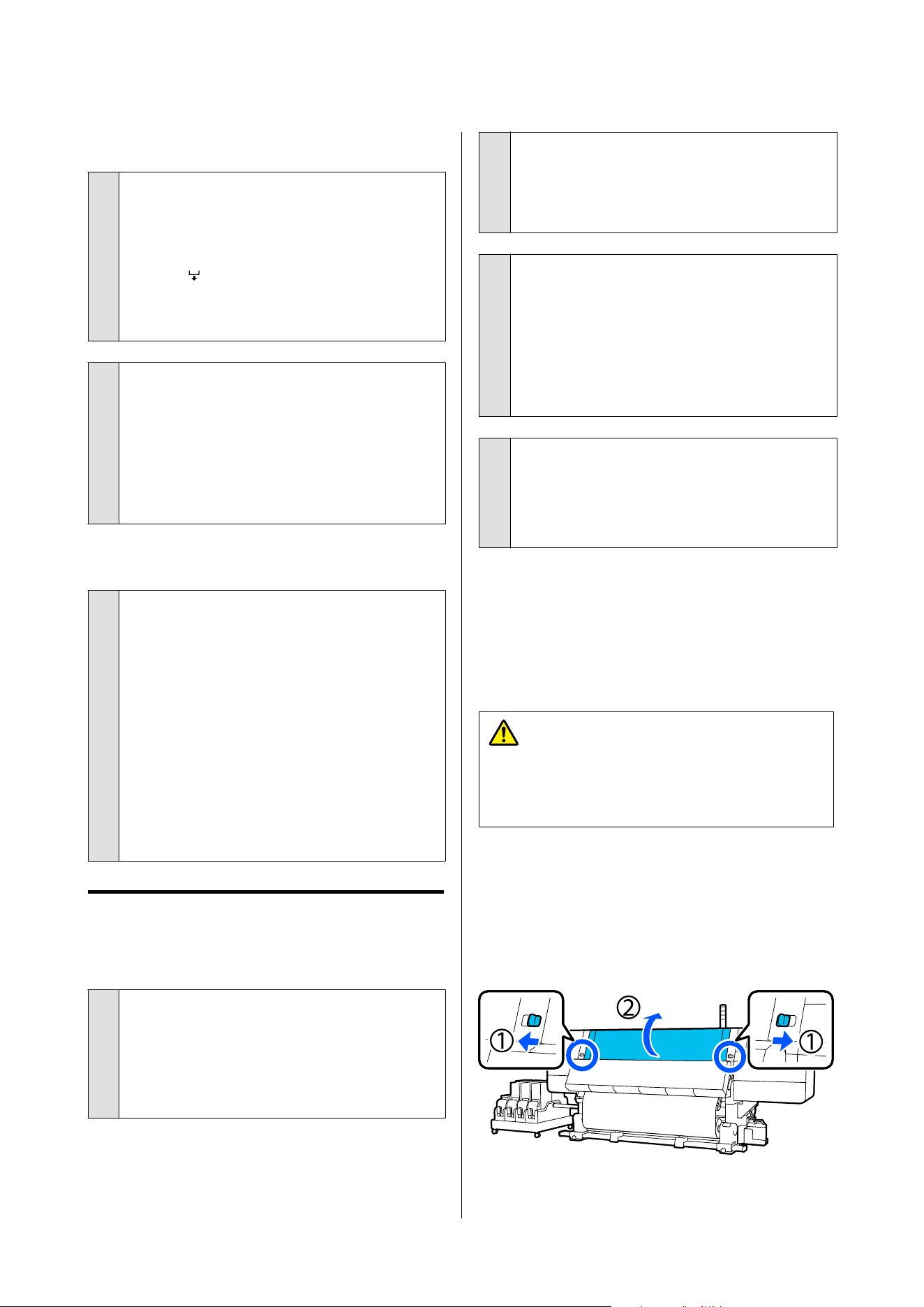
Vertical ruled lines are misaligned.
o
Is the media wavy?
Certain types of media may develop waves under
some conditions (humidity and temperature) while
installed in the printer. If a wave has developed,
press the
button in the control panel to feed the
media and avoid the affected area. We recommend
that you lower the temperature and humidity to
prevent waves developing.
o
Is the print head misaligned?
If the print head is misaligned, ruled lines may be
misaligned accordingly. When vertical ruled lines are
misaligned, select Print Adjustments - Print Head
Alignment in the media settings to adjust print
head misalignment that occurs during printing.
U “Print Head Alignment” on page 141
Printout is dirty
o
Are the print heads dirty?
If the print heads are dirty, dirt may stick to the
printout during printing. Check for dirt stuck to the
print heads and clean them, if necessary.
U “Cleaning around the print head” on page 164
If there is still dirt after cleaning, the heads may be
scuffing. See "Troubleshooting & Tips" in the Online
Manual to take measures so scuffing does not occur.
Setting Actions after Media Scuffing makes it easy
to detect when scuffing occurs, so you can take
measures immediately.
U “General Settings menu” on page 201
Media
Media Jams.
o
Is media curled, folded, curved, creased, or
waved?
Cut and remove the curled, folded, curved, creased,
or waved part.
U “Cutting Media” on page 130
o
Is media loaded just before printing?
The pressure rollers may crease media left in the
printer, or the media may also become wavy or
curled.
o
Is the media too thick or too thin?
❏ Check the media specifications to determine
whether it can be used in the printer.
U “Supported Media” on page 237
❏ For information on how to configure print
settings using the software RIP, contact the RIP
manufacturer.
o
Is Paper Suction set too high?
In the media settings, reduce Paper Suction (the
force that sucks media down the media path).
U “Media Setting Item” on page 211
Removing Jammed Media.
This section uses illustrations of the standard roll/reel
models for the explanations.
Follow the steps below to remove jammed media.
Caution:
Be careful not to trap your hands or fingers when
opening or closing the front cover. Failure to
observe these precautions could result in injury.
A
If you are using a large capacity reel model, cut
the media and remove it.
U “Removing the Take-up Roll” on page 130
B
Move the lock levers on the left and right side
outwards to open the front cover.
SC-F20000 Series/SC-F11000H Series/SC-F11000 Series/SC-F10000H Series/SC-F10000 Series User's Guide
Problem Solver
228
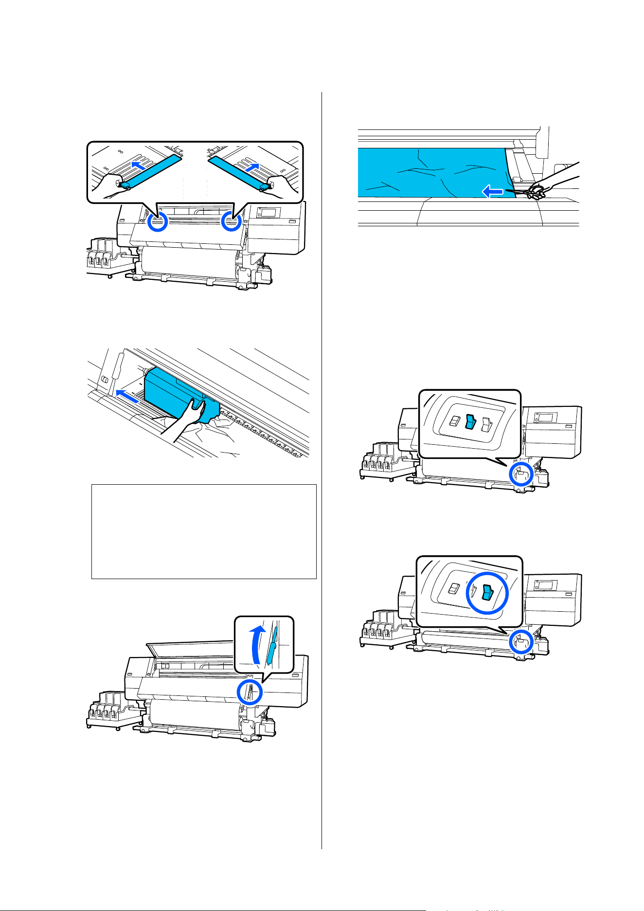
C
While holding the tabs of the media edge plate
on both sides, move the plate out of the way
toward both edges of the platen.
D
If the print head is over the media, move it
away from the jam.
c
Important:
Move the print head only after moving the
media edge plates out of the way. Contact
with deformed media edge plates could
damage the print head.
E
Raise the media loading lever.
F
Use scissors, at the platen, to cut away the torn
or wrinkled parts.
If there are torn or wrinkled parts deep inside
the platen, pull out the media and then cut
them away.
If you are using a large capacity reel model, go
to step 9.
G
Set the Auto switch on the auto take-up reel
unit to Off.
H
Take up the cut media completely by operating
the Manual switch according to how the media
is rolled.
SC-F20000 Series/SC-F11000H Series/SC-F11000 Series/SC-F10000H Series/SC-F10000 Series User's Guide
Problem Solver
229
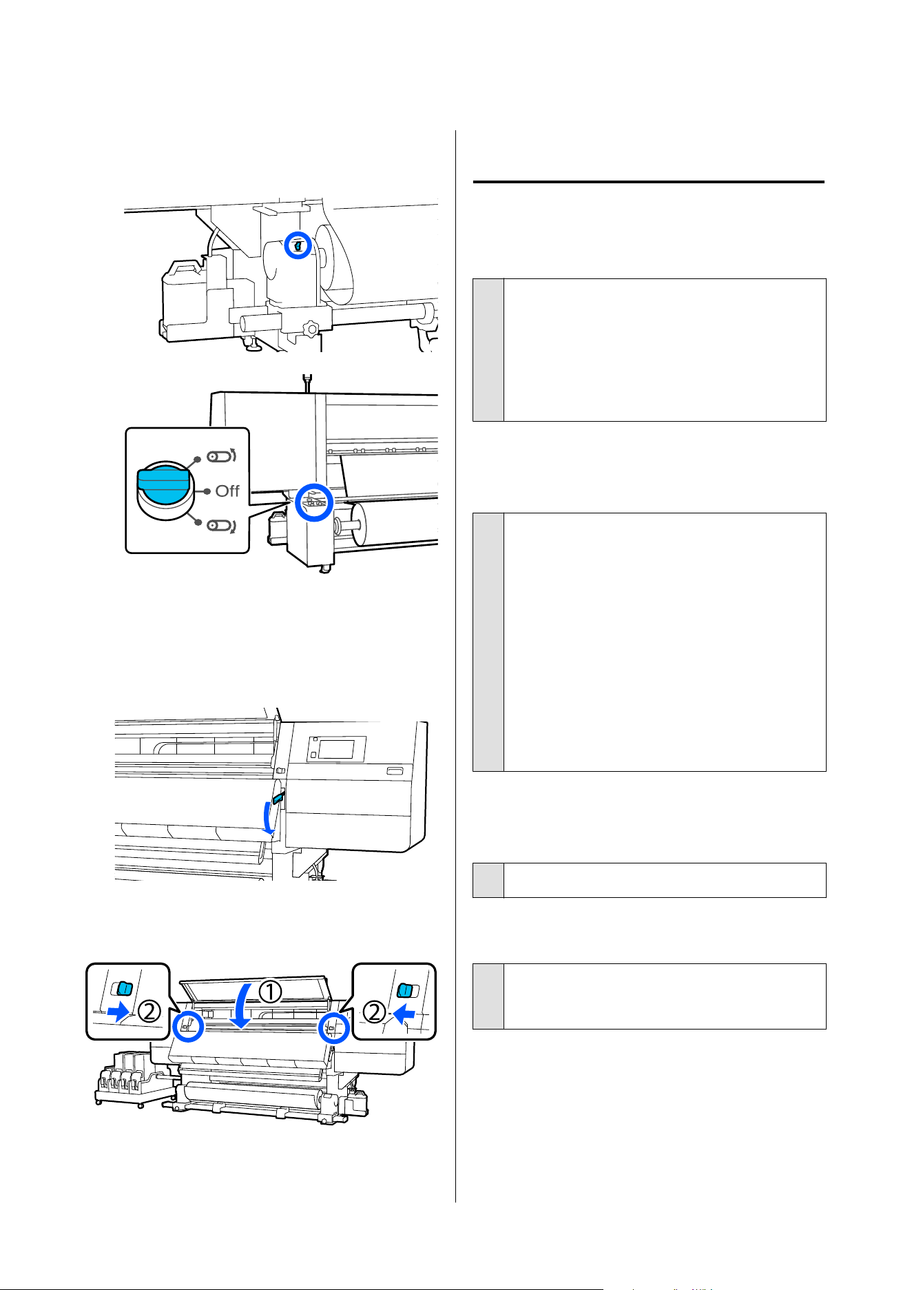
I
Move to the back, and take up the media by
operating the drive switch or the Manual switch
according to how the media is rolled.
J
Move to the front, check the platen, and remove
any cut ends of the media and so on that
remain.
K
Lower the media loading lever.
L
Close the front cover, and then move the left
and right lock levers inward.
After that, follow the on-screen instructions to check
the print head, and if it is dirty, clean it.
U “Cleaning around the print head” on page 164
Others
Heater automatically turns off
o
The heater turns off if no print job is received and no
errors occur in the printer for a certain time. You can
change the time until the heaters automatically
switch to Off in Heater Off Timer in the setup
menu. U “General Settings menu” on page 201
The heater restarts when a print job is received or
Preheat Start is pressed.
The control panel display keeps
turning off.
o
Is the printer in sleep mode?
When no operations are performed on the printer
for the time set in Sleep Timer in the setup menu,
the printer enters sleep mode. The time before
entering sleep mode can be changed in the General
Settings menu.
U “General Settings menu” on page 201
The screen display recovers when you press on the
control panel screen.
Sleep mode is canceled when a print job is received,
the media loading lever is used, or another
operation involving printer hardware is performed.
Forgotten password for network
setup protection
o
Contact your dealer or Epson Support.
The red light is on inside the printer.
o
This is not a failure.
The red light is a light inside the printer.
SC-F20000 Series/SC-F11000H Series/SC-F11000 Series/SC-F10000H Series/SC-F10000 Series User's Guide
Problem Solver
230
Appendix
For the latest information, see the Epson Web site. (as of January, 2026)
Options and Consumable Products
Ink cartridges
Printer model Product Part number
SC-F11000H
SC-F10000H
SC-F11060H
SC-F10060H
Ink cartridges (10000 ml) High Density Black T43H1
Cyan T43H2
Magenta T43H3
Yellow T43H4
Light Cyan T43H5
Light Magenta T43H6
Fluorescent Yellow T43H7
Fluorescent Pink T43H8
Orange (Only for
SC-F11000H/SC-F11060H)
T43HA
Violet (Only for
SC-F11000H/SC-F11060H)
T43HD
Ink cartridges (3000ml) High Density Black T43B1
Cyan T43B2
Magenta T43B3
Yellow T43B4
Light Cyan T43B5
Light Magenta T43B6
Fluorescent Yellow T43B7
Fluorescent Pink T43B8
SC-F20000 Series/SC-F11000H Series/SC-F11000 Series/SC-F10000H Series/SC-F10000 Series User's Guide
Appendix
231
Printer model Product Part number
SC-F11030H
SC-F10030H
Ink cartridges (10000 ml) High Density Black
T43G1/T56K1
*
Cyan
T43G2/T56K2
*
Magenta
T43G3/T56K3
*
Yellow
T43G4/T56K4
*
Light Cyan
T43G5/T56K5
*
Light Magenta
T43G6/T56K6
*
Fluorescent Yellow T43G7
Fluorescent Pink T43G8
Orange (Only for
SC-F11030H)
T43GA
Violet (Only for
SC-F11030H)
T43GD
Ink cartridges (3000ml) High Density Black T43A1
Cyan T43A2
Magenta T43A3
Yellow T43A4
Light Cyan T43A5
Light Magenta T43A6
Fluorescent Yellow T43A7
Fluorescent Pink T43A8
SC-F20000 Series/SC-F11000H Series/SC-F11000 Series/SC-F10000H Series/SC-F10000 Series User's Guide
Appendix
232
Printer model Product Part number
SC-F11040H
SC-F10040H
Ink cartridges (10000 ml) High Density Black T43L1
Cyan T43L2
Magenta T43L3
Yellow T43L4
Light Cyan T43L5
Light Magenta T43L6
Fluorescent Yellow T43L7
Fluorescent Pink T43L8
Orange (Only for
SC-F11040H)
T43LA
Violet (Only for
SC-F11040H)
T43LD
Ink cartridges (3000ml) Light Cyan T43E5
Light Magenta T43E6
Fluorescent Yellow T43E7
Fluorescent Pink T43E8
SC-F11070H
SC-F10070H
Ink cartridges
(10000 ml)
*
High Density Black T43M1
Cyan T43M2
Magenta T43M3
Yellow T43M4
Light Cyan T43M5
Light Magenta T43M6
Fluorescent Yellow T43M7
Fluorescent Pink T43M8
Orange (Only for
SC-F11070H)
T43MA
Violet (Only for
SC-F11070H)
T43MD
SC-F20000 Series/SC-F11000H Series/SC-F11000 Series/SC-F10000H Series/SC-F10000 Series User's Guide
Appendix
233

Printer model Product Part number
SC-F11080H
SC-F10080H
Ink cartridges (10000 ml) High Density Black
T43K1 / T56K1
*
Cyan
T43K2 / T56K2
*
Magenta
T43K3 / T56K3
*
Yellow
T43K4 / T56K4
*
Light Cyan
T43K5 / T56K5
*
Light Magenta
T43K6 / T56K6
*
Fluorescent Yellow T43K7
Fluorescent Pink T43K8
Orange (Only for
SC-F11080H)
T43KA
Violet (Only for
SC-F11080H)
T43KD
Ink cartridges (3000ml) Light Cyan T43D5
Light Magenta T43D6
Fluorescent Yellow T43D7
Fluorescent Pink T43D8
SC-F20000
SC-F20060
SC-F11000
SC-F10000
SC-F11060
SC-F10060
Ink cartridges (10000 ml) High Density Black T43H1
Cyan T43H2
Magenta T43H3
Yellow T43H4
Ink cartridges (3000ml) High Density Black T43B1
Cyan T43B2
Magenta T43B3
Yellow T43B4
SC-F20030
SC-F11030
SC-F10030
Ink cartridges (10000 ml) High Density Black
T43G1/T56K1
*
Cyan
T43G2/T56K2
*
Magenta
T43G3/T56K3
*
Yellow
T43G4/T56K4
*
Ink cartridges (3000ml) High Density Black T43A1
Cyan T43A2
Magenta T43A3
Yellow T43A4
SC-F20000 Series/SC-F11000H Series/SC-F11000 Series/SC-F10000H Series/SC-F10000 Series User's Guide
Appendix
234
Printer model Product Part number
SC-F20040
SC-F11040
SC-F10040
Ink cartridges (10000 ml) High Density Black T43L1
Cyan T43L2
Magenta T43L3
Yellow T43L4
SC-F20070
SC-F11070
SC-F10070
Ink cartridges
(10000 ml)
*
High Density Black T43M1
Cyan T43M2
Magenta T43M3
Yellow T43M4
SC-F20080
SC-F11080
SC-F10080
Ink cartridges (10000 ml) High Density Black T43K1
Cyan T43K2
Magenta T43K3
Yellow T43K4
* Not available in all regions.
Epson recommends the use of genuine Epson ink cartridges. Epson cannot guarantee the quality or reliability of
nongenuine ink. The use of non-genuine ink may cause damage that is not covered by Epson's warranties, and
under certain circumstances, may cause erratic printer behavior.
Information about non-genuine ink levels may not be displayed, and use of non-genuine ink is recorded for
possible use in service support.
Others
Product Part number Explanation
Cleaning Kit
(except for SC-F20080/SC-
F11080H/SC-F11080/SC-F10080H/
SC-F10080)
C13S210103 The following consumable items are included in one
maintenance set.
❏ Cleaning fluid (x1)
❏ Cup (x1)
❏ Gloves (x16)
❏ Cleaning stick (x50)
Cleaning Kit
(for SC-F20080/SC-F11080H/SC-
F11080/SC-F10080H/SC-F10080)
C13S210104
Wiper Roll
(except for SC-F20080/SC-
F11080H/SC-F11080/SC-F10080H/
SC-F10080)
C13S210065 Identical to the Wiper Roll supplied with the printer.
Wiper Roll
(for SC-F20080/SC-F11080H/SC-
F11080/SC-F10080H/SC-F10080)
C13S210066
SC-F20000 Series/SC-F11000H Series/SC-F11000 Series/SC-F10000H Series/SC-F10000 Series User's Guide
Appendix
235

Product Part number Explanation
Waste Ink Bottle
(except for SC-F20080/SC-
F11080H/SC-F11080/SC-F10080H/
SC-F10080)
C13S210071 Identical to the Waste Ink Bottle supplied with the
printer.
Waste Ink Bottle
(for SC-F20080/SC-F11080H/SC-
F11080/SC-F10080H/SC-F10080)
C13S210072
Take Up Media Holder
*
(except for
SC-F20080/SC-
F11080H/SC-F11080/SC-F10080H/
SC-F10080)
C12C933881 Parts for the standard type Auto Take-up Reel Unit.
Identical to the media holder of Auto Take-up Reel Unit
for this printer.
Take Up Media Holder
(for
SC-F20080/SC-F11080H/SC-
F11080/SC-F10080H/SC-F10080)
C12C933891
Take In Media Holder
*
(except for SC-F20080/SC-
F11080H/SC-F11080/SC-F10080H/
SC-F10080)
C12C933901 Parts for the standard type Media Feeding Unit
Identical to the media holder of Media Feeding Unit for
this printer.
Take In Media Holder
(for SC-F20080/SC-F11080H/S
C-
F11080/SC-F10080H/SC-F10080)
C12C933911
Media Cleaner Brush
*
C12C936031 Identical to the Media Cleaner Brush supplied with the
printer.
Presser Roller Spacer
*
C12C936041 Identical to the Presser Roller Spacer supplied with the
printer.
* Contact your Epson sales representative for availability.
SC-F20000 Series/SC-F11000H Series/SC-F11000 Series/SC-F10000H Series/SC-F10000 Series User's Guide
Appendix
236
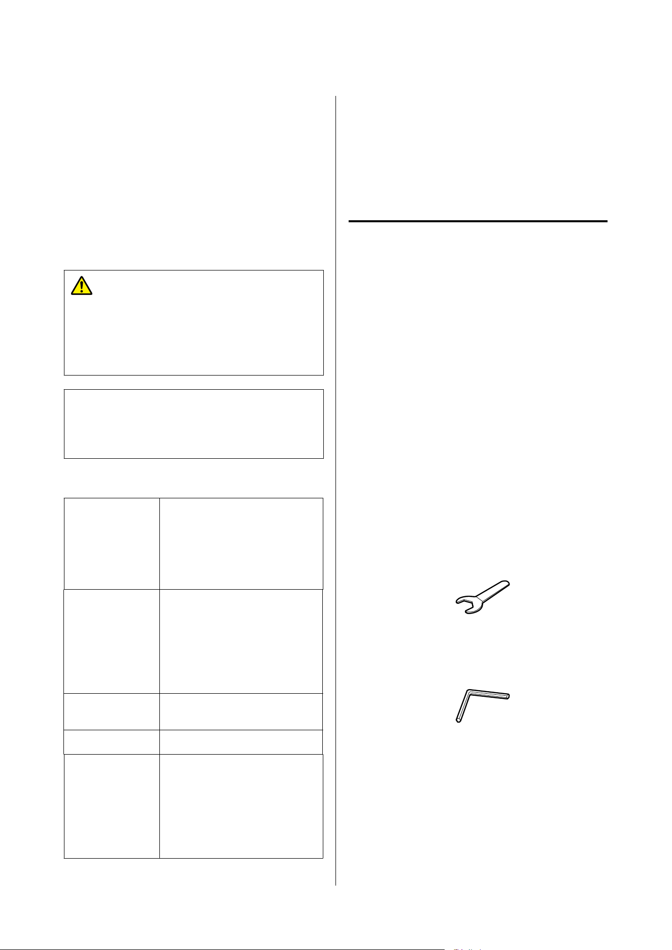
Supported Media
The following media can be used with the printer.
Print quality is greatly affected by the type and quality
of media used. Choose a media suited to the task at
hand. For information on use, refer to the
documentation supplied with the media or contact the
manufacturer. Before buying media in large quantities,
try printing on a smaller sample and check the results.
Caution:
Because the media is heavy, it should not be
carried by one person.
We recommend using a lifter for media that weighs
over 40 kg (88.18 lb.).
c
Important:
Do not use media that is wrinkled, scuffed, torn, or
dirty.
Roll media
Roll core size 2 inch, 3 inch (standard type
Media Feeding Unit/Auto Take-up
Reel Unit)
3 inch (large capacity type Media
Feeding Unit/Auto Take-up Reel
Unit)
Roll outer
diameter
Maximum 250 mm (9.84 in.)
(standard type Media Feeding
Unit/Auto Take-up Reel Unit)
Maximum 500 mm (19.68 in.)
(large capacity type Media
Feeding Unit/Auto Take-up Reel
Unit)
Media width 300 to 1950 mm (11.81 to 76.77
in.)(76 inches)
Media thickness Up to 1 mm (0.03 in.)
Roll weight Maximum 60 kg (132 lb.) (standard
type Media Feeding Unit/Auto
Take-up Reel Unit)
Maximum 300 kg (661.38 lb.)
(large capacity type Media
Feeding Unit/Auto Take-up Reel
Unit)
Moving and Transporting
the Printer
This section describes how to move and transport the
product.
Moving the printer
This section explains how to move a standard roll/reel
model or a large capacity roll model to another
location on the same floor.
Before moving a large capacity reel model, contact
your dealer or Epson Support.
U Epson Support
See below for information on moving the printer
between floors or to another building.
U “Transport” on page 253
Necessary items
Use the following items supplied with the printer to
move it. Prepare them and keep have them handy
before you start working.
❏ Spanner
Use to turn the nuts on the adjusters.
❏ Hex wrench
Use to secure the print head and to install and
remove the large capacity type Media Feeding
Unit.
Large capacity roll models come with three sizes
of hex wrenches (A, B, and C from largest to
smallest) or four sizes (A, B, C, and D) as shown
SC-F20000 Series/SC-F11000H Series/SC-F11000 Series/SC-F10000H Series/SC-F10000 Series User's Guide
Appendix
237
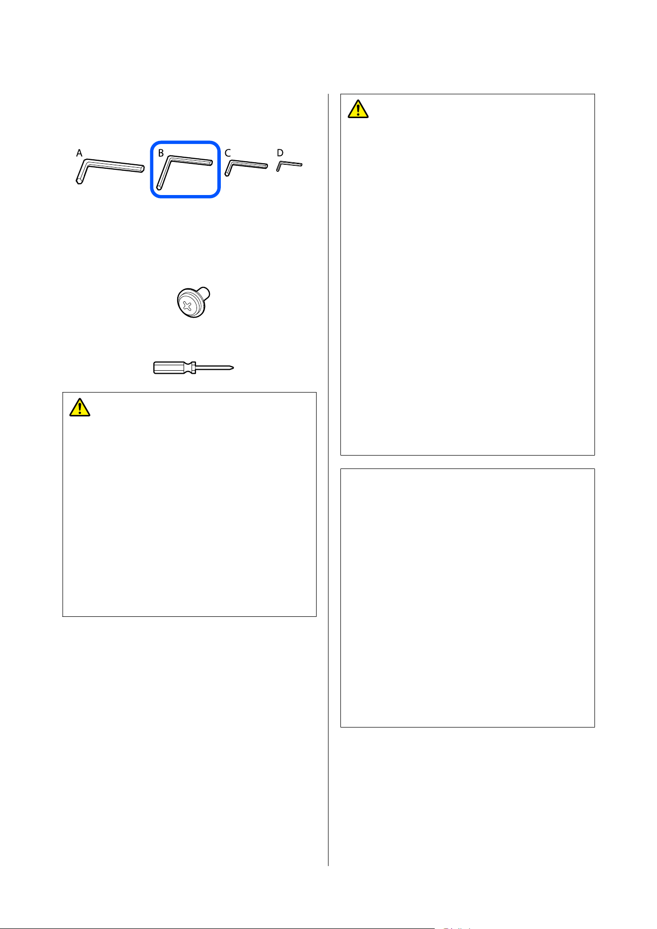
in the illustration. Use hex wrench B for parallel
adjustment.
The following items are used to install and remove
reinforcement components that are used when
moving the large capacity type Media Feeding Unit.
❏ Screws (8 pieces)
❏ Commercially available Phillips head screwdriver
War n ing :
❏ To prevent accidents due to electrical leakage,
connect to an outlet with a grounded (earthed)
connector. Connecting to an outlet other than
a grounded outlet may cause electric shock or
fire.
❏ Use only the type of power source indicated on
the printer’s label. An electric shock or fire
could occur.
❏ Do not connect the power cable to a power
strip or multi plug. An electric shock or fire
could occur. Connect the power cable directly
to an outlet for domestic use.
Caution:
❏ Because the product is heavy, it should not be
carried by one person. Moving the product
requires more than five people. See the
following for the weight of the product. Lifting
the large capacity type Media Feeding Unit
requires more than two people.
U “Specifications Table” on page 290
❏ Do not tilt the product more than 10 degrees
forward or back while moving it. Failure to
observe this precaution could result in the
printer falling over, causing accidents.
❏ When moving the large capacity type Media
Feeding Unit along an uneven path, be careful
that it does not catch on uneven surfaces. If it
hits an uneven surface and its casters are
damaged, the large capacity type Media
Feeding Unit could fall over and injure
someone.
❏ Arrange the power cable such that people do
not trip on it. People who are working could
trip and fall over, resulting in injury.
c
Important:
❏ The printer can be moved across bumps of less
than 5 mm (0.19 in.) and gaps of less than 30
mm (1.18 in.). Before you start, check the
bumps and gaps of the route to move the
printer.
❏ Be sure to move the printer under the
following conditions.
❏ Do not separate ink supply unit from the
printer.
❏ Leave fixing wire attached.
❏ Leave ink cartridges installed.
❏ For large capacity roll models, remove the
Media Feeding Unit from the printer.
Getting Ready
This section uses illustrations of the standard roll/reel
models for the explanations. If you are using a large
capacity roll model, the adjuster operation for the
standard type Media Feeding Unit is not necessary.
SC-F20000 Series/SC-F11000H Series/SC-F11000 Series/SC-F10000H Series/SC-F10000 Series User's Guide
Appendix
238
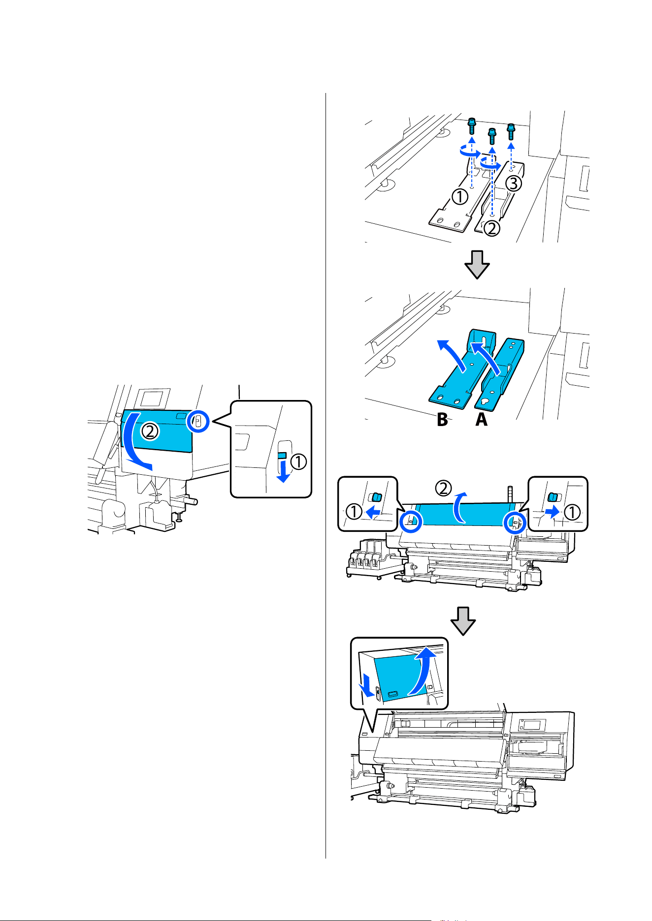
A
Confirm that the printer is off.
B
Remove the Waste Ink Bottle.
U “Replacing the waste ink bottle” on
page 176
C
Disconnect the power cords and all other
cables.
Remove any wires that are in clamps from the
clamps.
D
Remove media from the Media Feeding Unit
and Auto Take-up Reel Unit.
U “Removing the Take-up Roll” on page 130
U “Removing the Loaded Media” on page 134
E
Open the right-side maintenance cover.
F
Loosen the 3 screws and remove the screws and
print head anchors A and B, as shown in the
illustrations.
If screws (1) and (2) are difficult to loosen by
hand, use a hex wrench.
Pull screw (3) out as is.
G
Open the front cover and left-side maintenance
cover.
SC-F20000 Series/SC-F11000H Series/SC-F11000 Series/SC-F10000H Series/SC-F10000 Series User's Guide
Appendix
239
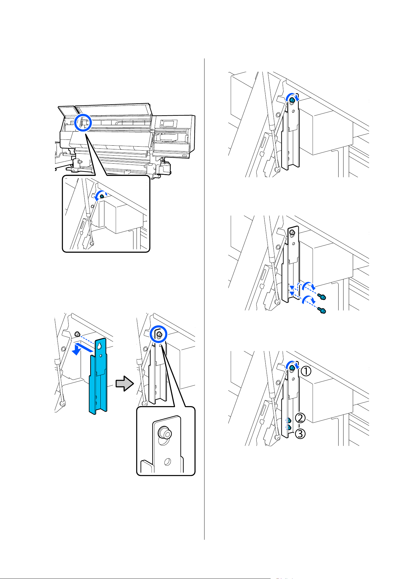
H
Loosen the screw shown in the illustration
inside the front cover about halfway.
If a screw is difficult to loosen by hand, use a
hex wrench.
I
Hang anchor A on the screw as shown in the
illustration.
Put the screw through the hole in the anchor to
hook it. When doing this, confirm that the
screw is hooked into the upper part of the hole.
J
Lightly tighten the screw.
K
Insert the screws removed in Step 5 into the 2
holes in the bottom part of the anchor, and
lightly tighten them.
L
Use the hex wrench to securely tighten the
screws in the order shown in the illustration.
SC-F20000 Series/SC-F11000H Series/SC-F11000 Series/SC-F10000H Series/SC-F10000 Series User's Guide
Appendix
240
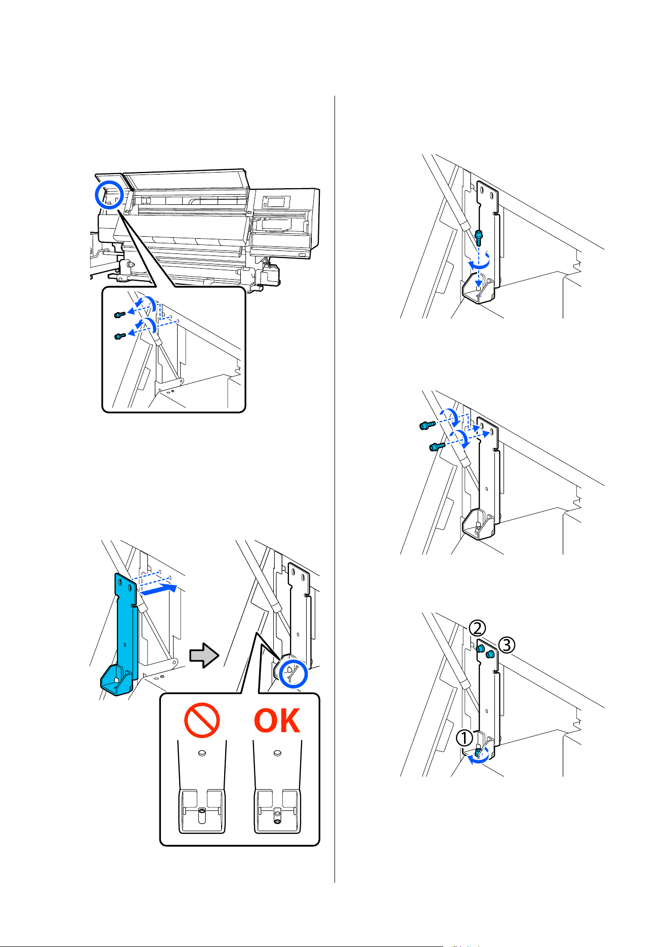
M
Loosen and remove the 2 screws inside the
maintenance cover, as shown in the illustration.
If a screw is difficult to loosen by hand, use a
hex wrench.
N
Align the screw holes on the printer and on
anchor B in the orientation shown in the
illustration.
When doing this, position the anchor without
tilting it. When it is positioned correctly, the
screw hole appears at the front end of the
rectangular hole in the bottom of the anchor.
O
Insert the screw removed in Step 5 into the hole
in the bottom part of the anchor, and lightly
tighten it.
P
Insert the screws removed in Step 12 into the 2
screw holes in the top part of the anchor, and
lightly tighten them.
Q
Use the hex wrench to securely tighten the
screws in the order shown in the illustration.
R
Close all the covers, and then move the front
cover's left and right lock levers inward.
SC-F20000 Series/SC-F11000H Series/SC-F11000 Series/SC-F10000H Series/SC-F10000 Series User's Guide
Appendix
241
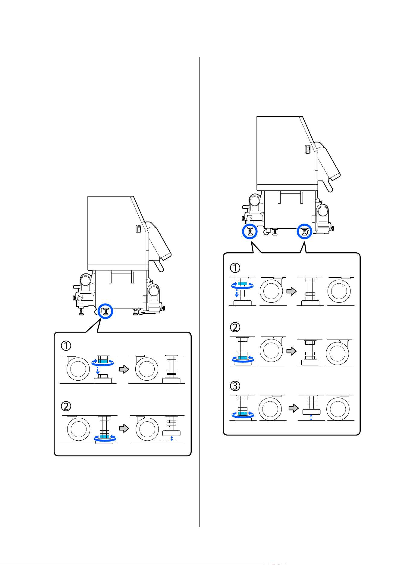
S
If you are using a large capacity type Media
Feeding Unit, follow the procedure below to
remove the Media Feeding Unit.
U “Removing the Media Feeding Unit (Large
Capacity Type only)” on page 243
T
On the left side, raise the center adjuster so it is
higher than the caster.
(1) Turn the top nut clockwise to move it
downward.
(2) Turn the bottom nut counter-clockwise until
the adjuster is higher than the caster.
U
On the left side, raise the front and back
adjusters so they are higher than the casters.
(1) Turn the top nut clockwise to move it
downward.
(2) Turn the bottom nuts counter-clockwise until
the casters touch the floor.
(3) Continue to turn it counter-clockwise until
the adjuster is higher than the caster.
The metal plates under the adjusters are used
for installing the printer after moving it, so do
not throw them away.
SC-F20000 Series/SC-F11000H Series/SC-F11000 Series/SC-F10000H Series/SC-F10000 Series User's Guide
Appendix
242
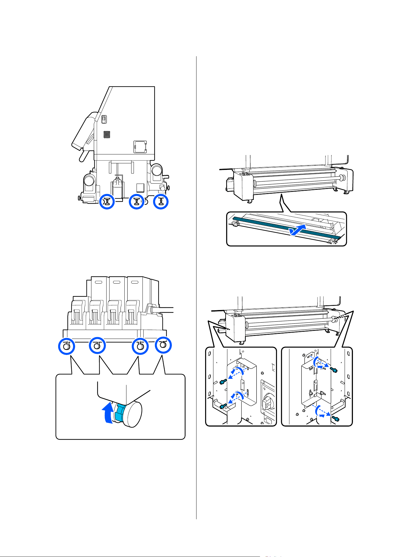
V
Repeat Steps 19 and 20 on the right side to raise
those adjusters so they are higher than the
casters.
W
Release the locks on the casters on the ink
supply unit.
Release all the locks, four on the SC-F20000
Series/SC-F11000 Series/SC-F10000 Series and
six on the SC-F11000H Series/SC-F10000H
Series.
Removing the Media Feeding Unit
(Large Capacity Type only)
A
Remove the reinforcement component, shown
in the illustration, from the bottom of the
Media Feeding Unit.
The reinforcement component is secured by
magnets, so just pull it down to remove it.
Place the removed reinforcement component
where it will not interfere with your work.
B
Remove the screws that secure the Media
Feeding Unit to the printer.
Remove two screws from the left and right as
shown in the illustration.
SC-F20000 Series/SC-F11000H Series/SC-F11000 Series/SC-F10000H Series/SC-F10000 Series User's Guide
Appendix
243
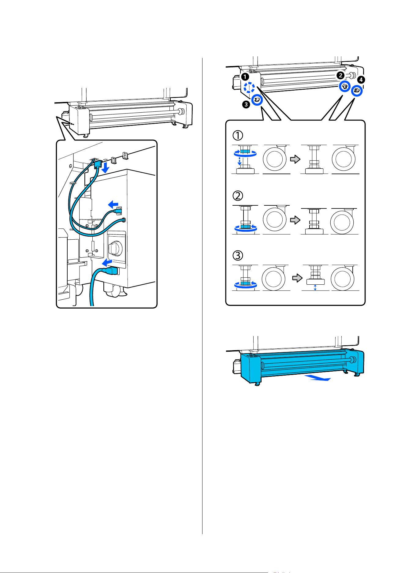
C
Remove the two cables that connect the Media
Feeding Unit to the printer, and then remove
the power cable.
D
Raise the four adjusters so they are higher than
the casters.
Follow the steps below to raise the adjusters.
(1) On all the adjusters, turn the top nuts
clockwise to move them downward.
(2) Turn the bottom nuts counter-clockwise until
the casters touch the floor. When doing this,
turn the nuts on each of the four adjusters 1/4
turn each, in the order of the numbers, until
the casters touch the ground.
(3) Continue to turn it counter-clockwise until
the adjuster is higher than the caster.
E
Separate the Media Feeding Unit from the
printer.
SC-F20000 Series/SC-F11000H Series/SC-F11000 Series/SC-F10000H Series/SC-F10000 Series User's Guide
Appendix
244
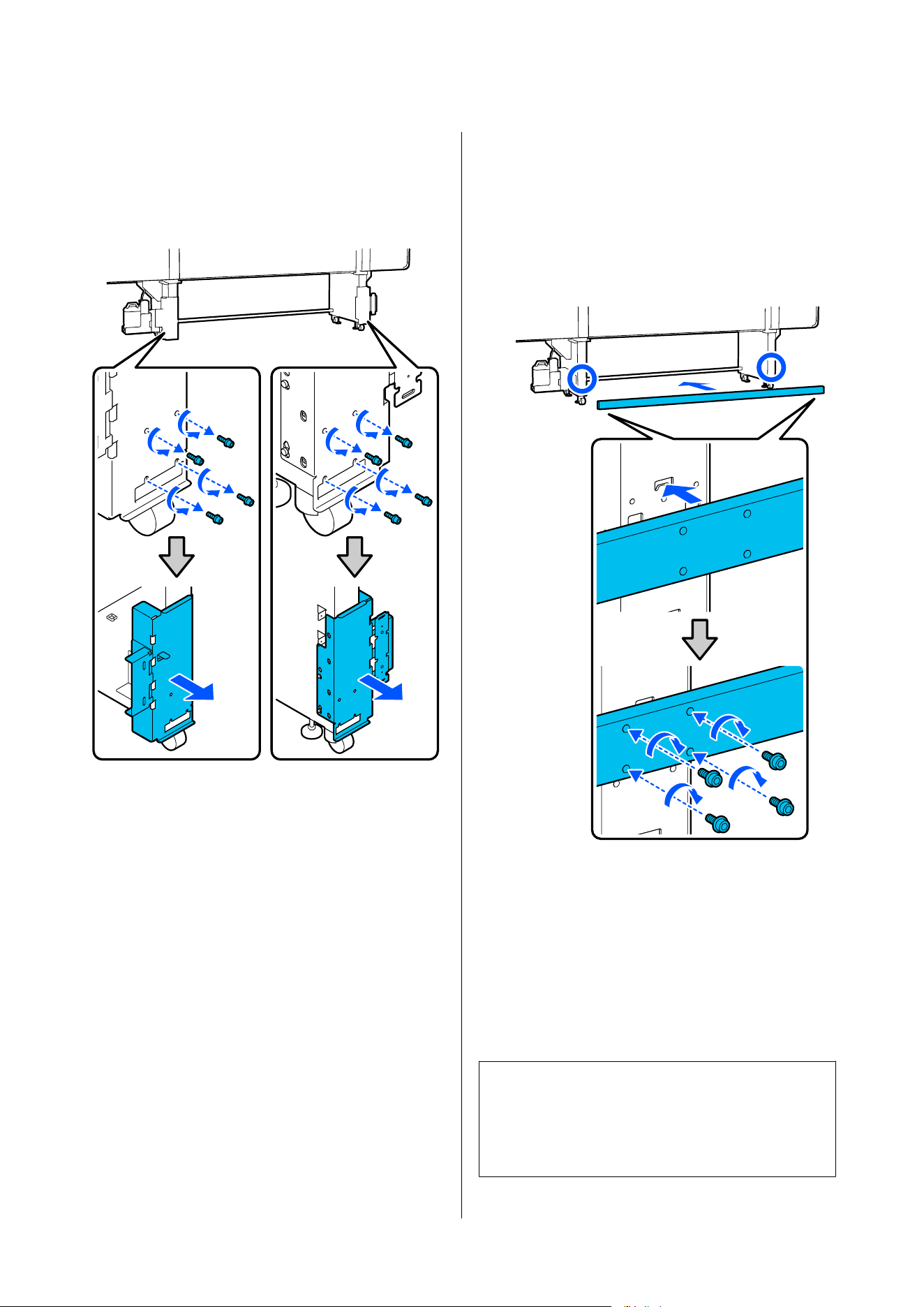
F
Remove the bracket components from the
Media Feeding Unit.
Remove the four screws from the left and right,
as shown in the illustration, and then remove
the mounting components.
G
Install the reinforcement component removed
in step 1 to the legs of the printer.
Insert and hook the protrusions on the back of
the reinforcement component in the holes on
the legs, and then tighten the screws into the
four threaded holes on the left and right. Use a
commercially available Phillips head
screwdriver to tighten the screws.
Moving
Use a total of 5 people, 4 for the printer and 1 for the
ink supply unit, to move the equipment. Also, move so
that the printer moves first in the direction you are
moving.
Move the large capacity type Media Feeding Unit with
two people.
c
Important:
Use the casters on the printer only to move the
printer indoors a short distance over a level floor.
They can not be used for transport.
SC-F20000 Series/SC-F11000H Series/SC-F11000 Series/SC-F10000H Series/SC-F10000 Series User's Guide
Appendix
245
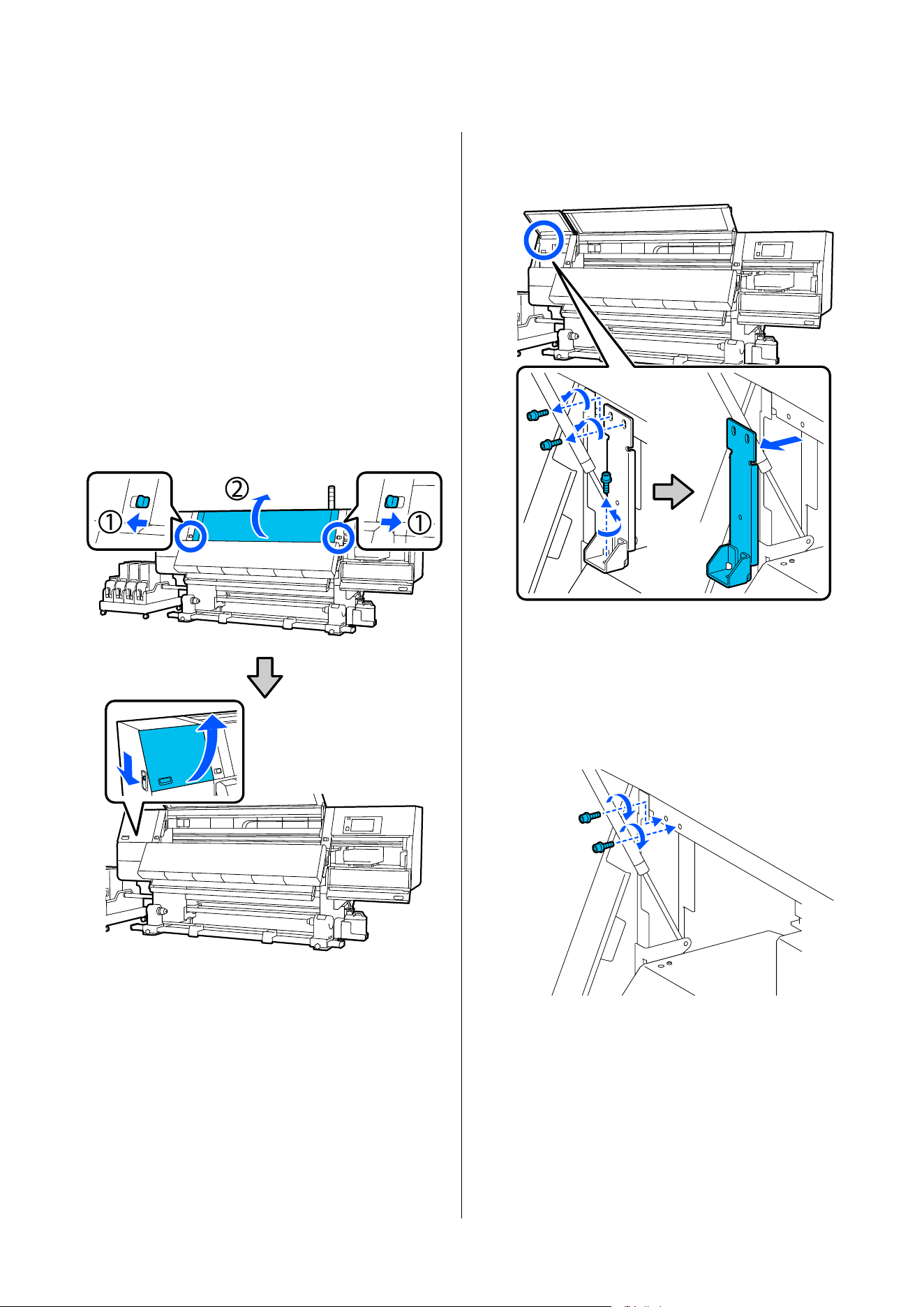
Post-Move Installation
After moving the printer, follow the steps below to
ready it for use.
This section uses illustrations of the standard roll/reel
models for the explanations. If you are using a large
capacity roll model, the adjuster operation for the
standard type Media Feeding Unit is not necessary.
A
Check that the location is appropriate for
installation.
U “Notes on Usage and Storage” on page 40
B
Open the front cover and left-side maintenance
cover.
C
Use a hex wrench to loosen the 3 screws on
anchor B, and then remove the screws and
anchor B.
D
Put the 2 top screws back into their original
screw holes, and use a hex wrench to tighten
them securely.
If they are tightened loosely, they may interfere
when closing the maintenance cover. Tighten
them securely.
SC-F20000 Series/SC-F11000H Series/SC-F11000 Series/SC-F10000H Series/SC-F10000 Series User's Guide
Appendix
246
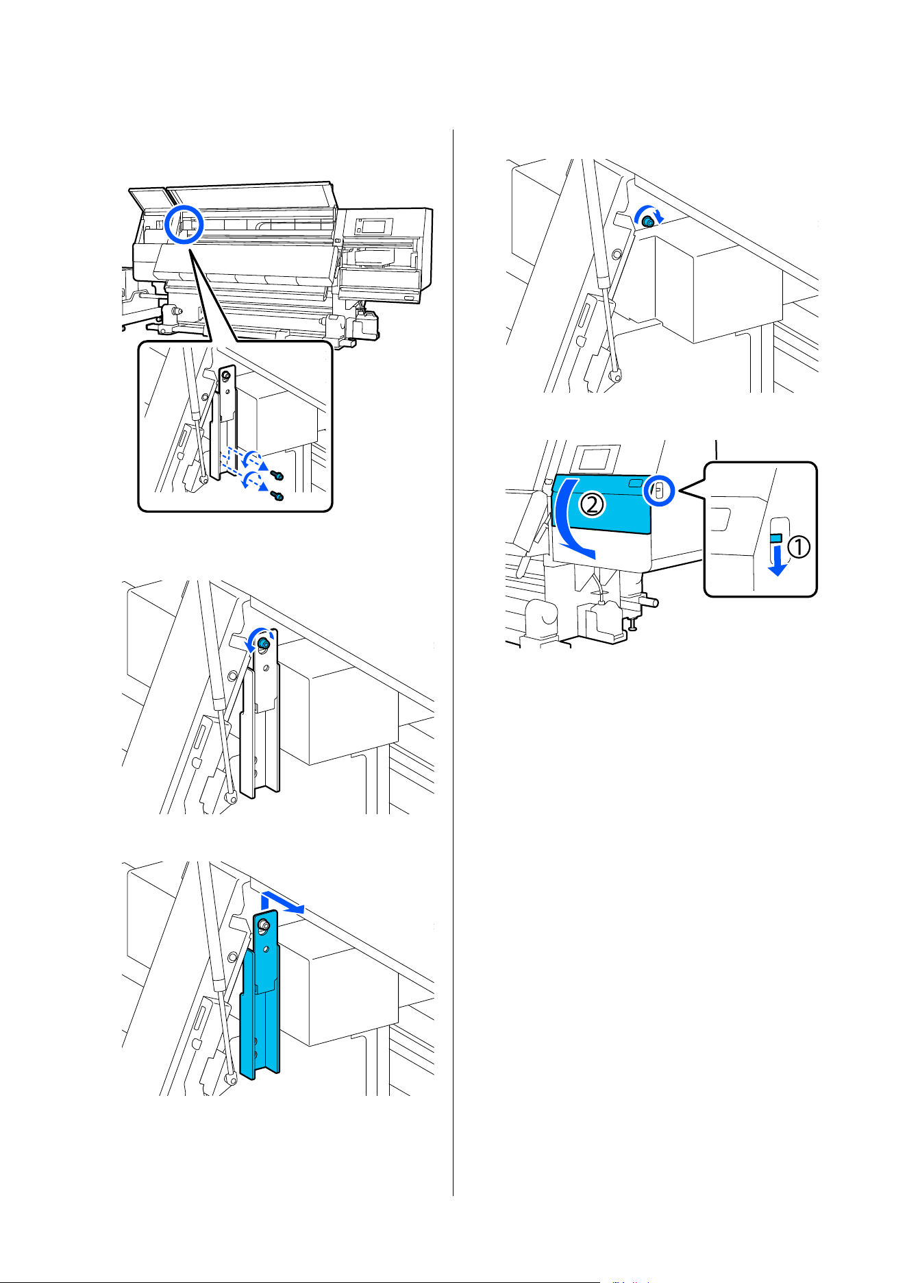
E
Use a hex wrench to loosen and remove the 2
bottom screws on anchor A.
F
Use a hex wrench to halfway loosen the top
screw on anchor A.
G
Slide anchor A upward and then remove it.
H
Tighten the top screw.
I
Open the right-side maintenance cover.
SC-F20000 Series/SC-F11000H Series/SC-F11000 Series/SC-F10000H Series/SC-F10000 Series User's Guide
Appendix
247
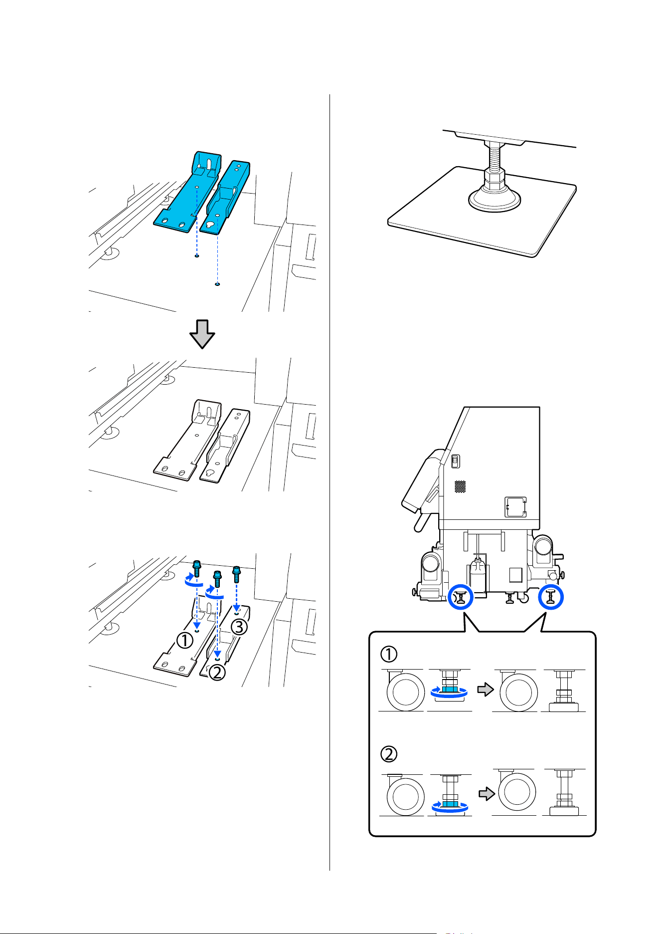
J
Align anchor A and B with the screw hole
positions on the printer as shown in the
illustration.
K
Use the screws removed in Steps 3 and 5, and
insert and tighten 2 of them into screw holes
(1) and (2), and insert 1 of them into hole (3).
L
Close all the covers, and then move the front
cover's left and right lock levers inward.
M
Place the metal plates under the printer's 6
adjusters.
N
On the right side, use the front and back
adjusters on the printer to suspend the casters.
(1) Turn the bottom nut clockwise until the
adjuster touches the floor.
(2) Continue to turn it clockwise until the caster
is suspended.
SC-F20000 Series/SC-F11000H Series/SC-F11000 Series/SC-F10000H Series/SC-F10000 Series User's Guide
Appendix
248
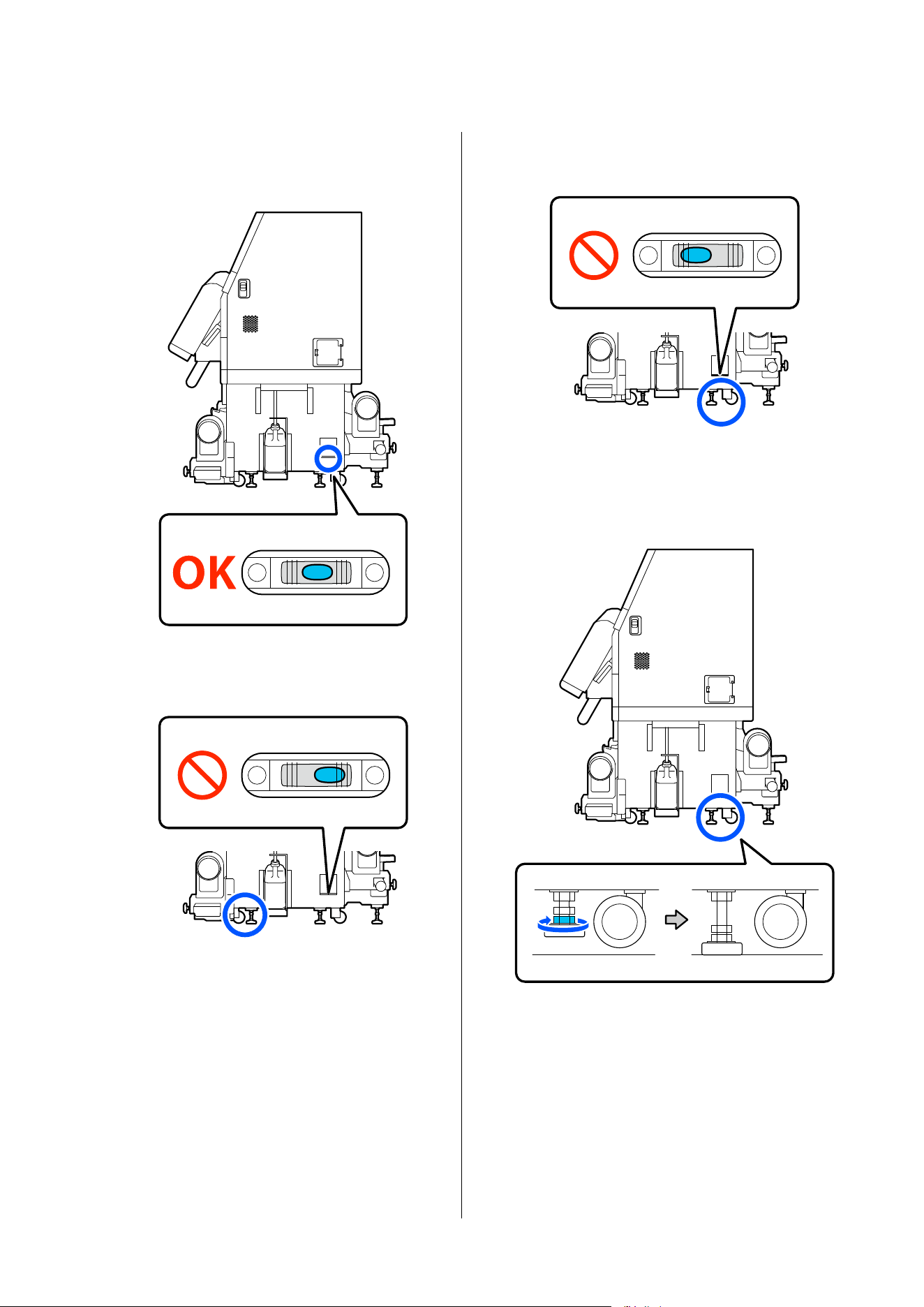
O
Adjust the adjusters so the printer is level.
Turn the bottom nut of the adjuster until the air
bubble in the level gauge is centered.
When the air bubble is toward the back side
Turn the nut on the front adjuster clockwise.
When the air bubble is toward the front side
Turn the nut on the back adjuster clockwise.
P
On the right side, lower the center adjuster
until it touches the floor.
Turn the bottom nut clockwise until the
adjuster touches the floor.
Q
Repeat Step 14 to suspend the left side casters.
R
Repeat Step 16 to suspend the center adjuster
on the left side.
SC-F20000 Series/SC-F11000H Series/SC-F11000 Series/SC-F10000H Series/SC-F10000 Series User's Guide
Appendix
249
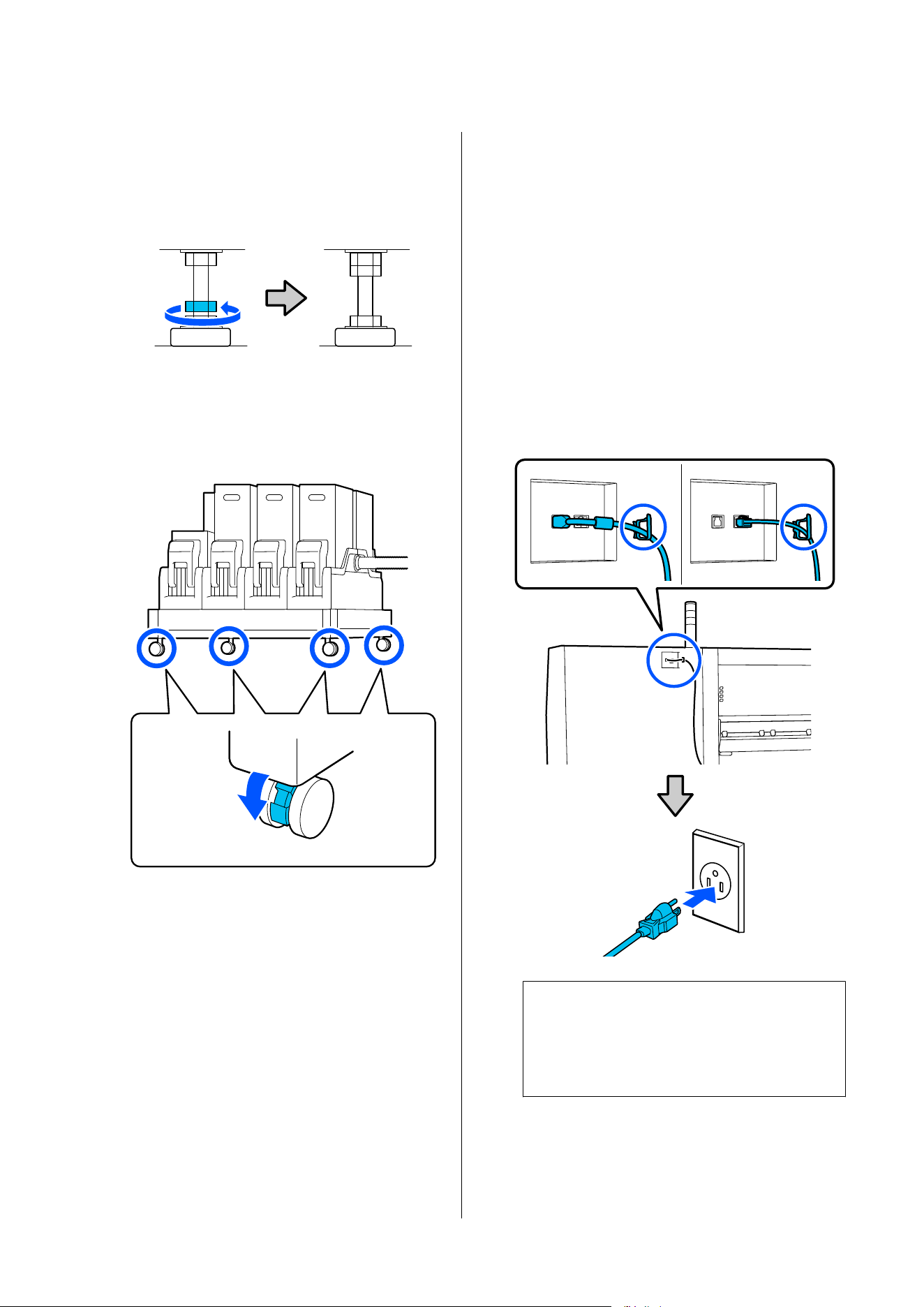
S
On all six adjusters, turn the top nut
counter-clockwise until it reaches the top part
and stops.
After it reaches the top part, tighten it securely
to fix it.
T
Lock the casters on the ink supply unit.
Lock all the casters, four on the SC-F20000
Series/SC-F11000 Series/SC-F10000 Series and
six on the SC-F11000H Series/SC-F10000H
Series.
U
If you are using a large capacity type Media
Feeding Unit, install the Media Feeding Unit.
U “Installing the Media Feeding Unit (Large
Capacity Type only)” on page 251
V
Do parallel adjustments to the Auto Take-up
Reel Unit.
U “Parallel Adjustments for the Auto Take-up
Reel Unit and the Media Feeding Unit” on
page 255
W
If you are using a large capacity type Media
Feeding Unit, perform parallel adjustment for
the Media Feeding Unit.
U “Parallel Adjustments for the Auto Take-up
Reel Unit and the Media Feeding Unit” on
page 255
X
Connect all necessary wires, plug the power
plug into an outlet with a grounding (earth)
connector, and then turn on the power.
Put the cables that went through clamps back
through the clamps.
Be sure to put the USB cable and LAN cable
through their clamps.
c
Important:
The shape of the plug varies with the region
or country of sale. Use the supplied power
cable only.
Y
Perform a nozzle check to check for clogged
nozzles.
U “Printing nozzle check patterns” on
page 186
SC-F20000 Series/SC-F11000H Series/SC-F11000 Series/SC-F10000H Series/SC-F10000 Series User's Guide
Appendix
250
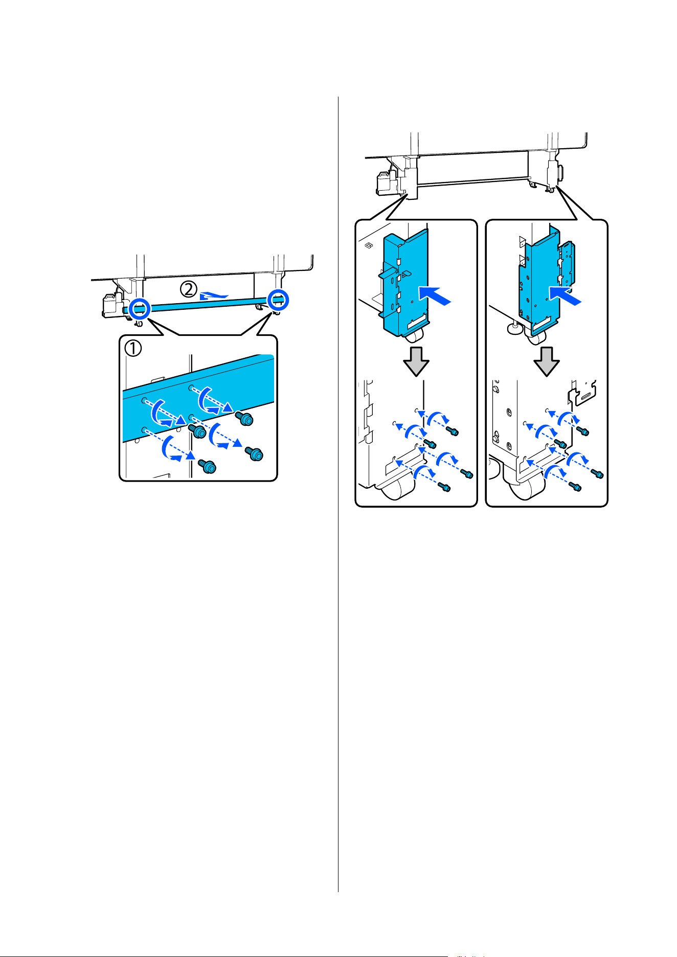
Z
Perform Print Adjustments in the setup menu,
and check the print quality.
U “Print Adjustments” on page 140
Installing the Media Feeding Unit
(Large Capacity Type only)
A
Remove the reinforcement components on the
printer's legs.
Put the removed reinforcement component
where it will not interfere while you are
working.
Keep the screws in a safe place; do not throw
them out.
B
Install the bracket components to the Media
Feeding Unit.
SC-F20000 Series/SC-F11000H Series/SC-F11000 Series/SC-F10000H Series/SC-F10000 Series User's Guide
Appendix
251
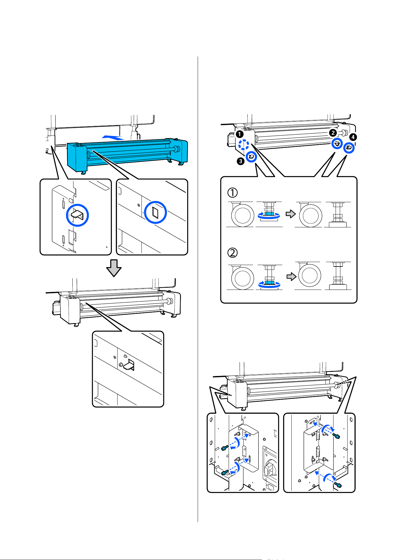
C
Move the Media Feeding Unit to the specified
position at the rear of the printer.
Press the Media Feeding Unit against the
bracket components so that the protrusions on
the bracket components go into the holes on
the back of the Media Feeding Unit.
D
Use the four adjusters to suspend the casters.
Follow the steps below to operate the adjusters
to suspend the casters.
(1) Turn the bottom nut clockwise until the
adjuster touches the floor.
(2) Continue to turn it clockwise until the caster
is suspended. When doing this, turn the nuts
for each of the four adjusters 1/4 turn each, in
the order of the numbers, until the casters are
suspended.
E
Temporarily fasten the screws on the left and
right sides on the rear of the Media Feeding
Unit.
Leave them temporarily fastened until you have
finished the parallel adjustments.
SC-F20000 Series/SC-F11000H Series/SC-F11000 Series/SC-F10000H Series/SC-F10000 Series User's Guide
Appendix
252
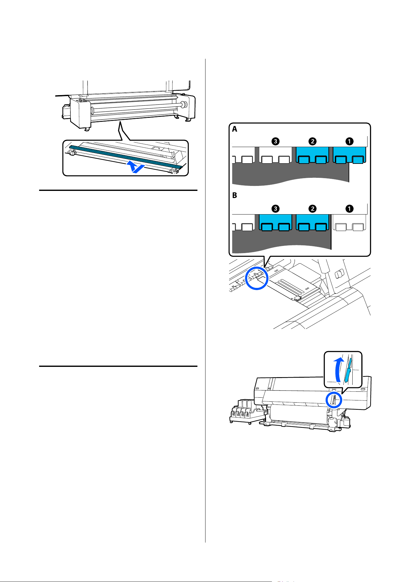
F
Install the reinforcement component to the
bottom of the Media Feeding Unit.
Transport
Before transporting the printer, contact your dealer or
Epson Support.
U Epson Support
Using Pressure Roller
Spacers
If wrinkles occur near the end of the media, using
spacers so the pressure roller does not press on the end
of the media may improve the wrinkles. Use the
following procedure to install the spacers to the
pressure rollers.
How to install spacers
A
Confirm on which pressure rollers to install the
spacers.
Spacers are installed in a total of 4 positions, 2
each on the left and right pressure rollers that
press on the ends of the media. Look at the left
and right ends of the media, to confirm the
pressure rollers that are pressing on the media.
The illustration shows an example of pressure
rollers pressing on the right end of the media. If
the edge of the media is in the A position,
install the spacers on the A and B pressure
rollers. If the edge of the media is in the B
position, install the spacers on the B and C
pressure rollers.
B
Raise the media loading lever.
SC-F20000 Series/SC-F11000H Series/SC-F11000 Series/SC-F10000H Series/SC-F10000 Series User's Guide
Appendix
253
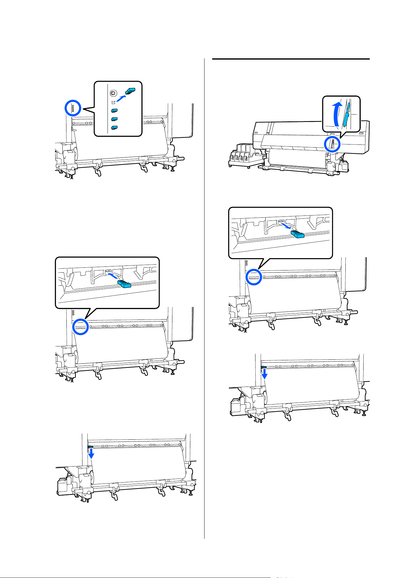
C
Move to the back side and remove the spacers
from where they are stored.
D
Insert the spacers into the holes on the back
side of the rollers that you confirmed in Step 1.
Insert the spacers until they are deep inside a
total of 4 pressure rollers, 2 each on the left and
the right. If they are only inserted shallowly,
they may come out while the printer is
operating.
E
Lower the media loading lever.
The pressure rollers on which the spacers are
installed are immobilized, so they do not move
even if the lever is lowered.
How to remove spacers
A
Raise the media loading lever.
B
Move to the back side and remove the 4 spacers
and return them to where they are stored.
C
Lower the media loading lever.
SC-F20000 Series/SC-F11000H Series/SC-F11000 Series/SC-F10000H Series/SC-F10000 Series User's Guide
Appendix
254
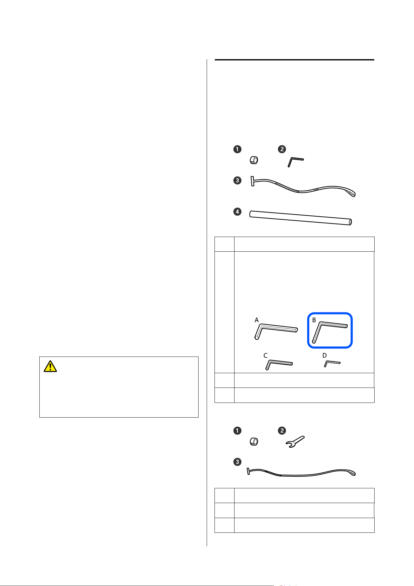
Parallel Adjustments for
the Auto Take-up Reel
Unit and the Media
Feeding Unit
This section explains how to make parallel
adjustments for standard roll/reel models and large
capacity roll models.
For parallel adjustments for large capacity reel models,
contact your dealer or Epson Support.
U Epson Support
In the following situations, do parallel adjustments to
the Auto Take-up Reel Unit and the Media Feeding
Unit. Parallel adjustments for the Media Feeding Unit
are only performed for the large capacity type.
❏ When there are problems with take-up, such as it
creating large misalignments with the roll
❏ The printer has been moved
Have two people do parallel adjustment work because
there is work to be done to the front and back sides of
the printer at the same time.
Caution:
Be sure to turn off the power before making
parallel adjustments. Not turning off the power
could result in an unexpected operation that
causes an injury.
Preparing for parallel
adjustments
Parallel Adjustments for the Auto Take-up Reel Unit
Perform parallel adjustment using the provided
shorter roll core and adjustment tools. Get the
following items ready before beginning adjustment.
A Weight
B Hex wrench
Large capacity roll models come with three sizes
of hex wrenches (A, B, and C from largest to
smallest) or four sizes (A, B, C, and D) as shown in
the illustration. Use hex wrench B for parallel
adjustment.
C Film
D Roll core (shorter roll)
Parallel adjustment for the Media Feeding Unit
A Weight
B Spanner
C Film (long one)
SC-F20000 Series/SC-F11000H Series/SC-F11000 Series/SC-F10000H Series/SC-F10000 Series User's Guide
Appendix
255
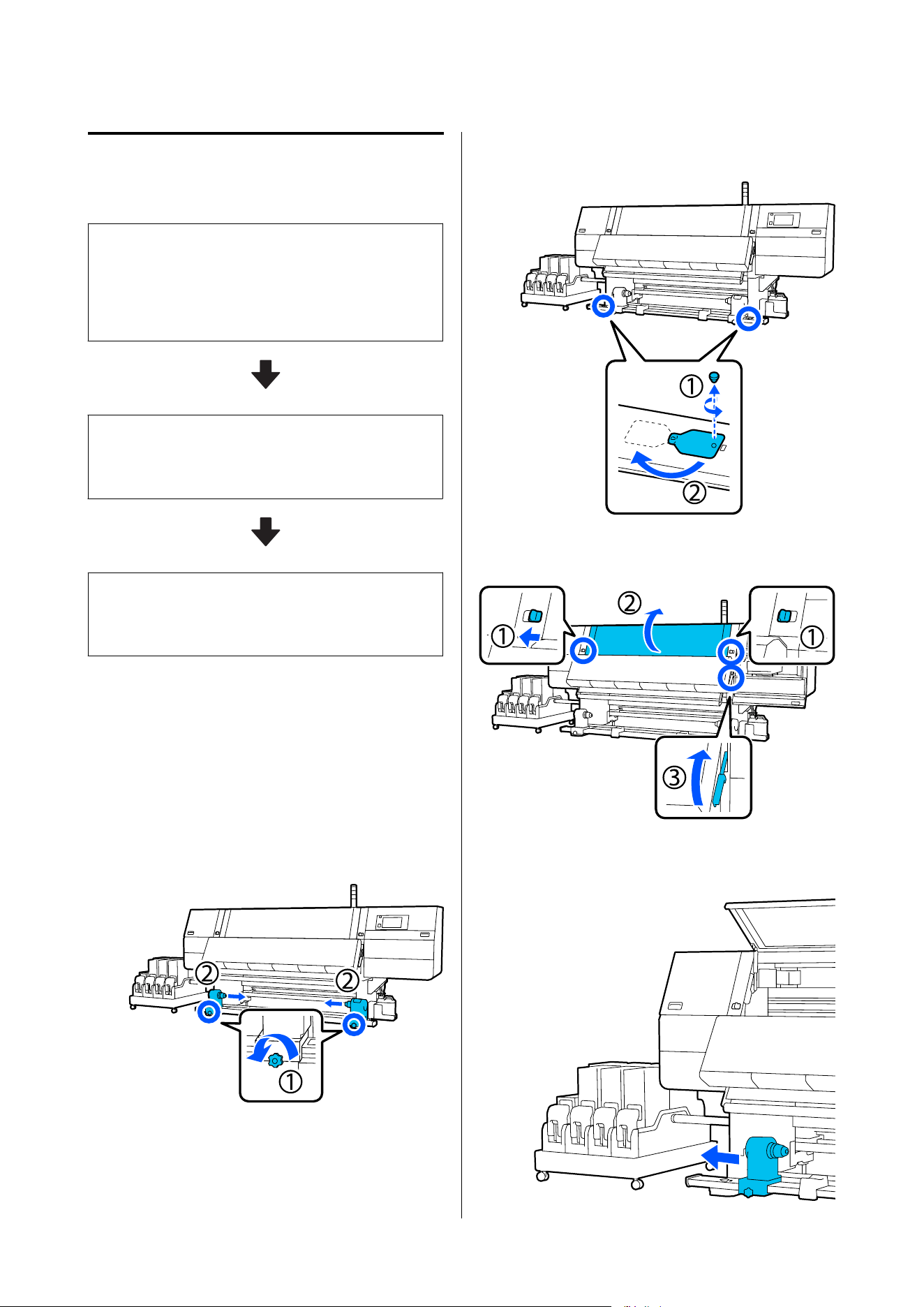
How to adjust
Do adjustment work in the following order.
1. Checking the Parallelism
Attach the adjustment tool to confirm there is no
misalignment in the parallelism of the Auto Take-up Reel
Unit and the Media Feeding Unit. If there is no
misalignment, then adjustment is not necessary.
2. Adjustments
Visually confirm as you do adjustments until any
misalignment in the parallelism is eliminated.
3. Completing Adjustments
Remove the adjustment tool, and set up the printer so
you can use it again.
Checking the Parallelism
Auto Take-up Reel Unit
A
Confirm that the printer is off.
B
Loosen both the left and right media holder
locking screws and move the media holders
inward.
C
Remove the screws in the illustration below,
and then turn the cover to open it.
D
Open the front cover and raise the media
loading lever.
E
Move the left-side media holder to the outer
side.
SC-F20000 Series/SC-F11000H Series/SC-F11000 Series/SC-F10000H Series/SC-F10000 Series User's Guide
Appendix
256
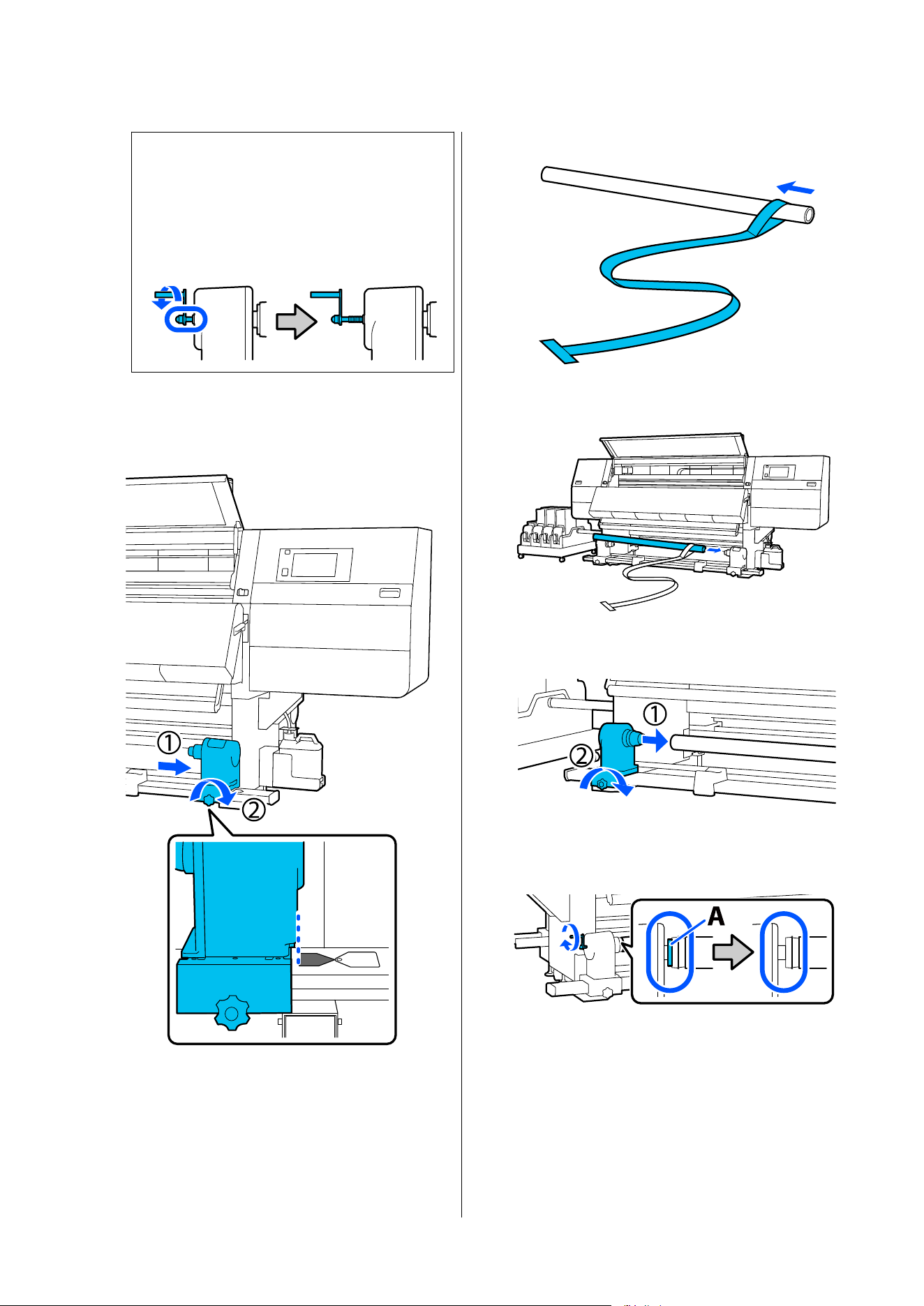
c
Important:
If the left-side media holder handle's shaft is
not visible, rotate the handle as shown in the
illustration until it stops. The roll core cannot
be properly loaded if the handle's shaft is not
visible.
F
Align the right-side media holder with the
position of the dotted line, and then tighten the
locking screw.
G
Pass film through the roll core.
H
Insert the roll core into the right-side media
holder.
I
Push the left-side media holder inwards, and
then tighten the locking screw.
J
Rotate the handle until part A in the illustration
below is fully inserted.
SC-F20000 Series/SC-F11000H Series/SC-F11000 Series/SC-F10000H Series/SC-F10000 Series User's Guide
Appendix
257
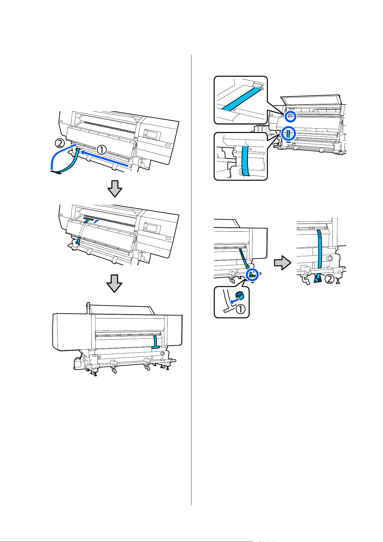
K
Move the film to the left side, insert its leading
edge into the printer, and pass it through to the
back side.
Insert it into the bottom of the dryer and then
out the top part, over the platen and through to
the back.
L
Align the film with the tips of the triangles on
the top and bottom of the left side of the dryer.
M
Attach the weight to the leading edge of the
film at the back of the printer, letting it hang in
the position shown in the following illustration.
SC-F20000 Series/SC-F11000H Series/SC-F11000 Series/SC-F10000H Series/SC-F10000 Series User's Guide
Appendix
258
N
After the film stops swinging, read the value on
the scale at the position on the platen shown in
the illustration, and record that value.
O
Lift the film at the front and back of the printer
and move it so that it aligns with the tips of the
triangles on the right side.
P
After the film stops swinging, read the value on
the scale at the position on the platen shown in
the illustration, and record that value.
If the difference between the values of both
sides is more than 0.5 mm (0.01 in.), proceed to
the adjustments in the next section.
If the difference is under 0.5 mm (0.01 in.), no
adjustments are necessary. Refer to the
following to remove the film.
U “Completing Adjustments” on page 266
Media Feeding Unit
A
Open the front cover and raise the media
loading lever.
SC-F20000 Series/SC-F11000H Series/SC-F11000 Series/SC-F10000H Series/SC-F10000 Series User's Guide
Appendix
259
B
Move to the back, hold the handle and rotate
the spindle so that it looks as shown in the
illustration, and then lower the handles on both
sides outward.
C
Remove the spindle.
D
Put the spindle through the film.
E
Put the spindle in the socket, then raise the
handles on both sides.
SC-F20000 Series/SC-F11000H Series/SC-F11000 Series/SC-F10000H Series/SC-F10000 Series User's Guide
Appendix
260
F
Insert the tip of the film into the printer, and
pass it through to the front.
G
Align the film with the 17 cm point on the
spindle's scale (on the side with the printer's
control panel) and the position on the label on
the Media Feeding Unit.
H
Attach the weight to the leading edge of the
film at the front of the printer, letting it hang in
the position shown in the following illustration.
SC-F20000 Series/SC-F11000H Series/SC-F11000 Series/SC-F10000H Series/SC-F10000 Series User's Guide
Appendix
261
I
Align the film with the tips of the triangles on
the top and bottom of the right side of the
dryer.
J
After the film stops swinging, read the value on
the scale at the position on the platen shown in
the illustration, and record that value.
K
Lift the film at the front and back of the printer
and move it to the opposite side and align the
film position in the same as in steps 7 to 9.
L
After the film stops swinging, read the value on
the scale at the position on the platen shown in
the illustration, and record that value.
If the difference between the values of both
sides is more than 2 mm (0.07 in.), proceed to
the adjustments in the next section.
If the difference is under 2 mm (0.07 in.), no
adjustments are necessary. Refer to the
following to remove the film.
SC-F20000 Series/SC-F11000H Series/SC-F11000 Series/SC-F10000H Series/SC-F10000 Series User's Guide
Appendix
262
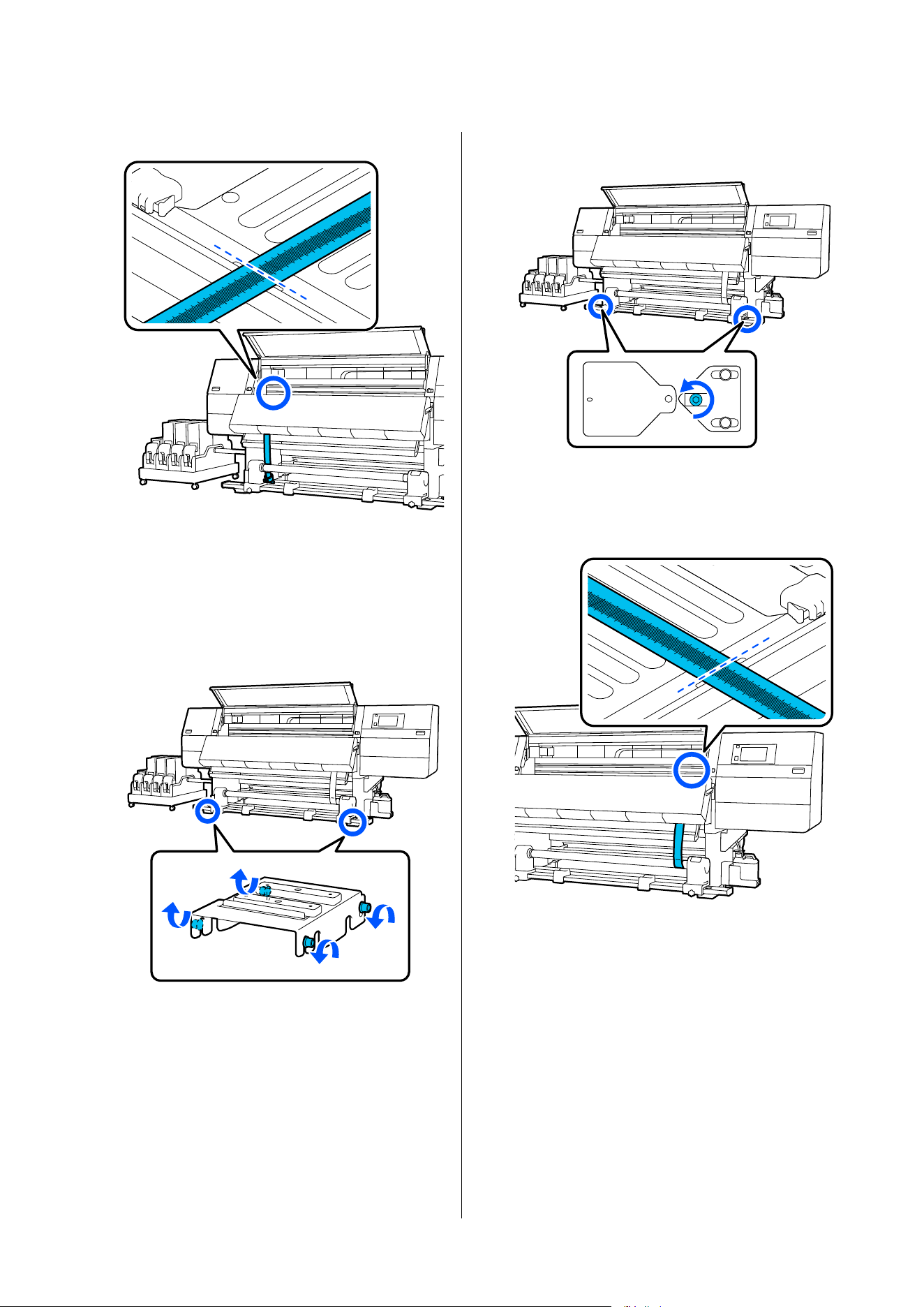
U “Completing Adjustments” on page 266
Adjustments
Auto Take-up Reel Unit
A
Loosen all of the metal fixing screws in the
illustration below.
B
Completely loosen the adjustment screws on
both sides in the illustration below.
C
Confirm that the film is aligned with the tips of
the triangles on the right side, read the value on
the scale at the position on the platen shown in
the illustration, and record that value.
SC-F20000 Series/SC-F11000H Series/SC-F11000 Series/SC-F10000H Series/SC-F10000 Series User's Guide
Appendix
263
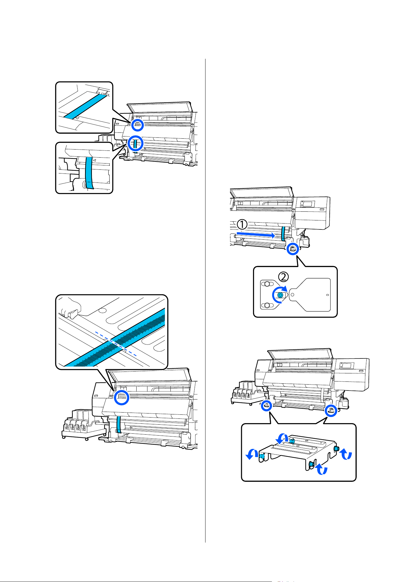
D
Move the film to align with the tips of the
triangles on the left side.
E
After the film stops swinging, read the value on
the scale at the position on the platen shown in
the illustration, and record that value.
If the difference between the values on the left
and the right is more than 0.5 mm (0.01 in.),
proceed to Step 6 to adjust the screw with the
higher value to reduce the difference.
If the difference is under 0.5 mm (0.01 in.),
proceed to Step 7.
F
Adjust it so the difference between the left and
right is less than 0.5 mm (0.01 in.).
(1) Align the film with the tips of the triangles on
the side you are adjusting.
(2) While checking the scale, turn the adjustment
screw clockwise until the difference in the
values for both sides is less than 0.5 mm (0.01
in.).
The scale moves from the place that has tension
when the screw is turned.
Fully rotating the screw once makes the value
about 0.6 mm (0.23 in.) smaller.
Example When the Value of the Right Side is
High
G
Securely tighten all the screws in the following
illustration.
Next, continue to the next section, Completing
Adjustments.
SC-F20000 Series/SC-F11000H Series/SC-F11000 Series/SC-F10000H Series/SC-F10000 Series User's Guide
Appendix
264
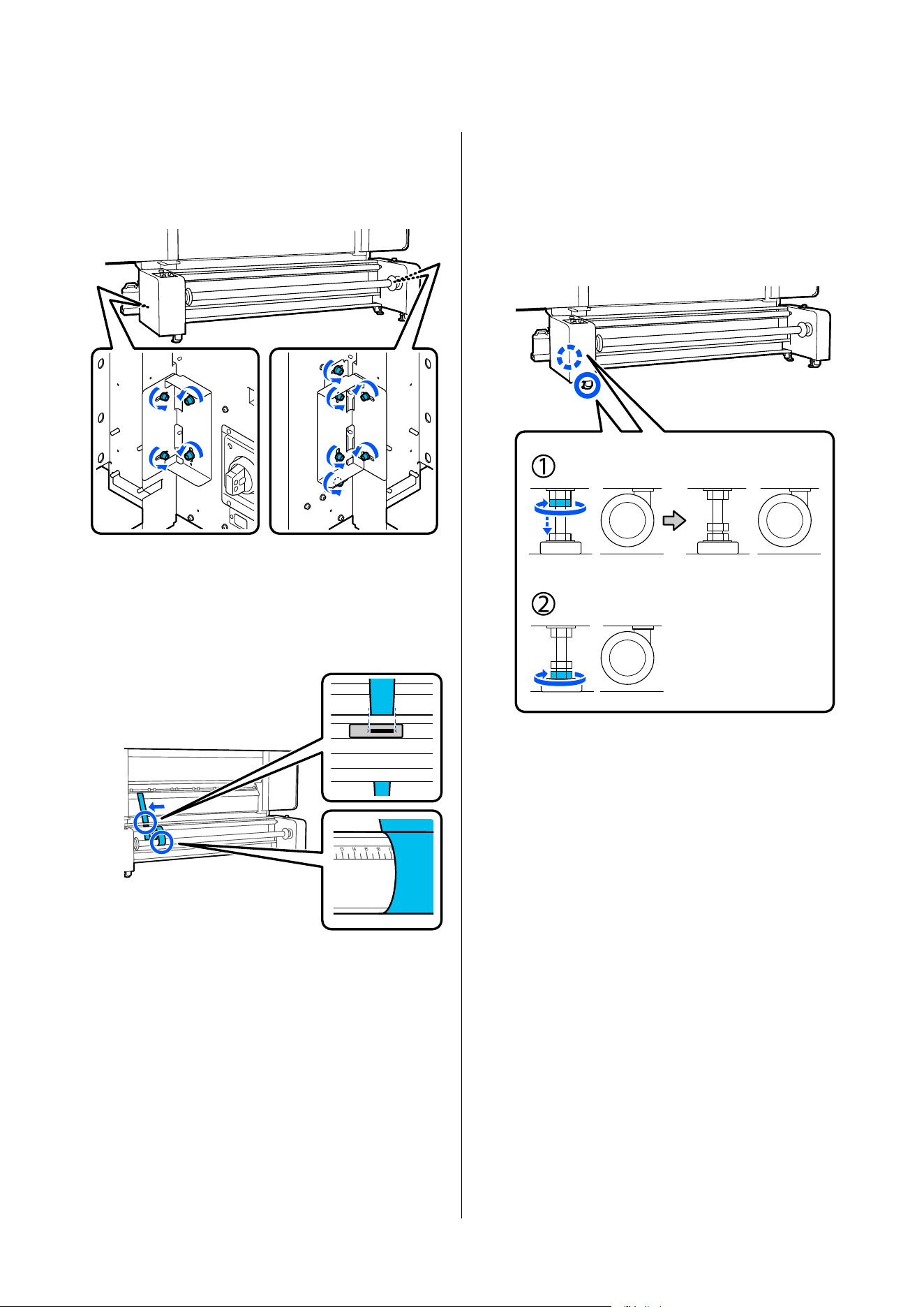
Media Feeding Unit
A
Loosen all the screws on the left and right sides,
shown in the illustration, on the rear of the
Media Feeding Unit.
B
Move the film toward the larger value of the
results of checking the parallelism and align it
with the specified position.
The example in this section assumes a larger
value on the side toward the control panel.
C
Adjust it so the difference between the left and
right is less than 2 mm (0.07 in.).
Follow the steps below to operate and adjust the
adjusters.
(1) Turn the top nut clockwise to move it
downward.
(2) While checking the scale, turn the bottom nut
clockwise until the difference in the values for
both sides is less than 2 mm (0.07 in.). When
doing this, turn both nuts of the two adjusters
by the same amount while making the
adjustment.
SC-F20000 Series/SC-F11000H Series/SC-F11000 Series/SC-F10000H Series/SC-F10000 Series User's Guide
Appendix
265
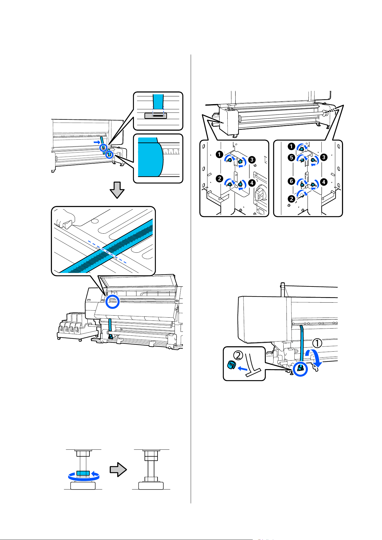
D
After adjustment, move the film to the opposite
side and read the scale on the film again to
confirm that the difference between the left and
right values is less than 2 mm (0.07 in.).
If the difference in the values is larger than 2
mm (0.07 in.), then repeat steps 2 to 4 until the
value drops below 2 mm (0.07 in.).
If the difference is under 2 mm (0.07 in.),
proceed to the next step.
E
On all the adjusters operated, turn the top nut
counter-clockwise until it reaches the top part
and stops.
F
Securely tighten the screws on the left and right
sides, in the order of the numbers in the
illustration, on the rear of the Media Feeding
Unit.
Completing Adjustments
Auto Take-up Reel Unit
A
Remove the weight attached to the film at the
back of the printer.
SC-F20000 Series/SC-F11000H Series/SC-F11000 Series/SC-F10000H Series/SC-F10000 Series User's Guide
Appendix
266
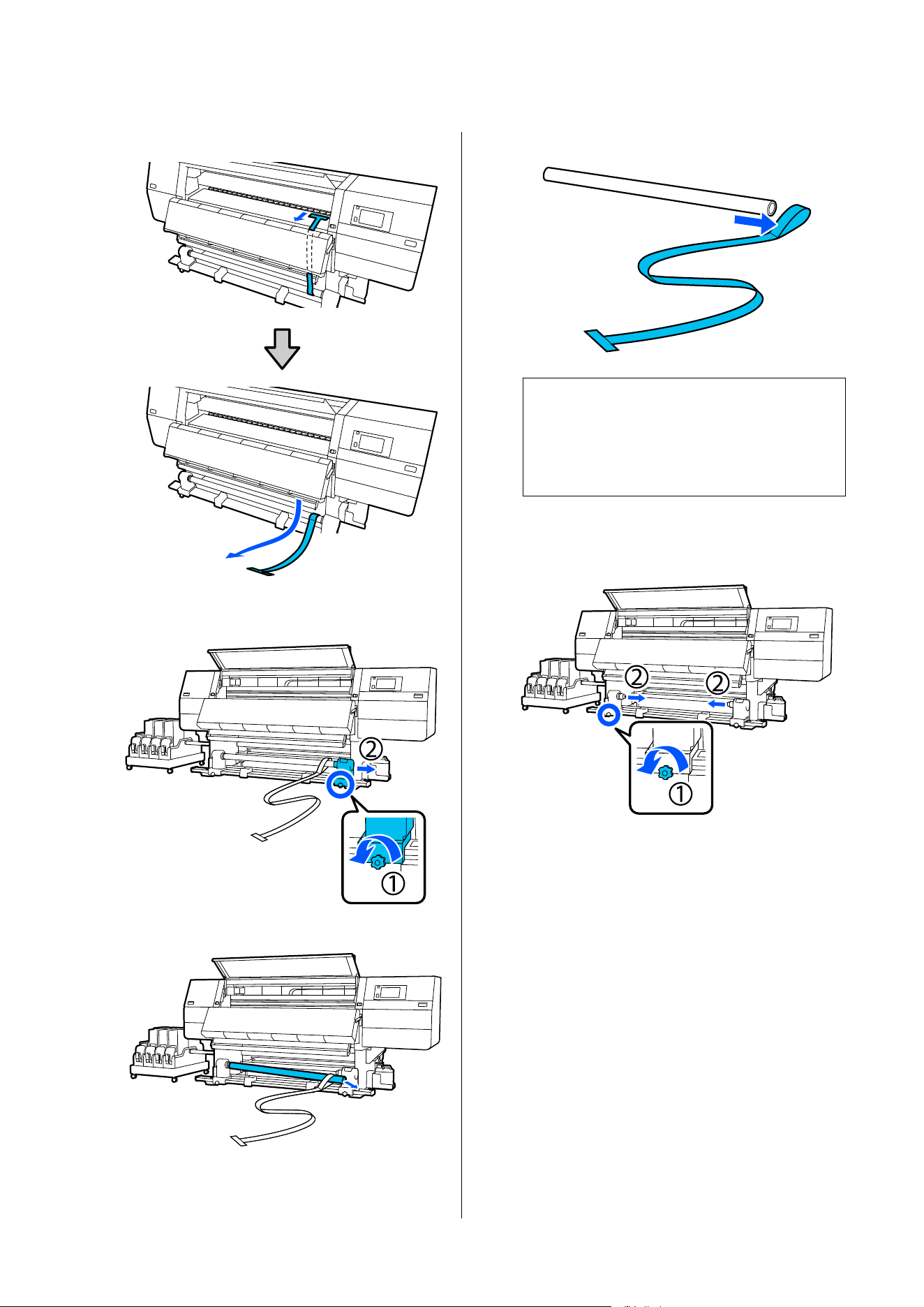
B
Pull film out from the front of the printer.
C
Loosen the right media holder fixing screw and
remove the media holder.
D
Remove the roll core.
E
Remove film from the roll core.
Note:
After removing the film, be careful not to crease it,
and store it together with the weight. If you plan
on using the film again, remove dust, etc., and
smooth it out straight before use.
F
Loosen the locking screw on the left media
holder locking screw and move the left and
right media holders inward.
SC-F20000 Series/SC-F11000H Series/SC-F11000 Series/SC-F10000H Series/SC-F10000 Series User's Guide
Appendix
267
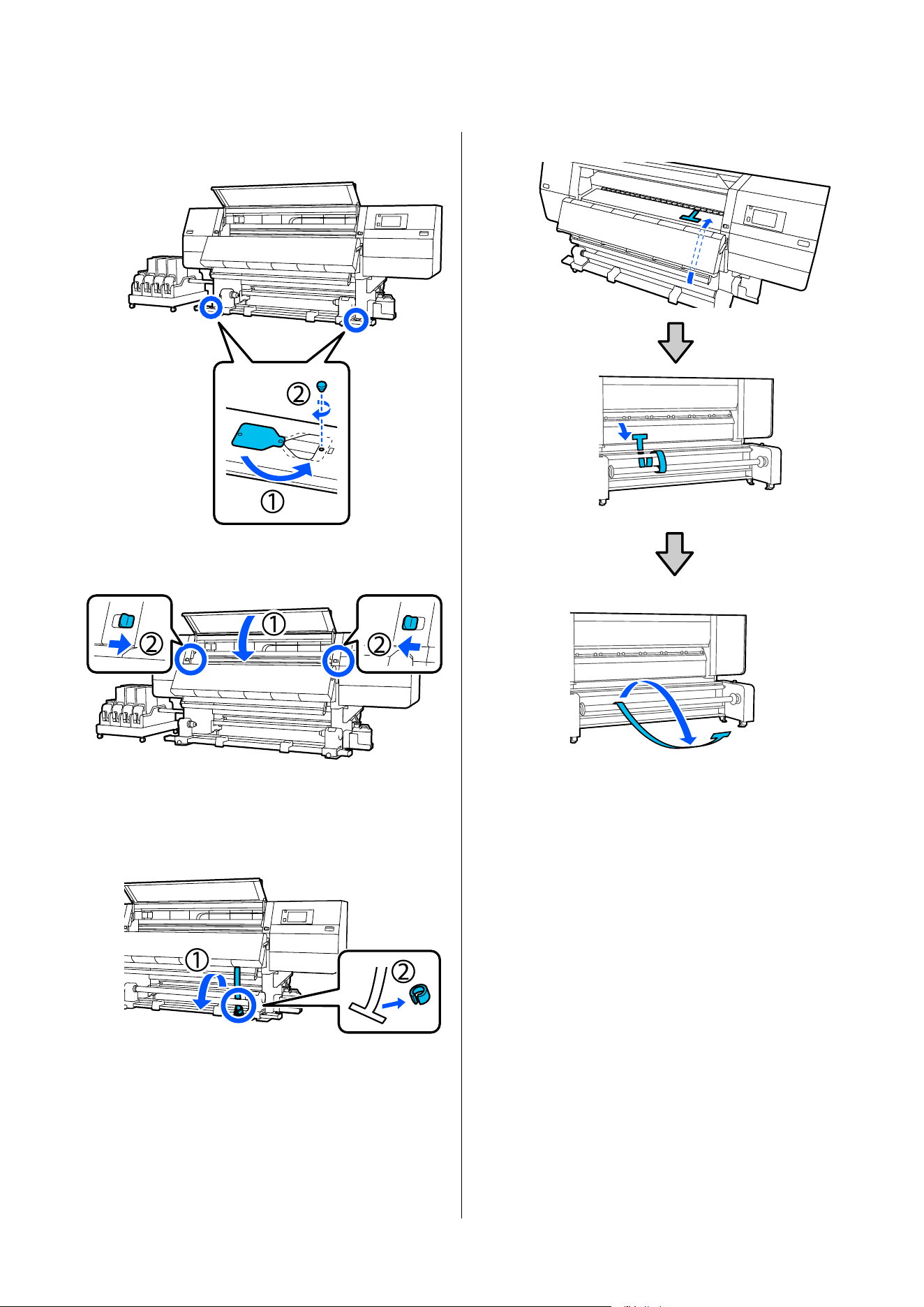
G
Turn the cover in the illustration below to close
it, and then tighten the screw.
H
Close the front cover, and then move the left
and right lock levers inward.
Media Feeding Unit
A
Remove the weight attached to the film at the
front of the printer.
B
Pull the film out from the back of the printer.
SC-F20000 Series/SC-F11000H Series/SC-F11000 Series/SC-F10000H Series/SC-F10000 Series User's Guide
Appendix
268
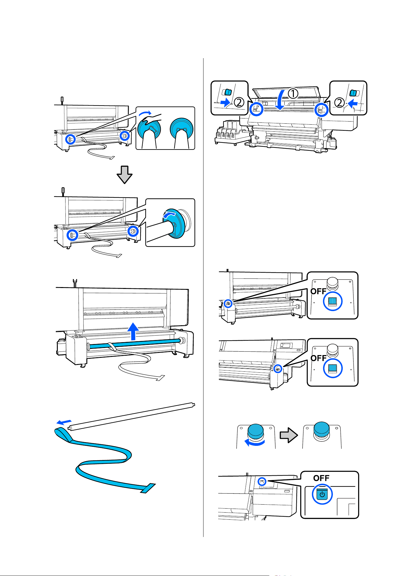
C
Hold the handle and rotate the spindle so that it
looks as shown in the illustration, and then
lower the handles on both sides outward.
D
Remove the spindle.
E
Remove the film from the spindle.
F
Close the front cover, and then move the left
and right lock levers inward.
Recovering from an
Emergency Stop
If the printer has been stopped using the emergency
stop button on a large capacity roll model or large
capacity reel model, follow the steps below to restart
printer operations.
A
Turn off the unit that was stopped.
B
Rotate the emergency stop button to the right
to reset the button.
C
Turn off the power to the printer.
SC-F20000 Series/SC-F11000H Series/SC-F11000 Series/SC-F10000H Series/SC-F10000 Series User's Guide
Appendix
269
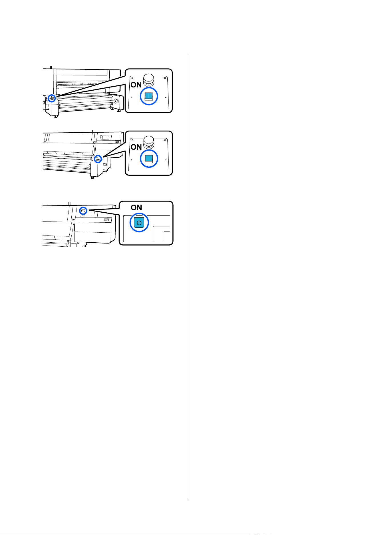
D
Turn on the power to the unit that was stopped.
E
Turn on the power to the printer.
SC-F20000 Series/SC-F11000H Series/SC-F11000 Series/SC-F10000H Series/SC-F10000 Series User's Guide
Appendix
270

Media Settings List for Each Media Type
The following table shows the media settings registered when a Media Type is selected.
❏ The upper row of temperatures shows the settings when using a standard type Auto Take-up Reel Unit, and
the lower row shows the settings when using a large capacity type Auto Take-up Reel Unit. When using a large
capacity type Auto Take-up Reel Unit, check the temperature setting from the home screen after attaching the
media to the take-up unit, and if it differs from the table, reset it to the value in the table.
❏ The switch setting values for the large capacity type Media Feeding Unit and the Auto Take-up Reel Unit are
the recommended values. Set each unit's switches according to the media you are using.
❏ Setting items marked *1 are disabled when using a large capacity type Media Feeding Unit.
❏ Setting items marked *2 are disabled when using a large capacity type Auto Take-up Reel Unit.
SC-F20000 Series/SC-F11000H Series/SC-F11000 Series/SC-F10000H Series/SC-F10000 Series User's Guide
Appendix
271
SC-F11000H Series/SC-F11000 Series/SC-F10000H Series/
SC-F10000 Series
Ultra-Thin
Item
Pass Mode (*: Default value)
300x600dpi 600x600dpi 600x1200dpi
1200x
1200dp
i
1.1
pas
s
1.5
pas
s
2.1
pas
s
3.1
pas
s
2.1
pas
s
2.5
pas
s
3.1
pas
s
4.3
pas
s
*
5.0
pas
s
5.0pas
s HD
9.0pass
HD
Heater On
Temperature
Standard type
90 80 70 65 70 65 65 60 55 55 50
Temperature
Large capacity type
90 80 70 65 70 65 65 60 55 55 50
Fan Off
Drying Time 14 19 23 33 23 27 33 46 52 52 89
Proceed to Drying
after Print
Off
Drying Action Auto
Platen Gap 2.0
Feeding Tension
*1
Lv2
Paper Suction Lv1
Media Feed Speed
Limitation
Off
Pressure Roller Load Standard
Remove Skew On
Stick Prevention On
Rewind Tension
*2
Lv6 Lv6 Lv6 Lv6 Lv6 Lv6 Lv6 Lv4 Lv4 Lv4 Lv4
Print Quality
Adjustment
Limitation
Temperature
5
Media Feed
Adjustment value
0
Large capacity type Media Feeding Unit
Load switch Mid
SC-F20000 Series/SC-F11000H Series/SC-F11000 Series/SC-F10000H Series/SC-F10000 Series User's Guide
Appendix
272

Item
Pass Mode (*: Default value)
300x600dpi 600x600dpi 600x1200dpi
1200x
1200dp
i
1.1
pas
s
1.5
pas
s
2.1
pas
s
3.1
pas
s
2.1
pas
s
2.5
pas
s
3.1
pas
s
4.3
pas
s
*
5.0
pas
s
5.0pas
s HD
9.0pass
HD
Large capacity type Auto Take-up Reel Unit
Heater switch On
Load switch Lo
SC-F20000 Series/SC-F11000H Series/SC-F11000 Series/SC-F10000H Series/SC-F10000 Series User's Guide
Appendix
273
Thin
Item
Pass Mode (*: Default value)
300x600dpi 600x600dpi 600x1200dpi
1200x
1200dp
i
1.1
pas
s
1.5
pas
s
2.1
pas
s
3.1
pas
s
2.1
pas
s
2.5
pas
s
3.1
pas
s
4.3
pas
s
*
5.0
pas
s
5.0pas
s HD
9.0pass
HD
Heater On
Temperature
Standard type
90 80 70 65 70 65 65 60 55 55 50
Temperature
Large capacity type
70 60 55 50 55 50 50 50 50 50 50
Fan Off
Drying Time 14 19 23 33 23 27 33 46 52 52 89
Proceed to Drying
after Print
Off
Drying Action Auto
Platen Gap 2.0
Feeding Tension
*1
Lv2
Paper Suction Lv3
Media Feed Speed
Limitation
Off
Pressure Roller Load Standard
Remove Skew On
Stick Prevention Off
Rewind Tension
*2
Lv6 Lv6 Lv6 Lv6 Lv6 Lv6 Lv6 Lv4 Lv4 Lv4 Lv4
Print Quality
Adjustment
Limitation
Temperature
5
Media Feed
Adjustment value
0
Large capacity type Media Feeding Unit
Load switch Mid
Large capacity type Auto Take-up Reel Unit
Heater switch On
SC-F20000 Series/SC-F11000H Series/SC-F11000 Series/SC-F10000H Series/SC-F10000 Series User's Guide
Appendix
274

Item
Pass Mode (*: Default value)
300x600dpi 600x600dpi 600x1200dpi
1200x
1200dp
i
1.1
pas
s
1.5
pas
s
2.1
pas
s
3.1
pas
s
2.1
pas
s
2.5
pas
s
3.1
pas
s
4.3
pas
s
*
5.0
pas
s
5.0pas
s HD
9.0pass
HD
Load switch Mid
SC-F20000 Series/SC-F11000H Series/SC-F11000 Series/SC-F10000H Series/SC-F10000 Series User's Guide
Appendix
275
Med-Thick
Item
Pass Mode (*: Default value)
300x600dpi 600x600dpi 600x1200dpi
1200x
1200dp
i
1.1
pas
s
1.5
pas
s
2.1
pas
s
3.1
pas
s
2.1
pas
s
2.5
pas
s
3.1
pas
s
4.3
pas
s
*
5.0
pas
s
5.0pas
s HD
9.0pass
HD
Heater On
Temperature
Standard type
105 105 100 85 100 90 85 75 70 70 55
Temperature
Large capacity type
95 90 85 70 85 75 70 65 55 55 50
Fan Off
Drying Time 14 19 23 33 23 27 33 46 52 52 89
Proceed to Drying
after Print
Off
Drying Action Auto
Platen Gap 2.0
Feeding Tension
*1
Lv2
Paper Suction Lv5
Media Feed Speed
Limitation
Off
Pressure Roller Load Standard
Remove Skew On
Stick Prevention Off
Rewind Tension
*2
Lv8 Lv8 Lv8 Lv8 Lv8 Lv8 Lv8 Lv8 Lv8 Lv8 Lv8
Print Quality
Adjustment
Limitation
Temperature
5
Media Feed
Adjustment value
0
Large capacity type Media Feeding Unit
Load switch Mid
Large capacity type Auto Take-up Reel Unit
Heater switch On
SC-F20000 Series/SC-F11000H Series/SC-F11000 Series/SC-F10000H Series/SC-F10000 Series User's Guide
Appendix
276

Item
Pass Mode (*: Default value)
300x600dpi 600x600dpi 600x1200dpi
1200x
1200dp
i
1.1
pas
s
1.5
pas
s
2.1
pas
s
3.1
pas
s
2.1
pas
s
2.5
pas
s
3.1
pas
s
4.3
pas
s
*
5.0
pas
s
5.0pas
s HD
9.0pass
HD
Load switch Hi
SC-F20000 Series/SC-F11000H Series/SC-F11000 Series/SC-F10000H Series/SC-F10000 Series User's Guide
Appendix
277
Thick
Item
Pass Mode (*: Default value)
300x600dpi 600x600dpi 600x1200dpi
1200x
1200dp
i
1.1
pas
s
1.5
pas
s
2.1
pas
s
3.1
pas
s
2.1
pas
s
2.5
pas
s
3.1
pas
s
4.3
pas
s
*
5.0
pas
s
5.0pas
s HD
9.0pass
HD
Heater On
Temperature
Standard type
90 85 80 75 80 80 75 75 70 70 55
Temperature
Large capacity type
90 85 80 75 80 80 75 75 70 70 55
Fan Off
Drying Time 14 19 23 33 23 27 33 46 52 52 89
Proceed to Drying
after Print
Off
Drying Action Auto
Platen Gap 2.0
Feeding Tension
*1
Lv2
Paper Suction Lv8
Media Feed Speed
Limitation
Off
Pressure Roller Load Standard
Remove Skew On
Stick Prevention Off
Rewind Tension
*2
Lv8 Lv8 Lv8 Lv8 Lv8 Lv8 Lv8 Lv8 Lv8 Lv8 Lv8
Print Quality
Adjustment
Limitation
Temperature
15
Media Feed
Adjustment value
0
Large capacity type Media Feeding Unit
Load switch Mid
Large capacity type Auto Take-up Reel Unit
Heater switch On
SC-F20000 Series/SC-F11000H Series/SC-F11000 Series/SC-F10000H Series/SC-F10000 Series User's Guide
Appendix
278

Item
Pass Mode (*: Default value)
300x600dpi 600x600dpi 600x1200dpi
1200x
1200dp
i
1.1
pas
s
1.5
pas
s
2.1
pas
s
3.1
pas
s
2.1
pas
s
2.5
pas
s
3.1
pas
s
4.3
pas
s
*
5.0
pas
s
5.0pas
s HD
9.0pass
HD
Load switch Hi
SC-F20000 Series/SC-F11000H Series/SC-F11000 Series/SC-F10000H Series/SC-F10000 Series User's Guide
Appendix
279
SC-F20000 Series
Ultra-Thin
Item
Pass Mode (*: Default value)
600x600dpi
600x1
200d
pi
1200x
1200d
pi
1.0pa
ss HS
1.1pa
ss HS
1.5pa
ss HS
2.1pa
ss HS
1.1pa
ss
*
1.5pa
ss
2.1pa
ss
3.1pa
ss
5.0pa
ss HD
Heater On
Temperature
Standard type
85 85 70 70 90 70 65 50 50
Temperature
Large capacity type
60 60 60 55 70 60 55 50 50
Fan Off
Drying Time 10 10 15 21 14 19 23 33 52
Proceed to Drying
after Print
Off
Drying Action Auto
Platen Gap 2.0
Feeding Tension
*1
Lv2
Paper Suction Lv1
Media Feed Speed
Limitation
Off
Pressure Roller Load Standard
Remove Skew On
Stick Prevention On
Rewind Tension
*2
Lv6 Lv6 Lv6 Lv6 Lv6 Lv6 Lv6 Lv6 Lv4
Print Quality
Adjustment
Limitation
Temperature
5
Media Feed
Adjustment value
0
Large capacity type Media Feeding Unit
Load switch Mid
Large capacity type Auto Take-up Reel Unit
SC-F20000 Series/SC-F11000H Series/SC-F11000 Series/SC-F10000H Series/SC-F10000 Series User's Guide
Appendix
280

Item
Pass Mode (*: Default value)
600x600dpi
600x1
200d
pi
1200x
1200d
pi
1.0pa
ss HS
1.1pa
ss HS
1.5pa
ss HS
2.1pa
ss HS
1.1pa
ss
*
1.5pa
ss
2.1pa
ss
3.1pa
ss
5.0pa
ss HD
Heater switch On
Load switch Lo
SC-F20000 Series/SC-F11000H Series/SC-F11000 Series/SC-F10000H Series/SC-F10000 Series User's Guide
Appendix
281
Thin
Item
Pass Mode (*: Default value)
600x600dpi
600x1
200d
pi
1200x
1200d
pi
1.0pa
ss HS
1.1pa
ss HS
1.5pa
ss HS
2.1pa
ss HS
1.1pa
ss
*
1.5pa
ss
2.1pa
ss
3.1pa
ss
5.0pa
ss HD
Heater On
Temperature
Standard type
85 85 70 70 90 65 60 55 55
Temperature
Large capacity type
60 60 60 55 80 60 55 50 50
Fan Off
Drying Time 10 10 15 21 14 19 23 33 52
Proceed to Drying
after Print
Off
Drying Action Auto
Platen Gap 2.0
Feeding Tension
*1
Lv2
Paper Suction Lv3
Media Feed Speed
Limitation
Off
Pressure Roller Load Standard
Remove Skew On
Stick Prevention Off
Rewind Tension
*2
Lv6 Lv6 Lv6 Lv6 Lv6 Lv6 Lv6 Lv6 Lv4
Print Quality
Adjustment
Limitation
Temperature
5
Media Feed
Adjustment value
0
Large capacity type Media Feeding Unit
Load switch Mid
Large capacity type Auto Take-up Reel Unit
Heater switch On
Load switch Mid
SC-F20000 Series/SC-F11000H Series/SC-F11000 Series/SC-F10000H Series/SC-F10000 Series User's Guide
Appendix
282
Med-Thick
Item
Pass Mode (*: Default value)
600x600dpi
600x1
200d
pi
1200x
1200d
pi
1.0pa
ss HS
1.1pa
ss HS
1.5pa
ss HS
2.1pa
ss HS
1.1pa
ss
*
1.5pa
ss
2.1pa
ss
3.1pa
ss
5.0pa
ss HD
Heater On
Temperature
Standard type
100 100 100 95 105 105 100 85 70
Temperature
Large capacity type
100 100 100 95 95 90 85 65 55
Fan Off
Drying Time 10 10 15 21 14 19 23 33 52
Proceed to Drying
after Print
Off
Drying Action Auto
Platen Gap 2.0
Feeding Tension
*1
Lv2
Paper Suction Lv5
Media Feed Speed
Limitation
Off
Pressure Roller Load Standard
Remove Skew On
Stick Prevention Off
Rewind Tension
*2
Lv8 Lv8 Lv8 Lv8 Lv8 Lv8 Lv8 Lv8 Lv8
Print Quality
Adjustment
Limitation
Temperature
5
Media Feed
Adjustment value
0
Large capacity type Media Feeding Unit
Load switch Mid
Large capacity type Auto Take-up Reel Unit
Heater switch On
Load switch Hi
SC-F20000 Series/SC-F11000H Series/SC-F11000 Series/SC-F10000H Series/SC-F10000 Series User's Guide
Appendix
283
Thick
Item
Pass Mode (*: Default value)
600x600dpi
600x1
200d
pi
1200x
1200d
pi
1.0pa
ss HS
1.1pa
ss HS
1.5pa
ss HS
2.1pa
ss HS
1.1pa
ss
*
1.5pa
ss
2.1pa
ss
3.1pa
ss
5.0pa
ss HD
Heater On
Temperature
Standard type
100 100 95 90 105 100 95 75 70
Temperature
Large capacity type
100 100 95 90 100 95 95 75 70
Fan Off
Drying Time 10 10 15 21 14 19 23 33 52
Proceed to Drying
after Print
Off
Drying Action Auto
Platen Gap 2.0
Feeding Tension
*1
Lv2
Paper Suction Lv8
Media Feed Speed
Limitation
Off
Pressure Roller Load Standard
Remove Skew On
Stick Prevention Off
Rewind Tension
*2
Lv8 Lv8 Lv8 Lv8 Lv8 Lv8 Lv8 Lv8 Lv8
Print Quality
Adjustment
Limitation
Temperature
15
Media Feed
Adjustment value
0
Large capacity type Media Feeding Unit
Load switch Mid
Large capacity type Auto Take-up Reel Unit
Heater switch On
Load switch Hi
SC-F20000 Series/SC-F11000H Series/SC-F11000 Series/SC-F10000H Series/SC-F10000 Series User's Guide
Appendix
284
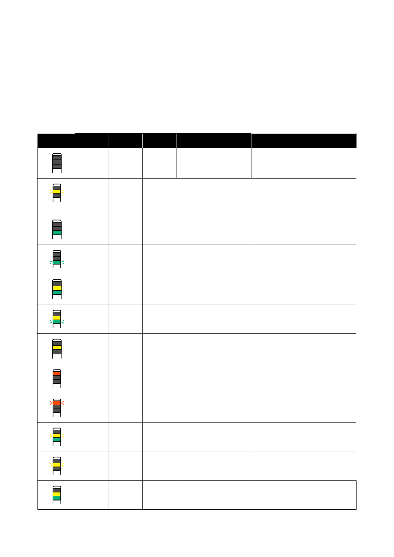
Reading the Signal Lamps
The signal lamps indicate the status of the printer as shown in the following table. The lamps are, in order from the
top, red, yellow, and green.
The following table is for standard settings. These settings may have been changed to suit your operating
environment.
Green Yellow Red Status Explanation
Off Off Off Power off The power is off.
Off Flashing Off
Starting/stopping
operations
Doing start up operations after the
power is turned on, or doing shut
down operations after the power is
turned off.
On Off Off Idling Idling in a normal state. Ready to print.
Flashing Off Off Printing Printing in a normal state.
On On Off
Consumable near end
(idling)
Printing is possible, but printing will
not be possible when the
consumables need to be replaced.
Flashing On Off
Consumable near end
(printing)
Printing can continue, but printing will
stop and not be possible when the
consumables need to be replaced.
Off On Off Printing cannot start
Printing not possible in current state
for such reasons as a cover is open or a
consumable is not loaded.
Off Off On Error (recoverable)
An error has occurred so printing is
not possible. Resolve the error and
printing can be done.
Off Off Flashing Fatal error (service call)
An error has occurred that cannot be
resolved, so printing is not possible.
On Flashing Off
Doing maintenance (jobs
can be received)
A maintenance function is being
executed. Print jobs can be received.
Off Flashing Off
Doing maintenance (jobs
cannot be received)
A maintenance function is being
executed. Print jobs cannot be
received.
On On Off
Pause mode (printing
stopped)
Printing is stopped.
SC-F20000 Series/SC-F11000H Series/SC-F11000 Series/SC-F10000H Series/SC-F10000 Series User's Guide
Appendix
285

Green Yellow Red Status Explanation
Flashing On Off
Pause mode (waiting to
stop printing)
Waiting to stop printing. Printing
continues to the end of the page, and
then stops.
Off On Off
Offline (jobs cannot be
received)
The connection to the computer is
offline. Print jobs cannot be received.
SC-F20000 Series/SC-F11000H Series/SC-F11000 Series/SC-F10000H Series/SC-F10000 Series User's Guide
Appendix
286
System Requirements
Each software can be used in the following environments. (As of January 2026)
The supported operating systems may change.
For the latest information, see the Epson website.
Epson Edge Dashboard
The Epson Edge Dashboard can be used in the following environments.
c
Important:
Make sure the computer on which the Epson Edge Dashboard is installed meets the following requirements.
If these requirements are not met, the software cannot monitor the printer correctly.
❏ Disable your computer's hibernate function.
❏ Disable the sleep function so that the computer does not enter sleep status.
Windows
Operating systems Windows 10 x64
Windows 11
CPU Multi-core processor (3.0 GHz or more)
Intel
®
Core
™
i5 3.4 GHz or faster recommended
Free memory 4 GB or more
Hard disk
(free space during installation)
2 GB or more
Display resolution 1280 x 1024 or better
Communication interface High Speed USB
Ethernet 1000Base-T
Browser Microsoft Edge
Mac
Operating systems Mac OS X 10.9.5 Mavericks or later
CPU Multi-core processor (3.0 GHz or more)
Intel
®
Core
™
i5 3.4 GHz or faster recommended
Free memory 4 GB or more
Hard disk
(free space during installation)
2 GB or more
SC-F20000 Series/SC-F11000H Series/SC-F11000 Series/SC-F10000H Series/SC-F10000 Series User's Guide
Appendix
287
Display resolution 1280 x 1024 or better
Communication interface High Speed USB
Ethernet 1000Base-T
Browser Safari 6 or later
Linux
Distribution Debian 8.6 64 bit (MATE desktop environment only) or later
CPU Multi-core processor (3.0 GHz or more)
Intel
®
Core
™
i5 3.4 GHz or faster recommended
Free memory 4 GB or more
Hard disk
(free space during installation)
2 GB or more
Display resolution 1280 x 1024 or better
Communication interface High Speed USB
Ethernet 1000Base-T
Browser Mozilla Firefox 45 (ESR) or later
Epson Edge Print
Operating environment
Operating system (OS) Windows 10 x64
Windows 11
CPU Intel
®
Core
™
i3 3.0 GHz or faster (released after April 2014)
Free memory 8 GB or more
Hard disk drive
(free space during installation)
50 GB or more
Display resolution 1280 x 1024 or better
Communication interface Hi-Speed USB
Ethernet 100Base-TX/1000Base-T
We recommend installing this software on a computer with high specifications since the software will be used in
combination with software applications such as Adobe Illustrator.
Also, this software normally handles data that is several GB in size, and in some cases may be tens of GB in size
particularly when performing high quality banner printing jobs.
We therefore recommend using a computer with sufficient storage space.
The following shows the recommended environment when using this software.
SC-F20000 Series/SC-F11000H Series/SC-F11000 Series/SC-F10000H Series/SC-F10000 Series User's Guide
Appendix
288
Recommended environment
Operating system (OS) Windows 10 x64
Windows 11
CPU Intel
®
Core
™
i7-14700 processor or faster
Free memory 32 GB or more
Storage
(free space during installation)
SSD 1 TB or more
Display resolution 1280 x 1024 or better
Communication interface Hi-Speed USB
Gigabit Ethernet
Web Config
The following browsers are supported. Use the latest version of the browser.
Windows
Browser Internet Explorer 11, Microsoft Edge, Mozilla Firefox, Google Chrome
Mac
Browser Safari, Mozilla Firefox, Google Chrome
SC-F20000 Series/SC-F11000H Series/SC-F11000 Series/SC-F10000H Series/SC-F10000 Series User's Guide
Appendix
289
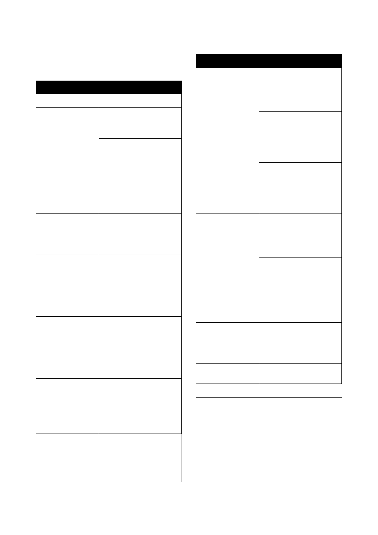
Specifications Table
Printer Specifications
Printing method On-demand ink jet
Nozzle configuration SC-F20000 Series:
1600 nozzles x 2 rows x 8
heads
SC-F11000H Series/
SC-F10000H Series:
1600 nozzles x 2 rows x 6
heads
SC-F11000 Series/SC-F10000
Series:
1600 nozzles x 2 rows x 4
heads
Resolution (maxi-
mum)
1200 × 1200 dpi (With 300 ×
300 dpi 16 Half Tone layers.)
Control code ESC/P raster (undisclosed
command)
Media Feed Method Friction feed
Rated voltage
(#1, #2, large capacity
type Media Feeding
Unit, large capacity
type Auto Take-up
Reel Unit)
AC 200 to 240 V
Rated frequency (#1,
#2, large capacity type
Media Feeding Unit,
large capacity type
Auto Take-up Reel
Unit)
50/60 Hz
Rated current (#1, #2) 16 A
Rated current (large
capacity type Media
Feeding Unit)
10 A
Rated current (Large
capacity type Auto
Take-up Reel Unit)
15 A
Short-circuit current
rating (large capacity
type Media Feeding
Unit, large capacity
type Auto Take-up
Reel Unit)
10 kA (UL rated)
Printer Specifications
Power consumption
(total for numbers #1
and #2)
SC-F20000 Series:
Printing: Approx. 5.0 kW
Sleep mode: Approx. 229 W
Power off: Approx. 13.1 W
SC-F11000H Series/
SC-F10000H Series:
Printing: Approx. 4.4 kW
Sleep mode: Approx. 230 W
Power off: Approx. 9.6 W
SC-F11000 Series/SC-F10000
Series:
Printing: Approx. 3.9 kW
Sleep mode: Approx. 221 W
Power off: Approx. 9.6 W
Power consumption
(large capacity type
Media Feeding Unit)
SC-F20000 Series:
Printing: Approx. 50 W
Sleep mode: Approx. 38 W
Power off: Approx. 0.8 W
SC-F11000H Series /
SC-F11000 Series /
SC-F10000H Series /
SC-F10000 Series:
Printing: Approx. 42 W
Sleep mode: Approx. 38 W
Power off: Approx. 0.8 W
Power consumption
(Large capacity type
Auto Take-up Reel
Unit)
Printing: Approx. 190 W
Sleep mode: Approx. 50 W
Power off: Approx. 0.8 W
Sound pressure level
dB (A) while operating
Approx. 59 dB
Temperature and humidity (without condensation)
SC-F20000 Series/SC-F11000H Series/SC-F11000 Series/SC-F10000H Series/SC-F10000 Series User's Guide
Appendix
290
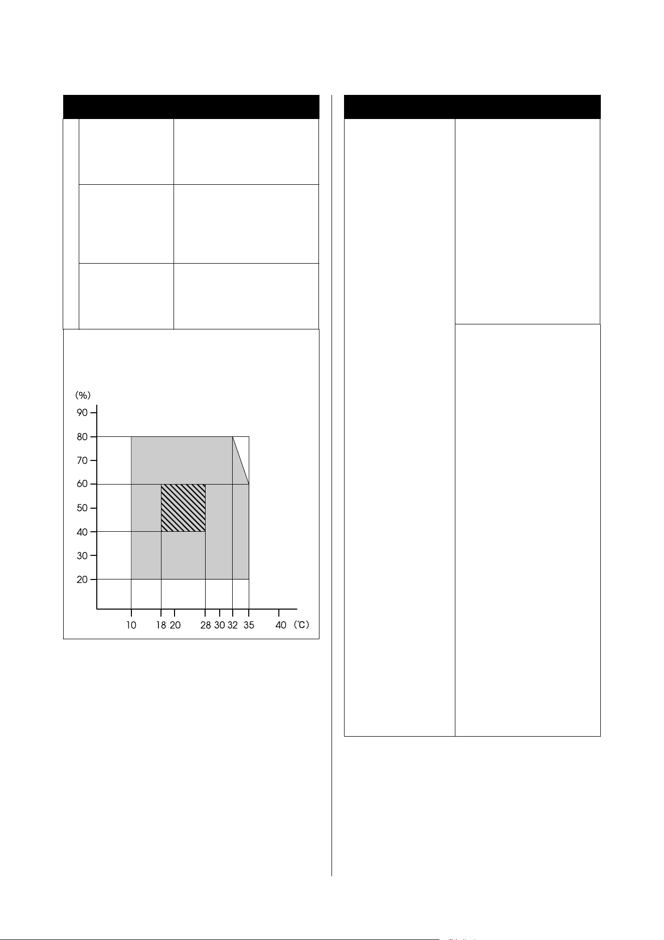
Printer Specifications
Printing 10 to 35˚C (50 to 95˚F), 20 to
80%
Recommended: 18 to 28˚C
(64.4 to 82.4˚F), 40 to 60%
In storage
(Before
unpacking)
-20 to 60˚C (-4 to 140˚F), 5 to
85%
(Within 120 hours at 60 ˚C (140
˚F), within a month at 40 ˚C
(104 ˚F))
In storage
(after opening)
-20 to 40˚C (-4 to 104˚F), 5 to
85%
(Within a month at 40 ˚C (104
˚F))
Temperature and humidity range
Gray area: While operating
Cross-hatch line area: Recommended
❏ Be sure your AC power cord meets relevant safety
standards of the area where you plan to use it.
❏ To prevent ground leak accidents, connect to a
grounded (earthed) outlet. Connecting to
anything other than a grounded outlet could
result in electric shock or fire.
Printer specifications (standard roll/reel models)
Dimension Printer
When stored: 3710 (W) x 1303
(D) x 1886 (H) mm (146 [W] ×
51.29 [D] × 74.25 [H] in.)
When at maximum size: 3710
(W) × 1350 (D) × 1931 (H) mm
(146 [W] × 53.14 [D] × 76.02
[H] in.)
Take Up Media Holder: 280 (W)
× 236 (D) × 352 (H) mm (11.02
[W] × 9.29 [D] × 13.85 [H] in.)
Take In Media Holder: 280 (W)
× 285 (D) × 352 (H) mm (11.02
[W] × 11.22 [D] × 13.85 [H] in.)
Ink supply unit
SC-F11000H Series/
SC-F10000H Series:
1278 (W) × 556 (D) × 541 (H)
mm (50.31 [W] × 21.88 [D] ×
21.29 [H] in.) (ink supply unit
only)
1278 (W) × 556 (D) × 580 (H)
mm (50.31 [W] × 21.88 [D] ×
22.83 [H] in.) (when 3 L ink
cartridge is installed)
1278 (W) × 556 (D) × 790 (H)
mm (50.31 [W] × 21.88 [D] ×
31.10 [H] in.) (when 10 L ink
cartridge is installed)
SC-F20000 Series/SC-F11000
Series/SC-F10000 Series:
877 (W) × 556 (D) × 541 (H)
mm (34.52 [W] × 21.88 [D] ×
21.29 [H] in.) (ink supply unit
only)
877 (W) × 556 (D) × 580 (H)
mm (34.52 [W] × 21.88 [D] ×
22.83 [H] in.) (when 3 L ink
cartridge is installed)
877 (W) × 556 (D) × 790 (H)
mm (34.52 [W] × 21.88 [D] ×
31.10 [H] in.) (when 10 L ink
cartridge is installed)
SC-F20000 Series/SC-F11000H Series/SC-F11000 Series/SC-F10000H Series/SC-F10000 Series User's Guide
Appendix
291
Printer specifications (standard roll/reel models)
Weight
*
Printer
Total weight (SC-F20000
Series): 744 kg (1640 lb.)
Total weight (SC-F11000H
Series/SC-F10000H Series): 687
kg (1515 lb.)
Total weight (SC-F11000
Series/SC-F10000 Series): 683
kg (1506 lb.)
Take Up Media Holder: Approx.
7 kg (15.43 lb.)
Take In Media Holder: Approx.
7 kg (15.43 lb.)
Ink supply unit
SC-F11000H Series/
SC-F10000H Series: 80 kg
(176.37 lb.)
SC-F20000 Series/SC-F11000
Series/SC-F10000 Series: 53 kg
(116.84 lb.)
* Ink not included.
Printer specifications (large capacity roll models)
Dimension Printer
When stored: 3710 (W) x 1740
(D) x 1886 (H) mm (146 [W] ×
68.50 [D] × 74.25 [H] in.)
When at maximum size: 3710
(W) × 1839 (D) × 1931 (H) mm
(146 [W] × 72.40 [D] × 76.02
[H] in.)
Take Up Media Holder: 280 (W)
× 236 (D) × 352 (H) mm (11.02
[W] × 9.29 [D] × 13.85 [H] in.)
Ink supply unit
The same as the ink supply
unit for standard roll/reel
models
Weight
*
Printer
Total weight (SC-F20000
Series): 872 kg (1922 lb.)
Total weight (SC-F11000H
Series): 815 kg (1797 lb.)
Total weight (SC-F11000
Series): 811 kg (1788 lb.)
Take Up Media Holder: Approx.
7 kg (15.43 lb.)
* Ink not included.
Printer specifications (large capacity reel models)
Dimension Printer
When stored: 3710 (W) x 2494
(D) x 1886 (H) mm (146 [W] ×
98.18 [D] × 74.25 [H] in.)
When at maximum size: 3710
(W) × 2494 (D) × 1931 (H) mm
(146 [W] × 98.18 [D] × 74.25
[H] in.)
Ink supply unit
The same as the ink supply
unit for standard roll/reel
models
Weight
*
Printer
Total weight (SC-F20000
Series): 1045 kg (2304 lb.)
Total weight (SC-F11000H
Series): 988 kg (2178 lb.)
Total weight (SC-F11000
Series): 984 kg (2169 lb.)
* Ink not included.
c
Important:
❏ Use this printer at altitudes below 2000 m
(6561 ft.).
❏ This printer is for indoor use only.
War n ing :
This is a class A product. In a domestic
environment this product may cause radio
interference in which case the user may be
required to take adequate measures.
For California customers only
The lithium batteries in this product contain
Perchlorate Material - special handling may apply.
See www.dtsc.ca.gov/hazardouswaste/perchlorate.
SC-F20000 Series/SC-F11000H Series/SC-F11000 Series/SC-F10000H Series/SC-F10000 Series User's Guide
Appendix
292
Interface Specifications
USB port for a
computer
USB 3.0 (SuperSpeed USB)
Wired LAN
compliance
standard
1000Base-T
*1
Network printing
protocols/
functions
EpsonNet Print (Windows)
*2
Standard TCP/IP (Windows)
*3
WSD (Windows)
*3
Bonjour (Mac)
*3
IPP (Windows)
*3
IPP (Mac)
*3
FTP
*3
Interface Specifications
Security
standards/
protocols
IEEE802.1X (Ethernet)
IPsec (v4/v6), IP filtering
SSL/TLS:
HTTPS Server (Web Config)
IPPS Server
SMTPS Client (Email send)
STARTTLS (SMTPS)
Root certificate (client)
Root certificate version 2.01
Root certificate update (client)
CA-signed certificate (server)
CA certificate
CSR generation (server)
Self-signed certificate (server)
EC key CSR/self-signed certificate
generation (server)
Certificate, secret key import
OpenSSL version: 1.0.2j
Supported TLS versions:
1.0/1.1/1.2
Authentication for email sending:
POP before SMTP
APOP
SMTP authentication (Kerberos/
NTLMv1/CRAM-MD5/PLAIN/
LOGIN)
Authentication for IPP printing:
HTTP Basic authentication
MIB access authentication,
encyription: SNMPv3
*1 Use a shielded twisted pair cable (category 5e or better).
*2 IPv4 compliant.
*3 IPv4 and IPv6 compliant.
SC-F20000 Series/SC-F11000H Series/SC-F11000 Series/SC-F10000H Series/SC-F10000 Series User's Guide
Appendix
293
Ink Specifications
Type Special ink cartridges
Sublimation dye
ink
SC-F11000H Series:
High Density Black, Cyan,
Magenta, Yellow, Light Cyan, Light
Magenta, Fluorescent Yellow,
Fluorescent Pink, Orange, Violet
SC-F10000H Series:
High Density Black, Cyan,
Magenta, Yellow, Light Cyan, Light
Magenta, Fluorescent Yellow,
Fluorescent Pink
SC-F20000 Series/SC-F11000
Series/SC-F10000 Series:
High Density Black, Cyan,
Magenta, Yellow
Use by date See the date printed on the ink
cartridge (stored at normal
temperature)
Print quality
guarantee expiry
Six months (from date ink
cartridge is opened)
Storage
temperature
5 to 35 ˚C (41 to 95 ˚F)
Ink cartridge
capacity
10000 ml, 3000 ml
Ink cartridge
dimensions
10000 ml: 150 (W) × 235 (D) × 412
(H) mm (5.90 [W] × 9.25 [D] ×
16.22 [H] in.)
3000 ml: 158 (W) × 260 (D) × 168
(H) mm (6.22 [W] × 10.23 [D] ×
6.61 [H] in.)
Note:
To ensure the colors you want to print, maintain a
constant room temperature of 18 to 28˚C (64.4 to
82.4˚F).
Information of EU declaration of conformity
The full text of the EU declaration of conformity of
this equipment is available at the following internet
address.
https://www.epson.eu/conformity
CE Marking
https://www.epson.eu/conformity
ZICTA Type Approval for Users in Zambia
See the following website to check the information for
ZICTA Type Approval.
https://support.epson.net/zicta/
SC-F20000 Series/SC-F11000H Series/SC-F11000 Series/SC-F10000H Series/SC-F10000 Series User's Guide
Appendix
294