Commercial Pressure and Float
Switches for Power Circuits
Catalog
9034CT9701R01/11
Class 9013, 9036, 9037, 9038
TM


Commercial Pressure and Float Switches for Power Circuits
Table of Contents
3
03/2011
© 2011 Schneider Electric
All Rights Reserved
Table of Contents
SELECTION GUIDE—PUMPTROL™ COMMERCIAL PRESSURE
SWITCHES .............................................................................................. 4
Class 9013 Electromechanical, Conforming to UL508 and CSA ...... 4
SELECTION GUIDE—FLOAT SWITCHES ............................................. 6
Class 9036 Type D—Open Tank, General Purpose ......................... 6
Class 9036 Type G—Open Tank, Heavy Duty .................................. 7
Class 9049—Accessories for Class 9036 Type D and G .................. 8
Class 9036 Type FG—Open Tank, Pedestal Style ........................... 9
Class 9049 Type UMS1—Universal Mounting Plate ....................... 10
Class 9037 Type E—Closed Tank, Flange Mounted ...................... 11
Class 9037 Type H—Closed Tank with Bushing ............................. 12
Class 9038 Type A—Mechanical Alternator, Open Tank ................ 13
Class 9038 Type C—Mechanical Alternator, Closed Tank ............. 14
Class 9038 Type D—Mechanical Alternator, Closed Tank ............. 15
ELECTROMECHANICAL PRESSURE SWITCHES,
CLASS 9013 TYPES F AND G.............................................................. 17
Introduction ...................................................................................... 17
Settings ........................................................................................... 18
General Specifications
Types FSG/FSW, FTG/FTW, and FYG/FYW .................................. 19
Types FRG, FHG, and G ................................................................. 20
Interpretation of the Catalog Number .............................................. 21
Class 9013 Type F Water Pump Switches ...................................... 21
Class 9013 Type F Air Compressor Switches ................................. 22
Class 9013 Type G Pressure Switches ........................................... 23
Selection and Specifications ........................................................... 24
Dimensions ...................................................................................... 44
FLOAT SWITCHES—CLASS 9036, 9037, AND 9038 .......................... 45
Introduction ...................................................................................... 45
Class 9036 Open Tank .................................................................... 45
Class 9037 Closed Tank ................................................................. 46
Class 9038 Mechanical Alternators ................................................. 46
Selecting a Float Switch .................................................................. 47
Selecting Floats and Rods .............................................................. 47
Temperature Ratings ....................................................................... 48
Electrical Ratings ............................................................................. 48
Class 9036 Type D and G Open Tank Float Switches .................... 49
Class 9036 Type FG and Class 9049 Accessories ......................... 52
Class 9037 Type E Closed Tank Float Switches ............................ 53
Class 9037 Type E Flange-Mounted Float Switches ...................... 53
Class 9037 Type E Closed Tank Rod Kits ...................................... 55
Class 9037 Type H with Screw-in Bushing ..................................... 57
Class 9038 Type A Mechanical Alternators .................................... 59
Class 9038 Type A Open and Sump Tank Mechanical Alternators 59
Class 9038 Type C Mechanical Alternators with Bushing ............... 61
Class 9038 Type D Flange-Mounted Mechanical Alternators ......... 63
Class 9049 Rod Kits for Class 9038 Type D ................................... 64
Class 9049 Accessories and Class 9998 Renewal Parts Kits ......... 67
© 2011 Schneider Electric
All Rights Reserved
Commercial Pressure and Float Switches for Power Circuits
Selection Guide—Pumptrol™ Commercial Pressure Switches
4
03/2011
Selection Guide—Pumptrol
™
Commercial Pressure Switches
Class 9013 Electromechanical, Conforming to UL508 and CSA
TM
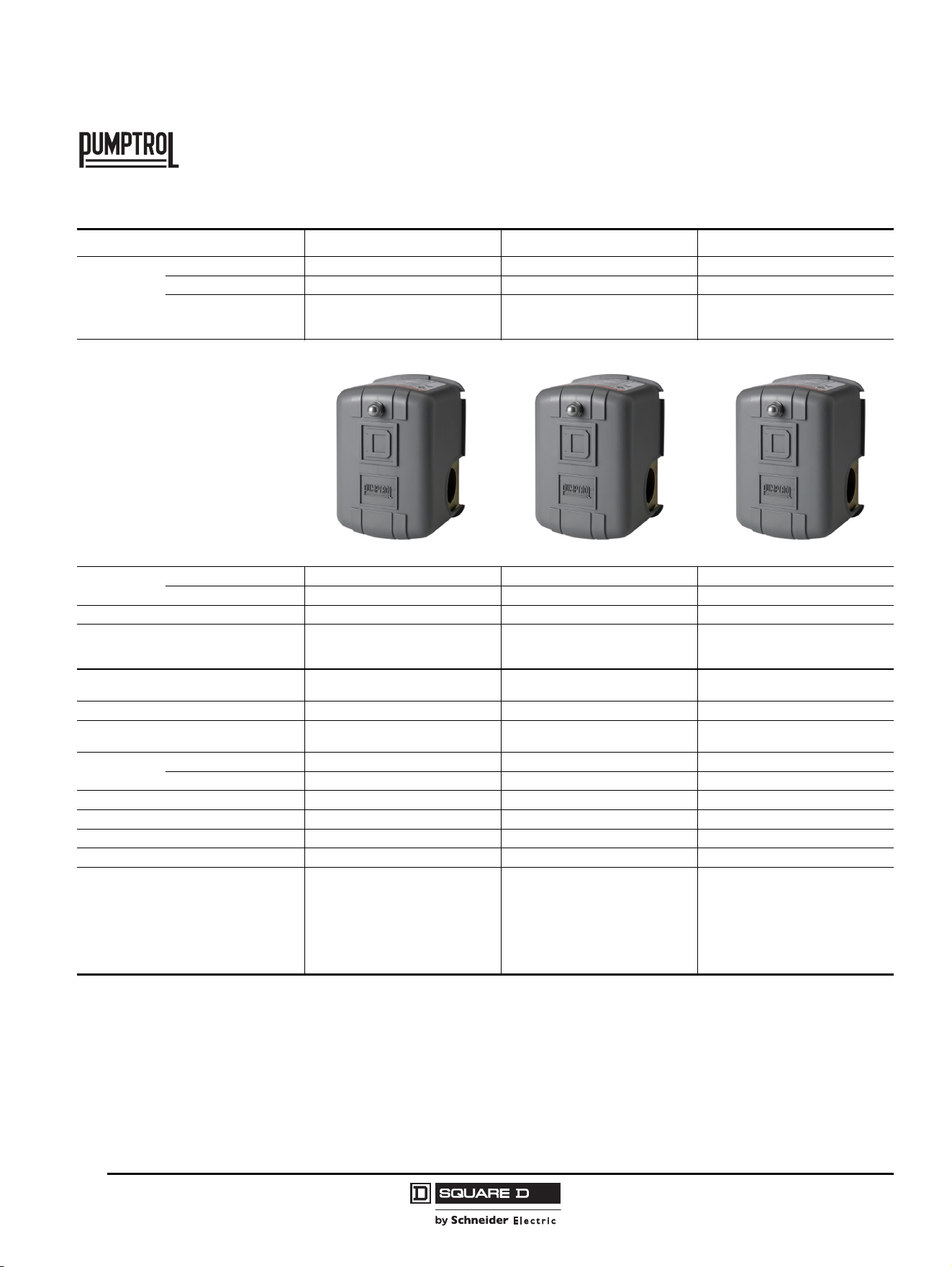
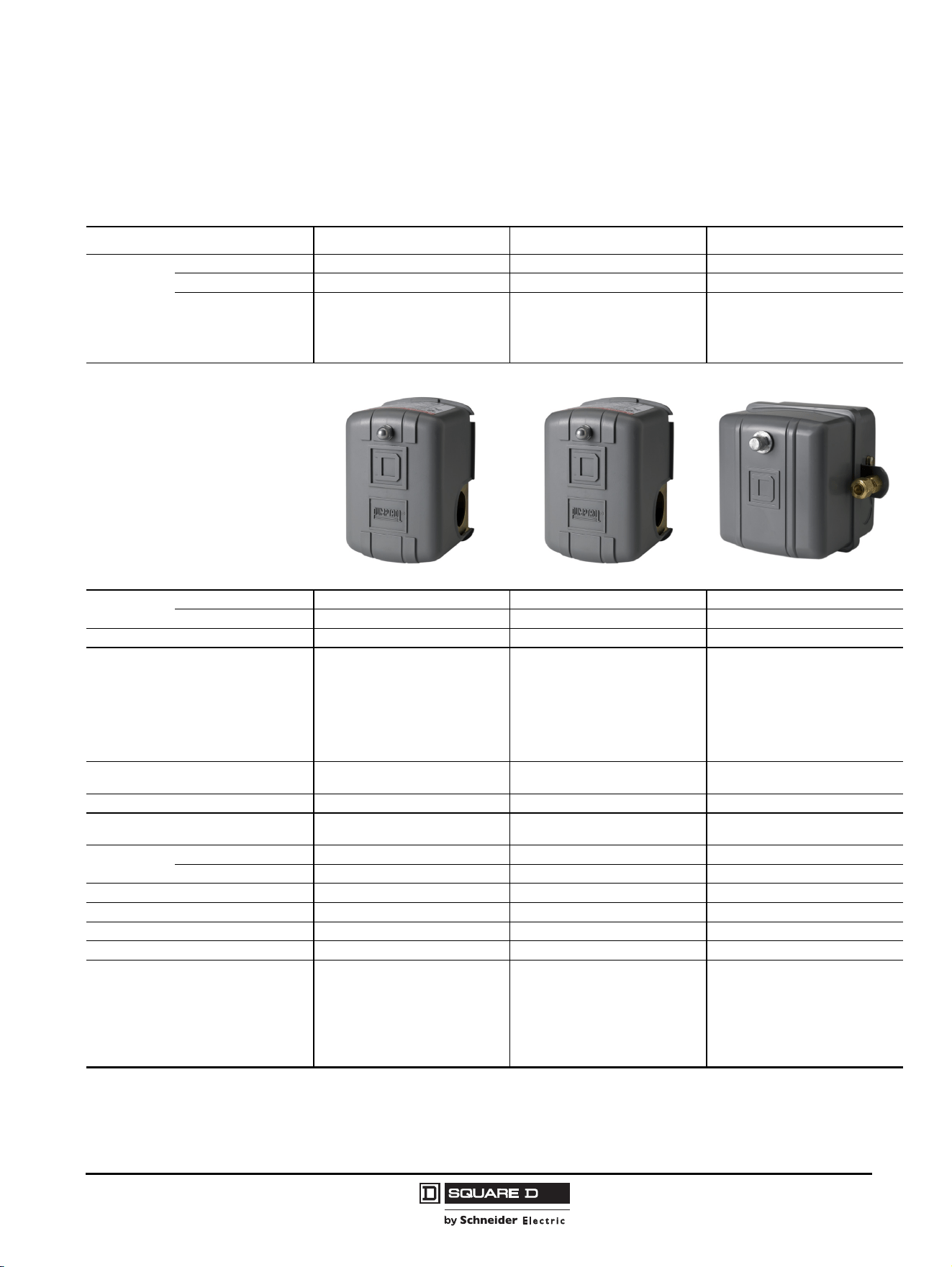
Pumptrol Family 9013FSG 9013FTG 9013FYG
Applications
Type of Installation Power circuit Power circuit Power circuit
Controls Fresh or sea water Fresh or sea water Fresh or sea water
Type of Operation
Regulation between 2 thresholds
(adjustable differential).
Suitable for all pumps.
Detection of a single threshold
(non-adjustable differential)
Regulation between 2 thresholds
(adjustable differential). For higher hp
and pressure requirements.
Size / Range
psi 20–80 20–65 25–80
bar 1.38–4.48 1.38–4.48 1.72–5.52
Conforming to Standards NEMA A600 UL508 UL508 NEMA A600 UL508
Product Certifications
UL File: E12158 CCN NKPZ
CSA File: LR 25490
Class 3211 06
UL File: E12158 CCN NKPZ
CSA File: LR 25490
Class 3211 06
UL File: E12158 CCN NKPZ
CSA File: LR 25490
Class 3211 06
Dimensions (l x h x w) in inches (mm)
3.76 x 2.8 x 2.78
(95.5 x 71.12 x 70.6)
3.76 x 2.8 x 2.78
(95.5 x 71.12 x 70.6)
3.76 x 2.8 x 2.78
(95.5 x 71.12 x 70.6)
Contact Blocks (snap action contacts) 2 N.C. 2 N.C. 2 N.C.
Degree of Protection
NEMA Type 1, NEMA Type 3R,
and IP20
NEMA Type 1, NEMA Type 3R,
and IP20
NEMA Type 1, NEMA Type 3R,
and IP20
Connections
Electrical Screw terminals Screw terminals Screw terminals
Fluid Multiple Multiple Multiple
Cable Entries 222
Catalog Numbers 9013FSG••• 9013FTG••• 9013FYG•••
Specifications Page 19 Page 19 Page 19
Interpretation of Catalog Numbers Page 24 Page 27 Page 29
Other versions:
Form B7, one grommet, CE
Form B8, two grommets, CE
NOTE: Inclusion of B7 or B8 grommets will
negate UL/CSA approvals for the device, but
they may be used for applications which do
not require UL/CSA approvals.
—
—
—
—
—
—
Commercial Pressure and Float Switches for Power Circuits
Selection Guide—Pumptrol™ Commercial Pressure Switches
5
03/2011
© 2011 Schneider Electric
All Rights Reserved
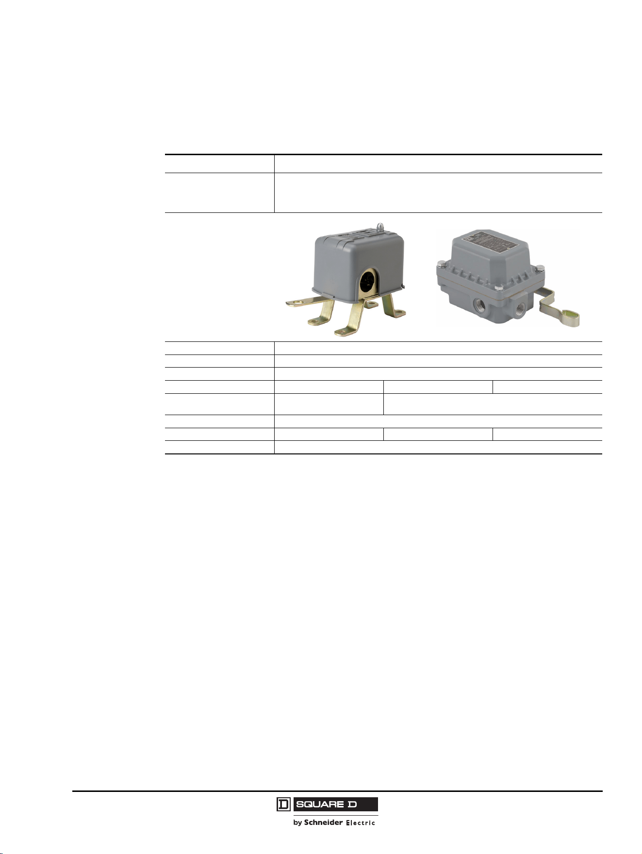
Pumptrol Family 9013FRG 9013FHG 9013G
Applications
Type of Installation Power circuit Power circuit Power circuit
Controls Fresh or sea water Air only Water or air
Type of Operation
Reverse acting, contacts open on
falling pressure (adjustable
differential)
Control of electrically driven air
compressors, contacts open on rising
pressure (fixed differential, adjustable
cut-out), diaphragm actuated
Light industrial, with higher electrical
ratings for direct control of motors in
pumps and compressors, contacts
open on rising pressure (adjustable
differential)
Size / Range
psi 8–150 40–200 10–250
bar 0.41–10.34 2.76–13.79 0.69–17.24
Conforming to Standards NEMA A300 UL508 NEMA A600 UL508 NEMA A600 UL508
Product Certifications
UL File: E12158 CCN NKPZ
CSA File: LR 25490
Class 3211 06
UL File: E12158 CCN NKPZ
with Form T
CSA File: LR 25490
Class 3211 06
UL File: E12158 CCN NKPZ
(except GHR and GSR)
UL File: E12443 CCN NOWT
(for GHR and GSR)
CSA File: LR 25490 Class 3211 06
(except GHR and GSR)
CSA File: LR 26817 Class 3218 05
(for GHR and GSR)
Dimensions (l x h x w) in inches (mm)
3.76 x 2.8 x 2.78
(95.5 x 71.12 x 70.6)
3.76 x 2.8 x 2.78
(95.5 x 71.12 x 70.6)
3.68 x 3.85 x 3.44
(93.47 x 97.79 x 87.37)
Contact Blocks (snap action contacts) 2 N.O. 2 N.C. 2 N.C.
Degree of Protection
NEMA Type 1, NEMA Type 3R,
and IP20
NEMA Type 1, NEMA Type 3R,
and IP20
NEMA Type 1, NEMA Type 3R, NEMA
Type 7, NEMA Type 9, and IP20
Connections
Electrical Screw terminals Screw terminals Screw terminals
Fluid Multiple Multiple Multiple
Cable Entries 2 2 3 knock-outs available
Catalog Numbers 9013FRG••• 9013FHG••• 9013G•••
Specifications Page 20 Page 20 Page 20
Interpretation of Catalog Numbers Page 21 Page 21 Page 21
Other versions:
Form B7, one grommet, CE
Form B8, two grommets, CE
NOTE: Inclusion of B7 or B8 grommets will
negate UL/CSA approvals for the device, but
they may be used for applications which do
not require UL/CSA approvals.
—
—
—
—
—
—
© 2011 Schneider Electric
All Rights Reserved
Commercial Pressure and Float Switches for Power Circuits
Selection Guide—Float Switches
6
03/2011
Selection Guide—Float Switches
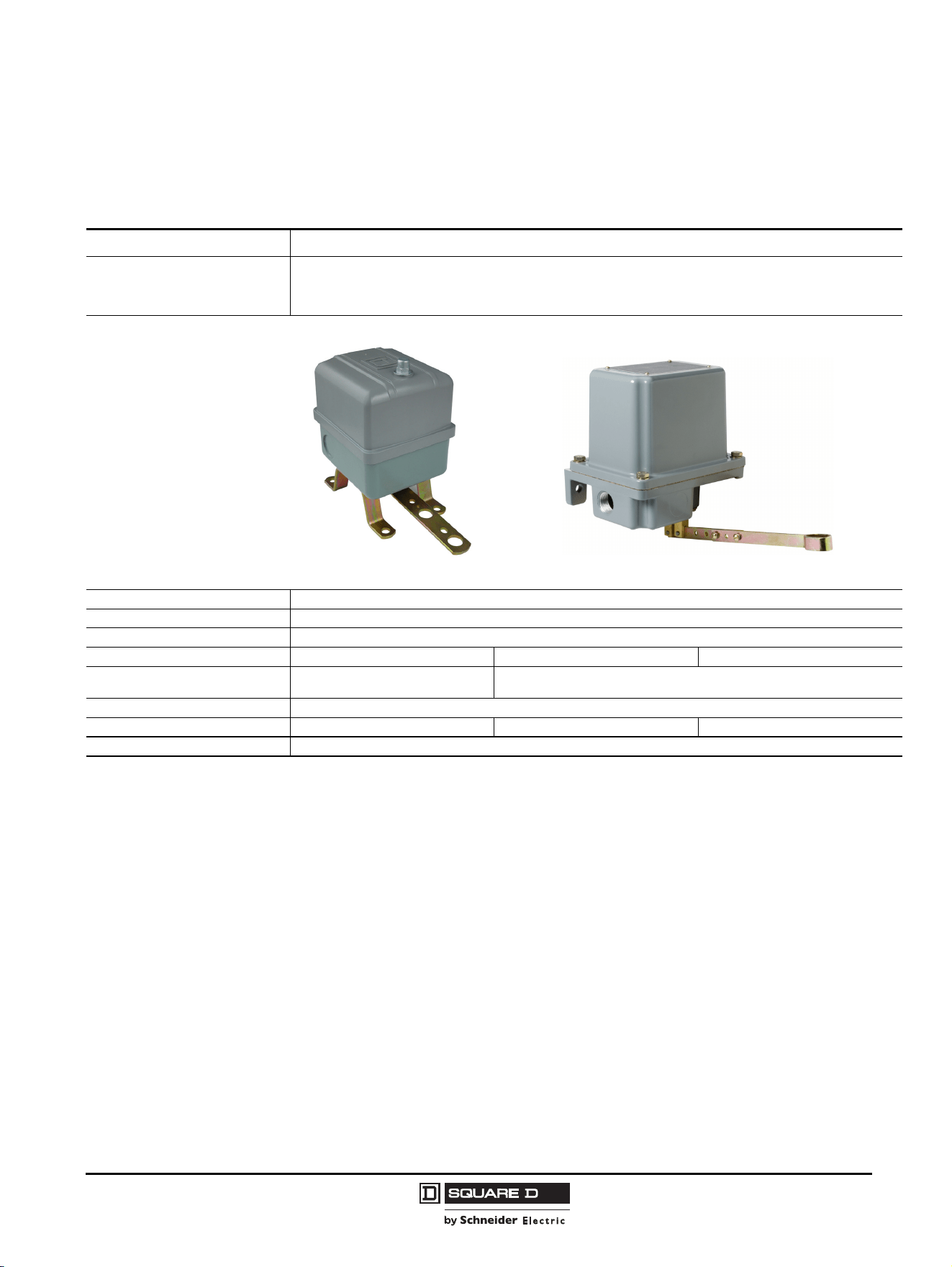
Class 9036 Type D—Open Tank, General Purpose
Type of Installation Horsepower rated
Product Features
2-pole switch, lever operated
Standard action—contacts close on liquid rise
Reverse action—contacts open on liquid rise
Fluids Controlled Water, hydraulic oils, corrosive fluids
Fluid Characteristics Fresh water, sea water, hydraulic oils, and corrosive fluids with a density ≥ 0.8
Contact Arrangement Standard: 2 N.O. (DPST), Form R: 2 N.C. (DPST), Form H: 1 N.O. and 1 N.C. (SPDT)
Degree of Protection NEMA Type 1 NEMA Type 4 NEMA Type 7, 9
Electrical Connection
4 screw terminals, 3 knockouts
for 1/2 in. conduit entry
4 screw terminals, 2 cable entries, 3/4-14 conduit entry
Ambient Temperature –22 to +220 °F (–30 to +105 °C)
Catalog Numbers 9036DG 9036DW 9036DR
Page
49
Commercial Pressure and Float Switches for Power Circuits
Selection Guide—Float Switches
7
03/2011
© 2011 Schneider Electric
All Rights Reserved
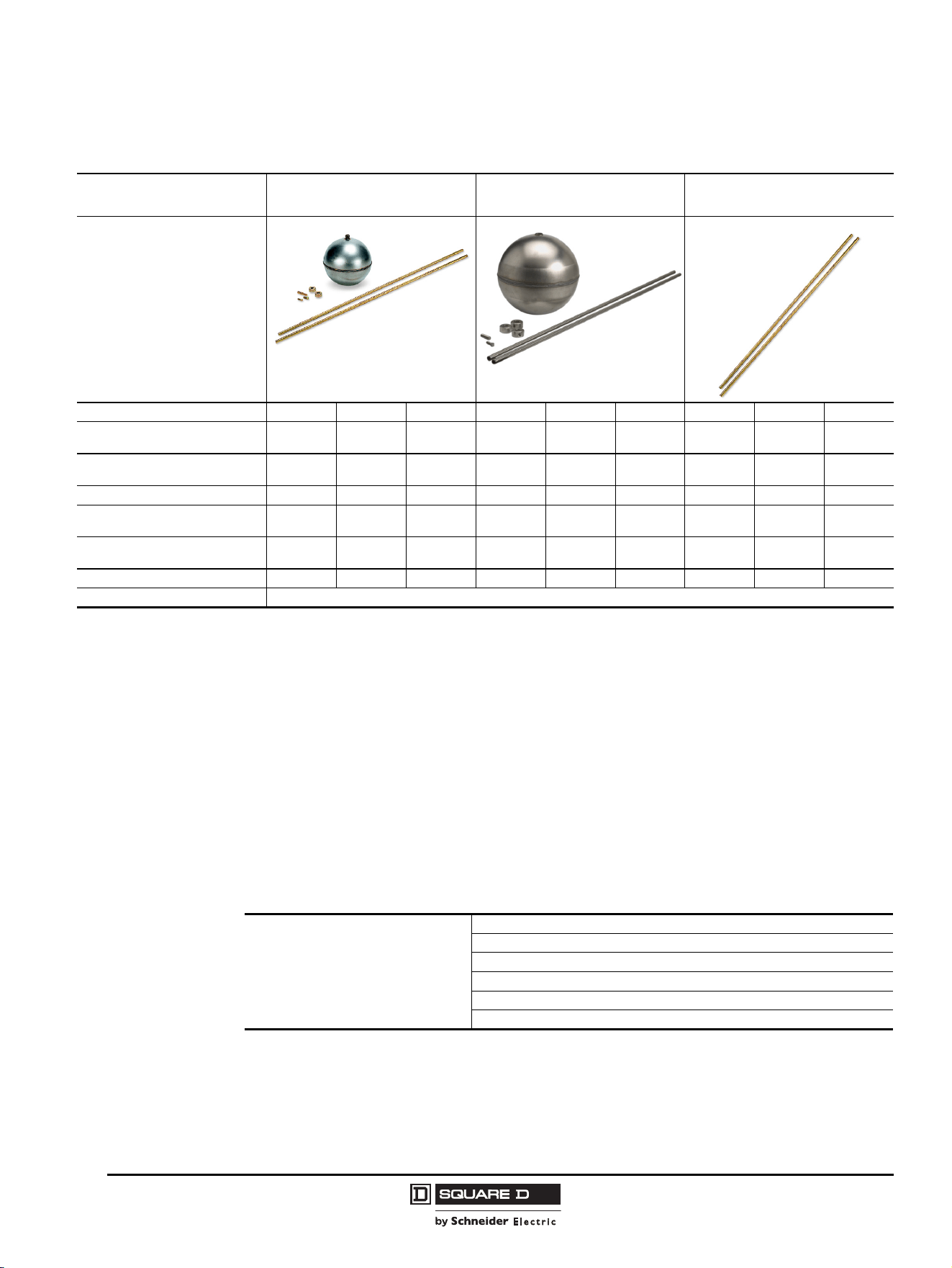
Class 9036 Type G—Open Tank, Heavy Duty
Type of Installation Horsepower rated
Product Features
2-pole switch
Standard action—contacts close on liquid rise
Reverse action—contacts open on liquid rise
Fluids Controlled Water, hydraulic oils, corrosive fluids
Fluid Characteristics Fresh water, sea water, hydraulic oils, and corrosive fluids with a density ≥ 0.8
Contact Arrangement Standard: 2 N.O. (DPST), Form R: 2 N.C. (DPST), Form H: 1 N.O. and 1 N.C. (SPDT)
Degree of Protection NEMA Type 1 NEMA Type 4 NEMA Type 7, 9
Electrical Connection
4 screw terminals, 3 knockouts for
1/2 in. conduit entry
4 screw terminals, 2 cable entries, 3/4-14 conduit entry
Ambient Temperature –22 to +220 °F (–30 to +105 °C)
Catalog Numbers 9036GG 9036GW 9036GR
Page
49
© 2011 Schneider Electric
All Rights Reserved
Commercial Pressure and Float Switches for Power Circuits
Selection Guide—Float Switches
8
03/2011
Class 9049—Accessories for Class 9036 Type D and G
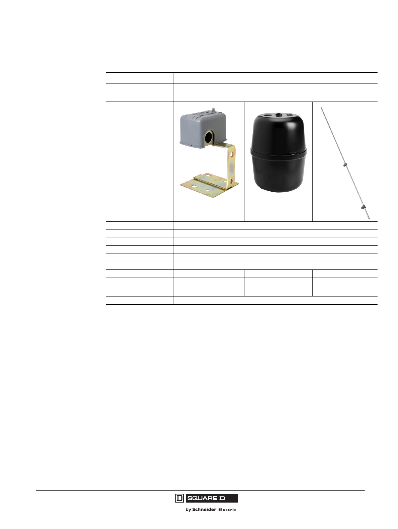
NOTE: When ordering float accessories, first specify the desired accessory kit, then as a second item,
give the catalog number and the quantity of the additional tubing kits required. For example, for a
9049A6C kit with 15 ft of tubing, specify:
• 9049A6C, quantity = 1 (float with 5 ft of tubing)
• 9049T1, quantity = 4 (2.5 ft of tubing each, for a total of 10 additional ft)
Compensating Spring
Compensating springs support the weight of long rods that cannot be supported by center-hole floats.
Example
Accessory Kits
Tapped-at-Top Floats
(#304 SS)
[1]
1
Maximum recommended tubing length for tapped-at-top float: 12.5 ft (3810 mm).
Center-Hole Floats
(#304 SS)
[2]
2
Maximum recommended tubing length for center-hole float: 30 ft (9144 mm).
Additional Tubing
[3]
3
Additional tubing kits add on to float accessory kits and include a connector.
Tubing (rods) 5 ft brass 5 ft Al 5 ft SS 5 ft brass 5 ft Al 5 ft SS 2.5 ft brass 2.5 ft Al 2.5 ft SS
Net buoyancy in water
7 in. float
[4]
4
Net buoyancy calculated with the float 80% submerged, allowing for a 20% operating margin. Buoyancy data calculated for use in water. Contact the Sensor
Competency Center for buoyancy data in media having a specific gravity different than water (1.0).
60 60 60 70 70 70 — — —
Total weight of stops
oz (g)
3 (85) 3 (85) 3 (85) 6 (170) 6 (170) 6 (170) — — —
Number of stops 222444———
Weight of the included 5 ft rod
oz (g)
18.5 (524) 6 (170) 16.9 (479) 18.5 (524) 6 (170) 16.9 (479) — — —
Weight per ft of extra rod
oz (g)
3.7 (105) 1.2 (34) 3.4 (96) 3.7 (105) 1.2 (34) 3.4 (96) 3.7 (105) 1.2 (34) 3.4 (96)
Catalog Numbers 9049A6 9049A6A 9049A6S 9049A6C 9049A6CA 9049A6CS 9049T1 9049T1A 9049T1S
Page 50
Calculation example
Measuring 15 ft of tank depth
System has 15 ft of brass rod, 4 stops, and a
center hole float.
Buoyancy is positive, so no compensating
spring is required
Float buoyancy 70.0 oz
Total weight (61.5 oz)
Weight of stops: (6.0 oz)
Weight of 5 ft of brass rod (included): (18.5 oz)
Weight of 10 ft of brass rod (separate): (37.0 oz)
Buoyancy 8.5 oz
Commercial Pressure and Float Switches for Power Circuits
Selection Guide—Float Switches
9
03/2011
© 2011 Schneider Electric
All Rights Reserved
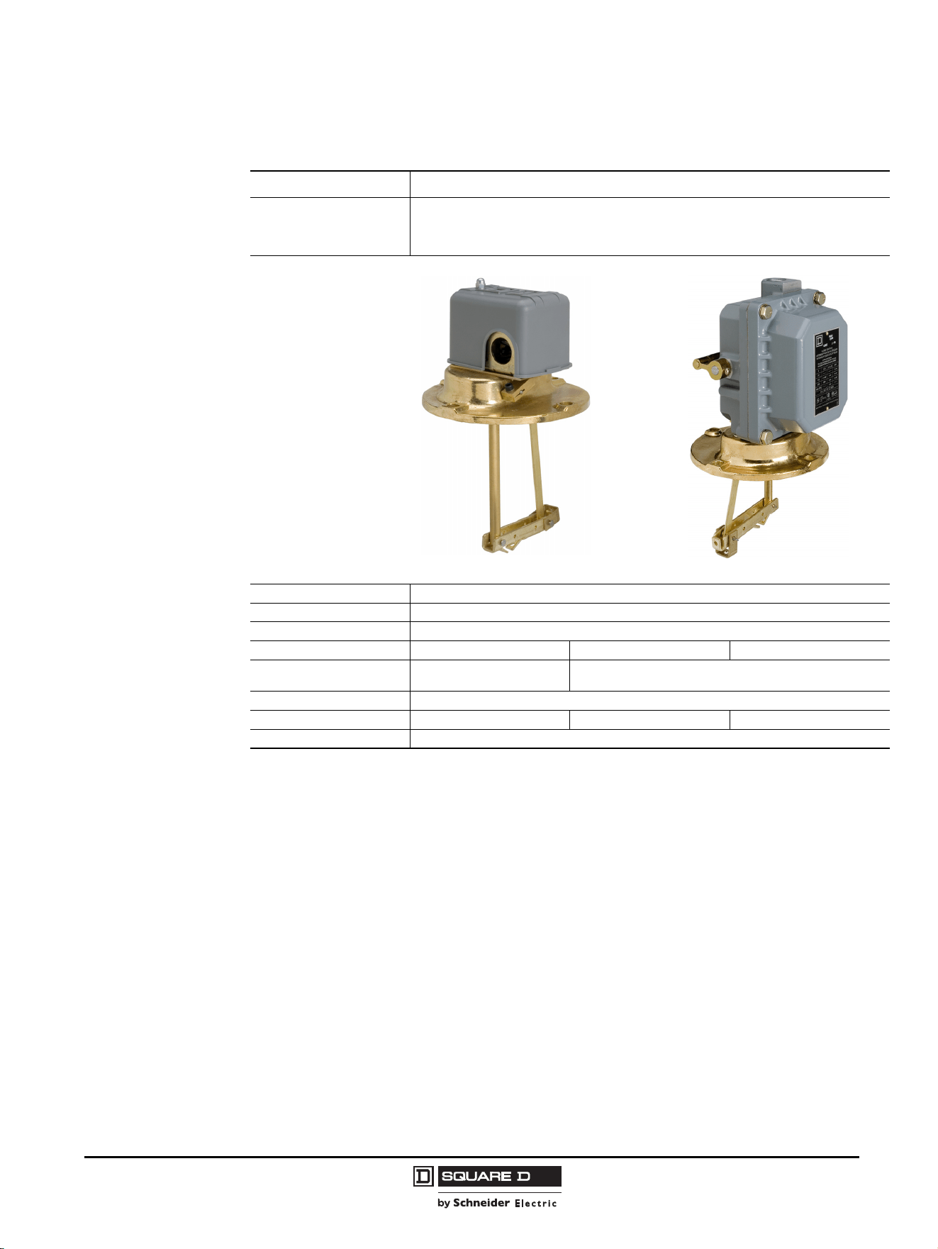
Class 9036 Type FG—Open Tank, Pedestal Style
Type of Installation Horsepower rated
Product Features
2-pole switch, forward or reversing
Contacts open or close on liquid rise (field convertible)
Fluids Controlled Water, hydraulic oils, corrosive fluids
Fluid Characteristics Fresh water, sea water, hydraulic oils, and corrosive fluids with a density ≥ 0.8
Contact Arrangement 2 N.O. or 2 N.C. (DPST), depending on rod connection
Degree of Protection NEMA Type 1
Electrical Connection 4 screw terminals, 2 cable entries 0.88 in. (22.4 mm) with 0.84 in. (21.3 mm) across flat
Ambient Temperature –22 to +220 °F (–30 to +105 °C)
Catalog Numbers 9036FG 9049A60 9049A61
Description
2-pole, pedestal-style sump
pump switch
Plastic, center-hole float
33.75 in. aluminum rod,
2 float stop assemblies,
and attaching hardware
Page
51

© 2011 Schneider Electric
All Rights Reserved
Commercial Pressure and Float Switches for Power Circuits
Selection Guide—Float Switches
10
03/2011
Class 9049 Type UMS1—Universal Mounting Plate
Description Mounting plate
Product Features Pedestal mount
Material Cold rolled steel
Finish Painted, powder coated
Mounting Connection Threaded to accept 1 in. diameter iron pipe
Catalog Numbers 9049UMS1
Page
67
Figure 1: 9049UMS1 Dimensions
7.00 in.
4.00 in.
1.31 in.
Commercial Pressure and Float Switches for Power Circuits
Selection Guide—Float Switches
11
03/2011
© 2011 Schneider Electric
All Rights Reserved
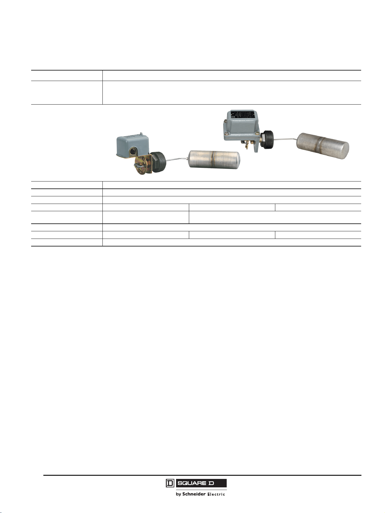
Class 9037 Type E—Closed Tank, Flange Mounted
NOTE: For float and rod kits, refer to page 55.
Type of Installation Horsepower rated
Product Features
2-pole switch
Standard action—contacts close on liquid rise
Reverse action—contacts open on liquid rise
Fluids Controlled Water, hydraulic oils, corrosive fluids
Fluid Characteristics Fresh water, sea water, hydraulic oils, and corrosive fluids with a density ≥ 0.8
Contact Arrangement Standard: 2 N.O. (DPST), Form R: 2 N.C. (DPST)
Degree of Protection NEMA Type 1 NEMA Type 4 NEMA Type 7, 9
Electrical Connection
4 screw terminals, 3 knockouts
for 1/2 in. conduit entry
4 screw terminals, 2 cable entries, 3/4-14 conduit entry
Ambient Temperature –22 to +220 °F (–30 to +105 °C)
Catalog Numbers 9037EG 9037EW 9037ER
Page
53
© 2011 Schneider Electric
All Rights Reserved
Commercial Pressure and Float Switches for Power Circuits
Selection Guide—Float Switches
12
03/2011
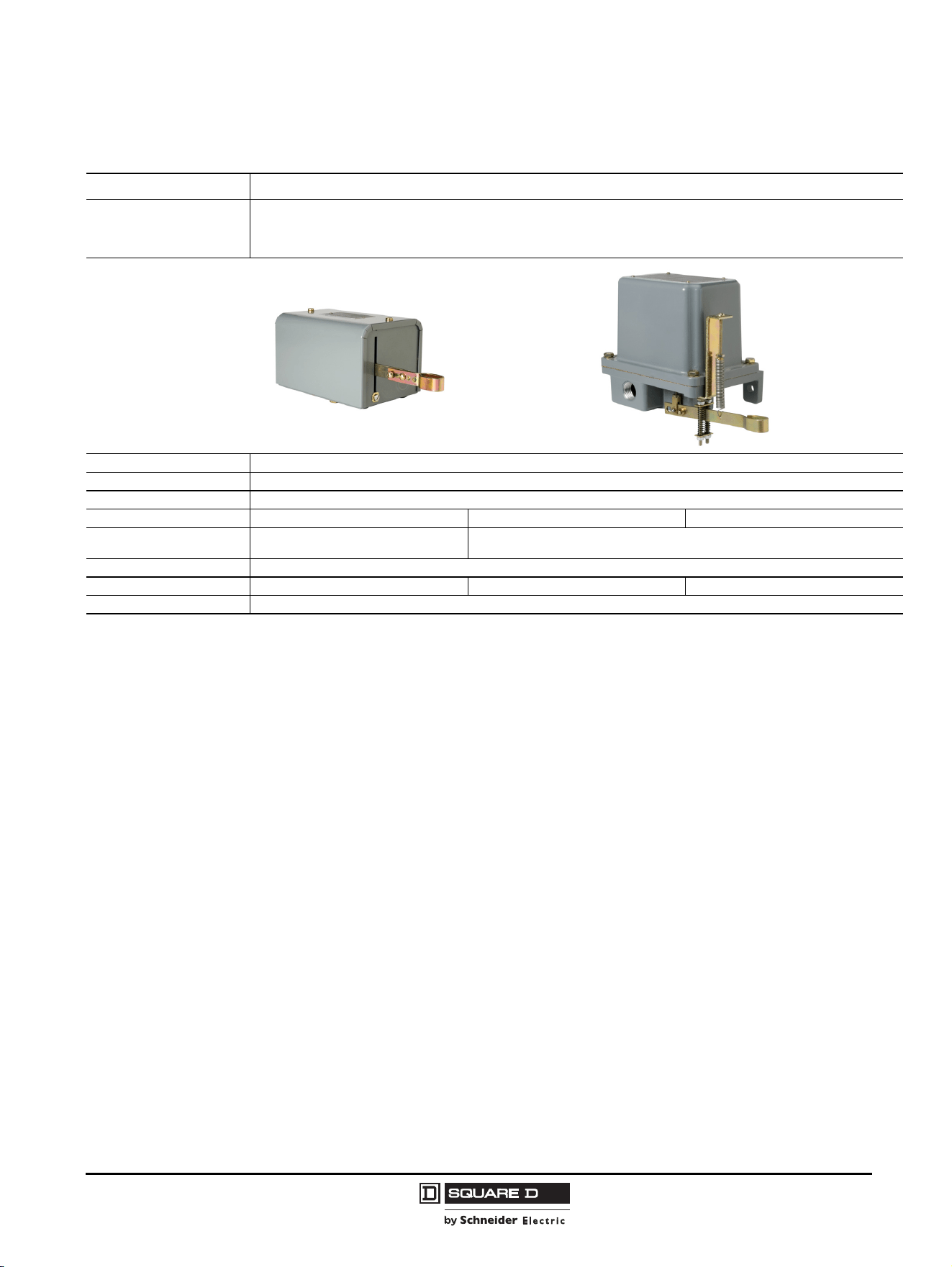
Class 9037 Type H—Closed Tank with Bushing
Type of Installation Horsepower rated
Product Features
2-pole switch
Standard action—contacts close on liquid rise
Reverse action—contacts open on liquid rise
Fluids Controlled Water, hydraulic oils, corrosive fluids
Fluid Characteristics Fresh water, sea water, hydraulic oils, and corrosive fluids with a density ≥ 0.8
Contact Arrangement Standard: 2 N.O. (DPST). Form R: 2 N.C. (DPST).
[1]
1
NEMA Type 1 devices can be field modified for reverse action. NEMA Type 4, 7, and 9 devices cannot be field modified for reverse action.
Degree of Protection NEMA Type 1 NEMA Type 4 NEMA Type 7, 9
Electrical Connection
4 screw terminals, 3 knockouts for 1/2 in.
conduit entry
4 screw terminals, 2 cable entries, 3/4-14 conduit entry
Ambient Temperature –22 to +220 °F (–30 to +105 °C)
Catalog Numbers 9037HG 9037HW 9037HR
Page
57
Commercial Pressure and Float Switches for Power Circuits
Selection Guide—Float Switches
13
03/2011
© 2011 Schneider Electric
All Rights Reserved
Class 9038 Type A—Mechanical Alternator, Open Tank
Type of Installation Horsepower rated
Product Features
4-pole switch
Standard action—contacts close on liquid rise
Reverse action—contacts open on liquid rise
Fluids Controlled Water, hydraulic oils, corrosive fluids
Fluid Characteristics Fresh water, sea water, hydraulic oils, and corrosive fluids with a density ≥ 0.8
Contact Arrangement 4 N.O. (2 DPST)
Degree of Protection NEMA Type 1 NEMA Type 4 NEMA Type 7, 9
Electrical Connection
8 screw terminals, 4 knockouts for 1/2 in.
or 3/4 in. conduit entry
8 screw terminals, 2 cable entries, 3/4-14 conduit entry
Ambient Temperature –22 to +220 °F (–30 to +105 °C)
Catalog Numbers 9038AG 9038AW 9038AR
Page
59

© 2011 Schneider Electric
All Rights Reserved
Commercial Pressure and Float Switches for Power Circuits
Selection Guide—Float Switches
14
03/2011
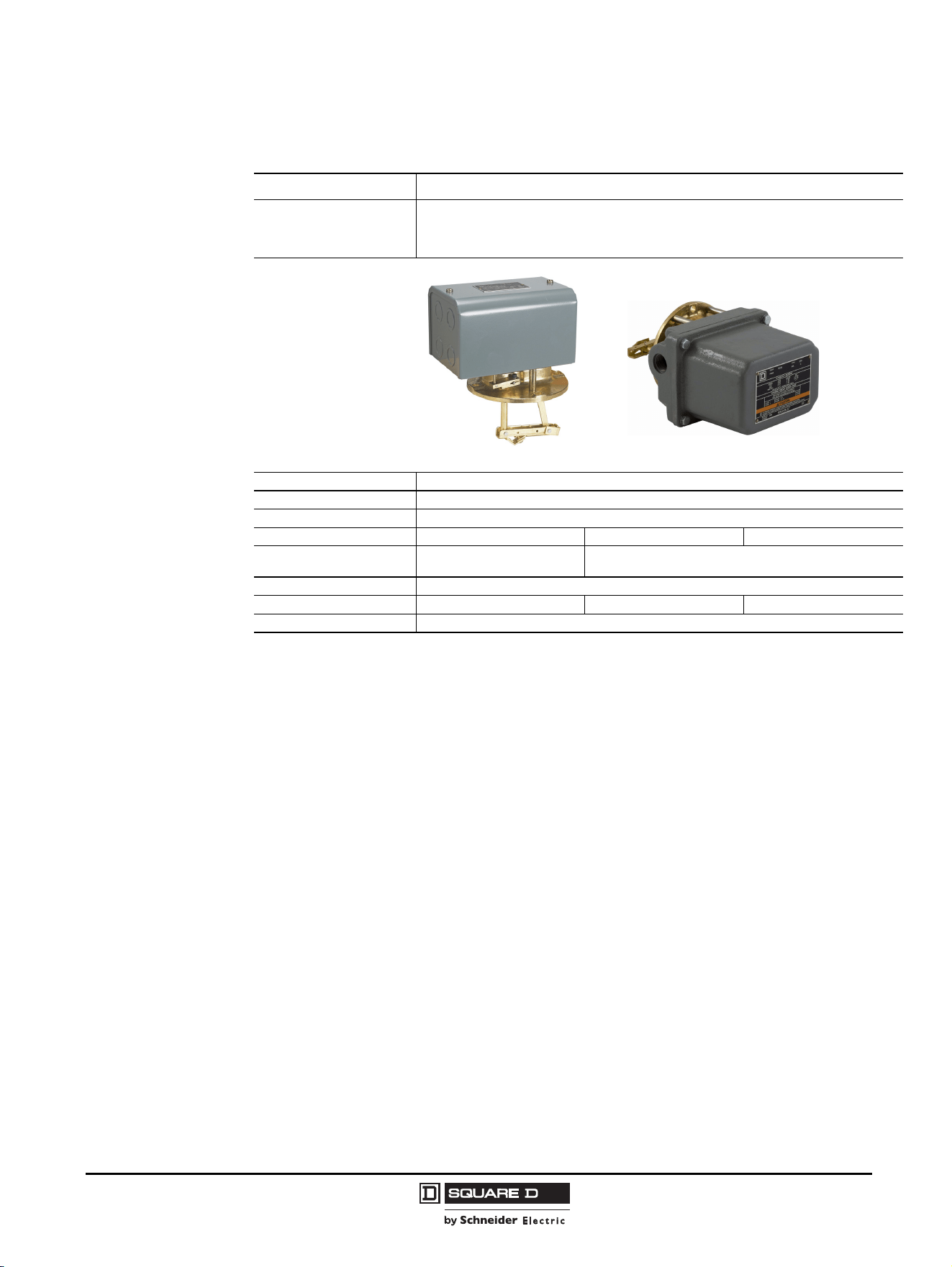
Class 9038 Type C—Mechanical Alternator, Closed Tank
Type of Installation Horsepower rated
Product Features
4-pole switch
Standard action—contacts close on liquid rise
Reverse action—contacts open on liquid rise
Fluids Controlled Water, hydraulic oils, corrosive fluids
Fluid Characteristics Fresh water, sea water, hydraulic oils, and corrosive fluids with a density ≥ 0.8
Contact Arrangement 4 N.O. (2 DPST), alternating contacts
Degree of Protection NEMA Type 1 NEMA Type 4 NEMA Type 7, 9
Electrical Connection
8 screw terminals, 8 knockouts
for 1/2 in. or 3/4 in. conduit entry
8 screw terminals, 2 cable entries, 3/4-14 conduit entry
Ambient Temperature –22 to +220 °F (–30 to +105 °C)
Catalog Numbers 9038CG 9038CW 9038CR
Page
61
Commercial Pressure and Float Switches for Power Circuits
Selection Guide—Float Switches
15
03/2011
© 2011 Schneider Electric
All Rights Reserved
Class 9038 Type D—Mechanical Alternator, Closed Tank
Type of Installation Horsepower rated
Product Features
4-pole switch
Standard action—contacts close on liquid rise
Reverse action—contacts open on liquid rise
Fluids Controlled Water, hydraulic oils, corrosive fluids
Fluid Characteristics Fresh water, sea water, hydraulic oils, and corrosive fluids with a density ≥ 0.8
Contact Arrangement 4 N.O. (2 DPST)
Degree of Protection NEMA Type 1 NEMA Type 4 NEMA Type 7, 9
Electrical Connection
8 screw terminals, 8 knockouts
for 1/2 in. or 3/4 in. conduit entry
8 screw terminals, 2 cable entries, 3/4-14 conduit entry
Ambient Temperature –22 to +220 °F (–30 to +105 °C)
Catalog Numbers 9038DG 9038DW 9038DR
Page
63
© 2011 Schneider Electric
All Rights Reserved
Commercial Pressure and Float Switches for Power Circuits
Selection Guide—Float Switches
16
03/2011
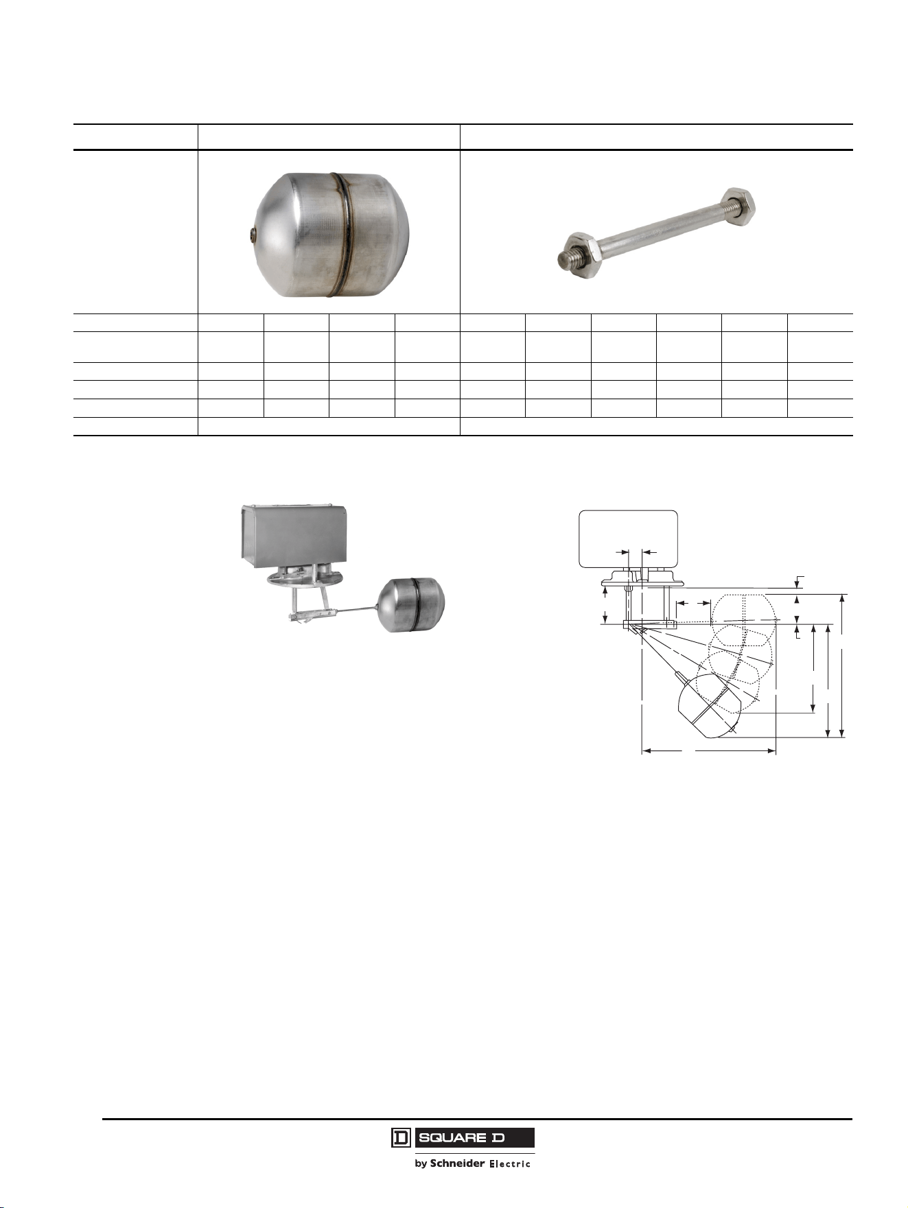
Figure 2: Float and Rod Kits
Type of Installation Float Kits Float Rod Kits
Material #304 SS #316 SS #304 SS #316 SS — —————
Dimensions, in. (mm)
Diameter x Length
3.625 x 4.5
(92 x 114)
3.625 x 4.5
(92 x 114)
2.5 x 7
(64 x 178)
2.5 x 7
(64 x 178)
——————
R Dimension, in. (mm) ————1.75 (44)2.50 (64)3.25 (83)5.25 (133)7.25 (184)12.25 (311)
H Dimension, in. (mm) ————8.25 (210)9.00 (229) 9.50 (241) 11.75 (298) 13.75 (349) 18.75 (476)
Catalog Numbers 9049EF1 9049EF2 9049HF3 9049HF4 9049ER1 9049ER2 9049ER3 9049ER5 9049ER7 9049ER12
Pages
53, 63, 67 55–56, 64–67
31/32
V
R
H
B
C
A
F
D
G
9038DG with 9049EF1 Float
9038DG shown with
rod kit 9049ER5 and
float kit 9049EF1
installed
For additional dimensions,
refer to pages 64–66.

Commercial Pressure and Float Switches for Power Circuits
Electromechanical Pressure Switches, Class 9013 Types F and G
17
03/2011
© 2011 Schneider Electric
All Rights Reserved
Electromechanical Pressure Switches,
Class 9013 Types F and G
Introduction
The Pumptrol Class 9013 Type F commercial pressure switches are UL Listed and CSA certified as
commercial control equipment. Type G pressure switches are UL Listed and CSA certified as
commercial / light industrial control equipment.
The Type FHG compressor pressure switch is used to control electrically driven air compressors. It is
diaphragm actuated, and its contacts open on rising pressure.
The Type FSG, FTG, FYG, and FRG water pump pressure switches are used to control electrically
driven water pumps. They are diaphragm actuated.
• The Type FSG standard water pump switch is suitable for all types of pumps, including jets,
submersible, and reciprocating.
• The Type FTG fixed differential water pump switch is suitable for all types of pumps, including jets,
submersible, and reciprocating. It is an ideal choice for OEM markets. Minimum quantity
restrictions apply.
• The Type FYG is designed to meet higher horsepower and pressure requirements.
• The Type FRG is reverse acting: the contacts open on falling pressure.
The Type G commercial / light industrial pressure switch is used to control electrically driven water
pumps and air compressors. It has higher electrical ratings for direct control of motors in pump and
compressor applications. The Type G switch is diaphragm actuated, and its contacts open on rising
pressure.
Setting Points
Every pressure switch has two setting points: one on rising pressure and one of falling pressure. For
pumps and compressors, the setting point on rising pressure is called the trip point or cut-out; the
setting point on falling pressure is called the reset point or cut-in.
Differential
The differential is the difference in pressure between the trip point (cut-out) and the reset point (cut-in).
It can be adjustable or fixed. Example—Cut-in (30 psi) / Cut-out (50 psi): Differential = 20 psi
Range
The range indicates the pressure limits within which the settings can be adjusted. The range is
referenced to the setting point on rising pressure (trip point). The differential subtracts from the trip
point setting. When using a diaphragm-actuated switch, system pressure during the normal operating
cycle should never exceed the upper limit of the range. Excessive pressure will greatly reduce the life
of the diaphragm.
Maximum Allowable Pressure
Maximum allowable pressure is the pressure to which a switch can be subjected without causing a
change in operating characteristics, shift in settings, or damage to the device. Pressure surges may
occur in a system during the start up of a machine or from valve operation. Surges are not normally
detrimental to the life of a switch if the surge is within the maximum allowable pressure rating of the
switch. Diaphragm-actuated switches should not be subjected to more than 10 surges per day. More
frequent surges will greatly reduce the life of the diaphragm.
TM
Commercial Pressure and Float Switches for Power Circuits
Electromechanical Pressure Switches, Class 9013 Types F and G
© 2011 Schneider Electric
All Rights Reserved
18
03/2011
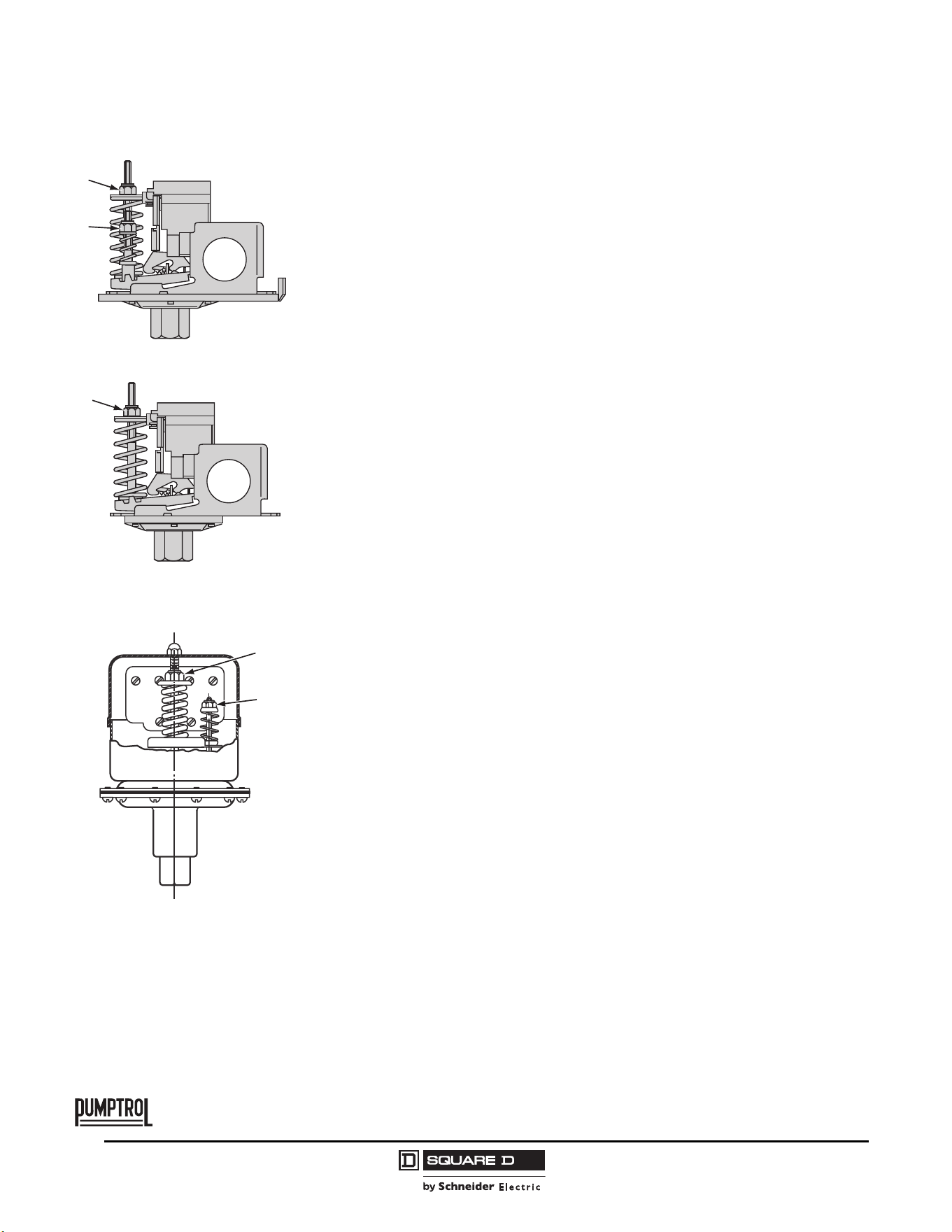
Settings
Pressure switches with adjustable differential
(Types FSG, FYG, and FRG)
When setting the pressure switch, adjust the setting point on falling pressure
first, then the setting point on rising pressure (PB).
• Setting point on falling pressure
The setting point on falling pressure is set by adjusting range-nut
1
.
• Setting point on rising pressure
The setting point on rising pressure is set by adjusting range-nut
2
.
Pressure switches with fixed differential
(Types FTG and FHG)
Only the setting point on rising pressure is adjustable.
• Setting point on rising pressure
The setting point on rising pressure is set by adjusting range-nut
1
.
• Setting point on falling pressure
The setting point on falling pressure is not adjustable.
The difference between the tripping and resetting points of the contact is the
inherent differential of the switch (due to factors such as contact differential
and friction).
Pressure switches with adjustable differential
(Type G)
When setting the pressure switch, adjust the setting point on falling pressure
first, then the setting point on rising pressure.
• Setting point on falling pressure
The setting point on falling pressure is set by adjusting range-nut
1
.
• Setting point on rising pressure
The setting point on rising pressure is set by adjusting range-nut
2
.
1
2
1
1
2
TM
Commercial Pressure and Float Switches for Power Circuits
Electromechanical Pressure Switches, Class 9013 Types F and G
19
03/2011
© 2011 Schneider Electric
All Rights Reserved
TM
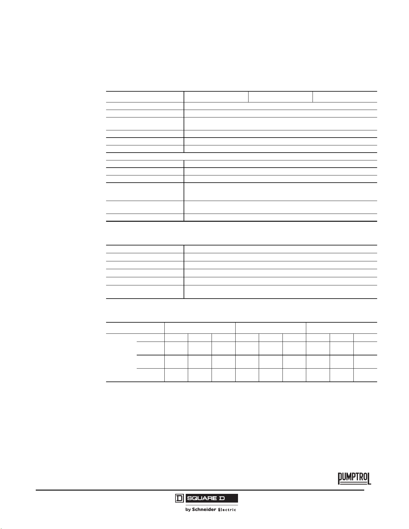
General Specifications
Types FSG/FSW, FTG/FTW, and FYG/FYW
Table 1: Environment
Type FSG/FSW FTG/FTW FYG/FYW
Conforming to standards UL 508, NEC Article 430-84, ANSI/NSF Standard 61, FDA 21CFR.2600
Product approvals UL File E12158 CCN NKPZ , CSA File LR 25490 Class 321106
Degree of protection
IP20, NEMA Type 1 (Types F•G). NEMA Type 3R (Types F•W) must be mounted in vertical
position to maintain enclosure rating.
Operating position IP20 and NEMA Type 1 in any position, NEMA Type 3R in the vertical position only.
Operating rate 10 cycles/m
Repeat accuracy ±3% of the range
Ambient air temperature
Storage –22 to 158 °F (–30 to 70 °C)
Operation –22 to 257
°F (–30 to 125 °C)
Fluids Controlled Fresh water (or sea water with Form Q)
Materials
Cover: polypropylene, Noryl
®
thermoplastic resin or equivalent for Type 3R.
Component material in contact with fluid: flange, zinc plated or equivalent (fluid entry), nitrile
or equivalent rubber (diaphragm)
Fluid connection
1/8" NPSF internal, 1/4" NPSF internal, 1/2" NPT external, 1/4" bayonet (barbed), 90° elbow
1/4" bayonet, four-way flange, 3/8" NPSF internal, 1/4" flare and other specials
Electrical connection 2 open side entries, 0.88 in. diameter, with two flats
Table 2: Contact Block Characteristics
Type of contacts One 2 pole, 2 N.C. (4 terminal) contacts, snap action
Resistance across terminals
< 25 mΩ
Short-circuit protection 5,000 A
Connection Screw clamp terminals. Clamping capacity up to 10 AWG (5.261 mm
2
)
Electrical durability 100,000 cycles
Mechanical durability
300,000 cycles (actual product life will vary based on electrical load, duty cycle, application,
and environmental conditions)
Table 3: Electrical Ratings
Type (2 pole) FSG/FSW FTG/FTW FYG/FYW
Power
ratings of
controlled
motors
Voltage
~ 1ØVac ~ 3ØVac Vdc ~ 1ØVac ~ 3ØVac Vdc ~ 1ØVac ~ 3ØVac Vdc
115 V
1.1 kW
(1.5 hp)
1.5 kW
(2 hphp)
0.18 kW
(.25 hp)
0.75 kW
(1 hp)
——
1.5 kW
(2 hp)
2.2 kW
(3 hp)
0.37 kW
(.50 hp)
230 V
1.5 kW
(2 hp)
2.2 kW
(3 hp)
0.18 kW
(.25 hp)
0.75 kW
(1 hp)
——
2.2 kW
(3 hp)
3.7 kW
5 hp)
0.37 kW
(.50 hp)
460 / 575 V —
0.75 kW
(1 hp)
—————
0.75 kW
(1 hp)
—
© 2011 Schneider Electric
All Rights Reserved
Commercial Pressure and Float Switches for Power Circuits
Electromechanical Pressure Switches, Class 9013 Types F and G
20
03/2011
TM
Types FRG, FHG, and G
Table 4: Environment
Type FRG FHG G
Conforming to Standards UL 508, NEC Article 430-84, ANSI/NSF Standard 61, FDA 21CFR.2600
Product approvals UL File E12158 CCN NKPZ , CSA File LR 25490 Class 321106
Degree of protection IP20, NEMA Type 1. NEMA Type 3R (only Types G•B) must be mounted in vertical position to maintain enclosure rating
Operating position IP20 and NEMA Type 1 in any position, NEMA Type 3R in the vertical position only
Operating rate 10 cycles/m
Repeat accuracy ±3% of the range
Ambient air temperature
Storage –22 to 158 °F (–30 to 70 °C)
Operation –22 to 257
°F (–30 to 125 °C)
Fluids Controlled Fresh water (or sea water with Form Q)
Materials
Cover: polypropylene, Noryl thermoplastic resin or equivalent for Type 3R,
Component material in contact with fluid: flange, zinc plated or equivalent (fluid entry), nitrile or equivalent rubber (diaphragm)
Fluid connection
1/8" NPSF internal, 1/4" NPSF internal, 1/2" NPT external, 1/4" bayonet (barbed), 90° elbow 1/4" bayonet, four-way flange, 3/8"
NPSF internal, 1/4" flare and other specials
Electrical connection 2 open side entries, 0.88 in. diameter, with two flats 3 knockouts for 1/2" conduit
Table 5: Contact Block Characteristics
Type of contacts
One 2 pole, 2 N.C. (4 terminal) contacts, snap action
Type FRG: 1 or 2 pole, 2 N.O. (2 or 4 terminal) contacts, snap action
Resistance across terminals
< 25 mΩ
Short-circuit protection 5,000 A
Connection Screw clamp terminals. Clamping capacity up to 10 AWG (5.261 mm
2
)
Electrical durability 100,000 cycles
Mechanical durability 300,000 cycles (actual product life will vary based on electrical load, duty cycle, application, and environmental conditions)
Table 6: Electrical Ratings
Type (1 pole)
[1]
1
Includes: FHG 2, 3, 4, 9, 12, 13, 14, 19, 42, 44, 49
FRG FHG G
Power
ratings of
controlled
motors
[2]
2
Type FRG and G devices include 1 N.O. and 1 N.C. contact (Form H).
Voltage
~ 1ØVac ~ 3ØVac Vdc ~ 1ØVac ~ 3ØVac Vdc ~ 1ØVac ~ 3ØVac Vdc
32 V —————————
115 V
0.75 kW
(1 hp)
—
0.18 kW
(.25 hp)
1.1 kW
(1.5 hp)
1.5 kW
(2 hp)
0.18 kW
(.25 hp)
0.75 kW
(1 hp)
—
0.37 kW
(.50 hp)
230 V
0.75 kW
(1 hp)
—
0.18 kW
(.25 hp)
1.5 kW
(2 hp)
2.2 kW
(3 hp)
0.18 kW
(.25 hp)
1.5 kW
(2 hp)
—
0.37 kW
(.50 hp)
460 / 575 V ————
0.75 kW
(1 hp)
—
1.5 kW
(2 hp)
—
Type (2 pole)
[3]
3
Includes: FHG 22, 24, 29, 32, 33, 34, 39, 52, 54, 59
Power
ratings of
controlled
motors
Voltage
~ 1ØVac ~ 3ØVac Vdc ~ 1ØVac ~ 3ØVac Vdc ~ 1ØVac ~ 3ØVac Vdc
32 V ——
0.18 kW
(.25 hp)
——————
115 V
0.75 kW
(1 hp)
0.75 kW
(1 hp)
0.18 kW
(.25 hp)
1.5 kW
(2 hp)
2.2 kW
(3 hp)
0.37 kW
(.50 hp)
1.5 kW
(2 hp)
2.2 kW
(3 hp)
0.75 kW
(1 hp)
230 V
0.75 kW
(1 hp)
0.75 kW
(1 hp)
0.18 kW
(.25 hp)
2.2 kW
(3 hp)
3.7 kW
5 hp)
0.37 kW
(.50 hp)
2.2 kW
(3 hp)
3.7 kW
5hp)
0.75 kW
(1 hp)
460 / 575 V ————
0.75 kW
(1 hp)
—
3.7 kW
5hp)
3.7 kW
5hp)
—
Commercial Pressure and Float Switches for Power Circuits
Electromechanical Pressure Switches, Class 9013 Types F and G
21
03/2011
© 2011 Schneider Electric
All Rights Reserved
TM
Interpretation of the Catalog Number
Class 9013 Type F Water Pump Switches
Example: 9013FSG2J24C20
NOTE: Use this table only to interpret the catalog number. Some combinations are not available.
TM
FS G 2 J24 C20
Type Enclosure Fluid Connection
Differential
psi
Range
psi
Code psi Form Modification
FS:
Standard Adj
Diff ≤ 1.5 hp
FT:
Fixed Diff
≤ 1 hp
FY:
Adj Diff
≤ 2 hp
FR:
Reverse Acting,
Adj Diff
≤ 1 hp
G: NEMA 1
W: NEMA 3R
1:
2:
9:
10:
20:
22:
29:
42:
49:
52:
59:
1/8" NPSF Internal
¼“ NPSF internal
¼“ NPT external
¼“ Bayonet (barbed)
90° Elbow
¼“ Bayonet
¼“ NPSF internal
¼“ NPT external
¼“ NPSF internal
¼“ NPT external
¼“ NPSF internal
¼“ NPT external
15–30
15–30
15–30
15–30
15–30
10–30
10–30
6–20
6–20
20–30
20–30
20–65
20–65
20–65
20–65
20–65
20–50
20–60
9–30
9–30
25–80
25–80
Standard Action C20: Standard pack of 20 devices per box
[1]
J15:
J16:
J20:
J18:
J21:
J24:
J33:
J34:
J25:
5–21
8–20
20–40
20–50
30–50
40–60
50–70
55–85
60–80
H: 1 N.O. / 1 N.C. contact
FRG 2-pole only
M1: Maintained manual cut-out lever
(Auto-Off)
FSG, FYG
M3: Momentary manual cut-in lever
(Auto-Start) (FRG2–59)
M4: Low pressure cut-off
(Auto-Start-Off) FSG, FYG
M5: Maintained manual cut-in lever
(Auto-On) FRG2–59
Reverse Action P: Pulsation plug (Type 2 and 9)
J17:
J36:
J22:
J19:
J70:
J23:
J35:
J32:
J51:
J64:
J99:
8.5–5.5
10–5
22–12
22–16
35–20
40–20
50–30
80–60
100–80
150–120
Specify
pressure
setting
T: ½“ conduit bushing—
½“ long thread—on left
U: Slip-on connections
(load side terminals only)
FSG, FYG
U2: Slip-on connections
(line and load side terminals)
FSG, FYG
Z22: Black cover
FSG, FYG
1
Additional bulk packages are available. See Table 7 on page 37.
© 2011 Schneider Electric
All Rights Reserved
Commercial Pressure and Float Switches for Power Circuits
Electromechanical Pressure Switches, Class 9013 Types F and G
22
03/2011
TM
Class 9013 Type F Air Compressor Switches
Example: 9013FHG2J27C20
NOTE: Use this table only to interpret the catalog number. Some combinations are not available.
TM
FH G 2 J27 C20
Type Enclosure
Low hp
≤ 1.5 hp
High hp
≥ 2 hp
Fluid
Connection
Differential
psi
Range
psi
Code psi Form Modification
FH: G: NEMA 1 2:
3:
4:
9:
12:
13:
14:
19:
42:
44:
49:
22:
—
24:
29:
32:
33:
34:
39:
52:
54:
59:
¼“ NPSF internal
3/8“ NPSF internal
¼“ 4-way flange
¼“ NPT external
¼“ NPSF internal
3/8“ NPSF internal
¼“ 4-way flange
¼“ NPT external
¼“ NPSF internal
¼“ 4-way flange
¼“ NPT external
20
20
20
20
30
30
30
30
40
40
40
40–100
40–100
40–100
40–100
70–150
70–150
70–150
70–150
100–200
100–200
100–200
J43:
J27:
J37:
J38:
J69:
J52:
J39:
J68:
J55:
J40:
J59:
J99:
Off at 80
Off at 100
Off at 110
Off at 115
Off at 120
Off at 125
Off at 135
Off at 140
Off at 150
Off at 155
Off at 175
Specify
pressure
setting
C20: Standard pack of 20 devices
per box
[1]
G4: Addition of a second ground
screw
M1: Maintained manual cut-out lever
(Auto-Off)
P: Pulsation plug (copper)
(not field installable)
T: ½“ conduit bushing—
½“ long thread—on left
U: Slip-on connections
(load side terminals only)
U2: Slip-on connections
(line and load side terminals)
W: Factory sealed range stud
X: 2-way pressure release value
X1: Quick connect two-way
pressure release valve
Z22: Black cover
1
Additional bulk packages are available. See Table 7 on page 37.
Commercial Pressure and Float Switches for Power Circuits
Electromechanical Pressure Switches, Class 9013 Types F and G
23
03/2011
© 2011 Schneider Electric
All Rights Reserved
TM
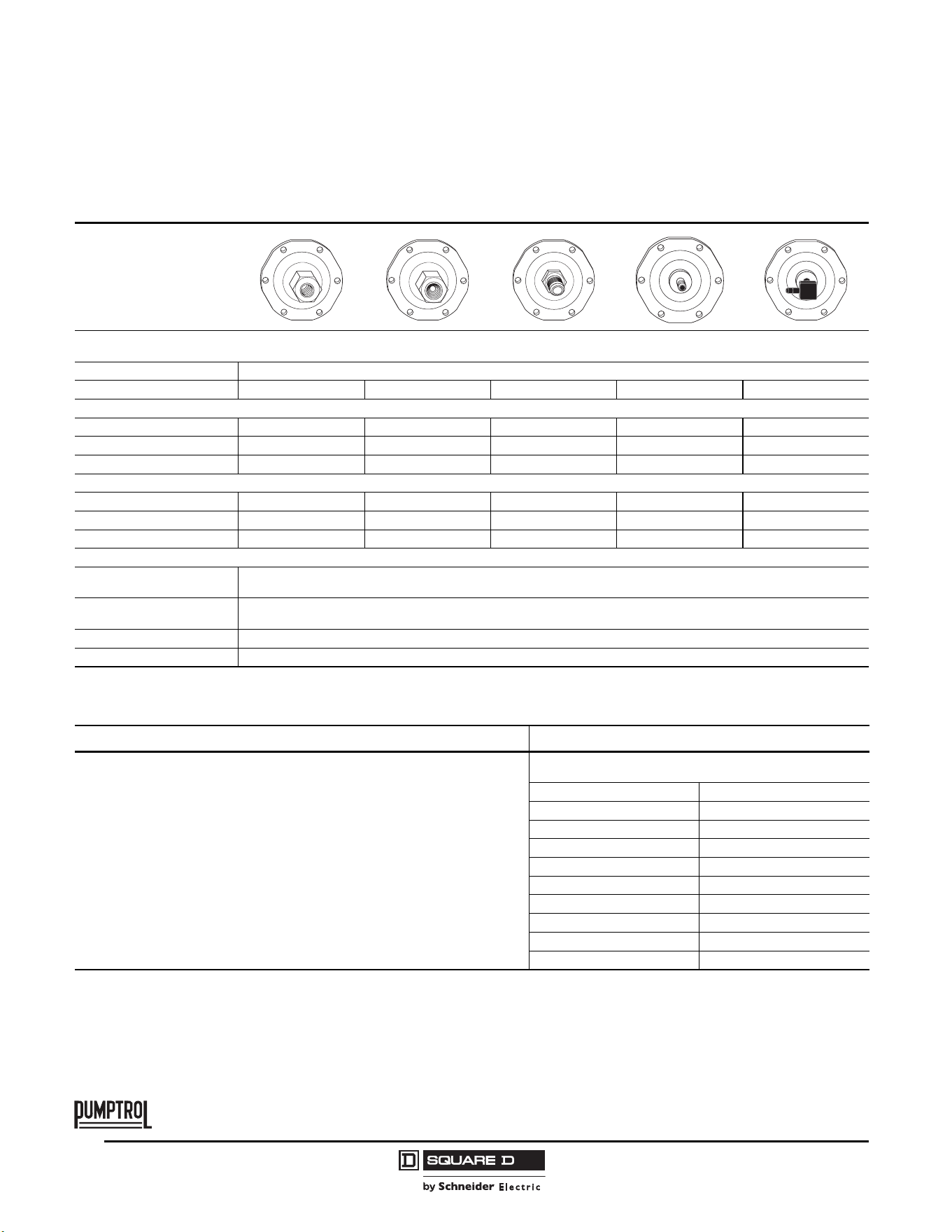
Class 9013 Type G Pressure Switches
Example: 9013GHG2J26C10
NOTE: Use this table only to interpret the catalog number. Some combinations are not available.
TM
GH G 2 J26 C10
Type Enclosure Fluid Connection Code psi Form Modification
[1]
GH
GH: 200/250 psi
GS: 80 psi
GM: 35 psi
G: NEMA 1
B: NEMA 3R
W: NEMA 4
R: NEMA 7, 9
1:
2:
3:
4:
5:
6:
1/8“ NPSF internal
¼“ NPSF internal
3/8“ NPSF internal
1/8“ NPSF internal
¼“ NPT external
3/8“ NPSF internal
200
200
200
250
250
250
J20:
J21:
J23:
J24:
J25:
J26:
J28:
J29:
J30:
J31:
J51:
J53:
J54:
J56:
J57:
J58:
J60:
J61:
J50:
J66:
J62:
J63:
J64:
J67:
J65:
J99:
20–40
30–50
40–20
40–60
60–80
70–90
70–100
75–100
80–100
90–120
100–80
100–125
110–125
110–150
120–150
125–150
125–175
130–175
135–175
140–170
140–175
145–175
150–120
150–175
215–250
Specify
pressure
setting
C10:
E:
H:
P:
R:
U:
U2:
X:
Z:
Z16:
Standard pack of 10 devices per box GHB, GHG, GSB, GSG
3-way lever (On-Auto-Off) not compatible with Form X GHG,
GMG, GSG
1 N.O. / 1 N.C. contact
Pulsation plug (copper) (not field installable)
Reverse action / 2 N.O. contacts
Slip-on connections (load side terminals only)
Slip-on connections (line and load side terminals)
2-way pressure release value (not compatible with Form E)
available on GHB, GMG, GSB, GHG, GSG, GHR, GHW,
GSR, GSW
¼“ male pipe thread on pressure connection
½" - 14 NPT external, ¼“ - 18 NPT internal
GS
1:
2:
3:
1/8“ NPSF internal
¼“ NPSF internal
3/8“ NPSF internal
80
80
80
GM
2: ¼“ NPSF internal 35
1
Cannot order Form R in combination with Form H.
© 2011 Schneider Electric
All Rights Reserved
Commercial Pressure and Float Switches for Power Circuits
Electromechanical Pressure Switches, Class 9013 Types F and G
24
03/2011
TM
Selection and Specifications
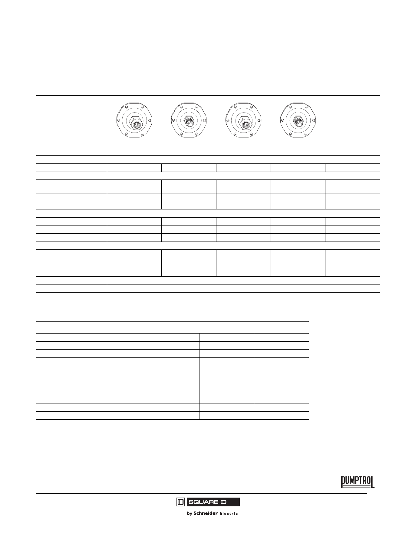
Type FSG, 2-Pole, 2 N.C. Contacts
Degree of Protection IP20, NEMA Type 1
Flange Style
Adjustable range of setting point 20.3–66.7 psi (1.4–4.6 bar)
Contacts open on rising pressure
Differential Adjustable
Fluid Connections 1/8" NPSF internal 1/4" NPSF internal 1/4" NPT external 1/4" bayonet (barbed) 90° elbow ¼" bayonet
Catalog Numbers
NEMA Type 1, IP20 9013FSG1 9013FSG2 9013FSG9 9013FSG10 9013FSG20
NEMA Type 3R
[1]
1
Must be mounted in a vertical position to maintain enclosure rating.
9013FSW1 9013FSW2 9013FSW9 9013FSW10 9013FSW20
Fluids Controlled Water Water Water Water Water
Pressure Range
Cut-out psig (bar) 20–65 (1.4–4.5) 20–65 (1.4–4.5) 20–65 (1.4–4.5) 20–65 (1.4–4.5) 20–65 (1.4–4.5)
Cut-in psig (bar) 5–45 (0.3–3.1) 5–45 (0.3–3.1) 5–45 (0.3–3.1) 5–45 (0.3–3.1) 5–45 (0.3–3.1)
Weight, lb (kg) 0.75 (0.340) 0.75 (0.340) 0.75 (0.340) 0.75 (0.340) 0.75 (0.340)
Supplemental Specifications (not shown under General Specifications)
Differential
psig (bar)
15–30 (1.0–2.1)
Maximum Allowable Pressure
psig (bar)
65 (4.5)
Cable Entry 2 cable entries 0.88 in. (22.4 mm) with 0.84 in. (21.3 mm) across flats
Pressure Switch Style Diaphragm
Ordering information Pressure codes
1. Select the catalog number from the table above.
2. Select the pressure code and add the code designation to the end of the catalog
number. Ensure that the pressure code falls within the limits of the device as
shown in the device listings.
3. If special features are desired, add the appropriate Form letter to the catalog
number after the pressure code. Arrange the Form letters in alphabetical
sequence when ordering more than one special feature.
4. Add the packaging code at the end of the sequence, after the Forms. (For
example, to order a standard pack of 20 devices, specify 9013FSG2J21MIC20.) If
no packaging code is indicated, the devices will be shipped individually packaged.
NOTE: Existence of a code does not imply that the code is available
for any or all devices.
Settings (psi) Code
5–21 J15
8–20 J16
20–40 J20
20–50 J18
30–50 J21
40–60 J24
50–70 J33
60–80 J25
Specify pressure settings J99
Commercial Pressure and Float Switches for Power Circuits
Electromechanical Pressure Switches, Class 9013 Types F and G
25
03/2011
© 2011 Schneider Electric
All Rights Reserved
TM
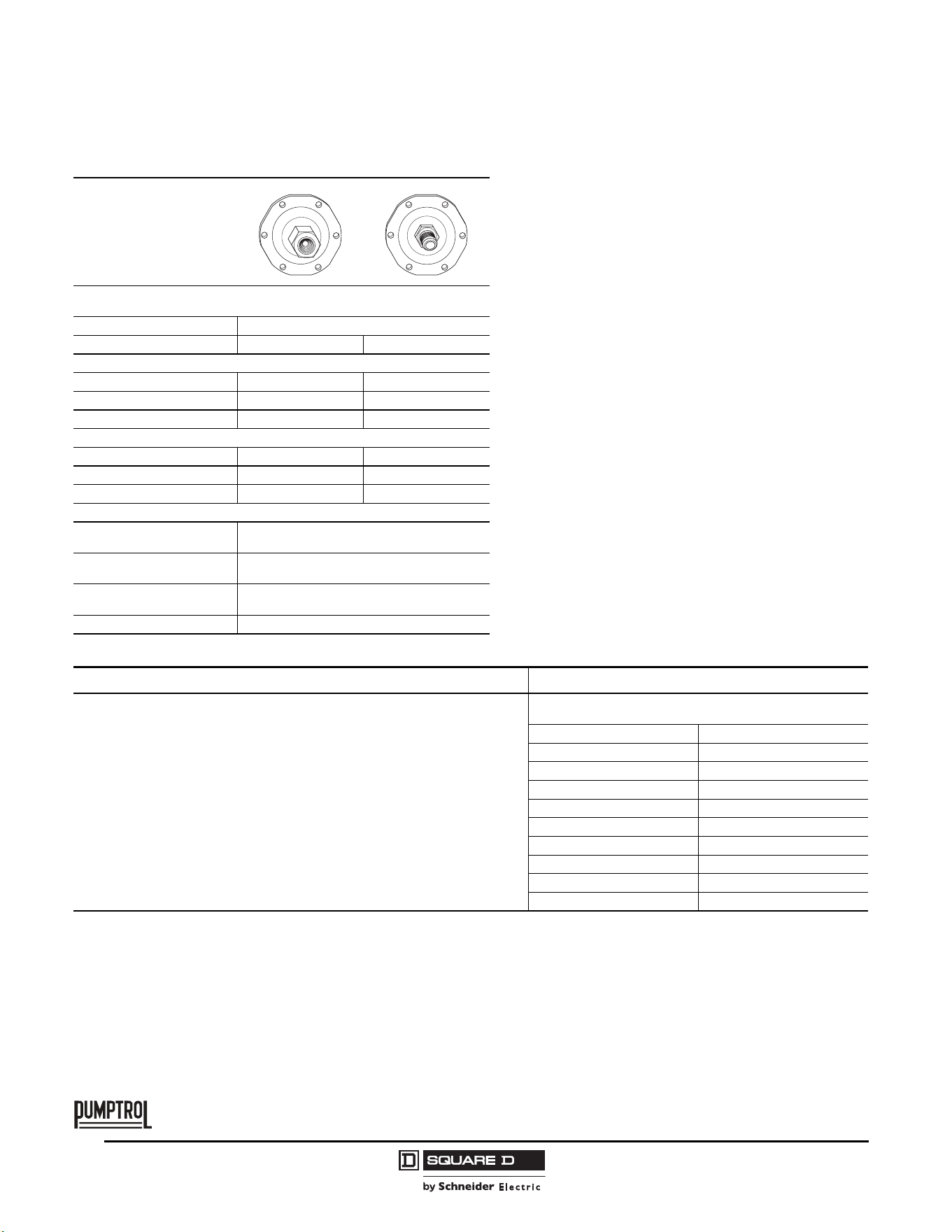
Flange Style
Adjustable range of setting point 20.3–66.7 psi (1.4–4.6 bar)
Contacts open on rising pressure
Differential Adjustable
Fluid Connections 1/4" NPSF internal 1/4" NPT external 1/4" NPSF internal 1/4" NPT external —
Catalog Numbers
NEMA Type 1, IP20 9013FSG22 9013FSG29 9013FSG42 9013FSG49
9013FSG1–20
with M4
[1]
NEMA Type 3R
[2]
9013FSW22 9013FSW29 9013FSW42 9013FSW49 —
Fluids Controlled Water Water Water Water Water
Pressure Range
Cut-out psig (bar) 20–50 (1.4–3.5) 20–60 (1.4–4.2) 9–30 (0.6–2.1) 9–30 (0.6–2.1) 34–65 (2.3–4.5)
Cut-in psig (bar) 10–30 (0.7–2.1) 10–45 (0.7–3.1) 3–10 (0.2–0.7) 3–10 (0.2–0.7) 19–45 (1.3–3.1)
Weight, lb (kg) 0.75 (0.340) 0.75 (0.340) 0.75 (0.340) 0.75 (0.340) 0.75 (0.340)
Supplemental Specifications (not shown under General Specifications)
Differential
psig (bar)
10–30 (0.7–2.1) 10–30 (0.7–2.1) 6–20 (0.4–1.4) 6–20 (0.4–1.4) 15–30 (1.0–2.1)
Maximum Allowable Pressure
psig (bar)
50 (3.5) 60 (4.1) 30 (2.1) 30 (2.1) 65 (4.5)
Cable Entry 2 cable entries 0.88 in. (22.4 mm) with 0.84 in. (21.3 mm) across flats
Pressure Switch Style Diaphragm
1
Nylon pulsation plug can be field installed on types having 1/4" NPSF internal connector. Catalog number 1530S6G1 is one bag of 50 plugs.
2
Must be mounted in a vertical position to maintain enclosure rating.
Modifications (Forms)
Description Applies to: Form letter
Standard pack of 20 devices per box All Type F C20
[1]
1
Additional bulk packages are available. See Table 7 on page 37.
Maintained manual cut-out lever (Auto-Off) FSG, FYG M1
Low pressure cut-off (Auto-Start-Off ) operates at approximately 10 psig
below cut-in and will turn off the pump
FSG, FYG
(Type 1–20 only)
M4
Maintained manual cut-in lever (Auto-On) FSG, FYG M5
Pulsation plug (standard on FSG4) FSG2, 9 P
[2]
2
Nylon pulsation plug can be field installed on types having 1/4" NPSF internal connector.
Catalog number 1530S6G1 is one bag of 50 plugs.
½" conduit bushing—½" long thread—on left All Type F T
Slip-on connectors (load side terminals only) FSG, FYG U
Slip-on connectors (line and load side terminals) FSG, FYG U2
Black cover FSG, FYG Z22
© 2011 Schneider Electric
All Rights Reserved
Commercial Pressure and Float Switches for Power Circuits
Electromechanical Pressure Switches, Class 9013 Types F and G
26
03/2011
TM
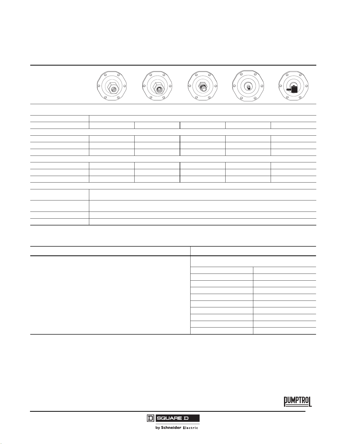
Flange Style
Adjustable range of setting point
Contacts open on rising pressure
Differential Adjustable
Fluid Connections 1/4" NPSF internal 1/4" NPT external
Catalog Numbers
NEMA Type 1, IP20 9013FSG52 9013FSG59
NEMA Type 3R ——
Fluids Controlled Water Water
Pressure Range
Cut-out psig (bar) 25–80 (1.7–5.5) 25–80 (1.7–5.5)
Cut-in psig (bar) 5–60 (0.3–4.2) 5–60 (0.3–4.2)
Weight, lb (kg) 0.75 (0.340) 0.75 (0.340)
Supplemental Specifications (not shown under General Specifications)
Differential
psig (bar)
20–30 (1.4–2.1)
Maximum Allowable Pressure
psig (bar)
80 (5.5)
Cable Entry
2 cable entries 0.88 in. (22.4 mm) with
0.84 in. (21.3 mm) across flats
Pressure Switch Style Diaphragm
Ordering information Pressure codes
1. Select the catalog number from the table above.
2. Select the pressure code and add the code designation to the end of the catalog
number. Ensure that the pressure code falls within the limits of the device as
shown in the device listings.
3. If special features are desired, add the appropriate Form letter to the catalog
number after the pressure code. Arrange the Form letters in alphabetical
sequence when ordering more than one special feature.
4. Add the packaging code at the end of the sequence, after the Forms. (For
example, to order a standard pack of 20 devices, specify 9013FSG2J21MIC20.) If
no packaging code is indicated, the devices will be shipped individually packaged.
NOTE: Existence of a code does not imply that the code is available
for any or all devices.
Settings (psi) Code
5–21 J15
8–20 J16
20–40 J20
20–50 J18
30–50 J21
40–60 J24
50–70 J33
60–80 J25
Specify pressure settings J99
Commercial Pressure and Float Switches for Power Circuits
Electromechanical Pressure Switches, Class 9013 Types F and G
27
03/2011
© 2011 Schneider Electric
All Rights Reserved
TM
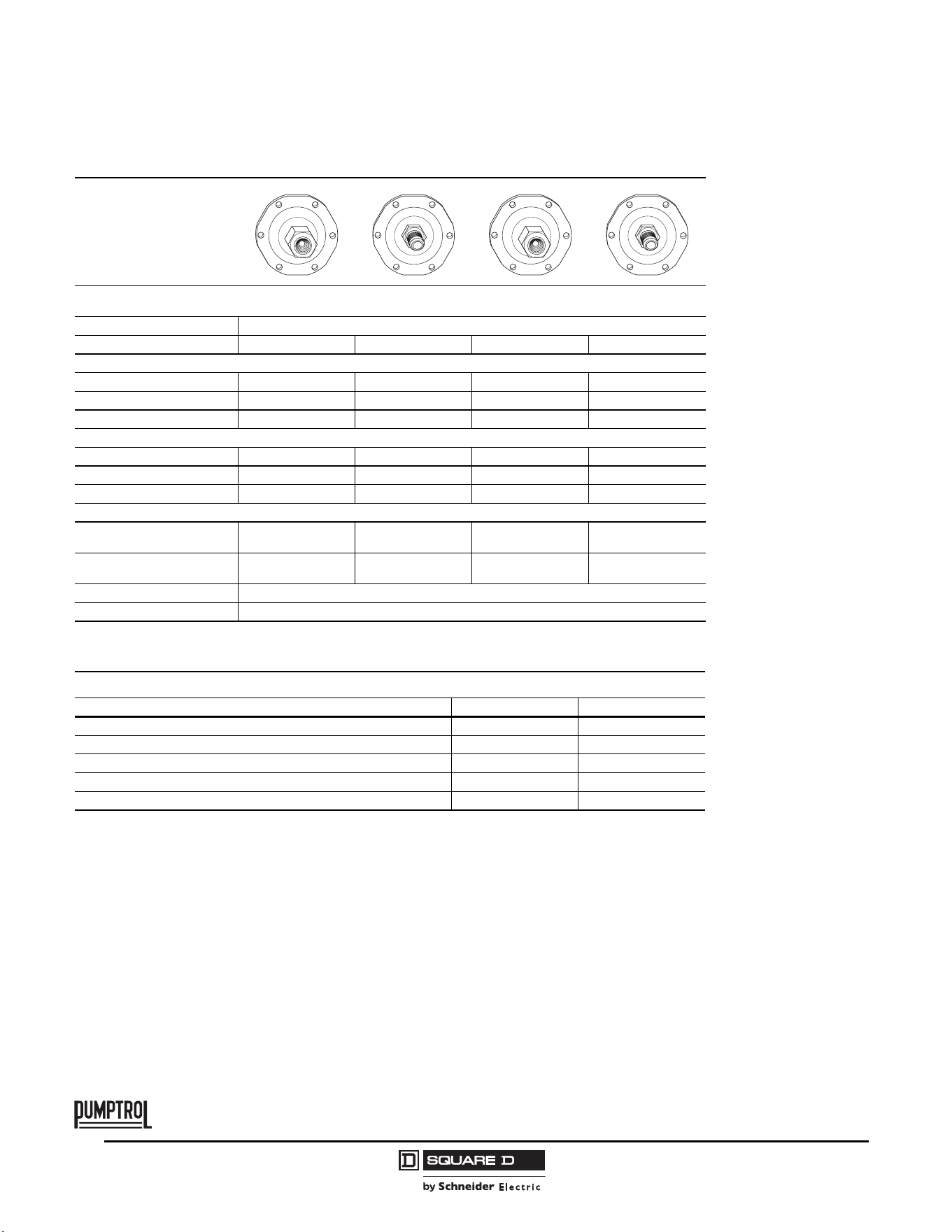
Type FTG, 2-Pole, 2 N.C. Contacts
Degree of Protection IP20, NEMA Type 1
Flange Style
Fixed range of setting point
Contacts open on rising pressure
Differential Fixed
Fluid Connections 1/8" NPSF internal 1/4" NPSF internal 1/4" NPT external 1/4" bayonet (barbed) 90° elbow ¼" bayonet
Catalog Numbers
NEMA Type 1, IP20 9013FTG1 9013FTG2 9013FTG9 9013FTG10 9013FTG20
NEMA Type 3R
[1]
1
Must be mounted in a vertical position to maintain enclosure rating.
9013FTW1 9013FTW2 9013FTW9 9013FTW10 9013FTW20
Fluids Controlled Water Water Water Water Water
Pressure Range
Cut-out psig (bar) 20–65 (1.4–4.5) 20–65 (1.4–4.5) 20–65 (1.4–4.5) 20–65 (1.4–4.5) 20–65 (1.4–4.5)
Cut-in psig (bar)—————
Weight, lb (kg) 0.75 (0.340) 0.75 (0.340) 0.75 (0.340) 0.75 (0.340) 0.75 (0.340)
Supplemental Specifications (not shown under General Specifications)
Differential
psig (bar)
20 (1.4)
Maximum Allowable Pressure
psig (bar)
65 (4.5)
Cable Entry 2 cable entries 0.88 in. (22.4 mm) with 0.84 in. (21.3 mm) across flats
Pressure Switch Style Diaphragm
Ordering information Pressure codes
1. Select the catalog number from the table above.
2. Select the pressure code and add the code designation to the end of the catalog
number. Ensure that the pressure code falls within the limits of the device as
shown in the device listings.
3. If special features are desired, add the appropriate Form letter to the catalog
number after the pressure code. Arrange the Form letters in alphabetical
sequence when ordering more than one special feature.
4. Add the packaging code at the end of the sequence, after the Forms. (Sold in
lots or multiple of 500; for example: 9013FTG2J21C500.) If no packaging code is
indicated, the devices will be shipped individually packaged.
NOTE: Existence of a code does not imply that the code is available for
any or all devices.
Settings (psi) Code
5–21 J15
8–20 J16
20–40 J20
20–50 J18
30–50 J21
40–60 J24
50–70 J33
60–80 J25
Specify pressure settings J99
© 2011 Schneider Electric
All Rights Reserved
Commercial Pressure and Float Switches for Power Circuits
Electromechanical Pressure Switches, Class 9013 Types F and G
28
03/2011
TM
Flange Style
Fixed range of setting point
Contacts open on rising pressure
Differential Fixed
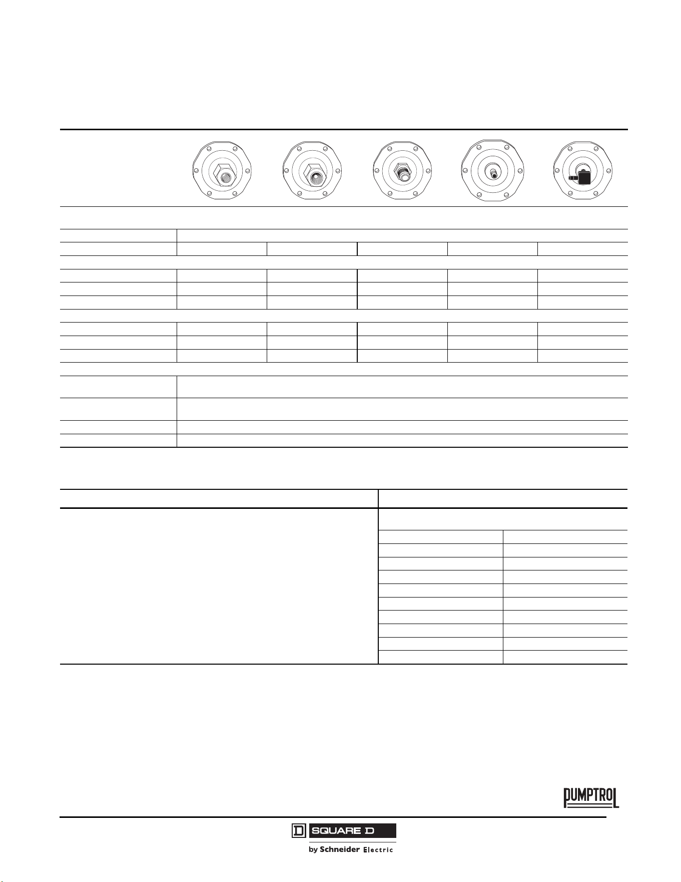
Fluid Connections 1/4" NPSF internal 1/4" NPT external 1/4" NPSF internal 1/4" NPT external
Catalog Numbers
NEMA Type 1, IP20 9013FTG22 9013FTG29 9013FTG42 9013FTG49
NEMA Type 3R
[1]
1
Must be mounted in a vertical position to maintain enclosure rating.
9013FSW22 9013FSW29 9013FSW42 9013FSW49
Fluids Controlled Water Water Water Water
Pressure Range
Cut-out psig (bar) 20–50 (1.4–3.5) 20–60 (1.4–4.1) 9–30 (0.6–2.1) 9–30 (0.6–2.1)
Cut-in psig (bar) — — — —
Weight, lb (kg) 0.75 (0.340) 0.75 (0.340) 0.75 (0.340) 0.75 (0.340)
Supplemental Specifications (not shown under General Specifications)
Differential
psig (bar)
20 (1.4) 15 (1.0) 20 (1.4) 20 (1.4)
Maximum Allowable Pressure
psig (bar)
50 (3.5) 60 (4.2) 30 (2.1) 30 (2.1)
Cable Entry 2 cable entries 0.88 in. (22.4 mm) with 0.84 in. (21.3 mm) across flats
Pressure Switch Style Diaphragm
Modifications (Forms)
Description Applies to: Form letter
Standard pack of 500 devices per box All Type FTG C500
Pulsation plug FTG2, 9 P
[1]
1
Nylon pulsation plug can be field installed on types having 1/4" NPSF internal connector.
Catalog number 1530S6G1 is one bag of 50 plugs.
½" conduit bushing—½" long thread—on left All Type FTG T
Slip-on connectors (line and load terminals) All Type FTG, FYG U2
[2]
2
Standard device has slip-on connectors on the load side.
Black cover FTG, FYG Z22
Commercial Pressure and Float Switches for Power Circuits
Electromechanical Pressure Switches, Class 9013 Types F and G
29
03/2011
© 2011 Schneider Electric
All Rights Reserved
TM
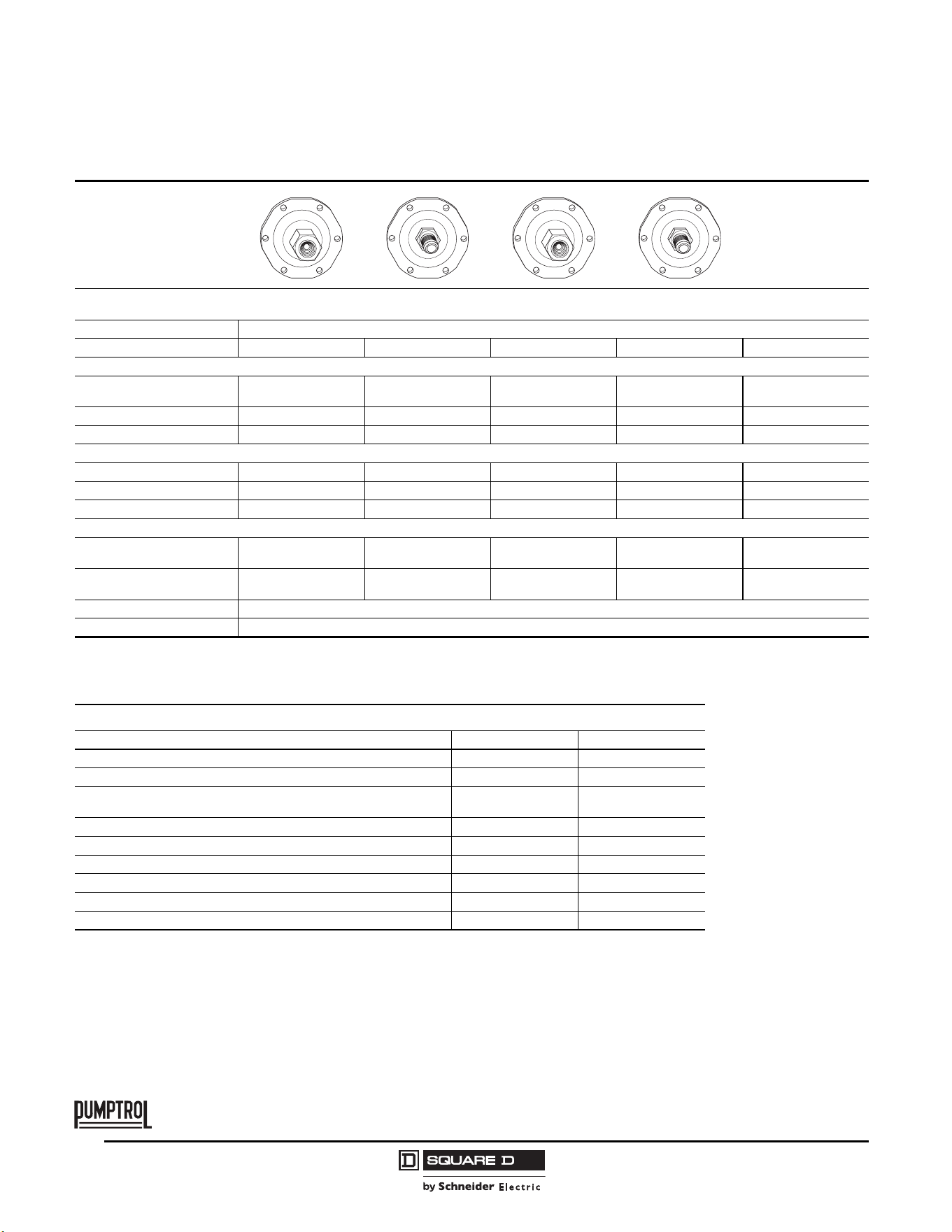
Type FYG, 2-Pole, 2 N.C. Contacts
Degree of Protection IP20, NEMA Type 1
Flange Style
Adjustable range of setting point
Contacts open on rising pressure
Differential Adjustable
Fluid Connections 1/8" NPSF internal 1/4" NPSF internal 1/4" NPT external 1/4" bayonet (barbed) 90° elbow ¼" bayonet
Catalog Numbers
NEMA Type 1, IP20 9013FYG1 9013FYG2 9013FYG9 9013FYG10 9013FYG20
NEMA Type 3R
[1]
1
Must be mounted in a vertical position to maintain enclosure rating.
9013FYW1 9013FYW2 9013FYW9 9013FYW10 9013FYW20
Fluids Controlled Water Water Water Water Water
Pressure Range
Cut-out psig (bar) 25–80 (1.7–5.5) 25–80 (1.7–5.5) 25–80 (1.7–5.5) 25–80 (1.7–5.5) 25–80 (1.7–5.5)
Cut-in psig (bar) 5–60 (0.3–4.2) 5–60 (0.3–4.2) 5–60 (0.3–4.2) 5–60 (0.3–4.2) 5–60 (0.3–4.2)
Weight, lb (kg) 0.75 (0.340) 0.75 (0.340) 0.75 (0.340) 0.75 (0.340) 0.75 (0.340)
Supplemental Specifications (not shown under General Specifications)
Differential
psig (bar)
20–30 (1.4–2.1)
Maximum Allowable Pressure
psig (bar)
80 (5.5)
Cable Entry 2 cable entries 0.88 in. (22.4 mm) with 0.84 in. (21.3 mm) across flats
Pressure Switch Style Diaphragm
Ordering information Pressure codes
1. Select the catalog number from the table above.
2. Select the pressure code and add the code designation to the end of the catalog
number. Ensure that the pressure code falls within the limits of the device as
shown in the device listings.
3. If special features are desired, add the appropriate Form letter to the catalog
number after the pressure code. Arrange the Form letters in alphabetical
sequence when ordering more than one special feature.
4. Add the packaging code at the end of the sequence, after the Forms. (For
example, to order a standard pack of 20 devices, specify 9013FYG2J21C20.) If
no packaging code is indicated, the devices will be shipped individually
packaged.
NOTE: Existence of a code does not imply that the code is available for
any or all devices.
Settings (psi) Code
5–21 J15
8–20 J16
20–40 J20
20–50 J18
30–50 J21
40–60 J24
50–70 J33
60–80 J25
Specify pressure settings J99
© 2011 Schneider Electric
All Rights Reserved
Commercial Pressure and Float Switches for Power Circuits
Electromechanical Pressure Switches, Class 9013 Types F and G
30
03/2011
TM
Flange Style
Adjustable range of setting point
Contacts open on rising pressure
Differential Adjustable
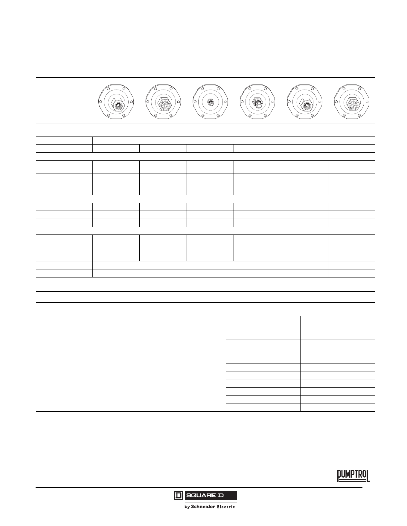
Fluid Connections 1/4" NPSF internal 1/4" NPT external 1/4" NPSF internal 1/4" NPT external —
Catalog Numbers
NEMA Type 1, IP20 9013FYG22 9013FYG29 9013FYG42 9013FYG49
9013FYG1–20
FYG20 with M4
[1]
NEMA Type 3R
[2]
9013FYW22 9013FYW29 9013FYW42 9013FYW49 —
Fluids Controlled Water Water Water Water Water
Pressure Range
Cut-out psig (bar) 25–50 (1.7–3.5) 20–60 (1.4–4.2) 9–40 (0.6–2.8) 9–40 (0.6–2.8) 39–80 (2.1–5.5)
Cut-in psig (bar) 10–30 (0.7–2.1) 10–45 (0.7–3.1) 3–10 (0.2–0.7) 3–10 (0.2–0.7) 19–60 (1.3–4.2)
Weight, lb (kg) 0.75 (0.340) 0.75 (0.340) 0.75 (0.340) 0.75 (0.340) 0.75 (0.340)
Supplemental Specifications (not shown under General Specifications)
Differential
psig (bar)
10–30 (0.7–2.1) 10–30 (0.7–2.1) 6–20 (0.4–1.4) 6–20 (0.4–1.4) 20–30 (1.4–2.1)
Maximum Allowable Pressure
psig (bar)
50 (3.5) 60 (4.2) 40 (2.8) 40 (2.8) 80 (5.5)
Cable Entry 2 cable entries 0.88 in. (22.4 mm) with 0.84 in. (21.3 mm) across flats
Pressure Switch Style Diaphragm
1
Nylon pulsation plug can be field installed on types having 1/4" NPSF internal connector. Catalog number 1530S6G1 is one bag of 50 plugs.
2
Must be mounted in a vertical position to maintain enclosure rating.
Modifications (Forms)
Description Applies to: Form letter
Standard pack of 20 devices per box All Type F C20
[1]
1
Additional bulk packages are available. See Table 7 on page 37.
Maintained manual cut-out lever (Auto-Off) FSG, FYG M1
Low pressure cut-off (Auto-Start-Off ) operates at approximately 10 psig
below cut-in and will turn off the pump
FSG, FYG
(Type 1–20 only)
M4
Pulsation plug (standard on FYG4) FYG2, 9 P
[2]
2
Nylon pulsation plug can be field installed on types having 1/4" NPSF internal connector.
Catalog number 1530S6G1 is one bag of 50 plugs.
Salt water flange (¼ NPSF internal only) All Type F Q
½" conduit bushing—½" long thread—on left All Type F T
Slip-on connectors (load side terminals only) FSG, FYG U
Slip-on connectors (line and load side terminals) FSG, FYG U2
Black cover FSG, FYG Z22
Commercial Pressure and Float Switches for Power Circuits
Electromechanical Pressure Switches, Class 9013 Types F and G
31
03/2011
© 2011 Schneider Electric
All Rights Reserved
TM
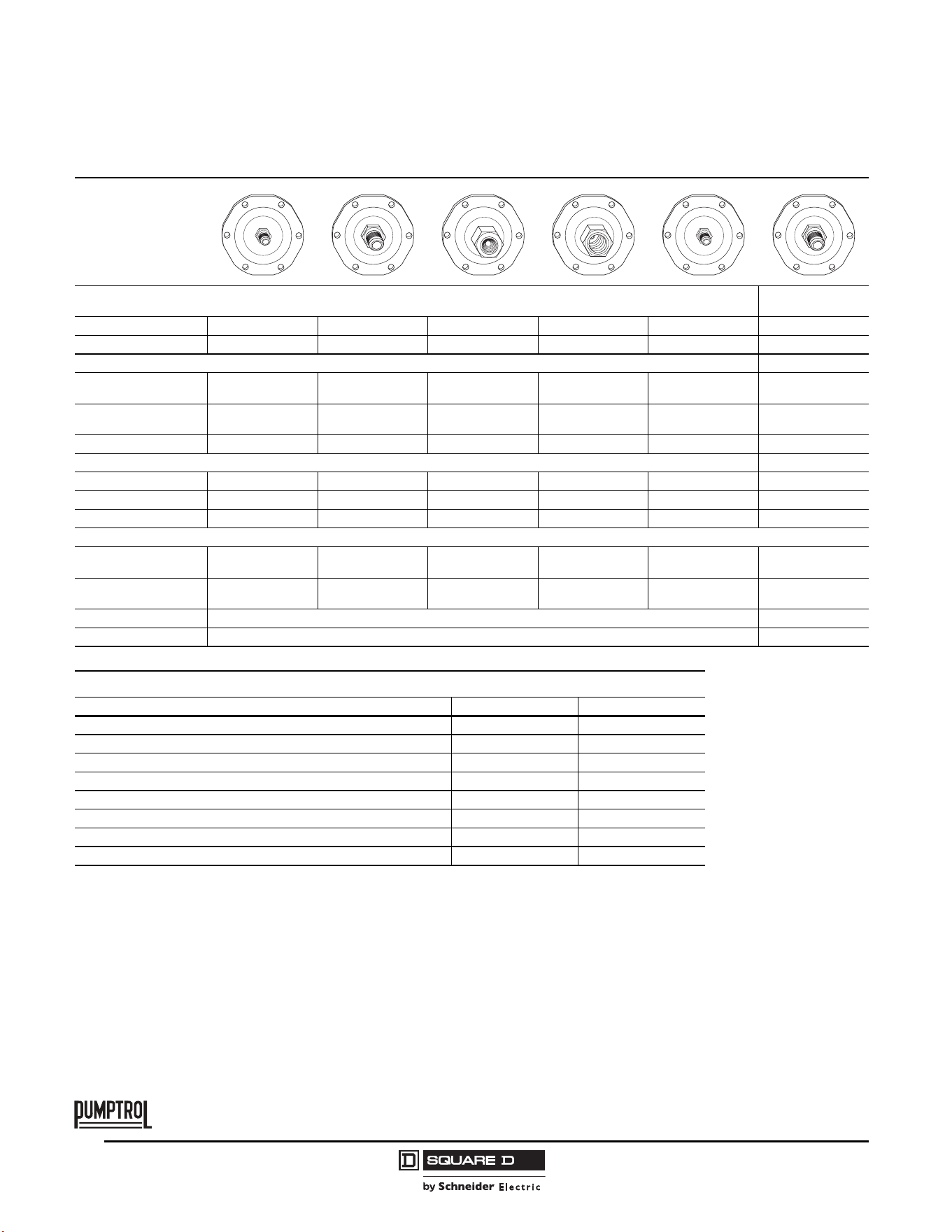
Type FRG, 1- or 2-Pole, 2 N.O. Contacts
Degree of Protection IP20, NEMA Type 1
Flange Style
Adjustable range of setting point
Contacts open on falling pressure
Differential Adjustable
Fluid Connections 1/4" NPSF internal 3/8" NPSF internal 1/4" flare 1/4" NPT external 1/4" NPSF internal 3/8" NPSF internal
Catalog Numbers
1-pole
NEMA Type 1, IP20
9013FRG12 9013FRG13 9013FRG18 9013FRG19 9013FRG32 9013FRG33
2-pole
NEMA Type 1, IP20
9013FRG2 9013FRG3 9013FRG8 9013FRG9 9013FRG22 9013FRG23
Fluids Controlled Water Water Water Water Water Water
Pressure Range
Cut-out psig (bar) 8–45 (0.6–3.1) 8–45 (0.6–3.1) 8–45 (0.6–3.1) 8–45 (0.6–3.1) 4–25 (0.3–1.7) 4–25 (0.3–1.7)
Cut-in psig (bar) 23–65 (1.6–4.5) 23–65 (1.6–4.5) 23–65 (1.6–4.5) 23–65 (1.6–4.5) 10–45 (0.7–3.1) 10–45 (0.7–3.1)
Weight, lb (kg) 0.75 (0.340) 0.75 (0.340) 0.75 (0.340) 0.75 (0.340) 0.75 (0.340) 0.75 (0.340)
Supplemental Specifications (not shown under General Specifications)
Differential
psig (bar)
15–30 (1.0–2.1) 15–30 (1.0–2.1) 15–30 (1.0–2.1) 15–30 (1.0–2.1) 6–20 (0.4–1.4) 6–20 (0.4–1.4)
Maximum Allowable
Pressure psig (bar)
65 (4.5) 65 (4.5) 65 (4.5) 65 (4.5) 45 (3.1) 45 (3.1)
Cable Entry 2 cable entries 0.88 in. (22.4 mm) with 0.84 in. (21.3 mm) across flats
Pressure Switch Style Diaphragm
Ordering information Pressure codes
1. Select the catalog number from the table above.
2. Select the pressure code and add the code designation to the end of the catalog
number. Ensure that the pressure code falls within the limits of the device as
shown in the device listings.
3. If special features are desired, add the appropriate Form letter to the catalog
number after the pressure code. Arrange the Form letters in alphabetical
sequence when ordering more than one special feature.
4. Add the packaging code at the end of the sequence, after the Forms. (For
example, to order a standard pack of 20 devices, specify 9013FRG2J21MIC20.)
If no packaging code is indicated, the devices will be shipped individually
packaged.
NOTE: Existence of a code does not imply that the code is available for
any or all devices.
Settings (psi) Code
8.5–5.5 J17
10–5 J36
22–12 J22
22–16 J19
35–20 J70
40–20 J23
50–30 J35
80–60 J32
100–80 J51
150–120 J64
Specify pressure settings J99
© 2011 Schneider Electric
All Rights Reserved
Commercial Pressure and Float Switches for Power Circuits
Electromechanical Pressure Switches, Class 9013 Types F and G
32
03/2011
TM
Flange Style
Adjustable range of setting point
Contacts open on falling pressure
Differential Adjustable Adjustable Fixed Fixed Fixed Fixed
Fluid Connections 1/4" flare 1/4" NPT external 1/4" NPSF internal 3/8" NPSF internal 1/4" flare 1/4" NPT external
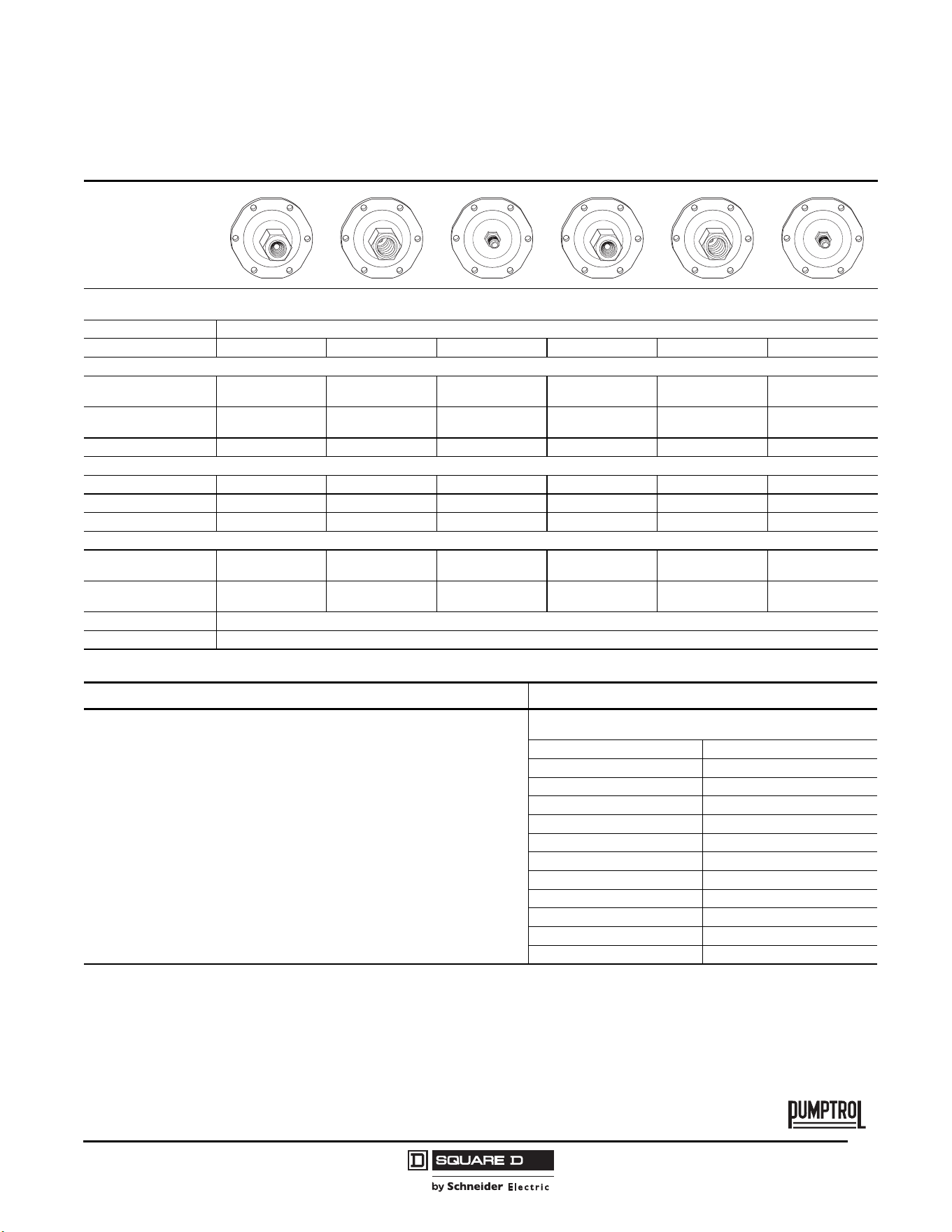
Catalog Numbers
1-pole
NEMA Type 1, IP20
9013FRG38 9013FRG39 9013FRG52 9013FRG53 9013FRG58 9013FRG59
2-pole
NEMA Type 1, IP20
9013FRG28 9013FRG29 9013FRG42 9013FRG43 9013FRG48 9013FRG49
Fluids Controlled Water Water Water Water Water
Pressure Range
Cut-out psig (bar) 4–25 (0.3–1.7) 4–25 (0.3–1.7) 1–11 (0.1–0.8) 1–11 (0.1–0.8) 1–11 (0.1–0.8) 1–11 (0.1–0.8)
Cut-in psig (bar) 10–45 (0.7–3.1) 10–45 (0.7–3.1) 6–14 (0.4–1.0) 6–14 (0.4–1.0) 6–14 (0.4–1.0) 6–14 (0.4–1.0)
Weight, lb (kg) 0.75 (0.340) 0.75 (0.340) 0.75 (0.340) 0.75 (0.340) 0.75 (0.340) 0.75 (0.340)
Supplemental Specifications (not shown under General Specifications)
Differential
psig (bar)
6–20 (0.4–1.4) 6–20 (0.4–1.4) 5 (0.3) 5 (0.3) 5 (0.3) 5 (0.3)
Maximum Allowable
Pressure psig (bar)
45 (3.1) 45 (3.1) 14 (1.0) 14 (1.0) 14 (1.0) 14 (1.0)
Cable Entry 2 cable entries 0.88 in. (22.4 mm) with 0.84 in. (21.3 mm) across flats
Pressure Switch Style Diaphragm
Modifications (Forms)
Description Applies to: Form letter
Standard pack of 20 devices per box All Type F C20
[1]
1
Additional bulk packages are available. See Table 7 on page 37.
1 N.O. / 1 N.C. contact FRG (2-pole only) H
Momentary manual cut-in lever (Auto-Start) FRG2–59 only M3
Maintained manual cut-in lever (Auto-On) FRG2–59 only M5
Pulsation plug FSG2, 9 P
[2]
2
Nylon pulsation plug can be field installed on types having 1/4" NPSF internal connector.
Catalog number 1530S6G1 is one bag of 50 plugs.
Salt water flange (¼ NPSF internal only) All Type F Q
½" conduit bushing—½" long thread—on left All Type F T
Black cover FSG, FYG, FRG Z22
Commercial Pressure and Float Switches for Power Circuits
Electromechanical Pressure Switches, Class 9013 Types F and G
33
03/2011
© 2011 Schneider Electric
All Rights Reserved
TM
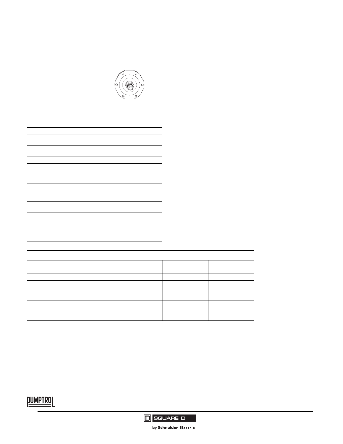
Type FRG, 1- or 2-Pole, 2 N.O. Contacts
Degree of Protection IP20, NEMA Type 1
Flange Style
Adjustable range of setting point
Contacts open on falling pressure
Differential Adjustable
Fluid Connections 1/4" NPSF internal 3/8" NPSF internal 1/4" flare 1/4" NPSF internal 3/8" NPSF internal 1/4" flare
Catalog Numbers
1-pole
NEMA Type 1, IP20
9013FRG72 9013FRG73 9013FRG78 9013FRG92 9013FRG93 9013FRG98
2-pole
NEMA Type 1, IP20
9013FRG62 9013FRG63 9013FRG68 9013FRG82 9013FRG83 9013FRG88
Fluids Controlled Water Water Water Water Water Water
Pressure Range
Cut-out psig (bar) 20–75 (1.4–5.2) 20–75 (1.4–5.2) 20–75 (1.4–5.2) 35–120 (2.4–8.3) 35–120 (2.4–8.3) 35–120 (2.4–8.3)
Cut-in psig (bar) 40–100 (2.8–6.9) 40–100 (2.8–6.9) 40–100 (2.8–6.9) 65–150 (4.5–10.3) 65–150 (4.5–10.3) 65–150 (4.5–10.3)
Weight, lb (kg) 0.75 (0.340) 0.75 (0.340) 0.75 (0.340) 0.75 (0.340) 0.75 (0.340) 0.75 (0.340)
Supplemental Specifications (not shown under General Specifications)
Differential
psig (bar)
20–30 (1.4–2.1) 20–30 (1.4–2.1) 20–30 (1.4–2.1) 30–45 (2.1–3.1) 30–45 (2.1–3.1) 30–45 (2.1–3.1)
Maximum Allowable
Pressure psig (bar)
100 (6.9) 100 (6.9) 100 (6.9) 150 (10.3) 150 (10.3) 150 (10.3)
Cable Entry 2 cable entries 0.88 in. (22.4 mm) with 0.84 in. (21.3 mm) across flats
Pressure Switch Style Diaphragm
Ordering information Pressure codes
1. Select the catalog number from the table above.
2. Select the pressure code and add the code designation to the end of the catalog
number. Ensure that the pressure code falls within the limits of the device as
shown in the device listings.
3. If special features are desired, add the appropriate Form letter to the catalog
number after the pressure code. Arrange the Form letters in alphabetical
sequence when ordering more than one special feature.
4. Add the packaging code at the end of the sequence, after the Forms. (For
example, to order a standard pack of 20 devices, specify 9013FRG72J23C20.) If
no packaging code is indicated, the devices will be shipped individually
packaged.
NOTE: Existence of a code does not imply that the code is available for
any or all devices.
Settings (psi) Code
8.5–5.5 J17
10–5 J36
22–12 J22
22–16 J19
35–20 J70
40–20 J23
50–30 J35
80–60 J32
100–80 J51
150–120 J64
Specify pressure settings J99
© 2011 Schneider Electric
All Rights Reserved
Commercial Pressure and Float Switches for Power Circuits
Electromechanical Pressure Switches, Class 9013 Types F and G
34
03/2011
TM
Flange Style
Adjustable range of setting point
Contacts open on falling pressure
Differential Adjustable
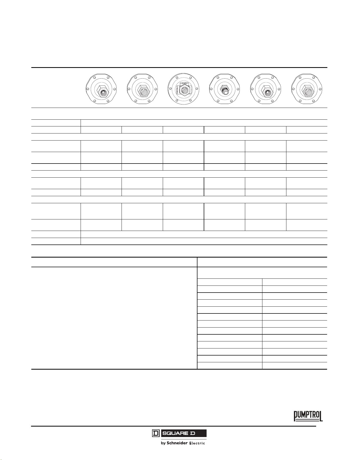
Fluid Connections 1/4" NPT external
Catalog Numbers
1-pole
NEMA Type 1, IP20
9013FRG99
2-pole
NEMA Type 1, IP20
9013FRG89
Fluids Controlled Water
Pressure Range
Cut-out psig (bar) 35–120 (2.4–8.3)
Cut-in psig (bar) 60–150 (4.14–10.3)
Weight, lb (kg) 0.75 (0.340)
Complementary Characteristics
(not shown under general characteristics)
Differential
psig (bar)
30–45 (2.1–3.1)
Maximum Allowable Pressure
psig (bar)
150 (10.3)
Cable Entry
2 cable entries 0.88 in. (22.4 mm)
with 0.84 in. (21.3 mm) across flats
Pressure Switch Style Diaphragm
Modifications (Forms)
Description Applies to: Form letter
Standard pack of 20 devices per box All Type F C20
[1]
1
Additional bulk packages are available. See Table 7 on page 37.
1 N.O. / 1 N.C. contact FRG (2-pole only) H
Momentary manual cut-in lever (Auto-Start) FRG2–59 only M3
Maintained manual cut-in lever (Auto-On) FRG2–59 only M5
Pulsation plug FSG2, 9 P
[2]
2
Nylon pulsation plug can be field installed on types having 1/4" NPSF internal connector.
Catalog number 1530S6G1 is one bag of 50 plugs.
Salt water flange (¼ NPSF internal only) All Type F Q
½" conduit bushing—½" long thread—on left All Type F T
Black cover FSG, FYG, FRG Z22
Commercial Pressure and Float Switches for Power Circuits
Electromechanical Pressure Switches, Class 9013 Types F and G
35
03/2011
© 2011 Schneider Electric
All Rights Reserved
TM
Type FHG, 2-Pole, 2 N.C. Contacts
Degree of Protection IP20, NEMA Type 1
Flange Style
Adjustable range of setting point
Contacts open on rising pressure
Differential Fixed
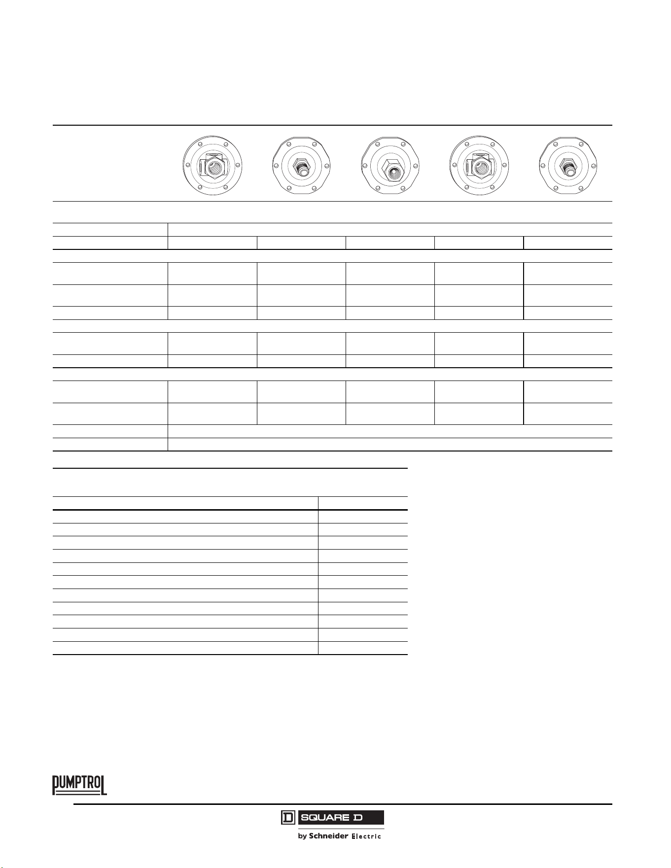
Pressure Connections 1/4" NPSF internal 3/8" NPSF internal 1/4" 4-way Flange 1/4" NPT external 1/4" NPSF internal 3/8" NPSF internal
Catalog Numbers
Lower hp, 2-pole
NEMA Type 1, IP20
9013FHG2 9013FHG3 9013FHG4 9013FHG9 9013FHG12 9013FHG13
Higher hp, 2-pole
NEMA Type 1, IP20
9013FHG22 — 9013FHG24 9013FHG29 9013FHG32 9013FHG33
Controls AirAirAirAirAirAir
Pressure Range
Adjustable cut-out
psig (bar)
40–100 (2.8–6.9) 40–100 (2.8–6.9) 40–100 (2.8–6.9) 40–100 (2.8–6.9) 70–150 (4.8–10.3) 70–150 (4.8–10.3)
Weight, lb (kg) 0.75 (0.340) 0.75 (0.340) 0.75 (0.340) 0.75 (0.340) 0.75 (0.340) 0.75 (0.340)
Supplemental Specifications (not shown under General Specifications)
Differential,
Fixed
psig (bar)
20 (1.4) 20 (1.4) 20 (1.4) 20 (1.4) 30 (2.1) 30 (2.1)
Maximum Allowable
Pressure psig (bar)
100 (6.9) 100 (6.9) 100 (6.9) 100 (6.9) 150 (10.3) 150 (10.3)
Cable Entry 2 cable entries 0.88 in. (22.4 mm) with 0.84 in. (21.3 mm) across flats
Pressure Switch Style Diaphragm
Ordering information Pressure codes
1. Select the catalog number from the table above.
2. Select the pressure code and add the code designation to the end of the catalog
number. Ensure that the pressure code falls within the limits of the device as
shown in the device listings.
3. If special features are desired, add the appropriate Form letter to the catalog
number after the pressure code. Arrange the Form letters in alphabetical
sequence when ordering more than one special feature.
4. Add the packaging code at the end of the sequence, after the Forms. (For
example, to order a standard pack of 20 devices, specify
9013FHG19J52MIXC20.) If no packaging code is indicated, the devices will be
shipped individually packaged.
NOTE: Existence of a code does not imply that the code is available for
any or all devices.
Settings (psi) Code
Off at 80 J43
Off at 100 J27
Off at 110 J37
Off at 115 J38
Off at 120 J69
Off at 125 J52
Off at 135 J39
Off at 140 J68
Off at 150 J55
Off at 155 J40
Off at 175 J59
Specify pressure settings J99
© 2011 Schneider Electric
All Rights Reserved
Commercial Pressure and Float Switches for Power Circuits
Electromechanical Pressure Switches, Class 9013 Types F and G
36
03/2011
TM
Flange Style
Adjustable range of setting point
Contacts open on rising pressure
Differential Fixed
Pressure Connections 4-way Flange 1/4" NPT external 1/4" 4-way Flange 1/4" 4-way Flange 1/4" 4-way Flange
Catalog Numbers
Lower hp, 2 pole
NEMA Type 1, IP20
9013FHG14 9013FHG19 9013FHG42 9013FHG44 9013FHG49
Higher hp, 2-pole
NEMA Type 1, IP20
9013FHG34 9013FHG19 9013FHG52 9013FHG54 9013FHG59
Controls Air Air Air Air Air
Pressure Range
Adjustable cut-out
psig (bar)
70–150 (4.8–10.3) 70–150 (4.8–10.3) 100–200 (6.9–13.8) 100–200 (6.9–13.8) 100–200 (6.9–13.8)
Weight, lb (kg) 0.75 (0.340) 0.75 (0.340) 0.75 (0.340) 0.75 (0.340) 0.75 (0.340)
Supplemental Specifications (not shown under General Specifications)
Differential, Fixed
psig (bar)
30 (2.1) 30 (2.1) 40 (2.8) 40 (2.8) 40 (2.8)
Maximum Allowable Pressure
psig (bar)
150 (10.3) 150 (10.3) 200 (13.8) 200 (13.8) 200 (13.8)
Cable Entry 2 cable entries 0.88 in. (22.4 mm) with 0.84 in. (21.3 mm) across flats
Pressure Switch Style Diaphragm
Modifications (Forms)
NOTE: Modifications G4 and Z22 can be field installed, all others are factory installed only.
Description Form letter
Standard pack of 20 devices per box C20
[1]
1
Additional bulk packages are available. See Table 7 on page 37.
Addition of a second ground screw G4
Maintained manual cut-out lever (Auto-Off) M1
Pulsation plug (copper) P
½" conduit bushing—½" long thread—on left T
Slip-on connectors (load side terminals only) U
Slip-on connectors (line and load side terminals) U2
Factory sealed range stud W
Two-way pressure release valve X
Quick connect two-way pressure release valve (for use with Polyflow Tubing) X1
Black cover Z22
Commercial Pressure and Float Switches for Power Circuits
Electromechanical Pressure Switches, Class 9013 Types F and G
37
03/2011
© 2011 Schneider Electric
All Rights Reserved
TM
Table 7: Bulk Package Form Numbers for 9013F Pressure Switches
Description Bulk Package Quantity 16 20 40 50 400 500
Product without
Forms M1, M3, M4,
M5, T, X1
9013FHG (without 1/4" four-way) — C20 — C50 — —
9013FHG4, 14, 24, 34, 44, 54 (with 1/4" 4-way flange) — C20 — C50 C400 —
9013FRG — C20 — C50 — —
9013FSG — C20 — C50 — —
9013FYG — C20 — C50 — —
Product with
Forms M1, M3, M4,
M5
9013FHG (without 1/4" four-way) — C20 C40 — — —
9013FHG4, 14, 24, 34, 44, 54 (with 1/4" 4-way flange) — C20 C40 — — —
9013FRG — C20 C40 — — —
9013FSG — C20 C40 — — —
9013FYG — C20 C40 — — —
Product with
Forms T, X1
9013FHG (without 1/4" four-way) C16 — C40 — — —
9013FHG4, 14, 24, 34, 44, 54 (with 1/4" 4-way flange) C16 — C40 — — —
9013FRG C16 — C40 — — —
9013FSG C16 — C40 — — —
9013FYG C16 — C40 — — —
9013FHG9 Special with Extended Flange C16————C500
© 2011 Schneider Electric
All Rights Reserved
Commercial Pressure and Float Switches for Power Circuits
Electromechanical Pressure Switches, Class 9013 Types F and G
38
03/2011
TM
Type G, 2-Pole, 2 N.C. Contacts
Degree of Protection IP20, NEMA Type 1, 3R, 7, and 9
Flange Style
Adjustable range of setting point
Contacts open on rising pressure
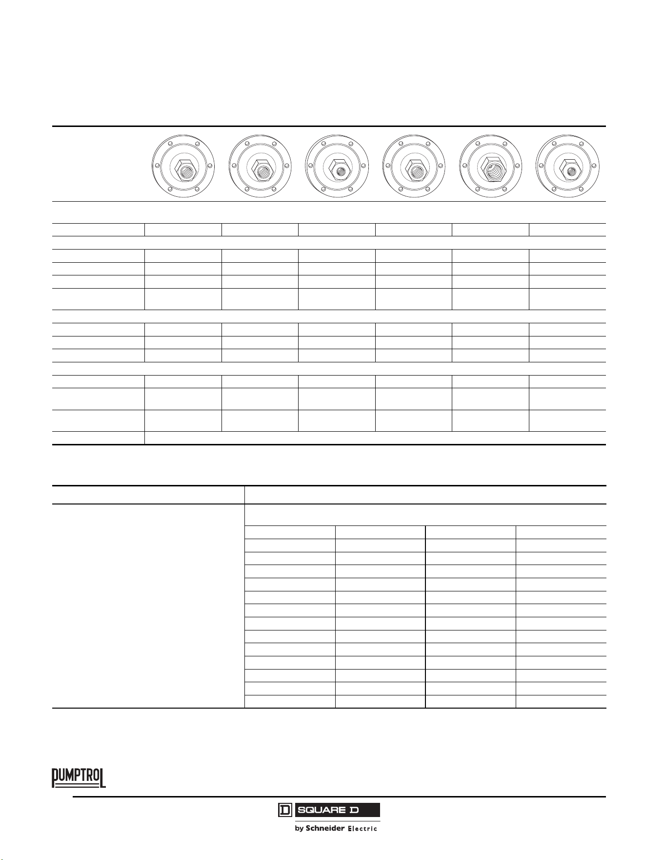
Fluid Connections 1/4" NPSF internal 1/4" NPSF internal 1/8" NPSF internal 1/4" NPSF internal 3/8" NPSF internal 1/8" NPSF internal
Catalog Numbers
NEMA Type 1, IP20 9013GMG2 — 9013GSG1 9013GSG2 9013GSG3 —
NEMA Type 3R
[1]
1
Must be mounted in vertical position to maintain enclosure rating.
— 9013GSB2 — — — —
NEMA Type 7, 9 —————9013GSR1
Fluids / Pressure
Controls
Water or air Water or air Water or air Water or air Water or air Water or air
Pressure Range
Cut-out psig (bar) 10–35 (0.7–2.4) 20–80 (1.4–5.5) 20–80 (1.4–5.5) 20–80 (1.4–5.5) 20–80 (1.4–5.5) 20–80 (1.4–5.5)
Cut-in psig (bar) 5.5–30.5 (0.4–2.1) 5–60 (0.4–4.2) 5–60 (0.4–4.2) 5–60 (0.4–4.2) 5–60 (0.4–4.2) 5–60 (0.4–4.2)
Weight, lb (kg) 2 (0.91) 2 (0.91) 2 (0.91) 2 (0.91) 2 (0.91) 8 (3.62)
Supplemental Specifications (not shown under General Specifications)
Differential psig (bar) 4–8 (0.3–0.6) 15–30 (1.0–2.1) 15–30 (1.0–2.1) 15–30 (1.0–2.1) 15–30 (1.0–2.1) 20–40 (1.4–2.8)
Maximum Allowable
Pressure psig (bar)
35 (2.4) 80 (5.5) 80 (5.5) 80 (5.5) 80 (5.5) 80 (5.5)
Cable Entry
3 knockouts for
1/2 in. conduit
3 knockouts for
1/2 in. conduit
3 knockouts for
1/2 in. conduit
3 knockouts for
1/2 in. conduit
3 knockouts for
1/2 in. conduit
2 conduit entries
3/4"-14 NTP
Pressure Switch Style Diaphragm
Ordering information Pressure codes
1. Select the catalog number from the table above.
2. Select the pressure code and add the code
designation to the end of the catalog number.
Ensure that the pressure code falls within the
limits of the device as shown in the device listings.
3. If special features are desired, add the
appropriate Form letter to the catalog number
after the pressure code. Arrange the Form letters
in alphabetical sequence when ordering more
than one special feature.
4. Add the packaging code at the end of the
sequence, after the Forms. (For example, to order
a standard pack of 10 devices, specify
9013GHG2J99RZC10.) If no packaging code is
indicated, the devices will be shipped individually
packaged.
To order a standard pack of 10 devices per box
C10 (available on GHB, GHG, GSB, and GSG)
see page 39 for Form C10.
NOTE: Existence of a code does not imply that the code is available for any
or all devices.
Settings (psi) Code Settings (psi) Code
20–40 J20 110–150 J56
30–50 J21 120–150 J57
40–20 J23 125–150 J58
40–60 J24 125–175 J60
60–80 J25 130–175 J61
70–90 J26 140–170 J66
70–100 J28 140–175 J62
75–100 J29 145–175 J63
80–100 J30 150–120 J64
90–120 J31 150–175 J67
100–80 J51 215–250 J65
100–125 J53 Specify pressure settings J99
110–125 J54 — —
Commercial Pressure and Float Switches for Power Circuits
Electromechanical Pressure Switches, Class 9013 Types F and G
39
03/2011
© 2011 Schneider Electric
All Rights Reserved
TM
Flange Style
Adjustable range of setting point
Contacts open on rising pressure
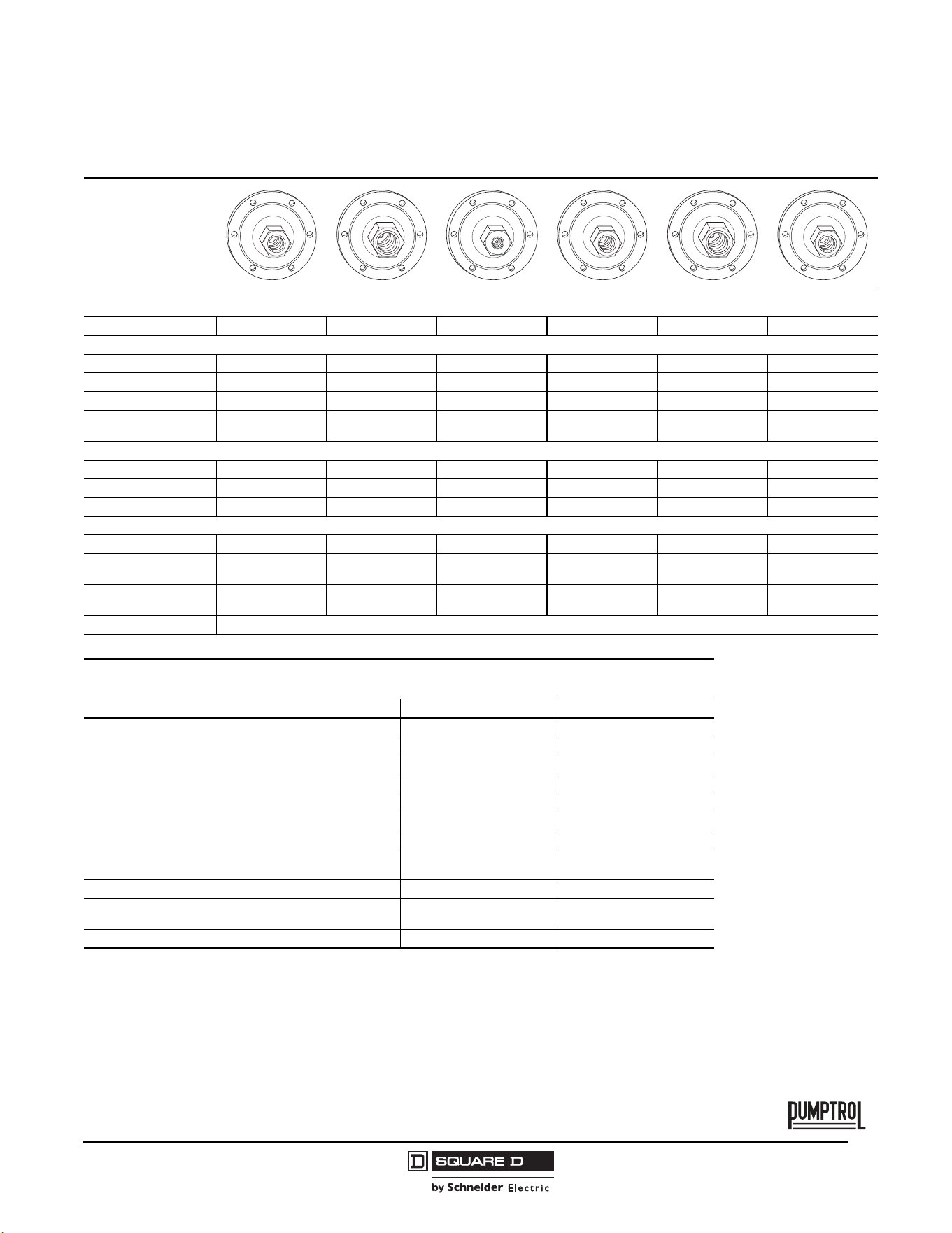
Fluid Connections 1/4" NPSF internal 3/8" NPSF internal 1/8" NPSF internal 1/4" NPSF internal 3/8" NPSF internal 1/4" NPSF internal
Catalog Numbers
NEMA Type 3R —————9013GHB2
NEMA Type 4 — — 9013GSW1 9013GSW2 9013GSW3 —
NEMA Type 7, 9 9013GSR2 9013GSR3 — — — —
Fluids / Pressure
Controls
Water or air Water or air Water or air Water or air Water or air Water or air
Pressure Range
Cut-out psig (bar) 20–80 (1.4–5.5) 20–80 (1.4–5.5) 20–80 (1.4–5.5) 20–80 (1.4–5.5) 20–80 (1.4–5.5) 60–200 (4.1–13.8)
Cut-in psig (bar) 5–50 (0.4–3.5) 5–50 (0.4–3.5) 5–50 (0.4–3.5) 5–50 (0.4–3.5) 5–50 (0.4–3.5) 40–170 (2.8–12)
Weight, lb (kg) 8 (3.62) 8 (3.62) 8 (3.62) 8 (3.62) 8 (3.62) 2 (0.91)
Supplemental Specifications (not shown under General Specifications)
Differential psig (bar) 20–40 (1.4–2.8) 20–40 (1.4–2.8) 20–40 (1.4–2.8) 20–40 (1.4–2.8) 20–40 (1.4–2.8) 20–40 (1.4–2.8)
Maximum Allowable
Pressure psig (bar)
80 (5.5) 80 (5.5) 80 (5.5) 80 (5.5) 80 (5.5) 200 (13.8)
Cable Entry
2 conduit entries
3/4"-14 NTP
2 conduit entries
3/4"-14 NTP
2 conduit entries
3/4"-14 NTP
2 conduit entries
3/4"-14 NTP
2 conduit entries
3/4"-14 NTP
3 knockouts for
1/2 in. conduit
Pressure Switch Style Diaphragm
Modifications (Forms)
NOTE: Factory installed only.
Description Applies to: Form letter
Standard pack of 10 devices per box GHB, GHG, GSB, GSG C10
3-way lever (On-Auto-Off) not compatible with Form X GHG, GMG, GSG E
1 N.O. / 1 N.C. contact All Type G H
[1]
1
Cannot order Form R in combination with Form H.
Pulsation plug (copper) All Type G P
Reverse action / 2 N.O. contacts All Type G R
[1]
Slip-on connectors (load side terminals only) All Type G U
Slip-on connectors (line and load side terminals) All Type G U2
2-way pressure release valve (not compatible with Form E)
GHB, GMG, GSB, GHG, GSG,
GHR, GHW, GSR, GSW
X
¼" male pipe thread on pressure connection All Type G Z
½" - 14 NPT external
¼" - 18 NPT internal
All Type G Z16
3/8“ male pipe thread on pressure connection All Type G Z23
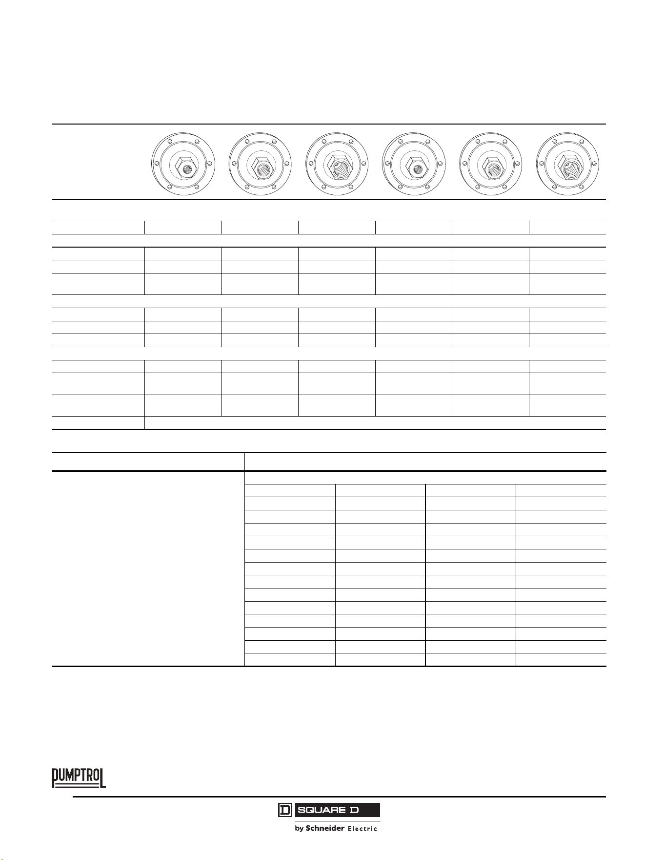
© 2011 Schneider Electric
All Rights Reserved
Commercial Pressure and Float Switches for Power Circuits
Electromechanical Pressure Switches, Class 9013 Types F and G
40
03/2011
TM
Flange Style
Adjustable range of setting point
Contacts open on rising pressure
Fluid Connections 1/8" NPSF internal 1/4" NPSF internal 3/8" NPSF internal 1/8" NPSF internal 1/4" NPSF internal 3/8" NPSF internal
Catalog Numbers
NEMA Type 1, IP20 9013GHG1 9013GHG2 9013GHG3 — — —
NEMA Type 7, 9 — — — 9013GHR1 9013GHR2 9013GHR3
Fluids / Pressure
Controls
Water or air Water or air Water or air Water or air Water or air Water or air
Pressure Range
Cut-out psig (bar) 60–200 (4.1–13.8) 60–200 (4.1–13.8) 60–200 (4.1–13.8) 65–200 (4.5–13.8) 65–200 (4.5–13.8) 65–200 (4.5–13.8)
Cut-in psig (bar) 40–170 (2.8–12) 40–170 (2.8–12) 40–170 (2.8–12) 35–150 (2.4–10.3) 35–150 (2.4–10.3) 35–150 (2.4–10.3)
Weight, lb (kg) 2 (0.91) 2 (0.91) 2 (0.91) 8 (3.62) 8 (3.62) 8 (3.62)
Supplemental Specifications (not shown under General Specifications)
Differential psig (bar) 20–40 (1.4–2.8) 20–40 (1.4–2.8) 20–40 (1.4–2.8) 30–50 (2.1–3.5) 30–50 (2.1–3.5) 30–50 (2.1–3.5)
Maximum Allowable
Pressure psig (bar)
80 (5.5) 80 (5.5) 80 (5.5) 80 (5.5) 80 (5.5) 200 (13.8)
Cable Entry
3 knockouts for
1/2 in. conduit
3 knockouts for
1/2 in. conduit
3 knockouts for
1/2 in. conduit
2 conduit entries
3/4"-14 NTP
2 conduit entries
3/4"-14 NTP
2 conduit entries
3/4"-14 NTP
Pressure Switch Style Diaphragm
Ordering information Pressure codes
1. Select the catalog number from the table above.
2. Select the pressure code and add the code
designation to the end of the catalog number.
Ensure that the pressure code falls within the
limits of the device as shown in the device listings.
3. If special features are desired, add the
appropriate Form letter to the catalog number
after the pressure code. Arrange the Form letters
in alphabetical sequence when ordering more
than one special feature.
4. Add the packaging code at the end of the
sequence, after the Forms. (For example, to order
a standard pack of 10 devices, specify
9013GHG2J99RZC10.) If no packaging code is
indicated, the devices will be shipped individually
packaged.
To order a standard pack of 10 devices per box
C10 (available on GHB, GHG, GSB, and GSG)
see page 39 for Form C10.
NOTE: Existence of a code does not imply that the code is available for any or all devices.
Settings (psi) Code Settings (psi) Code
20–40 J20 110–150 J56
30–50 J21 120–150 J57
40–20 J23 125–150 J58
40–60 J24 125–175 J60
60–80 J25 130–175 J61
70–90 J26 140–170 J66
70–100 J28 140–175 J62
75–100 J29 145–175 J63
80–100 J30 150–120 J64
90–120 J31 150–175 J67
100–80 J51 215–250 J65
100–125 J53 Specify pressure settings J99
110–125 J54 — —
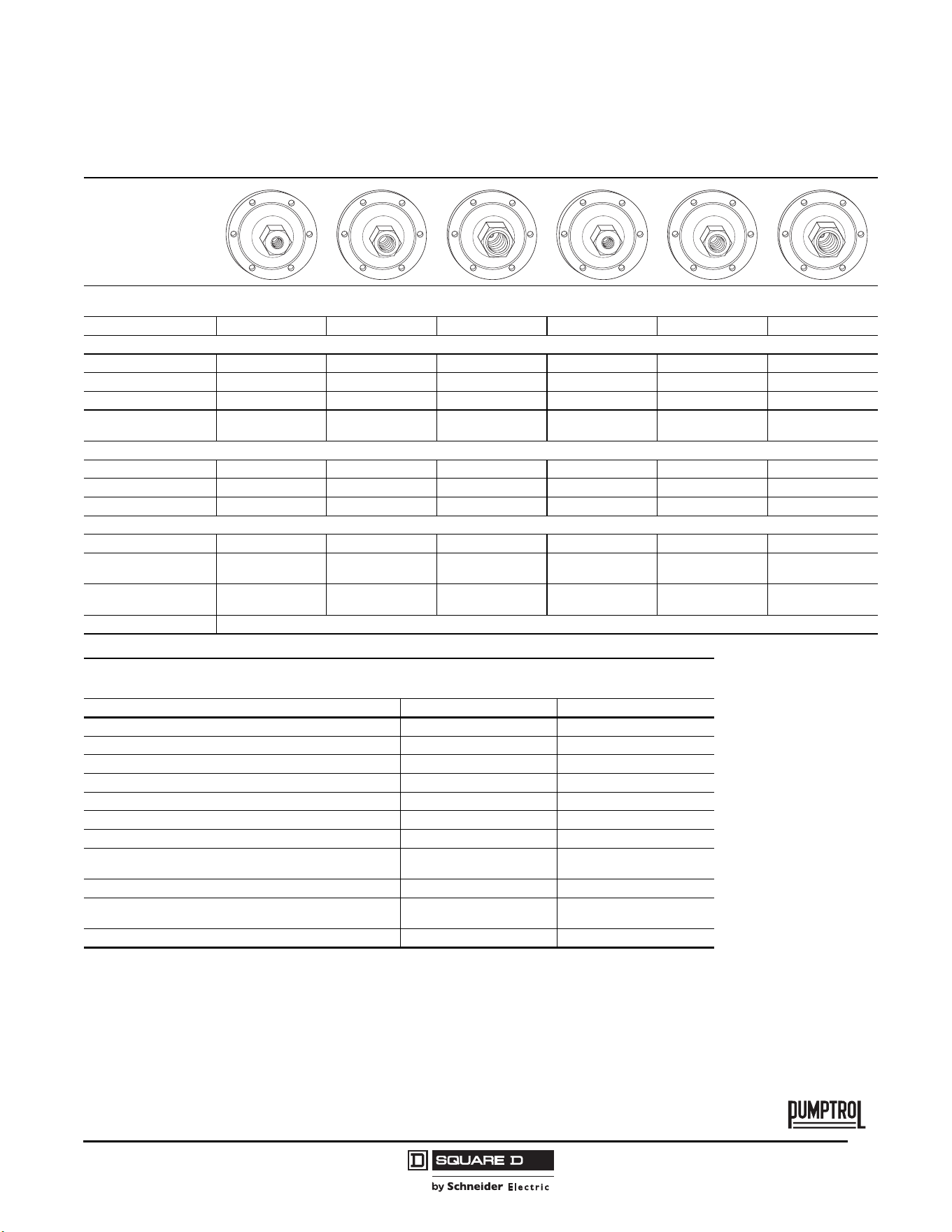
Commercial Pressure and Float Switches for Power Circuits
Electromechanical Pressure Switches, Class 9013 Types F and G
41
03/2011
© 2011 Schneider Electric
All Rights Reserved
TM
Flange Style
Adjustable range of setting point
Contacts open on rising pressure
Fluid Connections 1/8" NPSF internal 1/4" NPSF internal 3/8" NPSF internal 1/4" NPSF internal 1/8" NPSF internal 1/4" NPSF internal
Catalog Numbers
NEMA Type 1, IP20 — — — — 9013GHG4 9013GHG5
NEMA Type 3R — — — 9013GHB5 — —
NEMA Type 4 9013GHW1 9013GHW2 9013GWG3 — — —
Fluids / Pressure
Controls
Water or air Water or air Water or air Water or air Water or air Water or air
Pressure Range
Cut-out psig (bar) 65–200 (4.5–13.8) 65–200 (4.5–13.8) 65–200 (4.5–13.8) 80–250 (5.5–17.2) 80–250 (5.5–17.2) 80–250 (5.5–17.2)
Cut-in psig (bar) 35–150 (2.4–10.3) 35–150 (2.4–10.3) 35–150 (2.4–10.3) 32–215 (2.2–14.8) 32–215 (2.2–14.8) 32–215 (2.2–14.8)
Weight, lb (kg) 8 (3.62) 8 (3.62) 8 (3.62) 2 (0.91) 2 (0.91) 2 (0.91)
Supplemental Specifications (not shown under General Specifications)
Differential psig (bar) 30–50 (2.1–3.5) 30–50 (2.1–3.5) 30–50 (2.1–3.5) 25–45 (1.7–3.1) 25–45 (1.7–3.1) 25–45 (1.7–3.1)
Maximum Allowable
Pressure psig (bar)
200 (13.8) 200 (13.8) 200 (13.8) 250 (17.2) 250 (17.2) 250 (17.2)
Cable Entry
2 conduit entries
3/4"-14 NTP
2 conduit entries
3/4"-14 NTP
2 conduit entries
3/4"-14 NTP
3 knockouts for
1/2 in. conduit
3 knockouts for
1/2 in. conduit
3 knockouts for
1/2 in. conduit
Pressure Switch Style Diaphragm
Modifications (Forms)
NOTE: Factory installed only.
Description Applies to: Form letter
Standard pack of 10 devices per box GHB, GHG, GSB, GSG C10
3-way lever (On-Auto-Off) not compatible with Form X GHG, GMG, GSG E
1 N.O. / 1 N.C. contact All Type G H
[1]
1
Cannot order Form R in combination with Form H.
Pulsation plug (copper) All Type G P
Reverse action / 2 N.O. contacts All Type G R
[1]
Slip-on connectors (load side terminals only) All Type G U
Slip-on connectors (line and load side terminals) All Type G U2
2-way pressure release valve (not compatible with Form E)
GHB, GMG, GSB, GHG, GSG,
GHR, GHW, GSR, GSW
X
¼" male pipe thread on pressure connection All Type G Z
½" - 14 NPT external
¼" - 18 NPT internal
All Type G Z16
3/8“ male pipe thread on pressure connection All Type G Z23
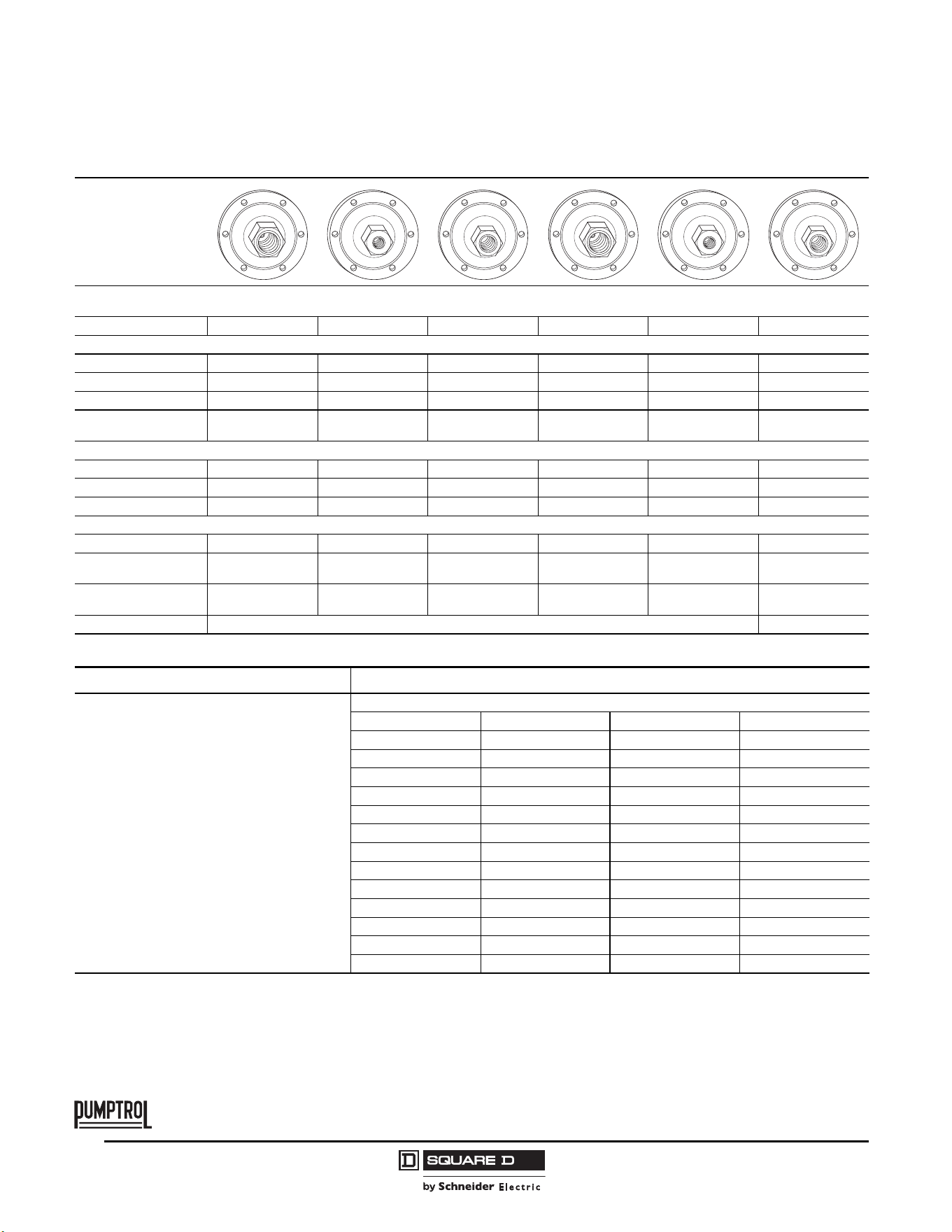
© 2011 Schneider Electric
All Rights Reserved
Commercial Pressure and Float Switches for Power Circuits
Electromechanical Pressure Switches, Class 9013 Types F and G
42
03/2011
TM
Flange Style
Adjustable range of setting point
Contacts open on rising pressure
Fluid Connections 3/8" NPSF internal 1/8" NPSF internal 1/4" NPSF internal 3/8" NPSF internal 1/8" NPSF internal 1/4" NPSF internal
Catalog Numbers
NEMA Type 1, IP20 9013GHG6 —————
NEMA Type 4 ————9013GHW4 9013GHW5
NEMA Type 7, 9 — 9013GHR4 9013GHR5 9013GHR6 — —
Fluids / Pressure
Controls
Water or air Water or air Water or air Water or air Water or air Water or air
Pressure Range
Cut-out psig (bar) 80–250 (5.5–17.2) 80–250 (5.5–17.2) 80–250 (5.5–17.2) 80–250 (5.5–17.2) 80–250 (5.5–17.2) 80–250 (5.5–17.2)
Cut-in psig (bar) 32–215 (2.2–14.8) 30–190 (2.0–13.1) 30–190 (2.0–13.1) 30–190 (2.0–13.1) 30–190 (2.0–13.1) 30–190 (2.0–13.1)
Weight, lb (kg) 2 (0.91) 8 (3.62) 8 (3.62) 8 (3.62) 8 (3.62) 8 (3.62)
Supplemental Specifications (not shown under General Specifications)
Differential psig (bar) 25–45 (1.7–3.1) 40–60 (2.8–4.1) 40–60 (2.8–4.1) 40–60 (2.8–4.1) 40–60 (2.8–4.1) 40–60 (2.8–4.1)
Maximum Allowable
Pressure psig (bar)
250 (17.2) 250 (17.2) 250 (17.2) 250 (17.2) 250 (17.2) 250 (17.2)
Cable Entry
3 knockouts for
1/2 in. conduit
2 conduit entries
3/4"-14 NTP
2 conduit entries
3/4"-14 NTP
2 conduit entries
3/4"-14 NTP
2 conduit entries
3/4"-14 NTP
2 conduit entries
3/4"-14 NTP
Pressure Switch Style Diaphragm
Ordering information Pressure codes
1. Select the catalog number from the table above.
2. Select the pressure code and add the code
designation to the end of the catalog number.
Ensure that the pressure code falls within the
limits of the device as shown in the device listings.
3. If special features are desired, add the
appropriate Form letter to the catalog number
after the pressure code. Arrange the Form letters
in alphabetical sequence when ordering more
than one special feature.
4. Add the packaging code at the end of the
sequence, after the Forms. (For example, to order
a standard pack of 10 devices, specify
9013GHG2J99RZC10.) If no packaging code is
indicated, the devices will be shipped individually
packaged.
To order a standard pack of 10 devices per box
C10 (available on GHB, GHG, GSB, and GSG)
see page 39 for Form C10.
NOTE: Existence of a code does not imply that the code is available for any or all devices.
Settings (psi) Code Settings (psi) Code
20–40 J20 110–150 J56
30–50 J21 120–150 J57
40–20 J23 125–150 J58
40–60 J24 125–175 J60
60–80 J25 130–175 J61
70–90 J26 140–170 J66
70–100 J28 140–175 J62
75–100 J29 145–175 J63
80–100 J30 150–120 J64
90–120 J31 150–175 J67
100–80 J51 215–250 J65
100–125 J53 Specify pressure settings J99
110–125 J54 — —
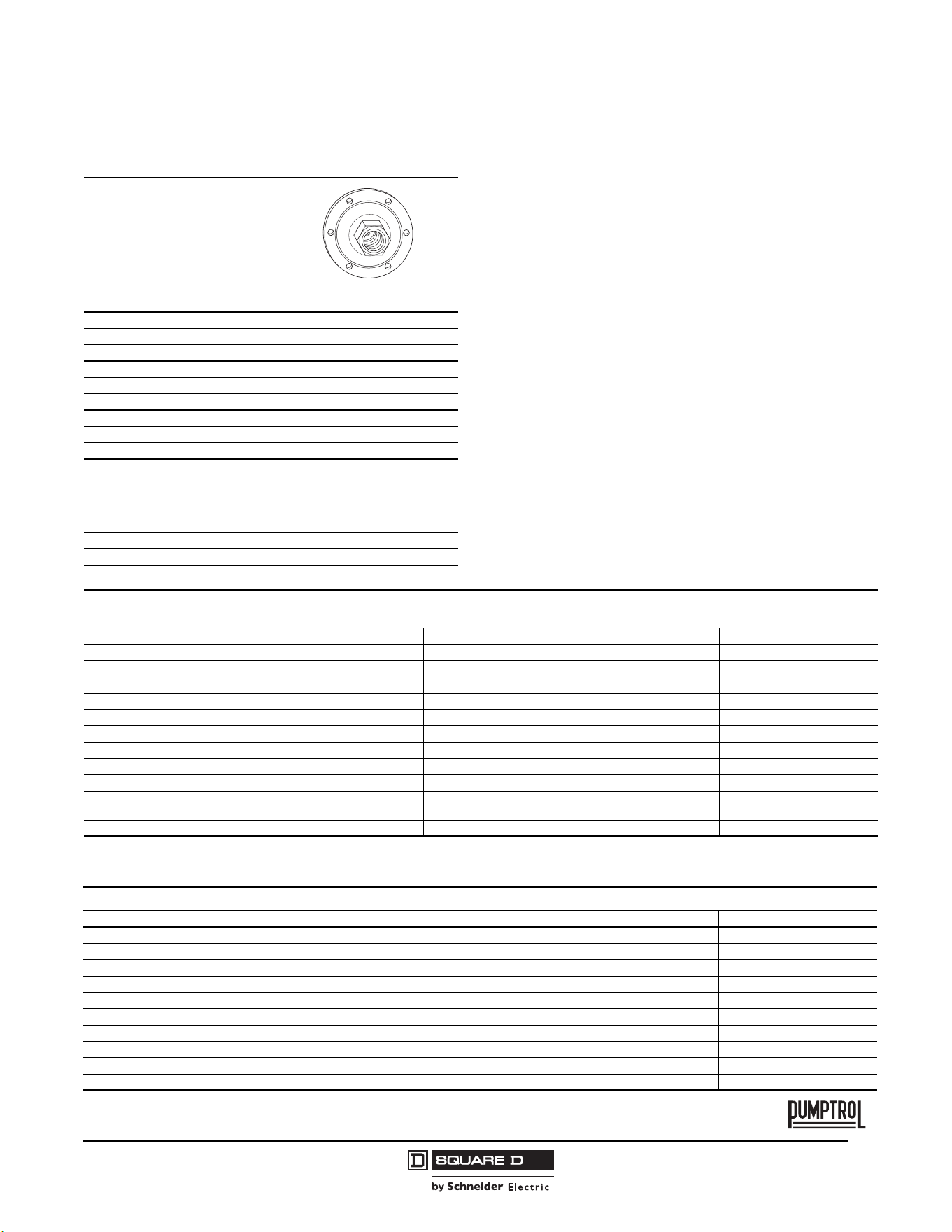
Commercial Pressure and Float Switches for Power Circuits
Electromechanical Pressure Switches, Class 9013 Types F and G
43
03/2011
© 2011 Schneider Electric
All Rights Reserved
TM
Flange Style
Adjustable range of setting point
Contacts open on rising pressure
Fluid Connections 3/8" NPSF internal
Catalog Numbers
NEMA Type 4 9013GHW6
NEMA Type 7, 9 —
Fluids / Pressure Controls Water or air
Pressure Range
Cut-out psig (bar) 80–250 (5.5–17.2)
Cut-in psig (bar) 30–190 (2.0–13.1)
Weight, lb (kg) 8 (3.62)
Supplemental Characteristics
(not shown under General Characteristics)
Differential psig (bar) 40–60 (2.8–4.1)
Maximum Allowable Pressure
psig (bar)
250 (17.2)
Cable Entry 2 conduit entries 3/4"-14 NTP
Pressure Switch Style Diaphragm
Modifications (Forms)
NOTE: Factory installed only.
Description Applies to: Form letter
Standard pack of 10 devices per box All Type G C10
3-way lever (On-Auto-Off) not compatible with Form X GHG, GMG, GSG E
1 N.O. / 1 N.C. contact All Type G H
[1]
1
Cannot order Form R in combination with Form H.
Pulsation plug (copper) All Type G P
Reverse action All Type G R
[1]
Slip-on connectors (load side terminals only) All Type G U
Slip-on connectors (line and load side terminals) All Type G U2
2-way pressure release valve (not compatible with Form E) GHB, GMG, GSB, GHG, GSG, GHR, GHW, GSR, GSW X
¼" male pipe thread on pressure connection All Type G Z
½" - 14 NPT external
¼" - 18 NPT internal
All Type G Z16
3/8“ male pipe thread on pressure connection All Type G Z23
Replacement contacts and diaphragms
Description 9998 Type
Repl. Contact Kit 9013GHG, GSG, GHR, GSR, GMG Series C, all except Forms H & R PC205
Repl. Contact Kit 9013GHG, GSG, GSR, GMG; 9036GG, GR, GW; 9037GG, GR, GW Series C, Form H only; 9016GVG, Form H PC206
Repl. Contact Kit 9013GHG, GSG, GHR, GSR, GMG; 9036GR, GW Series C, Form R only; 9016GVG PC207
Convoluted Diaphragm Assy. 9013GHG, GSG Series C PC208
Diaphragm Assy. 9013GMG Series C PC209
Diaphragm Assy. 9013GHW, GSW, GSR, GHR Series C PC211
Repl. Contact Kit 9013FSG PC241
[1]
1
Diaphragm is included.
Repl. Contact Kit 9013FYG PC242
[1]
Repl. Contact Kit 9013FRG (1 pole) PC289
[1]
Repl. Contact Kit 9013FRG (Form H) PC290
[1]
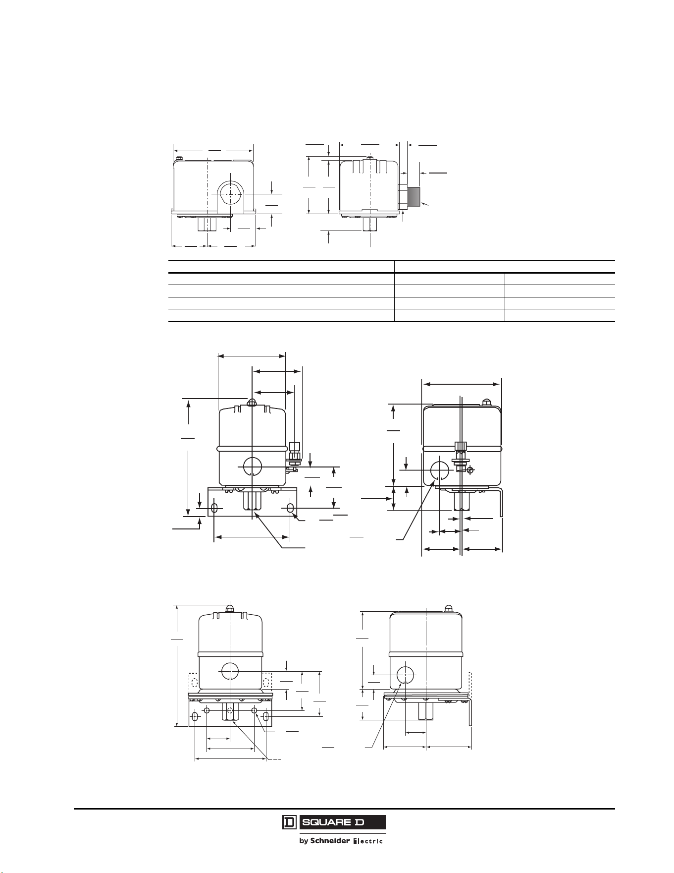
© 2011 Schneider Electric
All Rights Reserved
Commercial Pressure and Float Switches for Power Circuits
Electromechanical Pressure Switches, Class 9013 Types F and G
44
03/2011
Dimensions
Type F Compressor and Water Pump Pressure Switches
Type G Compressor and Water Pump Pressure Switches
Switch Type: GHG, GSG (with Form X installed)
Switch Type: GMG
Switch Type A Dimension, in. (mm)
FSG1, FYG1 1-1/32 26
FHG2, 12, 22, 32, 42, 52, FRG2, FSG2, FYG2 29/32 23
FHG3, 13, 33, FRG3, FSG3, FYG3 1-9/32 33
FHG9, 19, 29, 39, 49, 59, FSG9, FYG9 1-3/32 28
2.78
71
0.30
8
0.30
8
0.50
13
2.50
64
2.80
71
2.34
59
1.59
40
1.19
30
0.75
19
3.76
96
A
15/16 Hex
1/2-14 Straight Pipe Thread
(Form T)
3.68
99
3.85
98
0.73
18
1.22
31
0.06
2
1.99
51
1.09
28
1.94
49
C65075-043
0.94
24
2.05
52
0.29
7
(2) Wide Mtg Holes
0.87
22
(3)
Dia K.O.
1
4
18 NPSF
Pipe Thread
3.75
99
0.42
11
5.72
145
2.09
53
63
2.47
3.44
87
NOTE: Mounting bracket
shown is available as a
Class 9049 Type A-52 Kit.
6.17
157
1.25
32
2.50
64
0.29
7
1
4
(3)
(3)
3.75
95
18 NPSF
Pipe Thread
Dia. Holes
Dia. K.O.
2.39
61
2.03
52
0.94
24
0.875
22
2.37
60
2.22
56
1.09
28
1.67
42
0.73
18
3.85
98
NOTE: Mounting bracket
shown is available as a
Class 9049 Type A-52 Kit.
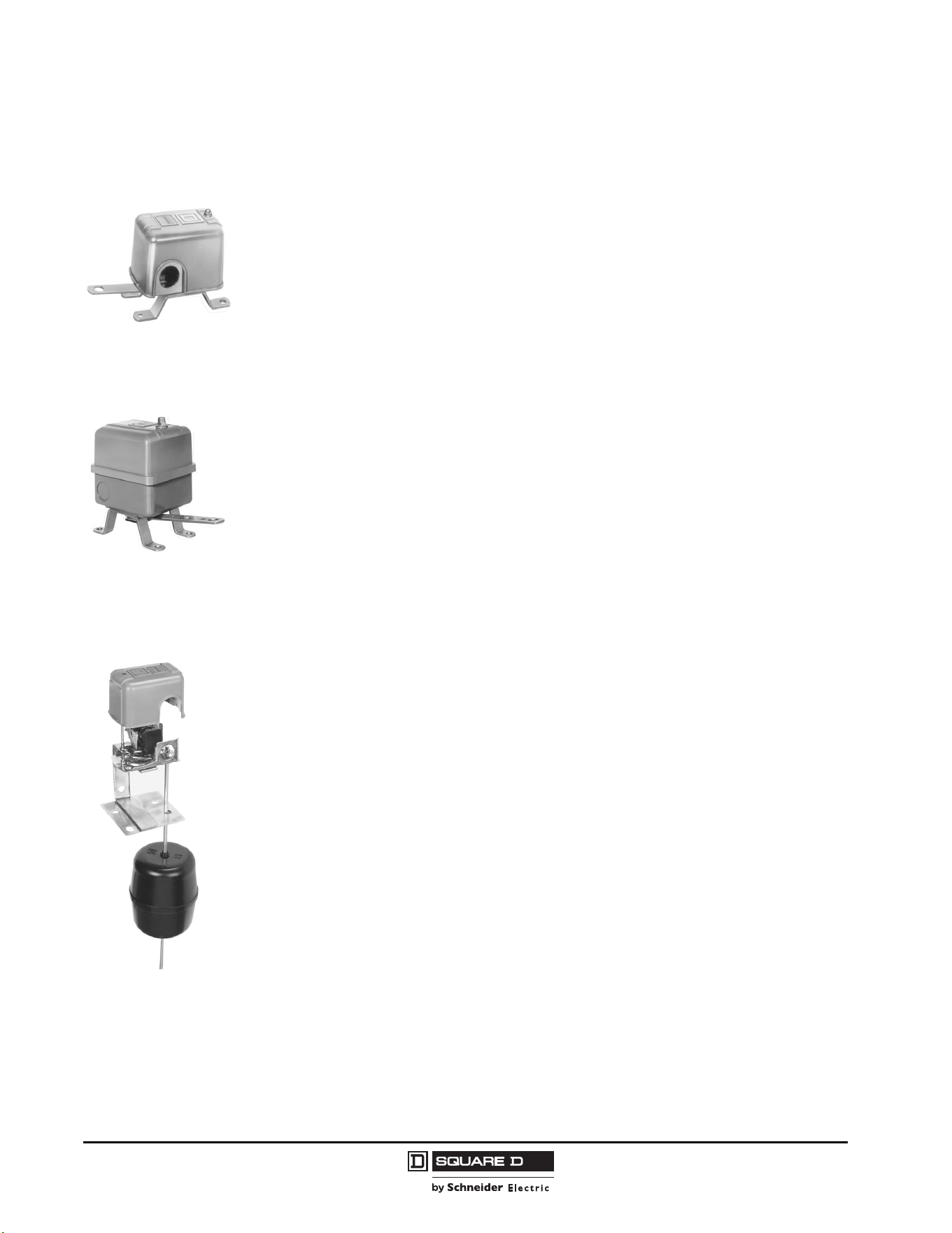
Commercial Pressure and Float Switches for Power Circuits
Float Switches—Class 9036, 9037, and 9038
45
03/2011
© 2011 Schneider Electric
All Rights Reserved
Float Switches—Class 9036, 9037, and 9038
Introduction
Square D™ brand offers a wide range of electromechanical level control products.
• Class 9036, Open Tank
• Class 9037, Closed Tank
• Class 9038, Mechanical Alternators
Class 9036 Open Tank
Type D and G
The Class 9036 Type D and G float switches are lever operated and designed for open tank
applications. These switches are floor mounted, or they can be pedestal mounted using mounting plate
9049UMS1. They are available in NEMA Type 1, Type 4, or Type 7 and 9 enclosures.
Type FG
The Class 9036 Type FG30 pedestal-style sump pump switch is designed for liquid level control with
electric-motor operated pumps, either directly or through a magnetic starter. It can also be used to
activate alarms in liquid level control systems. The upward or downward movement of the lever arm of
the float switch controls the On and Off positions corresponding to the water level changes required to
turn the pump or alarm on and off.
NOTE: The rod for this device is 33.75 in. long. It cannot be lengthened.
9036DG2
9036GG
9036FG
9049A60
9049A61
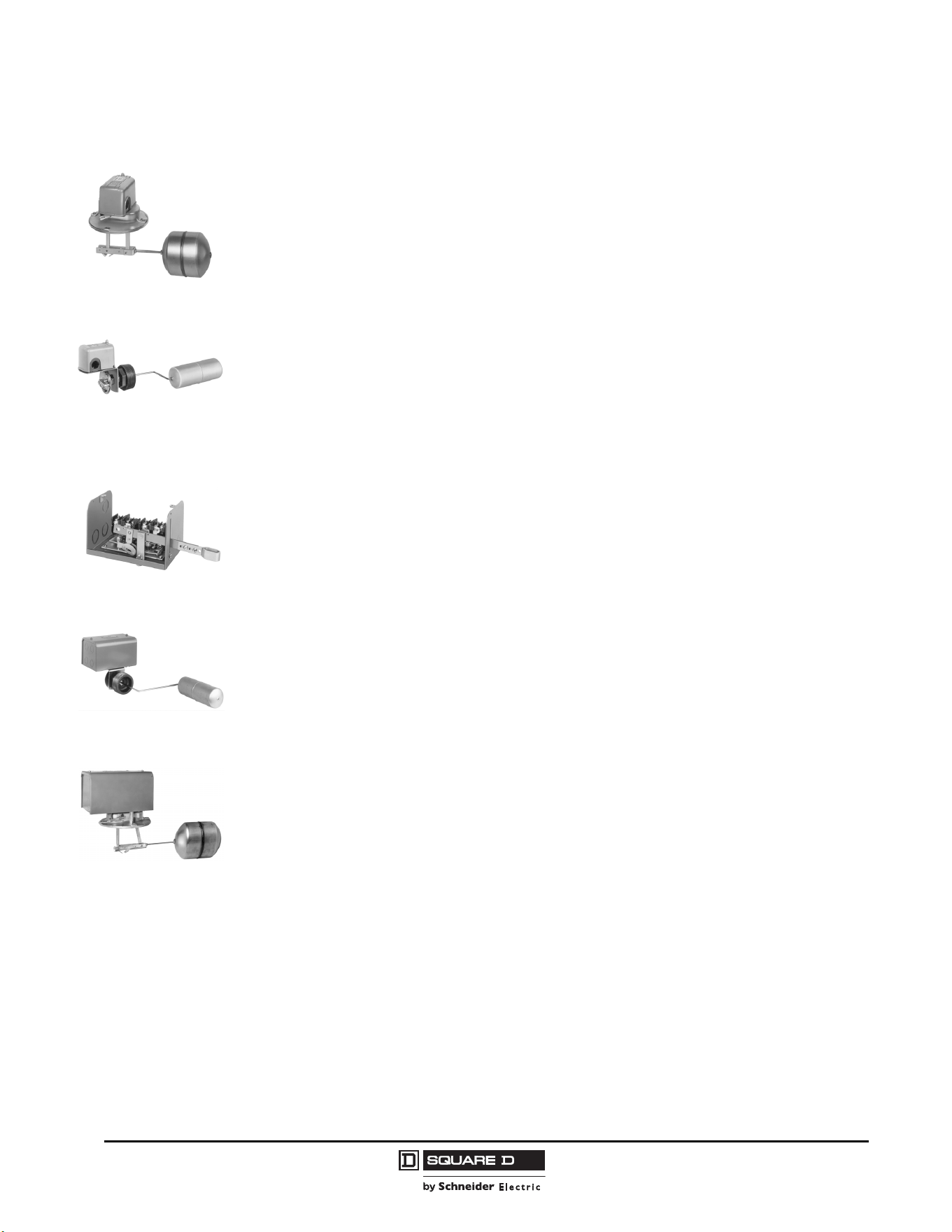
© 2011 Schneider Electric
All Rights Reserved
Commercial Pressure and Float Switches for Power Circuits
Float Switches—Class 9036, 9037, and 9038
46
03/2011
Class 9037 Closed Tank
Type E
The Class 9037 Type E switches are flange mounted. Float movement is transmitted through a quad
ring seal. Each switch consists of a basic switch, float rod, and float. The switch can be configured in
the field for contacts that open on liquid rise or close on liquid rise. These switches are used for top
mounted or side mounted, closed tank applications.
Type H
The Class 9037 Type H switches are attached to the tank by means of a 2-1/2 in. bushing. An external
pointer indicates the float position within the tank when the unit is mounted. Switches come complete
with stainless steel float and rod. A nitrile rubber seal, such as a Buna-N quad ring seal, is used
between the float rod and the sealing connector. Normal application is at atmospheric pressure. Where
higher pressures are encountered, the available Viton
®
seal allows the switch to withstand tank
pressures up to 50 psi at ambient temperatures up to 220 °F. Occasional replacement of the quad ring
seal may be necessary.
Class 9038 Mechanical Alternators
Type A (Open Tank)
The Class 9038 Type A Open Tank level switch is a mechanical alternator designed to provide motor
alternation in the operation of two motors.
Type C (Closed Tank, Bushing Mounted)
The Class 9038 Type C Closed Tank level switches are bushing mounted. Float movement is
transmitted through a quad ring seal. Each switch consists of a basic switch, rod, and float.
Type C switches are attached to the tank by means of a 2-1/2 in. bushing. An external pointer indicates
the float position within the tank when the unit is mounted. Switches come complete with bushing,
stainless steel float, and rod.
Occasional replacement of the quad ring may be necessary.
Type D (Closed Tank, Flange Mounted, Top)
Type D mechanical alternators are designed for applications where flange mounting is to be made at
the top of a closed tank.
9037E
9037H
9038AG1
9038CG
9038DG
9049ER5
9049EF1
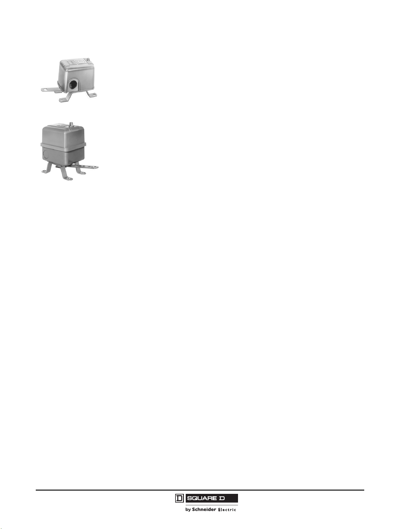
Commercial Pressure and Float Switches for Power Circuits
Float Switches—Class 9036, 9037, and 9038
47
03/2011
© 2011 Schneider Electric
All Rights Reserved
Selecting a Float Switch
Standard float switches have two contacts that close when the liquid rises above the designated level.
This contact configuration is used for tank emptying applications. Float switches are also available with
reverse (Form R) and double throw (Form H) contacts. Form R switches, used for tank filling
applications, have two contacts that open when the liquid rises above the designated level. Form H
switches, which can be used for both applications, have one normally open (N.O.) and one normally
closed (N.C.) contact.
To select the proper Square D™ float switch, determine the following:
• Type and shape of tank (open, closed, sump, etc.)
• Enclosure requirements
— NEMA Type 1: For general purpose applications intended for indoor use.
— NEMA Type 4: For watertight and dusttight applications for either indoor or outdoor use.
— NEMA Type 7 and 9: For explosion proof applications. Suitable for Class I, Division 1 and 2,
Groups C and D and Class II, Division 1 and 2, Groups E, F, and G hazardous locations.
• Total level change required
• Mounting requirements (such as flange mounting or screw-in bushing)
• Horsepower, phase, and voltage requirements
• Float material
— Stainless steel (SS)
— Plastic (available on 9036FG30 and as a Form for use with diesel fuel)
• Rod material
—Brass
— Stainless steel (SS)
— Aluminum (Al)
In direct motor control applications, float switch ratings must be greater than or equal to the pump
motor ratings.
NOTE: Contact the Sensor Competency Center when using float switches in liquids with a specific
gravity different than water (1.0).
Specify the Class and Type when ordering float switches or accessory kits.
Selecting Floats and Rods
Class 9036 and Class 9038 Type A float switches are actuated with the Class 9049 Type A line of
accessories. Select the float and rod material according to the corrosiveness of the liquid used in the
application. Two types of float kits are offered:
• Tapped-at-top float (Class 9049 Type A6, A6S, and A6A)
• Center-hole float (Class 9049 Type A6C, A6CS, and A6CA)
The tapped-at-top float is for applications requiring short lengths of tubing and small liquid level
changes. The maximum tubing length is 12 ft (3.66 m). Adequate space must be available to allow for
ceiling clearance when the level changes. The float must be buoyant enough to lift the tubing, stop
collars, and switch lever. The rod has two stops, one above and one below the switch lever. The
position of the stops determines the amount of water level change.
9036DG2
9036GG2
© 2011 Schneider Electric
All Rights Reserved
Commercial Pressure and Float Switches for Power Circuits
Float Switches—Class 9036, 9037, and 9038
48
03/2011
The center-hole float is used in applications requiring long lengths of tubing and large liquid level
changes. A compensating spring, used for longer lengths of tubing, supports the weight of the tubing
and stops. When a compensating spring is used, the float must be buoyant enough to lift up the switch
lever and heavy enough to trip the switch lever down. The rod has four stops. The position of the stops
on the rod above and below the float determines the amount of water level change.
Temperature Ratings
Electrical Ratings
The following float switches are UL Listed under file E12158, CCN NKPZ:
• Class 9036 Types DG, DW, GG, GW
• Class 9037 Types EG, EW, HG, HW
• Class 9038 Types AG, AW, CG, CW, DG, DW
The following float switches are UL Listed under file E12443, CCN NOWT:
• Class 9036 Types DR, GR
• Class 9037 Types ER, HR
Table 8: Temperature Limitations for all Float Switches
Ambient
Min. –30 °C (–22 °F)
Max. 105 °C (220 °F)
Table 9: Class 9036, 9037, and 9038 Electrical Ratings
Class Type
Single Phase AC Ratings
(hp)
Polyphase AC Ratings
(hp)
DC
(hp)
Control
Circuit
Rating
115 V 230 V 460/575 V 115 V 230 V 460/575 V 32 V 115 V 230 V
9036
D (2 pole) 2 3 — 3 5 1 0.25 0.5 0.5 A600
G (2 pole) 2 3 5 3 5 5 0.5 1 1 A600
G Form H
(1 N.O., 1 N.C.)
1 2 2 — — — — 0.5 0.5 A300
9037 E, H (2 pole) 2 3 — 3 5 1 0.25 0.5 0.5 A600
9038 All (2 pole) 2 3 — 3 5 1 0.25 0.5 0.5 A600
Table 10: Control Duty Circuit Ratings (Form N5 or N25 only)
Contacts
AC—50 or 60 Hz DC AC or DC
V
Inductive,
35% Power Factor
Resistive,
75% Power Factor
V
Inductive and Resistive
Continuous
Carrying
Amperes
Make Break
Make and Break
Amperes
Make and Break Amperes
A VA A VA Single Throw Double Throw
SPDT
Form N5
120 60 7200 6 720 6 120 0.55 0.22 10
240 30 7200 3 720 3 250 0.27 0.11 10
480 15 7200 1.5 720 1.5 600 0.10 — 10
600 12 7200 1.2 720 1.2 — — — —
DPDT
Form N25
120 60 7200 6 720 6 125 0.22 0.22 10
240 30 7200 3 720 3 250 0.11 0.11 10
480 15 7200 1.5 720 1.5 600 — — 10
600 12 7200 1.2 720 1.2 — — — —
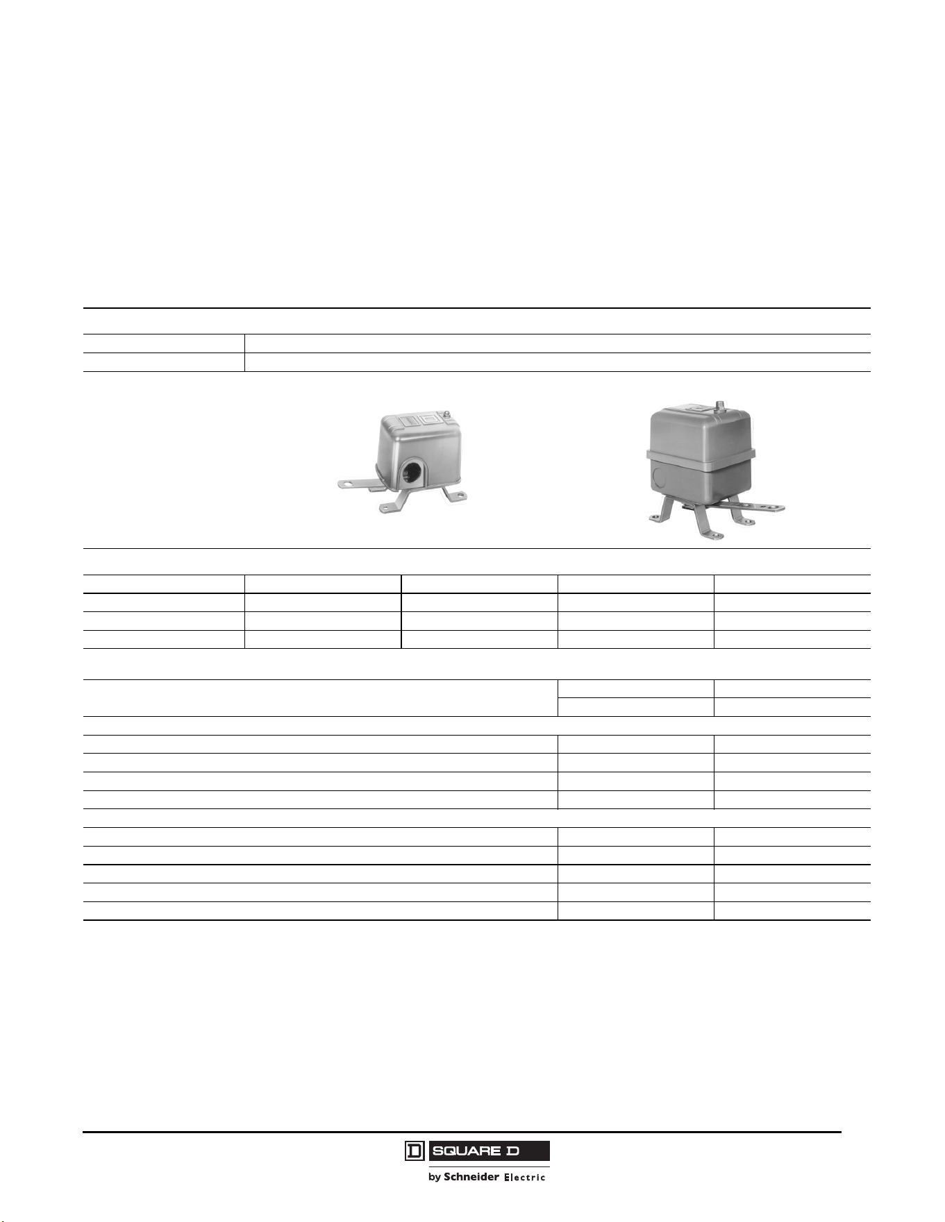
Commercial Pressure and Float Switches for Power Circuits
Float Switches—Class 9036, 9037, and 9038
49
03/2011
© 2011 Schneider Electric
All Rights Reserved
Class 9036 Type D and G Open Tank Float Switches
Table 11 lists Class 9036 float switches and modifications.
• When ordering a factory installed modification, add the Form number to the end of the float
switch catalog number. For example, to select a 9036DG2 switch with reverse action, order
9036DG2R.
• Field installed modifications, when available, are ordered as kits.
Table 11: Class 9036 Float Switches
Specifications
Description 2-pole, single-lever operated float switches
Applications Open industrial tanks and sump applications
General Purpose
Heavy Duty
Catalog Numbers
Contact Action Close on Liquid Rise Open on Liquid Rise Close on Liquid Rise Open on Liquid Rise
NEMA Type 1
[1]
9036DG2 9036DG2R 9036GG2 9036GG2R
NEMA Type 4 9036DW31 9036DW31R 9036GW1
[2]
9036GW1R
[2]
NEMA Type 7, 9 9036DR31 9036DR31R 9036GR1
[2]
9036GR1R
[2]
NOTE: A compensating spring supports the weight of long rods that cannot be supported by center-hole floats. A compensating spring is standard on Types GR
and GW, and can be ordered as a modification (Form C) on other Class 9036 Type D and G float switches.
Modifications
Factory Installed Field Installed
Class 9036 Form Kit Catalog Number
For Type D (General Purpose)
Reverse action (Type DG) R 9049A58
Compensating spring (Type DG) C 9049A19
Compensating spring (Types DR and DW) C 9049A20
Compensating spring and reverse action (Types DG, DR, and DW) CR —
For Type G (Heavy Duty)
Reverse action
[3]
R—
Compensating spring (Type GG)
[4]
C 9049A13
Compensating spring and reverse action (Type GG) CR 9049A13
1 N.O.–1 N.C. contact configuration H —
Compensating spring and 1 N.O.–1 N.C. contact configuration (Type GG) CH —
1
Contact action can be converted in the field by installing the appropriate float rod lever.
2
Compensating spring standard. Use center-hole float accessories.
3
Type GG is field convertible without the use of a kit. Types GR and GW are not field convertible.
4
Compensating spring standard on Types GR and GW.
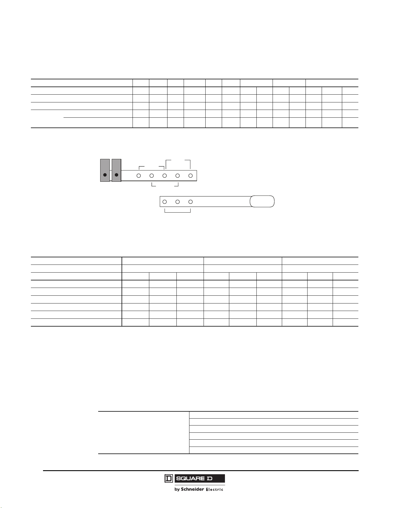
© 2011 Schneider Electric
All Rights Reserved
Commercial Pressure and Float Switches for Power Circuits
Float Switches—Class 9036, 9037, and 9038
50
03/2011
Table 12 lists the trip forces and compensating spring requirements for Class 9036 Type D and G float
switches. The trip force can be adjusted on the Type G switches by changing the lever length position.
Figure 3: Lever Length
Table 13 lists Class 9049 accessory kits, which are ordered separately from Class 9036 Type D and G
float switches. A float kit is required; a tubing kit and replacement float do not provide all needed parts.
When ordering, first specify the desired accessory kit, then as a second item give the number of
additional tubing kits required. For example, to get a 9049A6C kit with 15 ft of tubing, specify:
A. 9049A6C, quantity = 1 (includes 5 ft of tubing)
B. 9049T1, quantity = 4 (2.5 ft of tubing each, for a total of 10 additional ft)
Example
Table 12: Maximum Trip Forces for Class 9036 Float Switches
Class 9036 Type and Form DG2 DG2R DW31 DW31R DR31 DR31R GG2 GG2R GR1, GW1
Lever Length Position — — — — — — Short Long Short Long Short Medium Long
Force Up to Trip (oz) 9 8 8 8 8 8 3321302224 22 20
Force Down to Trip (oz) 8 8 8 8 8 8 3927241631 29 27
Maximum
Supported
Weight (oz)
Without Compensating Spring 6 4 5 5 5 5 2513181119 17 16
With Compensating Spring 60 60 66 66 66 66
[1]
100
[1]
150 80 72 64
1
The compensating spring is not effective in combination with short lever length position.
Long
Short
AB
AB
AB
AB
Medium
NOTE: Holes should be aligned as shown
to adjust for the desired length.
Table 13: Class 9049 Accessories for Class 9036 Type D and G Float Switches (weight in oz)
Accessory Kits Tapped-at-Top Floats (#304 SS) Center-Hole Floats (#304 SS)
[1]
Additional Tubing (#303 SS)
[2]
Used on Class 9036 Float Switch Types All Except GW, GR, and Form C GW, GR, and Form C All
Catalog Number 9049A6 9049A6A 9049A6S 9049A6C 9049A6CA 9049A6CS 9049T1 9049T1A 9049T1S
Tubing (rod) 5 ft brass 5 ft Al 5 ft SS 5 ft brass 5 ft Al 5 ft SS 2.5 ft brass 2.5 ft Al 2.5 ft SS
Net buoyancy in water, 7 in. float
[3]
60 60 60 70 70 70 — — —
Combined weight of stops 3 3 3 6 6 6 — — —
Number of stops 222444———
Weight of 5 ft rod, included 18.5 6 16.9 18.5 6 16.9 — — —
Weight per ft of extra rod 3.7 1.2 3.4 3.7 1.2 3.4 3.7 1.2 3.4
1
Require the use of the 9049A6, 9049A6A, or 9049A6S kit. The additional tubing only attaches to other lengths of tubing.
2
Additional tubing kits add on to the float accessory kits and include a connector.
Maximum recommended tubing length: Tapped-at-top float: 12.5 ft (3810 mm); Center-hole float: 30 ft (9144 mm).
3
Net buoyancy calculated with float 80% submerged, allowing for a 20% operating margin. Buoyancy data calculated for use in water. Consult the Sensor
Competency Center for buoyancy data in media having specific gravity different than water (1.0).
Calculation example
Measuring 15 ft of tank depth
System has 15 ft of brass rod, 4 stops, and a
center hole float.
Buoyancy is positive, so no compensating
spring is required
Float buoyancy 70.0 oz
Total weight (61.5 oz)
Weight of stops: (6.0 oz)
Weight of 5 ft of brass rod (included): (18.5 oz)
Weight of 10 ft of brass rod (separate): (37.0 oz)
Buoyancy 8.5 oz
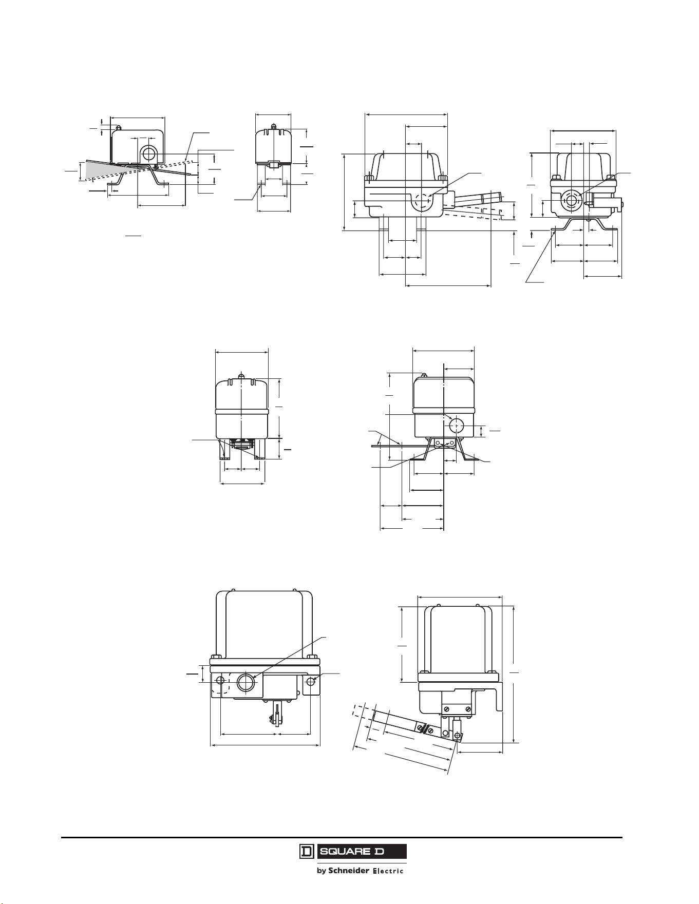
Commercial Pressure and Float Switches for Power Circuits
Float Switches—Class 9036, 9037, and 9038
51
03/2011
© 2011 Schneider Electric
All Rights Reserved
Figure 6: Type GG Dimensions
Figure 7: Types GR/GW Dimensions
Figure 4: Type DG Dimensions Figure 5: Types DR/DW Dimensions
Dual Dimensions:
in.
mm
0.30
8
3.93
100
0.78
20
1.31
33
0.31
8
0.41
10
0.94
24
2.53
64
2.53
64
0.63
16
3.50
89
4.38
111
2.20
56
1.44
37
1.76
45
1.13
29
2.38
60
2 Holes
Dia.
0.28
7
2 Holes
Dia.
Reverse
action
1.88
48
2.19
56
0.28
7
2.47
63
2.19
56
1.88
48
0.5
13
0.5
13
4.19
106
1.13
29
0.88
22
0.69
17
1.19
30
5.47
139
3.13
80
1.47
37
1.88
48
5.06
129
5.5
138
2.75
70
0.06
2
1.13
29
1.03
26
0.81
21
0.38
10
4.25
108
0.31
8
Dia. Holes
Conduit
1.09
26
1.87
48
1.87
48
2.18
55
2.62
67
1.50
38
Short
Long
(Standard action)
Pin Position
"B" Contacts
Closed in
Up Position
Pin Position
"A" Contacts
Open in
Up Position
Form R
(Reverse action)
0.73
19
3.87
98
3.43
87
1.12
29
1.12
29
2.87
73
5.56
141
1.93
49
3.61
97
1.37
35
0.875 Dia. Knockout
for 0.50 Conduit
in 3 Sides
0.41 Dia. Holes
Lever Arm Travel between Closing and Opening of Contacts
Standard: short = 0.375 in. (10 mm), long = 0.625 in. (16 mm)
Form R: short = 0.5 in. (13 mm), long = 0.75 in. (19 mm)
4 Holes
Dia.
0.28
7
3.69
94
2.19
56
2.94
75
8.19
208
5.38
137
3.69
94
Short
Medium
Long
7.55
192
8.24
209
8.92
227
0.62
16
4.69
119
0.44
11
1.03
26
3/4-14 in.
Connection
for 1/2 in. Conduit
2 Mtg. Holes
Dia.
Float Lever Travel between Closing and Opening of Contacts:
short = 1 in. (25 mm), medium = 1.12 (28 mm), long = 1.25 in. (31.8)
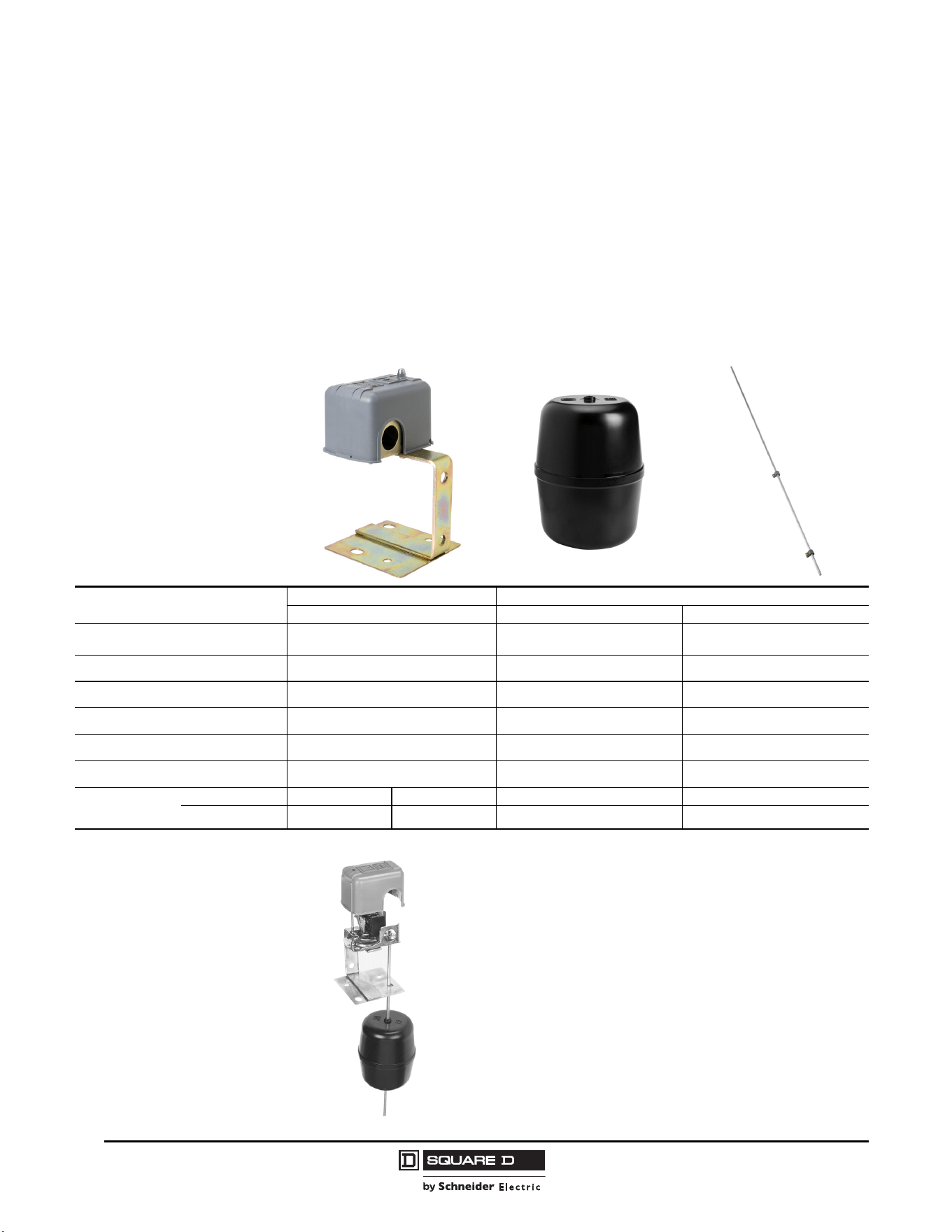
© 2011 Schneider Electric
All Rights Reserved
Commercial Pressure and Float Switches for Power Circuits
Float Switches—Class 9036, 9037, and 9038
52
03/2011
Class 9036 Type FG and Class 9049 Accessories
Class 9036 Type FG30 pedestal-style sump pump switches provide:
• Liquid level control with pumps operated by an electric motor, either directly or through a
magnetic starter
• Activation of alarms in liquid level control systems
• Forward or reverse action (field selectable)
The upward or downward movement of the lever arm controls the On and Off positions corresponding
to the water level changes required to turn the pump or alarm on and off.
\
Table 14: Class 9036 Type FG30 Pedestal-Style Sump Pump Switch and Accessory Kits
Catalog Number
Pedestal-style Sump Pump Switch Accessory Kits
9036FG30 9049A60 9049A61
Description
2-pole, pedestal-style sump pump switch Plastic center hole float
33.75 in. aluminum rod, 2 float stop
assemblies, and attaching hardware
Quantity Required
111
NEMA Type
NEMA Type 1 — —
Contact Action
Contacts close on liquid rise — —
Rod Length
— — 33.75 in. (cannot be lengthened)
Voltage
120/240 Vac — —
Horsepower
Rating
Single phase 2 hp @ 120 Vac 3 hp @ 240 Vac — —
Polyphase 3 hp @ 120 Vac 5 hp @ 240 Vac — —
Example:
9036FG
9049A60
9049A61
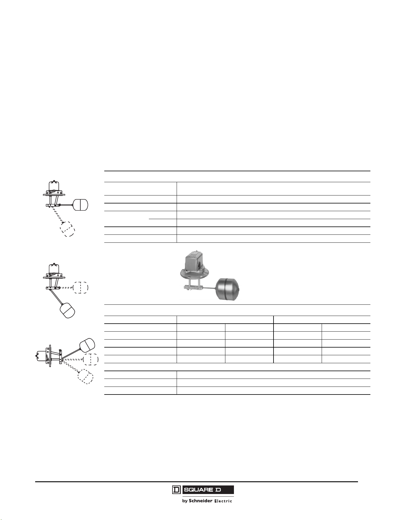
Commercial Pressure and Float Switches for Power Circuits
Float Switches—Class 9036, 9037, and 9038
53
03/2011
© 2011 Schneider Electric
All Rights Reserved
Class 9037 Type E Closed Tank Float Switches
Class 9037 closed tank float switches are used primarily on condensate pumps but may also be
installed on closed industrial and diesel fuel day tanks. There are two types of Class 9037 float
switches:
• Type E (flange mounted)
• Type H (with screw-in bushing)
Class 9037 Type E Flange-Mounted Float Switches
Table 15 contains ordering information for Class 9037 Type E float switches. Order the rod and float
accessory kits separately. Contact the Sensor Competency Center when using Class 9037 float
switches in liquids with a different specific gravity than water (1.0).
For rod kit catalog numbers, refer to pages 55 and 56.
To receive all components packaged in a single carton, specify:
• Float switch Class, Type, and Form
• “R” and the rod number
• “F” and the float number
For example, to receive one each of 9037EG8, 9049ER1, and 9049EF1, specify 9037EG8R1F1.
Table 15: Class 9037 Type E Float Switches
Specifications
Application
Closed industrial tanks
Flange mounted
Float movement Transmitted through a quad ring seal, which may need occasional replacement
Tank Pressure Up to 50 psi
Temperature
Ambient Up to 220 °F
Media Buna-N seal: up to 215 °F. Viton
®
seal: up to 250 °F.
Contact Operation Determined by the float and rod mounting position
Float Travel Determined by the post length
Catalog Numbers
Post Length (L), in. (mm) 2.63 (67) 4.69 (119)
Water Level Change Minimum Maximum Minimum Maximum
NEMA 1 9037EG8 9037EG9 9037EG10 9037EG13
NEMA 4 9037EW8 9037EW9 9037EW10 9037EW13
NEMA 7, 9 9037ER8 9037ER9 9037ER10 9037ER13
Float Position
[1]
1
For more information on float position, refer to pages 55–56.
1 1, 2, 3 1 1, 2, 3
Float Kits
Material Catalog Number
#304 Stainless Steel 9049EF1
#316 Stainless Steel 9049EF2
Float Position 1
Float Position 2
Float Position 3
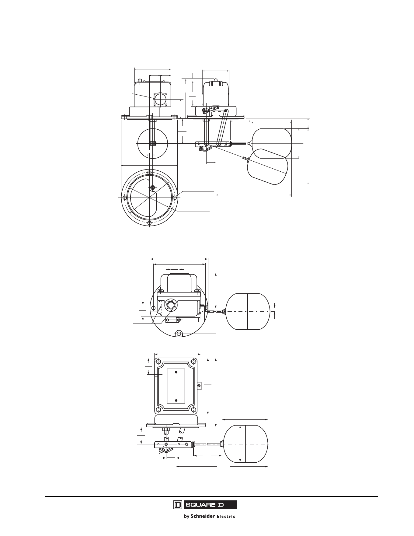
© 2011 Schneider Electric
All Rights Reserved
Commercial Pressure and Float Switches for Power Circuits
Float Switches—Class 9036, 9037, and 9038
54
03/2011
Figure 8: Type EG Dimensions
Figure 9: Type ER/EW Dimensions
R
H
F
4.5
114
2.63
67
4.19
106
3.63
92
DIA.
0.41
10
4.41
112
5.13
130
0.13
3
3.69
94
0.97
25
1.97
50
3.97
101
0.25
6
2.69
68
2.5
64
2.38
60
5.75
146
1.11
28
1.06
27
Wide Bead
4 Holes Dia.
Shown with Rod Kit and Float Kit installed,
with Pattern for hole in tank.
Recommended hole size =
diameter.
NEMA 1 Enclosure, Post
Net Weight 4 lb (1.8 kg)
Two 3/4-1/4 in.
openings for
1/2 in. conduit
on both sides
CL of Flange
CL of Flange
of Float
diameter
dia.
dia.
**
Short length
2.63
67
0.97
25
3.63
92
4.5
114
H
R
0.41
10
3.44
87
0.31
8
4 Holes
Dia.
0.5
C
L
of Flange
C
L
of Float
1.13
29
0.81
21
1.69
43
5.59
142
6.81
173
5.13
130
5.75
146
4.59
117
Dia.
Dia.
Dia.
13
Two 3/4-14 in.
openings for
1/2 in. conduit
Dual Dimensions:
in.
mm
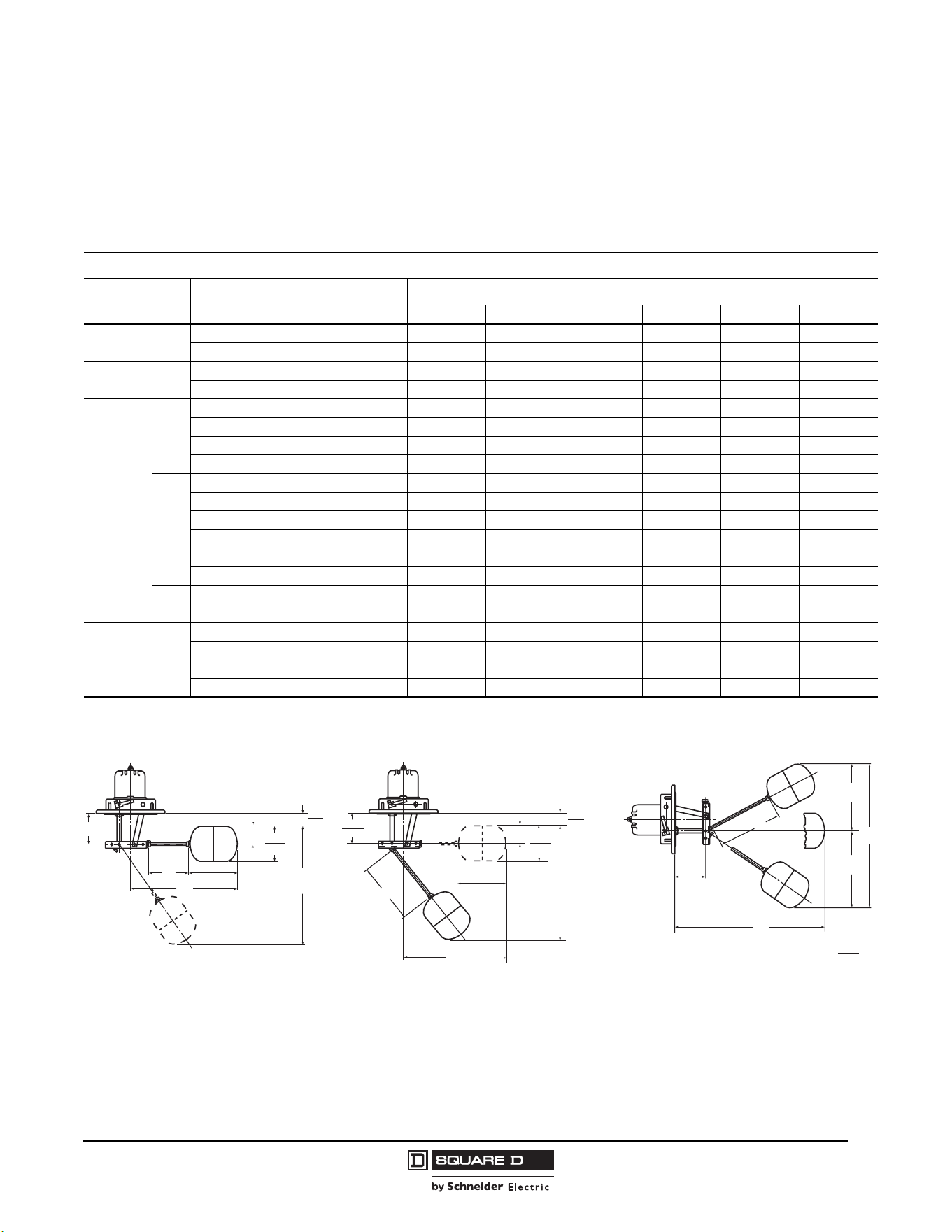
Commercial Pressure and Float Switches for Power Circuits
Float Switches—Class 9036, 9037, and 9038
55
03/2011
© 2011 Schneider Electric
All Rights Reserved
Class 9037 Type E Closed Tank Rod Kits
Position 1 Operation
In Position 1, the contacts close when the liquid rises. Select rod kits from Table 16.
Table 16: Class 9049 Rod Kits—Position 1 Operation (Contacts Close on Liquid Rise)
Catalog Numbers
Dimension
in. (mm)
For Use on Float Switch Types
Rod Kits
9049ER1 9049ER2 9049ER3 9049ER5 9049ER7 9049ER12
R
EG8, EW8, ER8, EG10, EW10, ER10 1.75 (44) 2.5 (64) 3.25 (83) 5.25 (133) 7.25 (184) 12.25 (311)
EG9, EW9, ER9, EG13, EW13, ER13 1.75 (44) 2.5 (64) 3.25 (83) 5.25 (133) 7.25 (184) 12.25 (311)
H
EG8, EW8, ER8, EG10, EW10, ER10 8.25 (210) 9 (229) 9.5 (241) 11.75 (298) 13.75 (349) 18.75 (476)
EG9, EW9, ER9, EG13, EW13, ER13 7.5 (191) 8.25 (210) 9 (229) 11 (279) 12 (305) 18 (457)
A
Min.
EG8, EW8, ER8 1 (25) 1 (25) 1 (25) 1 (25) 1 (25) 1 (25)
EG9, EW9, ER9 1 (25) 1 (25) 1 (25) 1 (25) 1 (25) 1 (25)
EG10, EW10, ER10 3.06 (78) 3.06 (78) 3.06 (78) 3.06 (78) 3.06 (78) 3.06 (78)
EG13, EW13, ER13 3.06 (78) 3.06 (78) 3.06 (78) 3.06 (78) 3.06 (78) 3.06 (78)
Max.
EG8, EW8, ER8 2 (51) 2 (51) 2 (51) 2.5 (64) 3 (76) 4.25 (108)
EG9, EW9, ER9 4 (102) 4.5 (114) 5 (127) 6 (152) 7.5 (191) 9.5 (241)
EG10, EW10, ER10 4.06 (103) 4.06 (103) 4.06 (103) 4.56 (116) 5.06 (129) 6.31 (160)
EG13, EW13, ER13 6.06 (154) 6.56 (167) 7.06 (179) 8.06 (205) 9.56 (243) 11.56 (294)
F
Min.
EG8, EW8, ER8, EG10, EW10, ER10 4.75 (121) 4.75 (121) 4.75 (121) 4.75 (121) 5 (127) 5.75 (146)
EG9, EW9, ER9, EG13, EW13, ER13 6 (152) 6.25 (159) 6.25 (159) 6.5 (165) 6.5 (165) 9 (229)
Max.
EG8, EW8, ER8, EG10, EW10, ER10 6 (152) 6.25 (159) 6.5 (165) 6.75 (171) 7.25 (184) 9 (229)
EG9, EW9, ER9, EG13, EW13, ER13 9 (229) 9.75 (248) 10.25 (260) 11.5 (292) 13 (330) 17.5 (445)
Water
Level
Change
Min.
EG8, EW8, ER8, EG10, EW10, ER10 1.75 (44) 1.75 (44) 1.75 (44) 1.75 (44) 2 (51) 2.75 (70)
EG9, EW9, ER9, EG13, EW13, ER13 3 (76) 3.25 (83) 3.25 (83) 3.5 (89) 3.5 (89) 6 (152)
Max.
EG8, EW8, ER8, EG10, EW10, ER10 3 (76) 3.25 (83) 3.5 (89) 3.75 (95) 4.25 (108) 6 (152)
EG9, EW9, ER9, EG13, EW13, ER13 6 (152) 6.75 (171) 7.25 (184) 8.5 (216) 10 (254) 14.5 (368)
Figure 10: Float Position 1 Figure 11: Float Position 2 Figure 12: Float Position 3
H
F
R
L
4.5
114
3.625
92
1.81
46
1.0
25
A
H
F
R
4.5
114
3.625
92
1.81
46
2.625
67
1.0
25
A
H
L
R
F
f2
f1
Dual Dimensions:
in.
mm
© 2011 Schneider Electric
All Rights Reserved
Commercial Pressure and Float Switches for Power Circuits
Float Switches—Class 9036, 9037, and 9038
56
03/2011
Position 2 Operation
In Position 2, the contacts open when the liquid rises. Select rod kits from Table 17.
Position 3 Operation
In Position 3, the contacts can be set to open (standard) or close (sump) on liquid rise by turning the
control switch 180° around its horizontal center line. Select rod kits from Table 18.
Table 17: Class 9049 Rod Kits—Position 2 Operation (Contacts Open on Liquid Rise)
Catalog Numbers
Dimension
in. (mm)
For Use on Float Switch Types
Rod Kits
9049ER1 9049ER2 9049ER3 9049ER5 9049ER7 9049ER12
R EG9, EW9, ER9, EG13, EW13, ER13 1.75 (44) 2.50 (64) 3.25 (83) 5.25 (133) 7.25 (184) 12.25 (311)
H EG9, EW9, ER9, EG13, EW13, ER13 7.50 (191) 8.25 (210) 9.00 (229) 11.00 (279) 13.00 (330) 18.00 (457)
A
Min.
EG9, EW9, ER9 1.00 (25) 1.00 (25) 1.00 (25) 1.00 (25) 1.00 (25) 1.00 (25)
EG13, EW13, ER13 3.06 (78) 3.06 (78) 3.06 (78) 3.06 (78) 3.06 (78) 3.06 (78)
Max.
EG9, EW9, ER9 3.00 (76) 3.50 (89) 4.00 (102) 5.00 (127) 6.00 (152) 8.50 (216)
EG13, EW13, ER13 5.06 (129) 5.56 (141) 6.06 (154) 7.06 (179) 8.06 (205) 10.56 (268)
F
Min. EG9, EW9, ER9, EG13, EW13, ER13 5.25 (133) 5.75 (146) 6.00 (152) 6.75 (171) 7.75 (197) 10.25 (260)
Max. EG9, EW9, ER9, EG13, EW13, ER13 7.25 (184) 8.25 (210) 9.00 (229) 10.75 (273) 12.75 (324) 17.75 (451)
Water Level
Change
Min. EG9, EW9, ER9, EG13, EW13, ER13 2.75 (70) 2.75 (70) 3.00 (76) 3.75 (95) 4.75 (121) 7.25 (184)
Max. EG9, EW9, ER9, EG13, EW13, ER13 4.25 (108) 5.25 (133) 6.00 (152) 7.75 (197) 9.00 (229) 12.25 (311)
Table 18: Class 9049 Rod Kits—Position 3 Operation (Contact Operation Adjustable)
Catalog Numbers
Dimension
in. (mm)
For Use on Float Switch Types
Rod Kits
9049ER1 9049ER2 9049ER3 9049ER5 9049ER7 9049ER12
R EG9, EW9, ER9, EG13, EW13, ER13 1.75 (44) 2.50 (64) 3.25 (83) 5.25 (133) 7.25 (184) 12.25 (311)
H
EG9, EW9, ER9 9.00 (229) 9.75 (248) 10.50 (267) 12.50 (318) 14.50 (368) 19.50 (495)
EG13, EW13, ER13 11.00 (279) 11.75 (298) 12.50 (318) 14.50 (368) 16.50 (419) 21.50 (546)
f1 or f2
Min. EG9, EW9, ER9, EG13, EW13, ER13 2.75 (70) 2.75 (70) 3.00 (76) 3.50 (89) 3.75 (95) 4.50 (114)
Max. EG9, EW9, ER9, EG13, EW13, ER13 4.50 (114) 4.50 (114) 5.00 (127) 6.00 (152) 7.00 (178) 9.50 (241)
F
Min. EG9, EW9, ER9, EG13, EW13, ER13 5.50 (140) 5.50 (140) 6.00 (152) 7.00 (178) 7.50 (191) 8.75 (222)
Max. EG9, EW9, ER9, EG13, EW13, ER13 9.00 (229) 9.00 (229) 10.00 (254) 12.00 (305) 14.00 (356) 19.00 (483)
Water Level
Change
Min. EG9, EW9, ER9, EG13, EW13, ER13 2.25 (57) 2.25 (57) 2.75 (70) 3.75 (95) 4.25 (108) 5.5 (140)
Max. EG9, EW9, ER9, EG13, EW13, ER13 5.75 (146) 5.75 (146) 6.75 (171) 8.75 (222) 10.75 (273) 15.75 (400)
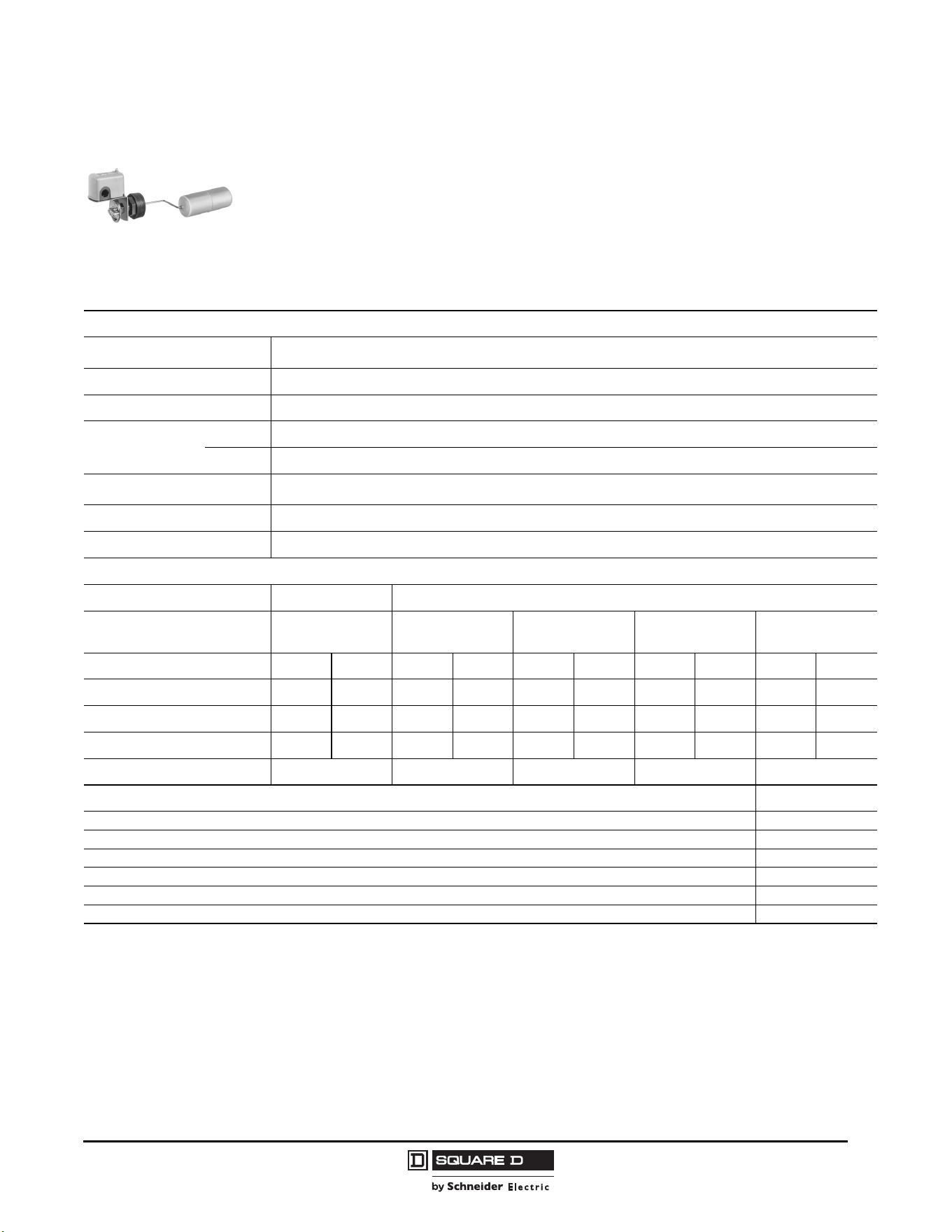
Commercial Pressure and Float Switches for Power Circuits
Float Switches—Class 9036, 9037, and 9038
57
03/2011
© 2011 Schneider Electric
All Rights Reserved
Class 9037 Type H with Screw-in Bushing
Table 19 contains ordering information for Class 9037 Type H float switches and factory installed
modifications. Contact the Sensor Competency Center when using float switches in liquids with a
different specific gravity than water (1.0).
When ordering factory installed modifications, add the Form number to the end of the float switch
catalog number. For example, to select a 9037HG36 switch with reverse action, order 9037HG36R.
NOTE: For replacement floats, see “Class 9049 Accessories” on page 67.
9037HG35
Float on the Right
Table 19: Class 9037 Type H Float Switches
Specifications
Application
Condensate pumps
A 2.5 in. cast-iron bushing attaches the float switch to the tank
Float movement
Transmitted through a nitrile rubber seal such as a Buna-N quad ring. Occasional replacement may be necessary.
Tank Pressure
Up to 50 psi
Temperature
Ambient
Up to 220 °F
Media
Buna-N seal: up to 215 °F. Viton
®
seal: media up to 250 °F.
Contact Operation
Close on liquid rise (standard)
Open on liquid rise (Form R)
Float Travel
Determined by the float rod angle. An external pointer indicates the float position.
Materials (Standard)
#304 SS float, #316 SS rod, 2.5 in. cast iron bushing, brass sealing connector, Buna-N quad ring packing.
Catalog Numbers
Float Rod Angle 45° 90° offset
Water Level Change
Minimum–Maximum, in. (mm)
2.00–5.00
(52–127)
2.50–5.00
(64–127)
3.75–7.00
(95–178)
4.25–8.25
(108–210)
6.00–11.50
(152–292)
Float Position
[1]
1
Viewed from the front of the switch, facing the indicator scale.
Left Right Left Right Left Right Left Right Left Right
NEMA Type 1
9037HG34 9037HG33 9037HG36 9037HG35 9037HG38 9037HG37 9037HG30 9037HG39 9037HG32 9037HG31
NEMA Type 4
9037HW34 9037HW33 9037HW36 9037HW35 9037HW38 9037HW37 9037HW30 9037HW39 9037HW32 9037HW31
NEMA Type 7, 9
9037HR34 9037HR33 9037HR36 9037HR35 9037HR38 9037HR37 9037HR30 9037HR39 9037HR32 9037HR31
CL to CL in. (mm)
— 3 (76) 4.25 (108) 5 (127) 7 (178)
Modifications Form
Omit 2.5 in. bushing F3
Omit float L
Reverse action: contacts open on liquid rise R
[2]
2
Type HG is field modifiable. Type HR and HW cannot be modified in the field.
Viton packing, 5 oz float (diesel fuel, Types HG, HW, HR30, 31, 32, 37, 38, 39 only) Z19
Viton packing, for media temperature up to 250 °F Z20
Viton packing, #316 SS float Z21
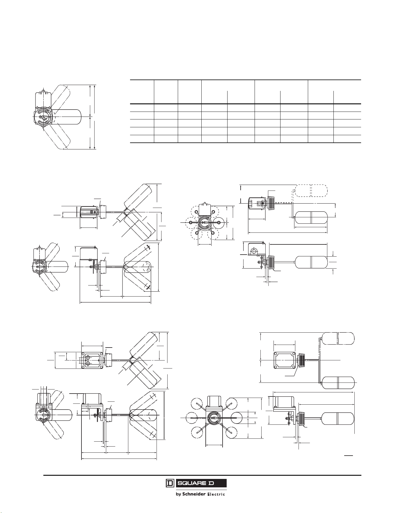
© 2011 Schneider Electric
All Rights Reserved
Commercial Pressure and Float Switches for Power Circuits
Float Switches—Class 9036, 9037, and 9038
58
03/2011
Table 20 lists the float travel distances for the screw-in float switches. Refer to Figure 13.
Figure 13: Travel Dimensions Table 20: Type H Float Travel Distances, in. (mm)
Float
Rod
Angle
RH
[1]
f1 f2 F
Minimum Maximum Minimum Maximum Minimum Maximum
45° — 6.22 (158) 2.25 (57) 4.50 (114) 2.00 (52) 4.50 (110) 4.25 (108) 9.00 (229)
90° offset 3.00 (76) 4.25 (108) 2.75 (70) 4.25 (108) 2.25 (57) 4.25 (108) 5.00 (127) 7.50 (191)
90° offset 4.25 (108) 5.50 (140) 3.50 (89) 5.50 (140) 2.75 (70) 4.00 (102) 6.25 (159) 9.50 (241)
90° offset 5.00 (127) 6.25 (159) 3.75 (95) 6.25 (159) 3.00 (76) 4.50 (110) 6.75 (171) 10.75 (273)
90° offset 7.00 (178) 8.25 (210) 4.75 (121) 8.25 (210) 3.75 (95) 5.75 (146) 8.50 (216) 14.00 (356)
1
Clearance from centerline of hub to side of tank.
F
f2
f1
Figure 14: Type HG—45° Angle Dimensions Figure 15: Type HG—90° Offset Dimensions
Figure 16: Type HR/HW—45° Angle Dimensions Figure 17: Type HR/HW—90° Offset Dimensions
4.44
113
3.89
99
0.44
12
0.38
10
2.5
64
2.5
64
1.06
27
6.22
158
14.66
372
6.22
158
12.44
316
2.0
51
3.86
98
1.22
31
2.56
65
Pipe
Thread
Dia.
6.94
176
Extreme Float Position –
See Price Sheet
Across
Flats
Bushing
5.98
152
2.88
73
0.44
11
0.38
10
11.5
292
2.58
65
2.5" NPT
2.0
51
3.86
98
16.06
408
7.13
184
Across
Flats
Bushing
H
R
C
L
f2
f1
F
C
L
C
L
4.78
121
1.44
37
3.38
86
0.44
12
0.38
10
5.5
140
2.5
64
1.06
27
6.22
158
15.09
383
2.5
64
6.22
158
12.44
316
2.0
51
4.81
122
3.63
92
1.81
46
Pipe
Thread
Dia.
6.94
176
Extreme Float Position –
See Price Sheet
Across
Flats
Bushing
0.66
17
0.66
17
0.66
17
0.66
17
Two (2)
3/4-14 in.
entries for
1/2 in. conduit
6.22
158
0.44
11
0.38
10
3.63
92
11.5
292
7.13
184
2.5" NPT
2.58
65
2.0
51
16.94
430
Across Flats
Bushing
H
f2
f1
F
C
L
C
L
4.75
122
R
C
L
Dual Dimensions:
in.
mm
Commercial Pressure and Float Switches for Power Circuits
Float Switches—Class 9036, 9037, and 9038
59
03/2011
© 2011 Schneider Electric
All Rights Reserved
Class 9038 Type A Mechanical Alternators
Class 9038 mechanical alternators provide a simple, positive means of mechanically alternating two
pumps or motors. These alternators are used on devices that are installed in a duplex system with a
common tank. There are three types of Class 9038 mechanical alternators:
• Type A (open tank and sump)
• Type C (with bushing)
• Type D (flange mounted, vertical)
When liquid level rises to the first level, one pump turns on. Both pumps automatically turn on when a
peak condition occurs and the liquid level continues to rise. If Form N5 or N25 is present, and the water
level continues to rise, a high water alarm is activated.
Mechanical alternators can be ordered with a manual transfer selector switch (Form N3), which allows
the operator to select which pump cuts in first. The second pump only operates under peak demand
conditions or if the first pump fails. When the switch is disengaged, the alternator reverts to normal
operation. Another option (Form N4) allows the alternator to be used as a two-level non-alternating unit.
Class 9038 Type A Open and Sump Tank Mechanical Alternators
Table 21 contains ordering information for Class 9038 Type A mechanical alternators, including factory
installed modifications. Order float accessories separately. Contact the Sensor Competency Center
when using Class 9038 alternators in liquids with a different specific gravity than water (1.0).
When ordering a factory modification, add the Form number to the end of the mechanical alternator
catalog number. For example, to select a 9038AG1 alternator with reverse action, order 9038AG1R.
Table 21: Class 9038 Type A Mechanical Alternators
Specifications
Application Open and sump tanks using duplex pumps
Float Movement Float operated
Ambient Temperature –22 to +200 °F
Contact Operation
Close on liquid rise (standard)
Open on liquid rise (Form R)
Catalog Numbers
NEMA 1 9038AG1
NEMA 4 (compensating spring standard) 9038AW1
NEMA 7, 9 (compensating spring standard) 9038AR1
Modifications
NOTE: Factory installed only.
Form
Compensating spring (Type AG) C (field installable)
Two-level, non-alternating unit N4
High water alarm circuit (single pole) N5
High water alarm circuit (two pole) N25
Reverse action: contacts open on liquid rise R
Accessories Catalog Number
Compensating spring (Type AG) 9049A15
9038AG1
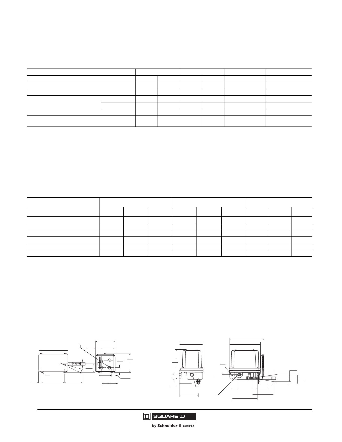
© 2011 Schneider Electric
All Rights Reserved
Commercial Pressure and Float Switches for Power Circuits
Float Switches—Class 9036, 9037, and 9038
60
03/2011
Table 22 lists the operating forces for Class 9038 Type A alternators. Use this table when selecting
additional tubing or when selecting floats and rods for accessories made by other manufacturers.
Accessory Kits
Table 23 lists the Class 9049 accessory kits for Class 9038 Type A alternators. The accessories are
ordered separately from the alternators. Order tapped-at-top floats for Type AG1 (except form C) and
center-hole floats for Types AG1C, AW1, and AR1.
When ordering float accessories, first specify the desired accessory kit, then as a second item, give the
catalog number and the quantity of the additional tubing kits required. For example, for a 9049A6C kit
with 15 ft of tubing, specify:
A. 9049A6C, quantity = 1 (includes 5 ft of tubing)
B. 9049T1, quantity = 4 (2.5 ft of tubing each, for a total of 10 additional ft)
Table 22: Class 9038 Type A Operating Forces
Catalog Number 9038AG1 9038AG1R 9038AR1/9038AW1 9038AR1R/9038AW1R
Lever Length Position Minimum Maximum Minimum Maximum Standard Standard
Force Up to Trip (oz), without Form C
[1]
18 16 14 11 — —
Force Down to Trip (oz), without Form C
[1]
20 17 16 12 — —
Maximum Rod Length Supported
by the Compensating Spring
ft (m)
[2]
Brass 10 (3.05) 8 (2.44) 7 (2.13) 6 (1.83) 16 (4.88) 19 (5.79)
Stainless Steel 12 (3.66) 10 (3.05) 8 (2.44) 7 (2.13) 20 (6.1) 23 (7.01)
Aluminum 25 (7.62) 21 (6.4) 17 (5.18) 15 (4.57) 41 (12.5) 47 (14.33)
Maximum Weight of Tubing and Stops
Supported by the Compensating Spring (oz)
47 41 33 30 74 85
1
Add 2 oz for high water alarm (Form N5 or N25).
2
Rod length determined using Class 9049 rod material (0.38 in. / 10 mm O.D. tubing).
Other types of rod must be weighed and compared to the “Maximum Weight of Tubing and Stops” row above.
Table 23: Class 9049 Accessories for Class 9038 Type A Float Switches (weight in oz)
Accessory Kits Tapped-at-Top Floats (#304 SS) Center-Hole Floats (#304 SS) Additional Tubing
[1]
Catalog Numbers
9049A6 9049A6A 9049A6S 9049A6C 9049A6CA 9049A6CS 9049T1 9049T1A 9049T1S
Tubing 5 ft brass 5 ft Al 5 ft SS 5 ft brass 5 ft Al 5 ft SS 2.5 ft brass 2.5 ft Al 2.5 ft SS
Net buoyancy in water, 7 in. float
[2]
60 60 60 70 70 70 — — —
Total weight of stops 3 3 3 6 6 6 — — —
Number of stops 222444———
Weight of 5 ft rod, included 18.5 6 16.9 18.5 6 16.9 — — —
Weight per ft of extra rod — — — — — — 3.7 1.2 3.4
1
Additional tubing kits add on to the float accessory kits and include a connector. Maximum recommended tubing length for tapped-at-top float: 12.5 ft (3810 mm).
2
Net buoyancy calculated with float 80% submerged, allowing for a 20% operating margin. Buoyancy data calculated for use in water. Contact the Sensor
Competency Center for buoyancy data in media having specific gravity different than water (1.0).
Figure 18: Type AG1 Dimensions Figure 19: Type AR1/AW1 Dimensions
6.88
175
2.06
52
3
76
1.13
76
3.63
92
4.69
119
1.06
27
0.84
21
1.75
44
3.5
89
4.19
106
5.38
137
0.75
19
2
3
0.28
7
Dia.
4 Mtg.
Holes
4 knockouts for
0.5 to 0.75 Conduit
1
Position:
to
1.47
37
4.5
114
6.86
174
2.91
74
0.44
11
0.06
2
1.69
43
1.25
32
4.75
121
0.75
19
7.13
181
8.35
212
5.35
136
5.88
149
1.03
26
4.16
106
C
L
3/4-14
Pipe Tap
3/4-14
Pipe Tap
1.50
38
2.31
59
Approx.
Pos. 2
Pos. 1
Pos. 3
Mtg.
Hole
Dia.
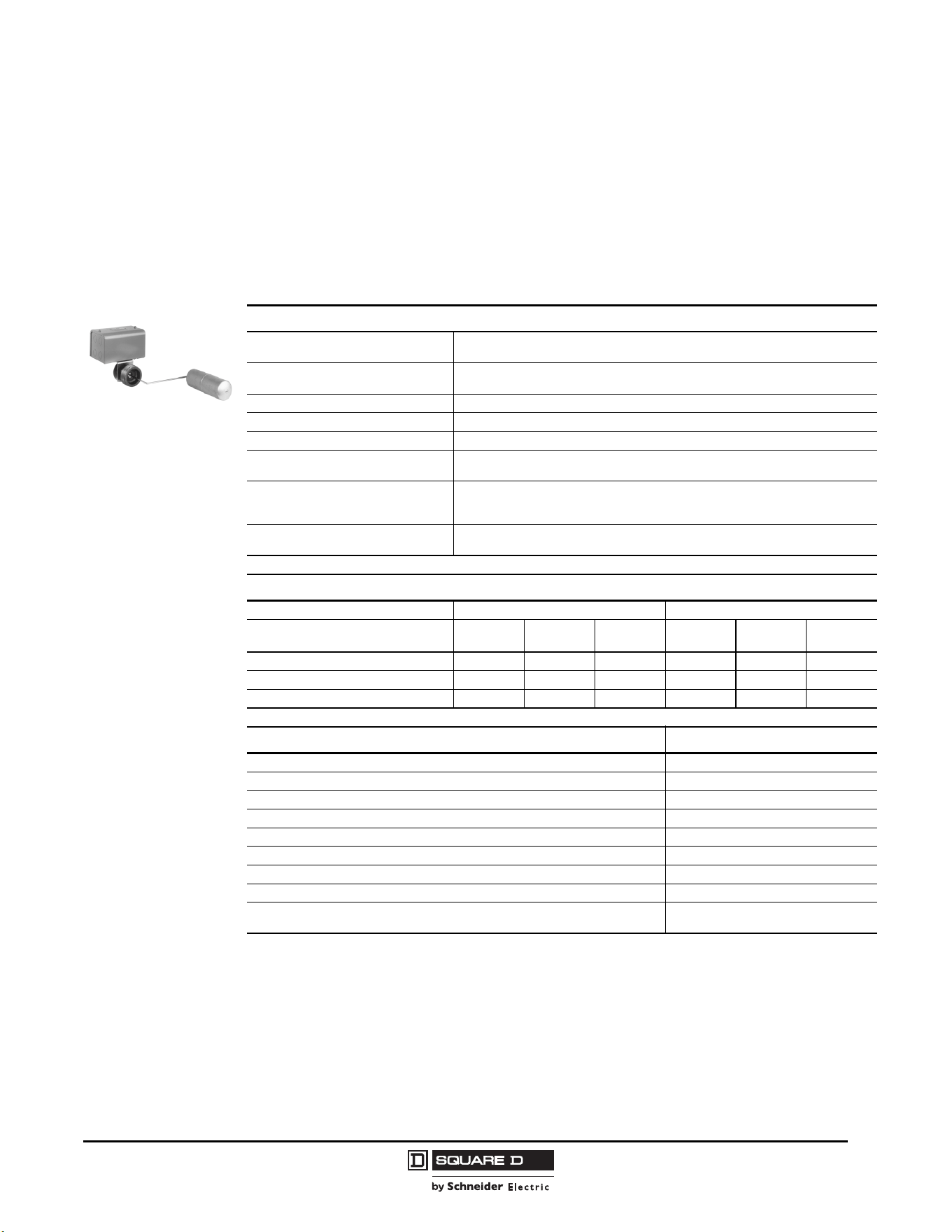
Commercial Pressure and Float Switches for Power Circuits
Float Switches—Class 9036, 9037, and 9038
61
03/2011
© 2011 Schneider Electric
All Rights Reserved
Class 9038 Type C Mechanical Alternators with Bushing
Table 24 contains ordering information for Class 9038 Type C mechanical alternators. Contact the
Sensor Competency Center when using Class 9038 alternators in liquids with a different specific
gravity than water (1.0).
When ordering a factory modification, add the Form number to the end of the alternator catalog
number. For example, to select a 9038CG36 alternator with reverse action, select 9038CG36R.
NOTE: For replacement floats, refer to page 67.
Table 24: Class 9038 Type C Mechanical Alternators
Specifications
Application
Closed tanks using duplex, condensate pumps
A 2.5 in. cast iron bushing attaches the float switch to the tank
Float movement
Transmitted through a nitrile rubber seal such as a Buna-N quad ring.
Occasional seal replacement may be necessary.
Tank Pressure Up to 50 psi
Ambient Temperature –22 to +200 °F
Media Temperature (Minimum) Solidification point of the medium in the tank, down to –22 °F
Contact Operation
Close on liquid rise (standard)
Open on liquid rise (Form R)
Float Travel
Float travel is determined by the rod length.
An external pointer indicates the float position.
For more information on float travel and position, see “Float Travel” on page 64.
Materials (Standard)
#304 SS float, #316 SS rod, 2.5 in. cast iron bushing, brass sealing connector,
Buna-N quad ring packing
Catalog Numbers
Float Position
[1]
1
Viewed from front of alternator, facing indicator scale.
Left Right
Water Level Change,
Minimum–Maximum
in.
(mm)
6.5–13
(165–330)
4–7.75
(102–197)
4.75–9.25
(121–235)
6.5–13
(165–330)
4–7.75
(102–197)
4.75–9.25
(121–235)
NEMA 1 9038CG32 9038CG34 9038CG36 9038CG31 9038CG33 9038CG35
NEMA 4 9038CW32 9038CW34 9038CW36 9038CW31 9038CW33 9038CW35
NEMA 7, 9 9038CR32 9038CR34 9038CW36 9038CR31 9038CR33 9038CW35
Modifications Form
Omit 2.5 in. cast iron bushing F3
Omit float L
Two-level, non-alternating unit N4
[2]
2
Factory installed only.
High water alarm circuit, single pole (Type CG only) N5
[2]
High water alarm circuit, two pole (Type CG only) N25
[2]
Reverse action: contacts open on liquid rise R
[2]
Fluorocarbon polymer such as Viton
®
packing, 5 oz float (diesel fuel, Type CG only) Z19
Fluorocarbon polymer such as Viton packing, for media temperature up to 250 °FZ20
Fluorocarbon polymer such as Viton packing, #316 SS float for liquid temperatures
up to 250 °F
Z21
9038CG36
Front
Float on the left
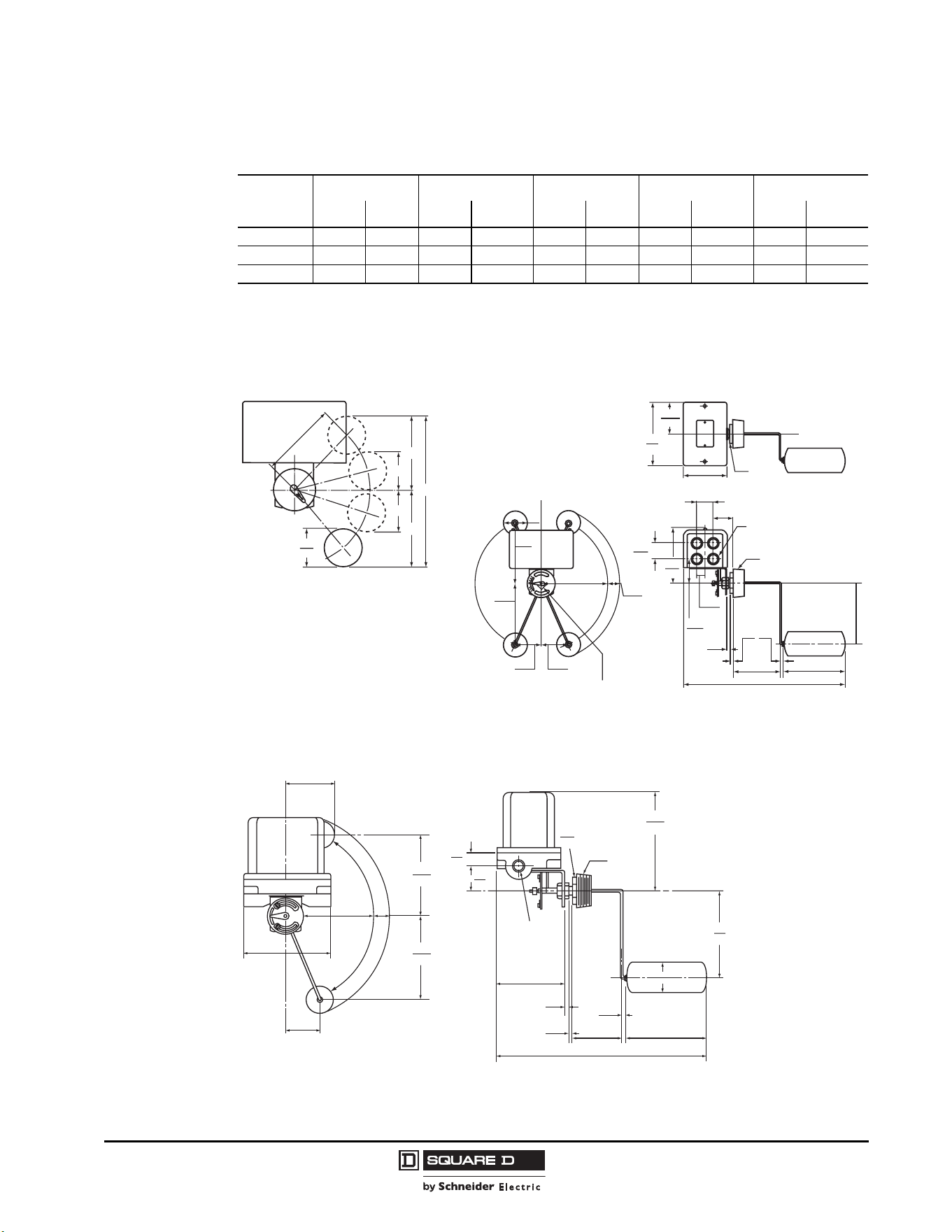
© 2011 Schneider Electric
All Rights Reserved
Commercial Pressure and Float Switches for Power Circuits
Float Switches—Class 9036, 9037, and 9038
62
03/2011
Table 25 lists the float travel distances for the screw-in float switches. Refer to Figure 20.
Table 25: Type C Float Travel Adjustments, in. (mm)
R
ABCD F
Min. Max. Min. Max. Min. Max. Min. Max. Min. Max.
4.25 (108)
[1]
1
CG33, CG34, CW33, CW34, CR33, CR34
2 (51) 3.5 (89) 3.5 (89) 4.75 (121) 2.5 (64) 3.75 (95) 3.5 (89) 4.75 (121) 7 (178) 9.5 (241)
5 (127)
[2]
2
CG35, CG36, CW35, CW36, CR35, CR36
2.25 (57) 3.75 (95) 4 (102) 5.25 (133) 2.75 (70) 3 (76) 4 (102) 5.25 (133) 8 (203) 10.5 (267)
7 (178)
[3]
3
CG31, CG32, CW31, CW32, CR31, CR32
2.5 (64) 5 (127) 5 (127) 7 (178) 2 (51) 4 (102) 5 (152) 7 (178) 10 (254) 14 (495)
Figure 20: Travel Dimensions Figure 21: Type CG Dimensions
Figure 22: Type CR/CW Dimensions
R
A
C
B
D
F
2.5
64
1.97
50
5.94
151
2.59
66
0.88
22
0.38
10
0.44
11
0.44
11
4.0
102
7.0
179
17.81
452
1.75
44
2.5
64
6.5
165
max.
6.5
165
7.0
178
1.25
32
2.63
67
2.63
67
max.
To reverse the float, change the
operating link in the holes of the adjusting plate.
2.17
55
2.5
64
2.0
51
4.69
119
6.84
174
Pipe Tap
Bushing
Across
Flats
Combination knockouts,
0.5 in. (13 mm) and 0.75 in.
(19 mm) conduit, both ends
3.42
87
5.4
137
18.5
470
7.0
178
7.78
198
6.5
165
6.5
165
2.63
67
7.78
198
7.0
178
1.25
32
3.88
99
2.0
51
2.5
64
7.0
178
2.5
64
0.38
10
4.0
102
0.44
11
0.44
11
2.0
51
1.0
25
Pipe Tap
Bushing
Across
Flats
0.75-14
(19-356)
Pipe Tap,
Both Ends
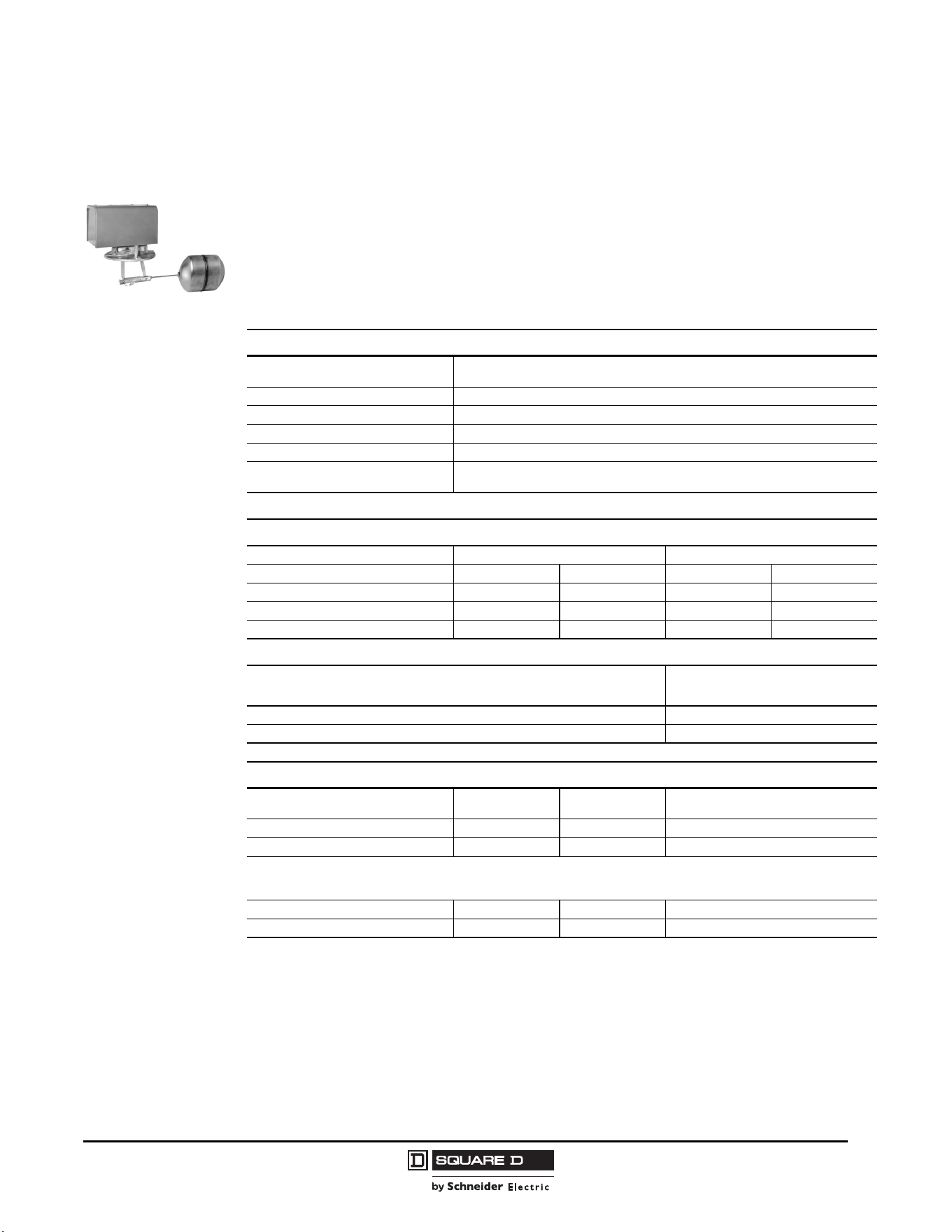
Commercial Pressure and Float Switches for Power Circuits
Float Switches—Class 9036, 9037, and 9038
63
03/2011
© 2011 Schneider Electric
All Rights Reserved
Class 9038 Type D Flange-Mounted Mechanical Alternators
Flange Mounted
Table 26 contains ordering information for Class 9038 Type D alternators, factory modifications, and
float kits. Order rod and float accessory kits separately. Contact the Sensor Competency Center when
using Class 9038 alternators in liquids with a different specific gravity than water (1.0).
When ordering a factory modification, add the Form number to the end of the alternator Type number.
For example, to select a 9038DG7 alternator with manual transfer, order 9038DG7N3.
Table 26: Class 9038 Type D Mechanical Alternators
Specifications
Application
Industrial closed tanks using duplex, condensate pumps
Top mounted only
Float movement Transmitted through a quad ring seal (occasional replacement may be necessary)
Tank Pressure Up to 50 psi
Media Temperature Viton
®
seal: up to 250 °F
Contact Operation Close on liquid rise or open on liquid rise (field reversible)
Float Travel
Determined by the length of the hinge post and rod and by the float position
For more information on float travel and position, see “Float Travel” on page 64.
Catalog Numbers
Hinge Post Length (V) in. (mm) 2.63 (67) 4.69 (119)
Water Level Change Minimum Maximum Minimum Maximum
NEMA 1 9038DG7 9038DG8 9038DG9 9038DG10
NEMA 4 9038DW7 9038DW8 9038DW9 9038DW10
NEMA 7, 9 9038DR7 9038DR8 9038DR9 9038DR10
Modifications
NOTE: Factory installed only.
Form
Two-level, non-alternating unit N4
High water alarm circuit (Type DG only) N5
Float Kits
Material
Diameter
in. (mm)
Length
in. (mm)
Catalog Number
#304 stainless steel 3.62 (92) 4.5 (114) 9049EF1
#316 stainless steel 3.62 (92) 4.5 (114) 9049EF2
NOTE: The following float kits are available but are not recommended for use with 9038D mechanical alternators.
The float travel dimensions shown in this catalog for 9038D devices do not apply when using these floats. A correction factor
appears in the footnote of Tables 27–30 on pages 64 and 66.
#304 stainless steel 2.5 (64) 7 (178) 9049HF3
#316 stainless steel 2.5 (64) 7 (178) 9049HF4
9038DG
9049ER5
9049EF1
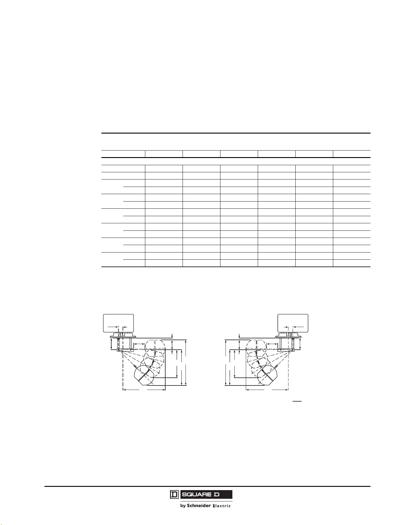
© 2011 Schneider Electric
All Rights Reserved
Commercial Pressure and Float Switches for Power Circuits
Float Switches—Class 9036, 9037, and 9038
64
03/2011
Class 9049 Rod Kits for Class 9038 Type D
Float Travel
Float travel is determined by the length of the hinge post and rod and by the float position. The float
may be operated in three different positions. In Position 1, the contacts close when the liquid rises. In
Position 2, the contacts open when the liquid rises. Use Table 27 to select the appropriate rod kit when
ordering Class 9038 Types DG7, DW7, or DR7 alternators.
Figure 23: Travel Dimensions
Table 27: Class 9049 Rod Kits for Class 9038 Type DG7, DW7, and DR7 Alternators
Float Travel for Class 9038 Types DG7, DW7, and DR7 Alternators
Minimum Water Level Change (V = 2.63 in. / 67 mm)
Catalog No. 9049ER1 9049ER2 9049ER3 9049ER5 9049ER7 9049ER12
Dimensions in. (mm)
R 1.75 (44) 2.5 (64) 3.25 (83) 5.25 (133) 7.25 (184) 12.25 (311)
H
[1]
1
Add 2.5 in. (64 mm) to H when using HF3 or HF4 floats.
8.25 (210) 9 (229) 9.5 (241) 11.75 (298) 13.75 (349) 18.75 (476)
A
Min. 0.75 (19) 0.63 (16) 0.5 (13) 0.13 (3) 0.25 (6) 0.38 (10)
Max. 0.63 (16) 0.38 (10) 0.25 (6) 0.0 (0) 0.5 (13) 1.5 (38)
B
Min. 5 (127) 5.38 (137) 5.5 (140) 6.38 (162) 7 (178) 8.63 (219)
Max. 5 (127) 5.25 (133) 5.5 (140) 6.25 (159) 7 (178) 8.75 (222)
C
Min. 4 (102) 4.25 (108) 4.38 (111) 5 (127) 5.5 (140) 6.75 (171)
Max. 4.25 (108) 4.5 (114) 4.63 (118) 5.13 (130) 5.75 (146) 7.75 (197)
D
Min. 1.75 (44) 1.75 (44) 1.75 (44) 1.75 (44) 1.75 (44) 1.75 (44)
Max. 1.5 (38) 1.38 (35) 1.25 (32) 1 (25) 0.88 (22) 0.63 (16)
F
Min. 6.75 (171) 7.13 (181) 7.25 (184) 8.13 (207) 8.75 (222) 10.38 (264)
Max. 6.5 (165) 6.63 (168) 6.75 (171) 7.25 (184) 7.88 (200) 9.38 (238)
G
Min. 1 (25) 1 (25) 1 (25) 1 (25) 1 (25) 1 (25)
Max. 1.5 (38) 1.5 (38) 1.5 (38) 1.75 (44) 2 (51) 2.5 (64)
Dual Dimensions:
in.
mm
0.97
25
R
V
G
A
D
F
B
C
H
0.97
25
R
V
G
A
D
F
B
C
H
Postion 1 Postion 2
Commercial Pressure and Float Switches for Power Circuits
Float Switches—Class 9036, 9037, and 9038
65
03/2011
© 2011 Schneider Electric
All Rights Reserved
Use the following table to select the appropriate rod kit when ordering Class 9038 Types DG8, DW8, or
DR8 alternators.
Use the following table to select the appropriate rod kit when ordering Class 9038 Types DG9, DW9, or
DR9 alternators.
Table 28: Class 9049 Rod Kits for Use on Class 9038 Types DG8, DW8, and DR8 Alternators
Float Travel for Class 9038 Types DG8, DW8, and DR8 Alternators
Minimum Water Level Change (V = 2.63 in. / 67 mm)
Catalog No. 9049ER1 9049ER2 9049ER3 9049ER5 9049ER7 9049ER12
Dimensions in. (mm)
R 1.75 (44) 2.5 (64) 3.25 (83) 5.25 (133) 7.25 (184) 12.25 (311)
H
[1]
1
Add 2.5 in. (64 mm) to H when using HF3 or HF4 floats.
7.5 (191) 8.25 (210) 9 (229) 11 (279) 13 (330) 18 (457)
A
Min. 0.0 (0) 0.5 (13) 1 (25) 2 (51) 3 (76) 5.5 (140)
Max. 1.25 (32) 1.5 (38) 2 (51) 3 (76) 4 (102) 6.5 (165)
BMin.8 (203) 8.75 (222) 9.5 (241) 11.5 (292) 13.5 (343) 18.5 (470)
C
Min. 6.5 (165) 7 (178) 7.75 (197) 9.5 (241) 11 (279) 14.75 (375)
Max. 6.5 (165) 7 (178) 7.5 (1910 9 (229) 10.75 (273) 15 (381)
D
[2]
2
D is negative when the top of the float is below the horizontal centerline.
Min. 2 (51) 1.75 (44) 1.5 (38) 1.25 (32) 0.75 (19) 0.5 (13)
Max. 0.5 (13) 0.25 (6) 0.0 (0) 0.75 (19) 1.75 (44) 4.25 (108)
F
Min. 10 (254) 10.5 (267) 11 (279) 12.75 (324) 14.25 (362) 19 (483)
Max. 8.5 (216) 9 (229) 9.5 (241) 10.75 (273) 11.75 (298) 14.25 (362)
G
Min. 1.5 (38) 1.5 (38) 1.75 (44) 2 (51) 2 (51) 2.25 (57)
Max. 2.5 (64) 2.75 (70) 3 (76) 3.75 (95) 4.5 (114) 6.25 (159)
Table 29: Class 9049 Rod Kits for Class 9038 Type DG9, DW9, and DR9 Alternators
Float Travel for Class 9038 Types DG9, DW9, and DR9 Alternators
Minimum Water Level Change (V = 4.69 in. / 119 mm)
Catalog No. 9049ER1 9049ER2 9049ER3 9049ER5 9049ER7 9049ER12
Dimensions in. (mm)
R 1.75 (44) 2.5 (64) 3.25 (83) 5.25 (133) 7.25 (184) 12.25 (311)
H
[1]
1
Add 2.5 in. (64 mm) to H when using HF3 or HF4 floats.
8.25 (210) 9 (229) 9.5 (241) 11.75 (298) 13.75 (349) 18.75 (476)
A
Min. 1 (25) 1 (25) 0.88 (22) 0.63 (16) 0.25 (6) 0.13 (3)
Max. 0.5 (13) 0.13 (3) 0.0 (0) 0.88 (22) 1.63 (41) 2.88 (73)
B
Min. 5.25 (133) 5.75 (146) 6 (152) 7.25 (184) 8.25 (210) 10.75 (273)
Max. 5.25 (133) 5.63 (143) 5.88 (149) 7.13 (181) 8.25 (210) 11 (279)
C
Min. 4.5 (114) 4.75 (121) 5 (127) 5.75 (146) 6.5 (165) 8.38 (213)
Max. 4.5 (114) 4.75 (121) 5 (127) 5.88 (149) 6.75 (171) 8.5 (216)
D
Min. 2 (51) 2 (51) 2 (51) 2 (51) 1.88 (48) 1.63 (41)
Max. 1.5 (38) 1.25 (32) 1.13 (29) 0.75 (19) 0.5 (13) 0.5 (13)
F
Min. 7.25 (184) 7.75 (197) 8 (203) 9.25 (235) 10.13 (257) 12.38 (314)
Max. 6.75 (171) 6.88 (175) 7 (178) 7.88 (200) 8.75 (222) 11.5 (292)
G
Min. 3 (76) 3 (76) 3 (76) 3 (76) 3.25 (83) 4 (102)
Max. 3.75 (95) 4 (102) 4 (102) 4.38 (111) 4.63 (117) 5.75 (146)
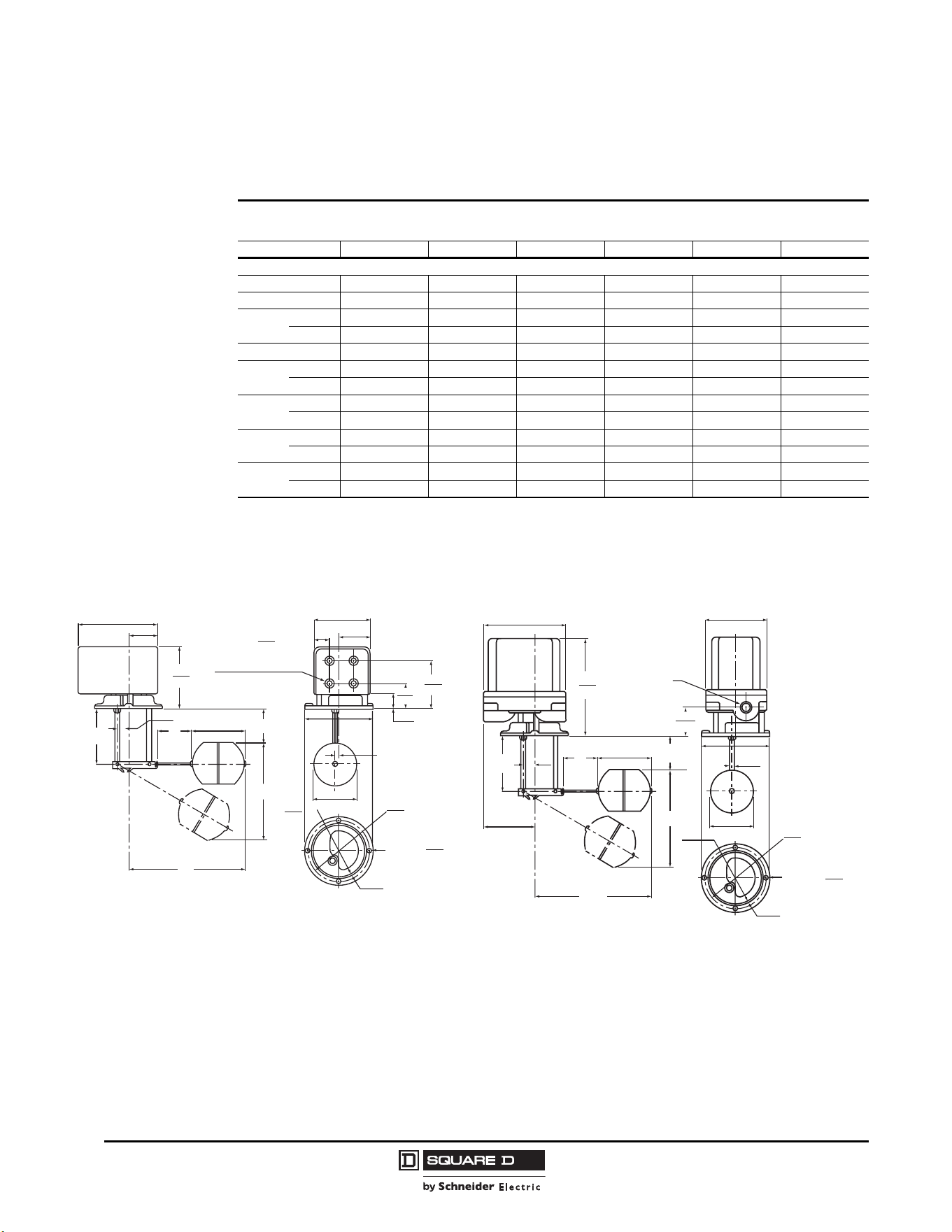
© 2011 Schneider Electric
All Rights Reserved
Commercial Pressure and Float Switches for Power Circuits
Float Switches—Class 9036, 9037, and 9038
66
03/2011
Use the following table to select the appropriate rod kit when ordering Class 9038 Type DG10, DW10,
or DR10 alternators.
Table 30: Class 9049 Rod Kits for Class 9038 Type DG10, DW10, and DR10 Alternators
Float Travel for Class 9038 Types DG10, DW10, and DR10 Alternators
Minimum Water Level Change (V = 4.69 in. / 119 mm)
Catalog No. 9049ER1 9049ER2 9049ER3 9049ER5 9049ER7 9049ER12
Dimensions in. (mm)
R 1.75 (44) 2.5 (64) 3.25 (83) 5.25 (133) 7.25 (184) 12.25 (311)
H
[1]
1
Add 2.5 in. (64 mm) to H when using HF3 or HF4 floats.
7.5 (191) 8.25 (210) 9 (229) 11 (279) 13 (330) 18 (457)
A
Min. 0.5 (13) 1 (25) 1.5 (38) 2.5 (64) 3.25 (83) 6 (152)
Max. 1.5 (38) 2 (51) 2.5 (64) 4 (102) 5.5 (140) 9.25 (235)
BMin.8 (203) 8.75 (222) 9.5 (241) 11.5 (292) 13.5 (343) 18.5 (470)
C
Min. 7 (178) 7.75 (194) 8.25 (210) 10 (254) 11.5 (292) 15.5 (394)
Max. 7 (178) 7.5 (191) 8.25 (210) 10 (254) 12 (305) 17 (432)
D
[2]
2
D is negative when the top of the float is below the horizontal centerline.
Min. 1.75 (44) 1.75 (44) 1.5 (38) 1.25 (32) 1 (25) 0.5 (13)
Max. 0.5 (13) 0.25 (6) 0.0 (0) 1 (25) 1.5 (38) 2.75 (70)
F
Min. 8.75 (222) 10.5 (267) 11 (279) 12.75 (324) 14.5 (368) 19 (483)
Max. 8.5 (216) 9 (229) 9.5 (241) 10.5 (267) 12 (305) 15.75 (400)
G
Min. 3.25 (83) 3.5 (89) 3.5 (89) 3.75 (95) 4 (102) 4.75 (121)
Max. 4.75 (121) 5 (127) 5.25 (133) 6 (152) 6.75 (171) 8.5 (216)
Figure 24: Type DG Dimensions
Figure 25: Type DR/DW Dimensions
H
F
G
R
V
C
L
of
Flange
C
L
of
Flange
3.63
92
0.31
8
5.75
146
1.53
39
4.44
113
2.47
63
5.13
130
0.41
10
0.13
3
4.41
112
4.5
114
2.53
64
4.69
119
1.47
37
Wide Bead
5.59
142
5.59
142
6.84
174
Dia.
Dia.
4 Holes
(2) PLS
0.5–0.75 (13–19)
4 knockout holes for
conduit on each end
Note: The recommended size of hole in the tank for the
entry of the float and mounting of the control is 4.19 (106).
Floats shown are Type EF, 4.5 (114) long.
Add 2.5 (64) to H if using Type HF Floats, which are 7.0 (178) long.
H
F
G
R
V
C
L
of
Flange
C
L
of
Flange
3.63
92
2.44
62
0.31
8
5.75
146
5.13
130
0.41
10
0.13
3
4.41
112
4.5
114
4.44
113
0.97
25
5.16
131
Wide Bead
6.31
160
7.13
181
Dia.
Dia.
(4) Holes
Two 3/4-14 in.
conduit connection
on both ends
Commercial Pressure and Float Switches for Power Circuits
Float Switches—Class 9036, 9037, and 9038
67
03/2011
© 2011 Schneider Electric
All Rights Reserved
Class 9049 Accessories and Class 9998 Renewal Parts Kits
Renewal parts are generally available for Pump Control products with a current date code or with a
numerical date code (such as 172, which corresponds to the first quarter of 1972). Parts are no longer
available for devices manufactured before 1965.
Table 31: Class 9049 Accessories
Catalog Number Description Equipment To Be Serviced
9049A6 7 in. Tapped at Top #304 Stainless Steel Float, 5 ft Brass Rod, 2 Stops All 9036, 9038A
9049A6A 7 in. Tapped at Top #304 Stainless Steel Float, 5 ft Aluminum Rod, 2 Stops All 9036, 9038A
9049A6C 7 in. Center Hole #304 Stainless Steel Float, 5 ft Brass Rod, 4 Stops All 9036, 9038A
9049A6CA 7 in. Center Hole #304 Stainless Steel Float, 5 ft Aluminum Rod, 4 Stops All 9036, 9038A
9049A6CS 7 in. Center Hole #316 Stainless Steel Float, 5 ft Stainless Steel Rod, 4 Stainless Steel Stops All 9036, 9038A
9049A6S 7 in. Tapped at Top #316 Stainless Steel Float, 5 ft Stainless Steel Rod, 2 Stainless Steel Stops All 9036, 9038A
9049AF1 7 in. Round Center Hole #304 Stainless Steel Replacement Float (do not remove ballast) 9049A6C, A6CA, DRA31
9049AF2 7 in. Round Center Hole #316 Stainless Steel Replacement Float (do not remove ballast) 9049A6CS, DRA32
9049AF3 7 in. Round Tapped at Top #304 Stainless Steel Replacement Float (do not remove ballast) 9049A6, A6A, DCA1, DCA3
9049AF4 7 in. Round Tapped at Top #316 Stainless Steel Replacement Float (do not remove ballast) 9049A6S, DCA2, DCA4
9049A13 Compensating Spring 9036GG
9049A15 Compensating Spring 9038AG
9049A19 Compensating Spring 9036DG
9049A20 Compensating Spring 9036DR, DW
9049A54 Mounting Bracket—Replacing Obsolete 9036A with 9036G 9036GG
9049A55 Mounting Bracket—Replacing 9036A (S or F1) with 9036G 9036GG
9049A58 Form R Lever 9036DG
9049EF1 #304 Stainless Steel Float (do not remove ballast) 9037E, 9038D
9049EF2 #316 Stainless Steel Float (do not remove ballast) 9037E, 9038D
9049ER1 1-3/4 in. Stainless Steel Rod 9037E, 9038D
9049ER2 2-1/2 in. Stainless Steel Rod 9037E, 9038D
9049ER3 3-1/4 in. Stainless Steel Rod 9037E, 9038D
9049ER5 5-1/4 in. Stainless Steel Rod 9037E, 9038D
9049ER7 7-1/4 in. Stainless Steel Rod 9037E, 9038D
9049ER12 12-1/4 in. Stainless Steel Rod 9037E, 9038D
9049GF1 #304 Stainless Steel Float (do not remove ballast) 9037G
9049GF2 #316 Stainless Steel Float (do not remove ballast) 9037G
9049HF3 #304 Stainless Steel Float (do not remove ballast) 9037H, 9038C, D
[1]
1
Not recommended for 9038D mechanical alternators. 9049EF1 (#304 SS) and 9049EF2 (#316 SS) are recommended instead.
9049HF4 #316 Stainless Steel Float (do not remove ballast) 9037H, 9038C, D
[1]
9049T1 Additional Rod Kit: One 2-1/2 ft Section of Brass Rod, Connector 9049A6, A6C
9049T1A Additional Rod Kit: One 2-1/2 ft Section of Aluminum Rod, Connector 9049A6A, A6CA
9049T1S Additional Rod Kit: One 2-1/2 ft Section of Stainless Steel Rod, Connector 9049A6S, A6CS
9049UMS1 Universal Mounting Bracket All 9036; 9038AG, AR, AW
Table 32: Class 9998 Renewal Parts Kits for Class 9036–9038 Devices
Catalog Number Description Equipment To Be Serviced
9998AO1 Replacement High-Level Alarm, Single-Pole Snap Switch, SPDT Form N5
9998CO3 Replacement High-Level Alarm, Double-Pole Snap Switch, DPDT Form N25
9998PC213 Replacement Switch Mechanism 9036GR, GW, Series C (All Except Form H and R)
9998PC214 Replacement Switch Mechanism 9036GR, GW, Series C (Form R Only)
9998PC215 Replacement Switch Mechanism 9036GR, GW, Series C (Form H Only)
9998PC216 Cover Gasket 9036, 9037 GW Only
9998PC242 Replacement Contact Kit 9036, 9037, 9038 (2 required)
9998PC286 Replacement Switch Mechanism 9036DR1, DW1, Series B, Form C
9998PC287 Replacement Switch Mechanism 9036DR1, DW1, Series B, Form R
9998PC319 Replacement Switch Mechanism 9035DG11
9998PC334 Replacement Switch Mechanism 9035DR10, DW10, DR30, DW30
9998PC335 Replacement Switch Mechanism 9035DR11, DW11, DR31, DW31

© 2011 Schneider Electric
All Rights Reserved
Commercial Pressure and Float Switches for Power Circuits
Float Switches—Class 9036, 9037, and 9038
68
03/2011

Commercial Pressure and Float Switches for Power Circuits
69
03/2011
© 2011 Schneider Electric
All Rights Reserved
INDEX
9013FSG ......................4
9013FTG ......................4
9013FRG ......................5
9013FHG ......................5
9049A6 .........................8
9049A6A ......................8
9049A6S ......................8
9049A6C ......................8
9049A6CA ....................8
9049A6CS ....................8
9049T1 .........................8
9049T1A .......................8
9049T1S .......................8
9036DG2 ....................49
9036DG2R .................49
9036GG2 ....................49
9036GG2R .................49
9036DW31 .................49
9036DW31R ...............49
9036GW1 ...................49
9036GW1R ................49
9036DR31 ..................49
9036DR31R ...............49
9036GR1 ....................49
9036GR1R .................49
9049A58 .....................49
9049A19 .....................49
9049A20 .....................49
9049A13 .....................49
9049A13 .....................49
9049A6 .......................50
9049A6A ....................50
9049A6S ....................50
9049A6C ....................50
9049A6CA ..................50
9049A6CS ..................50
9049T1 .......................50
9049T1A .....................50
9049T1S .....................50
9036FG30 ..................52
9049A60 .....................52
9049A61 .....................52
9049EF1 ....................53
9049EF2 ....................53
9049ER1 ....................55
9049ER2 ....................55
9049ER3 ....................55
9049ER5 ....................55
9049ER7 ....................55
9049ER12 ..................55
9049ER1 ....................56
9049ER2 ....................56
9049ER3 ....................56
9049ER5 ....................56
9049ER7 ....................56
9049ER12 ..................56
9049ER1 ....................56
9049ER2 ....................56
9049ER3 ....................56
9049ER5 ....................56
9049ER7 ....................56
9049ER12 ..................56
9037HG34 ..................57
9037HG33 ..................57
9037HG36 ..................57
9037HG35 ..................57
9037HG38 ..................57
9037HG37 ..................57
9037HG30 ..................57
9037HG39 ..................57
9037HG32 ..................57
9037HG31 ..................57
9037HW34 .................57
9037HW33 .................57
9037HW36 .................57
9037HW35 .................57
9037HW38 .................57
9037HW37 .................57
9037HW30 .................57
9037HW39 .................57
9037HW32 .................57
9037HW31 .................57
9037HR34 .................. 57
9037HR33 .................. 57
9037HR36 .................. 57
9037HR35 .................. 57
9037HR38 .................. 57
9037HR37 .................. 57
9037HR30 .................. 57
9037HR39 .................. 57
9037HR32 .................. 57
9037HR31 .................. 57
9038AG1 .................... 59
9038AW1 ................... 59
9038AR1 .................... 59
9049A15 ..................... 59
9038AG1 .................... 60
9038AG1R ................. 60
9038AR1/9038AW1 ... 60
9038AR1R/9038AW1R
.................................... 60
9049A6 ....................... 60
9049A6A .................... 60
9049A6S .................... 60
9049A6C .................... 60
9049A6CA .................. 60
9049A6CS .................. 60
9049T1 ....................... 60
9049T1A .................... 60
9049T1S .................... 60
9038CG32 .................. 61
9038CG34 .................. 61
9038CG36 .................. 61
9038CG31 .................. 61
9038CG33 .................. 61
9038CG35 .................. 61
9038CW32 ................. 61
9038CW34 ................. 61
9038CW36 ................. 61
9038CW31 ................. 61
9038CW33 ................. 61
9038CW35 ................. 61
9038CR32 .................. 61
9038CR34 .................. 61
9038CW36 ................. 61
9038CR31 .................. 61
9038CR33 .................. 61
9038CW35 ................. 61
9038DG7 ................... 63
9038DG8 ................... 63
9038DG9 ................... 63
9038DG10 ................. 63
9038DW7 ................... 63
9038DW8 ................... 63
9038DW9 ................... 63
9038DW10 ................. 63
9038DR7 .................... 63
9038DR8 .................... 63
9038DR9 .................... 63
9038DR10 .................. 63
9049EF1 .................... 63
9049EF2 .................... 63
9049HF3 .................... 63
9049HF4 .................... 63
9049ER1 .................... 64
9049ER2 .................... 64
9049ER3 .................... 64
9049ER5 .................... 64
9049ER7 .................... 64
9049ER12 .................. 64
9049ER1 .................... 65
9049ER2 .................... 65
9049ER3 .................... 65
9049ER5 .................... 65
9049ER7 .................... 65
9049ER12 .................. 65
9049ER1 .................... 65
9049ER2 .................... 65
9049ER3 .................... 65
9049ER5 .................... 65
9049ER7 .................... 65
9049ER12 .................. 65
9049ER1 .................... 66
9049ER2 .................... 66
9049ER3 .................... 66
9049ER5 .................... 66
9049ER7 .................... 66
9049ER12 .................. 66
9049A6 ...................... 67
9049A6A .................... 67
9049A6C .................... 67
9049A6CA ................. 67
9049A6CS ................. 67
9049A6S .................... 67
9049AF1 .................... 67
9049AF2 .................... 67
9049AF3 .................... 67
9049AF4 .................... 67
9049A13 .................... 67
9049A15 .................... 67
9049A19 .................... 67
9049A20 .................... 67
9049A54 .................... 67
9049A55 .................... 67
9049A58 .................... 67
9049EF1 .................... 67
9049EF2 .................... 67
9049ER1 .................... 67
9049ER2 .................... 67
9049ER3 .................... 67
9049ER5 .................... 67
9049ER7 .................... 67
9049ER12 .................. 67
9049GF1 .................... 67
9049GF2 .................... 67
9049HF3 .................... 67
9049HF4 .................... 67
9049T1 ...................... 67
9049T1A .................... 67
9049T1S .................... 67
9049UMS1 ................. 67



9034CT9701R01/11 © 2006–2011 Schneider Electric All Rights Reserved
Replaces 9013CT9701R6/06 dated January 2007 and 9034CT9701R2/08 dated May 2008.
03/2011
Schneider Electric USA, Inc.
8001 Knightdale Blvd.
Knightdale, NC 27545 USA
1-888-Square D (1-888-778-2733)
www.schneider-electric.us
Square D™, Schneider Electric™, and Pumptrol™ are trademarks or registered trademarks of
Schneider Electric. Other trademarks used herein are the property of their respective owners.