Gotonomi Module Installation Guide Gotonomi.com | CONFIDENTIAL Page 1 of 30
Gotonomi Module Installation Guide
V2.3
Go Beyond

Gotonomi Module Installation Guide Gotonomi.com | CONFIDENTIAL Page 2 of 30
1 Contents
1 Contents ......................................................................................................................................... 2
2 Glossary .......................................................................................................................................... 4
3 Introduction .................................................................................................................................... 5
4 System overview .............................................................................................................................. 5
4.1 BGAN System overview ........................................................................................................... 5
4.2 Gotonomi Module ................................................................................................................... 5
4.4 Gotonomi Multilink Module ..................................................................................................... 6
4.5 Gotonomi V200 ....................................................................................................................... 6
4.7 External Interfaces .................................................................................................................. 7
4.7.1 Gotonomi Module ............................................................................................................... 7
4.7.2 Gotonomi Multilink .............................................................................................................. 9
4.7.3 Gotonomi 200 ................................................................................................................... 10
5 Installation .................................................................................................................................... 11
5.1 Process ................................................................................................................................ 11
5.2 Storage and transport ............................................................................................................ 11
5.3 Installation guidelines ........................................................................................................... 11
5.3.1 Safety ............................................................................................................................... 11
5.3.2 Mechanical Guide ............................................................................................................. 11
5.3.3 Thermal Management ........................................................................................................ 12
5.3.4 IP Protection ..................................................................................................................... 13
5.3.5 Power and Ethernet Cable ................................................................................................. 13
5.3.6 Antenna and RF Cable ....................................................................................................... 13
5.3.7 Satellite Coverage ............................................................................................................. 14
5.3.8 Satellite Selection ............................................................................................................. 14
5.3.9 Antenna positioning .......................................................................................................... 14
5.3.10 Weather ........................................................................................................................ 16
5.3.11 GNSS ............................................................................................................................ 16
5.3.12 Power supply ................................................................................................................. 17
5.3.13 Known sources of Interference ....................................................................................... 17
6 Maintenance ................................................................................................................................. 18
6.1 Servicing ............................................................................................................................... 18
7 User Terminal Operation ................................................................................................................ 18
7.1 Terminal Interfaces Overview ................................................................................................. 18
7.1.1 IP Address ......................................................................................................................... 18
7.1.2 Certificates Username & Password .................................................................................... 18
7.1.3 REST API Interface ............................................................................................................. 18

Gotonomi Module Installation Guide Gotonomi.com | CONFIDENTIAL Page 3 of 30
7.1.4 AT Command Interface ...................................................................................................... 18
7.1.5 WebUI Interface ................................................................................................................ 18
7.1.6 Multilink Interface ............................................................................................................. 18
7.2 WebUI .................................................................................................................................. 20
7.2.1 Dashboard ........................................................................................................................ 20
7.2.2 Connections ..................................................................................................................... 22
7.2.3 Upgrade ............................................................................................................................ 22
7.3 Satellite Data Link ................................................................................................................. 22
7.3.1 Data rate ........................................................................................................................... 22
7.3.2 APN .................................................................................................................................. 23
7.3.3 PPPoE ............................................................................................................................... 23
7.4 Data rate control ................................................................................................................... 24
8 Safety information ......................................................................................................................... 25
8.1 Introduction .......................................................................................................................... 25
8.2 Outside use .......................................................................................................................... 25
8.3 Power supply ........................................................................................................................ 25
8.4 RF Safety .............................................................................................................................. 25
8.5 Thermal safety ...................................................................................................................... 25
9 Regulatory ..................................................................................................................................... 26
9.1 Regulatory declaration information ........................................................................................ 26
9.1.1 Frequency use................................................................................................................... 26
9.2 Country Safety Certificates .................................................................................................... 26
9.3 Regulatory Declaration .......................................................................................................... 26
9.3.1 Velaris Module .................................................................................................................. 26
9.3.2 Velaris Multilink Module .................................................................................................... 27
9.3.3 Velaris 200 ........................................................................................................................ 28
9.4 Type Approval ....................................................................................................................... 29
9.5 Export control ....................................................................................................................... 29
10 Document Version History ......................................................................................................... 30
Gotonomi Module Installation Guide Gotonomi.com | CONFIDENTIAL Page 4 of 30
2 Glossary
L
-
Band
1
-
2GHz part of the spectrum, here
specifically used to mean 1525 and
1646.5 MHz
RPAS
Remotely Piloted
Aircraft
System
UAV
Unpiloted Aerial Vehicle
BGAN
Broadband Global Area Network
BVLoS
Beyond Visual Line of Sight
LTE
Long Term Evolution
–
4G Cellular
network
IMEI
International Mobile Equipment Identity
Bit 8:15 form the TAC code
Bit 2:7 are the serial number
Bit 1 is the checksum
ICCID
Integrated Circuit Card Identifier
IMSI
International Mobile Subscriber Identity
APN
Access Point Name
Gotonomi Module Installation Guide Gotonomi.com | CONFIDENTIAL Page 5 of 30
3 Introduction
The Gotonomi range of satcom terminals are for operation on the Viasat BGAN Service. The
terminals are designed to be low Size, Weight and Power and Cost (SWaP-C). They provide reliable
data connectivity across a large proportion of the globe
1
.
The there are 3 dierent variants of the terminal in the range which address dierent capabilities
and installation options. This document provides information on all three variants.
4 System overview
4.1 BGAN System overview
The Gotonomi terminals operate on the Viasat L-band Network. This compromises 4
geostationary satellites which give coverage across the globe. The satellites communicate with
the terminals using Mobile Satellite System (MSS) frequencies (1.5-1.6GHz). All communication
must go from the terminal, to the satellite, to the ground station; communication directly from
terminal to terminal or from terminal to satellite to terminal is not possible.
4.2 Gotonomi Module
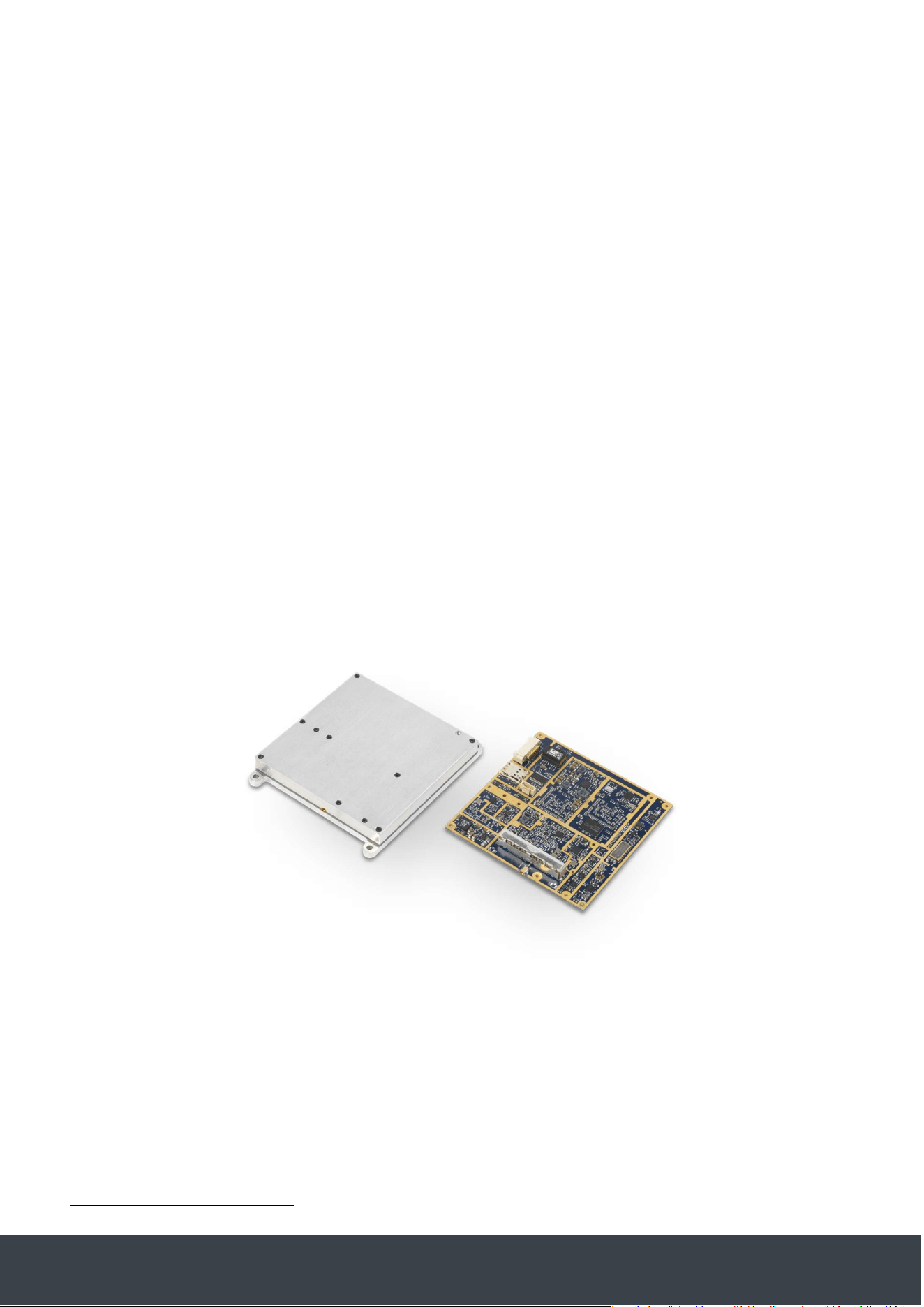
The Gotonomi Module is a satcom only solution. The terminal is 90mm x 90mm x 16mm and
weighs 195g.
Figure 1 - Gotonomi Module
An external antenna is required for satellite connectivity.
1
See section Satellite Coverage
Gotonomi Module Installation Guide Gotonomi.com | CONFIDENTIAL Page 6 of 30
4.4 Gotonomi Multilink Module
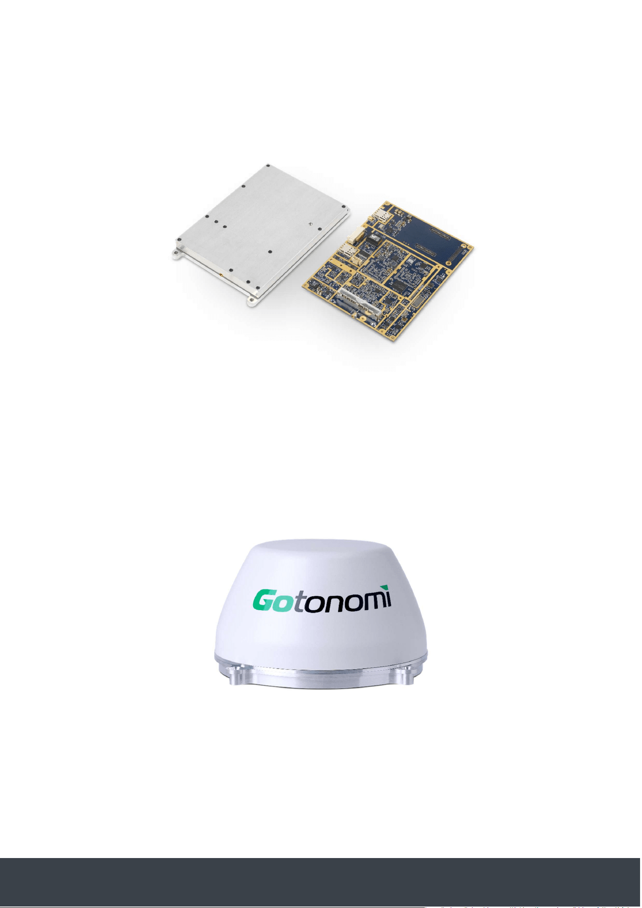
The Gotonomi Multilink Module integrates the satcom modem from the Gotonomi Module with an
iMX8 System On Module (SOM) [DART-MX8MQ 1.600GHz 2048MB RAM, 16GB eMMC] and a 4G
LTE modem chipset (Quectel EG21G). The terminal is 130mm x 90mm x 16mm and weighs 245g.
Figure 2 Gotonomi Multilink Module
4.5 Gotonomi V200
The Gotonomi V200 integrates the satcom modem from the Gotonomi Module with an integrated
satcom antenna, providing a single item solution. The terminal is 145mm dia x 83mm and weighs
580g.
Figure 3 - Gotonomi V200
Gotonomi Module Installation Guide Gotonomi.com | CONFIDENTIAL Page 7 of 30
4.7 External Interfaces
4.7.1 Gotonomi Module
The Gotonomi Module has 3 external interfaces: Remotely Piloted Aircraft System (RPAS), RF &
Satcom uSIM
4.7.1.1 RPAS
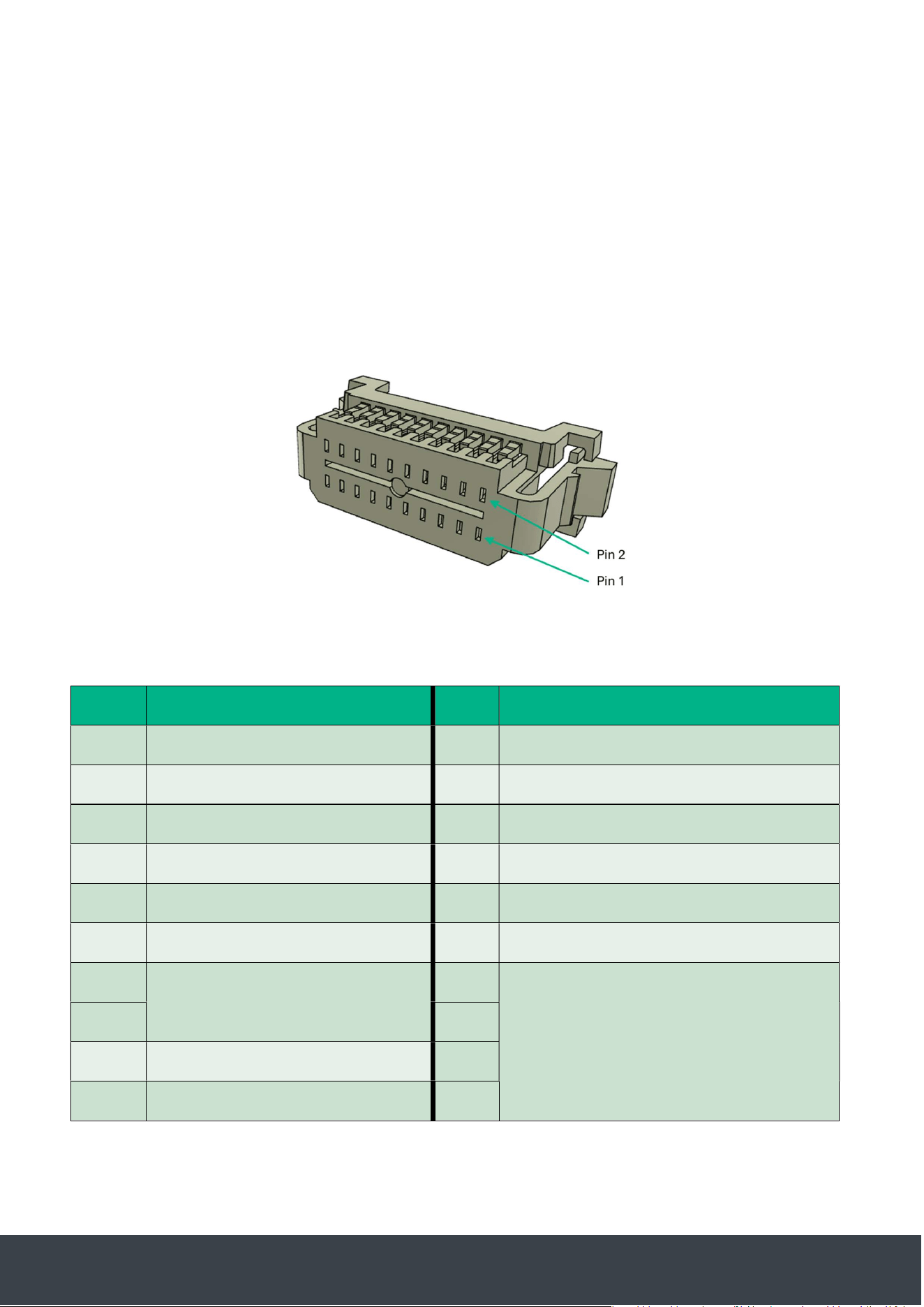
The Gotonomi Module has a side mounted 20 way socket, part number: T1M-10-GF-DH
The mating connector shell for this is the Samtec S1SD-10
Figure 4 – Gotonomi Module and Multilink RPAS and power connector
The pinout is as follows based on the 586B standard, named from the terminal:
Pin
Terminal
Signal
Name
Pin
Terminal Signal Name
1
Ethernet_RX_N
–
Solid Green
2
Do not connect
3
Ethernet_RX_P
–
Green Stripe
4
Do not connect
5
Ethernet Shield
6
Do not connect
7
Ethernet_TX_N Orange
8
Vin 0v
9
Ethernet_TX_P
–
Orange Stripe
10
Do not connect
11
Vin 0v
12
Do not connect
13
Vin 18
-
36v
14
Vin 0v
15
16
17
Do not connect
18
19
Do not connect
20
Gotonomi Module Installation Guide Gotonomi.com | CONFIDENTIAL Page 8 of 30
Figure 5 - Gotonomi Module Connector
Care must be taken when connecting and disconnecting this cable as irreparable internal damage
can be caused to the terminal if the connector is forced whilst the pins are misaligned.
4.7.1.2 Satcom uSIM
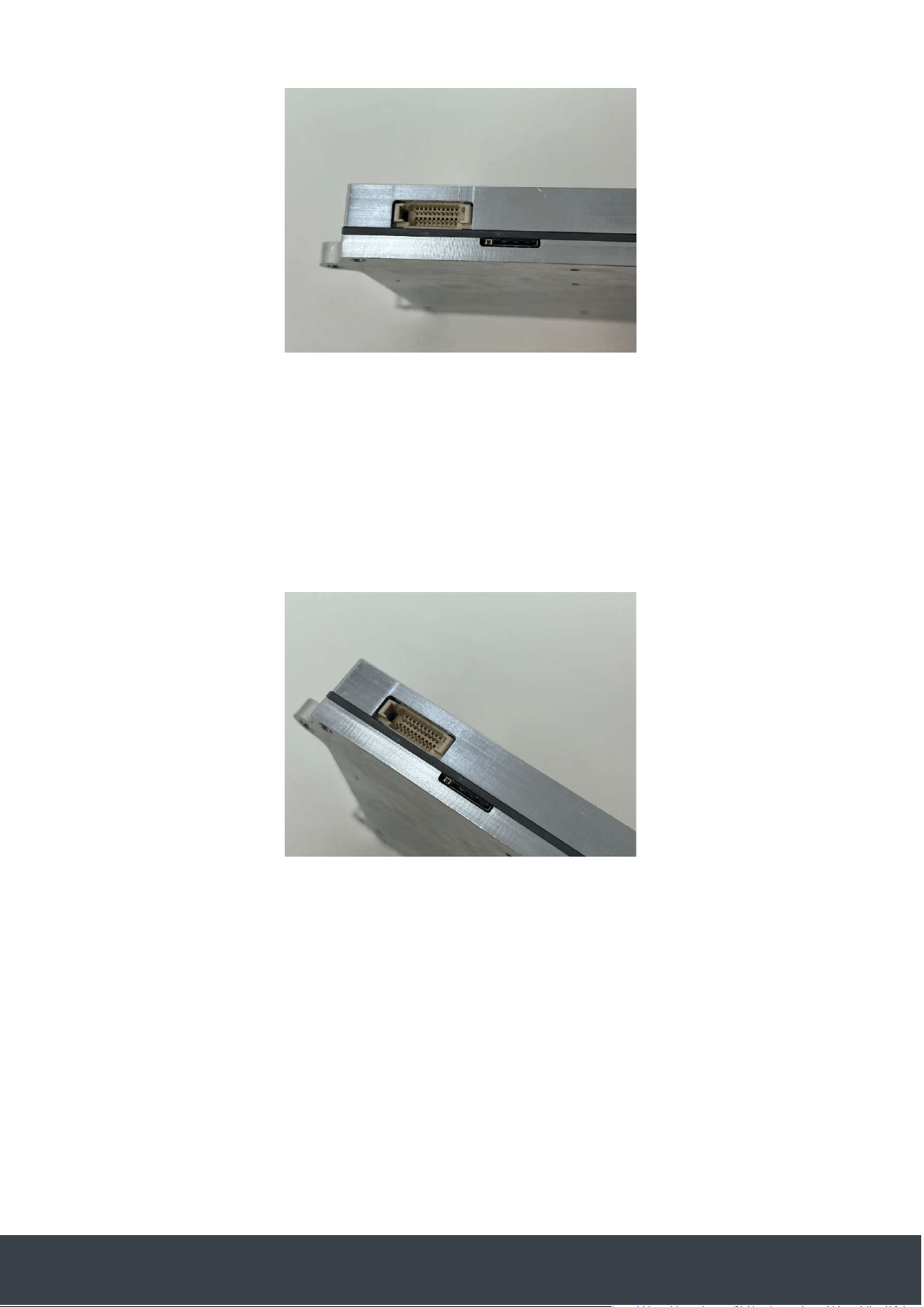
A 4FF size (nanoSIM) slot is provided. This should only be used with SIM provided by Inmarsat or
an Inmarsat distribution partner. The SIM is polarised and can only be inserted in the correct
orientation. The SIM card slot can be damaged if a modified 2FF SIM card is used.
Figure 6 - Gotonomi Module uSIM Slot
Gotonomi Module Installation Guide Gotonomi.com | CONFIDENTIAL Page 9 of 30
4.7.1.3 RF
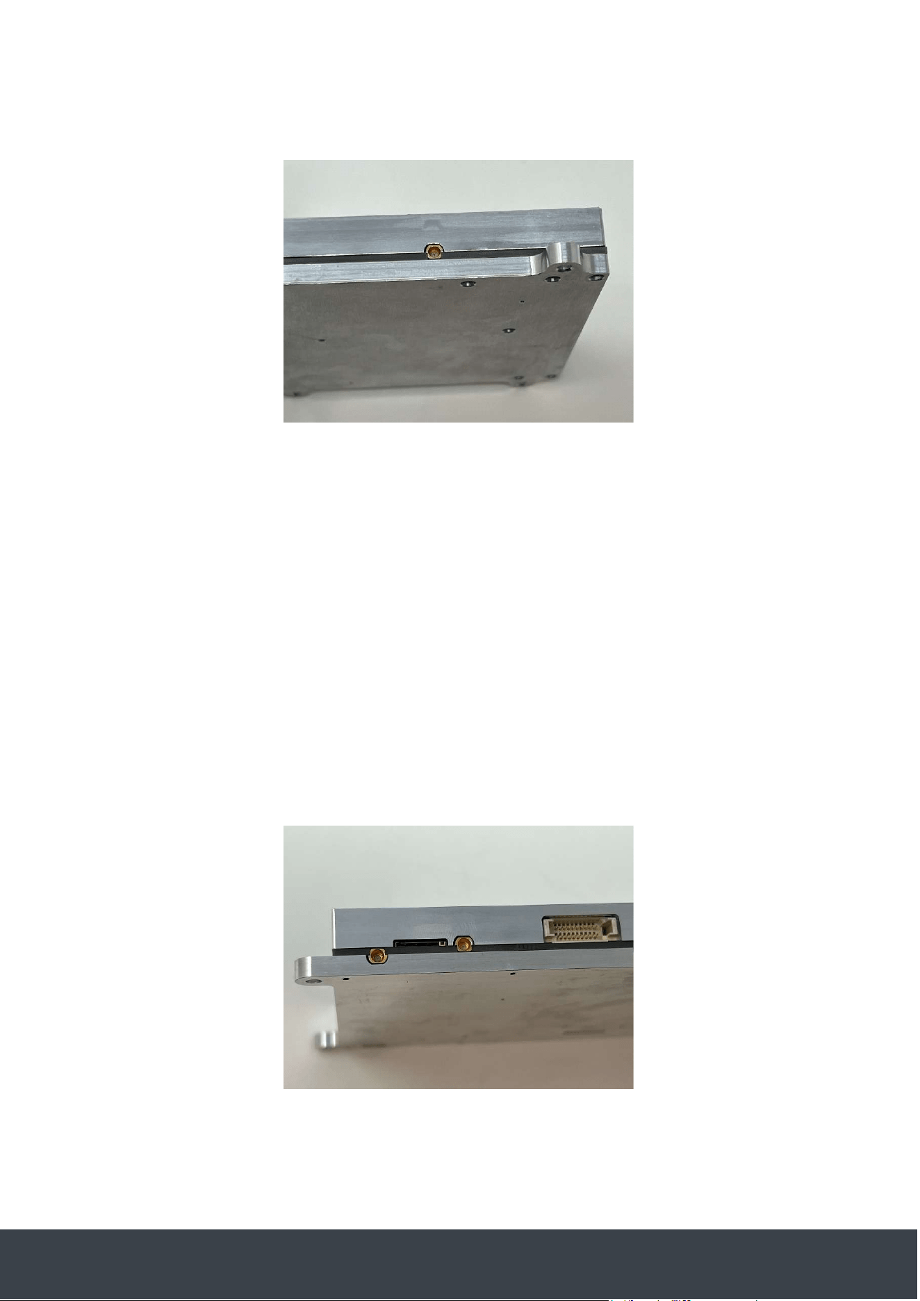
The RF antenna interface is SMPM 50Ω interface. Refer to section 5.3.6 for more information.
Figure 7 - Gotonomi Module Antenna Connection
4.7.2 Gotonomi Multilink
The Gotonomi Multilink shares the same external connections as the Gotonomi module however
it has 2 additional interfaces for the LTE modem.
4.7.2.1 LTE uSIM
A 4FF (nanoSIM) slot is provided. This may be used with any appropriate airtime provider.
Additional software configuration of the terminal may be required to support individual airtime
providers. The SIM is polarised and can only be inserted in the correct orientation. The SIM card
and or slot can be damaged if incorrectly orientated.
4.7.2.2 LTE RF
Two LTE antenna ports are provided, 1 main antenna port and 1 for a diversity antenna. The
connector type is SMPM, any standard LTE antenna is supported.
Figure 8 - Gotonomi Multilink LTE Antenna ports.
Main antenna connector bottom left, diversity antenna connector closer to the centre
Gotonomi Module Installation Guide Gotonomi.com | CONFIDENTIAL Page 10 of 30
4.7.3 Gotonomi 200
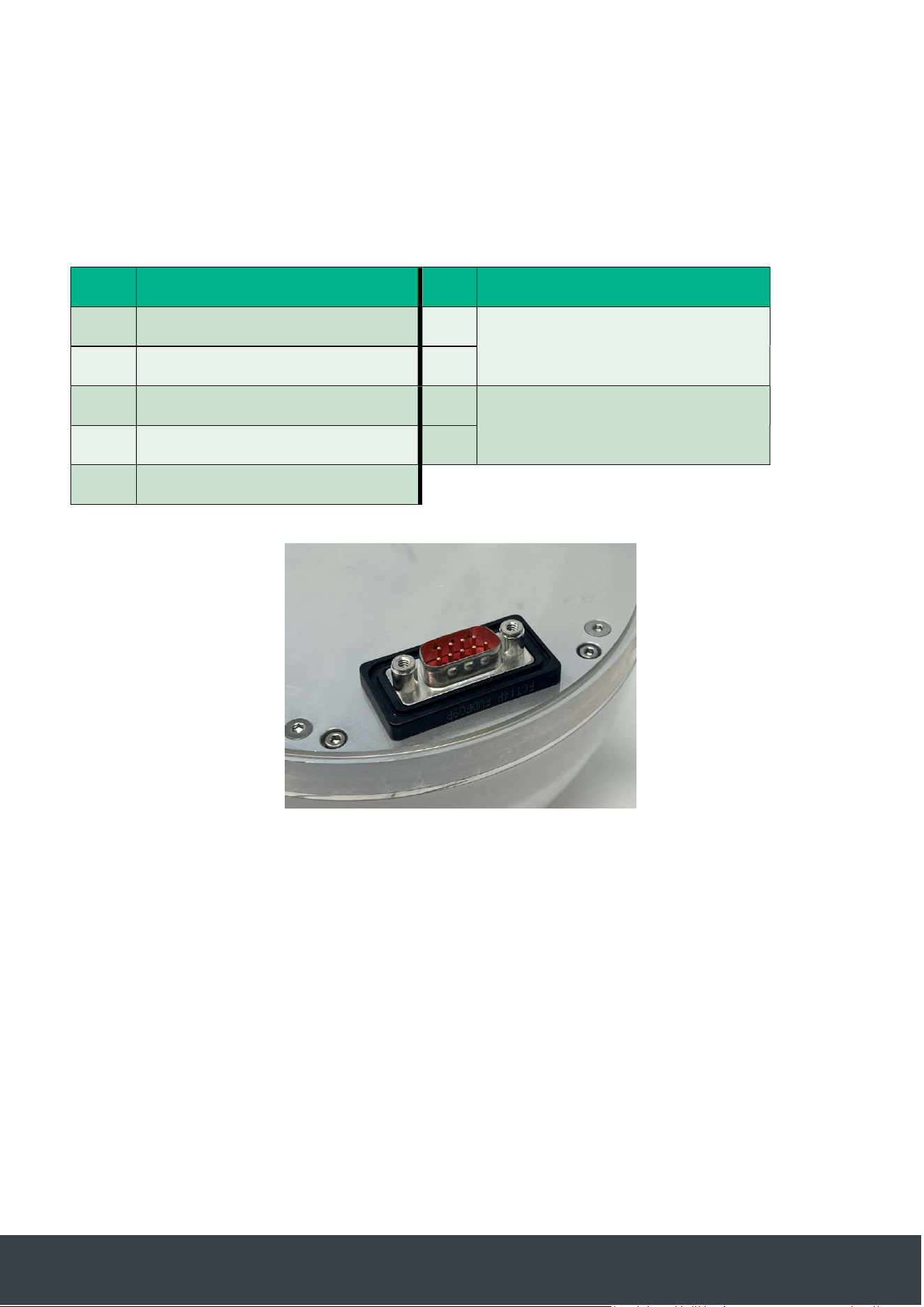
The Gotonomi 200 has a single IP65 rated standard D-SUB 9 connector. The mating connector is a
Molex 173114-0383. The uSIM is not user accessible.
4.7.3.1 Gotonomi 200 RPAS Interface
Pin names based on the 586B standard viewed from the terminal
Pin
Terminal Signal Name
Pin
Terminal Signal Name
1
Ethernet_TX_P – Orange Stripe
6
Vin 18
-
36v
–
Blue Stripe
Solid Blue
2
Ethernet_TX_N – Solid Orange
7
3
Ethernet Shield
8
Vin 0v
–
Brown Stripe
Solid Brown
4
Ethernet_RX_P – Solid Green
9
5
Ethernet_RX_N – Green Stripe
Figure 9 - V200 Connector
Gotonomi Module Installation Guide Gotonomi.com | CONFIDENTIAL Page 11 of 30
5 Installation
5.1 Process
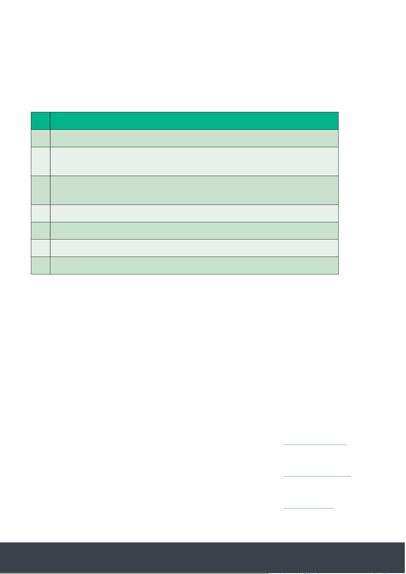
Whilst there is no standard airframe, use case or installation the following steps should be
considered as a minimum:
1
Unpacking of equipment
2
Check
-
out test of equipment in a lab or controlled environment confirming
ethernet connectivity and satellite connection
3
Onboard system integration including control and monitoring of the modem and
desired data flow control and routing
4
Mechanical and electrical integration with the airframe
5
Satcom operation following integration
6
Test to ensure other onboard systems are not adversely aected by the satcom
7
Systematic flight trials
5.2 Storage and transport
Temperature: -40 to +70deg C
Humidity: 0 to 95% non-condensing
5.3 Installation guidelines
5.3.1 Safety
Safety guidelines are detailed in section 8.
5.3.2 Mechanical Guide
5.3.2.1 Gotonomi Module
Mechanical drawings and 3D STEP files are available for download here: Gotonomi Module
5.3.2.2 Gotonomi Multilink
Mechanical drawings and 3D STEP files are available for download here: Gotonomi Multilink
5.3.2.3 Gotonomi 200
Mechanical drawings and 3D STEP files are available for download here: Gotonomi 200
Gotonomi Module Installation Guide Gotonomi.com | CONFIDENTIAL Page 12 of 30
5.3.3 Thermal Management
The design of the thermal management is a key part of the integration design and will vary
depending on the use case and the environment.
In all cases the thermal management of the terminal must be considered and designed.
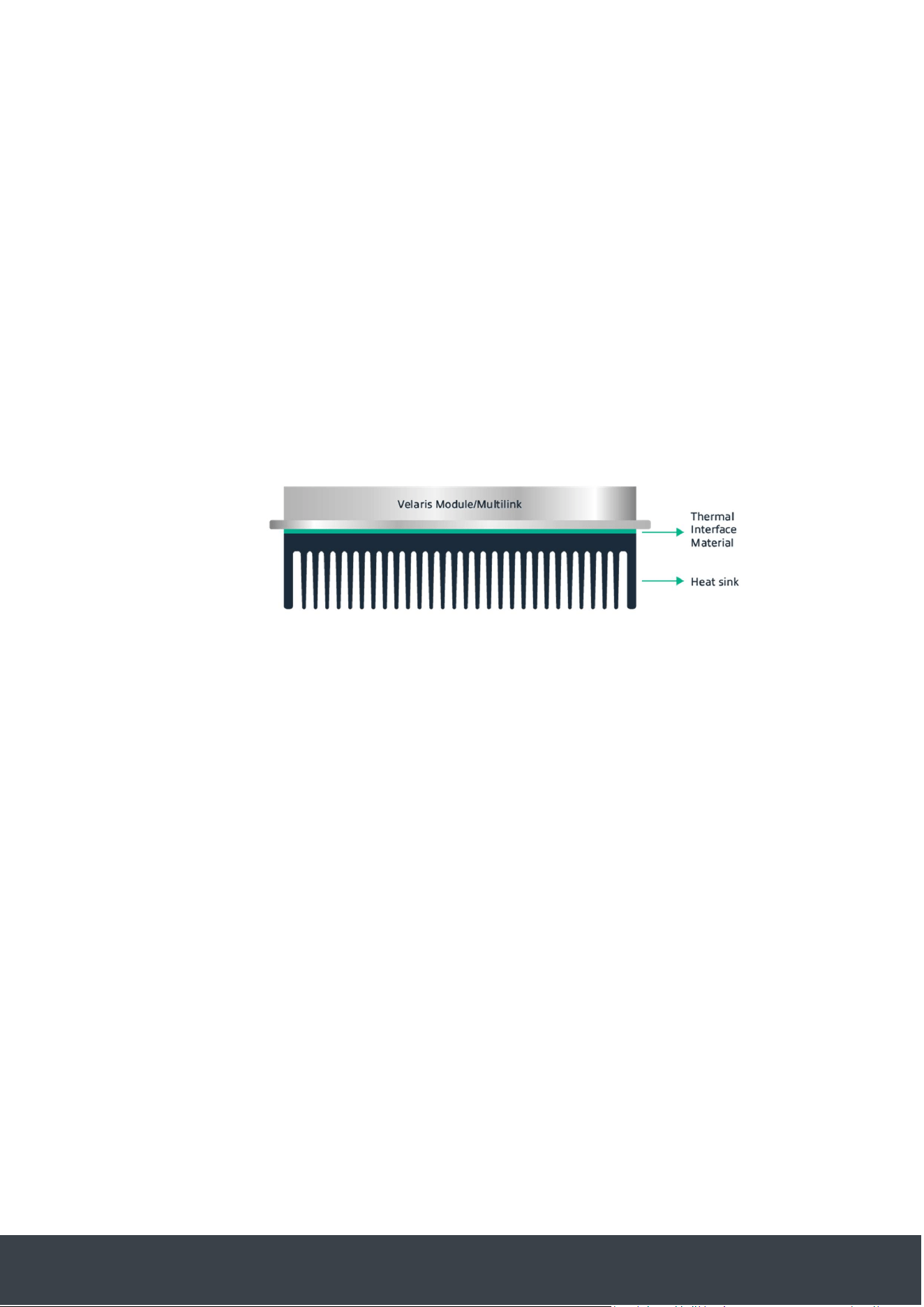
The thermal output of the terminal is highly dependent on the uplink data rate. During receive only
operation the system produces approximately 4W, at peak upload capacity the system produces
approximately 20W.
Figure 10 – Gotonomi Module and Mullikink with heatsink
The terminal cannot be damaged by self-induced heating and will enter a protective power down
state if the internal temperature reaches 85°C. This status may be queried via the REST API or
viewed in the WebUI.
5.3.3.1 Example 1
For evaluation use a Fischer Elektronik SK92-100-SA or equivalent (1K/W) with a suitable thermal
interface pad or paste applied is appropriate for mixed use, with 20°C ambient with no radiant
heating.
5.3.3.1.1 Example 2
A Gotonomi Module placed inside a fixed wing UAV with trickle airflow, no heatsink, 18°C ambient
with limited solar gain. With a data rate of 50kbps maintained a stable operating temperature of
approximately 60°C

Gotonomi Module Installation Guide Gotonomi.com | CONFIDENTIAL Page 13 of 30
5.3.4 IP Protection
The Gotonomi Module and Gotonomi Multilink have been designed to IP20 rating. It is
recommended that these terminals be installed within an airframe or otherwise protected.
The V200 terminal is designed to IP67 rating. A breathable membrane is fitted to allow for pressure
changes.
5.3.5 Power and Ethernet Cable
All terminals use a combined power and data cable. The interface specification is described in
section Power supply.
The wiring selected for the power connection should be able to supply 40W with the voltage drop
of the cable still meeting the power supply requirements of the terminal.
The ethernet connection utilises 2 twisted pairs (100Base-TX) so an appropriate data cable may
be used to reduce weight.
Care must be taken to prevent EMI from the ethernet cables coupling to the power supply cabling,
this should be either via screened ethernet cable or physical separation.
Care must be taken to prevent EMI from the antenna from coupling to the power supply cabling, it
is recommended to shield the power supply cables in the vicinity of the terminal, to a distance of
at least 30 cm.
The grounding scheme adopted for the system will be airframe specific, it is acceptable to treat
the housing of the terminal as a system ground. The housing of the terminal is directly connected
to the 0v power supply terminal of the external interface.
5.3.5.1 Multilink
The SOM module will thermally protect at 85°C
5.3.6 Antenna and RF Cable
The Gotonomi Module and Gotonomi Multilink terminals require external antennas. The approved
antennas are the Gotonomi 200-A Omni and Cobham LGA3000. Please contact Gotonomi about
use of alternative antennas.
The terminals are designed and calibrated to be used with an RF cable equivalent to Amphenol
7032-7526 or 7029-3640 . The Gotonomi terminals are designed to be placed within 30cm of the
antenna in order to minimise cable loss. Use of a longer cable, or with lower performance than the
cable specified may result in poor network performance.
The cable loss between terminal and antenna must be <= 0.3dB at 1.6GHz.
Gotonomi Module Installation Guide Gotonomi.com | CONFIDENTIAL Page 14 of 30
5.3.7 Satellite Coverage
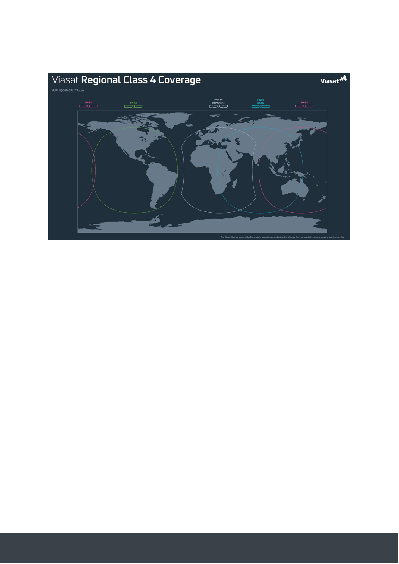
Figure 11 – Viasat Regional Class 4 Coverage map
This map shows the approximate coverage of the dierent Viasat satellites.
The Gotonomi terminals currently operate as a regional class 4.2 terminal down to an elevation of
20 degrees. Below this elevation terminals will not be able to connect to the network. Terminals
which are already connected before they cross this elevation will remain connected as long as the
link is maintained, if they disconnect from the network they will not be able to attach again until
they have returned to below 20deg elevation.
5.3.8 Satellite Selection
The terminals are designed to switch from one satellite to another as they move across the globe.
In areas where more than 1 satellite is available it is possible for the terminal to remain attached
to the satellite with the weaker signal if the terminal is in a static location. If you think this is likely
to aect you then please contact Gotonomi support for more information.
5.3.9 Antenna positioning
The antenna requires clear line of sight to the satellite. Several online tools
2
are available which
can indicate where the satellite from your current location to the satellite named in Satellite
Coverage.
The system is designed for use with omni-directional antennas operating in the open environment.
This means that the antenna does not need to be pointed towards the satellite. The antenna must
be mounted with the base plate horizontal to the ground during straight and level flight.
2
https://www.groundcontrol.com/us/knowledge/look-angle-calculator/ - Accessed Aug 2024
Gotonomi Module Installation Guide Gotonomi.com | CONFIDENTIAL Page 15 of 30
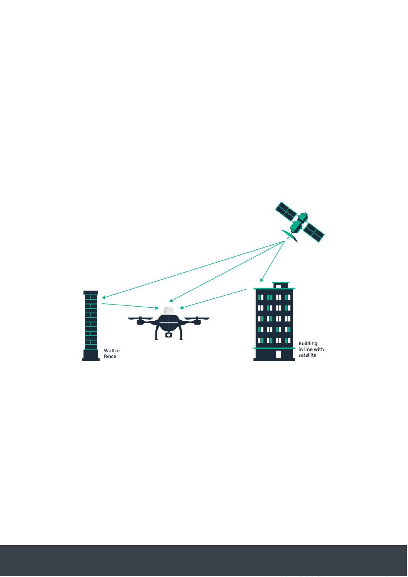
Buildings or structures can reflect the satellite signal which may interfere with operation of the
system. It is recommended that the antenna be at least 20m away from any large structures.
When operating at low elevation, ground structures may also cause reflections and interference.
See Figure 12 – Note that whilst L-Band is unaected by weather, the multipath reflections may
change due to weather conditions which can adversely aect performance if the system is
experiencing multipath interference.
This kind of interference may present as:
- Low signal strength
- Highly variable signal strength (working 1 minute, not working the next)
- High CRC error rate
- Poor data rate performance
Figure 12 -Examples of multipath interference
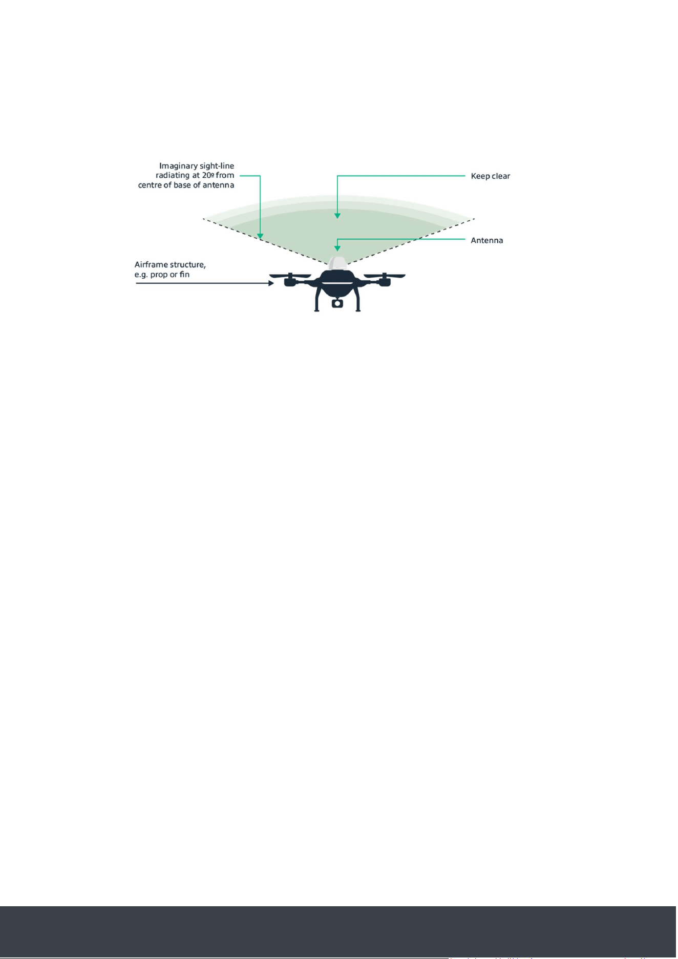
Figure 13 shows the positioning of the antenna relative to elements of the airframe. The antenna
must have a clear line of sight from the centre of the base of the antenna, at an angle of 20
degrees. For future development it is recommended to have a clear line of sight of 5 degrees.
Gotonomi Module Installation Guide Gotonomi.com | CONFIDENTIAL Page 16 of 30
Figure 13 – Example of Airframe blocking
5.3.10 Weather
Signals to/from the satellite are not aected by cloud or rain.
5.3.11 GNSS
All Gotonomi terminals are able to receive GNSS information via the same antenna used for the
Satellite communication. This information is available for other use via the REST API. The
terminals support reception on the L1 band of GPS and Galileo.
GNSS data may be supplied to the terminal via the REST API from an alternative system.
It is known that L-Band Satellite Communication transmission will cause interference with other
GPS receivers. Consideration should be made to locate GNSS receivers away from the Gotonomi
antenna, to provide appropriate filtering on the GNSS receiver, or to select a GNSS receiver which
incorporates filtering specifically designed to minimise Satcom interference (for example the
Ublox NEO-8MN). Antenna placement should such that the installation can achieve at least 42dB
radio frequency isolation between the Gotonomi terminal and GNSS receiver. As a general
guideline, GNSS receiver interference can be further minimised if the GNSS receiver antenna is
mounted below the level of the Gotonomi antenna. To ensure suicient isolation is achieved the
installer should perform post installation and prior to flight testing, with the satcom and GNSS
receiver active, checking that the GNSS receiver continues to operate nominally.
The terminal may be configured to use external GNSS information for certain use cases, please
contact Gotonomi for more information.
Gotonomi Module Installation Guide Gotonomi.com | CONFIDENTIAL Page 17 of 30
5.3.12 Power supply
A Power Source Type 2 (PS2) supply should be used – slow blow fuse protected.
Voltage range: 18 – 36v.
The power requirement depends on the usage conditions, these figures are provided for guidance,
it is recommended to test the terminals in your intended configuration.
All measurements were made at 20v DC supply
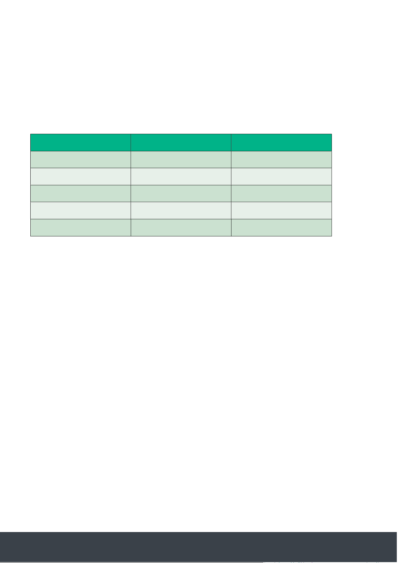
Conditions
5 sec average
Peak Transient
Idle
–
GNSS search
150mA
150mA
Satcom network attach
200mA
2000mA
Satcom 150kbps transfer
1000mA
1400mA
LTE no Satcom
tbc
tbc
SOM no Satcom, no LTE
tbc
tbc
5.3.12.1 Transient response
The power supply must be capable of coping with the transient power draw of the system. A
transient is described as magnitude above with a rise time of <10ms.
As the system employs switch-mode power supplies the currents given are referenced to the
supply voltage so may fluctuate depending on the supply voltage.
5.3.12.2
5.3.13 Known sources of Interference
5.3.13.1 USB3
USB3 uses spread-spectrum clocking to reduce the intensity of electromagnetic emissions in its
fundamental frequencies. The result is to cause broadband emissions from approximately DC to
10GHz.
USB3 equipment e.g. USB3-Ethernet adaptors added to external devices (Raspberry Pi logger, or
RPAS instrumentation etc.) should be appropriately shielded from the satcom antenna.

Gotonomi Module Installation Guide Gotonomi.com | CONFIDENTIAL Page 18 of 30
6 Maintenance
6.1 Servicing
The terminals contain no user-serviceable parts.
The Gotonomi module and Gotonomi multilink are not sealed units, cleaning should be with a
clean dry cloth only.
7 User Terminal Operation
7.1 Terminal Interfaces Overview
7.1.1 IP Address
By default the terminals are configured to use the IP address 192.168.1.1 and to act as DHCP
servers on their ethernet port. This behaviour is configurable, please consult Gotonomi support
pages for instructions.
7.1.2 Certificates Username & Password
The REST and WebUI interface operate over https with basic authentication. The username and
password are available from support@gotonomi.com
Note that as the terminal uses a self-signed certificate you will receive a warning from most
modern web browsers or command line tools.
7.1.3 REST API Interface
The primary control interface for the terminal is the REST API. An OpenAPI specification for the
interface is available. The API can control all aspects of the terminal, from device status and
monitoring to connection configuration and management.
7.1.4 AT Command Interface
A legacy AT command interface is supported by the terminal. This is disabled by default but may
be enabled by user configuration. Please contact support for instructions.
7.1.5 WebUI Interface
The WebUI is available via any web browser. The default location for this is https://192.168.1.1.
The WebUI provides support for many basic operations of the terminal such as configuring
connection profiles and activating and deactivating connections.
7.1.6 Multilink Interface
The multilink terminal includes a SOM processor and LTE modem
Gotonomi Module Installation Guide Gotonomi.com | CONFIDENTIAL Page 19 of 30
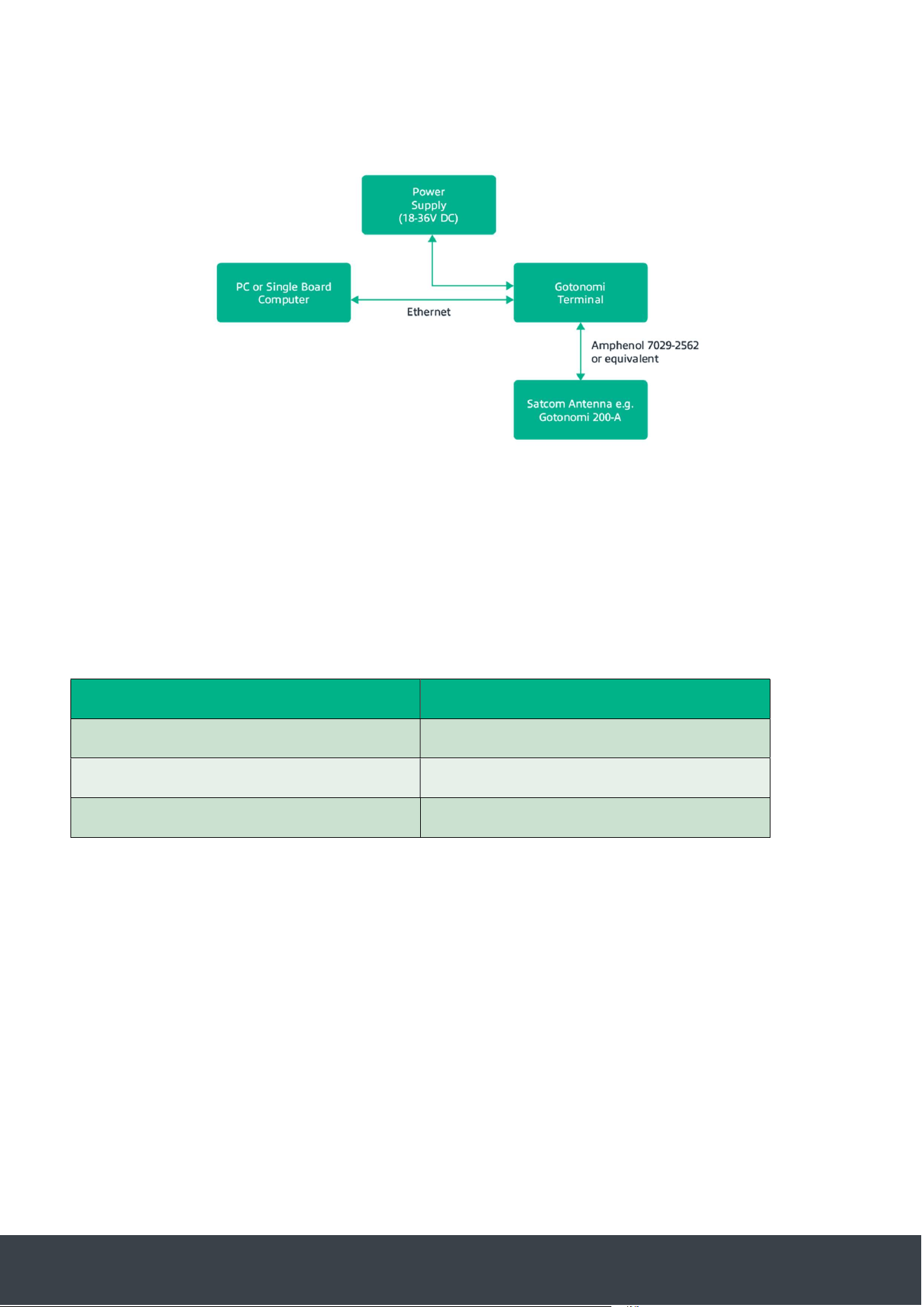
Figure 14 - Gotonomi block diagram
The external ethernet interface connects to the SOM processor. The SOM processor is a Variscite
DART-MX8M-MINI.
Specification:
CPU
Quad Core Arm Cortex A53 @ 1.6GHz
Memory
2GB RAM
Storage
16GB eMMC
OS
Yocto
Linux
Due to the variety of software configurations available for the SOM processor it is not possible to
detail them here, please seek advice from support on both supported commercial oerings
and/or customer development options.
Gotonomi Module Installation Guide Gotonomi.com | CONFIDENTIAL Page 20 of 30
7.2 WebUI
The WebUI is available on the IP address of the terminal, by default this would be
https://192.168.1.1
Note: If using a Multilink then the WebUI is accessible as it is routed via the SOM ethernet
interface to make getting started easier. Certain configuration does not work in the same way as
the Gotonomi module or V200, you are advised to contact support@gotonomi.com.
7.2.1 Dashboard
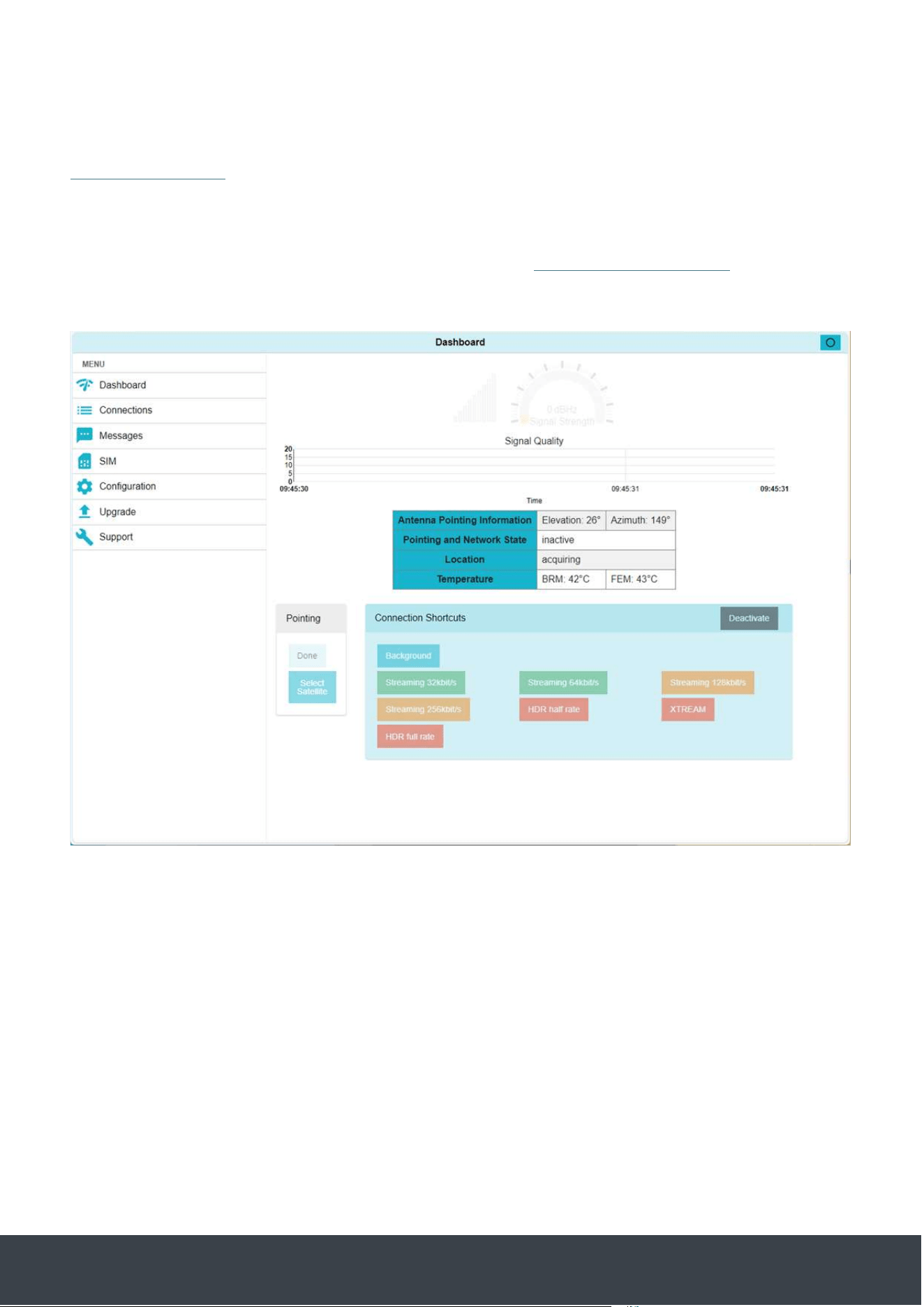
Figure 15 - WebUI

Gotonomi Module Installation Guide Gotonomi.com | CONFIDENTIAL Page 21 of 30
The central blue box provides critical information regarding the status of the terminal:
Entry
Description
Location
The Gotonomi terminal cannot connect
to the BGAN network without a valid GPS
fix. This entry will progress from:
acquiring, to valid fix and finally display a
longitude and latitude
Pointing and Network State
This entry will start at detached and (once
a valid fix is achieved) progress to ready
(detached) and then ready + attached
Antenna pointing information
The Gotonomi terminals currently only
support operation where the elevation of
the satellite is greater than 20 degrees. If
the elevation falls below this it is likely
that the network will not permit
attachment
Temperature
The temperature of the FEM must remain
below 85 degrees. If this temperature is
exceeded the terminal will shut down the
satcom link until the temperature has
fallen
Note that the connection shortcuts links on the main dashboard are not valid for the Gotonomi
terminals and will be removed in a future FW update
Gotonomi Module Installation Guide Gotonomi.com | CONFIDENTIAL Page 22 of 30
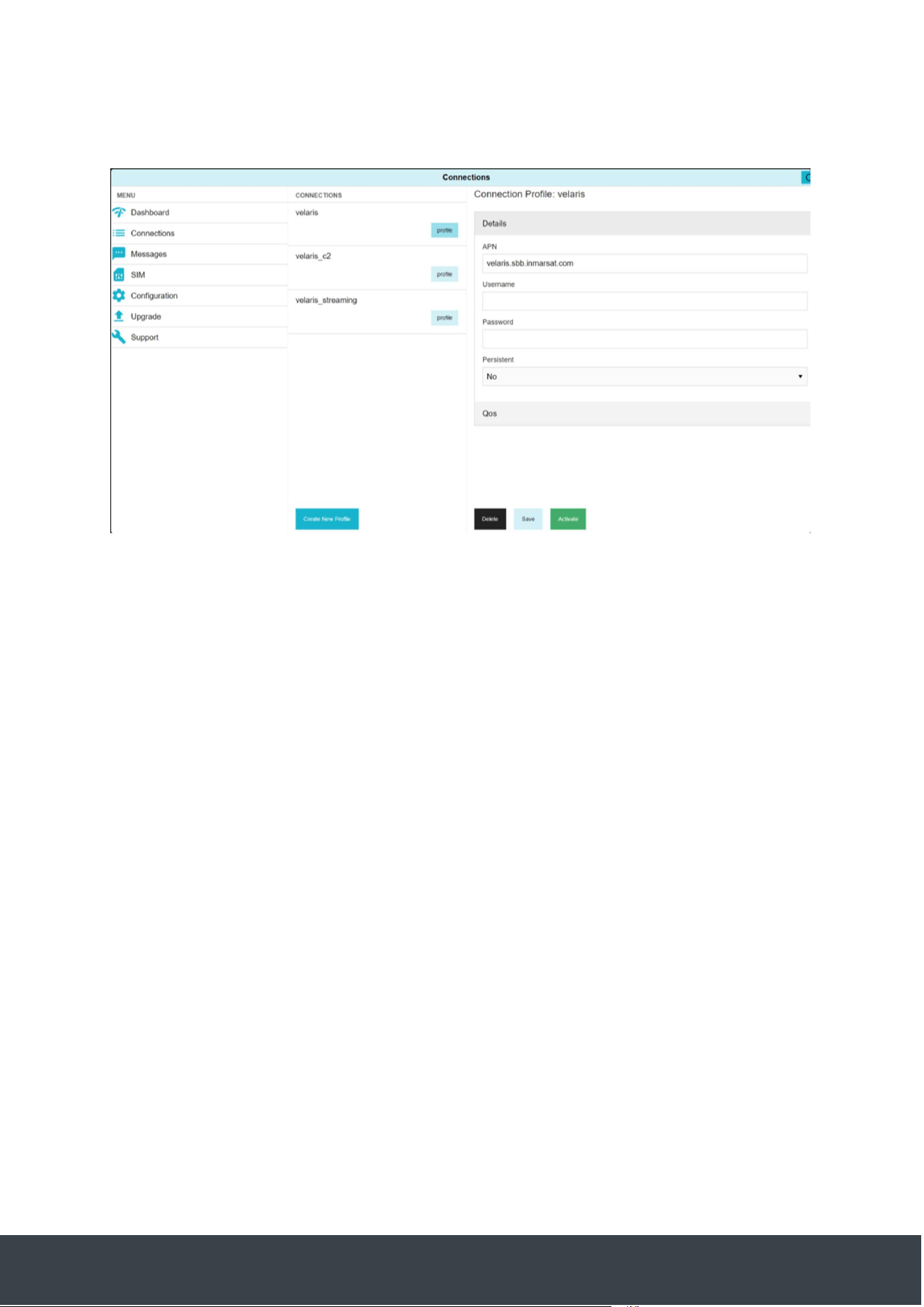
7.2.2 Connections
The connections tab allows the configuration and activation of dierent PDP contexts
Figure 16 - Connections interface
Clicking on a profile will allow modification of the configuration and/or activation of it
Setting a profile to persistent will cause the terminal to activate this connection each time the
terminal connects to the network.
The QoS settings are a request to the network for a particular quality of service, once the link has
been established the QoS section will be marked “negotiated” and will show the QoS agreed with
the network.
Note: a streaming connection incurs per-minute charges
7.2.3 Upgrade
The upgrade tab allows for firmware updates to the modem by dragging and dropping files
provided.
7.3 Satellite Data Link
7.3.1 Data rate
The system provides maximum background connection data rates of 200kbps up and down
however this is not guaranteed bandwidth and depends both on signal strength and network
loading. Streaming data connections up to 32kbps are supported which provide guaranteed
bandwidth. Streaming connections at 8 and 16kbps are also supported.

Gotonomi Module Installation Guide Gotonomi.com | CONFIDENTIAL Page 23 of 30
7.3.2 APN
By default 3 dierent satcom connection profiles are configured:
Connection Name
APN / Configuration
Description
velaris
velaris.sbb.inmarsat.com
Background data connection
velaris_c2
velaris.c2.sbb.inmarsat.com
Prioritised background data
connection for C2 data –
please note this is not
currently implemented
data over is this apn is the
same as the velaris connectin
velaris_streaming
velaris.stream.sbb.inmarsat.com
Streaming enabled data
connection at 8, 16 or 32kbps
The username and password present for each connection profile are synchronised with the SIM
card. Each username and password is specific for the APN and cannot be used multiple times
simultaneously. Please contact support@gotonomi.com if you require more active PDP contexts
to each APN.
If a connection is activated then the terminal will route all traic via that connection.
7.3.3 PPPoE
The Gotonomi terminals can support up to 10 simultaneous PDP contexts. A host system can
establish a PPPoE connection to the modem. The PPPoE connection must specify one of the
APN’s. Instructions are available for Windows and Linux from support@gotonomi.com.
Once a PPPoE connection is established the modem will no longer route traic via a normally
activated context, it would therefore be required for the host system to do that if needed.
PPPoE connections will only succeed if the terminal is able to activate the network connection,
therefore it will not work until the terminal is attached to the network.

Gotonomi Module Installation Guide Gotonomi.com | CONFIDENTIAL Page 24 of 30
7.4 Data rate control
Due to the nature of operation of these terminals it is likely that the available bandwidth will
fluctuate whether this is due to the capacity of background data or due to the antenna being
turned away from the satellite during a banking manoeuvre.
During these periods the network acts as a store and forwards system, with both the terminal and
the ground station buering data until the link returns. During this and immediately after, until the
backlog has been cleared, it is likely that the user will experience an increase in latency, not due to
an increase in the link itself but as data has to queue before it can be transferred. Users should be
mindful that the capacity of the link can fluctuate and the closer to operating at link maximum the
terminal is the longer it will take to return to normal operation. If the latency is too high then
certain user applications running over the satcom link may start to fail.
Note: Windows in its default configuration will place a lot of traic on the connection which can
both aect testing and/or create large data bills.

Gotonomi Module Installation Guide Gotonomi.com | CONFIDENTIAL Page 25 of 30
8 Safety information
8.1 Introduction
All variants of the Velaris product are considered system components. There are certain
requirements for system integration which were assumed during the terminal safety assessment.
These requirements are described in this section.
8.2 Outside use
The terminal must only be used within a structure or self-contained system such as a UAV. The
terminal must not be connected to infrastructure cabling without appropriate protection for the
terminal from external circuit transients.
If the terminal is attached to a building or building structure then the maximum height above
ground for which the unit has been assessed is 2m.
8.3 Safeguards against transient voltages from external circuits
When using the terminal in a non-integrated state the ethernet interface must be protected by a
network isolator compliant to IEC 62368-1.
When using the terminal in an integrated state the installer may assess the terminal has a
permanently installed protective earth as an alternative route to meet IEC62368-1.
8.4 Power supply
The power supply of the terminal must be of type PS2. This requires that the power supply is
limited to not exceed 100W after 5 seconds.
8.5 RF Safety
When the antenna is operational an operator should maintain a distance from the antenna
radome of at least 68cm. Note that there is no requirement below the horizon of the antenna.
8.6 Thermal safety
The integrator is responsible for providing suicient heat sinking to limit the internal and external
temperatures of the terminal. With no thermal management, under non fault high throughput
conditions the surface temperature of the terminal may reach 85 degrees. Appropriate warnings
and access controls should be appropriate to the installation situation.
Gotonomi Module Installation Guide Gotonomi.com | CONFIDENTIAL Page 26 of 30
9 Regulatory
9.1 Regulatory declaration information
9.1.1 Frequency use
Parameter
Value
Terminal TX frequency
1626.5 to
1660
.5MHz
1668 to 1675MHz
Terminal RX frequency
1518 to 1559MHz
GNSS frequency (receive)
1559 to 1610MHz
9.2 Country Safety Certificates
Contact support@gotonomi.com for further information.
9.3 Regulatory Declaration
Changes or modifications not expressly approved by Gotonomi/TTP Plc could void the user's
authority to operate the equipment
9.3.1 Velaris Module
FCC Supplier’s Declaration of Conformity
Gotonomi Module VM01
FCC Identifier – 2BO4Q-VMODULE200A
This device complies with part 15 of the FCC Rules. Operation is subject to the following two
conditions: (1) This device may not cause harmful interference, and (2) this device must accept
any interference received, including interference that may cause undesired operation.
Designated U.S. Agent
Company Name: Approve-IT, Inc.
Contact Name: Nathan Grinager
Street Address: 8011 34th Ave South, Suite 342
City/Province/Zip: Bloomington, MN 55425
Telephone No: 651-247-1678
Email: team@approve-it.net
FRN #: 0027533835
To ensure compliance with FCC and ISED RF exposure requirements this device must be installed
to provide a minimum of 64cm between the antennas and people.
Pour garantir la conformité aux exigences d'exposition RF de la FCC et d'ISED Canada, cet
appareil doit être installé de manière à laisser un minimum de 64 cm entre l'antenne et les
personnes.

Gotonomi Module Installation Guide Gotonomi.com | CONFIDENTIAL Page 27 of 30
This radio transmitter 33922-VMODULE200A has been approved by Innovation, Science and
Economic Development Canada to operate with the antenna types listed below, with the
maximum permissible gain indicated. Antenna types not included in this list that have a gain
greater than the maximum gain indicated for any type listed are strictly prohibited for use with this
device.
Cet émetteur radio 33922-VMODULE200A a été approuvé par Innovation, Sciences et
Développement économique Canada pour fonctionner avec les types d'antennes énumérés ci-
dessous, avec le gain maximal autorisé indiqué. Les types d'antennes non inclus dans cette liste
et dont le gain est supérieur au gain maximal indiqué pour l'un des types énumérés sont
strictement interdits avec cet appareil.
Gotonomi Omni 200A Antenna, Gain 3.5dbi, Impedance 50 Ohm
9.3.2 Velaris Multilink Module
FCC Supplier’s Declaration of Conformity
Gotonomi Module VML01
FCC Identifier – pending
This device complies with part 15 of the FCC Rules. Operation is subject to the following two
conditions: (1) This device may not cause harmful interference, and (2) this device must accept
any interference received, including interference that may cause undesired operation.
Designated U.S. Agent
Company Name: Approve-IT, Inc.
Contact Name: Nathan Grinager
Street Address: 8011 34th Ave South, Suite 342
City/Province/Zip: Bloomington, MN 55425
Telephone No: 651-247-1678
Email: team@approve-it.net
FRN #: 0027533835
To ensure compliance with FCC and ISED RF exposure requirements this device must be installed
to provide a minimum of 68cm between the antennas and people.
Pour garantir la conformité aux exigences d'exposition RF de la FCC et d'ISED Canada, cet
appareil doit être installé de manière à laisser un minimum de 68 cm entre l'antenne et les
personnes.

Gotonomi Module Installation Guide Gotonomi.com | CONFIDENTIAL Page 28 of 30
This radio transmitter 33922-VMULTIL200A has been approved by Innovation, Science and
Economic Development Canada to operate with the antenna types listed below, with the
maximum permissible gain indicated. Antenna types not included in this list that have a gain
greater than the maximum gain indicated for any type listed are strictly prohibited for use with this
device.
Cet émetteur radio 33922-VMULTIL200A a été approuvé par Innovation, Sciences et
Développement économique Canada pour fonctionner avec les types d'antennes énumérés ci-
dessous, avec le gain maximal autorisé indiqué. Les types d'antennes non inclus dans cette liste
et dont le gain est supérieur au gain maximal indiqué pour l'un des types énumérés sont
strictement interdits avec cet appareil.
Gotonomi Omni 200A Antenna, Gain 3.5dbi, Impedance 50 Ohm
9.3.3 Velaris 200
FCC Supplier’s Declaration of Conformity
Gotonomi Module V200
FCC Identifier – pending
This device complies with part 15 of the FCC Rules. Operation is subject to the following two
conditions: (1) This device may not cause harmful interference, and (2) this device must accept
any interference received, including interference that may cause undesired operation.
Designated U.S. Agent
Company Name: Approve-IT, Inc.
Contact Name: Nathan Grinager
Street Address: 8011 34th Ave South, Suite 342
City/Province/Zip: Bloomington, MN 55425
Telephone No: 651-247-1678
Email: team@approve-it.net
FRN #: 0027533835
To ensure compliance with FCC and ISED RF exposure requirements the V200 device must be
installed to provide a minimum of 64cm between the device and people.
Pour garantir la conformité aux exigences d'exposition RF de la FCC et d'ISED Canada, cet V200
appareil doit être installé de manière à laisser un minimum de 64 cm entre l'appareil et les
personnes.

Gotonomi Module Installation Guide Gotonomi.com | CONFIDENTIAL Page 29 of 30
9.4 Type Approval
The Gotonomi Terminals are type approved for the Viasat network.
Contact support@gotonomi.com for further information.
9.5 Export control
Each of the 3 Gotonomi terminals have undergone rating by the UK government. They have
advised that the terminals are covered by the Dual Use designation, rating 5A101. Users should
ensure that they comply with all appropriate laws and regulations.
Gotonomi Module Installation Guide Gotonomi.com | CONFIDENTIAL Page 30 of 30
10 Document Version History
Version
Release Date
Comments
2.3
Aug 2025
Updated Antenna Gain
2.2
July 2025
Added network isolator
section
and FCC identifier for VM
2.
1
May 2025
Added regulatory info
, safety
section and FCC agent’s details.
1.
1
March
2025
Added
altitude restrictions
1.0
21 Jan 2025
Initial release