Installatio n / User Manual
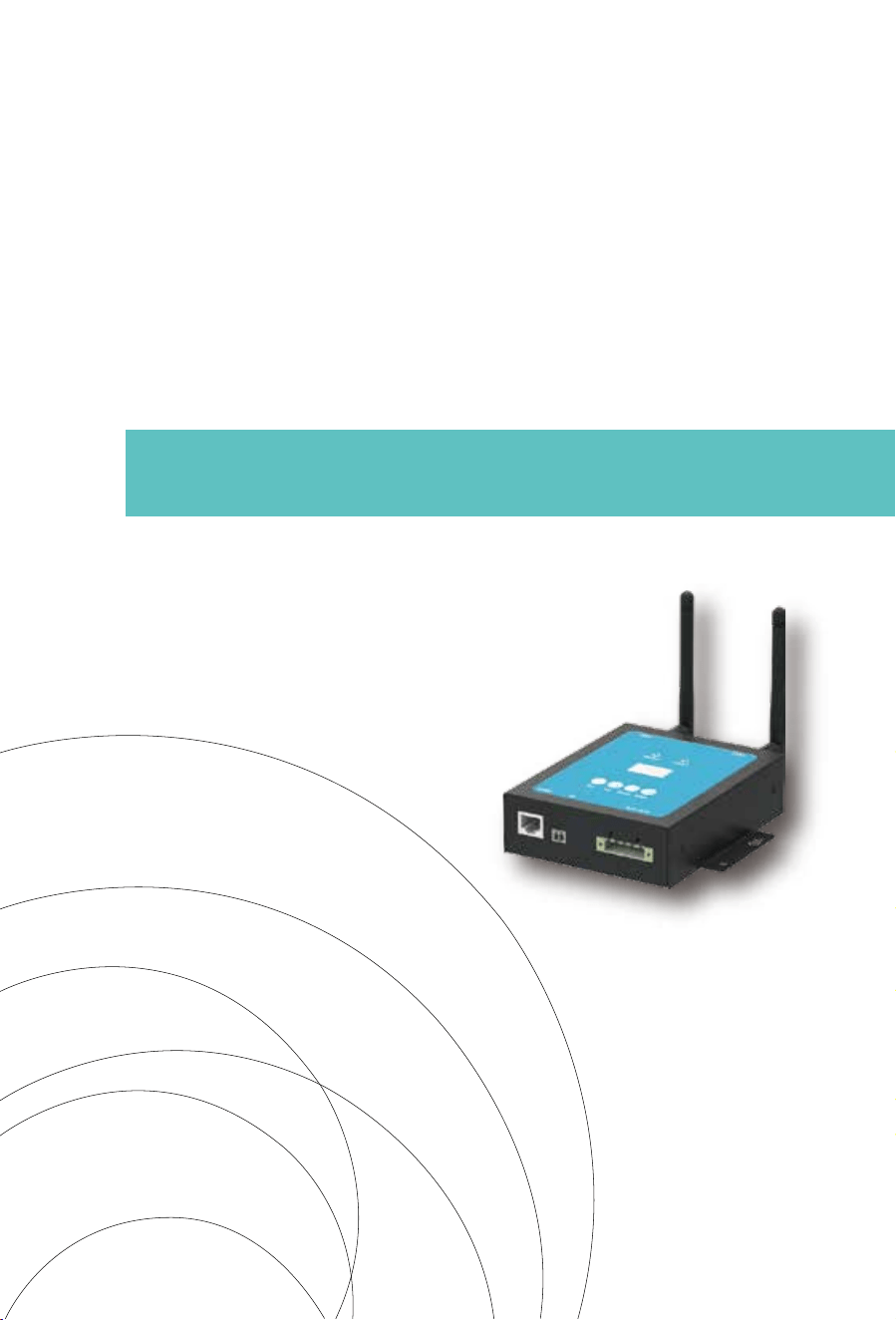
Energy Collect Device(MECD)
&Energy Monitoring Analysis(EMA)
The MECD communications gateway collects and delivers modular performance data in
real time, for comprehensive monitor and manage of your solar system, optimizing the
performance of your solar system.
With built-in programmable DI, the MECD is able to control the microinverter connected
shutdown immediately when the DI status is changed.
LCD display and buttons, easy operation;
Compact design and light in weight.
Features
Built-in Zigbee, PLC and WIFI modular;
Compatible with single phase and three phase applications;
Enables remotely monitoring and management.
Capable
User-friendly;
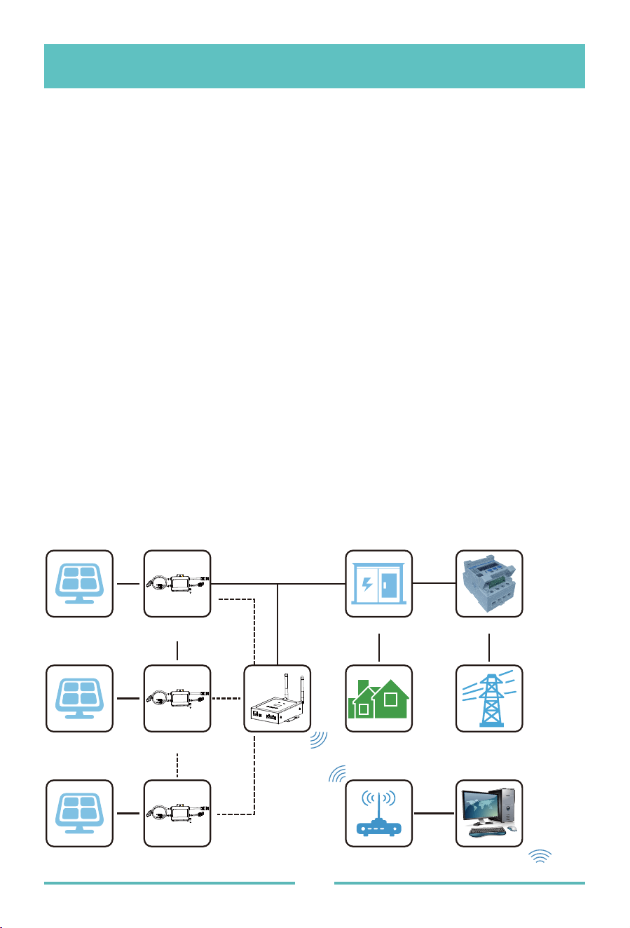
Applicaon Diagram for Single Phase System(5#,10#,20#,32#Max)
Support quick shutdown remotely for inverter;
Robust design, 3 years warranty.
Safe
Introducon
- 01 -
1# PV module 1# Microinverter
2# PV module 2# Microinverter
32# PV module 32# Microinverter
MECD
AC distribution Meter
LOAD
Router
RJ45
Server
WIFI
Zigbee PLC
AC Power supply
Zigbee
Grid
The maximum number of microinverters allowed for each branch depends on the model
of the microinverter. And the total number of microinverses of the system is not allowed
to exceed the maximum number of microinverter allowed of MECD.
- 02 -
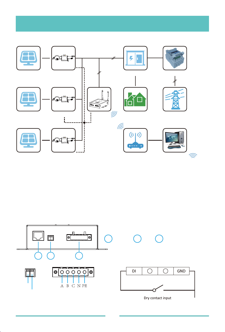
Applicaon Diagram for Three Phase System
1# PV module 1# Microinverter
2# PV module 2# Microinverter
3# PV module 3# Microinverter
MECD
AC distribution Meter
LOAD
Router
RJ45
Server
WIFI
Zigbee
L1
L2
L3
PLC
AC Power supply
Zigbee
Grid
All of the MECD interface as below,from left to right ,are Nerwork port, DI and Power
Connection Port.
DI
GND
Interface posion
RS485
: This port function is reserved.
Interface Explanaon
RS 485 DI Power Connection Port
321
1 2 3
● A dedicated standard AC electrical outlet (located electrically as close to the array
as is possible).
● A broadband Internet connection is available for your use.
● Wireless router is available for you use a laptop.
● With a web browser (to view the EMA online monitoring application).
● A pre-programmed MECD.
● A location that is electrically as close to the array asis possible-preferably a
dedicated outlet installed directly to the solar system sub-panel.
● The ECD is not rated for outdoor use, so if installing outdoors near a junction
box or breaker panel, making sure that you enclose it in an appropriate weather
proof NEMA electrical box.
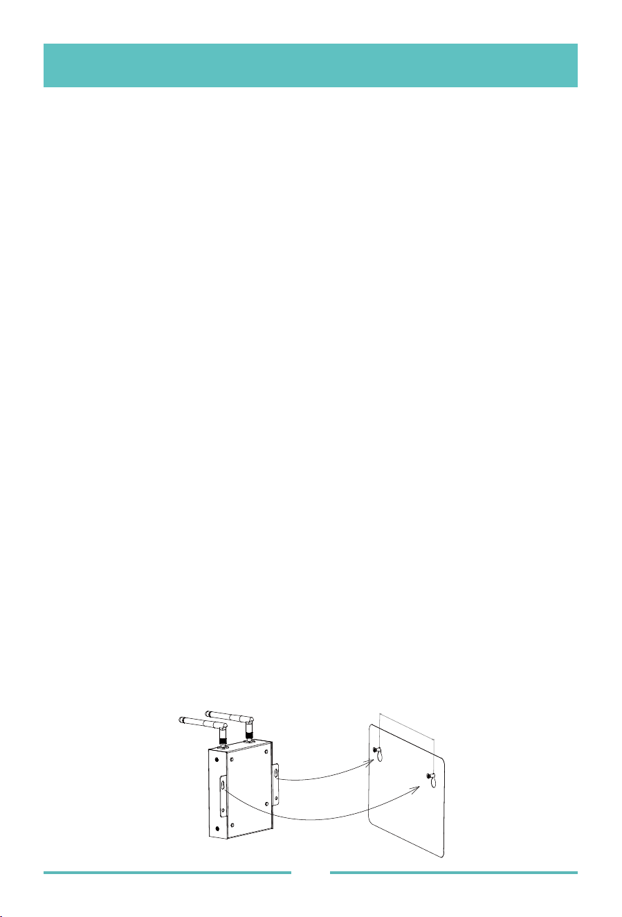
● Using wall-mounted
When mounting the MECD on the wall, make sure to select a cool, dry, indoor
location.
● Depending on the wall surface you are mounting the MECD, use either two
#4 drywall screws or wall anchors, installed 122.5 mm apart. The drywall
screws and wall anchors are NOT included in the MECD kit.
● Align and slide the MECD onto the mounting screws.
Make sure you have the following things taken care of before attempting to install the
ECD:
Preparaon
Selecng an Installaon Locaon for the MECD
Power connecon port
: L1, L2, L3, N, PE, connects power through the power line.
Power cable included in the MECD package.
DI: Digital input. When the DI status changed from 1 to 0, the MECD will send command
to control the microinverter shutdown immediately via Zigbee or PLC.
- 03 -
122.5mm
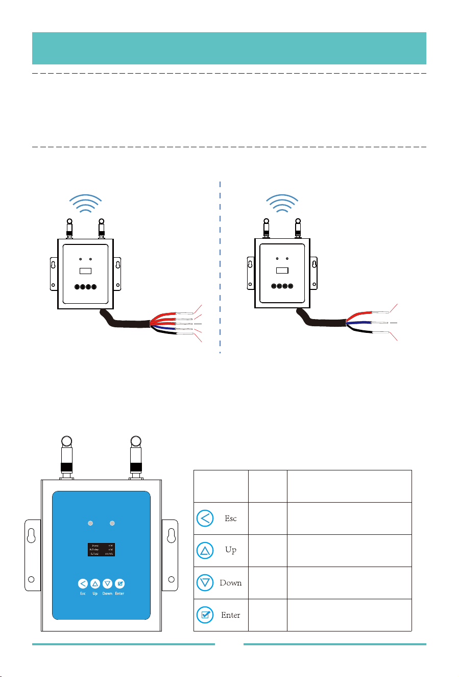
Once power is supplied to the ECD, it automatically steps into the main screens on its LCD
display which including below details info.
Single phase / Three phase PLC/ZIGBEE type MECD wifi connection
- 04 -
MECD + WIFI Plug Setup Sequence
1. Connect the power cable to the power connection port on the bottom of the ECD;
2. Config the wifi device with your home router.
Connecons
Three Phase
L1
L2
L3
N
PE
Single Phase
L
N
PE
ANT2ANT1
Normal
Comm
DI A B C N PERS485
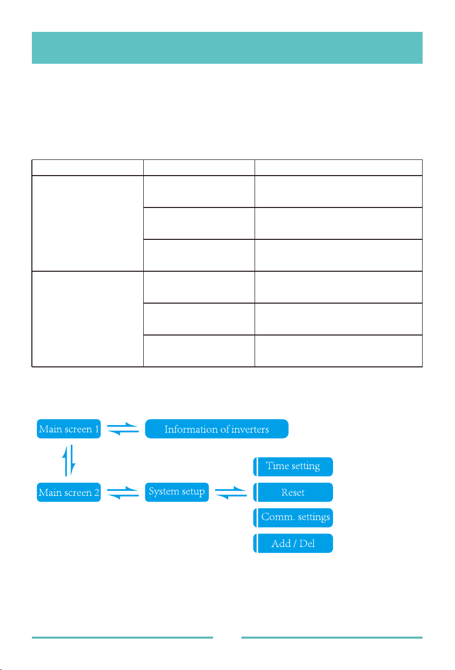
Return
bu�on
Allows you to return to the last
page or end an opera�on.
Allows you to go to the upper-
level menu or set parameters.
Allows you to go to the lower-
level menu or set parameters.
Allows you to go to the menu
or confirm the value.
Cursor
Up
bu�on
Cursor
Down
bu�on
Confirm
bu�on
Buons Name Funcons
MECD LCD operaon flow chart
MECD LED indicaons
There are two indicators of the MECD. The following description will tell how it works.
- 05 -
Indicator Status Meaning
Steady blue
All inverters connected works
normal
Off
All inverters connected has
alarms
Blinking blue
Some inverters connected has
alarms
Steady blue
All inverters connected
communication successfully
Off
All inverters connected
communication failed
Blinking
Some inverters
communication failed
Normal indicator
(left LED)
Comm indicator
(right LED)
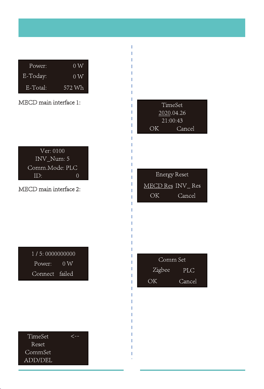
Informaon of inverters
1: Inverter ID currently connected;
2: Power generation;
3: Connection Status.
1: Time setting;
2: Reset;
3: Communication settings;
4: Add or Delete.
1: Time setting;
1: MECD reset: reset to factory setting.
2: Inverter reset: clear all inverters
information of MECD.
1: Zigbee or PLC communication method
selection.
- 06 -
Informaon on the LCD home page
MECD main interface 1:
1: Output power;
2: Today's total power generation;
3: Total power generation of microinverters
connected.
MECD main interface 2:
1: version information.
2: Number of connected inverters.
3: Communication method.
4: MECD Serial number.
System setup
Time seng
Reset
Communicaon sengs
The MECD has built-in WIFI modular which is able to connect router directly.
Web monitoring address: https://pro.solarmanpv.com; (for Solarman distributor account);
https://home.solarmanpv.com (for Solarman end user account).
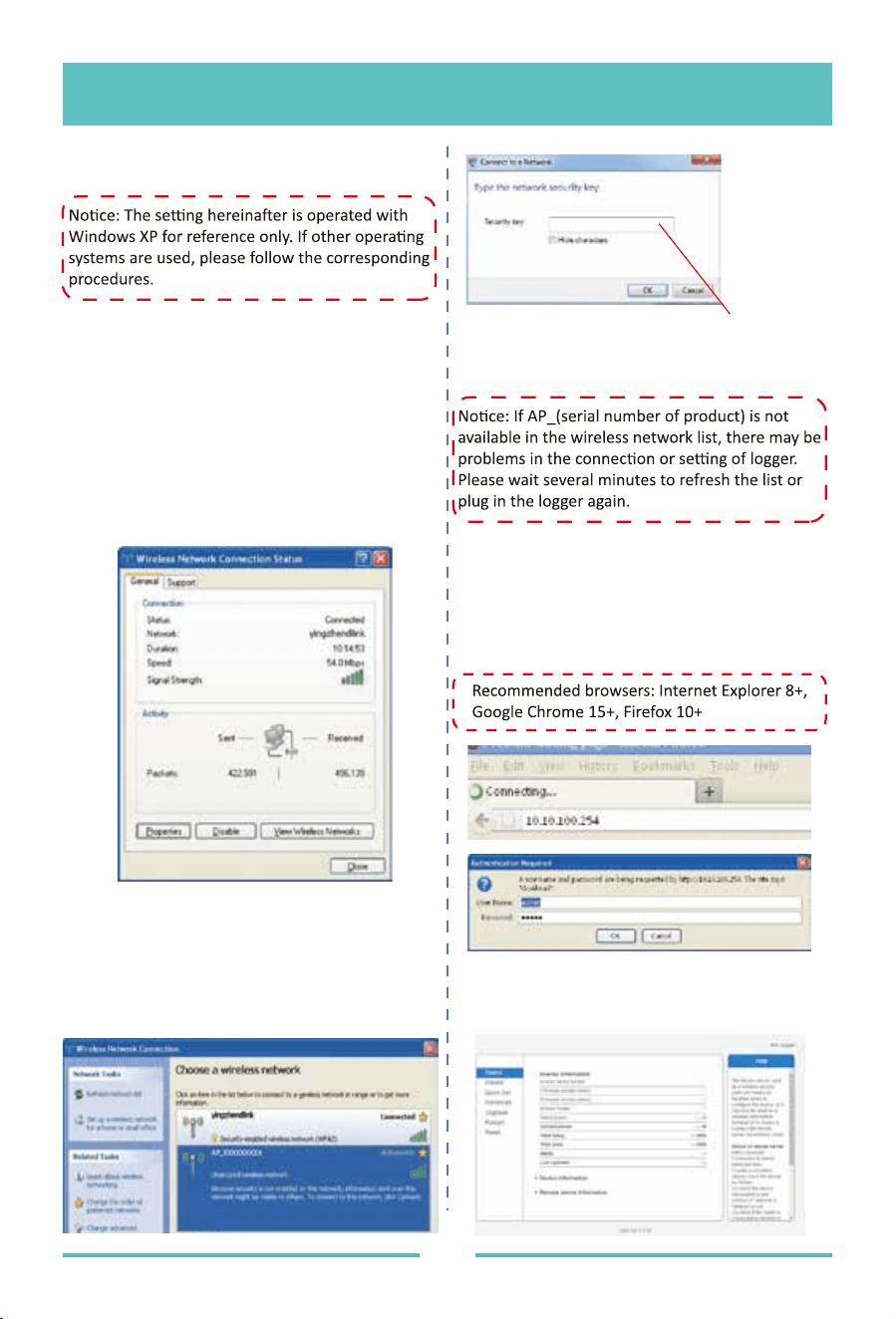
For mobile phone monitoring system, scan the below QR code to download the APP.
Or by searching “Solarman Business” in App store or Google Play store, and this app is
for distributor account. Searching “Solarman Smart” in App store or Google Play store
and choose “Solarman smart”, this app is for end user account.
- 07 -
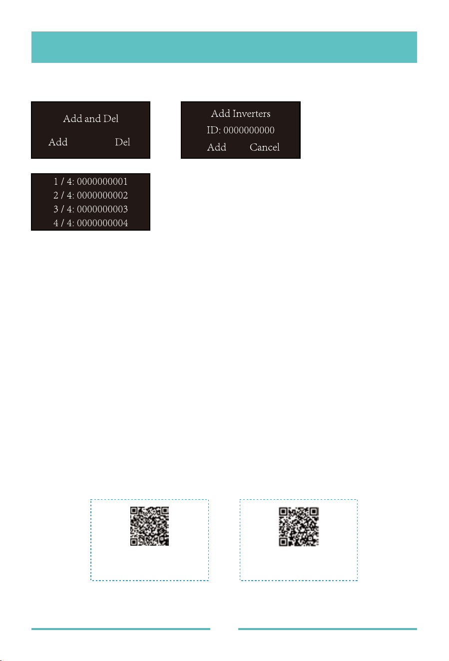
Add or delete inverter ID on ECD
Monitoring Plaorm
SOLARMAN Smart
for end user
SOLARMAN Business
for business
- 08 -
Default password:12345678
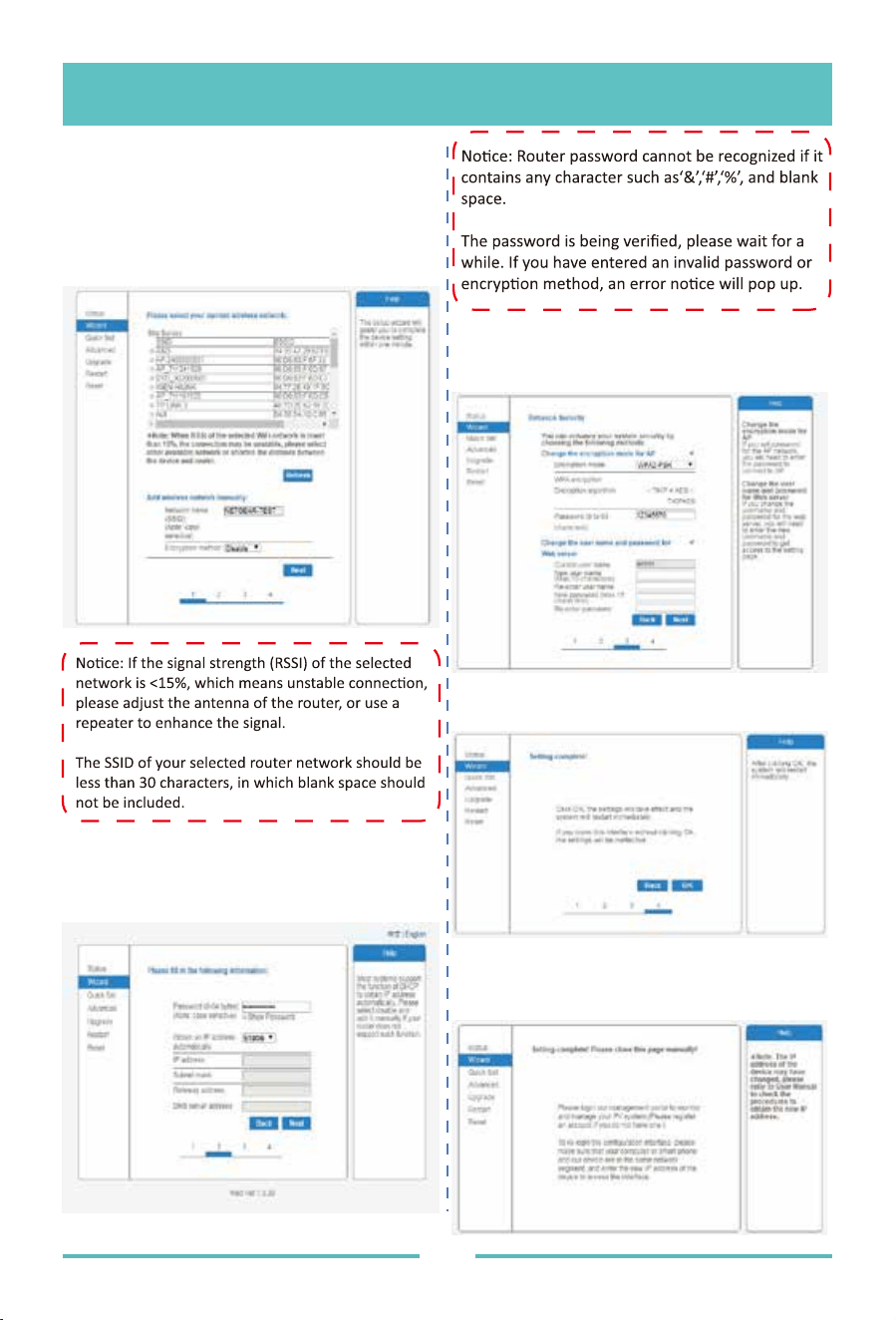
1. Prepare a computer or device with WiFi,
e.g. tablet PC and smartphone with WiFi
function.
2. Obtain an IP address automatically.
3. Set WiFi connection to the logger
3.1 Open wireless network connection and
click View
4.1 Open a web browser, and enter 10.10.
100.254, then fill in username and password,
both of which are admin as default.
4.2 In the Status page, you can view general
information of the logger.
3.2 Select wireless network of the logger.
The network name consists of AP and the
serial number of the product. Input the
password shown on the logger. Then click
Connect.
Wireless Networks
3. Set WiFi connection on PC
4. Set parameters of logger
- 09 -
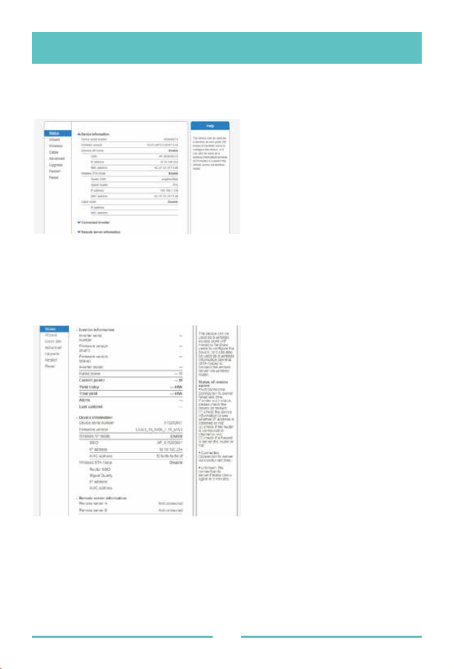
4.3 Follow the setup wizard to start quick
setting.
(a)Click Wizard to start. Select the wireless
network you need to connect, then click Next
(c)Enhance security se�ngs of the WiFi
logger by selec�ng any op�ons as listed,
then click Next
(d) If se�ng is successful, the following page
will display. Click OK to restart.
(e) If restart is successful, the following page
will display. If this page does not display
automa�cally,please refresh your browser.
(b)Enter the password for the selected
network, select Enable to obtain an IP address
automa�cally, then click Next
- 10 -
(f) Re- log in this se�ng page to Status page a�er the Web server restart, and check the
network connec�on status of the logger.
No�ce: A�er network se�ng is complete, the Wireless AP mode should be enabled and rela�ve
informa�on of your router will display on the interface automa�cally. Besides the Remote server
A should be connected.
If you meet any problems and need support, please provide the screenshot of the status page
as shown below.
Datasheet
- 11 -
Communication method Zigbee, PLC
Max. number of inverters connected 5、10、20、32(Max.)
WIFI wireless security
Communication to router
RS485
WIFI
WEP, WPA2-PSK
Reserved
Max.distance(free space) PLC 300m; Zigbee 100m(Max. straight-line distance)
Model MECD
Communication
AC Power Supply
Power consumption
100 to 240V AC,50/60Hz
5W typical, 10W Maxinum
IEC60950, IEC61000-6-2, FCC Part15 Class B / Class CCompliance
Warranty 3 years
Grid type Single phase / three phase
Digital Input Control device connection
Dimensions(W×H×D) 133.6×132×35.5 mm
Weight 0.3KG
Operation temperature range -20~+50℃
Mounting method Wall-mounted
Display OLED and LED indicators
Power Supply
Mechanical Data
Features
Others

502011349
Ver: 1.1, 2020-07