LIVESCOPE
™
BULKHEAD CONNECTOR KIT
INSTRUCTIONS
Important Safety Information
WARNING
See the Important Safety and Product Information guide in the transducer or sonar module product box for
product warnings and other important information.
CAUTION
To avoid possible personal injury, always wear safety goggles, ear protection, and a dust mask when drilling,
cutting, or sanding.
NOTICE
When drilling or cutting, always check what is on the opposite side of the surface to avoid damaging the vessel.
For the best possible performance and to avoid potential damage to the device or to your vessel, you must
install this device according to these instructions.
Tools Needed
• Drill
• 37mm (1
1
/
2
in.) hole saw
• #1 Phillips bit or screwdriver
• Marine sealant (optional)
NOTE: If this is a temporary installation, avoid using a permanent sealant.
If you do not have access to the space behind the mounting surface, you will also need the following tools.
• 2.7mm (
3
/
32
in.) drill bit
• #2 Phillips bit or screwdriver
Mounting Considerations
When selecting a mounting location, observe these considerations.
• You must select a mounting location with at least 60 mm (2
12
/
32
in.) of clearance behind the bulkhead.
• You must select a mounting location that a transducer extension cable can reach from your sonar module.
LiveScope transducer extension cables in various lengths are available from your Garmin
®
dealer.
• You must select a mounting location within the reach of your transducer cable when it is in use.
• You should select a convenient mounting location for quickly connecting and disconnecting your transducer
cable.
GUID-191D3DB0-2CCA-49D2-ADF7-ADD0F5A822AB v1November 2023

Mounting the Connector
1 Route the transducer extension cable to the mounting location.
2 Using a 37mm (1
1
/
2
in.) hole saw, drill a cable-passthrough hole in the mounting surface.
3 If you have access to the space behind the mounting surface, feed the transducer extension cable through
the mounting nut .
4 Feed the extension cable through the hole in the bulkhead .
5 Feed the extension cable through the hole in the self-adhesive gasket with the adhesive lining facing
away from the mounting surface.
6 Place the extension cable connector into one half of the connector holder .
The front of the connector holder must fit in the groove around the connector. The
rear of the connector holder must slide completely between the strain relief ribs on the
connector.
7 If you need to prevent water ingress through the connector holder, apply marine
sealant to the groove on both halves of the connector holder, forming a seal with
each other and with the extension cable connector, and place the connector into
the connector holder again, maintaining the correct alignment.
8 Snap together the two halves of the connector holder around the extension cable.
9 Using a #1 Phillips screwdriver, secure the halves of the connector holder to each
other with the included 8 mm (
5
/
16
in.) screws .
10 Peel the adhesive liner off of the self-adhesive gasket, and attach the gasket to the connector holder, aligning
the mounting holes on the connector holder and gasket.
11 Push the connector holder into the bulkhead.
12 Select an option:
• If you have access to the space behind the mounting surface, tighten the mounting nut to the back of
the connector holder until it is secured to the mounting surface, and install the finish plate (Installing the
Finish Plate, page3).
• If you do not have access to the space behind the mounting surface, secure the connector holder using
the included mounting screws (Securing the Connector using Screws, page3).
2
Securing the Connector using Screws
NOTE: You must assemble the bulkhead connector and secure it to the extension cable before you secure it to
the surface using screws.
NOTICE
If you mounted the bulkhead connector using the mounting nut, do not install the mounting screws. Attempting
to use both the mounting nut and the mounting screws may damage the product.
If you are mounting the device in fiberglass, when drilling the pilot holes, use a countersink bit to drill a
clearance counterbore through only the top gel-coat layer. This will help to avoid cracking in the gel-coat layer
when the screws are tightened.
1 Mark the locations of the four mounting holes, using the connector holder as a template.
2 Remove the connector holder from the bulkhead.
NOTICE
To avoid damaging the connector holder, you should not drill the pilot holes through the bracket.
3 Using a 2.7mm (
3
/
32
in.) drill bit, drill pilot holes for the four mounting screws.
NOTICE
To minimize the risk of damaging the transducer extension cable, avoid drilling deeper than the thickness of the
mounting surface.
4 Using a #2 Phillips screwdriver, secure the connector holder to the mounting surface with the included 20
mm (
25
/
32
in.) screws.
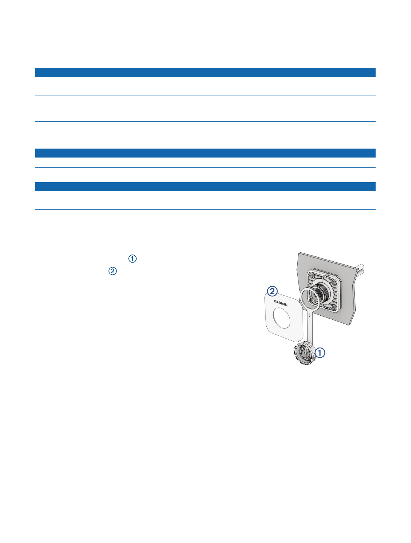
Installing the Finish Plate
1 Place the weather cap retaining ring around the connector, with the
weather cap hanging down .
2 Snap the finish plate onto the connector holder with the Garmin
logo right side up.
Make sure the weather cap tether band is aligned with the groove on
the bottom of the finish plate.
Limited Warranty
The Garmin standard limited warranty applies to this accessory. For more information, go to garmin.com
/support/warranty.
Australian Purchases: Our goods come with guarantees that cannot be excluded under the Australian
Consumer Law. You are entitled to a replacement or refund for a major failure and for compensation for any
other reasonably foreseeable loss or damage. You are also entitled to have the goods repaired or replaced if the
goods fail to be of acceptable quality and the failure does not amount to a major failure. The benefits under our
Limited Warranty are in addition to other rights and remedies under applicable law in relation to the products.
Garmin Australasia, 30 Clay Place, Eastern Creek, NSW 2766, Australia. Phone: 1800 235 822.
© 2023 Garmin Ltd. or its subsidiaries
Garmin
®
and the Garmin logo are trademarks of Garmin Ltd. or its subsidiaries, registered in the USA and other countries. LiveScope
™
is a trademark of Garmin Ltd. or its
subsidiaries. These trademarks may not be used without the express permission of Garmin.
Garmin Corporation
3