I
NTRODUCTION
Thank you for purchasing a Sonance
®
volume control.The VC60R/S is
CE approved.Sonance also offers the largest selection of high fidelity
in-wall/in-ceiling speakers in the world. Consult Sonance literature
or your Authorized Sonance Dealer for more information on the
wide variety of speakers, amplifiers, switchers, controls, cable, and
other custom installation products available from Sonance.
Please read these instructions carefully before connecting this
device to your system. If connections are made incorrectly you may
damage your amplifier/receiver.
IMPORTANT NOTE: TURN YOUR AMPLIFIER/RECEIVER OFF
BEFORE ATTEMPTING THE FOLLOWING HOOK-UP
PROCEDURES.
VC60R/S APPLICATIONS
The VC60R is a rotary volume control. The volume can be
controlled by turning the knob clockwise to increase volume and
counterclockwise to decrease volume. This 12 position rotary knob
incorporates light touch and silent switching capabilities. The
slider volume control,VC60S,controls volume by sliding the switch
up to increase volume and down to decrease volume. The slider
also displays 12 volume positions with silent switch action. The
VC60S and VC60R both contain easy screw in quick disconnectors
and can safely handle 60 watts per channel of power.
WIRING AND PLACEMENT
DO NOT mount the volume control in the same
electrical box with AC house wiring,light switches,dimmers,or any
other high voltage device or control. The VC can share gang boxes
with other low voltage controls such as A/B speaker switches,
infrared receivers and emitters, and other volume controls if these
other devices are rated as Class 2 devices by the National Electrical
Code. With 14-18 gauge cable, wire the volume control between a
single pair of speakers and the amplifier powering those speakers.
Run four 14-18ga. wires for carrying speaker signals (L+, L-, R+,
and R-) from the amplifier, through the walls or ceiling, to the
volume control. We recommend high quality wire like Sonance
MediaLinQ
®
. If using free standing speakers, run the wire through the
wall or ceiling to a convenient location near the speaker and
terminate it with a Sonance FielDress
™
series system terminator or
other audio jack.
WARNING: TO PREVENT THE RISK OF FIRE OR
ELECTRIC SHOCK, DO NOT EXPOSE THIS APPLIANCE TO
RAIN OR MOISTURE
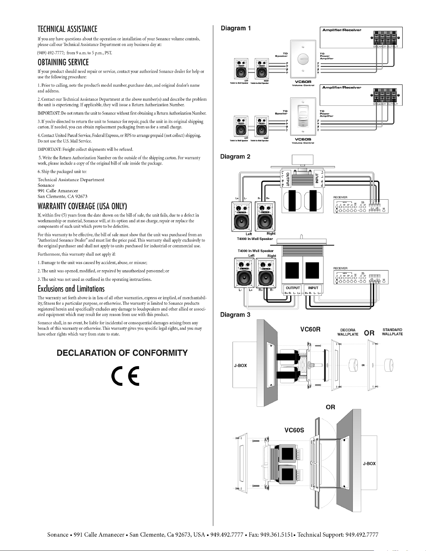
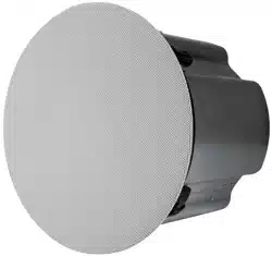
INSTALLATION FOR VC60R/S (SEE DIAGRAMS 1 AND 2)
1. Once the speaker wires have been run, install a standard light
switch plaster ring or J-box that is 3-1/2" in depth,available from an
electrical supply source.
2. TURN THE AMPLIFIER/RECEIVER POWER OFF.
Then connect the left or Channel-A speaker output, ofthe
amplifier/receiver, to the left screw-to-connect input terminals of
the volume control, observing proper polarity. For example
connect L+ of the amplifier to L+ of the VC, and L- to L-
(see diagrams 1 and 2).
3. Repeat step 2 for the right or Channel-B speaker output.
4. Connect the left speaker wires to the left or Channel-A
output terminals ofthe volume control. Check proper polarity of
wires for correct speaker phase. For example connect the +
terminal of the speaker to the + VC output, and - to - (see
diagrams 1 and 2).
5. Repeat step 4 for the right or Channel-B speaker connection.
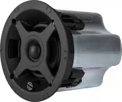
MOUNTING THE CONTROLS:
Once the unit has been wired, attach it to a standard light switch
plaster ring or J-box. Use the included screws to attach the volume
control to the electrical box. Attach the wallplate
to the control using the screws provided. DO NOT OVER-
TIGHTEN THE PLATE SCREWS OR YOU MAY DAMAGE THE
PLATE. Finally, with the rotary VC attach the knob onto the
control shaft. With the slider VC, please note vertical
orientation of VC by noting marking of"TOP" on circuit board for
proper vertical orientation during installation. (See Diagram 3)
OPERATION
Determine the maximum volume you wish to feed to the rooms in
which you have volume controls and speakers. With your house
music source (amplifier/receiver) turned down, turn the volume
control(s) all the way up.Feed the amplifier/receiver a strong music
signal, then gradually increase the amplifier/ receiver volume until
the volume in the room(s) is as loud as you are likely to ever listen.
Take particular care that no audible distortion is heard through
your speakers or speaker damage will occur. Ifyou are using an
amplifier with input level controls, such as the Sonance Sonamp
®
series amplifiers, adjust the level controls appropriately. Then
return to the rooms with volume controls and lower the volume
settings to normal listening levels.Setting the maximum volume in
this way will ensure safe operation for speakers and amplifiers. If
you think there should be sound coming from your speakers but do
not hear anything when the VC is turned all the way up, DO NOT
leave it in the full ON position when checking your sources or
source material. Otherwise there may be a startling increase in
volume when the problem is remedied, and speaker damage
may occur.
SPECIFICATIONS
Power Rating: 60 Watts RMS MAX INPUT/CH
Switch Type: VC60S 12 Position light touch slide switch with silent
slide action
VC60R 12 Position light touch silent rotary switch
Terminal Type: Screw quick disconnect 20-14 AWG wire capacity
Frequency Response: 20-20KhZ ±1dB
Speaker Impedance: 8Ω
Dimensions (WxHxD) VC60S: 1-5/8" x 4" x 3"
(41mm x 102mm x 76mm)
VC60R: 1-1/2" x 4" x 3"
(38mm x 102mm x 76mm)
INSTALLATION INSTRUCTIONS
VC60R/S ROTARY/SLIDER IN-WALL
STEREO VOLUME CONTROL
PN.33-1518 12.98
1