Movement
Velocity
Direction
Presence
Distance
Angle
www.innosent.de
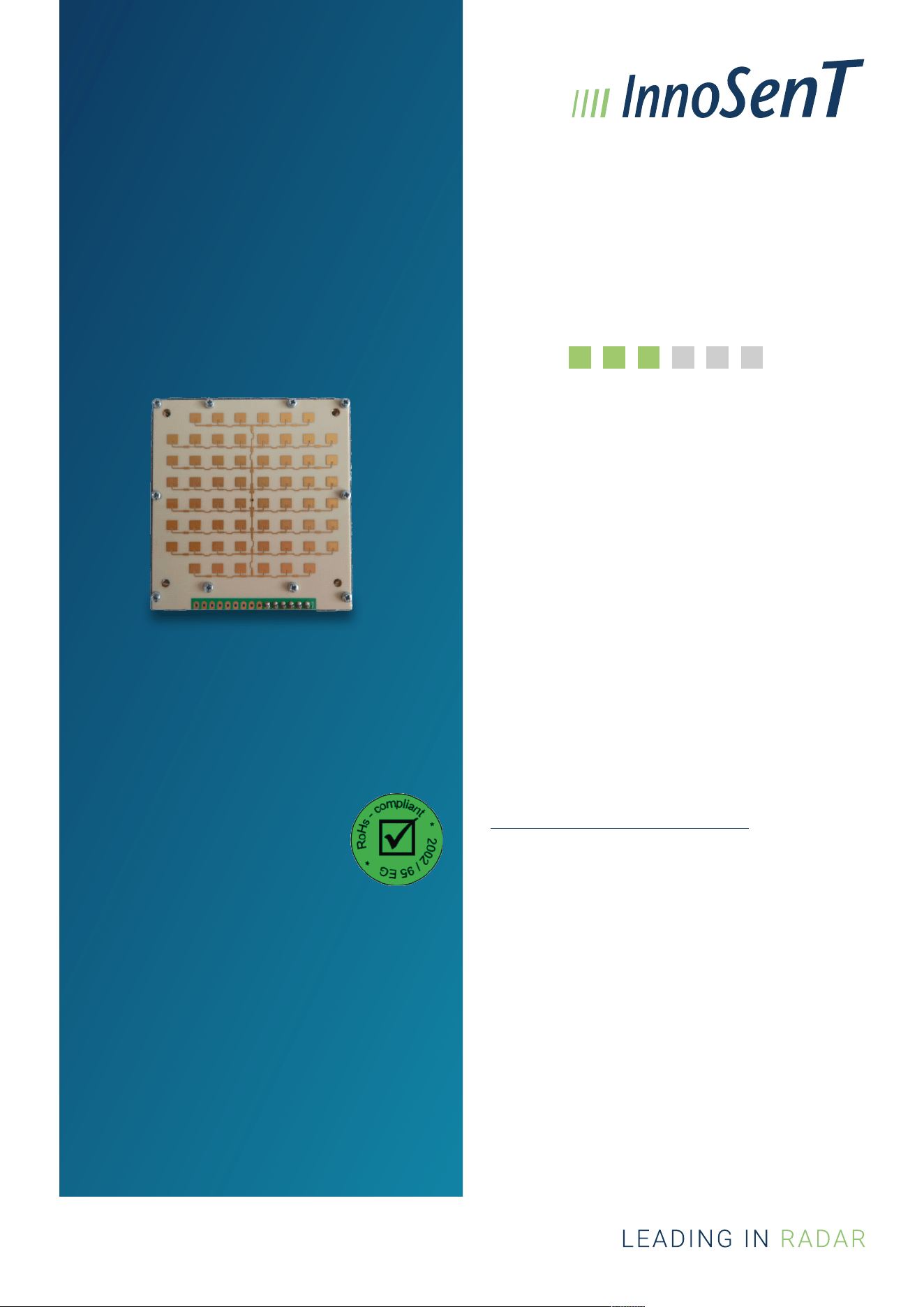
IVS234
Version 6.11
User Manual
The IVS-234 is a CW K-Band Transceiver with an
integrated PLL-circuit for high frequency stability.
The PLL-circuit enables the customer to program its
own transmit frequencies directly via TUV-PIN.
This product is compliant to the
restriction of hazardous substances
(RoHS - European Union directive
2011/65/EU)
FEATURES
• K-Band Transceiver
• CW (continuous wave) mode
• Stereo (dual channel) operation for direction-of-
motion identication
• Integrated PLL circuit for high frequency
stability
• Programmable transmitter frequency
• Balanced mixer with reduced common mode
noise for both channels (DOP and QDOP)
PRODUCT FAMILY
PLL stabilized K-Band VCO Transceiver
APPLICATION
True Speed over Ground measurement
CERTIFICATES
InnoSenT GmbH has established and applies a
quality system for: development, production and
sales of radar sensors for industrial and automotive
sensors.
See more information on our quality standards:
https://www.innosent.de/certications/
ADDITIONAL INFORMATION
Customer specic product for DEUTA-WERKE GmbH
DEUTA-WERKE GmbH has to be informed about all
technical changes.
CONFIDENTIAL & PROPRIETARY
The information contained in this document shall
remain the sole and exclusive property of InnoSenT
GmbH and shall not be disclosed by the recipient to
third parties without prior consent of InnoSenT in
writing.
2www.innosent.de
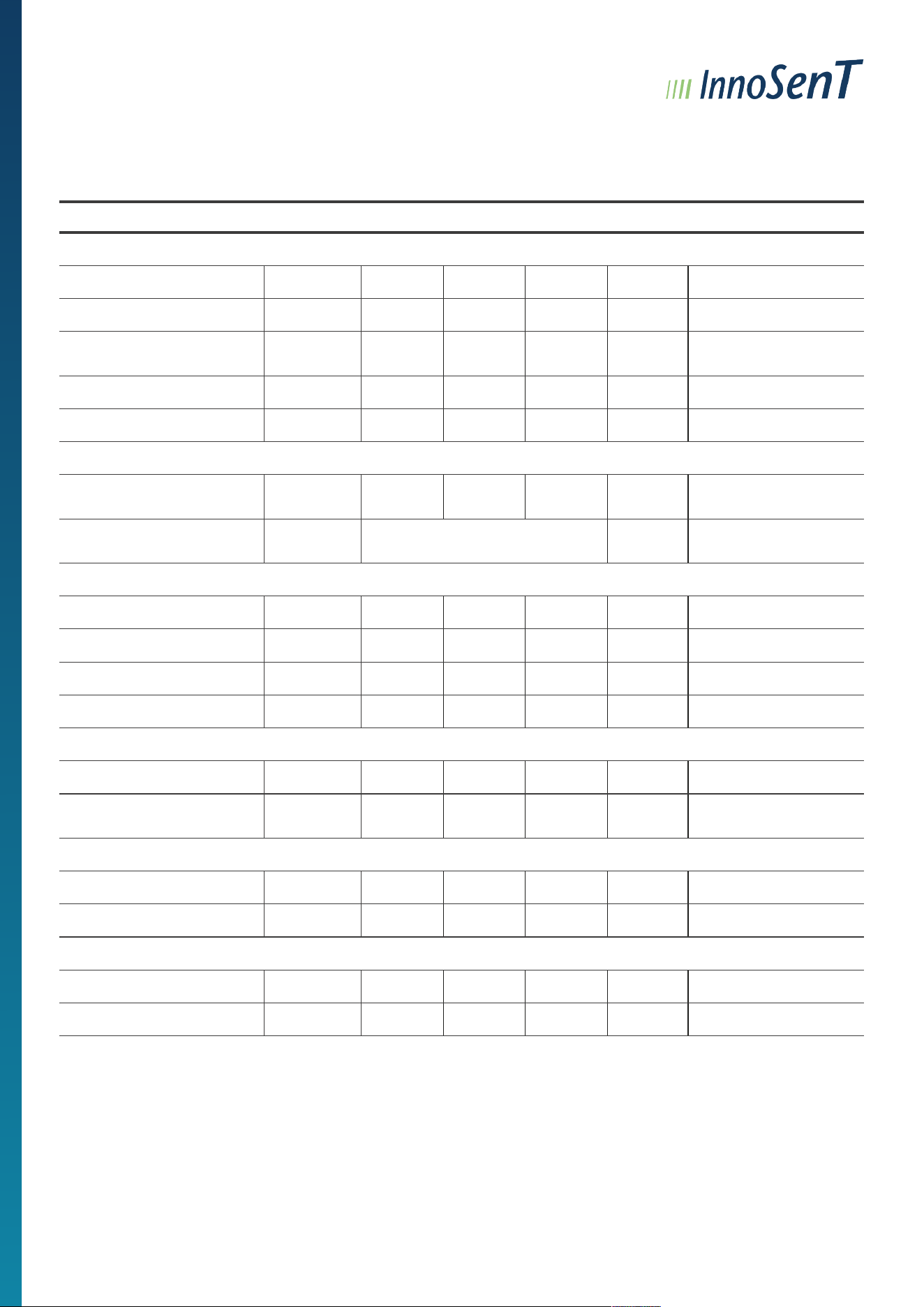
ELECTRICAL CHARACTERISTICS
PARAMETER SYMBOL MIN. TYP. MAX. UNITS COMMENT
Oscillator
Transmit frequency range 24.008 24.243 GHz can be adjusted by user
1
Frequency spacing 1.6 MHz
Variation 1.2125 MHz
due to crystal tolerance
±50 ppm
Temperature drift (frequency) |Δf| 10 30 kHz/K
Output power (EIRP) P
out
20 dBm
Plausibility check
Frequency correct 24.008 EEPROM 24.243 GHz
use read value from
EEPROM
Frequency not correct 24.243 < Read EEPROM or < 24.008 GHz
set frequency
24.1664 GHz
Receiver (compare with amplier circuit on page 4)
IF-amplier bandwidth 10 ‒ 1M Hz
gain 46 dB
I/Q balance amplitude 6 dB
phase 70 110 ° reject criteria
Offset
Reject criteria offset v_offset
I(DOP)
-500 500 mV @ InnoSenT test setup
2
v_offset
Q(QDOP)
-500 500 mV @ InnoSenT test setup
2
Signal level
Reject criteria signal level S
I(DOP)
207.5 295 382.6 mV @ InnoSenT test setup
2
S
Q(QDOP)
207.5 295 382.6 mV @ InnoSenT test setup
2
Noise level
Reject criteria noise level R
I(DOP)
0.4 1.5 mV
RMS
@ InnoSenT test setup
2
R
Q(QDOP)
0.4 1.5 mV
RMS
@ InnoSenT test setup
2
1
The user is responsible for the compliance of the transmit frequency! Delivery condi�on is 24.1664 GHz.
2
Measured during end of line test according to InnoSenT instruc�on manual AA 8-5_89
3www.innosent.de
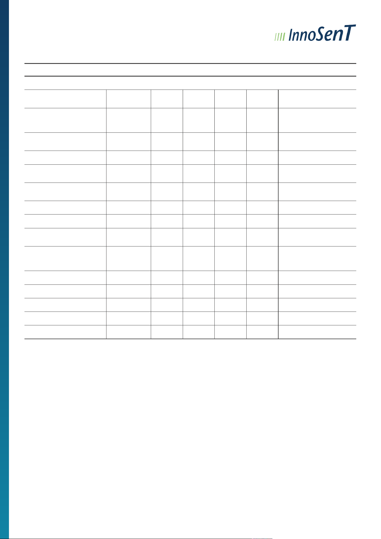
PARAMETER SYMBOL MIN. TYP. MAX. UNITS COMMENT
Communication
Interface Type TUV
point-to-point-connection
Pin #4 TUV_COM
Transmission Rate 300 1200 1200 Baud
UART (switches
automatically between Rx
and Tx)
Communication Protocol 8N1
8 data bits, 1 stop bit, no
parity
Time 0.1 s Receive start
10 s
Receive stop without
communication
2 s
or Receive stop after last
communication
Start 0x7E Master Tx-word
0x55 write to EEPROM command
Operating Temperature 10 25 40 °C
for single-wire bus
communication
ISP interface VCC 3.0 3.3 3.6 V
VCC for the external
programmer must be
provided by the customer
Low_input 0 0.8 V 25°C ± 10°K
High_input 1 2.6 V 25°C ± 10°K
Low-output 0 0.8 V 25°C ± 10°K
High-output 2 3.6 V 25°C ± 10°K
Current-output 462 541 633 µA for low output level
4www.innosent.de
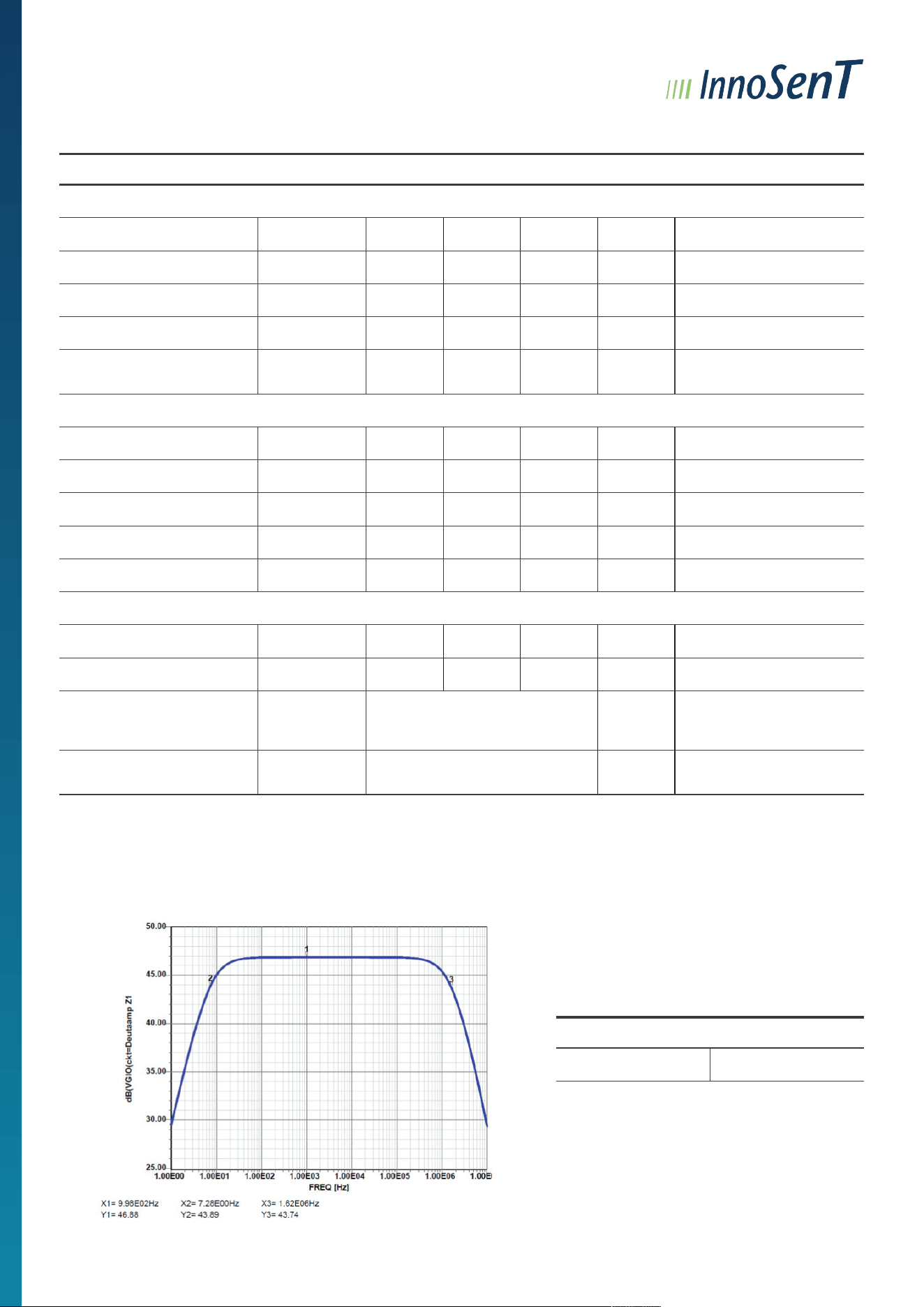
PARAMETER SYMBOL MIN. TYP. MAX. UNITS COMMENT
Power supply
Supply voltage V
cc
4.75 5.25 V
V
SS
-5.25 -4.75 V
Supply current I
CC
150 200 mA
I
SS
20 50 mA
Recovery time 0.1 s
time between shut down
and restart
Antenna pattern (compare with antenna plot on page 4)
Full beam width @ -3dB horizontal 11 13 15 °
vertical 11 13 15 °
Side-lobe suppression horizontal 12 dB
vertical 12 dB
Antenna gain 22 dBi
Environment
Operating temperature T
OP
-40 +80 °C
Storage temperature T
STG
-40 +85 °C
Outline dimensions
height
length
width
10.5 (11.8)
70.0
65.8
mm
tolerances according to
DIN1687-4
FIT-rate 419 10
-9
/h
Siemens-Norm SN-29500,
55°C
GAIN BANDWIDTH
46dB 10Hz - 1MHz
BANDWIDTH AND GAIN SIMULATION
5www.innosent.de
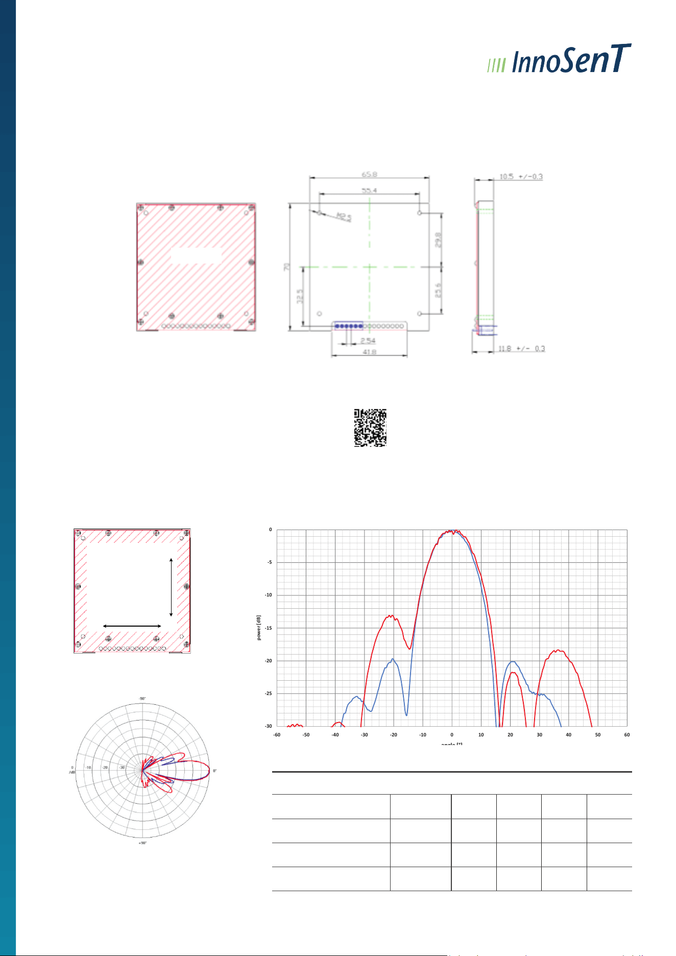
MECHANICAL OUTLINES/LABEL
All dimensions in mm / all tolerances according DIN1687-4
front
Example label:
Model: IVS-234 FCC ID: UXS-IVS-234-2G
99999999 IC: 6902A-IVS2342G
S/N: 00131809 So845
back
Tx - ANTENNA PATTERN
antenna
front
horizontal
ver�cal
InnoSenT sets standards – worldwide
Page 4 Version 6.7 DATA SHEET IVS-234
Tx - antenna paern
full beam width @ -3dB horizontal 11 13 15 °
vertical 11 13 15 °
side-lobe suppression horizontal 12 dB
vertical 12 dB
antenna
front
horizontal
vertical
Parameter Symbol Min. Typ. Max. Units Comment
-15
-10
-5
0
power [dB]
Horizontal
Vertical
-30
-25
-20
-60 -50 -40 -30 -20 -10 0 10 20 30 40 50 60
angle [°]
CONFIDENTIAL AND PROPRIETARY
The information contained in this document shall remain the sole and exclusive property of InnoSenT GmbH
and shall not be disclosed by the recipient to third parties without prior consent of InnoSenT in writing.
PARAMETER SYMBOL MIN. TYP. MAX. UNITS
Full beam width @ -3dB horizontal 11 13 15 °
vertical 11 13 15 °
Side-lobe suppression horizontal 12 dB
vertical 12 dB
6www.innosent.de
INTERFACE
The sensor provides a 6-PIN Berg connector and 2.54mm grid pads for programming
PIN # DESCRIPTION IN � OUT COMMENT
1 V
cc
input
positive supply voltage for VCO Controller,
IF-amplier
2 V
ss
input negative supply voltage for IF-amplier
3 GND input analog ground
4 TUV_COM
1
input timed programming
output current mirror
5 DOP output I (DOP / -S2-S1)
6 QDOP output Q (QDOP / S2-S1)
7 NC not connected
8 DNC input SCK (do not connect)
9 DNC output MISO (do not connect)
10 DNC input MOSI (do not connect)
11 DNC input RES (do not connect)
12 NC not connected
13 NC not connected
14 NC not connected
15 GND input analog ground
1
TUV “low” signals “Transceiver Unit Valid”: PLL-frequency is locked

7www.innosent.de
APPROVAL
This Data Sheet contains the technical specications of the described product. Changes of the specication must be in
written form. All previous versions of this Data Sheet are no longer valid.
The technical specications of this Data Sheet are approved:
FCC approval
This device complies with Part 15 of the FCC Rules and with RSS-210 of Industry Canada.
Operation is subject to the following two conditions:
(1) this device may not cause harmful interference, and
(2) this device must accept any interference received, including interference that may cause undesired operation.
Warning: Changes or modications made to this equipment not expressly approved by InnoSenT GmbH may void the FCC
authorization to operate this equipment. Manufacturers of mobile or xed devices incorporating IVS-234 modules are
authorized to use the FCC Grants and IC Certicates of the IVS-234 modules for their own nal products according to the
conditions referenced in these documents. In this case, the FCC label of the module shall be visible from the outside, or the
host device shall bear a second label stating contains
“FCC ID: UXS-IVS-234-2G“and contains “IC: 6902A-IVS2342G”.
Le présent appareil est conforme aux CNR d’Industrie Canada applicables aux appareils radio exempts de licence.
L’exploitation est autorisée aux deux conditions suivantes:
(1) l’appareil ne doit pas produire de brouillage, et
(2) l’utilisateur de l’appareil doit accepter tout brouillage radioélectrique subi, même si le
brouillage est susceptible d’en compromettre le fonctionnement.
Transmit frequency can be programmed by the customer. The following frequency ranges apply according to the
certication for FCC and IC: 24.075 GHz - 24.175 GHz
La fréquence d’émission peut être programmée par le client. Les plages de fréquences suivantes s’appliquent
conformément à la certication FCC et IC : 24,075 GHz – 24,175 GHz
This equipment complies with FCC and IC radiation exposure limits set forth for an uncontrolled environment. This
equipment should be installed and operated with minimum distance of 20cm between the radiator and your body. This
transmitter must not be co-located or operating in conjunction with any other antenna or transmitter.
Cet équipement est conforme aux limites d’exposition aux rayonnements IC établies pour un environnement non contrôlé.
Cet équipement doit être installé et utilisé avec un minimum de 20 cm de distance entre la source de rayonnement et votre
corps. Ce transmetteur ne doit pas être place au même endroit ou utilise simultanément avec un autre transmetteur ou
antenne.

8www.innosent.de
OEM INTEGRATION INSTRUCTIONS — FCC AND ISED
The IVS-234 is intended for integration by qualied OEM manufacturers or system integrators. Use of the module’s FCC/I-
SED authorizations is subject to the issued grant and certicate, their applicable conditions and the instructions below. The
module authorization does not constitute approval of the complete host product.
Operating conditions and installation
The transmitter has been evaluated against FCC 47 CFR § 15.245, ISED RSS-210 Annex F, and the applicable RSS-Gen requi-
rements. Host controls, programming and software updates shall prevent unauthorized operating settings.
The module shall be operated within the supply voltage and operating temperature limits specied in this manual.
Antenna and enclosure
Use only the original integrated patch antenna with a typical gain of 22 dBi. The antenna, RF circuitry and shielding shall
remain unchanged. External antennas, RF ampliers and host PCB antenna traces are not part of the authorized congurati-
on. The host enclosure, mounting arrangement and any radome shall preserve compliance with the applicable emission
and RF exposure requirements.
RF exposure
The FCC and ISED RSS-102 evaluations demonstrate compliance for the evaluated conguration at 20 cm. Maintain a mini-
mum distance of 20 cm between the radiating antenna and all persons during operation.
Under these integration conditions, the transmitter shall not be co-located or operated in conjunction with another antenna
or transmitter. Shorter separation distances or simultaneous transmission require reassessment and any necessary autho-
rization changes.
Host evaluation
Evaluate the completed host with the module operating in its normal CW mode and with the host electronics and accesso-
ries active in representative operating congurations.
Power supply arrangements shall meet the module’s electrical requirements and maintain compliance.
The host manufacturer is responsible for continued transmitter compliance and any additional host requirements, including
FCC Part 15, Subpart B, and applicable Canadian ICES requirements. FCC KDB 996369 D04 provides guidance for host eva-
luation.
Labelling and user information
If the module identiers are not visible from outside the assembled product, provide a permanent, legible host label stating:
Contains FCC ID: UXS-IVS-234-2G
Contains IC: 6902A-IVS2342G
The host user manual shall include the applicable FCC/ISED notices, modication warning and installation restrictions, in-
cluding the 20 cm separation distance and restriction on co-location and simultaneous transmission. Required Canadian
user notices shall be provided in English and French.
For deviations from these instructions or changes affecting the authorized conguration, contact InnoSenT GmbH at
[email protected] before relying on the existing authorization. Additional testing or authorization may be required.

www.innosent.de
DEUTA - WERKE GmbH
Paffrather Straße 140 | 51465 Bergisch Gladbach | Germany
InnoSenT GmbH
Am Rödertor 30 | 97499 Donnersdorf | Germany
E-Mail: [email protected]