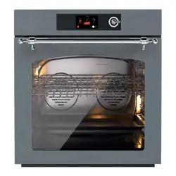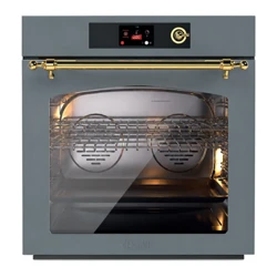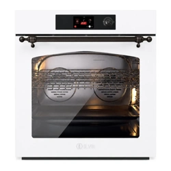
BUILT-IN
OVEN PY
UOV30...PY
EN User’s manual

2
- Before beginning, please read these instructions
completely and carefully.
- Do not remove permanently axed labels, warnings, or
plates from the product. This may void the warranty.
- Please observe all local and national codes and
ordinances.
- Please ensure that this product is properly grounded.
- The installer should leave these instructions with the
consumer who should retain them for local inspector’s
use and for future reference.
IMPORTANT - PLEASE READ AND FOLLOW
WARNING If the informations
in this instructions is not
followed exactly, a re or
explosion may result causing
property damage, personal
injury or death.
- Appliances are not intended for manufactured (mobile)
home installation .
- Misuse of appliance doors such as stepping, leaning or
sitting on them can result in damage or personal hazards
or injuries.
- DO NOT TOUCH HEATING ELEMENTS OR INTERIOR
SURFACES OF OVEN – Heating elements may be hot
even though they are dark in color. Interior surfaces of
an oven become hot enough to cause burns. During and
aer use, do not touch, or let clothing or other ammable
materials contact heating elements or interior surfaces
of oven until they have had sucient time to cool.
- Other surfaces of the appliance may become hot enough
to cause burns – these surfaces include oven vent
openings and surfaces near these openings, oven doors
and oven door windows, the control panel, the cooking
chamber surface, and accessories such as racks and the
drip tray.
- Care must be taken to prevent aluminum foil and meat
probes from contacting the heater elements.
- NEVER use this appliance as a space heater to heat or
warm the room.
- Keep appliance area clear and free from combustible
materials, gasoline and other ammable vapors and
liquids.
- If the enclosed hardware cannot be utilized, please refer
to a qualied installer to properly fasten the appliance so
that it does not tip over.
- Failure to do so can result in death or serious burns to
children or adults.
- Installation must conform with local codes. Electrical
installation must be in accordance with the National
Electrical Code, ANSI/NFPA70 latest edition and/or
local codes.
- Electrical installation must be in accordance with the
current CSA C22.1 Canadian Electrical Codes Part 1
and/or local codes.
- The manufacture reserves the right to make changes
to its products when considered necessary and useful,
without aecting the essential safety and operating
characteristics.
- This appliance has been designed for non-professional,
domestic use only.
- This appliance must be used only for the purposes for
which it was intended. Any other use is incorrect and
therefore dangerous.
- Possible hazards may result from using this appliance for
storage space.
WARNING
WARNING
DO NOT ATTEMPT TO EXIT AN OIL /
GREASE FIRE WITH WATER.
3
IMPORTANT INSTRUCTION
CAUTION: Do Not Leave Children Alone - Children should not
be le alone or unattended in area where appliance is in use.
They should never be allowed to sit or stand on any part of the
appliance. Do not store items of interest to children above or at
the back of this appliance, as they could climb on the appliance
to reach items and be injured.
Wear Proper Apparel - Loose-tting or hanging garments should
never be worn while using the appliance.
User Servicing - Do not repair or replace any part of the appliance
unless specically recommended in the manual.
All other servicing should be referred to a qualied technician.
Storage in or on Appliance – Flammable materials should not be
stored in an oven or near surface units.
Do Not Use Water on Grease Fires - Smother re or ame or use
dry chemical or foam type extinguisher .
Do Not Clean Door Gasket – The door gasket is essential for a
good seal. Care should be taken not to rub, damage, or move the
gasket.
Do not use a protective coating to line the oven and do not
use commercial oven cleaner unless Certied for use in a self-
cleaning oven.
Clean Only Parts Listed in Manual.
Before Self-Cleaning the Oven – Remove broiler pan and other
utensils
Use Only Dry Potholders - Moist or damp potholders on hot
surfaces may result in burns from steam. Do not let potholder
touch hot heating elements. Do not use a towel or other bulky
cloth.
Never leave this appliance unattended when in use. Boilovers
and greasy spills may smoke or ignite Do not heat unopened
food containers, such as baby food jars and cans. Pressure build-
up may cause the container to burst and cause injury. Before
performing service, shut o electricy to this appliance.
- Wear proper apparel. Loose-tting or hanging garments
should never be worn while using this appliance.
- Use extreme caution when moving a grease kettle or
disposing of hot grease.
- Clean only those parts listed in this guide.
- Do not repair or replace any part of this appliance unless
specically recommended in literature accompanying this
appliance.
- Do not obstruct the ow of air to ensure proper combustion
and ventilation.
- Proper Installation – Be sure your appliance is properly
installed and grounded by a qualied technician.
- Never Use Your Appliance for Warming or Heating the Room.
1. Use Care When Opening Door - Let hot air or steam escape
before removing or replacing food.
2. Keep Oven Vent Ducts Unobstructed.
3. Placement Of Oven Racks - Always place oven racks in
desired location while oven is cool. If rack must be moved
while oven is hot, do not let potholder contact hot heating
element in oven.
- This appliance must be installed only by an authorized
person. The installation must be carried out in accordance
with the manufacturer’s instructions.
- IMPORTANT: This appliance must be installed in
compliance with the applicable standards in the country
concerned.
- The installation of this appliance must comply with local
codes and regulations. In the absence of local codes,
installation must comply with U.S. standards: American
National Standards – National Fuel Gas Code ANSI
Z223.1 – NFPA 54.
- If local codes permit, it is recommended that this
appliance be connected to the gas supply with a certied
AGA or CGA exible metal connector, with a maximum
length of 5 feet (1.5 m) and an inside diameter of ½”. Do
not kink or damage the exible connector when moving
the appliance. The pressure regulator has a ½” female
threaded connection. You will need to determine the
proper tting according to the diameter of your gas
supply line, the exible connector, and the shuto valve.
- Once installed, the appliance must be grounded in
accordance with local codes, or, in the absence of local
codes, in accordance with the National Electrical Code
ANSI/NFPA 70 and Canadian Standard CSA C22.1-02.
WARNING
Before removing the appliance, disconnect the power
supply cord and close the corresponding gas shuto valve.
Make sure that the power supply cord is not damaged
during cleaning or maintenance operations.
NOTE 1: Hazards may occur in case of abnormal use,
including excessive load on the oven door.
NOTE 2: Reinstall the appliance according to the
manufacturer’s instructions to avoid any risk of tipping.
CALIFORNIA PROPOSITION 65
WARNING: This product can expose you to chemicals
including lead and cadmium, which are known to the
State of California to cause cancer and birth defects or
other reproductive harm. For more information, visit: www.
P65Warnings.ca.gov.
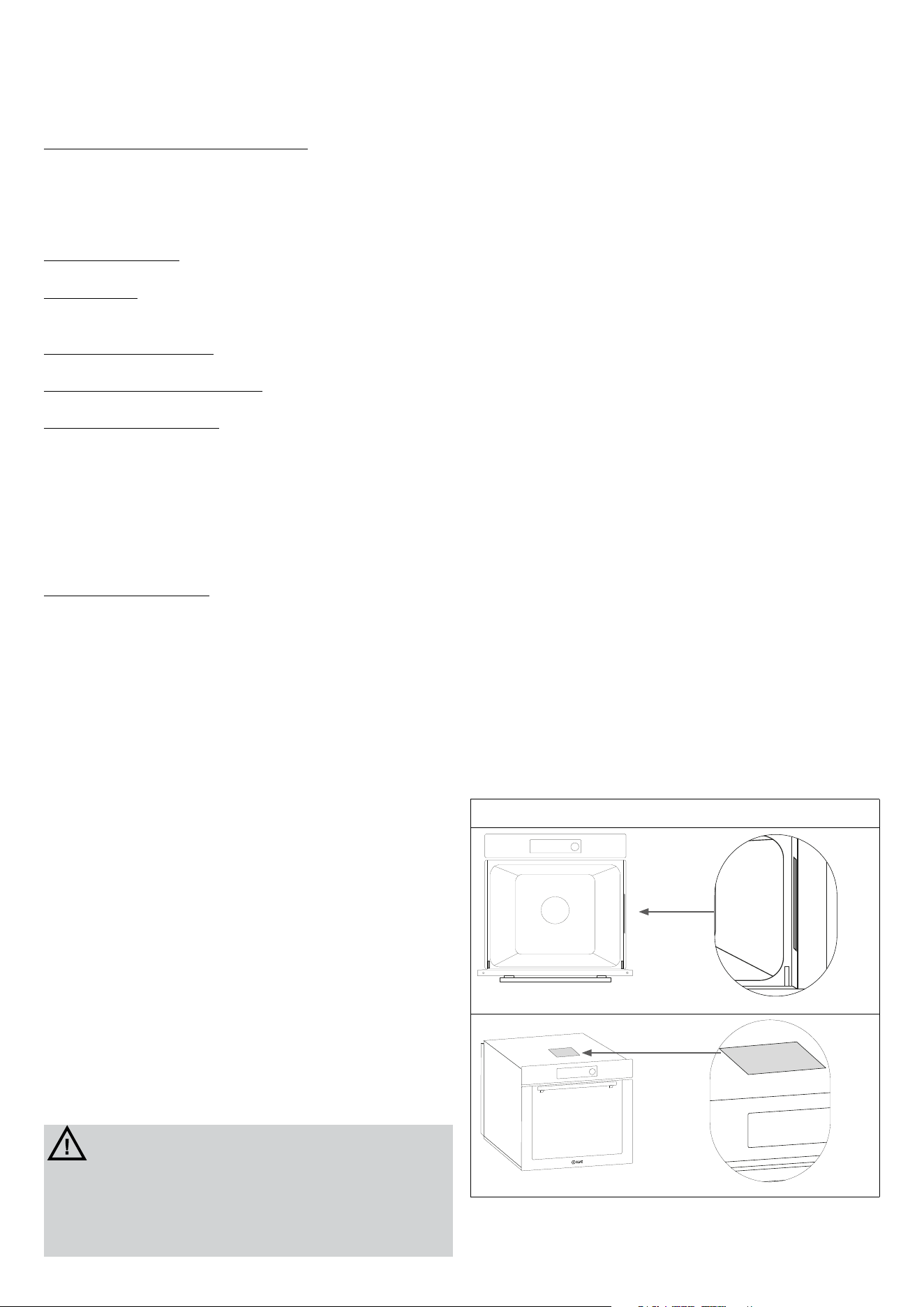
Product Model/Serial Label and Rating Label Locations
4
INSTALLATION INSTRUCTIONS
IMPORTANT – SAVE FOR THE LOCAL ELECTRICAL
INSPECTOR’S USE
APPLIANCE INSTALLATION
Unpacking the oven
To avoid risk of severe personal injury and damage to the unit
and ooring; this appliance requires two or more personnel
while handling and moving. Possible use of appliance dollies
moving devices is recommended
- Remove all packing materials from the shipping pallet but
leave the adhesive-backed foam layer over brushed-metal
surfaces to protect it from scratches until the range is
installed in its nal position.
- Examine the appliance aer unpacking it. In the event of
transport damage, do not plug it in. Take pictures of the
damage and report it immediately to the freight forwarder.
- If the power supply cable is damaged, it must be replaced
by the manufacturer, its service agent or similarly qualied
person in order to avoid a safety hazard.
- Remove the oven door. This will reduce the weight of the
appliance.
- The oven racks should be removed to facilitate handling.
- Before moving the appliance, protect the oor to prevent
damage.
- Use an appliance dolly to move the oven near the opening.
Place the appliance dolly on the side to prevent damage, do
not use on front or rear.
- Use the supplied brackets to attach to the cabinet
- Place the oven in the opening and slide into position. To
ensure adequate depth for proper installation, the conduit
must t into the recessed area along the rear edge of the
oven.
- Li the oven by the handle installed on the side panel.
- Shield the edge of the cabinet with a tape before insert the
oven.
- Check that the oven is correctly aligned with the units.
- Locate the mounting hole in each side trim, and install
screws, ensuring that the oven remains centered.
- Cover the screws with the caps.
- Remove and recycle packing materials including the white
protective material behind each rack guide mounting
location.
The misuse of the oven door ( placing heavy objects on the oven
doo, hanging o the handle, stepping or hiting on the door) can
result in damage to the product and /or injuries.
DO NOT install two or more wall ovens single or
double side-by-side or stacked on top of the other.
The characteristics label, which can be found on the door
frame or on the oven lid and is shown on page 1, is visible
when the door is open. It contains all the necessary installation
information, such as: appliance model, nominal voltage, and
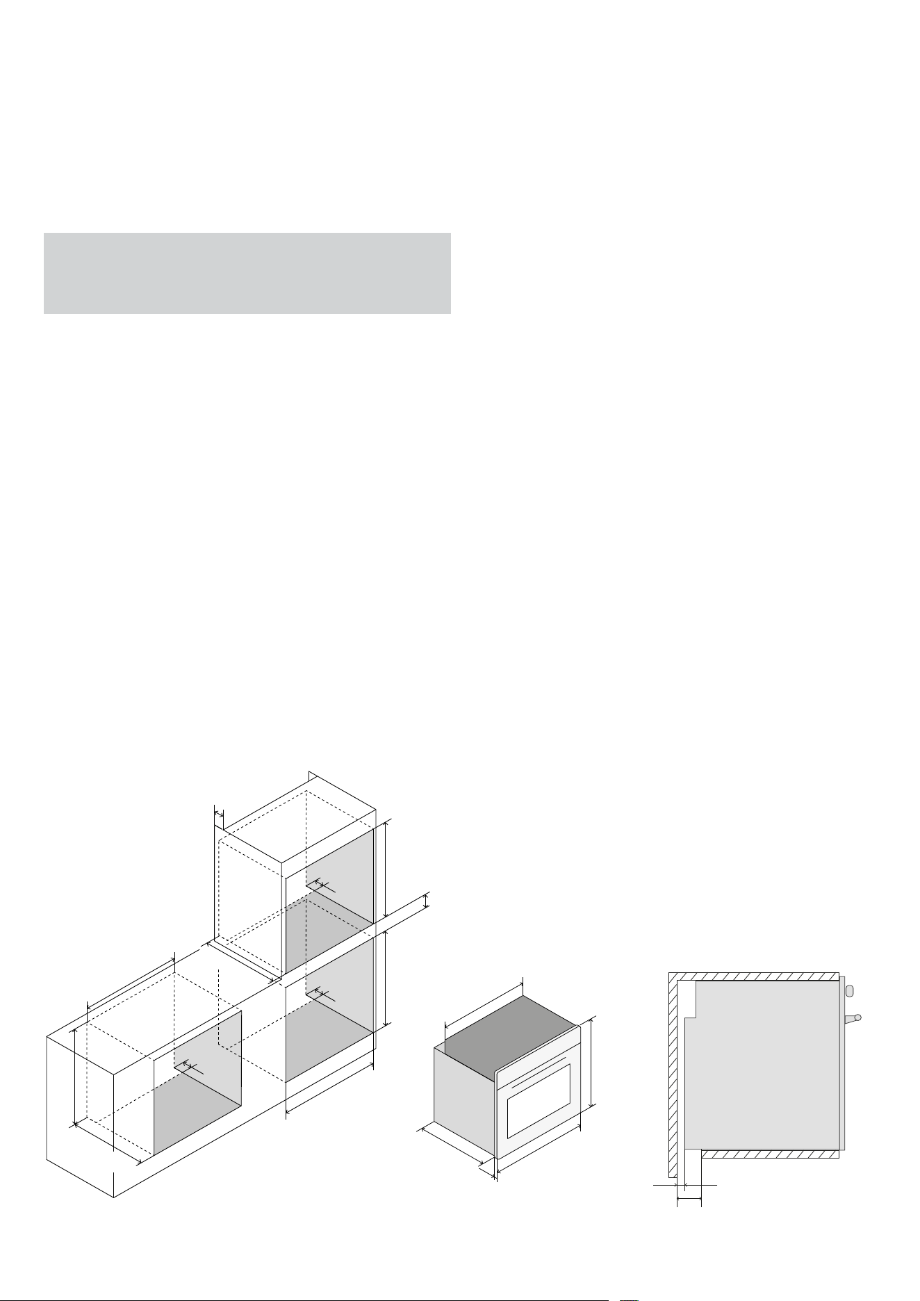
power consumption. First, measure and check the niche for the
oven installation in the cabinet, ensuring that it exactly matches
the dimensions shown in gure A. Make sure that the cabinet’s
nish, veneer, or other materials are glued with heat-resistant
adhesive (300°F). If the nish or adhesive is not heat-resistant,
the material may warp or peel, especially at the narrowest
points of the cabinet. Ensure that the cabinet intended for the
oven installation has a solid base and can support the weight of
the appliance. All screws and accessories required for securing
the oven to the cabinet are included. The following gures will
be helpful for the proper installation and correct placement in
the cabinet.
3
1/8"
(80)
3
1/8"
(80)
3
1/8"
(80)
28
3/4"
(730)
23
5/8"
(600)
5/8"
23
(600)
27
3/4"
(705)
27
3/8"
(695)
min 7/8" (20)
3
1/8"
(80)
28
3/4"
(730)
27
3/8"
(695)
29
7/8”
(759)
28
3/8"
(722)
23
(584)
28
(712)
"1 (25,5)
"
3
1/8"
(80)
3/4"
(16)
3
1/8"
(80)
3
1/8"
(80)
3
1/8"
(80)
28
3/4"
(730)
23
5/8"
(600)
5/8"
23
(600)
27
3/4"
(705)
27
3/8"
(695)
min 7/8" (20)
3
1/8"
(80)
28
3/4"
(730)
27
3/8"
(695)
29
7/8”
(759)
28
3/8"
(722)
23
(584)
28
(712)
"1 (25,5)
"
3
1/8"
(80)
3/4"
(16)
3
1/8"
(80)
3
1/8"
(80)
3
1/8"
(80)
28
3/4"
(730)
23
5/8"
(600)
5/8"
23
(600)
27
3/4"
(705)
27
3/8"
(695)
min 7/8" (20)
3
1/8"
(80)
28
3/4"
(730)
27
3/8"
(695)
29
7/8”
(759)
28
3/8"
(722)
23
(584)
28
(712)
"1 (25,5)
"
3
1/8"
(80)
3/4"
(16)
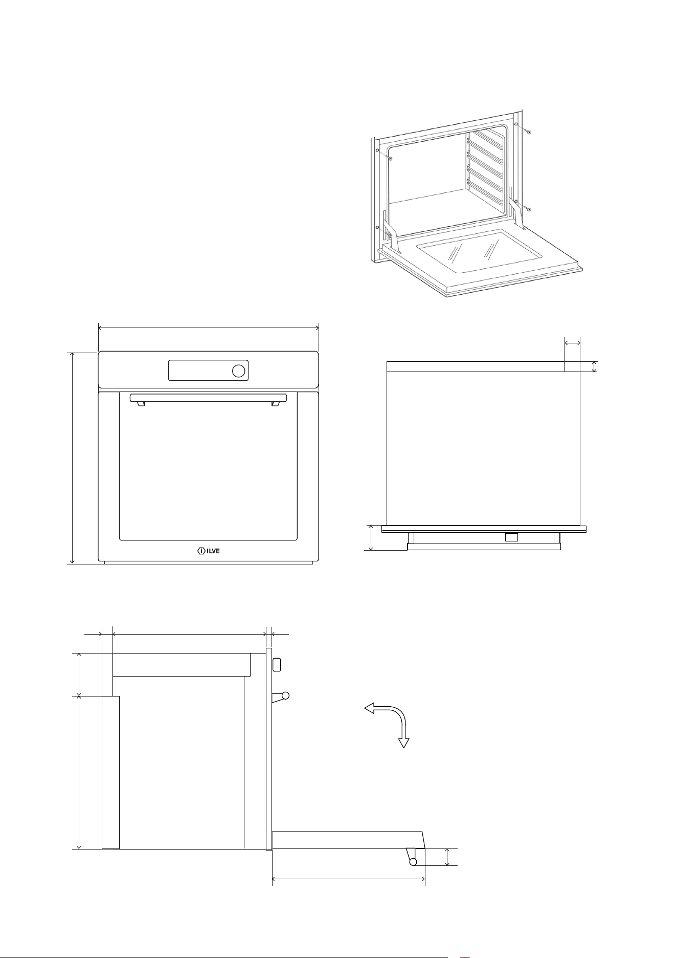
5
Installation underneath a built-in hob
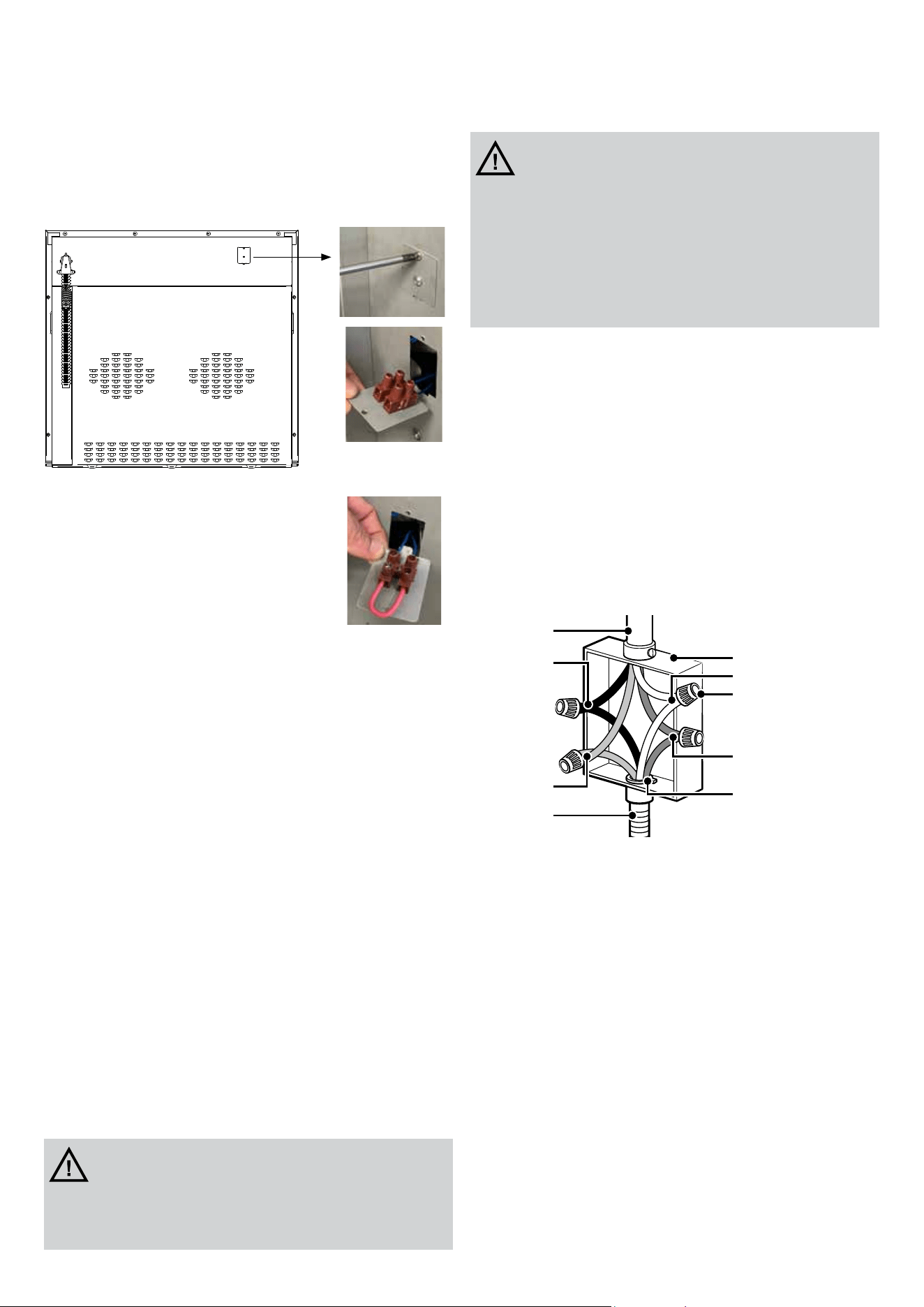
The oven can be installed in a standard or ush application. Finish
the edges of the opening because they may be visible when the
door is open. The clearance between the oven and the kitchen
units or other installed appliances must be enough to ensure
sucient ventilation and air discharge (minimun clearance 1”).
If installed under a hob, space must be le between the bottom
of the hob and the top of the oven to allow for ventilation of the
entire compartment. Any ventilation openings required for the
hob are
to be added to those required by the oven.
Oven dimension
INSTALLATION INSTRUCTIONS
29 (759)
7/8"
28 (712)
"
1
3/8"
(36)
3
3/8"
(85,7)
2
3/8"
(60,5)
"1 (25,5)(548)
21
5/8"
1
3/8"
(36)
2
1/8"
(53)
21
3/4"
(554)
5
7/8"
(148)
21
1/8"
(536,5)
6
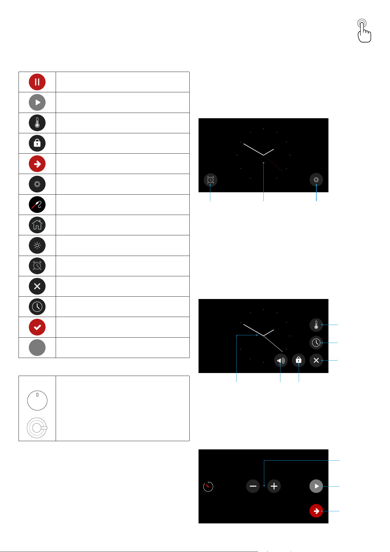
The appliance must be connected to a single-phase electrical
line of 120/240 V~ 60 Hz or 120/208 V~ 60 Hz.
The following images show the procedure for switching from
120/240 V to 120/208 V.
1
2
3
WITH OUT
BRIDGE 240V
WITH
BRIDGE 208V
The appliance is factory-equipped with a exible conduit.
Inside the exible conduit there are four wires:
the green wire must be connected to ground,
the white wire (NEUTRAL),
the red and black wires: power supply wires (F – F1).
Please refer to the wiring diagram available at the end of our
instruction manual.
The power consumption values for each model are indicated in
the attached electrical power rating table.
Before connecting the appliance to the electric network, follow
the instructions below:
1. fuse and electric supply installation of your home must
bear the load of the appliance (see registration label).
2. the power supply system must have an ecient earth
connection.
3. the outlet or multiple-switch, with a minimum1/8” (3mm)
contact opening, has to be easily reached once the
appliance has been installed.
ELECTRICAL CONNECTION
WARNING
If the voltage is wrong, the oven can be
damaged.
CAUTION
Risk of Electric Shock. If the cord or
plug becomes damaged, disconnect
the appliance from the power supply
and replace only with a cord or plug
of the same type
Service & maintenance
instructions
Replacement Parts.
Authorized replacement parts may be used in performing
service on the appliance. Replacement parts are available from
factory authorized part distributors.
NON WORKING APPLIANCES
Before calling the Aer Sales Service, check that the appliance
is connected or that the main switch is activated.
Aer, call the Aer Sales Service. The faults must be checked
by an experienced technician.
Note: The appliance is equipped with a certied soware
safety device. If it reaches an excessively high temperature, the
appliance switches o and displays an error message.
Check your local code for which of the options below should be
used in grounding the receptacle power supply connections.
FOUR-WIRE CONNECTION:
- Connect the L1 receptacle terminal to the incoming BLACK
electrical supply wire (L1 – hot wire).
- Connect the L2 receptacle terminal to the incoming RED
electrical supply wire (L2 – hot wire).
- Connect the NEUTRAL receptacle terminal to the incoming
NEUTRAL (WHITE) electrical supply wire.
- Connect the GROUND receptacle terminal to the incoming
GROUND (GREEN) electrical supply wire.
Four-wire connection diagram (NEMA 14-50R receptacle)
Power supply
Black wires
Junction box
White wires
UL-listed wire connectors
Red wires
UL or CSA listed connector
Green wires
Flexible metal
conduit from oven
7
INSTRUCTIONS FOR USE
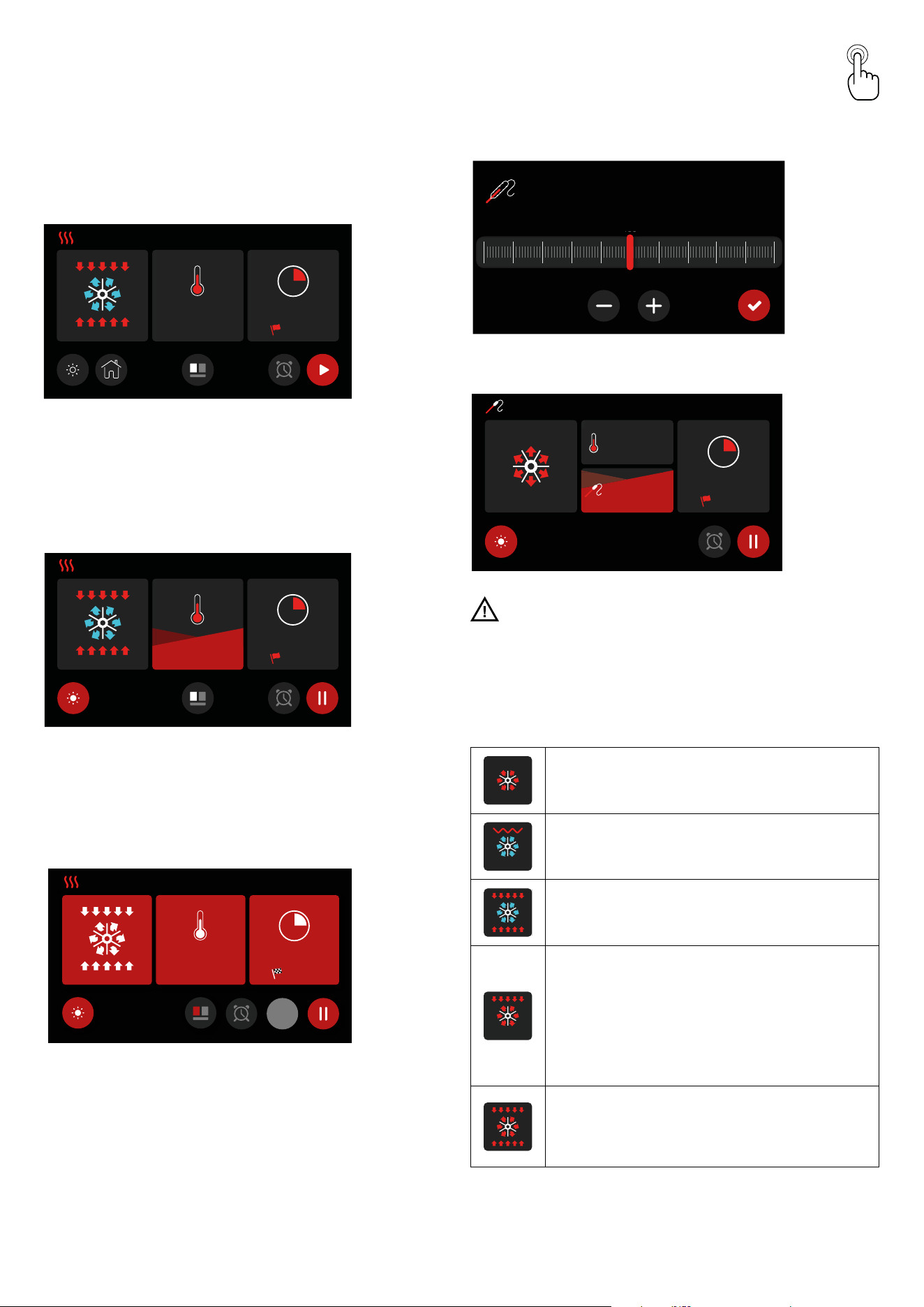
TFT touch display
Icons legend
Pause
Start
°C - °F
Screen lock
Conrm
Settings
Meat probe
Home
Light
Timer
Exit - Term
Time
Settings conrmation
OFF
O
Knob to activate PYROLISIS function
Functioning
Home - Initial display page
1 = Allows you to proceed to the cavity settings screen.
2 = Allows you to set the timer.
3 = Allows you to access the settings directly.
PM
1 2 3
9 7
4
5
6
8
Settings
4 = Choice of temperature scale (°C or °F)
5 = Set the time
6 = Exit - End of a function
7 = Lock screen
8 = To unlock, touch the display for 10 seconds
9 = Allows you to set the volume of the sound signal and,
optionally, choose a sound for touch interactions.
Set a Timer
10 = Increase or decrease the time
11 = Confirm once the desired time is set. A sound signal will
indicate when the time is up.
12 = Confirm and return to the home page
11:4 8 AM
10m
11
12
10
8
INSTRUCTIONS FOR USE
TFT touch display
Cavity set
Once the cavity is set (cooking function, temperature, and
timer are set), confirm to begin preheating. At this point, the
display will switch to preheating mode
11:48 AM
280
°F
10m
12:58
Preheating phase
There are multiple levels that allow you to monitor the
preheating process. The red section will progressively increase
until it fills the display. If no cooking time was set, it is possible
to pause the cooking (PAUSE, by pressing the button) or stop
it by pressing OFF
11:48
280
9m 15s
°F
AM
12:58
Preheating complete
When the set temperature is reached, the display will turn red
to indicate the end of the preheating phase and the beginning
of the cooking phase. If a cooking time was set, the oven will
automatically turn off when the time expires.
11: 4 8
280
8m 02s
°F
AM
12:5 8
OFF
MODALITÀ COTTURA
Cooking with meat probe
N.B. The meat probe function cannot be used in the “DEFROST,”
“QUICK START,” “PIZZA,” and “ECO” modes. With the oven in
standby, insert the meat probe into the designated connection
socket, which is primarily located on the left side wall of the
oven.
Temperature probe selector
160
°F
SELETTORE TEMPERATURA SONDA
110120 130140 150160 170
160
180190 200210
Heating mode with probe
11:48
AM
180
80
°F
°F
61°
9m 15s
12:58
MODALIT
À
RISCALDAMENTO CON SONDA
WARNING: If the display does not respond to commands
(touch screen locked), simply open and close the oven door
Functions
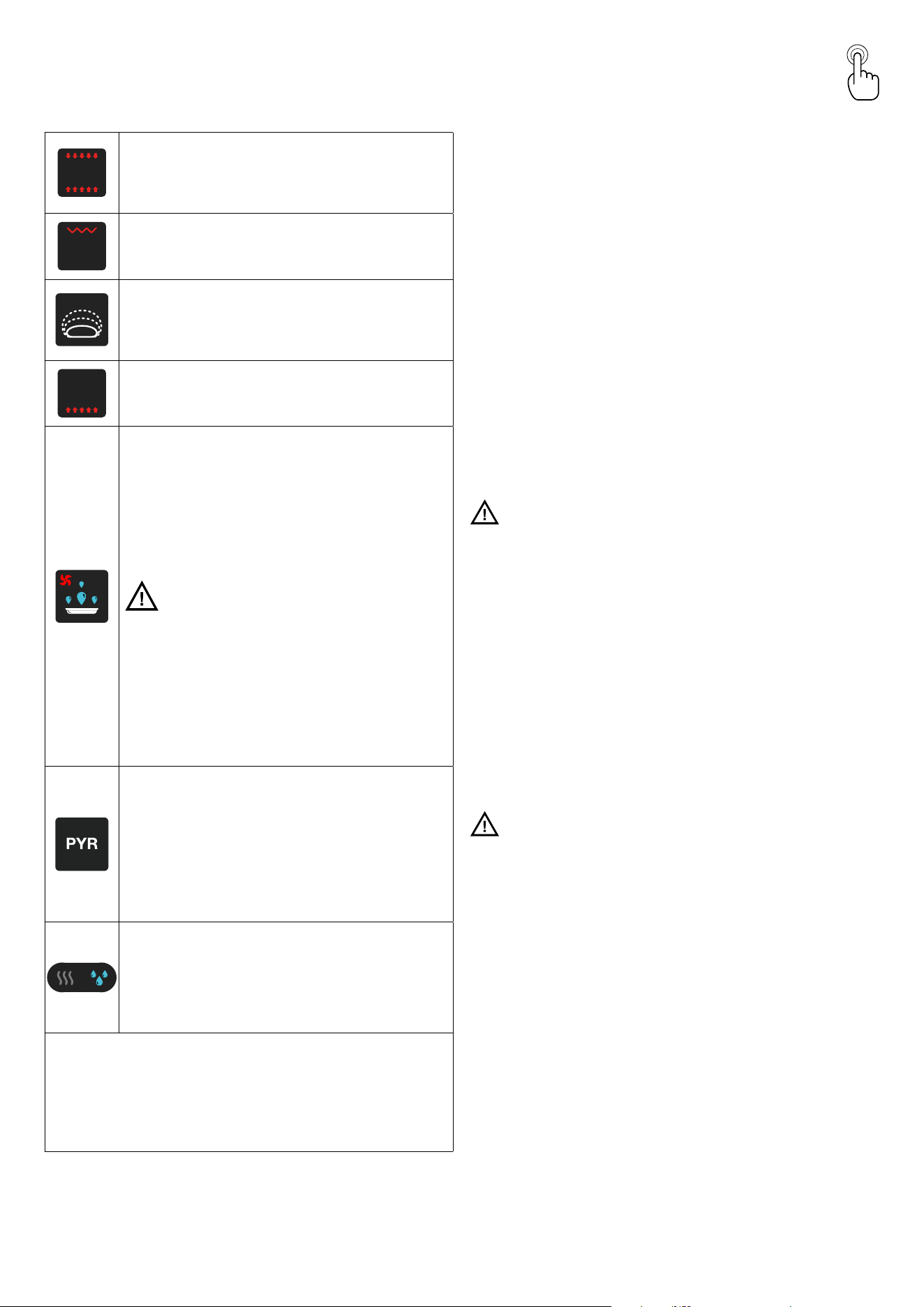
1- Multi-Ventilated Cooking
This function allows the simultaneous cooking of dierent
dishes without mixing their odors. You can cook lasagna,
pizza, croissants, pastries, pies, etc.
2- Ventilated Grill Cooking
Particularly fast and deep with signicant energy savings,
this function is suitable for many foods such as pork ribs,
sausages, pork or mixed skewers, game, Roman gnocchi, etc.
3- Intensive Cooking
This function provides rapid and intense cooking for various
dishes; it is ideal for: baked sh, braised vegetables, skewers,
duck, chicken, etc.
4- Quick Start
This function speeds up the preheating of your oven. It is
recommended for use when setting a cooking temperature
between 390°F and 570°F. Using Quick Start for temperatures
lower than 392°F does not provide signicant benets.
WARNING: The Quick Start function is not suitable for
cooking food; it is only used to preheat the oven more quickly.
DO NOT USE THE QUICK START FUNCTION FOR MORE
THAN 20 MINUTES.
5- Pizza Cooking
This function is particularly suitable for cooking pizzas,
focaccias, and bread. The main heat source comes from the
lower heating element, which works in combination with the
other oven elements.
9
INSTRUCTIONS FOR USE
TFT touch display
6- Static Conventional Cooking
This is the classic electric oven function, particularly suitable
for cooking the following foods: pork ribs, sausages, salted
cod, braised meat, game, veal roast, meringues and cookies,
baked fruit, etc.
7- Grill Cooking with Closed Door
This function is suitable for fast and deep grilling, gratinating,
and roasting in general, such as let, Florentine steak, grilled
sh, and even grilled vegetables.
8- Proong
This function is used to rise dough. Put the dough in a greased
bowl, and cover it with a damp cloth or plastic wrap coated
with nonstick spray. Set the temperature between 85°F and
105°F and the timer for the recipe’s rise time.
9- Bottom Cooking
This is the most suitable cooking method for nishing dishes,
especially pastries (cookies, meringues, leavened cakes, fruit
cakes, etc.) and other foods.
10- Dehydration
This oven is designed not only to cook, but also to dehydrate
fruits, vegetables and meat. Warm air is circulated by a
motorized fan in the rear of the oven and over a period of
time, the water is removed from the food by evaporation.
Removal of water inhibits growth of microorganisms and
retards the activity of enzymes. lt is important to remember
that dehydration does not improve the quality, so only fresh,
top-quality foods should be used.
WARNING You must carefully check the food during
the dehydration process to ensure that it does not
catch re.
Typical values are shown in the table:
FOOD TYPE DEHYDRATING TEMP
Fruit 100°F
Vegetable 125°F
Meat 150°F
11- Pyrolysis, automatic oven cleaning
Selecting this function the AUTOMATIC CLEANING cycle is
started. With “PYROLYSIS” a temperature of around 850°F is
reached which reduces to dust any food residue. It is enough
aerwards to pass a damp cloth to remove the residual ashes,
without having to use any detergents. During the pyrolysis
cycle, the special catalytic lter starts working and absorbs
and eliminates fats and bad odours.
Note: to activate the self-cleaning function the relevant knob
must be used.
Dry / Moist Cooking
The oven is equipped with an automatic device that allows
cooking vapors, in certain functions ( 1 -3 -6 - 9), to be
expelled from the oven, resulting in dry (dry) cooking. If the
cooking requires the humidity to remain inside the oven
(moisture), the automatic device can be deactivated by
touching the corresponding icon.
COOKING INSPECTION
If it is necessary to inspect the food during cooking, you can open the oven
door. In this case, the lights will turn on, and the forced ventilation will stop if
you are using a ventilated cooking function. Additionally, the rotation of the
spit will stop if using the grill cooking with the door closed. Closing the door
will reactivate the previously set function.
Pyrolytic Function
Cleaning Procedure
1. For optimal results, manually remove any food pieces with
a damp sponge (smoke may form).
2. Remove all accessories from the cooking cavity (grids,
trays, side racks, and any cookware).
3. With the door closed, select the pyrolysis function. After a
few seconds, the door lock device will activate.
4. During the pyrolysis cycle, the special catalytic filter will
activate to absorb and eliminate grease and odors.
5. The oven door will only open once the function is complete
and the oven has cooled to a safe temperature.
6. At the end of the process, it is easy to remove any residues
that may have formed, depending on the degree of dirt in
the cavity, by using a damp cloth.
7. The duration of the pyrolysis cycle can be set to 90 minutes
or 150 minutes, depending on the amount of dirt deposited
on the oven walls. A delayed start for the cleaning cycle can
also be set.
WARNING:
- Risk of Burns
There is a risk of injury due to high temperatures on the
surfaces – during the pyrolytic cleaning cycle, the oven
heats up much more than during normal cooking. Avoid
touching the oven.
- Health Risk
Due to the high temperature reached, nearly 850°F, vapors
are released that could irritate the mucous membranes.
Therefore, it is essential to ventilate the room well during
use and avoid prolonged exposure. Keep children away.
Note: During the pyrolysis function, the oven light does not
turn on.
- CAUTION: DO NOT LEAVE FOOD OR COOKING
UTENSILS IN OVEN DURING THE PYROLITIC SELF-
CLEANING MODE OF OPERATION
WARNING:
- IF TWO OVENS ARE INSTALLED (ONE ABOVE THE
OTHER), IT IS NOT RECOMMENDED TO RUN THE
PYROLYTIC CLEANING FUNCTION ON BOTH OVENS
AT THE SAME TIME. THE PYROLYTIC CLEANING
CYCLE SHOULD BE CARRIED OUT SEPARATELY: FIRST
ON ONE OVEN AND, ONCE IT HAS COMPLETED THE
CYCLE AND COOLED DOWN, ON THE OTHER OVEN.
10
PM
1
2
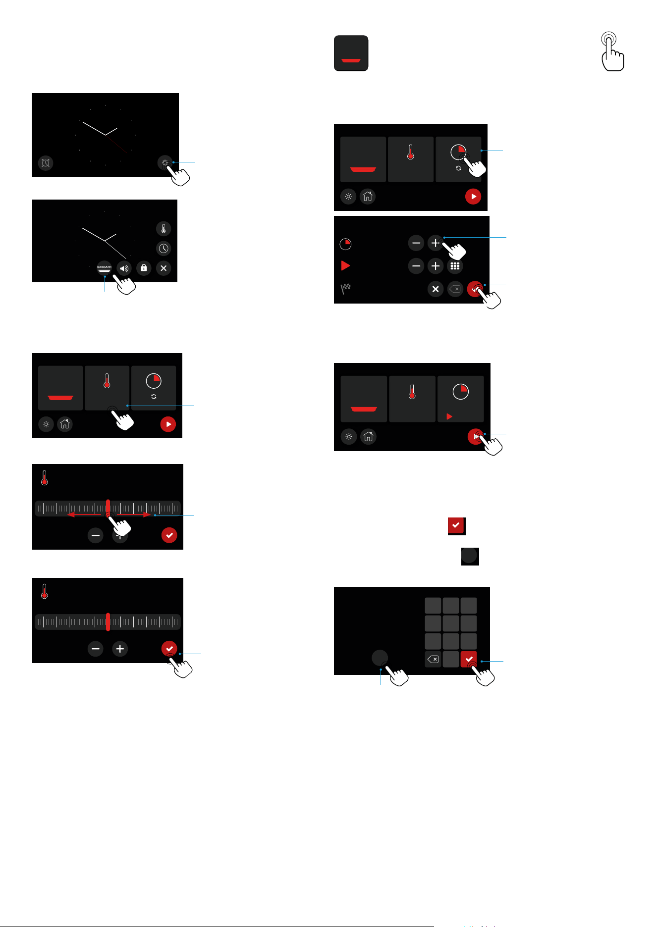
3 - 4 - 5 - Before using sabbath mode adjust
the cavity temperature.
11: 4 8
350
°F
SABBATH
3
350
°F
100 200 300 400 500
4
350
°F
100 200 300 400 500
5
6- 7 - Fix the cooking time till 74 hours
11: 4 8
350
°F
SABBATH
6
11: 4 8
0:06
74h 0 0 m
2:06
8
7
9- Starting cooking sabbath mode
11: 4 8
350
°F
SABBATH
0:06
74 h 0 0 m
9
10.- During sabbath cooking it is possible to change the cavity
temperature using the numeric keypad (e.g. we set 250°f) and
then conrm with the key
0
2
5
8
1
4
7
3
6
9
Sabbath
OFF
11- It is always possible to exit the sabbath function by pressing
the o key for a few seconds
0
2
5
8
1
4
7
3
6
9
Sabbath
OFF
.
0
2
5
8
1
4
7
3
6
9
Sabbath
OFF
10
11
11: 4 8
350
°F
SABBATH
INSTRUCTIONS FOR USE
SABBATH Function
11
INSTRUCTIONS FOR USE
Accessories
Telescopic guides
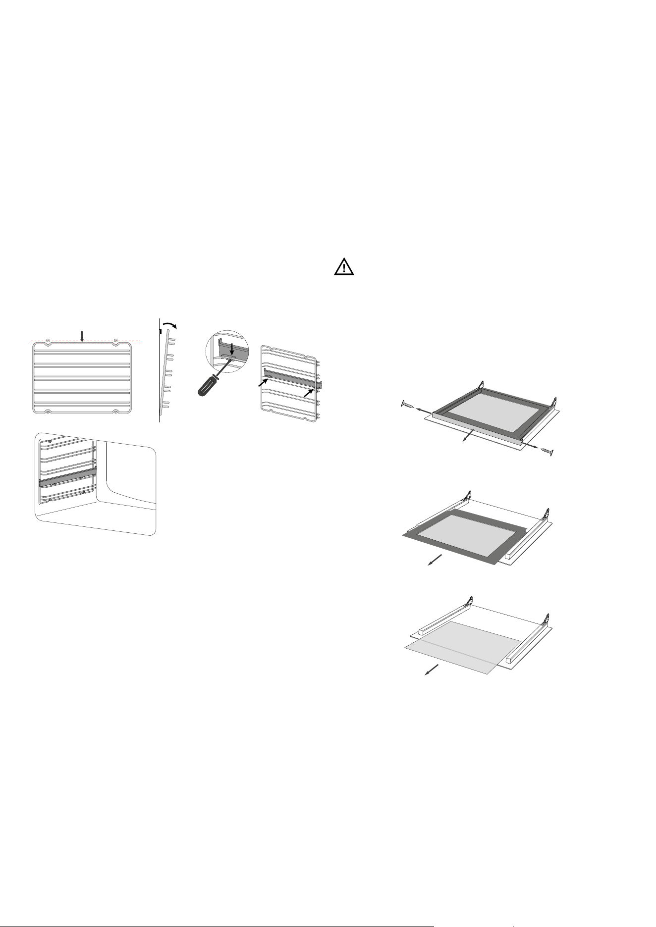
(available only in some models)
This solution is designed to enhance ergonomics, practicality,
and safety when handling trays and pans in the oven. The kit
consists of fully extendable side rails that slide on ball bearings
to facilitate the removal and placement of trays. The rails are
anti-tip for added safety. They can be removed for cleaning or
repositioned, as shown in the photos below.
1. Pull down the part highlighted in red to remove it from the
oven wall.
2. Turn them over and place them on a at surface with the
sliding guide side facing down..
3. To release the clip, loosen it with a athead screwdriver..
4. Repeat the steps in reverse to reposition the guide..
CLEANING AND MAINTENANCE
Recommendations for cleaning
Disassembly and Cleaning of the Glass
Panels
The oven door consists of four glass panels. Clean the glass
parts using non-abrasive kitchen paper and a common
detergent. Do not use rough abrasive materials or sharp metal
scrapers, as they may scratch the surface and cause the glass
to break.
The inner glass panels are removable (the central glass must
be repositioned correctly with the writing visible, as shown in
Figure 3) to facilitate cleaning. To remove them, it is necessary
to disassemble the oven door.
WARNING: All operations must always be carried out
with the door removed from the oven and placed on a suitable
surface to avoid damaging the front part of the door.
The central glass must be reinserted correctly with the writing
visible, as shown in the following images:
1. Unscrew the two screws on the right and le sides of the
upper trim.
2. Li the top glass and slide it outwards.
xxxxxxxxx
xxxxxxxxx
3. Slide the two central glass panels outwards.
xxxxxxxxx
xxxxxxxxx
12
CLEANING AND MAINTENANCE
Recommendations for cleaning
Removing the door
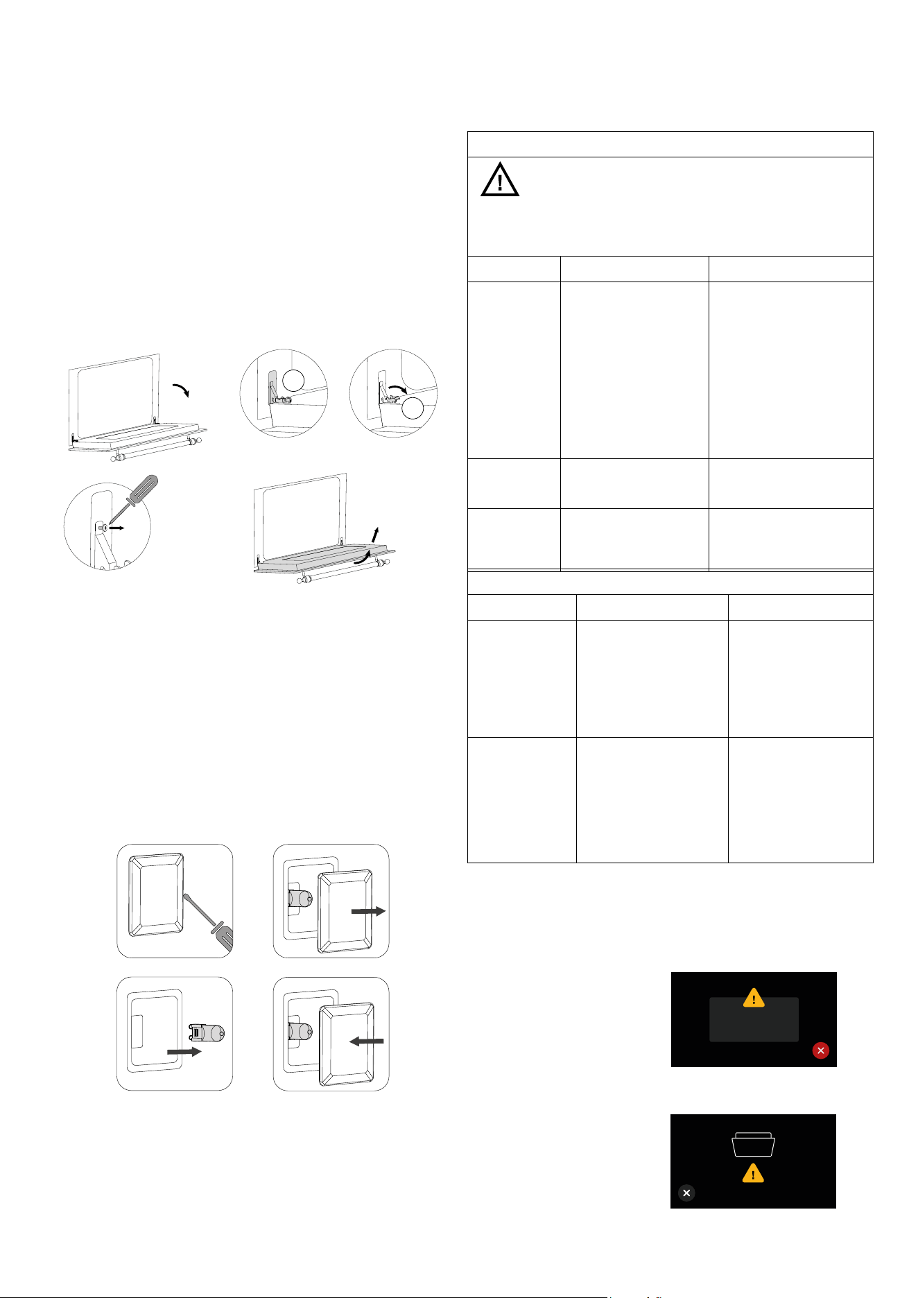
To facilitate intensive cleaning of the oven, it is practical to
remove the door by following these instructions:
1. Open the door
2. Move the latch C to the hinge section D following the
steps:
3. Unscrew the screw
4. Remove the door
1
3
C
D
2
4
Lamp Replacement
If the oven light is not working, disconnect the appliance from
the power supply, remove the protective glass of the lamp, and
replace the bulb. It is important to ensure that the replacement
bulb is suitable for high-temperature use and has the necessary
specications for such an application.
1. Loosen with a athead screwdriver
2. Remove the lamp cover glass
3. Remove the lamp:
4. Replace and close it:
1
3
2
4
OVEN
ATTENTION! Before carrying out any cleaning
operations, disconnect the appliance from the mains and
close the gas valve. The cooktop must be cleaned aer it
has been let cooling down.
COMPONENT CLEANING METHOD WARNINGS
Oven interior
It is recommended to clean
the oven aer each use.
Dirt is easier to clean if it is
prevented from burning at
high temperatures repeatedly.
Remove all removable parts
and wash them separately with
warm water and non abrasive
detergent. Clean the cooking
cavity with a so cloth soaked
in a solution of warm water and
ammonia, then rinse and dry.
Do not use steam cleaners for
cleaning the oven interior. Do not
use abrasive/corrosive detergents
or sharp metal tools to clean the
oven’s glass door, as they may
damage the surface and cause it
to break.
Tray
Soak in a solution of warm
water and mild soap. Dry aer
washing.
Remove food residues
immediately aer use.
Racks
Clean with hot water and non-
abrasive detergents or with a
suitable degreaser.
In case of baked-on and hardened
dirt, it is recommended to soak
the racks for a few hours before
cleaning.
FRONT PANEL
COMPONENT CLEANING METHOD WARNINGS
Stainless steel/
glass surface
Clean the details with
lukewarm water and non
corrosive liquid detergent,
then dry them with a so
cloth or microber cloth.
Shine is maintained
through periodic cleaning
with specic products
typically available on
the market. Never use
abrasive powders.
Painted surfaces
To maintain the
characteristics of the
painted parts, it is
necessary to clean them
frequently with soapy water.
Avoid leaving acidic or
alkaline substances
(vinegar, lemon juice, salt,
tomato juice, etc.) on the
painted parts, and do not
wash the painted surfaces
while they are still hot.
PROBLEM SOLVING
System errors
The syntax of the error code is: “E YY
x”, where:
YY = Error code
X = Cavity where the error is detected,
or 0 for general errors
Warning issue
error
E YY X
Door open warning with cooking in
progress
DOOR OPEN
Close the oven door
13
4
3
2
1
5
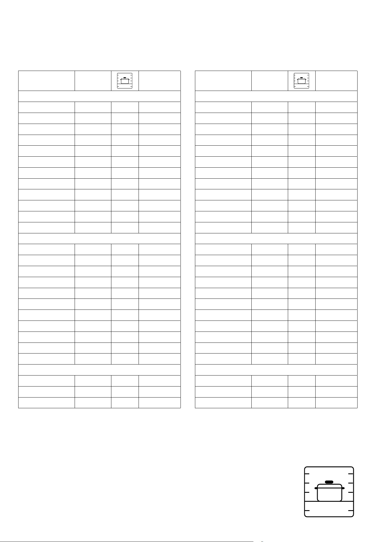
Convection oven (indicative values)
DISH TEMP (°F)
4
3
2
1
5
TIME (MIN)
MEATS
Roast beef 680 / 360 2/3 40/50
Roast ox 340 / 370 2/3 40/60
Roast veal 320 / 360 2/3 65/90
Roast lamb 280 / 320 2 100/130
Rare roast beef 360 / 370 2/3 40/45
Roast hare 340 / 360 2/3 80/100
Roast rabbit 320 / 340 2 80/100
Roast turkey 320 / 340 2 160/240
Roast goose 320 / 360 2/3 120/160
Roast duck 340 / 360 2/3 100/160
Roast chicken 360 2/3 90/120
FISH 320 / 360 2/3 15/25
PATISSERIE
Fruit cake 360 / 390 2 40/50
Margherita cake 360 / 370 2 40/45
Brioches 340 / 360 2 40/60
Sponge cake 370 / 390 2 25/35
Donuts 320 / 360 2 35/45
Sweet pu pastry 360 / 390 2 20/30
Grape atbread 370 / 390 2 30/40
Strudel 320 2 25/35
Savoiardi biscuits 300 / 360 2 50/60
Apple fritters 360 / 390 2 18/25
Savoiardi pudding 340 / 360 2 30/40
BAKERY
Bread 360 / 390 3 45
Pizza 480 3 10/20
Toast 370 / 380 2 7
IMPORTANT: Introduce the food when the oven is preheated.
Grill cooking
For appliances with an electric grill, cooking is done with the door closed at
360°F. The food to be grilled should be placed on the corresponding grill,
preferably on the fourth rack.
COOKING CHART
Static oven (indicative values)
DISH TEMP (°F)
4
3
2
1
5
TIME (MIN)
MEATS
Roast beef 440 2/3 60/80
Roast ox 480 2/3 50/60
Roast veal 440 2/3 60/80
Roast lamb 440 2 40/50
Rare roast beef 450 2/3 50/60
Roast hare 490 2/3 40/50
Roast rabbit 490 2 40/50
Roast turkey 490 2 50/60
Roast goose 440 2/3 60/70
Roast duck 490 2/3 45/60
Roast chicken 490 2/3 40/45
FISH 390/440 1/2 15/25
PATISSERIE
Fruit cake 440 2 35/40
Margherita cake 350/390 2 50/60
Brioches 350/390 2 25/30
Sponge cake 430/480 2 20/30
Donuts 360/390 2 30/40
Sweet pu pastry 390/420 2 15/20
Grape atbread 490 2 25/35
Strudel 360 2 20/30
Savoiardi biscuits 360/390 2 40/50
Apple fritters 390/430 2 15/20
Savoiardi pudding 390/430 2 20/30
BAKERY
Bread 430 3 30
Pizza 480 3 10/20
Toast 480 3 5
IMPORTANT: Introduce the food when the oven is preheated.
Grill cooking
For appliances with an electric grill, cooking is done with the door closed at
360°F. The food to be grilled should be placed on the corresponding grill,
preferably on the fourth rack.
Position of cooking grids
There are 5 shelf position - 1 is the lowest and 5 is the highest near to the grill.
If cooking one dish use shelf position 3, if cooking more than one tray depending on the height
of the tray or food is suggested to cook on shelf positions 2 and 4.
Use the 4 and 5 shelf position for grilling and the grill pan in the botton shelf 1 to cath any drips.
The lower shelp position 1 can be used to slow cooking down or the temperature can be reduced.
14
INSTALLATION
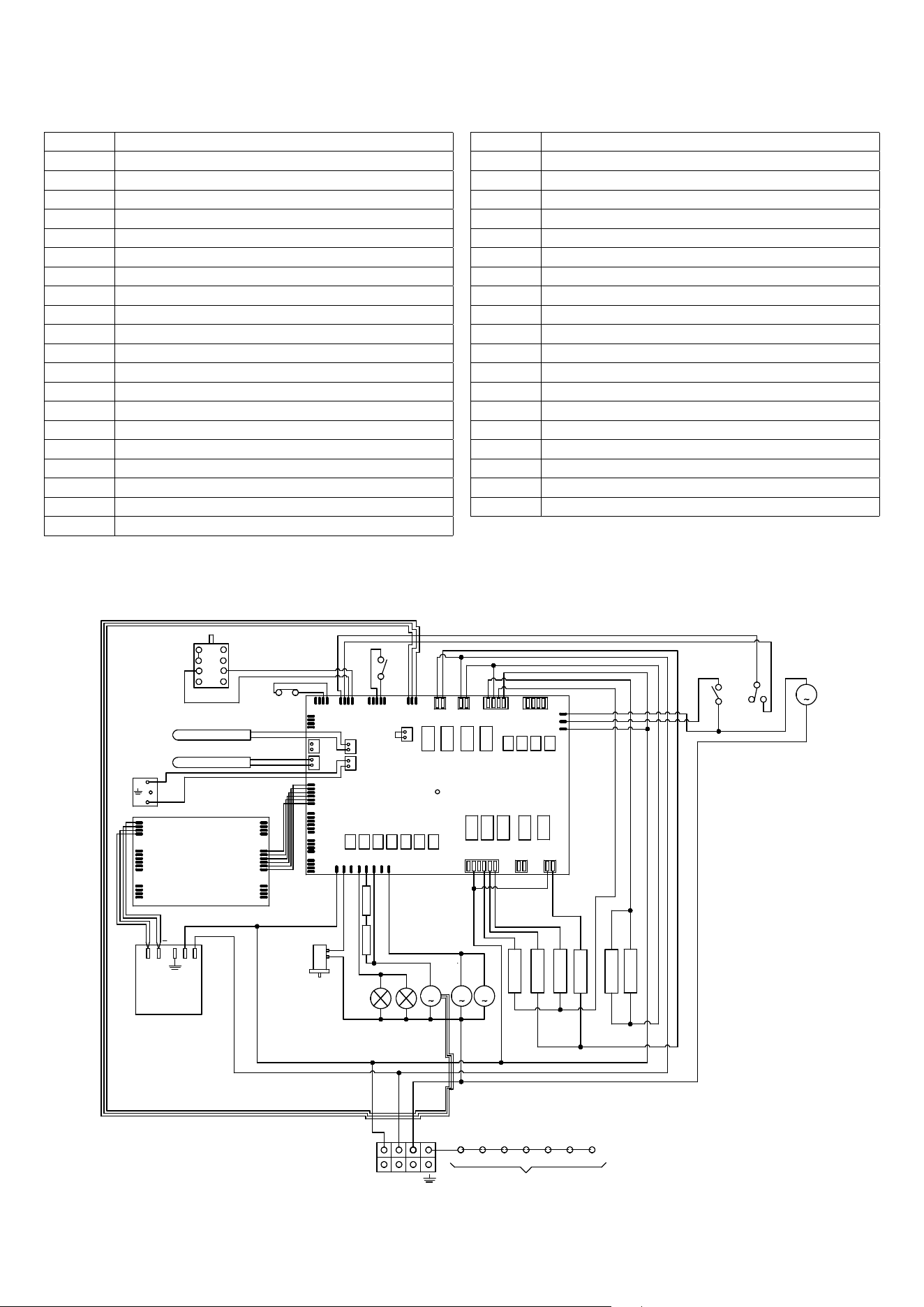
Key - Wiring diagram
00 Black
11 Brown
22 Red
33 White
44 Yellow
45 Yellow-green
55 Grey
66 Blue
C Commutator
CP Cooking probe
DU Wax thermal actuator discharging steam
SD Display
F Phase
F1 Phase 1
K1 Earth wire terminal block
K3 Earth wire oven fan
K5 Earth wire upper resistance
K6 Earth wire oven light 1
K7 Earth wire oven light 2
K13 Earth wire grill resistance
K15 Earth wire frame
J21
PB
J18
J15-1
J20
J9
J7
J5
J4
J2
J1
J14
71J31J
1
1
1
1
1
1
1
1
1
J16
1
1
J12
1
J15
1
J8
1
J22
J6
J10
1
J19
1
J11
1
R3
22
00
R2
00
11
R1
11
00
L2
L1
00
22
N
33
00
00
00
55
R4
55
55
55
22
22
00
00
00
DU
L1
L2
M
VT
M
VR
22
44
44
3333
33
33
33
22
55
55
A
B
C
D
1
2
3
4
C
MU
M
MDL
33
33
R6
00
11
PT1000 cavity
J3
J6
J4
1
1
1
J2
J1
J10
1
1
1
00
SD
L
SA
NV-V+
22
MP
B
C
A
CP
BA
K1 K3 K6
45
K5
K8
K7
K15
RL
1
33
00
J24
55
22
PT1000 cavity
R4
M
VR
RL
00
00
00
44
22
44
22
22
33
66
66
66
66
66
66 33
66
00
ML
L1
Oven light
L2 Oven light
M Terminal block
MDL Door lock motor
ML Lock microswitch
MUL Unlock microswitch
N Neutral
PB Power board
PT1000 Temperature probe
R1 Upper heating element
R2 Lower heating element
R3 Grill heating element
R4 Circulating heating element
R6 Additional lower
RL Limit resistance
SA Power supply board
SD Display board
TS2 Safety thermostat
VR Oven fan
VT Cooler fan
ELECTRICAL AND GAS
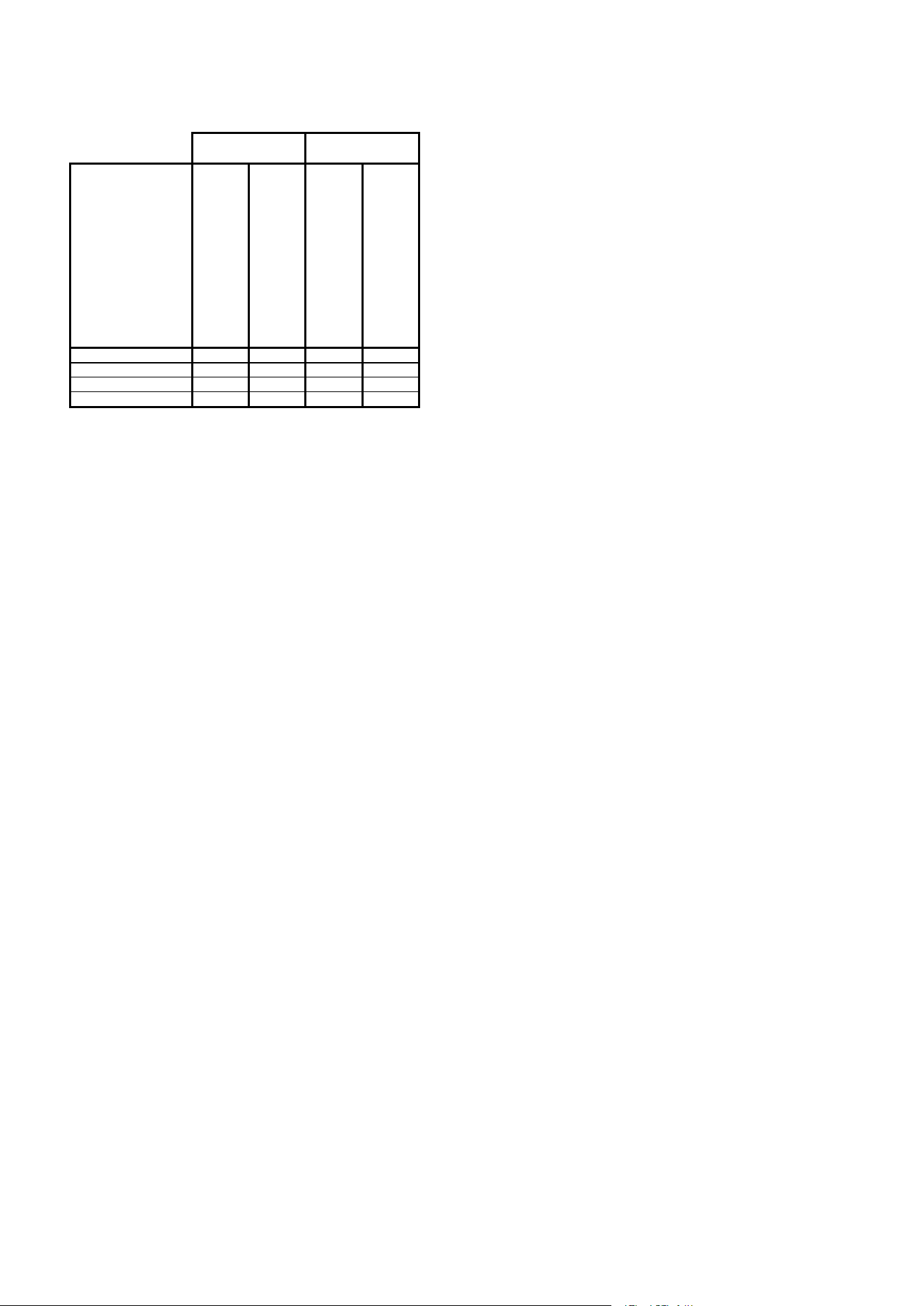
POWER TABLE
TYPE UOV
BUILT-IN OVEN
E
LECTRIC RATED INPUT
[
kW]
ELECTRIC RATED INPUT [A]
E
LECTRIC RATED INPUT
[
kW]
ELECTRIC RATED INPUT [A]
Models
UOV30NTPY
5,7 24 4,3 21
UOV30GTPY
5,7 24 4,3 21
UOV30STPY
5,7 24 4,3 21
UOV30WTPY
5,7 24 4,3 21
120/240V; 60 Hz 120/208V; 60 Hz

ilve.com
ILVE S.p.A Via Antoniana, 100 — 35011 — Campodarsego (PD) Italy
T. +39 049 9200990 / Email: mail@ilve.com
cod. EI33961080000EN 25/2026