
MODEL NUMBER
USER MANUAL
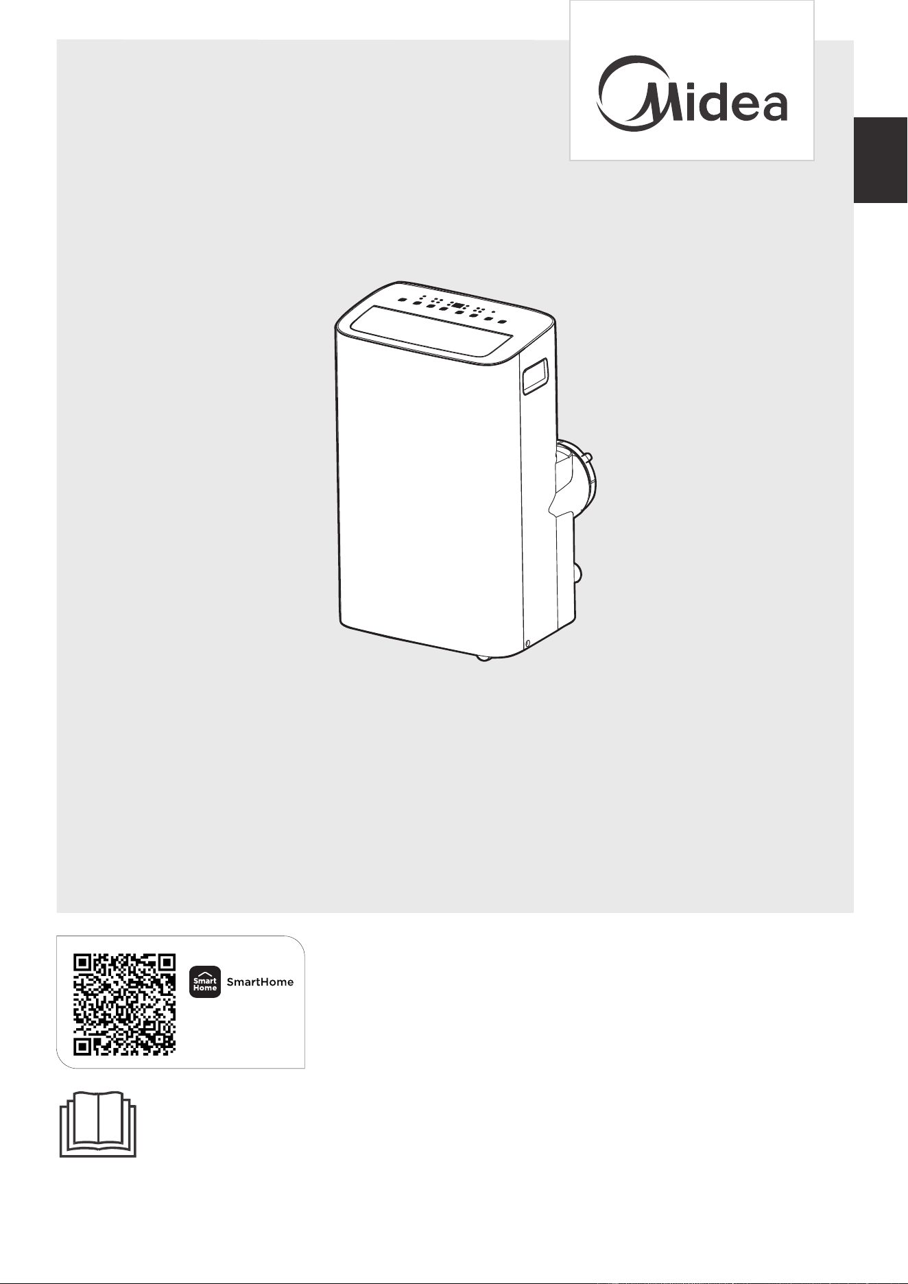
Before using this product, please read this manual carefully and keep it for future reference.
The design and specifications are subject to change without prior notice for product improvement. Consult
with your dealer or the manufacturer for details.
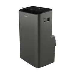
PORTABLE AIR CONDITIONER
en
Download the app
& activate product
MAP08S1XWGR-T
MAP10S1XWBL-T
MAP10HS1XWGR-T
02
Read This Manual
Inside you’ll find many helpful hints on how to use and maintain your air conditioner
properly. Just a little preventive care on your part can save you a great deal of time
and money over the life of your air conditioner. You’ll find many answers to common
problems in the troubleshooting tips - you should be able to fix most of them quickly
before calling service. These instructions may not cover every possible condition of
use, so common sense and attention to safety is required when installing, operating
and maintaining this product.
CAUTION
THANK YOU LETTER
Thank you for choosing Midea! Before using your new Midea product, please
read this manual thoroughly to ensure that you know how to operate the
• For support, please call the Service Center at 1-866-646-4332.
• This appliance is not intended for use by persons (including children) with reduced
physical, sensory or mental capabilities or lack of experience and knowledge, unless
they have been given supervision or instruction concerning use of the appliance by
a person responsible for their safety.
• Children should be supervised to ensure that they do not play with the air conditioner.
• The appliance shall be installed in accordance with national wiring regulations.
• Do not operate your air conditioner in a humid room such as a bathroom or laundry room.
OWNER’S MANUAL
Get to know your AC
Drainage guide
Store the unit when not in use
Cleaning & maintenance
Troubleshooting
Before you get start
Safety Precautions
Product overview
Installation overview
Installation guide
Warranty
Remote control and App instructions
Return Policy
03
1 3
24
26
28
27
29
16
17
18
30
47
48
03
Safety Precautions
Explanation of Symbols
Must read the warning message.
Read Safety Precautions Before Operation and Installation
To prevent death or injury to the user or other people and property damage, the
following instructions must be followed.
Incorrect operation due to ignoring of instructions may cause death, harm or damage.
WARNING
CAUTION
This symbol indicates the possibility of property damage or serious
consequences.
This symbol indicates the possibility of personnel injury or loss of life.
NOTICE
The power supply cord with this
air conditioner contains a current
detection device designed to reduce
the risk of fire.
In the event that the power supply
cord is damaged, it can not be
repaired. It must be replaced with a
cord from the manufacturer.
Grounding type wall receptacle
Do not, under any
circumstances, cut,
remove or bypass
the grounding prong.
Power supply cord with 3-prong grounding
plug and current detection device.
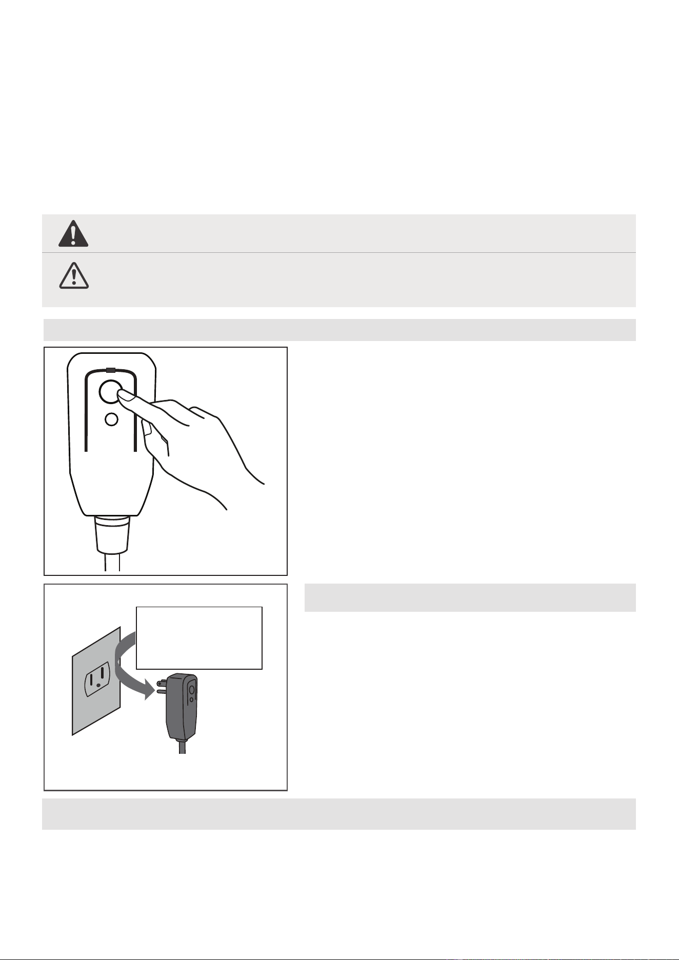
The power supply cord contains a
measurement current device that senses
damage to the power cord. Test your
power supply cord as follows:
1. Plug in the air conditioner.
2. The power supply cord will have TWO
buttons on the plug head. Press the
TEST button. You will notice a click as
the RESET button pops out.
3. Press the RESET Button. You will
notice a click as the button engages.
4. The power supply cord is now
supplying electricity to the unit. (On
some products this is also indicated
by a light on the plug head.)
RESET
TEST
Plug in &
press RESET
Operation of Current Device
NOTICE
• Do not use this device to turn the unit on or off.
• Always make sure the RESET button is pushed in for correct operation.
• The power supply must be replaced if it fails to reset when either the TEST button
is pushed, or it can not be reset. Please contact Customer Service.
04
WARNING
Installation must be performed according to the installation instructions. Improper
installation can cause water leakage, electrical shock, or fire.
Use only the included accessories and parts, and specified tools for the installation.
Using nonstandard parts can cause water leakage, electrical shock, fire, and injury or
property damage.
Make sure that the outlet you are using is grounded and has the appropriate voltage.
The power cord is equipped with a three-prong grounding plug to protect against
shock. Voltage information can be found on the nameplate of the unit.
Your unit must be used in a properly grounded wall receptacle. If the wall receptacle
you intend to use is not adequately grounded or protected by a time delay fuse or
circuit breaker(the fuse or circuit breaker needed is determined by the maximum
current of the unit. The maximum current is indicated on the nameplate located on
unit), have a qualified electrician install the proper receptacle.
Install the unit on a flat, sturdy surface. Failure to do so could result in damage or
excessive noise and vibration.
The unit must be kept free from obstruction to ensure proper function and to mitigate
safety hazards.
Do not modify the length of the power cord or use an extension cord to power the unit.
Do not share a single outlet with other electrical appliances. Improper power supply can
cause fire or electrical shock.
Do not install your air conditioner in a wet room such as a bathroom or laundry room.
Too much exposure to water can cause electrical components to short circuit.
Do not install the unit in a location that may be exposed to combustible gas, as this
could cause fire.
The unit has wheels to facilitate moving. Make sure not to use the wheels on thick
carpet or to roll over objects, as these could cause tipping.
Do not touch the unit with wet or damp hands or when barefoot.
the unit and unplug it from
damage to the machine due to
Your air conditioner should be used in such a way that it is protected from moisture.
e.g. condensation, splashed water, etc. Do not place or store your air conditioner
where it can fall or be pulled into water or any other liquid. Unplug immediately if it
occurs.
All wiring must be performed strictly in accordance with the wiring diagram located
inside of the unit.
The unit's circuit board(PCB) is designed with a fuse to provide overcurrent protection.
The specifications of the fuse are printed on the circuit board, such as: T 3.15A/250V, etc.
Do not operate a unit that it has been dropped or damaged.
The appliance with electric heater shall have at least 1 meter space to the combustible
materials.
the main power supply immediately. Visually inspect the unit to ensure there is no
damage. If you suspect the unit has been damaged, contact a technician or customer
service for assistance.
lightning.
05
CAUTION
This appliance is not intended for use by persons (including childr ) with reduced
physical, sensory or mental capabilities or lack of experience and knowledge, unless
they have been given supervision or instruction concerning use of the appliance by a
person responsible for their safety. Children should be supervised to ensure that they
do not play with the appliance. Children must be supervised around the unit at all times.
If the supply cord is damaged, it must be replaced by the manufacturer,its service
agent or similarly qualified persons in order to avoid a hazard.
Prior to cleaning or other maintenance, the appliance must be disconnected from the
supply mains.
Do not remove any fixed covers. Never use this appliance if it is not working properly,
or if it has been dropped or damaged.
Do not run cord under carpeting. Do not cover cord with throw rugs, runners, or
similar coverings. Do not route cord under furniture or appliances. Arrange co
rd away
Do not operate unit with a damaged cord, plug, power fuse or circuit breaker. Discard
unit or return to an authorized service facility for examination and/or repair.
To reduce the risk of fire or electric shock, do not use this fan with any solid-state
speed control device.
The appliance shall be installed in accordance with national wiring regulations.
Contact the authorized service technician for repair or maintenance of this unit.
Do not cover or obstruct the inlet or outlet grilles.
Disconnect the power if strange sounds, smell, or smoke comes from it.
Do not press the buttons on the control panel with anything other than your fingers.
Do not remove any fixed covers. Never use this appliance if it is not working properly,
or if it has been dropped or damaged.
Do not operate or stop the unit by inserting or pulling out the power cord plug.
Do
not use hazardous chemicals to clean or come into contact with the unit. Do not
use the unit in the presence of inflammable substances or vapour such as alcohol,
insecticides, pet
rol,etc.
Do not use this product for functions other than those described in this instruction manual.
Always transport your air conditioner in a vertical position and stand on a stable, level
surface during use.
Always contact a qualified person to carry out repairs. If the damaged power supply
cord must be replaced with a new power supply cord obtained from the product
manufacturer and not repaired.
Hold the plug by the head of the power plug when taking it out.
en
Electronic Work
WARNING:
BEFORE PERFORMING ANY ELECTRICAL OR WIRING WORK,
TURN OFF THE MAIN POWER TO THE SYSTEM.
06
Servicing shall only be performed as recommended by the equipment manufactur-
er. Maintenance and repair requiring the assistance of other skilled personnel shall
be carried out under the supervision of the person competent in the use of flamma-
ble refrigerants.
DO NOT modify the length of the power cord or use an extension cord to power
the unit.
DO NOT share a single outlet with other electrical appliances. Improper power
supply can cause fire or electrical shock.
Please follow the instruction carefully to handle, install, clear, service the appliance
to avoid any damage or hazard.
CAUTION:
Risk of fire
flammable materials
IMPORTANT NOTE:Read this manual
carefully before installing or operating
WARNING:
your new appliance unit. Make sure
to save this manual for future reference.
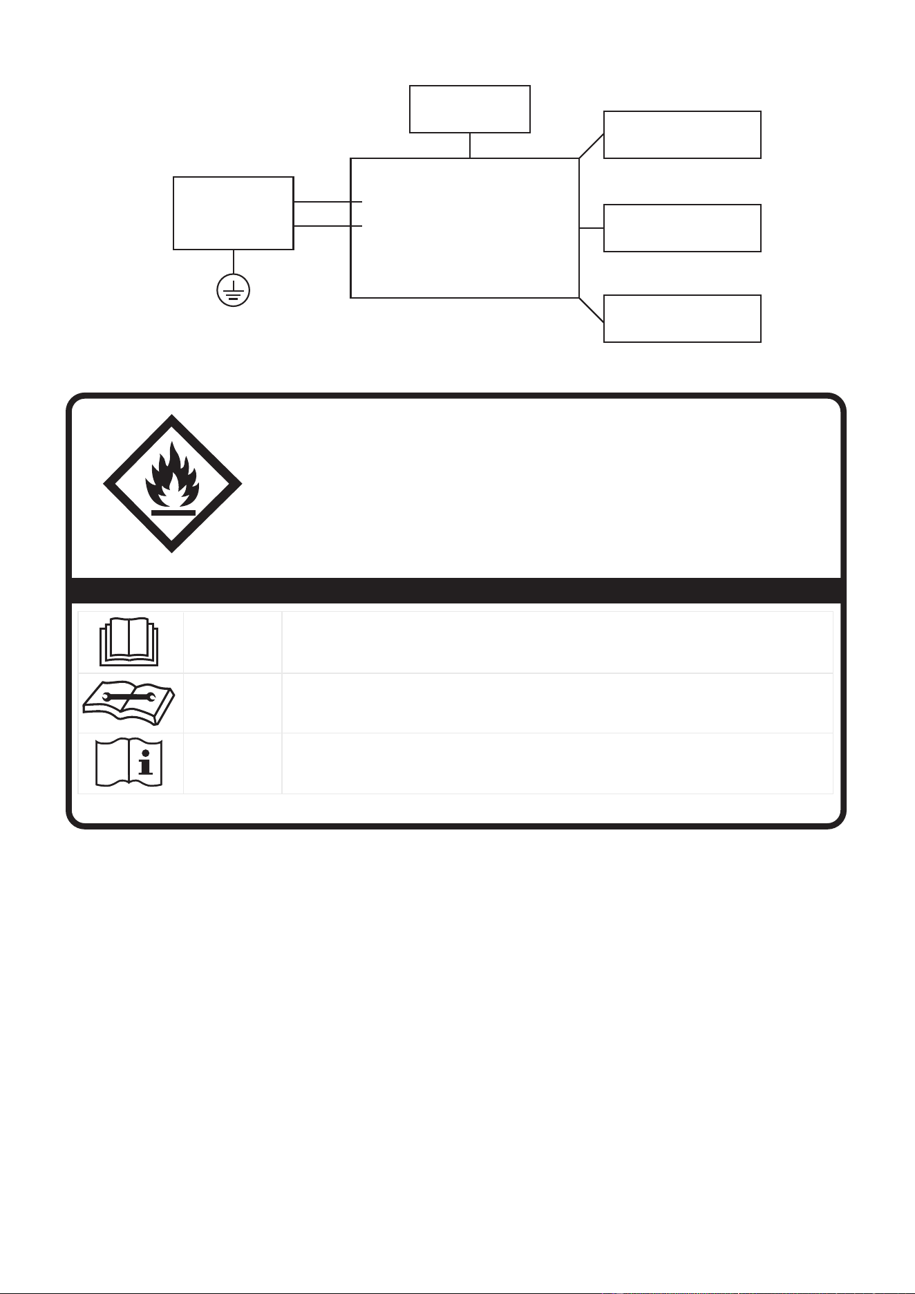
Explanation of symbols displayed on the unit
CAUTION
This symbol shows that the operation manual should be read carefully.
CAUTION
This symbol shows that a service personnel should be handling this equipment with
reference to the installation manual.
CAUTION
This symbol shows that information is available such as the operating manual or
installation manual.
A2L
-
-
-
-
Main Control
Compressor
Fan Motor
Display
Power
Supply
L/AC L/L1/L-IN
N/AC N/L2/N-IN
Other
Electronic Type

07
Flammable
Refrigerant R32 is used within appliance.
- When maintaining or disposing the appliance, the refrigerant (R32) shall be
recovered properly, shall not discharge to air directly.
- Compliance with national gas regulations shall be observed.
- Keep ventilation openings clear of obstruction.
- The appliance shall be stored so as to prevent mechanical damage from occurring.
- A warning that the appliance shall be stored in a well-ventilated area where the
room size corresponds to the room area as specified for operation.
- Any person who is involved with working on or breaking into a refrigerant circuit
should hold a current valid certificate from an industry-accredited assessment
authority, which authorises their competence to handle refrigerants safely in
accordance with an industry recognised assessment specification. All training
shall follow the ANNEX HH requirements of UL 60335-2-40 Edition.
Examples for such working procedures are:
• breaking into the refrigerating circuit;
• opening of sealed components;
• opening of ventilated enclosures.
- No open fire or device like switch which may generate spark/arcing shall be
around appliance to avoid causing ignition of the flammable refrigerant used.
Please follow the instruction carefully to store or maintain the appliance to
prevent mechanical damage from occurring.
-Do not use means to accelerate the defrosting process or to clean, other than
those recommended by the manufacturer.
- The appliance shall be stored in a room without continuously operating ignition
sources (for example: open flames, an operating gas appliance) and ignition
sources or (for example: an operating electric heater) close to the appliance.
The appliance shall be stored in a room without continuously operating ignition
sources (for example: open flames, an operating gas appliance or an operating
electric heater).
- Do not pierce or burn.
- Be aware that the refrigerants may not contain an odour.
1.Transport of equipment containing flammable refrigerants
See transport regulations.
2.Marking of equipment using signs
See local regulations.
3.Disposal of equipment using flammable refrigerants
See national regulations.
4.Storage of equipment/appliances
The storage of the appliance should be in accordance with the applicable
regulations or instructions, whichever is more stringent.

08
5.Storage of packed (unsold) equipment
Storage package protection should be constructed such that mechanical
damage to the equipment inside the package will not cause a leak of the refrig-
erant charge. The maximum number of pieces of equipment permitted to be
stored together will be determined by local regulations.
6.Information on servicing
1)Checks to the area
Prior to beginning work on systems containing flammable refrigerants, safety
checks are necessary to ensure that the risk of ignition is minimised. For repair
to the refrigerating system, the following precautions shall be complied with
prior to conducting work on the system.
2)Work procedure
Work shall be undertaken under a controlled procedure so as to minimise the
risk of a flammable gas or vapour being present while the work is being per-
formed.
3)General work area
All maintenance sta and others working in the local area shall be instructed on
the nature of work being carried out. Work in confined spaces shall be avoided.
The area around the workspace shall be sectioned of. Ensure that the condi-
tions within the area have been made safe by control of flammable material.
4)Checking for presence of refrigerant
The area shall be checked with an appropriate refrigerating detector prior to
and during work, to ensure the technician is aware of potentially flammable
atmospheres. Ensure that the leak detection equipment being used is suitable
for use with flammable refrigerants, i.e. non-sparking, adequately sealed or
intrinsically safe.
5)Presence of fire extinguisher
If any hot work is to be conducted on the refrigeration equipment or any associ-
ated parts, appropriate fire extinguishing equipment shall be available to hand.
Have a dry powder or CO2 fire extinguisher adjacent to the charging area.
6)No ignition sources
No person carrying out work in relation to a refrigerating system which involves
exposing any pipe work that contains or has contained flammable refrigerant
shall use any sources of ignition in such a manner that it may lead to the risk of
fire or explosion. All possible ignition sources, including cigarette smoking,
should be kept suciently far away from the site of installation, repairing, remov
ing and disposal, during which flammable refrigerant can possibly be released
to the surrounding space. Prior to work taking place, the area around the equip-
ment is to be surveyed to make sure that there are no flammable hazards or
ignition risks. No Smoking signs shall be displayed.
7)ventilated area
Ensure that the area is in the open or that it is adequately ventilated before
breaking into the system or conducting any hot work. A degree of ventilation
shall continue during the period that the work is carried out. The ventilation
should safely disperse any released refrigerant and preferably expel it externally
into the atmosphere.

09
8)Checks to the refrigerating equipment
Where electrical components are being changed, they shall be fit for the pur-
pose and to the correct specification. At all times the manufacturer's mainte-
nance and service guidelines shall be followed. If in doubt consult the manufac-
turer's technical department for assistance. The following checks shall be
applied to installations using flammable refrigerants:
The actual refrigerant charge is in accordance with the room size within which
the refrigerant containing parts are installed;
The ventilation machinery and outlets are operating adequately and are not
obstructed; If an indirect refrigerating circuit is being used, the secondary
circuit shall be checked for the presence of refrigerant; Marking to the equip-
ment continues to be visible and legible. Markings and signs that are illegible
shall be corrected; Refrigerating pipe or components are installed in a position
where they are unlikely to be exposed to any substance which may corrode
refrigerant containing components, unless the components are constructed of
materials which are inherently resistant to being corroded or are suitably pro-
tected against being so corroded.
9)Checks to electrical devices
Repair and maintenance to electrical components shall include initial safety
checks and component inspection procedures. If a fault exists that could com-
promise safety, then no electrical supply shall be connected to the circuit until it
is satisfactorily dealt with. If the fault cannot be corrected immediately but it is
necessary to continue operation, an adequate temporary solution shall be used.
This shall be reported to the owner of the equipment so all parties are advised.
Initial safety checks shall include:
That capacitors are discharged: this shall be done in a safe manner to avoid
possibility of sparking; That there no live electrical components and wiring are
exposed while charging, recovering or purging the system; That there is conti-
nuity of earth bonding
7.Repairs to sealed components
8.Repair to intrinsically safe components
9.Cabling
Check that cabling will not be subject to wear, corrosion, excessive pressure,
vibration, sharp edges or any other adverse environmental efects. The check shall
also take into account the eects of aging or continual vibration from sources
such as compressors or fans.
10.Detection of flammable refrigerants
Under no circumstances shall potential sources of ignition be used in the search-
ing for or detection of refrigerant leaks. A halide torch (or any other detector
using a naked flame) shall not be used.
The following leak detection methods are deemed acceptable for systems con-
taining flammable refrigerants. Electronic leak detectors shall be used to detect
flammable refrigerants, but the sensitivity may not be adequate, or may need
re-calibration.

(Detection equipment shall be calibrated in a refrigerant-free area).
Ensure that the detector is not a potential source of ignition and is suitable for
the refrigerant used. Leak detection equipment shall be set at a percentage of the
LFL of the refrigerant and shall be calibrated to the refrigerant employed and the
appropriate percentage of gas (25 % maximum) is confirmed. Leak detection
fluids are suitable for use with most refrigerants but the use of detergents con-
taining chlorine shall be avoided as the chlorine may react with the refrigerant
and corrode the copper pipe-work.
If a leak is suspected, all naked flames shall be removed/extinguished. If a leakage
of refrigerant is found which requires brazing, all of the refrigerant shall be recov-
ered from the system, or isolated (by means of shut of valves) in a part of the
system remote from the leak. Removal of refrigerant shall be according to Re-
moval and evacuation.
12.Charging procedures
In addition to conventional charging procedures, the following requirements shall
be followed. Ensure that contamination of dierent refrigerants does not occur
when using charging equipment. Hoses or lines shall be as short as possible to
minimise the amount of refrigerant contained in them. Cylinders shall be kept in
an appropriate position according to the instructions. Ensure that the refrigera-
tion system is earthed prior to charging the system with refrigerant. Label the
system when charging is complete (if not already). Extreme care shall be taken
not to overfill the refrigeration system. Prior to recharging the system it shall be
pressure tested with OFN. The system shall be leak tested on completion of
charging but prior to commissioning. A follow up leak test shall be carried out
prior to leaving the site.
11.Removal and evacuation
When breaking into the refrigerant circuit to make repairs – or for any other pur
-
pose–conventional procedures shall be used.
However, for flammable refrigerants it is important that best practice be followed,
since flammability is a consideration. The following procedure shall be adhered to:
a) safely remove refrigerant following local and national regulations;
b) purge the circuit with inert gas;
c) evacuate (optional for A2L);
d) purge with inert gas (optional for A2L);
e) open the circuit by cutting or brazing.
The refrigerant charge shall be recovered into the correct recovery cylinders if
venting is not allowed by local and national codes. For appliances containing
flammable refrigerants, the system shall be purged with oxygen-free nitrogen to
render the appliance safe for flammable refrigerants. This process might need to
be repeated several times.
Compressed air or oxygen shall not be used for purging refrigerant systems. For
appliances containing flammable refrigerants, refrigerants purging shall be
achieved by breaking the vacuum in the system with oxygen-free nitrogen and
continuing to fill until the working pressure is achieved, then venting to atmosphere,
and finally pulling down to a vacuum (optional for A2L). This process shall
be repeated until no refrigerant is within the system (optional for A2L). When the
final oxygen-free nitrogen charge is used, the system shall be vented down to
atmospheric pressure to enable work to take place. Ensure that the outlet for the
vacuum pump is not close to any potential ignition sources and that ventilation is
available.
10

13.Decommissioning
Before carrying out this procedure, it is essential that the technician is completely
familiar with the equipment and all its detail. It is recommended good practice
that all refrigerants are recovered safely. Prior to the task being carried out, an oil
and refrigerant sample shall be taken in case analysis is required prior to re-use of
reclaimed refrigerant. It is essential that electrical power is available before the
task is commenced.
a)Become familiar with the equipment and its operation.
b)Isolate system electrically.
c)Before attempting the procedure ensure that: Mechanical handling equipment
is available, if required, for handling refrigerant cylinders;
All personal protective equipment is available and being used correctly; The
recovery process is supervised at all times by a competent person; Recovery
equipment and cylinders conform to the appropriate standards.
d)Pump down refrigerant system, if possible.
e)If a vacuum is not possible, make a manifold so that refrigerant can be removed
from various parts of the system.
f)Make sure that cylinder is situated on the scales before recovery takes place.
g)Start the recovery machine and operate in accordance with instructions.
h)Do not overfill cylinders. (No more than 80 % volume liquid charge).
i)Do not exceed the maximum working pressure of the cylinder, even temporarily.
j)When the cylinders have been filled correctly and the process completed,
make sure that the cylinders and the equipment are removed from site prompt-
ly and all isolation valves on the equipment are closed of.
k)Recovered refrigerant shall not be charged into another refrigeration system
unless it has been cleaned and checked.
14.Labelling
Equipment shall be labelled stating that it has been de-commissioned and emp-
tied of refrigerant. The label shall be dated and signed.
Ensure that there are labels on the equipment stating the equipment contains
flammable refrigerant.
11

15.Recovery
When removing refrigerant from a system, either for servicing or decommission-
ing, it is recommended good practice that all refrigerants are removed safely.
When transferring refrigerant into cylinders, ensure that only appropriate refriger-
ant recovery cylinders are employed.
Ensure that the correct number of cylinders for holding the total system charge is
available. All cylinders to be used are designated for the recovered refrigerant
and labelled for that refrigerant (i.e. special cylinders for the recovery of refriger-
ant). Cylinders shall be complete with pressure relief valve and associated shut-of
valves in good working order. Empty recovery cylinders are evacuated and, if
possible, cooled before recovery occurs. The recovery equipment shall be in good
working order with a set of instructions concerning the equipment that is at hand
and shall be suitable for the recovery of flammable refrigerants.In addition, a set
of calibrated weighing scales shall be available and in good working order. Hoses
shall be complete with leak-free disconnect couplings and in good condition.
Before using the recovery machine, check that it is in satisfactory working order,
has been properly maintained and that any associated electrical components are
sealed to prevent ignition in the event of a refrigerant release. Consult manufac-
turer if in doubt. The recovered refrigerant shall be returned to the refrigerant
supplier in the correct recovery cylinder, and the relevant Waste Transfer Note
arranged.
Do not mix refrigerants in recovery units and especially not in cylinders. If com-
pressors or compressor oils are to be removed, ensure that they have been evac-
uated to an acceptable level to make certain that flammable refrigerant does not
remain within the lubricant. The evacuation process shall be carried out prior to
returning the compressor to the suppliers. Only electric heating to the compres-
sor body shall be employed to accelerate this process. When oil is drained from a
system, it shall be carried out safely.
Non-duct connected appliances containing A2L refrigerants with the supply and
return air openings in the conditioned space may have the body of the appliance
may be installed in open areas such as false ceilings not being used as return air
plenums, as long as the conditioned air does not directly communicate with the
air of the false ceiling.
12
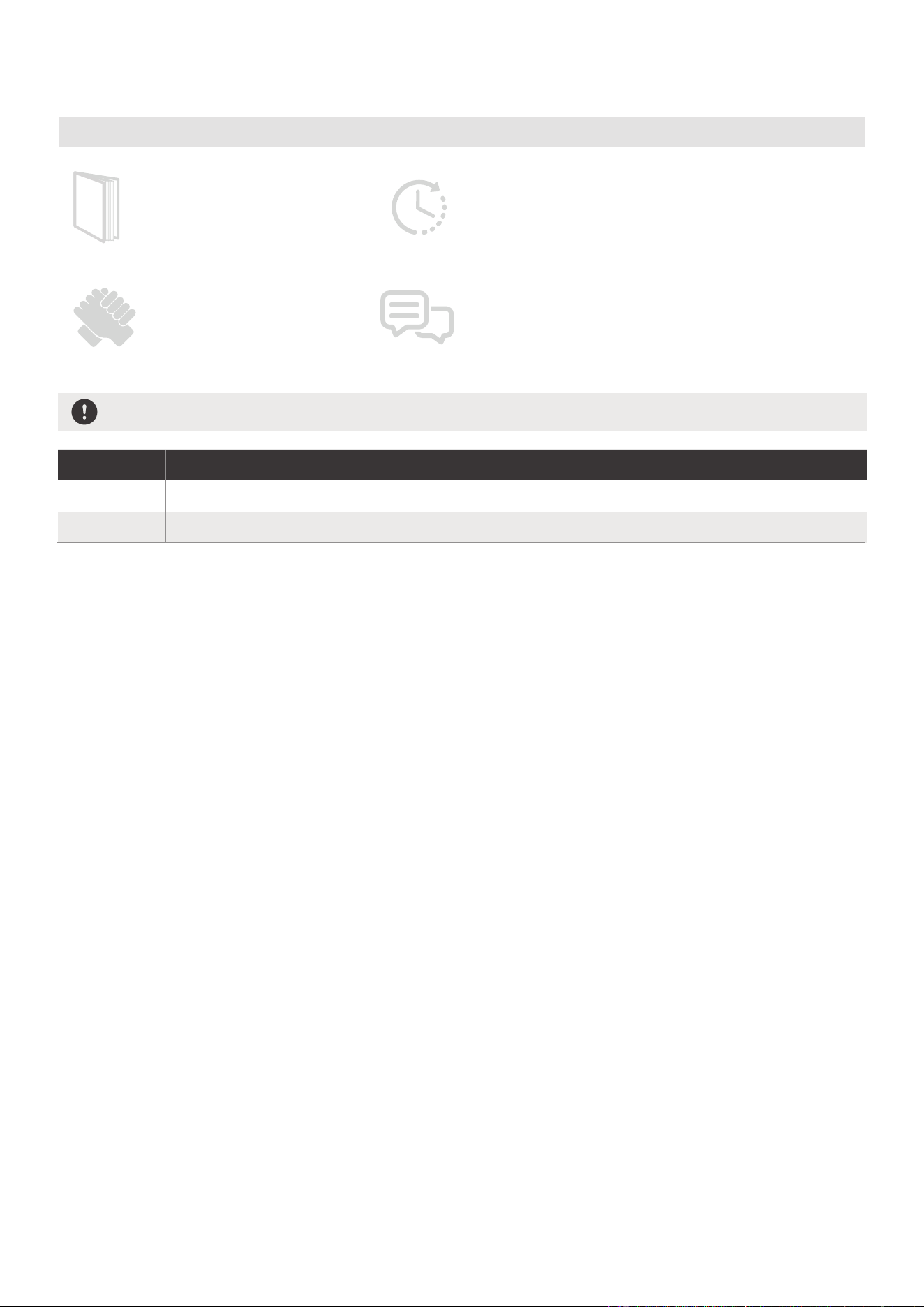
Preparations before installation
Before you get start
Installing your AC
should take about
30 minutes.
The installation must be
carried out in strict
accordance with the
instructions in this manual.
Manual
We recommend
doing this with
a helper.
We’re here if you need us,
please contact your local
distributor for assistance.
Know your Portable Air Conditioner
AMBIENT TEMPERATURE RANGE FOR UNIT OPERATING
MODE Temperature Range MODE Temperature Range
Cool 16-35°C (60-95°F)
Dry
Heat(pump heat mode)
Heat(electrical heat mode) 13-35°C (55-95°F)
5-30°C (41-86°F)
30°C (86°F)
≥
Energy Rating Information
The energy rating and noise information for this unit is based on the standard installation using an
un-extended exhaust duct without window slider adaptor (as shown in the Installation section of this
manual). At the same time, the unit must be operate on the COOL MODE and HIGH FAN SPEED by
remote controller.
The unit with 3 meters extended exhaust duct is running by using 2 exhaust ducts(Diameter:150mm,
Length:1.5m + Diameter: 130mm,Length: 1.5m) .The Energy rating and noise information for unit with 3
meters extended exhaust duct is not assessed. (For some models)
NOTE:
We recommend that operating the unit at room temperature below 35°C . Since there is a risk that the
unit with 3 meters extended exhaust duct would not work at room temperature above 35°C under some
extreme conditions, such as the lower air intake be blocked for 50%.
How to Stay Cool with a New Portable Air Conditioner (For the models comply with
the requirements of Department Of Energy in US).
Because of a new federal test procedure for Portable Air Conditioners, you may notice that the cooling
capacity claims on portable air conditioner packaging are significantly lower than that of models
produced prior to 2017. This is due to changes in the test procedure, not to the portable air conditioners
themselves.
13
Why newer products have lower cooling capacity than older models.
How to purchasing a Portable air conditioner.
will not remove enough humidity, leaving the air feeling damp. To find the
by multiplying the
Federal regulations require manufacturers to calculate cooling capacity based on a specific test
procedure, which was changed just this year.
or years’models. So, while the
What is SACC ?
SACC is the representative value of Seasonally Adjusted Cooling Capacity, in Btu/h, as determined in
accordance with the DOE test procedure at title 10 Code of Federal Regulations (CFR) 430, subpart B,
appendix CC and applicable sampling plans.
proper air conditioner, determine the square footage of the room you want to cool
room length by its width. You also need to know the air conditioner's BTU (British Thermal Unit) rating,
which indicates the amount of heat it can remove from a room. A higher number means more cooling
power for a larger room. (Be sure you are comparing only newer models to each other older models may
appear to have a higher capacity, but are actually the same). Be sure to “size up” if your portable air
conditioner will be placed in a very sunny room, in a kitchen, or in a room with high ceilings. After you’ve
found the right cooling capacity or your room, you can look at other features.
BTUs may be lower, the actual cooling capacity of the air conditioners has not changed.
14
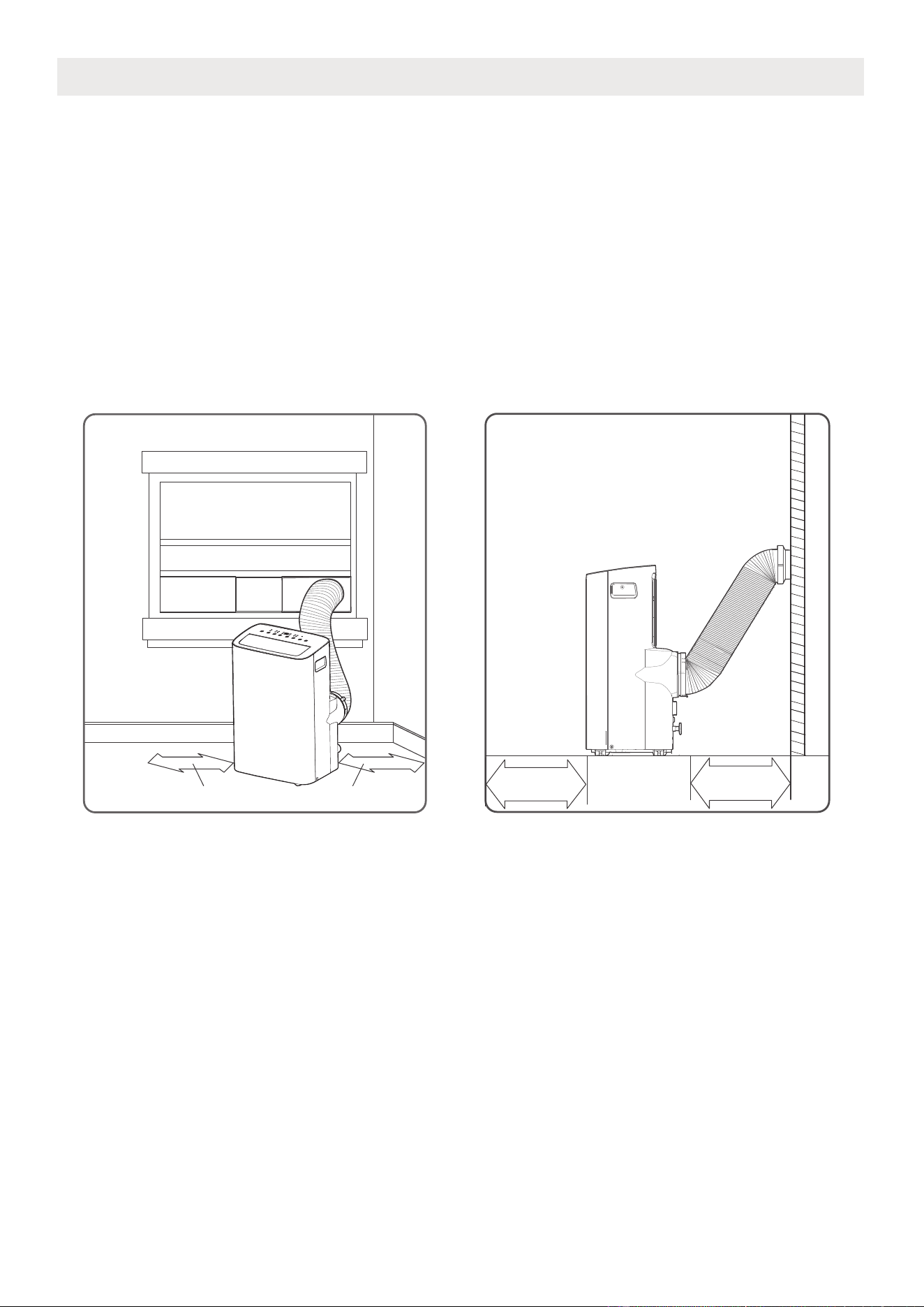
Unit Installation Location Restricted Space Requirements
PRODUCT INSTALLATION LOCATION
Your installation location should meet the following requirements:
• Make sure that you install your unit on an even surface to minimize noise and vibration.
• The unit must be installed near a grounded plug, and the Collection Tray Drain (found on the back of
the unit) must be accessible.
• The unit should be located at least 30cm (12”) from the nearest wall to ensure proper air conditioning.
The air outlet of the unit should be at least 50cm(19.7”) away from obstacles.
• DO NOT cover the Intakes, Outlets or Remote Signal Receptor of the unit, as this could cause damage
to the unit.
≥30cm(12”)≥30cm(12”)
≥50cm
19.7”
≥
50cm
19.7
”
15
The unit can be controlled by the unit control panel alone
NOTE ON ILLUSTRATIONS
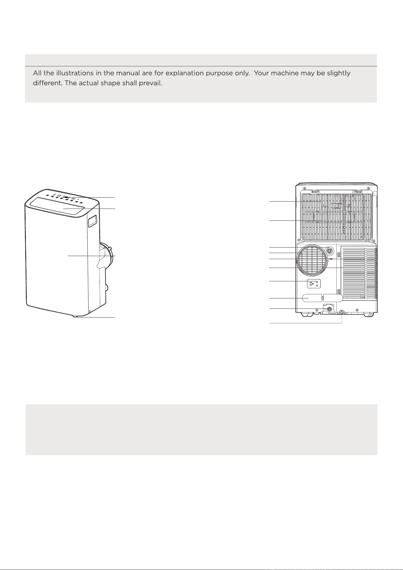
Product overview
Design Notice
In order to ensure the optimal performance of our products, the design
specifications of the unit and remote control are subject to change without
prior notice.
or with the remote controller.
Front View
Caster
horizontal louver blade
(swing automatically)
Control panel
Front panel
Rear View
Drain outlet
Power plug socket
Power cord buckle
Bottom tray drain outlet
Upper air filter
(behind the grille)
Upper air intake
Air outlet
Lower air filter
Lower air intake
Drain outlet
( heat pump model only)
16
Security Bracket and 2 Screws
Extended Exhaust Hose
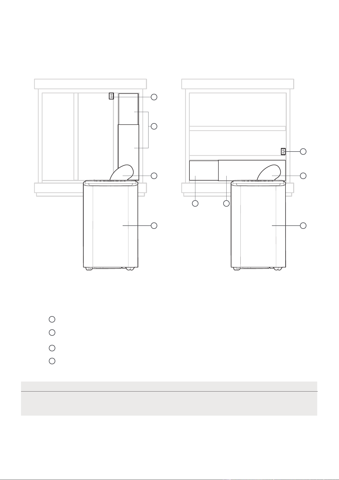
Installation overview
Installation Completion Display
Illustrations in this manual are for explanatory purposes. The actual shape of
your indoor unit may be slightly different. The actual shape shall prevail.
NOTE
Local Air Conditioner
1
2
3
4
Sliding Window Installation Hung Window Installation
1
4
2 2
1 1
4
3
3
window slider assembly
17
NOTE
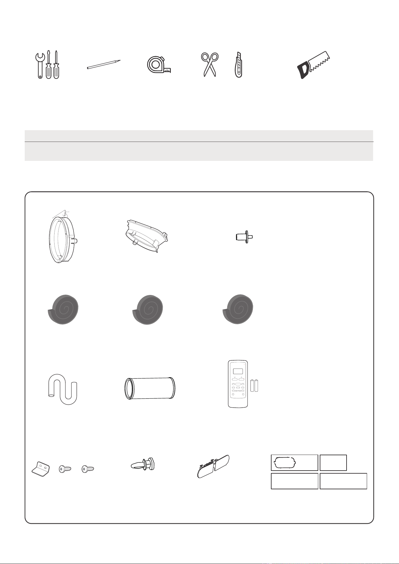
List of installation tools (not included)
Installation accessories
Items with (*) are on some models. Slight variations in design may occur.
Screwdriver
& wrench
A tape measure
Scissors or Knife
Pencil
Saw (On some models, to shorten
window adaptor for narrow windows)
Bolt 3 pc(*)
Unit Adaptor
Security Bracket and
2 Screws 1 set
Exhaust Hose (1 pc)
(1 pc)
Drain Hose
2 pc(*)
4 pc(*)
Foam Seal A (Adhesive)
2 pc
Foam Seal B (Adhesive)
Foam Seal C (Non-adhesive)
Power Cord Buckle ( 1 pc)
Air exhaust passage (1 pc*)
Remote Controller
and Battery (only
for remote control
models)(1set*)
1 set(*)Window Sliders
drain hose adaptor
(for heat pump model only)
Your Window Installation Kit fits windows 19.4”-62.2”(49.3-158.1cm) and can be
shortened for smaller windows.
18
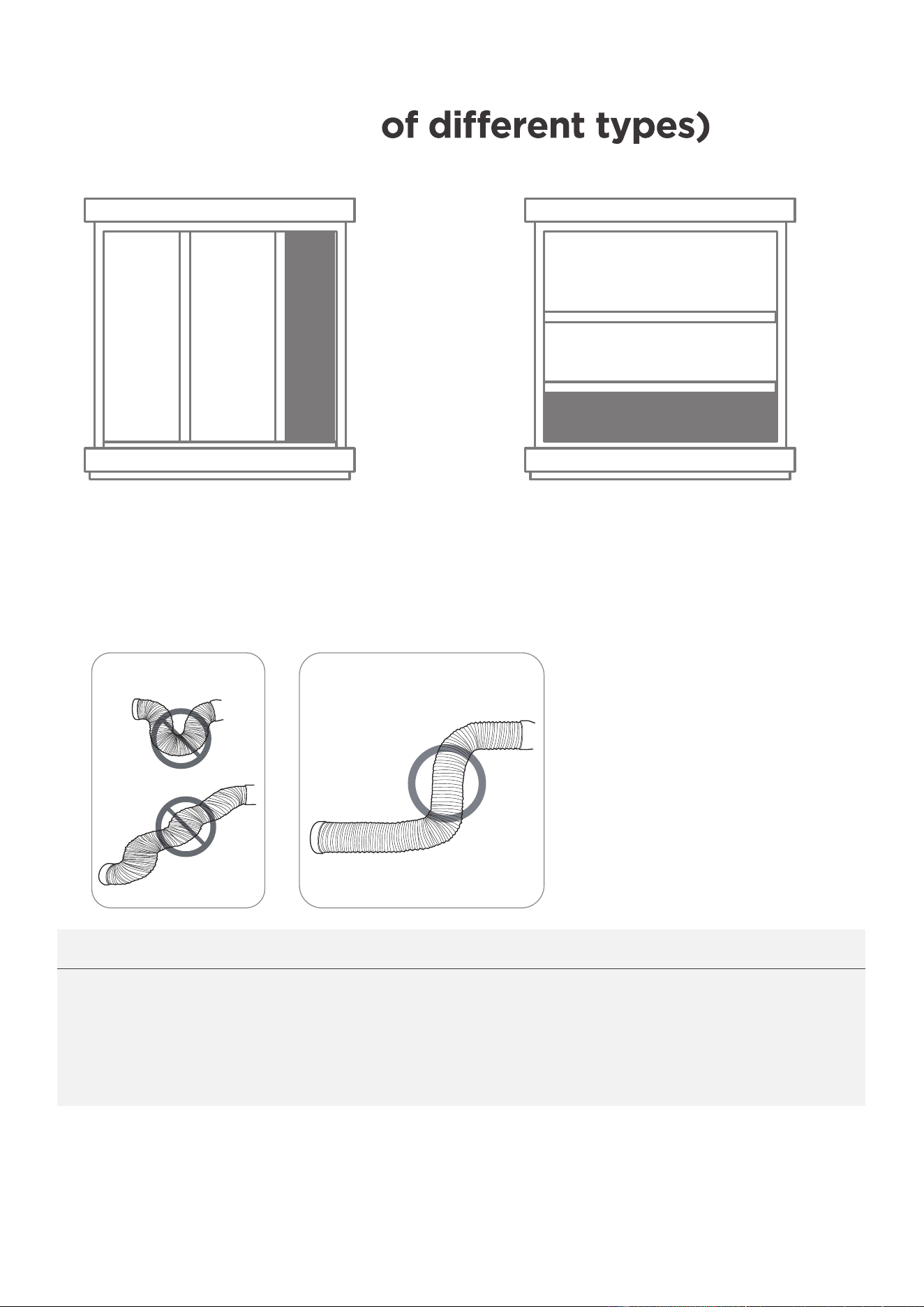
Confirm your window type (window type
and opening size
Sliding Window Installation Hung Window Installation
NOTICE:
INCORRECT
CORRECT
For optimal performance in operation
To ensure proper function, DO NOT overextend or bend the hose. Make sure
that there is no obstacle around the air outlet of the exhaust hose (in the range
of 500mm) in order to the exhaust system works properly. All the illustrations
in this manual are for explanation purpose only. Your air conditioner may be
slightly different. The actual shape shall prevail.
19
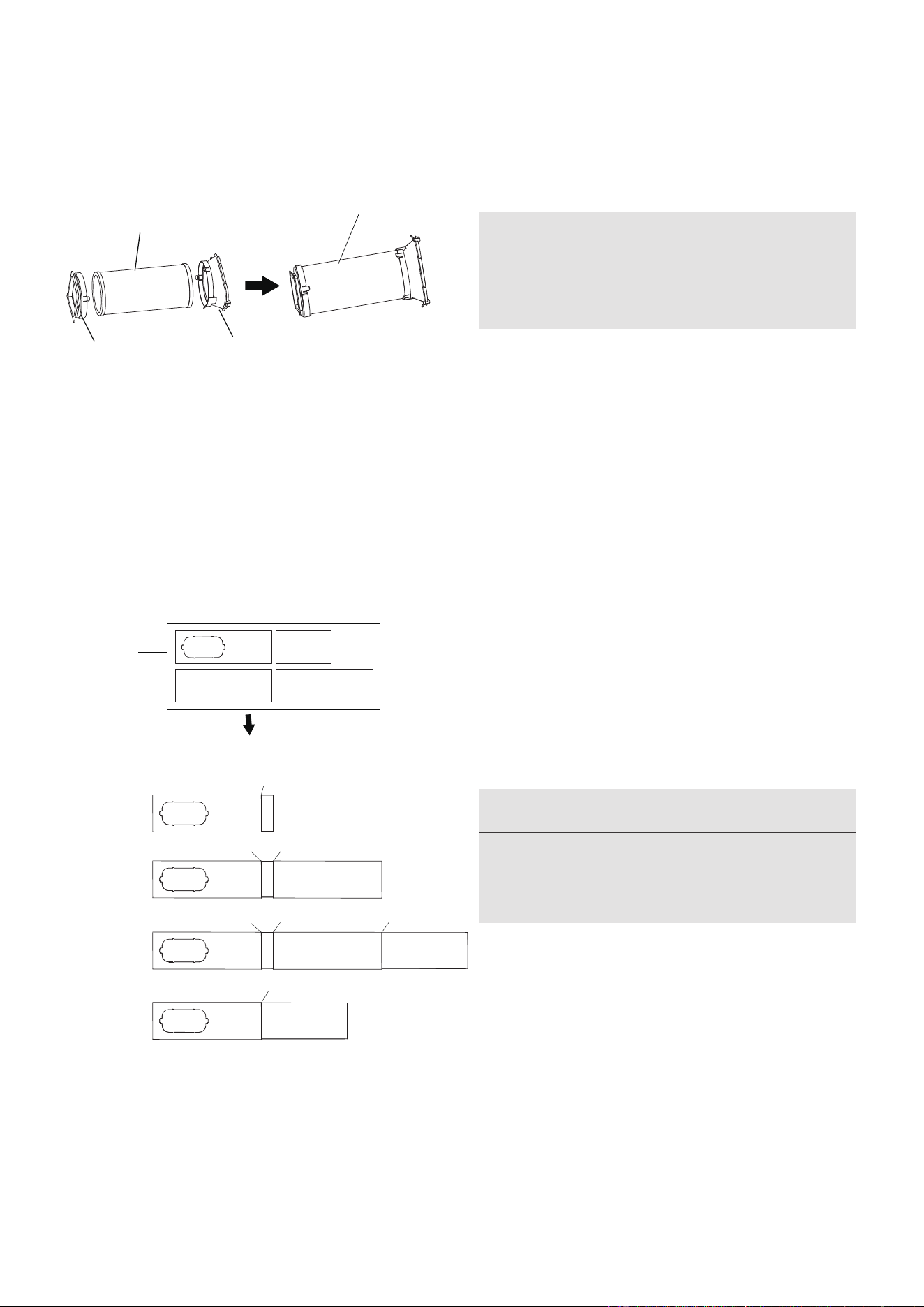
2. Preparing the Adjustable Window Slider
1+2:
Bolt
1+2+3:
Bolt
Bolt
1+2+3+4:
Bolt
BoltBolt
1+4:
Bolt
Window
Sliders
After assembly
Before assembly
1.Exhaust hose and adaptors installation
Exhaust hose
assembly
Exhaust hose
Unit adaptor
Air exhaust
passage
Choose the window sliders according to the
size of your window. Sometimes, it needs to be
cut short to meet the window size, please take
extra care to cut it properly.
Use bolts to fasten the window sliders once
they are adjusted to the proper length.
NOTICE
Please base your window slider installation
on the accessories in your kit and the size
NOTICE
Please install the exhaust hose assembly
according to the fittings in your kit.
of your window.
Press the exhaust hose (or extended exhaust
hose) into the window slider adaptor and unit
adaptor, clamp automatically by elastic buckles
of the adaptors.
20
Foam seal B
(Adhesive type-shorter)
Foam seal A
(Adhesive type)
Foam seal B
(Adhesive type-shorter)
Foam seal A
(Adhesive type)
Hung Window Installation
Sliding Window Installation
3. Complete sealing of window
Cut the adhesive foam seal A and B strips to the proper lengths, and attach them to the window sash
and frame as shown.
21
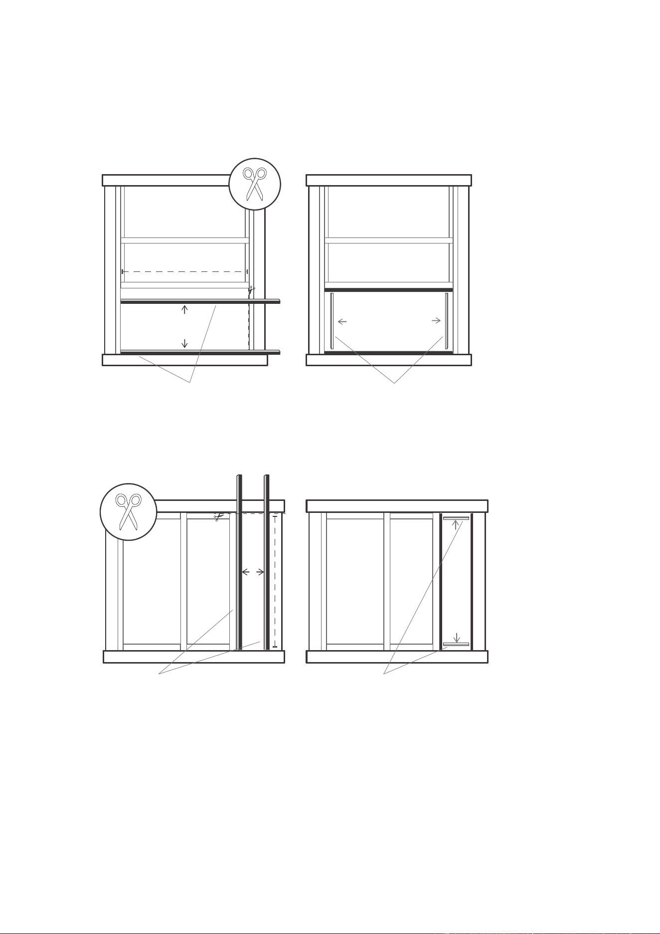
5. Sliding Window Installation
Insert the window slider assembly into the window opening.
Step 1:
Cut the non-adhesive foam seal C strip to match the height of the window. Insert the seal between the
glass and the window frame to prevent air and insects from getting into the room.
Step 2:
If desired, install the security bracket with 2 screws as shown.
Step 3:
Once the Exhaust Hose assembly and Adjustable Window Slider are prepared,
choose from one of the following two installation methods.
Once the Exhaust Hose assembly and Adjustable Window Slider are prepared,
choose from one of the following two installation methods.
4. Hung Window Installation
Insert the window slider assembly into the window opening.
If desired, install the security bracket with 2 screws as shown.
Cut the non-adhesive foam seal C strip to match the width of the window. Insert the seal between the glass
and the window frame to prevent air and insects from getting into the room.
Step 1:
Step 2:
Step 3:
NOTICE:
NOTICE:
22
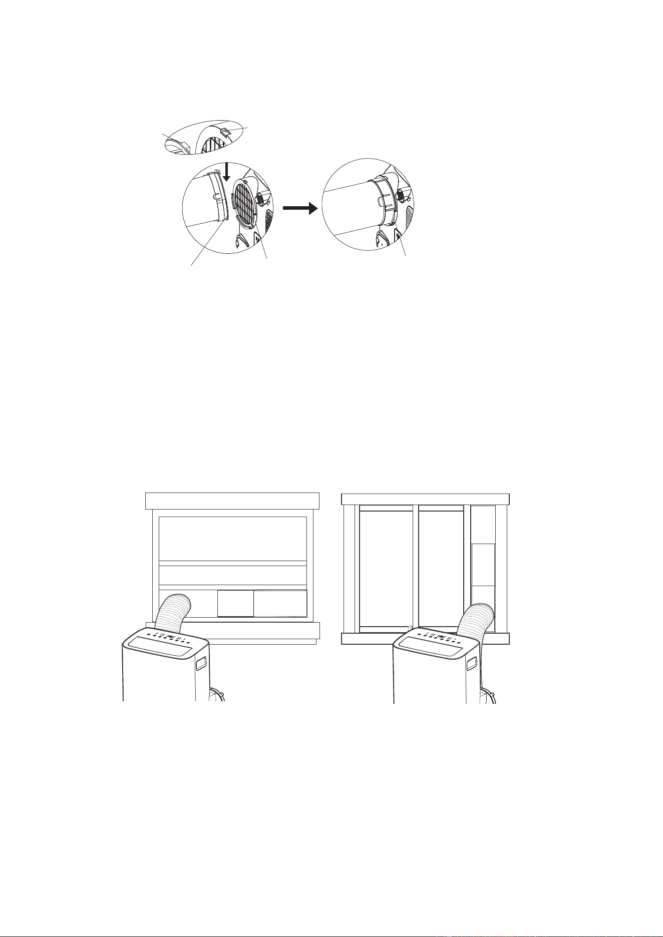
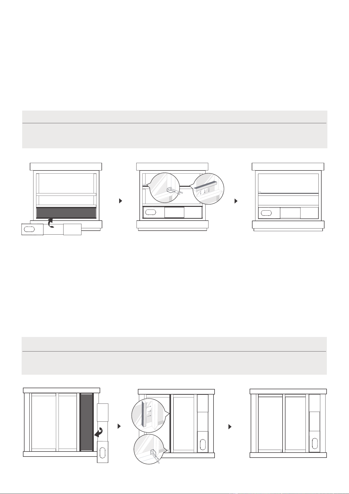
6. Install the Exhaust hose assembly to the unit
Push the Exhaust hose into the airoutlet opening of the unit along the arrow direction.
7. Connect the adaptor to the unit and the window
Insert the window slider adaptor into the hole of the window slider.
Hook
Hook Seat
Lower groove
adaptor
Make sure the adaptor
is inserted into the lower
groove of the air outlet.
Hung Window Installation Sliding Window Installation
23
Press the "MODE" button until the "Dry" indicator
light comes on. In this mode, the fan speed or the
temperature cannot be adjusted. The fan motor
operates at auto speed.
The air conditioner will control room temperature
automatically round the temperature point set by
you. Under AUTO mode, you can not select the
fan speed.
COOL operation
Press the "MODE" button until the "COOL" indicator
light comes on.
Press the ADJUST buttons "+" or "-" to select your
desired room temperature. The temperature can be
set within a range of 16°C~30°C/60°F~86°F.
Press the "FAN SPEED" button to choose the fan
speed.
Get to know your AC
Electronic control operating instructions
1
7
8
2
56
4
3
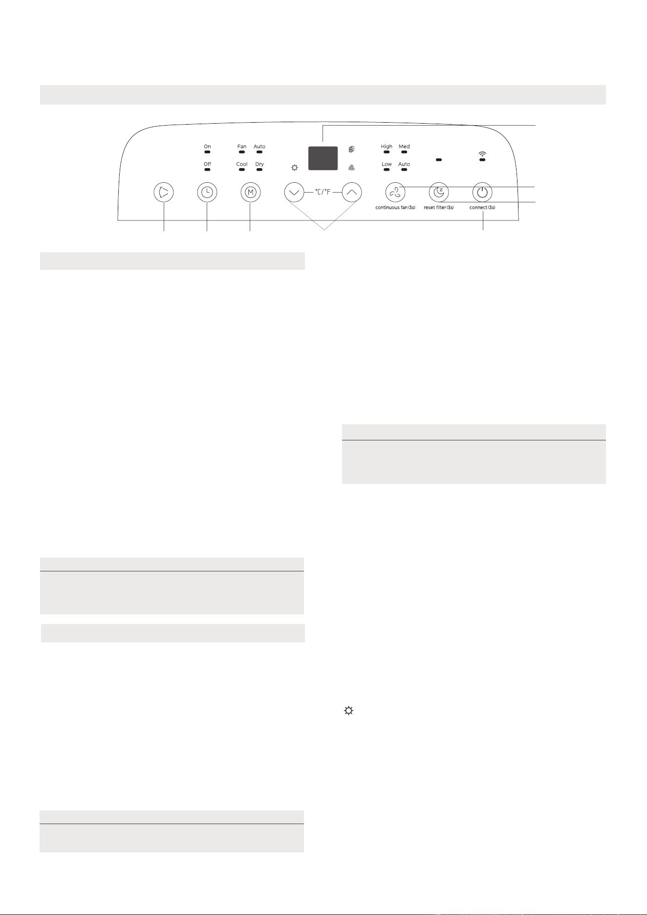
1. POWER Button
2. MODE Function
Selects the appropriate operating mode. Each
time you press the button, a mode is selected in
a sequence that goes from AUTO, COOL, DRY,
FAN and HEAT (heat pump model only).
The mode indicator light illuminates under the
different mode settings.
Used to initiate the Wireless function. For the
first time to use Wireless function, press and
hold the power button for 3 seconds to initiate
the Wireless connection mode. The LED DISPLAY
shows 'AP' to indicate you can set Wireless
connection. If connection(router) is successful
within 8 minutes, the unit will exit Wireless
connection mode automatically and the Wireless
indicator illuminates.
If connection is failure within 8 minutes, the unit
exits Wireless connection mode automatically.
After Wireless connection is successful, you can
press and hold SWING and DOWN (-) buttons at
the same time for 3 seconds to turn off Wireless
function and the LED DISPLAY shows 'OF' for 3
seconds, press POWER and UP(+) buttons at the
same time to turn on Wireless function and the
LED DISPLAY shows 'On' for 3 seconds.
Power switch on/off.
DRY mode
AUTO mode
COOL mode
When you set the air conditioner to AUTO
mode, it will automatically select cooling,
heating (cooling only models without) or fan
only operation depending on what
temperature you have selected and the
room temperature.
FAN mode
• When in FAN mode, press the FAN button to
choose the fan speed. The temperature can not
be adjusted.
HEAT operation(heat pump model only)
• Press the "MODE" button until the "HEAT"
indicator light comes on.
• Press the ADJUST buttons UP and DOWN
to select
your desired room temperature. The temperature
can be set within a range of 16°C-30°C/60°F-86°F.
• Press the FAN button to choose the fan speed.
Note: For the fan speed can not be adjusted under
Keep windows and doors closed for the
best dehumidifying effect.
Under AUTO mode, both the AUTO
mode and the actual operation mode indicator
lights illuminate for some models.
When you restart the Wireless function, it may
take a period of time to connect to the network
automatically.
NOTE
NOTE
NOTE
HEAT mode.
24
COMFORT SENSE feature
This feature can be activated from the remote control ONLY. There is no indicator light on the control
panel. The remote control serves as a remote thermostat allowing for the precise temperature control
at its location.
To activate the
Comfort Sense
feature, point the remote control towards the unit and press the
Comfort
button. The remote control will send this signal to the AC until press the Comfort Sense
Comfort Sense
button
If the unit does not receive the
Comfort Sense
signal during
any 7 minutes interval, the unit will
exit the mode.
NOTE: This feature is unavailabe under FAN or DRY mode.
9. Other features
8. SLEEP mode
Press this button, the selected temperature will increase(cooling) or decrease(heating) by 1°C/2°F(or 1°F) 30
minutes. The temperature will then increase (cooling) or decrease (heating) by another 1°C/2°F(or 1°F) after
an additional 30 minutes. This new temperature will be maintained for 7 hours before it returns to the
originally selected temperature. This ends the Sleep/Eco mode and the unit will continue to operate as
originally programmed.
7. Continuous Fan function
In Cool or Dry mode, press and hold the constant Fan button for 3 seconds to turn the constant fan
function on or off. When the function is turned on, the constant fan light will illuminate. When the
function is turned on,the constant fan light will turn off
NOTE: This feature is unavailabe under FAN or DRY mode.
5.Timer button
3. UP and DOWN buttons
Used to adjust (increasing/decreasing) temperature settings in 1°C/2°F (or 1°F) increments in a range
of 16°C/60°F to 30°C/86°F.
TIMER setting in a range of 0~24hrs.
4. Display
Used to initiate the AUTO ON start time and AUTO OFF stop time program, in conjuction with the + & -
buttons. The timer on/off indicator light illuminates under the timer on/off settings.
6. SWING mode
Used to initiate the Auto swing feature. When the operation is ON, press the SWING button can stop the
louver at the desired angle.
When one of the above malfunctions occurs, turn off the unit, and check for any obstructions.
Restart the unit, if the malfunction is still present, turn off the unit and unplug the power cord. Contact
the manufacturer, its service agents or a similar qualified person for service.
Shows the set temperature in °C or °F and the Auto-timer settings. While on DRY and FAN modes, it
shows the room temperature.
Shows Error codes and protection code:
EH60-Room temperature sensor error.
EH61-Evaporator temperature sensor error.
EC52-Condenser temperature sensor error (on some models).
EH0b-Display panel communication error.
ELOC-Refrigerant leakage detection malfunction (on some models).
P1-Bottom tray is full. Connect the drain hose and drain the collected water. If the P1 code does not erase, call for
service.
NOTE
NOTE
The control is capable of displaying temperature in degrees Fahrenheit or degrees Celsius. To convert
from one to the other, press and hold the Up and Down buttons at the same time for 3 seconds.
Sense
again.
25
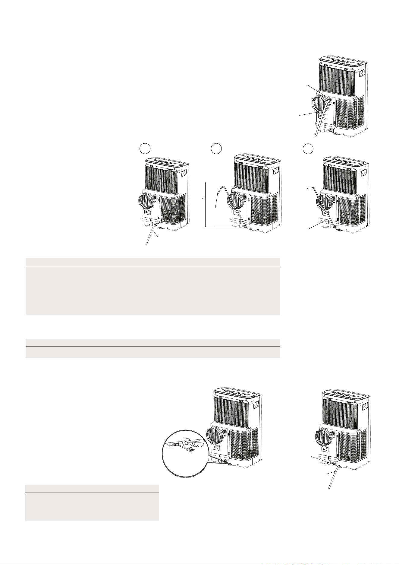
Drainage guide
During dehumidifying modes, remove the upper drain plug from the back
of the unit, install the drain connector(5/8" universal female mender) with
3/4" hose(locally purchased). For the models without drain connector,
just attach the drain hose to the hole. Place the open end of the hose
directly over the drain area in your basement floor.
During heating pump mode, carefully move the unit to a drain location,and let
the water drain away.
When the water level of the bottom tray
reaches a predetermined level, the unit
beeps 8 times, the digital display area
shows "P1" . At this time the air
conditioning/dehumidification process
will immediately stop. However, the fan
motor will continue to operate
(this is normal). Carefully move the unit
to a drain location, remove the bottom
drain plug and let the water drain away.
Reinstall the bottom drain plug and
restart the machine until the "P1" symbol
disappears. If the error repeats, call for
service.
During heating pump mode,
remove the lower drain plug
from the back of the unit,
install the drain connector
(5/8" universal female mender)
with 3/4" hose(locally purchased).
For the models without drain
connector, just attach the drain
hose to the hole.
Place the open end of the Hose
adaptor directly over the drain
area in your basement floor.
Continuous
drain hose
Remove the
upper drain
plug
Continuous
drain hose
drain hose
adaptor
√√
delivery lift <1.8m
X
drain hose
adaptor
Press the power
cord buckle into
the rear cover.
Continuous
drain hose
Remove the
lower drain
plug
NOTE
NOTE
Make sure the hose is secure so there are no leaks. Direct the hose toward
the drain, making sure that there are no kinks that will stop the warter
flowing. Place the end of the hose into the drain and make sure the end of
the hose is down to let the water flow smoothly. Do never let the end of the
hose up. When the continuous drain hose is not used, ensure that the
corresponding drain plug and knob are installed firmly to prevent leakage.
Be sure to reinstall the bottom drain
plug firmly to prevent leakage before
usingthe unit.
NOTE
Make sure the drain hose is lower than the bottom tray drain outlet.
26
How to clean & maintenance your AC.
Cleaning & maintenance
Air Filter & Cabinet Cleaning
· Always unplug the unit before cleaning or servicing.
· DO NOT use flammable liquids or chemicals to clean the unit.
· DO NOT wash the unit under running water. Doing so causes electrical danger.
· DO NOT operate the machine if the power supply was damaged during cleaning.
A damaged power cord must be replaced with a new cord from the manufacturer.
DO NOT operate the unit without filter because dirt and lint will clog it and reduce
performance.
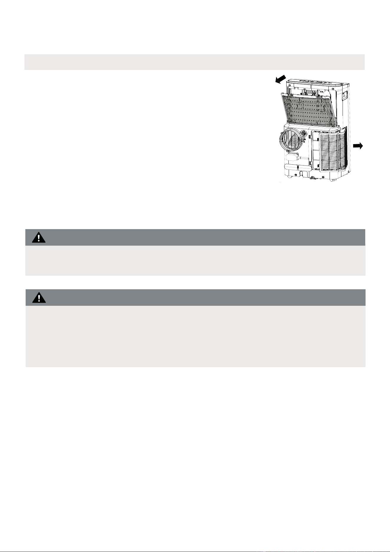
Remove the air filter
CAUTION
CAUTION
Clean the unit using a damp, lint-free cloth and mild detergent.
Dry the unit with a dry, lint-free cloth.
• Take the filter out along the arrow direction.
• Wash the air filter by immersing it gently in warm water
(about 40°C/104°F) with a neutral detergent.
• Rinse the filter and dry it in a shady place.
• Install the air filter after cleaning.
27

Store the unit when not in use
NOTE
12hours
Step6
Step 3
Step4
Step 1
Step 2
Step 5
*Please refer to the actual
plug, and the legend is for
reference only.
*Drain the unit‘s water collection
tray then reinstall the bottom
drain plug back in.
• Be sure to store the unit in a cool, dark place. Exposure to direct sunshine or
extreme heat can
shorten the lifespan of the unit.
• The cabinet and front may be dusted with an oil-free cloth or washed with a
cloth dampened
in a solution of warm water and mild liquid dishwashing
wipe dry. Never use harsh cleansers, wax or
excess water from the cloth
controls
detergent. Rinse thoroughly and
polish on the cabinet front. Be sure to wring
before wiping around the controls. Excess water in or around the
may cause damage to the unit.
Step 1: Drain the unit’s water collection tray according to the instructions in the following section.
Step 2: Run the appliance on FAN mode for 12 hours in a warm room to dry it and prevent mold.
Step 4: Clean the machine.
Step 6: Remove the batteries from the remote control.
Step 3: Turn off the appliance and unplug it.
Step 5: Clean the air filter according to the instructions in the previous section. Reinstall the clean,
dry filter before storing.
SWING
C-SENSE
°C/°F
28
Problem Solving
TROUBLESHOOTING
Common Issues
The following problems are not a malfunction and in most situations will not require repairs.
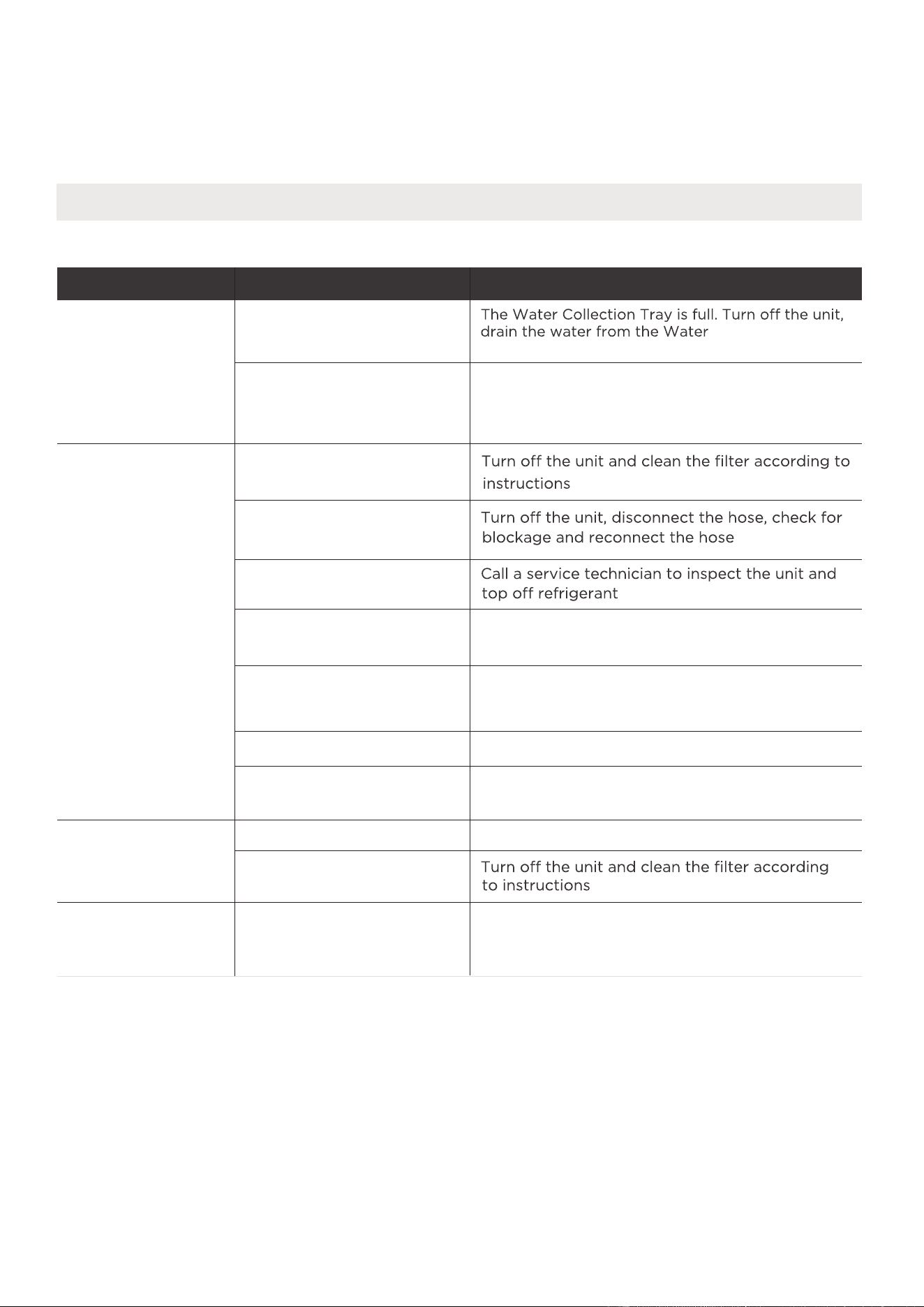
Problem Possible Causes Solution
Unit does not turn
on when pressing
ON/OFF button
P1 Protection Code
In COOL mode: room
temperature is lower than
the set temperature
Reset the temperature
Collection Tray and
The air filter is blocked with
dust or animal hair
The unit is low on
refrigerant
Temperature setting is too
high
The windows and doors in
the room are open
The room area is too large
Unit does
not cool well
Exhaust hose is not
connected or is blocked
There are heat sources
inside the room
Decrease the set temperature
Make sure all windows and doors are closed
Double-check the cooling area
Remove the heat sources if possible
The unit is noisy
and vibrates too
much
The unit makes a
gurgling sound
The ground is not level Place the unit on a flat, level surface
The air filter is blocked with
dust or animal hair
This sound is caused by the
flow of refrigerant inside
the unit
This is normal
restart the unit.
29
REMOTE CONTROL AND APP
INSTRUCTIONS
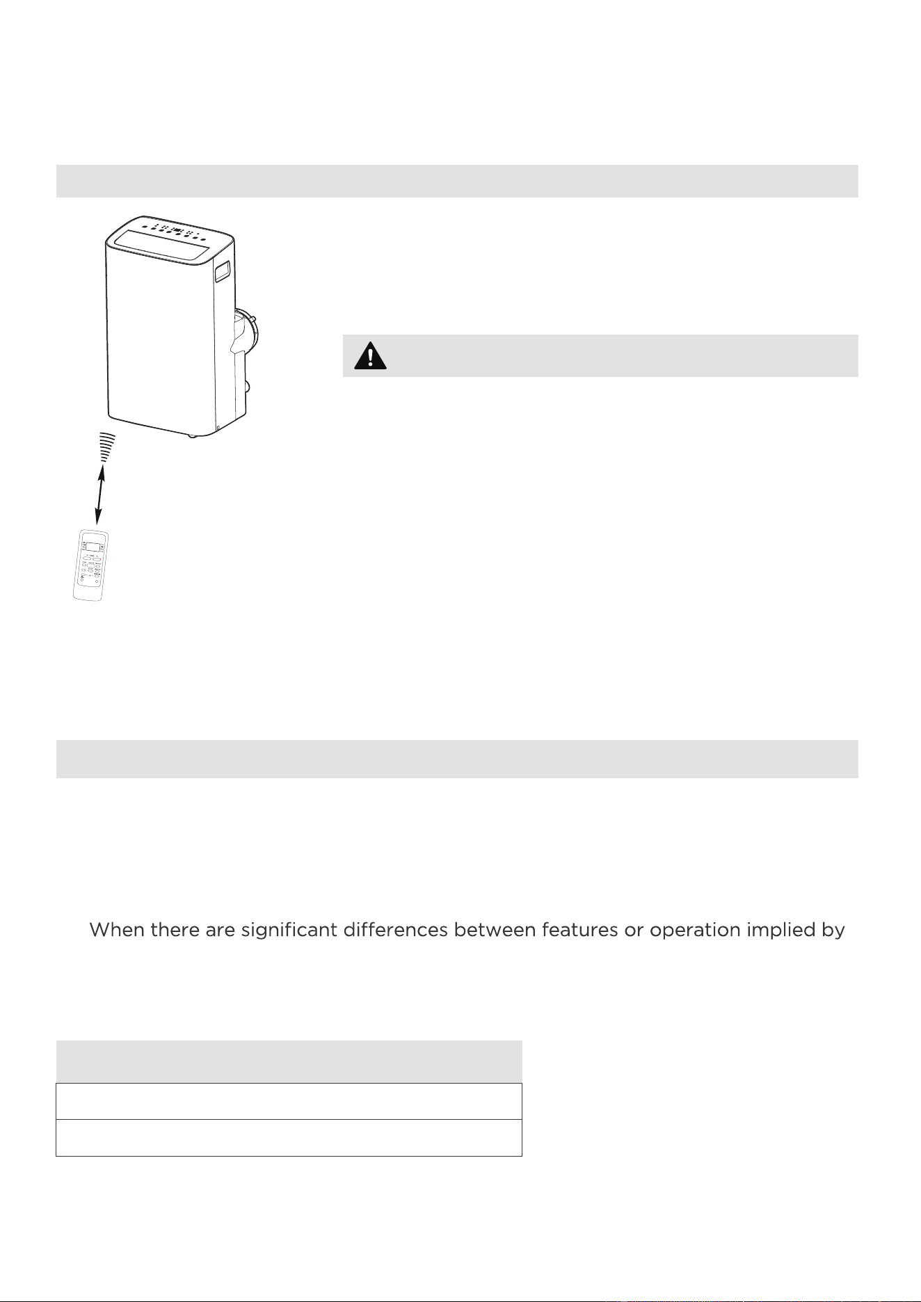
Location of the remote control
Use the remote controller within a distance of 26.2 ft
(8 meters) from the air conditioner, pointing it towards
the receiver. Reception is confirmed by a beep.
Handling the Remote Control
•
The air conditioner will not operate if curtains,
doors or other materials block the signals from the
remote control to the unit.
•
Prevent any liquid from spilling onto the remote
control. Do not expose the remote control to
direct sunlight or heat.
•
If the infrared signal receiver on the indoor unit is
exposed to direct sunlight, the air conditioner may
not function properly. Use curtains to prevent the
sunlight from falling on the receiver.
•
If other electrical appliances react to the remote
control, either move these appliances or consult
your local dealer.
CAUTION
26.2 ft (8 meters)
NOTICE
Remote Controller Specifications
•
Button design is based on typical model and may vary slightly from the actual
one you purchased.
•
All the functions described are accomplished by the unit. If the unit is without a
feature, the unit will not respond if the corresponding button on the remote is
pressed.
•
the remote control illustration and the actual functions described in the USER’S
MANUAL, the descriptions in the USER’S MANUAL shall prevail.
Rated Voltage: 3.0V (Dry batteries R03/LR03x2)
Environment: 23°F ~140°F (-5°~60°)
SWING
C-SENSE
°C/°F
30
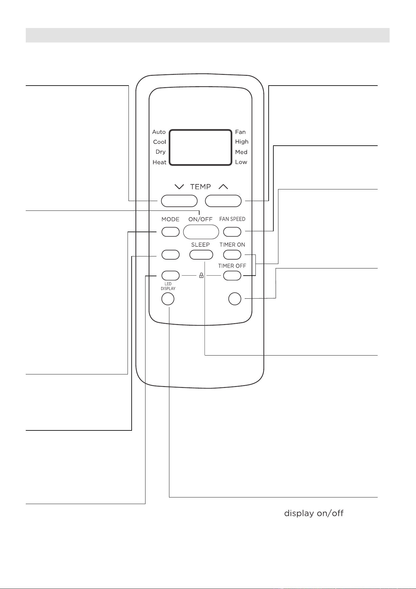
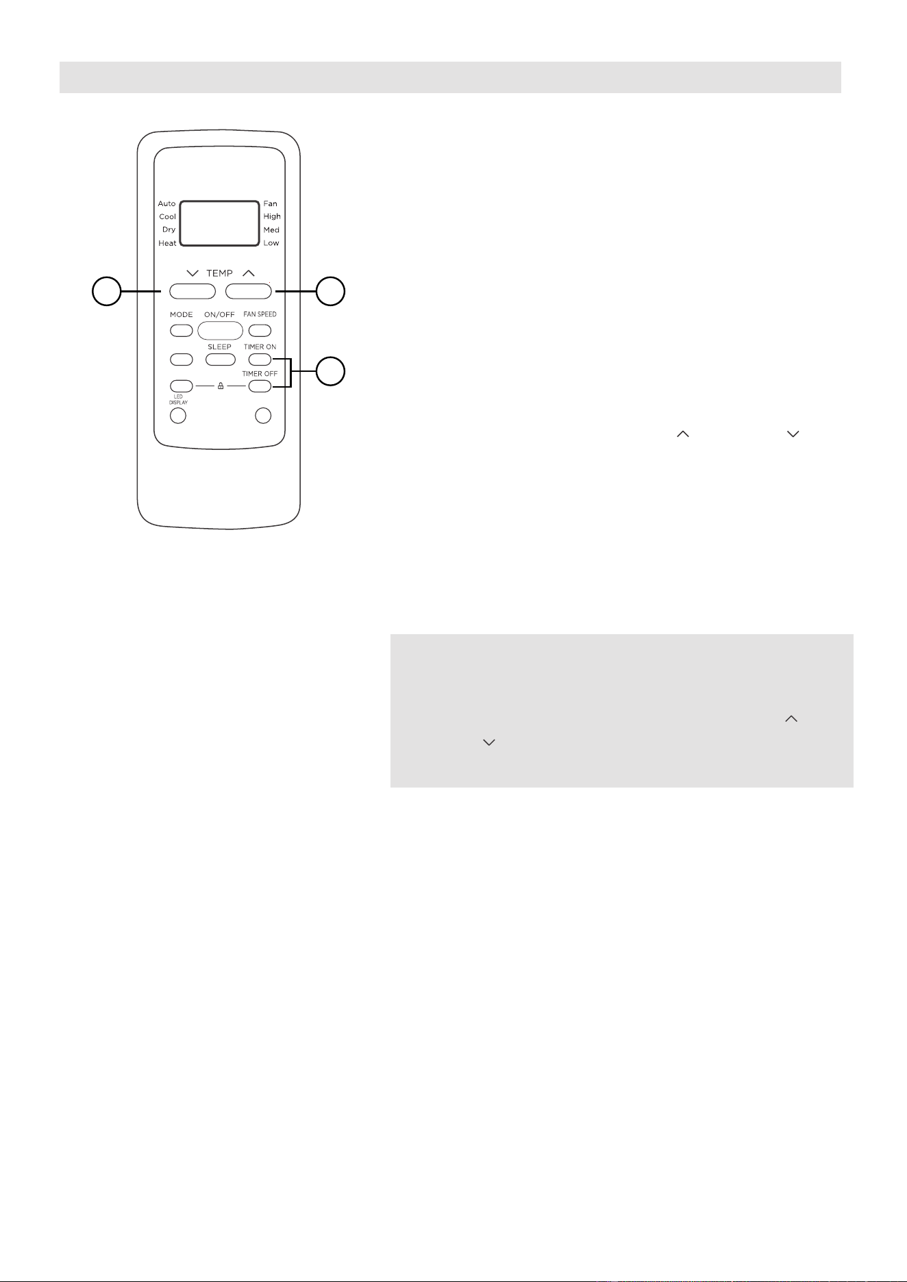
Function Buttons
MODE Button
Press this button to
select the desired
operation mode.
TEMP UP Button
Press this button to
increase the indoor
temperature setting.
SPEED Button
Used to select the
desired fan speed.
SLEEP Button
Press this button to
LED DISPLAY Button
Turns the unit’s LED
activate the Sleep
mode. This function
is available on COOL
or AUTO mode only
and will maintain the
most comfortable
temperature for you
while saving energy.
For more details, see
“sleep operation” in
Page 25
°C/°F Button
Press this button to
change the temperature
display between Celsius
and Fahrenheit
TEMP DOWN Button
Press this button to
decrease the indoor
temperature setting.
TIMER Button
Press this button to
activate the “Auto
Start” or “Auto Stop”
program.
ON/OFF Button
Operation starts when
this button is pressed
and stops when the
button is pressed again.
Press this button to start and
stop the horizontal louver
movement. Hold down for
2 seconds to initiate vertical
louver auto swing feature
(some units) .
COMFORTSENSE Button
Press this button to active the
ComfortSense mode, to optimize
the temperature around you and
ensure maximum comfort.
SWING
C-SENSE
°C/°F
SWING Button
NOTE: If the unit
has ENERGY SAVER
function, it will initiate
automatically the
Energy Saver function
under Cool, Dry, and
Auto (only Auto-
Cooling and Auto-Fan)
modes.
31
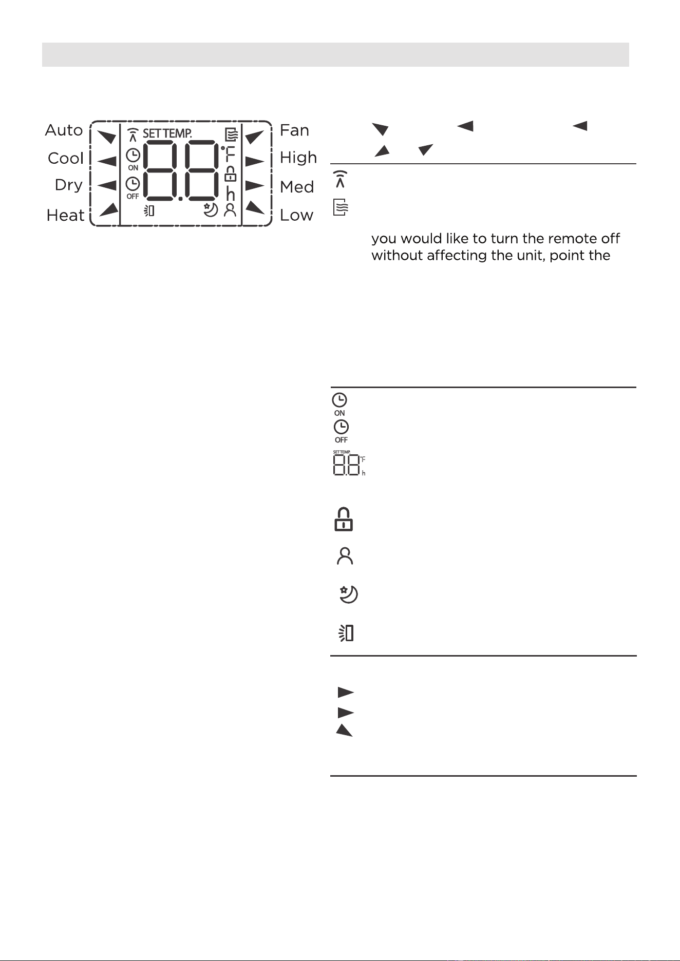
Information are displayed when the remote controller is power up.
All indicators shown in the figure are for the purpose of clear presentation.
But during the actaul operation, only the relative function signs are shown
on the display window.
Remote Screen Indicators
Displayed when data transmitted.
Appears when the remote is enabled
and can send a signal to the unit. If
remote away from the unit and press
the ON/OFF button.
To turn the remote on, point the
remote away from the unit and press
the ON/OFF button. The unit will not
receive commands from the remote
if this indicator is not illuminated.
Auto
Heat
Cool
Fan
Dry
Mode display
Low speed
NO display
Medium speed
High speed
Auto fan speed
Displayed when TIMER ON time is set
Displayed when TIMER OFF time is set
Indicated all the current settings are
locked
Shows set temperature or room
temperature, or time under TIMER
setting
HIGH
MED
LOW
Fan speed indication
Displayed when ComfortSense feature
is activated
Displayed when SLEEP feature is
activated
Note:
Horizontal louver swing display
32
SWING
C-SENSE
°C/°F
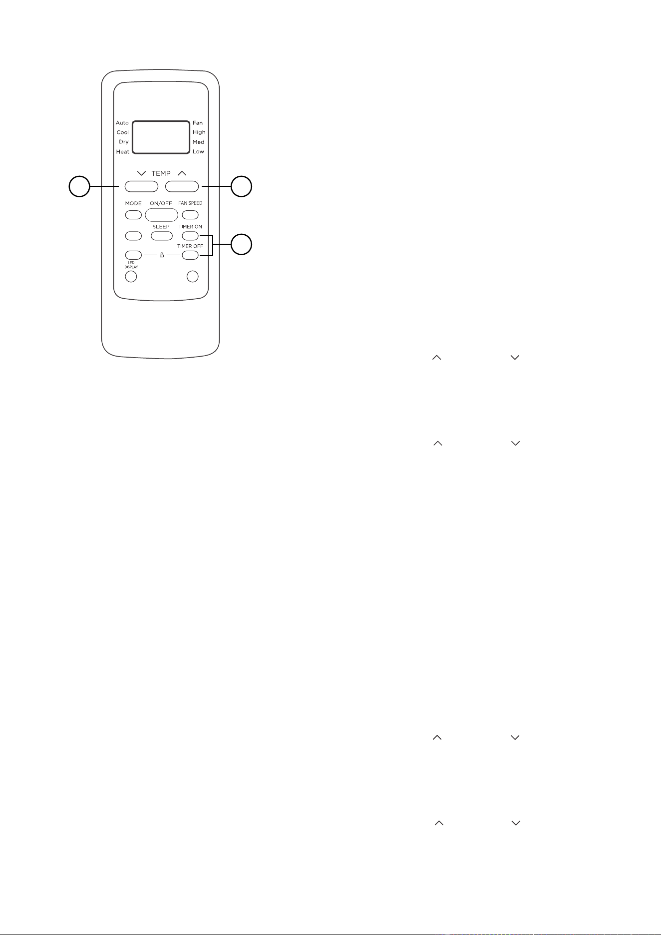
How to Use the Buttons
TIMER OPERATION
Press the TIMER button to initiate the Auto-start
and Auto-stop setting program of the unit.
To set the Auto-start/stop time.
1. Press the TIMER button, when the TIMER ON
indicator is displayed on the LED window of
the air conditioner, it indicates the Auto Start
setting program is initiated. When the TIMER
OFF indicator is displayed on the LED window
of the air conditioner, it indicates the Auto
Stop setting program is initiated.
2. Press or hold the TEMP UP ( )/DOWN ( ) to
change the Auto time. The control will count
down the time remaining until start/stop.
3. The selected time will register in 5 seconds and
the air conditioner will automatically revert back
to display the previous temperature
setting.
4. Turning the unit ON or OFF at any time will
cancel the Auto Start/stop function.
NOTES
To cancel the TIMER setting, push the TIMER
button and press or hold the TEMP UP ( )/
DOWN ( ) until 0 hour is displayed on the LCD
window of the air conditioner.
1
22
33
COMBINED TIMER
(Setting both ON and OFF timers simultaneously)
AUTO STOP >AUTO START
(On > Stop > Start operation)
This feature is useful when you want to stop the
air conditioner after you go to bed, and start it
again in the morning when you wake up or when
you return home.
Example:
To stop the air conditioner 2 hours after setting
and start it again 10 hours after setting.
AUTO START > AUTO STOP
(Off > Start > Stop operation)
This feature is useful when you want to start the
air conditioner before you wake up and stop it
after you leave the house.
Example:
To start the air conditioner 5 hours after setting,
and stop it 8 hours after setting.
SWING
C-SENSE
°C/°F
1
22
1. Press the TIMER button until the TIMER OFF
indicator is displayed on the LED display of
the air conditioner.
2. Use the TEMP UP ( )/DOWN ( ) button to
display “2.0” on the LED display of the air
conditioner.
3. Press the TIMER button again to display the
TIMER OFF on the LED display of the unit.
4. Use the TEMP UP ( )/DOWN ( ) button to
display “10” on the LED display of the unit.
5. Wait for 5 seconds until the previous display
appears in LED window.
1. Press the TIMER button until the TIMER ON
indicator is displayed on the LED display of
the air conditioner.
2. Use the TEMP UP ( )/DOWN ( ) button to
display “5.0” on the LED display of the air
conditioner.
3. Press the TIMER button again to display the
TIMER OFF on the LED display of the unit.
4. Use the TEMP UP ( )/DO
WN ( ) button to
display “8.0” on the LED display of the unit.
5. Wait for 5 seconds until the previous display
appears in LED window.
34
NOTES
• Button design is based on a typical model and may slightly vary from the actual
one you purchased.
• This device complies with part 15 of the FCC Rules. Operation is subject to the
following two conditions: (1) This device may not cause harmful interference,
and (2) this device must accept any interference received, including interference
that may cause undesired operation.
•
This equipment has been tested and found to comply with the limits for a Class
B digital device, pursuant to part 15 of the FCC Rules. These limits are designed
to provide reasonable protection against harmful interference in a residential
installation. This equipment generates, uses and can radiate radio frequency
energy and, if not installed and used in accordance with the instructions, may cause
harmful interference to radio communications. However, there is no guarantee that
interference will not occur in a particular installation. If this equipment does cause
harmful interference to radio or television reception, which can be determined by
interference by one or more of the following measures:
- Reorient or relocate the receiving antenna.
- Increase the separation between the equipment and receiver.
receiver is connected.
- Consult the dealer or an experienced radio/TV technician for help.
- Changes or modifications not approved by the party responsible for compliance
could void users authority to operate the equipment.
Battery Warning:
Do not mix old and new batteries and Do not mix alkaline, standard (carbon-zinc)
or rechargeable (ni-cad, ni-mh, etc.) batteries
Unique Identifier: Midea brand, RG51F2(2)/CEFU1, RG51F2(2)/EFU1
Responsible Party U.S. Contact Information
Midea America Corporation
300 Kimball Dr
Parsippany NJ
07054
This device complies with Part 15 of the FCC Rules. Operation is subject to the
following two conditions: (1) This device may not cause harmful interference, and
(2) this dev
ice must accept any interference received, including interference that
may cause undesired operation.
Telephone number or internet contact information: Midea.com/us
FCC Compliance Statement ( products subject to Part 15)
Supplier's Declaration of Conformity
47 CFR § 2.1077 Compliance Information
35

We hereby declare that this AC is in compliance with the essential requirements and
other relevant provisions of Directive 1999/5/EC.
1. Supports operating systems: iOS 10+ or Android 5+.
2.
In the event of a OS update, there may be a delay between the update of the OS
and a related software update during which your OS may or may not be supported
until a new version is released. Your specific mobile phone or problems in your
network may prevent the system from working and Midea will not be responsible
for any problems that could be caused by incompatibility or network issues.
3.
This Smart AC only supports WPA-PSK/WPA2-PSK (recommended) encryption.
4.
To ensure proper scanning of the QR code, your smart phone must have at least a
5-megapixel camera.
5.
Due to unstable network connectivity, requests may time out. If this happens, rerun
the network configuration.
6. Due to unstable network connectivity, commands may time out. If this happens,
the smartphone app and the actual product may display conflicting information.
The information displayed on the actual product is always the most accurate
available. Refresh the app to re-sync.
Midea will not be responsible for any problems that could be caused by
incompatibility or network issues, your wireless router and mobile phone.
NOTICE
DECLARATION OF CONFORMITY
PRECAUTIONS
Devices required to use the Smart AC:
SYSTEM OVERVIEW
1. Smart Phone with compatible iOS or Android system.
2. Wireless Router
3. Smart Air Conditioner
36
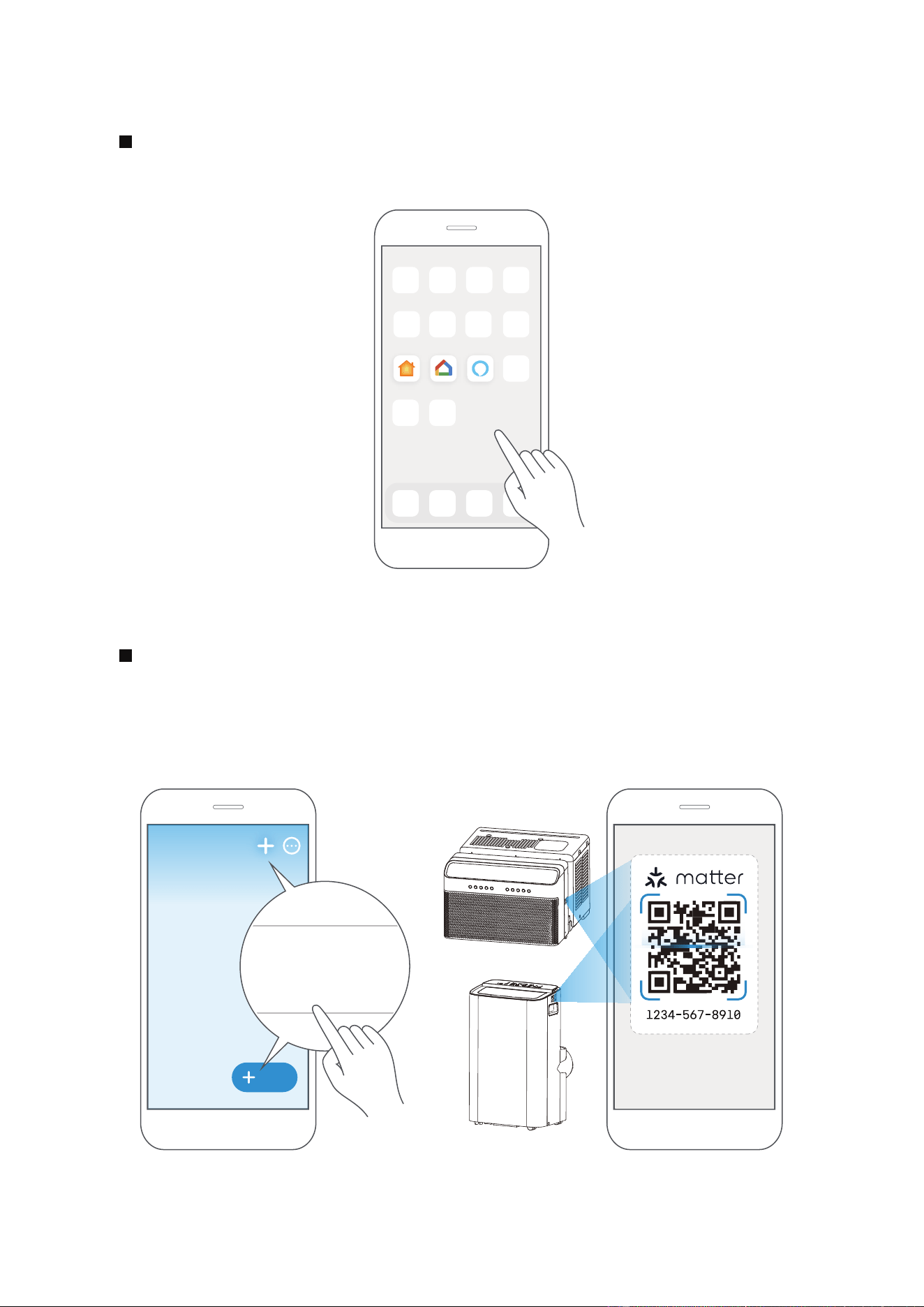
1
How to use SmartHome App
Make sure your smartphone is connected to your wireless router and your
wireless router has a working 2.4 GHz internet connection.
Bluetooth must be turned on. The device must also be powered up.
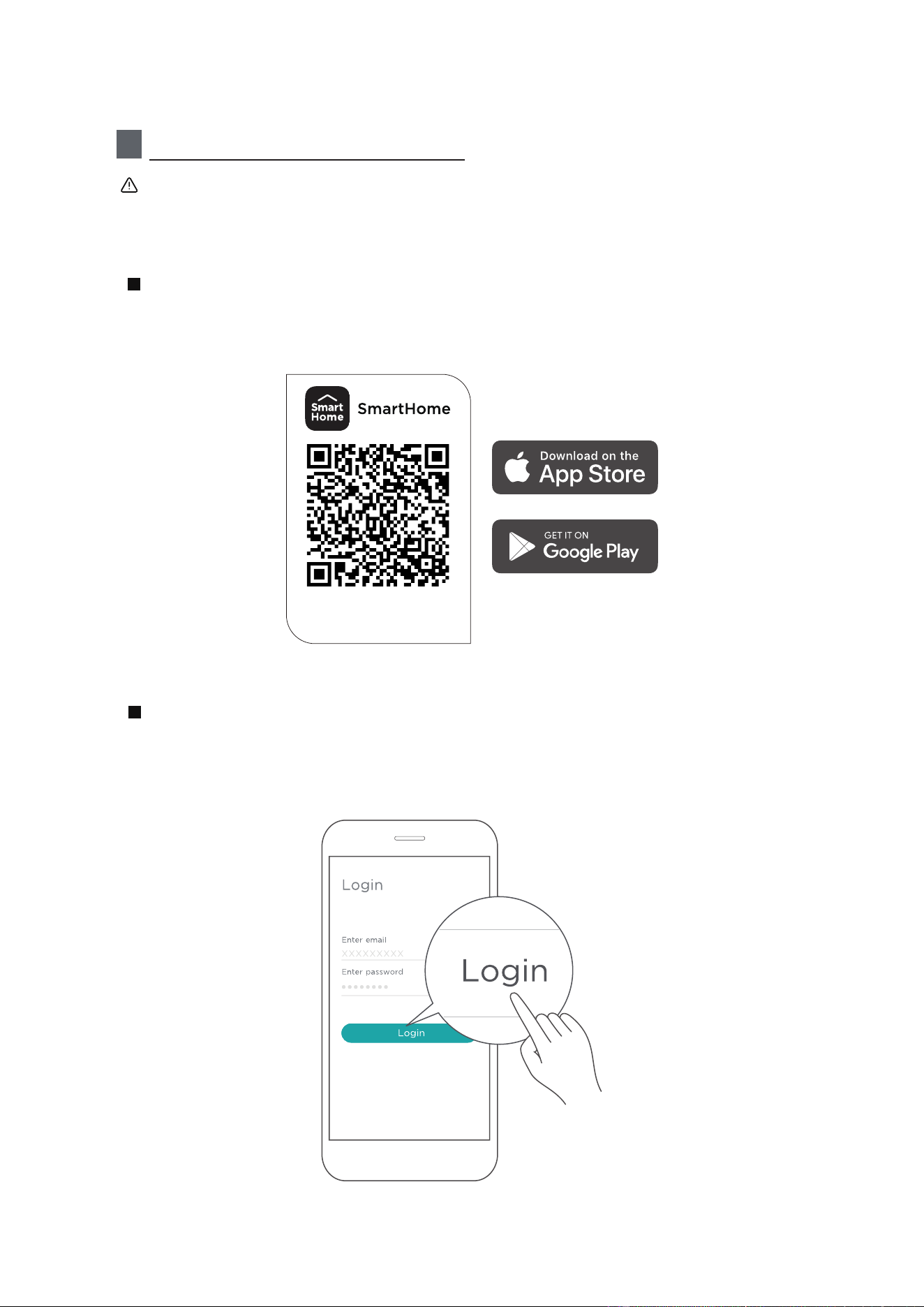
Scan the QR code below to download the SmartHome app from app store
or search for it directly on the Google Play Store or Apple's App Store.
Step 1: Download the SmartHome app
Open the SmartHome app. Log in directly if you have an existing SmartHome
account or create a new account. Alternatively, you can also use a 3rd party
login platform.
Step 2: Log in
Download the app
& activate product
37
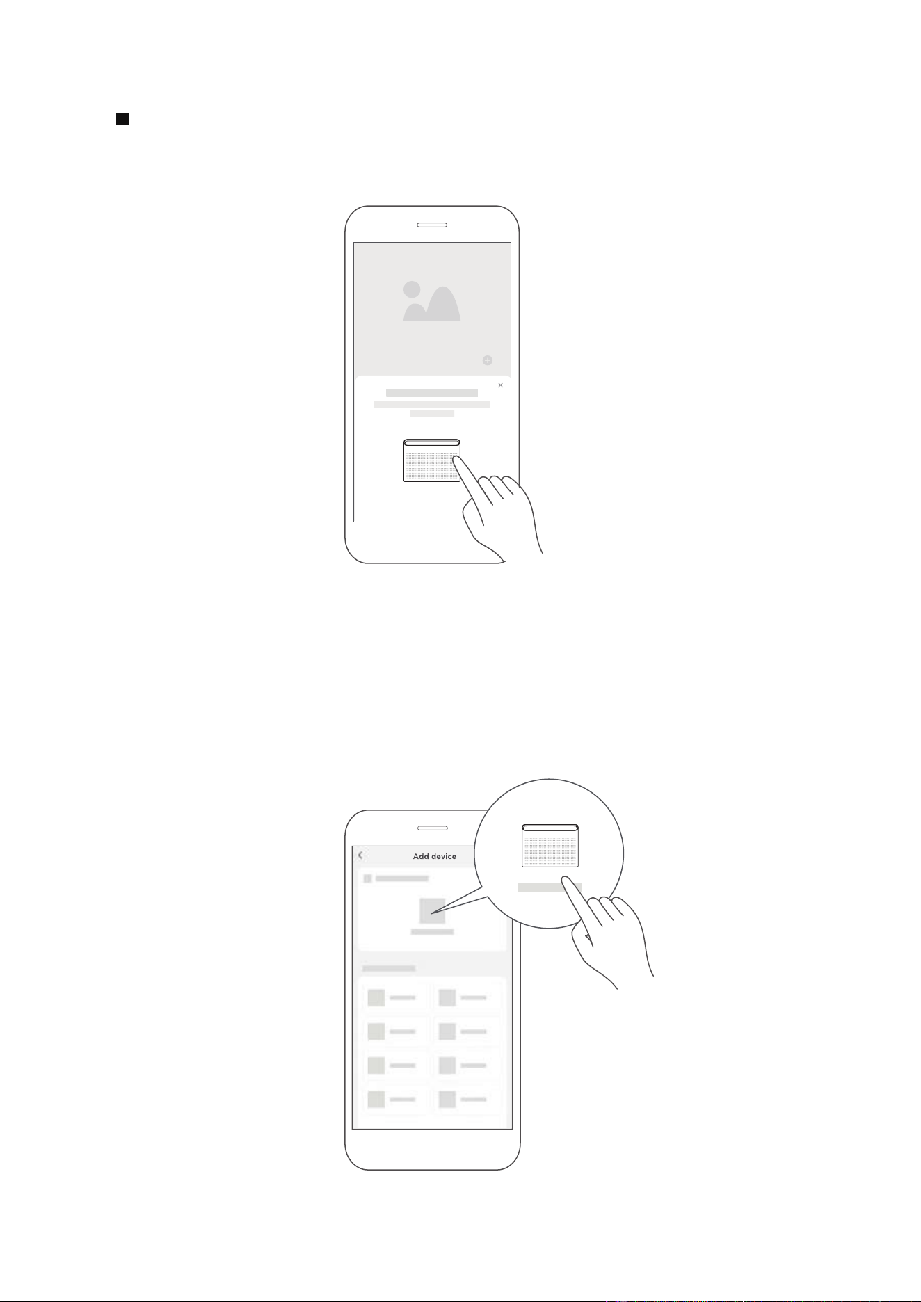
1) When you log in, you may see the message "Smart devices discovered nearby".
Tap to add your device.
2) If no such message appears, proceed as follows: Tap on "+" and select your
device in the list of nearby available devices.
If your device is not listed, please add your device manually, first selecting the
device category e.g. Window AC.
Step 3: Connecting the device
38

After pairing successfully, a card will be created for the device in the SmartHome
app.
Shortcuts for basic functions will appear on the card such as changing the
temperature or switching the device on or off.
Tapping on the card, will reveal additional features and settings. The actual UI
design may look different from examples due to app updates.
Step 4: Controlling the device
SmartHome
3) Follow the steps in the app to connect your device to the wireless network.
If your device fails to connect, follow the additional instructions in the app.
Add device
For Window AC For Portable AC
Add device
39
2
How to use Matter
Connect Your Air Conditioner through Matter
Make sure your mobile device is connected to your wireless router.
Wireless router should support and turn on IPv6. Please make sure your
smartphone connect to 2.4G not 5G network.
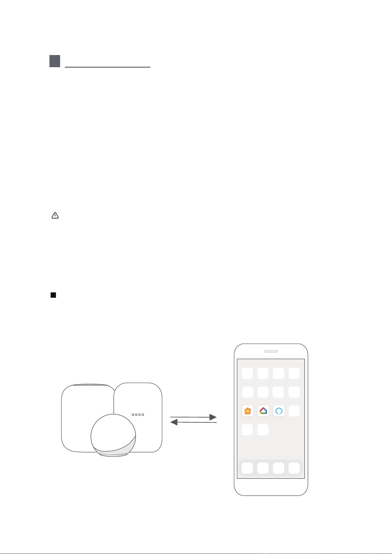
Matter is a connectivity technology that harmonizes the smart home, enabling
devices and ecosystems like Alexa, Google Home, and Apple Home to
communicate seamlessly. This integration unlocks innovative features.
To use Matter, you will need at least one Matter enabled smart speaker (Amazon,
Google or Apple) and its respective app.
-- If you have a Matter enabled smart speaker, please proceed to the "How to
use Matter" instructions on the following pages.
-- If you don't have a Matter enabled smart speaker, you won't be able to use
Matter right now. However, you can still achieve full functionality of the product
by using our SmartHome app. To do this, proceed to the "How to use SmartHome
app" section.
For optimal Matter compatibility, connect your air conditioner to the Alexa, Google
Home, or Apple Home ecosystems, paired with at least one of their compatible
Matter-enabled smart speakers.
Step 1: Connect to smart speaker
Choose your preferred ecosystem (Alexa, Google Home, or Apple Home) and
ensure that you have one of their Matter-enabled products, such as a smart
speaker, connected to your wireless router.
Apple Home Google Home Alexa
40
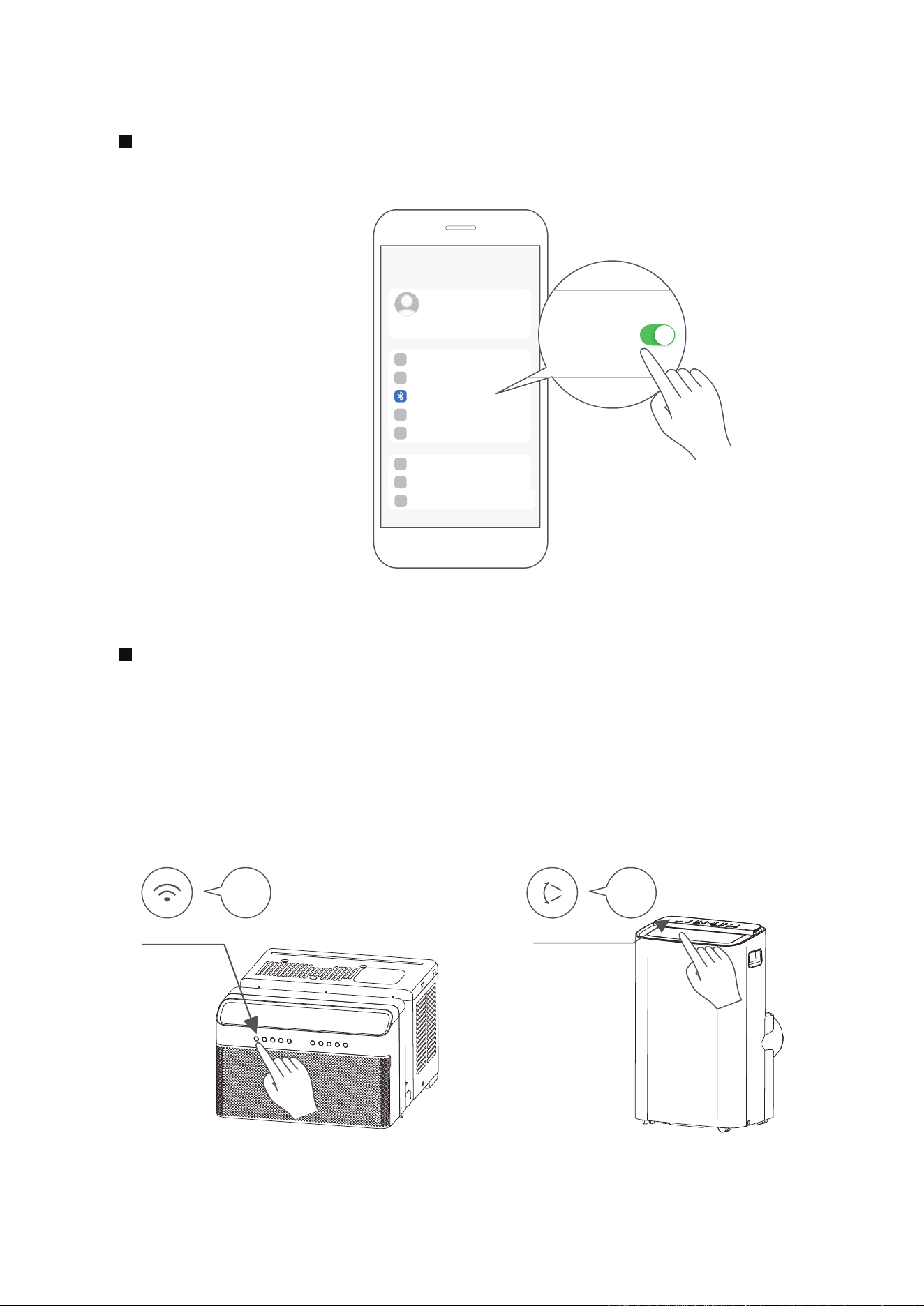
Turn on Bluetooth on your mobile device.
Step 2: Turn on Bluetooth
Settings
Bluetooth
Window AC: Hold down the CONNECT / Power button for 3 seconds to begin
the pairing process (“AP” will appear on the AC’s display).
Portable AC: Hold down the SWING / Power button for 3 seconds to begin the
pairing process (“AP” will appear on the AC’s display).
Note: Entering AP pairing mode may vary between different AC, please follow
instruction of AC panel.
Step 3: Enter AP mode
AP
CONNECT
AP
SWING
Window AC Portable AC
41
Open the Alexa, Google Home, Apple Home app on your mobile device.
Step 4: Open app
Apple Home Google Home Alexa
Open your app and tap the “+” or "+Add" to begin adding a device/accessory.
Select the Matter device option and scan the QR code located on the side of
your AC unit. Follow the instructions provided in the Alexa, Google Home, or
Apple Home app to complete the pairing process.
Step 5: Scan matter QR code
Add
Add Device/Accessory
scan
Matter QR code
42
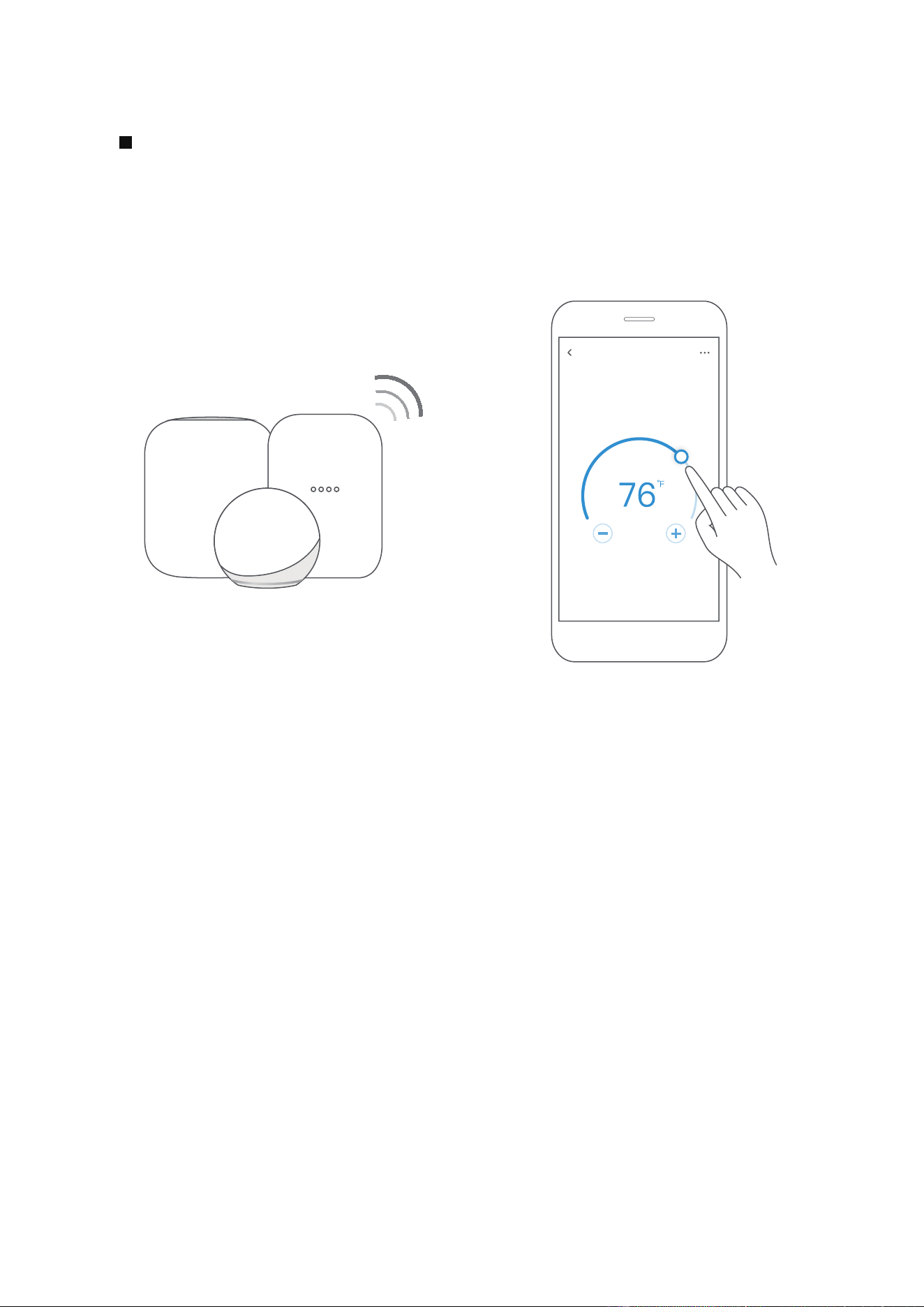
After pairing is successful, you can control your AC’s temperature and mode
settings, etc. through the respective ecosystem app and smart speaker.
Due to a compatibility issue, the temperature value shown in the Alexa,
Google Home or Apple Home app may be 1 degree different from that
displayed on the air conditioner. However, this will not impact the device's
ability to cool the room.
Step 6: Control device
Air conditioner
43
NOTE:
The functions shown in the Alexa, Google Home or Apple Home apps may
change with updates to their products or apps.
Setup processes and features may vary between ecosystems.
Make sure the Matter enabled app is up to date to ensure the best experience.
Periodically, we will update the device’s software to improve the experience.
Device software updates can be accomplished through the SmartHome app.
is developed by the Connectivity Standards Alliance TM. This
brand, related logos, and marks are trademarks of the Alliance, all rights
reserved.
Use of the Works with Apple badge means that an accessory has been designed
to work specifically with the technology identified in the badge and has been
certified by the developer to meet Apple’s performance standards. Apple is not
responsible for the operation of this device or its compliance with safety and
regulatory standards.
App & Smart Speakers can support Matter only when using these
versions or above.
909443955
Google Play services min version: 22.36.15
Google Home app (GHA) min version: 2.58.24.1-dogfood
Google Hub firmware min version: 1.56.324896
(appears on hub as Chromecast firmware version)
2.2.536317
16.5
Device Version
iOS 16.5iPhone
Apple Home
Pod
Alexa Echo
Device
Android
Google
Home Hub
Alexa App
44
3
Specification
Model: US-SK109 Dimensions: 41 x 24 x 5 (mm)
Operation Temperature: 0°C ~ 45°C / 32°F ~ 113°F.
Antenna Type: Printed PCB
Antenna
Operation Humidity: 10% ~ 85%
Frequency: 2400-2483.5MHz
Power Input: DC 5V/500 mA
MaximumTransmittedPower:
<20dBm
45
Declaration of conformity
CONTAINS FCC ID: 2ADQOMDNA23
CONTAINS IC : 12575A-MDNA23
This device complies with Part 15 of the FCC Rules and Industry Canada’s license exempt RSSs.
Operation is subject to the following two conditions:
(1) This device may not cause interference;and
(2) This device must acceptany interference,including interference that may cause undesired
operation of the device.
Only operate the device in accordance with the instructions supplied. Changes or modifications
to this unit not expressly approved by the party responsible for compliance could void the
user's authority to operate the equipment.This device complies with FCC radiation exposure
limits set forth for an uncontrolled environment. In order to avoid the possibility of exceeding
the FCC radio frequency exposure limits, human proximity to the antenna shall not be less than
20cm (8 inches) during normal operation.
NOTE: This equipment has been tested and found to comply with the limits for a Class B digital
device, pursuant to part 15 of the FCC Rules. These limits are designed to provide reasonable
protection against harmful interference in a residential installation. This equipment generates,
uses and can radiate radio frequency energy and, if not installed and used in accordance with
the instructions, may cause harmful interference to radio communications. However, there is
no guarantee that interference will not occur in a particular installation. If this equipment does
cause harmful interference to radio or television reception, which can be determined by turning
more of the following measures:
--Reorient or relocate the receiving antenna.
--Increase the separation between the equipment and receiver.
connected.
--Consult the dealer or an experienced radio/TV technician for help.
NOTE:
All the illustrations in the manual are for explanation purpose only. Your unit may be slightly
46
WARRANTY
Air Conditioner Limited Warranty
Your product is protected by this Limited Warranty:
Warranty service must be obtained from Midea Consumer Services or an authorized Midea servicer.
Warranty
• One
• The date of delivery establishes the warranty period, should service be required.
year full warranty from the the date of delivery or purchase date, whichever is later.
Midea, through its authorized servicers will:
• Pay all costs for reparing or replacing parts of this appliance which prove to be defective in materials or workmanship.
Consumer will be responsible for:
• Diagnostics, removal, transportation and reinstallation cost required because of service.
• Costs of service calls that are a result of items listed under NORMAL RESPONSABILITIES OF THE CONSUMER**
Midea replacement parts shall be used and will be warranted only for the original warranty.
NORMAL RESPONSABILITIES OF THE CONSUMER**
This warranty applies only to products in ordinary household use, and the consumer is responsible for the items
listed below:
1. Proper use of the appliance in acordance with instructions provided with the product.
2. Routine maintenance and cleaning necessary to keep the good working condition.
3. Proper installation by an authorized service professional in accordance with instructions provided with the
appliance and in accordance with all local plumbing, electrical and/or gas codes.
connections or defects in house wiring.
5. Expenses for making the appliance accessible for servicing.
6. Damages to finish after intallation.
EXCLUSIONS
This warranty does not cov
er the following:
1) Failure caused by damage to the unit while in your possesion (other than damage caused by defect or
malfunction), by its improper installation, or by unreasonable use of the unit, including without limitation, failure to
provide reasonable and necessary maintenance or to follow the written installation and Operating Instructions.
2) Damages caused by services performed by persons other than authorized Midea costumer service; or external
causes such as abuse, misuse, inadequate power supply or acts of God.
3) If the unit is put to commercial, business, rental, or other use or application other than for consumer use, we make
no warranties, express or implied, including but not limited to, any implied warranty of merchantability or fitness
for use or purpose.
4) Products without original serial numbers or products that have serial numbers which have been altered or cannot
be readily determined.
NOTE: Some states do not allow the exclusions or limitation of incidental or consequential damages. So this
limitation or exclusion may not apply to you.
IF YOU NEED SERVICE
Keep your bill of sale, delivery slip, or some other appropriate payment Record.
The date on the bill establishes the warranty period, should service be required.
If service is performed, its your best interest to obtain and keep all receipts.
This written warranty gives you specific legal rights. You may also have other rights that vary from state to state.
Service under this warranty must be obtained by following these steps, in order:
1) Contact Midea Consumer Services or an authorized Midea services at 1 866 646 4332.
2) If there is a question as to where to obtain service, contact our consumer relations Departament.
47

RETURN POLICY
Questions about installing or operating your
Midea product?
If you still need assistance, please call Customer
Service at 1-866-646-4332.
Have your sales receipt, serial number and product model
mumber available when you call.
The product may be returned within 30 days of purchase
with receipt, After 30 days, the product is covered under
limited warranty. Please refer to the warranty section
in the User Manual for details.
Return policy
save your
receipt
48

2025
MAPXWMT
16120600A32040

AIRE ACONDICIONADO PORTÁTIL
es
Download the app
& activate product
NÚMERO DE MODELO
MANUAL DEL USUARIO
Avisos de advertencia: antes de usar este producto, lea atentamente este manual y consérvelo para futuras
referencias.
El diseño y las especificaciones están sujetos a cambios sin previo aviso para la mejora del producto.
Consulte con su distribuidor o fabricante para obtener más detalles.
MAP08S1XWGR-T
MAP10S1XWBL-T
MAP10HS1XWGR-T
02
PRECAUCIÓN:
CARTA DE AGRADECIMIENTO
¡Gracias por elegir Midea! Antes de usar su nuevo producto Midea, lea este manual
detenidamente para asegurarse de que conoce cómo operar las características y
funciones que su nuevo electrodoméstico ofrece de manera segura.
Precauciones de seguridad
Antes de empezar
Descripción del producto
Vista general de la instalación
Guía de instalación
Conozca su aire acondicionado
Guía de drenaje
Limpieza y mantenimiento
Guarde la unidad cuando no la utilice
Resolución de problemas
MANUAL DEL PROPIETARIO
Instrucciones del control remoto y aplicación
Garantía
Politica de Devolucion
Lea este manual
Dentro de este manual podría encontrar muchos consejos ayudables diciendo cómo
usar y mantener su aire acondicionado correctamente. Le cuesta un poco cuidado
antes, le ahorrará mucho tiempo y dinero en su aire acondicionado. Puede encontrar
muchas respuestas a los problemas communes en el cuadro de las soluciones de
problemas. Si lea nuestro cuadro de soluciones de problemas primero, quizá no será
necesario llamar por servicio.
• Para obtener asistencia, llame el Central de Servicio Técnico al 1-866-646-4332.
• Este aparato no está indicado a ser utilizado por personas (incluidos niños) con
capacidades físicas, sensoriales o mentales reducidas o falta de experiencia y
conocimientos, a menos que hayan recibido supervisión o instrucción sobre el
uso del aparato por parte de una persona responsable de su seguridad.
• Los niños deben supervisarse para asegurar que ellos no jueguen con el
acondicionador de aire.
• El aparato deberá ser instalado de acuerdo con la norma nacional de instalación
eléctrica.
• No utilizar su acondicionador de aire en una habitación húmeda, como un baño o
una lavandería..
03
1 3
24
26
28
27
29
16
1 7
18
30
47
48
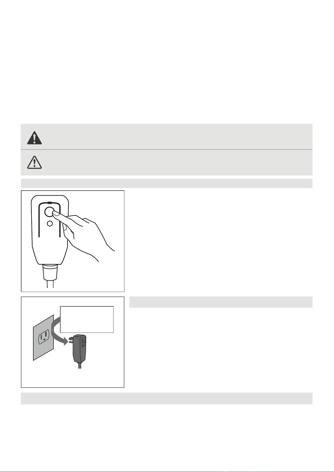
03
Precauciones de seguridad
Lea el mensaje de advertencia.
Lea las precauciones de seguridad antes del funcionamiento y la instalación de la
unidad
Para evitar la muerte o lesiones al usuario o a otras personas, así como daños
materiales, deben seguirse las siguientes instrucciones.
El funcionamiento incorrecto debido a ignorar las instrucciones puede causar la
muerte, lesiones o daños.
Explicación de los símbolos
ADVERTENCIA
Este símbolo indica la posibilidad de lesiones personales o pérdida de la
vida.
PRECAUCIÓN
Este símbolo indica la posibilidad de daños materiales o consecuencias
graves.
AVISO
• No utilice este dispositivo para encender o apagar la unidad.
• Asegúrese siempre de que el botón RESET esté pulsado para un funcionamiento correcto.
•
El cable de alimentación debe ser reemplazado si lo falla al reiniciar mismo cuando el botón TEST
o no se puede reiniciarse. Póngase en contacto con el servicio de atención al cliente.
AVISO
El cable de alimentación que
acompaña este acondicionador
de aire contiene un dispositivo de detección de corriente
diseñado para reducir el riesgo de incendio.
En el caso del cable de alimentación esté dañado
reparar. Debe sustituirlo por un cable del fabricante.
El cable de alimentación contiene un
dispositivo de medición que detecta
daños en el proprio cable. Pruebelo de la siguiente manera:
1. Enchufe el acondicionador de aire.
2.
El cable de alimentación t
endrá DOS
botones en el cabezal del enchufe.
Pulse el botón TEST. Notará un clic a medida que aparezca el
.
3. Pulse el botón RESET. Notará un clic a
medida que el botón se activa.
4. El cable de alimentación ahora está energizando la unidad. (En algunos
productos esto también se indica mediante una luz en el cabezal del
enchufe.)
RESET
TEST
Enchufe y pulse
el botón RESET
Funcionamiento del Dispositivo Actual
Tomacorriente de pared conectado a tierra
Do not, under any
circumstances, cut,
remove or bypass
the grounding prong.
Power supply cord with 3-prong grounding
plug and current detection device.
No corte, retire ni
desvíe, bajo ninguna
circunstancia, la punta
de conexión a tierra.
Cable de alimentación con enchufe de
conexión a tierra de 3 clavijas y dispositivo
de detección de corriente.
es té pulsado
botón RESET
, no se puede

04
ADVERTENCIA
• La instalación debe realizarse de acuerdo con las instrucciones de instalación. Una
instalación incorrecta puede causar fugas de agua, descargas eléctricas o incendios.
• Utilice sólo los accesorios y piezas incluidos y las herramientas especificadas para la
instalación. El uso de piezas no estándar puede provocar fugas de agua, descargas
eléctricas, incendios y lesiones o daños materiales.
• Asegúrese de que la toma de corriente que utiliza está conectada a tierra y tiene el
voltaje adecuado. El cable de alimentación está equipado con un enchufe de tres
clavijas con toma de tierra para proteger contra descargas eléctricas. La información
sobre el voltaje se encuentra en la placa de características de la unidad.
• Conecte la unidad a una toma de corriente debidamente conectada a tierra. Si el
receptáculo de pared que pretende utilizar no está adecuadamente conectado a tierra
o protegido por un fusible de retardo o disyuntor (el fusible o disyuntor n
ecesario
está determinado por la corriente máxima de la unidad. que está especificada en la
placa de características situada en la unidad), haga que un electricista debidamente
capacitado instale el tomacorriente apropiado.
• No toque la unidad con las manos mojadas o húmedas ni cuando esté descalzo.
• Si el aire acondicionado sufre un golpe durante su uso, apáguelo y desconéctelo
inmediatamente de la red eléctrica. Revise la unidad y compruebe que no haya sufrido
ningún daño. Si sospecha que la unidad ha sufrido algún daño, póngase en contacto
con un técnico o con el servicio de atención al cliente para obtener ayuda.
• En caso de tormenta eléctrica, desconecte el cable de alimentación para evitar que los
efectos de un rayo dañen la unidad.
• El aire acondicionado debe protegerse de la humedad. Por ejemplo: de la
condensación, salpicaduras de agua, etc. No coloque ni guarde el aire acondicionado
donde pueda caerse o donde pueda entrarle agua o cualquier otro líquido.
Desenchúfelo inmediatamente si ocurre.
• Instale la unidad sobre una superficie plana y resistente. De lo contrario, podrían
producirse daños oruidos y vibraciones excesivos.
• La unidad debe mantenerse libre de obstrucciones para garantizar su correcto
funcionamiento y mitigar los riesgos de seguridad.
• No modifique la longitud del cable de alimentación ni utilice un alargador para
alimentar la unidad.
• No comparta una misma toma de corriente con otros aparatos eléctricos. Una
alimentación inadecuada puede provocar un incendio o una descarga eléctrica.
• No instale el aire acondicionado en una habitación húmeda, como un cuarto de baño
o un lavadero. Una exposición excesiva al agua puede provocar un cortocircuito en los
componentes eléctricos.
• No instale la unidad en un lugar que pueda estar expuesto a gas combustible, ya que
podría provocar un incendio.
• La unidad tiene ruedas para facilitar su desplazamiento. Asegúrese de no utilizar las
ruedas sobre moqueta gruesa o para rodar sobre objetos, ya que podrían provocar
vuelcos.
• No utilice una unidad que se haya caído o dañado.
• El aparato con calentador eléctrico debe tener un espacio de al menos 1 metro
respecto a los materiales combustibles.
• Todo el cableado debe realizarse estrictamente de acuerdo con el diagrama de
cableado situado en el interior de la unidad.
• La placa de circuito impreso (PCB) de la unidad está diseñada con un fusible para
proporcionar protección contra sobrecorriente. Las especificaciones del fusible están
impresas en la placa de circuito, las cuales pueden ser: T 3.15 A/250 V, etc.
05
PRECAUCIÓN
• Este aparato puede ser utilizado por personas (incluyendo niños) con capacidades
físicas, sensoriales o mentales reducidas, o falta de experiencia y conocimientos,
siempre y cuando sean supervisados o hayan recibido instrucciones sobre el uso del
aparato por parte de una persona responsable de su seguridad. Los niños deben
supervisarse para asegurarse de que no jueguen con el aparato. Los niños deben ser
supervisados alrededor de la unidad en todo momento.
• Si el cable de alimentación está dañado, solo el fabricante, su agente de servicio
o un técnico calificado debe reemplazarlo para evitar riesgos de seguridad.
• No utilice este producto para funciones distintas de las descritas en este manual
de instrucciones.
• Antes de limpiar la unidad, apague el interruptor de encendido y desconecte el
cable de alimentación.
• Si observa ruidos raros, olores extraños o humo, desconecte el cable de
alimentación inmediatamente.
• No pulse los botones del panel de control con nada que no sean los dedos.
• No retire ninguna cubierta fija. No utilice nunca este aparato si no funciona
correctamente o si se ha caído o dañado.
• No haga funcionar ni detenga el aparato introduciendo o extrayendo el enchufe
del cable de alimentación.
• No utilice productos químicos peligrosos para limpiar o entrar en contacto con
la unidad. No utilice la unidad en presencia de sustancias o vapores inflamables
como alcohol, insecticidas, gasolina, etc.
• Antes de llevar a cabo las tareas de limpieza o mantenimiento, desconecte la
unidad del suministro eléctrico.
• No retire ninguna cubierta fija. No utilice nunca este aparato si no funciona
correctamente o si se ha caído o dañado.
• No pase el cable de alimentación por debajo de alfombras. No cubra el cable de
alimentación con alfombrillas, tapetes o cubiertas similares. No pase el cable por
debajo de muebles o electrodomésticos. Coloque el cable de alimentación lejos
de áreas transitadas para evitar tropiezos.
• No utilice la unidad si el cable, el enchufe, el fusible o el disyuntor están dañados.
Deseche la unidad o llévela a un centro de servicio técnico autorizado para que la
inspeccionen o reparen.
• Para reducir el riesgo de incendio o descarga eléctrica, no utilice este ventilador
con ningún dispositivo de control de velocidad de estado sólido.
• Este aparato debe instalarse de acuerdo con la normativa nacional sobre cableado.
• Póngase en contacto con el servicio técnico autorizado para la reparación o el
mantenimiento de esta unidad.
• No cubra ni obstruya las rejillas de entrada o salida.
• Transporte siempre el aire acondicionado en posición vertical y colóquelo sobre
una superficie estable y nivelada durante su uso.
• Póngase siempre en contacto con una persona cualificada para realizar
reparaciones. Si el cable de alimentación dañado debe ser sustituido por un
nuevo cable de alimentación obtenido del fabricante del producto y no reparado.
•
Sujete el enchufe por la cabeza al sacarlo.
• Apague la unidad cuando no esté en uso.
Trabajo Electrónico
ADVERTENCIA :
ANTES DE REALIZAR CUALQUIER TRABAJO ELÉCTRICO O DE
CABLEADO, APAGUE LA ENERGÍA PRINCIPAL DEL SISTEMA.
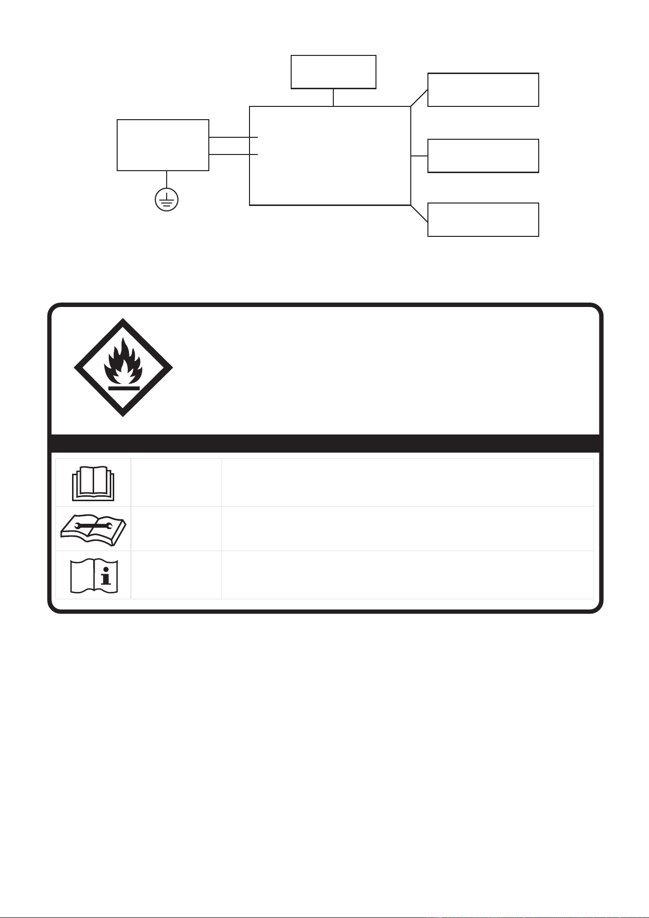
06
A2L
PRECAUCIÓN:
Riesgo de incendio
materiales
inflamables
NOTA IMPORTANTE: Lea atentamente
este manualantes de instalar o poner
en funcionamiento su nuevo aparato.
Asegúrese de guardar este manual para
referencia futura.
Explicación de los símbolos que aparecen en la unidad
A2L
PRECAUCIÓN
Este símbolo indica que debe leerse atentamente el manual de
instrucciones.
A2L
PRECAUCIÓN
Este símbolo indica que el personal de servicio debe manipular este
equipo consultando el manual de instalación.
A2L
PRECAUCIÓN
Este símbolo indica que hay información disponible, como el manual
de instrucciones o el manual de instalación.
ADVERTENCIA:
- El mantenimiento sólo debe realizarse según las recomendaciones del fabricante
del equipo. El mantenimiento y la reparación que requieran la asistencia de otros
técnicos especializados se llevarán a cabo bajo la supervisión de la persona
competente en el uso de refrigerantes inflamables.
- NO modifique la longitud del cable de alimentación ni utilice un alargador para
alimentar la unidad.
- NO comparta una misma toma de corriente con otros aparatos eléctricos. Una
alimentación inadecuada puede provocar un incendio o una descarga eléctrica.
Siga atentamente las instrucciones de manipulación, instalación, limpieza y
mantenimiento del aparato para evitar cualquier daño o peligro.
Control principal
compresor
El motor del
ventilador
La pantalla
Fuente de
alimentación
L/AC L/L1/L-IN
N/AC N/L2/N-IN
Otras

07
Inflamable
El aparato utiliza refrigerante R32.
- Cuando realice el mantenimiento o deseche el aparato, el refrigerante (R32)
deberá recuperarse adecuadamente y no deberá verterse directamente al aire.
- Deberá respetarse la normativa nacional sobre gases.
- Mantenga las aberturas de ventilación libres de obstrucciones.
- El aparato deberá almacenarse de manera que no se produzcan daños mecánicos.
- Advertencia de que el aparato debe almacenarse en una zona bien ventilada
donde el tamaño de la sala corresponda a la superficie de la sala especificada
para el funcionamiento.
- Toda persona que trabaje o intervenga en un circuito de refrigerante debe estar
en posesión de un certificado válido de una autoridad de evaluación acreditada
por la industria, que autorice su competencia para manipular refrigerantes de
forma segura de acuerdo con una especificación de evaluación reconocida por la
Ejemplos de tales procedimientos de trabajo son:
• irrupción en el circuito frigorífico
• apertura de componentes sellados
• apertura de recintos ventilados
- Para evitar la ignición del refrigerante inflamable utilizado, no debe haber cerca
del aparato ningún fuego abierto ni ningún dispositivo como interruptores que
puedan generar chispas/arcos. Siga cuidadosamente las instrucciones para
almacenar o mantener el aparato para evitar que se produzcan daños mecánicos.
- No utilice medios para acelerar la operación de descongelación o para limpiar que
no sean los recomendados por el fabricante.
- El aparato debe almacenarse en una habitación sin fuentes de ignición de
funcionamiento continuo (por ejemplo: llamas abiertas, un aparato de gas en
funcionamiento) y fuentes de ignición o (por ejemplo: un calentador eléctrico en
funcionamiento) cerca del aparato. El aparato debe almacenarse en un local sin
fuentes de ignición en funcionamiento continuo (por ejemplo: llamas abiertas, un
aparato de gas en funcionamiento o un calentador eléctrico en funcionamiento).
- No lo perfore ni lo queme.
- Tenga en cuenta que los refrigerantes pueden no contener olor.
1. Transporte de equipos que contengan refrigerantes inflamables
Véase la normativa de transporte.
2. Señalización de los equipos mediante carteles
Véase la normativa local.
3. Eliminación de equipos que utilizan refrigerantes inflamables
Consulte la normativa nacional.
4. Almacenamiento de equipos/electrodomésticos
industria. Todo el entrenamiento debe seguir los requisitos del ANEXO HH de la
UL 60335-2-40 4ta Edición.
El almacenamiento del electrodoméstico debe estar de acuerdo con las
regulaciones aplicables o las instrucciones, lo que sea más estricto.

08
5. Almacenamiento de material embalado (no vendido)
La protección del embalaje de almacenamiento debe realizarse de forma que
los daños mecánicos al equipo dentro del embalaje no provoquen una fuga de
la carga de refrigerante. La normativa local determinará el número máximo de
equipos que pueden almacenarse juntos.
6. Información sobre el mantenimiento
1) Revisión del área
Antes de empezar a trabajar en sistemas que contengan refrigerantes
inflamables, es necesario realizar comprobaciones de seguridad para garantizar
que se reduzca al mínimo el riesgo de ignición. Para la reparación del sistema
de refrigeración, se deberán tomar las siguientes precauciones antes de realizar
trabajos en el sistema.
2) Procedimiento de trabajo
Los trabajos se realizarán según un procedimiento controlado para minimizar el
riesgo de presencia de gases o vapores inflamables durante los mismos.
3) Área de trabajo general
Todo el personal de mantenimiento y otras personas que trabajen en la zona
deberán recibir instrucciones sobre la naturaleza del trabajo que se está
realizando. Se evitará trabajar en espacios confinados. Se seccionará la zona
alrededor del espacio de trabajo. Cerciórese de que las condiciones dentro del
área son seguras mediante el control del material inflamable.
4) Verificación de la presencia de refrigerante
Se c
omprobará la zona con un detector frigorífico adecuado antes y durante
el trabajo, para garantizar que el técnico es consciente de la existencia de
atmósferas potencialmente inflamables. Asegúrese de que el equipo de detección
de fugas utilizado es adecuado para su uso con refrigerantes inflamables, es
decir, que no produce chispas, está adecuadamente sellado o es intrínsecamente
seguro.
5) Presencia de extintor de incendios
Si se va a realizar algún trabajo en caliente en el equipo de refrigeración o en
alguna de las piezas asociadas, deberá tenerse a mano el equipo de extinción de
incendios adecuado. Tenga un extintor de polvo seco o de CO2 junto al área de
carga.
6) Ausencia de fuentes de ignición
Ninguna persona que realice trabajos en relación con un sistema de refrigeración
que implique la exposición de tuberías que contengan o hayan contenido
refrigerantes inflamables utilizará fuentes de ignición de tal manera que pueda
producirse un riesgo de incendio o explosión. Todas las posibles fuentes de
ignición, incluido el consumo de cigarrillos, deberán mantenerse suficientemente
alejadas del lugar de instalación, reparación, retirada y eliminación, durante las
cuales es posible que se libere refrigerante inflamable al espacio circundante.
Antes de empezar a trabajar, se deberá inspeccionar el área alrededor del equipo
para asegurarse de que no hay riesgos de inflamación o ignición. Se colocarán
señales de prohibido fumar.

09
8) Controles del equipo frigorífico
Cuando se cambien componentes eléctricos, deberán ser aptos para el fin
previsto y cumplir las especificaciones correctas. Se seguirán en todo momento
las directrices de mantenimiento y servicio del fabricante. En caso de duda,
consulte al departamento técnico del fabricante. Se efectuarán las siguientes
verificaciones en las instalaciones que utilicen refrigerantes inflamables:
La carga real de refrigerante es acorde con el tamaño de la sala en la que están
instaladas las piezas que contienen refrigerante;
La maquinaria de ventilación y las salidas funcionan adecuadamente y no están
obstruidas; Si se utiliza un circuito de refrigeración indirecto, se comprobará la
presencia de refrigerante en el circuito secundario; El marcado del equipo sigue
siendo visible y legible. La tubería o los componentes frigoríficos se instalarán en
un lugar en el que sea improbable que queden expuestos a cualquier sustancia
que pueda corroer los componentes que contengan refrigerante, a menos que
los componentes estén fabricados con materiales que sean intrínsecamente
resistentes a la corrosión o estén convenientemente protegidos contra ésta.
9) Controles de los dispositivos eléctricos
La reparación y el mantenimiento de los componentes eléctricos incluirán
revisiones iniciales de seguridad y procedimientos de inspección de los
componentes. Si existe un desperfecto que pueda comprometer la seguridad,
no se conectará ningún suministro eléctrico al circuito hasta que se solucione
satisfactoriamente. Si el fallo no puede corregirse inmediatamente pero es
necesario continuar el funcionamiento, se utilizará una solución temporal
adecuada. Esto se comunicará al propietario del equipo para que todas las partes
estén informadas. Las verificaciones iniciales de seguridad incluirán:
Que los condensadores estén descargados: esto se hará de forma segura para
evitar la posibilidad de chispas; Que no haya componentes eléctricos en tensión
ni cableado expuesto mientras se carga, recupera o purga el sistema; Que haya
continuidad de la conexión a tierra.
7. Reparación de componentes sellados
8. Reparación de componentes intrínsecamente seguros
9. Cableado
Compruebe que el cableado no estará sometido a desgaste, corrosión, presión
excesiva, vibración, bordes afilados o cualquier otro efecto ambiental adverso.
La comprobación también tendrá en cuenta los efectos del envejecimiento o la
vibración continua de fuentes como compresores o ventiladores.
10. Detección de refrigerantes inflamables
En ningún caso se utilizarán fuentes potenciales de ignición en la búsqueda o
detección de fugas de refrigerante. No se utilizará un soplete de halogenuros (ni
ningún otro detector que utilice una llama desnuda).
Los siguientes métodos de detección de fugas se consideran aceptables para
los sistemas que contienen refrigerantes inflamables. Se utilizarán detectores
electrónicos de fugas para detectar refrigerantes inflamables, pero es posible que la
sensibilidad no sea la adecuada o que haya que recalibrarlos.

(El equipo de detección se calibrará en una zona libre de refrigerantes).
Asegúrese de que el detector no es una fuente potencial de ignición y es adecuado
para el refrigerante utilizado. El equipo de detección de fugas se ajustará a un
porcentaje del LFL del refrigerante y se calibrará para el refrigerante empleado y
se confirmará el porcentaje adecuado de gas (25 % como máximo). Los líquidos de
detección de fugas son adecuados para la mayoría de los refrigerantes, pero debe
evitarse el uso de detergentes que contengan cloro, ya que éste puede reaccionar
con el refrigerante y corroer las tuberías de cobre.
Si se sospecha una fuga, se retirarán/extinguirán todas las llamas desnudas. Si se
detecta una fuga de refrigerante que requiera soldadura, se recuperará todo el
refrigerante del sistema o se aislará (cerrando las válvulas) en una parte del sistema
alejada de la fuga. La extracción del refrigerante se realizará de acuerdo con la
sección Extracción y evacuación.
11. Remoción y evacuación
Al acceder al circuito de refrigeración para realizar reparaciones, o con cualquier
otro propósito, se seguirán los procedimientos convencionales.
Sin embargo, en el caso de refrigerantes inflamables es importante seguir las
mejores prácticas, ya que la inflamabilidad es un factor a tener en cuenta. Se seguirá
el siguiente procedimiento:
a) elimine el refrigerante de forma segura siguiendo la normativa local y nacional;
b) purgue el circuito con gas inerte;
c) evacuar (opcional para A2L);
d) purgar con gas inerte (opcional para A2L);
e) abra el circuito cortándolo o soldándolo.
12. Procedimientos de carga
Además de los procedimientos de carga convencionales, se seguirán los siguientes
requisitos. Al utilizar el equipo de carga, asegúrese de que no se produce
contaminación de los distintos refrigerantes. Las mangueras o líneas serán lo
más cortas posible para minimizar la cantidad de refrigerante que contienen. Las
botellas se mantendrán enuna posición adecuada de acuerdo con las instrucciones.
La carga de refrigerante se recuperará en los cilindros de recuperación correctos si
la ventilación no está permitida por los códigos locales y nacionales. Para los
electrodomésticos que contengan refrigerantes inflamables, el sistema debe ser
purgado con nitrógeno libre de oxígeno para hacer que el electrodoméstico sea
seguro para los refrigerantes inflamables. Es posible que este proceso deba repetirse
varias veces. No se utilizará aire comprimido ni oxígeno para purgar los sistemas
de refrigerantes. En el caso de aparatos que contengan refrigerantes inflamables, la
purga de refrigerantes se realizará rompiendo el vacío en el sistema con nitrógeno
libre de oxígeno y continuando el llenado hasta alcanzar la presión de trabajo,
ventilando a continuación a la atmósfera y, por último, reduciendo el vacío (opcional
para A2L). Este proceso se repetirá hasta que no quede refrigerante en el sistema
(opcional para A2L). Cuando se utilice la carga final de nitrógeno libre de oxígeno,
el sistema se purgará hasta la presión atmosférica para permitir que se realice el
trabajo. Asegúrese de que la salida de la bomba de vacío no está cerca de ninguna
fuente potencial de ignición y de que se dispone de ventilación.
10

Verifique que el sistema de refrigeración esté conectado a tierra antes de recargarlo
con refrigerante. Etiquete el sistema cuando la carga esté completa (si no lo está
ya). Deberán extremarse las precauciones para no llenar en exceso el sistema
de refrigeración. Antes de recargar el sistema, se someterá a una prueba de
presión con nitrógeno libre de oxígeno. El sistema se someterá a una prueba de
estanqueidad una vez finalizada la carga de forma previa a la puesta en servicio.
Se realizará una prueba de fugas de seguimiento antes de abandonar el lugar de
trabajo
.
13. Desmantelamiento
Antes de llevar a cabo este procedimiento, es esencial que el técnico esté
completamente familiarizado con el equipo y todos sus detalles. Se recomienda
como buena práctica que todos los refrigerantes se recuperen de forma segura.
Antes de realizar la tarea, se tomará una muestra de aceite y refrigerante por si
fuera necesario realizar un análisis antes de reutilizar el refrigerante recuperado. Es
esencial que se disponga de energía eléctrica antes de comenzar la tarea.
a) Deberá familiarizarse con el equipo y su funcionamiento.
b) Aislar eléctricamente el sistema.
c) Antes de intentar el procedimiento asegúrese de que: Se dispone de equipos
de manipulación mecánica, si es necesario, para manipular los cilindros de
refrigerante; todo el equipo de protección personal esté disponible y se utilice
correctamente; el proceso de recuperación esté supervisado en todo momento
por una persona competente; el equipo de recuperación y los cilindros se
ajusten a las normas apropiadas.
d) Bombee el sistema de refrigeración, si es posible.
e) Si no es posible lograr el vacío, consiga un colector para poder extraer el
refrigerante de las distintas partes del sistema.
f) Asegúrese de que el cilindro esté ubicado en la balanza antes de proceder a la
recuperación.
g) Ponga en marcha la máquina de recuperación y hágala funcionar de acuerdo
con las instrucciones.
h) No sobrellene los cilindros. (No más del 80 % de volumen de carga líquida).
i) No exceda la presión de trabajo máxima del cilindro, ni siquiera temporalmente.
j) Una vez que los cilindros se hayan llenado correctamente y el proceso haya
finalizado, asegúrese de que los cilindros y el equipo se retiren rápidamente del
lugar y de que se cierren todas las válvulas de aislamiento del equipo.
k) El refrigerante recuperado no debe cargarse en otro sistema de refrigeración a
menos que se haya limpiado y revisado.
14. Etiquetado
El equipo se etiquetará indicando que ha sido retirado de servicio y vaciado de
refrigerante. La etiqueta deberá estar fechada y firmada.
Asegúrese de que el equipo tenga etiquetas que indiquen que contiene refrigerante
inflamable.
11

15. Recuperación
Al retirar el refrigerante de un sistema, ya sea para su mantenimiento o
desmantelamiento, se recomienda como buena práctica que todos los refrigerantes
se retiren de forma segura.
Al trasvasar refrigerante a botellas, asegúrese de que sólo se utilizan botellas de
recuperación de refrigerante adecuadas.
Asegúrese de que se dispone del número correcto de botellas para la carga total
del sistema. Todos los cilindros que se utilicen estén designados para el refrigerante
recuperado y etiquetados para ese refrigerante (es decir, cilindros especiales
para la recuperación de refrigerante). Los cilindros deberán estar completos con
válvula de alivio de presión y válvulas de cierre asociadas en buen estado de
funcionamiento. Los cilindros vacíos deben evacuarse y, si es posible, enfriarse
antes de la recuperación. Los equipos de recuperación deben estar en buen estado
de funcionamiento, contar con un conjunto de instrucciones que esté a mano y
ser aptos para la recuperación de refrigerantes inflamables. Además, es necesario
contar con un conjunto de balanzas calibradas que funcionen correctamente. Las
mangueras deberán estar completas, con acoplamientos de desconexión sin fugas y
en buen estado.
Antes de utilizar el equipo de recuperación, compruebe que funciona
correctamente, que se ha sometido a un mantenimiento adecuado y que todos los
componentes eléctricos asociados están sellados para evitar la ignición en caso
de fuga de refrigerante. En caso de duda, consulte al fabricante. El refrigerante
recuperado se devolverá al proveedor en el cilindro de recuperación correcto, al que
se adjuntará la correspondiente nota de transferencia de residuos.
No mezcle refrigerantes en las unidades de recuperación y especialmente en los
cilindros. Si se deben retirar los compresores o su aceite, asegúrese de que hayan
sido evacuados a un nivel aceptable para que no quede refrigerante inflamable
en el lubricante. El proceso de evacuación se llevará a cabo antes de devolver el
compresor a los proveedores. Para acelerar este proceso, solamente se empleará el
calentamiento eléctrico del cuerpo del compresor. Sea cuidadoso al drenar el aceite
del sistema.
Los aparatos no conectados a conductos que contengan refrigerantes A2L con las
aberturas de impulsión y retorno de aire en el espacio acondicionado pueden tener
el cuerpo del aparato puede instalarse en zonas abiertas como falsos techos que no
se utilicen como plénums de aire de retorno, siempre que el aire acondicionado no
se comunique directamente con el aire del falso techo.
12
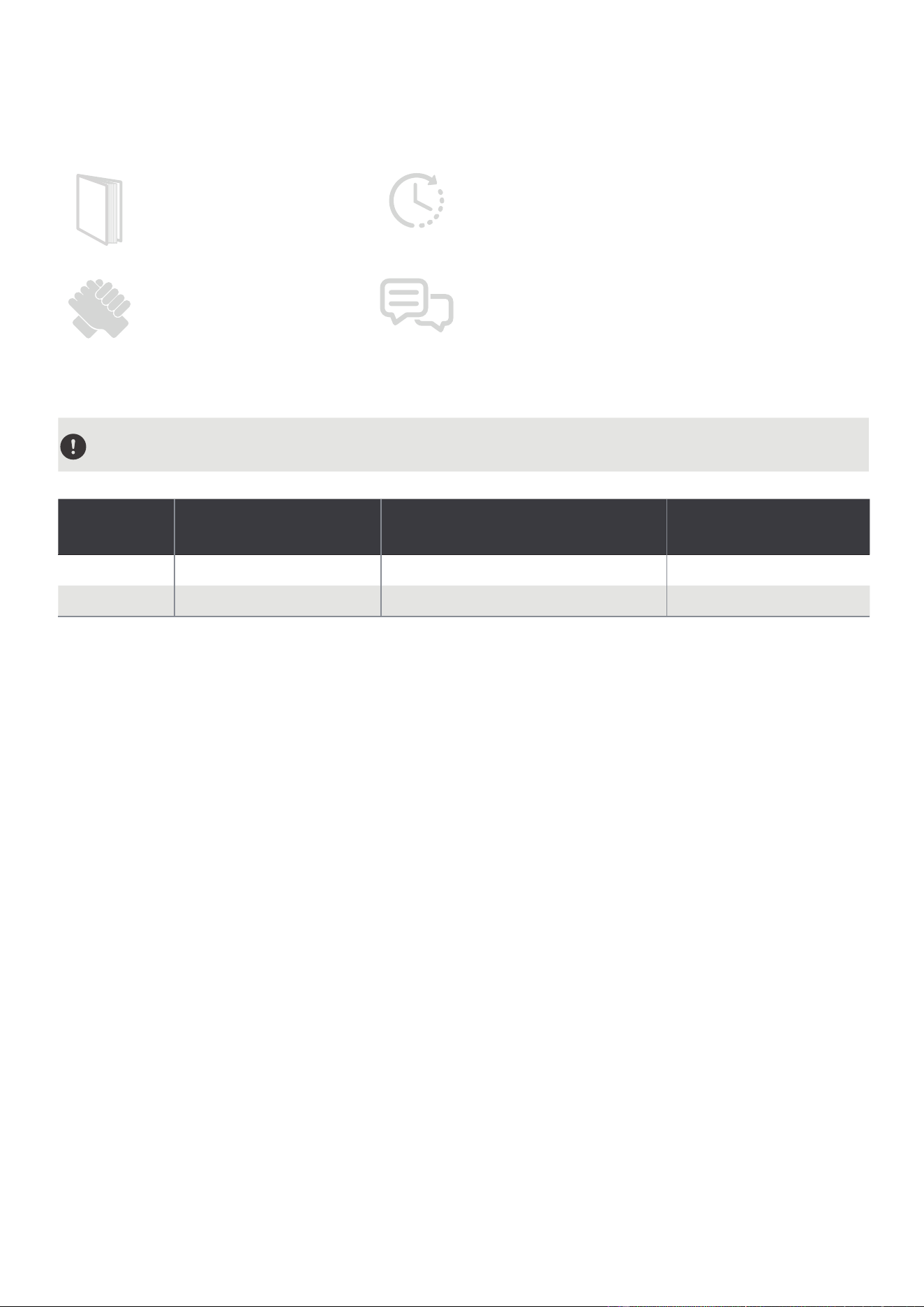
Antes de empezar
Preparativos para la instalación
Manual
La instalación debe
realizarse siguiendo
estrictamente las
instrucciones de este
manual.
La instalación de su aire
acondicionado debería
durar unos 30 minutos.
Recomendamos hacerlo con
un ayudante.
Estamos aquí si nos
necesita. Póngase
en contacto con su
distribuidor local para
obtener ayuda.
RANGO DE TEMPERATURA AMBIENTE PARA EL FUNCIONAMIENTO
DE LA UNIDAD
MODO
Rango de
temperatura
MODO
Rango de
temperatura
Fresco 16-35°C (60-95°F) Calor (modo bomba de calor) 5-30°C (41-86°F)
Seco 13-35°C (55-95°F) Calor (modo de calor eléctrico) ≤ 30 °C (86 °F)
Conozca su tipo de móvil Aire acondicionado
Información sobre la clasificación energética
La clasificación energética y la información sobre el ruido de esta unidad se basan en la instalación
estándar utilizando un conducto de escape sin prolongar y sin adaptador deslizante de ventana (como se
muestra en la sección Instalación de este manual). Al mismo tiempo, la unidad debe funcionar en MODO
FRÍO y ALTA VELOCIDAD DEL VENTILADOR mediante el mando a distancia.
La unidad con 3 metros de conducto de escape extendido se hace mediante el uso de 2 conductos
de escape (diámetro: 150 mm, longitud: 1.5 m + diámetro: 130 mm, longitud: 1.5 m). La clasificación
energética y la información de ruido para la unidad con conducto de escape extendido de 3 metros no se
evalúan. (Para algunos modelos)
NOTA:
Se recomienda utilizar la unidad a una temperatura ambiente inferior a 35 °C. Dado que existe el riesgo
de que la unidad con un conducto de escape extendido de 3 metros no funcione a una temperatura
ambiente superior a 35 °C en algunas condiciones extremas, como en el caso de que la entrada de aire
inferior se bloquee en un 50 %.
Cómo mantenerse fresco con este nuevo aire acondicionado portátil (Para los
modelos que cumplen con los requisitos del Departamento de Energía de EE. UU.)
Debido a un nuevo procedimiento de prueba federal para Acondicionadores de Aire Portátiles, puede
notar que las afirmaciones de capacidad de enfriamiento en el embalaje del acondicionador de aire
portátil son significativamente más bajas que las de los modelos producidos antes de 2017. Esto se debe
a los cambios en el procedimiento de prueba, no a los acondicionadores de aire portátiles en sí.
13

Cómo comprar un aire acondicionado de tipo portátil.
El aire acondicionado adecuado ayuda a enfriar una habitación de forma eficiente. Una unidad de
tamaño insuficiente no enfriará adecuadamente, mientras que una demasiado grande no eliminará
suficiente humedad, dejando el aire húmedo. Para encontrar el aire acondicionado adecuado, determine
los metros cuadrados de la habitación que desea enfriar multiplicando la longitud de la habitación
por su anchura. También debe conocer el valor nominal en BTU (unidades térmicas británicas) del aire
acondicionado, que indica la cantidad de calor que puede eliminar de una habitación. Una cifra más
alta significa más potencia de refrigeración para una habitación más grande. (Asegúrese de comparar
sólo los modelos más nuevos entre sí; los modelos más antiguos pueden parecer de mayor capacidad,
pero en realidad son iguales). Asegúrese de "dimensionar" si su aire acondicionado portátil se va a
colocar en una habitación muy soleada, en una cocina o en una habitación con techos altos. Una vez
que haya encontrado la capacidad de refrigeración adecuada para su habitación, puede fijarse en otras
características.
Por qué los productos más nuevos tienen menor capacidad de refrigeración que los
modelos más antiguos.
La normativa federal obliga a los fabricantes a calcular la capacidad de refrigeración basándose en un
procedimiento de ensayo específico, que se ha modificado este mismo año. Los modelos fabricados
antes de 2017 se sometieron a pruebas con un procedimiento diferente y la capacidad de refrigeración se
mide de forma distinta a la de los modelos de años anteriores. Por tanto, aunque los valores en BTU sean
inferiores, la capacidad real de refrigeración de los aparatos de aire acondicionado no ha cambiado.
¿Qué es la SACC?
SACC es el valor representativo de la capacidad de refrigeración ajustada estacionalmente, en Btu/h,
determinado de acuerdo con el procedimiento de prueba del DOE en el título 10 del Código de
Reglamentos Federales (CFR) 430, subparte B, apéndice CC y los planes de muestreo aplicables.
14
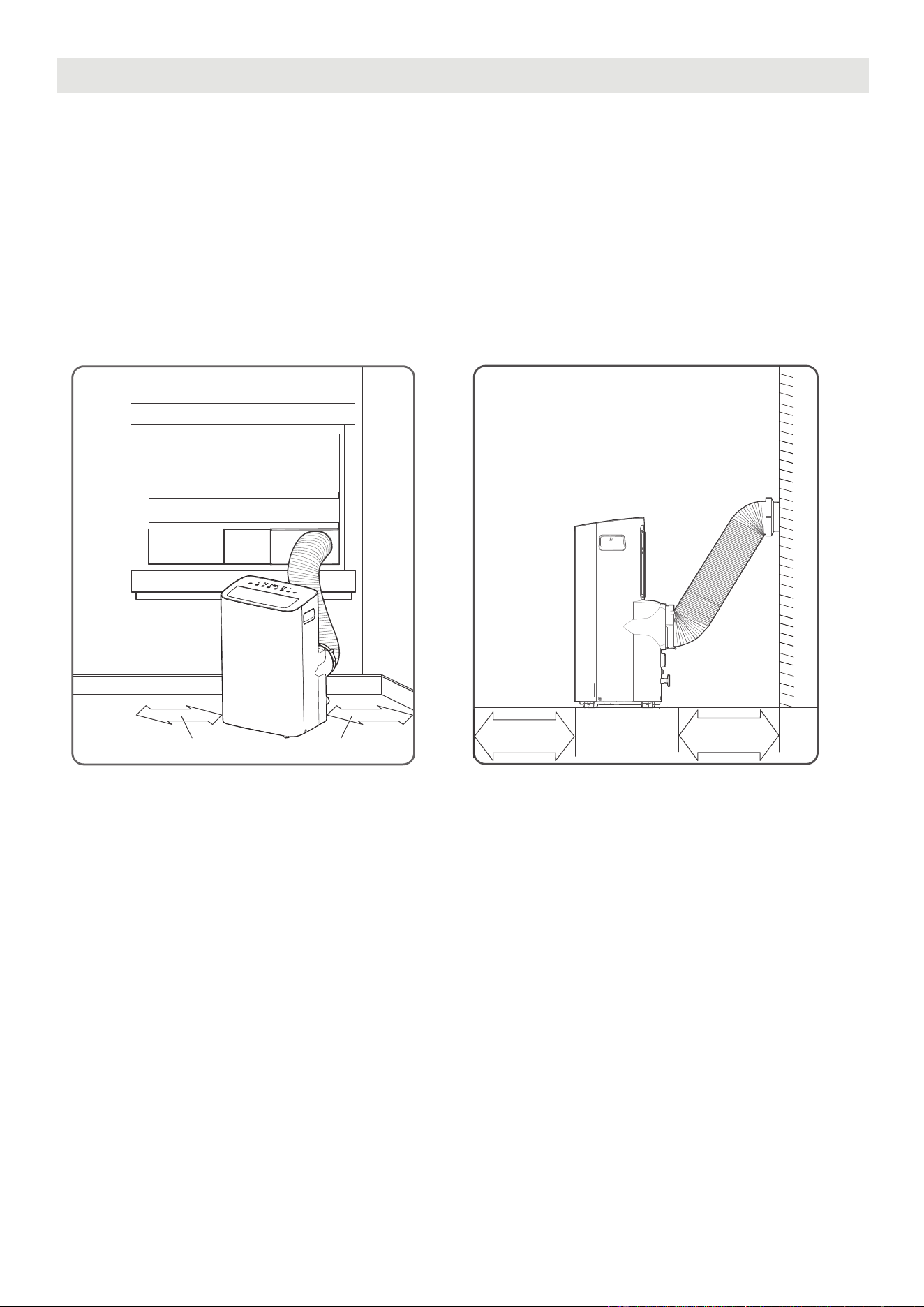
LUGAR DE INSTALACIÓN DEL PRODUCTO
El lugar de instalación debe cumplir los siguientes requisitos:
- Asegúrese de instalar la unidad sobre una superficie plana para minimizar el ruido y las vibraciones.
- La unidad debe instalarse cerca de un enchufe con toma de tierra, y el desagüe de la bandeja de
recogida (que se encuentra en la parte posterior de la unidad) debe ser accesible.
- La unidad debe estar situada al menos a 30 cm (12") de la pared más cercana para garantizar una
correcta climatización. La salida de aire de la unidad debe estar al menos a 50cm (19,7") de obstáculos.
- NO cubra las Entradas, Salidas o el Receptor de Señal Remota de la unidad, ya que esto podría causar
daños a la unidad.
Ubicación de instalación de la unidad Requisitos de espacio restringido
≥30cm(12”)≥30cm(12”)
≥50cm
19.7”
≥
50cm
19.7
”
15
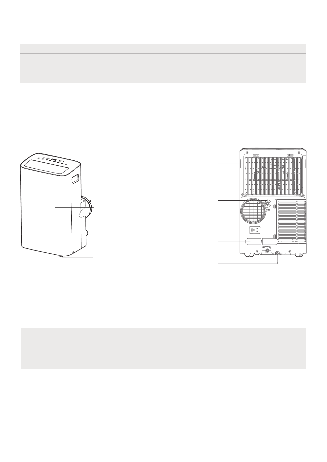
Todas las ilustraciones del manual son solo para fines explicativos. El aparato puede ser ligeramente
diferente. La apariencia real prevalecerá.
El funcionamiento de la unidad se puede controlar a través del panel de control o del control remoto.
NOTA SOBRE LAS ILUSTRACIONES:
Descripción del producto
Aviso sobre el diseño
Con el fin de garantizar el rendimiento óptimo de nuestros productos, las
especificaciones de diseño de la unidad y el mando a distancia están sujetas
a cambios sin previo aviso.
Vista frontal
Tobillera
Hoja de persiana horizontal
(Balanceo automático)
Panel de control
Panel frontal
Vista posterior
Salida de drenaje
Enchufe de alimentación
Hebilla de cable de alimentación
Salida de drenaje de la
bandeja inferior
Filtro de aire superior
(Detrás de la rejilla)
Entrada de aire superior
Salida de aire
Filtro de aire inferior
Entrada de aire inferior
Desagüe de salida
(sólo para modelos de bomba de calor)
16
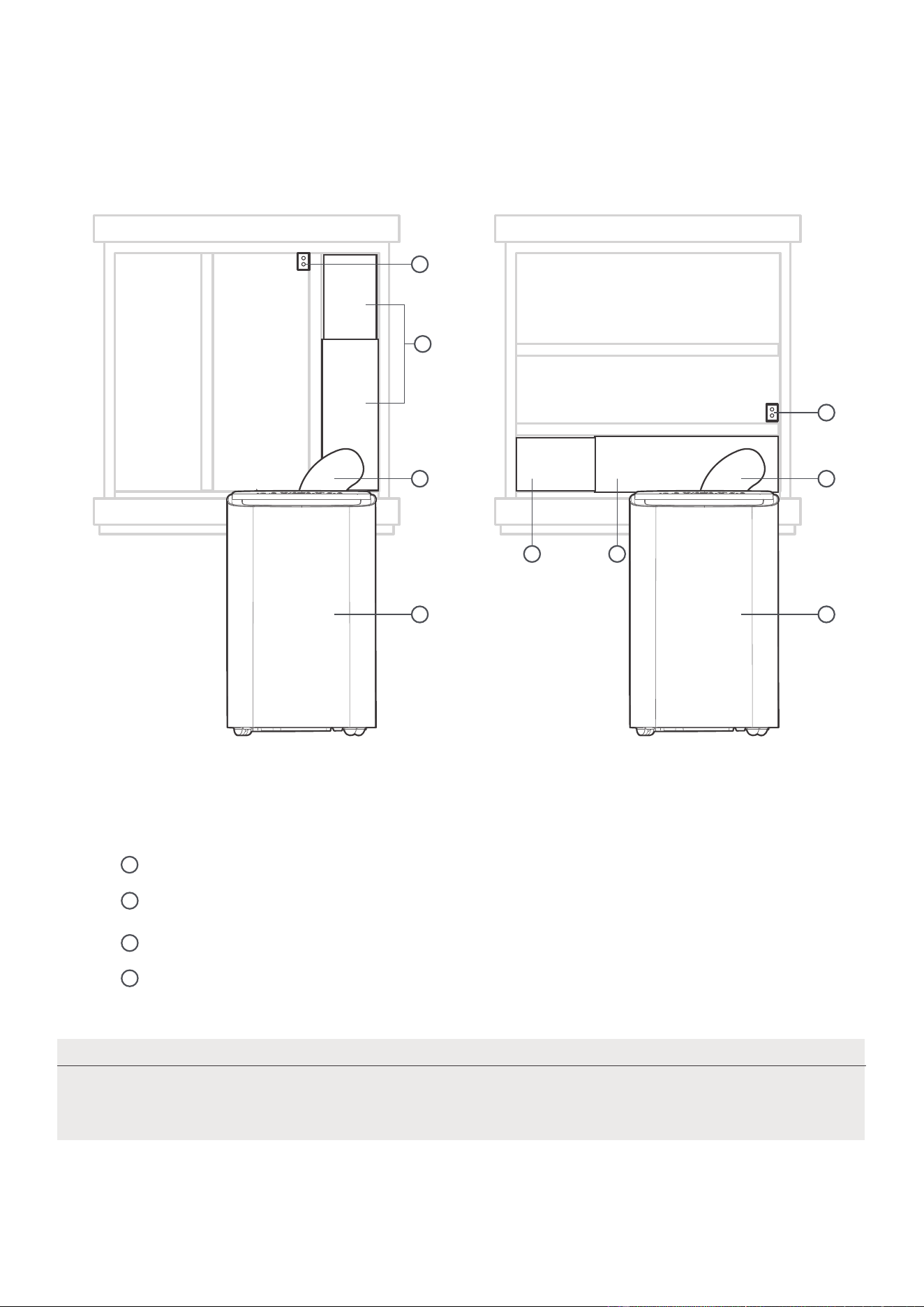
Vista general de la instalación
Installation Completion Display
Las ilustraciones de este manual tienen fines explicativos. La apariencia real de su
unidad interior puede ser ligeramente diferente. La apariencia real prevalecerá.
NOTA
1
4
2 2
1 1
4
3
3
Instalación de ventanas correderas Instalación de Ventanas Colgadas
Conjunto de deslizadores de ventanas
Manguera de escape extendida
Unidad de aire acondicionado
Soporte de seguridad y 2 tornillos
1
2
3
4
17
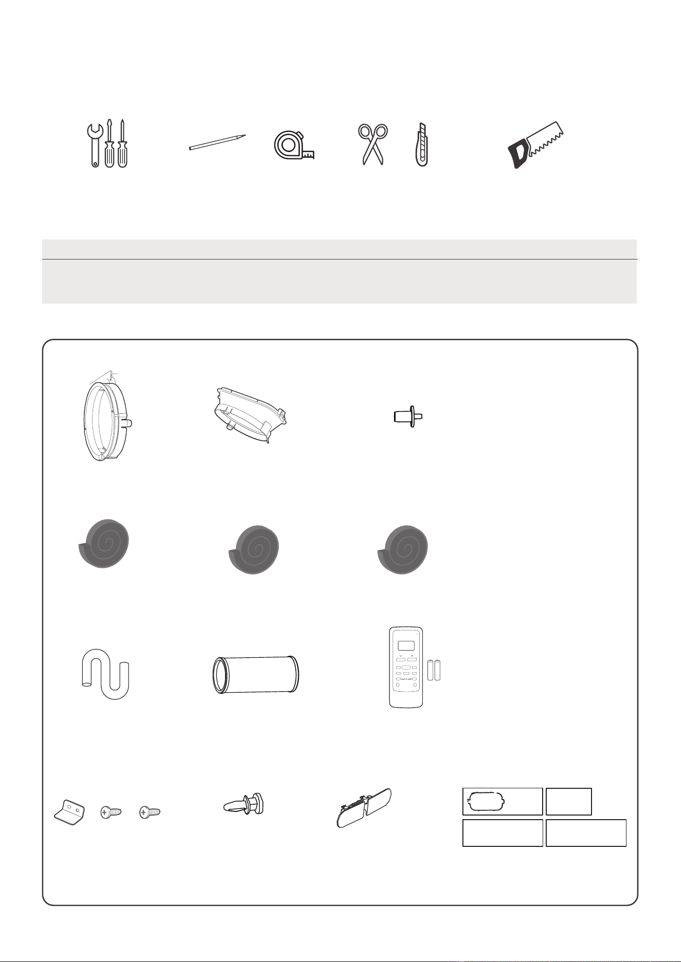
NOTA
Los elementos con (*) se encuentran en algunos modelos. Pueden producirse
ligeras variaciones en el diseño.
Adaptador de unidad
Manguera de escape (1 pc)
Cerradura de cable de
alimentación ( 1 pc)
Conducto de escape de
aire (1 ud.*)
1 set(*)Deslizador de ventana
Lista de herramientas de instalación
(no incluidas)
Destornillador y llave inglesa
Tijeras o cuchillo
Lápiz
Una cinta métrica
Sierra (En algunos modelos, para acortar
el adaptador para ventanas estrechas)
Accesorios de instalación
Junta de espuma B
(adhesiva) 2 uds.
Junta de espuma C (no
adhesiva) 2 uds. (*)
Junta de espuma A
(adhesiva) 4 uds. (*)
Manguera de drenaje
(1 ud.)
Control remoto y pila
(solo para modelos
con control remoto)
(1 juego*)
Soporte de seguridad y
2 tornillos (1 juego*)
Tornillo (3 ud.*)
drain hose adaptor
(for heat pump model only)
El kit de instalación de ventanas es adaptable a ventanas de 19,4"-62,2"(49,3-158,1 cm).
18
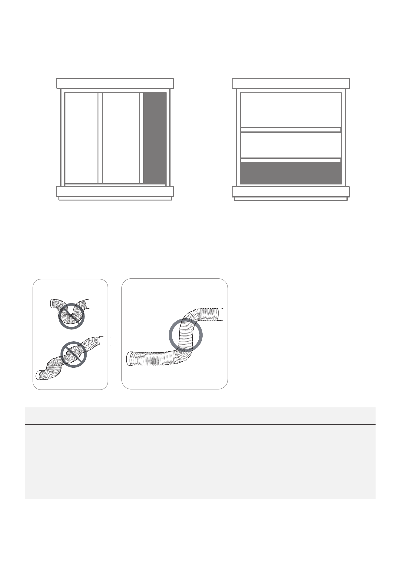
Confirme su tipo de ventana (tipo de
ventana y tamaño de apertura)
Instalación de ventanas correderas Instalación de Ventanas Colgadas
Para un funcionamiento óptimo
INCORRECTO
CORRECTO
NOTA:
Para garantizar un funcionamiento correcto, NO extienda ni doble excesivamente la
hay ningún obstáculo alrededor de la salida de aire
manguera de escape (en el rango de 500 mm) para que el sistema de escape
ilustraciones del manual son solo para fines
Su aire acondicionado puede ser ligeramente diferente. La apariencia
manguera. Asegúrese de que no
de la
funcione correctamente. Todas las
explicativos.
real prevalecerá.
19
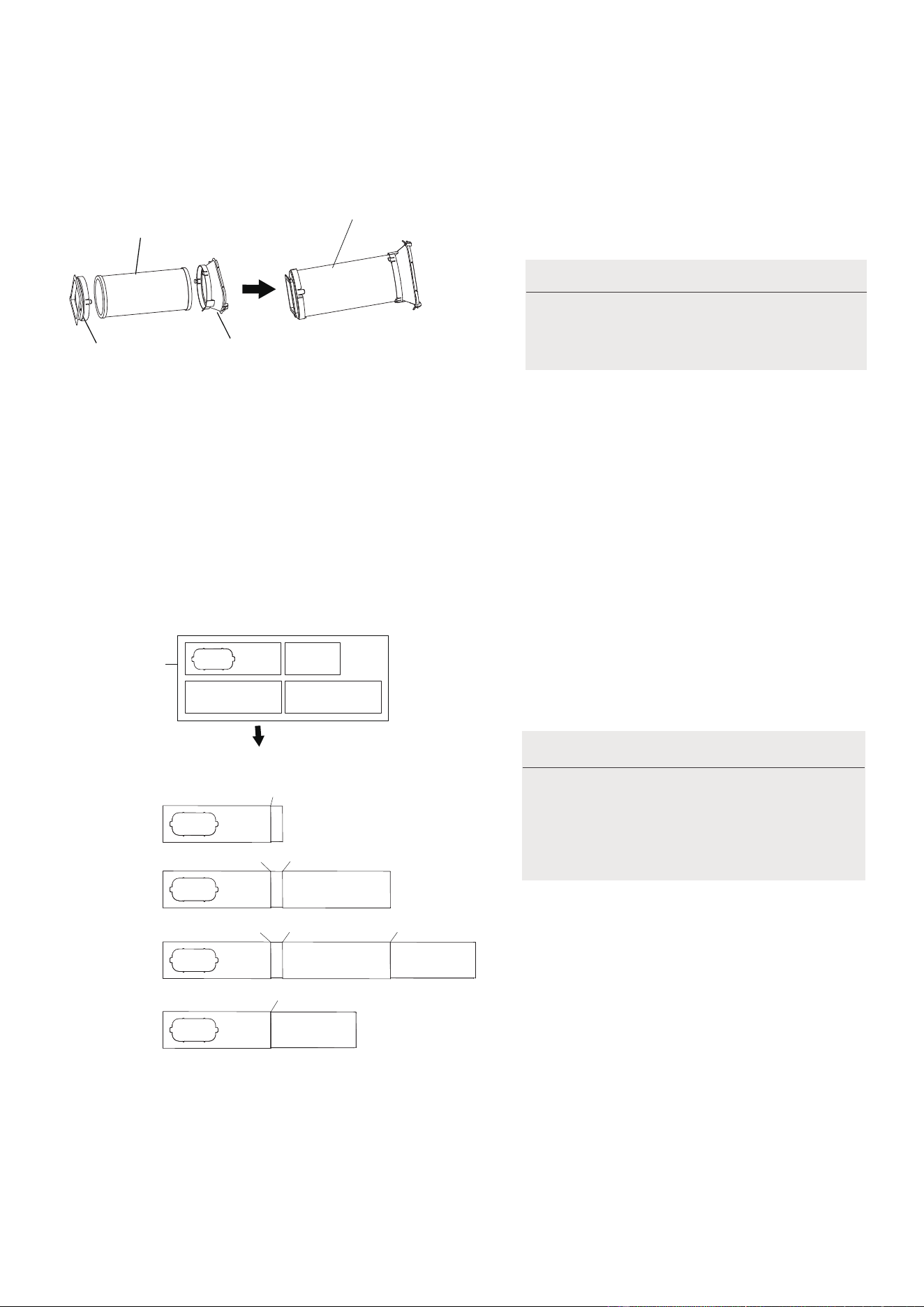
1.Instalación de la manguera de escape y adaptadores
Adaptador de
la unidad
Conducto de
escape de aire
Manguera de escape
Conjunto de manguera
de escape
NOTA:
su kit.
Presione la manguera de escape (o la
manguera de escape extendida) en
el adaptador deslizante de la ventana
y el adaptador de la unidad, sujete
automáticamente por las hebillas
elásticas de los adaptadores.
Instale el conjunto de la manguera
de escape de acuerdo con los
accesorios de
Preparación de la corredera ajustable de la ventana
Elija los deslizadores de ventana de acuerdo
con el tamaño de su ventana. A veces, es
necesario acortarlo para que se ajuste al
Utilice pernos para fijar los deslizadores de
ventana una vez que estén ajustados a la
longitud adecuada.
Por favor, base la instalación de su
deslizador de ventana en los
accesorios de su kit y en el ancho
de su ventana.
2.
NOTA:
1+2:
1+2+3:
1+2+3+4:
1+4:
Antes del montaje
Después del montaje
Adaptadores
deslizantes
Perno
Perno
Perno
Perno
Perno
Perno
Perno
tamaño de la ventana.
20
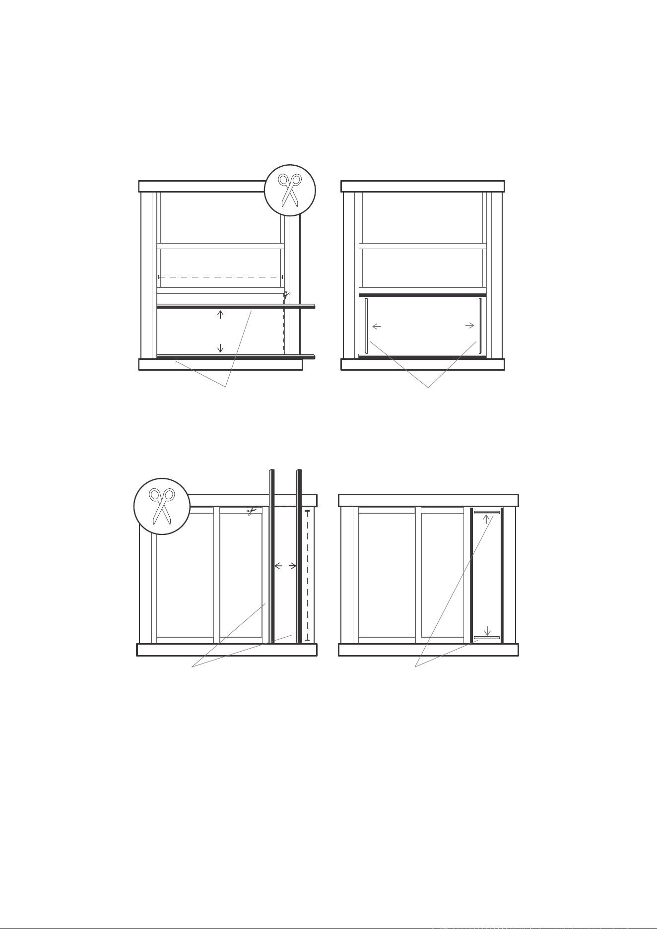
Junta de espuma A
(adhesiva)
Junta de espuma B
(adhesiva, más corta)
Instalación de Ventanas Colgadas
Junta de espuma A
(adhesiva)
Junta de espuma B
(adhesiva, más corta)
Instalación de ventanas correderas
3. Sellado completo de la ventana
Corte las tiras de junta de espuma adhesiva A y B a las longitudes adecuadas, y fíjelas a la hoja y al
marco de la ventana como se muestra.
21
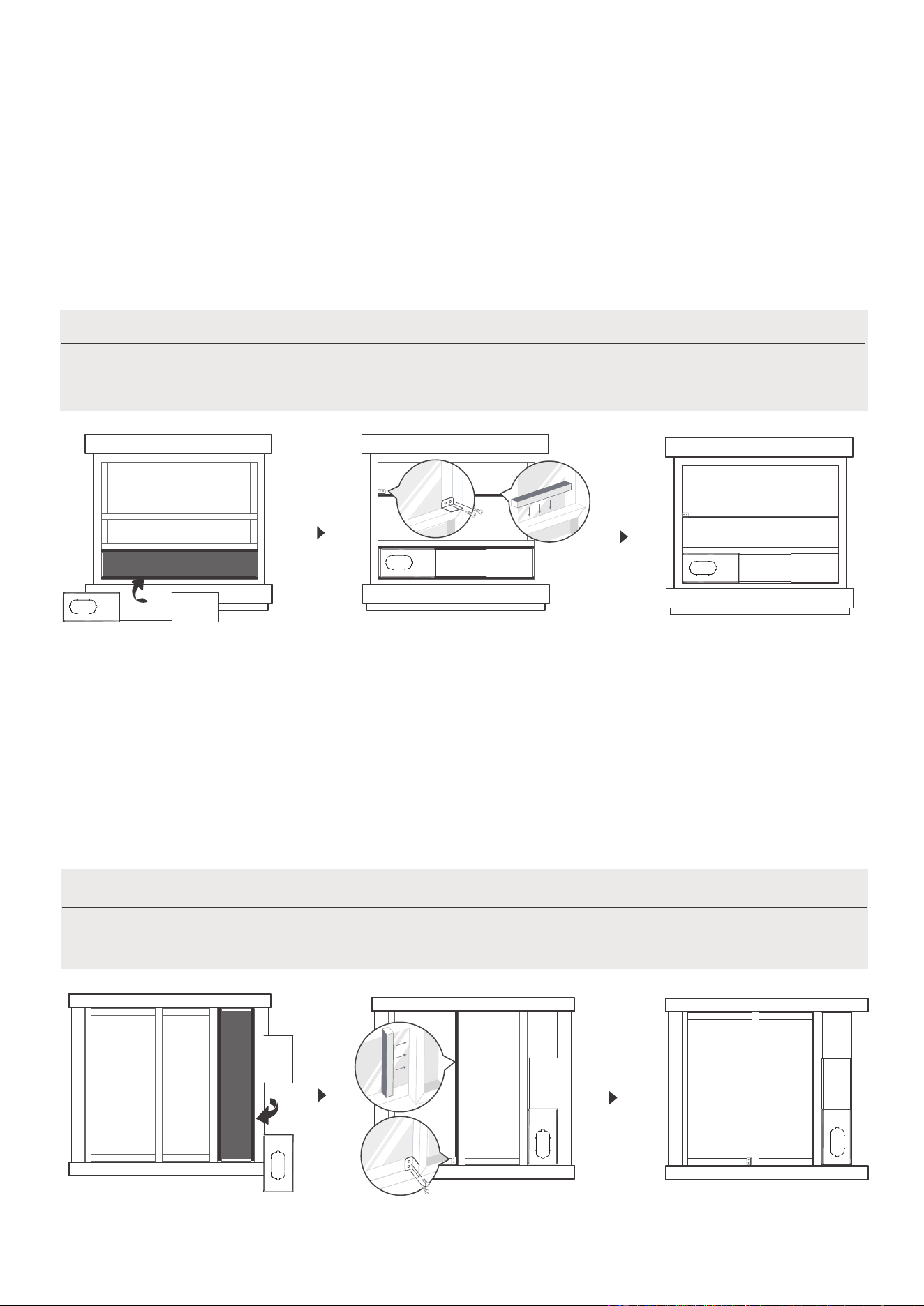
Paso 1:
Inserte el conjunto de la
corredera de la ventana en el
hueco de la ventana.
Paso 3:
Si lo desea, instale el soporte de
seguridad con 2 tornillos, tal como
se muestra.
Paso 2:
Corte la tira de espuma de sellado no adhesiva C para que coincida
con la anchura de la ventana. Introduzca la junta entre el cristal y el
marco de la ventana para evitar la entrada de aire e insectos en la
habitación.
Una vez preparados el conjunto de la manguera de escape y la corredera ajustable
de la ventana, elija uno de los dos métodos de instalación siguientes.
4. Instalación de Ventanas Colgadas
NOTA:
Paso 1:
Inserte el conjunto de la
corredera de la ventana en el
hueco de la ventana.
Paso 3:
Si lo desea, instale el soporte
de seguridad con 2 tornillos, tal
como se muestra.
Paso 2:
Corte la tira C de junta de espuma no adhesiva para que coincida con la
altura de la ventana. Introduzca la junta entre el cristal y el marco de la
ventana para evitar la entrada de aire e insectos en la habitación.
5. Instalación de ventanas correderas
Una vez preparados el conjunto de la manguera de escape y la corredera
ajustable de la ventana, elija uno de los dos métodos de instalación siguientes.
NOTA:
22
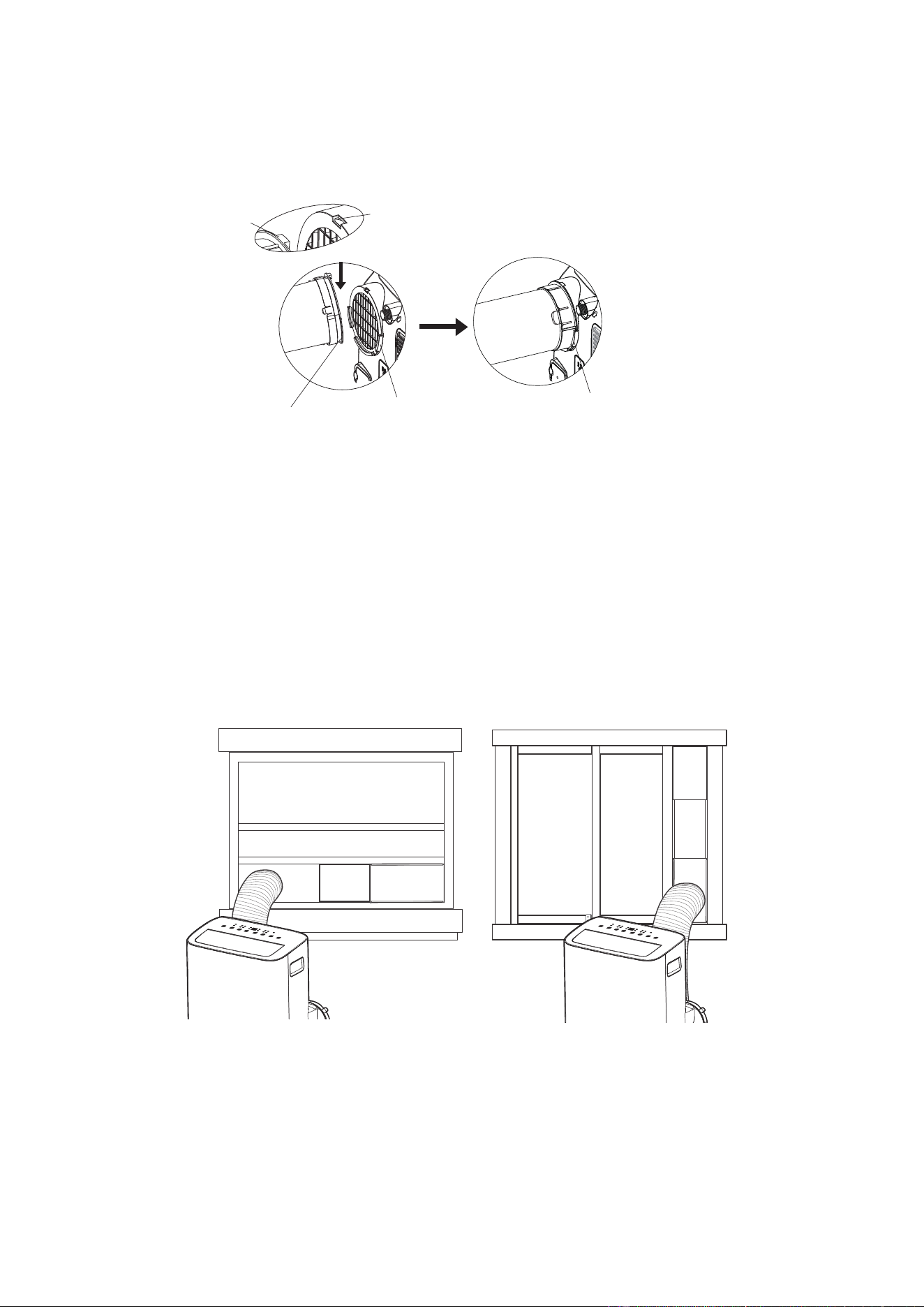
6. Instale el conjunto de la manguera de escape en la unidad
Introduzca la manguera de escape en la abertura de salida de aire de la unidad siguiendo la dirección de
7. Conecte el adaptador a la unidad y a la ventana
Inserte el adaptador de la ventana corredera en el orificio de la ventana corredera.
Gancho
Asiento en forma de gancho
Ranura inferior
adaptador
Asegúrese de que el SIM se
ha insertado en la ranura
inferior de la salida de aire.
la flecha.
Instalación de Ventanas Colgadas Instalación de ventanas correderas
23
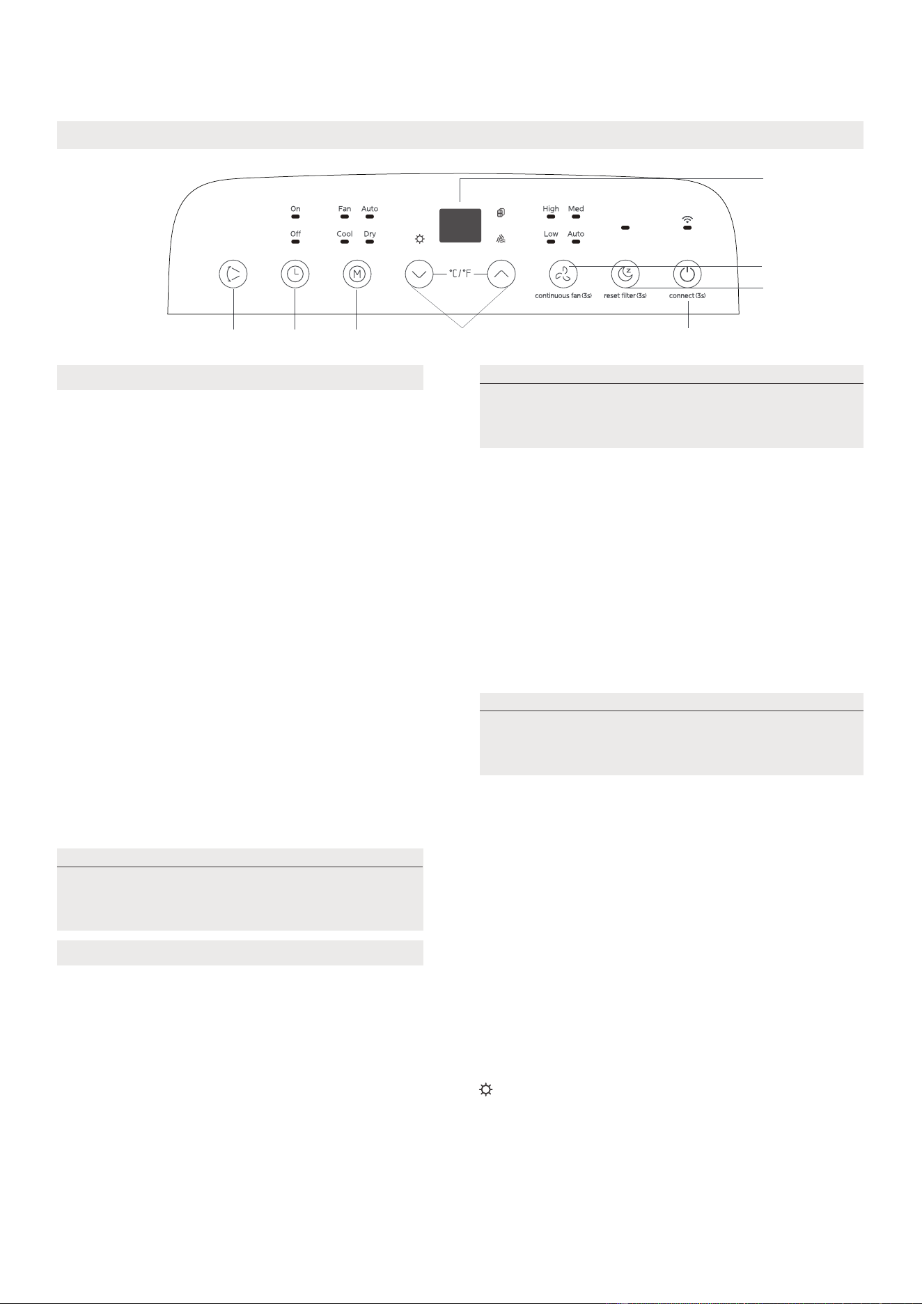
Conozca su aire acondicionado
Instrucciones de funcionamiento del control electrónico
1
7
8
2
56
4
3
Pulse el botón "MODE" hasta que se encienda
la luz indicadora "Dry". En este modo no es
posible ajustar la velocidad del ventilador ni la
temperatura. El motor del ventilador funciona a
velocidad automática.
El aire acondicionado controlará automáticamente
la temperatura ambiente para que se acerque al
punto de temperatura que ha establecido. En
modo automático, no puede seleccionar la
velocidad del ventilador.
COOL operation
Pulse el botón "MODE" hasta que se encienda la
luz indicadora "Cool".
Pulse los botones ADJUST "+" o "-"
elija la temperatura ambiente que desea The
temperature can be set within the range of
16 ° C to 30 ° C/60 ° F to 86 ° F.
The temperature can be set within the range of
16 ° C to 30 ° C/60 ° F to 86 ° F.
1. Botón POWER
2. Función MODE
Seleccione el modo de funcionamiento adecuado.
Cada vez que se presiona el botón, se selecciona
el modo en la secuencia AUTO (AUTOMÁTICO),
DRY (DESHUMIDIFICADOR), COOL (FRÍO), FAN
(VENTILADOR) y HEAT (sólo para modelos de
bomba de calor). La luz indicadora de modo se
ilumina bajo los diferentes indicadores de modo.
Interruptor de encendido y apagado.
Modo DRY
Modo AUTO
Modo COOL
Cuando establece el aire acondicionado en modo
automático,Seleccionará automáticamente la
refrigeración, la calefacción (solo se limita al modelo
frío, no al modelo de refrigeración) o solo el
funcionamiento del ventilador en función de la
temperatura y la temperatura ambiente que elija.
Modo FAN
• When in FAN mode, press the FAN button to
choose the fan speed. The temperature can
not be adjusted.
• No coloque el conducto de aire en la ventana.
Operación Heat(sólo para modelos de bomba
de calor)
• Presione el botón "modo" hasta que se encienda el
indicador "heat".
• Presione los botones Adjust (ajuste hacia arriba) y down
(ajuste hacia abajo) para seleccionar la temperatura
ambiente deseada. La temperatura se puede establecer
en un rango de 16 ° C - 30 ° C / 60 ° F - 86 ° F.
Mantenga las ventanas y puertas cerradas
para obtener el mejor efecto deshumidificador.
No coloque el conducto en la ventana.
Se utiliza para activar la función inalámbrica. La
primera vez que se utiliza la función inalámbrica,
Presione el botón POWER durante 3 segundos
para activar el modo de conexión inalámbrica.
La pantalla LED muestra "ap", lo que significa que
puede configurar una conexión inalámbrica. Si la
conexión (enrutador) tiene éxito en 8 minutos, el
dispositivo saldrá automáticamente del modo de
conexión inalámbrica y se encenderá el indicador
inalámbrico.
Si la conexión falla en 8 minutos, el dispositivo
saldrá automáticamente del modo de conexión
inalámbrica.
Después de que la conexión inalámbrica sea
exitosa, puede presionar los botones Swing y
down (-) durante 3 segundos al mismo tiempo
para activar la función inalámbrica, y la pantalla
LED muestra "de" durante 3 segundos.
Presione los botones POWER y up (+) al mismo
tiempo para activar la función inalámbrica, LED
Display muestra "on" (on) durante 3 segundos
NOTA
al reiniciar la función inalámbrica, puede
tardar un tiempo en conectarse
automáticamente a la red
NOTA
NOTA
en modo automático, se encienden los
indicadores de modo automático y modo de
operación real en algunos modelos.
24
3. Botones hacia arriba y hacia abajo
Para ajustar (aumentar / disminuir) la temperatura en incrementos de 1 ° C / 2 ° F (o 1 ° F) en un rango
de 16 ° C / 60 ° F a 30 ° C / 86 ° F.
El rango de configuración del tiempo es de 0 a 24 horas.
4. Pantalla
Muestra la temperatura ajustada mientras está en modo Frío, o Auto. Muestra la temperatura ambiente
en los modos DRY (DESHUMIDIFICADOR) y FAN (VENTILADOR).
Muestra los códigos de error:
• Presione el botón fan (ventilador) para seleccionar la velocidad del ventilador.
EH60-Error del sensor de temperatura ambiente
EH61-Error del sensor de temperatura del evaporador
EC52-Error del sensor de temperatura del condensador (en algunos modelos).
EH0b-Error de comunicación del panel de visualización.
ELOC-Mal funcionamiento de la detección de fugas de refrigerante (en algunos modelos).
P1-Bandeja inferior llena--Conecte la manguera de drenaje y drene el agua recogida.
Si la protección se repite, llame al servicio técnico
COMFORT SENSE
9. Otras características
8. SLEEP mode
Al presionar este botón, la temperatura seleccionada aumentará (enfriará) o bajará (calentará)
1 ° C / 2 ° F (o 1 ° F) durante 30 minutos. En otros 30 minutos, la temperatura volverá a subir (enfriarse) o bajar
(calentar) 1 ° C / 2 ° F (o 1 ° F). Esta nueva temperatura se mantendrá durante 7 horas y luego volverá a la
temperatura inicialmente seleccionada. Esto pondrá fin al modo de sueño / ahorro de energía y el dispositivo
seguirá funcionando como estaba programado inicialmente.
7. Función de ventilador continuo
En modo COOL (FRÍO) o DRY (DESHUMIDIFICADOR), pulse el botón Fan (Ventilador) durante
3 segundos para activar o desactivar la función de ventilador continuo. Cuando la función está
encendida, la luz del ventilador Cont. (Continuo) se iluminará, indicando que el ventilador funcionará de
forma continua. Cuando la función está desactivada, la luz del ventilador Cont. (Continuo) se apagará,
indicando que el ventilador se detendrá cuando el compresor se pare.
Nota: esta función no está disponible en modo fan (fan) o Dry (seco).
5.Botón del cronómetro
Junto con el botón + / - se utiliza para iniciar el programa Auto on START time y auto off Stop time. Bajo
la configuración de encendido / apagado del cronómetro, el cronómetro del indicador se enciende / enciende.
6. Modo Swing
Botón Swing / Wireless
Se utiliza para activar la función de rotación automática. Al abrir la operación, Presione el botón Swing
para detener las persianas en el ángulo deseado.
Cuando se produzca una de las fallas anteriores, apague la unidad y verifique que no haya
obstrucciones. Si la falla persiste, apague la unidad y desenchufe el cable de alimentación. Póngase en
contacto con el fabricante o con el centro de servicio técnico o una persona calificada similar.
Esta función solamente puede activarse desde el control remoto. No hay indicador luminoso en el panel
de control. El control remoto hace las veces de termostato remoto, lo que permite controlar con precisión
la temperatura en su ubicación. Para activar la función Comfort Sense, apunte con el mando a distancia
hacia la unidad y pulse el botón Comfort Sense. El mando a distancia enviará esta señal al aparato hasta
que vuelva a pulsar el botón Comfort Sense. Si la unidad no recibe la señal de seguimiento de temperatura
durante un intervalo de 7 minutos, la unidad saldrá del modo de seguimiento de temperatura.
NOTA: Esta función no está disponible en los modos FAN (VENTILADOR) o DRY (DESHUMIDIFICADOR).
NOTA
NOTA
NOTA
Sólo para modelos de bomba de calor, la velocidad del ventilador no se puede ajustar en modo heat.
el control puede mostrar la temperatura en grados Fahrenheit o centígrados. Para pasar de uno a otro,
presione y mantenga los botones hacia arriba y hacia abajo durante 3 segundos al mismo tiempo.
25
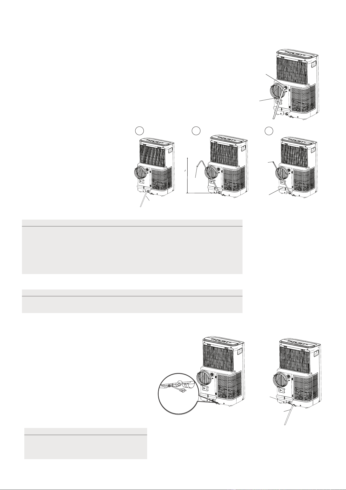
Guía de drenaje
Durante los modos de deshumidificación, retire el tapón de drenaje de la
parte posterior de la unidad, instale el conector de drenaje (5/8" hembra
universal) con una manguera de 3/4" (adquirida localmente). Para los
modelos sin conector de drenaje, simplemente conecte la manguera
de drenaje al orificio. Coloque el extremo abierto de la manguera
directamente sobre la zona de desagüe del suelo del sótano.
Mueva cuidadosamente el dispositivo a la posición de drenaje para que el
agua se descargue.
Cuando el nivel de agua de la bandeja
inferior alcanza un nivel predeterminado,
la unidad emite 8 pitidos, el área de
visualización digital muestra "P1". En este
momento, el proceso de aire acondicionado/
deshumidificación se detendrá inmediatamente.
Sin embargo, el motor del ventilador
continuará funcionando (esto es normal).
Mueva con cuidado la unidad a un lugar
de drenaje, retire el tapón de drenaje
inferior y deje que el agua se drene.
Vuelva a colocar el tapón de drenaje
inferior y reinicie la máquina hasta que
desaparezca el símbolo "P1". Si el error
persiste, póngase en contacto con el
servicio técnico.
Durante los modos de Bomba
de calefacción, retire el Reducir
de drenaje de la parte posterior
de la unidad, instale el conector
de drenaje (5/8" hembra universal)
con una manguera de 3/4" (adquirida
localmente). Para los modelos sin
conector de drenaje, simplemente
conecte la manguera de drenaje
al orificio. Coloque el extremo
abierto de la manguera directamente
sobre la zona de desagüe del suelo
del sótano
Mangueras
de drenaje
continuo
Mangueras
de drenaje
continuo
Retire el
tapón de
drenaje
Retire el
tapón de
drenaje
Mangueras de
drenaje continuo
Conector
de mangueras
de drenaje
√√
delivery lift <1.8m
X
Conector de
mangueras
de drenaje
Presione la cerradura
del cable de alimentación
en la tapa trasera.
NOTA:
Nota:
Asegúrese de que la manguera esté segura para que no haya
fugas. Dirija la manguera hacia el desagüe, asegurándose de que no
haya dobleces que detengan el flujo de agua. Coloque el extremo de la
manguera en el desagüe y asegúrese de que el extremo de la manguera
esté hacia abajo para que el agua fluya suavemente. Cuando no se
utilice la manguera de drenaje continuo, asegúrese de que el tapón y el
pomo de drenaje están instalados firmemente para evitar fugas.
Asegúrese de volver a instalar firmemente
el tapón de drenaje inferior para evitar
fugas antes de utilizar la unidad.
NOTA:
asegúrese de que la manguera de drenaje esté por debajo del drenaje de la
bandeja inferior.
26
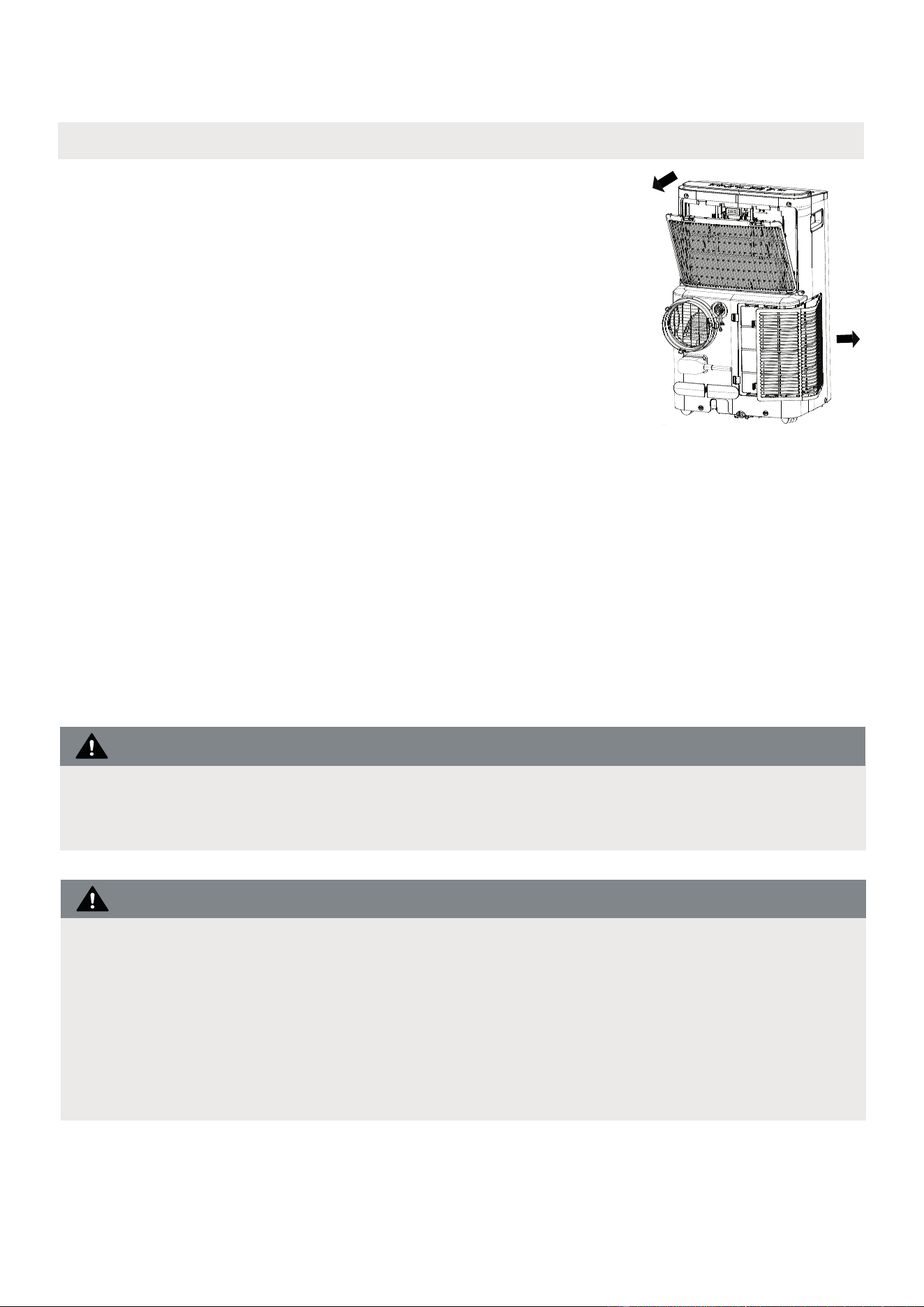
Cómo limpiar y mantener su aire acondicionado.
Limpieza y mantenimiento
Limpieza del filtro de aire y de la carcasa
· Desenchufe siempre la unidad antes de limpiarla o repararla.
· NO utilice líquidos inflamables o productos químicos para limpiar la unidad.
· NO lave la unidad con agua corriente. De lo contrario, podría producirse un
cortocircuito.
· NO utilice la máquina si la fuente de alimentación se ha dañado durante la limpieza.
Un cable de alimentación dañado debe reemplazarse por un cable nuevo del
fabricante.
NO haga funcionar la unidad sin filtro porque la suciedad y la pelusa lo obstruirán
y reducirán su rendimiento.
Retire el filtro de aire
PRECAUCIÓN:
PRECAUCIÓN:
Limpie la unidad con un paño húmedo sin pelusas y
detergente suave. Seque la unidad con un paño seco
sin pelusas.
• Retire el filtro en la dirección de la flecha.
• Sumerja suavemente el filtro de aire en agua tibia
(unos 40 ° C / 104 ° f) con un detergente neutro
para limpiar.
• Instale el filtro de aire después de limpiar.
Asegúrese de limpiar el filtro de aire cada 2 semanas para un rendimiento óptimo.
· La bandeja de recogida de agua debe vaciarse inmediatamente después de
que se produzca el error P1 y antes de guardarla para evitar la formación de
moho.
· En los hogares con animales, tendrá que limpiar periódicamente la rejilla
para evitar el bloqueo del flujo de aire debido al pelo de los animales.
• Enjuague el filtro y seque a la sombra.
27
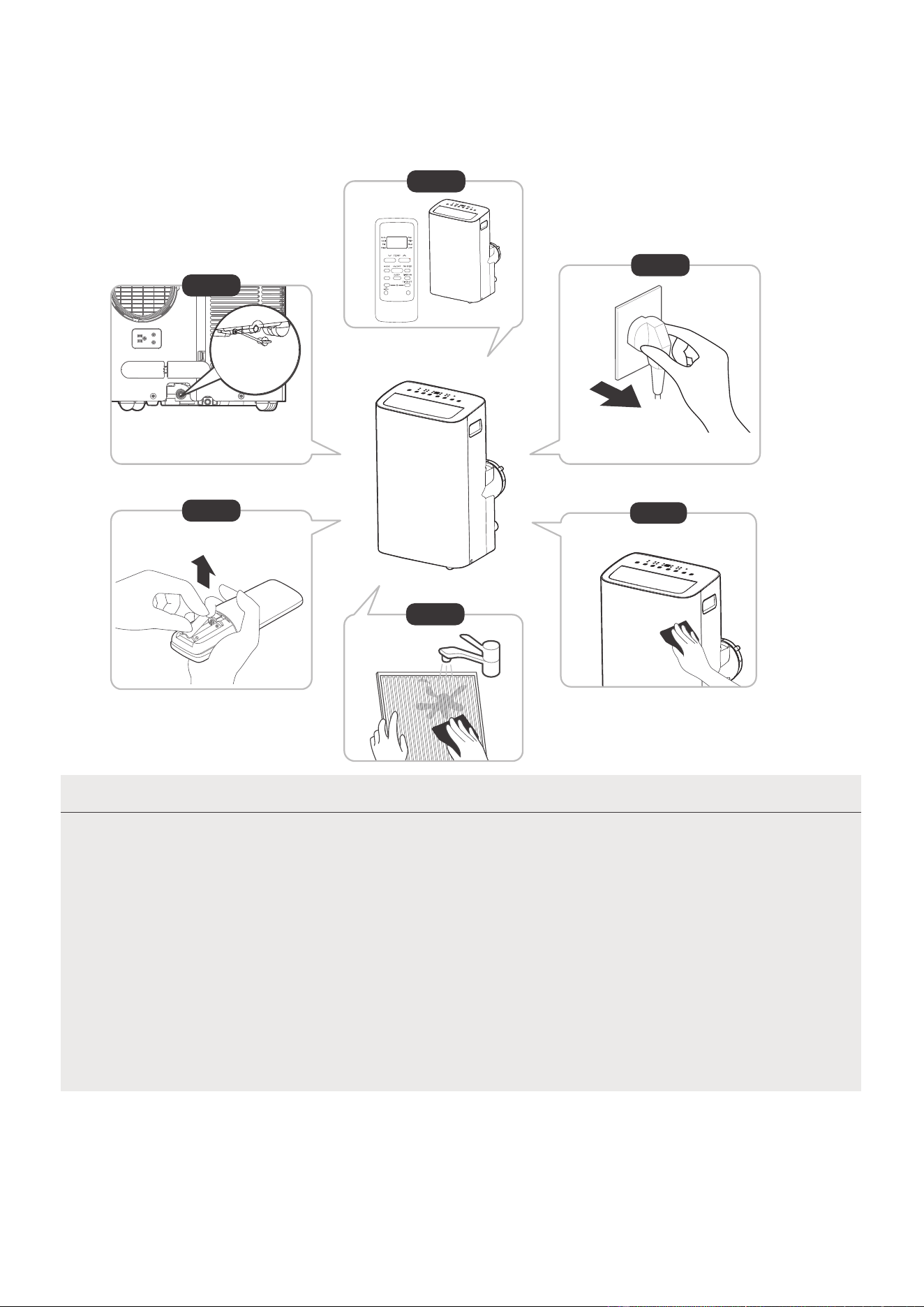
NOTA
12horas
Paso 6
Paso 3
Paso 1
Paso 2
Paso 5
Guarde la unidad cuando no la utilice
*Por favor, consulte el
enchufe real, y la leyenda es
sólo para referencia.
*Vacíe la bandeja de recogida de
agua de la unidad y vuelva a colocar
el tapón de vaciado inferior.
· Asegúrese de guardar la unidad en un lugar fresco y oscuro. La exposición
directa al sol o al calor extremo puede acortar la vida útil de la unidad.
· El gabinete y el frente pueden limpiarse con un paño libre de aceite o lavarse
con un paño humedecido en una solución de agua tibia y detergente para
platos suave. Enjuagar bien y secar con un paño.
No utilice nunca limpiadores abrasivos, cera ni abrillantadores en la parte
frontal del gabinete.
Asegúrese de escurrir el exceso de agua del paño antes de limpiar alrededor
de los controles.
El exceso de agua en los controles o alrededor de ellos puede causar daños a
la unidad.
· Vacíe la bandeja de recolección de agua de la unidad de acuerdo con las instrucciones de la siguiente sección.
· Haga funcionar el aparato en modo FAN (VENTILADOR) durante 12 horas en una habitación cálida
para secarlo y evitar la formación de moho.
· Apague el aparato y desenchúfelo.
· Limpie el filtro de aire según las instrucciones de la sección anterior. Vuelva a instalar el filtro limpio y
seco antes de guardarlo.
· Retire las pilas del mando a distancia.
Paso 4
SWING
C-SENSE
°C/°F
28
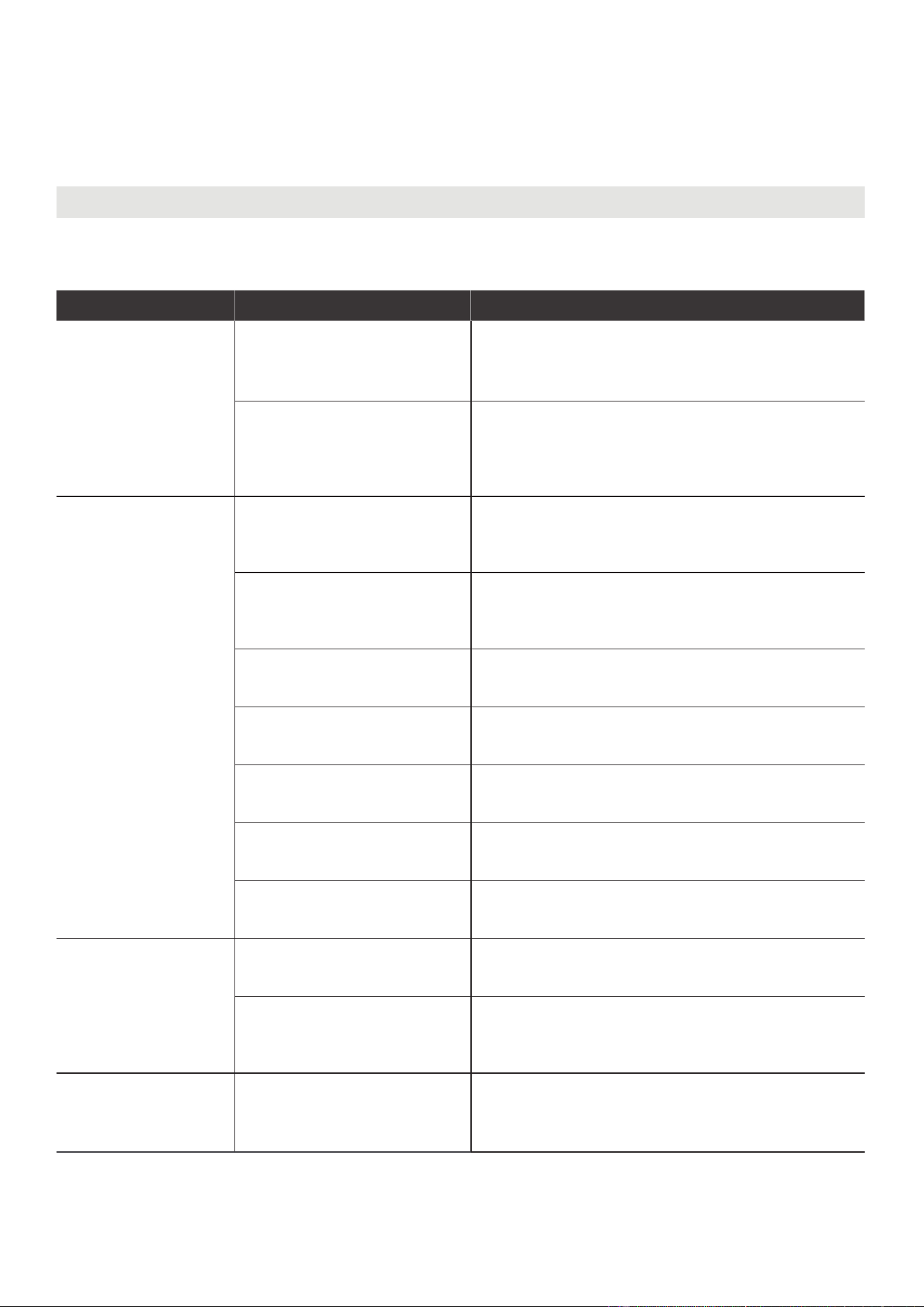
RESOLUCIÓN DE PROBLEMAS
Resolución de problemas
Problemas comunes
Los siguientes problemas no significan un mal funcionamiento y en la mayoría de los casos no
requieren reparación.
Problema Posible Causas Solución
La unidad no
se enciende
al presionar el
botón ON/OFF
(ENCENDIDO/
APAGADO)
P1 Código de protección
La bandeja de recolección de agua está llena.
Apague la unidad, drene el agua de la bandeja
de recolección de agua y reinicie la unidad.
En modo COOL (FRÍO): la
temperatura ambiente es
inferior a la temperatura
programada.
Reinicie la temperatura
La unidad no enfría
bien
El filtro de aire está
obstruido con polvo o con
pelos de animales
Apague el aparato y limpie el filtro siguiendo las
instrucciones
La manguera de escape
no está conectada o está
obstruida
Apague la unidad, desconecte la manguera,
compruebe si hay obstrucciones y vuelva a
conectar la manguera
La unidad tiene poco
refrigerante
Llame al servicio técnico para que examine la
unidad y añada refrigerante
La temperatura es
demasiado alta
Baje la temperatura programada
Las ventanas y puertas de la
habitación están abiertas
Asegúrese de que todas las ventanas y puertas
estén cerradas
La habitación es demasiado
grande
Controle el área de refrigeración
Hay fuentes de calor dentro
de la habitación
Si es posible, retire las fuentes de calor
La unidad es
ruidosa y vibra
demasiado
El suelo no está nivelado
Coloque la unidad sobre una superficie plana y
nivelada
El filtro de aire está
obstruido con polvo o con
pelos de animales
Apague el aparato y limpie el filtro siguiendo las
instrucciones
La unidad emite un
sonido de gorgoteo
Este sonido es causado
por el flujo de refrigerante
dentro de la unidad
Esto es normal
29
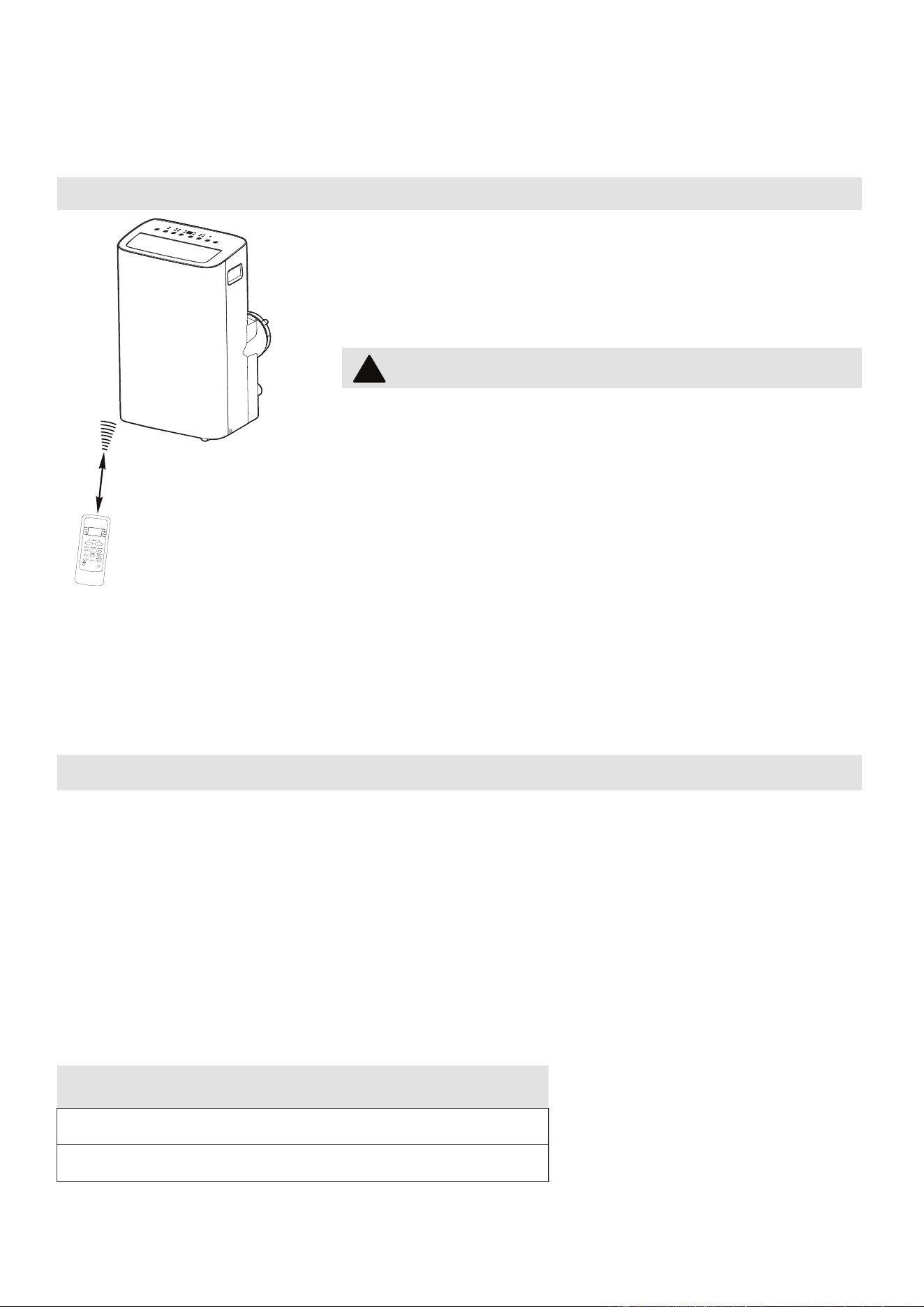
INSTRUCCIONES DEL CONTROL
REMOTO Y APLICACIÓN
Especificaciones del control remoto
Voltaje nominal: 3.0V (baterías secas R03/LR03x2)
Ambiente: 23°F ~140°F (-5°~60°)
Ubicacióndelcontrolremoto
Utilice el control remoto a distancia a una distancia de
26.2 ft (8 metros) del acondicionador de aire, apuntando
hacia el receptor. La recepción se confirma con un pitido.
Manejo del Control Remoto
PRECAUCIÓN
26.2 ft (8 metros)
AVISO
•
El diseño del botón se basa en el modelo típico y puede variar ligeramente del
real que compró.
•
Todas las funciones descritas son realizadas por la unidad. Si la unidad no tiene
una función, la unidad no responderá si se presiona el botón correspondiente en
el control remoto.
•
Cuando existan diferencias significativas entre las características u operaciones
implícitas en la ilustración del control remoto y las funciones reales descritas
en el MANUAL DEL USUARIO, prevalecerán las descripciones en el MANUAL
DEL USUARIO.
• El acondicionador de aire no funcionará si las
cortinas, puertas u otros materiales bloquean las
señales del control remoto a la unidad.
• Evite que cualquier líquido se derrame sobre el
mando a distancia. No exponga el mando a distancia
a la luz solar directa ni al calor.
• Si el receptor de señal infrarroja de la unidad interior
está expuesto a la luz solar directa, es posible que el
a
condicionador de aire no funcione correctamente.
Utilice cortinas para evitar que la luz del sol caiga
sobre el receptor.
• Si otros aparatos eléctricos reaccionan al control
remoto, mueva estos aparatos o consulte a su
distribuidor local.
SWING
C-SENSE
°C/°F
30
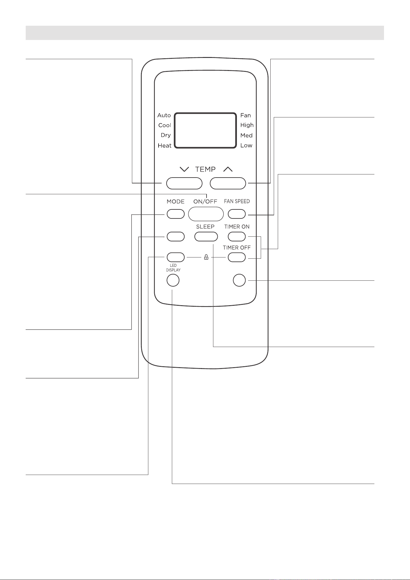
SWING
C-SENSE
°C/°F
Función de los Botones
Botón TEMP DOWN
Pulse este botón para
reducir la configuración
de la temperatura interior.
Botón TEMP UP
Pulse este botón para
aumentar la configuración
de la temperatura interior.
Botón FAN SPEED
Pulse este botón para
seleccionar la velocidad
deseada del ventilador.
Botón TIMER
Pulse este botón para
activar el programa
“Inicio Automático”
(Auto Start) o “Parada
Automática” (Auto Stop).
Botón SLEEP
Pulse este botón para
activar el modo de
Suspensión. Esta función
solo está disponible en
modo COOL o AUTO y
mantendrá la temperatura
más cómoda p
ara usted
mientras ahorra energía.
Para obtener más
información, consulte la
función “Sueño” (sleep)
en la página 25.
Botón °C/°F
Pulse este botón para
cambiar la visualización
de temperatura entre
Celsius y Fahrenheit.
Botón °C/°F.
Botón ON/OFF
La unidad se enciende
cuando se pulsa este
botón y se apaga cuando
pulsarlo nuevamente.
Botón MODE
Pulse este botón para
seleccionar el modo de
operación deseado.
Botón SWING
Presione este botón para
iniciar y detener el movimiento
de la rejilla horizontal.
Mantenga presionado dur
ante
2 segundos para iniciar la
función de oscilación
automática de la rejilla vertical
(algunas unidades).
Botón COMFORTSENSE
Pulse este botón para activar
el modo Comfort Sense, para
optimizar la temperatura a
su alrededor y garantizar la
máxima comodidad.
Botón LED DISPLAY
Enciende apaga la
pantalla LED de la unidad.
NOTA: Si la unidad tiene la
función ENERGY SAVER,
iniciará automáticamente
la función de ahorro de
energía en los modos
Cool, Dry y Auto (solo
Auto-Cooling y Auto-Fan).
31
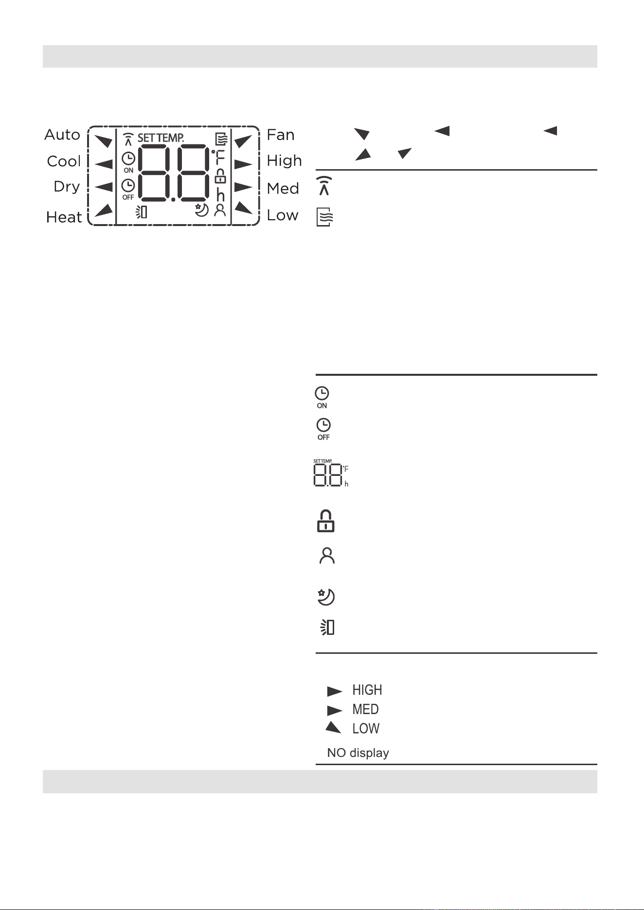
Indicatores del Visor del Control Remoto
La información se muestra cuando se enciende el control remoto.
Se muestra cuando se transmiten los datos.
Se muestra cuando el control remoto está
habilitado y puede enviar una señal a la
unidad. Si desea apagar el control remoto
sin afectar la unidad, apunte el control
remoto lejos de la unidad y presione el
botón ON/OFF. Para encender el control
remoto, apunte el control remoto lejos de
la u
nidad y presione el botón ON/OFF.
La unidad no recibirá comandos del control
remoto si este indicador no está iluminado.
Se muestra cuando el TIMER ON es
ajustado.
Se muestra cuando el TIMER OFF es
ajustado.
Muestra la temperatura establecida o la
temperatura ambiente, o el tiempo en la
configuración del TIMER.
Indica que todos los ajustes actuales
están bloqueados.
Aparece cuando la función Comfort Sense
está activada
Se muestr
a cuando la función SLEEP es
activada.
Auto
Cool
Fan
Dry
Mode display
Alta Velocidad
Media Velocidad
Baja Velocidad
Velocidad Automática
Todos los indicadores que se muestran en la figura tienen el propósito de una
presentación
clara. Pero durante la operación, solo los ícones de función se muestran en el visor.
AVISO
Indicación de la Velocidad del Ventilador
Pantalla oscilante de lamas horizontales
Heat
32
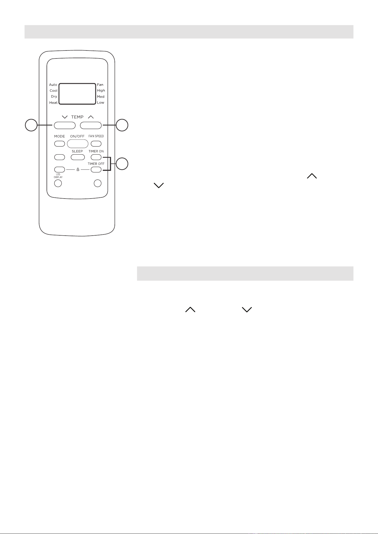
Cómo Usar los Botones
FUNCIÓN DEL TEMPORIZADOR (TIMER)
Pulse el botón TIMER para iniciar el programa de ajuste
de inicio automático y de parada automática de la unidad.
To set the Auto-start/stop time.
1. Pulse el botón TIMER. Cuando el indicador TIMER
ON aparecer en el visor LED del acondicionador de
aire, indica que se ha iniciado el programa de ajuste
de inicio automático. Cuando el indicador TIMER
OFF aparecer en el visor LED del acondicionador de
aire, indica que se ha iniciado el programa de aju
ste
de parada automática.
2.
Mantenga pulsado los botones TEMP UP ( )/DOWN
( ) para cambiar la hora automática. El control
contará el tiempo restante hasta el inicio/parada.
3. El tiempo seleccionado se registrará en 5 segundos y
el acondicionador de aire volverá automáticamente a
mostrar el ajuste de temperatura anterior.
4. Encender o apagar la unidad en cualquier momento,
cancelará la función de inicio/parada automática.
NOTICE
Para cancelar el ajuste TIMER, pulse el botón TIMER y,
a continuación, pulse o mantenga pulsado los botones
TEMP UP ( ) / DOWN ( ) hasta que aparezca 0
horas en el visor LED del acondicionador de aire.
SWING
C-SENSE
°C/°F
2 2
1
33
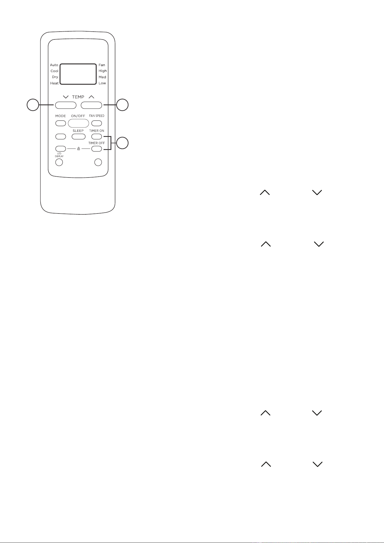
TEMPORIZADOR (TIMER) COMBINADO
(Ajuste simultáneo de los temporizadores ON y OFF)
PARADA AUTOMÁTICA > INICIO AUTOMÁTICO (AUTO
STOP >AUTO START)
(Activado > Detener > Iniciar operación)
Esta función es útil cuando desea detener el
acondicionador de aire después de acostarse, y volver
a encenderlo por la mañana cuando se despierta o
cuando regresa a casa.
Ejemplo:
Para detener el acondicionador de aire 2 horas después de
la configuración y volver a encenderlo 10 horas después de
la configuración.
1. Pulse el botón TIMER hasta que muestre TIMER OFF
en el indicador LED del acondicionador de aire.
2. Utilice los botones TEMP UP ( )/DOWN ( ) hasta
mostrar “2.0” en el indicador LED del acondicionador
de aire.
3. Presione el botón TIMER nuevamente para mostrar el
TIMER OFF en el LED de la unidad.
4. Utilice los botones TEMP UP ( )/DOWN ( ) hasta
mostrar “10” en el indicador LED del acondicionador de
aire.
5. Espere 5 segundos hasta que aparezca la visualización
anterior en el LED.
INICIO AUTOMÁTICO > PARADA AUTOMÁTICA (AUTO
START > AUTO STOP)
(Desactivado > Iniciar > Detener operación)
Esta función es útil cuando se desea encender el
acondicionador de aire antes de despertar y detenerlo
después de que se sale de la casa.
Ejemplo:
Para iniciar el acondicionador de aire 5 horas después
de la configuración, y detenerlo 8 horas después de la
configuración.
1. Pulse el botón TIMER hasta que muestre TIMER ON en
el indicador LED del acondicionador de aire.
2. Utilice los botones TEMP UP ( )/DOWN ( ) hasta
mostrar “5.0” en el indicador LED del acondicionador
de aire.
3. Presione el botón TIMER nuevamente para mostrar el
TIMER OFF en el LED de la unidad.
4. Utilice los botones TEMP UP ( )/DOWN ( ) hasta
mostrar “8.0” en el indicador LED del acondicionador
de aire.
5. Espere 5 segundos hasta que aparezca la visualización
anterior en el LED.
2 2
1
SWING
C-SENSE
°C/°F
34

NOTES
• El diseño del botón se basa en un modelo típico y puede variar ligeramente del real
que compró.
• Este dispositivo cumple con laparte 15 de las Reglas de la FCC. El funcionamiento
está sujeto a las dos condiciones siguientes: (1) Este dispositivo no puede causar
interferencias perjudiciales, y (2) este dispositivo debe aceptar cualquier
interferencia recibida, incluidas las interferencias que puedan causar un
funcionamiento no deseado.
• Este equipo ha sido probado y se encontró que cumple con los límites para un
dispositivo digital de Clase B, de acuerdo con la parte 15 de las Reglas de la FCC.
Estos límites están diseñados para proporcionar una protección razonable contra
interferencias dañinas en una instalación residencial. Este equipo genera, usa y
puede irradiar energía de radiofrecuencia y, si no se instala y usa de acuerdo con
las instrucciones, puede causar interferencia dañina a las comunicaciones de radio.
Sin embargo, no hay garantía de que la interferencia no ocurra en una instalación
en particular. Si este equipo causa interferencias perjudiciales para la recepción de
radio o televisión, lo cual puede determinarse encendiendo y apagando el equipo,
se recomienda al usuario que intente corregir la interferencia mediante una o más
de las siguientes medidas:
- Reorientar o reubicar la antena receptora.
- Aumente la separación entre el equipo y el receptor.
- Conecte el equipo a una toma de corriente en un circuito diferente al que está
conectado el receptor.
- Consulte con el distribuidor o un técnico experimentado en radio / TV para
obtener ayuda.
- Los cambios o modificaciones no aprobados por la parte responsable del
cumplimiento pueden anular la autoridad de los usuarios para operar el equipo.
Advertencia de batería:
No mezcle pilas nuevas y viejas y no mezcle pilas alcalinas, estándar
(carbono-zinc) o recargables (ni-cad, ni-mh, etc.)
Declaración de conformidad del proveedor
47 CFR § 2.1077 Información sobre el cumplimiento
Identificador únic
o:Midea brand,RG51F2(2)/CEFU1, RG51F2(2)/EFU1
Parte responsable Información de contacto de los Estados Unidos
Midea America Corporation
300 Kimball Dr
Parsippany NJ
07054
Este dispositivo cumple con la Parte 15 de las Normas de la FCC. La operación
está sujeta a las siguientes dos condiciones: (1)Este dispositivo no puede
causar interferencias perjudiciales,y (2)este dispositivo debe aceptar
cualquier interferencia recibida, incluida la interferencia que pueda provocar
un funcionamiento no deseado.
Número de teléfono o información de contacto en Internet
:Midea.com/us
Declaración de cumplimiento de la FCC(productos sujetos a la Parte 15)
35

Dispositivos necesarios para utilizar el Acondicionadordeaireinteligente:
1. Smartphone con sistema iOS o Android compatible.
2. Router inalámbrico
3. Acondicionador de aire Inteligente
VISIÓN GENERAL DEL SISTEMA
Declaramos que este Acondicionador de Aire cumple los requisitos esenciales y otras
disposiciones pertinentes de la Directiva 1999/5/CE.
1. Soporte para los sistemas operativos: iOS 10+ or Android 5+.
2. En el caso de una actualización del sistema operativo, puede haber un retraso entre
la actualización del sistema operativo y una actualización de software durante la cual
su sistema operativo puede o no ser compatible hasta que una nueva versión sea
lanzada. Su teléfono móvil específico o problemas en su red puede
n impedir que el
sistema funcione y Midea no será responsable de ningún problema que pueda ser
causado por incompatibilidad o problemas de red.
3. Este acondicionador de aire inteligente solo permite el cifrado WPA-PSK/WPA2-PSK
(recomendado).
4
. Para garantizar el escaneo adecuado del código QR, su smart phone debe tener al
menos una cámara de 5 megapíxeles.
5. Debido a la conectividad de red inestable, las solicitudes pueden agotar el tiempo de
espera. Si esto sucede, vuelva a ejecutar la configuración de red.
6. Debido a la conectividad de red inestable, los comandos pueden agotar el tiempo
de espera. Si esto sucede, la aplicación del Smartphone y el producto actual
pueden presentar información conflictiva. La información presentada en el producto
actual es siempre la más precisa disponible. Actualice la aplicación para volver a
sincronizarla.
Midea no será responsable de ningún problema que pueda ser causado por
incompatibilidad o problemas de red, su router inalámbrico y teléfono móvil.
AVISO
DECLARACIÓN DE CONFORMIDAD
PRECAUCIONES
36
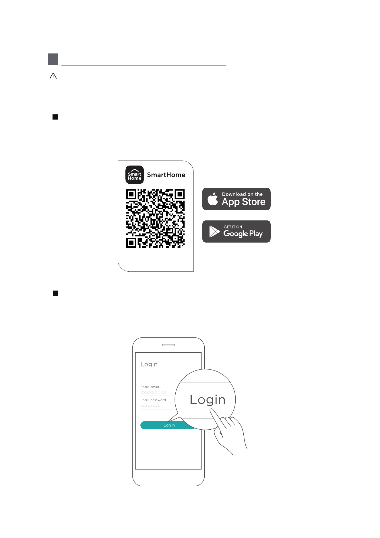
1
Cómo usar la aplicación SmartHome
Asegúrese de que su Smartphone esté conectado a su router inalámbrico y
que su router inalámbrico tenga una conexión a Internet de 2,4 GHz. El
Bluetooth debe estar encendido. El dispositivo también debe estar encendido.
Escanee el código QR a continuación para descargar la aplicación SmartHome
desde la tienda de aplicaciones o búsquela directamente en Google Play Store
o Apple's App Store.
Paso 1: Descargue la aplicación SmartHome
Abra la aplicación SmartHome. Inicie sesión directamente si tiene una cuenta
existente de SmartHome o cree una nueva cuenta. Alternativamente, también
puedes usar una plataforma de inicio de sesión de terceros.
Paso 2: Iniciar sesión
Descargue la aplicación
y active el producto
37

1) Cuando inicies sesión, es posible que veas el mensaje "Dispositivos inteligentes
encontrados cerca". Toca para agregar tu dispositivo.
2) Si no aparece dicho mensaje, procede de la siguiente manera: Toca en "+" y
selecciona tu dispositivo en la lista de dispositivos disponibles cercanos.
Si tu dispositivo no aparece en la lista, por favor agrega tu dispositivo
manualmente, seleccionando primero la categoría del dispositivo, por ejemplo,
Aire Acondicionado de Ventana.
Paso 3: Conectar el dispositivo
38
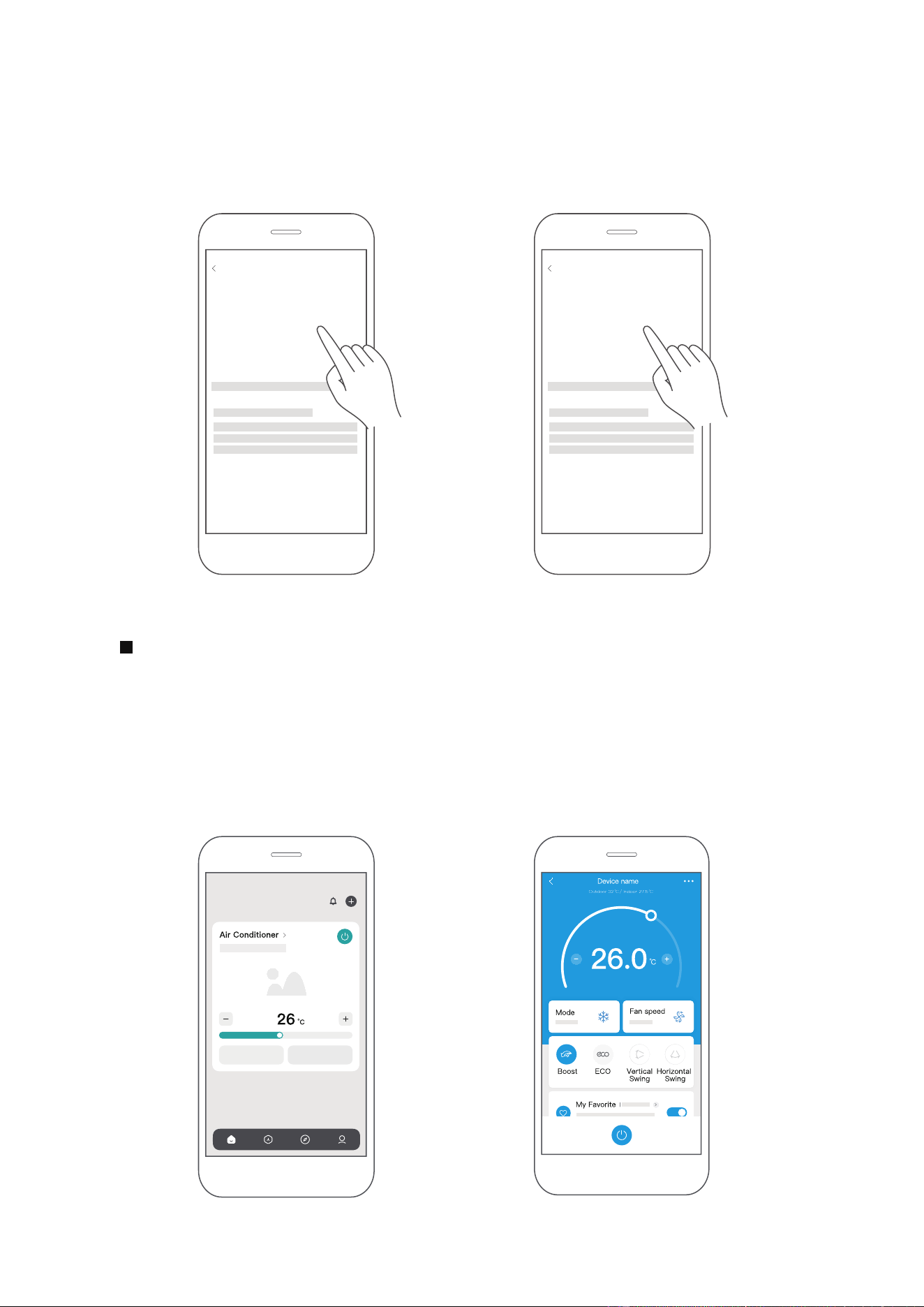
Después de emparejar con éxito, se creará una tarjeta para el dispositivo en la
aplicación SmartHome.
Atajos para funciones básicas aparecerán en la tarjeta, como cambiar la
temperatura o encender y apagar el dispositivo.
Al tocar en la tarjeta, se revelarán funciones y ajustes adicionales. El diseño real
de la interfaz de usuario puede verse diferente a los ejemplos debido a
actualizaciones de la aplicación.
Paso 4: Controlar el dispositivo
SmartHome
3) Sigue los pasos en la aplicación para conectar tu dispositivo a la red
inalámbrica. Si tu dispositivo no logra conectarse, sigue las instrucciones
adicionales en la aplicación.
Agregar dispositivo
Para aire acondicionado de ventana Para aire acondicio nado portátil
Agregar dispositivo
39
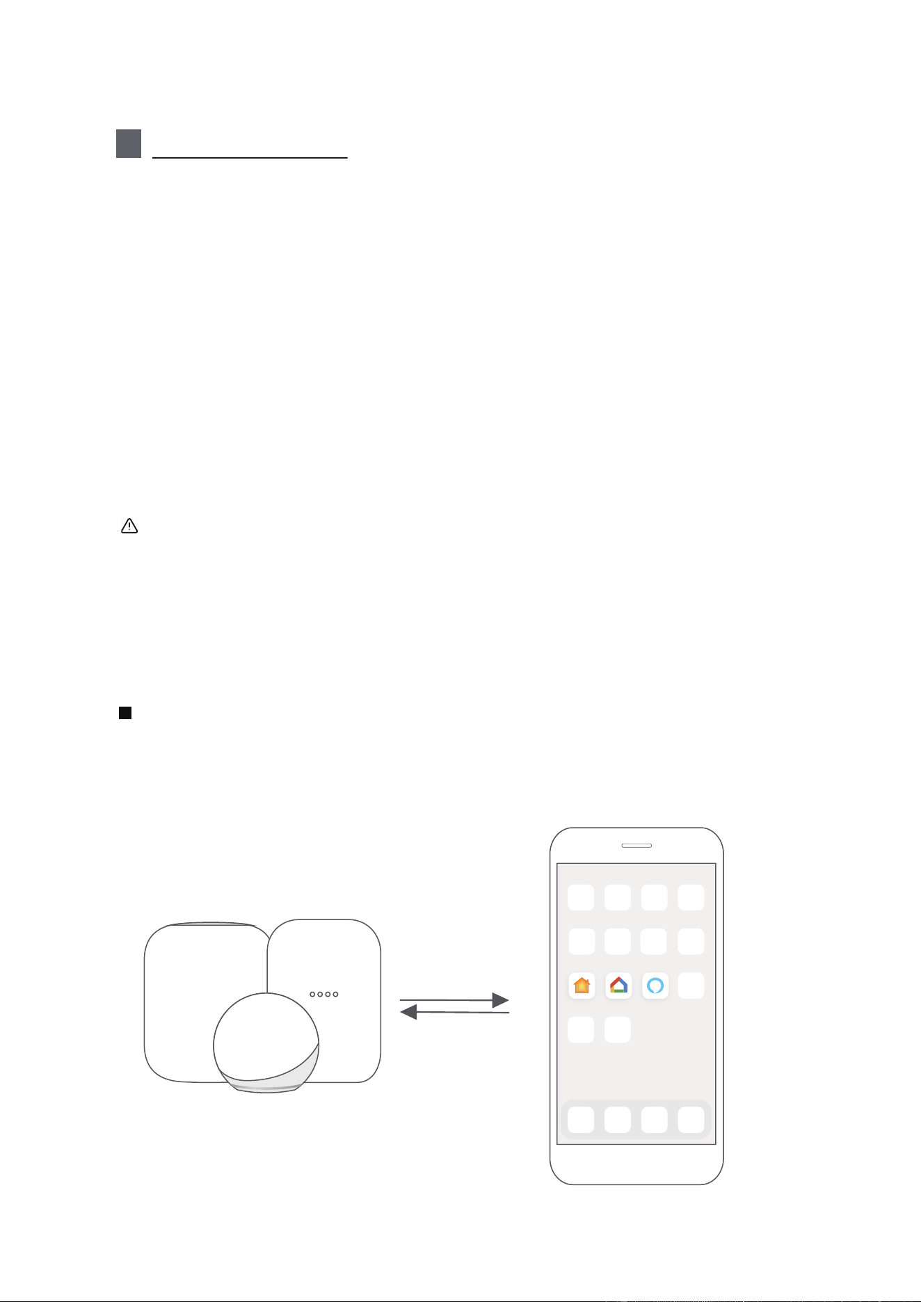
2
Cómo usar Matter
Conecta tu aire acondicionado a través de Matter
Asegúrate de que tu dispositivo móvil esté conectado a tu enrutador
inalámbrico.
El enrutador inalámbrico debe admitir y tener activado IPv6. Asegúrate
de que tu smartphone se conecte a la red 2.4G y no a la red 5G.
.
Matter es una tecnología de conectividad que armoniza el hogar inteligente,
permitiendo que dispositivos y ecosistemas como Alexa, Google Home y Apple
Home se comuniquen de manera fluida. Esta integración desbloquea funciones
innovadoras.
Para usar Matter, necesitarás al menos un altavoz inteligente habilitado para
Matter (Amazon, Google o Apple) y su respectiva aplicación.
-- Si tienes un altavoz inteligente habilitado para Matter, por favor sigue las
instrucciones de "Cómo usar Matter" en las siguientes páginas.
-- Si no tienes un altavoz inteligente habilitado para Matter, no podrás usar
Matter en este momento. Sin embargo, aún puedes obtener la funcionalidad
completa del producto utilizando nuestra aplicación SmartHome. Para hacer
esto, sigue a la sección "Cómo usar la aplicación SmartHome".
Para una compatibilidad óptima con Matter, conecta tu aire acondicionado a los
ecosistemas de Alexa, Google Home o Apple Home, emparejado con al menos
uno de sus altavoces inteligentes compatibles con Matter.
Paso 1: Conectar al altavoz inteligente
Elige tu ecosistema preferido (Alexa, Google Home o Apple Home) y asegúrate
de tener uno de sus productos habilitados para Matter, como un altavoz
inteligente, conectado a tu enrutador inalámbrico.
Apple Home Google Home Alexa
40
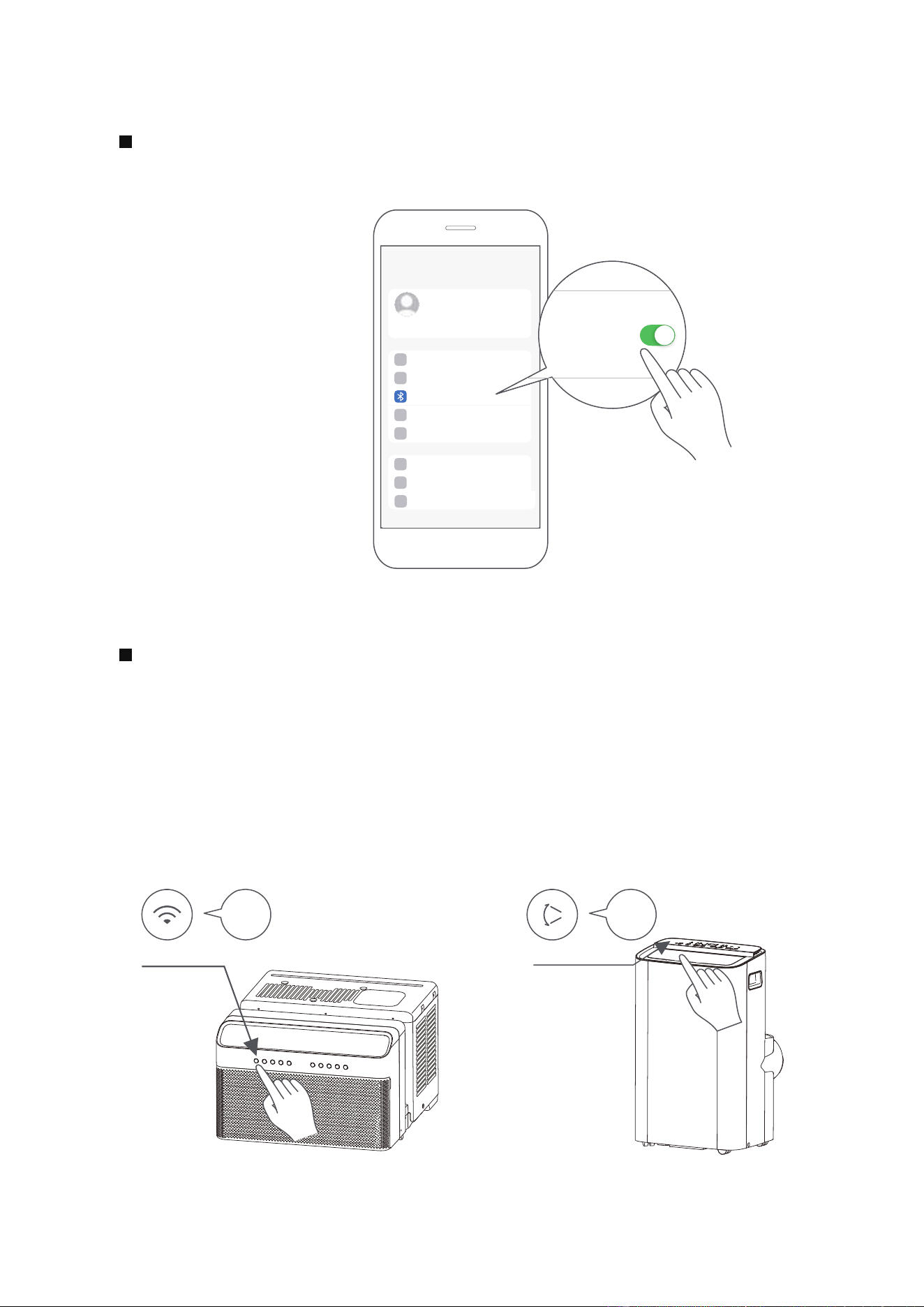
Activa el Bluetooth en tu dispositivo móvil.
Paso 2: Activar el Bluetooth
Ajustes
Bluetooth
AC de ventana: Mantén presionado el botón CONECTAR / Encendido durante
3 segundos para iniciar el proceso de emparejamiento (aparecerá "AP" en la
pantalla del AC).
AC portátil: Mantén presionado el botón SWING / Encendido durante 3 segundos
para iniciar el proceso de emparejamiento (aparecerá "AP" en la pantalla del AC).
Nota: El modo de emparejamiento AP puede variar entre diferentes AC, por
favor sigue las instrucciones del panel del AC.
Paso 3: Ingrese al modo AP
AP
CONECTAR
AP
OSCILAR
Aire acondicionado de ventana Aire acondicionado portátil
41
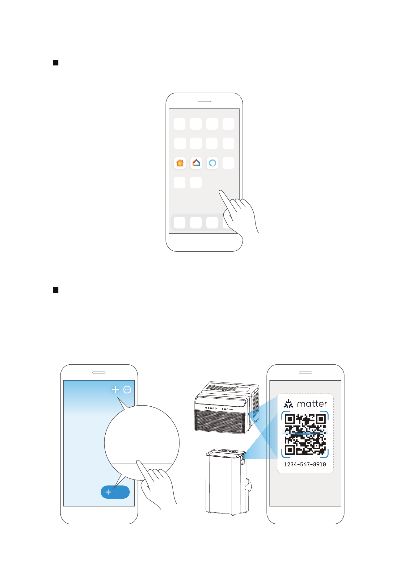
Abra la aplicación Alexa, Google Home, Apple Home en su dispositivo móvil.
Paso 4: Abra la aplicación
Apple Home Google Home Alexa
Abra su aplicación y toque el símbolo “+” o "+Agregar" para comenzar a
agregar un dispositivo/accesorio.
Seleccione la opción de dispositivo Matter y escanee el código QR ubicado
en el lateral de su unidad de aire acondicionado. Siga las instrucciones
proporcionadas en la aplicación Alexa, Google Home o Apple Home para
completar el proceso de emparejamiento.
Paso 5: Escanear código QR de Matter
Agregar
Agregar dispositivo/accesorio
escanear
código QR de Matter
42
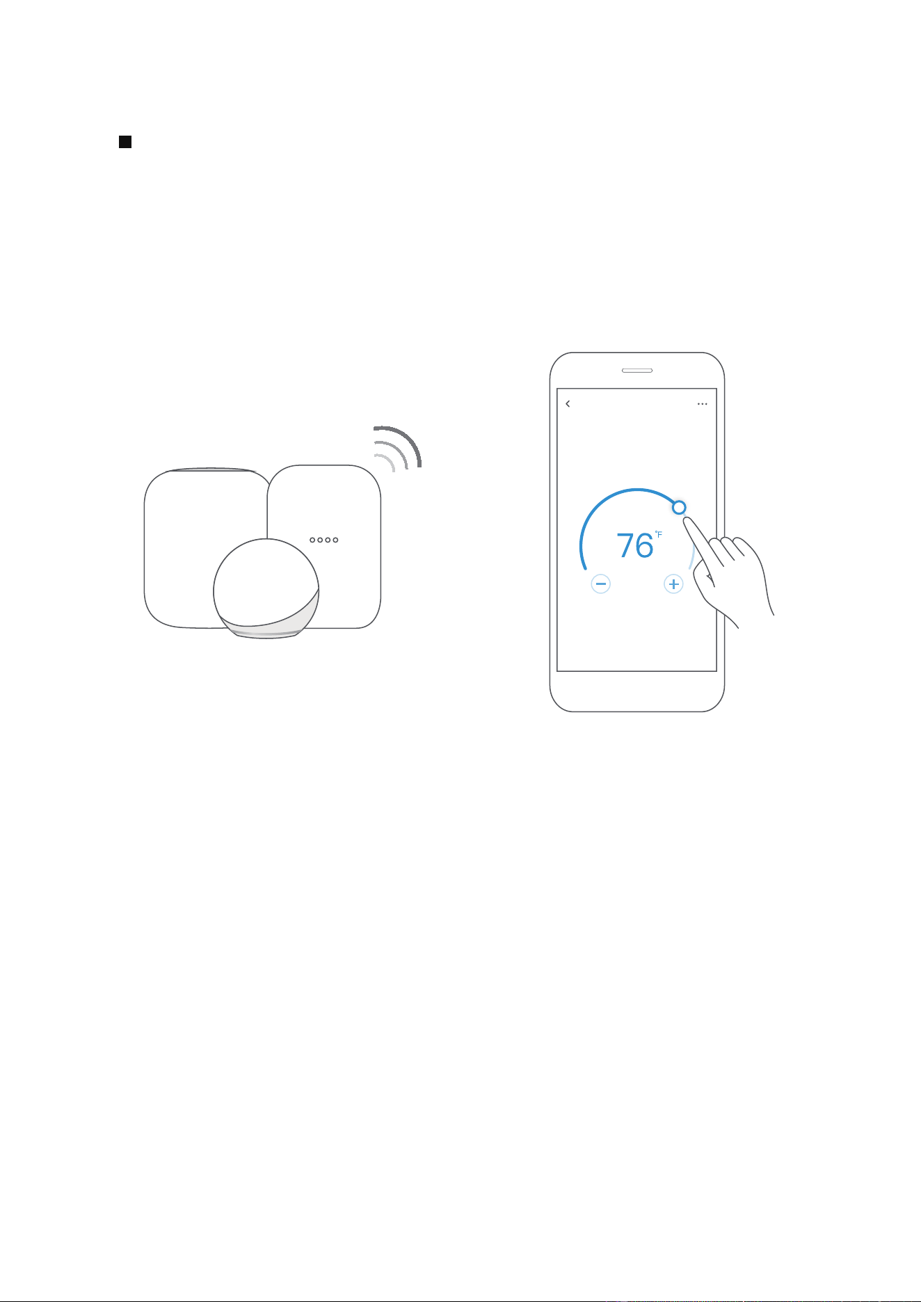
Una vez que el emparejamiento sea exitoso, podrá controlar la temperatura y
los ajustes de modo de su aire acondicionado, etc. a través de la aplicación del
ecosistema respectivo y el altavoz inteligente.
Debido a un problema de compatibilidad, el valor de temperatura mostrado en
la aplicación Alexa, Google Home o Apple Home puede ser 1 grado diferente al
que se muestra en el aire acondicionado. Sin embargo, esto no afectará la
capacidad del dispositivo para enfriar la habitación.
Paso 6: Control del dispositivo
Aire acondicionado
43
La aplicación y los altavoces inteligentes solo pueden admitir
Matter cuando se utilizan estas versiones o superiores.
NOTA:
Las funciones mostradas en las aplicaciones de Alexa, Google Home o Apple
Home pueden cambiar con las actualizaciones de sus productos o aplicaciones.
Los procesos de configuración y las funciones pueden variar entre ecosistemas.
Asegúrese de que la aplicación habilitada para Matter esté actualizada para
garantizar la mejor experiencia.
Periódicamente, actualizaremos el software del dispositivo para mejorar la
experiencia.
Las actualizaciones de software del dispositivo se pueden realizar a través de.
la aplicación SmartHome. es desarrollado por la Connectivity
Standards Alliance TM. Esta marca, logotipos relacionados y marcas son marcas
comerciales de la Alianza, todos los derechos reservados.
El uso del distintivo Works with Apple significa que un accesorio ha sido diseñado
para funcionar específicamente con la tecnología identificada en el distintivo y
ha sido certificado por el desarrollador para cumplir con los estándares de
rendimiento de Apple. Apple no es responsable de la operación de este
dispositivo ni de su cumplimiento de normas de seguridad y regulación.
9094439556
Versión mínima de Google Play services: 22.36.15
Versión mínima de la aplicación Google Home (GHA): 2.58.24.1-dogfood
Versión mínima del firmware de Google Hub: 1.56.324896
(aparece en el hub como versión del firmware de Chromecast)
2.2.536317
16.5
Dispositivo Versión
iOS 16.5iPhone
Apple Home
Pod
Dispositivo
Alexa Echo
Android
Google
Home Hub
Aplicación
Alexa
44
Modelo: US-SK109 Dimensiones: 41 x 24 x 5 (mm)
Temp. de funcionamiento: 0°C ~ 45°C / 32°F ~ 113°F.
Tipo de Antena: Printed PCB
Antenna
Humedad de funcionamiento: 10% ~ 85%
Frecuencia:
2400-2483.5MHz
Entrada de potencia: DC 5V/500 mA
Potencia máxima transmitida:
<20dBm
3
Especificació
45

Declaración de conformidad
CONTIENE FCC ID: 2ADQOMDNA23
CONTIENE IC: 12575A-MDNA23
El funcionamiento está sujeto a las dos condiciones siguientes:
(1) Este dispositivo podría no causar interferencia; y
(2) Este dispositivo debe aceptar cualquier interferencia, incluida la interferencia que pueda
causar un funcionamiento no deseado del dispositivo.
Utilice el dispositivo únicamente de acuerdo con las instrucciones suministradas.
Los cambios o modi caciones a esta unidad no aprobados expresamente por el responsable del
cumplimiento podrían anular la autoridad del usuario para operar el equipo. Este dispositivo
cumple con los límites de exposición a la radiación FCC establecidos para un entorno no
controlado. Para evitar la posibilidad de superar los límites de exposición a radiofrecuencia
FCC, la proximidad humana a la antena no deberá ser inferior a 20 cm (8 pulgadas) durante
el funcionamiento normal.
NOTA: Este equipo ha sido probado y se ha comprobado que cumple con los límites para
un dispositivo digital de clase B, de conformidad con la parte 15 de las Reglas de FCC. Estos
límites están diseñados para proporcionar una protección razonable contra interferencias
dañinas en una instalación residencial. Este equipo genera, utiliza y puede irradiar energía
de radiofrecuencia y, si no se instala y utiliza de acuerdo con las instrucciones, puede causar
interferencias dañinas a las comunicaciones radioeléctricas. Sin embargo, no hay garantía de
que no se produzcan interferencias en una instalación particular. Si este equipo causa
interferencias perjudiciales en la recepción de radio o televisión, que se pueden determinar
apagando y encendiendo el equipo, se recomienda al usuario que intente corregir la
interferencia mediante una o más de las siguientes medidas:
-- Reoriente o reubique la antena receptora.
-- Aumente la separación entre el equipo y el receptor.
-- Conecte el equipo a un enchufe en un circuito diferente al que está conectado el receptor.
-- Consulte al distribuidor o a un técnico de radio/TV con experiencia para obtener ayuda.
NOTA:
Todas las ilustraciones en el manual son solo con fines explicativos. Su unidad puede ser
ligeramente diferente. La forma real prevalecerá.
Este dispositivo cumple con la Parte 15 de las Reglas de la FCC y los RSS exentos de licencia
de Industry Canada.
46

GARANTÍA
Garantía limitada del aire acondicionado
Su producto está protegido por esta Garantía Limitada:
El servicio de garantía debe ser obtenido de Servicios al Consumidor de Midea o prestador de servicio autorizado Midea.
Garantía
• Garantía limitada de un año desde la fecha de compra original. Garantía limitada del sistema sellado de cinco años
(incluye componentes que contienen refrigerante) desde la fecha de compra original. Garantía limitada de tres
años para el compresor desde la fecha de compra original.
El consumidor será responsable de:
• Costos de diagnóstico, remoción, transporte y reinstalación requeridos por el servicio.
• Los costos de las llamadas de servicio que son el resultado de ítems indicados en el RESPONSABILIDADES
NORMALES DEL CONSUMIDOR **
Las piezas de reemplazo Midea se utilizarán y garantizarán sólo por el período restante de la garantía original.
RESPONSABILIDADES NORMALES DEL CONSUMIDOR **
Esta garantía sólo se aplica a los productos de uso doméstico normal, y el consumidor es responsable de los ítems
listados siguientes:
1. Uso correcto del aparato de acuerdo con las instrucciones proporcionadas con el producto.
2. Mantenimiento rutinario y limpieza necesaria para mantener el buen estado de funcionamiento.
3. Instalación correcta por un profesional de servicio autorizado de acuerdo con las instrucciones proporcionadas
con el aparato y de acuerdo con todos los códigos locales de plomería, electricidad y/o gas.
4. Conexión adecuada a una fuente de alimentación conectada a tierra de suficiente voltaje, reemplazo de fusibles
quemados, reparación de conexiones aflojadas o defectos en el cableado doméstico.
5. Gastos para facilitar el acceso al aparato para el servicio.
6. Daños después de la instalación.
EXCLUSIONES
Esta garantía no cubre lo siguiente:
1) Fallo causado por daño a la unidad mientras en su posesión (diferente de los daños causados por defecto o mal
funcionamiento), mediante su instalación inadecuada, o por uso irracional de la unidad, incluyendo, pero no limitado
a, la falta de mantenimiento razonable y necesario o de seguir las instalaciones escritas y el manual de instrucciones.
2) Daños causados por servicios realizados por personas que no sean prestadores de servicio autorizados Midea,
por uso de piezas que no sean piezas de repuesto Midea, obtenidos desde personas que no sean de servicios al
Consumidor Midea, o por causas externas como abuso, mal uso, suministro eléctrico inadecuado o casos fortuitos.
3) Si la unidad se pone a usos comerciales, de negocios, de alquiler u otro uso o aplicación que no sea para uso del
consumidor, no hacemos ninguna garantía, expresa o implícita, incluyendo, pero sin limitado a, cualquier garantía
implícita de comerciabilidad o idoneidad para un uso o propósito particular.
4) Productos sin números de serie originales o productos que tengan números de serie que se han alterado o no se
puede determinar fácilmente.
Nota: Algunos estados no permiten la exclusión o limitación de daños incidentales o consecuentes. Así que esta
limitación o exclusión no se aplique a usted.
SI USTED NECESITA SERVICIO
Conserve la factura de compra, la boleta de entrega o cualquier otro registro de pago apropiado.
La fecha en la factura estableció el período de garantía si requerir servicio.
Si el servicio se lleva a cabo, es su mejor interés para obtener y conservar todos los recibos.
Esta garantía escrita le otorga derechos legales específicos. Usted también puede tener otros derechos que varían de
estado a estado.
El servicio bajo esta garantía debe ser obtenido mediante los siguientes pasos, en orden:
1) Póngase en contacto con Servicios al Consumidor Midea o un prestador de servicio autorizado Midea a 1 866 646 4332.
2) Si hay una pregunta sobre dónde obtener servicio, póngase en contacto con nuestro departamento de relaciones
de consumidor.
47
POLITICA DE DEVOLUCION
Preguntas sobre la instalación o el funcionamiento
producto Midea?
Sitodavía necesita asistencia, por favor llame al Atención
al Cliente en 1-866-646-4332.
Tenga disponible su recibo de compra número de serie
y el múmero de modelo del producto cuando llame.
El producto podrá devolverse dentro de lo 30 días de
la compra con el recibo. Luego de los 30 días, el producto
está cubierto por la garantía limitada. Consulte la sección
de garantía en el manual de usuario para información.
Política de devolución
guarde su
comprobante
48

2025
MAPXWMT
16120600A32040
