v.1.1
User’s Guide
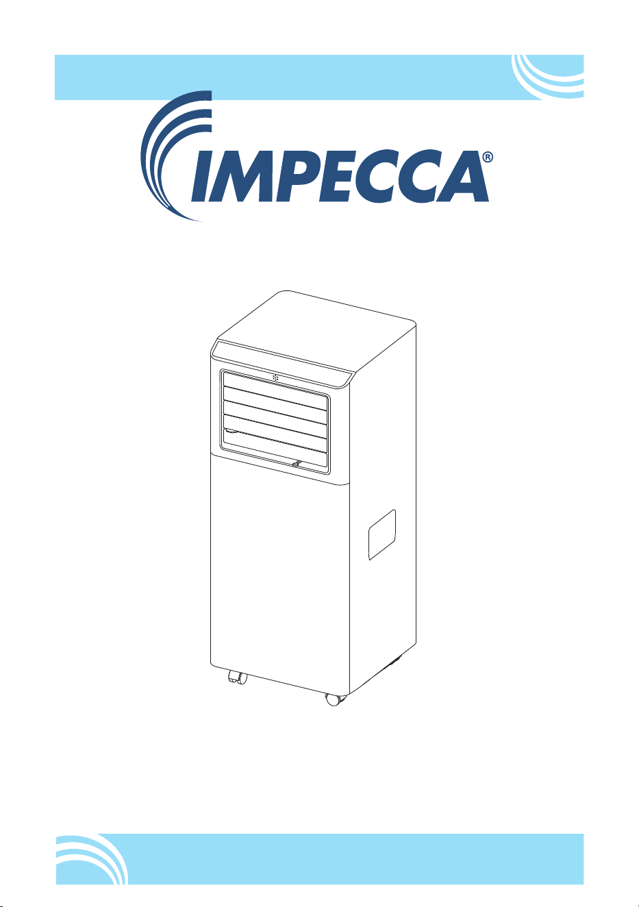
MODELS: IPAC05-E1
IPAC06-E1
Portable Air Conditioner
www.impecca.com


TABLE OF CONTENTS
IMPORTANT SAFETY INSTRUCTIONS . . . . . . . . . . . . . . . . . . . . . . . . . . . . . . . .3
UNIT DIAGRAM . . . . . . . . . . . . . . . . . . . . . . . . . . . . . . . . . . . . . . . . . . . . . 15
INSTALLATION INSTRUCTIONS . . . . . . . . . . . . . . . . . . . . . . . . . . . . . . . . . . . 16
WINDOW SLIDER KIT INSTALLATION . . . . . . . . . . . . . . . . . . . . . . . . . . . . . . . 17
LOCATION . . . . . . . . . . . . . . . . . . . . . . . . . . . . . . .
. . . . . . . . . . . . . . . . . 17
DISPLAY SCREEN AND CONTROL PANEL . . . . . . . . . . . . . . . . . . . . . . . . . . . . . 19
REMOTE CONTROL . . . . . . . . . . . . . . . . . . . . . . . . . . . . . . . . . . . . . . . . . . 19
OPERATING THE APPLIANCE . . . . . . . . . . . . . . . . . . . . . . . . . . . . . . . . . . . . 20
SETTING THE TIMER . . . . . . . . . . . . . . . . . . . . . . . . . . . . . . . . . . . . . . . . . 22
SWITCH THE UNIT OF TEMPERATURE . . . . . . . . . . . . . . . . . . . .
. . . . . . . . . . 22
TIPS FOR CORRECT USE . . . . . . . . . . . . . . . . . . . . . . . . . . . . . . . . . . . . . . . 22
WATER DRAINAGE METHOD . . . . . . . . . . . . . . . . . . . . . . . . . . . . . . . . . . . . . 23
CLEANING . . . . . . . . . . . . . . . . . . . . . . . . . . . . . . . . . . . . . . . . . . . . . . . . 24
START/END OF SEASON OPERATIONS . . . . . . . . . . . . . . . . . . . . . . . . . . . . . . 25
SELF-DIAGNOSTICS . . . . . . . . . . . . . . . . . . . . . . . . . . . . . . . . . . . . . . . . . . 26
TROUBLESHOOTING . . . . . . . . . . . . . . . . . . . . . . . . . . . . . . . . . . . . . . . . . 26
ONE-YEAR LIMITED APPLIANCE WARRANTY (US) . . . . . . . . . . . . . . . . . . . . . . . . 29
NOTES . . . . . . . . . . . . . . . . . . . . . . . . . . . . . . . . . . . . . . . . . . . . . . . . . . 30
2
ENGLISH
IMPORTANT SAFETY INSTRUCTIONS
Read Before Operating: Always read all instructions thoroughly before using the
appliance.
• This appliance is for household use only.
• Disconnect the appliance from its power source during service and when replacing
parts and cleaning.
• Please note: Check the nameplate for the type of refrigerant gas used in your
appliance.
• Specific information regarding appliances with refrigerant gas: Do not pierce the
cooling circuit of the machine. At the end of its useful life, deliver the appliance
to a special waste collection centre for disposal. GWP(Global Warming Potential):
R410A: 2088, R134a: 1430, R290: 3, R32: 675.
• This hermetically sealed system contains fluoridated greenhouse gases.
• ENVIRONMENTAL INFORMATION: This unit contains fluoridated greenhouse gases
covered by the Kyoto Protocol.
• Do not use this unit for functions other than those described in this instruction
manual.
• Make
sure the plug is plugged firmly and completely into the outlet. It can result in
the risk of electric shock or fire.
• Do not plug other appliances into the same outlet, it can result in the risk of electric
shock.
• Do not disassemble or modify the appliance or the power cord, it can result in
the risk of electric shock or fire. All other services should be referred to a qualified
technician.
• Do not place the power cord or appliance near a heater, radiator, or other heat
source. It can result in the risk of electric shock or fire.
• This unit is equipped with a cord that has a earthed wire connected to an earthed
pin or grounding tab. The plug must be plugged into a socket that is properly
installed and earthed. Do not under any circumstances cut or remove the earthed
pin or grounding tab from this plug.
•
The unit should be used or store in such a way that it is protected from moisture e.g.
condensation, splashed water, etc. Unplug unit immediately if this occurs.
• Always transport your appliance in a vertical position and place on a stable, level
surface during use. If the unit is transported laying on its side it should be stood up
•
and do not start or stop operation by plugging in or unplugging the power cord. It
can result in the risk of electric shock.
• Do not use hazardous chemicals to clean or come into contact with the unit. To
3
ENGLISH
Do not use wax, thinner, or a strong detergent. Do not use the unit in the presence of
inflammable substance or vapour such as alcohol, insecticides, gasoline, etc.
• If the appliance is making unusual sounds or is emitting smoke or an unusual odor,
unplug it immediately.
• Do not clean the unit with water. Water can enter the unit and damage the insulation,
creating a shock hazard. If water enters the unit, unplug it immediately and contact
Customer Service.
•
• Always grasp the plug when plugging in or unplugging the appliance. Never unplug
by pulling on the cord. It can result in the risk of electrical shock and damage.
• Install the appliance on a sturdy, level floor capable of supporting up to 110lbs(50kg).
Installation on a weak or unlevel floor can result in the risk of property damage and
personal injury.
• Details of type and rating of fuses: T, 250V AC, 3.15A.
• ELECTRICAL CONNECTIONS
• Before plugging the appliance into the mains socket, check that:
• The mains power supply corresponds to the value indicated on the rating plate on
the back of the appliance.
• The power socket and electrical circuit are adequate for the appliance.
• The mains socket matches the plug. If this is not the case, have the plug replaced.
• The mains socket is adequately earthed. Failure to follow these important safety
instructions absolves the manufacturer of all liability.
WARNING
• This appliance is not intended for use by persons (including children)with reduced
physical, sensory or mental capabilities,or lack of experience and knowledge, unless
they have been given supervision or instruction concerning use of the appliance by
a person responsible for their safety.
• Children should be supervised to ensure that they do not play with the appliance.
• If the SUPPLY CORD is damaged, it must be replaced by the manufacturer, its service
agent or similarly qualified persons in order to avoid a hazard.
• The appliance shall be installed in accordance with national wiring regulations.
• Do not use means to accelerate the defrosting process or to clean, other than those
recommended by the manufacturer.
• The appliance shall be stored in a room without continuously operating ignition
sources (for example: open flames, an operating gas appliance or an operating
electric heater.
• Do not pierce or burn.
• Be aware that refrigerants may not contain an odour.
4
ENGLISH
WARNING
• The handling, installation, storage, servicing and disposal must comply with the
provisions of gas-related national laws and regulations, and also national wiring
regulation.
• It is necessary to clear away the refrigerant in the system when maintaining or
scrapping an appliance.
VENTILATED AREA (OPEN DOORS AND WINDOWS)
• Ensure that the working area is open or well ventilated before turning on the
system or performing hot work. Ventilation should be maintained during operation.
Ventilation quickly displaces safely diluted leaked refrigerant into the atmosphere.
• Flammable refrigerant R32/R290 is used within appliance. Please follow the
instructions carefully to handle, install, clean, and service the appliance to avoid
damage or hazard. Do not dispose of appliance in regular trash. Contact qualified
agency for proper disposal.
•
When using electrical appliances, basic safety precautions should always be followed:
DO NOT touch the appliance or the electrical plug with wet hands.
Check the household voltage to ensure it matches the appliance's specification.
Before operating, remove all packaging material and check for any damage that
may have occurred during shipping.
DO NOT operate any product with a damaged cord or plug.
DO NOT use an extension cord with this appliance.
DO NOT run power cord under carpeting, or cover it with rugs or runners, Keep the
cord away from areas where it may be tripped over.
Always power off and unplug the appliance before emptying the water tank.
The water collected in the tank must be discarded. The water should never be used
for drinking.
Always unplug the appliance and remove the water from the water tank before
cleaning.
servicing or relocating the unit.
Remove the power cord from the electrical receptacle by grasping and pulling on
the power cord plug-end only, never pull the cord.
This appliance has been manufactured for use in domestic environments and
must not be used for other purposes
5
ENGLISH

ENGLISH
6
DO NOT use the product in areas where gasoline, paint or other flammable goods and
objects are used or stored
This appliance is designed for indoor residential applications only. lt should not be
used for commercial or industrial applications.
DO NOT attempt to repair or adjust any electrical or mechanical functions of the
appliance as this may cause danger and void the warranty.
DO NOT cover the air inlet or outlet on the appliance as this may cause the unit to fail.
DO NOT insert or allow objects to enter any ventilation or exhaust opening as this may
damage the product and could cause electrical shock or fire.
DO NOT let children play with this appliance, packaging or included plastic bag.
If the unit is damaged or it malfunctions, do not continue to operate it. Unplug the
product from the electrical outlet. Refer to the troubleshooting section and contact the
customer support center.
Always place the appliance on a leveled floor.
Never install the product near a bathtub or any water container.
Store in a dry area, away from direct sunlight, when not in use.
This appliance and its packaging materials are not intended for use by persons
(including children or elderly) with reduced physical, sensory or mental capabilities, or
lack of experience and knowledge, unless they have been given supervision or
instructions concerning the use of the appliance by a person responsible for their safety.
Always grip the top handle and keep the unit upright when transporting from room to
room -DO NOT tilt the product on its side or upside-down.
If the appliance was transported tilted on its side, you must position it upright again
and wait at least 6 hours before using it.
WARNING: To reduce the risk of fire or electric shock, do not use this appliance with
any solid state speed control device.
Information for qualification of workers
All operators or refrigeration system maintenance personnel shall have a valid
certificate issued by an industry-recognized evaluation body to certify that they are
qualified for the safe disposal of refrigerant agents as recognized by the industry;
• Maintain and repair the equipment only in accordance with the method recommended
by the equipment manufacturer. If other professionals are required to assist in the
maintenance and repair of equipment, do so under the supervision of personnel
qualified to use combustible refrigerants.
HH.1 General
Information of procedures additional to usual information for refrigerating appliance
installation, repair, maintenance and decommission procedures is required when an
appliance with FLAMMABLE REFRIGERANTS is affected.
The training of these procedures is carried out by national training organisations or
manufacturers that are accredited to teach the relevant national competency standards
that may be set in legislation.

ENGLISH
7
The achieved competence should be documented by a certificate.
HH.2 Information and training
HH.2.1 The training should include the substance of the following:
HH.2.2 Information about the explosion potential of FLAMMABLE REFRIGERANTS
to show that flammables may be dangerous when handled without care.
HH.2.3 Information about POTENTIAL IGNITION SOURCES, especially those that
are not obvious, such as lighters, light switches, vacuum cleaners, electric heaters.
HH.2.4 Information about the different safety concepts:
Unventilated – Safety of the appliance does not depend on ventilation of the
housing. Switching off the appliance or opening of the housing has no significant
effect on the safety. Nevertheless, it is possible that leaking refrigerant may
accumulate inside the enclosure and flammable atmosphere will be released
when the enclosure is opened.
Ventilated enclosure – Safety of the appliance depends on ventilation of the
housing. Switching off the appliance or opening of the enclosure has a significant
effect on the safety. Care should be taken to ensure sufficient ventilation before.
Ventilated room – Safety of the appliance depends on the ventilation of the room.
Switching off the appliance or opening of the housing has no significant effect on
the safety. The ventilation of the room shall not be switched off during repair
procedures.
HH.2.5 Information about refrigerant detectors:
• Principle of function, including influences on the operation.
• Procedures, how to repair, check or replace a refrigerant detector or parts of it in
a safe way.
• Procedures, how to disable a refrigerant detector in case of repair work on the
refrigerant carrying parts.
HH.2.6 Information about the concept of sealed components and sealed
enclosures according to IEC 60079-15:2010.
a) Commissioning
• Ensure that the floor area is sufficient for the REFRIGERANT CHARGE or that the
ventilation duct is assembled in a correct manner.
• Connect the pipes and carry out a leak test before charging with refrigerant.
• Check safety equipment before putting into service.
b) Maintenance
• Portable equipment shall be repaired outside or in a workshop specially
equipped for servicing units with FLAMMABLE REFRIGERANTS.
• Ensure sufficient ventilation at the repair place.
• Be aware that malfunction of the equipment may be caused by refrigerant loss
and a refrigerant leak is possible.
• Discharge capacitors in a way that wonʼt cause any spark. The standard
procedure to short circuit the capacitor terminals usually creates sparks.
• Reassemble sealed enclosures accurately. If seals are worn, replace them.
• Check safety equipment before putting into service.

ENGLISH
8
c) Repair
• Portable equipment shall be repaired outside or in a workshop specially equipped
for servicing units with FLAMMABLE REFRIGERANTS.
• Ensure sufficient ventilation at the repair place.
• Be aware that malfunction of the equipment may be caused by refrigerant loss and a
refrigerant leak is possible.
• Discharge capacitors in a way that wonʼt cause any spark.
• When brazing is required, the following procedures shall be carried out in the
following order:
– Safely remove the refrigerant following local and national regulations. If the recovery
is not required by national regulations, drain the refrigerant to the outside. Take care
that the drained refrigerant will not cause any danger. In doubt, one person should
guard the outlet. Take special care that drained refrigerant will not float back into the
building;
– Purge the refrigerant circuit with oxygen free nitrogen;
– Evacuate the refrigerant circuit;
– Purge the refrigerant circuit with nitrogen for 5 min (not required for A2L refrigerants).
– Evacuate again (not required for A2L refrigerants).
– Remove parts to be replaced by cutting or brazing.
– Purge the braze point with nitrogen during the brazing procedure required for repair.
– Carry out a leak test before charging with refrigerant.
• Reassemble sealed enclosures accurately. If seals are worn, replace them.
• Check safety equipment before putting into service.
d) Decommissioning
• If the safety is affected when the equipment is putted out of service, the REFRIGERANT
CHARGE shall be removed before decommissioning.
• Ensure sufficient ventilation at the equipment location.
• Be aware that malfunction of the equipment may be caused by refrigerant loss and a
refrigerant leak is possible.
• Discharge capacitors in a way that wonʼt cause any spark.
• Remove the refrigerant. If the recovery is not required by national regulations, drain
the refrigerant to the outside. Take care that the drained refrigerant will not cause any
danger. In doubt, one person should guard the outlet. Take special care that drained
refrigerant will not float back into the building.
• When FLAMMABLE REFRIGERANTS except A2L REFRIGERANTS are used,
– Evacuate the refrigerant circuit.
– Purge the refrigerant circuit with nitrogen for 5 min.
– Evacuate again.
– Fill with nitrogen up to atmospheric pressure.
– Put a label on the equipment that the refrigerant is removed.
e) Disposal
• Ensure sufficient ventilation at the working place.
• Remove the refrigerant. If the recovery is not required by national regulations, drain

ENGLISH
9
the refrigerant to the outside. Take care that the drained refrigerant will not cause any
danger. In doubt, one person should guard the outlet. Take special care that drained
refrigerant will not float back into the building.
• When flammable refrigerants are used,
a) Evacuate the refrigerant circuit.
b) Purge the refrigerant circuit with oxygen free nitrogen.
c) Evacuate again. (not required for A2L refrigerants)
d) Cut out the compressor and drain the oil.
GENERAL INSTRUCTIONS
1.1 Checks to the area
Prior to beginning work on systems containing flammable refrigerants, safety checks
are necessary to ensure that the risk of ignition is minimised. For repair to the
refrigerating system, the following precautions shall be complied with prior to
con-ducting work on the system.
1.2 Work procedure
Work shall be undertaken under a controlled procedure so as to minimise the risk of a
flammable gas or vapour being present while the work is being performed.
1.3 General work area
All maintenance staff and others working in the local area shall be instructed on the
nature of work being carried out. Work in confined spaces shall be avoided.The area
around the workspace shall be sectioned off. Ensure that the conditions within the
area have been made safe by control of flammable material.
1.4 Checking for presence of refrigerant
The area shall be checked with an appropriate refrigerant detector prior to and during
work, to ensure the technician is aware of potentially flammable atmospheres. Ensure
that the leak tection equipment being used is suitable for use with flammable
refrigerants, i.e. nonsparking, adequately sealed or intrinsically safe.
1.5 Presence of fire extinguisher
If any hot work is to be conducted on the refrigeration equipment or any associated
parts, propriate fire extinguishing equipment shall be available to hand. Have a dry
powder or CO 2 fire extinguisher adjacent to the charging area.
1.6 No ignition sources
No person carrying out work in relation to a refrigeration system which involves
exposing any pipe work that contains or has contained flammable refrigerant shall
use any sources of ignition in such a manner that it may lead to the risk of fire or
explosion. All possible ignition sources, including cigarette smoking, should be kept
sufficiently far away from the site of installation, repairing, removing and disposal,

ENGLISH
10
during which flammable refrigerant can possibly be released to the surrounding space.
Prior to work taking place, the area around the equipment is to be surveyed to make
sure that there are no flammable hazards or ignition risks. “No Smoking” signs shall
be displayed.
1.7 Ventilated area
Ensure that the area is in the open or that it is adequately ventilated before breaking
into the system or conducting any hot work. A degree of ventilation shall continue
during the period that the work is carried out. The ventilation should safely disperse
any released refrigerant and preferably expel it externally into the atmosphere.
1.8 Checks to the refrigeration equipment
Where electrical components are being changed, they shall be fit for the purpose and
to the correct specification. At all times the manufacturerʼs maintenance and service
guidelines shall be followed. If in doubt consult the manufacturerʼs technical department
for assistance.The following checks shall be applied to installations using flammable
refrigerants: the charge size is in accordance with the room size within which the
refrigerant containing parts are installed; the ventilation machinery and outlets are
operating adequately and are not obstructed; if an indirect refrigerating circuit is
being used, the secondary circuit shall be checked for the presence of refrigerant;
marking to the equipment continues to be visible and legible. Markings and signs that
are illegible shall be corrected; refrigeration pipe or components are installed in a
position where they are unlikely to be exposed to any substance which may corrode
refrigerant containing components, unless the components are constructed of
materials which are inherently resistant to being corroded or are suitably protected
against being so corroded.
1.9 Checks to electrical devices
Repair and maintenance to electrical components shall include initial safety checks
and component inspection procedures. If a fault exists that could compromise safety,
then no electrical supply shall be connected to the circuit until it is satisfactorily dealt
with. If the fault cannot be corrected immediately but it is necessary to continue
operation, an adequate temporary solution shall be used. This shall be reported to the
owner of the equipment so all parties are advised.
Initial safety checks shall include: that capacitors are discharged: this shall be done in
a safe manner to avoid possibility of sparking; that there no live electrical components
and wiring are exposed while charging, recovering or purging the system; that there is
continuity of earth bonding.
REPAIRS TO SEALED COMPONENTS
2.1 During repairs to sealed components, all electrical supplies shall be disconnected
from the equipment being worked upon prior to any removal of sealed covers, etc.
If it is absolutely necessary to have an electrical supply to equipment during servicing,

ENGLISH
11
then a permanently operating form of leak detection shall be located at the most
critical point to warn of a potentially hazardous situation.
2.2 Particular attention shall be paid to the following to ensure that by working on
electrical
components, the casing is not altered in such a way that the level of protection is
affected.
This shall include damage to cables, excessive number of connections, terminals not
made to original specification, damage to seals, incorrect fitting of glands, etc. Ensure
that apparatus is mounted securely. Ensure that seals or sealing materials have not
degraded such that they no longer serve the purpose of preventing the ingress of
flammable atmospheres. Replacement parts shall be in accordance with the
manufacturerʼs specifications.
NOTE The use of silicon sealant may inhibit the effectiveness of some types of leak
detection equipment. Intrinsically safe components do not have to be isolated prior to
working on them.
REPAIR TO INTRINSICALLY SAFE COMPONENTS
Do not apply any permanent inductive or capacitance loads to the circuit without
ensuring that this will not exceed the permissible voltage and current permitted for the
equipment in use.
Intrinsically safe components are the only types that can be worked on while live in the
presence of a flammable atmosphere. The test apparatus shall be at the correct rating.
Replace components only with parts specified by the manufacturer. Other parts may
result in the ignition of refrigerant in the atmosphere from a leak.
CABLING
Check that cabling will not be subject to wear, corrosion, excessive pressure, vibration,
sharp edges or any other adverse environmental effects. The check shall also take into
account the effects of aging or continual vibration from sources such as compressors
or fans.
DETECTION OF FLAMMABLE REFRIGERANTS
Under no circumstances shall potential sources of ignition be used in the searching for
or detection of refrigerant leaks. A halide torch (or any other detector using a naked
flame) shall not be used.
The following leak detection methods are deemed acceptable for all refrigerant systems.
Electronic leak detectors may be used to detect refrigerant leaks but, in the case of
FLAMMABLE REFRIGERANTS, the sensitivity may not be adequate, or may need
re-calibration. (Detection equipment shall be calibrated in a refrigerant-free area.)
Ensure that the detector is not a potential source of ignition and is suitable for the
refrigerant used. Leak detection equipment shall be set at a percentage of the LFL of
the refrigerant and shall be calibrated to the refrigerant employed, and the appropriate
percentage of gas (25 % maximum) is confirmed.

ENGLISH
12
Leak detection fluids are also suitable for use with most refrigerants but the use of
detergents containing chlorine shall be avoided as the chlorine may react with the
refrigerant and corrode the copper pipe-work.
NOTE Examples of leak detection fluids are
– bubble method,
– fluorescent method agents.
If a leak is suspected, all naked flames shall be removed/extinguished.
If a leakage of refrigerant is found which requires brazing, all of the refrigerant shall be
recovered from the system, or isolated (by means of shut off valves) in a part of the
system remote from the leak. Removal of refrigerant shall be according to (Removal
and evacuation).
REMOVAL AND EVACUATION
When breaking into the refrigerant circuit to make repairs – or for any other purpose –
conventional procedures shall be used. However, for flammable refrigerants it is
important that best practice be followed, since flammability is a consideration. The
following procedure shall be adhered to:
a) safely remove refrigerant following local and national regulations;
b) purge the circuit with inert gas;
c) evacuate (optional for A2L);
d) purge with inert gas (optional for A2L);
e) open the circuit by cutting or brazing.
The refrigerant charge shall be recovered into the correct recovery cylinders if venting
is not allowed by local and national codes. For appliances containing flammable
refrigerants, the system shall be purged with oxygen-free nitrogen to render the
appliance safe for flammable refrigerants. This process might need to be repeated
several times. Compressed air or oxygen shall not be used for purging refrigerant systems.
For appliances containing flammable refrigerants, refrigerants purging shall be
achieved by breaking the vacuum in the system with oxygen-free nitrogen and
continuing to fill until the working pressure is achieved, then venting to atmosphere,
and finally pulling down to a vacuum (optional for A2L). This process shall be repeated
until no refrigerant is within the system (optional for A2L). When the final oxygen-free
nitrogen charge is used, the system shall be vented down to atmospheric pressure to
enable work to take place.
Ensure that the outlet for the vacuum pump is not close to any potential ignition
sources and that ventilation is available.
CHARGING PROCEDURES
In addition to conventional charging procedures,the following requirements shall
be followed.
- Ensure that contamination of different refrigerants does not occur when using charging
equipment. Hoses or lines shall be as short as possible to minimise the amount of
refrigerant contained in them.

ENGLISH
13
- Cylinders shall be kept upright.
- Ensure that the refrigeration system is earthed prior to charging the system with
refrigerant.
- Label the system when charging is complete (if not already).
- Extreme care shall be taken not to overfill the refrigeration system.
Prior to recharging the system it shall be pressure tested with OFN. The system shall
be leak tested on completion of charging but prior to commissioning. A follow up leak
test shall be carried out prior to leaving the site.
DECOMMISSIONING
Before carrying out this procedure, it is essential that the technician is completely
familiar with the equipment and all its detail. It is recommended good practice that all
refrigerants are recovered safely. Prior to the task being carried out, an oil and
refrigerant sample shall be taken in case analysis is required prior to re-use of
reclaimed refrigerant. It is essential that electrical power is available before the task is
commenced.
a) Become familiar with the equipment and its operation.
b) Isolate system electrically.
c) Before attempting the procedure ensure that :mechanical handling equipment is
available, if required, for handling refrigerant cylinders; all personal protective
equipment is available and being used correctly; the recovery process is supervised at
all times by a competent person; recovery equipment and cylinders conform to the
appropriate standards.
d) Pump down refrigerant system,if possible.
e) If a vacuum is not possible, make a manifold so that refrigerant can be removed from
various parts of the system.
f) Make sure that cylinder is situated on the scales before recovery takes place.
g) Start the recovery machine and operate in accordance with manufacturer's
instructions.
h) Do not overfill cylinders. (No more than 80 % volume liquid charge).
i) Do not exceed the maximum working pressure of the cylinder,even temporarily.
j) When the cylinders have been filled correctly and the process completed, make sure
that the cylinders and the equipment are removed from site promptly and all isolation
valves on the equipment are closed off.
k) Recovered refrigerant shall not be charged into another refrigeration system unless
it has been cleaned and checked.
LABELLING
Equipment shall be labelled stating that it has been decommissioned and emptied of
refrigerant.The label shall be dated and signed.
Ensure that there are labels on the equipment stating the equipment contains
flammable refrigerant.

ENGLISH
SAVE THESE INSTRUCTIONS
14
RECOVERY
When removing refrigerant from a system, either for servicing or decommissioning, it
is recommended good practice that all refrigerants are removed safely. When
transferring refrigerant into cylinders, ensure that only appropriate refrigerant recovery
cylinders are employed. Ensure that the correct number of cylinders for holding the
total system charge are available.All cylinders to be used are designated for the
recovered refrigerant and labelled for that refrigerant (i.e. special cylinders for the
recovery of refrigerant). Cylinders shall be complete with pressure relief valve and
associated shut-off valves in good working order. Empty recovery cylinders are
evacuated and, if possible, cooled before recovery occurs.
The recovery equipment shall be in good working order with a set of instructions
concerning the equipment that is at hand and shall be suitable for the recovery of
flammable refrigerants.In addition,a set of calibrated weighing scales shall be
available and in good working order. Hoses shall be complete with leak-free
disconnect couplings and in good condition. Before using the recovery machine, check
that it is in satisfactory working order, has been properly maintained and that any
associated electrical components are sealed to prevent ignition in the event of a
refrigerant release. Consult manufacturer if in doubt.
The recovered refrigerant shall be returned to the refrigerant supplier in the correct
recovery cylinder,and the relevant Waste Transfer Note arranged. Do not mix
refrigerants in recovery units and especially not in cylinders.
If compressors or compressor oils are to be removed, ensure that they have been
evacuated to an acceptable level to make certain that flammable refrigerant does not
remain within the lubricant. The evacuation process shall be carried out prior to
returning the compressor to the suppliers. Only electric heating to the compressor
body shall be employed to accelerate this process.When oil is drained from a system,
it shall be carried out safely.
ENGLISH
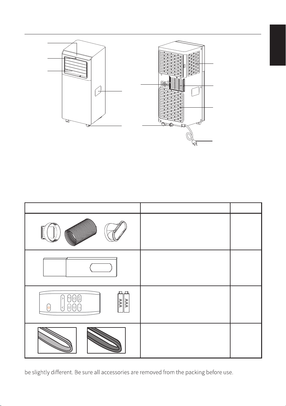
UNIT DIAGRAM
Parts Parts Name Quantity
Hose inlet
Exhaust hose
Hose outlet
1 Set
Window slider kit 1 Set
Remote control
Batteries
1 Set
Foam seal A (adhesive type)
Foam seal B(no adhesive type)
1 Set
Note: All the illustrations in this manual are for explanatory purposes only. Your appliance may
1. Control panel
2. Remote control
receiver
3. Deflector
4. Handle (both sides)
5. Castors
6. Intake grille
7. Air outlet grille
8. Intake grille
9. Plug fixer
10. Condenser drain
11. Power cable
** Open the deflector before use the appliance.
15
1
2
3
4
5
6
7
9
8
10
11
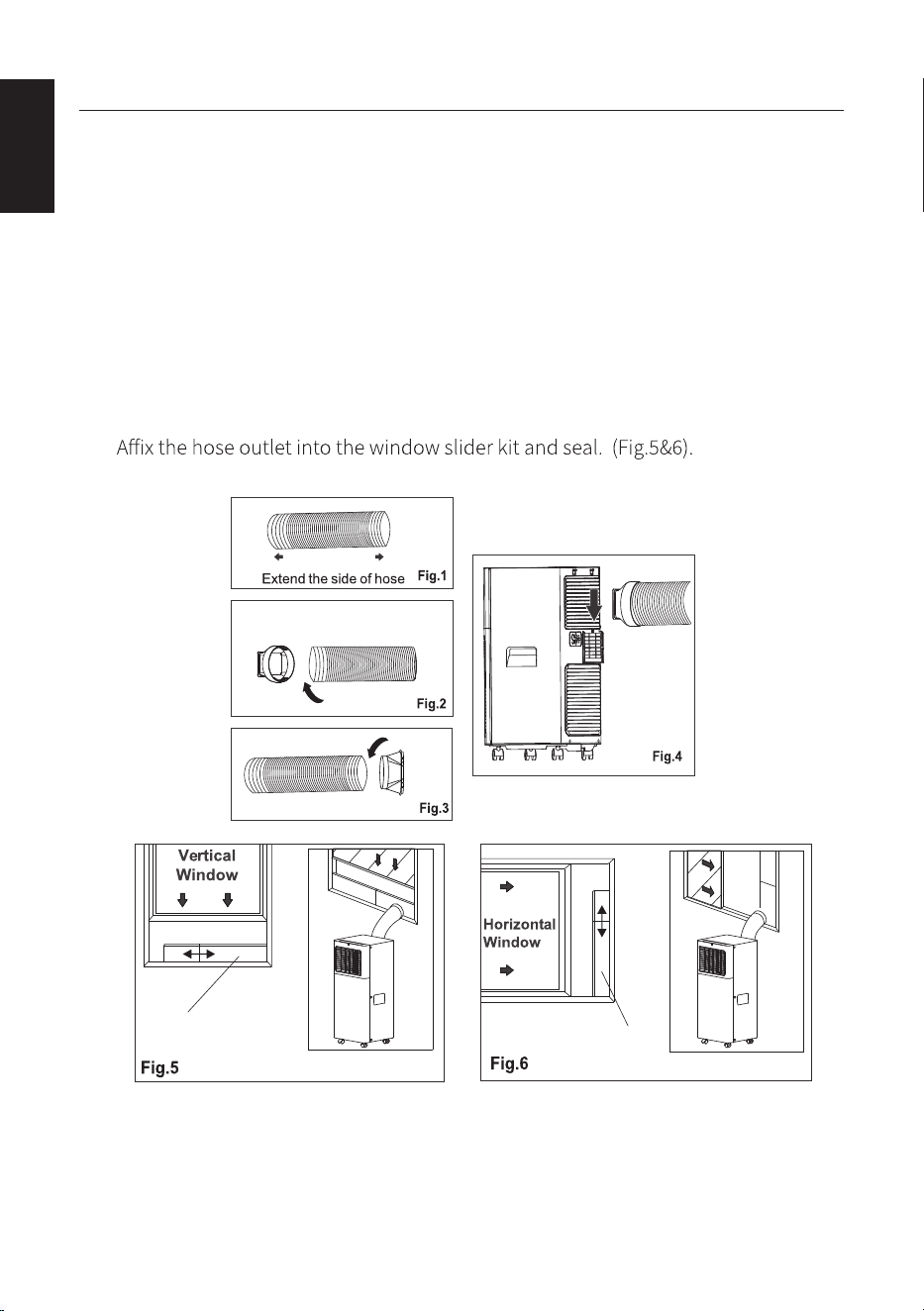
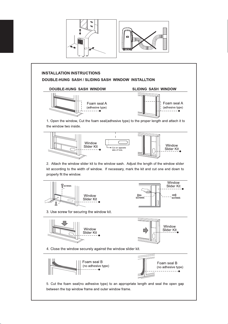
INSTALLATION INSTRUCTIONS
EXHAUSTING HOT AIR
When use the appliance in cool mode, the hot air exchange of the condenser must be
exhausted out of the room completely.
First position unit on a flat floor and make sure there's a minimum of 18" (45cm)
clearance around the unit, and is within the vicinity of a single circuit outlet power
source.
1. Extend either side of the hose (Fig.1), and screw the hose inlet (Fig.2).
2. Extend the other side of the hose and screw it to the hose outlet (Fig.3).
3. Install the hose inlet into the unit (Fig.4).
4.
The window slider kit has been designed to fit most standard vertical and horizontal
window applications,however, it may be necessary for you to modify some aspects of
the installation procedures for certain types of windows. The window slider kit can be
fastened with screws.
16
ENGLISH
Slide int o
Window slider
Window slider
ENGLISH
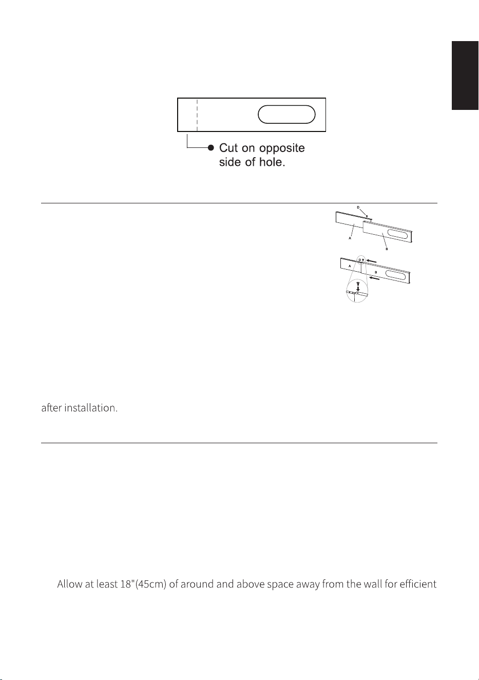
NOTE: If the window opening is less than the minimum length of the window slider kit,
cut the end without the hold in it short enough to fit in the window opening. Never cut
out the hole in window slider kit.
WINDOW SLIDER KIT INSTALLATION
1: Parts:
A. Panel
B. Panel with one hole
C. Screw/Pin
2: Assembly:
Slide Panel B into Panel A and size to window width. Windows sizes vary. When sizing
the window width, be sure that the window kit assembly is free from gaps from gaps
and or air pockets when taking measurements.
3: Lock the screw/pin
Lock the screw/pin into the holes that correspond. With the width that your window
requires to ensure that there are no gaps or air pockets in the window kit assembly
LOCATION
• The unit should be placed on a firm foundation to minimize noise and vibration.
For safe and secure positioning place the unit on a smooth, level floor strong
enough to support the unit.
• The unit has casters to aid placement, but it should only be rolled on smooth, flat
surfaces. Use caution when rolling on carpeted surfaces. Use caution and protect
floors when rolling over wood floors. Do not attempt to roll the unit over objects.
• The unit must be placed within reach of a properly rated grounded socket.
• Never place any obstacles around the air inlet or outlet of the unit.
•
working.
• The hose can be extended, but it is the best to keep the length to minimum
required. Also make sure that the hose does not have any sharp bends or sags.
17
ENGLISH
18
45 cm
45 cm
45 cm

ENGLISH
DISPLAY SCREEN AND CONTROL PANEL
REMOTE CONTROL
Fan speed button
Increase button Mode button
Decrease button
Swing button
Timer button
Sleep button
Unit Switch button
NOTE: This serial model has no auto swing function.
• Point the remote control at the receiver on the appliance.
• The remote control must be no more than 7 meters away from the appliance
(without obstacles between the remote control and the receiver).
• The remote control must be handled with extreme care.
Do not drop it or expose it to direct sunlight or sources of
heat. If the remote control do not work, please try to take
out the battery, and put it back again.
1. Control panel
2. Remote control
receiver
3. Deflector
4. Handle (both sides)
5. Castors
6. Intake grille
7. Air outlet grille
8. Intake grille
9. Plug fixer
10. Condenser drain
11. Power cable
19
1 2 3 4 5 6
7
A B CD

INSERTING OR REPLACING THE BATTERIES
• Remove the cover on the rear of the remote control;
• Insert two "AAA" 1.5V batteries in the correct position (see
instructions inside the battery compartment;
NOTE:
• If the remote control unit is replaced or disposed of, the batteries must be removed
and discarded in accordance with current legislation as they are harmful to the
environment.
• Do not mix old and new batteries. Do not mix alkaline, standard (carbon-zinc) or
rechargeable (nickel-cadmium) batteries.
• Do not dispose of batteries in fire. Batteries may explode or leak.
• If the remote control is not be used for a certain length of time, remove the
batteries
OPERATING THE APPLIANCE
• Plug into the mains socket, then the appliance is standby.
• Press the ON/OFF button to make the appliance turn on. The last function active
button , then wait for a few minutes before unplugging. This allows the appliance
to perform a cycle of checks to verify operation.
COOL mode
Ideal for hot muggy weather when you need to cooling and dehumidify the room.
To set this mode correctly:
• Press the " " button a number of times until the "Cool" symbol light appears.
• Select the target temperature 18°C-32°C (64°F-90°F) by pressing the " " / " "
button until the corresponding value is displayed.
• Select the required fan speed by pressing the "
F2 High To achieved the temperature as fast as possible.
F1 Low Run of the low noise.
" button to select the required
fan speed: High / Low.
The most suitable temperature for the room during the summer varies from 24°C to
27°C (75°F to 81°F). You are recommended, however, not to set a temperature much
appliance is under FAN mode but may not be noticeable under COOL mode.
FAN mode
When using the appliance in this mode, the air hose does not need to be attached.
20
ENGLISH
• Press the " " button a number of times until the "Fan" symbol light appears.
• Select the required fan speed by pressing the " "button to select the required
fan speed: High / Low.
DRY mode
Ideal to reduce room humidity (spring and autumn, damp rooms rainy periods, etc).
In dry mode, the appliance should be prepared in the same way as for cool mode, with
the air exhaust hose attached to enable the moisture to be discharged outside.
To set this mode correctly:
• Press the " " button a number of times until the "Dry"symbol light appears, the
screen will appear " ".
• In this mode, fan speed is selected automatically by the appliance and default low
speed fan.
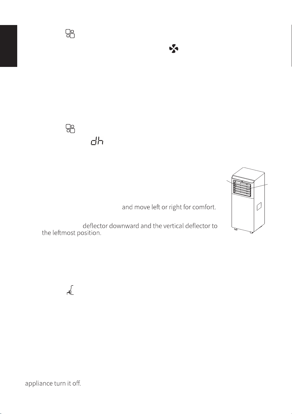
SWING function
Notes: This serial unit have no auto swing function
• Hold the horizontal deflectors (A) and move up and down for comfort.
• Hold the vertical deflectors (B)
Note: For optimal cooling performance, it is recommended to position
the horizontal
SLEEP function
This function is useful for the night as it gradually reduces operation of the appliance.
To set this function correctly:
• Select the cool mode as described above.
• Press the " " button.
The appliance operates in the previously selected mode. When
you choose the sleep function, the screen will reduce the
brightness and the fan speed will slow.
The SLEEP function maintains the room at optimum temperature without excessive
fluctuations in either temperature or humidity with silent operation. Fan speed is
always at Low, while room temperature and humidity vary gradually to ensure the
most comfortable.
When in COOL mode, the selected temperature will increase by 1°C (1°F) per hour in a
2 hour period. This new temperature will be maintained for the next 6 hours. Then the
21
ENGLISH
A
B
The SLEEP function can be canceled at any time during operation by pressing the
"Sleep", "Mode" or "fan speed" button.
In DRY mode, SLEEP function is still available.
SETTING THE TIMER
This timer can be used to delay the appliance startup or shutdown, this avoids wasting
electricity by optimising operating periods.
Programming start up
• Turn on the appliance, choose the mode you want, for example cool, 24°C, high fan
• Press the " " button, the " Timer " symbol and number of hours flash.
• Press the " " / " " button until the corresponding time is displayed.
• Wait about 5 seconds, the timer will be active, the " Timer " symbol is light.
• Press again the " " Timer button or the " " ON/OFF button , the timer will be
canceled, and the "Timer" symbol will disappear from screen.
Programming shut down
• When the appliance is running, press the button, the " " Timer symbol and
number of hours flash.
• Press the " " / " " button until the corresponding time is displayed.
• Wait about 5 seconds, the timer will be active, the " Timer " symbol is light.
• Press again the " " Timer button or the " " ON/OFF button, the timer will be
canceled, and the "Timer" symbol will disappear from screen.
SWITCH THE UNIT OF TEMPERATURE
ON REMOTE: When the appliance is running, press the button to change the
unit of temperature.
ON UNIT: When the appliance is running, hold on " " and " " button together 3
seconds by the same time, then you can change the unit of temperature.
TIPS FOR CORRECT USE
To get the best from your appliance, follow these recommendations:
• Close the windows and doors in the room to be air conditioned (fig. 21).When
installing the appliance semi-permanently, you should leave a door slightly open
(as little as 1 cm) to guarantee correct ventilation;
22
ENGLISH
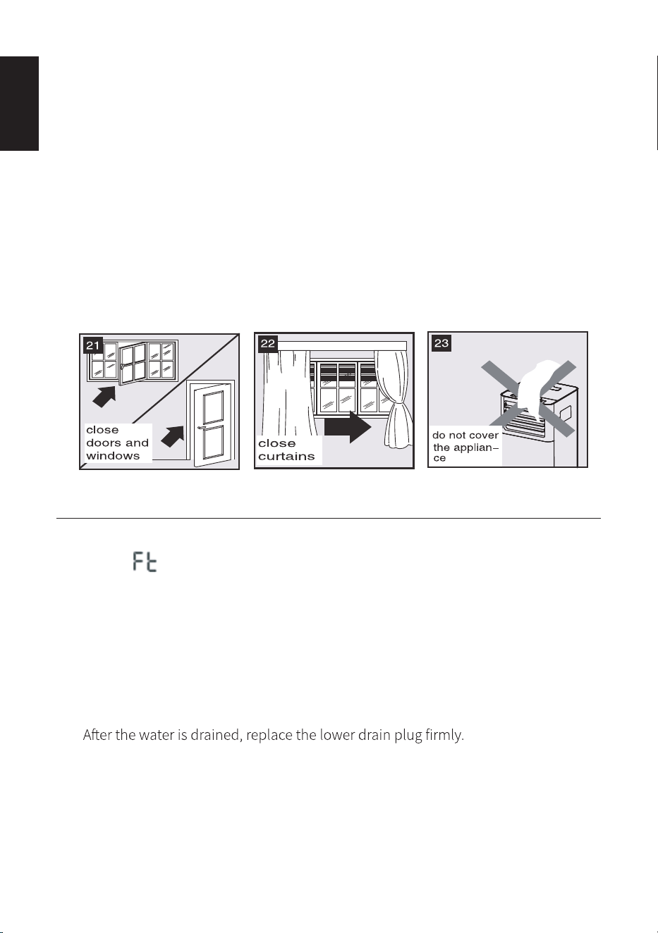
• Protect the room from direct exposure to the sun by partially closing curtains and/
or blinds to make the appliance much more economical to run
(fig. 22);
• Never rest objects of any kind on the appliance;
• Do not block the air inlet or outlet of the appliance. Reduced air
flow will result in poor performance and could damage the unit
(fig. 23).
• Make sure there are no heat sources in the room;
• Never use the appliance in very damp rooms (laundries for
example).
• Never use the appliance outdoors.
• Make sure the appliance is standing on a level surface. If necessary, place the castor
locks under the front wheels.
WATER DRAINAGE METHOD
When there is excess water condensation inside the unit, the appliance stops running
and shows " " (FULL TANK as mentioned in SELF-DIAGNOSE). This indicates that the
water condensation needs to be drained using the following procedures:
Manual Draining (fig.24)
1. Unplug the unit from power source.
2. Place a pan (not supply) under the lower drain plug. See diagram.
3. Remove the lower drain plug.
4. Water will drain out and collect in the pan.
5.
6. Turn on the unit.
Continuous Draining (fig.25)
1. Unplug the unit from the power source.
2. Remove the drain plug. While doing this operation some residual water may spill
so please have a pan (not supplied) to collect the water.
23
ENGLISH
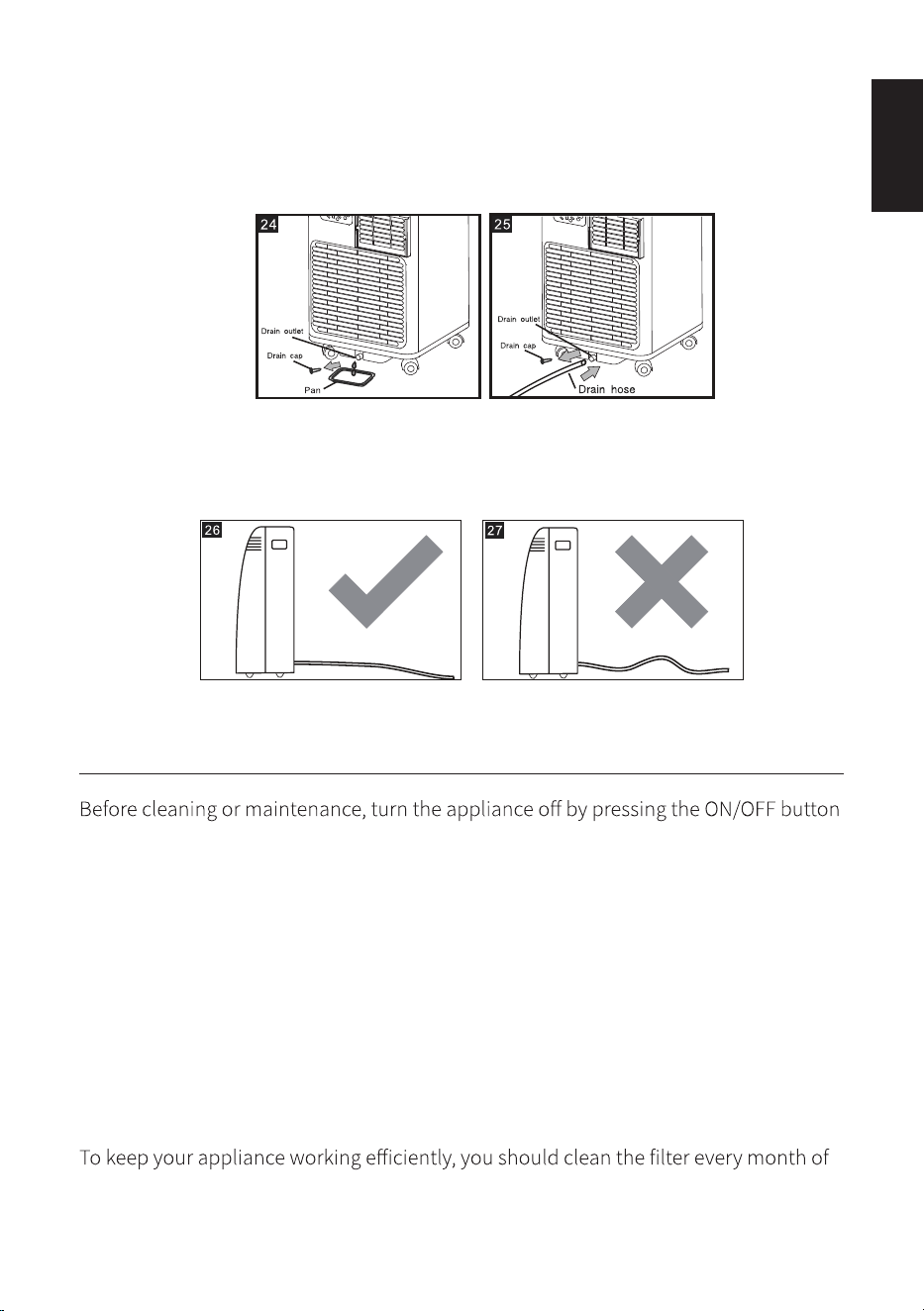
3. Connect the drain hose (1/2" or 12.7mm, possibly supplied). See diagram.
4. The water can be continuously drained through the hose into a floor drain or
bucket.
5. Turn on the unit.
NOTE: Please be sure that the height of and section of the drain hose should not be
higher than that of the drain outlet, or the water tank may not be drained. (fig.26 and
fig.27)
CLEANING
on the control panel or remote control, wait for a few minutes then unplug from the
mains socket.
CLEANING THE CABINET
You should clean the appliance with a slightly damp cloth then dry with a dry cloth,
may not used water to wash appliance.
• Never wash the appliance with water. It could be dangerous.
• Never use petrol, alcohol or solvents to clean the appliance.
• Never spray insecticide liquids or similar.
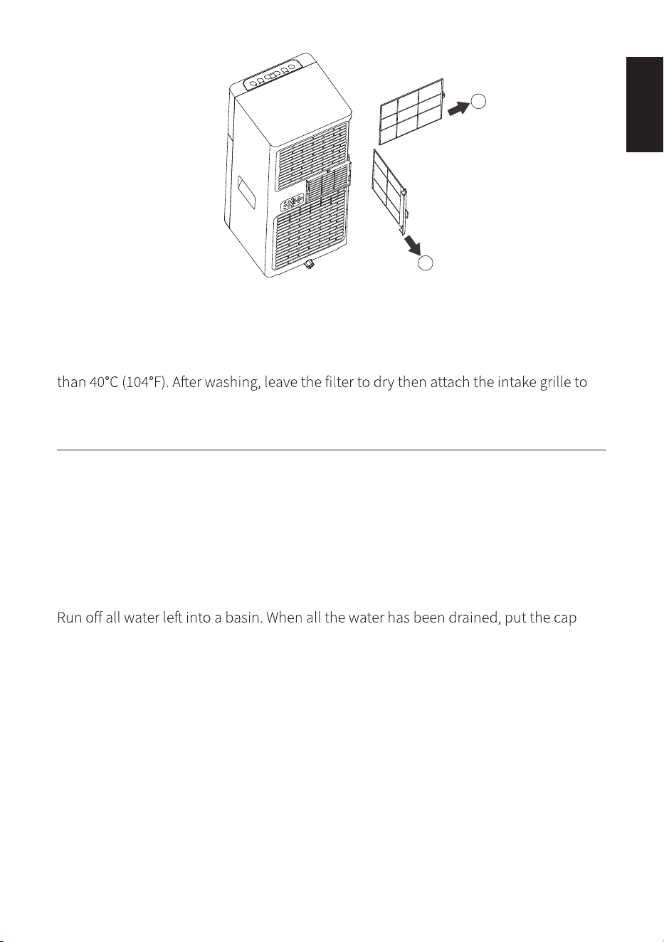
CLEANING THE AIR FILTERS
operation.
The evaporator filter can be taken out, shown in figure below.
24
ENGLISH
ENGLISH
To avoid possible cuts, avoid contacting the metal parts of the appliance when
removing or re-installing the filter. It can result in the risk of personal injury.
Use a vacuum cleaner to remove dust accumulations from the filter. If it is very dirty,
immerse in warm water and rinse a number of times. The water should never be hotter
the appliance.
START/END OF SEASON OPERATIONS
Start of season operation
Make sure the power cable and plug are undamaged. Follow the installation
instructions precisely.
End of season operation
To empty the internal circuit completely of water, remove the cap.
back in place.
Clean the filter and dry thoroughly before putting back.
Strictest operation environment:
Cooling mode: 18°C-35°C (64°F-95°F), 30%RH~90%RH
25
1
2
26
ENGLISH
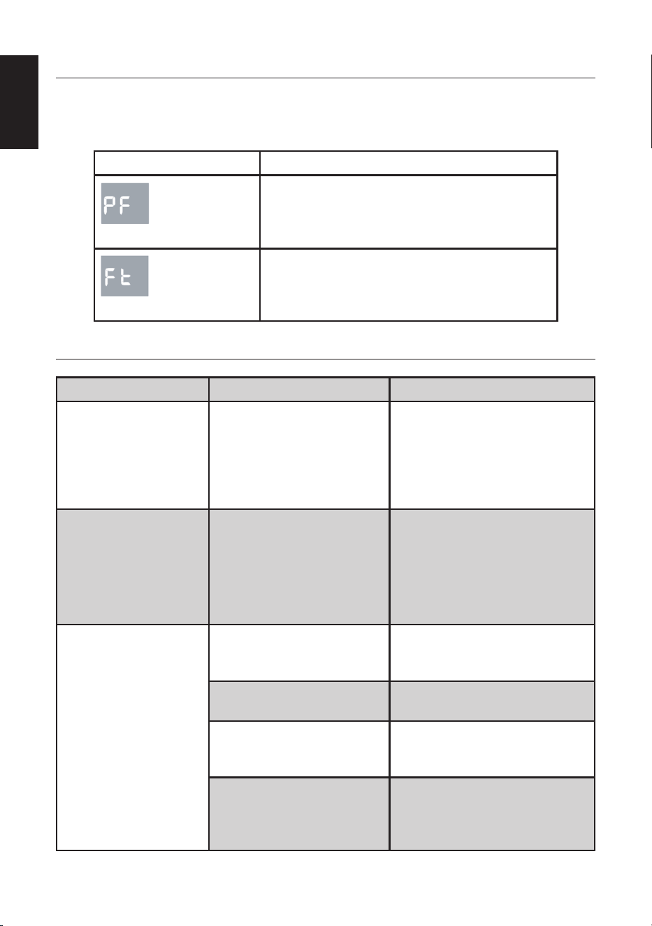
SELF-DIAGNOSTICS
The appliance has a self diagnosis system to identify a number of malfunctions.
Protection tips are displayed on the appliance display.
IF IS DISPLAYED WHAT SHOULD I DO?
PROBE FAILURE
(sensor damaged)
If this is displayed, contact your local
authorize service centre.
FULL TANK
(safety tank full)
Empty the internal safety tank, following the
instructions in the "End of season operations"
paragraph.
TROUBLESHOOTING
Problem Cause Possible Solution
The appliance does not
come on
There is no current
It is not plugged into the
mains
The internal safety device has
tripped
Wait
Plug into the mains
Wait 30 minutes, if the problem
persists, contact your service
center
The appliance works
for a short time only
Here are bends in the air
exhaust hose
Something is preventing the
air from being
discharged
Position the air exhaust hose
correctly, keeping it as short and
free of curves as possible to avoid
bottlenecks
Check and remove any obstacles
obstructing air discharge
The appliance works,
but does not cool the
room
Windows, doors and/or
curtains open
Close doors, windows and
curtains, bearing in mind the "tips
for correct use" given above
There are heat sources in the
room (oven, hairdryer, etc)
Eliminate the heat sources
The air exhaust hose is
detached from the appliance
Fit the air exhaust hose in the
housing at the back of the
appliance
The technical specification of
the appliance is not adequate
for the room in which it is
located
27
ENGLISH
During operation,
there is an unpleasant
smell in the room
Air filter clogged Clean the filter as described above
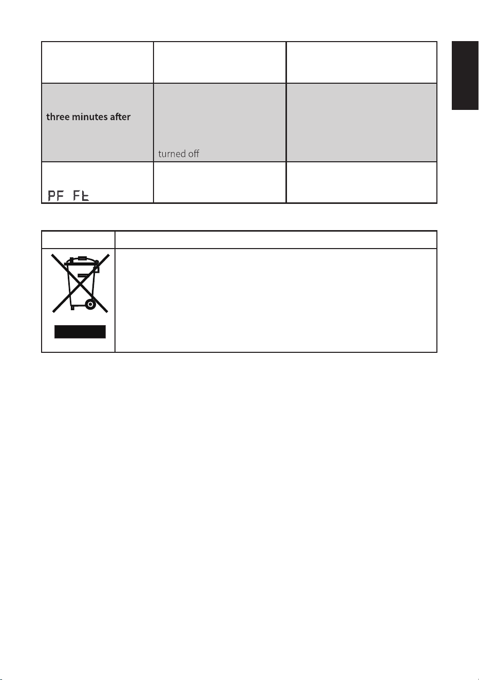
The appliance does
not operate for about
restarting it
The internal compressor
safety device prevents
the appliance from being
restarted until three minutes
have elapsed since it was last
Wait. This delay is part of normal
operation
The following message
appears on the display:
The appliance has a self
diagnosis system to identify a
number of malfunctions
See the SELF-DIAGNOSIS Chapter
Correct Disposal of this product
This symbol on the product or in its packing indicates that this product may not be
treated as household waste. Instead, it should be taken to the appropriate waste
collection point for the recycling of electrical and electronic equipment. By ensuring
this product is disposed of correctly, you will help prevent potential negative
consequences for the environment and human health, which could otherwise be
caused by the inappropriate waste handling of this product. For more detailed
information about the recycling of this product, please contact your local council,
your household waste disposal service, or the shop where you purchased the
product.
/
28
ENGLISH
CUSTOMER SUPPORT
Visit our website to contact us, find answers to Frequently Asked
Questions, and for other resources which may include an updated version
of this userʼs manual.
www.impecca.com
If you wish to contact us by phone, please be sure to have your model
number and serial number ready and call us between 9:00am and 6:00pm
ET, at +1 866-954-4440.
Keep tabs on Impeccaʼs newest innovations and enter contests via our
social network feeds:
www.facebook.com/Impecca/
www.instagram.com/impecca/
@impeccausa
ENGLISH
29
ENGLISH
ONE-YEAR LIMITED APPLIANCE WARRANTY (US)
Impecca™ warrants this product against defects in material
and workmanship to the original purchaser as specified be-
low.
PARTS AND LABOR– if the product is determined to
have a manufacturing defect, within a period of one
year from the date of the original purchase, Impec-
ca™, at its own discretion, will repair or replace the
product parts at no charge to you in the U.S.A.
To obtain warranty service by an authorized Impecca™ ser-
vice center, please email us at: service@impecca.com to ob-
tain a Repair and Maintenance Authorization (RMA) number
and received instructions on how the repair and/or replace-
ment procedure will take place.
Any glass materials included with the appliance will
be covered for a period of 60 days from purchase.
Impecca™ specifically excludes from this warranty any
non-electric/mechanical attachments, accessories and
disposable parts including but not limited to outside case,
connecting
cables, batteries and AC adapters. Impecca™ re-
serves the right to repair or replace defective products with
the same, equivalent or newer models.
We reserve the right to either repair or replace product at our
discretion. Replacement may be either new or refurbished
and while every endeavor will be made to ensure it is the
same model, if not possible it will be equal or higher spec-
ification.
Normal “Wear and Tear” is not covered by this warranty. Fur-
ther, Impecca™ hereby reserves the right to determine “Wear
and Tear” on any and all products. Tampering or opening the
product casting or shell will void this warranty in its entirety.
Exclusions: This warranty does not cover the following:
1. Any product that has a defaced or covered serial num-
ber.
2. Products that have been transferred to a second owner.
3. Rust on the interior or exterior of the unit.
4. Products listed as “As-Is” or “Refurbished.”
5. Food loss due to any p
roduct failure.
6. Window air conditioners installed in a wall.
7. The product if used in a commercial setting.
8. Service calls that do not involve product malfunction.
9. Service calls for a product ruined by not following the
provided instructions.
10. Service calls to correct improper installation.
11. Costs associated with making the product accessible
for servicing (including but not limited to removal of
trim/molding/cabinetry, etc.)
12. Service calls to replace any consumables such as light
bulbs, filters, etc.
13. Surcharges that may apply to service calls on weekends,
nights, holidays. Damages to the finish of appliance or
household furnishings due to installation of appliance.
14. Damages caused by any of the following: Acts of God;
fires; misuse; accidents; incorrect power supply; service
performed by unauthorized persons; use of non-genu-
ine Impecca parts, etc.
ALL IMPLIED WARRANTIES, INCLUDING IMPLIED WARRAN-
TIES OF MERCHANTABILITY AND FITNESS FOR A PARTICU-
LAR PURPOSE ARE LIMITED IN DURATION TO 1
YEAR FROM
THE DATE OF THE ORIGINAL RETAIL PURCHASE OF THIS
PRODUCT.
THESE WARRANTIES AND REMEDIES ARE THE SOLE AND
EXCLUSIVE WARRANTIES AND REMEDIES IN CONNECTION
WITH THE SALE AND USE OF THE PRODUCT. NO OTHER
WARRANTIES, ORAL OR WRITTEN, EXPRESSED OR IMPLIED,
ARE GIVEN.
IMPECCA™ IS NOT RESPONSIBLE OR LIABLE FOR ANY DAM-
AGE, WHETHER SPECIAL, INCIDENTAL, CONSEQUENTIAL,
DIRECT OR OTHERWISE, OR WHETHER KNOWN OR SHOULD
HAVE BEEN KNOWN TO IMPECCA™, INCLUDING LOST PROF-
ITS, GOODWILL, AND PROPERTY AND PERSONAL INJURY RE-
SULTING FROM ANY BREACH OF WARRANTY, THE INABILITY
TO USE THE PRODUCT OR UNDER ANY LEGAL THEORY IN
CONTRACT OR TORT. IMPECCA LIABILITY IS LIMITED TO THE
ACTUAL PURCHASE PRICE PAID TO THE RETAIL SELLER OF
THE DEFECTIVE PRODUCT.
No Impecca™ dealer, agent or employee is authorized to
make any modification, extension, change or amendment to
this warranty without
the written consent and authorization
from Impecca™.
Some states do not allow the exclusion or limitation of im-
plied warranties or liability for incidental or consequential
damages, or do not allow a limitation on how long an im-
plied warranty lasts, so the above limitations or exclusions
may not apply to you. This warranty gives you specific legal
rights, and you have other rights, which vary from state to
state.
Note: Our Warranty center services only to Continental U.S.A.
ONE-YEAR LIMITED APPLIANCE WARRANTY (US)
NOTES