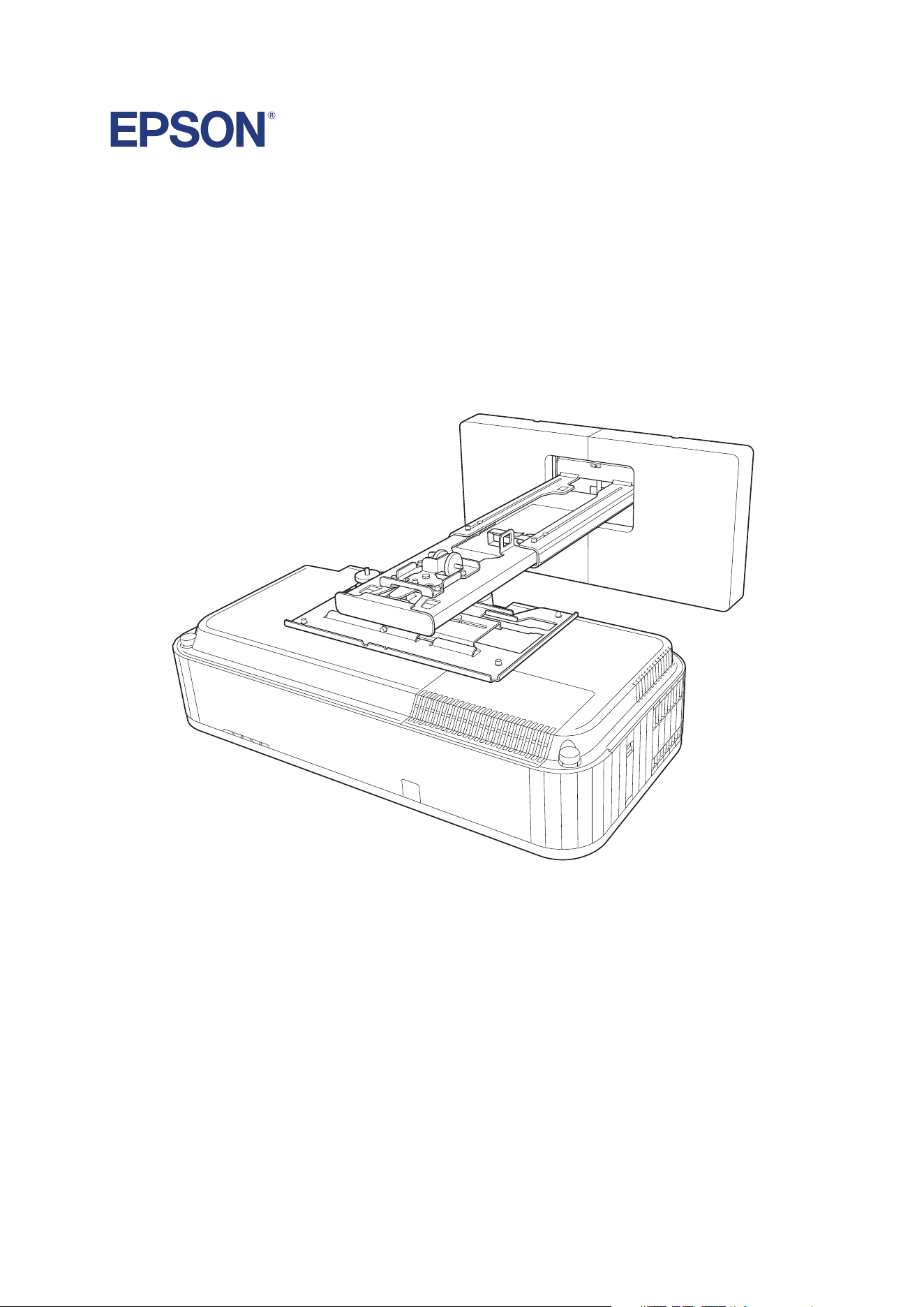
Installation Guide
2
About This Installation Guide
This guide describes how to mount the ultra-short-throw projectors listed below to a wall using the Epson®
ELPMB75 wall mount.
The following projectors are covered by this guide:
• EB-810E/EB-815E
• EH-QS100B/EH-QS100W
The EB-810E is shown in most illustrations in this guide, but the steps are the same for all models unless
otherwise noted.
Safety Instructions
For your safety, read all the instructions in this guide before using the wall mount. Incorrect handling that
ignores instructions in this guide could damage the wall mount or could result in personal injury or property
damage. Keep this installation guide on hand for future reference.
Read the safety instructions in the online Notices or User's Guide for your projector and follow the instructions
in this document.
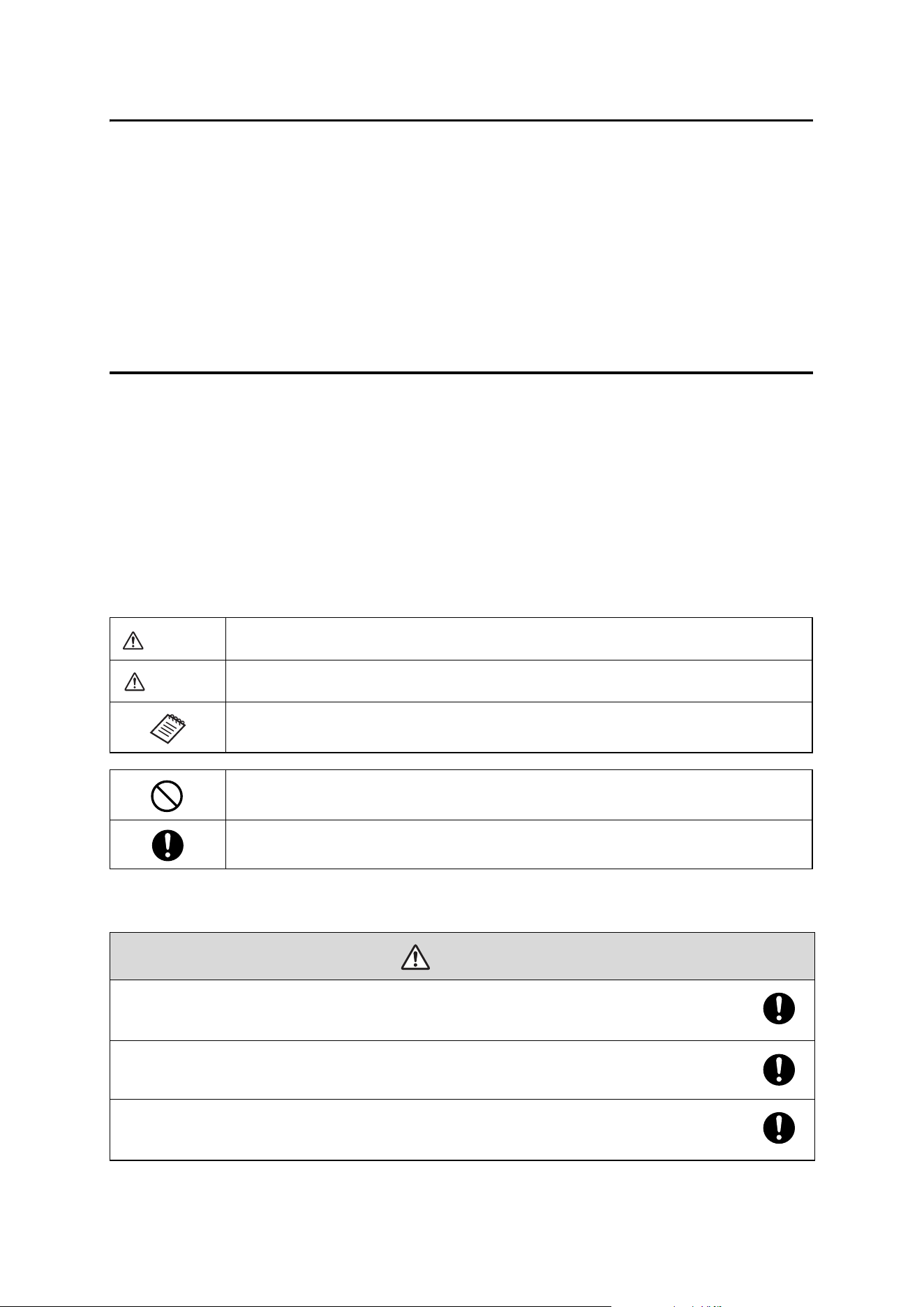
Explanation of Symbols
The warning marks shown below are used throughout this installation guide to prevent personal injury or
property damage. Make sure you understand these warnings when reading this installation guide.
Safety Precautions for Installation
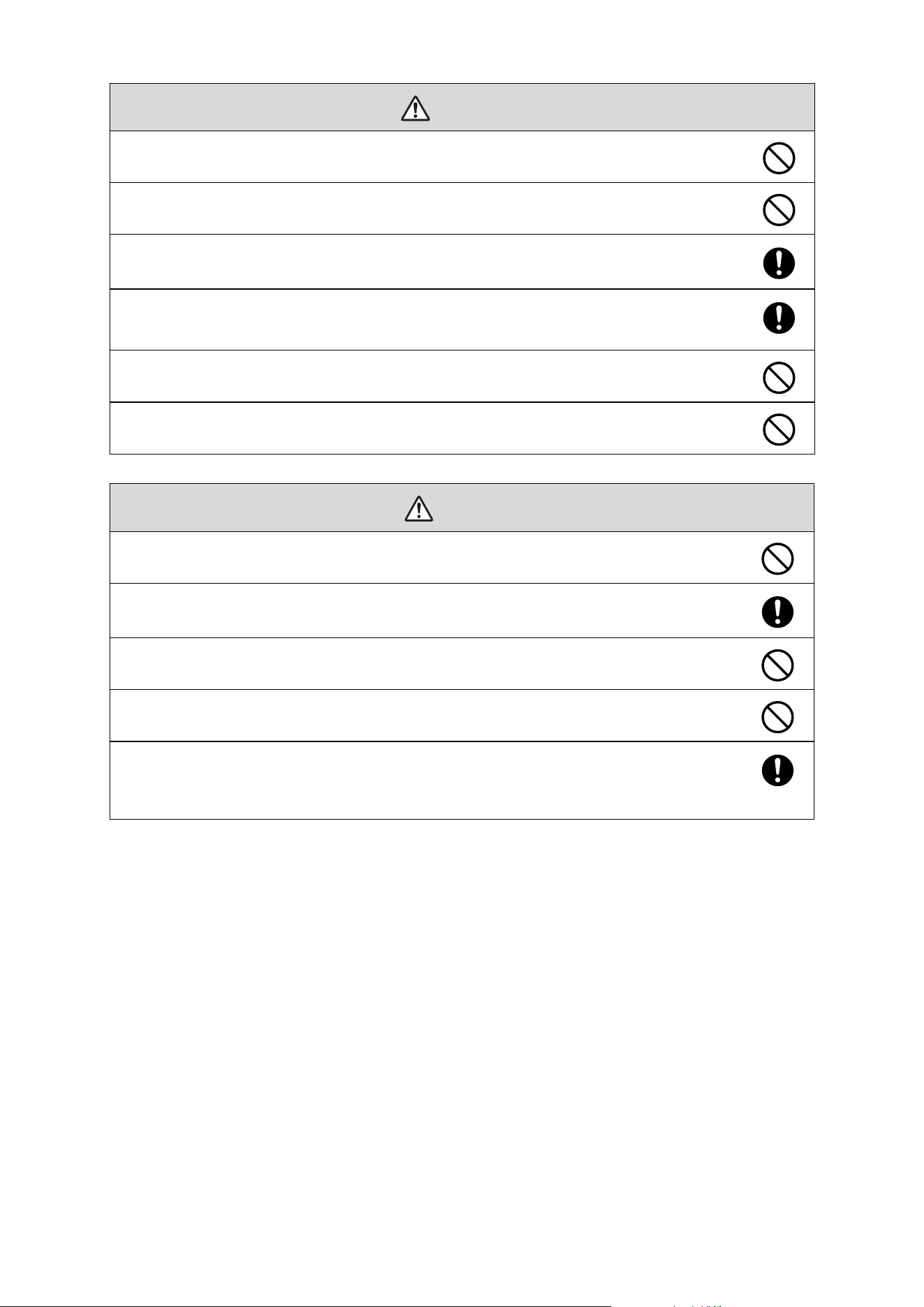
This symbol indicates information that, if ignored, could possibly result in personal injury or even death
due to incorrect handling.
This symbol indicates information that, if ignored, could possibly result in personal injury or physical
damage due to incorrect handling.
This symbol indicates related or useful information.
Symbol indicating an action that must not be done
Symbol indicating an action that should be done
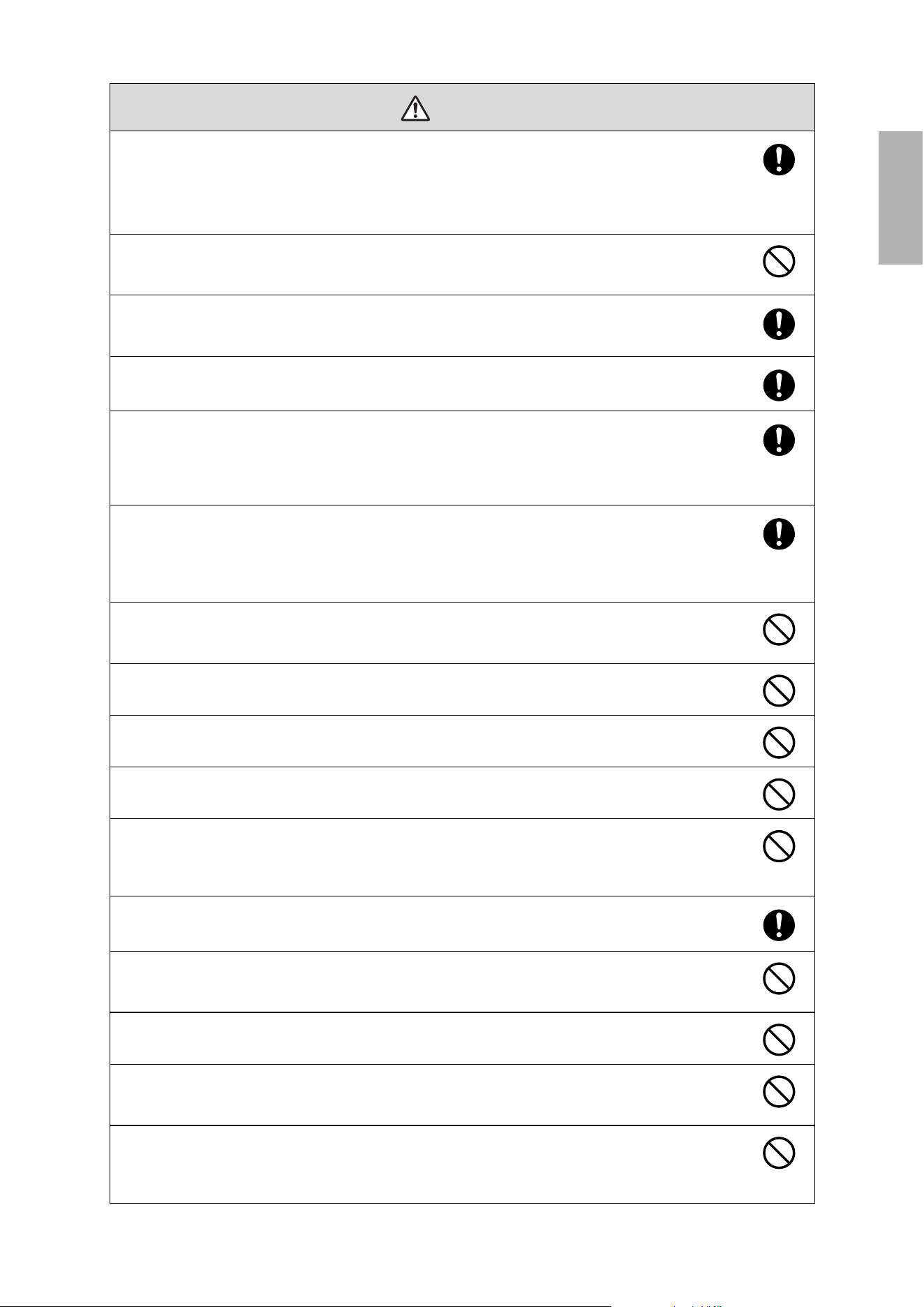
The wall mount is designed specifically for mounting a projector to a wall. If anything other than a
projector is mounted, the weight may result in damage.
If the wall mount falls, it could cause personal injury or property damage.
The installation work (wall mounting) should be performed by specialists who have technical knowledge
and ability. Incomplete or incorrect installation could cause the wall mount to fall and cause personal
injury or property damage.
Follow the steps in this guide to install the wall mount, and be sure to use the bolts and screws specified in
this guide
If the instructions are not followed, this product may fall, resulting in personal injury or an accident.
Warning
Caution
Warning
3
English
Handle the power cord carefully.
Incorrect handling may cause fire or electric shock. Observe the following precautions when handling:
• Do not handle the power plug with wet hands.
• Do not use a power cord that is damaged or modified.
• Do not pull the power cord with too much force when routing the cable through the wall mount.
Do not install the wall mount in a place where it might be subjected to vibration or shock.
Vibration or shock could cause damage to the projector or mounting surface. It could also cause the wall mount or
projector to fall and cause personal injury or property damage.
The installation work should be performed by at least two qualified service personnel. If you need to
loosen any screws during installation, be careful not to drop the wall mount.
If the wall mount or projector falls, it could cause personal injury or property damage.
Make sure you use the included safety wire kit when mounting your projector.
Install the wall mount so that it can sufficiently support the weight of the projector and wall mount, and
resist any horizontal vibration. Use M10 or 3/8 inch x 60 mm nuts and bolts and make sure to use
appropriate wall anchors for your wall type.
Nuts and bolts smaller than M10 or 3/8 inch x 60 mm could cause the wall mount to fall. Epson accepts no
responsibility for any damage or injury caused by lack of wall strength or inadequate installation.
When you mount the projector on the wall with the wall mount, the wall must be strong enough to hold the
projector and the wall mount.
This product should be installed on a concrete wall.
The maximum combined weight of the projector and wall mount is approximately 48.5 lb (22 kg) not
including cables. If the wall is not strong enough, reinforce the wall before installation.
Inspect the wall mount on a regular basis to ensure there are no broken parts or loose screws.
If there are any broken parts, stop using the wall mount immediately. If the wall mount or projector falls, it could
cause personal injury or property damage.
Never modify the wall mount.
Do not disassemble or modify the projector.
There are numerous high-voltage sections inside the product that could cause a fire, electric shock, or an accident.
Do not hang on the wall mount or hang a heavy object on the wall mount.
If the projector or wall mount falls, it could cause personal injury or property damage.
Do not use adhesives, lubricants, or oils to install or adjust the wall mount.
If you use adhesives to prevent the screws from loosening or things such as lubricants or oils on the part of the
projector attached to the slide plate, the case may crack and cause the projector to fall, resulting in personal injury
or property damage.
Tighten all screws firmly after adjustment.
Otherwise, the projector or wall mount may fall and cause personal injury or property damage.
Never loosen the bolts and nuts after installation.
Confirm that the screws have not become loose on a regular basis. If you find any loose screws, tighten them
firmly. Otherwise, the projector or wall mount may fall and cause personal injury or property damage.
When performing wiring, make sure the cable does not come into contact with any screws or bolts.
Handling the cable incorrectly may cause fire or electric shock.
Do not install in a location subject to oily smoke or smoke for events.
If oils stick to the slide plate fixing part of the projector, the case may crack and cause the projector to fall, resulting
in personal injury or property damage.
When turning on the projector, do not look into the projection lens.
This could cause damage to eyesight due to the powerful light emitted. Take particular care when there are
children present. When turning on the projector at a distance using the remote control, make sure there is no one
looking into the projection lens.
Warning
4
When using the projector, do not place any objects or put your hand near the projection lens.
This area is dangerous as it reaches a high temperature due to the concentrated projection light.
Do not use the projector in a location subject to combustible or explosive gas.
High temperature within the projector may cause ignition and a fire to occur.
Only a specialist should remove or reinstall the projector, including for maintenance and repairs.
See the projector’s User Guide for instructions on maintenance and repairs.
If any abnormalities occur with the product, immediately disconnect the cables from the product, and then
contact Epson.
Continuing to use the product in an abnormal condition could cause a fire, electric shock, or visual impairment.
Never open any cases on the projector.
Electrical voltages inside the projector can cause severe injury.
Do not look directly into the projector’s light source.
This product may emit hazardous optical radiation that can cause eye injury.
Do not install the wall mount in a location where the operating temperature for your projector model may
be exceeded. Such an environment may damage the projector.
Install the wall mount in a place free from excessive dust and humidity to prevent the lens or optical
components from becoming dirty.
Do not use excessive force when adjusting the wall mount.
The wall mount may break, resulting in personal injury.
Do not disassemble the projector when disposing of it.
Dispose according to your local or national laws and regulations.
EB-810E/EB-815E: This projector is a Class 1 laser product that complies with the IEC/EN60825-1: 2014
international standard for lasers.
EH-QS100B/EH-QS100W: This projector is a Class 1 laser product that complies with the IEC60825-1:2014
and EN60825-1:2014 + A11:2021 international standards for lasers.
Warning
Caution
5
English
Installation Location
• Before installing the projector, verify the power supply wiring for the installation location.
• We suggest projecting onto a sturdy surface like a wall or whiteboard. To prevent any image distortion on
a screen, make sure that the screen remains stationary and doesn't sway due to air currents.
• For optimal results with extreme short throw projection, it is crucial to use a flat projection surface. When
using a projection screen, make sure it is pulled tight and flat to avoid any distortion. Avoid roll-up screens
as they tend to be uneven when unrolled and can result in distorted images.
• Install and adjust the projector at a room temperature that is close to the actual intended usage
environment. If the temperature changes, the position of the image may shift.
• If you want to hide the projector power plug under the wall plate cover, make sure the power outlet is
located in the empty space to the left or right of the wall plate.
• Install the projector away from other electric devices such as fluorescent lights or air conditioners. Some
kinds of fluorescent lights could interfere with the remote control of the projector.
• Install the projector away from direct sunlight and other bright light sources.
• To ensure proper ventilation:
• EB-810E/EB-815E: Leave a minimum of 13.7 inches (35 cm) of space on the right side and 3.7 inches
(10 cm) of space on the left side between the wall and the projector's exhaust.
EH-QS100B/EH-QS100W: Leave a minimum of 7.9 inches (20 cm) of space on the right and left sides
between the wall and the projector’s exhaust.
• Additionally, the intake vents located on the top right of the projector require a space of 8.2 inches
(21.2 cm) between the wall and the projector.
• Install the projector at an angle of no more than 3° horizontally or vertically in relation to the projection
surface.
• You can also use the Epson Projector Throw Distance Simulator at http://epson.com/support/calculators
(U.S.), http://epson.ca/support/calculators (Canada), or http://epson.com.jm/support/calculators (Latin
America) to determine the correct measurements. (Conversion figures may have been rounded up or
down.)
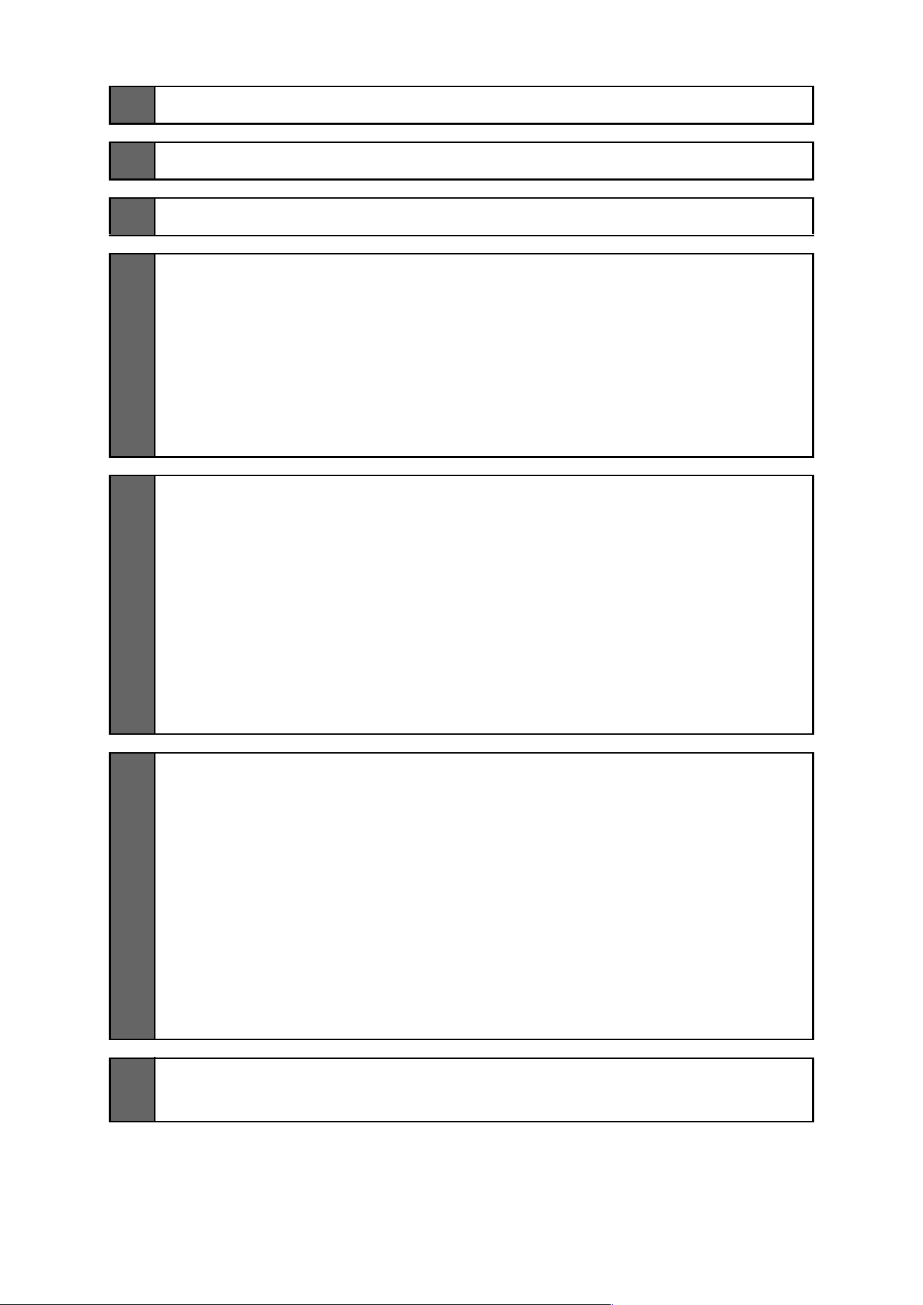
• EB-810E/EB-815E: When installing two or more projectors, check the following:
• Make sure the temperature of the surrounding environment is less than 95°F (35°C). If the
environment is too hot, the projectors may overheat and the power may turn off without warning.
• Make sure you leave a gap of at least 29.5 inches (75 cm) between the projectors.
If the projectors are installed closer than 29.5 inches (75 cm) apart, install a partition to block the heat
from the projector’s exhaust vents. The partition should be larger than the exhaust vents and installed
approximately 13.7 inches (35 cm) from the exhaust vents and 3.9 inches (10 cm) from the intake vent.
29.5 inches (75 cm)
13.7 inches (35 cm)
3.9 inches (10 cm)
6
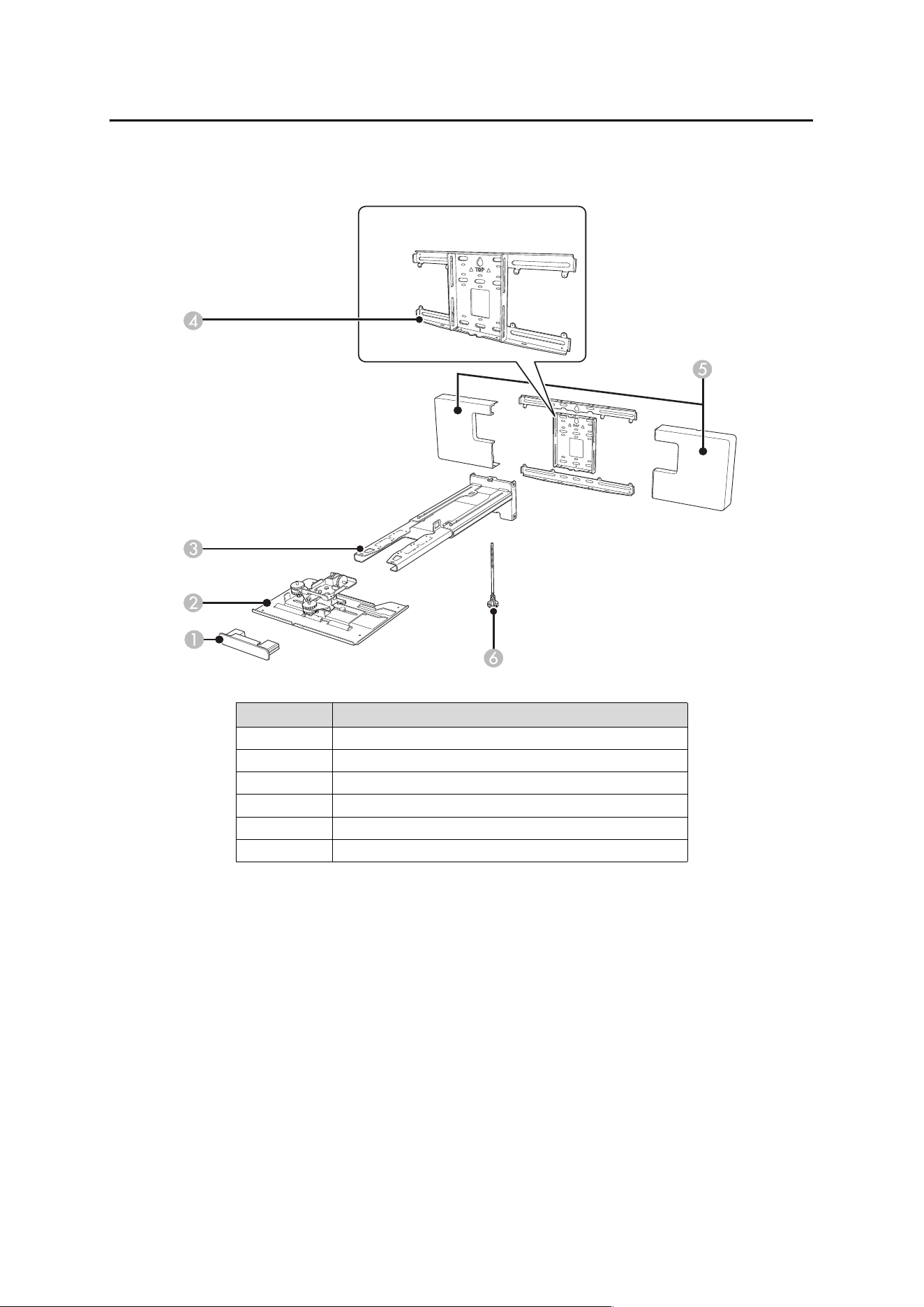
1 Package Contents
8
2 Specifications
10
3 Connecting Devices
13
4 Positioning the Projector
Installation worksheet for projecting on a whiteboard
Installation worksheet for projecting on a plain wall
Projection distance worksheets
Diagonal image size and mounting position
Distance from top of projected image to wall plate
Installation measurement tables
14
14
16
17
18
19
19
5 Installing the Projector
Assemble the parts
Install the wall plate on the wall
Determine the projection distance an
d pull out the mount arm slider
Attach the arm unit to the wall plate
Route the cables through the arm unit
Adjust the vertical slide position of the arm
Attach the projector to the wall mount
Attach a Mini PC or Stick PC if necessary
25
25
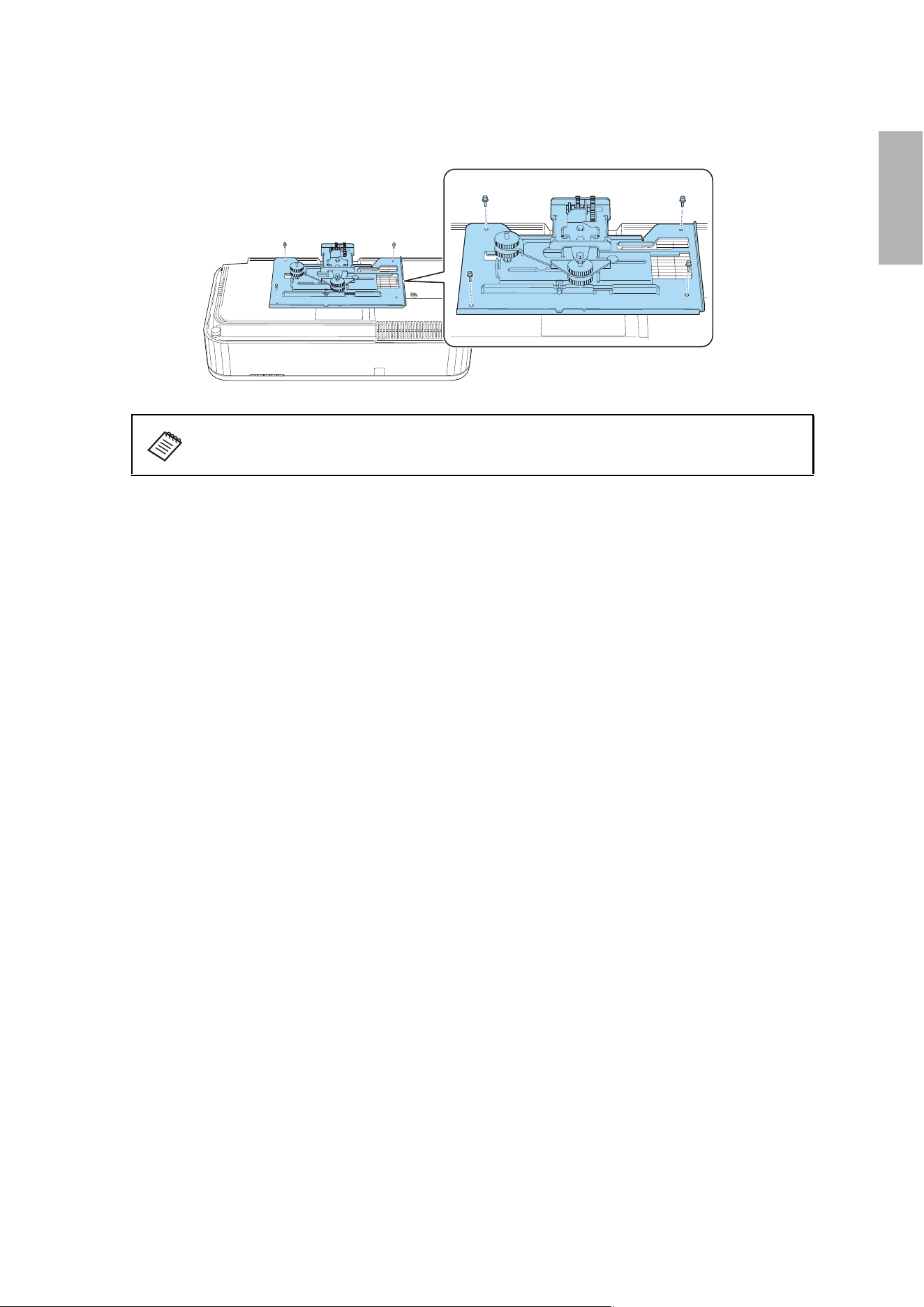
28
31
32
33
35
36
37
6 Adjusting the Image
Display the Setting Plate Installation Guide
Use adjustment dial 1 on the left side to adjust the horizontal roll
Use adjustment dial 2 on the top to adjust the horizontal rotation
Use adjustment dial 3 on the front to adjust the vertical tilt
Adjust the horizontal slide
Adjust the forward/backward slide
Adjust the vertical slide
Adjust the focus
Turn off the display of the test pattern
39
39
40
41
41
42
42
43
44
44
7 Attaching the Covers
Attach the wall plate cover and end cap
45
45

8
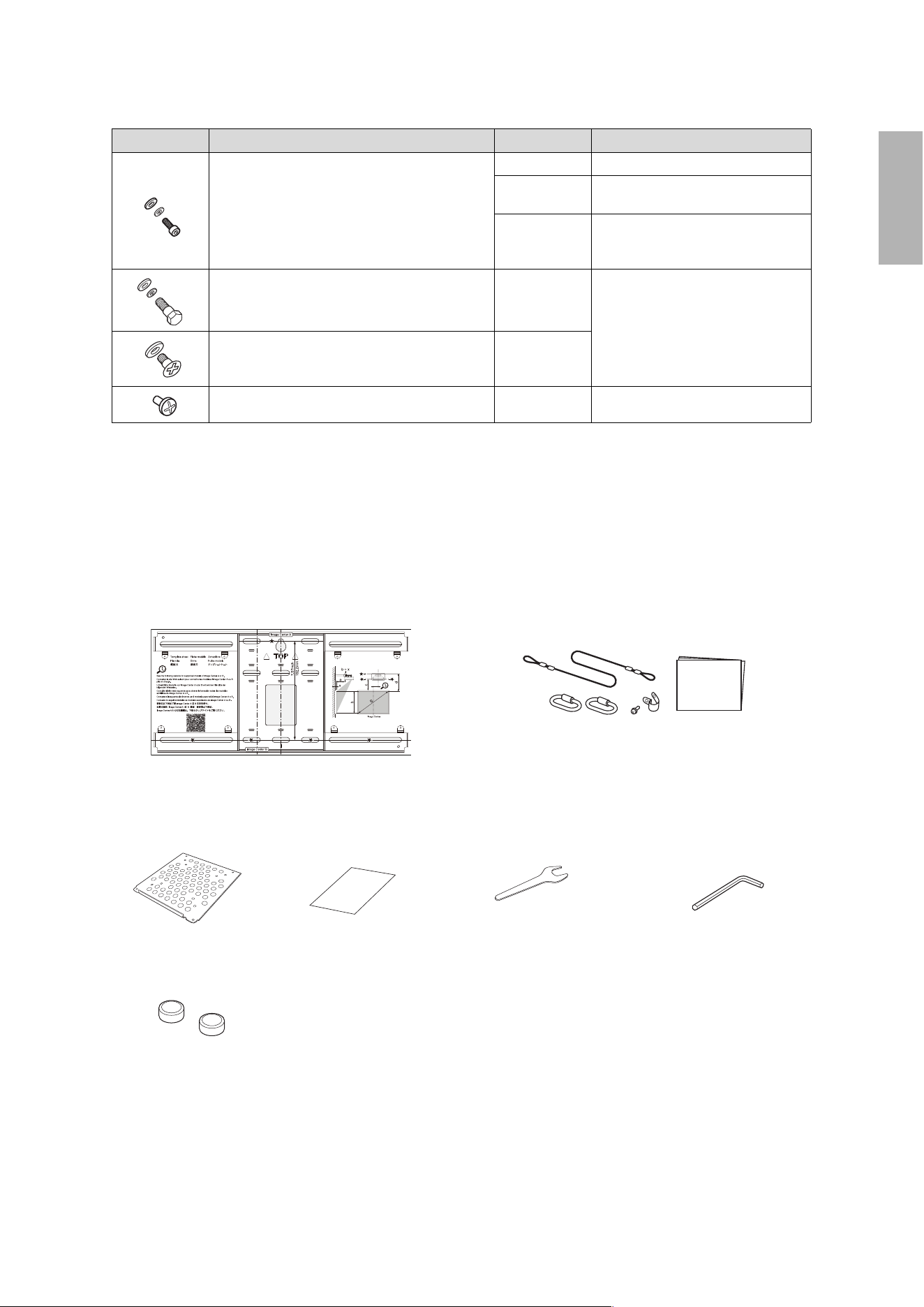
1 Package Contents
Wall Mount
# Part name
1End cap
2 3-axis adjustment unit and slide plate (attached when shipped)
3Arm unit
4 Wall plate
5 Wall plate covers
6 Hexagonal shaft
9
English
Hardware
• Use the bolts or screws supplied with the wall mount to install it as directed in this guide. Do not
substitute these bolts with any other types.
• You need to use commercially available M10 × 60 mm or 3/8 inch anchors (at least 4) and one M10 screw
to attach the wall plate to the wall.
• Gather the tools and parts you need before you begin installation, including a 17 mm ratchet wrench (for
adjusting the hexagonal shaft).
Accessories
Shape Name Quantity Application
M4 × 12 mm hexagon socket head cap bolt with
washer/spring washer
5 For wall plate assembly
4 For 3-axis adjustment unit/wall mount
installation
4 For slide plate/projector installation
M6 × 20 mm hexagon shoulder head bolt with
washer/spring washer
1 For wall mount/wall plate installation
M6 × 20 mm cross recessed head shoulder screw
with plastic washer
3
M3 × 6 mm cross recessed head shoulder screws 4
For Mini PC plate installation
Template sheet
(for installing the wall plate)
Mini PC plate
Rubber Caps
Safety wire installation kit (for
securing the projector)
Masking sticker
Open-ended wrench
13 mm (for M6) × 6 mm
Hexagon Wrench (for M4)
10
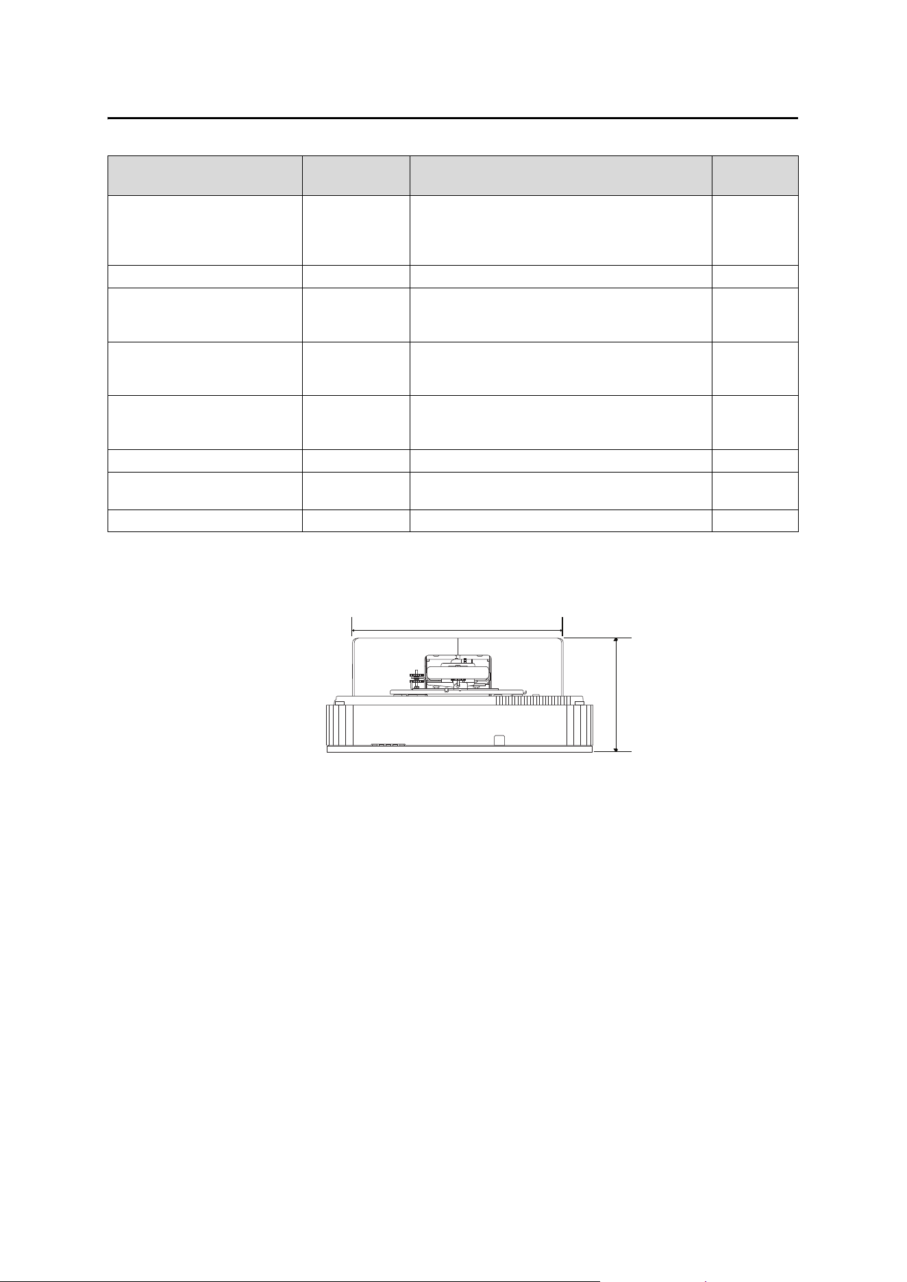
2 Specifications
Wall plate cover
Item Specification Additional information
Reference
page
Wall mount weight (including the
3-axis adjustment unit, slide plate,
wall plate, wall plate cover, and
end cap)
Approx. 20.9 lb
(9.5 kg)
——
Maximum load capacity 33.1 lb (15.0 kg) — —
Vertical slide adjustment range ±1.6 in. (40 mm) — Refer to the
illustration on
p. 11
Horizontal slide adjustment range ±1.8 in. (45 mm) — Refer to the
illustration on
p. 11
Forward/backward slide
adjustment range
0 to 10.4 in.
(0 to 266 mm)
Determine adjustment unit installation position based
on screen size
Refer to the
illustration on
p. 12
Horizontal roll adjustment range ±3° Fine adjustments possible with adjustment dial
s p. 40
Horizontal rotation adjustment
range
±8° Fine adjustments possible with adjustment knob
s p. 41
Vertical tilt adjustment range ±3° Fine adjustments possible with adjustment dial
s p. 41
21.6 in. (549.9 mm)
10.4 to 13.6 in. (266 to 346 mm)
11
English
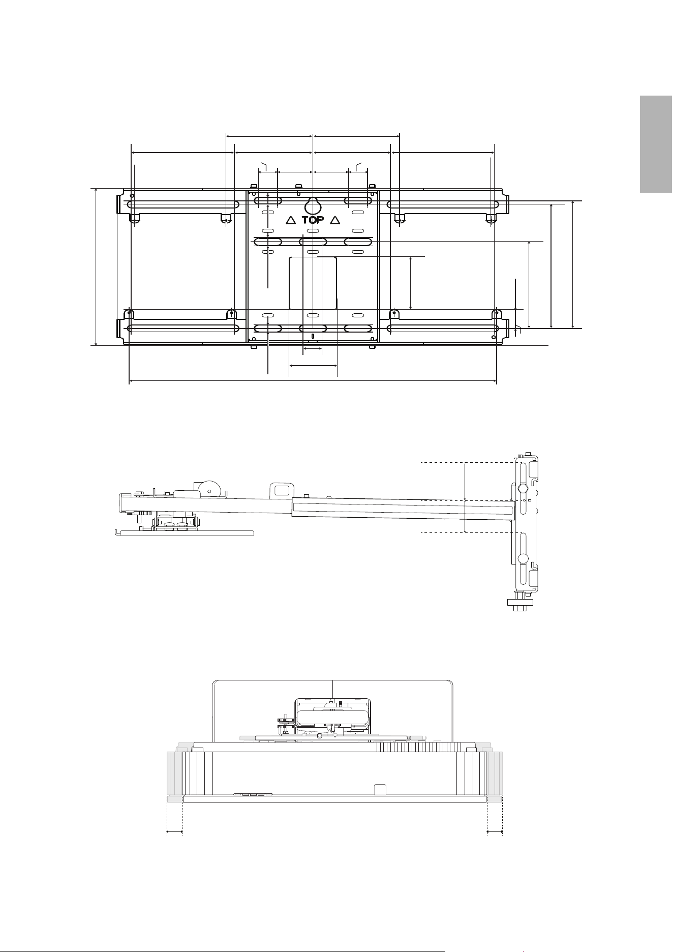
Wall plate
The wall plate is in three pieces when shipped. Use the included M4 × 12 mm bolts (×5) to attach the separate
pieces together before mounting the projector. See page 25 for instructions.
Vertical slide adjustment range
Horizontal slide adjustment range
18.3 in. (466 mm)
5.2 in. (131 mm)
1.1 in. (28.3 mm)
5.1 in. (130.2 mm)
7.3 in. (186.4 mm)
7.6 in. (192.2 mm)
1.8 in.
(45 mm)
1.8 in.
(45 mm)
4.3 in. (110 mm) 4.3 in. (110 mm)
5.2 in. (131 mm)
3.1 in.
(79 mm)
0.9 in. (24 mm)
2.4 in. (60 mm)
9.2 in. (234.8 mm)
0.9 in. (24 mm)
0.9 in. (24 mm)
1.6 in. (40 mm)
1.6 in. (40 mm)
1.8 in. (45 mm) 1.8 in. (45 mm)
12
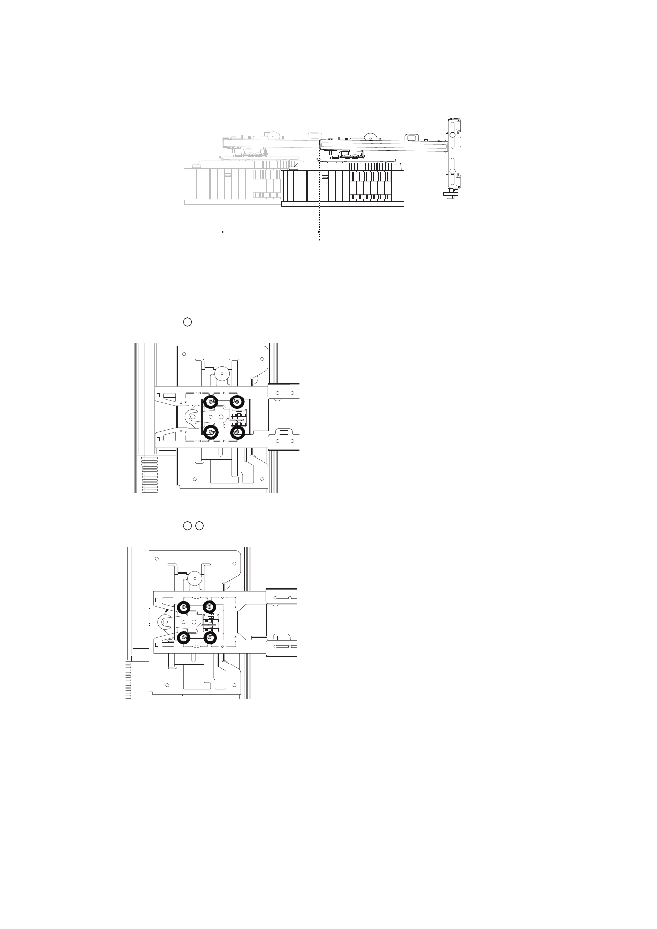
Forward/backward slide adjustment range
Arm slide adjustment range
Adjustment from 3-axis adjustment unit installation position
By changing the installation position of the 3-axis adjustment unit to the front or back, you can adjust the
installation position of the projector.
• Mount at the stamp when the image is less than 117 inches diagonally.
• Mount at the stamp when the projected image is 117 inches or more diagonally.
To see these stamps, you need to loosen the two top bolts and slide out the arm extension.
10.4 in. (266 mm)
13
English
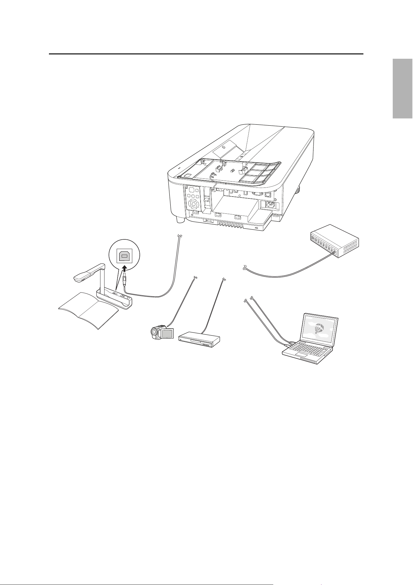
3Connecting Devices
Make sure you have the power cord, computer cable, and other parts at the location where the wall mount is
to be installed. Make sure you also have all necessary cables for the devices, such as a document camera that
you will connect to the projector. Your projector’s connection panel may differ slightly from the model in the
illustrations. For details, refer to the online User’s Guide for your projector.
Connection Example
14
4 Positioning the Projector
Your Epson projector can project images up to the following sizes:
You can project onto a plain wall, screen, or pre-installed whiteboard.
The height of the included wall mount determines the maximum image size and how high the image appears
on the wall. The distance from the projector to the wall (once it is mounted on the adjustable arm of the wall
mount) also affects image size and position.
If you are planning to project on a whiteboard, the image may not fill the entire board, depending on the
aspect ratio. If you match the image height to the board’s height, gaps may appear on the sides of the board.
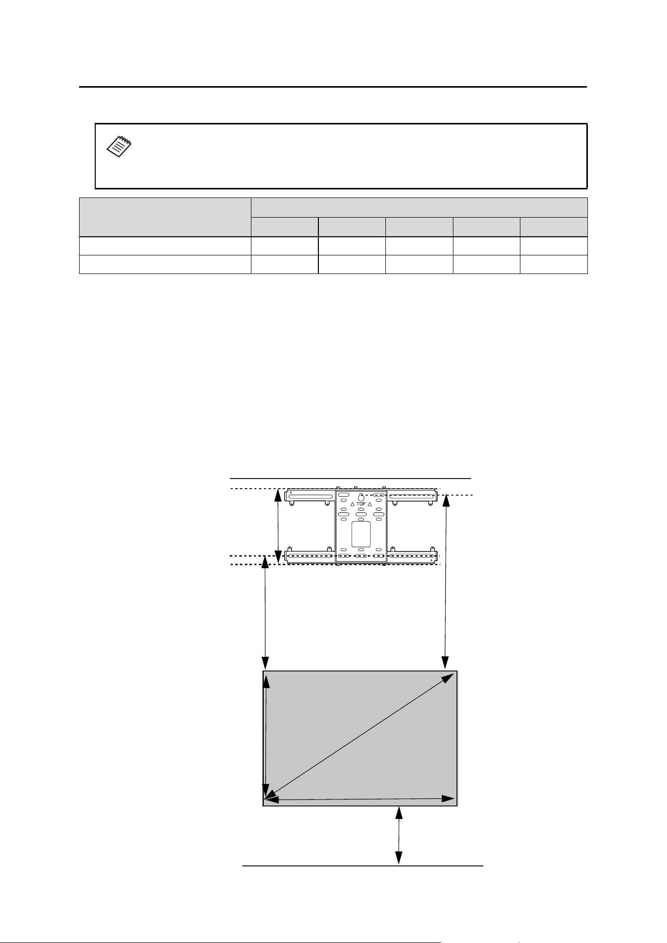
Use the following worksheets to determine the proper location of the wall plate on the wall. If you are
projecting onto a whiteboard, use the worksheet below If you are projecting on a plain wall, use the
worksheet on page 16.
Installation worksheet for projecting on a whiteboard
This guide covers select image sizes. For guidance on other image sizes, use the Epson
Projector Throw Distance Simulator at http://epson.com/support/calculators (U.S.),
http://epson.ca/support/calculators (Canada), or
http://epson.com.jm/support/calculators (Latin America).
Projector
Maximum projected image size (diagonally)
16:9 16:10 4:3 21:9 16:6
EB-810E/EB-815E 160 inches 148 inches 130 inches 151 inches 148 inches
EH-QS100B/EH-QS100W 160 inches 148 inches 130 inches Not supported Not supported
11 in. (280 mm)—height of
wall plate plus cover
Required distance from the
bottom holes of the wall
plate to the top of the
image area (c)
Diagonal size of
image area (S)
Height of
image area (h)
Width of image area (w)
Distance from floor to
bottom of image area (f)
Distance from the
temporary wall plate
hole to the top of the
image area (d)

15
English
1. Measure the ceiling height (distance from the floor to the ceiling). _____
2. Measure the height of the board’s image area (h). _____ (h)
3. Measure the width of the board’s image area (w). _____ (w)
4. Measure the distance from the floor to the bottom of the board’s image area (f). _____ (f)
5. Measure the thickness of the board (distance from the projection surface to the wall)
(x).
_____ (x)
6. Determine the aspect ratio of the board or of the images that will be projected. You
may need to consult your IT department for this information.
___ 4:3 ___ 16:10 ___ 16:9 Widescreen ___ 16:6* ___ 21:9*
* EB-810E/EB-815E only.
If your desired aspect ratio does not match the native aspect ratio of your product,
use the Epson Projector Throw Distance Simulator at
http://epson.com/support/calculators (U.S.),
http://epson.ca/support/calculators (Canada), or
http://epson.com.jm/support/calculators (Latin America) to determine the correct
measurements.
7. Using the tables on pages 20 to 24 and your desired image height (h), find the required
distance between the top of the image area and the bottom holes of the wall plate (c). _____ (c)
8. Using the tables on pages 20 to 24 and your desired image height (h), find the required
distance between the top of the image area and the temporary wall plate hole (d). _____ (d)
9. Add:
Required distance from top of image area to bottom holes of wall plate (c)
Height of image area (h)
Distance from floor to bottom of image area (f)
Height of wall plate plus cover
If the total exceeds the ceiling height, you will need to reduce the image size or reduce
the distance from the floor to the bottom of the image area.
_____ (c)
_____ (h)
_____ (f )
+ 11
inches
(280 mm)
_____ total
10. After confirming your image size, use tape or a pencil to mark the distance (c) from the
top of the image area on the board to the bottom holes of the wall plate.
11. Align the line (horizontal) on the template sheet with the (c) mark, then align the
center line on the template sheet with the center of the image area. Follow the
instructions on page 25 to install the projector.
16
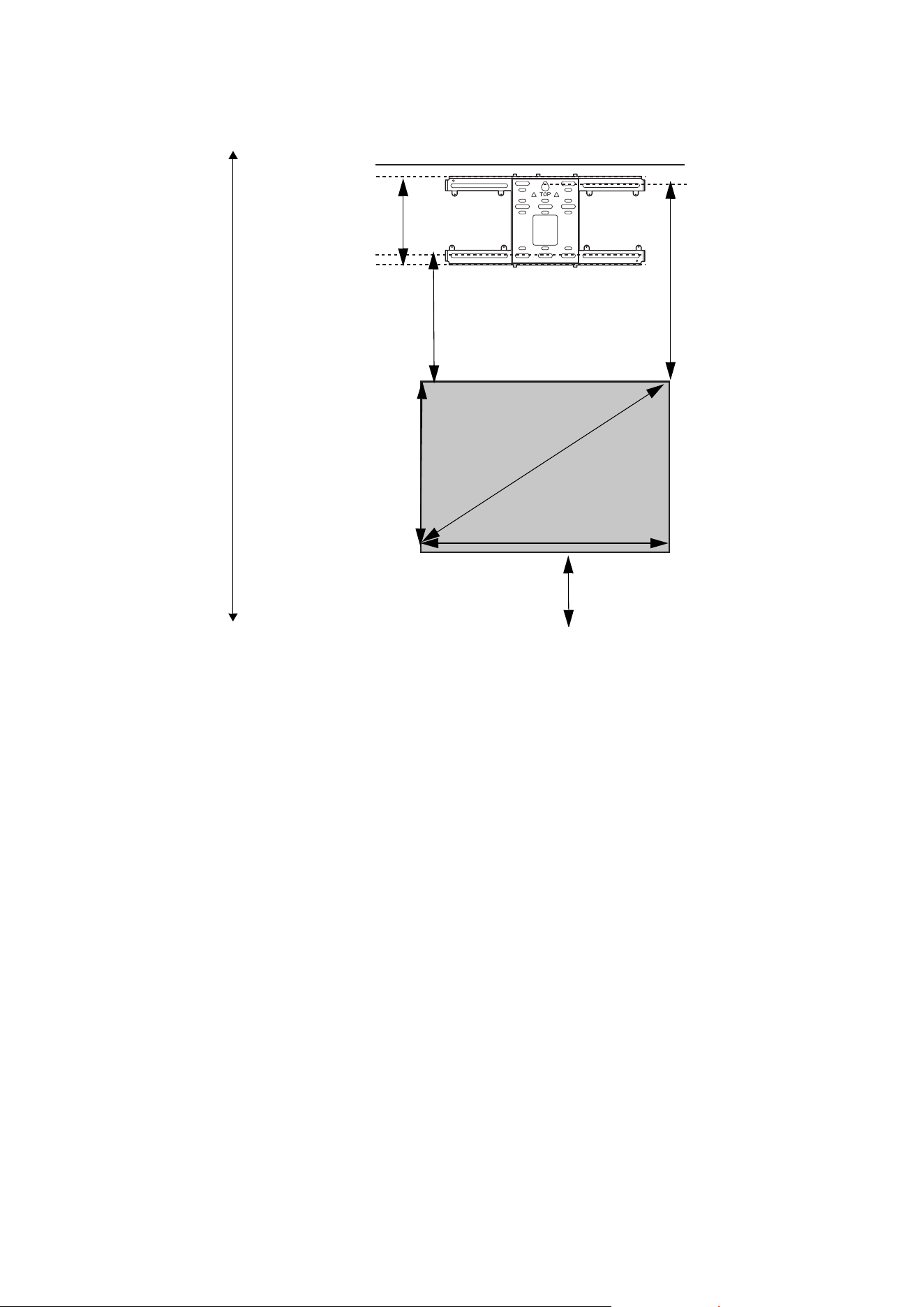
Installation worksheet for projecting on a plain wall
1. Measure the ceiling height (distance from the floor to the ceiling). _____
2. Determine the aspect ratio of the images that will be projected. You may need to
consult your IT department for this information.
___ 4:3 ___ 16:10 ___ 16:9 Widescreen ___ 16:6* ___ 21:9*
* EB-810E/EB-815E only.
If your desired aspect ratio does not match the native resolution of your product, use
the Epson Projector Throw Distance Simulator at
http://epson.com/support/calculators (U.S.),
http://epson.ca/support/calculators (Canada), or
http://epson.com.jm/support/calculators (Latin America) to determine the correct
measurements.
3. Using the tables on pages 20 to 24, select the largest image size available for your
ceiling height.
Image height (h)
Image width (w)
_____ (h)
_____ (w)
4. Determine the desired distance from the floor to the bottom of the image area (f).
The recommended minimum distance is 30 inches (762 mm). Images appearing less
than 28 inches (711 mm) from the floor may be obstructed for some viewers.
_____ (f )
5. Find the top of the projected image area by adding distances (f ) and (h). _____
6. Use the tables on pages 20 to 24 to determine the required distance from the top of the
image area to the bottom holes of the wall plate (c). _____ (c)
7. Use the tables on pages 20 to 24 to determine the required distance between the top
of the image area and the temporary wall plate hole (d). _____ (d)
11 in. (280 mm)—height of
wall plate plus cover
Required distance from the
bottom holes of the wall plate
to the top of the image area
(c)
Diagonal size of
image area (S)
Height of
image area (h)
Distance from the
temporary wall plate
hole to the top of the
image area (d)
Width of image area (w)
Distance from floor to
bottom of image area (f)
Ceiling height

17
English
Projection distance worksheets
The tables on the following pages provide installation information for select image sizes. The minimum ceiling
height is based on an image 30 inches (762 mm) from the floor; if the image is lower, the minimum ceiling
height is reduced by the corresponding measurement.
Use the worksheets, the illustrations, and the information in the tables on the following pages to determine
the projection distance and placement of the wall plate.
8. Add:
Required distance from top of image area to bottom holes of wall plate (c)
Height of image area (h)
Distance from floor to bottom of image area (f)
Height of wall plate plus cover
If the total exceeds the ceiling height, you will need to reduce the image size or reduce
the distance from the floor to the bottom of the image area.
_____ (c)
_____ (h)
_____ (f)
+ 11
inches
(280 mm)
_____ total
9. After confirming your image size, use tape or a pencil to mark the distance (c) from the
top of the image area on the board to the bottom holes of the wall plate.
10. Align the line (horizontal) on the template sheet with the (c) mark, then align the
center line on the template sheet with the center of the image area. Follow the
instructions on page 25 to install the projector.
18
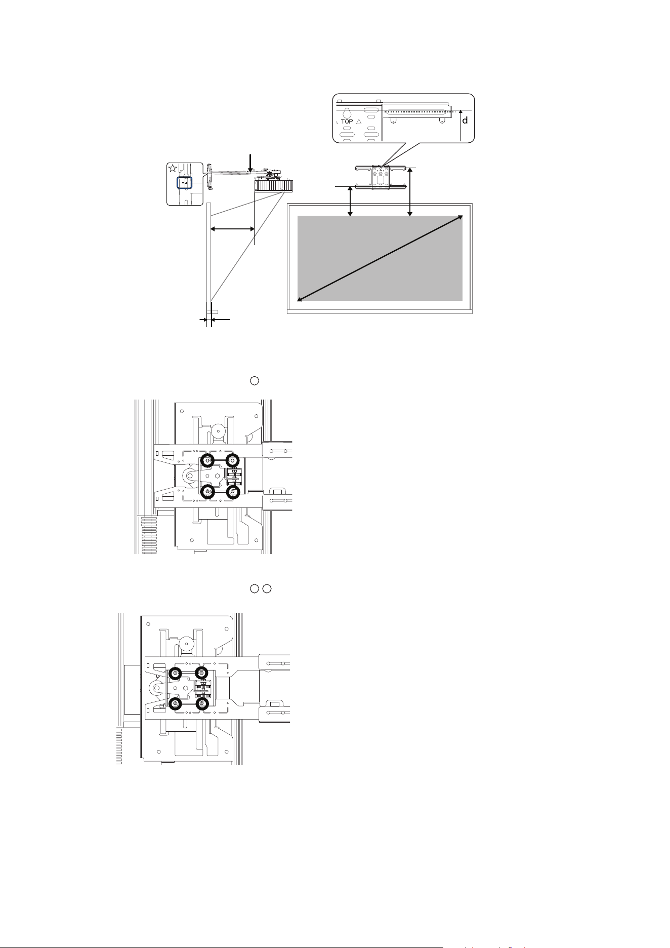
Diagonal image size and mounting position
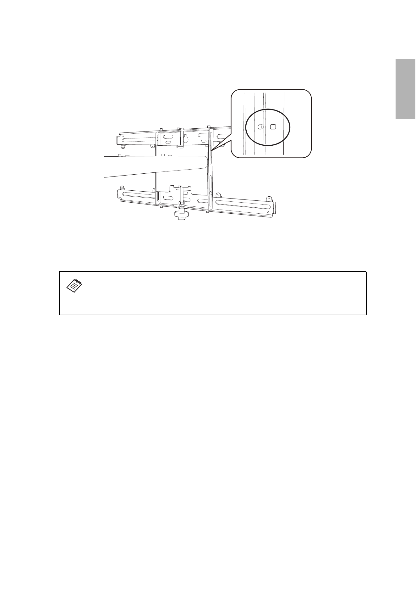
In order to see the stamp and the numbers on the slider scale (b), you need to loosen the two top bolts and
slide out the arm extension.
• Mount the projector at the stamp when the image is less than 117 inches diagonally.
• Mount the projector at the stamp when the image is 117 inches or more diagonally.
S
a
c
d
b + x
x
19
English
Distance from top of projected image to wall plate
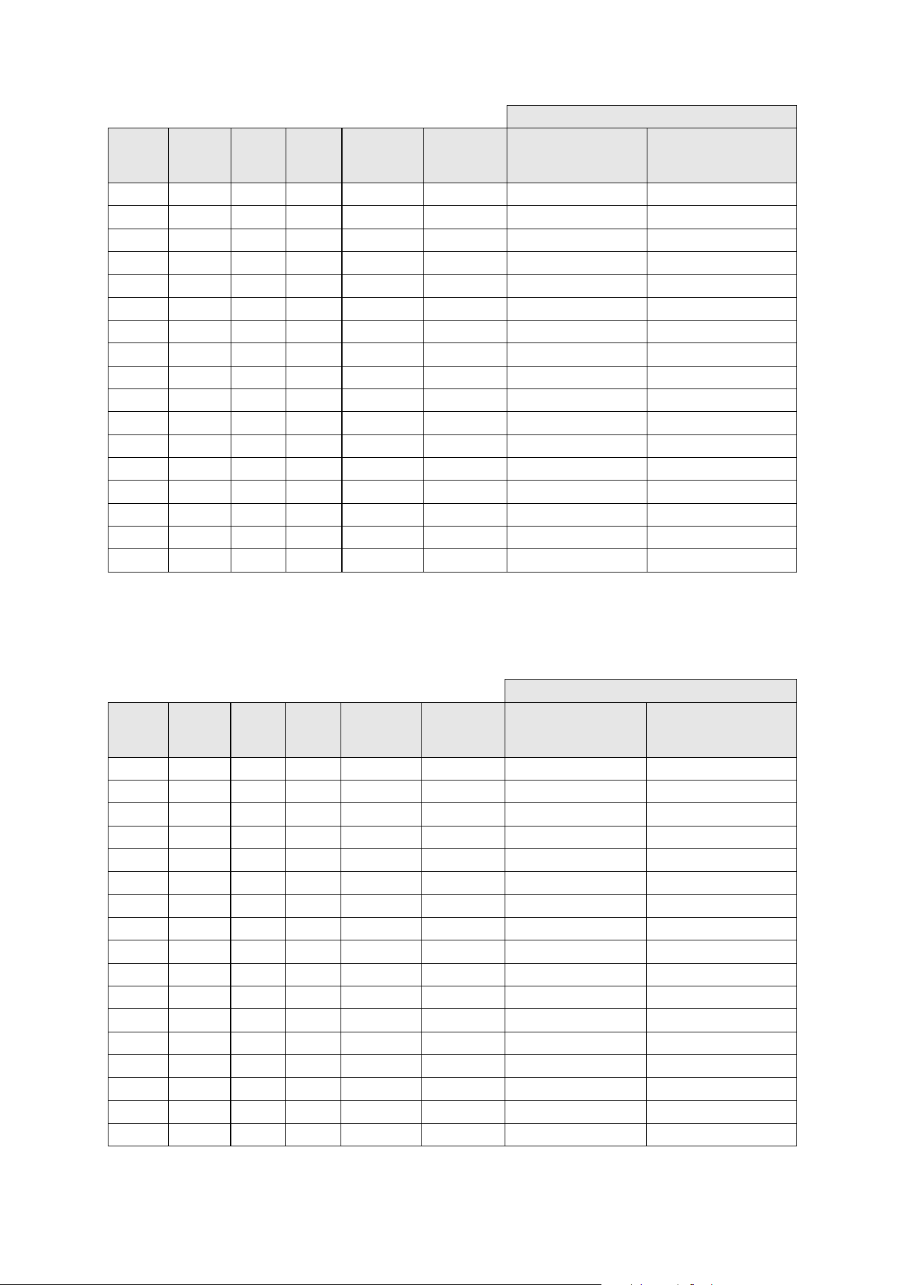
The distance (c) from the top of the projected image to the bottom mounting holes on the wall plate is the
number given when the vertical slide is set to the base position, as shown below.
Match the notch on the arm unit to the position of the stamp on the wall plate.
Installation measurement tables
See the following pages for your projector’s installation measurement tables.
The measurements may differ depending on the location where you place the
projector. When projecting in Tele mode, the quality of the projected images may
decrease.
A shorter (x) distance may increase the minimum projection size.
20
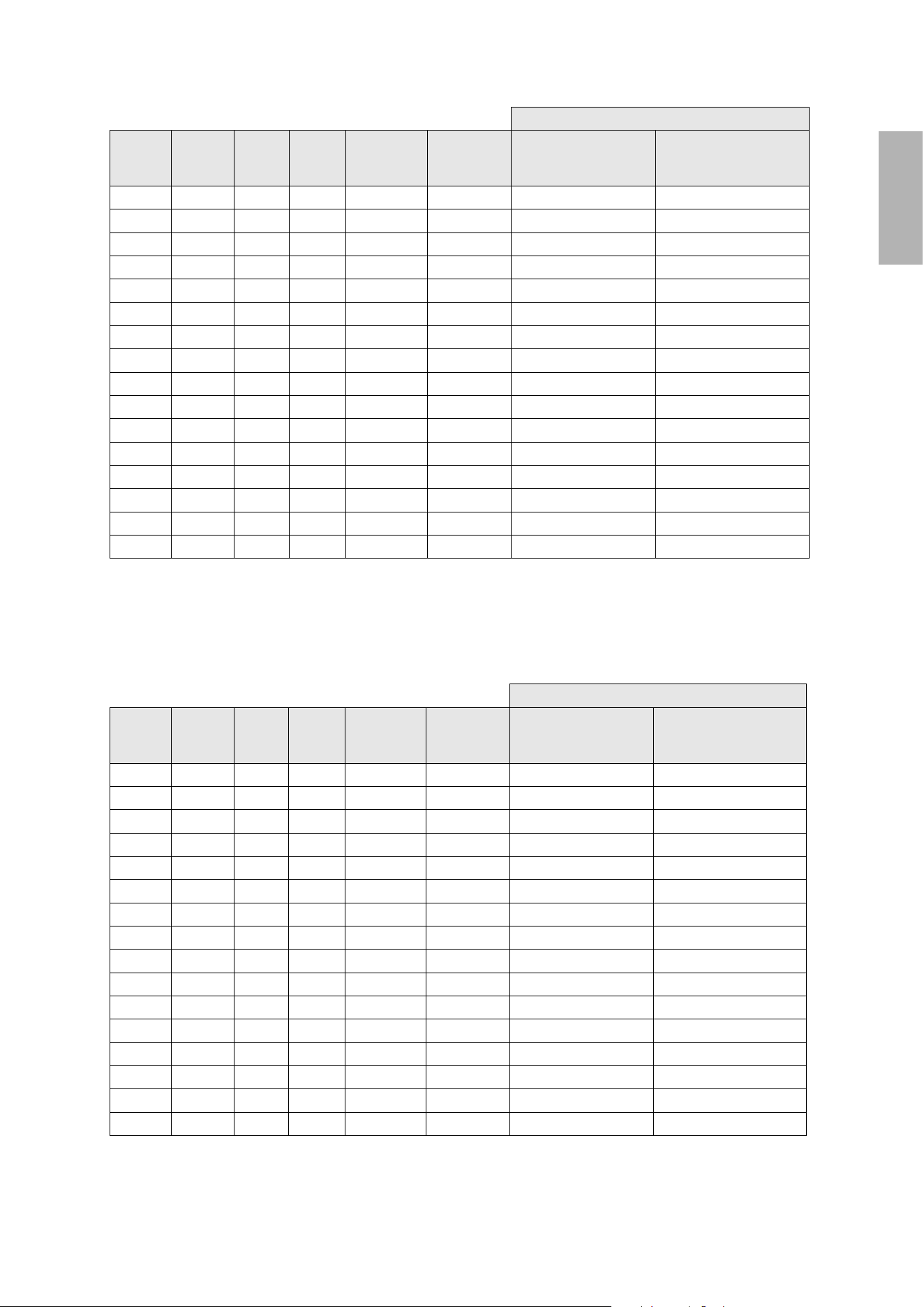
Measurements in Inches for 16:9
* Based on an image 30 inches from the floor; if the image is lower, the minimum ceiling height is reduced by the corresponding
measurement.
** EH-QS100B/EH-QS100W
Measurements in Centimeters for 16:9
* Based on an image 76.2 cm from the floor; if the image is lower, the minimum ceiling height is reduced by the corresponding
measurement.
** EH-QS100B/EH-QS100W
Default Screen Position
Diagonal
image
size (S)
Min.
ceiling
height*
Image
width
(w)
Image
height
(h)
Min.
projection
distance (a)
Sliderscale
mark (b)
Distance from top of
image to bottom wall
plate holes (c)
Distance from top of
image to temporary wall
plate hole (d)
80”**
87.8 69.7 39.2 0.9 2.9 7.6 15.2
85”**
90.7 74.1 41.7 1.6 2.2 8.0 15.6
90”**
93.6 78.4 44.1 2.4 1.4 8.4 16.0
95”**
96.4 82.8 46.6 3.1 0.7 8.8 16.4
100”
99.2 87.1 49 3.8 0.05 9.2 16.7
105”
102.1 91.5 51.5 4.5 .8 9.6 17.1
110”
104.9 95.8 53.9 5.3 1.5 10 17.5
115”
107.7 100 56.3 6 2.3 10.4 18
120”
110.6 104.5 58.8 6.7 .5 10.8 18.4
125”
113.5 108.9 61.3 7.5 1.3 11.2 18.8
130”
116.3 113.2 63.7 8.2 2 11.6 19.2
135”
119.1 117.5 66.1 9 2.8 12 19.5
140”
122 121.9 68.6 9.7 3.5 12.4 20
145”
124.8 126.2 71 10.4 4.2 12.8 20.4
150”
127.7 130.6 73.5 11.2 5 13.2 20.8
155”
130.5 134.9 75.9 11.9 5.7 13.6 21.2
160”
133.4 139.3 78.4 12.6 6.4 14 21.6
Default Screen Position
Diagonal
image
size (S)
Min.
ceiling
height*
Image
width
(w)
Image
height
(h)
Min.
projection
distance (a)
Sliderscale
mark (b)
Distance from top of
image to bottom wall
plate holes (c)
Distance from top of
image to temporary wall
plate hole (d)
80”**
223.1 177.1 99.6 2.3 7.3 19.3 38.5
85”**
230.3 188.2 105.8 4.1 5.5 20.3 39.5
90”**
237.7 199.2 112.1 6.0 3.6 21.4 40.6
95”**
244.9 210.3 118.3 7.9 1.7 22.4 41.6
100”
251.9 221.2 124.4 9.6 0.1 23.3 42.4
105”
259.3 232.4 130.8 11.4 2 24.3 43.4
110”
266.4 243.3 136.9 13.4 3.8 25.4 44.4
115”
273.5 254 143 15.2 5.8 26.4 45.7
120”
280.9 265.4 149.3 17 1.2 27.4 46.7
125”
288.2 276.6 155.7 19 3.3 28.4 47.7
130”
295.4 287.5 161.7 20.8 5 29.4 48.7
135”
302.5 298.4 167.8 22.8 7.1 30.4 49.5
140”
309.8 309.6 174.2 24.6 8.8 31.4 50.8
145”
316.9 320.5 180.3 26.4 10.6 32.5 51.8
150”
324.3 331.7 186.6 28.4 12.7 33.5 52.8
155”
331.4 342.6 192.7 30.2 14.4 34.5 53.8
160”
338.8 353.8 199.1 32 16.2 35.5 54.8
21
English
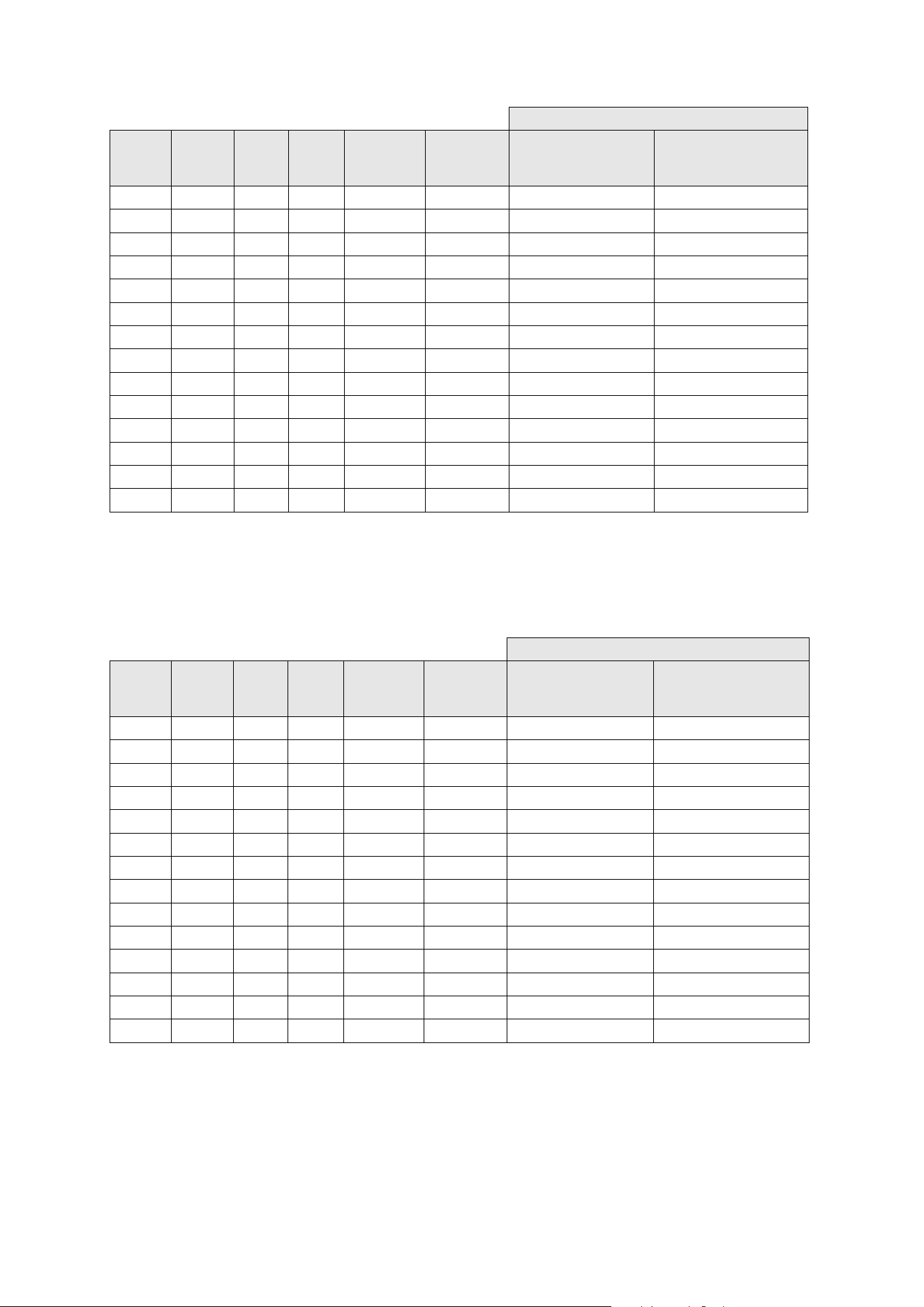
Measurements in Inches for 16:10
* For images less than 99 inches, the projector's Tele settings must be used to reduce the image size.
** Based on an image 30 inches from the floor; if the image is lower, the minimum ceiling height is reduced by the corresponding
measurement.
*** EH-QS100B/EH-QS100W
Measurements in Centimeters for 16:10
* For images less than 99 inches, the projector's Tele settings must be used to reduce the image size.
** Based on an image 76.2 cm from the floor; if the image is lower, the minimum ceiling height is reduced by the corresponding
measurement.
*** EH-QS100B/EH-QS100W
Default Screen Position
Diagonal
image
size* (S)
Min.
ceiling
height**
Image
width
(w)
Image
height
(h)
Min.
projection
distance (a)
Sliderscale
mark (b)
Distance from top of
image to bottom wall
plate holes (c)
Distance from top of
image to temporary wall
plate hole (d)
75”***
88.5 63.6 39.8 1.1 2.7 7.7 15.2
80”***
91.5 67.8 42.4 1.9 1.9 8.1 15.7
85”***
94.6 72.1 45.0 2.6 1.1 8.5 16.1
90”***
97.7 76.3 47.7 3.4 0.4 9.0 16.5
95”
100.7 80.4 50.3 4.2 0.4 9.4 16.9
100”
103.7 84.6 52.9 5 1.2 9.8 17.4
105”
106.9 88.9 55.6 5.8 2 10.3 17.9
110”
109.9 93.1 58.2 6.6 2.8 10.7 18.3
115”
113 97.4 60.9 7.4 3.6 11.1 18.7
120”
116.1 101.6 63.5 8.2 2.2 11.6 19.2
125”
119.2 105.9 66.2 9 2.8 12 19.6
130”
122.3 110.2 68.9 9.8 3.6 12.4 20
135”
125.4 114.4 71.5 10.5 4.3 12.9 20.5
140”
128.4 118.5 74.1 11.4 5.2 13.3 20.9
145”
131.5 122.8 76.8 12.2 6 13.7 21.3
148”
133.4 125.4 78.4 12.6 6.4 14 21.6
Default Screen Position
Diagonal
image
size* (S)
Min.
ceiling
height**
Image
width
(w)
Image
height
(h)
Min.
projection
distance (a)
Sliderscale
mark (b)
Distance from top of
image to bottom wall
plate holes (c)
Distance from top of
image to temporary wall
plate hole (d)
75”***
224.7 161.5 101.0 2.7 6.9 19.5 38.7
80”***
232.5 172.3 107.7 4.7 4.9 20.6 39.8
85”***
240.3 183.1 114.4 6.7 2.9 21.7 40.9
90”***
248.2 193.9 121.2 8.7 0.9 22.8 42.0
95”
255.7 204.2 127.7 10.6 1 23.8 42.9
100”
263.3 214.8 134.3 12.7 3 24.8 44.1
105”
271.5 225.8 141.2 14.7 5 26.1 45.4
110”
279.1 236.4 147.8 16.7 7.1 27.1 46.4
115”
286.9 247.3 154.6 18.7 9.1 28.1 47.4
120”
294.8 258 161.2 20.8 5.5 29.4 48.7
125”
302.7 268.9 168.1 22.8 7.1 30.4 49.7
130”
310.6 279.9 175 24.8 9.1 31.4 50.8
135”
318.5 290.5 181.6 26.6 10.9 32.7 52
140”
326.1 300.9 188.2 28.9 13.2 33.7 53
145”
333.9 311.9 195 30.9 15.2 34.7 54.1
148”
338.8 318.5 199.1 32 16.2 35.5 54.8
22
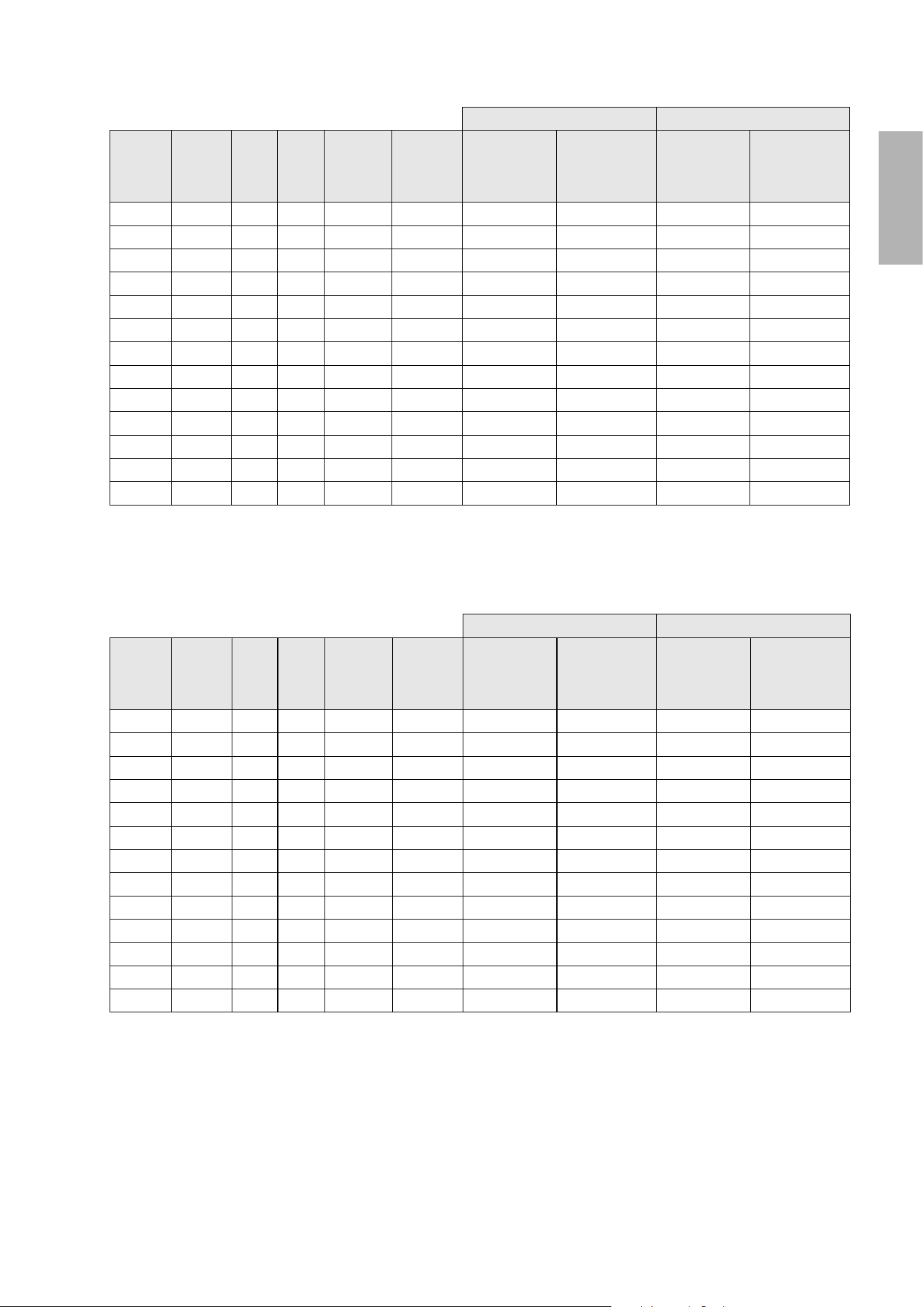
Measurements in Inches for 4:3
* For images less than 99 inches, the projector's Tele settings must be used to reduce the image size.
** Based on an image 30 inches from the floor; if the image is lower, the minimum ceiling height is reduced by the corresponding
measurement.
*** EH-QS100B/EH-QS100W
Measurements in Centimeters for 4:3
* For images less than 99 inches, the projector's Tele settings must be used to reduce the image size.
**Based on an image 76.2 cm from the floor; if the image is lower, the minimum ceiling height is reduced by the corresponding
measurement.
*** EH-QS100B/EH-QS100W
Default Screen Position
Diagonal
image
size* (S)
Min.
ceiling
height**
Image
width
(w)
Image
height
(h)
Min.
projection
distance (a)
Sliderscale
mark (b)
Distance from top of
image to bottom wall
plate holes (c)
Distance from top of
image to temporary wall
plate hole (d)
66”***
88.3 52.8 39.6 1.0 2.8 7.7 15.2
70”***
91.1 56.0 42.0 1.7 2.0 8.1 15.6
75”***
94.6 60.0 45.0 2.6 1.1 8.5 16.1
80”***
98.1 64.0 48.0 3.5 0.2 9.1 16.6
85”
101.5 68 51 4.4 0.6 9.5 17.1
90”
104.9 71.8 53.9 5.3 1.5 10 17.6
95”
108.5 76 57 6.2 2.4 10.5 18
100”
112 80 60 7.1 3.3 11 18.6
105”
115.4 83.8 62.9 8 4.2 11.5 19
110”
118.9 87.8 65.9 8.9 5.1 12 19.5
115”
122.4 92 69 9.8 6 12.4 20
120”
125.9 95.8 71.9 10.7 4.5 13 20.5
125”
129.4 100 75 11.6 5.4 13.4 21
130”
132.8 103.8 77.9 12.5 6.3 13.9 21.5
Default Screen Position
Diagonal
image
size* (S)
Min.
ceiling
height**
Image
width
(w)
Image
height
(h)
Min.
projection
distance (a)
Sliderscale
mark (b)
Distance from top of
image to bottom wall
plate holes (c)
Distance from top of
image to temporary wall
plate hole (d)
66”***
224.3 134.1 100.6 2.6 7.0 19.5 38.7
70”***
231.4 142.2 106.7 4.4 5.2 20.5 39.7
75”***
240.2 152.4 114.3 6.7 2.9 21.7 40.9
80”***
249.1 162.6 121.9 9.0 0.6 23.0 42.2
85”
257.8 172.7 129.5 11.1 1.5 24.1 43.4
90”
266.5 182.3 136.9 13.4 3.8 25.4 44.7
95”
275.5 193 144.7 15.7 6 26.6 45.7
100”
259.1 203.2 127 18 8.3 27.9 47.2
105”
293.1 212.8 159.7 20.3 10.6 29.2 48.2
110”
301.9 223 167.3 22.6 12.9 30.4 49.5
115”
310.8 233.6 175.2 24.8 62.9 31.4 50.8
120”
319.8 243.3 182.6 27.1 68.8 33 52
125”
328.7 254 190.5 29.4 74.6 34 53.3
130”
337.3 263.6 197.8 31.7 80.5 35.3 54.6
23
English
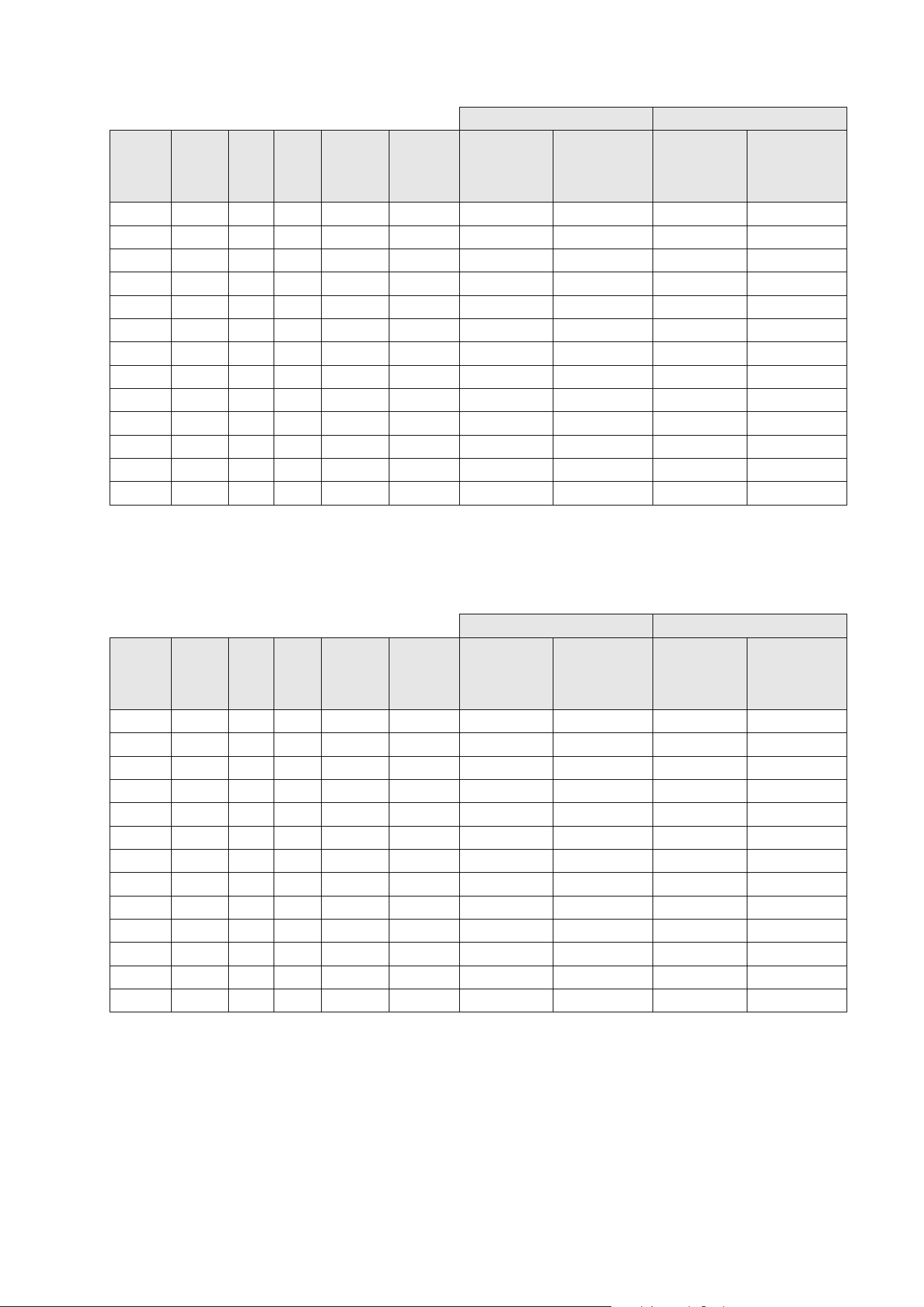
Measurements in Inches for 21:9 (EB-810E/EB-815E)
* For images less than 99 inches, the projector's Tele settings must be used to reduce the image size.
** Based on an image 30 inches from the floor; if the image is lower, the minimum ceiling height is reduced by the corresponding
measurement.
Measurements in Centimeters for 21:9 (EB-810E/EB-815E)
* For images less than 99 inches, the projector's Tele settings must be used to reduce the image size.
** Based on an image 30 inches from the floor; if the image is lower, the minimum ceiling height is reduced by the corresponding
measurement.
Default Screen Position Screen Position max. (top)
Diagonal
image
size* (S)
Min.
ceiling
height**
Image
width
(w)
Image
height
(h)
Min.
projection
distance
(a)
Sliderscale
mark (b)
Distance from
top of image
to bottom wall
plate holes (c)
Distance from
top of image to
temporary wall
plate hole (d)
Distance from
top of image
to bottom wall
plate holes (c)
Distance from
top of image to
temporary wall
plate hole (d)
95”
93.5 87.3 37.4 3.9 -9 0.1 15.1 22.6 9.2 16.8
100”
96.2 91.9 39.4 4.6 - 10.1 0.9 15.8 23.3 9.6 17.2
105”
98.9 96.5 41.4 5.4 - 11.1 1.7 16.5 24.1 10.1 17.6
110”
101.6 101.1 43.3 6.2 - 12.2 2.4 17.3 24.8 10.5 18.1
115”
104.3 105.7 45.3 7 3.2 18 25.6 10.9 18.5
120”
107 110.3 47.3 7.8 1.5 18.7 26.3 11.4 18.9
125”
109.6 114.9 49.2 8.5 2.3 19.4 27.0 11.8 19.3
130”
112.4 119.5 51.2 9.3 3.1 20.2 27.8 12.2 19.8
135”
113.5 121.3 52 10.1 3.4 20.5 28.0 12.3 19.9
140”
116.2 128.6 55.1 10.9 4.2 21.2 28.8 12.8 20.4
145”
118.8 133.2 57 11.7 5 21.9 29.5 13.2 20.7
150”
121.6 137 59 12.4 6.1 23.1 30.6 13.6 21.2
151”
122.1 138.7 59.4 12.6 6.3 23.2 30.8 13.7 21.3
Default Screen Position Screen Position max. (top)
Diagonal
image
size* (S)
Min.
ceiling
height**
Image
width
(w)
Image
height
(h)
Min.
projection
distance
(a)
Sliderscale
mark (b)
Distance from
top of image
to bottom wall
plate holes (c)
Distance from
top of image to
temporary wall
plate hole (d)
Distance from
top of image
to bottom wall
plate holes (c)
Distance from
top of image to
temporary wall
plate hole (d)
95”
237.6 221.8 95.1 35.3 - 48.4 0.2 38.3 57.5 23.4 42.7
100”
244.4 233.5 100.1 37.3 - 51.1 2.2 40.1 59.3 24.5 43.7
105”
251.3 245.1 105.1 39.3 - 53.8 4.2 42 61.2 25.6 44.8
110”
258.2 256.8 110.1 42.1 - 56.4 6.1 43.9 63.1 26.7 45.9
115”
265 268.5 115.1 43.2 8.1 45.7 64.9 27.2 46.9
120”
271.9 280.2 120.1 45.2 3.9 47.6 66.8 28.2 48.1
125”
278.7 291.8 125.1 47.2 5.9 49.4 68.6 29.2 49.1
130”
285.6 303.5 130.1 49.1 7.8 51.3 70.5 31 50.2
135”
292.4 315.2 135.1 51.1 9.8 53.1 72.3 32 51.2
140”
299.3 326.8 140.1 53.1 11.8 55 74.2 33.1 52.3
145”
228.3 289.5 124.1 46.8 5.5 49.1 68.3 29.7 48.9
150”
284.2 301.2 129.1 48.7 7.4 50.9 70.1 30.7 50
151”
285.6 303.5 130.1 49.1 7.8 51.3 70.5 31 50.2
24
Measurements in Inches for 16:6 (EB-810E/EB-815E)
* For images less than 99 inches, the projector's Tele settings must be used to reduce the image size.
** Based on an image 30 inches from the floor; if the image is lower, the minimum ceiling height is reduced by the corresponding
measurement.
Measurements in Centimeters for 16:6 (EB-810E/EB-815E)
* For images less than 99 inches, the projector's Tele settings must be used to reduce the image size.
** Based on an image 30 inches from the floor; if the image is lower, the minimum ceiling height is reduced by the corresponding
measurement.
Default Screen Position Screen Position max. (top)
Diagonal
image
size* (S)
Min.
ceiling
height**
Image
width
(w)
Image
height
(h)
Min.
projection
distance
(a)
Sliderscale
mark (b)
Distance from
top of image
to bottom wall
plate holes (c)
Distance from
top of image to
temporary wall
plate hole (d)
Distance from
top of image
to bottom wall
plate holes (c)
Distance from
top of image to
temporary wall
plate hole (d)
93”
91.1 87.1 32.7 3.8 0.1 17.4 24.9 9.2 16.8
95”
92.1 89 33.4 4.1 0.4 17.7 25.3 9.4 16.9
100”
94.7 93.6 35.1 4.9 1.2 18.6 26.1 9.8 17.4
105”
97.3 98.3 36.9 5.7 1.9 19.4 27 10.2 17.8
110”
99.9 103 38.6 6.5 2.8 20.3 27.9 10.7 18.2
115”
104.3 107.7 40.4 7.3 3.6 21.2 28.7 11.1 18.7
120”
105.2 112.4 42.1 8.1 1.9 22.1 29.6 11.6 19.1
125”
107.9 117 43.9 8.9 2.7 23 30.5 12 19.5
130”
110.4 121.7 45.6 9.7 3.5 23.8 31.4 12.4 20
135”
113.1 126.4 47.4 10.5 4.3 24.7 32.2 12.8 20.4
140”
115.8 131.1 49.2 11.3 5.1 25.6 33.1 13.3 20.8
145”
118.3 135.8 50.9 12 5.8 26.4 34 13.7 21.3
148”
119.9 138.6 52 12.5 6.3 26.9 34.5 13.9 21.5
Default Screen Position Screen Position max. (top)
Diagonal
image
size* (S)
Min.
ceiling
height**
Image
width
(w)
Image
height
(h)
Min.
projection
distance
(a)
Sliderscale
mark (b)
Distance from
top of image
to bottom wall
plate holes (c)
Distance from
top of image to
temporary wall
plate hole (d)
Distance from
top of image
to bottom wall
plate holes (c)
Distance from
top of image to
temporary wall
plate hole (d)
93”
231.2 221.1 82.9 35.2 .1 44.1 63.3 23.4 42.6
95”
233.9 225.9 84.7 36 .9 45 64.2 23.8 43
100”
240.5 237.8 89.1 38 2.9 47.2 66.4 24.9 44.1
105”
247.2 249.7 93.6 40 4.9 49.4 68.6 26 45.2
110”
253.9 261.6 98.1 42.1 7 51.6 70.8 27.1 46.3
115”
260.5 273.5 102.5 44.1 9 53.8 73 28.2 47.4
120”
267.5 285.3 107.2 46.1 4.8 56.1 75.3 29.3 48.6
125”
273.9 297.2 111.4 48.1 6.8 58.3 77.5 30.4 49.6
130”
280.6 309.1 115.9 50.1 8.8 60.5 79.7 31.5 50.7
135”
287.3 321 120.4 52.1 10.8 62.7 81.9 32.6 51.8
140”
293.9 332.9 124.8 54.1 12.8 64.9 84.1 33.7 52.9
145”
300.6 344.8 129.3 56.1 14.8 67.1 86.3 34.8 54
148”
304.5 351.9 131.9 57.3 16 68.4 87.6 35.4 54.6
25
English
5 Installing the Projector
Make sure to follow the steps below to install the wall mount. If you ignore these steps, the wall mount could
fall and cause personal injury or property damage.
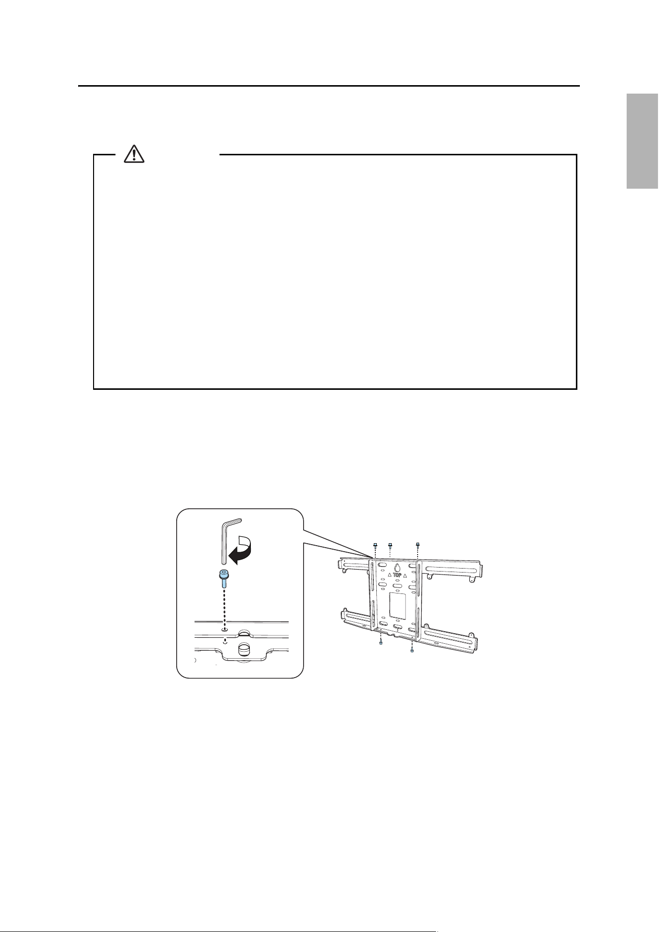
A Assemble the parts
1. Assemble the wall plate.
Assemble the wall plate and two frames into one unit, and secure them with the M4 × 12 mm hexagon
socket head cap bolts (×5) supplied.
❏ When you mount the projector on the wall with the wall mount, the wall requires enough
strength to hold the projector and the wall mount.
This wall mount should be installed on a concrete wall. Confirm the weight of the projector
and the wall mount before installation, and maintain the strength of the wall. If the wall is
not strong enough, reinforce the wall before installation.
❏ The maximum combined weight of the projector and the wall mount is about 48.5 lb
(22 kg).
❏ Do not hang cables over the wall mount.
❏ Install the wall mount so that it can sufficiently support the weight of the projector and
wall mount, and resist any horizontal vibration. Use M10 or 3/8 inch nuts and bolts and
make sure to use appropriate wall anchors for your wall type. Nuts and bolts smaller than
M10 or 3/8 inch could cause the wall mount to fall.
❏ Epson accepts no responsibility for any damage or injury caused by lack of wall strength or
inadequate installation.
Warning
26
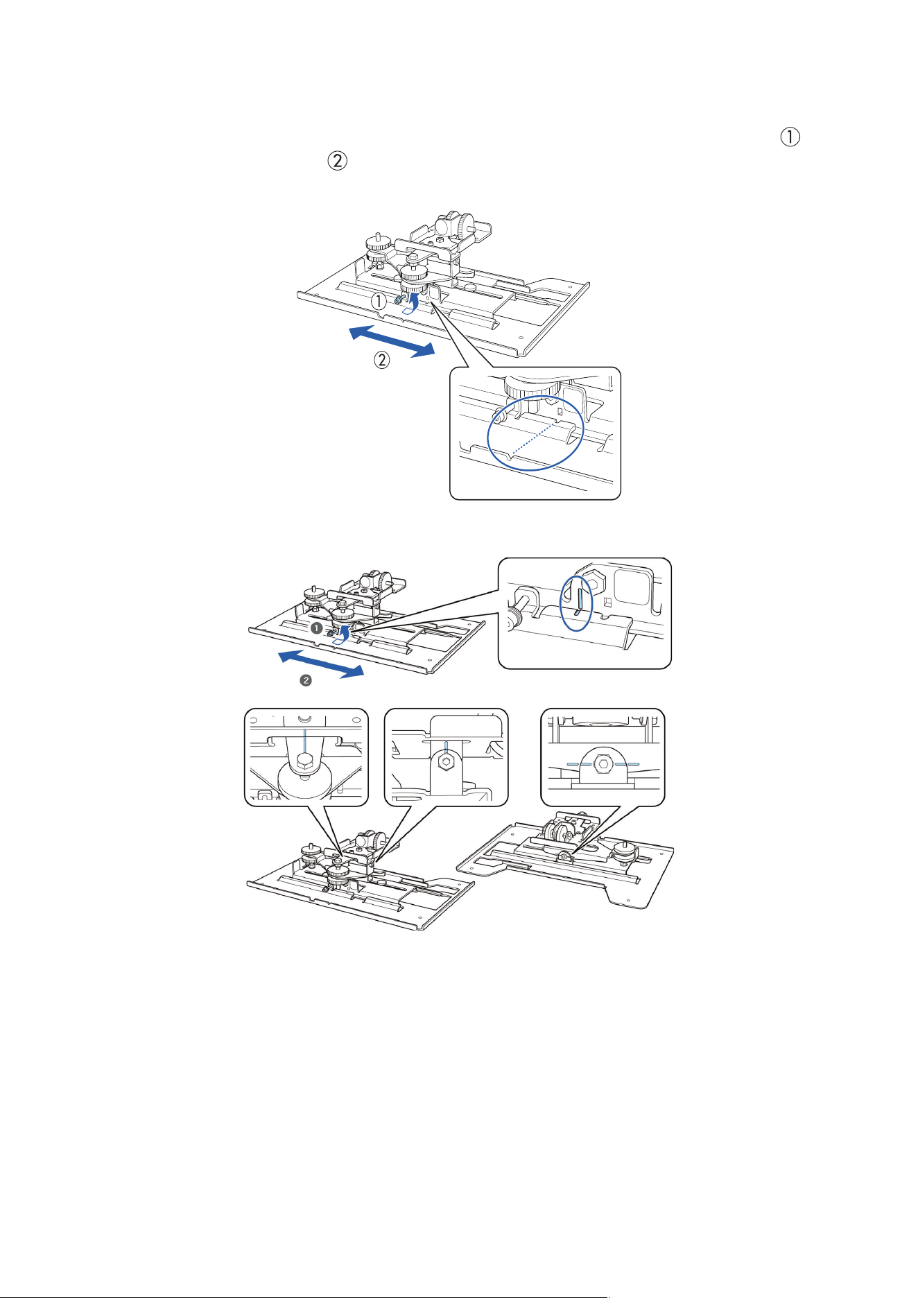
2. Align the 3-axis adjustment unit with the slide plate’s alignment mark.
If the 3-axis adjustment unit is not aligned, loosen the M4 × 12 mm hexagon socket head cap bolt ( )
and correct the alignment ( ). Then, tighten the M4 × 12 mm hexagon socket head cap bolt.
• Models without markings on the adjustment unit
• Models with markings on the adjustment unit
Adjust so that the center of the markings are aligned.
27
English
3. Attach the 3-axis adjustment unit and slide plate to the projector.
Attach the 3-axis adjustment unit and slide plate to the projector using the M4 × 12 mm hexagon
socket head cap bolts (×4) supplied.
Remove the feet from the projector and then attach the rubber caps to the front foot
section.
28
B Install the wall plate on the wall
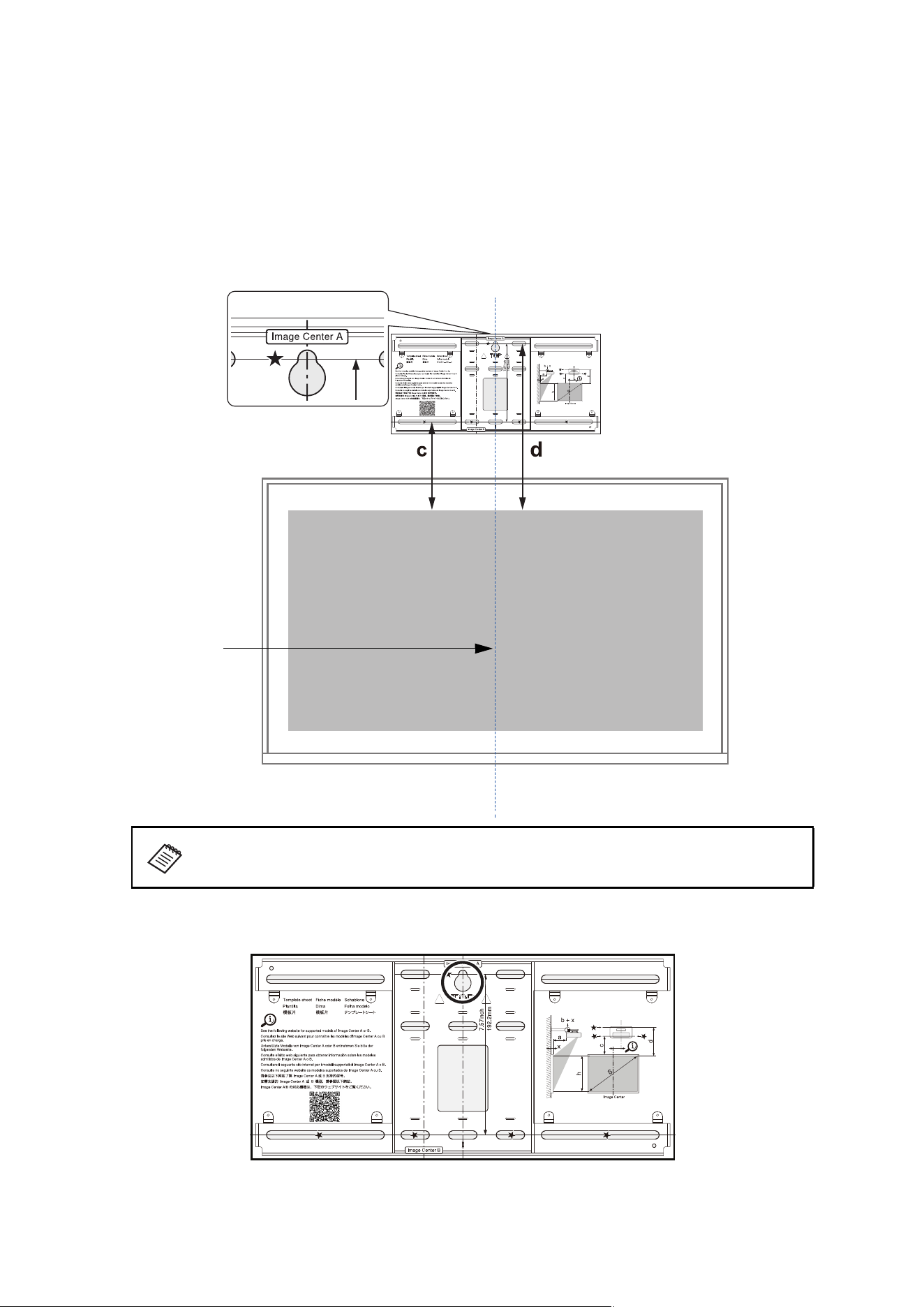
1. Determine the template sheet position and attach it to the wall.
• Confirm where the beams or studs are within the wall that can support the projector and wall mount.
• From the projection distance table, confirm the screen size (S), the distance between the projection
image and wall plate bottom holes (c), and the distance between the projection image and
temporary wall plate hole (d).
• Align the center position of the screen being projected with Image Center A on the Template sheet.
2. Drive an M10 screw (not included) into the temporary wall plate hole.
Leave at least 0.2 inch (6 mm) between the screw head and the wall.
If you want to hide the projector power plug under the wall plate cover, make sure the
power outlet is located in the empty space to the left or the right of the wall plate.
Center line of
projection surface
29
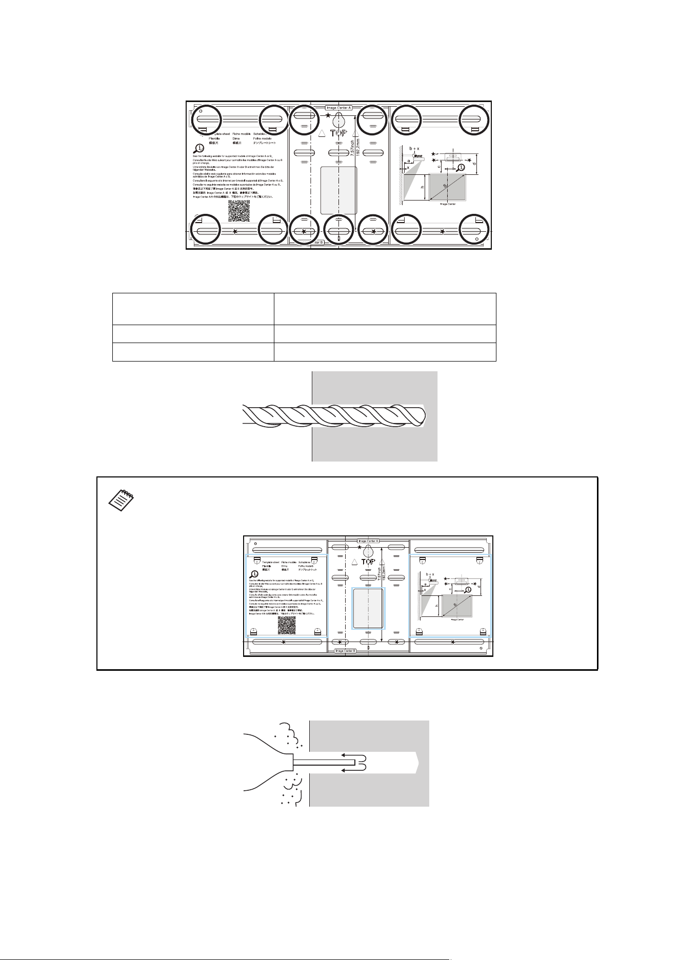
3. Determine the position of the wall plate’s mounting holes.
Use at least four mounting holes at the top, bottom, left, and right for proper balance.
4. Drill holes of the following diameters and depths.
5. Remove the template sheet.
6. If necessary, use a device such as a dust pump to clean out concrete dust from the hole.
Drill diameter
3/8 inch anchor bolts: 0.39 in. (10 mm)
M10 anchor bolts: 0.41 in. (10.5 mm)
Pilot hole depth 1.8 in. (45 mm)
Anchor hole depth 1.6 in. (40 mm)
When routing cables to the projector through a wall, you can drill routing holes within
the areas shown below. When installing a mini PC, check the position at which the
mini PC plate will be installed before drilling the cable routing holes.
30
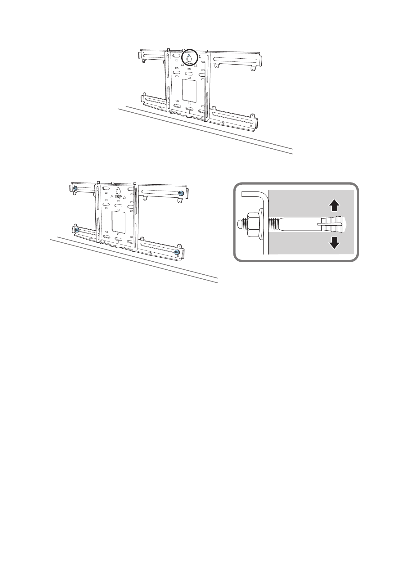
7. Position the wall plate on the temporary wall plate screw.
8. Insert commercially available M10 × 60 mm or 3/8 inch anchors into the holes and secure them in
place.
31
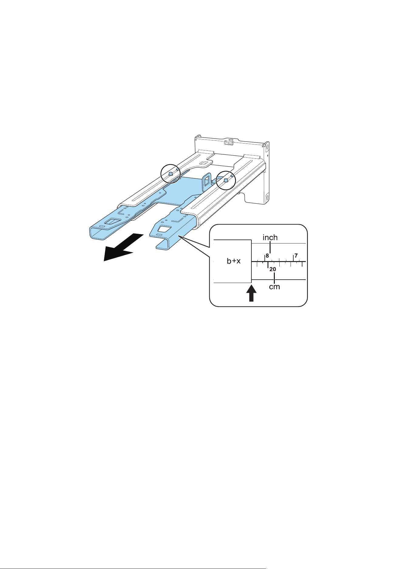
C Determine the projection distance and pull out the mount arm slider
1. Using the tables on pages 20 to 24, check the number for the slider measure (b).
2. Loosen the M4 × 12 mm hexagon socket head cap bolts (×2), and then pull out the slider on the arm
unit.
Adjust the slider to the value that is equal to the slider measure (b) plus the distance from the wall plate
installation surface to the projection surface (x).
For an illustration of how to measure the distance from the wall plate installation surface to the
projection surface (x), see page 18.
32
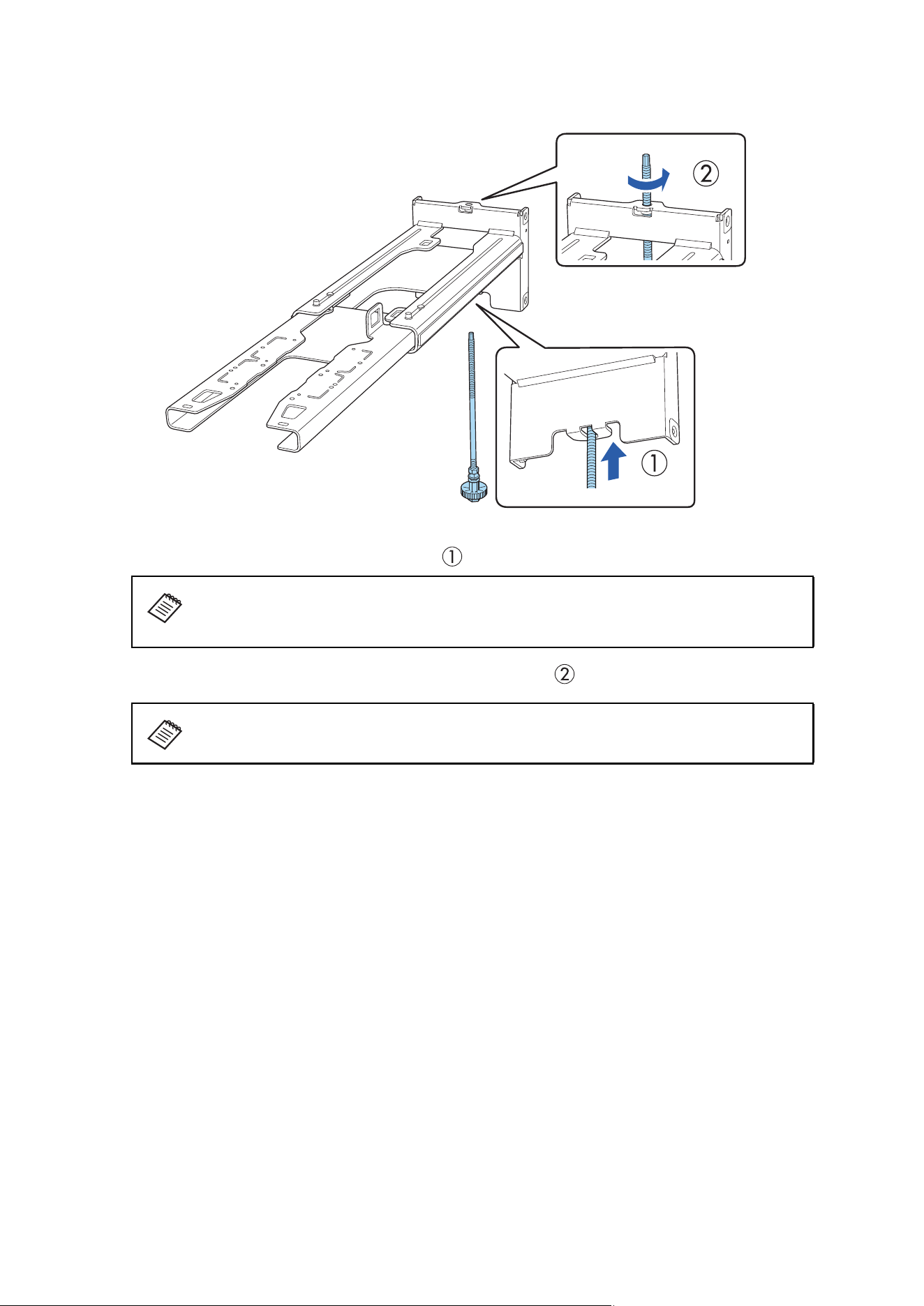
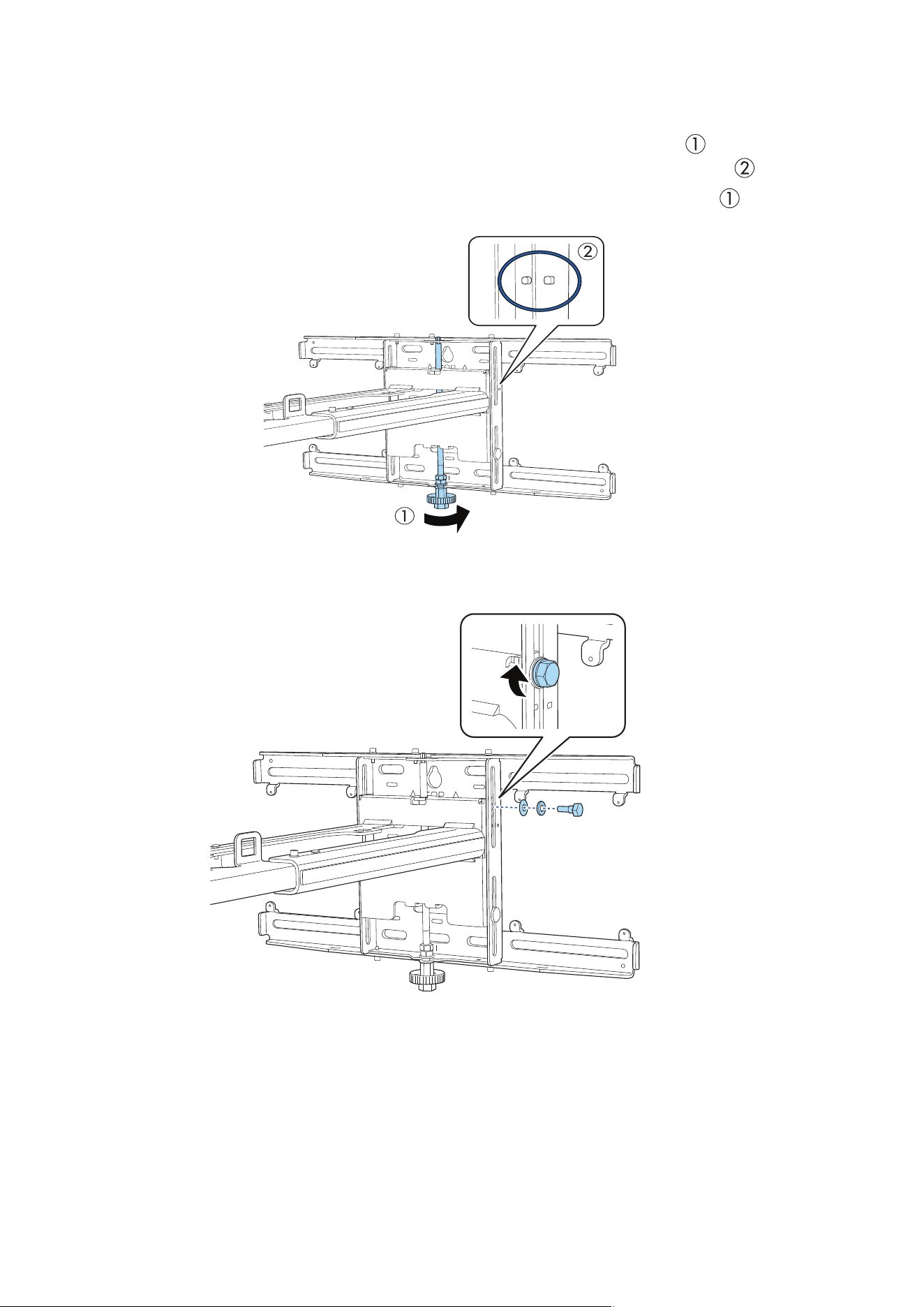
D Attach the arm unit to the wall plate
1. Insert the hexagonal shaft into the arm unit ( ).
2. Insert and turn the hexagonal shaft at the top of the arm unit ( ).
EH-QS100B/EH-QS100W: If there is a white mark on the hexagonal shaft, align the
mark with the top edge of the setting plate. Although the white mark may wear off
over time, this does not indicate a defect in the hardware.
Make sure that cable ports for connecting to peripheral devices such as mini PCs are
routed so that they come out of the lower part of the arm unit and not through walls.
33
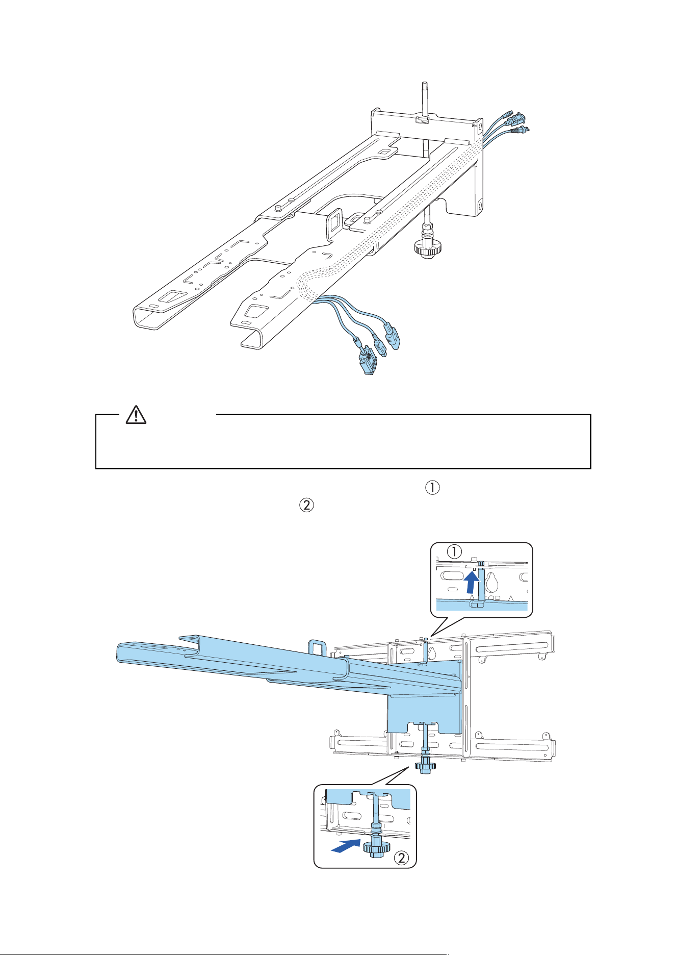
3. Route the cables through the arm unit.
4. Insert the hexagonal shaft into the slot at the top of the wall plate ( ). Insert the hexagonal shaft into
the slot at the bottom of the wall plate ( ).
❏ Do not hang the rest of the cables over the arm unit. They could fall and cause an accident.
Caution
34
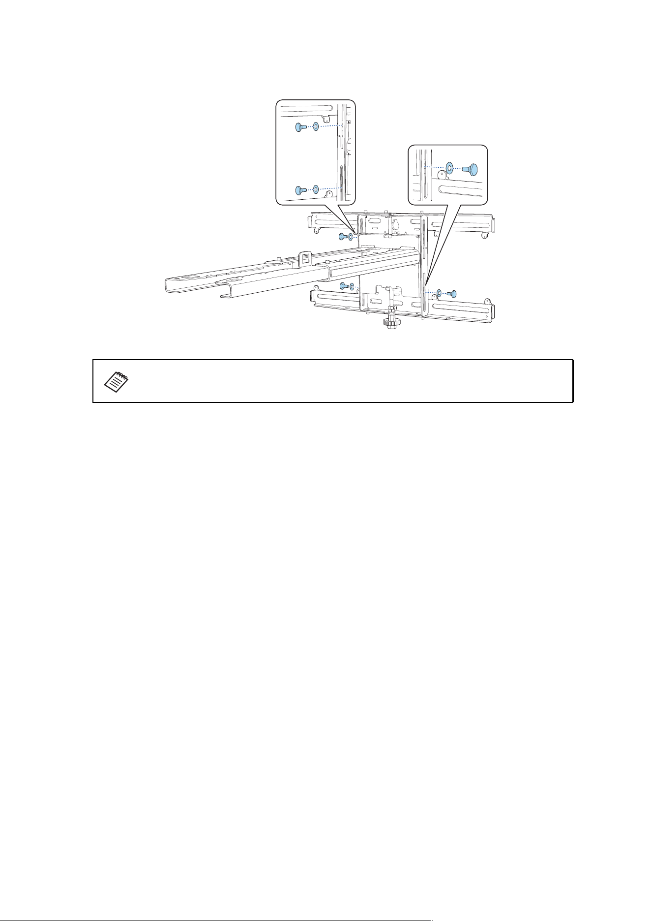
5. Secure the mount arm to the wall plate by tightening the supplied M6 × 20 mm cross recessed head
shoulder screws (×3) with the #3 cross-head screwdriver.
Make sure you use the included plastic washers. If you don’t use the plastic washers,
you may damage the M8 hexagon bolt as you adjust the vertical slide position.
35
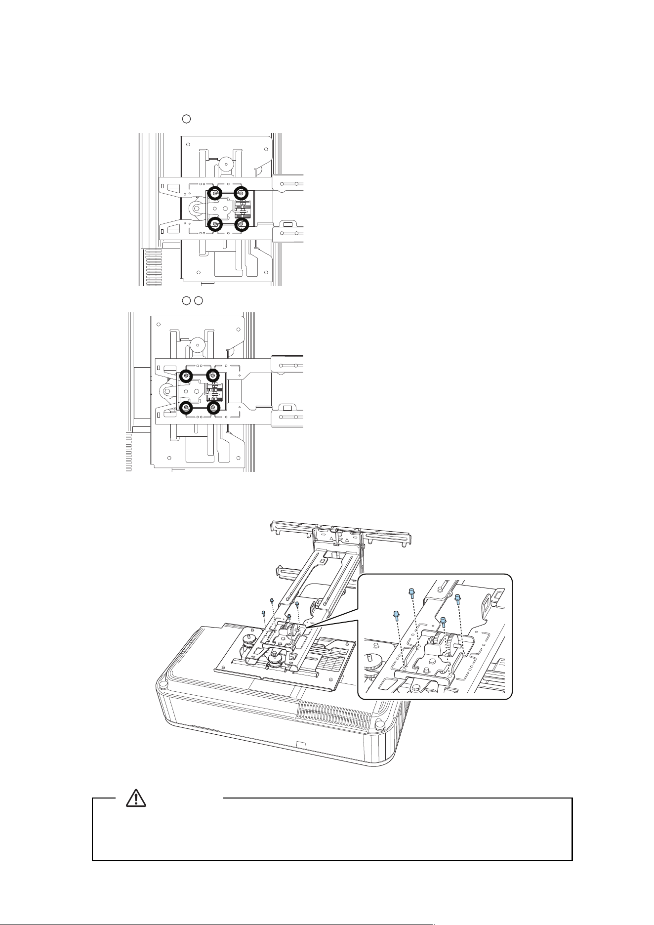
E Adjust the vertical slide position of the arm
1. Adjust the vertical slide with the hexagonal shaft at the bottom of the wall mount ( ). Start by
aligning the notch on the arm with the alignment mark on the wall plate as shown below ( ).
Tightening the hexagonal shaft raises the wall mount, and loosening the shaft lowers it ( ).
2. Secure the wall mount with the M6 × 20 mm hexagon shoulder bolt.
36
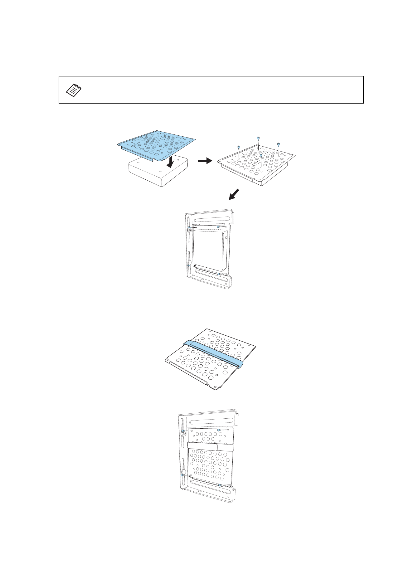
F Attach the projector to the wall mount
Attach the 3-axis adjustment unit with the projector to the wall mount arm:
• Mount at the stamp when the image is less than 117 inches diagonally.
• Mount at the stamp when the image is 117 inches or more diagonally.
• Tighten the M4 × 12 mm hexagon socket head cap bolts (×4) supplied to attach the 3-axis
adjustment unit.
When installing or adjusting the wall mount, do not use adhesives to prevent the screws from
loosening and do not use lubricants or oils on the projector slide plate. This may cause the case
to crack and the projector to fall, resulting in personal injury or property damage.
Warning
37
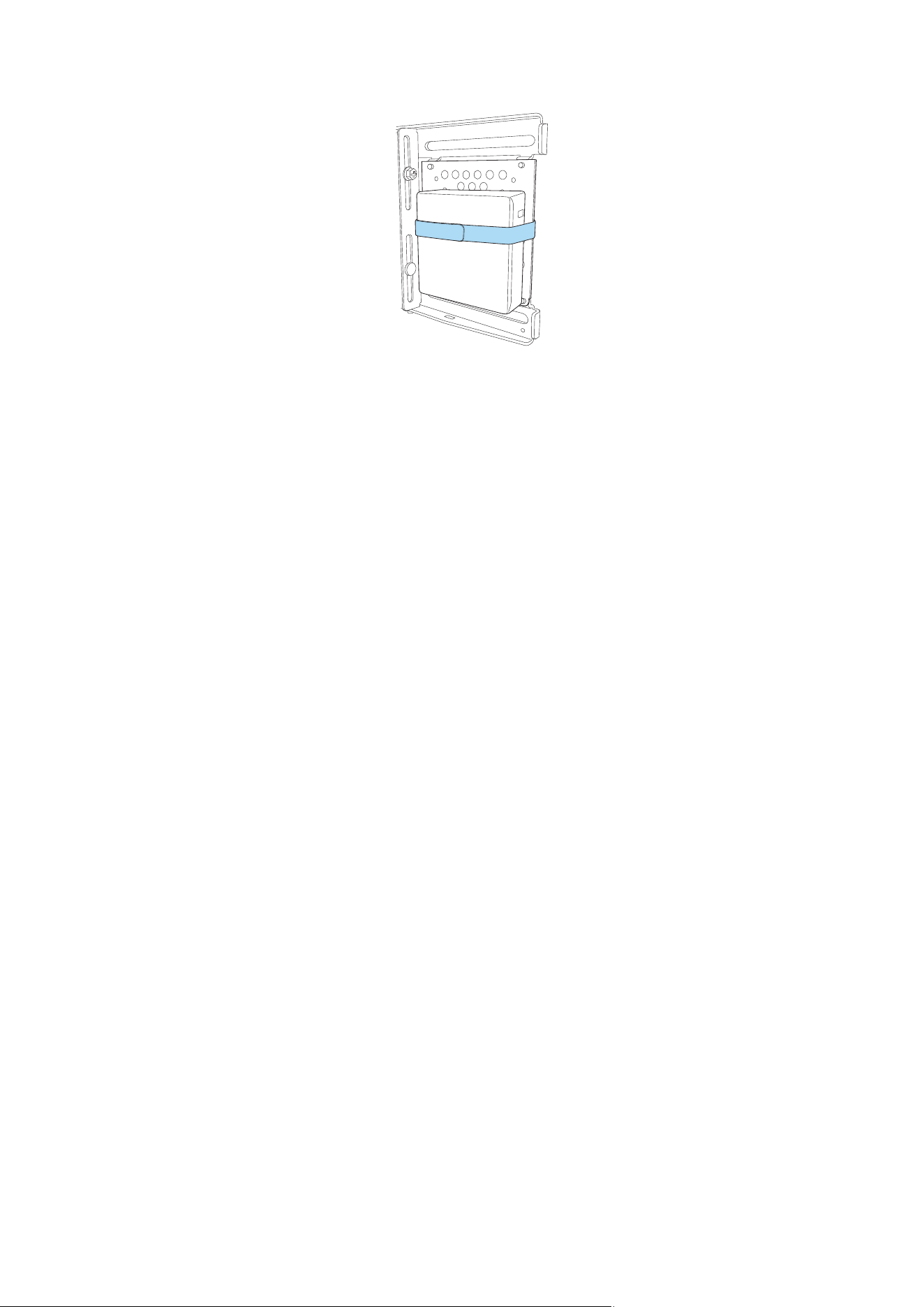
G Attach a Mini PC or Stick PC if necessary
You can secure a Mini PC or Stick PC to the left or the right side of the wall plate.
If your Mini PC has screw holes that line up with the holes in the Mini PC plate, you can secure it with
the M3 × 6 mm screws (×4) supplied.
If your Mini PC does not have screw holes or they do not line up with the holes on the Mini PC plate, you
can secure it with the included Mini PC band.
1. Wrap the band around the Mini PC plate.
2. Secure the Mini PC plate to the wall plate using the M3 × 6 mm screws (×4) supplied.
Attach the Mini PC so that the air exhaust vents of the PC are not blocked. Install the PC
so that the air exhaust vents are at the top and the air intake vents are at the bottom.
38
3. Rest the PC on the lip of the Mini PC plate and secure it with the band.
39
6 Adjusting the Image
To ensure the best image quality, follow the steps below to adjust the projected image.
The initial setup wizard is displayed when you turn on the projector for the first time. Use the up, down, left,
right, and [Enter] buttons to set the Projection, Language, and Date & Time. Continue to adjust the shape
and position of the projected image, as necessary. If necessary, you can then enable Quick Startup to speed
up the projector’s startup. Enabling this setting increases the power consumed during standby.
A Display the Setting Plate Installation Guide
1. Press the power button on the remote control or the projector.
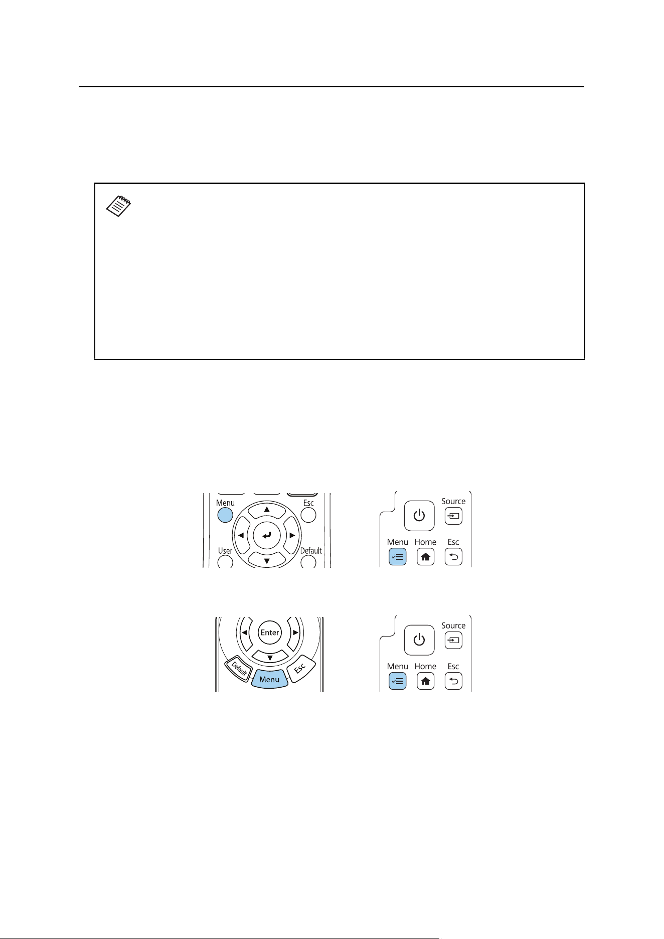
2. Press the [Menu] button on the remote control or control panel.
EB-810E/EB-815E:
EH-QS100B/EH-QS100W:
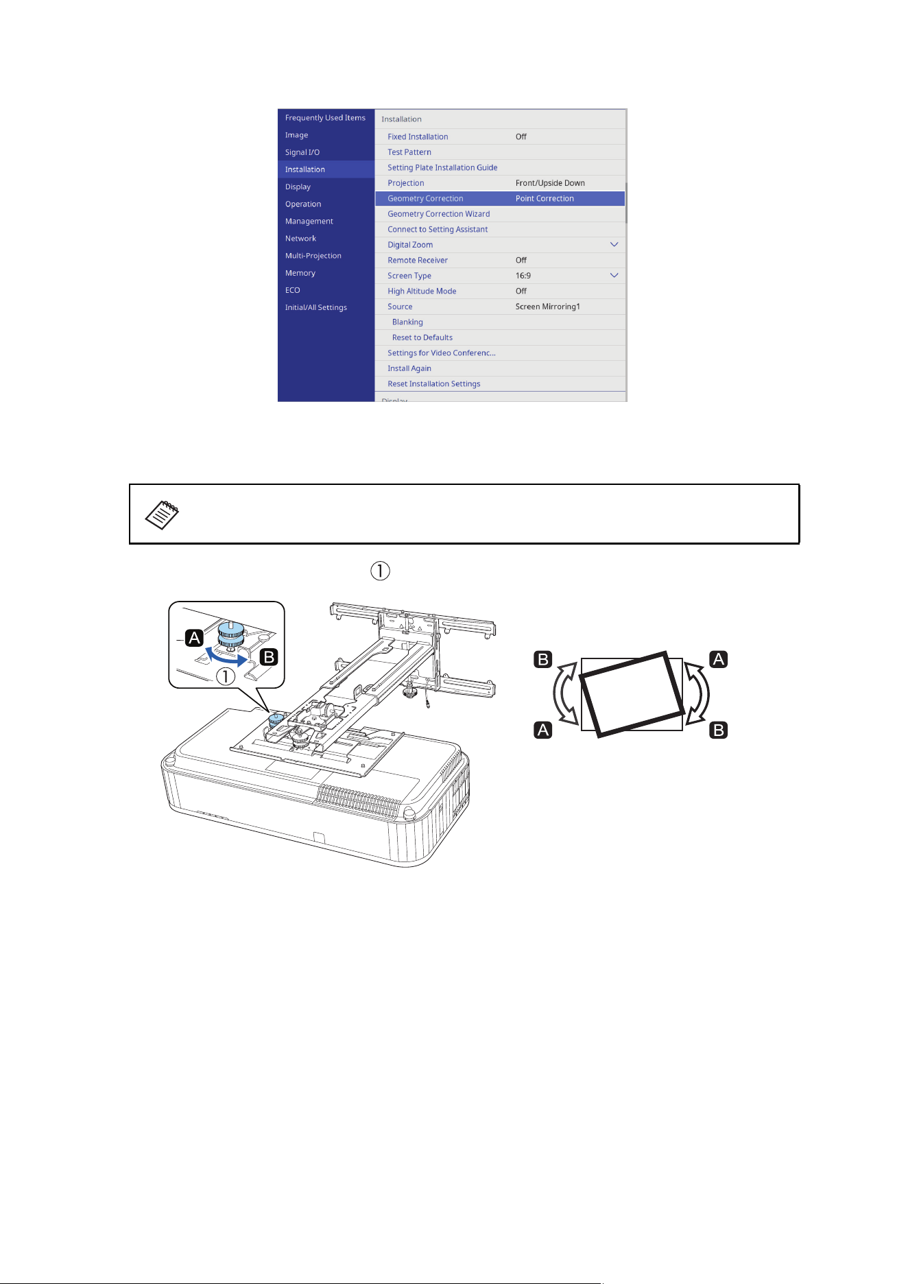
3. Select Installation.
❏ Images are not stable immediately after turning on the projector. After starting
projection, wait for at least 30 minutes before adjusting the image.
❏ Install and adjust the projector at a room temperature that is close to the actual
intended usage environment. If the temperature changes, the position of the
image may shift.
❏ When setting up multiple projectors using the batch setup function, perform the
batch setup before adjusting the projected image.
❏ We recommend using the mechanical position adjustment on the mount to
achieve the best image quality.
❏ We recommend positioning the projector to be as parallel as possible to the
projection surface to reduce image distortion.
Remote Control Control Panel
Remote Control Control Panel
40
4. Select Setting Plate Installation Guide.
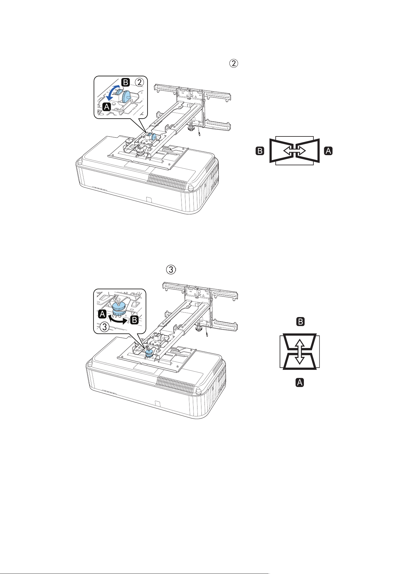
B Use adjustment dial 1 on the left side to adjust the horizontal roll
Loosen the lower adjustment dial ( ) to adjust the horizontal roll.
Repeat steps
B toG as necessary.
41
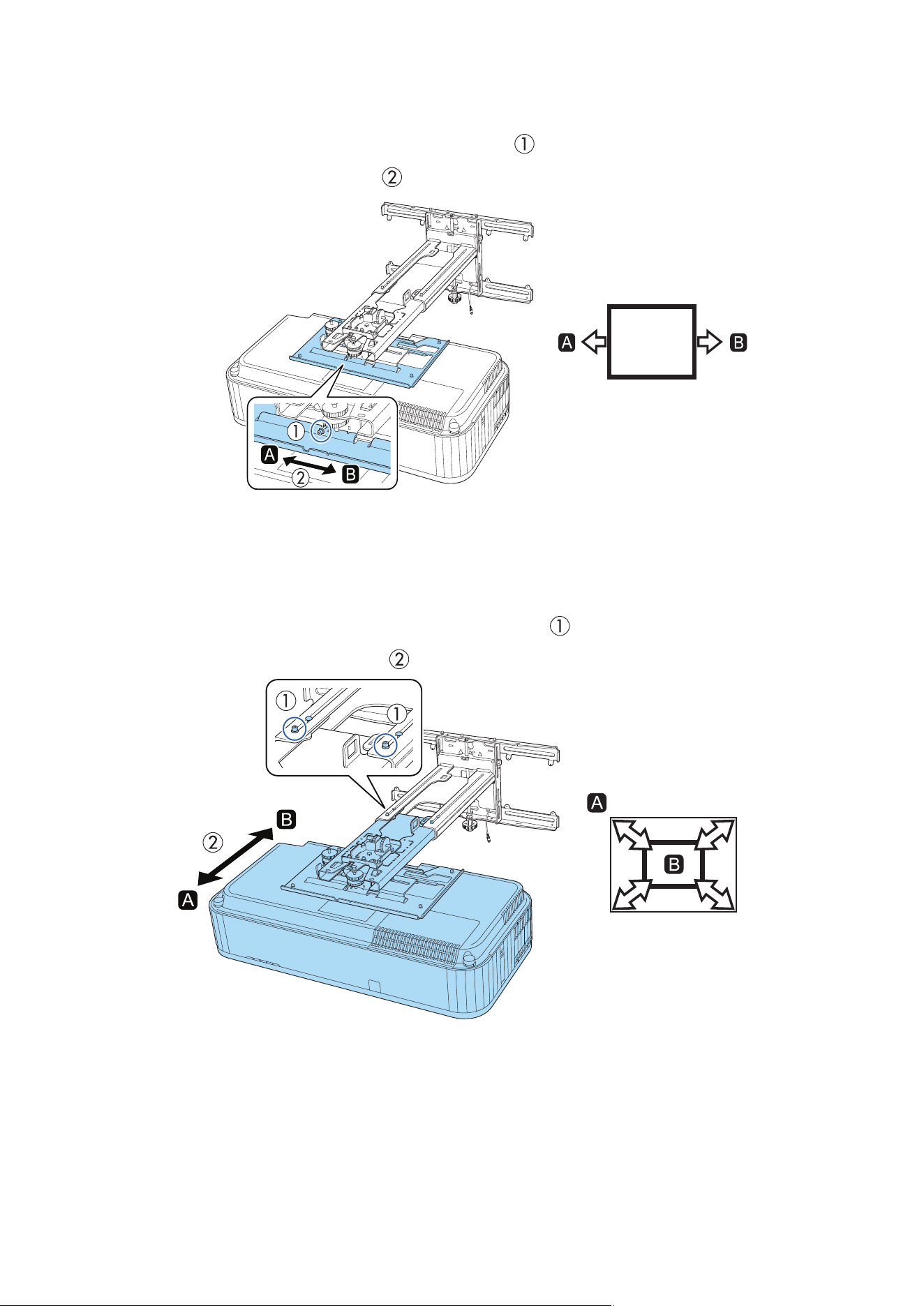
C Use adjustment dial 2 on the top to adjust the horizontal rotation
Loosen the M4 screw, and then turn the adjustment dial ( ) to adjust the horizontal rotation.
D Use adjustment dial 3 on the front to adjust the vertical tilt
Loosen the lower adjustment dial ( )to adjust the vertical tilt.
42
E Adjust the horizontal slide
1. Loosen the M4 × 12 mm hexagon socket head cap bolt ( ).
2. Adjust the slider for the slide plate ( ).
F Adjust the forward/backward slide
1. Loosen the M4 × 12 mm hexagon socket head cap bolts (×2) ( ).
2. Adjust the slider for the wall mount ( ).
43
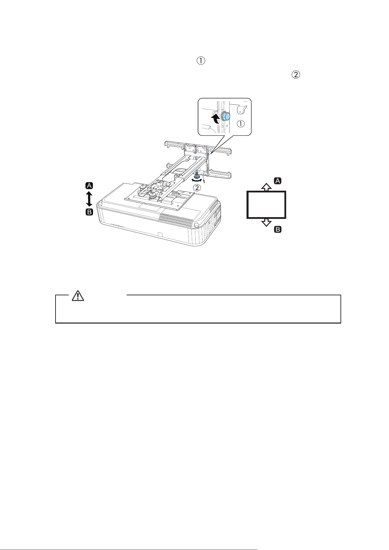
G Adjust the vertical slide
1. Loosen the M6 × 20 mm hexagon shoulder bolt ( ).
2. Adjust the vertical slide using the hexagonal shaft at the bottom of the wall mount ( ).
Tightening the hexagonal shaft raises the wall mount, and loosening the shaft lowers it.
3. After you finish making all of the adjustments in steps
B to G, retighten all the screws and bolts
loosened in steps
B to G.
Tighten all bolts and screws firmly. Otherwise, the projector or wall mount may fall and cause
personal injury or property damage.
Warning
44
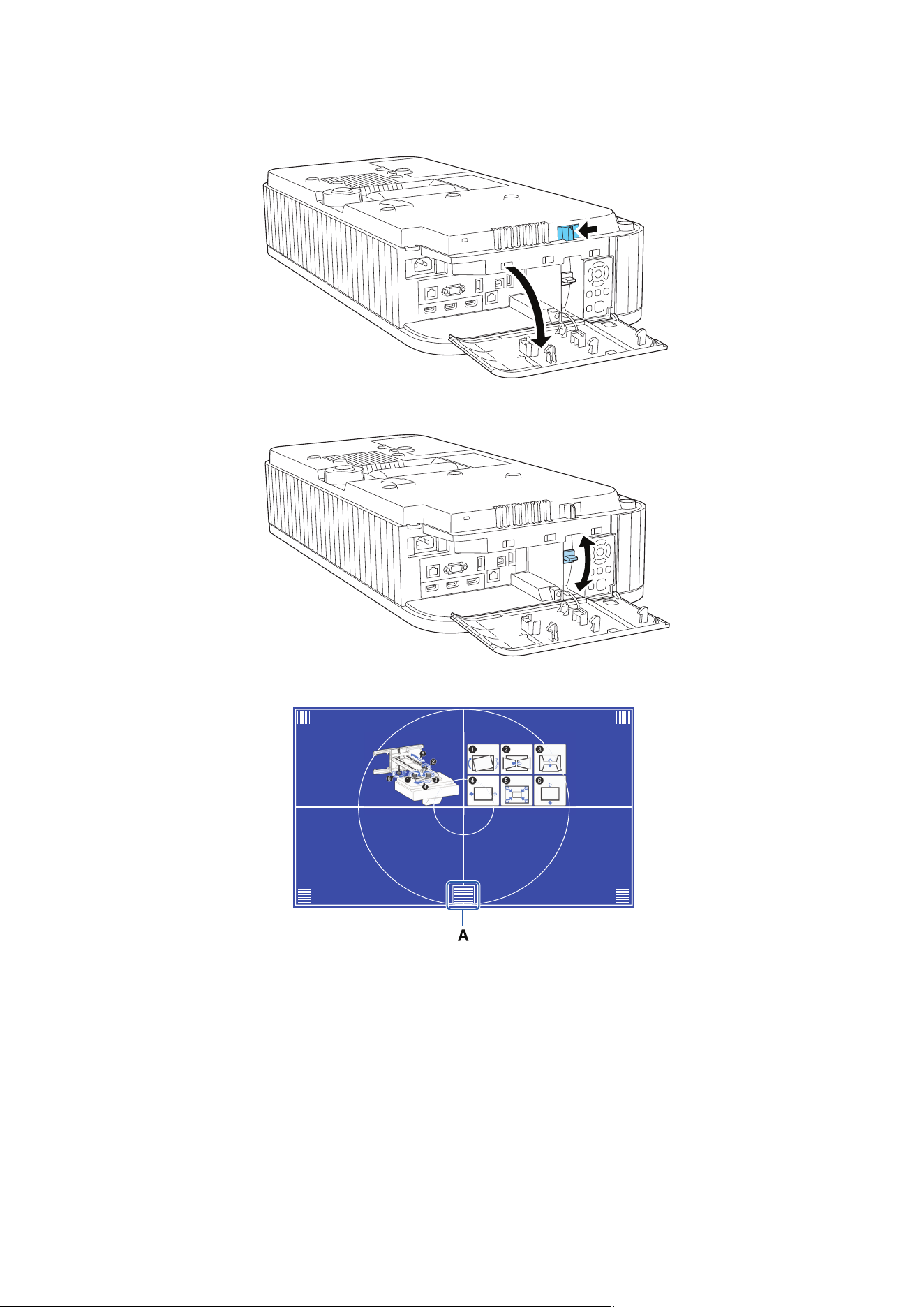
H Adjust the focus
1. Remove the projector’s side cover by sliding the side cover latch.
2. Raise or lower the focus lever to adjust the image.
3. Adjust the focus of position A.
4. After you finish making the adjustment, carefully replace the projector’s side cover.
I Turn off the display of the test pattern
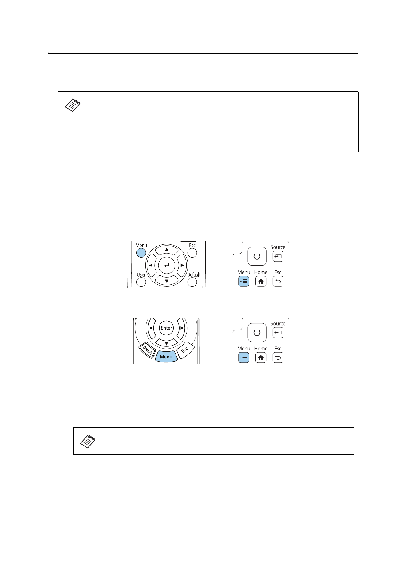
1. Press the [Esc] button on the remote or control panel to exit the guidance screen after adjusting.
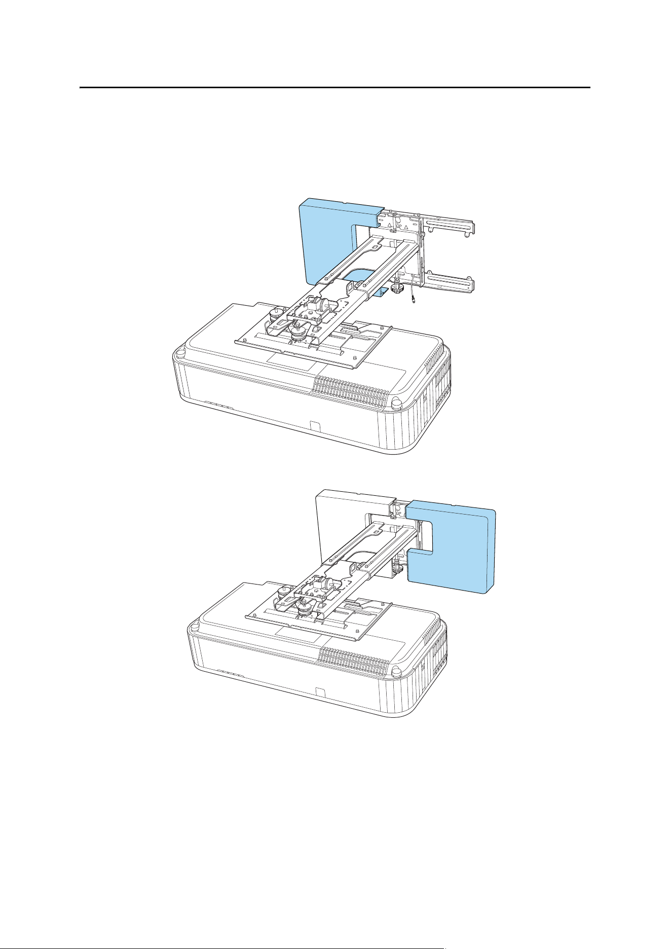
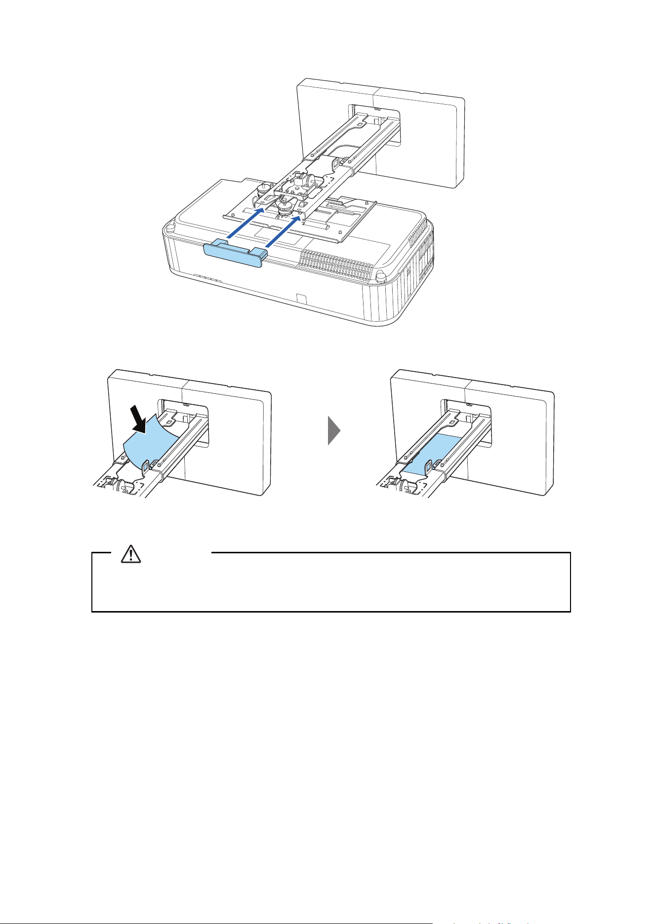
46
3. Attach the end cap to the arm unit.
4. If you want to cover the groove in the arm unit, attach the masking sticker as shown.
Only a specialist should remove or reinstall the projector, including for maintenance and
repairs. Refer to your online User’s Guide for your projector for instructions on maintenance and
repairs.
Caution
47
8Appendix
Making Screen Adjustments
Epson Setting Assistant app
To correct distortion more easily, you can use the Epson Setting Assistant app on a smartphone or tablet that
has a camera function. You can download it from the Apple App Store or Google Play™ Store.
1. Download and install the app on your smartphone or tablet.
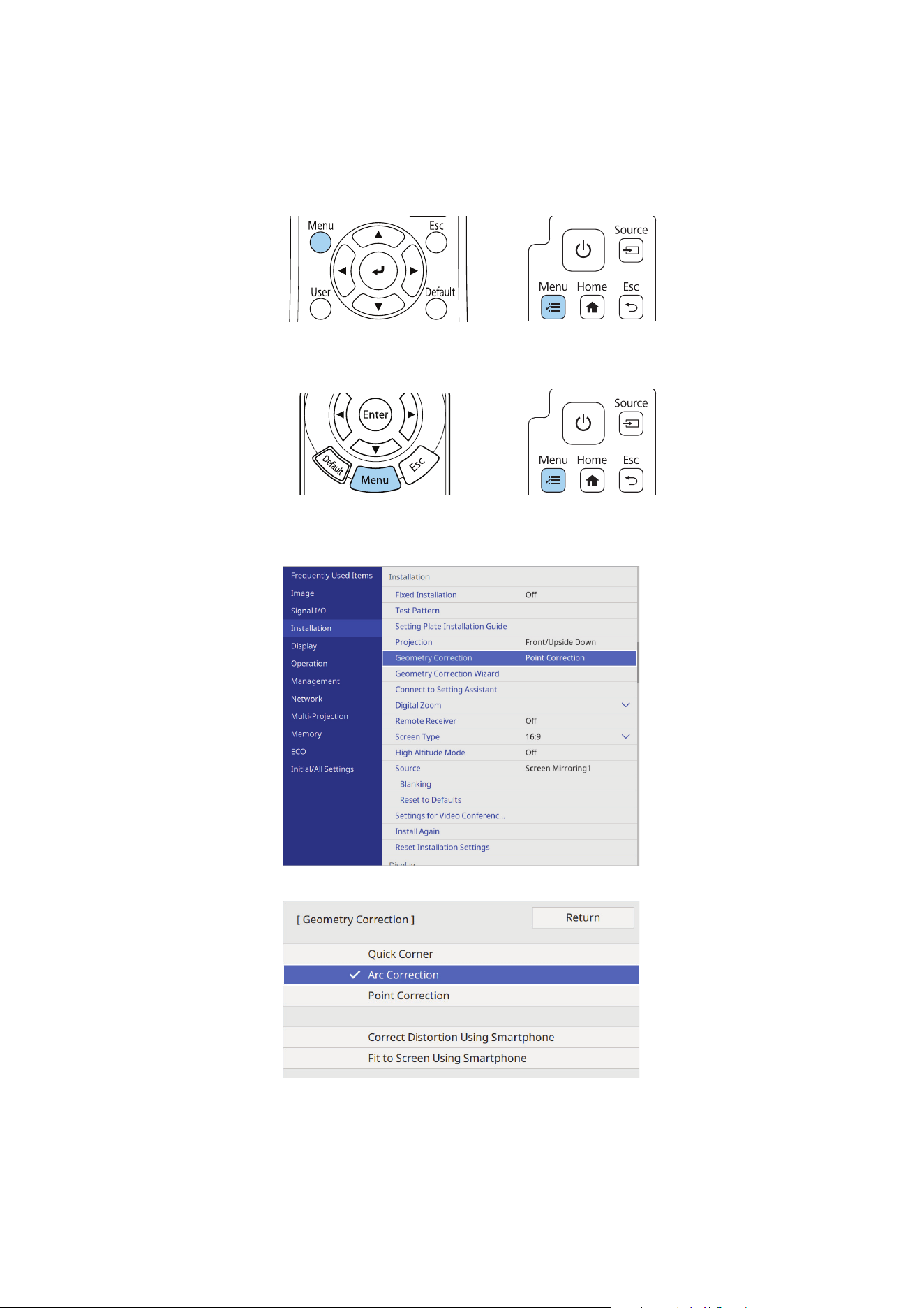
2. Press the [Menu] button on the remote control or control panel.
EB-810E/EB-815E:
EH-QS100B/EH-QS100W:
3. Select Installation and then do one of the following:
• EB-810E/EB-815E: Select Connect to Setting Assistant. A QR code is displayed. Open the app on
your smartphone or tablet, make selections to connect using a QR code and then scan the QR code.
Follow the instructions in the app.
• EH-QS100B/EH-QS100W: Select Geometry Correction Wizard and then use the remote control or
control panel to select your projection surface. Select App and follow the on-screen instructions.
❏ Before performing the adjustments, set the Screen Type and the Screen Position
setting. If you change the Screen Type or the Screen Position after making
corrections, the corrections will be reset.
❏ You can save adjusted values in Memory from the Geometry Correction menu.
❏ You can also use the Geometry Correction Wizard and follow the on-screen
instructions to make corrections. See the online User’s Guide for details.
Remote Control Control Panel
Remote Control Control Panel
Make sure the smartphone or tablet is on the same network as the projector.
48
Correcting the Image Shape on a Curved Surface
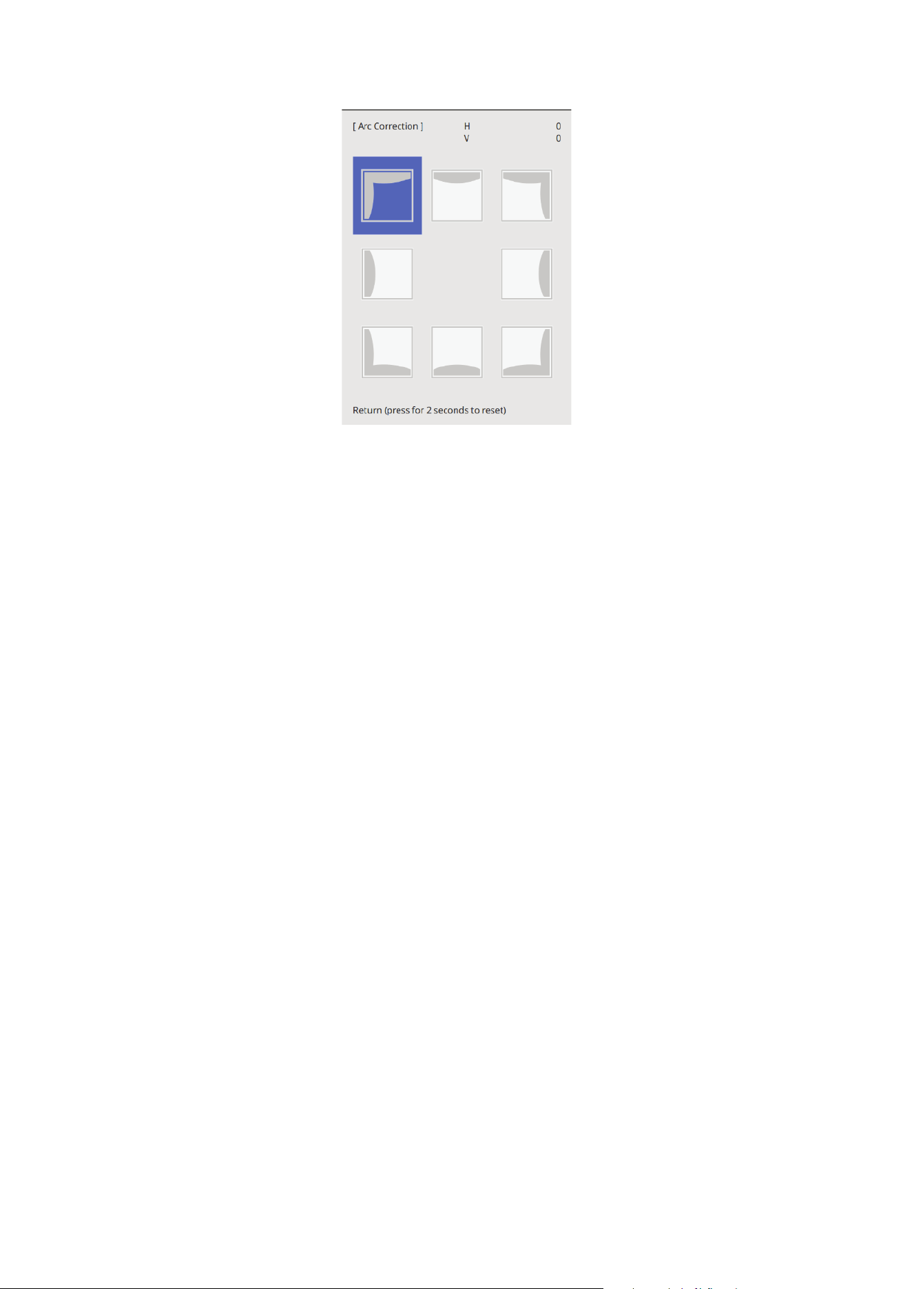
If you are projecting on a curved screen, adjust the Arc Correction setting to correct the image shape.
1. Press the [Menu] button on the remote control or control panel.
EB-810E/EB-815E:
EH-QS100B/EH-QS100W:
2. Select Installation.
3. Select Geometry Correction.
4. Select Arc Correction.
5. EH-QS100B/EH-QS100W: Select Arc Correction again.
Remote Control Control Panel
Remote Control Control Panel
49
6. Select the area that you want to correct.
7. Use the arrow buttons on the remote control or control panel to change the shape of the selected area.
8. Repeat steps 6 and 7 to adjust any additional areas.
50
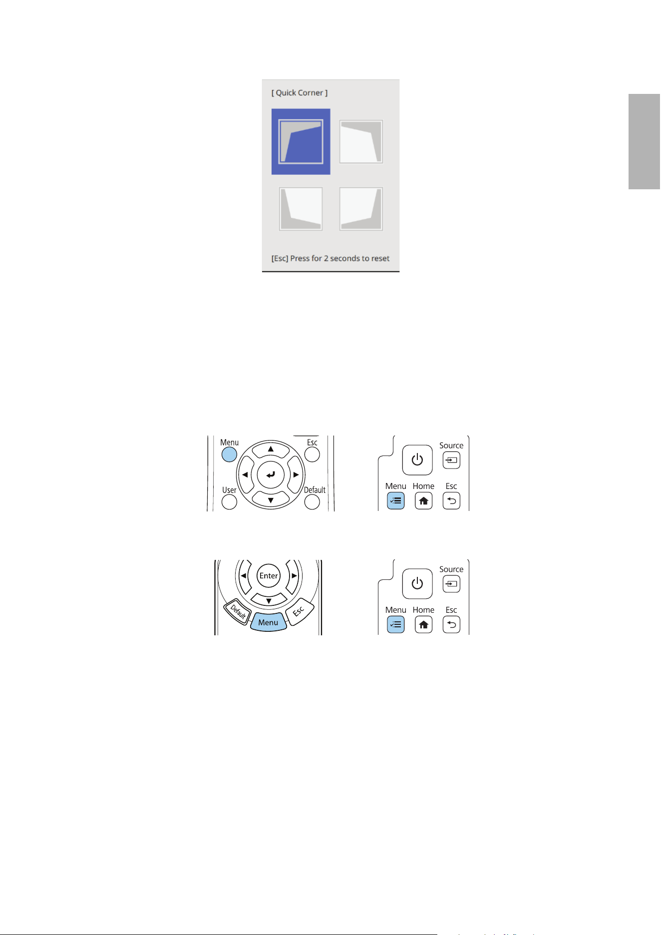
Correcting the Corner Shape
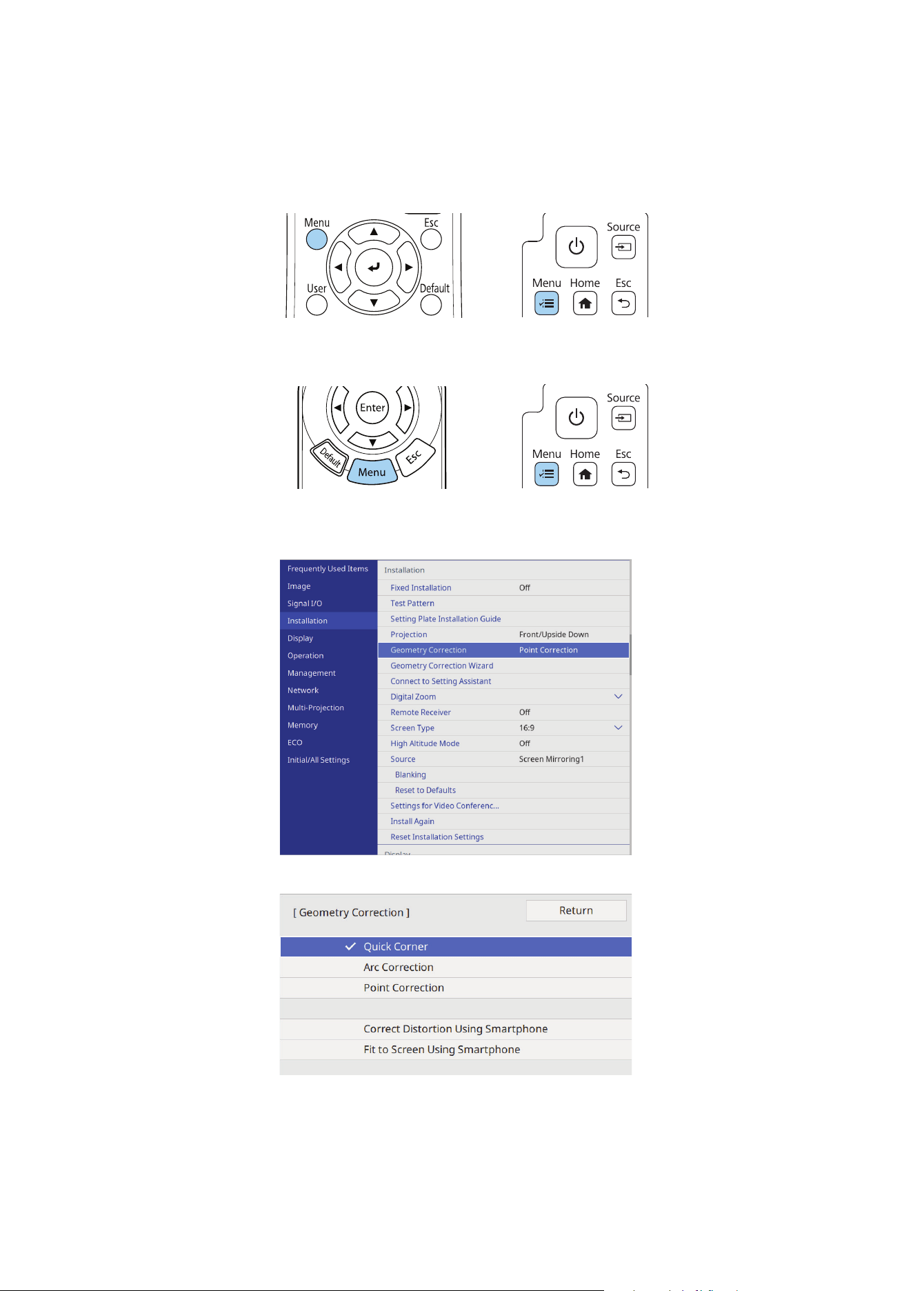
You can adjust the shape of the image corners with the Quick Corner setting.
1. Press the [Menu] button on the remote control or control panel.
EB-810E/EB-815E:
EH-QS100B/EH-QS100W:
2. Select Installation.
3. Select Geometry Correction.
4. Select Quick Corner.
Remote Control Control Panel
Remote Control Control Panel
51
English
5. Select the corner that you want to correct.
6. Use the arrow buttons on the remote control or control panel to change the shape of the selected
corner.
7. Repeat steps 5 and 6 to adjust any additional corners.
Correcting the Image Shape at Individual Points
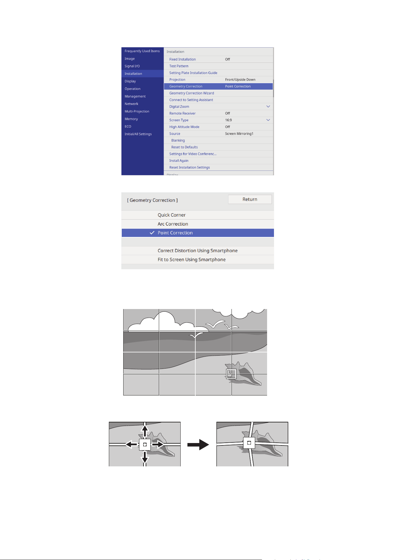
You can adjust the image at specific points with the Point Correction setting.
1. Press the [Menu] button on the remote control or control panel.
EB-810E/EB-815E:
EH-QS100B/EH-QS100W:
2. Select Installation.
Remote Control Control Panel
Remote Control Control Panel
52
3. Select Geometry Correction.
4. Select Point Correction.
5. EH-QS100B/EH-QS100W: Select Point Correction again.
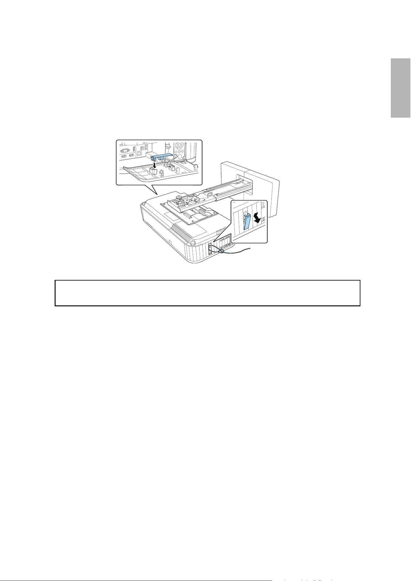
6. Select Points (Vert.) and Points (Horiz.) and set the number of grids.
7. Select the point on the grid that you want to correct.
8. Use the arrow buttons on the remote control or control panel to change the shape of the selected
point.
9. Repeat steps 7 and 8 to adjust any additional areas.
53
English
Attaching a Security Cable
If the projector is installed in a room where it will be left unattended, you can use a commercially available
theft-prevention cable and the security slot on the projector to secure the projector to a post or other object
to prevent someone from taking it.
EB-810E/EB-815E: You can also remove the security cable installation point cover, and then attach the cable
to the security cable installation point on the projector.
You can attach the security cable installation point cover to the back of the side cover so that it does not get
lost.
For details on how to configure the cable, refer to the documentation supplied with the cable.
If applicable, make sure you leave the remote control and batteries in the room with the
projector. The accessories included with the projector vary by model and region.
54
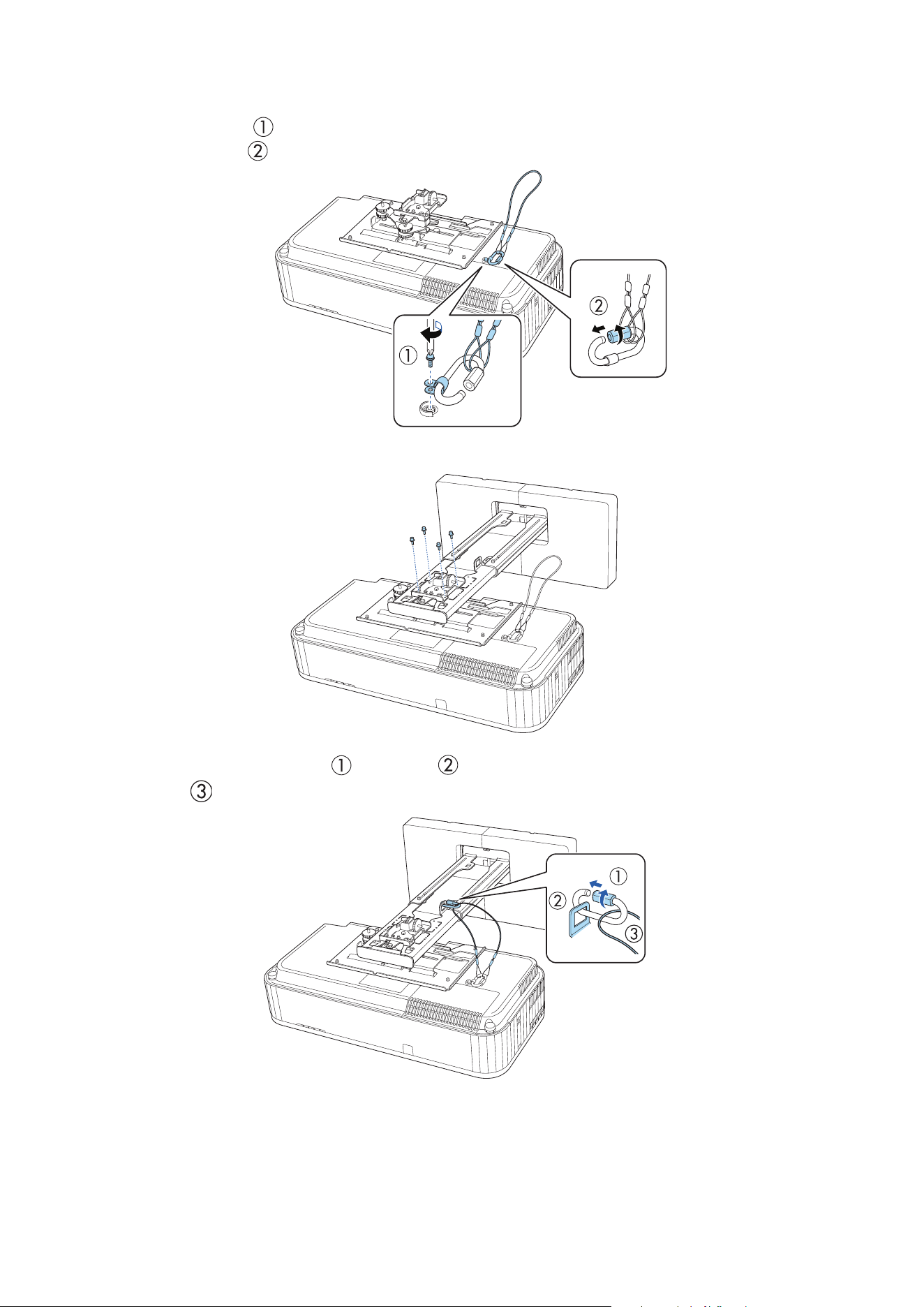
Attaching a Safety Wire
1. Use the clamp ( ) to attach the carabiner and safety wire to the bottom of the projector and tighten
the carabiner ( ).
2. Place the projector into the arm unit and tighten the screws.
3. Attach the other carabiner ( ) to the hole ( ) in the arm section of the arm unit and pass the safety
wire ( ) through it before tighten the carabiner.

55
English
EPSON® is a registered trademark and the EPSON logo is a registered logomark of Seiko Epson Corporation.
App Store is a trademark of Apple Inc., registered in the U.S. and other countries.
Google® is a registered trademark and Google Play™ is a trademark of Google LLC.
General Notice: Other product names used herein are for identification purposes only and may be trademarks
of their respective owners. Epson disclaims any and all rights in those marks.
© 2025 Epson America, Inc., 4/25
CPD-63742R1