
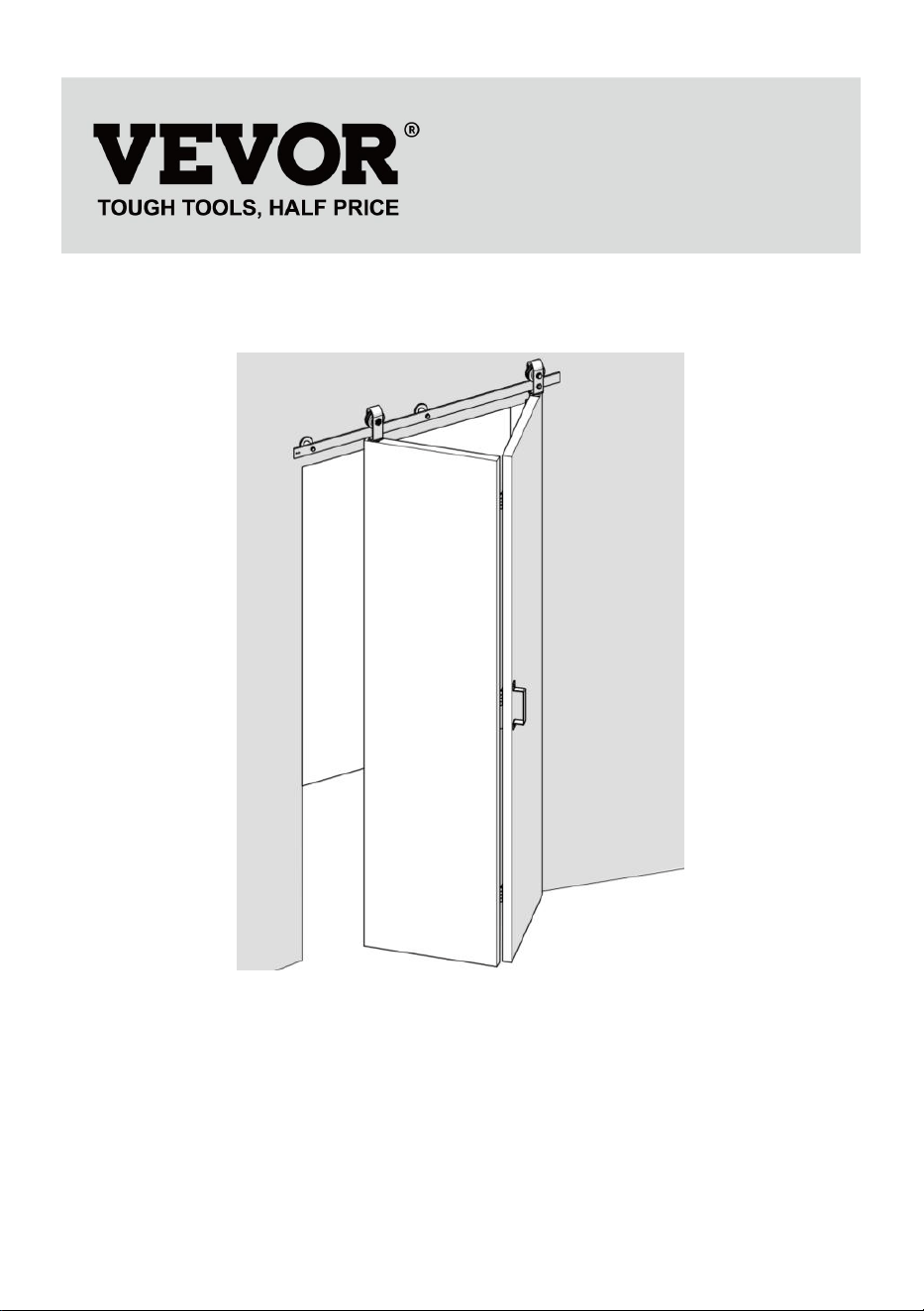
BIFOLD SLIDING BARN DOOR
HARDWARE KIT
Model:36IN-3D-3K/40IN-3D-3K/52IN-2D-3K
Technical Support and E-Warranty Certificate
www.vevor.com/support

- 1 -
Model:36IN-3D-3K/40IN-3D-3K/52IN-2D-3K
This is the original instruction, please read all manual instructions
carefully before operating. VEVOR reserves a clear interpretation of our
user manual. The appearance of the product shall be subject to the
product you received. Please forgive us that we won't inform you again if
there are any technology or software updates on our product.
Bifold Sliding Barn Door
Hardware Kit

- 2 -
SAFETY INSTRUCTIONS
WARNING:
Read this material before using this product. Failure to do so can result in
serious injury.
Assembly precautions
1.Assemble only according to these instructions. Improper assembly can
create hazards.
2. Wear ANSI-approved safety goggles and heavy-duty work gloves during
assembly.
3.Keep assembly area clean and well lit.
4.Keep bystanders out of the area during assembly.
5.Do not assemble when tired or when under the influence of alcohol,
drugs or medication.
6.Product capabilities apply to properly and completely assembled product
only.
7. For additional information regarding the parts listed in the following
pages, please refer to the Assembly Diagram of this manual. Unwrap and
separate all parts in a clean work area.
8. For safety reasons,This hardware is recommended to be installed by 2
people
9.Products are installed away from children and pets;
Use precautions
1. This product is not a toy. Do not allow children to play with this item.
2. Use as intended only.
3. Inspect before every use; do not use if parts are loose or damaged.
SAVE THESE INSTRUCTIONS
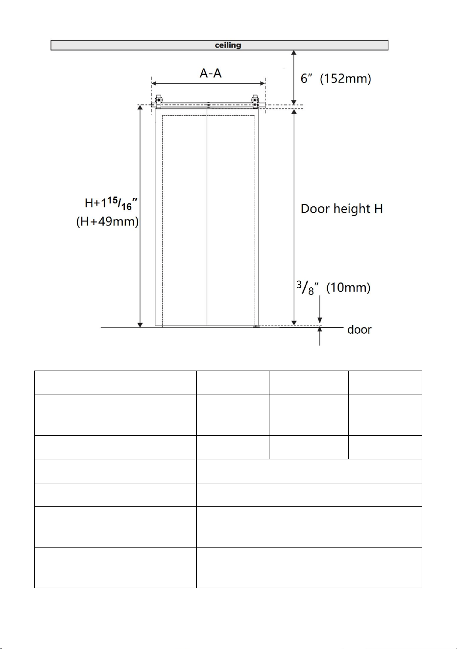
Product Suitability
- 3 -
Model
36IN-3D-3K
40IN-3D-3K
52IN-2D-3K
rail length A-A
36inch
(914mm)
40inch
(1016mm)
52inch
(1320mm)
Door width
≤16inch
≤18inch
≤24inch
Door thick
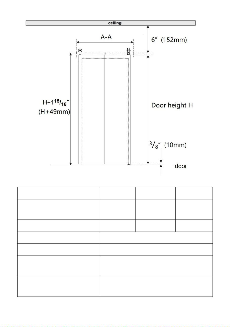
1.375 to 1.75inchs (34.92-44.45mm)
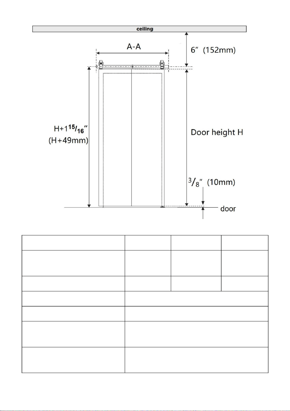
Door height
H(Depending on the user)
Distance of the rail from the
ground
H+49mm
Distance at the bottom of the
door from the ground
10mm

- 4 -
Distance between the door
top and the ceiling
6inch(152mm)
quantity of doors
2pcs
The box does not contain door panels and other wooden squares,which
require additional purchase.
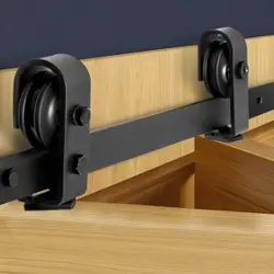
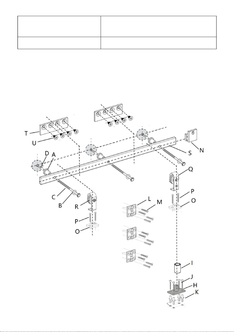
Product decomposition diagram
- 5 -
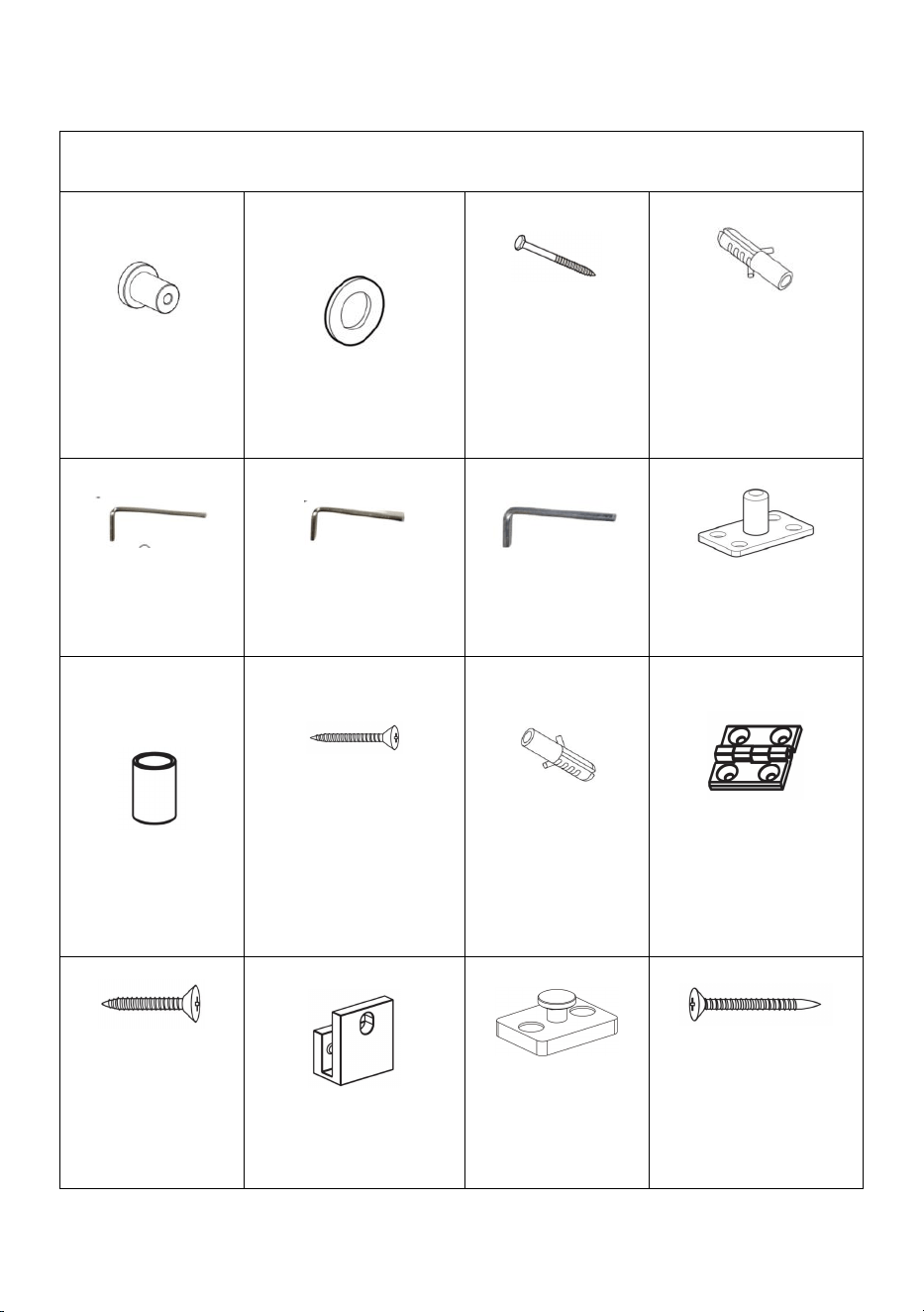
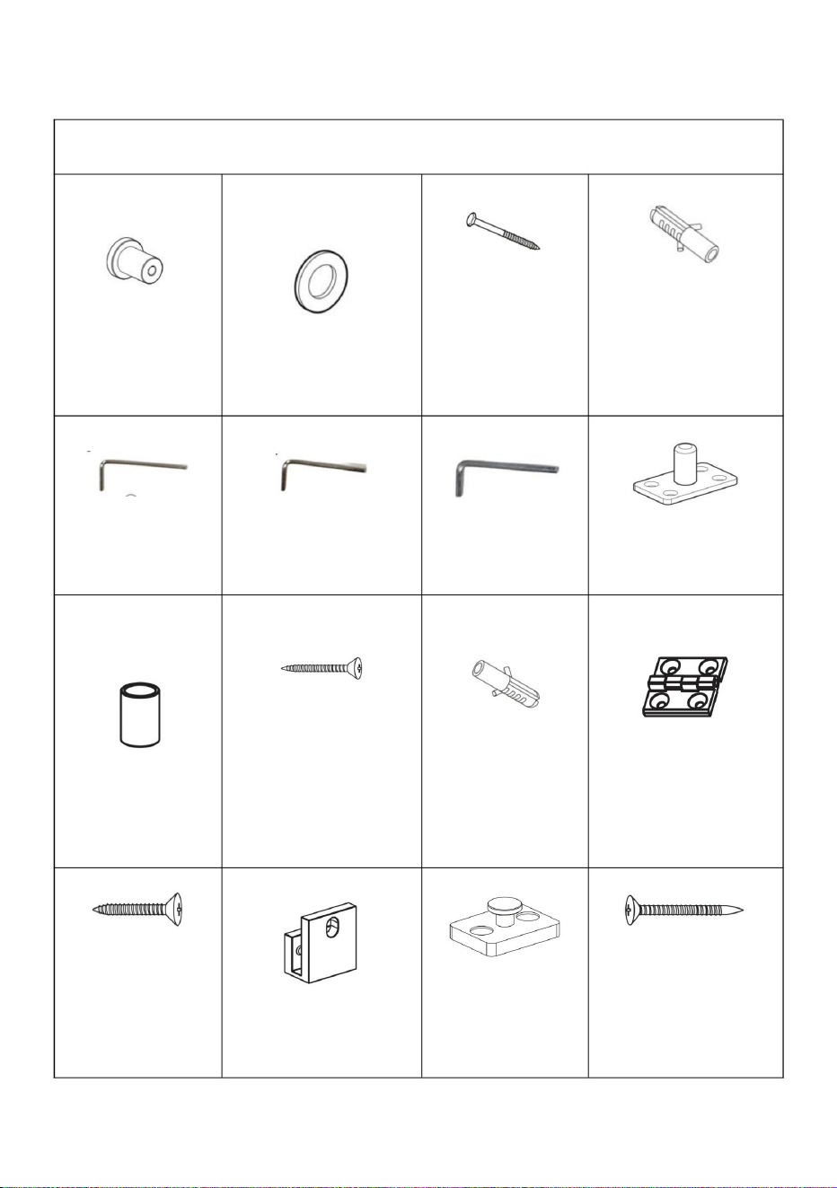
Parts list
Same parts of different models
A:Wall
Spacer×3pcs
B:washers×3pcs
C:M8×90mm
Plastic
Tapping
Screw×3pcs
D:φ12×50 Plastic
expansion
bolt×3pcs
E:2mm Hex
Key×1pc
F 2.5mm Hex
Key×1pc
G: 4mm Hex
Key×1pc
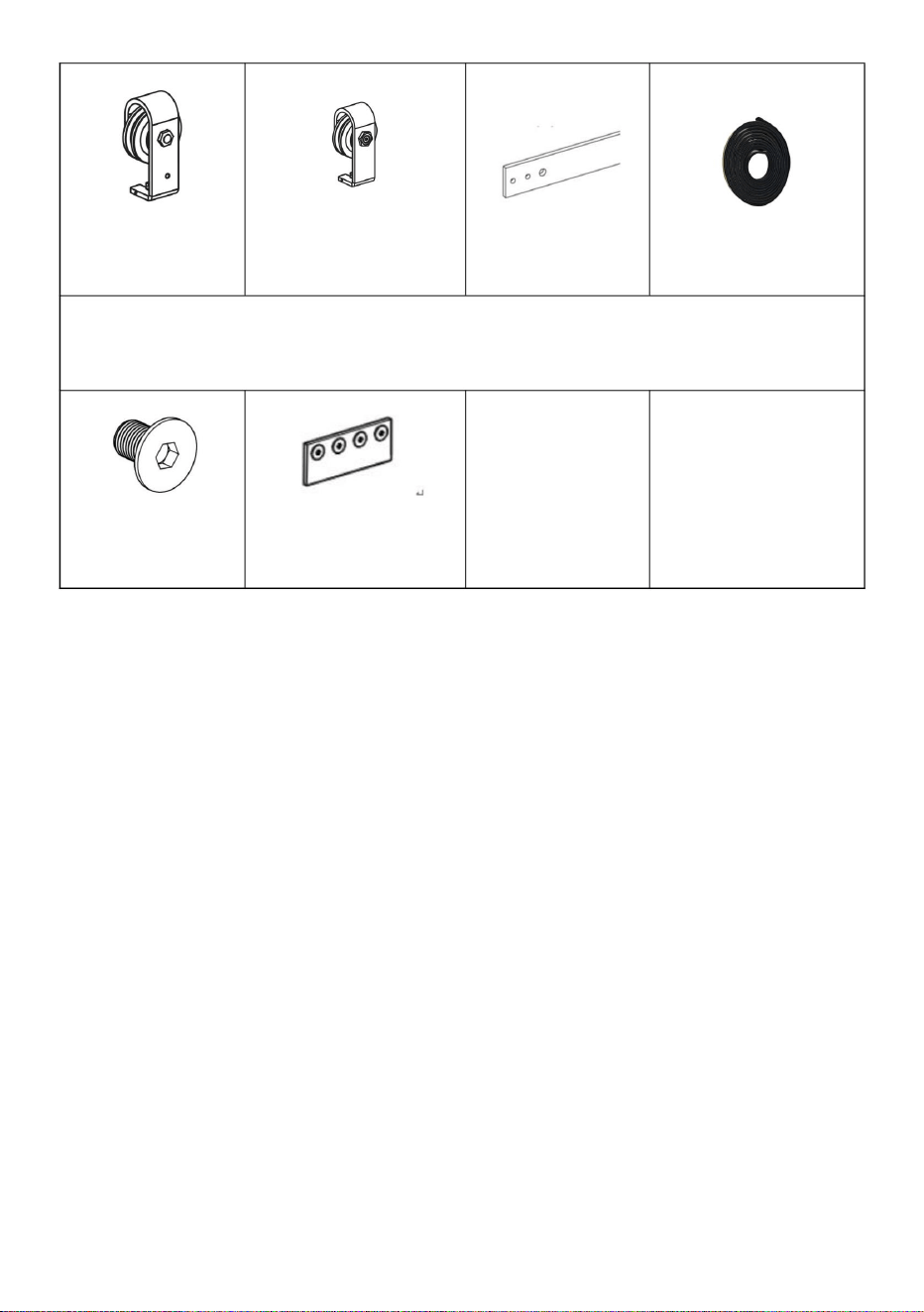
H:Bottom Pivot
Plate×1pc
I:Sleeve×1pc
J:M4×30
countersunk head
tapping
screw×4pcs
K:φ6×30
Plastic
expansion
bolt×4pcs
L:Bi-Fold Door
Butt
Hinges×3pcs
M:M6×25
countersunk
head tapping
screw×12pcs
N:Fixed Roller
Lock Bracket×1pc
O: Roller
Rotating
Base×2pcs
P:M5×50
countersunk
head tapping
screw×4pcs
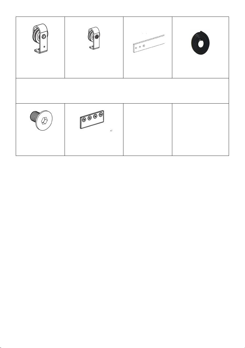
- 6 -
Q:Fixed
Roller×1pc
R:Adjustable
Roller×1pc
S:Rail Kit 1pc
V:Sealing
Strip×1pc
The model 36IN-3D-3K and 40IN-3D-3K have these parts, but they are
not available in the model 52IN-2D-3K
U:M6×10
bolt×8pcs
T:connection
strap×2pcs
CNOAUTION
Mishandling of heavy objects (i.e.,doors) may cause a loss of balance and
serious injury. Always be sure you have a secure
hold on the object and are balanced before moving the object.Always wear
safety shoes when lifting heavy objects.
Getting body parts (i.e., hair,fingers) caught in moving parts may cause
pinching and serious injury.Do not put fingers in parts that may move and
always remove or contain anything on your body that may become
entangled with a moving part.
Closing doors with your hand on the end of the door may result in your
hand, or fingers, getting caught between the door and other solid objects
(i.e., another door, molding) causing serious injury. Always use the door
handle to close door.
Usage Statement
- 7 -
Use of excessive force when opening and closing the door(s) may result in
damage to the hardware. Always hold the handle to gently move the
door(s).
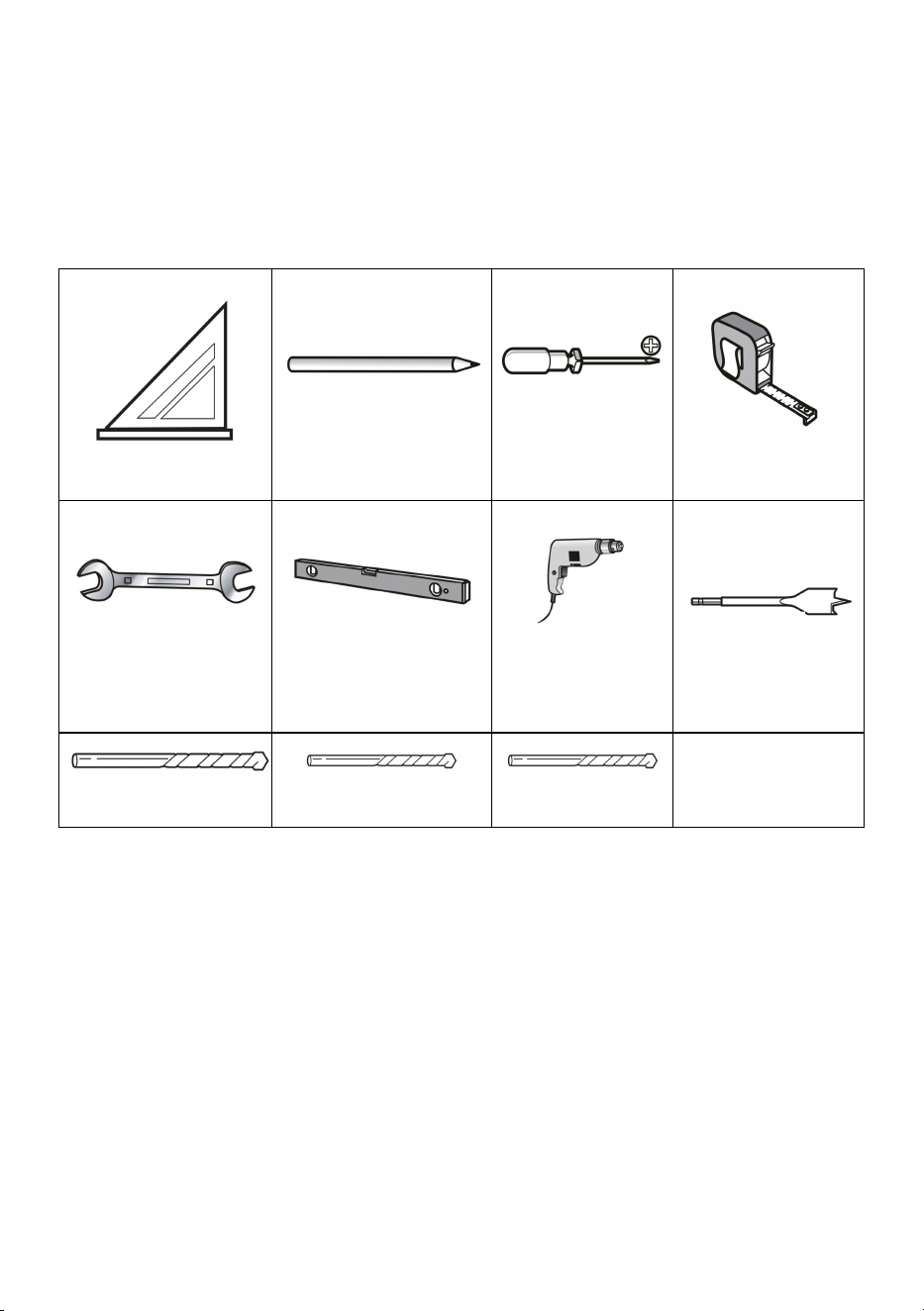
Tools required
Speed Square
Pencil
Phillips
Screwdriver
Tape
Wrench
Level
Drill
Φ19/32”Drill Bit
Φ29/64”Drill Bit
Φ7/32”Drill Bit
Φ3/16”Drill Bit
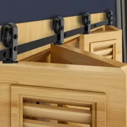
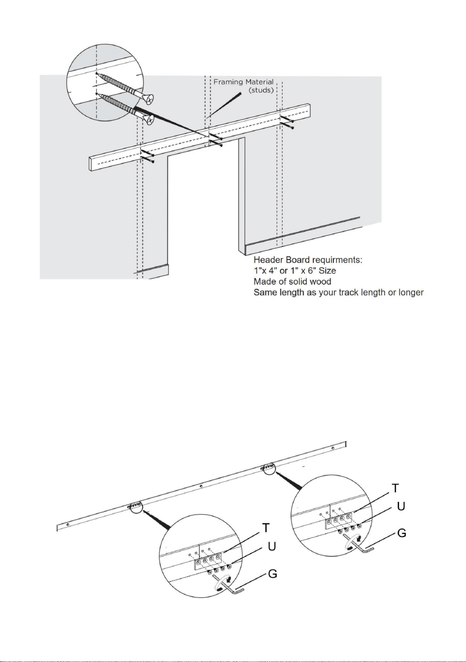
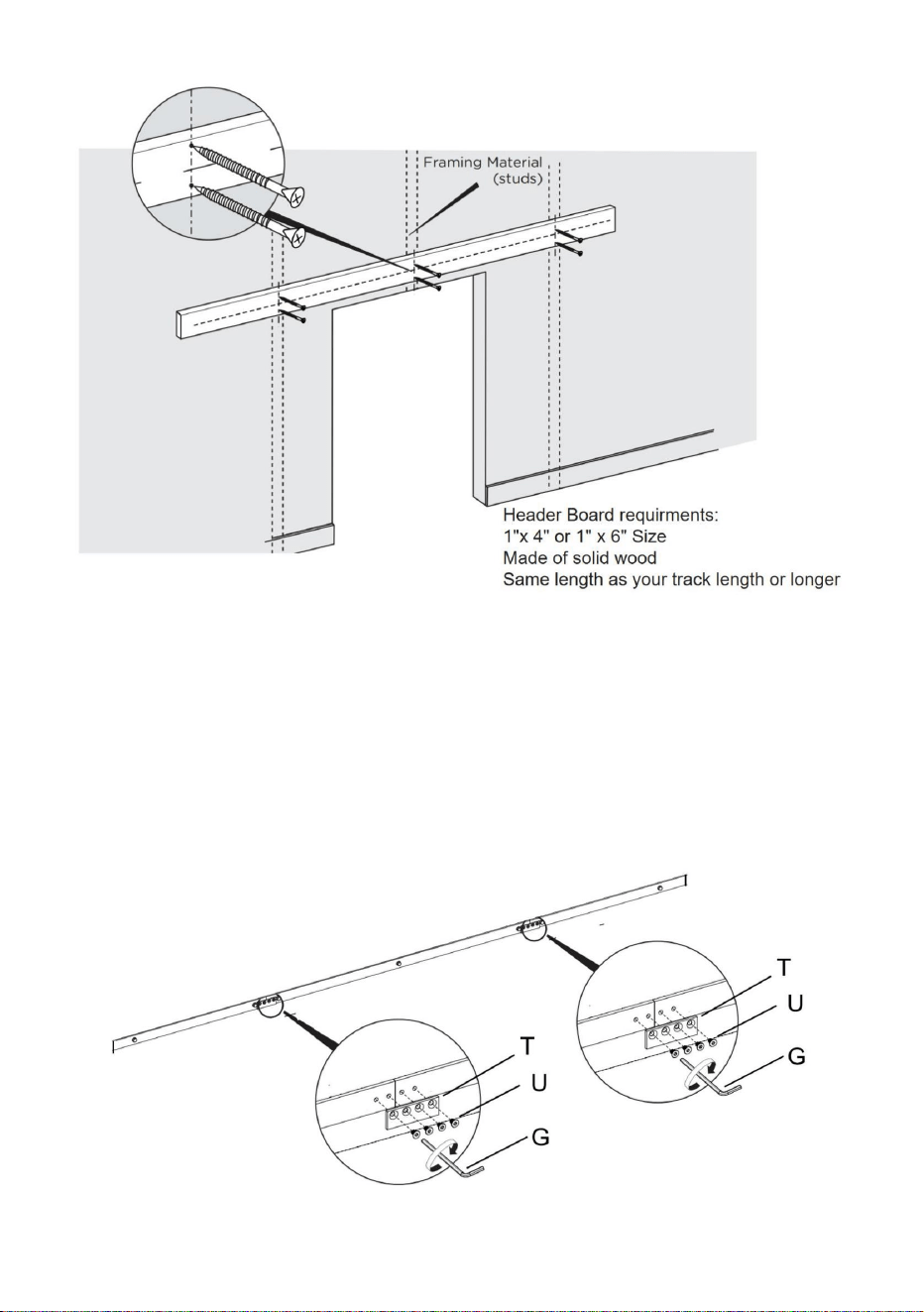
Product Assembly
It is very important to determine whether you need to install a Header
Board before you install the track.
If you meet following situations, we highly recommended you using a
header board (These situations might include but are not limited to)
• there is a doorway trim (like a door frame or a skirting line)
•the wall is not concrete wall, such as drywall or other type wall
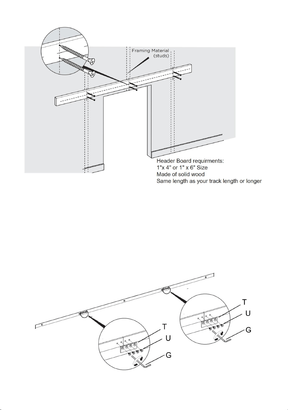
- 8 -
Attention: Header Board & the screws to install header board are not
included. You can buy them online or offline.
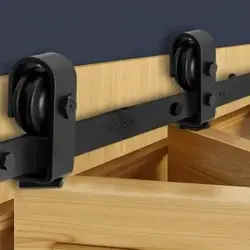
Step-1
1.1.Tighten screw U with Hex Key G to connect connection strap T to three
rails;Complete the connection of the guide rail.This installation method is
suitable for the guide rail of the model 36IN-3D-3K and 40IN-3D-3K
- 9 -
1.2.The rail of the model 52IN-2D-3K is a 2-segment rail splicing by petal
shape.
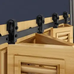
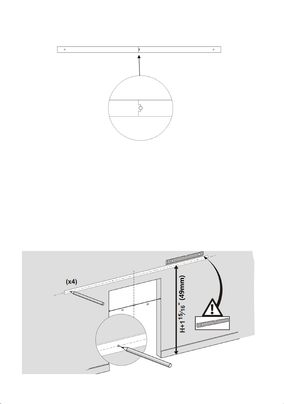
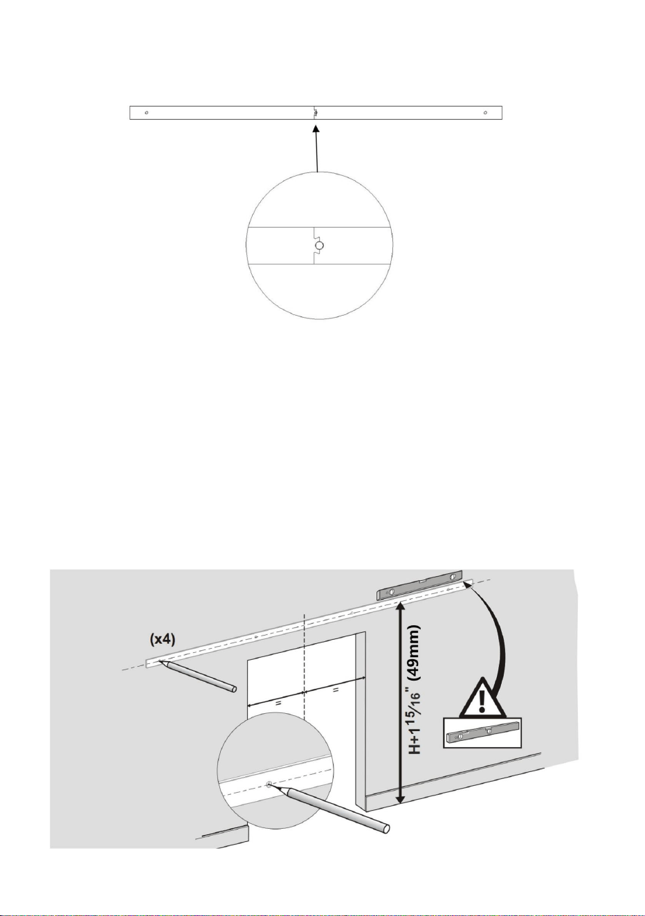
1.3.Use a Level and Tape Measure to mark the center line of the track. As
shown in the product selection diagram, the height of the door is H in the
picture above, the height of the center line(measuring up from the floor) is
the height of your door PLUS 115/16”.
1.4.Position the track in place by the marked center line, ensuring it is level,
and use the track as a template to mark mounting holes location for the
track with a pencil.You can also refer to the track size to mark the position
of the rail holes.
See installation tip below.
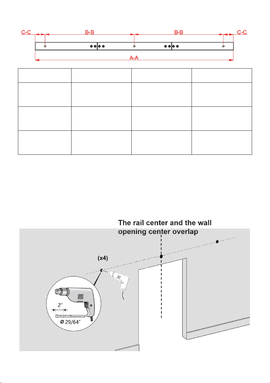
- 10 -
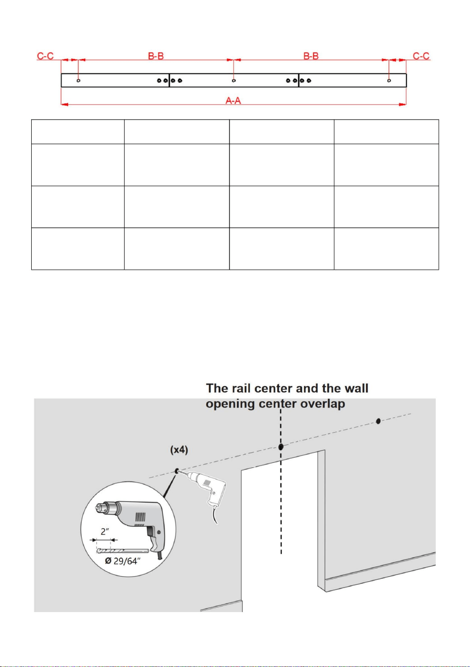
Model
36IN-3D-3K
40IN-3D-3K
52IN-2D-3K
rail length
A-A
36inch(9140mm)
40inch(1016mm)
52inch(1320mm)
rail hole
distance B-B
406mm
457mm
600mm
rail hole
distance C-C
51mm
51mm
60mm
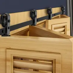
We suggest that the center of the track is at the center of the wall opening.
Step-2:
2.1.Use a Φ29/64”drill hole in the marked position, 2inches deep;

- 11 -
Step-3:Install the guide rail
3.1.Install the Plastic expansion bolt D to holes on the concrete wall
first,Then use screw P through the washers B, rail S and Wall Spacer A,
and finally lock on Plastic expansion bolt D.
Step-4
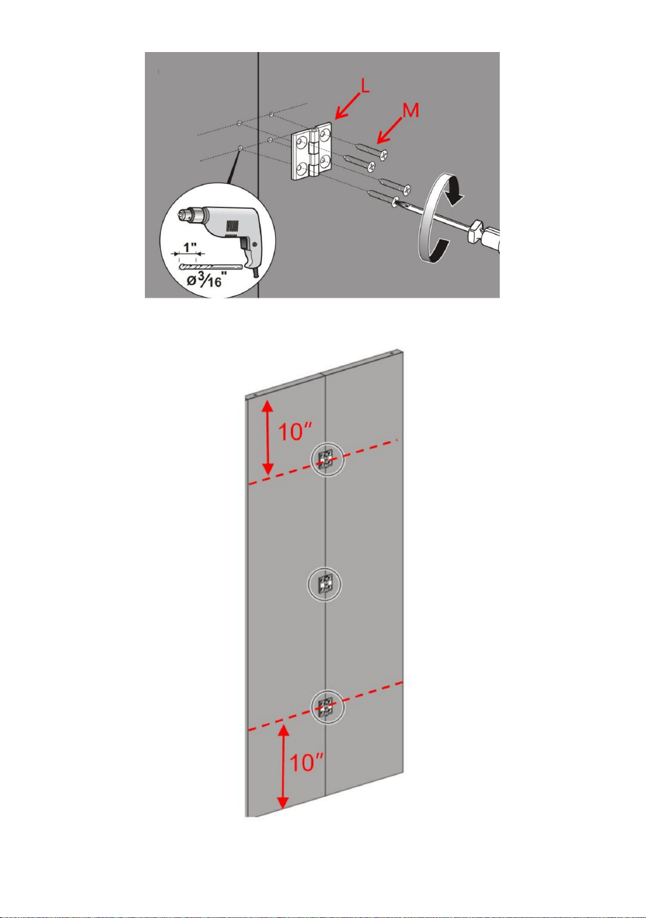
4.1.First splicing the door together, with the Bi-Fold Door Butt Hinges L
hole in the door to determine the position of the screw,and mark,and finally
with Φ3/16" drill hole,hole-depth of 1inch.
4.2.Screw M holds the Bi-Fold Door Butt Hinges L to the door,Complete the
assembly of the door.

- 12 -
- 13 -
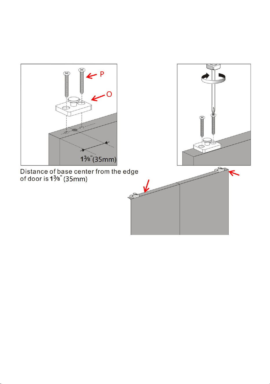
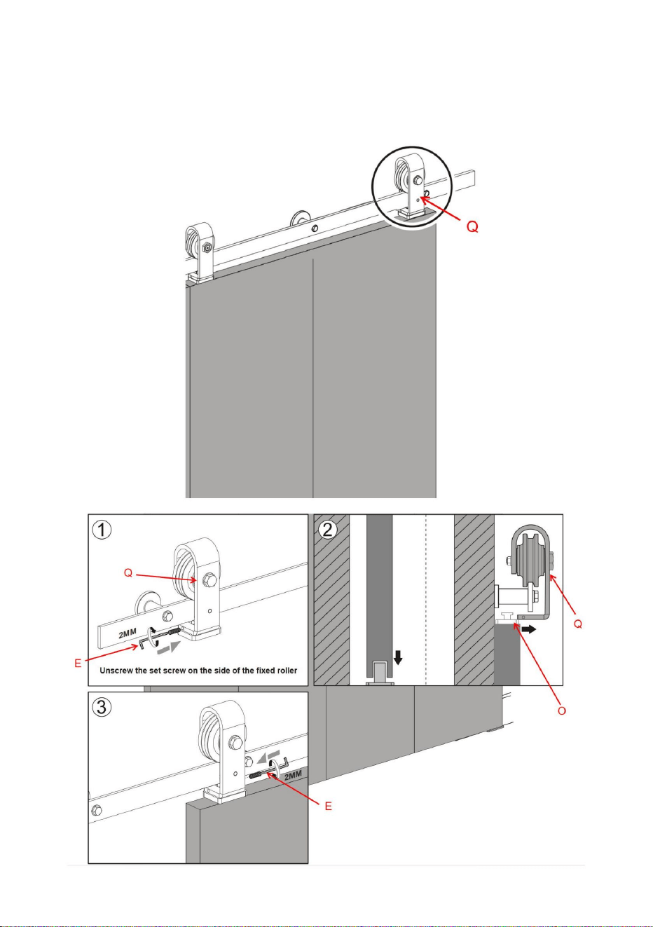
Step-5
Using screw P, install 2 Roller Rotating Base O on the top of the door, the
center of Roller Rotating Base O is 35mm from the edge of the door.
Step-6
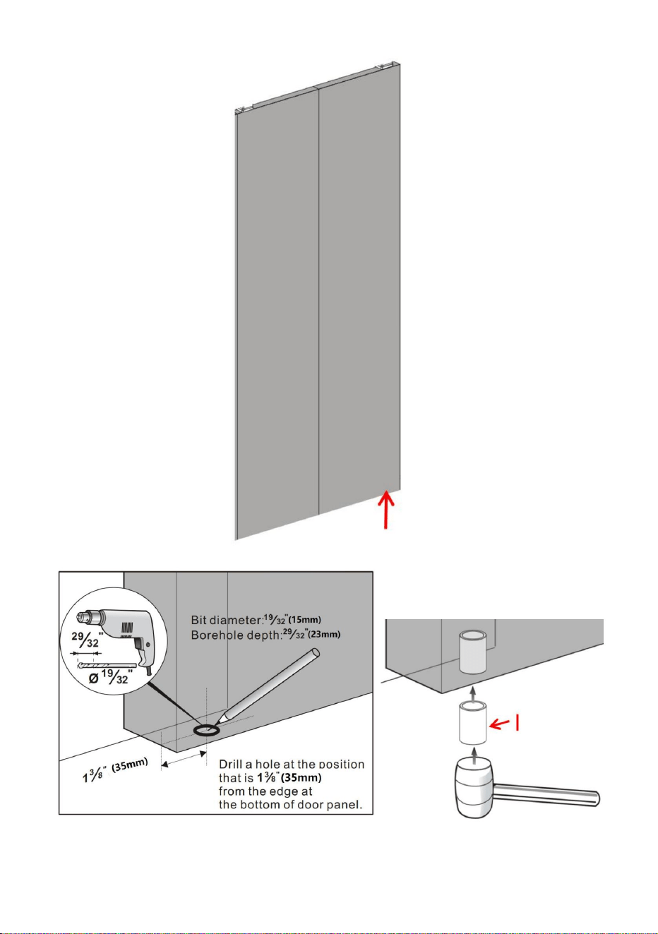
6.1.drill depth 23mm holes on side of the door with a Φ19/32"drill;the
center of the hole is located 35mm away from the door edge;
6.2.Fill Sleeve I into the hole;

- 14 -
- 15 -
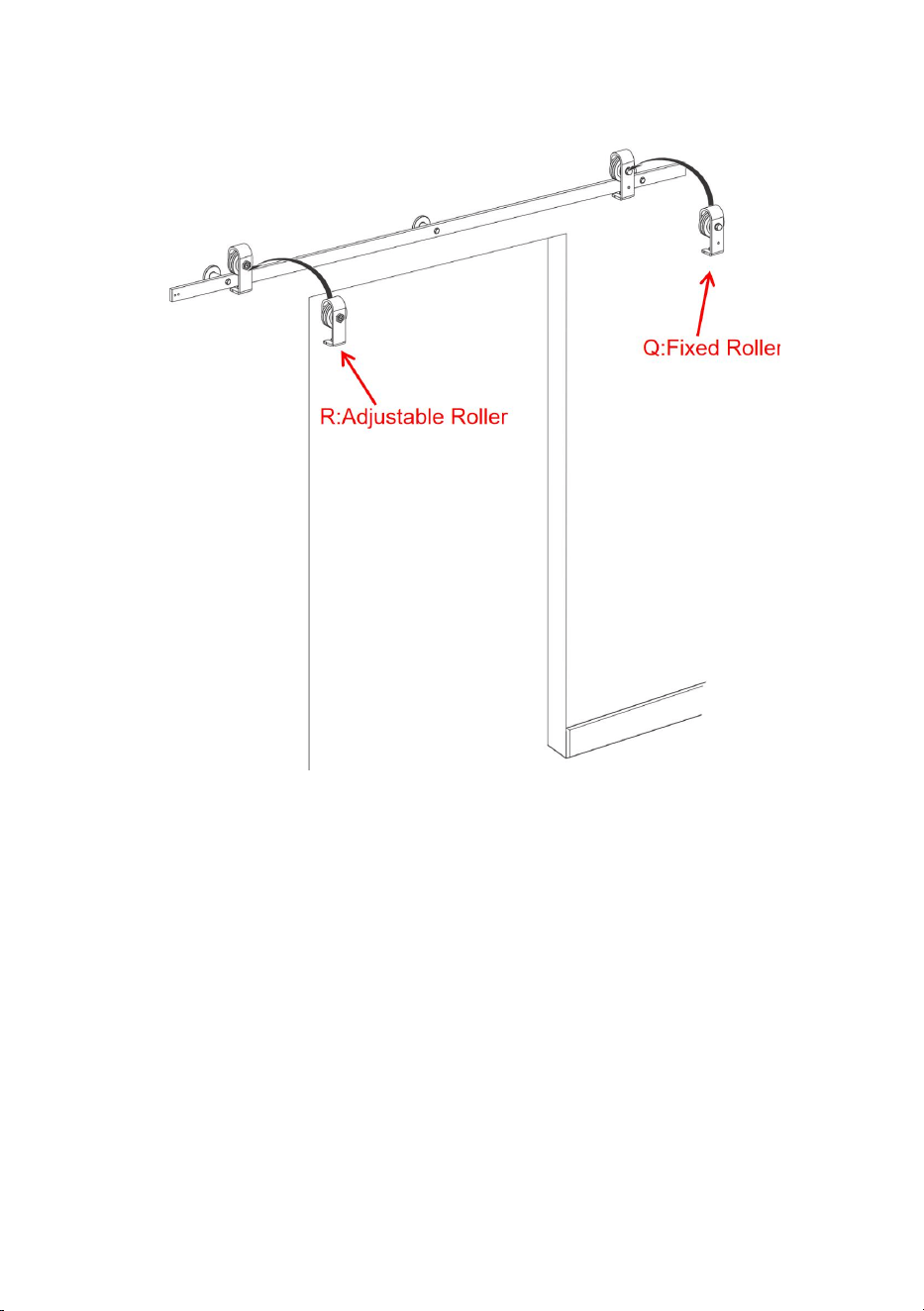
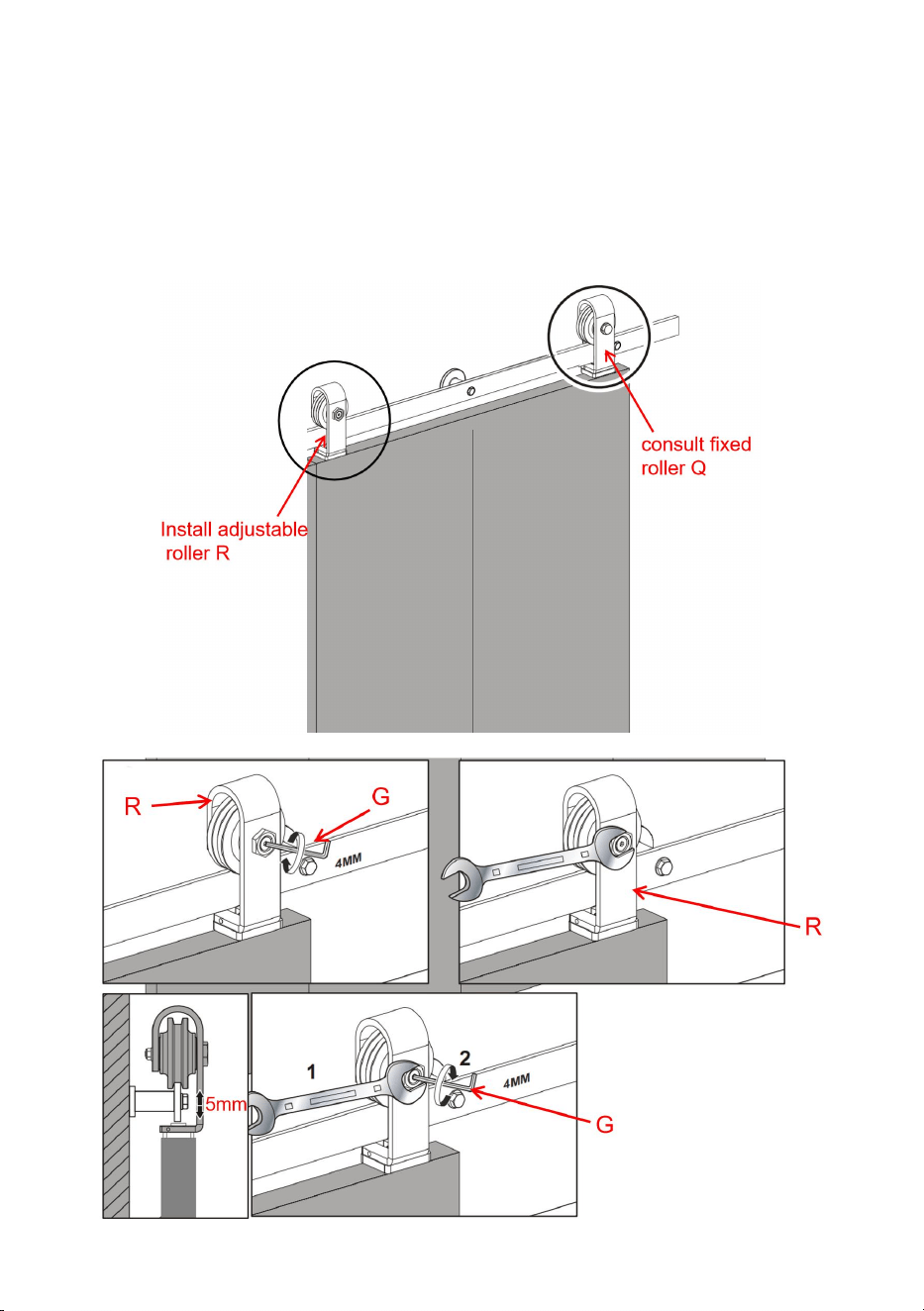
Step-7
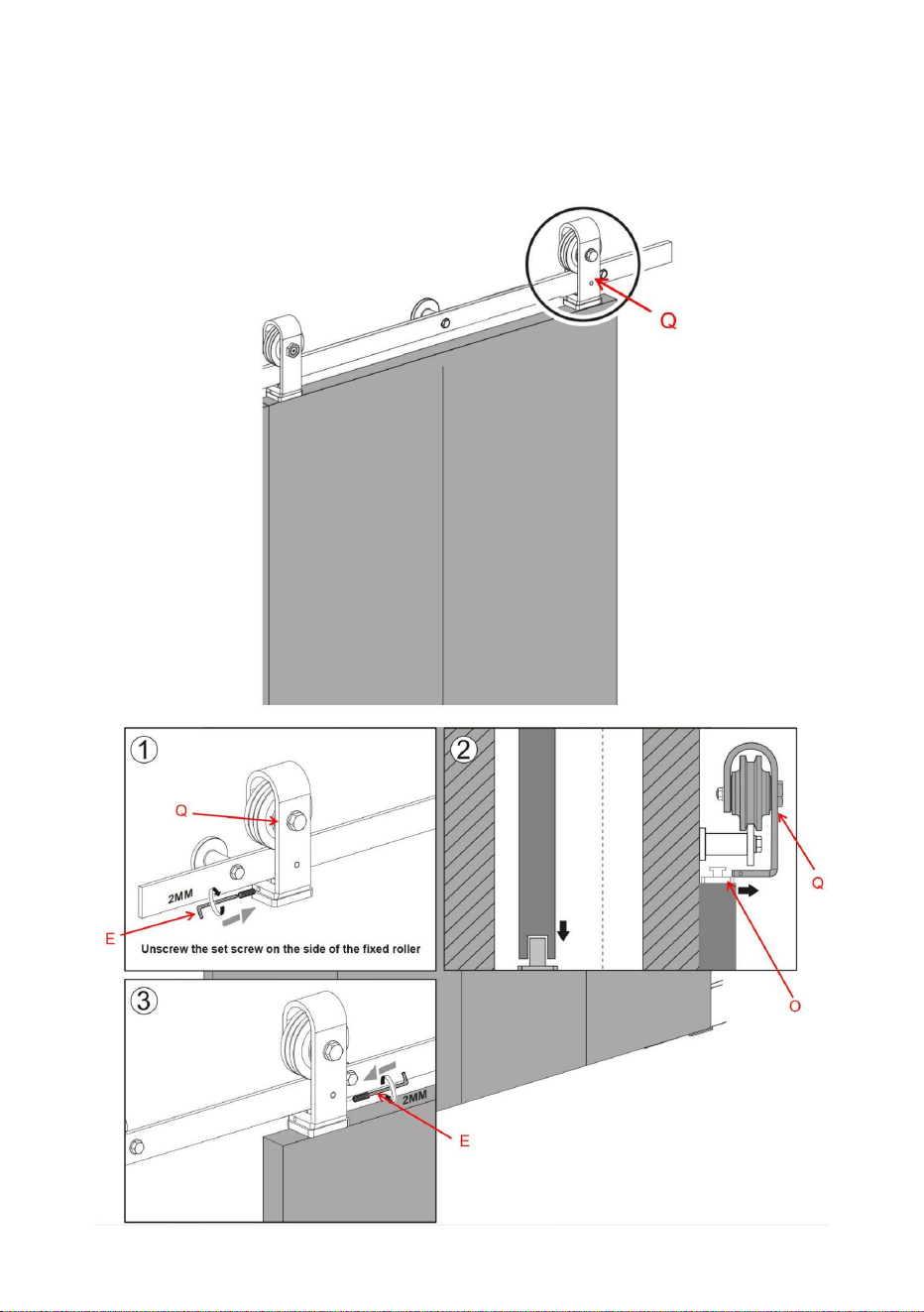
7.1.Hang the Fixed Roller Q And Adjustable Roller R on the rail.
Step-8
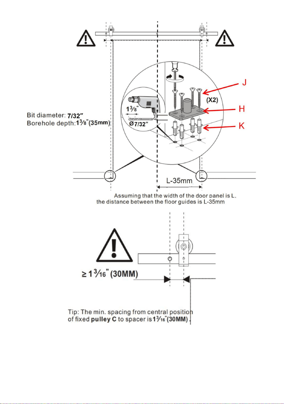
8.1.Install Bottom Pivot Plate H;Assuming the width of a single door is
L;the distance between the bottom pivot plate H and the central axis of the
wall opening is L-35mm;the distance of Bottom Pivot Plate H center from
the wall is 47.6mm;
8.2.Four spots were marked above the ground with the through-hole of
Bottom Pivot Plate H;drill depth 35mm holes in the mark with a
Φ7/32"drill;then insert Plastic expansion bolt k into the holes.
8.3.Attach the Bottom Pivot Plate H to the floor using a screw J.
8.4.The distance between the center of Fixed Roller Q and the outer hole
of the track is not less than 30mm

- 16 -
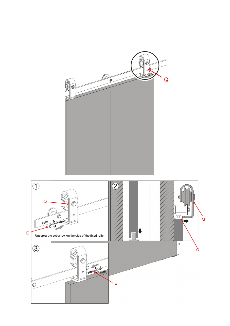
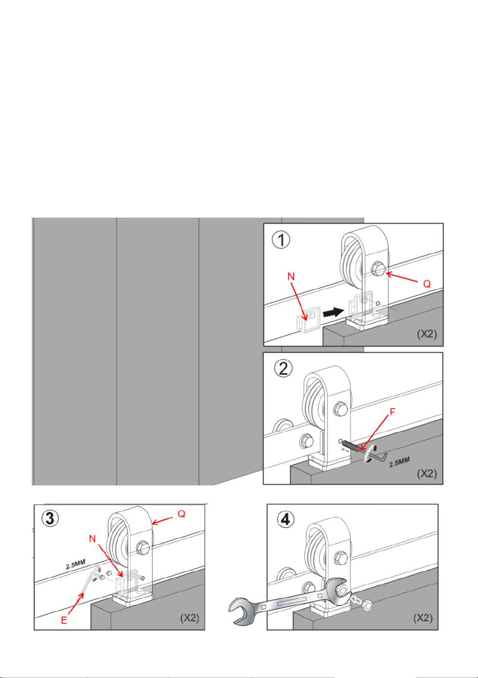
Step-9
9.1.Unscrew the set screw on the side of the fixed roller Q.
- 17 -
9.2.Put the door on the Sleeve I;Engage the Roller Rotating Base O on the
top of the door with the fixed roller
9.3.Tight down set screws to lock the fixed roller to the Roller Rotating
Base O.
- 18 -
Step-10
10.1.Refer to step 9, install Adjustable Roller R by the method of installing
fixed roller Q.
10.2.Refer to the prompts below,Adjust the height of the adjustable roller R
to a suitable position.Let the left and right door height be at the same level.
The height of the door can be adjusted by Approximately 5mm
- 19 -
Step-11
Install the fixed roller lock bracket N.
11.1.Slide the fixed roller lock bracket N onto the rail behind the set screw
located on the front of the fixed roller Q.
11.2.Using the supplied Allen Wrench F, tighten the set screws on the back
of the fixed roller lock bracket N.
11.3.Lock the fixed roller Q onto the rail by tightening the long set screw
through the fixed roller strap lock bracket and into the rail.
11.4.tighten the hex-head nut onto this set screw.
- 20 -
Manufacturer: Shanghaimuxinmuyeyouxiangongsi
Address: Shuangchenglu 803nong11hao1602A-1609shi, baoshanqu,
shanghai 200000 CN.
Imported to AUS: SIHAO PTY LTD. 1 ROKEVA STREETEASTWOOD
NSW 2122 Australia
Imported to USA: Sanven Technology Ltd. Suite 250, 9166 Anaheim
Place, Rancho Cucamonga, CA 91730
REP
UK
YH CONSULTING LIMITED. C/O YH Consulting
Limited Office 147, Centurion House, London
Road, Staines-upon-Thames, Surrey, TW18 4AX
REP
EC
E-CrossStu GmbH
Mainzer Landstr.69,
60329 Frankfurt am Main.


Technical Support and E-Warranty Certificate
www.vevor.com/support

Assistancetechniqueetcertificatdegarantie
électroniquewww.vevor.com/support
Modèle:36IN3D3K/40IN3D3K/52IN2D3K
KITDEMATÉRIEL
PORTEDEGRANGECOULISSANTEÀDEUXPORTES
Machine Translated by Google

Machine Translated by Google

Ils'agitdelanoticed'utilisationd'origine.Veuillezlireattentivementtoutes
lesinstructionsdumanuelavantdel'utiliser.VEVORseréserveledroitd'interpréter
clairementnotremanueld'utilisation.L'apparenceduproduitdépendduproduit
quevousavezreçu.Veuilleznousexcuser,nousnevousinformeronsplussides
misesàjourtechnologiquesoulogiciellessontdisponiblessurnotreproduit.
Modèle:36IN3D3K/40IN3D3K/52IN2D3K
Kitdequincaillerie
Portedegrangecoulissantepliante
1
Machine Translated by Google

assemblée.
6.Lescapacitésduproduits'appliquentauproduitcorrectementetcomplètementassemblé.
8.Pourdesraisonsdesécurité,ilestrecommandéd'installercematérielpar2
3.Gardezlazonedemontagepropreetbienéclairée.
personnes
1.Ceproduitn'estpasunjouet.Nelaissezpaslesenfantsjoueraveccetarticle.
AVERTISSEMENT:
4.Gardezlesspectateurshorsdelazonependantl’assemblage.
créerdesdangers.
pages,veuillezvousréférerauschémad'assemblagedecemanuel.Déballezet
9.Lesproduitssontinstallésloindesenfantsetdesanimauxdomestiques;
2.Portezdeslunettesdesécuritéapprouvéesparl'ANSIetdesgantsdetravailrobustespendant
séparertouteslespiècesdansunezonedetravailpropre.
CONSERVEZCESINSTRUCTIONS
Précautionsdemontage
seulement.
2.Utiliseruniquementcommeprévu.
1.Assemblezuniquementseloncesinstructions.Unassemblageincorrectpeut
7.Pourplusd'informationssurlespiècesrépertoriéescidessous
3.Inspectezavantchaqueutilisation;nepasutilisersidespiècessontdesserréesouendommagées.
Lisezcedocumentavantd'utiliserceproduit.Lenonrespectdecetteconsignepeutentraîner
5.Nepasmontersivousêtesfatiguéousousl'influencedel'alcool,dedroguesoudemédicaments.
Précautionsd'emploi
blessuregrave.
Adéquationduproduit
CONSIGNESDESÉCURITÉ
2
Machine Translated by Google

3
(914mm)
Distancedurailparrapportàla
Modèle
Largeurdelaporte
longueurdurailAA
≤18pouces
36po3D3K40po3D3K52po2D3K
Porteépaisse
52pouces
portedusol
≤24pouces
1,375à1,75pouces(34,92à44,45mm)
≤16pouces
(1320mm)
40pouces
sol
(1016mm)
Distanceaubasdela
10mm
Hauteurdelaporte
36pouces
H(selonl'utilisateur)
H+49mm
Machine Translated by Google

Diagrammededécompositionduproduit
quantitédeportes
6pouces(152mm)
lehautetleplafond
Distanceentrelaporte
Laboîtenecontientpasdepanneauxdeporteetautrescarrésenbois,qui
nécessiteunachatsupplémentaire.
2pièces
4
Machine Translated by Google

Bout
A:Mur
G:4mmhexagonal
L:Portepliante
Tournant
Base×2pièces
Plastique
F2,5mmhexagonal
fraisé
Plastique
fraisé
visautotaraudeuseà
têteplate×4pièces
J:M4×30
M:M6×25
visautotaraudeuseà
têteplate×12pièces
Vis×3pièces
B:rondelles×3pièces
H:Pivotinférieur
Charnières×3pièces
N:Rouleaufixe
D:φ12×50Boulon
d'expansion
enplastique×3pièces
Clé×1pièce
boulon
d'expansion×4pièces
O:Rouleau
C:M8×90mm
Clé×1pièce
K:φ6×30
P:M5×50
Mêmespiècesdedifférentsmodèles
Tapotement
Assiette×1pc
E:2mmhexagonal
visautotaraudeuseàtête
fraisée×
4pièces
I:Manchon×1pc
Supportdeverrouillage×1pièce
Entretoise×3pièces
Clé×1pièce
Listedespièces
5
Machine Translated by Google

Déclarationd'utilisation
AVERTISSEMENT
Rouleau×1pièce
U:M6×10
R:Réglable
boulon×8pièces
Rouleau×1pièce
T:connexion
Lesmodèles36IN3D3Ket40IN3D3Kpossèdentcespièces,maisellesnesontpasdisponiblesdansle
modèle52IN2D3K
Fermerlesportesaveclamainsurl'extrémitédelaportepeutentraînerlecoincementdelamainoudesdoigts
entrelaporteetd'autresobjetssolides(parexemple,uneautreporte,unemoulure),cequipeutentraînerdes
blessuresgraves.Utiliseztoujourslapoignéedeportepourfermerlaporte.
KitS:Rail1pièce
V:Étanchéité
Unemauvaisemanipulationd'objetslourds(parexemple,desportes)peutentraîneruneperted'équilibreetdes
blessuresgraves.Assurezvoustoujoursdebientenirl'objetetd'êtreen
équilibreavantdeledéplacer.Porteztoujoursdeschaussuresdesécuritélorsquevoussoulevezdesobjetslourds.
Bande×1pièce
Lefaitdecoincerdespartiesducorps(c.àd.lescheveux,lesdoigts)dansdespiècesmobilespeutprovoquer
unpincementetdesblessuresgraves.Nemettezpaslesdoigtsdansdespiècessusceptiblesdebougeretretirez
oureteneztoujourstoutcequisetrouvesurvotrecorpsetquipourraits'emmêlerdansunepiècemobile.
sangle×2pièces
Q:Corrigé
6
Machine Translated by Google

Outilsnécessaires
Assemblageduproduit
Percer
Carrédevitesse
L'utilisationd'uneforceexcessivelorsdel'ouvertureetdelafermeturedesportespeutentraîner
Clé
Ilesttrèsimportantdedéterminersivousdevezinstallerunentête
Plancheavantd'installerlapiste.
endommagerlematériel.Teneztoujourslapoignéepourdéplacerdoucementle
Niveau
Crayon
ForetΦ3/16”
Sivousrencontrezlessituationssuivantes,nousvousrecommandonsfortementd'utiliserun
Rubanadhésif
Phillips
ForetΦ29/64”
Tournevis
ForetΦ7/32”
ForetΦ19/32”
par(s).
panneaud'entête(Cessituationspeuventinclure,sanstoutefoiss'ylimiter)•ilya
unegarnituredeporte(commeuncadredeporteouuneplinthe)•lemur
n'estpasunmurenbéton,commeunecloisonsècheouunautretypedemur
7
Machine Translated by Google

8
inclus.Vouspouvezlesacheterenligneouhorsligne.
Attention:lepanneaud'entêteetlesvispourinstallerlepanneaud'entêtenesontpas
Étape1
1.1.SerrezlavisUaveclacléhexagonaleGpourconnecterlasangledeconnexionTaux
troisrails;terminezlaconnexionduraildeguidage.Cetteméthoded'installationconvient
auraildeguidagedesmodèles36IN3D3Ket40IN3D3K
Machine Translated by Google

9
lahauteurdevotreportePLUS115/16”.
1.4.Positionnezlapisteenplaceprèsdelalignecentralemarquée,envousassurantqu'elleestde
niveau,etutilisezlapistecommegabaritpourmarquerl'emplacementdestrousdemontagepourle
imagecidessus,lahauteurdelalignecentrale(mesuréeàpartirdusol)est
tracezunepisteavecuncrayon.Vouspouvezégalementvousréféreràlatailledelapistepourmarquerlaposition
forme.
indiquédanslediagrammedesélectiondeproduit,lahauteurdelaporteestHdansle
1.3.Utilisezunniveauetunrubanàmesurerpourmarquerlalignecentraledelapiste.
1.2.Leraildumodèle52IN2D3Kestunrailà2segmentsépisséparpétale
Voirleconseild'installationcidessous.
destrousdurail.
Machine Translated by Google

10
distanceBB
457mm
Noussuggéronsquelecentredelapistesoitaucentredel’ouverturedumur.
Modèle
trouderail
Étape2:
36IN3D3K
distanceCC
36pouces(9140mm),40pouces(1016mm),52pouces(1320mm)
51mm
2.1.UtilisezuntroudeperçageΦ29/64”danslapositionmarquée,à2poucesdeprofondeur;
trouderail
60mm
longueurdurail
600mm
AA
51mm
40IN3D3K
406mm
52IN2D3K
Machine Translated by Google

11
Étape4
4.1.Commencezparassemblerlaporte,aveclescharnièresdeportepliantes,percezun
trouenLdanslaportepourdéterminerlapositiondelavis,puismarquezleetenfinpercez
untroudeΦ3/16",d'uneprofondeurdetroude1pouce.
Étape3:Installezlerailde
guidage3.1.Installezd'abordleboulond'expansionenplastiqueDdanslestrousdu
murenbéton,puisutilisezlavisPàtraverslesrondellesB,lerailSetl'entretoisemurale
A,etenfinverrouillezleboulond'expansionenplastiqueD.
4.2.LavisMmaintientlescharnièresdeportepliantesLsurlaporte.Terminezl'assemblage
delaporte.
Machine Translated by Google

12
Machine Translated by Google

13
Étape5
Àl'aidedelavisP,installez2basesrotativesàrouleauxOsurledessusdelaporte,le
centredelabaserotativeàrouleauxOestà35mmduborddelaporte.
Étape6
6.1.percezdestrousde23mmdeprofondeursurlecôtédelaporteavecunforet
Φ19/32";lecentredutrouestsituéà35mmduborddelaporte;6.2.
RemplissezlemanchonIdansletrou;
Machine Translated by Google

14
Machine Translated by Google

15
Étape8
8.1.InstallerlaplaquepivotanteinférieureH;Ensupposantquelalargeurd'uneseule
porteestL;ladistanceentrelaplaquepivotanteinférieureHetl'axecentraldel'ouverturedu
murestL35mm;ladistanceducentredelaplaquepivotanteinférieureHparrapportaumur
estde47,6mm;
8.2.Quatrepointsontétémarquésaudessusdusolavecletroutraversantdelaplaque
pivotanteinférieureH;percerdestrousde35mmdeprofondeurdanslamarque
avecuneperceuseΦ7/32";puisinsérerleboulond'expansionenplastiquekdanslestrous.
8.4.LadistanceentrelecentredurouleaufixeQetletrouextérieurdelapisten'estpas
inférieureà30mm
8.3.FixezlaplaquepivotanteinférieureHausolàl'aided'unevisJ.
Étape7
7.1.AccrochezlerouleaufixeQetlerouleauréglableRsurlerail.
Machine Translated by Google

16
9.1.DévissezlavisderéglagesurlecôtédurouleaufixeQ.
Étape9
Machine Translated by Google

17
9.2.PlacezlaportesurlemanchonI;engagezlabaserotativedurouleauOsurledessus
delaporteaveclerouleaufixe.9.3.Serrez
lesvisderéglagepourverrouillerlerouleaufixesurlabaserotativedurouleauO.
Machine Translated by Google

18
10.1.Reportezvousàl'étape9,installezlerouleauréglableRselonlaméthoded'installation
10.2.Reportezvousauxinstructionscidessous,réglezlahauteurdurouleauréglableR
rouleaufixeQ.
Étape10
Lahauteurdelaportepeutêtrerégléed'environ5mm
àunepositionappropriée.Laissezlahauteurdelaportegaucheetdroiteêtreaumêmeniveau.
Machine Translated by Google

dusupportdeverrouillageàrouleaufixeN.
11.3.VerrouillezlerouleaufixeQsurlerailenserrantlalonguevisderéglage
11.2.Àl'aidedelacléAllenFfournie,serrezlesvisderéglageàl'arrière
InstallerlesupportdeverrouillagedurouleaufixeN.
situéàl'avantdurouleaufixeQ.
11.1.FaitesglisserlesupportdeverrouillagedurouleaufixeNsurlerailderrièrelavisderéglage
Étape11
àtraverslesupportdeverrouillagedelasangleàrouleaufixeetdanslerail.
11.4.serrezl'écrouàtêtehexagonalesurcettevisderéglage.
19
Machine Translated by Google

20
ImportéauxÉtatsUnis:SanvenTechnologyLtd.Suite250,9166AnaheimPlace,
RanchoCucamonga,CA91730
YHCONSULTINGLIMITED.C/OYHConsultingLimited
Bureau147,CenturionHouse,LondonRoad,Staines
uponThames,Surrey,TW184AX
ImportéenAustralie:SIHAOPTYLTD.1ROKEVASTREETEASTWOODNSW2122
Australie
Fabricant:ShanghaimuxinmuyeyouxiangongsiAdresse:
Shuangchenglu803nong11hao1602A1609shi,baoshanqu,shanghai200000CN.
ECrossStuGmbH
MainzerLandstr.69,
60329FrancfortsurleMain.
REPRÉSENTANTDELACE
REPRÉSENTANTDUROYAUMEUNI
Machine Translated by Google

Machine Translated by Google

Assistancetechniqueetcertificatdegarantie
électroniquewww.vevor.com/support
Machine Translated by Google

Technischer Support und E-Garantie-Zertifikat
www.vevor.com/support
Modell: 36IN-3D-3K/40IN-3D-3K/52IN-2D-3K
HARDWARE KIT
FALTBARES SCHIEBETÜR
Machine Translated by Google

Machine Translated by Google

Modell: 36IN-3D-3K/40IN-3D-3K/52IN-2D-3K
Dies ist die Originalanleitung. Bitte lesen Sie alle Anweisungen sorgfältig durch,
bevor Sie das Gerät in Betrieb nehmen. VEVOR behält sich eine klare Auslegung unserer
Bedienungsanleitung vor. Das Erscheinungsbild des Produkts richtet sich nach
dem Produkt, das Sie erhalten haben. Bitte verzeihen Sie uns, dass wir Sie nicht erneut
informieren, wenn es Technologie- oder Software-Updates für unser Produkt gibt.
Hardware-Kit
Faltbare Schiebetür im Scheunenstil
- 1 -
Machine Translated by Google

4. Halten Sie während der Montage unbeteiligte Zuschauer vom Bereich fern.
9.Produkte werden außerhalb der Reichweite von Kindern und Haustieren installiert;
5. Nicht zusammenbauen, wenn Sie müde sind oder unter dem Einfluss von Alkohol, Drogen oder
Medikamenten stehen.
Lesen Sie dieses Material, bevor Sie dieses Produkt verwenden. Andernfalls kann es zu
Vorsichtsmaßnahmen treffen
1. Dieses Produkt ist kein Spielzeug. Erlauben Sie Kindern nicht, mit diesem Artikel zu spielen.
schwere Verletzungen.
Vorsichtsmaßnahmen bei der Montage
6.Produktfunktionen gelten für ordnungsgemäß und vollständig montierte Produkte
nur.
1. Nur gemäß dieser Anleitung zusammenbauen. Unsachgemäßer Zusammenbau kann
7. Weitere Informationen zu den im Folgenden aufgeführten Teilen finden Sie
2. Nur bestimmungsgemäß verwenden.
3. Vor jedem Gebrauch prüfen; nicht verwenden, wenn Teile lose oder beschädigt sind.
Gefahren schaffen.
Seiten finden Sie im Montagediagramm dieses Handbuchs. Auspacken und
BEWAHREN SIE DIESE ANWEISUNGEN AUF
Trennen Sie alle Teile in einem sauberen Arbeitsbereich.
2. Tragen Sie ANSI-zugelassene Schutzbrillen und schwere Arbeitshandschuhe während
Montage.
3. Halten Sie den Versammlungsbereich sauber und gut beleuchtet.
8. Aus Sicherheitsgründen wird empfohlen, diese Hardware von 2 zu installieren
Menschen
WARNUNG:
SICHERHEITSHINWEISE
Produkteignung
- 2 -
Machine Translated by Google
- 3 -
36ZOLL-3D-3K 40ZOLL-3D-3K 52ZOLL-2D-3K
1,375 bis 1,75 Zoll (34,92–44,45 mm)
Türhöhe
36 Zoll
H (je nach Benutzer)
H+49mm
(914 mm)
40 Zoll
Abstand der Schiene vom
Boden
(1016 mm)
Abstand am unteren Ende des
10 mm
52 Zoll
Tür vom Boden
ÿ16 Zoll
(1320 mm)
Schienenlänge AA
Modell
Türbreite ÿ18 Zoll ÿ24 Zoll
Türdicke
Machine Translated by Google
Produktzerlegungsdiagramm
Anzahl Türen
6 Zoll (152 mm)
oben und an der Decke
Abstand zwischen Tür
Die Box enthält keine Türpaneele und andere Holzquadrate, die
erfordern einen zusätzlichen Kauf.
2 Stück
- 4 -
Machine Translated by Google

B: Unterlegscheiben × 3 Stück
H: Unterer Drehpunkt
Scharniere × 3 Stück
N:Feste Rolle
Schraube × 3 Stück
M:M6×25
J:M4×30
Blechschraube
mit Kopf × 12 Stück
Senkkopf
Blechschraube
mit Kopf × 4 Stück
Plastik
Plastik
F 2,5 mm Sechskant
Senkkopf
A:Wand
G: 4 mm Sechskant
L: Falttür
Drehen
Abstandshalter × 3 Stück
Schlüssel × 1 Stück
Hintern
Basis × 2 Stück
Tippen
I: Ärmel × 1 Stück
Platte × 1 Stück
Schlosshalterung × 1 Stück
E: 2 mm Sechskant
Senkkopf-Blechschraube
× 4 Stück
Gleiche Teile verschiedener Modelle
C: M8 × 90 mm
Schlüssel × 1 Stück
K:ÿ6×30
P:M5×50
D:ÿ12×50 Kunststoff-
Spreizbolzen
× 3 Stück
Schlüssel × 1 Stück
Spreizbolzen
× 4 Stück
O: Walze
Ersatzteilliste
- 5 -
Machine Translated by Google
Nutzungserklärung
ACHTUNG
Rolle × 1 Stück
Riemen × 2 Stück
F: Behoben
Rolle × 1 Stück
V: Versiegelung
Der falsche Umgang mit schweren Gegenständen (z. B. Türen) kann zu Gleichgewichtsverlust und schweren Verletzungen
führen. Achten Sie immer darauf, dass Sie den Gegenstand sicher im Griff haben
und das Gleichgewicht halten, bevor Sie ihn bewegen. Tragen Sie beim Heben schwerer Gegenstände immer
Sicherheitsschuhe.
Streifen × 1 Stück
Wenn sich Körperteile (z. B. Haare, Finger) in beweglichen Teilen verfangen, kann dies zu Quetschungen und
schweren Verletzungen führen. Stecken Sie Ihre Finger nicht in bewegliche Teile und legen Sie stets alle Gegenstände
am Körper ab bzw. bewahren Sie sie auf, die sich in beweglichen Teilen verfangen könnten.
Die Modelle 36IN-3D-3K und 40IN-3D-3K verfügen über diese Teile, sie sind jedoch im
Modell 52IN-2D-3K nicht verfügbar
Wenn Sie beim Schließen einer Tür Ihre Hand am Ende der Tür haben, kann es passieren, dass Ihre
Hand oder Ihre Finger zwischen der Tür und anderen festen Objekten (z. B. einer anderen Tür, einer
Zierleiste) eingeklemmt werden, was zu schweren Verletzungen führen kann. Verwenden Sie zum
Schließen der Tür immer den Türgriff.
S:Schienensatz 1Stk
U:M6×10
R: Einstellbar
Bolzen × 8 Stück
T:Verbindung
- 6 -
Machine Translated by Google

Produktmontage
Erforderliches Werkzeug
Ebene
Wenn Sie auf die folgenden Situationen stoßen, empfehlen wir Ihnen dringend die Verwendung eines
ÿ19/32" Bohrer
von(n).
Kopfbrett (Diese Situationen können Folgendes umfassen, sind aber nicht darauf beschränkt):
• Es gibt eine Türverkleidung (wie einen Türrahmen oder eine Fußleiste) • Die
Wand ist keine Betonwand, sondern eine Trockenbauwand oder eine andere Art von Wand
Bohren
Phillips
ÿ29/64” Bohrer
Schraubendreher
ÿ7/32" Bohrer
Bleistift
ÿ3/16" Bohrer
Band
Geschwindigkeitsquadrat
Übermäßiger Kraftaufwand beim Öffnen und Schließen der Tür(en) kann zu
Schlüssel
Es ist sehr wichtig zu bestimmen, ob Sie einen Header installieren müssen
Brett, bevor Sie die Schiene installieren.
Beschädigung der Hardware. Halten Sie den Griff immer fest, um das
- 7 -
Machine Translated by Google

- 8 -
Schritt
1 1.1.Ziehen Sie die Schraube U mit dem Inbusschlüssel G fest, um das Verbindungsband T mit den
drei Schienen zu verbinden. Schließen Sie die Verbindung der Führungsschiene ab. Diese
Installationsmethode ist für die Führungsschiene der Modelle 36IN-3D-3K und 40IN-3D-3K geeignet.
Achtung: Die Kopfplatte und die Schrauben zur Befestigung der Kopfplatte sind nicht
enthalten. Sie können sie online oder offline kaufen.
Machine Translated by Google
- 9 -
die Höhe Ihrer Tür PLUS 115/16”.
1.4. Positionieren Sie die Schiene an der markierten Mittellinie, stellen Sie sicher, dass sie waagerecht
ist, und verwenden Sie die Schiene als Vorlage, um die Position der Befestigungslöcher für die
Bild oben, die Höhe der Mittellinie (vom Boden aus gemessen) beträgt
1.3.Markieren Sie mit einer Wasserwaage und einem Maßband die Mittellinie der Schiene.
Im Produktauswahldiagramm ist die Türhöhe H in der
Form.
1.2.Die Schiene des Modells 52IN-2D-3K ist eine 2-Segment-Schiene, die durch Blütenblatt verbunden ist
der Schienenlöcher.
Siehe Installationstipp unten.
Spur mit einem Bleistift. Sie können auch die Spurgröße verwenden, um die Position zu markieren
Machine Translated by Google
- 10 -
36IN-3D-3K
2.1.Bohren Sie an der markierten Stelle ein ÿ29/64"-Bohrloch mit einer Tiefe von 2 Zoll.
406 mm
40IN-3D-3K 52IN-2D-3K
Schienenlänge
457 mm 600 mm
AA
51 mm
36 Zoll (9140 mm) 40 Zoll (1016 mm) 52 Zoll (1320 mm)
51 mm 60 mm
Schienenloch
Abstand BB
Modell
Schienenloch
Wir empfehlen, dass sich die Schienenmitte in der Mitte der Wandöffnung befindet.
Schritt 2:
Abstand CC
Machine Translated by Google

- 11 -
Schritt
4 4.1. Zuerst die Tür zusammenfügen, mit dem L-Loch der Falttürscharniere in der Tür die Position
der Schraube bestimmen und markieren und abschließend ein ÿ3/16"-Bohrloch mit einer Lochtiefe
von 1 Zoll bohren.
Schritt 3: Führungsschiene
installieren 3.1. Zuerst den Kunststoff-Spreizbolzen D in den Löchern an der Betonwand
installieren, dann Schraube P durch die Unterlegscheiben B, Schiene S und Wandabstandshalter
A führen und schließlich den Kunststoff-Spreizbolzen D verriegeln.
4.2. Schraube M hält die Falttürscharniere L an der Tür. Schließen Sie die Montage der Tür ab.
Machine Translated by Google
- 12 -
Machine Translated by Google

- 13 -
Schritt
6: 6.1. Bohren Sie mit einem ÿ19/32"-Bohrer 23 mm tiefe Löcher in die Seite der Tür;
die Mitte des Lochs befindet sich 35 mm von der Türkante entfernt; 6.2.
Füllen Sie Hülse I in das Loch;
Schritt
5 : Montieren Sie mit der Schraube P zwei rotierende Rollensockel O oben auf der Tür.
Die Mitte der rotierenden Rollensockel O befindet sich 35 mm vom Rand der Tür entfernt.
Machine Translated by Google
- 14 -
Machine Translated by Google

- 15 -
8.3. Befestigen Sie die untere Schwenkplatte H mit einer Schraube J am Boden.
8.4.Der Abstand zwischen der Mitte der festen Rolle Q und dem äußeren Loch der Schiene
beträgt nicht weniger als 30 mm
Schritt
8 8.1. Untere Drehplatte H installieren; Angenommen, die Breite einer Einzeltür beträgt
L; der Abstand zwischen der unteren Drehplatte H und der Mittelachse der Wandöffnung
beträgt L-35 mm; der Abstand der Mitte der unteren Drehplatte H von der Wand beträgt 47,6
mm; 8.2. Über dem
Boden wurden vier Punkte mit dem Durchgangsloch der unteren Drehplatte H markiert;
bohren Sie mit einem ÿ7/32"-Bohrer 35 mm tiefe Löcher in die Markierung;
stecken Sie dann den Kunststoff-Spreizbolzen k in die Löcher.
Schritt
7: 7.1. Hängen Sie die feste Rolle Q und die verstellbare Rolle R an die Schiene.
Machine Translated by Google

- 16 -
9.1.Die Stellschraube an der Seite der Festrolle Q lösen.
Schritt 9
Machine Translated by Google
- 17 -
9.2.Setzen Sie die Tür auf die Hülse I; bringen Sie die drehbare Rollenbasis O oben an der
Tür mit der festen Rolle in Eingriff.
9.3.Ziehen Sie die Stellschrauben fest, um die feste Rolle an der drehbaren Rollenbasis
O zu verriegeln.
Machine Translated by Google

- 18 -
10.1.Beachten Sie Schritt 9, installieren Sie die verstellbare Rolle R mit der Installationsmethode
10.2.Beachten Sie die Anweisungen unten. Passen Sie die Höhe der verstellbaren Rolle R an.
Festrolle Q.
Schritt 10
Die Höhe der Tür kann um ca. 5 mm verstellt werden
an eine geeignete Position. Lassen Sie die linke und rechte Türhöhe auf gleicher Höhe sein.
Machine Translated by Google

- 19 -
des festen Rollenschlosshalters N.
11.3.Feststellen der Feststellrolle Q auf der Schiene durch Anziehen der langen Stellschraube
11.2.Mit dem mitgelieferten Inbusschlüssel F die Stellschrauben auf der Rückseite festziehen
11.1.Die feste Rollenverriegelungshalterung N auf die Schiene hinter der Stellschraube schieben
befindet sich auf der Vorderseite der Festwalze Q.
Montieren Sie die feste Rollenverriegelungshalterung N.
Schritt 11
durch die feste Rollenbandverriegelungshalterung und in die Schiene. 11.4. Ziehen Sie
die Sechskantmutter auf dieser Stellschraube fest.
Machine Translated by Google

UK REP
Vertreter der EG
Importiert in die USA: Sanven Technology Ltd. Suite 250, 9166 Anaheim Place,
Rancho Cucamonga, CA 91730
YH CONSULTING LIMITED. C/O YH Consulting Limited
Office 147, Centurion House, London Road, Staines-
upon-Thames, Surrey, TW18 4AX
Nach AUS importiert: SIHAO PTY LTD. 1 ROKEVA STREETEASTWOOD NSW 2122
Australien
Hersteller: Shanghaimuxinmuyeyouxiangongsi Adresse:
Shuangchenglu 803nong11hao1602A-1609shi, Baoshanqu, Shanghai 200000 CN.
E-CrossStu GmbH
Mainzer Landstr.69,
60329 Frankfurt am Main.
- 20 -
Machine Translated by Google

Machine Translated by Google

Technischer Support und E-Garantie-Zertifikat
www.vevor.com/support
Machine Translated by Google

Modello:36IN-3D-3K/40IN-3D-3K/52IN-2D-3K
Supporto tecnico e certificato di garanzia
elettronica www.vevor.com/support
KIT FERRAMENTA
PORTA SCORREVOLE A PIEGHEVOLE
Machine Translated by Google

Machine Translated by Google

Questa è l'istruzione originale, si prega di leggere attentamente tutte le
istruzioni del manuale prima di utilizzare. VEVOR si riserva una chiara
interpretazione del nostro manuale utente. L'aspetto del prodotto sarà
soggetto al prodotto ricevuto. Vi preghiamo di perdonarci se non vi informeremo
di nuovo se ci sono aggiornamenti tecnologici o software sul nostro prodotto.
Modello:36IN-3D-3K/40IN-3D-3K/52IN-2D-3K
Kit hardware
Porta scorrevole pieghevole
- 1 -
Machine Translated by Google

5. Non riunirsi quando si è stanchi o sotto l'effetto di alcol, droghe o farmaci.
Leggere questo materiale prima di utilizzare questo prodotto. La mancata osservanza di questa norma può comportare
persone
9. I prodotti siano installati lontano dalla portata di bambini e animali domestici;
Usare precauzioni
lesioni gravi.
6. Le capacità del prodotto si applicano al prodotto correttamente e completamente assemblato
1. Questo prodotto non è un giocattolo. Non permettere ai bambini di giocare con questo articolo.
soltanto.
Precauzioni di montaggio
2. Utilizzare solo come previsto.
3. Ispezionare prima di ogni utilizzo; non utilizzare se alcune parti sono allentate o danneggiate.
1. Assemblare solo secondo queste istruzioni. Un assemblaggio improprio può
7. Per ulteriori informazioni sulle parti elencate di seguito
creare pericoli.
pagine, fare riferimento allo schema di montaggio di questo manuale. Scartare e
SALVA QUESTE ISTRUZIONI
separare tutte le parti in un'area di lavoro pulita.
2. Indossare occhiali di sicurezza approvati ANSI e guanti da lavoro resistenti durante
3. Mantenere l'area di assemblaggio pulita e ben illuminata.
assemblaggio.
AVVERTIMENTO:
4. Tenere gli astanti fuori dall'area durante l'assemblaggio.
8. Per motivi di sicurezza, si consiglia di installare questo hardware da 2
Idoneità del prodotto
ISTRUZIONI DI SICUREZZA
- 2 -
Machine Translated by Google
- 3 -
Altezza della porta
36 pollici
ÿ24 pollici
Da 1,375 a 1,75 pollici (34,92-44,45 mm)
H(A seconda dell'utente)
(914mm)
Distanza della rotaia dal
Altezza+49mm
terra
40 pollici
10 millimetri
(1016mm)
Distanza in fondo al
52 pollici
porta da terra
ÿ16 pollici
(1320mm)
Modello
Larghezza della porta
lunghezza rotaia AA
36IN-3D-3K 40IN-3D-3K 52IN-2D-3K
Porta spessa
ÿ18 pollici
Machine Translated by Google

Diagramma di decomposizione del prodotto
in alto e il soffitto
6 pollici (152 mm)
quantità di porte
Distanza tra la porta
2 pezzi
La scatola non contiene pannelli porta e altri quadrati di legno, che
richiedono un acquisto aggiuntivo.
- 4 -
Machine Translated by Google

B: rondelle × 3 pezzi
H: Perno inferiore
Cerniere × 3 pezzi
Vite × 3 pezzi
N:Rullo fisso
: M4×30
Misura: M6×25
vite autofilettante a
testa esagonale × 12 pezzi
svasato
vite autofilettante a
testa esagonale × 4 pezzi
Plastica
F 2,5 mm esagonale
Plastica
svasato
L: Porta pieghevole
Rotante
A: Muro
G: Esagonale da 4 mm
Base×2pz
Distanziatore × 3 pezzi
Chiave × 1 pz
Culo
toccando
I:Manica × 1 pz
Piastra×1pz
vite autofilettante a
testa
svasata × 4 pezzi
Stesse parti di modelli diversi
E:2mm esagonale
C:M8×90mm
Chiave × 1 pz
K:ÿ6×30
P:M5×50
Staffa di bloccaggio × 1 pz
Chiave × 1 pz
bullone di
espansione × 4 pezzi
O: Rullo
D:ÿ12×50 Bullone di
espansione in
plastica×3pz
Elenco dei pezzi
- 5 -
Machine Translated by Google

- 6 -
cinghia×2pz
D: Corretto
Rullo × 1 pz
La movimentazione errata di oggetti pesanti (ad esempio, porte) può causare perdita di equilibrio e gravi
lesioni. Assicurarsi sempre di avere una presa salda sull'oggetto e di
essere in equilibrio prima di spostarlo. Indossare sempre scarpe antinfortunistiche quando si sollevano
oggetti pesanti.
V: Sigillatura
Striscia×1pz
Se parti del corpo (ad esempio capelli, dita) rimangono incastrate in parti in movimento, si possono
verificare schiacciamenti e gravi lesioni. Non mettere le dita in parti che potrebbero muoversi e
rimuovere o contenere sempre qualsiasi cosa sul corpo che potrebbe impigliarsi in una parte
in movimento.
I modelli 36IN-3D-3K e 40IN-3D-3K hanno queste parti, ma non sono disponibili nel modello
52IN-2D-3K
Chiudere le porte tenendo la mano all'estremità della porta potrebbe causare che la mano
o le dita restino incastrate tra la porta e altri oggetti solidi (ad esempio, un'altra porta, una
modanatura) causando gravi lesioni. Utilizzare sempre la maniglia della porta per chiudere
la porta.
S:Kit ferroviario 1 pz.
R: Regolabile
bullone×8pz
U:M6×10
Rullo × 1 pz
T:connessione
Dichiarazione di utilizzo
CNOAUZIONE
Machine Translated by Google

- 7 -
Punta da trapano ÿ19/32”
da(i).
Prima di installare la pista, assicella.
Se ti trovi nelle seguenti situazioni, ti consigliamo vivamente di utilizzare un
pannello di testata (Queste situazioni potrebbero includere, ma non sono limitate a) • c'è una
modanatura della porta (come uno stipite della porta o una linea di battiscopa) • il
muro non è un muro di cemento, come cartongesso o un altro tipo di muro
Trapano
Punta da trapano ÿ29/64”
Phillips
Cacciavite
Punta da trapano ÿ7/32”
Matita
Punta da trapano ÿ3/16”
Nastro
L'uso di una forza eccessiva durante l'apertura e la chiusura della/e porta/e può causare
Chiave
Quadrato di velocità
danni all'hardware. Tenere sempre la maniglia per spostare delicatamente il
Livello
È molto importante determinare se è necessario installare un'intestazione
Assemblaggio del prodotto
Strumenti necessari
Machine Translated by Google
inclusi. Puoi acquistarli online o offline.
Attenzione: la scheda di testata e le viti per installare la scheda di testata non sono
Fase 1
1.1. Serrare la vite U con la chiave esagonale G per collegare la cinghia di collegamento
T alle tre guide; completare il collegamento della guida. Questo metodo di installazione
è adatto per la guida del modello 36IN-3D-3K e 40IN-3D-3K
- 8 -
Machine Translated by Google

nell'immagine sopra, l'altezza della linea centrale (misurata dal pavimento) è
l'altezza della porta PIÙ 115/16”.
1.4. Posizionare la pista in posizione lungo la linea centrale contrassegnata, assicurandosi che sia a
livello, e utilizzare la pista come modello per contrassegnare la posizione dei fori di montaggio per il
1.3.Utilizzare una livella e un metro a nastro per segnare la linea centrale della pista. Come
come mostrato nel diagramma di selezione del prodotto, l'altezza della porta è H nel
forma.
1.2.La rotaia del modello 52IN-2D-3K è una rotaia a 2 segmenti con giunzione a petalo
dei fori delle rotaie.
traccia con una matita. Puoi anche fare riferimento alla dimensione della traccia per contrassegnare la posizione
Vedere i suggerimenti per l'installazione di seguito.
- 9 -
Machine Translated by Google

- 10 -
406mm
40IN-3D-3K
Fase 2:
2.1. Utilizzare un foro da trapano da ÿ29/64” nella posizione contrassegnata, profondo 2 pollici;
52IN-2D-3K
457mm 600mm
lunghezza della rotaia
AAA
51mm
36 pollici (9140 mm) 40 pollici (1016 mm) 52 pollici (1320 mm)
51mm 60mm
foro ferroviario
Modello
foro ferroviario
distanza BB
distanza CC
36IN-3D-3K
Suggeriamo che il centro della pista sia al centro dell'apertura nel muro.
Machine Translated by Google

4.2. La vite M fissa le cerniere a battuta per porta a soffietto L alla porta. Completare il
montaggio della porta.
Fase 3: Installare la guida 3.1.
Installare prima il bullone di espansione in plastica D nei fori sul muro di cemento,
quindi utilizzare la vite P attraverso le rondelle B, la guida S e il distanziale da parete A
e infine bloccare il bullone di espansione in plastica D.
Fase 4
4.1. Per prima cosa unire insieme la porta, con il foro a L delle cerniere a soffietto per porte
a soffietto nella porta per determinare la posizione della vite e contrassegnare, e infine con
un foro da ÿ3/16", profondità del foro di 1 pollice.
- 11 -
Machine Translated by Google

- 12 -
Machine Translated by Google

Fase 5
Utilizzando la vite P, installare 2 basi rotanti a rulli O sulla parte superiore della porta; il
centro della base rotante a rulli O si trova a 35 mm dal bordo della porta.
Fase 6
6.1. Forare fori profondi 23 mm sul lato della porta con una punta da trapano da
ÿ19/32"; il centro del foro si trova a 35 mm di distanza dal bordo della
porta; 6.2. Riempire il manicotto I nel foro;
- 13 -
Machine Translated by Google

- 14 -
Machine Translated by Google
- 15 -
8.3.Fissare la piastra girevole inferiore H al pavimento utilizzando una vite J.
8.4.La distanza tra il centro del rullo fisso Q e il foro esterno della pista non è inferiore a 30
mm
Fase 8
8.1. Installare la piastra pivotante inferiore H; Supponendo che la larghezza di una
porta singola sia L; la distanza tra la piastra pivotante inferiore H e l'asse centrale dell'apertura
nel muro è L-35 mm; la distanza del centro della piastra pivotante inferiore H dal muro è
47,6 mm; 8.2. Sono
stati contrassegnati quattro punti sopra il terreno con il foro passante della piastra
pivotante inferiore H; praticare fori di profondità 35 mm nel segno con un
trapano da ÿ7/32"; quindi inserire il bullone di espansione in plastica k nei fori.
Fase 7
7.1. Appendere il rullo fisso Q e il rullo regolabile R alla rotaia.
Machine Translated by Google

- 16 -
Passo 9
9.1.Svitare la vite di fissaggio sul lato del rullo fisso Q.
Machine Translated by Google
- 17 -
9.2. Posizionare la porta sul manicotto I; agganciare la base rotante a rulli O sulla parte
superiore della porta con il rullo fisso. 9.3.
Serrare le viti di fissaggio per bloccare il rullo fisso alla base rotante a rulli O.
Machine Translated by Google

- 18 -
rullo fisso Q.
10.2.Fare riferimento alle istruzioni riportate di seguito, regolare l'altezza del rullo regolabile R
10.1.Fare riferimento al passaggio 9, installare il rullo regolabile R con il metodo di installazione
Passo 10
in una posizione adatta. Lasciare che l'altezza della porta sinistra e destra siano allo stesso livello.
L'altezza della porta può essere regolata di circa 5 mm
Machine Translated by Google

- 19 -
11.2. Utilizzando la chiave a brugola F in dotazione, serrare le viti di fissaggio sul retro
della staffa di bloccaggio del rullo fisso N.
11.3.Bloccare il rullo fisso Q sulla rotaia serrando la vite di fissaggio lunga
11.1. Far scorrere la staffa di bloccaggio del rullo fisso N sulla rotaia dietro la vite di fissaggio
situato sulla parte anteriore del rullo fisso Q.
Installare la staffa di bloccaggio del rullo fisso N.
Passo 11
attraverso la staffa di bloccaggio della cinghia del rullo fisso e nella rotaia.
11.4. Serrare il dado esagonale su questa vite di fissaggio.
Machine Translated by Google

Rappresentante della CE
RAPPRESENTANZA DEL REGNO UNITO
Importato negli USA: Sanven Technology Ltd. Suite 250, 9166 Anaheim Place,
Rancho Cucamonga, CA 91730
YH CONSULTING LIMITED. C/O YH Consulting Limited
Ufficio 147, Centurion House, London Road, Staines-
upon-Thames, Surrey, TW18 4AX
Importato in AUS: SIHAO PTY LTD. 1 ROKEVA STREETEASTWOOD NSW 2122
Australia
Produttore: Shanghaimuxinmuyeyouxiangongsi Indirizzo:
Shuangchenglu 803nong11hao1602A-1609shi, baoshanqu, shanghai 200000 CN.
E-CrossStu GmbH
Mainzer Landstr.69,
60329 Francoforte sul Meno.
- 20 -
Machine Translated by Google

Machine Translated by Google

Supporto tecnico e certificato di garanzia
elettronica www.vevor.com/support
Machine Translated by Google

PUERTADEGRANEROCORREDIZAPLEGABLE
KITDEHERRAMIENTAS
Soportetécnicoycertificadodegarantía
electrónicawww.vevor.com/support
Modelo:36IN3D3K/40IN3D3K/52IN2D3K
Machine Translated by Google

Machine Translated by Google

1
Puertacorredizaplegableparagranero
Kitdehardware
Modelo:36IN3D3K/40IN3D3K/52IN2D3K
Estassonlasinstruccionesoriginales,leaatentamentetodaslas
instruccionesdelmanualantesdeutilizarelproducto.VEVORsereservauna
interpretaciónclaradenuestromanualdeusuario.Laaparienciadel
productoestarásujetaalproductoquerecibió.Perdónenospornoinformarle
nuevamentesihayactualizacionesdetecnologíaosoftwareennuestroproducto.
Machine Translated by Google

2
INSTRUCCIONESDESEGURIDAD
Adecuacióndelproducto
solo.
Separartodaslaspiezasenunáreadetrabajolimpia.
2.Utilíceloúnicamentesegúnloprevisto.
Precaucionesdemontaje
3.Inspeccioneantesdecadauso;noutilicesilaspiezasestánsueltasodañadas.
1.Realiceelmontajeúnicamentedeacuerdoconestasinstrucciones.Unmontajeincorrectopuede
Leaestematerialantesdeutilizaresteproducto.Elnohacerlopuedeprovocar
5.Norealizarelmontajecuandoseencuentrecansadoobajolainfluenciadealcohol,drogaso
medicamentos.
7.Paraobtenerinformaciónadicionalsobrelaspiezasenumeradasacontinuación,
Tomeprecauciones
lesióngrave
6.Lascapacidadesdelproductoseaplicanaproductosensambladosdemaneracorrectaycompleta.
1.Esteproductonoesunjuguete.Nopermitaquelosniñosjueguenconél.
3.Mantengaeláreadereuniónlimpiaybieniluminada.
asamblea.
8.Porrazonesdeseguridad,serecomiendaqueestehardwareseainstaladopor2
ADVERTENCIA:
4.Mantengaalostranseúntesfueradeláreaduranteelmontaje.
gente
9.Losproductosseinstalanlejosdelosniñosylasmascotas;
crearpeligros
páginas,consulteeldiagramadeensamblajedeestemanual.Desenvuelvay
GUARDEESTASINSTRUCCIONES
2.UsegafasdeseguridadaprobadasporANSIyguantesdetrabajoresistentesdurante
Machine Translated by Google

suelo
≤16pulgadas
10mm
40pulgadas
(1016mm)
36pulgadas
Alturadelapuerta
Distanciaenlaparteinferiordela
H(Dependiendodelusuario)
(914mm)
Distanciadelrieldesdeel
Alto+49mm
Modelo
longituddelrielAA
Anchodelapuerta ≤18pulgadas
36PULGADAS3D3K40PULGADAS3D3K52PULGADAS2D3K
Puertagruesa
≤24pulgadas
1,375a1,75pulgadas(34,9244,45mm)
52pulgadas
puertadesdeelsuelo
(1320mm)
3
Machine Translated by Google

4
cantidaddepuertas
6pulgadas(152mm)
arribayeltecho
Distanciaentrelapuerta
Lacajanocontienepanelesdepuertaniotroscuadradosdemadera,que
2piezas
requierecompraadicional
Diagramadedescomposicióndelproducto
Machine Translated by Google

5
Listadepiezas
Tornillo×3piezas
Tornillodecabeza
roscada×12piezas
J:M4×30
M:M6×25
H:Pivoteinferior
Bisagras×3piezas
B:arandelas×3piezas
N:Rodillofijo
L:Puertaplegable
A:Muro
G:Hexagonalde4mm
Giratorio
avellanado
Plástico
Plástico
HexagonalF2,5mm
avellanado
Tornillodecabeza
roscada×4piezas
I:Manga×1pieza
Tocando
Plato×1pieza
Lasmismaspartesdediferentesmodelos
E:Hexagonalde2mm
Tornilloderoscaconcabeza
avellanada
×4piezas
Soportedebloqueo×1pieza Base×2piezas
Espaciador×3piezas
Llave×1pieza
Culata
O:Rodillo
Llave×1pieza
Pernode
expansión×4piezas
D:φ12×50Pernode
expansiónde
plástico×3piezas
Llave×1pieza
C:M8×90mm
K:φ6×30
P:M5×50
Machine Translated by Google

Declaracióndeuso
CNOAUCIÓN
Elmanejoinadecuadodeobjetospesados(porejemplo,puertas)puedeprovocarlapérdidadelequilibrioy
lesionesgraves.Asegúresesiempredesujetarelobjetodeformaseguray
demantenerelequilibrioantesdemoverlo.Utilicesiemprecalzadodeseguridadallevantarobjetospesados.
V:Sellado
Tira×1pieza
P:Arreglado
Sialgunapartedelcuerpo(porejemplo,cabelloodedos)quedaatrapadaenpiezasmóviles,puedequedar
atrapadaysufrirlesionesgraves.Nocoloquelosdedosenpiezasquepuedanmoverseysiempreretireo
contengacualquiercosaensucuerpoquepuedaenredarseconunapiezamóvil.
Correa×2piezas
Rodillo×1pieza
R:Ajustable
U:M6×10
Perno×8piezas
T:conexión
Rodillo×1pieza
Losmodelos36IN3D3Ky40IN3D3Ktienenestaspiezas,peronoestándisponiblesenelmodelo
52IN2D3K
Sicierralaspuertasconlamanoenelextremodelamisma,esposiblequesumanoo
susdedosquedenatrapadosentrelapuertayotrosobjetossólidos(porejemplo,otrapuerta
ounamoldura),loquepodríacausarlelesionesgraves.Utilicesiemprelamanijadela
puertaparacerrarla.
S:Kitderiel1pieza
6
Machine Translated by Google

Herramientasnecesarias
Ensamblajedeproductos
BrocadeΦ29/64”
Phillips
Destornillador
por(s).
BrocadeΦ19/32”
BrocadeΦ7/32”
tablerodecabecera(Estassituacionespuedenincluir,entreotras):•hayunamoldurade
entrada(comounmarcodepuertaounrodapié)•laparednoesdehormigón,
comopanelesdeyesouotrotipodepared
Perforar
Elusodefuerzaexcesivaalabrirycerrarla(s)puerta(s)puedeprovocar
Llaveinglesa
Cuadradodevelocidad
Esmuyimportantedeterminarsiesnecesarioinstalarunencabezado
Dañosenelhardware.Sujetesiempreelmangoparamoversuavementeel
Nivel
Tableroantesdeinstalarlapista.
Siseencuentraenlassiguientessituaciones,lerecomendamosencarecidamentequeutiliceun
Lápiz
BrocadeΦ3/16”
Cinta
7
Machine Translated by Google

8
Incluido.Puedescomprarlosonlineooffline.
Atención:Laplacadecabeceraylostornillosparainstalarlaplacadecabeceranoestánincluidos.
Paso1
1.1.AprieteeltornilloUconlallavehexagonalGparaconectarlacorreadeconexiónTalostresrieles;
completelaconexióndelrielguía.Estemétododeinstalaciónesadecuadoparaelrielguíadelmodelo
36IN3D3Ky40IN3D3K
Machine Translated by Google

9
laalturadesupuertaMÁS115/16”.
Enlaimagendearriba,laalturadelalíneacentral(medidadesdeelpiso)es
1.4.Coloqueelrielensulugarjuntoalalíneacentralmarcada,asegurándosedequeesté
nivelado,yuseelrielcomoplantillaparamarcarlaubicacióndelosorificiosdemontaje.
Pistaconunlápiz.Tambiénpuedesconsultareltamañodelapistaparamarcarlaposición.
1.3.Utiliceunnivelyunacintamétricaparamarcarlalíneacentraldelapista.
Comosemuestraeneldiagramadeseleccióndeproductos,laalturadelapuertaesHenel
forma.
1.2.Elrieldelmodelo52IN2D3Kesunrielde2segmentosempalmadoporpétalos.
Veaelconsejodeinstalaciónacontinuación.
delosagujerosdelriel.
Machine Translated by Google

10
600mm
60mm
longituddelriel
Automóvilclubbritánico
40EN3D3K
406mm
51mm
52pulgadas,2dimensiones,3kilos
457milímetros
Modelo
distanciaBB
agujerodelcarril
Sugerimosqueelcentrodelapistaestéenelcentrodelaaberturadelapared.
36pulgadas,3D,3K
distanciaCC
Paso2:
2.1.UtiliceunorificiodeperforacióndeΦ29/64”enlaposiciónmarcada,de2pulgadasdeprofundidad;
36pulgadas(9140mm)40pulgadas(1016mm)52pulgadas(1320mm)
51mm
agujerodelcarril
Machine Translated by Google

4.2.EltornilloMsujetalasbisagrasdepuertaplegableLalapuerta.Completeelensamblaje
delapuerta.
Paso3:Instaleelrielguía3.1.
PrimeroinstaleelpernodeexpansióndeplásticoDenlosorificiosdelaparedde
concreto.LuegouseeltornilloPatravésdelasarandelasB,elrielSyelespaciadorde
paredA,yfinalmentebloqueeelpernodeexpansióndeplásticoD.
Paso4
4.1.Primeroempalmelapuerta,conlasbisagrasatopedepuertaplegable,hagaunorificioen
Lenlapuertaparadeterminarlaposicióndeltornilloymarcar,yfinalmente,conunorificiode
Φ3/16",unaprofundidaddeorificiode1pulgada.
11
Machine Translated by Google

12
Machine Translated by Google

13
Paso6
6.1.Perforeagujerosde23mmdeprofundidadenelcostadodelapuertaconunabroca
deΦ19/32";elcentrodelagujeroseencuentraa35mmdelbordedelapuerta;
6.2.RelleneelmanguitoIenelagujero;
Paso5:
UsandoeltornilloP,instalelabasegiratoriade2rodillosOenlapartesuperiordelapuerta,el
centrodelabasegiratoriade2rodillosOestáa35mmdelbordedelapuerta.
Machine Translated by Google

14
Machine Translated by Google

15
Paso8
8.1.InstalelaplacapivotanteinferiorH;Suponiendoqueelanchodeunapuertasimple
esL;ladistanciaentrelaplacapivotanteinferiorHyelejecentraldelaaberturadelapared
esL35mm;ladistanciadelcentrodelaplacapivotanteinferiorHdesdelaparedesde
47,6mm;8.2.Se
marcaroncuatropuntossobreelsueloconelorificiopasantedelaplacapivotante
inferiorH;taladreagujerosde35mmdeprofundidadenlamarcaconun
taladrodeΦ7/32";luegoinserteelpernodeexpansióndeplásticokenlosagujeros.
8.4.LadistanciaentreelcentrodelrodillofijoQyelorificioexteriordelapistanoesinferior
a30mm.
8.3.FijelaplacapivotanteinferiorHalpisousandountornilloJ.
Paso7
7.1.CuelgueelrodillofijoQyelrodilloajustableRenelriel.
Machine Translated by Google
16
9.1.DesatornilleeltornillodefijaciónenelcostadodelrodillofijoQ.
Paso9
Machine Translated by Google

17
9.2.ColoquelapuertaenlamangaI;EnganchelabasegiratoriadelrodilloOenlaparte
superiordelapuertaconelrodillofijo.9.3.
Aprietelostornillosdefijaciónparabloquearelrodillofijoalabasegiratoriadelrodillo
O.
Machine Translated by Google

18
RodillofijoQ.
10.2.Consultelasindicacionesacontinuación.AjustelaalturadelrodilloajustableR
10.1.Consulteelpaso9,instaleelrodilloajustableRmedianteelmétododeinstalación
Paso10
Laalturadelapuertasepuedeajustaraproximadamente5mm.
enunaposiciónadecuada.Dejequelaalturadelapuertaizquierdayderechaesténalmismonivel.
Machine Translated by Google

19
delsoportedebloqueodelrodillofijoN.
11.2.UtilizandolallaveAllenFsuministrada,aprietelostornillosdefijaciónenlaparteposterior
11.3.BloqueeelrodillofijoQenelrielapretandoeltornillodefijaciónlargo.
11.1.DesliceelsoportedebloqueodelrodillofijoNsobreelrieldetrásdeltornillodefijación
UbicadoenlapartefrontaldelrodillofijoQ.
InstaleelsoportedebloqueodelrodillofijoN.
Paso11
atravésdelsoportedebloqueodelacorreadelrodillofijoydentrodelriel.
11.4.Aprietelatuercadecabezahexagonalenestetornillodefijación.
Machine Translated by Google

REPRESENTANTECE
REPRESENTANTEDELREINOUNIDO
ImportadoaEE.UU.:SanvenTechnologyLtd.Suite250,9166AnaheimPlace,Rancho
Cucamonga,CA91730
YHCONSULTINGLIMITED.ALADIRECCIÓNDEYH
ConsultingLimitedOficina147,CenturionHouse,London
Road,StainesuponThames,Surrey,TW184AX
ImportadoaAUS:SIHAOPTYLTD.1ROKEVASTREETEASTWOODNSW2122
Australia
Fabricante:ShanghaimuxinmuyeyouxiangongsiDirección:
Shuangchenglu803nong11hao1602A1609shi,baoshanqu,shanghai200000CN.
ECrossStuGmbH
MainzerLandstr.69,
60329FráncfortdelMeno.
20
Machine Translated by Google

Machine Translated by Google

Soportetécnicoycertificadodegarantía
electrónicawww.vevor.com/support
Machine Translated by Google

Model:36IN-3D-3K/40IN-3D-3K/52IN-2D-3K
Wsparcie techniczne i certyfikat gwarancji
elektronicznej www.vevor.com/support
DRZWI SKŁADANE PRZESUWNE DO STODOŁY
ZESTAW SPRZĘTOWY
Machine Translated by Google

Machine Translated by Google

To jest oryginalna instrukcja, przed użyciem należy uważnie przeczytać
wszystkie instrukcje. VEVOR zastrzega sobie jasną interpretację naszej instrukcji
obsługi. Wygląd produktu będzie zależał od produktu, który otrzymałeś.
Prosimy o wybaczenie, że nie poinformujemy Cię ponownie, jeśli w naszym
produkcie pojawią się jakiekolwiek aktualizacje technologiczne lub oprogramowania.
Model:36IN-3D-3K/40IN-3D-3K/52IN-2D-3K
Zestaw sprzętowy
Drzwi przesuwne do stodoły składane
- 1 -
Machine Translated by Google

2. Używać wyłącznie zgodnie z przeznaczeniem.
oddzielić wszystkie części w czystym miejscu pracy.
2. Podczas pracy należy nosić okulary ochronne i wytrzymałe rękawice robocze zgodne z normą ANSI.
stwarzać zagrożenia.
strony, zapoznaj się ze schematem montażu w tym podręczniku. Rozpakuj i
4. Nie dopuść, aby osoby postronne przebywały w pobliżu podczas montażu.
OSTRZEŻENIE:
9. Produkty należy instalować w miejscu niedostępnym dla dzieci i zwierząt domowych;
ludzie
3. Utrzymuj miejsce zgromadzenia w czystości i zapewnij dobre oświetlenie.
ZAPISZ TE INSTRUKCJE
montaż.
8. Ze względów bezpieczeństwa zaleca się, aby ten sprzęt był instalowany przez 2 osoby.
poważny uraz.
6. Możliwości produktu odnoszą się do produktu prawidłowo i całkowicie zmontowanego
1. Ten produkt nie jest zabawką. Nie pozwalaj dzieciom bawić się tym przedmiotem.
5. Nie przychodź na spotkania, jeśli jesteś zmęczony lub pod wpływem alkoholu, narkotyków lub leków.
Przeczytaj ten materiał przed użyciem tego produktu. Nieprzestrzeganie tego może skutkować
Stosuj środki ostrożności
3. Przed każdym użyciem sprawdź produkt; nie używaj go, jeśli jakieś części są luźne lub uszkodzone.
1.Montaż należy wykonywać wyłącznie zgodnie z niniejszą instrukcją. Nieprawidłowy montaż może
7. Aby uzyskać dodatkowe informacje dotyczące części wymienionych poniżej,
tylko.
Środki ostrożności podczas montażu
INSTRUKCJE BEZPIECZEŃSTWA
Przydatność produktu
- 2 -
Machine Translated by Google

- 3 -
10mm
16 cali
(1320 mm)
52 cale
drzwi od ziemi
36 cali-3D-3K 40 cali-3D-3K 52 cale-2D-3K
Drzwi grube
1,375 do 1,75 cala (34,92-44,45 mm)
24 cale
Model
Szerokość drzwi
długość szyny AA
18 cali
(914 mm)
Odległość szyny od
Wysokość + 49 mm
Wysokość drzwi
36 cali
H(W zależności od użytkownika)
(1016 mm)
Odległość na dole
grunt
40 cali
Machine Translated by Google

Schemat rozkładu produktu
ilość drzwi
6 cali (152 mm)
góra i sufit
Odległość między drzwiami
2 szt.
W pudełku nie ma paneli drzwiowych i innych drewnianych kwadratów, które
wymagają dodatkowego zakupu.
- 4 -
Machine Translated by Google

C:M8×90mm
Klucz×1 szt.
K:φ6×30
P:M5×50
śruba
rozporowa×4szt
Klucz×1 szt.
O: Rolka
D:φ12×50 Plastikowa
śruba
rozporowa×3 szt.
Podstawa×2szt.
Dystans×3szt
Klucz×1 szt.
Te same części różnych modeli
E: 2mm sześciokąt
Wkręt samogwintujący
z łbem
stożkowym×4szt
Krupon
Stukający
I:Rękaw×1 szt.
Talerz×1 szt.
Plastikowy
F 2,5 mm sześciokątny
Plastikowy
stożkowy
Uchwyt blokady × 1 szt.
stożkowy
Wkręt samogwintujący
z łbem walcowym×4szt
L:Drzwi składane
Obracanie
A: Ściana
G: 4mm sześciokąt
B: podkładki × 3 szt.
H: Dolny punkt obrotu
Zawiasy×3szt
N:Wałek stały
Ż:M4×30
M:M6×25
Wkręt samogwintujący
z łbem walcowym×12szt
Śruba×3szt
Lista części
- 5 -
Machine Translated by Google

Oświadczenie o użytkowaniu
CNOAUCJA
S:Zestaw szyn 1 szt.
Modele 36IN-3D-3K i 40IN-3D-3K mają te części, ale nie są one dostępne w modelu
52IN-2D-3K
Zamykanie drzwi z ręką na końcu drzwi może spowodować, że twoja ręka lub palce zostaną
przytrzaśnięte między drzwiami a innymi stałymi przedmiotami (np. innymi drzwiami, listwą),
powodując poważne obrażenia. Zawsze używaj klamki do zamykania drzwi.
Wałek × 1 szt.
T:połączenie
R:Regulowany
śruba×8szt
U:M6×10
Wałek × 1 szt.
pasek×2szt
P: Naprawiono
Pasek×1 szt.
Zaplątanie się części ciała (np. włosów, palców) w ruchome części może spowodować przytrzaśnięcie i
poważne obrażenia. Nie wsuwaj palców w części, które mogą się poruszać. Zawsze usuwaj lub trzymaj
na ciele wszystkie rzeczy, które mogą zostać zaplątane w ruchome części.
Niewłaściwe obchodzenie się z ciężkimi przedmiotami (np. drzwiami) może spowodować utratę równowagi
i poważne obrażenia. Zawsze upewnij się, że trzymasz przedmiot i
utrzymujesz równowagę przed jego przesunięciem. Zawsze zakładaj obuwie ochronne podczas podnoszenia
ciężkich przedmiotów.
V:Uszczelnienie
- 6 -
Machine Translated by Google

Wymagane narzędzia
Montaż produktu
Taśma
Ołówek
Wiertło Φ3/16”
uszkodzenia sprzętu. Zawsze trzymaj uchwyt, aby delikatnie przesunąć
Poziom
Jeżeli spotkasz się z poniższymi sytuacjami, zdecydowanie zalecamy skorzystanie z
Zamontuj płytę przed zainstalowaniem toru.
Użycie nadmiernej siły podczas otwierania i zamykania drzwi może spowodować:
Klucz
Kwadrat prędkości
Bardzo ważne jest ustalenie, czy konieczna jest instalacja nagłówka
Wiertarka
Wiertło Φ19/32”
przez(y).
deska nagłówkowa (Sytuacje te mogą obejmować, ale nie ograniczają się do): • istnieje
wykończenie drzwi (np. ościeżnica lub listwa przypodłogowa) • ściana nie jest
ścianą betonową, taką jak ściana z płyt gipsowo-kartonowych lub innego rodzaju ściana
Śrubokręt
Wiertło Φ7/32”Wiertło Φ29/64”
Krzyżak
- 7 -
Machine Translated by Google

Krok 1
1.1. Dokręć śrubę U kluczem imbusowym G, aby połączyć pasek łączący T z trzema szynami;
Zakończ podłączanie szyny prowadzącej. Ta metoda instalacji jest odpowiednia dla szyny
prowadzącej modelu 36IN-3D-3K i 40IN-3D-3K
Uwaga: Płyta czołowa i śruby do jej zamontowania nie są
w zestawie. Możesz je kupić online lub offline.
- 8 -
Machine Translated by Google
- 9 -
na powyższym zdjęciu widać wysokość linii środkowej (mierzoną od podłogi)
wysokość Twoich drzwi PLUS 115/16”.
1.4.Umieść szynę na miejscu wzdłuż zaznaczonej linii środkowej, upewniając się, że jest
wypoziomowana, i użyj szyny jako szablonu do zaznaczenia położenia otworów montażowych.
zaznacz ołówkiem tor. Możesz również sprawdzić rozmiar toru, aby oznaczyć pozycję
1.3. Użyj poziomicy i miarki, aby zaznaczyć linię środkową toru.
pokazano na schemacie wyboru produktu, wysokość drzwi wynosi H w
kształt.
1.2.Szyna modelu 52IN-2D-3K jest szyną 2-segmentową składaną metodą płatkową
otworów w szynie.
Zobacz wskazówkę dotyczącą instalacji poniżej.
Machine Translated by Google

60mm
otwór w szynie
36 cali (9140 mm), 40 cali (1016 mm), 52 cale (1320 mm)
51mm
36IN-3D-3K
odległość CC
2.1. Wywierć otwór o średnicy Φ29/64” w zaznaczonym miejscu i głębokości 2 cali;
Krok 2:
Model
otwór w szynie
odległość BB
Sugerujemy, aby środek toru znajdował się w środku otworu w ścianie.
52IN-2D-3K
457 mm406 mm
40IN-3D-3K
AA
51mm
600 mm
długość szyny
- 10 -
Machine Translated by Google

4.2. Śruba M mocuje zawiasy drzwi składanych L do drzwi. Zakończ montaż drzwi.
Krok 3: Zamontuj szynę
prowadzącą 3.1. Najpierw zamontuj plastikową śrubę rozporową D w otworach w
ścianie betonowej. Następnie użyj śruby P, przekładając ją przez podkładki B, szynę S i
dystans ścienny A, a na koniec zablokuj plastikową śrubę rozporową D.
Krok 4
4.1. Najpierw połącz drzwi ze sobą, wywierć otwór w kształcie litery L w drzwiach, aby
określić położenie śruby i zaznaczyć, a na końcu wywierć otwór o średnicy Φ3/16" i
głębokości 1 cala.
- 11 -
Machine Translated by Google

- 12 -
Machine Translated by Google

- 13 -
Krok 6
6.1. Wywierć otwory o głębokości 23 mm z boku drzwi wiertłem Φ19/32"; środek
otworu będzie znajdował się w odległości 35 mm od krawędzi drzwi; 6.2.
Włóż tuleję I do otworu;
Krok 5
Używając śruby P, zamontuj 2 obrotowe podstawy rolkowe O na górze drzwi. Środek
obrotowej podstawy rolkowej O będzie znajdował się 35 mm od krawędzi drzwi.
Machine Translated by Google

- 14 -
Machine Translated by Google
8.3.Przymocuj dolną płytę obrotową H do podłogi za pomocą śruby J.
8.4. Odległość między środkiem rolki stałej Q a zewnętrznym otworem szyny nie może być
mniejsza niż 30 mm.
Krok 8
8.1. Zamontuj dolną płytę obrotową H. Zakładając, że szerokość pojedynczych drzwi
wynosi L, odległość między dolną płytą obrotową H a osią środkową otworu ściennego wynosi
L-35 mm, a odległość środka dolnej płyty obrotowej H od ściany wynosi 47,6 mm. 8.2.
Zaznaczono cztery
punkty nad ziemią, w których należy wykonać otwory przelotowe dolnej płyty obrotowej
H. Wywierć otwory o głębokości 35 mm w oznaczonym miejscu wiertłem
Φ7/32", a następnie włóż w otwory plastikowe kołki rozporowe k.
Krok 7
7.1. Zawieś rolkę stałą Q i rolkę regulowaną R na szynie.
- 15 -
Machine Translated by Google

9.1.Odkręcić śrubę ustalającą znajdującą się z boku rolki stałej Q.
Krok 9
- 16 -
Machine Translated by Google
9.2. Załóż drzwi na tuleję I; połącz obrotową podstawę rolkową O na górze drzwi z rolką stałą.
9.3. Dokręć śruby ustalające, aby zablokować
rolkę stałą w obrotowej podstawie rolkowej O.
- 17 -
Machine Translated by Google

rolka stała Q.
10.2.Odnieś się do poniższych wskazówek, dostosuj wysokość regulowanego wałka R
10.1. Zobacz krok 9, zainstaluj rolkę regulowaną R, korzystając z metody instalacji
Krok 10
do odpowiedniej pozycji. Niech wysokość lewych i prawych drzwi będzie na tym samym poziomie.
Wysokość drzwi można regulować w zakresie około 5 mm
- 18 -
Machine Translated by Google
- 19 -
11.2. Za pomocą dołączonego klucza imbusowego F dokręć śruby ustalające z tyłu
stałego wspornika blokady rolkowej N.
11.3. Zablokuj rolkę stałą Q na szynie, dokręcając długą śrubę ustalającą
przez stały uchwyt blokady paska rolkowego i do szyny. 11.4.dokręć
nakrętkę sześciokątną do tej śruby ustalającej.
11.1.Przesuń stały wspornik blokady rolki N na szynę za śrubą ustalającą
znajduje się z przodu rolki stałej Q.
Zamontuj stały wspornik blokady rolki N.
Krok 11
Machine Translated by Google

Przedstawiciel UE
REP WIELKIEJ BRYTANII
Importowane do AUS: SIHAO PTY LTD. 1 ROKEVA STREETEASTWOOD NSW 2122 Australia
YH CONSULTING LIMITED. C/O YH Consulting Limited Biuro
147, Centurion House, London Road, Staines-upon-
Thames, Surrey, TW18 4AX
Importowane do USA: Sanven Technology Ltd. Suite 250, 9166 Anaheim Place, Rancho
Cucamonga, CA 91730
Producent: Shanghaimuxinmuyeyouxiangongsi Adres:
Shuangchenglu 803nong11hao1602A-1609shi, Baoshanqu, Szanghaj 200000 CN.
E-CrossStu GmbH
Mainzer Landstr.69,
60329 Frankfurt nad Menem.
- 20 -
Machine Translated by Google

Machine Translated by Google

Wsparcie techniczne i certyfikat gwarancji
elektronicznej www.vevor.com/support
Machine Translated by Google

Technische ondersteuning en e-garantiecertificaat
www.vevor.com/support
Model: 36IN-3D-3K/40IN-3D-3K/52IN-2D-3K
HARDWARE-KIT
SCHUIFDEUR MET DUBBELE SCHUIFDEUR
Machine Translated by Google

Machine Translated by Google

Dit is de originele instructie, lees alle handleidingen zorgvuldig door
voordat u het product gebruikt. VEVOR behoudt zich een duidelijke interpretatie
van onze gebruikershandleiding voor. Het uiterlijk van het product is
afhankelijk van het product dat u hebt ontvangen. Vergeef ons dat we u niet
opnieuw zullen informeren als er technologie- of software-updates voor ons product zijn.
Model: 36IN-3D-3K/40IN-3D-3K/52IN-2D-3K
Hardware-kit
Vouwschuifdeur schuurdeur
- 1 -
Machine Translated by Google

Lees dit materiaal voordat u dit product gebruikt. Als u dit niet doet, kan dit leiden tot
mensen
WAARSCHUWING:
4. Houd omstanders uit de buurt tijdens de montage.
9. Producten worden buiten bereik van kinderen en huisdieren geïnstalleerd;
montage.
3. Zorg ervoor dat de montageplek schoon en goed verlicht is.
8. Om veiligheidsredenen wordt aanbevolen om deze hardware door 2 personen te laten installeren.
Scheid alle onderdelen in een schone werkruimte.
2. Draag tijdens het werk een door de ANSI goedgekeurde veiligheidsbril en stevige werkhandschoenen.
Neem voorzorgsmaatregelen
gevaren creëren.
pagina's, raadpleeg dan het montageschema van deze handleiding. Uitpakken en
BEWAAR DEZE INSTRUCTIES
1. Monteer alleen volgens deze instructies. Onjuiste montage kan
7. Voor aanvullende informatie over de onderdelen die in de volgende lijst staan vermeld,
3. Controleer het apparaat voor elk gebruik. Gebruik het apparaat niet als er onderdelen loszitten of beschadigd zijn.
Voorzorgsmaatregelen bij de montage
alleen.
2. Gebruik het product alleen zoals bedoeld.
1. Dit product is geen speelgoed. Laat kinderen niet met dit artikel spelen.
ernstig letsel.
6. Producteigenschappen zijn van toepassing op correct en volledig geassembleerd product
5. Ga niet in de winkel staan als u moe bent of onder invloed van alcohol, drugs of medicijnen.
VEILIGHEIDSINSTRUCTIES
Productgeschiktheid
- 2 -
Machine Translated by Google

- 3 -
36 inch
ÿ24 inch
Deur dik
36IN-3D-3K 40IN-3D-3K 52IN-2D-3K
1,375 tot 1,75 inch (34,92-44,45 mm)
spoorlengte AA
Model
Deurbreedte ÿ16 inch
(1320mm)
ÿ18 inch
H(Afhankelijk van de gebruiker)
52 inch
deur vanaf de grond
(1016 mm)
Afstand onderaan de
40 inch
grond
10mm
Hoogte + 49 mm
(914mm)
Afstand van de rail tot de
Deurhoogte
Machine Translated by Google

Productontledingsdiagram
Aantal deuren
vereisen een extra aankoop.
boven en het plafond
Afstand tussen de deur
2 stuks
6 inch (152 mm)
De doos bevat geen deurpanelen en andere houten vierkanten, die
- 4 -
Machine Translated by Google
Kont
A:Muur
G: 4 mm zeskant
L: Vouwdeur
Roterend
Basis×2st
Plastic
Plastic
F 2,5 mm zeskant
verzonken verzonken
kopschroef ×
4 stuks
J:M4×30
M:M6×25
kopschroef ×
12 stuks
Schroef×3st
B:ringen×3st
H: Onderste draaipunt
Scharnieren×3st
N:Vaste rol
D:ÿ12×50 Kunststof
expansiebout×3st
Sleutel×1pc
expansiebout×4st
O: Rol
C:M8×90mm
K:ÿ6×30
Sleutel×1pc
P:M5×50
Dezelfde onderdelen van verschillende modellen
E: 2 mm zeskant
verzonken kop
tapschroef×4st
Tikken
Plaat×1st
I: Mouw×1st
Slotbeugel×1st
Afstandhouder×3st
Sleutel×1pc
Onderdelenlijst
- 5 -
Machine Translated by Google

- 6 -
V:Vast
T:verbinding
Rol×1st
U:M6×10
R:Verstelbaar
bout×8st
S:Railkit 1st
Het model 36IN-3D-3K en 40IN-3D-3K hebben deze onderdelen, maar ze zijn niet
beschikbaar in het model 52IN-2D-3K
Deuren sluiten met uw hand aan het uiteinde van de deur kan ertoe leiden dat uw hand of
vingers tussen de deur en andere vaste objecten (bijv. een andere deur, lijstwerk) bekneld
raken, wat ernstig letsel kan veroorzaken. Gebruik altijd de deurkruk om de deur te sluiten.
Strook × 1 st
Als lichaamsdelen (zoals haar en vingers) vast komen te zitten in bewegende onderdelen,
kan dit beknelling en ernstig letsel veroorzaken. Steek uw vingers niet in onderdelen die
kunnen bewegen en verwijder of omsluit altijd alles van uw lichaam dat vast kan
komen te zitten in een bewegend onderdeel.
V: Afdichten
Verkeerd hanteren van zware objecten (bijv. deuren) kan leiden tot verlies van
evenwicht en ernstig letsel. Zorg er altijd voor dat u het
object stevig vasthoudt en in evenwicht bent voordat u het object verplaatst. Draag
altijd veiligheidsschoenen bij het tillen van zware objecten.
Rol×1st
band×2st
CNOAUTIE
Gebruiksverklaring
Machine Translated by Google

- 7 -
door(s).
Controleer het bord voordat u de rails installeert.
schade aan de hardware. Houd altijd de hendel vast om de
Niveau
Als u de volgende situaties tegenkomt, raden wij u ten zeerste aan om een
Snelheid Vierkant
Het gebruik van buitensporig geweld bij het openen en sluiten van de deur(en) kan leiden tot:
Moersleutel
Het is erg belangrijk om te bepalen of u een header moet installeren
Plakband
kopbord (Deze situaties kunnen omvatten, maar zijn niet beperkt tot): • er is een
deuropening (zoals een deurkozijn of een plint) • de muur is geen betonnen
muur, zoals gipsplaat of een ander type muur
Potlood
ÿ3/16” boor
Schroevendraaier
ÿ7/32” boor
Phillips
ÿ29/64” boor
Oefening
ÿ19/32” boor
Benodigde gereedschappen
Productassemblage
Machine Translated by Google
Stap 1
1.1. Draai schroef U vast met inbussleutel G om verbindingsband T aan drie rails te
bevestigen; Voltooi de verbinding van de geleiderail. Deze installatiemethode is geschikt
voor de geleiderail van het model 36IN-3D-3K en 40IN-3D-3K
Let op: Kopbord en de schroeven om het kopbord te installeren zijn niet inbegrepen.
inbegrepen. Je kunt ze online of offline kopen.
- 8 -
Machine Translated by Google

- 9 -
foto hierboven, de hoogte van de middellijn (gemeten vanaf de vloer) is
weergegeven in het productselectiediagram is de hoogte van de deur H in de
de hoogte van uw deur PLUS 115/16”.
spoor met een potlood. U kunt ook de spoorgrootte raadplegen om de positie te markeren
vorm.
1.4. Plaats de rail op zijn plaats met behulp van de gemarkeerde middellijn, zorg ervoor dat deze
waterpas is en gebruik de rail als sjabloon om de locatie van de montagegaten voor de rail te markeren.
1.3. Gebruik een waterpas en een meetlint om de middellijn van de baan te markeren.
1.2.De rail van het model 52IN-2D-3K is een 2-segmentsrail die door middel van een kroonblad wordt gesplitst
van de railgaten.
Zie onderstaande installatietip.
Machine Translated by Google
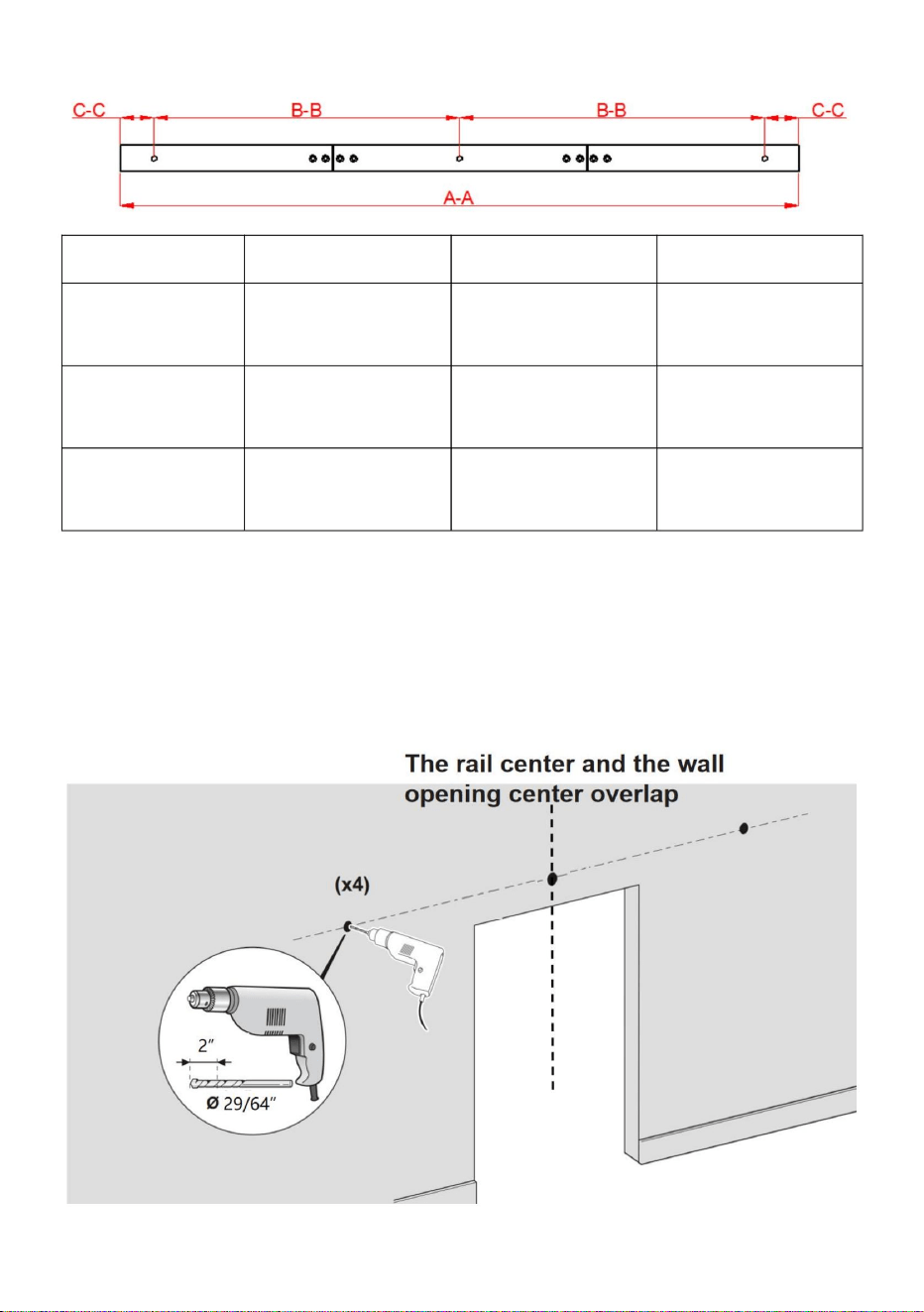
- 10 -
40IN-3D-3K
Stap 2:
36IN-3D-3K
afstand CC
2.1. Gebruik een boorgat van ÿ29/64” op de gemarkeerde positie, 2 inch diep;
afstand BB
Model
spoor gat
60mm
spoor gat
Wij raden aan dat het midden van het spoor zich in het midden van de muuropening bevindt.
36 inch (9140 mm) 40 inch (1016 mm) 52 inch (1320 mm)
51mm
AA
51mm
spoorlengte
600mm
52IN-2D-3K
457mm406mm
Machine Translated by Google

- 11 -
Stap 4
4.1. Eerst de deur in elkaar zetten, met het L-gat van de Bi-Fold Door Butt Hinges in de
deur om de positie van de schroef te bepalen en te markeren, en ten slotte met een
boorgat van ÿ3/16" en een gatdiepte van 1inch.
Stap 3: De geleiderail installeren
3.1. Installeer eerst de kunststof expansiebout D in de gaten in de betonnen
muur. Gebruik vervolgens schroef P door de ringen B, rail S en muurafstandhouder
A en vergrendel ten slotte de kunststof expansiebout D.
4.2.Schroef M bevestigt de vouwdeurscharnieren L aan de deur. Voltooi de montage van
de deur.
Machine Translated by Google

- 12 -
Machine Translated by Google
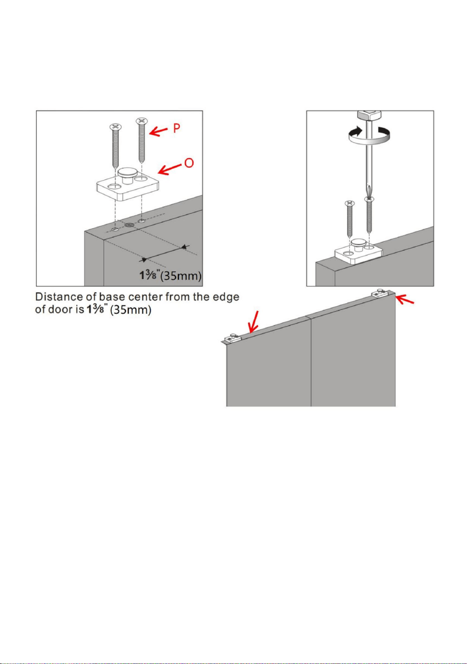
- 13 -
Stap 6
6.1. Boor gaten met een diepte van 23 mm aan de zijkant van de deur met een boor
van ÿ19/32". Het midden van het gat bevindt zich op 35 mm afstand van de
deurrand. 6.2. Vul huls I in het gat.
Stap 5
Gebruik schroef P om 2 draaibare rollerbases O op de bovenkant van de deur te monteren.
Het midden van de draaibare rollerbase O bevindt zich op 35 mm van de rand van de deur.
Machine Translated by Google

- 14 -
Machine Translated by Google

8.3.Bevestig de onderste draaiplaat H aan de vloer met behulp van een schroef J.
Stap 8
8.1. Onderste draaiplaat H installeren; Uitgaande van de breedte van een enkele deur
van L; is de afstand tussen de onderste draaiplaat H en de centrale as van de muuropening
L-35 mm; is de afstand van het midden van de onderste draaiplaat H tot de muur 47,6 mm;
8.2. Vier plekken werden
boven de grond gemarkeerd met het doorlopende gat van de onderste draaiplaat H; boor
gaten met een diepte van 35 mm in de markering met een boor van ÿ7/32";
plaats vervolgens de kunststof expansiebout k in de gaten.
Stap 7
7.1. Hang de vaste rol Q en de verstelbare rol R aan de rail.
8.4.De afstand tussen het midden van vaste rol Q en het buitenste gat van de baan is niet
minder dan 30 mm
- 15 -
Machine Translated by Google

9.1.Draai de stelschroef aan de zijkant van de vaste rol Q los.
Stap 9
- 16 -
Machine Translated by Google

9.2. Plaats de deur op de huls I; plaats de draaiende basis O van de rol aan de bovenkant van
de deur in verbinding met de vaste rol. 9.3.
Draai de stelschroeven vast om de vaste rol aan de draaiende basis O van de rol te
vergrendelen.
- 17 -
Machine Translated by Google
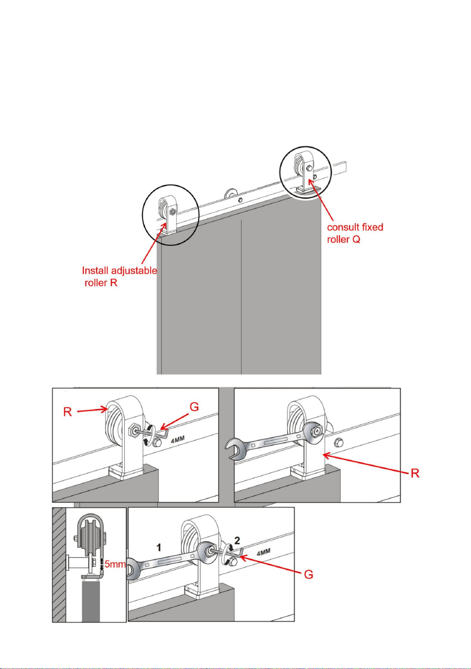
vaste rol Q.
10.1. Raadpleeg stap 9, installeer de verstelbare rol R volgens de installatiemethode
Stap 10
naar een geschikte positie. Zorg dat de linker- en rechterdeur op dezelfde hoogte zijn.
10.2. Raadpleeg de onderstaande aanwijzingen, Pas de hoogte van de verstelbare rol R aan
De hoogte van de deur kan ongeveer 5 mm worden aangepast
- 18 -
Machine Translated by Google
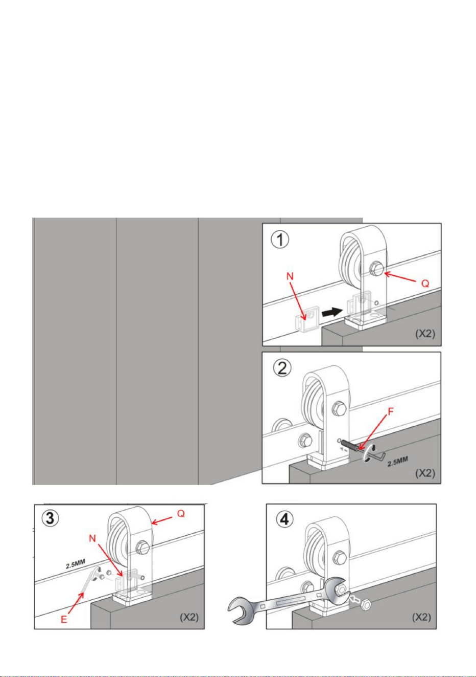
- 19 -
11.2. Gebruik de meegeleverde inbussleutel F om de stelschroeven aan de achterkant vast te draaien
bevindt zich aan de voorzijde van de vaste rol Q.
van de vaste rolvergrendelingsbeugel N.
door de vaste rolbandvergrendelingsbeugel en in de rail. 11.4.Draai de
zeskantmoer op deze stelschroef vast.
11.1. Schuif de vaste rolvergrendelingsbeugel N op de rail achter de stelschroef
11.3. Vergrendel de vaste rol Q op de rail door de lange stelschroef vast te draaien
Monteer de vaste rolvergrendelingsbeugel N.
Stap 11
Machine Translated by Google

EC-REP
VK REP
Geïmporteerd naar de VS: Sanven Technology Ltd. Suite 250, 9166 Anaheim Place,
Rancho Cucamonga, CA 91730
Geïmporteerd naar AUS: SIHAO PTY LTD. 1 ROKEVA STREETEASTWOOD NSW
2122 Australië
Fabrikant: Shanghaimuxinmuyeyouxiangongsi Adres:
Shuangchenglu 803nong11hao1602A-1609shi, baoshanqu, shanghai 200000 CN.
E-CrossStu GmbH
Mainzer Landstr.69,
60329 Frankfurt am Main.
YH CONSULTING LIMITED. C/O YH Consulting Limited
Kantoor 147, Centurion House, London Road, Staines-
upon-Thames, Surrey, TW18 4AX
- 20 -
Machine Translated by Google

Machine Translated by Google

Technische ondersteuning en e-
garantiecertificaat www.vevor.com/support
Machine Translated by Google

HÅRDVARUKIT
BIFOLD SKJUDBÖR DÖRR
Teknisk support och e-garanticertifikat
www.vevor.com/support
Modell: 36IN-3D-3K/40IN-3D-3K/52IN-2D-3K
Machine Translated by Google

Machine Translated by Google

- 1 -
Hårdvarusats
Bifold skjutbar ladugårdsdörr
Detta är den ursprungliga instruktionen, läs alla instruktioner
noggrant innan du använder den. VEVOR reserverar sig för en tydlig
tolkning av vår användarmanual. Utseendet på produkten är beroende
av den produkt du fått. Ursäkta oss att vi inte kommer att informera dig igen
om det finns någon teknik eller mjukvaruuppdateringar på vår produkt.
Modell: 36IN-3D-3K/40IN-3D-3K/52IN-2D-3K
Machine Translated by Google

- 2 -
Produktens lämplighet
SÄKERHETSINSTRUKTIONER
VARNING:
4. Håll åskådare borta från området under monteringen.
personer
9. Produkter installeras på avstånd från barn och husdjur;
3. Håll monteringsområdet rent och väl upplyst.
montering.
8. Av säkerhetsskäl rekommenderas den här hårdvaran att installeras senast 2
2. Bär ANSI-godkända skyddsglasögon och kraftiga arbetshandskar under
separera alla delar i ett rent arbetsområde.
skapa faror.
sidorna, se monteringsdiagrammet i denna manual. Packa upp och
3. Inspektera före varje användning; Använd inte om delar är lösa eller skadade.
SPARA DESSA INSTRUKTIONER
1. Montera endast enligt dessa instruktioner. Felaktig montering kan
endast.
7. För ytterligare information om delarna som listas nedan
2. Använd endast på avsett sätt.
Försiktighetsåtgärder vid montering
6. Produktegenskaper gäller för korrekt och fullständigt monterad produkt
allvarlig skada.
1. Denna produkt är inte en leksak. Tillåt inte barn att leka med detta föremål.
Läs detta material innan du använder denna produkt. Underlåtenhet att göra det kan resultera i
5. Sätt dig inte ihop när du är trött eller påverkad av alkohol, droger eller medicin.
Använd försiktighetsåtgärder
Machine Translated by Google

36IN-3D-3K 40IN-3D-3K 52IN-2D-3K
Dörr tjock
ÿ24 tum
1,375 till 1,75 tum (34,92-44,45 mm)
Modell
skena längd AA
Dörrbredd ÿ18 tum
(1320 mm)
ÿ16 tum
52 tum
dörr från marken
(1016 mm)
jord
Avstånd längst ner på
10 mm
40 tum
(914 mm)
Rälsens avstånd från
H+49mm
36 tum
Dörrhöjd H (beroende på användaren)
- 3 -
Machine Translated by Google

- 4 -
mängd dörrar
2 st
toppen och taket
Avstånd mellan dörren
kräver ytterligare köp.
Boxen innehåller inte dörrpaneler och andra trärutor, som
6 tum (152 mm)
Produktnedbrytningsdiagram
Machine Translated by Google

- 5 -
Delarlista
L: Dubbelvikt dörr
A: Vägg
G: 4 mm hex
Roterande
försänkt
Plast
Plast
F 2,5 mm hex
försänkt
Skruv×3st
huvudskruv×4sthuvudskruv×12st
J:M4×30
M:M6×25
H: Bottenpivot
B:brickor×3st
Gångjärn×3st
Nyckel×1 st
expansionsbult×4st
D:ÿ12×50
Expansionsbult i plast×3st
O: Rull
N: Fast rulle
Nyckel×1 st
C:M8×90mm
K:ÿ6×30
P:M5×50
I:Sleeve×1st
Tappning
Samma delar av olika modeller
E:2mm Hex
försänkt gängskruv×4st
Tallrik×1 st
Låsfäste×1 st Bas×2 st
Spacer×3st
Nyckel×1 st
Stånga
Machine Translated by Google
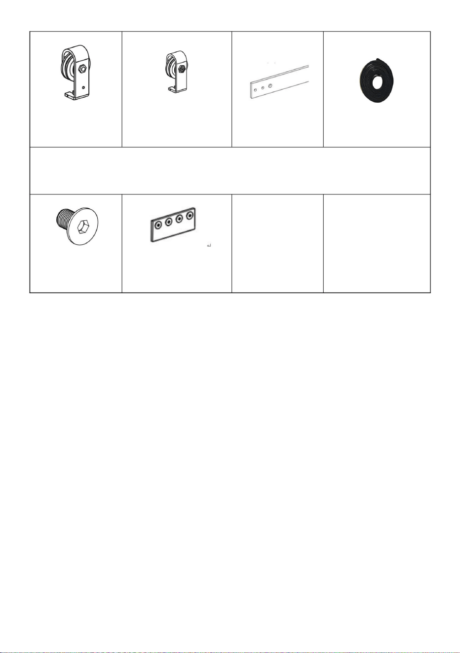
- 6 -
Rull×1 st
T:anslutning
R: Justerbar
U:M6×10
bult×8st
S:Rail Kit 1st
Modellerna 36IN-3D-3K och 40IN-3D-3K har dessa delar, men de är inte tillgängliga i
modellen 52IN-2D-3K
Om du stänger dörrar med handen på dörrens ände kan det leda till att din hand eller fingrar
fastnar mellan dörren och andra fasta föremål (t.ex. en annan dörr, gjutning) och orsaka allvarlig
skada. Använd alltid dörrhandtaget för att stänga dörren.
Remsa×1 st
Felhantering av tunga föremål (t.ex. dörrar) kan orsaka förlust av balans och
allvarliga skador. Se alltid till att du har ett säkert
grepp om föremålet och är balanserad innan du flyttar föremålet. Bär alltid
skyddsskor när du lyfter tunga föremål.
Att få kroppsdelar (t.ex. hår, fingrar) fast i rörliga delar kan orsaka klämning
och allvarlig skada. Placera inte fingrarna i delar som kan röra sig och ta alltid
bort eller innehålla något på kroppen som kan trassla in sig i en rörlig
del.
V: Tätning
Rull×1 st
F: Fixat
rem×2st
Användningsdeklaration
FÖRSIKTIGHET
Machine Translated by Google
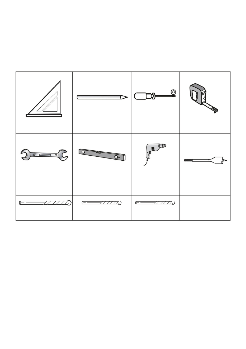
- 7 -
skada på hårdvaran. Håll alltid i handtaget för att försiktigt flytta
Nivå
Gå ombord innan du installerar banan.
Om du möter följande situationer rekommenderar vi starkt att du använder en
Användning av överdriven kraft när du öppnar och stänger dörren/dörrarna kan leda till
Speed Square
Rycka
Det är mycket viktigt att avgöra om du behöver installera en Header
Tejpa
Penna
ÿ3/16” borr
Skruvmejsel
ÿ29/64” borr ÿ7/32” borr
Phillips
Borra
av(ar).
ÿ19/32” borr
header board (dessa situationer kan inkludera men är inte begränsade till) • det
finns en dörröppning (som en dörrkarm eller en golvlist) •väggen är inte en
betongvägg, såsom gipsvägg eller annan typ av vägg
Verktyg krävs
Produktmontering
Machine Translated by Google

- 8 -
ingår. Du kan köpa dem online eller offline.
Observera: Header Board och skruvarna för att installera header board är det inte
Steg-1
1.1. Dra åt skruven U med insexnyckel G för att ansluta anslutningsremmen T till tre
skenor; Slutför anslutningen av styrskenan. Denna installationsmetod är lämplig för
styrskenan av modellen 36IN-3D-3K och 40IN-3D-3K
Machine Translated by Google

- 9 -
1.4.Placera spåret på plats vid den markerade mittlinjen, se till att det är plant,
och använd spåret som en mall för att markera monteringshålens placering för
höjden på din dörr PLUS 115/16”.
visas i produktvalsdiagrammet är dörrens höjd H i
av rälshålen.
1.3. Använd en nivå och ett måttband för att markera spårets mittlinje. Som
bilden ovan, höjden på mittlinjen (mätt upp från golvet) är
form.
1.2. Skenan av modellen 52IN-2D-3K är en 2-segments skena som skarvas med kronblad
Se monteringstips nedan.
spåra med en penna. Du kan också hänvisa till spårstorleken för att markera positionen
Machine Translated by Google
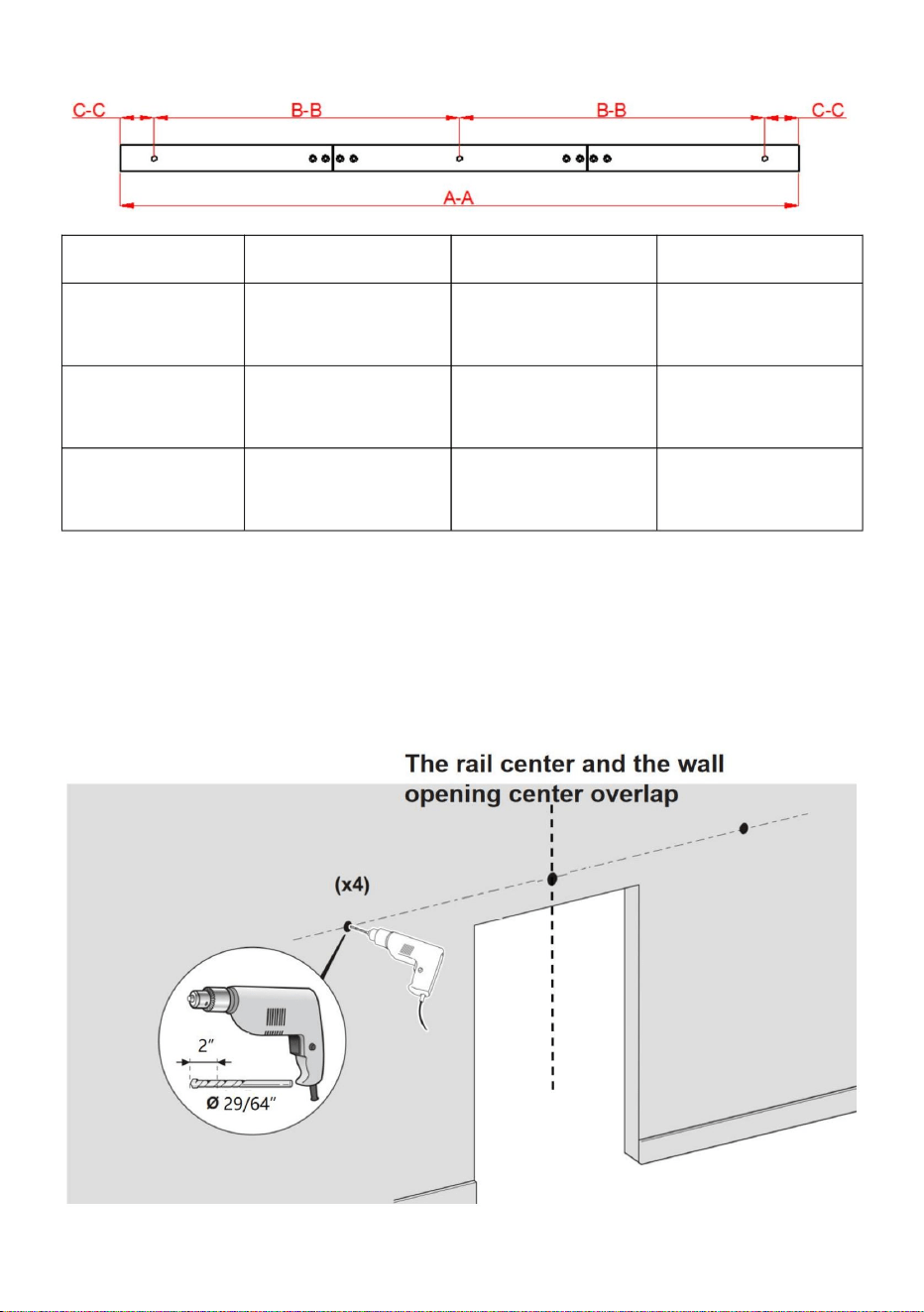
- 10 -
36IN-3D-3K
avstånd CC
Steg-2:
2.1. Använd ett ÿ29/64” borrhål i det markerade läget, 2 tum djupt;
Modell
avstånd BB
rälshål
Vi föreslår att mitten av spåret är i mitten av väggöppningen.
rälshål
60 mm
36 tum (9140 mm) 40 tum (1016 mm) 52 tum (1320 mm)
51 mm
AA
600 mm
51 mm
räls längd
52IN-2D-3K
457 mm
40IN-3D-3K
406 mm
Machine Translated by Google
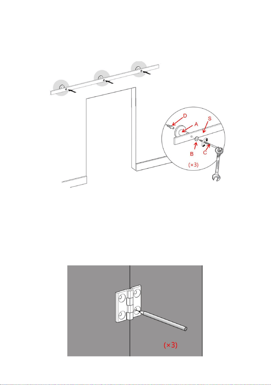
- 11 -
Steg-4
4.1. Skarva först ihop dörren, med det dubbelvikta dörrstumsgångjärnen L-hålet i
dörren för att bestämma skruvens position och markera, och slutligen med ÿ3/16"
borrhål, håldjup på 1 tum.
Steg-3: Installera styrskenan
3.1. Installera plastexpansionsbulten D i hålen på betongväggen först,
använd sedan skruv P genom brickorna B, skenan S och väggdistansen A
och lås till sist på plastexpansionsbulten D.
4.2.Skruven M håller de dubbelvikta dörrstumlarnas gångjärn L till dörren, slutför
monteringen av dörren.
Machine Translated by Google

- 12 -
Machine Translated by Google

- 13 -
Steg-5
Använd skruv P och montera 2 rullar roterande bas O på toppen av dörren,
mitten av rulle roterande bas O är 35 mm från kanten av dörren.
Steg-6
6.1.borra djup 23 mm hål på sidan av dörren med en ÿ19/32" borr; mitten
av hålet är placerat 35 mm från dörrkanten; 6.2. Fyll hylsa I i hålet;
Machine Translated by Google
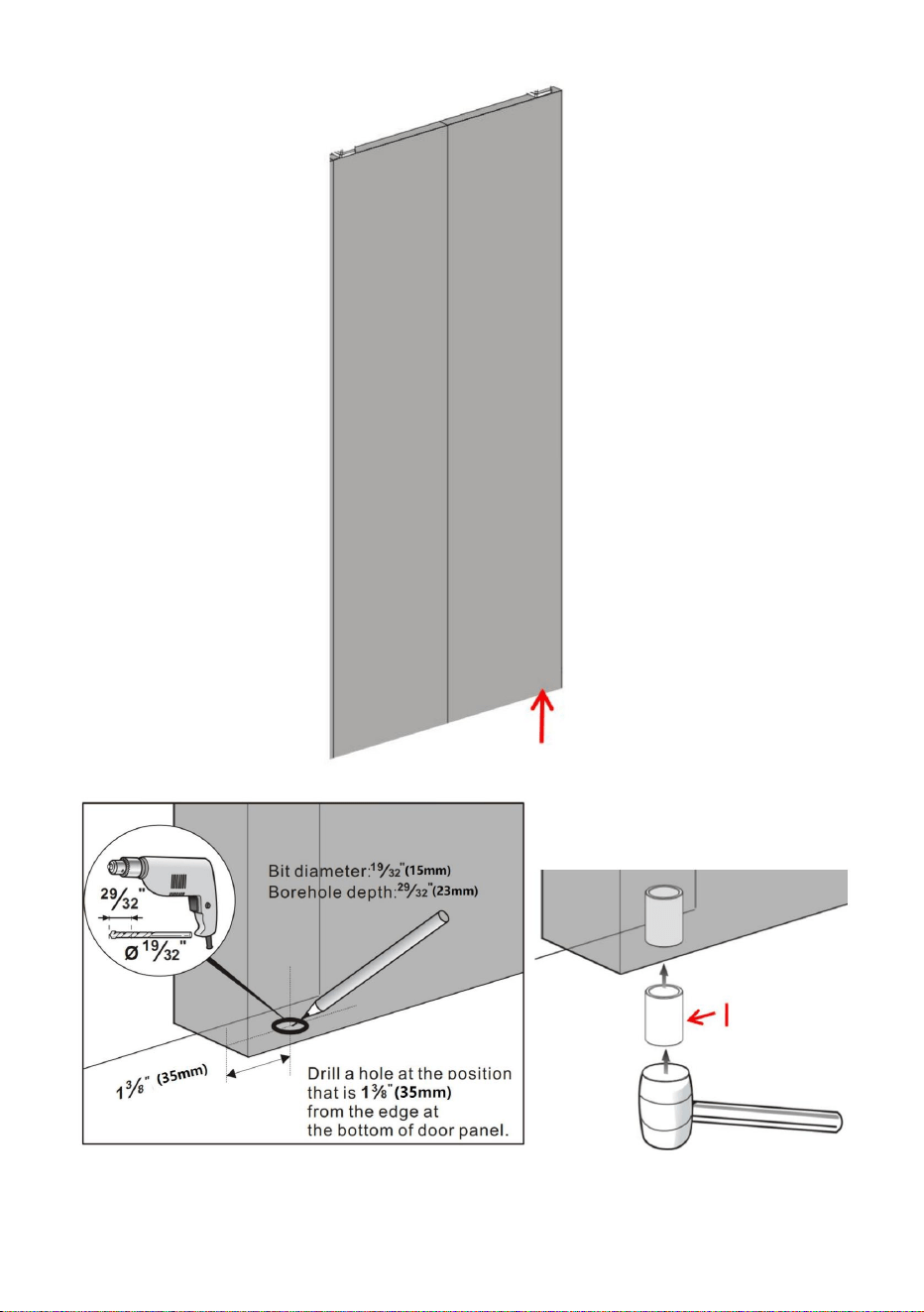
- 14 -
Machine Translated by Google

- 15 -
8.3. Fäst den nedre svängplattan H i golvet med en skruv J.
Steg-8
8.1.Installera den nedre svängplattan H;Antag att bredden på en enkel dörr är L;avståndet
mellan den nedre svängplattan H och väggöppningens centrala axel är L-35 mm;avståndet
mellan den nedre svängplattan H mitt från väggen är 47,6 mm; 8.2. Fyra fläckar markerades
ovanför marken med det
genomgående hålet på den nedre svängplattan H; borra djup 35 mm hål i märket med en
ÿ7/32" borr; sätt sedan in plastexpansionsbulten k i hålen.
Steg-7
7.1.Häng den fasta rullen Q och den justerbara rullen R på skenan.
8.4. Avståndet mellan mitten av Fixed Roller Q och spårets yttre hål är inte mindre än 30 mm
Machine Translated by Google

- 16 -
Steg-9
9.1.Skruva loss ställskruven på sidan av den fasta rullen Q.
Machine Translated by Google

- 17 -
9.2.Sätt dörren på hylsan I; Koppla in den roterande rullen O på toppen av dörren med den
fasta rullen 9.3. Dra åt ställskruvarna för att
låsa den fasta rullen till den roterande rullbasen O.
Machine Translated by Google

- 18 -
fast rulle Q.
till en lämplig position. Låt vänster och höger dörrhöjd vara på samma nivå.
10.1. Se steg 9, installera Adjustable Roller R enligt installationsmetoden
Steg-10
Höjden på dörren kan justeras med cirka 5 mm
10.2. Se instruktionerna nedan, Justera höjden på den justerbara rullen R
Machine Translated by Google

- 19 -
11.3.Lås fast rullen Q på skenan genom att dra åt den långa ställskruven
av det fasta rulllåsfästet N.
placerad på framsidan av den fasta rullen Q.
genom det fasta rullbandets låsfäste och in i skenan. 11.4.dra åt
sexkantsmuttern på denna ställskruv.
11.1.Skjut in det fasta rulllåsfästet N på skenan bakom ställskruven
11.2. Använd den medföljande insexnyckeln F, dra åt ställskruvarna på baksidan
Montera det fasta rulllåsfästet N.
Steg-11
Machine Translated by Google
EC REP
UK REP
Importerad till USA: Sanven Technology Ltd. Suite 250, 9166 Anaheim Place,
Rancho Cucamonga, CA 91730
E-CrossStu GmbH
Mainzer Landstr.69,
60329 Frankfurt am Main.
Importerad till AUS: SIHAO PTY LTD. 1 ROKEVA STREETEASTWOOD NSW 2122
Australien
Tillverkare: Shanghaimuxinmuyeyouxiangongsi Adress:
Shuangchenglu 803nong11hao1602A-1609shi, baoshanqu, shanghai 200000 CN.
YH CONSULTING LIMITED. C/O YH Consulting Limited
Office 147, Centurion House, London Road, Staines-
upon-Thames, Surrey, TW18 4AX
- 20 -
Machine Translated by Google

Machine Translated by Google

Teknisk support och e-garanticertifikat
www.vevor.com/support
Machine Translated by Google