Document # G_GHD_OM_CUISINE_4605671 9/20
Users are cautioned that maintenance and repairs must be performed by a Garland authorized service agent
using genuine Garland replacement parts. Garland will have no obligation with respect to any product that has been
improperly installed, adjusted, operated or not maintained in accordance with national and local codes or installation
instructions provided with the product, or any product that has its serial number defaced, obliterated or removed,
or which has been modified or repaired using unauthorized parts or by unauthorized service agents.
For a list of authorized service agents, please refer to the Garland web site at http://www.garland-group.com.
The information contained herein, (including design and parts specifications), may be superseded and is subject
to change without notice.
FOR YOUR SAFETY:
DO NOT STORE OR USE GASOLINE
OR OTHER FLAMMABLE VAPORS OR
LIQUIDS IN THE VICINITY OF
THIS OR ANY OTHER
APPLIANCE
WARNING:
IMPROPER INSTALLATION, ADJUSTMENT,
ALTERATION, SERVICE OR MAINTENANCE
CAN CAUSE PROPERTY DAMAGE, INJURY,
OR DEATH. READ THE INSTALLATION,
OPERATING AND MAINTENANCE
INSTRUCTIONS THOROUGHLY
BEFORE INSTALLING OR
SERVICING THIS EQUIPMENT
PLEASE READ ALL SECTIONS OF THIS MANUAL
AND RETAIN FOR FUTURE REFERENCE.
THIS PRODUCT HAS BEEN CERTIFIED AS
COMMERCIAL COOKING EQUIPMENT AND
MUST BE INSTALLED BY PROFESSIONAL
PERSONNEL AS SPECIFIED.
IN THE COMMONWEALTH OF MASSACHUSETTS
THIS PRODUCT MUST BE INSTALLED BY A
LICENSED PLUMBER OR GAS FITTER. APPROVAL
NUMBER: G-1-07-05-28
For Your Safety:
Post in a prominent location, instructions to be
followed in the event the user smells gas. This
information shall be obtained by consulting
your local gas supplier.
INSTALLATION OPERATION AND SERVICE
MANUAL
CUISINE C SERIES COMMERCIAL RANGES,
ADD-A-UNITS, MODULAR RANGES, AND CHAR BROILERS
Original Document
Bring Your Passion to the Surface

Document # G_GHD_OM_CUISINE_4605671 9/20Page 2
IMPORTANT INFORMATION
WARNING:
This product contains chemicals known to the state of California to cause cancer and/or birth defects
or other reproductive harm. Installation and servicing of this product could expose you to airborne
particles of glass wool/ceramic fibers. Inhalation of airborne particles of glass wool/ceramic fibers
is known to the state of California to cause cancer. Operation of this product could expose you to
carbon monoxide if not adjusted properly. Inhalation of carbon monoxide is known to the state of
California to cause birth defects or other reproductive harm.
Keep appliance area free and clear of combustibles.

Document # G_GHD_OM_CUISINE_4605671 9/20 Page 3
TABLE OF CONTENTS
IMPORTANT INFORMATION........................2
SPECIFICATIONS ..................................4
Table A: Gas Pressures .......................................4
Table B: Model Designations .................................4
Table C: Input Rating. . . . . . . . . . . . . . . . . . . . . . . . . . . . . . . . . . . . . . . . .9
INTRODUCTION .................................10
Uncrating ..................................................10
Rating Plate ................................................10
INSTALLATION ...................................10
Clearances to Combustible Construction ....................10
Installation Procedure ......................................10
Siting ......................................................11
Appliance Equipped With Casters ...........................11
Appliances Equipped With Legs ............................11
Installation Instructions for Cuisine Stub Backguard .........11
Installation Instructions for Cuisine Back Risers. .............12
Installation Instructions For Cuisine Single
And Double Deck High Shelves .............................12
Installation Instructions For
Cuisine Salamander or Cheese Melter .......................13
Statutory Regulations ......................................13
Gas Supply .................................................13
Gas Supply Notes: ..........................................14
Gas Connection ............................................14
Electrical Supply (Models with Convection Oven only) .......14
Assembly of Battery ........................................15
Ventilation And Air Supply ..................................15
COMMISSIONING ................................16
Pressure Regulators. ........................................16
Testing and Adjustments. ...................................16
Pressure Settings (All Models) ...............................16
Thermostat Bypass Adjustment – Oven.................17
Pilot Burner Adjustments ...................................18
General................................................18
Oven ..................................................18
Solid Hot Plate/Griddle.................................18
Front Fired Hot Top ....................................18
Broiler . . . . . . . . . . . . . . . . . . . . . . . . . . . . . . . . . . . . . . . . . . . . . . . . . 18
OPERATION .....................................18
Open Top Burners ..........................................18
Hot top and Spectro-Top Sections ..........................18
Thermostatically Controlled Griddles .......................19
Valve Controlled Griddles ...................................19
Oven (Standard) ............................................19
“RC” Convection Ovens .................................... 20
Unit Broilers ................................................21
Fryers ......................................................21
MAINTENANCE AND CLEANING...................21
Seasoning ..................................................21
Griddle Seasoning .....................................21
Seasoning Cast Iron Top Grates.........................21
Cleaning ...................................................21
General Cleaning ......................................21
Stainless Steel Exterior and Standard Oven
Interior Finishes........................................22
Oven Interior (Optional Porcelain Enamel Finish)........22
Griddle Cleaning.......................................23
Open Top Burners .....................................23
Cast Iron Top Grates....................................23
Cast Iron Hot tops and Spectro-Heat Tops ..............23
Broiler Cleaning ........................................... 24
C36-NRR/C36-NRC Models .............................24
C36-ABR/C36-ABC Models .............................24
C36-ARR/C36-ARC Models .............................24
Adjustments .............................................. 24
Oven Orice ...........................................24
Pilot Adjustments......................................24
Automatic Pilot Valve ..................................25
Burner Gas/Air Adjustments............................25
CONVECTION OVEN PRODUCT APPLICATION . . . . . . 25
PROBLEM/SOLUTIONS CONVECTION OVEN........26
SERVICING ......................................27
Thermostat Calibration .................................... 27
Cleaning/Servicing Burners ................................ 27
Open-Type Burners ....................................27
Front Fired Solid Top Burners...........................27
Solid Hot Plate/Griddle Burners ........................27
Standard Oven Burners ................................28
RC Oven Burners.......................................28
Broiler . . . . . . . . . . . . . . . . . . . . . . . . . . . . . . . . . . . . . . . . . . . . . . . . . 28
Pilot Burner Cleaning ...................................... 28
Oven Top/Hot Top/Griddle/Broiler/Front Fired Top......28
Oven ..................................................28
REPLACEMENT OF PARTS.........................29
Gas Valves ................................................. 29
Oven Thermostat .......................................... 29
Power Switch .............................................. 30
Door Switch ............................................... 30
Oven Pilot ................................................. 30
Convection Ovens - Spark Module ......................... 30
Convection Oven Motor ................................... 30
TROUBLESHOOTING GUIDE ......................31
Document # G_GHD_OM_CUISINE_4605671 9/20Page 4
SPECIFICATIONS
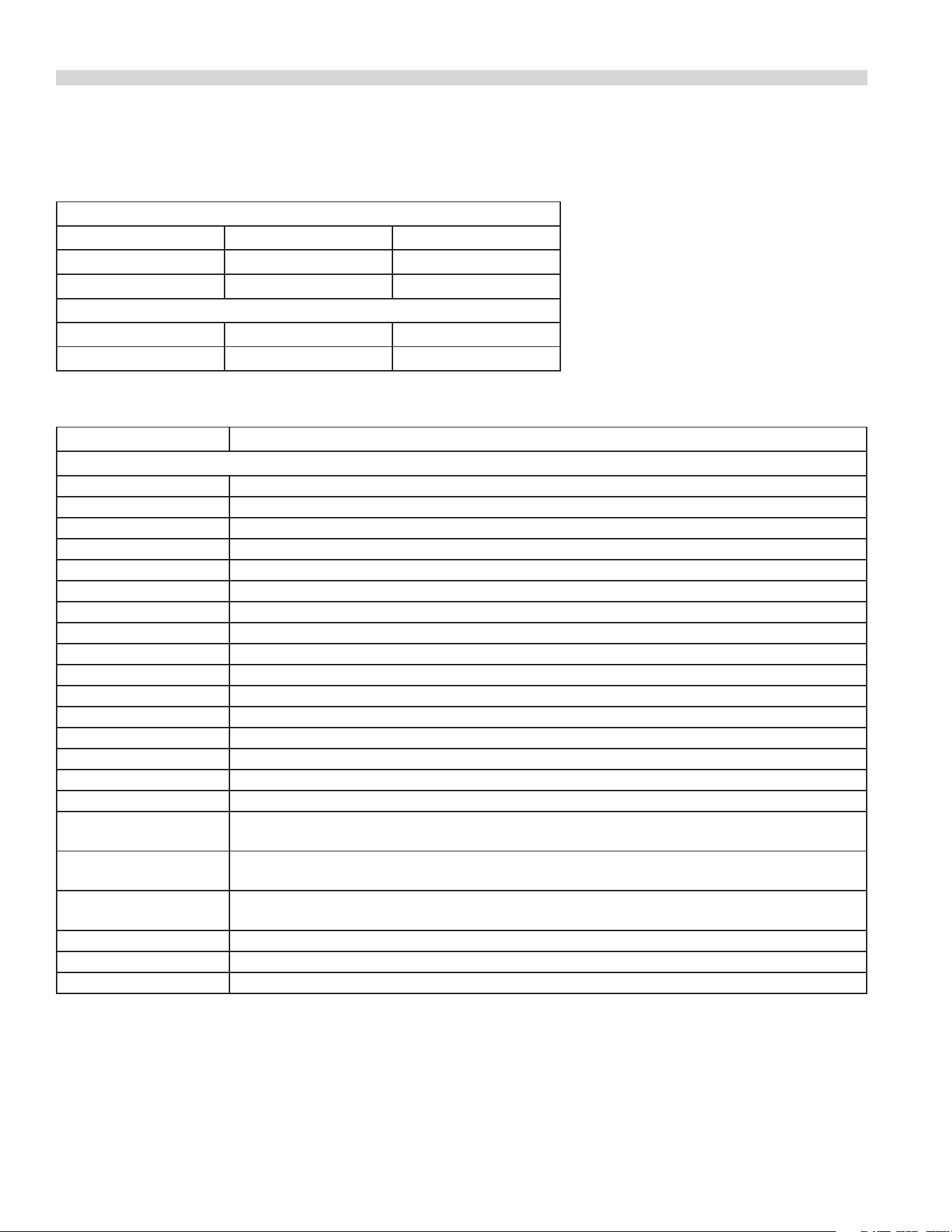
Table A: Gas Pressures
SUPPLY GAS PRESSURE RANGE
Type Minimum Maximum
Natural 7” W.C.( 17.5 mbar) 14” W.C. (35 mbar)
Propane 11” W.C. (27.5 mbar) 14” W.C. (35 mbar)
MANIFOLD OPERATING PRESSURE
Type Natural Propane
Ranges, Broilers 6”W.C. (15 mbar) 10” W.C. (25 mbar)
Table B: Model Designations
MODELS DESCRIPTION
Standard Oven Base
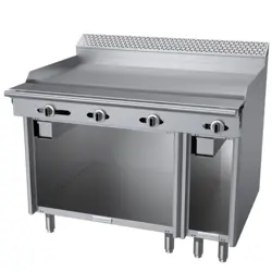
C36-1R 36” Griddle
C36-1-1R 36” Thermostatic Griddle
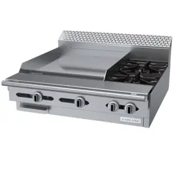
C36-2R 24” Griddle, (2) Open Burners (12” Top Grate)
C36-2-1R 24” Therm. Griddle, (2) Open Burners (12” Top Grate)
C36-3R 24” Griddle, 12” Hot Top
C36-3-1R 24” Therm. Griddle, 12” Hot Top
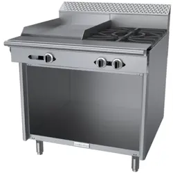
C36-4R 18” Griddle, (2) Open Burners (18” Top Grate)
C36-4-1R 18” Therm. Griddle, (2) Open Burners (18” Top Grate)
C36-5R 18” Griddle, 18” Hot Top
C36-5-1R 18” Therm. Griddle, 18” Hot Top
C36-6R Six Open Burners – (3) 12” Top Grates
C36-6SUR Six Open Burners (3 Are Step-up) – (6) Half Top Grates (12” Inch Wide Each)
C36-7R Four Open Burners (2) 18” Top Grates
C36-8R (3) 12” Hot Tops
C36-9R (2) 18” Hot Tops
C36-10R (2) 18” Front Fired Hot Tops
C36-11R 18” Hot Top (Left), 18” Front Fired Hot Top (Right) OR 18” Front Fired Hot Top (Left), 18” Hot Top
(Right)
C36-12R (2) Open Burners, 12” Top Grate (Left, Centre or Right), 12” Hot Top (Left or Centre), 12” Hot Top
(Centre or Right)
C36-13R 12” Hot Top (Left, Right or Centre), (2) Open Burners, 12” Top Grate (Left or Centre), (2) Open
Burners, 12” Top Grate (Centre or Right)
C36-14R (2) Open Burners, 18” Top Grate (Left or Right), 18” Hot Top (Left or Right)
C36-15R (3) 12” French Tops
C36-17R (2) Open Burners, 18” Top Grate (Left or Right), 18” Front Fired Hot Top (Right or Left)
Document # G_GHD_OM_CUISINE_4605671 9/20 Page 5
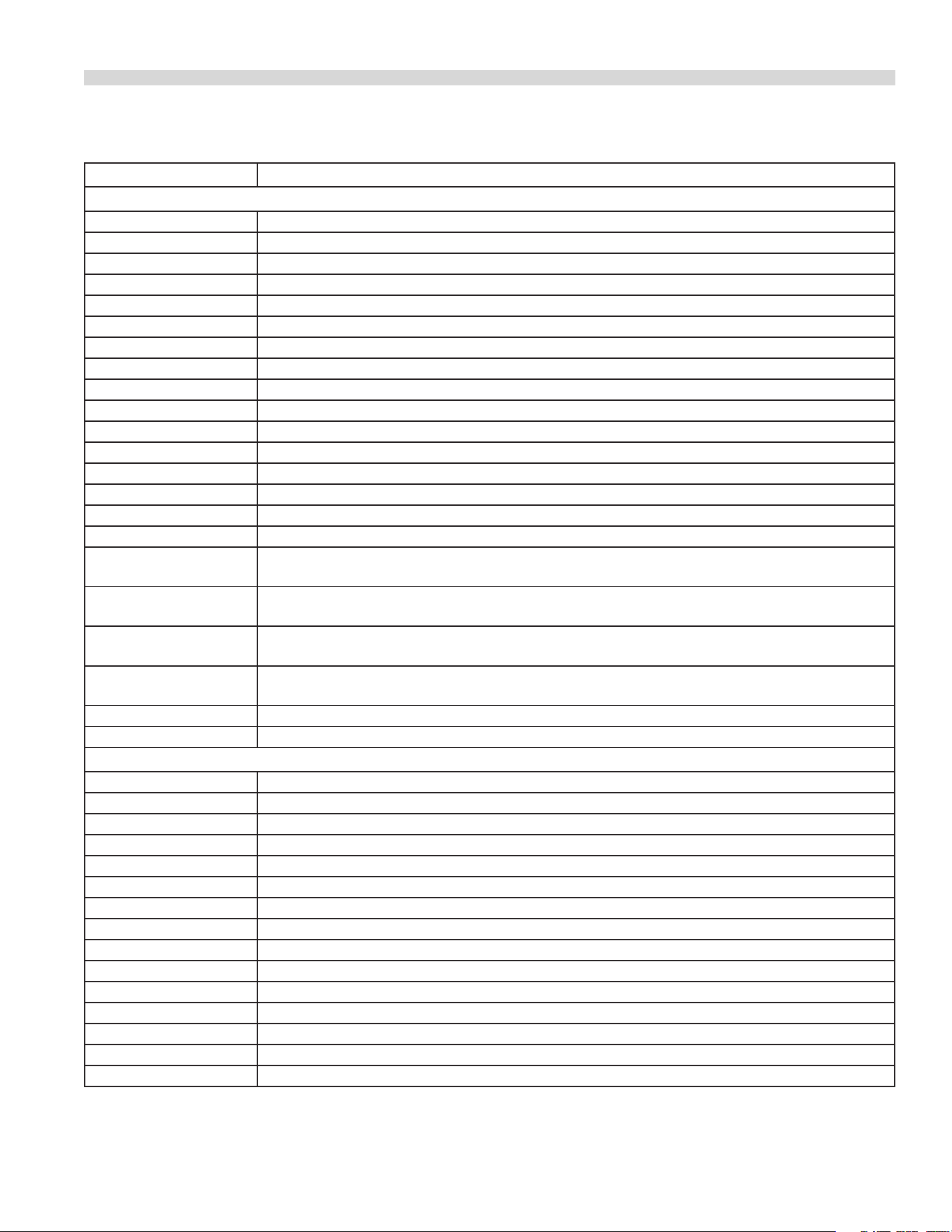
MODELS DESCRIPTION
Convection Oven Base
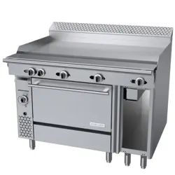
C36-1C 36” Griddle
C36-1-1C 36” Thermostatic Griddle
C36-2C 24” Griddle, (2) Open Burners (12” Top Grate)
C36-2-1C 24” Therm. Griddle, (2) Open Burners (12” Top Grate)
C36-3-C 24” Griddle, 12” Hot Top
C36-3-1C 24” Therm. Griddle, 12” Hot Top
C36-4-C 18” Griddle, (2) Open Burners (18” Top Grate)
C36-4-1C 18” Therm. Griddle, (2) Open Burners (18” Top Grate)
C36-5C 18” Griddle, 18” Hot Top
C36-5-1C 18” Therm. Griddle, 18” Hot Top
C36-6C Six Open Burners – (3) 12” Top Grates
C36-6SUC Six Open Burners (3 Are Step-up) – (6) Half Top Grates (12” Inch Wide Each)
C36-7C Four Open Burners (2) 18” Top Grates
C36-8C (3) 12” Hot Tops
C36-9C (2) 18” Hot Tops
C36-10C (2) 18” Front Fired Hot Tops
C36-11C 18” Hot Top (Left), 18” Front Fired Hot Top (Right) or 18” Front Fired Hot Top (Left), 18” Hot Top
(Right)
C36-12C (2) Open Burners, 12” Top Grate (Left, Centre or Right), 12” Hot Top (Left or Centre), 12” Hot Top
(Centre or Right)
C36-13C 12” Hot Top (Left, Centre or Right), (2) Open Burners, 12” Top Grate (Left or Centre), (2) Open
Burners, 12” Top Grate (Centre or Right)
C36-14C (2) Open Burners, 18” Top Grate (Left), 18” Hot Top (Right) or (2) Open Burners, 12” Top Grate
(Right), 18” Hot Top Grate (Left)
C36-15C (3) 12” French Tops
C36-17C (2) Open Burners, 18” Top Grate (Left or Right), 18” Front Fired Hot Top (Left or Right)
Storage Base (Open Cabinet)
C36-1S 36” Griddle
C36-1-1S 36” Thermostatic Griddle
C36-2S 24” Griddle, (2) Open Burners (12” Top Grate)
C36-2-1S 24” Therm. Griddle, (2) Open Burners (12” Top Grate)
C36-3S 24” Griddle, 12” Hot Top
C36-3-1S 24” Therm. Griddle, 12” Hot Top
C36-4S 18” Griddle, (2) Open Burners (18” Top Grate)
C36-4-1S 18” Therm. Griddle, (2) Open Burners (18” Top Grate)
C36-5S 18” Griddle, 18” Hot Top
C36-5-1S 18” Therm. Griddle, 18” Hot Top
C36-6S Six Open Burners – ((3) 12” Top Grates
C36-6SUS Six Open Burners (3 Are Step-up) – (6) Half Top Grates (12” Inch Wide Each)
C36-7S Four Open Burners (2) 18” Top Grates
C36-8S (3) 12” Hot Tops
C36-9S (2) 18” Hot Tops
SPECIFICATIONS Continued
Document # G_GHD_OM_CUISINE_4605671 9/20Page 6
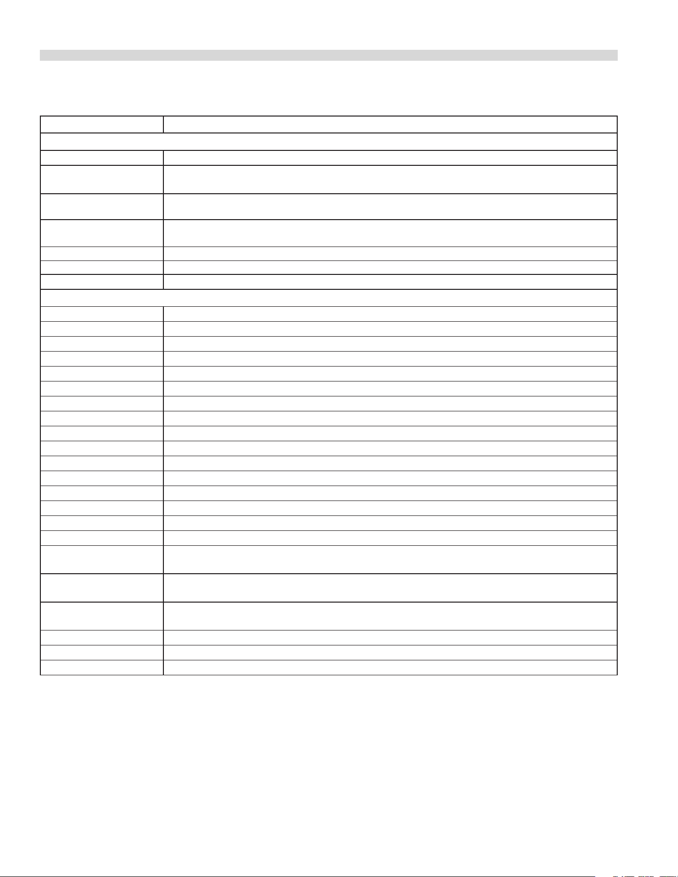
MODELS DESCRIPTION
Storage Base (Open Cabinet) Continued
C36-10S (2) 18” Front red Hot Tops
C36-11S 18” Hot Top (Left), 18”Front Fired Hot Top (Right) or 18” Front Fired Hot Top (Left), 18” Hot Top
(Right)
C36-12S
(2) Open Burners, 12” Top Grate (Left, Centre or Right), 12” Hot Top (Left or Centre), 12” Hot Top
(Right or Centre)
C36-13S 12” Hot Top (Left, Centre or Right), (2) Open Burners, 12” Top Grate (Left or Centre), (2) Open
Burners, 12” Top Grate (Centre or Right)
C36-14S (2) Open Burners, 18” Top Grate (Left or Right), 18” Hot Top (Left or Right)
C36-15S (3) 12” French Tops
C36-17S (2) Open Burners, 18” Top Grate (Left or Right), 18” Front Fired Hot Top (Left or Right)
Modular “T” Top (On Square Tubular Legs)
C36-1M 36” Griddle
C36-1-1M 36” Thermostatic Griddle
C36-2M 24” Griddle, (2) Open Burners (12” Top Grate)
C36-2-1M 24” Therm. Griddle, (2) Open Burners (12” Top Grate)
C36-3M 24” Griddle, 12” Hot Top
C36-3-1M 24” Therm. Griddle, 12” Hot Top
C36-4M 18” Griddle, (2) Open Burners (18” Top Grate)
C36-4-1M 18” Therm. Griddle, (2) Open Burners (18” Top Grate)
C36-5M 18” Griddle, 18” Hot Top
C36-5-1M 18” Therm. Griddle, 18” Hot Top
C36-6M Six Open Burners – (3) 12” Top Grates
C36-6SUM Six Open Burners (3 Are Step-up) – (6) Half Top Grates (12” Inch Wide Each)
C36-7M Four Open Burners (2) 18” Top Grates
C36-8M (3) 12” Hot Tops
C36-9M (2) 18” Hot Tops
C36-10M (2) 18” Front Fired Hot Tops
C36-11M 18” Hot Top (Left), 18”Front Fired Hot Top (Right) or 18” Front Fired Hot Top (Left), 18” Hot Top
(Right)
C36-12M (2) Open Burners, 12” Top Grate (Left, Centre or Right), 12” Hot Top (Left or Centre), 12” Hot Top
(Right or Centre)
C36-13M 12” Hot Top, (Left, Centre or Right), (2) Open Burners, 12” Top Grate (Left or Centre), (2) Open
Burners, 12” Top
C36-14M (2) Open Burners, 18” Top Grate (Left or Right), 18” Hot Top (Left or Right))
C36-15M (3) 12” French Tops
C36-17M (2) Open Burners, 18” Top Grate (Left or Right), 18” Front Fired Hot Top (Left or Right)
SPECIFICATIONS Continued
Document # G_GHD_OM_CUISINE_4605671 9/20 Page 7
MODELS DESCRIPTION
Char-Broilers on Standard Oven Base
C36-ABR Lava Rock W/Adjustable Grates – 36” Wide
C36-ARR Cast Iron Radiants W/Adjustable Grates – 36” Wide
C36-NRR Cast Iron Radiants W/Non-Adjustable Grates – 36” Wide
Char-Broilers on Convection Oven Base
C36-ABC Lava Rock W/Adjustable Grates – 36” Wide
C36-ARC Cast Iron Radiants W/Adjustable Grates – 36” Wide
C36-NRC Cast Iron Radiants W/Non-Adjustable Grates – 36” Wide
Range Match Char-Broilers on Storage Base (Open Cabinet)
C24-ABS Lava Rock W/Adjustable Grates – 24” Wide
C36-ABS Lave Rock W/Adjustable Grates – 36” Wide
C24-ARS Cast Iron Radiants W/Adjustable Grates – 24” Wide
C36-ARS Cast Iron Radiants W/Adjustable Grates – 36” Wide
C24-NRS Cast Iron Radiants W/Non-Adjustable Grates – 24” Wide
C36-NRS Cast Iron Radiants W/Non-Adjustable Grates – 36” Wide
Modular “T” Top Char-Broilers on Square Tubular Legs
C24-NRM Cast Iron Radiants W/Non-Adjustable Grates – 24” Wide
C36-NRM Cast Iron Radiants W/Non-Adjustable Grates – 36” Wide
12” Wide, Add-A-Units with Storage Base (Open Cabinet)
C12-1S 12” Griddle
C12-1-1S 12” Thermostatic Griddle
C12-6S (2) Open Burners (12” Top Grate)
C12-8S 12” Hot Top
C12-15S 12” French Top
18” Wide, Add-A-Units with Modular Top/Square Tubular Legs)
C18-1M 18” Griddle
C18-1-1M 18” Thermostatic Griddle
C18-7M (2) Open Burners (18” Top Grate)
C18-9M 18” Hot Top
C18-10M 18” French Top
18” Wide, Add-A-Units with Storage Base (Open Cabinets)
C18-1S 18” Griddle
C18-1-1S 18” Thermostatic Griddle
C18-7S (2) Open Burners (18” Top Grate)
C18-9S 18” Hot Top
C18-10S 18” French Top
SPECIFICATIONS Continued
Document # G_GHD_OM_CUISINE_4605671 9/20Page 8
MODELS DESCRIPTION
Additional Griddle Models
48” Wide Units
C48-1R 36” Std. Oven Base + 12” Storage Base + 48” Manual Griddle Top
C48-1-1R 36” Std. Oven Base + 12” Storage Base + 48” Therm. Griddle Top
C48-1C 36” RC Oven Base + 12” Storage Base + 48” Manual Griddle Top
C48-1-1C 36” RC Oven Base + 12” Storage Base + 48” Therm. Griddle Top
C48-1S 36” Storage Base + 12” Storage Base + 48” Manual Griddle Top
C48-1-1S 36” Storage Base + 12” Storage Base + 48” Therm. Griddle Top
C48-1M 48” Modular Top + 48” Manual Griddle Top
C48-1-1M 48” Modular Top + 48” Thermostatic Griddle Top
PREFIX DEFINITIONS: SUFFIX DEFINITIONS:
C Cuisine A Broiler
M Modular Top Section
C Unit With Convection Oven
R Unit With Standard Oven
SU Step Up Burner
S Unit With Storage Base
SPECIFICATIONS Continued
Document # G_GHD_OM_CUISINE_4605671 9/20 Page 9
SPECIFICATIONS Continued
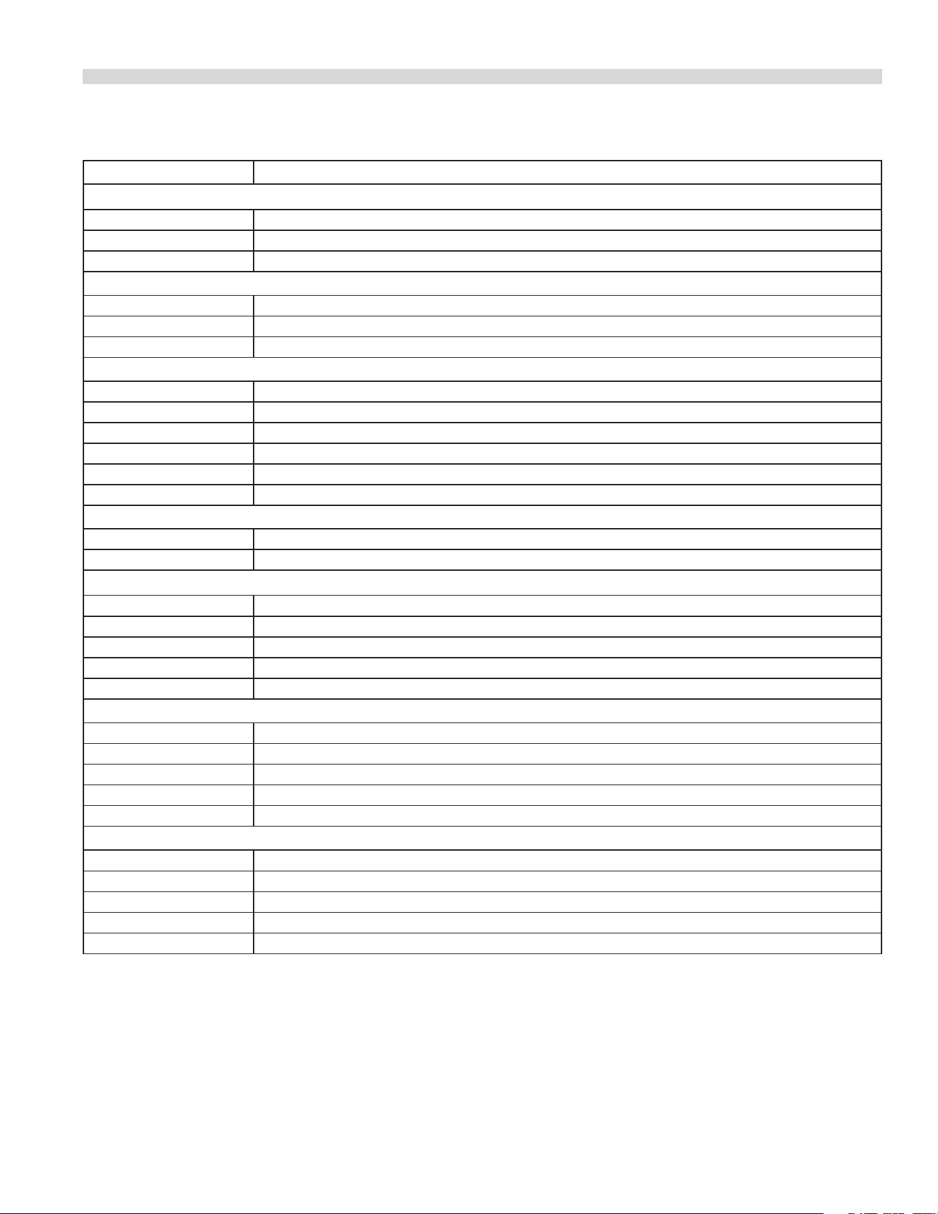
Table C: Input Rating
Model Number
GAS TYPE
Natural (@ 6”W.C.) Propane (@ 10”W.C.)
BTU/HR BTU/HR
Open Burner for Models: C36-2,-2-1,-6,-6SU,-12,-13,-15(Front) 35,000 33,000
Open Burner for Models: C36-4,-4-1,-7,-14,-17 40,000 38,000
C36-15 Rear hot-top burner 15,000 15,000
C36-10,-11,-17 Front red hot top burner 12,500 12,500
C36-3,-3-1,-8,-12,-13,-12” Hot top burner 25,000 25,000
C36-5,-5-1,-9,-11,-14, 18” Hot top burner 32,500 32,500
C36-1,-1-1,-2,-2-1,-3,-3-1,-4,-4-1,-5,-5-1 Griddle burner 30,000 30,000
C36 Convection Oven burner 37,000 35,000
C24/36-AB Broiler burner 45,000 45,000
C18-NR, C24/36-AR, -NR Broiler burner 18,000 18,000
C36 Std oven burner 40,000 35,000
(Note: data applied to operation at elevation from sea level to 2000 ft)
Document # G_GHD_OM_CUISINE_4605671 9/20Page 10
INSTALLATION
INTRODUCTION
Uncrating
1. Check crate for possible damage sustained during transit.
Carefully remove unit from crate and again check for
damage. Any damage to the appliance must be reported
to the carrier immediately.
2. The wires for retaining the burners and other packing
material must be removed from units. Any protective
material covering stainless steel parts must also be
removed.
3. All equipment is shipped from the factory with legs
tted, unless otherwise specied. Where the range is to
be mounted on a dias or cove base, it is shipped without
legs. Legs must be tted to the oven where it is installed
on a combustible oor.
4. The type of gas and supply pressure that the equipment
was set-up for at the factory is noted on the data plate
and on the packaging. This type of gas supply must be
used.
5. Do not remove permanently axed labels, warnings or
data plates from the appliance, for this may invalidate the
manufacturer’s warranty.
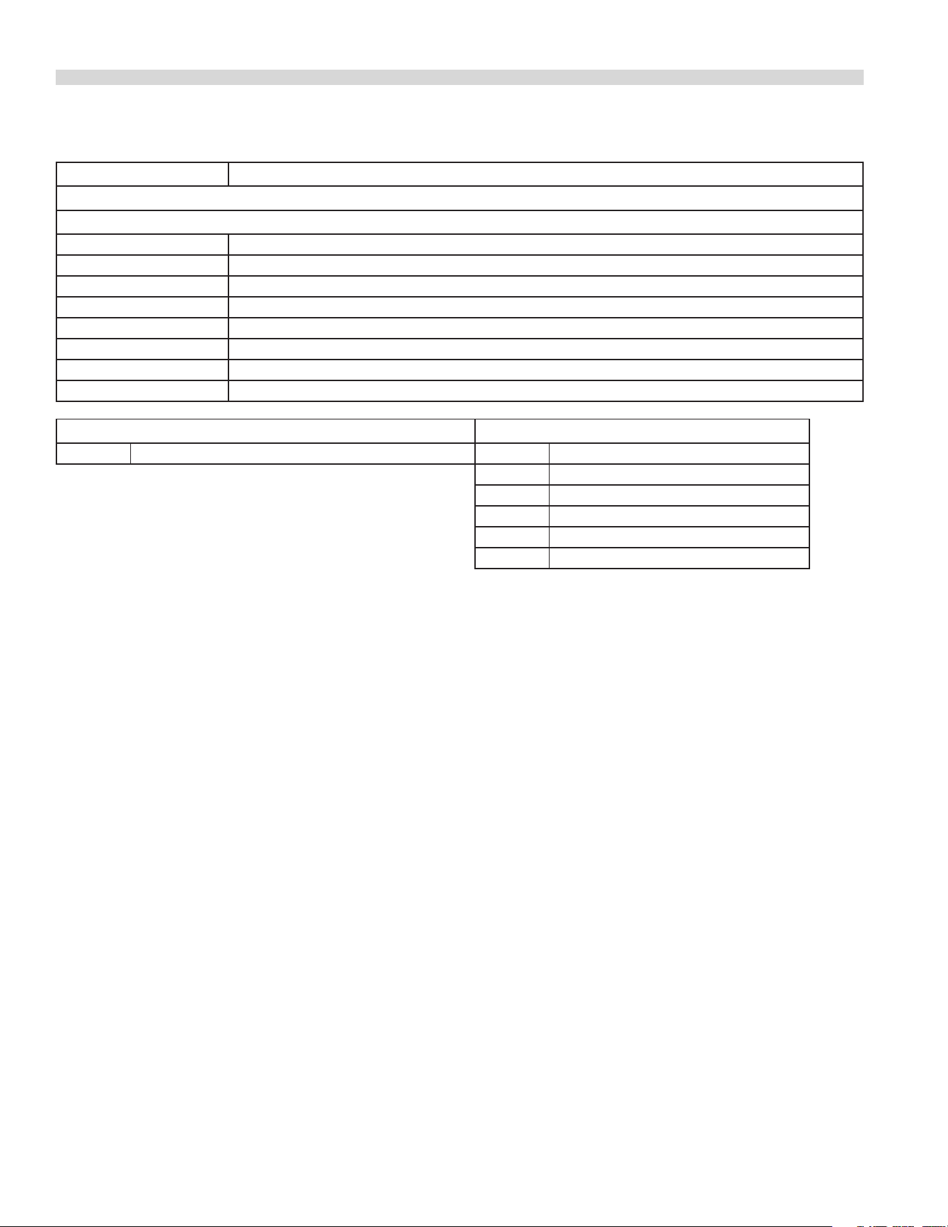
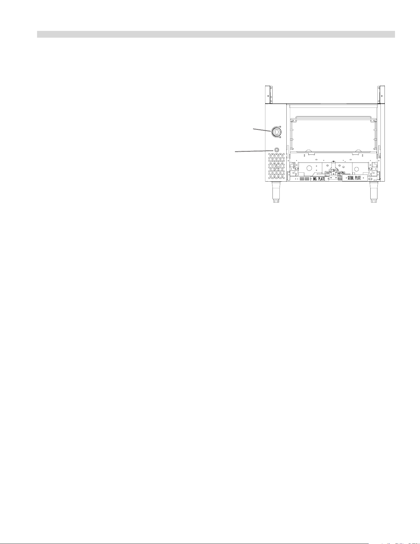
Rating Plate
Every cooking unit has a rating plate. Information on this
plate includes model and serial numbers. Knowing the
equipment model and serial number is essential if spare
parts are required or for discussing equipment problems
with Garland’s technical support sta. Other information
on the rating plate indicates BTU/hr input of the burners,
manifold gas pressure in inches water column (WC) and
whether orices are for natural or propane gas. The following
table gives the location of the rating plate on the designated
models, and Table B in the Specication Section lists the
various models of heavy duty equipment in the U.S. range
gas operated Cuisine series.
MODEL WITH SUFFIX LOCATION
R or C Behind the lower kick panel
S
In the storage cabinet on
the left hand side panel
M On the front panel
NOTE: Cuisine heavy duty gas operated equipment must
be connected only to the type of gas identied on the rating
plate!
Clearances to Combustible Construction
MODELS CLEARANCES
C36-ARR/-ARC
Installation in Non-
Combustible Locations
Only with 0” Side & Rear
Clearance
C36-NRR/-NRC
C24/C36-ABS
C24/C36-ARS
C18/C24/C36-NRS
C18/C24/C36-NRM
All Other Models
10” (254mm) Side, 6”
(152mm) Rear, from
combustible walls.
1. All models may be installed with 0” side and rear
clearance from non-combustible construction.
NOTE: When installed without legs on a non-combustible
curb or platform, front of unit should extend at least 3 inches
(76mm).
NOTE: Adequate clearance must be provided for servicing
and proper operation.
Installation Procedure
1. Remove all packing material.
2. Remove the front valve panel.
Document # G_GHD_OM_CUISINE_4605671 9/20 Page 11
3. Place the appliance in the required position and level by
means of the adjustable feet, or shims if the appliance is
not equipped with legs.
4. Where spreader plates are installed between units the
plate is secured at the front by means of the gas manifold
and at the rear by means of the connecting bolts.
5. Connect the gas supply pipe work to the appliance. The
connection may be made to the left or right hand side of
the appliance or optionally at the rear on some models.
Siting
The oor on which the appliance is to be sited must be
capable of adequately supporting the weight of the
appliance and any ancillary equipment.
Units with ovens must be tted with legs if installed on a
combustible oor. The equipment area must be kept free and
clear of combustible substances.
Appliance Equipped With Casters
A. The installation shall be made with a connector that
complies with the Standard for Connectors for Moveable
Gas Appliances, ANSI Z21.69/CSA 6.16, Addenda
Z21.69B-2006/CSA 6.16B-2006 (or latest edition), and a
quick-disconnect device that complies with the Standard
for Quick Disconnects for Use with Gas Fuel, ANSI Z21.41/
CSA 6.9, Addenda Z21.41A-2005/CSA 6.16A-2005 (or
latest edition).
B. The front casters of the unit are equipped with brakes
to limit the movement of the oven without depending
on the connector and any quick-disconnect device or its
associated piping to limit the appliance movement.
C. Please be aware, that the required restraint is attached
to a bracket (which is located on the left rear caster) and
if disconnection of the restraint is necessary, be sure
to reconnect the restraint after the appliance has been
returned to its originally installed position.
Appliances Equipped With Legs
Raise front of the unit and block. Do not lay unit on its back.
Position leg insert into leg retainer opening and tap up until
it seats at collar ange. Repeat at rear of unit making sure
all four legs are adjusted to the same height. Legs can be
INSTALLATION Continued
adjusted to overcome an uneven oor.
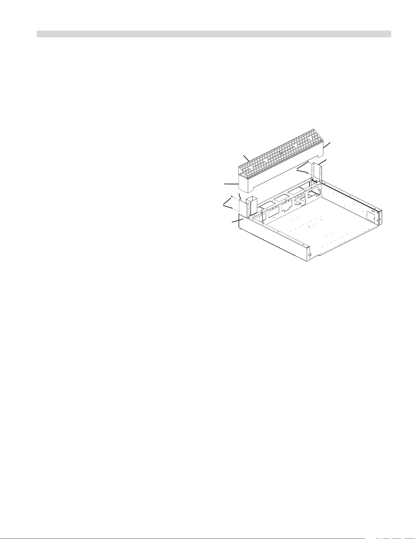
Installation Instructions for Cuisine
Stub Backguard
Figure 1
1. Remove four #10-24 self tap screws (item 1) from rear of
uprights (item 2) installed in range and set aside.
2. Install backguard assembly (item 3) over uprights (item 2)
in range and reinstall screws removed in step1 through
holes in backguard back panel (item4) and rear of top cap
(item5).
3. If the range is in a battery line-up, fasten units together at
hole marked “X” with 1/4” x 20 bolts, nuts and washers.
NOTE: Stub Backguard is shipped pre-assembled (with the
range) as standard equipment on all Cuisine units, unless
optional back riser or high shelf has been ordered.
Oven Flue Riser
Optional right or
left side.
1
2
“X”
3
2
4
1
5
1
Document # G_GHD_OM_CUISINE_4605671 9/20Page 12
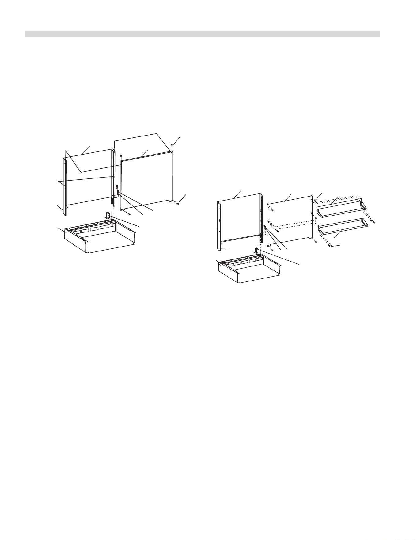
Installation Instructions for
Cuisine Back Risers.
Double Deck Risers
Figure 2
Shoulder
Bolts
2
"x"
7
6
5
5
4
3
1
Oven Flue Riser
Optional right or
left Side
1. Remove four 5/16 hex bolts and at washers from top
rear of unit.
2. Remove four #10 x 1 1/4” long sheet metal screws (Item 5)
from top and lower front corners of front panel. Remove
front panel by lifting upwards and pulling outward to
clear heads of shoulder bolts axed to uprights (Item 2).
3. With back panel, (3), still attached to the uprights, (2),
drop the uprights into the rectangular openings at the
rear of the range.
4. Fasten the uprights, (2), to the range with four, 5/16” x 18
bolts and at washers, (Item 6 & 7) removed in step one.
5. If the range is in a battery line-up fastens units together
at hole marked “X” with 1/4-20 bolts, nuts and washers.
6. Reattach the front panel by placing notches in back of
the front panel over heads of shoulder bolts and pulling
panel down until the top of the front panel rests on top
of uprights. This will allow shoulder bolts to lock panel
in-place. Re-install sheet metal screws (Item 5) previously
removed.
INSTALLATION Continued
Single Deck Risers:
Follow instructions above for double-deck backriser but
as there are no shoulder bolts involved in the single deck
assembly, the installation and removal of the front panel only
comprises assembly and disassembly of the four #10 x 1 1/4”
long sheet metal screws (Item 5).
Installation Instructions For Cuisine Single And
Double Deck High Shelves
Figure 3
9
10
8
5
4
6
7
3
2
Oven Flue Riser
Optional right or
left side
1
"X"
1. Remove four 5/16” x 18 hex bolts and at washers from
top rear of unit (Item 6 & 7).
2. Remove four (4) 1/4-20 locking acorn nuts securing shelf
(Item 9). Remove shelf.
3. Remove (6) #10 sheet metal screws (Item 5) that ax
front panel (Item 4) to uprights (Item 2).
4. With back panel (3) still attached to uprights (2), drop the
uprights into the rectangular openings at the rear of the
range.
5. Fasten the uprights (2) to the range with four (4) 5/16” x
18 bolts and at washers previously removed.
6. If the appliance is in a battery line-up, fasten unit
together at hold marked “X” with 1/4 - 20 bolts, nuts and
washers.
Document # G_GHD_OM_CUISINE_4605671 9/20 Page 13
7. Reattach the front panel by rst aligning clearance holes
with studs in uprights and then re-installing sheet metal
screws (Item 5) previously removed.
8. After installing front panel install shelf (Item 8) by
hooking the top of shelf over the top of the front panel.
Threaded studs on uprights will pass through clearance
holes on rear of shelf. Fasten shelf to studs via 1/4 - 20
locking acorn nuts provided (Item 9).
9. For double deck shelves, mount the lower shelf (one
with at back and no upper hook) to uprights through
front panel via locking nuts (Item 9) provided to 1/4” – 20
threaded studs on uprights.
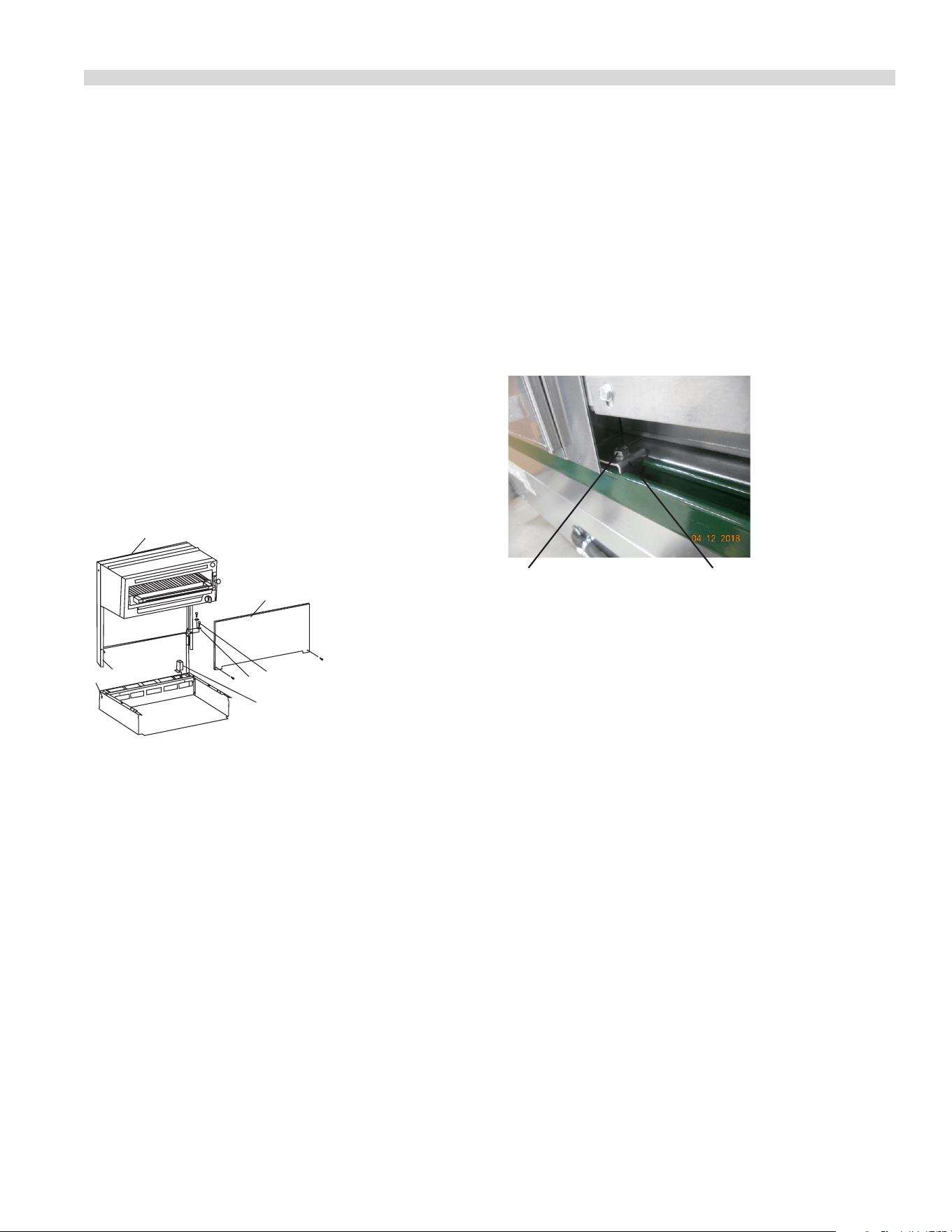
Installation Instructions For Cuisine
Salamander or Cheese Melter
Figure 4
2
"X"
Oven Flue Riser
Optional right or
left side
7
6
4
3
1
1. Remove four 5/16 x 18 hex bolts and at washers (Items 6
& 7) from rear top of unit.
2. Remove front panel, (4), by removing two, (2), sheet
metal screws from the underside of the salamander or
cheesemelter.
3. With back panel, (3), still attached to the uprights, (2),
drop the uprights into the rectangular openings at the
rear of the range.
4. Fasten the uprights (2), to the range with four, (4) 5/16” x
18 and at washers, (6 & 7) removed previously.
5. If the range is in a battery line-up, fasten units together at
hole marked “X” with 1/4 - 20 bolts, nuts and washers.
6. Reattach the front panel, (4) to the salamander or
Cheesemelter with sheet metal screws previously
removed.
Installation Instructions For Cuisine Modular
Units on Deleld Refrigeration Bases
Polar Cuisine refrigeration bases from Deleld have a
U-channel welded across the back and are provided with
spring loaded T-nuts in the channel. Using the brackets and
bolts supplied with the modular unit, clamp the rear corners
of the unit to the U-channel of the refrigeration base by
bolting the brackets to the T-nuts in the channel. See photo
below.
Statutory Regulations
The installation of this appliance must be carried out by
a competent person and in accordance with the relevant
regulations, codes of practice and the related publications of
the country of destination.
Gas Supply
The local gas authority should be consulted at the
installation planning stage in order to establish the
availability of an adequate supply of gas and to ensure
that the meter is adequate for the required ow rate. The
pipe work from the meter to the appliances must be of an
appropriate size. Where a number of appliances are installed
in a battery, no more than ve should be served by any one
supply pipe.
All xed (non-mobile) appliances MUST be tted with a
manual gas cock-upstream of the appliance to provide a
means of isolation for servicing or cleaning purposes. A
union or similar means of disconnection must be provided
between the gas cock and the appliance.
A manually operable valve must be tted to the gas supply
to the kitchen to enable it to be isolated in a emergency.
Wherever the practical, this shall be located either outside
the kitchen or near to an exit in a readily accessible position.
INSTALLATION Continued
Clamp bolt (provided with
Cuisine Modular Unit)
Rail clamp (provided with
Cuisine Modular unit)

Document # G_GHD_OM_CUISINE_4605671 9/20Page 14
Where it is not practical to do this, an automatic isolation
valve system shall be tted which can be operated from a
readily accessible position near to the exit.
At locations where the manual isolation valve is tted or
the automatic system can be reset a notice MUST be tted
stating:
“ALL DOWNSTREAM BURNER AND PILOT VALVES MUST
BE TURNED OFF PRIOR TO ATTEMPTING TO RESTORE THE
SUPPLY AFTER EXTENDED SHUT OFF, PURGE BEFORE
RESTORING GAS.”
Gas Supply Notes:
Before assembly and connection check gas supply.
A. The type of gas for which the unit is equipped is stamped
on the data plate located behind the lower front panel.
Connect a unit stamped “NAT” only to natural gas;
connect one stamped “PRO” only to propane gas.
B. If it is a new installation have the gas authorities check
meter size and piping to assure that the unit is supplied
with the necessary amount of gas pressure required to
operate the unit.
C. If it is additional or replacement equipment have gas
authorities check pressure to make certain that existing
meter and piping will supply fuel to the unit with not
more than 1/2” water column pressure drop.
NOTE: When checking gas pressure be sure that all other
equipment on the same gas line is on. A pressure regulator
is not supplied as standard equipment with US Range Heavy
Duty Equipment, however a 1-1/4” pressure regulator is sold
as an option with the original purchase. If you would like to
purchase a regulator after original purchase contact your
equipment dealer. The installation must conform with the
national Fuel Gas Code ANSI Z 223.1 -1988 or latest edition,
NFPA No. 54 – latest edition and National Electrical Code
ANSI/NFPA 70-1990 or latest edition and/or local code to
assure safe and ecient operation. In Canada, the installation
must comply with CAN/CGA-149.1 Natural Gas Installation
Code, or CAN/CGA-B149.2 Propane Gas Installation code, and
local codes where applicable.
In Canada, electrical connections must comply with
applicable sections of the Canadian Electrical Code, C22.1
-1990, (or latest edition), “Safety Standard for Installation,
Part 1” and C22.2 – No. 0-M 1982; (or latest edition), “General
Requirements, Part 2”.
Note: The appliance and its individual shut-o valve must be
disconnected from the gas supply piping system during any
INSTALLATION Continued
pressure testing of that system at pressures in excess of
1/2 PSIG (3.45 kPa).
The appliance must be isolated from the gas supply piping
system by closing its individual manual shut-o (not
supplied with appliance) during any testing of the gas supply
piping system at test pressures equal to or less than 1/2 PSIG
(3.45kPa).
NOTE: This appliance is not recommended for residential
installation.
Gas Connection
The gas pipe connection is made at the left hand side or right
hand side of the equipment or optionally at rear on some
units.
Note: If the gas connection to the unit is via a exible gas
hose be sure cable restraints are assembled to the unit.
The size of the pipe work supplying the appliance must
not be less than the inlet connection, which is 1 1/4” NPT.
(Note: a 3/4” NPT single unit optional connection must be
specied.) An isolating valve is recommended to be close
to and upstream of the appliance and regulator to allow for
shutdown during an emergency or routine servicing. A gas
pressure regulator must be installed at the appliance prior
to connecting the equipment to the gas supply (service)
line. Failure to install a regulator will void the equipment
warranty. After installation, be certain to check the complete
pipe work for leakage.
Electrical Supply
(Models with Convection Oven only)
The electrical supply required is single phase, 115V, 60Hz.
As an option, equipment can be supplied for 240V, 60Hz
operation.
If 240V, the supply must be connected to the terminal block
termination located at the rear of the range for models with
the sux C.
For ease in attaching the supply line, there is a removable
cover. A qualied electrician should make the connection to
the mains in accordance with the applicable local codes.
WARNING: Electrical Grounding Instructions.
This appliance is equipped with a three prong (grounding)
plug for your protection against shock hazard and should
be plugged directly into a properly grounded three-prong
receptacle. Do not cut or remove the grounding prong from
this plug.

Document # G_GHD_OM_CUISINE_4605671 9/20 Page 15
POWER FAILURE NOTE: In the event of a power failure, no
attempt should be made to operate this oven. This oven is
gas operated but has electrical features, motor and door
switches.
Assembly of Battery
All models described except Models C36-ABR, C36-ARR, C36-
ABC and C36-ARC may be installed to battery with Cuisine
Series Ranges, sharing common manifold connections.
Models C36-ABR, C36-ARR, C36-ABC and C36-ARC range base
broilers may be connected to other like broilers, but cannot
be placed in a battery with other Cuisine units.
A. All such units should be placed in their respective battery
position. Detach valve panels to prevent damage and
remove them from the area where the battery is being
assembled.
B. Level each unit (to the front rail) by adjusting the six inch
(6”) legs or where legs are not used, adjust level with
shims. Readjust legs, if required.
C. Connect units together by mating the unions at each
end of the manifold. (Adjoining units must have
matching unions, unless the union parts are of the
same specications, a leak proof connection cannot be
assured.) Hand tighten unions at this point.
D. The units should be fastened at the rear by inserting 5/16”
bolts through the holes provide at the rear of the burner
box sides. Install washer and nut and hand tighten. Be
sure of proper unit alignment in the battery before nal
tightening of these bolts or unions, improper tightening
will cause “fanning” or “bowing” of batteried units.
The nal tightening of the union should be accomplished
by using a suitable spanner wrench. If such a wrench
is not available, the GARLAND union collar has special
ridges, and a cold chisel can be driven against these
ridges to properly seat and seal the union.
E. The manifold of this unit or the manifold of which it is
a part of must be equipped with a certied pressure
regulator suitable for battery application and adjustable
for an outlet pressure at the manifold as specied on the
rating plate.
INSTALLATION Continued
Ventilation And Air Supply
The range(s) must be installed so that the ow of combustion
and ventilation air is unobstructed. Adequate clearance for
air openings into combustion chambers must be provided.
Avoid installing units on a convection oven base back to
back with a high heat emitting appliance such as a wood or
charcoal burning broiler. The high temperatures can shorten
the life of the convection motor.
Proper ventilation is highly important for good operation.
The ideal method of ventilating a range is the use of
a properly designed canopy which should extend
approximately six inches (6”, 152 mm) beyond all sides of the
appliance and six feet (6’) six inches (6”), (1981mm) from the
oor.
A strong exhaust fan will create a vacuum in the room. For an
exhaust system vent to work properly, replacement air must
enter the room in which the vent is located.
All gas burners and pilots need sucient air to operate and
large objects should not be placed in front of the appliance
which would obstruct the airow through the front.
The following notes are intended to give general guidance.
For detailed recommendations, refer to the applicable
code(s) in the country of destination.
NOTE 1: The room containing the appliance is required to
have a permanent air vent. The minimum eective area of
the vent is related to the maximum rated heat input of the
appliance and shall be 4.5 cm² per kW (2.04 X 10⁻⁴ in² per
BTU/H) in excess of 7 kW. (23,900 BTU/H).
NOTE 2: Air vents should be of such a size to compensate for
the eects of any extract fan in the premises.

Document # G_GHD_OM_CUISINE_4605671 9/20Page 16
COMMISSIONING
Pressure Regulators.
1. Must have a maximum regulation capacity for the total
connected load.
2. The pressure regulator(s) installed must be listed by a
nationally recognized agency.
3. The pressure regulators must have a pressure adjustment
range to allow adjustment to the manifold pressure on
the appliance rating plate.
4. Unless the manifold pressure on all connected appliances
is the same, a separate pressure regulator must be
supplied for each appliance having diering manifold
pressures.
5. Gas supply lines may be connected at right, left or both
ends of a battery or at the TEE connections on spreader
plates. If ve (5) or more units are placed in a battery,
more than one (1) supply line should be used. A readily
accessible, approved type of hand shut-o valve should
be installed on each supply line.
WARNING: Local codes may require that the pressure
regulator be externally vented. This will be supplied by
others.
Testing and Adjustments.
All ttings and pipe connections, including connections
internal to the unit, must be tested for leaks. Use approved
gas leak detectors, soap solutions or equivalent, checking
over and around the ttings and pipe connections. DO NOT
USE A FLAME! Accessibility to all gas lines and ttings require
that valve panel(s), knob(s), lower front panel(s), oven rack(s)
be removed. It may be necessary to remove or at least raise
and securely prop-griddles, hot tops and top grates. All parts
removed (including fasteners) should be stored safely for
re-use.
NOTE: Each valve knob has a set screw fastening it to the
valve. This set screw must be loosened prior to removing
the knob. Subsequent to replacing the knob, tighten the set
screw to ax the knob to the valve.
Testing
1. Be sure that all valves and thermostats are in the “OFF”
position.
2. Turn on the main gas supply valve. Light all top section
pilots.
3. Leak test all valves and ttings as described in the
procedure above. Correct any leaks as required and
recheck.
4. Light oven pilot.
5. If the range is provided with an oven shut-o valve
separate from the thermostat, turn this valve on and set
the thermostat at 500°F (260°C) degrees. If the range
oven thermostat has an “OFF” position on the dial the
thermostat is equipped with an internal, integral shut-o
valve. Set this thermostat dial to 500°F (260°C) degrees. In
both cases, gas will now ow to the oven burner.
6. Leak test all valves, ttings, etc, as above. Correct any
leaks and retest.
7. Shut o all range valves and set thermostat dials to “OFF”
or low position.
All units are tested and adjusted at the factory. However,
burners and pilots should be checked at installation and
adjusted if necessary.
CAUTION: Gas will ow to top burners even with top pilots
out. Gas will not be interrupted. It is the responsibility of
the operator to check the ignition of the burners. Should
ignition fail after ten (1) seconds, turn burner valve o and
wait ve (5) minutes and then try again.
Pressure Settings (All Models)
1. Make sure all gas valves are in the OFF position and turn
on the main gas supply.
2. Light all pilots in accordance with the User’s Instructions.
3. Connect a U-gauge manometer to the pressure test point
on the main manifold and turn all gas controls to the ON
position.
Conrm that the pressure is the same as stated on the rating
plate.
Document # G_GHD_OM_CUISINE_4605671 9/20 Page 17
COMMISSIONING Continued
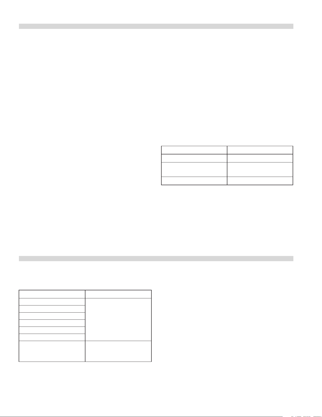
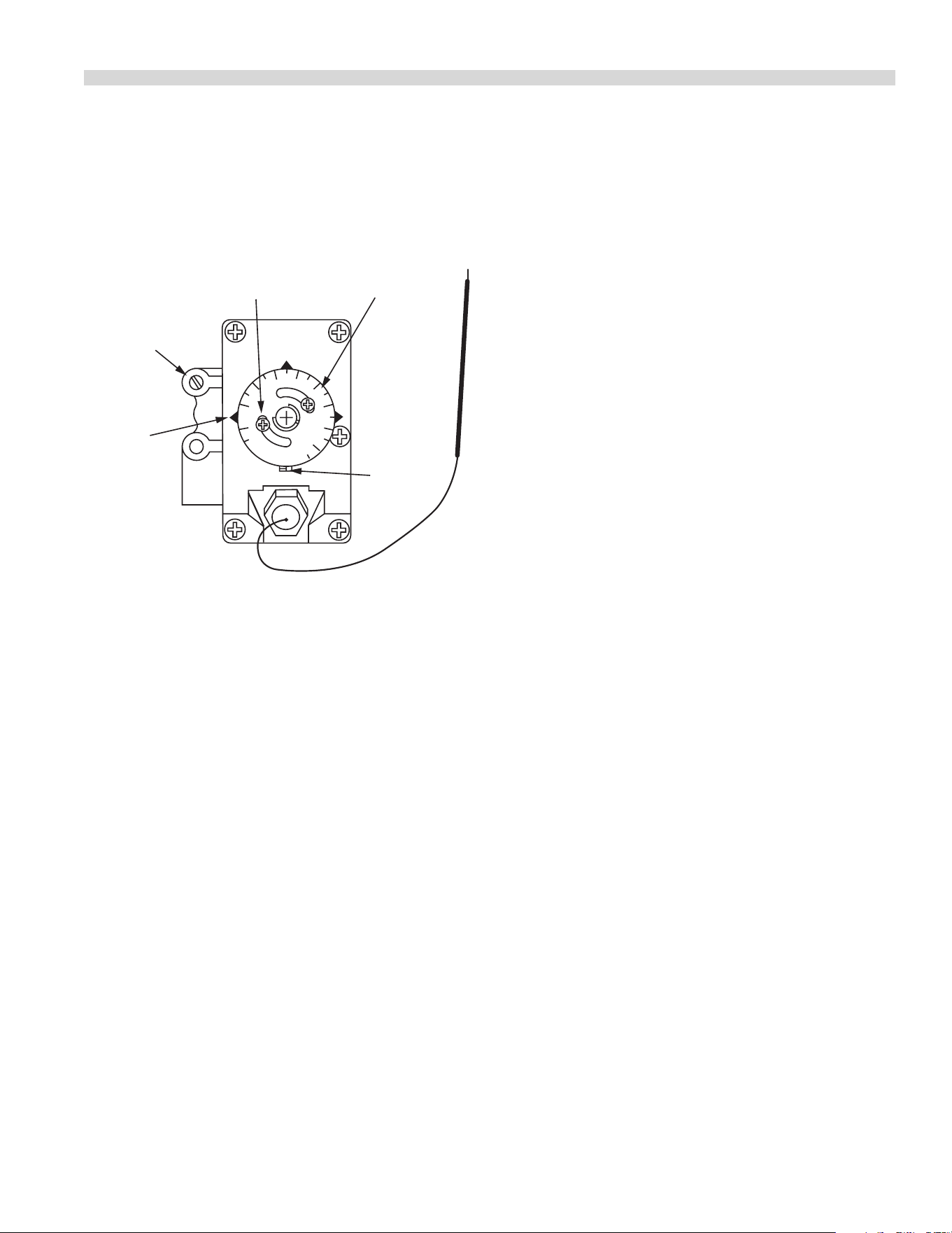
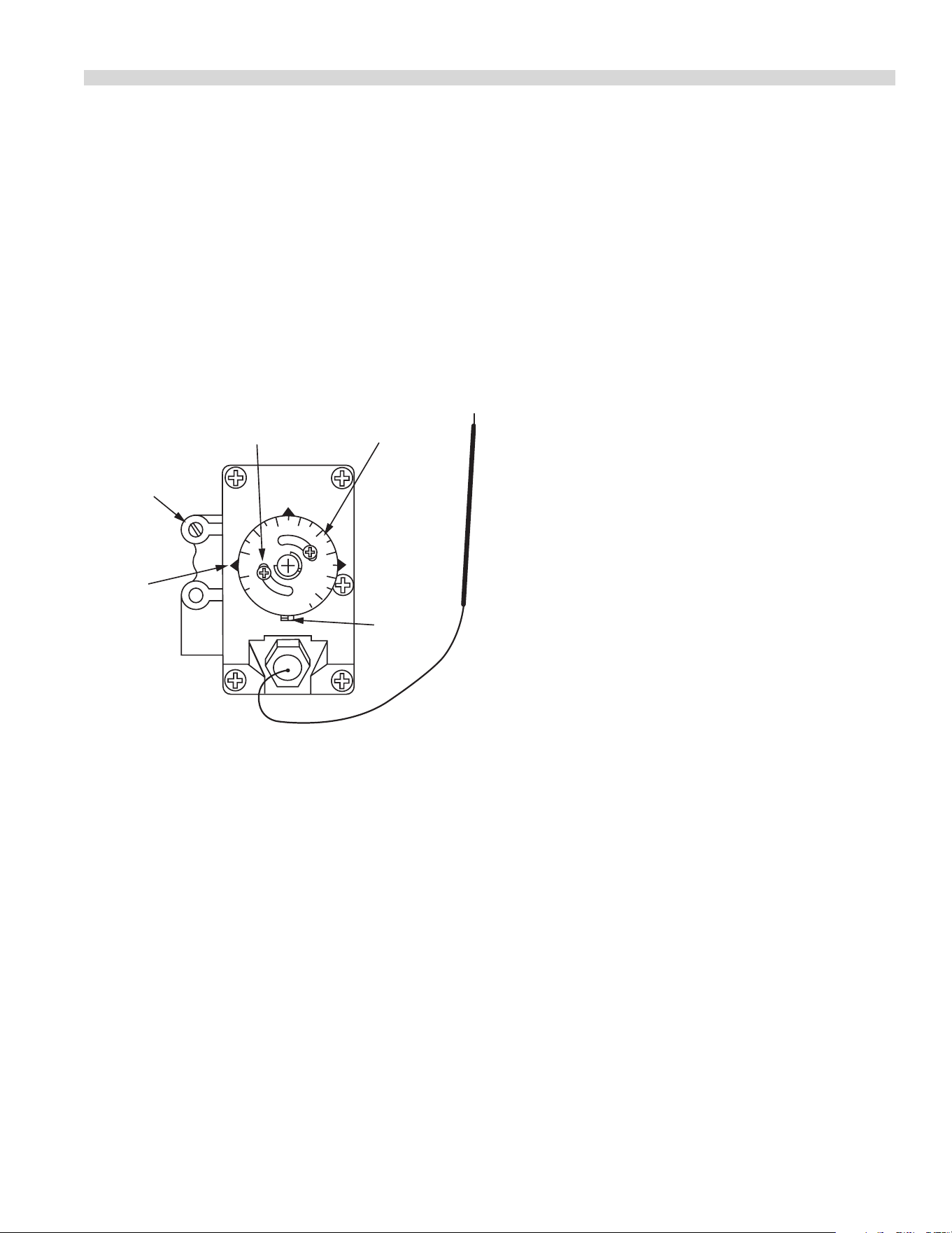
Thermostat Bypass Adjustment – Oven
Figure 5
R
O
B
E
R
T
S
H
A
W
MODEL
FDO
1/2 PSI
By-Pass
Flame Adjuster
Indicator
Mark
Calibration
Lock Screw
Calibration
Plate
Dial
Stop
With reference to Figure 5, the Robertshaw FDO snap-
throttle thermostat requires a bypass adjustment. To adjust
the bypass, follow this procedure.
1. Turn the oven temperature control dial to 200°F (93° C)
then allow the oven to heat for 3 minutes.
2. Turn the oven control dial to the OFF position, then
slowly turn the oven temperature control dial counter-
clockwise until an audible click is heard.
3. Making sure not to disturb the oven temperature control
dial, turn the bypass ame adjusting screw and adjust
the bypass ame to the Lowest Possible Stable ame
covering the Entire Ported Area of the Burner. Turn
the adjusting screw counter-clockwise to increase or
clockwise to decease the size of the bypass ame.
NOTE: For calibration please refer to Thermostat Calibration
in the Service Section.

Document # G_GHD_OM_CUISINE_4605671 9/20Page 18
Pilot Burner Adjustments
General
1. Light the pilot light in accordance with the Operation
Instructions in Operation Section.
2. Check the length of the ame and adjust as necessary for
desired characteristics. Screwdriver adjustment may be
made to the pilot valve adjacent to the burner valve on
the manifold, through the valve panel opening.
Oven
1. Open the lower kick panel.
2. Remove the oven bottom assembly.
3. Light the pilot light in accordance with the Operations
Instructions.
4. Check the length of the pilot light. Adjust pilot ame for
desired characteristics. Screwdriver adjustments may be
made to the pilot valve, adjacent to the oven burner valve
on the manifold, through the valve panel opening.
COMMISSIONING Continued
Solid Hot Plate/Griddle
1. Light the pilot in accordance with the Operation
Instructions.
2. Check the length of the ame. Adjust pilot ame for
desired characteristics. Screwdriver adjustment may be
made to the pilot valve adjacent to the burner valve on
the manifold through the valve panel opening.
Front Fired Hot Top
1. Light the pilot light in accordance with the Operation
Instructions.
2. Check the length of the ame. Adjust pilot ame for
desired characteristics. Screwdriver adjustment may be
made to the pilot valve adjacent to the burner valve on
the manifold through the valve panel opening.
Broiler
1. Light the pilot light in accordance with the Operation
Instructions.
2. Check the length of the ame. Adjust pilot ame for
desired characteristics. Screwdriver adjustment may be
made to the pilot valve adjacent to the burner valve on
the manifold through the valve panel opening.
OPERATION
This section deals with equipment operating instructions
and some of the simple and obvious cleaning methods
that will help keep heavy duty cooking equipment in good
condition.
Open Top Burners
1. Open top burner pilots may be reached down through
the opening of the top grate.
2. Light the pilots.
3. Turn the valve completely on by rotating the knob to the
“ON” position. If burner fails to light after 10 seconds turn
the valve “OFF”, wait 30 seconds and try again.
NOTE: The burner ame should be a 1/2” stable ame and
impinge on the underside of a pot placed on the top grate.
Shutdown
1. Turn all valves to the o position.
2 If the unit is to be shut down for an extended time, close
the in-line gas valve.
Note: Never place sheet pans over open top grates with
burners operating, or ip and try using them as a wok.
Hot top and Spectro-Top Sections
1 Light the pilots via a long match or taper through the
opening in the valve panel.
2. Turn the burner valve on by rotating the knob to the “ON”
position. A sharp blue ame should be approximately
1/4” high. If burner fails to light after 10 seconds turn the
valve “OFF”, wait one minute and try again.
Document # G_GHD_OM_CUISINE_4605671 9/20 Page 19
Shutdown
1. Turn all valves to the o position.
If the unit is to be shut down for an extended time, close the
in-line gas valve.
Thermostatically Controlled Griddles
1. Light the pilots at the front right side of the burner via
a long match or tape through the opening in the valve
panel.
2. Set the thermostat to maximum one at a time. The burner
should have a 5/16” high stable ame. If burner fails
to light after 10 seconds turn the valve “OFF”, wait two
minutes and try again.
CAUTION: Do not allow the griddle to heat for longer than
one minute. The griddle must be seasoned before use.
(Refer to the Passage Entitled “Griddle Seasoning”).
Shut Down
1 Turn all thermostat valves to the OFF position.
2 If the unit is to be shut down for an extended time, close
the in-line gas valve.
Valve Controlled Griddles
1. Light the pilot at the front right side of the burner via a
long match or taper through the opening in the valve
panel.
2. Turn the burners on by rotating them to the “ON”
position. The burners should have a 1/2” to 5/8” stable
blue ame. If burner fails to light after 10 seconds turn
the valve “OFF”, wait one minute and try again.
CAUTION: Do not allow the griddle to heat for longer than
one minute. The griddle must be seasoned before use.
(Refer to the Passage Entitled “Griddle Seasoning”).
Shut Down
1. Turn all valves to the OFF position.
2. If the unit is to be shut down for an extended time, close
the in-line gas valve.
NOTE: Never exceed the weight limit of 490 lbs. on the top
section of the range.
OPERATION Continued
Oven (Standard)
Lighting
1. Remove Oven bottom.
2. Depress and hold reset button (red) located through the
access hole on the front control panel to the left of the
oven door (When facing the unit front.) While lighting the
oven pilot, continue to depress the reset button for 60
seconds. Release button. If pilot does not stay lit, repeat
this procedure after 5 minutes.
3. Turn oven valve knob to the “ON” position.
4. Rotate oven thermostat dial to the desired setting.
Shut Down
1. Turn oven valve and thermostats to, the o position.
2. If range is to be shut down for an extended period of
time, close the in line gas valve.
Relighting
1. Shut all gas valves o.
2. Wait 5 minutes.
3. Repeat lighting instructions in lighting above.
NOTE: Never leave the oven door open with oven burner
operating.
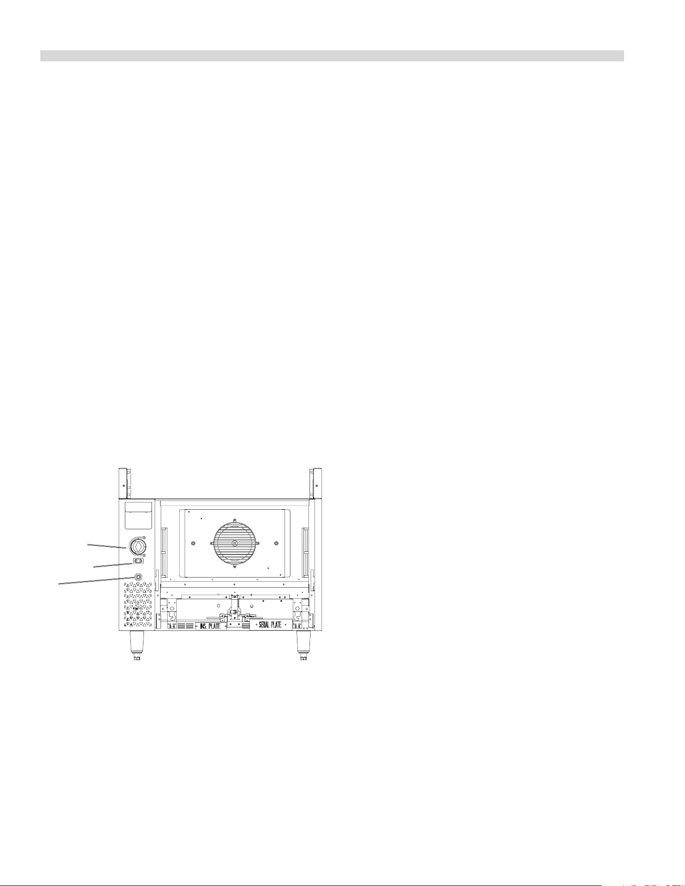
Oven
Thermostat
Red
Reset
Button
Document # G_GHD_OM_CUISINE_4605671 9/20Page 20
“RC” Convection Ovens
For 115 V usage, a cord and plug is provided but connection
to the electrical service must comply with local codes; or in
the absence of local codes with the National electrical code,
ANSI/NFPA No. 70-(or current edition)in the U.S., or in Canada
with the Canadian Electrical Code C22.1-1990 (or latest
edition) “Safety Standard for Installation, Part 1” and C22.2-
No. O-M 1982 (or latest edition), “General Requirements Part
2.”
WARNING:
Electrical Grounding Instructions.
This appliance is equipped with a three pronged (grounding)
plug for your protection against shock hazard and should be
plugged directly into a properly grounded three-pronged
receptacle. Do not cut or remove the grounding prong from
this plug.
POWER FAILURE NOTE: In the event of a power failure, no
attempt should be made to operate this oven. This oven is
gas operated but has electrical features, motor and door
switches.
A wiring diagram is attached to the rear of this unit.
Lighting Instructions
1. Remove the lower front panel.
2. Push the power switch to cook position. This will activate
the spark module and light the pilot.
3. Using the access hole in the front control panel to the
left of the oven door (when facing unit front) depress
and hold the reset button (Red) located on the oven
safety valve. Continue to depress the reset button for 60
seconds. Release button.
OPERATION Continued
4. If the pilot does not stay lit after you release the reset
button, wait 5 minutes and repeat Step 3 & 4.
Start Up
1. Turn oven knob on to the “ON” position.
2. Turn thermostat to desired setting.
Cool Down
1. Turn thermostat and oven valve o.
2. Open Door.
3. Activate power switch to the cool down position.
Shut Down
1. Turn thermostat o.
2. Return power switch to “OFF” position.
3. Turn oven valve o.
The motor on your range convection oven is maintenance
free since it is constructed with self lubricating sealed ball
bearings. It is designed to provide durable service when
treated with ordinary care. We have a few suggestions to
follow on the care of your motor.
A. When the motor is operating, it cools itself internally by
air entering the rear of the motor case, provided proper
clearance has been allowed.
B. Since the blower wheel is in the oven cavity it is at the
same temperature at the oven. If the motor is stopped
while the oven is hot, the heat from the blower wheel is
conducted down the shaft and into the armature of the
motor. This action could shorten motor life.
C. We recommend, at the end of the bake or roasting
period, when the oven will be idle for any period of time
or before shutting down completely, that the oven door
be left open, and by use of the cool-down position on the
fan switch, the fan continue to run for at least 20 minutes.
The “FAN” should never be turned “OFF” when the oven is
“HOT”.
Oven
Thermostat
Red
Reset
Button
Power Switch

Document # G_GHD_OM_CUISINE_4605671 9/20 Page 21
Unit Broilers
1. Light the pilots via a long match or taper through the
opening(s) in the valve panel.
2. Turn the burner valve on by rotating the knob to the “ON”
position. A sharp ame should be about 1/4” high.
Shut Down
1. Turn all valves to the OFF position.
OPERATION Continued
2. If the unit is to be shut down for an extended time, close
the in-line gas valve.
Fryers
• Refer to separate instruction manual provided with fryer
unit.
MAINTENANCE AND CLEANING
Seasoning
Griddle Seasoning
A. Remove all factory applied protective material washing
with hot water, mild detergent or soap solution.
B. Apply a thin coat of cooking oil to the griddle surface,
about one ounce per square foot of griddle surface.
Spread over the entire griddle surface with a cloth to
create a thin lm. Wipe o any excess oil with a cloth.
C. Light all burners, set at lowest possible setting. Some
discoloring will occur when heat is applied to steel.
D. Heat the griddle slowly for 15 to 20 minutes. Then wipe
away oil. Repeat the procedure 2 to 3 times until the
griddle has a slick, mirror like nish. Do this until you have
reached the desired cooking temperature.
IMPORTANT: Do not attain high (on valve control) or 450
degrees (on thermostat control) during “Seasoning” period.
The griddle will not require reseasoning if it is used properly.
If the griddle is over heated and product begins to stick to
the surface it may be necessary to repeat the seasoning
process again. If the griddle is cleaned with soap and water it
will be necessary to reseason the griddle surface again.
Seasoning Cast Iron Top Grates
First, remove the cast iron top grates from the range. Wash
the cast iron top grates thoroughly with a mild soap and
warm water. Dry the cast-iron top grates thoroughly with a
clean cloth. Immediately after drying season the top grates
lightly with a non-toxic (Liquid vegetable oil or Pam spray
oil).
WARNING: Do Not Season the Top Grates While On the
Range top! Seasoning grates on the range top over an
open ame could cause a ash re.
After seasoning, replace the top grates onto the range. Turn
all the range open top sections “ON LOW”.
Allow the top sections to burn in this manner for at least
20 minutes before using pots or pans on the top grates.
Seasoning of the top grates will be required whenever
they have been cleaned. Failure to season grates will cause
rusting.
Cleaning
General Cleaning
NOTE: Disconnect line cord (if applicable) from power
supply before cleaning or servicing.
Proper maintenance, cleaning and care of cooking
equipment is an important part of any program and will keep
it in good operating condition. These notes provide a code
of good practice for users to maintain a regular cleaning
schedule.

Document # G_GHD_OM_CUISINE_4605671 9/20Page 22
Establish a regular cleaning schedule. Any spill should be
wiped o immediately.
The oven should be permitted to cool down before cleaning
exterior surfaces. Wipe exposed, cleanable surfaces when
cool with a mild detergent and hot water. Stubborn residue
spots may be removed with a light weight non-metallic
scouring pad. Dry thoroughly with a clean cloth.
NOTE: Many parts of the commercial range are raw steel, (i.e.
hot tops, griddles, springs, door hooks, etc.) and can react
to moisture, forming rust. This occurrence is normal and not
considered a factory defect. Clean with a stainless steel or
ber pad. A coating of salt free oil may be applied.
Stainless Steel Exterior and
Standard Oven Interior Finishes
NOTE: Disconnect line cord (if applicable) from power
supply before cleaning or servicing.
For routine cleaning just wash with a hot water and
detergent solution. Wash just a small area at a time or the
water will evaporate leaving the chemicals behind causing
streaking. Rinse the washed area with a clean sponge dipped
in a sanitizing solution and wipe dry with a soft cloth before
it can dry.
Use a paste (of water and a mild scouring powder) if you
have to, but never rub against the grain. All stainless steel
should be polished in one direction. Rub with the polished
lines to preserve the original nish. Then thoroughly rinse as
before.
To prevent nger prints on exterior surfaces there are several
stainless steel polishes on the market that leave an oily or
wavy lm. Do not use on surfaces that will be in contact with
food.
Stainless steel may discolor if overheated. These stains can
usually be removed by vigorous rubbing with a scouring
powder paste.
Use only stainless steel, wooden or plastic tools if necessary
to scrape o heavy deposits of grease and oil. Do not use
ordinary steel scrapers or knives as particles of the iron may
become imbedded and rust. STEEL WOOL SHOULD NEVER
BE USED. Either a typical bleach solution or hot water can be
used to sanitize stainless steel without harm.
MAINTENANCE AND CLEANING Continued
Oven Interior
(Optional Porcelain Enamel Finish)
NOTE: Disconnect line cord (if applicable) from power
supply before cleaning or servicing.
1. Before cleaning oven interior, remove all oven racks and
guides (if “convection oven” base). Oven racks and guides
can be cleaned with a mild soap and warm water or run
through dish washer.
2. The porcelain interior can be cleaned with oven cleaners
such as “Easy-O” , or “Dow Oven cleaner”. Apply only
when oven is cold.

Document # G_GHD_OM_CUISINE_4605671 9/20 Page 23
Note that griddle, open top grates and burners, hot tops
and broiler components should be cool to the touch prior
to performing any clenaing procedure.
Griddle Cleaning
Do Not use water on griddle tops while still hot or do not
cool by using ice! This will cause griddle plate to warp and
possibly crack. This is not a factory defect.
To produce evenly cooked, perfectly browned griddle
products, keep griddle free from carbonized grease.
Carbonized grease on the surface hinders the transfer of
heat from the griddle surface to food product. This results
in uneven browning and loss of cooking eciency, and
worst of all, carbonized grease tends to cling to the griddle
foods, giving them a highly unsatisfactory and unappetizing
appearance. To keep the griddle clean and operating at peak
performance, follow these simple instructions.
A. After Each Use clean griddle thoroughly with a grill
scraper or spatula. Wipe o any excess debris left from
cooking process.
B. Once a Day clean griddle surface with a grill brick and
grill pad. Remove grease container and clean thoroughly,
in same manner as any ordinary cooking utensil.
C. Once a Week clean griddle surface thoroughly. If
necessary, use a grill stone or grill pad over the griddle
surface. Rub with grain of the metal while still warm.
A detergent may be used on the plate surface to help
clean it, but care must be taken to be sure it is thoroughly
removed. After removal of detergent, the surface of the
plate should be covered with a thin lm of oil to prevent
rusting. To remove discoloration, use a non-abrasive
cleaner. Before re-using the griddle must be reseasoned.
Keep griddle drain tube to grease container clear at all
times on those models without side grease container.
CAUTION: This griddle plate is steel, but the surface is
relatively soft and can be scored or dented by careless use
of spatula. Be careful not to dent, scratch or gouge the
plate surface. This will cause food to stick in those areas.
Also, note, since this is a steel griddle if a light coating of oil
is not always present rust will develop on exposed areas.
Open Top Burners
Periodically burners should be removed and cleaned with
soap and hot water. You may soak the burner in a bucket of
hot soapy water and brush o any burnt on grease or debris.
MAINTENANCE AND CLEANING Continued
Allow the cast iron burner to dry thoroughly before installing
into the range. If the burner ports are blocked or plugged
with grease, it will be necessary to clear the ports with a wire
or blunt instrument.
Cast Iron Top Grates
Cast Iron Top Grates can be cleaned with mild soap and
warm water. For baked on material, a wire brush can be
used. Dry thoroughly. Lightly coat with vegetable oil to help
prevent rust from forming.
Seasoning of the top grates will be required whenever the
grates have been cleaned. Failure to season grates will cause
rusting.
Cast Iron Hot tops and Spectro-Heat Tops
DO NOT use water on tops while still hot or DO NOT cool by
using ice!
While the surface is still slightly warm, wipe down with a
clean burlap cloth. Burnt on spillage should be scraped o. If
necessary, remove the plate and wash in a sink with soap and
hot water. Dry thoroughly. In damp climates, wipe down with
a light coating of oil to prevent rusting. Avoid excessive use
of water as this could damage the surface and the control
below.
NOTE: Cast Iron Hot Tops & Spectro-Heat Tops surface will
“tone” (blue/brown discoloration) from heat. This toning will
not diminish function or operation and is not a defect.

Document # G_GHD_OM_CUISINE_4605671 9/20Page 24
Broiler Cleaning
C36-NRR/C36-NRC Models
Daily
1. Remove the broiler grates. Wire brush them clean of
any encrusted materials and wash in hot, soapy water.
A common cleaning practice is to turn grates upside-
down to burn o encrusted material. Do not do this with
the Cuisine Char-broiler! The ame from the burner is
shielded by a cast iron radiant, with the result that heat-
not ame – reaches the grate. It is likely that cooked-on
matter will cook in even deeper rather than burn o.
2. Remove the radiants and wire brush them clean; then
wash in hot, soapy water. A rule of thumb is that if the
grates are becoming encrusted, so are the radiants.
3. The Cuisine Char-Broiler uses a double drip tray. The front
grease trough (at the top of the unit) downspouts to a 3
5/8” wide tray running the depth of the unit. Remaining
grease which drips past the radiants is collected by a
second pan covering the remainder of the broiler bottom.
The front tray must be checked frequently during
operation and drained as necessary: the rear drip pan
should also be checked occasionally. Spills should be
wiped as they occur and at the end of the day both pans
should be washed in hot soapy water.
Weekly
If daily maintenance is performed as recommended above,
weekly maintenance will not be required beyond the daily
cleaning for the last day of the working week.
C36-ABR/C36-ABC Models
Daily
1. Remove the broiler grates. Wire brush them clean of
any encrusted materials and wash in hot, soapy water. A
common cleaning practice is to turn grates upside-down
to burn o encrusted material. Do not do this with the
Cuisine Char-broiler! It is likely that cooked-on matter will
cook in even deeper rather than burn o.
2. With the grates removed, turn over all the briquettes on
the ceramic coal model.
3. Remove the perforated screen, drip pan, and grease can
and clean thoroughly.
MAINTENANCE AND CLEANING Continued
C36-ARR/C36-ARC Models
Daily
1. Remove the broiler grates. Wire brush them clean of
any encrusted materials and wash in hot, soapy water.
A common cleaning practice is to turn grates upside-
down to burn o encrusted material. Do not do this with
the Cuisine Char-broiler! The ame from the burner is
shielded by a cast iron radiant, with the result that heat-
not ame – reaches the grate. It is likely that cooked-on
matter will cook in even deeper rather than burn o.
2. Remove the radiants and wire brush them clean; then
wash in hot, soapy water. A rule of thumb is that if the
grates are becoming encrusted, so are the radiants.
3. The Cuisine Char-Broiler uses a double drip tray. The front
grease trough (at the top of the unit) downspouts to a 3
5/8” wide tray running the depth of the body remaining
grease which drips past the radiants is collected by a
second pan covering the remainder of the broiler bottom.
The front tray must be checked frequently during
operation and drained as necessary: the rear drip pan
should also be checked occasionally. Spills should be
wiped as they occur and at the end of the day both pans
should be washed in hot soapy water.
Adjustments
Oven Orice
The top and oven orices are xed and cannot be adjusted.
Proper rate is attained if the gas supply pressure is adequate.
Pressure may be checked by using the 1/8” N.P.T. manifold
pressure tap. A properly adjusted air shutter will provide for
a distinct blue ame over the entire port area of the burners
when at full rate.
Pilot Adjustments
All pilot adjustment valves are mounted on the range top
manifold. The pilot burner for the open top, broiler, griddle
or hot top burner should provide for rapid ignition of the
burner but should not impinge on any part of the burner.
When properly adjusted the pilot ame should neither lift o
the burner, nor should it show a yellow tip.

Document # G_GHD_OM_CUISINE_4605671 9/20 Page 25
Automatic Pilot Valve
The automatic pilot valve is a protective device which allows
gas to ow to the oven burner only when the pilot burner is
burning. (This device is used on Cuisine ranges and has safe
lighting provisions provided by the ow interrupter which
will not allow gas to ow to the oven burner while the red
button is depressed).
A too loose or too tight connection of the thermocouple nut
to the automatic pilot valve can prevent the thermocouple
from activating the valve. It should be drawn up nger tight
and the TIGHTENED ONLY 1/4 turn with a wrench.
Burner Gas/Air Adjustments
Variations in eld conditions, rough handling of the
equipment in transit may indicate the need for adjustment
of primary air to the burners. Check operation and adjust as
below to provide a sharp blue ame at full rate (open valve
fully so that the thermostat is calling for maximum gas ow).
On the burner (Open top, “H” griddle, knuckle, broiler, oven
burners) locate the air shutter. Loosen the lock-nut so that
the air shutter turns freely (Figure 6). Reinstall burner. Turn on
gas ow and ignite burner. Rotate air shutter to obtain the
following.
MAINTENANCE AND CLEANING Continued
a. Open Burner 1/2” stable, sharp inner blue cones.
b. Hot tops, griddles and broilers 1/4” to 5/16” stable, sharp
inner blue cones.
c. Knuckle burners 4” to 6” stable, blue ame, slight yellow
tips.
If the burner ames are sharp but lift o the burner ports,
reduce the amount of primary air by closing the air shutter.
If the burner ames are lazy and yellow in appearance,
increase primary air by opening the shutter. If poor burner
performance persists check for proper gas pressure.
NOTE: The rates shown in Table C on Page 9 are maximum
rates and must not be exceeded.
CONVECTION OVEN PRODUCT APPLICATION
• As a guide, set oven temperatures 25° to 50° lower than
called for in recipes or directions using standard or
conventional ovens. Cooking time may be less depending
upon the product you are preparing. 2% to 5% is a
general rule. Product should be watched the rst time it is
prepared.
• Cooking time and oven temperature will vary depending
upon such factors as size of load, temperature of product,
and mixture of recipe, particular moisture.
• When you have established satisfactory time and
temperature for your products, record them on a chart
and keep as a reference guide.
• Preheat oven thoroughly before use. To reach 350° takes
approximately 15 minutes. For optimum results oven
should be preheated for 30 minutes to allow for thorough
heat saturation.
• The load should be centered on the racks to allow for
proper heat circulation around the sides.
• Load size. The oven will hold three (3) 18” x26” sheet pans,
six (6) 12” x 20” x 2.5” steam table pans or one (1) 21” x 18”
x 7” roast pan with cover.
• Never place pans directly on the oven bottom. Always
use the lowest rack position which will allow the air to
circulate within the oven cavity.
• Load and unload food as quickly as possible to prevent
an excessive drop in temperature.
• Avoid using wrapped pans since level pans bake more
evenly.
Document # G_GHD_OM_CUISINE_4605671 9/20Page 26
• Do not use a deep pan for shallow cakes, cookies, etc. as
circulation across the surface is essential for even cooking
and browning.
• To prevent excessive shrinkage, roast meats at a low
temperature, 250° to 325°.
• When rethermalizing frozen products, preheat the oven
50° higher than cooking temperature to compensate for
heat loss during and after loading. Thermostat must be
returned to cooking temperature after loading.
• To conserve energy, turn the oven o and cool down
when not in use.
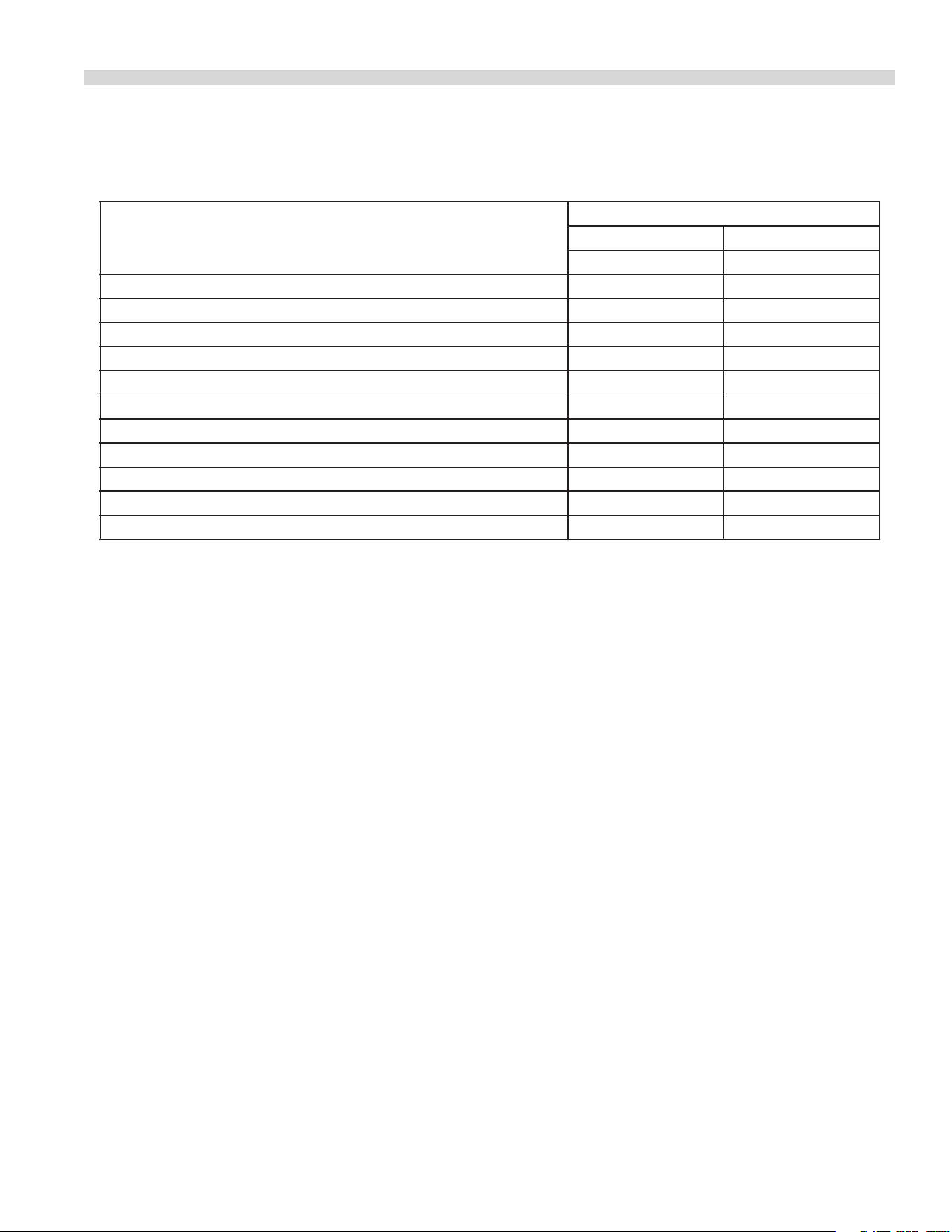
Problem Solution
Cakes are dark on the sides and not done in the center Lower oven temperature
Cakes edges are too brown Reduce number of pans or lower oven temperature
Cakes have light outer color Raise temperature
Cake settles slightly in the center Bake longer or raise oven temperature slightly.
Do not open doors too often or for long periods
Cake ripples Overloading pans or batter is too thin
Cakes are too coarse Lower oven Temperature
Pies have uneven color pans Reduce number of pies per rack
or eliminate use of bake pans
Cupcakes crack on top Lower oven temperature
Meats are browned and not done in center Lower temperature and roast longer.
Meats are well done and browned Reduce time. Limit amount of moisture
Meats develop hard crust Reduce temperature or place pan of water in oven.
CONVECTION OVEN PRODUCT APPLICATION Continued
PROBLEM/SOLUTIONS CONVECTION OVEN
Document # G_GHD_OM_CUISINE_4605671 9/20 Page 27
SERVICING
Regular maintenance and servicing by competent and
qualied personnel is recommended for the continued safe
and ecient operation of cooking equipment.
WARNING: Before working on any appliance, SHUT OFF
the gas supply at the main shut-o valve and electrical
supply at the main disconnect. On completion of any
servicing work, test for gas leaks before returning the
equipment into service.
Thermostat Calibration
Oven
R
O
B
E
R
T
S
H
A
W
MODEL
FDO
1/2 PSI
By-Pass
Flame Adjuster
Indicator
Mark
Calibration
Lock Screw
Calibration
Plate
Dial
Stop
To check the calibration, follow this procedure:
1 Place the thermocouple of the test instrument or a
mercury thermometer in the center of the oven.
2. Turn the oven control dial to 400°F (202°C) to allow the
oven temperature to stabilize. Allow the oven to cycle
twice before taking a test reading.
3. Check the temperature reading when the control cuts
down to bypass. If the temperature does not read within
15° (5°C) of the dial setting recalibrate as follows.
4. Remove the control dial, making sure not to disturb the
setting.
5. Hold the calibration plate and loosen the two calibration
lock screws until the plate can be rotated independently
of the control.
6. Turn the calibration plate until the temperature indicated
on the plate corresponds with the reading of a test
instrument. Hold the plate and tighten the screws rmly.
7. Repeat the temperature reading and check when the
control cuts down to bypass to make sure the correct
adjustment has been made.
Cleaning/Servicing Burners
Open-Type Burners
1. Lift and remove the open top grates
2. Lift and remove the burner heads. Lift the venturi
housing at the rear and slide it backwards o the orices.
3. Clean the burner heads and venturi in hot soapy water
with a sti scrubbing brush.
4. Rinse the burner heads and venturi and shake them well
to remove the water.
6. Make sure the gas ports are free of debris. Clear ports of
debris if necessary.
7. Reassemble the units in reverse order. Be sure to align
hole in bottom of burner head with pin in venturi
housing so that head seats properly on housing. Also,
install top grates so that integral shields cover open top
pilots.
Front Fired Hot Top Burners
1 Remove the key plates from the top of the range.
2. Remove the two screws that retain the air shield in place
and remove shield.
3. Lift the burner to disengage the locating peg and slide it
backwards o the orice.
4. Clean the burners in hot soapy water with a sti
scrubbing brush.
5. Rinse the burners and shake them well to remove the
water.
6. Make sure the ports are free of debris. Clear ports of
debris if necessary.
7. Reassemble the burners in reverse order.
Solid Hot Top/Griddle Burners
1 Lift o the griddle or hot top plates as applicable.
2. Lift the rear of the burner and slide it backwards o the
orice.

Document # G_GHD_OM_CUISINE_4605671 9/20Page 28
3. Clean the burners in hot soapy water with a sti
scrubbing brush.
4. Rinse the burners and shake them well to remove the
water.
5 Make sure the ports are free of debris. Clear ports of
debris if necessary.
6. Reassemble the burners in reverse order.
Standard Oven Burners
1. Remove the oven bottom assembly.
2. Remove the two screws that secure the front air shield in
place and lift out.
3. Slide the burner towards the rear, o the orice tting,
and remove from oven.
4. Clean the burner in hot soapy water with a sti scrubbing
brush.
5. Rinse the burner and shake it well to remove the water.
6. Make sure the ports are free of debris. Clear ports of
debris if necessary.
7. Reassemble the burners in reverse order.
RC Oven Burners
1. Open the lower front panel.
2. Remove the right hand oven door spring.
CAUTION: The oven door may need additional support to
remain closed.
3. Remove the right hand front radiation shield.
4. Slide the burner to the rear and o the orice. Then
slide it to the right and remove it from the combustion
chamber.
5. Clean the burner in hot soapy water with a sti scrubbing
brush.
6. Rinse the burners and shake them well to remove the
water.
7. Make sure the ports are free of debris. Clear ports of
debris if necessary.
8. Reassemble the burners in reverse order.
SERVICING Continued
Broiler
1 Remove the top grates.
2 Remove the briquettes or radiants.
3. Lift the rear of the burner and slide it to the rear and o
the oriface.
4. Clean the burners in hot soapy water with a sti
scrubbing brush.
5. Rinse the burners and shake them well to remove the
water.
6. Make sure the ports are free of debris. Clear ports of
debris if necessary.
7. Reassemble the burners in reverse order.
Pilot Burner Cleaning
Open Top/Hot Top/Griddle/Broiler/Front Fired Hot
Top
1. Remove the main burners. Refer to the appropriate
section on burner cleaning.
2. Disconnect the pilot gas supply pipe from the pilot
burner.
3. Remove the pilot burner.
4. Clean the pilot burner by blowing through it or washing
it.
CAUTION: Do not use wire to clear the pilot burner. It
might damage the unit.
5. Reassemble the pilot burner in reverse order.
Oven
1 On all models but RC (convection) units, remove the oven
bottom assembly. To deal with convection oven (RC)
models, follow the procedure specied below.
2. Remove the two screws securing the front air shield and
remove it from the oven.
3. Disconnect the pilot gas supply pipe.

Document # G_GHD_OM_CUISINE_4605671 9/20 Page 29
SERVICING Continued
4. For RC convection oven models: Follow procedures
specied for burner cleaning, then disconnect pilot
tubing from the base of the pilot burner and remove two
screws retaining pilot bracket to burner rest. Remove
bracket and burner from unit. Remove screws retaining
burner to bracket.
5. Remove pilot jet from pilot burner.
6. Clean the pilot burner by blowing through it or washing
it in water.
CAUTION: Do not use wire to clear the pilot burner. It
might damage the unit.
7. Reassemble the unit in reverse order.
REPLACEMENT OF PARTS
For replacement parts, users and service personnel are
referred to US Range Cuisine Series Heavy-Duty Ranges and
Attachments parts list. This section of the service manual
deals only with the replacement of parts on heavy duty
cooking equipment.
WARNING:
Before servicing any cooking appliance be certain to
SHUT OFF the gas supply at the shut-o valve and the
electrical supply at the main disconnect. On completion of
any servicing work, test for gas leaks before returning the
equipment into service. Regarding electrical work, always
shut o the electrical supply at the mains and secure the
breaker panel with a lock before doing electrical work. Do
not service electrical equipment until the power is securely
locked o.
Gas Valves
1. Loosen the set screw of each knob and remove the knob
of each gas valve and thermostat on the unit.
2. Remove the two securing screws on the valve panel and
remove it.
3. Disconnect the gas tubing from the pressure tting at the
main manifold to the inlet of the gas valve.
4. Unthread the gas valve from the manifold.
5. Fit a replacement gas valve.
6. Re-assemble the unit in reverse order. Do not forget to
tighten the set screw of each knob to the stem of each
valve.
NOTE: For thermostatic griddle units the thermocouple
must be removed from the griddle bottom prior to removal
of the valve/thermostat. In-order to perform this step
prop up the griddle assembly (ensure that it is adequately
supported) and remove the capillary shields. The valve/
thermostat threads into a tting on the main manifold. The
tting doesn’t have to be removed. Reassemble in reverse
order.
Oven Thermostat
1. Loosen the set screw of each knob and remove the knob
of each gas valve and thermostat on the range.
2. Remove the two securing screws on the valve panel and
remove it.
3. Remove the two screws retaining the front control panel
and pull the panel away from the unit. Set the panel a
side. On “RC” units gently set the panel aside as power
switch is axed to panel.
4. Disconnect the pipe work between the oven gas valve
and the thermostat.
5. Disconnect the thermocouple connection at the oven gas
valve outlet.
6. Remove the two thermostat mounting screws and pull
the thermostat.
7. Disconnect the oven gas supply pipe from the outlet of
the thermostat.

Document # G_GHD_OM_CUISINE_4605671 9/20Page 30
8. Remove the two thermostat mounting screws and pull
the thermostat forward.
9. Release the thermostat sensor retaining clips from the
oven lining and the sensor from the clips.
10. Withdraw the thermostat sensor from the oven
compartment. The thermostat should now be totally free
to remove from the appliance.
11. Fit the replacement thermostat and reassemble the unit
in reverse order. Do not forget to tighten the set screw of
each knob to the stem of each valve and thermostat.
Power Switch
1. Remove the screws securing the front control panel and
pull forward to “unsnap” it from the unit.
2. Disconnect the wires from the terminals on the switch.
3. Depress the tabs on the body of the switch and push the
switch through the panel opening.
4. Fit a replacement switch and reassemble in reverse order,
ensuring wires are attached correctly.
Door Switch
1. Remove the screw securing the front control panel and
pull out on the panel to “unsnap” it from the unit.
2. Remove the cover protecting the door switch.
3. Remove fasteners securing the door switch to the
mounting bracket and remove the switch.
4. Disconnect wires from terminals on switch.
5. Replace with new switch and reassemble in reverse order.
Oven Pilot
1. Remove the screws securing the front control panel and
remove the panel by pulling forward to “unsnap” it from
the unit.
2. Disconnect the thermocouple connection at the gas
valve.
3. Disconnect the pilot connection at the gas valve.
4. Open the lower front panel.
REPLACEMENT OF PARTS Continued
5. Remove the oven bottom assembly plate. (For RC models,
refer to the previous section under burner cleaning.)
6. Disconnect the pilot gas supply pipe at the pilot burner.
7. Remove the screws that secure the pilot mounting
bracket to the oven burner support.
8. Remove the pilot assembly.
9. Replace the faulty component and reassemble the unit in
reverse order.
CAUTION: Don’t over-tighten the connection between the
thermocouple and the ame safety device. It is sucient for
it to be nger tight plus a quarter of a turn.
Convection Ovens (RC) - Spark Module
1. Remove the screws securing the front control panel and
pull out on panel to “unsnap” it from the unit. Gently set
panel down and ensure its supported.
2. Remove screws from front component support plate and
slide forward.
3. Disconnect the wires from spark module.
4. Remove the screws that secure the module.
5. Replace with a new module and reassemble the unit in
reverse order.
Convection Oven (RC) Motor
1. Remove the oven racks from the oven compartment.
2. Remove the two (2) wing screws securing the fan guard
and remove the guard.
3. Using an Allen key, loosen the screw securing the fan
wheel to the motor shaft.
4. Remove the six (6) screws securing the motor mount
plate to the oven casing back and pull the plate forward
into the oven compartment.
5. Disconnect the wires from the motor terminals noting
which terminal each wire came from.
6. Replace with new motor and reassemble in the reverse
order.
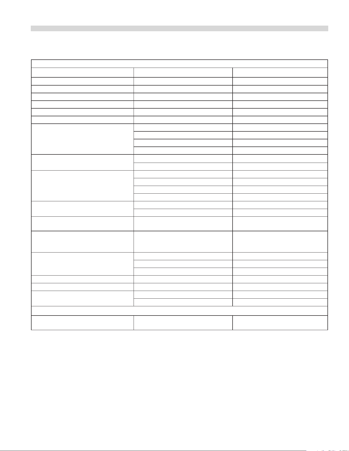
Document # G_GHD_OM_CUISINE_4605671 9/20 Page 31
Oven (Standard & Convection)
PROBLEM POSSIBLE CAUSE SOLUTION
Oven too hot or not hot enough Thermostat out of calibration Check Calibration
Burner ame too large Incorrect setting pressure or injector Check setting pressure and injector
Burner ame soft-yellow tip Insucient primary air Check aeration shutter setting
Flame lifts o burner ports Excessive primary air Check aeration shutter setting
Flame lights back to the injector Excessive primary air Check aeration shutter setting
Burner “pops” when turned o Excessive primary air Check aeration shutter setting
Delayed ignition Pilot ame too small Check pilot ame length
Burner ports blocked Clean burner
Incorrect aeration Check aeration shutter setting
Incorrect setting pressure Check setting pressure
Pilot burner will not ignite Pilot orice blocked Clean jet
Pilot adjusting screw closed Open and adjust ame
Pilot keeps going out Pilot ame too small Check pilot ame length
Loose thermocouple connection Tighten connection
Faulty thermocouple Replace thermocouple
Faulty gas/safety valve Replace valve
Low millivolt output on open circuit tests Pilot ame too small Adjust pilot ame length
Defective thermocouple Replace thermocouple
Millivolt output high in open circuit test
but low in closed circuit
Faulty gas/safety valve Replace valve
Millivolt output high on closed circuit
test but ame safety tap will not stay
open
Faulty gas/safety valve Replace valve
Door will not stay closed Insucient tension on springs Adjust tension
Broken spring Replace spring
Broken hinge link Replace
Door will not stay open Too much tension on springs Adjust tension
Door not closing on one side Door warped Replace door
Door not level or low in centre Trunion support loose Level and tighten
Trunion support worn Replace
Oven (Standard Only)
Burner ame shuts o when oven is at
the required temperature
Thermostat has incorrect by-pass rate Adjust by-pass or replace them
TROUBLESHOOTING GUIDE
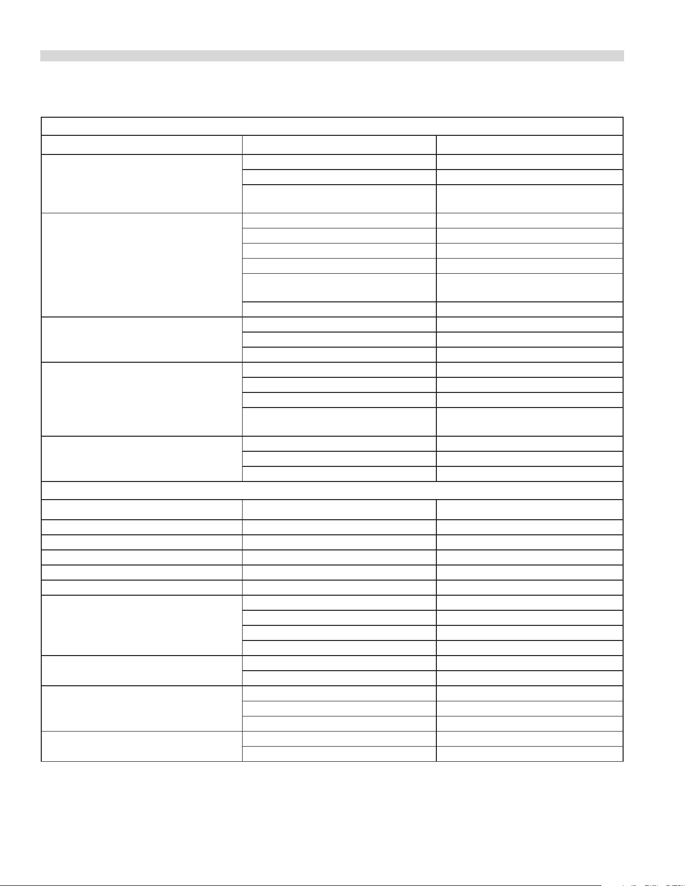
Document # G_GHD_OM_CUISINE_4605671 9/20Page 32
Oven (Convection Only)
Problem Possible Cause Solution
Cook/Cool Down switch set to “Cook”
position Light o Motor working
No power to oven Check power supply
Defective Cook/Cool down Switch Replace Switch
Faulty wiring Check condition of wires and all
connections
Cook/Cool Down switch set to “Cook”
position Light o Motor not working
Defective Cook/Cool Down switch Replace switch
Defective door switch Replace switch
Door switch out of alignment Align switch
Oven door open Close door
Faulty wiring Check condition of wires and all
connections
Defective motor Replace motor
Noisy motor Blower wheel rubbing on oven bae Adjust blower wheel
Blower wheel loose on motor shaft Retighten blower wheel
Defective motor Replace motor
Cook/Cool Down switch set to “Cool
Down” position Light on, motor not
working
Defective Cook/Cool Down switch Replace switch
Defective door switch Replace switch
Door switch out of alignment Align switch
Faulty wiring Check condition of wires and all
connections
No spark to pilots Disconnected or loose hi tension wires Reconnect hi tension wires
Defective spark module Replace module
No Power to range Check power supply
Open Top, Solid Hot Top, Griddles & Broilers
Problem Possible Cause Solution
Burner ame too large Incorrect setting pressure or injector Check setting pressure and injector
Burner ame soft-yellow tip Insucient primary air Check aeration shutter setting
Flame lifts o burner ports Excessive primary air Check aeration shutter setting
Flame lights back to the injector Excessive primary air Check aeration shutter setting
Burner “pops” when turned o Excessive primary air Check aeration shutter setting
Delayed ignition Pilot ame too small Check pilot ame length
Burner ports blocked Clean burner
Incorrect aeration Check aeration shutter setting
Incorrect setting pressure Check setting pressure
Pilot burner will not ignite Pilot orice blocked Clean jet
Pilot adjusting screw closed Open and adjust ame length
Pilot keeps going out Pilot ame too small Check pilot ame length
Loose thermocouple connection Tighten connection
Faulty thermocouple Replace thermocouple
Low millivolt output on open circuit tests Pilot ame too small Adjust pilot ame length
Defective thermocouple Replace thermocouple
TROUBLESHOOTING GUIDE Continued

Document # G_GHD_OM_CUISINE_4605671 9/20 Page 33
Notes

Document # G_GHD_OM_CUISINE_4605671 9/20Page 34
Notes

Document # G_GHD_OM_CUISINE_4605671 9/20 Page 35
THIS PAGE INTENTIONALLY LEFT BLANK
Welbilt oers fully-integrated kitchen systems and our products are backed by
KitchenCare® aftermarket parts and service. Welbilt’s portfolio of award-winning brands
includes Cleveland™, Convotherm®, Crem®, Deleld®, tkitchen®, Frymaster®,
Garland®, Kolpak®, Lincoln®, Manitowoc®, Merco®, Merrychef® and Multiplex®.
Bringing innovation to the table • welbilt.com
©2020 Welbilt Inc. except where explicitly stated otherwise. All rights reserved.
Part # U_GHD_OM_CUISINE_4605671 - 9/20
GARLAND COMMERCIAL RANGES, LTD.
1177 KAMATO ROAD, MISSISSAUGA, ONTARIO, CANADA L4W 1X4
888-442-7526
WWW.GARLAND-GROUP.COM