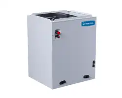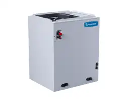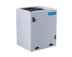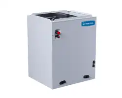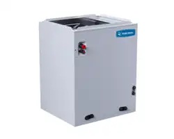
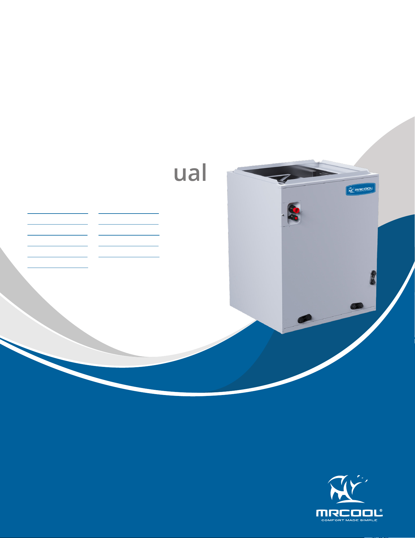
PRODIRECT™ Series
Multi-Position
Cased Coils
Installation &
Owner’s Manual
MODELS:
Read this manual carefully before installation and keep it where
the operator can easily nd it for future reference.
Due to updates and constantly improving performance, the
information and instructions within this manual are subject to
change without notice.
Version Date: 10/02/2024
Please visit www.mrcool.com/documentation
to ensure you have the latest version of this manual.
HCMP3036AFOA
HCMP3036BFOA
HCMP3036CFOA
HCMP3642BFOA
HCMP3642CFOA
HCMP3642DFOA
HCMP4248BFOA
HCMP4248CFOA
HCMP4248DFOA
HCMP4860CFOA
HCMP4860DFOA

mrcool.com1
CONTENTS
SAFETY ................................................................................................................... 2
UNIT OVERVIEW .................................................................................................... 3
2.1 Unit Dimensions ....................................................................................... 3
2.2 Codes & Regulations ............................................................................... 4
2.3 Initial Inspection ...................................................................................... 4
2.4 Clearances ................................................................................................. 4
INSTALLATION ...................................................................................................... 5
3.1 Replacement Parts ................................................................................... 5
3.2 Pre-Installation Instructions ................................................................... 5
3.3 Installation & Trap Connection .............................................................. 5
DRAIN APPLICATION ............................................................................................ 7
4.1 Condensate Drain Piping ........................................................................ 7
4.2 Plastic Drain Pan Installation ................................................................. 7
REFRIGERANT CONNECTIONS............................................................................. 8
PISTON/TXV INSTALLATION ................................................................................ 8
6.1 Piston Installation .................................................................................... 8
6.2 Optional TXV Kit Installation .................................................................. 9
AIRFLOW PERFORMANCE .................................................................................. 10
1
2
3
4
5
Contents
6
7
mrcool.com 2 2
Incorrect usage may cause serious damage or injury.
The symbols below are used throughout this manual to indicate instructions that should be
followed closely or actions that should be avoided to prevent death, injury, and/or property
damage.
Safety Precautions
CAUTION
Indicates the possibility of personal injury or loss of life.
Indicates the possibility of property damage or serious
consequences.
Read Before Using
WARNING
WARNING
• These instructions are intended as an aid to qualied licensed service personnel for proper installation,
adjustment, and operation of this unit. Read these instructions thoroughly before attempting installation
or operation. Failure to follow these instructions may result in improper installation, adjustment, service, or
maintenance possibly resulting in re, electric shock, property damage, personal injury, or death.
• This appliance is not intended for use by persons (including children) with reduced physical, sensory or
mental capabilities, or lack of experience and knowledge, unless they have been given supervision or
instruction concerning use of the appliance by a person responsible for their safety.
• Children should be supervised to ensure that they do not play with the appliance.
• Proposition 65: This appliance contains berglass insulation. Respirable particles of berglass are known to
the state of California to cause cancer. For more information, go to www.P65Warnings.ca.gov.
• Disconnect all power to the unit before starting any service and maintenance. Failure to do so could cause
severe electrical shock resulting in personal injure or death.
• Installation or servicing of this unit can be hazardous due to parts, components and system pressure.
• Qualied and proper trained service personnel should perform installation and repair. Failure to do so
could cause severe electrical shock resulting in personal injury or death.
• This is a safety alert symbol indicating a potential hazardous situation ,which could result in personal
injury, property and/or product damage or death.
SAFETY
1
mrcool.com3
2.1 Unit Dimensions
UNIT OVERVIEW
2
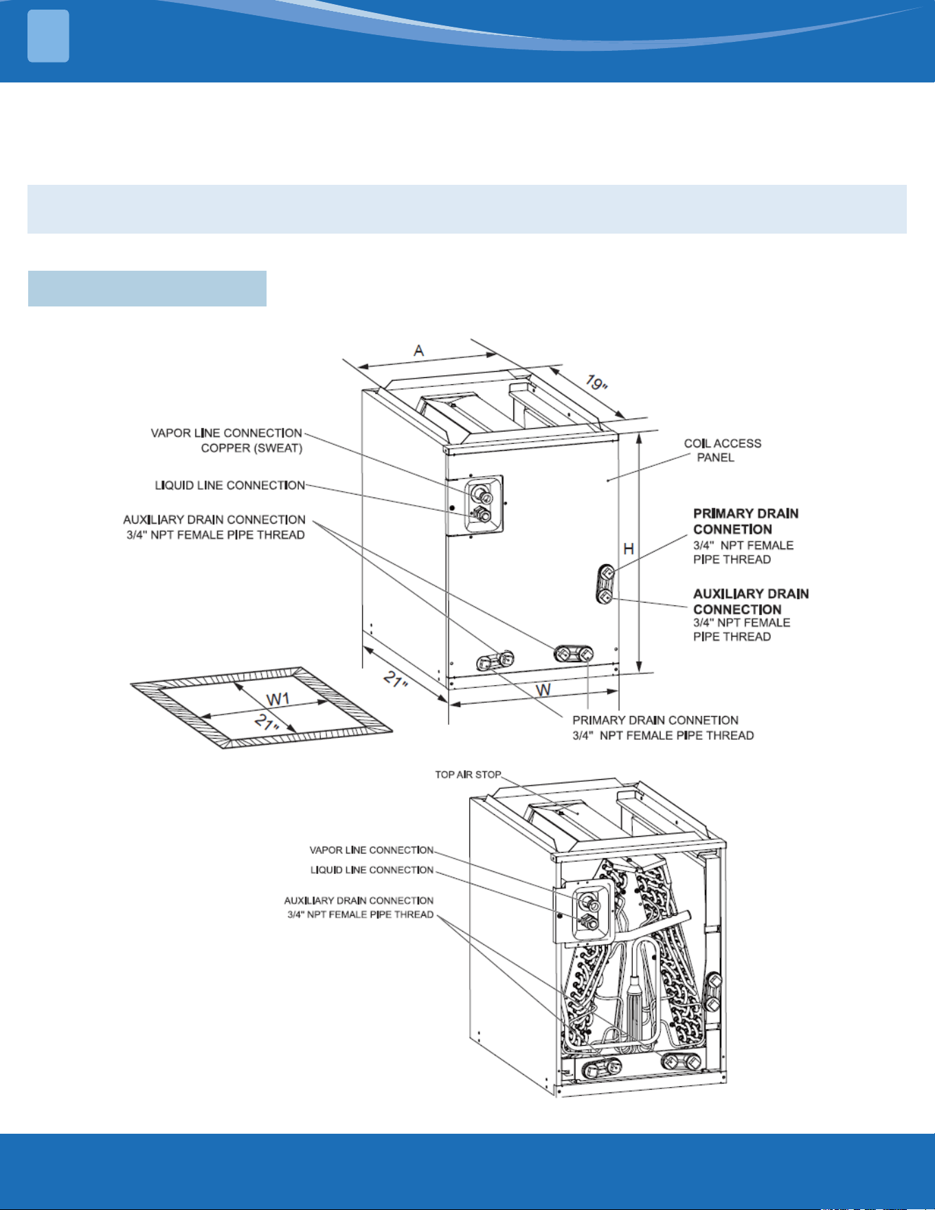
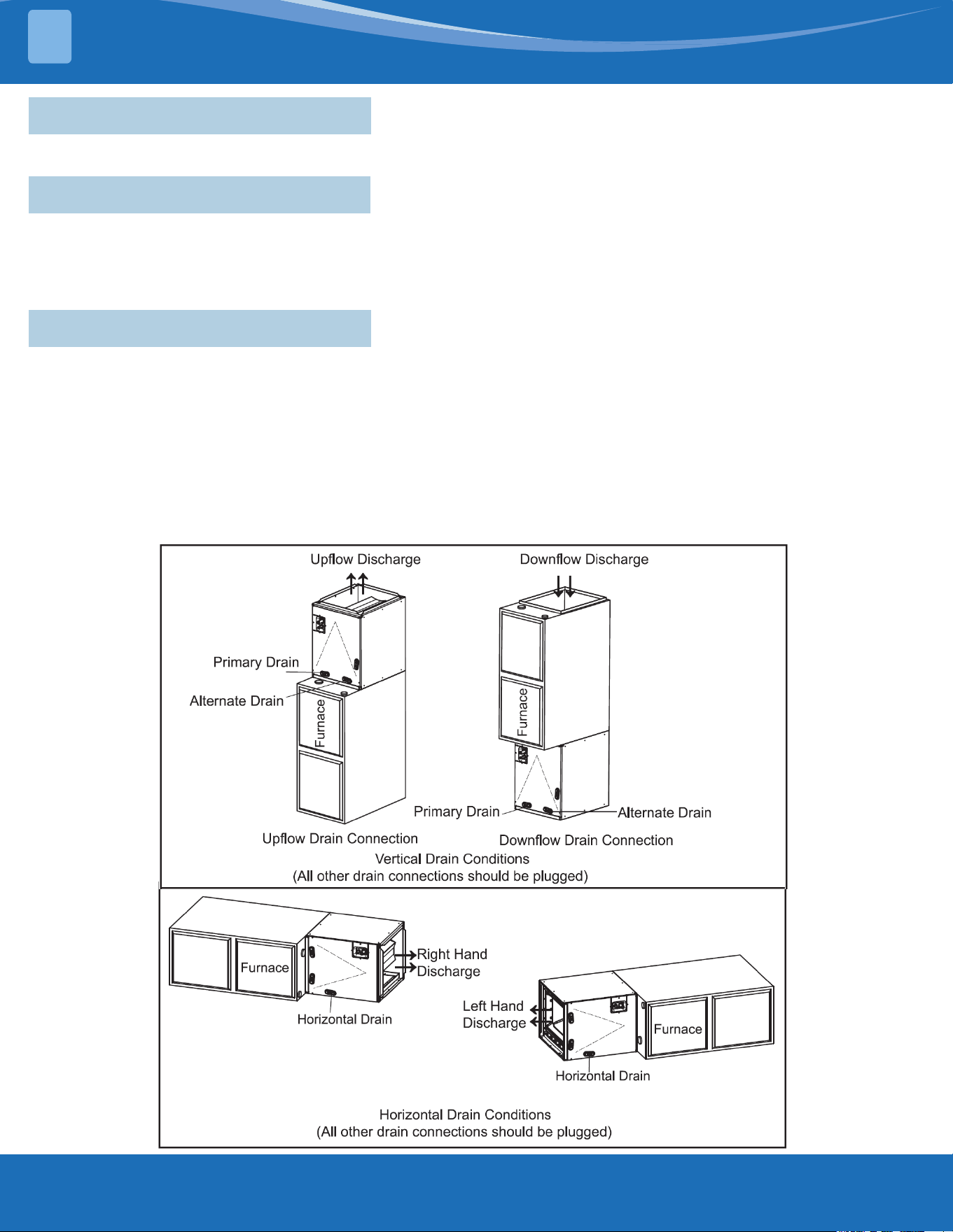
The coil can be positioned for bottom return air in the upow and horizontal right applications. It must be
positioned for top return when in downow and horizontal left applications. For furnace applications, the coil
must be installed downstream (in the air outlet) of the furnace.
NOTE:
This coil comes with a factory-installed heat shield on the drain pan.
mrcool.com 4
4
2.2 Codes & Regulations
This product is designed and manufactured to comply with national codes and regulations.
Installation in accordance with such codes and/or prevailing local codes/regulations is the responsibility of the
installer. MRCOOL
®
assumes no responsibility for equipment installed in violation of any codes or regulations.
The United States Environmental Protection Agency (EPA) has issued various regulations regarding the introduction
and disposal of refrigerants. Failure to follow these regulations may harm the environment and can lead to the
imposition of substantial nes. Should you have any questions, contact your local EPA oce.
UNIT OVERVIEW
2
Unit Dimensions
Model
Height "H"
(in. [mm])
Width "W"
(in. [mm])
Supply Duct "A"
(in. [mm])
"W1"
(in. [mm])
Liquid Line/
Vapor Line
Weight
(lbs.[kg])
HCMP3036AFOA 20" [508] 14-1/2" [368] 13" [330] 13-1/2" [343] 3/8" / 3/4" 46 [21]
HCMP3036BFOA 20" [508] 17-1/2" [445] 16" [407] 16-1/2" [419] 3/8" / 3/4" 49 [22]
HCMP3036CFOA 20" [508] 21" [533] 19-1/2" [495] 20" [508] 3/8" / 3/4" 51 [23]
HCMP3642BFOA 26" [660] 17-1/2" [445] 16" [407] 16-1/2" [419] 3/8" / 7/8" 60 [27]
HCMP3642CFOA 26" [660] 21" [533] 19-1/2" [495] 20" [508] 3/8" / 7/8" 62 [28]
HCMP3642DFOA 26" [660] 24-1/2" [622] 23" [584] 23-1/2" [597] 3/8" / 7/8" 66 [30]
HCMP4248BFOA 30" [762] 17-1/2" [445] 16" [407] 16-1/2" [419] 3/8" / 7/8" 73 [33]
HCMP4248CFOA 30" [762] 21" [533] 19-1/2" [495] 20" [508] 3/8" / 7/8" 73 [33]
HCMP4248DFOA 30" [762] 24-1/2" [622] 23" [584] 23-1/2" [597] 3/8" / 7/8" 77 [35]
HCMP4860CFOA 30" [762] 21" [533] 19-1/2" [495] 20" [508] 3/8" / 7/8" 81 [37]
HCMP4860DFOA 30" [762] 24-1/2" [622] 23" [584] 23-1/2" [597] 3/8" / 7/8" 86 [39]
2.3 Initial Inspection
As soon as the unit is received, it should be inspected and noted for possible shipping damage during transportation.
It is the carrier's responsibility to cover the costs of shipping damage. MRCOOL
®
will not accept a claim from
contractors for any transportation damage.
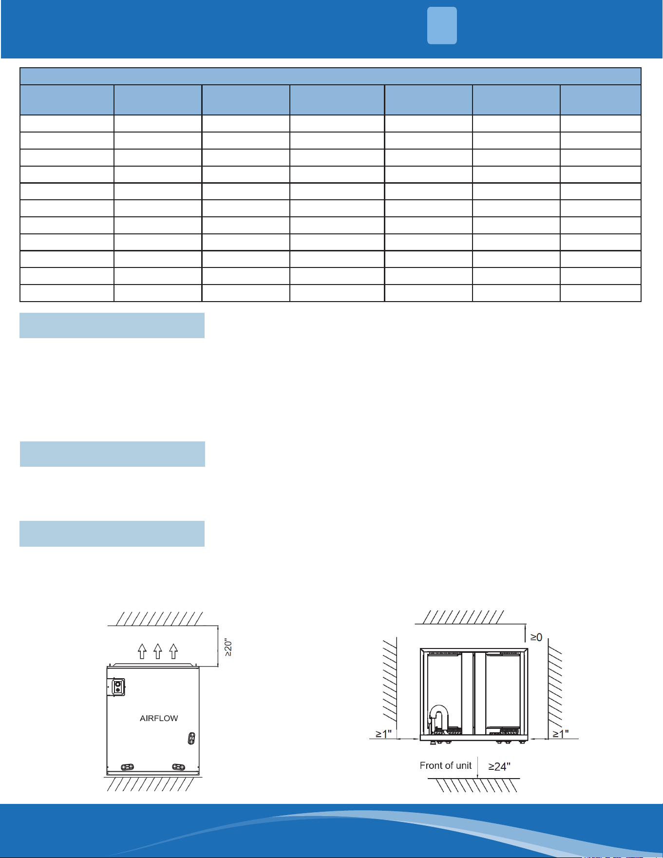
2.4 Clearances
During installation, maintain clearance for maintenance and service access, including coil cleaning and coil
assembly removal, refrigerant piping and connections, and the condensate drain line.
To ensure a proper installation, select a solid and level location site, and ensure there is enough space for
installation and maintenance.
Front View of Indoor Unit (including air duct) Top View of Indoor Unit (including air duct)
mrcool.com5
INSTALLATION
3
3.1 Replacement Parts
Contact MRCOOL
®
for authorized replacement parts.
3.2 Pre-Installation Instructions
Carefully read all instructions for installation prior to installing the unit. Ensure each step or procedure is
understood and take into account any special considerations before starting the installation process. Assemble all
tools, hardware, and supplies needed to complete the installation. Some items may need to be purchased locally.
Make sure everything needed to install the unit is on hand before starting.
3.3 Installation & Trap Connection
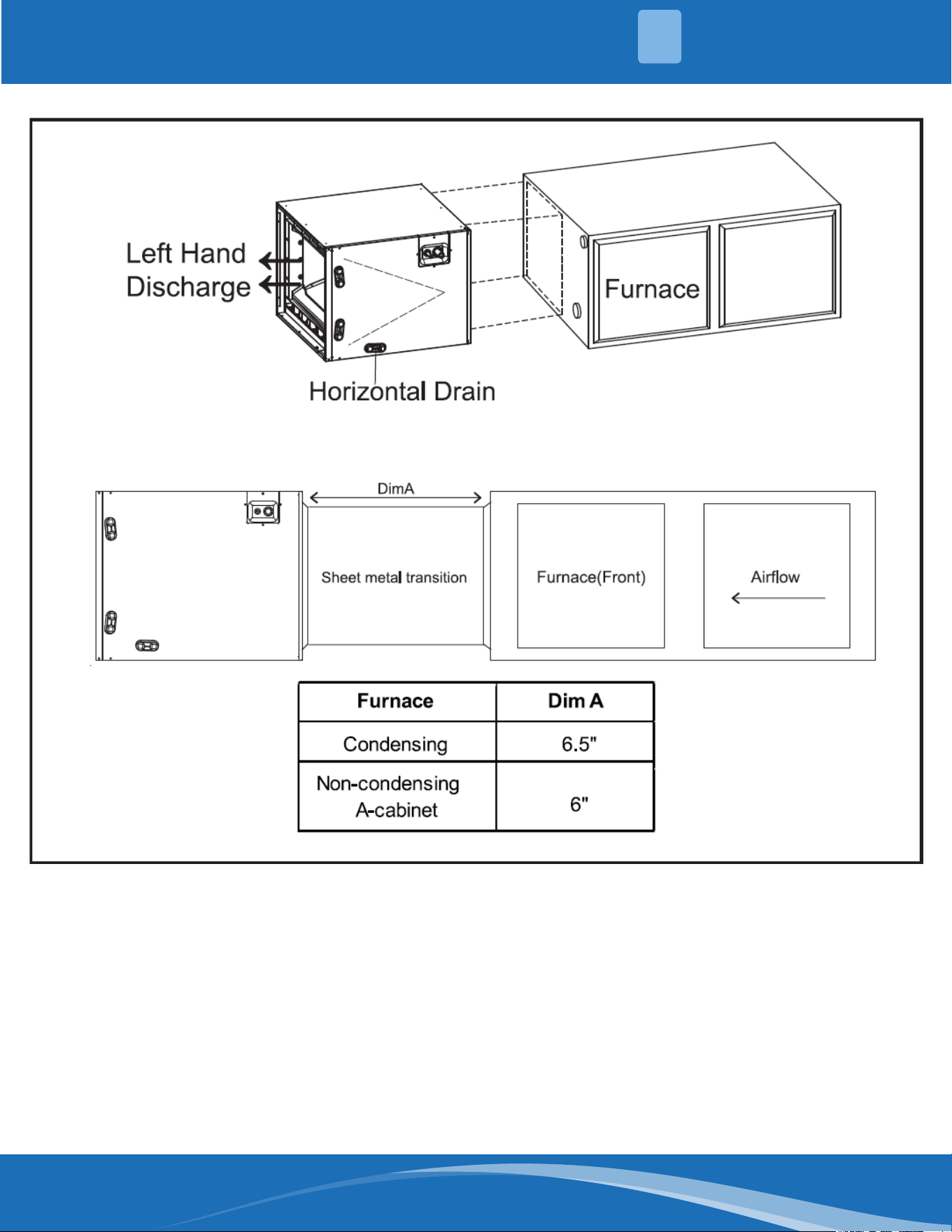
See the gures below for coil installation and drain connection.
Installation steps for cased coil:
1. Shut o or disconnect gas furnace's power and remove the gas pipe if necessary.
2. Disconnect and remove a sucient portion of the supply ductwork to provide clearance for the cased coil.
3. Ensure that the coil is leveled well and seal the gap between the coil and the furnace. (If the coil and furnace
sizes do not match, use the proper size of sheet metal or other material to ll the gap, then seal the gap to
prevent air leakage.)
4. Reconnect the power line on the gas furnace. Turn on the furnace to check for any sign of leakage.
mrcool.com 6
6
INSTALLATION
3
Transition for Horizontal Left Orientation
If the coil is used in connection with an upow furnace in horizontal left orientation, a sheet metal transition can
be installed between the furnace supply air outlet and the evaporator coil supply air inlet to create clearance
between the coil lineset and the furnace ue outlet for A-cabinet non-condensing furnaces and for all cabinet size
condensing furnaces.
For A-cabinet non-condensing furnaces, a 6" transition is needed.
For all cabinet size condensing furnaces, a 6.5" transition is needed.
If space is a constraint, the lines/ue interference can be removed by rotating the coil so the lineset is facing the
opposite direction and air ows through the bottom of the A-coil, thus optimizing airow.
mrcool.com7
DRAIN APPLICATION
4
4.1 Condensate Drain Piping
Consult local codes for special requirements.
To provide extra protection from water damage, it is
always recommended to install an additional drain pan,
provided by the installer, under the entire unit with a
separate drain line. MRCOOL
®
will not be responsible
for any damages due to the failure to follow these
recommendations.
4.2 Plastic Drain Pan Installation
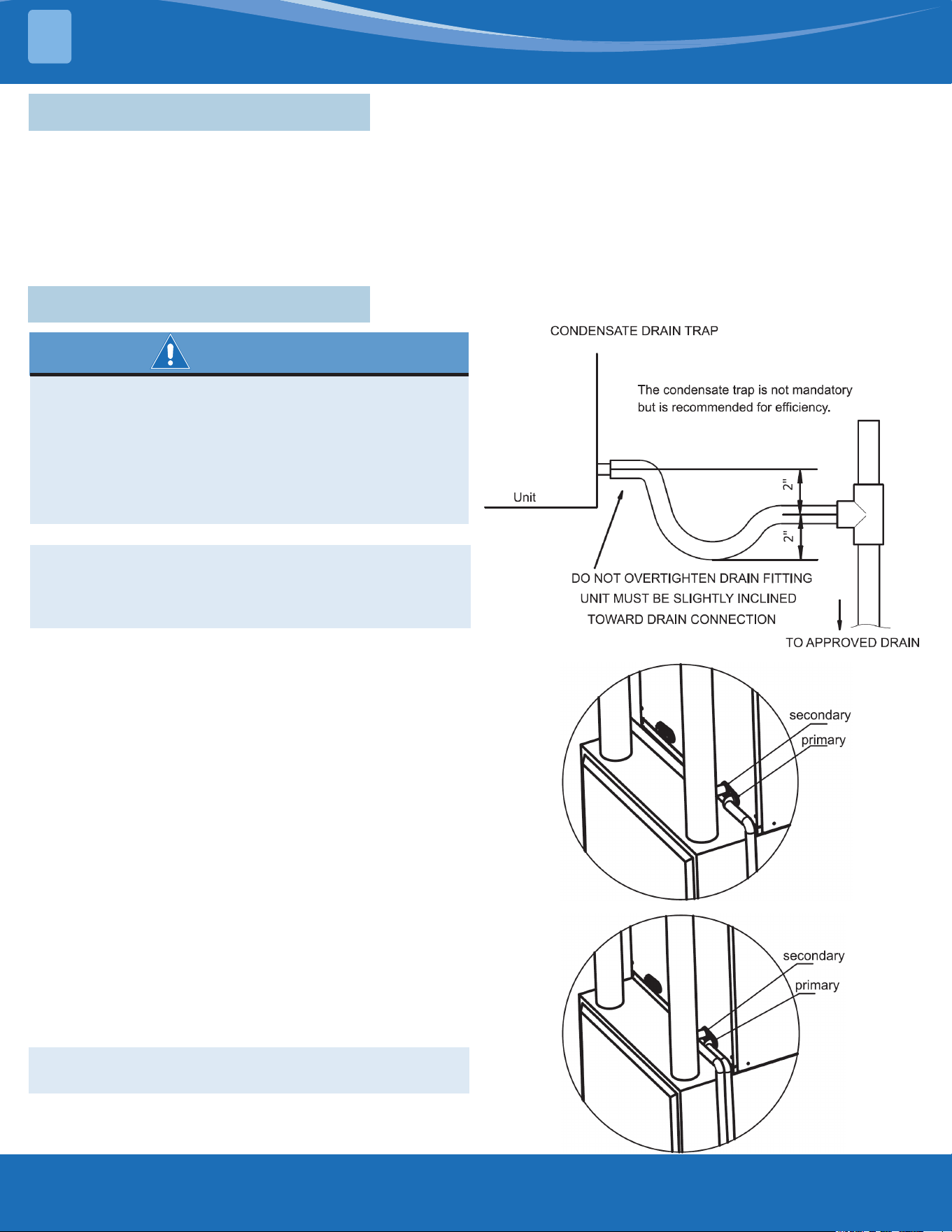
The coil drain pan has a primary and an optional
secondary drain pan with 3/4" NPT female connections;
use either PVC or copper pipe and hand-tighten to a
torque of approximately 37 in-lbs. to prevent damage to
the drain pan connection. An insertion depth between
0.355 to 0.485 inches (3-5 turns) should be expected at
this torque setting.
Use male 3/4" NPT threaded tting for outside connection
and make sure the drain holes are not blocked.
Insulation may be needed for the drain line to prevent
sweating.
The drain pan has two drain connections on each side
to provide exibility of connection and drainage. Make
sure the pan has a proper pitch and is plugged if the
second connection is not used.
If the secondary drain line is required, run the line
separately from the primary drain and terminate it
where it can be easily seen.
WARNING
Do not use the coil pan shipped with the unit on oil
furnaces or any application where the temperature
of the drain pan may exceed 275°F. A eld-fabricated
metal drain pan can also be used for these types of
applications.
Failure to follow this warning may result in property
damage and/or personal injury.
NOTE:
Use Teon tape on the drain line connections. Do not
use pipe joint compound or PVC/CPVC cement on the
drain nipple.
NOTE: Water coming from this line means the coil's
primary drain is plugged and needs cleaning.
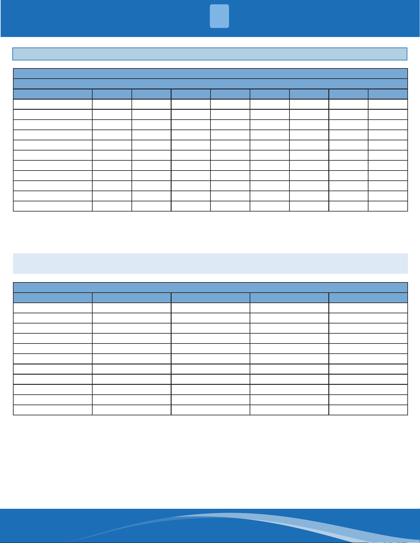
Install a trap in the drain line below the bottom of the
drain pan. If using a copper drain line, solder a short
piece of pipe to the connector before installing a drain
tting. DO NOT over-torque the 3/4" copper connector
to the plastic drain connection. Use a wet rag or heat-
sink material on the short piece to protect the plastic
drain pan, and complete the drain line installation. Use
the gures below as a template for a typical drain pipe
routing.
This gure shows how to avoid an interference with
vent piping.
mrcool.com 8
8
REFRIGERANT CONNECTIONS
5
5 - Refrigerant Connections
CAUTION
When using the unit with an electrical heater, the
switch is used only for the electrical heater on the
front of the panel.
To prevent a refrigerant leak, use proper tools to ensure
a clean, burr-free cut.
CAUTION
TXV bulb MUST be protected (wrapped with
wet cloth) or removed while brazing the tubing.
Overheating of the sensing bulb will aect the
functional characteristics and performance of the
comfort coil.
Use brazing shield when brazing close to the cabinet
surface and wet rag to protect rubber grommet.
Brazing alloy should be at least 5% silver content.
6 - Piston/TXV Installation
NOTE: A piston does come pre-installed. The piston
must be removed before installing a TXV.
6.1 Piston Installation
NOTE: A piston does come pre-installed. The piston
must be removed before installing a TXV.
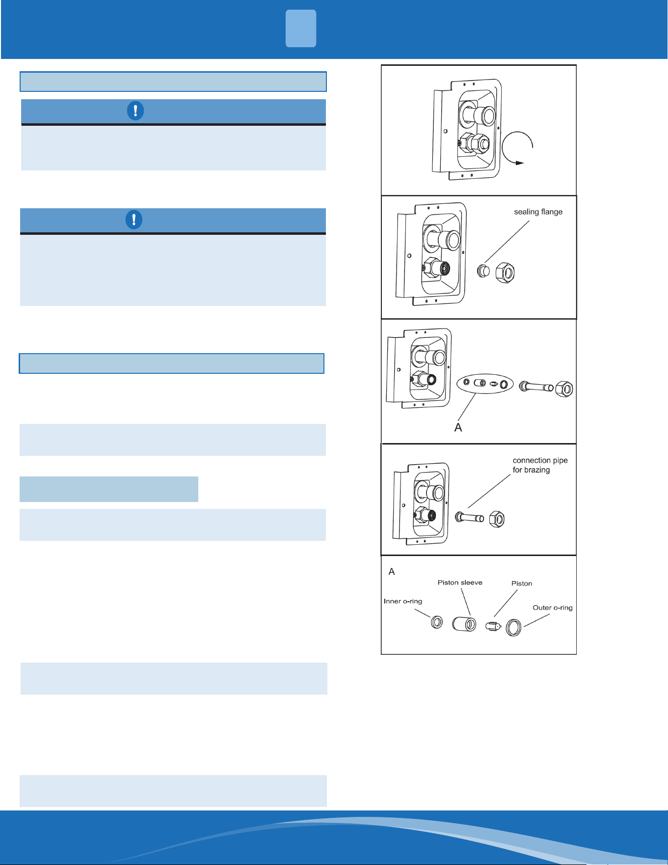
1. Using a wrench to loosen the nut. Remove the nut
and sealing ange.
2. Check the piston sizes for each outdoor/coil
combination in Table 6.1 and choose the correct
orientation.
3. If a dierent-sized piston is needed for your specic
system combination, remove the pre-installed
piston.
4. Choose the correct size piston and insert it with the
correct orientation.
5. Replace the outer O-ring with the O-ring provided.
6. Attach the connection pipe with the nut and hand-
tighten, plus an additional 1/6th turn.
NOTE: Avoid pulling the piston sleeve out when
removing the pre-installed piston.
IMPORTANT: Wrap the nut with a wet rag before
brazing.
This coil comes with a factory-installed piston metering
device. See table 6.1 for factory-installed piston sizes.
Some system combinations will require a dierent
sized piston to be eld-installed.
• Use the piston size recommended by the outdoor
unit, if available.
• Reference table 6.2 if the outdoor unit does not list
a piston size.
• Additional R-410A pistons for most applications are
shipped with the unit. Contact MRCOOL to order
the appropriate piston if needed.
mrcool.com9
INSTALLATION
6
6.2 Optional TXV Kit Installation
Reference the TXV kit literature for installation
instructions.
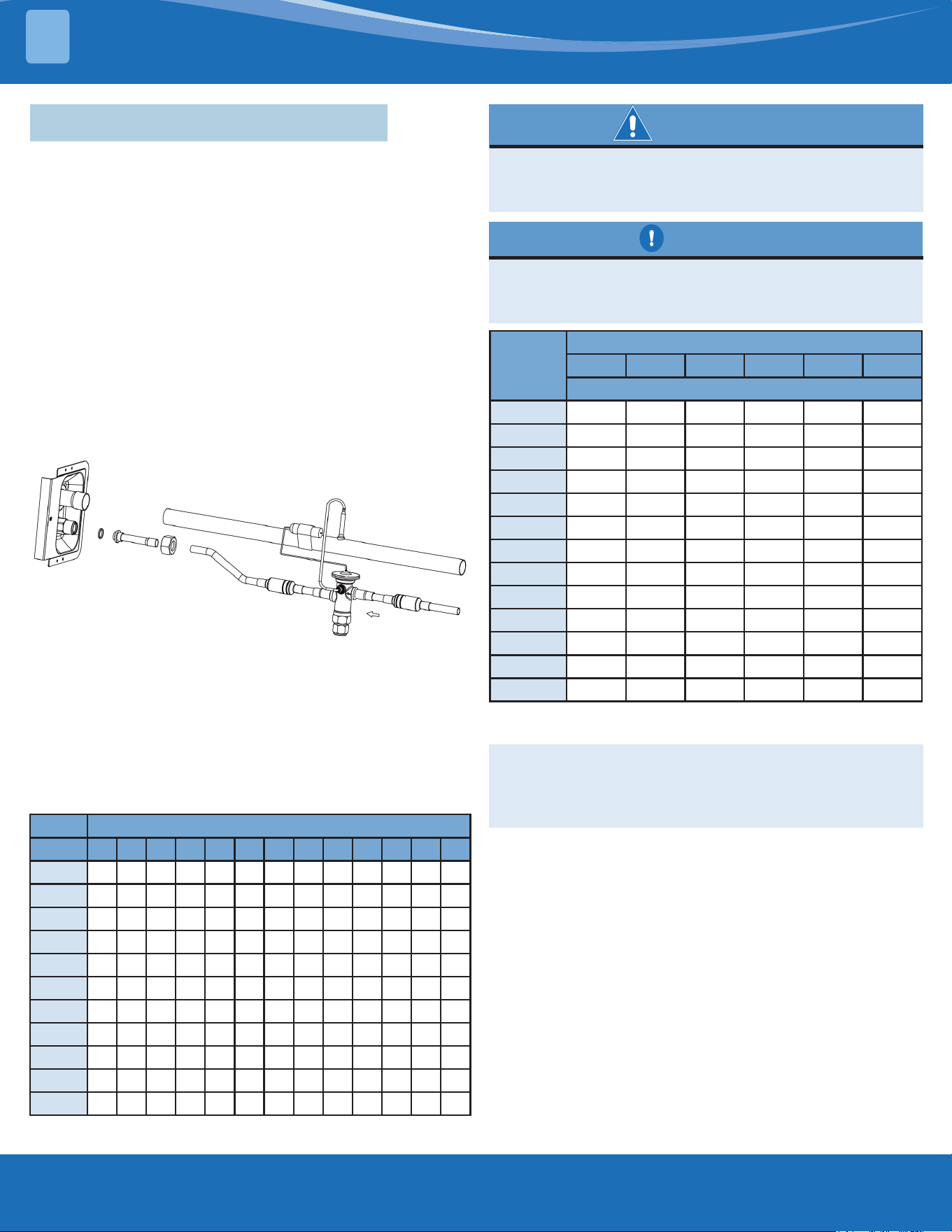
1. Use a wrench to loosen the nut and remove the
sealing ange and sealing gasket.
2. Take out the connecting pipe and braze it onto the
refrigeration-out pipe.
3. Install the sealing washers, TXV, and ange
connection tube.
4. Use a wrench to fasten the nut and connecting pipe
(18
±
2N•m).
5. Connect TXV equalizer pipe to the port on the
connecting pipe.
6. Attach bulbs on the connecting pipe using materials
included with the TXV kit.
A TXV may be required to achieve minimum eciency
ratings or for long refrigerant line set applications.
Reference AHRI for system combination ratings.
Reference Table 6.2 to charge the system by superheat
when using the piston.
Reference the outdoor unit installation guide to charge
the system when using a TXV.
MCPM Piston/Orice Sizes
Model 50 52 56 58 60 64 68 70 73 75 80 83 90
3036A X X X X* X
3036B X X X X* X
3036C X X X X* X
3642B X X X X X*
3642C X X X X*
3642D X X X X*
4248B X X X X X*
4248C X X X X*
4248D X X X*
4860C X X X X*
4860D X X X X*
Table 6.1
WARNING
Failure to install the proper piston can lead to poor
system performance and possible compressor
damage.
CAUTION
When using the unit with an electrical heater, the
switch is used only for the electrical heater on the
front of the panel.
Outdoor
Temp
(°F)
Indoor Temperature (°F) Dry Bulb/Wet Bulb
50 52 56 58 60 64
Superheat
115 23 16 7 5 5 5
110 24 17 9 5 5 5
105 26 19 11 5 5 5
100 27 21 13 7 5 5
95 29 23 16 9 5 5
90 30 25 18 12 5 5
85 35 26 20 14 8 5
80 34 28 22 17 11 5
75 35 30 24 19 13 6
70 37 32 26 21 16 10
65 38 34 29 24 19 13
60 40 36 31 27 22 17
55 41 37 33 29 25 21
NOTE: The chart is based on 400CFM/Ton indoor
airow and 50% relative humidity. If indoor relative
humidity is above 70% or below 20%, use indoor wet
bulb temperature only.
Table 6.2
mrcool.com 10
10
AIRFLOW PERFORMANCE
7
Maximum Airow Setting (CFM)
Model Upow Horizontal Left Downow Horizontal Right
HCMP3036AFOA 1200 1050 1050 1200
HCMP3036BFOA 1250 1200 1050 1250
HCMP3036CFOA 1250 1200 1050 1250
HCMP3642BFOA 1575 1400 1400 1575
HCMP3642CFOA 1575 1400 1400 1575
HCMP3642DFOA 1575 1450 1450 1575
HCMP4248BFOA 1800 1800 1700 1500
HCMP4248CFOA 1800 1800 1700 1700
HCMP4248DFOA 1800 1800 1700 1700
HCMP4860CFOA 1850 1750 1750 1850
HCMP4860DFOA 2000 1850 1850 2000
NOTE: Water blow-o could occur in certain installation positions if the airow setting exceeds the maximum
values listed.
Data based on wet coil with entering air at 80°F DB / 67°F WB without air lter.
The maximum allowable pressure drop is 0.4 IWG.
The maximum CFM is the data at 0.4 IWG pressure.
Pressure Drop Characteristics for Cooling and Heat Pump Coils
Pressure Drop (inches of water)
Model 0.05 0.1 0.15 0.2 0.25 0.3 0.35 0.4*
HCMP3036AFOA 307 485 618 729 823 911 991 1063
HCMP3036BFOA 327 527 682 810 925 1024 1122 1217
HCMP3036CFOA 360 585 748 893 925 1024 1122 1217
HCMP3642BFOA 401 600 773 916 1045 1160 1256 1357
HCMP3642CFOA 457 663 856 1019 1156 1277 1394 1502
HCMP3642DFOA 496 718 924 1102 1259 1398 1530 1651
HCMP4248BFOA 456 638 810 953 1077 1191 1284 1390
HCMP4248CFOA 505 726 932 1098 1244 1375 1494 1604
HCMP4248DFOA 533 857 1105 1319 1509 1675 1824 1956
HCMP4860CFOA 439 699 906 1071 1224 1362 1487 1589
HCMP4860DFOA 466 764 978 1157 1313 1466 1590 1695
7 - Air Flow Performance

PRODIRECT™ Series
Multi-Position
Cased Coils
The design and specications of this product and/or manual are subject to change without prior notice.
Consult with the sales agency or manufacturer for details.