ENEN
User’s manual
ZONA PER
TARGHETTA
REFRIGERATORS
SERVICE
MANUAL
TROUBLE SHOOT
MODEL
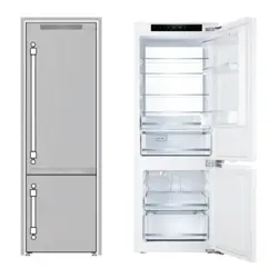
URBM22 - 24" Bottom Freezer Refrigerator
URBM28 - 28" Bottom Freezer Refrigerator
EN
1 646-444-8054 | [email protected] | US.ILVE.COM | ©ILVE USA 2026. ALL RIGHTS RESERVED.
Refrigerator
Serial Number ........................................................................................................ 3
Safety Information .................................................................................................. 4
Installation, Electrical & Plumbing Requirements ....................................................... 6
Theory of Operation ................................................................................................ 7
Refrigerator Components ........................................................................................ 8
Freezer Components ..........................................................................................
9
Rear & Compressor Area Components .................................................................
11
Gas Flow Diagram & Parts ..................................................................................
12
Electrical Components & Specifications ..................................................................... 13
Display Panel Set Up Instructions ............................................................................ 14
Error Codes & Control Board Connections ............................................................
17
F2 & F3 ..............................................................................................................
18
F4 & F5 ..............................................................................................................
19
F6 .....................................................................................................................
20
CE
....................................................................................................................
21
2E& DR .......................................................................................................
22
Maintenance guide for refrigeration failure & High Temp Error ................................... 23
Temperature to Resistance Chart ..............................................................................
24
Wiring Diagram ......................................................................................................
25
Control Board Test Points ........................................................................................ 26
Main control board led flashing fault ........................................................................ 27
Control Board ......................................................................................................... 28
Display .................................................................................................................. 29
Ice Maker .............................................................................................................. 30
Sensor ..............................................................................................................
31
Light Switch ...........................................................................................................
32
LED Light ..........................................................................................................
33
Refrigerator rail removal ......................................................................................... 34
Refrigerator the Rear Wall ...................................................................................... 35
Freezer the Rear Wall ............................................................................................. 36
Defrost Element & Thermal Fuse+.......................................................................... 37
Troubleshooting .....................................................................................................
38
2
SERVICE MANUAL
Refrigerator
SERVICE MANUAL
3
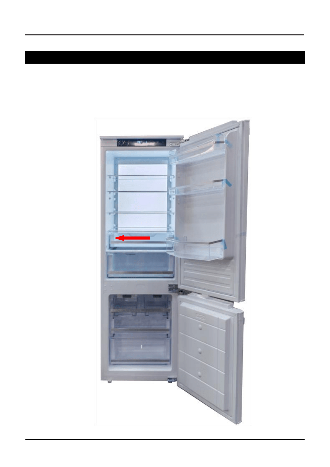
Serial Number
The serial tag is located on either the upper left-hand wall of the refrigerator section, or
bottom of the compartment, beneath the large crisper drawer.
Refrigerator
4
SERVICE MANUAL
SAVE THESE INSTRUCTIONS
REVIEW ALL SERVICE INFORMATION IN THIS SERVICE MANUAL BEFORE
BEGINNING REPAIRS.
This product should only be serviced by a qualified service technician,
who is familiar with the standard safety producers required for servicing
this product. The technician should be equipped with the proper tools,
parts, and test equipment before beginning.
Safety Information
We have provided many important safety messages in this manual and on the appli-
ance. ALWAYS READ AND OBEY ALL SAFETY MESSAGES.
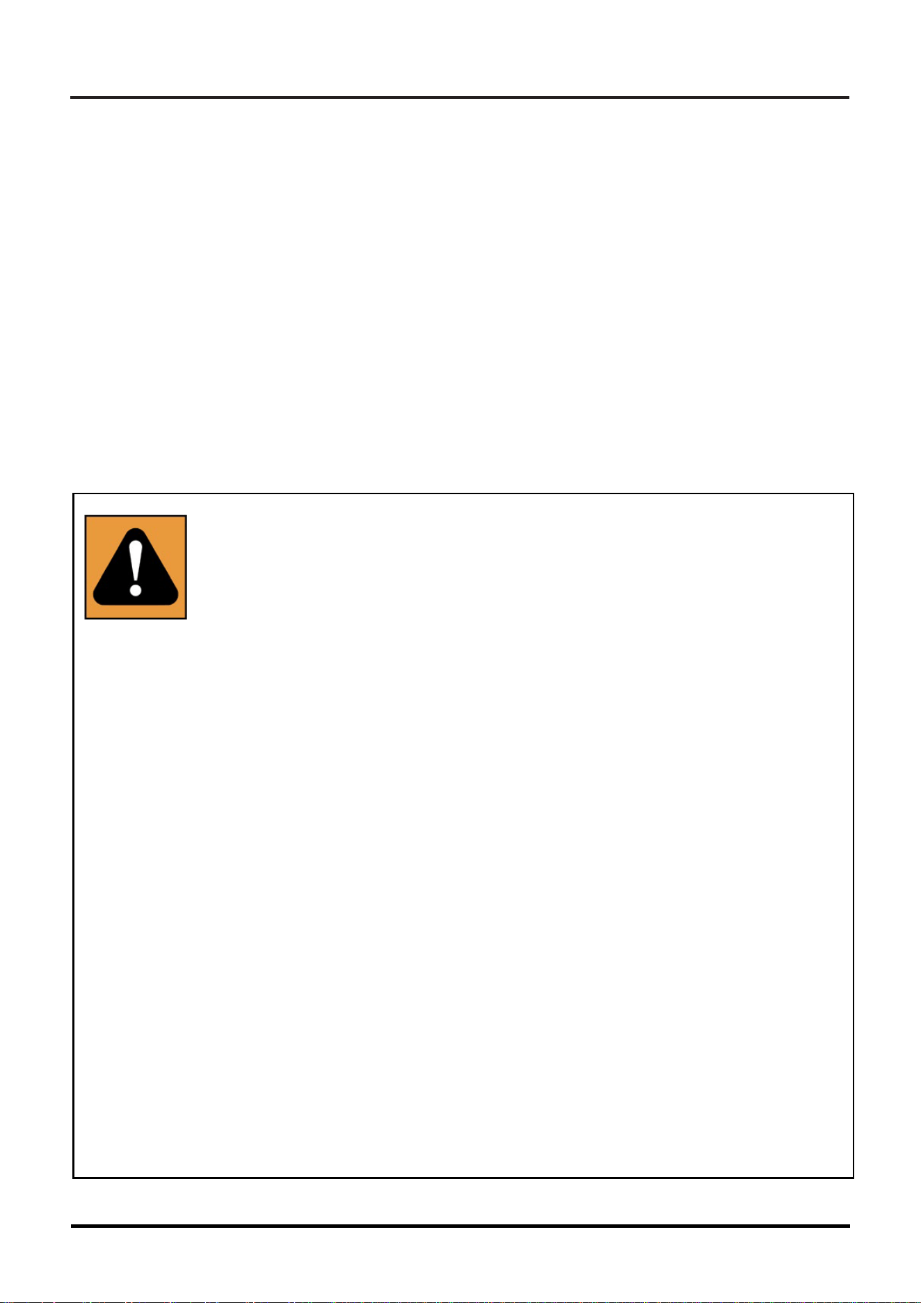
This is the safety alert symbol
This symbol alerts you to hazards that could
cause death or injury to you or others, or cause
damage to product or property. Each occur-
rence will identify the hazard, describe how to
reduce the chance of injury, and describe what
can happen if the instructions are not followed.
The symbol will be surrounded by a color which
corresponds to are particular type of hazard.
Red for DANGER, Orange for WARNING, and
Yellow for CAUTION.
These categories are defined in the boxes to the
right
Refrigerator
SERVICE MANUAL
5
Safety Instructions
The manufacturer reserves the right to make changes in the technical specifications
in order to improve the appliance quality without any prior notice. Figures included in
this manual are for schematic purposes only and may not match the appliance exactly.
Values stated on the markings of the appliance, or in other printed documents supplied
with the appliance, are obtained under laboratory conditions as per relevant standards.
These values may vary according to the usage of the appliance and ambient conditions.
Proper Installation - Be sure your appliance is properly installed and grounded by a
qualified technician.
If the supplied electrical cord is damaged, it must be replaced by a power cord or as-
sembly from the manufacturer. It must also be installed by a qualified service techni-
cian.
Service repairs must always be performed by an Authorized Servicer. Instal-
lations must be performed by a Certified Installer (This can include certified
and licensed electrician or plumbers. The Manufacturer cannot be held re-
sponsible for damages caused by operations performed by unauthorized, un-
certified or unlicensed persons.
• If the refrigerator is malfunctioning, it must not be operated until it is repaired by an
Authorized Servicer. There is a risk of electrical shock!
• The unit should be plugged into a three-prong, grounded and polarized 10A, 110V,
60Hz dedicated wall outlet. Our company will not be responsible for damages in-
curred while using the product in a way that does not comply with the electrical
code of the location where the product is installed.
• If the unit is not going to be used for an extended period of time, turn off the power
to it via the circuit breaker, shut of the water supply, and leave the doors open.
• Never wash the refrigerator by spraying or pouring water on it. There is a risk of
electric shock!
• Caution should be used when unplugging the unit for service. Make sure your hands
are not wet, and always hold the plug when disconnecting from the outlet, not the
cord. If the outlet is loose, have a licensed electrician repair or replace the outlet.
• This unit was designed to operate on a normal 60Hz, 110VAC electrical grid system.
If it is connected to any energy saving system, alternative power, or solar power sys-
tem, etc. and is experiencing any operational issues, please contact your local elec-
trical provided for further information.
• Shut off power to the refrigerator at the circuit breaker during installation, cleaning
near exposed electrical components, or service repairs.
Refrigerator
6
SERVICE MANUAL
1 3/4” (4cm) between them.
WARNING: A damaged power cord must be replaced by an Authorized
Service Technician.
Installation, Electrical & Plumbing Requirements
• The refrigerator must not be located too close to a heat source. Be sure it is installed at
least 12” (30cm) from cooktops, ovens, radiators or stoves, and at least 2” (5cm) from
electric ovens. Also, be sure the unit is not subject to direct sunlight or exces-sively humid
locations.
• Do not install the refrigerator in place where the temperature falls below 50OF/10OC.
• Do not block the ventilation grill in the bottom to ensure proper ventilation (cooling
air intake).
• This product requires a 110VAC, 50Hz service.
• The electrical connection must comply with national regulations.
• Be sure power cable is accessible after installation.
• Do not make connections via extension cords or multi-plugs.
• Rated total current draw is 0.8A. A circuit breaker above this amount must be used, in
compliance with local regulations.
• GFCI outlets will provide added protection, but any failure of the GFCI could cause
food spoilage, which is not covered by the manufacturer’s warranty.
SERVICE MANUAL
7
Refrigerator
Theory of Operation
Compressor & Evaporators
The refrigerator has one evaporators, but only one compressor, charged with R600a refrigerant.
Display
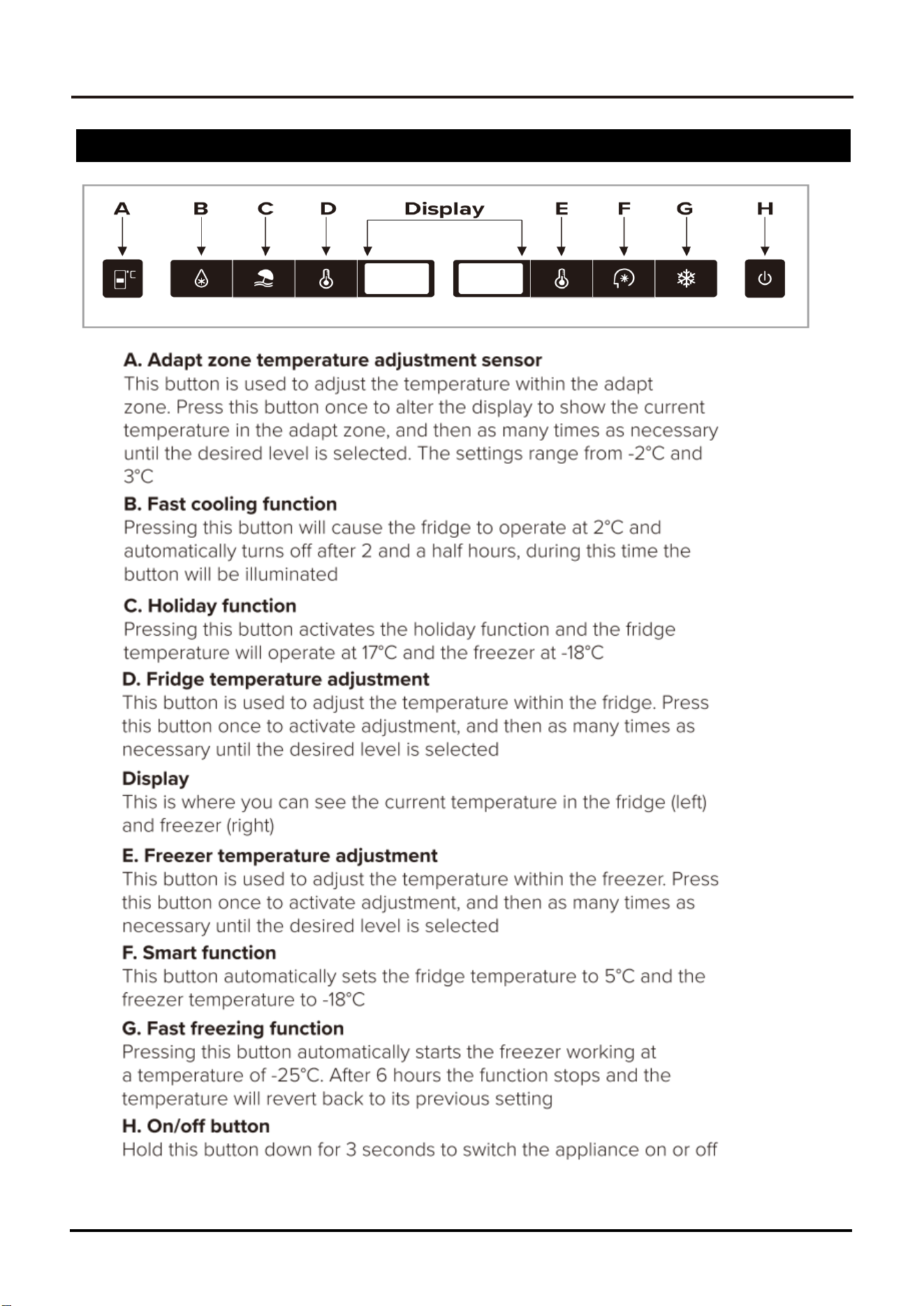
The Display is the operational interface for the customer. For information about each key and option, see the
description below
Temperature Sensors
There are five thermistors on this product - One for the Special fridge (Air ), One for the Chiller (Air ), One for
theAmbient Temperature Sensor, Two for the Freezer (Air & Evaporator).All of these sensors are NTC
thermistors.Temperature information is transmitted to the main board via changes in their resistance.
These thermistors ensure that the product operates according to the parameters set by the system software.
Heating Elements
There are one heating elements on this refrigerator - a Freezer Heater (evaporator),
the maximum defrosting time is limited to less than 50 minutes. When the sensor detects the temperature ≥ 46℉/8 ℃
during defrosting, the defrosting willbe stopped. After defrosting, delay 5 minutes for the compressor
to start, and 3 minutes for the fan to run after the compressor starts.
Fans
There are one fans on this product - a Freezer Fan 12VD
.
C
Ice Makers
There are a 115VAC motor twist the ice trays to eject the ice cubes.
A water valve is used to send water to the ice trays after each ice harvest. Use a flow meter to measure the
amount of water. A solenoid on the main water valve assembly is energized for the time set by the system
software.
Lights
12VDC LED light boards are used to illuminate fridge. Reed switches at the under of the doors activate the
lights when a door is opened.
Controller
All the components listed above are operated by the Main Control Board located at the under of the
product. Access to this, and all other components, is explained in the disassembly section of this manual.
8
SERVICE MANUAL
Refrigerator
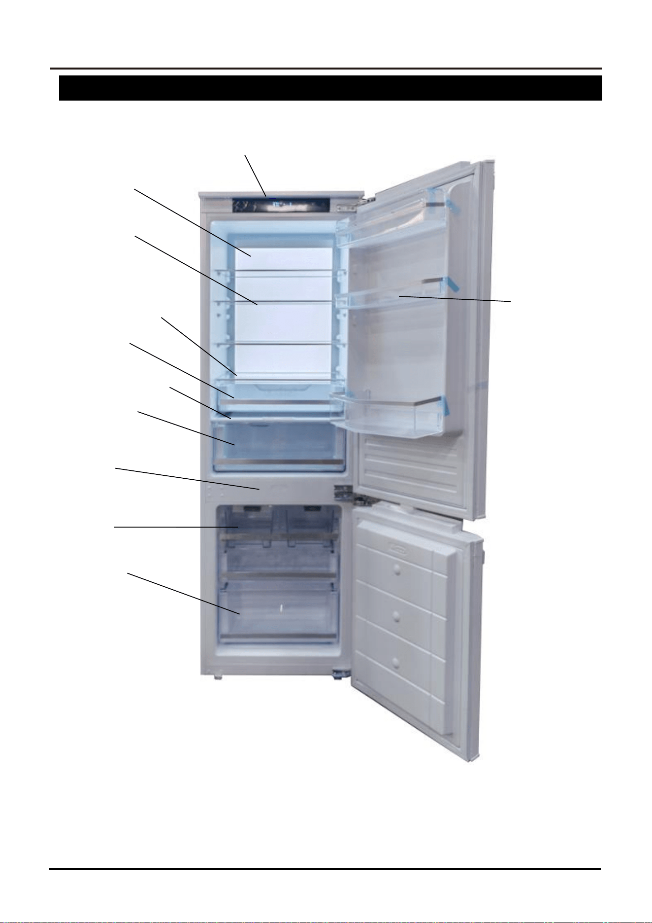
Refrigerator Components
Display
Lighting
Glass Shelves
Door Shelves
Vegetable Bin Cover
Vegetable Bin
Zero Degree Bin Cover
Zero Degree Bin
Door switch
Ice drawer
Freezer drawer
SERVICE MANUAL
9
Refrigerator
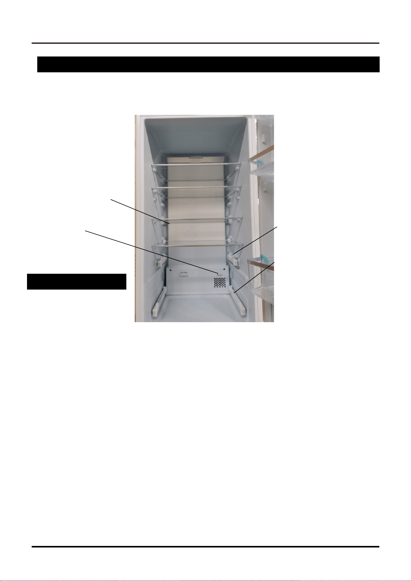
Refrigerator Components
The air sensor is located
behind the air duct
chiller
Sensor
Upper Rails
Lower Freezer
R
ails
10
SERVICE MANUAL
Refrigerator
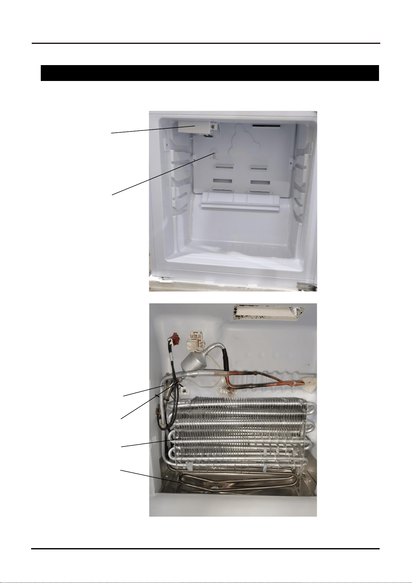
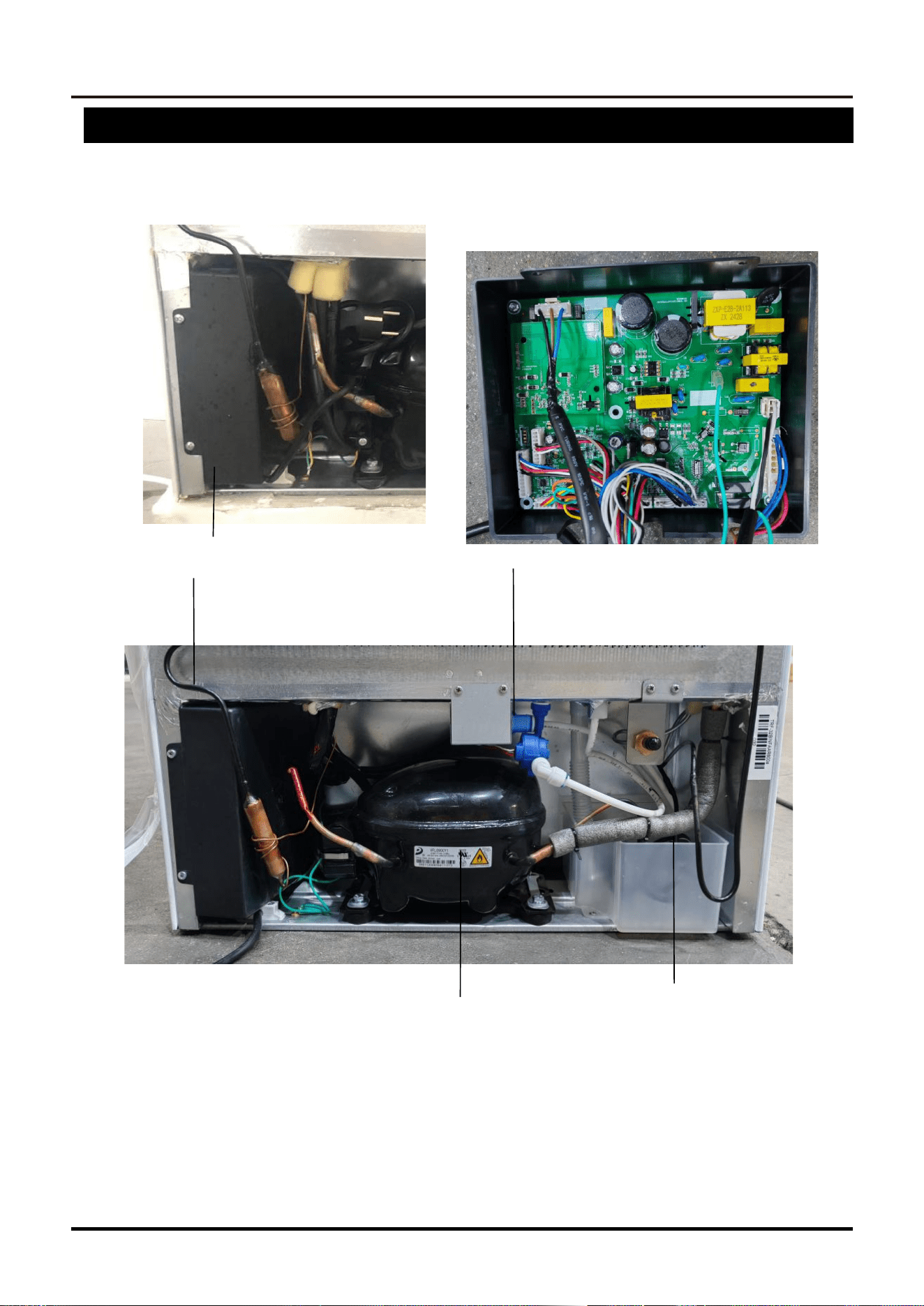
Freezer Components
Ice Makers
Air Sensor
Thermal Fuse
Evaporator Sensor
Evaporator
Defrost Element
SERVICE MANUAL
11
Refrigerator
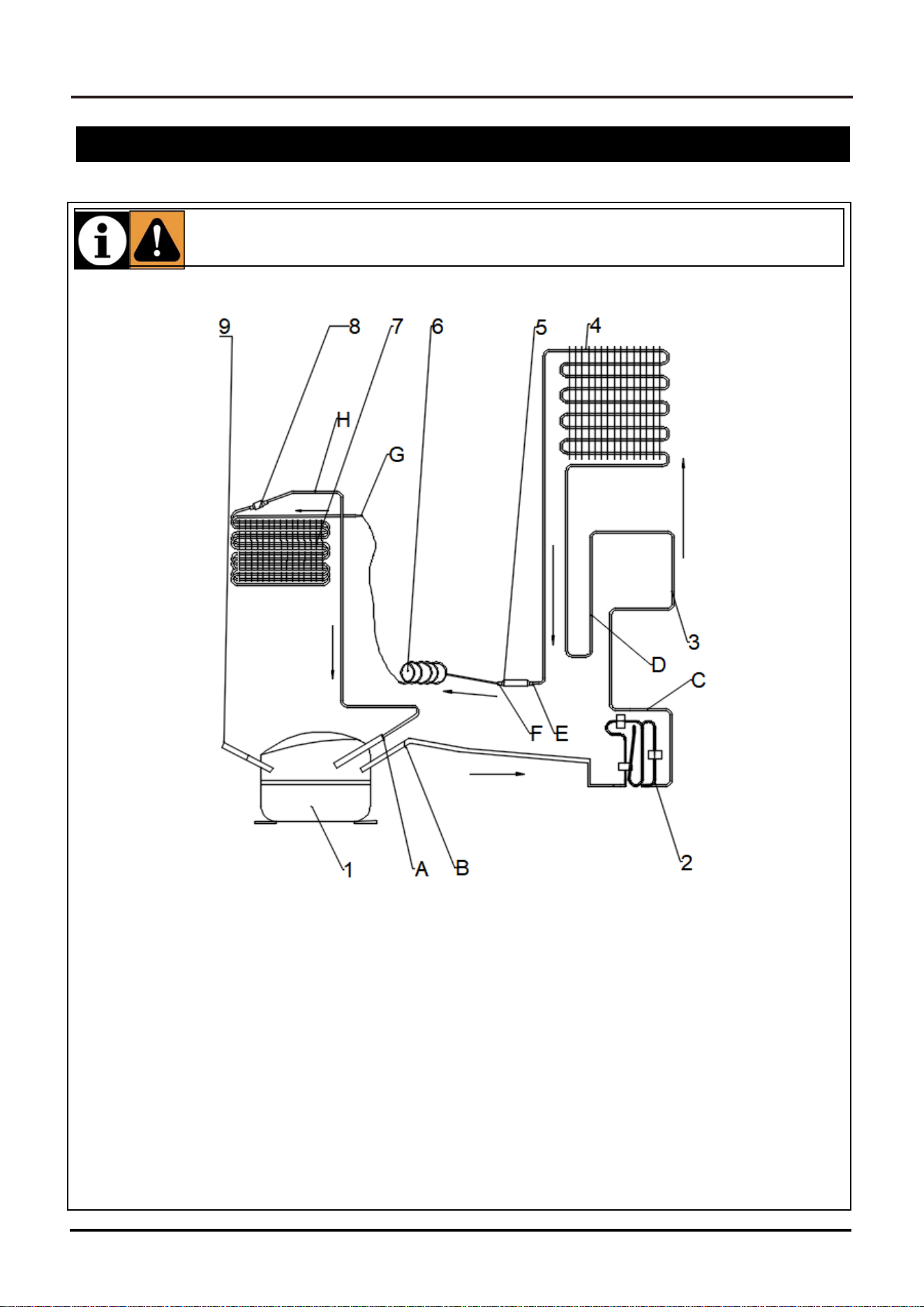
Rear & Compressor Area Components
Control board Water Valve
epair from the lower left of the back
Compressor
Water connection box
12
SERVICE MANUAL
Refrigerator
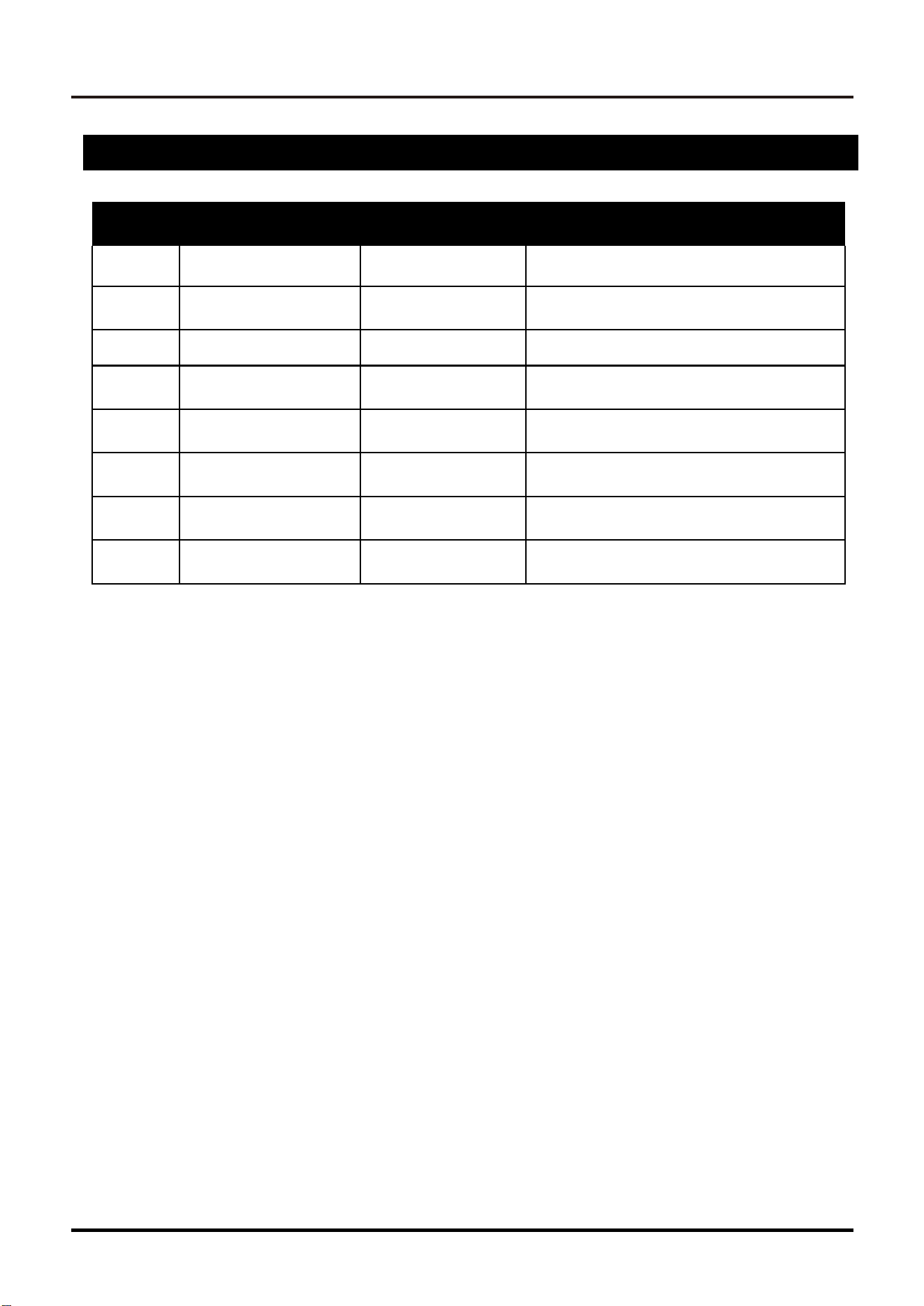
This refrigerator utilizes a cooling system using R600a refrigerant. Take care to avoid damaging the cool-
ing system and its pipes while using and moving the unit. This gas is flammable. If the cooling system is
damaged, keep the unit away from potential sources of fire and ventilate the room immediately.
Gas Flow Diagram & Parts
Cooling System Components
1- Compressor
2- Exhaust evaporation tube
3- Freezer Heater pipe
4- Condenser
5- Drier
6-
Capillary Tube
7-
Frz Evaporator
8-
Reservoir
9- Service pipe
Welding Point
A-Connector pipe / Compressor
B-Compressor / Exhaust evaporation tube
C-Exhaust evaporation tube/Heater Pipe
D-Freezer Heater Pipe / Condenser
E-Condenser / Drier
F-Drier / Capillary Tube
G-Capillary Tube / Frz Evaporator
H-Frz Evaporator / Suction Pipe
SERVICE MANUAL
13
Refrigerator
Electrical Components & Specifications
Quantity Component Stock Number Specifications
1
Compressor
1.10.12090E-4XX
VFL090CY1 110V/60Hz R600a UL
2
Freezer Fan Motor
1.33.DTQ431-041
DC12V 2W1600rpm
【
TRF-32BINFA
】
3
LED Board
1.06.TQ4772-404
LED【TRF-32BINFHA】
4
Freezer Defrost Heater
1.31.A2941X-341
110V/160W
【
TRF-32BINFA
】
5
Display Board
1.27.03A2XX-341
UL 12V
【
TRF-32BINFA
】
6
Control Board
1.27.01A101-435
UL 110V
组件【
TRF-32BINFIA
】
7
Door
switch
1.11.02341TQ-01
【
TRF-32BINFA
】
8
damper
1.31.D2840X-341
【
TRF-32BINFA
】
*Note: For the exact stock number information, look at the BOM List .
14
SERVICE MANUAL
Refrigerator
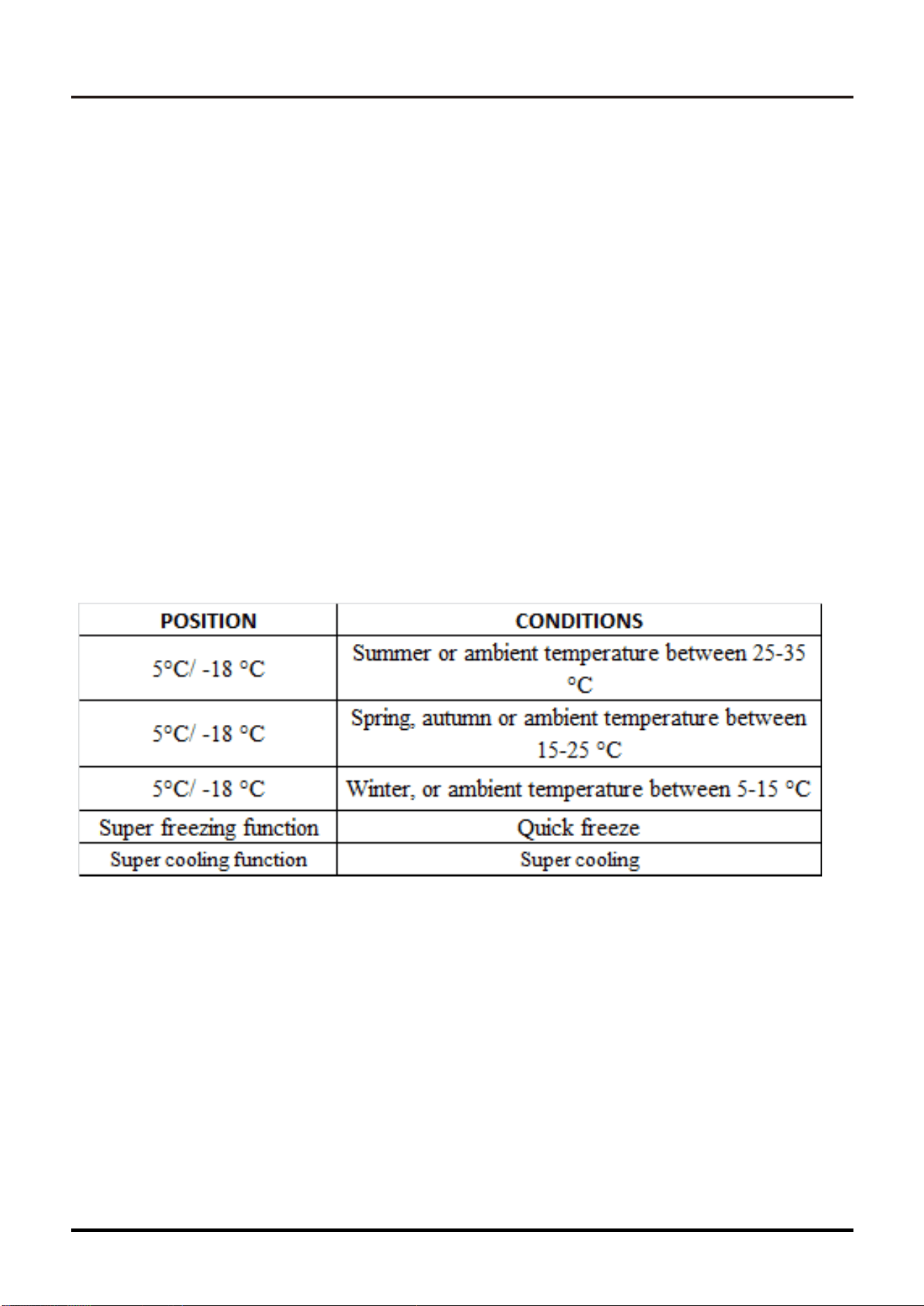
Display Panel Set U
p
Instructions
SERVICE MANUAL
15
Refrigerator
Display Fault Codes
This appliance has ‘fault display & alarm’ function. Once the sensors got fault, there are
alarms displayed on the temperature displaying, the appliance still cools but professional
service engineer should be called and check the appliance.
F2 – Sensor of adapt zone
F3 – Sensor of fridge apartment
F4 – Sensor of freezer compartment
F5 – Sensor of defrosting
2E – Fault of fan/motor in freezer
1S – Ice machine malfunction
CE– Communication fault between main panel and display panel.
The above Errors only show on display, no voice
Over temperature alarm in freezer: after freezer temperature arrives at the set temperature,
after that, if the temperature rises to >-1 °C, the alarm will start, accompany with flash of
freezer temperature digit. Press any button to cancel the voice alarm. The flash will remain
until the temperature is <-1 °C.
PS: Main board locates in compressor compartment
16
SERVICE MANUAL
Refrigerator
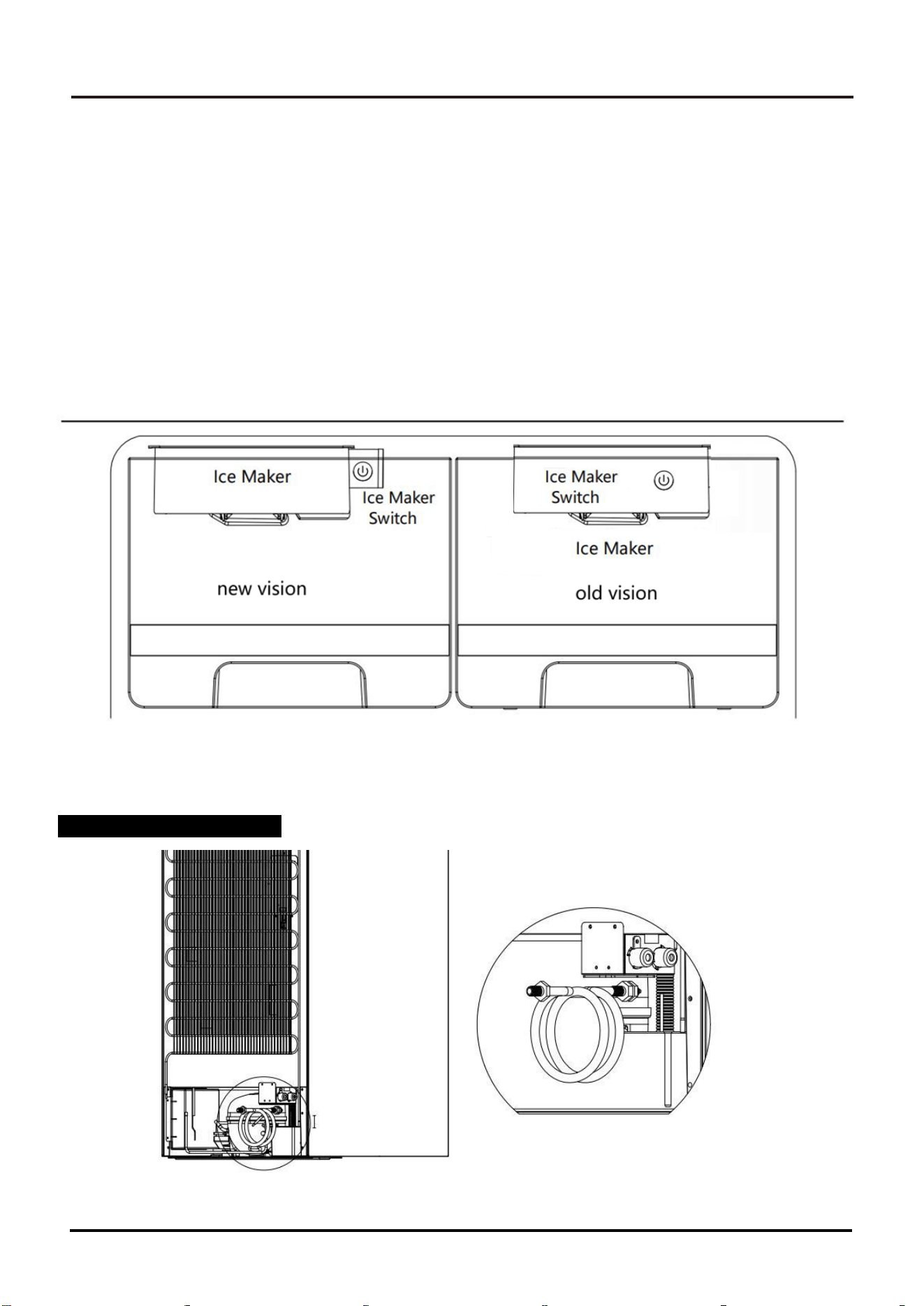
Instructions for Ice Maker(if applicable)
Key operation instructions.
1. Short press the button, the ice machine state for switching on or off.
2. In the on state, press and hold the button for 10 seconds for manual de-icing.
Lamp status description:
1. Switch on state: the light will fade on and then fade off ---->Breathing state
2. Switch off state: the light is not on.
3. Ice full state: always on
4. Drawer removal: slow flash 0.5 seconds flash once (1HZ)
Fault status.
1. Ice jam:Fast flash 1 time 200ms
Water connection
Before installing the refrigerator, connect the water pipe in the rear cabin to the water pipe
in your home, the cabin is equipped with M11 size connecting water pipe as shown below.
SERVICE MANUAL
17
Refrigerator
Error Codes
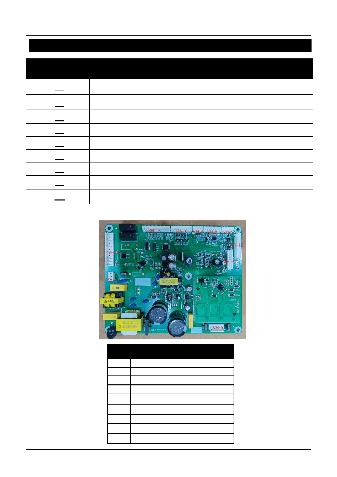
Error Codes Error Explanation
F1
This item is not available for this model
F2
Chiller Sensor Error
F3
Fridge Sensor Error
F4
Freezer Sensor Error
F5
Defrost Freezer Sensor Error
F6
Ambient Temperature Sensor Error
CE
Communication Failure
2E
Freezer Fan Error
DR
The Refrigerator Opens For More Than 2 Minutes
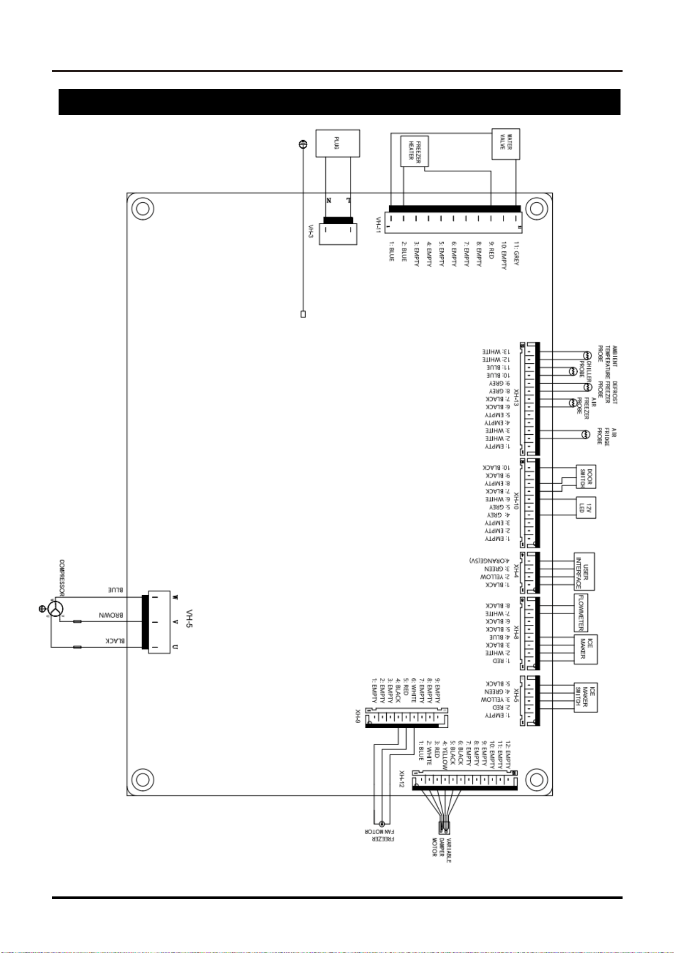
Knowing the connection numbers on the control board will be necessary for the following error code
explanations.
Control Board Connection Numbers
XH-4
User Interface
XH-10
Lights and Door Switch
XH-8
Ice Maker and Flowmeter
XH-12
Fridge Damper Motor
XH-13
Sensors
XH-5
Ice Maker Switch
VH-3
Power plug input
VH-5
Compressor
VH-11
Freezer Heater
18
SERVICE MANUAL
Refrigerator
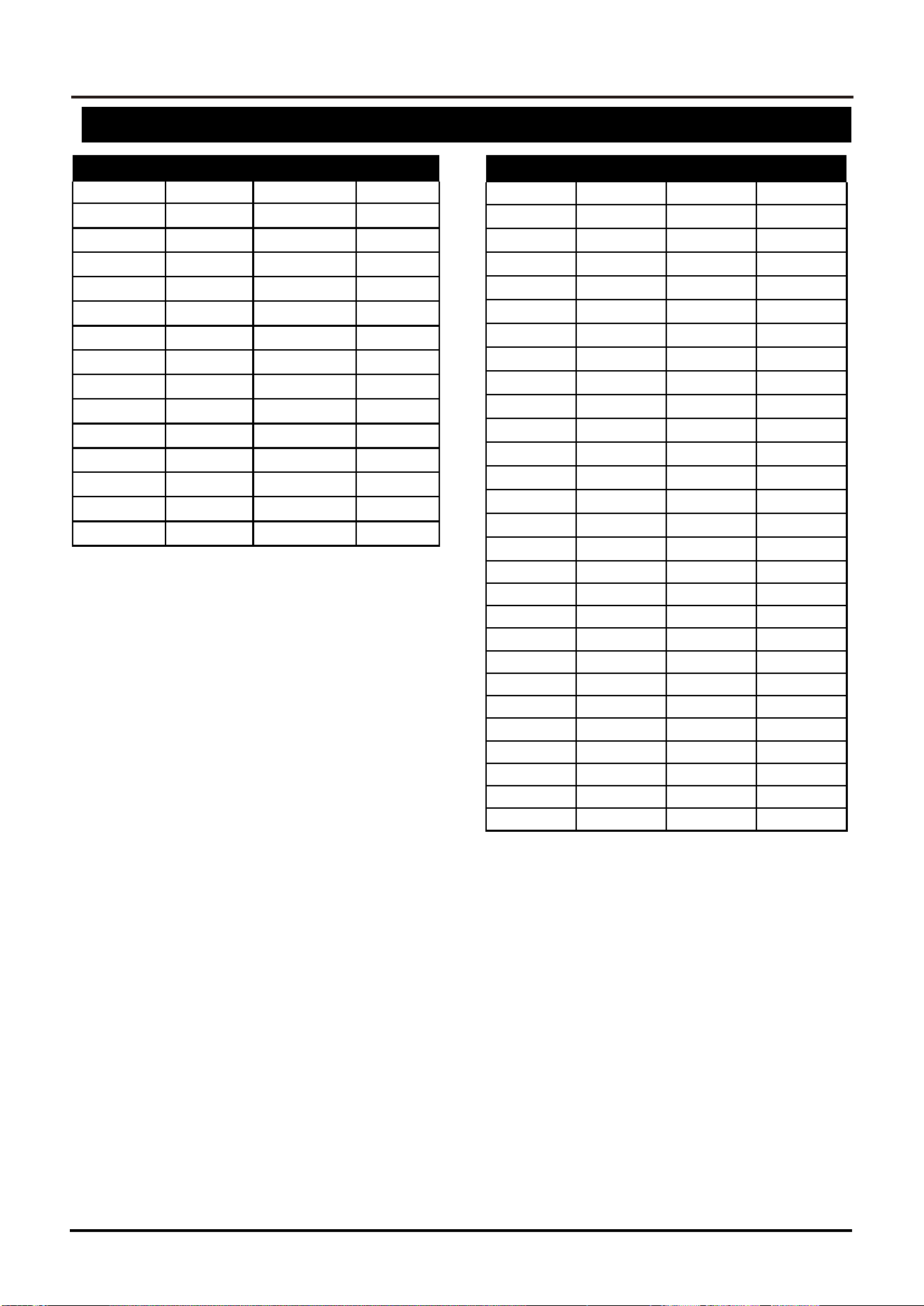
F2 - Chiller Sensor Error
Yes
No
1
Is F2 flashing?
>>2
Stop
2
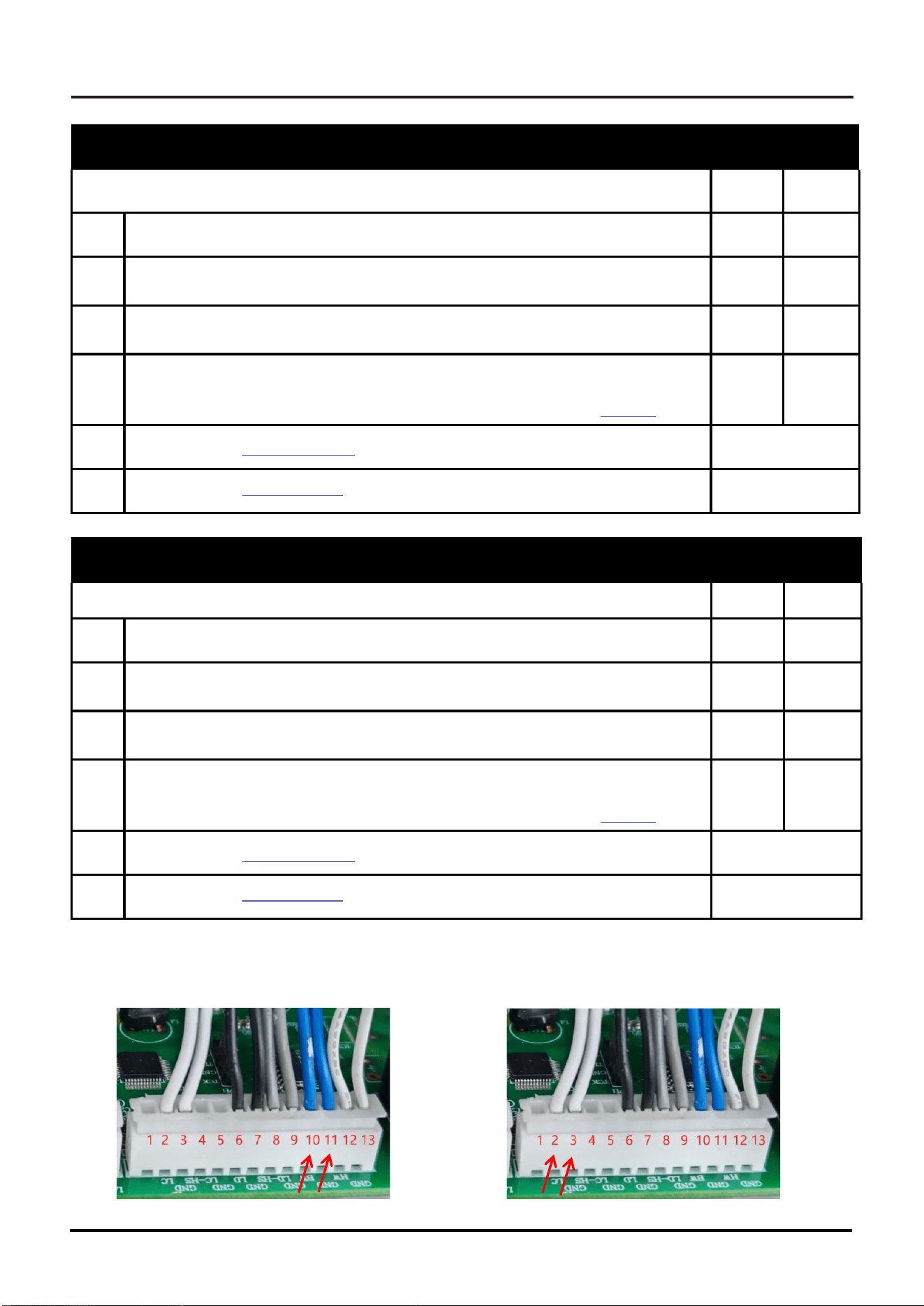
Check cables connected to control board sensor socket (XH-13)
pins 10 & 11. Is the cable disconnected?
>>3
>>
3
Reconnect the cable and turn the refrigerator back on.
Is error still there?
>>4
Solved
4
Remove the harness from the XH-13 socket on the control board.
Using a multimeter, measure the sensor pins (10 & 11).Is the resistance
reading be-tween 1kΩ and 4kΩ. (2k at 77℉ (25℃)) (See chart on
page 23
)
>>5
>>6
5
Replace the
Control Board.
(Turn refrigerator back on)
Solved
6
Replace the
faulty Sensor.
(Turn refrigerator back on)
F3 - Fridge Sensor Error
Yes
No
1
Is F3 flashing?
>>2
Stop
2
Check cables connected to control board sensor socket (XH-13)
pins 2 & 3. Is the cable disconnected?
>>3
>>4
3
Reconnect the cable and turn the refrigerator back on.
Is error still there?
>>4
Solved
4
Remove the harness from the XH-13 socket on the control board.
Using a multimeter, measure the sensor pins (2 & 3).Is the resistance
reading be-tween 1kΩ and 4kΩ. (2k at 77℉ (25℃)) (See chart on
page 23
)
>>5
>>6
5
Replace the
Control Board.
(Turn refrigerator back on)
Solved
6
Replace the
faulty Sensor.
(Turn refrigerator back on)
Solved
F2 Test points F3 Test points
SERVICE MANUAL
19
Refrigerator
F4 - Freezer Sensor Error
Yes
No
1
Is F4 flashing?
>>2
Stop
2
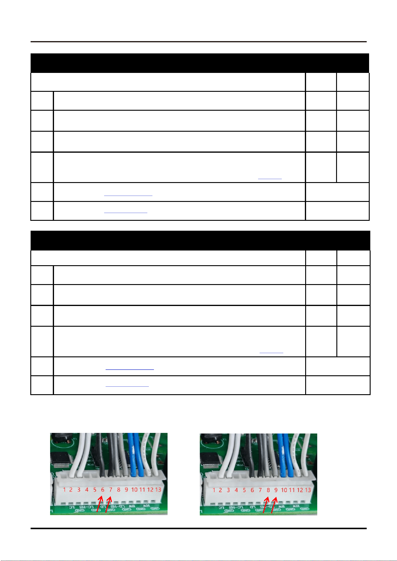
Check cables connected to control board sensor socket (XH-13)
pins 6 & 7. Is the cable disconnected?
>>3
>>
3
Reconnect the cable and turn the refrigerator back on.
Is error still there?
>>4
Solved
4
Remove the harness from the XH-13 socket on the control board.
Using a multimeter, measure the sensor pins (6 & 7).Is the resistance
reading be-tween 1kΩ and 4kΩ. (2k at 77℉ (25℃)) (See chart on
page 23
)
>>5
>>6
5
Replace the
Control Board.
(Turn refrigerator back on)
Solved
6
Replace the
faulty Sensor.
(Turn refrigerator back on)
F5 - Defrost Freezer Sensor Error
Yes
No
1
Is F5 flashing?
>>2
Stop
2
Check cables connected to control board sensor socket (XH-13)
pins 8 & 9. Is the cable disconnected?
>>3
>>4
3
Reconnect the cable and turn the refrigerator back on.
Is error still there?
>>4
Solved
4
Remove the harness from the XH-13 socket on the control board.
Using a multimeter, measure the sensor pins (8 & 9).Is the resistance
reading be-tween 1kΩ and 4kΩ. (2k at 77℉ (25℃)) (See chart on
page 23
)
>>5
>>6
5
Replace the
Control Board.
(Turn refrigerator back on)
Solved
6
Replace the
faulty Sensor.
(Turn refrigerator back on)
Solved
F4 Test points
F5 Test points
20
SERVICE MANUAL
Refrigerator
F6 - Ambient Temperature Sensor Error
Yes
No
1
Is F6 flashing?
>>2
Stop
2
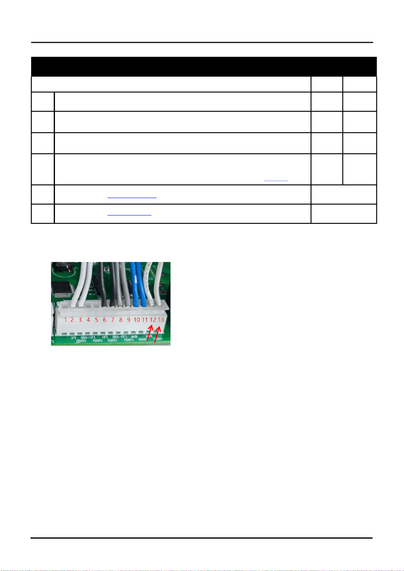
Check cables connected to control board sensor socket (XH-13)
pins 12 & 13. Is the cable disconnected?
>>3
>>4
3
Reconnect the cable and turn the refrigerator back on.
Is error still there?
>>4
Solved
4
Remove the harness from the XH-13 socket on the control board.
Using a multimeter, measure the sensor pins (12 & 13).Is the resistance
reading be-tween 1kΩ and 4kΩ. (2k at 77℉ (25℃)) (See chart on
page 23
)
>>5
>>6
5
Replace the
Control Board.
(Turn refrigerator back on)
Solved
6
Replace the
faulty Sensor.
(Turn refrigerator back on)
Solved
F6 Test points
SERVICE MANUAL
21
Refrigerator
CE - Communication Failure
Yes
No
1
Is CE flashing?
>>2
Stop
2
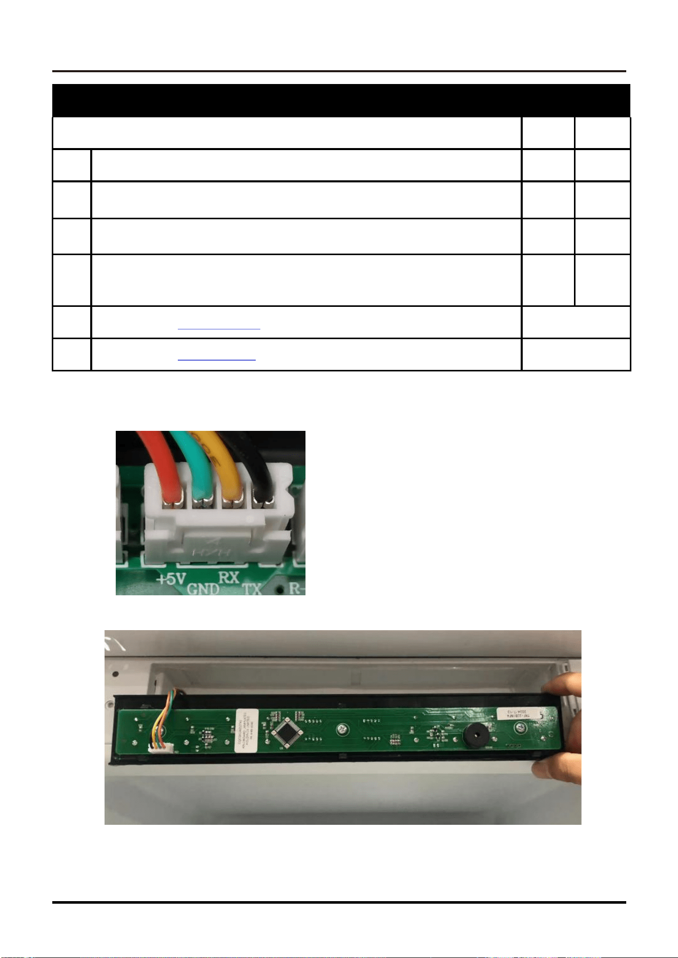
Check cables connected to control board socket
(XH-4) Is the cable disconnected?
>>3
>>
3
Reconnect the cable and turn the refrigerator back on.
Is error still there?
>>4
Solved
4
Check cables connected to User Interfce socket
Is the cable disconnected?
>>5
>>6
5
Replace the
Control Board.
(Turn refrigerator back on)
Solved
6
Replace the
User Interfce.
(Turn refrigerator back on)
Solved
CE Test points
(Control Board)
CE Test points
User Interfce)
22
SERVICE MANUAL
Refrigerator
2E- Freezer Fan Error
Yes
No
1
Is 2E flashing?
>>2
Stop
2
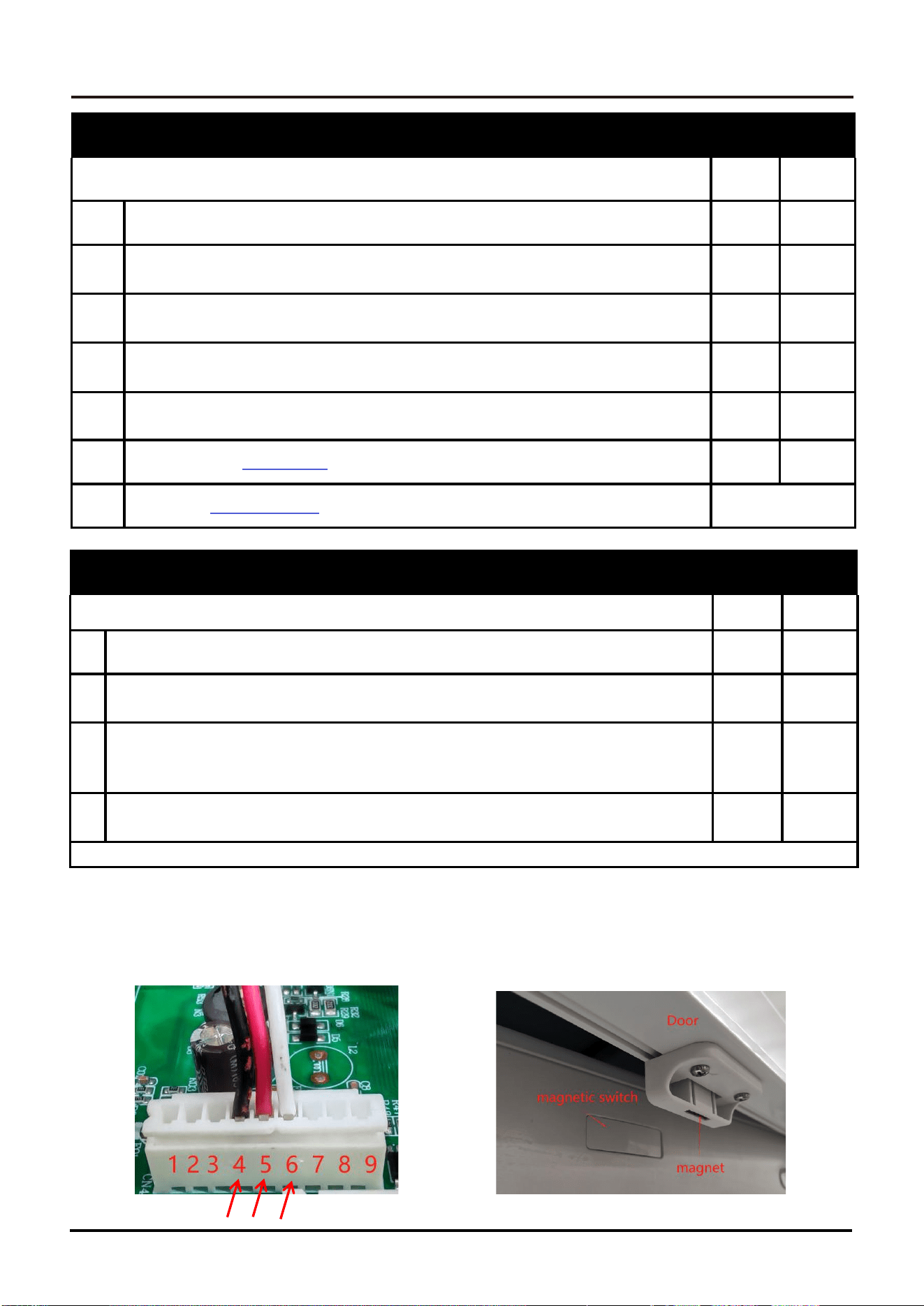
Check cables connected to control board Fan socket (XH-9)
pins 3
4& 5. Is the cable disconnected?
>>3
>>4
3
Reconnect the cable and turn the refrigerator back on.
Is error still there?
>>4
Solved
4
Using a multimeter, measure the DC voltage between pins Is
theresistance reading approximately 12VDC?
>>5
>>6
5
Remove the evaporator cover and ensure nothing is preventing fan blade
rotation. Remove blockage. Turn refrigerator back on. Is error still there?
>>6
Solved
6
Replace the
Freezer Fan.
Turn refrigerator back on. Is error still there?
>>7
Solved
7
Replace
control board.
Turn refrigerator back on.
Solved
2E Test points
DR
Test points
DR - Door opening alarm Error
Yes
No
1
Is DR flashing?
>>2
Stop
2
Check whether the refrigeration door is closed tightly,Repeat
closing the door, if the fault still exists
>>3
>>4
3
Check whether the induction magnet on the top of the
door of the refrigerator is missing. If it is missing, the
fault will continue
>>4
Solved
4
Check whether the magnetic switches of the upper beam are normal
>>5
Solved
SERVICE MANUAL
23
Refrigerator
Maintenance guide for refrigeration failure
1.
Freezer is not cold enough.
●
Error code on display.First,open and closethe freezerdoor to seeif the freezer
light is alwayson. If so, checkthe freezerdrawer brackets.
●
No error code on display.Checkif the plugs on the main control board
is connected properly.
●
Evacuate the gasand re-gas the system.
2.
Freeer does not work
● If the compressor works, check if the capillary is blocked.
3.
Fridge does not work
●
If there is an error code F1,check the fan in fridge. If it is still not working after
replacing the fan, check the wiring connection.
● Check if the reed switch is working properly.
●
Check if the appliancesis on a holiday mode.
4.
Freshzone is not working properly
●
Check if the fresh zone is switched off.
●
Check if there is cold air blowing from the outlet, if not, replacethe air duct
5.
Fridge and freezerare not working
●
Check whether the power cord plug of the main control board is off or not connected.
●
Method 2 Check whether the plugs on the main control board are fully connected
or correctly connected.
High Temp Erro
When the temperature collected by the freezing sensor reaches set 39℉(+4℃), if the
temperature rises ≥30℉(-1℃), the high temperature alarm will buzz twice consecutively, and
the freezing temperature LED light will flash; Touch any button, the over-temperature alarm
sound will be canceled, but the freezing temperature LED light will continue to flash; The alarm
will stop only when the temperature collected by the sensor is less than 28℉(-2℃).
If the over-temperature alarm continues after rebooting the appliance, it is necessary
to check whether the refrigeration system is blocked, and whether the compressor and
fan are working properly.
r
24
SERVICE MANUAL
Refrigerator
Low Range
Temp
Resistance
Temp
Resistance
-40ºF/-40ºC
64.06KΩ
-15ºF/-26ºC
27.07KΩ
-38ºF/-39ºC
60.10KΩ
-13ºF/-25ºC
25.52KΩ
-36ºF/-38ºC
56.41KΩ
-11ºF/-24ºC
24.06KΩ
-35ºF/-37ºC
52.96KΩ
-9ºF/-23ºC
22.70KΩ
-33ºF/-36ºC
49.74KΩ
-8ºF/-22ºC
21.42KΩ
-31ºF/-35ºC
46.73KΩ
-6ºF/-21ºC
20.22KΩ
-29ºF/-34ºC
43.92KΩ
-4ºF/-20ºC
19.10KΩ
-27ºF/-33ºC
41.29KΩ
-2ºF/-19ºC
18.04KΩ
-26ºF/-32ºC
38.83KΩ
-.3ºF/-18ºC
17.05KΩ
-24ºF/-31ºC
36.53KΩ
1ºF/-17ºC
16.11KΩ
-22ºF/-30ºC
34.38KΩ
3ºF/-16ºC
15.24KΩ
-20ºF/-29ºC
32.37KΩ
5ºF/-15ºC
14.41KΩ
-18ºF/-28ºC
30.49KΩ
7ºF/-14ºC
13.64KΩ
-17ºF/-27ºC
28.72KΩ
9ºF/-13ºC
12.91KΩ
Normal Operator Range
Temp
Resistance
Temp
Resistance
10ºF/-12ºC
12.22K
Ω
59ºF/15ºC
3.13K
Ω
12ºF/-11ºC
11.57K
Ω
61ºF/16ºC
2.99K
Ω
14ºF/-10ºC
10.96K
Ω
63ºF/17ºC
2.85K
Ω
16ºF/-09ºC
10.39K
Ω
64ºF/18ºC
2.73K
Ω
18ºF/-08ºC
9.85K
Ω
66ºF/19ºC
2.60K
Ω
19ºF/-07ºC
9.34K
Ω
68ºF/20ºC
2.49K
Ω
21ºF/-06ºC
8.86K
Ω
70ºF/21ºC
2.38K
Ω
23ºF/-05ºC
8.41K
Ω
72ºF/22ºC
2.28K
Ω
25ºF/-04ºC
7.98K
Ω
73ºF/23ºC
2.18K
Ω
27ºF/-03ºC
7.57K
Ω
75ºF/24ºC
2.08K
Ω
28ºF/-02ºC
7.19K
Ω
77ºF/25ºC
1.99K
Ω
30ºF/-01ºC
6.83K
Ω
79ºF/26ºC
1.91K
Ω
32ºF/00ºC
6.49K
Ω
81ºF/27ºC
1.83K
Ω
34ºF/01ºC
6.17K
Ω
82ºF/28ºC
1.75K
Ω
36ºF/02ºC
5.87K
Ω
84ºF/29ºC
1.68K
Ω
37ºF/03ºC
5.58K
Ω
86ºF/30ºC
1.61K
Ω
39ºF/04ºC
5.31K
Ω
88ºF/31ºC
1.54K
Ω
41ºF/05ºC
5.06K
Ω
90ºF/32ºC
1.48K
Ω
43ºF/06ºC
4.81K
Ω
91ºF/33ºC
1.41K
Ω
45ºF/07ºC
4.58K
Ω
93ºF/34ºC
1.36K
Ω
46ºF/08ºC
4.37K
Ω
95ºF/35ºC
1.30K
Ω
48ºF/09ºC
4.16K
Ω
97ºF/36ºC
1.25K
Ω
50ºF/10ºC
3.96K
Ω
99ºF/37ºC
1.20K
Ω
52ºF/11ºC
3.78K
Ω
100ºF/38ºC
1.15K
Ω
54ºF/12ºC
3.60K
Ω
102ºF/39ºC
1.11K
Ω
55ºF/13ºC
3.44K
Ω
104ºF/40ºC
1.06K
Ω
57ºF/14ºC
3.28K
Ω
Temperature to Resistance Chart
SERVICE MANUAL
25
Refrigerator
Wiring Diagram
26
SERVICE MANUAL
Refrigerator
XH-10
Lights and Switch
Contacts
Values
Light
4&6
12VDC
Door Switch
7&10
Continuity
when Open
XH-4
Display
Contacts
Values
Display Voltage
3&4
5VDC
XH-8
Ice Maker and Flowmeter
Contacts
Values
Ice Maker
1-4
12VDC
Flowmeter
7&8 &10
12VDC
XH-12
Motor
Contacts
Values
Fridge Damper Motor
1-6
12VDC
XH-9
Fan
Contacts
Values
Freezer Fan Motor
4&5&6
12VDC
XH-13
Temp Sensors
Contacts
Values
Air Fridge Probe
2&3
(See chart
on page 23)
Air Freezer Probe
6&7
Defrost Freezer Probe
8&9
Chiller
Probe
10&11
Ambient Temperature Sensor
12&13
XH-5
Ice Maker Switch
Contacts
Values
Ice Maker Switch
2-5
12VDC
VH-3
Plug
Contacts
Values
Plug
1&3
110VAC
VH-5
Compressor
Contacts
Values
Compressor
1&3&5
110VAC
VH-11
Heaterand Water Valve
Contacts
Values
Freezer Heater
2&9
110VAC
Water Valve
1&11
110VAC
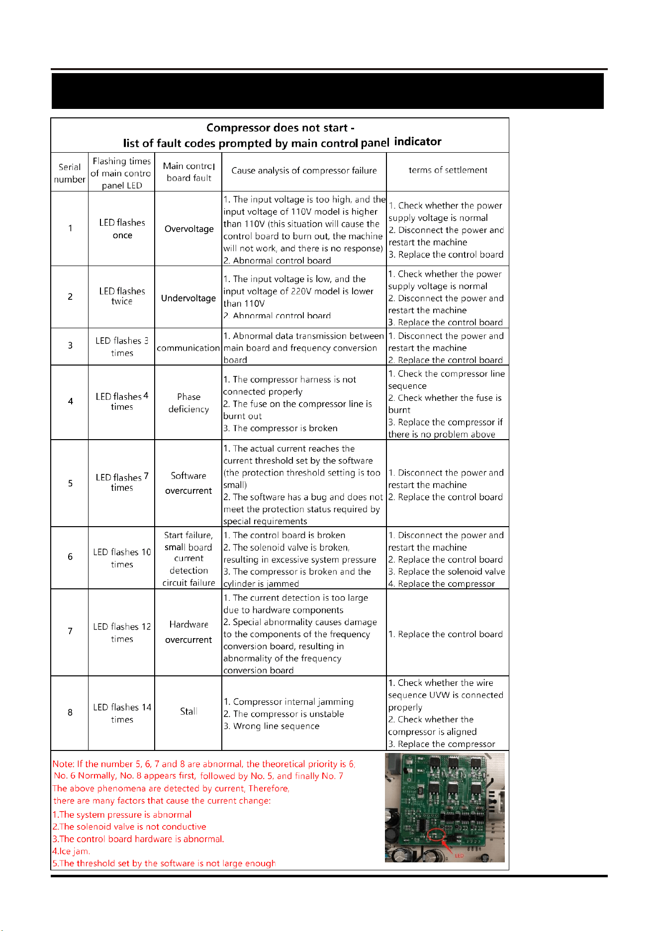
(See the picture on page 14 for the control board)
Control Board Test Points
SERVICE MANUAL
27
Refrigerator
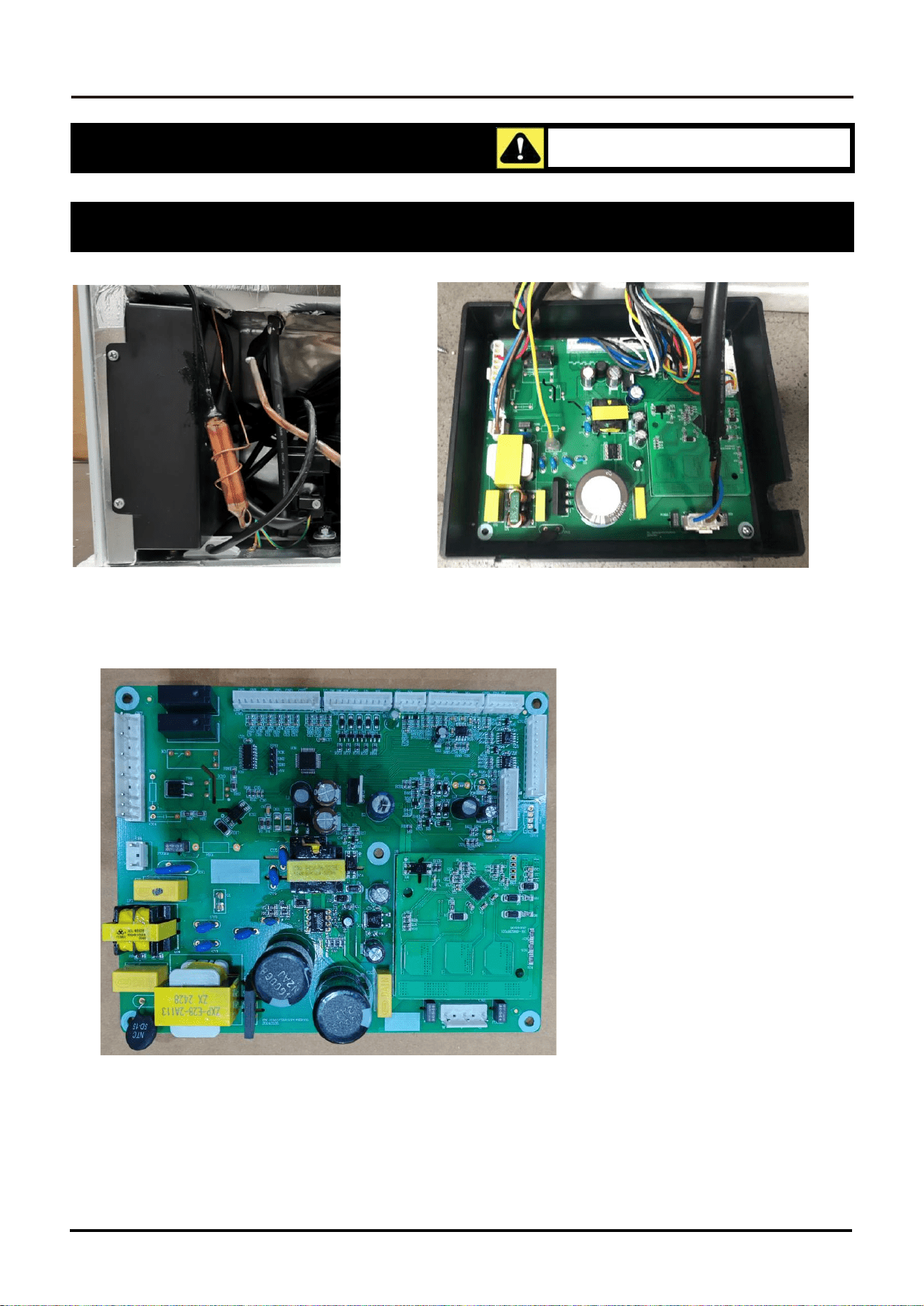
Main control board led flashing fault
28
SERVICE MANUAL
Refrigerator
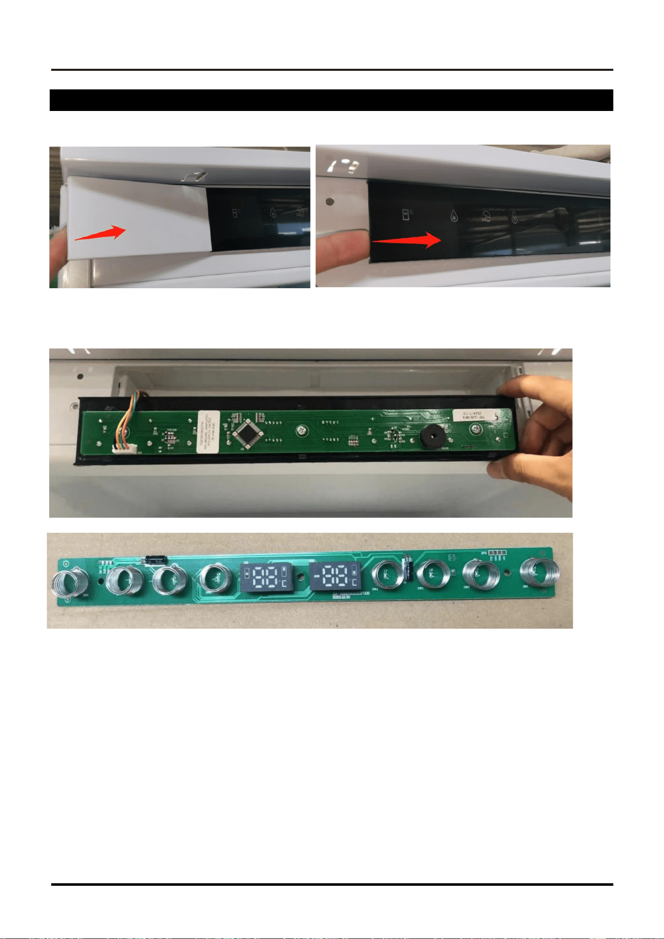
Control Board
1.Remove the mounting box on the left side of the press bin
2.Remove the clip and take out the main control board
Disassembly should only be done with the product
unplugged and by an authorized technician.
Component Access and Removal
SERVICE MANUAL
29
Refrigerator
Display
1.Remove the left trim cover
2.Remove the display board mounting box
30
SERVICE MANUAL
Refrigerator
Ice Maker
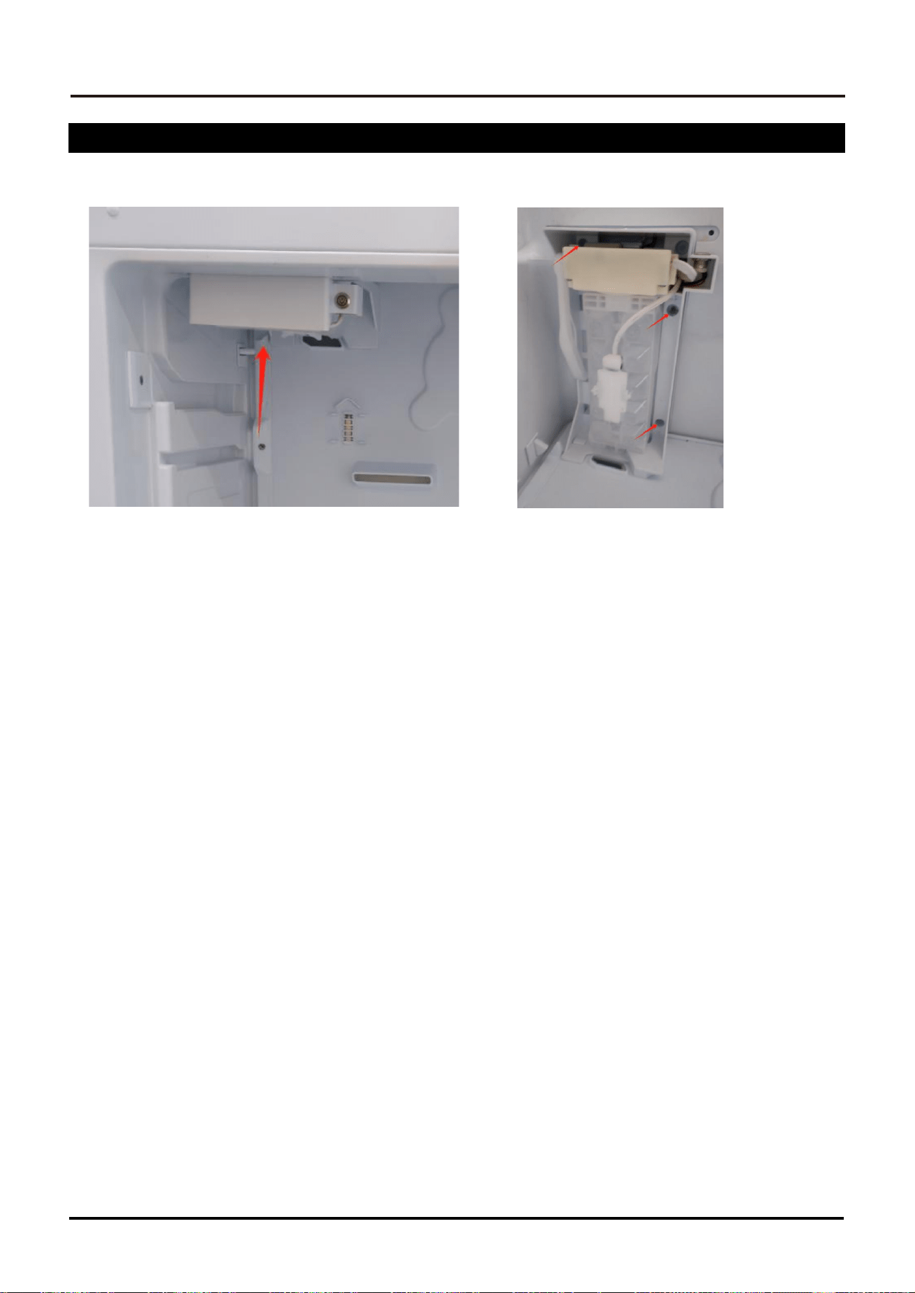
1. Pull out the freezer drawer
2. Remove the 3 screws holding the ice maker in place to remove the ice maker
SERVICE MANUAL
31
Refrigerator
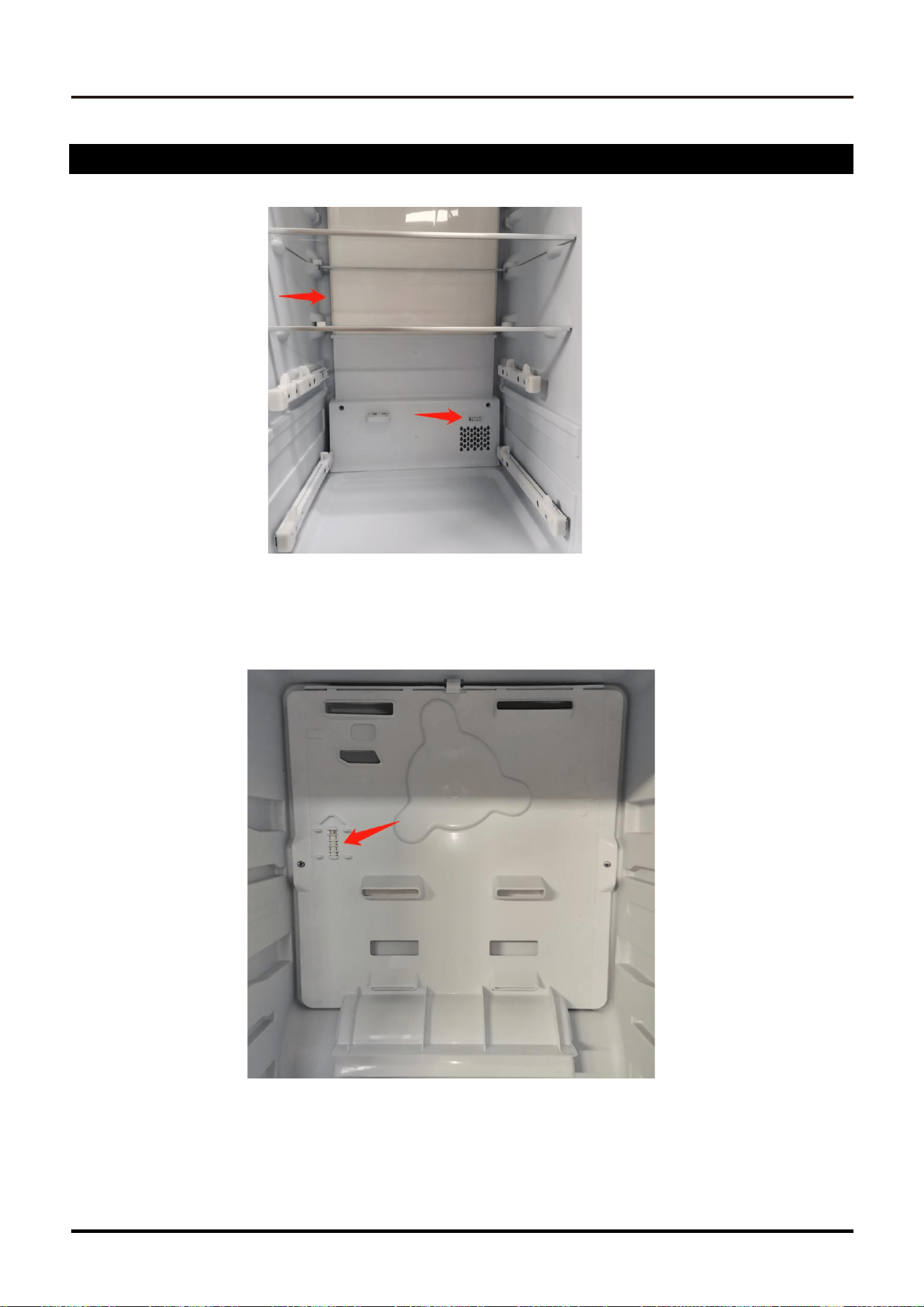
Temperature inside the box Sensor
1. Remove the air duct cover to take out the internal sensor
32
SERVICE MANUAL
Refrigerator
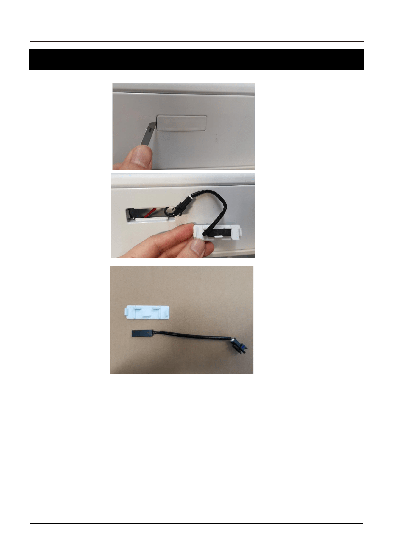
1. Remove the door switch mounting cover located in the center sill.
Take out the magnetic control switch
Refrigerator magnetic light switch
SERVICE MANUAL
33
Refrigerator
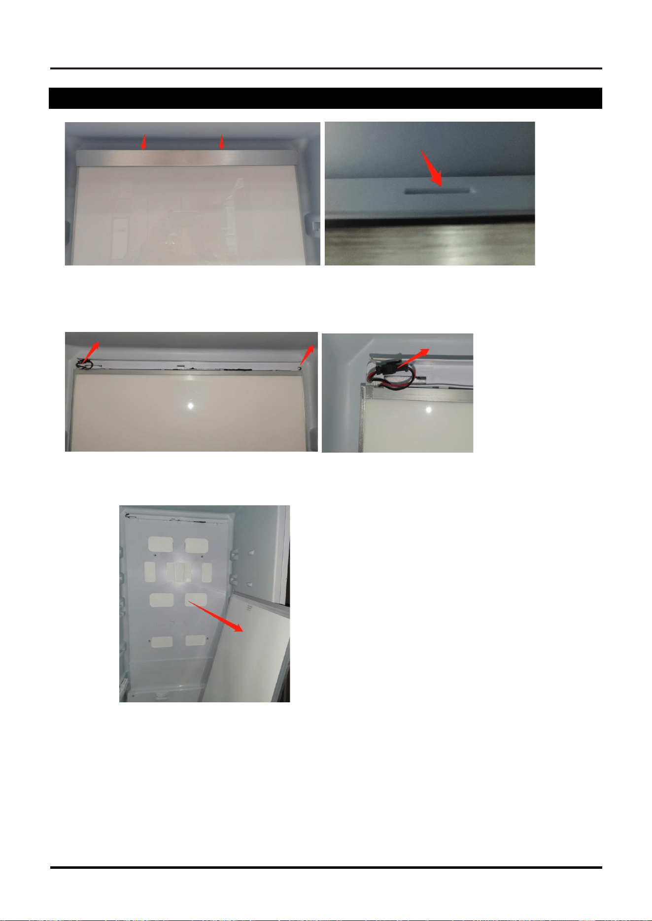
Refrigerator room Overhead light
1.Remove the top metal strip and take it out from the clip at the back of the top
2.Remove the two left and right fixing screws and pull off the plug
34
SERVICE MANUAL
Refrigerator
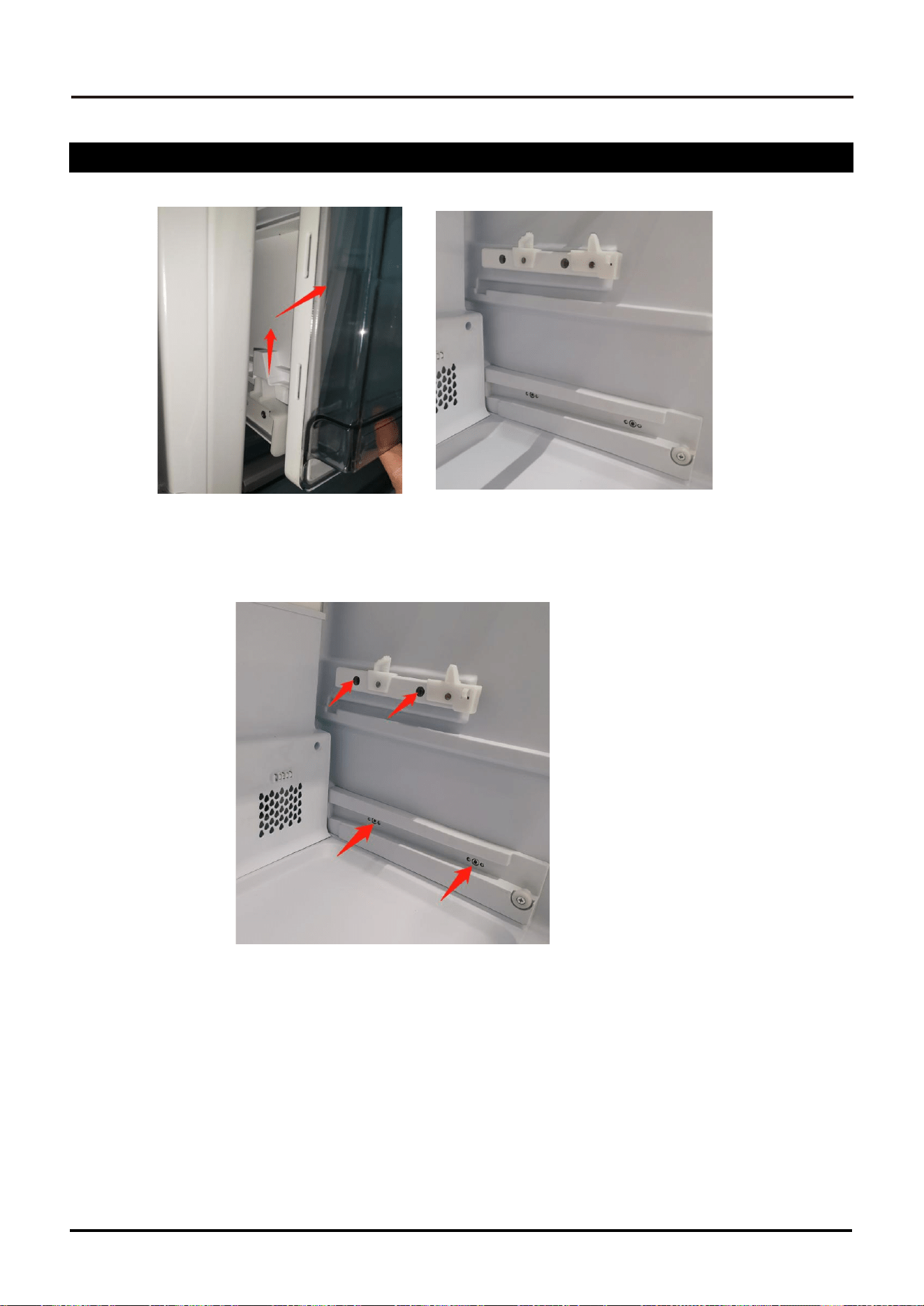
Refrigerator rail removal
1. Pull out the fruit and vegetable box and take it up
2. Retract the slide rail and remove it with a Torx T20 screwdriver
Refrigerator
SERVICE MANUAL
35
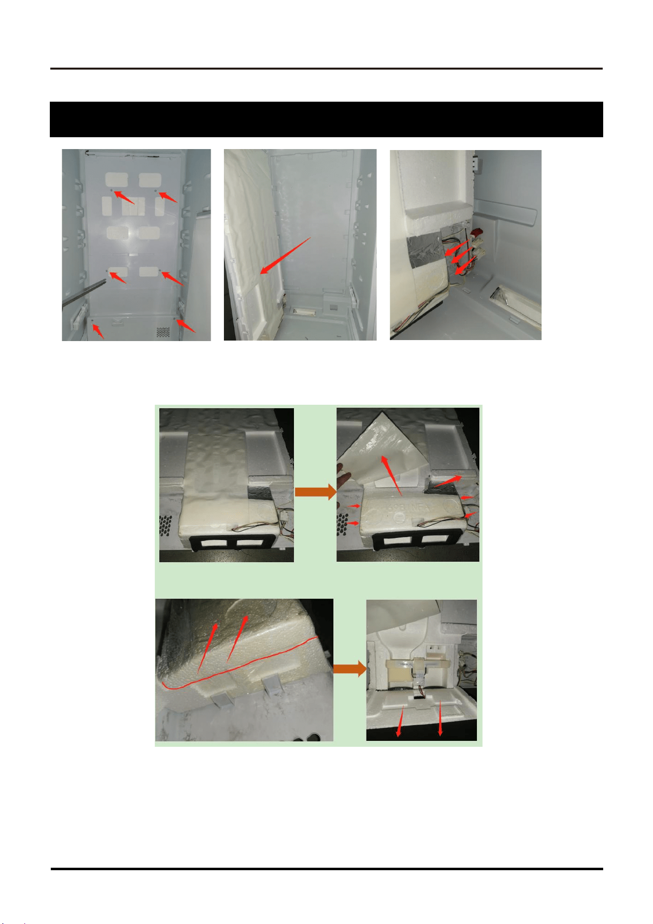
Refrigerator the Rear Wall
1.Remove the rear cover as shown and unplug the cable
2. Remove the sealing cotton according to the steps shown in the
figure and remove the electric damper
36
SERVICE MANUAL
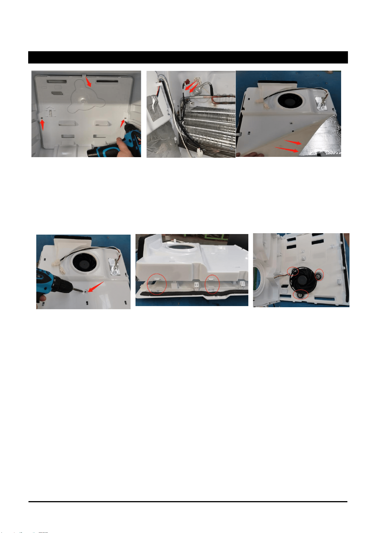
Freezer the Rear Wall
1.Remove the rear cover as shown and unplug the cable
2.Uncover the isolation sponge
3.Remove the fifixing screws and separate the front and rear covers of the cover plate
4.Remove the fan
Refrigerator
SERVICE MANUAL
37
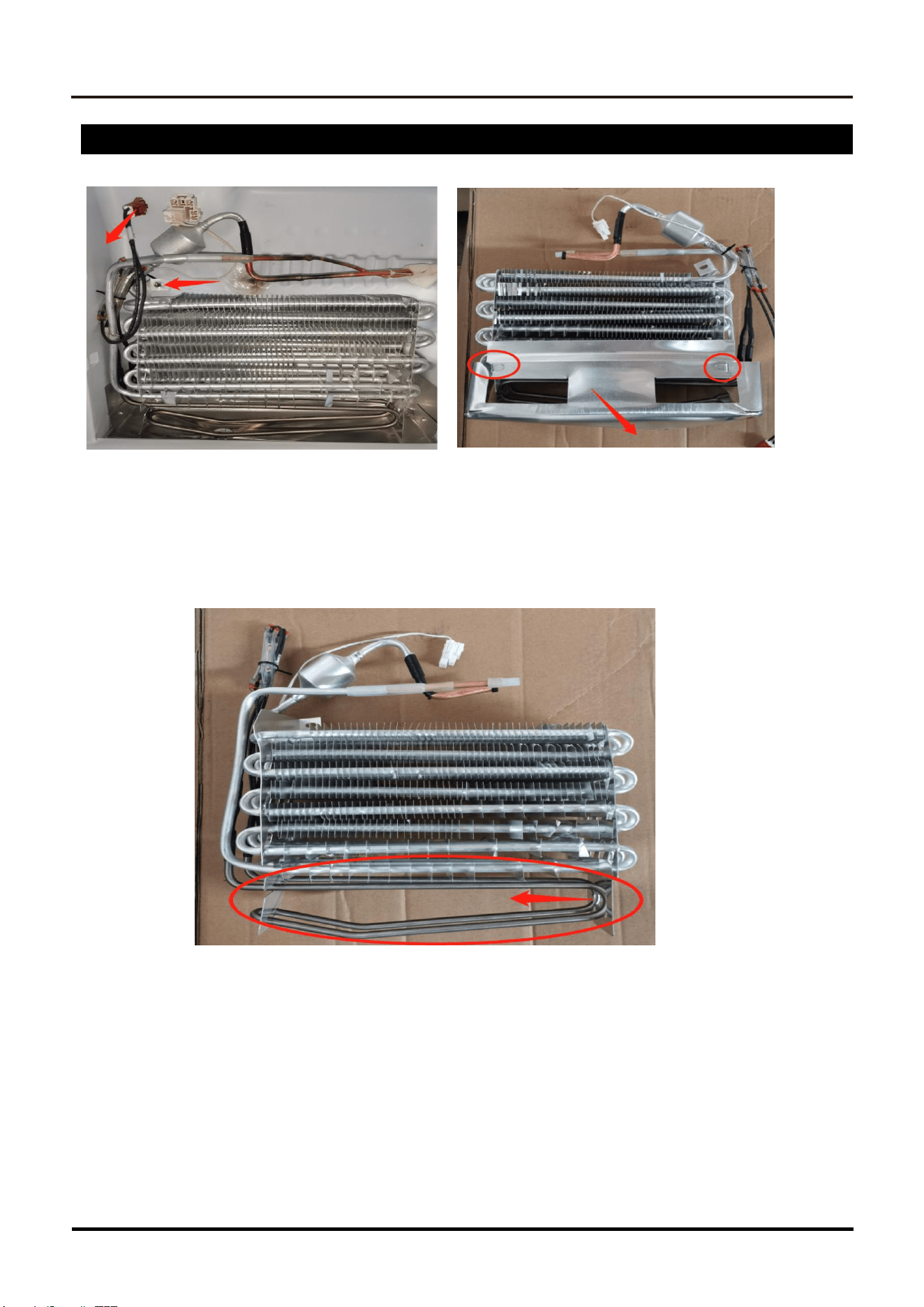
Defrost Element & Thermal Fuse+
1.Remove the fifixing screws
2.Remove the water drip pan at the back
3.Remove the heater
38
SERVICE MANUAL
Refrigerator
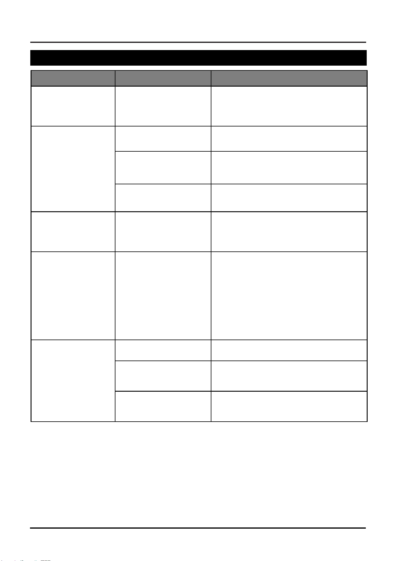
Troubleshooting
Symptom
Possible Cause
Corrective Action
The Freezer compart-
ment is too cold, but
the refrigerator tem-
perature is fine.
The Freezer compartment
temperature is set too
low.
Set Freezer temperature to a higher setting.
The Fresh Food com-
partment is too cold ,
but the Freezer tem-
perature is fine.
The Fresh Food tempera-
ture is set too low.
Set Fresh Food temperature to a higher
setting.
Door not sealing
Check door gaskets.
Fan not running
Check fan.
The refrigerator’s op-
erating sounds varies
over time.
The operating sounds will
vary according to different
cycles, food volume and
environmental conditions.
This is normal.
The refrigerator makes
vibration or other
strange noises.
Various components make
vibration sounds, such as
when water valves en-
ergize. Also gas flowing
through refrigerant lines
can make gurgling noises.
And popping and sizzling
sounds can occur during
the defrost cycle.
As long as both compartments are maintain-
ing proper temperatures, these sounds are
normal.
Evaporator Fan is
noisy.
The fan blade may be
irregular.
Remove evaporator cover and inspect fan for
irregularities. Replace if necessary.
Fan blade may be hitting
something.
Remove evaporator cover and inspect fan
area for any obstructions. Adjust fan or
remove obstructions.
Fan speed may be too
high.
Check fan speed for proper RPMs. Fan may
be noisy if RPMs are too high. Replace fan
motor, if so.
SERVICE MANUAL
39
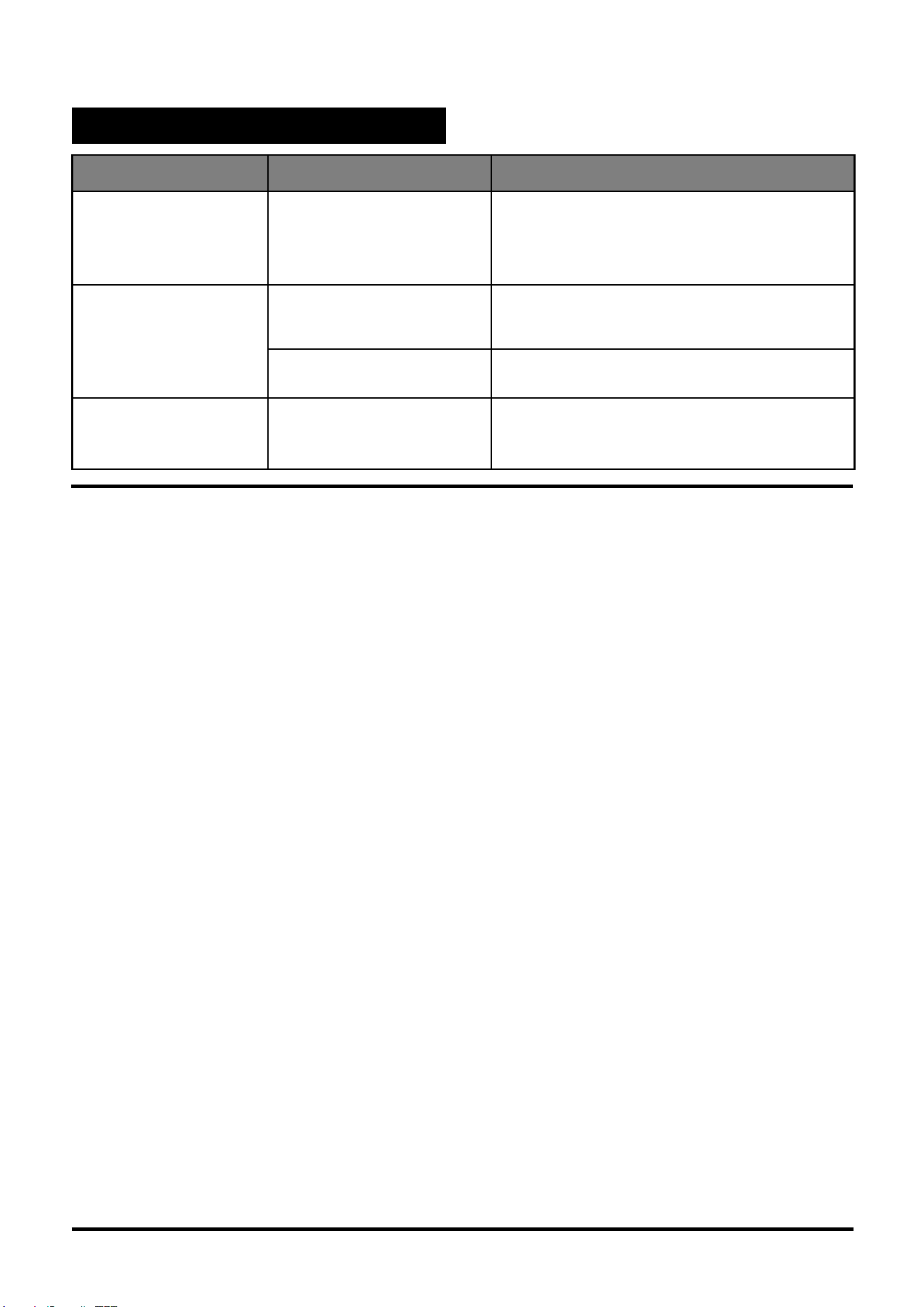
Troubleshooting (Continued)
Symptom
Possible Cause
Corrective Action
Condensation devel-
ops on outside of re-
frigerator, or between
doors.
Excessive ambient heat or
humidity can cause mois-
ture to develop on cooler
surfaces.
It is normal during hot or humid seasons to
see increased condensation on the outside
of the unit. This will decrease as ambient
humidity goes away.
Refrigerator doors will
not close.
Something may be block-
ing the door.
Check food placement and adjust if neces-
sary.
The door gasket may not
be seating properly
Inspect gasket. Adjust or replace.
The doors squeak
when opening or
closing.
Door hinges are worn.
Replace door hinges.
1 646-444-8054 | [email protected] | US.ILVE.COM | ©ILVE USA 2026. ALL RIGHTS RESERVED.