
Operator’s Manual
Veterinary Intensive Care Cabin
ViCare U7/ViCare U7L/ViCare U7R

1
©2026 Shenzhen Mindray Animal Medical Technology Co., Ltd. All Rights Reserved.
For this Operator’s Manual, the issue date is 2026-05.
Intellectual Property Statement
Shenzhen Mindray Animal Medical Technology Co., Ltd. (hereinafter called Mindray Animal Medical)
owns the intellectual property rights to this device and this manual. This manual may refer to information
protected by copyright or patents and does not convey any license under the patent rights or copyright of
Mindray Animal Medical, or of others.
Mindray Animal Medical intends to maintain the contents of this manual as confidential information.
Disclosure of the information in this manual in any manner whatsoever without the written permission of
Mindray Animal Medical is strictly forbidden.
Release, amendment, reproduction, distribution, rental, adaptation, translation or any other derivative
work of this manual in any manner whatsoever without the written permission of Mindray Animal
Medical is strictly forbidden.
is the trademark of SHENZHEN MINDRAY BIO-MEDICAL ELECTRONICS CO., LTD. in
China and other countries. All other trademarks that appear in this manual are used only for
informational or editorial purposes. They are the property of their respective owners.
Responsibility on the Manufacturer Party
Contents of this manual are subject to change without prior notice.
All information contained in this manual is believed to be correct. Mindray Animal Medical shall not be
liable for errors contained herein or for incidental or consequential damages in connection with the
furnishing, performance, or use of this manual.
Mindray Animal Medical is responsible for the effects on safety, reliability and performance of this
device, only if:
• all installation operations, expansions, changes, modifications and repairs of this device are
conducted by Mindray Animal Medical authorized personnel;
• the electrical installation of the relevant room complies with the applicable national and local
requirements; and
• the device is used in accordance with the instructions for use.
Important!
The device is veterinary use only.

2
NOTE
This device must be operated by skilled/trained clinical professionals.
WAR N I N G
It is important for the hospital or organization that employs this device to carry out a reasonable
service/maintenance plan. Neglect of this may result in machine breakdown or personal injury.
Warranty
THIS WARRANTY IS EXCLUSIVE AND IS IN LIEU OF ALL OTHER WARRANTIES,
EXPRESSED OR IMPLIED, INCLUDING WARRANTIES OF MERCHANTABILITY OR FITNESS
FOR ANY PARTICULAR PURPOSE.
Exemptions
Mindray Animal Medical’s obligation or liability under this warranty does not include any transportation
or other charges or liability for direct, indirect or consequential damages or delay resulting from the
improper use or application of the device or the use of parts or accessories not approved by Mindray
Animal Medical or repairs by people other than Mindray Animal Medical authorized personnel.
This warranty shall not extend to:
• Malfunction or damage caused by improper use or man-made failure.
• Malfunction or damage caused by unstable or out-of-range power input.
• Malfunction or damage caused by force majeure such as fire and earthquake.
• Malfunction or damage caused by improper operation or repair by unqualified or unauthorized
service people.
• Malfunction of the instrument or part whose serial number is not legible enough.
• Others not caused by instrument or part itself.

3
Contact Information
Global Service Department
North America Service Department
Important Information
• It is the customer’s responsibility to maintain and manage the device after delivery.
• The warranty does not cover the following items, even during the warranty period:
– Damage or loss due to misuse or abuse.
– Damage or loss caused by Acts of God such as fires, earthquakes, floods, lightning, etc.
– Damage or loss caused by failure to meet the specified conditions for this device, such as
inadequate power supply, improper installation or environmental conditions.
– Damage or loss due to use of the device outside the region where the device was originally sold.
– Damage or loss involving the device purchased from a source other than Mindray Animal
Medical or its authorized agents.
• This device shall not be used by persons other than fully qualified and certified medical personnel.
• DO NOT make changes or modifications to the software or hardware of this device.
• In no event shall Mindray Animal Medical be liable for problems, damage, or loss caused by
relocation, modification, or repair performed by personnel other than those designated by Mindray
Animal Medical.
• The purpose of this device is to provide physicians with data for clinical diagnosis. The physician is
responsible for the results of diagnostic procedures. Mindray Animal Medical shall not be liable for
the results of diagnostic procedures.
• Important data must be backed up on external memory media.
• Mindray Animal Medical shall not be liable for loss of data stored in the memory of this device
caused by operator error or accidents.
Shenzhen Mindray Animal Medical Technology Co., Ltd.
Address: Room 702, Tower 4, YESUN Intelligent Community III, No.1301-88
Guanguang Road, Xinlan Community, Guanlan Street, Longhua District,
Shenzhen 518110, P. R. China
Website: www.mindrayanimal.com
E-mail Address: [email protected]
Tel: +86 755 33997000
Mindray Animal Medical Technology North America Co., Ltd.
Address: 1200 MacArthur Blvd, Unit 302B, Mahwah, NJ 07430, USA
E-mail Address: [email protected]
Tel: 1.800.864.5364
4
• This manual contains warnings regarding foreseeable potential dangers, but you shall also be
continuously alert to dangers other than those indicated. Mindray Animal Medical shall not be liable
for damage or loss resulting from negligence or ignorance of the precautions and operating
instructions described in this operator’s manual.
• If a new manager takes over this device, be sure to hand over this operator’s manual to the new
manager.
About This Manual
This operator’s manual describes the operating procedures for this device. To ensure safe and correct
operation, carefully read and understand the manual before operating the device.
NOTE
• If you find that the contents of the multi-language manuals are NOT consistent with the device or
the English manuals, refer ONLY to the corresponding English manuals.
• The accompanying manuals may vary depending on the specific device you purchased. Please refer
to the packing list.
Meaning of Signal Words
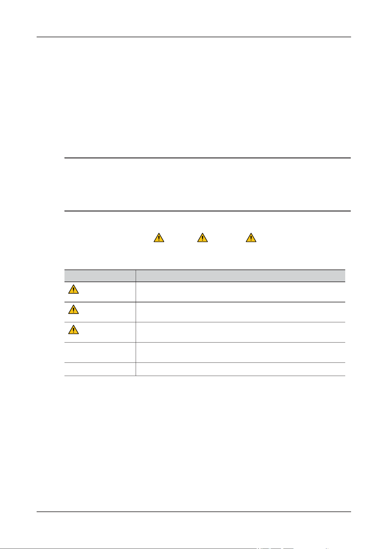
In this manual, the signal words DANGER, WARNING, CAUTION,
NOTE
and
TIP
are
used regarding safety and other important instructions. The signal words and their meanings are defined
as follows. Please understand their meanings clearly before reading this manual.
Software Interfaces in this Manual
Depending on the software version, preset settings and optional configuration, the actual interfaces may
be different from those in this manual.
In this manual, the following conventions are used to describe the buttons on the control panel, items in
the menus, buttons in the dialog boxes and some basic operations:
• Press XX: select the corresponding button on the control panel.
• Bold font indicates items in menus, on the soft menu or buttons in dialog boxes.
•Tap Bold font: select the corresponding item on the touch screen.
• Bold font > Bold font: select a submenu item following the path.
Signal word Meaning
DANGER
Indicates an imminently hazardous situation that, if not avoided, will result
in death or serious injury.
WARNING
Indicates a potentially hazardous situation that, if not avoided, could result
in death or serious injury.
CAUTION
Indicates a potentially hazardous situation that, if not avoided, may result
in minor or moderate injury.
NOTE
Indicates a potentially hazardous situation that, if not avoided, may result
in property damage.
TIP
Important information that helps you to use the device more effectively.

Contents
i
Contents
Intellectual Property Statement ..................................................................................................... 1
Responsibility on the Manufacturer Party ................................................................................... 1
Warranty ......................................................................................................................................... 2
Exemptions ........................................................................................................................................................ 2
Contact Information ....................................................................................................................... 3
Global Service Department ................................................................................................................................ 3
North America Service Department .................................................................................................................. 3
Important Information ................................................................................................................... 3
About This Manual ......................................................................................................................... 4
Meaning of Signal Words .................................................................................................................................. 4
Software Interfaces in this Manual .................................................................................................................... 4
1 Safety Information ....................................................................................................................1 - 1
1.1 Warnings ................................................................................................................................................. 1 - 1
1.2 Cautions .................................................................................................................................................. 1 - 2
1.3 Notes ....................................................................................................................................................... 1 - 4
2 Product Overview .....................................................................................................................2 - 1
2.1 Intended Use ........................................................................................................................................... 2 - 1
2.2 Contraindications .................................................................................................................................... 2 - 1
2.3 Introduction to Each Unit ....................................................................................................................... 2 - 2
2.3.1 ViCare U7 .................................................................................................................................... 2 - 2
2.3.2 ViCare U7L .................................................................................................................................. 2 - 6
2.3.3 ViCare U7R ................................................................................................................................ 2 - 10
2.4 Wireless Monitoring Modules .............................................................................................................. 2 - 14
2.4.1 SpO
2
Module (MAS30) ............................................................................................................. 2 - 14
2.4.2 Temp Module (MAT30) ............................................................................................................ 2 - 14
2.4.3 ECG module (MAE30) .............................................................................................................. 2 - 15
2.4.4 NIBP Module (MAB30) ............................................................................................................ 2 - 16
2.4.5 Receiver Module (R20) .............................................................................................................. 2 - 17
2.4.6 Chargers ..................................................................................................................................... 2 - 18
2.5 Portable Storage Bag ............................................................................................................................ 2 - 19
2.6 Screen Display ...................................................................................................................................... 2 - 20
2.6.1 Available Quick Keys ................................................................................................................ 2 - 21
2.6.2 On-screen Symbols .................................................................................................................... 2 - 23
2.7 Symbols and Warning Labels ............................................................................................................... 2 - 24
3 Basic Operations .......................................................................................................................3 - 1
3.1 Touch Screen Operations ........................................................................................................................ 3 - 1
3.1.1 Tapping or Swiping across the Screen ......................................................................................... 3 - 1
3.1.2 Soft Keyboard Operations ............................................................................................................ 3 - 1

Contents
ii
3.1.3 Submenu Operations .................................................................................................................... 3 - 2
3.2 Locking the Touch Screen ...................................................................................................................... 3 - 2
3.3 Using the On-Screen Timers .................................................................................................................. 3 - 3
3.4 Initiating a Manual Event ....................................................................................................................... 3 - 3
3.5 Setting the Nursing Level Indicator ........................................................................................................ 3 - 4
3.6 Operating the Cabin Door ....................................................................................................................... 3 - 4
3.6.1 Opening the Cabin Door .............................................................................................................. 3 - 4
3.6.2 Closing the Cabin Door ................................................................................................................ 3 - 4
3.6.3 Operating the Operation Window ................................................................................................ 3 - 4
4 Preparations ..............................................................................................................................4 - 1
4.1 Installation .............................................................................................................................................. 4 - 1
4.1.1 Environmental Requirements ....................................................................................................... 4 - 1
4.1.2 Installing the Device .................................................................................................................... 4 - 2
4.2 Connecting the Power Supply ................................................................................................................ 4 - 3
4.2.1 Connecting the AC Power Supply ............................................................................................... 4 - 3
4.2.2 Using the Battery .......................................................................................................................... 4 - 3
4.3 Connecting Oxygen Supplies ................................................................................................................. 4 - 5
4.3.1 Connecting the High-Pressure Oxygen Supply ............................................................................ 4 - 5
4.3.2 Connecting the Low-Pressure Oxygen Supply ............................................................................ 4 - 6
4.4 Filling Water to the Water Tank ............................................................................................................. 4 - 7
4.5 Filling/Replacing the Soda Lime ............................................................................................................ 4 - 8
4.6 Installing Curtains ................................................................................................................................. 4 - 12
4.7 Wireless Monitoring Modules .............................................................................................................. 4 - 13
4.7.1 Safety Information ..................................................................................................................... 4 - 13
4.7.2 Charging the Batteries ................................................................................................................ 4 - 14
4.7.3 Installing the Receiver Module .................................................................................................. 4 - 16
4.7.4 Installing the Battery of the Temp Module ................................................................................ 4 - 16
4.7.5 Connecting the Monitoring Modules ......................................................................................... 4 - 17
4.7.6 Establishing Wireless Connection .............................................................................................. 4 - 19
4.8 Powering On the Device ....................................................................................................................... 4 - 21
4.8.1 Check before Powering On ........................................................................................................ 4 - 21
4.8.2 Turning on the Device ................................................................................................................ 4 - 21
4.8.3 Check after Powering On ........................................................................................................... 4 - 22
4.9 Turning Off the Device ......................................................................................................................... 4 - 22
4.10 Standby ............................................................................................................................................... 4 - 22
4.10.1 Entering the Standby Mode ...................................................................................................... 4 - 23
4.10.2 Exiting the Standby Mode ........................................................................................................ 4 - 23
5 Setup ...........................................................................................................................................5 - 1
5.1 System Setup ......................................................................................................................................... 5 - 1
5.1.1 Setting the Audio .......................................................................................................................... 5 - 1
5.1.2 Setting the Date and Time ............................................................................................................ 5 - 2
5.1.3 Adjusting the Screen Brightness .................................................................................................. 5 - 2
5.1.4 Other Settings ............................................................................................................................... 5 - 2
5.1.5 Setting Night Mode ...................................................................................................................... 5 - 2
5.1.6 Managing Configurations ............................................................................................................. 5 - 3
5.2 User Maintenance Settings ..................................................................................................................... 5 - 6

Contents
iii
5.2.1 General Maintenance ................................................................................................................... 5 - 6
5.2.2 Monitoring Maintenance ............................................................................................................ 5 - 16
5.2.3 Infusion Maintenance ................................................................................................................. 5 - 17
5.2.4 Environment Maintenance ......................................................................................................... 5 - 18
5.3 Learning and Demo .............................................................................................................................. 5 - 19
5.4 About .................................................................................................................................................... 5 - 19
6 Managing Animals ....................................................................................................................6 - 1
6.1 Admitting an Animal .............................................................................................................................. 6 - 1
6.2 Editing Animal Information ................................................................................................................... 6 - 2
6.3 Discharging an Animal ........................................................................................................................... 6 - 3
7 Alarms ........................................................................................................................................7 - 1
7.1 Safety Information .................................................................................................................................. 7 - 1
7.2 Understanding the Alarms ...................................................................................................................... 7 - 2
7.2.1 Alarm Categories ......................................................................................................................... 7 - 2
7.2.2 Alarm Priorities ............................................................................................................................ 7 - 2
7.2.3 Alarm Indicators ........................................................................................................................... 7 - 2
7.2.4 Alarm Status Symbols .................................................................................................................. 7 - 4
7.2.5 Accessing On-screen Help for Alarms ......................................................................................... 7 - 4
7.3 Changing Alarm Settings ........................................................................................................................ 7 - 4
7.3.1 Setting parameter alarms .............................................................................................................. 7 - 4
7.3.2 Initiating Auto Alarm Limits ....................................................................................................... 7 - 5
7.3.3 Setting the Alarm Delay Time ..................................................................................................... 7 - 6
7.3.4 Setting the Apnea Delay Time ..................................................................................................... 7 - 6
7.3.5 Restoring the Default Alarm Settings .......................................................................................... 7 - 7
7.3.6 Setting the Length of Printed Waveforms .................................................................................... 7 - 7
7.4 Pausing Alarms/Pausing Alarm Tones ................................................................................................... 7 - 7
7.4.1 Defining the Pause Function ........................................................................................................ 7 - 7
7.4.2 Pausing Alarms ............................................................................................................................ 7 - 7
7.4.3 Switching Off All Alarms ............................................................................................................ 7 - 8
7.4.4 Pausing Alarm Sound ................................................................................................................... 7 - 8
7.5 Resetting Alarms .................................................................................................................................... 7 - 8
7.5.1 Resetting Physiological Alarms ................................................................................................... 7 - 8
7.5.2 Resetting Technical Alarms ......................................................................................................... 7 - 9
7.6 Latching Alarms ..................................................................................................................................... 7 - 9
7.7 Testing Alarms ........................................................................................................................................ 7 - 9
7.8 Actions When an Alarm Occurs ............................................................................................................. 7 - 9
8 Environment Control ................................................................................................................8 - 1
8.1 Setting the Oxygen Concentration .......................................................................................................... 8 - 1
8.2 Setting the Atmosphere Temperatures .................................................................................................... 8 - 3
8.3 Setting the Atmosphere Humidity .......................................................................................................... 8 - 4
8.4 Setting the CO
2
Concentration ............................................................................................................... 8 - 5
8.5 Auxiliary Functions ................................................................................................................................ 8 - 7
8.5.1 Nebulization ................................................................................................................................. 8 - 7
8.5.2 Ventilation .................................................................................................................................... 8 - 9
8.5.3 Anion ............................................................................................................................................ 8 - 9

Contents
iv
8.5.4 Light ........................................................................................................................................... 8 - 10
9 Monitoring ECG .......................................................................................................................9 - 1
9.1 Overview ................................................................................................................................................. 9 - 1
9.2 Starting the ECG Monitoring .................................................................................................................. 9 - 2
9.3 Results Display ....................................................................................................................................... 9 - 3
9.4 Parameter Adjustment ............................................................................................................................ 9 - 4
9.5 Monitoring Arrhythmia .......................................................................................................................... 9 - 6
9.5.1 Safety Information ....................................................................................................................... 9 - 6
9.5.2 Arrhythmia Events ....................................................................................................................... 9 - 6
9.5.3 Displaying Arrhythmia Information ............................................................................................ 9 - 8
9.5.4 Changing Arrhythmia Settings ..................................................................................................... 9 - 8
9.5.5 Setting the Lethal Arrhythmia Alarms Switch ............................................................................. 9 - 9
9.5.6 Arrhythmia Alarms Timeout ...................................................................................................... 9 - 11
9.6 ST Segment Monitoring ....................................................................................................................... 9 - 14
9.6.1 Safety Information ..................................................................................................................... 9 - 14
9.6.2 Enabling ST Monitoring ............................................................................................................ 9 - 14
9.6.3 Displaying ST Numerics ............................................................................................................ 9 - 14
9.6.4 Displaying the ST segment in the waveform area ..................................................................... 9 - 15
9.6.5 Entering the ST View ................................................................................................................. 9 - 15
9.6.6 Saving the Current ST as Baseline ............................................................................................. 9 - 15
9.6.7 Entering the ST Graphic Window .............................................................................................. 9 - 16
9.6.8 Changing ST Settings ................................................................................................................. 9 - 16
9.6.9 Adjusting ST Measurement Points ............................................................................................. 9 - 17
9.7 QT/QTc Interval Monitoring ................................................................................................................ 9 - 18
9.7.1 QT/QTc Monitoring Limitations ................................................................................................ 9 - 19
9.7.2 Enabling QT/QTc Monitoring .................................................................................................... 9 - 19
9.7.3 Displaying QT/QTc Numerics and Segments ............................................................................ 9 - 19
9.7.4 Entering the QT View ................................................................................................................ 9 - 20
9.7.5 Saving the Current QTc as Baseline .......................................................................................... 9 - 21
9.7.6 Changing QT Settings ................................................................................................................ 9 - 21
9.8 ECG Relearning .................................................................................................................................... 9 - 22
9.8.1 Auto ECG Relearning ................................................................................................................ 9 - 22
9.8.2 Manually Initiating an ECG Relearning .................................................................................... 9 - 22
9.9 Calibrating ECG ................................................................................................................................... 9 - 23
9.10 Troubleshooting .................................................................................................................................. 9 - 23
10 Monitoring Respiration ........................................................................................................10 - 1
10.1 Overview ............................................................................................................................................. 10 - 1
10.2 Starting the Monitoring ....................................................................................................................... 10 - 1
10.3 Results Display ................................................................................................................................... 10 - 3
10.4 Parameters Setup ................................................................................................................................ 10 - 4
11 Monitoring Pulse Oxygen Saturation .................................................................................. 11 - 1
11.1 Overview ............................................................................................................................................. 11 - 1
11.2 Measurement Limitations ................................................................................................................... 11 - 2
11.3 Starting the Monitoring ....................................................................................................................... 11 - 3
11.4 Results Display ................................................................................................................................... 11 - 3

Contents
v
11.5 Parameters Setup ................................................................................................................................ 11 - 5
11.5.1 SpO
2
Parameters ...................................................................................................................... 11 - 5
11.5.2 PR Parameters .......................................................................................................................... 11 - 6
11.6 Troubleshooting .................................................................................................................................. 11 - 7
12 Monitoring Temperature ......................................................................................................12 - 1
12.1 Overview ............................................................................................................................................. 12 - 1
12.2 Starting the Measurement ................................................................................................................... 12 - 1
12.3 Results Display ................................................................................................................................... 12 - 1
12.4 Parameters Setup ................................................................................................................................ 12 - 2
12.5 Troubleshooting .................................................................................................................................. 12 - 3
13 Monitoring Noninvasive Blood Pressure ............................................................................13 - 1
13.1 Overview ............................................................................................................................................. 13 - 1
13.2 NIBP Measurement Limitations ......................................................................................................... 13 - 2
13.3 Starting the Measurement ................................................................................................................... 13 - 2
13.4 Results Display ................................................................................................................................... 13 - 4
13.5 Parameter Adjustment ........................................................................................................................ 13 - 5
13.6 Correcting the NIBP Measurements ................................................................................................... 13 - 6
13.7 NIBP Leakage Test ............................................................................................................................. 13 - 7
13.8 NIBP Accuracy Test ........................................................................................................................... 13 - 7
14 Infusion ..................................................................................................................................14 - 1
14.1 Safety Information .............................................................................................................................. 14 - 1
14.2 Preparing the IV Container ................................................................................................................. 14 - 2
14.3 Loading the Infusion Set ..................................................................................................................... 14 - 2
14.4 Purge ................................................................................................................................................... 14 - 3
14.5 Starting Infusion ................................................................................................................................. 14 - 4
14.6 Using the Heating Control .................................................................................................................. 14 - 5
14.7 Completing Infusion ........................................................................................................................... 14 - 7
14.8 Replacing the IV Container ................................................................................................................ 14 - 7
14.9 Unloading the Infusion Set ................................................................................................................. 14 - 7
14.10 Checking the Total Infusion Volume ............................................................................................... 14 - 8
15 Monitoring Review ................................................................................................................15 - 1
15.1 Review Page ....................................................................................................................................... 15 - 1
15.1.1 Accessing the Review Page ..................................................................................................... 15 - 1
15.1.2 Example Review Page .............................................................................................................. 15 - 1
15.1.3 Symbols on Review Pages ....................................................................................................... 15 - 3
15.2 Common Operations ........................................................................................................................... 15 - 3
15.2.1 Browsing Trend Data ............................................................................................................... 15 - 3
15.2.2 Viewing Events ........................................................................................................................ 15 - 3
15.3 Tabular Trends Review Page .............................................................................................................. 15 - 3
15.3.1 Entering the Tabular Trends Review Page ............................................................................... 15 - 4
15.3.2 Changing the Tabular Trend Group ......................................................................................... 15 - 4
15.3.3 Editing the Tabular Trend Group ............................................................................................. 15 - 4
15.3.4 Changing the Resolution of Trend Data ................................................................................... 15 - 4
15.3.5 Printing a Tabular Trends Report ............................................................................................. 15 - 4
15.4 Reviewing the Graphics Trends .......................................................................................................... 15 - 5

Contents
vi
15.4.1 Entering the Graphic Trends Review Page .............................................................................. 15 - 5
15.4.2 Changing the Graphic Trend Group ......................................................................................... 15 - 5
15.4.3 Editing the Graphic Trend Group ............................................................................................ 15 - 5
15.4.4 Changing the Resolution of Trend Data ................................................................................... 15 - 5
15.4.5 Changing the Number of Waveforms ...................................................................................... 15 - 5
15.4.6 Printing a Graphic Trends Report ............................................................................................ 15 - 5
15.5 Reviewing Events ............................................................................................................................... 15 - 6
15.5.1 Configuring the Filter ............................................................................................................... 15 - 6
15.5.2 Editing Events .......................................................................................................................... 15 - 6
15.5.3 Viewing Event Details ............................................................................................................. 15 - 7
15.5.4 Printing Event Reports ............................................................................................................. 15 - 7
15.6 Reviewing Full Disclosure ................................................................................................................. 15 - 8
15.6.1 Selecting Waveforms ............................................................................................................... 15 - 8
15.6.2 Setting the Scale and Duration ................................................................................................. 15 - 8
15.6.3 Viewing Details of Compressed Waveforms ........................................................................... 15 - 8
15.6.4 Printing the Full Disclosure Waveform Report ....................................................................... 15 - 9
15.7 ST Review Page .................................................................................................................................. 15 - 9
15.7.1 Setting the ST Reference .......................................................................................................... 15 - 9
15.7.2 Displaying/Hiding the ST Reference ....................................................................................... 15 - 9
15.7.3 Displaying/Hiding Markers ...................................................................................................... 15 - 9
15.7.4 Printing ST Data ....................................................................................................................... 15 - 9
15.8 Reviewing Discharged Animals ....................................................................................................... 15 - 10
16 Monitoring Auxiliary Function ...........................................................................................16 - 1
16.1 Overview ............................................................................................................................................. 16 - 1
16.2 ECG 24h Summary ............................................................................................................................. 16 - 1
16.2.1 Opening the ECG 24h Summary Window ............................................................................... 16 - 1
16.2.2 The Display of ECG 24h Summary .........................................................................................16 - 2
16.2.3 Selecting Typical ECG Strips .................................................................................................. 16 - 2
16.2.4 Setting the Statistical Duration of the ECG 24h Summary ...................................................... 16 - 3
16.2.5 Reviewing the ECG Summary ................................................................................................. 16 - 3
16.3 ECG Library ....................................................................................................................................... 16 - 3
16.3.1 Entering the ECG Library Screen ............................................................................................ 16 - 3
16.3.2 The Display of ECG Library .................................................................................................... 16 - 4
17 Printing ..................................................................................................................................17 - 1
17.1 Supported Printer ................................................................................................................................ 17 - 1
17.2 End Case Reports ................................................................................................................................ 17 - 1
17.2.1 Printing the End Case Report ................................................................................................... 17 - 1
17.2.2 Setting a Report as An End Case Report .................................................................................17 - 1
17.2.3 Setting the End Case Report .................................................................................................... 17 - 2
17.2.4 Setting the End Case Report Period ......................................................................................... 17 - 2
17.3 Stopping a Printing Task .................................................................................................................... 17 - 2
17.4 Setting Reports .................................................................................................................................... 17 - 3
17.4.1 Setting Realtime Reports .......................................................................................................... 17 - 3
17.4.2 Setting Tabular Trends Reports ............................................................................................... 17 - 3
17.4.3 Setting Graphic Trends Reports ............................................................................................... 17 - 3
17.5 Viewing Printer Status ........................................................................................................................ 17 - 4

Contents
vii
17.6 Printer Out of Paper ............................................................................................................................ 17 - 4
18 Networked Monitoring .........................................................................................................18 - 1
18.1 Overview ............................................................................................................................................. 18 - 1
18.2 Safety Information .............................................................................................................................. 18 - 1
18.3 Connecting to the CMS ...................................................................................................................... 18 - 2
18.3.1 Connecting to the CMS through Wired Network .................................................................... 18 - 2
18.3.2 Connecting to the CMS through Wireless Network ................................................................ 18 - 3
18.4 Monitoring Animals via Video Through C-View ..............................................................................18 - 3
19 Care and Cleaning ................................................................................................................19 - 1
19.1 Overview ............................................................................................................................................. 19 - 1
19.2 Safety Information .............................................................................................................................. 19 - 1
19.3 Cleaning and Disinfection the Device ................................................................................................ 19 - 2
19.3.1 Cleaning ................................................................................................................................... 19 - 2
19.3.2 Disinfecting .............................................................................................................................. 19 - 2
19.4 Cleaning the Water Tank .................................................................................................................... 19 - 3
19.5 Cleaning the Sponge Filter ................................................................................................................. 19 - 3
19.6 Cleaning Dust-Proof Meshes and Filters ............................................................................................ 19 - 5
19.7 Cleaning and Disinfecting Accessories ............................................................................................ 19 - 12
19.7.1 Cleaning ................................................................................................................................. 19 - 13
19.7.2 Disinfecting ............................................................................................................................ 19 - 13
19.8 Cleaning and Disinfecting Wireless Modules and Chargers ............................................................ 19 - 13
19.8.1 Cleaning Wireless Modules ................................................................................................... 19 - 13
19.8.2 Cleaning the Chargers ............................................................................................................ 19 - 14
19.8.3 Cleaning the Receiver ............................................................................................................ 19 - 14
19.8.4 Disinfecting ............................................................................................................................ 19 - 14
19.9 Sterilization ....................................................................................................................................... 19 - 17
19.10 Impact of Improper Cleaning .......................................................................................................... 19 - 17
20 Maintenance ..........................................................................................................................20 - 1
20.1 Overview ............................................................................................................................................. 20 - 1
20.2 Safety Information .............................................................................................................................. 20 - 1
20.3 Maintenance and Testing Schedule .................................................................................................... 20 - 2
20.4 Testing Methods and Procedures ........................................................................................................ 20 - 3
20.4.1 Performing Visual Inspection .................................................................................................. 20 - 3
20.4.2 Performing Power-on Test ....................................................................................................... 20 - 4
20.4.3 Testing the Network Printer ..................................................................................................... 20 - 4
20.4.4 Maintaining the Battery ............................................................................................................ 20 - 4
20.5 Disposing of the device ...................................................................................................................... 20 - 5
A Accessories ...............................................................................................................................A - 1
A.1 ECG Accessories .................................................................................................................................. A - 2
A.2 SpO
2
Accessories .................................................................................................................................. A - 2
A.3 NIBP Accessories ................................................................................................................................. A - 2
A.4 Temp Accessories ................................................................................................................................. A - 3
A.5 Wireless Monitoring Modules .............................................................................................................. A - 3
A.6 Other Accessories ................................................................................................................................. A - 4
B Product Specifications ............................................................................................................. B - 1

Contents
viii
B.1 Safety Specifications ..............................................................................................................................B - 1
B.2 Environmental Specifications ................................................................................................................B - 1
B.3 Main Unit ...............................................................................................................................................B - 2
B.3.1 Power Supply Specifications .......................................................................................................B - 2
B.3.2 Battery Specifications ..................................................................................................................B - 3
B.3.3 AC Power Auxiliary Outputs ......................................................................................................B - 3
B.3.4 Physical Specifications ................................................................................................................B - 3
B.3.5 Hardware Specifications ..............................................................................................................B - 4
B.3.6 Data Storage ................................................................................................................................B - 5
B.3.7 Wi-Fi Specifications ....................................................................................................................B - 5
B.4 Wireless Monitoring Modules ...............................................................................................................B - 7
B.4.1 Power Supply Specifications .......................................................................................................B - 7
B.4.2 Physical Specifications ................................................................................................................B - 8
B.4.3 Hardware Specifications ..............................................................................................................B - 9
B.4.4 Wi-Fi Specifications ..................................................................................................................B - 10
B.5 Measurement Specifications ................................................................................................................B - 11
B.5.1 ECG Specifications ...................................................................................................................B - 12
B.5.2 Resp Specifications ...................................................................................................................B - 16
B.5.3 SpO
2
Specifications ...................................................................................................................B - 16
B.5.4 PR Specifications .......................................................................................................................B - 17
B.5.5 NIBP Specifications ..................................................................................................................B - 18
B.5.6 Temp Specifications ..................................................................................................................B - 19
B.6 Infusion Pump ......................................................................................................................................B - 20
B.6.1 Infusion Control .........................................................................................................................B - 20
B.6.2 Recommended Infusion Sets .....................................................................................................B - 21
B.6.3 Infusion Warmer ........................................................................................................................B - 21
B.6.4 Occlusion Alarm Delay and Bolus Volume ..............................................................................B - 21
B.6.5 Infusion Accuracy Graphs .........................................................................................................B - 22
B.7 Environment Specifications .................................................................................................................B - 25
C EMC Guidance and Manufacturer’s Declaration ................................................................C - 1
D Alarm Messages .......................................................................................................................D - 1
D.1 Monitoring Alarm Messages ................................................................................................................ D - 1
D.1.1 Physiological Alarms ................................................................................................................. D - 1
D.1.2 Technical Alarms ....................................................................................................................... D - 4
D.2 Infusion Module Alarm Messages ........................................................................................................ D - 9
D.3 Environment Module Alarm Messages .............................................................................................. D - 12
D.4 System Technical Alarm Messages .................................................................................................... D - 19
E Default Settings ........................................................................................................................ E - 1
E.1 Monitoring Default Settings ...................................................................................................................E - 1
E.1.1 ECG Default Settings ..................................................................................................................E - 1
E.1.2 ST Default Settings ......................................................................................................................E - 2
E.1.3 Arrhythmia Default Settings ........................................................................................................E - 3
E.1.4 QT/QTc Default Settings .............................................................................................................E - 6
E.1.5 Respiration Default Settings ........................................................................................................E - 7
E.1.6 SpO
2
Default Settings ..................................................................................................................E - 7

Contents
ix
E.1.7 Temperature Default Settings ......................................................................................................E - 8
E.1.8 NIBP Default Settings .................................................................................................................E - 8
E.1.9 Review Default Settings ..............................................................................................................E - 9
E.1.10 Report Default Settings ............................................................................................................E - 10
E.2 Infusion Default Settings ......................................................................................................................E - 10
E.2.1 Infusion Control .........................................................................................................................E - 10
E.2.2 Heating Control .........................................................................................................................E - 10
E.2.3 Environment Default Settings ....................................................................................................E - 11
E.3 System Default Settings .......................................................................................................................E - 11
E.3.1 Audio and Display .....................................................................................................................E - 11
E.3.2 Night Mode ................................................................................................................................E - 12
E.3.3 General Maintenance .................................................................................................................E - 12
E.3.4 Monitoring Maintenance ...........................................................................................................E - 14
E.3.5 Infusion Maintenance ................................................................................................................E - 14
E.3.6 Environment Maintenance .........................................................................................................E - 15
F Electrical Safety Inspection .................................................................................................... F - 1
F.1 Power Cord Plug .....................................................................................................................................F - 1
F.1.1 The Power Plug ............................................................................................................................ F - 1
F.2 Device Enclosure and Accessories ......................................................................................................... F - 2
F.2.1 Visual Inspection .........................................................................................................................F - 2
F.2.2 Contextual Inspection .................................................................................................................. F - 2
F.3 Device Labeling ...................................................................................................................................... F - 2
F.4 Protective Earth Resistance ....................................................................................................................F - 2
F.5 Earth Leakage Test ................................................................................................................................. F - 3
F.6 Touch Current ......................................................................................................................................... F - 3
F.7 Patient Leakage Current .........................................................................................................................F - 3
F.8 Mains on Applied Part Leakage .............................................................................................................F - 4
F.9 Patient Auxiliary Current ....................................................................................................................... F - 4
G Terms ........................................................................................................................................G - 1
H Declaration of Conformity .....................................................................................................H - 1

1 Safety Information
1 - 1
1 Safety Information
1.1 Warnings
WAR N I N G
• Only properly trained or fully qualified personnel are authorized to operate this device.
• The device and monitoring accessories are suitable for use within the animal environment. For other
equipment and accessories connected to the device, consult corresponding manufacturers for the
suitability within the animal environment.
• If it is not evident from the device specifications whether a particular combination with other
devices is hazardous, for example, due to summation of leakage currents, please consult an expert in
the field, the Customer Service Department or your local distributor. A determination must be made
that the proposed combination will not negatively affect the devices themselves or the animal's
safety.
• The device is not intended to be used within the Magnetic Resonance (MR) environment.
• The software copyright of the device is solely owned by Mindray Animal Medical. No organization
or individual shall resort to modifying, copying, or exchanging it or to any other infringement on it
in any form or by any means without due permission.
• Physiological data and alarm messages provided by the device should not be used as the only basis
for diagnosis or therapy decisions. They must be used in conjunction with clinical signs and
symptoms. Misinterpreting measured values or other parameters may result in animal hazards.
• This device is used for single animal at a time.
• Do not move the device after installation or stacking.
• Components not specified in this manual should not be connected to the device.
• Do not use the device if you suspect it is not working properly, or if it is mechanically damaged.
Contact the Customer Service Department or your local distributor.
• Do not open the device housings. All servicing and future upgrades must be carried out by trained
and authorized personnel.
• To avoid explosion hazard, do not use the device in the presence of oxygen-rich atmospheres,
flammable anesthetics, or other flammable agents.
• Do not use the multiple portable socket outlets (MPSO) or AC mains extension cords. Ensure that
the sum of the individual ground leakage currents does not exceed the allowable limits.
• Do not touch the animal and live parts simultaneously. Otherwise animal injury may result.

1 Safety Information
1 - 2
• Pay close attention to the connected status to prevent animal data error or loss.
• Keep close observation on the device connection status during patient monitoring, in case patient
data loss or errors occur.
• Use only installation accessories specified by Mindray Animal Medical.
• Do not loop the animal cabling into a tight coil or wrap around the device, as this can damage the
animal cabling.
• If the accuracy of any value displayed on the device, CMS system, or printed on a graph strip or
report is questionable, determine the animal’s vital signs by alternative means. Verify that all
devices are working correctly.
• Before use, the user must check the device, connection cables and accessories to ensure normal and
safe operation.
• Devices connected to this device must meet the requirements of the IEC standards (e.g. IEC 62368-
1 safety standards for information technology equipment and IEC 60601-1 safety standards for
medical electrical equipment). The configurations of the devices must meet the requirements of the
IEC 60601-1 medical electrical systems standard. Any personnel who connect devices to this
device’s signal input/output port is responsible for providing evidence that the safety certification of
the devices has been performed in accordance to the IEC 60601-1. If you have any questions,
contact the Customer Service Department or your local distributor.
• Customize alarm settings according to animal situations and keep animals under close surveillance.
• To avoid electric shock, do not touch animal and other non-defibrillation proof equipment during
defibrillation. Defibrillation will not affect the performance of the device.
• Do not touch the auxiliary output mains plug with wet hand. Eliminate the liquid or any residue
inside of or at the surroundings of the AC power input connector and power cord connectors.
• To avoid the risk of electric shock, connect the device to the protective earth power supply network.
• No modification of this device is allowed.
• Possible risk of electric shock. The device can only be serviced by authorized service personnel.
• All gas supplies should be of medical grade.
• The device and its accessories shall not be served or maintained while in use with an animal.
• Ensure that the current alarm presets are appropriate before use on each animal.
• A hazard may exist if different alarm presets are used for the same or similar device in any single
area.
• Due to the dimensions and weight of the device, it should only be moved by qualified personnel.
• Overloading device may cause tipping. Equipment attached to the side of the device should be
within the rated weights to prevent dumping of the device.
• Do not touch the animal when connecting external devices via the I/O signal ports to prevent patient
leakage current from exceeding the requirements specified by the standard.
1.2 Cautions
CAUTION
• The device should be installed by the authorized personnel.
• Do not collide with the radiator assembly on the bottom of the analyzer during transportation and
cleaning to avoid damage.

1 Safety Information
1 - 3
• The device may be subject to microbacteria contamination during storage, transport, or use. Prior to
use, please verify that the packages are intact, especially the packages of single use accessories. In
case of any damage, do not apply it to animals.
• Dry the device immediately in case of rain or water spray.
• Some settings are password protected and can only be changed by authorized personnel. Contact the
Customer Service Department or your distributor for the passwords used at your facility.
• Magnetic and electrical fields are capable of interfering with the proper performance of the device.
For this reason, ensure that all external equipment operated in the vicinity of the device comply with
the relevant EMC requirements. Mobile phone, X-ray equipment or MRI devices are a possible
source of interference as they may emit higher levels of electromagnetic radiation.
• The device may not meet the performance specifications if stored or used outside the specified
temperature and humidity ranges. If the performance of the device is degraded due to aging or
environmental conditions, contact the Customer Service Department or your local distributor.
• Observance of this manual is a prerequisite for proper product performance and correct operation
and ensures animal and operator safety.
• Always install or carry the device properly to avoid damage caused by drop, impact, strong
vibration or other mechanical force. The device should be observed to verify normal operation after
fall, otherwise it cannot be used.
• Ensure that the device is supplied with continuous electric power during work. Sudden power failure
may cause data loss.
• Check and ensure that the wireless monitoring modules have sufficient charge before use.
• At the end of its service life, the device, as well as its accessories, must be disposed of in compliance
with the guidelines regulating the disposal of such products. If you have any questions concerning
disposal of the device, please contact the Customer Service Department or your local distributor.
• Dispose of the package material as per the applicable waste control regulations. Keep it out of
children’s reach.
• The animal should be placed in a specified area. If the animal is at the edge of or outside the network
coverage range, unstable network connection may compromise the monitoring performance.
• Do not step on the floor when operating the device.
• Do not use the cabin door as a force structure. When opening and closing the cabin door, pay
attention to the surrounding conditions to avoid collision or pinch.
• No heavy objects shall be placed on top of the device except for those specified by Mindray Animal
Medical.
• Do not hit the cabin door glass with hard or sharp objects.
• If the device does not function as described, it must be examined and repaired as necessary by
qualified service personnel before being put back to use.
• Ensure that the gas supply of the device always complies with the technical specifications.
• Before clinical use, the device must be correctly calibrated and/or the respective tests must be
performed, as described in this manual.
• After servicing, functional, sensor, and system tests must be performed before clinical use.
• The voltage on the auxiliary outlets should be the same voltage as the outlet into which the device is
plugged. Ensure that equipment plugged into the auxiliary outle
ts is rated for the same supply
voltage as the device.

1 Safety Information
1 - 4
1.3 Notes
NOTE
• The software is developed in compliance with IEC 62304.
• If the device is powered off abnormally and then powered on again, the device behaves the same as
it is normally turned off.
• This manual includes information related to all features of the device. Some features may not be
available on your device.
• Save the packing case and packaging material as they can be used if the device must be reshipped.
• Install the device in a place that facilitates observation, operation, and maintenance. The intended
location for the device where users can touch with hands.
• When stored under temperature conditions beyond the defined operating conditions, the device
needs to be placed under room temperature at least 1 hour before use.
• In normal use, the operator is expected to be in front of the device.

2 Product Overview
2 - 1
2 Product Overview
2.1 Intended Use
It is intended to provide a medical care environment with temperature, humidity, and oxygen (O
2
)
concentration control for critical, weak, or newborn animals. It is also used for monitoring of
physiological parameters including electrocardiogram (ECG), heart rate (HR), respiration (Resp),
temperature (Temp), pulse oxygen saturation (SpO
2
), pulse rate (PR), and non-invasive blood pressure
(NIBP); infusion therapy; and monitoring of carbon dioxide (CO
2
) concentration inside the device.
This device is applicable to critical emergency treatment, postoperative recovery, cardiopulmonary
disease, aged animal care, and mother and infant care.
This device must be used by clinically trained medical personnel.
2.2 Contraindications
Not identified yet.
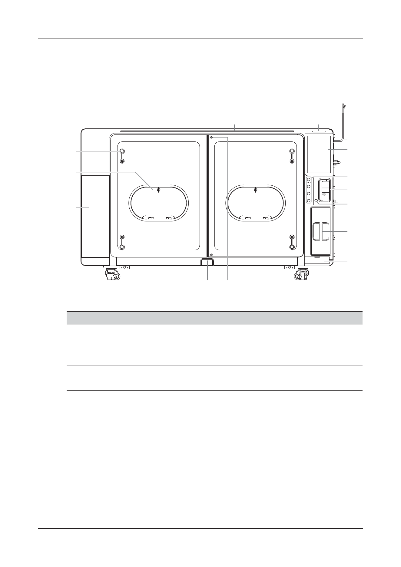
2 Product Overview
2 - 2
2.3 Introduction to Each Unit
2.3.1 ViCare U7
Figure 2-1 Front view
No. Name Description
1. Nursing Level
Indicator
Indicates the current animal's level of care with different colors.
2. Alarm Lamp When a physiological alarm or technical alarm occurs, this lamp lights and
flashes corresponding with the alarm priority.
3. Infusion Set Hook Used for hanging the infusion bag.
4. Touch Screen Screen-touching operator-system interface or control.
12
3
4
5
6
7
8
9
11 10
12
13
14
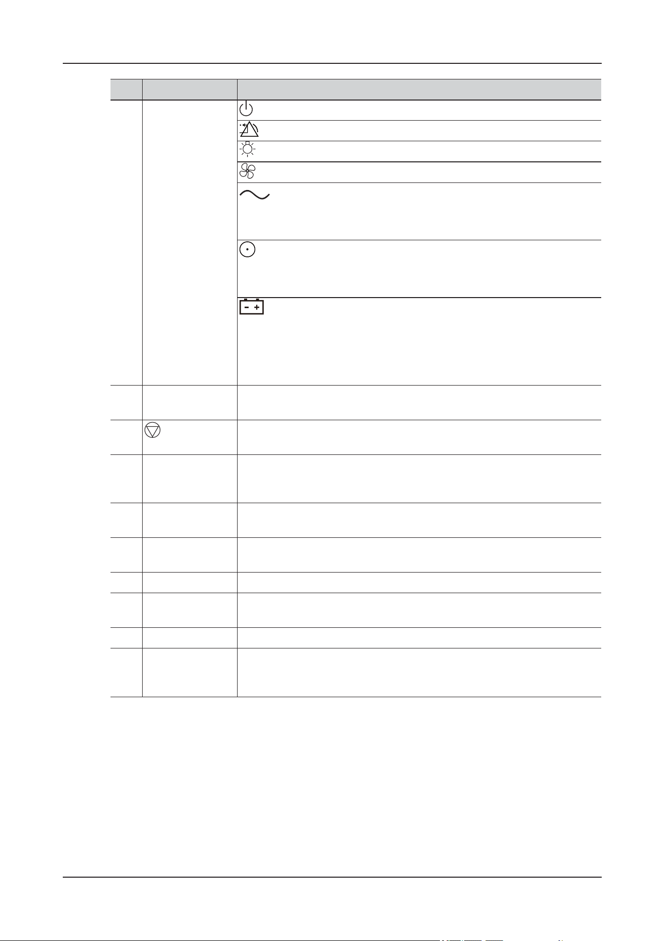
2 Product Overview
2 - 3
5. Control Panel (Power Button): Press to turn on/off the device.
(Alarm Reset Button): Press to reset the alarm system.
(Lamp Button): Press to turn on/off the light in the device.
(Ventilation Button): Press to turn on/off the emergency vents and fans.
(AC Power Indicator):
• On: the AC power supply is connected.
• Off: when the AC power is not connected.
(Power indicator):
• On: when the device is turned on.
• Off: when the device is turned off.
(Battery Indicator):
• Steady Green: the battery is fully charged or being charged.
• Flashing Green: the device operates by battery power.
• Off: no battery is installed, or the battery is malfunctioning, or the device
is powered off and no power is connected.
6. Built-in Infusion
Pump
Open the pump door to load or unload the infusion set.
7.
˄Infusion Stop
Button˅
Press to stop the infusion.
8. CO2 Absorber
Canister
Used for holding the CO2 absorbent. Inspect the color of the soda lime in the
canister. Replace the soda lime immediately if obvious color change is
detected.
9. Infusion Warmer Built-in infusion warmer module, used for heating the fluid or drug in the
infusion tubing.
10. Emergency Door
Screw (2)
Used for opening the cabin door in case of emergency. For emergency use
only.
11. Door Open Button Used for opening the cabin door.
12. Storage
Compartment
Used for temporal storage.
13. Operation Window Used for animal care inside the device.
14. Multi-function
Operation Hole
Used for routing infusion tubes and cables, and connecting to the nebulizer.
In case of emergency ventilation, it can also be fully opened to form air
convection.
No. Name Description
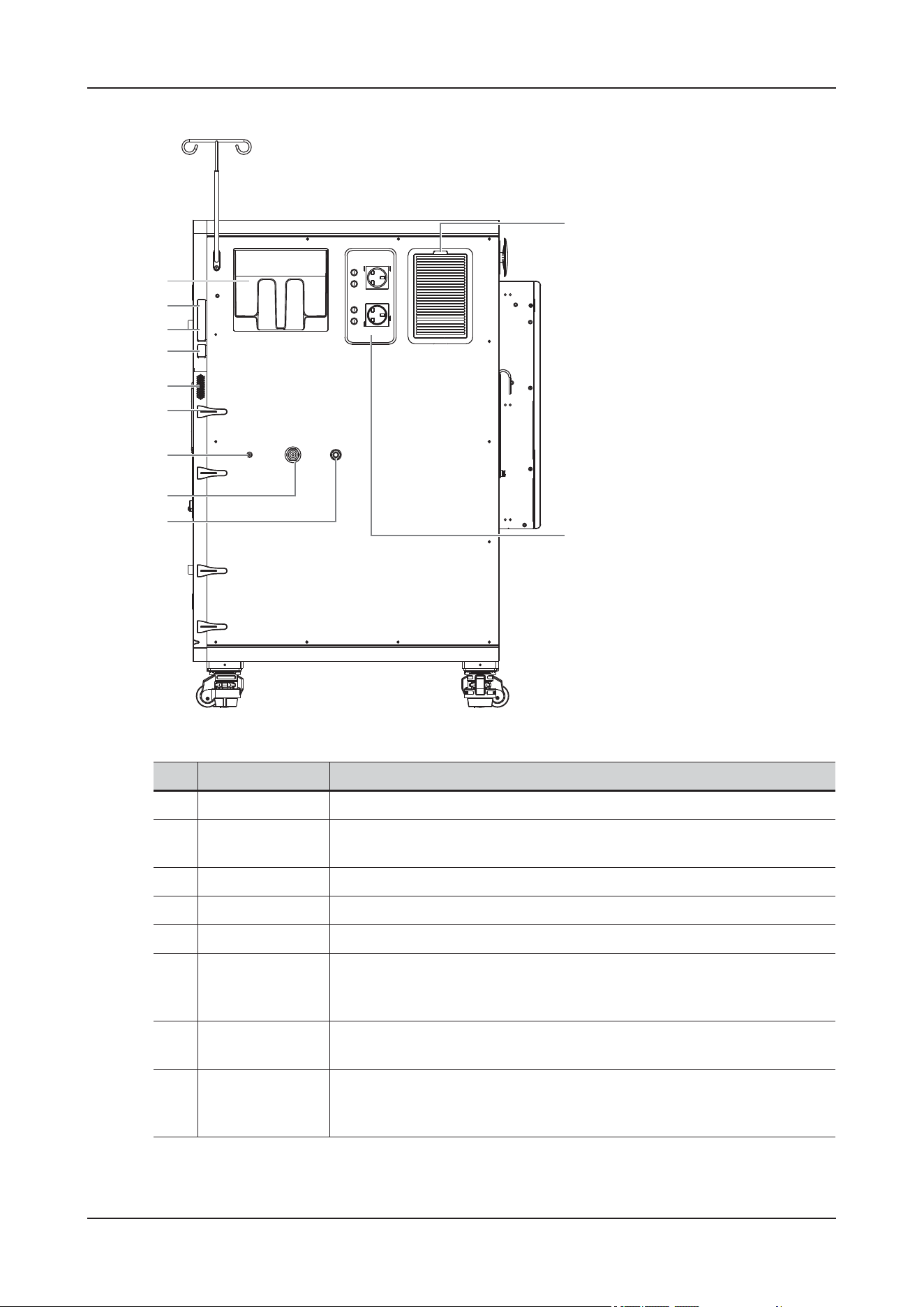
2 Product Overview
2 - 4
Figure 2-2 Right View
No. Name Description
1. Water Tank Used for filling purified water for humidification.
2. Data Transmission
Ports
Used for connecting external I/O devices.
3. Video Output Port Used for connecting the external display
4. USB Ports Used for connecting USB devices.
5. Speaker Outputs the audio.
6. Cable
Management
Clamp
Used for arranging cables and tubes.
7. Nebulizer
Connector
Used for connecting a nebulizer.
8. High-Pressure
Oxygen Supply
Connector
Used for connecting the high-pressure oxygen supply.
1
2
3
4
5
6
7
8
9
10
11
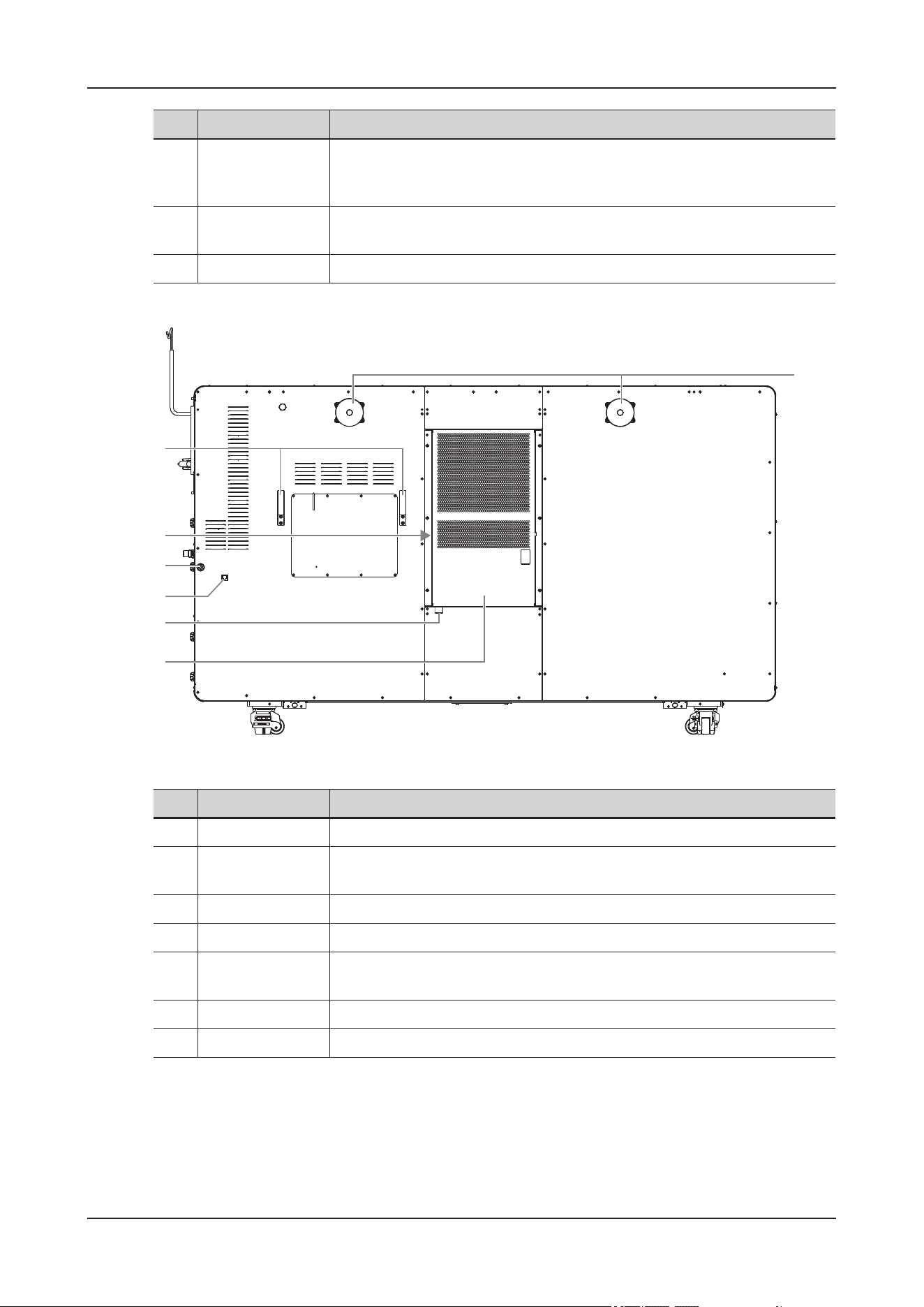
2 Product Overview
2 - 5
Figure 2-3 Rear view
9. Low-Pressure
Oxygen Supply
Connector
Used for connecting the low-pressure oxygen supply.
10. AC Power
Auxiliary Outputs
Used for supplying power for optional peripheral devices.
11. Dust-Proof Mesh Used for filtering dust and hair.
No. Name Description
1. Cable Hooks Used for arranging cables.
2. A/C Dust-Proof
Mesh
Used for filtering dust and hair.
3. Drain Connector Used for connecting drain tubes or containers.
4. Network Port Used for connecting the wired network.
5. A/C Drain
Connector
Used for connecting drain tubes or containers.
6. Air Conditioner Used for control the temperature conditions inside the device.
7. Vent Used for cooling the main unit.
No. Name Description
1
7
2
3
4
5
6
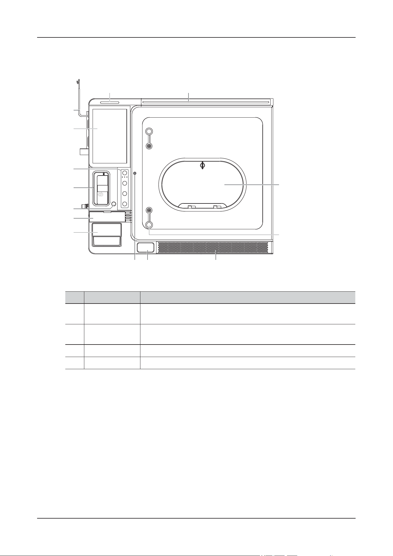
2 Product Overview
2 - 6
2.3.2 ViCare U7L
Figure 2-4 Front view
No. Name Description
1. Nursing Level
Indicator
Indicates the current animal's level of care with different colors.
2. Alarm Lamp When a physiological alarm or technical alarm occurs, this lamp lights and
flashes corresponding with the alarm priority.
3. Infusion Set Hook Used for hanging the infusion bag.
4. Touch Screen Screen-touching operator-system interface or control.
1
14
13
2
4
5
6
8
9
1110
7
12
3
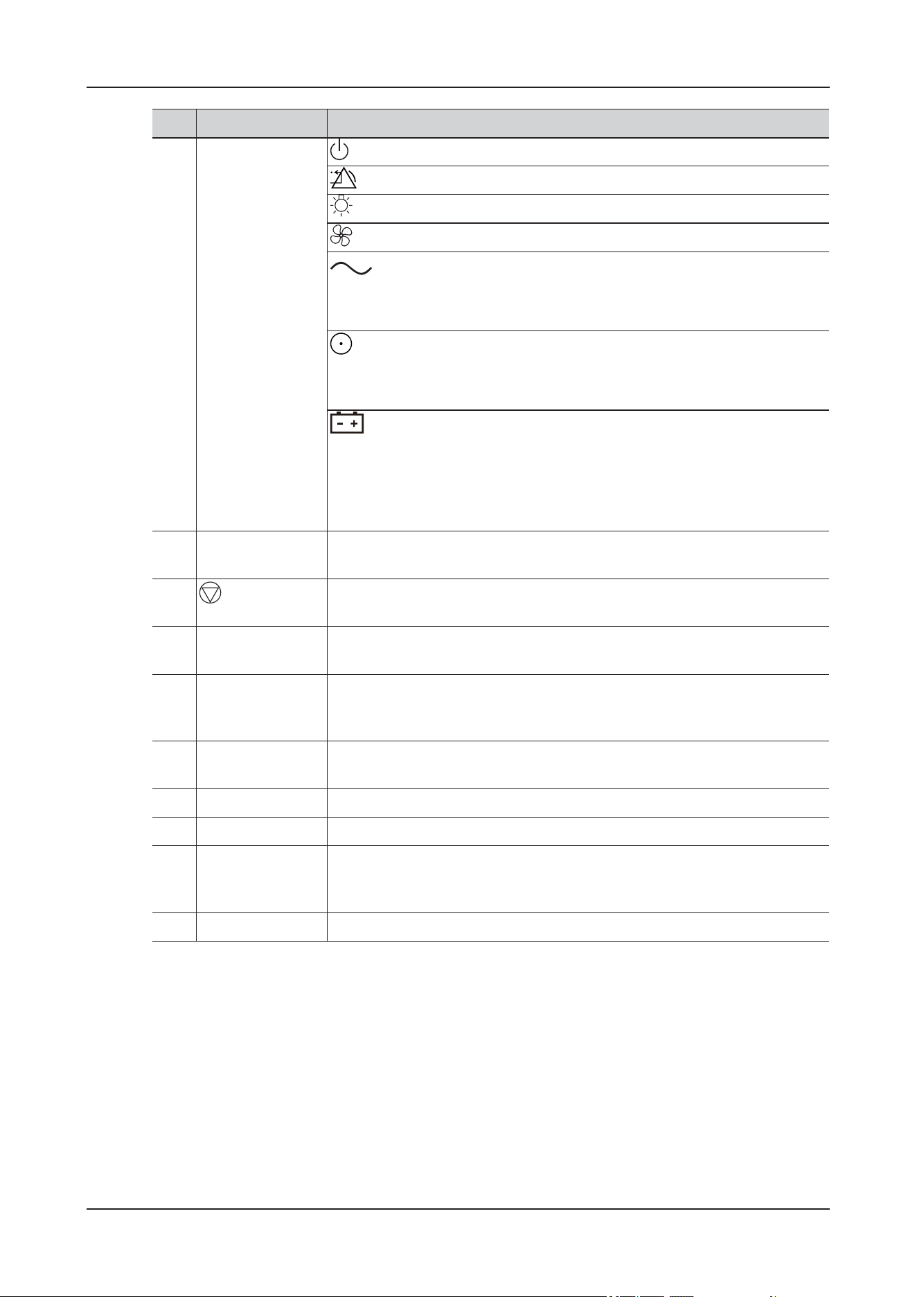
2 Product Overview
2 - 7
5. Control Panel (Power Button): Press to turn on/off the device.
(Alarm Reset Button): Press to reset the alarm system.
(Lamp Button): Press to turn on/off the light in the device.
(Ventilation Button): Press to turn on/off the emergency vents and fans.
(AC Power Indicator):
• On: the AC power supply is connected.
• Off: when the AC power is not connected.
(Power indicator):
• On: when the device is turned on.
• Off: when the device is turned off.
(Battery Indicator):
• Steady Green: the battery is fully charged or being charged.
• Flashing Green: the device operates by battery power.
• Off: no battery is installed, or the battery is malfunctioning, or the device
is powered off and no power is connected.
6. Built-in Infusion
Pump
Open the pump door to load or unload the infusion set.
7.
˄Infusion Stop
Button˅
Press to stop the infusion.
8. Infusion Warmer Built-in infusion warmer module, used for heating the fluid or drug in the
infusion tubing.
9. CO2 Absorber
Canister
Used for holding the CO2 absorbent. Inspect the color of the soda lime in the
canister. Replace the soda lime immediately if obvious color change is
detected.
10. Emergency Door
Screw
Used for opening the cabin door in case of emergency. For emergency use
only.
11. Door Open Button Used for opening the cabin door.
12. Dust-Proof Mesh Used for filtering dust and hair.
13. Multi-function
Operation Hole
Used for routing infusion tubes and cables, and connecting to the nebulizer.
In case of emergency ventilation, it can also be fully opened to form air
convection.
14. Operation Window Used for animal care inside the device.
No. Name Description
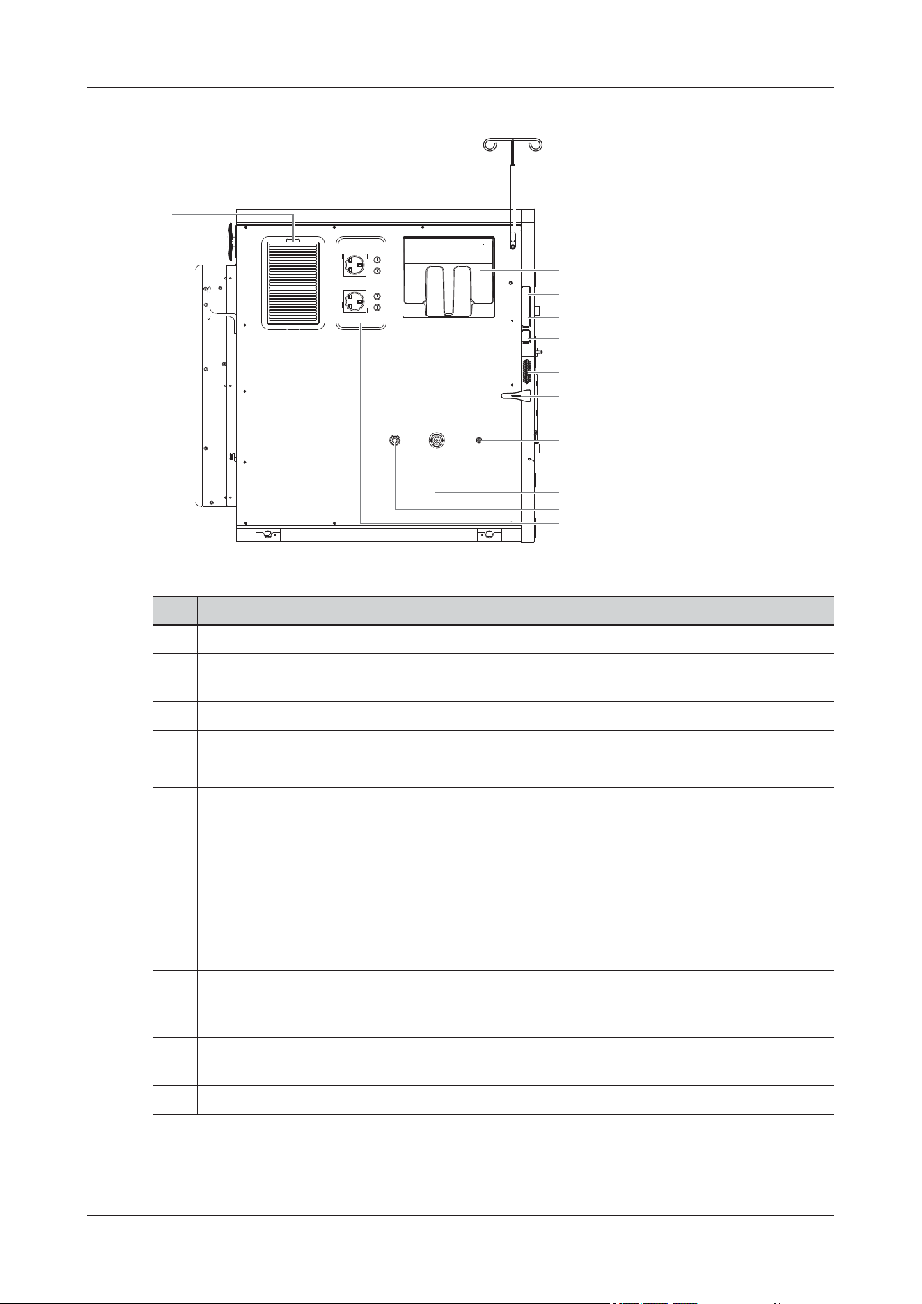
2 Product Overview
2 - 8
Figure 2-5 Left view
No. Name Description
1. Water Tank Used for filling purified water for humidification.
2. Data Transmission
Ports
Used for connecting external I/O devices.
3. Video Output Port Used for connecting the external display
4. USB Ports Used for connecting USB devices.
5. Speaker Outputs the audio.
6. Cable
Management
Clamp
Used for arranging cables and tubes.
7. Nebulizer
Connector
Used for connecting a nebulizer.
8. High-Pressure
Oxygen Supply
Connector
Used for connecting the high-pressure oxygen supply.
9. Low-Pressure
Oxygen Supply
Connector
Used for connecting the low-pressure oxygen supply.
10. AC Power
Auxiliary Outputs
Used for supplying power for optional peripheral devices.
11. Dust-Proof Mesh Used for filtering dust and hair.
1
2
3
4
5
6
7
8
9
10
11
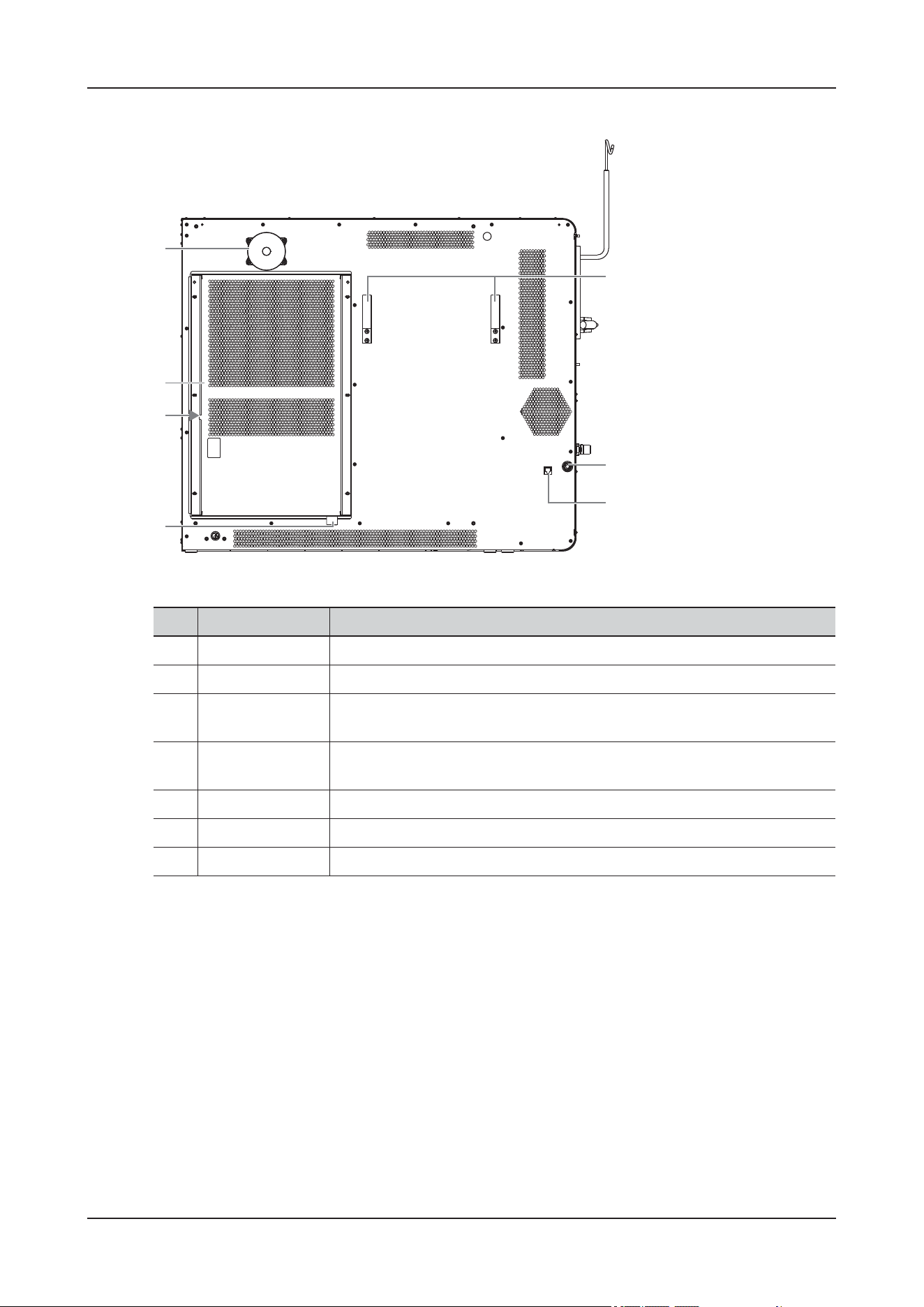
2 Product Overview
2 - 9
Figure 2-6 Rear view
No. Name Description
1. Vent Used for cooling the main unit.
2. Air Conditioner Used for control the temperature conditions inside the device.
3. A/C Dust-Proof
Mesh
Used for filtering dust and hair.
4. A/C Drain
Connector
Used for connecting drain tubes or containers.
5. Network Port Used for connecting the wired network.
6. Drain Connector Used for connecting drain tubes or containers.
7. Cable Hooks Used for arranging cables.
1
2
3
4
5
6
7
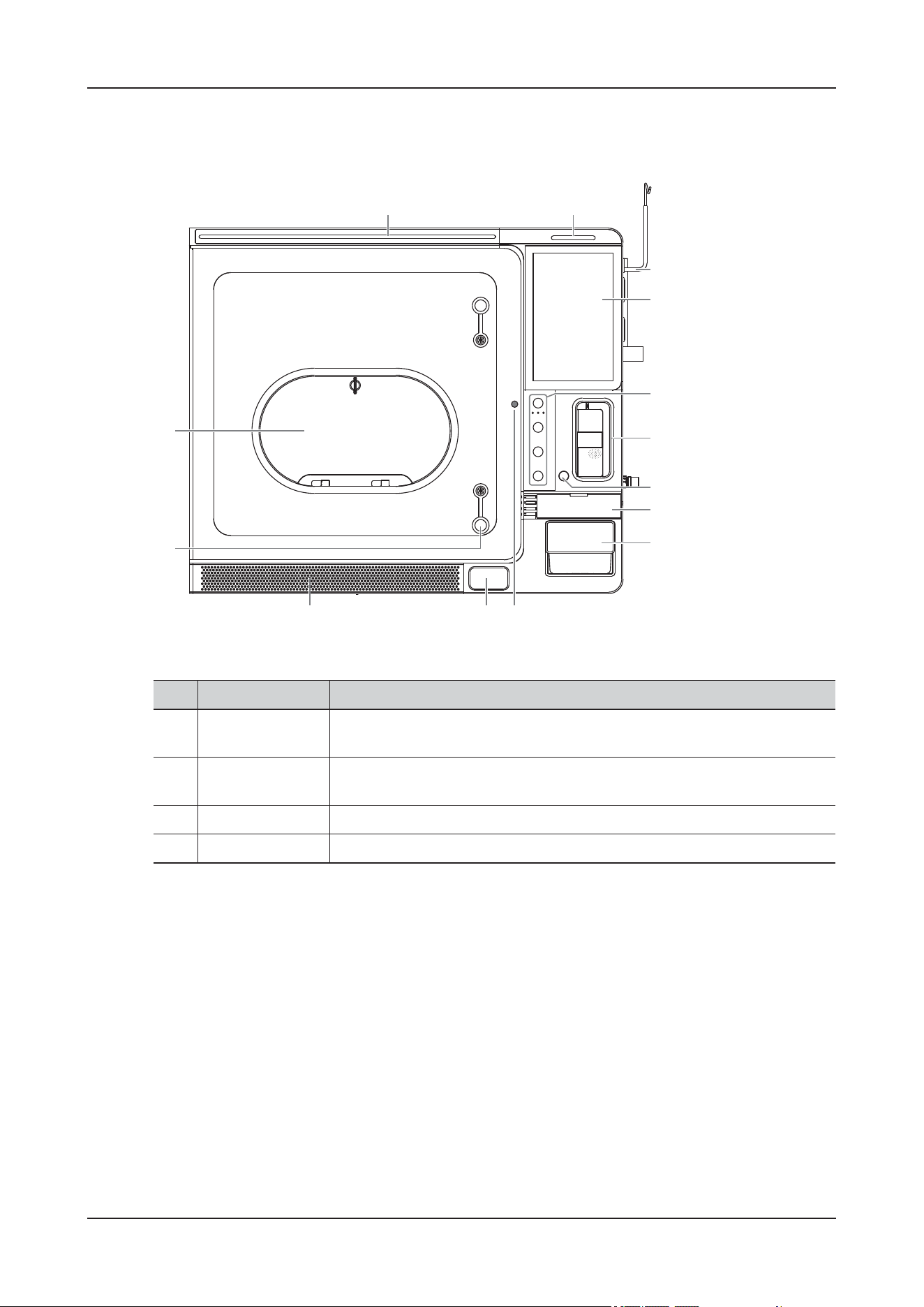
2 Product Overview
2 - 10
2.3.3 ViCare U7R
Figure 2-7 Front view
No. Name Description
1. Nursing Level
Indicator
Indicates the current animal's level of care with different colors.
2. Alarm Lamp When a physiological alarm or technical alarm occurs, this lamp lights and
flashes corresponding with the alarm priority.
3. Infusion Set Hook Used for hanging the infusion bag.
4. Touch Screen Screen-touching operator-system interface or control.
1
14
13
2
4
5
6
8
9
1011
12
7
3
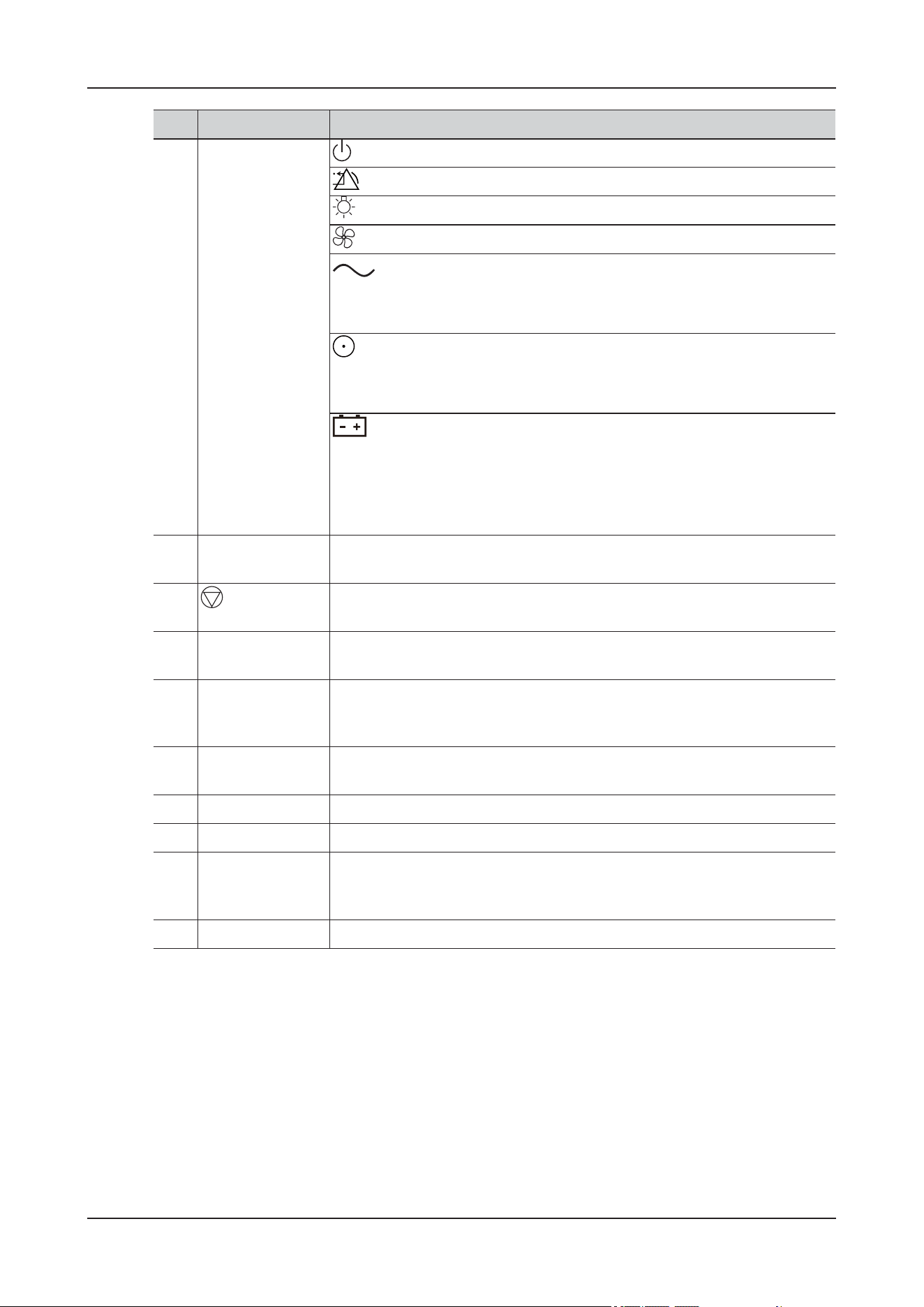
2 Product Overview
2 - 11
5. Control Panel (Power Button): Press to turn on/off the device.
(Alarm Reset Button): Press to reset the alarm system.
(Lamp Button): Press to turn on/off the light in the device.
(Ventilation Button): Press to turn on/off the emergency vents and fans.
(AC Power Indicator):
• On: the AC power supply is connected.
• Off: when the AC power is not connected.
(Power indicator):
• On: when the device is turned on.
• Off: when the device is turned off.
(Battery Indicator):
• Steady Green: the battery is fully charged or being charged.
• Flashing Green: the device operates by battery power.
• Off: no battery is installed, or the battery is malfunctioning, or the device
is powered off and no power is connected.
6. Built-in Infusion
Pump
Open the pump door to load or unload the infusion set.
7.
˄Infusion Stop
Button˅
Press to stop the infusion.
8. Infusion Warmer Built-in infusion warmer module, used for heating the fluid or drug in the
infusion tubing.
9. CO2 Absorber
Canister
Used for holding the CO2 absorbent. Inspect the color of the soda lime in the
canister. Replace the soda lime immediately if obvious color change is
detected.
10. Emergency Door
Screw
Used for opening the cabin door in case of emergency. For emergency use
only.
11. Door Open Button Used for opening the cabin door.
12. Dust-Proof Mesh Used for filtering dust and hair.
13. Multi-function
Operation Hole
Used for routing infusion tubes and cables, and connecting to the nebulizer.
In case of emergency ventilation, it can also be fully opened to form air
convection.
14. Operation Window Used for animal care inside the device.
No. Name Description
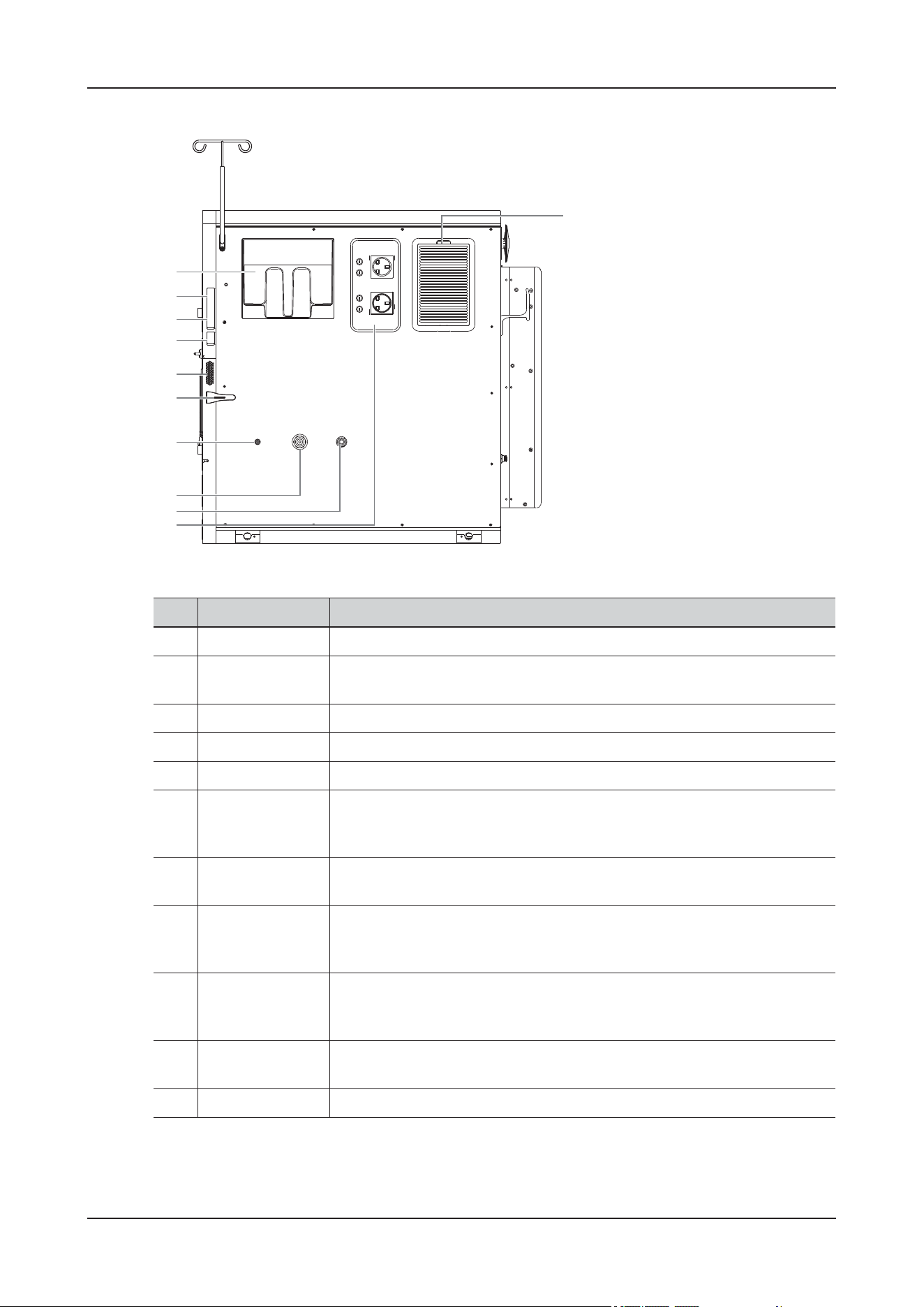
2 Product Overview
2 - 12
Figure 2-8 Right view
No. Name Description
1. Water Tank Used for filling purified water for humidification.
2. Data Transmission
Ports
Used for connecting external I/O devices.
3. Video Output Port Used for connecting the external display
4. USB Ports Used for connecting USB devices.
5. Speaker Outputs the audio.
6. Cable
Management
Clamp
Used for arranging cables and tubes.
7. Nebulizer
Connector
Used for connecting a nebulizer.
8. High-Pressure
Oxygen Supply
Connector
Used for connecting the high-pressure oxygen supply.
9. Low-Pressure
Oxygen Supply
Connector
Used for connecting the low-pressure oxygen supply.
10. AC Power
Auxiliary Outputs
Used for supplying power for optional peripheral devices.
11. Dust-Proof Mesh Used for filtering dust and hair.
1
2
3
4
5
6
7
8
9
10
11
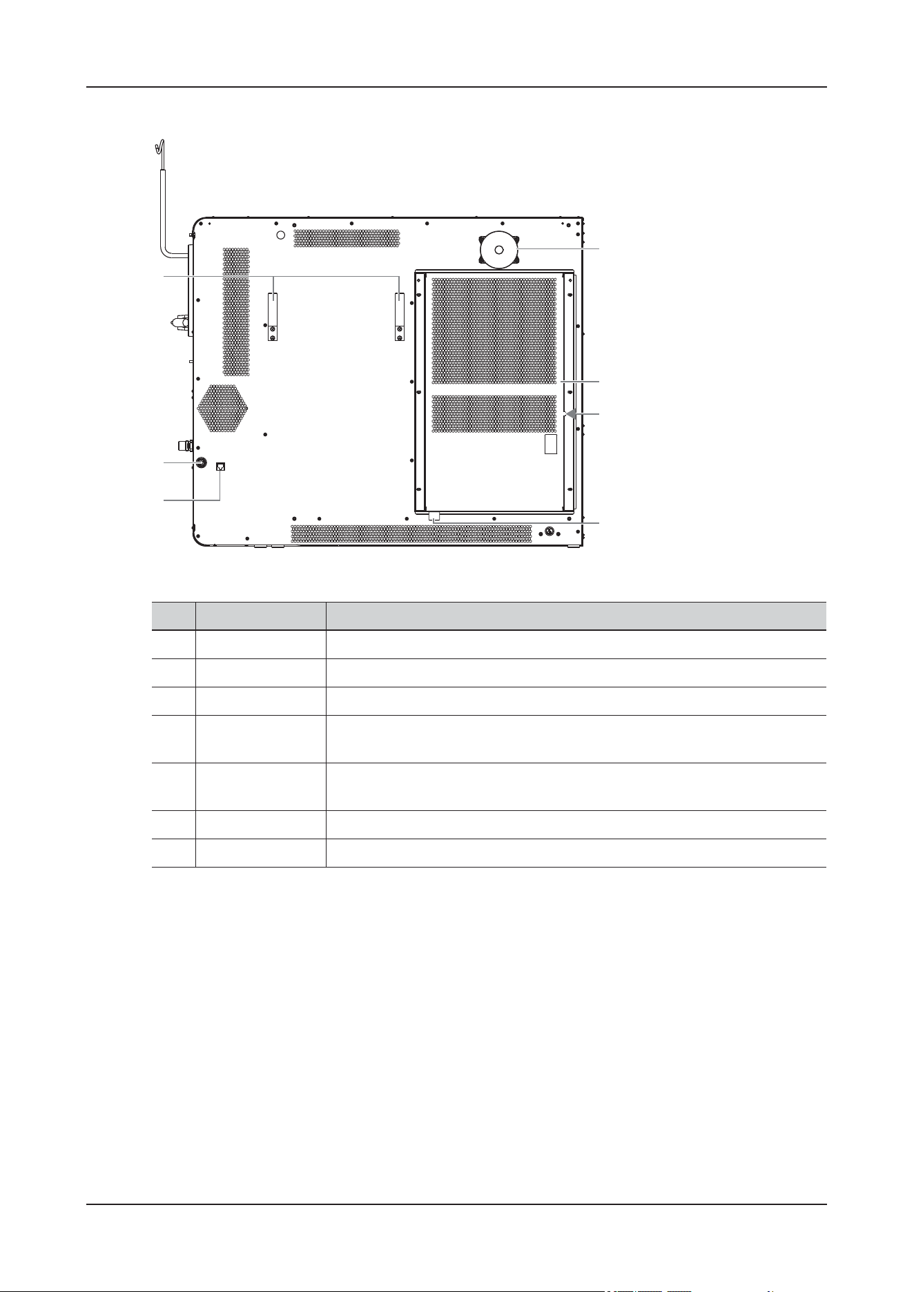
2 Product Overview
2 - 13
Figure 2-9 Rear view
No. Name Description
1. Cable Hooks Used for arranging cables.
2. Drain Connector Used for connecting drain tubes or containers.
3. Network Port Used for connecting the wired network.
4. A/C Drain
Connector
Used for connecting drain tubes or containers.
5. A/C Dust-Proof
Mesh
Used for filtering dust and hair.
6. Air Conditioner Used for control the temperature conditions inside the device.
7. Vent Used for cooling the main unit.
1
2
3
4
5
6
7
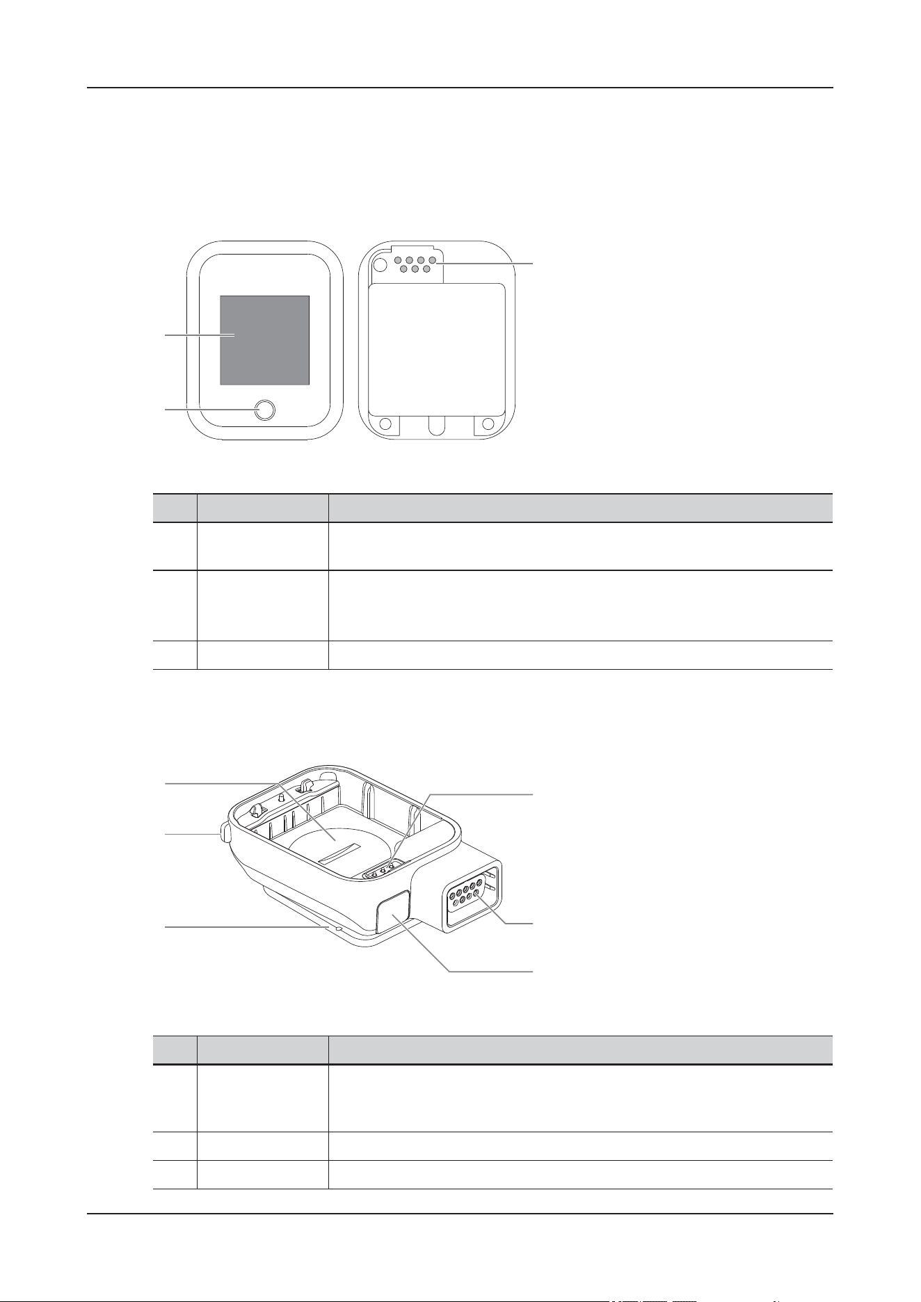
2 Product Overview
2 - 14
2.4 Wireless Monitoring Modules
2.4.1 SpO
2
Module (MAS30)
Figure 2-10 SpO
2
module
2.4.2 Temp Module (MAT30)
Figure 2-11 Temp module
No. Name Description
1. Display screen Displays ECG, SpO
2
, blood pressure, temperature parameters, connection
status, and so on.
2. Touch button • On a black screen, press the button to wake the screen up.
• On a working screen, press the button to switch between different
interfaces.
3. Contacts Used for connecting the Temp module.
1
2
3
No. Name Description
1. Battery
compartment of
Temp module
Used for powering the Temp module.
2. Release button Press to unlock the SpO
2
module and Temp module.
3. Clip Used for fixing the NIBP module.
1
2
4
5
6
3
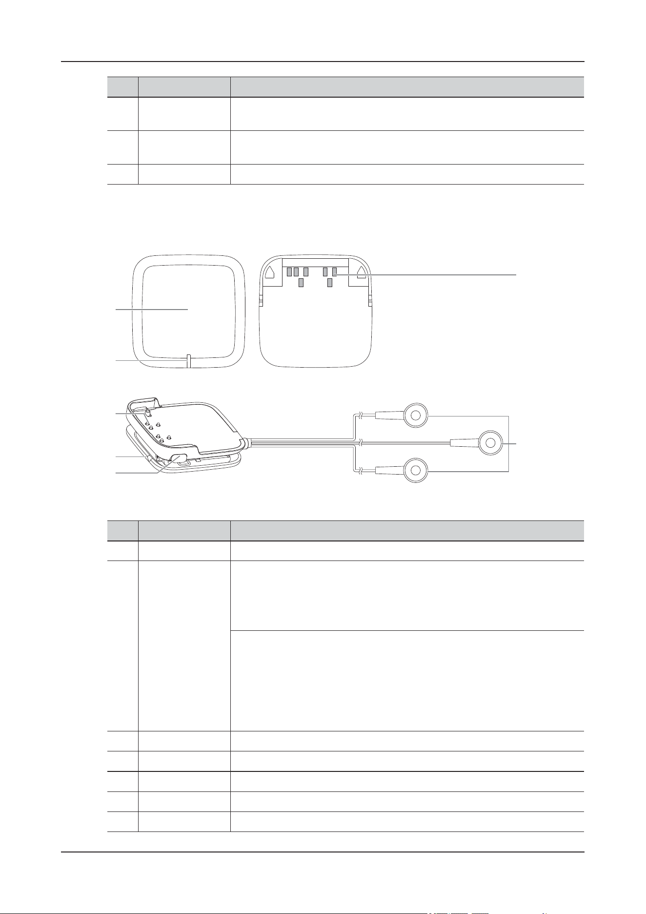
2 Product Overview
2 - 15
2.4.3 ECG module (MAE30)
Figure 2-12 ECG module and ECG lead
4. Temperature probe
connector
Used for connecting the temperature probe
5. SpO
2
sensor
connector
Used for connecting the SpO
2
sensor.
6. Contacts Used for connecting the SpO
2
module.
No. Name Description
No. Name Description
1. ECG module Used for connecting the ECG lead and transmitting ECG monitoring signal.
2. Status indicator When connected with an ECG lead:
• Lighting up in green and then off: the ECG module is paired successfully
and starts working.
• Flashing green: the ECG module is searching the device to be paired.
When installed on the charger:
• Flashing green: the battery is being charged.
• Green: the battery is fully charged.
• Yellow: error occurred during charging.
• Off: the charger is not connected to the AC power, or the charger is
malfunctioning.
3. Contacts Used for connecting the ECG Module.
4. Clip Used for fixing the ECG module.
5. Release button Press to unlock the ECG lead and the ECG module.
6. ECG electrodes Used for installing electrode pads.
7. Contacts Used for connecting the ECG lead.
6
7
2
3
4
5
1
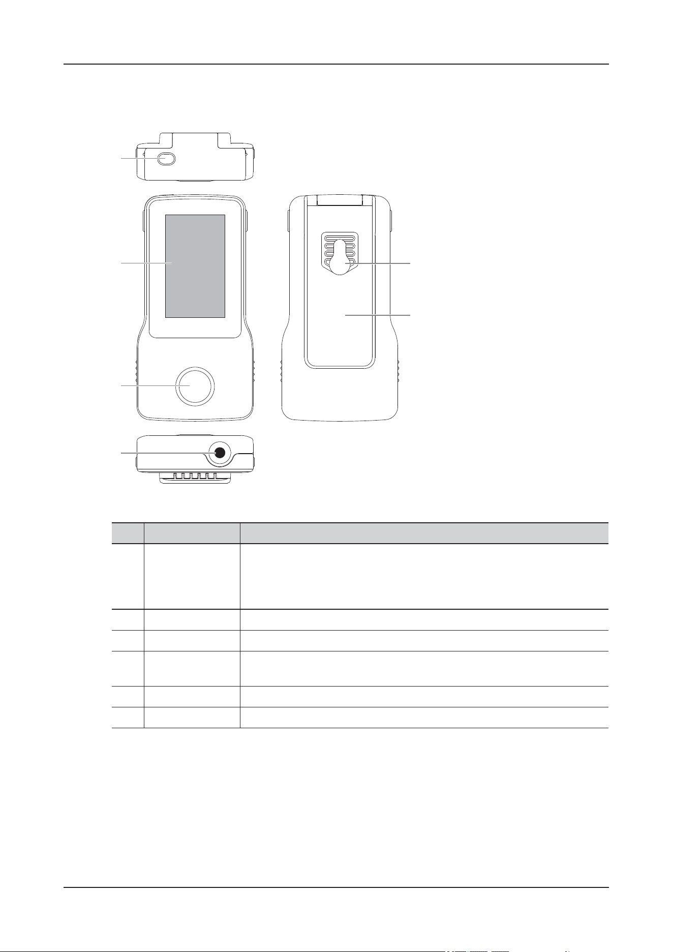
2 Product Overview
2 - 16
2.4.4 NIBP Module (MAB30)
Figure 2-13 NIBP module
No. Name Description
1. Power on/off
button
• After a battery is installed and when the NIBP module is off: press to turn
on the NIBP module.
• When the NIBP module is on: press and hold to turn off the NIBP
module.
2. Display Displays the measurement results.
3. Start/Stop button Press to start/stop NIBP measurement.
4. NIBP hose
connector
Used for connecting the NIBP air hoses.
5. Clip Fix the blood pressure module.
6. Installation hole Used for hanging the NIBP module.
1
2
3
4
5
6
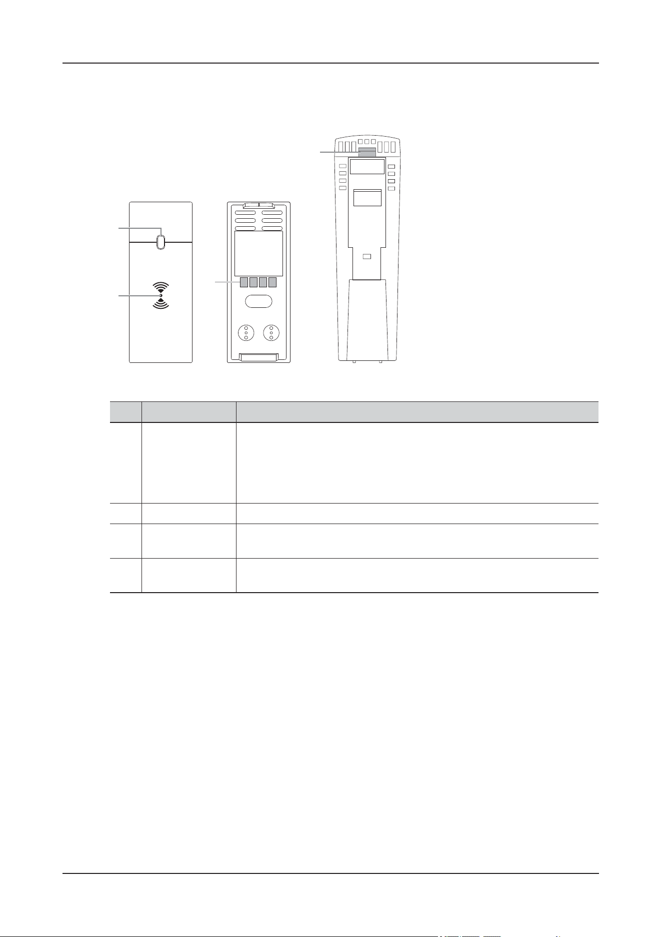
2 Product Overview
2 - 17
2.4.5 Receiver Module (R20)
Figure 2-14 Receiver module
No. Name Description
1. Status indicator • On: the SpO
2
module has established Bluetooth connection with the
device
• Flashing: the receiver works properly but has no Bluetooth connection
with an SpO
2
module.
• Off: the receiver is not properly installed or is malfunctioning.
2. Pairing area Place the SpO
2
module close to the sensing region for pairing.
3. Contacts (rear
panel)
Used for transmitting data or charge the battery. Avoid touching the contacts
during operation.
4. Release button
(bottom panel)
Press to unlock and disconnect the receiver from the device.
1
2
3
4
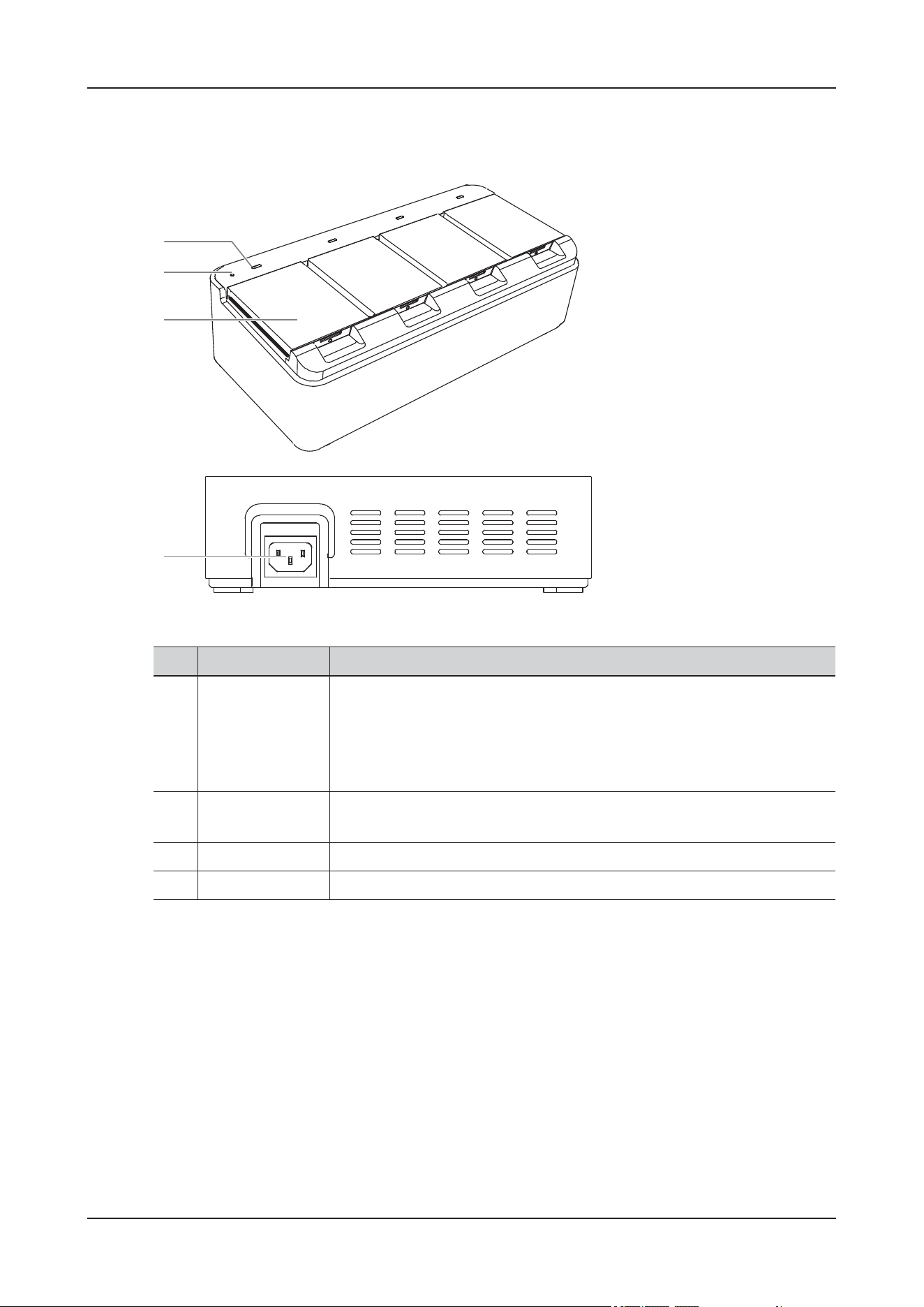
2 Product Overview
2 - 18
2.4.6 Chargers
Figure 2-15 C10 Charger
No. Name Description
1. Status indicator for
the batteries of
NIBP modules
• Steady yellow: the battery is being charged.
• Flashing yellow: a charging failure occurs.
• Steady green: the battery is fully charged.
• Off: the battery is not properly connected or the charger is not connected
to the AC power supply.
2. AC Power
indicator
• On: AC power is connected.
• Off: no AC power is connected.
3. Charing slot Used for installing the batteries for charging.
4. AC power socket Used for connecting to the AC power supply.
1
2
3
4
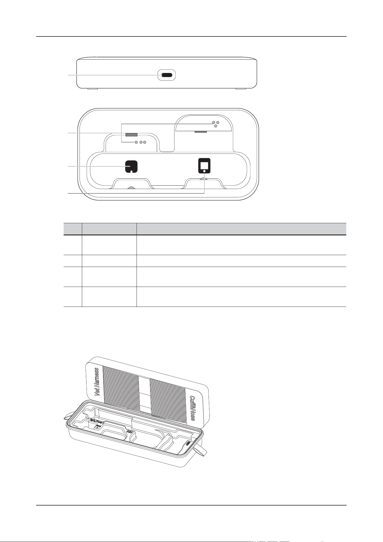
2 Product Overview
2 - 19
Figure 2-16 C25 Charger
2.5 Portable Storage Bag
Figure 2-17 Portable Storage Bag
Pull the zipper to open the accessory storage bag, and store the accessories according to the label areas.
No. Name Description
1. USB Type-C
connector
Used for connecting a USB Type-C cable for power input.
2. Contacts Used for charging the battery. Avoid touching the contacts during operation.
3. Charging slot for
the ECG module
Used for installing the ECG module for charging.
4. Charging slot for
the SpO
2
module
Used for installing the SpO
2
module for charging.
1
2
3
4
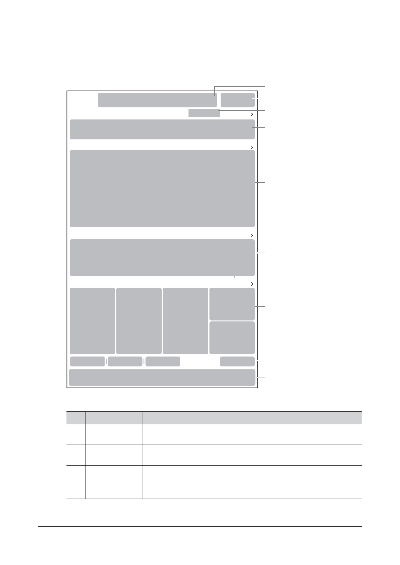
2 Product Overview
2 - 20
2.6 Screen Display
Figure 2-18 Main screen
No. Name Description
1. Alarm Information
Area
Displays technical alarm messages, physiological alarm messages and
prompt messages.
2. System Status
Information Area
Displays alarm symbol, battery status, network status, storage device status,
and system time.
3. CMS display area Displays the currently connected CMS.
Tap to open the available CMS list, and select the desired central monitoring
system to be connected.
XXXXXXX
XXXXXX
XXXXXX
XXXXXX
2
1
3
4
5
6
7
9
8
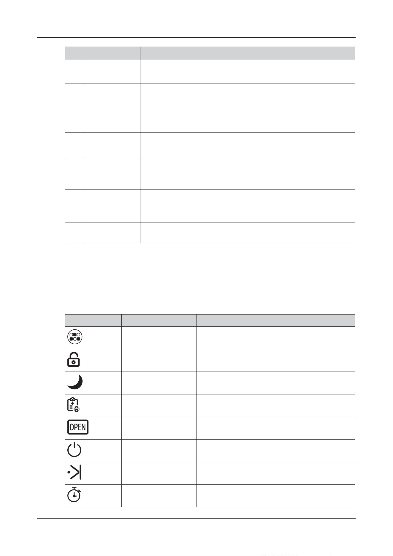
2 Product Overview
2 - 21
2.6.1 Available Quick Keys
The device provides quick keys to allow quick access some functions.
The quick keys displayed on the Monitoring interface are configurable.
4. Patient
Information Area
Displays the basic animal information.
Tap to enter the Patient details interface.
5. Monitoring
Parameters Area
Displays parameter waveforms or parameter values, units, alarm limits, and
alarm status.
Tap to enter the Monitoring details interface. Selecting a waveform enters
corresponding parameter menu, selecting the parameter list enters tabular
trend review.
6. Infusion
Parameters Area
Displays the basic infusion information.
Tap to enter the Infusion details interface.
7. Environmental
Parameters Area
Displays the basic environment control information.
Tap to enter the Environment details interface to set environment
parameters and auxiliary functions.
8. Auxiliary
Functions Running
Status Area
Displays information of the enabled auxiliary functions.
Tap to enter the Environment details interface to set environment
parameters and auxiliary functions.
9. Quick Buttons
Area
Displays the quick keys supported in the current function module.
No. Name Description
Symbols Name Function
More Tap to show more quick keys.
Screen Lock Tap to lock the touch screen.
Night Mode Tap to enter the night mode.
End Case Report Tap to print the selected end case reports.
Open Door Tap to open the cabin door.
Standby Tap to enter the standby mode.
Manual Event Tap to manually trigger and save an event.
Timer Tap to open the Timer Setup menu.
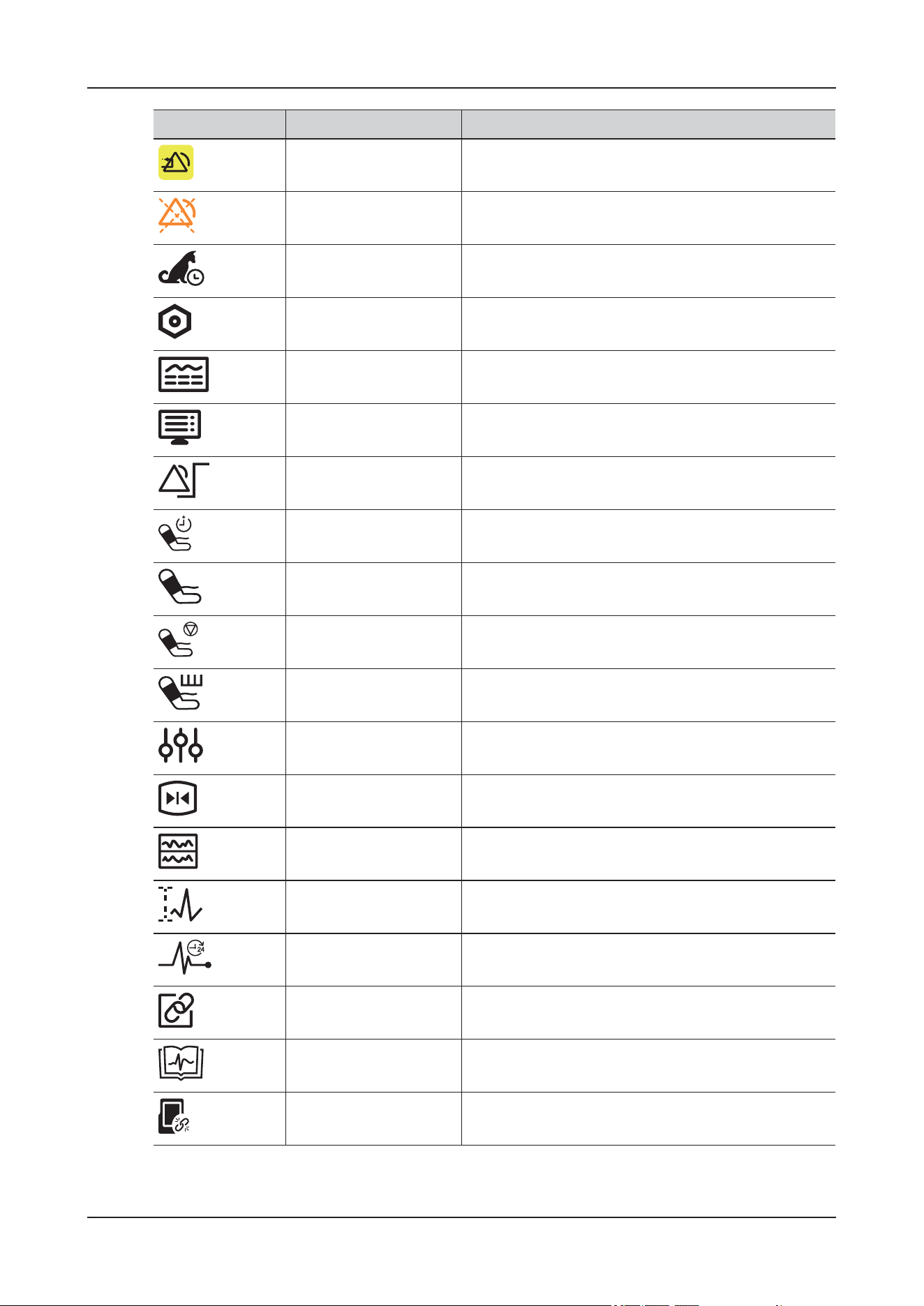
2 Product Overview
2 - 22
Alarm Reset Tap to reset the alarm system.
Alarm Pause Tap to pause the physiological alarms.
Discharged Patients Tap to open the Discharged Patients menu.
Setup Tap to open the corresponding setup menu.
Review Tap to open the Review menu.
Screen Setup Tap to open the Screen Setup menu.
Alarm Setup Tap to open the Alarm Setup menu.
NIBP Measure Tap to open the NIBP Measure menu.
NIBP Start/Stop Tap to start or stop the current NIBP measurement.
NIBP Stop All Tap to stop all NIBP measurements.
STAT Tap to start a five-minutes continuous NIBP
measurement.
Parameters Setup Tap to open the Parameters Setup menu.
Freeze Tap to freeze waveforms.
Minitrends Tap to enter the Minitrends screen.
ECG Lead/Gain Tap to open the ECG Lead/Gain menu.
ECG 24h Sum Tap to view the ECG 24h Summary.
Wireless Pair Tap to enter the Wireless Pair screen.
ECG Library Tap to enter the ECG Library screen.
Unpair Tap to unpair the SpO
2
Module with this device.
Symbols Name Function
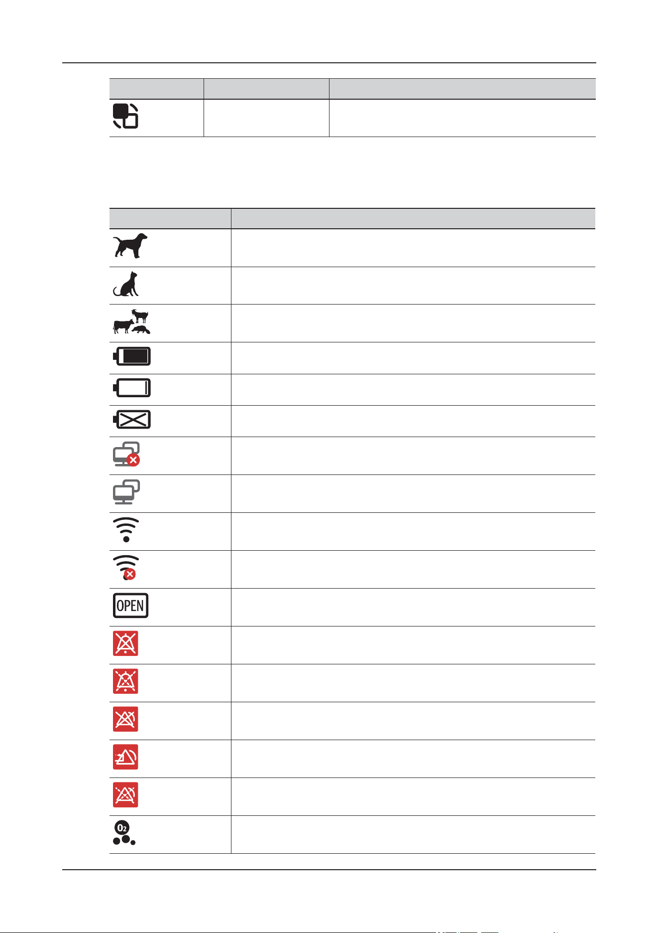
2 Product Overview
2 - 23
2.6.2 On-screen Symbols
Environment Mode Tap to enter the Environment Mode details interface.
Symbols Name Function
Symbol Description
Canine
Feline
Other
Battery capacity
The battery has low power and needs to be charged.
No battery is installed.
Wired network is not connected.
Wired network is connected.
Wireless network is connected. The solid part indicates network signal
strength.
Wireless network is not connected.
The cabin door not closed.
Audible alarm tones are turned off.
Audible alarm tones are paused.
Individual alarms are turned off or the device is in the alarm off status.
The alarm system is reset.
All the alarms are paused.
Oxygen
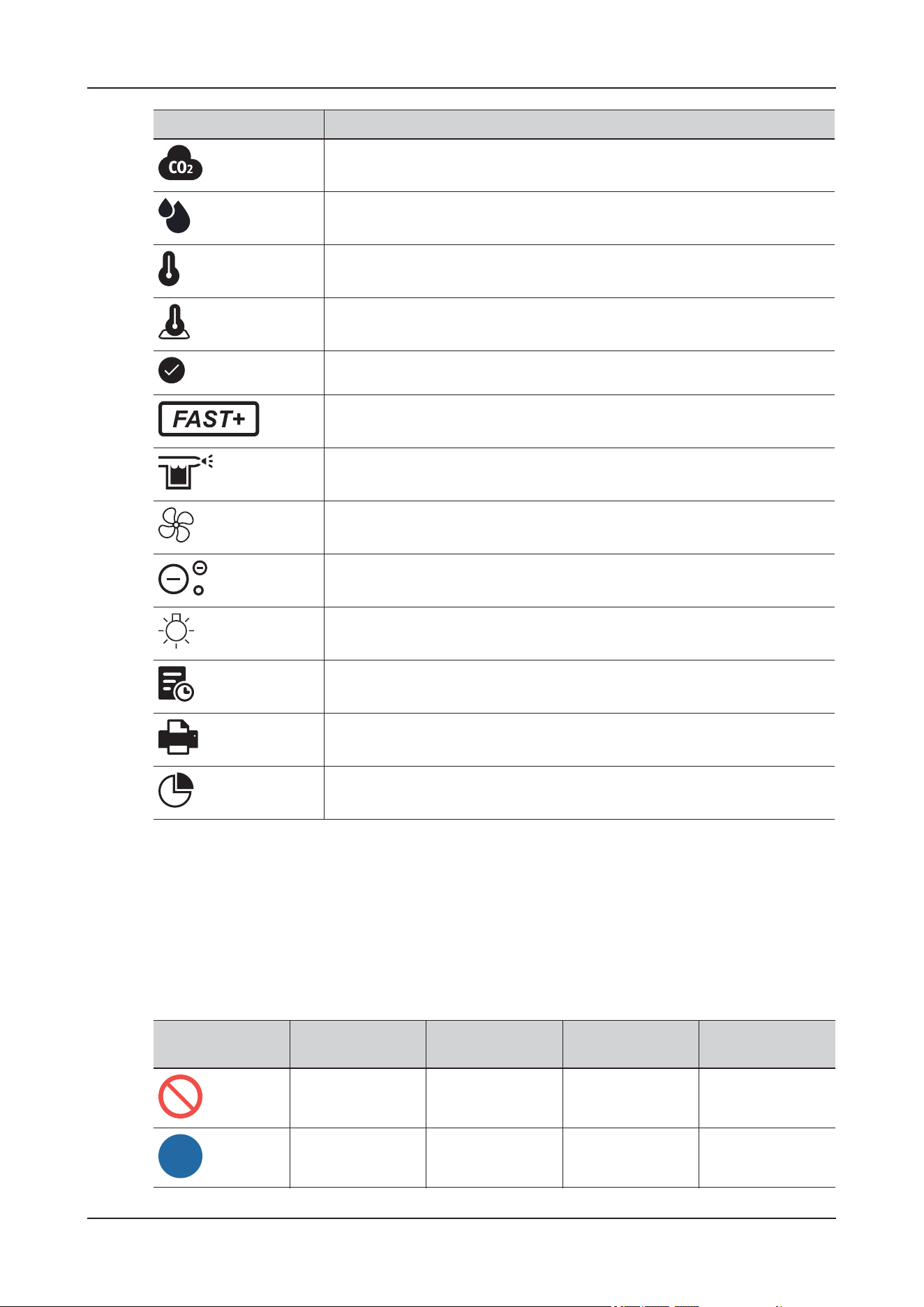
2 Product Overview
2 - 24
2.7 Symbols and Warning Labels
The symbols and warning labels of this device in order to call your attention to potential hazards. Read
this manual carefully before using the device.
The general meaning assigned to geometric shapes, safety colors and contrast colors for safety signs are
as follows:
Carbon dioxide (CO2)
Humidity
Air Temp
Floor Temp
Environment parameter has reached the target value
Smart Fast O2 Mode has been enabled.
Nebulization
Ventilation
Anion
Light
Patient Status Review
Patient Report
Inpatient Statistics
Symbol Description
Geometric shape Meaning Safety color Contrast color Graphical symbol
color
Prohibition Red White Black
Mandatory action Blue White White
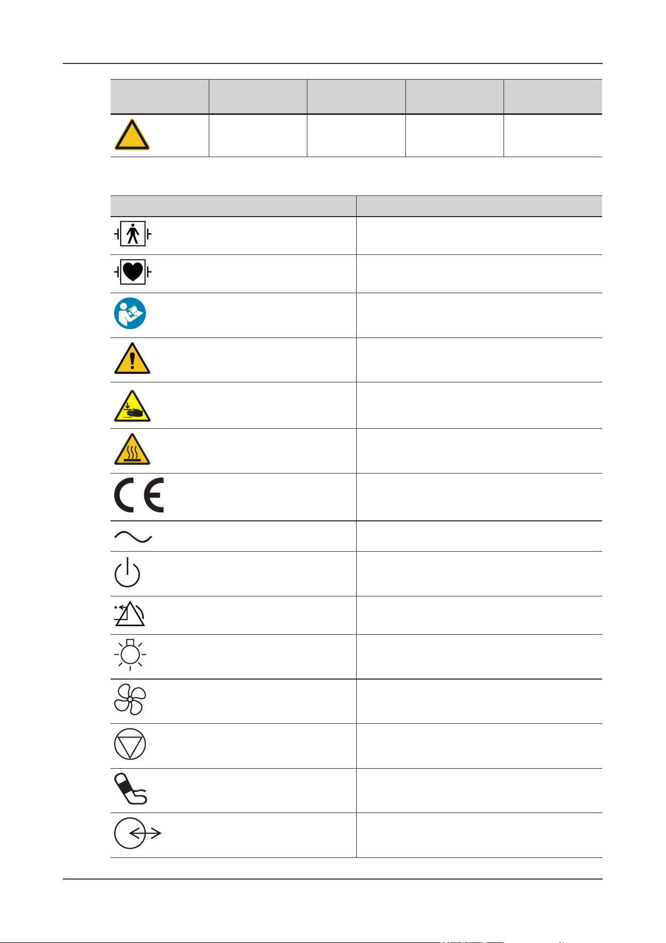
2 Product Overview
2 - 25
Their meanings are explained as follows:
Warning Yellow Black Black
Symbol Description
DEFIBRILLATION-PROOF TYPE BF APPLIED
PART
DEFIBRILLATION-PROOF TYPE CF APPLIED
PART
Refer to instruction manual/booklet
General warning sign
Warning; Crushing of hands
Warning; Hot surface
CE marking
Alternating current
Stand-by
ALARM RESET
Lamp; lighting; illumination
Ventilating fan; air-circulating fan
Stop
NIBP start/stop
Input/Output
Geometric shape Meaning Safety color Contrast color Graphical symbol
color
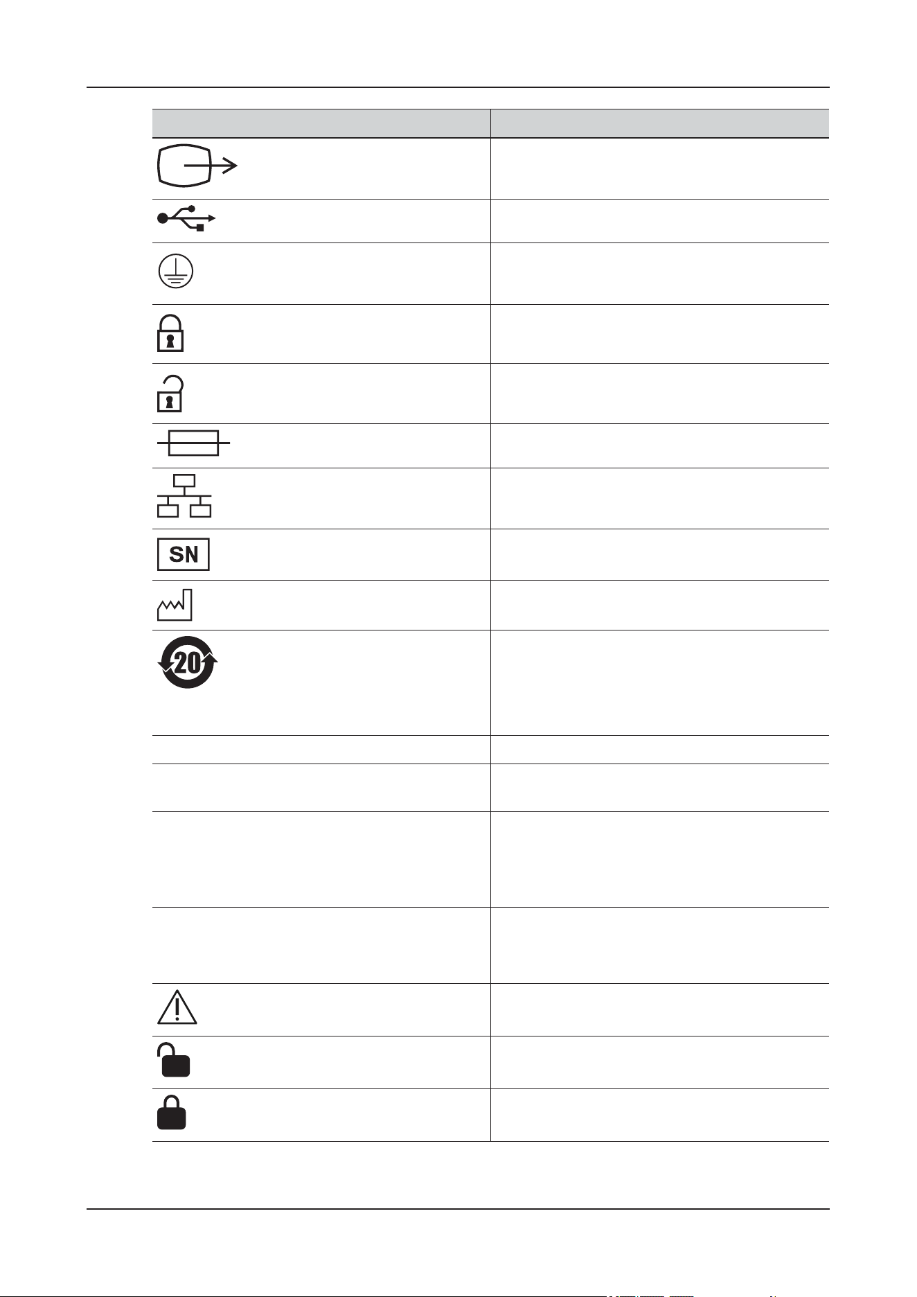
2 Product Overview
2 - 26
Video output
USB port
Protective earth (ground)
Locking, general
Unlocking
Fuse
Computer network
Serial number
Date of manufacture
RoHS (China). Administrative Measure on the
Control of Pollution Caused by Electronic
Information Products. Contains RoHS substances
with 20 years environmentally friendly use period
(EFUP)
IPX1 Protected against vertically falling water drops
IPX2 Protected against vertically falling water drops
when enclosure tilted up to 15°
IP22 Protected against solid foreign objects of 12.5 mm
ĭ and greater;
Protected against vertically falling water drops
when enclosure tilted up to 15°
IP24 Protected against solid foreign objects of 12.5 mm
ĭ and greater;
Protected against splashing water
Caution
Unlocking position
Locking position
Symbol Description
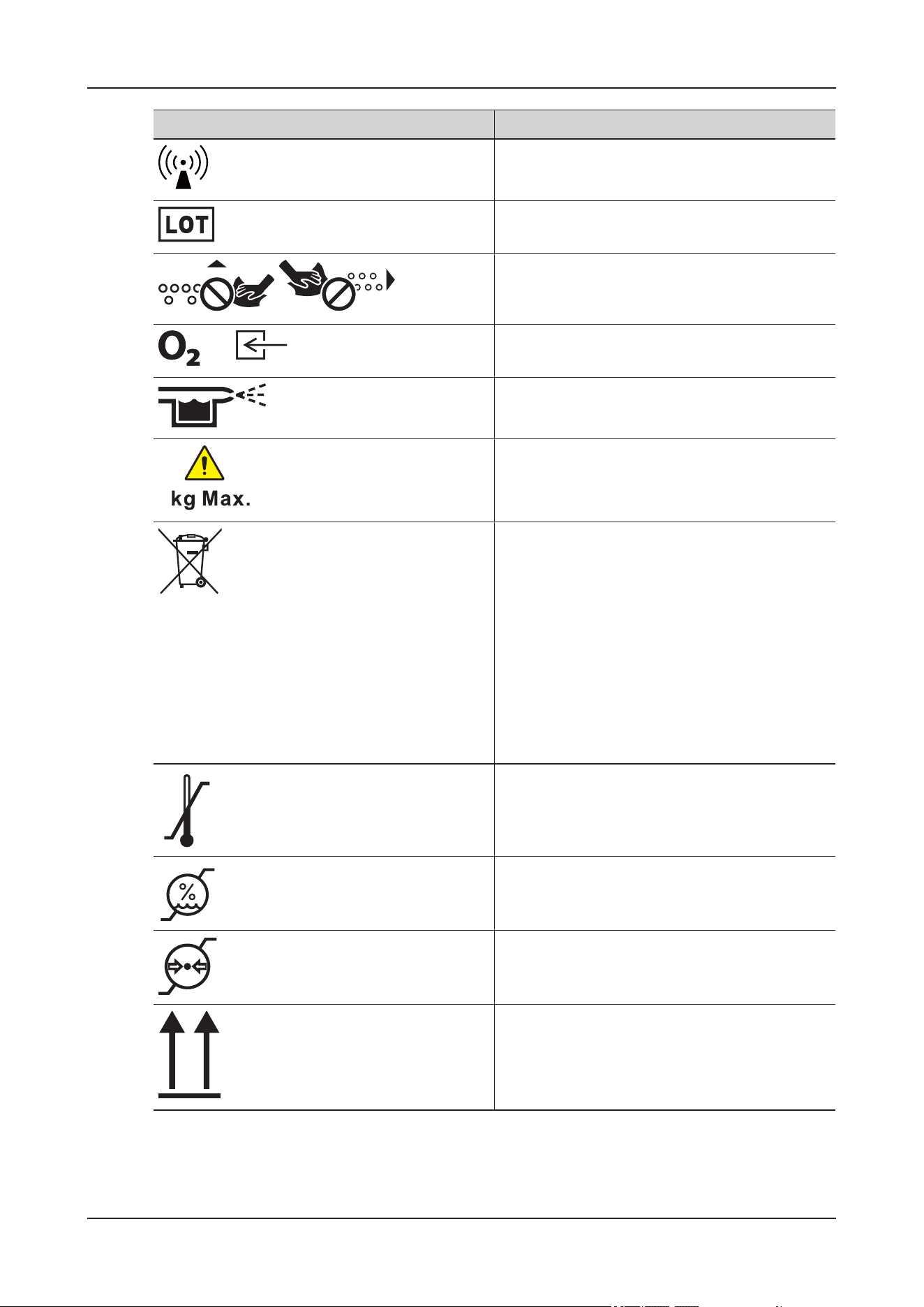
2 Product Overview
2 - 27
Non-ionizing electromagnetic radiation
Batch code
/
Do not wipe
Oxygen supply connector
Nebulizer connector
Maximum load n kg
The following definition of the WEEE label
applies to EU member states only: the use of this
symbol indicates that waste electrical and
electronic equipment must not be disposed of as
unsorted municipal waste and must be collected
separately. By ensuring that this product is
disposed of correctly, you will help prevent
bringing potential negative consequences to the
environment and human health. For more detailed
information with regard to returning and recycling
this product, consult the distributor from whom
you purchased the product
Temperature limit
Humidity limitation
Atmospheric pressure limitation
This way up
Symbol Description
n
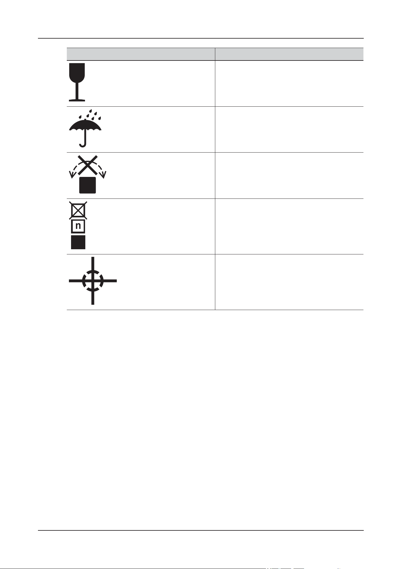
2 Product Overview
2 - 28
Fragile, handle with care
Keep dry/Keep away from rain
Do not roll
Stacking limit by number
Centre of gravity
Symbol Description

3 Basic Operations
3 - 1
3 Basic Operations
3.1 Touch Screen Operations
3.1.1 Tapping or Swiping across the Screen
CAUTION
• Check that the touchscreen is not damaged or broken. If there is any sign of damage, stop using the
device and contact the Customer Service Department or your local distributor.
• If the touchscreen is loose, stop using the device and contact the Customer Service Department or
your local distributor.
You can touch the screen or swipe across the screen with your fingers to operate the device.
• Tapping the screen
– To select an item from menus or lists, tap on the item with your finger.
– To enter a parameter menu, tap corresponding numeric area or waveform area. For example,
select the ECG numeric area or waveform area to enter the ECG menu.
• Swiping across the screen with a single finger
To scroll through a list and a menu, swipe up and down.
• Swiping across the screen with two fingers
To discharge an animal, swipe from top to bottom.
3.1.2 Soft Keyboard Operations
The on-screen keyboard enables you to enter information:
• Enter the information by selecting one character after another.
• Select the (Backspace) button to delete single characters or select to delete the entire
entry.
• Select the (Caps Lock) button to access uppercase letters.
Select the (Enter) button to confirm the entry and close the on-screen keyboard.
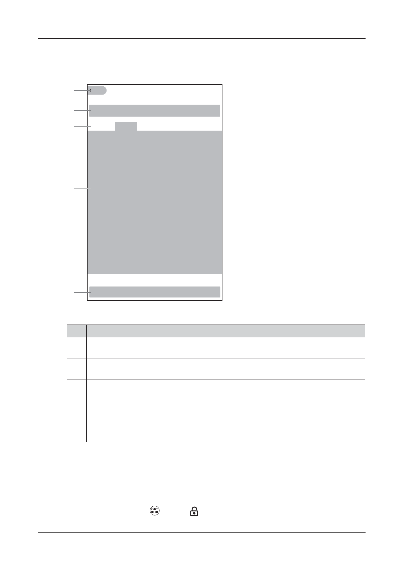
3 Basic Operations
3 - 2
3.1.3 Submenu Operations
Tap any functional area on the main screen to enter the corresponding function details interface.
3.2 Locking the Touch Screen
To avoid misuse, you can temporarily disable the touch screen.
Do one of the following to lock the touch screen:
• On the main screen, tap (More) > (Screen Lock).
No. Area Operation
1. Home button Tap to return to the main screen when on other screens.
2. Patient
Information Area
Tap to enter to the animal information details interface.
3. Function switch
tab
Tap to switch to the corresponding function details interface.
4. Function Details Displays the menu, tools and other detailed information of the current
function.
5. Quick Buttons
Area
Displays the quick keys supported in the current function module.
XXX XXX XXX XXX XXX
1
2
3
4
5
3 Basic Operations
3 - 3
•Set Auto Screen Lock Time, and the touch screen will be locked when the preset time is reached.
After the touch screen is locked, the lower part of the main screen displays the lock symbol ,
prompting that the touch screen is locked.
To unlock the touch screen:
• Tap any position on the touch screen and slide to .
• The touchscreen is enabled when the preset time is reached.
3.3 Using the On-Screen Timers
WAR N I N G
Do not use the timers for tasks related to critical animals.
The device has a timer function to notify you when a preset time period is expired.
Perform the following procedure:
1. Tap (Timer) quick key on the main screen to open the Timer Setup menu.
2. Set the timer parameters as required.
3. Tap Start timer.
• The timer control appears in the auxiliary function area of the main screen, and use the control to
pause or resume the timer.
– : pauses the timer.
– : starts the timer.
– : clears the timer and end this timer episode.
•Tap (Timer) quick key on the main screen to open the Timer Setup menu, and then tap Stop
timer to end the current timing.
3.4 Initiating a Manual Event
Perform the following procedure:
1. Tap Manual Event quick key on the main screen to open the Manual Event menu.
Tap to open the Manual Event Setup menu. And edit the name of preset event names as required.
2. Select a name for this event, or manually enter the event name.
3. Tap OK.
The device saves this manual event automatically.
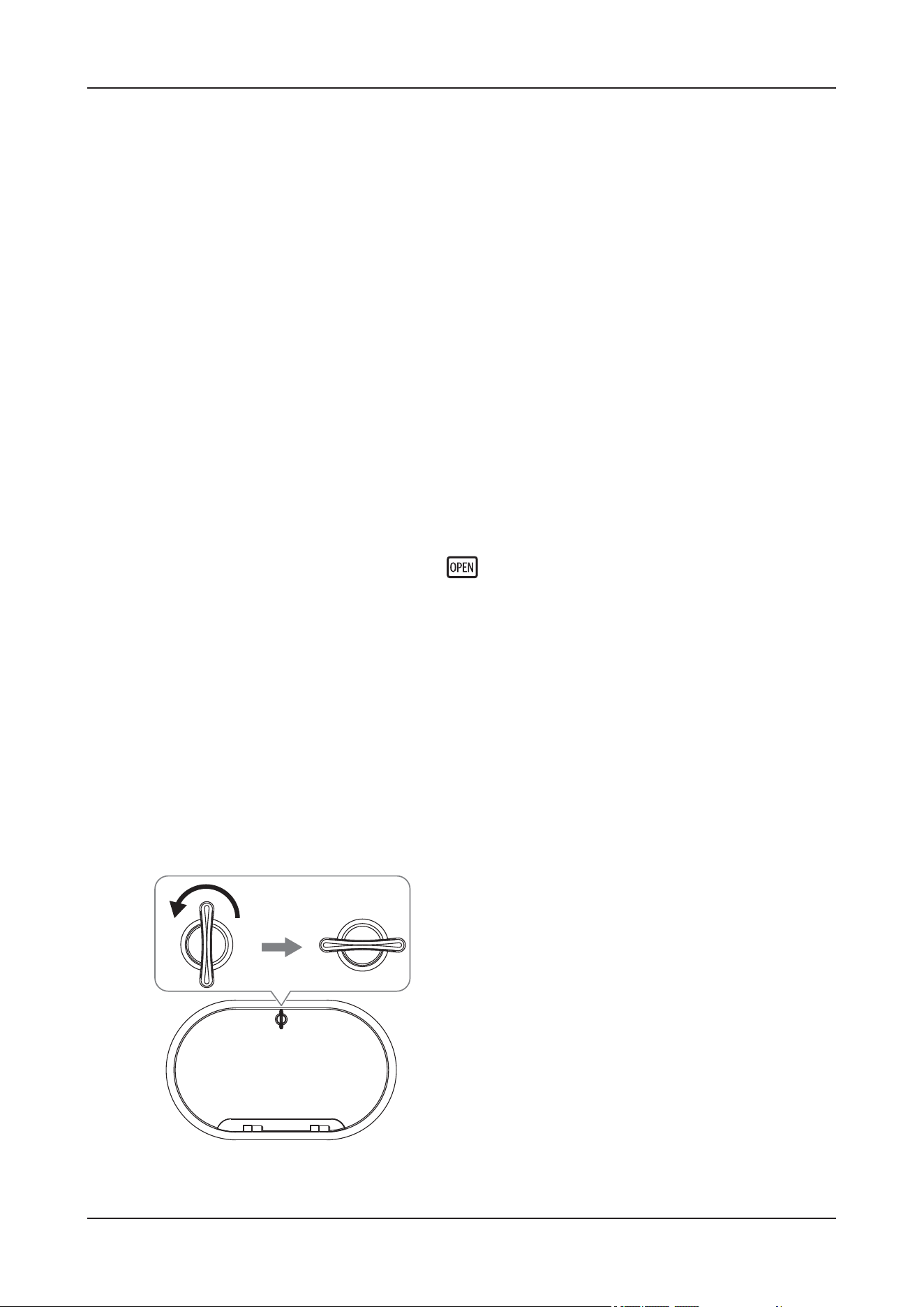
3 Basic Operations
3 - 4
3.5 Setting the Nursing Level Indicator
Perform the following procedure:
1. On the main screen, tap the patient information area to enter the Patient detail screen.
2. Tap Nursing Level Indicator in the Basic Information area, and select the desired nursing level name
from the drop-down list box.
The nursing level indicator will illuminate in the color of the selected nursing level.
The nursing level name can be customized as needed. For details, see 5.2.1 General Maintenance.
3.6 Operating the Cabin Door
3.6.1 Opening the Cabin Door
Do one of the following to open the cabin door:
• Use the Door Open Button on the lower side of the device.
• On the main screen, tap More > Open Door.
The cabin door opens automatically, and the is displayed in the System Status Information Area.
3.6.2 Closing the Cabin Door
Push the door to the closed position, and the cabin door will be closed automatically.
For ViCare U7, close the left door firstly, and then the right door.
3.6.3 Operating the Operation Window
Opening the Operation Window
Perform the following procedure:
1. Press and hold the operation window knob while rotating it 90° counterclockwise.
2. Pull the knob gently to open the operation window.
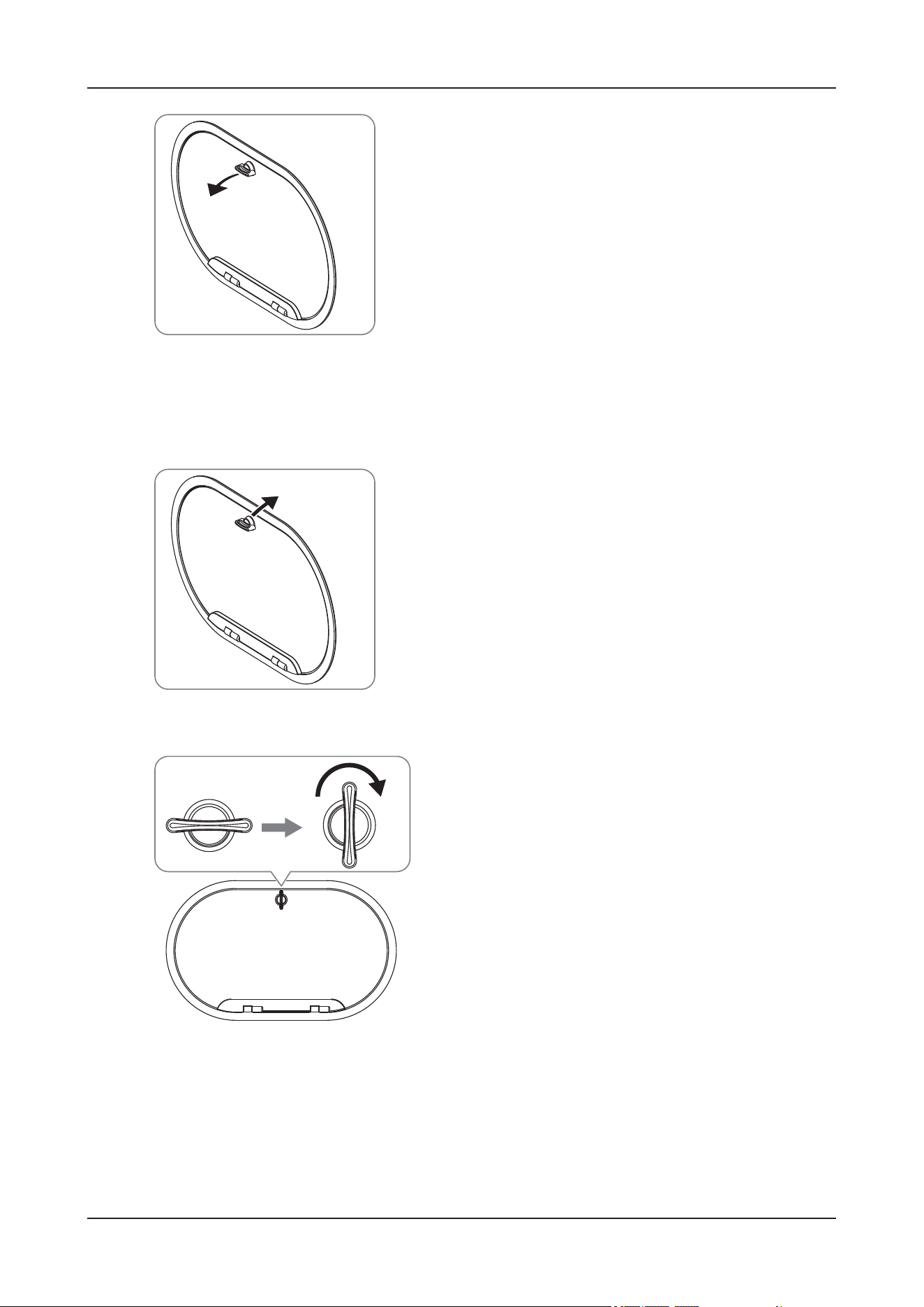
3 Basic Operations
3 - 5
Closing the Operation Window
Perform the following procedure:
1. Push the operation window gently to the closed position.
2. Press and hold the operation window knob while rotating it 90° clockwise.

4 Preparations
4 - 1
4 Preparations
4.1 Installation
WAR N I N G
• The installation must be performed by a qualified electrical engineer under the guidance of the
customer service engineer or your distributor.
• Always use the accompanying power cord delivered with the device.
• Before connecting the AC power supply, confirm that the voltage and frequency of the AC power
supply comply with the specifications specified in the device label or in the manual.
• Use batteries to power the external protective cables when there is doubt about the integrity of the
installation or wiring. Otherwise, the patient and operator may receive electric shock.
• Connect the drain pipe or container to the drain outlet at the back of the device before use.
4.1.1 Environmental Requirements
The operating environment of the device must meet the requirements specified in this manual.
The environment should be reasonably free from noises, vibration, dust, corrosive, flammable and
explosive substances. If is installed in a cabinet, sufficient space in front and behind should be left for
convenient operation, maintenance and repair.
Sufficient space should be reserved around the device after installation so that air can be circulated
smoothly for good ventilation and operation. The device can be installed in various ways as required, see
Figure 4-1, Figure 4-2, Figure 4-3.
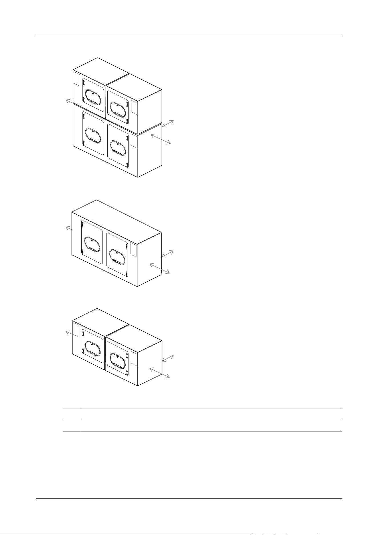
4 Preparations
4 - 2
Figure 4-1 ViCare U7/ViCare U7L/ViCare U7R
Figure 4-2 ViCare U7
Figure 4-3 ViCare U7L/ViCare U7R
When the device is moved from one place to another, condensation may occur as a result of temperature
or humidity difference. In this case, never start the device before the condensation disappears.
4.1.2 Installing the Device
For installation-related operations, contact the Customer Service Department or your distributor.
1. Leave at least 250 mm at the back
2. Leave at least 300 mm on each side of the left and right sides
1
2
2
1
2
2
1
2
2

4 Preparations
4 - 3
4.2 Connecting the Power Supply
4.2.1 Connecting the AC Power Supply
After connecting the device to the AC mains, check that the AC indicator is on to ensure the AC power
connection is normal.
4.2.2 Using the Battery
WAR N I N G
• Keep the batteries out of children’s reach.
• Use only specified battery. Use of a different battery may present a risk of fire or explosion.
• Do not allow the battery to come into contact with liquid.
• Do not crush, drop or puncture the battery. Mechanical abuse can lead to internal damage and
internal short circuits. If a battery has been dropped or banged against a hard surface, whether
damage is externally visible or not, remove the battery from use and dispose of it properly.
• If a battery shows signs of damage or signs of leakage, replace it immediately.
• Extremely high ambient temperature may cause battery overheat protection, resulting in device
shutdown.
• Do not incinerate batteries or expose them to temperatures above 60°C This may cause the battery to
burn, explode, leak, or become hot, causing personal injury.
CAUTION
• Properly dispose of batteries according to local regulations.
• Remove the battery of NIBP module before shipping or if it will not be used for an extended period
of time.
NOTE
• Battery operating time depends on device configuration and operation.
• Do not use this device for animal monitoring or infusion during battery conditioning.
• Do not interrupt battery conditioning.
• Storing batteries at high temperatures for an extended period of time will significantly shorten their
life expectancy.
• Storing batteries in a cool place can slow the aging process. Ideally the batteries should be stored at
15 °C.
• Check the battery for adequate power when the device runs on battery power. Charging the battery if
required
• If the battery is not conditioned for a prolonged time, its charge indication may not be accurate and
you may wrongly evaluate the remaining battery runtime. In addition, if the battery is fully charged
for a long time and is not maintained regularly, the aging of the battery will be accelerated, resulting
in premature failure of the battery.

4 Preparations
4 - 4
Using the Battery of the Main Unit
WAR N I N G
• The battery must only be installed by service personnel trained and authorized by Mindray Animal
Medical.
• Keep the batteries in their original package until you are ready to use them.
• The battery should be charged only in this device.
• The service life of the main unit battery depends on the frequency and time of battery use. The built-
in battery of the main unit has a service life of 3 years. Replace your battery when it reaches the end
of its service life. Failure to replace the battery may cause serious damage to your device from
battery overheating.
NOTE
• If the power input fails and the device runs on the battery power, the display brightness
automatically lowers to the dimmest. You can manually adjust the display brightness as required.
• When the battery is low, the device presents the Low Battery alarm; If the battery is almost
depleted, the device presents the Critically Low Battery alarm. In this case, immediately connect
the AC mains to power the device and charge the battery. Otherwise, the device will automatically
shut down soon.
• The battery storage temperature is between -5 °C and 35 °C. When storing batteries, make sure that
the battery terminals do not come into contact with metal objects. If batteries are stored for an
extended period of time, place the batteries in a cool place.
This device is designed to operate battery power when the external power supply is not available.
The device uses mains power as primary power source. In case of mains power failure, the device
automatically runs on the battery power, which will not interrupt monitoring and infusion. However, the
environment control function will be suspended.
Using the Batteries of Wireless Modules
Wireless modules include SpO
2
module, NIBP module and ECG module. The SpO
2
module and ECG
module are powered by embedded rechargeable lithium-Ion batteries. The NIBP module is powered by a
replaceable rechargeable battery.
The service lives of the batteries depend on how frequently they are used.
The service life of the built-in batteries of the SpO
2
module and ECG module is about 5 years. Improper
use of the batteries may shorten its life. We recommend replacing the batteries every 5 years. The
performance of the batteries deteriorates over time. You should check the battery performance every 3
months or if you doubt that the battery may fail.
The NIBP module battery has a service life of 3 years. Replace your battery when it reaches the end of its
service life. Failure to replace the battery may cause serious damage to your device from battery
overheating.
4 Preparations
4 - 5
Battery Status Indicator
The battery status indicator indicates the battery capacity.
• The battery status indicator of the main unit is located in the System Status area of the main screen.
• The battery status indicators of the wireless modules are located in the corresponding monitoring
parameter area on the main screen.
4.3 Connecting Oxygen Supplies
This device provides high-pressure and low-pressure oxygen supply connectors.
WAR N I N G
• Inspect the oxygen supply connector carefully and ensure that there is no leakage. High leakage may
result in the oxygen concentration around the device higher than the normal atmospheric level to
create an oxygen-enriched environment that contains potential hazards.
• Place the oxygen supply hose carefully and avoid its exposure to the environment in which possible
damage to the oxygen supply hose is easily caused by cut or heating.
CAUTION
• Do not connect the high-pressure and low-pressure oxygen supplies at the same time.
• Do not use the humidifier and oxygen generator together when the oxygen generator is used as a gas
supply of device. If the oxygen generator is equipped with a humidifier, drain the water away from
the humidifier or remove the humidifier before using the device.
• The low-pressure oxygen hose assembly shall comply with the requirements of ISO 5359.
• Use only hoses that have been approved to serve medical purposes and for connection with oxygen
supplies to reduce the risk of fire.
• Switch off the oxygen supply when the device is not in the oxygen therapy status to reduce the risk
of fire.
• Please use dry and clean medical oxygen as gas supply. Moisture in the gas supply may lead to
device faults.
4.3.1 Connecting the High-Pressure Oxygen Supply
NOTE
Check if the sealing ring at the gas supply connection is intact before connecting the gas supply hose. If
the sealing ring is damaged, do not use the hose. Replace the sealing ring to prevent leakage.
Perform the following procedure:
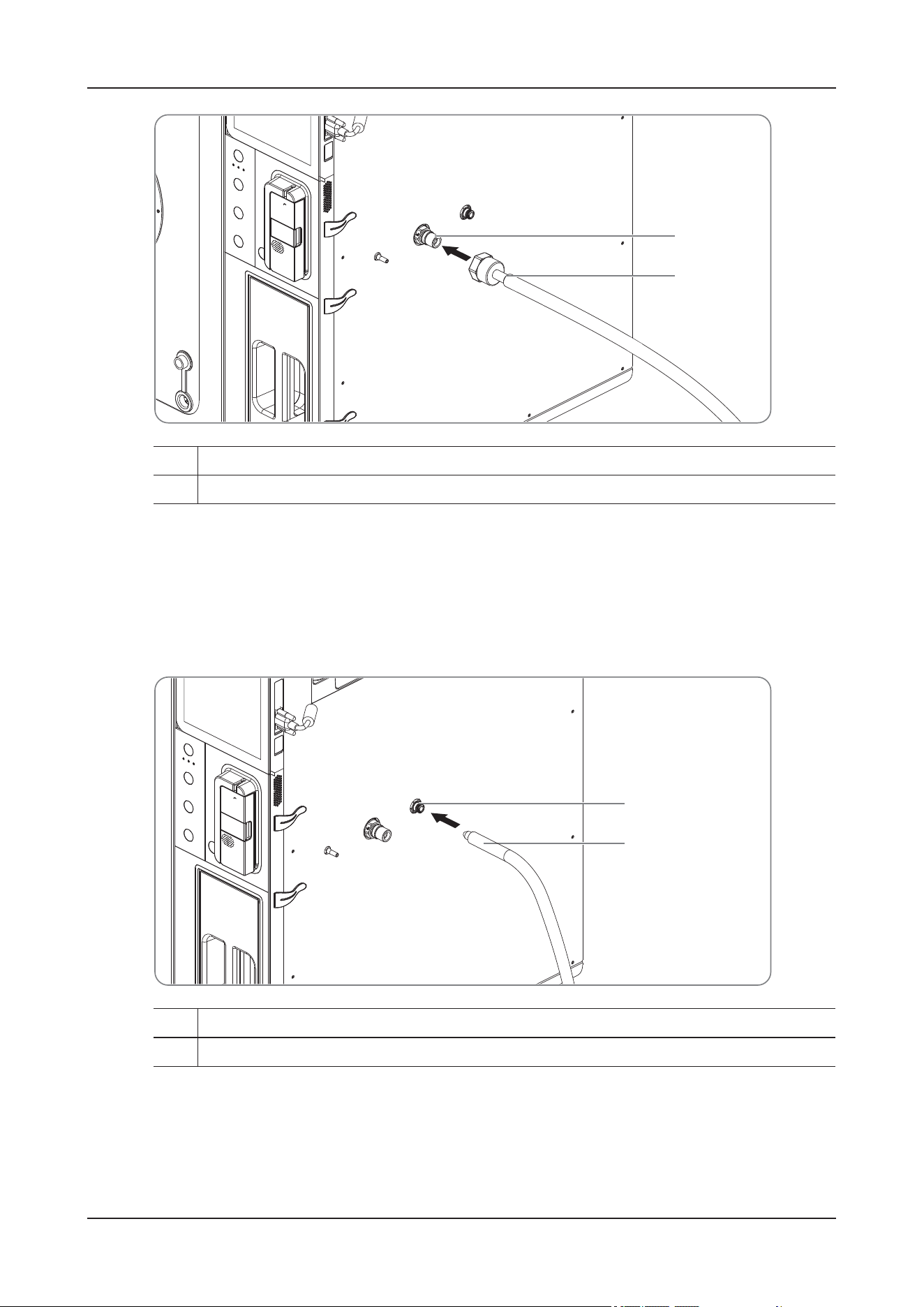
4 Preparations
4 - 6
1. Insert the connector into the high-pressure oxygen supply inlet on the side panel of the device.
2. Ensure that the gas supply hose is properly connected to the gas supply inlet and tighten the hose nut.
4.3.2 Connecting the Low-Pressure Oxygen Supply
Perform the following procedure:
Insert the connector into the low-pressure oxygen supply inlet on the side panel of the device. When a
click is heard, it indicates that the gas supply hose is inserted in place.
Depress the metal dome on the low-pressure oxygen supply connector to remove the gas supply hose.
1. High-pressure oxygen supply connector
2. High-pressure oxygen supply hose and fitting
1
2
1. Low-pressure oxygen supply connector
2. Low-pressure oxygen supply hose
1
2
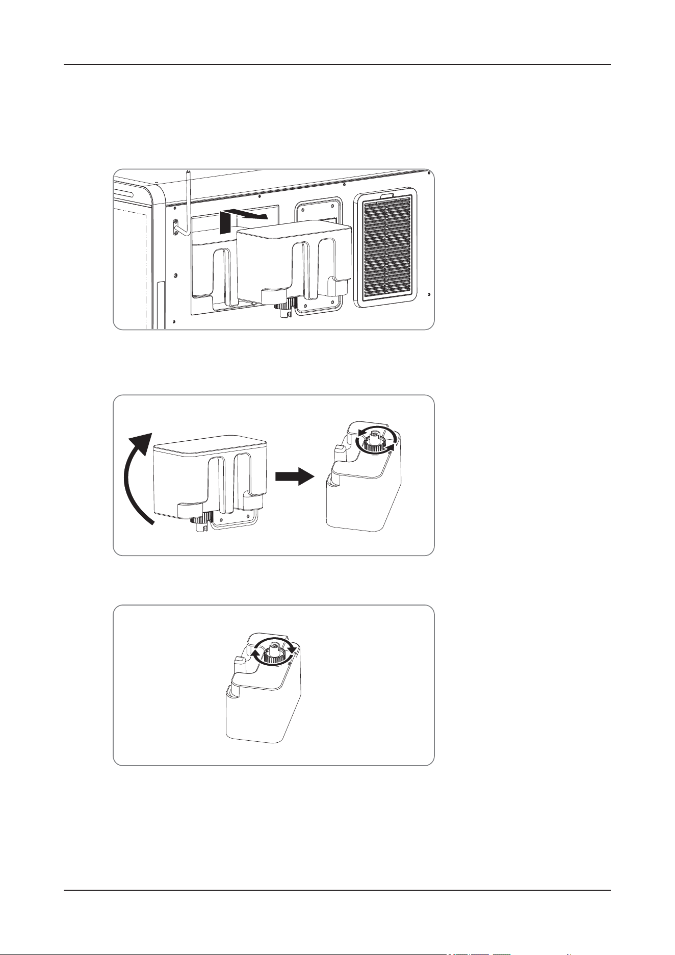
4 Preparations
4 - 7
4.4 Filling Water to the Water Tank
Perform the following procedure:
1. Hold the handle of the water tank and lift it up, and then pull the water tank out horizontally.
2. Turn over the water tank, loosen the water tank connector in the direction of the arrow, and fill it with
water.
3. Tighten the water tank connector.
4. Hold the handle of the water tank and turn over it for 180°, and then install the water tank back as
indicated by the arrow.
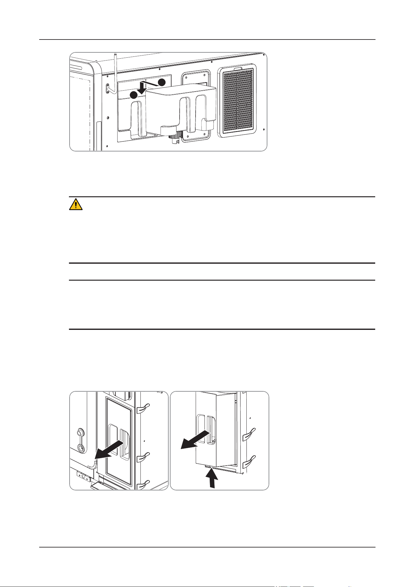
4 Preparations
4 - 8
4.5 Filling/Replacing the Soda Lime
WAR N I N G
Single use items may be considered potential biologically hazardous items and should not be reused.
Single use items may be considered potential biologically hazardous items and should not be reused.
Dispose of these items in accordance with hospital policy and local regulations for contaminated and
biologically hazardous items.
NOTE
• Install soda lime as needed before the first use of the device.
• Inspect the color of the soda lime in the CO
2
absorber canister. Replace the soda lime immediately if
obvious color change is detected.
ViCare U7
Perform the following procedure:
1. Remove the CO
2
absorber canister:
1. Hold the handle of the CO
2
absorber canister and pull it out partially.
2. Support the bottom of the CO
2
absorber canister and pull it out completely.
2. Remove the upper cover of the CO
2
absorber canister and fill the soda lime.
A
B
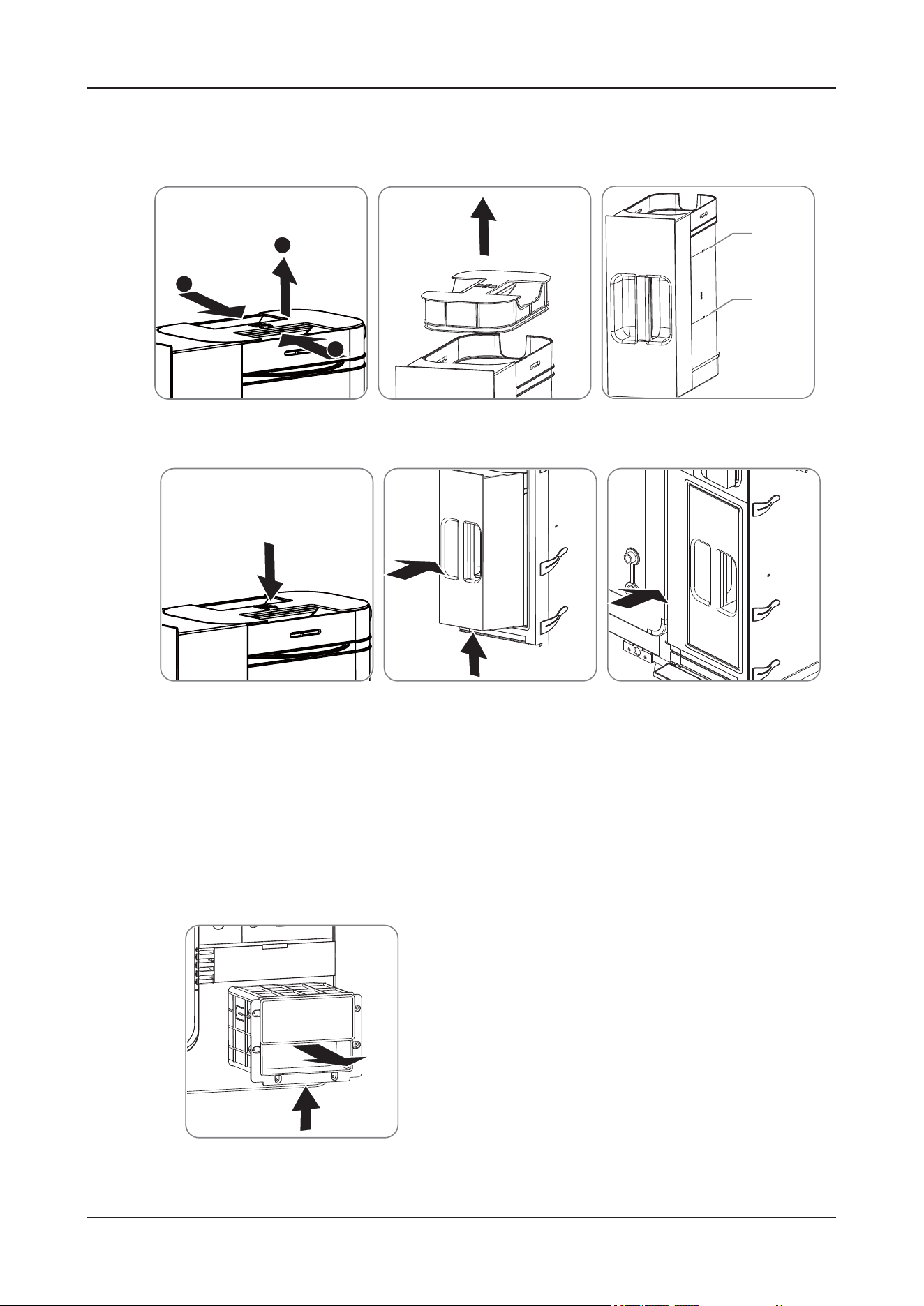
4 Preparations
4 - 9
The amount of soda lime should be filled between the MIN and MAX scale lines.
To replace the soda lime, remove all the used soda lime and then fill new soda lime.
3. Install the CO
2
absorber canister:
1. Install the upper cover of the CO
2
absorber canister.
2. Hold the handle with one hand and install the CO
2
absorber canister back onto the device with the
other hand.
3. Gently push the handle to ensure that the CO
2
absorber canister is installed in place.
ViCare U7R/ViCare U7L
Perform the following procedure:
1. Remove the CO
2
absorber canister:
1. Hold the handle of the CO
2
absorber canister and pull it out partially.
MAX
MIX
A
A
B
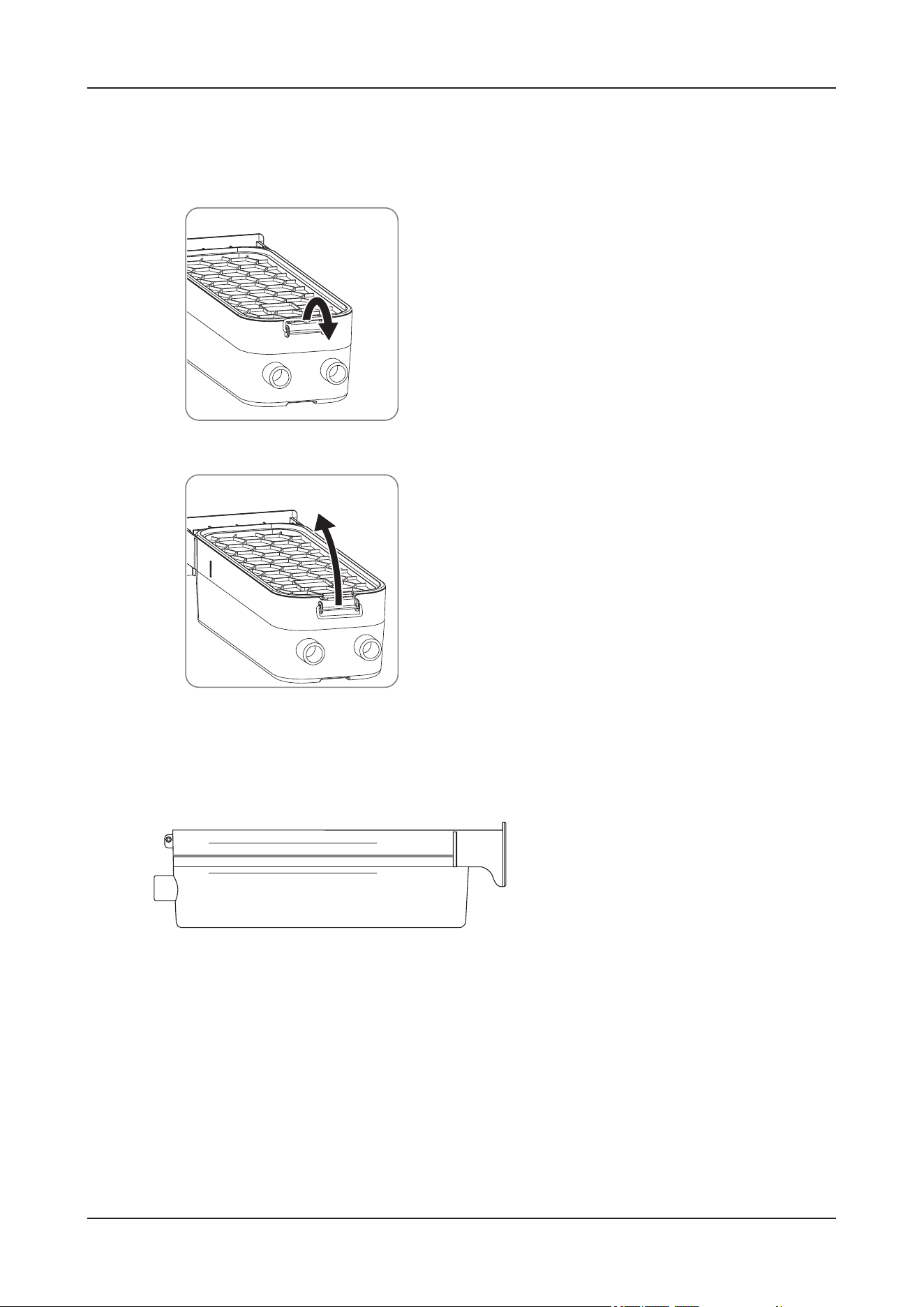
4 Preparations
4 - 10
2. Support the bottom of the CO
2
absorber canister and pull it out completely.
2. Remove the upper cover of the CO
2
absorber canister.
1. Loosen the retaining ring on the upper cover of the CO
2
absorber canister.
2. Remove the upper cover in the direction of the arrow.
3. Fill the soda lime.
The amount of soda lime should be filled between the MIN and MAX scale lines.
To replace the soda lime, remove all the used soda lime and then fill new soda lime.
4. Install the CO
2
absorber canister:
1. Insert the tenon end of the upper cover into the slot, press the other end of the upper cover, and
ensure that it is installed in place.
MAX
MIN
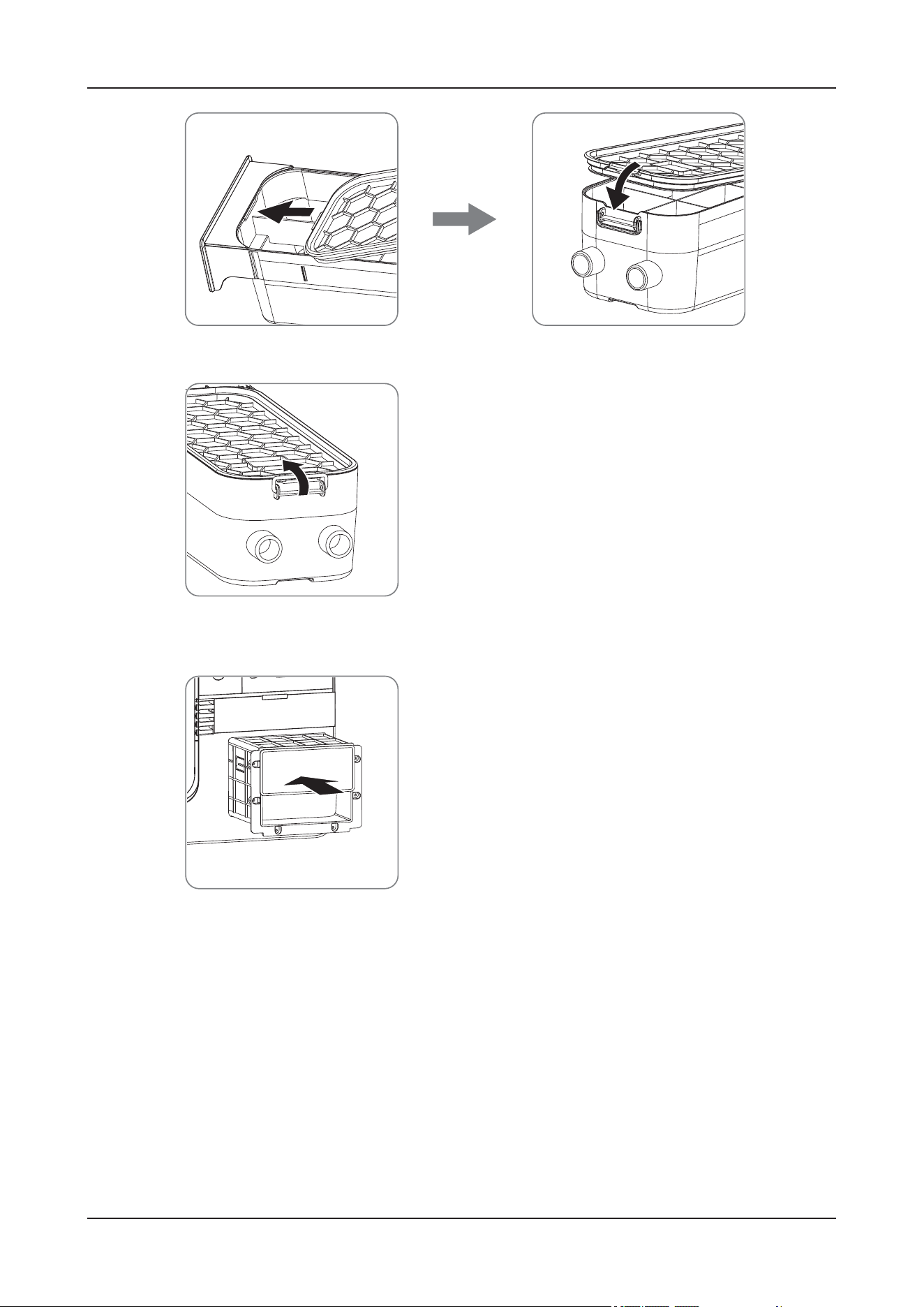
4 Preparations
4 - 11
2. Fasten the retaining ring.
3. Install the CO
2
absorber canister back to the device and gently push the handle to ensure that the
CO
2
absorber canister is installed in place.
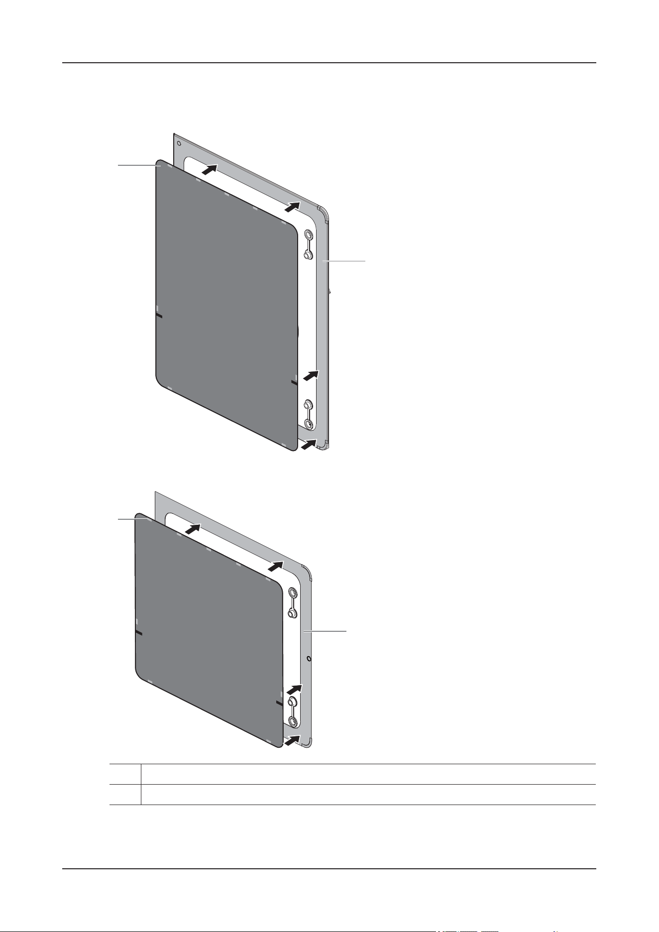
4 Preparations
4 - 12
4.6 Installing Curtains
Figure 4-4 ViCare U7
Figure 4-5 ViCare U7L/ViCare U7R
With the patterned side facing outward, attach all curtain magnets to the outer metal frame.
1. Built-in magnets
2. Outer metal frame of the cabin door
1
2
1
2

4 Preparations
4 - 13
4.7 Wireless Monitoring Modules
4.7.1 Safety Information
WAR N I N G
• The wireless monitoring modules and parameter monitoring accessories are suitable for use in
animal environment. The chargers are not for use in patient environment. For other device and
accessories connected to the wireless monitoring modules, consult corresponding manufacturers for
the suitability within the animal environment.
• If it is not evident from the device specifications whether a particular combination with other
devices is hazardous, for example, due to summation of leakage currents, please consult Mindray
Animal Medical or an expert in the field. A determination must be made that the proposed
combination will not negatively affect the devices themselves or the animal's safety.
• Use only the chargers by Mindray Animal Medical to charge the batteries.
• Use only the power cord delivered with C10 charger.
• Operate the chargers on a stable and flat surface.
• Keep the chargers, wireless mobile modules and batteries away from liquids. Use the chargers in dry
and indoor environment.
• Do not disassemble, puncture or incinerate the chargers or batteries.
• Do not stack the chargers.
• No modification of the chargers or power plug is allowed.
• Before connecting the charging station to the AC mains, check that the voltage and frequency
ratings of the power line are the same as those indicated beside the AC power input.
• Make sure the charger is intact and functioning well before charging.
• Do not cover the charger or batteries. Keep the charger in a cool and ventilated place while charging.
• Do not connect other devices to the power supply system.
• Extremely high ambient temperature may cause battery overheat protection and interrupt the
charging. Do not charge the batteries at a temperature over 40°C.
• In the case of charger failure, disconnect the AC power, remove the batteries, and contact the
Customer Service Department or your distributor.
• The ECG module and SpO
2
module are powered by embedded batteries that are not intended to be
replaced. Do not open the device housings. All servicing and future upgrades must be carried out by
trained and authorized personnel. If you find any signs of damage, remove the device from use and
contact the Customer Service Department or your local distributor.
CAUTION
• Use the chargers only in an environment as specified in this manual.
• Do not touch the contacts of the chargers, wireless monitoring modules or batteries. Impaired
contacts could affect the charging performance.
• Make sure the battery clicks into place for charging so the battery can be secured onto the charging
slot.
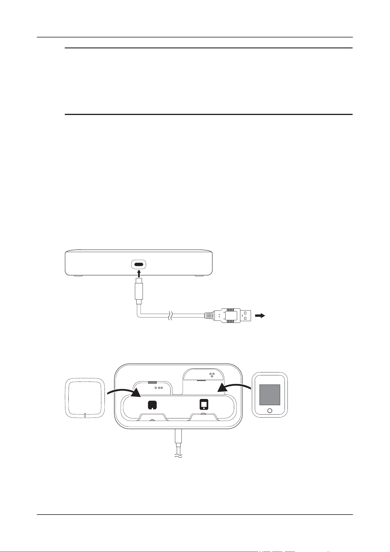
4 Preparations
4 - 14
NOTE
• The charging station uses a mains plug as isolation means to the mains power. Do not locate the
charging station in a place difficult to operate the mains plug.
• After a battery is properly installed onto the charging station, check that the indicators light up.
• Charge the battery at room temperature. The charging time may be prolonged at excessive high or
low temperature.
4.7.2 Charging the Batteries
Before use, check the battery capacity of the SpO
2
module, Temp module, ECG module, and NIBP
module.
he NIBP module is powered by a rechargeable lithium-Ion battery. Install the battery before using the
NIBP module.
Charging the SpO
2
module and ECG module by using the C25 charger
Perform the following procedure:
1. Connect a USB Type-C cable to the USB Type-C connector on the C25 charger and then the external DC
power.
2. Put the SpO
2
module or ECG module onto the correct charging slot.
Make sure the contacts of the SpO
2
module or ECG module are aligned with those on the C25 charger.
3. Push the SpO
2
module or ECG module down until you hear a click.
After the SpO
2
module or ECG module is properly installed on the C25 charger, the battery starts to be
charged.
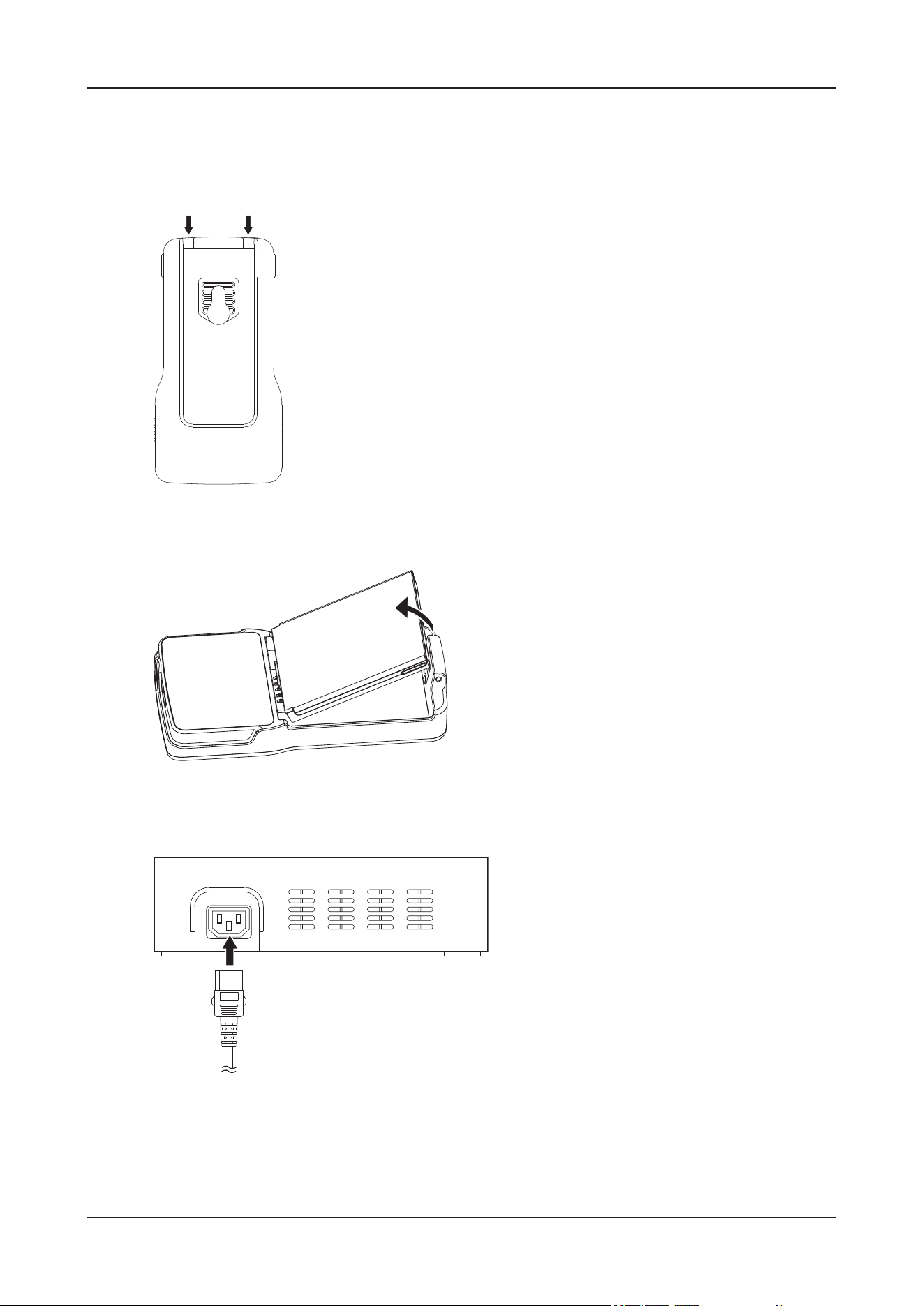
4 Preparations
4 - 15
Charging the battery of NIBP module by using the C10 charger
Perform the following procedure:
1. Follow the directions indicated in the following picture and remove the clip from the NIBP module.
2. Hold the protrusions on both sides of the battery and lift up the battery to remove it from the battery
compartment.
3. Connect the power cord of the charging station to a wall AC outlet.
Make sure the power indicator of the charging station is on and green.
4. Make sure the contacts of the battery are aligned with those on the charging station, and then push the
battery down until you hear a click.
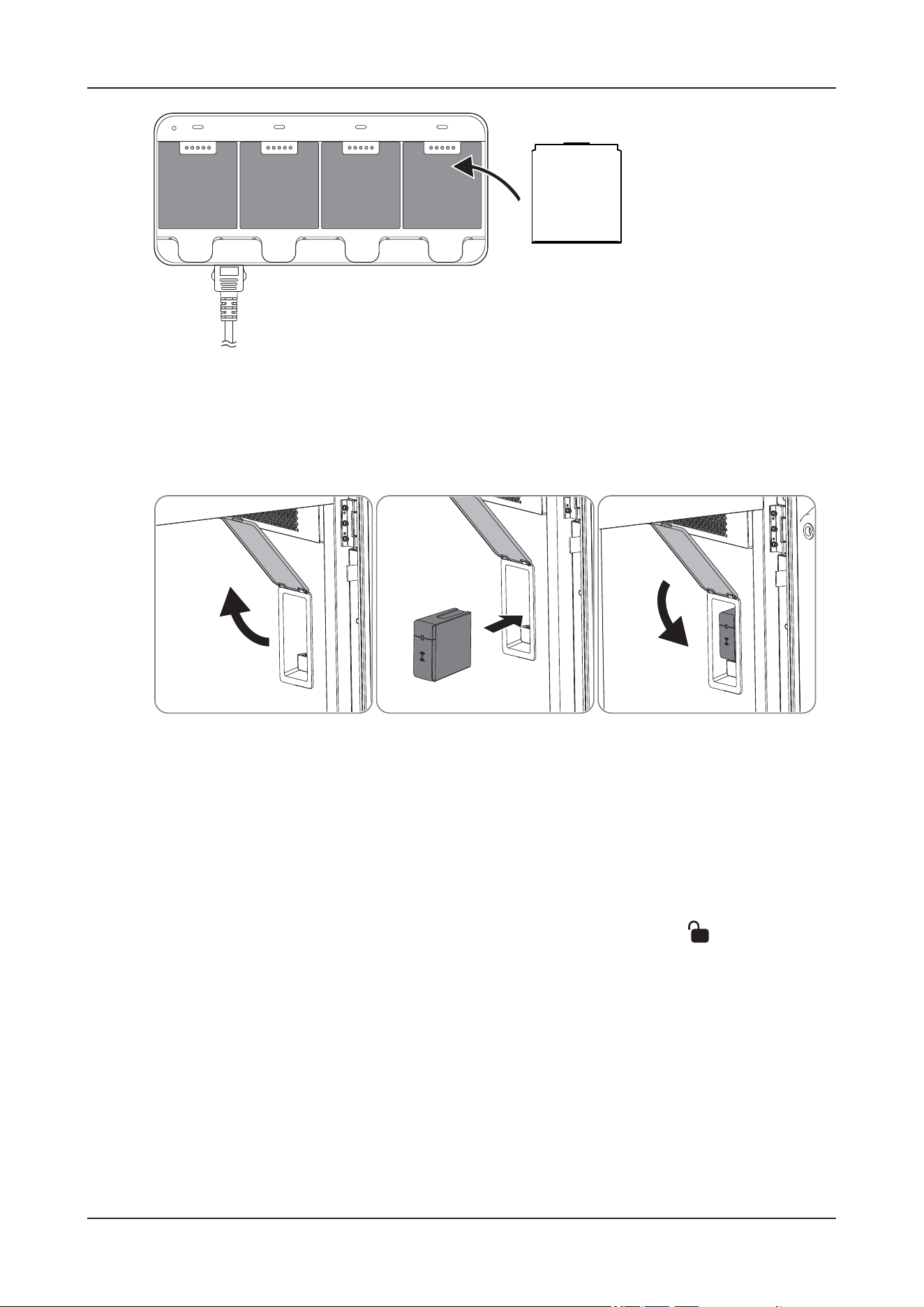
4 Preparations
4 - 16
After the battery is properly installed on the charger, it starts to be charged.
4.7.3 Installing the Receiver Module
Perform the following procedure:
1. Open the module slot cover inside the device.
2. Push the receiver module into the module slot and ensure that it is installed in place.
3. Close the module slot cover.
4.7.4 Installing the Battery of the Temp Module
Perform the following procedure:
1. Rotate the battery compartment cover counterclockwise to the unlocked position ( ).
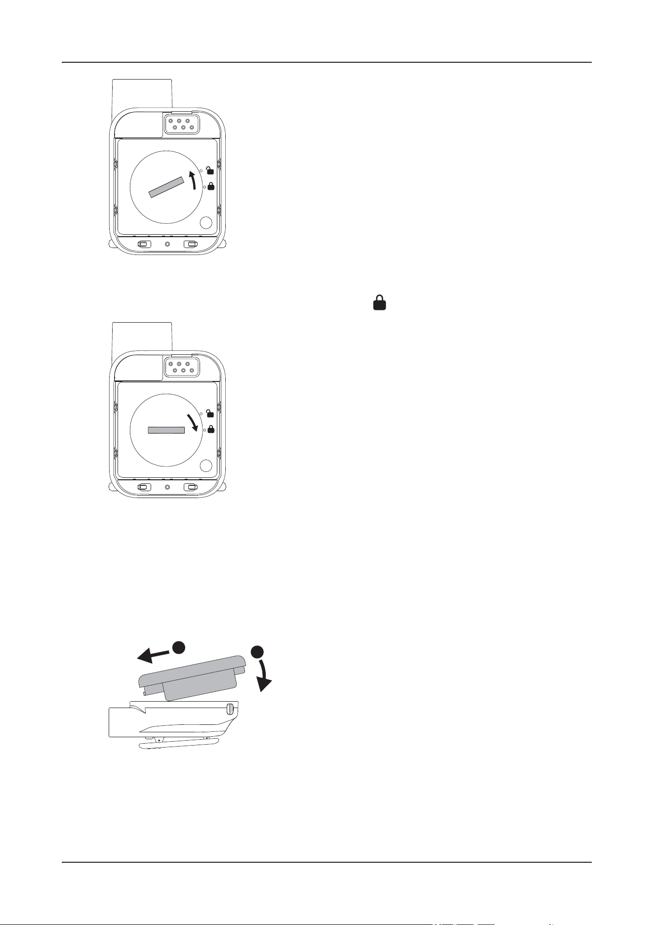
4 Preparations
4 - 17
2. Install the coin battery into the battery compartment as indicated by the positive and negative poles.
3. Rotate the battery compartment cover clockwise to lock ( ).
4.7.5 Connecting the Monitoring Modules
Connecting the SpO
2
module and SpO
2
Sensor
Perform the following procedure:
1. Align the contact points of the SpO
2
module with that of the Temp module, and then press the bottom
edge of the SpO
2
module to install the SpO
2
module to the Temp module.
2. Connect the SpO
2
sensor and temperature probe.
• Connect the SpO
2
sensor
For detailed information about the SpO
2
sensor, see the instructions delivered with it.
A
B
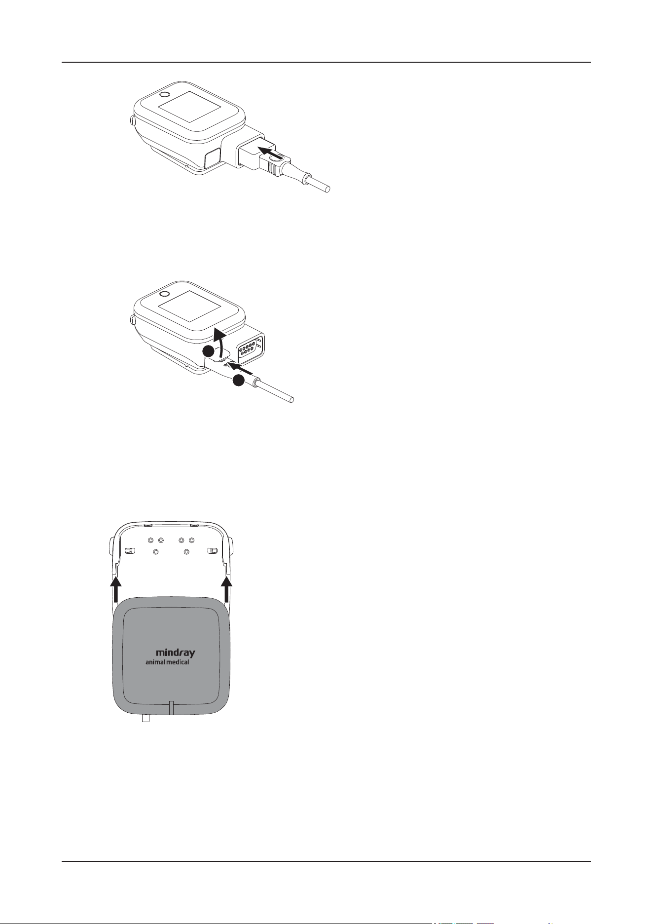
4 Preparations
4 - 18
• Connect the temperature probe
Before connecting the temperature probe, open the protective cover and then plug in the temperature
probe connector.
For detailed information about the temperature probe, see the instructions delivered with it.
Connecting the ECG Lead of ECG Module
For detailed information about the ECG lead, see the instructions delivered with it.
Perform the following procedure:
1. Put the ECG module onto the connector of the ECG lead with both sides aligned.
2. Slide the ECG module to the left to install it into the connector of the ECG lead.
A
B
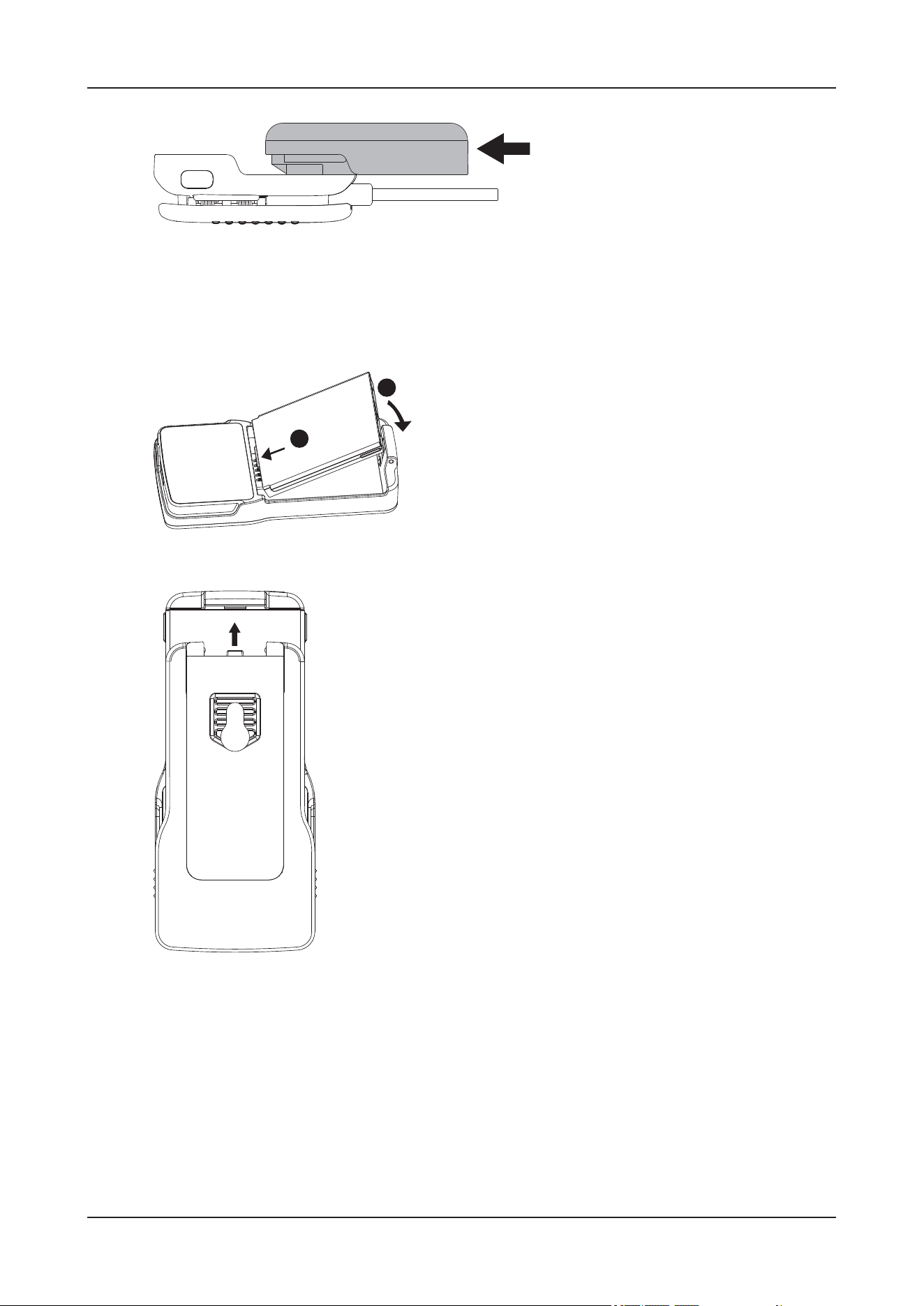
4 Preparations
4 - 19
Installing Battery for the NIBP Module
Perform the following procedure:
1. Push the battery into the battery compartment and press down until it clicks into the place.
2. Align the clip with the grooves on the back of the module, and push it until you hear a click.
4.7.6 Establishing Wireless Connection
Pairing the SpO
2
Module with the Device
Perform the following procedure:
A
B
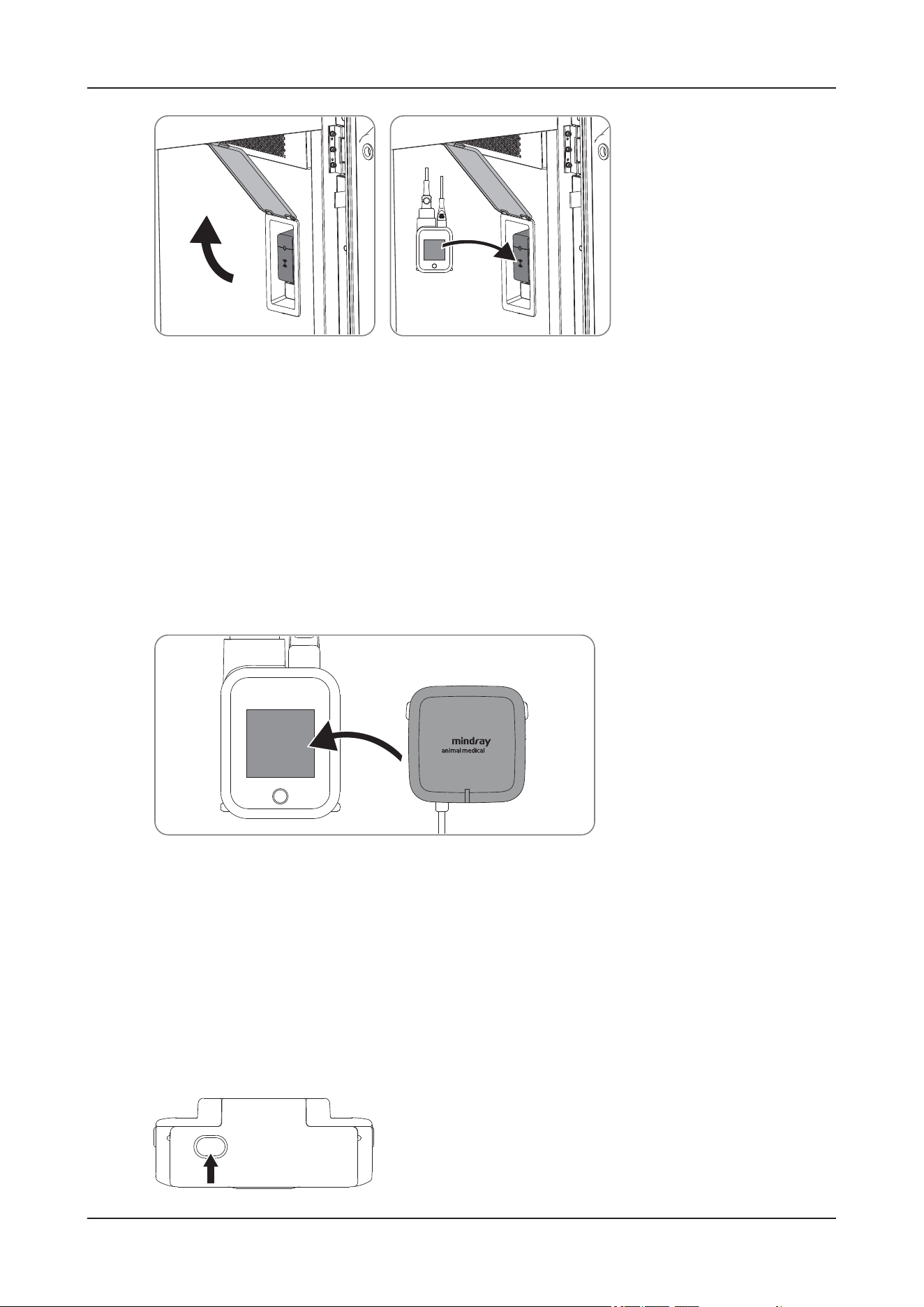
4 Preparations
4 - 20
1. Open the module slot cover inside the device.
2. Place the SpO
2
module close to the pairing area of the receiver module until you hear a beep.
3. Check the screen of the SpO
2
module immediately. If a confirmation screen is displayed, press the touch
button to confirm the pairing.
Failing to do so would cancel the pairing.
4. After successful pairing, close the module slot door inside the device.
Pairing the SpO
2
Module with an ECG Module
Perform the following procedure:
1. Place the front of the ECG module close to the screen of the SpO
2
module until you hear a beep.
2. Check the screen of the SpO
2
module immediately. If a confirmation screen is displayed, press the touch
button to confirm the pairing.
Failing to do so would cancel the pairing.
Pairing the SpO
2
Module with an NIBP Module
Perform the following procedure:
1. Press the Power on/off button on the NIBP module to turn the module on.
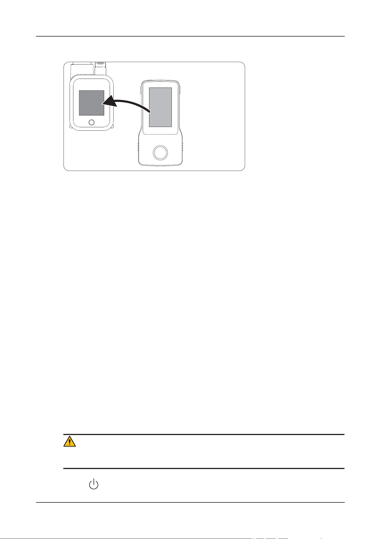
4 Preparations
4 - 21
2. Place the front of the NIBP module close to the screen of the SpO
2
module until you hear a beep.
3. Check the screen of the SpO
2
module immediately. If a confirmation screen is displayed, press the touch
button to confirm the pairing.
Failing to do so would cancel the pairing.
If the pairing succeeds, Paired successfully is displayed on the screen of the NIBP module.
4.8 Powering On the Device
4.8.1 Check before Powering On
Check before the device is powered on:
• The temperature, relative humidity and atmospheric pressure meet the requirements of the
operating conditions.
• There is no condensation.
• There is no distortion, damage or dirt on the device and peripheral devices.
• If any dirt is found, cleaning shall be performed.
• The touch screen and control panel should not be loose or have loose screws.
• There is no cable damage (e.g., power cord). Maintain secure connections to the device at all times.
• No miscellaneous odds and ends are attached or affixed to the device.
• Ensure that all connections are free from damage and remain clear of foreign object blockages.
There are no obstacles around the device and its air vent.
• The entire scanning environment and field must be clean.
4.8.2 Turning on the Device
WAR N I N G
After transportation, keep the device still for 24 hours before connecting it to AC power.
Press the (power switch) button on the control panel to power the device on.
4 Preparations
4 - 22
4.8.3 Check after Powering On
Check after the device is powered on:
• There are no unusual sounds or smells indicating possible overheating.
• There are no persistently displayed system error messages.
• There is no evident excessive noise.
• The control panel buttons are fully functional.
• The screen displays normally depending on the device modes.
WAR N I N G
If you find anything not functioning properly, this may indicate that the device is defective. In this case,
shut down the department immediately and contact the Customer Service Department or your local
distributor.
4.9 Turning Off the Device
Before turn off the device, perform the following check:
• Ensure that the monitoring of the animal has been completed.
• Disconnect the cables and sensors from the animal.
• Make sure to save or clear the animal monitoring data as required.
To turn off the device, press and hold the (power switch) button for 3 seconds. Turning off the device
does not disconnect the device from the AC mains. To completely disconnect the power supply, turn off
the AC power.
CAUTION
Press and hold the (power switch) for 10 seconds to forcibly shut down the device if it could not be
shut down normally. This may cause loss of animal data.
4.10 Standby
If the operator wants to stop monitoring an animal temporarily but does not want to turn off the device,
standby mode can be used.
WAR N I N G
In the standby mode, the device stops all parameter measurements and environment controls, and disable
all the alarm indications except for Air Temperature Too High, Floor Temperature Too High, O2
Concentration Too Low, Reboot due to system error, No AC Power, Low Battery, Critically Low
Battery, No Battery. Pay attention to the potential risk of placing the device to standby.

4 Preparations
4 - 23
4.10.1 Entering the Standby Mode
Perform the following procedure:
1. On the main screen, tap More > Standby.
2. Tap OK.
4.10.2 Exiting the Standby Mode
Do one of the following to exit standby mode:
•Tap Restore to exit the standby mode and resume the current animal monitoring and environment
control settings.
•Tap Discharge to discharge the current animal.
When the device exists the standby mode, the alarms are paused for 2 minutes. Then the alarm system is
activated.

5 Setup
5 - 1
5 Setup
The Setup function is designed to set the configuration parameters of operating the device and
maintaining user workflow setup data.
On the main screen, tap the any information area to enter the details interface, and then tap System to
enter the device maintenance menu.
Set parameters by operating interface controls:
• Tab: tap to switch to the corresponding tab page.
• Submenu button: tap to open the corresponding submenu.
• Drop-down list: tap to display the drop-down list, and then tap to select the corresponding option.
• Checkbox: tap to select or deselect an option.
• Text box/parameter value: input using the pop-up soft keyboard.
The modified parameter values are automatically saved.
5.1 System Setup
5.1.1 Setting the Audio
Item Description
Alarm Volume Set the volume.
High Alarm Volume
QRS Volume
Key Volume
Reminder Volume
5 Setup
5 - 2
5.1.2 Setting the Date and Time
CAUTION
Changing the date and time affects the storage of trends and events and may result in loss of data.
NOTE
If your device is connected to a central monitoring system (CMS), the date and time are automatically
taken from the CMS. In this case, you cannot change the date and time from your device.
5.1.3 Adjusting the Screen Brightness
5.1.4 Other Settings
5.1.5 Setting Night Mode
The night mode is a special clinical monitoring mode. To avoid troubling the patient, turn on the night
mode.
Item Description
Date Set the device date.
Time Set the language for the device.
Date Format Set the date format.
24-Hour Time Set the time format.
Daylight Savings Time Enable or disable the daylight savings time.
Item Description
Brightness Set the brightness of the touch screen.
Brightness On Battery Set the brightness of the screen when it is powered by the battery.
Item Description
Auto Screen Lock
Time
Set the touchscreen lock period.
5 Setup
5 - 3
5.1.6 Managing Configurations
When continuously monitoring an animal, the clinical professional often needs to adjust the device’s
settings according to the animal’s condition. The collection of all these settings is called a configuration.
You can change some settings from a certain set of configuration and then save the changed
configuration as a user configuration.
WAR N I N G
The configuration management function is password protected. The configuration management
tasks must be performed by clinical professionals.
Loading Configurations
NOTE
The device may configure some settings by default when you load a configuration of different software
version with the current configuration.
Category Item Description
Brightness Brightness Set the screen brightness in the night mode.
Audio All Mute Set silence the device in the night mode. In night
mode, all the monitoring sounds, including the alarm
tone, heartbeat tone, key tone, and prompt tone, will
be turned off. Local password for accessing the
maintenance menu is required for switching on All
Mute.
Alarm Volume Set the alarm volume in the night mode.
“0” indicates silence.QRS Volume
Key Volume
Reminder Volume
NIBP NIBP End Tone Set to disable the reminder tone at the completion of
NIBP measurement after entering the night mode.
Stop NIBP Set to stop the NIBP measurement after entering the
night mode.
Auto Night Mode Auto Night Mode Set the device to automatically enter and exit the night
mode.
Night Time Period Displays the current night mode period.
Notes: If needed, please enter the Time table in
Maintenance Menu to modify the Night Time
Period.

5 Setup
5 - 4
You may make changes to some settings during operation. However, these changes or the pre-selected
configuration may not be appropriate for the newly admitted animal. Therefore, the device allows you to
load a desired configuration to ensure that all the settings are appropriate for your animal.
Perform the following procedure:
1. Select the desired configuration:
• Select the configuration on this device in the Local page.
• Select the configuration on the USB drive in the USB Drive page.
2. Tap Load.
Setting Default Configuration
The device will load the pre-set default configuration in the following cases:
• An animal is admitted.
• An animal is discharged.
• Species is changed.
The default configuration can be the latest configuration, factory configuration or user configuration.
Perform the following procedure:
1. Tap Config Manage.
2. Input the required password, and then tap OK.
3. Tap Select Default Config.
4. Tap Load the Latest Config or Load Specified Config.
• When you select Load the Latest Config, the latest configuration is loaded when the device is
started or an animal is admitted
• When you select Load Specified Config, the specific configurations are loaded when the device is
started or an animal is admitted.
Saving Current Settings
Current settings can be saved as a user configuration.
Perform the following procedure:
1. Tap Config Manage.
2. Input the required password, and then tap OK.
3. Tap Save Current Settings.
4. Input the configuration name.
5. Tap OK.
Delete Configuration
Perform the following procedure:
1. Tap Config Manage.

5 Setup
5 - 5
2. Input the required password, and then tap OK.
3. Tap Delete Configuration.
4. Select the configuration you want to delete.
5. Tap Delete.
6. Tap OK.
Exporting a Configuration
Export the current device’s configuration to a USB flash drive.
Perform the following procedure:
1. Connect the USB drive to the device’s USB connector.
2. Tap Config Manage.
3. Input the required password, and then tap OK.
4. Tap Export Configuration.
5. Select the configurations and user maintenance settings to export.
6. Tap Export.
Importing a Configuration
Import the configuration from the USB drive to the device.
Perform the following procedure:
1. Connect the USB drive that has saved the configuration file to the device’s USB port.
2. Tap Config Manage.
3. Input the required password, and then tap OK.
4. Tap Import Configuration.
5. Select the configurations and user maintenance settings to import.
6. Tap Import.
Modifying Configuration Password
You can modify the configuration password if necessary.
Perform the following procedure:
1. Tap Config Manage.
2. Input the required password, and then tap OK.
3. Tap Modify Password.
4. Input the old password and new password respectively.
5. Tap OK.
5 Setup
5 - 6
5.2 User Maintenance Settings
User maintenance enables you to customize your device to best meet your needs. Accessing the
Maintenance menu is password protected.
CAUTION
The maintenance settings can only be changed by authorized personnel. Contact the Customer Service
Department or your distributor for the passwords used at your facility.
NOTE
Factory Maintenance settings must be performed by service personnel.
Perform the following procedure:
1. On the main screen, tap the any information area to enter the details interface, and then tap System to
enter the device maintenance menu.
2. Select desired tab.
3. Input the required password, and then select OK.
5.2.1 General Maintenance
Cabin Location
Item Description
Device ID Displays the device ID.
Cabin Name Set the device name.
Facility Set the facility name.
Department Set the department name.
WLAN MAC Displays the MAC Address of the wireless network adapter.
LAN MAC Displays the MAC Address of the wired network adapter.
Room No Set the room number of the device.
Bed No

5 Setup
5 - 7
Patient Management
Category Item Description
Nursing Tags Advanced, Medium,
Low
Set the prompt content of the nursing tag.
TIP
Tap Defaults to restore to factory default.
Nursing Level
Indicator
/ Set the nursing level names corresponding to nursing
level indicators in different colors.
TIP
Tap Defaults to restore to factory default.
Discharge
Patient
Auto delete discharged
patients when storage
space is full
Set whether animal data is deleted when the animal is
discharged.
When the storage space of the device is insufficient, the
latest animal data will replace the earliest retained
animal data.
TIP
The animal data will be deleted and unrecoverable,
it is recommended to perform animal data backup
before enabling this function to avoid data loss.
Prompt on patient auto
deleted
Set whether an alarm is issued when the device
automatically deletes earlier discharged animal data.
Prompt Alarm When
Storage Is Nearly Full
Set whether an alarm is issued when the device memory
is very low and the priority of this alarm.
Include Patient
Demographics When
Exporting Patient Data
Set whether animal demographics is included when
exporting the animal data.
Auto Delete Patient
Data if Discharged
Set whether delete patient data when discharge patient
Clear All Patient Data Deletes all animal information and data. Clearing
animal data will discharge the current animal

5 Setup
5 - 8
Alarm
Category Item Description
Audible Minimum Alarm
Volume
Set the minimum alarm volume.
Alarm Sound Set the alarm tone pattern to distinguish the heart beat
tone, pulse tone, and keystroke tone by frequency.
High Alarm Interval Set the interval between alarm tones for the ISO mode.
Med Alarm Interval
Low Alarm Interval
Auto Increase Volume if an alarm is not reset within the designated delay time
after the alarm occurs, the alarm volume automatically
increases.
TIP
The alarm volume escalation function is not applied
to the latched alarms.
Increase Volume Delay Set the delay time of alarm volume escalation.
Pause/Reset Pause Set the pause function.
Pause Time Set the alarm pause time.
Pause Priority Set alarms of what priority can be paused.
Pause 5 min Set how long the alarm can be paused if switched on.
Pause 10 min
Pause 15 min
Alarm Light • On When Reset: when the alarm system is reset, the
alarm tones of the current alarms are switched off,
but the alarm lamp remains flashing.
• Off When Reset: when the alarm system is reset,
both the alarm tone and alarm lamp of the current
alarms are switched off.
Alarm Reset Reminder Set the reminder tone rule when the alarm volume is set
to 0, or the alarm is reset or switched off.
Alarm Off Reminder Set whether to remind when the alarm is switched off.
Reminder Interval Set the time interval of the reminder tone.
Latching Lethal Set alarm latching rules.
• If Visible is selected, you can separately latch visual
alarm signal.
• Latching audible alarm signal simultaneously
latches visual signal.
• Selecting alarms of lower priority simultaneously
latches higher priority alarms.
Maximum
Med
Low

5 Setup
5 - 9
Others ECG Lead Off Set the priority of the ECG lead off alarm.
SpO2 Sensor Off Set the priority of the SpO
2
sensor off alarm.
CMS/eGW
Disconnected
Set the priority of the CMS disconnection alarm.
Alarm Delay • 1 sec to 15 sec: for continuously measured
parameters, the device does not represent the alarm
if the alarm condition is resolved within the
designated delay time.
• Off: an alarm is always presented.
The delay time of the apnea alarm and ST alarm is not
affected by the Alarm Delay setting.
ST Alarm Delay The device does not present the ST alarm if the alarm
condition is resolved within the delay time.
Lethal Arrhy Alarms
Off
Set to enable or disable the lethal arrhythmia alarms.
• Disable: lethal arrhythmia alarms cannot be
switched off.
• Enable: lethal arrhythmia alarms can be switched
off from the ECG menu.
SPO2 Desat Alarm Off Set whether the SpO
2
Desat alarm can be switched off.
Apnea Alarm Off St to enable or disable the apnea alarm.
Arrhy Shield Time Alarm light and alarm tone will be disabled for
designated period of time when certain arrhythmia
alarms are detected.
0: disables this function.
CMS/eGW
Disconnected Alarm
Set whether an alarm is issued when the device is not
connected or disconnected from the CMS.
• Off: the Offline alarm is not presented when the
device is not connected or disconnected from the
CMS.
High Humidity Alarm Set to enable or disable the High Humidity alarm.
Low Humidity Alarm Set to enable or disable the low humidity alarm.
Disable Night Mode Set to enable or disable the night mode.
Notify Alarm Change Selects whether the device gives a prompt when alarm
settings, including alarm limits, priorities, and switches,
are changed from the CMS.
Defaults Tap to restore the default settings.
Category Item Description
5 Setup
5 - 10
Review
Category Item Description
Tabs Tabular Trends Set whether to display in the Review menu.
Graphic Trends
Event
Full Disclosure
ST
Event Lethal Set the type of alarm events to be locked. The locked
event cannot be deleted.
Maximum
Med
Low
Rename Event Set whether arrhythmia events can be renamed.

5 Setup
5 - 11
Arrhy Mark Asystole Set whether the compressed ECG waveform segments
for arrhythmia events are marked with a specific
background color.
V-Fib
V-Fib/V-Tach
V-Tach
Vent Brady
Extreme Brady
Extreme Tachy
PVCs/min High
Vent Rhythm
R on T
Multiform PVC
Pauses/min High
Run PVCs
Couplet
PVC
Bigeminy
Trigeminy
Tachy
Brady
Pacer Not Capture
Pacer Not Pacing
Missed Beat
Nonsus V-Tach
Pause
Irr Rhythm
SVT
SVCs/min High Restrain
Export Export Patient Data Select desired animals from the animal list to export
data of selected animals via a USB drive.
Save Path Storage Path Set the path to store review data.
• Local: store review data locally in the device.
• USB Drive: store review data in the U drive users
plug into the device. When selecting this option,
restart the device is required in order to make this
option effective.
Category Item Description
5 Setup
5 - 12
Print
Unit
Category Item Description
Printer Connection Type Set to output animal reports via the print server or a
network printer.
Printer IP Address Set the printer IP address.
Paper Size Set the paper size to be printed.
Printer Resolution Set the resolution for the printer.
Print Test Page Test whether the printer works properly.
Print Server Print Server Address For print server only.
Print Server IP Address
Port
General Report • Printer: set the default printer (for paper report
only).
• Printer Resolution: set the resolution for the
default printer (for paper report only).
• PDF Resolution: set the resolution for the default
printer (for PDF report only).
• Print Action: set the default printer (for paper
report only).
• Color Mode: Set the default printer color.
End Case Report
Print on Alarm Report
Print Test Page Test whether the printer works properly.
Report Layout / Set the contents and location of the animal
information.
PDF File Name / Set the name of PDF files.
N/A: refers to no information.
Others Second Mark (Printer) Set whether to show second marks on the report
output by the printer.
Item Description
Weight Unit Set the measurement unit for each parameter.
Temp Unit
ST Unit
BP Unit
Infusion Pressure Unit
Gas Supply Pressure
Unit
5 Setup
5 - 13
Time
Others
Settings
Authorization Setup
Category Item Description
Time
Synchronization
Time Zone Set the time zone where the device belongs.
Night Time Period Set the night time for heart rate statistics.
Start NTP Time Sync Enable synchronizing the device time with the NTP
server time.
Intmt. Time Set the time interval for synchronizing the device time
with the NTP server time.
Time Server Address The domain name of the time server.
Time Server The IP address of the time server.
Connection Status Displays the connection status between this device
and the NTP server.
Network Test Test whether the NTP server is properly connected.
Daylight Savings
Time
Auto Daylight Savings
Time
Set whether to automatically enable the daylight
saving time.
Daylight Savings Time
Start
Set the start time of the daylight saving time.
Daylight Savings Time
End
Set the end time of the daylight saving time.
Item Description
Mouse Sensitivity /
Clear CMS IP at startup /
Language Set the device display language.
Screenshot Set to enable or disable the screen capture function.
Manual Event Edit Set whether selecting and editing the name of a manual event is allowed.
Category Item Description
/ Automatic Logout Time Set timeout period of the MLDAP password for
accessing the Maintenance menu, alarm settings and
arrhythmia settings.
If there is no operation after the specified timeout
period is reached, you need to re-input the password.
5 Setup
5 - 14
Version
Displays device software version, module hardware and software version, and firmware version.
Network Setup
Maintenance User Maintenance Set the password for accessing the device’s
Maintenance menu.
• Local Password: the device’s password for
accessing the maintenance menu is required.
• User Password: the user name and password
saved in the MLDAP server are required.
Modify Local Password Changes the device’s password for accessing the
maintenance menu.
Clinical Setting Alarm Setup Set the password for changing alarm settings.
Arrhythmia Set the password for changing arrhythmia settings.
View Discharged
Patients
Set the password for viewing discharged animals.
Viewing Patient Review
Data
Set the password for viewing discharged animals.
Modify Local Password Changes the device’s clinical password.
Category Item Description
Category Item Description
Network Type Monitoring Set what kind of network your device will use.
LAN1 IP Obtain IP Address
Automatically
Automatically gets the IP address.
Use the Following
Address
Manually input the IP address.
IP Address
Subnet Mask
Gateway
Obtain DNS address
automatically
Automatically gets the DNS address.
Using the Following DNS
Address
Manually input the DNS address.
Preferred DNS Server
Alternate DNS Server
WLAN Available Network List Displays available wireless network list.
Certificate Management Manage wireless network certificates.
Add WLAN Add wireless network and set the network in the pop-
up menu.

5 Setup
5 - 15
Central Station
Setup
Select CMS Set whether to enable the CMS selection function for
your device.
Add Local
CentralStation
Input the name, and server address of the local CMS.
Add Cloud
CentralStation
Input the name, server address, user name and
password of the CMS of the cloud CMS.
Device Discover Multicast TTL Set multicast parameters so that between different
devices and between devices and CMS can mutually
discover each other. Devices in the same multicast
group can be mutually discovered.
Multicast Address
Master Server Address
Master Server IP
Address
Connected Status
Network Test Test whether the master server is properly connected.
QoS QoS Level For Realtime
Monitoring
Set the service quality of network connection for
realtime monitoring, for example parameter
measurements and waveforms, alarms, and so on.
QoS Level For Others Set the service quality of network connection for non-
realtime monitoring, for example history data,
printing, and as on.
HL7
Configuration
Server Address Input the name or IP address for the server receiving
the realtime data and waveform.
Destination IP
Port /
Send Data /
Data Interval /
Send Waveforms /
Send Alarms /
HL7 Protocol Version Set the version of the HL7 protocol.
Information
Security
Encryption Connection
Type
• Only Private Encryption: Mindray Animal
Medical private encryption is used to encrypt the
transmitted data. You cannot connect devices
supporting SSL (secure sockets layer) encryption.
• SSL Encryption Priority: for devices supporting
SSL encryption, SSL encryption is used when
connecting the devices. For devices not supporting
SSL encryption, private encryption is used when
connecting the devices.
Broadcast Patient
Demographics
Set whether the animal information is displayed in the
remote device list.
• On: when viewing other animals, device location
and animal information of remote devices are
displayed in the remote device list.
• Off: animal information does not display in the
remote device list.
Category Item Description

5 Setup
5 - 16
5.2.2 Monitoring Maintenance
MLDAP Server Address Input the name or IP address for the MLDAP server.
IP Address
Port /
Network Test Test whether the device is properly connected with the
MLDAP server.
Category Item Description
Category Item Description
ECG ECG Standard Set the ECG standard according to the leadwires you
are using.
QTc Formula Set the QTc formula used to correct the QT interval
for heart rate.
• Hodges:
• Bazett:
• Fridericia:
• Framingham:
Notch Filter Set notch filter frequency according to the power line
frequency of your country.
Calibrate Tap this button to start the ECG calibration.
SpO2 SpO2 Tone Set the SpO
2
tone mode. The device adjusts the QRS
tone (pitch tone) according to the SpO
2
values.
The same SpO
2
tone mode shall be used for the same
devices in a single area.
()
6075.1 −×+= HeartRateQTQTc
2
1
60
¸
¹
·
¨
©
§
×=
HeartRate
QTQTc
3
1
60
¸
¹
·
¨
©
§
×=
HeartRate
QTQTc
¸
¹
·
¨
©
§
−×+=
HeartRate
QTQTc
60
1154
5 Setup
5 - 17
5.2.3 Infusion Maintenance
NIBP NIBP Accuracy Test The NIBP accuracy test should be performed once
every 2 years or when you doubt the NIBP
measurements. The NIBP accuracy test should be
performed by Mindray Animal Medical-qualified
service personnel only.
NIBP Leakage Test The NIBP leakage test checks the integrity of the
device and of the valve. The NIBP leakage test should
be performed once every 2 years or when you doubt
the NIBP measurements. The NIBP leakage test
should be performed by Mindray Animal Medical-
qualified service personnel only.
NIBP Timeout The measurements become outline fonts after a preset
time. This avoids older values being misinterpreted as
current measurements.
Others Parameters On/Off
Config Influenced
Set whether the settings of parameter switches are
influenced by configuration.
Parameters On/Off
Protected
Set whether setting parameter switches is password
protected.
Parameters On/Off Set what parameters can be monitored.
Outline Font for
Suspected Values
Set whether unreliable HR and SpO
2
measurements
are displayed in outline font. This prevents unreliable
measurements from being misinterpreted as normal
measurements,
Category Item Description
Category Item Description
Accuracy
Calibration
Edit Edit calibration data.
Accuracy Calibration Contact the Customer Service Department or your
local distributor.
Pressure
Calibration
Pressure Calibration
Brand
Management
Common Brand Set the common brands to be displayed in the brand
list.
Edit Edit the brand library.
Delete
Add
Import
Export
5 Setup
5 - 18
5.2.4 Environment Maintenance
Other Purge Limit Set the maximum volume of the purge. The purge
stops when the set volume is reached.
Para. Memory Set whether to enable parameter memory function. Set
the parameter memory switch. If this switch is turned
on, the device can automatically reload the infusion
mode and other infusion parameters when restarted if
the same drug has been selected.
Block Restart Set whether to restart the infusion or not when the
occlusion pressure is reduced.
Brand Selection Set whether the brand list will be displayed after the
infusion set is loaded or replaced.
Category Item Description
Category Item Description
Environment
Mode
Display Set whether display in the environment mode menu.
Name Displays the name of the environment mode.
Parameters Displays the preset value of the environment mode.
Edit Tap the edit the preset value of the environment mode.
Defaults
7DSWRUHVWRUHWKHHQYLURQPHQWYDOXHVWRWKH
IDFWRU\GHIDXOW
Smart
Adjustment
Prompts
Display Set whether to display in the Smart Adjustment
Prompts menu.
Trigger Condition Set the trigger condition for the smart adjustment
prompt.
Recommended Target
Value
Set the adjustment target in the smart adjustment
prompt.
Ignore Time Length Set the ignore time period for the smart adjustment
prompt.
Defaults Restore the trigger conditions and display settings to
the factory defaults.
Water Tank Descaling Reminder Set to enable or disable the descaling reminder.
Reminder Cycle Set the reminder cycle for descaling.
Last Descaling Time Displays the completion date of last descaling.
Next Descaling
Reminder Time
Displays the next descaling date.
Descaling Tap to start to perform descaling.
Drain condensate Tap to start to drain condensate.
Tank Drainage Tap to start to drain water tank.
Auto Drain Switch. Set whether to perform the condensate drainage
procedure automatically.
5 Setup
5 - 19
5.3 Learning and Demo
5.4 About
View the device software version, copyright statement and other information.
CO2 Zero
Calibration
CO2 Zero Calibration
Reminder
Set to enable or disable the reminder for the CO
2
zero
calibration.
Reminder Cycle Set the reminder cycle for the CO2 zero calibration.
Last CO2 Zero
Calibration Time
Displays the completion date of last CO
2
zero
calibration.
Next CO2 Zero
Calibration Reminder
Time
Displays the next date for the CO
2
zero calibration.
Others Air Circulation State
Changed Prompt
Set whether to display the prompt when the air
circulation state is changed.
Smart Fast O2 Mode Set whether to automatically enable Smart Fast O2
Mode when meeting the required conditions.
Category Item Description
Item Description
Operation Guides View the operation guides.
Demo Enter demo mode after inputting the password.
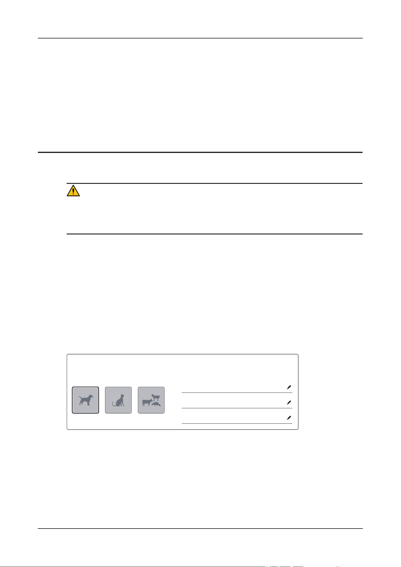
6 Managing Animals
6 - 1
6 Managing Animals
WAR N I N G
• Always discharge the previous animal before starting monitoring a new animal. Failure to do so can
lead to data being attributed to the wrong animal.
• Before starting monitoring a new animal, check if the setting is correct for your animal.
6.1 Admitting an Animal
Perform the following procedure:
1. The device admits a new animal in the following situations:
• After startup, the device automatically enters the Admit New Patient interface.
• After the patient is manually discharged, the device automatically enters the Admit New Patient
interface.
2. Input animal information.
3. Select an appropriate environment mode.
Make sure that the selected environment mode matches the animal's condition.
XXXXXX
xxxxxx
XXX
XXX
XXX
XXX
XXX
XXX
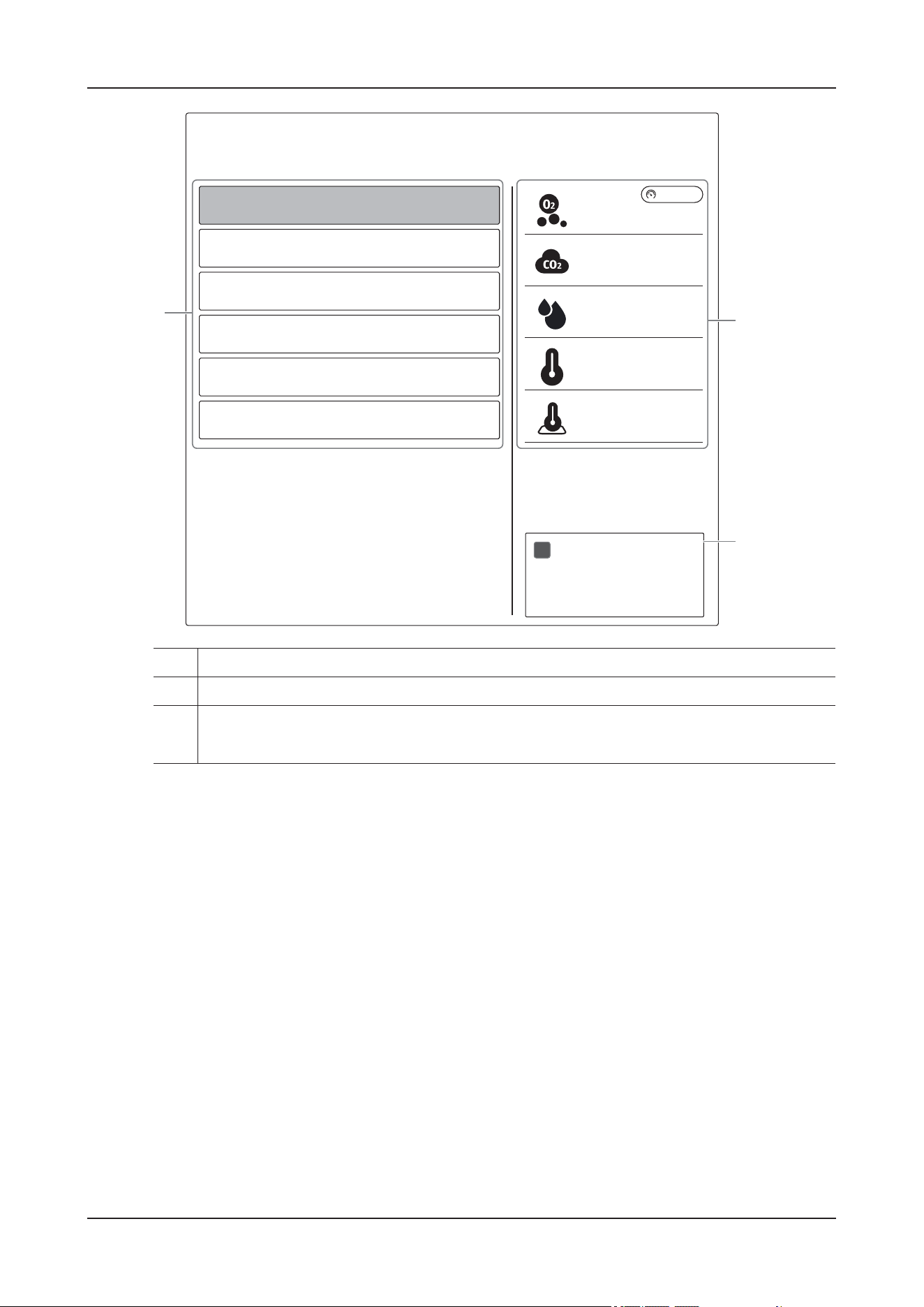
6 Managing Animals
6 - 2
4. Tap Enter to start the animal care.
6.2 Editing Animal Information
Perform the following procedure:
1. On the main screen, tap the patient information area to enter the Patient detail screen.
1. List of default therapy environment modes
2. Preset parameter values of the selected environment mode
3. Set to suspend the oxygen supply function of the selected environment mode
When the cabin door is closed, a confirmation dialog for oxygen supply is displayed.
xx kPa
1
2
3
XX%
XX%
<XXXXppm
XX.X°C
XX.X°C
Choose Environment Mode
One-click to set desired treatment environment parameters for the patient.
XXXXXX
XXXXXX
XXXXXX
XXXXXX
XXXXXX
XXXXXX
XXX
XXX
XXX
XXX
XXX
XXXXXX
XXXXXX
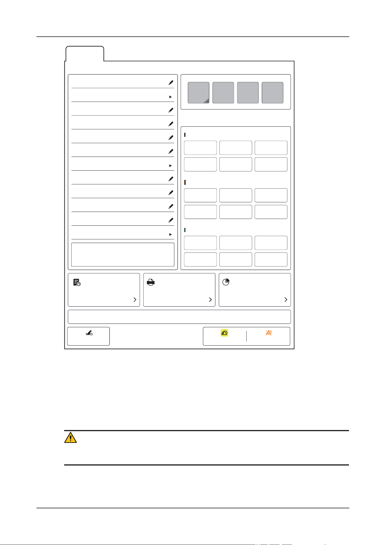
6 Managing Animals
6 - 3
Use the controls on the interface to edit the animal information. The device automatically saves the
edited information.
2. Tap Home to return to the main screen.
6.3 Discharging an Animal
WAR N I N G
Do not discharge the animal during infusion or nebulization.
Before monitoring a new animal, discharge the previous animal. After the animal is discharged, the
technical alarms are reset, and device settings return to their defaults.
XXXXXXX
X
XX
X
XX
XXX
XXX
XXX
XXX
XXX
X
XX
X
XX
XXX
X
XX
X
XX
0/3
XXXX XXXXXXXX
XXXX XXXXXXXX
XXXX XXXXXXXX
XXXX XXXXXXXX
XXXX XXXXXXXX
XXXX XXXXXXXX
XXX
XXXXXX
XXXXXX
XXXXXX
XXXXXX
XXXXXX
XXXXXX
XXXXXX (kg)
XXXXXX
XXXXXX
XXXXXX
XXXXXX
XXXXXX
XXXXXX
XXXXXX
XXXXXX
XXXXXX
XXXXXX
XXXXXX
XXXXXX
XXXXXX XXXXXX XXXXXX
XXXXXX
XXXXXX XXXXXX XXXXXX

6 Managing Animals
6 - 4
Perform the following procedure:
1. To manually discharge an animal, choose any of the following ways:
• Swipe down the touchscreen with two fingers.
• On the main screen, tap the patient information area to enter the Patient details interface, and then
tap Discharge Patient.
2. Select from the pop-up dialog box:
Print End Case Report: prints the end case report when the animal is discharged.
3. Tap OK to discharge the current animal.
After the animal is manually discharged, the device automatically enters the Admit New Patient screen.
For detailed information, see 6.1 Admitting an Animal.

7 Alarms
7 - 1
7 Alarms
7.1 Safety Information
WAR N I N G
• A potential hazard can exist if different alarm presets and default configuration settings are used for
the same or similar devices in the same care area, for example, an intensive care unit or cardiac
operating room.
• If the device is connected to the central monitoring system (CMS), alarms can be presented and
controlled remotely. Remote suspension, inhibition, or reset of device alarms via the CMS may
cause a potential hazard. For more information, see the Operator’s Manual of the CMS.
• The devices in the care area may each have different alarm settings to suit different animals. Before
starting monitoring, check that the alarm settings are appropriate for the animal. Always make sure
that necessary alarm limits are active and set according to the animal's clinical condition.
• Setting alarm limits to extreme values may cause the alarm system to become ineffective.
• When the alarm sound is switched off, the device gives no alarm tones even if a new alarm occurs.
Be careful about whether to switch off the alarm sound or not. When the alarms are off or while
alarm audio is paused either temporarily or indefinitely, observe the animal frequently.
• When monitoring animals that are not continuously attended by a clinical operator, properly
configure the alarm system and adjust alarm settings as per the animal's condition.
• Do not exclusively rely on audible alarms for animal monitoring. Adjusting alarm volume to a low
level or turning off alarm sound may result in animal hazards. Always make sure that the audio
alarm volume level is adequate in your care environment. Always keep the animal under close
surveillance.
NOTE
When the alarm system is powered off, the device will save the alarms before power-off. The stored
alarm information does not change with the power-off time.
7 Alarms
7 - 2
7.2 Understanding the Alarms
7.2.1 Alarm Categories
The device has two different types of alarms: physiological alarms and technical alarms.
• Physiological alarms: triggered by animal measurement exceeding the parameter limits, or by an
abnormal animal’s condition.
• Technical alarms: triggered by an electrical, mechanical, or other device failure, or by failure of a
sensor or component. Technical alarm conditions may also be caused when an algorithm cannot
classify or interpret the available data.
Apart from the physiological and technical alarms, the device can also prompt some messages telling the
device status or animal status.
7.2.2 Alarm Priorities
By severity, the alarms are classified into the following priority levels:
• High priority alarms: indicates a life threatening situation or a severe device malfunction. High
priority alarms require an immediate response.
• Medium priority alarms: indicates abnormal vital signs or a device malfunction. Medium priority
alarms require a prompt response.
• Low priority alarms: indicates a discomfort condition, a device malfunction, or an improper
operation. Low priority alarms require you to be aware of this condition.
• Messages: provides additional information on the animal or the device.
7.2.3 Alarm Indicators
When an alarm occurs, the device indicates it to you through visual or audible alarm indications. For
more information, see the following table.
Alarm
Indicator
High Priority
Alarm
Medium
Priority Alarm
Low Priority
Alarm
Message Description
Alarm lamp Red
Flashing
frequency: 1.4
Hz - 2.8 Hz;
Duty cycle:
20% - 60%
Yellow
Flashing
frequency: 0.4
Hz - 0.8 Hz;
Duty cycle:
20% - 60%
Cyan
No flashing,
Duty cycle:
100% on
None None

7 Alarms
7 - 3
NOTE
• When multiple alarms of different priority levels occur simultaneously, the device selects the alarm
of the highest priority to light the alarm lamp and issues the alarm tone.
• When multiple technical alarms of different priority levels occur simultaneously and should be
displayed in the same area, the device only displays the messages of the highest priority alarm.
• When multiple physiological alarms of different priority levels occur simultaneously and should be
displayed in the same area, the device displays the high priority alarm, while the medium and low
priority alarms are displayed circularly.
• When multiple alarms of the same priority levels occur simultaneously, alarm messages are
displayed circularly.
• Lethal arrhythmia alarms, apnea, and SpO
2
Desat are exclusive high priority alarms. When these
alarms occur, the device only displays messages of exclusive alarms. Other high priority alarms will
Audible tone
pattern: ISO
Repeat pattern
of 2 x 5 beep
tones
Repeat pattern
of triple beeps
Single beep
Repeat pattern
of 2 x 5 beep
tones
Repeat pattern
of 2 x 5 beep
tones
Single beep
Repeat pattern
of 3-beep tones
1-beep tone None The alarm tone
is different from
the heartbeat,
pulse, and
keystroke in
frequency.
Alarm message White text
inside a flashing
red box
Black text
inside a flashing
yellow box
Black text
inside a flashing
cyan box
White text Alarm messages
are displayed in
the alarm
information
area at the top
of the screen.
You can select
the alarm
messages to
show the alarm
list.
Alarm Level !!! !! ! None The indicator
shows in front
of
corresponding
alarm message.
Parameter value White text
inside a flashing
red box
Black text
inside a flashing
yellow box
Black text
inside a flashing
yellow box
None None
Alarm
Indicator
High Priority
Alarm
Medium
Priority Alarm
Low Priority
Alarm
Message Description
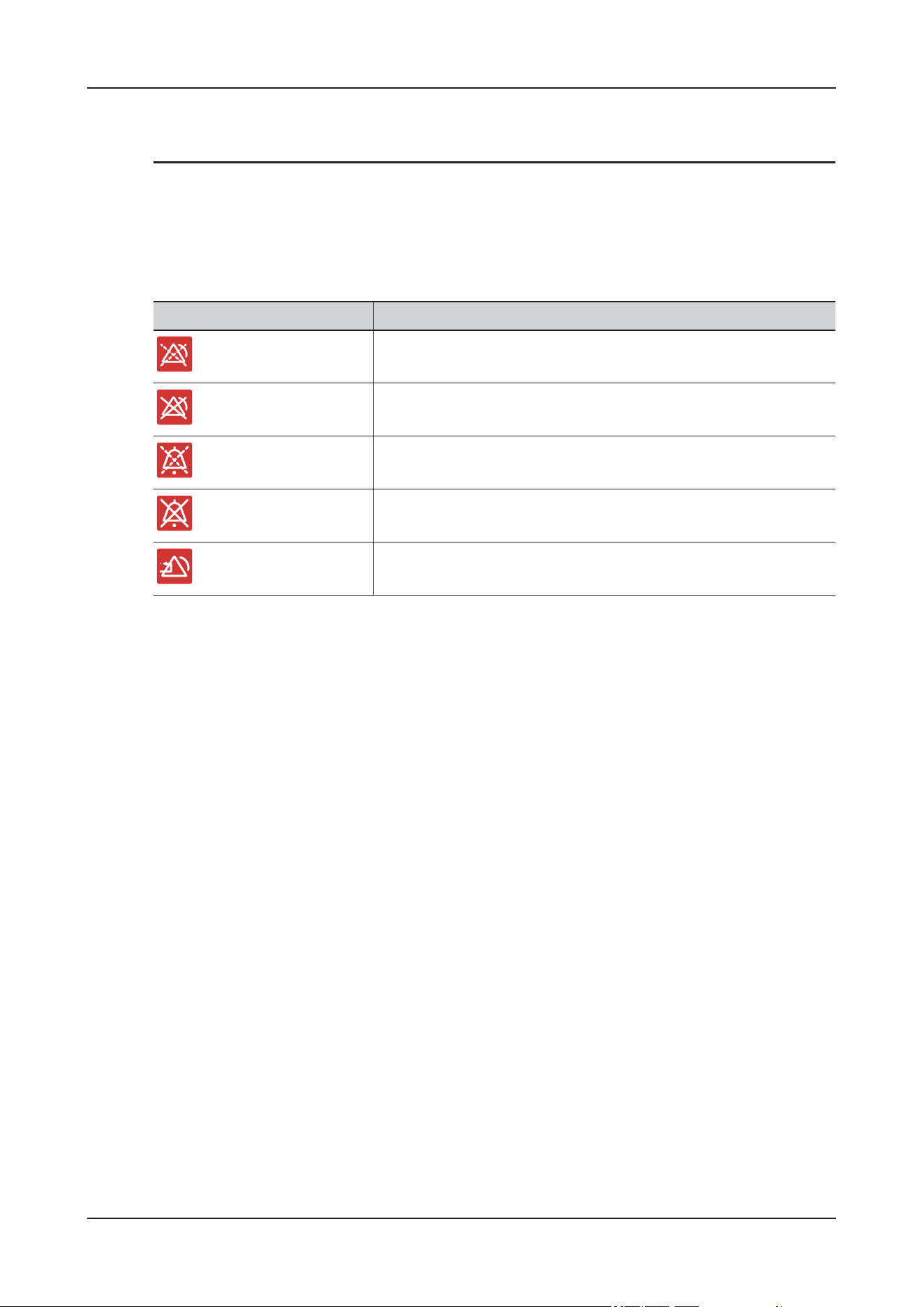
7 Alarms
7 - 4
not be displayed. When multiple exclusive alarms occur simultaneously, alarm messages are
displayed circularly.
7.2.4 Alarm Status Symbols
The device uses the following symbols to indicate the alarm status:
7.2.5 Accessing On-screen Help for Alarms
In the alarm list, if the message is displayed after alarm messages, the alarm contains help messages or
pictures to help you identify the problem.
Perform the following procedure:
1. Tap the alarm message area to open the Alarm menu.
2. Tap the corresponding alarm module tab.
3. Select the desired alarm from the alarm list.
7.3 Changing Alarm Settings
Set the alarm properties in a centralized manner.
7.3.1 Setting parameter alarms
Perform the following procedure:
1. Enter the Monitoring details interface. Tap More > Alarm Setup quick keys.
2. Select a parameter tab and set alarm properties as desired.
You can also change the alarm properties of individual parameter from corresponding parameter menu.
Symbols Description
indicates that all the alarms are paused.
indicates that individual measurement alarms are turned off or the
system is in the alarm off status.
indicates that audible alarm tones are paused.
indicates that audible alarm tones are turned off.
indicates that the alarm system is reset.
7 Alarms
7 - 5
7.3.2 Initiating Auto Alarm Limits
The device provides the auto alarm limits function to automatically adjust alarm limits according to the
animal’s vital signs using. When auto limits are selected, the device calculates safe auto limits based on
the latest measured values.
To get accurate auto alarm limits, you need to collect a set of measured vital signs as a baseline.
Perform the following procedure:
1. Enter the Monitoring details interface, and then do any of the following to open the Limits menu.
•Tap More > Alarm Setup quick keys, and then tap Limits tab.
•Tap Monitoring Setup quick key, then select Limits from the Alarm Setup column.
2. Tap Auto Limits.
3. Select OK from the popup dialog box.
The device will automatically calculate alarm limits basing on the latest measured values. These alarm
limits will remain unchanged until you select auto limits again or adjust them manually. Before applying
these automatically created alarm limits, confirm if they are appropriate for your animal. If not, you can
adjust them manually.
The device calculates auto limits basing on the following rules:
Module Parameter Lower Limit Upper Limit Auto Limit Range
ECG HR/PR (bpm) (HR - 30) or 90
(whichever is
greater)
(HR + 40) or 200
(whichever is
smaller)
55 to 225
Resp RR (rpm) (RR - 10) or 30
(whichever is
greater)
(RR + 25) or 85
(whichever is
smaller)
10 to 90
SpO
2
SpO
2
(%) Same as the default
alarm limit
Same as the default
alarm limit
Same as the measurement
range

7 Alarms
7 - 6
7.3.3 Setting the Alarm Delay Time
For continuously measured parameters, you can set the alarm delay time. If the alarm condition is
resolved within the delay time, the device does not present the alarm. This setting is password protected.
The delay time of the apnea alarm and ST alarm is not affected by the Alarm Delay time setting.
NOTE
The Alarm Delay can be set to a maximum of 15 seconds. Changing this setting to an inappropriate level
could result in a hazard to the animal.
7.3.4 Setting the Apnea Delay Time
Perform the following procedure:
1. Enter the Monitoring details interface, and then do any of the following to open the Limits menu.
•Tap More > Alarm Setup quick keys, and then tap Setup tab
•Tap Monitoring Setup quick key, then select Setup from the Alarm Setup column.
2. Select Apnea Delay to set the apnea delay time.
NIBP NIBP-S (mmHg) (SYS x 0.68 + 10) SYS x 0.86 + 38 • Weight >23kg or >50
lb:45 to 270
• Weight 10 to 23 kg or
21 to 50 lb: 45 to 185
• Weight <10 kg or <21
lb:45 to 185
NIBP-D (mmHg) (Dia x 0.68 + 6) (Dia x 0.86 + 32) • Weight >23kg or >50
lb:25 to 225
• Weight 10 to 23 kg or
21 to 50 lb: 25 to 150
• Weight <10 kg or <21
lb:25 to 150
NIBP-M (mmHg) (Mean x 0.68 + 8) (Mean x 0.86 + 35) • Weight >23kg or >50
lb:30 to 245
• Weight 10 to 23 kg or
21 to 50 lb: 30 to 180
• Weight <10 kg or <21
lb:30 to 180
Temp
(xx
indicates
temperature
site)
Txx (°C) (Txx - 0.5) (Txx + 0.5) 1 to 49
Module Parameter Lower Limit Upper Limit Auto Limit Range

7 Alarms
7 - 7
7.3.5 Restoring the Default Alarm Settings
Perform the following procedure:
1. Enter the Monitoring details interface, and then do any of the following to open the Limits menu.
•Tap More > Alarm Setup quick keys, and then tap Limits tab.
•Tap Monitoring Setup quick key, then select Limits from the Alarm Setup column.
2. Tap Defaults.
3. Select OK from the popup dialog box.
7.3.6 Setting the Length of Printed Waveforms
You can define the length of printed waveforms when an alarm is triggered. To do so, follow this
procedure:
1. Enter the Monitoring details interface, and then do any of the following to open the Limits menu.
•Tap More > Alarm Setup quick keys, and then tap Setup tab
•Tap Monitoring Setup quick key, then select Setup from the Alarm Setup column.
2. Tap Printing Duration On Alarm.
7.4 Pausing Alarms/Pausing Alarm Tones
WAR N I N G
Pausing or switching off alarms may result in a hazard to the animal.
7.4.1 Defining the Pause Function
You can either pause alarms or pause alarm tones. This depends on the pause setting. This setting is
password protected
7.4.2 Pausing Alarms
If the pause function is designated as pausing alarms, selecting the Alarm Pause quick key can
temporarily disable alarm indicators. When alarms are paused, the following rules are followed:
• No physiological alarm will be presented.
• Except battery-related technical alarms, sounds of other technical alarms are paused, but alarm
lamps and alarm messages remain presented.
• The remaining alarm pause time is displayed in the physiological alarm information area.
• The alarm pause symbol is displayed in the system information area.
When the alarm pause time expires, the alarm paused status is automatically deactivated. You can also
tap Alarm Pause quick key to cancel the alarm pause manually.
The following alarm pause and alarm reset settings are password protected:

7 Alarms
7 - 8
• Alarm pause time
• Priorities of paused alarms
• Alarm reset setting
• Reminder tone settings
7.4.3 Switching Off All Alarms
If the pause function is designated as pausing alarms and Pause Threshold is set to Permanent, tap
Alarm Pause quick key to switch off all alarms. The alarm off status has the following features:
• Physiological alarms are switched off. The alarm lamp does not flash and alarm sound is not issued.
• Alarm sound of technical alarms is switched off, but alarm lamp flashes and alarm messages are
presented.
• The message Alarm Off with red background is displayed in the physiological alarm information
area.
• The alarm off symbol is displayed in the system status information area.
To exit the alarm off status, tap Alarm Pause quick key again.
7.4.4 Pausing Alarm Sound
If the pause function is defined as Audio Pause, and when alarm tones are paused, the following rules
are followed:
• The sound of all physiological alarms and technical alarms are switched off.
• The remaining audio pause time is displayed in the physiological alarm information area.
• The audio pause symbol is displayed in the system information area.
When the audio pause time expires, the audio paused status is automatically deactivated.
7.5 Resetting Alarms
Pressing the Alarm Reset quick key to reset the alarm system. When the alarm system is reset, the alarm
reset symbol displays in the system status information area for alarm symbols.
NOTE
If a new alarm is triggered after the alarm system is reset, the alarm reset icon will disappear and the
alarm light and alarm tone will be reactivated.
7.5.1 Resetting Physiological Alarms
Physiological alarms give different alarm indicators when the alarm system is reset:
• The alarm sound is silenced.
•A ¥ appears before the alarm message.
• The color of the parameter numeric background corresponds with the alarm priority, but the
parameter numeric does not flash.

7 Alarms
7 - 9
7.5.2 Resetting Technical Alarms
Technical alarms give different alarm indicators when the alarm system is reset:
• Some technical alarms are cleared. The device gives no alarm indications.
• Some technical alarms are changed to the prompt messages.
• For some technical alarms, the alarm is silenced and a ¥ appears before the alarm message.
7.6 Latching Alarms
Physiological alarms can be set to enable or disable Latching.
• Disable Latching: indications of physiological alarms disappear when the alarm condition ends.
•Enable Latching: all visual and audible alarm indications remain until you reset the alarms. For
latched alarms the time when the alarm is last triggered is displayed behind the alarm message.
You can separately latch visual indications or simultaneously latch the visual and the audible indications.
• When visual indications are latched, visual indications, including alarm lamp, alarm message and its
background remain when the alarm condition ends and the time when the alarm last triggered is
displayed behind the alarm message.
• When audible indications are latched, the device issues alarm sounds when the alarm condition
ends.
NOTE
• Changing alarm priority may affect the latching status of corresponding alarm. Determine if you
need to reset the alarm latching status if you changed the alarm priority.
• When the alarm system is reset, latched physiological alarms are cleared.
7.7 Testing Alarms
The device automatically performs a selftest at startup. Check that an alarm tone is heard, the alarm lamp
illuminates, one after the other, in red, yellow, and cyan. This indicates that the visible and audible alarm
indicators function correctly.
To further test individual measurement alarms, perform measurements on yourself or using a simulator.
Adjust alarm limits and check that appropriate alarm behavior is observed.
7.8 Actions When an Alarm Occurs
When an alarm occurs, observe the following steps and take proper actions:
1. Check the animal’s condition.
2. Confirm the alarming parameter or alarm category.
3. Identify the source of the alarm.
4. Take proper action to eliminate the alarm condition.

7 Alarms
7 - 10
5. Make sure the alarm condition is corrected.
8 Environment Control
8 - 1
8 Environment Control
WAR N I N G
Make sure that the settings of environmental parameters match the animal’s condition.
8.1 Setting the Oxygen Concentration
This device provides high-pressure and low-pressure oxygen supply connectors.
WAR N I N G
•Use SpO
2
monitoring for animals who are dependent only on an increased defined O
2
%. Otherwise,
a deterioration in the animal's condition may not be recognized.
• Insufficient source pressure may cause inaccurate control of oxygen concentration
• Ensure the high-pressure oxygen supply is sufficient so as not to affect the operation of other
devices.
• The device must be used under the supervision of qualified medical staff, so that help is immediately
available if malfunctions occur or the patient has insufficient spontaneous breathing.
• When the oxygen concentration target is set too high, if the oxygen supply capability of the gas
source is insufficient, the oxygen concentration target may not be achieved.
• The gas supply pressure range of the high-pressure oxygen source is 200 kPa to 600 kPa, and the gas
supply pressure range of the low-pressure oxygen source is 0 to 220 kPa. If the pressure range of the
oxygen supply is not within the allowable range, device damage may be caused.
CAUTION
• To prevent possible animal injury, use the low-pressure oxygen supply only when it can provide
sufficient oxygen.
• To prevent possible animal injury, ensure that an emergency backup oxygen supply (such as a gas
cylinder) is available in case the low-pressure oxygen supply fails.
• The low-pressure oxygen hose assembly shall comply with the requirements of ISO 5359.
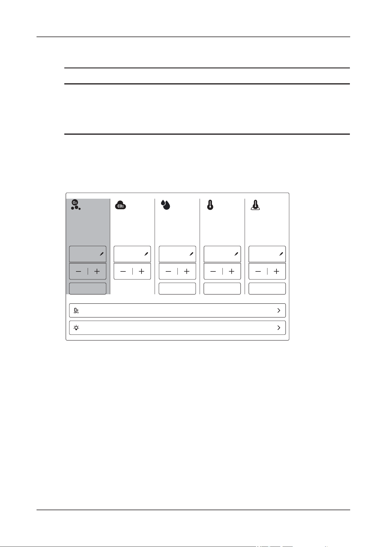
8 Environment Control
8 - 2
• To ensure the accuracy of oxygen concentration monitoring, contact the Customer Service
Department or your distributor for regular maintenance of the oxygen flow sensor.
NOTE
When the cabin door is opened or emergency ventilation is enabled, the oxygen supply is automatically
stopped. The oxygen supply will be automatically restored after the cabin door is closed or ventilation is
terminated.
Perform the following procedure:
1. On the main screen, tap the environment information area to enter the Environment details interface.
2. Use the controls in the O2 area to set the target values.
3. Tap Start to enable oxygen delivery.
• When the high-pressure oxygen source is connected: the real-time oxygen value target oxygen
value -1.5%, start oxygen supply; the real-time oxygen value is greater than or equal to the target
oxygen value, and the oxygen supply is stopped.
• When the low-pressure oxygen source is connected: The real-time oxygen value target oxygen
value -1.5%, start oxygen supply; the real-time oxygen value is greater than or equal to the target
oxygen value +1.5%, and the oxygen supply is stopped.
• When connecting the oxygen generator: after the oxygen delivery is enabled, the device adjusts the
internal oxygen concentration by using the emergency ventilation switch and fan speed.
4. Tap Home to return to the main screen.
The current oxygen concentration inside the device and the target oxygen concentration are displayed in
the environment information area.
O2
XX
%
CO2
XXX
ppm
XX
%
XX.X
°C
XX.X
°C
XX <XXXX XX XX.X XX.X
XXXXXX XXXXXX XXXXXX
XXX
XXXXXX
XXXXXX
XXX XXX XXX
XXXXXX
8 Environment Control
8 - 3
Smart Fast O
2
Mode
NOTE
Before use, enable the Smart Fast O2 Mode from the Environment Maintenance menu, see
5.2.4 Environment Maintenance.
When the high-pressure oxygen source is connected, if target oxygen value – real-time oxygen value
3% and target oxygen value 30%, the device will automatically start Smart Fast O2 Mode to quickly
increase the internal oxygen concentration.
During Smart Fast O2 Mode, when target oxygen value – real-time oxygen value 2%, the device will
exit the Smart Fast O2 Mode and enter the general oxygen supply mode.
Accumulated Oxygen Volume
On the main screen, tap the environment information area to enter the Environment details interface.
You can view the current animal's oxygen usage amount and usage time in the Accumulated O2
Volume area.
Tap Clear to pop up the confirmation dialog box. Tap Clear to manually clear the oxygen volume.
The oxygen volume will be automatically cleared after the current animal is discharged.
8.2 Setting the Atmosphere Temperatures
WAR N I N G
• If the target value of the air temperature and floor temperature exceeds 40ႏ, pay attention to
prevent scalds.
• The air cooling function is enabled only when the target air temperature is lower than the current air
temperature.
• The floor cooling function is enabled only when the target floor temperature is lower than the
current floor temperature.
The device supports the adjustment function of air temperature and floor temperature in the cabin to meet
the temperature care requirements of animals.
Perform the following procedure:
1. On the main screen, tap the environment information area to enter the Environment details interface.
2. Use the controls in the Air Temp and Floor Temp areas to set the target values.
Accumulated O2 Volume
O2 Statistics xL(xh xmin)
Clear
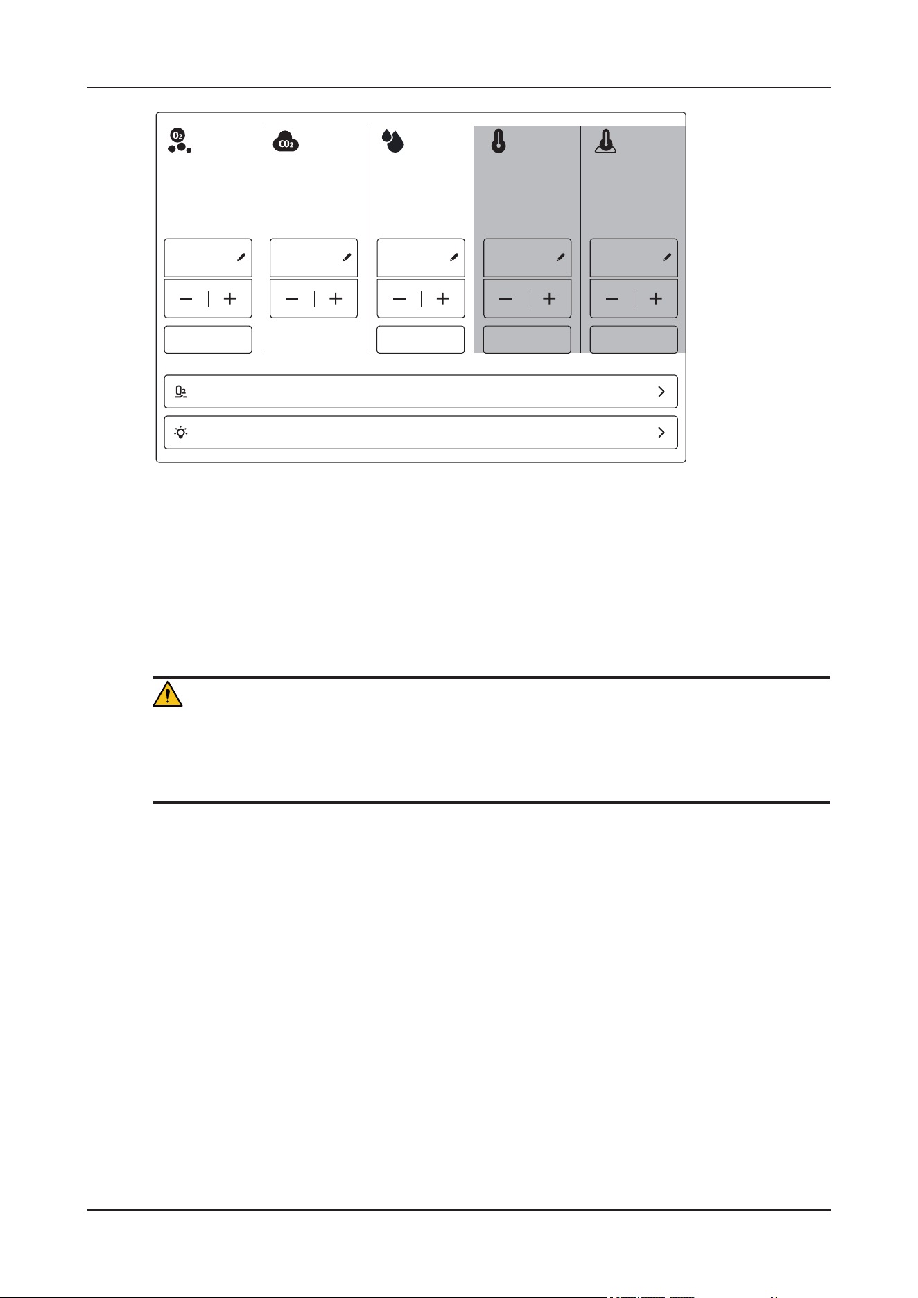
8 Environment Control
8 - 4
3. Tap Start to start the temperature adjustment function.
4. Tap Home to return to the main screen.
The current temperature and the target temperature are displayed in the environment information area.
8.3 Setting the Atmosphere Humidity
WAR N I N G
In order to prevent too much condensed water from generating on the inner shell of the device, the
dehumidification function will be automatically enabled if the humidity in the device is high and the
inner shell temperature is too low after the device is powered on.
Perform the following procedure:
1. On the main screen, tap the environment information area to enter the Environment details interface.
2. Use the controls in the humidity area to set the target value.
O2
XX
%
CO2
XXX
ppm
XX
%
XX.X
°C
XX.X
°C
XX <XXXX XX XX.X XX.X
XXXXXX XXXXXX XXXXXX
XXX
XXXXXX
XXXXXX
XXX XXX XXX
XXXXXX
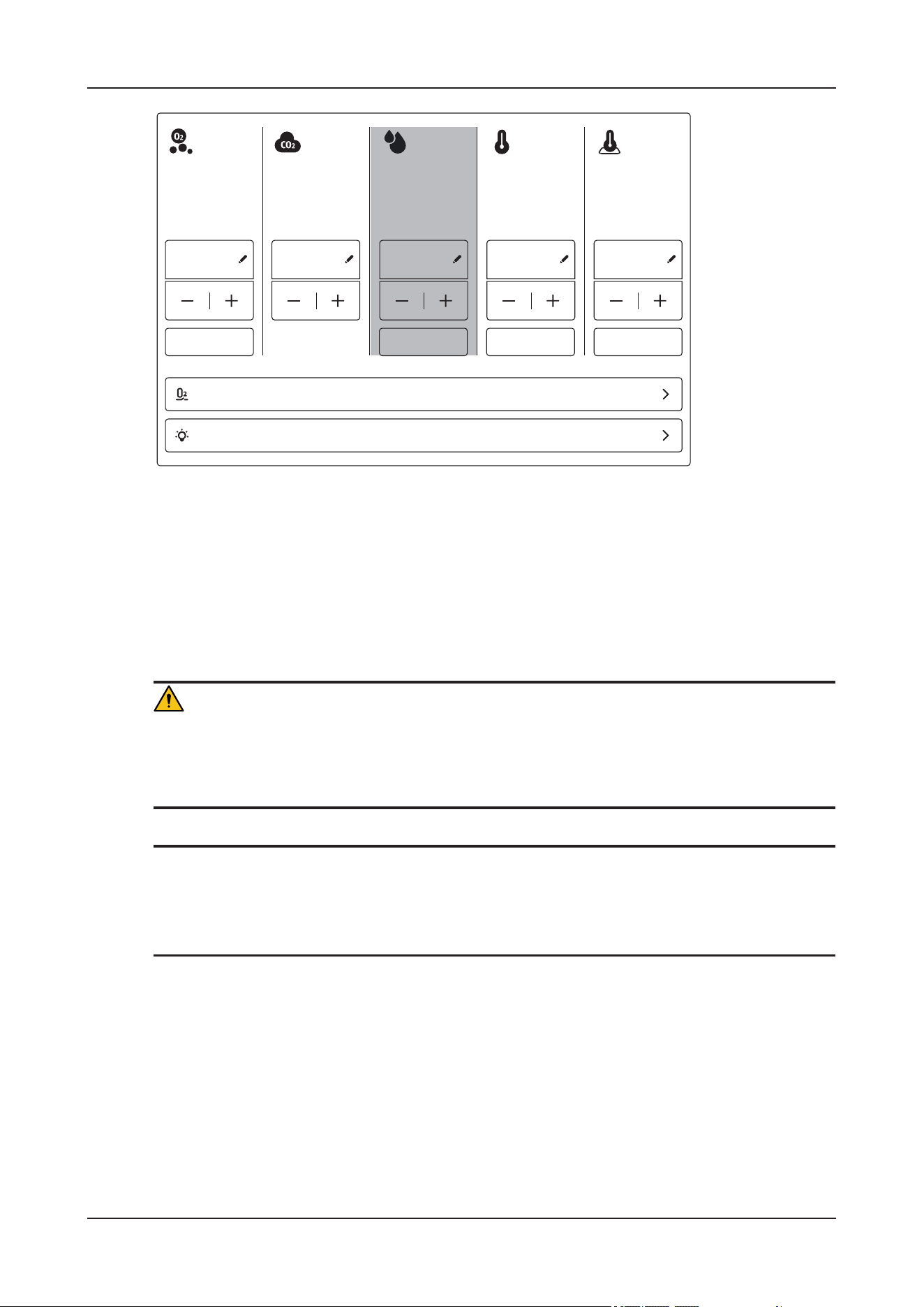
8 Environment Control
8 - 5
3. Tap Start to start the humidity adjustment function.
4. Tap Home to return to the main screen.
The current humidity and the target humidity are displayed in the environment information area.
8.4 Setting the CO
2
Concentration
WAR N I N G
Single use items may be considered potential biologically hazardous items and should not be reused.
Dispose of these items in accordance with hospital policy and local regulations for contaminated and
biologically hazardous items.
NOTE
• Install soda lime as needed before the first use of the device.
• Inspect the color of the soda lime in the CO
2
absorber canister. Replace the soda lime immediately if
obvious color change is detected.
Perform the following procedure:
1. On the main screen, tap the environment information area to enter the Environment details interface.
2. Use the controls in the CO2 area to set the target values.
O2
XX
%
CO2
XXX
ppm
XX
%
XX.X
°C
XX.X
°C
XX <XXXX XX XX.X XX.X
XXXXXX XXXXXX XXXXXX
XXX
XXXXXX
XXXXXX
XXX XXX XXX
XXXXXX
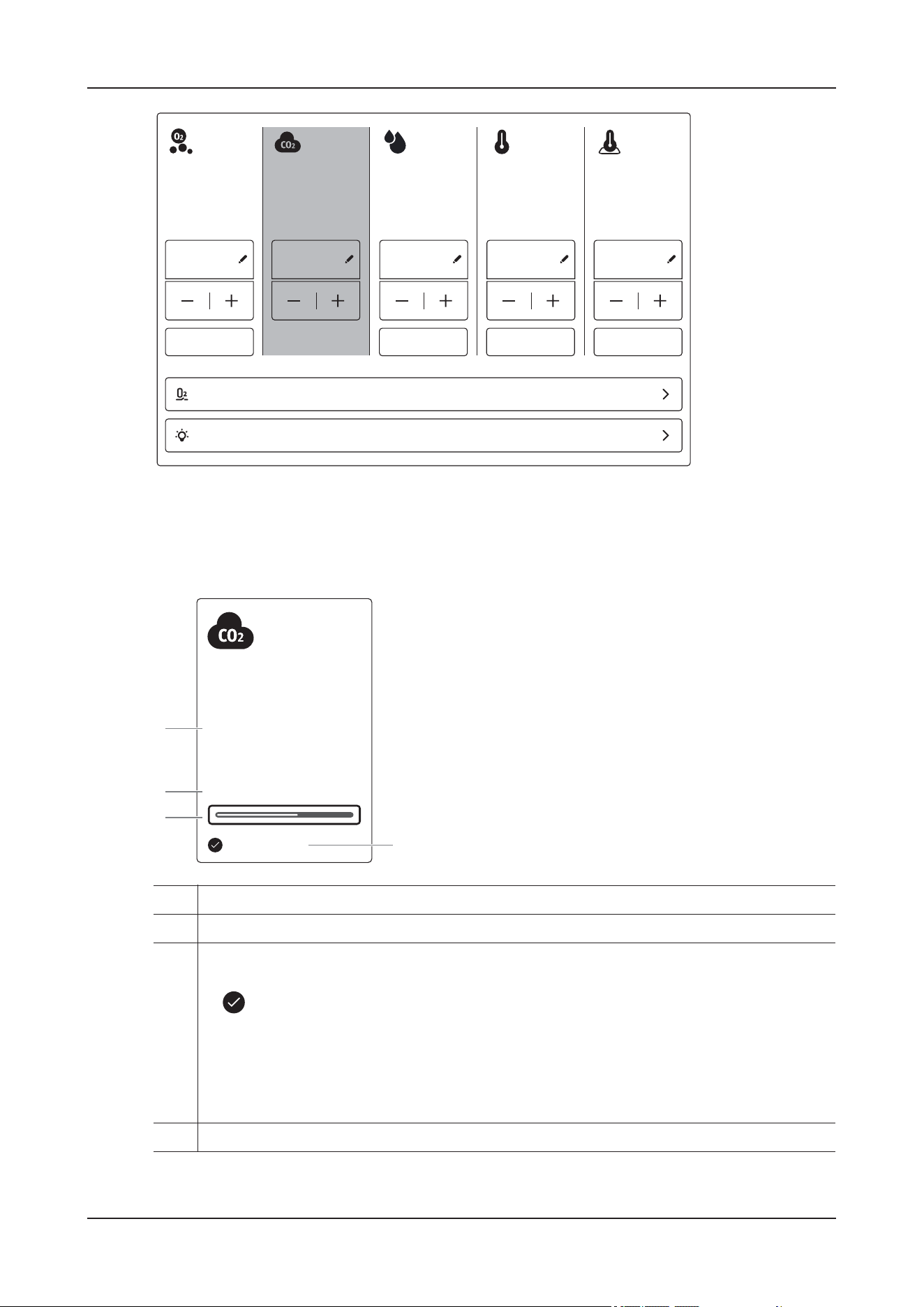
8 Environment Control
8 - 6
3. Tap Home to return to the main screen.
The current CO
2
concentration and the target CO
2
concentration are displayed in the environment
information area.
O2
XX
%
CO2
XXX
ppm
XX
%
XX.X
°C
XX.X
°C
XX <XXXX XX XX.X XX.X
XXXXXX XXXXXX XXXXXX
XXX
XXXXXX
XXXXXX
XXX XXX XXX
XXXXXX
1. Current CO
2
concentration inside the device
2. Indication text of the current CO
2
concentration status
3. Indication bar of the current CO
2
concentration status
• A white progress bar indicates that the CO2 concentration is below the target value. The
icon appears before the target value.
• A yellow progress bar indicates that the CO2 concentration is equal to or greater than
the target value and that active CO2 absorption is automatically enabled (not applicable
to external circulation).
• A full yellow progress bar indicates that the CO2 concentration exceeds the automatic
ventilation alarm limit and that ventilation is automatically started.
4. Target CO
2
concentration value
<XXXXppm
XXX
CO2
ppm
1
2
4
3
XXXXX

8 Environment Control
8 - 7
8.5 Auxiliary Functions
8.5.1 Nebulization
WAR N I N G
• Install the specified nebulizer.
• Pay attention to the connection of the nebulizer during operation in case of interruption of
nebulization.
CAUTION
• To avoid corrosion of components inside the device by the atomizing liquid, after the nebulization is
enabled, the controls of air temperature, humidity, O
2
concentration and CO
2
concentration is
suspended and manual ventilation is also not allowed.
During nebulization, the device will automatically enable the emergency ventilation in case of
hazardous conditions such as the air temperature is too high, the oxygen concentration is too low, or
the CO
2
concentration is too high.
• The remaining nebulized drug will affect the ambient air.
• After nebulization, open the cabin door and keep still for half an hour.
NOTE
• Refer to the nebulizer accompanying directions for use to install and use the nebulizer.
• Only use medications approved for nebulization.
To connect the nebulizer
Perform the following procedure:
1. Install one end of the airway tube to the nebulizer connector of the device and the other end to the
nebulizer cup.
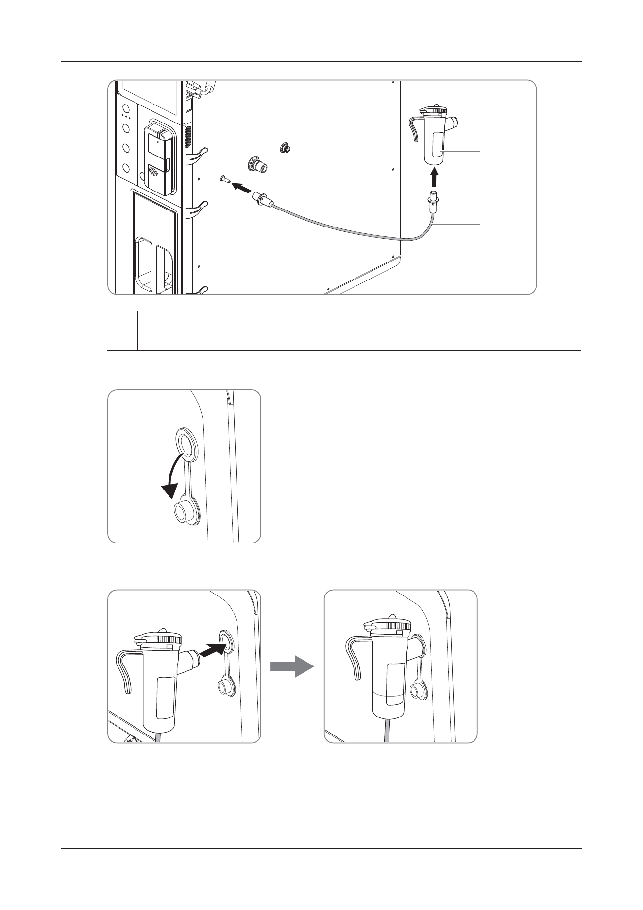
8 Environment Control
8 - 8
2. Select an appropriate multi-function operation hole, and then open the hole cover.
3. Install the nebulizer cup into the multi-function operation hole as shown.
To enable the nebulization
Perform the following procedure:
1. On the main screen, tap the environment information area to enter the Environment details interface.
1. Nebulizer cup
2. Airway tube
1
2
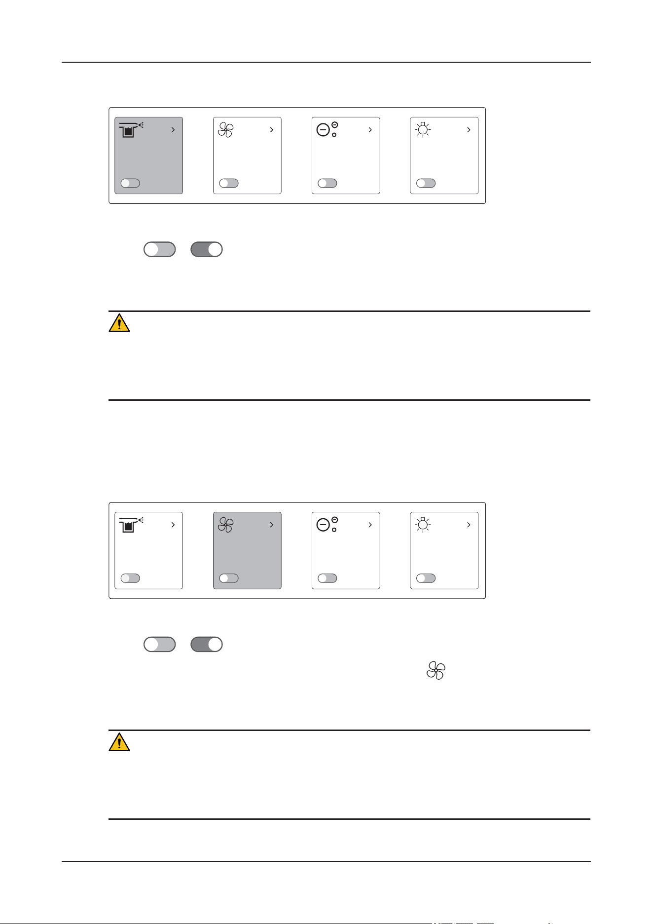
8 Environment Control
8 - 9
2. Tap Nebulization icon to enter the Nebulization Setup dialog.
3. Set the target value and tap OK.
4. Switch to to enable the nebulization function.
8.5.2 Ventilation
WAR N I N G
To ensure safety and avoid excessive oxygen consumption, the device will suspend air temperature,
humidity, oxygen concentration and CO
2
concentration controls and nebulization when the ventilation
function is enabled.
Perform the following procedure:
1. On the main screen, tap the environment information area to enter the Environment details interface.
2. Tap Ventilation icon to enter the Ventilation Setup dialog.
3. Set the target value and tap OK.
4. Switch to to enable the ventilation function.
You can also quickly enable the ventilation function by pressing the button on the control panel.
8.5.3 Anion
WAR N I N G
To ensure safety, when oxygen supply is enabled or the oxygen concentration is too high, the device will
disable the anion function. The anion function is allowed only when the oxygen concentration inside the
device is lower than 23%.
xxxxxx
xxx
XXXXXX XXXXXX XXXXXX XXXXXX
XXXXXX
xxxxxx
xxx
XXXXXX XXXXXX XXXXXX XXXXXX
XXXXXX
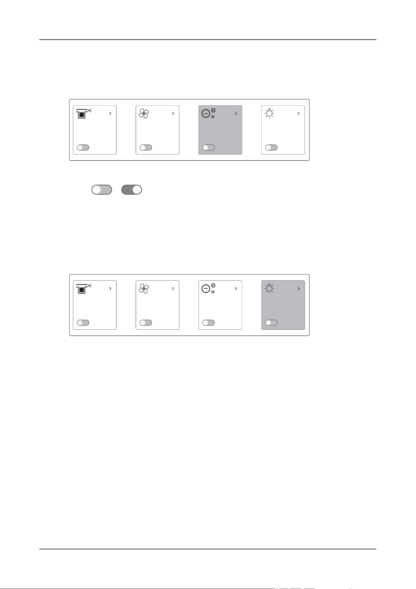
8 Environment Control
8 - 10
Perform the following procedure:
1. On the main screen, tap the environment information area to enter the Environment details interface.
2. Tap Anion icon to enter the Anion Setup dialog.
3. Set the target value and tap OK.
4. Switch to to enable the anion function.
8.5.4 Light
Perform the following procedure:
1. On the main screen, tap the environment information area to enter the Environment details interface.
2. Tap Light icon to enter the Light Setup dialog.
3. Set the light mode as required, and tap OK.
xxxxxx
xxx
XXXXXX XXXXXX XXXXXX XXXXXX
XXXXXX
xxxxxx
xxx
XXXXXX XXXXXX XXXXXX XXXXXX
XXXXXX
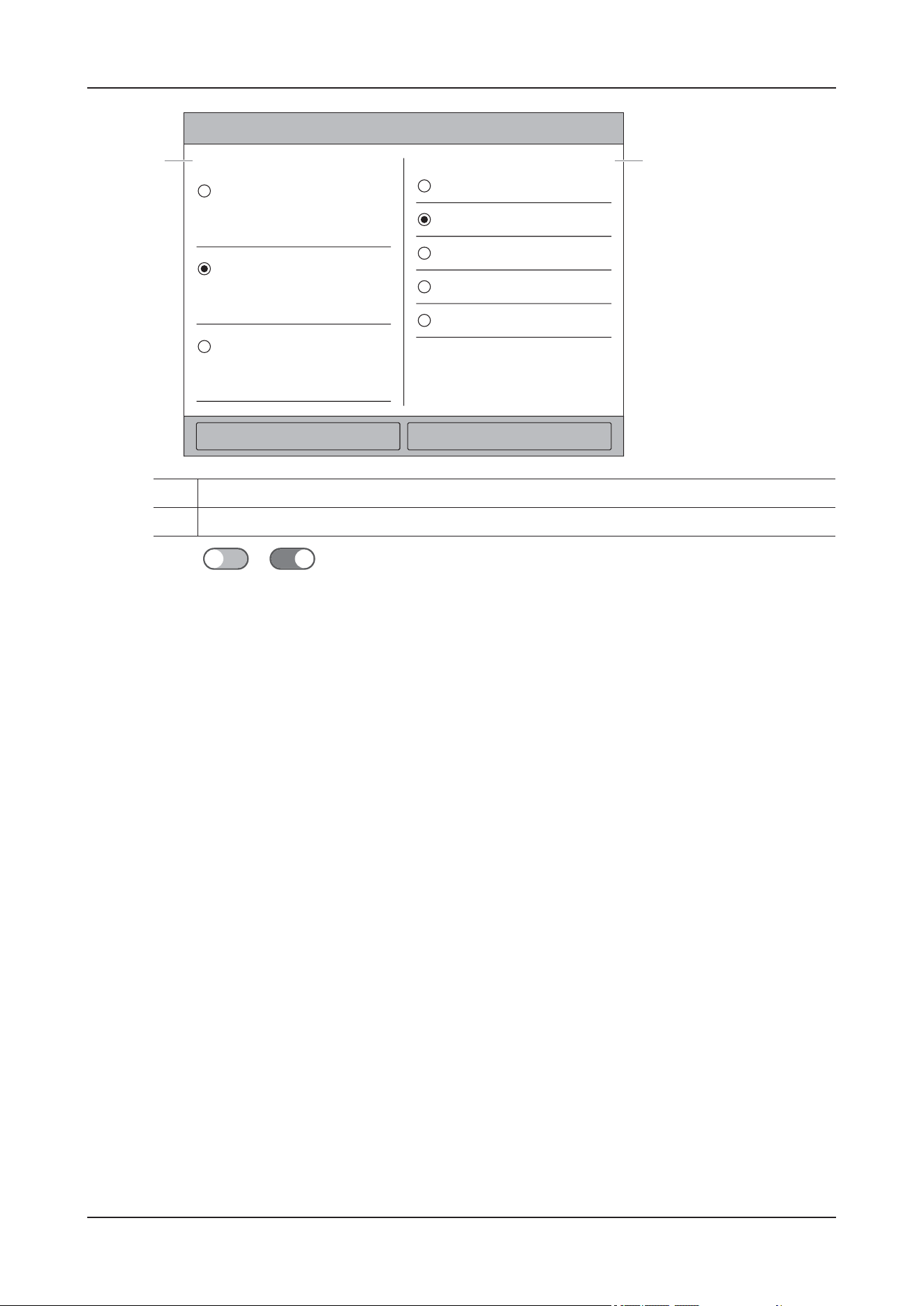
8 Environment Control
8 - 11
4. Switch to to enable the light function.
1. Select an appropriate light mode according to the animal condition
2. Adjust the light brightness level when White Light is enabled
12
XXXXXX
XXXXXX XXXXXXX
XXX
XXX
XXX
XXX
XXX
XXX
XXX
XXX
XXX XXX
XXXXXX
XXXXXX
XXXXXX

9 Monitoring ECG
9 - 1
9 Monitoring ECG
9.1 Overview
The electrocardiogram (ECG) measures and records the electrical activity of the heart.
WAR N I N G
• This device is not intended for direct cardiac application.
• Make sure the conductive parts of electrodes and associated connectors, including the neutral
electrode, do not contact any other conductive parts including earth.
• Use defibrillation-proof ECG cables during defibrillation.
• Do not touch the animal or metal devices connected to the animal during defibrillation.
• To reduce the hazard of burns during high-frequency surgical procedure, ensure that the device’s
cables and transducers never come into contact with the electrosurgery unit (ESU).
• To reduce the hazard of burns during use of high-frequency surgical unit (ESU), the ECG electrodes
should not be located between the surgical site and the ESU return electrode.
• Never entangle the ESU cable and the ECG cable together.
• If the ESU is used, do not place ECG electrodes near the grounding plate of the ESU. Otherwise,
interference on ECG signals may occur.
• Make sure the device connection and animal information are correct before monitoring ECG.
• Keep close observation on the device connection status during animal monitoring, in case animal
data loss or errors occur.
CAUTION
• Only use parts and accessories specified in this manual. Follow the instructions for use and adhere to
all warnings and cautions.
• Periodically inspect the electrode application site to ensure skin integrity. If the skin quality
changes, replace the electrodes or change the application site.
• Interference from ungrounded instrument near the animal and electrosurgery interference can induce
noise and artifact into the waveforms.
• The animal should be placed in a specified area. If the animal is at the edge of or outside the network
coverage range, unstable network connection may compromise the monitoring performance.

9 Monitoring ECG
9 - 2
• Make sure the SpO
2
module screen and touch button are not damaged or broken. If there is any sign
of damage, remove it from use and contact the Customer Service Department or your local
distributor.
• Check the metal parts like contacts and pins on the SpO
2
module, accessories and charging station
before use or on a regular basis. If needed, clean them with a soft cloth moistened with water or
ethanol. Otherwise, the performance might be degraded because of poor contact.
•If the SpO
2
module screen is loose, remove it from use and contact the Customer Service
Department or your local distributor.
NOTE
• Store the electrodes at room temperature.
• Immediately use the electrode after open the its package.
• Never mix animal electrode types or brands. This may lead to problem due to impedance mismatch.
• When applying the electrodes, avoid bony area, obvious layers of fat, and major muscles. Muscle
movement can result in electrical interference. Applying electrodes on major muscles, for example
on muscles of the thorax, may lead to erroneous arrhythmia alarms due to excessive muscle
movement.
9.2 Starting the ECG Monitoring
Perform the following procedure:
1. Wear the Vet Harness for ICU.
For details, see its accompanying manual.
2. Prepare the animal’s skin:
Proper skin preparation is necessary for good signal quality at the electrode, as the skin is a poor
conductor of electricity. To properly prepare the skin, choose flat areas and then follow this procedure:
1. Shave hair from skin at chosen sites.
2. Gently rub skin surface at sites to remove dead skin cells.
3. Thoroughly cleanse the site. It is not recommend using ether or pure alcohol, because this dries the
skin and increases the resistance.
4. Dry the skin completely before applying the electrodes.
3. Attach the clips or snaps to the electrodes before placing them.
Check that electrode packages are intact and the electrodes are not past the expiry date. Make sure the
electrode gel is moist. Attach the snaps to the electrodes before placing electrodes on the animal.
4. Place the electrodes on the prepared sites.
Exhaust all air between the electrode pads and the animal's skin.
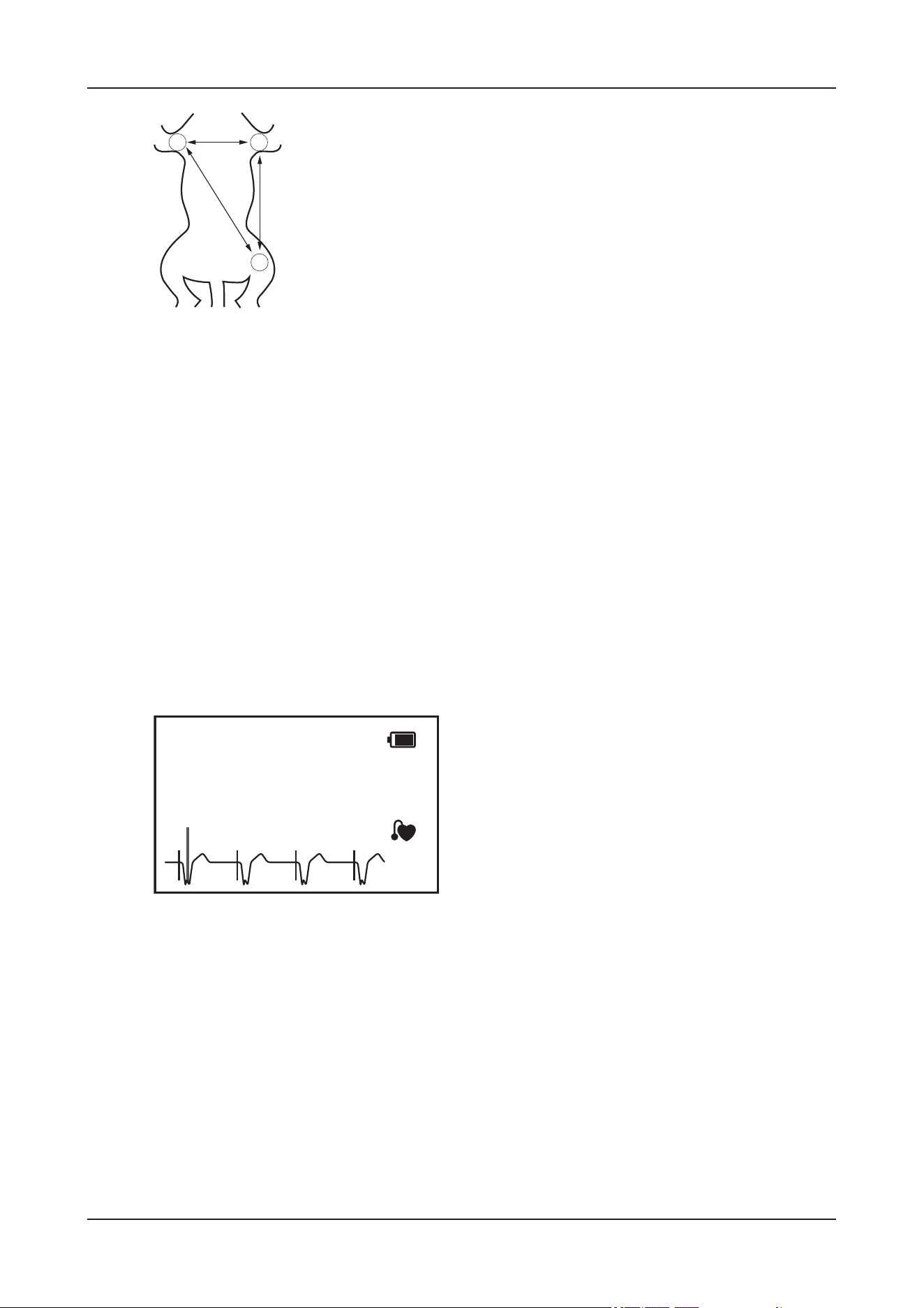
9 Monitoring ECG
9 - 3
• RA placement: on the right foreleg.
• LA placement: on the left foreleg.
• LL placement: on the left hind leg.
5. Install the ECG module into the connector of the ECG module docking.
6. Clamp the ECG module docking to the harness.
7. Adjust parameters in the ECG menu to obtain the optimized waveform display.
9.3 Results Display
The measurement results are displayed on the main screen and the Monitoring details interface.
The ECG numeric area and waveform area are configured to be different for different lead type and ECG
settings.
Figure 9-1 ECG results on the main screen
LA
LL
RA
I
II
III
ECG
bpm
XXX
XX
II
X2
XXX
XXX
1mV
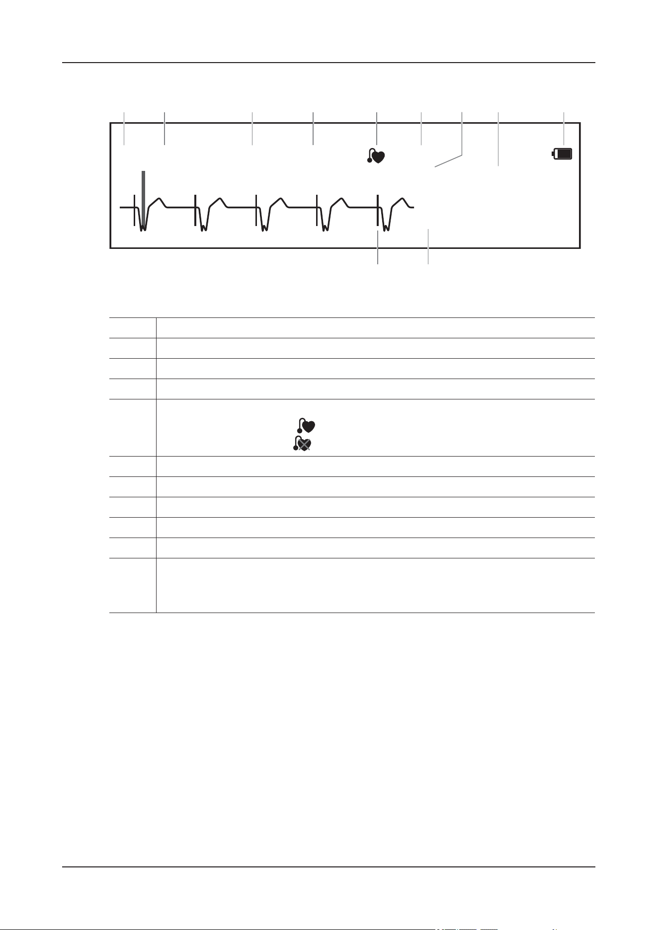
9 Monitoring ECG
9 - 4
Figure 9-2 ECG results on the monitoring details interface
9.4 Parameter Adjustment
Enter the Monitoring details interface, tap the ECG numeric area or waveform area to open the ECG
menu.
Setting ECG Alarm Properties
Perform the following procedure:
1. Select the Alarm tab.
2. Set alarm properties as desired.
Input the password if required.
1. ECG lead label of the displayed waveform
2. ECG waveform gain
3. ECG filter mode
4. ECG Location
5. Paced status
• When Paced is set to Yes:
• When Paced is set to No:
6. Parameter label
7. HR Unit
8. HR value
9. Battery capacity of ECG module
10. HR alarm limits
11. Paced status
When Paced is set to Yes, the pace pulse markers are displayed corresponding to detected
pace pulse on each ECG waveform.
II
x2
XXXX
XXX
ECG
XXX
bpm
XXX
XX
1 mV
12 3 546789
1011

9 Monitoring ECG
9 - 5
Changing ECG Wave Settings
Perform the following procedure:
1. Select the Setup tab.
2. Adjust parameters as required:
Adjusting the Minimum QRS Detection Threshold
To avoid false asystole alarm due to low R wave amplitude, and to avoid tall T waves and P waves being
mistaken for QRS complexes, the device provides a means to manually adjust the minimum QRS
detection threshold.
CAUTION
• The setting of the QRS detection threshold can affect the sensitivity for arrhythmia, ST, QT/QTc
detection, and heart rate calculation.
Item Description
ECG Set the leads of displayed ECG waveforms,
TIP
Ensure that you have selected the optimal leads with the best waveform
amplitude and the highest signal-to-noise ratio. Selecting the optimal
leads is important for detecting beats, classifying beats, and detecting
ventricular fibrillation.
Speed Change ECG waveform speed.
Filter Set the ECG waveform filter mode.
• Monitor: use under normal measurement conditions.
• Surgery: use when the signal is distorted by high frequency or low
frequency interference. High frequency interference usually results in
large amplitude spikes making the ECG signal look irregular. Low
frequency interference usually leads to wandering or rough baseline. The
surgery filter reduces artifacts and interference from electrosurgical
units. Under normal measurement conditions, selecting Surgery may
suppress certain features or details of the QRS complexes.
• ST: recommended for ST monitoring.
Notch Filter Notch Filter is always On.
The notch filter removes the line frequency interference.
Lead Set Set according to the lead type you are going to use.
Measurement Site Set the desired ECG measurement site.
CrozFusion Enable/disable CrozFusion function.
ECG Gain Set to change the ECG waveform size by adjusting the ECG gain.
Display CrozFusion The ECG SQI, Pleth SQI, and signal fusion status are displayed when the
CrozFusion function is enabled.
QRS Volume Adjust the QRS volume.
9 Monitoring ECG
9 - 6
• If QRS amplitude is low, the device might not be able to calculate heart rate and false asystole calls
may occur.
NOTE
The minimum QRS detection threshold can only be adjusted when the ECG filter is set to Monitor.
Perform the following procedure:
1. Select the Setup tab, and set Filter to Monitor.
2. Select the QRS Threshold tab.
3. Select / to adjust the minimum threshold for QRS detection.
Select Defaults to reset the QRS threshold to the default value (0.16 mV).
9.5 Monitoring Arrhythmia
9.5.1 Safety Information
WAR N I N G
• Heart rate reading may be affected by cardiac arrhythmias. Do not rely entirely on heart rate alarms
when monitoring animals with arrhythmia. Always keep these animals under close surveillance.
• The arrhythmia function may detect an incorrect arrhythmia. Therefore, physicians must combine
more clinical signs to analyze arrhythmia information.
CAUTION
• The arrhythmia analysis program may incorrectly identify the presence or absence of an arrhythmia.
Therefore, a physician must analyze the arrhythmia information with other clinical findings.
• The ECG waveform amplitude and QRS threshold settings will affect the sensitivity of arrhythmia
detection and heart rate calculation.
• If the QRS amplitude is too low, the device may not be able to calculate the heart rate or detect an
incorrect asystole.
• During the learning phase of the algorithm, arrhythmia detection may not be available. To allow the
algorithm to reach optimal detection performance, you should closely device animal condition
during learning phase and for several minutes after the learning phase.
9.5.2 Arrhythmia Events
This section lists all arrhythmia events and their criteria.
Lethal Arrhythmia Events

9 Monitoring ECG
9 - 7
Nonlethal Arrhythmia Events
Arrhythmia messages Description
Asystole No QRS complex detected within the set time interval in the absence of
ventricular fibrillation or chaotic signal.
V-Fib/V-Tach A fibrillatory wave for 6 consecutive seconds. A dominant rhythm of
adjacent PVCs and the ventricular rate is greater than the V-tach rate limit.
V-Tach The number of consecutive PVCs is greater than or equal to the V-Tach
PVCs limit, and the ventricular rate is greater than or equal to the V-Tach
rate limit.
Vent Brady The number of consecutive PVCs is greater than or equal to V brady PVC
limit and the ventricular rate is less than the V brady rate limit.
Extreme Tachy The heart rate is greater than the extreme tachycardia limit.
Extreme Brady The heart rate is less than the extreme bradycardia limit.
Arrhythmia messages Description
R on T R on T PVC is detected.
Run PVCs More than two consecutive PVCs, but lower than the V brady PVCs limit,
and the ventricular rate is lower than the V-Tach rate limit.
Couplet A Pair of PVCs detected in between normal beats.
Multiform PVC Multiform PVCs detected in Multif. PVC’s Window (which is adjustable).
PVC One PVC detected in between normal beats.
Bigeminy* A dominant rhythm of N, V, N, V, N, V.
Trigeminy* A dominant rhythm of N, N, V, N, N, V, N, N, V.
Tachy The heart rate is greater than the tachycardia limit.
Brady The heart rate is lower than the bradycardia limit.
Pacer Not Capture No QRS complex detected for 300 ms following a pace pulse (for paced
animals only).
Pacer Not Pacing No pace pulse detected for 1.75 x average R-to-R intervals following a QRS
complex (for paced animals only).
Missed Beat At least 3 consecutive Ns, and
The current RR interval is greater than 1.5 x previous RR interval, and
The next RR interval is lower than 1.5 x average RR interval, and
HR lower than 100 and the current RR interval is greater than 1.75 x average
RR interval, or HR is greater than or equal to 100 and the current RR
interval is greater than 1000 ms.
Nonsus V-Tach The number of consecutive PVCs is lower than the V-Tach PVCs limit but
greater than 2, and the ventricular rate is greater than or equal to the V-Tach
Rate limit.
Vent Rhythm The number of consecutive PVCs is greater than or equal to the V Brady
PVCs limit, and ventricular rate is greater than or equal to the V Brady Rate
limit but lower than V-Tach Rate limit.

9 Monitoring ECG
9 - 8
TIP
N: normal beat; V: ventricular beat
9.5.3 Displaying Arrhythmia Information
The arrhythmia information displays in the numeric area.
Perform the following procedure:
1. On the main screen, tap the monitoring information area to enter the Monitoring details interface.
2. Do one of the following to open the Tile Layout menu:
•Select More > Screen Setup > Monitor > Tile Layout.
•Select Monitoring Setup > Screen Setup > Tile Layout.
3. Tap the numeric area where you want to display the arrhythmia information, and then select ECG >
Arrhythmia.
9.5.4 Changing Arrhythmia Settings
Perform the following procedure:
1. On the main screen, tap the monitoring information area to enter the Monitoring details interface.
2. Tap the ECG parameter area or waveform to open the ECG menu.
3. Select Arrhythmia > Alarm.
4. Input the password if required.
5. Set alarm properties as desired.
NOTE
• Switch off lethal arrhythmia alarms only when the Lethal Arrhy Alarms Off is set to Enable.
• The priority of lethal arrhythmia alarms is always high. It cannot be altered.
Pause No QRS complex is detected within the set time threshold of pause.
Irr Rhythm Consistently irregular rhythm (N, irregular RR interval change is greater
than 12.5%)
PVCs/min High PVCs/min exceeds high limit.
Pauses/min High Pauses/min exceeds high limit.
SVT The number of consecutive SVCs is greater than or equal to the SVT SVCs
limit, and the supraventricular HR is greater than or equal to the SVT HR
limit.
SVCs/min High SVCs/min exceeds the high limit.
Arrhythmia messages Description

9 Monitoring ECG
9 - 9
9.5.5 Setting the Lethal Arrhythmia Alarms Switch
You can choose whether switching off lethal arrhythmia alarms is permissible or not. This function is
password protected.
WAR N I N G
If you switch off all arrhythmia alarms, the device will not alarm for any arrhythmia event. This may
result in a hazard to the animal. Always keep the animal under close surveillance.
NOTE
If any of the lethal arrhythmia alarms is switched off, the ECG waveform area displays the Lethal
Arrhys Off message.
Changing Arrhythmia Alarm Threshold Settings
You can change threshold settings for some arrhythmia alarms. When an arrhythmia violates its
threshold, an alarm will be triggered.
Perform the following procedure:
1. On the main screen, tap the monitoring information area to enter the Monitoring details interface.
2. Tap the ECG parameter area or waveform to open the ECG menu.
3. Select Arrhythmia > Threshold.
4. Input the password if required.
5. Set the threshold of desired arrhythmia alarms.
NOTE
The Asystole Delay relates to ECG relearning. When heart rate is less than 30 bpm, it is recommended to
set Asystole Delay to 10s.
Arrhythmia Threshold Range
Arrhythmia Threshold Range
PVCs/min 1 to 100
Asystole Delay 3S to 10s
Tachy(HR High) 60 bpm to 295 bpm
Brady(HR Low) 16 bpm to 120 bpm
Extreme Tachy 65 bpm to 300 bpm
Extreme Brady 15 bpm to 115 bpm

9 Monitoring ECG
9 - 10
Setting Thresholds for PVC-Related Alarms
PVC-related alarms are detected on the basis of the current PVC rate and the number of consecutive
PVCs.
Perform the following procedure:
1. On the main screen, tap the monitoring information area to enter the Monitoring details interface.
2. Tap the ECG parameter area or waveform to open the ECG menu.
3. Select Arrhythmia > More Threshold.
4. Input the password if required.
5. Adjust V-Tach PVCs, V-Tach Rate, V-Brady PVCs, V-Brady Rate to set the threshold of desired
PVC-related alarms.
The following figure illustrates the conditions under which PVC alarms will be generated if V-Tach
PVCs is set to 3, V-Tach Rate is set to 160, V-Brady PVCs is set to 5, and V-Brady Rate is set to 40.
Multif PVCs Window 3 beats to 31 beats
V-Tach Rate 100 bpm to 200 bpm
V-Tach PVCs 3 beats to 99 beats
Pause Threshold 1.5s, 2.0s, 2.5s, 3.0s
V-Brady PVCs 3 beats to 99 beats
V-Brady Rate 15 bpm to 60 bpm
Pauses/min 1 to 15
SVT SVCs 3 beats to 99 beats
SVT HR 100 bpm to 300 bpm
SVCs/min 1 beat to 100 beats
Refractory Period 1 Off, 30 sec, 1 min, 2 min, 3 min, 4 min, 5 min
Refractory Period 2 Off, 30 sec, 1 min, 2 min, 3 min, 4 min, 5 min, 10 min, 15 min
Arrhythmia Threshold Range
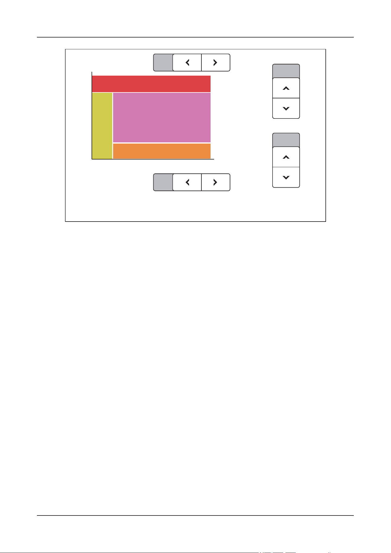
9 Monitoring ECG
9 - 11
• If the number of consecutive PVCs is greater than or equal to the V-Tach PVCs limit (3), and the
ventricular rate (Vent Rate) is greater than or equal to the V-Tach Rate limit (160), a V-Tach alarm is
generated.
• If the number of consecutive PVCs is lower than the V-Tach PVCs limit (3) but greater than 2, and
the ventricular rate is greater than or equal to the V-Tach Rate limit (160), a Nonsus V-Tach alarm is
generated.
• If the number of consecutive PVCs is greater than or equal to the V-Brady PVCs limit (5), and the
ventricular rate is lower than the V-Tach Rate limit (160) but greater than or equal to the V Brady
Rate limit (40), a Vent Rhythm alarm is generated.
• If the number of consecutive PVCs is lower than the V-Brady PVCs limit (5) but greater than 2, and
the ventricular rate is lower than the V-Tach Rate limit (160), a Run PVCs alarm is generated.
• If the number of consecutive PVCs is greater than or equal to the V-Brady PVCs limit (5), and the
ventricular rate is lower than the V Brady Rate limit (40), a Vent Brady alarm is generated.
9.5.6 Arrhythmia Alarms Timeout
Normally, an arrhythmia alarm is presented when an alarm condition is detected. However, there are
certain situations that can inhibit audible and visible alarm indications even though an alarm condition
was detected.
Arrhythmia Alarm Chains
If multiple arrhythmia conditions occur simultaneously, announcing all detected alarm conditions may
be confusing. This may result in serious conditions being overlooked. So arrhythmia alarms are
prioritized through alarm chains.
There are 5 arrhythmia alarm chains: one high priority chain and four medium priority chains, including
PVC chain, beats detection chain, and supraventricular chain.
3
5
160
40
20
3
4567
8
910111213
14
15
99
40
60
80
100
120
140
160
180
200
---
V-Tach PVCs
Vent Rate(bpm)
V-Tach Rate
V-Brady Rate
PVCs(beats)
V-Brady PVCs
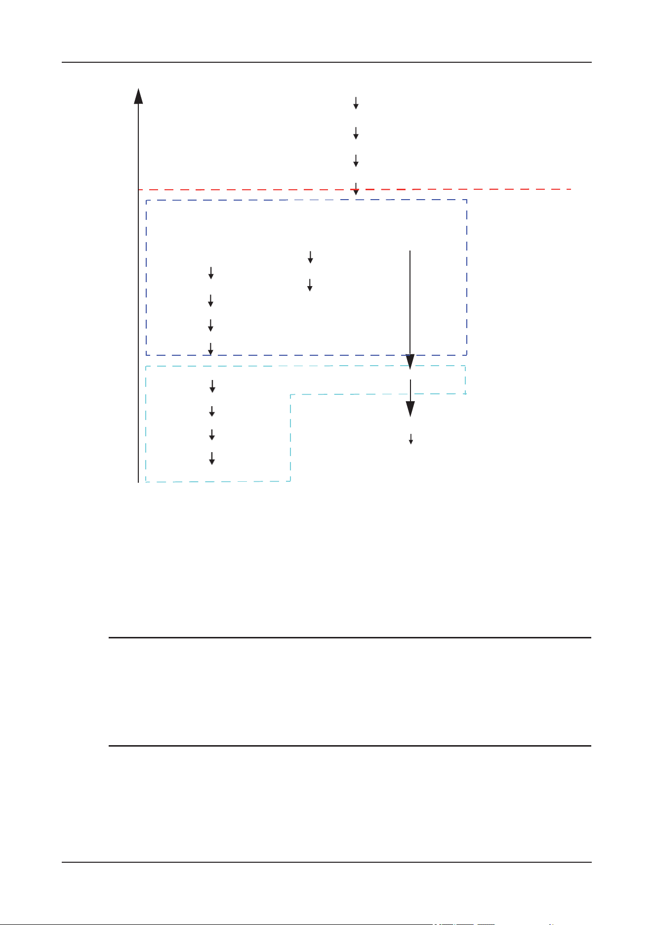
9 Monitoring ECG
9 - 12
Setting Arrhythmia Alarm Shielding Period
The arrhythmia algorithm can disable alarm light and alarm tone for designated period of time when
certain arrhythmia alarms are detected.
This function is password protected.
NOTE
• The arrhythmia shielding period is only applicable to arrhythmias in the medium priority chains. For
arrhythmias in the high priority chain, alarm tone and alarm light are generated as soon as an alarm
condition is detected.
• The arrhythmia shielding period has no impact on HR High, HR Low, Tachy, Brady, and Irr
Rhythm End.
Arrhythmia Alarm Shielding Rules
The following table explains how audible and visual alarm indicate during arrhythmia alarm shielding
period.
Pause
SVCs/min High
Multiform PVC
PVCs/min High
Trigeminy
Bigeminy
The refractory periods have no impact on Tachy, Brady, HR High, and HR Low.
Refractory Period 1
Beats detection chain
Nonsus V-Tach/
Vent Rhythm
PVC
SVT
Pauses/min High
Pacer Not Pacing/
Pacer Not Capture/
Missed Beat
Asystole
V-Fib/V-Tach
V-Tach/Vent Brady
Extreme Tachy/Extreme Brady
Couplet
Run PVCs
R on T
Tachy/Brady
HR High/HR Low
Supraventricular PVC chain
Refractory Period 2
High priority chainMedium priority chains

9 Monitoring ECG
9 - 13
Setting Arrhythmia Refractory Periods
For some arrhythmias in the medium priority chain, an arrhythmia and arrhythmias with lower priority in
the same alarm chain can be deactivated in a designated period of time. This period is called refractory
period. When an arrhythmia is detected, the refractory period automatically starts. During the refractory
period, the same alarm condition does not trigger an alarm. If the condition of an arrhythmia with lower
priority in the same alarm chain appears, the device does not generate an alarm either.
Perform the following procedure:
1. On the main screen, tap the monitoring information area to enter the Monitoring details interface.
2. Tap the ECG parameter area or waveform to open the ECG menu.
3. Select Arrhythmia > Threshold.
4. Set Refractory Period 1 and Refractory Period 2.
The default value of Refractory Period 1 is 3 minutes; the default value of Refractory Period 2 is 10
minutes. To disable a refractory period, set it to Off.
NOTE
• Refractory periods are only applicable to arrhythmias in the medium priority chains.
• The refractory periods have no impact on Tachy, Brady, HR Low, and Irr Rhythm End.
Previous
alarm
Current alarm Alarm indication
Alarm in high
priority chain
Alarm in high priority chain Alarm light and alarm tone
Alarm in medium priority chain During the shielding period, alarm light
and alarm tone are disabled. When the
shielding period is reached, alarm light and
alarm tone are reactivated.
Alarm in
medium
priority chain
Alarm in high priority chain Alarm light and alarm tone
Alarm in the same medium priority chain,
but with higher priority
Alarm light and alarm tone
The same alarm reoccurs During the shielding period, alarm light
and alarm tone are disabled. When the
shielding period is reached, alarm light and
alarm tone are reactivated.
Alarm in the same medium priority chain,
but with lower priority
During the shielding period, alarm light
and alarm tone are disabled. When the
shielding period is reached, alarm light and
alarm tone are reactivated.
Alarm in other medium priority chain Alarm light and alarm tone

9 Monitoring ECG
9 - 14
9.6 ST Segment Monitoring
The ST segment of the ECG waveform refers to the period from the end of ventricular depolarization to
the beginning of ventricular repolarization, or from the end of the QRS complex (point J) to the
beginning of the T wave. ST segment analysis is commonly used to device an animal’s oxygen supply
and myocardial viability.
9.6.1 Safety Information
WAR N I N G
• ST values may be affected by such factors as some drugs or metabolic and conduction disturbances.
• ST deviation is often calculated at a fixed offset from the J point. Changes in heart rate may affect
ST.
• The significance of the ST segment changes must be decided by the physician.
• This device provides ST segment change information, and the clinical opinion on the information
should be decided by the physician.
9.6.2 Enabling ST Monitoring
TIP
ST Analysis is set to Off by default.
Perform the following procedure:
1. On the main screen, tap the monitoring information area to enter the Monitoring details interface.
2. Tap the ECG parameter area or waveform to open the ECG menu.
3. Select ST > Setup.
4. Switch to to enable ST Analysis.
ST analysis may not be reliable under the following situations:
• All ECG leads are noisy.
• Arrhythmias such as atrial fibrillation or flutter occur, which may cause irregular baseline.
• The animal is implanted with a ventricular pacemaker.
• The animal has left bundle branch block.
Consider switching off ST analysis in these cases.
9.6.3 Displaying ST Numerics
To display ST numerics and Segments, follow this procedure:
1. On the main screen, tap the monitoring information area to enter the Monitoring details interface.
2. Do one of the following to open the Tile Layout menu:

9 Monitoring ECG
9 - 15
•Select More > Screen Setup > Monitor > Tile Layout.
•Select Monitoring Setup > Screen Setup > Tile Layout.
3. Tap the waveform area where you want to display the ST segments, and then select ECG > ST.
9.6.4 Displaying the ST segment in the waveform area
Perform the following procedure:
1. On the main screen, tap the monitoring information area to enter the Monitoring details interface.
2. Do one of the following to open the Tile Layout menu:
•Select More > Screen Setup > Monitor > Tile Layout.
•Select Monitoring Setup > Screen Setup > Tile Layout.
3. Tap the numeric area where you want to display the ST numerics, and select ECG > ST Segment.
The waveform area displays the current and baseline ST segments. It also displays the current and
baseline ST values. In the following picture, the current ST segment and value are in green, while the
baseline ST segment and value are in white.
9.6.5 Entering the ST View
The ST View shows a complete QRS segment for each ST lead. The ST View shows a complete QRS
segment for each ST lead. The color of current ST segments and ST values is consistent with the color of
ECG waveforms, normally green. The color of baseline ST segments and ST values is white.
You can enter the ST View either by selecting the ST View in the waveform area or by the following
ways:
1. On the main screen, tap the monitoring information area to enter the Monitoring details interface.
2. Tap the ECG parameter area or waveform to open the ECG menu.
3. Tap ST tab.
4. Tap ST View.
9.6.6 Saving the Current ST as Baseline
ST deviation is typically monitored as a relative change from a baseline value. Set an ST baseline when
ST values become stable. If you did not set the ST baseline, the device automatically saves the baseline
when valid ST values appear for 5 minutes. You can also update the baseline manually by selecting Set
Baseline on the lower-left corner of the ST View menu.
From the ST View window, you can also perform the following operations:
• Display or hide ST baseline by selecting Display Baseline or Hide Baseline.
• Display or hide the position of ISO point, J point and ST point by selecting Display Marker or
Hide Marker.

9 Monitoring ECG
9 - 16
CAUTION
Updating ST baseline affects ST alarms.
9.6.7 Entering the ST Graphic Window
Perform the following procedure:
1. On the main screen, tap the monitoring information area to enter the Monitoring details interface.
2. Tap the ECG parameter area or waveform to open the ECG menu.
3. Tap ST tab.
4. Tap ST Graphic.
• When ST Alarm Mode is set to Absolute: the height of the bar indicates the ST value of
corresponding ST lead. The color of the bar indicates ST alarm status: green indicates that
corresponding ST value is within alarm limits; yellow and red indicate that the ST value exceeds the
alarm limits. The color matches ST alarm priority.
• When ST Alarm Mode is set to Relative: the height of grey bar indicates the baseline ST value and
the green bar (yellow or red if an alarm occurs) indicates ǻST.
9.6.8 Changing ST Settings
Setting ST Alarm Properties
To set ST alarm properties, follow this procedure:
1. On the main screen, tap the monitoring information area to enter the Monitoring details interface.
2. Tap the ECG parameter area or waveform to open the ECG menu.
3. Select ST > Alarm.
4. Set ST Alarm Mode to Absolute or Relative.
• Absolute: separately set the alarm properties for each ST alarm.
• Relative: set the alarm properties for ST Single and ST Dual alarms.
5. Set the ST alarm properties as required.
Changing Leads for ST Display
The device automatically selects the three most deviated leads for ST display. You can also manually
select the leads.
Perform the following procedure:
1. On the main screen, tap the monitoring information area to enter the Monitoring details interface.
2. Tap the ECG parameter area or waveform to open the ECG menu.
3. Select ST > Setup.
4. Tap ST Segment to set the lead to be displayed.
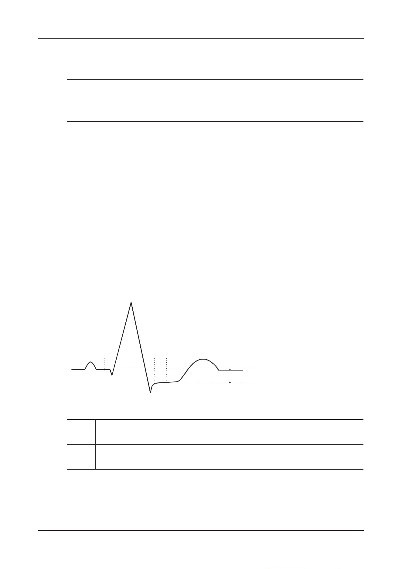
9 Monitoring ECG
9 - 17
You can select up to 3 leads.
Showing ISO Point, J Point, and ST Point Marks
TIP
In the waveform area, the ISO point, J point, and ST point mark do not display on the ST segments by
default.
Perform the following procedure:
1. On the main screen, tap the monitoring information area to enter the Monitoring details interface.
2. Tap the ECG parameter area or waveform to open the ECG menu.
3. Select ST > Setup.
4. Switch on Show Markers.
9.6.9 Adjusting ST Measurement Points
About ST Point, ISO Point, and J Point
The ST deviation value for each beat is the potential difference between the isoelectric (ISO) point and
the ST point. The ISO point provides the baseline. The ST point is at the midpoint of the ST segment.
The J point is the end of the QRS complex. As the J point is a fixed distance away from the ST point, it
can be useful to help you correctly position the ST point.
1. ISO Point
2. J Point
3. ST Point
4. ST value
P
R
Q
S
T
(1) (2) (3) (4)

9 Monitoring ECG
9 - 18
Setting ST Point, ISO Point, and J Point
CAUTION
• You need to adjust the ST points before starting monitoring, or if the animal's heart rate or ECG
morphology changes significantly, as this may affect the size of the QT interval and thus the
placement of the ST point. Artificial ST segment depression or elevation may occur if the isoelectric
point or the ST point is incorrectly set.
• Always make sure that the positions of ST points are appropriate for your animal.
Perform the following procedure:
1. On the main screen, tap the monitoring information area to enter the Monitoring details interface.
2. Tap the ECG parameter area or waveform to open the ECG menu.
3. Select ST > Adjust.
4. Tap ST Point to set ST point location.
The setting of Auto Adjust defines the method of adjusting the ISO point and J point. Auto Adjust is
enabled by default. In this case, positions of ISO point and J point are automatically adjusted
accordingly. If Auto Adjust is disabled, you need to manually adjust the position of ISO point and J
point by selecting the arrows at the right sides of ISO and J.
• The ISO point (isoelectric) position is given relative to the R-wave peak. Position the ISO point in
the middle of the flattest part of the baseline (between the P and Q waves).
• The J point position is given relative to the R-wave peak and helps locating the ST point. Position
the J point at the end of the QRS complex and the beginning of the ST segment.
• The ST point is positioned a fixed distance from the J point. Move the J point to position the ST
point at the midpoint of the ST segment. Position the ST point relative to the J point at J+60/80
msec, J+40 msec, J+60 msec or J+80 msec.
When J+60/80 msec is selected, the device automatically adjusts the position of the ST point
according to the heart rate:
– When the heart rate is greater than 120 bpm, the device will use J+60/80 msec to determine the
location of the ST point.
– When the heart rate is smaller than or equal to 120 bpm, the device will use J+80 msec to
determine the location of the ST point.
9.7 QT/QTc Interval Monitoring
The QT interval is defined as the time between the beginning of the Q-wave and the end of the T-wave.
It measures the total duration of ventricular depolarization (QRS duration) and repolarization (ST-T). QT
interval monitoring can assist in the detection of long QT syndrome.
The QT interval has an inverse relationship to heart rate. Faster heart rates shorten the QT interval and
slower heart rates prolong the QT interval. Therefore, several formulas can be used to correct the QT
interval for heart rate. The heart rate corrected QT interval is abbreviated as QTc.

9 Monitoring ECG
9 - 19
9.7.1 QT/QTc Monitoring Limitations
Some conditions may make it difficult to achieve reliable QT/QTc monitoring, for example:
• R-wave amplitudes are too low
• The presence of frequent ventricular ectopic beats
• Unstable RR intervals
• P-waves tending to encroach on the end of the previous T-wave at high heart rates
• The T-wave is very flat or T-wave are not well defined
• The end of the T-wave is difficult to delineate because of the presence of U-waves
• QTc measurements are not stable
• In the presence of noise, asystole, ventricular fibrillation, and ECG lead off
For these cases you should select a lead with good T-wave amplitude and no visible flutter activity, and
without a predominant U-wave or P-wave.
Some conditions such as left or right bundle branch block or hypertrophy can lead to a widened QRS
complex. If a long QTc is observed you should verify it to ensure that it is not caused by QRS widening.
Because normal beats followed by ventricular beats are not included in the analysis, no QT measurement
will be generated in the presence of a bigeminy rhythm.
If the heart rate is extremely high, QT will not be measured. When the heart rate changes, it can take
several minutes for the QT interval to stabilize. For reliable QTc calculation, it is important to avoid
measurements when the heart rate is changing.
9.7.2 Enabling QT/QTc Monitoring
The QT monitoring function is disabled by default. Before you start QT monitoring, enable the QT
function.
Perform the following procedure:
1. On the main screen, tap the monitoring information area to enter the Monitoring details interface.
2. Tap the ECG parameter area or waveform to open the ECG menu.
3. Select QT > Setup.
4. Switch to to enable QT Analysis.
9.7.3 Displaying QT/QTc Numerics and Segments
To display QT/QTc numerics and Segments, follow this procedure:
1. On the main screen, tap the monitoring information area to enter the Monitoring details interface.
2. Do one of the following to open the Tile Layout menu:
•Select More > Screen Setup > Monitor > Tile Layout.
•Select Monitoring Setup > Screen Setup > Tile Layout.
3. Tap the parameter numeric area where you want to display the QT numerics, and then select ECG > QT/
QTc.

9 Monitoring ECG
9 - 20
NOTE
QTc values are calculated based on the QT-HR, not the ECG HR.
The display of the QT numeric area differs as related settings change.
9.7.4 Entering the QT View
QT View shows the current and baseline QT parameter values and waveforms.
Perform the following procedure:
1. On the main screen, tap the monitoring information area to enter the Monitoring details interface.
2. Select the QT numerics area, ECG numeric area, or waveform area to open the QT menu.
3. Tap QT View.
• The current waveform is shown in the upper half in green.
1. Parameter label
2. QTc value
3. ǻQTc value
TIP
The difference between the current and baseline QTc values. If the QTc value is alarm off,
the alarm off icon is displayed on the right of this value.
4. QT-HR value
5. QT value
6. QTc alarm limit
TIP
If QTc alarm is off, the alarm off symbol is displayed.
QT
msec
xxx
QTc
QT
ΔQTc
QT-HR
XXX
x
xx
xxx
12
3
45
6

9 Monitoring ECG
9 - 21
• The baseline waveform is shown below in white.
• The start of QRS complex and the end of the T wave are marked with a vertical line.
• In some conditions, no QT measurement can be calculated. Then the cause of failed QT
measurement is shown at the bottom of the QT numerics area and the message Cannot Analyze QT
is shown in the technical alarm area.
Select the left or right arrow to switch leads. Corresponding waveform will be highlighted.
9.7.5 Saving the Current QTc as Baseline
CAUTION
Updating QTc baseline affects ǻQTc value and alarm.
In order to quantify differences in the QTc value, you can set a QTc baseline. If you do not set a baseline
within the first 5 minutes after getting valid QT values, the device will automatically set a baseline for
this animal.
Perform the following procedure:
1. Select QT > QT View, and then select Set Baseline.
2. From the pop-up dialog box, select OK.
This baseline will then be used to calculate ǻQTc.
After a new QT baseline is set, the old baseline will be discarded. The baseline will be cleared upon
animal discharge.
Tap Display Baseline or Hide Baseline to display or hide the QT baseline waveform.
9.7.6 Changing QT Settings
Setting QT Alarm Properties
Perform the following procedure:
1. On the main screen, tap the monitoring information area to enter the Monitoring details interface.
2. Select the QT numerics area, ECG numeric area, or waveform area to open the QT menu.
3. Tap Alarm tab.
4. Set QTc and ǻQTc alarm properties.
Selecting Leads for QT Calculation
You can select one lead or all leads for QT calculation.
Perform the following procedure:
1. On the main screen, tap the monitoring information area to enter the Monitoring details interface.
2. Select the QT numerics area, ECG numeric area, or waveform area to open the QT menu.

9 Monitoring ECG
9 - 22
3. Tap Setup tab.
4. Set QT Leads.
All is selected by default. This means all leads are used for QT calculation.
9.8 ECG Relearning
Changes in ECG template could result in incorrect arrhythmia alarms and/or inaccurate heart rate.
This device provides the ECG learning function. ECG relearning allows the device to learn new ECG
template so as to correct arrhythmia alarms and HR value.
Once learning is complete, the dominant QRS complex is stored as a reference template. The reference
template is used as a normal morphology of that animal and it is compared with incoming beats to
identify possible arrhythmias.
If you suspect that abnormal arrhythmia alarms are presented, you may need to manually initiate an ECG
relearning.
9.8.1 Auto ECG Relearning
Auto arrhythmia relearning happens in the following situation:
1. The ECG lead type or lead label is changed.
2. ECG leads are off and are not reconnected within 60 seconds.
3. The animal's paced status is changed.
9.8.2 Manually Initiating an ECG Relearning
CAUTION
Initiate ECG relearning only during periods of predominantly normal rhythm and when ECG signal is
relatively free of noise. If ECG relearning occurs during arrhythmia, abnormal QRS complex may be
incorrectly learned as normal QRS complex, resulting in missed detection of subsequent arrhythmia.
Perform the following procedure:
1. Enter the monitoring details interface:
2. On the main screen, tap the monitoring information area to enter the Monitoring details interface.
3. Tap the ECG parameter area or waveform area to open the ECG menu.
4. Tap Relearn.

9 Monitoring ECG
9 - 23
9.9 Calibrating ECG
The ECG signal may be inaccurate due to hardware or software problems. As a result, the ECG
waveform amplitude becomes greater or smaller. In that case, you need to calibrate the ECG module.
This function is password protected.
9.10 Troubleshooting
This section lists the problems that might occur. If you encounter problems when using the device or
accessories, check the table below before requesting for services. If the problem persists after you have
taken corrective actions, contact the Customer Service Department or your local distributor.
Problem Solution
Do not see ECG numeric area or waveform area on
the main screen
• Check that ECG is set to display in the Tile
Layout menu.
• Check that if the ECG parameter switch is
enabled. If not, enable the ECG measurement.
• Check that the cable connections of ECG
electrode and the lead set are tight. Replace the
ECG electrode or the lead set if needed.
Noisy ECG traces • Check that electrodes are not detached or dry.
Replace with fresh and moist electrodes if
necessary.
• Check that leadwires are not defective. Replace
leadwires if necessary.
• Check that animal cable or leadwires are routed
too close to other electrical devices. Move the
animal cable or leadwires away from electrical
devices.
Muscle Noise Inadequate skin preparation, tremors, tense subject,
and/or poor electrode placement.
• Perform skin preparation again and re-place the
electrodes.
• Apply fresh, moist electrodes. Avoid muscular
areas.
Intermittent Signal • Check that cables are properly connected.
• Check if the electrodes get loose or the
conductive paste of the electrodes gets dry.
Perform skin preparation again and re-place the
electrodes.
• Check that the animal cable or leadwires are not
damaged. Change them if necessary.

9 Monitoring ECG
9 - 24
Excessive alarms: heart rate, lead fault • Check that electrodes are not dry. Perform skin
preparation again and re-place the electrodes.
• Check for excessive animal movement or
muscle tremor. Reposition the electrodes.
Replace with fresh and moist electrodes if
necessary. If necessary, replace with a new
moist electrode pad.
Low Amplitude ECG Signal • Check that the ECG gain is not set too low.
Adjust the gain as required.
• Perform skin preparation again.
• Check electrode application sites. Avoid bone
or muscular area.
• Check that electrodes are not dry or used for a
prolonged time. Replace with fresh and moist
electrodes if necessary.
No ECG Waveform • Check that the ECG gain is not set too low.
Adjust the gain as required.
• Check that the leadwires and animal cables are
properly connected.
• Check that the animal cable or leadwires are not
damaged. Change them if necessary.
Base Line Wander • Check for excessive animal movement or
muscle tremor. Secure leadwires and cable.
• Check that electrodes are not detached or dry
and replace with fresh and moist electrodes if
necessary.
• Check for ECG filter setting. Set ECG Filter
mode to Monitor to reduce baseline wander on
the display.
Problem Solution

10 Monitoring Respiration
10 - 1
10 Monitoring Respiration
10.1 Overview
Impedance respiration is measured across the thorax. When the animal is breathing or ventilated, the
volume of air changes in the lungs, resulting in impedance changes between the electrodes. Respiration
rate (RR) is calculated from these impedance changes, and a respiration waveform appears on the screen.
WAR N I N G
• When monitoring the animal’s respiration, do not use ESU-proof ECG cables.
• If you do not set the detection level for the respiration correctly in manual detection mode, it may
not be possible for the device to detect apnea. If you set the detection level too low, the device is
more likely to detect cardiac activity, and to falsely interpret cardiac activity as respiratory activity
in the case of apnea.
• The respiration measurement does not recognize the cause of apneas. It only indicates an alarm if no
breath is detected when a pre-adjusted time has elapsed since the last detected breath. Therefore, it
cannot be used for diagnostic purpose.
• If operating under conditions according to the EMC Standard IEC 60601-1-2 (Radiated Immunity
3V/m), field strengths above 3V/m may cause erroneous measurements at various frequencies.
Therefore, it is recommended to avoid the use of electrically radiating equipment in close proximity
to the respiration measurement unit.
NOTE
• Respiration monitoring is not for use on the animals who are very active, as this will cause false
alarms.
• After changing the respiration gain, check whether the threshold setting is reasonable.
10.2 Starting the Monitoring
Perform the following procedure:
1. Wear the Vet Harness for ICU.
For details, see its accompanying manual.

10 Monitoring Respiration
10 - 2
2. Prepare the animal’s skin:
Proper skin preparation is necessary for good signal quality at the electrode, as the skin is a poor
conductor of electricity. To properly prepare the skin, choose flat areas and then follow this procedure:
1. Shave hair from skin at chosen sites.
2. Gently rub skin surface at sites to remove dead skin cells.
3. Thoroughly cleanse the site. It is not recommend using ether or pure alcohol, because this dries the
skin and increases the resistance.
4. Dry the skin completely before applying the electrodes.
3. Set the respiration lead:
1. Enter the Monitoring details interface, tap the Resp numeric area or waveform area to open the
Resp menu.
2. Select Setup > Resp Lead to choose the appropriate respiration lead.
4. Attach the clips or snaps to the electrodes before placing them.
Check that electrode packages are intact and the electrodes are not past the expiry date. Make sure the
electrode gel is moist. Attach the snaps to the electrodes before placing electrodes on the animal.
5. Place the electrodes on the prepared sites.
Exhaust all air between the electrode pads and the animal’s skin.
Standard ECG cable and electrode placement methods are used for respiration measurement. The
respiration signal is measured between two ECG electrodes. If a standard ECG electrode location is used,
the two electrodes are the RA (right forelimb) and LA (left forelimb) electrodes for lead I, or the RA
(right forelimb) and LL (left forelimb) electrodes for lead II.
NOTE
• To optimize the respiration waveform, place the RA and LA electrodes horizontally when
monitoring respiration with ECG Lead I; place the RA and LL electrodes diagonally when
monitoring respiration with ECG Lead II.
• Optimizing Lead Placement for Resp: If you want to measure Resp and you are already measuring
ECG, you may need to optimize the placement of the two electrodes between which Resp will be
measured. Repositioning ECG electrodes from standard positions results in changes in the ECG
waveform and may influence ST and arrhythmia interpretation.
• Cardiac Overlay: Cardiac activity that affects the Resp waveform is called cardiac overlay. It
happens when the Resp electrodes pick up impedance changes caused by the rhythmic blood flow.
LL
RA
II
LA
RA
I
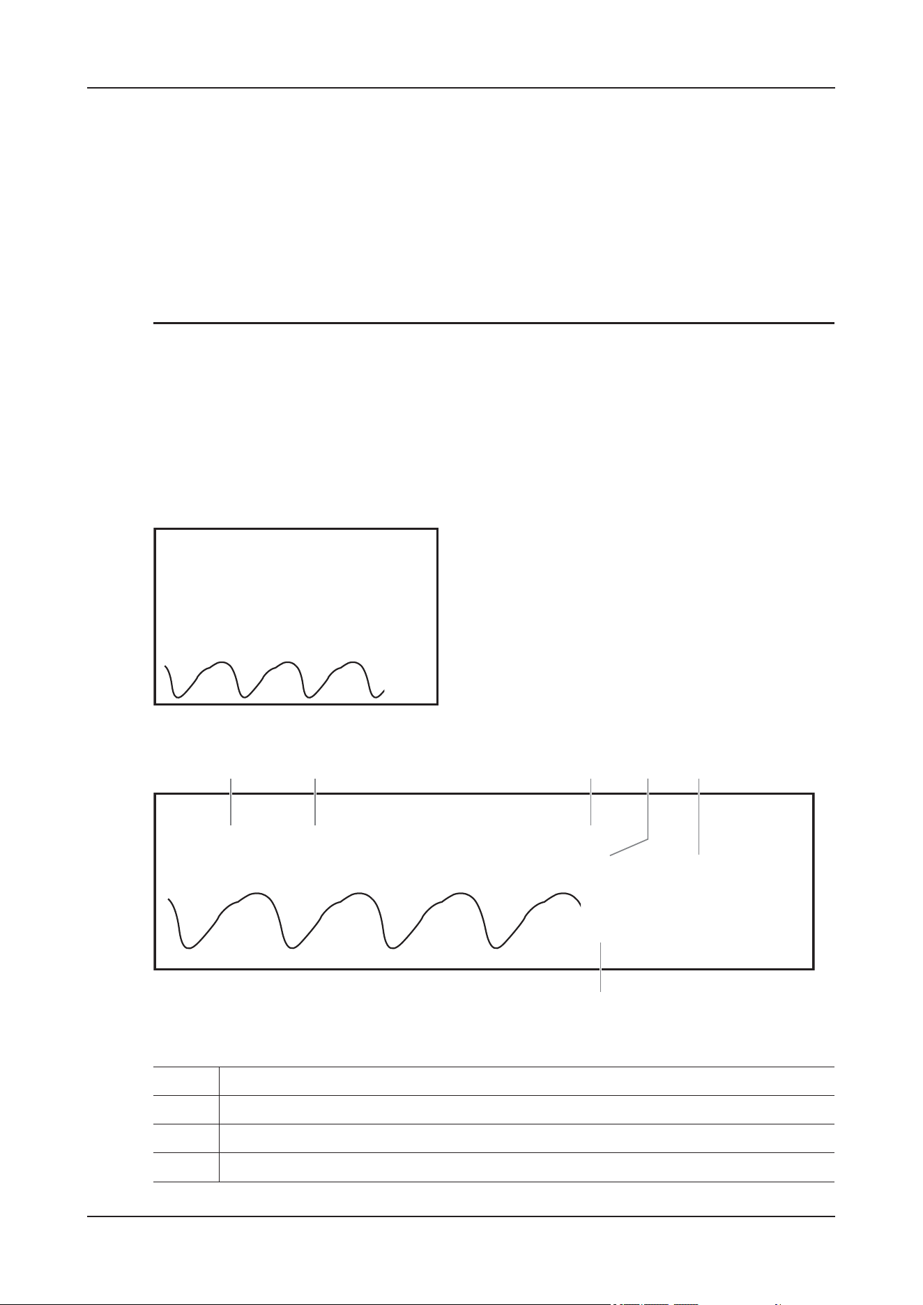
10 Monitoring Respiration
10 - 3
Correct electrodes placement can help to reduce cardiac overlay: avoid the liver area and the
ventricles of the heart in the line between the respiratory electrodes.
• Abdominal Breathing: Some animals with restricted movement breathe mainly abdominally. In
these cases, you may need to place the left leg electrode on the left abdomen at the point of
maximum abdominal expansion to optimize the respiratory waveform.
• Lateral Chest Expansion: Some animals expand their chests laterally, causing a negative
intrathoracic pressure. In these cases, it is better to place the two respiration electrodes in the right
midaxillary and the left lateral chest areas at the animal’s maximum point of the breathing
movement to optimize the respiratory waveform.
6. Adjust parameters in the Resp menu to obtain the optimized waveform display.
10.3 Results Display
The measurement results are displayed on the main screen and the Monitoring details interface.
Figure 10-1 Resp results on the main screen
Figure 10-2 Resp results on the monitoring details interface
1. Resp waveform gain
2. Resp lead
3. Parameter label
4. RR unit
Resp
Resp
rpm
xx
x
II
X2
XX
Resp
XX
rpm
XXX
XX
12 345
6
Resp
x2 XX

10 Monitoring Respiration
10 - 4
10.4 Parameters Setup
Enter the Monitoring details interface, tap the Resp numeric area or waveform area to open the Resp
menu.
Setting the Resp Alarm Properties
Perform the following procedure:
1. Select the Alarm tab.
2. Set alarm properties as desired.
Input the password if necessary.
Changing Resp Settings
Perform the following procedure:
1. Select the Setup tab.
2. Adjust parameters as required:
5. Respiration rate (RR)
6. Alarm limits
Item Description
RR Source Set the RR source.
TIP
When you select Auto: the device automatically selects RR source
according to the priority.
Resp Lead Set the respiration lead for optimal respiratory waveform.
Gain Set the Resp waveform size.
TIP
After changing the respiration gain, check whether the threshold setting
is reasonable.
Speed Set the Resp waveform speed.

10 Monitoring Respiration
10 - 5
Adjusting the Resp Waveform Detection Threshold
It is recommended to use the manual detection mode in the following situations:
• The animal’s RR is close to HR.
• The animal has intermittent mandatory ventilation.
• Respiration is weak. Try repositioning the electrodes to improve the signal.
Perform the following procedure:
1. Enter the Monitoring details interface, tap the Resp numeric area or waveform area to open the Resp
menu.
2. Select the Threshold tab.
3. Select the up and down arrows corresponding to Upper Line and Lower Line to define the Resp
waveform threshold.
Once set, the detection level will not adapt automatically to different respiration depths. It is important to
remember that if the depth of breathing changes, you may need to change the detection level.
Auto Threshold
Detection
Switch on/off the Auto Threshold Detection function.
•If Auto Threshold Detection is switched on, the device automatically
adjusts the Resp waveform detection level, or threshold.
In the auto detection mode, if ECG is switched off when you are
monitoring respiration, the device cannot compare ECG and RR to detect
cardiovascular artifact. To avoid cardiovascular artifact being interpreted
as respiration, the respiration threshold is automatically set higher.
•If Auto Threshold Detection is switched off, adjust the Resp waveform
threshold.
In the manual detection mode, cardiac overlay can in certain situations
trigger the respiration counter. This may lead to a false indication of a
high respiration or an undetected apnea condition. If you suspect that
cardiac overlay is being registered as breathing activity, raise the
detection level above the zone of cardiac overlay. If the Resp wave is so
small that raising the detection level is not possible, you may need to
optimize the electrode placement.
Item Description

11 Monitoring Pulse Oxygen Saturation
11 - 1
11 Monitoring Pulse Oxygen
Saturation
11.1 Overview
Pulse Oxygen Saturation (SpO
2
) monitoring is a non-invasive technique used to measure the amount of
oxygenated haemoglobin and pulse rate by measuring the absorption of selected wavelengths of light.
The light generated in the emitter side of the probe is partly absorbed when it passes through the
monitored tissue. The amount of transmitted light is detected in the detector side of the probe. When the
pulsative part of the light signal is examined, the amount of light absorbed by the haemoglobin is
measured and the pulse oxygen saturation can be calculated. This device is calibrated to display
functional oxygen saturation.
WAR N I N G
• Measurement accuracy verification: The SpO
2
accuracy has been verified by comparing with
arterial blood sample reference measured with a CO-oximeter. Pulse oximeter measurements are
statistically distributed and about two-thirds of the measurements are expected to come within the
specified accuracy range compared to CO-oximeter measurements.
• A functional tester or SpO
2
simulator can be used to determine the pulse rate accuracy.
• A functional tester or SpO
2
simulator cannot be used to assess the SpO
2
accuracy.
• Dye (e.g. Indocyanine Green) or other substances, containing dyes which usually modify the light
absorption capacities, can lead to faulty measurement values of the oxygen saturation.
•The SpO
2
sensors and cables have been tested and validated for conformity with the standard IEC
60601-2-61 with the device.
• If the animal has a trend of deoxygenation, analyze the blood samples with a laboratory CO-
oximeter to completely understand the animal's condition.
• Do not use the device or SpO
2
sensors during MRI scanning or in an MRI environment. Induced
current could potentially cause burns. The device may affect the MRI image, and the MRI device
may affect the accuracy of the SpO
2
measurements.
• Prolonged continuous monitoring may increase the risk of undesirable changes in skin
characteristics, such as irritation, reddening, blistering or burns. Inspect the sensor site every 2 hours
and move the sensor if the skin quality changes. For animals with poor peripheral blood circulation
or sensitive skin, inspect the sensor site more frequently.

11 Monitoring Pulse Oxygen Saturation
11 - 2
• Setting alarm limits to extreme values may cause the alarm system to become ineffective. For
example, high oxygen levels may predispose a premature infant to retrolental fibroplasia. Setting the
SpO
2
high alarm limit to 100% is equivalent to switching off the SpO
2
alarm.
CAUTION
• Select proper SpO
2
sensor according to application site. Applying sensor too tight may severely
obstruct circulation and lead inaccurate measurements. Loose application may result in
measurement site exposing to ambient light.
• When monitoring SpO
2
at high ambient temperature, to avoid burns at the application site that is not
well perfused, pay attention to prolonged SpO
2
sensor application.
• Avoid placing the SpO
2
sensor on the same extremity with an NIBP cuff, arterial catheter, or
intravascular line.
11.2 Measurement Limitations
The following factors may influence the accuracy of SpO
2
measurement:
• Animal physiological characteristics
– Cardiac arrest
– Hypotension
– Darkly pigmented skin
–Shock
– Severe vasoconstriction
– Hypothermia
– Severe anemia
– Ventricular septal defects (VSDs)
– Venous pulsations
– Poor perfusion
• Interfering substances
– Intravascular dyes (such as indocyanine green, methylene blue, indigo carmine, etc.)
– Non-functional hemoglobin concentrations such as carboxyhemoglobin (COHb) and
methemoglobin (MetHb)
– Dyes in the measure site, such as nail polish
• Environmental conditions
– Excessive ambient light
– Electrosurgery equipment
– Defibrillation (may cause inaccurate reading for a short amount of time)
– Excessive animal/sensor motion
– Electromagnetic field
•Others
– Inappropriate positioning of the SpO
2
sensor, or use of incorrect SpO
2
sensor
– Cuff or arterial blood pressure measurement device on the same limb as the SpO
2
sensor.
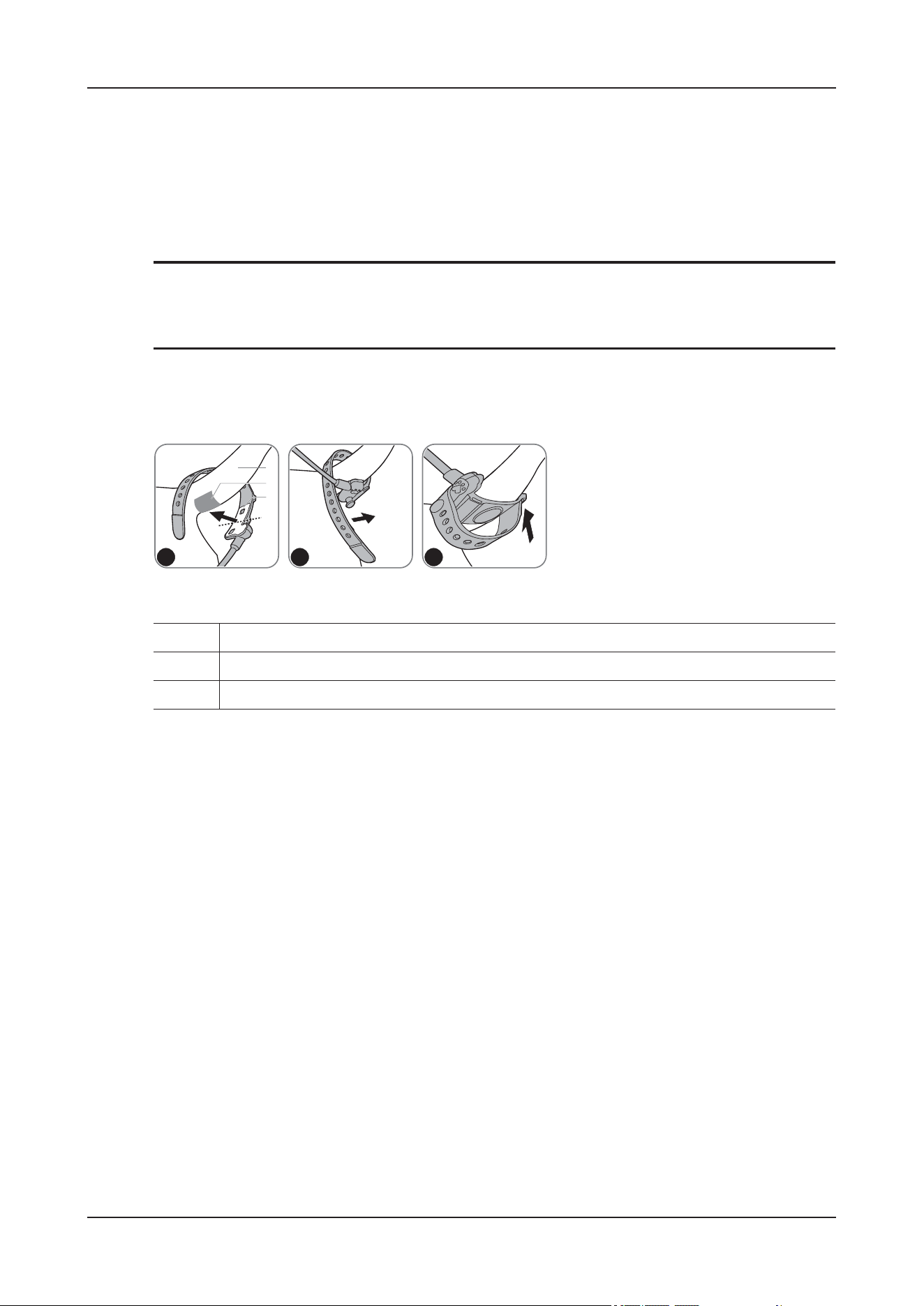
11 Monitoring Pulse Oxygen Saturation
11 - 3
11.3 Starting the Monitoring
Perform the following procedure:
1. Clean the sensor and belt before and after each use.
2. Shave hair from skin at the measured site, and clean the measured site with medical alcohol or water.
TIP
• The optimal measured site for feline and canine animals is the base of the tail.
• The shaved area must be greater than the white area of the sensor belt.
3. Bind the sensor to the base of the tail from bottom to up, and ensure the white area of the sensor belt falls
within the shaved area.
1. Stretch the belt naturally to fix the sensor reliably but do not stretch it too tightly.
2. Insert the mushroom-shaped buckle into the adjacent hole.
3. Pull the belt and allow it to go through the belt fastener.
4. After binding, gently pull the belt to ensure that it does not move.
Ensure that the sensor cable is positioned along the side of the animal tail to avoid entanglement
with the animal.
4. Connect the SpO
2
plug into the SpO
2
sensor connector of the Temp module.
5. Adjust parameters in the SpO2 menu to obtain the optimized waveform display.
11.4 Results Display
The measurement results are displayed on the main screen and the Monitoring details interface.
1. Animal tail
2. Shaved area below the base of the tail
3. White area of the sensor belt
a b c
1
2
3
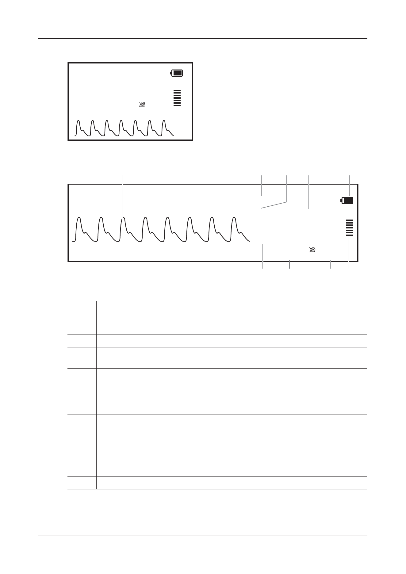
11 Monitoring Pulse Oxygen Saturation
11 - 4
Figure 11-1 SpO
2
results on the main screen
Figure 11-2 SpO
2
results on the monitoring details interface
1. Pleth waveform (Pleth): indicates the blood pulsation at the measurement site. The waveform
is not normalized.
2. Parameter label
3. Unit
4. Oxygen saturation of arterial blood (SpO
2
): indicates the percentage of oxygenated
hemoglobin relative to total hemoglobin.
5. Battery capacity of SpO
2
module
6. Perfusion indicator: the pulsatile portion of the measured signal caused by arterial pulsation.
The higher the bar, the better the perfusion quality.
7. Pulse rate: indicates the number of pulsations per minute.
8. Perfusion index (PI): indicates the percentage of pulsate signal to non-pulsate signal. PI is an
indicator of the pulsate strength. You can also use it to assess the SpO
2
signal strength.
• Above 1 is optimal.
• Between 0.3 and 1 is acceptable.
• Below 0.3 indicates low perfusion. Reposition the SpO
2
sensor or find a better site. If low
perfusion persists, choose another method to measure oxygen saturation if possible.
9. Alarm limits
SpO2
%
XXX
XX
PI PRX.XX XX
Pleth
XX
Pleth
SpO2
XX
%
XXX
XX
234 5
98 76
PI PRX.XX
XX
1

11 Monitoring Pulse Oxygen Saturation
11 - 5
11.5 Parameters Setup
Enter the Monitoring details interface, tap the SpO2 numeric area or waveform area to open the SpO2
menu.
11.5.1 SpO
2
Parameters
Changing the SpO
2
Alarm Settings
Perform the following procedure:
1. Select SpO2 > Alarm.
2. Set alarm properties as desired.
Input the password if necessary.
You can switch off the SPO2 Desat Alarm Off alarm only when SpO2 Desat is set to Enable.
Monitoring SpO
2
and NIBP Simultaneously
When monitoring SpO
2
and NIBP on the same limb simultaneously, you can switch on NIBP Simul to
lock the SpO
2
alarm status until the NIBP measurement ends. If you switch off NIBP Simul, low
perfusion caused by NIBP measurement may lead to inaccurate SpO
2
readings and therefore cause false
physiological alarms.
Perform the following procedure:
1. Select SpO2 > Alarm.
2. Switch to to enable NIBP Simul.
Changing the SpO
2
Settings
Perform the following procedure:
1. Select SpO2 > Setup.
2. Adjust parameters as required:
Item Description
Sensitivity Set the averaging time if necessary.
• High: 7s
• Med: 9s
• Low: 11s
TIP
The SpO
2
value displayed on the device screen is the average of data
collected within a specific time. The shorter the averaging time is, the
quicker the device responds to changes in the animal’s oxygen saturation
level. Contrarily, the longer the averaging time is, the slower the device
responds to changes in the animal’s oxygen saturation level, but the
SpO
2
measurement is more stable. For critically ill animals, selecting
shorter averaging time will help understanding the animal’s condition.

11 Monitoring Pulse Oxygen Saturation
11 - 6
11.5.2 PR Parameters
Changing the PR Alarm Settings
Perform the following procedure:
1. Select PR > Alarm.
2. Set alarm properties as desired.
Input the password if necessary.
3. Set Alarm Source.
Changing the PR Settings
Perform the following procedure:
1. Select PR > Setup.
2. Adjust parameters as required:
Display PI Set whether to display the PI value in the SpO
2
parameter area.
Speed Set the sweep speed of Pleth waveform.
Item Description
Item Description
PR Source Set the source of PR. The current PR source is displayed in the PR numeric
area.
TIP
The PR from current pulse source has the following characteristics:
• PR is monitored as system pulse and generates alarms when you
select PR as the active alarm source.
• PR is stored in the device’s database and reviewed in the graphic/
tabular trends; in trend graphs, as the PR curve is in the same color
with that of the PR source, it is unlikely to distinguish the PR source.
• PR data is sent to the CMS (if any).
Display PR Set whether to display the PR value in the SpO
2
parameter area.
QRS Volume Set the QRS volume.
If the Alarm Source is set to PR, the QRS tone is derived from PR
measurements. The device adjusts QRS volume by adjusting QRS Volume.
If the SpO
2
value is effective, the device also adjusts the QRS tone (pitch
tone) according to the SpO
2
value.

11 Monitoring Pulse Oxygen Saturation
11 - 7
11.6 Troubleshooting
This section lists the problems that might occur. If you encounter the problems when using the device or
accessories, check the table below before requesting for services. If the problem persists, contact the
Customer Service Department or your local distributor.
Problem Solution
Do not see SpO
2
numeric area or waveform area on
the main screen.
• Check that the SpO
2
is set to display in the Tile
Layout menu.
• Check that if the SpO
2
parameter switch is
enabled. If not, enable the SpO
2
measurement.
• Check that the cable connections of SpO
2
sensor and the extension cable are tight.
Replace the SpO
2
sensor or the extension cable
if necessary.
Dashes “- -” display in place of numerics. • Check that the cable connections of SpO
2
sensor and the extension cable are tight.
Replace the SpO
2
sensor or the extension cable
if necessary.
• Reconnect the SpO
2
sensor if the alarm SpO2
Sensor Off appears.
• Check the PI value. If the PI value is too low,
adjust the SpO
2
sensor, or apply the sensor to
the site with better perfusion.
• Move the sensor to the place with weaker light,
or cover the sensor with shade cloth if the alarm
SpO2 Excess Light appears.
Low amplitude SpO
2
signal. • The SpO
2
sensor and NIBP cuff are placed on
the same limb. Change a monitoring site if
necessary.
• Check the PI value. If the PI value is too low.
Adjust the SpO
2
sensor, or apply the sensor to
the site with better perfusion.
• Check the sensor and its application site.
SpO
2
value is inaccurate. • Check the animal’s vital signs.
• Check for conditions that may cause inaccurate
SpO
2
readings.
• Check the device or the SpO
2
module for
proper functioning.

12 Monitoring Temperature
12 - 1
12 Monitoring Temperature
12.1 Overview
You can continuously monitor the animal’s skin temperature and core temperature. Thermally sensitive
resistors (thermistors) are used. They are based on the principle that electrical resistance of the thermistor
changes as temperature changes. Thermistors measure the resistance change and use it to calculate the
temperature.
NOTE
If the Temp module enters the standby mode, reconnect the 2-pin connector of the probe to the Temp
module.
12.2 Starting the Measurement
Perform the following procedure:
1. Plug the probe to the temperature connector of the Temp module.
2. Insert the probe into the rectum or esophagus to a recommended depth of 5 cm to 10 cm.
3. Secure the probe:
• When the probe is used with our 553V SpO
2
sensor, insert the fixing clamp into the fixing hole of
the SpO
2
sensor and fasten the clamp.
• Under other conditions, secure the temperature probe with tape or bandage.
For detailed information about the temperature probe, see the instructions delivered with it.
12.3 Results Display
The measurement results are displayed on the main screen and the Monitoring details interface.
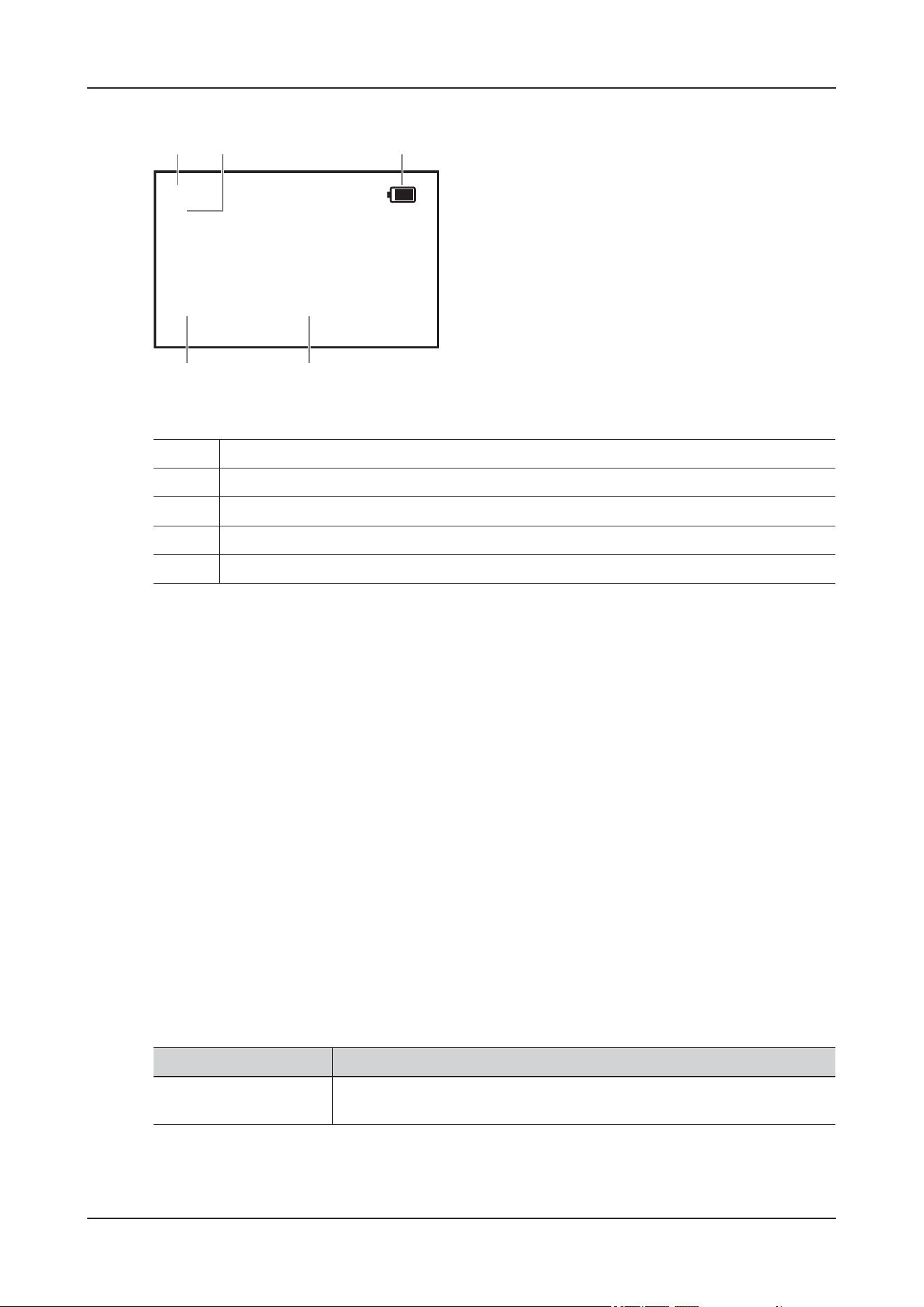
12 Monitoring Temperature
12 - 2
Figure 12-1 Temperature results
12.4 Parameters Setup
Enter the Monitoring details interface, tap the Temp numeric area to open the Temp menu.
Setting the Temperature Alarm Properties
Perform the following procedure:
1. Select the Alarm tab.
2. Set alarm properties as desired.
Input the password if required.
Changing Temperature Settings
Perform the following procedure:
1. Select the Setup tab.
2. Adjust parameters as required:
1. Temperature site
2. Temperature unit
3. Battery capacity of Temp module
4. Temperature value
5. Alarm limits
1
2
3
4
5
Txx
°C
XX.X
XX.X
XX.X
Item Description
Temperature channel
(T3) label
Set the temperature label according to the measurement site.
12 Monitoring Temperature
12 - 3
12.5 Troubleshooting
This section lists the problems that might occur. If you encounter the problems when using the device or
accessories, check the table below before requesting for services. If the problem persists, contact the
Customer Service Department or your local distributor.
Problem Solution
Do not see Temp numeric area on the main screen. • Check that the Temp is set to display in the
Screen Setup menu.
• Check that if the Temp parameter switch is
enabled. If not, enable the Temp measurement.
• Check that the connections of the temperature
probe and the temperature cable are tight.
Measurement fails/‘--’ is displayed in the Temp
numeric area.
• If you are using a disposable probe, check the
connection between the probe and the
temperature cable.
• Try using a known good probe in case the
sensor is damaged.

13 Monitoring Noninvasive Blood Pressure
13 - 1
13 Monitoring Noninvasive Blood
Pressure
13.1 Overview
The device uses the oscillometric method for measuring the non-invasive blood pressure (NIBP). NIBP
measurement is based on the principle that pulsatile blood flow through an artery creates oscillations of
the arterial wall. The oscillometric device uses a blood pressure cuff to sense these oscillations that
appear as tiny pulsations in cuff pressure. The oscillometric method measures the mean pressure and
determines the systolic and diastolic pressures.
WAR N I N G
• Be sure to select the correct species setting for your animal before NIBP measurement.
• Do not perform NIBP measurements on animals with sickle-cell disease.
• Use clinical judgment to determine whether to perform frequent unattended blood pressure
measurements on animals with severe blood clotting disorders because of the risk of hematoma in
the limb fitted with the cuff.
• To avoid the risk of animal injury, do not apply the NIBP cuff on a limb that has an intravenous
infusion or catheter in place. Apply the cuff on another limb if possible.
• Continuous cuff pressure due to connection tubing kinking may cause blood flow interference, and
resulting in harmful injury to the animal.
• NIBP reading can be affected by the measurement site, the position of the animal, exercise, or the
animal's physiologic condition. If you doubt the NIBP measurements, determine the animal’s vital
signs by alternative means, and then verify that the device is working correctly.
• Taking NIBP measurements exert pressure on the animal's tissue. This can cause skin purpura,
ischemia, and neuropathy. Periodically check the cuff site and the limb distal to the cuff for normal
color, warmth and sensitivity. If there is a sign of skin change or poor distal circulation, move the
cuff to another limb or stop NIBP measurements. Check more frequently when using the STAT
mode or using the auto mode at short intervals. Auto NIBP measurements with one and two minute
intervals are not recommended for extended periods of time.
• NIBP diagnostic significance must be decided by the physician.

13 Monitoring Noninvasive Blood Pressure
13 - 2
CAUTION
• Using IABP may cause NIBP, including PR, measurements inaccurate or failed.
• Only use parts and accessories specified in this manual. Follow the instructions for use and adhere to
all warnings and cautions.
• Accuracy of NIBP measurement depends on using a cuff of proper size. It is essential to measure
limb circumference and choose a cuff with proper size.
• Using a cuff of wrong size, or a cuff with twisted bladder and kinked air tubing, can cause inaccurate
measurements.
• Do not touch or apply external pressure against the cuff and air tubing during NIBP measurement.
This may cause inaccurate blood pressure values.
• Use care when placing the cuff on an extremity used for monitoring other animal parameters.
NOTE
• Blood pressure measurements determined with this device are equivalent to those obtained by a
trained observer using the cuff/stethoscope auscultatory method or an intra-arterial blood pressure
measurement device, within the limits prescribed by the American National Standard: manual,
electronic, or automated sphygmomanometers.
• NIBP measurement can be performed during electro-surgery and discharge of defibrillator.
13.2 NIBP Measurement Limitations
Measurements are impossible with heart rate extremes of less than 30 bpm or greater than 300 bpm, or if
the animal is on a heart-lung machine.
The measurement may be inaccurate or impossible in the following situations:
• Regular arterial pressure pulses are hard to detect
• Excessive or continuous patient movement such as shivering or convulsions
• Cardiac arrhythmias
• Rapid blood pressure change
• Severe shock or hypothermia that reduces blood flow to the peripheries
• On an edematous extremity
13.3 Starting the Measurement
Perform the following procedure:
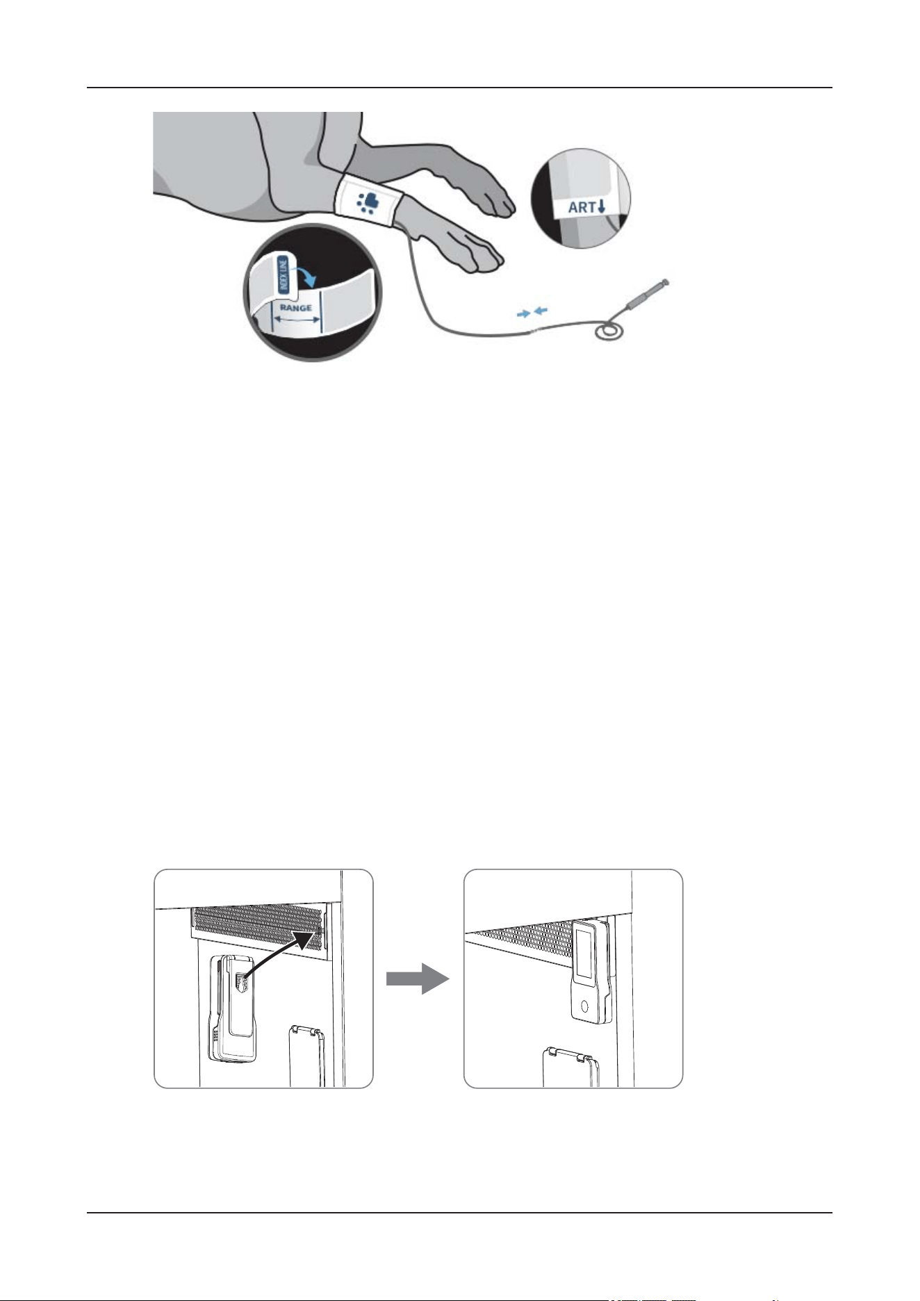
13 Monitoring Noninvasive Blood Pressure
13 - 3
1. Verify that settings of species and weight value are set correctly on the device.
2. Select an appropriate size cuff for the animal.
3. Select a NIBP cuff by referring to the limb circumference marked on the NIBP cuff. The cuff width
should be 40% of the circumference of the measurement site. Check that the NIBP cuff is completely
deflated.
For detailed information about the NIBP cuff, see the instructions delivered with it.
4. Apply the NIBP Cuff.
Select a cuff position based on the patient type and weight.
• When the animal is lying on the right side, left side or seated, place the NIBP cuff on the animal's
limb.
• When the animal appears agitated or when placing the cuff to larger animals, place the NIBP cuff on
the base of the tail.
5. Connect the cuff to the air tubing. Avoid compression or restriction of pressure tubes. Air must pass
unrestricted through the tubing.
6. Connect the air tubing to the NIBP connector of the NIBP module.
7. Use the back clip to hang the NIBP module on the hook inside the device.
8. Adjust parameters or select the measurement mode in the NIBP menu if necessary.
9. Do one of the following to start the NIBP measurement:
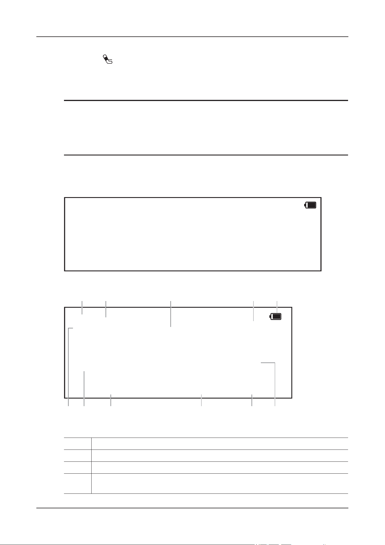
13 Monitoring Noninvasive Blood Pressure
13 - 4
• Enter the Monitoring details interface, tap NIBP Start/Stop quick key.
• Press the (Start/Stop) button of the NIBP module.
13.4 Results Display
NOTE
• If NIBP Measurement Failed is measured, the measured value is displayed as “XX”. If no
measurement is performed, the measured value is displayed as “---”.
• When the NIBP measurement result is displayed as a hollow number, it indicates that the
measurement result has exceeded the set expiration time and is not recommended as a reference.
The measurement results are displayed on the main screen and the Monitoring details interface.
Figure 13-1 NIBP results on the main screen
Figure 13-2 NIBP results on the monitoring details interface
1. Parameter label
2. The last NIBP measurement time
3. Systolic pressure/Diastolic pressure
4. Measurement mode: for Auto NIBP, interval is displayed; for Sequence mode, the current
phase and interval are displayed
NIBP
mmHg
@xx:xx
XXX
XX
XXXX
PR
XXX
XX
XXX
XX
X
X/X
(X)
NIBP
mmHg
@xx:xx
XXX
XX
PR
XX
XXX/XX
(XX)
XXXX
XXX
XX
XXX
XX
12 3 45
67891011
13 Monitoring Noninvasive Blood Pressure
13 - 5
13.5 Parameter Adjustment
Enter the Monitoring details interface, tap the NIBP numeric area or waveform area to open the NIBP
menu.
Setting NIBP Alarm Properties
Perform the following procedure:
1. Select the Alarm tab.
2. Set alarm properties as desired.
Input the password if necessary.
Setting NIBP Parameters
Perform the following procedure:
1. Select the Setup tab.
2. Adjust parameters as required:
5. Battery capacity of NIBP module
6. Diastolic pressure alarm limits
7. Mean pressure alarm limits
8. Mean pressure (displayed after measurement completed) or cuff pressure (displayed during
the measurement)
9. Pulse Rate
10. Systolic pressure alarm limits
11. NIBP unit: mmHg or kPa
Item Description
Initial Pressure Set initial cuff inflation pressure.
Time Between Readings For auto NIBP measurement, you need to set the interval between two NIBP
measurements.
Start Mode Set the NIBP start mode.
• Clock: after the first measurement, the device automatically
synchronizes NIBP automatic measurements with the real time clock.
• Time Between Readings: after the first measurement, the device
automatically repeats measurements at set interval.
NIBP End Tone Enable the NIBP end tone.
The device can issue a reminder tone at the completion of NIBP
measurement.
Venipuncture Pressure Set the cuff inflation pressure to help venous puncture.
Display Format Set the display format of the artery pressure.

13 Monitoring Noninvasive Blood Pressure
13 - 6
Viewing NIBP Analysis
NIBP analysis provides you a dynamic analysis of NIBP changes and distribution over the time scale. It
allows you to know the animal’s condition of the latest 24 hours before you entering the NIBP Analysis
interface.
Perform the following procedure:
1. Select Analysis in the NIBP menu.
2. Tap anywhere in the NIBP Analysis window to enter the Patient Status Review interface.
Setting NIBP Sequence
NIBP sequence measurement can have up to five phases: A, B, C, D, and E. You can individually set the
duration and interval of each phase.
Perform the following procedure:
1. Select Sequence in the NIBP menu.
2. Set the Duration and Time Between Readings of each phase.
Assisting Venous Puncture
You can use the NIBP cuff to cause sub-diastolic pressure to block the venous blood vessel and therefore
help venous puncture.
Perform the following procedure:
1. Select Setup in the NIBP menu.
2. Set Venipuncture Pressure.
3. Tap Venipuncture.
4. Puncture vein and draw blood sample.
During venous puncture, pay attention to the cuff pressure and the remaining time displayed in the NIBP
numerics area.
5. Tap the NIBP Start/Stop quick key to deflate the cuff.
13.6 Correcting the NIBP Measurements
The middle of the cuff should be at the level of right atrium. If the limb is not at the heart level, you need
to correct the measurement:
• Add 0.75 mmHg (0.10 kPa) to the displayed value for each centimeter higher.
• Deduct 0.75 mmHg (0.10 kPa) to the displayed value for each centimeter lower.
Display Alarm Limits Set whether to display the alarm limits of diastolic NIBP and mean NIBP.
Display PR Set whether to display the PR value in the NIBP parameter area.
Item Description

13 Monitoring Noninvasive Blood Pressure
13 - 7
13.7 NIBP Leakage Test
The NIBP leakage test checks the integrity of the system and of the valve. The NIBP leakage test should
be performed once every 2 years or when you doubt the NIBP measurements. The NIBP leakage test
should be performed by Mindray Animal Medical-qualified service personnel only.
13.8 NIBP Accuracy Test
The NIBP accuracy test should be performed once every 2 years or when you doubt the NIBP
measurements. The NIBP accuracy test should be performed by Mindray Animal Medical-qualified
service personnel only.

14 Infusion
14 - 1
14 Infusion
14.1 Safety Information
WAR N I N G
• Clearing the occlusion result from line kinks, filter coagulation, etc. may cause extra bolus to
animals. Appropriate measures should be taken.
• To ensure the accuracy of air bubble detection, check and remove the remained fluid in the infusion
set slot before loading the infusion set.
• While loading the infusion set, do not touch the anti free-flow clamp to avoid injury.
• Try to keep the heart of the animal in the same horizontal level as the infusion pump. The most
accurate pressure monitoring in the infusion set is achieved when the infusion pump is positioned
close to the animal’s heart level.
• We recommend you to use an infusion set stated in this manual. If a non-recommended infusion set
must be used or a different set needs to be changed, perform the calibration and performance test
before use. Otherwise, the accuracy of the infusion and the performance of the device may be
adversely affected.
• To ensure the accuracy of rate and alarm detection, the infusion set should be calibrated in the
device before first use.
• Single use accessories are not designed to be reused. Reuse may cause a risk of contamination and
affect the measurement accuracy.
• Do not connect an animal until disposables have been purged and loaded into the infusion pump.
• Before infusion starts or after infusion stops, check that no drops are falling in the drip. If drips are
falling, do not use the device, and contact the Customer Service Department or your local
distributor.
• Do not start an infusion unless the setup was verified to be correct.
• Ensure that the device is properly secured and positioned. Position change and severe shock may
lead to changes to the delivery accuracy.

14 Infusion
14 - 2
CAUTION
• When several infusion lines are connected to the same vascular access, there may be back flow or
prolonged response time of occlusion alarm. Therefore, use check valve at the line end or follow
local hospital’s instructions while in connection with other infusion system.
• Make sure the current selected infusion set brand is the same as the brand actually used, or its
accuracy cannot be guaranteed.
NOTE
• Make sure the roller clamp is closed before opening the pump door.
• Take care that your hands are not squeezed when you close the pump door.
• Make sure that the infusion set is located in both sides of the tubing channel notches after loading
the infusion set.
• Monitor the connection of infusion set, tubing, infusion pump and animal, and the drug information
on a regular basis. Start infusion according to the instructions in this manual.
14.2 Preparing the IV Container
The height between the IV container and the infusion pump is critical to the flow accuracy.
Perform the following procedure:
1. Hang the IV container onto the infusion hook.
The external IV stand arm can be installed. For the installation and adjustment methods, see its
accompanying instructions.
2. Adjust the height of the infusion pump so that there is 51 ± 5 cm (20 ± 2 in.) between the fluid line and
the middle of the infusion pump.
Distances outside of this tolerance can adversely affect flow accuracy.
14.3 Loading the Infusion Set
Perform the following procedure:
1. Pull the door holder to open the pump door.
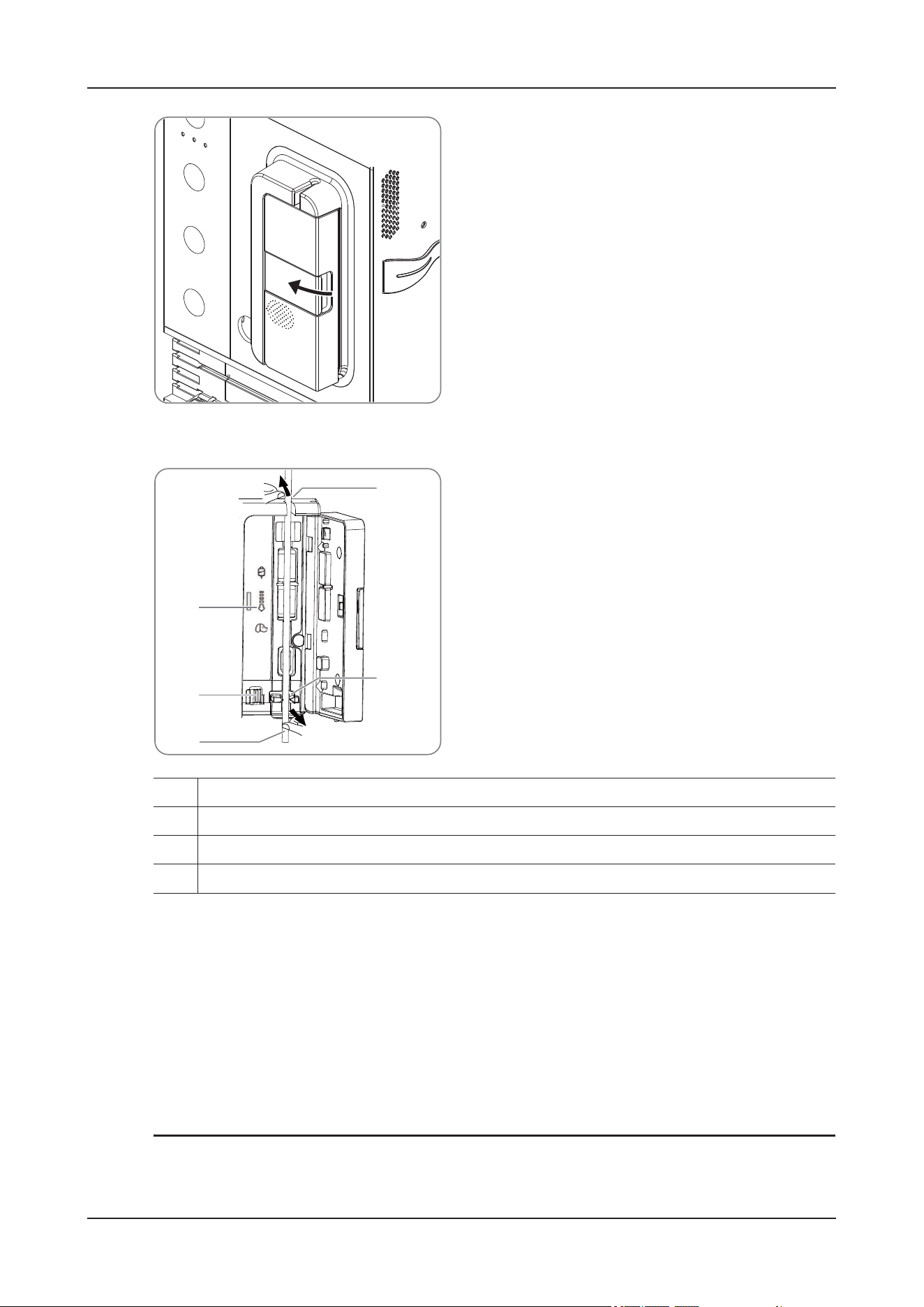
14 Infusion
14 - 3
2. Install the infusion line:
1. Pull the release lever (3) upward left to release the anti free-flow clamp.
2. Avoiding any slack, insert the infusion line into the tubing channel notches (1) by following the flow
direction indicator (2).
Ensure that the infusion set is straightly and firmly clipped into the tubing channel notches (1) on
both sides of the casing.
3. Close the pump door.
14.4 Purge
NOTE
• The volume used for purging is not added to the infused volume.
1. Tubing channel notches
2. Flow direction indicator
3. Release lever
4. Infusion line
1
2
3
1
4
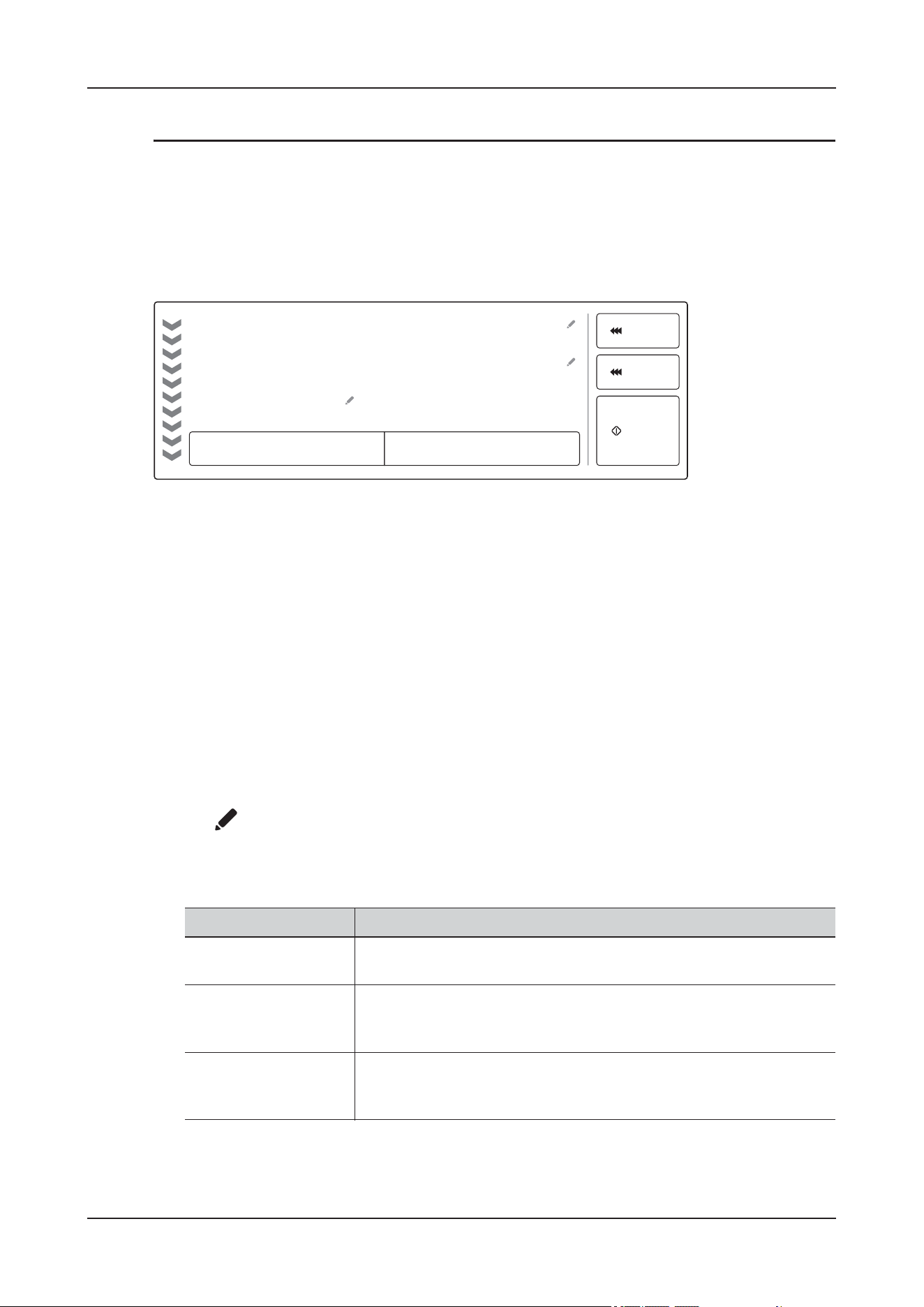
14 Infusion
14 - 4
•The Air in Line or Accumulated Bubble alarm will not pop up during purging.
The infusion set should be purged prior to being connected to the animal.
Perform the following procedure:
1. Ensure that the infusion pump is disconnected from the animal.
2. On the main screen, tap the infusion information area to enter the Infusion details interface.
3. Tap Purge to enter the Purge prompt screen.
4. Tap Purge to start purge.
5. Tap Stop to complete purge after the air bubbles are purged.
14.5 Starting Infusion
Perform the following procedure:
1. On the main screen, tap the infusion information area to enter the Infusion details interface.
2. Tap Brand to select the infusion set brand.
3. Set infusion parameters:
•Tap of Rate, VTBI and Time to input the desired value. When two of these parameters are
entered, the third is calculated.
• Set other infusion parameters:
Tap Infusion Setup to open the Infusion Setup menu:
XXX
XX:XX:XX
h:m:s
XX/XX
mlml/h
Rate
VTBI/Volume
Time
Rate Mode
Purge
Bolus
Start
Brand
Item Description
Occlusion Pressure Set the occlusion alarm limit. The device gives the Downstream
Occlusion alarm when the occlusion pressure exceeds the alarm limit.
Bubble Size Set the alarm limit for the size of single air bubble. The device gives the
Air in Line alarm when the size of single air bubble exceeds the alarm
limit.
Accumulated Bubble Set the alarm limit for the volume of accumulated air bubble. The device
gives the Accumulated Bubble alarm when the accumulation air bubble
volume exceeds the alarm limit.

14 Infusion
14 - 5
4. After setting infusion parameters, connect the infusion set to the animal.
5. Tap Start to start the infusion.
TIP
• The screen displays the running icon. An arrow moves from up to down and the speed of the arrow
increases as the rate increases.
• The infusion parameters can also be adjusted as required during infusion.
14.6 Using the Heating Control
Perform the following procedure:
1. Open the cover of the infusion heating module.
KVO Rate Set the KVO rate. If KVO rate is set to zero, the device stops infusion
when VTBI is completed.
If the KVO rate is set to 0, the device will not initiate a KVO infusion
when the preset volume is complete.
TIP
• If the KVO rate is greater than the infusion rate, the device will
continue to infuse at the set infusion rate.
• The device runs for 30 minutes at a KVO rate. At the completion
of the KVO infusion, the device stops infusion, and gives a KVO
Complete alarm.
• The volume used during KVO infusion will be added to the total
infusion volume.
Auto Bolus Limit Set the upper limit for automatic bolus.
Manual Bolus Limit Set the upper limit for manual bolus.
Time Near End Set for how long the Infusion Near Done alarm is triggered since the
infusion is completed.
When it is set to Off, the device does not give the Infusion Near Done
alarm.
Pump Reminder Set for how long the Pump Reminder alarm is triggered since the
device is last operated.
When it is set to Off, the device does not give the Pump Reminder
alarm.
Item Description
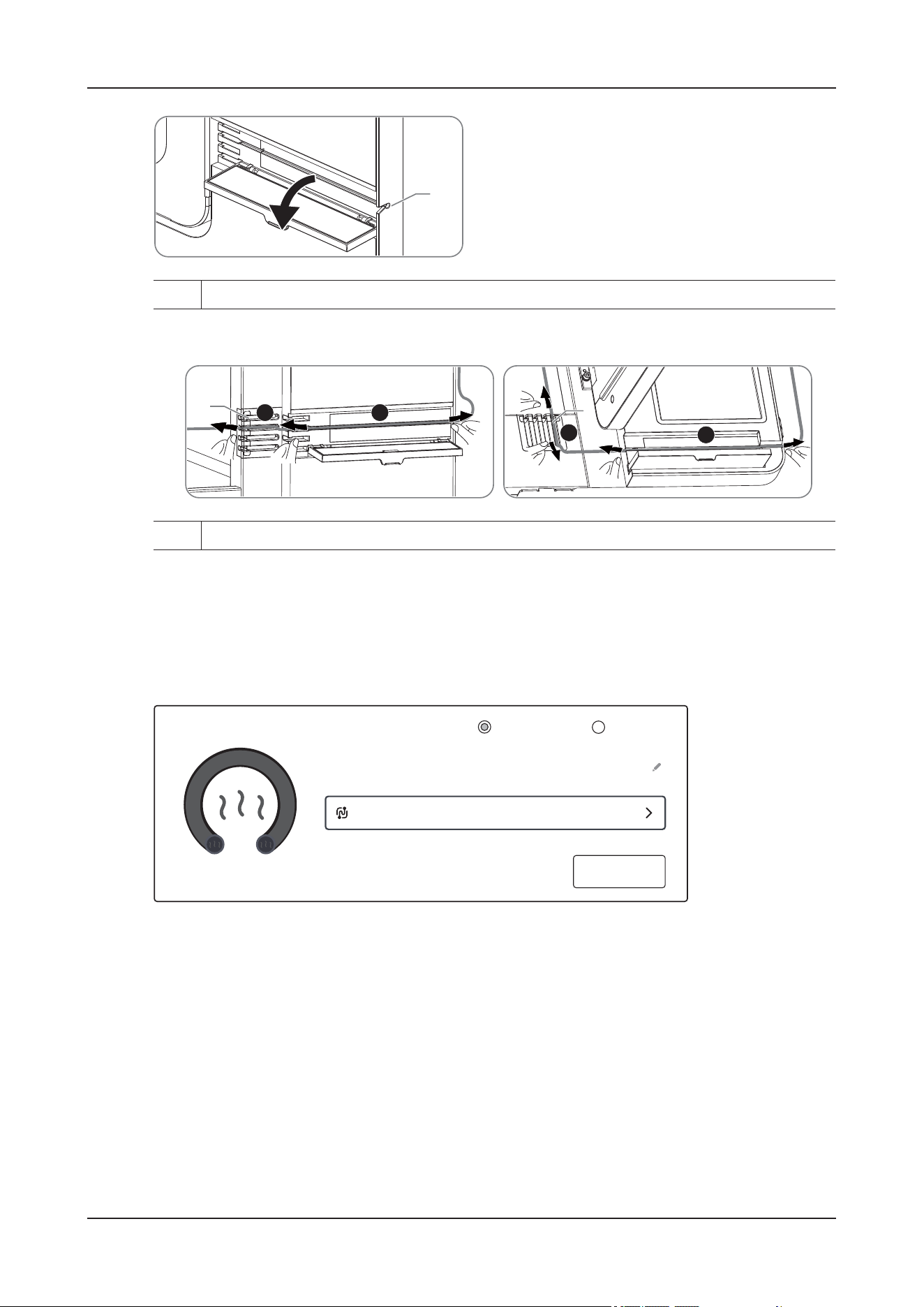
14 Infusion
14 - 6
2. Secure the infusion line:
1. Straighten the infusion line and put it into the tubing channel notch (a) of the warmer.
2. Straighten the infusion line and put it into the tubing channel notch (b) of the cabin door.
3. On the main screen, tap the infusion information area to enter the Infusion details interface.
Set the heating parameters in the heating function area.
1. Select the infusion pump.
2. Set the value of Target Temperature as required.
3. If the selected infusion pump is Built-in Pump, you can enable the Intelligent Flow-Linked
Heating function.
After this function is enabled, the warmer is synchronized with the flow rate of the built-in infusion
pump to make the infusion temperature more precise.
4. Tap Start Heating to start the heating control function.
1. Tubing channel notches
1
1. Tubing channel notches
a
b
ab
1
1
XX.X
°C
Pump
Built-in Pump External Pump
Target Temperature
Intelligent Flow-Linked Heating Built-in Pump Only
Start Heating
Flow-linked internal pump heating

14 Infusion
14 - 7
14.7 Completing Infusion
During the infusion, if the remaining infusion time is close to the Infusion Near Done set by the users,
the Infusion Near Done alarm will be triggered. If no action has been taken, the alarm will not be
canceled automatically until the infusion is completed, and then switch to Infusion completed alarm.
14.8 Replacing the IV Container
NOTE
Check the infusion status after replacing the IV container. If the device is running a KVO infusion,
reconfigure the infusion parameters before restarting the infusion.
Perform the following procedure:
1. To prevent animal injury due to free flow, before replacing the IV container, please shut down the Robert
clip (or flow rate regulator).
During infusion, stop the infusion:
1. On the main screen, tap the infusion information area to enter the Infusion details interface.
2. Tap Stop to stop the infusion.
3. Shut down the Robert clip (or flow rate regulator).
2. Remove the IV container from the IV pole, and replace a new container.
14.9 Unloading the Infusion Set
WAR N I N G
It is recommended that the infusion sets be changed every 24 hours (or as per national hygiene
regulations or manufacturer’s instructions). If infusion sets not recommended by this manual are used,
adjust the fixing site every 4 hours.
Perform the following procedure:
1. On the main screen, tap the infusion information area to enter the Infusion details interface.
2. Tap Stop to stop the infusion.
3. Disconnect the animal from the infusion set.
4. Pull the door holder to open the pump door.
5. On the outside of the pump, grasp the tubing on both sides of the pump and pull the tubing
straight out of the pumping channel.
14 Infusion
14 - 8
14.10 Checking the Total Infusion Volume
NOTE
• When the volume exceeds 9999 ml, it is automatically cleared.
• After the device is shut down, the total volume is automatically cleared.
Total infusion volume refers to the amount of liquid infused into the animal within a certain time.
On the main screen, tap the infusion information area to enter the Infusion details interface. You can
view the current animal's infusion volume in the Infused Volume area.
Tap Clear to pop up the confirmation dialog box. Tap Clear to manually clear the infusion volume.
The total infusion volume is automatically cleared after the current animal is discharged.
Infused Volume
Infused Volume x.x ml
Clear

15 Monitoring Review
15 - 1
15 Monitoring Review
Trends are animal data collected over time and displayed in graphic, tabular, or other forms to give you a
picture of how your animal's condition is developing.
15.1 Review Page
The review page contains tabs to display trend data in tabular, graphic, or other forms.
15.1.1 Accessing the Review Page
On the main screen, tap the monitoring information area to enter the Monitoring details interface. Tap
More > Review, and then tap the required tab. If reviewing animal data is password protected, input the
device's clinical password (local password).
15.1.2 Example Review Page
The review pages have similar structure. The Graphic Trends review page is taken as an example.
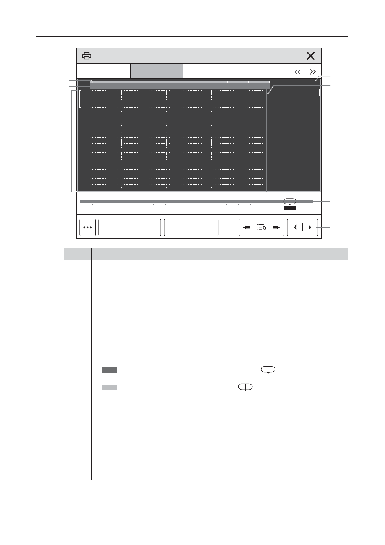
15 Monitoring Review
15 - 2
No. Description
1. Event type indicator: different color blocks match different types of events.
• Red: high priority alarm event
• Yellow: medium priority alarm event
• Cyan: low priority alarm event
• Green: manual event
• White: operation-related event
2. Current window time line: indicates the time length of the current window.
3. Waveform area: displays trend curves. The color of trend curves is consistent with the color of
parameter labels.
4. Time line: indicates the entire time length.
• : indicates the time length of reviewable trend data. can be moved within this
time length.
• : indicates the time length of no trend data. cannot be moved within this time
length.
• Different color blocks at the time line indicate events of different types. See the color
definition for the event type indicator.
5. Button area
6. Slider: indicates the position of current window time in the entire time length. Dragging this
button left or right enables you to locate the trend data at a specific time and also refreshes
trend data in current window accordingly.
7. Numeric area: displays numeric values at the cursor indicated time. The background color of
numeric values matches the alarm priority.
8
9
1
2
3
4 6
5
7
xxx
xxxx-xx-xx xx:xx:xx
XX
xx
XXX
XX
xx
XXX
XX
xx
XXX
XX
xx
XXX
XX
xx
XXX
xxx
xxx
xxx
xx-xx xx-xx xx-xx
xx:xx
xx:xx xx:xx xx:xx xx:xx xx:xx xx:xx xx:xx xx:xx
Tabular Trends Graphic Trends Events Full Disclosure
Trend Group Standard Zoom 8 hrs
Patient Status Review
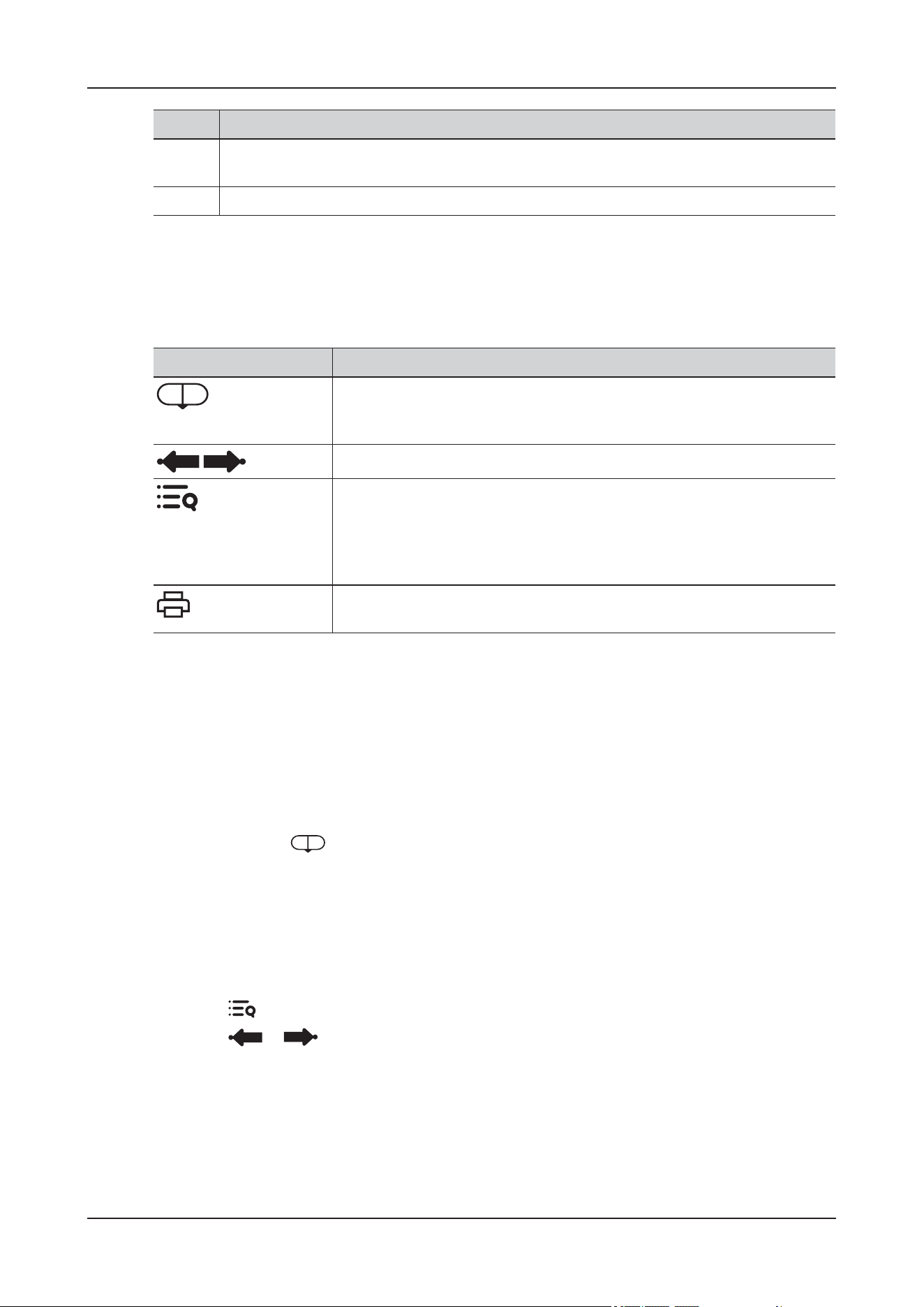
15 Monitoring Review
15 - 3
15.1.3 Symbols on Review Pages
The following table lists the symbols on review pages.
15.2 Common Operations
This section describes common operations for all review pages.
15.2.1 Browsing Trend Data
To browse trend data, choose any of the following ways:
• Move the slider .
• Move the cursor.
• Slide your finger on the screen.
15.2.2 Viewing Events
To view events, choose either of the following ways:
• Select and select the desired event.
• Select or to view the previous or next event.
15.3 Tabular Trends Review Page
The tabular trends review page displays trend data in a tabular form.
8. Event area: displays the event of the cursor time. Selecting the event accesses the event list. If
there is no event at the cursor time, the cursor time is displayed.
9. Cursor
No. Description
Symbols Description
Slider: indicates the position of current window time in the entire time
length. Dragging the slider left or right enables you to locate the trend data
at a specific time and also refreshes data in current window accordingly.
/
Goes to the previous or next event.
Event list: displays events in a chronological order. The most recent event is
displayed at the top. The number of exclamation symbols before an event
matches alarm priority. The event that occurs most recently is displayed on
the top of the list. Symbol Before Event (!) The quantity corresponds to
different alarm priority values.
Print button: select it to output animal information and data through the
printer.

15 Monitoring Review
15 - 4
15.3.1 Entering the Tabular Trends Review Page
Select Review > Tabular Trends to enter the Tabular Trends review page.
15.3.2 Changing the Tabular Trend Group
To change the tabular trend group, follow this procedure:
1. Enter the Tabular Trends review page.
2. Tap Trend Group.
15.3.3 Editing the Tabular Trend Group
The setting of the Trend Group defines the contents of displayed and printed trends. To edit the tabular
trend group, follow this procedure:
1. Enter the Tabular Trends review page.
2. Tap Group Setup.
NOTE
• You cannot edit trend group labeled All or Standard.
• ECG parameter and waveform are always displayed in the first row on the trend page. It cannot be
deleted or moved.
15.3.4 Changing the Resolution of Trend Data
The resolution of tabular trends defines the interval of displaying trend data.
Enter the Tabular Trends review page, and then tap Interval:
• 5 sec Or 30 sec: select to view up to 4 hours of tabular trends at an interval of 5 seconds or 30
seconds.
• 1 min, 5 min, 10 min, 15 min, 30 min, 1 hr, 2 hrs, 3 hrs: select to view up to 120 hours of tabular
trends at selected interval.
• NIBP: select to view the tabular trends when parameter measurements are acquired.
15.3.5 Printing a Tabular Trends Report
Perform the following procedure:
1. Enter the Tabular Trends review page.
2. Tap to open the Print Setup menu.
3. Set the tabular trends report as desired.
4. Tap Print.

15 Monitoring Review
15 - 5
15.4 Reviewing the Graphics Trends
The Graphic Trends review page displays trend data in a graphic form.
15.4.1 Entering the Graphic Trends Review Page
Select Review > Graphic Trends to enter the Graphic Trends review page.
15.4.2 Changing the Graphic Trend Group
To change the graphic trend group, follow this procedure:
1. Enter the Graphic Trends review page.
2. Tap Trend Group.
15.4.3 Editing the Graphic Trend Group
To edit the graphic trend group, follow this procedure:
1. Enter the Graphic Trends review page.
2. Select > Group Setup.
3. Select the desired tab.
15.4.4 Changing the Resolution of Trend Data
To change the length of trend data displayed on the current screen, follow this procedure:
1. Enter the Graphic Trends review page.
2. Set the Zoom.
• 8 min: the screen displays eight minutes of trend data. You can view the recent 1 hour data.
• 30 min, 1 hr, 2 hrs, 4 hrs: the screen displays 30 minutes, 1 hour, 2 hours, or 4 hours of trend data.
You can view the recent 4 hours data.
• 8 hrs, 12 hrs, 24 hrs, 48 hrs: the screen displays eight hours, 12 hours, 24 hours, or 48 hours of
trend data. You can view the recent 120 hours of data.
15.4.5 Changing the Number of Waveforms
Perform the following procedure:
1. Enter the Graphic Trends review page.
2. Select > Trends.
3. Set the Trends.
15.4.6 Printing a Graphic Trends Report
Perform the following procedure:
1. Enter the Graphic Trends review page.

15 Monitoring Review
15 - 6
2. Tap to open the Print Setup menu.
3. Set the tabular trends report as desired.
4. Tap Print.
15.5 Reviewing Events
The device stores events in real time, including technical alarm events, physiological alarm events,
manual events, and operational events. When an event occurs, all the measurement numerics and the
event-related waveforms 16 seconds before and after the event are stored.
NOTE
• A total loss of power has no impact on the events stored.
• The device saves this manual event automatically. Alarms are saved as events and will be
maintained if the device is powered down. The time of device power down is not recorded as an
event and cannot be reviewed.
• Earlier events will be overwritten by later ones if the capacity is reached.
Select Review > Event to enter the Event review page.
15.5.1 Configuring the Filter
You can filter events to facilitate event review.
Perform the following procedure:
1. Tap Filter to select the filter condition from drop-down list.
You can customize two criteria. To do so, follow this procedure:
1. From the Filter drop-down list, select Custom 1 or Custom 2 to open the Filter Setup menu.
2. Tap the Name field to edit the name of the custom criterion.
3. Select desired items.
4. Tap OK.
If you want to review events happened around certain time, select > set the time > OK. Then
the cursor jumps to the event happened closest to the defined time.
15.5.2 Editing Events
Perform the following procedure:
1. Enter the Event page and tick off the desired events.
2. Tap to edit the selected events.
• Lock: manually lock the event. When the event number reaches its maximum, the locked event will
not automatically be deleted by the system.
• Unlock: unlock the event.
• Delete: delete the event.

15 Monitoring Review
15 - 7
• Note: enter comments for the event.
• Select All: select all the events.
• Cancel All: unselect all the events.
• Show Disabled Arrhythmia Alarms: This option is not selected by default. After this option is
selected, the Event List displays the arrhythmia events when the alarm switch is set to Off.
• Rename: allow renaming an event name. Only manual events and arrhythmia events can be
renamed if enabled by the hospital’s settings.
15.5.3 Viewing Event Details
Perform the following procedure:
1. Enter the Event review page.
2. Tap Detail.
To display beat labels on the first ECG waveform, switch on Beat Anno. The white beat labels indicate
heart beats classification and may explain suspected, missed, or false arrhythmia calls. Heart beats are
classified as follows:
• N = Normal
• V = Ventricular ectopic
• S = Supraventricular premature
• P = Paced
• L = Learning
• ? = Insufficient information to classify beats
• I = Inoperative (for example, Lead Off)
• M = Missed beat
If the beat switch is set to On on the Event review page, the beat label is also displayed on the Full
Disclosure review page and vice versa.
Tap List to return to the Event page.
15.5.4 Printing Event Reports
You can print event reports either via a printer.
Perform the following procedure:
1. Enter the Event review page.
2. Tap to open the Print Setup menu.
3. Select the desired options, and then Print.
• Print All Event List: print the entire event list.
• Print List of Selected Events: print the list of selected events.
• Print Detail of Selected Events: print the details of selected events.
• Print Displayed Event Detail: print the waveforms and parameters of the currently displayed
event.
• Print Overview of Selected Events: print the overview of selected events.

15 Monitoring Review
15 - 8
15.6 Reviewing Full Disclosure
You can review up to 48-hour waveform data on the Full Disclosure review page. You can view both the
compressed waveforms and numeric values.
Select Review > Full Disclosure to enter the Full Disclosure review page.
15.6.1 Selecting Waveforms
Before reviewing compressed waveforms, you must select waveforms you want to store and display.
Perform the following procedure:
1. Enter the Full Disclosure review page.
2. Tap Setup to enter the Select Waveform page.
3. Select the Storage tab and set the desired waveforms to be stored in the device.
4. Select the Display(Maximum: 3) tab and set the desired waveforms to be displayed.
NOTE
The more waveforms selected in the Storage column, the shorter the waveform storage time. The
waveforms may not be stored for 48 hours. Please exert caution when selecting waveforms.
In case of alarms, the background of compressed waveform at the alarm time is highlighted as follows:
• Red: high alarm priority
• Yellow: medium alarm priority or low alarm priority
15.6.2 Setting the Scale and Duration
You can set the length and size of displayed compressed waveforms.
Perform the following procedure:
1. Enter the Full Disclosure review page.
2. Tap ,and then set Duration and Scale.
15.6.3 Viewing Details of Compressed Waveforms
Perform the following procedure:
1. Enter the Full Disclosure review page.
2. Tap Detail.
You can perform the following operations on this page:
• Switch on Beat Anno the beat annotation is displayed in white font above the first ECG waveform.
• Tap , and then set Speed, ECG Gain and Save As Event.
•Tap Overview to switch to the compressed waveform page.

15 Monitoring Review
15 - 9
15.6.4 Printing the Full Disclosure Waveform Report
Perform the following procedure:
1. Enter the Full Disclosure review page.
2. Tap .
3. Set the time range for printing.
4. Tap Print.
15.7 ST Review Page
When ST analysis is enabled, the device saves ST segments and values at an interval of five minutes.
You can review the latest 120 hours of ST data.
Select Review > ST to enter the ST Review page.
15.7.1 Setting the ST Reference
Perform the following procedure:
1. Enter the ST Review page.
2. Tap Set Reference to set the currently displayed ST as reference.
NOTE
The ST baseline is used as ST reference by default.
15.7.2 Displaying/Hiding the ST Reference
Perform the following procedure:
1. Enter the ST Review page.
2. Tap Display Reference or Hide Reference.
15.7.3 Displaying/Hiding Markers
Perform the following procedure:
1. Enter the ST Review page.
2. Tap Display Marker or Hide Marker.
• Display Marker: ISO point, J point, and ST point are marked with white vertical lines in the ST
template.
• Hide Marker: ISO point, J point, and ST point are not displayed in the ST template.
15.7.4 Printing ST Data
Perform the following procedure:

15 Monitoring Review
15 - 10
1. Enter the ST Review page.
2. Locate the required time.
3. Tap .
15.8 Reviewing Discharged Animals
For discharged animals, you can review the trend data in the review page and the events.
Perform the following procedure:
1. Enter the Patient details interface, and then tap Discharged Patients quick key to enter the Discharged
Patients dialog.
2. Enter the search criteria to view the desired animal.
Select the desired animal from the animal list, and then tap Delete to delete the data of the selected
animal.

16 Monitoring Auxiliary Function
16 - 1
16 Monitoring Auxiliary Function
16.1 Overview
The Auxiliary Function integrates some commonly used clinical guidelines and tools into the device. It
puts the currently monitoring parameter measurements together and provides comprehensive analysis
results.
The Auxiliary Function is not intended to replace the competent judgment of a clinician. It must be used
in conjunction with observation of clinical signs and symptoms.
16.2 ECG 24h Summary
The ECG 24h Summary provides ECG statistics of the current animal over the latest 24 hours. It also
displays the animal’s typical ECG strips.
NOTE
• The ECG 24h Summary function is intended for the current animal. It is not intended for discharged
animals.
• Pacing statistics are only applicable to animals wearing pacemakers. Pacing statistics can be
performed only when the patient's pacing status is set to On.
• ST statistics is available only when ST analysis is switched on.
• QT statistics is available only when QT analysis is switched on.
• Data displayed in the ECG 24h Summary is not recalculated.
16.2.1 Opening the ECG 24h Summary Window
Perform the following procedure:
1. Enter the Monitoring details interface.
2. Tap Monitoring Setup to open the Monitoring Setup menu.
3. Tap ECG 24h Summary from the Auxiliary Function column.
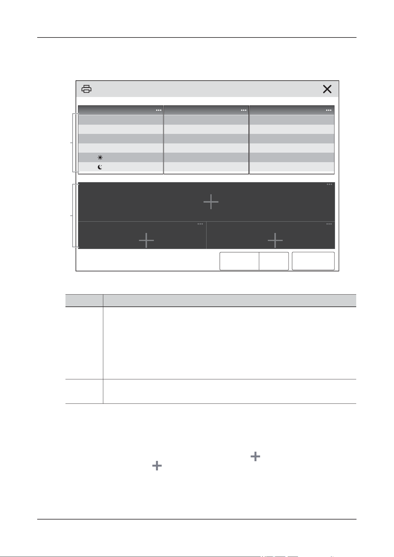
16 Monitoring Auxiliary Function
16 - 2
16.2.2 The Display of ECG 24h Summary
The following figure is an example of the ECG 24h Summary window:
16.2.3 Selecting Typical ECG Strips
Taking V-Tach as an example, to select typical V-Tach waveform, select the currently displayed V-Tach
waveform, from the popup list select the desired waveform as typical V-Tach waveform.
If no V-Tach occurs to the animal within 24 hours, an add symbol is displayed in the V-Tach area.
You can select the add symbol to display a typical ECG waveform of other event in this area
No. Description
1. ECG statistics, including the following items:
• Statistics of heart rates
• Statistics of ventricular beats and ventricular events
• Statistics of supraventricular beats and supraventricular events
• Statistics of QT/QTc measurements
• Statistics of maximum ST elevations and depressions
• Statistics of pace
2. Typical ECG strips
Notes area: includes additional information on the ECG 24h Summary.
1
2
XXXXXX
Period: XXXX-XX-XX XX:XX ToXXXX-XX-XX XX:XX
XXXXXX XXXXXX XXXXXX
XXXXXXX XXXXX
XXXXXX
XXXXXX
XXXXXX
XXXXXX
XXXXXX
XXXXXXX XXXXX
XXXXXX
XXXXXXX XXXXX
XXXXXXX XXXXX
XXXXXXX XXXXX
XXXXXX
XXXXXX
XXXXXXX XXXXX
Runs
XXXXXXX XXXXX
XXXXXX
Typical Strips
XXXXXX
XXXXXX XXXXXX
XXX XXX XXX

16 Monitoring Auxiliary Function
16 - 3
16.2.4 Setting the Statistical Duration of the ECG 24h Summary
You can view a maximum of 24 hours of ECG statistics through the ECG 24h Summary. To select the
statistical duration, select Zoom.
16.2.5 Reviewing the ECG Summary
Selecting any of the statistic area can access corresponding trends and events review. Selecting Full
Disclosure can review ECG full disclosure waveforms.
16.3 ECG Library
NOTE
Due to the individual animal differences, the real-time waveform of the animal may not be completely
consistent with the ECG reference waveforms, and the ECG reference waveforms are only for reference.
ECG Library screen is displayed on the left of the screen, displaying the following:
• ECG waveform within the first minute before entering the ECG library menu.
• ECG reference waveforms and characteristics description.
16.3.1 Entering the ECG Library Screen
Do one of the following to enter the ECG Library screen:
• Enter the Monitor details interface, tap More quick key, and then tap ECG Library.
•Enter the Monitoring details interface, tap Monitoring Setup to open the Monitoring Setup menu,
and then tap ECG Library from the Auxiliary Function column.
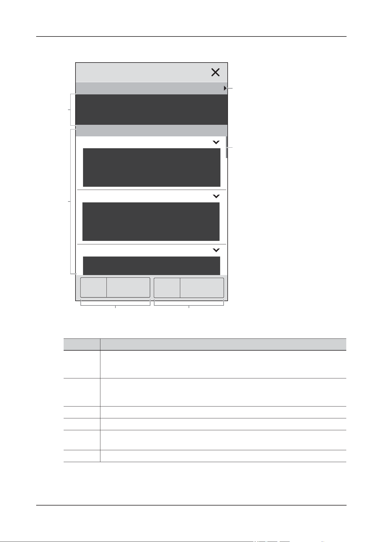
16 Monitoring Auxiliary Function
16 - 4
16.3.2 The Display of ECG Library
No. Description
1. Frozen waveform: displays ECG waveform with the speed of 25 mm/s within 1 minute
before entering the ECG library menu. Swipe from left to right or right to left across the
frozen waveform area to view the frozen waveform.
2. Reference waveform: displays reference waveforms with the speed of 25 mm/s. Each
waveform name is displayed in the upper left corner of its waveform fragment. Tap “v” to
display the waveform characteristics.
3. Filter: select to filter the reference waveforms according to the type.
4. Species: select to filter the reference waveforms according to the species.
5. Scroll bar: swipe up and down on the reference waveform area to view reference
waveforms.
6. ECG Gain: set the ECG gain in the frozen waveform area.
2
34
1
6
5
XXXXXX
XXX XXX XXX XXX
XXXX XXXX: x1
XXXXXX
XXXXXX
XXXXXX
XXXXXX

17 Printing
17 - 1
17 Printing
The device can output animal reports via network printer or printer server.
17.1 Supported Printer
The device supports the following printer:
• HP LaserJet Pro M202dw
• HP LaserJet Enterprise M605
• HP LaserJet P4015n
• HP LaserJet Pro 400 M401n
• HP LaserJet 600 M602
• HP LaserJet Enterprise M608
• HP LaserJet Enterprise M203dw
• HP LaserJet Pro M203dn
NOTE
For more details about the printer, see the document accompanying the printer. With product upgrades,
the device may support more printers and no prior notice will be given. If you have any doubt about the
printer you have purchased, contact the Customer Service Department or your local distributor.
17.2 End Case Reports
17.2.1 Printing the End Case Report
To print the end case report, choose one of the following ways:
• On the main screen, tap More > End Case Report.
•Select Print End Case Report > OK when you discharge an animal.
17.2.2 Setting a Report as An End Case Report
The following reports can be set as end case reports:

17 Printing
17 - 2
• Tabular Trends Report
• Graphic Trends Report
• Event Report
• Alarm Limits Report
• Realtime Report
• ECG Summary
Perform the following procedure:
1. On the main screen, tap the patient information area to enter the Patient detail screen.
2. Select Patient Report > Select Reports.
3. Select the checkbox before the desired report.
4. Tap Print.
17.2.3 Setting the End Case Report
Perform the following procedure:
1. On the main screen, tap the patient information area to enter the Patient detail screen.
2. Select Patient Report > Report Setup.
3. Tap the corresponding tab to set the report type as required.
17.2.4 Setting the End Case Report Period
NOTE
• End case report print period is calculated from the animal discharged time to the configured period.
• Period setting is applicable to all the end case report.
Perform the following procedure:
1. On the main screen, tap the patient information area to enter the Patient detail screen.
2. Select Patient Report > Select Reports.
3. Set the Period.
17.3 Stopping a Printing Task
Perform the following procedure:
1. On the main screen, tap the patient information area to enter the Patient detail screen.
2. Select Patient Report > Print Queue.
3. Select desired printing tasks and then tap Delete.
Tap Delete All to stop all the printing tasks.

17 Printing
17 - 3
17.4 Setting Reports
This section focuses on how to set Realtime Report, Tabular Trends Report, Graphic Trends
Report, and Event Report.
17.4.1 Setting Realtime Reports
Perform the following procedure:
1. On the main screen, tap the patient information area to enter the Patient detail screen.
2. Select Patient Report > Report Setup.
3. Tap Realtime Report tab.
4. Set the desired options.
The following table only lists some of the options.
17.4.2 Setting Tabular Trends Reports
Perform the following procedure:
1. On the main screen, tap the patient information area to enter the Patient detail screen.
2. Select Patient Report > Report Setup.
3. Tap Tabular Trends Report tab.
4. Set the desired options.
The following table only lists some of the options.
17.4.3 Setting Graphic Trends Reports
Perform the following procedure:
Item Description
Speed Set the print speed of ECG waveforms.
Select Waveform Set the desired waveform to print.
• Current Waveforms: prints the realtime report for current
waveforms.
• Selected Waveforms: prints the realtime report for the selected
waveforms.
Item Description
Interval Set the resolution of the tabular trends printed on a report.
Report Format Set the printing principle.
Trend Group Set the desired graphic trend group to print.

17 Printing
17 - 4
1. On the main screen, tap the patient information area to enter the Patient detail screen.
2. Select Patient Report > Report Setup.
3. Tap Graphic Trends Report tab.
4. Set the desired options.
17.5 Viewing Printer Status
Tap the patient information area on the main screen to enter the Patient details interface, and then select
Patient Report > Print Queue to view the status of printing tasks.
You can view the status of the recent ten printing tasks in the Print Queue window.
Each printing task includes the following information:
•Print time
• Report title
• Printer name (when using the printer server) or IP address (when using the network printer)
• Print Status: Printing, Fail, Retry, Waiting, and so on
17.6 Printer Out of Paper
Ensure that there is enough paper in the printer before sending a print request.
When the printer runs out of paper, the print request will not be responded. If there are too many print
jobs that are not responded, a printer error may occur. In these cases, you need to install paper and then
re-send the print request. Restart the printer if necessary.

18 Networked Monitoring
18 - 1
18 Networked Monitoring
18.1 Overview
You can connect the device to the central monitoring system (CMS) through wired LAN or wireless
LAN.
18.2 Safety Information
CAUTION
• Wireless network design, deployment, debugging, and maintenance should be executed by Mindray
Animal Medical service personnel or authorized technicians.
• Always deploy the wireless network according to local wireless regulations.
• Using 5G frequency band is recommended whenever possible. There are more interference sources
in 2.4G frequency band.
• Private APs and wireless routers are not allowed. These devices may cause radio interference and
result in the device and CMS data loss.
• To ensure network security and stability, data communication must be performed within a closed
network or within a virtually isolated hospital network. The hospital is responsible for ensuring the
security of the virtually isolated network.
• WPA2-PSK and WPA2-Enterprise verification and encryption should be used if possible.
Otherwise, the device may not be able to work or animal information may be leaked. WPA2-
Enterprise and a long password are recommended.
• Keep network authentication information, for example password, from being accessed by
unauthorized users.
• Do not connect non-medical devices in this device network.
• If wireless network signal is poor, there may be a risk of CMS data loss.
• Maximum number of devices connected to a single AP is 16. Too many devices connected to the
same AP may result in network disconnection.
• RF interference may result in wireless network disconnection.
• Disconnecting from the network may result in CMS data loss and function failure. Check the animal
in case of network disconnection and reconnect the network as soon as possible. If disconnection is
found, check the animal and solve the disconnection problem as soon as possible.

18 Networked Monitoring
18 - 2
• Ensure that the device IP address setting is correct. Changing the network settings may result in
network disconnection. Contact the Customer Service Department or your local distributor if you
have any problems on setting the IP address.
18.3 Connecting to the CMS
TIP
The user name and password are not required for the local CMS.
You can obtain the user name, password and sever address of the cloud CMS through the following
methods:
• See the accompanying installation package of cloud CMS.
• Contact the Customer Service Department or your distributor.
You can connect the device to the Central Monitoring System (CMS) through wired LAN or wireless
LAN. When connected to the CMS, the device provides the following function:
• The device can transmit parameter values, waveforms, alarm settings, and events to the CMS. From
the CMS, you can check the animal’s monitoring data and alarms.
• Animal information, alarm settings, and alarm status can be synchronized between the device and
the CMS.
• You can start or stop NIBP measurements from the CMS.
• In case of network disconnection, the device can transmit the off-line data to the CMS when
network is reconnected.
18.3.1 Connecting to the CMS through Wired Network
To connect the device to the CMS, set that the device and the CMS are on the same network segment
when the device is connected to the CMS through wired network.
Perform the following procedure:
1. Use a network cable to connect the device to the LAN where the CMS resides.
2. Perform the network settings on the device:
1. On the main screen, tap the patient information area to enter the Patient detail screen.
2. Select the System tab, and then select General Maintenance.
3. Input the required password, and then tap .
4. Select Network Setup > Network Type > LAN1 IP:
5. On the LAN1 IP tab page, tap Obtain IP Address Automatically or set the network information
manually.
6. On the Central Station Setup tab page, switch the Select CMS from to .
7. Select Add Local CentralStation to add the local central station or select Add Cloud
CentralStation to add the cloud central station.
8. Admit the device at the CMS.
For detailed procedure, see the Operator’s Manual of the CMS.

18 Networked Monitoring
18 - 3
18.3.2 Connecting to the CMS through Wireless Network
When the device is connected to the CMS through wireless network, the device and CMS should use the
same wireless network.
Perform the following procedure:
1. On the main screen, tap the patient information area to enter the Patient detail screen.
2. Select the System tab, and then select General Maintenance.
3. Input the required password, and then tap .
4. Select Network Setup > Network Type > WLAN:
5. On the WLAN tab page, tap Add WLAN or set the network information manually.
6. On the Central Station Setup tab page, switch the Select CMS from to .
7. Select Add Local CentralStation to add the local central station or select Add Cloud CentralStation to
add the cloud central station.
8. Admit the device at the CMS.
For detailed procedure, see the Operator’s Manual of the CMS.
18.4 Monitoring Animals via Video Through C-View
If the device is equipped with a built-in camera, you can monitor the animal via video through C-View.
For detailed procedure, see the Operator’s Manual of the CMS.

19 Care and Cleaning
19 - 1
19 Care and Cleaning
19.1 Overview
In this chapter we only describe cleaning and disinfection of the device and certain accessories. For the
cleaning and disinfection of other reusable accessories, refer to their instructions for use.
19.2 Safety Information
WAR N I N G
• Use only cleaners, disinfectants and methods specified in this chapter. Using unapproved substances
or methods may damage the device and void the warranty.
• Do not mix disinfecting solutions, as hazardous gases may result.
• Mindray Animal Medical is not liable for the efficacy of the specified cleaners, disinfectants, or
methods as a means for controlling infection. Refer to your hospital for infection controlling.
• The responsible hospital or institution shall carry out all cleaning and disinfection procedures
specified in this chapter.
CAUTION
• Never immerse any part of the device or accessories in liquids or allow liquid to enter the interior.
• Any contact of cleaners or disinfectants with connectors or metal parts may cause corrosion.
• Do not pour or spray any liquid directly on the device or accessories or permit fluid to seep into
connections or openings.
• If you spill the liquid on the instrument or accessories, disconnect the instrument from the power
supply immediately, wipe off the liquid, and contact our customer service engineer or your
distributor.
• Never use abrasive materials (such as steel wool or silver polish), or erosive cleaners (such as
acetone or acetone-based cleaners).
• Dilute and use the cleaners or disinfectants according to the manufacturer's instructions.
• Check the device after cleaning and disinfecting. If there is any sign of damage, remove it from use.
19 Care and Cleaning
19 - 2
• When performing care and cleaning, pay attention to prevent injury.
19.3 Cleaning and Disinfection the Device
CAUTION
• During the cleaning procedure, disable the touch operation by turning off the device or locking the
touch screen.
• Any contact of cleaners or disinfectants with connectors or metal parts may cause corrosion.
NOTE
• Disinfect the device as required in your hospital’s servicing schedule. Cleaning the device before
disinfecting is recommended.
• Do not spray cleaner or disinfectant on the dust-proof mesh in the cabin.
The following table lists approved cleaners and disinfectants:
19.3.1 Cleaning
The device should be cleaned regularly. In areas with severe environmental pollution or heavy wind and
sand, the cleaning frequency should be increased. Before cleaning the device, consult your hospital’s
regulations for cleaning the device.
Perform the following procedure:
1. Dampen a soft lint-free cloth with water or ethanol (70%), and wring excess liquid from the cloth.
2. Wipe the screen and the outer housing of the device.
When wiping, avoid the connectors and metal parts.
3. Dry the surface with a clean cloth. Allow the device air dry in a ventilated and cool place.
19.3.2 Disinfecting
Disinfect the device as required in your hospital’s servicing schedule. Cleaning the device before
disinfecting is recommended.
Always dilute and use disinfectants according to the manufacturer's instructions.
Type Name Applicable parts
Cleaners Water Device housing and interior
Soap and water (pH value:7.0~10.5)
Disinfections 75% ethanol Device outer housing
X5 disinfectant Device inner housing
Dupont Vecna
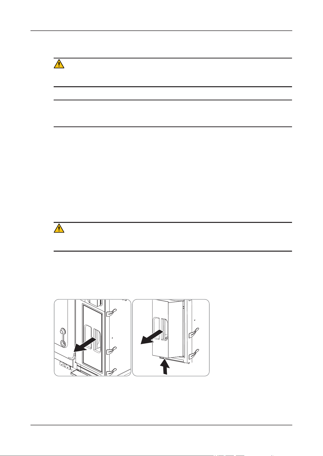
19 Care and Cleaning
19 - 3
19.4 Cleaning the Water Tank
WAR N I N G
Ensure that there is no patient inside the device before performing the operation.
NOTE
Recommended descaling solution: food-grade citric acid.
It is necessary to regularly remove water scale to ensure optimal performance of the humidification
function.
•Enter Environment Maintenance > Water Tank menu, and follow the instructions on the screen
to perform the descaling procedure.
• It is recommended to perform the descaling procedure every 6 months. You can adjust the interval
based on your local water quality conditions.
19.5 Cleaning the Sponge Filter
WAR N I N G
Ensure that there is no patient inside the device before performing the operation.
ViCare U7
Perform the following procedure:
1. Remove the CO
2
absorber canister:
1. Hold the handle of the CO
2
absorber canister and pull it out partially.
2. Support the bottom of the CO
2
absorber canister and pull it out completely.
2. Remove the upper cover of the CO
2
absorber canister and take out all soda lime.
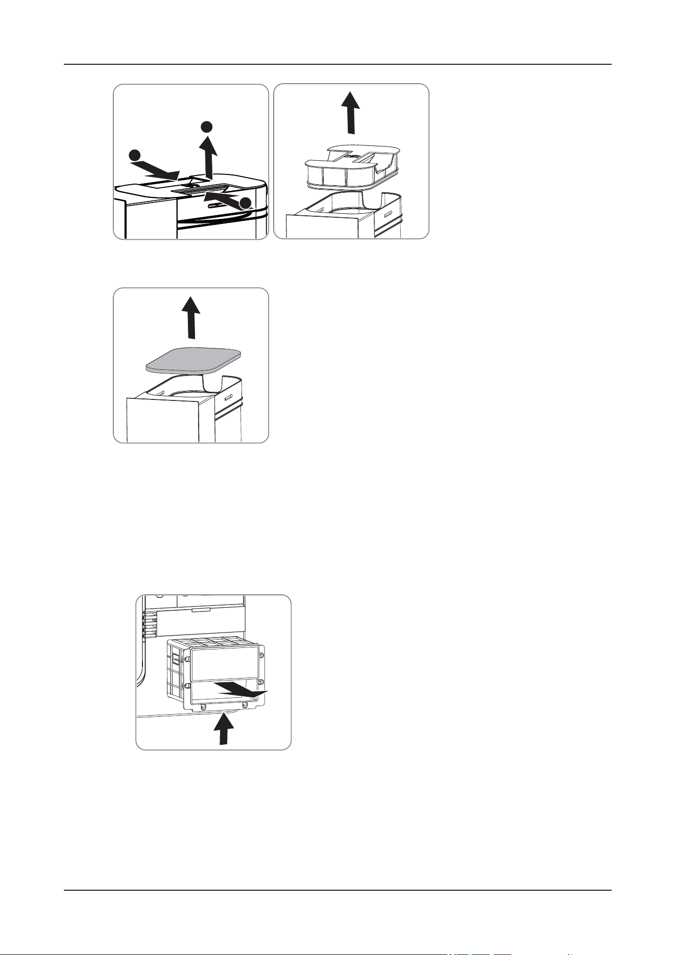
19 Care and Cleaning
19 - 4
3. Take out the sponge filter.
4. Use water or soft brush to clean the sponge filter. If necessary, replace the sponge filter.
5. Install the sponge filter in the reversed steps above after the cleaning.
ViCare U7R/ViCare U7L
Perform the following procedure:
1. Remove the CO
2
absorber canister:
1. Hold the handle of the CO
2
absorber canister and pull it out partially.
2. Support the bottom of the CO
2
absorber canister and pull it out completely.
2. Remove the upper cover of the CO
2
absorber canister.
1. Loosen the retaining ring on the upper cover of the CO
2
absorber canister.
A
A
B
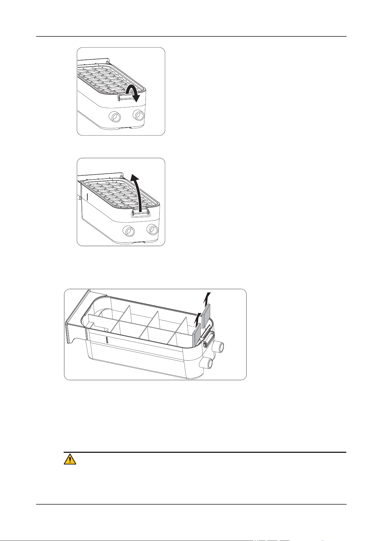
19 Care and Cleaning
19 - 5
2. Remove the upper cover in the direction of the arrow.
3. Take out all soda lime.
4. Take out the two sponge filters.
5. Use water or soft brush to clean the sponge filters. If necessary, replace the sponge filters.
6. Install the sponge filters in the reversed steps above after the cleaning.
19.6 Cleaning Dust-Proof Meshes and Filters
CAUTION
• Clean all dust-proof meshes and filters on a regular basis (once a month) to avoid damage. When
using in dusty locations, increase the cleaning times.
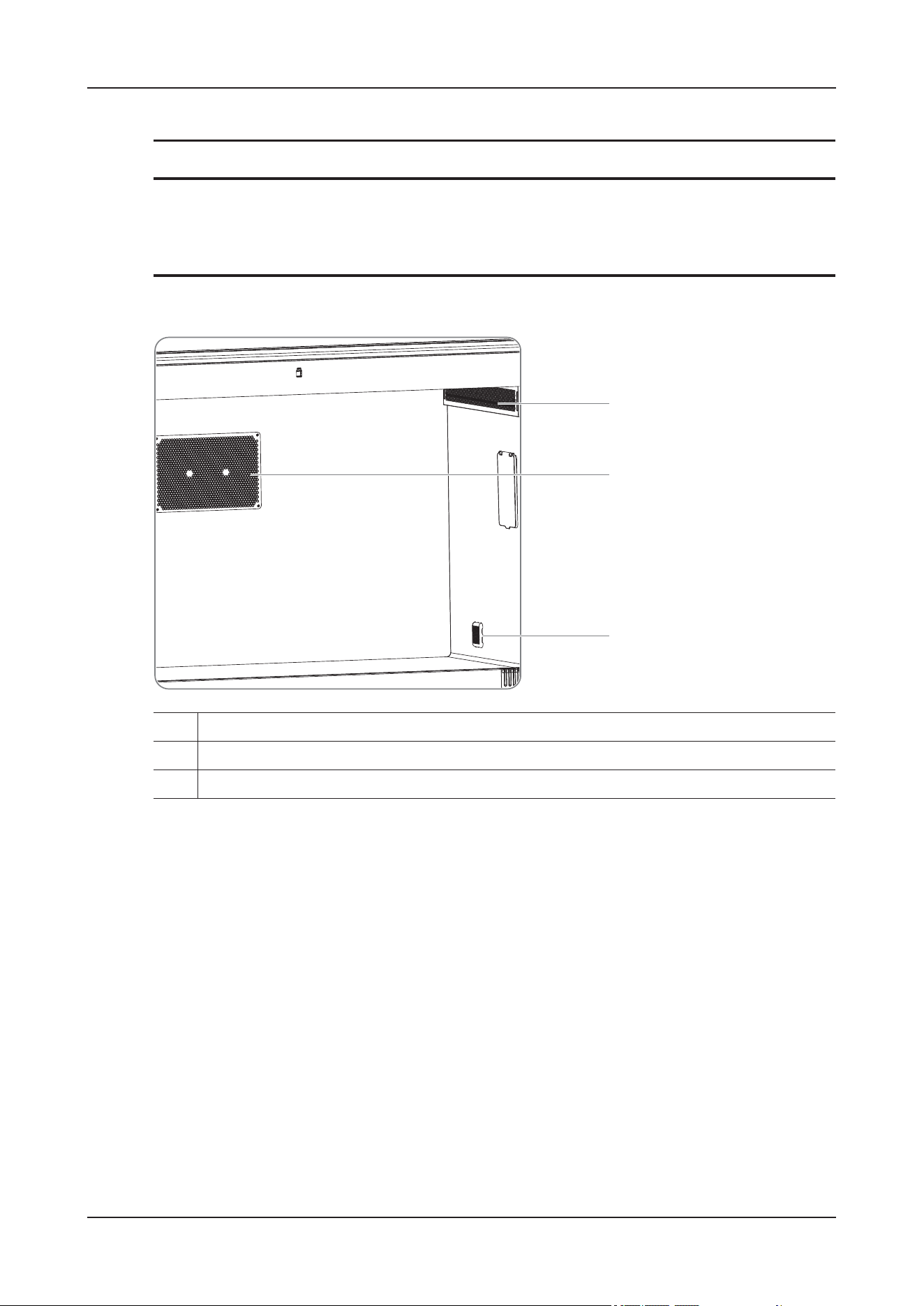
19 Care and Cleaning
19 - 6
• Ensure that there is no patient inside the device before performing the operation.
TIP
Dust-proof meshes are located in different positions based on the different models, but the cleaning
procedures are the same.
Figure 19-1 Inner dust-proof meshes
1. At Internal Circ. Duct(Both sides)
2. At A/C 1
3. At CO2 Duct
1
2
3
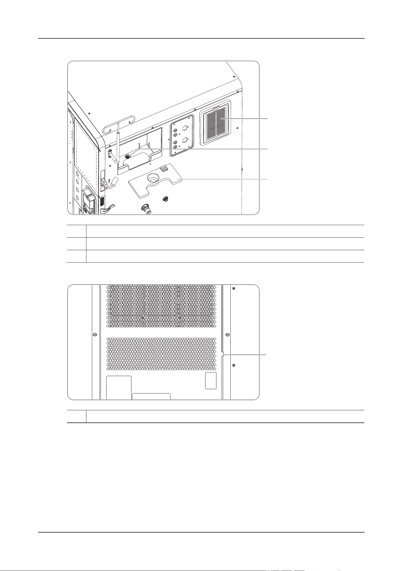
19 Care and Cleaning
19 - 7
Figure 19-2 Side filters
Figure 19-3 Rear A/C dust-proof mesh
At Internal Circ. Duct
Perform the following procedure:
1. Remove the dust-proof mesh:
1. At Dehumidifier
2. Water tank filter
3. Water tank bracket
1. Dust-proof mesh at the external circulation
1
2
3
1
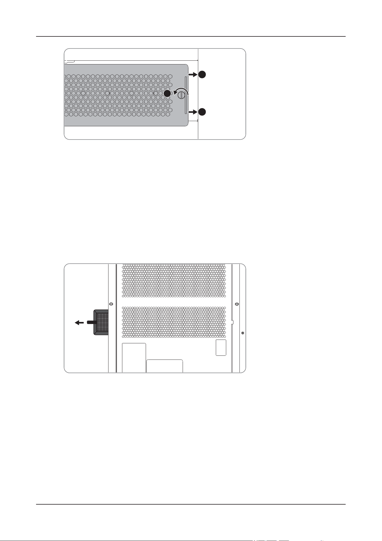
19 Care and Cleaning
19 - 8
1. Loosen the retaining screw counterclockwise.
2. Drag the dust-proof mesh towards the cabin door to remove it.
2. Clean the dust-proof mesh. If necessary, replace the sponge filter.
3. Install the dust-proof mesh in the reversed steps above after the cleaning.
Dust-proof mesh at the external circulation
Perform the following procedure:
1. Remove the dust-proof mesh:
Hold the handle of the dust-proof mesh and pull it out horizontally towards the side of the touch screen.
2. Clean the dust-proof mesh. If necessary, replace the dust-proof mesh.
3. Install the dust-proof mesh in the reversed steps above after the cleaning.
At CO2 Duct
Perform the following procedure:
1. Use a screwdriver to remove the retaining screws.
2
2
1
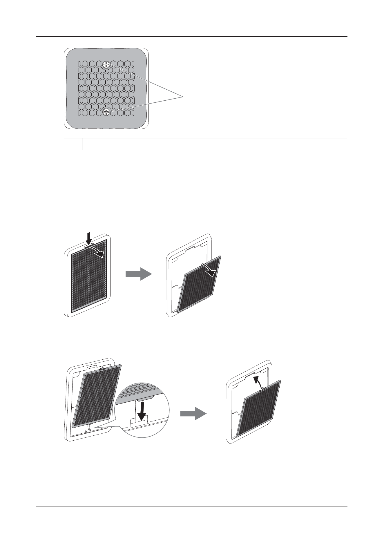
19 Care and Cleaning
19 - 9
2. Clean the dust-proof mesh. If necessary, replace the sponge filter.
3. Install the dust-proof mesh in the reversed steps above after the cleaning.
At Dehumidifier
Perform the following procedure:
1. Press the buckle of the dust-proof mesh downwards, and turn the dust-proof mesh outward to remove it.
2. Use water or soft brush to clean the dust-proof mesh. If necessary, replace the sponge filter.
3. Install the dust-proof mesh in the reversed steps above after the cleaning.
Water Tank Filter
Perform the following procedure:
1. Hold the water tank handle and lift it up, and then pull the water tank out horizontally.
1. Retaining screw (x2)
1
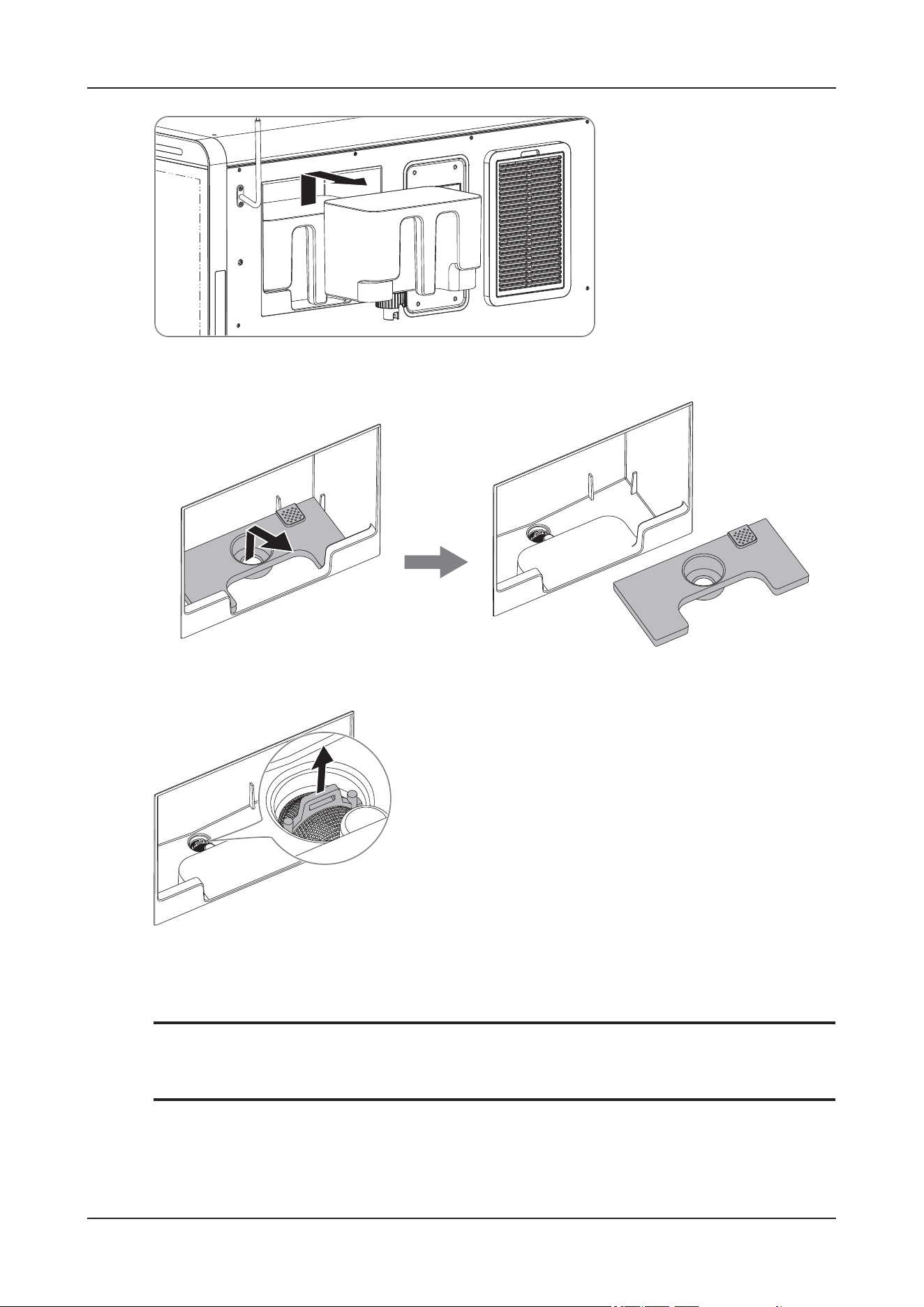
19 Care and Cleaning
19 - 10
2. Follow the arrow direction below to remove the water tank bracket.
3. Pull the filter upwards to remove it.
4. Use water or soft brush to clean the filter mesh.
5. Install the dust-proof mesh in the reversed steps above after the cleaning.
NOTE
Do not install the filter reversely.
At A/C 1 (Internal)
Perform the following procedure:
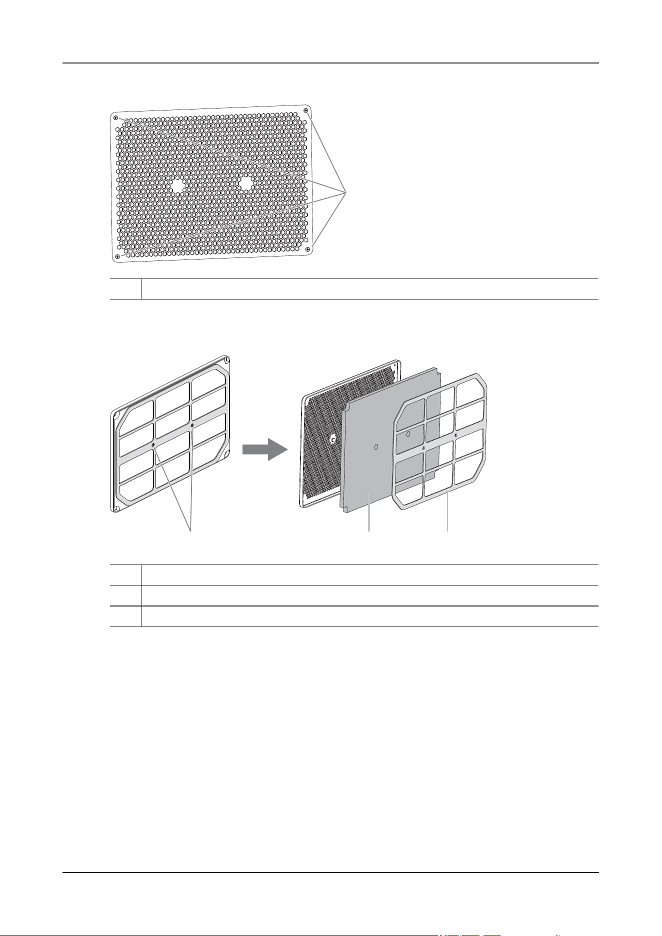
19 Care and Cleaning
19 - 11
1. Use a screwdriver to remove the retaining screws.
2. Use a screwdriver to remove the retaining screws of the sponge filter bracket, and then remove the
sponge filter bracket and sponge filter in turn.
3. Use water or soft brush to clean the dust-proof mesh. If necessary, replace the sponge filter.
4. Install the dust-proof mesh in the reversed steps above after the cleaning.
Front Dust-proof Mesh (ViCare U7L/ViCare U7R)
Perform the following procedure:
1. Use a screwdriver to press the buckle and pull the dust-proof mesh outward to remove it.
1. Retaining screw (x4)
1
1. Retaining screw (x2)
2. Sponge filter
3. Sponge filter bracket
123
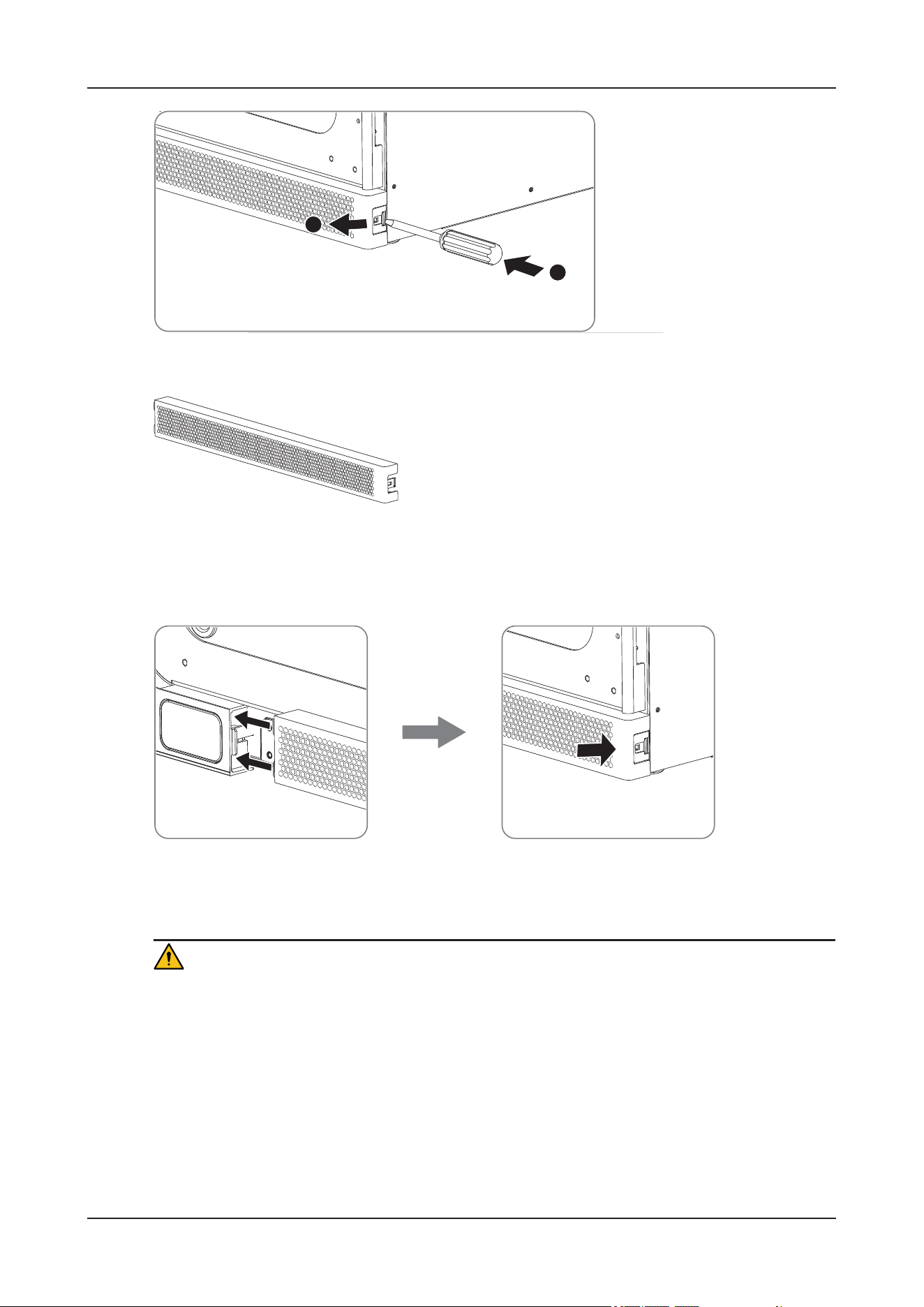
19 Care and Cleaning
19 - 12
2. Use water or soft brush to clean the dust-proof mesh.
3. Restore the dust-proof mesh.
Insert the tenons of the dust-proof mesh into the slot, press the other end to lock the dust-proof mesh in
place.
19.7 Cleaning and Disinfecting Accessories
CAUTION
• When cleaning or disinfecting the NIBP air hose, prevent liquid from entering the hose.
• Periodically inspect the NIBP air hose and connector for signs of wear or deterioration after
cleaning or disinfecting the NIBP air hose. Replace the NIBP air hose if you detect a leak. Dispose
of damaged NIBP air hose according to local laws for disposal of hospital waste.
• Never immerse or soak the accessories in any liquid.
• Never clean or disinfect the connectors and metal parts.
• Use only Mindray Animal Medical approved cleaners and disinfectants and methods listed in this
section to clean or disinfect the accessories. Warranty does not cover damage caused by unapproved
A
B
19 Care and Cleaning
19 - 13
substances or methods. To avoid long term damage, the accessories should be disinfected only when
necessary as determined by your hospital’s policy.
Clean and disinfect the NIBP hose using the methods recommended in this section. For other
accessories, you should consult the instructions delivered with the accessories.
19.7.1 Cleaning
You should clean the NIBP hose on a regular basis. Before cleaning, consult your hospital’s regulations.
Perform the following procedure:
1. Clean the accessories with a soft cloth moistened with water or ethanol (70%).
2. Wipe off all the cleaner residue with a dry cloth.
3. Allow the accessories to air dry.
19.7.2 Disinfecting
We recommend that the NIBP hose should be disinfected only when necessary as determined by your
hospital’s policy. Cleaning the NIBP hose before disinfecting is recommended.
Disinfectants for the NIBP Air Hose
The following table lists approved disinfectants for the NIBP air hose:
19.8 Cleaning and Disinfecting Wireless Modules and
Chargers
19.8.1 Cleaning Wireless Modules
CAUTION
Any contact of cleaners or disinfectants with connectors or metal parts may cause corrosion. If
necessary, you can clean the connectors and metal parts with a soft cloth moistened with water or
ethanol.
Perform the following procedure:
1. Remove the sensor, electrode pads and NIBP cuff from the animal.
Name Type Manufacturer
Ethanol, 70% Liquid /
Isopropanol, 70% Liquid /
Glutaraldehyde, 2% Liquid /

19 Care and Cleaning
19 - 14
2. Remove the wireless modules.
3. Dampen a soft lint-free cloth with water or ethanol (70%), and wring excess liquid from the cloth.
4. Wipe the display screens of the SpO
2
module and NIBP module.
5. Wipe the outer surface of the wireless modules and all accessories.
When wiping, avoid the connectors and metal parts.
6. Dry the surface with a clean cloth. Allow the device air dry in a ventilated and cool place.
19.8.2 Cleaning the Chargers
WAR N I N G
Disconnect the chargers from the power supply before cleaning.
Perform the following procedure:
1. Disconnect the chargers from the power supply. Take out the wireless modules or batteries of the NIBP
module from the charging slots.
2. Dampen a soft lint-free cloth with water or ethanol (70%), and wring excess liquid from the cloth.
3. When wiping, avoid the connectors and metal parts.
4. Dry the surface with a clean cloth. Allow the device air dry in a ventilated and cool place.
19.8.3 Cleaning the Receiver
Perform the following procedure:
1. Remove the receiver from the module slot of the device.
2. Dampen a soft lint-free cloth with water or ethanol (70%), and wring excess liquid from the cloth.
3. Wipe the outer surface of the receiver.
When wiping, avoid the connectors and metal parts.
4. Dry the surface with a clean cloth. Allow the device air dry in a ventilated and cool place.
19.8.4 Disinfecting
Disinfect wireless modules, chargers and accessories as required in your hospital’s servicing schedule.
Cleaning before disinfecting is recommended. Always dilute and use disinfectants according to the
manufacturer's instructions.

19 Care and Cleaning
19 - 15
Approved disinfectants
Table 19-1 Disinfectants for SpO
2
module, ECG module, NIBP module, and receiver
Name Type Manufacturer
1-Propanol, 50% Liquid /
Alpet
®
D2 Surface Sanitizing Wipes Wipes BEST SANITIZERS INC™.
CIDEXR OPA Solution Liquid Gilag GmbH International Advanced
Sterilization products
Clorox Dispatch® Hospital Cleaner
Disinfectant Towels with Bleach
Wipes CClorox professional products company
Clorox Healthcare
®
Bleach germicidal
wipe
Wipes CClorox professional products company
Clorox Healthcare® Hydrogen Peroxide
Cleaner Disinfectant Wipes
Wipes Clorox professional products company
Diversey Oxivir® TB Wipes Wipes Diversey Inc
Hydrogen peroxide, 3% Liquid /
Isopropanol, 70% Liquid /
Metrex CaviCide1™ Liquid, spray METERX® RESEARCH
Metrex CaviWipes™ Wipes METERX® RESEARCH
PDI Sani-Cloth® AF3 Germicidal
Disposable Wipe
Wipes PDI Inc.
PDI Sani-Cloth® Bleach Germicidal
Disposable Wipe
Wipes PDI Inc.
PDI Sani-Cloth® HB Germicidal
Disposable Wipe
Wipes PDI Inc.
PDI Sani-Cloth® Plus Germicidal
Disposable Cloth
Wipes PDI Inc.
PDI Super Sani-Cloth® Germicidal
Disposable Wipe
Wipes PDI Inc.
Perform® Classic Concentrate OXY,
0.5%
Powder Schülke & Mayr GmbH
Rely+On™ Virkon® High Level surface
Disinfectant, 1%
Powder Antec International Ltd
Sodium hypochlorite bleach, 0.5% Liquid /
Virex® II 256 (1:256) Liquid Diversey Inc
Virex® TB Liquid, spray Diversey Inc
HEALTH ESSENCE Disinfecting
Effervescent Tablets
Tablet Beijing ChangJiangMai Medical
Science Technology Co. Ltd
Environmental Surface of Health
Essence brand Disinfectant
Liquid, spray Beijing ChangJiangMai Medical
Science Technology Co. Ltd
JIAN ZHI SU Disinfectant, Double-
chain Quaternary Ammonium
Liquid Beijing ChangJiangMai Medical
Science Technology Co. Ltd

19 Care and Cleaning
19 - 16
DIAN’ERKANG® Surface Wipes Wipes Shanghai Likang Disinfectant Hi-Tech
Co., Ltd
DIAN’ERKANG® Surface Disinfectant Liquid Shanghai Likang Disinfectant Hi-Tech
Co., Ltd
DIAN’ERKANG® Disinfectant Spray Liquid, spray Shanghai Likang Disinfectant Hi-Tech
Co., Ltd
Clinell® Universal Wipes Wipes GAMA Healthcare Ltd
Clinell ® Sporicidal Wipes Wipes GAMA Healthcare Ltd
Tristel Duo™ Liquid, foam Tristel solutions Limited
Tristel Jet Liquid, spray Tristel solutions Limited
Tristel Fuse For Surfaces, 196ppm Liquid Tristel solutions Limited
Surfanios Premium, 0.25% Liquid ANIOS LABORATORIES
Surfa 'safe Liquid, spray ANIOS LABORATORIES
Wip' Anios premium Wipes ANIOS LABORATORIES
Aniosurf ND premium, 0.25% Liquid ANIOS LABORATORIES
Mikrobac® Tissues Wipes BODE Chemie GmbH
Cleanisept® Wipes Wipes Dr. Schumacher GmbH
mikrozid® PAA Wipes Wipes Schülke & Mayr GmbH
mikrozid® Sensitive Wipes Wipes Schülke & Mayr GmbH
Ethanol, 70% Liquid /
Glutaraldehyde, 2% Liquid /
Ecolab Incidin® OxyWipe S. Wipes Ecolab Deutschland GmbH
Descosept® forte Liquid Dr. Schumacher GmbH
Descosept® AF Liquid Dr. Schumacher GmbH
Dismozon® plus, 0.4% Powder BODE Chemie GmbH
mikrozid® AF Wipes Wipes Schülke & Mayr GmbH
Terralin® Liquid Liquid Schülke & Mayr GmbH
Table 19-2 Disinfectants for the Temp module
Name Type Manufacturer
Ethanol, 75% Liquid /
Isopropanol, 70% Liquid /
Soap and water Liquid /
X5 disinfectant Liquid /
Dupont Vecna Liquid Antec International Ltd
Table 19-1 Disinfectants for SpO
2
module, ECG module, NIBP module, and receiver
Name Type Manufacturer

19 Care and Cleaning
19 - 17
19.9 Sterilization
Do not sterilize the device, accessories, or supplies unless otherwise specified in the instructions for use
delivered with the accessories and supplies.
19.10 Impact of Improper Cleaning
Using cleaners other than those recommended may have the following impact:
• Product discoloration
• Metal part corrosion
• Brittle and breaking wires, connectors, and device housing
• Reduced cable and leadwire life
• Overall system performance degradation
• Device malfunction or failure
Table 19-3 Disinfectants for chargers
Name Type Manufacturer
Ethanol, 70% Liquid /
1-Propanol, 50% Liquid /
Isopropanol, 70% Liquid /
Sodium hypochlorite bleach,
0.5%
Liquid /
Hydrogen peroxide, 3% Liquid /
Rely+On™ Virkon® High Level
surface Disinfectant, 1%
Powder Antec International Ltd
Descosept® forte Liquid Dr. Schumacher GmbH
Dismozon® plus, 0.4% Powder BODE Chemie GmbH
mikrozid® AF Wipes Wipes Schülke & Mayr GmbH
Terralin® Liquid Liquid Schülke & Mayr GmbH
Perform® Classic Concentrate
OXY, 0.5%
Powder Schülke & Mayr GmbH

20 Maintenance
20 - 1
20 Maintenance
20.1 Overview
Regular maintenance is essential to ensure that the device functions properly. This chapter contains
information on periodic testing and maintenance.
20.2 Safety Information
WAR N I N G
• Follow the maintenance and testing schedule or local regulations to perform testing and
maintenance. Not implementing the maintenance schedule may cause device failure and possible
health hazards.
• No modification of this device is allowed.
• This device contains no user serviceable parts. If maintenance is required, contact the Customer
Service Department or your distributor.
• The safety checks or maintenance involving any disassembly of the device should be performed by
professional service personnel. Otherwise, undue device failure and possible health hazards could
result.
• Do not open batteries, heat batteries to above 60 °C, incinerate batteries, or short the battery
terminals. Batteries may ignite, explode, leak or heat up, causing personal injury.
• The service personnel must be properly qualified and thoroughly familiar with the operation of the
device.
• To avoid electric shock, stop using the pump if you find the housing of the pump has signs of
broken. Contact the Customer Service Department or your distributor for help in that case.
CAUTION
• If a problem occurs to the device, contact the Customer Service Department or your local
distributor.
• Use and store the device within the specified temperature, humidity, and elevation ranges.
• When disposing of the packaging material, be sure to observe the applicable waste control
regulations and keep it out of children’s reach.

20 Maintenance
20 - 2
• At the end of its service life, the device, as well as its accessories, must be disposed of in compliance
with the guidelines regulating the disposal of such products. If you have any questions concerning
disposal of the device, contact the Customer Service Department or your local distributor.
• The device and its accessories shall not be served or maintained while in use with an animal.
• If you discover a problem with the device, such as the product label falls off or illegible, contact the
Customer Service Department or your local distributor.
NOTE
If necessary, contact the Customer Service Department or your distributor for the circuit diagram, list of
parts and calibration instructions of products or other information related to device maintenance.
20.3 Maintenance and Testing Schedule
Follow the maintenance and testing schedule or local regulations to perform testing and maintenance.
Make sure to clean and disinfect the device before taking any tests and maintenance.
The following table lists the maintenance and testing schedule:
Test/Maintenance Item Recommended Frequency
Performance Tests Visual inspection Every day, before first use.
Measurement module
performance test and
calibration
• If you suspect that the measurement values are
incorrect.
• Follow any repairs or replacement of relevant
module.
• Once every 2 years for other parameter module
performance tests.
Analog output test If you suspect that the analog output function does not
work properly.
Tests required by IEC
60601-2-24
• Once every 3 years.
• When you suspect that the occlusion alarm is
abnormal.
• When you suspect that the rate is abnormal.
Electrical Safety
Tests
Electrical safety tests
required by IEC 60601-1
• When the power board is repaired or replaced.
• When the main board is replaced, or the device drops
to the ground.
• Once every 3 years or as necessary.

20 Maintenance
20 - 3
20.4 Testing Methods and Procedures
Except the following maintenance tasks, all other test and maintenance tasks should be performed by
Mindray Animal Medical-qualified service personnel only.
• Regular check, including visual inspection and power-on test
• Printer and recorder tests
• Battery check
If your device needs a safety test and performance test, contact the Customer Service Department or your
local distributor.
20.4.1 Performing Visual Inspection
Visually inspect the device before its first used every day. If you find any signs of damage, remove the
device from use and contact the Customer Service Department or your local distributor.
Verify that the device meets the following requirements:
• Environment and power supply specifications are met.
• The device housing and display screen are free from cracks or other damages.
• The power cord is not damaged and the insulation is in good condition.
• Connectors, plugs, and cables are not damaged and kinked.
• Power cord and other cables are securely connected with the device and modules.
Other Tests Power-on test Before use.
Network printer tests • When first installed.
• Follow any repair or replacement of the printer.
Battery check for wireless
monitoring modules
Functionality test:
• When first installed.
• When battery is replaced.
Every three months or if the battery runtime reduced
significantly.
Pressure calibration, and
accuracy calibration, see
the service manual.
If the performance test fails.
Oxygen sensor
calibration
Oxygen concentration
sensor
Once every year or as necessary
CO
2
concentration sensor Every month or as necessary
On-demand Soda lime in the canister If the soda lime color changes, replace the soda lime in
the canister.
Gas supply hose Replace the delivered gas hose if it is damaged.
Hose assembly for
oxygen
Replace the oxygen supply hose if it is damaged.
Test/Maintenance Item Recommended Frequency

20 Maintenance
20 - 4
20.4.2 Performing Power-on Test
The device automatically performs a selftest at startup.
Check the following items for the power-on test:
• The device powers on properly.
• The alarm system works properly.
• The device displays properly.
20.4.3 Testing the Network Printer
To check the printer, follow this procedure:
1. Start a printing task to print waveforms and reports.
2. Check that the printer is properly connected and functions correctly.
3. Check that the printout is clear without missing dots.
20.4.4 Maintaining the Battery
NOTE
• Do not use the device to the animal during battery conditioning.
• Do not interrupt battery conditioning.
• If the battery is not conditioned for a prolonged time, its charge indication may not be accurate and
you may wrongly evaluate the remaining battery runtime.
• Perform the battery performance check as described in this section. The operating time of the battery
reflects their performance directly. If the operating time of a battery is noticeably shorter than that
stated in the specifications, the battery may reach its service life or malfunction, contact the
Customer Service Department or your local distributor.
• You should check the battery performance every three months or if you doubt that the battery may
fail.
• The stored batteries should also be conditioned periodically.
• You should check the battery performance if you doubt that the battery may fail.
For detailed information about battery conditioning, contact the Customer Service Department or your
distributor.
Recycling Batteries
Discard a battery in the following situations:
• The battery has visual signs of damage.
• The battery fails.
• The battery is aged and its runtime significantly less than the specification.
• The battery service life is reached.
Properly dispose of batteries according to local regulations.

20 Maintenance
20 - 5
20.5 Disposing of the device
WAR N I N G
Unless otherwise specified, dispose of parts and accessories in accordance with local regulations
regarding disposal of hospital waste.
Dispose of the device and its accessories when its service life is reached. Follow local regulations
regarding the disposal of such product.

A Accessories
A - 1
A Accessories
The accessories listed in this chapter comply with the requirements of IEC 60601-1-2 when in use with
this device. For detailed information about accessories, see the related instructions.
WAR N I N G
• Use accessories specified in this manual. Using other accessories may cause damage to the device or
not meet the claimed specifications.
• The listed accessories must be used together with the specified device. Before usage, read the
operator’s manual of the device (including accessories) or contact the Customer Service Department
or your local distributor to ensure that the accessories and the device can be safely used together.
Otherwise, the animal may be injured.
• Single use accessories are not designed to be reused. Reuse may cause a risk of contamination and
affect the measurement accuracy.
CAUTION
• The accessories may not meet the performance specifications if stored or used outside the specified
temperature and humidity ranges. If accessory performance is degraded due to aging or
environmental conditions, contact the Customer Service Department or your local distributor.
• Check the accessories and their packages for any sign of damage. Do not use them if any damage is
detected.
• Use the accessories before the expiry date if their expiry date is indicated.
• The disposable accessories shall be disposed of according to hospital's regulations.
NOTE
• For accessories with a safe service life, see the accessory package.
• For sterilization accessories, see the accessory package.
A Accessories
A - 2
A.1 ECG Accessories
A.2 SpO
2
Accessories
Wavelength emitted by the sensors is between 600 nm and 1000 nm. The maximum photic output
consumption of the sensor is less than 18 mW.
The information about the wavelength range and maximum photic output consumption can be especially
useful to clinicians, for example, when photodynamic therapy is performed.
A.3 NIBP Accessories
Name Model Description Type
Trunk cable EA6433B 3-lead ECG cable, AHA,
Snap
Reusable
EA6434B 3-lead ECG cable, IEC,
Snap
Reusable
ECG electrodes EB6903 Alligator Clip, Vet Reusable
H124SG ECG Electrode Disposable
Name Model Description Type
SpO
2
sensor 553V Veterinary SpO
2
Sensor
(Reusable, Wrap)
Reusable
551B Veterinary SpO
2
Sensor
(Reusable, 2-Clips)
Reusable
Name Model Description Type
NIBP hoses CMA94 Vet NIBP hoses Reusable
A Accessories
A - 3
A.4 Temp Accessories
A.5 Wireless Monitoring Modules
NIBP cuff CMA01 Vet NIBP Cuff 1#, Vet
(CMA01 Vet, 3.1-5.7cm)
Disposable
CMA02 Vet NIBP Cuff 2#, Vet
(CMA02 Vet, 4.3-8.0
cm)
CMA03 Vet NIBP Cuff 3#, Vet
(CMA03 Vet, 5.8-10.9
cm)
CMA04 Vet NIBP Cuff 4#, Vet
(CMA04 Vet, 7.1-
13.1cm)
CMA05 Vet NIBP Cuff 5#, Vet
(CMA05 Vet, 8-15cm)
CMA06 Vet NIBP Cuff 6#, Vet
(CMA06 Vet, 10-17cm)
NIBP cuff CMA11 Vet NIBP Cuff 1#, Vet
(CMA11 Vet, 15-20 cm)
Reusable
CMA12 Vet NIBP Cuff 2#, Vet
(CMA12 Vet, 19-25 cm)
CMA13 Vet NIBP Cuff 3#, Vet
(CMA13 Vet, 24-32 cm)
CMA14 Vet NIBP Cuff 4#, Vet
(CMA14 Vet, 32-42 cm)
CMA15 Vet NIBP Cuff 5#, Vet
(CMA15 Vet, 42-50 cm)
Name Model Description Type
Name Model Description Type
Temperature probe MRA405V Reusable Temp Probe,
0.5 m, Vet
Reusable
Name Model Description
SpO
2
module MAS30 Used for ECG, HR, Resp, Temp,
SpO
2
, and PR monitoring
Temp module MAT30
ECG module MAE30
NIBP module MAB30 Used for NIBP measurement
A Accessories
A - 4
A.6 Other Accessories
Receiver module R20 Receives the monitoring data and
transmits to the device
Chargers C10 Used for charging the battery of
the NIBP module
C25 Used for charging the built-in
batteries of the SpO
2
module and
ECG module
Name Model Description
No. Description
1. C10 charger
2. Protective pouch for SpO
2
module
3. Protective pouch for ECG module
4. Oxygen source hose material pack
5. Hose assembly for oxygen
6. Curtains
7. Vet Harness for ICU
8. Portable storage bag for wireless monitoring modules
9. Nebulizer Cup Set, 8ml
10. NIBP module rear panel
11. 8 Inch IV stand arm
12. 32A Leakage current breaker
13. USB Flash Drive 32GB USB3.0

B Product Specifications
B - 1
B Product Specifications
B.1 Safety Specifications
B.2 Environmental Specifications
CAUTION
The device may not meet the performance specifications if stored or used outside the specified
temperature and humidity ranges. If the performance of the device is degraded due to aging or
environmental conditions, contact the Customer Service Department or your local distributor.
Type of protection against electrical shock Class I
Degree of protection against electrical shock Type CF defibrillation proof for ECG, TEMP,
SpO
2
, NIBP
Type BF defibrillation proof for others
Degree of protection against harmful ingress of
water
Main unit: IPX0
According to the disinfection and sterilization
method(s) recommended by manufacturer
The devices recommended by the manufacturer
Degree of safety of application in the presence of
flammable anesthetic mixture with air or with
oxygen or nitrous oxide
The device is not suitable for use in the presence of
a flammable anesthetic mixture with air or with
oxygen or nitrous oxide
Mode of operation Continuous
The device equipped with the applied part of
defibrillation protection
Yes
Permanently installed or non-permanently installed Permanently installed
According to the installation and use Fixed device

B Product Specifications
B - 2
NOTE
The environmental specifications of unspecified parameter modules are the same as those of the main
unit.
Main Unit
Wireless Monitoring Modules
The wireless monitoring modules include the SpO
2
module, Temp module, ECG module and NIBP
module.
B.3 Main Unit
B.3.1 Power Supply Specifications
External Power Supply Specifications (ViCare U7)
Item Temperature Relative humidity (no
condensation)
Atmospheric pressure
Operating condition 10ႏ to +35ႏ 30% to 95% 525 mmHg to 805.5
mmHg (70.0 kPa to
107.4 kPa)
Storage Condition -20ႏ to +60ႏ 10% to 95% 120 mmHg to 805.5
mmHg (16.0 kPa to
107.4 kPa)
Item Temperature Relative humidity (no
condensation)
Atmospheric pressure
Operating condition 0ႏ to +40ႏ 15% to 95% 427.5 mmHg to 805.5
mmHg (57.0 kPa to
107.4 kPa)
Storage Condition -20ႏ to +60ႏ 10% to 95% 120 mmHg to 805.5
mmHg (16.0 kPa to
107.4 kPa)
Item Description
Input voltage 200-240V AC
Input current 17A
Frequency 50/60Hz
B Product Specifications
B - 3
External Power Supply Specifications (ViCare U7L/ViCare U7R)
B.3.2 Battery Specifications
B.3.3 AC Power Auxiliary Outputs
B.3.4 Physical Specifications
ViCare U7
ViCare U7L/ViCare U7R
Item Description
Input voltage 200-240V AC
Input current 14.5A
Frequency 50/60Hz
Item Description
Number of batteries 1
Battery type Lithium battery
Rated battery voltage 10.95 V
Battery capacity 5000 mAh
Minimum battery run time 150 minutes (a new and fully-charged battery when working
continuously at a temperature of 20ႏ±2ႏ, default brightness and
volume, infusion pump flow rate is 25 ml/h)
Item Description
Input voltage 200V-240V AC
Input current 2A
Frequency 50/60Hz
Item Description
Dimensions (W x H x D) Width 1200 mm, depth 600 mm, height 700 mm
Weight 200 kg
Item Description
Dimensions (W x H x D) Width 640 mm, depth 600 mm, height 500 mm
Weight 150 kg
B Product Specifications
B - 4
B.3.5 Hardware Specifications
Display
LEDs
Audio Indicator
Interface Specifications
Item Description
Screen type Color touchscreen
Screen Size 12.1 inches
Resolution 1280 pixels x 800 pixels
Item Description
Alarm lamp 1 or 2 (three color-coded: red, yellow, and cyan)
Power-on LED 1 (green)
AC power LED 1 (green)
Battery LED 1 (two color-coded: yellow and green)
Item Description
Speaker Give alarm tones (45 to 85 dB), reminder tones, key tones, QRS
tones; support PITCH TONE and multi-level tone modulation.
Alarm tones comply with IEC 60601-1-8.
Item Description
AC Power Auxiliary Outputs Alternative current auxiliary outputs (x2)
Network connector 1, standard RJ45 connectors, 100 Base-TX, IEEE 802.3
USB connector 2, USB 2.0
Multifunctional connector 1
Video output connector 1, 15-pin D-sub
B Product Specifications
B - 5
B.3.6 Data Storage
B.3.7 Wi-Fi Specifications
Wi-Fi Technical Specifications
Item Description
Trends Internal card:
• Up to 120 hours of trend data with the resolution no less than 1
minute
• Up to 4 hours of trend data with the resolution no less than 5
seconds
External card:
Up to 120 hours of trend data with the resolution no less than 1 minute
Events • Internal card: 1000 events
• External card: 5000 events
• 128 arrhythmia events
NIBP measurements • Internal card: 1600 sets
• External card: 5000 sets
Full-disclosure waveforms Up to 48 hours for one waveform.
ST view At least 120 hours of ST segment waveforms. One group of ST
segment waveforms is stored every 5 minutes.
Item Description
Protocol IEEE 802.11a/b/g/n/ac
Modulation mode BPSK, QPSK, 16QAM, 64QAM, 256QAM
Operating frequency 2412 MHz to 2472 MHz
5180 MHz to 5320 MHz
5500 MHz to 5700 MHz
5745 MHz to 5825 MHz
Wireless data rate IEEE 802.11a: 6 Mbps to 54 Mbps
IEEE 802.11b: 1 Mbps to 11 Mbps
IEEE 802.11g: 6 Mbps to 54 Mbps
IEEE 802.11n: MCS0 - MCS7
IEEE 802.11ac: MCS0 - MCS8
Output power < 20dBm (CE requirements, detection mode: RMS)
< 30dBm (FCC requirements, detection mode: peak power)
Operating mode As station, access AP for data transmission

B Product Specifications
B - 6
Wi-Fi Performance Specifications
WAR N I N G
Do perform all network functions of data communication within an enclosed network.
• System Capacity and Resistance to Wireless Interference
All the devices do not encounter communication loss and meet the following requirements:
– The total delay of data transmission from the device to the CMS: 2 seconds.
– The delay for device-related settings configured at the CMS to be effective: 2 seconds.
– The total delay of data transmission from one device to the other: 2 seconds.
– The delay for the device to reset alarms of another to be effective: 2 seconds.
Testing conditions are as follows:
– Number of the devices supported by a single AP: 16.
– Each device can communicate with the CMS.
– Only one device can transmit history data.
– The worst AP Signal Level value of the device is not less than -65 dBm.
– The distance between the interfering equipment and this device is greater than 20 cm. A Wi-Fi
interference (no greater than -85 dBm) in the same channel and a Wi-Fi interference (no greater
than -50 dBm) in an adjacent-channel are presented synchronously. The interfering devices
include, but are not limited to, 2.4G wireless devices, cellular mobile networks, microwave
ovens, interphones, cordless phones, and ESU equipment. The interfering devices do not
include Wi-Fi devices.
• Wi-Fi Network Stability
The ratio of the communication data loss on the CMS from any device does not exceed 0.1% over a
24-hour period.
Testing conditions are as follows:
– Number of the devices supported by a single AP: 16.
– Each device can communicate with the CMS.
– Only one device can transmit history data.
– The weakest strength of the AP signal where the device is located cannot be less than -65 dBm.
• Distinct Vision Distance
The distinct vision distance between the device and the AP is no less than to 50 meters.
Data security Standards: WPA-PSK, WPA2-PSK, WPA-Enterprise, WPA2-
Enterprise
EAP method: EAP-FAST, EAP-TLS, EAP-TTLS, PEAP-GTC,
PEAP-MSCHAPv2, PEAP-TLS, LEAP
Encryption: TKIP, AES
Item Description

B Product Specifications
B - 7
B.4 Wireless Monitoring Modules
B.4.1 Power Supply Specifications
SpO
2
Module (MAS30) Battery
Temp Module (MAT30) Battery
ECG Module (MAE30) Battery
Item Description
Battery type Rechargeable lithium-Ion battery, model LI21S001G
Run time At least 36 hours with a new and fully-charged battery when working
continuously at a temperature of 25±5ႏ and at the following
conditions: SpO
2
module is connected with the Temp module, and
paired with an ECG module that is connected with an ECG lead; the
beeper is not beeping; the screen is resting; the SpO
2
module is in
Bluetooth connection with an wireless receiver and works under
Wireless Monitoring mode
At least 72 hours with a new and fully-charged battery when working
at 25ºC±5ºC and at the following conditions: SpO
2
module is
connected with the Temp module, and paired with an ECG module
that is connected with an ECG lead
Charge time < 3 hours to 90% at 20ºC±5ºC
Shutdown delay At least 30 minutes after the low battery indication first occurs
Item Description
Battery type CR2032 coin battery
Run time At least 200 hours with a new coin battery
Item Description
Battery type Rechargeable lithium-Ion battery, model LI11S001G
Run time At least 72 hours with a new and fully-charged battery when working
at 25ºC±5ºC, with an ECG lead connected, and sending data
continuously to the SpO
2
module
Charge time < 3 hours to 90% at 20ºC±5ºC
Shutdown delay At least 30 minutes after the low battery indication first occurs on
SpO
2
module
B Product Specifications
B - 8
SpO
2
Module (MAB30) Battery
C10 Charger
Specification of C25 Charger
Receiver Module (R20)
The receiver is powered by the device after being properly installed to the module slot.
B.4.2 Physical Specifications
Item Description
Battery type Rechargeable lithium-Ion battery, model LP11I001E
Run time At least 600 NIBP measurements, when the NIBP module is powered
by a new fully-charged battery at 25ºC±5ºC
Charge time < 5 hours to 90% at 25ºC±5ºC
Shutdown delay At least 30 minutes after the low battery indication first occurs
Item Description
Input voltage 100-240V AC (±10%)
Input current 0.6A-0.3A
Frequency 50/60 Hz (±3 Hz)
Overcharge protection The charger stops charging automatically after the battery is fully
charged
Item Description
Input voltage 4.5V to 5.5V
Input current 0.7A
Output voltage 5V±5%
Module Model Weight Dimensions (W x H x D)
SpO
2
module MAS30 60 g 62mm x 50mm x 19mm
Temp module MAT30 60 g 75mm x 50mm x 30mm
ECG module MAE30 35 g 47mm x 47mm x 13mm
NIBP module MAB30 165 g 119mm x60mmx 19 mm (excluding the
air nozzle, back clip, and cuff accessories)
Receiver module R20 250 g 150mm x 50mm x 120mm
Chargers C10 1.5 kg 222 mm x 105mm x 68mm

B Product Specifications
B - 9
B.4.3 Hardware Specifications
Display
Interfaces
Data Storage
The SpO
2
module has the power-off storage function.
The SpO
2
module can store trend data of not less than 8 hours.
Signal Outputs
Alarm output (on the Device)
Chargers C25 < 165g 154.5mm x 78mm x 26.5mm
Module Model Weight Dimensions (W x H x D)
Module Item Description
SpO
2
Module (MAS30) Screen type LCD TFT screen
Screen size 1.54inches
Resolution 240 pixels x 240 pixels
Display Supports the display of one waveform
Supports multi-screen display, and press to switch
the screen
NIBP Module (MAB30) Screen type Black and white, untouchable
Screen size 2.4inches
Resolution 208 pixels x 360 pixels
Item Description
Power input Charger:
• C10: 1, AC power input
• C25: 1, standard USB Type-C connector
Data transmission interfaces Bluetooth, Wi-Fi and NFC interface
Item Description
Inherent delay time for
indicating the confirmed alarms
1s
Alarm delay time from the
device to remote equipment
The alarm delay time from the device to remote equipment is 2
seconds, measured at the device signal output connector.
Alarm signal sound pressure
level range
45 dB(A) to 85 dB(A) within a range of one meter
B Product Specifications
B - 10
Audio Indicator
B.4.4 Wi-Fi Specifications
Wi-Fi Specifications (SpO
2
module)
WMTS Specifications (SpO
2
Module)
Item Description
Audio signal Key tone: 1000 Hz
Pairing prompt tone: 4000 Hz
Item Description
Protocol IEEE 802.11a/b/g/n
Operating frequency 2412 MHz to 2472 MHz
5180 MHz to 5320 MHz
5500 MHz to 5700 MHz
5745 MHz to 5825 MHz
Data security Standards:
WPA/WPA2-PSK, WPA/WPA2-Enterprise
EAP Method
EAP-TLS, PEAP-MsCHAPv2, EAP-TTLS
Encryption TKIP and AES
Modulation mode BPSK, QPSK, 16-QAM, 64-QAM
Transmission power The average power is not greater than 20 dBm
Item Description
Protocol Private protocol
Operating frequency 608 MHz to 630 MHz
Modulation mode GFSK
Transmission power 10 dBm
Data security Private protocol
B Product Specifications
B - 11
Bluetooth Specifications
NFC Specifications
B.5 Measurement Specifications
Items marked with an asterisk symbol “*” are applicable only when the SpO
2
module is in Bluetooth
connection with this device.
Item Description
Protocol • SpO
2
/Temp module/ECG module/wireless receiving module:
Support Bluetooth 5
• NIBP module: Bluetooth low energy 4.0
Operating frequency 2402 MHz to 2480 MHz
Modulation mode GFSK
Transmission power < 10 mW
Data security Private protocol
Communication distance • ECG module and SpO
2
module: no less than 1.5m (line of sight
distance)
• NIBP module and SpO
2
module: no less than 1.5m (line of sight
distance)
• Wireless receiver module and SpO
2
module: no less than 7m (line
of sight distance)
Resistance to interference In a range of 100 m2, there should be no more than 10 groups of
paired SpO
2
modules, ECG modules, NIBP modules, and wireless
receivers working simultaneously.
The Bluetooth signal strength around the SpO
2
module should be no
less than -70 dBm.
The distance between the interfering devices and the SpO
2
module is
greater than 20 cm. The interfering devices include 2.4 GHz Wi-Fi
devices, cellular mobile networks, microwave ovens, intercoms, and
cordless phones.
Item Description
Protocol • SpO
2
module/Wireless receiver: ISO/IEC 14443 A; ISO/IEC
14443 B
• ECG module/NIBP module: ISO/IEC 14443 A
Operating frequency 13.56 MHz
Modulation mode ASK (SpO
2
module/Wireless receiver)
Data security Private protocol

B Product Specifications
B - 12
B.5.1 ECG Specifications
ECG
Item Description
Lead Set 3-lead: I, II, and III
ECG standard AHA, IEC
Display sensitivity • 1.25 mm/mV (x0.125), 2.5 mm/mV (x0.25), 5 mm/mV (x0.5), 10
mm/mV (x1), 20 mm/mV (x2), 40 mm/mV (x4), Auto, less than
5% error
• With ±800 mV direct current polarization voltage, the sensitivity
change is within ±5%
• The sensitivity change is 3% after 1 minute and 1 hour since the
device starts up.
Sweep speed 6.25 mm/s, 12.5 mm/s, 25 mm/s, 50 mm/s, less than ±5% error
Bandwidth (-3dB) • Monitor:
0.5 Hz to 40 Hz
• Surgery:
1 Hz to 20 Hz
• ST:
0.05 Hz to 40 Hz
Common mode rejection ratio • Monitor: >105 dB
• Surgery: >105 dB
• ST: >105 dB
Notch filter Monitor, Surgery, and ST: 50/60 Hz, notch filter turns on
automatically
Differential input impedance 5Mȍ
Input signal range ±10 mV (peak-to-peak value)
Electrode offset potential
tolerance
±800 mV
Input offset current 0.1 ȝA, (drive lead1ȝA)
Baseline recovery time <5s (after defibrillation)
Defibrillation protection and
recovery time
Enduring 5000V (360 J) charge without data loss or corruption
Baseline recovery time: <5s (after defibrillation)
Polarization recovery time: <10s
Defibrillation energy absorption: 10% (100ȍ load)
Patient leakage current <10 ȝA
0.4dB
3.0dB–
©¹
§·
0.4dB
3.0dB–
©¹
§·
0.4dB
3.0dB–
©¹
§·

B Product Specifications
B - 13
Pace Pulse
HR
Calibration signal 1mV (peak-to-peak value) ±5%
ESU protection In compliance with the requirements of IEC 60601-2-27.
• Cut mode: 300 W
• Coagulate mode: 100 W
• Recovery time: 10s
ESU noise rejection 2 mV (peak-to-peak value), use standard ECG leadwires, relative to
the ECG baseline
Item Description
Item Description
Pace pulse markers Pace pulses meeting the following conditions are labelled with a
PACE marker:
• Amplitude: ±2 mV to ±700 mV
• Width: 0.1 ms to 2 ms
• Rise time: 10 ȝs to 100 ȝs
Pace pulse rejection When tested in accordance with the IEC 60601-2-27, the heart rate
meter rejects all pulses meeting the following conditions:
• Amplitude: ±2 mV to ±700 mV
• Width: 0.1 ms to 2 ms
• Rise time: 10 ȝs to 100 ȝs
• No overshoot
Item Description
Measurement range 15 bpm to 350 bpm
Resolution 1 bpm
Accuracy ±1 bpm or ±1%, whichever is greater
HR averaging method In compliance with the requirements of IEC 60601-2-27.
The following method is used:
If the last 3 consecutive RR intervals are greater than 1200 ms, the 4
most recent RR intervals are averaged to compute the HR. Otherwise,
heart rate is computed by subtracting the maximum and minimum
ones from the most recent 12 RR intervals and then averaging them
The HR value displayed on the device screen is updated no more than
one second.

B Product Specifications
B - 14
ST Segment Analysis
Response to irregular rhythm In compliance with the requirements of IEC 60601-2-27.
The heart rate after 20 seconds of stabilization is displayed as follows:
• Ventricular bigeminy (waveform 3a): 80±1 bpm
• Slow alternating ventricular bigeminy (waveform 3b): 60±1 bpm
• Rapid alternating ventricular bigeminy (waveform 3c): 120±1 bpm
• Bidirectional systoles (waveform 3d): 90±2 bpm
Response time to heart rate
change
In compliance with the requirements of IEC 60601-2-27.
• From 80 to 120 bpm: less than 11s
• From 80 to 40 bpm: less than 11s
Time to alarm for tachycardia In compliance with the requirements of IEC 60601-2-27.
Waveform:
• 4ah-range: <11s
• 4a-range: <11s
• 4ad-range: <11s
• 4bh-range: <11s
• 4b-range: <11s
• 4bd-range: <11s
Tall T-wave rejection capability When the test is performed based on IEC 60601-2-27, the heart rate
calculation is not affected for QRS of 100 ms duration, T-wave
duration of 180 ms and amplitude lower than 1.2 mV, and QT interval
of 350 ms.
Arrhythmia analysis
classifications
Asystole, V-Fib/V-Tach, V-Tach, Vent Brady, Extreme Tachy,
Extreme Brady, PVCs/min High, R on T, Run PVCs, Couplet,
Multiform PVC, PVC, Bigeminy, Trigeminy, Tachy, Brady, Pacer
Not Pacing, Pacer Not Capture, Missed Beat, Nonsus V-Tach, Vent
Rhythm, Pause, Irr Rhythm, Pauses/min High, SVT, SVCs/min High
Restrain
Item Description
Item Description
Measurement range –2.5 mV to +2.5 mV
Accuracy -0.8 mV to 0.8 mV: ±0.02 mV or ±10%, whichever is greater
Beyond this range: Not specified.
Resolution 0.01 mV

B Product Specifications
B - 15
QT/QTc Analysis
Alarm Limit
Item Description
Measurement range QT: 200 ms to 800 ms
QTc: 20 ms to 800 ms
QT-HR: 15 bpm to 180 bpm
Accuracy QT: ±30 ms
Resolution QT:4 ms
QTc: 1 ms
Item Description
HR High limit Range:
•HR 40 bpm: (low limit + 2 bpm) to 40 bpm
• HR > 40bpm: (low limit + 5 bpm) to 295 bpm
Step
•HR 40 bpm: 1 bpm
• HR > 40 bpm: 5 bpm
Low limit Range:
•HR 40bpm: 16 bpm to (high limit - 2 bpm)
• HR > 40 bpm: 40 bpm to (high limit - 5 bpm)
Step
•HR 40 bpm: 1 bpm
• HR > 40 bpm: 5 bpm
ST High limit (low limit + 0.2 mV) to 2.0 mV (ST alarm mode: Absolute)
0 to 2.0 mV (ST alarm mode: Relative)
Step: 0.05 mV
Low limit -2.0 mV to (high limit - 0.2 mV) (ST alarm mode: Absolute)
2.0 mV to 0 mV (ST alarm mode: Relative)
Step: 0.05 mV
QTc high limit Range: 200 ms to 800 ms
Step: 10 ms
ǻQTc high limit Range: 30 ms to 200 ms
Step: 10 ms

B Product Specifications
B - 16
B.5.2 Resp Specifications
B.5.3 SpO
2
Specifications
Item Description
Lead Options are lead I, lead II and auto
Respiration excitation waveform Less than 300 ȝA RMS, 64 kHz (±10%)
Minimum respiration impedance
threshold
0.3ȍ
Baseline impedance range 200ȍ to 2500ȍ (using an ECG cable with 1kȍ resistance)
Measurement range 0 to 150 rpm
Resolution 1 rpm
Accuracy 0 to 120 rpm: ±1 rpm
121 rpm to 150 rpm: ±2 rpm
Apnea alarm time 10s, 15s, 20s, 25s, 30s, 35s, 40s
Alarm limit RR High
• Range (rpm): (low limit + 2) to 150
• Step: 1rpm
RR Low
• Range (rpm): 0 to (high limit - 2)
• Step: 1rpm
Item Description
Measurement range 0% to 100%
Resolution 1%
Response time < 30s (normal perfusion, no disturbance, SpO
2
value sudden changes
from 70% to 100%)
Accuracy 70% to 100%: ±3%ABS
0% to 69%: Not specified.
Refreshing rate 2s
Perfusion index (PI) Measurement range: 0.05 to 20%, measurement error not specified
Resolution
• PI < 10.0: 0.01
•PI 10.0: 0.1

B Product Specifications
B - 17
B.5.4 PR Specifications
Alarm limit
PR from SpO
2
Module
Alarm limit SpO
2
High
• Range: (low limit + 2%) to 100%
•Step: 1%
SpO
2
Low
• Range: (Desat+1%) to (high limit - 2%)
•Step: 1%
SpO
2
Desat Low:
• Range: 0 to (low limit - 1%)
•Step: 1%
Item Description
Item Description
PR High Range:
•PR40 bpm: (low limit + 2 bpm) to 40 bpm
• PR>40 bpm: (low limit + 5 bpm) to 295 bpm
Step
•PR40: 1
•PR>40: 5
PR Low Range:
•PR40bpm: 16 bpm to (high limit - 2 bpm)
• PR > 40 bpm: 40 bpm to (high limit - 5 bpm)
Step
•PR40: 1
•PR>40: 5
Item Description
Measurement range 20 bpm to 300 bpm
Resolution 1 bpm
SpO
2
specifications <30 s (normal perfusion, no disturbance, PR value sudden changes
from 25 bpm to 240 bpm)
Accuracy +3 bpm
Refreshing rate 2s

B Product Specifications
B - 18
B.5.5 NIBP Specifications
Item Description
Mode of operation Manual, Interval, NIBP STAT, Sequence, Clock
Auto mode repetition intervals 1 min, 2 min, 2.5 min, 3 min, 5 min, 10 min, 15 min, 20 min, 30 min,
1 hr, 1.5 hrs, 2 hrs, 3 hr, 4 hrs, 8 hrs
STAT mode cycle time 5 min
Max measurement time 120s
Measurement range Systolic (mmHg):
• Weight >23kg (>50 lb): 25 to 290
• Weight 10 kg to 23 kg (21 lb to 50 lb): 25 to 240
• Weight <10 kg (<21 lb): 25 to 240
Diastolic (mmHg):
• Weight >23kg (>50 lb): 10 to 250
• Weight 10 kg to 23 kg (21 lb to 50 lb): 10 to 200
• Weight <10 kg (<21 lb): 10 to 200
Mean (mmHg):
• Weight >23kg (>50 lb): 15 to 260
• Weight 10 kg to 23 kg (21 lb to 50 lb): 15 to 215
• Weight <10 kg (<21 lb): 15 to 215
Accuracy Max mean error: ±5 mmHg
Max standard deviation: 8 mmHg
Resolution 1 mmHg (0.1 kPa)
Initial cuff inflation pressure
range (mmHg)
• Weight >23kg (>50 lb): 80 to 280
• Weight 10 kg to 23 kg (21 lb to 50 lb): 80 to 210
• Weight <10 kg (<21 lb): 80 to 210
Default initial cuff inflation
pressure (mmHg)
• Weight range >23 kg: 160
• Weight 10 kg to 23 kg (21 lb to 50 lb): 25 to 140
• Weight range <10 kg: 140
Software overpressure
protection (mmHg)
297±3
Hardware overpressure
protection (mmHg)
330
Static pressure measurement
range
0 to 300 mmHg
Static pressure measurement
accuracy
+3 mmHg

B Product Specifications
B - 19
B.5.6 Temp Specifications
Systolic alarm limits NIBP-D High (mmHg):
• Weight >23kg (>50 lb): 25 to 290
• Weight 10 kg to 23 kg (21 lb to 50 lb): 25 to 240
• Weight <10 kg (<21 lb): 25 to 240
NIBP-D Low (mmHg):
25 to (high limit - 5)
Step (mmHg): 5
Mean alarm limits NIBP-D High (mmHg):
• Weight >23kg (>50 lb): 15 to 260
• Weight 10 kg to 23 kg (21 lb to 50 lb): 15 to 215
• Weight <10 kg (<21 lb): 15 to 215
NIBP-D Low (mmHg):
15 to (high limit - 5)
Step (mmHg): 5
Diastolic alarm limits NIBP-D High (mmHg):
• Weight >23kg (>50 lb): 10 to 250
• Weight 10 kg to 23 kg (21 lb to 50 lb): 10 to 200
• Weight <10 kg (<21 lb): 10 to 200
NIBP-D Low (mmHg):
10 to (high limit - 5)
Step (mmHg): 5
Item Description
Item Description
Measurement range 25ႏ to 45ႏ
Resolution ±0.1ႏ
Accuracy ±0.1 ႏ (±0.2 °F) (module)
±0.1 ႏ (±0.2°F) (sensor)
High limit Range: (low limit + 1ºC) to 50.0ºC
Step: 0.1ºC (0.1ºF)
Low limit Range: 0.1ºC to (high limit - 1ºC)
Step: 0.1ºC (0.1ºF)
B Product Specifications
B - 20
B.6 Infusion Pump
B.6.1 Infusion Control
WAR N I N G
The infusion accuracy and pressure detection are affected by viscosity of liquids and disposables used
(for example diameter, material, elasticity and needle).
Item Description
Accuracy Universal tube configuration model:
• Infusion accuracy: ±5% (use SHINVA ANDE single use
infusion set for pump)
• Infusion accuracy: ±4.5% (use B. Braun Intrafix Primeline)
• Bolus accuracy: ±5% or ±0.02 ml, whichever is greater
• Long-time infusion accuracy: At the 25 ml/h rate, the accuracy
error within 24 hours does not exceed ±10%(use B. Braun Intrafix
Primeline)
• Standard condition: Test in accordance with IEC 60601-2-24:2012
• Atmosphere temperature: 20 ± 2ºC
Range of the infusion rate Adjustable range: 0.1 ml/h to 2000 ml/h
Minimum resolution:
• 0.01ml/h (0.1 ml/h to 99.99 ml/h)
• 1ml/h (1000 ml/h to 2000 ml/h)
Rang of bolus rate Adjustable range of fast push speed: 0.1ml/h to 2000ml/h
Minimum resolution:
• 0.01ml/h (0.1 ml/h to 99.99 ml/h)
• 0.1ml/h (100.0 ml/h to 999.9ml/h)
• 1ml/h (1000 ml/h to 2000ml/h)
Time set range 00:00:01 to 99:59:59 (h:min:sec), minimum resolution:1 second
VTBI set range 0.1 ml to 9999 ml
• 0.1 ml to 999.9 ml: step is 0.1 ml
• 1000 ml to 9999 ml: step is 1 ml
Volume range 0.0 ml to 9999 ml
Occlusion pressure 150 mmHg to 1125 mmHg, 5 adjustable levels in total
Bubble size 50 ȝl, 100 ȝl, 250 ȝl, 500 ȝl, 800 ȝl
Accumulated bubble 0.1 ml to 4.0 ml
KVO Rate 0.1 ml/h to 5.0 ml/h
B Product Specifications
B - 21
B.6.2 Recommended Infusion Sets
NOTE
The pump will not affect the quality of disposables from other suppliers. Changes in quality may affect
the technical data of the pump. Mindray Animal Medical is not responsible for such changes.
B.6.3 Infusion Warmer
B.6.4 Occlusion Alarm Delay and Bolus Volume
The maximum time required for the occlusion alarm to be triggered when the pump operates under the
following conditions:
Test conditions:
• Infusion set brand: B.Braun Intrafix Primeline
• Test temperature: 20°C ±2°C
• Infusion line length: 1 meter
Product Name Model Manufacturer
Single Use Infusion Set for
Pump
BPQ SHINVA ANDE HEALTHCARE APPARATUS
CO., LTD
B.Braun Intrafix Primeline Intrafix
Primeline
B.Braun Melsungen AG
Item Description
Heating temperature (outlet
temperature) setting range
32 ć to 40 ć
Resolution 0.1ႏ
Temperature control accuracy in
Intelligent Flow-Linked Heating
mode with the built-in pump
-2.5ႏ to +0.5ႏ
Rate (ml/h) Occlusion pressure (mmHg) Alarm time (hh: mm: ss)
1
150 ˘ 00:18:00
1125 ˘ 02:01:00
25
150 ˘ 00:01:50
1125 ˘ 00:03:25
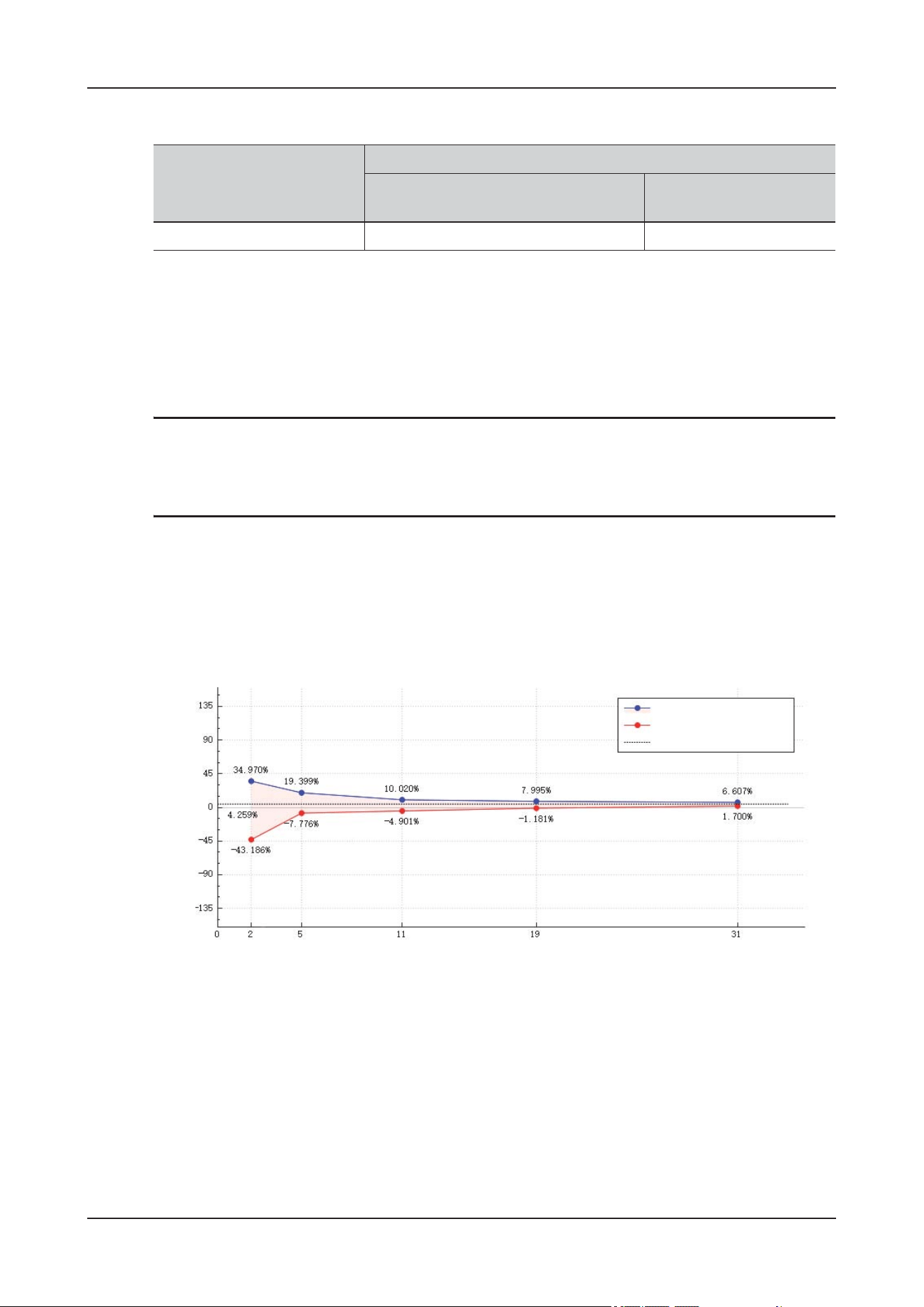
B Product Specifications
B - 22
When the pump operates under the following conditions, the bolus volume is:
Test conditions:
• Infusion set brand: B.Braun Intrafix Primeline
• Anti-bolus: On
• Test temperature: 20°C ±2°C
• Infusion line length: 1 meter
NOTE
Occlusion alarm pressure, alarm delays and bolus volume may vary depending on test conditions,
temperature and tube length.
B.6.5 Infusion Accuracy Graphs
Infusion accuracy at 1 ml/h
Rate (ml/h) Bolus volume after occlusion (ml)
High occlusion alarm pressure level Low occlusion alarm
pressure level
25
˘ 0.18 ˘ 0.18
Rate: 1 ml/h Trumpet Curve (2nd hour)
Ep (Max)
Ep (Min)
Overall percentage error (A)
Percentage error of flow %
Observation window (min)
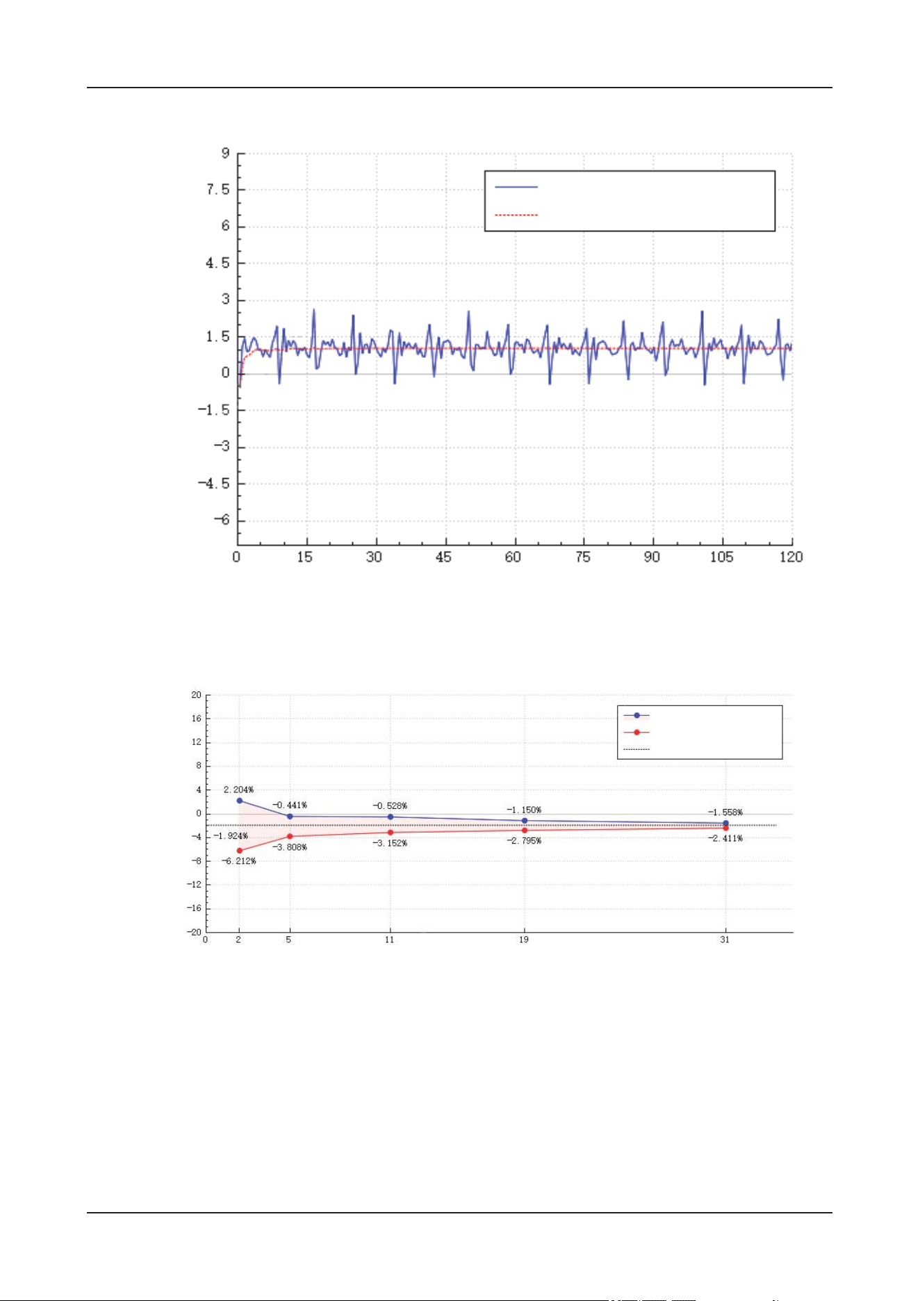
B Product Specifications
B - 23
Infusion accuracy at 25ml/h
Rate: 1 ml/h
Instantaneous Rate
Average Rate
Rate (ml/h)
Time (min)
Set Rate: 25 ml/h Trumpet Curve (2nd hour)
Ep (Max)
Ep (Min)
Overall percentage error (A)
Percentage error of flow %
Observation window (min)
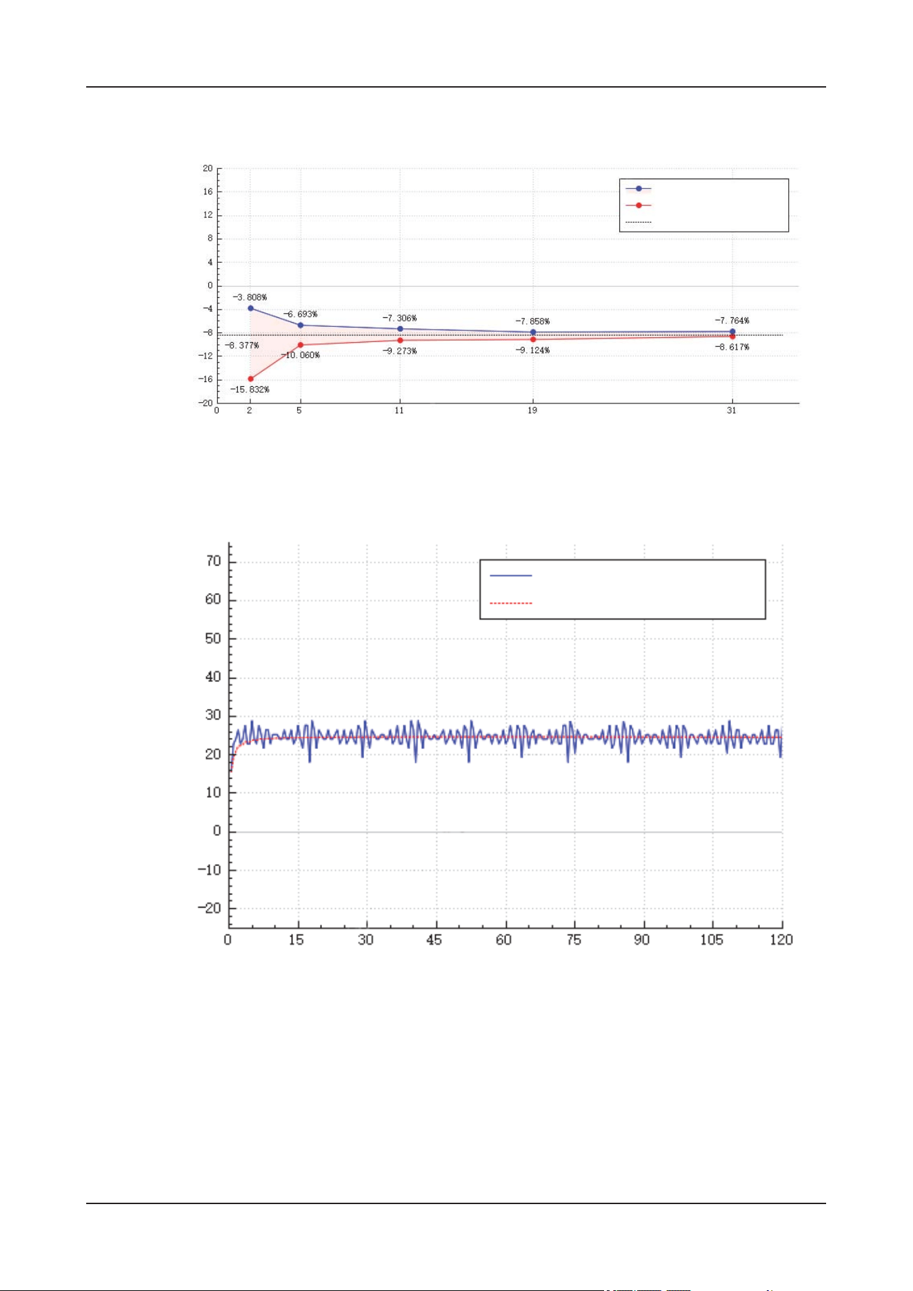
B Product Specifications
B - 24
Test conditions:
• Infusion set brand: B.Braun Intrafix Primeline
• Test interval: Ƹ t =0.5 minutes
• Sampling quantity of pump: 3
• Sampling quantity of infusion set: 3
Set Rate: 25 ml/h Trumpet Curve (last hour)
Ep (Max)
Ep (Min)
Overall percentage error (A)
Percentage error of flow %
Observation window (min)
Set Rate: 25 ml/h
Instantaneous Rate
Average Rate
Rate (ml/h)
Time (min)

B Product Specifications
B - 25
NOTE
Infusion accuracy may be influenced by the pump's environment (such as pressure, temperature,
humidity, and any infusion consumables used).
B.7 Environment Specifications
Item Index
Air heating temperature
control performance
Temperature stability 0.5ႏ (Atmosphere temperature is 22ႏ to 25ႏ,
no wind, and the target air temperature inside the
device is set to 32ႏ)
Temperature control
accuracy
±1ႏ (Atmosphere temperature is 22ႏ to 25ႏ,
no wind, and the target air temperature inside the
device is set to 32ႏ)
Temperature control
uniformity
2ႏ (Atmosphere temperature is 22ႏ to 25ႏ,
no wind, and the target air temperature inside the
device is set to 32ႏ)
Temperature display
accuracy
±1.5ႏ (Atmosphere temperature is 22ႏ to
25ႏ, no wind, and the target air temperature
inside the device is set to 32ႏ)
Rise time 5ႏ (time of rising 5ႏ, atmosphere
temperature is 22ႏ to 25ႏ, no wind, and the
target air temperature inside the device is set to
32ႏ)
Wind speed 0.4 m/s (Atmosphere temperature is 22ႏ to
25ႏ, no wind, and the target air temperature
inside the device is set to 32ႏ)
Noise inside the device 50dBA (Atmosphere temperature is 22ႏ to
25ႏ, no wind, and the target air temperature
inside the device is set to 32ႏ)

B Product Specifications
B - 26
Air conditioner
refrigeration performance
Temperature control
stability
2.5ႏ (Atmosphere temperature is 24ႏ to 27ႏ,
no wind, and the target air temperature inside the
device is set to 18ႏ)
Temperature control
accuracy
±2ႏ (Atmosphere temperature is 24ႏ to 27ႏ,
no wind, and the target air temperature inside the
device is set to 18ႏ)
Temperature control
uniformity
2ႏ (Atmosphere temperature is 24ႏ to 27ႏ,
no wind, and the target air temperature inside the
device is set to 18ႏ)
Temperature display
accuracy
±2.5ႏ (Atmosphere temperature is 24ႏ to
27ႏ, no wind, and the target air temperature
inside the device is set to 18ႏ)
Fall time 20 min (time of falling 5ႏ, atmosphere Temp is
24ႏ to 27ႏ, no wind)
Noise inside the device 60 dBA (Atmosphere temperature is 24ႏ to
27ႏ, no wind, and the target air temperature
inside the device is set to 18ႏ)
Floor heating temperature
control performance
Temperature stability 0.5ႏ (Atmosphere temperature is 22ႏ to 25ႏ,
no wind, and the target floor temperature inside
the device is set to 32ႏ)
Temperature control
accuracy
±1ႏ (Atmosphere temperature is 22ႏ to 25ႏ
,
no wind, and the target floor temperature inside
the device is set to 32ႏ)
Temperature control
uniformity
2ႏ (Atmosphere temperature is 22ႏ to 25ႏ,
no wind, and the target floor temperature inside
the device is set to 32ႏ)
Temperature display
accuracy
±1.5ႏ (Atmosphere temperature is 22ႏ to
25ႏ, no wind, and the target floor temperature
inside the device is set to 32ႏ)
Heating performance • 4 min (ViCare U7L/ViCare U7R)
• 7 min (ViCare U7)
(Time required for the floor temperature to rise
by 5ႏ, atmosphere temperature is 22ႏ to 25ႏ,
no wind, and the target floor temperature inside
the device is set to 32ႏ)
Item Index

B Product Specifications
B - 27
Floor refrigeration
control performance
Temperature control
stability
1ႏ (atmosphere temperature is 22ႏ to 25ႏ, no
wind, and the target floor temperature inside the
device is set to 20ႏ)
Temperature control
accuracy
±1ႏ (Atmosphere temperature is 22ႏ to 25ႏ,
no wind, and the target floor temperature inside
the device is set to 20ႏ)
Temperature control
uniformity
2ႏ (Atmosphere temperature is 22ႏ to 25ႏ,
no wind, and the target floor temperature inside
the device is set to 20ႏ)
Temperature display
accuracy
±1.5ႏ (Atmosphere temperature is 22ႏ to
25ႏ, no wind, and the target floor temperature
inside the device is set to 20ႏ)
Fall time 30 min (Time required for the floor temperature
to fall by ႏ, atmosphere Temp is 24ႏ to 27ႏ,
no wind, and the target floor temperature inside
the device is set to 18ႏ)
Noise 50dBA (Atmosphere Temp is 22ႏ to 25ႏ, no
wind, and the target floor temperature inside the
device is set to 20ႏ)
Humidification
performance
Relative humidity upper
control limit
80% (Atmosphere Temp 22~25ႏ, normally open
for vaporization and humidification; the humidity
inside the device may be greater than 80%)
Relative humidity display
accuracy
±7% (Atmosphere temperature is 22ႏ
to 25ႏ,
ambient humidity is
60%, humidity inside the
device can be set to 80%)
Humidification rise time
(Time when humidity is
increased by 10%)
5 min (Atmosphere temperature is 22ႏ to
25ႏ, ambient humidity is 60%, humidity inside
the device can be set to 80%)
Condensing state Anhydrous condensation (Atmosphere
temperature is 22ႏ to 25ႏ, ambient humidity is
60%, humidity inside the device can be set to
80%)
Semiconductor
dehumidification
performance
Dehumidification control
relative humidity range
60% (Atmosphere temperature is 24ႏ to 27ႏ,
ambient humidity is 80%, humidity inside the
device is set to 30%)
Dehumidification amount 8g/h (Atmosphere temperature is 22ႏ to 25ႏ,
ambient humidity is 60%; the temperature
inside the device is maintained at 24ႏ to 27ႏ;
the humidity inside the device is 80%. In this
case, dehumidification is normally working)
Humidity display
accuracy
±7% (Atmosphere temperature is 24ႏ to 27ႏ,
ambient humidity is 80%, humidity inside the
device is set to 30%)
Noise 50dBA (Atmosphere temperature is 24ႏ to
27ႏ, ambient humidity is 80%, humidity inside
the device is set to 30%)
Item Index

B Product Specifications
B - 28
Oxygen supply inlet Gas supply pressure
range (High-pressure
oxygen inlet)
200 kPa to 600 kPa
Gas supply pressure
range (Low-pressure
oxygen inlet)
0 to 220 kPa
Oxygen flow monitoring Flow reading Range 0 to 30 LPM
Accuracy ±300 ml/min or ±5%, whichever is greater
Oxygen concentration
monitoring inside the
device
Concentration monitoring
range
15 vol% to 100 vol%
High-pressure oxygen
supply
Oxygen concentration
rise time (ViCare U7)
(21 vol% to 40 vol%)5 min
Oxygen concentration
rise time (ViCare U7L/
ViCare U7R)
(21 vol% to 40 vol%)3 min
Noise inside the device 53 dBA
CO
2
concentration
monitoring inside the
device
Concentration monitoring
range
400 ppm to 5000 ppm
Emergency ventilation CO
2
concentration Fall time from 3000 ppm to 2000 ppm: 6 min
CO
2
active absorption
system
ViCare U7 When the 3.75 LPM 4% CO
2
gas is continuously
supplied, the CO
2
concentration in the device is
maintained below 3000 ppm, and the soda lime
replacement interval is 24 hours
ViCare U7L/ViCare U7R When the 1.5 LPM 4% CO
2
gas is continuously
supplied, the CO
2
concentration in the device is
maintained below 2000 ppm, and the soda lime
replacement interval is 24 hours
Item Index

B Product Specifications
B - 29
Normal oxygen
adjustment
Maximum oxygen
concentration (10 SLPM)
40 vol% (10 SLPM oxygen supply flow, oxygen
concentration 99%)
Maximum oxygen
concentration (20 SLPM)
60 vol% (high-pressure oxygen supply,
pressure: 200 kPa to 600 kPa, maximum output
flow 50 SLPM, oxygen concentration99%)
Oxygen concentration
rise time
• 25 min (ViCare U7)
• 15 min (ViCare U7L/ViCare U7R)
(Time from 21 vol% to 40 vol%, oxygen supply
flow of 10 SLPM, oxygen concentration 99%)
Oxygen Concentration
control accuracy
±4 vol% (high-pressure oxygen supply, pressure:
200 kPa to 600 kPa, maximum output flow: 50
SLPM, oxygen concentration99%, set the
oxygen concentration to 40%)
Oxygen Concentration
Control Stability
3 vol% (oxygen supply by high-pressure oxygen
cylinder, pressure: 200 kPa to 600 kPa, maximum
output flow: 50 SLPM, oxygen
concentration99%, set the oxygen concentration
to 40%)
Noise 50 dBA (non-fast oxygen ventilation period)
Item Index

C EMC Guidance and Manufacturer’s Declaration
C - 1
C EMC Guidance and Manufacturer’s
Declaration
The device meets the requirements of IEC 60601-1-2:2014+A1:2020.
WAR N I N G
• This device is intended for use by healthcare professionals only. This device may cause radio
interference or may disrupt the operation of nearby device. It may be necessary to take mitigation
measures, such as re-orienting or relocating the device or shielding the location.
• Use of accessories and cables other than those specified or provided by the manufacturer of this
device could result in increased electromagnetic emissions or decreased electromagnetic immunity
of this device and result in improper operation.
• Use of this device adjacent to or stacked with other equipment should be avoided because it could
result in improper operation. If such use is necessary, this device and the other equipment should be
observed to verify that they are operating normally.
• The device may be interfered with by other equipment, even if that other equipment complies with
CISPR EMISSION requirements.
• The use of the ACCESSORY cable with the device other than those specified may result in
increased EMISSIONS or decreased IMMUNITY of the device.
• Portable RF communications equipment (including peripherals such as antenna cables and external
antennas) should be used no closer than 30 cm (12 inches) to any part of the device, including cables
specified by the manufacturer. Otherwise, degradation of the performance of this device could
result.
• The device needs special precautions regarding EMC and needs to be installed and put into service
according to the EMC information provided below.
If the device is operated within the electromagnetic environment listed in Tab le C-2,Table C-3andTable
C-6, the device will remain safe and will provide the following basic performances:
• Operating mode
• Accuracy
•Function
• Accessories identification

C EMC Guidance and Manufacturer’s Declaration
C - 2
• Data stored
•Alarm
• Detect for connection
• Protection against UNINTENDED BOLUS volumes
• Occlusion
Tab le C-1
Guidance and manufacturer’s declaration – electromagnetic emissions
The device is intended for use in the electromagnetic environment specified below. The customer
or the user of the ME EQUIPMENT should assure that it is used in such an environment.
Emissions test Compliance Electromagnetic environment –
guidance
RF emissions
CISPR 11
Group 1 The device uses RF energy only
for its internal function.
Therefore, its RF emissions are
very low and are not likely to
cause any interference in nearby
electronic equipment.
RF emissions
CISPR 11
Class A The device is suitable for use in
all establishments other than
domestic and those directly
connected to the public low-
voltage power supply network
that supplies buildings used for
domestic purposes.
Harmonic emissions
IEC 61000-3-2
Not applicable
Voltage fluctuations/flicker
emissions
IEC 61000-3-3
Not applicable
Tab le C-2
Guidance and manufacturer’s declaration – electromagnetic immunity
The device is intended for use in the electromagnetic environment specified below. The customer
or the user of the device should assure that it is used in such an environment.
IMMUNITY test IEC 60601 test level Compliance level Electromagnetic
environment –
guidance
Electrostatic Discharge
(ESD)
IEC 61000-4-2
±8 kV contact
±2 kV, ±4 kV, ±8 kV,
±15 kV air
±8 kV contact
±2 kV, ±4 kV, ±8 kV,
±15 kV air
Floors should be wood,
concrete or ceramic tile.
If floors are covered with
synthetic material, the
relative humidity should
be at least 30%.
Electrical fast transient/
burst
IEC 61000-4-4
±2 kV for power supply
lines
±1 kV for input/output
lines
±2 kV for power supply
lines
±1 kV for input/output
lines
Mains power quality
should be that of a
typical commercial or
hospital environment.

C EMC Guidance and Manufacturer’s Declaration
C - 3
Surge
IEC 61000-4-5
±0.5 kV, ±1 kV line(s) to
line(s)
±0.5 kV, ±1 kV, ±2 kV
line(s) to earth
±0.5 kV, ±1 kV line(s) to
line(s)
±0.5 kV, ±1 kV, ±2 kV
line(s) to earth
Mains power quality
should be that of a
typical commercial or
hospital environment.
Mains power quality
should be that of a
typical commercial or
hospital environment. If
the user of the device
requires continued
operation during power
mains interruptions, it is
recommended that the
device be powered from
an uninterruptible power
supply or a battery.
Voltage dips, short
interruptions and voltage
variations on power
supply input lines
IEC 61000-4-11
0% U
T
; 0.5 cycle
At 0°, 45°, 90°,
135°,180°, 225°, 270°
and 315°
0% U
T
; 0.5 cycle At 0°
70% U
T
; 25/30 cycle
At 0°
0% U
T
; 250/300 cycle
0% U
T
; 0.5 cycle
At 0°, 45°, 90°,
135°,180°, 225°, 270°
and 315°
0% U
T
; 0.5 cycle At 0°
70% UT; 25/30 cycle
At 0°
0% U
T
; 250/300 cycle
Mains power quality
should be that of a
typical commercial or
hospital environment.
Mains power quality
should be that of a
typical commercial or
hospital environment. If
the user of the device
requires continued
operation during power
mains interruptions, it is
recommended that the
device be powered from
an uninterruptible power
supply or a battery.
50/60 Hz
IEC 61000-4-8
30 A/m 30 A/m Power frequency
magnetic fields should
be at levels characteristic
of a typical location in a
typical commercial or
hospital environment.
Note: U
T
is the a.c. mains voltage prior to application of the test level.
Tab le C-2
Guidance and manufacturer’s declaration – electromagnetic immunity
The device is intended for use in the electromagnetic environment specified below. The customer
or the user of the device should assure that it is used in such an environment.
IMMUNITY test IEC 60601 test level Compliance level Electromagnetic
environment –
guidance
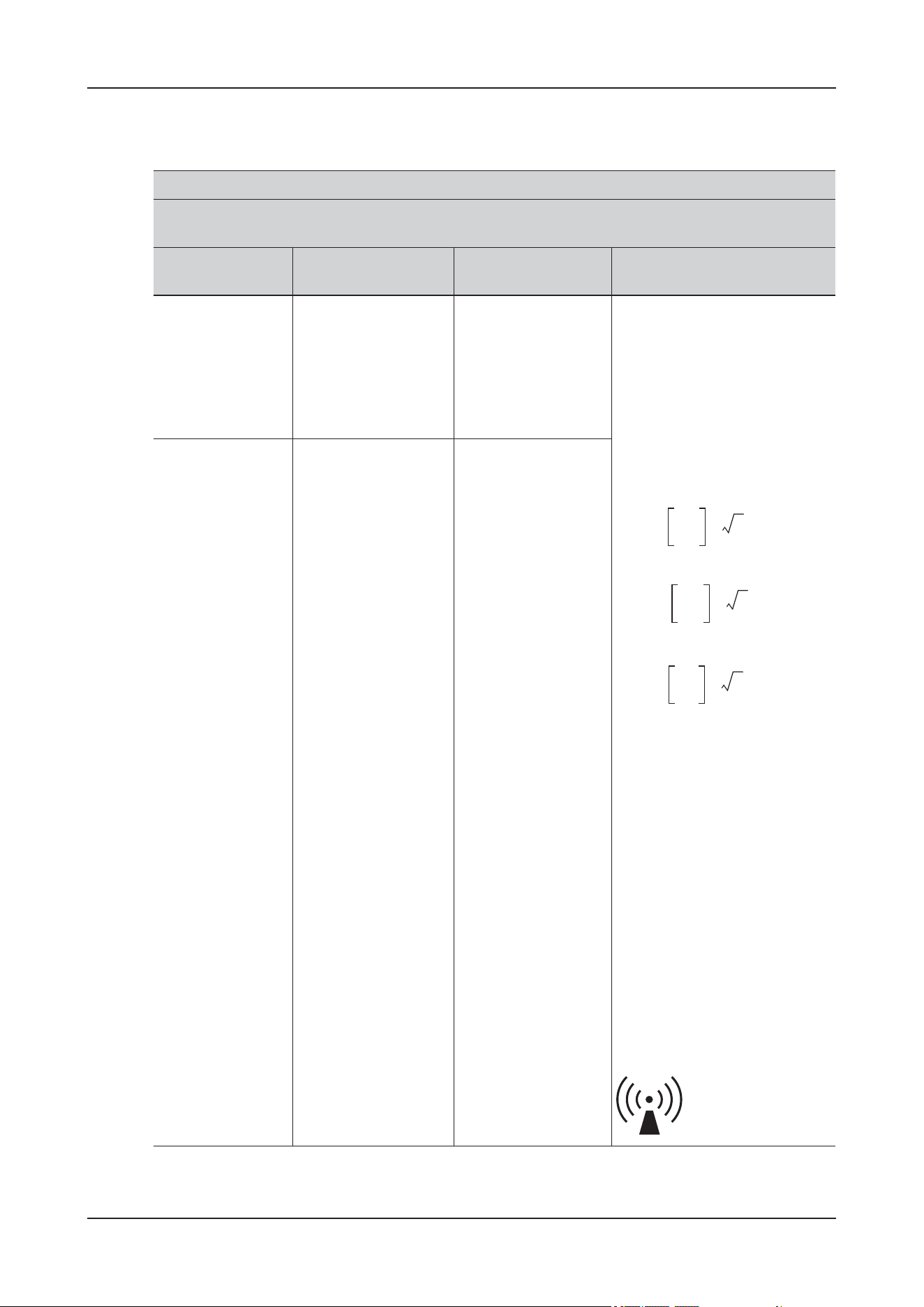
C EMC Guidance and Manufacturer’s Declaration
C - 4
Tab le C-3
Guidance and manufacturer’s declaration – electromagnetic immunity
The device is intended for use in the electromagnetic environment specified below. The customer
or the user of the device should assure that it is used in such an environment.
IMMUNITY test IEC 60601 test level Compliance level Electromagnetic environment
– guidance
Conducted RF
IEC 61000-4-6
3 Vrms
150 kHz to 80 MHz
10 Vrms
150 kHz to 80 MHz
in ISM bands
a
3 Vrms
150 kHz to 80 MHz
10 Vrms
150 kHz to 80 MHz
in ISM bands
a
Portable and mobile RF
communications equipment
should be used no closer to any
part of the device, including
cables, than the recommended
separation distance calculated
from the equation applicable to
the frequency of the transmitter.
Recommended separation
distance
80 MHz
to 800 MHz
800 MHz
to 2.7 GHz
where P is the maximum output
power rating of the transmitter in
watts (W) according to the
transmitter manufacturer and d
is the recommended separation
distance in meters (m).
b
Field strengths from fixed RF
transmitters, as determined by an
electromagnetic site survey
c
,
should be less than the
compliance level in each
frequency range.
d
Interference may occur in the
vicinity of equipment marked
with the following symbol:
Radiated RF
IEC 61000-4-3
10 V/m
80 MHz to 2.7 GHz
10 V/m
80 MHz to 2.7 GHz
d
3.5
V
1
-------
P⋅=
d
3.5
E
1
-------
P⋅=
d
7
E
2
------
P⋅=
C EMC Guidance and Manufacturer’s Declaration
C - 5
Note 1: At 80 MHz and 800 MHz, the higher frequency range applies.
Note 2: These guidelines may not apply in all situations. Electromagnetic propagation is affected by
absorption and reflection from structures, objects and people.
a
The ISM (industrial, scientific and medical) bands between 150 kHz and 80 MHz are 6.765 MHz to
6.795 MHz; 13.553 MHz to 13.567 MHz; 26.957 MHz to 27.283 MHz; and 40.66 MHz to 40.70 MHz.
b
The compliance levels in the ISM frequency bands between 150 kHz and 80 MHz and in the frequency
range 80 MHz to 2.7 GHz are intended to decrease the likelihood that mobile/portable communications
equipment could cause interference if it is inadvertently brought into patient areas. For this reason, an
additional factor of 10/3 has been incorporated into the formulae used in calculating the recommended
separation distance for transmitters in these frequency ranges.
c
Field strengths from fixed transmitters, such as base stations for radio (cellular/cordless) telephones
and land mobile radios, amateur radio, AM and FM radio broadcast and TV broadcast cannot be
predicted theoretically with accuracy. To assess the electromagnetic environment due to fixed RF
transmitters, an electromagnetic site survey should be considered. If the measured field strength in the
location in which the device is used exceeds the applicable RF compliance level above, the device
should be observed to verify normal operation. If abnormal performance is observed, additional
measures may be necessary, such as re-orienting or relocating the device.
d
Over the frequency range 150 kHz to 80 MHz, field strengths should be less than [V1] V/m.
Tab le C-4
Recommended separation distances between portable and mobile RF communications equipment
and the device
The device is intended for use in an electromagnetic environment in which radiated RF
disturbances are controlled. The customer or the user of the device can help prevent
electromagnetic interference by maintaining a minimum distance between portable and mobile
RF communications equipment (transmitters) and the device as recommended below, according
to the maximum output power of the communications equipment.
Rated maximum
output power of
transmitter (W)
Separation distance according to frequency of transmitter (m)
150 kHz - 80 MHz
outside ISM bands
Within 150 kHz -
80 MHz in ISM
bands
80 MHz to 800
MHz
800 MHz to 2.7
GHz
0.01 0.12 0.2 0.12 0.23
0.1 0.38 0.64 0.38 0.73
11.221.22.3
10 3.8 6.4 3.8 7.3
Tab le C-3
Guidance and manufacturer’s declaration – electromagnetic immunity
The device is intended for use in the electromagnetic environment specified below. The customer
or the user of the device should assure that it is used in such an environment.
IMMUNITY test IEC 60601 test level Compliance level Electromagnetic environment
– guidance
d
3.5
V
1
-------
P⋅=
d
12
V
2
------
P⋅=
d
12
E
1
------
P⋅=
d
23
E
12
---------
P⋅=
C EMC Guidance and Manufacturer’s Declaration
C - 6
10012201223
For transmitters rated at a maximum output power not listed above, the recommended separation
distance d in meters (m) can be determined using the equation applicable to the frequency of the
transmitter, where P is the maximum output power rating of the transmitter in watts (W) according to
the transmitter manufacturer.
NOTE 1 At 80 MHz and 800 MHz, the separation distance for the higher frequency range applies.
NOTE 2 The ISM (industrial, scientific and medical) bands between 150 kHz and 80 MHz are 6.765
MHz to 6.795 MHz; 13.553 MHz to 13.567 MHz; 26.957 MHz to 27.283 MHz; and 40.66 MHz to
40.70 MHz.
NOTE 3 An additional factor of 10/3 has been incorporated into the formulae used in calculating the
recommended separation distance for transmitters in the ISM frequency bands between 150 kHz and 80
MHz and in the frequency range 80 MHz to 2.7 GHz to decrease the likelihood that mobile/portable
communications equipment could cause interference if it is inadvertently brought into patient areas.
NOTE 4 These guidelines may not apply in all situations. Electromagnetic propagation is affected by
absorption and reflection from structures, objects and people.
Tab le C-4
Recommended separation distances between portable and mobile RF communications equipment
and the device
The device is intended for use in an electromagnetic environment in which radiated RF
disturbances are controlled. The customer or the user of the device can help prevent
electromagnetic interference by maintaining a minimum distance between portable and mobile
RF communications equipment (transmitters) and the device as recommended below, according
to the maximum output power of the communications equipment.
Rated maximum
output power of
transmitter (W)
Separation distance according to frequency of transmitter (m)
150 kHz - 80 MHz
outside ISM bands
Within 150 kHz -
80 MHz in ISM
bands
80 MHz to 800
MHz
800 MHz to 2.7
GHz
d
3.5
V
1
-------
P⋅=
d
12
V
2
------
P⋅=
d
12
E
1
------
P⋅=
d
23
E
12
---------
P⋅=

C EMC Guidance and Manufacturer’s Declaration
C - 7
Tab le C-5
Recommended separation distances between portable and mobile RF communications equipment
and this device
The device is intended for use in an electromagnetic environment in which radiated RF
disturbances are controlled. The customer or the user of this device can help prevent
electromagnetic interference by maintaining a minimum distance between portable and mobile
RF communications equipment (transmitters) and the device as recommended below, according
to the maximum output power of the communications equipment. Portable and mobile radio
communications equipment (e.g. two-way radio, cellular/ cordless telephones and similar
equipment) should be used no closer to any part of this device, including cables, than determined
according to the following method:
MHz Band
a
(MHz) Communicat
ion Service
a
modulation Maximum
Power (W)
Distance m V/m
385 380 - 390 TETRA 400 Pulse
modulation
b
18 Hz
1.8 0.3 27
450 430 - 470 GMRS 460,
FRS 460
FM
c
± 5 kHz
deviation
1 kHz sine
20.328
710 704 - 787 LTE Band 13,
17
Pulse
modulation
b
217 Hz
0.2 0.3 9
745
780
810 800 - 960 GSM 800/
900, TETRA
800, iDEN
820, CDMA
850, LTE
Band 5
Pulse
modulation
b
18 Hz
20.328
870
930
1720 1700 - 1990 GSM 1800;
CDMA 1900;
GSM 1900;
DECT; LTE
Band 1, 3, 4,
25; UMTS
Pulse
modulation
b
217 Hz
20.328
1845
1970
2450 2400 - 2570 Bluetooth,
WLAN,
802.11 b/g/n,
RFID 2450,
LTE Band 7
Pulse
modulation
b
217 Hz
20.328
5240 5100 - 5800 WLAN
802.11 a/n
Pulse
modulation
b
217 Hz
0.2 0.3 9
5500
5785
To achieve the immunity test level, the distance between the transmitting antenna and the ME
equipment or ME system can be reduced to 1 m. IEC 61000-4-3 The allowable test distance is 1m.
C EMC Guidance and Manufacturer’s Declaration
C - 8
a Some services only include the uplink frequency.
b The carrier should use 50% wifi use percent square wave signals for modulation.
c As an alternative to frequency modulation, carriers can use 50% wifi use percent square wave signals
of 18 Hz for pulse modulation. Although it does not represent actual modulation, it will be the worst
case.
Tab le C-6
Guidance and declaration—electromagnetic immunity
The device is intended for use in the electromagnetic environment specified below. The customer or the
user of device should assure that it is used in such an environment.
IMMUNITY TEST IEC 60601 TEST
LEVEL
COMPLIANCE LEVEL ELECTROMAGNETIC
ENVIROMENT –
GUIDANCE
Proximity magnetic
fields IEC 61000-4-39
65 A/m
134.2 kHz
Pulse modulation
2.1 kHz
65 A/m
134.2 kHz
Pulse modulation
2.1 kHz
/
7.5 A/m
13.56 MHz
Pulse modulation
50 kHz
7.5 A/m
13.56 MHz
Pulse modulation
50 kHz
Table C-7 Cable Information
No. Name Cable Length (m) Shield or Not Remarks
1. Power cord 5.0m No /
2. ECG signal cable 2.9m Yes /
3. SpO
2
signal cable 2.9m Yes /
4. Temperature cable 0.5m No /
Tab le C-5
Recommended separation distances between portable and mobile RF communications equipment
and this device
The device is intended for use in an electromagnetic environment in which radiated RF
disturbances are controlled. The customer or the user of this device can help prevent
electromagnetic interference by maintaining a minimum distance between portable and mobile
RF communications equipment (transmitters) and the device as recommended below, according
to the maximum output power of the communications equipment. Portable and mobile radio
communications equipment (e.g. two-way radio, cellular/ cordless telephones and similar
equipment) should be used no closer to any part of this device, including cables, than determined
according to the following method:
MHz Band
a
(MHz) Communicat
ion Service
a
modulation Maximum
Power (W)
Distance m V/m

C EMC Guidance and Manufacturer’s Declaration
C - 9

D Alarm Messages
D - 1
D Alarm Messages
D.1 Monitoring Alarm Messages
D.1.1 Physiological Alarms
General Physiological Alarm Messages
TIP
XX represents a measurement or parameter label.
Arrhy. Alarm
Alarm messages Default priority Cause and solution
XX High Med XX value has risen above the high alarm limit or fallen below
the low alarm limit. Check the animal’s condition and check if
the species and alarm limit settings are correct.
XX Low Med XX value has fallen below the low alarm limit. Check the
animal’s condition and check if the species and alarm limit
settings are correct.
Alarm messages Default priority Cause and solution
Asystole High Enter Event Review to view the parameters or waveform
information at the alarm moment.
V-Fib/V-Tach High Enter Event Review to view the parameters or waveform
information at the alarm moment.
V-Tach High Enter Event Review to view the parameters or waveform
information at the alarm moment.
Vent Brady High Enter Event Review to view the parameters or waveform
information at the alarm moment.

D Alarm Messages
D - 2
Extreme Tachy High Enter Event Review to view the parameters or waveform
information at the alarm moment.
Extreme Brady High Enter Event Review to view the parameters or waveform
information at the alarm moment.
R on T Med Enter Event Review to view the parameters or waveform
information at the alarm moment.
Run PVCs Low Enter Event Review to view the parameters or waveform
information at the alarm moment.
Couplet Prompt Enter Event Review to view the parameters or waveform
information at the alarm moment.
Multiform PVC Med Enter Event Review to view the parameters or waveform
information at the alarm moment.
PVC Prompt Enter Event Review to view the parameters or waveform
information at the alarm moment.
Bigeminy Med Enter Event Review to view the parameters or waveform
information at the alarm moment.
Trigeminy Med Enter Event Review to view the parameters or waveform
information at the alarm moment.
Tachy Med Enter Event Review to view the parameters or waveform
information at the alarm moment.
Brady Med Enter Event Review to view the parameters or waveform
information at the alarm moment.
Pacer Not Capture Prompt Enter Event Review to view the parameters or waveform
information at the alarm moment.
Pacer Not Pacing Prompt Enter Event Review to view the parameters or waveform
information at the alarm moment.
Missed Beat Prompt Enter Event Review to view the parameters or waveform
information at the alarm moment.
Nonsus V-Tach Med Enter Event Review to view the parameters or waveform
information at the alarm moment.
Vent Rhythm Med Enter Event Review to view the parameters or waveform
information at the alarm moment.
Pause Med Enter Event Review to view the parameters or waveform
information at the alarm moment.
Irr Rhythm Prompt Enter Event Review to view the parameters or waveform
information at the alarm moment.
PVCs/min Med Enter Event Review to view the parameters or waveform
information at the alarm moment.
Pauses/min Med Enter Event Review to view the parameters or waveform
information at the alarm moment.
SVT Med Enter Event Review to view the parameters or waveform
information at the alarm moment.
Alarm messages Default priority Cause and solution

D Alarm Messages
D - 3
ST Physiological Alarm Messages
TIP
XX represents the ECG lead label.
SpO
2
Physiological Alarm Messages
Resp Physiological Alarm Messages
SVCs/min Med Enter Event Review to view the parameters or waveform
information at the alarm moment.
Alarm messages Default priority Cause and solution
ST alarm mode Alarm messages Default priority Cause and solution
Absolute ST-XX High Med ST value of any ECG leads has risen above
the high alarm limit or fallen below the
low alarm limit. Check the animal’s
condition and check if the species and
alarm limit settings are correct.
ST-XX Low Med ST value of any ECG leads has risen above
the high alarm limit or fallen below the
low alarm limit. Check the animal’s
condition and check if the species and
alarm limit settings are correct.
Relative ST Single High ST value of any ECG leads has risen above
the high alarm limit or fallen below the
low alarm limit. Check the animal’s
condition and check if the species and
alarm limit settings are correct.
ST Dual Med ST values of two or more ECG leads have
risen above the high alarm limit or fallen
below the low alarm limit. Check the
animal’s condition and check if the species
and alarm limit settings are correct.
Alarm messages Default priority Cause and solution
SpO2 Desat High The SpO
2
value falls below the desaturation alarm limit. Check
the animal’s condition and check if the alarm limit settings are
correct.
Alarm messages Default priority Cause and solution
Zero RR High The respiration signal was so weak that the device cannot
perform respiration analysis. Check the animal’s condition,
module and animal connections.

D Alarm Messages
D - 4
PR Physiological Alarm Messages
D.1.2 Technical Alarms
This section lists technical alarms, their default priority, indication on alarm reset, and the actions that
can be taken when an alarm occurs.
Technical alarms give different alarm indicators when the alarm system is reset. In this section we
classify the technical alarms into three categories for easy clarification:
• Completely cleared: technical alarms are cleared. The device gives no alarm indications.
• Sound/light cleared: technical alarms are changed to the prompt messages.
• Unclearable: the alarm is silenced and a ¥ appears before the alarm message.
General Technical Alarm Messages
NOTE
XX represents a measurement or parameter label.
ECG Technical Alarm Messages
Resp Artifact Med The animal’s heartbeat has interfered with his respiration.
Check the animal’s condition and the Resp connections.
Alarm messages Default priority Cause and solution
Alarm messages Default priority Cause and solution
No Pulse High The pulse signal was so weak that the device cannot perform
pulse analysis. Check the animal’s condition, SpO
2
sensor and
measurement site.
Alarm messages Default priority Indication on
alarm reset
Cause and solution
XX Error High Unclearable XX module does not work properly.
Restart the device, if the alarm persists,
contact the Customer Service Department
or your local distributor.
Alarm messages Default priority Indication on
alarm reset
Cause and solution
ME Disconnected Low Unclearable ECG module is powered off for depleting
of battery charge or moved out of the
network coverage. Charge the battery, or
move the ECG module back to network
covered area.

D Alarm Messages
D - 5
ME Module Error High Unclearable • Disconnect the ECG module from the
base, place it on the charger to charge
it, wait for a short period of time, then
reconnect it, and check if the issue still
exists.
• If the issue still exists, contact the
service personnel.
ECG Lead Off Low Sound/light
cleared
Check the connection of the ECG
electrodes.
ECG XX Lead Off Low Sound/light
cleared
The electrode has become detached from
the animal or the lead wire has become
disconnected from the adapter cable.
Check the connections of the electrodes
and leadwires.
ECG Noisy Low/Prompt Completely
cleared
• Inspect the connection of the ECG
electrode pads and replace them with
new ones if necessary.
• Check leadwires for damage.
• Ensure the patient is not obviously
moving.
• Check the filter setup
ECG Calibrating Prompt //
ECG Learning Prompt / ECG learning is manually or automatically
triggered.
Cannot Analyze
QT
Prompt //
ECG Amplitude
Too Small
Low Unclearable Check patient condition.
ECG Signal
Invalid
Low Completely
cleared
• Inspect the connection of the ECG
electrode pads and replace them with
new ones if necessary.
• Clean the ECG electrode pads and
the metal parts of the lead wires.
• Clean the measurement sites.
ME Battery
Temperature Too
High
High Unclearable The battery temperature of the ECG
module is high. Replace the battery.
ME Battery Aged Low Unclearable The battery of the ECG module reaches its
lifetime. Contact the Customer Service
Department or your local distributor.
ME Battery
Error
High Unclearable The battery of the ECG module encounters
communication error. Contact the
Customer Service Department or your
local distributor.
ME Low Battery Med Unclearable Low battery on the ECG module. Please
charge it promptly.
Alarm messages Default priority Indication on
alarm reset
Cause and solution

D Alarm Messages
D - 6
SpO
2
Technical Alarm Messages
ME Battery
Depleted
High Unclearable The ECG module battery is about to be
depleted. Please charge it immediately.
Alarm messages Default priority Indication on
alarm reset
Cause and solution
Alarm messages Default priority Indication on
alarm reset
Cause and solution
MS Disconnected Low Unclearable The SpO
2
module lost Bluetooth
connection with the R20. Check the SpO
2
module and R20 module. If needed, repair
them.
MS Error High Unclearable • Disconnect the SpO2 module from
the base unit, place it on the charger
and charge it, wait for a short period
of time, and then reconnect the SpO2
module to the base unit to check if
the issue persists.
• If the issue still exists, contact the
service personnel.
SpO2 Sensor Off Low Sound/light
cleared
• Check sensor application.
• Check the connection between the
pulse oximeter sensor and the
module interface.
SpO2 Searching
Pulse
Prompt Unclearable • Check sensor application.
• Reposition the sensor if necessary.
SpO2 Low
Perfusion
Prompt Unclearable • Check sensor application.
• Reposition the sensor if necessary.
• Check the patient for signs of low
perfusion (hypotension,
hypovolemia, vasoconstriction, etc.).
SpO2 No Pulse Low Unclearable • Check sensor application.
• Reposition the sensor if necessary.
SpO2 Excess
Light
Low Unclearable • Check sensor application.
• Cover the SpO2 sensor.
MS Battery
Temperature Too
High
High Unclearable The battery temperature of the SpO
2
module is high. Replace the battery.
MS Battery Aged Low Unclearable The battery of the SpO
2
module reaches its
lifetime. Contact the Customer Service
Department or your local distributor.
MS Battery Error High Unclearable The battery of the SpO
2
module
encounters communication error. Contact
the Customer Service Department or your
local distributor.

D Alarm Messages
D - 7
Resp Technical Alarm Messages
Temp Technical Alarm Messages
NIBP Technical Alarm Messages
MS Low Battery Med Unclearable Low battery on the SpO2 module.
Please charge it promptly.
MS Battery
Depleted
High Unclearable The battery of the SpO2 module is
about to deplete. Please charge it
immediately.
Alarm messages Default priority Indication on
alarm reset
Cause and solution
Alarm messages Default priority Indication on
alarm reset
Cause and solution
Resp Interference Prompt / Interference may be caused by the
following factors: movement, poor
electrode connection, other forms of
electromagnetic interference, etc.
LA-RA Electrode
Poor Contact,
LL-RA Electrode
Poor Contact
Prompt /•Check the placement of the ECG
electrodes and avoid placing them on
bony prominences.
• Switch the Resp lead on the Resp
menu.
Alarm messages Default priority Indication on
alarm reset
Cause and solution
Temp Low
Battery
Med Unclearable Low battery in the Temp Module.
Please replace the battery promptly.
Alarm messages Default priority Indication on
alarm reset
Cause and solution
NIBP Module
Error
High Unclearable • Please restart the NIBP module and
check if the issue persists.
• If the issue still exists, contact the
service personnel.
NIBP Cuff Loose Low Completely
cleared
• Choose a cuff with proper size.
• Check whether the cuff, hose, and
connection are leaking.
• Ensure that the INDEX LINE on the
cuff edge falls within the range
markings on the cuff. Place the cuff
with proper tightness.

D Alarm Messages
D - 8
NIBP Cuff or
Airway Leak
Low Completely
cleared
• Check the NIBP cuff and tubing for
leakages.
• Replace NIBP cuff and tubing.
• Restart an NIBP measurement.
• If the issue still exists, contact the
service personnel.
NIBP Excessive
Motion
Low Completely
cleared
• Ensure the patient keeps their limb
still during the NIBP measurement.
• Restart an NIBP measurement.
NIBP Airway
Error
Low Completely
cleared
Check the air tubing for kinking.
NIBP Weak
Signal
Low Completely
cleared
• Check the patient. Make sure that
application site is not edematous.
• Check the cuff is not loosen or
detached.
NIBP Cuff
Overpressure
Low Completely
cleared
Make sure there is no external pressure
against the cuff.
NIBP Overrange Low Completely
cleared
• Ensure the patient is not obviously
moving.
• Make sure there is no external
pressure against the cuff.
NIBP Timeout Low Completely
cleared
• Check the cuff is not loosen or
detached.
• Ensure the patient is not obviously
moving.
NIBP Airway
Leak
Low Completely
cleared
Check whether the cuff, hose, and
connection are leaking.
MB Battery
Temperature Too
High
High Unclearable The battery temperature of the SpO
2
module is high. Replace the battery.
MB battery aged.
Replace the
battery.
Low Unclearable The battery of the SpO
2
module reaches its
lifetime. Contact the Customer Service
Department or your local distributor.
MB Battery
Error
High Unclearable The battery of the NIBP module
encounters communication error. Contact
the Customer Service Department or your
local distributor.
MB Low Battery Med Unclearable NIBP module has low battery. Please
charge it promptly or replace the
battery.
MB Battery
Depleted
High Unclearable NIBP module battery is about to be
depleted. Please replace the battery
immediately.
Alarm messages Default priority Indication on
alarm reset
Cause and solution
D Alarm Messages
D - 9
R20 Module Technical Alarm Messages
Other Technical Alarms
D.2 Infusion Module Alarm Messages
Infusion Pump
Alarm messages Default priority Indication on
alarm reset
Cause and solution
Receiver Error High Unclearable • Please reinsert the wireless receiver
module.
• If the issue still exists, contact the
service personnel.
Alarm messages Default priority Indication on
alarm reset
Cause and solution
XX Measurement
has been closed
(XX refers to the
module label)
Prompt / The parameter module is disabled. Switch
on the module if you want to use it.
The display setup
for XX is disabled.
(XX refers to the
parameter label)
Prompt / Select a desired area to display the
parameter numerics and waveforms.
Alarm messages Default priority Cause and solution
Infusion Near
Done
Low During infusion, when the remaining VTBI is less than or
equal to the set alarm time, the Infusion Near Done alarm is
triggered.
The alarm will be automatically cleared when infusion is
completed.
Pump Reminder Low No operation is detected after the preset reminder time is
reached, the Reminder Time alarm is triggered.
Press (Alarm Reset) button or open the pump door.
Parameter not
confirmed
Low On the infusion parameter setting screen, on-line titration
screen, bolus setting screen, and purge setting screen,
Parameter not confirmed is triggered when parameters are in
editable status and no operation is performed for 10 seconds.
Press (Alarm Reset) button to clear the alarm.
D Alarm Messages
D - 10
Pump Door Open High The Pump Door Open alarm is triggered when door opens
during infusion.
The alarm is cleared automatically after the pump door is
closed.
Air in Line High During infusion, the Air in Line alarm is triggered when the
bubble sensor detects that the size of a single bubble is larger
than the threshold of a single bubble.
Press (Alarm Reset) button to clear the alarm.
Accumulated
Bubble
High During infusion, the Accumulated Bubble alarm is triggered
when the bubble sensor detects that the accumulated bubbles
reach the threshold of the accumulated bubble within 1 hour.
Press (Alarm Reset) button to clear the alarm.
Downstream
Occlusion
High During infusion, the Downstream Occlusion alarm is
triggered when the occlusion pressure of the pipeline (between
the pimp and the animal) reaches the set threshold.
• The alarm is automatically cleared when the occlusion
restarts successfully.
• Manually remove the tube occlusion, make the pressure
within the threshold range, and press (Alarm Reset)
button to clear the alarm.
Infusion
completed
High The Infusion completed alarm is triggered when the preset
VTBI is completed.
Press (Alarm Reset) button to clear the alarm.
KVO Complete High The KVO Complete alarm is triggered when the KVO
infusion is running for 30 minutes.
Press (Alarm Reset) button to clear the alarm.
Alarm messages Default priority Cause and solution
D Alarm Messages
D - 11
Warmer Module
System Error
1001
High When the device detects a motor error or an internal error of
the device, the System Error alarm is triggered and the system
error code is displayed.
Press (Alarm Reset) button to clear the alarm.
System Error
1002
System Error
1003
System Error
1004
System Error
1005
System Error
1006
System Error
1007
System Error
1008
System Error
1009
System Error
1010
System Error
1011
System Error
1012
System Error
1013
Alarm messages Default priority Cause and solution
Alarm messages Default priority Cause and solution
System Error
2001
Med Abnormal infusion temperature detection sensor.
Restart the device; if the issue persists, contact the service
personnel.
System Error
2002
High Infusion temperature control has stopped working.
• Please promptly remove the infusion set from the
warmer.
• Restart the device; if the issue persists, contact the
service personnel.
System Error
2003
Med Infusion warming control is not functioning properly.
Restart the device; if the issue persists, contact the service
personnel.

D Alarm Messages
D - 12
D.3 Environment Module Alarm Messages
Air Temperature
System Error
2004
High Infusion temperature control has stopped working.
• Please promptly remove the infusion set from the
warmer.
• Restart the device; if the issue persists, contact the
service personnel.
Infusion
Temperature Too
High
High • Please promptly remove the infusion set from the
warmer and inspect the infusion solution. If necessary,
discontinue the infusion.
• Verify the infusion pump mode selection.
• Verify if the ambient temperature is too high.
Alarm messages Default priority Cause and solution
Alarm messages Default priority Cause and solution
Air Temperature
Too High
High All environmental control systems have stopped
functioning.
• Immediately evacuate the patient from the chamber and
check their condition.
• Open the hatch for ventilation.
• Restart the device; if the issue persists, contact the
service personnel.
Air Temperature
Too Low
Med • Check whether the ambient temperature outside the
cabin is too low.
• Check whether the operation window is open.
Air Temperature
High
Low • Check whether the ambient temperature outside the
cabin is too high.
• Check whether the equipment is exposed to sunlight.
Air Temperature
Not Reaching
Target for Long
Time
Low • Check whether the operation window is open.
• Check whether the external environmental temperature
is too high or too low.
• Check whether the equipment is exposed to sunlight.
• Clean the dust-proof mesh at the internal circulation
duct.
System Error
3001
High Oxygen (O2), air temperature, and humidity control have
stopped working.
• Immediately evacuate the patient from the chamber and
check their condition.
• Restart the device; if the issue persists, contact the
service personnel.

D Alarm Messages
D - 13
System Error
3002
High Oxygen (O2), air temperature, and humidity control have
stopped working.
• Immediately evacuate the patient from the chamber and
check their condition.
• Restart the device; if the issue persists, contact the
service personnel.
System Error
3003
High Oxygen (O2), air temperature, and humidity control have
stopped working.
• Clean the dust-proof mesh at the internal circulation
duct.
• Check whether the top ventilation port of the
compartment is blocked.
• Restart the device; if the issue persists, contact the
service personnel.
System Error
3004
High Oxygen (O2), air temperature, and humidity control have
stopped working.
• Clean the dust-proof mesh at the internal circulation
duct.
• Check whether the top ventilation port of the
compartment is blocked.
• Restart the device; if the issue persists, contact the
service personnel.
System Error
3005
Med • Clean the dust-proof mesh at the internal circulation
duct.
• Check whether the top ventilation port of the
compartment is blocked.
• Restart the device; if the issue persists, contact the
service personnel.
System Error
3006
Med • Clean the dust-proof mesh at the internal circulation
duct.
• Check whether the top ventilation port of the
compartment is blocked.
• Restart the device; if the issue persists, contact the
service personnel.
System Error
3007
High Restart the device; if the issue persists, contact the service
personnel.
System Error
3008
High Restart the device; if the issue persists, contact the service
personnel.
System Error
3009
Low Restart the device; if the issue persists, contact the service
personnel.
System Error
3010
High Restart the device; if the issue persists, contact the service
personnel.
System Error
3011
High Restart the device; if the issue persists, contact the service
personnel.
System Error
3012
Med Restart the device; if the issue persists, contact the service
personnel.
Alarm messages Default priority Cause and solution

D Alarm Messages
D - 14
Floor Temperature
System Error
3013
Med Restart the device; if the issue persists, contact the service
personnel.
System Error
4001
Med Restart the device; if the issue persists, contact the service
personnel.
System Error
4002
Med • Clean the dust-proof mesh 1/dust-proof mesh 2 at the A/
C.
• Verify whether the distance between the air
conditioning unit and the wall meets the requirements.
• Restart the device; if the issue persists, contact the
service personnel.
System Error
4003
Med • Clean the dust-proof mesh 1/dust-proof mesh 2 at the A/
C..
• Verify whether the distance between the air
conditioning unit and the wall meets the requirements.
• Restart the device; if the issue persists, contact the
service personnel.
System Error
4004
Med • Clean the dust-proof mesh 1/dust-proof mesh 2 at the A/
C.
• Verify whether the distance between the air
conditioning unit and the wall meets the requirements.
• Restart the device; if the issue persists, contact the
service personnel.
System Error
4005
Med • Clean the dust-proof mesh 1/dust-proof mesh 2 at the A/
C.
• Verify whether the distance between the air
conditioning unit and the wall meets the requirements.
• Restart the device; if the issue persists, contact the
service personnel.
System Error
4006
Med • Clean the dust-proof mesh 1/dust-proof mesh 2 at the A/
C.
• Verify whether the distance between the air
conditioning unit and the wall meets the requirements.
• Restart the device; if the issue persists, contact the
service personnel.
Alarm messages Default priority Cause and solution
Alarm messages Default priority Cause and solution
Floor
Temperature Too
High
High • Immediately evacuate the patient from the chamber and
check their condition.
• Check the floor to see if there are other heat sources
placed on it.
• Restart the device; if the issue persists, contact the
service personnel.

D Alarm Messages
D - 15
Floor
Temperature
High
Low Check the floor to see if there are other heat sources placed
on it.
System Error
6001
Med Restart the device; if the issue persists, contact the service
personnel.
System Error
6002
Med Restart the device; if the issue persists, contact the service
personnel.
Floor
Temperature Not
Reaching Target
for Long Time
Low • Check whether other heat sources/cold sources are
placed on the floor.
• Check whether there is a significant difference between
the setpoints of air temperature and floor temperature.
• Clean the dust-proof mesh at the floor duct.
System Error
6003
High Restart the device; if the issue persists, contact the service
personnel.
System Error
6004
High Restart the device; if the issue persists, contact the service
personnel.
System Error
6007
Med • Clean the dust-proof mesh at the floor duct.
• Restart the device; if the issue persists, contact the
service personnel.
System Error
6008
Med • Clean the dust-proof mesh at the floor duct.
• Restart the device; if the issue persists, contact the
service personnel.
System Error
6009
Med • Clean the dust-proof mesh at the floor duct.
• Restart the device; if the issue persists, contact the
service personnel.
System Error
6010
Med • Clean the dust-proof mesh at the floor duct.
• Restart the device; if the issue persists, contact the
service personnel.
System Error
6011
High • Clean the dust-proof mesh at the floor duct.
• Restart the device; if the issue persists, contact the
service personnel.
System Error
6012
High • Clean the dust-proof mesh at the floor duct.
• Restart the device; if the issue persists, contact the
service personnel.
System Error
6013
High • Clean the dust-proof mesh at the floor duct.
•
Restart the device; if the issue persists, contact the
service personnel.
System Error
6014
High • Clean the dust-proof mesh at the floor duct.
• Restart the device; if the issue persists, contact the
service personnel.
System Error
6015
High Restart the device; if the issue persists, contact the service
personnel.
System Error
6016
High Restart the device; if the issue persists, contact the service
personnel.
Alarm messages Default priority Cause and solution

D Alarm Messages
D - 16
Humidity
Water Tank
System Error
6017
High Restart the device; if the issue persists, contact the service
personnel.
System Error
6018
High Restart the device; if the issue persists, contact the service
personnel.
Alarm messages Default priority Cause and solution
Alarm messages Default priority Cause and solution
Humidity Too
High
Med • Activate the ventilation function or open the cabin door
for ventilation.
• Reduce liquid in the cabin, such as water, urine, etc.
• Check whether the humidity in the external
environment is too high.
Humidity Too
Low
Med Check whether the humidity in the external environment is
too low.
System Error
5001
High Restart the device; if the issue persists, contact the service
personnel.
System Error
5002
High Restart the device; if the issue persists, contact the service
personnel.
System Error
5003
Med • Clean the dust-proof mesh at the dehumidifier.
• Check if the ventilation port on the back cover of the
device is blocked by foreign objects.
• Restart the device; if the issue persists, contact the
service personnel.
System Error
5004
High • Clean the dust-proof mesh at the dehumidifier.
• Check if the ventilation port on the back cover of the
device is blocked by foreign objects.
• Restart the device; if the issue persists, contact the
service personnel.
Alarm messages Default priority Cause and solution
Water Tank
Short of Water
Low • Please refill the water tank with distilled water.
• Clean water tank filter.
• If the issue still exists, contact the service personnel.
Dehumidbox Full Med • Please perform the condensate drainage procedure.
• If the issue still exists, contact the service personnel.
ColdBox Full Med • Please perform the condensate drainage procedure.
• If the issue still exists, contact the service personnel.

D Alarm Messages
D - 17
Oxygen Control
Descaling
interrupted
Med • Check if the water tank has not been filled with the
required amount of lemon acid solution or clean water.
• Check if there was an abnormal alarm during the
descaling process.
• Clean water tank filter.
• If the issue persists after re-running the descaling
procedure, contact the service personnel.
Water Tank Not
In Position
Prompt /
Please remove the
scale from the
water tank.
Prompt • The descaling reminder time has arrived. Please execute
the descaling procedure.
• If the descaling procedure has been executed, you can
select "System" > "Environment Maintenance" >
"Water Tank" to update "Last Cleaning Time" or
adjust "Reminder Cycle".
System Error
5005
Med • Check the drainage tubing for bends or obstructions.
• Check if the drainage tubing is higher than the drainage
port.
• Restart the device; if the issue persists, contact the
service personnel.
System Error
5006
High Restart the device; if the issue persists, contact the service
personnel.
System Error
5007
Med • Try to execute the descaling procedure.
• Restart the device; if the issue persists, contact the
service personnel.
System Error
5008
Med Restart the device; if the issue persists, contact the service
personnel.
System Error
5009
Med • Clean the dust-proof mesh at the dehumidifier.
• Restart the device; if the issue persists, contact the
service personnel.
Alarm messages Default priority Cause and solution
Alarm messages Default priority Cause and solution
O2 Concentration
Too Low
High • Immediately evacuate the patient from the chamber and
check their condition.
• Check the oxygen source or oxygen supply lines.
O2 Concentration
Not Reaching
Target for Long
Time
Low • Check whether the operation window is open.
• Check the oxygen supply capacity of the oxygen source.
O2 Concentration
Too High for
Long Time
Med • Open the hatch for ventilation.
• Adjust the target O2 value or the alarm threshold.

D Alarm Messages
D - 18
CO
2
Oxygen Source
Error
Med/Prompt • Check if the oxygen source is turned on or if the oxygen
tank is empty.
• Check if the oxygen source is abnormal.
• Check the oxygen tubing connections.
Oxygen Flow
Error
Med • Check if the oxygen flow rate is properly set.
• Check for leaks in the oxygen tubing.
System Error
7002
Med Restart the device; if the issue persists, contact the service
personnel.
System Error
7003
Med Restart the device; if the issue persists, contact the service
personnel.
System Error
7004
Med Restart the device; if the issue persists, contact the service
personnel.
System Error
7005
Med • Check if the ventilation port on the back cover of the
device is blocked by foreign objects.
• Restart the device; if the issue persists, contact the
service personnel.
System Error
7006
High Restart the device; if the issue persists, contact the service
personnel.
System Error
7007
Med Restart the device; if the issue persists, contact the service
personnel.
System Error
7008
Med Restart the device; if the issue persists, contact the service
personnel.
Please perform O
2
sensor calibration
Prompt The oxygen sensor calibration reminder date is reached.
Perform the oxygen sensor calibration procedure.
Alarm messages Default priority Cause and solution
Alarm messages Default priority Cause and solution
CO2
Concentration
Too High for
Long Time
Med • Check if the CO2 absorbent has failed and replace it
promptly.
• Adjust the CO2 alarm setpoint.
• Clean the dust-proof mesh at the CO2 duct.
• Clean the sponge filter inside the CO2 absorber
canister.
• Execute CO2 calib zero function.
CO2 Absorber
Canister Not In
Position
Prompt /
Please perform
CO
2
sensor
calibration
Prompt The CO
2
sensor calibration reminder date is reached. Perform
the CO
2
sensor calibration procedure.
Emergency Valve
1 Error
High • Verify the distance between the equipment's rear panel
and the wall meets the requirements.
• Check the emergency vent for foreign object blockage.

D Alarm Messages
D - 19
Others
D.4 System Technical Alarm Messages
Cabin Door Technical Alarm Messages
Emergency Valve
2 Error
High • Verify the distance between the equipment's rear panel
and the wall meets the requirements.
• Check the emergency vent for foreign object blockage.
System Error
7011
Med Restart the device; if the issue persists, contact the service
personnel.
System Error
7012
Med Restart the device; if the issue persists, contact the service
personnel.
System Error
7013
High Restart the device; if the issue persists, contact the service
personnel.
System Error
7014
High Restart the device; if the issue persists, contact the service
personnel.
System Error
7015
Med Restart the device; if the issue persists, contact the service
personnel.
System Error
7016
Low • Clean the dust-proof mesh at the CO2 duct.
• If the issue still exists, contact the service personnel.
System Error
7017
Med Restart the device; if the issue persists, contact the service
personnel.
System Error
7018
Med Restart the device; if the issue persists, contact the service
personnel.
System Error
7019
Med Restart the device; if the issue persists, contact the service
personnel.
Alarm messages Default priority Cause and solution
Alarm messages Default priority Cause and solution
System Error
8001
High Restart the device; if the issue persists, contact the service
personnel.
System Error
8002
High Restart the device; if the issue persists, contact the service
personnel.
System Error
8015
Med Restart the device; if the issue persists, contact the service
personnel.
Alarm messages Default priority Cause and solution
Door Open Prompt Close the cabin door.
System Error
8016
High Check the door frame for foreign objects lodged in it.
Restart the device; if the issue persists, contact the service
personnel.
D Alarm Messages
D - 20
Power Technical Alarm Messages
Other Technical Alarm Messages
System Error
8017
High Check the door frame for foreign objects lodged in it.
Restart the device; if the issue persists, contact the service
personnel.
System Error
8018
High Restart the device; if the issue persists, contact the service
personnel.
Alarm messages Default priority Cause and solution
Alarm messages Default priority Cause and solution
No AC Power High • Check the power connection.
• Check if the circuit breaker has tripped.
Low Battery Low Please connect to the power supply as soon as possible.
Critically Low
Battery
High The device is about to shut down due to battery depletion.
Please connect to a power source promptly.
No Battery Med Please contact the service personnel.
Alarm messages Default priority Cause and solution
Reboot due to
system error
High Restart the device; if the issue persists, contact the service
personnel.
System Error
8004
High
System Error
8005
High
System Error
8006
Low
System Error
8007
High
System Error
8008
Low
System Error
8009
High
System Error
8010
High
System Error
8012
High
System Error
8013
High
System Error
8014
High

D Alarm Messages
D - 21
Network Technical Alarm Messages
Printer Technical Alarm Messages
Storage Error High The storage card fails or files are damaged. Restart the device
to format the storage card. If the alarm persists, contact the
Customer Service Department or your local distributor.
Loading Default
Config Failed
Low The default configuration is not correctly loaded. The device
will restore to the factory default configuration for the current
species.
The patient data
storage space is
nearly full. Please
delete some
discharged
patients.
Med/Low/Prompt
Configurable
The animal data storage space is nearly full. Please delete some
discharged animals.
Alarm messages Default priority Cause and solution
Alarm messages Default priority Cause and solution
Network is
disconnected.
Please check.
Low Check the network connection.
WLAN IP
Address Conflict
Low Check the network settings.
LAN1 IP Address
Conflict
Low Check the network settings.
Fail To Get
WLAN IP
Address
Low Unable to automatically obtain the wireless network IP
address. Check the network settings.
Fail To Get LAN1
IP Address
Low Unable to automatically obtain the wired network LAN1 IP
address. Check the network settings.
Alarm messages Default priority Cause and solution
Printer Buffer
Full
Prompt The printer buffer is full. Wait till the printer finishes the
printing task.
Cached Report
Printing Failed
Prompt The printer runs out of paper or cannot be connected. Check
the printer.
Printing Stopped Prompt Printing is manually stopped.
Printer
Unavailable
Prompt The printer may fail. Check the printer.
PDF storage
space is nearly
full
Prompt Delete the files saved under the PDF file path to release storage
space. Otherwise, you cannot save new PDF files.

D Alarm Messages
D - 22
Error storing
PDF file
Prompt The PDF file path settings on the printer server and the
PDFCreator are not consistent or the PDF storage space is full.
Check the PDF file path settings for consistency, or delete the
files saved under the PDF file path to release storage space.
Please ensure the
language settings
of the print server
and this cabin are
consistent.
Prompt Verify that the language settings of the printer server and the
device are consistent. Otherwise, you cannot perform printing.
Print Server
Disconnected
Prompt Check that the device is properly connected with the printer
server.
Alarm messages Default priority Cause and solution

E Default Settings
E - 1
E Default Settings
E.1 Monitoring Default Settings
E.1.1 ECG Default Settings
Item Default Settings
HR/PR Alarm switch (On/Off) On
High limit Canine: 170bpm
Feline: 220bpm
Other: 170bpm
Low limit Canine: 50bpm
Feline: 120bpm
Other: 50bpm
Alarm Priority Med
Alarm Outputs Off
Extreme Tachy Alarm switch (On/Off) On
High limit Canine: 190bpm
Feline: 240bpm
Other: 190bpm
Alarm Priority High
Alarm Outputs Off
Extreme Brady Alarm switch (On/Off) On
Low limit Canine: 35bpm
Feline: 100bpm
Other: 35bpm
Alarm Priority High
Alarm Outputs Off
E Default Settings
E - 2
E.1.2 ST Default Settings
Alarm Source Auto
Speed 25 mm/sec
Filter Monitor
Notch Filter On
Lead Set Auto
Measurement Site Chest Lead
CrozFusion On
Display CrozFusion Off
ECG Gain x2
QRS Volume 2
QRS Threshold 0.16mV
Pace No
Item Default Settings
Item Default Settings
ST-I Alarm switch (On/Off) Off
High limit 0.2mV
Low limit -0.2mV
Alarm Priority Med
Alarm Outputs Off
ST-II Alarm switch (On/Off) Off
High limit 0.2 mV
Low limit -0.2 mV
Alarm Priority Med
Alarm Outputs Off
ST-III Alarm switch (On/Off) Off
High limit 0.2 mV
Low limit -0.2 mV
Alarm Priority Med
Alarm Outputs Off
ST Single Alarm switch (On/Off) Off
High limit 0.1 mV
Low limit -0.1 mV
Alarm Priority Med
Alarm Outputs Off

E Default Settings
E - 3
E.1.3 Arrhythmia Default Settings
Arrhythmia Alarm Default Settings
ST Dual Alarm switch (On/Off) Off
High limit 0.1 mV
Low limit -0.1 mV
Alarm Priority Med
Alarm Outputs Off
ST Alarm Mode Absolute
Item Default Settings
Item Default Settings
Asystole Alarm switch (On/Off) On
Alarm Priority High
Alarm Outputs Off
V-Fib/V-Tach Alarm switch (On/Off) On
Alarm Priority High
Alarm Outputs Off
V-Tach Alarm switch (On/Off) On
Alarm Priority High
Alarm Outputs Off
Vent Brady Alarm switch (On/Off) On
Alarm Priority High
Alarm Outputs Off
Extreme Tachy Alarm switch (On/Off) On
Alarm Priority High
Alarm Outputs Off
Extreme Brady Alarm switch (On/Off) On
Alarm Priority High
Alarm Outputs Off
R on T Alarm switch (On/Off) Off
Alarm Priority Med
Alarm Outputs Off
Run PVCs Alarm switch (On/Off) Off
Alarm Priority Low
Alarm Outputs Off

E Default Settings
E - 4
Couplet Alarm switch (On/Off) Off
Alarm Priority Prompt
Alarm Outputs Off
Multiform PVC Alarm switch (On/Off) Off
Alarm Priority Med
Alarm Outputs Off
PVC Alarm switch (On/Off) Off
Alarm Priority Prompt
Alarm Outputs Off
Bigeminy Alarm switch (On/Off) Off
Alarm Priority Med
Alarm Outputs Off
Trigeminy Alarm switch (On/Off) Off
Alarm Priority Med
Alarm Outputs Off
Tachy Alarm switch (On/Off) Off
Alarm Priority Med
Alarm Outputs Off
Brady Alarm switch (On/Off) Off
Alarm Priority Med
Alarm Outputs Off
Pacer Not Capture Alarm switch (On/Off) Off
Alarm Priority Prompt
Alarm Outputs Off
Pacer Not Pacing Alarm switch (On/Off) Off
Alarm Priority Prompt
Alarm Outputs Off
Missed Beat Alarm switch (On/Off) Off
Alarm Priority Prompt
Alarm Outputs Off
Nonsus V-Tach Alarm switch (On/Off) Off
Alarm Priority Med
Alarm Outputs Off
Vent Rhythm Alarm switch (On/Off) Off
Alarm Priority Med
Alarm Outputs Off
Item Default Settings
E Default Settings
E - 5
Arrhythmia Threshold Default Settings
Pause Alarm switch (On/Off) Off
Alarm Priority Low
Alarm Outputs Off
Irr Rhythm Alarm switch (On/Off) Off
Alarm Priority Prompt
Alarm Outputs Off
PVCs/min Alarm switch (On/Off) Off
Alarm Priority Med
Alarm Outputs Off
Pauses/min Alarm switch (On/Off) Off
Alarm Priority Med
Alarm Outputs Off
SVT Alarm switch (On/Off) Off
Alarm Priority Med
Alarm Outputs Off
SVCs/min Alarm switch (On/Off) Off
Alarm Priority Med
Alarm Outputs Off
Item Default Settings
Item Default Settings
Asystole Delay 5s
Extreme Tachy Canine: 190bpm
Feline: 240bpm
Other: 190bpm
Tachy(HR High) Canine: 170bpm
Feline: 220bpm
Other: 170bpm
Brady(HR Low) Canine: 50bpm
Feline: 120bpm
Other: 50bpm
Extreme Brady Canine: 35bpm
Feline: 100bpm
Other: 35bpm
Multif PVCs Window 15 beats
PVCs/min 10
E Default Settings
E - 6
E.1.4 QT/QTc Default Settings
Pauses/min 8
Pause Threshold 2.0s
Irr Rhy End Time 2 min
SVT HR Canine: 180bpm
Feline: 240bpm
Other: 180bpm
SVT SVCs 3 beats
SVCs/min 10
Refractory Period 1 3 min
Refractory Period 2 10 min
Item Default Settings
Item Default Settings
QTc Alarm switch (On/Off) Off
High limit Canine: 240pm
Feline: 200bpm
Other: 240bpm
Alarm Priority Med
Alarm Outputs Off
ǻQTc Alarm switch (On/Off) Off
High limit 40
Alarm Priority Med
Alarm Outputs Off
QT Analysis Off
QT Leads All
E Default Settings
E - 7
E.1.5 Respiration Default Settings
E.1.6 SpO
2
Default Settings
Item Default Settings
RR Alarm switch (On/Off) On
High limit Canine: 40
Feline: 45
Other: 40
Low limit Canine: 8
Feline: 12
Other: 8
Alarm Priority Med
Alarm Outputs Off
Zero RR Delay Alarm switch (On/Off) On
Alarm Priority High
Alarm Outputs Off
RR Source Auto
Resp Lead II
Gain x2
Speed 6.25 mm/sec
Auto Threshold Detection On
Item Default Settings
SpO2 Alarm switch (On/Off) On
High limit 100%
Low limit 95%
Alarm Priority Med
Alarm Outputs Off
SpO2 Desat Alarm switch (On/Off) On
Low limit 85%
Alarm Priority High
Alarm Outputs Off
NIBP Simul Off
Sensitivity Med
Display PI Off
Speed 25 mm/s
E Default Settings
E - 8
E.1.7 Temperature Default Settings
E.1.8 NIBP Default Settings
PR Alarm switch (On/Off) On
High limit Canine: 170bpm
Feline: 220bpm
Other: 170bpm
Low limit Canine: 50bpm
Feline: 120bpm
Other: 50bpm
Alarm Priority Med
Alarm Outputs Off
Alarm Source Auto
PR Source Auto
QRS Volume 2
Display PR Off
Item Default Settings
Item Default Settings
Rectal Alarm switch (On/Off) On
High limit Canine: 39.5
Feline: 40.0
Other: 39.5
Low limit 36.7
Alarm Priority Med
Alarm Outputs Off
Temperature channel (T3) label Rectal
Item Default Settings
NIBP-S Alarm switch (On/Off) On
High limit 170 mmHg
Low limit 90 mmHg
Alarm Priority Med
Alarm Outputs Off
E Default Settings
E - 9
E.1.9 Review Default Settings
NIBP-D Alarm switch (On/Off) On
High limit 110 mmHg
Low limit 45 mmHg
Alarm Priority Med
Alarm Outputs Off
NIBP-M Alarm switch (On/Off) On
High limit 130 mmHg
Low limit 60 mmHg
Alarm Priority Med
Alarm Outputs Off
Initial Pressure Weight range >23 kg: 160
Weight range 10 kg to 23 kg: 140
Weight range <10 kg: 140
Time Between Readings 15 min
Start Mode Time Between Readings
NIBP End Tone Off
Venipuncture Pressure Auto
Display Format Sys/Dia(Mean)
Display Alarm Limits Off
Display PR Off
Item Default Settings
Item Default Settings
Tabular Trends Trend Group Standard
Interval 30 min
Graphic Trends Trends 5
Trend Group Standard
Zoom 8h
Event Filter All
Beat Anno: Off
Speed 25 mm/s
ECG Gain x2
E Default Settings
E - 10
E.1.10 Report Default Settings
E.2 Infusion Default Settings
E.2.1 Infusion Control
E.2.2 Heating Control
Full Disclosure Display(Maximum: 3) II
Scale x1
Duration 1 min
Beat Anno: Off
Speed 25 mm/s
ECG Gain x1
Item Default Settings
Item Default Settings
Tabular Trends Report Resolution 30 min
Report Format Landscape
Trend Group Standard
Graphic Trends Report Trend Group Standard
Realtime Report Speed Auto
Select Waveform Current Waveforms
Item Default Settings
Occlusion Pressure 600 mmHg
Bubble Size 100 ȝl
Accumulated Bubble 1.5 ml/h
KVO Rate 0.5 ml/h
Auto Bolus Limit 50 ml
Manual Bolus Limit 3 ml
Time Near End 3 min
Reminder Time 2 min
Item Default Settings
Pump Built-in Pump

E Default Settings
E - 11
E.2.3 Environment Default Settings
E.3 System Default Settings
E.3.1 Audio and Display
Target Temperature 38.0ႏ
Intelligent Flow-Linked
Heating
On
Item Default Settings
Item Default Settings
CO2 <2000
Smart Adjustment
Prompts
On
Anion 30 min
CO2 Automatic
Ventilation Alarm Limit
• ViCare U7L/ViCare U7R: 3000ppm
• ViCare U7: 4000ppm
High O2 Alarm Limit
(Concentration)
60%
High O2 Alarm Limit
(Duration)
24 hrs
Item Default Settings
Alarm Volume 2
High Alarm Volume Alarm Volume+3
QRS Volume 2
Key Volume 2
Reminder Volume 2
Brightness 5
Brightness On Battery 1
Date Format yyyy-mm-dd
24-Hour Time On
Daylight Savings Time Off
Auto Screen Lock Time Off
E Default Settings
E - 12
E.3.2 Night Mode
E.3.3 General Maintenance
Alarm Settings
Item Default Settings
Brightness 1
All Mute Off
Alarm Volume 2
QRS Volume 0
Key Volume 0
Reminder Volume 1
NIBP End Tone Off
Stop NIBP Off
Auto Night Mode Off
Night Time Period 22:00-06:00
Item Default Settings
Audible Minimum Alarm
Volume
2
Alarm Sound ISO
High Alarm Interval 3s
Med Alarm Interval 8s
Low Alarm Interval 20s
Auto Increase Volume Lv 2
Increase Volume Delay 20s
Pause/Reset Pause Alarm Pause
Pause Threshold 2 min
Pause Priority All
Pause 5 min Off
Pause 10 min Off
Pause 15 min Off
Alarm Light On When Reset
Alarm Reset Reminder On
Alarm Off Reminder On
Reminder Interval 5 min
E Default Settings
E - 13
Unit Settings
Timer Settings
Other ECG Lead Off Low
SpO2 Sensor Off Low
CMS/eGW
Disconnected
Low
Alarm Delay 12 sec
ST Alarm Delay 30 sec
Lethal Arrhy Alarms
Off
Disable
SPO2 Desat Alarm Off Disable
Apnea Alarm Off Disable
Arrhy Shield Time 2 min
CMS/eGW
Disconnected Alarm
Off
High Humidity Alarm On
Low Humidity Alarm On
Disable Night Mode Off
Notify Alarm Change Off
Item Default Settings
Item Default Settings
Weight Unit kg
Temp Unit ႏ
ST Unit mV
BP Unit mmHg
Infusion Pressure Unit mmHg
Gas Supply Pressure
Unit
kPa
Item Default Settings
Time Synchronization Start NTP Time Sync Off
Interval 1 hr
Daylight Savings Time Auto Daylight Savings
Time
Off
E Default Settings
E - 14
Other Settings
Authorization Settings
E.3.4 Monitoring Maintenance
E.3.5 Infusion Maintenance
Item Default Settings
Mouse Sensitivity 5
Clear CMS IP at
startup
Off
Screenshot Off
Manual Event Edit On
Item Default Settings
Automatic Logout Time 20s
Item Default Settings
ECG ECG Standard AHA
QTc Formula Hodges
Notch Frequency 50 Hz
SpO2 SpO2 Tone Mode 1
NIBP NIBP Timeout 15 min
Other Parameters On/Off
Config Influenced
On
Parameters On/Off
Protected
Off
Outline Font for
Suspected Values
On
Item Default Settings
Purge Limit 15 ml
Para. Memory On
Block Restart On
Brand Selection On
E Default Settings
E - 15
E.3.6 Environment Maintenance
Item Default Settings
Water Tank Descaling Reminder On
Reminder Cycle 180 Days
CO2 Zero Calibration CO2 Zero Calibration
Reminder
On
Reminder Cycle 30 Days
Other Air Circulation State
Changed Prompt
On
Smart Fast O2 Mode On

F Electrical Safety Inspection
F - 1
F Electrical Safety Inspection
The following electrical safety tests are recommended as part of a comprehensive preventive
maintenance program. They are a proven means of detecting abnormalities that, if undetected, could
prove dangerous to either the patient or the operator. Additional tests may be required according to local
regulations.
All tests can be performed using commercially-available safety analyzer test equipment. These
procedures assume the use of a 601PROXL International Safety Analyzer or equivalent safety analyzer.
Other popular testers which comply with IEC 60601-1 and are used, such as Fluke, Metron or Gerb, may
require modifications to the procedure. Follow the analyzer manufacturer's instructions.
An electrical safety inspection should be periodically performed 2 times every year. The safety analyzer
is also an excellent troubleshooting tool for detecting abnormalities in line voltage and grounding, as
well as total current loads.
NOTE
Make sure the safety analyzer is authorized and complies with the requirements of IEC 60601-1. Follow
the analyzer manufacturer’s instructions.
F.1 Power Cord Plug
F.1.1 The Power Plug
Test Ite m Acceptance Criteria
The power plug The power plug pins No broken or bent pins. No discolored pins.
The plug body No physical damage to the plug body.
The strain relief No physical damage to the strain relief. No plug warmth
when device is in use.
The power plug No loose connections.
F Electrical Safety Inspection
F - 2
F.2 Device Enclosure and Accessories
F.2.1 Visual Inspection
F.2.2 Contextual Inspection
F.3 Device Labeling
Check that the labels provided by the manufacturer or the healthcare facility are present and legible.
• Main unit label
• Integrated warning labels
F.4 Protective Earth Resistance
1. Plug the analyzer probes into the device’s protective earth terminal and the protective earth terminal
of the AC power cord.
2. Test the earth resistance with a current of 25 A.
3. Verify the resistance is less than the limits.
The power cord No physical damage to the cord. No deterioration to the
cord.
For devices with detachable power cords, inspect the
connection with the device.
For devices with non-detachable power cords, inspect the
strain relief at the device.
Test Ite m Acceptance Criteria
Test Ite m Acceptance Criteria
The enclosure and
accessories
No physical damage to the enclosure and accessories.
No physical damage to meters, switches, connectors, etc.
No residue of fluid spillage (e.g., water, coffee, chemicals, etc.).
No loose or missing parts (e.g., knobs, dials, terminals, etc.).
Test Ite m Acceptance Criteria
The enclosure and
accessories
No unusual noises (e.g., rattles inside the case).
No unusual smells (e.g., burning or smoky smells, particularly from
ventilation holes).
No taped notes that may suggest device deficiencies or operator concerns.

F Electrical Safety Inspection
F - 3
LIMITS
ALL COUNTRIES R = 0.2 ȍ Maximum
F.5 Earth Leakage Test
Run an Earth Leakage test on the device being tested before performing any other leakage tests.
The following outlet conditions apply when performing the Earth Leakage test.
• normal polarity (Normal Condition).
• reverse polarity (Normal Condition).
• normal polarity with open neutral (Single Fault Condition).
• reverse polarity with open neutral (Single Fault Condition).
LIMITS
For IEC 60601-1:
•500 ȝA in Normal Condition.
• 10 mA in Single Fault Condition.
F.6 Touch Current
The following outlet conditions apply when performing the Touch current test.
• normal polarity (Normal Condition).
• reverse polarity (Normal Condition).
• normal polarity with open neutral (Single Fault Condition).
• reverse polarity with open neutral (Single Fault Condition).
• normal polarity with open earth (Single Fault Condition).
• reverse polarity with open earth (Single Fault Condition).
LIMITS
For IEC 60601-1:
•100 ȝA in Normal Condition.
•500 ȝA in Single Fault Condition.
F.7 Patient Leakage Current
Patient leakage currents are measured between a selected applied part and mains earth. All measurements
have a true RMS only.
The following outlet conditions apply when performing the Touch current test.
• normal polarity (Normal Condition).
• reverse polarity (Normal Condition).
• normal polarity with open neutral (Single Fault Condition).
• reverse polarity with open neutral (Single Fault Condition).

F Electrical Safety Inspection
F - 4
• normal polarity with open earth (Single Fault Condition).
• reverse polarity with open earth (Single Fault Condition).
LIMITS
For IEC 60601-1:
• For BF applied parts:
– 100 ȝA in Normal Condition.
– 500 ȝA in Single Fault Condition.
• For Defibrillation-Proof Type CF applied parts:
–10 ȝA in Normal Condition.
–50 ȝA in Single Fault Condition.
• For CF applied parts:
–10 ȝA in Normal Condition.
–50 ȝA in Single Fault Condition.
F.8 Mains on Applied Part Leakage
The Mains on Applied Part test applies a test voltage, which is 110% of the mains voltage using a
limiting resistance, to selected applied part terminals. Current measurements are then taken between the
selected applied part and earth. Measurements are taken with the test voltage (110% of mains) on applied
parts in the normal and reverse polarity conditions.
The following outlet conditions apply when performing the Mains on Applied Part test.
• normal polarity.
• reverse polarity.
LIMITS
For IEC 60601-1:
• For BF applied parts: 5000 ȝA
• For Defibrillation-Proof Type CF applied parts: 50 ȝA
• For CF applied parts: 50 ȝA
F.9 Patient Auxiliary Current
Patient Auxiliary currents are measured between any selected Applied Part connector and the remaining
Applied Part connectors. All measurements may have a true RMS response.
The following outlet conditions apply when performing the Patient Auxiliary Current test.
• normal polarity (Normal Condition).
• reverse polarity (Normal Condition).
• normal polarity with open neutral (Single Fault Condition).
• reverse polarity with open neutral (Single Fault Condition).
• normal polarity with open earth (Single Fault Condition).

F Electrical Safety Inspection
F - 5
• reverse polarity with open earth (Single Fault Condition).
LIMITS
For IEC 60601-1:
• For BF applied parts:
–100 ȝA in Normal Condition.
–500 ȝA in Single Fault Condition.
• For Defibrillation-Proof Type CF applied parts:
–10 ȝA in Normal Condition.
–50 ȝA in Single Fault Condition.
• For CF applied parts:
–10 ȝA in Normal Condition.
–50 ȝA in Single Fault Condition.

G Terms
G - 1
G Terms
Abbreviations In Full
AaDO
2
alveolar-arterial oxygen gradient
ABD apnea, brandycardia, SpO
2
desat
AC alternating current
AG anaesthesia gas
AHA American Heart Association
Ao aortic pressure
Art arterial
ATMP barometric pressure
awRR airway respiratory rate
BAP brachial arterial pressure
BOLUS Bolus
BSA body surface area
BT blood temperature
btbHR beat to beat heart rate
BTPS body temperature and pressure, saturated
C.I. cardiac index
C.O. cardiac output
CaO
2
arterial oxygen content
CCU(CICU) Cardiac Intensive Care Unit
CE Conformité Européenne
CIS Clinical Information System
CISPR International Special Committee on Radio Interference
CMS central monitoring system
CO
2
carbon dioxide
COHb carboxyhemoglobin

G Terms
G - 2
CPU Central Processing Unit
CVP central venous pressure
DC Direct Current
DERS Dose Error Reduction Systems
Des desflurane
Dia diastolic
DO
2
oxygen delivery
DO
2
I oxygen delivery index
dpi dot per inch
DPS Dynamic Pressure System
ECG electrocardiograph
EDV end-diastolic volume
EE Energy Expenditure
EEC European Economic Community
EMC electromagnetic compatibility
EMG electromyograph
EMI Electromagnetic Interference
Enf enflurane
ESU electrosurgical unit
EtO Ethylene oxide
FAP femoral arterial pressure
FCC Federal Communication Commission
FiO
2
fraction of inspired oxygen
Hal halothane
Hb hemoglobin
HR heart rate
IABP intra-aortic balloon pump
ICU Intensive Care Unit
ID Identification
IEC International Electrotechnical Commission
IEEE Institute of Electrical and Electronic Engineers
IP internet protocol
IPS individual parameter score
ISO International Organization for Standardization
IV Intravenous
KVO Keep vein open
Abbreviations In Full

G Terms
G - 3
LA left foreleg
LAP left atrial pressure
LCW left cardiac work
LCWI left cardiac work index
LDAP Lightweight Directory Access Protocol
LED Light Emitting Diode
LL left hind leg
LVSW left ventricular stroke work
LVSWI left ventricular stroke work index
MAP mean arterial pressure
Max Maximum
Mb Myoglobin
MetHb methemoglobin
Min Minimum
MLDAP Mindray Animal Medical LDAP, Mindray Animal Medical
Lightweight Directory Access Protocol
MRI Magnetic Resonance Imaging
MV minute volume
N/A Not Applied
N
2
O nitrous oxide
NIBP noninvasive blood pressure
O
2
oxygen
O
2
% oxygen concentration
OR Operating Room
PA pulmonary artery
pArt artery pressure
PAWP pulmonary artery wedge pressure
Pleth plethysmogram
PPV pulse pressure variation
PR pulse rate
PVC premature ventricular contraction
PVR pulmonary vascular resistance
PVRI pulmonary vascular resistance index
RA right fore leg
RAP right atrial pressure
Resp respiration
RL right hind leg
Abbreviations In Full

G Terms
G - 4
RQ respiratory quotient
RR respiration rate
SaO
2
arterial oxygen saturation
SEF spectral edge frequency
Sev sevoflurane
SN Series Number
SpO
2
arterial oxygen saturation from pulse oximetry
SQI signal quality index
SV stroke volume
SVI stroke volume index
SvO
2
venous oxygen saturation
SVR systemic vascular resistance
SVRI systemic vascular resistance index
Sys systolic pressure
TB Blood Temperature
TD temperature difference
Temp temperature
TFC thoracic fluid content
TI injectate temperature
TV tidal volume
UAP umbilical arterial pressure
USB Universal Serial Bus
UVP umbilical venous pressure
VAC volts alternating current
Vd/Vt Deadspace to tidal volume ratio
Vdphy Physiologic Deadspace
VI velocity index
VO
2
oxygen consumption
VO
2
I oxygen consumption index
VTBI Volume To Be Infused
Abbreviations In Full
H Declaration of Conformity
H - 1
H Declaration of Conformity
Hereby, Shenzhen Mindray Animal Medical Technology Co., Ltd. declares that the radio equipment type
ViCare U7/ViCare U7L/ViCare U7R Veterinary Intensive Care Cabin is in compliance with Directive
2014/53/EU.
The full text of the declaration of conformity is available at the following Internet address:
Site Location QR Code
https://ims.mindrayanimal.com/pub/
detail.aspx?tid=14&rid=30357

P/N: 046-00916A-00 (2.0)
)&&:DUQLQJ
7KLVGHYLFHFRPSOLHVZLWKSDUWRIWKH)&&5XOHV2SHUDWLRQLVVXEMHFWWRWKHIROORZLQJWZRFRQGLWLRQV7KLVGHYLFHPD\QRW
FDXVHKDUPIXOLQWHUIHUHQFHDQGWKLVGHYLFHPXVWDFFHSWDQ\LQWHUIHUHQFHUHFHLYHGLQFOXGLQJLQWHUIHUHQFHWKDWPD\FDXVHXQGHVLUHG
RSHUDWLRQ
1RWH7KLVHTXLSPHQWKDVEHHQWHVWHGDQGIRXQGWRFRPSO\ZLWKWKHOLPLWVIRUD&ODVV%GLJLWDOGHYLFHSXUVXDQWWRSDUWRIWKH)&&
5XOHV7KHVHOLPLWVDUHGHVLJQHGWRSURYLGHUHDVRQDEOHSURWHFWLRQDJDLQVWKDUPIXOLQWHUIHUHQFHLQDUHVLGHQWLDOLQVWDOODWLRQ7KLV
HTXLSPHQWJHQHUDWHVXVHVDQGFDQUDGLDWHUDGLRIUHTXHQF\HQHUJ\DQGLIQRWLQVWDOOHGDQGXVHGLQDFFRUGDQFHZLWKWKHLQVWUXFWLRQV
PD\FDXVHKDUPIXOLQWHUIHUHQFHWRUDGLRFRPPXQLFDWLRQV+RZHYHUWKHUHLVQRJXDUDQWHHWKDWLQWHUIHUHQFHZLOOQRWRFFXULQD
SDUWLFXODULQVWDOODWLRQ,IWKLVHTXLSPHQWGRHVFDXVHKDUPIXOLQWHUIHUHQFHWRUDGLRRUWHOHYLVLRQUHFHSWLRQZKLFKFDQEHGHWHUPLQHGE\
WXUQLQJWKHHTXLSPHQWRIIDQGRQWKHXVHULVHQFRXUDJHGWRWU\WRFRUUHFWWKHLQWHUIHUHQFHE\RQHRUPRUHRIWKHIROORZLQJPHDVXUHV
²5HRULHQWRUUHORFDWHWKHUHFHLYLQJDQWHQQD
²,QFUHDVHWKHVHSDUDWLRQEHWZHHQWKHHTXLSPHQWDQGUHFHLYHU
²&RQQHFWWKHHTXLSPHQWLQWRDQRXWOHWRQDFLUFXLWGLIIHUHQWIURPWKDWWRZKLFKWKHUHFHLYHULVFRQQHFWHG
²&RQVXOWWKHGHDOHURUDQH[SHULHQFHGUDGLR79WHFKQLFLDQIRUKHOS
1RWH7KH*UDQWHHLVQRWUHVSRQVLEOHIRUDQ\FKDQJHVRUPRGLILFDWLRQVQRWH[SUHVVO\DSSURYHGE\WKHSDUW\UHVSRQVLEOHIRU
FRPSOLDQFHVXFKPRGLILFDWLRQVFRXOGYRLGWKHXVHUVDXWKRULW\WRRSHUDWHWKHHTXLSPHQW
0RGHO0$(0$%50$7
7KHGHYLFHKDVEHHQHYDOXDWHGWRPHHWJHQHUDO5)H[SRVXUHUHTXLUHPHQW
7RPDLQWDLQFRPSOLDQFHZLWK)&&V5)H[SRVXUHJXLGHOLQHVWKHGLVWDQFHPXVWEHDWOHDVWFPEHWZHHQWKHUDGLDWRUDQG\RXUERG\
DQGIXOO\VXSSRUWHGE\WKHRSHUDWLQJDQGLQVWDOODWLRQ
0RGHO0$6
7KHGHYLFHKDVEHHQHYDOXDWHGWRPHHWJHQHUDO5)H[SRVXUHUHTXLUHPHQW7KH6$5OLPLWRI86$)&&LV:NJDYHUDJHGRYHURQH
JUDPRIWLVVXH'HYLFHW\SHV6S20RGXOHZLWK0$6)&&,'$:%0$6KDVDOVREHHQWHVWHGDJDLQVWWKLV6$5OLPLW7KH
XVHRIDFFHVVRULHVWKDWGRQRWVDWLVI\WKHVHUHTXLUHPHQWVPD\QRWFRPSO\ZLWK)&&5)H[SRVXUHUHTXLUHPHQWVDQGVKRXOGEHDYRLGHG
,&:DUQLQJ
7KLVGHYLFHFRQWDLQVOLFHQFHH[HPSWWUDQVPLWWHUVUHFHLYHUVWKDWFRPSO\ZLWK,QQRYDWLRQ6FLHQFHDQG(FRQRPLF'HYHORSPHQW
&DQDGD¶VOLFHQFHH[HPSW566V2SHUDWLRQLVVXEMHFWWRWKHIROORZLQJWZRFRQGLWLRQV
7KLVGHYLFHPD\QRWFDXVHLQWHUIHUHQFH
7KLVGHYLFHPXVWDFFHSWDQ\LQWHUIHUHQFHLQFOXGLQJLQWHUIHUHQFHWKDWPD\FDXVHXQGHVLUHGRSHUDWLRQRIWKHGHYLFH
&HWDSSDUHLOFRQWLHQWGHVpPHWWHXUVUpFHSWHXUVH[HPSWVGHOLFHQFHTXLVRQWFRQIRUPHVDX[QRUPHV&15H[HPSWHVGHOLFHQFH
G¶,QQRYDWLRQ6FLHQFHVHW'pYHORSSHPHQWpFRQRPLTXH&DQDGD6RQIRQFWLRQQHPHQWHVWDVVXMHWWLDX[GHX[FRQGLWLRQVVXLYDQWHV
&HWDSSDUHLOQHGRLWSDVFDXVHUG¶LQWHUIpUHQFHV
&HWDSSDUHLOGRLWDFFHSWHUWRXWHLQWHUIpUHQFH\FRPSULVFHOOHVTXLSHXYHQWHQWUDvQHUXQIRQFWLRQQHPHQWLQGpVLUDEOHGHO¶DSSDUHLO
0RGHO0$(0$%50$7
7KHGHYLFHKDVEHHQHYDOXDWHGWRPHHWJHQHUDO5)H[SRVXUHUHTXLUHPHQW7RPDLQWDLQFRPSOLDQFHZLWK5665DGLR)UHTXHQF\
5)([SRVXUHJXLGHOLQHVWKLVHTXLSPHQWVKRXOGEHLQVWDOOHGDQGRSHUDWHGZLWKDPLQLPXPGLVWDQFHRIFPEHWZHHQWKHUDGLDWRU
DQG\RXUERG\
OHGLVSRVLWLIGHDpWppYDOXpjUpSRQGUHJpQpUDOUIH[SRVLWLRQH[LJHQFHSRXUPDLQWHQLUODFRQIRUPLWpDYHFOHVGLUHFWLYHVGH[SRVLWLRQGX
5665DGLR)UpTXHQFH5)FHPDWpULHOGRLWrWUHLQVWDOOpHWH[SORLWpjXQHGLVWDQFHPLQLPDOHGHFPHQWUHOHUDGLDWHXUHWYRWUH
FRUSV
0RGHO0$6
7KHGHYLFHKDVEHHQHYDOXDWHGWRPHHWJHQHUDO5)H[SRVXUHUHTXLUHPHQW7RPDLQWDLQFRPSOLDQFHZLWK5665DGLR)UHTXHQF\
5)([SRVXUHJXLGHOLQHV7KH6$5OLPLWRI,&LV:NJDYHUDJHGRYHURQHJUDPRIWLVVXH'HYLFHW\SHV6S20RGXOHZLWK
0$6,&0$6KDVDOVREHHQWHVWHGDJDLQVWWKLV6$5OLPLW7KHXVHRIDFFHVVRULHVWKDWGRQRWVDWLVI\WKHVHUHTXLUHPHQWV
PD\QRWFRPSO\ZLWK,&5)H[SRVXUHUHTXLUHPHQWVDQGVKRXOGEHDYRLGHG
&HWDSSDUHLODpWppYDOXpHWHVWFRQIRUPHDX[H[LJHQFHVJpQpUDOHVGH[SRVLWLRQDX[UDGLRIUpTXHQFHV5),OUHVSHFWHOHVGLUHFWLYHV
566VXUOH[SRVLWLRQDX[UDGLRIUpTXHQFHV5)/DOLPLWH'$6GpELWGDEVRUSWLRQVSpFLILTXHG,&HVWGH:NJHQPR\HQQH
VXUXQJUDPPHGHWLVVX/HVDSSDUHLOV6S20RGXOHDYHF0$6,&0$6RQWpJDOHPHQWpWpWHVWpVFRQIRUPpPHQWj
FHWWHOLPLWH'$6/XWLOLVDWLRQGDFFHVVRLUHVQRQFRQIRUPHVjFHVH[LJHQFHVSHXWHQWUDvQHUXQHQRQFRQIRUPLWpDX[H[LJHQFHV
GH[SRVLWLRQDX[5)G,&HWGHYUDLWrWUHpYLWpH
*+]EDQGLVUHVWULFWHGWRLQGRRUXVHRQO\
/DEDQGHGH*+]HVWOLPLWpHjXQHXWLOLVDWLRQjO¶LQWpULHXUVHXOHPHQW