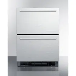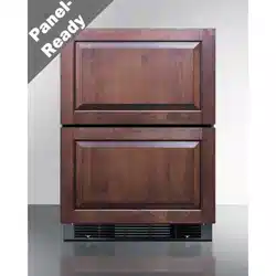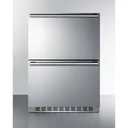
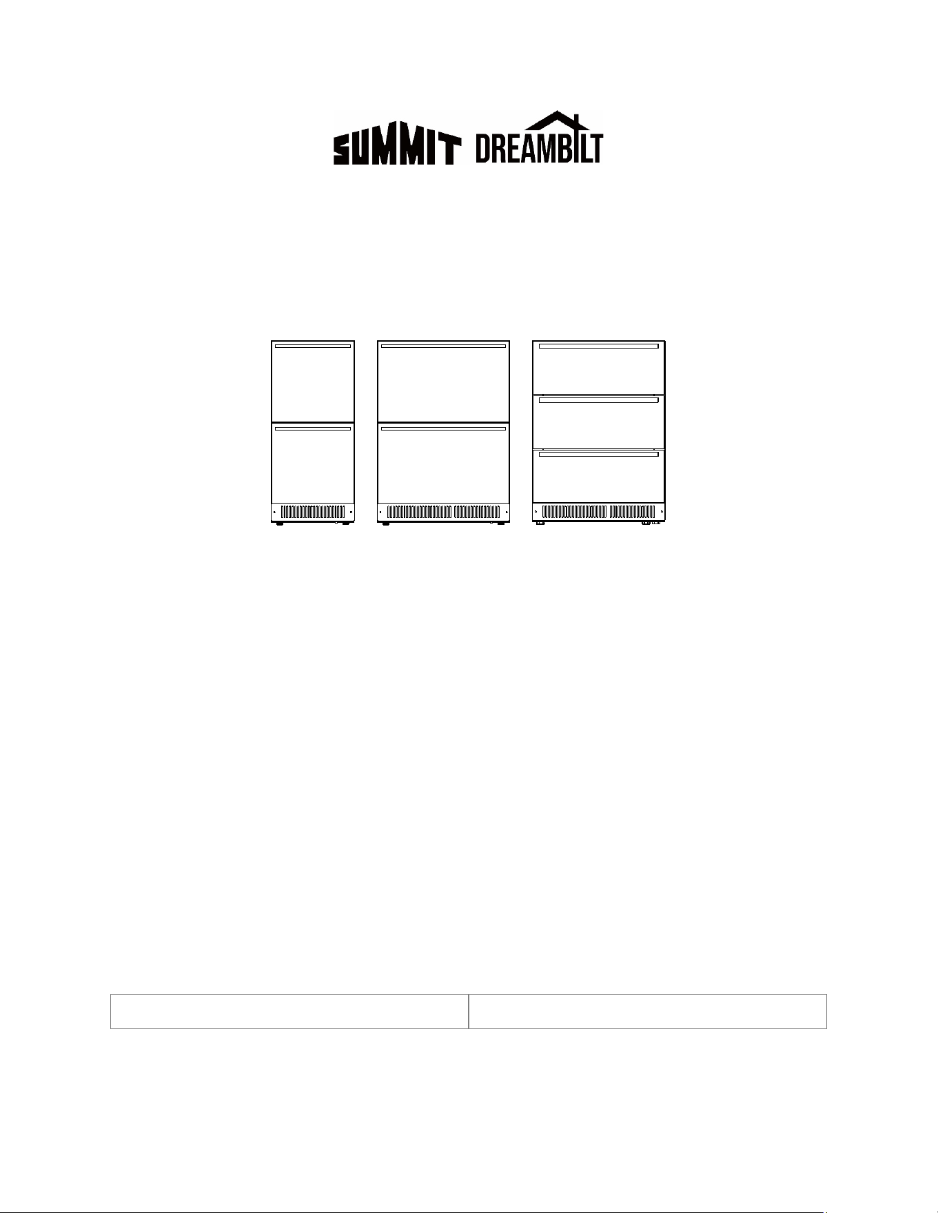
2-Drawer and 3-Drawer Refrigerators, Freezers, and
Refrigerator-Freezers (15" & 24")
User Manual
MODELS:
Refrigerators:
ADRD241 | ASDR1524 | ASDR1554 | ASDR2414 | ASDR2444 | DB2DRR1584ASD
DB2DRR1585SD | DB2DRR2486ADA | DB2DRR2487ASD | DB2DRR2488SD
DB2DRROS2489 | DB3DRR2499 | FF493D | FF642D | FF642DADA | LADR1545
LADR2433 | LDR1549 | LDR2437 | LDR24A | SDDR1558 | SDDR2448 | SDHDR1535
SDHDR2446 | SDR1529 | SDR2418 | SP6DS3D | SPR245OS3D | SPR627OS2D
Freezers:
ADFD243 | ADFD243IM | DB2DFZ2474ADA | DB2DFZ2475 | DB2DFZIM2494ADA
DB2DFZIM2495 | DB2DFZOS2478 | LDF24A | SCFF532D | SCFF532DADA
SCFF532DIM | SPFF51OS2D
Refrigerator/Freezers:
ADRF244 | ADRF244IM | DB2DRF2479ADA | DB2DRF2481 | DB2DRFIM2482ADA
DB2DRFIM2483 | LDRF24A | SPRF2D24ADA | SPRF34D | SPRF34DIM
BEFORE USE, PLEASE READ AND FOLLOW ALL SAFETY RULES AND OPERATING INSTRUCTIONS.
Models:
Serial Number:
Felix Storch, Inc.
An ISO 9001:2015 registered company
770 Garrison Ave
Bronx, New York 10474
www.summitappliance.com

2
TABLE OF CONTENTS
Appliance Safety 3
Important Safeguards 3-5
Disposal 6
Location of Parts 7-8
Installation Instructions 9-14
Before Using your Appliance 9
Installation of your Appliance 9
Connecting to the Water Supply 9
Built-In Under-Counter Instructions 10
Anti-tip Bracket Installation 11
Installing the Stainless-Steel Handles 11
Adjusting the Kick Plate 12
Fully Overlay Panel Installation 12-14
Operating your Appliance 15-18
Control Panels 15-17
Interior Light 18
Sabbath Mode 18
Temperature Memory Function 18
Defrosting 18
Using the Freezer 18
Ice Maker 18
Temperature Alarm/Door Alarm 18
Care and Maintenance 19
Cleaning your Appliance 19
Power Failure 19
Vacation Time 19
Moving your Appliance 19
Energy-Saving Tips 19
Troubleshooting 20-21
Limited Warranty 23
3
APPLIANCE SAFETY
Your safety and the safety of others are very important.
We have provided many important safety messages in this manual and on your appliance. Always read and obey all
safety messages.
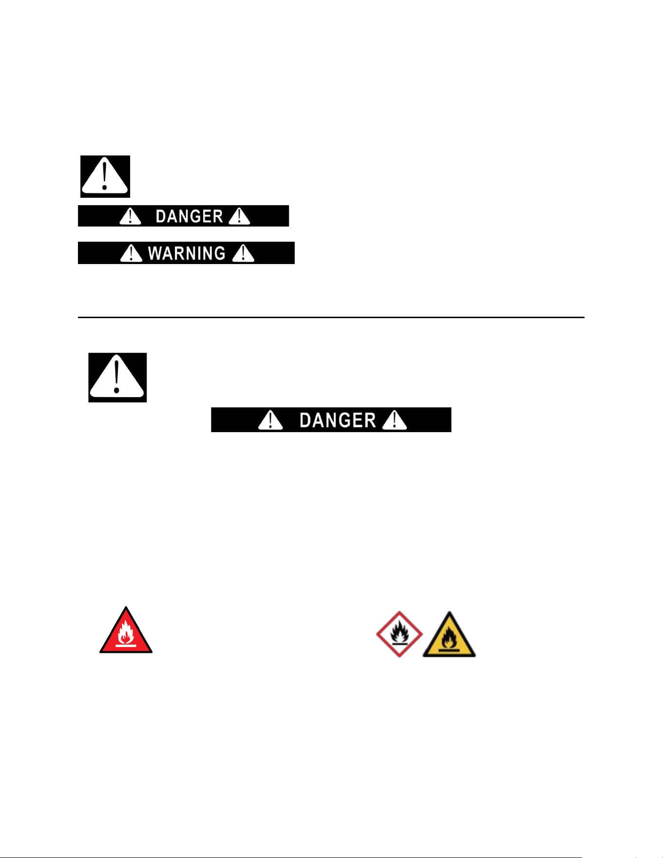
This is the Safety Alert Symbol. The symbol alerts you to potential hazards that
can kill or injure you and others. All safety messages will follow the Safety
Alert Symbol and either the words "DANGER" or "WARNING".
DANGER means that failure to heed this safety statement may
result in severe personal injury or death.
WARNING means that failure to heed this safety statement may
result in extensive product damage, serious personal injury, or
death.
All safety messages will alert you about the potential hazard, tell you how to reduce the chance of injury, and let you
know what can happen if the instructions are not followed.
IMPORTANT SAFEGUARDS
Before the appliance is used, it must be properly positioned and installed as
described in this manual, so read the manual carefully. To reduce the risk of fire,
electrical shock or injury when using the appliance, follow basic precautions,
including the following:
• Plug into a grounded 3-prong outlet, do not remove grounding prong, do not use an adapter, and do not use an
extension cord.
• Replace all panels before operating.
• It is recommended that a separate circuit serving only your appliance be provided. Use receptacles that cannot be
turned off by a switch or pull chain.
• WARNING: Never clean appliance parts with flammable fluids. These fumes can create a fire hazard or explosion.
And do not store or use gasoline or other flammable vapors and liquids or explosive substances such as aerosol
cans with a flammable propellant in this appliance or in the vicinity of this or any other appliance. The fumes can
create a fire hazard or explosion.
• Do not connect or disconnect the electric plug when your hands are wet.
• Unplug the appliance or disconnect power before cleaning or servicing. Failure to do so can result in electrical
shock or death.
• Do not attempt to repair or replace any part of your appliance unless it is specifically recommended in this manual.
All other servicing should be referred to a qualified technician.
•
• A3 Warning: Risk of Fire / Flammable Materials.
R600a
• This appliance is CFC- and HFC-free and contains small quantities of Isobutane (R600a) which is environmentally
friendly, but flammable. It does not damage the ozone layer, nor does it increase the greenhouse effect. Care must
be taken during transportation and setting up of the appliance that no parts of the cooling system are damaged.
Leaking coolant can ignite and may damage the eyes.
• In the event of any damage:
o Avoid open flames and anything which creates a spark,
o Disconnect from the power supply,
o Air the room in which the appliance is located for several minutes and
o Contact the Service Department for advice.
4
• The more coolant there is in an appliance, the larger the room it should be installed in. In the event of a leakage,
if the appliance is in a small room, there is the danger of combustible gases building up.
• For every ounce of coolant at least 325 cubic feet of room space is required. The amount of coolant in the appliance
is stated on the data plate inside the appliance. It is hazardous for anyone other than an Authorized Service Person
to carry out servicing or repairs to this appliance.
• Take serious care when handling, moving and using the appliance to avoid either damaging the refrigerant tubing
or increasing the risk of a leak.
• Replacing component parts and servicing shall be done by factory authorized service personnel, so as to minimize
the risk of possible ignition due to incorrect parts or improper service.
• This appliance is not intended for use by persons (including children) with reduced physical, sensory or mental
capabilities, or lack of experience and knowledge, unless they have been given supervision or instruction
concerning use of the appliance by a person responsible for their safety.
• Children should be supervised to ensure that they do not play with the appliance.
FOLLOW WARNING CALLOUTS BELOW ONLY WHEN APPLICABLE TO YOUR MODEL
• Use two or more people to move and install appliance. Failure to do so can result in back or other injury.
• WARNING: Keep ventilation openings, in the appliance enclosure or in the built-in structure, clear of obstruction.
• WARNING: Do not use mechanical devices or other means to accelerate the defrosting process or to clean, other
than those recommended by the manufacturer.
• WARNING: The appliance shall be stored in a room without continuously operating ignition sources (for example:
open flames, an operating gas appliance or an operating electric heater.
• WARNING: Do not pierce or burn. Do not damage the refrigerant circuit.
• WARNING: Be aware that refrigerants may not contain an odour.
• WARNING: Do not use electrical appliances inside the food storage compartments of the appliance, unless they
are of the type recommended by the manufacturer.
• WARNING: To avoid a hazard due to instability of the appliance, it must be fixed in accordance with the
instructions.
• WARNING: Danger of injury from LED lamp. If the cover is defective: do not look directly into the illumination with
optical lenses from close proximity. The eyes can be injured.
• CAUTION: Use this appliance only for its intended purpose. This equipment is intended for the storage and display
of packaged products only.
• To ensure proper ventilation for your appliance, the front of the unit must be completely unobstructed. Choose a
well-ventilated area with temperatures above 44°F (7°C) and below 90°F (32°C).
• The appliance should not be located next to ovens, grills or other sources of high heat.
• The appliance must be installed with all electrical, water and drain connections in accordance with state and local
codes. A standard electrical supply (115 V AC only, 60 Hz), properly grounded in accordance with the National
Electrical Code and local codes and ordinances, is required.
• Do not kink or pinch the power supply cord of the appliance.
• The size of the fuse (or circuit breaker) should be 15 amperes.
• It is important that the appliance be leveled in order to work properly. You may need to make several adjustments
to level it.
• Make certain that the pipes are not pinched, kinked or damaged during installation.
• Check for leaks after connection.
• Never allow children to operate, play with or crawl inside the appliance.
• Do not use solvent-based cleaning agents or abrasives on the interior. These cleaners may damage or discolor
the interior.
• Use this appliance only for its intended purpose as described in this User Manual.
• Keep fingers out of the “pinch point” areas. Clearances between the door and cabinet are necessarily small. Be
careful closing the door when children are in the area.
- SAVE THESE INSTRUCTIONS -

5
Electrical Connection
This appliance should be properly grounded for your safety. The power cord of this appliance is equipped with a three-
prong plug which mates with standard three-prong wall outlets to minimize the possibility of electrical shock.
Do not under any circumstances cut or remove the third (ground) prong from the power cord supplied. For personal
safety, this appliance must be properly grounded. Any questions concerning power and/or grounding should be directed
toward a certified electrician or an authorized service center.
This appliance requires a standard 115/120 Volt AC ~ 60Hz three-prong grounded electrical outlet. Have the wall outlet
and circuit checked by a qualified electrician to make sure the outlet is properly grounded. When a standard 2-prong
wall outlet is encountered, it is your responsibility and obligation to have it replaced with a properly grounded 3-prong
wall outlet.
To prevent accidental injury, the cord should be secured behind the appliance and not left exposed or dangling.
The appliance should always be plugged into its own individual electrical outlet which has a voltage rating that matches
the rating label on the appliance. This provides the best performance and also prevents overloading house wiring
circuits that could cause a fire hazard from overheating. Never unplug the appliance by pulling on the power cord.
Always grip the plug firmly and pull straight out from the receptacle. Repair or replace immediately all power cords that
have become frayed or otherwise damaged. Do not use a cord that shows cracks or abrasion damage along its length
or at either end. When moving the appliance, be careful not to damage the power cord.
Extension Cord
Because of potential safety hazards under certain conditions, it is strongly recommended that you do not use an
extension cord with this appliance. However, if you must use an extension cord, it is absolutely necessary that it be a
UL/CUL-Listed, 3-wire grounding type appliance extension cord having a grounding type plug and outlet and that the
electrical rating of the cord be 115 volts and at least 10 amperes.
6
DISPOSAL
Dispose of your appliance packaging properly. Ensure that any plastic wrappings, bags, etc., are disposed of safely
and kept out of the reach of babies and young children. Danger of suffocation!
Refrigeration equipment must be properly disposed of in a professional and appropriate way, in accordance with the
current local regulations and laws which protect the environment. This applies to your old appliance and to your new
unit once it has reached the end of its service life.
WARNING: Please ensure that old, worn appliances are rendered unusable before disposal by removing the doors,
removing the plug, cutting the network cable, and removing or destroying any snap fastenings or bolts. Leave shelving
in place. You will thus prevent children from locking themselves in the appliance during play (risk of suffocation) or
endangering their lives in any other way. DO NOT dispose of the appliance in landfill as the insulation (Cyclopentane)
and refrigerant gas (R600a) contained in these appliances are flammable.
Disposal instructions:
• The appliance must not be disposed of in the dustbin or with normal household rubbish.
• The coolant circuit, particularly the heat exchanger at the back/bottom of the unit, must not be damaged.
• The appliance is not to be handled as normal household waste but is to be taken to a recycling collection point for
electrical and electronic goods. By correctly disposing of this product, you are contributing to the protection of the
environment and to the health of your fellow human beings. Improper disposal endangers health and the
environment. Further information about the recycling of the product may be obtained from your town hall, refuse
collection department or the store where you purchased the product.
Risk of child entrapment!
Before discarding your old refrigerator:
• Take off the doors.
• Leave the shelves in place so that children may not easily climb inside.
Child entrapment and suffocation are not problems of the past. Junked or abandoned
appliances are still dangerous, even if they will “just sit for a few days”.
Warning
Improper use of the grounded plug can result in the risk of electrical shock. If the power cord is damaged,
have it replaced by a qualified electrician or an authorized service center.
7
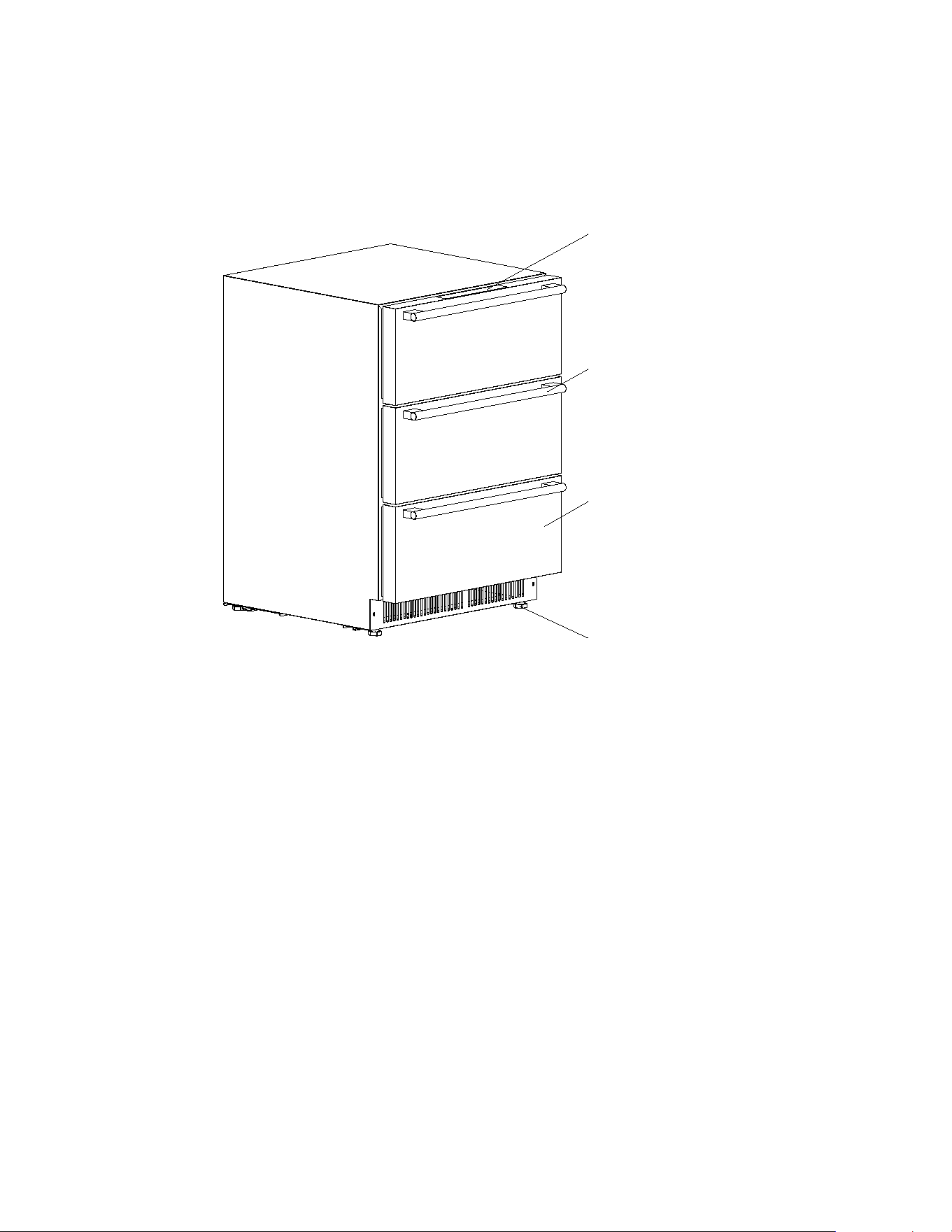
LOCATION OF PARTS
Refrigerators:
ADRD241 | ASDR1524 | ASDR1554 | ASDR2414 | ASDR2444 | DB2DRR1584ASD DB2DRR1585SD
DB2DRR2486ADA | DB2DRR2487ASD | DB2DRR2488SD | DB2DRROS2489 | FF642D | FF642DADA
LADR1545 | LADR2433 | LDR1549 | LDR2437 | LDR24A | SDDR1558 | SDDR2448 | SDHDR1535
SDHDR2446 | SDR1529 | SDR2418 | SPR627OS2D
Freezers:
ADFD243 | ADFD243IM | DB2DFZ2474ADA | DB2DFZ2475 | DB2DFZIM2494ADA | DB2DFZIM2495
DB2DFZOS2478 | LDF24A | SCFF532D | SCFF532DADA | SCFF532DIM | SPFF51OS2D
Refrigerator/Freezers:
ADRF244 | ADRF244IM | DB2DRF2479ADA | DB2DRF2481 | DB2DRFIM2482ADA | DB2DRFIM2483
LDRF24A | SPRF2D24ADA | SPRF34D | SPRF34DIM
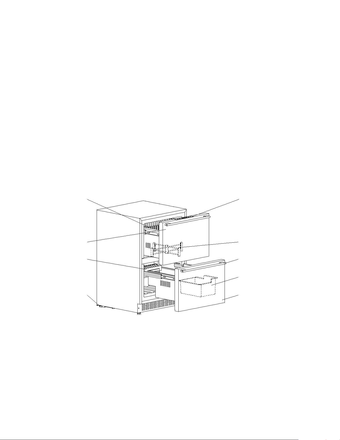
Digital Control Panel
Upper Drawer Divider
Handle
Ice Bucket (*)
Lower Drawer
Wire Rack (*)
Upper Drawer
Ice Maker (*)
Adjustable Legs
(*) Only available for certain models.
8
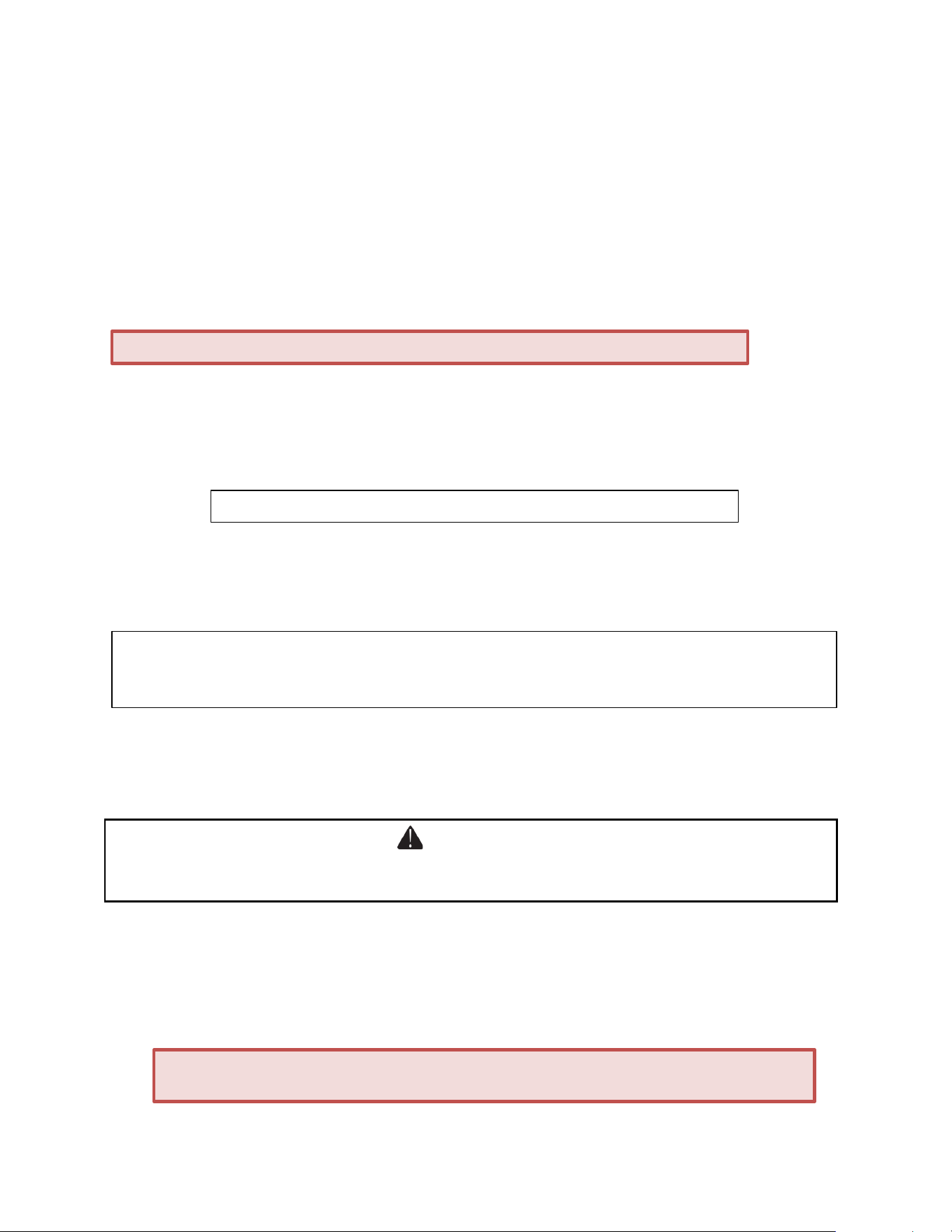
Refrigerators:
DB3DRR2499 | FF493D | SP6DS3D | SPR245OS3D
Digital Control Panel
Handle
Drawer
Adjustable Legs
9
INSTALLATION INSTRUCTIONS
Before Using your Appliance
• Remove the exterior and interior packing.
• Before connecting the appliance to the power source, let it stand upright for approximately 2 hours. This will reduce
the possibility of a malfunction in the cooling system from handling during transportation.
• Clean the interior surface with lukewarm water using a soft cloth.
• Install the handles on the drawers, if they are not already attached. (See Installing the Stainless Steel Handles.)
Installation of your Appliance
• The appliance is designed for built-in, recessed, or freestanding installation.
• For models: ADFD243, ADFD243IM, ADRD241, ADRF244, DB2DFZ2474ADA, DB2DFZIM2494ADA,
DB2DFZOS2478, DB2DRF2479ADA, DB2DRFIM2482ADA, DB2DRR2486ADA, DB2DRROS2489,
FF642DADA, LDF24A, LDR24A, LDRF24A, SCFF532DADA, SP6DS3D, SPFF51OS2D, SPR245OS3D,
SPR627OS2D, SPRF2D24ADA installation is suitable for both indoor and outdoor use.
• All other models are intended for indoor use only.
•
Place your appliance on a floor that is strong enough to support it when it is fully loaded. To level the unit, adjust
the front leveling legs.
• For free-standing installation, 5” (127mm) of space between the back and sides of the unit, and 4” (102mm) at the
top, are suggested. This allows the proper air circulation to cool the compressor and condenser. Even for built-in
installation, it is a must to keep
¼” (6.4 mm) space on each side and at the top and 2” (51mm) at the rear. Take
care that the air vent at the front of the appliance is never covered or blocked in any way.
• Avoid placing the unit in moist areas.
• Plug the appliance into an exclusive, properly grounded wall outlet.
Connecting to the Water Supply
(If available)
Prepare water supply line before installation for models with ice maker. Installation requires a 1/4" ID copper cold
water line and compression fitting (not supplied).
All the necessary hardware is not provided so it is necessary to hire a professional licensed plumber to complete the
installation.
Connect the water line to the nearest cold water source. Leave sufficient coiled copper tubing to the unit to allow the
unit to be pulled out of the cabinet or away from the wall for cleaning and service. Also make sure that the tubing is
not pinched or damaged during the transportation.
CAUTION: This appliance is not designed for the storage of medicine, or other medical products.
NOTE: Do not store or install the appliance outdoors for indoor use only models.
NOTE: It is recommended that you do not install the appliance near an oven, radiator or other heating source.
Direct sunlight may affect the outer coating and heat sources may increase electrical consumption. Don’t install in
a location where the temperature will fall below 44°F (7°C). For best performance, do not install the appliance
behind a cabinet door or block the base grille.
WARNING
Improper water line connection may result in flooding. You must use a licensed plumber. Review state and local
plumbing codes before installation.
WARNING: Connect to potable water supply only.
IMPORTANT: Water lines cannot be exposed to freezing temperatures.
10
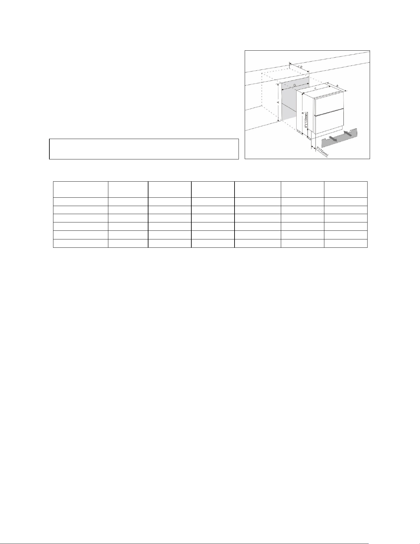
Built-In Under-Counter Instructions
Make sure your installation does not block the front ventilation grille.
The unit is designed to fit under worktops, using the height-adjustable
ventilation grille to ensure that the feet are concealed from front view.
If the unit is fully integrated to be installed for fitting kitchen plinth,
make sure that the ventilation gaps in the plinth are at least 300
square centimeters and remove the ventilation grilles, so that warm
air can disperse unhindered. Otherwise, the appliance has to work
harder, resulting in an increase in electricity consumption.
Model No.
a
(Inch/mm)
b
(Inch/mm)
c
(Inch/mm)
A
(Inch/mm)
B
(Inch/mm)
C
(Inch/mm)
ASDR1524
32" / 813
18" / 455
14¾" / 375
32⅛" / 816
18" / 455
15" / 380
SDHDR1535
34" / 864
18" / 455
14¾" / 375
34⅛" / 866
18" / 455
15" / 380
ASDR2414
32" / 813
18" / 455
23½" / 595
32⅛" / 816
18" / 455
23⅝" / 600
SDHDR2446
34" / 864
18" / 455
23½" / 595
34⅛" / 866
18" / 455
23⅝" / 600
ADRD241
32" / 813
22½" / 570
23½" / 595
32⅛" / 816
22¾" / 575
23⅝" / 600
SPR627OS2D
34" / 864
24" / 608
23½" / 595
34⅛" / 866
24" / 608
23⅝" / 600
NOTE:
1. ASDR1524 size as
ASDR1554 | DB2DRR1584ASD | LADR1545 | LDR1549 | SDDR1558 | SDR1529
2. SDHDR1535 same size as
DB2DRR1585SD
3. ASDR2414 same size as
ASDR2444 | DB2DRR2487ASD | LADR2433 | LDR2437 | SDDR2448 | SDR2418
4. SDHDR2446 same size as
DB2DRR2488SD
5. ADRD241 same size as
ADFD243 | ADFD243IM | ADRF244 | ADRF244IM | DB2DFZ2474ADA | DB2DFZIM2494ADA
DB2DRF2479ADA | DB2DRFIM2482ADA | DB2DRR2486ADA | FF642DADA | LDF24A
LDR24A | LDRF24A | SCFF532DADA | SPRF2D24ADA
6. SPR627OS2D same size as
DB2DFZ2475 | DB2DFZIM2495 | DB2DFZOS2478 | DB2DRF2481 | DB2DRFIM2483
DB2DRROS2489 | DB3DRR2499 | FF493D | FF642D | SCFF532D | SCFF532DIM
SP6DS3D | SPFF51OS2D | SPR245OS3D | SPRF34D | SPRF34DIM
NOTE: When pushing the appliance into the niche, make sure
that the mains cable does not get trapped.
11
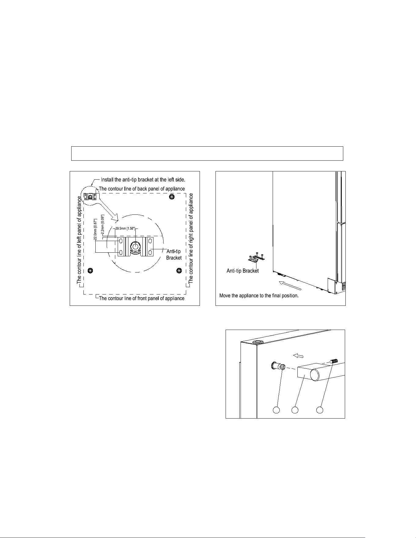
Anti-tip Bracket Installation
To reduce the risk of tipping the unit by abnormal usage or improper loading, the appliance must be secured by
properly installing the anti-tip device packed with the appliance.
• Place the anti-tip bracket on the floor as shown in the figure. An anti-tip bracket must be installed at the left
side.
• Mark the locations of the 4 holes of the anti-tip bracket on the floor.
• Use a 5/16” masonry drill bit and insert plastic anchors.
• Secure bracket to floor using screws.
• Slide appliance into position and make sure the leg engages the anti-tip bracket.
Installing a Stainless-Steel Handle
This appliance includes the stainless-steel handles that are
not required to operate the unit. To install the handles, follow
the instructions below:
Locate the handle (2) over the mounting stud (1) of the door
and using the supplied Allen key, tighten the securing grub
screws (3) to fix the handle.
1
2
3
NOTE: If the unit is relocated, the bracket must be removed and installed in the new location.
12
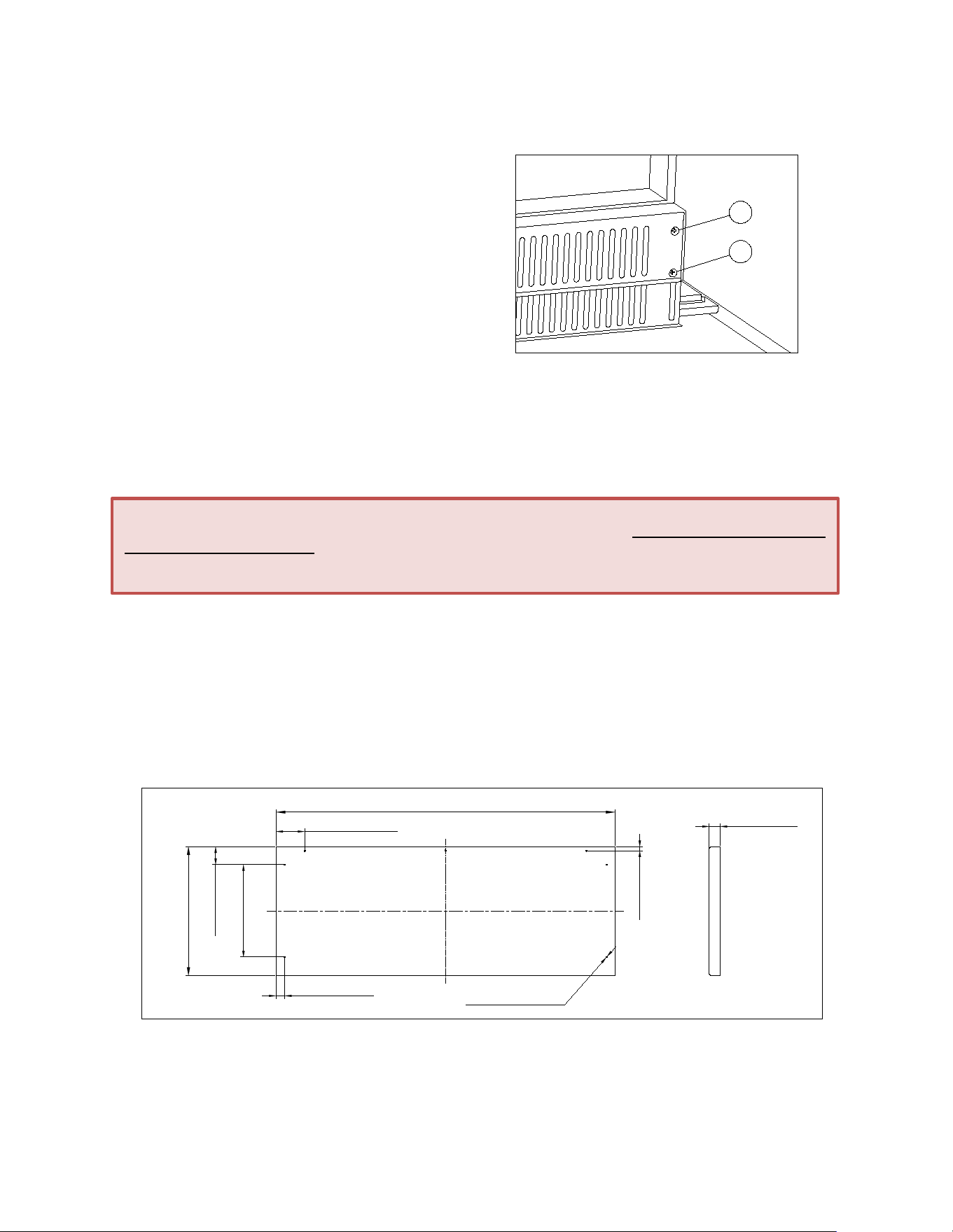
Adjusting the Kick Plate
(Only for ADA models)
The pre-fitted kick-plate of the appliance includes an
adjustable kick-plate section that is initially seated behind the
upper section. To adjust the kick-plate height, follow the
instructions below:
1. Remove the screws (1) from both the top left- and top
right-hand sides of the kick-plate.
2. Loosen or remove the screws (2) from both the bottom
left- and bottom right-hand sides of the kick-plate.
Failure to loosen the bottom screws sufficiently may
cause damage to the lower trim when adjusting it.
3. Carefully guide the lower trim down until the desired
height is achieved.
4. Reinsert screws and tighten them.
Full Overlay Panel Installation
(Optional)
An overlay panel covers the stainless steel to give it an integrated appearance. There are two installation options for
attaching the overlay panel to the unit’s door. Option 1 does not require drilling through the unit door and can be easily
installed using the bracket kit provided with your unit. Option 2 requires drilling into the unit door for a flush appearance.
The overlay panel and appropriate hardware are not included with the unit. Please refer to the instructions for both
options and choose the one that best suits your needs.
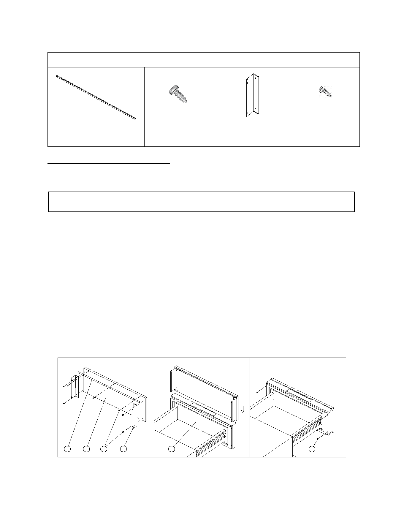
Overlay Panel Preparation
Prepare the overlay panel to the dimensions as per the descriptions given below.
H
W
19mm [3/4"]
7-§ ¶2.5mm [§ ¶1/10'']
6mm[15/64''] DEEP
35mm [1 3/8"]
15mm [19/32"]
50mm [1 31/32"]
8mm [5/16"]
180mm [7 3/32"]
IMPORTANT:
1. H = height of door + 3/80” (1mm), W = width of door + 5/32” (4mm).
2. Ensure that all new holes are drilled to the correct depth to avoid splits in the wood when hardware is installed.
1
2
Important Note:
The instructions below require pulling the complete drawer from its cabinet tracks. Do not attempt to remove the
drawer front from the tracks, as this will damage the wires connected to the digital thermostat. Damage incurred
from inappropriate installation and/or failure to follow these instructions will not be covered by your manufacturer's
warranty.
13
Door Panel Installation Option 1:
(using bracket kit provided)
This is an easier installation option that does not require drilling into the unit’s door.
Installing the Handle(s) on the Overlay Panel
If reusing the handle(s) that came with the unit:
1. Unscrew the studs located on the front face of the drawer and set them aside for later use.
2. Remove the screws from the drawer and proceed to mark their positions on the overlay panel by using the
handle as a guide.
3. Use a 3/16” (5mm) drill bit to the make the holes on the overlay panel for the screws.
4. Insert the screws, making sure to leave the head of the screw flush with the surface of the panel
(countersink screws if necessary).
5. Take the studs you saved in Step 1 and screw them back. They are now projecting from the face of the
panel.
6. Place the handle over the mounting studs and, using the supplied Allen key, tighten the securing grub
screws to fix the handle. Refer to “Installing a Stainless Steel Handle” (Refer to page 11).
If using a customer supplied handle(s):
1. Attach the handle to the overlay panel by using flat head or countersunk screws.
Figure 1
a c
d
b
e
f
Figure 2 Figure 3
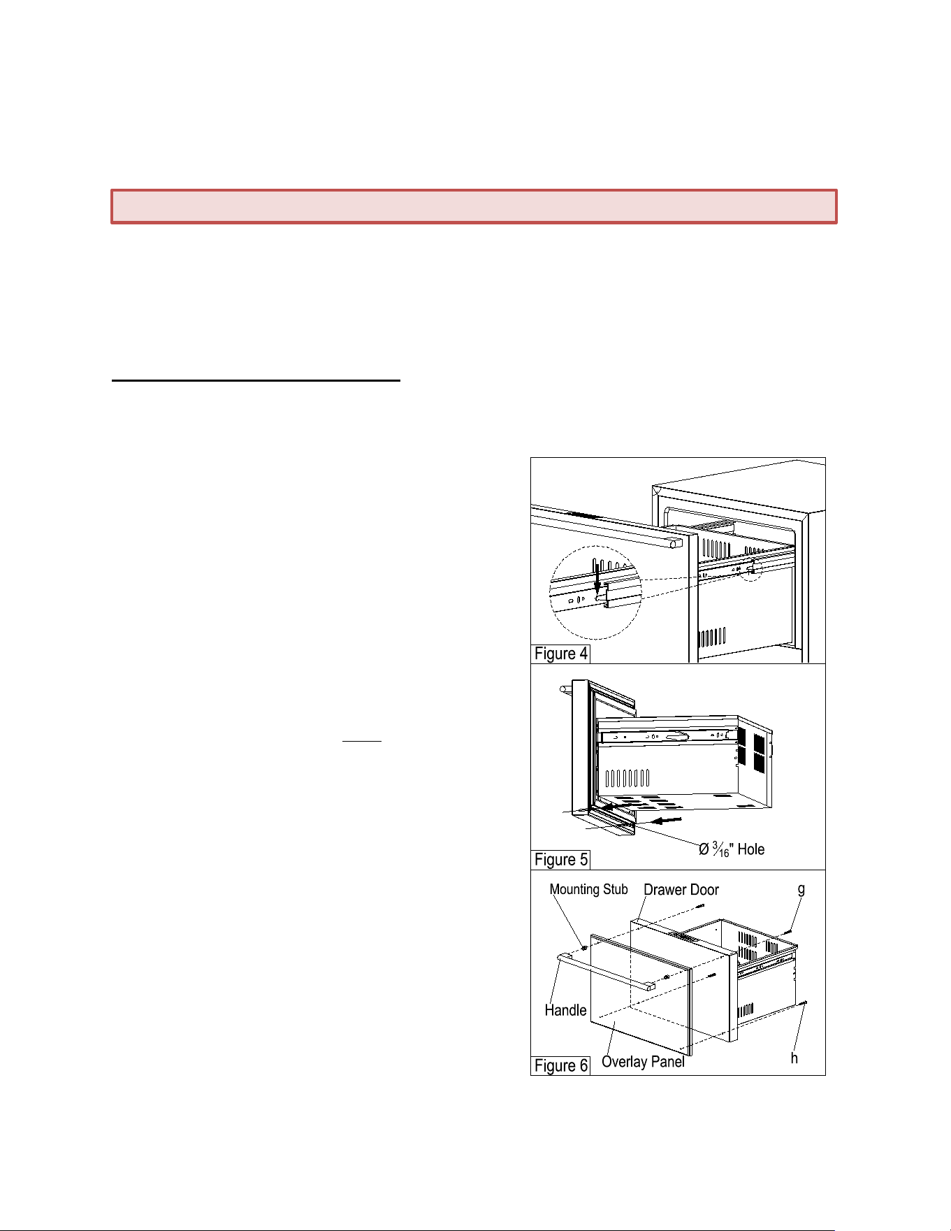
Included in the Bracket Kit
stainless trim (1)
per drawer
truss head screws (7)
per drawer
mounting brackets (2)
per drawer
pan head screws (4)
per drawer
NOTE: This option will leave a 3/16” (5mm) gap between the overlay panel and the top of door. The stainless-
steel trim (included in the kit) will fill this gap.
a.
c.
d.
f.
14
Installing the Bracket
1. Attach the stainless trim (a) at the top of the wood overlay panel (b) with (3) #8 x 3/8 truss head Phillips self-
tapping screws (c). (see Figure 1)
2. Drill the 2 mounting brackets (d) on either side of the wood overlay panel with (4) #8 x 3/8 truss head Phillips
screws (c). (see Figure 1)
3. Align the brackets (d) with the sides of the unit door (e) gently sliding wood overlay panel into place. (see Figure
2)
4. Drill (4) #8 x 3/8 pan head Phillips self-tapping screws (f) to secure the bracket to the door. (see Figure 3)
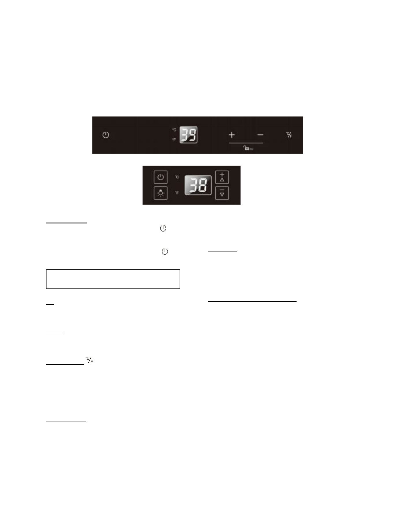
Door Panel Installation Option 2:
This option will leave the panel flush with the door but will require drilling through the front door(s) of the unit. (Hardware
is not included for this option).
1. Empty the drawers of any items.
2. Release the drawers from the track by pressing the right
lever down and lifting the left lever up at the same time. (see
Figure 4).
3. Pull the drawer completely off the cabinet tracks.
4. Peel gasket off the door groove and set it aside.
5. Unscrew the mounting studs that are on the door. Set them
aside for later use.
6. Remove the screws that were holding the studs in place.
7. Drill 2 new holes into the door groove at the lower inside of
the drawer with a 3/16” (5mm) drill bit until it goes through
the door face (see Figure 5).
8a. If reusing the handle(s) that came with the unit:
• Replace the screws from Step 6 with #10-32 UNF x 2.5
screws (g). (see Figure 6)
• Drill 2 holes with diameter 3/16” (5mm) into the overlay
panel at the top. The holes MUST match the position
of the protruding screws on the door.
• Mount the overlay panel on to the protruding screws.
• Screw the studs from Step 5 into the screw.
• Refer to Page 11 for handle installation.
• Drill 2 #10x2 Phillips self-tapping screws (h) through
the existing holes in the door groove at the bottom to
secure the overlay panel. (see Figure 6)
8b. If using a customer supplied handle(s):
• Attach the handles to the wood overlay panels with flat
head screws till they are flush.
• Drill 4 #10x2 Phillips self-tapping screws (h) through
the 4 existing holes in the door groove to secure the
overlay panel. (see Figure 6)
9. Reapply the gaskets, then align the left and right slide
channels with the tracks in the cabinet. Ensuring an even
engagement on both sides of the track, and gently push the
drawer into the cabinet until it stops.
Important Note: Tape over the head of the screws with a strong hold tape to prevent scratching the unit door.
15
OPERATING YOUR APPLIANCE
It is recommended you install the appliance in a place where the ambient temperature is between 44º and 95ºF (7º and
35ºC). If the ambient temperature is above or below the recommended temperatures, the performance of the unit may
be affected. For example, placing your unit in extremely cold or hot conditions may cause interior temperatures to
fluctuate. The expected operating temperature range may not be reached.
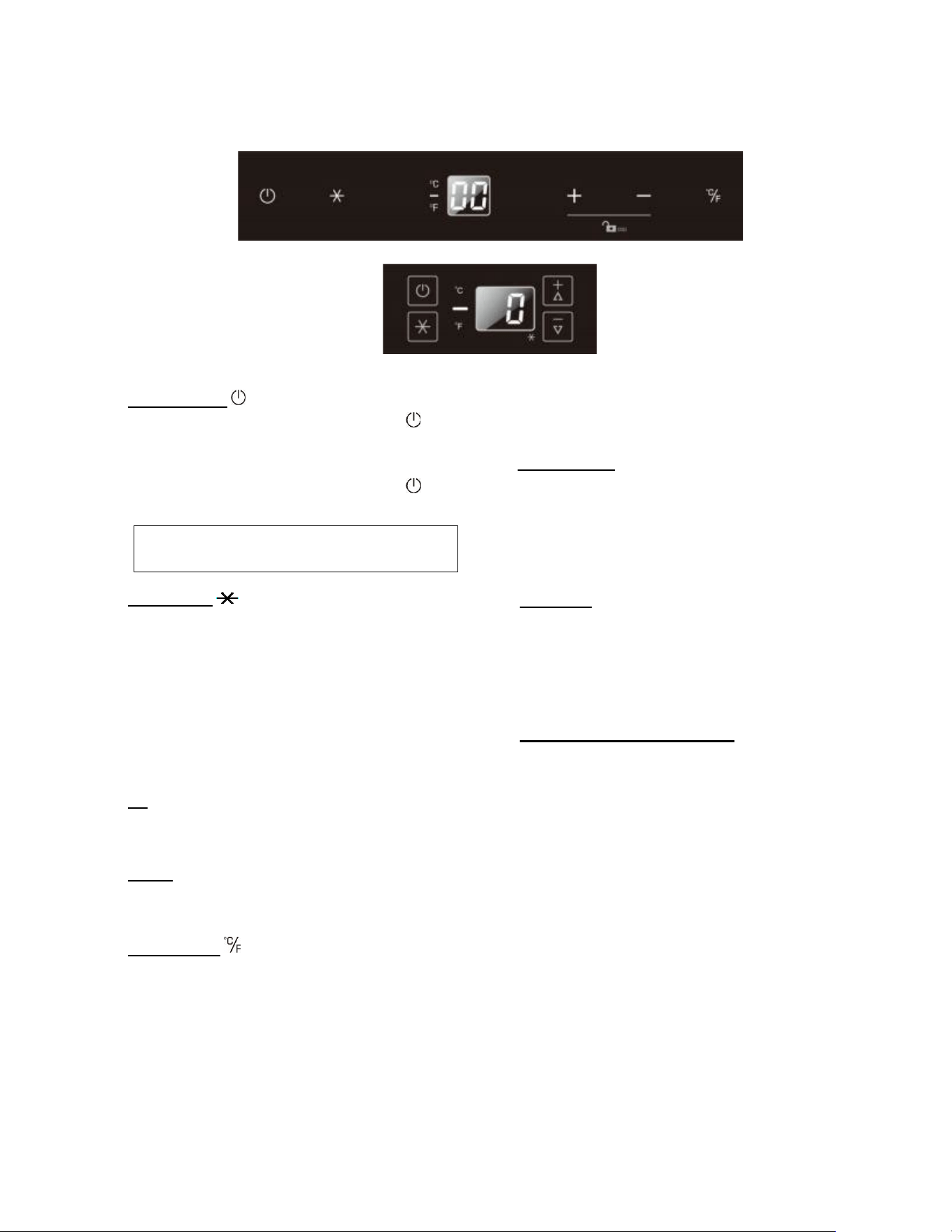
Control Panel for Refrigerators
*
**
ON/OFF Power
To turn the appliance off, press and hold the key for
5 seconds until the temperature display goes off.
To turn the appliance on, press and hold the key
for 1 second until the temperature display lights up.
UP +
Used to increase (warm) the set temperature by
1°C/1ºF.
DOWN -
Used to decrease (cool) the set temperature by
1°C/1ºF.
ºF/ºC Selector
* Select the temperature display in Fahrenheit or
Celsius degrees.
** To change the temperature from Fahrenheit to
Celsius or from Celsius to Fahrenheit, press and hold
the LIGHT key for 5 seconds.
Indicator Light
The indicator light is the dot located at the bottom
right corner of the display. The indicator light will be
on when a multi-key function is selected.
To perform a multi-key function, touch and hold the
first key, then touch the second key for at least 5
seconds and then release both keys.
Child Lock
* If in 2 minutes or longer without touching any key,
the child lock will be activated automatically. To
cancel the lock, press the UP and DOWN keys at the
same time for at least 5 seconds and the indicator
light will flash three times to confirm the action.
Setting the Temperature Control
• Set the temperature by pressing the UP and
DOWN keys. Pressing either key for the first time,
the LED readout will display the last temperature
setting. (The temperature is preset to 38°F / 3°C).
• To set the temperature, press the UP key to
increase by 1°F / 1°C with each press. Press the
DOWN key to decrease by 1°F / 1°C with each
press.
• The range of the temperature control is from 36°F
to 43°F (2°C to 6°C).
• To view the set temperature at any time, press the
UP or DOWN key. The set temperature will flash
in the display window for 5 seconds. After 5
seconds, the temperature inside the unit will
reappear on the display window.
NOTE: Pressing this key once will switch off the
audible alarm when the alarm is on.
16
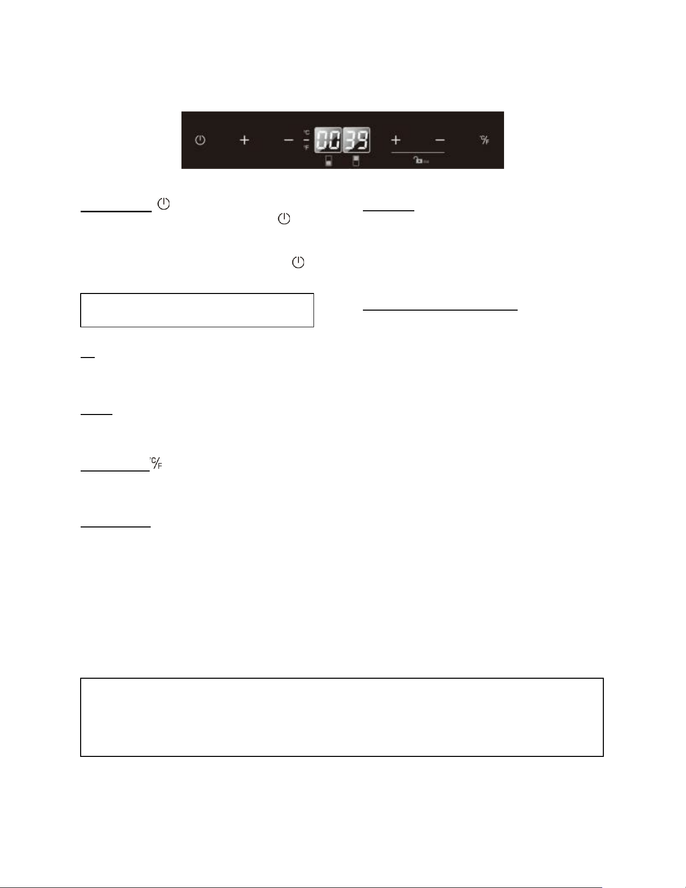
Control Panel for Freezers
*
**
ON/OFF Power
To turn the appliance off, press and hold the key
for 5 seconds until the temperature display goes
off.
To turn the appliance on, press and hold the key
for 1 second until the temperature display lights up.
SuperFreeze
The SuperFreeze function quickly freezes fresh food
by overriding the thermostat control, allowing the
compressor to run continuously. It is not necessary
to adjust the thermostat when using this function.
When activated, the SuperFreeze indicator (light at
the bottom right of the display) will light up. Press the
SuperFreeze key again to cancel; the indicator will
turn off. SuperFreeze turns off automatically after 8
hours.
UP +
Used to increase (warm) the set temperature by
1°C/1ºF.
DOWN -
Used to decrease (cool) the set temperature by
1°C/1ºF.
ºF/ºC Selector
* Select the temperature display in Fahrenheit or
Celsius degrees.
** To change the temperature from Fahrenheit to
Celsius or from Celsius to Fahrenheit, press and
hold the SuperFreeze key for 5 seconds.
Indicator Light
The indicator light is located at the bottom right
corner of the display. The indicator light will be on
when a multi-key function is selected. To perform a
multi-key function, touch and hold the first key, then
touch the second key for at least 5 seconds and
then release both keys.
Child Lock
* If in 2 minutes or longer without touching any key,
the child lock will be activated automatically. To
cancel the lock, press the UP and DOWN keys at
the same time for at least 5 seconds and the
indicator light will flash three times to confirm the
action.
Setting the Temperature Control
• Set the temperature by pressing the UP and
DOWN keys. Pressing either key for the first time,
the LED readout will display the last temperature
setting. (The temperature is preset to 0°F / -18°C).
• The temperature you are setting will increase by
one degree each time you press the UP key and
will decrease by one degree each time you press
the DOWN key.
• The range of the temperature control is from -11°F
to 11°F (-24°C to -12°C).
• To view the set temperature at any time, press the
UP or DOWN key. The set temperature will flash
in the display window for 5 seconds. After 5
seconds, the temperature inside the unit will
reappear on the display window.
NOTE: Pressing this key once will switch off the
audible alarm when the alarm is on.
17
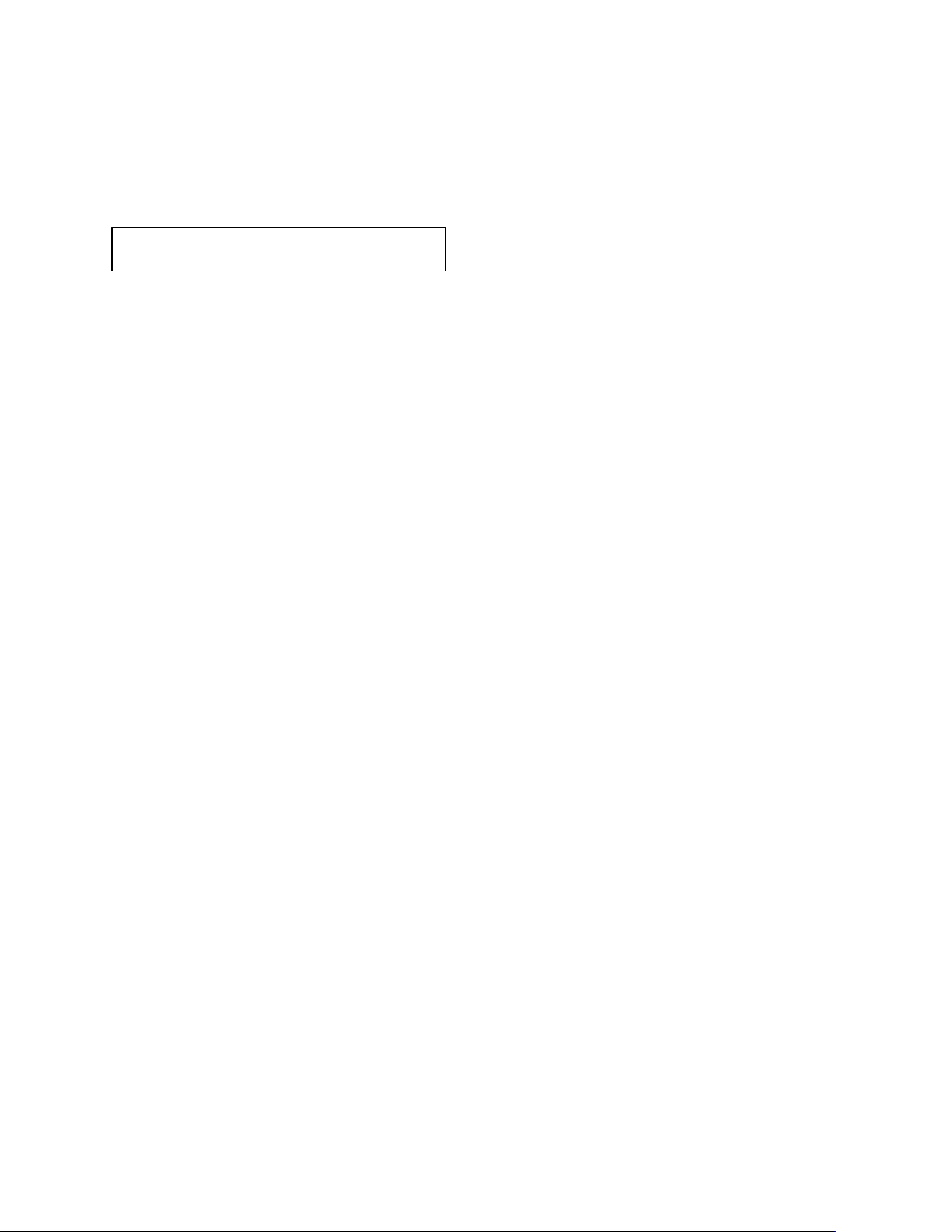
Control Panel for Refrigerator/Freezers
ON/OFF Power
To turn the appliance off, press and hold the key for
5 seconds until the temperature display goes off.
To turn the appliance on, press and hold the key
for 1 second until the temperature display lights up.
UP +
Used to increase (warm) the set temperature by
1°C/1ºF.
DOWN -
Used to decrease (cool) the set temperature by
1°C/1ºF.
ºF/ºC Selector
Select the temperature display setting in Fahrenheit
or Celsius degree.
Indicator Light
The indicator light is the dot located at the bottom right
corner of the display. The indicator light will be on when
a multi-key function is selected. To perform a multi-key
function, press and hold the first key, then touch the
second key for at least 5 seconds and then release
both keys.
Child Lock
If in 2 minutes or longer without touching any key, the
child lock will be activated automatically. To cancel the
lock, touch the UP and DOWN keys at the same time
for at least 5 seconds and the indicator light will flash
three times to confirm the action.
Setting the Temperature Control
• The unit has two separate temperature
compartments. You can set the temperature of the
bottom compartment (freezer) by touching the left
UP and DOWN symbols and set the temperature
of the top compartment (refrigerator) by touching
the right UP and DOWN symbols. When you touch
either key for the first time, the LED readout will
show the original temperature set previously. (The
factory preset temperature is 0°F / -18°C for the
freezer and 38°F / 3°C for the refrigerator.)
• The temperature you are setting will increase by
one degree each time you touch the UP key, and
will decrease by one degree each time you touch
the DOWN key.
• The temperature control range is -11°F to 11°F
(-24°C to -12°C) for the freezer compartment, and
36°F to 43°F (2°C to 6°C) for the refrigerator
compartment.
• To view the set temperature at any time, press the
UP or DOWN key. The set temperature will flash
in the display window for 5 seconds. After 5
seconds, the temperature inside the unit will
reappear on the display window.
NOTE:
• If the unit is unplugged, or there is a power loss or shutdown, wait 3–5 minutes before restarting. The unit will
not start if you try sooner.
• When first using the unit, or after it has been off for a long time, the temperature on the display may differ
slightly from the set temperature. This is normal and will correct itself after a few hours of operation.
NOTE: Press the power key to switch off the
audible alarm when the alarm is on.
18
Interior Light
The unit is equipped with the interior LED lights which
will be turned ON when a door is opened. The LED type
lights are designed for extremely long life. They are not
user serviceable. To change them please contact our
technical service department.
Sabbath Mode
Sabbath Mode is available for the observance of
certain religious holidays. This mode turns off the
displays, interior light and audible alarms and prevents
them from turning on again. Normal cooling operations
will still take place.
To initiate Sabbath Mode, touch and hold the POWER
and ºC/F or LIGHT or SUPERFREEZE keys
simultaneously for at least 5 seconds. The displays will
go off to confirm the Sabbath Mode is ON.
Sabbath Mode can be canceled by repeating the above
process. The Sabbath Mode will automatically turn off
after 96 hours.
Temperature Memory Function
In the event of a power interruption the unit can
remember the previous temperature settings, and
when the power is recovered, the cabinet temperature
will return to the same setting temperature as before
the power went off.
Defrosting
• Under normal operating conditions, the unit
requires no manual defrosting.
• The evaporator behind the rear wall of the unit
defrosts automatically. The condensate collects in
the drainage channel behind the rear wall of the
unit and flows through the drainage hole into the
drip tray by the compressor where it evaporates.
• However, frost may accumulate on the evaporator
if the unit is repeatedly opened in high heat or high
humidity locations. If this frost pattern does not
clear within 24 hours, your unit will require manual
defrosting.
Using the Freezer (if available)
• This unit is designed for the long-term storage of
frozen food. Storage time is up to three months.
• The storage life of frozen foods varies, and the
recommended storage time should not be
exceeded.
• Pre-packed commercially frozen food should be
stored in accordance with the frozen foods
manufacturer’s instructions for a three-star frozen
food storage compartment or home freezer.
• Place frozen food into the freezer as quickly as
possible after purchase. If there are instructions on
the packet, carefully follow these instructions
regarding storage times.
Ice Maker (if available)
Ensure the water supply is ON and lower the bail arm
on the ice maker to its ON position. As soon as the
inner mechanism reaches the proper temperature, the
ice maker will fill the mold with water.
The first cubes may be small because of air in the water
line. Later cubes will be of standard crescent moon
type size.
For the first time to use:
• Let the ice maker make ice for 1-2 days.
• Discard the first 2-3 batches of ice to remove the
impurities in the water supply system.
When the ice bucket is full, the ice making mechanism
will automatically shut off.
Ice delivery may be interrupted by raising the bail arm
to the OFF position.
If the ice maker is not used regularly, it is
recommended that the ice bucket be emptied
periodically to insure fresh ice.
Temperature Alarm/Door Alarm
• An audible alarm sounds if the storage
temperature is not cold enough. The temperature
display flashes at the same time.
• The cause of the temperature being too high may
be:
• Warm fresh food was placed inside.
• Too much warm ambient air flowed in when
rearranging and removing food.
• Power failure for some time
• The appliance is faulty.
• The audible alarm is automatically silenced, and
the temperature display stops flashing when the
temperature is sufficiently cold again.
• If a drawer has been left open for more than 60
seconds, the alarm will sound. Pressing the
POWER key once switches off the audible alarm.
NOTE: Only use the original LED light fittings
provided by the manufacturer.
19
CARE AND MAINTENANCE
Cleaning Your Appliance
• Turn off the power, unplug the appliance, and remove all items, including racks and dividers.
• Wash the inside surfaces with a solution of warm water and baking soda (about 2 tablespoons of baking soda to
a quart of water).
• Wash the racks and dividers with a mild detergent solution.
• Wring excess water out of the sponge or cloth when cleaning the area where the controls are located, or any
electrical parts.
• Wash the outside cabinet with warm water and mild liquid detergent. Rinse well and wipe dry with a clean, soft
cloth.
• Use an approved stainless-steel cleaner to clean the doors and handles. Do not use steel wool or a steel brush on
the stainless steel.
Power Failure
Most power failures are corrected within a few hours and should not affect the temperature of your appliance if you
minimize the number of times the drawers are opened. If the power is going to be off for a longer period of time, you
need to take the proper steps to protect the contents.
Vacation Time
• Short vacations: Leave the appliance operating during vacations of less than three weeks.
• Long vacations: If the appliance will not be used for several months, remove all items and turn off the appliance.
Clean and dry the interior thoroughly. To prevent odor and mold growth, leave the drawers open slightly, blocking
them open if necessary.
Moving your Appliance
1. Remove all items.
2. Securely tape down all loose items (racks, dividers) inside your appliance.
3. Turn the adjustable legs up to the base to avoid damage.
4. Tape the drawers shut.
5. Be sure the appliance stays secure in the upright position during transportation. Also, protect the outside of the
appliance with a blanket or similar item.
Energy-Saving Tips
• The appliance should be located in the coolest area of the room or outdoor location, away from heat-producing
appliances and out of direct sunlight.
• Ensure that the unit is adequately ventilated. Never cover air vents.
• Do not keep the drawers open any longer than necessary.
• Let hot foods cool to room temperature before placing in the unit. Overloading the unit forces the compressor to
run longer.
• Be sure to wrap foods properly, and wipe containers dry before placing them in the unit. This cuts down on frost
build-up inside the unit.
• Unit bins and racks should not be lined with aluminum foil, wax paper, or paper toweling. Liners interfere with cold
air circulation, making the unit less efficient.
• Organize and label food to reduce drawer openings and extended searches. Remove as many items as needed
at one time and close the drawer as soon as possible.
CAUTION:
Failure to unplug the appliance during cleaning could result in electrical shock or other personal injury.
20
TROUBLESHOOTING
You can solve many common problems easily, saving you the cost of a possible service call. Try the suggestions below
to see if you can solve the problem before calling the servicer.
PROBLEM
POSSIBLE CAUSE
REMEDY
Appliance does not
operate.
Appliance is not connected to a power supply.
The appliance is turned off.
Tripped circuit breaker or blown fuse
Connect the appliance.
Switch on the appliance.
Switch on circuit breaker or replace fuse.
Appliance is not
cold enough.
The temperature is not set correctly.
The ambient temperature could require a lower
temperature setting.
Drawers were opened too often.
A drawer was not closed completely.
Drawer is not hermetically sealed.
The condenser is too dirty.
The ventilation opening is blocked or too dusty.
Check the set temperature.
Set a lower temperature.
Do not open drawers more often than
necessary.
Close drawer properly.
Check the seal and clean or replace.
Clean the condenser when necessary.
Clear the obstructions and clean off the dust.
Appliance turns
itself on and off
frequently.
The room temperature is higher than average.
A large amount of food has been added to the
unit.
Drawers are opened too often.
A drawer is not closed completely.
A drawer gasket does not seal properly.
Put the appliance in a cooler place.
Leave the appliance to work for a while until the
set temperature has been reached.
Do not open the drawers more often than
necessary.
Close drawer properly.
Check the drawer seal and clean or replace it.
The light does not
work.
Appliance is not connected to a power supply.
Tripped circuit breaker or a blown fuse.
The light was switched off on the control panel.
Connect the appliance.
Switch on circuit breaker or replace fuse.
Switch on the light.
Vibrations
The appliance is not properly leveled.
Level the appliance with the adjustable feet.
The appliance
seems to make too
much noise.
The rattling noise may come from the flow of the refrigerant, which is normal. As each cycle ends,
you may hear gurgling sounds caused by the flow of refrigerant in your appliance.
If temperature fluctuations occur, the contraction and expansion of the inner walls may cause
popping and crackling noises.
The appliance is not properly leveled.
Level the appliance with the adjustable feet.
One or more of the following sounds is heard:
- Buzzing
- Trickling water
- Thud (clatter of ice)
The water valve is operating.
Water is entering the icemaker to fill cup.
Ice is being dumped into the ice bin.
Drawers
will not close
properly.
The appliance is not properly leveled.
The gaskets are dirty.
The racks or bins are out of position.
Level the appliance with the adjustable feet.
Clean the drawer gaskets.
Check the racks and bins and refit correctly.
Display “E0”, “E1”.
“E2”, “E3”, “E4”,
“E5” or “E7”.
“E0” indicates a communication error for 3
zone models.
“E1” or “E2” indicates that the air temperature
sensor has failed.
“E3” or “E4” indicates that the defrost sensor
in the evaporator has failed.
“E5” indicates defrost heater failure.
“E7” indicates door switch failure.
Call for service.
The alarm sounds
and the
temperature display
flashes.
Has a drawer been open for longer than 60
seconds? If not, then the temperature has
risen higher or fallen lower than the
temperature that has been set. This could be
due to:
The appliance drawers being opened too often.
The ventilation opening being covered or too
dusty.
If yes, close the drawer.
Do not open drawers more often than
necessary.
Clear the obstructions and clean off the dust.
Leave the appliance to work for a while until the
set temperature has been reached.
21
A lengthy interruption in the power supply.
A large amount of food has been added to the
unit.
The icon “--” is lit
and flashing in the
temperature
display.
The display temperature is out of range.
Only temperatures within the range 16~99°F/-
9~37°C for refrigerators and the range -
99~99°F/-73~37°C for freezers can be
displayed. If the temperature is not within this
range, the icon “--” will be displayed instead.
This is normal.
Ice tastes stale.
The ice is old.
Make a new batch.
Water in icemaker
overflows
Refrigerator or icemaker is not level.
If the icemaker still overflows after leveling.
Level the appliance with the adjustable feet.
Water pressure must be 20-80 psi.
Turn off the icemaker’s water supply at the shut-
off valve and raise the icemaker’s bail arm to the
“off” position (see previous page); then contact
your local service center.
Not enough ice.
It will take 48 hours to fill the ice bucket. The
icemaker will make ice every 2 to 3 hours.
For more ice, adjust the freezer control to a
colder setting.
Ice making has
stopped.
Be sure that the bail arm is lowered to its ON
position. Make sure that the water shut-off
valve is open. The water shut-off valve or the
water valve screen is clogged.
Contact your local service center.
If you have checked the information above and you still need help with your appliance, call our Customer
Service facility at 800-932-4267 (Ext. 513) between 9:00 AM and 5:00 PM ET or visit our website
summitappliance.com/support at any time. We will do our best to answer your questions.
To order replacement parts, visit our website: summitapplianceparts.com
WARNING: This product can expose you to chemicals including Nickel (Metallic)
which is known to the State of California to cause cancer.
For more information go to www.P65Warnings.ca.gov
Note: Nickel is a component in all stainless steel and some other metallic compositions.
CALIFORNIA CARB/SNAP DISCLOSURE
This product uses eco-friendly hydrocarbon refrigerant and fully complies with California CARB
regulations.
However, we are required by California Law to provide the following disclosure statement in every product sold in
California.
"This equipment is prohibited from use in California with any refrigerants on the 'List of Prohibited Substances' for
that specific end-use, in accordance with California Code of Regulations, title 17, section 95374. This disclosure
statement has been reviewed and approved by Felix Storch, Inc. and Felix Storch, Inc. attests, under penalty of
perjury, that these statements are true and accurate."
This product does not use any refrigerants on the 'List of Prohibited Substances'

22
NOTES
23
LIMITED WARRANTY
ONE-YEAR LIMITED WARRANTY
Warranty coverage is available within the 48 contiguous United States, along with select areas of Alaska, Hawaii,
and Canada. For locations not covered, consumers can either contact a local provider or coordinate with Felix
Storch, Inc. to find nearby service options, which may qualify for partial reimbursement.
The warranty for this appliance is valid for one year from the date of purchase, provided the appliance is operated
and maintained according to the instructions included with the product. The warrantor will cover the cost of factory-
specified parts and repair labor needed to correct defects in materials or workmanship. Service must be performed
by a designated service company.
All parts, except the compressor, are warranted for one year against manufacturing defects. Plastic parts, shelves,
and cabinets are produced to commercially acceptable standards but are not covered for damages incurred during
handling or for breakage.
5-YEAR COMPRESSOR WARRANTY
1. The compressor is covered for 5 years.
2. Replacement does not include labor.
ITEMS WARRANTOR WILL NOT PAY FOR:
1. Service calls to correct the installation of your appliance, to instruct you how to use your appliance, to replace
or repair fuses or to correct wiring or plumbing.
2. Service calls to repair or replace appliance light bulbs or broken shelves. Consumable parts (such as filters)
are excluded from warranty coverage.
3. Damage resulting from accident, alteration, misuse, abuse, fire, flood, acts of God, improper installation,
installation not in accordance with electrical or plumbing codes, or use of products not approved by warrantor.
4. Replacement parts or repair labor costs for units operated outside the 48 contiguous United States, along with
select areas of Alaska, Hawaii, and Canada.
5. Repairs to parts or systems resulting from unauthorized modifications made to the appliance.
6. Expenses for travel and transportation for product service in remote locations.
7. The removal and reinstallation of your appliance if it is installed in an inaccessible location or is not installed
in accordance with published installation instructions.
DISCLAIMER OF IMPLIED WARRANTIES; LIMITATION OF REMEDIES
CUSTOMER'S SOLE AND EXCLUSIVE REMEDY UNDER THIS LIMITED WARRANTY SHALL BE PRODUCT REPAIR AS
PROVIDED HEREIN. IMPLIED WARRANTIES, INCLUDING WARRANTIES OF MERCHANTABILITY OR FITNESS FOR A
PARTICULAR PURPOSE, ARE LIMITED TO ONE YEAR. WARRANTOR SHALL NOT BE LIABLE FOR INCIDENTAL OR
CONSEQUENTIAL DAMAGES. SOME STATES DO NOT ALLOW THE EXCLUSION OR LIMITATION OF INCIDENTAL OR
CONSEQUENTIAL DAMAGES, OR LIMITATIONS ON THE DURATION OF IMPLIED WARRANTIES OF
MERCHANTABILITY OR FITNESS, SO THESE EXCLUSIONS OR LIMITATIONS MAY NOT APPLY TO YOU. THIS
WARRANTY GIVES YOU SPECIFIC LEGAL RIGHTS AND YOU MAY ALSO HAVE OTHER RIGHTS, WHICH VARY FROM
STATE TO STATE.
24
Felix Storch, Inc.
An ISO 9001:2015 registered company
770 Garrison Ave
Bronx, New York 10474
www.summitappliance.com
Revised: 2025-10-06