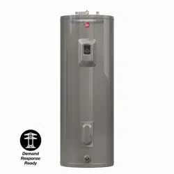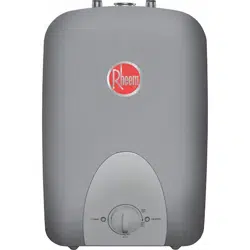
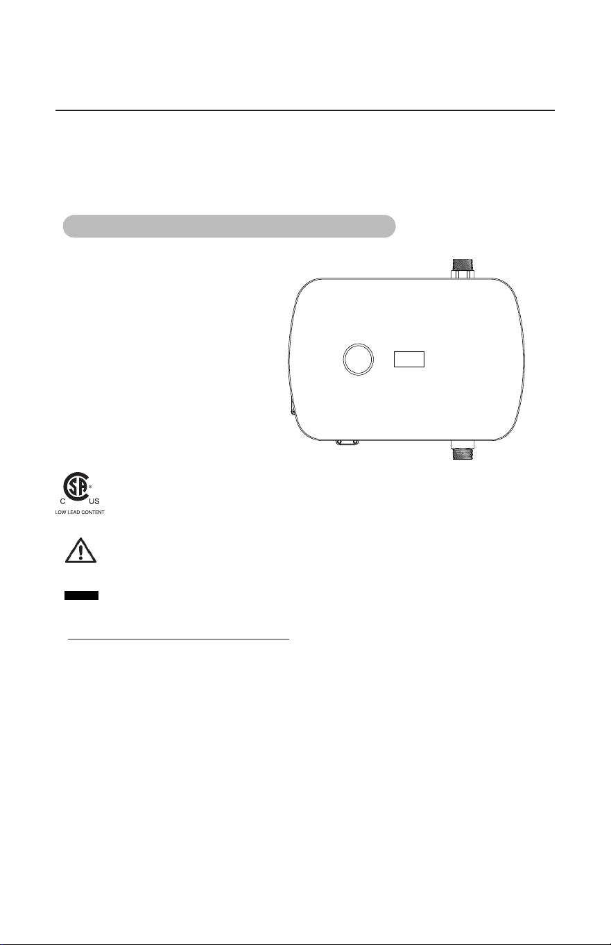
WATER HEATER BOOSTER
Water Heaters
Electric Tankless
RETEX-AB7
RMTEX-AB7
HATB007240
EEMTB240
RTEX-AB7
ECOTB240
IMPORTANT SAFETY INFORMATION
When installing or using any high voltage electrical appliance, basic safety precautions should
always be followed. Under no circumstance should you attempt to clean, install, inspect, repair,
disassemble or otherwise service this water heater, without first shutting off all power to the unit
directly at the circuit breaker box. SERIOUS BODILY INJURY OR DEATH OCCUR IF
YOU IGNORE THIS WARNING.
THIS PRODUCT SHOULD BE INSTALLED BY A QUALIFIED ELECTRICIAN AND
A QUALIFIED PLUMBER IN ACCORDANCE WITH ALL NATIONAL, STATE,
PROVINCIAL AND LOCAL ELECTRICAL & PLUMBING CODES.
PLEASE READ THESE INSTRUCTIONS THOROUGHLY AND COMPLETELY
PRIOR TO INSTALLATION & USE. FAILURE TO DO SO COULD CAUSE
PROPERTY DAMAGE, SERIOUS INJURY, OR DEATH.
This manual should be given to the homeowner after installation and should be retained for
future reference.
Proposition 65 Warning: This product contains chemicals known to the State of California to
cause cancer, birth defects or other reproductive harm
Tested and certified by the Canadian Standards Association for low lead compliance.
Recognize this symbol as an indication of Important Safety Information!
Destroy this manual. Please read carefully and keep it in a safe place for future
reference
Use & Care Manual
With Installation Instructions for the Installer
DO
NOT
AP25495
2
BEFORE INSTALLATION ....................................................5
SELECTING A LOCATION TO INSTALL.......................................6
SETTING UP TO INSTALL ...................................................6
PLUMBING INSTALLATION .................................................9
ELECTRICAL INSTALLATION ..............................................11
GENERAL OPERATING INSTRUCTIONS ....................................16
MAINTENANCE ...........................................................16
TROUBLE SHOOTING GUIDE ..............................................17
USER INTERFACE .........................................................19
PARTS ORDERING .........................................................21
FOR YOUR RECORDS
Write the model and serial numbers here:
#
#
You can find them on a label on the appliance.
Staple sales slip or cancelled check here.
Proof of the original purchase date is needed to obtain service under the
warranty.
Inside you will find many helpful hints on how to use and maintain your
water heater properly. A little preventive care on your part can save you
time and money over the life of your water heater.
You'll find many answers to common problems in the before You call for
Service section. If you review our chart of Troubleshooting Tips first, you
manu not need to call for service at all.
READ THIS MANUAL
Your safety and the safety of others are very important. There are many
important safety messages in this manual and on your appliance. Always
read and obey all safety messages.
!
This is the safety alert symbol. Recognize this symbol as an
indication of Important Safety Information! This symbol alerts you
to potential hazards that can kill or hurt you and others.
All safety messages will follow the safety alert symbol and either the word
“DANGER”, “WARNING”, “CAUTION” or “NOTICE”.
CONTENTS
READ THE SAFETY INFORMATION
3
Congratulations on the purchase of your Water Heater Booster!
The Booster is a device that extends the usable hot water from your existing hot water storage
device, while maintaining the existing electrical power infrastructure.
To get the best performance and energy savings from your Water Heater Booster, it is important that
it be installed in accordance with the instructions and the electrical and plumbing codes applicable
to your area, and that you read this manual thoroughly for important operating instructions and tips.
If you have questions at any time, please contact us directly at:
Manufacturer's National Service Department
800 Interstate Park Drive
Montgomery, Alabama
ABOUT YOUR BOOSTER
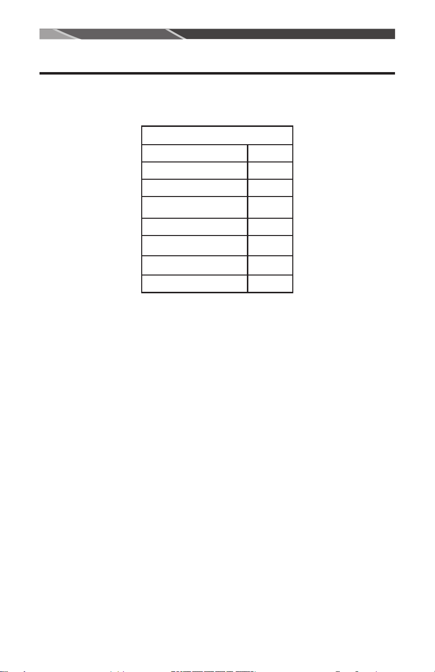
TECHNICAL SPECIFICATIONS
Voltage 240 VAC
Max Amperage 30 Amps
Max Power Rating 7.2 kW
Max Tank Power Rating 5.5 kW
Pre-Set Outlet Temperature 120°F
Activation Temp Range 60-130°F
Outlet Temperature Range 60-140°F
Activation Flow Rate 0.3 GPM
4
!
DANGER
HOT
BURN
BURN
Water temperature over 125°F (52°C)
can cause severe burns instantly or
death from scalds.
Children, disabled and elderly are at
highest risk of being scalded.
See instruction manual before
setting temperature at water heater.
Feel water before bathing or
showering.
Temperature limiting valves are
available, see manual.
!
DANGER!
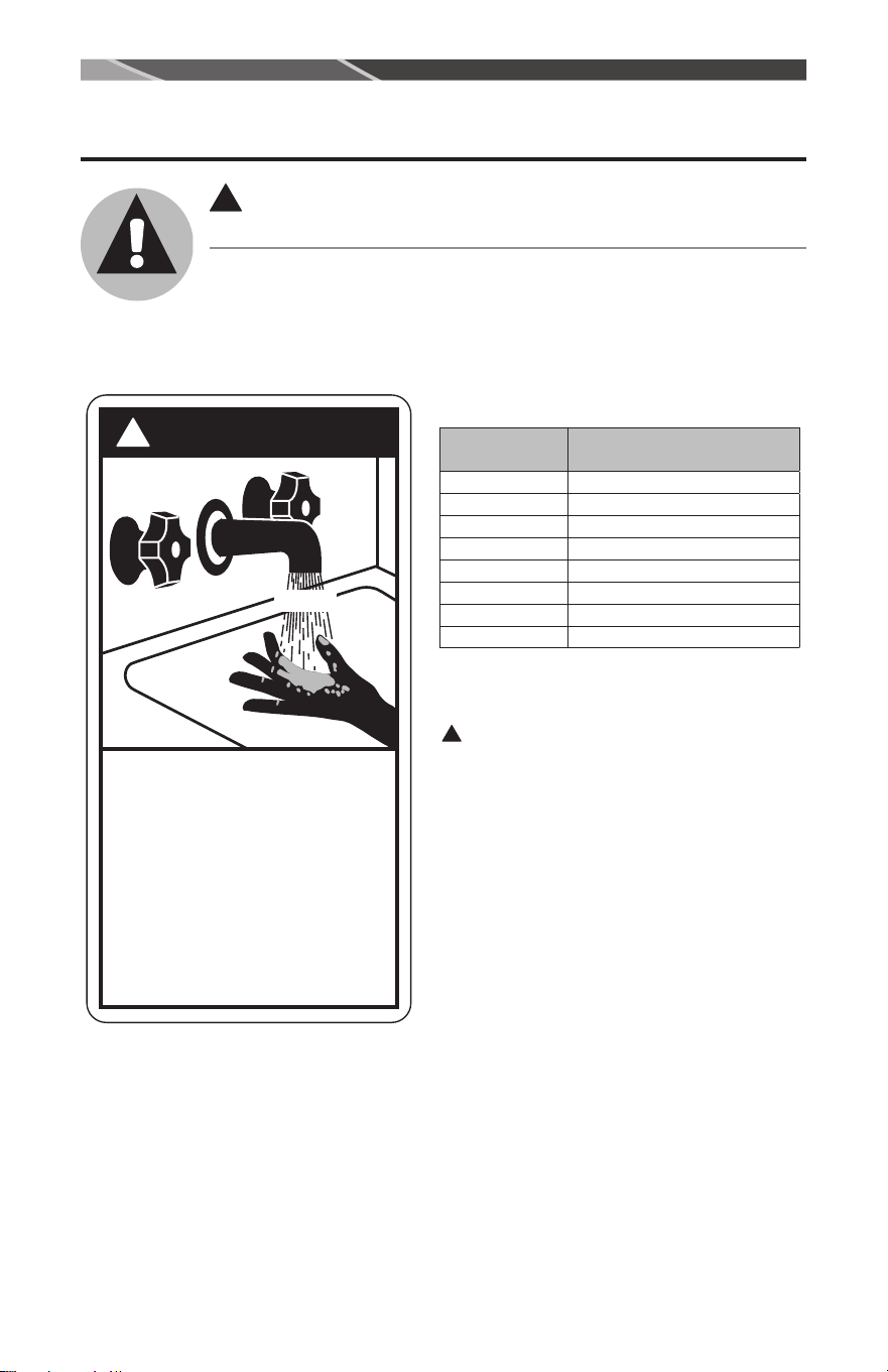
WATER TEMPERATURE SETTING
Safety and energy conservation are factors to be considered when selecting
the water temperature setting of water heater’s thermostat. Water
temperatures above 125°F (52°C) can cause severe burns or death from
scalding. Be sure to read and follow the warnings outlined on the label
pictured below. This label is also located on the water heater near the
thermostat access panel.
Notice: Mixing valves are recommended
for reducing point of use water
temperature by mixing hot and cold
water in branch water lines. It is
recommended that a mixing valve
complying with the Standard for
Temperature Actuated Mixing Valves for
Hot Water Distribution Systems, ASSE
1017 be installed.
!
DANGER:
Households with small children, disabled, or
elderly persons may require a 120°F(49°C)or
lower thermostat setting to prevent contact with
“HOT” water. The temperature of the water in the
heater is regulated by the electronic control on the
front of the water heater. To comply with safety
regulations the thermostat was set at 120°F(49°C)
before the water heater was shipped from the
factory.
Please consult Section 9 to learn more about
setting your heaters temperature.
Time/Temperature Relationship in Scalds
Water
Temperature
Time To Produce a Serious
Burn
120°F More than 5 minutes
125°F 1
1
/2 to 2 minutes
130°F About 30 seconds
135°F About 10 seconds
140°F Less than 5 seconds
145°F Less than 3 seconds
150°F About 1
1
/2 seconds
155°F About 1 second
Table courtesy of Shriners Burn Institute
IMPORTANT SAFETY INFORMATION.
READ ALL INSTRUCTIONS BEFORE USING.
5
PLEASE READ THESE INSTRUCTIONS THOROUGHLY AND COMPLETELY PRIOR
TO INSTALLATION & USE.
FAILURE TO FOLLOW INSTRUCTIONS COULD CAUSE PROPERTY DAMAGE,
SERIOUS PERSONAL INJURY, OR DEATH.
By installing this product, you acknowledge the terms of the manufacturer’s warranty. Once
the heater is installed, do not return product to the place of purchase. If you have any questions
regarding the warranty or product return policies, please call 1-(800)-374-8806.
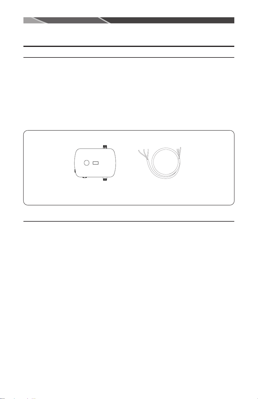
Inspect all components. The contents of your box should include the following components:
What you will need to install:
1. Phillips Head Screwdriver
2. Flat Head Screwdriver
3. Pipe Cutter
4. Adjustable Wrench
5. Teflon Tape
6. Tape Measure/Ruler
7. Pencil (recommended for marking measurements when cutting pipe)
8. Needle-Nose Pliers (not required but may be beneficial)
9. Appropriate fittings and piping
Before Installation
INSTALLATION INSTRUCTIONS
Included Items
Pigtail Cord (1X)Booster Unit
6
This product is designed to be installed indoors only, in series with your pre-existing tank water
heater.
DO NOT install this product in a location where it may be subject to freezing temperatures. If the
water inside your unit freezes, it can cause severe and permanent damage that is not covered under
your warranty.
DO NOT locate the Water Heater Booster in a location that is difficult to access.
DO NOT locate the Water Heater Booster in areas of excessive heat, if using on a gas water heater
remotely mount the unit away, provide at least 6" of clearance.
This product does NOT require venting.
Avoid installing your Water Heater Booster in a location prone to excessive humidity, moisture, or
dust, or in an area where it may be splashed lines that might leak or condense moisture that could
then drip onto the booster. DO NOT install above electrical boxes or junctions.
If you plan to install your water heater on a second floor or in a heated attic space, make sure that
you follow all code requirements for such installations as required for your area. You can install an
active water leak detector and shutoff valve designed to turn off your water supply in the event that
a leak is ever detected.
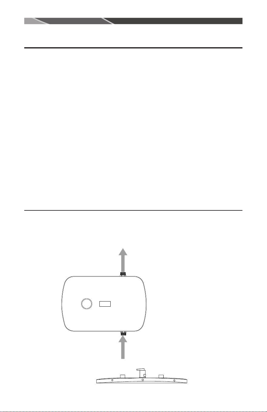
Recommended Clearances:
Adequate space for installation and service of the unit is needed.
INSTALLATION INSTRUCTIONS
Setting up to install
14 inches
HOT
WATER
OUT
WATER IN
FROM TANK
OUTLET

7
1. SHUT OFF ELECTRICITY ON YOUR CIRCUIT BREAKER BEFORE PROCEEDING
TO ANY FURTHER INSTALLATION STEPS.
2. Make sure there is adequate clearance above the tank heater. If there is not enough room above
the tank, this unit may be installed on an adjacent wall.
3. IF SPACIAL ISSUES ARISE OR USED WITH A GAS FIRED TANK, OR IF THE PIPING
IS NOT STRAIGHT (ABNORMAL PIPING THAT IS NOT STRAIGHT), ADDITIONAL
PIPING MAY NEED TO BE USED.
4. Close the supply water valve to the tank heater, located in most cases above the tank heater on
the cold water inlet side.
5. Drain the piping below your work area to prevent damage from water. The drain valve is usually
located near the bottom of the tank.
6. Drain the water from all existing hot water pipes by first opening all hot water faucets of any
kind in the house. Leave the faucets open until plumbing installation is complete. If water does
not stop flowing, check to make sure the inlet water to the tank heater has been completely shut
off.
7. Assess your plumbing system before you cut the pipe.
INSTALLATION INSTRUCTIONS
8
Installing the water heater.
Please follow all pre-installation instructions carefully. If further assistance is needed, a licensed and
qualied plumber in accordance with all applicable national, state, provincial, and local plumbing
codes should be hired.
When there is not enough room above the tank to install this unit, it may be installed on an adjacent
wall utilizing appropriate exible stainless steel or copper connectors. This typically occurs if there
is very low ceiling height.
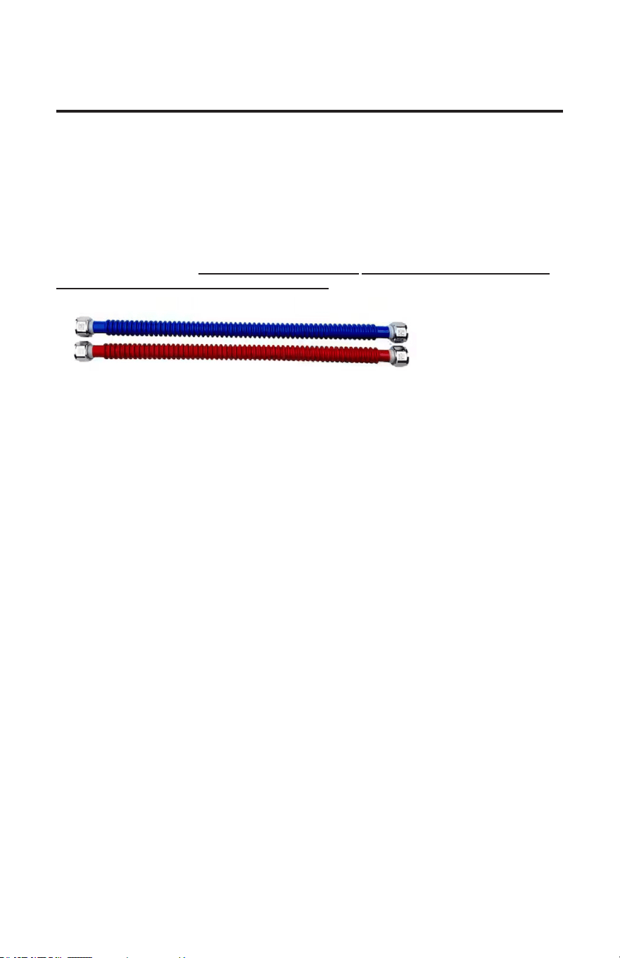
In order to install your unit, you will need to purchase exible stainless steel or copper connectors.
We recommend to purchase a water heater installation kit. A kit such as the one shown can be
purchased at a low cost at most home center stores.
This method of installation requires more experience and judgment, because each household may
have a moderately dierent layout in this situation.
For further installation assistance, please call or email our customer service and technical support
team for any help you may need.
9
Plumbing Installation
Plumbing Installation Instructions
Please see installation diagrams on the following pages for visual guidance.
FAILURE TO FOLLOW THESE STEPS WILL CAUSE WATER TANK DAMAGE.
Please follow all plumbing instructions carefully. We recommend that this product be installed by a
qualied person. If further assistance is needed, a licensed and qualied plumber in accordance with
all applicable national, state, provincial, and local plumbing codes should be hired.
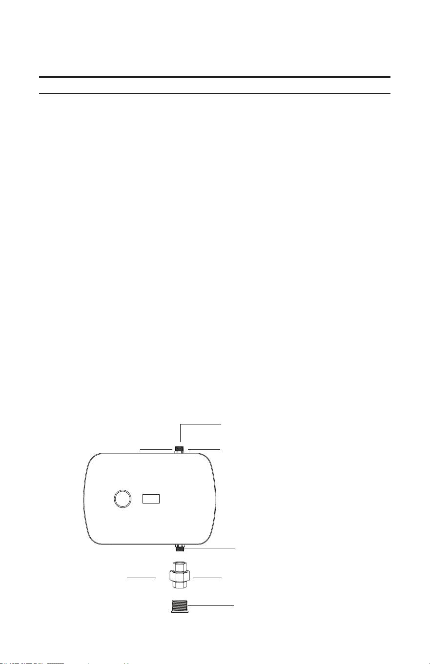
STEP 1: Using the corresponding ttings for which layout was used, connect the HOT
WATER outlet from your water tank to the INLET thread located on the bottom side of the
Water Heater Booster when facing the unit. Use a 3/4" Union to secure the connection.
STEP 2: Connect hot water outlet (3/4" NPT) to hot water distribution system.
STEP 5: Carefully inspect all connections, unions, and the pressure relief valve (if installed)
for leaks
STEP 6: TURN OFF ALL FAUCETS BEFORE PROCEEDING TO ELECTRICAL
INSTALLATION
STEP 4: After tightening all ttings, open all hot water faucets and allow un-heated water to
run through the water heater for at least 2 to 3 minutes. This process purges all the air from the
water lines and MUST be performed prior to turning on the power at the unit.
FAILURE TO FOLLOW THIS STEP CAN CAUSE PERMANENT DAMAGE TO THE
HEATING ELEMENTS OF THE TANK
If any maintenance is performed on the water heater or the home's plumbing system that may
introduce air into the plumbing pipes, it is important to turn the power o to the water heater
and purge the air out of the lines before allowing the unit to power up.
STEP 3:
• Close the tank drain valve.
• Make sure at least one warm water faucet is open in the house.
• Re-open the water supply valve on the cold water copper pipe.
10
Installation Instructions
Important installation notes:
1. Do not apply heat or solder directly to this unit. Heat from soldering may damage the ow sensor
in the unit.
2. This unit is quipped with both computer-controlled and electro-mechanical auto resting
thermostat switches for high-limited temperature protection. Since this product does not use
a storage tank, the use of a temperature pressure relief valve (T&P) is not required for most
installations. UL standard 499 does NOT require that a pressure relief valve be used. However,
a T&P valve may be required to meet installation code in your area. If one is required, install the
pressure relief valve in accordance with local codes and ensure that it operates correctly and that
air is purged from the valve prior to installing the water heater. When connecting to Flex to High
Temperature CPVC pipe, we recommend that a T&P valve be used for added safety.
Please note: Installations in the Commonwealth of Massachusetts require a pressure relief
valve. Please check your local installation codes for any special requirements.
3. The maximum operating water pressure is 150 PSI. If the water pressure is higher, a pressure
reducing valve must be installed on the main incoming water supply line prior to installing the
unit.
4. When connecting the inlet water pipe to the unit, make sure to use a wrench to hold the unit's
connection, and another wrench to tighten, so the flow sensor on the unit is not loosened or
damaged. Serious internal damage to the water heater can occur if the inlet connections are over
tightened or if solder connections are made.
5. We recommend that a manual shut-off valve (ball valve) be installed on the inlet and outlet of
the water heater so that there is a convenient shut-off point available in the event that future
maintenance or servicing is required. Before connecting pipes to the water heater, it is extremely
important to flush the lines to eliminate all plumbing paste or residue in the lines caused by any
brazing or soldering.
We recommend that all the water piping within 3 feet of the inlet and outlet connections be rated for
high temperature applications with a 150 ºF minimum temperature rating.
Hot water outlet to xtures
3/4" NPT Outlet Fitting
3/4" NPT Inlet Fitting
3/4" - 3/4" Union
(Purchased Separately)
NPT From Tank
(OUTLET SIDE OF TANK)
Step 2
Step 1
A.
11
Electrical Installation
Electrical Installation instructions
CAUTION:
Ensure that you have made the correct connections. You must follow the wiring connection as shown
to ensure the proper operation of the unit. If you mix up one set of wires with another, the unit will
not operate correctly even though it turns on and otherwise appears to function properly.
STEP 1: Making sure all electrical power is shut o, remove the red, black (possibly white
in some applications), and ground wires from the existing tank heater coming from the circuit
breaker. These wires will now go into the Water Heater Booster through the hole in the unit's
side plate (see wiring diagram and connection reference 1 on the subsequent pages).
STEP 2: Using the existing wires removed from the tank in step 1, run Line 1 (red wire),
Line 2 (black wire - possibly white in some applications), and ground (green wire) from the
home's main breaker panel to the Water Heater Booster, through the side plate hole. This is
connection reference 1, specied on page 12.
Note: If you are installing a new circuit, select a suitable wire gauge that meets all applicable
electrical codes for the size of the breakers used.
Note: A separate ground conductor for each incoming circuit is required.
STEP 5: DOUBLE CHECK the electrical connections to make sure they are correct and that
all wire connections are tight and secure. Also conrm that the correct breaker size and wire
gauge has been used and conrm that the unit has been connected to a ground in accordance
with applicable codes.
STEP 6: Conrm that all the air has been purged from the water lines prior to turning on
power to the unit. Refer to STEP 4 in the plumbing installation section.
STEP 4: Now connect the wires from the Water Heater Booster (pigtail cord stemming from
the unit) to the existing tank heater. The red, black, and green/yellow (ground) wires should
all have secure connections.
MAKE SURE THESE CONNECTIONS ARE IN AN ENCLOSED AREA. EXPOSED
CONNECTIONS CAN LEAD TO SERIOUS INJURY OR DEATH.
STEP 3: Connect the supplied pigtail cord to the Booster. See connection reference 2 on
page 12.
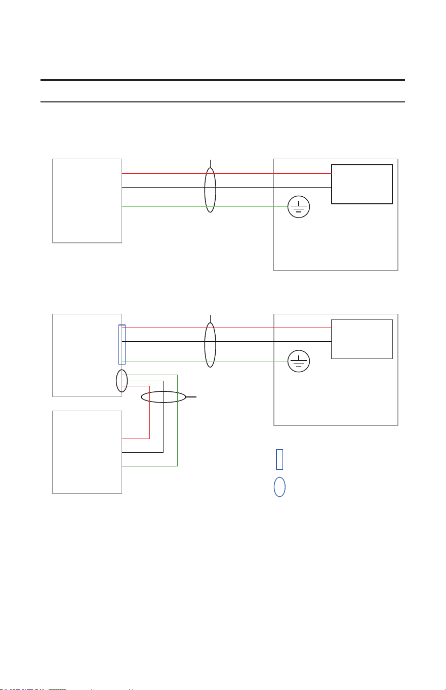
12
Installation Instructions
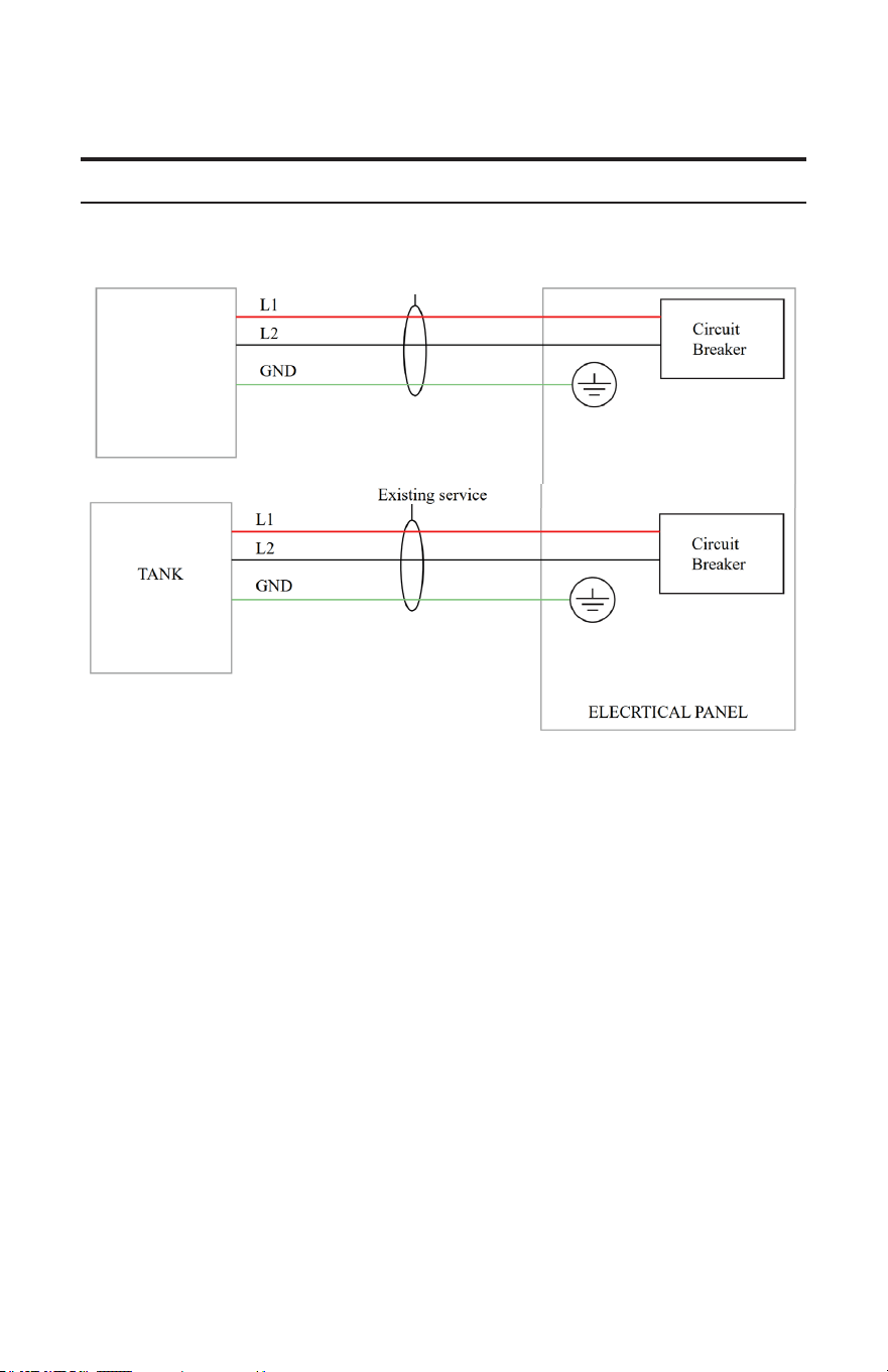
Wiring Diagram
ELECRTICAL PANEL
ELECRTICAL PANEL
= Connection reference 2
= Connection reference 1
TANK
TANK
BOOSTER
L1
L2
GND
L1
L2
GND
Existing service
Wires from
BOOSTER
Existing service
Normal Tank Configuration:
Booster and Electric Tank Configuration:
Circuit
Breaker
Circuit
Breaker
T1
T2
GND
13
Installation Instructions
Wiring Diagram
1 | PRG Enterprise Strategy Session 2025
CONFIDENTIAL
Gas or Heat Pump Tank Configuration:
NEW DEDICATED SERIVCE
Water Heater
Booster
Gas or Heat Pump Tank Conguration:
14
Installation Instructions
Connection Reference 1
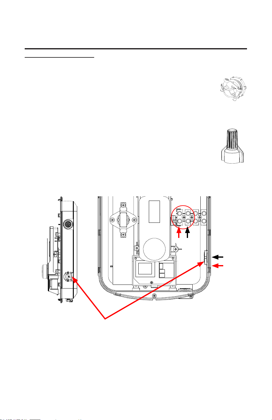
Connecting Lines 1 & 2 from the circuit (existing service) to the Booster:
For Gas or Heat Pump Tank congurations, follow these steps with a NEW DEDICAT-
ED SERVICE from the panel to the Booster.
1. Remove the control knob from the unit, then remove the cover of the unit. Two
screws on the end must be removed in order to do this.
2. For this step, if the leads from the breaker are wrapped a common household
cable jacket, make sure the ends of the leads are exposed from the external
jacket for at least 10 inches. Strip back 3/8" to bare copper on Ll & L2.
• Lines 1 & 2 and ground (from the circuit breaker) will be connected to the
Booster's inner terminal block. Make sure to thread these lines into the heater
from the side via the Side hole, using the supplied cord grommet.
• Connect Line 1 (red) to the "L1" labelled wire terminal, and Line 2
(black) to the "L2" labelled wire terminal, using a flathead screwdriver to
secure the terminal.
• Using a supplied wire nut, connect the circuit breaker ground wire to
the green/yellow ground wire stem already inside the unit, which will be
exposed. Twist wires together, then twist the wire nut with both wires
inside to secure the connection.
3. Tighten the connections on the terminal block with a flathead screwdriver. MAKE SURE
WIRES ARE INSERTED ALL THE WAY IN THE TERMINAL, AND THAT THE SCREWS
SECURING THE CONNECTION ARE TIGHT AND SECURE. FAILURE TO DO THIS
WILL CAUSE HEATER MALFUNCTION. Also, make sure that the wire insulation is not
inserted into the terminal block as this will inhibit a good electrical connection.
4. Proceed to Connection Reference 2 on following page.
For Gas or Heat Pump Tank configurations, remove the pigtail cord from the Booster as it is not
needed.
Side Plate Hole
(installer must secure cable clamp here)
L1
L1
T1L2
L2
T2
Cable clamp
(Purchased
Separately)
Wire Nut
15
Installation Instructions
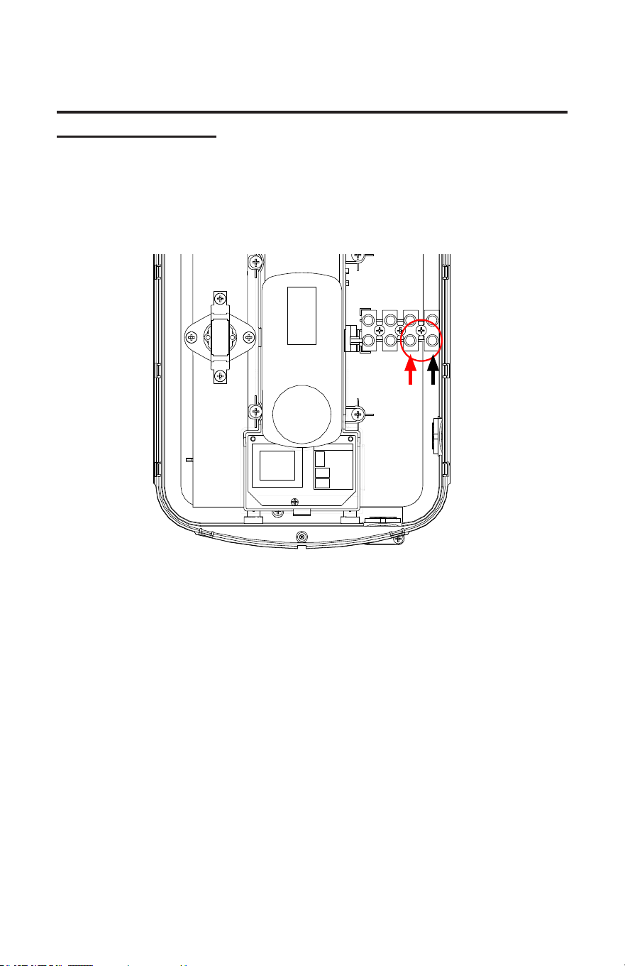
Connection Reference 2
Connecting the pigtail cord from the Booster to the tank heater:
1. The pigtail cord should be partially attached to the unit through the ground connection. With the
cover off, you should see an exposed red wire, black wire, and green wire from the pigtail, on the
end that's inside the unit. Connect the red wire to the "T1" labeled wire terminal, and the black
wire to the "T2" labeled terminal.
2. Tighten the connections on the terminal block with a flathead screwdriver. MAKE SURE WIRES
ARE INSERTED ALL THE WAY TERMINAL, AND THAT THE SCREWS SECURING THE
CONNECTION ARE TIGHT AND SECURE. FAILURE TO DO THIS WILL CAUSE HEATER
MALFUNCTION. Also, make sure that the wire insulation is not inserted into the terminal block
as this will inhibit a good electrical connection.
3. Take the green/yellow wire from the end of the pigtail, outside of the Unit, and connect it to the
existing ground connection on the tank heater's terminal. If additional help is required, reference
your tank heater manual.
4. Replace the unit cover, screws, and control knob.
L1 T1L2 T2

16
Installation Instructions
Operating your new unit is very similar to using any traditional water heating system. However,
it is very important that you carefully read all of the set-up procedures and operating instructions
and tips to ensure the maximum performance and energy savings from your new water heater. We
recommend that all members of the household read these General Operating Instructions.
How your new unit works: The Water Heater Booster combines with the traditional hot water
tank to provide an eective and ecient way of heating your home. The unit reads the temperature
coming out of the tank, and will turn on if the water drops below a set temperature, which you can
set. The booster will keep the water at the desired temperature, another limit which you can set.
To ensure maximum performance of your unit and to reduce the risk of a water leak, we recommend
the following maintenance:
You should inspect the connections on the inlet and outlet of the unit at least on an annual basis
for any signs of damage or failure. Any signs of damage, cracks, leakage or weakness should be
addressed. Take care not to over-tighten the connections. Serious internal damage to your water
heater can occur if you over-tighten the water heater connections at the unit.
IMPORTANT NOTES:
As with all electrical appliances, under no circumstances should you attempt to install, repair or
disassemble this water heater without rst shutting o all power to the unit directly at the fuse or
breaker box. SERIOUS BODILY INJURY OR DEATH COULD OCCUR IF YOU IGNORE THIS
WARNING.
When any maintenance is performed on the unit or the home’s plumbing system that may introduce
air into the plumbing pipes, it is important to turn the power o to the water heater and purge the
air out of the lines before allowing the unit to power up. FAILURE TO DO SO COULD CAUSE
PERMANENT DAMAGE TO THE HEATING ELEMENT AND VOID YOUR WARRANTY.
If you have a water supply with a high level of mineralization (hard water), you should increase the
frequency of your maintenance. Remove element and inspect for scale build up –soak in vinegar or
de-liming solution until scale is removed, typically within a few hours.
General operating instructions
Maintenance
17
Caring For Your Water Heater
Are you having problems with your water heater?
Please call our customer service and technical support team for any help you may need.
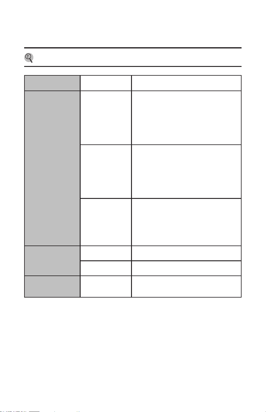
The following table represents some of the most common technical support questions we receive.
Before calling us, please read thoroughly to see if your question or problem is addressed.
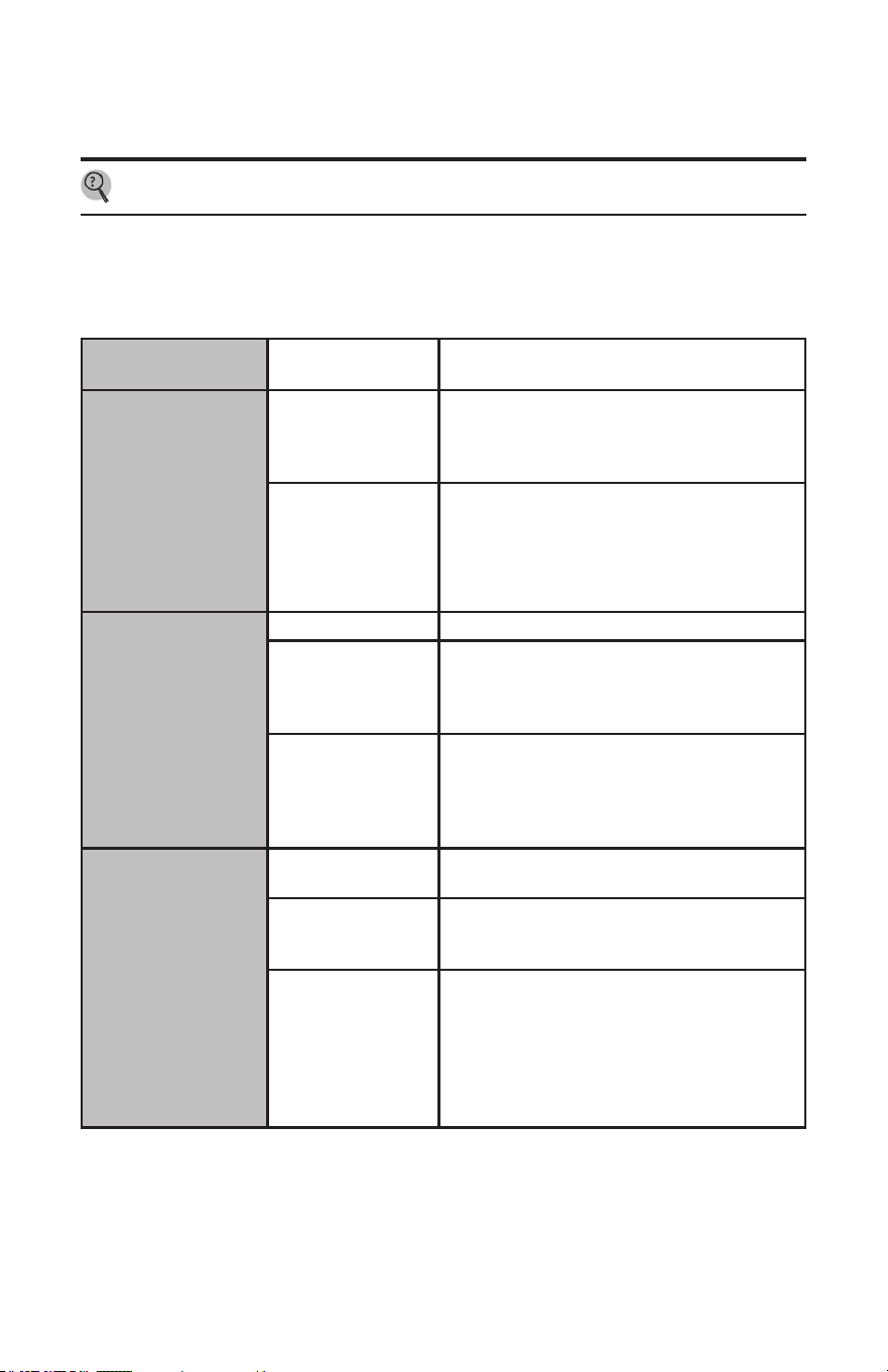
Trouble shooting Guide
PROBLEM POSSIBLE
CAUSES
SOLUTION
Unit is not heating at
all (water is owing
but the unit is not
heating at all-the
outgoing water
temperature is the
same as my cold water
supply) and/or the
digital display does
NOT light up.
No power or
incorrect wiring.
Make sure the breakers at main electrical panel
are ON. you may have a faulty breaker unit
may be Wired incorrect. Refer to 15 for proper
Wiring laout.
Internal part failure. Please call us for technical assistance.
Unit is not heating at
all (water is owing
but the unit is not
heating at all-the
outgoing water
temperature is the
same as my cold water
supply) and/or the
digital display does
light up.
Internal part failure. Please call us for technical assistance.
Flow rate is too low/
water pressure is
too low
Your water heater has an activation ow rate of
approximately 0.3 GPM. If your water ow rate
is less than this level, your unit will not activate.
Increase the ow rate.
Activation
temperature too low
The water heater will turn on when the
temperature of the water at the inlet of the unit
falls below the activation temperature (when
the tank is not providing hot water). Increase
activation temperature.
Unit is heating but the
water temperature is
not hot enough.
User temperature
setting too low.
Tern up the temperature setting on the unit.
Voltage less than 240
volts.
The heating elements on your unit are designed
for 240 volts. When use with a lower voltage,
they produce less heating power.
Mixing too much
cold water
You may have an anti-scald feature on your
faucet that is mixing cold water. These types
of faucets can usually be adjusted to reduce
the amount of cold water mixed. Also, your
tank may be completely out of hot water and is
mixing cold water. Give the tank time to recover
or reduce the amount of water your are using.
18
Caring For Your Water Heater
PROBLEM POSSIBLE
CAUSES
SOLUTION
The water temperature
at my faucet is less
than the temperature
setting of my water
heater.
Voltage less than 240
volts.
The computer chips in your unit are
programmed with the expectation that your
incoming line voltage is 240 volts. If you have
less than 240 volts, it may aect the reading on
your unit's digital and cause it to read slightly
higher than the actual output temperature. To
compensate for this, increase the setting on your
unit if you need/want hotter water.
Anti-scald pressure/
balancing valve or
tempering valve.
Your faucet may have an anti-scald feature or
a tempering valve that automatically mixes
cold water even when you turn your control
lever or handle to full hot. These devices are
usually adjustable so you can turn o the cold
mix completely. You can compensate for this by
increasing the setting on your unit if you need/
want hotter water.
Thermal loss due to
long pipe run
As the hot water from the unit runs through the
hot water delivery system to your faucet, some
heat will be lost especially if it has long distance
to travel or the pipes are cold. This is normal.
You can compensate for this by increasing the
setting on your unit if you need/want hotter
water.
Pre-existing water tank
is not heating.
Incorrect wiring. The unit may be wired incorrectly. Refer to page
12 for proper wiring layout.
Relay switch is
defective.
Please call us for technical assistance
Unit displays 999 as
inlet and/or outlet
temperature
Thermistor on
corresponding
channel is defective
The unit may be wired incorrectly. Refer to page
12 for proper wiring layout.
Troubleshooting Guide...
19
Notes :
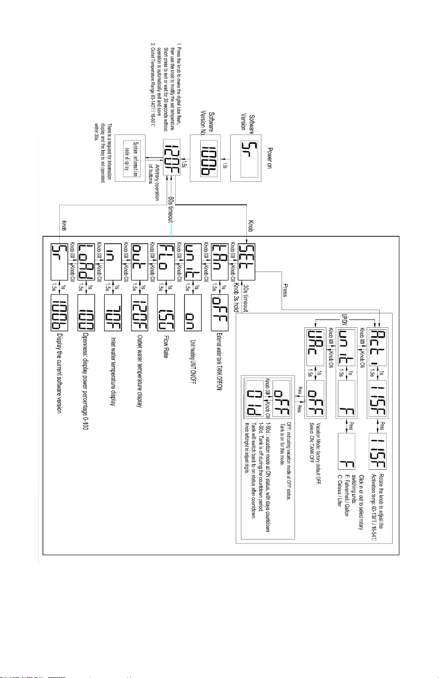
1. Alternate screen: text 1 second; value 1.5seconds (if no other value specied).
2. Knob operations: “CW” means clockwise turning and “CCW” means counterclockwise turning
of the encoder knob.
20
Caring For Your Water Heater
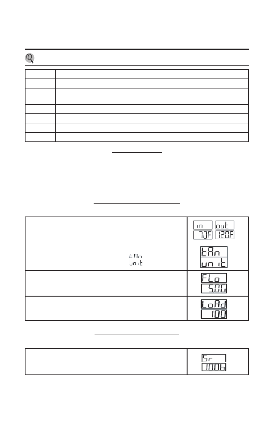
Booster Features
Primary Menu Cycle Screens
List of menu Options Provided by the Software (Claried Below and on Following Page):
• Inlet/Outlet Temperature Reading
• Active Unit in Operation
• Software Version
• Vacation Mode
Turn the control knob in either direction to cycle through menu options.
Booster Set Up Menu Cycle Screens
Turn the control knob in either direction to cycle through menu options.
Service Error Code Chart
Error Code Description
A70 High water temperature (>180 °F)
Instantaneous heating shutdown
A74
Inlet or outlet water temperature below freezing point (>35
°F
) Instantaneous heating
o
b00 Water inlet probe failure (>-20°F) Instantaneous heating o
b10 Inlet and outlet probe failure meanwhile Instantaneous heating o
c05 Outlet thermistor disconnected (>-20 °F)
d85 ow too high, inlet temperature too low
Inlet/Outlet Temperature Reading
The temperature of the water going in and out of the Booster can be
observed from this display.
Active Unit in Operation
1. External water tank TANK OFF/ON
2. Unit heating UNIT ON/OFF.
Flow
The ow screen will tell the user the amount of water that is owing
through the unit in gallons per minute.
Load factor
Here you can see how hard your Booster is working.
Software Version
Here you can view the heater software version (Useful for
troubleshooting)
21
Parts Ordering
!
WARNING:
For your safety, DO NOT attempt to
disassemble, repair, or replace any portion
of this unit. Refer all repairs, service, and/or
adjustments to qualified service personnel.
Address all parts orders to the distributor or
store where the water heater was purchased.
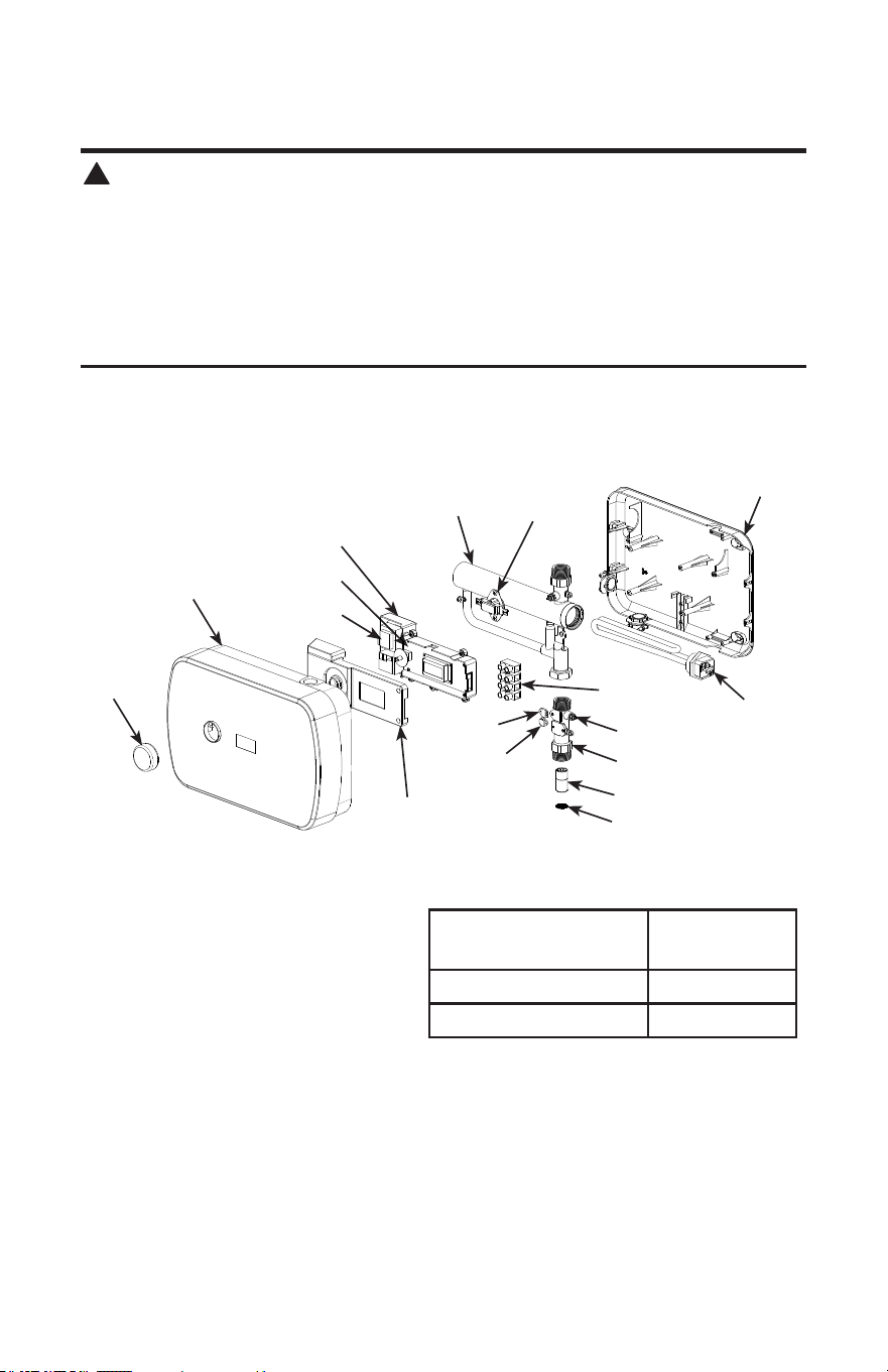
All parts orders should include:
1. The model and serial number of the water
heater from the rating plate.
2. Parts description (as shown below) and
number of parts desired.
Knob
Cover
Power panel
Pcb panel
Power box cover
Power box bottom
Filter screen
Water flow switch
Inlet nozzle
NTC
Connecting
terminal
Heating
element
Bottom
shell
Heating
steel body
ECO
Hall switch
SCR
Replacement Parts
Heating element
220V/6000W
240V/7200W
ECO 43V 70
oC
Connecting terminal 300V 68A

22