
Contents
Safety Instructions
.................................................1
Safety Operation ........................................................1
Safety Symbols ..........................................................2
Install The Battery Or Fuse
................................. 3
Install Battery ..............................................................3
Replace Fuse .............................................................4
Overview
...................................................................... 5
Meter Panel ................................................................5
Auto Power O ...........................................................6
Measurement Operation
.......................................6
Smart Measurement
, ...................................6
DC/AC mV Measurement .......................................... 9
Frequency/Duty Measurement ................................10
Capacitance Measurement ......................................10
Diode Test ................................................................. 11
DC/AC Current Measurement .................................12
Non-Contact Voltage (NCV) ....................................13
Live Test ....................................................................14
Customized Matching Meter Pen ............................14
Specications
.........................................................14
Accuracy
....................................................................15
DC voltage ................................................................15
AC voltage ................................................................15
DC current ................................................................16
AC current ................................................................. 16
Resistance ................................................................16
Capacitance .............................................................. 17
Frequency/Duty ........................................................17
Diode ......................................................................... 18
Continuity ..................................................................18
Clean
...........................................................................19
Three years Warranty
..........................................19

1
Safety Instructions
This meter conforms to the IEC61010-1 international
electrical safety standard. The design and manufacture
of instruments shall strictly comply with IEC61010-1
CATIII 600V safety standard and pollution level 2.
Safety Operation
WARNING
To avoid possible electric shock or personal injury
and other safety accidents, please abide by the
following specications:
● Please read this manual carefully before using the
instrument.
● Strictly observe the operation of this manual and use
this instrument. Otherwise, the protection function of
the instrument may be damaged or weakened.
● Please be careful if the measurement exceeds 30V
AC true RMS, 42V AC peak, or 60V DC. There may be
danger of electric shock at this kind of voltage.
● Do not measure a voltage higher than the rated value
between terminals or between terminals and ground.
● Check whether the meter works normally by
measuring on known voltage. Do not use it if it is
abnormal or damaged.
● Before using the meter, please check whether the
instrument shell is cracked or damaged by plastic
parts, if any, please do not use it.
● Before using the instrument, please check whether
the probe is cracked or damaged. If so, please replace
the probe of the same model and the same electrical
specication.
● Please use the meter according to the measurement
category, voltage, or current rating specified on the
instrument or manual.
● Please observe local and national safety regulations.
Wear personal protective equipment (such as approved
rubber gloves, masks, ame-retardant clothing, etc.) to
prevent injury caused by electric shock and electric arc
when the dangerous live conductor is exposed.
2
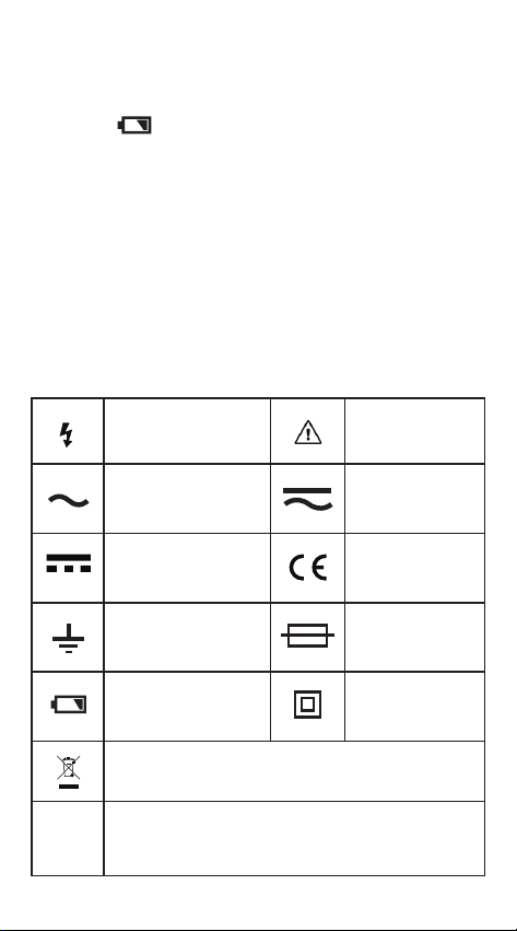
Dangerous Voltage
may be present
Warning;
Important
information
AC (Alternating
Current)
AC and DC
DC (Direct current)
Complies with
EU directives
Earth ground Fuse
Low Battery
Double
insulated
Do not dispose of this product as unsorted
municipal waste.
CAT
II
Suitable for testing and measuring circuits
directly connected to power points (sockets and
similarities) of low voltage power installations.
● Do not work alone so that you can get help in an
emergency.
● To avoid electric shock or injury due to wrong
reading, please replace the batteries in time when the
indicator “ ”is displayed.
● Do not use the instrument around explosive gas or
steam or in a humid environment.
● When using the probe, hold your nger behind the
probe nger guard.
● When measuring, please connect the neutral or
ground wire rst, and then connect the live wire; when
disconnecting, please disconnect the live wire rst and
then disconnect the neutral or ground wire.
● Remove the probe from the meter before opening
the case or battery cover.
Safety Symbols
3
CAT
III
Suitable for testing and measuring circuits
connected to the distribution part of low voltage
power supply devices in buildings.
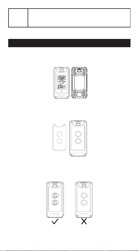
Install The Battery Or Fuse
Install Battery
①
Remove the rubber sleeve on the outside of the
multimeter.
②
Remove the screw that secures the battery cover
and remove the battery cover.
③
When installing the batteries, please pay attention
to the polarity of the battery. After the installation is
successful, you will hear a “beep” sound.
4
WARNING
● In order to avoid electric shock or personal injury
caused by inaccurate reading, please replace batteries
immediately when the battery power is low.
● Do not discharge the battery by shorting it or reversing
its polarity.
● In order to ensure the safe operation and maintenance
of the meter, please take out the battery when it is not
used for a long time.
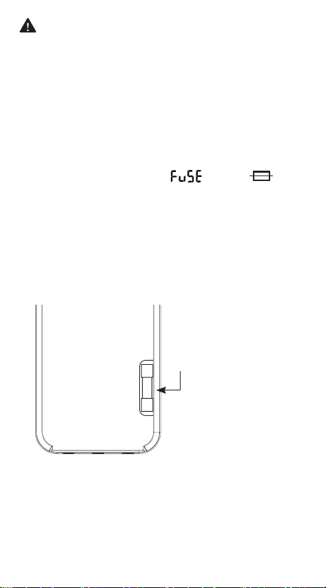
Replace Fuse
If the fuse is blown out, “ ” and “ ” will
be displayed on the screen and there will be a
continuous beeping sound.
①
Turn o the meter power and remove the test probe.
②
Remove the rubber sleeve and the 4 screws on the
four corners of the back cover.
③
Open the back cover and replace with fuse of the
same specication. Make sure that the fuse is clamped
tightly.
④
Install the back cover and lock it with screws.
Fuse: 600mA/250V, FAST
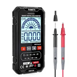
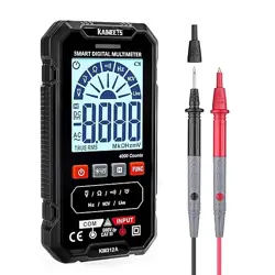
5
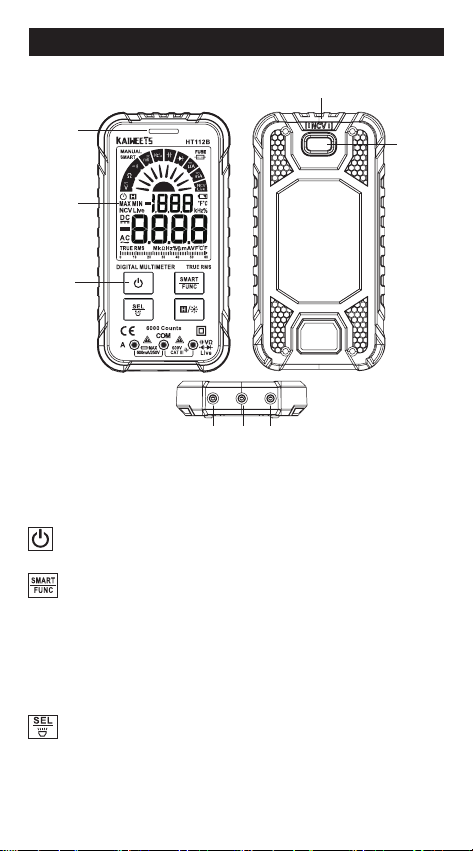
Overview
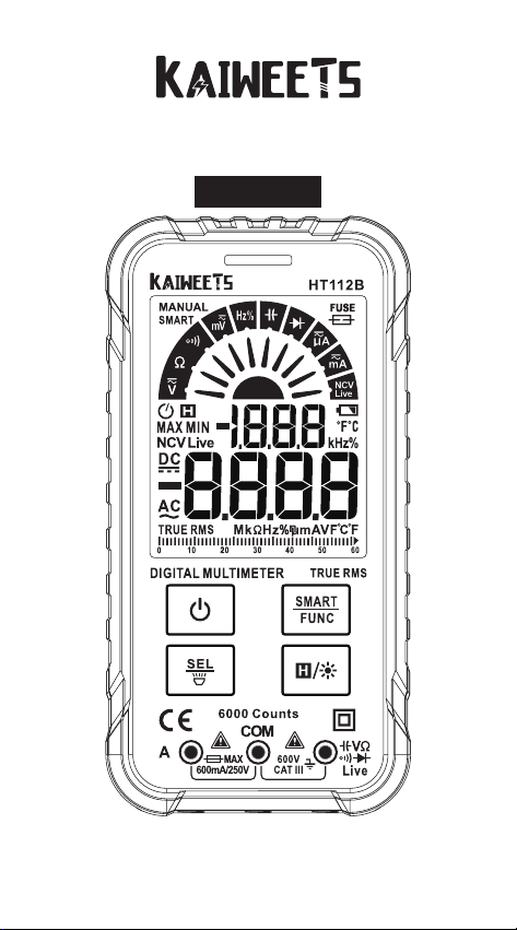
①
Indicator light
②
Display
③
Keys
:
Power key
Long press to turn on/o.
:
Smart/Manual Mode Key
●
After the meter is powered on, it defaults to a smart
function.
●
Press this key once to switch to manual function.
●
Press this key again to switch to other functions.
●
Press this key for more than 2 seconds to restore the smart
function.
:
Function selection / Flashlight key
●
When a position has multiple functions, press this key to
switch.
●
Press this key for more than 2 seconds to turn on or o the
ashlight.
METER PANEL
①
②
③
④ ⑤ ⑥
⑦
⑧
6
Smart Measurement
:
Backlight / Data hold key
●
Press this key to turn on or o the data holding function, ”H”
will be displayed on the screen.
●
Press this key for more than 2 seconds to turn on or o the
backlight.
④
Current jack
⑤
COM jack
⑥
Measuring jack except current
⑦
NCV sensor
⑧
Flashlight
Auto Power O
● No operation within 15 minutes, the meter will auto
power off to save battery energy. After automatic
shutdown, press the power button to restart.
● Cancel the auto-o function by pressing and holding
the “ ” key while turning on the meter.
● When the “ ” symbol is displayed, the auto-off
function is on.
Measurement Operation
Note:
The multimeter is very sensitive. It will be aected
by nearby magnetic fields. Without touching any
objects, there may be a reading jumping on the screen
when it is turned on. This is normal occurrence of a
digital multimeter and will not aect the measurement
results.
This measurement function is the default when power
on.
It can measure
DC voltage, AC voltage, Resistance,
Continuity.
The meter can measure automatically
without the user selecting the function.
1)
Long press “ ” key to turn on the power to smart

7
measurement. “ ” will be displayed.
2)
Insert the red probe into the “ ” jack and the black
probe into the “COM” jack.
3)
Touch the test lead tips together to check if they are
connected normally. The indicator light should turn
green and the buzzer sound.
4)
Connect the probe with the voltage source or
resistor in parallel for measurement. The meter will
automatically recognize the currently measured signal.
Start Testing
4.1 AC Voltage Test:
①
Connect the two test leads to the neutral and live
wires respectively (red to live, black to neutral).
②
After the reading stabilizes, record the reading
from the screen. The frequency will be displayed
simultaneously.
4.2 DC Voltage Test:
①
Connect the red test lead to the positive electrode
and the black test lead to the negative electrode.
②
After the reading stabilizes, record the reading from
the screen.
Note:
If the result is negative, it means the test leads
are connected inversely. To achieve a positive result,
reconnect the test leads to the correct electrodes.
4.3 Measuring Resistance:
①
Place the test leads at both ends of the resistance to
be measured and maintains strong contact.
②
After the reading stabilizes, record the reading from
the screen.

8
③
When the resistance is greater than 50Ω, it will
automatically jump to resistance measurement.
④
If the measured value is equal to the nominal
resistance of the resistor or within the range of error, the
resistor is functioning correctly.
If there is a large deviation between the nominal
resistance and the measured resistance, the resistor is
bad.
If the measured resistance is infinite (open circuit),
zero (short circuit), or unstable, it means the resistor is
damaged and can no longer be used.
In general, if the resistance value of fuse, wire,
household light bulb or other items exceeds 50Ω, it
indicates that the inside of the item has been damaged
or burned out.
4.4 Continuity Test:
①
Deenergize the circuit you will be testing.
②
Place the test leads on both sides of the object to be
measured.
③
When the measured resistance of the circuit is less
than 50Ω, it will automatically switch to the continuity
mode. The buzzer will sound and the indicator will
light up in green. If the resistance value is greater than
50Ω, it indicates that the object to be measured has
been damaged. It automatically switchs to resistance
measurement.
5)
When the measurement is completed, disconnect
the test leads from the measured object.
WARNING
1.A voltage higher than 600V cannot be measured
otherwise the meter may be damaged.
2.Pay special attention to safety when measuring
high voltage to avoid electric shock or personal
injury.
Note
:
Minimum measurable voltage: 0.5V.
9
1) Long press “ ” key to turn on the power.
2) Insert the red probe into the “ ” jack and the black
probe into the “COM” jack.
3) Touch the test lead tips together to check if they are
connected normally. The indicator light should turn
green and the buzzer sounds.
4) Press “ ” key to switch to “ ” function. Press ”
” to switch between AC voltage and DC voltage.
5) When measuring AC mV, connect the two tests leads
to the neutral and live wires respectively (red to live,
black to neutral). After the reading stabilizes, record
the reading from the screen. The frequency will be
displayed at the same time.
6) When measuring DC mV, connect the red test lead
to the positive electrode and the black test lead to
the negative electrode. After the reading stabilizes,
record the reading from the screen. Note: If the result
is negative, it means the test leads are connected
inversely. To achieve a positive result, reconnect the
test leads to the correct electrodes.
7) When the measurement is completed, disconnect
the test leads from the measured object.
WARNING
1. A voltage higher than 250V cannot be measured
otherwise the meter may be damaged.
2. Pay special attention to safety when measuring
high voltage to avoid electric shock or personal
injury.
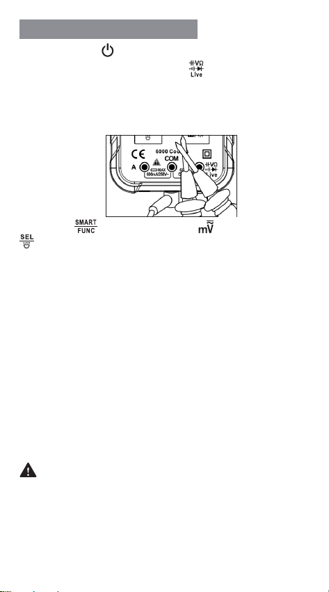
DC/AC mV Measurement
10
1)
Long press “ ” key to turn on the power.
2)
Insert the red probe into the “ ” jack and the black
probe into the “COM” jack.
3)
Touch the test lead tips together to check if they are
connected normally. The indicator light should turn
green and the buzzer sounds.
4)
Press “ ” key to switch to “ ” function.
5)
Connect the probe with voltage source or both ends
of load in parallel for measurement.
6)
After the reading stabilizes, record the reading from
the screen.
7)
When the measurement is completed, disconnect
the test leads from the measured object.
WARNING
1. A voltage higher than 250V cannot be measured;
otherwise, the meter may be damaged.
2. Pay special attention to safety when measuring
high voltage to avoid electric shock or personal
injury.
3. Before use, test on known voltage to confirm
intact function.
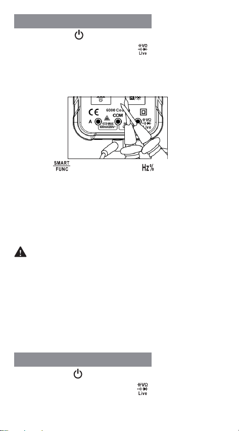
1)
Long press “ ” key to turn on the power.
2)
Insert the red probe into the “ ” jack and the black
probe into the "COM" jack.
Frequency/Duty Measurement
Capacitance Measurement
11
3)
Touch the test lead tips together to check if they are
connected normally. The indicator light should turn
green and the buzzer sounds.
4)
Press “ ” key to switch to “ ” function.
5)
Connect the probe with both ends of the capacitor in
parallel for measurement.
6)
After the reading stabilizes, record the reading from
the screen.
7)
When the measurement is completed, disconnect
the test leads from the measured object.
WARNING
When measuring capacitance, please disconnect
the power supply and discharge capacitors to
prevent safety hazard.
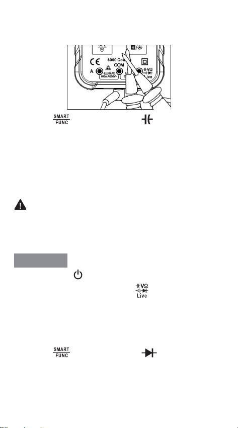
1)
Long press “ ” key to turn on the power.
2)
Insert the red probe into the “ ” jack and the black
probe into the "COM" jack.
3)
Touch the test lead tips together to check if they are
connected normally. The indicator light should turn
green and the buzzer sounds.
4)
Press “ ” key to switch to “ ” function.
5)
Connect the red test lead to the positive end of the
diode and the black test lead to the negative end.
Tips:
Generally, the positive end of the diode is the
longer end. If there is no reading, switch the test leads
Diode Test

12
to the opposite ends of the diode and measure again.
6)
After the reading stabilizes, record the reading from
the screen.
7)
When the measurement is completed, disconnect
the test leads from the measured object.
WARNING
To avoid damage to the meter and/ or the measured
object, disconnect the circuit power and discharge
all the high-voltage capacitors before testing.
Note:
①
The displayed value is an approximation of diode
forward voltage drop. The forward voltage drop of the
diode is generally 0.3V-0.8V.
②
If the probe has a reverse connection or the probe is
open, the meter shows “OL”.
③
When the voltage drop readings of the diode< 1V,
the buzzer will “beep” with a sound prompt.
1)
Long press “ ” key to turn on the power.
2)
Directly insert the red probe into “A” Current jack. The
meter automatically switches to current measurement.
Press “ ” key to switch between “ ” and “ ”.
Tips:
If the probe is not inserted into the current jack
in current measurement, “ ” will be displayed to
prompt jack change.
3)
Insert the black probe into the “COM” jack.
4)
Press “ ” key to switch between AC and DC
current.
5)
Disconnect the circuit to be tested, connect the red
and black test leads in series to the circuit then turn on
the power supply.
DC/AC Current Measurement
13
6)
After the reading stabilizes, record the reading from
the screen. When measuring AC current, the frequency
is displayed at the same time.
7)
When the measurement is completed, disconnect
the test leads from the measured object.
WARNING
1. Pay special attention to safety when measuring
high voltage to prevent safety hazard.
2.Before use, test on known current to confirm
intact function.
Caution:
The measured current should not exceed the rated
maximum current of 600mA to prevent safety
hazard.
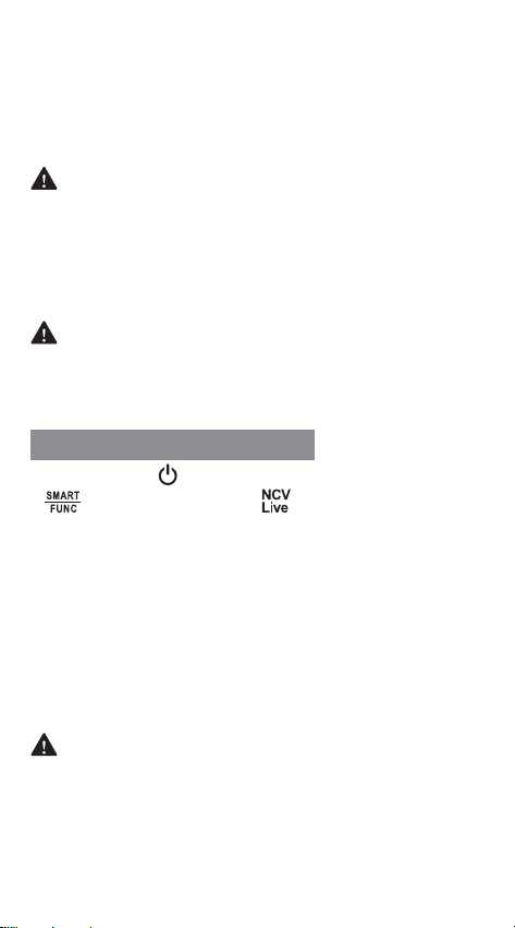
1)
Long press “ ” key to turn on the power. Press
“ ” key to switch to “ ” function. The meter
shows “NCV”.
2)
Detect objects with the top of the meter.
3)
If the meter senses weak AC voltage, the green
indicator light will be on. The buzzer will beep slowly,
displaying “--- L”.
4)
If the meter senses strong AC voltage, the red
indicator light will be on. The buzzer will beep fast,
displaying “--- H”.
Caution:
Please remove the probe while using NCV function
or the detection accuracy could be aected.
NCV function is affected by many factors, even if
there is no alarm prompt, there may still be high
voltage.
Non-Contact Voltage (NCV)

14
1)
Long press “ ” key to turn on the power, press
“ ”key to switch to “ ” function. Then press “ ”
key to switch to live function, the meter shows “Live”.
2)
The "COM" jack should remain empty. Insert the red
probe into the “ ” jack, then contact the probe the
test point.
3)
If the meter detects weak AC voltage, the green
indicator lights up, the buzzer beeps slowly, displaying
“--- L”.
4)
If the meter detects strong AC voltage, the red
indicator lights up, the buzzer beeps fast, displaying “---
H”. In general, the wire detected is the live at this time.
Customized Matching Meter Pen
This product uses customized test leads, you can go to
the
KAIWEETS
Amazon store to buy the matching test
leads set.
● Environmental conditions: CAT. III 600V
● Pollution Level
:
2
● Altitude < 2000m
● Working environment: 0~40°C(<80% RH, <10°C
non-condensing)
● Storage environment: -10~60°C(<70% RH, without
batteries)
● Temperature coefficient: 0.1Accuracy /°C(<18°C or
>28°C)
● Maximum voltage allowed between jacks: 600V
● Current protection: F600mA/250V fuse
● Sampling: approx. 3 times/second
● Display: maximum 6000 counts
● Over range indication: “OL” displayed
Specications
Live Test
15
DC voltage
AC voltage
Input impedance:
10MΩ
Overload protection/ Maximum voltage:
600V
Input impedance:
10MΩ
Overload protection/ Maximum voltage:
600V
Frequency Response:
40Hz ~ 1kHz True RMS
Range Resolution Accuracy
60mV 0.01mV
±(0.5% +3)
600mV 0.1mV
6V 0.001V
60V 0.01V
600V 0.1V
Range Resolution Accuracy
60mV 0.01mV
±(1.0%+3)
600mV 0.1mV
6V 0.001V
60V 0.01V
600V 0.1V
● Low battery: “ ” displayed
● Polarity indication: “-” displayed
● Power: 2 x 3V CR2032 batteries
Accuracy is applicable within one year after calibration.
Reference conditions: 18°C to 28°C, < 80% RH.
Accuracy: ± (% reading + word)
Accuracy
16
DC current
Overload protection:
F600mA/250V Fuse
Maximum current:
600mA
Range Resolution Accuracy
6000μA 1μA
±(1.2%+5)
60mA 0.01mA
600mA 0.1mA
AC current
Overload protection:
F600mA/250V Fuse
Maximum current:
600mA
Frequency Response:
40Hz ~ 1kHz True RMS
Range Resolution Accuracy
6000μA 1μA
±(1.5%+5)
60mA 0.01mA
600mA 0.1mA
Resistance
Overload protection:
250V
Range Resolution Accuracy
600Ω 0.1Ω
±(1.0%+5)
6kΩ 0.001kΩ
60kΩ 0.01kΩ
600kΩ 0.1kΩ
6MΩ 0.001MΩ
±(1.5%+3)
60MΩ 0.01MΩ
17
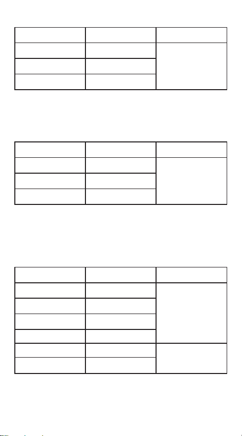
Capacitance
Range Resolution Accuracy
6nF 0.001nF
±(4.0%+5)
60nF 0.01nF
600nF 0.1nF
6μF 0.001μF
60μF 0.01μF
600μF 0.1μF
6mF 0.001mF
±(5.0%+5)
60mF 0.01mF
Overload protection:
250V
Frequency/Duty
Range Resolution Accuracy
10Hz 0.001Hz
±(1.0%+5)
100Hz 0.01Hz
1000Hz 0.1Hz
10kHz 0.001kHz
100kHz 0.01kHz
1000kHz 0.1kHz
10MHz 0.001MHz
±(3.0%+5)
1~99% 0.1%
Hz/% Position
:
1) Range:
10Hz ~ 10MHz
2) Voltage response:
0.5~10V AC
3) Overload protection:
250V
AC Voltage Position:
1) Range:
10Hz ~ 2 kHz
2) Voltage response:
≥ 0.5V AC
18
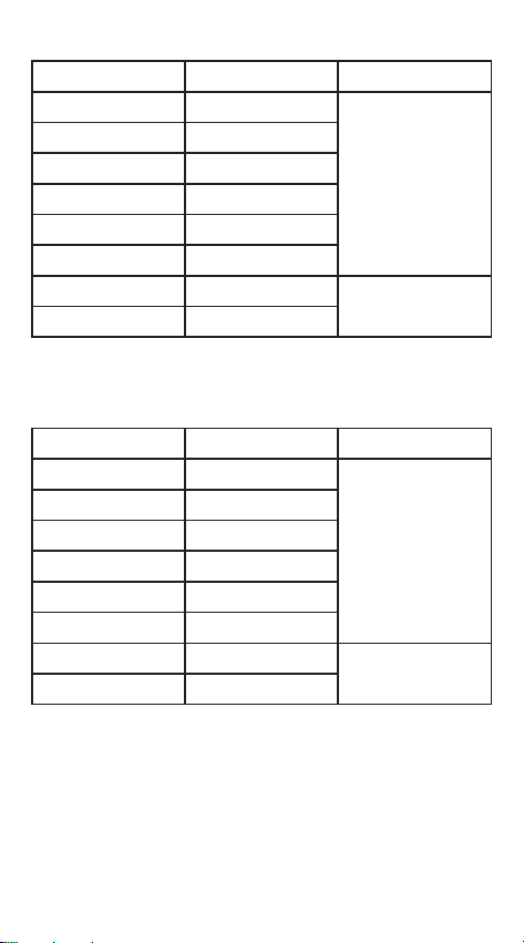
Diode
shows is an
approximation of
diode forward voltage
Open Voltage:
Approx. 2.0V
Overload protection:
250V
3) Overload protection:
250V
μA or mA Position:
1) Range:
10Hz ~ 2 kHz
2) Current response:
≥ 2mA
3) Overload protection:
F600mA/250V fuse
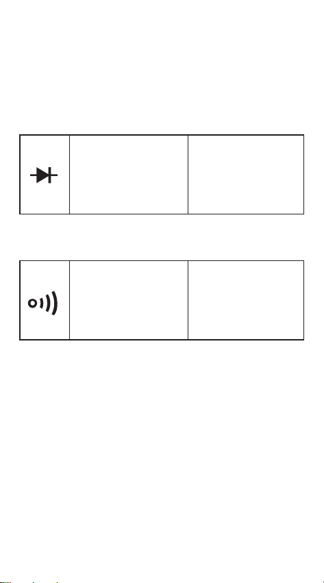
Continuity
<Approx.50Ω: the
buzzer sounds and
the LED lights up
Open Voltage:
Approx. 1.0V
Overload protection:
250V

19
Clean
Three years Warranty
If there is dust or humidity on the jack, it may cause
measurement error. Clean the instrument as follows:
1)
Turn o the meter power and remove the test probes.
2)
Wipe the case with a damp cloth or mild detergent.
Do not use abrasives or solvents. Wipe the contacts
in each input jack with a clean cotton swab soaked in
alcohol.
WARNING
Please keep the inside of the meter clean and dry at
all times to prevent electric shock or damage to the
instrument.
KAIWEETS
will repair, without charge, any defects due
to faulty materials or workmanship for three years from
the date of purchase provided that:
●
Proof of purchase is produced.
●
Service/repairs have not been attempted by unauthorized
persons;
●
The product has been subject to fair wear and tear;
●
The product has not been misused;
Defective products will be repaired or replaced, free
of charge, or at our discretion, if sent together with
proof of purchase to our authorized distributor(s). For
further detail of warranty coverage and warranty repair
information, send an email to