Quick Start Guide
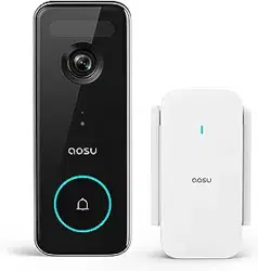
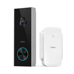
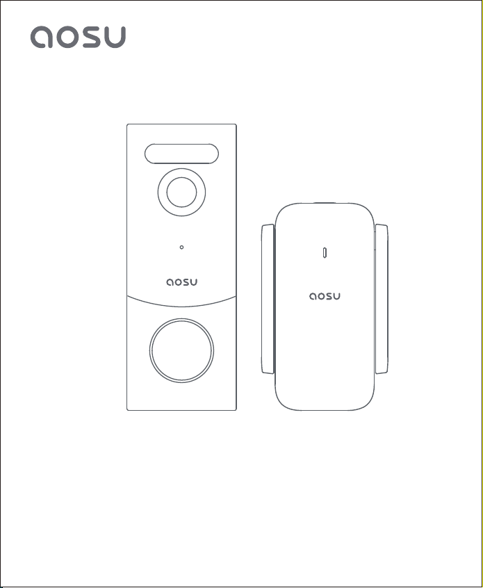
Video Doorbell and aosuBase Mini
(Battery or Hardwired Doorbell)
封面


TABLE OF CONTENTS
Please download the "aosu"App and then add devices before installing
doorbell.
P01What's Included
01
P02-P03
P04
P05
P06-P19
P20-P22
P23
Product Overview
02
How The System Works
03
Video Doorbell Installation
05
Notice
06
Customer Service
07
App Installation and System Setup
04
aosuBase Mini
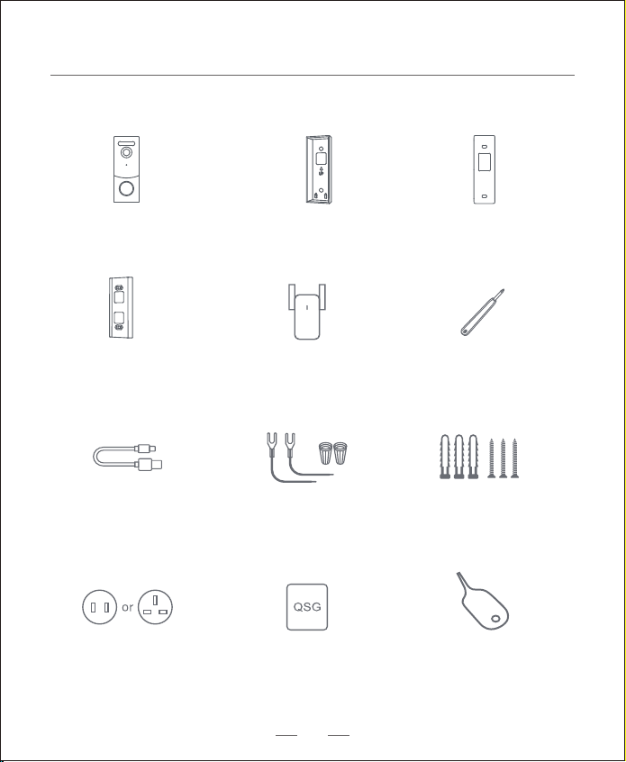
Screw Hole
Positioning-Card
Mounting Bracket
15° Mounting
Wedge (Optional)
Extension Wires and
Wire Nuts (Optional)
Screw Packs
Doorbell Detaching PinaosuBase Mini
Power Pin
Quick Start Guide
Video Doorbell
USB-C Charging
Cable
What's Included
Phillips-Head
Screwdriver
01
02
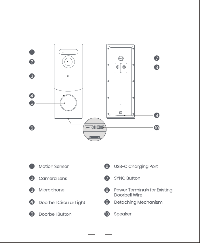
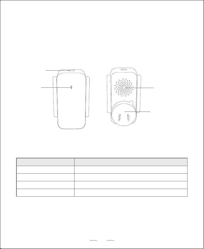
Product Overview
Video Doorbell (Battery or Hardwired)
Operation How-to
Power on the doorbell Press and release the SYNC button
Power o the doorbell Press and hold the SYNC button for 3 seconds.
Reset the doorbell Press and hold the SYNC button for 10 seconds.
Connect to Wi-Fi network Press and hold the SYNC button until you hear a beep
aosuBase Mini
SYNC Button
Status LED
Speaker
Power Pin
03
How The System Works
What’s Required for Installation
Phillips-Head Screwdriver
Power Drill with 1/4" (6.35mm) Drill Bit
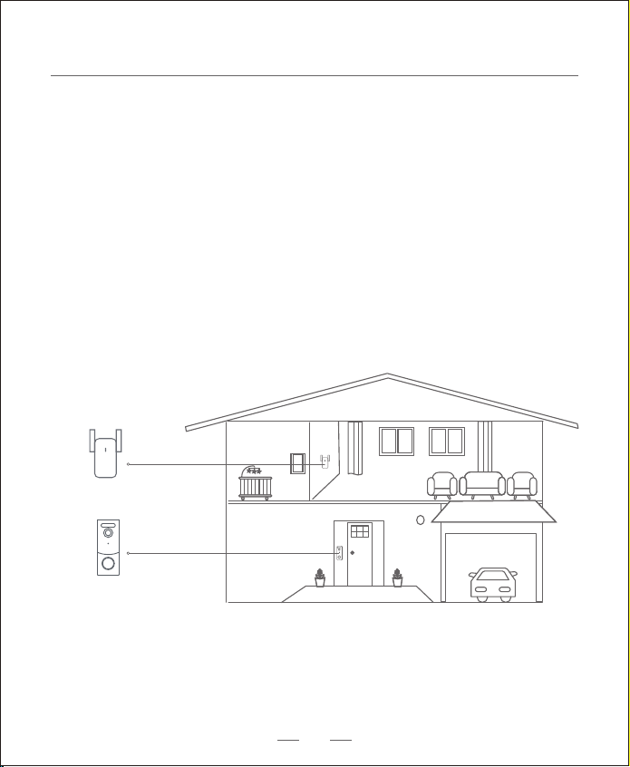
How the System Works
The video doorbell system includes 2 parts.
One is the video doorbell at your door.
The other is the aosuBase Mini in your house.
The video doorbell detects motion at your porch and allows you to answer
the door anytime and anywhere.
The aosuBase Mini stores video clips on its built-in storage.
When someone rings the doorbell, people in the house will be notied.
aosuBase Mini
Video Doorbell
04
App Installation and Set up the System
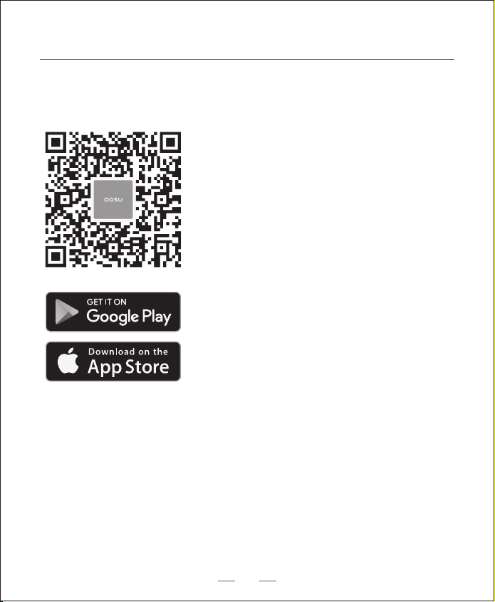
1. Download the aosu App from the App Store (iOS devices) or Google Play (Android
devices).
2. Scan the QR code below or search "aosu" in the App Store or Google Play.
Register or log into the App. Add Video Doorbell V8S and scan the QR code for later
installation process.
05
Video Doorbell Installation
Choose The Power Option
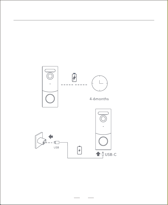
Option 1 - Battery Powered
1. If you don’t have existing doorbell wiring at the front door, please use the built-in
battery. You are free to determine the doorbell position and the mounting is easy and
quick.
2. When the doorbell battery level is low, you need to detach and charge it.
Warning: The battery life varies depending on usage. In most common cases, a doorbell
may have up to 10 events per day and each recording lasts 20 seconds on average.
Under this scenario, the doorbell battery life can last up to 6 months.
06
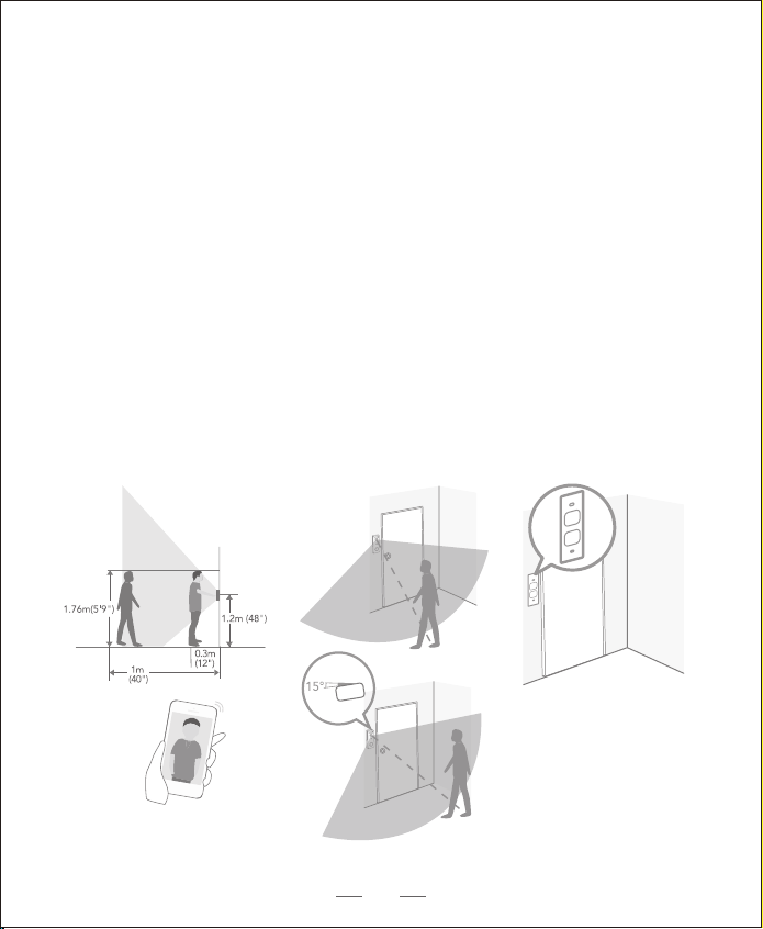
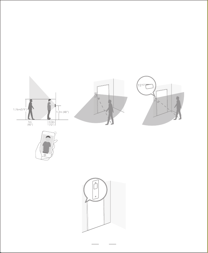
Step 1 Find a Mounting Spot
Take the video doorbell to your front door and check the live view on the
App at the same time. Find a location where you can get the desired field
of view.
Consider the factors below:
1. Check if you can reuse the existing holes and anchors on the wall or door frame.
2. If you want to place the doorbell close to a side wall, make sure the wall doesn’t
show up in the field of view. Otherwise IR light will be reflected and night vision
will become blurry.
3. If you drill the mounting holes for the first time, the recommended mounting
height is 48" / 1.2 m from the ground.
4. Use the 15° mounting wedge as a supplementary mounting bracket if you wish to
see more on a specific side.
Place the Screw Hole Positioning Card against the wall to mark the position.
Option 1 - Battery Powered
07
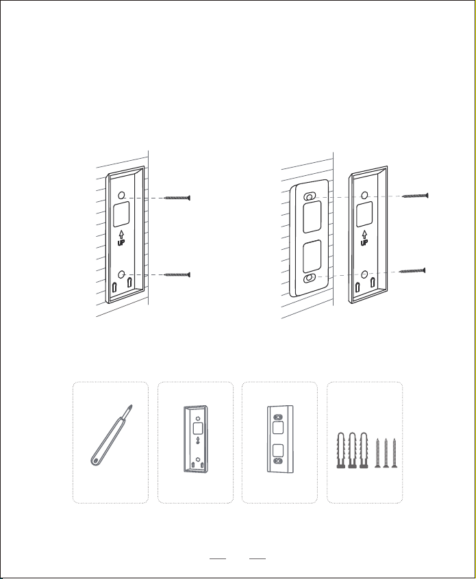
Mounting Bracket Mounting Wedge Mounting Bracket
Without 15° Mounting Wedge
What is required:
With 15° Mounting Wedge
Mounting Bracket
(Attached to 15° Mounting
Wedge)
15° Mounting
Wedge (Optional)
Screw Packs (Spare screws
and anchors are included.)
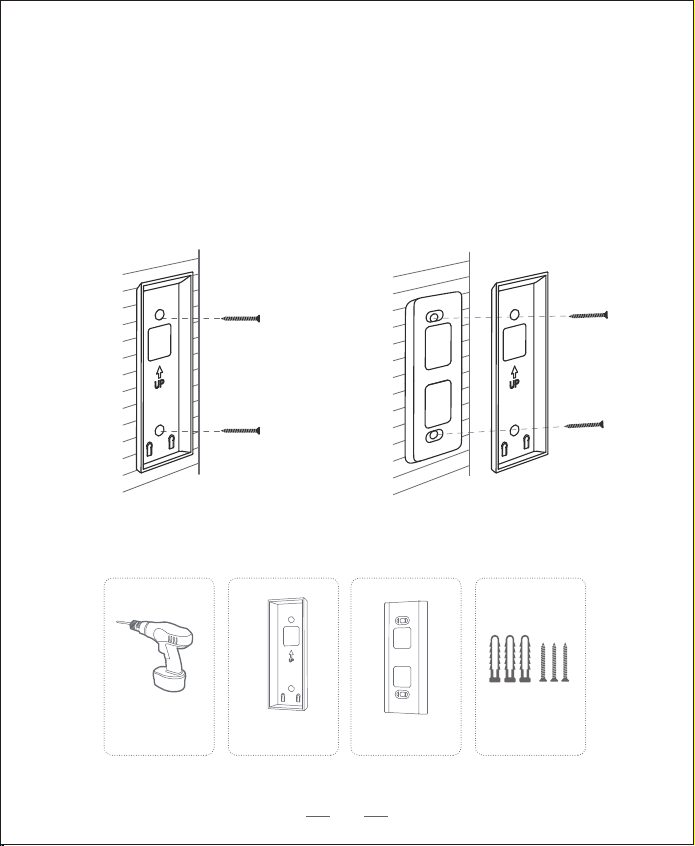
Step 2 Mounting the Bracket
Mount the Doorbell on a Wooden Surface
If you mount the doorbell on a wooden surface, you don’t need to pre-drill pilot
holes. Use the provided screws to secure the Mounting Bracket on the wall.
The Screw Hole Positioning Card indicates the position of the screw holes.
Power Drill
(not provided)
08
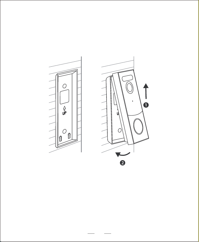
Step 3 Mounting the Doorbell
Mount the Doorbell
Align the doorbell on top and then snap it on the bottom.
Press it down until it clicks into place.
You’re all set!
If you want to detach the doorbell or recharge it, please refer to the following
sections.
09
What is required:
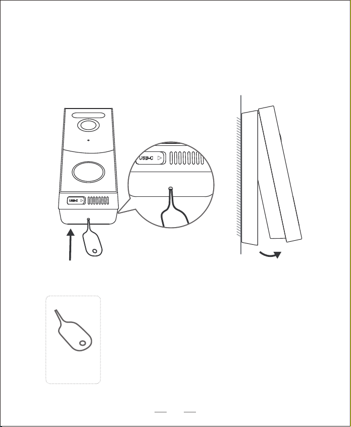
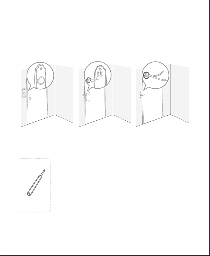
Detach the Doorbell
Doorbell
Detaching Pin
1. Use the doorbell detaching pin provided if you wish to detach the doorbell from
the Mounting Bracket.
2. Press and hold the hole on the bottom of the doorbell and then lift its bottom to
take it o.
10
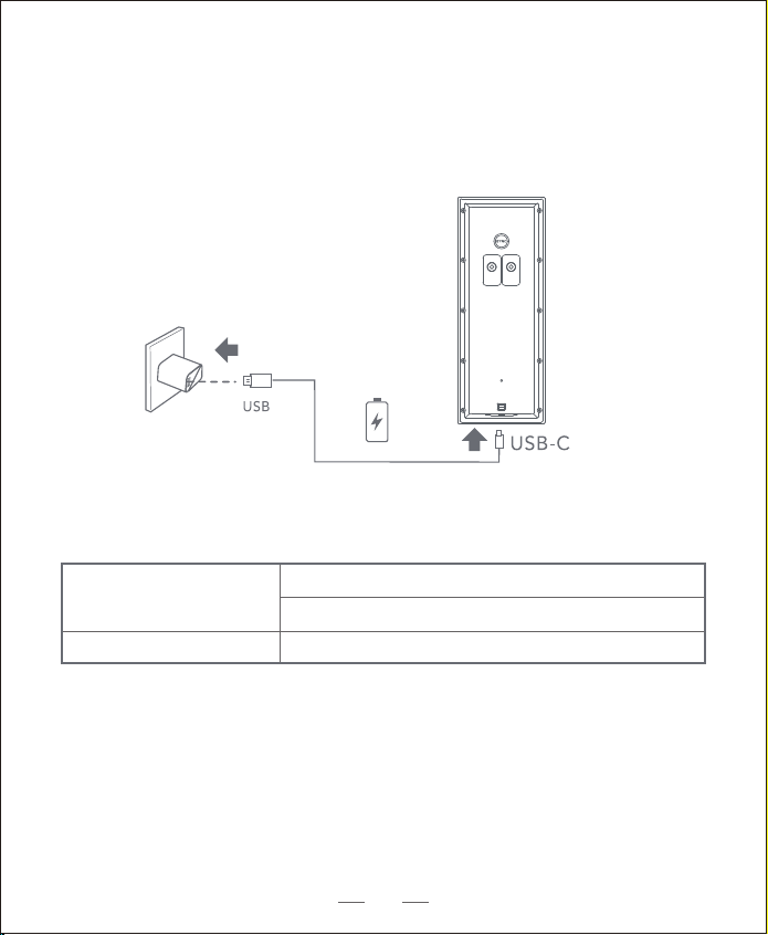
LED indication
Charging: The blue light ashes
Fully charged: Solid blue
Charging time
6 hours from 0% to 100%
Recharge the Doorbell
11
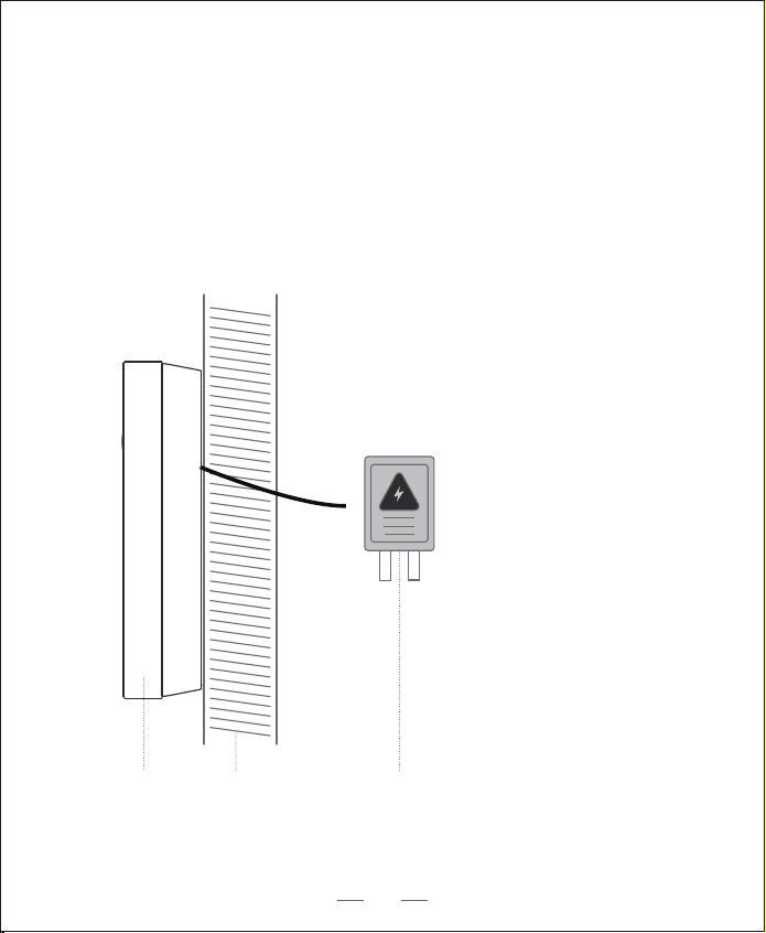
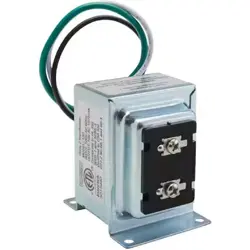
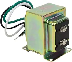
8 - 24V AC Doorbell WiringWallDoorbell
Option 2 - Doorbell Wire Powered
1. If you have existing and working doorbell wiring at the front door, the doorbell
will be powered by the wires constantly. So you don’t need to detach and charge
it after installation.
2. Since the doorbell is connected to the wires, the mounting position is limited.
3. If you choose this option, please jump to Appendix 2 Powering the Doorbell with
Doorbell Wires.
12
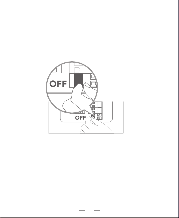
Step 1 Verify whether the doorbell wires are working
1. Ring the existing doorbell to check if it is working. If the doorbell doesn’t ring,
your doorbell wires may be defective. Power the doorbell on its own battery or
consult an electrician to x the wires.
2. Shut o power at the breaker. Turn the lights on / o in your home to make sure
the electricity in your house is properly shut o.
Warning: Always be careful when handling electricity wiring.
If you’re not comfortable to do it yourself, do consult a qualied electrician.
13
Breaker
What is required:
Phillips-Head Screwdriver
Step 2 Detach the Existing Doorbell Button
If you already have existing doorbell wiring:
1. Remove the existing doorbell button with a Phillips-Head screwdriver.
2. Pull the two wires out carefully when removing the existing doorbell. Straighten
the wire ends if necessary.
14
2. Place the Screw Hole Positioning Card against the wall to mark the position.
Step 3 Find a Mounting Spot
1. Determine the mounting position of the doorbell. Consider the factors below:
• Check if you can reuse the existing holes and anchors on the wall or door frame.
• If you drill the mounting holes for the rst time, the recommended mounting
height is 48" / 1.2 m from the ground.
• Use the 15° mounting wedge as a supplementary mounting bracket if you wish to
see more on a specic side.
15
What is required:
Without 15° Mounting Wedge With 15° Mounting Wedge
Mounting Bracket Mounting Wedge Mounting Bracket
Mounting Bracket
(Attached to 15°
Mounting Wedge)
15° Mounting
Wedge (Optional)
Screw Packs (Spare screws
and anchors are included.)
Phillips-Head Screwdriver
Step 4 Mount the Bracket
If you mount the doorbell on a wooden surface, you don’t need to pre-drill pilot
holes. Use the provided screws to secure the Mounting Bracket on the wall. The
Screw Hole Positioning Card indicates the position of the screw holes.
16
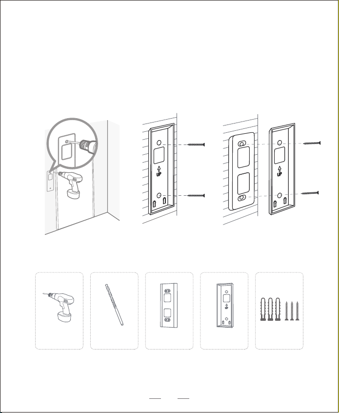
What is required:
Without 15° Mounting Wedge With 15° Mounting Wedge
Mounting Bracket Mounting Wedge Mounting Bracket
If you mount the doorbell on a surface made out of hard materials, like brick,
concrete, stucco:
• Drill 2 holes through the Screw Hole Positioning Card with 15/64”(6mm) drill bit.
• Insert the provided anchors, and then use the provided long screws to secure the
Mounting Bracket on the wall.
Mounting Bracket
(Attached to 15°
Mounting Wedge)
15° Mounting
Wedge (Optional)
Screw Packs (Spare screws
and anchors are included.)
15/64”(6mm) Drill Bit
Power Drill
(not provided)
17
What is required:
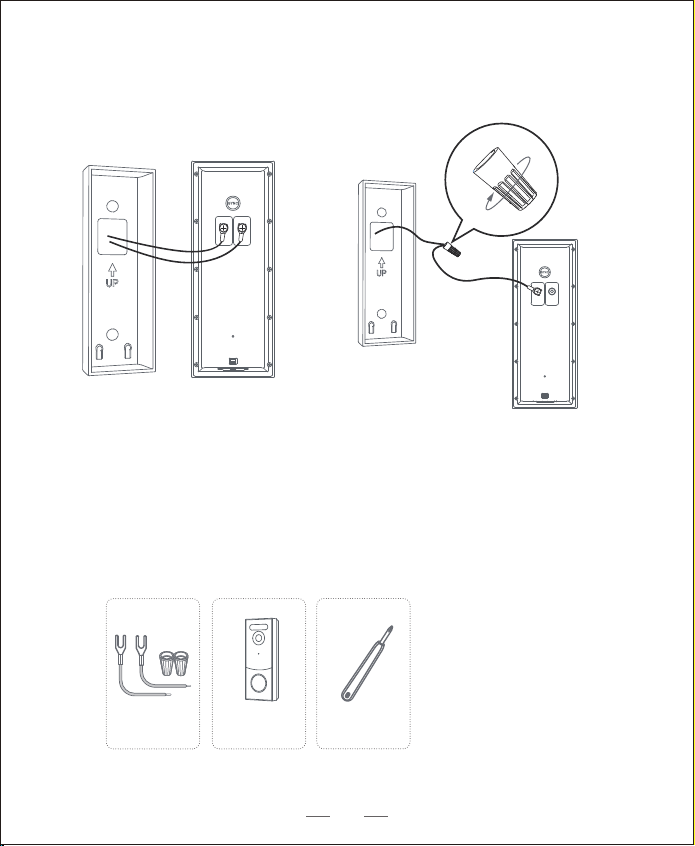
Step 5 Connect the Doorbell Wires to the Doorbell
Connect the wires to the terminals at the back of the doorbell, then tighten the
terminal screws. Wire can connect to any terminal.
Note:
• To prevent short-circuit, make sure the wires are not touched each other after
connecting them to the terminals.
• If the wires are too short, use the extension wires and wire nuts
provided to make them longer. Use electrical wiring tape instead if there
is no more space on the wall for wire nuts.
Extension Wires and
Wire Nuts (Optional)
Video Doorbell 2K
(Wired)
Model:T8210
Phillips-Head
Screwdriver
18
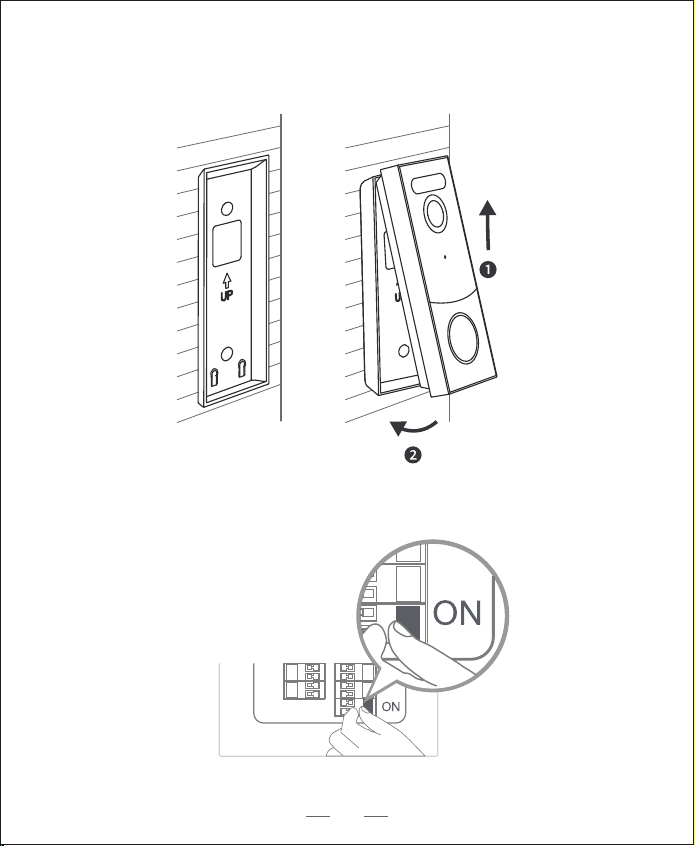
Step 6 Mount the Doorbell on the Bracket
Align the doorbell on top and then snap it on the bottom.
Step 7 Restore Power
Switch the master circuit breaker back to ON.
You’re all set!
19

Notice
FCC Statement
This device complies with Part 15 of the FCC Rules. Operation is subject to the
following two conditions: (1) this device may not cause harmful interference,
and (2) this device must accept any interference received, including
interference that may cause undesired operation.
Warning: Changes or modifications not expressly approved by the party
responsible for compliance could void the user's authority to operate the
equipment. Note: This equipment has been tested and found to comply with the
limits for a Class B digital device, pursuant to Part 15 of the FCC Rules. These
limits are designed to provide reasonable protection against harmful
interference in a residential installation.
This equipment generates uses and can radiate radio frequency energy and, if
not installed and used in accordance with the instructions, may cause harmful
interference to radio communications. However, there is no guarantee that
interference will not occur in a particular installation. If this equipment does
cause harmful interference to radio or television reception, which can be
determined by turning the equipment off and on, the user is encouraged to try to
correct the interference by one or more of the following measures: (1) Reorient
or relocate the receiving antenna. (2) Increase the separation between the
equipment and receiver. (3) Connect the equipment into an outlet on a circuit
different from that to which the receiver is connected. (4) Consult the dealer or
an experienced radio/ TV technician for help.
FCC Radio Frequency Exposure Statement
The device has been evaluated to meet general RF exposure requirements.
The device can be used in fixed/mobile exposure condition. The min separation
distance is 20cm.
20

21
IC Statement
This device contains licence-exempt transmitter(s)/receiver(s) that comply with
Innovation, Science and Economic Development Canada’s licence-exempt RSS(s).
Operation is subject to the following two conditions: (1)This device may not cause
interference.(2)This device must accept any interference, including interference that
may cause undesired operation of the device.
L’émetteur/récepteur exempt de licence contenu dans le présent appareil est conforme
aux CNR d’Innovation, Sciences et Développement économique Canada applicables
aux appareils radio exempts de licence. L’exploitation est autorisée aux deux
conditions suivantes :(1)L’appareil ne doit pas produire de brouillage; (2)L’appareil doit
accepter tout brouillage radioélectrique subi, même si le brouillage est susceptible
d’en compromettre le fonctionnement.
IC RF Statement
This equipment complies with IC RSS‐102 radiation exposure limits set forth for an
uncontrolled environment. This equipment should be installed and operated with
minimum distance 20cm between the radiator and your body.

22
Declaration of Conformity
This product complies with the radio interference requirements of the
European Community.
Hereby, Glazero Limited declares that this device is in compliance with the
essential requirements and other relevant provisions of Directive 2014/53/EU.
For the declaration of conformity, visit the Web site:https://www.aosulife.com/.
This product can be used across EU member states.
Do not use the Device in the environment at too high or too low temperature,
never expose the Device under strong sunshine or too wet environment.
The suitable temperature for aosuBase Mini and accessories is -10°C-45°C.
The suitable temperature for Video Doorbell and accessories is -20°C -
40°C .
When charging, please place the device in an environment that has a normal
room temperature and good ventilation.
It is recommended to charge the device in an environment with a temperature
that ranges from 5°C~25°C.
RF exposure information: The Maximum Permissible Exposure (MPE) level has
been calculated based on a distance of d=20 cm between the device and the
human body. To maintain compliance with RF exposure requirement, use
product that maintain a 20cm distance between the device and human body.
23
• Replacement of a battery with an incorrect type that can defeat a safeguard (for
example,in the case of some lithium battery types).
• Disposal of a battery into re or a hot oven, or mechanically crushing or cutting of a
battery, that can result in an explosion.
• Leaving a battery in an extremely high temperature surrounding environment that
can result in an explosion or the leakage of ammable liquid or gas.
• A battery subjected to extremely low air pressure that may result in an explosion or
the leakage of ammable liquid or gas.
This product is designed and manufactured with high quality materials
and components, which can be recycled and reused.
This symbol means the product must not be discarded as household
waste, and should be delivered to an appropriate collection facility for
recycling. Proper disposal and recycling helps protect natural
resources, human health and the environment. For more information
on disposal and recycling of this product, contact your local municipality,
disposal service, or the shop where you bought this product
Battery warning

Customer Service
Warranty
12-month limited warranty(The actual warranty period shall be implemented
according to the requirements of local laws and regulations)
Email Us
Customer Support: [email protected]
Call Us
Facebook:@aosulife
Twitter:@aosulife
YouTube:@aosulife
24
+1-866-905-9950 Mon-Fri 9AM-5PM (PST)
+44-20-3885-0830 Mon-Fri 9AM-5PM (GMT)
+33-980099094 Mon-Fri 8AM-4PM (CET)
+49-32-221094692 Mon-Fri 9AM-5PM (CET)
+81-50-5840-2601 Mon-Fri 9AM-5PM (JST)
US
UK
FR
DE
JP