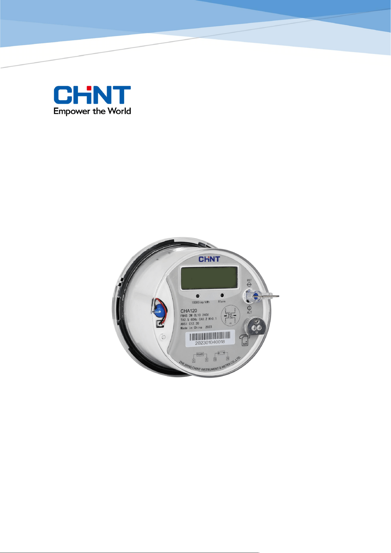
Contents
User Manual
© Copyright 2018, Zhejiang Chint Instrument & Meter Co., Ltd
All rights reserved.
CHA120
Single Phase Smart ANSI Meter

Contents
User Manual CHA120 1 / 24
README
Range of validity
The present user manual applies to the metering products specified on the title page.
Purpose
The user manual contains all the information required for application of the meters for the intended
purpose. This includes:
Provision of knowledge concerning characteristics, construction and function of
the metering products
Information about possible dangers, their consequences and measures to
prevent any danger
Details concerning the performance of all work throughout the service life of the
metering products
Target group
The contents of this user manual are intended for technically qualified personnel of utility companies
responsible for the metering products planning, installation, operation and maintenance
NOTICE
No part or all of the contents of this document may be copied or reproduced without the written permission
of the company, and may not be transmitted in any form.
The products, services, or features you purchase are subject to Chint's commercial contracts and terms,
and all or part of the products, services, or features described in this document may not be covered by
your purchase or use. Chint makes no express or implied of the representations or warranties for the
contents of this document, unless otherwise agreed in the contract.
The information contained in this document is subject to change without notice.
CHINT shall not be liable for errors contained herein or for incidental or consequential damages in
connection with the furnishing, performance, or use of this material.
For further information, see the following references:
Websites: http://en.chintim.com

Contents
User Manual CHA120 2 / 24
Contents
Contents .................................................................................................................................................... 2
1. Overview ................................................................................................................................................ 3
2. Introduction .......................................................................................................................................... 4
2.1. Device Description .................................................................................................................................................. 4
2.2. Standards and References .................................................................................................................................. 4
3. Block Schematic Diagram .................................................................................................................. 5
4. Basic Specifications ............................................................................................................................. 6
5. Meter Construction ............................................................................................................................. 7
5.1. Appearance................................................................................................................................................................ 7
5.2. Dimensions ................................................................................................................................................................ 8
5.3. Wiring Diagrams ...................................................................................................................................................... 9
6. Meter Functionalities ........................................................................................................................ 10
6.1. Function List ............................................................................................................................................................ 10
6.2. Display ....................................................................................................................................................................... 12
6.3. Measurement .......................................................................................................................................................... 15
6.4. Communication ...................................................................................................................................................... 17
6.5. Time of Use (optional) ......................................................................................................................................... 18
6.6. Billing .......................................................................................................................................................................... 19
6.7. Load Profile .............................................................................................................................................................. 19
6.8. Event........................................................................................................................................................................... 20
6.9. Data Security ........................................................................................................................................................... 21
7. Installation .......................................................................................................................................... 22
7.1. Installation Procedures and Cautions ........................................................................................................... 22
7.2. Acceptance After Installation ............................................................................................................................ 22
7.3. Safety Regulations ................................................................................................................................................ 23
8. Transportation and Storage ........................................................................................................... 24

Overview
User Manual CHA120 3 / 24
1. Overview
CHA120 single phase smart ANSI meter is designed for FM1S, FM2S and FM4S users. Max current up
to 200A. It has ultra Anti-Tamper features and multi communication channels, which can support Wi-SUN
communication and cellular communication. It can be used for remote data collecting and load control.
This smart meter can help the Utility company build smart home and AMI system easily.
Highlights:
Ultra Anti-Tamper Features
Multiple Communication Methods
Various AMI Functionalites
Introduction
User Manual CHA120 4 / 24
2. Introduction
2.1. Device Description
Type
Connectio
n
U
n
I
b
(Imax)
f
n
Imp/kWh
Accuracy Class
CHA120
FM2S
DC 120/240V 30(200)A
60Hz
1000
(by default)
Active
CA0.5
DC: direct connected
2.2. Standards and References
Standard Description
ANSI C12.10-2011
American National Standard for Physical Aspects of Watthour Meters—
Safety Standard
ANSI C12.20-2015
American National Standard For Electricity Meters-0.2 and 0.5 Accuracy
Classes
ANSI C12.1-2014 American National Standard for Electric Meters Code for Electricity Metering
IEC 62056-21-2002
Electricity metering – Data exchange for meter reading, tariff and load control
– Part 21: Direct local exchange
IEC 62056-6-2-2016
Electricity metering – Data exchange for meter reading, tariff and load control
– Part 62: Interface classes
IEC 62056-61-2006
Electricity metering data exchange – The DLMS/COSEM suite – Part 6-
1:COSEM object identification system (OBIS)
Block Schema
tic Diagram
User Manua
l CHA120 5 / 24
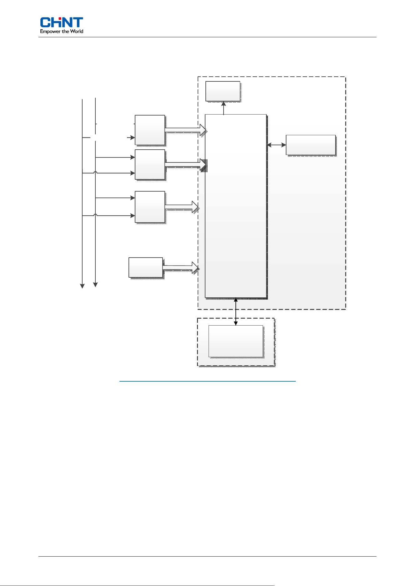
3. Block Schematic Diagram
Current sensor
L1
L2\N
Cur
rent
Sampling
V
oltage
Sampling
M
ain
Power
S
OC
E
EPROM
LCD
COMM. Module
Di
vider
resistance
B
attery
Current sensor
Figure 1: Block schem
atic diagram of (typical) of CHA120
The
meter is mainly comprised of current sampling unit, voltage sampling unit, MCU, main power supply,
backup power supply, LEDs, LCD, memory, and communication module.
The meter processes voltage and current sampling through SHUNT or CT and voltage sampling circuit,
upon which the integrated energy data is used to drive the pulse output and passed to energy registration.
Relevant controlling and meter reading function are all based on the registered energy data.
Besides the mains power supply, there are power backup which comprises of the internal super-cap and
the replaceable battery. All together they provide a reliable power management scheme to fulfill the power
requirement of a smart meter.
Basic Speci
fications
User Manua
l CHA120 6 / 24
4. Basic Specifications
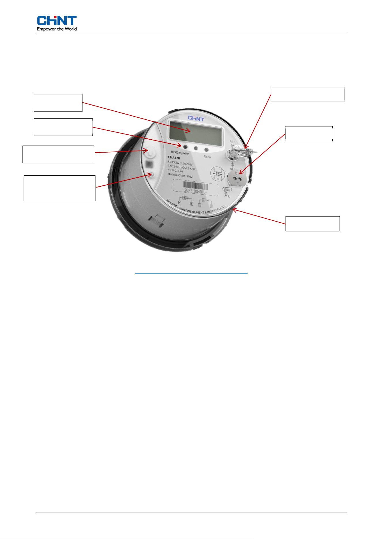
Table 1: S
pecifications of CHA120
Descri
ption
Values
Meter
Type
FM2S
A
ctive Accuracy
CA0.5
Nominal
Voltage Un
120V / 240V
Current
Range
30(200)A
Nominal
Frequency fn
60 Hz, ± 2%
Starting Current
0.4% In
Meter
Constant
1000 imp/kWh for FM2S
Start-up Ti
me
≤ 5s
Power
Consumption of Base Meter
Voltage circuit: ≦2W, 5VA
Current circuit at I
n
: ≦4VA
Operati
ng Voltage Range
0.8Un ~ 1.15Un
Operating temperature range
-40℃~+70℃
Storage and transportation limited
temperature range
-40℃~+80℃
Relativ
e Humidity
Up to 95% non-condensing
Life expecta
ncy
10 years
Dime
nsions
177mm (D) × 153.3mm (H)
Weight
1.0kg (Approx.)
Meter Const
ruction
User Manua
l CHA120 7 / 24
5. Meter Construction
5.1. Appearance
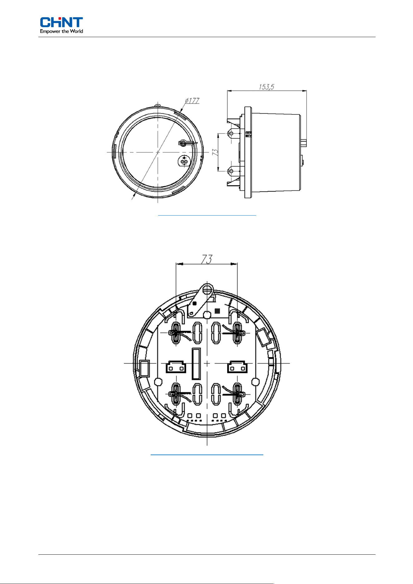
Figure 2:
Meter appearance of CHA120
The
mechanical housings are made of recyclable PC (UV light and solvent vapors resistant), subjected
to class II insulation. The meter offers IP54 (non-suction) ingress protection level, compliant to IEC
60529.2 lead seals are used to protect the meter housing. Without breaking the seals it’s impossible to
access the internal parts of the meter.
There are nameplates in the meter cover, providing sufficient spaces for the utility to attach device and
customer information.
LCD Scr
een
LED indicat
ors
Multi-function button
Optica
l Port
Replacea
ble battery
Meter
cover open
detection
SIM car
d slot
Meter Const
ruction
User Manua
l CHA120 8 / 24
5.2. Dimensions
5.2.1. Outline Dimensions
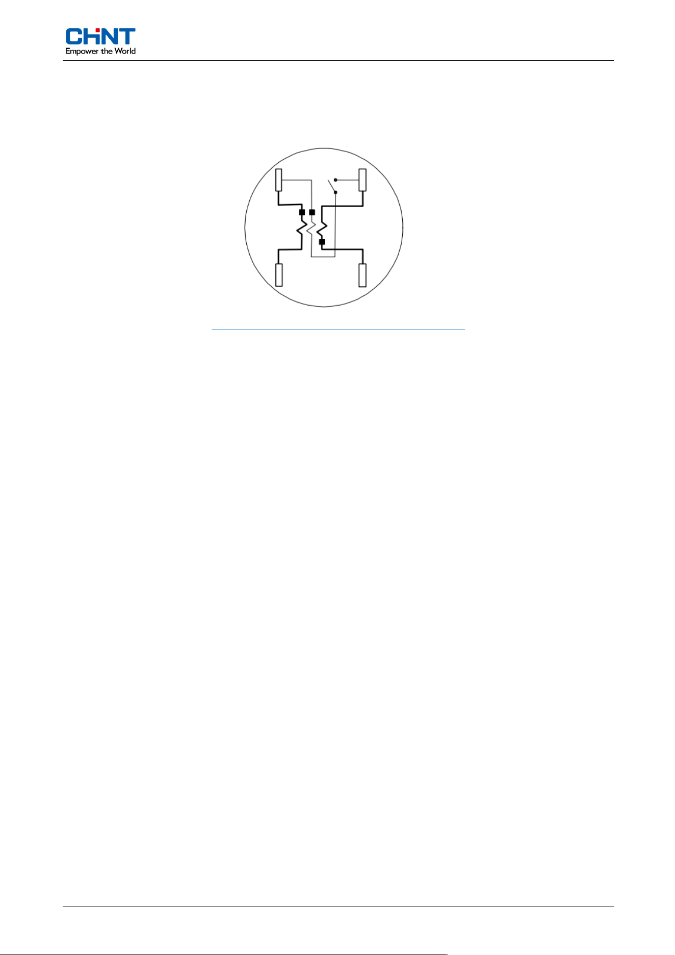
Figure 3: D
imension of CHA120
5.2.2. Installation Dimensions
Figure 4: Installat
ion size of CHA120
Meter Const
ruction
User Manua
l CHA120 9 / 24
5.3. Wiring Diagrams
5.3.1. Main Wiring
Figure 6: FM2S 3-wire wiring diagrams of CHA120
Meter Funct
ionalities
User Manua
l CHA120 10 / 24
6. Meter Functionalities
6.1. Function List
Table 2: Funct
ion list of CHA120
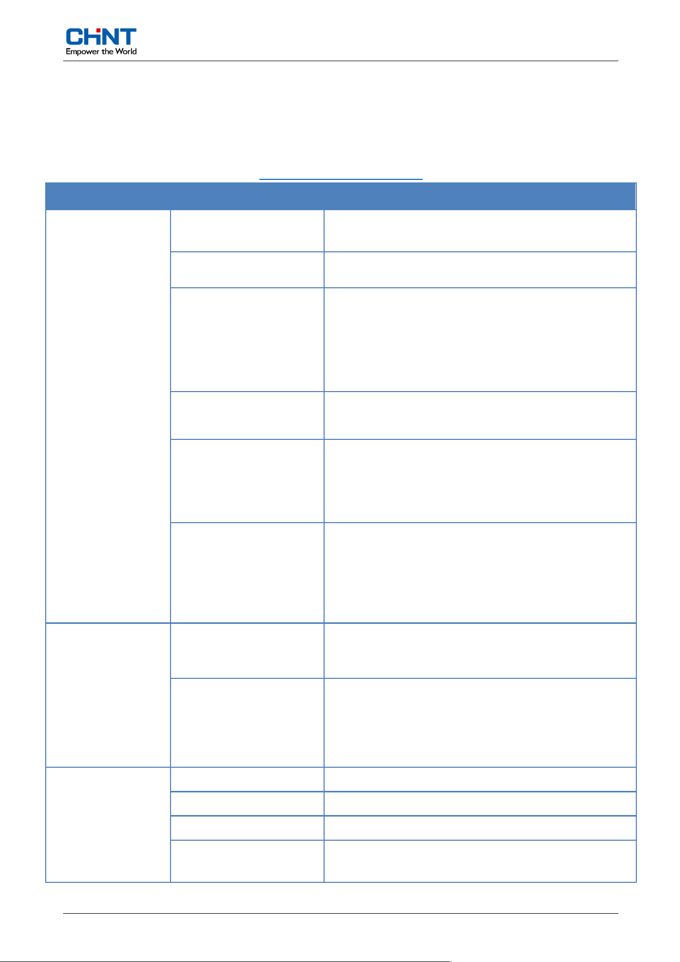
Item Sub-item Param
eter
LED &
Display
LED
1 x Active pulse, 1 x Alarm LED by default
Up to 4 LED indicators
Energy Data
Format Active: 7 digits
Instantaneous
Value Format
Energy: XXXXXXX, unit:kWh
Power: XX.xxx, unit:kW
Voltage: XXX.xx, unit:V
Current: XXX.xx, unit:A
Demand: XX.xxx, unit:kW
LCD
Size of LCD: 71
x 26mm (W x H)
Size of
digit: 7 x 12mm (W x H)
Display
Modes
- Auto scroll mode: interval by default is 6 seconds
(config
urable:1-99s).
- Manual scroll mode
- No power display.
Display
Symbol
- Tamper indicator
- Direction of current
- Communication Status
- Other special event indicator
Meas
urement
Active Energy(Default)
Import Active Energy = |+A|
Export Active Energy = |-A|
Instant
aneous
Phase Voltage (V)
Phase Current (A)
Active Power (kW)
Demand
Commu
nication
Optical Port ANSI 12.10 compliant
Optica
l Port Protocol IEC 62056-21
Communication Unit
Wi-SUN
Protocol for
Communication Unit
DLMS/COSEM
Meter Funct
ionalities
User Manua
l CHA120 11 / 24
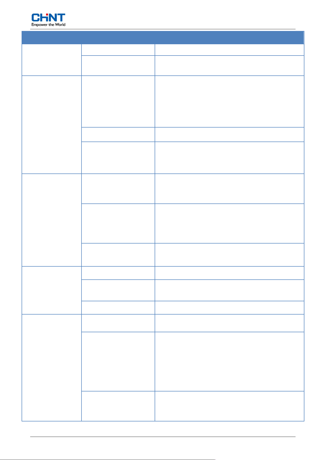
Item Sub-item Param
eter
W
ired Interface RS485 (optional)
Protoco
l for Wired
Interface
DLMS/COSEM
Clock
(optional)
ToU
- Up to 4 tariff operations
- Up to 12 season profiles
- Up to 12 week profiles
- Up to 8 day profiles, with each day 10 entries.
- 50 configurable special days
RTC Accur
acy ≤0.5 s/day (at 23ºC)
Backup B
attery
- Battery for no-power RTC and d
isplay
- 10-year
battery lifetime
Maximum
Demand
&
Billing
Maximum Demand
Optional average or sliding demand calculation
Configurable demand interval: 5,10,15,20,30 or 60
minutes
Billing(M
aximum Demand
Reset)
Three types of billing operation:
- Billing through communication command.
- Billing
based on calendar of tariff.
- Billing based on button manually
Capacity of Stored Value
(Billing Profile)
Number of captured objects up to 30
Load Profile
Number of Profiles 4
Capac
ity of Profiles
Each profile has the capacity of storing 1500 records
Profile Interval
1~1440minutes, configurable, 15 minutes by default
Event
Function
Number of Profiles 4 different types of event logs
Standar
d Event Log
Types of logs include:
- Timing synchronization
- Battery low
- Max demand manual reset Event log reset
- Power on / Power off
Capture object configurable
Tamper
ing Detection Log
Types of logs include:
- Meter cover open
- Strong magnetic
Meter Funct
ionalities
User Manua
l CHA120 12 / 24
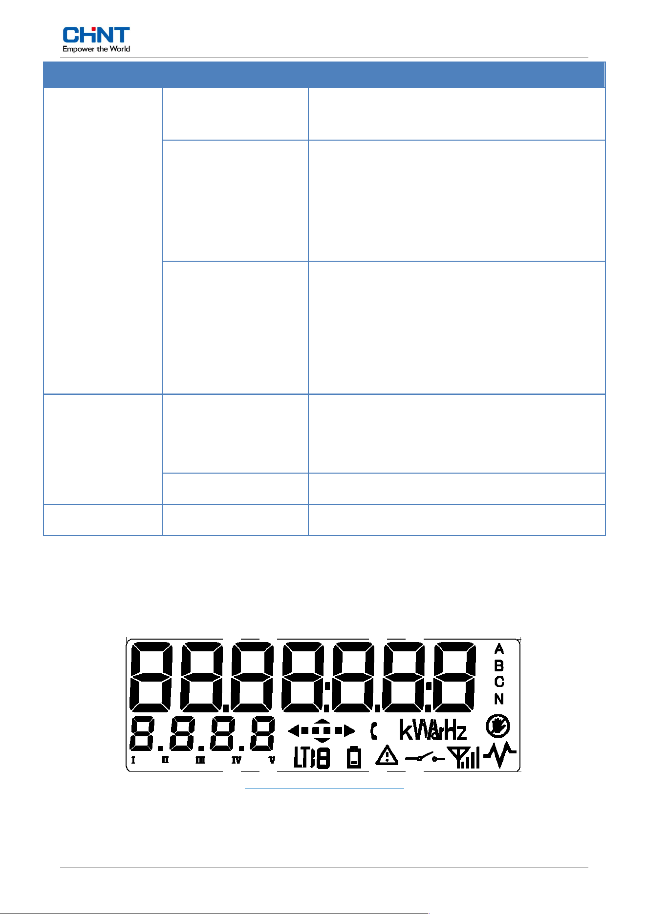
Item Sub-item Param
eter
- Current
bypass
Capture object configurable
Disconnect
Log
Types of logs include:
- Remote disconnect
- Remote connect
- Local disconnect
- Local connect
Capture object configurable
Power Q
uality Log
Types of logs include:
- Power outage
- Under voltage
- Over voltage
- Over current
- Over load
Capture object configurable
Load Control
Disconnect
ion Relay
Maximum Current:200A
Maximum switching voltage: Up to 440VAC
Support phase and neutral relay (optional)
Up to 10000 operations
Load L
imiting Configurable load limiting
Securi
ty
Access Level Up to 3 access levels protected by password
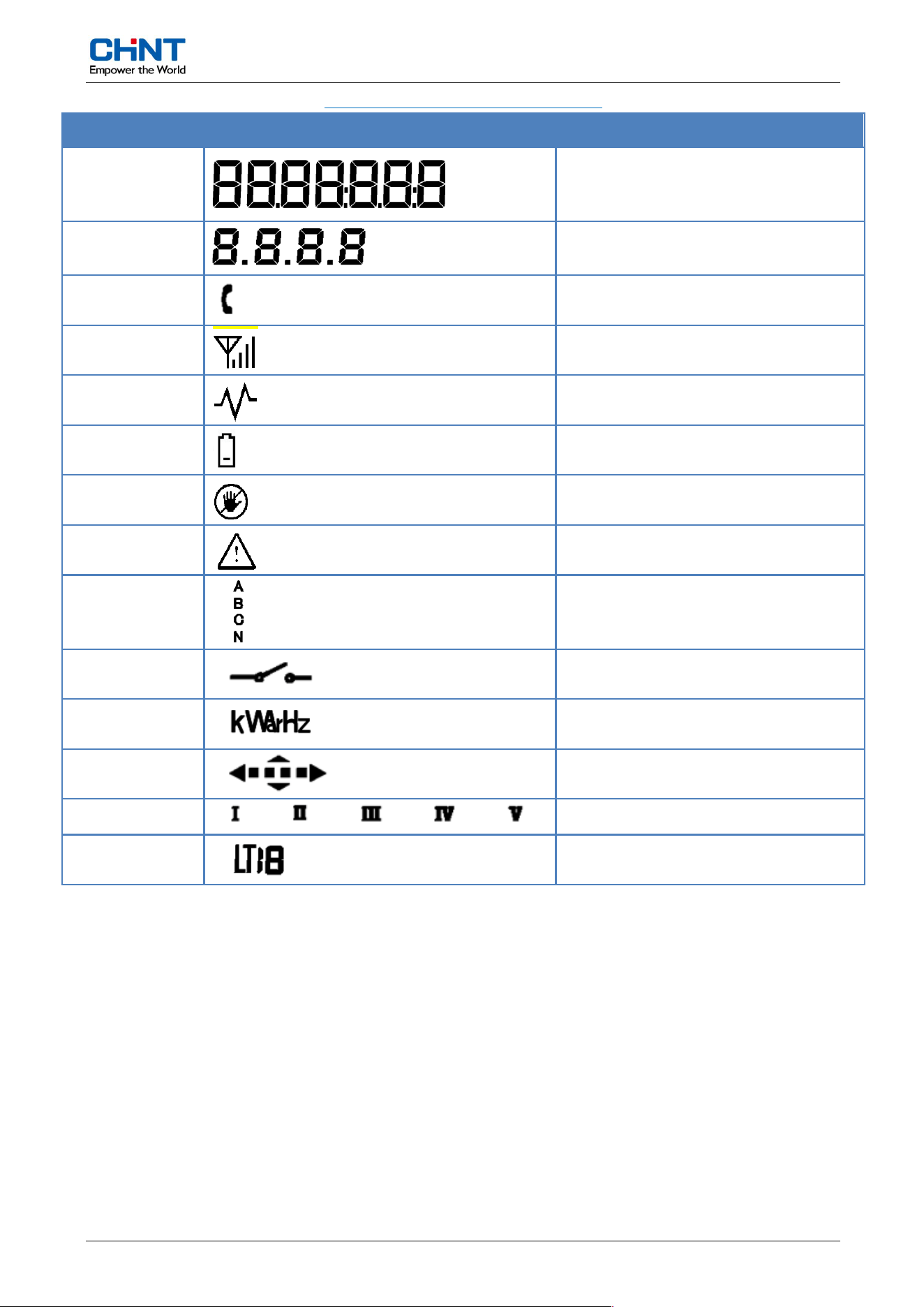
6.2. Display
6.2.1. LCD display information
Figure 8: LCD s
creen of CHA120
Symbol d
escriptions:
Meter Funct
ionalities
User Manua
l CHA120 13 / 24
Table 3: Sym
bol descriptions of CHA120
Sectio
n name
Display
symbol
Descri
ption
1
Metering
value
2
OBIS of display item
3
In com
munication
4
Signal strength
5
Reserved
6
Low battery voltage indication
7
T
ampering indication
8
Alarm
indication
9
Phase volta
ge indication
10
Rela
y connection/disconnection
11
Units
12
Current im
port/export indication
13
Tamper event specification
14
Step or m
ulti tariff indication
6.2.2. Data item
Digits
in this area has a size of 7 x 12 mm (W x H). Various type of meter value could be displayed in this
area. If the meter value is longer than 8 digits, it will be segmented and displayed with separated screens
6.2.3. LED
There ar
e 2 LEDs (by default) on the meter.
1) Energy impulse LED is used for active accuracy verification.
2) Alarm LED is used to indicate alarm state (configurable, current reversal by default).
Meter Funct
ionalities
User Manua
l CHA120 14 / 24
The q
uantity of LEDs support up to 4, the function of LEDs can be customized.
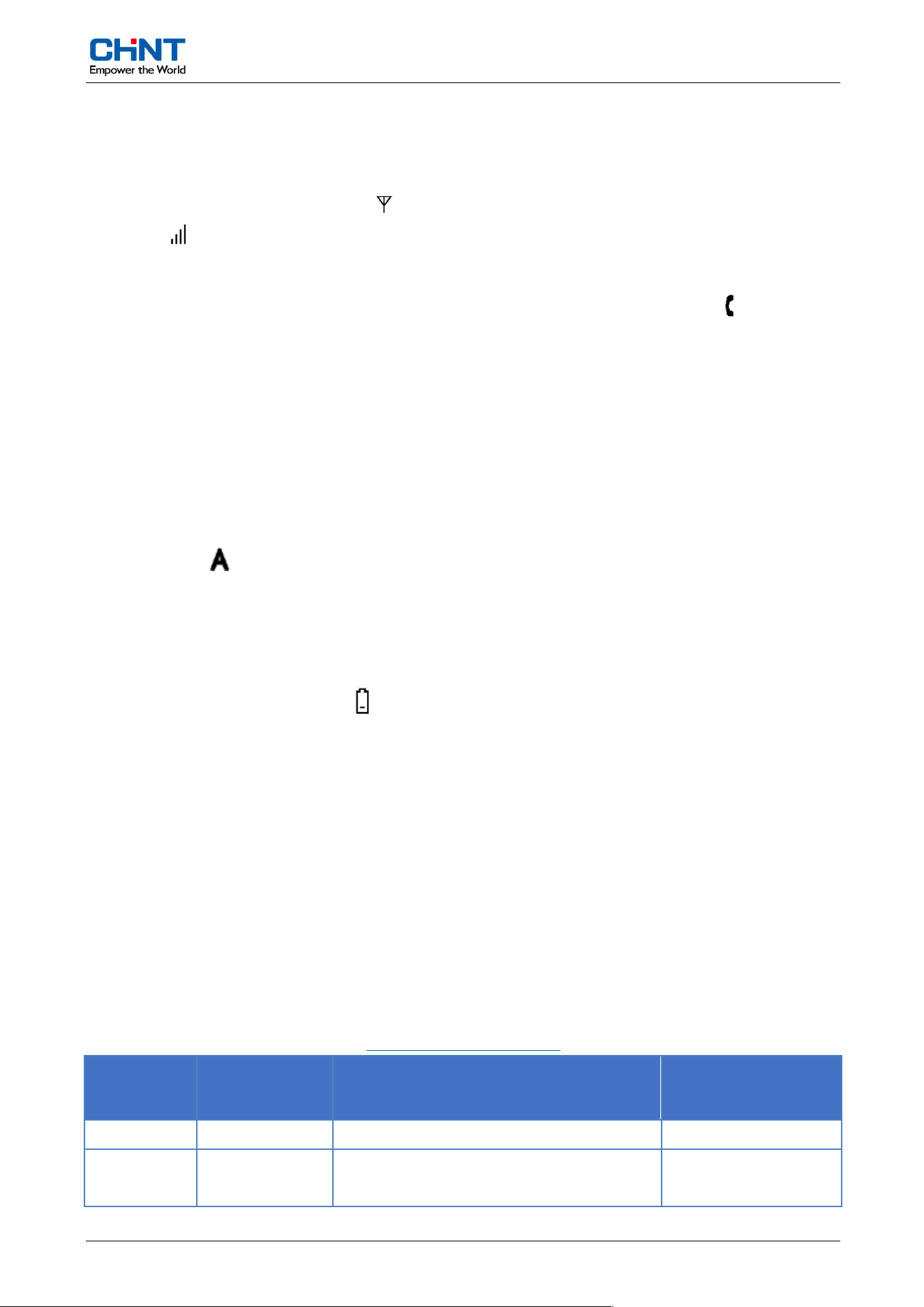
6.2.4. Communication symbol
If the cellular module
is connected, the symbol will be displayed, in addition to the signal strength
indication:
The meter automatically identifies the type of the module being connected and display relevant symbols.
When the meter is being communicated locally or remotely, the communication symbol will be on.
6.2.5. Relay Indication
The
relay on/off symbols can indicate the relay state, disconnection or connection. When the relay is in
Ready_for_Reconnection state, the symbol will flash at a frequency of 0.5Hz.
6.2.6. Phase Voltage Indication
V
oltage symbol indicates status of phase A. If the phase voltage is normal, the symbol is on. If it is
in overvoltage or under voltage state, the symbol will flash at a frequency of 0.5Hz.
6.2.7. Battery Indication
W
hen the battery voltage is low, the symbol will display, should change the replaceable battery at this
time.
6.2.8. LCD Display Modes
The
meter has 3 display modes: auto-scroll, manual-scroll and no-power read. Display objects for each
mode is configurable. The display time internal and display object list for each mode can be configured
according to different requirement.
In auto-scroll mode the meter automatically scrolls the display at an interval of 5s by default.
Once the display button is pressed, the meter will get into manual-scroll display mode. And user can press
the button to turn the display page. Through the following table for button operations, the meter could
change the display behavior.
Table 4: B
utton operate type
Operate
ty
pe
Operate
interv
al
Display
behavior
Display
tip
Short pres
s Tp < 2s Manual-scroll current display list
Medium
press
2s < Tp < 4s Switch display list to the next one PAGING
Meter Funct
ionalities
User Manua
l CHA120 15 / 24
Long press 4s <
Tp < 6s Reset display list to auto-scroll BACING
Extra-long
press
Tp > 8s Reset to auto-scroll mode H-cnct
The
meter is fitted with no-power read feature. When the meter is powered off, if the display button is
pressed the meter will wake up and get into no-power displaying.
The backlight will turn on automatically when the power is turned on or there is a display button or a demand
reset button. The backlight is turned on for 15s.
6.2.9. LEDs
There
are 2 LEDs on the meter by default. The one energy pulse LEDs are used for active accuracy
verification. One alarm indicator whether there are tampering event happens.
6.2.10. Button
The meter has one multi-function button, by rotation with different angle, it can support manual display
scrolling function and billing reset operation (Maximum Demand Reset). This multi-function button also
support lead seal.
6.3. Measurement
6.3.1. Energy pulse
Active energy pulse is output to relevant LED for accuracy verification. By default the meter constants are
configured as 1000imp/kWh, which are also configurable based on application.
6.3.2. Energy values
The
meter can measure and store the following energy quantities:
Import active energy (+A),
Export active energy (-
A),
Absolute a
ctive energy (|+A| + |-A|),
Algebraic sum active energy (|+A| - |-A),
Multi-tariff energy
.
After
the energy value reaches the maximum display limit, which is 99999.99 [kWh], it will overflow and
reset to zero, meanwhile the overflow counter increments by one.
Meter Funct
ionalities
User Manua
l CHA120 16 / 24
6.3.3. Demand
The
method used for demand calculation of the meter could be either average demand or sliding demand.
By default it’s configured as average demand.
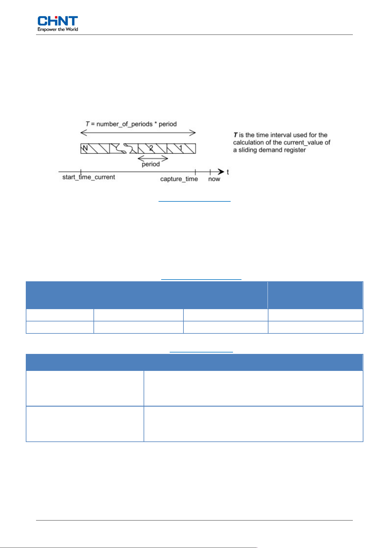
For sliding demand the interval “T” used for demand calculation is determined by the two parameters:
period and number_of_period, illustrated below:
Figure 9: Dema
nd period
For
average demand, it can be regarded as a special type of “sliding demand” where the number of period
is always 1.
Through the configuration of the above two parameters, the demand interval of the meter is defined. The
following table shows the value range of the parameters.
Table 5: Calculation method
Calculation
metho
d
Demand int
ernal (min)
Period
(min)
Number of
period
Sliding 1~60 1~60 1~60
Interval 1~60 1~60 1
Table 5: Demand type
Demand t
ype
M
easurement content
Im
port active demand (A+)
Current demand register (1.4.0)
Demand of last interval register (1.5.0)
Maximum demand registers – total and per tariff (1.6.x)
Export act
ive demand (A-)
Current demand register (2.4.0)
Demand of last interval register (2.5.0)
Maximum demand registers – total and per tariff (2.6.x)
Meter Funct
ionalities
User Manua
l CHA120 17 / 24
6.4. Communication
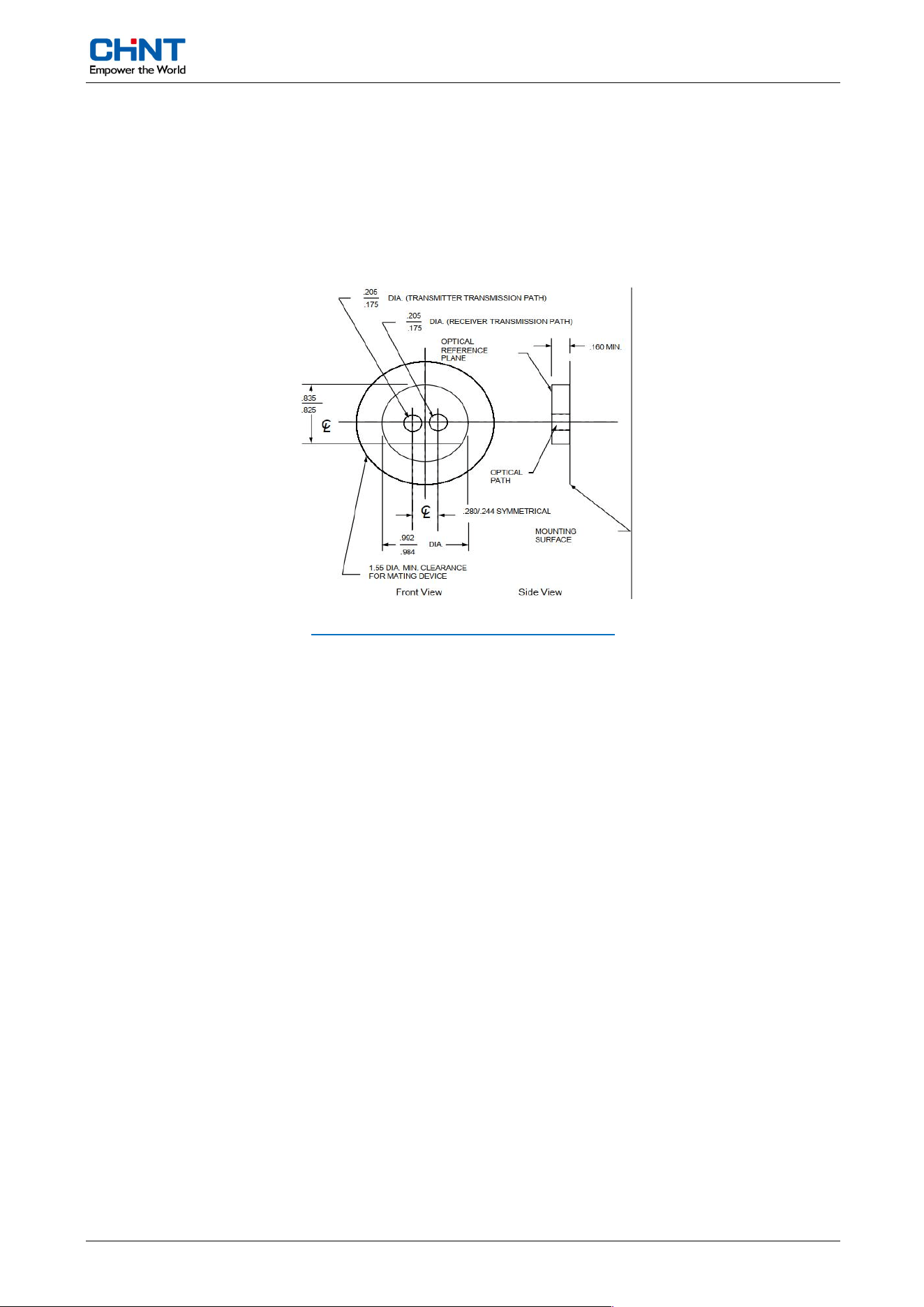
The meter offers 3 independent communication interfaces, which include an optical port, an RS485
wired port(optional) and a built-in communication module unit used for upstream communication.
6.4.1. Optical interface
Figure 10: External view of ANSI optical port
Compliant to ANSI optical communication physical interface
Conform to DLMS/COSEM communication standard
Configured as 9600bps, 7 bits, 1 even parity by default
Supporting software and HHU can be used for local data exchange through optical interface.
6.4.2. RS485 communication interface (optional)
DLMS/COSEM protocols
Configured as 9600bps, 8 bits, no parity by default
6.4.3. Upstream Communication Interface
DLMS/COSEM protocols
Wi-SUN
Meter Funct
ionalities
User Manua
l CHA120 18 / 24
6.5. Time of Use (optional)
6.5.1. General description
The meter offers up to 4 tariff operations, which feature is driven by its internal real time clock. The time
table used for the tariff switching consists of the season tables, the day tables and the special day tables.
6.5.2. Real time clock
6.5.2.1. RTC features
Auto
matic leap year switching
Accuracy at 23°C less than 0.5s/day
A 1Hz pulse output is available for quick clock accuracy verification
24-hour clock format
If the real-time clock stops, a predefined tariff can be designated for tariff energy registration
6.5.2.2. RTC backup power
Lithiu
m battery (Optional)
One lithium battery with 1200mAh capacity, 3.6V supply voltage battery provides backup power to the
RTC
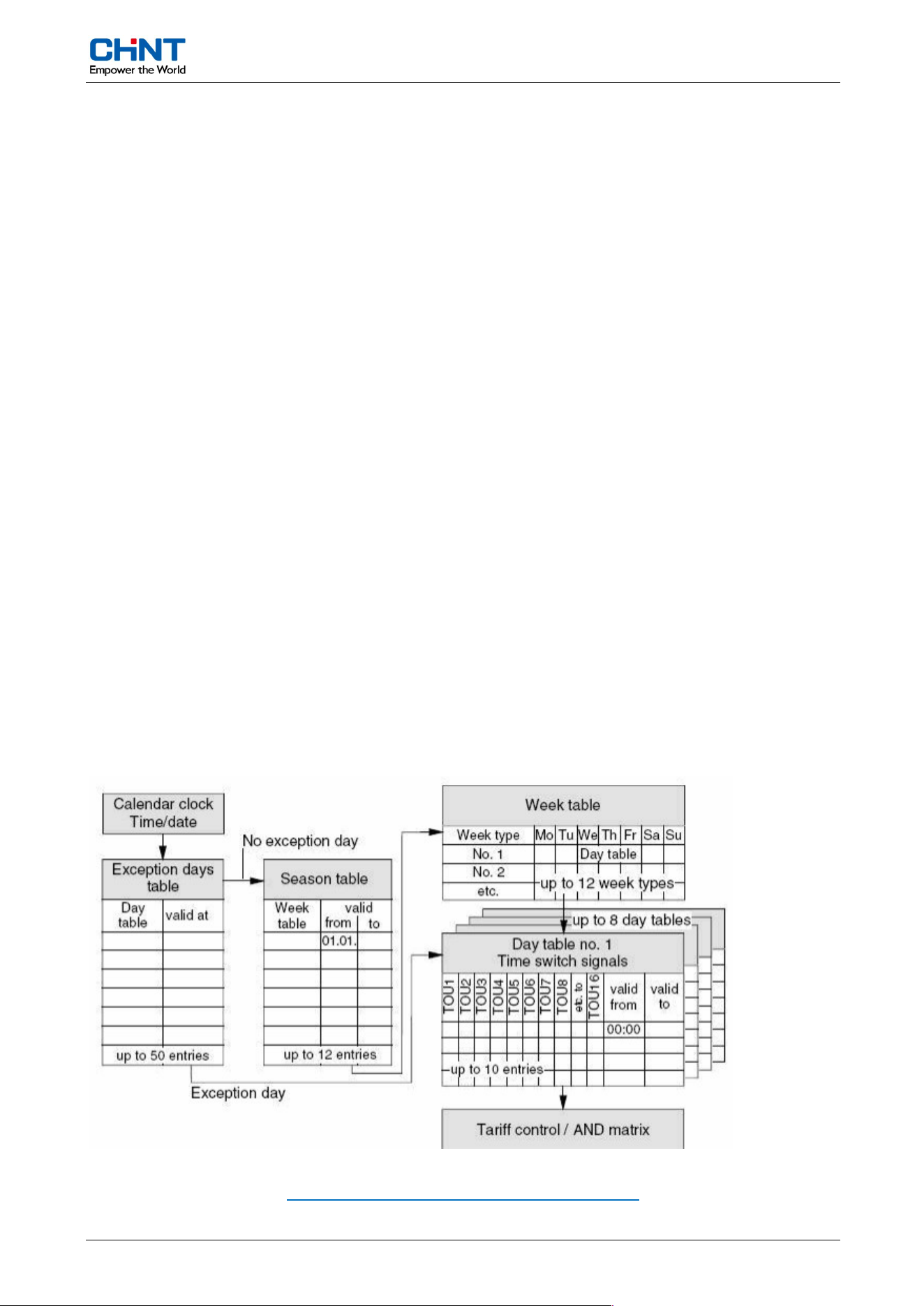
6.5.3. ToU time table
The
meter has 2 sets of TOU time tables, capable of up to 4 tariff operations. Each table consists of up
to 12 season entries, associated to 12 week tables respectively, and up to 8 day tables, each with up to
10 day entries. Besides, the meter can define up to 50 special days.
Figure 11: Schemat
ic diagram of the calendar clock

Meter Funct
ionalities
User Manua
l CHA120 19 / 24
6.5.4. Time table programming
The
time table programming is always applied on the passive time table. The activation time of the passive
time table is configurable. When the meter gets to the activation time the active and passive time table
will swap. The names of active and passive time table are both configurable but cannot be the same.
The time table switching can be done remotely through a communication command.
6.6. Billing
There
is a billing profile in the meter to store the billing values. The maximum demand registers reset and
a record is generated in the billing profile either the predefined billing time is due or a manual billing
operation (through MD Reset button) is detected.
6.6.1. Billing on predefined schedule
By
default the billing schedule is configured to trigger the billing operation at midnight on the first day of
each month. The number of captured objects for each billing entry can be up to 20.
The virgin startup of the meter generates a billing entry in the profile.
If a power outage or a time adjustment skips the billing time, the meter will complement the missed billing
entry either after the meter is re-powered up or after the time adjustment is completed.
6.6.2. Operations associated to billing
W
hen a billing operation is conducted, the meter will do the following:
Generate an entry in the billing profile
Reset maximum demand resisters,
Generate MD reset event log.
6.7. Load Profile
Suppor
t 4 channels of load profile, each channel can register up to 1500 records. Interval of each load
profile is configurable, configure by 15 min by default, can be 1 ~ 60 minutes. What values can be
stored in each load profile is configurable. The records in the load profile is stored in the FIFO (First In
First Out) manner, each entry with a timestamp. The load profile records can be read out flexibly by the
entry or time range defined by the readout.
Meter Funct
ionalities
User Manua
l CHA120 20 / 24
6.8. Event
The
meter detects and records events. The event log is identified with unique event number. The
generated event signal will be directed to generate alarm or error indication based on relevant
configuration.
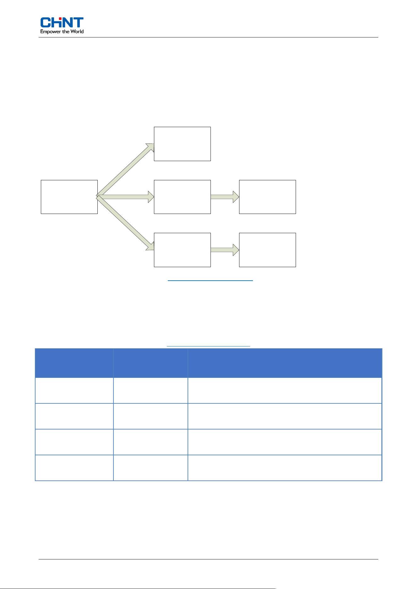
Event logs, alarm and error generation:
T
riggered
Event
E
vent
Logs
A
larm
Filter
Error
Filter
A
larm
Error
Figure 12: Triggered event
6.8.1. Event logs
The meter defines and records the following 4 type of event logs with separated event profile:
Table 6: Type of ev
ent logs
T
ypes of event
logs
Logical nam
e
Descriptio
n
Standard
event log 0-0:99.98.0.255
General events such as time synchronization,
meter configuration change, etc.
T
ampering detection
log
0-0:99.98.1.255 Events associated to tampering detection.
Disconnection even
t
log
0-0:99.98.2.255 Events associated to Connect and Disconnect
Power qua
lity event
log
0-0:99.98.4.255 Event associated to power quality

Meter Funct
ionalities
User Manua
l CHA120 21 / 24
6.8.2. Event alarming
There is an event register in the meter, containing a 32-bit data to indicate the on/off state of some
predefined events. An alarm filter of 32-bit value, which is configurable, is defined to filter out what events
have to trigger the alarm. The alarm indication includes the alarm LED, the backlight, the alarm symbol
on the LCD and even the audible alarm.
Alarm LED and backlight
When an alarm event occurs, the LCD backlight and alarm LED will flash continuously.
Alarm symbol of LCD
6.9. Data Security
The meter offers different categories of users the following 3 access levels which are protected by
access password.
Public Reading
Meter Reading
Meter Configuration

Installa
tion
User Manua
l CHA120 22 / 24
7. Installation
It
is recommended to refer to the wiring diagram for connecting the meter to the power network. If
appropriate a meter cabinet can be used to protect the meter. Preferably the meter should be installed in
a ventilated and environment.
7.1. Installation Procedures and Cautions
7.1.1. Installation Procedures
T
o ensure proper operation of the meter, follow the procedures below when install a meter:
Fix the first screw on the wall, leave some space between screw head and the wall to allow the
meter being able to hang on the screw
Hang the meter on the screw
Fix the other screws to install the meter on the wall
Make sure the power is off and connect the power lines to the meter as per the wiring diagram
Make sure the meter is firmly in place, power on the meter
Check relevant indications of the meter to make sure the installation is proper
7.1.2. Cautions
Improper
installation could damage the meter. Relevant verification must be done to ensure the meter is
properly installed:
Verify the operating voltage of the meter is within the range
Verify the current range is proper for the application at the installation site
Verify there is no visible mechanical or electrical damage on the meter
Verify the factory seals of the meter have not been broken
7.2. Acceptance After Installation
After the
meter is installed and power is connected, the following checking should be done on the meter:
The phase voltage symbol on the LCD should be present
If any load is applied on the meter the pulse LED should be flashing and the quadrant indicator
should correctly indicated
All seals should be installed.

Installation
User Manual CH
A120 23 / 24
7.3. Safety Regulations
Relevant national and international safety regulations must be complied with during the course of the
meter installation. The installation must be conducted by qualified personnel.
Do not touch any of the live parts of the meter at any time when the power is on. Be aware that
personal injury or equipment damage could result from improper wiring procedure.
FCC ID for CHA120 Wi-SUN type is: 2BXBXCHA12001
Please take attention that changes or modification not expressly approved by the party responsible
for compliance could void the user’s authority to operate the equipment.
This device complies with Part 15 of the FCC Rules. Operation is subject to the following two
conditions:
(1) This device may not cause harmful interference, and
(2) This device must accept any interference received, including interference that may cause undesired
operation
This equipment complies with FCC radiation exposure limits set forth for an uncontrolled environment.
This equipment should be installed and operated with minimum distance 20cm between the radiator &
your body.

Transportation and Storage
User Manual CHA120 24 / 24
8. Transportation and Storage
The
meter should be transported and unpacked violently. Do not apply power on when the case
has
been
damaged or violently dropped during handling, access and installation. Contact the supplier
as
soon a
s possible.
Save the energy meter should be in the original packaging, the ambient temperature is -40
℃
~
+85
℃
,
the av
erage relative humidity of not more than 75% of the air without corrosive gases.
Meter stored in the warehouse, should be placed on the bench, the stack height not more tha
n 10