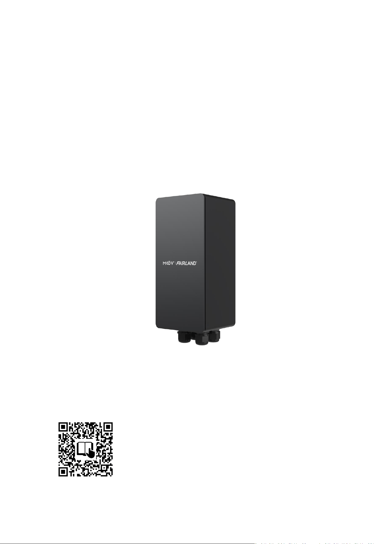
POOL ACTUATOR TRANSFORMER
I N S T A L L A T I O N A N D O P E R A T I O N M A N U A L
Follow this QR code for installation and operation manual
THANK YOU F O R P U R CHASING OUR PO O L A CTUATOR T R A N S F O RME R .
THIS MANUAL CONTAINS IMPORTANT INFORMATION THAT WILL HELP YOU IN
OPERATING AND MAINTAINING THIS PRODUCT.
PLEASE READ THE MANUAL CAREFULLY BEFORE INSTALLATION & OPERATION AND
RETAIN IT FOR FUTURE REFERENCE.
CONTENTS
1. IMPORTANT SAFETY INSTRUCTIONS ................................................................................... 1
2. TECHNICAL SPECIFICATIONS .......................................................................................................... 2
3. OVERALL DIMENSION ....................................................................................................................... 2
4. PRODUCT ILLUSTRATION ................................................................................................................ 3
5. LIGHT CHART ....................................................................................................................................... 4
6. INSTALLATION ..................................................................................................................................... 4
7. SETTING AND OPERATION ............................................................................................................... 7
8. WIFI OPERATION ................................................................................................................................. 9
9. TROUBLE SHOOTING ...................................................................................................................... 21
10. WARRANTY & EXCLUSIONS ........................................................................................................ 24
11. DISPOSAL .......................................................................................................................................... 24

1
1. IMPORTANT SAFETY INSTRUCTIONS
When installing and using this electrical equipment, basic safety precautions should always be followed,
including the following:
1) READ AND FOLLOW ALL INSTRUCTIONS.
2) Installation shall comply with the applicable requirements of the current National Electrical Code® (NEC®) or
Canadian Electrical Code (CEC), as appropriate.
3) WARNING – To reduce the risk of injury, do not permit children to use this product unless they are closely
supervised at all times.
4) WARNING – Installation and maintenance work must be performed by a licensed electrician.
5) WARNING – Before installation or maintenance, be sure to turn off the power switch on the left side of the
transformer.
6) WARNING – To reduce the risk of electric shock, replace the damaged cord immediately.
7) Can be used to connect 1 to 3 valve actuators.
8) CAUTION: To ensure continued protection against shock hazard, use only identical replacement parts when
servicing.
9) The transformer is not submersible.
10) Do not remove the insulator covering the terminals.
11) SAVE THESE INSTRUCTIONS.
2
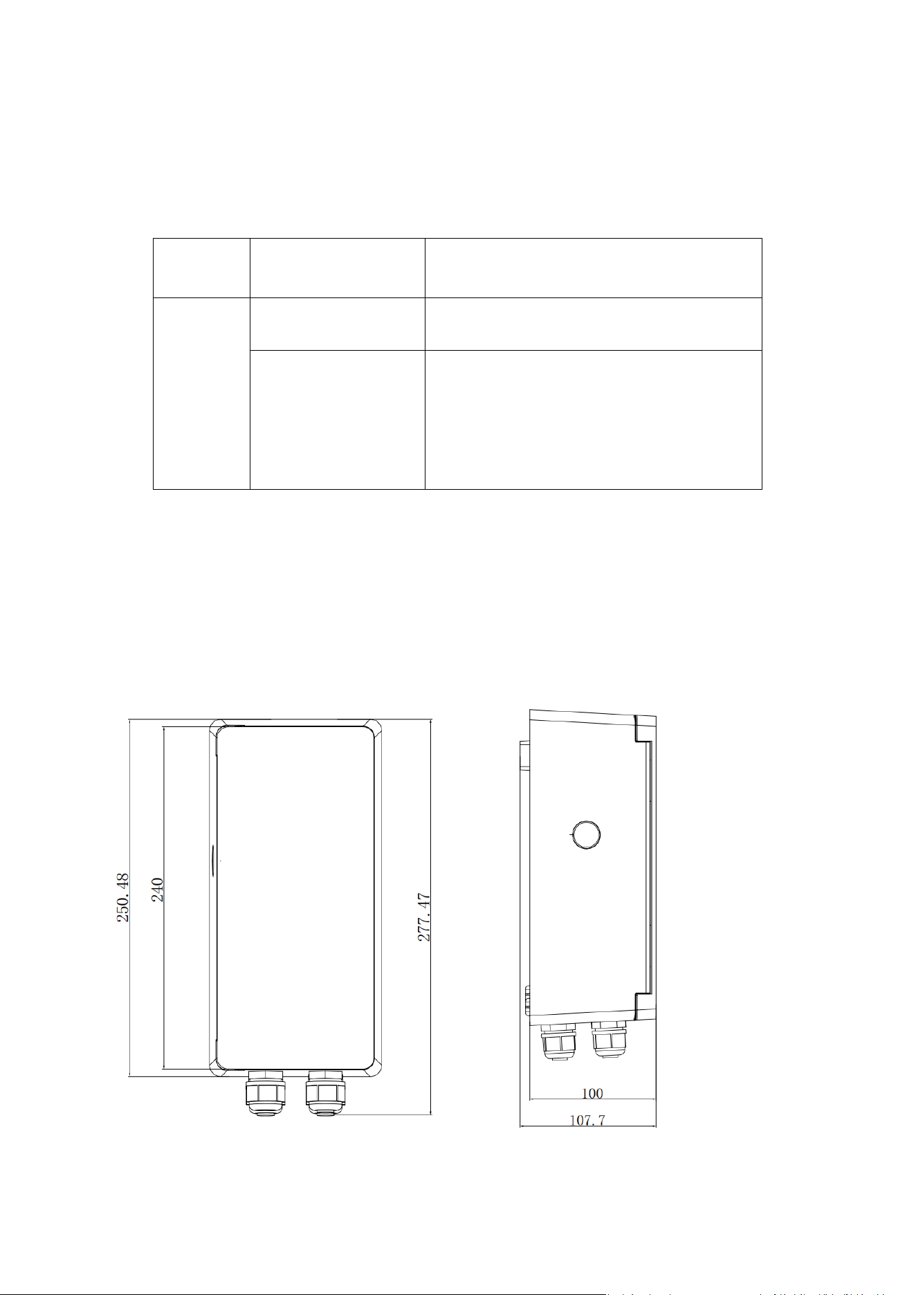
2. TECHNICAL SPECIFICATIONS
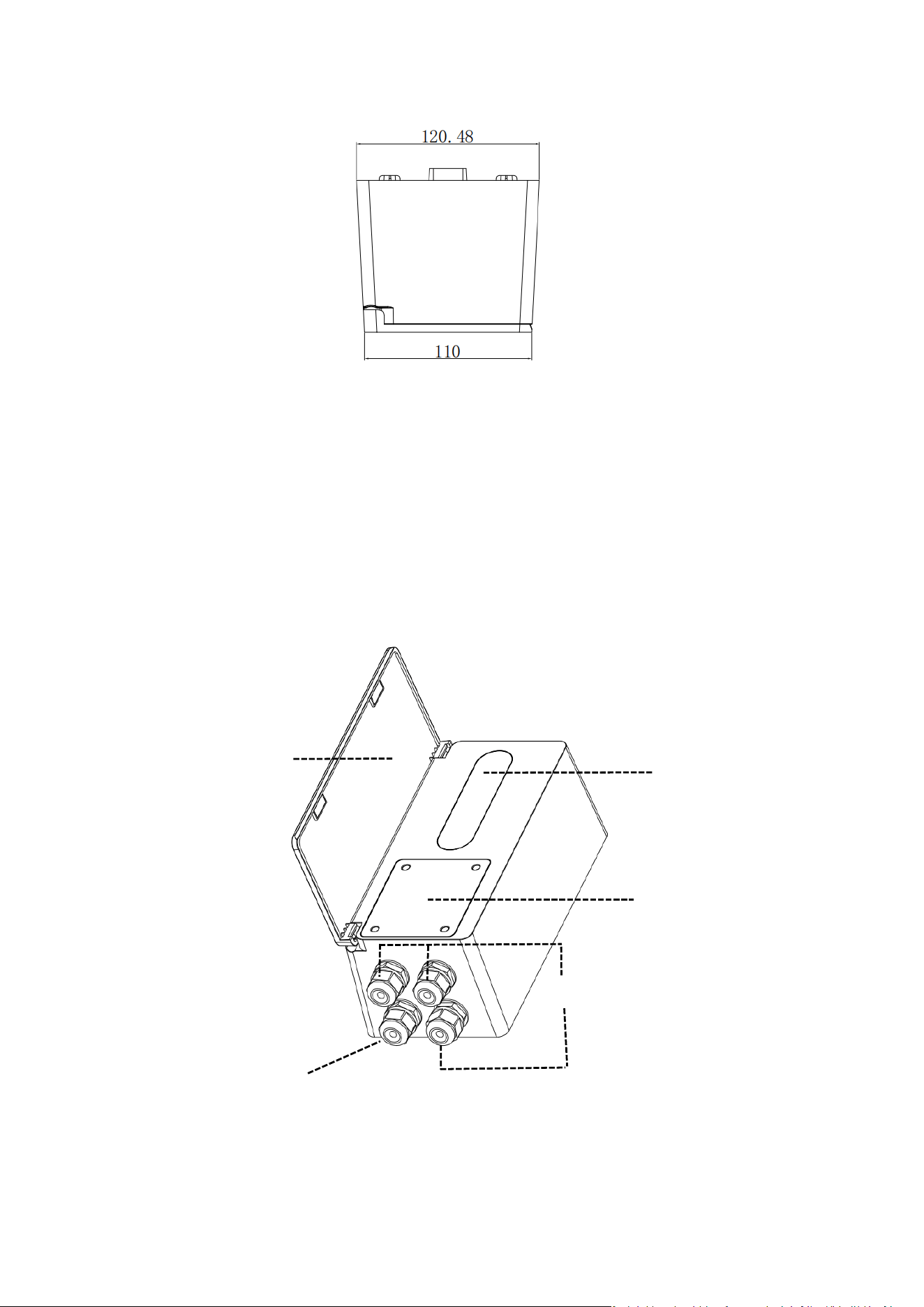
3. OVERALL DIMENSION (mm)
Model
INPUT
120VAC, 60Hz
PAT01
Load Capacity
1 to 3 sets of 24 VAC, 60 Hz, 0.75 A valve actuators
System
Wireless Type: 2.4GHz
APP: Moov Pool Ai app
IOS: 14.0 or higher
Android: 7.0 or higher
3
Figure 1 - Pool Actuator Transformer Dimensions
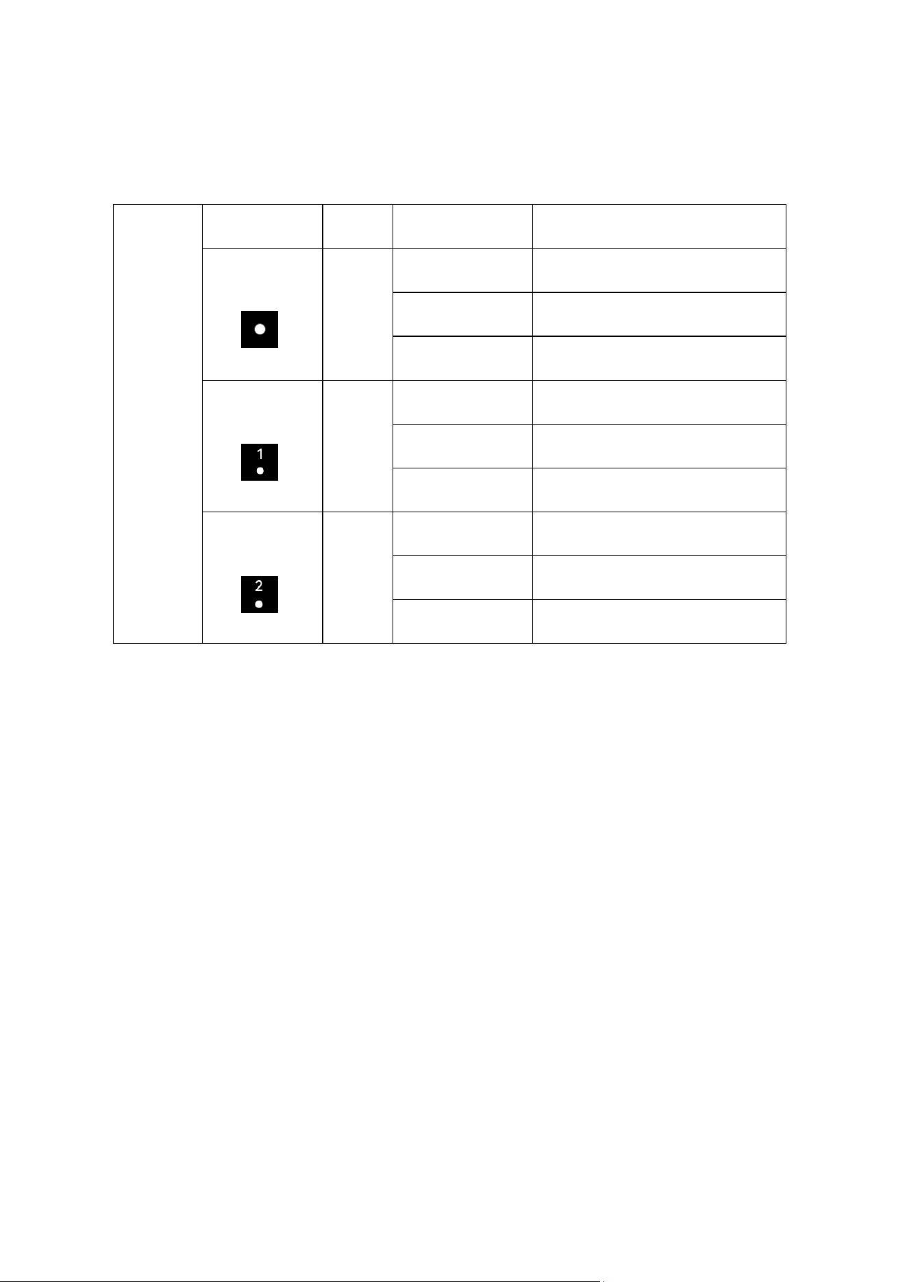
4. PRODUCT ILLUSTRATION
Figure 2 - Product Illustration
Control Panel
Electrical Connection
Valve Actuator Wiring Terminal
Power Supply Terminal
Magnetic Flip Cover
4
5. LIGHT CHART
6. INSTALLATION
6.1. Mounting the Pool Actuator Transformer
1) Select an appropriate wall-mounting location based on the length of the power cord and the positions of the
connected valve actuators.
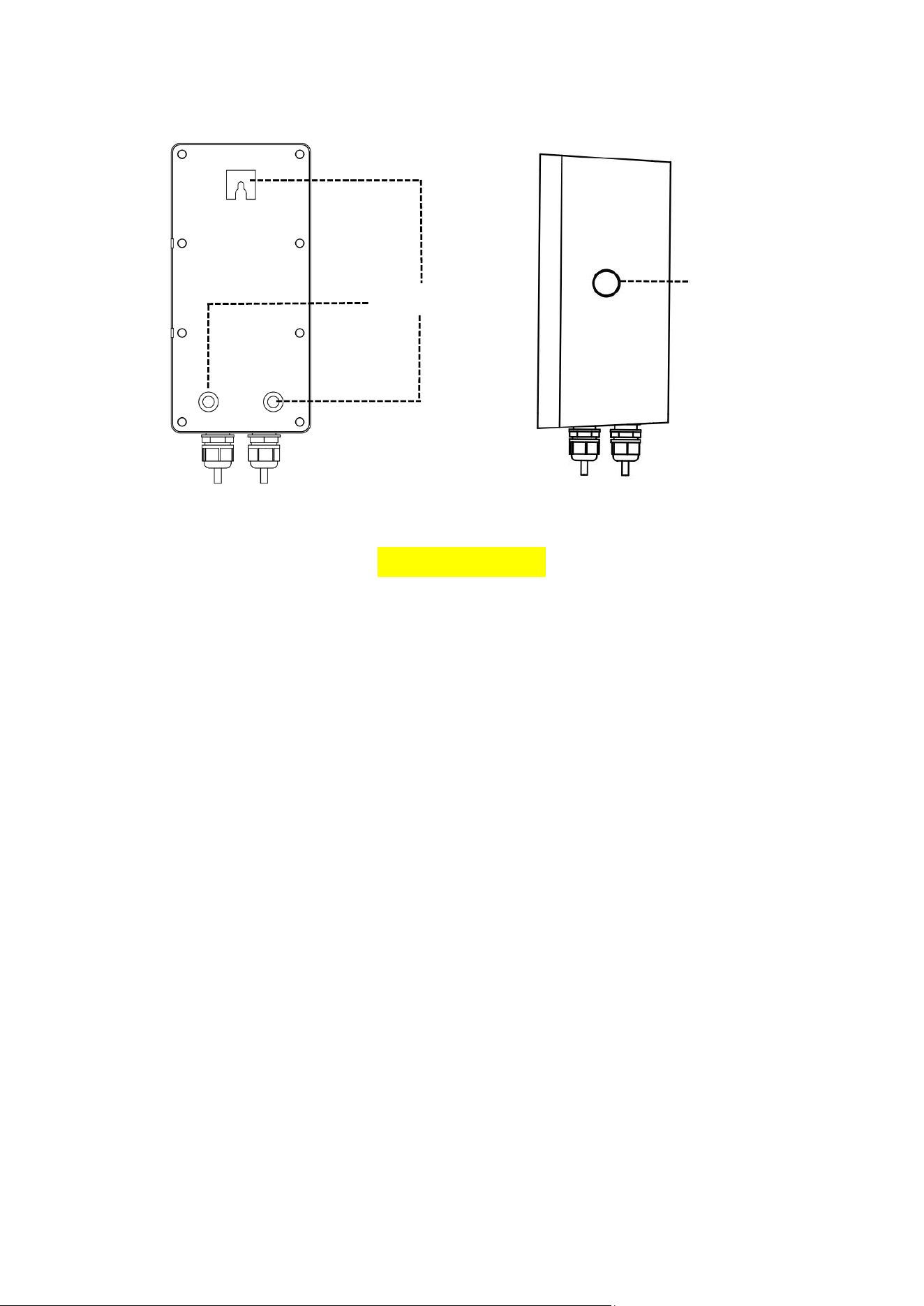
2) Hold the box in place and use the three holes (FIG.3) to mark position on the mounting surface.
3) The transformer should be installed horizontally and fixed in the hole on the support with screws to prevent
unnecessary vibration.
Light Chart
Name
Color
Indicator Status
Device Status
Wi-Fi Indicator
White
Blinks slowly
Connecting
Steady On
Connected
Off
No connection/Disconnected
Load Indicator 1
White
Blinks slowly
Valve actuator operation failure
Steady On
Auto On 1
Off
Not in Auto On 1
Load Indicator 2
White
Blinks slowly
Valve actuator operation failure
Steady On
Auto On 2
Off
Not in Auto On 2
5
Figure 3 - Mounting Holes
6.2. Connecting the Wires
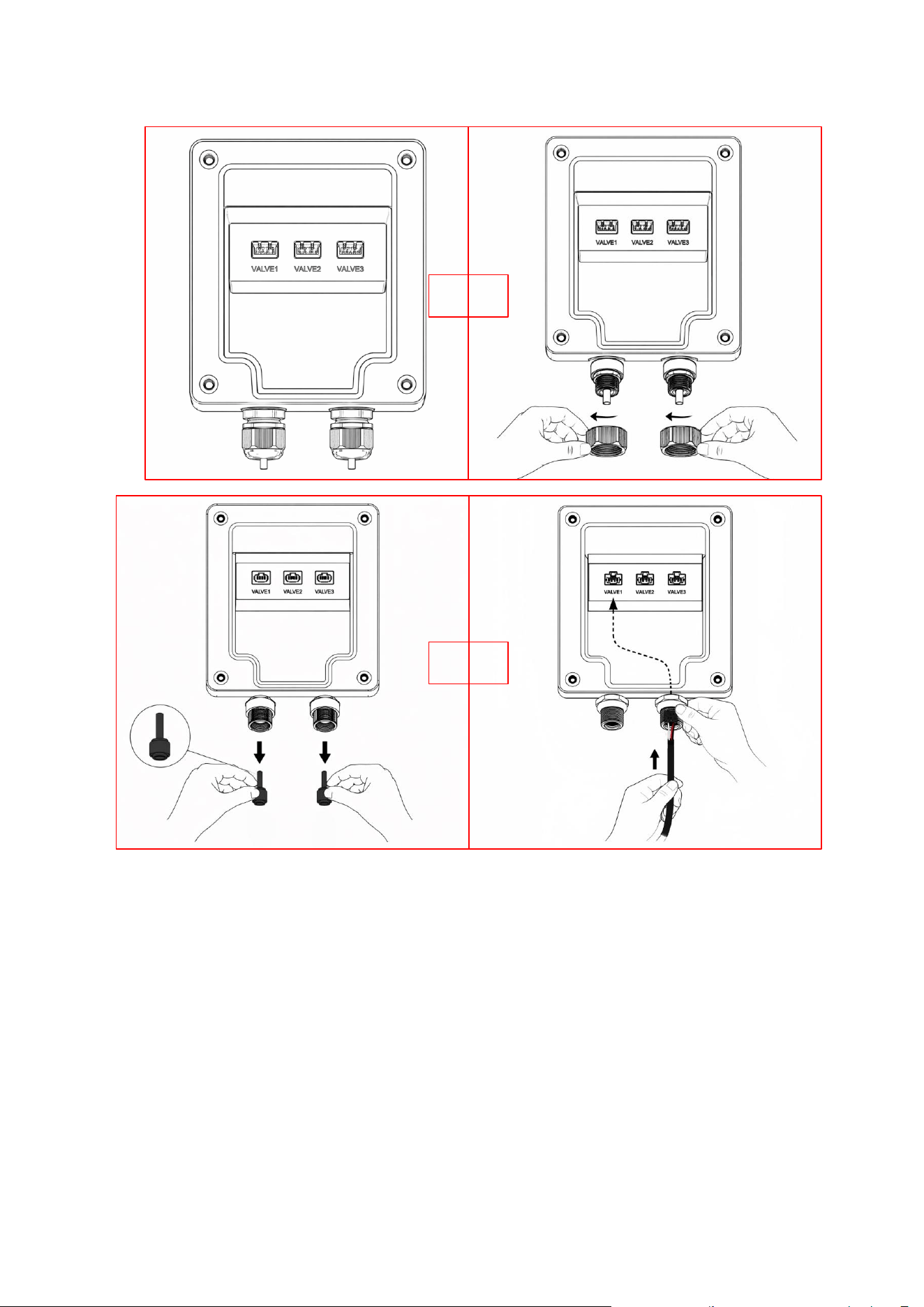
1) Remove the four screws securing the wiring compartment cover. Press the area indicated by the label to
release and open the cover. Loosen the waterproof cable gland nut and remove the rubber plug.
2) Route the actuator power cable through the waterproof cable gland nut and rubber plug, then insert the
power connector into the terminal strip (FIG.4).
3) Install the rubber plug, and screw the nut back on. Put the wiring cover back on and tighten the four screws.
Mounting Hole
power switch
6
Figure 4 - Wiring steps
NOTE
1)Before installation, please confirm the Wi-Fi signal is strong enough.
2)Wi-Fi range can be affected by obstructions, metal objects, distance and weather. Mount unit should be as close
to the router as possible.
3)Install the unit in a vertical orientation.
→
→
7
6.3. Check before initial startup
Check whether power supply voltage and frequency conform to the nameplate.
7. SETTING AND OPERATION
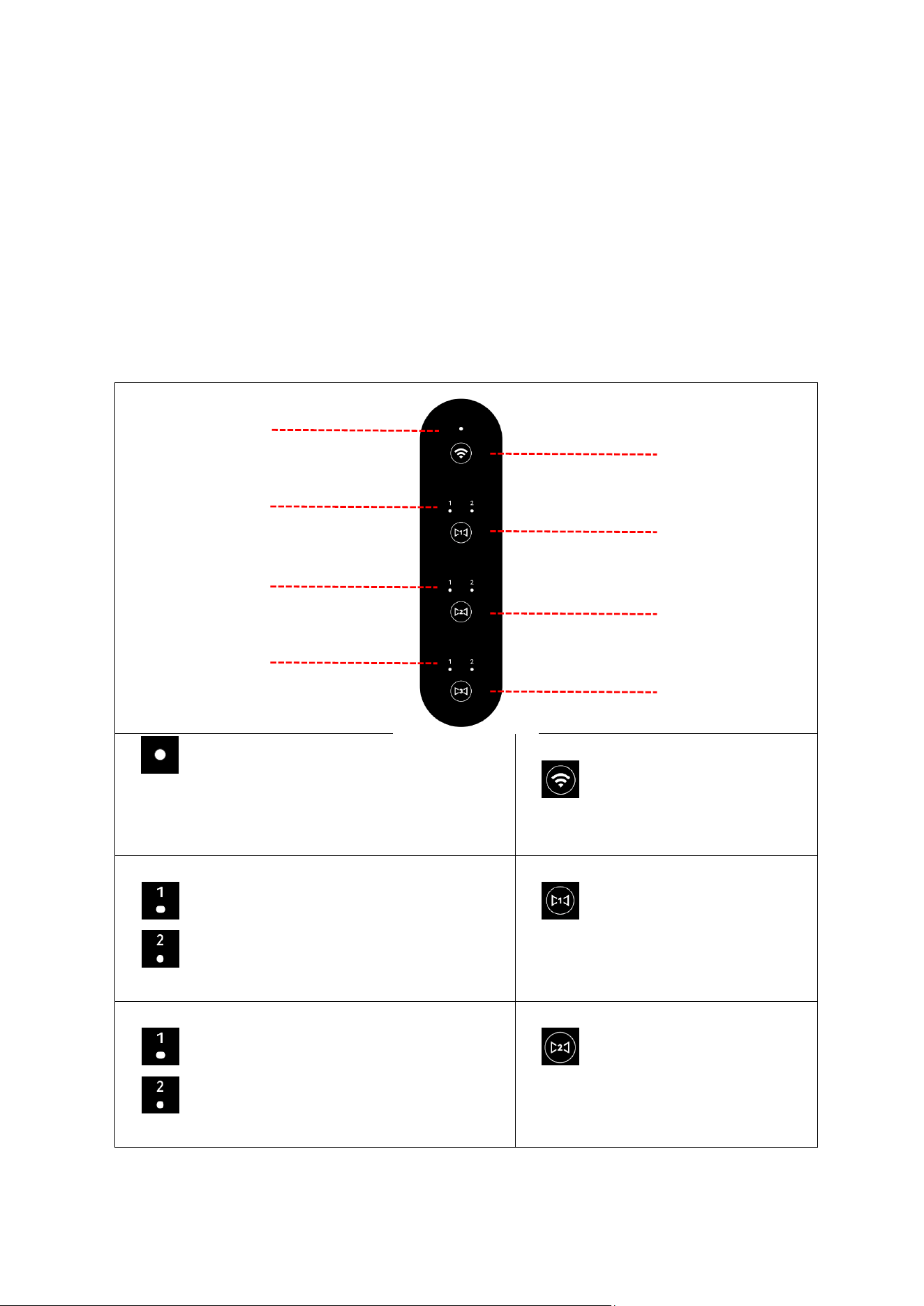
7.1. Display on control panel
① Wi-Fi indicator
blinks slowly : connecting
steady On : connected
off: disconnected / no connection
② Wi-Fi pairing switch : press and
hold for 3 seconds to start pairing
③ valve actuator 1 status indicator
indicator 1 on: valve actuator is in auto on 1 state
indicator 2 on: valve actuator is in auto on 2 state
off: not connected
④ valve actuator 1 state toggle : tap to
toggle the actuator state between auto on 1
and auto on 2
⑤ valve actuator 2 status indicator
indicator 1 on: valve actuator is in auto on 1 state
indicator 2 on: valve actuator is in auto on 2 state
Off: not connected
⑥ valve actuator 2 state toggle : tap to
toggle the actuator state between auto on 1
and auto on 2
③
①
②
④
⑤
⑥
⑦
⑧
8
⑦ valve actuator 3 status indicator
indicator 1 on: valve actuator is in auto on 1 state
indicator 2 on: valve actuator is in auto on 2 state
off: not connected
⑧ valve actuator 3 state toggle : tap to
toggle the actuator state between auto on 1
and auto on 2
7.2. Operation Interface Overview
Refer to Section 6.2, connect the valve actuator power cord to the terminal on the transformer.
① Step 1:Starting up
Connect the power cord and turn on the left-side power switch.
② Step 2:Valve actuator state switching
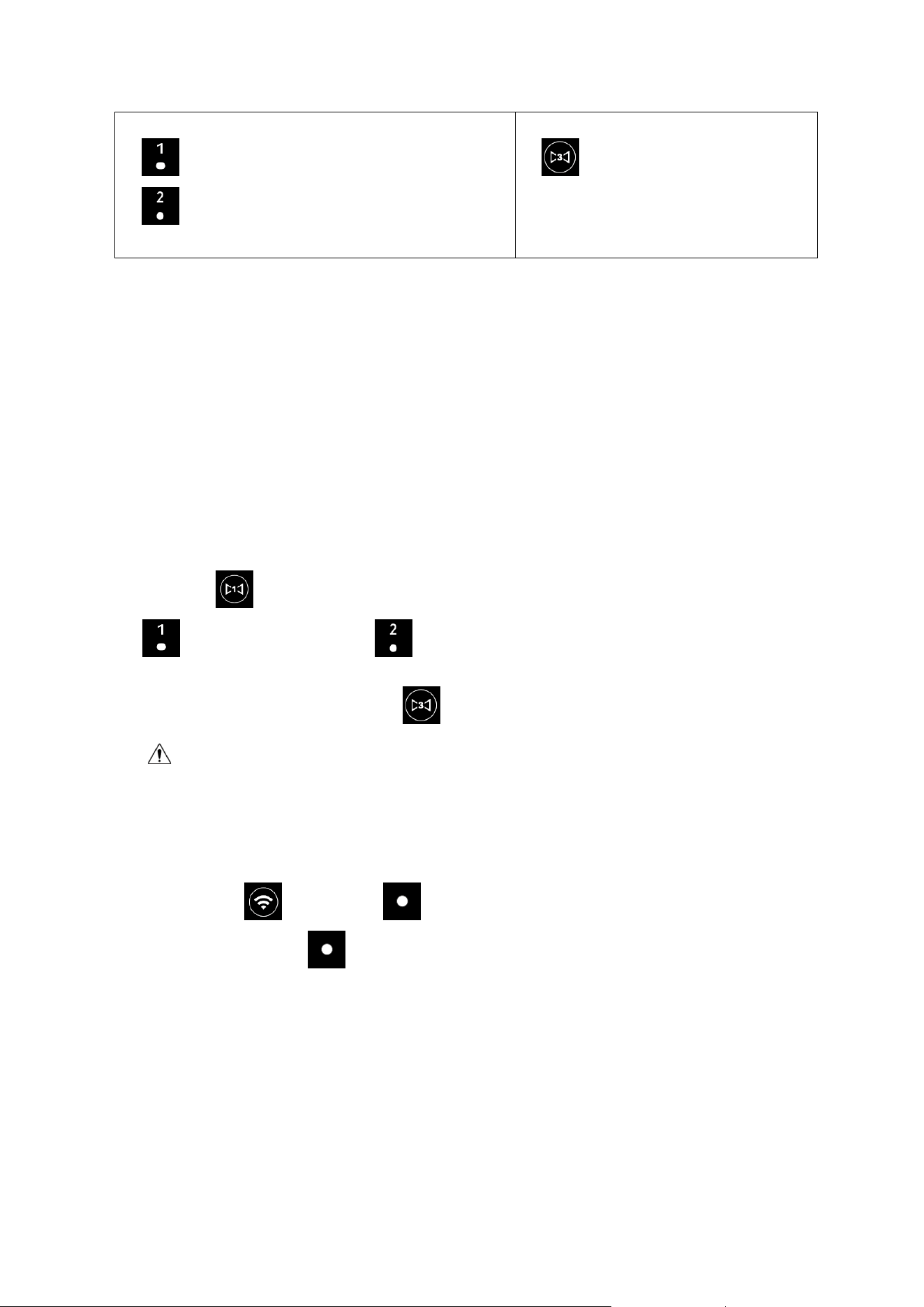
Each press , the valve actuator state toggles between Auto On 1 and Auto On 2. When in Auto On 1,
lights up; when in Auto On 2, lights up.
If valve actuator is not connected, press , none of the indicators light up.
Note: To avoid interference, two switching operations of the same valve actuator must be separated
by an interval of at least 3 minutes.
③ Step 3:App connection
Press and hold for 3 seconds, will flash, indicating Wi-Fi connection in progress. Once the
connection is successful, becomes solid on.
9
8. WIFI OPERATION
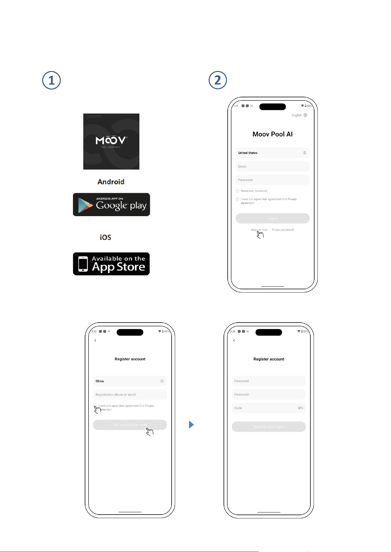
Download Moov Pool AI APP Account Registration
Phone / Email Registration
10
App Pairing
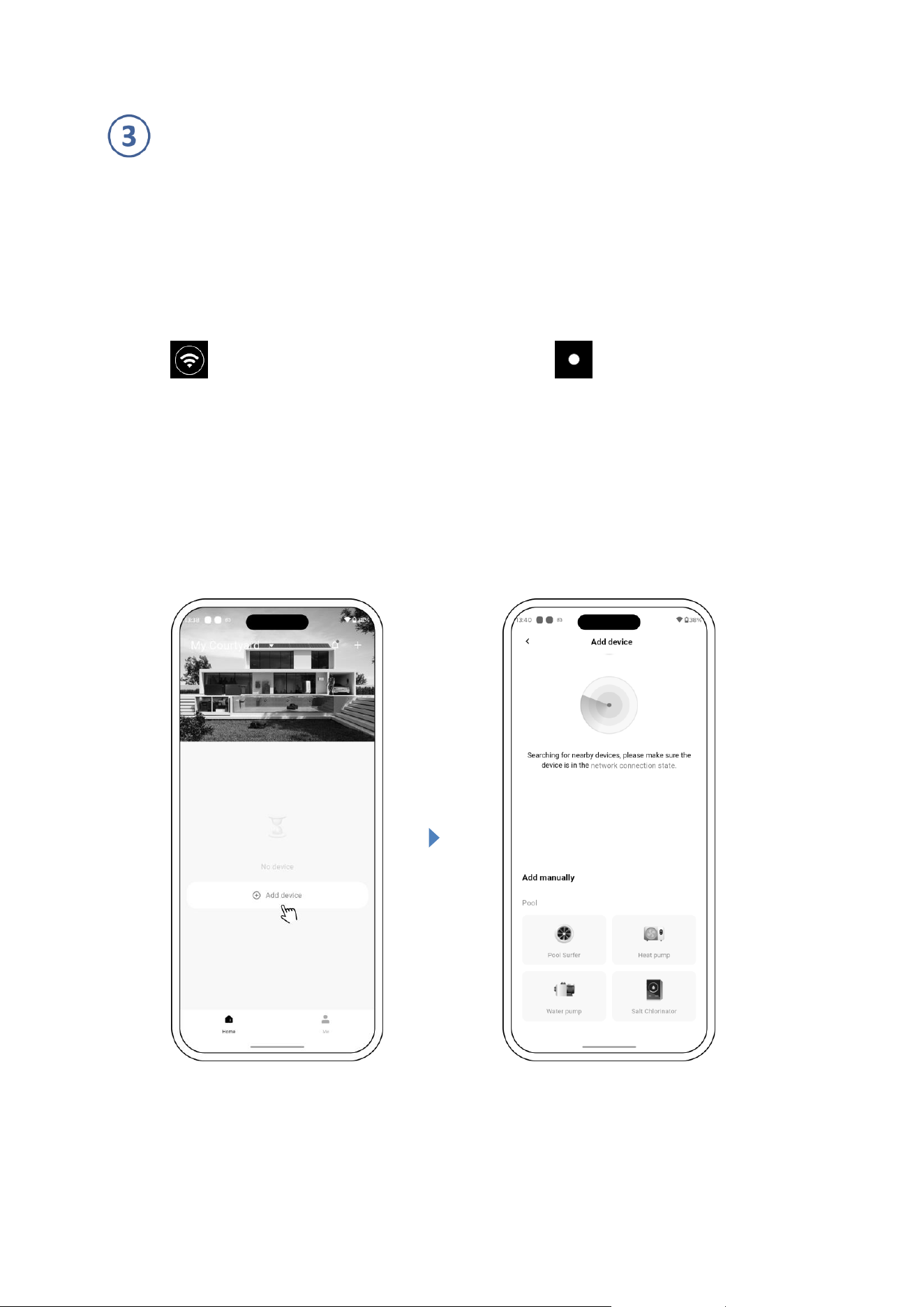
Please make sure your pool actuator transformer is turned on before you start.
Option 1 - Automatic pairing (Recommended):
Network requirement: 2.4GHz.
1) Please confirm that your phone is connected to Wi-Fi and the Bluetooth of your phone is ON.
2) Press for 3 seconds until hearing “Beep” and then release. will flash.
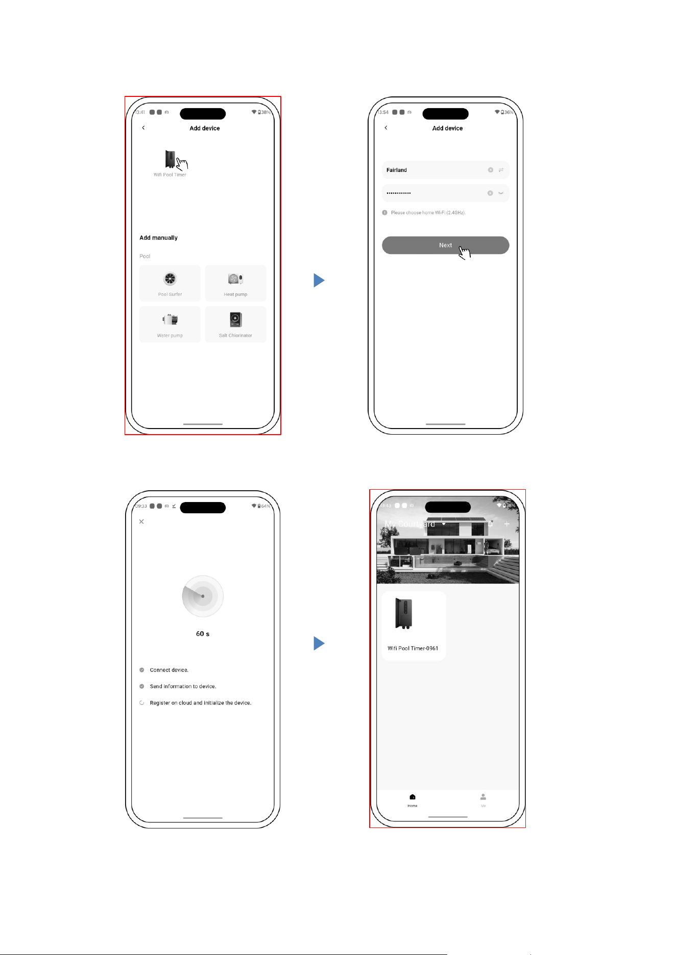
3) Click“Add Device”, and wait for a few seconds to search the nearby device.
4) Click on the transformer icon and follow the instructions to pair device.
11
12
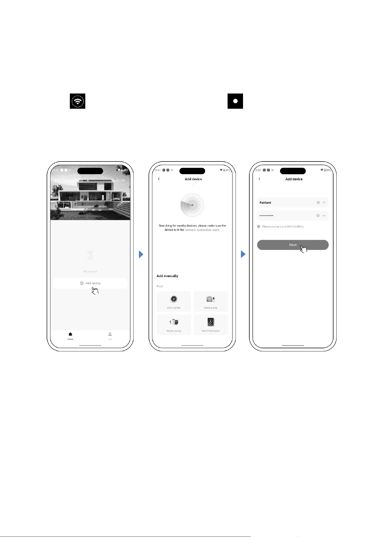
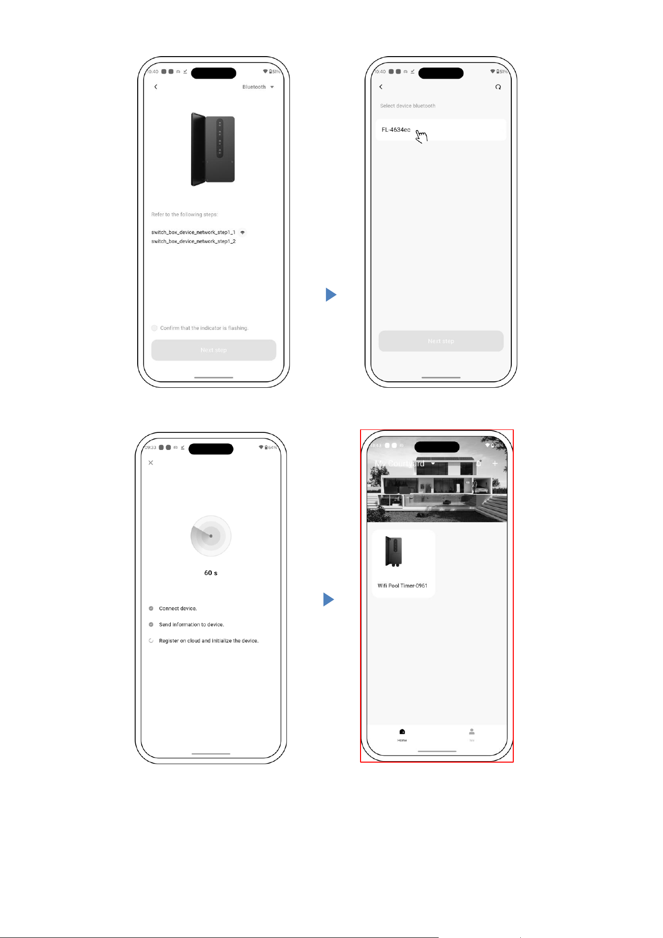
Option 2 - Bluetooth pairing :
Network requirement: 2.4GHz.
1) Please confirm that your phone is connected to Wi-Fi and the Bluetooth of your phone is ON.
2) Press for 3 seconds until hearing “Beep” and then release. will flash.
3) Click “Add Device”, and follow the instructions to pair device.
13
14
Operation
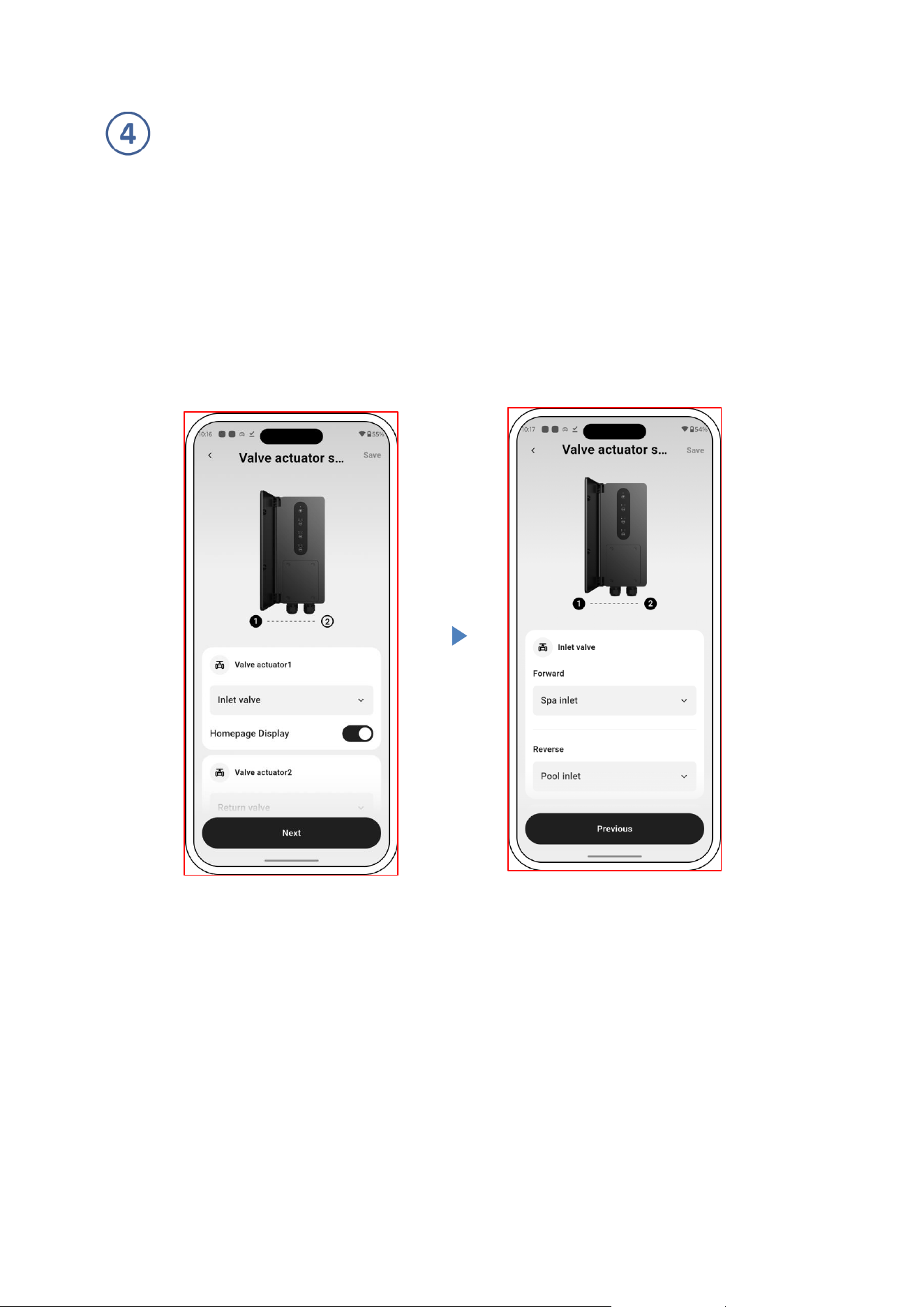
Option 1 - Valve Actuator & Status Naming
1)After successful pairing, the device will automatically report the number of currently connected valve
actuators.
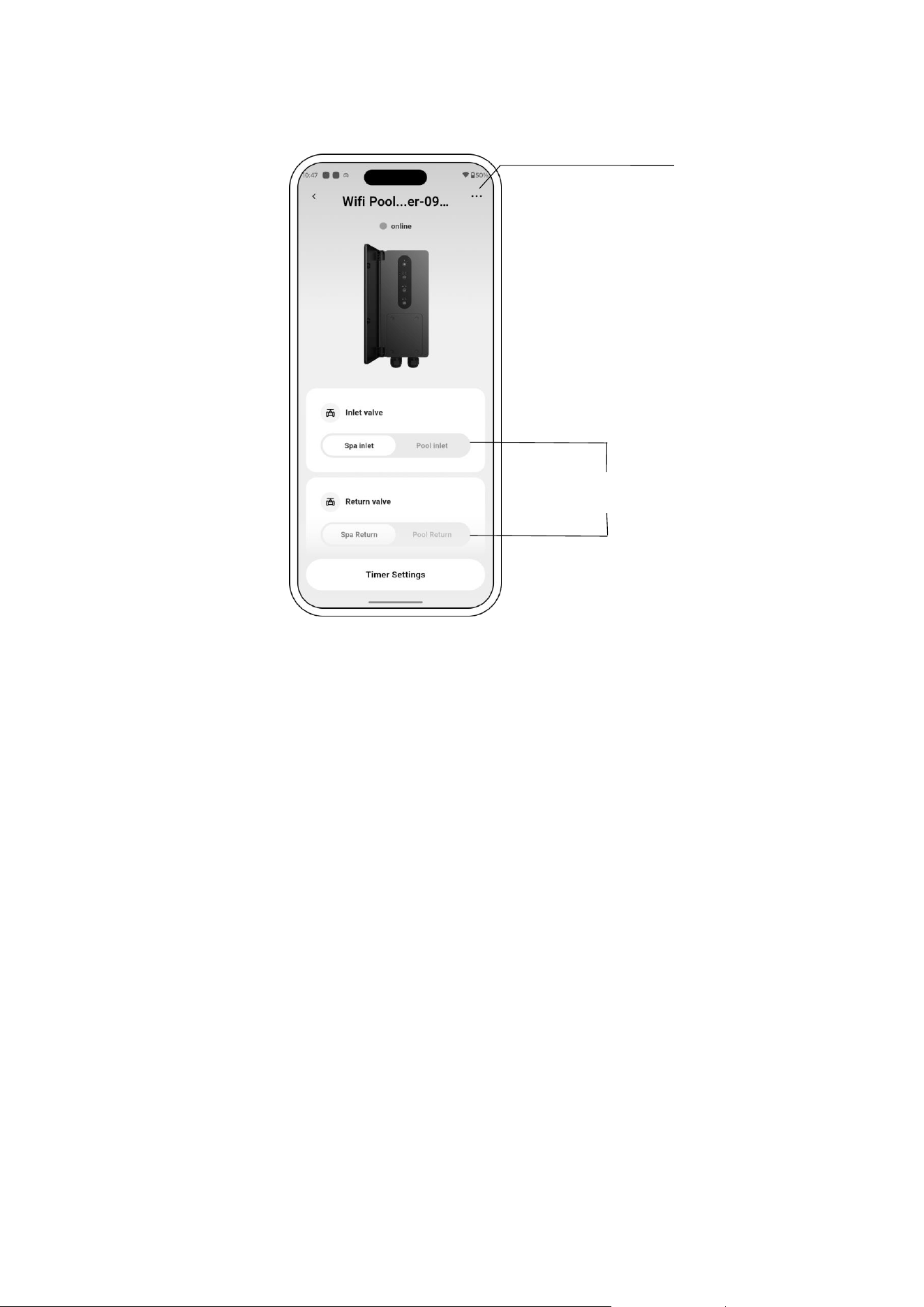
2)Set the names of the valve actuator and its states, or you can choose to skip and use the system default names.
You can switch the status of valve actuators on the home page. To change the naming, tap the "···" in the upper
right corner, go to the Valve Actuator Settings page, make your changes, and save.
set the names of the
valve actuator
set the names of the valve
actuator states
15
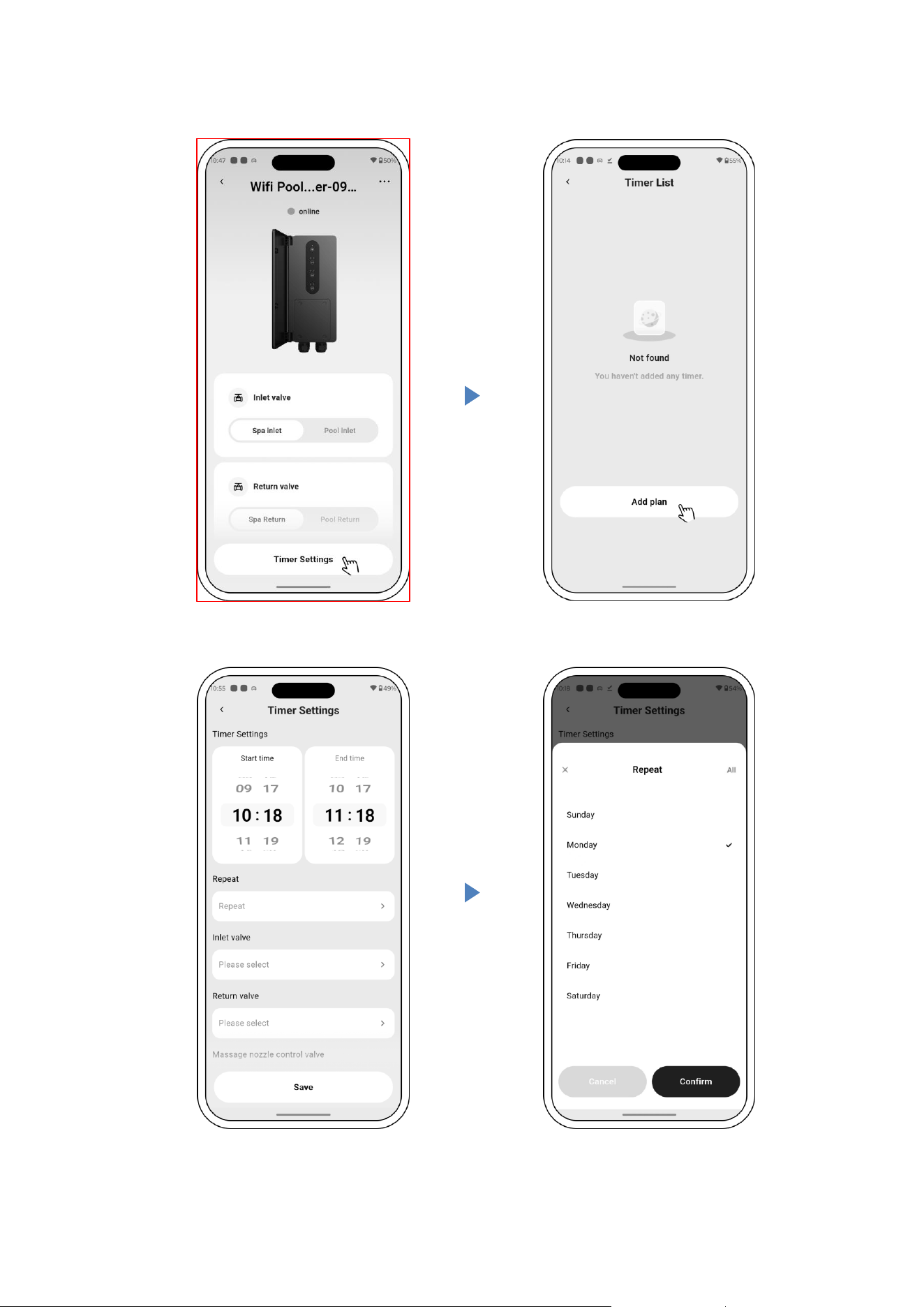
Option 2 - Timer Mode
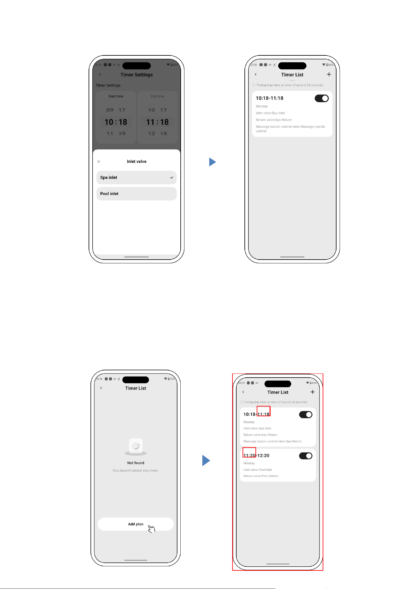
1)On the home page, click "Timer Settings" to enter the timer interface. Click "Add Plan" to add a schedule, set
the start and end time, repeat days, and valve actuator status.
2)Once the setup is complete, the current schedule will be displayed on the timer home page. You can enable
or disable the schedule with one click, or swipe left to delete it.
3)When the schedule ends, the valve actuator will automatically back to its state before the schedule started.
4)If the currently active scheduled task is interrupted, a pop-up message saying "Current scheduled task has
been interrupted." will appear on the device home screen in the app and will automatically disappear after 3
seconds.
the Valve Actuator
Settings page
switch the status of
valve actuators
16
17
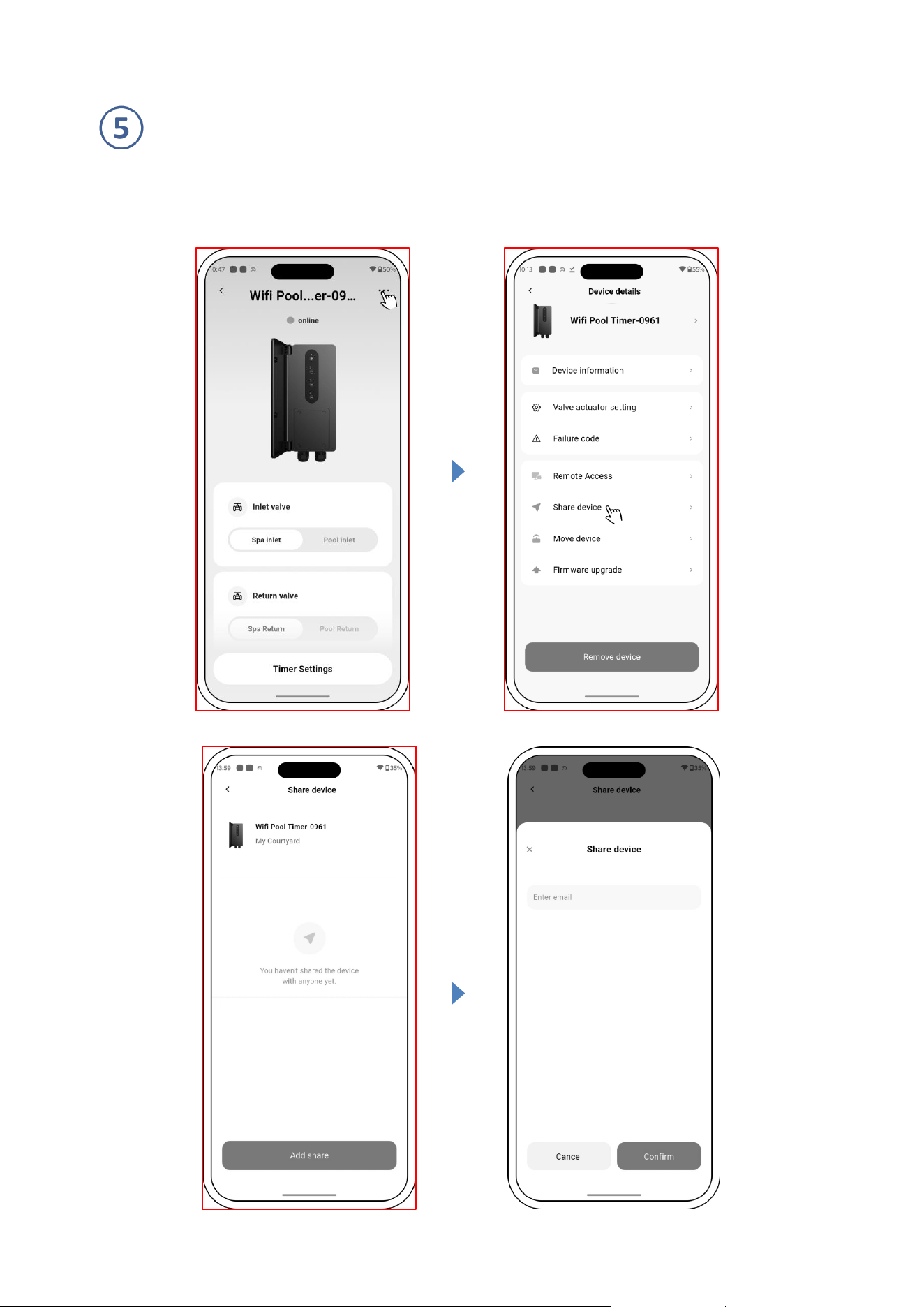
Notice for the timer setting via the APP :
1) Time variance is ±30s;
2) To avoid overlapping timing points conflicting and invalidating due to network delay, the start time of the
next timer cycle should not overlap with the end time of the previous one, and a minimum interval of 3
minutes is recommended between them.
18
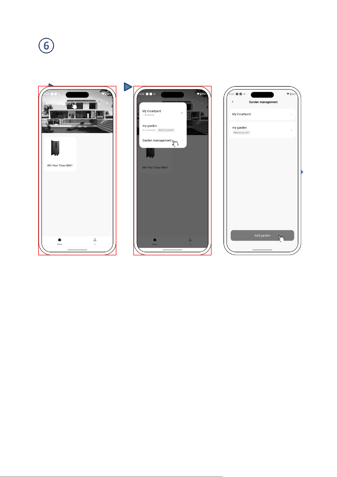
Sharing Devices with your family members
Users can share the devices to be controlled by their family members. Please let your family members register
“Moov Pool Ai” first, and then the administrator can operate as below:
19
Garden Management
In the device list, the current courtyard is displayed. After clicking, users can view/switch to all the current
courtyards, click Garden Management, and also enter the courtyard list page. As shown below:

20
Message Center
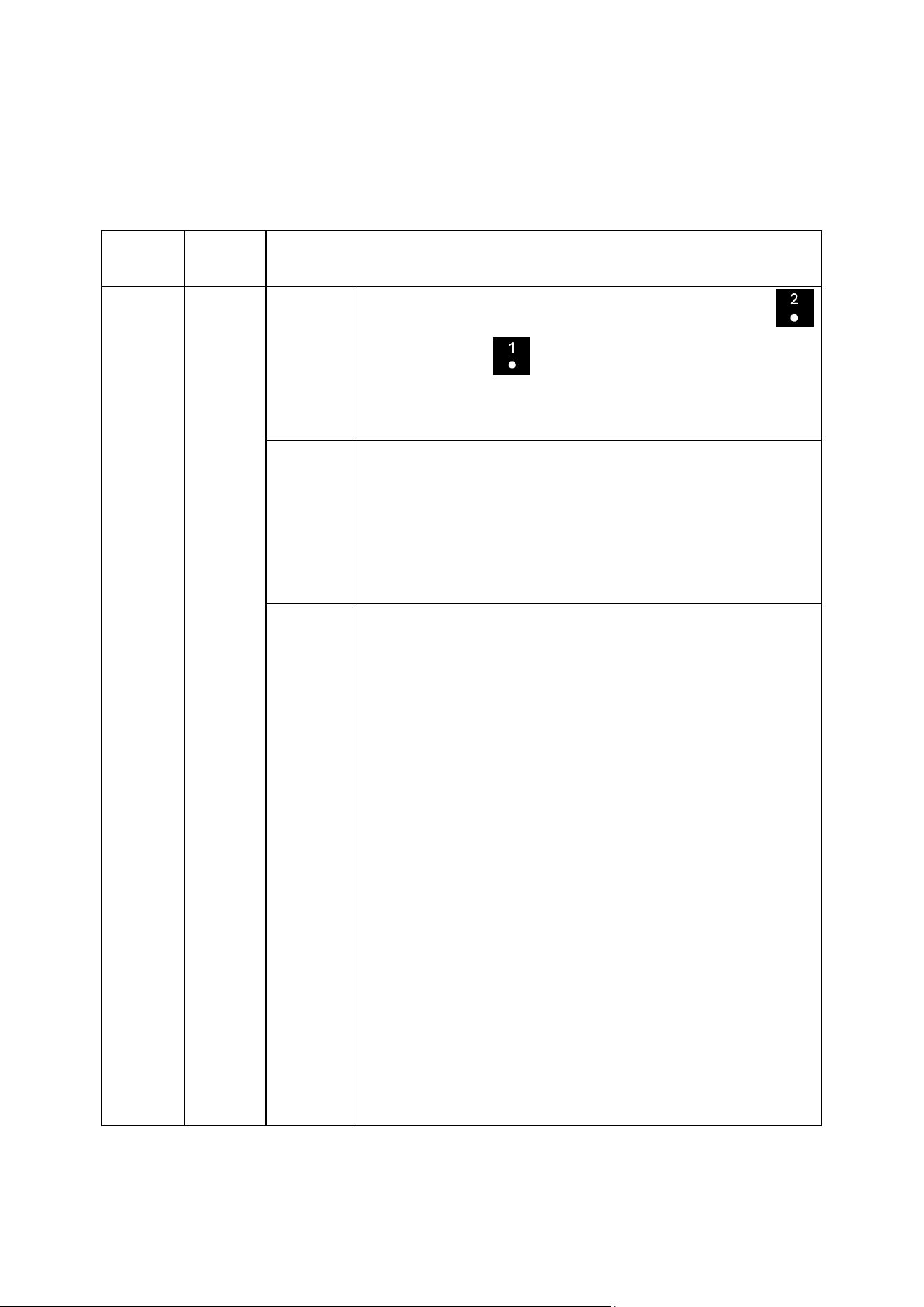
A: View Messages: On the device list page, tap the message icon to enter the message center
and view the corresponding messages (as shown below), including alarm, garden notifications,
system notifications.
B: Push Settings: On the Settings page, click [Push Settings] to enter the Push Settings page. Users can set the
push settings according to the message classification, as shown below:
21
Notice:
The App is subject to updates without notice.
9. TROUBLE SHOOTING
Problem
Error
Code
Details
Valve
actuator 1
operation
failure
E1
Description
If valve actuator 1 fails to switch from "Auto on1" to "Auto on2",
flashes; otherwise, flashes. On the app side, error code E1 is
displayed and a pop-up message appears: "Valve actuator 1 operation
failure".
Fault cause
Possible causes:
1.Improper wiring connection or loose connection of Valve Actuator 1.
2.Excessive mechanical resistance, valve binding.
3.Valve actuator malfunction (refer to the Valve Actuator
Troubleshooting Guide ).
Solution
Please follow the steps below for basic troubleshooting:
1.Power Off
Turn off the power switch.
2.Check Connections
Check Actuator 1 wiring for loose, disconnected, damaged, or poor
contacts.
3.Check Valve Condition
Verify that the valve has no mechanical binding, obstruction, or
excessive operating resistance.
4.Check Actuator Operation
Restore power, operate Actuator 1, and check if it runs normally and
completes the switching action.
5.Resume Operation
Resolve the fault and resume normal operation.
If the actuator is faulty, refer to the manufacturer's troubleshooting
guide or contact support.
22
Valve
actuator 2
operation
failure
E2
Description
If valve actuator 2 fails to switch from "Auto on1" to "Auto on2",
flashes; otherwise, flashes. On the app side, error code E2 is
displayed and a pop-up message appears: "Valve actuator 2 operation
failure".
Fault cause
Possible causes:
1.Improper wiring connection or loose connection of Valve Actuator 2.
2.Excessive mechanical resistance, valve binding.
3.Valve actuator malfunction (refer to the Valve Actuator
Troubleshooting Guide ).
Solution
Please follow the steps below for basic troubleshooting:
1.Power Off
Turn off the power switch.
2.Check Connections
Check Actuator 2 wiring for loose, disconnected, damaged, or poor
contacts.
3.Check Valve Condition
Verify that the valve has no mechanical binding, obstruction, or
excessive operating resistance.
4.Check Actuator Operation
Restore power, operate Actuator 2, and check if it runs normally and
completes the switching action.
5.Resume Operation
Resolve the fault and resume normal operation.
If the actuator is faulty, refer to the manufacturer's troubleshooting
guide or contact support.
Valve
actuator 3
operation
failure
E3
Description
If valve actuator 3 fails to switch from "Auto on1" to "Auto on2",
flashes; otherwise, flashes. On the app side, error code E3 is
displayed and a pop-up message appears: "Valve actuator 3 operation
failure".
Fault cause
Possible causes:
1.Improper wiring connection or loose connection of Valve Actuator 3.
23
2.Excessive mechanical resistance, valve binding.
3.Valve actuator malfunction (refer to the Valve Actuator
Troubleshooting Guide ).
Solution
Please follow the steps below for basic troubleshooting:
1.Power Off
Turn off the power switch.
2.Check Connections
Check Actuator 3 wiring for loose, disconnected, damaged, or poor
contacts.
3.Check Valve Condition
Verify that the valve has no mechanical binding, obstruction, or
excessive operating resistance.
4.Check Actuator Operation
Restore power, operate Actuator 3, and check if it runs normally and
completes the switching action.
5.Resume Operation
Resolve the fault and resume normal operation.
If the actuator is faulty, refer to the manufacturer's troubleshooting
guide or contact support.
Wi-Fi
connectio
n failure
/
Description
During use, if the device disconnects from the network, the Wi-Fi
indicator will turn off, and the app will display the device as offline.
Fault cause
Possible causes:
1.Incorrect Wi-Fi credentials.
2.Router or internet connection issue.
3.Weak Wi-Fi signal or long distance from router.
Solution
Please follow the steps below for basic troubleshooting:
1.Check Network Status
Ensure the home Wi-Fi network is working properly.
2.Check Wi-Fi Settings
Verify the Wi-Fi SSID and password, and ensure the device is connected
to a 2.4 GHz Wi-Fi network.
3.Check Signal Environment
24
Ensure the device is installed within Wi-Fi coverage and there are no
major obstructions between the controller and router.
4.Restart and Reconnect
Turn off the device power switch, wait until the device is fully powered
off, then restart and reconnect Wi-Fi through the app.
If the network is normal but the device still cannot connect to Wi-Fi,
contact technical support for further assistance.
10. WARRANTY & EXCLUSIONS
Should a defect become evident during the term of warranty, at its option, the manufacturer will repair or replace
such item or part at its own cost and expense. Customers need to follow the warranty claim procedure in order
to obtain the benefit of this warranty.
The guarantee will be void in cases of improper installation, improper operation, inappropriate use, tampering
or using of non-original spare parts.
11. DISPOSAL
When disposing of the product, please sort the waste products as electrical or electronic
product waste or hand it over to the local waste collection system.
The separate collection and recycling of waste equipment at the time of disposal will help
ensure that it is recycled in a manner that protects human health and the environment.
Contact your local authority for information on where you can drop off your pool actuator transformer for
recycling.

25
FCC Warning:
Warning: Changes or modifications to this unit not expressly approved by the party responsible for compliance
could void the user’s authority to operate the equipment.
This device complies with Part 15 of the FCC Rules. Operation is subject to the following two conditions: (1) this
device may not cause harmful interference, and (2) this device must accept any interference received, including
interference that may cause undesired operation.
Note: This equipment has been tested and found to comply with the limits for a Class B digital device, pursuant
to part 15 of the FCC Rules. These limits are designed to provide reasonable protection against harmful
interference in a residential installation. This equipment generates, uses and can radiate radio frequency energy
and, if not installed and used in accordance with the instructions, may cause harmful interference to radio
communications. However, there is no guarantee that interference will not occur in a particular installation. If this
equipment does cause harmful interference to radio or television reception, which can be determined by turning
the equipment off and on, the user is encouraged to try to correct the interference by one or more of the following
measures:
-- Reorient or relocate the receiving antenna.
-- Increase the separation between the equipment and receiver.
-- Connect the equipment into an outlet on a circuit different from that to which the receiver is connected.
-- Consult the dealer or an experienced radio/TV technician for help.
To maintain compliance with FCC's RF exposure guidelines, the distance must be at least 20cm between the
radiator and your body, and fully supported by the operating and installation configurations of the transmitter
and its antenna(s).

26
IC Waring:
This device contains license-exempt transmitter(s)/receiver(s) that comply with Innovation, Science and
Economic Development Canada’s license-exempt RSS(s). Operation is subject to the following two conditions:
1. This device may not cause interference.
2. This device must accept any interference, including interference that may cause undesired operation of the
device.
Cet appareil contient un ou des émetteurs/récepteurs exempts de licence qui sont conformes au(x) RSS exempts
de licence d'Innovation, Science et Développement économique Canada. Le fonctionnement est soumis aux deux
conditions suivantes :
1. Cet appareil ne doit pas causer d'interférences.
2. Cet appareil doit accepter toute interf é rence, y compris les interf é rences qui peuvent causer un
fonctionnement non désiré de l'appareil.
The device has been evaluated to meet general RF exposure requirement. To maintain compliance with RSS-102
- Radio Frequency (RF) Exposure guidelines, this equipment should be installed and operated with a minimum
distance of 20cm between the radiator and your body.
le dispositif de a été évalué à répondre général rf exposition exigence.pour maintenir la conformité avec les
directives d'exposition du RSS-102-Radio Fréquence (RF). ce matériel doit être installé et exploité à une distance
minimale de 20 cm entre le radiateur et votre corps.
PAT01-01