Visit our website at: https://www.harborfreight.com
Email our technical support at: [email protected]
TM
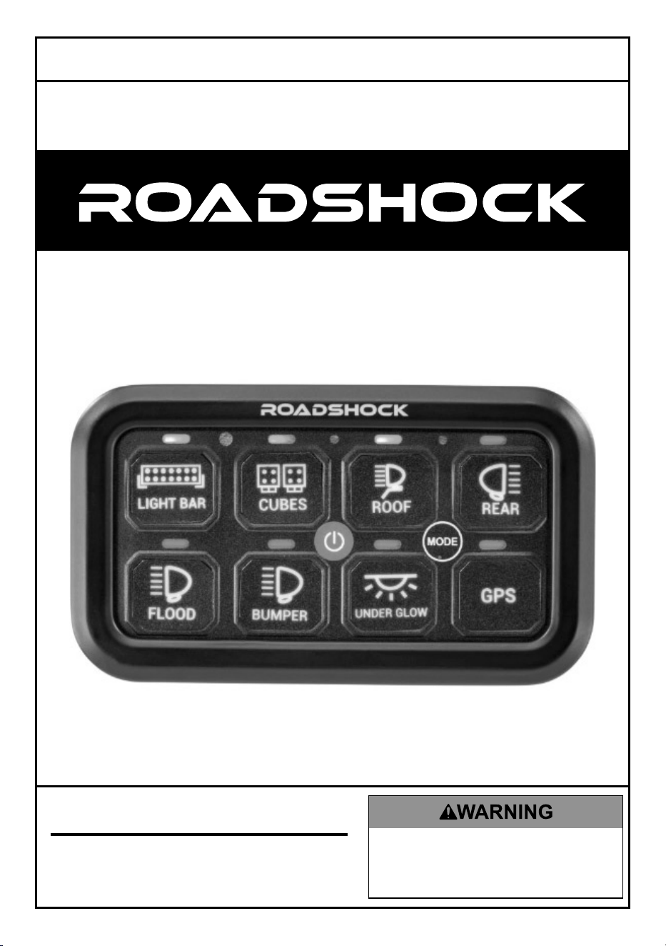
8-GANG
SWITCH PANEL
71426
Owner’s Manual & Safety Instructions
Save This Manual Keep this manual for the safety warnings and precautions, assembly,
operating, inspection, maintenance and cleaning procedures. Write the product’s date code in the back of
the manual near the assembly diagram (or month and year of purchase if product has no number). Keep
this manual and the receipt in a safe and dry place for future reference. 26a
When unpacking, make sure that the product is intact
and undamaged. If any parts are missing or broken,
please call 1-800-444-3353 as soon as possible.
Copyright
©
2025 by Harbor Freight Tools
®
. All rights reserved.
No portion of this manual or any artwork contained herein may be reproduced in
any shape or form without the express written consent of Harbor Freight Tools.
Diagrams within this manual may not be drawn proportionally. Due to continuing
improvements, actual product may differ slightly from the product described herein.
Tools required for assembly and service may not be included.
Read this material before using this product.
Failure to do so can result in serious injury.
SAVE THIS MANUAL.

Page 2 For technical questions, please call 1-800-444-3353. 71426
Important Safety Information
Installation Precautions
1. For off-road use only.
2. Install on vehicles that will not
be used on public roads only.
3. Install only according to these
instructions. Improper installation
can create hazards.
4. Wear ANSI-approved safety goggles
and heavy-duty work gloves
during Installation.
5. Keep installation area clean and well lit.
6. Keep bystanders out of the
area during installation.
7. Do not install when tired or when under
the influence of drugs or medication.
8. Read all instructions and safety
precautions in the vehicle’s manual onto
which the Light Bar will be installed.
9. Install on negative ground
12/24VDC systems only.
10. Keep wiring away from hot
surfaces and moving parts.
11. Do not install Switch Panel where it
could restrict sufficient airflow to the
radiator or obstruct the headlights
and/or turn signals of vehicle.
Use Precautions
1. This product is not a toy. Do not
allow children to play with this item.
2. Use as intended only.
Not for marine use. Do not
mount underwater.
3. Inspect before every use; do not use
if parts are loose or damaged.
4. To prevent damage, turn lights off before
starting or turning off the vehicle.
5. This product may not meet D.O.T.
requirements for use on public
roads or highways. Follow local,
state, and federal regulations.
6. Turn off lights and allow them to
cool completely before handling.
7. Maintain product labels and
nameplates. These carry
important safety information.
If unreadable or missing, contact
Harbor Freight Tools for a replacement.
Specifications
Rating 12/24VDC, 60A
Panel IP Rating IP54
Page 3For technical questions, please call 1-800-444-3353.71426
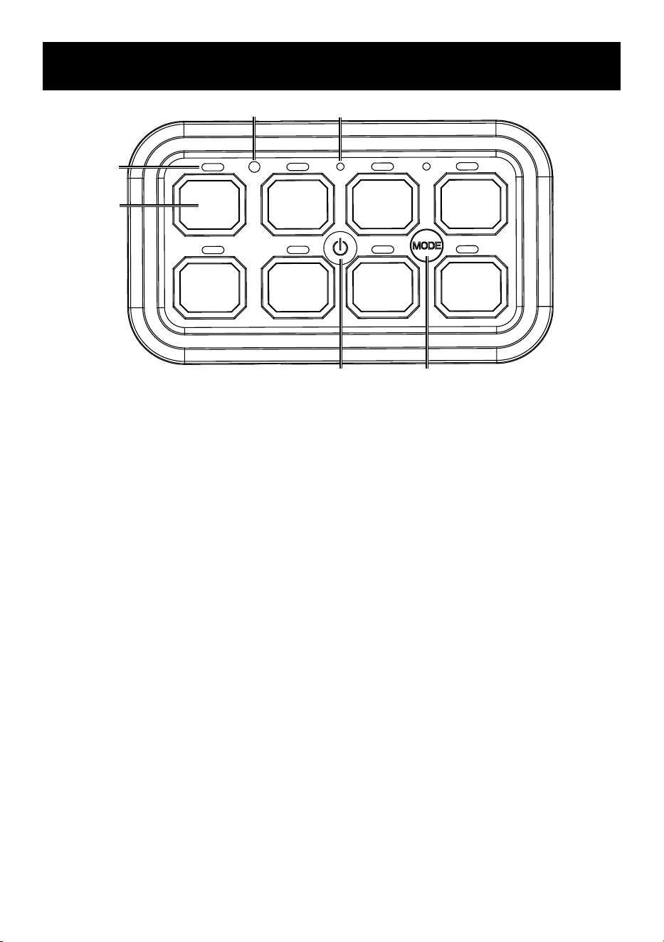
Functions
1
2
3
4
5
6
1. Circuit Power Indicator
2. Panel Button
3. Sensor Circuit Indicator
4. Power Button
5. Power Indicator
6. Mode Change Button
Page 4 For technical questions, please call 1-800-444-3353. 71426
Installation Instructions
Read the ENTIRE IMPORTANT SAFETY INFORMATION section at the
beginning of this document including all text under subheadings therein
before set up or use of this product.
CAUTION! Mount to flat, stable location with adequate clearance. If
drilling is required, beware of any hidden electrical lines or cables. Do not
damage or weaken the structural integrity of the mounting location.
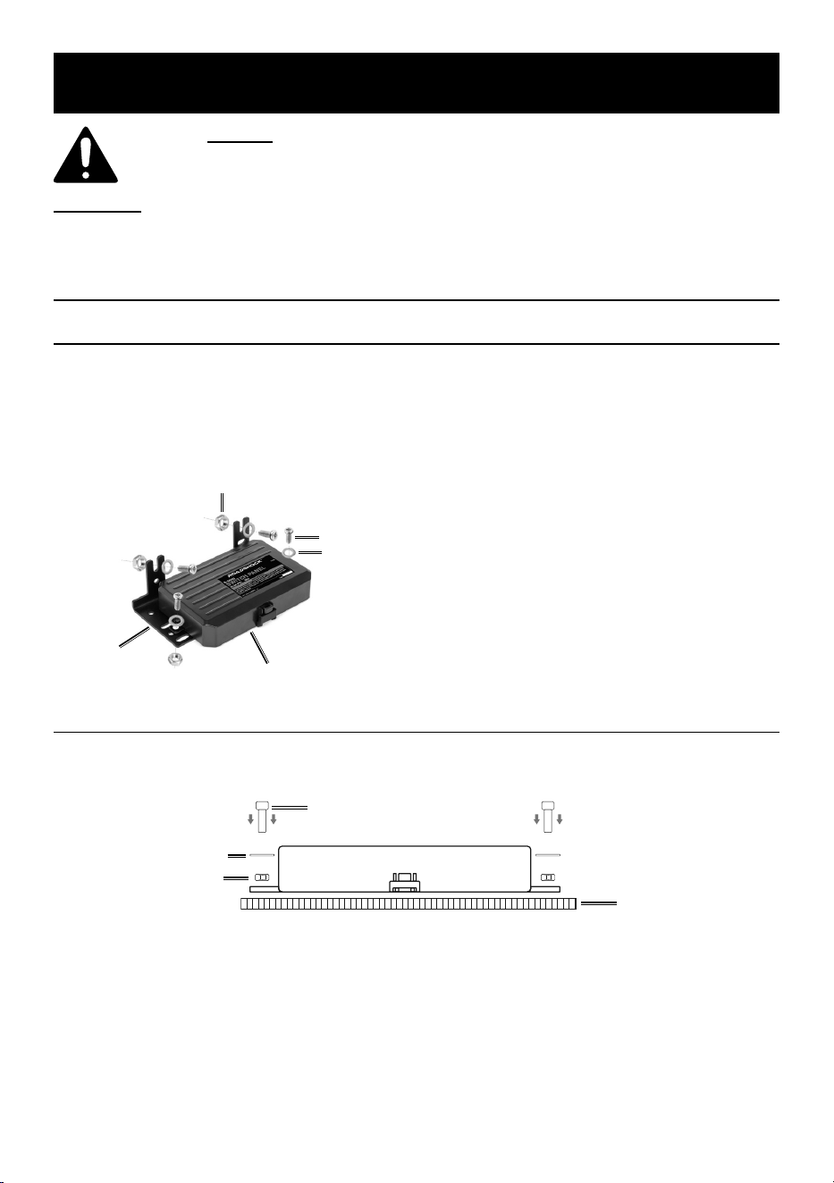
Power Module Installation
Fixed Mount
1. Place Power Module (1) on the Fixed
Mount Bracket (5) and secure using
2 sets of Washer (18), Nut (19),
and Screw (17) through each
mounting hole on the Module.
Power Module (1)
Bracket (5)
Washer (18)
Screw (17)
Nut (19)
2. Secure Bracket to mounting
location using 2 sets of Washer
(18), Nut (19), and Screw (17)
through each post on the Bracket.
Flush Mount
1. Using 2 sets of Washer (18), Nut (19), and Screw (17), secure
Flush Mount (6) and Power Module to mounting location.
Screw (17)
Washer (18)
Nut (19)
Mounting
Location
Page 5For technical questions, please call 1-800-444-3353.71426
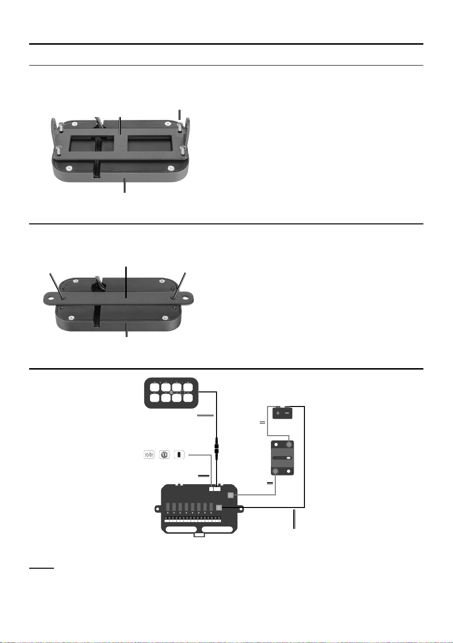
Switch Panel Mounting
Adjustable Mount Bracket
1. Secure Adjustable Mount Bracket (7) to
Switch Panel (2) using 4 Screws (26).
Bracket (7)
Switch Panel (2)
Screw (26)
2. Adjust the angle of Switch Panel
by using Hex Wrench (28) to
loosen and tighten bolts until the
desired angle is achieved.
Slim Flush Mount
1. Secure Slim Flush Mount Bracket (8)
to Switch Panel using 2 Screws (24).
Bracket (8)
Switch Panel
Insert Screw (24)
Insert Screw (24)
2. Secure Switch Panel and Bracket
to mounting location using 2
ST4.8*25 Screws (20) or ST4.8*18
Screws (21) or ST4.8*10 Screws
based on thickness of location.
Wiring Diagram
E9 60
Width/Position
Lamp
ACC
Car Cigarette
Adaptor
5A 5A 10A 10A 20A 20A 30A 30A
5
5
10
10
20
20
30
30
MODE
1 2 3 4
5 6 7 8
Red Wire
(9)
Wire
(13)
Red Wire (10)
Black Wire
(11)
Wire (12)
Vehicle
Battery
Circuit
Breaker
Note: Connect small Red Wire (10) from Control Box to either the
vehicle’s cigarette lighter, ACC, or Width/Position Lamp.
Page 6 For technical questions, please call 1-800-444-3353. 71426
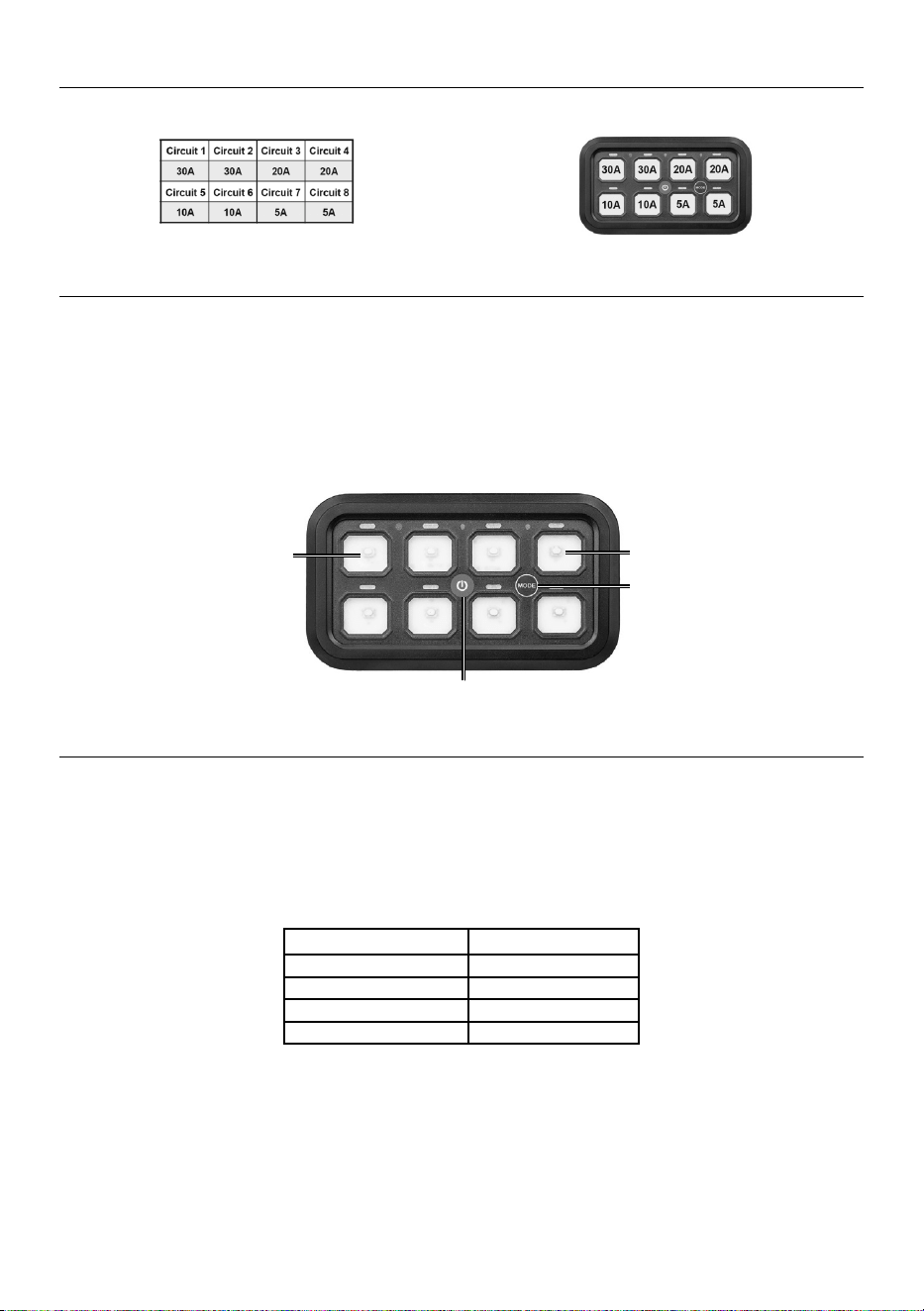
Circuitry Panel
Note the different amperage capacities per each Panel circuit and attach wiring accordingly.
Backlight Color Adjustment
1. Switch Panel backlight color is Green by default. To adjust
Switch Panel backlight color, press and hold Mode and any other
button simultaneously. Backlight color will turn Red.
2. Press and hold button 1 or 4 to scroll through color options. When
desired color is found, press Mode to save backlight color. To reset
backlight color, press and hold Mode for 10 seconds.
Button #1
Button #4
Power
MODE
Toggle/Momentary/Pulse/Blinking Settings
1. To switch between the above settings, double click Mode. All indicator lights will blink.
2. Press each panel button until the desired setting is reached. Toggle
mode will show as Red, Momentary mode will show as Blue, Pulse
mode will show as Green, and Blinking mode will show as Yellow.
3. To save these settings, press Mode again.
Mode Color
Toggle Red
Momentary Blue
Pulse Green
Blinking Yellow
Page 7For technical questions, please call 1-800-444-3353.71426
Maintenance
Read the ENTIRE IMPORTANT SAFETY INFORMATION section at the
beginning of this document including all text under subheadings therein
before set up or use of this product.
TO PREVENT SERIOUS INJURY OR DEATH FROM DRIVING HAZARDS:
Test operation of all lights before every use. Troubleshoot and repair
wiring properly before using. Do not use while trailer light operation
does not match vehicle light operation, if any lights do not light up, or
if any lights flicker. Park on level area away from traffic and set vehicle
parking brake/chock tires before diagnosing or servicing lights.
Cleaning and Maintenance
1. BEFORE EACH USE, inspect the
general condition of the tool. Check for:
• loose hardware,
• cracked or broken parts,
• damaged electrical wiring, and
• any other condition that may
affect its safe operation.
2. AFTER USE, wipe external surfaces
of the tool with clean cloth.
Troubleshooting
Problem Possible Causes
Light does not light up. 1. Power switch is not in “On” position.
2. Wiring connections are loose.
3. Wiring is damaged.
4. Wires are not connected according to the correct polarity.
Follow all safety precautions whenever diagnosing or servicing the lights.
Park on level area away from traffic and set vehicle parking brake/chock tires.
Page 8 For technical questions, please call 1-800-444-3353. 71426
PLEASE READ THE FOLLOWING CAREFULLY
THE MANUFACTURER AND/OR DISTRIBUTOR HAS PROVIDED THE PARTS LIST
AND INSTALLATION DIAGRAM IN THIS DOCUMENT AS A REFERENCE TOOL ONLY.
NEITHER THE MANUFACTURER OR DISTRIBUTOR MAKES ANY REPRESENTATION OR
WARRANTY OF ANY KIND TO THE BUYER THAT HE OR SHE IS QUALIFIED TO MAKE
ANY REPAIRS TO THE PRODUCT, OR THAT HE OR SHE IS QUALIFIED TO REPLACE
ANY PARTS OF THE PRODUCT. IN FACT, THE MANUFACTURER AND/OR DISTRIBUTOR
EXPRESSLY STATES THAT ALL REPAIRS AND PARTS REPLACEMENTS SHOULD
BE UNDERTAKEN BY CERTIFIED AND LICENSED TECHNICIANS, AND NOT BY THE
BUYER. THE BUYER ASSUMES ALL RISK AND LIABILITY ARISING OUT OF HIS OR
HER REPAIRS TO THE ORIGINAL PRODUCT OR REPLACEMENT PARTS THERETO, OR
ARISING OUT OF HIS OR HER INSTALLATION OF REPLACEMENT PARTS THERETO.
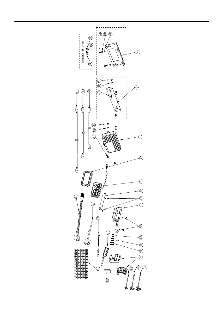
Parts List and Diagram
Parts List
Part Description Qty.
1 Power Module 1
2 Switch Panel 1
3 Panel Cover 1
4 60A Circuit Breaker 1
5 Fixed Mount Bracket 1
6 Flush Mount Bracket 1
7 Adjustable Mount Bracket 1
8 Slim Flush Mount Bracket 1
9 24in Red Wire 1
10 17in Red Wire 1
11 33in Black Wire 1
12 10ft Wire 1
13 Short Wire 1
14 Zip Tie 10
15 Phillips Head Screwdriver 1
Part Description Qty.
16 Label Sheet 60
17 M6*16 Round Head Screw 4
18 M6 Washer 4
19 M6 Nut 4
20 ST4.8*25 Screw 2
21 ST4.8*18 Screw 2
22 ST4.8*10 Screw 2
23 M3*8 Cross Countersunk Screw 2
24 M3*6 Cross Countersunk Screw 3
25 M3*8 Phillips Head Screw 2
26 M3*6 Phillips Head Screw 4
27 M5*8 Hex Socket Screw 2
28 Hex Wrench 1
29 Fuse Adapter Small 1
30 Fuse Adapter Medium 1
31 Fuse Adapter Large 1
Page 9For technical questions, please call 1-800-444-3353.71426
Assembly Diagram

Page 10 For technical questions, please call 1-800-444-3353. 71426
Record Date Code Here:
Note: If product has no date code record month and year of purchase instead.
Note: Some parts are listed and shown for illustration purposes only, and are not available individually as
replacement parts. Parts may not be interchangeable. Specify UPC 193175548276 when ordering parts:

Page 11For technical questions, please call 1-800-444-3353.71426
Limited 90 Day Warranty
Harbor Freight Tools Co. makes every effort to assure that its products meet high quality
and durability standards, and warrants to the original purchaser that this product is free from
defects in materials and workmanship for the period of 90 days from the date of purchase.
This warranty does not apply to damage due directly or indirectly, to misuse, abuse, negligence
or accidents, repairs or alterations outside our facilities, criminal activity, improper installation,
normal wear and tear, or to lack of maintenance. We shall in no event be liable for death,
injuries to persons or property, or for incidental, contingent, special or consequential damages
arising from the use of our product. Some states do not allow the exclusion or limitation of
incidental or consequential damages, so the above limitation of exclusion may not apply to you.
THIS WARRANTY IS EXPRESSLY IN LIEU OF ALL OTHER WARRANTIES, EXPRESS OR
IMPLIED, INCLUDING THE WARRANTIES OF MERCHANTABILITY AND FITNESS.
To take advantage of this warranty, the product or part must be returned to us with transportation
charges prepaid. Proof of purchase date and an explanation of the complaint must accompany
the merchandise. If our inspection verifies the defect, we will either repair or replace
the product at our election or we may elect to refund the purchase price if we cannot readily
and quickly provide you with a replacement. We will return repaired products at our expense,
but if we determine there is no defect, or that the defect resulted from causes not within
the scope of our warranty, then you must bear the cost of returning the product.
This warranty gives you specific legal rights and you may also
have other rights which vary from state to state.

26677 Agoura Road • Calabasas, CA 91302 • 1-800-444-3353
TM