Installation & Service Manual
Models: 90,000 - 500,000 Btu/hr
This manual supplies information for the
installation, operation, and servicing of the
appliance. It is strongly recommended that
this manual be reviewed completely before
proceeding with an installation. Perform
steps in the order given. Failure to comply
could result in severe personal injury, death,
or substantial property damage.
⚠ WARNING:
Save this manual for future reference.
CFA-I-S_100160907_2000001336_Rev R

2
Hazard definitions
The following defined terms are used throughout this manual to bring attention to the presence of hazards of various risk levels
or to important information concerning the life of the product.
⚠ DANGER
⚠ WARNING
⚠ CAUTION
CAUTION
NOTICE
DANGER indicates an imminently hazardous situation which, if not avoided, will result in death or serious
injury.
WARNING indicates a potentially hazardous situation which, if not avoided, could result in death or serious
injury.
CAUTION indicates a potentially hazardous situation which, if not avoided, may result in minor or moderate
injury.
CAUTION used without the safety alert symbol indicates a potentially hazardous situation which, if not
avoided, may result in property damage.
NOTICE indicates special instructions on installation, operation, or maintenance that are important but not
related to personal injury or property damage.
Contents
HAZARD DEFINITIONS .................................................. 2
PLEASE READ BEFORE PROCEEDING .................. 3-4
RATINGS ....................................................................... 5-6
THE COPPER-FIN -- HOW IT WORKS ............................ 7-9
1. DETERMINE UNIT LOCATION
Location of Unit ................................................................ 10
Clearances from Combustible Construction ..................... 10
Combustion and Ventilation Air .................................. 11-13
2. VENTING
A Conventional Negative Draft Venting System ......... 14-15
Vertical Vent Termination Clearances ............................. 16
Masonry Chimney Installation .......................................... 17
Inspection of a Masonry Chimney .............................. 17
Automatic Vent Damper ................................................... 20
3. GAS CONNECTIONS
Gas Supply ....................................................................... 21
Gas Pressure Test ........................................................... 21
Gas Connection ............................................................... 21
Gas Piping ........................................................................ 22
Gas Manifold Pressure Adjustment Procedure ................ 23
Checking Gas Supply Pressure ....................................... 24
Combination Gas Valves .................................................. 25
4. HYDRONIC PIPING
Relief Valve ...................................................................... 26
Water Flow Switch (if equipped) ...................................... 26
Low Water Cutoff (if equipped) ........................................ 27
Typical Heating Boiler Installations ............................. 27-28
Piping of the Boiler System .............................................. 28
Water Connections Heating Boilers Only ......................... 29
Circulator Pump Requirements ........................................ 29
Circulator Pump Specifications ...................................... 29
Circulator Pump Operation (Heating Boilers Only) ........ 29
Primary/Secondary Boiler Piping ..................................... 30
Low Temperature Bypass Requirements ......................... 31
Three Way Valves ............................................................ 31
Boiler Flow Rates ............................................................. 31
Figure 4-4_Prim. / Sec. Piping of a Single Boiler ....... 32
Figure 4-5_Prim. / Sec. Piping w/Low Temp. Bypass 33
Figure 4-6_Multiple Boilers Zoned w/Circulators ........ 34
5. ELECTRICAL CONNECTIONS
Boiler Operating Temperature Control ............................. 35
Room Thermostat or Remote Thermostat Connection .... 35
Power Venter Connection to Terminal Strip .................... 35
Pump Wiring for a Heating Boiler .................................... 36
Temperature Adjustment .................................................. 36
Temperature Control Settings .......................................... 37
Maximum Set Point Determination .................................. 37
Outdoor Air Reset Option ................................................. 39
Additional Temperature Controls ................................ 40-41
Blocked Vent and Flame Roll-Out / Flame Interlock Switch . 41
6. STARTUP
Initial Startup .................................................................... 42
Lighting Instructions for Standing Pilot Models (F1) ... 42-44
Safety Shutoff Test for Standing Pilot Ignition System .... 44
Lighting Instructions for Spark Ignition Pilot Models (F9/M9) 45-46
Safety Shutoff Test for Spark Ignition Pilot System ............ 46
Intermittent Pilot Spark Ignition System (F9/M9) ................. 46
Freeze Protection ........................................................................... 46
Water Treatment ....................................................................... 47-49
7. DOMESTIC WATER HEATERS
Water Velocity Control ..................................................... 50
Required Temperature Rise ............................................. 50
Water Chemistry............................................................... 51
Softened Water Systems ................................................. 51
Pump Operation ............................................................... 51
Figure 7-1_Single Water Heater Piping w/Single Tank ... 52
Figure 7-2_Single Water Heater Piping w/Multiple Tanks 53
Figure 7-3_Multiple Water Heater Piping w/Single Tank . 54
Remote Sensor Installation .............................................. 55
Heat Exchanger ............................................................... 55
Thermostat Settings .................................................... 55-56
Optional Relief Valve ........................................................ 57
Thermal Expansion .......................................................... 57
Cathodic Protection .......................................................... 57
8. MAINTENANCE
Maintenance and Annual Startup ................................ 58-64
9. TROUBLESHOOTING ............................................ 65-66
10. DIAGRAMS ............................................................67-70
33
Installation & Service Manual
Please read before proceeding
NOTICE
This is a gas appliance and should be installed
by a licensed electrician and/or certified gas
supplier. Service must be performed by a
qualified service installer, service agency or
the gas supplier.
⚠ WARNING
If the information in these instructions is
not followed exactly, a fire or explosion may
result causing property damage, personal
injury, or death.
This appliance MUST NOT be installed in
any location where gasoline or flammable
vapors are likely to be present, unless the
installation is such to eliminate the probable
ignition of gasoline or flammable vapors.
What to do if you smell gas –
• Do not try to light any appliance.
• Do not touch any electric switch; do not use any
phone in your building.
• Immediately call your gas supplier from a near by phone.
Follow the gas supplier’s instructions.
• If you cannot reach your gas supplier, call the fire
department.
Installation and service must be performed by a qualified
installer, service agency, or the gas supplier.
Warranty –
Installation and service must be performed by a qualified
service installer, service agency or the gas supplier.
Factory warranty (shipped with unit) does not apply to units
improperly installed or improperly operated.
Experience has shown that improper installation or system
design, rather than faulty equipment, is the cause of most
operating problems.
1. Excessive water hardness causing a lime/scale build-up in
the copper tube is not the fault of the equipment and is
not covered under the manufacturer’s warranty (see
Water Treatment and Water Chemistry).
2. Excessive pitting and erosion on the inside of the copper
tube may be caused by too much water velocity through
the tubes and is not covered by the manufacturer’s
warranty (see Boiler Flow Rates and Temperature Rise for
flow requirements).
Checking equipment –
Upon receiving equipment, check for signs of shipping
damage. Pay particular attention to parts accompanying the
appliances which may show signs of being hit or otherwise
being mishandled. Verify total number of pieces shown on
the packing slip with those actually received. In case there is
damage or a shortage, immediately notify the carrier.
Do not use this appliance if any part has been under water.
The possible damage to a flooded appliance can be extensive
and present numerous safety hazards. Any appliance that has
been under water must be replaced.
The installer must verify that at least one carbon monoxide
alarm has been installed within a residential living space or home
following the alarm manufacturer's instructions and applicable
local codes before putting the appliance into operation.
⚠ WARNING
Improper installation, adjustment,
alteration, service or maintenance can
cause injury or property damage. Refer
to this manual for assistance or additional
information, consult a qualified installer,
service agency or the gas supplier.
⚠ Owner warning –
NOTE: Retain this manual for future reference.
The information contained in this manual is intended for use
by qualified professional installers, service technicians, or gas
suppliers. Consult your local expert for proper installation
or service procedures.
IMPORTANT
Consult and follow all local Building and
Fire Regulations and other Safety Codes
that apply to this installation. Consult your
local gas utility company to authorize and
inspect all gas and flue connections.
Your conventionally vented gas appliance must have a supply
of fresh air circulating around it during burner operation for
proper gas combustion and proper venting.
⚠ WARNING
Should overheating occur or the gas supply
fail to shut off, do not turn off or disconnect
the electrical supply to the pump. Instead,
shut off the gas supply at a location external
to the appliance.

4
Installation & Service Manual
Please read before proceeding
⚠ WARNING
To minimize the possibility of serious
personal injury, fire, or damage to your
appliance, never violate the following safety
rules:
1. Boilers and water heaters are heat
producing appliances. To avoid damage
or injury, do not store materials against
the appliance or the vent-air intake
system. Use proper care to avoid
unnecessary contact (especially children)
with the appliance and vent-air intake
components.
2. Never cover your appliance, lean
anything against it, store trash or debris
near it, stand on it or in any way block
the flow of fresh air to your appliance.
3. UNDER NO CIRCUMSTANCES must
flammable materials such as gasoline or
paint thinner be used or stored in the
vicinity of this appliance, vent-air intake
system or any location from which fumes
could reach the appliance or vent-air
intake system.
Codes –
The equipment shall be installed in accordance with those
installation regulations in force in the local area where the
installation is to be made. These regulations shall be carefully
followed in all cases. Authorities having jurisdiction shall be
consulted before installations are made. In the absence of
such requirements, the installation shall conform to the latest
edition of the National Fuel Gas Code, ANSI Z223.1. Where
required by the authority having jurisdiction, the installation
must conform to American Society of Mechanical Engineers
Safety Code for Controls and Safety Devices for Automatically
Fired Boilers, ASME CSD-1. All boilers conform to the latest
edition of the ASME Boiler and Pressure Vessel Code, Section
IV. Where required by the authority having jurisdiction,
the installation must comply with the Canadian Association
Code, CAN/CGA- B149.1 and/or local codes.
This appliance meets the safe lighting performance criteria
with the gas manifold and control assembly provided as
specified in the ANSI standards for gas-fired appliances,
ANSI Z21.13 and ANSI Z21.10.3.
Boiler water –
Thoroughly flush the system to remove debris. Use an approved
pre-commissioning cleaner (see Start-Up Section), without the
boiler connected, to clean the system and remove sediment.
The high-efficiency heat exchanger can be damaged by build-up
or corrosion due to sediment.
NOTE: Cleaners are designed for either new systems or
pre-existing systems. Choose accordingly.
Prevention of freezing –
Heat exchangers and headers damaged by freezing are not
covered by warranty.
See Section 6, Start-Up - Freeze Protection for more information.
5
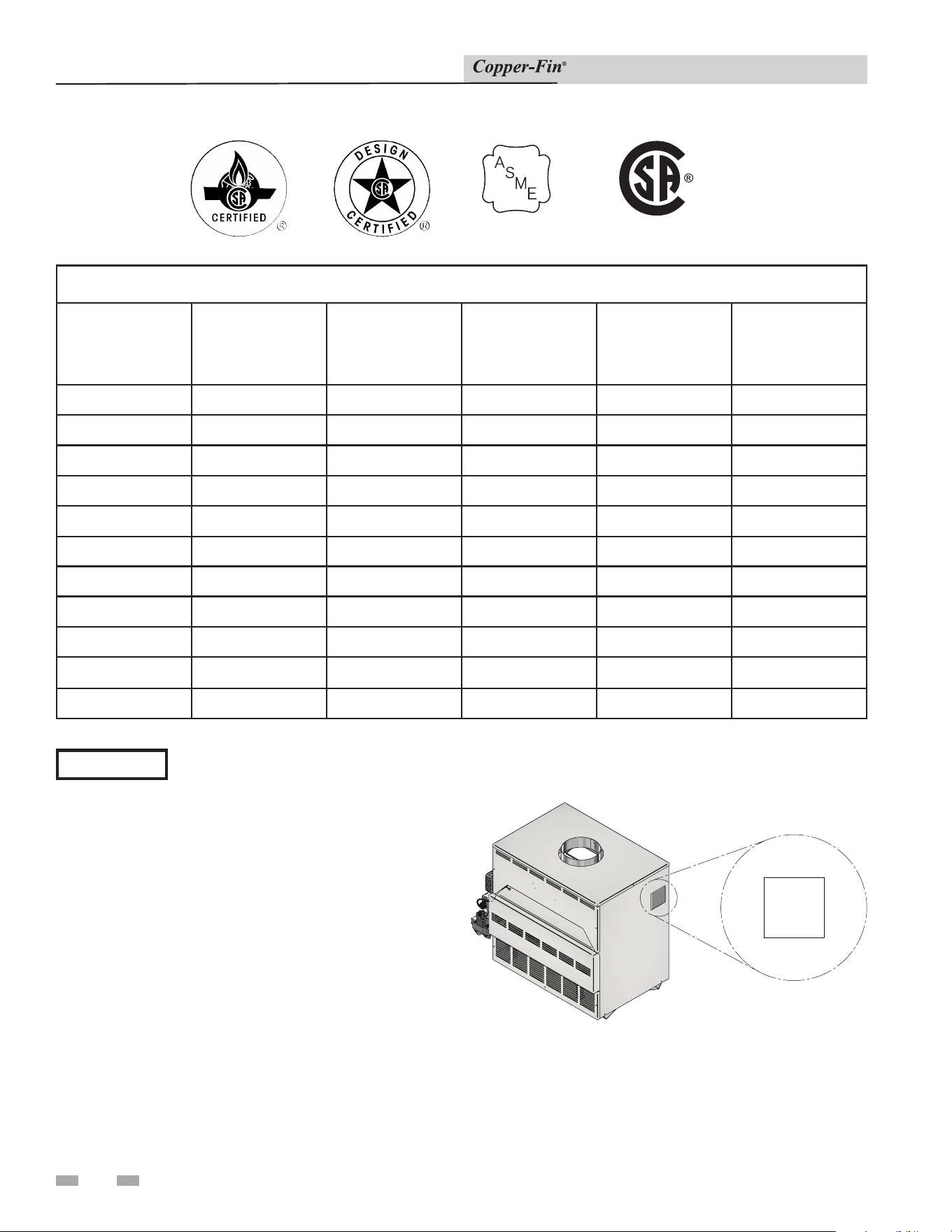
Ratings
Maximum allowed working pressure is located on the rating plate.
NOTICE
Installation & Service Manual
Notes:
1. The ratings are based on standard test procedures
prescribed by the United States Department of Energy.
2. Net AHRI ratings are based on net installed radiation of
sufficient quantity for the requirements of the building
and nothing need be added for normal piping and pickup.
Ratings are based on a piping and pickup allowance of 1.15.
3. Copper-fins require special gas venting. Use only the vent
materials and methods specified in the Installation and
Service Manual.
4. The Copper-fin is orificed for operation up to 2000
feet altitude. The ap pli ance will be derated 4% per 1000
feet above 2000 feet el e va tion. Consult the factory for
installations above 2000 feet elevation.
5. Ratings have been confirmed by AHRI.
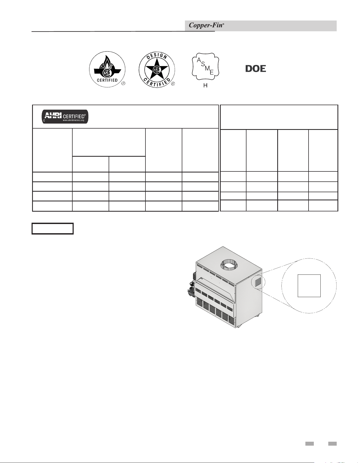
Figure A High Altitude Label Location
UNIT EQUIPPED FOR
HIGH ALTITUDE
UP TO 2000 FT.
Copper-Fin
AHRI Rating
Model Number
Note: Change
“N” to “L” for
L.P. gas models
Input
MBH
(Note 4)
Gross
Output
MBH
(Note 1)
Net
AHRI
Ratings
Water,
MBH
(Note 2)
MIN MAX
CBN315 157.5 315 258 224
CBN360 180 360 295 257
CBN399 199.5 399 327 285
CBN500 250 500 410 357
Other Specifications
Boiler
Water
Content
Gallons
Water
Connections
Gas
Connections
Vent Size
(Note 3)
1.2
2" 3/4" 8"
1.2
2" 1" 9"
1.3
2" 1" 10"
1.4 2" 1" 10"
6
Ratings
Installation & Service Manual
Notes:
1. Copper-fins require special gas venting. Use only the vent
materials and methods specified in the Installation and
Service Manual.
2. The Copper-fin is orificed for operation up to 2000
feet altitude. The ap pli ance will be derated 4% per 1000
feet above 2000 feet el e va tion. Consult the factory for
installations above 2000 feet elevation.
Figure B High Altitude Label Location
UNIT EQUIPPED FOR
HIGH ALTITUDE
UP TO 2000 FT.
Copper-fin Specifications
Model Number
Note: Change “N” to
“L” for L.P. gas models
Input
MBH
Water
Content Gallons
Water Connections Gas Connections
Vent Size
(Note 1)
CWN090 90 1.0 2" 1/2" 5"
CWN135 135 1.0 2" 1/2" 6"
CWN180 180 1.1 2" 3/4" 7"
CWN199 199 1.1 2" 3/4" 7"
CWN201
201
1.1
2"
3/4"
7"
CWN225 225 1.1 2" 3/4" 7"
CWN270 270 1.1 2" 3/4" 8"
CWN315
315 1.2 2" 3/4" 8"
CWN360
360 1.2 2" 1" 9"
CWN399
399 1.3 2" 1" 10"
CWN500
500 1.4 2" 1" 10"
HLW
Maximum allowed working pressure is located on the rating plate.
NOTICE
LOW LEAD CONTENT

7
Installation & Service Manual
The Copper-fin - How it works...
1. Control panel cover
The control panel cover provides access to the thermostat,
ignition module, and transformer.
2. Drain port (not shown)
Location from which the heat exchanger can be drained.
3. Flue outlet
The flue outlet allows the connection of the vent pipe to the unit.
4. Gas connection pipe
The gas pipe connection on this appliance should be connected to
the incoming gas supply for the purpose of delivering gas to the
appliance.
5. Gas valve
The gas valve allows the proper amount of gas to pass into the
burner for combustion.
6. Heat exchanger
The heat exchanger allows system water to flow through specially
designed tubes for maximum heat transfer. The glass lined
headers and copper finned tubing are encased in a jacket that
contains the combustion process.
7. High limit sensor
Device that monitors the outlet water temperature to ensure
safe operation. If the temperature exceeds its setting , it will break
the control circuit, shutting the appliance down.
8. Ignition module (F9 and M9 models only)
The ignition module responds to a call for heat signal to provide
burner operation .
9. Junction box
The junction box contains the connection points for the line
voltage power and the pump.
10. Relief valve
The relief valve is a safety device that ensures the maximum
pressure of the appliance is not exceeded. Water heaters are
supplied with a temperature and pressure relief valve.
11. Terminal strip
The boiler is equipped with a terminal strip on the left side of the
control panel to allow easy connection to contact points on the
unit.
12. Thermostat
The thermostat monitors the water temperature via a temperature
sensor and will initiate a call for heat when the water temperature
drops below the setpoint plus the differential on the thermostat.
13. Temperature gauge (CW models only)
The temperature gauge monitors the inlet temperature of the
water heater as well as the outlet temperature.
14. Transformer
The transformer reduces 120 VAC supply voltage to 24 VAC for the
control circuit.
15. Water inlet
The water inlet is a 2" pipe connection that receives water from the
system and delivers it to the heat exchanger.
16. Water outlet
The water outlet is a 2" pipe connection that supplies water to
the system .
17. Burner (not shown)
The burner is a cylindrical stainless steel tube used to regulate
burner flame.
18. Pilot (not shown)
( F9 and M9 models only)
The pilot is a spark ignition device is used to light a pilot flame
which in turn is used to light the main burners.
( F1 models only)
The pilot uses a standing flame to light the main burner.
19. Sight Glass (not shown)
The sight glass provides a view of the burner surface, burner
flame, and the pilot flame.
20. Temperature and pressure gauge (CB models only)
The temperature and pressure gauge monitors the outlet
temperature of the boiler as well as the system water pressure.
21. Pump (shipped with CW models only)
The pump ensures adequate flow to operate the unit.
22. Pump relay
The pump relay energizes the pump on a call for heat.
23. Temperature sensor
This sensor monitors inlet water temperature. If selected as the
controlling sensor, the appliance will maintain the setpoint at this
sensor.
Installation & Service Manual
8
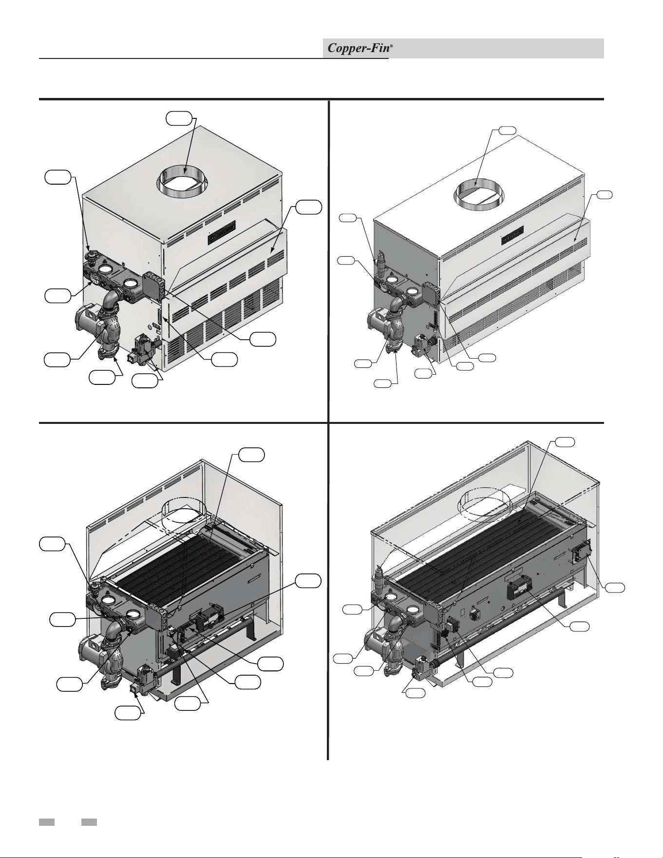
Models CWN270 Front View
Model CWN399 (inside unit)
Model CWN399 Front View
Model CWN270 (inside unit)
The Copper-fin - How it works...
3
1
10
9
11
5
21
15
16
22
6
12
8
4
14
23
7
13
1
3
10
16
15
21
5
11
9
6
7
13
23
4
22
14
12
8
9
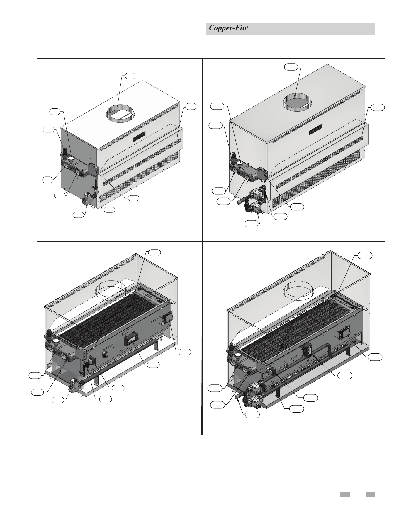
Installation & Service Manual
The Copper-fin - How it works... (continued)
Model CBN500 (inside unit)
Model CBN500 Front View
Models CBN399 (inside unit)
Model CBN399 Front View
3
1
20
10
16
15
11
9
5
6
12
8
14
22
23
4
7
3
1
20
10
16
15
5
11
9
6
12
4
14
8
7
23
22
10
Installation & Service Manual
1 Determine unit location
NOTICE
Clearances from combustible construction
are noted on the appliance rating plate.
Location of unit
1. Locate the appliance so that if water connections should
leak, water damage will not occur. When such locations
cannot be avoided, it is recommended that a suitable
drain pan, adequately drained, be installed under the
appliance. The pan must not restrict combustion air
flow. Under no circumstances is the manufacturer to be
held responsible for water damage in connection with
this appliance, or any of its components.
2. The appliance must be installed indoors where it is
protected from exposure to wind, rain and weather.
3. The appliance must be installed so that the ignition
system components are protected from water (dripping,
spraying, rain, etc.,) during appliance operation and
service (circulator replacement, control replacement,
etc.,).
4. Appliances located in a residential garage and in adjacent
spaces that open to the garage and are not part of the
living space of a dwelling unit must be installed so that
all burners and burner ignition devices have a minimum
clearance of not less than 18” (46cm) above the floor.
The appliance must be located or protected so that it is
not subject to physical damage by a moving vehicle.
5. DO NOT install this appliance in any location where
gasoline or flammable vapors are likely to be present.
6. All units have been approved for alcove installation (an
ALCOVE is a closet enclosure without a front door).
7. The appliance must not be installed on carpet.
8. All units have been approved for use on combustible
surfaces.
9. Allow sufficient space for servicing pipe connections,
pump and other auxiliary equipment, as well as the
appliance.
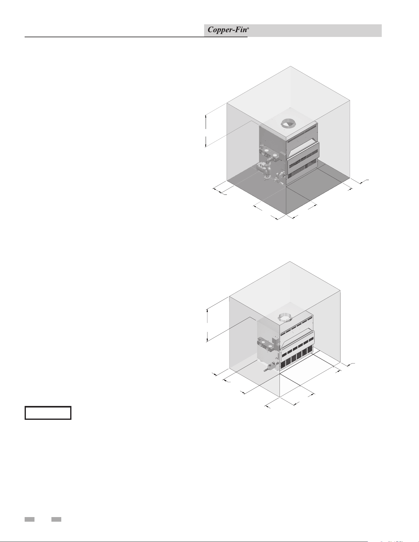
Figure 1-1_Alcove installation, 90,000 - 180,000 Btu/hr
6"
RIGHT
24"
LEFT
24"
FRONT
6" REAR
14 "
TOP
24"
LEFT
24"
FRONT
29"
TOP
6 "
REAR
6 " RIGHT
Figure 1-2_Alcove Installation , 225,000 - 500,000 Btu/hr
11
Installation & Service Manual
1 Determine unit location (continued)
Figure 1-3_Combustion Air Direct from Outside
Combustion and ventilation air requirements
for conventionally vented appliances
Provisions for combustion and ventilation air must be in
accordance with the latest edition of the National Fuel Gas
Code, ANSI Z223.1, in Canada, the latest edition of CGA
Standard B149 Installation Code for Gas Burning Appliances
and Equipment, or applicable provisions of the local building
codes.
The room where the appliance is installed MUST be provided
with properly sized openings to assure adequate combustion
air and proper ventilation when the appliance is installed with
conventional venting.
1. If air is taken directly from outside the building
with no duct, provide two permanent openings
(see FIG. 1-3):
(a) Combustion air opening, with a minimum free
area of one square inch per 4000 Btu/hr input
(5.5 cm
2
per kW). This opening must be located
within 12" (30 cm) of the floor.
(b) Ventilation air opening, with a minimum free
area of one square inch per 4000 Btu/hr input
(5.5 cm
2
per kW). This opening must be
located within 12" (30 cm) of the ceiling.
Figure 1-4_Combustion Air Through Ducts
2. If combustion and ventilation air is taken from the
outdoors using a duct to deliver the air to the room where
the appliance is installed, each of the two openings should
be sized based on a minimum free area of one square inch
per 2000 Btu/hr (11cm2 per kW) (see FIG. 1-4).
Figure 1-5_Combustion Air from Interior Space
3. If air is taken from another interior space that is adequately
ventilated, each of the two openings specified above should
have a net free area of one square inch for each 1000 Btu/
hr (22cm2 per kW) of input, but not less than 100 square
inches (645cm2) (see FIG. 1-5).
12
1 Determine unit location
Installation & Service Manual
4. If a single combustion air opening is provided to bring
combustion air in directly from the outdoors, the
opening must be sized based on a minimum free area of
one square inch per 3000 Btu/hr (7 cm
2
per kW). This
opening must be located within 12" (30 cm) of the top of
the enclosure (see FIG. 1-6).
Figure 1-6_Combustion Air from Outside Single Opening
Combustion air require ments are based on the latest edition
of the National Fuel Gas Code, ANSI Z223.1, in Canada
refer to National Standard CAN B149.1. Check all local code
re quire ments for combustion air.
All dimensions are based on net free area in square inch es.
Metal louvers or screens reduce the free area of a combustion
air opening a minimum of approximately 25%. Check with
louver manufacturers for exact net free area of louvers.
Where two openings are pro vid ed, one must be within
12" (30 cm) of the ceiling and one must be within
12" (30 cm) of the floor of the room where the appliance is
installed. Each opening must have a net free area as specified
in Table 1B (on page 13). Single openings shall be located
with in 12" (30 cm) of the ceiling.
⚠ CAUTION
Under no circumstances should the room
where the appliance is installed ever be
under a negative pressure. Particular care
should be taken where exhaust fans, attic
fans, clothes dryers, compressors, air
handling units, etc., may take away air from
the appliance.
The combustion air supply must be completely free of any
flammable vapors that may ignite or chemical fumes which
may be corrosive to the appliance. Common corrosive
chemical fumes which must be avoided are fluorocarbons
and other halogenated compounds, most commonly present
as refrigerants or solvents, such as freon, tricholorethylene,
perchlorethylene, chlorine, etc. These chemicals, when burned,
form acids which quickly attack the heat exchanger finned
tubes, headers, flue collectors, and the vent system. The result
is improper combustion and a non-warrantable, premature
appliance failure.
The result is improper combustion and a non-warrantable,
premature appliance failure.
EXHAUST FANS: Any fan or equipment which exhausts air
from the equipment room may deplete the combustion air
supply and/or cause a downdraft in the venting system. Spillage
of flue products from the venting system into an occupied
living space can cause a very hazardous condition that must be
immediately corrected. If a fan is used to supply combustion
air to the equipment room, the installer must make sure that it
does not cause drafts which could lead to nuisance operational
problems with the appliance.
13
Installation & Service Manual
TABLE - 1B
MINIMUM RECOMMENDED COMBUSTION
AIR SUPPLY TO EQUIPMENT ROOM
Input
Btu/hr
*Outside Air from
2 Openings Directly from
Outdoors
*Outside Air from
1 Opening Directly
from Outdoors, in
2
*Outside Air from
2 Ducts Delivered from
Outdoors
**Inside Air from
2 Ducts Delivered from
Interior Space
Top
Opening, in
2
Bottom
Opening, in
2
Top
Opening, in
2
Bottom
Opening, in
2
Top
Opening, in
2
Bottom
Opening, in
2
90,000
23
(148 cm
2
)
23
(148 cm
2
)
30
(194 cm
2
)
45
(291 cm
2
)
45
(291 cm
2
)
100
(646 cm
2
)
100
(646 cm
2
)
135,000
34
(220 cm
2
)
34
(220 cm
2
)
45
(291 cm
2
)
68
(439 cm
2
)
68
(439 cm
2
)
135
(871 cm
2
)
135
(871 cm
2
)
180,000
45
(291 cm
2
)
45
(291 cm
2
)
60
(388 cm
2
)
90
(581 cm
2
)
90
(581 cm
2
)
180
(1,162 cm
2
)
180
(1,162 cm
2
)
199,000/
201,000
50
(323 cm
2
)
50
(323 cm
2
)
67
(433 cm
2
)
100
(646 cm
2
)
100
(646 cm
2
)
200
(1,291 cm
2
)
200
(1,291 cm
2
)
225,000
57
(368 cm
2
)
57
(368 cm
2
)
75
(484 cm
2
)
113
(730 cm
2
)
113
(730 cm
2
)
225
(1,452 cm
2
)
225
(1,452 cm
2
)
270,000
68
(439 cm
2
)
68
(439 cm
2
)
90
(581 cm
2
)
135
(871 cm
2
)
135
(871 cm
2
)
270
(1,742 cm
2
)
270
(1,742 cm
2
)
315,000
79
(510 cm
2
)
79
(510 cm
2
)
105
(678 cm
2
)
158
(1,020 cm
2
)
158
(1,020 cm
2
)
315
(2,033 cm
2
)
315
(2,033 cm
2
)
360,000
90
(581 cm
2
)
90
(581 cm
2
)
120
(775 cm
2
)
180
(1,162 cm
2
)
180
(1,162 cm
2
)
360
(2,323 cm
2
)
360
(2,323 cm
2
)
399,000
100
(646 cm
2
)
100
(646 cm
2
)
134
(865 cm
2
)
200
(1,291 cm
2
)
200
(1,291 cm
2
)
400
(2,581 cm
2
)
400
(2,581 cm
2
)
500,000
125
(807 cm
2
)
125
(807 cm
2
)
167
(1,078 cm
2
)
250
(1,613 cm
2
)
250
(1,613 cm
2
)
500
(3,226 cm
2
)
500
(3,226 cm
2
)
*Outside air openings shall directly communicate with the outdoors. When combustion air is drawn from the outside through a
duct, the net free area of each of the two openings must have twice (2 times) the free area required for Outside Air/2 Openings.
The above requirements are for the boiler only; additional gas fired appliances in the equipment room will require an increase
in the net free area to supply adequate combustion air for all appliances.
**Combined interior space must be 50 cubic feet per 1,000 Btu/hr input. Buildings MUST NOT be of *“Tight Construction”.
For buildings of *“Tight Construction”, provide air openings into the building from outside.
*No combustion air openings are needed when the water heater is installed in a space with a volume NO LESS than 50 cubic feet
per 1,000 Btu/hr of all installed gas fired appliances. Buildings MUST NOT be of *“Tight Construction”.
* “Tight Construction” is defined as a building with less than 0.40 ACH (air changes per hour).
Vent installations for connection to gas vents or
chimneys must be in accordance with “Vent ing of Equipment,”
of the latest edition of the Na tion al Fuel Gas Code, ANSI
Z223.1, in Canada, the latest edi tion of CGA Standard B149
Installation Code for Gas Burning Appliances and Equipment
or applicable pro vi sions of the local building codes.
Adequate combustion and ventilation air must be
sup plied to the room where the appliance is installed in
accordance with the latest edition of the National Fuel Gas
Code, ANSI Z223.1, in Canada, the latest edition of CGA
Standard B149 Installation Code for Gas Burning Ap pli anc es
and Equipment, or applicable pro vi sions of the local building
codes.
1 Determine unit location (continued)
14
Installation & Service Manual
2 Venting
The distance of the vent terminal from adjacent
build ings, windows that open and building open ings MUST
comply with the latest edition of the National Fuel Gas
Code, ANSI Z223.1, in Canada, the latest edition of CGA
Standard B149 In stal la tion Code for Gas Burn ing Appliances
and Equipment.
Vent connection is made directly to the top of the
ap pli ance. This appliance is designed with a built-in draft
diverter. No additional external draft hood is re quired. The
connection from the appliance vent to the common vent or
chimney must be made as direct as possible.
A Conventional Negative Draft
Venting System
The negative draft in a conventional vent in stal la tion must be
within the range of a negative 0.02 to 0.05 inches water column
to ensure proper operation. All draft read ings are made while
the appliance is in stable op er a tion (approximately 2 to 5
minutes).
Multiple appliance installations with combined vent ing or
common venting with other negative draft ap pli anc es require
that each appliance must have draft with in the proper range.
If the draft mea sured above the appliance’s built-in draft
diverter ex ceeds the specified range in a dedicated chimney
for a single appliance installation or in combined venting with
other negative draft appliances, a baro met ric damper must be
in stalled to control draft.
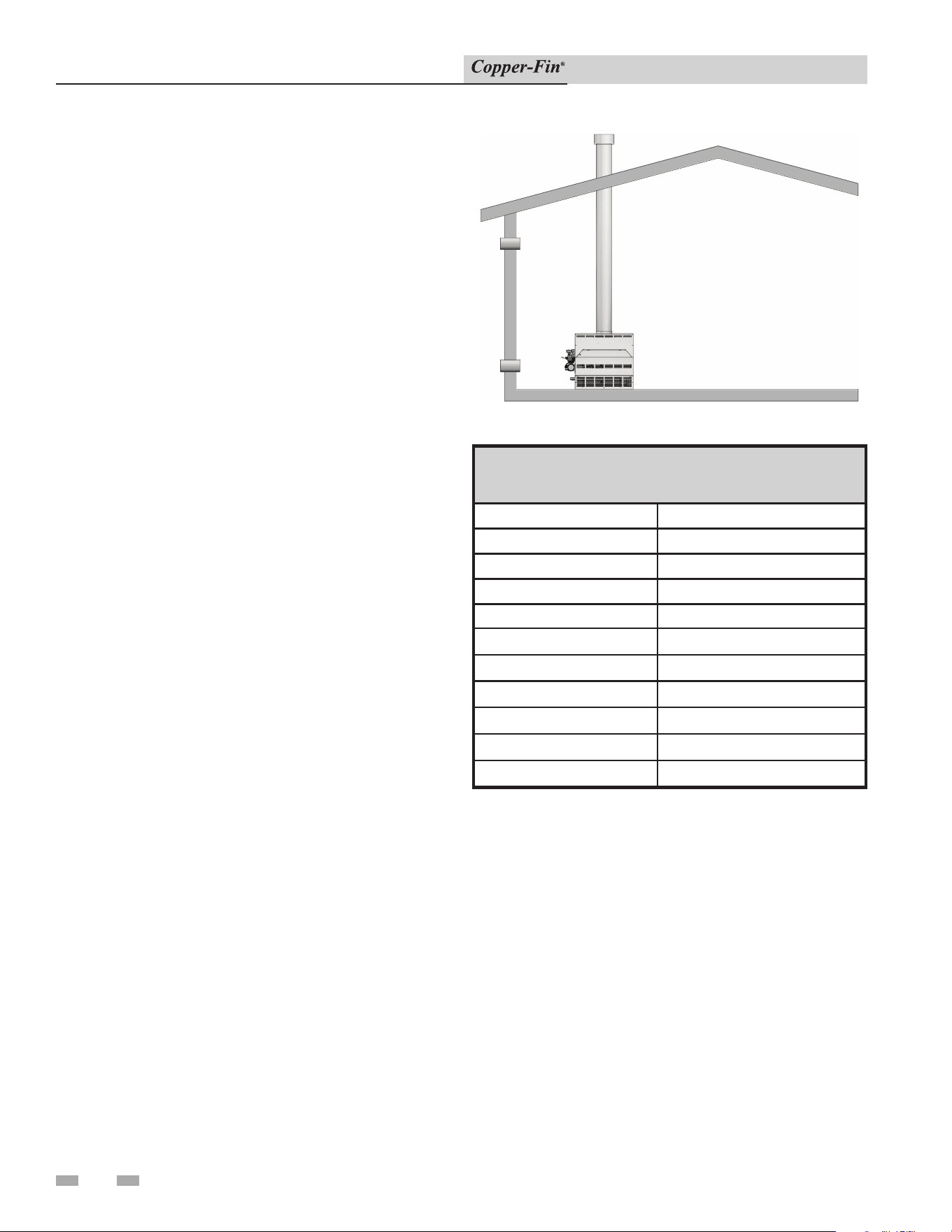
Figure 2-1_Conventional Negative Draft Vertical Venting
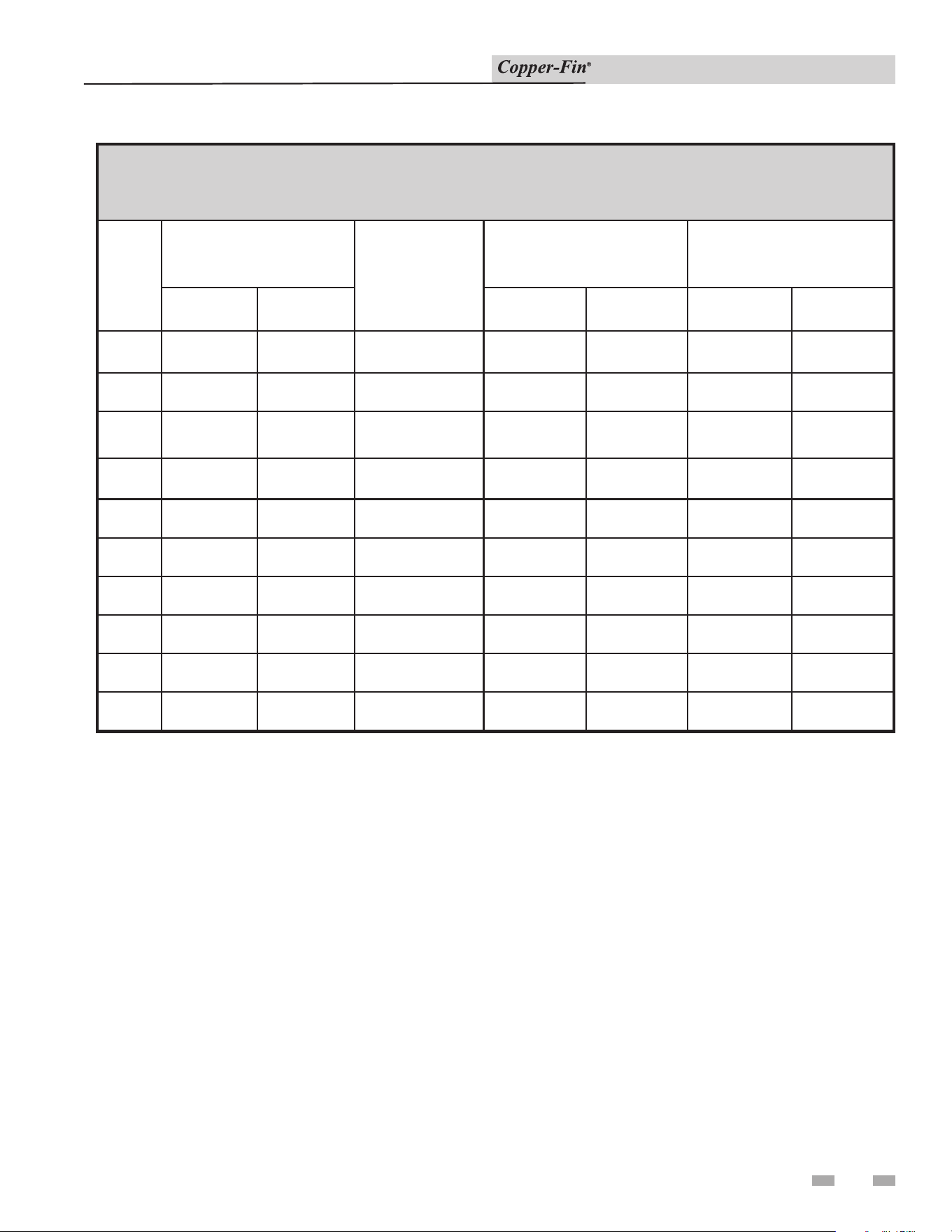
TABLE - 2A
VENT PIPE SIZES
Input Btu/hr Flue Size
90,000 5"
135,000 6"
180,000 7"
199,000/201,000 7"
225,000 7"
270,000 8"
315,000 8"
360,000 9"
399,000 10"
500,000 10"
On a conventionally vented, negative draft ap pli ance, the
connection from the vent to the chimney or vent termination
on the outside of the building MUST be made with listed Type
“B” double wall (or equivalent) vent connectors and must be
direct as possible with no reduction in diameter. To properly
size all double wall vent connectors and stacks, use the venting
tables in the latest edition of the National Fuel Gas Code, ANSI
Z223.1, in Canada, the latest edition of CGA Standard B149
Installation Code for Gas Burning Appliances and Equipment.
The Type “B” vent and accessories, such as firestop spacers,
thim bles, caps, etc., MUST be installed in accordance with the
manufacturer’s list ing. The vent connector and firestop must
provide correct spacing to combustible surfaces and seal to the
vent connector on the upper and lower sides of each floor or
ceiling through which the vent connector passes.
Any vent materials used must be listed by a na tion al ly recognized
test agency for use as vent ma te ri al.

2 Venting (continued)
15
Installation & Service Manual
Locate appliance as close as possible to a chimney or gas vent.
Avoid long horizontal runs of the vent pipe, 90° el bows,
reductions and restrictions. Horizontal por tions of the
venting system shall be supported to prevent sagging.
Horizontal runs must slope up wards not less than 1/4 inch
per foot (21 mm/m) from the appliance to the vent terminal.
Follow manufacturer’s instructions.
Do not use an existing chimney as a raceway for a flue pipe if
another appliance or fireplace is vented through the chimney.
A water heater shall not be connected to a chimney flue
serving a separate appliance designed to burn solid fuel.
The weight of the venting system must not rest on the
appliance. Adequate support of the venting sys tem must be
provided in compliance with local codes and other applicable
codes. All connections should be secured with rustproof
sheet metal screws.
Vent connectors serving appliances vented by nat u ral draft
shall not be connected to any portion of a me chan i cal draft
system operating under positive pres sure. Connection to
a positive pressure chim ney may cause flue products to be
discharged into the living space causing serious health injury.
Common venting systems may be too large when an existing
appliance is removed. At the time of removal of an existing
appliance, the following steps shall be followed with each
appliance remaining connected to the common venting
system placed in operation, while other appliances remaining
con nect ed to the common venting system are not in operation.
(a) Seal any unused opening in the common venting
system.
(b) Visually inspect the venting system for proper size
and horizontal pitch and determine there is no
blockage or restriction, leakage, corrosion and other
deficiencies which could cause an unsafe condition.
(c) Insofar as is practical, close all building doors and
windows and all doors between the space in which
the appliances remaining connected to the common
venting system are located and other spaces of the
building. Turn on clothes dryers and any other
appliances not connected to the common venting
system. Turn on any exhaust fans, such as range
hoods and bathroom exhausts, so they will operate
at maximum speed. Do not operate a summer
ex haust fan. Close fireplace dampers.
(d) Place in operation the appliance being inspected.
Follow the lighting instructions. Adjust thermostat
so appliance will operate continuously.
(e) Test for spillage at the draft hood/relief opening after
5 minutes of main burner operation. Use the flame of
a match or candle, or smoke from a cigarette, cigar or
pipe.
(f) After it has been determined that each appliance
remaining connected to the common venting system
properly vents when tested as outlined above, return
doors, windows, exhaust fans, fireplace dampers
and other gas burning ap pli anc es to their previous
conditions of use.
(g) Any improper operation of the common venting
system should be corrected so that the installation
conforms to the latest edition of the Na tion al Fuel Gas
Code, ANSI Z223.1. In Canada, the latest edition of
CGA Standard B149 Installation Code for Gas Burning
Appliances and Equipment. When resizing any
por tion of the common venting system, the common
venting system should be resized to ap proach the
min i mum size as determined using the appropriate
tables in Part 11 in the latest edition of the National
Fuel Gas Code, ANSI Z223.1. In Canada, the latest
edition of CGA Stan dard B149 Installation Code for
Gas Burning Appliances and Equipment.
16
2 Venting
Installation & Service Manual
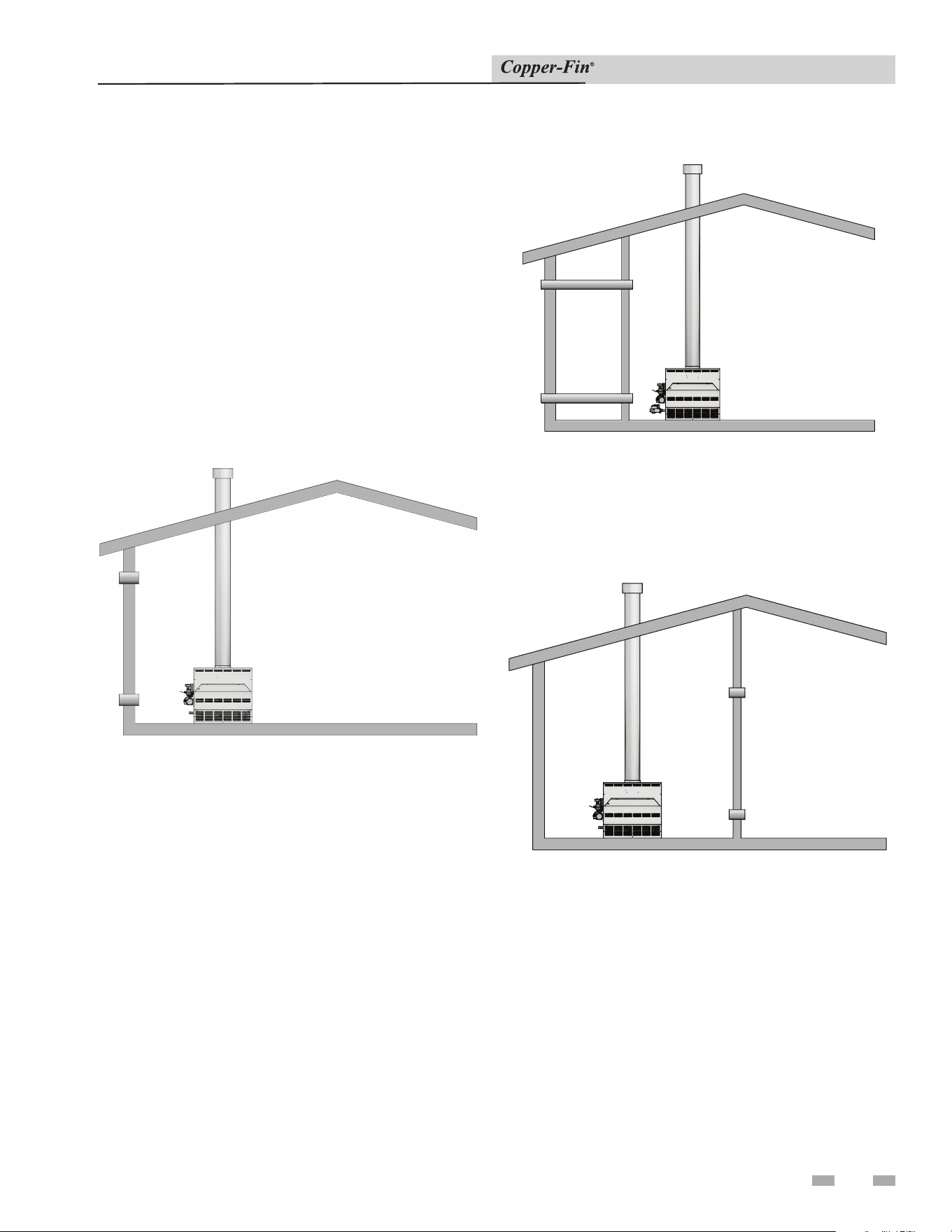
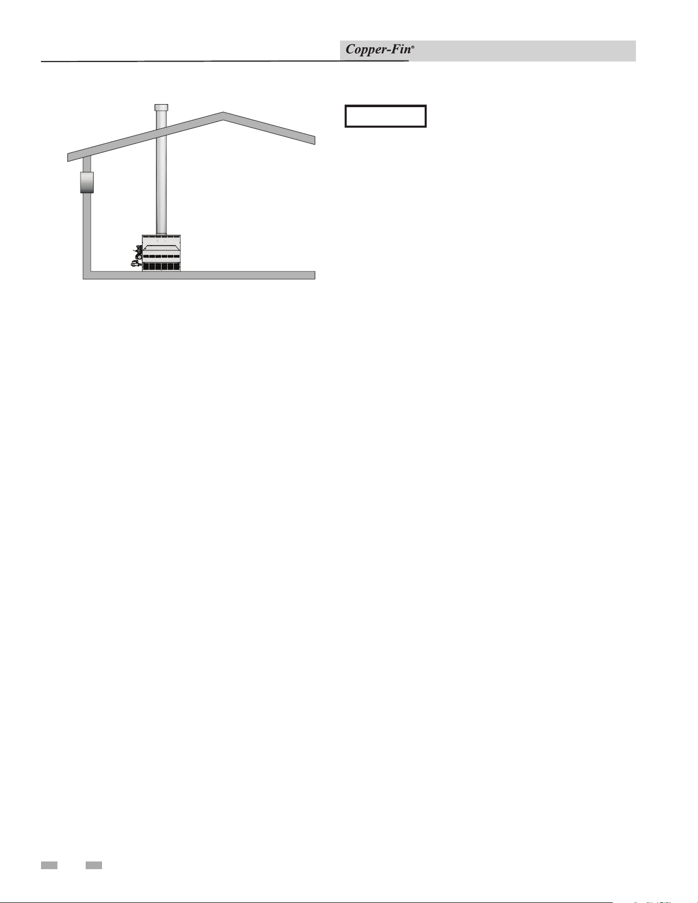
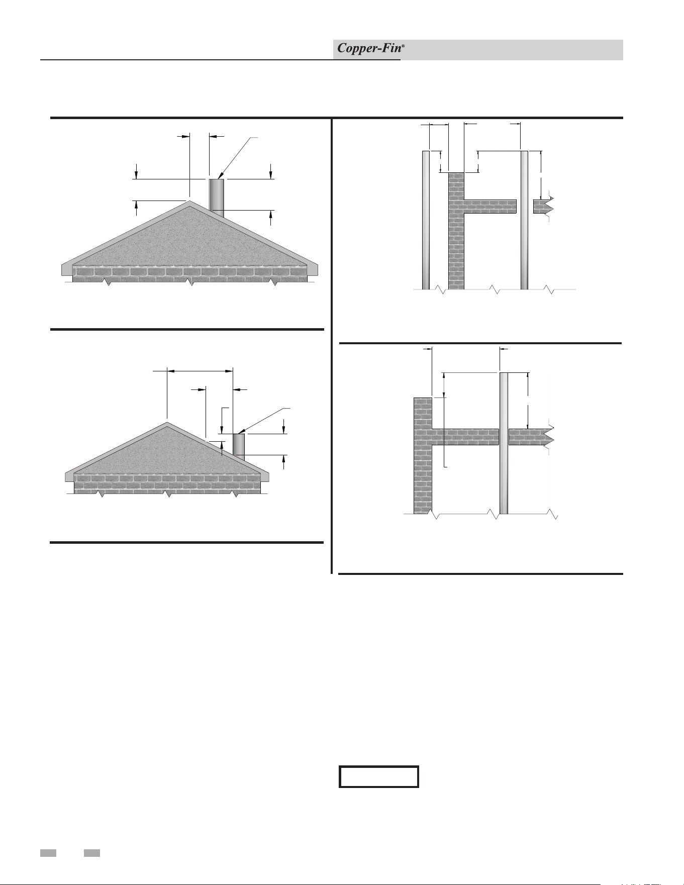
Vertical Vent Termination Clearances
Figure 2-2_Vent Termination from Peaked Roof 10' or
Less from Ridge
Figure 2-4_Vent Termination from Flat Roof 10' or
Less from Parapet Wall
Figure 2-3_Vent Termination from Peaked Roof More
than 10' from Ridge
Figure 2-5_Vent Termination from Flat Roof More Than
10' from Parapet Wall
The vent terminal should be vertical and exhaust outside the
building at least 2 feet (0.61m) above the high est point of the
roof within a 10 foot (3.05m) radius of the termination. The
vertical termination must be a minimum of 3 feet (0.91m)
above the point of exit.
A vertical terminal less than 10 feet (3.05m) from a parapet
wall must be a minimum of 2 feet (0.61m) higher than the
parapet wall.
The vent cap should have a minimum clearance of 4 feet
(1.22m) horizontally from and in no case above or below,
unless a 4 foot (1.22m) horizontal distance is maintained from
electric meters, gas meters, reg u la tors and relief equipment.
The venting system shall terminate at least 3 feet (0.9m) above
any forced air inlet within 10 feet (3.05m).
The venting system shall terminate at least 4 feet (1.2m)
below, 4 feet (1.2m) horizontally from, or 1 foot (30cm) above
any door, window or gravity air inlet into any building.
Do not terminate the vent in a window well, stair well, alcove,
courtyard or other recessed area.
The vent can not terminate below grade. The bot tom of the
vent terminal shall be located at least 12 inches (30cm) above
grade.
To avoid a blocked vent condition, keep the vent cap clear of
snow, ice, leaves, debris, etc.
Flue gases will form a white plume in winter. Plume could
obstruct window view.
Flue gas condensate can freeze on exterior sur fac es or on the vent
cap. Frozen condensate on the vent cap can result in a blocked
vent condition. Flue gas condensate can cause discoloration of
exterior build ing surfaces. Adjacent brick or masonry sur fac es
should be protected with a rust resistant sheet metal plate.
NOTICE
Examine the venting system at least once
a year. Check all joints and vent pipe
con nec tions for tightness. Also check for
corrosion or de te ri o ra tion. Immediately
correct any problems ob served in the
venting system.
2' MIN
10' OR LESS
3' MIN
CHIMNEY
RIDGE
MORE THAN 10'
10'
2' MIN
3' MIN
CHIMNEY
RIDGE
2' MIN
10' OR LESS
10' OR LESS
2' MIN
3' MIN
CHIMMEY
WALL OR
PARAPET
CHIMMEY
10' OR MORE
3'
NOTE:
NO HEIGHT ABOVE
PARAPET REQUIRED
WHEN DISTANCE
FROM WALLS OR
PARAPETS IS MORE
THAN 10'.
WALL OR
PARAPET
CHIMNEY
2 Venting (continued)
Installation & Service Manual
Masonry Chimney Installation
A masonry chimney must be properly sized for the installation
of a gas fired appliance. Venting of an appliance into a cold
or oversized masonry chimney can result in op er a tion al and
safety problems. Exterior masonry chim neys, with one or more
sides exposed to cold out door tem per a tures, are more likely to
have venting problems. The temperature of the flue gases from
an appliance may not be able to suf fi cient ly heat the ma son ry
structure of the chim ney to generate proper draft. This will
result in condensing of flue gases, damage the masonry flue/
tile, insufficient draft and possible spill age of flue gases into an
occupied living space. Care ful ly in spect all chimney systems
before installation. If there is any doubt about the sizing or
condition of a masonry chimney, it must be relined with a
prop er ly sized and approved chimney liner system.
Inspection of a Masonry Chimney
A masonry chimney must be carefully inspected to determine its
suitability for the venting of flue gas es. A clay tile lined chimney
must be structurally sound, straight and free of misaligned tile,
gaps between liner sections, missing sections of liner or any
signs of con den sate drainage at the breaching or clean out. If
there is any doubt about the condition of a masonry chimney,
it must be relined. An unlined masonry chimney must not
be used to vent flue gases from this appliance. An unlined
chimney must be relined with an approved chimney liner
system when a new appliance is be ing attached to it. Metallic
liner systems (Type “B” double wall or flexible or rigid metallic
liners) are recommended. Consult with local code officials to
determine code requirements or the advisability of using or
relining a masonry chimney.
Sidewall Venting
This appliance is NOT approved for sidewall venting with
the negative draft venting system as shipped from the factory.
An induced draft fan MUST be used if the installation
requires that the flue gases be vented out a sidewall. A
properly sized and in stalled induced draft fan may also be
used to vent the flue gases ver ti cal ly if required by job site
conditions. The induced draft fan must be listed by a nationally
recognized test agency, be properly sized and installed per the
rec om men da tions of the in duced draft fan manufacturer and
meet local code requirements. Use care to ensure that the
me chan i cal ly supplied draft does not exceed the range of a
negative 0.02 to 0.05 inches water column to ensure proper
operation. If draft exceeds the spec i fied range, the fan must be
adjusted or the installation of a baro met ric damper in the flue
may be required to prop er ly control draft.
An induced draft fan MUST be interlocked into the appliance’s
control circuit to start when the appliance calls for heat. The
in duced draft fan MUST also be equipped with a prov ing
switch, properly interlocked into the ap pli ance’s con trol circuit
to prove fan operation before the main burn ers are allowed
to fire. A vertical or sidewall vent termination for an induced
draft fan MUST be in stalled per the recommendations of the
fan manufacturer and provide proper clearances from any
combustion or ventilation openings, win dows, doors or other
open ings into the building. All induced draft fan in stal la tions
must comply with local code requirements. See FIG. 2-7 for
minimum sidewall venting clearances.
TABLE 2B - VENT MATERIALS
Kit
Number
Input
Btu / hr
Material
100157734
90,000 CPVC Rated
135,000 CPVC Rated
Minimum Vent Length = 12 Equivalent Feet *
(ALL UNITS)
Maximum Vent Length = 25 Equivalent Feet * *
(ALL UNITS)
*Equivalent Feet: 90° Elbow = 5 Feet
45° Elbow = 3 Feet
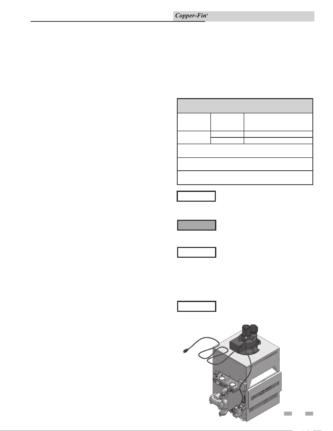
Figure 2-6_CW135 with Fan Assisted Venting
Fan Assisted Venting
A Power Venter kit is available on models 90,000 - 135,000
Btu/hr, water heaters only.
DO NOT use Radel or cellular (foam) core
PVC or CPVC pipe.
CAUTION
NOTE: In Canada, CPVC and PVC vent pipe, ttings and
cement/primer must be ULC-S636 certied.
⚠ WARNING
DO NOT insulate PVC or CPVC venting
materials. Use of insulation will cause
increased vent wall temperatures, which
could result in vent pipe failure.
17
All CPVC and PVC vent pipes must be
glued, properly supported, and the exhaust
NOTICE
must be pitched a minimum of 1/4" per foot back to the water
heater (to allow drainage of condensate). Horizontal runs
shall have supports suitable for non-metallic vent piping that
do not clamp tightly onto vent allowing for vent expansions or
contraction. Supports shall be as close to joints and fittings as
practical and no more than 5 ft. apart.
When available, follow all vent
manufacturer's installation instructions.
NOTICE
2 Venting
Installation & Service Manual
18
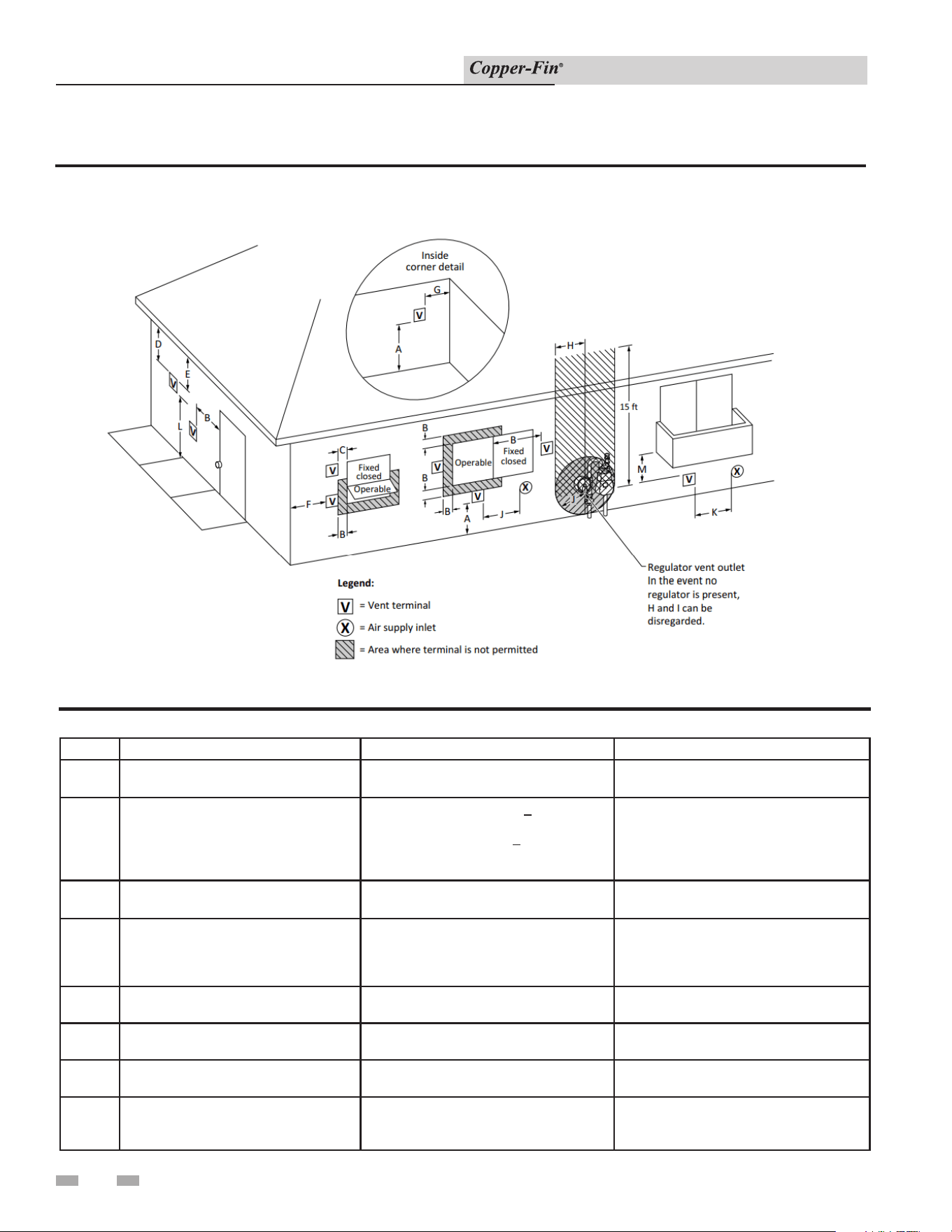
Figure 2-7 Other than Direct Vent Terminal Clearances
Canadian Installations¹ US Installations²
A =
Clearance above grade, veranda, porch,
deck, or balcony
12 in (30 cm) 12 in (30 cm)
B =
Clearance to window or door that may
be opened
6 in (15 cm) for appliances < 10,000 Btuh
(3 kW), 12 in (30 cm) for appliances >
10,000 Btuh (3 kW) and < 100,000 Btuh
(30 kW), 36 in (91 cm) for appliances >
100,000 Btuh (30 kW)
4 ft (1.2 m) below or to side of opening; 1 ft
(300 mm) above opening
C =
Clearance to permanently closed
window
* *
D =
Vertical clearance to ventilated soffit
located above the terminal within a
horizontal distance of 2 ft (61 cm) from
the center line of the terminal.
* *
E = Clearance to unventilated soffit
* *
F = Clearance to outside corner
* *
G = Clearance to inside corner
* *
H =
Clearance to each side of center line
extended above meter / regulator
assembly
3 ft (91 cm) within a height 15 ft (4.6 m)
*
Table 2C Other than Direct Vent Terminal Clearances
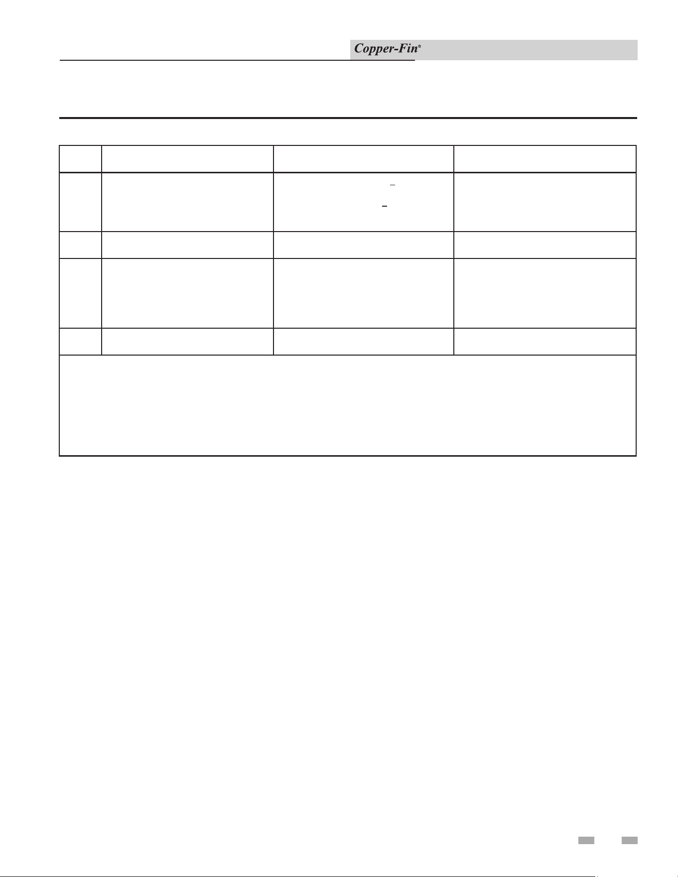
2 Venting (continued)
Installation & Service Manual
19
I =
Clearance to service regulator vent
outlet
3 ft (91 cm)
*
J =
Clearance to nonmechanical air supply
inlet to building or the combustion air
inlet to any other appliance
6 in (15 cm) for appliances < 10,000 Btuh
(3kW), 12 in (30 cm) for appliances >
10,000 Btuh (3 kW) and < 100,000 Btuh
(30 kW), 36 in (91 cm) for appliances >
100,000 Btuh (30 kW)
4 ft (1.2 m) below or to side of opening; 1 ft
(300 mm) above opening
K =
Clearance to a mechanical air supply
inlet
6 ft (1.83 m) 3 ft (91 cm) above if within 10 ft (3 m)
horizontally
L =
Clearance above paved sidewalk or
paved driveway located on public
property
7 ft (2.13 m)† 7 ft (2.13 m) for mechanical draft systems
(Category I appliances). Vents for
Category II and IV appliances cannot be
located above public walkways or other
areas where condensate or vapor can
cause a nuisance or hazard
M =
Clearance under veranda, porch, deck,
or balcony
12 in (30 cm)‡ *
* Clearance in accordance with local installation codes and the requirements of the gas supplier.
† A vent shall not terminate directly above a sidewalk or paved driveway that is located between two single family dwellings
and serves both dwellings.
‡ Permitted only if veranda, porch, deck, or balcony is fully open on a minimum of two sides beneath he oor.
NOTES:
1) In accordance with the current CSA B149.1, Natural Gas and Propane Installation Code
2) In accordance with the current ANSI Z223.1/NFPA 54, National Fuel Gas Code
Table 2C Other than Direct Vent Terminal Clearances (continued)
20
2 Venting
Installation & Service Manual
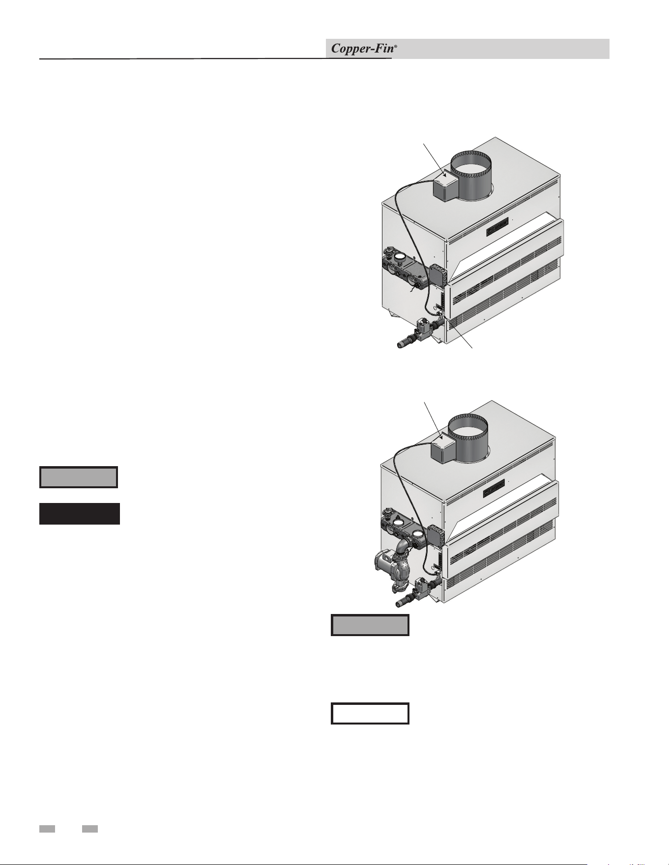
Automatic Vent Damper
This heating boiler is design certified for use with the automatic
vent damper (FIG. 2-8) part number printed on the boiler’s
rating plate. A vent damper is optional on heating boilers above
360,000 Btu/hr. Automatic vent dampers are not required or
fur nished on potable water heaters. Water heaters with inputs
of 360,000 Btu/hr and less may be ordered with the vent damp er
as an option. A vent damper is a useful tool for saving energy
when installed inside the living space where air can cir cu late
freely around the appliance. The vent damper will not save as
much, if any, energy if it is installed in locations such as:
- Unheated garage
- Attic
- Crawlspace
- Mechanical room that is vented outdoors
For installation and maintenance on the vent damper, refer to
the instructions supplied with the vent damper.
Larger input heating boilers and water heaters will have a
jumper plug installed in the ter mi nal block to allow operation
without a damper. Remove the jumper plug from the terminal
block to connect an optional vent damper wire harness (water
heater shown in FIG. 2-9). The jumper plug MUST be in place
if an optional vent damper is not used on water heaters and
larger input heating boilers.
Do not install the vent damper within 6"
(152 mm) of combustible materials.
The damper position indicator must be in a visible
lo ca tion with access for service following in stal la tion. The
damper must be in an open position when appliance main
burners are operating.
The part number for the automatic vent damper required
on this heating boiler is printed on the rating plate. Vent
damper regulations are design certified per the latest edition of
ANSI Z21.66.
VENT DAMPER
TERMINAL
BLOCK
Figure 2-8_CB with Vent Damper and Vent Damper
Terminal Block
⚠ WARNING
The vent damper must be installed directly
on the flue outlet located on the top of
the draft hood (see FIG. 2-8). Do not alter
the wire har ness sup plied with the vent
damper. Follow the instructions supplied
with the vent damper.
⚠ CAUTION
An appliance which is shut down or will
not operate may experience freezing due to
con vec tive air flow down the flue pipe
connected to the unit. Proper freeze
protection must be pro vid ed, see Freeze
Pro tec tion in the Startup Section of this
manual.
⚠ DANGER
Install the vent damper to service only the
single ap pli ance for which it is intended.
If improperly installed, a hazardous
condition such as an ex plo sion or carbon
monoxide poisoning could result.
⚠ WARNING
VENT DAMPER
Figure 2-9_CW with Vent Damper
21
Installation & Service Manual
3 Gas connections
Gas Supply
Verify that the appliance is supplied with the type gas
spec i fied on the rating plate. This appliance is orificed for
operation up to 2000 feet altitude. The ap pli ance will be
derated 4% per 1000 feet above 2000 feet el e va tion. Consult
the factory for installations above 2000 feet elevation. Field
conversions for operation at high altitude must be performed
by certified per son nel only. The appliance will be marked to
indicate suitability for high al ti tude operation.
GAS SUPPLY PRESSURE: Measured at the inlet pres-
sure tap located upstream of the combination gas valve(s)
see FIG.’s 3-5 and 3-6, page 25.
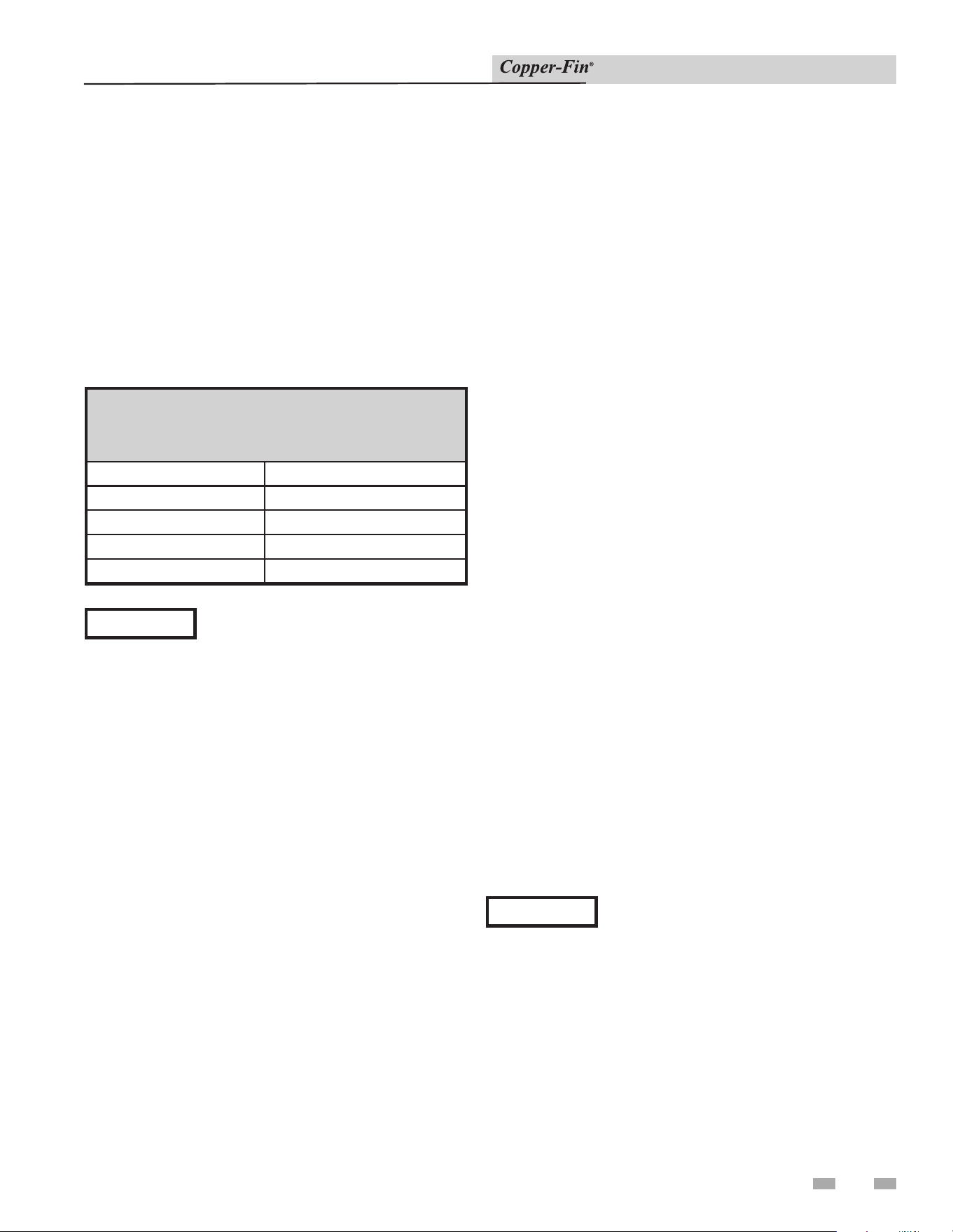
TABLE - 3A
GAS SUPPLY PRESSURE
Max. (Inches Water Column)
Natural Gas LP Gas
14 14
Min. (Inches Water Column) *4.5 11
Min. (Inches Water Column) **5.0 11
*Models 90,000 - 360,000 Btu/hr Only
**Models 399,000 - 500,000 Btu/hr Only
Maximum inlet gas pressure must not exceed the val ue
specified. Minimum value listed is for the purposes of input
adjustment.
MANIFOLD PRESSURE: Measured at the pres sure tap
on the downstream side of the com bi na tion gas valve(s)
(see FIG.’s 3-5 and 3-6, page 25). The gas regulator settings
for single stage and two stage operation are factory set to
supply proper manifold pressure for normal operation. To
check manifold pressure, see Manifold Ad just ment Procedure.
Do not increase manifold pressure beyond spec i fied pressure
settings shown below in Table 3B.
TABLE - 3B
MANIFOLD PRESSURE
Input Gas
Btu/hr
Single and Two-Stage Two Stage
Full or High Fire Settings Low Fire Settings
Natural Gas LP Gas Natural Gas LP Gas
90,000 - 180,000 3.5" 10" 0.9" 2.5"
199,000/201,000 2.9" 7.5" 0.9" 2.5"
215,000 - 399,000 3.5" 10" 0.9" 2.5"
500,000 3.5"
10"
(two valves)
N/A N/A
Gas Pressure Test
1. The appliance must be disconnected from the gas supply
piping system during any pressure testing of that system at
a test pressure in excess of 1/2 PSIG (3.5kPa).
2. The appliance must be isolated from the gas supply piping
system by closing a manual shutoff valve during any
pressure testing of the gas supply piping system at test
pressures equal to or less than 1/2 PSIG (3.5kPa).
3. The appliance and its gas connection must be leak-tested
before placing it in operation.
Gas Connection
1. Safe operation of the appliance requires properly sized gas
supply piping.
2. Gas pipe size may be larger than appliance gas connection.
3. Installation of a union is suggested for ease of service, see
FIG. 3-1 on page 22.
4. Install a manual main gas shutoff valve, outside of the
appliance gas connection and before the gas valve or
manifold connection, when local codes require.
5. A trap (drip leg) MUST be provided by the installer in
the inlet of the gas connection to the appliance, see
FIG. 3-1 on page 22.
6. The combination gas valve has an integral vent lim it ing
device and does not require venting to atmosphere,
outside the building.
7. Optional gas controls may require routing of bleeds and
vents to the atmosphere, outside the building when
required by local codes.
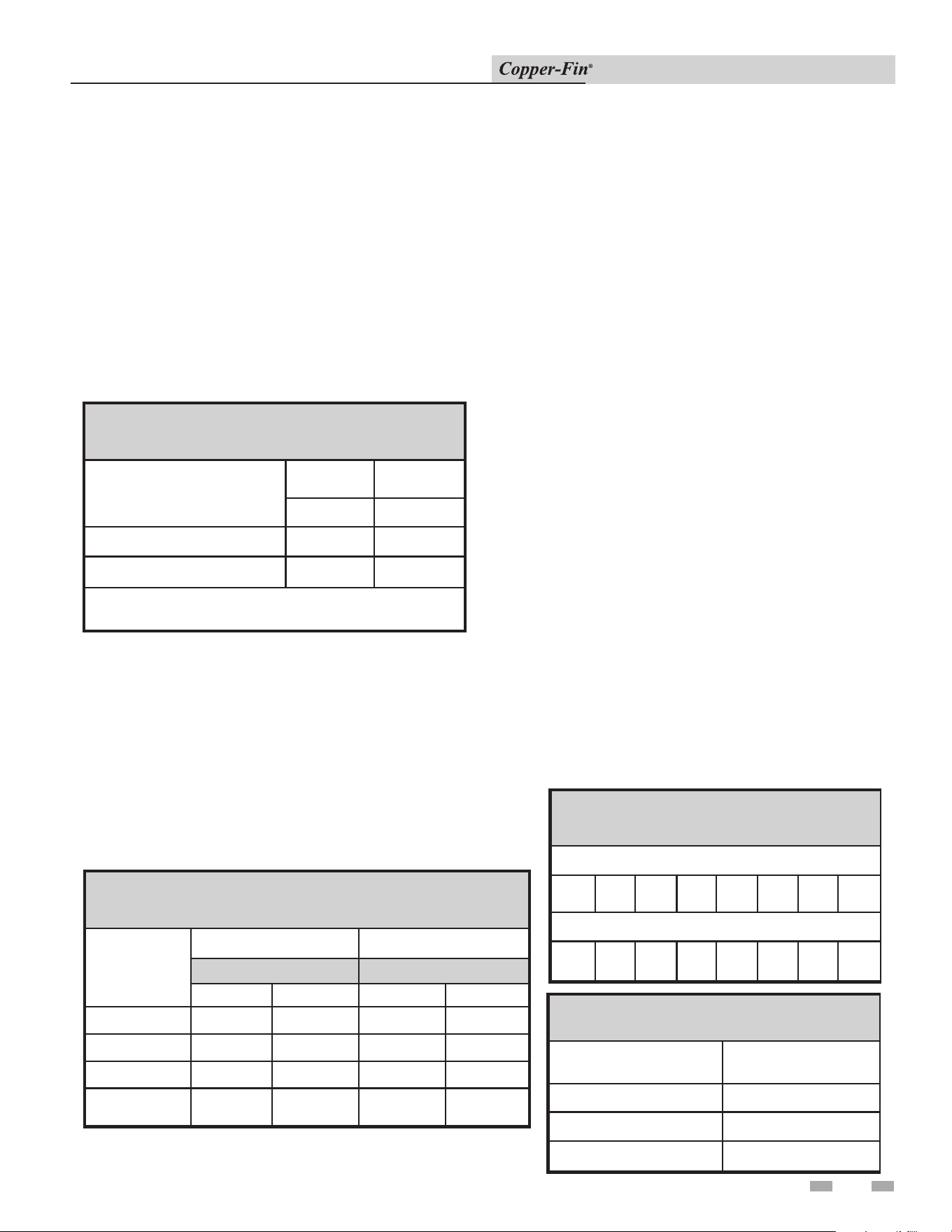
TABLE - 3C
FITTINGS TO EQUIVALENT STRAIGHT PIPE
Diameter Pipe (inches)
3/4 1 1 1/4 1 1/2 2 3 4 5
Equivalent Length of Straight Pipe (feet)
2 2 3 4 5 10 14 20
TABLE - 3D
GAS CONNECTIONS
Btu/hr
INPUT
Pipe Size
90,000 - 135,000 1/2"
180,000 - 315,000 3/4"
360,000 - 500,000 1
22
3 Gas connections
Installation & Service Manual
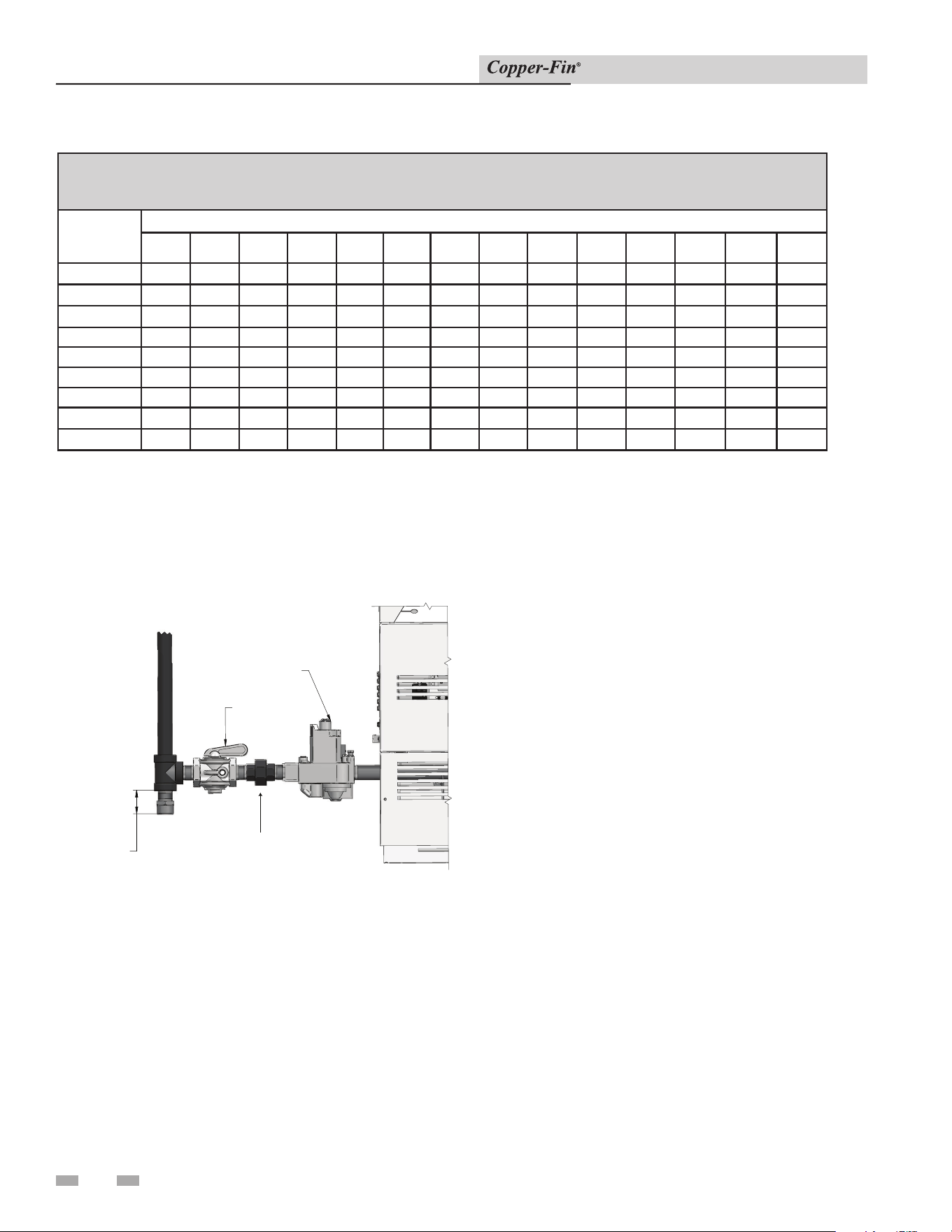
Gas Piping
GAS VALVE
GAS SHUTOFF
TRAP
( DRIP LEG )
UNION
Figure 3-1_Gas Line Connection
All gas connections must be made with pipe joint
com pound resistant to the action of liquefied pe tro leum and
natural gas. All piping must comply with local codes. Tubing
installations must com ply with ap proved standards and
practices. Reference FIG. 3-1 for a typical installation.
Install Piping to Control
1. The gas line should be a separate line direct from the
meter unless the existing gas line is of sufficient capacity.
Verify pipe size with your gas sup pli er.
2. Use new, properly threaded black iron pipe free from
chips. If tubing is used, make sure the ends are cut
squared, deburred and clean. All tubing bends must be
smooth and without deformation. Avoid flexible gas
connections. Internal diameter of flexible lines may not
provide proper volume of gas.
3. Run pipe or tubing to the gas valve or manifold inlet. If
tubing is used, obtain a tube to pipe coupling to connect
the tubing to the gas valve or man i fold inlet.
4. DO NOT OVER TIGHTEN. Over tightening may result in
damage to the gas valves. Valve distortion or malfunction
may result if the pipe is inserted too deeply into the gas
valve.
5. Apply a moderate amount of good quality pipe compound
(DO NOT use Teflon tape) to pipe only, leaving two end
threads bare.
6. Remove seal over gas valve or manifold inlet.
7. Connect pipe to gas valve or manifold inlet. Use wrench
to square ends of the gas valve (FIG. 3-2).
8. For L.P. gas, consult your L.P. gas supplier for expert
installation.
TABLE - 3E
Capacity of Schedule 40 Metallic Pipe in Cubic Feet of Natural Gas Per Hour
(based on .60 specific gravity, 0.30" w.c. pressure drop)
Pipe
Size
(Inches)
Length of Pipe in Straight Feet
10 20 30 40 50 60 70 80 90 100 125 150 175 200
1/2 131 90 72 62 55 N/A N/A N/A N/A N/A N/A N/A N/A N/A
3/4 273 188 151 129 114 104 95 89 83 79 70 63 58 N/A
1 514 353 284 243 215 195 179 167 157 148 131 119 109 102
1 1/4 1,060 726 583 499 442 400 368 343 322 304 269 244 224 209
1 1/2 1,580 1,090 873 747 662 600 552 514 482 455 403 366 336 313
2 3,050 2,090 1,680 1,440 1,280 1,160 1,060 989 928 877 777 704 648 602
2 1/2 4,860 3,340 2,680 2,290 2,030 1,840 1,690 1,580 1,480 1,400 1,240 1,120 1,030 960
3 8,580 5,900 4,740 4,050 3,590 3,260 3,000 2,790 2,610 2,470 2,190 1,980 1,820 1,700
4 17,500 12,000 9,660 8,270 7,330 6,640 6,110 5,680 5,330 5,040 4,460 4,050 3,720 3,460
3 Gas connections (continued)
23
Installation & Service Manual
APPLY WRENCH
TO FLANGE ONLY
WHEN FLANGE
IS USED
APPLY WRENCH FROM
BOTTOM OF GAS CONTROL
TO EITHER SHADED AREA
WHEN FLANGE
IS NOT USED
Figure 3-2_Wrench
IMPORTANT
Upon completion of any piping
con nec tions to the gas system, leak
test all gas con nec tions with a soap
solution while system is un der pressure.
Immediately repair any leaks found in
the gas train or related components. Do
Not op er ate an appliance with a leak in
the gas train, valves or related piping.
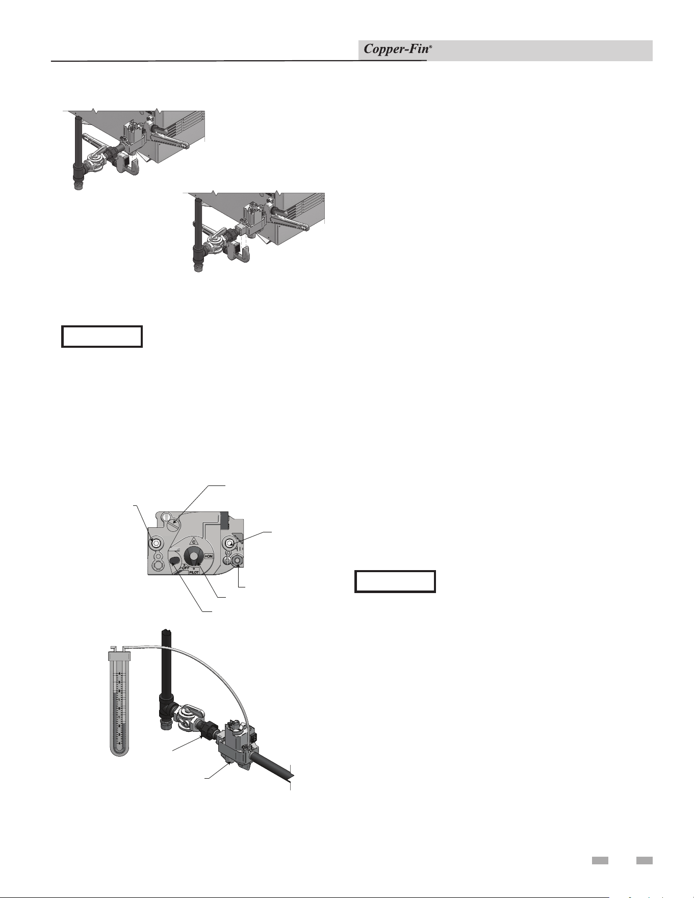
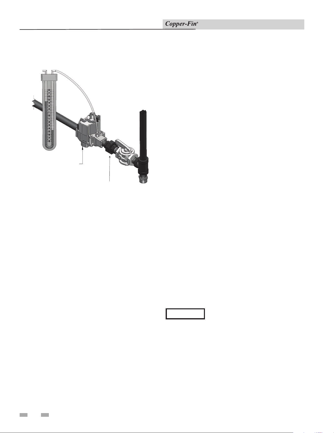
Gas Manifold Pressure Adjustment
Procedure
PRESSURE REGULATOR
ADJUSTMENT
(UNDER SCREW CAP)
OUTLET
PRESSURE TAP
PILOT OUTLET
GAS CONTROL KNOB
RED RESET BUTTON
INLET
PRESSURE
TAP
UNION
GAS VALVE
MANOMETER
Figure 3-3_Manifold Pressure Adjustment
2. Turn gas valve control knob to “PILOT” po si tion on
standing pilot models. Ensure that the stand ing pilot
remains on. If the pilot goes out, follow the “Lighting
Instructions” in Section 6 - Startup for standing pi lot
models to light the pilot. Turn gas valve control knob to
“OFF” po si tion on spark ignition models.
3. Remove the 1/8" hex plug located on the out let side of
the gas valve and install a fitting suitable to connect to a
manometer or magnahelic gauge. See FIG. 3-3. Minimum
range of scale should be up to 5" w.c. for Natural gas
mod els and 10" w.c. for L.P. gas models.
4. The 500,000 Btu/hr model will have two gas valves with
a pressure regulator on each valve. Repeat the following
adjustment pro ce dure to set the manifold pressure on each
gas valve.
5. Remove the pressure regulator adjustment cap screw on
the gas valve. See FIG. 3-3 for location.
6. Turn the power “ON” at the main dis con nect switch.
7. Turn gas valve control knob to “ON” po si tion.
8. Set the thermostat(s) to call for heat.
9. Observe gas regulator pressure when all burn ers are firing.
See Table 3B, Manifold Pressure (page 21) for proper
regulator pressure settings.
10. If adjustment is necessary, turn regulator ad just ment screw
clockwise to raise regulator gas pres sure, counterclockwise
to lower gas pres sure, to proper setting.
Note: Adjustment fitting is plas tic and may require
slightly greater turning force than a metal fitting.
11. Turn the power “OFF” at the main dis con nect switch.
NOTICE
Do not increase regulator pres sure beyond
specified pressure setting.
12. Turn gas valve control knob to “PILOT” po si tion on
standing pilot models. Turn gas valve control knob to
“OFF” position on spark ignition models.
13. Remove fitting from the gas valve and re place the 1/8” hex
plug that was previously removed and tighten.
14. Repeat the adjustment procedure for the sec ond gas valve
on the 500,000 Btu/hr model.
15. Turn the gas valve control knob(s) to “ON” position.
16. Turn the power “ON” at the main dis con nect switch. The
appliance is now ready to op er ate.
If manifold pressure can not be properly adjusted, use the
procedure on page 24 to check gas supply pressure with a
manometer connected to the inlet pressure tap on the gas
control.
1. Turn the power “OFF” at the main dis con nect switch.
24
Installation & Service Manual
Checking Gas Supply Pressure
GAS VALVE
MANOMETER
GAS SUPPLY PRESSURE
UNION
Figure 3-4_Gas Supply Pressure
1. Turn the power “OFF” at the main dis con nect
switch.
2. Turn gas valve control knob(s) to the “OFF” position.
3. The 500,000 Btu/hr model will have two gas valves.
Turn the gas valve control knob on each valve to the
“OFF” position.
4. Shut off gas supply at the manual valve in the gas piping
to the appliance. If fuel supply is L.P. gas, shut off gas
supply at the tank.
5. Remove the 1/8" hex plug, located on the “inlet” side of
the gas valve and install a fitting suitable to connect to
a manometer or magnahelic gauge. On two gas valve
models, remove the hex plug from the gas valve closest
to the gas sup ply connection. Range of scale should be
14" w.c. or greater to check inlet pressure. See FIG.’s 3-3
and 3-4 for location.
6. Turn on gas supply at the manual valve, turn on L.P. gas
at tank if required.
7. Turn the power “ON” at the main dis con nect switch.
8. Turn gas valve control knob to “PILOT”
po si tion on standing pilot models. Follow the “Lighting
Instructions” in Section 6 - Startup for standing pilot
models to light the pilot . Turn gas valve control knob
to the “ON” po si tion when the pilot is established. Turn
gas valve control knob(s) to the “ON” position on spark
ig ni tion models.
9. Set the thermostat(s) to call for heat.
10. Observe the gas supply pressure with all burn ers firing.
Ensure inlet pressure is within specified range. Check
gas supply pressure with all other gas fired appliances in
operation to en sure prop er gas volume during periods of
peak gas usage.
11. If gas pressure is out of range, contact gas utility, gas
supplier, qualified installer or service agen cy to determine
necessary steps to provide prop er gas pressure to the
appliance.
12. If the gas supply pressure is within the spec i fied range,
proceed with the following steps to return the appliance to
service.
13. Turn the power “OFF” at the main dis con nect switch.
14. Turn gas valve control knob to “PILOT” po si tion on
standing pilot models. Turn gas valve control knob(s) to
“OFF” position on spark ig ni tion mod els.
15. Shut off gas supply at the manual valve in the gas piping
to the appliance. If fuel supply is L.P. Gas, shut off gas
supply at the tank.
16. Remove the manometer and related fittings from the
“inlet” side of the gas valve, replace 1/8" hex plug in gas
valve.
17. Turn on gas supply at the manual valve, turn on L.P. Gas
at tank if required.
18. Turn the power “ON” at the main dis con nect switch.
19. Turn the gas valve control knob(s) to the “ON” position. If
the pilot is not burning, follow the “Light ing Instructions”
in Section 6 - Startup for standing pilot models to light the
pilot. Spark ignition models will au to mat i cal ly light the
pilot on a call for heat.
20. Set the thermostat to call for heat. The appliance is now
ready to operate.
IMPORTANT
Upon completion of any testing on the
gas system, leak test all gas connections
with a soap solution while main burners
are operating. Im me di ate ly repair any
leak found in the gas train or re lat ed
components. Do Not operate an appliance
with a leak in the gas train, valves or related
piping.
Check burner performance by cycling the system while you
observe burner response. Burners should ignite promptly.
Flame pattern should be stable, see the “Main te nance Section
-Normal Flame Pattern”. Turn system off and allow burners
to cool, then cycle burners again to en sure proper ignition and
flame characteristics.
3 Gas connections
3 Gas connections (continued)
25
Installation & Service Manual
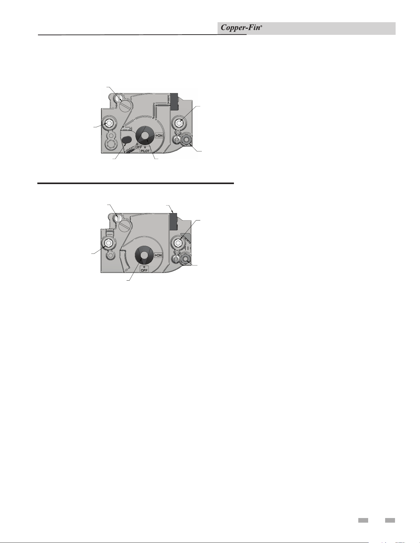
Combination Gas Valves
WIRING TERMINALS
PRESSURE REGULATO
R
A
DJUSTMENT (UNDER CAP SCREW)
INLET PRESSURE TAP
GAS CONTROL KNOB
PILOT OUTLET
OUTLET
PRESSURE TA
P
PRESSURE REGULATO
R
A
DJUSTMENT (UNDER CAP SCREW)
INLET PRESSURE TAP
RED RESET BUTTON
PILOT OUTL
ET
OUTLET
PRESSURE TA
P
GAS CONTROL KNOB
Figure 3-5_F1 Gas Valve, standing pilot
Figure 3-6_F9 Gas Valve, spark ignition
Each unit has a combination gas valve(s) to control the
gas supply to the burners. The 500,000 Btu/hr model has
two combination gas valves to supply gas to the burners.
The com bi na tion valve con sists of a gas regulator and
two valve seats to meet the requirements for redundant
gas valves. The valve has a gas control knob that must
remain in the open po si tion at all times when the
appliance is in service. Each gas valve has pres sure taps
located on the inlet and outlet sides. Manifold pressure
is adjusted using the regulator located on the valve. The
manifold pres sure is pre set at the factory and adjustment
is not usu al ly re quired. If the manifold pressure is to be
ad just ed, follow the “Gas Manifold Pressure Ad just ment
Pro ce dure”, page 23 for proper adjustment.
Venting of Combination Gas Valves
The combination gas valve regulator used on all mod els
is equipped with an integral vent limiting orifice. The
vent limiter ensures that the volume of gas emitted from
the valve does not exceed the maximum safe leak age
rate allowed by agency re quire ments. Com bi na tion gas
valve/regulators equipped with integral vent limiters
are not re quired to have vent or relief lines piped to the
outdoors. A dust cap is provided at the vent termination
point on the valve to prevent block age of the vent
limiter by foreign material. The com bi na tion gas valve
regulator with an integral vent limiter complies with
the safety code requirements of CSD-1, CF-190(a) as
shipped from the manufacturer with out the in stal la tion
of additional vent lines.
Two Stage Burner Control System
The 315,000 through 399,999 Btu/hr boiler models (M9)
will be equipped with a two stage gas valve to control
high/low burner op er a tion. The 500,000 Btu/hr boiler
mod el achieves two stage burner firing by staging the
operation of the two combination gas valves.

26
4 Hydronic piping
Installation & Service Manual
RELIEF VALVE
Figure 4-1_Relief Valve - CBN315-500
This appliance is supplied with a relief valve(s) sized in
accordance with ASME Boiler and Pressure Ves sel Code,
Section IV (“Heating Boilers”). The re lief valve(s) is mounted
directly into the heat ex chang er inside the header (see
FIG.’s 4-1 and 4-2). To pre vent water damage, the dis charge
from the relief valve shall be piped to a suit able floor drain
for disposal when relief occurs. No reducing couplings or
other restrictions shall be installed in the discharge line. The
discharge line shall allow complete drainage of the valve and
line. Relief valves should be manually operated at least once
a year.
⚠ CAUTION
Avoid contact with hot discharge water.
FLOW SWITCH
Figure 4-2_Water Flow Switch - CBN315-500
A water flow switch is available as a factory sup plied option on
all heating boilers and water heaters (see section 7). The flow
switch should be wired between terminals X and B. Remove
the jumper between the X and B terminals on the terminal
strip. This wiring connection installs the flow switch in the
24 VAC safety cir cuit to prove water flow before main burner
ig ni tion. A flow switch installed with the fac to ry sup plied
minimum adjustment setting requires a spe cif ic minimum flow
to make the switch and start burner operation. The flow rate
required is a function of the diameter of pipe and tee used for
installation. Ensure that the pump installed on the boiler will
supply adequate flow to make the flow switch con tacts and
operate the appliance.
Relief Valve
Water Flow Switch (if equipped)
4 Hydronic piping (continued)
27
Installation & Service Manual
A water flow switch meets most code re quire ments for
a low-water cut off device on boil ers requiring forced
cir cu la tion for operation.
Low Water Cutoff (if equipped)
A hot water boiler installed above radiation level must be
provided with a low water cutoff device either as part of
the unit or installed at the time the boiler is installed. An
electronic low water cutoff is available as a kit on all units.
Low water cutoffs should be in spect ed every six months,
including flushing of float types.
TABLE - 4A
MINIMUM REQUIRED FLOW
FOR HEATING BOILER
Input Btu/hr GPM Flow
315,000 13
360,000 14.9
399,000 16.5
500,000 20.7
NOTICE
Minimum flow is based on a 40°F
temper a ture rise across the boiler.
Minimum flow may not prove a flow
switch installed in the boiler piping.
Use care when operating a boiler at
or near the min i mum recommended
flow because conditions unique to the
installation (system pressure, operation
of multiple zone valves, glycol,
variations in flow, etc.,) may result in
overheating of the boiler water caus ing
noise or nuisance operation of safety
limit con trols. Typical heat ing boiler
applications will op er ate with a 20°F to
30°F temperature rise across the boiler.
Typical Heating Boiler Installations
General Plumbing Rules
1. Check all local codes.
2. For serviceability of the boiler, always install unions.
3. Always pipe pressure relief valves to an open drain.
4. Locate system air vents at the highest point of the system.
5. Expansion tank must be installed near the boil er and on
the suction side of the pump.
6. Support all water piping.
Placing the Boiler in Operation
Filling the System: All air must be purged from the system for
proper operation. An air scoop and air vent must be located
close to the boiler outlet and there should be a minimum
distance between the cold water feed and the system purge valve.
1. Close all drain cocks and air vents.
2. Open the makeup water valve and slowly fill the system.
3. If a makeup water pump is employed, ad just the pressure
to provide a minimum of 12 psi at the highest point in the
system. If a pressure regulator is also installed in the line,
it should be adjusted to the same pressure.
4. Close all valves. Purge one circuit at a time as follows:
A. Open one circuit drain valve and let the water drain
for at least five minutes. Ensure that there are no air
bubbles visible in the wa ter stream before closing the
drain valve.
B. Repeat this procedure for each circuit.
5. Open all valves after all circuits have been purged. Make
sure there are no system leaks.
NOTICE
Do not use petroleum based stop
leak products. All system leaks must
be repaired. The constant addition of
make-up water can cause damage to
the boiler heat exchanger due to scale
accumulation. Scale reduces flow and
heat transfer, causing overheating of the
heat exchanger.
6. Run the system circulating pump for a min i mum of 30
minutes with the boiler turned off.
7. Open all strainers in the system and check for debris.
8. Recheck all air vents as described in step 4, General
Plumbing Rules.
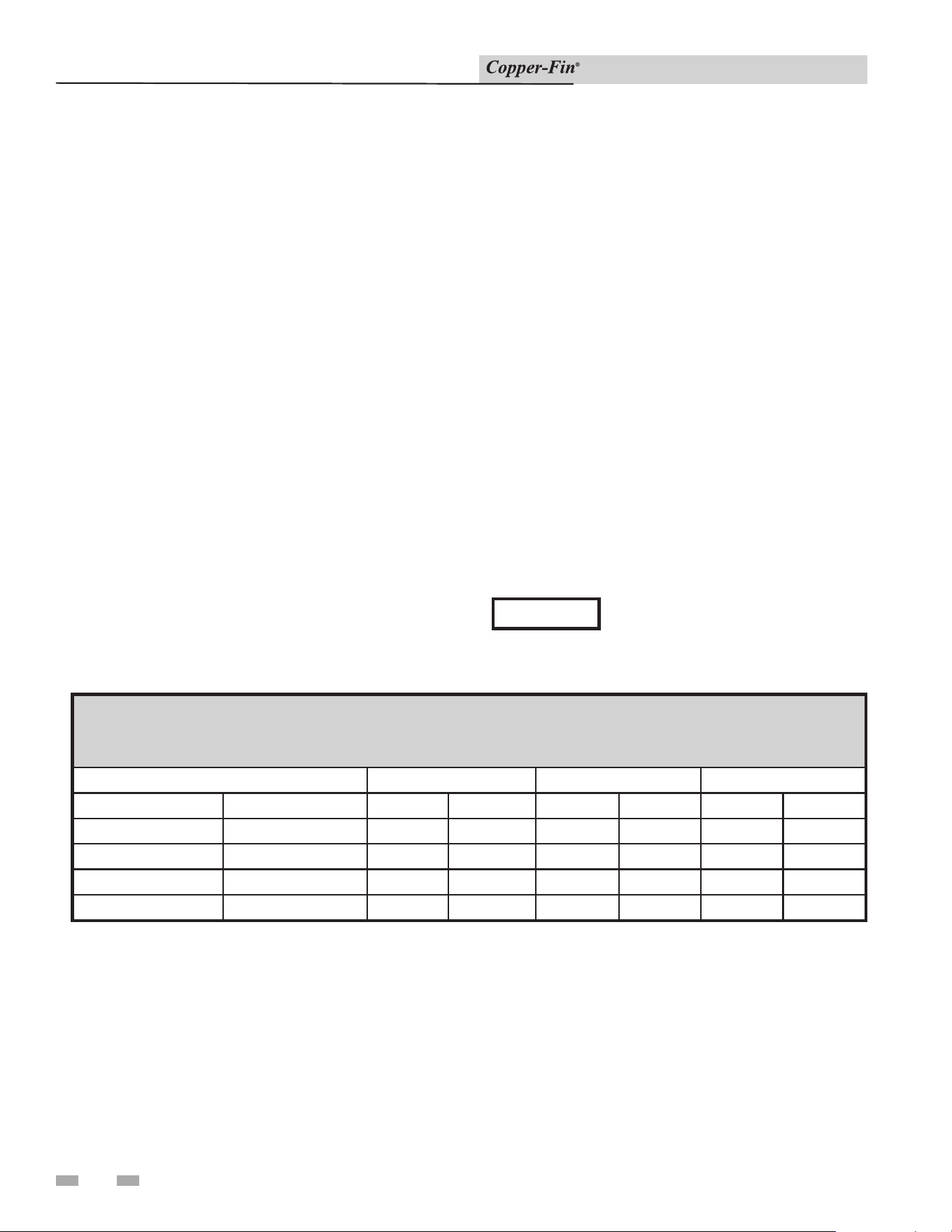
28
4 Hydronic piping
Installation & Service Manual
9. Inspect the liquid level in the expansion tank. The system
must be full and under normal operating pressure to ensure
proper water level in the expansion tank. Ensure that
diaphragm type ex pan sion tanks are properly charged and
not water logged.
10. Start the boiler according to the Section 6 - “Start-Up
Instructions” in this manual. Operate the system, including
the pump, boiler and radiation units, for one hour.
11. Recheck the water level in the expansion tank. If it exceeds
half the tank volume, open the tank to reduce the water
level. Recheck pres sure charge on diaphragm type tanks.
12. Shut down the entire system and vent all ra di a tion units
and high points in the system.
13. Close the water makeup valve and check the strainer and
pressure reducing valve for sediment or debris. Reopen the
water makeup valve.
14. Verify system pressure with the boiler pres sure gauge
before beginning regular operation.
15. Within three days of start-up, recheck and bleed all air vents
and the expansion tank using these instructions.
TABLE - 4B
SYSTEM TEMPERATURE RISE CHART
Based on Boiler Output in Btu/hr
Btu/hr
20°F rT 30°F rT 40°F rT
Input Output GPM Ft/hd GPM Ft/hd GPM Ft/hd
315,000 258,000 26.0 4.1 17.3 2.2 13.0 1.3
360,000 295,000 29.7 5.4 19.8 2.5 14.9 1.5
399,000 327,000 -- -- 22.0 3.6 16.5 2.0
500,000 410,000 -- -- 27.6 6.6 20.7 3.5
Piping of the Boiler System
The drawings in this section (see FIG’s 4-4 through 4-6)
show typical heating boil er piping installations. Before
beginning the in stal la tion, consult local codes for specific
plumb ing re quire ments. The installation should provide
unions and valves at the inlet and outlet of the boil er so it
can be isolated for service. The boiler cir cu lat ing pump, air
sep a ra tor, expansion tank and oth er components required
for proper installation must be purchased locally. An air
separation device must be supplied in the in stal la tion piping
to eliminate trapped air in the system. Lo cate a system
air vent at the highest point in the sys tem. The system
must also have a properly sized expansion tank installed.
Typically, an air charged di a phragm-type expansion tank
is used. The expansion tank must be installed close to the
boiler and on the suction side of the system pump to ensure
proper op er a tion. A water meter to monitor makeup water
is recommended. Makeup water volume should not exceed
5% of total system per year. Install a Y-strainer or equivalent
multi-purpose strainer just before the boiler pump at the
inlet of the heat exchanger. This item is used to remove
system debris from older hydronic systems and to protect
newer systems.
⚠ CAUTION
This boiler system should not be
operated at less than 12 PSIG (83 kPa)
(Non-metallic system piping must have
an oxygen barrier to be considered a
closed loop).
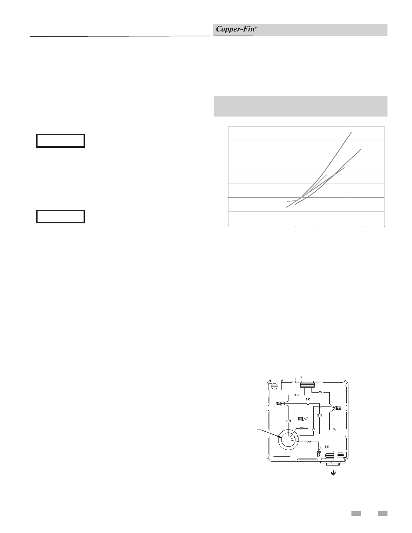
4 Hydronic piping (continued)
29
Installation & Service Manual
Hot water pip ing must be supported by suitable hangers or
floor stands, NOT by the boiler. Copper pipe systems will
be subject to considerable expansion and con trac tion. Rigid
pipe hangers could allow the pipe to slide in the hanger
resulting in noise transmitted into the system. Padding
is recommended on rigid hangers installed with a copper
system. The boiler pressure relief valve must be piped to a
suitable floor drain. See the relief valve section on page 26
of this manual.
⚠ CAUTION
A leak in a boiler system will cause the
system to intake fresh water constantly,
which will cause the tubes to accumulate
a lime/scale build up. This will cause a
NON-WARRANTABLE FAILURE.
Water Connections Heating Boilers Only
All water heaters and heating boilers with inputs of 315,000 -
500,000 Btu/hr have 2" NPT.
⚠ CAUTION
Field installed reducing bushings may
de crease flow re sult ing in boiler noise or
flashing to steam.
Circulator Pump Requirements
This is a low mass, high efficiency hot water boil er which
must have adequate flow for quiet, efficient op er a tion. The
boiler circulating pump must be pur chased locally. The boiler
circulator pump must operate con tin u ous ly while the boiler
is firing. Pump selection is critical to achieve proper op er-
a tion. A pump should be selected to achieve proper system
design water temperature rise. A heat ex chang er pressure
drop chart (Table 4C) is provided to assist in proper pump
selection. Also provided is a System Temperature Rise Chart
(Table 4B). This table provides GPM and boiler head-loss
at various temperature rises for each boiler based on Btu/
hr input. Temperature rise is the difference in boiler inlet
temperature and boiler outlet temperature while the boiler is
firing. Example: The boiler inlet tem per a ture is 160°F and the
boiler outlet temperature is 180°F, this means that there is a
20°F tem per a ture rise across the boiler.
Circulator Pump Specifications
1. Maximum operating pressure for the pump must exceed
system operating pressure.
2. Maximum water temperature should not ex ceed
nameplate rating.
TABLE - 4C
HEAT EXCHANGER PRESSURE DROP CHART
CB
3
CB 399
3
4
5
6
7
FT/HD
CB
3
CB
399
0
1
2
3
4
5
6
7
0510 15 20 25
FT/HD
Gallons
per
Minute
315
CB 360
CB 500
315
CB
360
CB
500
30 35
Circulator Pump Operation (Heating Boilers
Only)
Boilers are equipped with a relay for controlling the circulation
pump for the hot water loop. The relay turns ON and OFF in
response to the “W” input from the wall thermostat or zone
control.
The field installed boiler pump MUST NOT exceed 1 h.p. For
continuous pump operation, wire the system pump to the 120V
supply. The pump should be connected at the junction box as
shown in FIG. 4-3.
TO
CIRCULATION
PUMP
120V
SUPPLY
TO
UNIT
Figure 4-3_Boiler Wiring - Circulation Pump to Junction Box
3. Cast iron circulators may be used for closed loop systems.
4. A properly sized expansion tank must be in stalled near the
boiler and located on the suction side of the pump.
30
4 Hydronic piping
Installation & Service Manual
PUMP INSTALLATION AND MAIN TE NANCE: The
boiler circulating pump must be purchased lo cal ly. For
installation and maintenance information on the circulator
pump, refer to the pump man u fac tur ers in struc tion package
included with the pump.
The installer must ensure that the boiler has ad e quate flow
without excessive temperature rise. The tem per a ture rise on
a multiple zone system should be made when only the zone
with the longest length and/or high est head loss is open.
Low system flow can result in overheating of the boiler water
which can cause short burner on cycles, system noise and in
extreme cases, a knocking flash to steam. Sys tem noise may
also indicate an oversized boiler.
⚠ CAUTION
At no time should the system pressure be
less than 12 PSIG (83 kPa) (Non-metallic
system piping must have an oxygen
barrier to be considered a closed loop).
A boiler operated with an inlet temperature
of less than 140°F (60°C) must have a low
temperature bypass to prevent problems
with condensation. A 1 1/2" LTV Valve Kit
may be used. Follow the piping diagram in
FIG. 4-5 to complete installation.
Primary/Secondary Boiler Piping
Heating boilers with inputs of 315,000 - 500,000 Btu/hr or
larg er installed on multiple zone systems are rec om mend ed
to be installed with a primary/sec ond ary piping sys tem as
shown in FIG. 4-4. A primary/secondary piping system uses a
dedicated pump to supply flow to the boiler only. This pump
is sized based on de sired boiler flow rate, heat exchanger
head loss and head loss in the sec ond ary system piping only.
The secondary pump, in stalled in the boiler piping, ensures
a constant wa ter flow rate to the boiler for proper operation.
Boiler installation with a primary/secondary piping sys tem
can prevent noise problems caused by low sys tem water
flows. A primary/secondary piping system is recommended
on any boiler where low water flow conditions may present
an operational problem.
A primary/secondary piping system is ideal for sys tems filled
with a propylene glycol and water mix ture. A glycol and
water mixture is more dense than water only and may result
in a lower boiler flow rate. A lower boiler flow may cause
noise on operation or short cycling of the burners. A larger
secondary pump may be used on a primary/sec ond ary system
to pro vide an increased boiler flow rate. A glycol and water
system may require from 10 to 20% more flow to compensate
for the in creased density of the glycol and its effect on the
heat transfer process in the boiler. The exact in crease in flow
that may be required is based on the type and percentage of
glycol added to the boiler system. Consult the manufacturer
of the glycol for additional recommendations when using a
gly col and water fill for your boiler system.
NOTICE
4 Hydronic piping (continued)
31
Installation & Service Manual
Low Temperature Bypass
Requirements
This piping is like a primary/secondary boiler installation with a
bypass in the secondary boil er piping. Inlet water temperatures
below 140°F (60°C) can excessively cool the prod ucts of
combustion re sult ing in condensation on the heat exchanger and
in the flue. Condensation can cause operational prob lems, bad
combustion, sooting, flue gas spillage and reduced service life of
the vent system and related components. The bypass allows part
of the boiler discharge water to be mixed with the cooler boiler
return water to in crease the boiler inlet temperature above 140°F
(60°C). This should prevent the prod ucts of com bus tion from
condensing in most in stal la tions.
The bypass should be fully sized with a bal anc ing valve to allow
for proper adjustment. A valve must also be provided on the
boiler discharge, after the by pass. Closing this discharge
valve forces water through the bypass. Start boiler adjustment
with the bypass valve in the full open position and the boiler
discharge valve half open. A small amount of the high er
temperature boiler discharge water is mixed with the system
water to maintain the de sired lower system tem per a ture. A
remote low tem per a ture range operator is recommended to
control the boiler operation for temperatures lower than 100°F.
This remote op er a tor should be wired across the R and W
terminals (see Room Ther mo stat Connection and Terminal Strip
Instructions in Section 5 of this manual).
Three Way Valves
The installation of a three way valve on this boiler is not
generally recommended because most piping meth ods allow the
three way valve to vary flow to the boil er. This boiler is a low
mass, high ef fi cien cy unit which requires a constant water flow
rate for proper op er a tion.
Low flow rates can re sult in overheating of the boiler water
which can cause short burner on cycles, system noise and in
extreme cases, a knocking flash to steam. These conditions can
cause operational prob lems and non-warrantable failures of the
boiler. If a three way valve must be installed, please pipe in a
primary/secondary system. Based on boiler sizing and system
flow requirements, this piping may still result in boiler short
cycling.
Boiler Flow Rates
The heat exchanger is generally capable of op er at ing within the
flow rates of a residential heating system. Should the flow rate
exceed the maximum allowable flow rate through the boiler 30
GPM) an external bypass must be installed. The bypass should
be fully sized with a balancing valve to al low for proper ad just-
ment of flow. Flow rate can be determined by measuring the
temperature rise through the boiler.
The basic guide for minimum flow in this boiler is based on a
40°F temperature rise in most in stal la tions. Low er flow and
a higher temperature rise is acceptable if the boiler system is
specifically de signed for the char ac ter is tics of a higher tem-
per a ture rise. A system not specifically designed for a higher
temperature rise may experience over heat ing of the boiler
water. This can cause short burn er on cycles, system noise and
in ex treme cases, a knocking flash to steam. These con di tions
can lead to operational problems and non-war rant able fail ures
of the boiler. High temperature rise systems must be designed
by a qualified engineer.
TABLE - 4D
MAXIMUM FLOW FOR HEATING BOILER
The maximum flow rate through the boiler with a copper
heat exchanger must not exceed the following:
Model Maximum Flow
Maximum Flow for
CuNi Heat Exchanger
90,000 - 500,000 30 GPM 38 GPM
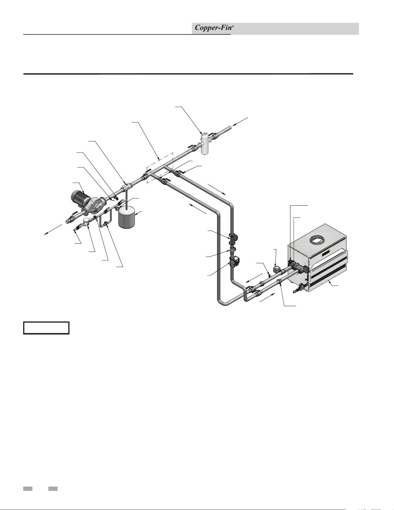
32
4 Hydronic piping
Installation & Service Manual
Primary / Secondary Piping
DIR #2000570578_000
DIRT SEPARATOR
(RECOMMENDED)
EXPANSION TANK
AIR SEPARATOR
PRESSURE REDUCING VALVE
BACK FLOW PREVENTER
BALL VALVE
(TYPICAL)
UNION (TYPICAL)
PRESSURE RELIEF
VALVE
FLOW CHECK
VALVE (TYPICAL)
BOILER
TEMPERATURE / PRES
SURE
GAUG
E
PRESSURE GAUGE
DRAIN
DRAIN POINT
(TYPICAL)
BOILER CIRCULATOR
SY
STEM SUPPLY SENSOR
(WHEN USED)
SYSTEM CIRCULATOR
FROM SYSTEM
MAKE UP WATER
NOT TO EXCEED 4 PIPE DIA OR MAX. OF 12" APART
Y-STRAINER
MAY SUBSTITUTE
LOW LOSS HEADER
FLOW SWITCH
TO SYSTEM
WATER METER
Figure 4-4_Primary / Secondary Piping of a Single Boiler
Please note that these illustrations are meant to show system piping concept only, the installer is responsible for
all equipment and detailing required by local codes.
NOTICE
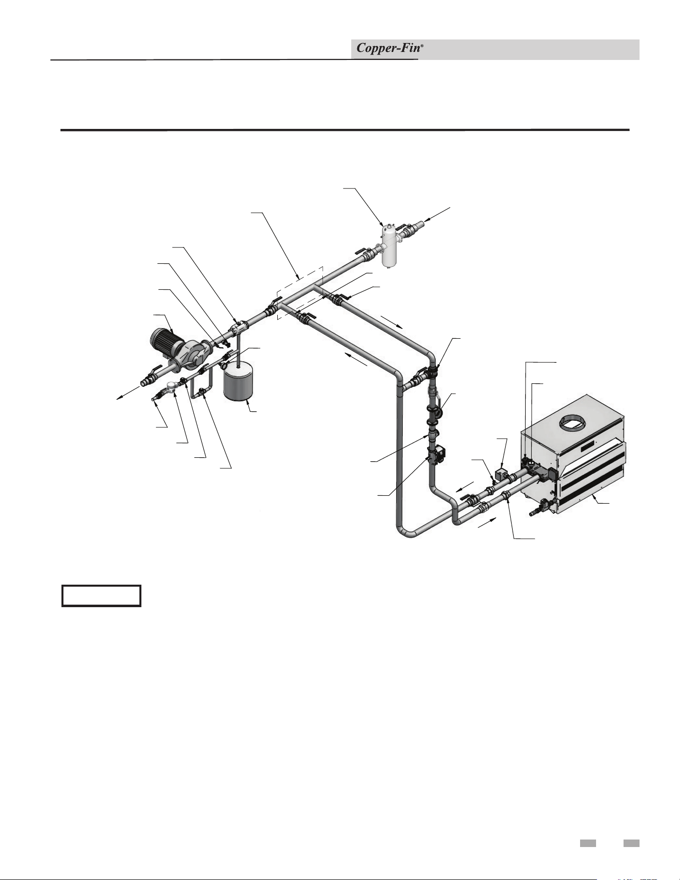
4 Hydronic piping (continued)
33
Installation & Service Manual
Figure 4-5_Single Boiler - Primary / Secondary with Low Temperature Bypass
DIR #2000570577_000
DIRT SEPARATOR
(RECOMMENDED)
DIR #2000570577_00
0
EXPANSION TANK
AIR SEPARATOR
PRESSURE REDUCING VALVE
BACK FLOW PREVENTER
BALL VALVE
(TYPICAL)
UNION (TYPICAL)
PRESSURE RELIEF
VALVE
FLOW CHECK
VALVE (TYPICAL)
BOILER
TEMPERATURE / PRESSURE
GAUGE
PRESSURE GAUGE
DRAIN
DRAIN POINT
(TYPICAL)
BOILER CIRCULATOR
SYSTEM SUPPLY SENSOR
(WHEN USED)
SYSTEM CIRCULATOR
TO SYSTEM
MAKE UP WATER
NOT TO EXCEED 4 PIPE DIA OR MAX. OF 12" APART
Y-STRAINER
MAY SUBSTITUTE
LOW LOSS HEADER
LOW TEMPERATURE BYPASS
FLOW SWITCH
FROM SYSTEM
WATER METER
Primary / Secondary Piping
Please note that these illustrations are meant to show system piping concept only, the installer is responsible for
all equipment and detailing required by local codes.
NOTICE
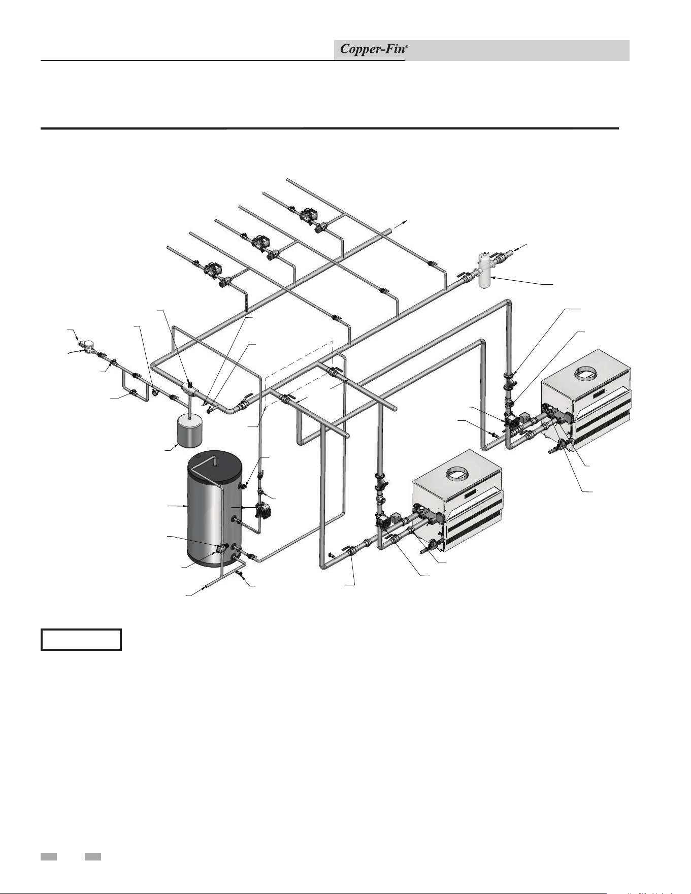
34
4 Hydronic piping
Installation & Service Manual
Primary / Secondary Piping
Figure 4-6_Multiple Boilers Zoned with Circulators
EXPANSION
TANK
AIR SEPARATOR
PRESSURE
REDUCING
VALVE
BACK FLOW
PREVENTER
BALL VALVE
(TYPICAL)
PRESSURE RELIEF
VALVE
(TYPICAL)
FLOW CHECK
VALVE (TYPICAL)
INDIRECT DHW
TANK
BOILER 1
PRESSURE
GAUGE
DRAIN
( TYPICAL )
DRAIN POINT
(TYPICAL)
COLD WATER IN
HOT WATER OUT
MAKE UP WATER
Y-STRAINER
(TYPICAL)
TEMPERATURE
LOOP 1
TEMPERATURE
LOOP 2
TEMPERATURE
LOOP 3
BOILER 2
FROM SYSTEM
TO SYSTEM
DOMESTIC
HOT WATER
CIRCULATOR
BOILER CIRCULATOR
TEMPERATURE /
PRESSURE GAUGE
( TYPICAL)
UNION (TYPICAL)
ANTI-SCALD
MIXING VALVE
SYSTEM SUPPLY
SENSOR
( WHEN USED )
PRESSURE
RELIEF
VALVE
MAY
SUBSTITUTE LOW
LOSS HEADER
NOT EXCEED
12" APART
DRAIN
FLOW CHECK
VALVE
WATER
METER
DIR #2000570579_000
DIRT SEPARATOR
(RECOMMENDED)
Please note that these illustrations are meant to show system piping concept only, the installer is responsible
for all equipment and detailing required by local codes.
NOTICE
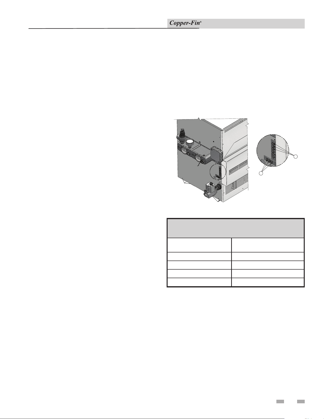
5 Electrical connections
35
Installation & Service Manual
This appliance is wired for 120 VAC service. The appliance,
when installed, must be electrically ground ed in accordance
with the requirements of the authority having jurisdiction or
in the absence of such re quire ments, with the latest edition of
the National Electrical Code ANSI/NFPA No. 70. When the
unit is in stalled in Canada, it must conform to the CSA C22.1,
Ca na di an Electrical Code, Part 1 and/or local Electrical
Codes.
1. All wiring between the appliance and field
in stalled devices shall be made with type T wire
[63° F(35° C) rise].
2. Line voltage wire exterior to the appliance must be
enclosed in approved conduit or approved metal clad
cable.
3. The pump must run continuously when the appliance is
being fired.
4. To avoid serious damage, DO NOT en er gize the
appliance until the system is full of water. Serious
damage may result.
5. Provide the unit with proper overload protection.
6. Install a wall thermostat on the inside wall. DO NOT
install the thermostat in an area affected by drafts,
sunlight, light fixtures, hot or cold water pipes or near
a fireplace. See “Terminal Strip Con nec tion of a Room
Thermostat” (this page), for prop er wiring con nec tion.
Boiler Operating Temperature Control
The operating temperature control is located in the control
panel, behind the control panel front ac cess door. The
sensing element for the operator is placed in a bulbwell
installed in the heat exchanger. Carefully observe the inlet
water temperature on the initial boiler on cycles. The exact
temperature set point is based on your system’s requirements.
Turn the con trol set point dial to the desired operating water
tem per a ture. Observe the boiler discharge tem per a ture after
each set point adjustment to ensure prop er operation.
Room Thermostat or Remote Thermostat
Connection to Terminal Strip
A room thermostat or remote temperature control may be
connected to the boiler. The room ther mo stat should be
installed on an inside wall, away from the influences of drafts,
hot or cold water pipes, lighting fixtures, televisions, sun rays
or fire plac es. Follow the manufacturers instructions supplied
with the ther mo stat for proper installation and ad just ment.
The boiler is equipped with a terminal strip on the left side of
the control panel to allow easy connection (FIG. 5-1).
Remove the jumper between the R and W terminals on the terminal
strip. Refer to the chart in this section (Table 5A) to determine
maximum allowable length and wire gauge recommended to
connect the switching con tacts of the room thermostat to the
R and W terminals on the terminal strip. Connection to the
terminal strip will allow the room thermostat to make and break
the 24 VAC boiler control circuit turning the boiler on and off
based on the room ambient temperature require ments. Set the
boiler operating temperature control as described in this section.
DETAIL
B
A
Figure 5-1_Terminal Strip Connections
TABLE - 5A
TERMINAL STRIP WIRING
Wire Gauge
Allowable Length
Maximum
12 GA 100 ft.
14 GA 75 ft.
16 GA 50 ft.
18 GA 30 ft.
Power Venter Connection to Terminal Strip
A terminal connection strip is provided for ease of connection for
Power Venting Systems, see FIG. 5-1, inset A.
A field supplied powered venter or powered louver/damper may
be connected to the boiler via a terminal strip located on the left
side of the unit, see FIG. 5-1, inset B.
A 24 VAC relay can be powered from this location when a call for
heat has been established. A proving switch can be interlocked
back to the appliance to ensure its operation before the appliance
is allowed to fire.
Reference the wiring diagrams on pages 65 through 68 of this
manual.
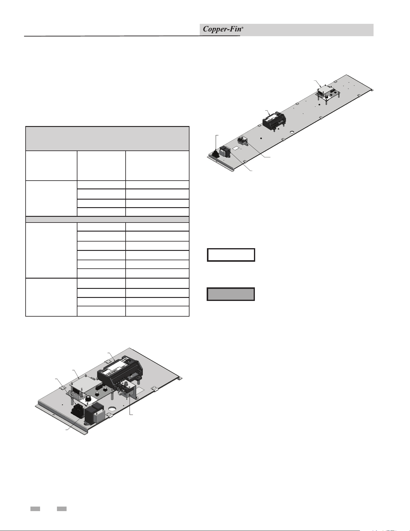
36
5 Electrical connections
Installation & Service Manual
Pump Wiring for a Heating Boiler
The heating boiler circulating pump must be pur chased
locally. The max i mum load for the pump switched by the
internal pump relay must not exceed 1 HP. The current draw
for a field installed 120 VAC pump MUST be add ed to the
boiler’s current draw to de ter mine the minimum wire size
for 120 volt service.
TEMPERATURE
CONTROL
IGNITION
MODULE
MANUAL RESET
HIGH LIMIT (IF EQUIPPED)
TRANSFORMER
PUMP
RELAY
INTERMITTENT PILOT SYSTEM M9 CONTROL PANEL
IGNITION MODULE
TRANSFORMER
MANUAL RESET
HIGH LIMIT (IF EQUIPPED)
PUMP RELA
Y
TEMPERATURE
CONTROL
Figure 5-2_Control Panel Assembly 90-135,000 BTU/hr
Figure 5-3_Intermittent Pilot System 500,000 Btu/hr
Control Panel
Temperature Adjustment
Operating Temperature Control
NOTICE
The temperature controller is pre-set at
the factory with test settings. You may
need to adjust the settings to meet your
specific needs.
⚠ WARNING
Return water temperatures must not
be less than 140°F. If lower return
water temperatures are required, follow
the instructions for Low Temperature
Bypass Requirements or Three-Way
Valves, see page 31.
* 1.0 AMPs added for “PM” water heaters
TABLE - 5B
AMP DRAW DATA FOR
STANDARD FIRING CODES
Firing Control
Model
Maximum
Total AMPs /
120VAC
M9
CB315 .5
CB360 .5
CB399 .5
CB500 .5
*F1
CW90 1.5
CW135 1.5
CW180 1.5
CW199/201 1.5
CW225 1.5
CW270 1.5
*F9
CW315 1.5
CW360 1.5
CW399 1.5
CW500 1.5
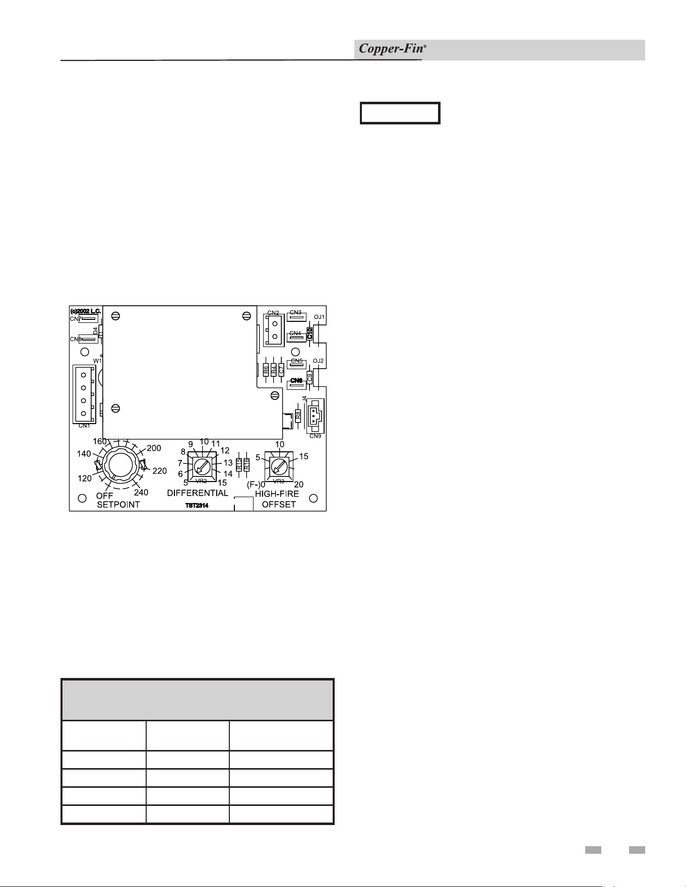
5 Electrical connections (continued)
37
Installation & Service Manual
Locating Temperature Control
Remove the control panel door on the front of the unit in
order to locate and access the temperature control.
Temperature Control Settings
Remove the control panel door on the front of the unit unless
your unit is specified as a boiler only with an outdoor air reset
option. If your unit is a boiler only with an outdoor air reset
option, there are additional controls for this option. They are
explained under Outdoor Air Reset Option, page 39.
The three setting knobs on the temperature control are for Set
point, Differential, and High-Fire Offset (see FIG. 5-4).
Figure 5-4_Temperature Control
Maximum Set Point Determination
The maximum set point for the control is factory set. Boilers
can be set to 240°F max., water heaters are set to 190°F max.,
and specialty state and local codes to 200°F.
These maximum set points are established by cutting the OJ1
and OJ2 jumpers located on the right side of the temperature
controller. The maximum set point is determined as shown
below in Table 5C.
TABLE - 5C
MAXIMUM SET POINT DETERMINATION
OJ1 OJ2
MAX.
SET POINT
Connected Connected 240°F
Cut Connected 190°F
Connected Cut 200°F
Cut Cut 160°F
NOTICE
Anytime that OJ1 is the only jumper cut, a
new overlay is required under the Set Point
knob on the temperature controller because
the scale has changed to a maximum of
190°F.
Anytime the OJ2 jumper is cut (with or
without OJ1), a new overlay is required
under the Set Point knob on the temperature
controller because the scale has changed to a
maximum of 200°F.
Set Point
The Set Point knob specifies the target inlet (or system sensor, if
used) water temperature in degrees, Fahrenheit. After the water
temperature reaches the set point, the temperature control shuts
off the burners.
Differential
The Differential specifies the number of degrees below the set
point that the control will allow the water temperature to drop
before it brings the unit back on again.
High-Fire Offset
The temperature control operates a two-stage firing system.
The two stages are High-Fire and Low-Fire. High-Fire operates
all burners at full rate while Low-Fire operates the burners at
approximately one-half rate.
The High-Fire Offset knob specifies the number of degrees
below set point that the High-Fire stage shuts down. At that
point, the unit will continue to operate at the Low-Fire stage
until the set point is reached.
The High-Fire Offset knob has settings between 0°F and 20°F.
If set at 0°F, the High-Fire Offset is disabled and the unit will
operate the High-Fire stage until the set point is reached and the
temperature control shuts the unit off.
If the High Fire Offset knob is set to 0 or 1, the delay will be
10 seconds; if set to 2 or above the delay will be 120 seconds.
Boiler Application
Standard boiler units are equipped with one inlet water
temperature sensor. An optional sensor is also provided for use
as a remote system sensor. Boilers with the outdoor air reset
option also have an outside air temperature sensor.
Water Heater Application
Water heater units are shipped with an inlet water temperature
sensor and a multi-purpose temperature sensor to be used as
a tank sensor. The inlet water temperature sensor is factory
installed on all water heaters.

38
5 Electrical connections
Installation & Service Manual
Temperature Control Sensors
This is a two-stage temperature control (M9/F9) that controls
the burner ignition and pump functions. This temperature
controller can measure up to three different sensor inputs,
depending upon how the unit is set up. They are as follows:
1. Inlet Water Temperature Sensor
2. Multi-Purpose Temperature Sensor
3. Outside Air Temperature Sensor
Inlet Water Temperature Sensor
This sensor measures the inlet water temperature coming
into the unit.
The inlet water temperature sensor is placed into the inlet
bulbwell on the boiler. This sensor is installed by the factory.
Multi-Purpose Temperature Sensor
Depending upon how your unit is set up, this sensor can be
used as a system sensor in a boiler system or a tank sensor
for water heater applications. Connect this sensor to the two
blue wires in the upper left-hand corner of the control panel.
Outdoor Air Temperature Sensor
The outside air temperature sensor will only be used for
boiler systems. The outside air sensor is optional. This
sensor allows you to tie boiler operation to the outdoor air
temperature. As outside temperatures drop, the control will
increase the temperature setting of the boiler. As outdoor
temperatures rise, the control will decrease the temperature
to the selected set point of the boiler. You can set the control
to shut the boiler off when a desired outdoor air temperature
level is reached.
You must purchase the sensor from the appliance
manufacturer. The sensor comes with a housing that helps
protect the sensor from the elements. Mount the air sensor
housing outdoors, under the eve of the roof. Make sure the
housing is out of direct sunlight. This will ensure that the
sensor will accurately read the true outdoor temperature.
Connect the outdoor air temperature sensor to the terminal
block on the outdoor air reset board. For more information
on wiring the sensor, see Wiring of Remote Sensors, this page.
Installation of Remote Sensors
Make sure to insert the sensor all the way into the bulbwell,
leaving no air pocket between the front surface of the sensor
and the back of the bulbwell. Air pockets are thermally
non-conductive and will cause sensors to read inaccurately.
System Sensor
The system sensor must be installed when piping the boiler
in Primary - Secondary fashion when using the Pump Delay
option.
Tank Sensor
Water heaters are provided with an extra temperature
sensor that MUST be field installed. The sensor is shipped
loose in the I & O packet. This remote mounted sensor will
be the primary temperature sensor which will inform the
appliance’s built-in thermostat control. For domestic water
heating, the sensor MUST be installed into a bulbwell on
the storage tank. This is required to maintain the desired
temperature in the tank and reduce cycling of the heater.
In both applications be sure to insert the sensor all the
way into the bulbwell, leaving no air pockets between the
front surface of the sensor and the back of the bulbwell.
Air pockets are thermally non-conductive and will cause
sensors to read inaccurately.
Wiring of Remote Sensors
To wire remote sensors, follow the guidelines below. Take
care to correctly wire sensors to the unit. Erratic temperature
readings can be caused by poor wiring practices. Twist
the wires between the unit and the remote sensor. Turn
wires at least three or four turns per linear foot of wiring.
This provides protection against some types of electrical
interferences.
1. Do not route temperature sensor wiring with building
power wiring.
2. Do not locate temperature sensor wiring next to control
contactors.
3. Do not locate temperature sensor wiring near electric
motors.
4. Do not locate temperature sensor wiring near welding
equipment.
5. Make sure good mechanical connections are made
to the sensor, any interconnecting wiring and the
controller.
6. Do not mount sensor with leadwire end pointing up in
an area where condensation can occur.
7. Use shielded wiring to connect the sensor to the
control when the possibility of an electrically noisy
environment exists. Shielded cable is recommended on
all cable runs of more than 25 feet in length.
NOTICE
Ground the cable shield at the connection
to the boiler temperature control only.
Do not ground the shielded cable at the
sensor end.
To maintain temperature accuracy,
sensor wires should be 18 AWG two
conductor (18/2). Use shielded wire if
required.
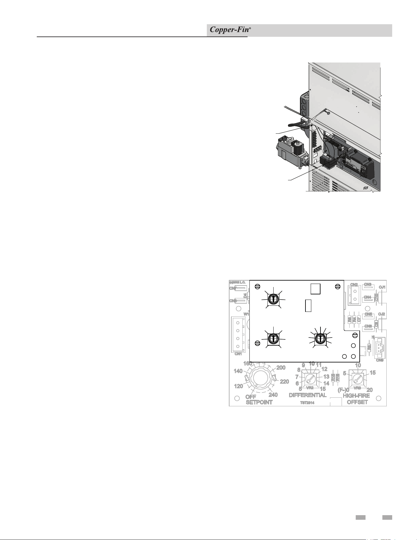
5 Electrical connections (continued)
39
Installation & Service Manual
Installation of a Remote Sensor (Boiler Application)
1. Turn OFF the main electrical power and the main
manual gas shutoff to the appliance.
2. Remove the side access panel from the appliance to gain
access to the thermostat.
3. Locate the sensor in the kit. Determine the location of the
remote sensor and measure the amount of wire needed
to connect the sensor to the thermostat. See Wiring of
Remote Sensors on page 38 for guidelines.
4. Use twisted pair wire, minimum 18 gauge or larger. See
Table 5A, page 35 regarding distance versus wire gauge.
Ensure all wire insulation is trimmed to reveal at least
3/8" of exposed wire.
5. Connect the measured wire to the sensor wire using wire
caps (see FIG. 5-5). Install .250 x .032 insulated female
quick connect terminals to the end of the wires. Feed
the wires through the access hole located on the back
of the unit and secure the connectors to the thermostat
connections (Sys/Tank) CN5 and CN6 located in the
upper right-hand of the thermostat.
6. Turn on the electrical power and the main manual gas
shutoff to the appliance.
7. Replace the side access panel.
8. Fire the appliance and resume operation.
Installation of a Tank Sensor (Water Heater
Application)
1. Turn OFF the main electrical power and the main
manual gas shutoff to the appliance.
2. Remove the side access panel from the appliance to gain
access to the wire harness.
3. Locate the two blue wires with a tag notating the remote
thermostat sensor. Feed the blue wires through the access
hole located on the back of the unit.
NOTE: It will be necessary to add additional wire to
reach from the appliance to the remote water source. Use
twisted pair wire, minimum 18 gauge or larger. See Table
5A, page 35 regarding distance versus wire gauge. Ensure
all wire insulation is trimmed to reveal at least 3/8" of
exposed wire.
4. Connect the wires to the sensor wire using wire caps.
5. Turn on the electrical power and the main manual gas
shutoff to the appliance.
6. Replace the side access panel.
7. Fire the appliance and resume operation.
ACCESS HOLE
CONNECT THE MEASURED
WIRE TO THE SENSOR WIRE
Figure 5-5_Installation of Remote Sensors
Outdoor Air Reset Option
For boilers ordered with the Outdoor Air Reset option,
there is an additional control (FIG. 5-6). There are three
setting knobs for Shutdown, Outdoor Air Max., and Ratio.
There is also a switch to turn the outdoor air shutdown
feature On or Off. An O.A. Sensor is also included.
R4
R6
R8
R16
R15
C7
C9 C10
VR2
VR3
OJ1
OJ2
D4
J4
CN1
CN2
CN9
CN7
CN8
CN3
CN4
CN5
CN6
W1
TST2314
20
15
10
5
(F-)0
15
14
13
12
11
9
8
7
6
5
OFF
120
240
220
200
160
140
SETPOINT
DIFFERENTIAL
HIGH-FIRE
OFFSET
(c)2002 L.C.
SHUTDOWN
45
50
45
1.3
O.A. MAX.
70
40
VR1
65
RATIO
VR2
0.6
0.5
0.7
1.4
1.5
W1 W2
W3
60
50
7040
55
60
VR3
65
DISABLE
O.A. SHUTDOWN
1.0
0.9
0.8
1.2
1.1
O.A. SENSOR
ENABLE
ON
SW1
55
CN1
Figure 5-6_Optional Outdoor Air Reset Control
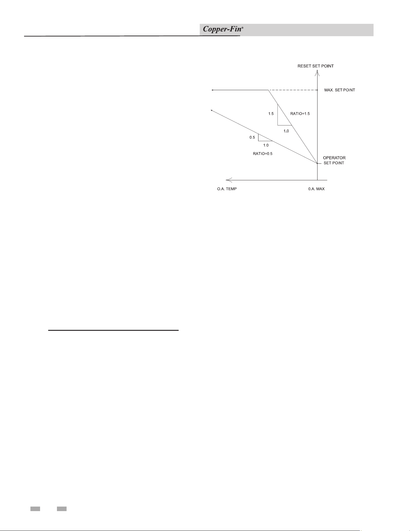
40
5 Electrical connections
Installation & Service Manual
Shutdown
The Shutdown knob specifies the outdoor air lockout
temperature at which the control would prevent the unit
from operating.
Outdoor Air Max (O.A. Max)
The O.A. Max knob allows a reset up to the maximum
outdoor air temperature specified by this knob setting. When
the outdoor air temperature is above the specified setting,
the unit will not function in the O.A. Reset Mode, but will
continue to run at the selected set point temperature.
Note that the set point knob will now indicate the “minimum”
boiler temperature. Target temperature is determined by
the ratio and outdoor air temperature below the O.A. Max
setting.
Ratio
The Ratio knob allows control over the reset ratio to be used
during Outdoor Air Reset. The allowable ratios are as low as
0.5:1 or as high as 1.5:1.
Selecting the 0.5:1 ratio will increase the set point 0.5°
for every 1.0° drop in outdoor air temperature up to the
maximum set point temperature.
Selecting the 1.5:1 ratio will increase the set point 1.5°
for every 1.0° drop in outdoor air temperature up to the
maximum set point temperature.
If the outdoor design and boiler design temperatures are
known, the Ratio setting can be calculated using the following
formula:
Ratio = (boiler design temperature - operator set point)
(O.A. Max. setting - outdoor design temperature)
Note that the reset set point cannot exceed the maximum set
point of the boiler thermostat.
These settings are illustrated graphically in FIG. 5-7.
Figure 5-7_Outdoor Air Control Example Chart
Outdoor Air Shutdown Enable/Disable Switch
The Outdoor Air Shutdown Enable/Disable switch turns the
outdoor air shutdown feature On and Off. Disabling the
Outdoor Air Shutdown feature allows the unit to operate
regardless of the outdoor air temperature. This is needed for
indirect domestic hot water systems for example.
Additional Temperature Controls
High Water Temperature Limit Con trol
The appliance is supplied with a fixed setting, auto-reset
high water temperature limit control. The setting of this
control limits max i mum discharge water tem per a ture. If water
temperature exceeds the setting, the limit will break the con trol
circuit and shut down the appliance. The limit control will
only be reset after the water tem per a ture has cooled well below
the setting of the limit. The auto-reset high water temperature
limit control is mount ed in the outlet side of the front header.
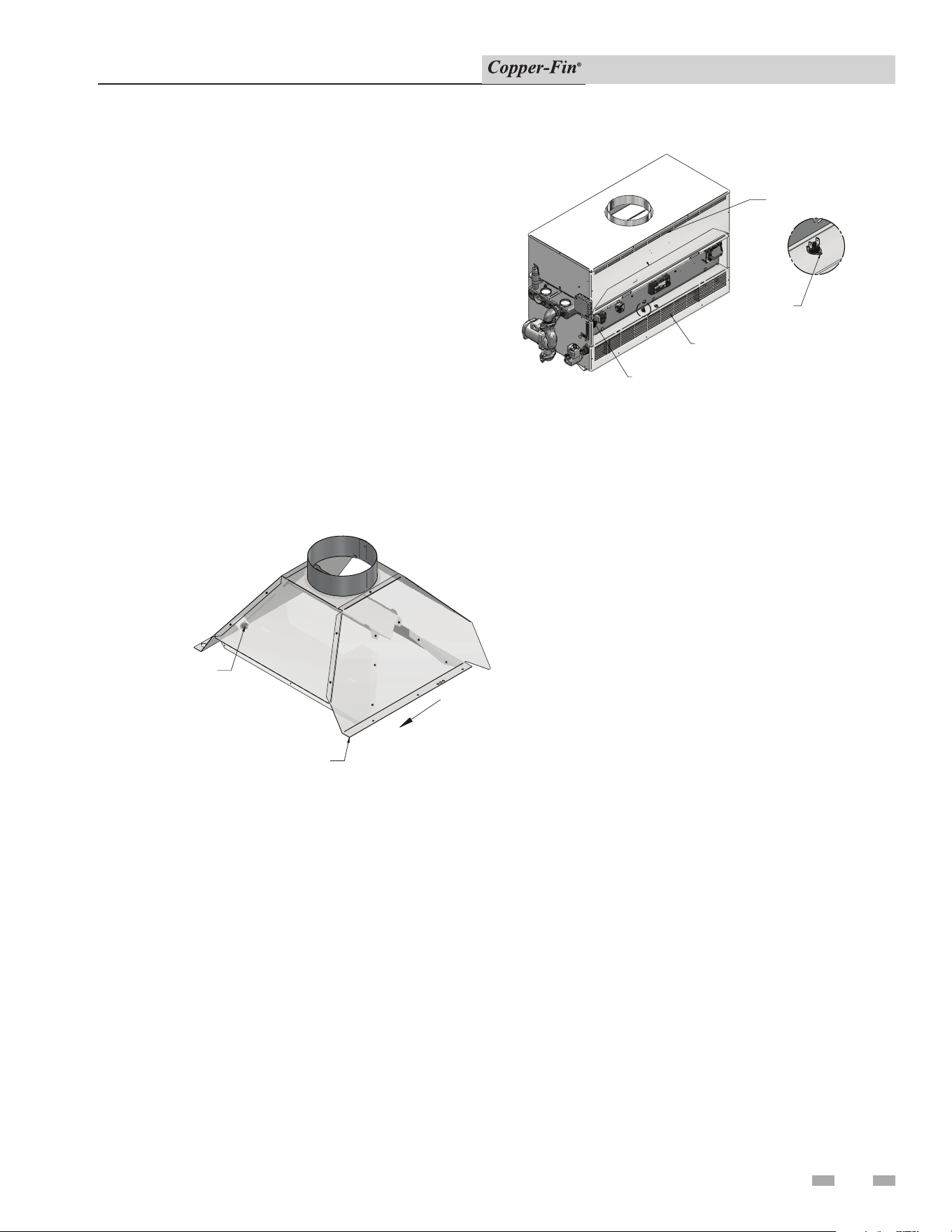
5 Electrical connections (continued)
41
Installation & Service Manual
Manual Reset High Water Temperature Limit Control
(Standard Fixed Settings on Boilers and Water
Heaters with Optional Adjustable Settings)
Water heaters are supplied with a fixed setting, manual reset
high water temperature limit control. This manual reset
temperature limit control has a fixed limit setting of 230°F
(110°C). If water tem per a ture ex ceeds this setting, the limit
will break the control circuit and shut down the unit. The
limit control can only be reset after the water tem per a ture
has cooled well below the setting of the lim it. Reset of the
limit con trol is accomplished by push ing the Red Reset
But ton (Manual Reset High Limit) (see FIG.’s 5-2 and 5-3
on page 36) located on the front side of the control panel. A
label on the control panel indicates the exact lo ca tion of the
manual reset high water temperature limit control.
BLOCKED VENT SW
ITCH
INVERTED TO SHOW RESET
UNDERNEAT
H
DRAFT HOOD
FRONT OF UNIT
Figure 5-8_Blocked Vent Switch Location
DETAIL
HEX FILLER BRACKET
FLAME
ROLL-OUT SWITCH /
INTERLOCK SWITCH
UPPER FRONT
JACKET PANEL
LOWER FRONT
JACKET PANEL
Figure 5-9_Flame Roll-Out / Flame Interlock Switch Location
All units are equipped with manual reset blocked vent and
flame roll-out / flame interlock switches. These temperature
switches are located in the controls compartment and in the
relief opening of the boiler’s built-in draft hood. Each switch
has a red reset button. In the event the system has actuated
to shut off the main burner gas supply, wait for the boiler to
cool, then press the red reset to return the boiler to operation.
Op er a tion of a blocked vent and/or flame roll-out / interlock
switch usually indicates a problem with the venting system,
obstruction of the heat ex chang er flue gas passageway and/or
a combustion air supply prob lem. The cause for operation of
the blocked vent and/or flame roll-out / interlock switch must
be determined and corrected. If the boiler cannot be restored
to normal operation, contact a qualified ser vice in stall er, service
agency or the gas supplier.
Blocked Vent and Flame Roll-Out / Flame
Interlock Switch

42
6 Start-up
Installation & Service Manual
Initial Start-up
Follow the Lighting Instructions on the label applied to the
appliance.
A. On water heaters and boilers with the system pump
delay option, the operating temperature control will
energize the pump relay which energizes the pump
on a call for heat. The operating temperature control
will de-energize the pump relay approximately 30
seconds after the call for heat ends. If either the inlet
sensor or the optional multi-purpose temperature
sensor reads below 40°F, the pump relay will turn
ON. When the temperature rises above 50°F the
pump relay will turn OFF.
On boilers, the pump will operate whenever the “W”
terminal is energized.
B. Location - The appliance should be located within
a room having a temperature safely above freezing
[32°F(0°C)].
C. Shutdown and Draining - If, for any rea son, the
appliance is shut off, the following pre cau tion ary
measures must be taken:
1. Shut off gas supply,
2. Shut off water supply.
3. Shut off electrical supply.
4. Drain the heat exchanger completely. Re move one
3/8" NPT plug or bulbwell from the inlet side and one
from the outlet side of the front head er of the heat
exchanger.
5. Drain the pump. Remove the 3/4" plug in the bypass
loop.
Pre-start Checklist
1. Inspect the burners to be sure they are prop er ly aligned.
2. Inspect the pilot gas line, thermocouple leads, ignition
leads and wire connections to the gas valve to be sure
none were damaged during shipment.
3. Check to ensure that gas connections have been made
properly and the gas line is purged of air.
4. Check to ensure that water connections are tight and the
appliance and piping system have been properly filled.
5. Ensure that discharge from the relief valve has been piped
to a floor drain.
6. Verify that properly sized combustion and ven ti la tion air
openings are provided and not obstructed in any way.
7. Check carefully for gas leaks.
8. Read the appliance’s safety warnings, light ing instructions
and check out procedure carefully, be fore firing the
system.
Lighting Instructions for Standing Pilot
Models (F1) Models (F1) Models 90,000
through 270,000 Btu/hr Input
FOR YOUR SAFETY READ BEFORE OPERATING
⚠ WARNING
If you do not follow these in struc tions
exactly, a fire or explosion may result
causing prop er ty damage, personal injury
or loss of life.
A. This appliance has a pilot which must be ig nited
by hand. When lighting the pilot, follow these
instructions exactly.
B. BEFORE OPERATING, smell around the appliance
area for gas. Be sure to smell next to the floor because
some gas is heavier than air and will settle to the
floor.
WHAT TO DO IF YOU SMELL GAS
Do not try to light any appliance.
Do not touch any electric switch; do not use any
phone in your building.
Immediately call your gas supplier from a near by
phone. Follow the gas supplier’s instructions.
If you cannot reach your gas supplier, call the fire
department.
C. Use only your hand to push in or turn the gas control
knob. Never use tools. If the knob will not turn by
hand, don’t try to repair it, call a qualified ser vice
technician. Force or attempted repair may result in a
fire or explosion.
D. Do not use this appliance if any part has been under
water. Immediately call a qualified service technician
to inspect the appliance. The pos si ble damage to
a flooded appliance can be extensive and present
numerous safety hazards. Any appliance that has
been under water must be replaced.
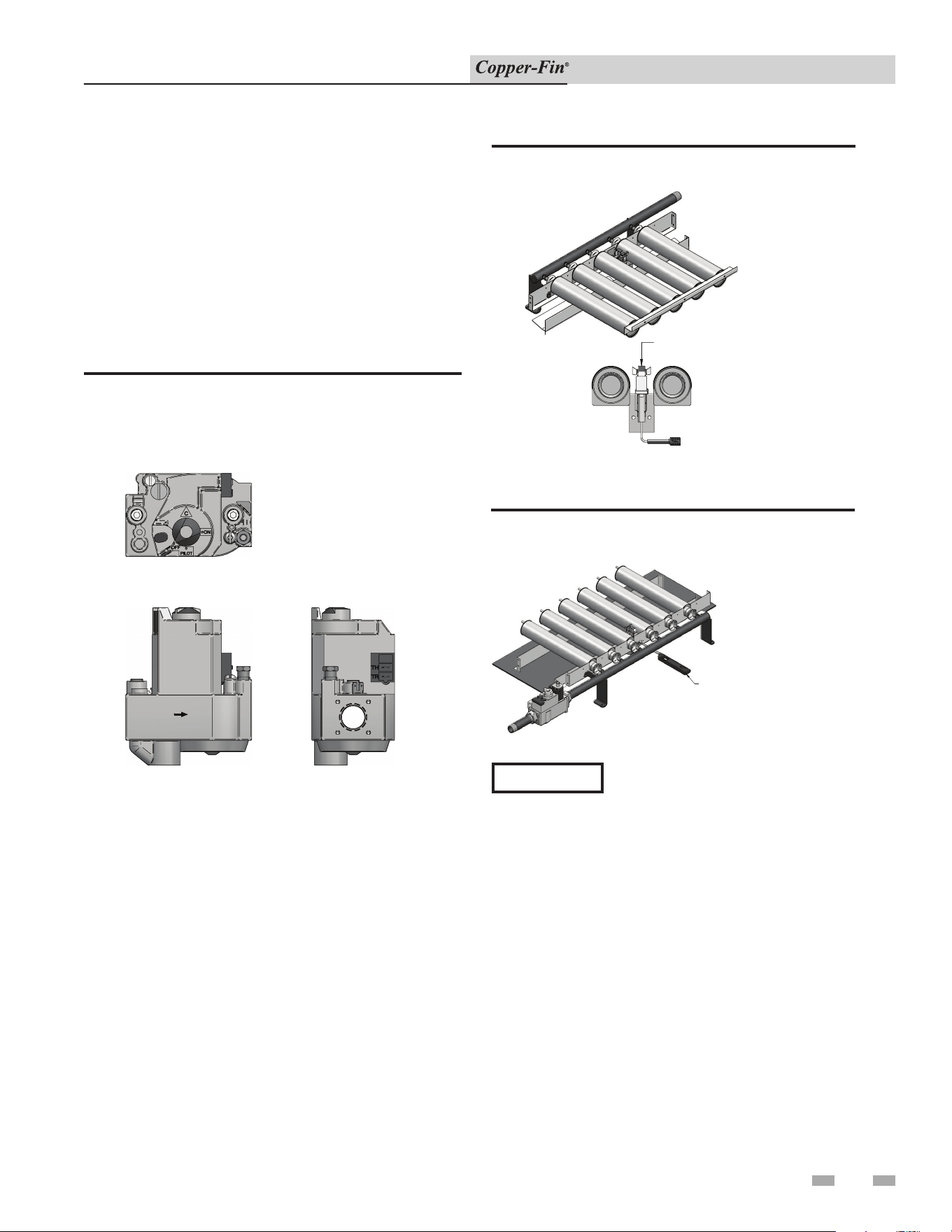
6 Start-up (continued)
43
Installation & Service Manual
Lighting Instructions
1. STOP! Read the safety information (page 42).
2. Remove the control panel door.
3. Set the thermostat to the lowest setting (OFF).
4. Turn off all electrical power to the appliance.
5. Turn the gas control knob on the gas valve clockwise to
the “OFF” position.
FLOW
SIDE
TOP
OUTLET
F-1 GAS VALVE
90,000 -270,000 BTU MODELS
Figure 6-1_Gas Valve 90,000 - 270,000 Btu/hr Models
6. Wait five (5) minutes to clear out any gas, then smell
for gas, including near the floor. If you smell gas,
STOP! Follow the steps in the“What To Do If You
Smell Gas” section in the safety information on page 42.
If you do not smell gas go on to the next step.
7. Remove the lower panel door to gain access to the pilot.
8. Find the pilot - Follow the metal tube from the gas
valve to the pilot. The pilot is located on the right side
of the burner approximately centered in the burner
tray.
Pilot Location
Main Burner
TOP OF FLAME SPREADER TO BE
FLUSH WITH TOP OF BURNER
Figure 6-2_Pilot Location
9. Turn the control knob on the gas valve coun ter clock-
wise to the “PILOT” position.
USE A FIELD SUPPLIED LIGHTER OR
THE
FACTORY SUPPLIED LIGHTING WAND TO
LIGHT THE STANDING PILOT
Figure 6-3_Lighting Wand
NOTICE
The information package shipped
with the appliance contains a wire
lighting wand. The loop end of the
wand will hold a match. The wand
extends your reach to the pilot
and makes lighting the pilot easier
(see FIG. 6-3).
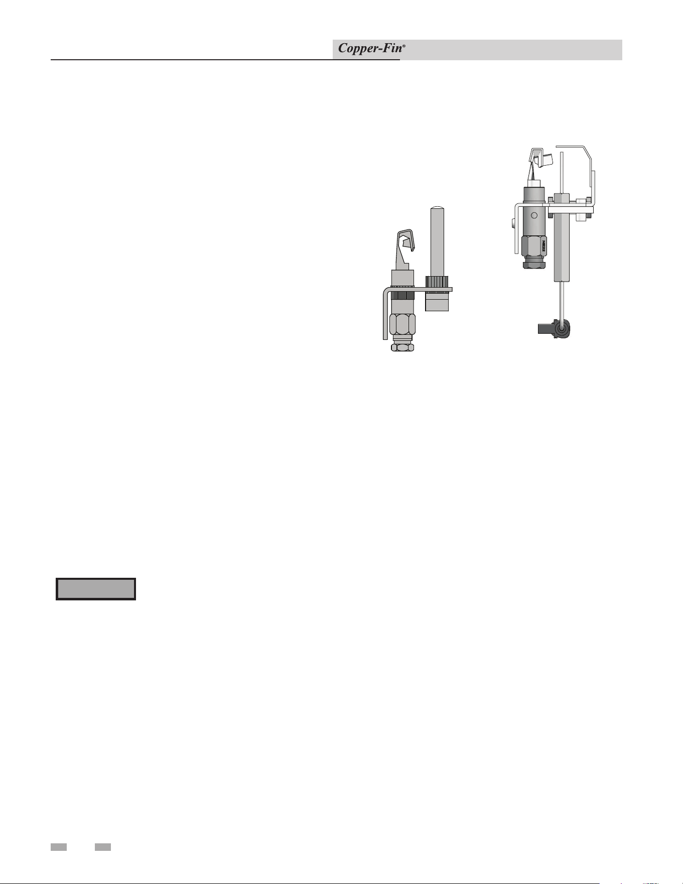
44
6 Start-up
Installation & Service Manual
10. Use the loop end of the wire lighting wand, shipped
with the instruction pack age, to hold the match and
reach the pi lot. An access slot is provided in the lower
front jacket panel, beside the burner, to insert the
lighting wand and match to the pilot. Lift the pilot cover
(FIG. 6-3) to access the pilot. Push down and hold in
the red button on the gas valve. This should start gas
flow to the pilot. Con tin ue to hold the red button in for
about one (1) minute after the pilot is lit. Release the
button and it will pop back up. The pilot should remain
lit. If the pilot goes out, repeat steps 5 through 10.
If the red button does not pop up when re leased, stop
and immediately call your gas supplier.
If the pilot will not stay lit after sev er al tries, turn the gas
control to “OFF” and call your service technician or gas
supplier.
11. Turn the gas control knob on the gas valve
counterclockwise to the “ON” position.
12. Turn on all electric power to the appliance.
13. Re-install the lower panel door.
14. Set the thermostat to the desired setting.
15. Re-install the control panel door.
TO TURN OFF GAS TO APPLIANCE
1. Set the thermostat to the OFF position.
2. Turn off all electric power to the appliance if service is
to be performed.
3. Turn the gas control knob on the gas valve clockwise to
the “OFF” position. Do not force.
⚠ WARNING
Should overheating occur or the gas fail
to shut off, turn off the external manual
gas valve to the appliance.
Safety Shutoff Test For Standing
Pilot Ignition System
PILOT WITH SPARK IGNITION
PILOT WITH THERMOCOUPLE
Figure 6-4_Pilot with Thermocouple and Spark Ignition
1. With the main burners on and firing, un screw the
thermocouple connection from the gas valve (FIG. 6-4)
and remove from the fitting.
2. The main gas valve should extinguish the burn ers
immediately after removal of the thermocouple.
3. If burners do not extinguish, immediately fol low steps in
“To Turn Off Gas To Appliance”.
4. Immediately call a qualified serviceman or in stall er to
repair an ignition system that fails to op er ate properly
and shut down the burners.
5. After successful completion of test, turn the control knob
on the gas valve clockwise to the “OFF” position. Do not
force.
6. Carefully reconnect the thermocouple to the gas valve.
7. Follow the Lighting Instructions to relight the pilot and
establish normal operation.

6 Start-up (continued)
45
Installation & Service Manual
Lighting Instructions for Spark
Ignition Pilot Models (F9/M9) Models
90,000 through 500,000 Btu/hr Input
FOR YOUR SAFETY READ BEFORE
OPERATING
⚠ WARNING
If you do not follow these instructions
exactly, a fire or explosion may result
causing property damage, personal
injury or loss of life.
A. This appliance is equipped with an ignition device
which automatically lights the pilot. Do not try to
light the pilot by hand.
B. BEFORE OPERATING, smell around the
appliance area for gas. Be sure to smell next to
the floor because some gas is heavier than air and
will settle to the floor.
WHAT TO DO IF YOU SMELL GAS
Do not try to light any appliance.
Do not touch any electric switch; do not use any
phone in your building.
Immediately call your gas supplier from a nearby
phone. Follow the gas supplier’s instructions.
If you cannot reach your gas supplier, call the fire
department.
C. Use only your hand to turn the gas control knob.
Never use tools. If the knob will not turn by
hand, don’t try to repair it, call a qualified ser vice
technician. Force or attempted repair may result
in a fire or explosion.
D. Do not use this appliance if any part has been
under water. Immediately call a qualified service
technician to inspect the appliance. The pos si ble
damage to a flooded appliance can be extensive
and present numerous safety hazards. Any
appliance that has been under water must be
replaced.
Operating Instructions
1. STOP! Read the safety information first.
2. Remove the control panel door.
3. Set the thermostat to the lowest setting (OFF).
4. Turn off all electrical power to the appliance.
5. This appliance is equipped with an ignition device which
automatically lights the pilot. DO NOT try to light the
pilot by hand.
6a. 90,000 - 135,000 and 399,000 - 500,000 Btu/hr models,
rotate the gas control knob on the gas valve clockwise to
the “OFF” position.
6b. 180,000 - 360,000 Btu/hr models, rotate the gas control
knob on the gas valve clockwise to the line on the collar
around the knob. Depress the knob and continue
rotation to the “OFF” position.
7. Wait five (5) minutes to clear out any gas, then smell for
gas, including near the floor. If you smell gas, STOP!
Follow the steps in the “What To Do If You Smell Gas”
section in the safety information, this page. If you do not
smell gas go on to the next step.
8a. 90,000 - 135,000 and 399,000 - 500,000 Btu/hr
models, rotate the gas control knob on the gas valve
counterclockwise to the “ON” position.
8b. 180,000 - 360,000 Btu/hr models, rotate the gas control
knob on the gas valve counterclockwise to the line on the
collar around the knob. Al low the knob to “pop” up, and
continue rotation to the “ON” position.
9. Turn on all electric power to the appliance.
10. Set the thermostat to the desired setting.
11. Re-install the control panel door.
12. If the appliance will not operate, follow the instructions
“To Turn Off Gas To Appliance” and call your service
technician or gas supplier.

46
6 Start-up
Installation & Service Manual
To Turn Off Gas to Appliance
1. Set the thermostat to the OFF position.
2. Turn off all electric power to the appliance if service is
to be performed.
3a. 90,000 - 135,000 and 399,999 - 500,000 Btu/hr models,
rotate the gas control knob on the gas valve clockwise
to the “OFF” position. Do not force.
3b. 180,000 - 360,000 Btu/hr models, rotate the gas control
knob on the gas valve clockwise to the line on the
collar around the knob. Depress the knob and continue
rotation to the “OFF” position. Do not force.
⚠ WARNING
Should overheating occur or the gas fail
to shut off, turn off the external manual
gas valve to the appliance.
Safety Shutoff Test for Spark Ignition
Pilot System
1. Turn “OFF” gas supply to the appliance.
2. Turn thermostat to highest setting.
3. Turn electric power “ON”.
4. Pump relay pulls in to start pump.
5. The ignition will begin sparking at the pilot.
6. The ignition module will lock out after the trial for
ignition period.
7. Immediately call a qualified serviceman or in stall er
to repair an ignition system that fails to lock out and
properly shut down burner operation.
8. After successful completion of the test, re ad just the
thermostat to normal setting.
9. Turn “ON” gas supply.
10. Turn power “OFF” then “ON” to reset ignition module.
11. If ignition system fails to operate properly, re pair
work must be performed by a qualified serviceman or
installer.
Intermittent Pilot Spark Ignition System
(F9/M9)
The ignition module is not repairable. Any mod i fi ca tion or repairs
will invalidate the warranty and may create hazardous conditions
that result in prop er ty damage, personal injury, fire, explosion
and/or toxic gases. A faulty ignition module must be re placed with
a new module.
Freeze Protection
1. For water heaters and boilers that utilize the pump delay
option, if either the inlet sensor or the optional multi-
purpose temperature sensor reads below 40°F, the pump
relay will turn ON. When the temperature rises above 50°F
the pump relay will turn OFF.
2. Location - Heating boilers and water heaters must be
located in a room having a temperature safely above freezing
[32°F(0°C)].
3. Caution - A room where the appliance is installed and
operating under a negative pressure may experience a
downdraft in the flue of an appliance which is not firing.
The cold outside air pulled down the flue may freeze a heat
exchanger. This condition must be cor rect ed to provide
adequate freeze protection.
4. Freeze protection for a heating boiler or hot water supply
boiler using an indirect coil can be provided by using
hydronic system antifreeze. Follow the manufacturers
instructions. DO NOT use un di lut ed or automotive type
antifreeze.
5. A snow screen should be installed to pre vent snow and ice
accumulation around the appliance vent ing system in cold
climates.
6. Shut-down and Draining - If for any rea son, the appliance is
to be shut off, the following precautionary measures must be
taken:
(a) Shut off gas supply.
(b) Shut off water supply.
(c) Shut off electrical supply.
(d) Drain the unit completely. Remove one threaded plug
or bulbwell from the inlet side of the front header and
one from the outlet side of the front header on the heat
exchanger. Blow all wa ter out of the heat exchanger.
(e) Drain pump and piping.
6 Start-up (continued)
47
Installation & Service Manual
Check/control fill water chemistry
Conduct water quality testing prior to
installing the appliance. Various solutions
are available to adjust water quality.
Hardness between 5 and 15 grains per gallon
1. Consult local water treatment companies for hard water
areas (above 15 grains per gallon hardness).
2. Hardness levels that are above 15 grains/gallon can lead
to lime scale buildup throughout the boiler system. If the
fill water is below 5 grains/gallons, usually due to use of a
water softener, it is recommended to mix in some potable
water at the inlet to increase the hardness of the water to
above 5 grains/gallons.
pH between 6.5 and 8.5
1. pH levels below 6.5 can cause an increase in the rate of
corrosion. pH of 8.5 or higher can potentially cause lime
scale buildup.
Total Dissolved Solids (TDS) less than 350 ppm
1. Total dissolved solids are all minerals, salts, metals, and
charged particles that are dissolved in water.
2. The greater the amounts of TDS present, the higher the
corrosion potential due to increased conductivity in the
water.
Chlorine concentration less than 150 ppm
1. Do not fill boiler or operate with water containing
chlorine in excess of 150 ppm.
2. Filling with fresh drinking water should be acceptable.
3. Do not use the boiler to directly heat swimming pool or
spa water.
IMPORTANT
Fill water
The manufacturer recommends the following for properly
filling your boiler with the appropriate water chemistry for
closed loop boilers. Good fill water quality will help extend
the life of the appliance by reducing the effects of lime scale
buildup and corrosion in closed loop systems.
Ethylene glycol is toxic, DO NOT use as
your freeze protection. Ethylene glycol has a
sweet aroma which children and pets could
mistake as food and ingest; leading to death.
⚠ WARNING
Pre-Commissioning Cleaning
1. Prior to fill and start-up, flush the entire heating system.
2. Clean the entire heating system with an approved pre-
commissioning cleaner (comparable to Sentinel X300
or Fernox F3) in accordance with the manufacturer’s
recommendation to remove debris and prolong the life of
the heat exchanger.
3. Clean all water filtering devices in the system.
4. Flush the cleaning solution out of the entire system and
refill.
Boiler water
BOILER WATER CHEMISTRY
Specication Range
Dissolved Solids < 2000 ppm
pH Level 6.5 to 9.5
Chloride < 150 ppm
• Monitoring pH, chlorides, TDS, and hardness
levels can prolong the life of the appliance by reducing
lime scale buildup, corrosion, and erosion. Check for
leaks to ensure that fresh water is not entering the
system.
• Continual fresh makeup water will reduce boiler life.
• Mineral buildup in the heat exchanger reduces heat
transfer, overheats the stainless steel heat exchanger,
and causes failure.
• The addition of oxygen carried in by makeup water
can cause internal corrosion in system components.
• Leaks in the boiler or piping must be repaired at
once to prevent excessive makeup water. For this
purpose, it is recommended to install a water meter
to easily check the amount of makeup water entering
the system. Makeup water volume should not exceed
5% of the total system volume per year. NOTE: When
makeup water is added, make sure the chemical
additives are added to maintain the correct level.
• An approved multi-metal corrosion inhibitor
(comparable to Sentinel X100 or Fernox F1) is
recommended at the correct concentration and in the
manner recommended by the manufacturer.
CAUTION
Do not use petroleum based cleaning or
sealing compounds in the boiler system.
Gaskets and seals in the system may be
damaged. This can result in substantial
property damage.
DO NOT use "homemade cures" or "boiler
patent medicines". Serious damage to
boiler, personnel, and/or property may
result.
Table 6A Boiler Water Chemistry
Freeze protection for a heating
boiler system (if required)

48
6 Start-up
Installation & Service Manual
1. Use glycol only if needed for freeze protection.
2. Propylene glycol is the recommended freeze protection.
3. Make sure to flush the boiler system before adding glycol.
4. Determine the freeze protection fluid quantity using
system water content, following the fluid manufacturer's
instructions. Boiler water content is listed on page 6.
Remember to include expansion tank water content.
5. Local codes may require a backflow preventer or actual
disconnect from city water supply.
6. When using freeze protection fluid with automatic fill, it is
suggested to install a water meter to monitor water makeup.
Freeze protection fluid may leak before the water begins to
leak, causing the concentration to drop, which reduces the
freeze protection level.
7. The freeze protection set points may be lowered when
freeze protection fluid is used (see the Copper-Fin Service
Manual).
8. Consult the glycol manufacturer for details on the suggested
mix of glycol and water for the desired freeze protection
level and the de-rate effect it will have on the boiler output.
Test / replace freeze protection fluid
1. For systems using freeze protection fluids, follow the fluid
manufacturer's instructions.
2. Freeze protection fluid must be replaced periodically due to
degradation of inhibitors over time.
3. It is recommended to test the glycol concentration annually
and adjust within the desired set points.
Oxygen prevention
Dissolved oxygen can have a negative effect on the boiler
system. Oxygen can cause iron oxide to generate iron deposits.
Oxygen may also increase the rate of corrosion on non-stainless
steel parts of the system. A low pH level combined with oxygen
further enhances its corrosive effects. After boiler installation,
check for air leaks in the following areas:
• Suction gasket
• Pump
• Air valve
• O-ring gaskets
Precautions include installing a water meter to evaluate the
fresh water volume entering the system (should be no more
than 5% system volume). Additional volumes of fresh water
could indicate that a leak is present.
CAUTION
Eliminate all system leaks. Continual
fresh makeup water will reduce boiler
life. Minerals can build up in the heat
exchanger, reducing heat transfer,
overheating the heat exchanger, and
causing heat exchanger failure.
6 Start-up (continued)
49
Installation & Service Manual
Check for gas leaks
Before starting the boiler, and during
initial operation, smell near the floor and
around the boiler for gas odorant or any
unusual odor. Remove the top access
panel and smell the interior of the boiler
enclosure. Do not proceed with startup
if there is any indication of a gas leak.
Use an approved leak detection solution.
Repair any leaks at once.
DO NOT adjust gas valve outlet pressure.
The gas valve is factory set for the correct
outlet pressure. This setting is suitable
for natural gas and propane, requiring
no field adjustment. Attempting to
alter the gas valve outlet pressure could
result in damage to the valve, causing
potential severe personal injury, death, or
substantial property damage.
⚠ WARNING
⚠ WARNING
Propane boilers only – Your propane
supplier mixes an odorant with the propane
to make its presence detectable. In some
instances, the odorant can fade, and the gas
may no longer have an odor. Before startup
(and periodically thereafter), have the
propane supplier verify the correct odorant
level in the gas.
⚠ WARNING
Fill and test water system
1. Fill system only after ensuring the water meets the
requirements of this manual.
2. Close automatic and manual air vents and boiler drain
valve.
3. Fill to correct system pressure. Correct pressure will vary
with each application.
a. The minimum cold water fill pressure for a system is
12 psi.
b. Pressure will rise when the boiler is turned ON and
system water temperature increases.
4. At initial fill and during boiler startup and testing, check
the system thoroughly for any leaks. Repair all leaks before
proceeding further.
Purge air from water system
1. Purge air from system:
a. Connect a hose to the purge valve (see purge/drain
valve in the piping diagrams on pages 32 through 34).
Route the hose to an area where water can drain and be
seen.
b. Close the boiler or system isolation valve between the
purge valve and fill connection to the system.
c. Close zone isolation valves.
d. Open the quick-fill valve on the cold water makeup
line.
e. Open purge valve.
f. Open the isolation valves one zone at a time. Allow
water to run through the zone, pushing out the air.
Run until no noticeable air flow is present. Close
the zone isolation valves and proceed with the next
zone. Follow this procedure until all zones are purged.
g. Close the quick-fill water valve and purge valve and
remove the hose. Open all isolation valves. Watch that
system pressure rises to correct cold-fill pressure.
h. After the system has operated for a while, eliminate
any residual air by using the manual air vents located
throughout the system.
i. If purge valves are not installed in the system, open the
manual air vents in the system one at a time, beginning
with the lowest floor. Close the vent when water
squirts out. Repeat with remaining vents.
2. Open the automatic air vent (diaphragm-type or bladder
type expansion tank systems only) one turn.
3. Open other vents:
a. Starting on the lowest floor, open air vents one at a
time until water squirts out.
b. Repeat with remaining vents.
4. Refill to correct pressure.
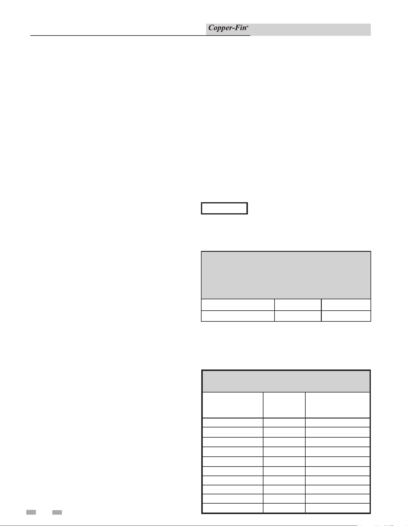
50
7 Domestic water heaters
Installation & Service Manual
Domestic Water Heaters 90,000 -
500,000 Btu/hr Models
This section applies only to those units used to sup ply direct
fired domestic hot water and installed with a storage tank(s).
The use of a properly sized pump and the control of water
velocity, as ex plained in the Water Velocity Control section, are
important for correct operation of your hot water heater.
This section contains specific instructions for those
units used to supply domestic hot water. All warn ings,
cau tions, notes and instructions in the gen er al installation
and service sections apply to these instructions. Water
heat ers are designed for installation with a storage tank. The
use of a properly sized pump and the control of water velocity,
as ex plained below, is important for correct operation of your
water heater.
Water Velocity Control
IMPORTANT - To ensure proper velocity through the heat
exchanger, it is necessary to regulate the tem per a ture rise across
the heat exchanger from inlet to outlet. This must be done on
initial in stal la tion and periodically rechecked. With the correct
temperature rise across the heat exchanger, you may be assured
of the proper velocity in the tubes. This will yield long life and
economical operation from your water heater. Excessive lime
build-up in the tube is a result of too little velocity in the tubes.
Excessive pit ting or erosion in the tube is caused by too much
ve loc i ty through the tubes. Care should be taken to measure
tem per a ture rise and maintain a velocity as follows:
1. The pump must run continuously when the burners are
firing.
2. With the pump running and the water heat er off, the
inlet and outlet ther mom e ters should read the same
temperatures. If they do not, an adjustment must be
made to your final calculation.
3. Turn the water heater on and allow time for the
temperature to stabilize. Record the difference between
the inlet and outlet temperatures. This difference will be
the “tem per a ture rise.”
4. Compare the temperature rise on the heater with the
required temperature rise in Table 7A. Should adjustment
be needed, proceed as fol lows:
If the temperature rise is too high, the water ve loc i ty is too low.
Check the following:
1. Check for restrictions in the outlet of the wa ter heater.
2. Be sure all valves are open between the water heater and
the tank.
3. Check the pump to be sure it is running prop er ly and that
the pump motor is running in the proper direction.
4. Be sure the circulation pipes between the wa ter heater and
storage tank are not less than 2" diameter for a single unit
installation.
5. Common manifold piping for multiple unit in stal la tions
will require larger minimum pipe siz es to tank tappings to
ensure proper flow. See Table 7B on page 49.
6. Multiple unit installations may also require a larger
circulating pump to achieve the specified flow against the
increased head loss of multiple unit com mon manifold
piping.
If the temperature rise is too low, the water ve loc i ty is too high.
Adjust as follows:
1. Slowly throttle the valve on the outlet side of the water
heater until the temperature rise is steady at the required
tem per a ture rise as noted in Table 7A.
2. Sustained high water velocity and low tem per a ture rise
may result in pitting or erosion of the copper tubes in
the heat exchanger. This is a non-warrantable failure.
Temperature rise must be properly adjusted to achieve the
specified flow rate.
Required Temperature Rise\
Temperature rise is based on the hardness of the potable water
to be heated. The temperature rise specified is for water with a
hardness of 5 to 20 grains per gallon. The total dissolved solids
shall not exceed 350 ppm.
TABLE - 7A
REQUIRED TEMPERATURE RISE
Btu/hr
INPUT
Flow Rate
GPM
Temperature Rise °F
90,000 30 5
135,000 30 7
180,000 30 10
199,000/201,000 30 11
225,000 30 12
270,000 30 15
315,000 30 17
360,000 30 20
399,000 30 22
500,000 30 28
TABLE - 4D
MAXIMUM FLOW FOR HEATING BOILER
The maximum flow rate through the boiler with a copper
heat exchanger must not exceed the following:
Model Maximum Flow
Maximum Flow for
CuNi Heat Exchanger
90,000 - 500,000 30 GPM 38 GPM
NOTICE
When connecting the unit to piping made of
a different material, use of a dielectric fitting
or a dielectric union conforming to ASSE 1079 is recommended
to prevent corrosion and potential subsequent water leaks at or
near the connection. Dielectric fittings may be required by local
plumbing codes.
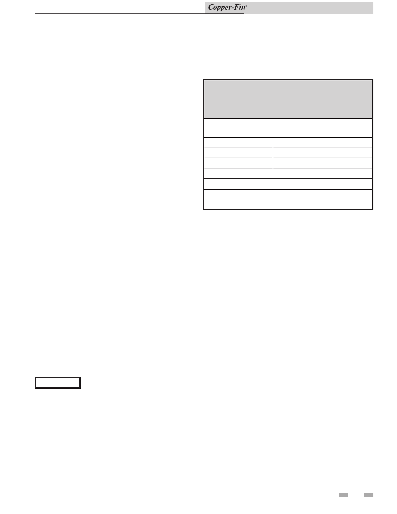
7 Domestic water heaters (continued)
Installation & Service Manual
Water Chemistry
The required temperature rise and the standard pump sizing
are based on the heating of potable water with chemistry
within the specified limits. Caution should be used when
heating water softened to less than 5 grains per gallon. Many
commercial water softeners reduce hardness to 0 grains
which may result in long term problems in the system.
Softened water will usually have a lower pH which can be
aggressive and corrosive causing non-warrantable damage to
the heater, pump, and associated piping.
Corrosion due to water chemistry generally shows up first in
the hot water system because heated water increases the rate
of corrosive chemical reactions. As water is heated it becomes
less soluble. The dissolved minerals and solids will precipitate
and collect as scale if water velocity is not properly controlled.
Follow the temperature rise requirements for unsoftened
water. Consult the manufacturer when heating potable
water with hardness or total dissolved solids exceeding
these specifications. Heating of high hardness and/or high
total dissolved solids water may require a larger circulating
pump, an optional cupro-nickel heat exchanger and a revised
temperature rise specification based on the water chemistry of
the water to be heated.
Softened Water Systems
Decreasing the flow rate will reduce the erosion process,
however the heat exchanger should be monitored to ensure
the scale/liming process is not made worse. The unit should
be placed on a comprehensive inspection schedule until
optimum flow rates can be established. Problematic water
areas may require heat exchanger inspection every two
weeks. The total scale accumulation should never exceed
the thickness of a piece of paper. Should scale accumulation
exceed this thickness the flow rate will need to be increased.
The tubes should not have a bright shiny copper look. This
would indicate that the erosion process has begun and the
flow rate will need to be decreased. Once the proper flow
rates have been established the inspection intervals can be
increased to every 30 days, once a quarter, or to a bi-annual
inspection. This procedure should ensure proper operation of
the unit as long as the water quality stays consistent.
TABLE - 7B
COMMON WATER MANIFOLD SIZE FOR
MULTIPLE HOT WATER SUPPLY BOILER
INSTALLATIONS
Pipe sizing chart provides minimum pipe size for common
manifold piping and tank tappings to ensure adequate flow.
Number of Units Common Manifold Size (Min.)
1 2"
2 2"
3 2 1/2"
4 3"
5 3 1/2"
6 3 1/2"
Pump Operation
1. The water heater/hot water supply boiler must be connected
to a properly sized pump that circulates water between the
heater and storage tank.
2. A standard water heater is furnished with a 1/6 HP, 120 VAC,
3.6 AMP circulating pump to be mounted on the units in let
water connection. This pump is sized based on installation
of a single storage tank and heat er in close proximity. If the
number of fit tings and straight pipe exceeds the quantities
shown in this sec tion, a larger pump will be required.
3. The pump must run continuously when the burners are
firing.
4. Lubricate the pump to the manufacturers rec om men da-
tions. Pump damage due to inadequate lu bri ca tion is non-
warrantable.
5. Pump is sized to heater input and water hard ness. Care
should be taken to size the pump correctly. See “Water
Chemistry”, this page.
The standard pump selection is based on the fol low ing pipe and
fittings from the unit to the stor age tank:
6 - 90° elbows 2 - ball valves
2 - unions 1 - cold water tee
Plus the following length of straight pipe based on the heater size:
90,000 through 360,000 Btu/hr Models
Not more than 45 feet of straight pipe
399,000 through 500,000 Btu/hr Models
Not more than 25 feet of straight pipe
For every elbow and tee in excess of those shown above, DEDUCT
5 FEET from maximum allowable straight pipe in heater to tank
circulating loop.
NOTICE
1. Do not use the water heater to directly
heat swimming pool or spa water.
2. At initial fill and during water heater start-up and testing,
check system thoroughly for any leaks. Repair all leaks before
proceeding further.
3. When water hardness levels are less than 5 gpg or 85.5 mg/l,
the following is recommended:
a. Flush and clean existing water heating system prior to
installation.
b. Inspect and, if necessary, replace the anodes in any existing
tanks.
c. Install a Y-strainer on the inlet of each water heater as
detailed in this section.
d. Limit the run time of the hot water recirculation loop.
e. Filter the hot water recirculation loop to a level of 10 microns.
CAUTION: Check recirculation pump size to verify it is sized
for filter addition and upsize if necessary.
4. When water softener is required, a Template Assisted
Crystallization system is recommended.
51
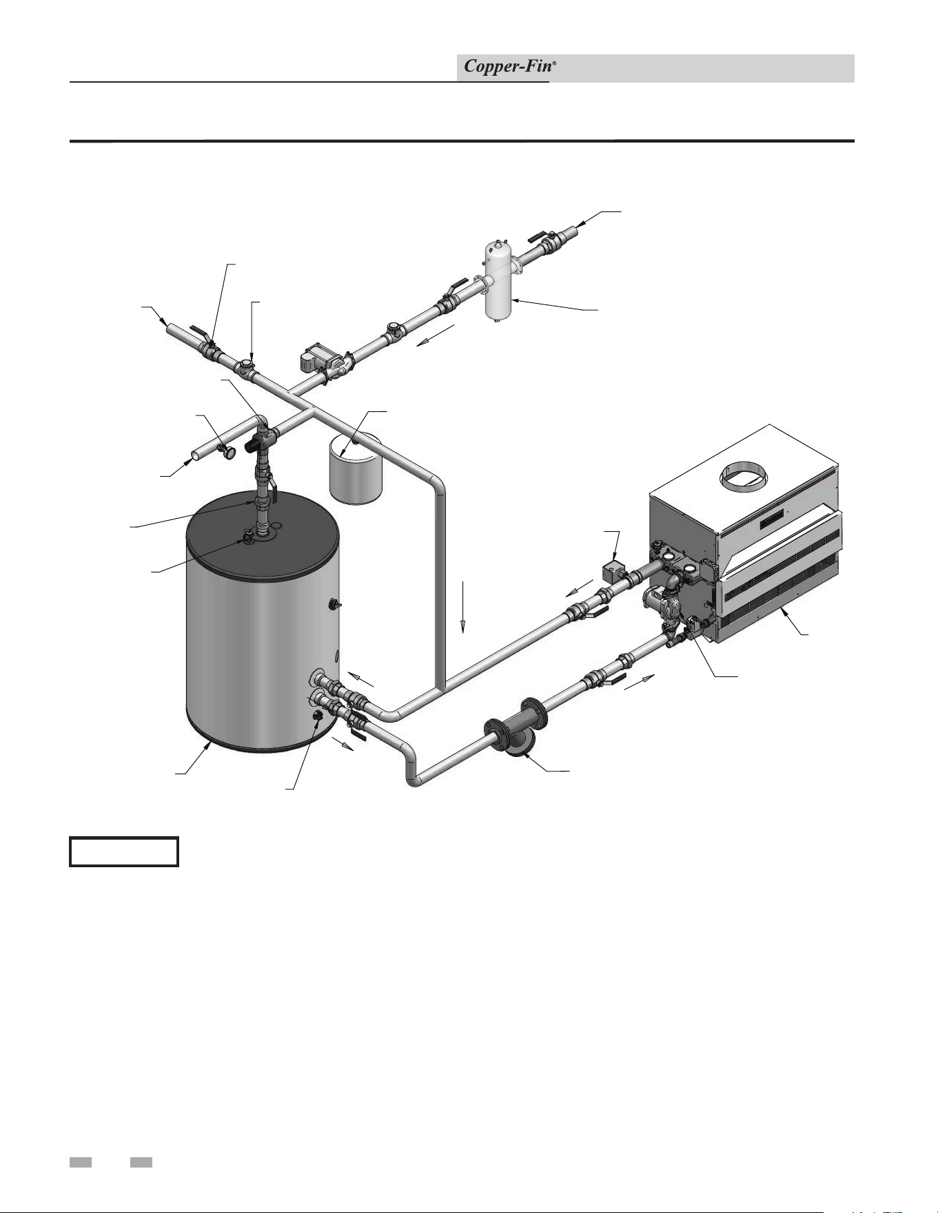
52
Installation & Service Manual
7 Domestic water heaters
Figure 7-1_Single water heater_single tank
FLOW CHECK
VALVE (TYPICAL)
EXPANSION
TANK
THERMOMETER
COLD
WATER
SUPPLY
HOT WATER
SUPPLY
BUILDING
RETURN
DRAIN
TEMPERATURE
& PRESSURE
RELIEF VALVE
(TYPICAL)
FLOW
SWITCH
WATER HEATER
CIRCULATOR
STORAGE
TANK
WATER
HEATER
UNION
(TYPICAL)
BALL VALVE
(TYPICAL)
MIXING VALVE
Y-STRAINER
DIR #2000570581_000
BUILDING RECIRCULATION FILTER
(IF REQUIRED SEE SECTION 7)
Please note that these illustrations are meant to show system piping concept only, the installer is responsible
for all equipment and detailing required by local codes.
NOTICE
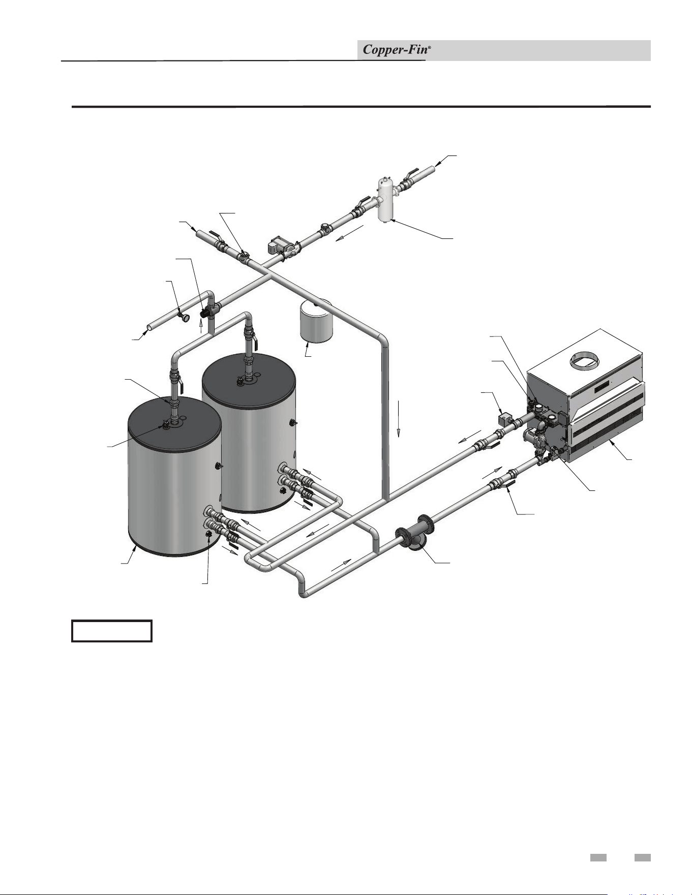
53
Installation & Service Manual
7 Domestic water heaters (continued)
Figure 7-2_Single water heater_multiple tank
FLOW CHECK
VALVE (TYPICAL)
BALL VALVE
(TYPICAL)
EXPANSION
TANK
THERMOMETER
COLD WATER
SUPPLY
HOT WATER
SUPPLY
BUILDING
RETURN
DRAIN
(TYPICAL)
TEMPERATURE
& PRESSURE
RELIEF VALVE
(TYPICAL)
FLOW
SWITCH
WATER HEATER
CIRCULATOR
STORAGE TANK
(TYPICAL)
WATER
HEATER
UNION
(TYPICAL)
MIXING VALVE
TEMPERATURE/
PRESSURE
GAUGE
RELIEF VALVE
( TYPICAL )
Y-STRAINER
DIR #2000570582_000
BUILDING RECIRCULATION FILTER
(IF REQUIRED SEE SECTION 7)
Please note that these illustrations are meant to show system piping concept only, the installer is responsible
for all equipment and detailing required by local codes.
NOTICE
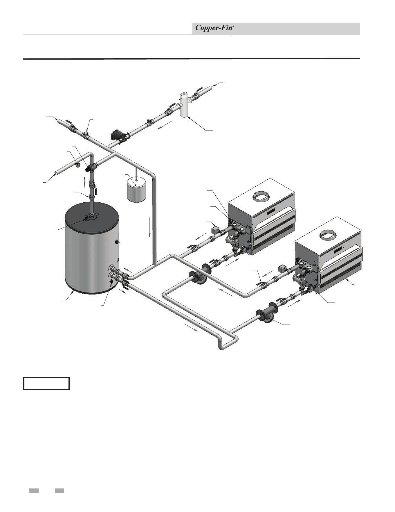
54
7 Domestic water heaters
Installation & Service Manual
Figure 7-3_Multiple water heater_single tank
HOT WATER
SUPPLY
TEMPERATURE
& PRESSURE
RELIEF VALVE
(TYPICAL)
FLOW SWITCH
( TYPICAL )
WATER HEATER
CIRCULATOR
( TYPICAL)
STORAGE
TANK
WATER
HEATER
UNION
(TYPICAL)
BALL VALVE
(TYPICAL)
PRESSURE RELIEF
VALVE
( TYPICAL )
TEMPERATURE/PRESSURE
GAUGE
(TYPICAL)
EXPANSION
FLOW CHECK
VALVE ( TYPICAL )
COLD WATER
SUPPLY
MIXING VALVE
BUILDING
RETURN
( TYPICAL)
Y-STRAINER
DIR #2000570583_000
BUILDING RECIRCULATION FILTER
(IF REQUIRED SEE SECTION 7)
DRAIN
THERMOMETER
Please note that these illustrations are meant to show system piping concept only, the installer is responsible
for all equipment and detailing required by local codes.
NOTICE
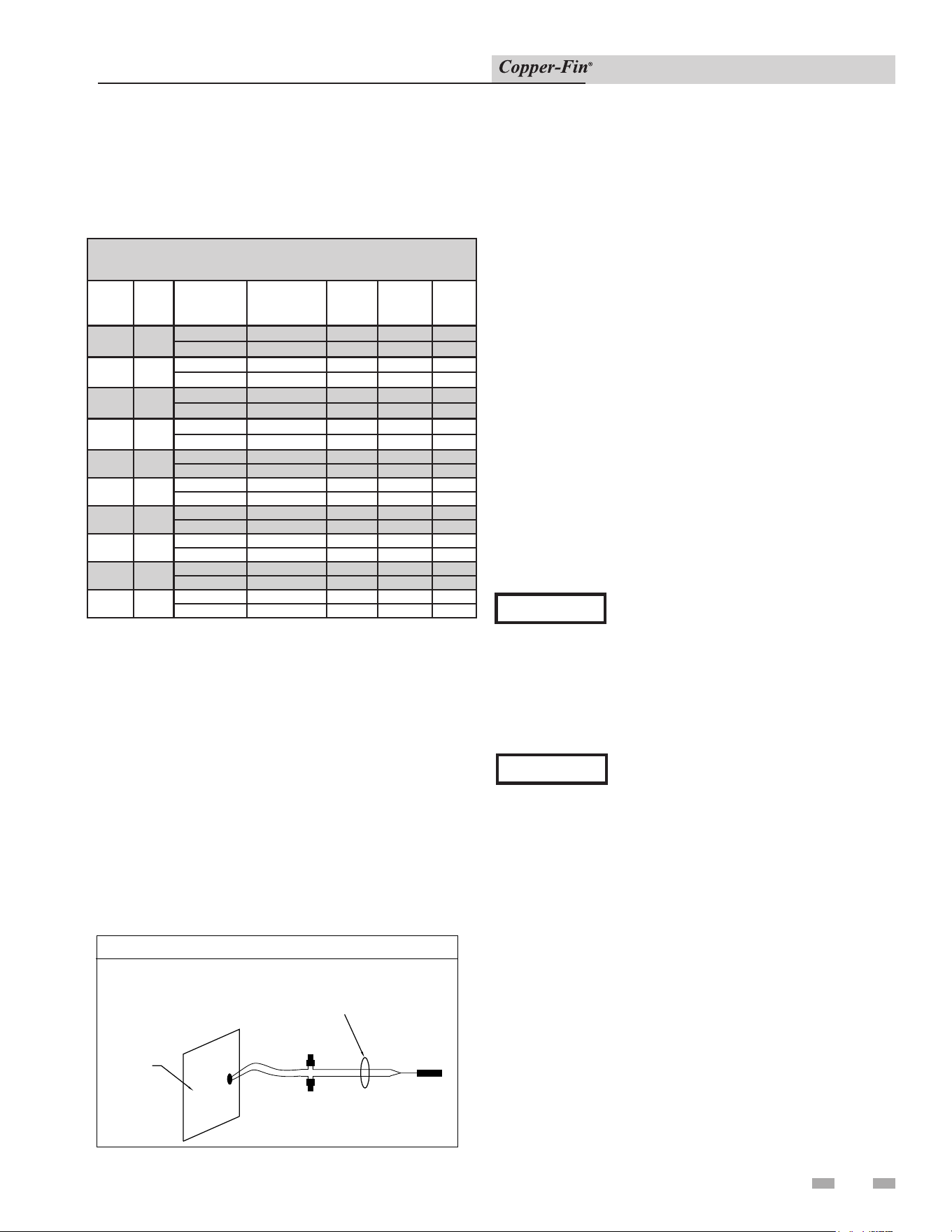
7 Domestic water heaters (continued)
55
Installation & Service Manual
Minimum Pump Performance
Based on heating potable water with a hardness of 5 to 20
grains per gallon and total dissolved solids not exceeding 350
ppm. See “Water Chemistry”, page 49.
EXTERNAL SENSOR FOR TANK, SYSTEM OR PUMP DELAY
REMOTE SENSOR CONNECTOR IS
LOCATED ON SIDE OF UNIT.
NOTE: COLOR OF WIRES AND
LEAD STYLES MAY VARY
WITH SENSOR PROVIDED.
CONNECTIONS ARE POLARITY
INSENSITIVE.
SIDE PANEL
Figure 7-4_External Sensor for Tank, System or Pump
Delay
Heat Exchanger
On all mod els, header inspection plugs can be removed for
field in spec tion and cleaning of copper tubes. The entire heat
exchanger may be easily removed from the unit.
Thermostat Settings
1. The thermostat is adjusted to a low test set ting when
shipped from the factory.
2. Set the thermostat to a maximum water temperature of
125°F which will satisfy hot water demands and prevent
risk of scald injury.
Households with small children or invalids may
require 120°F or lower temperature setting to re duce
risk of scald in ju ry. Some states may require a lower
temperature setting. Check with your gas supplier for local
re quire ments governing the tem per a ture setting. Re mem-
ber, no water heating sys tem will provide exact tem-
per a ture at all times. Allow a few days of operation at
this setting to de ter mine the correct temperature set ting
consistent with your needs.
NOTICE
(1) This water heater, when set at the
low er temperature setting, is not capable
of producing hot water of sufficient
temperature for sanitizing pur pos es.
(2) Higher stored water temperature
in creas es the ability of the water heater
to supply desired quantities of hot water,
however remember:
⚠ CAUTION
Hotter water increases the risk of scald
injury.
Incorrect piping of the cold water supply to the sys tem
may result in excessive low temperature op er a tion causing
condensate formation on the heat ex chang er and operational
problems. The cold water supply piping must be installed in
the dis charge piping from the heater to the storage tank. This
allows the cold water to be tempered in the storage tank before
entering the heater. See typ i cal installation drawings provided
in this manual. Higher wa ter temperatures reduce condensate
formation.
TABLE 7C
Water Heater Pump Applications
Model
Pipe
Size
Water
Hardness
Grundfos
Pump
Flow
Rate
(GPM)
Head
Loss
(FT)
Temp.
Rise
90,000
2"
5 to 15 gpg TP45PAB 30 8 5°F
15 to 20 gpg UPS 43-100 SF 38 8 4°F
135,000 2"
5 to 15 gpg TP45PAB 30 8 7°F
15 to 20 gpg UPS 43-100 SF 38 8 6°F
180,000 2"
5 to 15 gpg TP45PAB 30 8 10°F
15 to 20 gpg UPS 43-100 SF 38 8 8°F
199,000/
201,000
2"
5 to 15 gpg TP45PAB 30 8 9°F
15 to 20 gpg UPS 43-100 SF 38 8 7°F
225,000 2"
5 to 15 gpg TP45PAB 30 8 12°F
15 to 20 gpg UPS 43-100 SF 38 8 10°F
270,000
2"
5 to 15 gpg TP45PAB 30 8 15°F
15 to 20 gpg UPS 43-100 SF 38 8 12°F
315,000
2"
5 to 15 gpg TP45PAB 30 8 17°F
15 to 20 gpg UPS 43-100 SF 38 8 14°F
360,000
2"
5 to 15 gpg TP45PAB 30 8 20°F
15 to 20 gpg UPS 43-100 SF 38 8 16°F
399,000 2"
5 to 15 gpg TP45PAB 30 8 22°F
15 to 20 gpg UPS 43-100 SF 38 8 17°F
500,000 2"
5 to 15 gpg TP45PAB 30 8 28°F
15 to 20 gpg UPS 43-100 SF 38 8 22°F
Remote Sensor Installation
Water heaters are provided with an extra temperature sensor
that MUST BE field installed. The sensor is shipped loose
in the I & O packet. This remote mounted sensor will be the
primary temperature sensor which will inform the appliance’s
built-in thermostat control. For domestic water heating, the
sensor MUST BE installed into a bulbwell on the storage tank.
This is required to maintain the desired temperature in the
tank and reduce cycling of the heater.
The sensor must also be connected to two blue wires provided
in the upper left-hand corner of the control panel. It will be
necessary to add additional wire to reach from the appliance
to the remote water source. Use twisted pair wire, minimum
18 gauge or larger. See Table 5A, page 35 regarding distance
versus wire gauge.
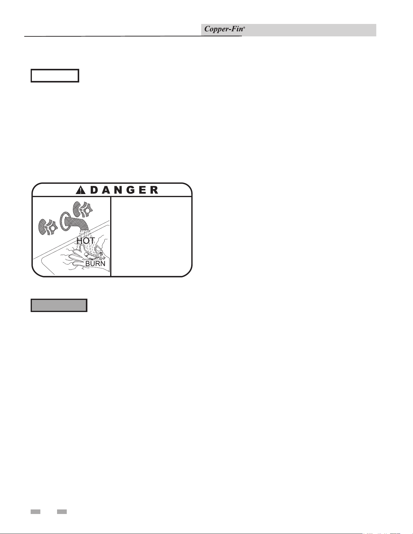
56
Installation & Service Manual
7 Domestic water heaters
⚠ CAUTION
Setting the temperature selector to high-
er settings provides hotter water, which
in creas es the risk of scald injury.
The manufacturer recommends the use of a prop er ly sized
thermostatic mixing valve to supply do mes tic hot water
at temperatures less than 140°F. Storing the water at a
higher temperature and ther mo stat i cal ly mixing the water
will increase the avail able quantity of mixed hot water,
greatly reduce the possibility of con den sate formation on the
heat exchanger and help pre vent the growth of water born
bacteria. Adequate care MUST be taken to prevent potential
scald injury when storing water at 140°F and hotter.
• Water temperature over 125°F (52°C)
can cause severe burns instantly or
death from scalds.
• Children, disabled and elderly are
at highest risk of being scalded.
• See instruction manual before
setting temperature at heating
appliance.
• Feel water before bathing or showering.
• If this appliance is used to produce
water that could scald if too hot,
such as domestic hot water use,
adjust the outlet control (limit) or use
temperature limiting valves to obtain
a maximum water temperature of
125°F (52°C).
Figure 7-5_Danger Warning
Should overheating occur or the gas
supply fail to shut off, DO NOT turn
off or disconnect the electrical supply
to the pump. Instead, shut off the gas
supply at a location external to the
appliance.
⚠ WARNING
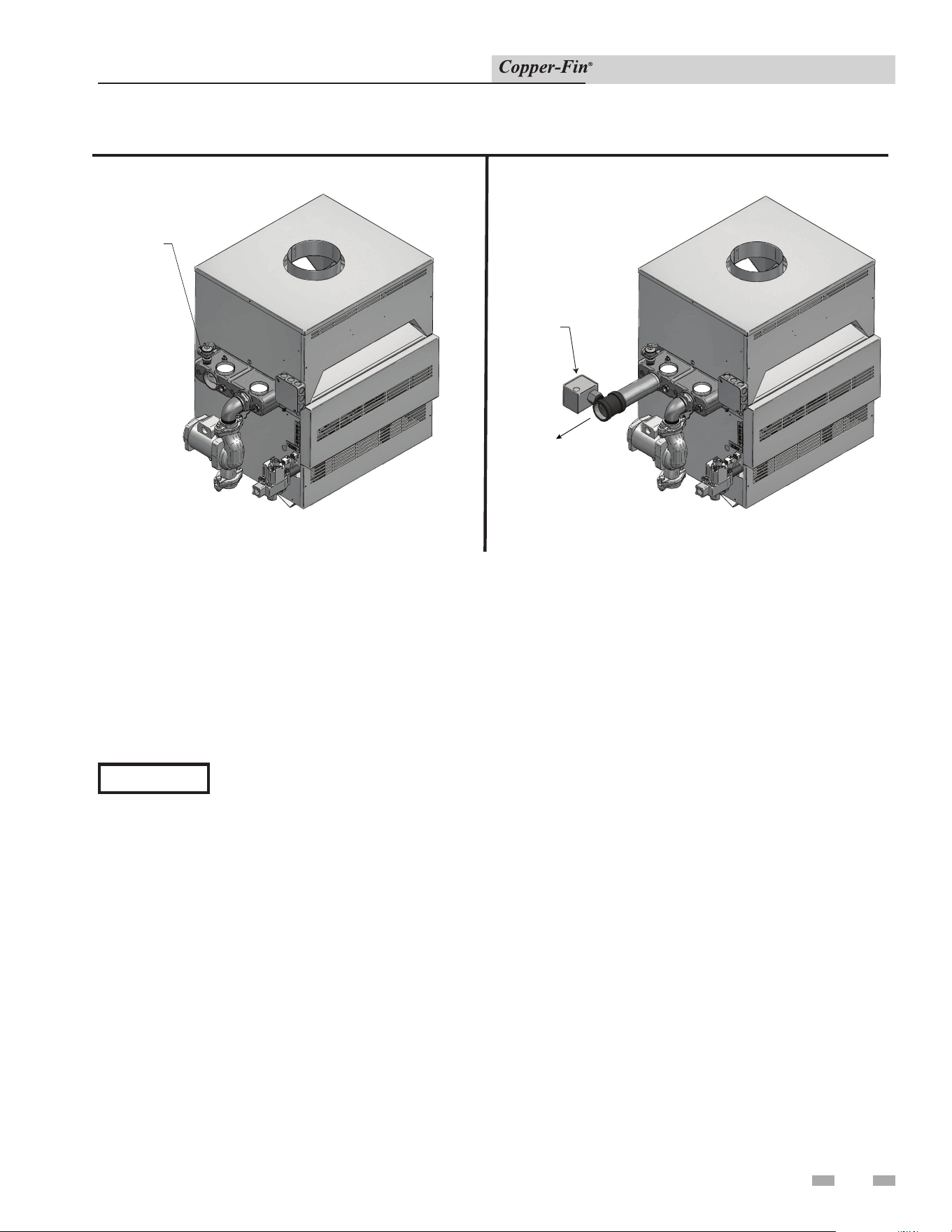
57
Installation & Service Manual
7 Domestic water heaters (continued)
Figure 7-6_Relief Valve - Water heater
Figure 7-7_Water Flow Switch, Water heater
Relief Valve
RELIEF
VALVE
FLOW
SWITCH
FLOW
This appliance is supplied with a relief valve sized in accordance
with ASME Boiler and Pressure Ves sel Code, Section IV
(“Heating Boilers”). The re lief valve is mounted directly into
the heat ex chang er inside the header (see FIG.’s 7-6 and 7-7).
To pre vent water damage, the dis charge from the relief valve
shall be piped to a suit able floor drain for disposal when relief
occurs. No reducing couplings or other restrictions shall be
installed in the discharge line. The discharge line shall allow
complete drainage of the valve and line. Relief valves should
be manually operated at least once a year.
⚠ CAUTION
Avoid contact with hot discharge water.
A water flow switch is available as a factory sup plied option
on all water heaters. The flow switch should be wired
between terminals X and B. Remove the jumper between
the X and B terminals on the terminal strip. This wiring
connection installs the flow switch in the 24 VAC safety
cir cuit to prove water flow before main burner ig ni tion. A
flow switch installed with the fac to ry sup plied minimum
adjustment setting requires a spe cif ic minimum flow to
make the switch and start burner operation. The flow rate
required is a function of the diameter of pipe and tee used for
installation. Ensure that the pump installed water heater will
supply adequate flow to make the flow switch con tacts and
operate the water heater.
Pressure Only Relief Valve
This water heater/hot water supply boiler is nor mal ly supplied
with a temperature and pressure re lief valve sized in accordance
with applicable codes. Units may be supplied with an optional
pres sure only relief valve. When a water heater/hot water
supply boil er equipped with this optional re lief valve is piped to
a separate storage vessel, the storage vessel must have a properly
installed tem per a ture and pressure relief valve which complies
with local codes.
Thermal Expansion
A relief valve which discharges periodically may be due to
thermal expansion in a closed system. A hot water supply
boiler installed in a closed sys tem, such as one with a backflow
preventer or check valve in stalled in the cold water supply,
shall be provided with means to control expansion. Con tact the
water sup pli er or local plumbing inspector on how to correct
this situation. Do not plug or cap the relief valve discharge!
Cathodic Protection
Hydrogen gas can be produced in a hot water sys tem that has
not been used for a long period of time (gen er al ly two weeks
or more). Hydrogen gas is ex treme ly flammable. To prevent
the pos si bil i ty of injury under these conditions, we rec om mend
the hot water faucet be open for several minutes at the kitch en
sink before you use any electrical ap pli ance which is connected
to the hot water sys tem. If hydrogen is present, there will be
an un usu al sound such as air escaping through the pipe as the
hot water begins to flow. There should be no smoking or open
flames near the faucet at the time it is open.
Water Flow Switch (if equipped)
58
Installation & Service Manual
8 Maintenance
Table 8A_Service and Maintenance Schedules
Service technician
(see the following pages for instructions)
General:
• Address reported problems.
• Inspect interior; clean and vacuum,
if necessary;
• Check for leaks (water, gas, flue)
• Examine venting system
• Check system water pressure/
system piping/expansion tank
• Check fill water meter
• Test boiler water. When test
indicates, clean system water with
approved system restorer following
manufacturer's information.
• Check control settings
• Check wiring and connections
• Flame inspection (stable, uniform)
• Check flue gas passageways
• Inspect and clean the burner
• Perform start-up check out and
performance verification per Section
6 - Start-up
If combustion or performance
indicate need:
• Clean heat exchanger
• Remove and wash burner
Annual Startup
Owner maintenance
(see the User’s Information Manual for
instructions)
Daily
• Check appliance area
• Check pressure/temperature
gauge
Monthly
• Check vent piping
• Check relief valve
• Remove debris from Y-strainer
per manufacturer’s instructions
• Check building recirculation
filter (if filter required)
Periodically
• Test low water cuto (if used)
• Reset button (low water cuto)
Every
6 months
• Check appliance piping (gas
and water) for leaks
• Operate relief valve
End
of season
months
• Shut appliance down (unless
boiler used for domestic hot
water)
8 Maintenance (continued)
59
Installation & Service Manual
Follow the service and maintenance procedures given throughout this manual and in component literature
shipped with the appliance. Failure to perform the service and maintenance could result in damage to the
appliance or system. Failure to follow the directions in this manual and component literature could result in
severe personal injury, death, or substantial property damage.
The appliance should be inspected annually only by a qualified service technician. In addition, the
maintenance and care of the appliance designated in Table 8A and explained on the following pages must
be performed to assure maximum appliance efficiency and reliability. Failure to service and maintain the
appliance and system could result in equipment failure.
Electrical shock hazard – Turn off power to the appliance before any service operation on the appliance except
as noted otherwise in this instruction manual. Failure to turn off electrical power could result in electrical
shock, causing severe personal injury or death.
Address reported problems
1. Inspect any problems reported by the owner and correct
before proceeding.
Inspect appliance area
1. Verify that appliance area is free of any combustible
materials, gasoline and other flammable vapors and
liquids.
Inspect appliance interior
1. Remove the outer access panels and inspect the interior of
the appliance.
2. Vacuum any sediment from inside the appliance and
components. Remove any obstructions.
Eliminate all system or appliance leaks.
Continual fresh makeup water will
reduce appliance life. Minerals can build
up in sections, reducing heat transfer,
overheating heat exchanger, and causing
heat exchanger failure. Leaking water
may also cause severe property damage.
1. Inspect all water and gas piping and verify to be leak free.
2. Look for signs of leaking lines and correct any problems
found.
3. Check gas line using the procedure found in Section 3
- Gas Connections.
Check all piping for leaks
⚠ WARNING
⚠ WARNING
⚠ WARNING
⚠ WARNING
⚠ CAUTION
Label all wires prior to dis con nec tion when servicing controls. Wiring errors can cause improp er and
dangerous operation.
Listed below are items that must be checked to en sure safe
reliable operation. Verify proper op er a tion after servicing.
Flue vent system
1. Examine the venting system at least once a year. Check
more often in the first year to de ter mine in spec tion interval.
Check all joints and pipe connections for tightness,
corrosion or deterioration. Clean louvers and/or screens
in the combustion air intake system as required. Have the
entire system, including the venting system, periodically
inspected by a qualified service agency.
Check water system
1. Verify all system components are correctly installed and
operational.
2. Check the cold fill pressure for the system. Verify it is
correct (must be a minimum of 12 PSI).
3. Watch the system pressure as the boiler heats up (during
testing) to ensure pressure does not rise too high. Excessive
pressure rise indicates expansion tank sizing or performance
problem.
4. Inspect automatic air vents and air separators. Remove air
vent caps and briefly press push valve to flush vent. Replace
caps. Make sure vents do not leak. Replace any leaking
vents.
60
8 Maintenance
Installation & Service Manual
Check Expansion Tank
1. Expansion tanks provide space for water to move in
and out as the heating system water expands due to
temperature increase or contracts as the water cools.
Tanks may be open, closed, diaphragm or bladder
type. See Section 4 - Hydronic Piping for suggested best
location of expansion tanks and air eliminators.
Check fill water meter
1. Check fill water meter for water usage. If the amount
exceeds 5% of your system volume, you could have a
leak. Have the system checked for leaks and fixed by a
qualified service technician.
Test boiler water
1. Test boiler water. Reference the Copper-Fin Installation
and Operation Manual for guidelines. When test
indicates, clean system water with approved system
restorer following the manufacturer’s information.
Check Relief Valve
1. Inspect the relief valve and lift the lever to verify flow.
Before operating any relief valve, ensure that it is piped
with its discharge in a safe area to avoid severe scald
potential. Read Section 4 - Hydronic Piping before
proceeding further.
Safety relief valves should be re-inspected
AT LEAST ONCE EVERY THREE
YEARS, by a licensed plumbing contractor
or authorized inspection agency, to
ensure that the product has not been
affected by corrosive water conditions
and to ensure that the valve and discharge
line have not been altered or tampered
with illegally. Certain naturally occurring
conditions may corrode the valve or its
components over time, rendering the
valve inoperative. Such conditions are
not detectable unless the valve and its
components are physically removed and
inspected. This inspection must only
be conducted by a plumbing contractor
or authorized inspection agency – not
by the owner. Failure to re-inspect the
boiler relief valve as directed could result
in unsafe pressure buildup, which can
result in severe personal injury, death, or
substantial property damage.
⚠ WARNING
Following installation, the valve lever
must be operated AT LEAST ONCE
A YEAR to ensure that waterways are
clear. Certain naturally occurring
mineral deposits may adhere to the valve,
rendering it inoperative. When manually
operating the lever, water will discharge
and precautions must be taken to avoid
contact with hot water and to avoid water
damage. Before operating lever, check
to see that a discharge line is connected
to this valve directing the flow of hot
water from the valve to a proper place
of disposal. Otherwise severe personal
injury may result. If no water flows, valve
is inoperative. Shut down the appliance
until a new relief valve has been installed.
2. After following the above warning directions, if the relief
valve weeps or will not seat properly, replace the relief
valve. Ensure that the reason for relief valve weeping is
the valve and not over-pressurization of the system due to
expansion tank waterlogging or undersizing.
⚠ WARNING
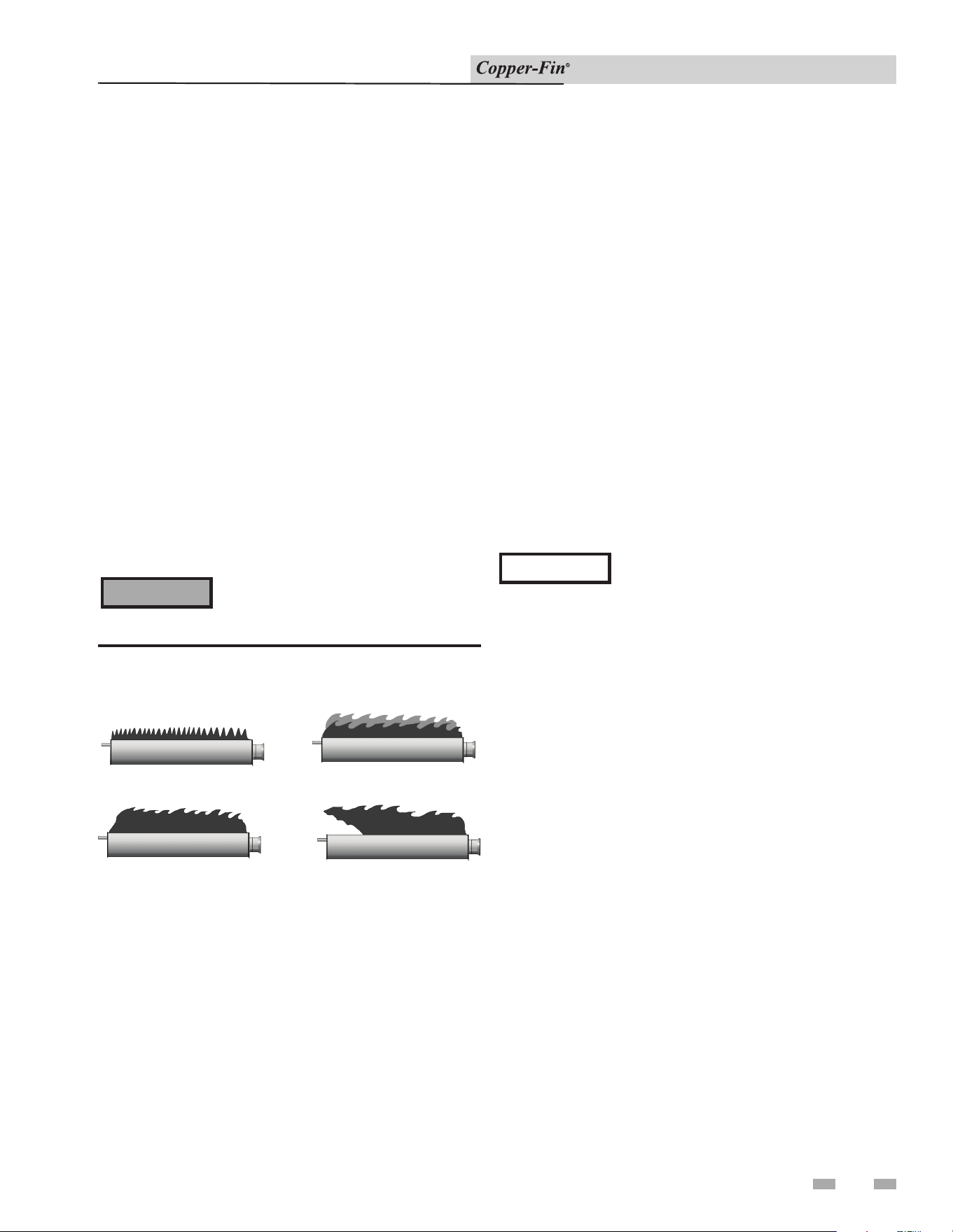
Installation & Service Manual
8 Maintenance (continued)
61
Check All Wiring
1. Inspect all wiring, making sure wires are in good condition
and securely attached.
Check Control Settings
1. Adjust settings if necessary. See Section 5 - Electrical
Connections for adjustment procedures.
2. Check settings of external limit controls (if any) and
adjust if necessary.
Check Burner Flame
Visually check main burner flames at each start-up after long
shutdown periods or at least every six months. A burner
viewport is located on the burner mounting flange.
Perform Start-up and Checks
1. Start appliance and perform checks and tests specified in
Section 6 - Start-up.
2. Verify cold fill pressure is correct and that operating
pressure does not go too high.
The area around the burner and burner
viewport is hot. Direct contact could
result in burns.
⚠ WARNING
NORMAL
A
YELLOW TIP
B
D
FLAME LIFT
C
YELLOW FLAME
Figure 8-1_Flame Pattern Illustration
Normal Flame: A normal flame is blue, with slight yellow
tips, with a well defined inner cone and no flame lifting.
Yellow Tip: Yellow tip can be caused by blockage or partial
obstruction of air flow to the burner(s).
Yellow Flames: Yellow flames can be caused by blockage of
primary air flow to the burner(s) or excessive gas input. This
condition MUST be cor rect ed immediately.
Lifting Flames: Lifting flames can be caused by over firing
the burner(s) or excessive primary air.
If improper flame is observed, examine the venting system,
ensure proper gas supply and adequate supply of combustion
and ventilation air.
Combustion Air Adjustment
This ap pli ance uses an atmospheric combustion process.
Combustion air is provided to the burners by the gas injection
pressure into the venturi of the burn ers. The burners do not
have an adjustable air shutter. Ad e quate combustion air must
be supplied to the room where the appliance is installed to
ensure proper burner operation. Check frequently to be sure
the flow of com bus tion and ventilation air to the unit is not
obstructed. When the main burn ers light, observe the burn er
flame. Flames should be light blue in color with slight yellow
tips; flames should be settled on burner head with no lifting
when supplied with correct vol ume of combustion air.
Check Flue Gas Passageways
Any sign of soot around the outer jacket, at the burn ers or
in the areas between the fins on the cop per heat exchanger
indicates a need for cleaning. The following cleaning procedure
must only be per formed by a qualified serviceman or installer.
Prop er service is required to maintain safe operation. Properly
installed and ad just ed appliances sel dom need flue cleaning.
All gaskets on disassembled components
must be replaced with new gaskets on
re as sem bly. Gasket kits are available from
your distributor.
NOTICE

62
8 Maintenance
Installation & Service Manual
q Avoid breathing dust and contact with skin and eyes.
• Use NIOSH certified dust respirator (N95). This type
of respirator is based on the OSHA requirements for
cristobalite at the time this document was written.
Other types of respirators may be needed depending on
the jobsite conditions. Current NIOSH
recommendations can be found on the NIOSH website at
(http://www.cdc.gov/niosh/homepage.html). NIOSH
approved respirators, manufacturers and phone numbers
are also listed on this website.
• Wear long-sleeved, loose fitting clothing, gloves, and eye
protection.
q Apply enough water to the combustion chamber lining to
prevent airborne dust.
qRemove combustion chamber lining from the appliance
and place it in a plastic bag for disposal.
q Wash potentially contaminated clothes separately from
other clothing. Rinse clothes thoroughly.
q NIOSH stated First Aid:
Eye: Irrigate immediately.
Breathing: Fresh air.
Heat Exchanger / Burner Access
a. Turn “OFF” main power to the appliance.
b. Turn “OFF” external manual gas shutoff valve to
appliance.
c. Remove the control panel door.
d. Remove the outer air deflector (FIG. 8-2).
e. Disconnect gas valve wiring and remove gas
manifold assembly.
f. Remove ignition wire leading to the pilot assembly
from the ignition module.
g. Disconnect the wiring from the flame rollout/
interlock switch, see FIG. 8-2, page 61.
h. Remove the lower front jacket panel.
i. Remove the control panel mounting screws. When
removing the control panel, lay the control panel to
the side with the wiring intact, being careful not to
damage any of the wiring.
j. Remove the combustion chamber door. Use caution
to prevent damage to burn ers, refractory, pilot or
wiring.
Inspection and Cleaning Procedure
k. Check the heat exchanger surface for sooting. The
external surfaces of the copper tubes should be free of
any soot deposits. (A slight black smudge is normal
with some types of gases.) If abnormal soot deposits
are present, the heat exchanger must be cleaned and
the cause of the soot problem corrected. Proceed as
follows:
l. Remove soot from burners and bottom of the finned
tubes with a stiff bristle brush. Dirt may also be
removed from burner ports by rinsing the burner
thor ough ly with water. Drain and dry burners before
re-installing. Damaged burners must be re placed.
An appliance installed in a dust or dirt con tam i nat ed
atmosphere will require cleaning of the burners on a 3
to 6 month schedule or more often, based on severity of
contamination. Contaminants can be drawn in with the
combustion air. Non-combustible particulate mat ter such
as dust, dirt, concrete dust or dry wall dust can block burner
ports and cause non-warrantable failure. Use extreme care
when operating an appliance for temporary heat during new
construction. The burners will probably re quire a thorough
cleaning before the appliance is placed in service.
m. Remove gas manifold as described in steps a. through
e. in “Heat Exchanger/Burner Access.”
n. Loosen mounting screws and remove front control
panel.
o. Loosen screws on the upper front jack et panel and
remove toward front of the appliance. Use caution
to prevent damage to re frac to ry on the doors inner
surface.
Inspect and Clean Burner
⚠ WARNING
The combustion chamber insulation in this
appliance contains ceramic fiber material.
The International Agency for Research
on Cancer (IARC) has concluded,
“Crystalline Silica in the form of quartz
or cristobalite from occupational sources
is carcinogenic to humans (Group 1).”
Normal operating temperatures in this
appliance are below the level to convert
ceramic fibers to cristobalite. Abnormal
operating conditions would have to be
created to convert the ceramic fibers in
this appliance to cristobalite.
The ceramic fiber material used in this
appliance is an irritant; when handling
or replacing the ceramic materials it is
advisable that the installer follow these
safety guidelines:
⚠ DANGER
When cleaning burner, DO NOT use a
steel wire brush as it may spark and create
a hazardous situation causing property
damage, serious injury, or death. Use a
soft bristle brush when cleaning burner.
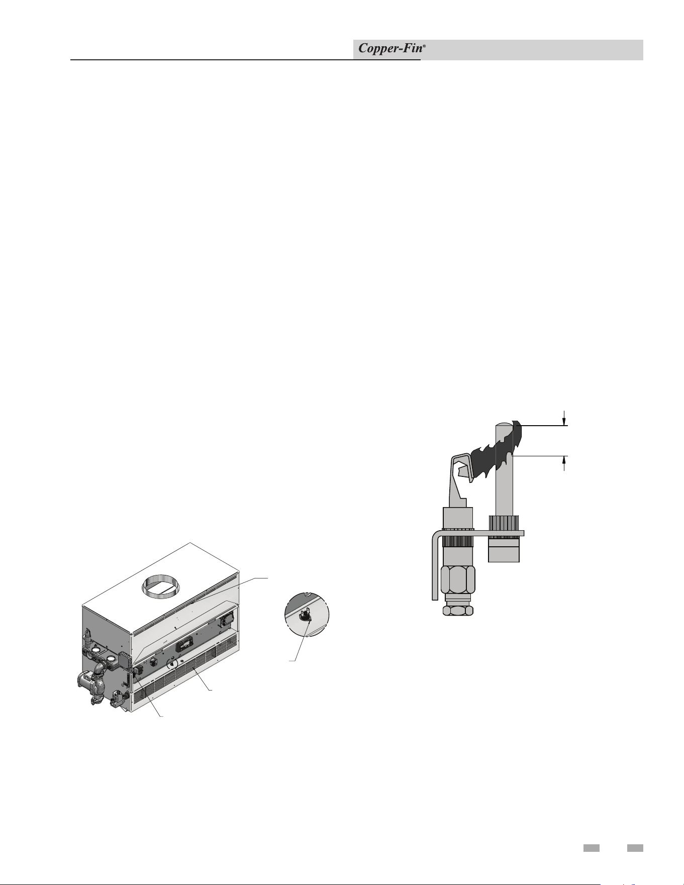
8 Maintenance (continued)
63
Installation & Service Manual
p. Check “V” baffles on top of the heat ex chang er.
Remove and clean if necessary.
q. Remove soot from the heat exchanger with a stiff
bristle brush. Soot may also be re moved from the heat
exchanger by washing thoroughly with detergent
and water. Remove the heat exchanger before using
water for cleaning. Rinse thoroughly and dry before
re-installing. Use a vacuum to remove loose soot
from surfaces and in ner chamber.
r. Remove the heat exchanger (HEX) filler bracket
(FIG. 8-2).
s. The heat exchanger can be removed by sliding
towards the front of the appliance. Once the heat
exchanger is removed from the ap pli ance, a garden
hose can be used to wash the tubes to ensure that all
soot is removed from the heat exchanger surfaces.
t. Ensure that all burner ports are cleaned to remove
any soot. See Inspection and Cleaning Procedure,
page 60.
u. Carefully re-install the heat exchanger, “V” baffles,
jacket panels, and wires.
v. Reassemble all gas and water piping. Test for gas
leaks.
w. Cycle the appliance and check for prop er operation.
DETAIL
HEX FILLER BRACKET
FLAME
ROLL-OUT SWITCH /
INTERLOCK SWITCH
UPPER FRONT
JACKET PANEL
LOWER FRONT
JACKET PANEL
Figure 8-2_Outer Air Deflector and HEX Filler Bracket
Water Circulating Pump
Inspect pump ev ery 6 months and oil if required. Use
SAE 30 non-detergent oil or lubricant specified by pump
man u fac tur er.
Pilot Flame Adjustment Procedure
The pi lot flame should envelop 3/8" to 1/2" (10 to 13mm) of the
tip of the thermocouple (see FIG. 8-3).
1/2"
Figure 8-3_Pilot Flame on Thermocouple
a. Remove pilot adjustment cover screw on the gas
valve. See the Gas Valve illustrations in the Lighting
Instructions section (page 43) for the lo ca tion of the
cover screw.
b. Turn the inner adjustment screw clock wise to decrease
or counterclockwise to increase pilot flame.
c. Replace the pilot adjustment cover screw on the valve.
Tighten firmly after adjustment to prevent gas leakage.
Clear Area
1. Keep appliance area clear and free from com bus ti ble
materials, gasoline and other flammable vapors and liquids.
2. Check frequently to be sure the flow of com bus tion and
ventilation air to the boiler is not obstructed.
Inspection of Heat Exchanger Waterways
Appliances operated in hard water areas should have periodic
inspections of the tubes to be sure that no sediment or scale
accumulates on the heat transfer sur fac es. Inspection plugs are
located at both ends of the heat exchanger. In spec tion plugs
should be removed and tubes inspected at the end of the first 45
days of operation and again at the end of 90 days of operation.
If no scale accumulation is ob served, inspections can be made at
the end of each six months of op er a tion.
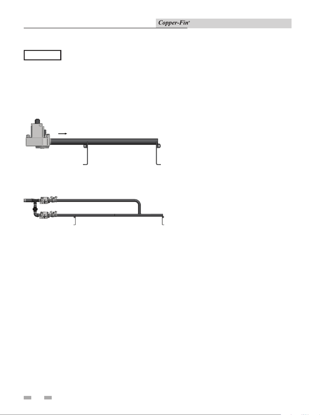
8 Maintenance
64
Installation & Service Manual
IMPORTANT
Upon completion of any testing on the
gas system, leak test all gas connections
with a soap solution while main burners
are operating. Im me di ate ly repair any
leak found in the gas train or re lat-
ed components. Do Not operate an
appliance with a leak in the gas train,
valves or related piping.
Gas Train and Controls
GAS FLOW
Figure 8-4_Gas Train 90,000 - 399,000 Btu/hr Models
Figure 8-5_Gas Train 500,000 Btu/hr Model
Review with owner
1. Review the User’s Information Manual with the owner.
2. Emphasize the need to perform the maintenance schedule
specified in the User’s Information Manual (and in this
manual as well).
3. Remind the owner of the need to call a licensed contractor
should the appliance or system exhibit any unusual behavior.
4. Remind the owner to follow the proper shutdown procedure
and to schedule an annual start-up at the beginning of the
next heating season.
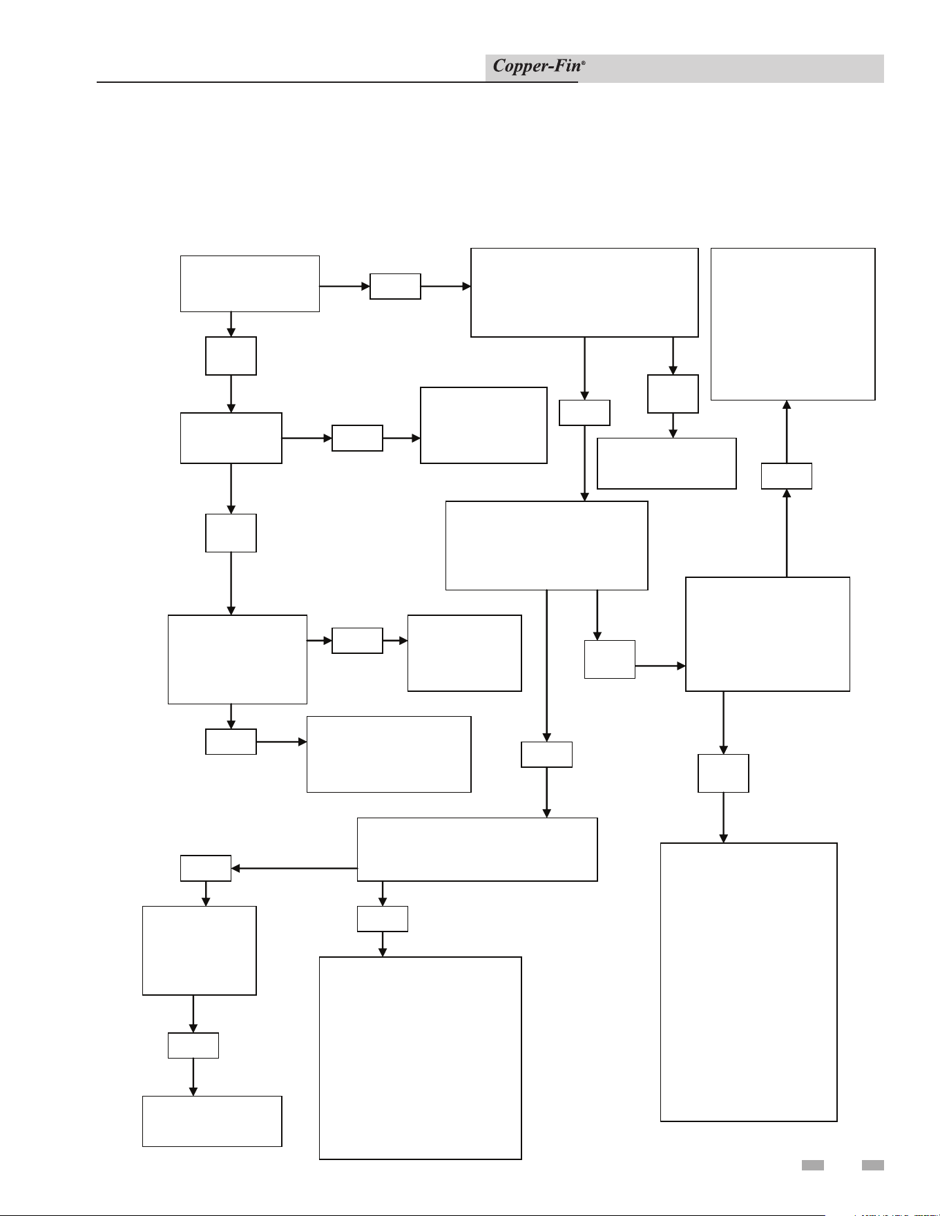
9 Troubleshooting
65
Installation & Service Manual
Troubleshooting Guide: 315,000 - 500,000 Btu/hr Models - Boilers
90,000 - 500,000 Btu/hr Water Heaters F9/M9
Step 1:
Step 2:
Step3:
Is the spark
ignitor sparking?
No
Yes
Check continuity on the spark
cable. Check for 24 VAC on
the 24v terminal (gray wire)
on the ignition module
No
Is there 24 VAC (purple
wire) on the 4-pin
connector plug on the
temperature controller?
Yes
Replace ignition
module
No
Check 24 VAC at R and W on
the terminal strip.
Check each of the
following for an open:
-white and purple wire on
the LWCO plug
-rollout switch
-manual reset high limit
-spill switch
If any of these devices are
open, press the reset
button.
Yes
Is there 24 VAC (tan
wire) on the 4-pin
connector plug on
the temperature
controller?
Yes
Check each of the
following for an open:
- X and B on the
terminal strip
-purple and gray wires
on the vent damper
plug
-the two gray wires on
the louver plug (315
and 360 models only)
-V and P on the
terminal strip
-auto reset high limit
No
Check
voltage to
and from the
transformer.
No
Check incoming
120 VAC
Check for an open
sensor. If no open
sensor, make sure
there’s a call for
heat. If call for heat
is present, replace
temperature control
No
Is the pilot
staying on?
No
Yes
Check the pilot
tube for gas.
Check draft
Is the gas valve
getting 24 VAC
to the MV
terminal?
No
Replace the
ignition
module
Yes
Check gas pressure
and make sure gas
valve knob is on.
Yes
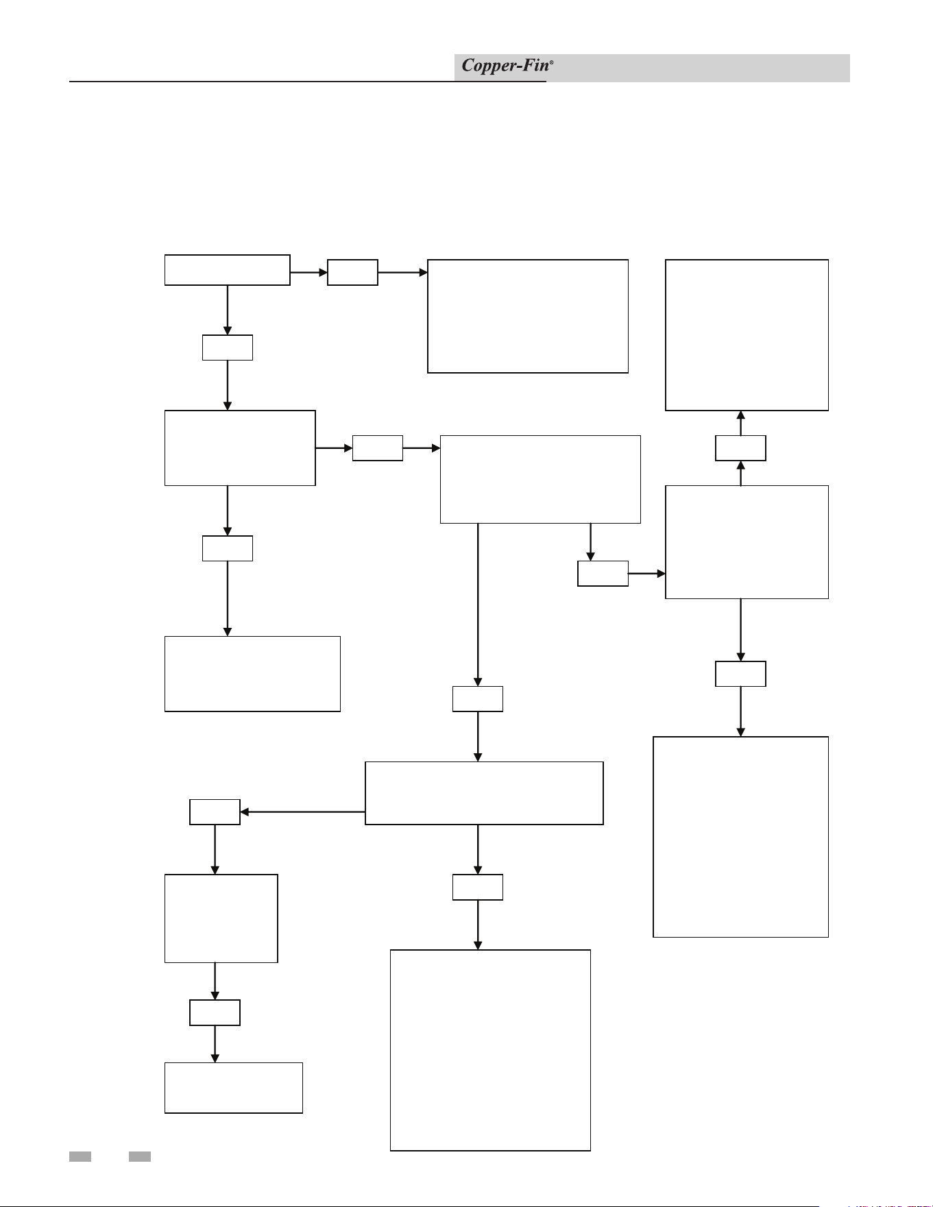
9 Troubleshooting
66
Installation & Service Manual
Step 1:
Step 2:
Step 3:
Is the pilot lit?
Yes
Is the gas valve
getting 24VAC to
the MV terminal?
Yes
Check gas pressure
and make sure the gas
valve knob is on
No
Check gas pressure.
Check the pilot assembly
and thermocouple. Clean
the thermocouple and
pilot or replace.
No
Is there 24 VAC (purple
wire) on the 4-pin
connector plug on the
temperature controller?
Yes
Is there 24 VAC (tan
wire) on the 4-pin
connector plug on
the temperature
controller?
Check for an open
sensor. If no open
sensor, make sure
there’s a call for
heat. If call for heat
is present, replace
temperature control
No
Yes
Check each of the
following for an open:
- X and B on the
terminal strip
-purple and gray wires
on the vent damper
plug
-V and P on the
terminal strip
-auto reset hi
g
h limit
No
Check 24 VAC at R and W on
the terminal strip.
Check each of the
following for an open:
-white and purple wire on
the LWCO plug
-rollout switch
-manual reset high limit
-spill switch
If any of these devices are
open, press the reset
button.
Yes
No
Check
voltage to
and from the
transformer.
No
Check incoming
120 VAC
Troubleshooting Guide:
90,000 - 270,000 Btu/hr Models - Water Heaters F1
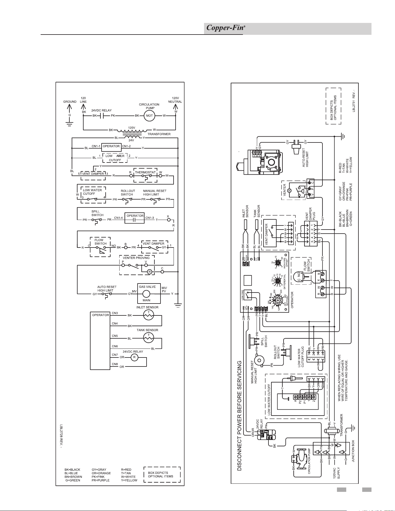
10 Diagrams
67
Installation & Service Manual
Schematic Diagram - F1 Unit
90,000 - 270,000 Btu/hr Models
Wiring Diagram - F1 Unit
90,000 - 270,000 Btu/hr Models
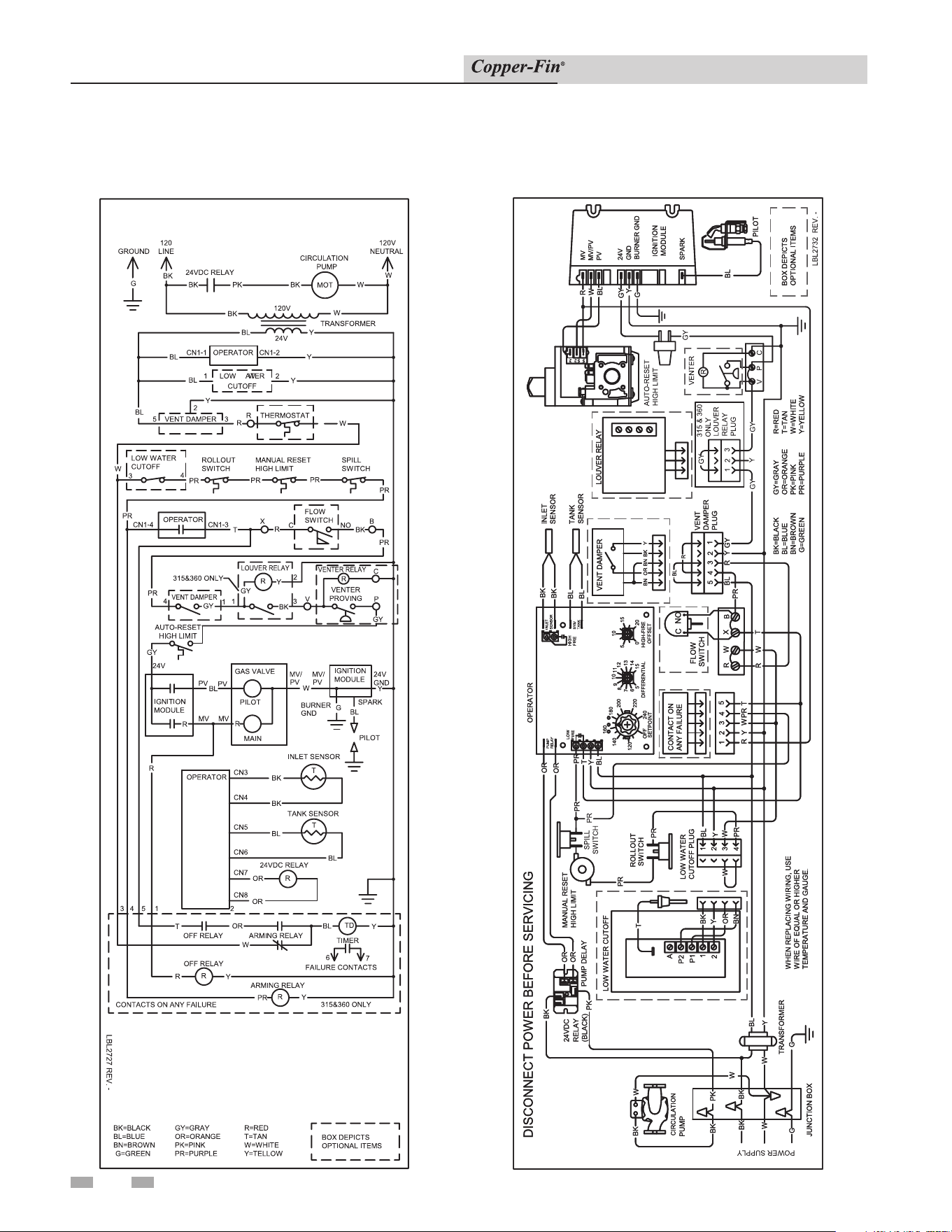
10 Diagrams
68
Installation & Service Manual
Schematic Diagram - F9 Unit
315,000 - 399,000 Btu/hr Models
Wiring Diagram - F9 Unit
315,000 - 399,000 Btu/hr Models
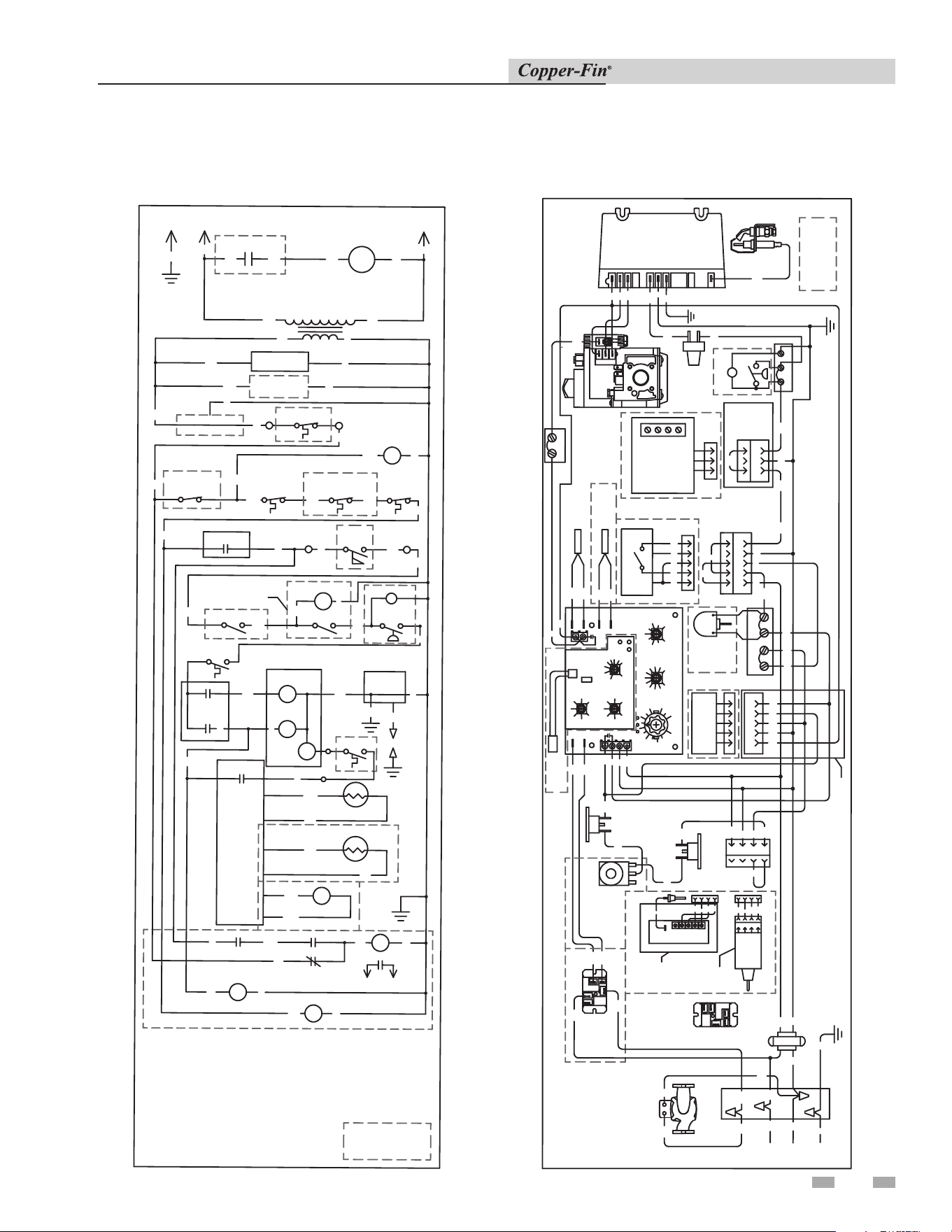
69
Installation & Service Manual
10 Diagrams (continued)
Schematic Diagram - M9 Unit
315,000 - 399,000 Btu/hr Models
BO
X DEPIC
T
S
O
PT
I
O
NA
L
I
TE
MS
120V
LINE
120
NEUTRALGROUND
24VDC RELAY
CIRCULATION
PUMP
MOT
120V
TRANSFORMER
24V
CN1-1 OPERATOR CN1-2
1 LOW WATER 2
CUTOFF
5 VENT DAMPER 3
R W
THERMOSTAT
LOW WATER
CUTOFF
3
4
ROLLOUT
SWITCH
MANUAL RESET
HIGH LIMIT
SPILL
SWITCH
24VAC RELAY
R
X
B
CN1-4
OPERATOR
CN1-3
FLOW
SWITCH
VENT DAMPER
4
1
1
IGNITION
MODULE
24V
PV
MV
GAS VALVE
PV
MV
MV/
PILOT
LOW
HIGH
OPERATOR
CN2-1 CN2-2
PV
MV/
PV
IGNITION
MODULE
24V
GND
BURNER
GND
2
LOUVER RELAY
R
PILOT
SPARK
T
CN3
CN4
INLET SENSOR
CN5
CN6
SYSTEM SENSOR
R
24VDC RELAY
CN7
CN8
T
TIMER
TD
ARMING RELAY
R
OFF RELAY
R
OFF RELAY ARMING RELAY
FAILURE CONTACTS
6
7
1 23 4 5
CONTACTS ON ANY FAILURE
1C
C NO
315&360 ONLY
315&360 ONLY
W
W
BKPKBK
BK
BK
W
BL Y
Y
Y
BL
BL
Y
Y
R
W
BL
W
PR
PR
PR
PR
PR
T
PR
PR
GY
GY
BL
R
R
W
G
Y
O
R
BK
BK
BL
BL
OR
OR
T
OR
W
BL
R
Y
PR
Y
Y
BL
G
BK=BL
ACK
BL=BL
UE
BN-
BRO
W
N
G
=
G
REEN
G
Y=
G
RAY
O
R=O
R
ANG
E
PK=PINK
PR
=
PUR
PL
E
R=
R
ED
T
-
TAN
W
=W
HI
T
E
Y=
YELLOW
R
BK
PR
PR
LBL20160 REV A
AUTO-RESET
HIGH LIMIT
HIGH FIRE
W2
R2
3
2
Y
BK
GY
V
P
VENTER
PROVING
R
VENTER RELAY
Wiring Diagram - M9 Unit
315,000 - 399,000 Btu/hr Models
MODULE
SPARK
IGNITION
BURNER GND
24V
GND
MV/PV
PV
MV
CIRCULATION
R1 W1
SPILL
ROLLOUT
X
B
NO
C
FLOW
SWITCH
INLET
SENSOR
SYSTEM
DIFFERENTIAL
240
SETPOINT
160
OFF
RELAY
PUMP
140
120
220
200
180
7
6
5
8
9
5
15
14
13
12
10
11
10
OFFSET
HIGH-FIRE
0
TANK
SYS/
SENSOR
INLET
20
15
BOX DEPICTS
OPTIONAL ITEMS
24VDC
Y
TRANSFORMER
BL
SENSOR
RELAY
A
P2
P1
1
2
1
2
3
4
OR
BN
BK
Y
T
W
LOW WATER
CUTOFF PLUG
5 4 3 2
1
VENT DAMPER
BN OR BN BK Y
BL
R
PK
BL
Y
W
PR
PR
PR
PR
PR
PR
T
Y
BL
R W
T
PR
BL R Y
GY
GY
GY
GY
Y
G
R
W
BL
BL
BK
BK
BL
BL
OR
OR
OR
BK
BK
W
G
LOW WATER CUTOFF
W
BK
BK
BK
G
JUNCTION BOX
DISCONNECT POWER BEFORE SERVICING
SWITCH
MANUAL RESET
HIGH LIMIT
SWITCH
AUTO-RESET
HIGH LIMIT
PILOT
VENT
DAMPER
PLUG
WHEN REPLACING WIRING, USE
WIRE OF EQUAL OR HIGHER
TEMPERATURE AND GAUGE.
OR
(BLACK)
PUMP
PK
W
W
PUMP
2 1 C
0.9
0.7
60
50
0.6
O.A. MAX.-°F
40
45
70
VR1
65
1.5
0.5
RATIO
VR2
1.1
1.3
1.0
W1
W2
W3
O.A. SHUTDOW N
SHUTDOWN-°F
50
40
45
70
55
VR3
60
55
65
O.A. SENSOR
DISABLE
SW1
0.8
ENABLE
ON
CN1
LOW
FIRE
HIGH
FIRE
OUTDOOR
SENSOR
OUTDOOR AIR RESET
P
O
R
21
3
BKGY
Y
GY
LOUVER
RELAY
PLUG
LOUVER RELAY
4321
5
CONTACT ON
ANY FAILURE
315&360 ONLY
R
Y
WPR T
MANUAL
RESET
1
2
3
4
BK
Y
OR
BN
AUTO
RESET
BK=BLACK
BL=BLUE
BN=BROWN
G=GREEN
GY=GRAY
OR=ORANGE
PK=PINK
PR=PURPLE
R=RED
T=TAN
W=WHITE
Y=YELLOW
PO
WER S
UPPLY
DELAY
LBL20159 REV A
C
MV
PV
HI
R2
W2
V P
VENTER
C
R
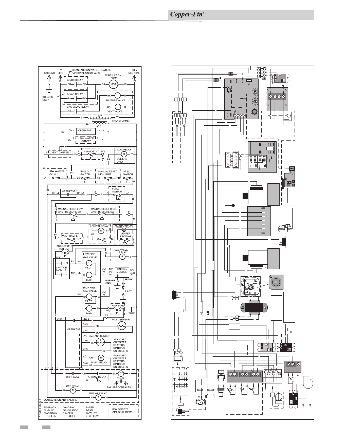
70
Schematic Diagram - F9/M9 Unit
500,000 Btu/hr Models
Wiring Diagram - F9/M9 Unit
500,000 Btu/hr Models
P=PINK
PV
PV/MV
MV
R
BK
BL
BL
PR
GR
R
Y
R
W
R
W
PR
BL
P
PR
O
O
O
BL
Y
O
2
1
PRPR
P
BK
BL
Y
O
BK
T
BK
P
OPERATOR
GY
AC
24V
PR
BL
Y
W
W
P
W
PR PR
W
24COM
24V
BK
W
BL
B
X
R1
W1
LB YW KB
INLET
GY
GY
BL
BL
BK
BK
OPTIONAL
Y
PR
1
2
3
4
5
T
FLOW
OPTIONAL
JUMPER
JUMPER
Y
PV
T
Y
INLET
BK
3
2
14
5
321
4
5
R
PR Y
T W
Y
Y
COM
N.O.
PR
PR
M
NEUTRAL
LINE
1 2
3
1
2
3
GY BK
CN9
CN9
W
GY
YGY
GY
P
P
GY
1
3
4
2
O
6
T=TAN
Y=YELLOW
BR=BROWN
G=GREEN
GY=GRAY
R=REDPR=PURPLE
BL=BLUE
O=ORANGE
PR TWR
Y
SPLICE
SPLICE
SPLICE
SPLICE
SPLICE
SPLICE
SPLICE
PV
MV
SPARK
MV/PV
YBLR GYW G
C
NO
NC
C
NO
NC
DC
24V
AC
24V
C
NO
NC
A
P2
P1
1
2
BL
W
Y
BK
Y
BK
O
BR
T
OPTIONAL
R2
W2
O
P
V
P
C
NO
120VAC
W
BK
BK
Y
Y
GY
BK
GY
GY
GY
GY
SYSTEM/ TANK
SYS/
TANK
PROVING
SWITCH
LOUVER
CONTACTS
LBL2726
REV E
OPTIONAL
LOUVER
CONTACTS/PROVING
120VAC
60Hz
LOUVERS
FIELD
PROVIDED
LOUVER
MOTOR
I/O
RESET BOARD
"BOILER ONLY"
SEE MANUAL
MOUNTED
ON
OPERATOR
OPTIONAL
ALARM
CIRCUIT
TIME
DELAY
RELAY
ALARM
CONTACTS
FIELD
PROVIDED
OPTIONAL
OUTDOOR
AIR RESET BOARD
"BOILER ONLY"
PUMP RLY
PV/MV
MV
ENABLE
CN1
DISABLE
SENSOR/WIRING
O.A.
SENSOR
STG #2
Hi-Fire
PILOT/
SPARK
DISCONNECT
POWER BEFORE SERVICING
W
= WHITE
BK
= BLACK
HOT
24
24V
GND
GND
BRN
MODIGNITION
SPILL
SWITCH
CHASSIS
GROUND
24VAC
GROUND
STG #1
Lo-Fire
GROUND
CHASSIS
FIELDINSTALLED
OPTIONAL
MANUAL
RESET
LIMIT
HIGH
OPTIONAL
ADJUSTABLE
HIGH LIMIT
ROLL-OUT
SWITCH
SYSTEM PUMP
ON
STANDARD
BOILERS
PUMP
DELAY RELAY
STANDARD ON
WATER HEATERS
REMOTE
THERMOSTAT
OPTIONAL
VENT
DAMPER
24VAC
RELAY
SWITCH
POWER SUPPLY
RESET
MANUAL
JUNCTION
BOX
AUTO
RESET
OPTIONAL
PUMP
AUTO-RESET
HIGH-LIMIT
HIGH
LIMIT
LIMIT
SWITCHES
OPTIONAL
POWER
VENTER
PROVING
XFMR.
24VAC
C
NC
BL
1
2
3
4
C
1
(+)
(+)
USE ELECTRICAL CONNECTION 1& 2
10 Diagrams
Installation & Service Manual

71
Notes

Revision Notes: Revision A (ECO #C06290) initial release.
Revision B (ECO C09691) reflects the update of AHRI/ASME logos
on pages 5 and 6.
Revision C (ECO C12077) reflects the update of ignition timing
information on page 44 and heat exchanger information on page
51.
Revision D (ECO #C13191) reflects the addition of the CSA Low
Lead Content logo on page 6.
Revision E (ECO #C14226) reflects the addition of cautionary
statements and notes on page 17 beneath the “Vent Materials”
table.
Revision F (ECO C16918) reflects the update of the ratings tables
on pages 5 and 6 and the update of Table 3E on page 20 (R07763).
Revision G (PCP #3000006582 / CN #500006680) reflects the
addition of new venting information on pages 18 and 19.
Revision H (PCP #3000021634 / CN #500011858) reflects changes
made to water chemistry information on pages 4, 28-34, 47-48, 50,
52-55, 58, and 60.
Revision J (PCP #3000030852 / CN #500020656) reflects the
addition of the notice on page 51 and an update to Table 8A and
all piping diagrams.
Revision K (PCP #3000033832 / CN #500022615) reflects the
input and gross rates and output rates are revised to match AHRI
rounding and comply with Energy Star turndown rate requirements.
Revision L (PCP #3000043534 / CN #500031265) reflects the
addition of the two notices at the end of page 17.
Revision M (PCP #3000045219 / CN #500032730) reflects an
update to FIG. 2-7 and Table 2C.
Revision N (PCP #3000049033 / CN #500036140) reflects an
update to add model number 201.
Revision P (PCP #3000057694 / CN #500043851) reflects an
added carbon monoxide warning on page 3.
Revision R (PCP #3000060820 / CN #500046810) reflects the
addition of a dielectric notice on page 50.
100160907_2000001336_Rev R
05/24