
i
Trademarks
Autel
®
, MaxiSys
®
, MaxiDAS
®
, MaxiScan
®
, MaxiRecorder
®
, MaxiTPMS
®
,
AutoLink
®
, and MaxiCheck
®
are trademarks of Autel Intelligent Technology Corp.,
Ltd., registered in China, the United States, and other countries. All other marks
are trademarks or registered trademarks of their respective holders.
Copyright Information
No part of this manual may be reproduced, stored in a retrieval system or
transmitted, in any form or by any means, electronic, mechanical, photocopying,
recording, or otherwise, without the prior written permission of Autel.
Disclaimer of Warranties and Limitation of Liabilities
All information, specifications and illustrations in this manual are based on the
latest information available at the time of printing.
Autel reserves the right to make changes at any time without notice. While
information of this manual has been carefully checked for accuracy, no guarantee
is given for the completeness and accuracy of the contents, including but not
limited to the product specifications, functions, and illustrations.
Autel will not be liable for any direct, special, incidental, indirect damages, or for
any economic consequential damages (including lost profits) as a result of using
this product.
IMPORTANT
Before operating or maintaining this unit, please read this manual carefully,
paying extra attention to the safety warnings and precautions.
For Services and Support:
pro.autel.com
www.autel.com
1-855-288-3587 (North America)
+86 (0755) 8614-7779 (China)
For technical assistance in all other markets, please refer to Service and Support
in this manual.

ii
Safety Precautions and Warnings
To prevent personal injury or damage to vehicles and/or the scan tool, read
this manual first and observe the following safety precautions at a minimum
whenever working on a vehicle:
Always perform automotive testing in a safe environment.
Wear safety eye protection that meets ANSI standards.
Keep clothing, hair, hands, tools, and test equipment, etc., away from all
moving or hot engine parts.
Operate the vehicle in a well-ventilated work area.
Put blocks in front of the drive wheels and never leave the vehicle
unattended while running tests.
Use extreme caution when working around the ignition coil, distributor
cap, ignition wires and spark plugs. These components create
hazardous voltages when the engine is running.
Put the transmission in PARK (for automatic transmission) or NEUTRAL
(for manual transmission) and make sure the parking brake is engaged.
Keep a fire extinguisher suitable for gasoline/chemical/electrical fires
nearby.
Do not connect or disconnect any test equipment while the ignition is on
or the engine is running.
Keep the scan tool dry, clean, and free from oil, water, and grease. Use
a mild detergent on a clean cloth to clean the outside of the scan tool,
when necessary.

iii
CONTENTS
SAFETY PRECAUTIONS AND WARNINGS.............................................................. II
1 USING THIS MANUAL ................................................................................. 1
CONVENTIONS ................................................................................................. 1
2 GENERAL INFORMATION ........................................................................... 3
ON-BOARD DIAGNOSTICS (OBD/OBDII) ........................................................... 3
DIAGNOSTIC TROUBLE CODES (DTCS) .............................................................. 3
LOCATION OF THE DATA LINK CONNECTOR (DLC) .............................................. 4
OBDII READINESS MONITORS .......................................................................... 5
OBDII MONITOR READINESS STATUS ................................................................ 6
OBDII DEFINITIONS ......................................................................................... 7
OBDII MODES OF OPERATION .......................................................................... 8
3 USING THE SCAN TOOL ........................................................................... 11
TOOL DESCRIPTION ....................................................................................... 11
SPECIFICATIONS ............................................................................................ 13
ACCESSORIES INCLUDED ................................................................................ 13
NAVIGATION CHARACTERS ............................................................................. 13
KEYBOARD .................................................................................................... 14
POWER ......................................................................................................... 14
VEHICLE COVERAGE ...................................................................................... 14
PRODUCT TROUBLESHOOTING ........................................................................ 15
4 OBDII DIAGNOSTICS ................................................................................ 17
READ CODES ................................................................................................ 18
ERASE CODES .............................................................................................. 21
LIVE DATA .................................................................................................... 23
VIEW FREEZE FRAME ..................................................................................... 31
I/M READINESS ............................................................................................. 32
ON-BOARD MONITOR TEST ............................................................................ 37
COMPONENT TEST ......................................................................................... 40
VEHICLE INFORMATION ................................................................................... 41
MODULES PRESENT ....................................................................................... 42

iv
5 ABS DIAGNOSIS ........................................................................................ 44
VEHICLE SELECTION ...................................................................................... 45
READING ABS CODES ................................................................................... 46
ERASING ABS CODE ..................................................................................... 47
6 BATTERY TEST ......................................................................................... 49
STARTING SYSTEM TEST ................................................................................ 49
CHARGING SYSTEM TEST ............................................................................... 53
7 DTC LOOKUP ............................................................................................ 57
8 PLAYBACK ................................................................................................. 59
REVIEW DATA ............................................................................................... 59
PRINT DATA .................................................................................................. 61
9 SETUP ........................................................................................................ 62
LANGUAGE .................................................................................................... 63
CONFIGURE MONITORS .................................................................................. 63
UNIT OF MEASURE ......................................................................................... 65
KEY BEEP SETTINGS ...................................................................................... 66
STATUS BEEP SETTINGS ................................................................................ 67
TOOL SELF-TEST ........................................................................................... 67
SET DATA LOG .............................................................................................. 69
UPLOAD DATA LOG MODE .............................................................................. 70
ABOUT .......................................................................................................... 71
10 UPDATES ................................................................................................... 73
REGISTER THE TOOL ...................................................................................... 73
UPDATE PROCEDURE ..................................................................................... 74
11 COMPLIANCE INFORMATION .................................................................. 76
12 WARRANTY AND SERVICE ...................................................................... 78
LIMITED ONE YEAR WARRANTY ....................................................................... 78
SERVICE AND SUPPORT .................................................................................. 79

1
1 Using This Manual
This manual contains device usage instructions.
Some illustrations shown in this manual may contain modules and optional
equipment that are not included in your system. Contact your sales
representative for availability of other modules and optional tools or
accessories.
Conventions
The following conventions are used:
Bold Text
Bold text is used to highlight selectable items such as buttons and menu
options.
Example:
Tap OK.
Notes and Important Messages
Notes
A NOTE provides helpful information such as additional explanations, tips,
and comments.
Important
IMPORTANT indicates a situation which, if not avoided, may result in damage
to the test equipment or vehicle.
Hyperlinks
Hyperlinks or links that take you to other related articles, procedures, and
illustrations are active in electronic documents. Blue italic text indicates a
selectable hyperlink and blue underlined text indicates a website link or an
email address link.

2
Illustrations
Illustrations used in this manual are samples, and the actual testing screen
may vary for each vehicle being tested. Observe the menu titles and on-
screen instructions to make correct option selection.

3
2 General Information
On-Board Diagnostics (OBD/OBDII)
The first generation of On-Board Diagnostics (called OBDI) was developed
by the California Air Resources Board (ARB) and implemented in 1988 to
monitor some of the emission control components on vehicles. As technology
evolved and the desire to improve the On-Board Diagnostic system increased,
a new generation of On-Board Diagnostic system was developed. This second
generation of On-Board Diagnostic regulations is called “OBDII.”
The OBDII system is designed to monitor emission control systems and key
engine components by performing either continuous or periodic tests of
specific components and vehicle conditions. When a problem is detected, the
OBDII system turns on a warning light on the vehicle instrument panel to alert
the driver typically by the phrase of “Check Engine” or “Service Engine Soon.”
The system will also store important information about the detected
malfunction so that a technician can accurately find and fix the problem. Here
below follow three pieces of such valuable information:
1) Whether the Malfunction Indicator Light (MIL) is commanded “on” or “off.”
2) Which, if any, Diagnostic Trouble Codes (DTCs) are stored.
3) Readiness Monitor status.
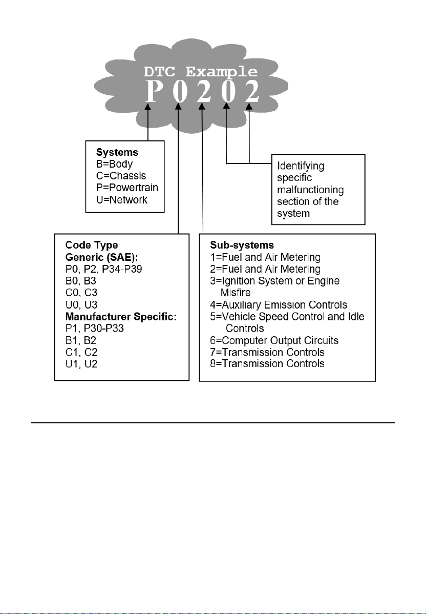
Diagnostic Trouble Codes (DTCs)
OBDII Diagnostic Trouble Codes are codes that are stored by the on-board
computer diagnostic system in response to a problem found in the vehicle.
These codes identify a particular problem and are intended to provide you
with a guide as to where a fault might be occurring within a vehicle. OBDII
Diagnostic Trouble Codes consist of a five-digit alphanumeric code. The first
letter identifies which control system sets the code. The four numbers provide
additional information on where the DTC originated and the operating
conditions that caused it to set. Here below is an example to illustrate the
structure of the digits:
4
Location of the Data Link Connector (DLC)
The DLC (Data Link Connector or Diagnostic Link Connector) is a
standardized 16-cavity connector where diagnostic scan tools interface with
the vehicle's on-board computer. The DLC is usually located 12 inches from
the center of the instrument panel (dashboard), under or around the driver’s
side for most vehicles. If the DLC is not located under the dashboard, a label
should be there telling the location. For some Asian and European vehicles,
the DLC is located behind the ashtray and the ashtray must be removed to
access the connector. If the DLC cannot be found, refer to the vehicle’s
service manual for the location.

5
OBDII Readiness Monitors
An important part of a vehicle’s OBDII system is the Readiness Monitors,
which are indicators used to find out if all of the emissions components have
been evaluated by the OBDII system. They run periodic tests on specific
systems and components to ensure that they are performing within the
allowable limits.
Currently, there are eleven OBDII Readiness Monitors (or I/M Monitors)
defined by the U.S. Environmental Protection Agency (EPA). Not all monitors
are supported by all vehicles and the exact number of monitors in any vehicle
depends on the motor vehicle manufacturer’s emissions control strategy.
Continuous Monitors — Some of the vehicle components or systems are
continuously tested by the vehicle’s OBDII system, while others are tested
only under specific vehicle operating conditions. The continuously monitored
components listed below are always ready:
1. Misfire
2. Fuel System
3. Comprehensive Components (CCM)
Once the vehicle is running, the OBDII system is continuously checking the
above components, monitoring key engine sensors, watching for engine
misfire, and monitoring fuel demands.
Non-Continuous Monitors — Unlike the continuous monitors, many
emissions and engine system components require the vehicle to be operated
under specific conditions before the monitor is ready. These monitors are
termed non-continuous monitors. For different ignition engine types, the
available monitors are different too.

6
The following monitors are to be used for spark ignition engines only:
EGR System
O
2
Sensors
Catalyst
Evaporative System
O
2
Sensor Heater
Secondary Air
Heated Catalyst
The following monitors are to be used for compression ignition engines only:
EGR System
NMHC Catalyst
NOx Aftertreatment
Boost Pressure System
Exhaust Gas Sensor
PM Filter
OBDII Monitor Readiness Status
OBDII systems must indicate whether or not the vehicle PCM’s monitor
system has completed testing on each component. Components that have
been tested will be reported as “Ready,” or “Complete,” meaning they have
been tested by the OBDII system. The purpose of recording readiness status
is to allow inspectors to determine if the vehicle’s OBDII system has tested
all the components and/or systems.
The power-train control module (PCM) sets a monitor to “Ready” or
“Complete” after an appropriate drive cycle has been performed. The drive
cycle that enables a monitor and sets readiness codes to “Ready” varies for
each individual monitor. Once a monitor is set as “Ready” or “Complete,” it
will remain in this state. A number of factors, including erasing of diagnostic
trouble codes (DTCs) with a scan tool or a disconnected battery, can result

7
in Readiness Monitors being set to “Not Ready.” Since the three continuous
monitors are constantly evaluating, they will be reported as “Ready” all of the
time. If the testing of a particular supported non-continuous monitor has not
been completed, the monitor status will be reported as “Not Complete” or “Not
Ready.”
In order for the OBD monitor system to become ready, the vehicle should be
driven under a variety of normal operating conditions. These operating
conditions may include a mix of highway driving and stop and go, city type
driving, and at least one overnight-off period. For specific information on
getting your vehicle’s OBD monitor system ready, please consult your vehicle
Owner’s Manual.
OBDII Definitions
Power-train Control Module (PCM) — OBDII terminology for the on-board
computer that controls engine and drive train.
Malfunction Indicator Light (MIL) — Malfunction Indicator Light (Service
Engine Soon, Check Engine) is a term used for the light on the instrument
panel. It is to alert the driver and/or the repair technician that there is a
problem with one or more of vehicle's systems and may cause emissions to
exceed federal standards. If the MIL illuminates with a steady light, it indicates
that a problem has been detected and the vehicle should be serviced as soon
as possible. Under certain conditions, the dashboard light will blink or flash.
This indicates a severe problem, and flashing is intended to discourage
vehicle operation. The vehicle onboard diagnostic system cannot turn the MIL
off until necessary repairs are completed or the condition no longer exists.
DTC — Diagnostic Trouble Codes (DTCs) identify which section of the
emission control system has malfunctioned.
Enabling Criteria — Also termed Enabling Conditions. They are the vehicle-
specific events or conditions that must occur within the engine before the
various monitors will set, or run. Some monitors require the vehicle to follow
a prescribed “drive cycle” routine as part of the enabling criteria. Drive cycles
vary among vehicles and for each monitor in any particular vehicle.
OBDII Drive Cycle — A specific mode of vehicle operation that provides
conditions required to set all the readiness monitors applicable to the vehicle
to the “ready” condition. The purpose of completing an OBDII drive cycle is

8
to force the vehicle to run its onboard diagnostics. Some form of a drive cycle
needs to be performed after DTCs have been erased from the PCM’s memory
or after the battery has been disconnected. Running through a vehicle’s
complete drive cycle will “set” the readiness monitors so that future faults can
be detected. Drive cycles vary depending on the vehicle and the monitor that
needs to be reset. For vehicle specific drive cycle, consult the vehicle Owner’s
Manual.
Freeze Frame Data — When an emissions related fault occurs, the OBDII
system not only sets a code but also records a snapshot of the vehicle
operating parameters to help identify the problem. This set of values is
referred to as Freeze Frame Data and may include important engine
parameters such as engine RPM, vehicle speed, air flow, engine load, fuel
pressure, fuel trim value, engine coolant temperature, ignition timing advance,
or closed loop status.
OBDII Modes of Operation
Here is a basic introduction to the OBDII communications protocol.
Mode Byte: The first byte in the stream is the mode number. There are 10
modes for diagnostic requests. The first byte in the response data bytes is
this same number plus 64. For example, a mode 1 request would have the
first data byte = 1, and the response would have the first data byte = 65. Here
is a brief description of the modes:
Mode $01 — Identifies the Power-train information and shows the current
data available to the scan tool. This data includes: DTC set, status of on-
board tests, and vehicle data such as engine RPM, temperatures, ignition
advance, speed, air flow rates, and closed loop status for fuel system.
Mode $02 — Displays Freeze Frame data. Same data as in mode 1, but it
was captured and stored when a malfunction occurred and a DTC was set.
Some of the PIDs for mode one are not implemented in this mode.
Mode $03 — Displays the type of power-train or emission related DTCs
stored by a 5-digit code identifying the faults. There may be more than one
response message if there are more trouble codes fit in the data bytes of the
response message, or if there are more than one ECU responding.

9
Mode $04 — Used to clear DTCs and freeze frame data. This clears all
diagnostic trouble codes that may be set including freeze frame data and
readiness monitors.
Mode $05 — Displays oxygen sensor test results. This mode displays the
oxygen sensor monitor screen and the test results gathered about the oxygen
sensor.
There are nine terms available for diagnostics:
1. $01 Rich-to-Lean O
2
sensor threshold voltage.
2. $02 Lean-to-Rich O
2
sensor threshold voltage.
3. $03 Low sensor voltage threshold for switch time measurement.
4. $04 High sensor voltage threshold for switch time measurement.
5. $05 Rich-to-Lean switch time in ms.
6. $06 Lean-to-Rich switch time in ms.
7. $07 Minimum voltage for test.
8. $08 Maximum voltage for test.
9. $09 Time between voltage transitions in ms.
Mode $06 — Non-continuously Monitored Systems test results. There are
typically a minimum value, a maximum value, and a current value for each
non-continuous monitor. This data is optional, and it is defined by a given
vehicle maker if it’s used.
Mode $07 — A request for DTCs (pending) from Continuously Monitored
Systems after a single driving cycle has been performed to determine if repair
has fixed a problem. This is used by service technicians to verify whether
repair was performed properly after diagnostic trouble codes are cleared.
Mode $08 — This special Control Mode requests control of the on-board
system, test, or component bi-directionally (where applicable). The mode is
manufacturer-specific.

10
Mode $09 — Reports vehicle information. This information includes vehicle
VIN number and calibration information stored in the vehicle ECUs.
Mode $0A — Requests Emissions-Related Diagnostic Trouble Codes with
Permanent Status. This mode is required for all emissions-related DTCs. The
presence of permanent DTCs during an inspection without the MIL
illuminated is an indication that a proper repair was not verified by the on-
board monitoring system.
11
3 Using the Scan Tool
Tool Description
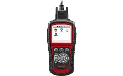
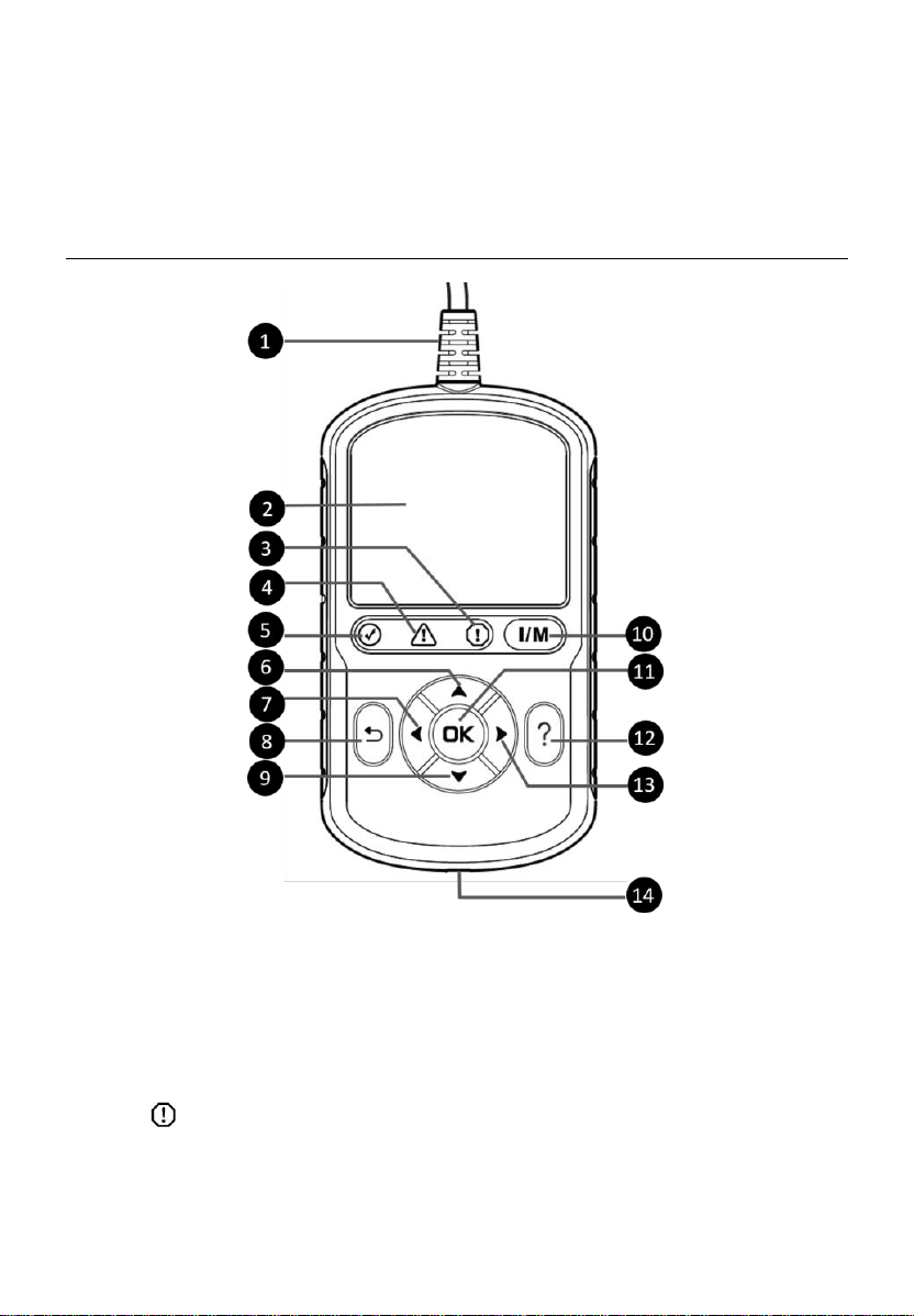
Figure 3-1 Product View
1) OBDII CONNECTOR — connects the scan tool to the vehicle’s Data Link
Connector (DLC).
2) LCD DISPLAY — displays menus and test results.
3) RED LED — indicates there is a problem in one or more of the
vehicle’s systems. The red LED also indicates DTCs are present. DTCs
displayed on the scan tool’s display. In this case, the MIL on the vehicle’s
instrument panel will illuminate.
12
4) YELLOW LED — indicates there is a possible problem. A “Pending”
DTC is present and/or some of the vehicle’s emission monitors have not
run their diagnostic testing.
5) GREEN LED — indicates that engine systems are running normally
(The monitors on the vehicle are active and the number of monitors
which are performing their diagnostic testing is in the allowed limit, and
no DTCs are present).
6) UP SCROLL BUTTON — moves up menu and submenu items in
menu mode. When more than one screen of data is retrieved, press to
scroll to the previous screens. When looking up DTC, it is used to change
the value of the selected character.
7) LEFT SCROLL BUTTON — selects/deselects PID data when
viewing or recording customized live data list and views previous frames
of recorded data when playing back live data. Press to update DTC
library in Update Mode. When looking up DTC definitions, press to view
the previous character and to display additional information on previous
screens if present.
8) ESC BUTTON — cancels a selection (or action) from a menu or
returns to the previous screen.
9) DOWN SCROLL BUTTON — moves down menu and submenu
items in menu mode. When more than one screen of data is retrieved,
press to move down through the current screen to next screens. When
looking up DTC, it is used to change the value of the selected character.
10) ONE-CLICK I/M READINESS KEY — quick-checks State
Emissions readiness and drive cycle verification.
11) OK BUTTON — confirms a selection (or action) from a menu.
12) HELP BUTTON — displays help information and accesses DTC
Guide function.
13) RIGHT SCROLL BUTTON — selects/deselects all marked PID data
when viewing or recording customized live data list, and views next
frames of data when playing back live data. When viewing DTC
definitions, press to view next character and additional DTC information.

13
14) USB CONNECTOR — connects the scan tool to the Windows-based PC
for printing and upgrading.
Specifications
Table 3-1 Specifications
Item
Description
Display
2.8-inch LCD (320 x 240 dpi)
Connectivity
USB Type C
OBDII DB16
Operating Temp.
0 to 60 ℃ (32 to 140 ℉)
Storage Temp.
-20 to 70 ℃ (-1 to 158 ℉)
External Power
8.0 to 18.0 V power provided via vehicle
battery
Dimensions (L x W x H)
150.6 mm (5.9”) x 85 mm (3.3”) x 19.9 mm
(0.8”)
Weight
275.4 g (with wire)
166.9 g (without wire)
Accessories Included
Quick Reference Guide — instructions on registering tool and updating
software.
Navigation Characters
Characters used to help navigate the scan tool are:
1) $ — identifies the control module number from data retrieved. Indicates
the Test ID in On-Board Monitor Test.
2) ? — indicates help or DTC Guide information is available.
3) G — indicates graphic viewing is available.
14
Keyboard
No solvents such as alcohol should be used to clean the keypad or display;
use mild non-abrasive detergent and soft cotton cloth instead. Do not soak
the keypad as the keypad is not waterproof.
Power
The scan tool is powered via the vehicle Data Link Connector (DLC). Follow
the steps below to turn on the scan tool:
1) Locate the DLC on the vehicle.
A plastic DLC cover may be found on some vehicles and you need
to remove it before connecting the OBDII cable.
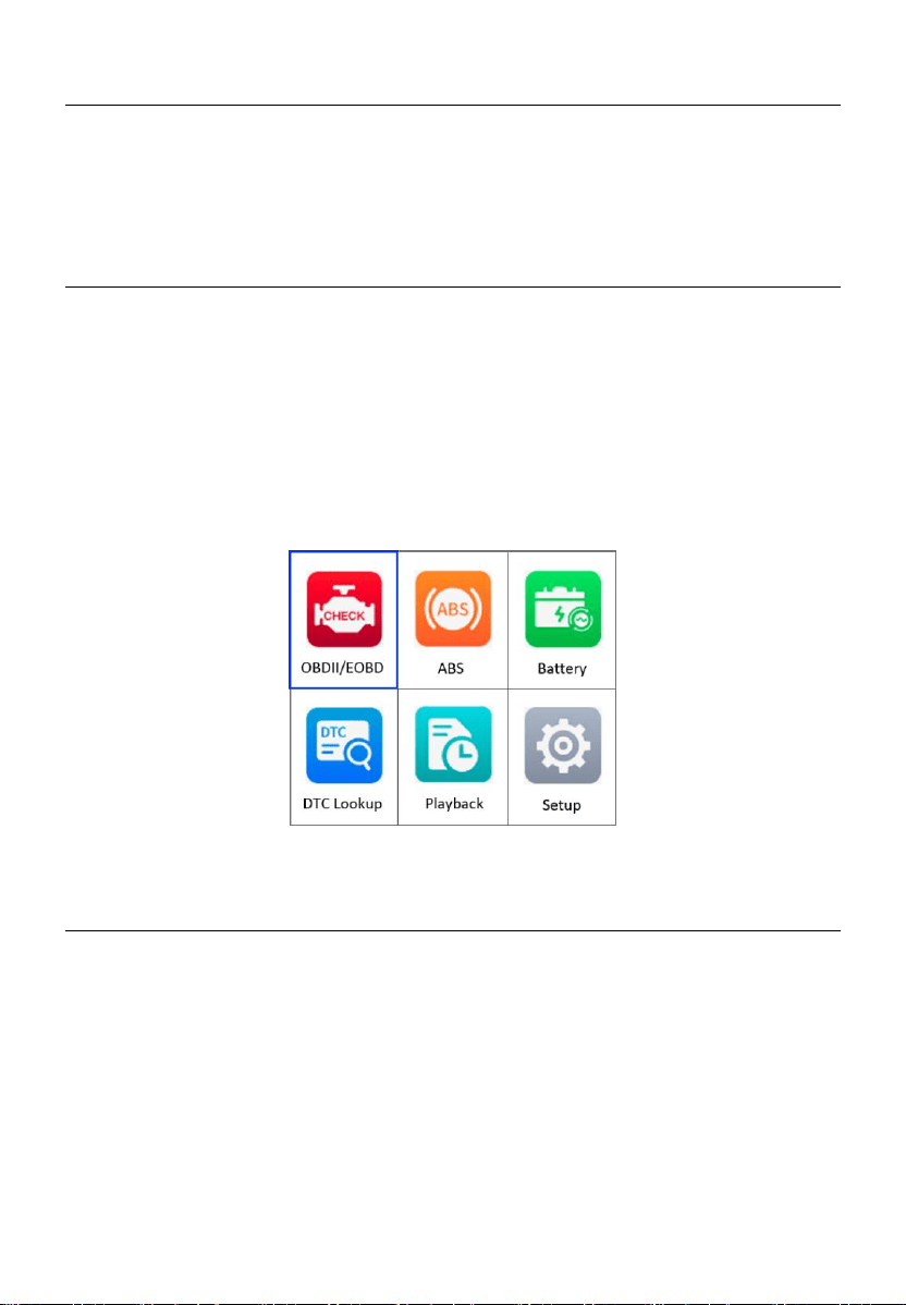
2) Plug the OBDII cable into the vehicle’s DLC. The scan tool will
automatically power up and the Main Screen appears. (Figure 3-2)
Figure 3-2 Main Screen
Vehicle Coverage
The AutoLink
AL549 OBDII Scanner is specially designed to work with all
OBDII compliant vehicles, including those equipped with Control Area
Network (CAN) protocol. The EPA requires all domestic, Asian and European
vehicles, 1996 and newer vehicles (including light trucks), sold in the United
States must be OBDII compliant.
A small number of 1994 and 1995 model year gasoline vehicles are OBDII
compliant. To verify if a 1994 or 1995 vehicle is OBDII compliant, check the
Vehicle Emissions Control Information (VECI) Label which is located under
the hood or by the radiator of most vehicles. If the vehicle is OBDII compliant,

15
the label will designate “OBDII Certified.” Additionally, government
regulations mandate that all OBDII compliant vehicles must have a “common”
sixteen-pin DLC.
For your vehicle to be OBDII compliant, it must have a 16-pin DLC under the
dash and the Vehicle Emission Control Information Label must state that the
vehicle is OBDII compliant.
In addition to OBDII diagnosis, the AL549 scan tool also supports the ABS
diagnostics function, dealing with more than 20 US, Asian and European
vehicles, including Toyota, Honda, Benz, BWM, Ford, GM, Volkswagen, Audi,
Chrysler, Hyundai, Infiniti, Jaguar, Kia, Land Rover, Lexus, Mazda, Mini,
Scion, Volvo, Dodge, Lincoln, Acura, and Nissan.
Product Troubleshooting
This section describes problems that may be encountered while using the
scan tool.
Vehicle Linking Error
A communication error occurs if the scan tool fails to communicate with the
vehicle’s ECU (Engine Control Unit). Do the following steps to resolve the
error:
Verify that the ignition is ON.
Ensure the scan tool’s OBDII connector is securely connected to the
vehicle’s DLC.
Verify that the vehicle is OBDII compliant.
Turn the ignition off and wait for about 10 seconds. Turn the ignition on
again and continue the testing.
Verify the control module is not defective.
Operating Error
If the scan tool freezes, then an exception occurs or the vehicle’s ECU is too
slow to respond to requests. You need to do the following steps to reset the
tool:
Reset the scan tool.

16
Turn the ignition off and wait for about 10 seconds. Turn the ignition on
again and continue the testing.
Scan Tool Does Not Power Up
If the scan tool will not power up or operates incorrectly, do the following steps:
Check if the scan tool’s OBDII connector is securely connected to the
vehicle’s DLC.
Check if the DLC pins are bent or broken. Clean the DLC pins if
necessary.
Check the vehicle battery to make sure it is still good with at least 8.0
volts.
17
4 OBDII Diagnostics
The OBDII Diagnostics function is a fast-access option that allows you to
carry out a quick test on the engine system of OBDII vehicles.
When more than one vehicle control module is detected by the scan tool,
you will be prompted to select the module with retrievable data. The Power
train Control Module (PCM) and Transmission Control Module (TCM) are
the most commonly scanned modules.
IMPORTANT
DO NOT connect or disconnect the scan tool while the ignition is on or the
engine is running.
1) Turn the ignition off.
2) Locate the vehicle’s 16-pin Data Link Connector (DLC).
3) Plug the scan tool into the vehicle’s DLC.
4) Turn the ignition on. Engine can be off or running.
5) Turn on the scan tool. From the Main Screen, use the UP/DOWN scroll
button and LEFT/RIGHT scroll button to select OBDII/EOBD.
Figure 4-1 Main Screen
18
6) Press the OK button and wait for the Menu to display. The tool will
display OBDII protocols and the vehicle information when the vehicle’s
communication protocol is detected.
If the scan tool has failed to communicate with the vehicle’s ECU
(Engine Control Unit) more than three times, a “LINKING ERROR!”
message appears on the tool.
Verify the ignition is ON.
Check if the scan tool’s OBDII cable is securely connected to
the vehicle’s DLC.
Verify that the vehicle is OBDII compliant.
Turn the ignition off and wait for about 10 seconds. Turn the
ignition back on and repeat step 5.
If the “LINKING ERROR!” message continues to display, contact
your local distributor or customer service for assistance.
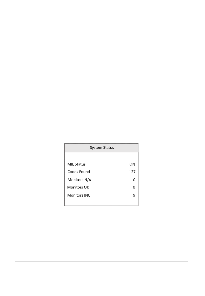
7) View a summary of the system status (MIL status, DTC counts, monitor
status) on screen. Wait a moment or press any key for the Diagnostic
Menu to appear.
Figure 4-2 System Status Screen
If more than one module is detected, you will be prompted to select
a module before testing.
Use the UP/DOWN scroll button to select a module and press the
OK button to confirm.
Read Codes
The Read Codes function can be performed with the key on engine off
(KOEO) or with the key on engine running (KOER).
19
Stored Codes are also known as “hard codes,” which are fault codes,
or trouble codes that have been stored in the vehicle computer memory
because the faults have reoccurred for more than a specified amount of
key-cycles. These codes will cause the control module to illuminate the
malfunction indicator light (MIL) when emissions-related faults occur.
Pending Codes are also referred to as “maturing codes” or “continuous
monitor codes.” They indicate problems that the control module has
detected during the current or last driving cycle but are not as yet
considered serious. Pending Codes will not turn on the malfunction
indicator light (MIL). If the fault does not occur within a certain number
of warm-up cycles, the code clears from memory.
Permanent Codes are DTCs that are "confirmed" and are retained in
the non-volatile memory of the vehicle’s computer until the appropriate
monitor for each DTC has determined that the malfunction is no longer
present and is not causing the MIL. Permanent DTCs are stored in non-
volatile memory and cannot be erased by any diagnostics service or by
disconnecting power to ECU.
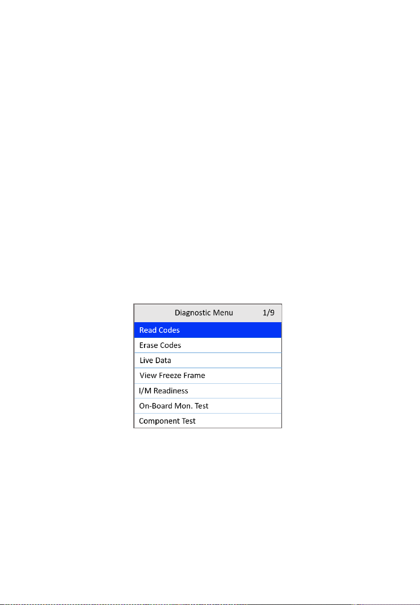
1) From the Diagnostic Menu screen, use the UP/DOWN scroll button to
select Read Codes and press the OK button.
Figure 4-3 Diagnostic Menu Screen
2) Use the UP/DOWN scroll button to select OBD Codes or Enhanced
Codes and press the OK button.
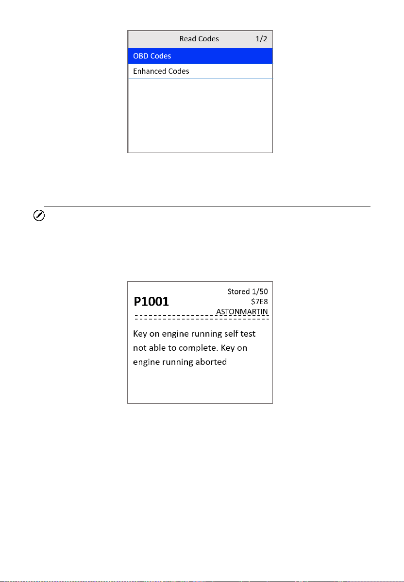
20
Figure 4-4 Read Codes Screen
If no codes are found, a message will appear. Wait a moment or
press any key to return to the previous screen.
NOTE
Permanent Codes function is available only for vehicles supporting the CAN
protocols.
3) View DTCs and their definitions.
Figure 4-5 DTC Screen
4) If more than one DTC is found, use the UP/DOWN scroll button to check
all codes.
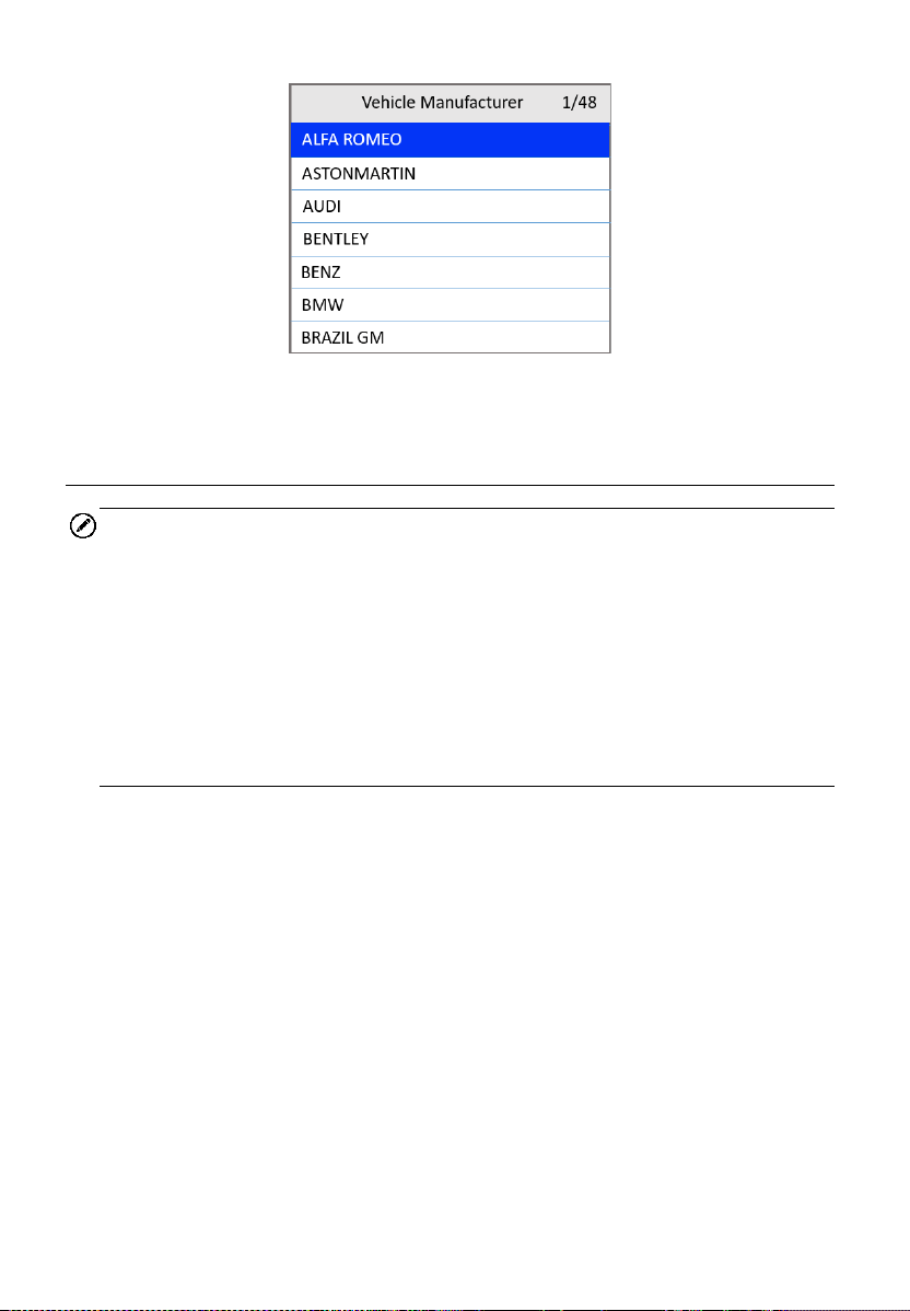
If retrieved DTCs contain any manufacturer specific or enhanced
codes, the tool’s AutoVIN technology will automatically display the
definition of the code. Use the UP/DOWN scroll button to select a
manufacturer and then press the OK button to confirm.
21
Figure 4-6 Vehicle Manufacturer Screen
Erase Codes
NOTE
1. Erasing the Diagnostic Trouble Codes (DTC) may allow the scan tool to
delete not only the codes from the vehicle’s on-board computer, but also
“Freeze Frame” data and manufacturer-specific enhanced data. Further,
the I/M Readiness Monitor Status for all vehicle monitors is reset to Not
Ready or Not Complete status. Do not erase the codes before repairs
or services have been performed.
2. Even if deleted, codes will again display if the underlining fault causing
the code is not addressed.
This function is performed with key on, engine off (KOEO). Do not start
the engine.
1) From the Diagnostic Menu screen (Figure 4-3), use the UP/DOWN
scroll button to select Erase Codes and press the OK button.
2) A warning message appears for your confirmation.
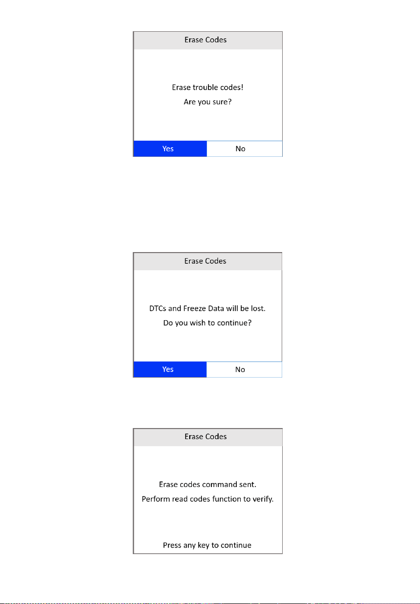
22
Figure 4-7 Erase Codes Screen 1
If you do not want to proceed with erasing codes, press the ESC
button or use the LEFT/RIGHT scroll button to select NO to exit.
If you press the OK button or use LEFT/RIGHT scroll button to
select Yes, a warning message will come up asking for your
confirmation.
Figure 4-8 Erase Codes Screen 2
3) Select Yes to confirm. When the command is sent, the tool will display
a message.
Figure 4-9 Erase Codes Screen 3
23
If the codes are cleared successfully, an “Erase Done!”
confirmation message appears.
If the codes are not cleared, then an “Erase Failure. Turn Key on
with Engine off!” message appears.
4) Press any button to return to the Diagnostic Menu.
Live Data
In this function, you can not only read the live data but also record data for
later review.
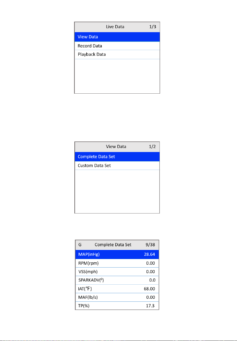
View Data
The View Data function allows viewing of live or real time PID (Parameter
Identification) data of vehicle’s computer modules.
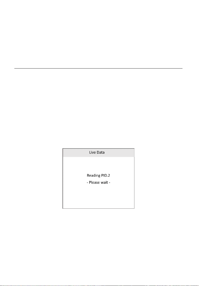
1) To view live data, use the UP/DOWN scroll button to select Live Data
from the Diagnostic Menu screen (Figure 4-3) and press the OK button.
2) Wait a few seconds while the scan tool validates the PID MAP.
Figure 4-10 Live Data Screen 1
3) Use the UP/DOWN scroll button to select View Data from the Live Data
menu and press the OK button.
24
Figure 4-11 Live Data Screen 2
View Complete Data Set
1) To view complete set of data, use the UP/DOWN scroll button to select
Complete Data Set from the View Data menu and press the OK button.
Figure 4-12 View Data Menu
2) View live PIDs on the screen. Use the UP/DOWN scroll button for more
PIDs if additional information is available on more than one page.
Figure 4-13 Complete Data Set Screen
25
The number “x” on the upper-right of the screen indicates the
sequence of the highlighted item.
To view full name of the highlighted PID, press the “?” HELP button.
3) Press the ESC button to return to the previous menu.
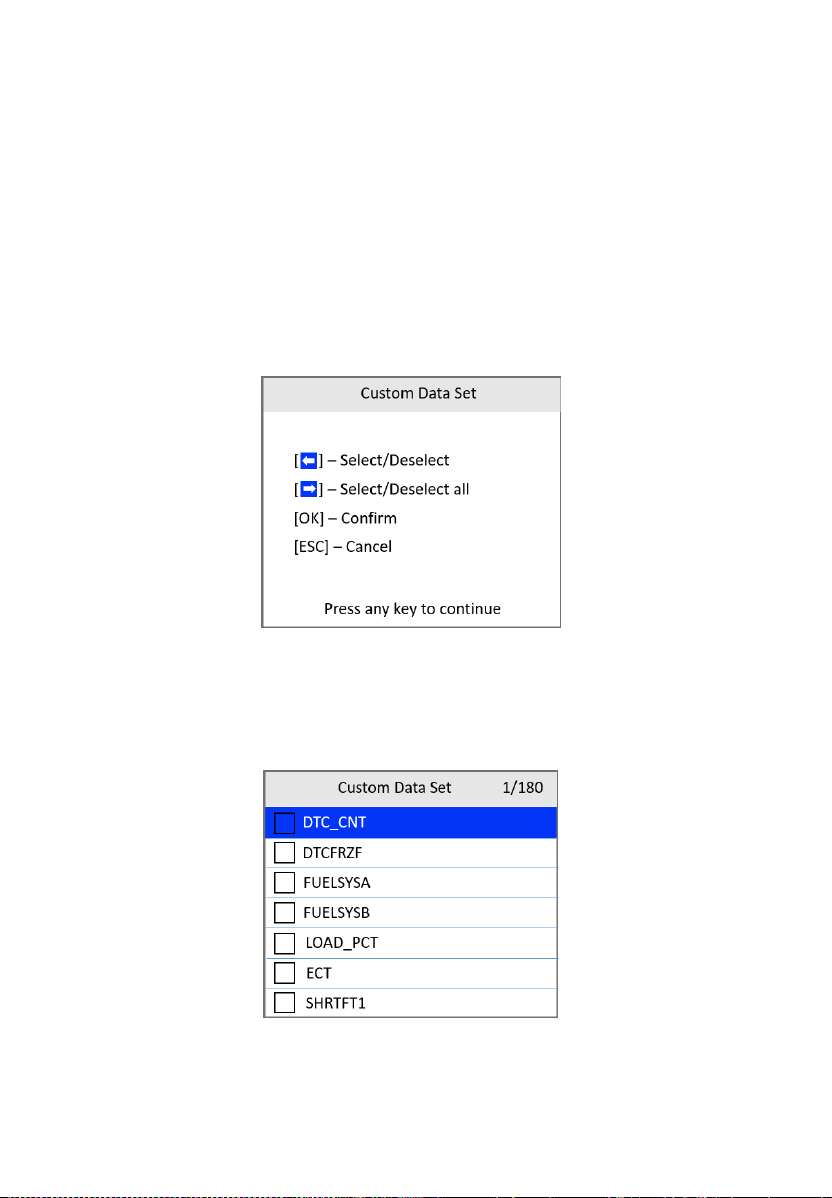
View Custom Data Set
1) To view customized PID data, use the UP/DOWN scroll button to select
Custom Data Set from the View Data menu (Figure 4-12) and press
the OK button.
2) Follow the on-screen instructions.
Figure 4-14 Custom Data Set Screen 1
3) Use the LEFT scroll button to deselect/select data parameters and the
UP/DOWN scroll button to move up and down. Selected parameters are
marked with solid squares.
Figure 4-15 Custom Data Set Screen 2

26
The number “x” on the upper-right corner of the screen indicates
the sequence of the highlighted item.
Press the RIGHT scroll button to deselect all marked items or select
all items. A message appears for your confirmation.
If you decide to deselect these items, press OK. If you decide not
to, press ESC or use the LEFT/RIGHT scroll button to select NO to
continue PID selections.
4) Press the OK button to view selected PIDs on the screen. Use the ESC
button to return to the previous menu.
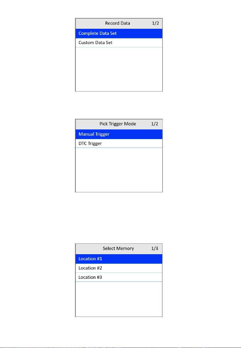
Record Data
The Record Data function allows recording vehicle modules’ Parameter
Identification (PID) data to help diagnose intermittent vehicle problems. A
recording includes 5 frames of live data before a trigger event and several
frames after a trigger event.
There are two trigger modes used to record data:
A. Manual Trigger — press the OK button to start recording.
B. DTC Trigger — automatically records PID data when a fault triggers a
DTC on the vehicle.
NOTE
DO NOT drive the vehicle and operate the tool at the same time.
To record live data, use the UP/DOWN scroll button to select Record Data
from Live Data screen (Figure 4-11) and press the OK button.
Record Complete Data Set
1) To record complete set of live data, use the UP/DOWN scroll button to
select Complete Data Set from Record Data screen and press the OK
button.
27
Figure 4-16 Record Data Screen
2) Use the UP/DOWN scroll button to select a trigger mode and press the
OK button.
Figure 4-17 Pick Trigger Mode Screen
If data from a previously tested vehicle is not erased, data from
current test will be temporarily stored in the tool’s memory.
3) Use the UP/DOWN scroll button to select a memory location and press
the OK button.
Figure 4-18 Select Memory Screen 1
28
The asterisk (*) icon on the screen indicates that a previous
recording is stored in the highlighted location.
If you select a location marked with an asterisk (*), a message
prompting to overwrite old recording appears.
If you wish to proceed with overwriting the recording, press the OK
button; if you do not wish to overwrite it, use the LEFT/RIGHT
button to select NO or press the ESC button to pick another
memory location.
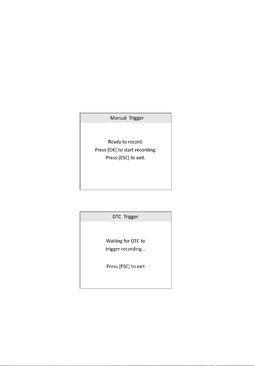
4) Observe the on-screen instructions.
If Manual Trigger is selected, the following screen appears:
Figure 4-19 Manual Trigger Screen
If DTC Trigger is selected, the following screen appears:
Figure 4-20 DTC Trigger Screen
5) Wait for DTC to trigger or press OK to start recording.
Drive till a DTC is detected when DTC Trigger is selected. If no
DTCs are detected, press ESC to exit recording.
29
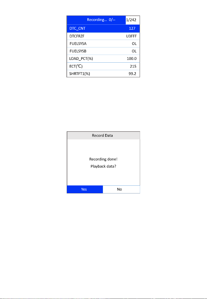
Figure 4-21 Recording Data Screen
The number “x/x...” in the upper-right corner of the screen indicates
the number of recorded frames out of the maximum frames that can
be recorded.
6) The scan tool continues to record PID data until the ESC button is
pressed, the selected memory location is full, or it completes recording.
A message will display asking if you want to play back the data.
Figure 4-22 Recording Done Screen
If you wish to play back recorded data, press the OK button; if you
do not wish to play back, press the ESC button, or use the
LEFT/RIGHT button to select NO and press the OK button to
return to the Record Data screen.
Record Custom Data Set
1) To record customized data, use the UP/DOWN scroll button to select
Custom Data Set from the Record Data screen (Figure 4-16) and press
the OK button.

30
2) Observe the on-screen instructions. Press the OK button to continue;
press the ESC button or the LEFT/RIGHT button to select NO and press
the OK button to return to Record Data screen.
3) Use the LEFT button to select/deselect data parameters. Selected
parameters are marked with solid squares. Press the OK button to
confirm.
If you wish to deselect all marked items, press the RIGHT button.
A message comes up to ask for your confirmation.
If you decide to deselect these items, press OK; if you decide not
to, press the ESC button, or use the UP/DOWN button to select NO
and press OK to continue PID selections.
4) Use the UP/DOWN scroll button to select a trigger mode and press the
OK button.
If data from previously tested vehicle is not erased, data from
current test will be stored in temporary cache.
5) Use the UP/DOWN scroll button to select a memory location and press
the OK button.
6) Follow the on-screen instructions to select a DTC trigger mode.
7) Wait for DTC to trigger recording or press OK to start recording.
8) The scan tool continues recording PID data until the user presses the
ESC button, the selected memory location is full, or it completes
recording. A message prompting to play back data shows on the screen.
If you wish to play back recorded data, press the OK button; if you
do not wish to play back, press the ECS button, or use the
LEFT/RIGHT scroll button to select NO and press the OK button to
return to the Record Data screen.
Playback Data
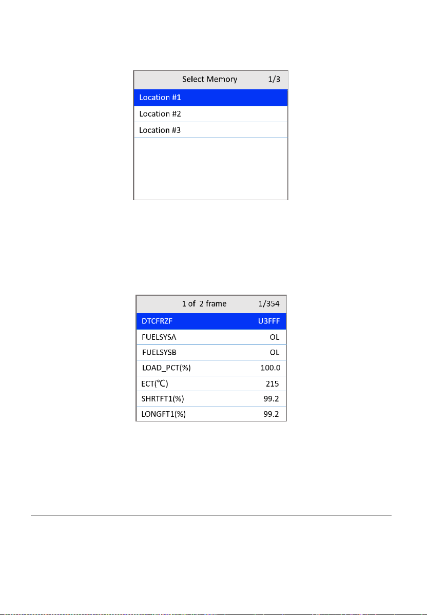
The Playback Data function allows viewing of previously stored PID data.
1) To play back recorded data, use the UP/DOWN scroll button to select
Playback Data from Live Data screen (Figure 4-11) and press the OK
button.
You are also allowed to play back recorded data immediately after
recording.
31
2) Use the UP/DOWN scroll button to select the memory location marked
with an asterisk (*).
Figure 4-23 Select Memory Screen 2
If there is no recording in selected location, a message “Not
Supported or Stored No Data.” appears on the screen. Press any
key to continue.
3) Use the UP/DOWN scroll button to view recorded PIDs of each frame.
Figure 4-24 Playback Data Screen
4) Use the LEFT/RIGHT scroll button to view PIDs of next or previous
frames.
View Freeze Frame
Freeze Frame Data allows the technician to view the vehicle’s operating
parameters at the moment a DTC is detected. For example, the parameters
may include engine speed (RPM), engine coolant temperature (ECT), or
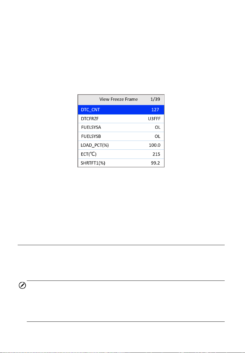
32
vehicle speed sensor (VSS). This information will aid the technician by
allowing the parameters to be duplicated for diagnostic and repair purposes.
1) To view freeze frame data, use the UP/DOWN scroll button to select
View Freeze Frame from the Diagnostic Menu screen (Figure 4-3) and
press the OK button.
2) Wait while the scan tool validates the PID MAP.
3) If retrieved information appears on more than one screen, use the
DOWN scroll button, as necessary, until all the data has been displayed.
Figure 4-25 View Freeze Frame Screen
If no freeze frame data is available, the message “No freeze frame
data stored!” appears.
4) To view the full name of a PID, use the UP/DOWN scroll button to select
the PID and press the HELP button.
5) Press the ESC button to return to the previous screen.
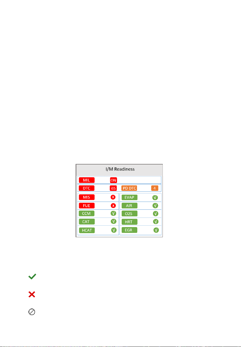
I/M Readiness
I/M Readiness function is used to check the operations of the Emission
System on OBDII compliant vehicles. It is an excellent function to use prior
to having a vehicle inspected for state emissions compliance.
NOTE
Clearing trouble codes also clears the readiness status for the individual
emission system readiness tests. In order to reset these monitors, the
vehicle must be driven through a complete drive cycle with no trouble codes
in memory. Amount of time needed for reset vary by vehicle.
33
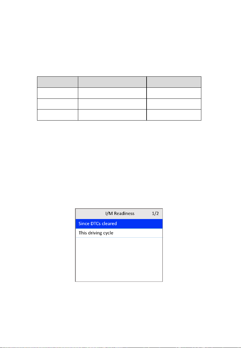
Some latest vehicle models may support two types of I/M Readiness tests:
A. Since DTCs Cleared — indicates status of the monitors since the DTCs
are erased.
B. This Driving Cycle — indicates status of monitors since the beginning
of the current driving cycle.
An I/M Readiness Status result of “NO” does not necessarily indicate that
the vehicle being tested will fail the state I/M inspection. In some states, one
or more such monitors may be allowed to be “Not Ready” to pass the
emissions inspection.
There are two ways to retrieve I/M readiness status.
Retrieve I/M Readiness status with One-Click I/M
Readiness Key
Press One-Click I/M Readiness Key to retrieve the I/M readiness status.
The screen will display as below. The LED colors and the audio tones
indicate readiness status.
Figure 4-26 I/M Readiness Screen
The green, yellow and red LEDs provide a quick way to help you determine
if a vehicle is ready for an Emission Test.
OK — indicates that a particular monitor being checked has completed
its diagnostic testing.
INC — indicates that a particular monitor being checked has not
completed its diagnostics test.
N/A — the monitor is not supported on the vehicle.

34
The LED and audio tone are interpreted as below:
LED Interpretation
GREEN LED — indicates that engine systems are “OK” and operating
normally (the number of Monitors supported by the vehicle that have
run and performed their self-diagnostics test is within the allowed limit.
MIL is off). There are neither stored nor pending DTCs. The vehicle is
ready for an Emissions Testing, and there is a good possibility that it
can be certified.
YELLOW LED — with MIL off, there may be three possible conditions
to cause the yellow LED to light.
If a “Stored” DTC is causing the Yellow LED to light, it is still
possible that the vehicle will be allowed to be tested for emissions
and certified.
If a “Pending” DTC is causing the Yellow LED to light, it is still
possible that the vehicle will be allowed to be tested for emissions
and certified.
The Yellow LED will also light if the monitors do not complete their
tests. Each state’s emissions standards differ on the number of
tested monitors needed to meet vehicle emissions compliance.
NOTE
Confer with your automotive technician about the status results of each
monitor to determine if the vehicle is ready for your state’s emissions testing.
RED LED — indicates there is a problem with one or more of the
vehicle’s system. The test of a vehicle resulting a lit red LED is not ready
for an Emissions Testing. The red LED is also an indication that there
are DTCs present. The MIL lamp on the vehicle’s instrument panel will
light steadily. The problem that is causing the red LED to light must be
repaired before an Emissions Testing. It is also suggested that the
vehicle be inspected/repaired before driving the vehicle further.
If the RED LED lights, there is a problem present in the system(s). In
this case, you have the following options:
Repair the vehicle yourself. Ensure that you proceed by reading the
vehicle service manual and following all procedures and
recommendations.
35
Take the vehicle to a professional to have it serviced. The
problem(s) causing the red LED to light must be repaired before
the vehicle undergoes Emissions Testing.
Audio Tone Interpretation
The audio tone is configured according to the I/M Readiness Status.
Table 4-1 Audio Tone Interpretation
LED Light
Audio Tone
Beeping Interval
Green
Two long beeps
5 seconds
Yellow
Short, long, short beep
5 seconds
Red
Four short beeps
5 seconds
After reading the information, press ESC to exit. Other buttons are disabled
to prevent misoperation.
Retrieve I/M Readiness status in typical way
1) Use the UP/DOWN scroll button to select I/M Readiness from the
Diagnostic Menu screen (Figure 4-3) and press the OK button.
2) Wait while the scan tool validates the PID MAP.
3) If the vehicle supports both types of tests, then both types will be
displayed on the screen for selection.
Figure 4-27 I/M Readiness Selection Screen
4) Use the UP/DOWN scroll button to view the status of the MIL light (ON
or OFF) and the following monitors.
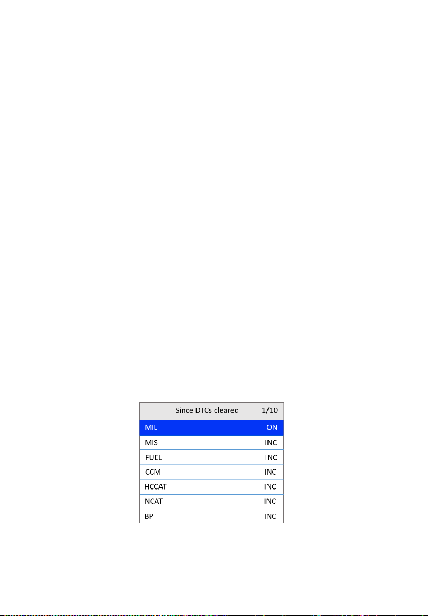
36
For spark ignition engines:
MIS — Misfire Monitor
FUEL — Fuel System Monitor
CCM — Comprehensive Component Monitor
EGR — EGR System Monitor
O2S — O
2
Sensors Monitor
CAT — Catalyst Monitor
EVAP — Evaporative System Monitor
HTR — O
2
Sensor Heater Monitor
AIR — Secondary Air Monitor
HCAT — Heated Catalyst Monitor
For compression ignition engines:
MIS — Misfire Monitor
FUEL — Fuel System Monitor
CCM — Comprehensive Component Monitor
EGR — EGR System Monitor
HCCAT — NMHC Catalyst Monitor
NCAT — NOx Aftertreatment Monitor
BP — Boost Pressure System Monitor
EGS — Exhaust Gas Sensor Monitor
PM — PM Filter Monitor
Figure 4-28 Since DTC Cleared Screen
5) If the vehicle supports readiness test of This Driving Cycle, the
following screen appears.
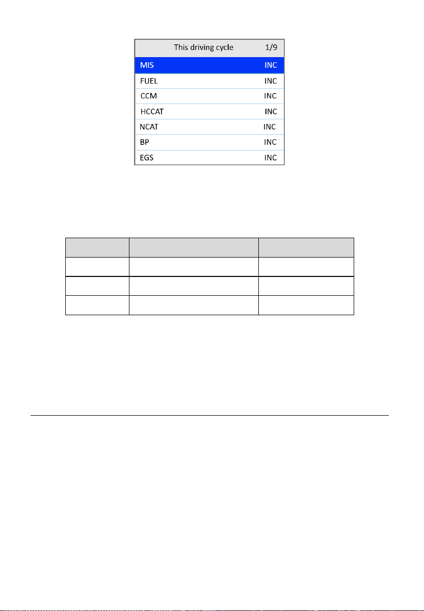
37
Figure 4-29 This Driving Cycle Screen
6) The LEDs and audio tone corresponding to different monitor status will
sound as below.
Table 4-2 LED and Audio Tone Description
LED Light
Audio Tone
Beeping Interval
Green
Two long beeps
2 minutes
Yellow
Short, long, short beep
2 minutes
Red
Four short beeps
2 minutes
7) Use the UP/DOWN scroll button for more PIDs if additional information
is available on more than one page. Or use the LEFT/RIGHT scroll
button to view PIDs in the previous/next page.
8) Press the ESC button to return to the Diagnostic Menu.
On-Board Monitor Test
The On-Board Monitor Test is useful after servicing or erasing a vehicle’s
control module memory. The On-Board Monitor Test for non-CAN-equipped
vehicles retrieves and displays test results for emissions-related power train
components and systems that are not continuously monitored. The On-
Board Monitor Test for CAN-equipped vehicles retrieves and displays test
results for emissions-related power train components and systems that are
continuously monitored or not.
The scan tool allows access to the results of on-board diagnostic monitoring
tests for specific components/systems. The vehicle manufacturer is
responsible for assigning "Manufacturer Defined Test IDs" and Component
38
IDs for tests of different systems and components. The advanced feature of
this scan tool enables you to read the definition of an On-Board Diagnostic
Monitor ID.
NOTE
The scan tool will display a test definition if one is present in the vehicle’s
computer memory. If no such definition is present, the scan tool will only
display the Test IDs.
In this test, there are typically a minimum value, a maximum value, and a
current value for each monitor. By comparing the current value with the
minimum and maximum values, the scan tool determines if the components
and monitors are normal.
1) Use the UP/DOWN scroll button to select On-Board Mon. Test from
the Diagnostic Menu screen (Figure 4-3) and press the OK button.
2) Wait while the scan tool validates the PID MAP.
3) The scan tool will prompt you to select the vehicle make.
4) After you select the vehicle manufacturer, the scan tool displays the On-
Board Monitors test results for specific monitored systems.
Figure 4-30 On-board Monitor Test Screen 1
5) From On-Board Monitor Test menu, use the UP/DOWN scroll button to
select a test to view and press the OK button. Or, use the LEFT/RIGHT
scroll button to view previous/next screen of test items.
If the vehicle being tested does not support the mode, an advisory
message will display on the screen.
For CAN-equipped vehicles, test selections may be as depicted
below:
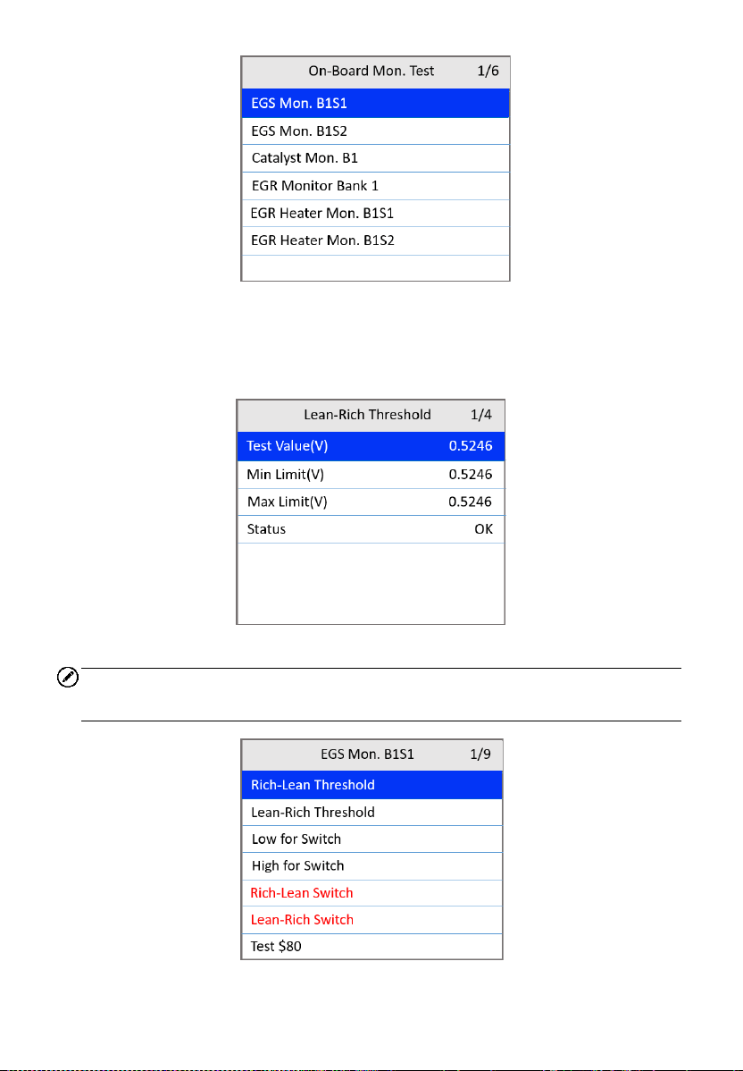
39
Figure 4-31 On-board Monitor Test Screen 2
6) Use the UP/DOWN scroll button to select the desired monitor from On-
Board Mon. Test menu and press the OK button.
7) View test data on the screen.
Figure 4-32 On-board Monitor Test Screen 3
NOTE
If the On-Board Monitor Test fails, the monitor item will display red.
Figure 4-33 On-board Monitor Test Screen 4
40
8) Press the ESC button to return to the previous menu.
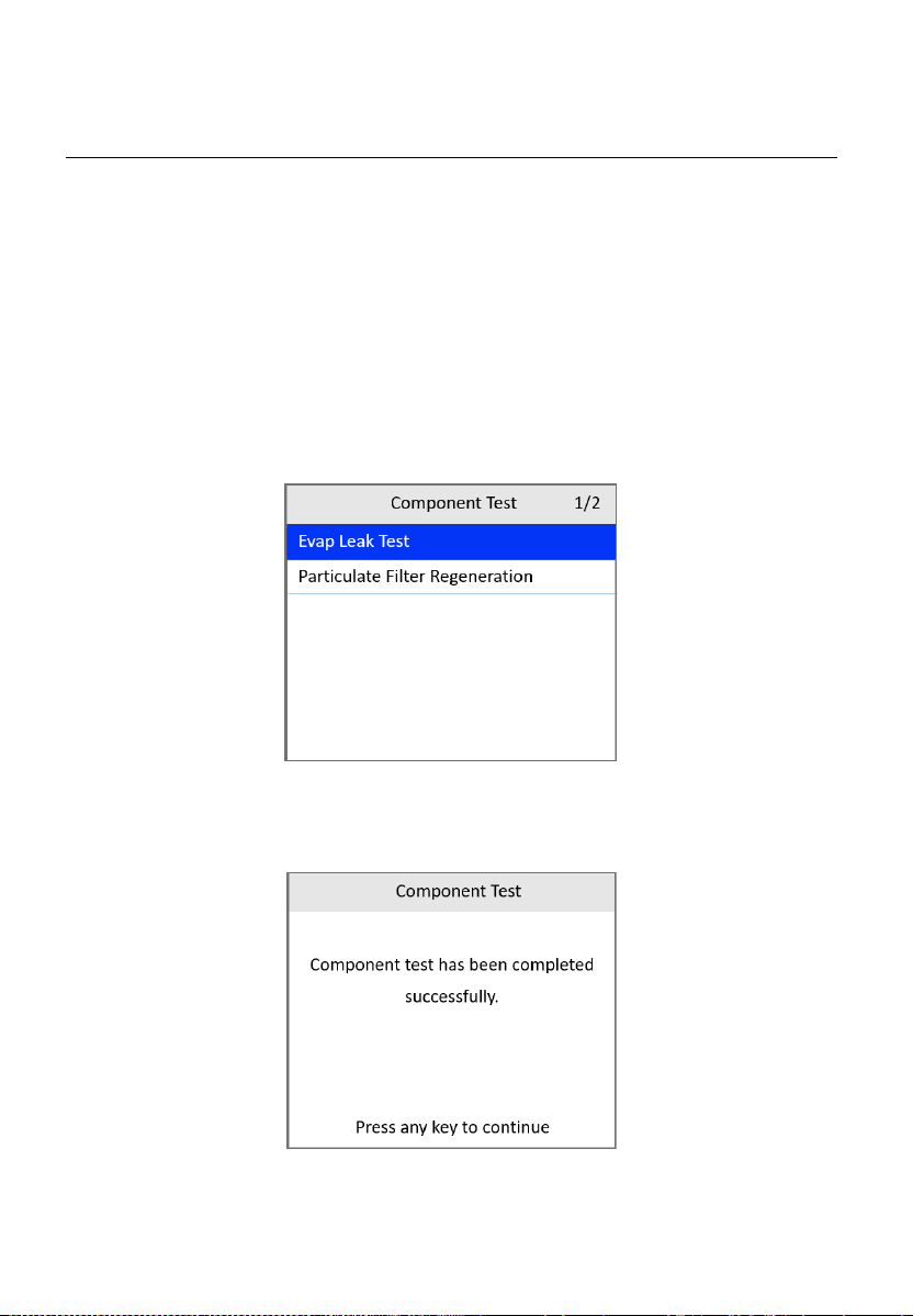
Component Test
The Component Test initiates a leak test for the vehicle's EVAP system. The
scan tool itself does not perform the leak test, but commands the vehicle's
on-board computer to start the test. Different vehicle manufacturers might
use different criteria and methods for stopping the test once it has been
started. Before starting the Component Test, refer to the vehicle service
manual for instructions to stop the test.
1) Use the UP/DOWN scroll button to select Component Test from the
Diagnostic Menu screen (Figure 4-3) and press the OK button.
2) Wait for the scan tool to display the Component Test menu.
Figure 4-34 Component Test Screen 1
3) If the test has been initiated by the vehicle, a confirmation message will
be displayed on the screen.
Figure 4-35 Component Test Screen 2
41
Some vehicles do not allow scan tools to control vehicle systems
or components. If the vehicle under test does not support the EVAP
Leak Test, a message will show.
Figure 4-36 Component Test Screen 3
4) Wait a few seconds or press any key to return to the previous screen.
Vehicle Information
The Vehicle Information function enables the retrieval of the Vehicle
Identification No. (VIN), Calibration ID Nos. (CINs), Calibration Verification
Nos. (CVNs) and In-use Performance Tracking on 2000 and newer vehicles
that support Mode 9.
1) From the Diagnostic Menu screen (Figure 4-3), use UP/DOWN scroll
button to select Vehicle Info. and press the OK button.
2) A message appears to remind you to “Turn key on with engine off.” Wait
a few seconds or press any key to continue.
Figure 4-37 Vehicle Info. Screen 1
42
3) Wait while the scan tool reads vehicle information.
If the vehicle does not support this mode, a message shows on the
display warning that the mode is not supported.
4) From the Vehicle Info. menu, use the UP/DOWN scroll button to select
an item available for viewing and press the OK button.
Figure 4-38 Vehicle Info. Screen 2
5) View the retrieved vehicle information.
Figure 4-39 Vehicle Info. Screen 3
6) Press the ESC button to return to the previous menu.
Modules Present
The Modules Present function displays the module IDs and communications
protocols for OBDII modules in the vehicle.
1) From the Diagnostic Menu screen (Figure 4-3), use the UP/DOWN
scroll button to select Modules Present and press the OK button.
2) View modules present with their IDs and communications protocols.
43
Figure 4-40 Modules Present Screen
3) Press the ESC button to return to the previous menu.

44
5 ABS Diagnosis
The ABS — Anti-lock Braking System in most vehicles is made up of an
electronic hydraulic pump of two to four Wheel Speed Sensors (WSS), a G-
force sensor, a Vehicle Speed Sensor, and an ABS Control Module (EBCM).
The EBCM is constantly monitoring the WSS, the Vehicle Speed Sensor, and
the G-sensor.
Diagnosing an ABS problem should always start with a visual inspection of
all brake components. Then you will need to retrieve ABS DTCs to tell you
where the problem is.
The ABS diagnostic function is used to retrieve and clear codes from the
vehicle’s Anti-lock Braking System. It also provides the definition of each
code to help diagnosing problems within the system that may cause the
Malfunction Indicator Light (MIL) to turn on.
IMPORTANT
Autel accepts no responsibility for any accident or injury arising from servicing
the ABS system. When interpreting DTCs retrieved from the vehicle, always
follow the manufacturer’s recommendation for repair.
NOTE
All screens shown in this manual are examples, actual test screens may vary
for each vehicle being tested. Observe the menu titles and on-screen
instructions to make correct option selections.
Please follow these steps to start the ABS diagnostics test procedure:
1) Turn the ignition off.
2) Locate the vehicle’s 16-pin Data Link Connector (DLC). Plug the scan
tool cable connector into the vehicle’s DLC.
3) Turn the ignition on, but do not start the engine.
4) The scan tool powers up and the Main Screen appears.
5) From the Main Screen, use the UP/DOWN scroll button and
LEFT/RIGHT scroll button to select ABS.
45
Figure 5-1 Main Screen
Vehicle Selection
The scan tool will communicate with the vehicle and a series of vehicle
identification screens appears for users to identify the vehicle. On each
screen, use the UP/DOWN scroll button to select the correct option and then
press the OK button. Do this until the vehicle is identified.
1) After selecting ABS from the Main Screen, use the UP/DOWN scroll
button to select a region.
Figure 5-2 Vehicle Area Screen
2) Use the UP/DOWN scroll button to select the vehicle make. Follow the
on-screen instructions, select the vehicle information, such as vehicle
model, year, type, and series, if needed.
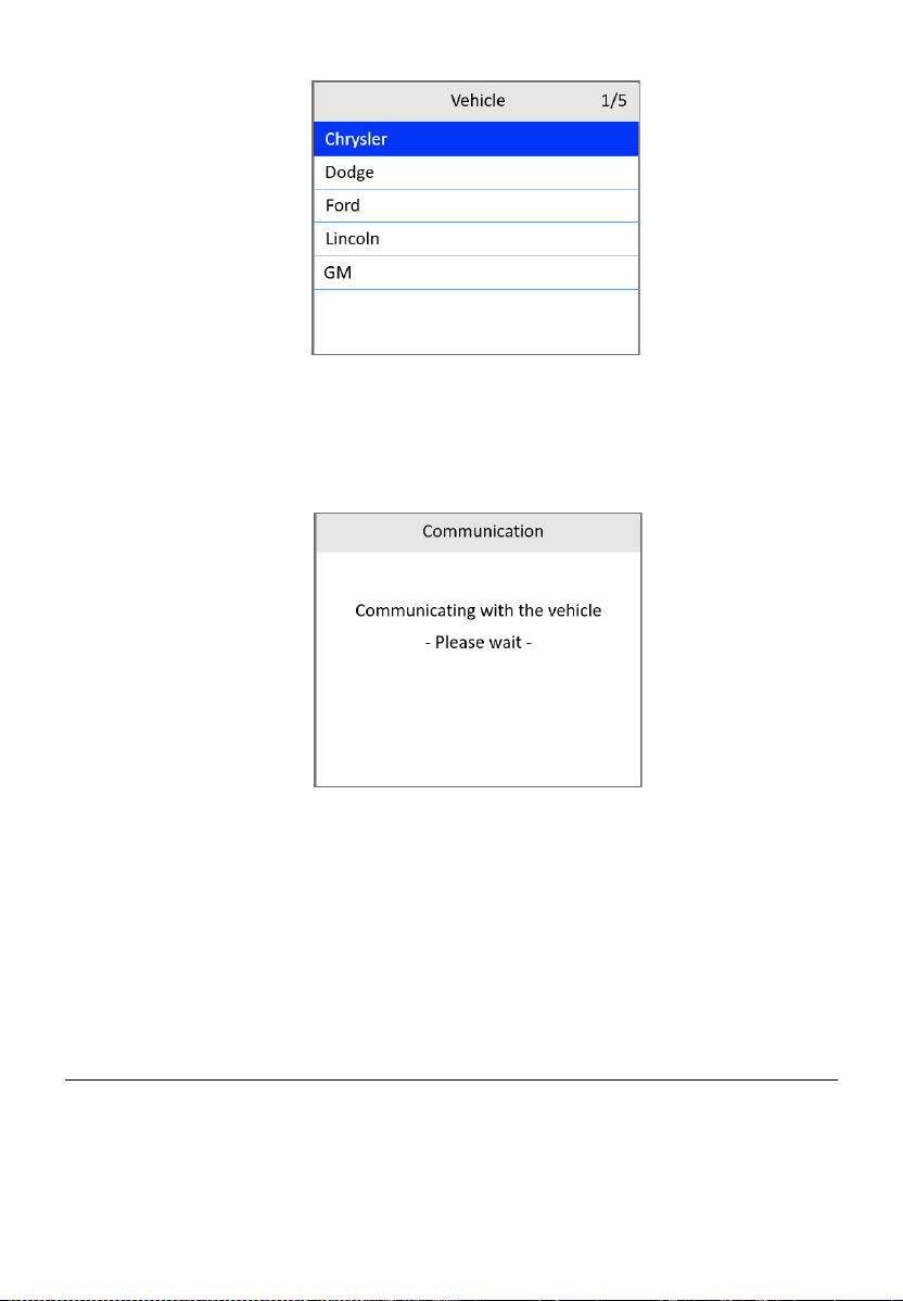
46
Figure 5-3 Vehicle Make Selection Screen
3) The scan tool will establish a communication link with the test vehicle.
Once the communication has been established successfully, the ABS
Function screen appears.
Figure 5-4 Communication Screen
If the scan tool fails to communicate with the vehicle’s ECU, a “LINK
ERROR!” message appears on the tool.
Make sure the ignition is ON.
Check if the scan tool is securely connected to the vehicle’s DLC.
Check that the vehicle battery is charged.
Reading ABS Codes
This function allows users to read the ABS DTCs from vehicle ECU.
1) Follow Vehicle Selection procedure to enter the vehicle information.
The scan tool displays a function screen.
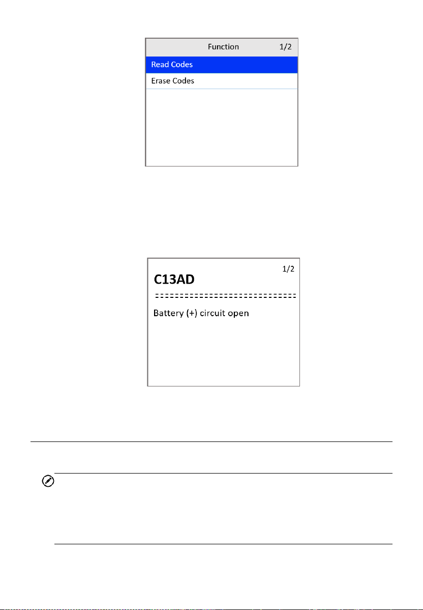
47
Figure 5-5 ABS Function Screen
2) Use the UP/DOWN scroll button to select Read Codes and press the
OK button.
3) View the DTC and its definition on the screen. Press the ESC button
to exit.
Figure 5-6 ABS Code Screen
Erasing ABS Code
This function allows user to erase the ABS DTCs in vehicle ECU.
NOTE
If you plan to take the vehicle to a Service Center for repair, DO NOT erase
the ABS DTCs from the vehicle’s computer. If the codes are erased,
valuable information that might help the technician troubleshoot the
problem will also be erased.
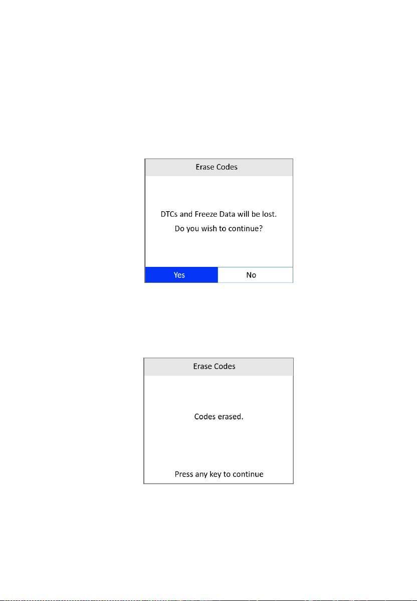
48
1) Follow Vehicle Selection procedure to enter the vehicle information.
The scan tool displays a function screen.
2) Use the UP/DOWN scroll button to select Erase Codes and press the
OK button.
3) Follow the on-screen instructions and make sure the ignition is on and
engine is off. Press Yes to continue.
4) A warning message will pop up asking for your confirmation. Use the
LEFT/RIGHT scroll button to select Yes to confirm or No to exit.
Figure 5-7 Erase Codes Screen 1
5) When the command is sent, a message “Codes erased.” appears on
the tool, indicating the codes are erased successfully. Press any key
to continue.
Figure 5-8 Erase Codes Screen 2
6) To make sure the codes are erased completely, perform the Read
Codes function to verify.

49
6 Battery Test
The Battery Test function is used to test the vehicle’s starting system and
charging system. It provides a quick and accurate check of the vehicle’s
battery and alternator system to ensure the system is operating properly.
Starting System Test
Before performing the test, the starting system should be visually inspected
for physical defects, and some preliminary checks should be performed to
aid you in diagnosing a starting system problem. These should be taken care
of during the pretest.
Pretest
1. To prevent possible personal injury and protect the vehicle from
damage, inspect the starting system for defects. Check for the
followings, and then repair and/or replace any defective components.
Battery defects.
Frayed or broken electrical wiring.
Corroded or loose connections.
Loosely mounted starter motor, series-parallel switch, magnetic
switch, solenoid, and starter relay, etc.
2. Check State of Charge (SoC) of battery. For accurate cranking voltage
test results, the battery must be at least 75 percent charged.
3. Make sure the handbrake on and the gear is on N or P.
Test Procedure
Follow the steps to complete the test:
1) Perform the pretest.
2) Turn off all of the vehicle's electrical accessories.
50
3) Connect the scan tool to the vehicle’s DLC with the OBDII connector.
The scan tool will power up and the Main Screen will appear.
Figure 6-1 Main Screen
4) Use the UP/DOWN scroll button to select Battery from the Main Screen
and press the OK button.
5) Use the UP/DOWN scroll button to select Starting System Test and
press the OK button.
Figure 6-2 Starting/Charging Test Screen
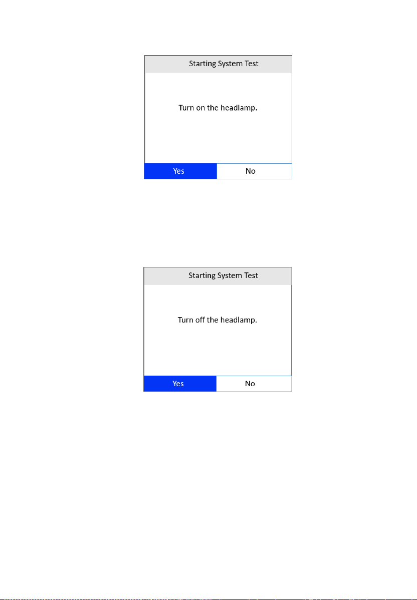
6) Read the on-screen preparations and notes. Use the LEFT/RIGHT
scroll button to select Yes or press OK to continue.
7) Turn on the headlamp. Use the LEFT/RIGHT scroll button to select Yes
or press OK to continue.
51
Figure 6-3 Starting System Test Screen 1
8) A “countdown” message shows while the battery test is in process. Wait
for a few seconds to show the next screen.
9) Turn off the headlamp. Use the LEFT/RIGHT scroll button to select Yes
or press OK to continue.
Figure 6-4 Starting System Test Screen 2
10) Start the engine in 30 seconds.
52
Figure 6-5 Starting System Test Screen 3
The test needs to be performed again if the engine has not been
started within 30 seconds.
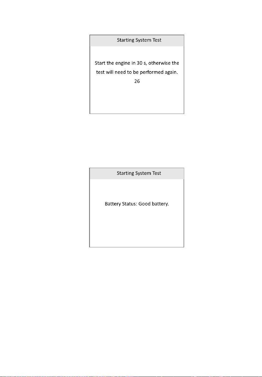
11) When the battery test is completed, a results screen shows the battery
status. Press the ESC button to return to the previous menu.
Figure 6-6 Starting System Test Screen 4
If the test fails, a “Battery test cannot be performed” message
will appear on the screen. You will need to try again.

53
Table 6-1 Starting System Test Results
Results
Description
Battery Good
The battery is normal and ready for service.
Charge Battery
Fully charge the battery and retest. Failure to fully
charge the battery before testing may cause false
readings. If “Charge Battery” appears again after
you fully charge the battery, replace the battery.
Battery Faulty
Replace the battery and retest.
Charging System Test
Before starting the test, inspect the alternator drive belt. A belt that is glazed,
worn, or lacks the proper tension will prevent the engine from achieving the
RPM levels needed for the test.
Test Procedure
1) Turn off all the vehicle's electrical accessories.
2) Connect the scan tool to the vehicle’s DLC with the OBDII connector.
The scan tool will power up and the Main Screen will appear.
3) Use the UP/DOWN scroll button to select Battery from the Main Screen
(Figure 6-1) and press the OK button.
4) Use the UP/DOWN scroll button to select Charging System Test from
the Starting/Charging Test screen (Figure 6-2) and press the OK button.
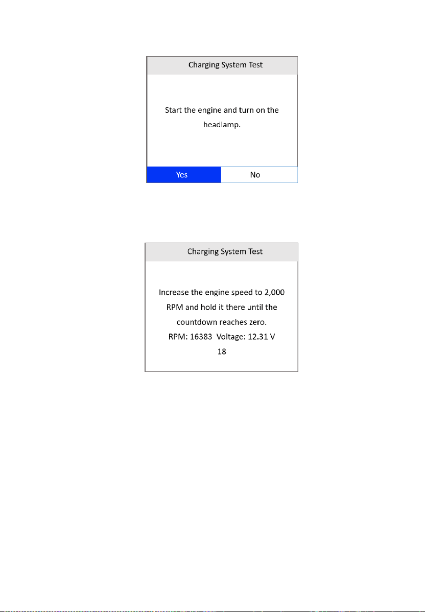
5) Start the engine and turn on the headlamp. Use the LEFT/RIGHT scroll
button to select Yes or press OK to continue.
54
Figure 6-7 Charging System Test Screen 1
6) Press the accelerator pedal to increase the engine speed to 2,000 RPM
and hold it there until the countdown reaches zero.
Figure 6-8 Charging System Test Screen 2
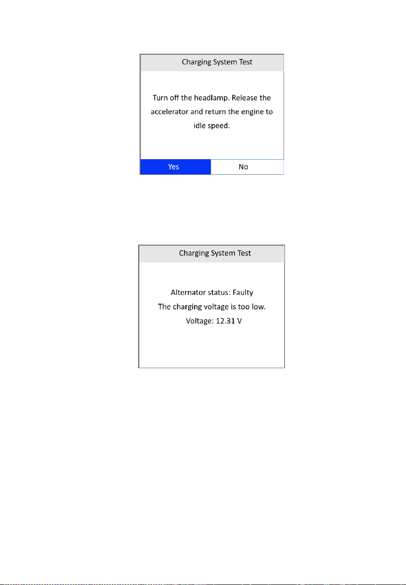
7) Turn off the headlamp. Release the accelerator and return the engine
to idle speed. Use the LEFT/RIGHT scroll button to select Yes or press
OK to continue.
55
Figure 6-9 Charging System Test Screen 3
8) When the Charging System Test is complete, a results screen will
display the alternator status and the value of the charging system
voltage. Press the ESC button to return to the previous menu.
Figure 6-10 Charging System Test Screen 4

56
Table 6-2 Charging System Test Results
Results
Description
Normal
The charging system is showing normal
output. No problem detected.
Low Output
There is a problem with the charging system.
The alternator is not providing enough
current to power the system’s electrical
loads and charge the battery.
Check the belts to ensure the alternator
is rotating with the engine running.
Replace broken or slipping belts and
retest.
Check the connections between the
alternator and the battery. If connection
is loose or heavily corroded, clean or
replace the cable and retest.
High Output
There is a problem with the charging system.
The voltage output from the alternator to the
battery exceeds the normal limits of a
functioning regulator.
Check to ensure there are no loose
connections and that the ground
connection is normal.
If the connection is good, check the
regulator.
NOTE: Most alternators have a built-in
regulator requiring you to replace the
alternator. In older vehicles that use external
voltage regulators, you may need to replace
only the voltage regulator.
57
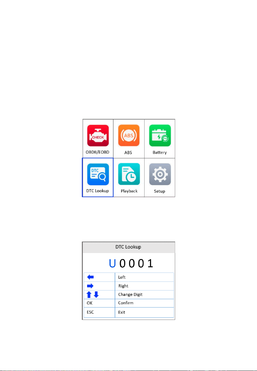
7 DTC Lookup
The DTC Lookup function is used to search for definitions of DTCs stored in
the DTC library.
1) From the Main Screen, use the UP/DOWN scroll button and
LEFT/RIGHT scroll button to select DTC Lookup and press the OK
button.
Figure 7-1 Main Menu
2) From the DTC Lookup screen, use the LEFT/RIGHT scroll button to
move to the desired character; use the UP/DOWN scroll button to
change selected digit/character and press the OK button to confirm.
Figure 7-2 Sample DTC Lookup Screen

58
3) View the DTC definition on the screen. When a DTC definition has more
than one screen, use the LEFT/RIGHT scroll button or UP/DOWN scroll
button to view additional information on previous/next screens.
If retrieved DTCs contain any manufacturer specific codes, the
AutoVIN function embedded in this tool will automatically display the
definition of the code. Press any key to select a vehicle make.
If definition cannot be found, the scan tool displays the message
“Please refer to vehicle service manual.”
For DTC Guide information, press the “?” HELP button.
4) Use the LEFT/RIGHT scroll button to view previous or next DTC in the
built-in DTC library.
5) To enter another DTC, press the ESC button to return to previous screen.
6) Press the ESC button To exit to the Main Screen.
59
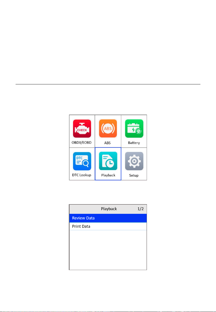
8 Playback
The Playback function allows the viewing and printing of data from the last
recorded test.
Review Data
1) From the Main Screen, use the UP/DOWN scroll button and
LEFT/RIGHT scroll button to select Playback, and then press the OK
button.
Figure 8-1 Main Screen
2) Select Review Data and press the OK button.
Figure 8-2 Playback Screen
60
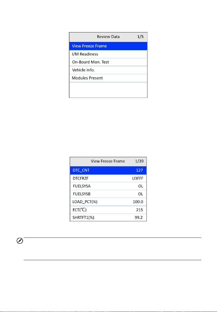
3) From the Review Data menu, use the UP/DOWN scroll button to select
the desired item and press OK.
Figure 8-3 Review Data Menu
If no data from a previously tested vehicle is recorded, only the
Modules Present data containing module ID and protocol type can
be viewed.
Diagnostics results can be reviewed from this list only when trouble
codes are detected in previous tests.
4) View the selected data on the screen or press the ESC button to exit.
Figure 8-4 View Freeze Frame Screen
NOTE
If there is no data stored for selected item, a “Not Supported or Stored No
Data!” message appears on the screen.
61
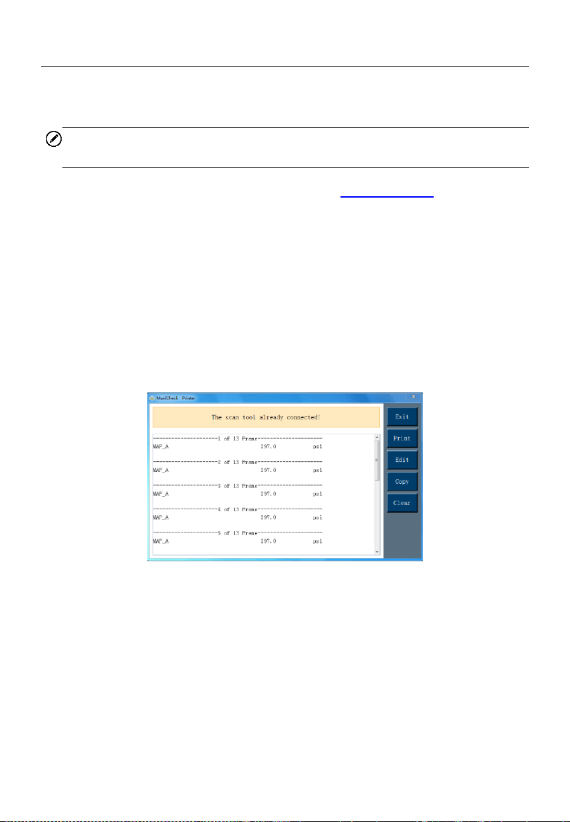
Print Data
The Print Data function allows the printing of DTC data recorded by the tool
by connecting the tool to a Windows-based PC with a USB cable.
NOTE
The print function is currently not available on the Mac OS.
1. Download the Maxi PC Suite from www.autel.com > Support >
Downloads > Autel Update Tools, and install to your Windows-based
computer.
2. Connect the tool to the computer using a Type-C USB cable.
3. Run Printer software on the computer.
4. Select Playback on the Main Screen of the tool. On the Playback screen,
select Print Data and then select the data you want to print. Wait for the
review window to display, and then select the Print function. The
selected file will be uploaded to your computer.
5. The Printer will appear as below.
Figure 8-5 Printer Screen
6. The selected data will display in the textbox. Select the appropriate
function button on the right to execute one of the following operations:
Print — print all data in the textbox to a printer connected to your
computer.
Edit — display an editable NOTEPAD window with recorded data.
Copy — copy the data in the textbox to the clipboard.
Clear — delete the data in the textbox.
Exit — quit the operation.

62
9 Setup
The Setup function allows you to adjust the default settings and view
information about the scan tool.
1) Language: Selects the desired language.
2) Configure Monitors: Sets the monitors you want to test.
3) Unit of measure: Sets the unit of measure to Imperial or Metric.
4) Key Beep Settings: Turns on/off beep.
5) Status Beep Settings: Turns on/off the I/M Readiness Status beep.
6) Tool Self-test: Checks if the LCD display, LED lamps and keyboard are
working normally.
7) Update Mode: Accesses the Update Mode.
8) Set Data Log: Turns on/off the data log function.
9) Upload Data Log Mode: Uploads the data log to the Autel platform.
10) About: Provides information of the scan tool.
Tool operates with default settings until changed.
To enter the Setup menu
From the Main Screen, use the UP/DOWN scroll button and LEFT/RIGHT
scroll button to select Setup and press the OK button. Following the
instructions to adjust the settings could make your diagnosis more convenient
and easy.
Figure 9-1 Main Screen
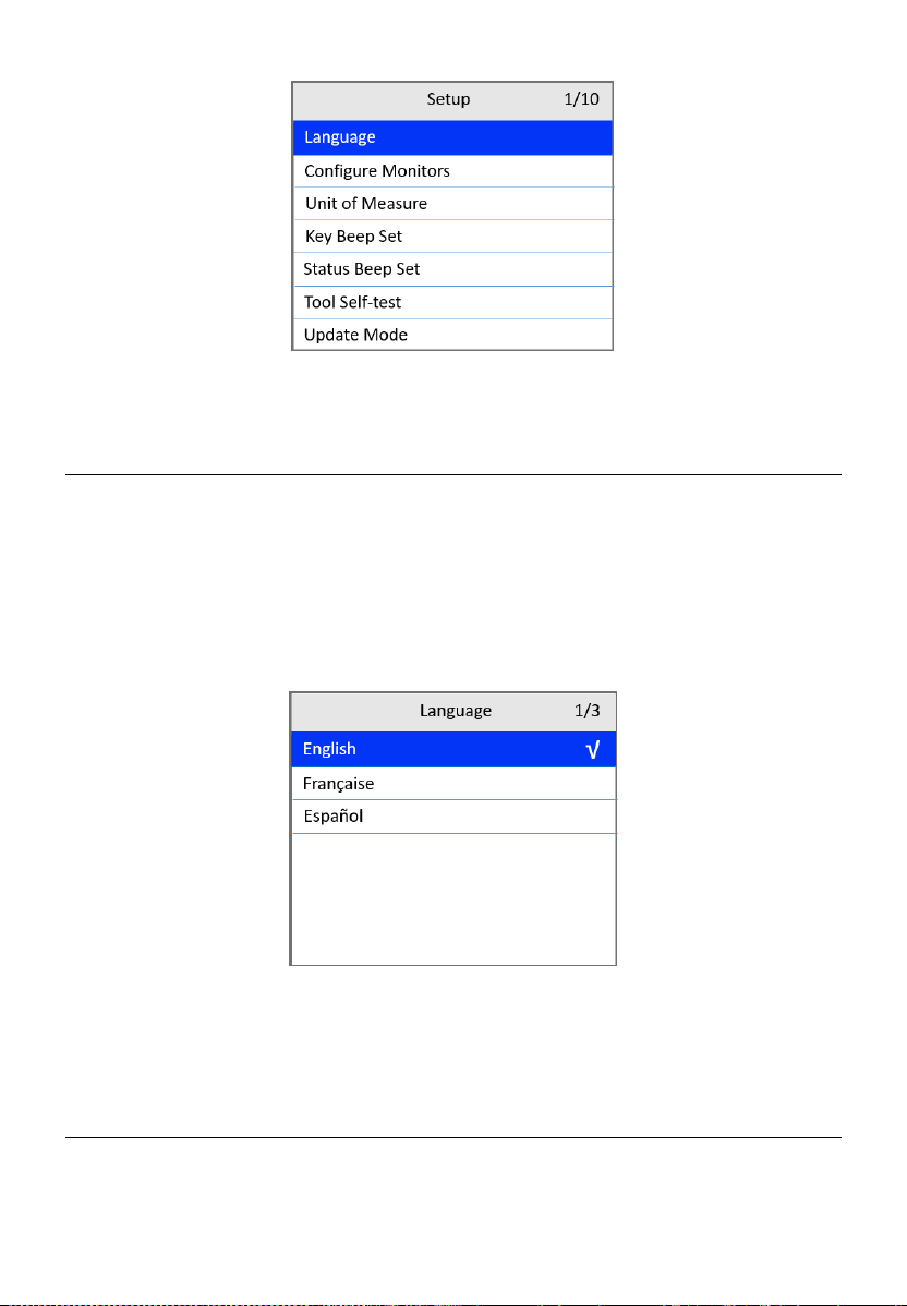
63
Figure 9-2 Setup Screen
Language
English is the default language.
1) From the Setup screen (Figure 9-2), use the UP/DOWN scroll button to
select Language and press the OK button.
2) Use the UP/DOWN scroll button to select the desired language. Press
the OK button to save your selection and return to previous screen or
press the ESC button to exit without saving.
Figure 9-3 Language Screen
More language options may be available when the software has
been updated to the latest version.
Configure Monitors
From the Setup screen (Figure 9-2), use the UP/DOWN scroll button to select
Configure Monitors and press the OK button.
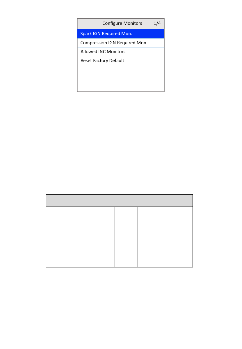
64
Figure 9-4 Configure Monitors Screen
On this menu, configure the monitors required to test spark ignition and
compression ignition, the number of monitors to pass diagnosis, and restore
the default settings.
Spark IGN Required Monitors
From the Configure Monitors screen, use the UP/DOWN scroll button to
select Spark IGN Required Mon. and press the OK button.
The monitors for spark ignition engines display as follows:
Table 9-1 Spark IGN Required Monitors
Spark IGN Required Monitors
√
MIS
√
EVAP
√
FUEL
√
AIR
√
CCM
√
O2S
√
CAT
√
HTR
√
HCAT
√
EGR
Compression IGN Required Monitors
From the Configure Monitors screen, use the UP/DOWN scroll button to
select Compression IGN Required Mon. and press the OK button.
The monitors for compression ignition engines display as follows:

65
Table 9-2 Compression IGN Required Monitors
Compression IGN Required Monitors
√
MIS
√
BP
√
FUEL
√
EGS
√
CCM
√
PM
√
HCCAT
√
EGR
√
NCAT
Allowed INC Monitors
From the Configure Monitors screen, use the UP/DOWN scroll button to
select Allowed INC Monitors and press the OK button.
Emissions tests vary depending on the areas where the vehicle is registered.
The scan tool provides a more flexible way to meet different standards by
allowing the user to select 0, 1, 2, or 3 “not complete” monitors in test.
Reset Factory Default
From the Configure Monitors screen, use the UP/DOWN scroll button to
select Reset Factory Default and press the OK button.
This will restore the default configuration settings in the Configure Monitors
menu and delete any customized settings. In this case, Spark IGN Required
Monitors and Compression IGN Required Monitors will include all the
available monitors, and the Allowed INC Monitors will be set to 1.
The tool will display a message to ask for your confirmation. Select Yes to
proceed or No to exit without saving.
Unit of Measure
Metric is the default measurement unit.
1) From the Setup screen (Figure 9-2), use the UP/DOWN scroll button to
select Unit of Measure and press the OK button.
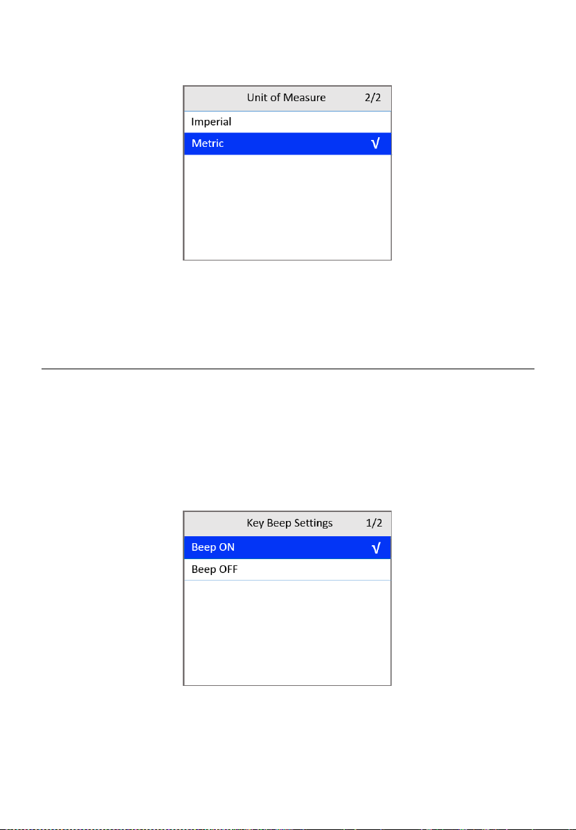
66
2) Use the UP/DOWN scroll button to select the desired unit of
measurement.
Figure 9-5 Unit of Measure Screen
3) Press the OK button to save your selection and return to the previous
menu or press the ESC button to exit without saving.
Key Beep Settings
This function allows you to turn on/off the built-in speaker for key pressing.
The default setting is Beep On.
1) From the Setup screen (Figure 9-2), use the UP/DOWN scroll button to
select Key Beep Settings and press the OK button.
2) Use the UP/DOWN scroll button to select Beep ON or Beep OFF to turn
on/off the beep.
Figure 9-6 Key Beep Settings Screen
3) Press the OK button to save your selection and return to the previous
menu or press the ESC button to exit without saving.
67
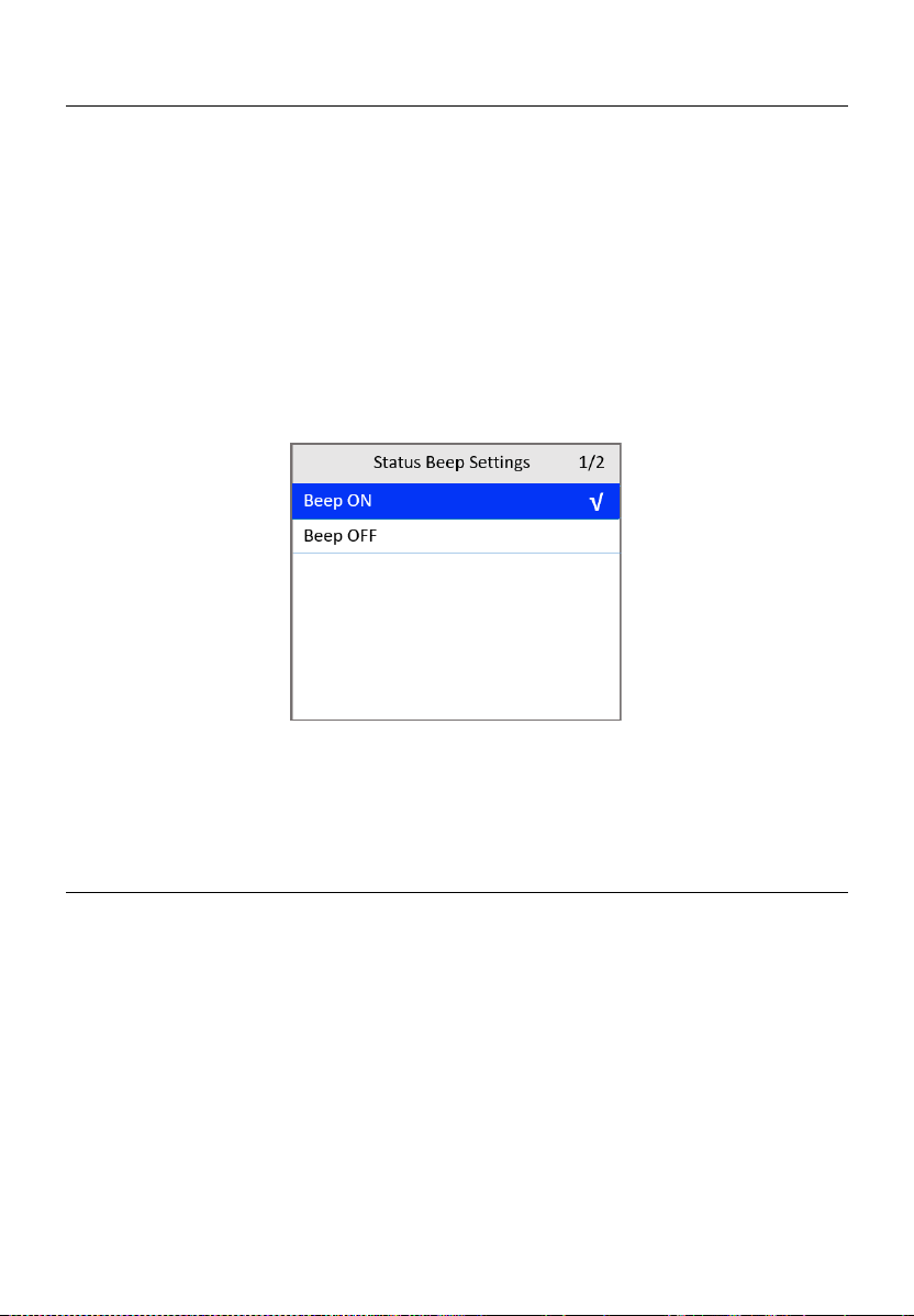
Status Beep Settings
The default setting is Beep On.
This function allows you to turn on/off the built-in speaker as an indicator
during diagnostic testing. Different audio tones correspond to different LED
lights. This function is useful when performing diagnostics alone, or while
working in bright areas where LED illumination alone is not sufficient.
1) From the Setup screen (Figure 9-2), use the UP/DOWN scroll button to
select Status Beep Settings and press the OK button.
2) Use the UP/DOWN scroll button to select Beep ON or Beep OFF to turn
on/off the beep.
Figure 9-7 Status Beep Settings Screen
3) Press the OK button to save your selection and return to the previous
menu or press the ESC button to exit without saving.
Tool Self-test
The Tool Self-test function checks if the display, LED lamps, and keyboard
are working properly.
Display Test
The Display Test function checks if the LCD display is working normally.
1) From the Setup screen (Figure 9-2), use the UP/DOWN scroll button to
select Tool Self-test and press the OK button.
2) Select Display Test from the Tool Self-test menu and press the OK
button to start test.
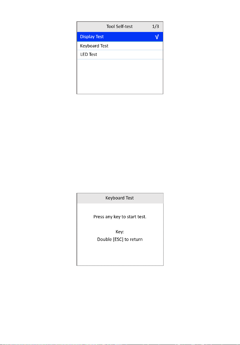
68
Figure 9-8 Tool Self-test Screen
3) When completed, press the ESC button to exit.
Keyboard Test
The Keyboard Test function verifies if the keys are functioning properly.
1) From the Tool Self-test screen, use the UP/DOWN scroll button to select
Keyboard Test, and then press the OK button.
2) Press any key to start test. When you press a key, the key name should
display on the screen. If the key name does not display, the key is not
functioning.
Figure 9-9 Keyboard Test Screen
3) Press ESC twice to return to the previous menu.
LED Test
The LED Test function verifies if the I/M Readiness LED indicators are
functioning properly.
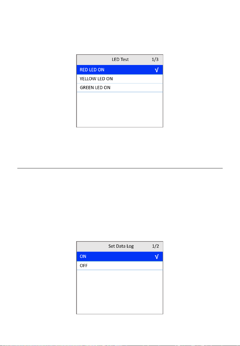
69
1) From the Tool Self-test screen, use the UP/DOWN scroll button to select
LED Test, and then press the OK button.
2) Use the UP/DOWN scroll button to select one or more LED lamps to test.
The LED should turn on or off according to the selected commands.
Figure 9-10 LED Self-test Screen
3) When completed, press the ESC button to exit.
Set Data Log
The default setting is OFF.
If you want to upload the data log to Autel company, please first set the data
log to ON.
1) From the Setup screen (Figure 9-2), use the UP/DOWN scroll button to
select Set Data Log and press the OK button.
2) Use the UP/DOWN scroll button to select ON or OFF to turn on/off the
data log.
Figure 9-11 Set Data Log Screen
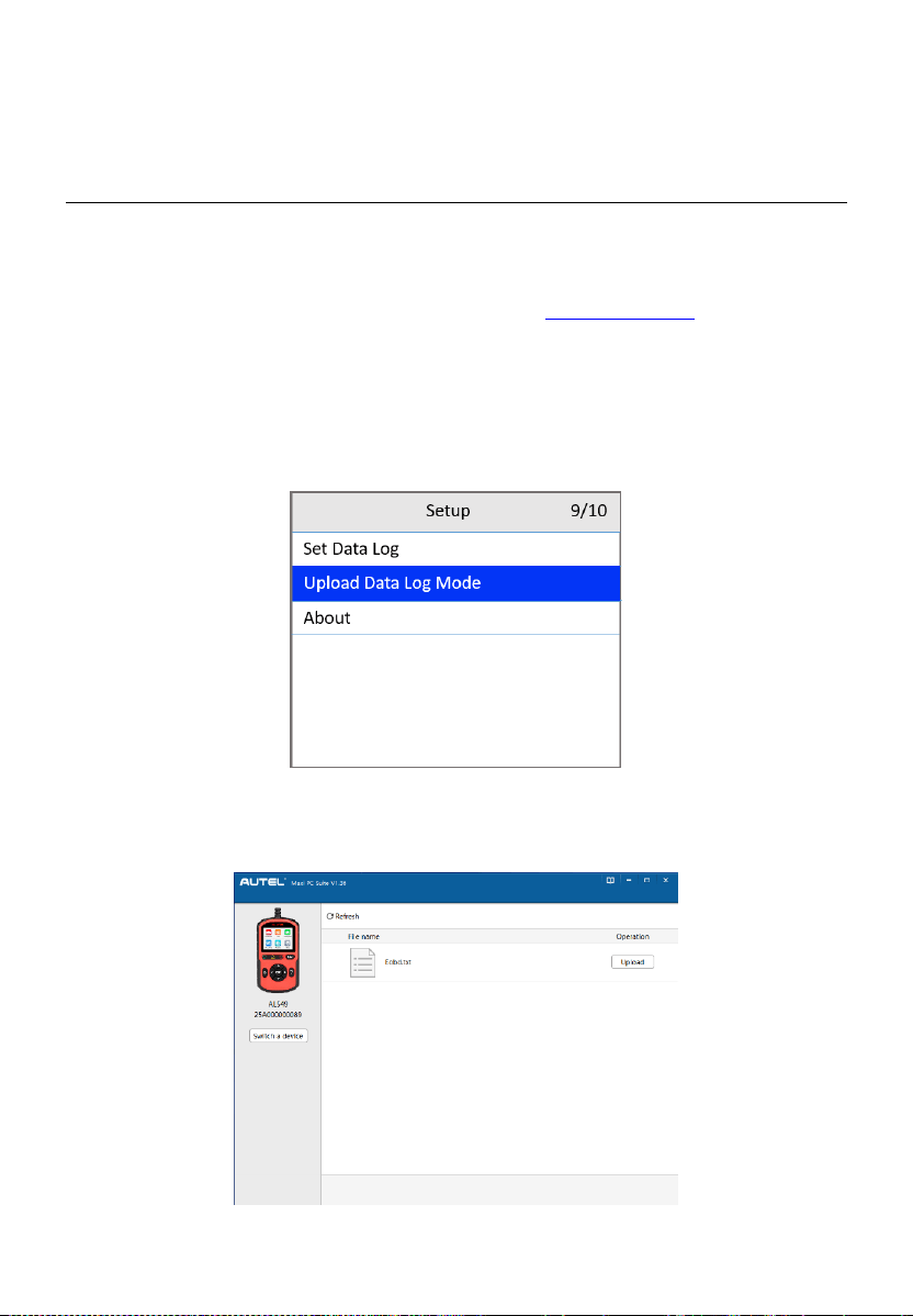
70
3) Press the OK button to save your selection and return to the previous
menu or press the ESC button to exit without saving.
Upload Data Log Mode
This function allows you to upload your data log to Autel company when you
encounter a test problem.
1) Download the Maxi PC Suite from www.autel.com > Support >
Downloads > Autel Update Tools, and install to your Windows-based
computer.
2) Connect the scan tool to your computer with a Type-C USB cable.
3) From the Setup screen (Figure 9-2), use the UP/DOWN scroll button to
select Upload Data Log Mode and press the OK button.
Figure 9-12 Upload Data Log Mode Screen
4) Run the Maxi PC Suite on your computer. Tap the Upload button on the
right side of the screen.
Figure 9-13 Upload Data Log Screen 1
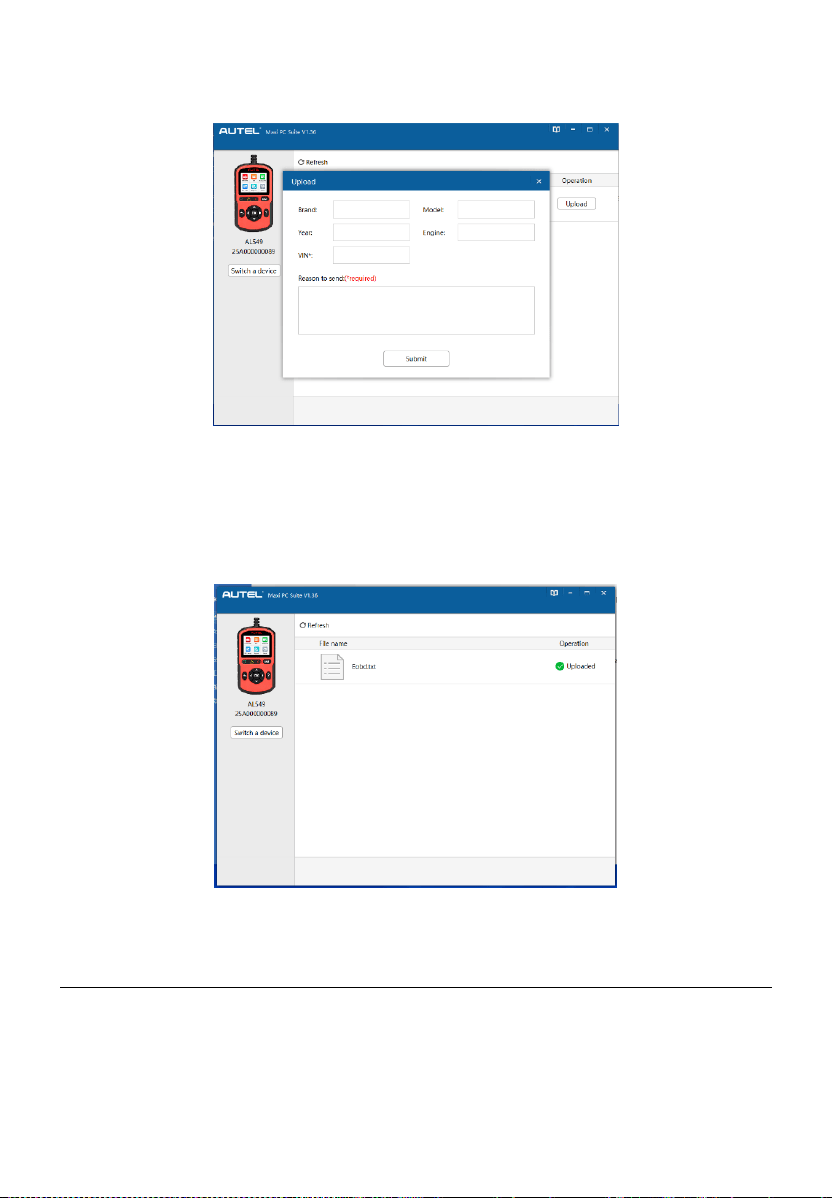
71
5) Enter the required information and then tap Submit. Fields marked with
an asterisk (*) are mandatory.
Figure 9-14 Upload Data Log Screen 2
6) The data log will be uploaded automatically. When uploaded
successfully, the operation status reads “Uploaded.”
When the data log is uploading, you can tap the ESC button on the
AL549 to exit if you do not want to proceed.
Figure 9-15 Upload Data Log Screen 3
About
The About function displays important tool information including serial
number, password, and software version number.
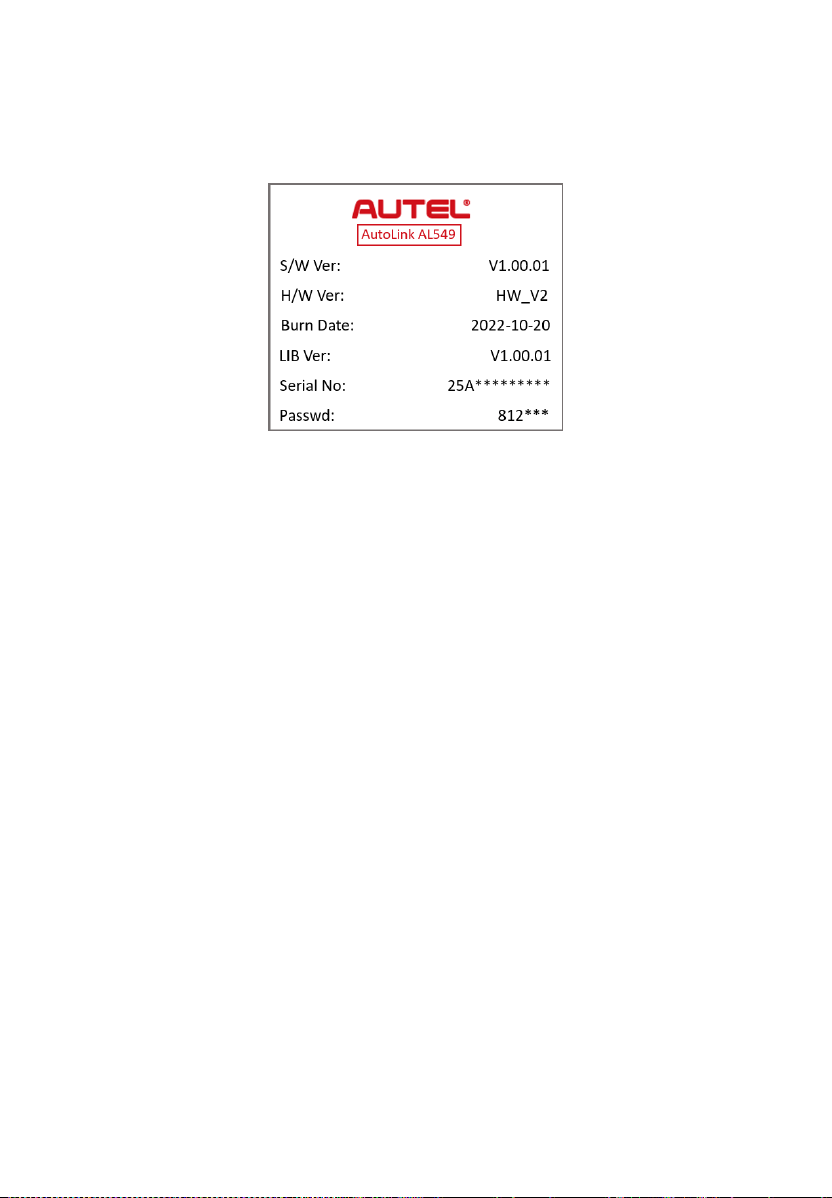

73
10 Updates
This function enables the tool software to be updated through a Windows-
based computer.
To update your scan tool, you need the following items.
AutoLink
AL549
A Windows-based computer or laptop with USB ports
USB cable
Register the Tool
The tool must be registered prior to updating. Register the tool on our website:
http://pro.autel.com. Visit the site to download software update programs,
research tools and retrieve warranty information.
NOTE
Prior to registration, please confirm your network is working properly.
1. Visit the website http://pro.autel.com.
2. If you have an Autel account, log in and skip to Step 7.
3. If you are a new member to Autel, click Register to create your Autel ID.
4. Enter your personal information. Fields marked with an asterisk (*) are
mandatory.
5. After all the mandatory information is entered, read the Autel User
Service Agreement and Autel Privacy Policy, then check the box to
accept the terms and click Register.
6. Once your account is successfully registered, you will be redirected to
the Product Registration screen. If not, click the button on the screen.
7. Your product serial number and password are required to enter. To find
your serial number and password on the tool: go to Settings > About.
8. Enter your tool’s serial number and password.
9. Enter the CAPTCHA code and click Submit to complete your product
registration.
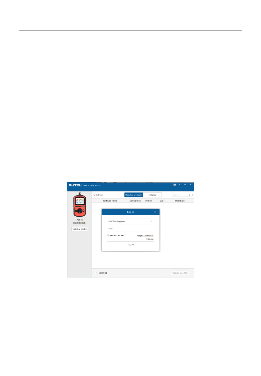
74
Update Procedure
Autel frequently releases software updates to download.
Connect the tool to a Windows-based computer using a USB cable. Follow
the update procedure to finish updating. The Windows version is taken as an
example here.
1. Download the Maxi PC Suite from www.autel.com > Support >
Downloads > Autel Update Tools, and install to your Windows-based
computer.
2. Connect the scan tool to your computer with a Type-C USB cable.
3. Run the Maxi PC Suite on your computer. From the Main Screen in the
tool, select Setup > Update Mode, and press OK. Wait for the Log In
window to display.
4. Enter your Autel ID and password and wait for the Update window to
appear. If you forgot your password, click Forgot Password to retrieve
it. If you do not already have an Autel ID, you can click Sign up to create
a new account.
Figure 10-1 Log In Window
5. Select tool and serial number, click OK to continue.
6. In the Update window, locate the desired update and click the Update
button.
7. The downloaded programs will automatically install. The update will
replace the existing version of the software.
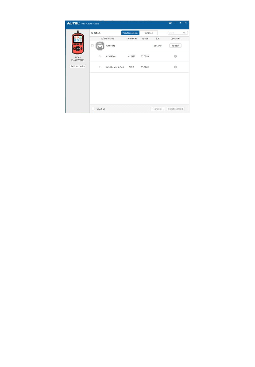
75
Figure 10-2 Update Window
If you want to delete the installed programs, click on the Installed
tag and then select the items you want to delete.

76
11 Compliance Information
FCC COMPLIANCE FCC ID: WQ8-DR2015
This device complies with Part 15 of the FCC Rules. Operation is subject to
the following two conditions:
(1) This device may not cause harmful interference, and
(2) This device must accept any interference received, including interference
that may cause undesired operation.
WARNING
Changes or modifications not expressly approved by the party responsible
for compliance could void the user’s authority to operate the equipment.
NOTE
This equipment has been tested and found to comply with the limits for a
Class B digital device, pursuant to Part 15 of the FCC Rules. These limits are
designed to provide reasonable protection against harmful interference in a
residential installation.
This equipment generates uses and can radiate radio frequency energy and,
if not installed and used in accordance with the instructions, may cause
harmful interference to radio communications. However, there is no
guarantee that interference will not occur in a particular installation. If this
equipment does cause harmful interference to radio or television reception,
which can be determined by turning the equipment off and on, the user is
encouraged to try to correct the interference by one or more of the following
measures:
– Reorient or relocate the receiving antenna.
– Increase the separation between the equipment and receiver.
– Connect the equipment into an outlet on a circuit different from that to which
the receiver is connected.
– Consult the dealer or an experienced radio/TV technician for help.

77
RF WARNING STATEMENT
The device has been evaluated to meet general RF exposure requirement.
The device can be used in portable exposure condition without restriction.
RoHS COMPLIANCE
This device is declared to be in compliance with the European RoHS Directive
2011/65/EU.
CE COMPLIANCE
Directive 2014/53/EU
On The Radio Equipment Directive

78
12 Warranty and Service
Limited One Year Warranty
Autel Intelligent Technology Corp., Ltd. (the Company) warrants to the
original retail purchaser of this Autel device that should this product or any
part thereof during normal usage and under normal conditions be proven
defective in material or workmanship that results in product failure within 1
year period from the date of purchase, such defect(s) will be repaired, or
replaced (with new or rebuilt parts) with Proof of Purchase, at the Company’s
option, without charge for parts or labor directly related to the defect(s).
NOTE
If the warranty period is inconsistent with local laws and regulations, please
comply with the relevant local laws and regulations.
The Company shall not be liable for any incidental or consequential damages
arising from the use, misuse, or mounting of the device. Some states do not
allow limitation on how long an implied warranty lasts, so the above limitations
may not apply to you.
This warranty does not apply to:
1) Products subjected to abnormal use or conditions, accident, mishandling,
neglect, unauthorized alteration, misuse, improper installation or repair
or improper storage;
2) Products whose mechanical serial number or electronic serial number
has been removed, altered or defaced;
3) Damage from exposure to excessive temperatures or extreme
environmental conditions;
4) Damage resulting from connection to, or use of any accessory or other
product not approved or authorized by the Company;
5) Defects in appearance, cosmetic, decorative or structural items such as
framing and non-operative parts.
6) Products damaged from external causes such as fire, dirt, sand, battery
leakage, blown fuse, theft or improper usage of any electrical source.

79
IMPORTANT
All contents of the product may be deleted during the process of repair. You
should create a back-up copy of any contents of your product before
delivering the product for warranty service.
Service and Support
If you have any questions regarding the product, please contact one of our
offices in your region.
Autel China Headquarters
Phone: +86 (0755) 8614-7779 (Monday-Friday, 9AM-6PM Beijing Time)
Email: [email protected]
Address: Floor 2, Caihong Keji Building, 36 Hi-tech North Six Road,
Songpingshan Community, Xili Sub-district, Nanshan District, Shenzhen
City, China
Web: www.autel.com
Autel North America
Phone: 1-855-288-3587 (Monday-Friday, 9AM-6PM Eastern Time)
Email: [email protected]
Address: 36 Harbor Park Drive, Port Washington, New York, USA
11050
Web: www.autel.com/us
Autel Europe
Phone: +49(0)89 540299608 (Monday-Friday, 9AM-6PM Berlin Time)
Email: [email protected]
Address: Landsberger Str. 408, 81241 München, Germany
Web: www.autel.eu
Autel APAC
Japan:
Phone: +81-045-548-6282
Email: [email protected]

80
Address: 6th Floor, Ari-nadoribiru 3-7-7, Shinyokohama, Kohoku-ku,
Yokohama-shi, Kanagawa-ken, 222-0033 Japan
Web: www.autel.com/jp
Australia:
Email: [email protected]
Address: Unit 5, 25 Veronica Street, Capalaba
Autel IMEA
Phone: +971 585 002709 (in UAE)
Email: [email protected]
Address: 906-17, Preatoni Tower (Cluster L), Jumeirah Lakes Tower,
DMCC, Dubai, UAE
Web: www.autel.com
Autel Latin America
Mexico:
Phone: +52 33 1001 7880 (Spanish in Mexico)
Email: [email protected]
Address: Avenida Americas 1905, 6B, Colonia Aldrete, Guadalajara,
Jalisco, Mexico
Brazil:
Email: [email protected]
Address: Avenida José de Souza Campos n° 900, sala 32 Nova
Campinas Campinas – SP, Brazil
Web: www.autel.com/br