1
LTR50001038, Rev. P-1
5/22/2023
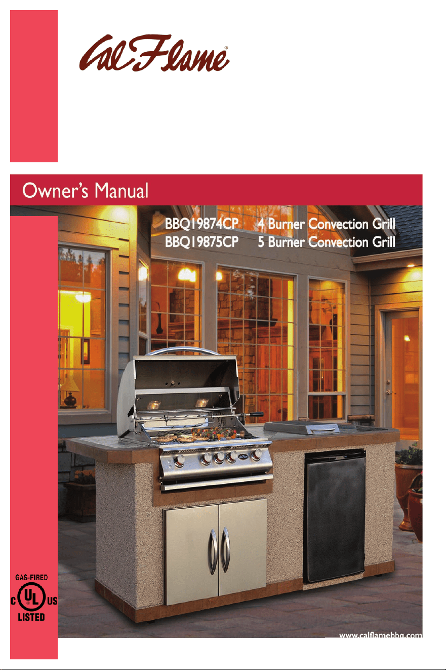
4-Burner and 5-Burner
Convection Grills
United States and Canada
2023
© 2023 Lloyd’s Material Supply Company, Inc.
MH63357
Convection grills
4 burner and 5 burner
©2025 LMS
LTR50001038 Convection
1/1/2025 REV 2.0
2
Warnings & Precautions
DANGER, FLAMMABLE GAS UNDER
PRESSURE. LEAKING LP GAS MAY CAUSE
A FIRE OR EXPLOSION IF IGNITED CAUS-
ING SERIOUS BODILY INJURY OR DEATH.
DANGER! GAZ INFLAMMABLE SOUS
PRESSION. Une fuite de GPL peut causer
un incendie ou une explosion si enam-
mée entraînant des blessures corporelles
graves ou la mort.
CONTACT LP SUPPLIER FOR REPAIRS
OR DISPOSAL OF THIS CYLINDER OR
UNUSED LP GAS.
Communiquez avec le fournisseur de
GPL pour les reparations ou pour dis-
poser de cette bouteille ou du GPL non
utilisé.
WARNING, FOR OUTDOOR USE ONLY.
DO NOT STORE THIS CYLINDER IN A
BUILDING, GARAGE OR ENCLOSED AREA.
Avertissement, Pour usage à l’extérieur
seulement. Ne pas utiliser ni entreposer
la bouteille dans un bâtiment, un garage
ou un endroit fermé.
WARNING: Do not store a spare LP
cylinder under or near a barbecue grill,
or other heat sources. NEVER ll an LP
cylinder beyond 80% full: a re causing
death or serious injury may occur
Avertissement: Ne pas entreposer de
bouteille de GPL sous le barbecue ou à
proximité de celui-ci et de toute source
de chaleur. Ne Jama is remplir une
bouteille de GPL à plus de 80 % de sa
capacité: un incendie causant la mart ou
des blessures graves peut se produire.
DANGER
if you smell gas.
• shut o gas to the appliance
• Extinguish any open ame
• Open lid
• If odor continues, keep away from
the appliance and immediately
call you gas supplier or your re
department.
DANGER
• Do not store or use gasoline or
other ammable liquids or vapors
in the vicinity of this or any other
appliance.
• An LP cylinder not connected for
use shall not be stored in the vicini-
ty of this or any other appliance.
DANGER
S’il y a une odeur de gaz.
• Coupez l’admission de gaz de
l’appareil.
• Éteindre toute amme nue.
• Ouvrir le couvercle.
• Si I’ odeur persiste, éloignez-vous
de l’appareil et appelez immédi-
atement le fournisseur de gaz ou le
service d’incendle.
DANGER
• Ne pas entreposer ni utiliser de l’essence
ni d’autres vapeurs ou liquides inam-
mables dans le voisinage de l’appareil,
ni de tout autre appareil.
• Une bouteille de propane qui n’est pas
raccordée en vue de son utilisation,
ne doit pas être entreposée dans le
voisinage de cet appareil ou de tout
autre appareil.
ANS 221.58-2018 • CSA 1.6-2018 Outdoor
Cooking Gas Appliances
3
Keep any electrical supply cord and the
fuel supply hose away from any heated
surfaces.
Gardez tout cordon d’alimentation élec-
trique et tuyau d’alimentation en com-
bustible à l’ecart des surfaces chauées.
Place dust cap on cylinder valve outlet
whenever the cylinder is not in use. Only
install the type of dust cap on the cyl-
inder valve outlet that is provided with
the cylinder valve. Other types of caps or
plugs may result in leakage of propane.
Mettre un bouchon antipoussière sur
la sortie du robinet d’une bouteille qui
n’est pas utilisée. Utiliser uniquement le
type de bouchon antipoussière fourni
avec le robinet de la bouteille. D’autres
types de bouchons pourraient ne pas
être étanches et permettre des fuites de
propane.
WARNING - Do not use this appliance
under extended awnings. Failure to
comply could result in a re or personal
injury
AVERTISSEMENT - Ne pas utiliser cet
appareil sous un auvent. Le non respect
de cette mesure de sécurité pourrait
entrainer un incendie ou des blessures.
For Outdoor Use Only. If Stored
Indoors, Detach and Leave Cylinder
Outdoors.
Pour utilisation à l’extérleur seulement.
Si l’apparell est entreposé à l’intérieur,
enlever les bouteilles et les lalsser à
l’extérleur.
Llsez les Instructions avant d’allumer
l’appareil
SI l’apparell ne s’allume pas en 5 sec-
ondes, fermez le robinet du brûleur,
attendez 5 minutes, et procédez de
nouveau a l’allumage.
Read Instructions before lighting.
If ignition does not occur In 5 seconds,
turn the burner control(s) o, wait 5 min-
utes, and repeat the lighting procedure.”
Minimum clearance from sides and back
of unit to combustible construction 24’’
inches from the sides and 24’’ inches
from the back.
Do not use this appliance under over-
head combustible surfaces
Only for installation in a built-in enclo-
sure constructed of non-combustible
materials
Dégagement minimal entre les parois
latérales et l’arrlère de l’appareil et la
construction combustible, 61 cm a partir
des parols latérales et 61 cm à partir de
l’arrière.
Ne pas utiliser cet appareil sous une
surface combustible.
Convient uniquement pour installation
dans une enceinte encastrée faite de
matériaux incombustibles.
4
Warning
If the information in this manual is not
followed exactly, a re or explosion may
result causing property damage,
personal injury, or a loss of life.
Do not store gasoline or any ammable
vapors and liquids in the vicinity of this
or any other appliance
Never use a dented, rusty, or damaged
LP cylinders. Never store spare LP
cylinders not connected to the grill or
another appliance, this can cause a re
resulting in serious injury or death.
If this grill is converted to operate with
natural gas, you are responsible for en-
suring that the natural gas line installed
is safe to use. LMS will not be held
responsible for any improperly installed
gas line.
CONTACT INFORMATION
For customer service please contact your autho-
rized dealer immediately. If you need additional
information and/or assistance, please contact
LMS Customer Service Department
1462 East Ninth Street
Pomona, Ca 91766
Toll Free: 1-800-225-7727
Fax: 1-909-629-3890
Copyright 2025 LMS. All rights reserved. Duplication
without written consent is strictly prohibited. Cal Flame
is a registered trademark.
Due to continuous improvement programs, all models,
operation, and/or specications are subject to change
without prior notice.
Please read this manual before
using the grill for the rst time.
Table of Contents
Safety Instructions
English/French Warnings & Precautions................
Placement and Location .........................................
Set-Up ......................................................................
Operation ................................................................
Maintenance & Repair ............................................
Storage ....................................................................
Precautions Regarding Children ...........................
Proper Location of the Grill
Ensuring Proper Ventilation ..................................
Built-in Construction
Construction Materials ...........................................
Built-in Dimensions ................................................
Enclosure Ventilation .............................................
Gas and Electrical Supply Requirements
Gas Requirements ...................................................
Electrical Supply Requirements .............................
Installation & Connection
Connecting the Grill and Side Burner ...................
Leak Testing Procedure ..........................................
Attaching the Rotisserie Motor .............................
Using Your Grill
Basic Grill Operation ...............................................
Gas Cylinder Orientation ........................................
Grill Controls ...........................................................
Lighting the Burners ...............................................
Proper Burner Flame ..............................................
Heat Distribution ....................................................
Cooking with the Rotisserie....................................
Optional Grill Accessories
Accessories.......................................................
Cleaning & Maintenance
Stainless Steel Care & Cleaning .....................
Rust Removal ..................................................
Cleaning the Interior of Your Grill .................
Covering Your Grill ..........................................
Seasonal Cleaning ..........................................
Light Bulb Replacement .................................
Appendix
Troubleshooting .............................................
Converting from LP to NG ..............................
Installing Sear Zone Burners .........................
Replacement Parts List ..................................
Limited Warranty ............................................
2
5
5
5
6
6
6
7
8
9
11
12
13
14
17
17
18
18
19
20
21
21
22
23
26
27
27
28
29
31
32
34
38
39
42
5
Safety InstructionsSafety Instructions
• Cal ame Grills are designed for outdoor use
only.
• Never locate this appliance in an enclosed room,
under a sealed overhead structure, or in any
type of enclosed area such as a garage, shed, or
breezeway. Keep clear of trees, shrubs, or other
ammable materials.
• Cal Flame grills are not designed to be installed
in a moving xture, this included recreational
vehicles, trailers, boats, or cooking carts.
• Maintain a minimum distance of 24’’ inches
(61cm) in all directions of the grill from amma-
ble materials, including overhead materials such
at patio covers and grill covers
• The area surrounding your grill must be clean
and free from ammable uids or materials,
such as mops, rags, plastics, gasoline, cleaning
uids, and solvents for example.
• Do not store spare LP canisters not connected
to the grill near the grill or inside of the grill
cabinet
• Before installing the grill copy all product infor-
mation from the appliances serial number plate,
the back of this manual may be used to write
down, serial number, fuel type, and grill model.
• Serial number plate is located behind the grill
visible with the grill lid shut.
General Set-Up
Placement and Location
Warning: Improper installation, adjustment, alteration, service, or maintenance can cause
injury or property damage. Read the installation, operating, and maintenance instructions
thoroughly before installing or servicing the unit.
• We recommend that a licensed contractor
installs your Cal Flame grill. Installation must
conform to all local codes. In absence of local
codes follow the National Fuel Gas Code, ANSI
Z2223.1/NFPA 54 or CAN/CGA-B149.1, Natural
Gas and Propane Installation Codes.
• The Cal Flame grill must be plugged into a per-
manent, grounded 110v outlet with a dedicated
15 amp GFCI breaker in accordance with local
codes, or the National Electrical Code ANSI/
NFPA 70, or the Canadian Electrical Code, CSA
C22.1.
• Do not use an extension cord to supply power
to your Cal Flame grill. Such use may result in
re, electrical shock, or other personal injury. Do
not install a fuse on the neutral or ground cir-
cuit, as this can result in a shock hazard. Do not
ground the appliance to a gas or hot water pipe.
Keep all electrical cords and fuel supply hoses
away from the grill and heated surfaces, includ-
ing the electrical cords from grill accessories.
• To prevent re or smoke damage, remove
all packaging materials from the grill before
operating.
• Before cooking in your Cal Flame grill, clean the
entire grill throughly with hot soapy water. This
is necessary to remove residual solvents, oils,
and grease from the manufacturing process, this
includes the BBQ grates as well.
• Have a ABC powder based re extinguisher
within a reasonable proximity to the grill.
Operation
• Do not use the grill for anything other than its
intended use.
• In the event that a grill burner goes out, turn
the burner knobs to the full o position, open
the grill hood and allow the grill to “air out” do
not attempt to use the grill until the grill has
enough time to dissipate.
• Never use the grill if the drip tray is not properly
installed. The drip pan must be pushed fully
into its rack located under the grill directly
underneath the burner knobs. A grease re
or explosion can result from an improperly
installed drip pan.
DANGER
What To Do If You Smell Gas
• Shut o gas/fuel to the appliance
• Extinguish any open ame.
• Open the grill lid
• If gas odor persists, keep away from
appliance and contact your gas supplier
or re department.
Avertissements traduits en français à la page 3 *French translated warnings on page 3

6
• Never use the grill or side burner in windy
conditions if used in a consistently windy area a
windbreak will be required. Always adhere to the
specied clearances listed in this manual.
• Never line the inside of the grill with aluminum foil.
• When the unit is not in use, be sure to turn o the
gas at the LP tank.
• Do not install your grill in such a manner that the
cross vents are blocked. Fresh air must be able to
pass through installed vents to safeguard against
residual gas accumulation. Failure to do so may
cause re or explosion.
• When handling LP gas line and connectors, do
not allow them to come in contact with any metal
surfaces of the cabinet. Do not drop or throw the LP
connectors.
• do not use fuel such as charcoal briquettes in gas
grills.
• Gas sources to the grill and side burners must be
regulated. Do not operate grill or side burners if
regulators have been removed, as a re or explosion
may occur.
• Never leave a lit grill or side burner unattended
when in use. When using pots and pans, boil over
may occur causing smoke, greasy boil overs can
ignite creating a re.
• Always use the proper size pans, and utensils with
at bottoms large enough to cover the burner. The
use of undersized utensils exposes them to direct
contact with the ame. This can scorch utensils
and hamper clean up. Excessive ames on stainless
steel bots and utensils can result in permanent
discoloration.
• Always position handles of utensils away from the
grill/heat source. This reduces the risk of burns,
ignition of ammable materials, and spillage due to
accidental contact with utensils.
• Do not use water to extinguish grease/oil res,
or pick up a aming pan, suocate the ame by
turning o the appliance and use a tight tting lid,
a cookie sheet or a at tray. For aming grease res
outside of a pan/pot, use an ABC Fire extinguisher
(powder or foam).
• Never allow clothing, pot holders or other am-
mable materials come in contact with or be close
to any grate, burner or hot surface until it has fully
cooled. Never wear loose tting or hanging gar-
ments when using the grill, this can catch re and
lead to injury or death.
• When using the grill do not touch the grill rack,
burner grate or immediate surroundings, as these
surfaces will be very hot causing burns, only use
handles and knobs to regulate or open your grill/
side burner.
• Only use dry pot holders and do not use a towel or
other cloth in place of pot holders. Moise or damp
pot holders used on hot surfaces can cause burns.
• Do not heat any unopened or pressurized glass/
metal containers. Pressure may build up and cause
the container to burst, possibly resulting in serious
personal injury or damage to the grill.
• Do not reach over your grill or any other appliance
when hot or in use.
• Spiders and other insects can nest in the burner of
the grill and block the gas and air ow to the burner
ports. This creates a dangerous condition that can
result in a re behind the valve panel. Inspect and
follow guidelines in the cleaning and maintenance
section of this manual.
• Unless specically recommended in this manual, do
not repair or replace any part of the grill. A qualied
technician should perform all service. Any repairs
made by a non-LMS approved dealer technician will
void your warranty.
Maintenance and Repair
Storage
• When your gas grill is not in use, turn o the gas
ow at the LP cylinder.
• Storage of the grill indoors is permissible only if the
LP cylinder is disconnected and stored outdoors.
• Never leave an open ow LP cylinder connected to
the grill when not in use
Precautions With Children
• Children should never be left alone or unattended
in an area where the grill is located. Place your grill
away from areas where children play. Do not store
items that may interest a child to go near the grill/
island.
• Never leave children unattended near the grill both
when in use and not in use. Close supervision of
children is necessary when in use.
• Never allow children to sit or stand on any part of
the grill.
• When the grill is not in use ensure that the LP cylin-
der valve is closed to prevent accidental activation.
This will ensure that if the valve dials are turned on
no gas will leak through the burner.
7
P4, P5, and P6 Barbecue Grills
LTR50001137, Rev. R
Proper Location of the Grill
www.calamebbq.com
3
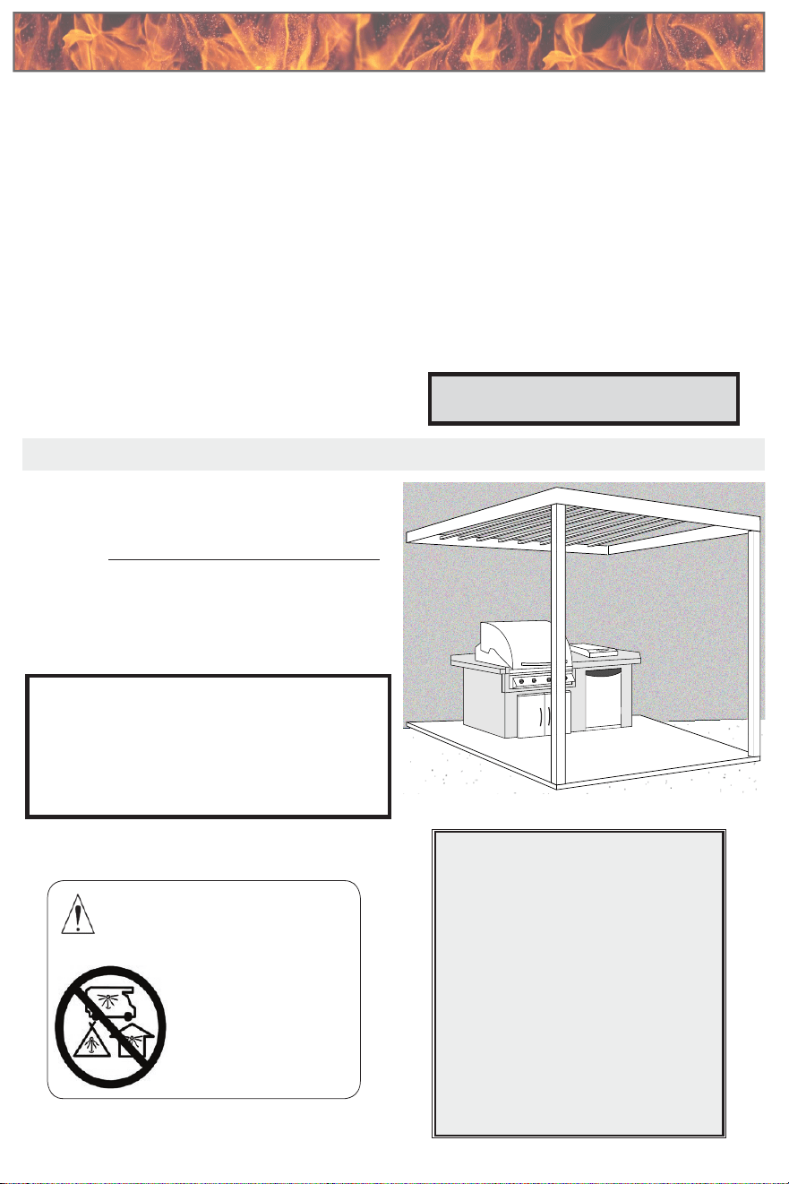
Proper Location of the Grill
Cal Flame grills are designed for outdoor use
only.
• Solid foundation
• Open on three sides
• Minimum distance of
six feet overhead from
combustible material
• Overhead is not sealed
• Not placed near windows
• No overhead storage
• No combustible materials
stored nearby
Ensuring Proper Ventilation
Do not locate your barbecue island in an enclosed
area, which is any covered area that is walled on two,
three, or four sides. This includes areas or rooms such
as a garage, shed, breezeway, patio, cabana, etc.
Although some enclosed areas may have
windows, screens, or ventilation systems, they
are nevertheless considered to be hazardous
and may cause damage, injury,
or death. Enclosed areas are NOT
approved for a barbecue island.
Do not locate your barbecue island under a sealed
overhead structure. Acceptable overhead structures
allow for airow, such as screen or lattice.
You can install an awning over your barbecue island,
provided you make sure it is high enough to prevent
damage or re. We recommend a minimum overhead
distance of six feet from the top of the grill hood.
Carbon Monoxide Hazard
This appliance can produce carbon
monoxide which has no odor.
Using it in an enclosed
space can kill you.
Never use this appliance in
an enclosed space such as a
camper, tent, car, or home.
Here are some general considerations when
determining where to place your new barbecue island.
Be certain that your installation will meet all city and
local safety codes and requirements.
When planning your Cal Flame grill location, access
to gas lines and 110V power supplies should be
considered. If you are using natural gas, the location
with the shortest gas line run is recommended. You
may need a grounded, dedicated, 15A 110V GFCI
power source for use of your appliances (e.g., lights,
rotisserie, refrigerator, receptacles, etc.).
When determining a suitable location, consider factors
such as exposure to wind, proximity to trafc paths,
and windows that open into the home.
Locate the grill enclosure any place where there is
adequate ventilation. The size and conguration of
your house and yard will determine how you should
locate your grill enclosure, but as a general rule, do
not place it under or near windows that can be opened
into your home. Ventilation is address in greater detail
in the next section.
The sides, bottom and back of the grill enclosure
should not be any closer than 24” to combustible
construction.
To reduce the risk of personal injury caused by
reaching over a hot appliance, avoid locating cabinet
storage space directly above the outdoor grill.
Proper Location of the GrillProper Location of the Grill
General considerations when determining the new
placement of your BBQ grill into your island. Be certain
that your installation meets all city and local safety
codes and requirements
When planning your location, access to 110v power
supplies must be considered, if you plan to convert
your Cal Flame grill to Natural gas, consideration of NG
gas lines near the island must be considered as well. If
natural gas is being used, the location with the short-
est gas line run is recommended for proper operation.
You will need a grounded 15 amp circuit if your BBQ
island or your grill is equipped with LED lights and/or
installed with other BBQ accessories including but not
limited to, refrigerator, rotisserie motor, food warmers,
etc.
Further details on ventilation will be in the following
section.
The sides, bottom and back of the grill enclosure
should not be closer than 24’’ to combustible construc-
tion or ammable materials. Avoid placing storage
spaces or cabinets above the grill.
Cal Flame grills are designed for outdoor
stationary use only.
P4, P5, and P6 Barbecue Grills
LTR50001137, Rev. R
Proper Location of the Grill
www.calamebbq.com
3
Proper Location of the Grill
Cal Flame grills are designed for outdoor use
only.
• Solid foundation
• Open on three sides
• Minimum distance of
six feet overhead from
combustible material
• Overhead is not sealed
• Not placed near windows
• No overhead storage
• No combustible materials
stored nearby
Ensuring Proper Ventilation
Do not locate your barbecue island in an enclosed
area, which is any covered area that is walled on two,
three, or four sides. This includes areas or rooms such
as a garage, shed, breezeway, patio, cabana, etc.
Although some enclosed areas may have
windows, screens, or ventilation systems, they
are nevertheless considered to be hazardous
and may cause damage, injury,
or death. Enclosed areas are NOT
approved for a barbecue island.
Do not locate your barbecue island under a sealed
overhead structure. Acceptable overhead structures
allow for airow, such as screen or lattice.
You can install an awning over your barbecue island,
provided you make sure it is high enough to prevent
damage or re. We recommend a minimum overhead
distance of six feet from the top of the grill hood.
Carbon Monoxide Hazard
This appliance can produce carbon
monoxide which has no odor.
Using it in an enclosed
space can kill you.
Never use this appliance in
an enclosed space such as a
camper, tent, car, or home.
Here are some general considerations when
determining where to place your new barbecue island.
Be certain that your installation will meet all city and
local safety codes and requirements.
When planning your Cal Flame grill location, access
to gas lines and 110V power supplies should be
considered. If you are using natural gas, the location
with the shortest gas line run is recommended. You
may need a grounded, dedicated, 15A 110V GFCI
power source for use of your appliances (e.g., lights,
rotisserie, refrigerator, receptacles, etc.).
When determining a suitable location, consider factors
such as exposure to wind, proximity to trafc paths,
and windows that open into the home.
Locate the grill enclosure any place where there is
adequate ventilation. The size and conguration of
your house and yard will determine how you should
locate your grill enclosure, but as a general rule, do
not place it under or near windows that can be opened
into your home. Ventilation is address in greater detail
in the next section.
The sides, bottom and back of the grill enclosure
should not be any closer than 24” to combustible
construction.
To reduce the risk of personal injury caused by
reaching over a hot appliance, avoid locating cabinet
storage space directly above the outdoor grill.
When determining a suitable location for your grill,
consider the environmental factors of exposure to
wind, proximity to trac, and windows that open into
the home. It is essential to locate the grill in a location
with adequate ventilation. The size and conguration
of the property will determine the nal location of
the grill. Avoid placing the grill near windows of the
home/living areas, due to smoke and carbon dioxide/
monoxide generated while cooking with propane
C3H8 + 3.5 O2 => CO2 + CO + C + 4 H2O + heat
Do not locate your BBQ island in an enclosed space,
which is any covered area what is walled on two, three,
or four sides areas such as a garage, shed, walled patio,
cabana, etc. Enclosed areas are not approved for BBQs.
Ensuring Proper Ventilation
Do not locate your grill under a sealed overhead
structure, a screen or lattice structure would be best
for airow. Ensure that the height of the structure is a
minimum of 6 feet above the grill hood.
• Solid Foundation
• Open on three sides minimum.
• Minimum distance of six feet overhead
from combustible material.
• No sealed overhead structures
• Not placed near windows
• No overhead storage
• No combustible materials stored or
placed nearby.
Although some enclosed spaces may have
windows, screens, or ventilation systems,
they are nevertheless considered to be
hazardous and may cause damage, injury, or
death. Enclosed areas are NOT approved for
BBQ islands.
8
P4, P5, and P6 Barbecue Grills
LTR50001137, Rev. R
Built-in Construction
www.calamebbq.com
4
Built-in Construction
Construction materials
DO NOT use combustible materials for the built-in construction.
Acceptable building materials: Brick,
cinder block, steel frame, hardiboard,
granite, tile, glass brick, concrete, cement,
stucco, stone.
Unacceptable building materials: Wood
of any sort, laminate or synthetic materials,
plastics, linoleum, berglass.
In addition, we do not recommend using materials that are susceptible to damage or decomposition by weather,
such as dry wall or plaster.
LMS will not be held responsible for property damage, injury, or death as a result of locating a grill
enclosure in a non-approved location or using non-approved construction materials.
Note: The terms “built-in construction” and “grill
enclosure” as used in these instructions refer to any
method for installing a barbecue island for use. A
barbecue island is both built-in constructions and a grill
enclosure. Read these instruction before constructing
your grill enclosure.
The Cal Flame convection grill is expected to be used
with a Cal Flame barbecue island. If the convection
grill is not placed in a Cal Flame barbecue island, it
must be used in a safe manner that will not void your
warranty. If you plan to do this, use the information in
this section on the construction and materials required
for the grill enclosure and its proper location. Cal Flame
wishes our customers to enjoy our products safely. We
strongly recommend that grill owners hire a contractor
to construct the built-in enclosure.
Failure to follow these instructions may result in voiding
your warranty, property damage, injury, or death.
WARNING! Proposition 65 Warning: Handling the brass material on this product
exposes you to lead, a chemical known to the State of California to cause cancer,
birth defects or other reproductive harm. (Wash hands after handling this
product.)
This product and the fuels used to operate this product (propane or natural
gas), and the products of combustion of such fuels, can expose you to chemicals
including Benzene, which is known to the state of California to cause cancer and
birth defects or reproductive harm.
For more information go to www.P65Warnings.ca.gov.
Built-in ConstructionBuilt-in Construction
Note: The terms “built in construction” and “grill
enclosure are used in these instructions to refer to any
method for installing a barbecue island for use. A
barbecue island is both built-in constructions and a
grill enclosure. Read these instructions before
constructing your grill enclosure.
Cal Flame grills are expected to be used in a Cal ame
BBQ island. If the grill is not placed in a Cal Flame BBQ
island it must be used in a safe manner that will not
void your warranty.
If you plan to do this, use the information in this
section on the construction and materials required
to create a proper grill enclosure and its proper
location. Cal Flame desires that our customers enjoys
our products safely. We recommend that grill owners
hire a contractor to construct and design the built in
enclosure.
Failure to follow these instructions may result in
voiding your warranty, property damage, injury, or
death.
Construction Materials
LMS, will not be held responsible for property damage, injury or death as a result of locating a grill
enclosure in a non approved location or using non-approved construction materials.
California Proposition 65 Warnings
Warning: This product is manufactured with and contains one or more
chemicals known in the state of California to cause cancer, birth defects or
other reproductive harm
This product and the fuels used to operate this product (propane or natural gas)
can expose you to chemicals including Benzene, which is known in the state of
California to cause cancer, birth defects, and other reproductive harm.
More information about Proposition 65 for California owners can be found:
www.P65Warnings.ca.gov
P4, P5, and P6 Barbecue Grills
LTR50001137, Rev. R
Built-in Construction
www.calamebbq.com
4
Built-in Construction
Construction materials
DO NOT use combustible materials for the built-in construction.
Acceptable building materials: Brick,
cinder block, steel frame, hardiboard,
granite, tile, glass brick, concrete, cement,
stucco, stone.
Unacceptable building materials: Wood
of any sort, laminate or synthetic materials,
plastics, linoleum, berglass.
In addition, we do not recommend using materials that are susceptible to damage or decomposition by weather,
such as dry wall or plaster.
LMS will not be held responsible for property damage, injury, or death as a result of locating a grill
enclosure in a non-approved location or using non-approved construction materials.
Note: The terms “built-in construction” and “grill
enclosure” as used in these instructions refer to any
method for installing a barbecue island for use. A
barbecue island is both built-in constructions and a grill
enclosure. Read these instruction before constructing
your grill enclosure.
The Cal Flame convection grill is expected to be used
with a Cal Flame barbecue island. If the convection
grill is not placed in a Cal Flame barbecue island, it
must be used in a safe manner that will not void your
warranty. If you plan to do this, use the information in
this section on the construction and materials required
for the grill enclosure and its proper location. Cal Flame
wishes our customers to enjoy our products safely. We
strongly recommend that grill owners hire a contractor
to construct the built-in enclosure.
Failure to follow these instructions may result in voiding
your warranty, property damage, injury, or death.
WARNING! Proposition 65 Warning: Handling the brass material on this product
exposes you to lead, a chemical known to the State of California to cause cancer,
birth defects or other reproductive harm. (Wash hands after handling this
product.)
This product and the fuels used to operate this product (propane or natural
gas), and the products of combustion of such fuels, can expose you to chemicals
including Benzene, which is known to the state of California to cause cancer and
birth defects or reproductive harm.
For more information go to www.P65Warnings.ca.gov.
9
P4, P5, and P6 Barbecue Grills
LTR50001137, Rev. R
Built-in Construction
www.calamebbq.com
5
Plan the installation so that the electrical connection,
gas shut-off valve, and pressure regulator are
accessible inside the base enclosure. The gas valve
shall be readily accessible for hand operation. A door
on the enclosure to gain access to the gas valve is
acceptable, provided it is non-locking and can be
opened without the use of tools.
The design of the outdoor cooking enclosure must allow
the LP gas cylinder to be connected and disconnected
and the connections inspected and tested.
There must be a minimum clearance of 2 inches
(51mm) between the oor of the LP-gas cylinder
enclosure and the ground.
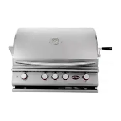
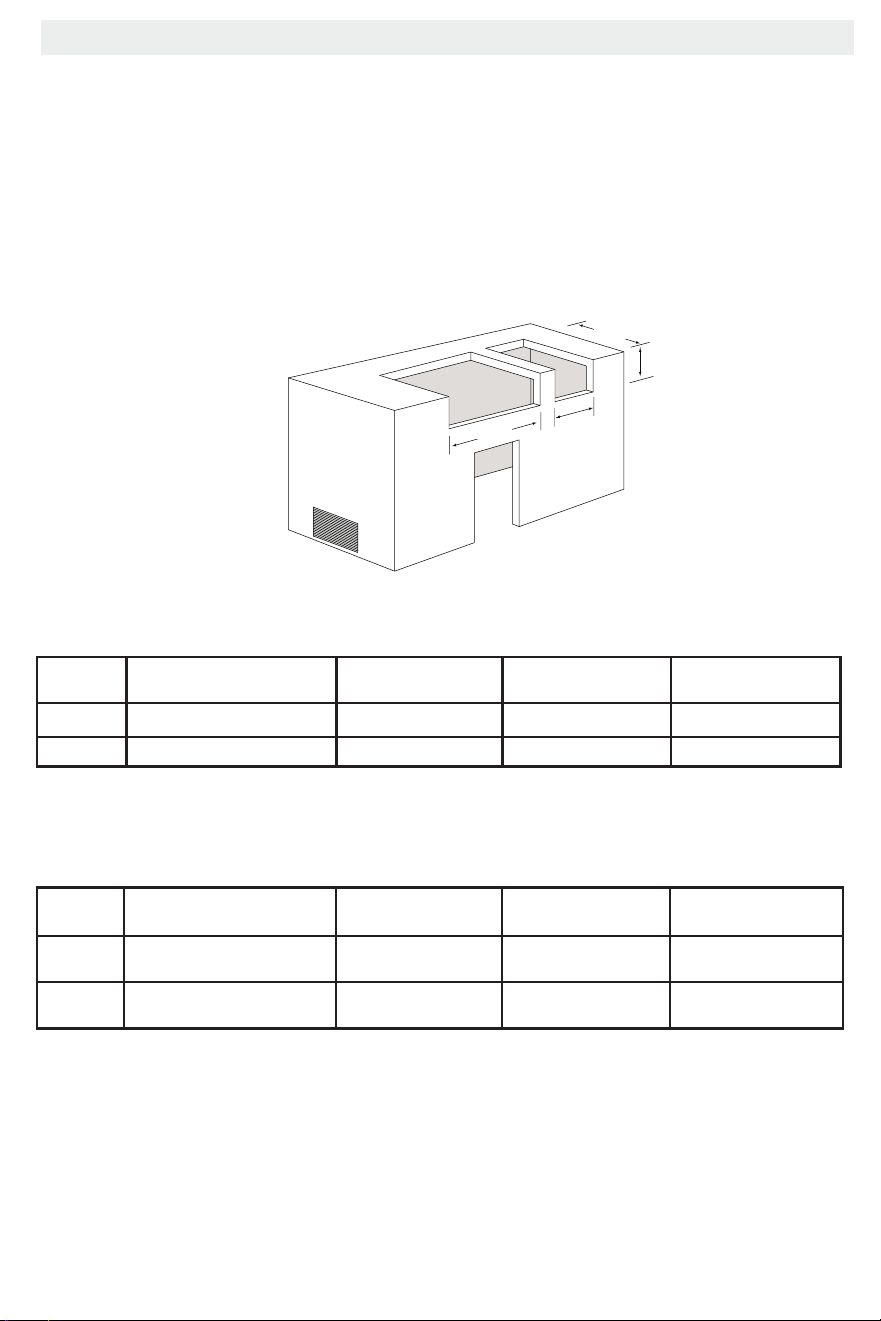
Model Description Width Depth Height
BBQ19P04 P4 Premium Four Burner Grill
30
”
22” 9 ½”
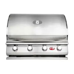
BBQ19P05 P5 Premium Five Burner Grill 38 ¼” 22” 9 ½”
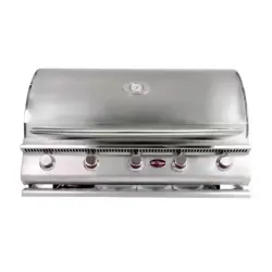
BBQ19P06 P6 Premium Six Burner Grill 45 ” 22” 9 ½”
W
ID
T
H
W
ID
T
H
W
ID
T
H
W
ID
T
H
Minimum
Clearance
12” Minimum Distance
Between Grill and Side Burner
Minimum
Clearance
Screen Vents
WIDTH
W
ID
T
H
WIDTH
DEPTH
WIDTH
WIDTH
DEPTH
WIDTH
WIDTH
WIDTH
DEPTH
DEPTH
DEPTH
HEIGHT
HEIGHT
HEIGHT
Burner
Locking Pin
Burner
Locking Pin
Model Description Width Depth Height
BBQ19954P Deluxe Side by Side Burner 25 ¼” 13 ¼” 7 ½”
BBQ19899P Deluxe Double Side Burner 12 ¼” 22” 7 ½”
The dimensions shown below are for Cal Flame appliances only.
Built-in Dimensions
Plan the installation so that the electrical connection,
and gas shut o (if applicable), and the pressure
regulator are easily accessible inside the base
enclosure. The gas valve shall be readily accessible
for hand operation. A door/panel with on the
enclosure to gain access to the gas valve is
acceptable, provided it is non-locking and can be
opened by hand, without the use of tools.
Built-in Dimensions
The design of the outdoor cooking enclosure must
allow the LP gas cylinder to be easily connected and
disconnected, with access to inspect gas and electric
connections through the BBQ island.
There must be a minimum clearance of 2 inches
(51mm) between the oor of the LP-gas cylinder
enclosure and the ground.
Model
Description
Width (Imperial/
metric)
Depth (Imperial/
Metric)
Height (Imperial/
Metric)
BBQ19P04 P4 Convection Grill 30 ⁷⁄₈’’ Inches : 78.4 cm 22’’ Inches : 55.9 cm 9 ½’’ Inches : 24.1 cm
BBQ19P05 P5 Convection Grill 38 ¼’’ Inches : 97.2 cm 22’’ Inches : 55.9 cm 9 ½’’ Inches : 24.1 cm
Model Description Width (Imperial/
Metric)
Depth (Imperial/
Metric)
Height (Imperial/
Metric)
BBQ19954P
Deluxe Side by Side Burner 25¼’’ Inches : 64.1 cm 13¼’’ Inches : 37.7 cm 7½’’ Inches : 19 cm
BBQ19899P
Deluxe Double Side Burner 12¼’’ Inches : 31.1 cm 22’’ Inches : 55.9 cm 7½’’ Inches : 19 cm
10
P4, P5, and P6 Barbecue Grills
LTR50001137, Rev. R
Built-in Construction
www.calamebbq.com
6
W
ID
T
H
W
ID
T
H
W
ID
T
H
W
ID
T
H
Minimum
Clearance
12” Minimum Distance
Between Grill and Side Burner
Minimum
Clearance
Screen Vents
WIDTH
W
ID
T
H
WIDTH
DEPTH
WIDTH
WIDTH
DEPTH
WIDTH
WIDTH
WIDTH
DEPTH
DEPTH
DEPTH
HEIGHT
HEIGHT
HEIGHT
Burner
Locking Pin
Burner
Locking Pin
W
ID
T
H
W
ID
T
H
W
ID
T
H
W
ID
T
H
Minimum
Clearance
12” Minimum Distance
Between Grill and Side Burner
Minimum
Clearance
Screen Vents
WIDTH
W
ID
T
H
WIDTH
DEPTH
WIDTH
WIDTH
DEPTH
WIDTH
WIDTH
WIDTH
DEPTH
DEPTH
DEPTH
HEIGHT
HEIGHT
HEIGHT
Burner
Locking Pin
Burner
Locking Pin
Model Description Width Depth
BBQ18953P Side By Side Flat Burner 24 ¼” 19 ¾”
BBQ18852P Single Flat Side Burner 11 ½” 17 ¾”
WIDTH
WIDTH
WIDTH
WIDTH
Minimum
Clearance
12” Minimum Distance
Between Grill and Side Burner
Minimum
Clearance
Screen Vents
WIDTH
WIDTH
WIDTH
DEPTH
WIDTH
WIDTH
DEPTH
WIDTH
WIDTH
WIDTH
DEPTH
DEPTH
DEPTH
HEIGHT
HEIGHT
HEIGHT
Burner
Locking Pin
Burner
Locking Pin
WIDTH
WIDTH
WIDTH
WIDTH
Minimum
Clearance
12” Minimum Distance
Between Grill and Side Burner
Minimum
Clearance
Screen Vents
WIDTH
WIDTH
WIDTH
DEPTH
WIDTH
WIDTH
DEPTH
WIDTH
WIDTH
WIDTH
DEPTH
DEPTH
DEPTH
HEIGHT
HEIGHT
HEIGHT
Burner
Locking Pin
Burner
Locking Pin
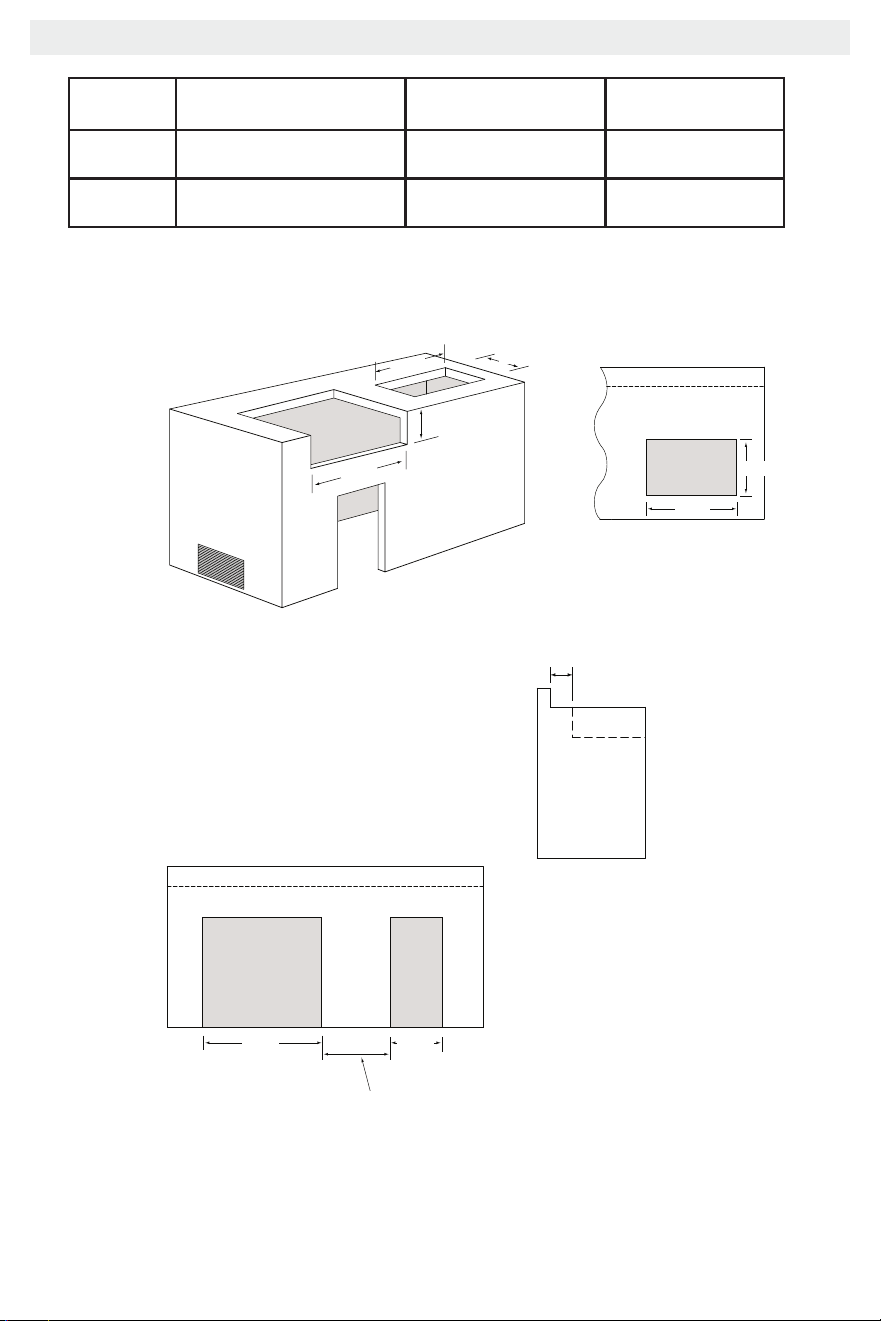
The back edge of the grill must maintain a minimum
clearance of 8” from non-combustible back splash materials.
The dimensions shown below are for Cal Flame appliances only.
Top view of enclosure
with back splash
Side view of enclosure
with back splash
Top view of enclosure
with back splash
Built-in Dimensions cont.
Model Description Width (Imperial/
Metric)
Depth (Imperial/
Metric)
BBQ18953P Side by Side Flat Burner 24¼’’ Inches : 61.6 cm 19¾’’ Inches : 50.2 cm
BBQ18852P Single Flat Side Burner 11½’’ Inches : 29.2 cm 17¾’’ Inches : 45.1 cm
Built-in Dimensions cont.
The back edge of the grill must maintain a minimum
clearance of 8’’ inches : 20.3 cm from non-combustible
back splash materials
Top view of enclosure
with back splash spacing
Side view of enclosure
with back splash spacing
Top view of enclosure
with back splash
12’’ Minimum distance
(30.5 cm)
11
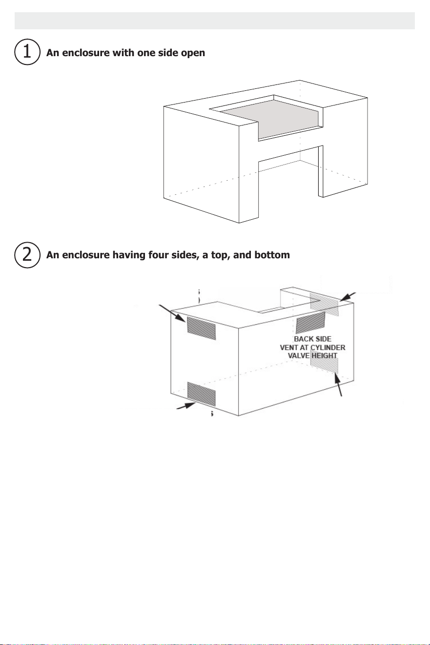
Enclosure Ventilation
The following diagrams are examples for proper ventilation, within the grill enclosure itself. This
ventilation would not be for the grill unit itself, but for the ventilation of the BBQ structure.
The base must be constructed using one of two designs:
The must be at least two ventilation openings at cylinder valve level shall be provided in the side
wall, equally sized spaced at 180 degrees and unobstructed. Each opening shall have a total free
area of not less than 10 square inches (64.5 cm²).
Ventilation openings shall be provided at oor level and shall have a total free area of not less than
10 square inches (64.5cm²). If the ventilation openings at oor level are in a side wall, there shall
be at least two openings. The bottom of the openings shall be at oor level and the upper edge no
more than 5 inches (12.7cm) above the oor.
The openings shall be equally sized, spaced and unobstructed. LP- Gas cylinders should be
ventilated by openings at the level of the cylinder valve and the oor level. The eectiveness of
the openings, for purposes of ventilation, shall be determined with the LP-gas supply cylinder in
place.
Note: Liquid Propane sinks to the bottom, Natural gas rises to the top.
Top Gun Barbecue Grill
LTR50001121, Rev. K
Built-in Construction
www.calamebbq.com
6
WIDTH
WIDTH
WIDTH
WIDTH
Minimum
Clearance
12” Minimum Distanc e
Between Grill and Side Burner
Minimum
Clearance
Screen Ve nts
W
IDTH
WIDTH
WIDTH
DEPTH
WIDTH
WIDTH
DEPTH
WIDTH
WIDTH
WIDTH
DEPTH
DEPTH
DEPTH
HEIGHT
HEIGHT
HEIGHT
Burner
Locking Pin
Burner
Locking Pin
Note: This section describes ventilation within the grill enclosure itself and not ventilation for the barbecue
island.
For proper ventilation, the base structure must be constructed using one of two designs:
An enclosure having four sides, a top, and bottom
1
2
An enclosure with one side open
At least two ventilation openings at cylinder valve level
shall be provided in the side wall, equally sized, spaced
at 180 degrees and unobstructed. Each opening shall
have a total free area of not less than 10 square inches
(254 square mm).
Ventilation openings shall be provided at oor level
and shall have a total free area of not less than 10
square inches (254 square mm). If the ventilation
openings at oor level are in a side wall, there shall
be at least two openings. The bottom of the openings
shall be at oor level and the upper edge no more
than 5 inches (127mm) above the oor. The openings
shall be equally sized, spaced, and unobstructed.
LP-gas cylinders should be ventilated by openings
at the level of the cylinder valve and the oor level.
The effectiveness of the openings, for purposes of
ventilation, shall be determined with the LP-gas supply
cylinder in place.
NOTE: Liquid Propane is heavy and settles to the oor
Natural Gas is light and will rise
Enclosure Ventilation
*LP Sinks to the bottom
*LP Sinks to the bottom
*NG rises upward
*NG rises upward
For Natural Gas
For Natural Gas
For Liquid Propane
For Liquid Propane
*In case of a gas leak or
improper combustion, proper
ventilation of excess gases
is required in any BBQ island
holding a Cal Flame grill.
Natural gas dissipates upward,
Liquid Propane dissipates
towards the bottom as it is
denser than air. Both gases
with proper ventilation will
dissipate quickly.
12
Gas and Electrical Supply Requirements Gas and Electrical Supply Requirements
Tank Requirements
For plumbed-in LP installation, use a convertible
regulator and set it for LP gas.
Maximum Line pressure for plumbed-in propane is
14’’ WC (3.5kPa). Minimum line pressure for propane
is 11’’ WC
The grill must be used with the gas pressure regulator.
The regulator controls and maintains a uniform gas
pressure in the manifold. The burner orices have been
sized for the gas pressure delivered by the regulator.
WARNING: Attempting to operate the grill without
the gas regulator may result in an explosion or risk of
death.
Gas Requirements and Connection
IMPORTANT: The Cal ame grill is manufactured to operate on liquid propane (LP). However
this grill can be converted to operate with natural gas (NG) by an authorized technician.
This barbecue grill does not include parts for converting the unit to NG; the conversion kit can
be ordered separately. The part number for this kit is BBQ07101046. The grill conversion kit
procedure can be found on page 34, the kit can be ordered through www.Quickbbqparts.com
or though an authorized Cal Flame dealer.
Liquid Propane
Liquid Propane
Any LP gas supplier used with this grill must be
approximately 12 inches in diameter (30.5cm) and
18’’ inches high (45.7cm).
The maximum fuel capacity of 20lbs (9.7kg) of
propane 5 gallons. The full cylinder weight should
be approximately 38 lbs: 43.7lbs nominal water
capacity, (17.2kg : 18.8kg nominal capacity). Never
ll the cylinder beyond 80% full.
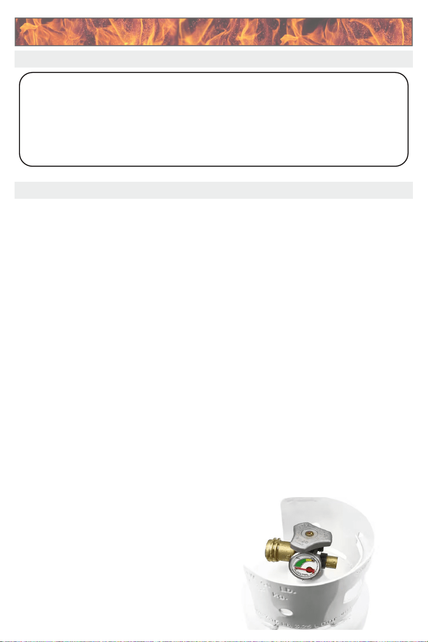
If you do not have an updated ller valve on your
existing propane tank, you will need to purchase
one at your local hardware store. Without it you will
not be able to attach your tank to your grill or rell
the tank at your local propane rell station.
Transporting and Storing LP Gas
Transport only one cylinder at a time. Ensure the
cylinder is secured in an upright position with the
control valve turned o and the dust cap in place.
Store LP cylinders outdoors way from children and
heat sources. Do not store LP cylinders in a building,
garage, or any other enclosed area.
Place the dust cap on the cylinder valve outlet
whenever the cylinder is not in use. Only install the
type of dust cap/cover on the cylinder valve outlet
that is provided with the cylinder valve. Other types
of caps/covers can result in leakage of propane.
Cylinder specications
The LP cylinder must be constructed and marked in
accordance with the Specications for LP-Gas Cylinders
of the US Department of Transportation or the Na-
tional Standard of Canada, CAN/CSA-B339, Cylinders,
Spheres and Tubes for transportation of dangerous
goods: and Commission, as applicable.
Warning: Do not store spare LP cylinders under or
near the appliance. Never ll the cylinder beyond 80%,
failure to follow this warning can result in an explosion
and/or re resulting in injury or even death.
Note: The LP cylinder must have an OPD valve
installed onto it. The OPD valve is designed to ensure
proper overll protection, this allows for safe oper-
ation of the propane grill, cutting fuel ow if tipped
over as well.
OPD valves are mandatory on all 4-40 lbs propane
tanks.
The OPD valve is normally pre-installed upon purchasing
a 20lbs propane tank by the propane tank manufacture.

13
P4, P5, and P6 Barbecue Grills
LTR50001137, Rev. R
Gas and Electrical Supply Requirements
www.calamebbq.com
9
Natural Gas
NG Service Installation and Connection
Natural gas installation of this appliance must conform
with local codes or, in the absence of local codes,
to the national fuel gas code, ANSI Z223.1a-1998.
Installation in Canada must be in accordance with
the standard CAN/CGA-B149.2, Propane Installation
Code.
You do not need to hire a contractor to install your
natural gas service, but you need to make sure you
have all required permits and ensure the installation
complies with State and local code. We recommend
you hire a certied contractor if you do not wish to do
the installation yourself.
The natural gas pipe from your house to the
location of your barbecue island needs to be ¾” and
terminate with a shut-off valve with a ½” male tting.
Check with a contractor or your local inspector for
requirements.
Always check the rating plate to make sure the gas
supply you are hooking up to is the gas type the grill
is manufactured for.
NG Regulator
The grill for use with natural gas comes equipped
with its own regulator that MUST NOT be removed.
If this regulator needs to be replaced, use only the
type specied by for this appliance.
IMPORTANT: Never connect the grill to an
unregulated gas supply.
Shut-off Valve
Ensure that the service supplying the grill is tted
with a shut off valve conveniently positioned near
the grill and giving ease of access.
The grill must be isolated from the gas supply piping
system by closing its individual manual shutoff valve
during any pressure testing of the gas supply piping
system at test pressures equal to or less than 0.5
psi (3.5 kPa).
Electrical Supply Requirements
You will need a dedicated 120V 10 amp grounded
electrical service. The power supplied to your grill
enclosure must be on a dedicated circuit with no other
appliances or lights sharing the power.
You do not need to hire a contractor to install your
electrical service, but you must ensure you have
all required permits and the installation complies
with State and local code. We recommend you hire
a certied contractor if you do not wish to do the
installation yourself.
If your dealer is not a certied contractor, you will need
to hire a contractor for installation of your electrical
service.
When installed in the United States, the electrical
wiring must meet the requirements of National Electric
Code, ANSI/NFPA 70-1999 and any applicable state
or local codes. The electrical circuit must be installed
by an electrical contractor and approved by a local
building / electrical inspector.
To determine the current, voltage, and wire size
required for the island conguration to be connected,
refer to the following:
• Wire size is determined by length of run from
breaker box to the barbecue island and maximum
current draw.
• We recommend copper wire with THHN insulation.
• All wiring must be copper to ensure adequate
connections. Do not use aluminum wire.
• When NEC requires the use of wires larger than #6
(10mm²), install a junction box near the barbecue
island and use #6 (10mm²) wire between the
junction box and the grill enclosure.
NG Service Installation and Connection.
Natural gas installation of this appliance must
conform with local codes or, in the absence of
local codes, review the national fuel gas code, ANSI
Z223.1a-1998. Installation in Canada must be in
accordance with the standard CAN/CGA-B149.2,
Propane Installation Code.
You do not need to hire a contractor to install your
natural gas service, but you need to make sure you
have all required permits and ensure the installation
complies with State and local code. We recommend
you hire a certied contractor if you do not want to
do the installation yourself.
The natural gas pipe from your house to the
location of your barbecue island needs to be ¾ and
terminate with a shut off valve with a ½ male fitting.
Check with a contractor or your local inspector
for requirements. Always verify the rating plate to
ensure the gas supply you are hooking up to is the
gas type the grill is designed for.
Never connect the grill to an unregulated gas
supply.
STATE OF MASSACHUSETTS: Massachusetts
requires all gas be installed using a plumber or
gas tter carrying the appropriate Massachusetts
license. All permanently installed natural gas or
propane installations require a “T” handle type
manual gas valve be installed in the gas supply
line in this appliance. This does not apply to
portable propane installations using a 20 pound
cylinder.
Shut o Valve
Ensure that the service supplying the grill is tted
with a shut o valve conveniently positioned near
the grill and giving ease of access.
The grill must be isolated from the gas supply pip-
ing system by closing its individual manual shuto
valve during any pressure testing of the gas supply
piping system at test pressures equal to or less than
05 psi (3.5 kPa).
Natural Gas
14
P4, P5, and P6 Barbecue Grills
LTR50001137, Rev. R
Installation and Connection
www.calamebbq.com
10
Installation and Connection
Connecting the Grill and Side Burner
These instructions show you how to connect a grill only or a grill and side burner combination.
If you plan to convert to your grill from LP to NG, you need to do this before it is connected to a gas source.
Grill conversion instructions can be found on page 31 and ordering information can be found in this manual on
page 37. There are a few differences between connecting to LP and NG.
You will need a second
person to help you to
avoid damaging the grill,
the transformer, or your
barbecue island.
Before installing a grill or side
burner in any island or cut out,
make sure that the opening is
not bigger than the outside
frame of the grill unit. The grill
should rest on the lip of the
frame. For drop-in accessories,
adequate cross ventilation must
be designed into enclosure
to ensure the drop-in grill or
side burner does not become
overheated.
Pay careful attention to the location of gas lines.
Gas lines should be routed away from sources of
heat and should make as few bends as possible.
Check to see if gas line connections will be accessible
when grill is installed.
• If gas line connections are not easily accessible
when the grill is installed, support the grill
above counter level and attach the gas lines to
the grill. When the gas connections are made,
slide the grill into the cut out.
• If gas line connections are accessible when the
grill is installed, slide the grill into the cut out
and then attach the gas lines.
1. Place the Grill and Side Burner in the Cut-outs
Be very careful not to kink gas lines when lowering the
grill or side burner into the cut out.
Keep your ngers away from where the grill will be
supported on counter. Your ngers could become
trapped and serious injury could occur.
Check to make sure the grill is level and is supported
around the entire outside edge. If the grill is not level
or is unstable, use non-combustible shims under the
outside lip to stabilize it.
Perform the leak test procedure as described earlier
in this manual.
Connecting the Grill and Side Burner
These instructions show you how to connect a grill only or a grill and side burner combination using
liquid propane
If you plan to convert to your grill from LP to NG, you need to refer to this installation guide as well as
the natural gas conversion guide found on page 34 as there are a few dierences between connecting a
LP line and an NG line.
You will need a second person to
help you avoid damaging the grill,
the transformer, or your barbecue
island.
Before installing a grill or side
burner in any island or cut-out,
make sure that the opening is not
bigger than the outside frame of
the unit. The grill should rest on
the lip of the frame. For drop-in
accessories, adequate cross venti-
lation must be designed into the
enclosure to ensure the drop-in grill
or side burner does not overheat.
1. Place the Grill and Side Burner in the Cut-outs
Pay careful attention to the location of the gas lines.
Gas lines should be routed away from sources of heat
and should make as few bends as possible.
Verify if gas line connections are easily accessible
when the grill is installed.
• If the gas line connections are not easily accessible
when the grill is installed, support the grill above
the counter level and attache the gas lines to the
grill. When the gas connections are made, slide
the grill into the cut out.
• If gas line connections are accessible when the
grill is installed, slide the grill into the cut out and
then attach the gas lines.
Be very careful not to bend or kink gas lines when
lowering the grill or side burner in place into the cut out.
Keep your ngers away from where the grill will be
supported. Your ngers could become trapped and
serious injury can occur.
Check to make sure the grill is level and supported
around the entire outside edge. If the grill is not level or
is unstable, use non-ammable shims under the outside
lip to stabilize it. Failure to have the grill properly leveled
will lead to a void warranty.
Perform the leak test procedure as described earlier in
this manual.
Installation and ConnectionInstallation and Connection
15
P4, P5, and P6 Barbecue Grills
LTR50001137, Rev. R
Installation and Connection
www.calamebbq.com
11
2. Connect the Gas Line to the Grill
Note: Make sure you have converted the grill for natural gas before connecting the gas line to the regulator.
See page 31 for instructions on converting the grill from LP to NG.
Connecting the grill only
If you have a grill and side burner combination, go
to step 3.b.
Slide the grill forward about six inches and connect the
gas line to the grill using the appropriate connection
for your gas type.
Natural Gas
Liquid Propane
2. Connecting the Gas Line to the Grill
Note: The natural gas conversion will require dierent steps, as you will need to convert the grill itself before
installing the gas line and NG regulator. This section is a general overview of the procedure.
Refer to page 34 for full conversion instructions.
For installing only a Cal ame grill (no side burner)
If you are installing both a grill and side burner refer to step 3
Slide the grill forward about six inches (15.3cm) and
connect the gas line to the grill using the appropriate
connection for you gas type.
These images represent a gas connection with only one appliance (grill only). You may
follow the diagram on page 15 to connect two gas appliances together.
Note:
Do not install the natural gas regulator if the grill has not been fully converted to natural
gas. The full procedure to convert the grill to natural gas can be found on page 35 and
within the natural gas kit when part number BBQ07101046 is ordered.
Note:
16
P4, P5, and P6 Barbecue Grills
LTR50001137, Rev. R
Installation and Connection
www.calamebbq.com
12
Note: This is only necessary if you
have a side burner.
a. Assemble the T Connection
Items required for connection (NOT
included with your grill):
• One 3/8” T adapter
• One or two 1/2” to 3/8” are
reducers
• Two 3/8” ex lines
• LP gas line with regulator OR
3/8” NG ex line
Connect two 3/8” ex lines to the
ends of the T connector that will
connect with the grill and side
burner. Connect either a third ex
line (if you are using NG) or a LP
gas line (if you are using LP) to
the third end of the T connector as
shown at left.
b. Connect to the grill
The gas manifold for the convection
grill can be congured for both LP
and NG. Make sure you connect
to the correct tting depending on
your gas type. Connect to gas line
to the grill as shown in step 3.a
above.
c. Connect to the side burner
Connect the ex line from the T connector to the 1/2” to 3/8” are reducer tting on the side burner gas line.
No regulator is required for either LP or NG.
Connect to
NG gas source
3/8” tee adapter
3/8” flex line 3/8” flex line
Connect to grill
Connect to
side burner
3/8” flex line
NG CONNECTION
IIIII
IIIII
IIIIIIIIIIIIIIII
IIIII
IIIII
IIIII
1/2” to 3/8” reducer
Connect to
propane tank
3/8” tee adapter
3/8” flex line
3/8” flex line
1/2” to 3/8” reducer
I
I
I
I
I
I
I
I
I
I
I
I
I
I
I
Connect to grill
Connect to
side burner
Black LP gas line
with regulator
LP CONNECTION
IIIII
IIIII IIIII
IIIII
Cap
3. Connect the Gas Line to the Grill and Side Burner
A- Assembling the T Connection
Items required for this connection type
(not included)
• One ³⁄₈’’ T adapter
• One or two ½’’ to ³⁄₈’’ flare reducers
• Two ³⁄₈’’ flex lines
• LP gas line with regulator OR ³⁄₈’’
NG flex line.
Connect two ³⁄₈’’ flex lines to the ends
of the T connector that will connect
with the grill and side burner. Connect
either a third flex line (if you are using
LP) to the third end of the T connector as
shown in the diagram on this page.
3. Connecting the Gas Line to a Grill and Side Burner
Note: This section is only necessary if your BBQ island has both a grill and side burner.
B- Connect to the grill
Connect the properly sized ³⁄₈’’ tting to
the grill manifold. Refer to diagram
C- Connect to the side burner.
Connect the ex line from the T connec-
tor to the ½” to ³⁄₈’’ are reducer tting
on the side burner gas line. No regulator
is required for this part of the connec-
tion in either LP or NG gas set-ups
P4, P5, and P6 Barbecue Grills
LTR50001137, Rev. R
Installation and Connection
www.calamebbq.com
12
Note: This is only necessary if you
have a side burner.
a. Assemble the T Connection
Items required for connection (NOT
included with your grill):
• One 3/8” T adapter
• One or two 1/2” to 3/8” are
reducers
• Two 3/8” ex lines
• LP gas line with regulator OR
3/8” NG ex line
Connect two 3/8” ex lines to the
ends of the T connector that will
connect with the grill and side
burner. Connect either a third ex
line (if you are using NG) or a LP
gas line (if you are using LP) to
the third end of the T connector as
shown at left.
b. Connect to the grill
The gas manifold for the convection
grill can be congured for both LP
and NG. Make sure you connect
to the correct tting depending on
your gas type. Connect to gas line
to the grill as shown in step 3.a
above.
c. Connect to the side burner
Connect the ex line from the T connector to the 1/2” to 3/8” are reducer tting on the side burner gas line.
No regulator is required for either LP or NG.
Connect to
NG gas source
3/8” tee adapter
3/8” flex line 3/8” flex line
Connect to grill
Connect to
side burner
3/8” flex line
NG CONNECTION
IIIII
IIIII
IIIIIIIIIIIIIIII
IIIII
IIIII
IIIII
1/2” to 3/8” reducer
Connect to
propane tank
3/8” tee adapter
3/8” flex line
3/8” flex line
1/2” to 3/8” reducer
I
I
I
I
I
I
I
I
I
I
I
I
I
I
I
Connect to grill
Connect to
side burner
Black LP gas line
with regulator
LP CONNECTION
IIIII
IIIII IIIII
IIIII
Cap
3. Connect the Gas Line to the Grill and Side Burner
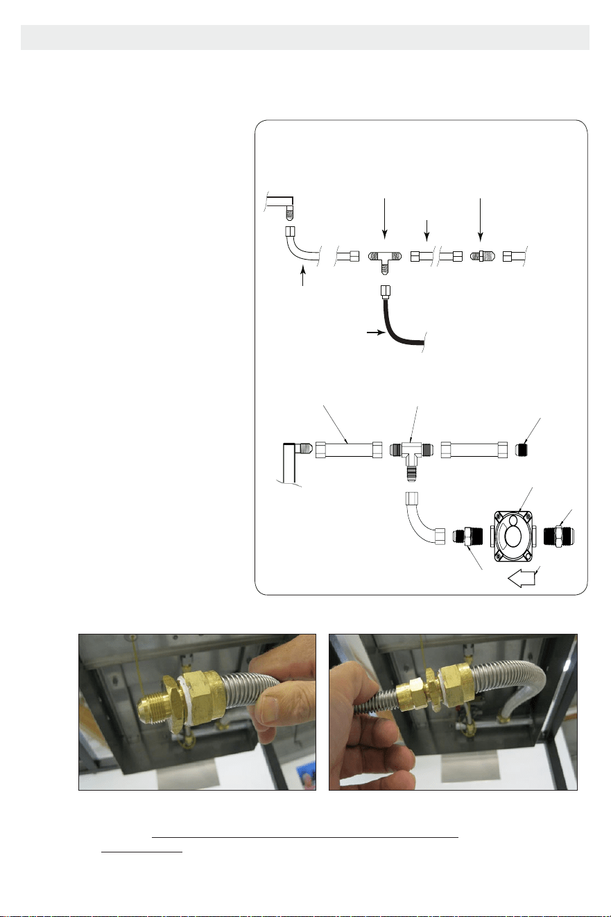
FROM GRILL
FROM SIDE BURNER
TUBING 3/8 FLARE FITTING BOTH SIDES
3 PLCS
"T" ADAPTER (3/8" FLARE FITTING)
FITTING 3/8" FLARE X 1/2" NPT
5" W.C. NG REGULATOR
FITTING 1/2" FLARE X 1/2" NPR
REGULATOR DIRECTION
OF ARROW
“T” Adapter
(³⁄₈flare fitting)
Connection to Grill
*Rotated for illustration
Side Burner
Fitting
Fitting
³⁄₈ Flare x ½ NPT
Tubing ³⁄₈ are tting
(both sides)
½ Flare x ½ NPT
5’’ W.C. NG
Regulator
Direction of
regulator
ow
NG CONNECTION
Note: For Natural gas, thread sealant must be used to secure the connection
between ³⁄₈ x ½ NPT & the ½ x ½ NPT fittings connected to the NG
regulator itself. We recommend plumbers putty, but Yellow PTFE tape/sealant
may be used as well.
17
P4, P5, and P6 Barbecue Grills
LTR50001137, Rev. R
Installation and Connection
www.calamebbq.com
13
Perform a leak test at least once a year whether the
gas supply cylinder has been disconnected or not. In
addition, whenever the gas cylinder is connected to
the regulator or whenever any part of the gas system
is disconnected or replaced, perform a leak test.
As a safety precaution, remember to always leak test
your grill outdoors in a well-ventilated area. Never
smoke or permit sources of ignition in the area while
doing a leak test. Do not use a ame, such as a
lighted match to test for leaks. Use a solution of
soapy water.
1. Prepare a leak testing solution of soapy water by
mixing in a spray bottle one part liquid soap to
one part water.
2. Make sure all the control knobs are in the OFF
position.
3. Turn on the gas.
a. On natural gas systems, turn the main feed
valve to the grill.
b. On LP systems, turn the cylinder valve knob
counter clockwise one turn to open.
4. Apply the leak-testing solution by spraying it
on joints of the gas delivery system. Blowing
bubbles in the soap solution indicates that a leak
is present.
5. Stop a leak by tightening the loose joint or by
replacing the faulty part with a replacement
part recommended by the manufacturer. Do
not attempt to repair the cylinder valve if it is
damaged. The cylinder must be replaced.
6. Turn all control knobs back to the full OFF
position.
If you are unable to stop a leak:
1. Turn all control knobs back to the full OFF
position.
2. Shut off the gas supply to the grill and release
pressure in the hose and manifold by pushing in
and turning any of the control valves one quarter
turn counter-clockwise.
3. On LP systems, remove the cylinder from the
grill.
4. Call an authorized gas appliance service
technician or an LP gas dealer.
Do not use the appliance until the leak is corrected.
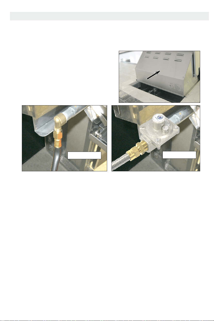
4. Connect to a Gas Source
Leak Testing Procedure
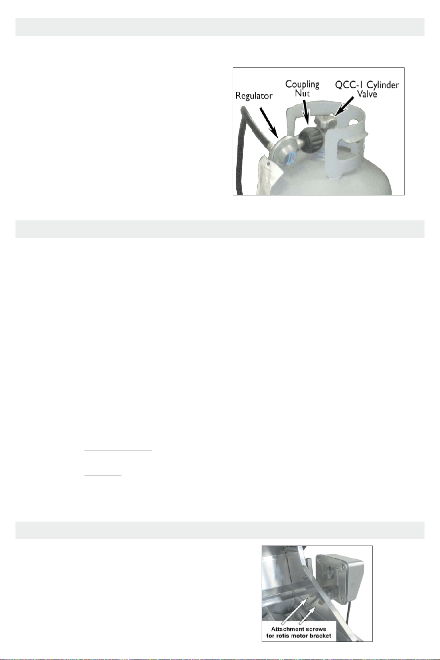
Liquid Propane Connection
Use the pressure regulator and hose assembly supplied
with the grill, or a regulator and hose assembly with
the same specications. Replacement LP regulator and
hose must have a coupling nut that will connect to a
QCC-1 cylinder valve on one end and a female tting
that will connect to a 3/8” tapered tting on the grill
manifold. See the gures below.
Connect the brass tting to the manifold behind the
grill. Do not use Teon tape or plumber’s dope. Do NOT
remove the NG regulator from the manifold. Connect
the coupling nut to the LP cylinder valve.
When you are nished connecting to the gas source, perform a leak test.
Natural Gas Connection
Connect the gas line to the NG stub-up inside the barbecue island. When you are nished connecting to the
gas source, perform a leak test.
4. Connect to a Gas Source
Liquid Propane Connection
Using the provided LP pressure regulator and hose
assembly connect the LP cylinder to the hose
assembly. Replacement LP regulators must match the
same specications as the original provided to you by
Cal Flame, including the coupling nut that connects to
a QCC-1 cylinder valve. The hose must have a QCC-1
coupling nut, and a female tting that will connect to
a ³⁄₈’’ tapered tting on the grill manifold.
Connect the brass tting to the manifold behind the
grill. Do not use PTFE/Teon tape or plumbers dope
when connecting the coupling nut to the LP cylinder
valve.
When you have nished connecting the gas source, perform a leak test.
Leak Testing Procedure
P4, P5, and P6 Barbecue Grills
LTR50001137, Rev. R
Installation and Connection
www.calamebbq.com
13
Perform a leak test at least once a year whether the
gas supply cylinder has been disconnected or not. In
addition, whenever the gas cylinder is connected to
the regulator or whenever any part of the gas system
is disconnected or replaced, perform a leak test.
As a safety precaution, remember to always leak test
your grill outdoors in a well-ventilated area. Never
smoke or permit sources of ignition in the area while
doing a leak test. Do not use a ame, such as a
lighted match to test for leaks. Use a solution of
soapy water.
1. Prepare a leak testing solution of soapy water by
mixing in a spray bottle one part liquid soap to
one part water.
2. Make sure all the control knobs are in the OFF
position.
3. Turn on the gas.
a. On natural gas systems, turn the main feed
valve to the grill.
b. On LP systems, turn the cylinder valve knob
counter clockwise one turn to open.
4. Apply the leak-testing solution by spraying it
on joints of the gas delivery system. Blowing
bubbles in the soap solution indicates that a leak
is present.
5. Stop a leak by tightening the loose joint or by
replacing the faulty part with a replacement
part recommended by the manufacturer. Do
not attempt to repair the cylinder valve if it is
damaged. The cylinder must be replaced.
6. Turn all control knobs back to the full OFF
position.
If you are unable to stop a leak:
1. Turn all control knobs back to the full OFF
position.
2. Shut off the gas supply to the grill and release
pressure in the hose and manifold by pushing in
and turning any of the control valves one quarter
turn counter-clockwise.
3. On LP systems, remove the cylinder from the
grill.
4. Call an authorized gas appliance service
technician or an LP gas dealer.
Do not use the appliance until the leak is corrected.
4. Connect to a Gas Source
Leak Testing Procedure
Liquid Propane Connection
Use the pressure regulator and hose assembly supplied
with the grill, or a regulator and hose assembly with
the same specications. Replacement LP regulator and
hose must have a coupling nut that will connect to a
QCC-1 cylinder valve on one end and a female tting
that will connect to a 3/8” tapered tting on the grill
manifold. See the gures below.
Connect the brass tting to the manifold behind the
grill. Do not use Teon tape or plumber’s dope. Do NOT
remove the NG regulator from the manifold. Connect
the coupling nut to the LP cylinder valve.
When you are nished connecting to the gas source, perform a leak test.
Natural Gas Connection
Connect the gas line to the NG stub-up inside the barbecue island. When you are nished connecting to the
gas source, perform a leak test.
P4, P5, and P6 Barbecue Grills
LTR50001137, Rev. R
Installation and Connection
www.calamebbq.com
14
Attach the two brackets to the sides of the grill, one
on each side, using two screws as shown below.
Slide the rotis motor on one of the brackets as
shown below. The rotis motor will work on either
side of the grill.
Attaching the Rotisserie Motor
Attaching the Rotisserie Motor
18
P4, P5, and P6 Barbecue Grills
LTR50001137, Rev. R
Using Your Grill
www.calamebbq.com
15
We recommend you wash your entire grill with soap
and water prior to lighting it for the rst time. Oils
are used during the manufacturing process and some
residual oil may still be on the stainless steel parts
of your grill. Washing will reduce the possibility of
discoloration. We also recommend you keep your
grill covered when not in use. This will minimize the
amount of dust and dirt that accumulates on your
grill and extend the life of your grill.
Remember to use your Cal Flame grill safely by
following these reminders:
• It is dangerous to use barbecue grills and side
burners in any manner other than for what it is
designed for.
• Do not use charcoal in a gas grill or side burner.
• Do not heat sealed containers such as cans or
jars on grills or side burners. Explosion may
result resulting in injury or death. Any sealed
container, such as a pressure cooker, must have
a properly operating pressure relieve valve to
minimize explosion hazard.
• Never put combustible material such as paper,
cloth, or ammable liquids on your grill at any
time. Do not use grill, side shelves, cabinets,
or any area around grill to store ammable
materials.
• Never operate main burners and rear infrared
convection burners at the same time. Excessive
grill temperatures will result.
Read all instructions before you operate your grill.
Before lighting, make sure all burner controls are
off. Do not attempt to light the burners if the smell
of gas is present. Check the connection with a soap
and water solution after attaching the hose. For LP
units, make sure there is gas in the tank and it is
sitting upright. For natural gas units, make sure the
shut off valve is on.
1. Make sure the drip tray is in place.
2. Light the grill burners using the instructions on
the previous page.
3. Turn the control knob to HIGH and preheat the
grill for 15 minutes. Close the top cover during
the appliance preheat period.
4. Place the food on the grill and cook to desired
completion. Adjust heat setting if necessary. You
may set the control knob to any position between
HIGH and LOW.
5. Allow the grill to cool and clean the drip tray
after each use.
Do not leave the grill unattended while cooking.
Basic Grill Operation
Using Your Grill
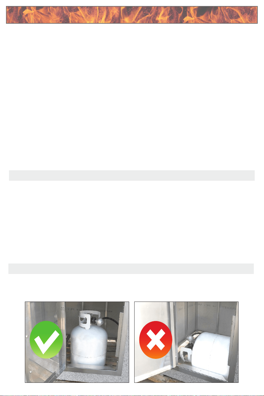
Gas Cylinder Orientation
LP gas cylinder must be up oriented upright during operation for proper vapor withdrawl. Operating the grill
with the cylinder on it side will allow liquid gas to ow into the regulator. Erratic gas ow will occur, resulting
in possible are-ups or explosion.
Using Your GrillUsing Your Grill
Note: Always inspect the LP hose before using the grill for any cracks, frays, or kinks.
failure to do so may result in a gas leak, causing re, injury, or death.
Immediately replace the LP hose if any of these are detected, do not use the grill.
Basic Grill Operation
1. Make sure the drip tray is properly placed.
2. Light the grill burners using the valve dials, press
down and slowly turn the knob to the ignition
position to light the burner.
P4, P5, and P6 Barbecue Grills
LTR50001137, Rev. R
Using Your Grill
www.calamebbq.com
15
We recommend you wash your entire grill with soap
and water prior to lighting it for the rst time. Oils
are used during the manufacturing process and some
residual oil may still be on the stainless steel parts
of your grill. Washing will reduce the possibility of
discoloration. We also recommend you keep your
grill covered when not in use. This will minimize the
amount of dust and dirt that accumulates on your
grill and extend the life of your grill.
Remember to use your Cal Flame grill safely by
following these reminders:
• It is dangerous to use barbecue grills and side
burners in any manner other than for what it is
designed for.
• Do not use charcoal in a gas grill or side burner.
• Do not heat sealed containers such as cans or
jars on grills or side burners. Explosion may
result resulting in injury or death. Any sealed
container, such as a pressure cooker, must have
a properly operating pressure relieve valve to
minimize explosion hazard.
• Never put combustible material such as paper,
cloth, or ammable liquids on your grill at any
time. Do not use grill, side shelves, cabinets,
or any area around grill to store ammable
materials.
• Never operate main burners and rear infrared
convection burners at the same time. Excessive
grill temperatures will result.
Read all instructions before you operate your grill.
Before lighting, make sure all burner controls are
off. Do not attempt to light the burners if the smell
of gas is present. Check the connection with a soap
and water solution after attaching the hose. For LP
units, make sure there is gas in the tank and it is
sitting upright. For natural gas units, make sure the
shut off valve is on.
1. Make sure the drip tray is in place.
2. Light the grill burners using the instructions on
the previous page.
3. Turn the control knob to HIGH and preheat the
grill for 15 minutes. Close the top cover during
the appliance preheat period.
4. Place the food on the grill and cook to desired
completion. Adjust heat setting if necessary. You
may set the control knob to any position between
HIGH and LOW.
5. Allow the grill to cool and clean the drip tray
after each use.
Do not leave the grill unattended while cooking.
Basic Grill Operation
Using Your Grill
Gas Cylinder Orientation
LP gas cylinder must be up oriented upright during operation for proper vapor withdrawl. Operating the grill
with the cylinder on it side will allow liquid gas to ow into the regulator. Erratic gas ow will occur, resulting
in possible are-ups or explosion.
Before lighting, make sure all burner controls are
o. Do not attempt to light the burners if the smell
of gas is present. Check the gas connection with a
soap and water solution after attaching the hose.
For LP units make sure the LP tank is sitting upright
and that gas is in the tank. For natural gas units,
make sure the shut o valve is on.
3. Once lit, turn the knob to the HIGH position and
preheat the grill for 15 minutes. Close the hood
of the grill during this period of time.
4. Place your food on the grill and cook to desired
completion, adjust temperature if necessary to
any position between HIGH and LOW.
5. Once you are done grilling turn the dials o and
allow the grill to cool down for 10-15 minutes
with the hood open, after 10-15 minutes have
passed remove and clean the drip tray.
Never leave a lit grill unattended.
LP Gas Cylinder Orientation
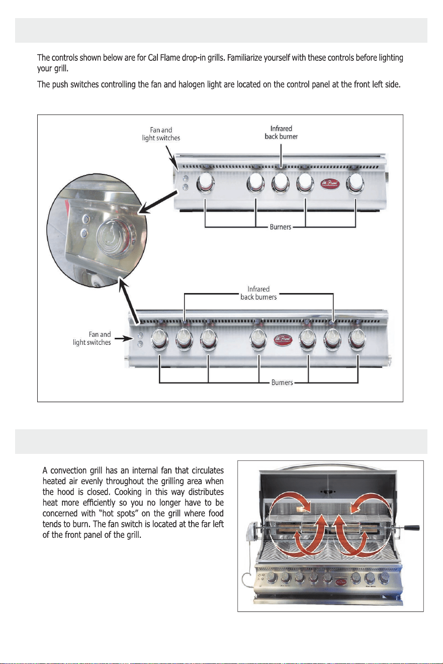
19
Convection Grills
LTR50001038, Rev. P-1
UsingYour Grill
www
17
Grill Controls
Grill Controls/Dials
Convection Grills
LTR50001038, Rev. P-1
UsingYour Grill
www
20
Gas Cylinder Orientation
Heat Distribution on the Cooking Grates
Convection Fan
Convection Fan
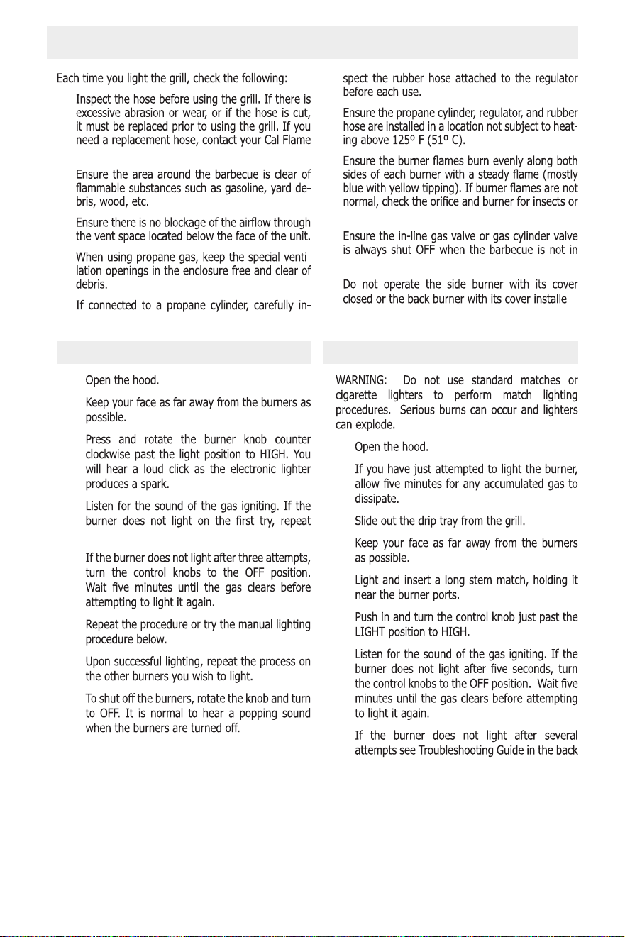
20
Convection Grills
LTR50001038, Rev. P-1
UsingYour Grill
www
18
Lighting the Burners
•
dealer.
•
•
•
•
•
•
insect nests.
•
use.
•
d.
Electronically Lighting the Burners Manually Lighting the Burners
1.
2.
3.
4.
immediately.
5.
6.
7.
8.
1.
2.
3.
4.
5.
6.
7.
8.
of this manual.
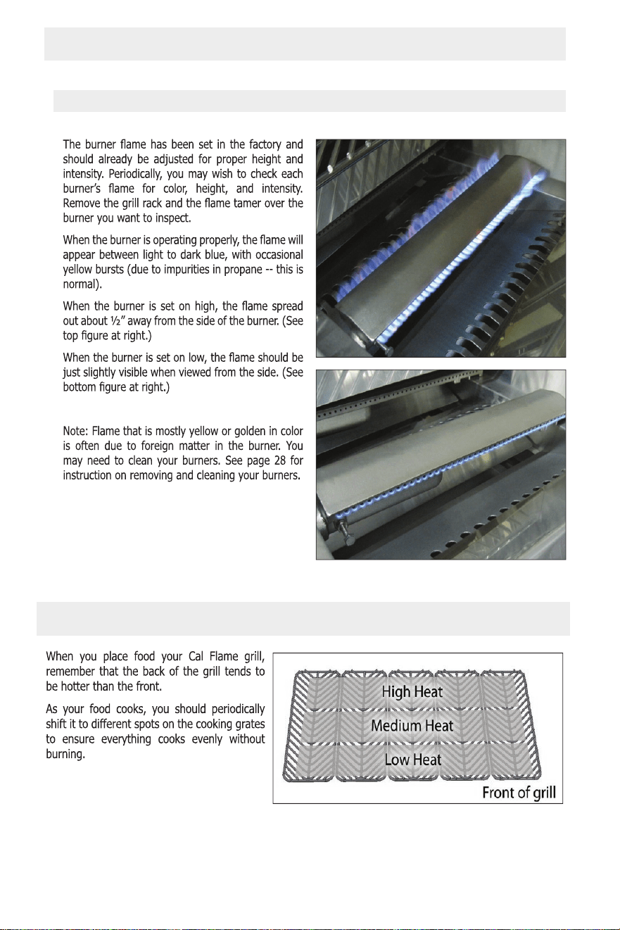
21
Convection Grills
LTR50001038, Rev. P-1
UsingYour Grill
www
19
Proper Burner Flame
Flame Color and Height
Convection Grills
LTR50001038, Rev. P-1
UsingYour Grill
www
20
Gas Cylinder Orientation
Heat Distribution on the Cooking Grates
Convection Fan
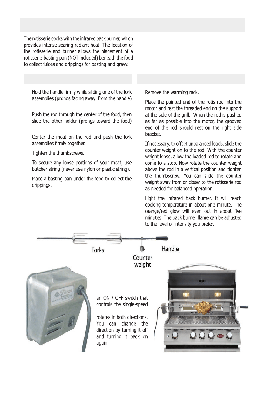
22
Convection Grills
LTR50001038, Rev. P-1
UsingYour Grill
www
21
Before you can use the rotisserie, you need to
1.
onto the rod.
2.
onto the rod.
3.
4.
5.
6.
1.
2.
3.
4.
Cooking with the Rotisserie
The rotisserie motor has
motor. The rotisserie
Loading food on the rotisserie rod Cooking with the rotisserie
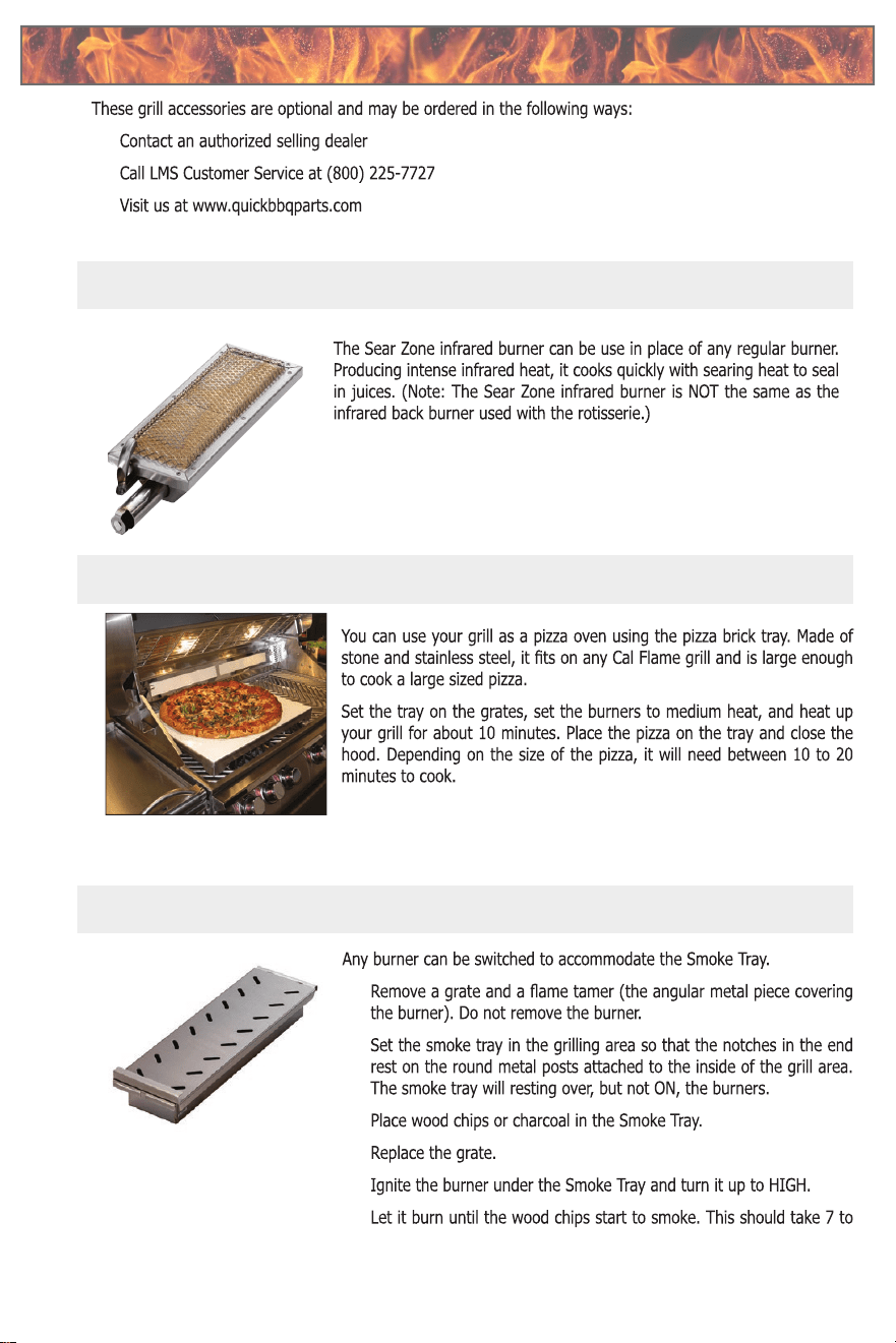
23
Convection Grills
LTR50001038, Rev. P-1
Optional Grill Accessories
www
22
•
•
•
BBQ07890P
BBQ07900
BBQ08854P
Sear Zone Infrared Burner
Pizza Brick Tray
Smoke Tray
Optional Grill Accessories
1.
2.
3.
4.
5.
6.
10 minutes. Then lower the heat to low.
Optional Grill AccessoriesOptional Grill Accessories
Instructions for installing the optional Sear Zone Burner are on Page 38
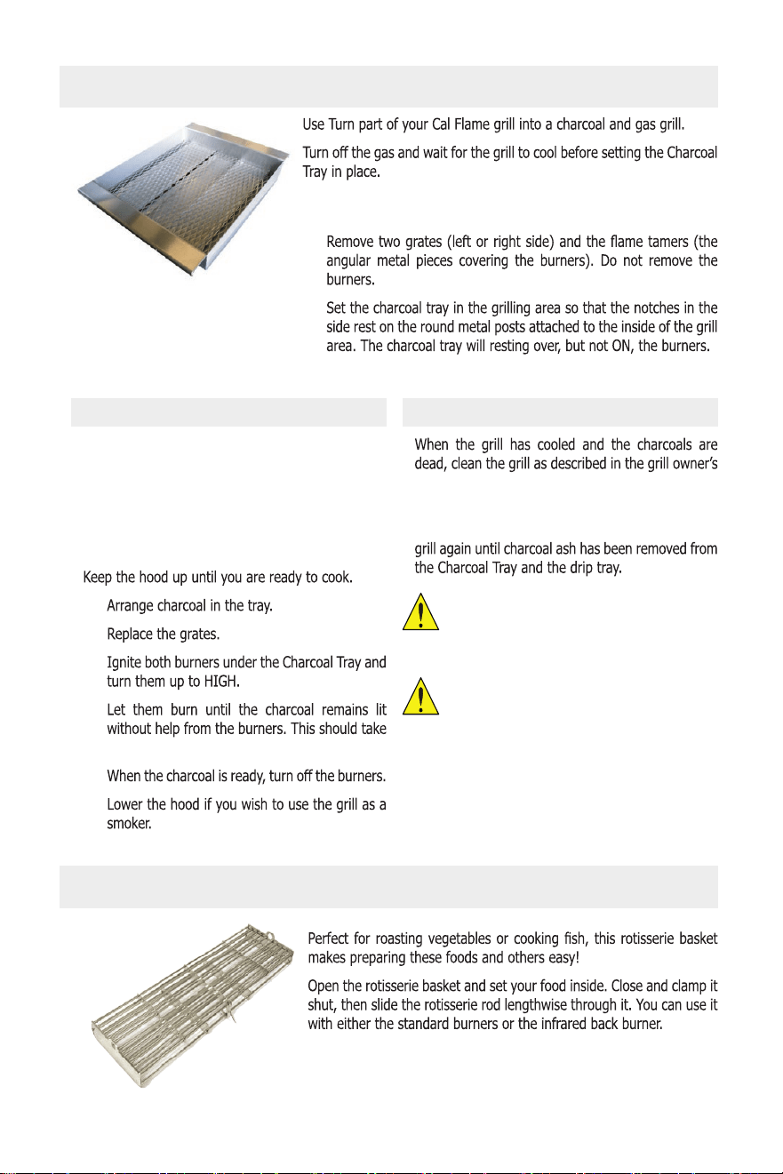
24
Convection Grills
LTR50001038, Rev. P-1
Optional Grill Accessories
www
23
Never use the Charcoal Tray over a
Sear Zone infrared burner.
NEVER use charcoal in a gas grill
without the charcoal tray. Doing so will
void your warranty.
BBQ11859
BBQ08892
Rotisserie Basket
Charcoal Tray
Placement
1.
2.
3. Place the ash screen in the Charcoal Tray.
Using the Charcoal Tray Removal and Clean-up
The Charcoal Tray is designed and intended to
be used with plain charcoal. Quick-light char-
coal can produce excessive heat and may be
dangerous.
Make sure the drip tray is in the grill before
you begin.
1.
2.
3.
4.
7 to 10 minutes.
5.
6.
manual.
Remove ash from the Charcoal Tray immediately
after use. Do not let it accumulate. Do not use the
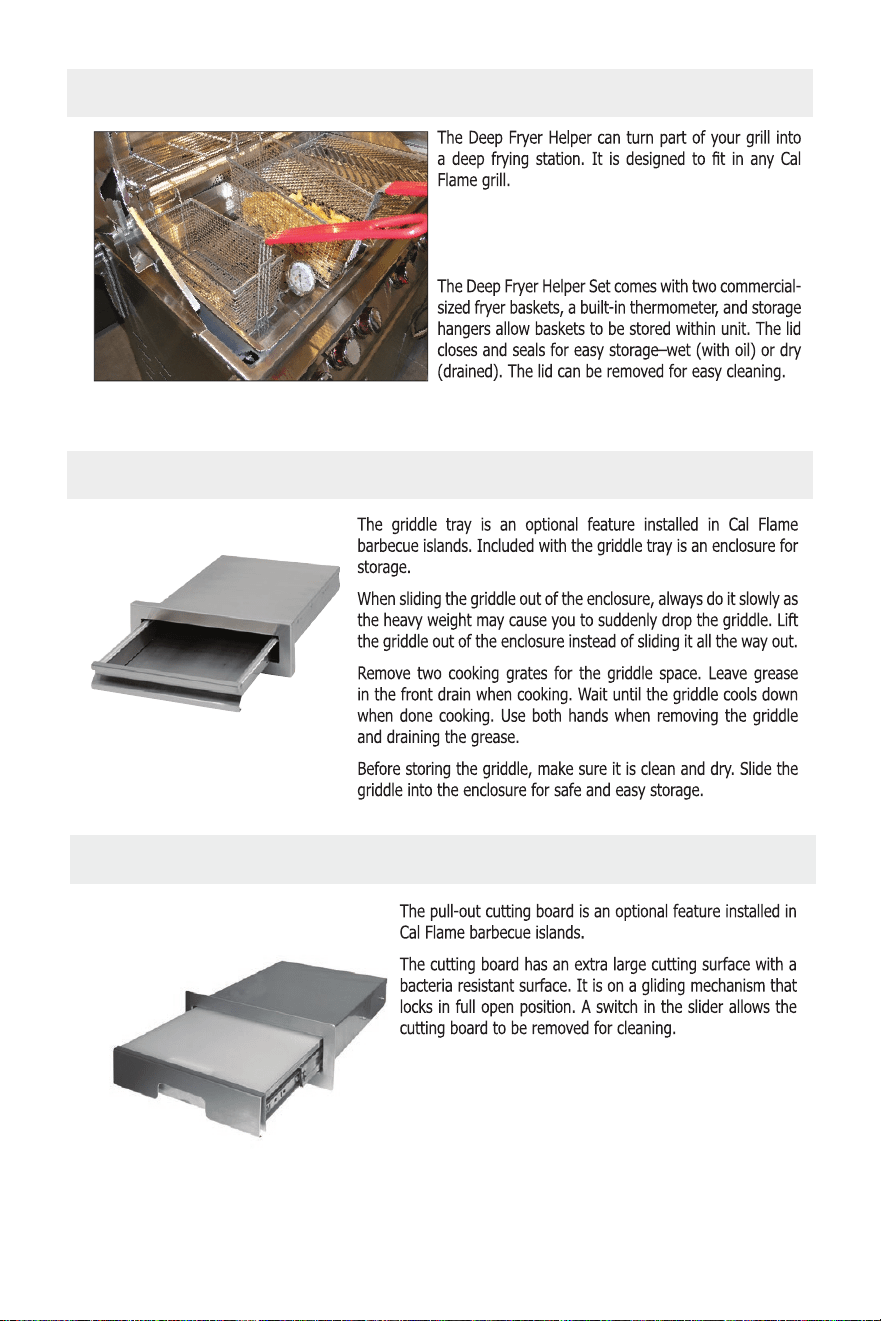
25
Convection Grills
LTR50001038, Rev. P-1
Optional Grill Accessories
www
24
The Deep Fryer Helper Set is shipped with its
own instructions for placement and use. Read
them carefully before use.
BBQ07862P
BBQ09902
BBQ07891P
Deep Fryer Helper Set
Griddle Tray
Pull-Out Cutting Board
Pull Out Cutting Board
26
P4, P5, and P6 Barbecue Grills
LTR50001137, Rev. R
Cleaning and Maintenance
www.calamebbq.com
23
Cleaning Products and Materials
DO NOT USE these common cleaning products and
materials – they will damage the surface of your
stainless steel.
• CLR
• Lime-Away
• Oven cleaner
• Cleansers such as Ajax or Comet
• Ammonia
• Bleach
• Chlorine
• Steel wool pads
• Wire brushes
• Scrapers
• Pumice
We recommend these products for cleaning your
stainless steel:
• Mild dish detergent such as Dawn
• Formula 409
• Fantastik
• Instant Rust Out (exterior ONLY)
• WD-40 (exterior ONLY)
• Sheila Shine (exterior ONLY)
We have had best success with Instant Rust Out,
but WD-40 works very well too. Instant Rust Out is
available in some hardware stores. WD-40 is widely
available.
Baking soda, lemon oil, olive oil, vinegar, or club
soda can also be effective for cleaning light soil on
all stainless steel surfaces.
Do not use steel wool or wire brushes to
scrub your grill.
For light soil, use a damp sponge or cloth.
For heavier stains, use a Scotch-Brite scrubber or
similar product.
These instructions describe the best way to care for
your stainless steel. They apply to grills and barbecue
islands with stainless steel xtures.
Although stainless steel grills will discolor and
accumulate grime with regular use, they can keep
their original shine with periodic cleaning. We strongly
recommend using a surface protectant to prevent
smudging and surface rust from accumulating.
The easiest way to clean the grill is immediately after
cooking is completed. Doing so will extend the life of
your grill, prevent grease res, and present a pleasant
appearance while you grill.
1. Clean
Thoroughly clean stains, food, and grime using
a sponge or damp cloth with warm water and a
mild dish soap. Use Fantastik or Formula 409 to
remove heavier soil.
2. Rinse
Thoroughly rinse all surfaces and dry them
completely with a clean towel. Do not allow
stainless steel to air dry.
3. Polish
We strongly recommend that you apply a surface
protectant to all exposed stainless steel surfaces.
Spray a small amount of WD-40 or Sheila Shine on a
piece of paper towel and rub with the grain over the
surface of the appliance. Using a clean terry cloth or
paper towel, polish the appliance by rubbing with the
Cleaning and Maintenance
To ensure safe and proper maintenance, we recommend you follow these directions carefully.
Clean internal parts of the grill regularly as determined by the amount of use and foods cooked. The entire
grill should be cleaned at least once a year.
In addition, keep the area around your grill clear and free from combustible materials, gasoline, and other
ammable vapors and liquids. Do not obstruct the ow of combustion and ventilation air.
DISCONNECT ELECTRICAL SUPPLY BEFORE CLEANING ANY PART OF THE GRILL.
Stainless Steel Care and Cleaning
All exposed stainless steel surfaces require special
attention if you want to keep them looking clean and
bright. Following these simple instructions will help
avoid scratching or damaging the nish and keep your
stainless steel attractive.
Cleaning instructions for grill interiors, including racks
and burners, are described after this section.
Cleaning and Maintenance Cleaning and Maintenance
Stainless Steel Care and Cleaning
Grill Care and Cleaning Products
27
Convection Grills
LTR50001038, Rev. P-1
Cleaning and Maintenance
www
26
1.
remove heavier soil.
2.
3.
Caution
or Sheila Shine near food or on food
ovens.
not rust. It does not stain, corrode, or rust as easily
stains less
Fire
Hazard
aerosol forms.
Important
Because salt will accelerate rust and
steel hardware. You need to clean and
Caution
stainless steel, we do not recommend
1. Rust removal with Instant Rust Out:
Instant Rust Out will leave a white residue which can
2. Rust removal with WD-40 or Sheila Shine:
Rust Removal
Cleaning the Interior of Your Grill
Burners
28
Convection Grills
LTR50001038, Rev. P-1
Cleaning and Maintenance
www
27
Note
Covering Your Grill
Cooking Grates
Drip Pan
Steam Cleaning Your Grill
Griddle
for cleanliness and condition and the location of the
stainless steel. There are various stainless steel
down.
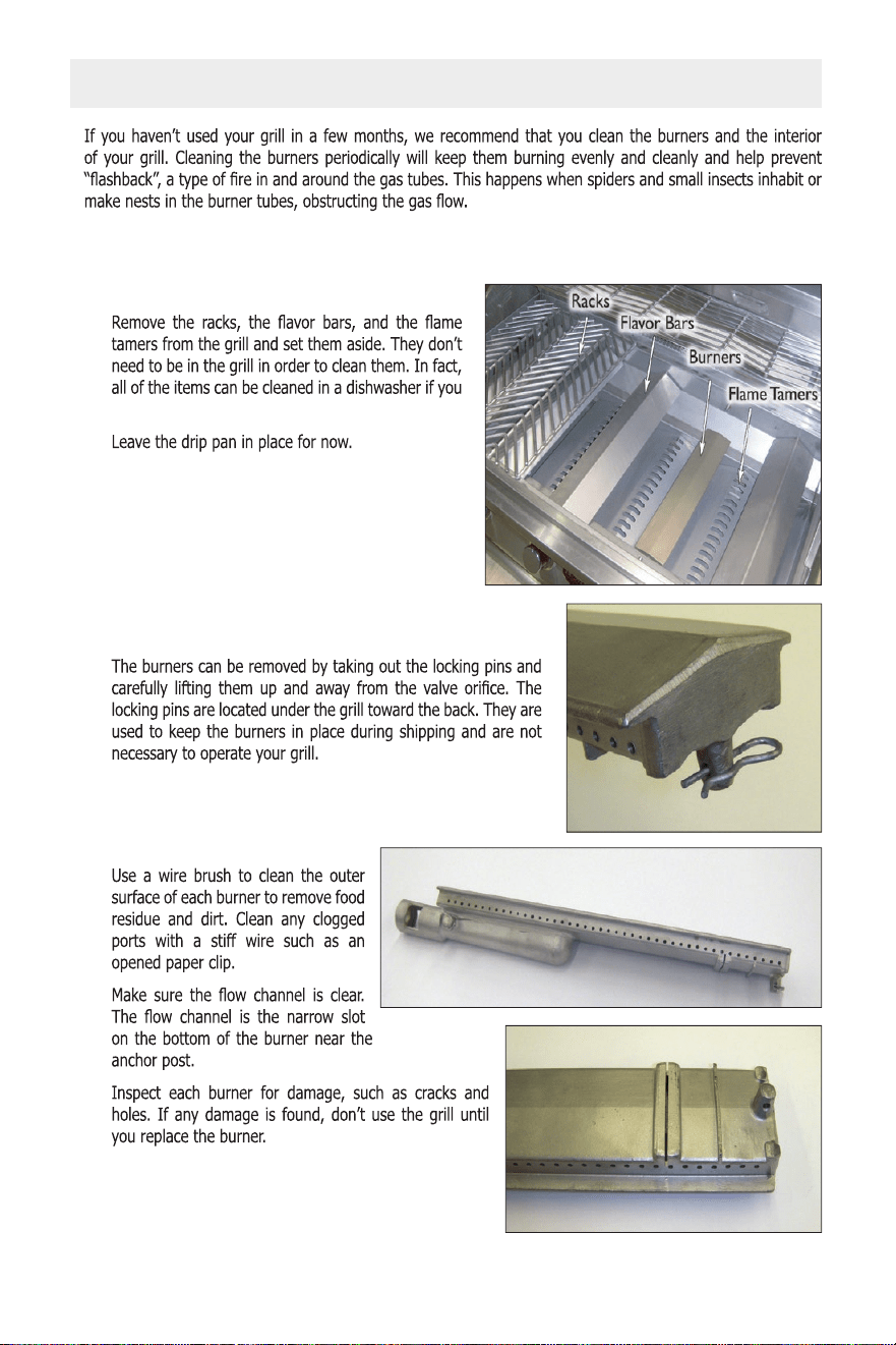
29
Convection Grills
LTR50001038, Rev. P-1
Cleaning and Maintenance
www
28
IMPORTANT: Before removing the burners, turn OFF all of the gas control knobs, shut off the fuel
supply, and disconnect the fuel line.
1. Remove the components
wish.
2. Remove the burners
3. Clean the burners
Seasonal Cleaning
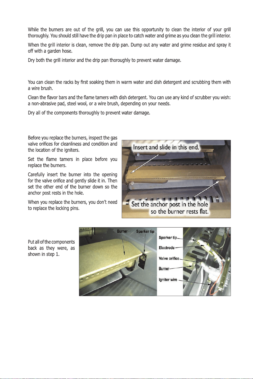
30
Convection Grills
LTR50001038, Rev. P-1
Cleaning and Maintenance
www
29
7. Replace the
components
4. Clean the grill interior
5. Clean the components
6. Replace the burners
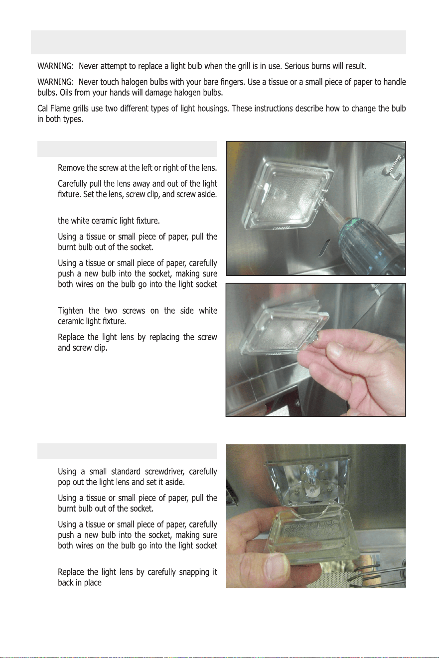
31
Convection Grills
LTR50001038, Rev. P-1
Cleaning and Maintenance
www
30
1.
2.
3. Unscrew the two screws located at the side of
4.
5.
evenly.
6.
7.
Light Lens with Screw Clip
Snap-in Light Lens
Light Bulb Replacement
1.
2.
3.
evenly.
4.
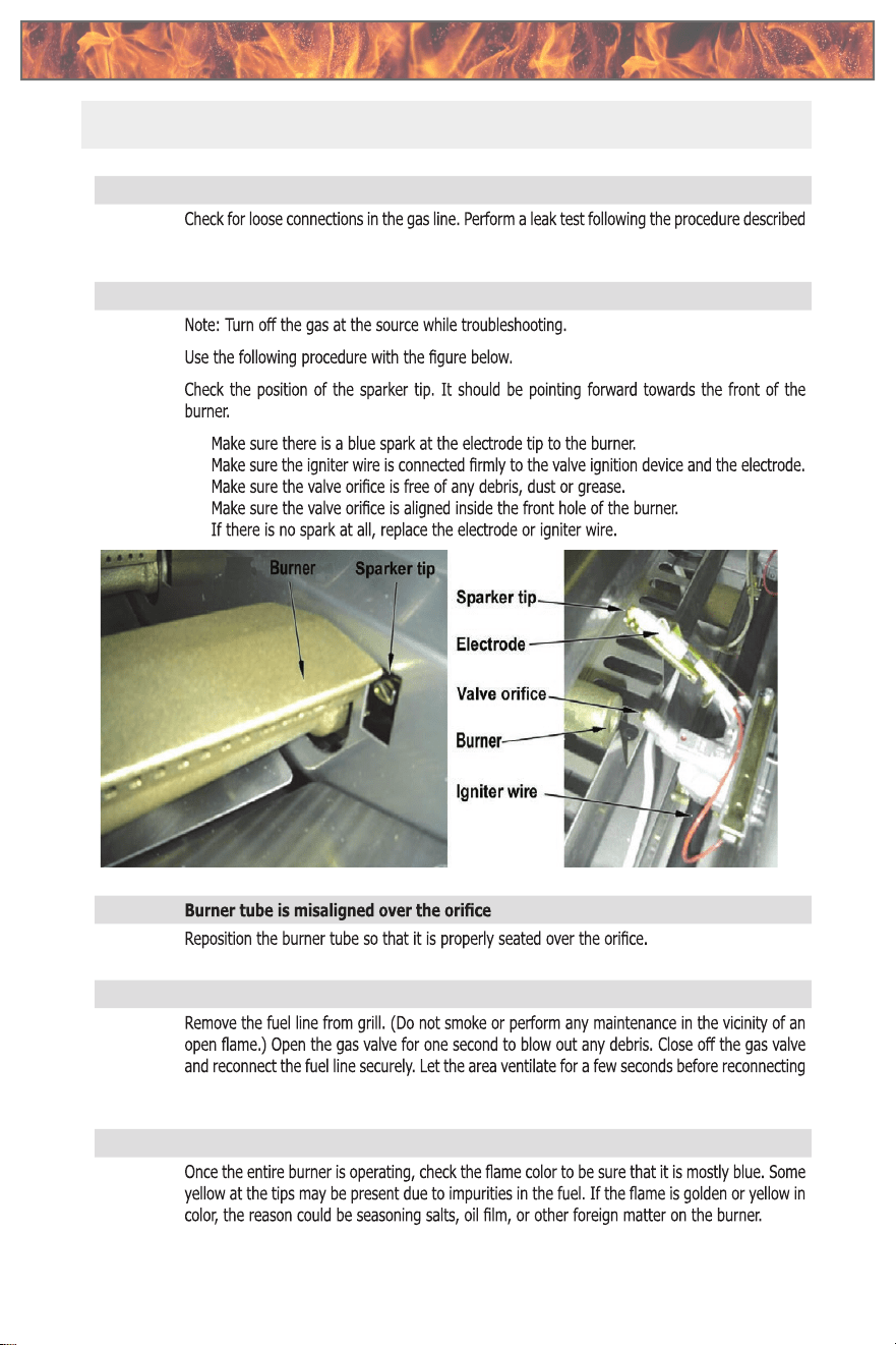
32
Convection Grills
LTR50001038, Rev. P-1
Appendix
www
31
Problem: Smell of gas is present
Solution:
in this manual.
Problem: Burner does not ignite
Solution:
•
•
•
•
•
Problem:
Solution:
Problem: Obstruction in the gas line
Solution:
the fuel line.
Problem: Yellow Flame
Solution:
Appendix
Troubleshooting
Troubleshooting Troubleshooting
33
Convection Grills
LTR50001038, Rev. P-1
Appendix
www
32
Problem:
Solution:
•
•
•
•
•
•
•
assistance.
Problem: Misalignment of Igniter on Burner
Solution: •
•
•
•
Problem: Flashback
Solution:
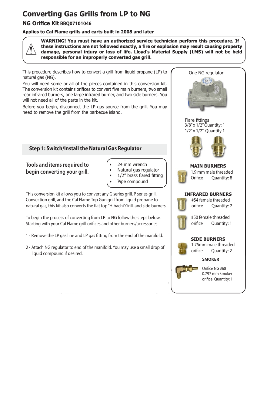
34
35
2
Page 1
Cal Flame Customer Service
1-800-225-7727
www.calamebbq.com
LTR07101045, Rev. D 7/9/15
This applies to the following grill
models:
BBQ08874CP
BBQ08875CP
The grills listed above are shipped with a NG regulator attached to the
manifold behind the grill. If you have Cal Flame G series, P series, or Top
Gun grill, this step does not apply to you. Go to Step 1b. The tting and
ex tubing you will attach the regulator to is located beneath the grill in
the accessory cabinet.
The manifold in the image below has been removed from a grill to
illustrate this procedure.
a. Remove the LP gas line.
b. Remove the cap tting from the end of the NG gas regulator.
c. Place the cap tting over the LP gas inlet.
d. Insert a 3/4” x 3/4” male ared tting in the NG gas regulator. Use
pipe compound or Teon tape.
Converting Gas Grills from LP to NG
NG Orice Kit BBQ07101045
Applies to Cal Flame grills and carts built in 2008 and later
WARNING! You must have an authorized service technician perform this procedure. If
these instructions are not followed exactly, a re or explosion may result causing property
damage, personal injury or loss of life. Lloyd’s Material Supply (LMS) will not be held
responsible for an improperly converted gas grill.
One NG regulator
Flare ttings:
3/8” x 3/4” Quantity: 1
3/4” x 3/4” Quantity: 1
#52 female threaded
Quantity: 2
#52 male threaded
Quantity: 2
1.9 mm male threaded
Quantity: 5
1.75 mm male threaded
Quantity: 2
This procedure describes how to convert a grill from liquid propane (LP) to
natural gas (NG).
You will need some or all of the pieces contained in this conversion kit.
The conversion kit contains orices to convert ve main burners, two small
rear infrared burners, one large infrared burner, and two side burners. You
will not need all of the parts in the kit.
Before you begin, disconnect the LP gas source from the grill. You may
need to remove the grill from the barbecue island.
You will need:
• 24 mm wrench
• 1/2” brass ared tting
• Pipe compound
Step 1a: Switch the regulator behind the grill
Note: Orice size is marked on the
top or side of the piece.
MAIN BURNERS
INFRARED BURNERS
SIDE BURNERS
3/8’’ x 1/2’’ Quantity: 1
1/2’’ x 1/2’’ Quantity 1
1.9 mm male threaded
Orice Quantity: 8
#54 female threaded
orice Quantity: 2
#50 female threaded
orice Quantity: 1
1.75mm male threaded
orice Quantity: 2
Page 2
Cal Flame Customer Service
1-800-225-7727
www.calamebbq.com
LTR07101045, Rev. D 7/9/15
This applies to the following grill models:
BBQ09G03 G series 3 burner grill
BBQ08G04 G series 4 burner grill
BBQ09G05 G series 5 burner grill
BBQ13P04 P series 4 burner grill
BBQ13P05 P series 5 burner grill
BBQ11875CTG Top Gun barbecue grill
The grills listed above are shipped without a regulator attached to the manifold behind the grill. You will need
to attach it.
a. Remove the grates, ame tamers, and drip tray
from the grill. See gure below.
Step 1b: Attach the regulator behind the grill
Step 2. Replace the main burner orices
You will need:
• 24 mm wrench
• Natural gas regulator
• 1/2” brass ared tting
• Pipe compound
You will need:
• 6 mm socket or nut driver
• Three to ve 1.9 mm orices (depending on
your grill
• Pipe compound suitable for natural gas
W
ID
T
H
W
ID
T
H
W
ID
T
H
W
ID
T
H
Minimum
Clearance
12” Minimum Distance
Between Grill and Side Burner
Minimum
Clearance
Screen Vents
W
ID
T
H
W
ID
T
H
WIDTH
DEPTH
WIDTH
WIDTH
DEPTH
WIDTH
WIDTH
WIDTH
DEPTH
DEPTH
DEPTH
HEIGHT
HEIGHT
HEIGHT
Burner
Locking Pin
Burner
Locking Pin
b. Remove the locking pins from the end of the
burners.
The locking pins are accessible by removing the
drip tray and tilting the grill back. They can be
seen underneath the grill in the back. See gures
at right.
c. Remove all burners by carefully lifting them up
and away from the valve orice.
1. Remove the LP gas line and LP gas tting from end of manifold.
2. Attach NG regulator to end of manifold.
Tools and items required to
begin converting your grill.
Page 2
Cal Flame Customer Service
1-800-225-7727
www.calamebbq.com
LTR07101045, Rev. D 7/9/15
This applies to the following grill models:
BBQ09G03 G series 3 burner grill
BBQ08G04 G series 4 burner grill
BBQ09G05 G series 5 burner grill
BBQ13P04 P series 4 burner grill
BBQ13P05 P series 5 burner grill
BBQ11875CTG Top Gun barbecue grill
The grills listed above are shipped without a regulator attached to the manifold behind the grill. You will need
to attach it.
a. Remove the grates, ame tamers, and drip tray
from the grill. See gure below.
Step 1b: Attach the regulator behind the grill
Step 2. Replace the main burner orices
You will need:
• 24 mm wrench
• Natural gas regulator
• 1/2” brass ared tting
• Pipe compound
You will need:
• 6 mm socket or nut driver
• Three to ve 1.9 mm orices (depending on
your grill
• Pipe compound suitable for natural gas
W
ID
T
H
W
ID
T
H
W
ID
T
H
W
ID
T
H
Minimum
Clearance
12” Minimum Distance
Between Grill and Side Burner
Minimum
Clearance
Screen Vents
W
ID
T
H
W
ID
T
H
WIDTH
DEPTH
WIDTH
WIDTH
DEPTH
WIDTH
WIDTH
WIDTH
DEPTH
DEPTH
DEPTH
HEIGHT
HEIGHT
HEIGHT
Burner
Locking Pin
Burner
Locking Pin
b. Remove the locking pins from the end of the
burners.
The locking pins are accessible by removing the
drip tray and tilting the grill back. They can be
seen underneath the grill in the back. See gures
at right.
c. Remove all burners by carefully lifting them up
and away from the valve orice.
1. Remove the LP gas line and LP gas tting from end of manifold.
2. Attach NG regulator to end of manifold.
This conversion kit allows you to convert any G series grill, P series grill,
Convection grill, and the Cal Flame Top Gun grill from liquid propane to
natural gas, this kit also converts the at top “Hibachi”Grill, and side burners.
To begin the process of converting from LP to NG follow the steps below.
Starting with your Cal Flame grill orices and other burners/accessories.
1 - Remove the LP gas line and LP gas tting from the end of the manifold.
2 - Attach NG regulator to end of the manifold. You may use a small drop of
liquid compound if desired.
Note: When converting more than one Cal Flame product on the same
BBQ island or xture, page 8 may be used as reference to direct NG ow
to both appliances.
(example) for a 5 burner grill with a side burner
SMOKER
Orice NG #68
0.797 mm Smoker
orice Quantity: 1
BBQ07101046
Step 1: Switch/Install the Natural Gas Regulator
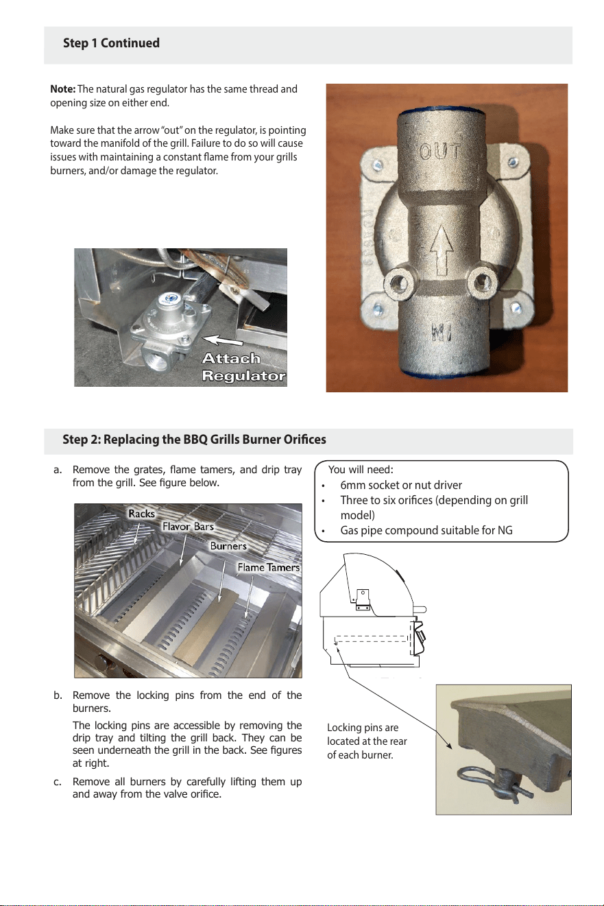
35
36
3
Page 2
Cal Flame Customer Service
1-800-225-7727
www.calamebbq.com
LTR07101045, Rev. D 7/9/15
This applies to the following grill models:
BBQ09G03 G series 3 burner grill
BBQ08G04 G series 4 burner grill
BBQ09G05 G series 5 burner grill
BBQ13P04 P series 4 burner grill
BBQ13P05 P series 5 burner grill
BBQ11875CTG Top Gun barbecue grill
The grills listed above are shipped without a regulator attached to the manifold behind the grill. You will need
to attach it.
a. Remove the grates, ame tamers, and drip tray
from the grill. See gure below.
Step 1b: Attach the regulator behind the grill
Step 2. Replace the main burner orices
You will need:
• 24 mm wrench
• Natural gas regulator
• 1/2” brass ared tting
• Pipe compound
You will need:
• 6 mm socket or nut driver
• Three to ve 1.9 mm orices (depending on
your grill
• Pipe compound suitable for natural gas
W
ID
T
H
W
ID
T
H
W
ID
T
H
W
ID
T
H
Minimum
Clearance
12” Minimum Distance
Between Grill and Side Burner
Minimum
Clearance
Screen Vents
WIDTH
W
ID
T
H
WIDTH
DEPTH
WIDTH
WIDTH
DEPTH
WIDTH
WIDTH
WIDTH
DEPTH
DEPTH
DEPTH
HEIGHT
HEIGHT
HEIGHT
Burner
Locking Pin
Burner
Locking Pin
b. Remove the locking pins from the end of the
burners.
The locking pins are accessible by removing the
drip tray and tilting the grill back. They can be
seen underneath the grill in the back. See gures
at right.
c. Remove all burners by carefully lifting them up
and away from the valve orice.
1. Remove the LP gas line and LP gas tting from end of manifold.
2. Attach NG regulator to end of manifold.
Note: The natural gas regulator has the same thread and
opening size on either end.
Make sure that the arrow “out” on the regulator, is pointing
toward the manifold of the grill. Failure to do so will cause
issues with maintaining a constant ame from your grills
burners, and/or damage the regulator.
Page 2
Cal Flame Customer Service
1-800-225-7727
www.calamebbq.com
LTR07101045, Rev. D 7/9/15
This applies to the following grill models:
BBQ09G03 G series 3 burner grill
BBQ08G04 G series 4 burner grill
BBQ09G05 G series 5 burner grill
BBQ13P04 P series 4 burner grill
BBQ13P05 P series 5 burner grill
BBQ11875CTG Top Gun barbecue grill
The grills listed above are shipped without a regulator attached to the manifold behind the grill. You will need
to attach it.
a. Remove the grates, ame tamers, and drip tray
from the grill. See gure below.
Step 1b: Attach the regulator behind the grill
Step 2. Replace the main burner orices
You will need:
• 24 mm wrench
• Natural gas regulator
• 1/2” brass ared tting
• Pipe compound
You will need:
• 6 mm socket or nut driver
• Three to ve 1.9 mm orices (depending on
your grill
• Pipe compound suitable for natural gas
W
ID
T
H
W
ID
T
H
W
ID
T
H
W
ID
T
H
Minimum
Clearance
12” Minimum Distance
Between Grill and Side Burner
Minimum
Clearance
Screen Vents
W
ID
T
H
W
ID
T
H
WIDTH
DEPTH
WIDTH
WIDTH
DEPTH
WIDTH
WIDTH
WIDTH
DEPTH
DEPTH
DEPTH
HEIGHT
HEIGHT
HEIGHT
Burner
Locking Pin
Burner
Locking Pin
b. Remove the locking pins from the end of the
burners.
The locking pins are accessible by removing the
drip tray and tilting the grill back. They can be
seen underneath the grill in the back. See gures
at right.
c. Remove all burners by carefully lifting them up
and away from the valve orice.
1. Remove the LP gas line and LP gas tting from end of manifold.
2. Attach NG regulator to end of manifold.
Step 1 Continued
• 6mm socket or nut driver
• Three to six orices (depending on grill
model)
• Gas pipe compound suitable for NG
Page 2
Cal Flame Customer Service
1-800-225-7727
www.calamebbq.com
LTR07101045, Rev. D 7/9/15
This applies to the following grill models:
BBQ09G03 G series 3 burner grill
BBQ08G04 G series 4 burner grill
BBQ09G05 G series 5 burner grill
BBQ13P04 P series 4 burner grill
BBQ13P05 P series 5 burner grill
BBQ11875CTG Top Gun barbecue grill
The grills listed above are shipped without a regulator attached to the manifold behind the grill. You will need
to attach it.
a. Remove the grates, ame tamers, and drip tray
from the grill. See gure below.
Step 1b: Attach the regulator behind the grill
Step 2. Replace the main burner orices
You will need:
• 24 mm wrench
• Natural gas regulator
• 1/2” brass ared tting
• Pipe compound
You will need:
• 6 mm socket or nut driver
• Three to ve 1.9 mm orices (depending on
your grill
• Pipe compound suitable for natural gas
W
ID
T
H
W
ID
T
H
W
ID
T
H
W
ID
T
H
Minimum
Clearance
12” Minimum Distance
Between Grill and Side Burner
Minimum
Clearance
Screen Vents
W
ID
T
H
W
ID
T
H
WIDTH
DEPTH
WIDTH
WIDTH
DEPTH
WIDTH
WIDTH
WIDTH
DEPTH
DEPTH
DEPTH
HEIGHT
HEIGHT
HEIGHT
Burner
Locking Pin
Burner
Locking Pin
b. Remove the locking pins from the end of the
burners.
The locking pins are accessible by removing the
drip tray and tilting the grill back. They can be
seen underneath the grill in the back. See gures
at right.
c. Remove all burners by carefully lifting them up
and away from the valve orice.
1. Remove the LP gas line and LP gas tting from end of manifold.
2. Attach NG regulator to end of manifold.
Locking pins are
located at the rear
of each burner.
Step 2: Replacing the BBQ Grills Burner Orices
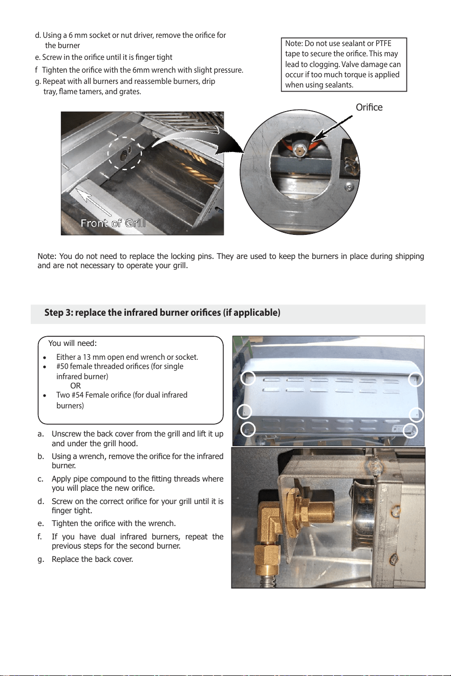
36
37
4
Page 3
Cal Flame Customer Service
1-800-225-7727
www.calamebbq.com
LTR07101045, Rev. D 7/9/15
Step 3: Replace the infrared burner orices (if required)
Orice
d. Using a 6 mm socket or nut driver, remove the
orice for the burner.
e. Apply a small amount of pipe compound to the
orice threads.
f. Screw in the orice until it is nger tight.
g. Tighten the orice with the 6 mm wrench.
h. Repeat the above steps for the remaining burners.
i. Replace the burners, ame tamers, drip tray, and
grates.
You will need:
• Either a 13 mm or 10 mm open end wrench
• #52 female threaded orices (for single
infrared burner)
OR
• #52 male threaded orices (for dual infrared
burners)
• Pipe compound suitable for natural gas
a. Unscrew the back cover from the grill and lift it up
and under the grill hood.
b. Using a wrench, remove the orice for the infrared
burner.
c. Apply pipe compound to the tting threads where
you will place the new orice.
d. Screw on the correct orice for your grill until it is
nger tight.
e. Tighten the orice with the wrench.
f. If you have dual infrared burners, repeat the
previous steps for the second burner.
g. Replace the back cover.
Note: You do not need to replace the locking pins. They are used to keep the burners in place during shipping
and are not necessary to operate your grill.
d. Using a 6 mm socket or nut driver, remove the orice for
the burner
e. Screw in the orice until it is nger tight
f Tighten the orice with the 6mm wrench with slight pressure.
g. Repeat with all burners and reassemble burners, drip
tray, ame tamers, and grates.
#50 female threaded orices (for single
infrared burner)
Either a 13 mm open end wrench or socket.
Two #54 Female orice (for dual infrared
burners)
Note: Do not use sealant or PTFE
tape to secure the orice. This may
lead to clogging. Valve damage can
occur if too much torque is applied
when using sealants.
Step 3: replace the infrared burner orices (if applicable)
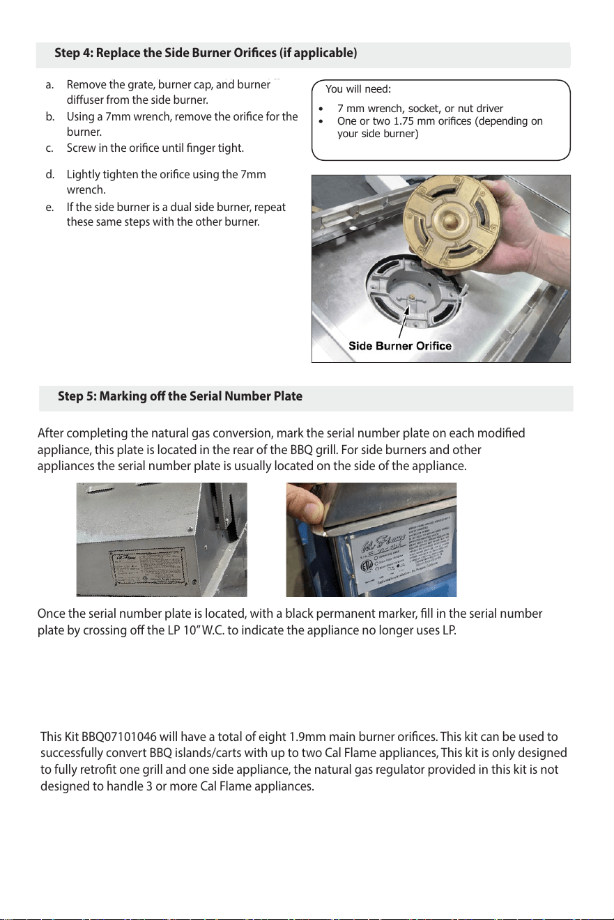
37
38
5
Page 4
Cal Flame Customer Service
1-800-225-7727
www.calamebbq.com
LTR07101045, Rev. D 7/9/15
You will need:
• 7 mm wrench, socket, or nut driver
• One or two 1.75 mm orices (depending on
your side burner)
• Pipe compound suitable for natural gas
a. Remove the grate, burner cap and burner diffuser
from the side burner.
b. Using a 7 mm wrench, remove the orice for the
burner.
c. Apply a small amount of pipe compound to the
orice threads.
d. Screw in the orice until it is nger tight.
e. Tighten the orice with the 7 mm wrench.
f. If you have dual side burners, repeat the previous
steps for the second burner.
Step 4: Replace the side burner orices (if required)
Step 5: Mark the rating plate
After conversion has been completed, mark
the rating plate as NG with an indelible
marker.
Draw a line through the selection “LP 18
WC” and ll in the circle next to “NG 4 WC”.
After completing the natural gas conversion, mark the serial number plate on each modied
appliance, this plate is located in the rear of the BBQ grill. For side burners and other
appliances the serial number plate is usually located on the side of the appliance.
Once the serial number plate is located, with a black permanent marker, ll in the serial number
plate by crossing o the LP 10” W.C. to indicate the appliance no longer uses LP.
Connecting Two Cal Flame Appliances
If both a Cal Flame side burner and a Cal Flame grill are being converted, you may refer to page 8 as
a guide to create a tee connection to supply natural gas for both appliances.
This Kit BBQ07101046 will have a total of eight 1.9mm main burner orices. This kit can be used to
successfully convert BBQ islands/carts with up to two Cal Flame appliances, This kit is only designed
to fully retrot one grill and one side appliance, the natural gas regulator provided in this kit is not
designed to handle 3 or more Cal Flame appliances.
Step 4: Replace the Side Burner Orices (if applicable)
a.
b.
c.
d.
e.
Remove the grate, burner cap, and burner
diuser from the side burner.
Using a 7mm wrench, remove the orice for the
burner.
Screw in the orice until nger tight.
Lightly tighten the orice using the 7mm
wrench.
If the side burner is a dual side burner, repeat
these same steps with the other burner.
Step 5: Marking o the Serial Number Plate
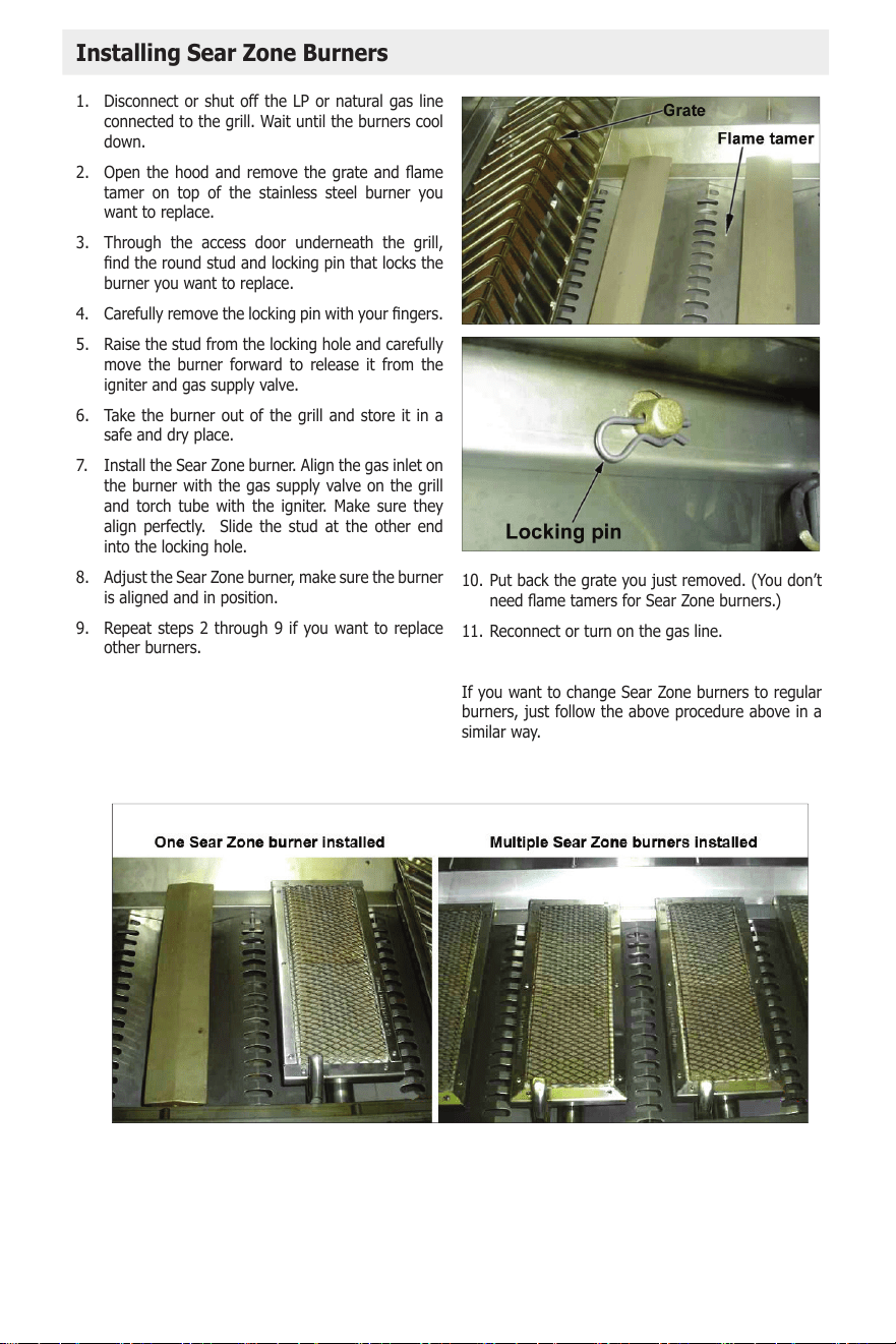
38
39
P4, P5, and P6 Barbecue Grills
LTR50001137, Rev. R
Appendix
www.calamebbq.com
34
1. Disconnect or shut off the LP or natural gas line
connected to the grill. Wait until the burners cool
down.
2. Open the hood and remove the grate and ame
tamer on top of the stainless steel burner you
want to replace.
3. Through the access door underneath the grill,
nd the round stud and locking pin that locks the
burner you want to replace.
4. Carefully remove the locking pin with your ngers.
5. Raise the stud from the locking hole and carefully
move the burner forward to release it from the
igniter and gas supply valve.
6. Take the burner out of the grill and store it in a
safe and dry place.
7. Install the Sear Zone burner. Align the gas inlet on
the burner with the gas supply valve on the grill
and torch tube with the igniter. Make sure they
align perfectly. Slide the stud at the other end
into the locking hole.
8. Adjust the Sear Zone burner, make sure the burner
is aligned and in position.
9. Repeat steps 2 through 9 if you want to replace
other burners.
10. Put back the grate you just removed. (You don’t
need ame tamers for Sear Zone burners.)
11. Reconnect or turn on the gas line.
If you want to change Sear Zone burners to regular
burners, just follow the above procedure above in a
similar way.
Installing Sear Zone Burners
39
Item # Part Grill Size Part #
1 Control Panel 4 burner BBQ07104050-CC
2 Control Panel 5 Burner BBQ10104045-CC
3 Grill Hood 4 Burner BBQ07100588-CC
4 Grill Hood 5 Burner BBQ07100589-CC
5 Drip tray 4 burner BBQ09100687
6 Drip tray 5 Burner BBQ09100688-CC
7 Infrared Burner 4 Burner BBQ07300440
8 Infrared Burner 5 Burner BBQ07300430
9 Light Housing All Models BBQ10103070-CC
10 Light Lens All Models BBQ10103068
11 Thermometer All Models BBQ07410351
12 Flavor Bar All Models BBQ04103000
13 2’’ Knobs All Models BBQ04101029
14 Grates All Models BBQ04100659
15 Handle 4 Burner BBQ07100639
16 Handle 5 Burner BBQ07100641-CC
17 Gas Manifold 4 Burner BBQ08000442
18 Gas Burner 5 Burner BBQ08000443
19 Warming Rack 4 Burner BBQ08100657-CC
20 Warming Rack 5 Burner BBQ08100658-CC
21 Rotisserie Bracket All Models BBQ04100783-CC
22 Flame Tamer All Models BBQ04103010
23 Burner All Models BBQ07100661
24 Spit Rod Assembly 4 Burner BBQ08856P4
25 Spit Rod Assembly 5 Burner BBQ08856P5
26 Convection Fan All Convection Grills BBQ08000420
27 Rotisserie Motor All Convection Grills BBQ07100781
28 Back Burner Igniter All Grills With Infrared BBQ04101809
29 Cal Flame Logo All Models BBQ04100972

40
Item # Part Grill Size Part #
30 Main Burner Valve (LP) All Models BBQ04101016
31 Main Burner Valve (NG) All Models BBQ04101015
32 Back Burner Valve (LP) All Models BBQ04101014
33 Back Burner Valve (NG) All Models BBQ04101013

41
42
This limited warranty is extended to the original purchaser of a Cal Flame P series (P4, P5, P6) grill manufac-
tured after January 1, 2025 and installed for residential use in the Unites States and Canada with proof of
purchase.
Direct any warranty issue with your grill via email to customerservice@calamebbq.com or phone us
1-800-225-7727
Cal Flame grill structure or frame housing is warranted against rust-through, due to defects
in material or workmanship in normal household use for ten years from the original date of
purchase
P4, P5, and P6 Barbecue Grills
LTR50001137, Rev. R
Appendix
www.calamebbq.com
40
Limited Warranty
This Limited Warranty is extended to the original purchaser of a Cal Flame P4, P5, or P6 grill manufactured after
January 1, 2021 and installed for residential use in the United States and Canada.
Direct any warranty issue with your grill via email to customerservice@calamebbq.com or phone
(800) 225-7727.
L
I
M
I
T
E
D
W
A
R
R
A
N
T
Y
YEAR
S
T
R
U
C
T
U
R
A
L
L
I
M
I
T
E
D
W
A
R
R
A
N
A
N
T
Y
Y
Y
Y
A
A
A
N
Y
10 Year Structure
Cal Flame grill structure or frame housing is warranted against rust-through, due to defects
in material or workmanship in normal household use for ten years from the original date of
purchase.
L
I
M
I
T
E
D
W
A
R
R
A
N
T
Y
YEAR
L
I
M
I
T
E
D
W
A
R
R
A
N
A
N
T
Y
Y
Y
Y
A
A
A
N
Y
S
T
A
I
N
L
E
S
S
S
T
E
E
L
B
U
R
N
E
R
S
10 Year Stainless Steel Burners
Cal Flame Stainless Steel Burners are warranted against rust-through and operation failure, due
to defects in material or workmanship in normal household use for ten years from the original
date of purchase.
L
I
M
I
T
E
D
W
A
R
R
A
N
T
Y
YEAR
L
I
M
I
T
E
D
W
A
R
R
A
N
A
N
T
Y
Y
Y
Y
A
A
A
N
Y
V
G
R
A
T
E
S
10 Year V-Grates
Cal Flame V-Grates are warranted against rust-through and operation failure, due to defects
in material or workmanship in normal household use for ten years from the original date of
purchase.
L
I
M
I
T
E
D
W
A
R
R
A
N
T
Y
YEAR
L
I
M
I
T
E
D
W
W
A
A
R
R
A
Y
T
Y
R
A
N
T
Y
Y
Y
T
T
T
Y
Y
Y
N
N
T
T
T
W
W
W
A
A
Y
R
R
A
T
Y
Y
T
T
F
L
A
M
E
T
A
M
E
R
S
3 Year Flame Tamers and Warming Rack
Cal Flame tamers and warming rack are warranted against rust-through and operation failure,
due to defects in material or workmanship in normal household use for three years from the
original date of purchase.
L
I
M
I
T
E
D
W
A
R
R
A
N
T
Y
YEAR
L
I
M
I
T
E
D
T
Y
D
W
W
T
W
A
R
N
T
A
N
R
R
R
R
R
A
A
T
T
T
Y
Y
T
T
T
N
N
N
T
T
R
R
A
A
A
N
N
N
R
R
R
R
R
A
A
A
Y
W
D
D
W
T
T
T
T
N
N
N
T
T
N
N
N
W
W
R
R
R
R
A
A
A
A
A
A
R
R
G
A
S
V
A
L
V
E
S
&
O
T
H
E
R
C
O
M
P
O
N
E
N
T
S
1 Year Gas Valves and Other Components
Cal Flame gas valves and other components detailed in the Cal Flame grill owners manual,
specically on the Cal Flame parts list page, are warranted against operation failure due to
defects in material or workmanship in normal household use for one year from the original date
of purchase.
This Limited Warranty is void if Cal Flame (the
“Manufacturer”) or its designated representative
determines that the grill has been subjected to
damage or failure due to installation of aftermarket
parts that are not genuine Cal Flame branded parts
and accessories. This disclaimer includes, but is not
limited to gas valves, gas nozzles, infrared burners,
lights and transformers. Genuine Cal Flame brand
parts and accessories are built to our highest standards
of quality, durability and performance, and they are
designed to work with your grill to ensure optimal
performance and function.
Performance
In the event of a defect covered by this Limited
Warranty, notify Cal Flame as soon as possible and use
all reasonable means to protect the grill from further
damage. Upon a receipt of a valid form of proof of
purchase, a designated service representative will
correct the defect, subject to the terms and conditions
contained in this Limited Warranty. There will be no
charge for parts, although providing access to affect
the repair is your responsibility as the grill owner.
Freight charges for replacement parts, labor and labor
related trip charges necessary to repair the grill are
Cal Flame Stainless Steel Burners are warranted against rust-through and operation failure,
due to defects in material or workmanship in normal household use for ten years from the
original date of purchase.
Cal Flame V-Grates are warranted against rust-through and operation failure, due to
defects in material or workmanship in normal household use for ten years from the original
date of purchase.
P4, P5, and P6 Barbecue Grills
LTR50001137, Rev. R
Appendix
www.calamebbq.com
40
Limited Warranty
This Limited Warranty is extended to the original purchaser of a Cal Flame P4, P5, or P6 grill manufactured after
January 1, 2021 and installed for residential use in the United States and Canada.
Direct any warranty issue with your grill via email to customerservice@calamebbq.com or phone
(800) 225-7727.
L
I
M
I
T
E
D
W
A
R
R
A
N
T
Y
YEAR
S
T
R
U
C
T
U
R
A
L
L
I
M
I
T
E
D
W
A
R
R
A
N
A
N
T
Y
Y
Y
Y
A
A
A
N
Y
10 Year Structure
Cal Flame grill structure or frame housing is warranted against rust-through, due to defects
in material or workmanship in normal household use for ten years from the original date of
purchase.
L
I
M
I
T
E
D
W
A
R
R
A
N
T
Y
YEAR
L
I
M
I
T
E
D
W
A
R
R
A
N
A
N
T
Y
Y
Y
Y
A
A
A
N
Y
S
T
A
I
N
L
E
S
S
S
T
E
E
L
B
U
R
N
E
R
S
10 Year Stainless Steel Burners
Cal Flame Stainless Steel Burners are warranted against rust-through and operation failure, due
to defects in material or workmanship in normal household use for ten years from the original
date of purchase.
L
I
M
I
T
E
D
W
A
R
R
A
N
T
Y
YEAR
L
I
M
I
T
E
D
W
A
R
R
A
N
A
N
T
Y
Y
Y
Y
A
A
A
N
Y
V
G
R
A
T
E
S
10 Year V-Grates
Cal Flame V-Grates are warranted against rust-through and operation failure, due to defects
in material or workmanship in normal household use for ten years from the original date of
purchase.
L
I
M
I
T
E
D
W
A
R
R
A
N
T
Y
YEAR
L
I
M
I
T
E
D
W
W
A
A
R
R
A
Y
T
Y
R
A
N
T
Y
Y
Y
T
T
T
Y
Y
Y
N
N
T
T
T
W
W
W
A
A
Y
R
R
A
T
Y
Y
T
T
F
L
A
M
E
T
A
M
E
R
S
3 Year Flame Tamers and Warming Rack
Cal Flame tamers and warming rack are warranted against rust-through and operation failure,
due to defects in material or workmanship in normal household use for three years from the
original date of purchase.
L
I
M
I
T
E
D
W
A
R
R
A
N
T
Y
YEAR
L
I
M
I
T
E
D
T
Y
D
W
W
T
W
A
R
N
T
A
N
R
R
R
R
R
A
A
T
T
T
Y
Y
T
T
T
N
N
N
T
T
R
R
A
A
A
N
N
N
R
R
R
R
R
A
A
A
Y
W
D
D
W
T
T
T
T
N
N
N
T
T
N
N
N
W
W
R
R
R
R
A
A
A
A
A
A
R
R
G
A
S
V
A
L
V
E
S
&
O
T
H
E
R
C
O
M
P
O
N
E
N
T
S
1 Year Gas Valves and Other Components
Cal Flame gas valves and other components detailed in the Cal Flame grill owners manual,
specically on the Cal Flame parts list page, are warranted against operation failure due to
defects in material or workmanship in normal household use for one year from the original date
of purchase.
This Limited Warranty is void if Cal Flame (the
“Manufacturer”) or its designated representative
determines that the grill has been subjected to
damage or failure due to installation of aftermarket
parts that are not genuine Cal Flame branded parts
and accessories. This disclaimer includes, but is not
limited to gas valves, gas nozzles, infrared burners,
lights and transformers. Genuine Cal Flame brand
parts and accessories are built to our highest standards
of quality, durability and performance, and they are
designed to work with your grill to ensure optimal
performance and function.
Performance
In the event of a defect covered by this Limited
Warranty, notify Cal Flame as soon as possible and use
all reasonable means to protect the grill from further
damage. Upon a receipt of a valid form of proof of
purchase, a designated service representative will
correct the defect, subject to the terms and conditions
contained in this Limited Warranty. There will be no
charge for parts, although providing access to affect
the repair is your responsibility as the grill owner.
Freight charges for replacement parts, labor and labor
related trip charges necessary to repair the grill are
Cal Flame tamers and warming rack are warranted against rust-though and operation
failure, due to defects in material or workmanship in normal household use for three years
from the original date of purchase
Cal Flame gas valves, convection fan, and other components detailed in the Cal Flame grill
owners manual, specically on the Cal Flame parts list, are warranted against operation
failure due to defects in material or workmanship in normal household use for one year
from the original date of purchase.
This Limited Warranty is void of Cal Flame (the
Manufacture) or its designated representative
determines that the grill has been subjected to
damage or failure due to installation of aftermarket
parts that are not genuine Cal Flame branded parts
and accessories. This disclaimer includes but is not
limited to gas valves, gas nozzles, infrared burners,
lights, and transformers. Genuine Cal Flame brand
parts and accessories are built to our highest stan-
dards of quality, durability, and performance, and
they are designed to work with your grill to ensure
optimal performance and function. Rust through is
dened as holes formed through the steel through
oxidation. Failure to treat the outer stainless steel
will result in rust spotting, which is not covered in
this limited warranty.
In the event of a defect covered by this Limited
Warranty, notify Cal Flame as soon as possible and
use all reasonable means to protect the grill from
further damage. Upon a receipt of a valid form of
proof of purchase, a designated service represen-
tative will correct the defect, subject to the terms
and conditions contained in the Limited Warranty.
There will be no charge for parts, it is the respon-
sibility of the grill owner to allow proper access to
conduct repair/service. Freight charges, labor fees,
diagnose fees and travel fees are not covered by
this warranty.
Performance

43
These fees are the responsibility of the grill owner. In
the event a replacement is oered, reasonable costs
for removal of the original grill, shipping costs from
the factory for the replacement grill, and delivery
and installation of the replacement will be the
responsibility of the grill owner. Any replacement
parts and or grill will carry the balance of the original
grill warranty. Grill covers are not included in this
warranty. This warranty ends either by specied time
frame listed above, owner transfer, relocation of the
grill, commercial installation, or installation of any
3rd party components.
This limited warranty is void if Cal Flame or its des-
ignated representative determines that the grill has
been subjected to alteration, neglect, misuse, abuse,
or freight damage caused by a common carrier; any
repairs or fuel conversions have been attempted by
anyone other than a designated representative or
experienced technician; or if the failure is caused by
accident, acts of God or other causes beyond the
control of the Manufacture. Neglect, misuse and
abuse include any installation, operation, or main-
tenance of the grill other than in accordance with
the instructions contained in the owner’s manual
provided with the grill. Corrosion, scratching and
discoloration due to improper use and care of this
outdoor product, is excluded from this warranty.
Units within the warranty time frame determined by
the Company to be non-repairable will be replaced
on a prorated bases with the same or a comparable
unit. The user will be charged one percent if the
current retail cost for each full month of ownership
from the date of purchase through the date failure is
determined to be non-repairable. This charge will be
waived during the rst twelve months of ownership.
[example]: Product failure is determined during sev-
en months of ownership. Owner will be responsible
to pay for 7% of the products current cost.
Warranty Limitations
Limitations
Disclaimers
The manufacture disclaims all warranties, ex-
pressed or implied, in fact or in law, to the extent
allowed by your State’s Law, including the warranty
of merchantability and tness for use, except as
stated specically herein. All warranty service must
be performed by the Manufacture or its designat-
ed representative using authorized Cal Flame parts.
No agent, dealer, distributor, service company,
or other party is authorized to change, modify or
extend the terms of this limited warranty in any
manner whatsoever. The Manufacture will not be
responsible for any statements or representations
made in any form that go beyond, are broader
than, or are inconsistent with any authorized litera-
ture or specications furnished by Cal Flame.
Prorated Warranty
The Manufacturer and its representatives shall not
be liable for any injury, loss, cost or other damage,
whether incidental or consequential, arising out
of any defect covered in this limited warranty. This
includes without limitation, loss of use of the grill
and cost for removal of defective product even if
the manufacturer was advised of the possibility of
damage. The liability of the Manufacturer under this
limited warranty if any shall not exceed the original
amount paid for the defective product. Coverage
under this limited warranty shall commence as of the
original date of purchase and the duration of such
coverage shall not extend for any reason whatsoever
beyond the stated time periods. These disclaimers
shall be equally applicable to any service provided by
the manufacturer and its designated representatives.
Legal Rights
This Limited Warranty gives you specic legal rights.
You may also have other rights that vary from state
to state. Some states do not allow limitations on how
long an implied warranty lasts, so this limitation may
not apply to you.

44
54
__________________________________________________
__________________________________________________
__________________________________________________
__________________________________________________
__________________________________________________
__________________________________________________
__________________________________________________
__________________________________________________
__________________________________________________
__________________________________________________
__________________________________________________
__________________________________________________
__________________________________________________
__________________________________________________
__________________________________________________
__________________________________________________
__________________________________________________
__________________________________________________
__________________________________________________
__________________________________________________
__________________________________________________
__________________________________________________
__________________________________________________
__________________________________________________
__________________________________________________
__________________________________________________
__________________________________________________
NOTES

45
54
__________________________________________________
__________________________________________________
__________________________________________________
__________________________________________________
__________________________________________________
__________________________________________________
__________________________________________________
__________________________________________________
__________________________________________________
__________________________________________________
__________________________________________________
__________________________________________________
__________________________________________________
__________________________________________________
__________________________________________________
__________________________________________________
__________________________________________________
__________________________________________________
__________________________________________________
__________________________________________________
__________________________________________________
__________________________________________________
__________________________________________________
__________________________________________________
__________________________________________________
__________________________________________________
__________________________________________________
NOTES

46

47
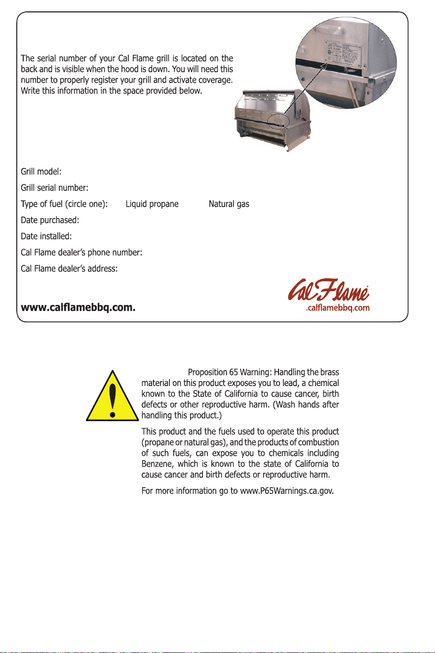
48
Locating the product serial number
___________________________________________________________________________
_____________________________________________________________________
_______________________________________________________________________
________________________________________________________________________
________________________________________________________
______________________________________________________________
Don’t forget to register your new product at
www
WARNING!
LTR50001038, REV. P-1
5/23/2023
LTR5000.1038
2024 REV A