
vintec.com
User Manual
VWS140FAB-X
VWS175FAB-X
VWD175FAB-X
VWD190FAB-L
VWD190FAB-R
Contents
WARNING
PRODUCT DESCRIPTION
TECHNICAL DATA
INSTALLATION
STORAGE
OPERATION AND FUNCTION
WINE SERVING & DEFROSTING
TROUBLESHOOTING
..........................................
3
..........................................
4
..........................................
6
...........................................
7
...........................................
17
..........................................
21
..........................................
23
..........................................
24
Important Information that may impact your Manufacturer's Warranty
Adherence to the directions for use in this manual is extremely important for health and safety. Failure to strictly adhere
to the requirements in this manual may result in personal injury,property damage and affect your ability to make a claim
under the Vintec manufacturer's warranty provided with your product. Products must be used, installed and operated in
accordance with this manual. You may not be able to claim on the Vintec manufacturer's warranty in the event that your
product fault is due to failure to adhere to this manual.

WARNING
The information
in this document is subject to
modification without any prior notice.
Some models are available in dedicated countries only.
VINTEC offers no guarantee for our wine cellar if it is
being
used for any purpose other than that for which it was
specifically designed.
VINTEC cannot be held responsible for any error in this
manual.
This appliance is not intended for storing food of any sort.
This appliance is not intended for use by persons (including
children) with reduced physical, sensory or mental capabilities,
or lack of experience and knowledge, unless they have been
given supervision or instruction concerning use of the appliance
by a person responsible for their safety.
Children should be supervised to ensure that they do not play
with the appliance.
This appliance uses flammable refrigerant. Please secure the
cooling pipe during the delivery process.
Position the wine cellar away from direct sunlight and sources of
heat (stove, heater, radiator, etc.). Never clean appliance parts
with flammable fluids. The fumes can create a fire hazard or
explosion. When disposing your appliance, please choose an
authorized disposal site.
R600A WARNINGS
The following models use small quantity of R600A
(isobutane) flammable refrigerant:
VWS140FAB-X:54g;
VWS175FAB-X:65g;
VWD175FAB-X:63g;
VWD190FAB-R/VWD190FAB-L: 65g
For your safety please observe the following
recommendations:
- This appliance contains a small quantity of
R600A
refrigerant which is flammable. Avoid safety
hazards by
carefully
installing,
handling, servicing and disposing of this
appliance.
- During transportation and installation, ensure that the
tubing of the refrigerant circuit is not damaged.
- Avoid using or manipulating sharp objects near the
appliances.
- Leaking refrigerant can ignite and may damage the eyes.
- In the event any damage does occur, avoid exposure to open
fires and any device which creates a spark.
Disconnect the appliance from the mains
power.
- Thoroughly ventilate the room in which the appliance is
located for several minutes.
- Notify Customer Service for necessary action and advice.
- The room for installing the appliance must be at least 1 cubic
metre per 8 grams of refrigerant. The refrigerant quantity
contained in this appliance is listed above in grams; it is also
noted on the Rating Plate of the appliance.
It is hazardous for anyone other than an authorized service
person to carry out servicing or repairs to this appliance.
- WARNING: Keep ventilation openings in the appliance
enclosure
or in the built-in structure clear of obstruction.
- WARNING: Do not use mechanical devices or other
means to accelerate the defrosting process, other
than those recommended by the manufacturer.
- WARNING: Do not damage the refrigerant circuit.
- WARNING: Do
not use electrical appliances
inside the
compartments.
- WARNING: Do not store explosive substances such as
aerosol cans with a flammable propellant in this
appliance.
- WARNING: This appliance is intended to be used in
household and similar applications such as:
* Staff kitchen areas in shops, offices and other
working environments;
* Farm houses and by clients
in hotels,
motels and
other residential type environments;
* Bed and breakfast type environments;
* Catering and similar
non-retail applications.
- WARNING: Do
not use electrical appliances
inside the
food storage compartments of the appliance, unless
they are the type recommended by the manufacturer.
- WARNING: If the power cord is damaged, it must be
replaced by the manufacturer, its service agent or
similarly qualified persons in order to avoid a hazard.
- WARNING: When positioning the appliance ensure the
supply cord is not trapped or damaged.
- WARNING: Do not locate multiple portable socket-
outlets or portable power supplies at the rear of the
appliance.
- WARNING: Your appliance is fitted with long life LED
lighting. In the unlikely event the LED lights should fail,
then the LED lights should be serviced by the
manufacturer, its service agent or similarly qualified
persons in order to avoid a hazard.
- WARNING: In Queensland, Australia, the authorized
person must hold a Gas Work Authorization for
hydrocarbon refrigerants, before carrying out servicing
or repairs which involve the removal of covers.
The environment and personal safety must be
considered when disposing of this appliance.
Please ensure the appliance is taken to a recycle centre
for safe recycling.
This appliance contains insulation formed with
flammable blowing gases and flammable refrigerant.
Avoid safety hazards by carefully disposing of this
appliance.
3
PRODUCT DESCRIPTION
Pr
oduct
Overview
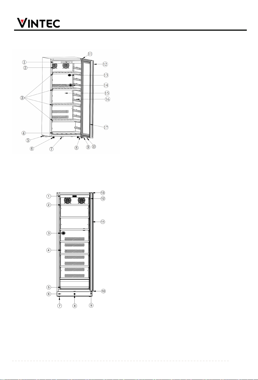
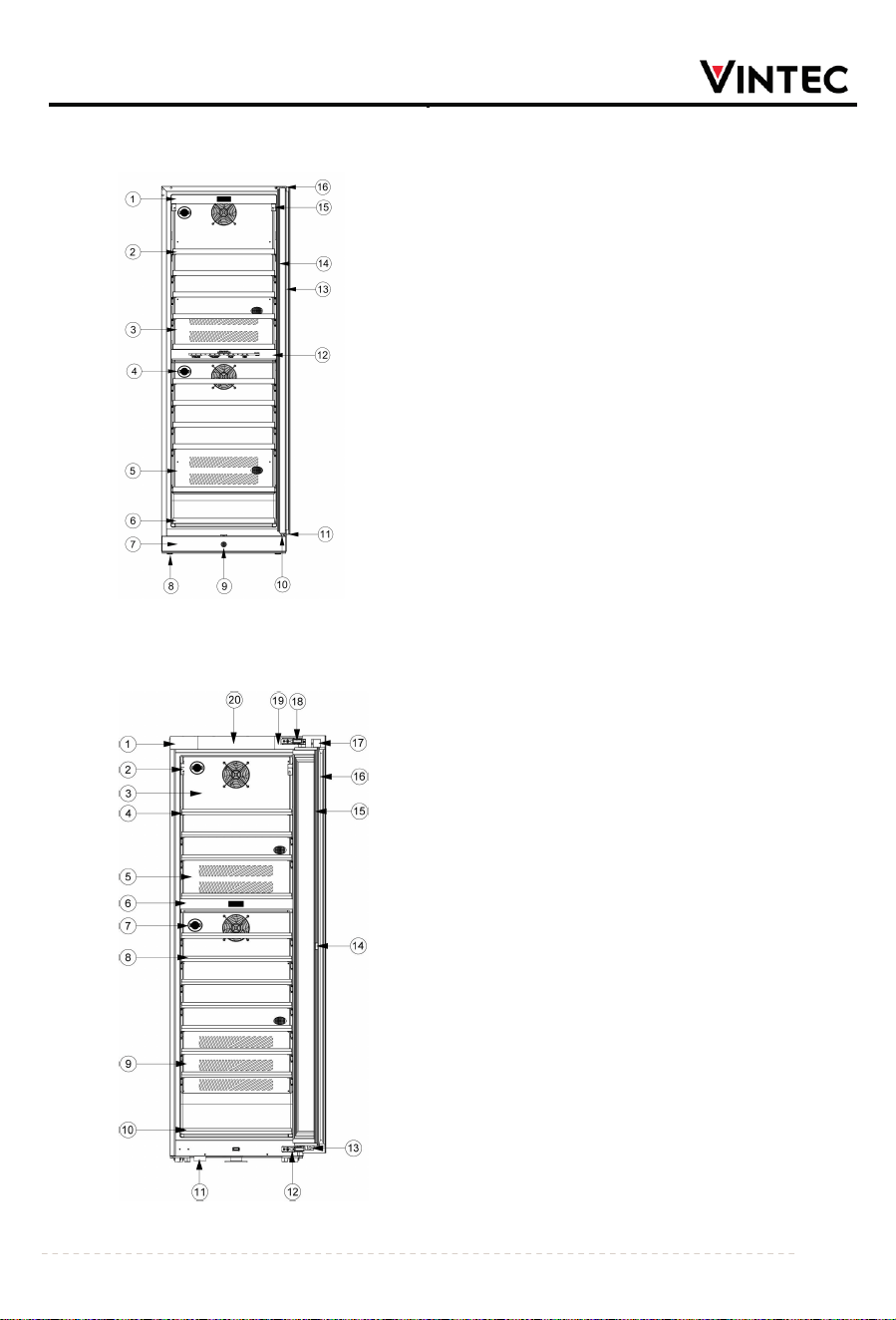
Model: VWS140FAB-X
①Temperature control box
② Inner fan and fan cover
③ Middle shelf
④ Bottom shelf
⑤ Compressor bottom plate
⑥ Feet
⑦ Hall components
⑧ Lower door hinge
⑨ Door stopper
⑩ Magnetic box
⑪ Right upper hinge
⑫ Glass door
⑬ Sensor assembly
⑭ Carbon filter
⑮ Air deflector
⑯ Shelf limit column
⑰ Door seal
Model
: VWS175FAB-X
① Temperature control box
② Wooden shelf
③ Carbon filter
④ Air deflector
⑤ Bottom shelf
⑥ Outlet grille
⑦ Feet
⑧ Lock
⑨ Right door stopper fixing plate
⑩ Lock plate
⑪ Glass door
⑫ Door seal
⑬ Right upper door hinge
4
PRODUCT DESCRIPTION
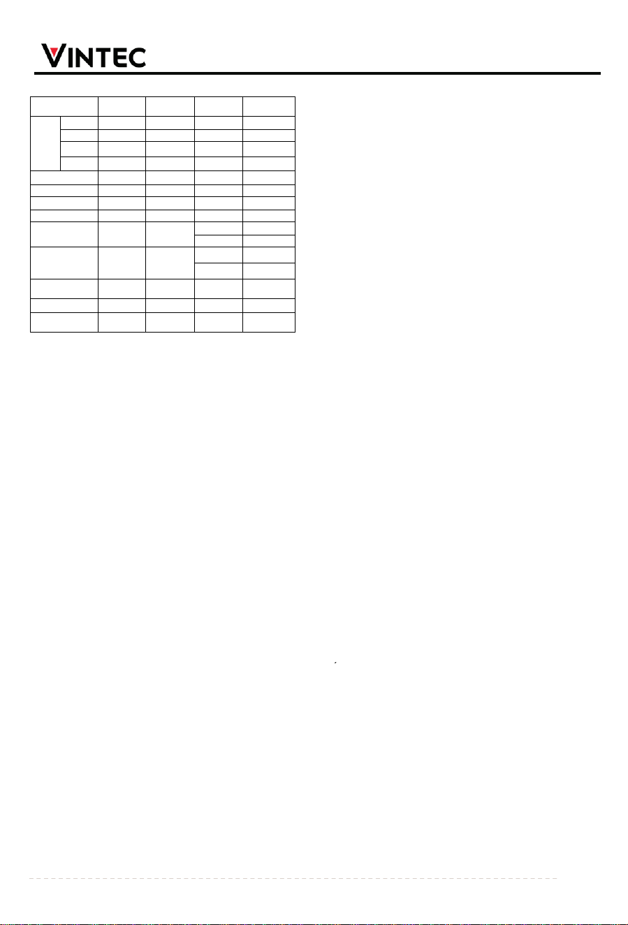
Model
: VWD175FAB
-X
① Temperature control box
② Wooden shelf
③ Upper air deflector
④ Carbon filter
⑤ Lower air deflector
⑥ Bottom shelf
⑦ Outlet grille
⑧ Feet
⑨ Lock
⑩ Right door stopper fixing plate
⑪ Lock plate
⑫ Middle
separator
⑬ Glass door
⑭ Door seal
⑮ Display shelf top support
⑯ Right upper door hinge
Model
:V
WD190FAB-R/VWD190FAB-L
⑤ Middle wooden shelf x 9
① Left upper door hinge cover
② Display shelf top support
③ The spare display shelf x 1 is for placing at the top position
④ Big wooden shelf x 2
⑥ Upper air deflector
⑦ Middle separator
⑧
Carbon filter
⑨
Lower air deflector
⑩
Bottom shelf x 1
⑪
Feet
⑫
Right lower door hinge
⑬
Push rod stop block
⑭
Door support block
⑮
Door seal
⑯
Glass door
⑰
Magnetic box
⑱
Right upper door hinge
⑲
Right upper door hinge cover
⑳ Upper middle cover
5
TECHNICAL DATA AND
INSTALLATION
Tec
hnical Data:
Models
VWS140FAB-X
VWS175FAB-X
VWD175FAB-X
VWD190FAB-R/
VWD190FAB-L
Capacity
750ml
bordeaux
Bottles
Max
129
169
129
120
Hospitality
100
138
130
121
Easy access
83
89
97
105
Display
/
/
112
100
Voltage(V)
220-240
220-240
220-240
220-240
Frequency(Hz)
50
50
50
50
Gas charge(g)
54g
65g
63g
65g
Net capacity
291L
418L
408L
366L
Preset
Temperature(℃)
12℃
12℃
upper 12℃
upper 12℃
lower 12℃
lower 12℃
Adjustable temp in
degrees
5 to 18℃
5 to 18℃
Upper 5-18℃
Upper 5-18℃
lower 5-18℃
lower 5-18℃
Freestanding or
Slot-in
Freestanding
Both
Both
Both
Number of shelves:
5
8
11
12
Dimensions(mm)
(WxDxH)
595×597x1397
595×691x1750
595×691x1750
595×580x1900
Allow 24 hours upright before switching on the wine
cellar. During this time,
we recommend that you leave
the door open to clear any residual odours before
loading & plugging in the wine cellar.
Important: All models without front venting
(air
opening) are strictly for free standing only.
Recommendations:
The location you have selected for your wine cellar
should:
-
be unencumbered and well ventilated;
-
be well away from any heat source and direct sunlight;
- not
be too damp (laundry, pantry, bathroom etc.);
- have a flat floor;
- have a standard and reliable electricity supply (standard
socket to country standards, linked to the ground. It
is
NOT recommended to use a multi-socket or extension
lead;
- have a surge protector fitted to the electrical outlet;
- away from the microwave oven. Certain microwave
ovens do not have wave interference shield. When
placed within 1 meter vicinity of the wine cabinet, they
may affect the operation of the wine cabinet.
Notes:
- VWS175FAB-X/VWD175FAB-X/
VWD190FAB-R/VWD190FAB-L models are
slot-in type as per the drawings
in the installation
section (page 5).
The wine cellar should be placed on a level surface in a
dry, well-ventilated room (max. 75% relative air
humidity) and in ambient temperature within the range
min 16C and max38C. In hot humid climate areas and
particularly on hot rainy days, humidity in the ambient
air can condense on the cold external surfaces, glass
door or door sealing gasket strip. Especially when
appliance is set at the coldest temperature setting for a
long period of time during high humid days, which is a
natural phenomenon. During monsoon season or high
humidity days, we recommend setting the temperature
at warmer or at cellar temperature mode. Or you can
simply wipe off any moisture or water droplets with a
soft dry cloth. Condensation will disappear when
humidity level drops or temperature is set to a warmer
setting.
If the ambient temperature is above or below the advised
range, the performance of the unit may be affected.
Placing your unit in extreme cold or hot conditions may
cause interior temperatures to fluctuate and the set may
not reached.
Grounding instructions
The wine cellar must be grounded in case of an electrical
short circuit. Grounding reduces the risk of electrical
shock. The wine cellar is equipped with a power cord
having a grounding wire and plug. The wine cellar plug
must be
plugged into a properly affixed and grounded
electrical outlet. Note: In locations where there is
frequent lightning, it is advisable to use surge protectors.
Improper use of the grounding plug can result in the risk
of electric shock. Consult a qualified electrician or service
person if the grounding instructions are not completely
understood. If the supply cord is damaged, it
must be
replaced by a qualified person in order to avoid electrical
hazard.
INSTALLATION
Unpack
and remove all of the protection and adhesive
strips from the packaging around and
inside the wine
cellar. The wine cellar must be positioned such that the
plug is accessible. Release the power cord.
Move your wine cellar to its final location. The wine cellar
should be installed in a suitable place where the
compressor will not be subject to physical contact.
- WARNING: Ensure the plug is accessible when the
appliance is in position, or a switch is incorporated in fixed
wiring according to the wiring rules.
(See licensed electrician for further advice).
Leveling your wine cellar: wine cellar must be leveled
BEFORE loading your wines. Your Vintec wine cellar is
equipped with adjustable feet to facilitate easy leveling.
VINTEC recommends that you tighten the back feet to the
maximum and adjust the front feet to level of the wine
cellar.
6
INSTALLATION
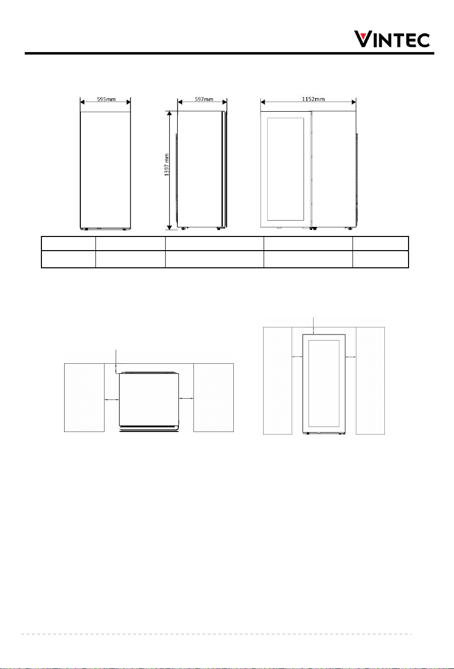
Tall wine cabinet model VWS140FAB-X
FREESTANDING INSTALLATION INSTRUCTIONS
N
oted: This model
is defined as freestanding. If there is space restrictions on installation, it is recommended to include
the following gaps. (Limiting gaps: top is 50mm. each sides is 50mm and the back is 50mm.)
Top view of wine cellar in line with cabinetry(flush)
Front view of wine cellar in line with cabinetry(flush)
Top
gap: 50mm
Minimum
cabinetry opening(W x D x H):695mm x 647mm x 1447mm
SLOT IN INSTALLATION INSTRUCTIONS
Model: VWS175FAB-X/VWD175FAB-X/VWD190FAB-R/VWD190FAB-L
This Vintec wine cellar is not designed to be fully integrated behind a joinery door.
Please note that:
1.
Vintec "Slot-in"
wine cellar are bottom venting but are not designed to be fully integrated behind a joinery door.
2. Vintec "Slot-in" wine cellars
For VWS175FAB-X/VWD175FAB-X: require 2.5mm clearance on both sides and 10mm on top, 30mm clearance at the
rear, to facilitate installation, removal, servicing and ventilation.
For VWD190FAB-R/VWD190FAB-L: require 5mm clearance on both sides and 5mm on top, 20mm clearance at the rear,
to facilitate installation, removal, servicing and ventilation.
3. Vintec “Slot-in”wine cellar have a power switch located on the control panel so power point location is not critical.
4. The Wine Cellar requires a standard 240 volt/10 amp power point. (Or according to different countries
specifications).
5. The power cord of is 2.5m in length and is fixed at the back when looking from front of cabinet.
6. As With most appliances of today, the wine cellar has sensitive electronic components which are susceptible to
damage through lightning and electricity supply faults. It is therefore advised to use a power surge protector to avoid
problems of this nature.
Model
Product dimension
(mm)
Product depth door closed
(mm)
Product depth door open
(mm)
Door angle
(degree)
VWS140FAB-X 595×597x1397 597
1152
90
7
5
0mm
5
0mm
�
1
-
50mm
50mm
50mm
50mm
INSTALLATIO
N
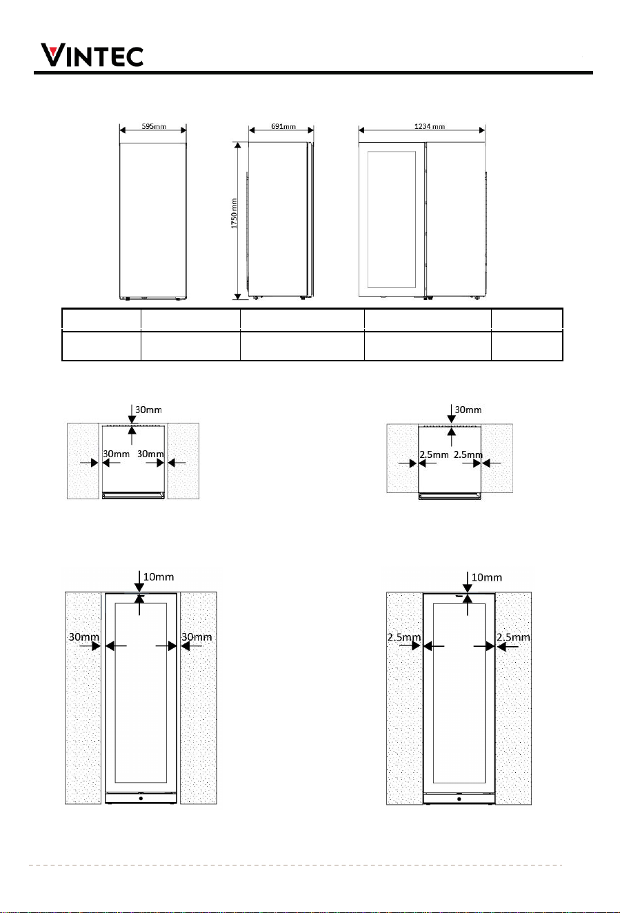
Tall wine cabinet model VWS175FAB-X, VWD175FAB-X
Top view of wine cellar in line with cabinetry(flush)
Top view of wine cellar in line with cabinetry(proud)
Front view of wine cellar in line with cabinetry(fl
ush) Front view of wine cellar in line with cabinetry(proud)
Top gap: 10mm Top gap: 10mm
Minimum cabinetry opening(W x D x H): Minimum cabinetry opening(W x D x H):
655mm x 721mm x 1760mm 600mm x 659mm x 1760mm
M
odel
P
roduct dimension
P
roduct depth door closed
Product
depth door pen
(
mm)
Do
or angle
(
degree)
VW
S175FAB-X,
VW
D175FAB-X
59
5×691x1750
691
1234
90
8
(
mm)
(mm)
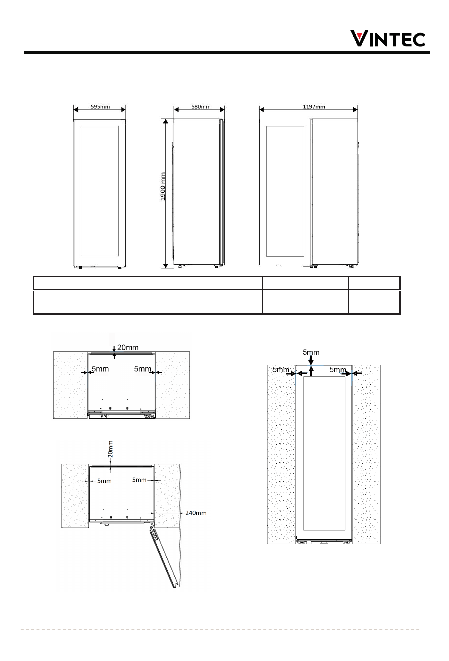
If the wine cellar is installed close to the wall, the minimum gap between the wine cellar and the wall should be 30mm.
INSTALLATION
Tall wine cabinet model VWD190FAB-L
Top view of wine cellar in line with cabinetry(flush)
Front view of wine cellar in line with cabinetry(flush)
Top view of wine cellar installed close to the wall
T
op gap: 5mm
Minimum cabinetry opening(W x D x H):605mm x 600mm x 1905mm
If the wine cellar is installed close to the wall, the minimum gap between the wine cellar and the wall should be 240mm.
Model
Product dimensi on Product depth door closed Product depth door open
(mm)
Door angle
(mm)
(mm)
(degree)
VWD190FAB-R, 595×580x1900 580 1197 115
VWD190FAB-L
9
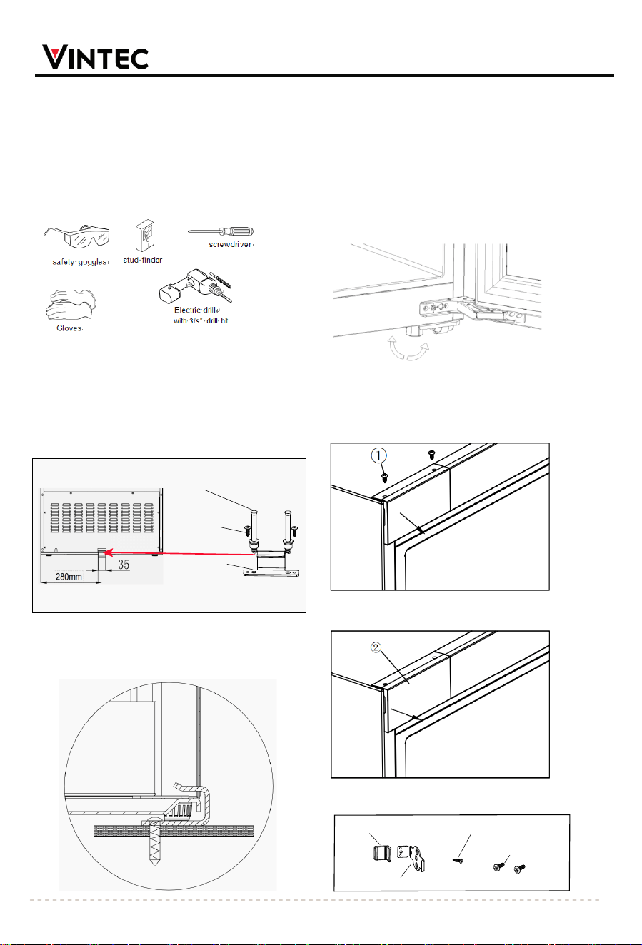
Model VWD190FAB-R/VWD190FAB-L:
Anti-Tip Bracket Installation Instructions
Tools You Will Need
FOR YOUR SAFETY: While performing installation
described in this section, gloves, safety glasses,
or goggles should be worn.
M8 expansion screws:
suitable for ceramic
tile floors
Self-tapping screw:
suitable for
wooden floors
Fixing buckle
Securing to Case Good
Place the fixing buckle into the back of the furniture cabinet,
fix the buckle by screw according to the below specified
position. It is important to follow the required dimension
below, otherwise, your wine cellar could not be properly
fixed.
After you have chosen the installat
ion location, place the
bracket on the wood floor, use: Screw (2pcs) align Lock and
secure the bracket into floor.
INSTALLATION
After the buckle is mounted in place, slide the unit into the
cabinet and make sure that the buckle completely fastens
and that the unit cannot be pushed back any more.
Place the wine cellar firmly on a wood base or on a floor
that is strong enough(isn’t cement floor or tile floor) to
support the wine cellar when it is fully loaded.
Stability Feet Adjustment Instructions
Turn the feet by hand to adjust the height of the product.
Turning counterclockwise will lower the height, while
turning clockwise will increase the height.
Fixed Slot In Installation Instructions
Step 1: Open the door, remove the two fixing screws of the
upper left door hinge cover ①.
Step 2: Pull down the left upper door hinge cover ② along
the arrow direction.
10
Fixed plate cover
⑥
Fixed plate
④
Self-tapping screws
⑤
x2
Fixed plate screws
③
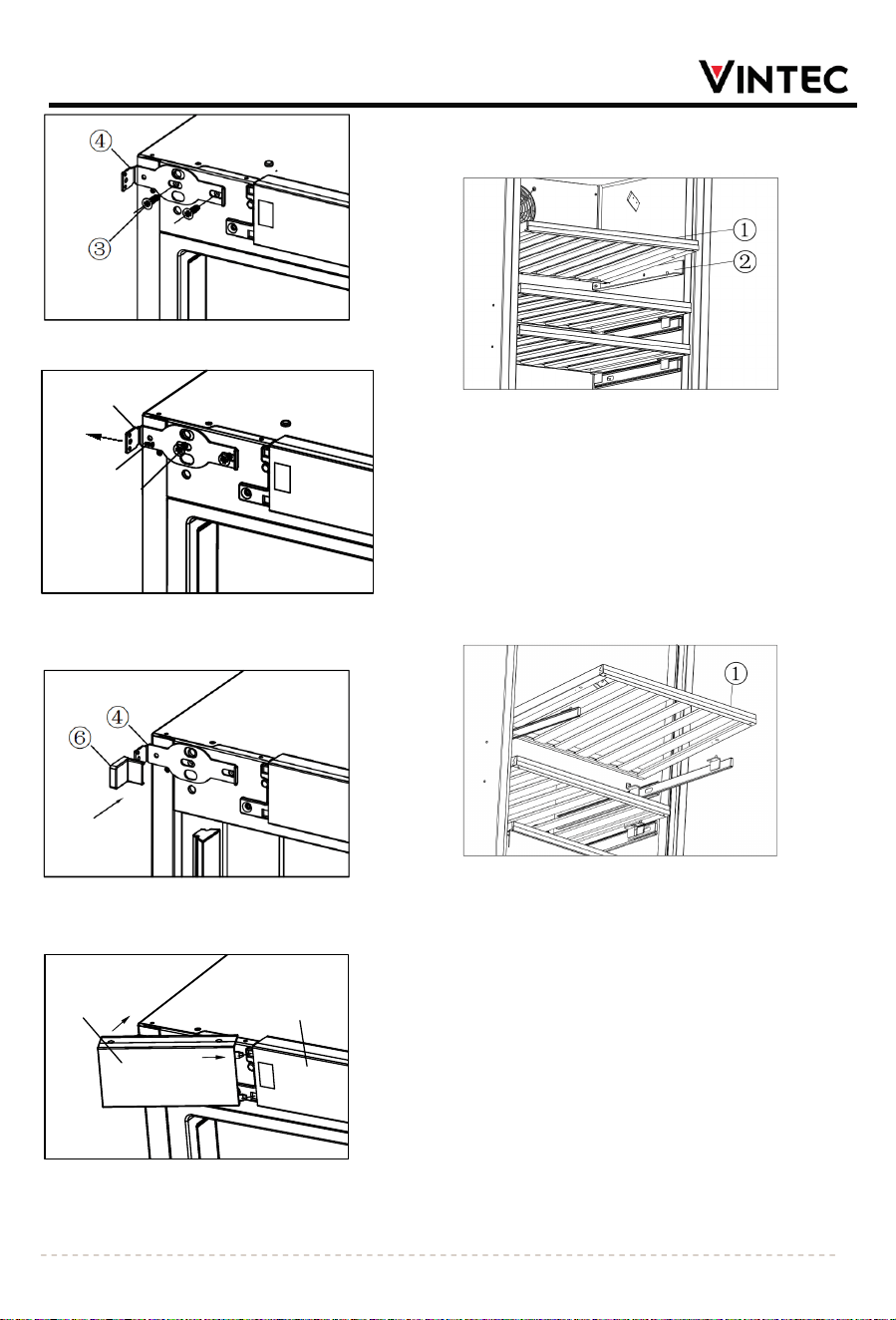
I
NSTALL
ATION
Step 3: Position the fixed plate ④ o
n the box with the fixed
plate screws ③, without tightening.
Step 4: Aer fixing the fixed plate ④
to the wooden cabinet using self-tapping screws ⑤,
then ghte n the fixedscrews ③.
Step 5: Align the fixed plate cover
⑥ with the positioning
hole in the direction of the arrow and then press it down
tightly onto the fixed plate ④.
Step 6: Insert the pins of the
left upper hinge cover ② into
the holes of the upper frame cover ⑦,
and then attach the left upper hinge cover ② to the box
along the arrow direction.
Installation Of Shelves
Disassembly
and Installation of methods
fo
r fixed shelves
Disassembly step:
Hold the front of shelf ① by hand and lift it by more than
8mm, then pull forward to remove the shelf;
Installation step:
Step 1: Place the shelf on the left and right support plates ②.
Step 2: Push backward to make the holes at the rear of the
shelf insert into the shafts on the support plates.(the same to
the left and the right)
Step 3: Align the front holes of the shelf with the front shafts
of the support plates. (the same to the left and the right)
Disassembly of the shelves with telescopic rails
Step 1: Open the door and remove the shelf ①.
Step 2: Grasp the front of the shelf, lift it higher than 8mm,
Then pull the shelf forward and it can be removed.
11
⑦
②
④
⑤
③
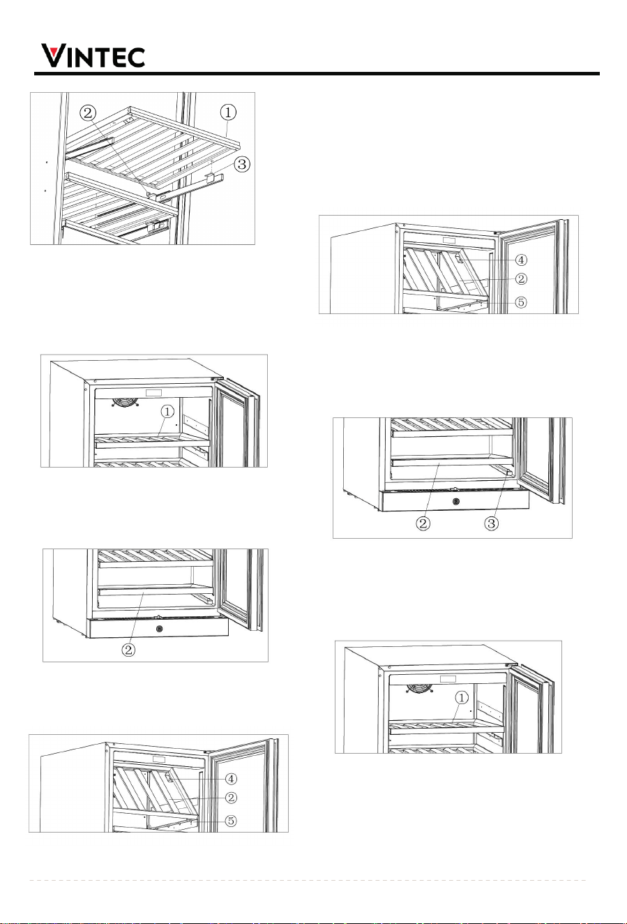
Installation of the shelves wit
h telescopic rails
S
tep 1: Place the rear of the shelf on the rear support ②.
Push the shelf backward so that the hole at the back of the
shelf is inserted into the rear support.
Step 2: Insert the front hole of the shelf into the front
support ③.
Installation of display shelf for model VWD175FAB-X,
Step 1: Grasp the front end of the top large shelf ①, lift
the front end of the top large shelf ① by more than 8mm,
then pull it forward, remove the top large shelf ①.
Step 2: Grasp the front end of the bottom shelf ②,
lift the
front end of the bottom shelf ② by more than 8mm, then
pull it forward and remove the bottom shelf ②.
INSTALLATION
12
Step 3: Place the bottom shelf ② on the display shel
f
support bracket ④, align the holes on the back of the
bottom shelf ② with the shaft of the display shelf support
bracket ④, then place the front end of the bottom shelf
② on the front end of the shelf support ⑤ and press it
down.
Disassembly of display shelf for model VWD175FAB-X
Step 1: Grasp the back of the bottom shelf ②, lift the
bottom shelf ② upwards and forward, causing the hole
position on the back of the bottom shelf ② to separate
from the shaft of the display shelf support bracket④. Then,
pull it forward to remove the bottom shelf ②.
Step 2: Place the rear end of the bottom shelf ② at the
bottom of the inner liner, push it inwards, and then align
the hole of the front end of the bottom shelf ② with the
shaft ③ on the bottom of the inner liner. This will
complete the installation of the bottom shelf ②.
Step 3: Place the top large shelf ① on the shelf support
⑤ and push it inward. Make sure the holes on the back of
the top large shelf ① are inserted into the shaft at the top
of the shelf support ⑤. Then align the holes at the front
end of the top large shelf ① with the shaft at the front
end of the shelf support ⑤.
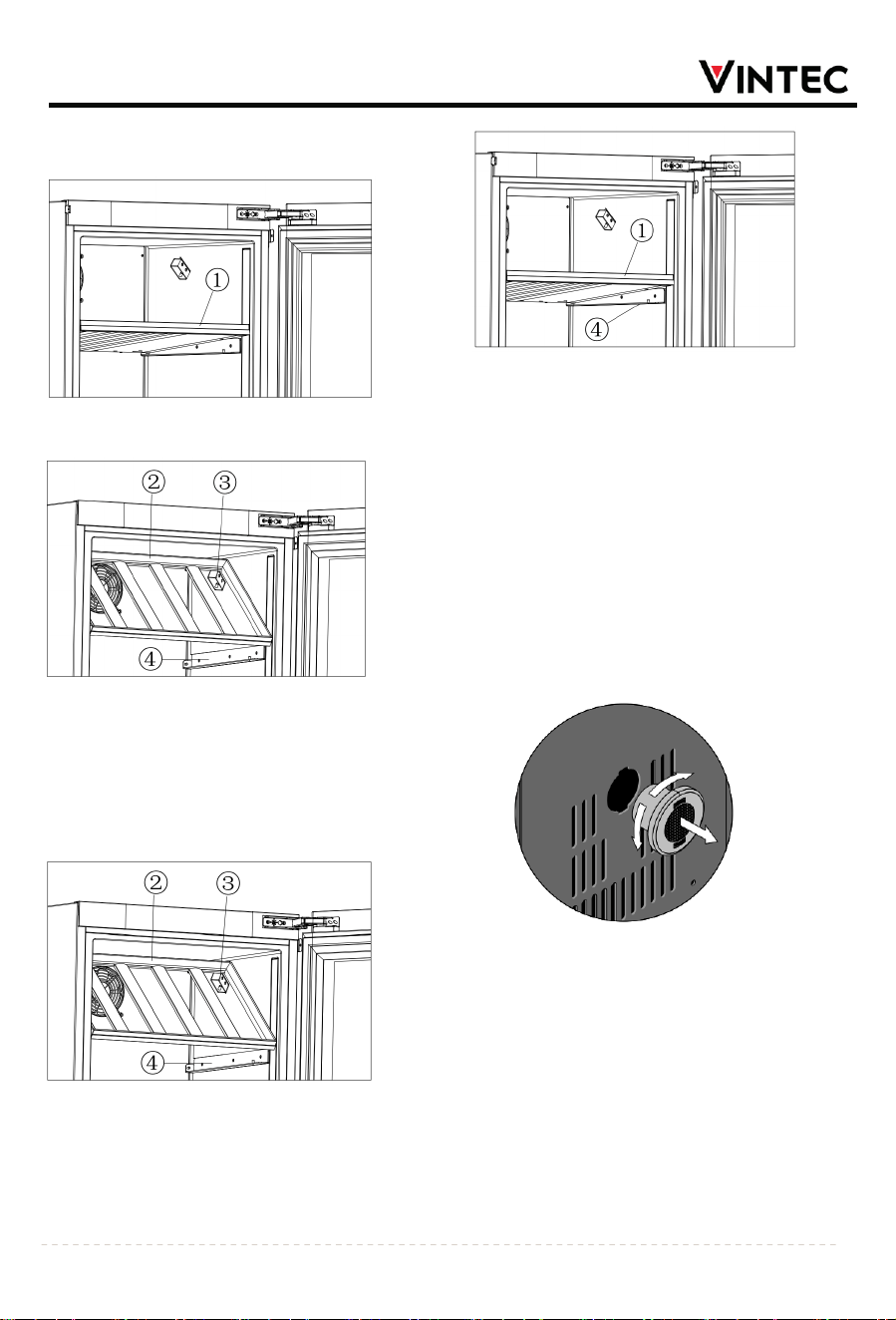
INSTALLATION
Step
2: Place the top large shelf ① on the shelf support ④
a
nd push it i
nward so that the holes on the back of the top
large shelf ① a
re inserted into the shafts on the back of the
shelf support ④. Then align the front h
oles of the top large
shelf ① with the front sh
afts of the shelf support ④.
Model VWS140FAB-X, V
WS175FAB-X, VWD175FAB-
X, VWD190FAB-R, VWD190FAB-
L:
How To Replace Activated C
harcoal Filter
Charcoal air filters e
nsure the natural ventilation and
humidity control t
hat encourages wine to mature properly
free from damaging o
dors. We recommend you replace
your f
ilter every 6 months, order part
number 3.02.01.3866 at vintec.com.
Located on the back wall of your wine cellar, Turn
counterclockwise to unlock, then remove. Replace with a
new filter and turn clockwise to lock in place.
13
Installation of display shelf for model VWD190FAB-R,
VWD190FAB-L
Step 1: Hold the front of the top large shelf ①, lift it by 8mm
or more, then pull it forward and remove it.
Step
2: Place display shelf ② on display shelf support
bracket ③, align the holes on the back of display shelf ①
with the shaft of display shelf support ②, then place the
front of display shelf ① on shelf support ④, and the
installation of display shelf ② is completed.
Disassembly of display shelf for model VWD175FAB-X,
VWD190FAB-R, VWD190FAB-L
S
tep 1: Hold the back of the display shelf ② by hand, lift the
display shelf ② forward, so that the hole on the back of the
display shelf ② is separated from the display shelf support
③. Then, pull it forward and out of the display shelf ②.
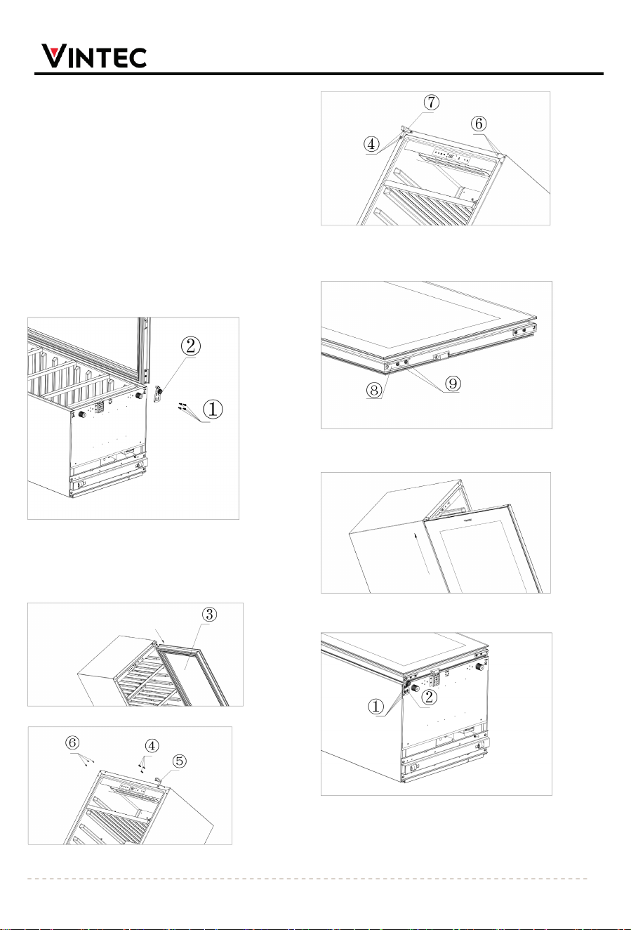
REVERSIBILITY OF THE DOOR
WAR
NING: To avoid accidents during the process of
changing the door, we recommend that you get
assistance.The glass door is heavy and may cause injury if
dropped.
For model VWS140FAB-X
①Fixing Sc
rews
②Lower Hinge
③Glass Door
④Hinge Screws
⑤Upper Right Hinge
⑥Hinge Holes Plug
⑦Upper Left Hinge
⑧Left Door Stopper
⑨Fixing screws For Stopper
Step 1: Take out all the win
e bottles in the wine cooler and
lay down the wine cooler(use foam or soft material to
support the back of the cabinet), remove the fixing screws
① of lower hinge with a screwdriver, and take out the
lower hinge②;
Step 2: Remove the door ③ fro
m the upper door hinge.
Step 3: Remove the hinge screws④, upper right hinge ⑤
and hinge holes plug ⑥.
INSTALLATION
Step 4: Pick up the upper le
ft hinge ⑦ from plastic bag and
assemble it by fixing screws ④. The hinge holes plug ⑥
need to be installed in the right.
Step 5: Pick up the left door
stopper ⑧ and install on the
left by fixing screws ⑨.
Step 6: Install the door ③ in t
he direction indicated by the
arrow and insert the left door hinge ⑦ shaft.
Step 7: Install the lower hing
e ② in the left by fixing
screws ①.
14
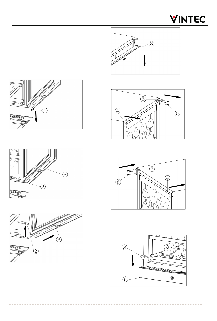
INSTALLATION
For model VWS175FAB-X, VWD175FAB-X
①Screw Of Door Hinge Fixing Plate
②Right Door Hinge Shaft Fixing Plate
③Glass Door
④Hinge Holes Plug
⑤Upper Right Hinge
⑥Door Hinge Screw
⑦Upper Left Hinge
⑧Left Door Hinge Pin Fixing Plate
⑨Air Outlet Grille
Step 1: Open the door to the maximum angle of 90°.
Remove the two screws ① of the door hinge fixing plates
along the arrow direction.
Step 2: Door ③ is separated from the right door hinge
shaft fixing plate ②.
Step
3: The door ③ is slightly tilted in the arrow direction,
completely separated from the right door hinge shaft fixing
plate ②, and the right door hinge shaft fixing plate ② is
removed along the arrow direction.
Step 4: Remove the door ③ in th
e direction indicated by
the arrow.
Step 5: Remove 3pcs door hinge p
lugs ④ and 3pcs right do
or hinge screws ⑥ in the direction indicated by the arrow,
and remove the right door hinge ⑤.
Step 6: Install 3pcs door hinge plu
gs ④ along the arrow
direction at the upper right corner of the cabinet. Align the
upper left hinge ⑦ with the door hinge holes of the
cabinet, and fix them firmly with 3pcs door hinge screws⑥.
Step 7: Align the hinge shaft o
f the door with the door
hinge hole on the air outlet grille ⑨, and install the left
door hinge shaft fixing plate ⑧ along the arrow direction.
15
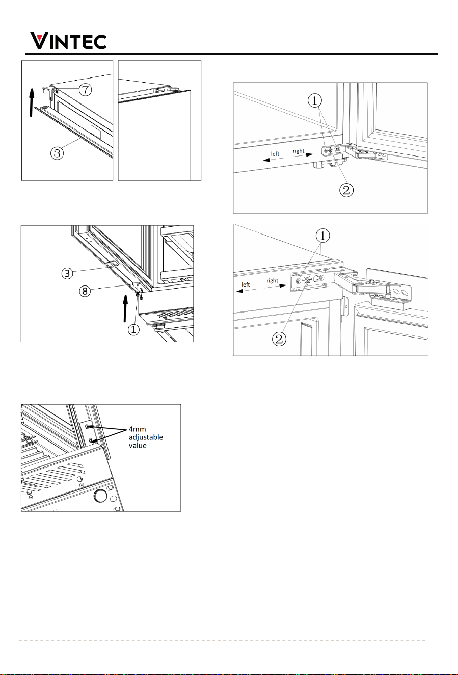
Step 8: Align the axis of
the left upper hinge ⑦ with the
axis of the door ③ shaft sleeve hole, and install the door
③ along the arrow direction.
Step 9: When the opening an
gle is fully extended to 90°,
simultaneously rotate the ⑧ holes of the left door hinge
shaft fixing plate to align with the door③. Install 2 screws
① of the door hinge shaft fixing plate in the direction
indicated by the arrow. Finally, secure it firmly.
Step 10: After installation,
check if the door③ is tilted. If
there is any tilt, the position of the door ③ can be
adjusted through the holes on the door hinge shaft fixing
plate.
INSTALLATION
LEVELING THE DOOR
For model VWD190FAB-R, VWD190FAB-L:
Step 1: Open the door to
its maximum position. Use a
Phillips screwdriver to loosen the fixing screws ① of the
hinges.
Step 2: Use a Phillips screwdriver to adjust the adjustment
screws ②.
Move the door hinges to the appropriate position.
A. If the door is sagging on the left side, then turn the door
hinge adjustment screw ②, then lower door hinge moves
to the left or the upper door hinge moves to the right (the
maximum movement is 2mm) until the door on level.
B. If the door is upturned on the left side, then turn the
door hinge adjustment screw ②,then the lower door hinge
moves to the right or the upper door hinge moves to the
left (the maximum movement is 2mm)until the door on
level.
Step 3: Tighten the hinge fixing screws ①.
16
**TURNING ON YOUR WINE CELLAR.**
P
lug in and switch on the cellar by pressing the
power button for a few seconds.
When you use the wine cellar for the first time (or restart
the wine cellar after having it shut off for a long time),
there will be a few degrees variance between the
temperature.
Once the wine cellar is running for a few hours,
everything will stabilise.
**OPERATING NOISES**
To reach the desired temperature settings, VINTEC
wine cellars, like all wine cellars, may produce the
following types of noises. These noises are normal
and may occur as follows:
- Gurgli
ng
sound - caused by the refrigerant
flowing through the appliance’s coils.
- Cracking/popping sounds -
resulting from the
contraction and expansion of the refrigerant gas
to produce cold.
- Fan operating sound - to circulate the air within
the wine cellar.
An individual’
s
perception of noise is directly linked to
the environment in which the wine cellar is
located,
as well as the specific type of models.
VINTEC wine cellars are in line with international
standards for such appliances.
VINTEC will always do its utmost to satisfy its
customers
but will not retake
possession of the
goods due to complaints based on normal
operating noise occurrences.
LOADING YOUR wine cellar. You may load your wine
bottles in single or double rows while taking note of
the following: if you do not have enough bottles to fill
your wine cellar, it is better to distribute the load
throughout the wine cellar so as to avoid all on top or
all below type loads.
STORAGE
17
CAUTION
Wine cellars generate heat during the process of making
cold air. In order to cool this heat down, heat dissipa
tion
pipes are installed on sides walls and back outer wall, so
when the product is operated, heat is generated on the
side walls and back walls of the wine cellars.
In addi
tion, to maintain the cool temperature inside the
wine cellars, the heat generated when the compressor is
operated periodically is dissipated to the back ans sides
of the wine cellar and, therefore, this phenomenon is
not a malfunction.
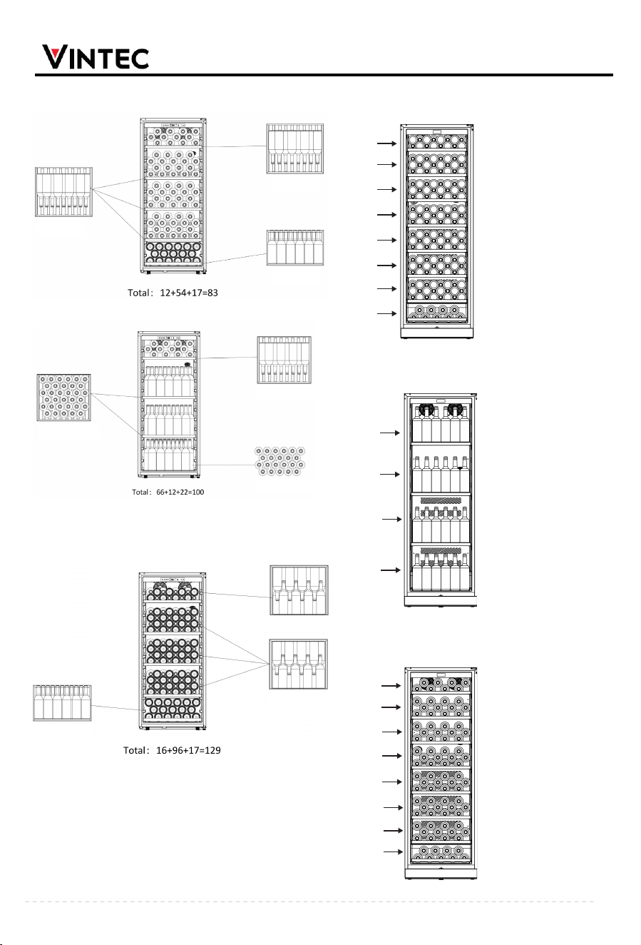
Storage diagram:
FOR VWS140FAB-X, Bottle Capacity. Easy access Total: 83 bottles
FOR VWS140FAB-X, Bottle Capacity. Hospitality
Total: 100 bottles
FOR VWS175FAB-X, Bottle Capacity. Hospitality Total: 138
bottles
FOR VWS175FAB-X, Bottle Capacity. Easy access Total: 89
bottles
STORAGE
18
•
11
16
+
24
+
24
+
24
+
24
+
24
+
24
+
9
+
169
•
138
11
36
+
36
+
36
+
30
+
11
•
89
8
+
12
+
12
+
12
+
12
+
12
+
12
+
+
9
φ 76×18×3
φ
76×12×1 φ 76×12×1
φ
76×17×1
φ76×33×2
φ76×12×1
φ76×22×1
φ76×17×1
φ76×16×1
φ76×32×3
FOR VWS140FAB-X, Bottle Capacity. Max long-term storage
Total: 129 bottles
FOR VWS175FAB-X, Bottle Capacity. Max long-term storage
Total: 169 bottles
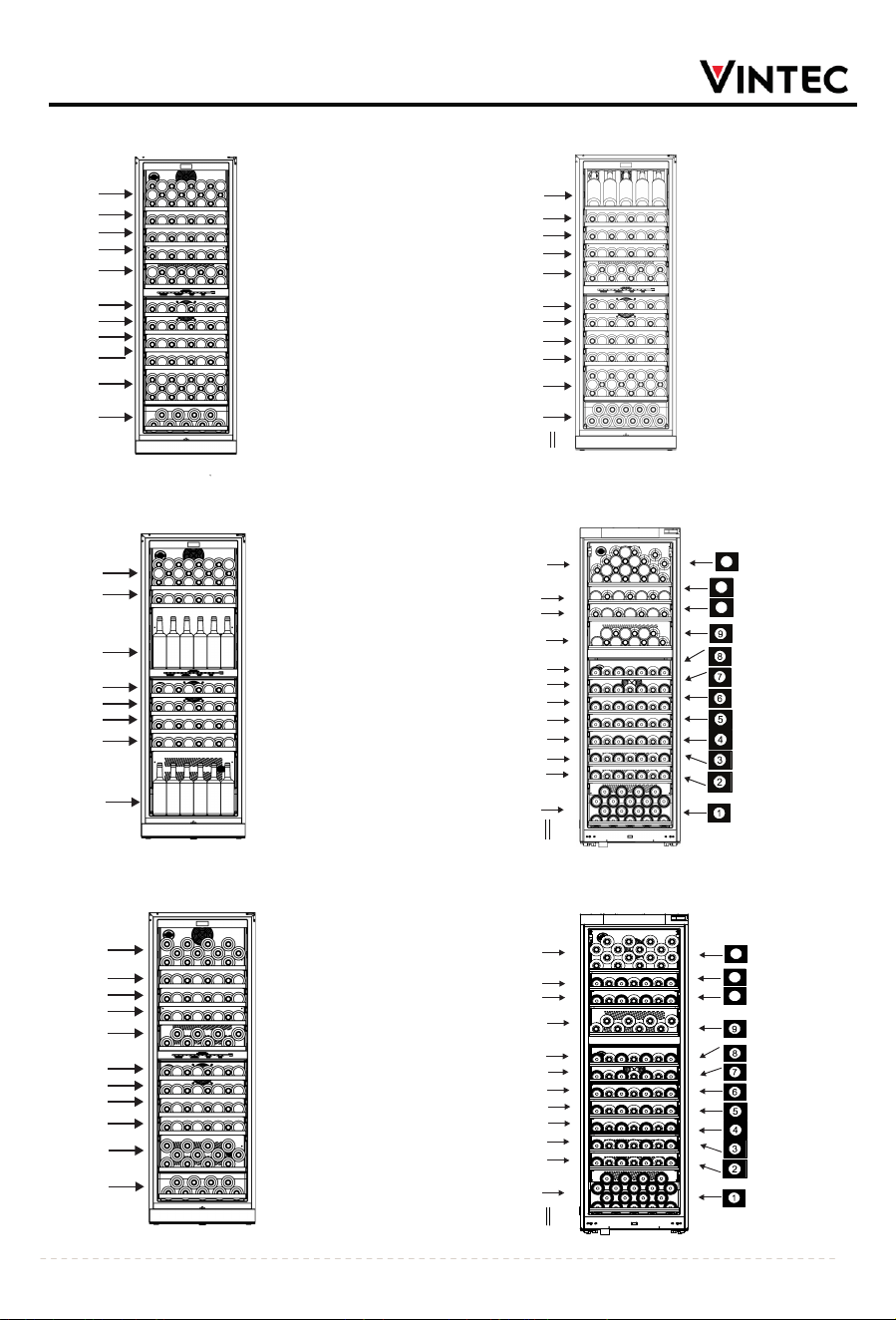
FOR VWD175FAB-X, Bottle Capacity.Hospitality
Total: 130 bottles
FOR VWD175FAB-X, Bottle Capacity. Easy access
Total: 97 bottles
FOR VWD175FAB-X, Bottle Capacity Display
Total: 112 bottles
FOR VWD190FAB-R/VWD190FAB-L, Bottle
Capacity. Max long-term storage. Total: 120 bottles
FOR VWD190FAB-R/VWD190FAB, Bottle Capacity. Easy
access Total: 105 bottles
STORAGE
19
•
5
+
8
8
8
16
8
8
8
8
24
+
11
+
+
+
+
+
+
+
+
+
112
II
129
•
II
130
•
II
97
•
24
+
8
+
+
8
+
8
16
+
8
8
+
+
8
+
8
+
2 4
+
9
+
24
+
8
+
36
+
8
+
8
+
8
+
8
+
30
+
12
+
8
+
8
+
8
+
8
+
8
+
+
8
+
8
8
+
12
+
9
+
25
+
7
+
7
+
14
+
7
+
7
+
7
+
7
+
7
+
7
+
7
+
18
+
120
12
11
10
12
11
10
16
+
7
+
7
+
8
+
7
+
7
+
7
+
7
+
7
+
7
+
7
+
18
+
105
FOR VWD175FAB-X, Bottle Capacity. Max long-term storage.
Total: 129 bottles
STORAGE
-Do not cover the wooden shelves with alloy foil or
oth
er materials, as it will obstruct air circulation.
- Do not move your wine cellar while it is loaded
with wines. This might distort the body of the wine
cellar and cause back injury.
TEMPERATURE STABILITY AND WINE STORAGE
Pleas
e note that depending on the loading and settings chosen,
it takes about 24 hours for the Wine Cellar to see the
temperature stabilising.
During this time, the LED seems to move erratically, in particular
for dual zone models.
It is normal, and this process occurs
whenever the setting is modified and/or whenever a large
amount of bottles are added to the cellar. Designed to store and
mature all wines: red, white and sparkling. These wine cellars
reproduce the ideal conditions for wine storage, at a constant
recommended temperature of 12°C. They can also be set to
provide ideal serving temperature for full enjoyment of the
wine’s qualities.
Unless stated by the wine maker on the bottle, VINTEC
recommends 7°C for your champagne, 12°C for whites and 18°C
for reds. (Refer to Wine Serving Temperature recommendation
chart).
Designed to store wines at the correct temperature for best
enjoyment. The upper chamber can hold 17 or 12 bottles
depending on the models, at a temperature of 6°C to 10°C
dedicated mainly to white, sparkling wines and champagnes. The
lower chamber accommodates 23 bottles, depending on the
models, mainly for red wines, which could be stored either at
room temperature (18°C-20°C) for consumption or at 12°C for a
longer time of storage.
TEMPERATURE SETTINGS
This appliance memorizes and saves its set temperature. In case
of a power outage, the unit adjusts to its previous temperature
setting when power resumes.
Factory preset chart
Model
Setting
temperature
Wine division
VWS140FAB-X
12℃
+/-2.0℃
VWS175FAB-X
12℃
+/-2.0℃
VWD175FAB-X
Upper compartment:
12
℃
+/-2.0℃
Lower compartment:
12℃
+/-2.0℃
VWD190FAB-R
/VWD190FAB-L
Upper compartment:
12℃
+/-2.0℃
Lower compartment:
12℃
+/-2.0℃
- Do remove or relocate adjustable wooden
shelves to accommodate larger types of bottles or
increase the capacity of the cellar by stacking the
bottles up when necessary. (See removing
shelves).
- Keep small gaps between the walls and the
bottles to allow air circulation. Like an
underground cellar, air circulation is important to
prevent mould and ensure a homogeneous
temperature within the cellar.
- Do not overload your wine cellar to facilitate air
circulation.
- Avoid obstructing the internal fans (located inside
on the back panel of the wine cellar).
- Do not slide the shelves outwards beyond the
fixed position to prevent the bottles from falling.
- Do not
pull out more than one loaded shelf at
time as this may cause the wine cellar to tilt
forward.
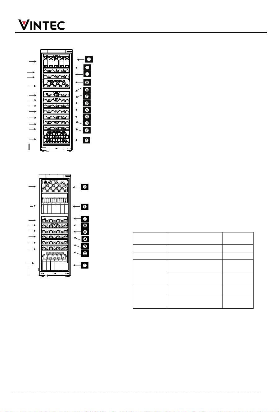
FOR
VWD190FAB-R/VWD190FAB-L, Bottle
Capaci
ty Display, Total: 100 bottles
20
25
+
30
+
7
+
7
+
7
+
7
+
7
+
7
+
24
+
121
12
11
10
7
+
7
+
18
+
5
+
7
+
7
+
14
+
7
+
7
+
7
+
7
+
7
+
100
FOR VWD190FAB-R/VWD190FAB-L Capacity .Hospitality
Total: 121 bottles
It
is important to understand that there is a difference between the air temperature inside the wine cellar and the actual
temperature of the wine: You will need to wait approximately 12 hours before noticing the effects of temperature
adjustment due to the critical mass within a full wine cellar. Once the temperature is set, it is strongly advised not to toy
with it or adjust frequently.
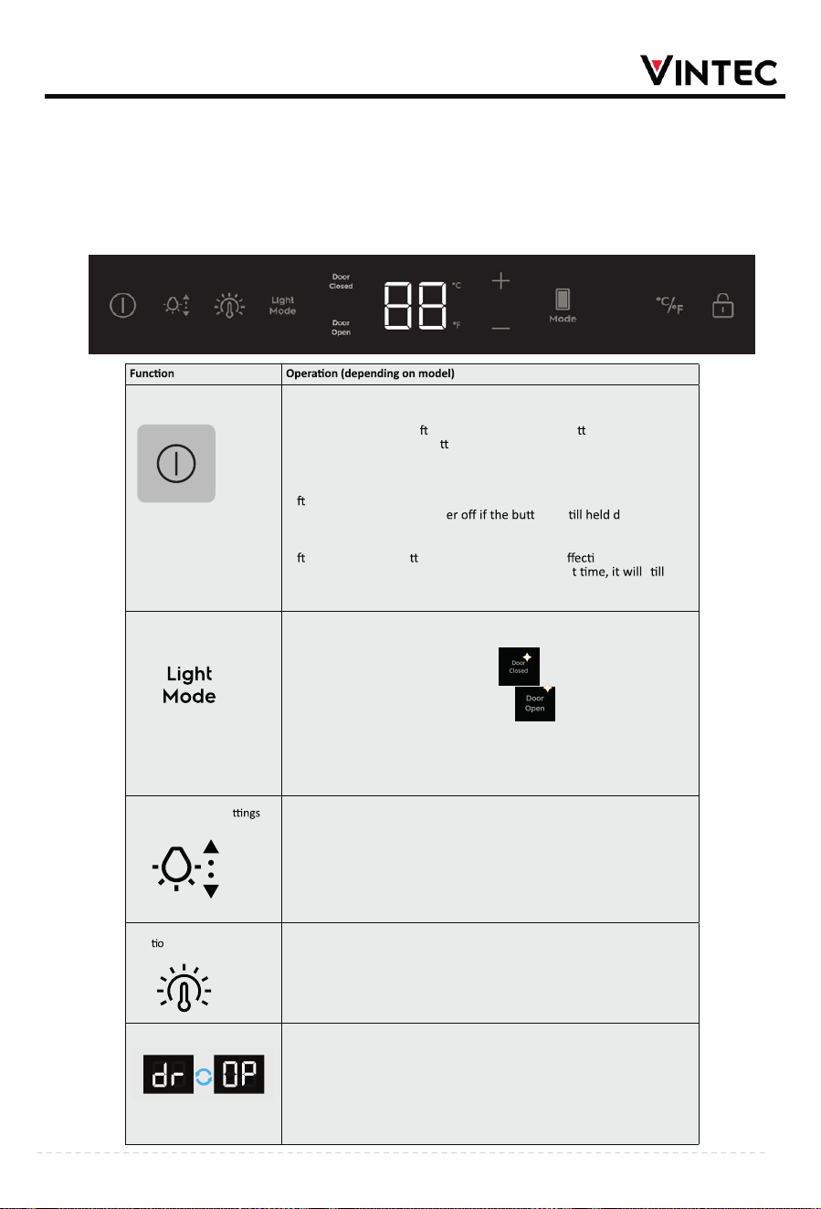
Control panel of VWS140FAB-X models
21
OPERATION AND FUNCTION
POWER
Short press has no effect;
Press and hold for 3 seconds to power off: the LED will display 3, 2,
1 and then power off
. A er power off, the pow
er bu on remains on,
while the lights of other bu
ons turn off.
Press and hold for 3 seconds to power on: the LED will display 3, 2, 1
and then power on.
A er being pressed and held for 3 seconds, the device will cycle
between pow
er on and pow
on is s own.
The wine cellar defaults to power on when powered on.
A er power off,
all bu ons except this one ar e ine
lights and displays turn off; When powered on nex
ve; all indicator
s
retain the set temperature before the last power off. Other working
modes (such as cellar mode, display mode, etc.) will be cleared.
Light sengs menu
Short press to cycle through the light sengs menu, which is divided into
2 menus: door closed menu and door open menu.
On the first press, it displays the lightt
s
engs when the door is
closed.
On the second press, it displays the lightt
open.
s
engs when the door is
On the third press, it cycles back to the first one.If there is no operaon
within 60 seconds under the light sengs menu, it will automacally exit
the menu.
Long press has no effect.
Light brightness se
Short press "Light Mode", then short press "Light brightness seng"
to adjust the light brightness, which is divided into 8 levels,
cycling from 7L to 0L.
0L: Lights off
1L:Lowest dim level / least brigh
t
7L: Highest dim level / most bright
4L: Default dim level / 50% bright
Light color temperature
Short press "Light Mode", then short press "Light color temperature
selecon" to adjust the color temperature of the lighng, which is
divided into 3 color temperatures, cycling fr
om 1H to 3H.
Cool color temperature: displayed as "1H";
Neutral color temperature: displayed as "2H";
Warm color temperature: displayed as "3H".
sele c n
Door opening alarm
When the door remains open for 5 minute, the lights start to dim up and
down (1000ms from lowest dim level to highest dim level) and the
temperature digits shows “dr” & “OP” alternavely with 500ms intervals,
and at full brightness unl the door is closed. If the door is kept open,
aer more 2 minutes, an acousc alarm sound is played. Any interacon
on the Control panel disable the lights blinking and audio signal and
restart the 5 minutes meout.
22
Control panel of VWS175FAB-X/ VWD175FAB-X/VWD190FAB-L/VWD190FAB-R models
Display
Touch display shows the current settings of the appliance.
Slide to see more settings.
Tap <or> to navigate the settings.
Tap √ to confirm the setting.
Single zone temperature
It shows the actual temperature and humidity. Press + or
– to set the temperature (5 – 18 °C). Note that humidity
cannot be controlled but can only be monitored.
Upper zone temperature
It shows the actual temperature and humidity. Press + or –
to set the temperature (5 – 18 °C). Note that humidity
cannot be controlled but can only be monitored.
Lower zone temperature
It shows the actual temperature and humidity. Press + or –
to set the temperature (5 – 18 °C). Note that humidity
cannot be controlled but can only be monitored.
Light
Tap the slider to turn on/off the light.
Tap the light icon to set the colour and brightness of the
light for the door closed and open.
• Light brightness: 0 – 7
• Light colour: cool, neutral, warm
Settings
Tap the setting icon to change the settings.
• Child lock : tap the slider
• Temperature units: °C, °F
• Display brightness: 1 – 5
• Language
• Sound: tap the slider
Error
The icon appears for below errors:
• High temperature
• Low temperature
• Door opening timeout
• Other error code
Filter
The filter icon is visible until you replace the filter.
The models VWS175FAB-X, VWD175FAB-X,
VWD190FAB-R and VWD190FAB-L have this reminder
function. If you replace the filter, press “reset”, then
press “OK” on the alarm page “Filter has been reset”.
Door open alarm
If the door remains open for 5 minutes, the light
flashes. After 2 more minutes, an acoustic alarm
sounds and a warning message appears on the
display. To stop the alarm, close the door or confirm.
the warning message on the display.
DAILY USE
Equipment varies by model.
Push-to-open glass door(model VWD190FAB-L/
VWD190FAB-R)
To open the appliance:
1. Press the door gently.
2. A piston moves the door to a position that allows
you to take hold of the door to open it wider.
During a power outage, the push-to-open mechanism
does not work. To open the door, insert your hand
between the door and the appliance opposite the
hinges.
To close the door, push it gently towards the
appliance. Before closing the door wait for the
push-to-open mechanism to reset. Closing the door
during the reset may damage the mechanism. It is
recommended that the interval between each door
opening should be no less than 12 seconds.
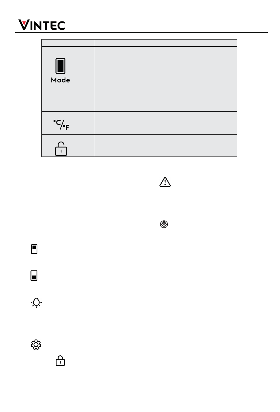
Funcon Operaon (depending on model)
Cellar mode
Short press to turn on/off the cellar mode (it is off by default when
powered on).
When the cellar mode is turned on, the words "CE" will be displayed and
flash.
If there is no touch operation on the cellar mode button within 5
seconds, "CE" will stop flashing and remain displayed at half brightness
until the cellar mode is turned off.
In cellar mode, the set temperature is fixed at 12°C and cannot be
changed.
When the cellar mode is turned off, the set temperature will return to
the value before the cellar mode was turned on.
°C/°F conversion Short press to cycle between °C and °F temperature units.
Lock function
Press and hold for 3 seconds, and the LED will count down to display 3, 2,
1, then lock/unlock. During the long press, the icons light up at 100% full
brightness. After 3 seconds, the lock icon turns to half brightness.
I
OPERATION AND FUNCTION
WINE SERVING TEMPERATURE CHART
All wines matur
e at the same temperature, which is a constant temperature set between 12℃ to 14℃.
The below chart is an indicative temperature chart to indicate the best temperature for drinking purposes.
Champagne NV, Sparkling, Spumante 6℃
Dry White Semillon, Sauvignon Blanc
8℃
Champagne Vintage
10℃
Dry White Chardonnay , Dry White Gewürztraminer, Riesling, Pinot grigio 10℃
Sweet White Sauternes, Barsac, Montbazillac, Ice Wine, Late Harvest
10℃
Beaujolais 13℃
Sweet White Vintage: Sauternes 14℃
White Vintage Chardonnay
14℃
Red Pinot Noir 16℃
Red Grenache, Syrah 16℃
Red Vintage Pinot Noir 18℃
Cabernet & Merlot: French, Australian, New Zealand, Chilean, Italian, Spanish, Californian,
Argennean
18℃
Vintage Bordeaux 18℃
IMPORTANT INFORMATION ABOUT TEMPERATURE
Your VINTEC wine cellar has
been designed to guarantee optimum conditions for storing and/or serving your wines.
Fine wines require long and gentle developments and need specific conditions in which to reach their full
potential.
All wines mature at the same temperature, which is a constant temperature set between 12 ℃ to 14 ℃. Only the
temperature of degustation (wine appreciation) varies according to the type of wines t emperature Chart above (see
Wine Serving). This being said and as it
is for natural cellars used by wine producers for long
periods of storage, it is
not the exact temperature that is important, but its consistency. In other words, as long as the temperature of your
wine cellar is constant (between 12 ℃ to 14 ℃) your wines will
be stored in perfect conditions.
Not all wines will improve over the years. Some should be consumed at an early stage (2 to 3 years) while others
have tremendous ageing capability (50 and over). All wines have a peak in maturity.
Do check with your wine
merchant to get the relevant information.
DEFROSTING/CONDENSATION/ HYG ROMETRY/ VENTILATION
Your wine cellar is designed with auto-cycle defrost system. During Off-cycle the refrigerated surfaces of the wine cellar
defrost automatically. Defrost water from the wine cellar storage compartment drains automatically and part of it goes
into a drainage container, which is located at the back of the wine cellar next to the compressor. The heat is transferred
from the compressor and evaporates any water that has collected in the pan. Part of the remaining water is collected
within the wine cellar for humidity purposes.
This system enables the creation of the correct humidity level inside your wine cellar required by the natural cork to
maintain a long lasting seal.
Notes: The water collected by condensation is therefore recycled.
All units are equipped with a triple glazed glass door that has a LOW-E layer to minimize condensation on the glass
door.
The wine cellar is not totally sealed; some fresh air is allowed through the drainpipe.
Air is circulated through the cellar by means of a fan/fans and the hollow shelves.
Notes: During the refrigerating cycle, heat is given off which disperses through the external surfaces of the wine cellar.
Avoid touching the surfaces during those cycles.
Notes: Always keep door opened at maximum angle when you push-in or pull-out shelves with telescopic rails for wine
taking and storage, to avoid damage to wine cellar.
23
WINE SERVING & DEFROSTING
TROUBLESHOOTING
If your wine cellar appears
to be malfunctioning, unplug it
and contact your VINTEC’s after sales service. Any
intervention on the cold circuit should be performed by a
refrigeration technician who should carry out an inspection
of the circuit sealing system. Similarly, any intervention on
the electrical circuit should be performed by a qualified
electrician.
Notes: Any intervention performed by a non-authorized
technician by Vintec will lead to the warranty being
considered null and void.
POWER FAILURES
This appliance memorizes and saves its set temperature. In
case of a power outage, the unit adjusts to its previous
temperature setting when power resumes.
To avoid sudden change of temperatu
re while the power
is off, you should avoid opening the door. For longer
periods of
power failure, do take steps to protect your
wine.
Irrespective of the cause, if you notice either
abnormal temperature or humidity levels inside your
wine cellar, be reassured that only long and frequent
exposure to these abnormal conditions can cause a
detrimental effect on your wines.
OPERATION ANOMALIES
Ensure that there is power to the electrical supply plug by
connecting another electrical appliance to it. Check fuse,
if any. Make sure that the door is closed properly
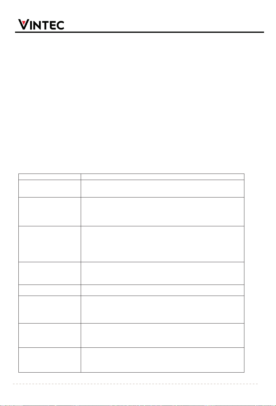
TROUBLESHOOTING GUIDE
Common problems may easily be solved, saving you the cost of a possible service call.
Please read carefully the instruction manual and refer to the troubleshooting guide chart.
PROBLEM
POSSIBLE CAUSE
wine cellar does not operate.
Not plugged in.
The appliance is turned off.
The circuit breaker tripped or the fuse is broken.
wine cellar is not cold enough.
Check the temperature control setting. External environment may require a higher
setting.
The door is opened too often.
The door is not closed completely.
The door gasket does not seal properly.
Turns on and off frequently.
The room temperature is higher than normal.
A large amount of contents have been added to the wine cellar.
The door is opened too often.
The door is not closed completely. The temperature control is not set correctly.
The door gasket does not seal properly.
The light does not work.
Not plugged in.
The circuit breaker tripped or a blown fuse.
The bulb is out of order.
The light button is “OFF”.
Vibrations.
Check to assure that the wine cellar is level.
The wine cellar seems to make
too much noise.
A Gurgling noise may come from the low side of the refrigerant system, which is normal
as each cycle ends in your wine cellar.
Contraction and expansion of the inside walls may cause popping and crackling noises.
The wine cellar is not level.
The door will not close properly.
The wine cellar is not level.
The door was reversed and not properly installed.
The gasket is faulty. (Magnet or rubber is spoiled).
The shelves are out of position.
Condensation or droplets on
exterior surfaces, glass door,
sealing gasket strip.
This is a natural phenomenon.
Wipe off any condensation or droplets with soft dry cloth.
Place appliance in a lower humidity area try adjusting temperature to be slightly warmer
above the coldest temperature
setting or wait until humidity back to at lower levels (recommended place appliance at
max or lower than 75% relative air humidity area).
24
TROUBLESHOOTING
Models with a heater w
ill raise their temperature to
the set temperature if the ambient temperature is
below the set temperature. Models without a heater
will not raise the temperature to the set temperature
in these conditions.
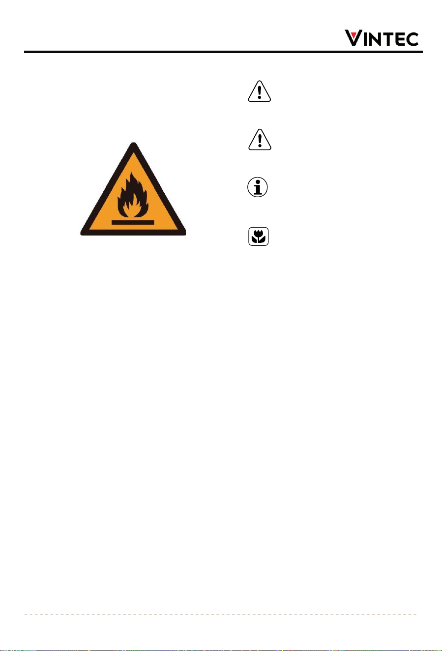
Do not store flammable or explosive items in or near
the cabinet.
The symbols you will see in this booklet have these
meanings:
WARNING
This symbol indicates information concerning your personal
safety.
CAUTION
This symbol indicates information on how to avoid
damaging the refrigerator.
IMPORTANT
This symbol indicates tips and information about use of the
refrigerator.
This symbol indicates tips and information about
economical and ecological use of the refrigerator.
Conditions of use
This refrigerator is designed and intended to be used in
normal domestic applications only.
In environments with hig
her humidity levels,
condensation droplets may appear on the appliance's
exterior door surfaces.
If condensate droplets occur, here are some suggestions
to address the issue:
·Ensure adequate ventilation around the appliance to
reduce humidity levels.
·Wipe and clean the surfaces to prevent any build-up of
moisture and condensation.
·If the appliance settings are too cold, try adjusting them
to be warmer to minimize condensation.
·Consider moving or relocating the appliance to a location
with lower humidity levels.
·
Use dehumidifiers in the room to lower overall humidity,
if possible.
Warning: Flammable materials
Risk Of Fire
25
ENVIRONMENT
Warranty
FOR SALES IN AUSTRALIA AND NEW ZEALAND
APPLIANCE: VINTEC
This document sets out the terms and conditions of the product
warranties for Vintec Appliances. It is an important document.
Please keep it with your proof of purchase documents in a safe place
for future reference should there be a manufacturing defect in your
Appliance. This warranty is in addition to other rights you may have
under the Australian Consumer Law.
1. In this warranty:
(a) ‘ACL’ or ‘Australian Consumer Law’ means Schedule 2 to the
Competition and Consumer Act 2010;
(b) ‘Appliance’ means any Electrolux product purchased by you and
accompanied by this document;
(c) ‘ASC’ means Electrolux’s authorized serviced centres;
(d) ‘Vintec’ is the brand controlled by Electrolux Home Products Pty Ltd
of 163 O’Riordan Street, Mascot NSW 2020, ABN 51 004 762 341 in
respect of Appliances purchased in Australia and Electrolux (NZ) Limited
(collectively “Electrolux”) of 3-5 Niall Burgess Road, Mount Wellington, in
respect of Appliances purchased in New Zealand;
(e) ‘Warranty Period’ means the period specified in clause 3 of this
warranty;
(f) ‘you’ means the purchaser of the Appliance not having purchased
the Appliance for re-sale, and ‘your’ has a corresponding meaning.
2. Application: This warranty only applies to new Appliances, purchased
and used in Australia or New Zealand and is in addition to (and does not
exclude, restrict, or modify in any way) other rights and remedies under
a law to which the Appliances or services relate, including any non-
3. Warranty Period: Subject to these terms and conditions, this warranty
continues for in Australia for a period of 24 months and in new Zealand
for a period of 24 months, following the date of original purchase of the
Appliance. Specific components are warranted against manufacturing
defects in Australia and New Zealand for the periods listed below;
• Compressor - Further 3 years
4. Repair or replace warranty: During the Warranty Period, Electrolux
or its ASC will, at no extra charge if your Appliance is readily accessible
for service, without special equipment and subject to these terms and
conditions, repair or replace any parts which it considers to be defective.
Electrolux may, in its absolute discretion, choose whether the remedy
offered for a valid warranty claim is repair or replacement. Electrolux or
its ASC may use refurbished parts to repair your Appliance. You agree
that any replaced Appliances or parts become the property of
Electrolux.
5. Travel and transportation costs: Subject to clause 7, Electrolux will
bear the reasonable cost of transportation, travel and delivery of the
Appliance to and from Electrolux or its ASC. Travel and transportation will
be arranged by Electrolux as part of any valid warranty claim.
6. Proof of purchase is required before you can make a claim under this
warranty.
7. Exclusions: You may not make a claim under this warranty unless the
defect claimed is due to faulty or defective parts or workmanship. This
warranty does not cover:
(a) light globes, batteries, filters or similar perishable parts;
(b) parts and Appliances not supplied by Electrolux;
(c) cos
metic damage which does not affect the operation of
the Appliance;
(d) damage to the Appliance caused by:
(i) negligence or accident;
(ii) misuse or abuse, including failure to properly maintain or service;
(iii) improper, negligent or faulty servicing or repair works done by
anyone other than an Electrolux authorized repairer or ASC;
(iv) normal wear and tear;
(v) power surges, electrical storm damage or incorrect power supply;
(vi) incomplete or improper installation;
(vii) incorrect, improper or inappropriate operation;
(viii) insect or vermin infestation;
(ix) failure to comply with any additional instructions supplied with
the Appliance;
In addition, Electrolux is not liable under this warranty if:
(a) the Appliance has been, or Electrolux reasonably believes that the
Appliance has been, used for purposes other than those for which
the Appliance was intended, including where the Appliance has
been used for any non-domestic purpose;
(b) the Appliance is modified without authority from Electrolux in writing;
(c) the Appliance’s serial number or warranty seal has been removed
or defaced.
8. How to claim under this warranty: To enquire about claiming under
this warranty, please follow these steps:
(a) carefully check the operating instructions, user manual and the
terms of this warranty;
(b) have the model and serial number of the Appliance available;
(c) have the proof of purchase (e.g. an invoice) available;
(d) telephone the numbers shown below.
9. Australia: For Appliances and services provided by Electrolux in
Australia: Electrolux goods come with guarantees that cannot be
excluded under the Australian Consumer Law. You are entitled to a
replacement or refund for a major failure and for compensation for any
other reasonably foreseeable loss or damage. You are also entitled to
have the Appliance repaired or replaced if the Appliance fails to be of
acceptable quality and the failure does not amount to a major failure.
‘Acceptable quality’ and ‘major failure’ have the same meaning as
referred to in the ACL.
10. New Zealand: For Appliances and services provided by Electrolux
in New Zealand, the Appliances come with a guarantee by Electrolux
pursuant to the provisions of the Consumer Guarantees Act, the Sale
of Goods Act and the Fair Trading Act. Where the Appliance was
purchased in New Zealand for commercial purposes the Consumer
Guarantee Act does not apply.
11. Confidentiality: You accept that if you make a warranty claim,
Electrolux and its agents including ASC may exchange information in
relation to you to enable Electrolux to meet its obligations under this
warranty.
Important Notice
Before calling for service, please ensure that the steps listed in clause 8 above have been followed.
AUSTRALIA
FOR SERVICE
or to
the address of your nearest
authorized service centre in Australia
PLEASE CALL 1800 666 778
For the cost of a local call
FOR ACCESSORIES
PLEASE CALL 1800 666 778
For the cost of a local call (Australia only)
or visit www.vintecclub.com
NEW ZEALAND
FOR SERVICE
or to
the address of your nearest
authorized service centre in New Zealand
PLEASE CALL 0800 10 66 10
FOR ACCESSORIES
PLEASE CALL 0800 550 020
(New Zealand only)
or visit www.vintecclub.com
Vintec Undercounter_Warr_Oct24


Service and support
In the rare event that your Vintec cabinet does not perform
to your satisfaction, contact our dedicated support team:
1800 666 778
Vintec. We are part of the
Electrolux Family. To add
a touch of professional
inspiration to your home,
visit electrolux.com.au
Stay in touch and share your
user experience by following us:
@vintecclub
© 2019 Electrolux Home Products Pty Ltd. ABN 51 004 762 341
Rev00_Mar 2026
vintec.com