
Installation and Troubleshooting Guide
Page - 1 of 6
This CDM Module replaces all 827509A1, 827509A3, 827509A7, 827509A9, 827509A10, and 827509T4 series CDM Modules
P/N: 114-7509
.
How to test the Engine Stop Circuit (Kill) for
Warning! This product is designed for installation by a professional marine mechanic. we cannot be held liable for injury
or damage resulting from improper installation, abuse, neglect, or misuse of this product.
DC Voltage:
1.
INSTALLA
DC voltage present on the kill circuit of the CDM Modules due to a faulty key switch, boat harness, or engine harness will severely
damage the CDM Module’s internal kill circuit. Disconnect the CDM wiring harness at the CDM’s on ALL OF THE CDM Modules at the
same time. Connect a Digital Multi Meter to the Ignition Stop wires (Black/Yellow) at the CDM’s by way of the plug connectors of the
CDM Harness. Use the Black/Yellow wires in reference to a known good engine ground (Black wire in CDM plug connector). Turn the
Ignition switch on and off several times. If, at any time, you see over 2 VDC on the kill wire(s), there is a problem with one or both
harnesses and/or the Ignition switch. The Ignition Stop wire should not be connected back to ANY CDM Module at any point until the
problem is corrected OR DAMAGE TO THE CDM MODULE’S WILL OCCUR!
TION
1.
2.
3.
4. Apply a light amount of dielectric grease to the seal area of the wire connector from the engine harness.
5. Apply a light amount of dielectric grease to the outside of the new spark plug wire and thread the spark plug wire into the new CD
Disconnect and clean all engine and battery ground wires.
Disconnect the old CDM Module and remove the high tension coil wire from the spark plug.
Unbolt and remove the old CDM Module. (Note the direction of the spark plug wire).
M
Module.
6. Bolt the new CDM Module onto the engine (orient the new CDM Module so that the spark plug wire is pointed in the same direction as
the original).
7. Plug in the connector from the wire harness into the new CDM Module and connect the spark plug wire to the spark plug.
GENERAL TROUBLESHOOTING
NO SPARK:
1.
2.
3.
You must have both the Green/White and White/Green Stator wire connected, or you will lose spark on all CDM Modules. You
can leave one wire connected to the CDM Module and ground the other Stator wire to complete the circuit for the Sta
Disconnect the Black/Yellow kill wires from the harness and retest. If the engine’s Ignition now has spark, the stop circuit has a fault.
Check the key switch, harness, and shift switch (if present).
Install a CDI Electronics P/N 511-5207A 1 test harness inline to one of the CDM Modules and unplug the Black/Yellow wires in the
harness. This will isolate that CDM from all other connections. If spark returns on that CDM Module with the Black/Yellow wires
unplugged, test the remaining CDM Modules. If you disconnect one CDM Module and all other CDM Modules start sparking, the one
that the test harness is connected to is defective. Remember, the fault could also be in the CDM harness.
Disconnect one CDM module one at a time and see if the other modules start sparking. If they do, the module you just unplugged is
defective.
tor.
4.
5.
6.
Disconnect the Yellow wires from the Stator to the Regulator/Rectifier and retest. If the ignition system now has spark, replace the
Regulator/Rectifier.
Check the Resistance of the Black wire in the 4 pin connector to the CDM Module in reference to a good clean engine ground. It should
show a short, less than 0.5 Ω. A high reading or an open reading indicates a break in the Black wire. Check the wire at the ground
terminal.
Check the cranking RPM. A cranking speed less than 250 RPM will not allow the system to spark properly.
7. Check the Stator and Trigger resistance and DVA. See your applicable engine category below.
8. Check the resistance and diodes of each of the CDM Modules as follows:
Installation and Troubleshooting Guide
Page - 2 of 6
Red Meter Lead Black Meter Lead OEM Reading CDI Reading
CDM Pin # (A) Ground (C) Trigger 1.2-1.4K Ω 1.2-1.4K Ω
CDM Pin # (D) Stator (A) Ground Open* Open*
CDM Pin # (A) Ground (D) Stator Reading* Reading*
CDM Pin # (D) Stator (B) Kill Circuit Reading* Reading*
CDM Pin # (B) Kill Circuit (D) Stator Open* Open*
CDM Pin # (A) Ground (B) Kill Circuit Reading* Reading*
CDM Pin # (B) Kill Circuit (A) Ground High M Ω or Open* High M Ω or Open*
- High Tension Lead (A) Ground 0.7-1.3K Ω 2.2-2.4K Ω
* This Measurement is with the meter set to the diode scale. Where you see the term “Reading” represents a reading on the
meter. Where you see the term “Open” represents no value showing on the meter.
INTERMITTENT SPARK OR NO SPARK ON ONE OR MORE CYLINDERS:
1. Check the resistance of the Black wire in the 4 pin connector to the CDM in reference to a good clean engine ground. It should show a
short, less than 0.5 Ω. A high reading or an open reading indicates a break in the Black wire. Check the wire at the ground terminal.
2. If the cylinders are only misfiring above an idle, connect an inductive Tachometer to all cylinders and try to isolate the problem
cylinders.
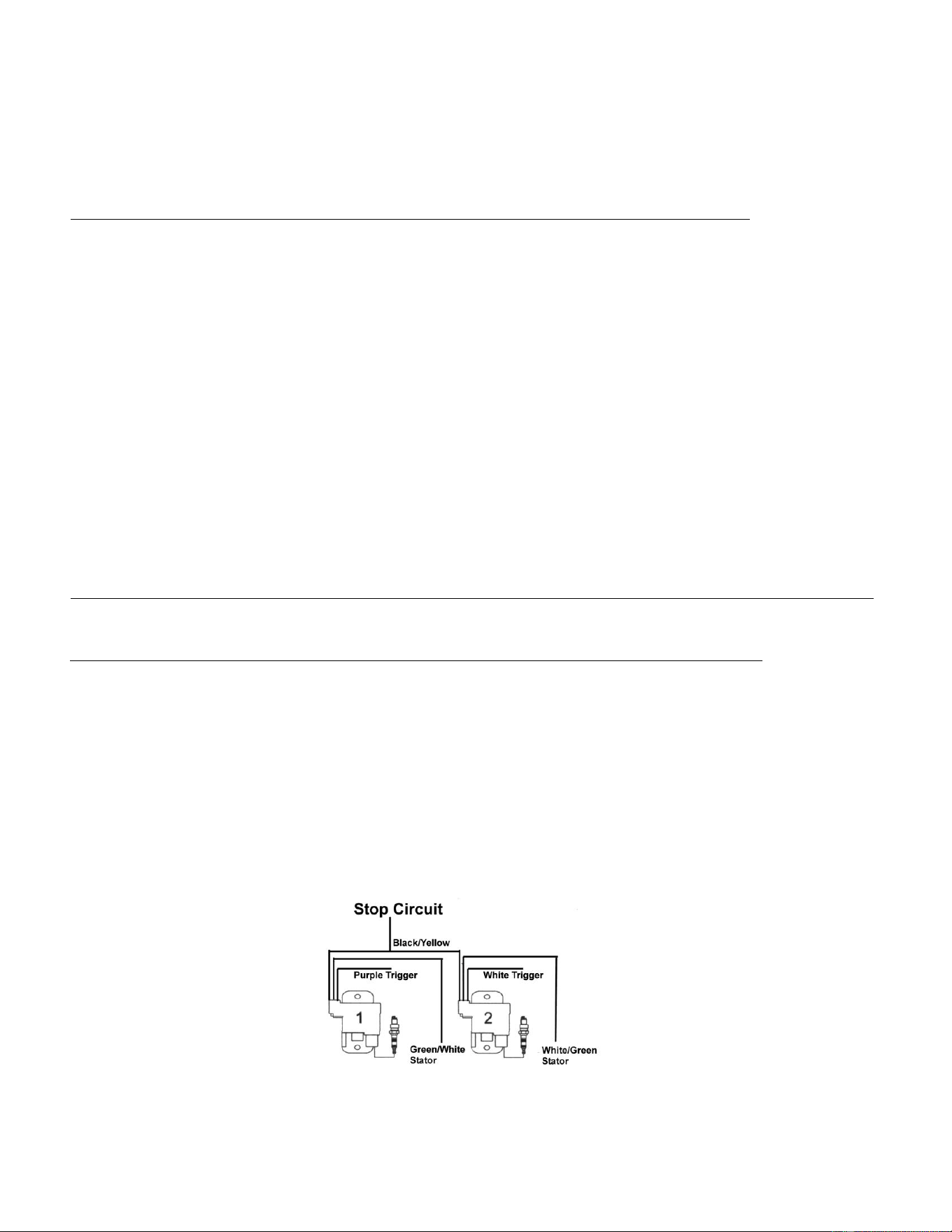
2 CYLINDER TROUBLESHOOTING
INTERMITTENT SPARK OR NO SPARK ON ONE OR MORE CYLINDERS:
1. Check the Stator resistance and DVA as given below:
Read from Read to OEM Ohms CDI Ohms DVA (Connected) DVA (Disconnected)
White/Green (Stator) Green/White (Stator) 500-700 Ω 400-550 Ω 180-400 V 200-400 V
2. Check the Trigger DVA as shown below:
Read from Read to Ohms DVA Connected DVA Disconnected
Purple wire (#1 Trigger) Engine Gnd Open 0.5-1.5 V** 5 V or more
White wire (#2 Trigger) Engine Gnd Open 0.5-1.5 V** 5 V or more
**A DVA reading that is close to the same reading connected as disconnected may indicate a broken ground wire.
NOTE: As these Triggers have the Bias circuit built into them, you cannot perform a Resistance test on the Trigger.
3. If one cylinder is not sparking, swap the White/Green and Green/White Stator wires and retest. If the problem moves to the other
cylinder, the Stator is likely bad. If no change, replace both CDMs. A continued no spark condition on the same cylinder indicates a bad
Trigger.
4. If #1 is not sparking, disconnect #2 CDM module. Check to see which Stator wire feeds #2 CDM and by using a jumper wire, short that
side of the Stator to engine ground. If # 1 starts sparking, replace the #2 CDM.
You must have both the Green/White and White/Green Stator wire connected, or you will lose spark on both CDMs. You can
leave one wire connected to the CDM Module and ground the other Stator wire to complete the circuit for the Stator.
5. For #2 CDM not firing, short the Stator wire that feeds the #1 CDM. Again, if the #2 CDM starts sparking, replace the #1 CDM.
Installation and Troubleshooting Guide
Page - 3 of 6
3 CYLINDER TROUBLESHOOTING
NO SPARK OR INTERMITTENT SPARK ON ONE OR MORE CYLINDERS:
1. Inspect the spark plug wires, boots, and spark plugs. Check for chafing on the wiring and harnesses.
2. Clean and inspect CDM ground wire connections to engine ground.
3. Check the Stator resistance and DVA as given below:
Read from Read to OEM Ohms CDI Ohms DVA (Connected) DVA (Disconnected)
White/Green Green/White 500-700 Ω 400-550 Ω 180-400 V 200-400 V
4. Check the Trigger DVA as shown below:
Read from Read to Ohms DVA (Connected)
Purple (#1 Trigger) Engine Gnd Open 1 V Minimum
White (#2 Trigger) Engine Gnd Open 1 V Minimum
Brown (#3 Trigger) Engine Gnd Open 1 V Minimum
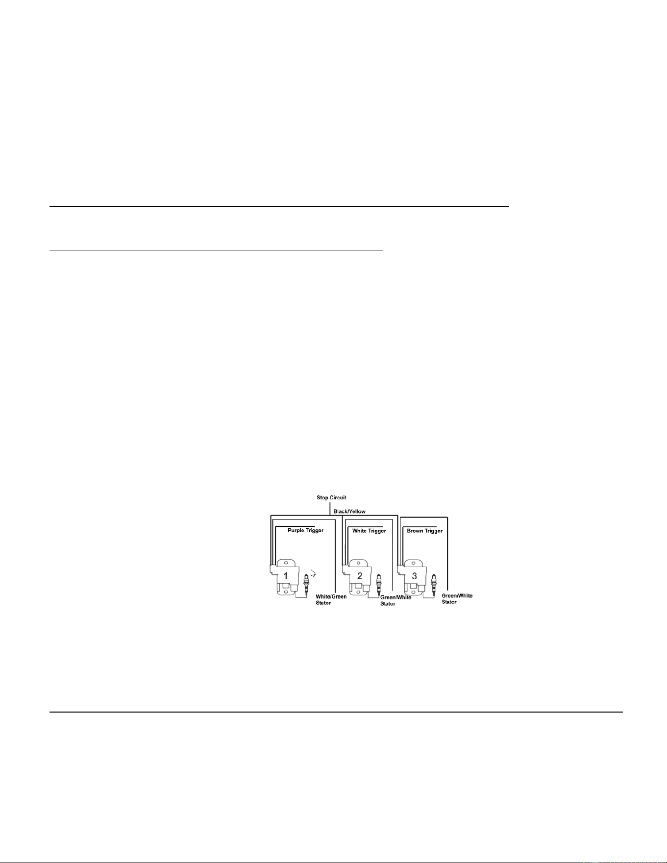
5. The two wire Stator provides voltage for all three cylinders. The #1 cylinder is supplied voltage from the Stator with the White/Green
wire, while cylinders #2 and #3 are supplied with voltage by the Green/White wire. If cylinder #1 is not sparking, or #2 AND #3 cylinders
are not sparking, you can swap the Stator wires where they connect to the CDM harness and test to see if the problem moves. If the
problem moves to the other cylinder(s), the Stator is likely bad. If no change, replace all CDMs. A continued no spark condition on the
same cylinder(s) indicates a bad Trigger.
You must have both the Green/White and White/Green Stator wire connected, or you will lose spark on all CDMs. You can
leave one wire connected to the CDM Module and ground the opposite Stator wire to complete the circuit for the Stator.
6. If #1 CDM module is not sparking, disconnect the #2 CDM module and see if the #1 CDM Module starts sparking. If it does, the #2
CDM Module is bad. If it does not, reconnect #2, then disconnect the #3 CDM module and see if the #1 module starts sparking. If it
does, the #3 CDM Module is bad.
7. If no change and #1 CDM Module is still not sparking, swap the #1 and #2 CDM Module and retest for spark. If the problem moved, the
CDM Module originally in the #1 position is likely defective.
8. If still no change, check the ground wire for the #1 CDM Module along with the DVA and resistance of the Trigger for the #1 cylinder.
9. If there is no spark on either #2 or #3, swap locations with #1 and see if the problem moves. If it does, the CDM Module is bad. A
continued no spark on the same cylinder indicates either a faulty ground wire for that cylinder or a bad Trigger. Test accordingly.
10. If the cylinders are only misfiring above an idle, connect an inductive tachometer to all cylinders and try to isolate the problem cylinders.
11. Check the resistance of each of the CDM modules.
4 CYLINDER TROUBLESHOOTING
NO SPARK OR INTERMITTENT SPARK ON ONE OR MORE CYLINDERS:
1. Inspect the spark plug wires, boots, and spark plugs. Check for chafing on the wiring and harnesses.
2. Clean and inspect CDM ground wire connections to engine ground.
3. Check the Stator resistance and DVA as given below:
Read from Read to OEM Ohms CDI Ohms DVA (Connected) DVA (Disconnected)
White/Green (Stator) Green/White (Stator) 500-700 Ω 400-550 Ω 180-400 V 200-400 V
Purple (#1 Trigger) Engine Gnd Open Open 1 V Minimum -
White (#2 Trigger) Engine Gnd Open Open 1 V Minimum -
Brown (#3 Trigger) Engine Gnd Open Open 1 V Minimum -
Blue (#4 Trigger) Engine Gnd Open Open 1 V Minimum -
Installation and Troubleshooting Guide
Page - 4 of 6
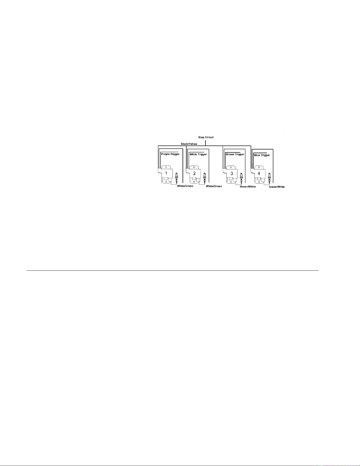
4. The two wire Stator provides voltage for all four cylinders. The #1 and #2 cylinders are supplied with voltage from the Stator
with the White/Green wire, while cylinders #3 and #4 are supplied with voltage by the Green/White wire. If cylinders #1 and
#2 or cylinders #3 and #4 are not sparking, swap the White/Green and Green/White Stator wires and retest. If the problem
moves to the opposite cylinders, the Stator is likely defective. If no change, replace all CDMs. A continued no spark
condition on the same cylinders indicates a bad Trigger.
Note: When moving CDM modules around on the engine, pay attention to the Stator wire colors going to the CDMs.
You must have a Green/White and White/Green wire connected or you will lose spark on all CDMs.
5. Disconnect the CDM Modules one at a time and see if you get spark back on the problem cylinders. If spark returns, replace the CDM
you disconnected.
6. If the cylinders are only misfiring above an idle, connect an inductive RPM meter to all cylinders and try to isolate the problem cylinders.
7. Check the resistance of each of the CDM modules.
2.5 LITER 6 CYLINDER TROUBLESHOOTING
NO SPARK ON ANY CYLINDER:
1. Disconnect the Timing Protection Module’s (TPM) 6 pin connectors from the Trigger and CDM Harness.
2. Connect the Trigger directly to the CDM Harness, bypassing the TPM. Remember, the TPM for the Carbureted engines has a built in
RPM Limiter but the one for the Fuel Injected engines does not.
3. Check for Spark.
4. If Spark is present, check the Purple wire to the TPM. With the key switch on, you should have battery voltage present (above 10 VDC
while cranking). This voltage is provided by the key switch. If the voltage is low, test the key switch and the wiring harness accordingly.
5. If the spark does not return, check the Stator and Trigger as shown:
Read from Read to OEM Ohms CDI Ohms DVA (Connected) DVA (Disconnected)
White/Green (Stator) Green/White (Stator) 380-430 Ω 380-430 Ω 160-400 V 200-400 V
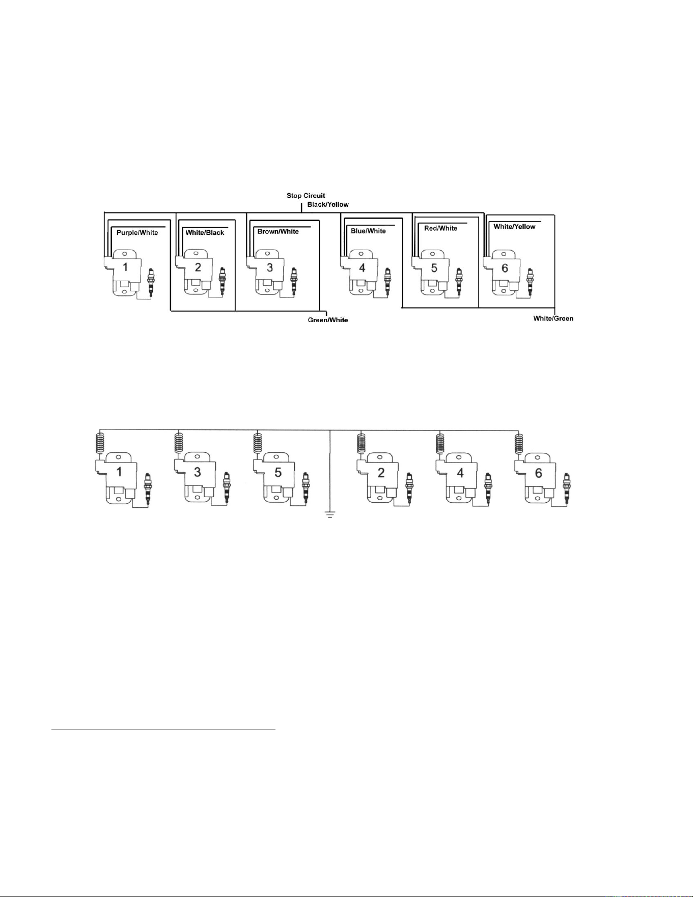
Purple (#1 Trigger) Blue (#4 Trigger) 1.1-1.4K Ω 0.85-1.05K Ω 0.4 V Minimum 4 V Minimum
White (#2 Trigger) Red (#5 Trigger) 1.1-1.4K Ω 0.85-1.05K Ω 0.4 V Minimum 4 V Minimum
Brown (#3 Trigger) Yellow (#6 Trigger) 1.1-1.4K Ω 0.85-1.05K Ω 0.4 V Minimum 4 V Minimum
Purple (#1 Trigger) Engine Gnd Open Open 0.2 V Minimum -
White (#2 Trigger) Engine Gnd Open Open 0.2 V Minimum -
Brown (#3 Trigger) Engine Gnd Open Open 0.2 V Minimum -
Blue (#4 Trigger) Engine Gnd Open Open 0.2 V Minimum -
Red (#5 Trigger) Engine Gnd Open Open 0.2 V Minimum -
Yellow (#6 Trigger) Engine Gnd Open Open 0.2 V Minimum -
6. If no change, disconnect the CDM Modules one at a time and see if you get spark back on the other cylinders. A shorted stop circuit in
one CDM can prevent ALL cylinders from sparking.
7. If there is still no spark, disconnect the boat side harness and check for spark. If spark returns, check the key switch, emergency kill
switch, and boat side harness.
8. Disconnect the Yellow wires from the Voltage Regulator and retest. If the engine has spark, replace the Voltage Regulator.
9. Check the cranking RPM. A cranking speed of less than 250 RPM may not allow the system to spark properly. This can be caused by a
weak battery, dragging starter, bad battery cables, or a mechanical problem inside the engine.
10. Inspect the spark plug wires, boots, and spark plugs. Check for chafing on the wiring and harnesses.
11. Inspect and clean all engine and ignition ground connections. Tug on the ground wires for the CDM Modules against the ring terminal.
If the insulation stretches, the wire is broken internally. Replace the original 3 wire ring terminal with individual ring terminals (Solder
them on if possible) and add a secondary ground wire (10 or 12 Ga) from the ground point of the CDM Modules and route it around and
connect it with the Negative Black Ground Battery cable on the engine.
Installation and Troubleshooting Guide
Page - 5 of 6
12. Pull on each wire from each CDM harness plug. Make sure all wires are making proper contact inside plugs.
13. Check the Trigger and Stator coil flywheel magnets for cracked, broken, or loose magnets.
The connection guide below will assist you in locating areas where problems can occur. Remember a short in either #1, #2 or #3
can cause either # 4, #5 and #6 not to have spark on a 2.5L engine.
3.0 LITER TROUBLESHOOTING
NO SPARK OR WEAK SPARK ON ANY CYLINDER:
1.
2.
3.
4.
5.
6.
7.
8.
Disconnect the Black/Yellow stop wires from the harness. Retest. If the engine’s ignition now has spark, the stop circuit has a fault.
Check the key switch, harness, and shift switch.
Install a CDI electronics P/N 511-5207A 1 test harness inline to one of the CDM Modules and unplug the Black/Yellow wires in the
harness. This will isolate that CDM Module from all other connections. If spark returns on that CDM Module with the Black/Yellow wires
unplugged, test the remaining CDM Modules. If you disconnect one CDM Module and all other CDM Modules start sparking, the one
that the test harness is connected to is defective. Remember, the fault could be in the CDM harness.
Inspect the spark plug wires, boots, and spark plugs. Check for chafing on the wiring and harnesses.
Check the Resistance of the Black wire in the 4 pin connector to the CDM Module in reference to a good clean engine ground. It should
show a short, less than 0.5 Ω. A high reading or an open reading indicates a break in the Black wire. Check the wire at the ground
terminal.
Inspect and clean all engine and ignition ground connections.
Check the Stator Harness for loose connections.
Check the Alternator for dragging as well as shorted diodes.
Check the Crank Position Sensor (CPS) resistance as given below:
Read from
Red
Read to
White
Ohms
0.9-1.3K Ω
9. Adjust the CPS air gap to 0.020”.

Installation and Troubleshooting Guide
Page - 6 of 6
NO SPARK OR WEAK SPARK ON ONE CYLINDER:
1.
2.
3.
4.
Inspect the spark plug wires, boots, and spark plugs. Check for chafing on the wiring and harnesses.
Clean and inspect the CDM ground wire connection to engine ground.
If the cylinders are only misfiring above an idle, connect an inductive RPM meter to all cylinders and try to isolate the problem cylinders.
Check the Stator resistance and DVA as given below:
Read from
Green (#1 Cyl)
Green/Red (#2 Cyl)
Read to
Engine Gnd
Engine Gnd
Green/Yellow (#3 Cyl) Engine Gnd
Green/Blue (#4 Cyl)
Green/Orange (#5 Cyl)
Green/Black (#6 Cyl)
Engine Gnd
Engine Gnd
Engine Gnd
Ohms
0.99-1.21K Ω
0.99-1.21K Ω
0.99-1.21K Ω
0.99-1.21K Ω
0.99-1.21K Ω
0.99-1.21K Ω
DVA (Connected)
100 V Minimum
100 V Minimum
100 V Minimum
100 V Minimum
100 V Minimum
100 V Minimum
HIGH SPEED MISS:
1.
2.
3.
Connect an inductive Tachometer to all cylinders and try to isolate the problem. A high variance in RPM on one cylinder indicates a
problem usually in the Trigger or CDM Module.
Perform a high-speed shutdown and read the spark plugs. Check for water. A crack in the block can cause a high speed miss when the
water pressure gets high, but a normal shutdown will mask the problem.
Remove the flywheel and check the Stator coil flywheel magnets for cracks or broken magnets.