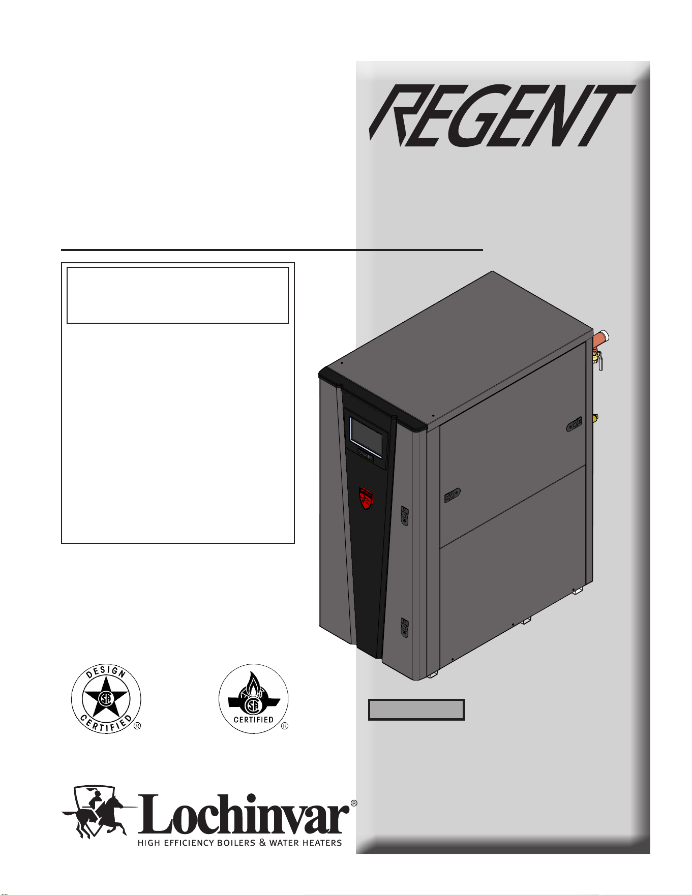
Installation & Operation
Manual
Models: 500 - 1000
This manual must only be used by
a qualified heating installer / service
technician. Read all instructions,
including this manual and the
Regent Water Heater Service
Manual, before installing. Perform
steps in the order given. Failure
to comply could result in severe
personal injury, death, or substantial
property damage.
⚠ WARNING
Save this manual for future reference.
100399794_2000857139_Rev B
-- This water heater MUST NOT be installed in
any location where gasoline or flammable vapors
are likely to be present.
-- WHAT TO DO IF YOU SMELL GAS
• Do not try to light any appliance.
• Do not touch any electric switch; do not use any
phone in your building.
• Immediately call your gas supplier from a near by
phone. Follow the gas supplier’s instructions.
• If you cannot reach your gas supplier, call the fire
department.
• Installation and service must be performed by a
qualified installer, service agency, or the gas
supplier.
⚠ WARNING: If the information in this
manual is not followed exactly, a fire or
explosion may result causing property damage,
personal injury or loss of life.
Commercial TANKLESS Water Heater

2
Hazard definitions
The following defined terms are used throughout this manual to bring attention to the presence of hazards of various risk levels or
to important information concerning the life of the product.
⚠ DANGER
⚠ WARNING
⚠ CAUTION
CAUTION
NOTICE
DANGER indicates an imminently hazardous situation which, if not avoided, will result in death or serious
injury.
WARNING indicates a potentially hazardous situation which, if not avoided, could result in death or serious
injury.
CAUTION indicates a potentially hazardous situation which, if not avoided, may result in minor or moderate
injury.
CAUTION used without the safety alert symbol indicates a potentially hazardous situation which, if not
avoided, may result in property damage.
NOTICE indicates special instructions on installation, operation, or maintenance that are important but not
related to personal injury or property damage.
HAZARD DEFINITIONS .................................................. 2
PLEASE READ BEFORE PROCEEDING ..................... 3
THE REGENT WATER HEATER-- HOW IT WORKS 4-5
PRODUCT SUMMARY .................................................... 6-7
RATINGS .......................................................................... 8
1. DETERMINE WATER HEATER LOCATION
Provide Clearances ............................................................ 9
Provide Air Openings to Room ........................................ 11
Flooring and Foundation .................................................. 11
Residential Garage Installation ........................................ 11
Vent and Air Piping .......................................................... 11
Prevent Combustion Air Contamination ........................... 11
Corrosive Contaminants and Sources ............................. 12
Using an Existing Vent System to Install a New Water
Heater ............................................................................... 12
Removing a Water Heater from Existing Common Vent . 13
2. PREPARE WATER HEATER
Remove Water Heater from Wood Pallet ........................ 14
Combustion Air Filter ........................................................ 14
3. GENERAL VENTING
Direct Venting Options ..................................................... 15
Install Vent and Combustion Air Piping ........................... 16
Requirements for Installation in Canada .......................... 17
Sizing ............................................................................... 17
Min./Max. Combustion Air & Vent Piping Lengths ............ 17
Materials ............................................................................ 18
Optional Room Air ............................................................ 19
PVC/CPVC ....................................................................... 20
Polypropylene ................................................................... 21
Stainless Steel Vent ......................................................... 22
4. SIDEWALL DIRECT VENTING
Vent/Air Termination - Sidewall ................................... 24-33
Determine Location ................................................ 24-28
Prepare Wall Penetrations .......................................... 29
Multiple Vent/Air Terminations ......................................... 30
Sidewall Termination - Optional Concentric Vent ....... 31-33
5. VERTICAL DIRECT VENTING
Vent/Air Termination - Vertical .................................... 34-39
Determine Location ..................................................... 34
Prepare Roof Penetrations ......................................... 35
Multiple Vent/Air Terminations .................................... 35
Vertical Termination - Optional Concentric Vent ... 36-37
Alternate Vertical Concentric Venting .................... 38-39
6. OUTDOOR INSTALLATIONS
Outdoor Venting .......................................................... 40-41
Outdoor Vent / Air Inlet Location ................................. 40-41
Location of Unit ................................................................ 40
7. SYSTEM PIPING
System Water Piping Methods ......................................... 42
Scalding ............................................................................ 42
Water Chemistry............................................................... 43
Piping Components .......................................................... 43
Piping Diagrams ........................................................... 44-45
8. GAS CONNECTIONS
Connecting Gas Supply Piping ........................................ 46
Natural Gas ...................................................................... 47
Pipe Sizing for Natural Gas ........................................ 47
Natural Gas Supply Pressure Requirements ............. 47
Propane Gas .................................................................... 47
Pipe Sizing for Propane Gas ...................................... 47
Propane Supply Pressure Requirements ................... 47
Check Inlet Gas Supply ................................................... 49
Gas Pressure ................................................................... 50
Gas Valve Replacement .................................................. 50
9. FIELD WIRING
Line Voltage Connections ........................................... 51-52
Low Voltage Connections ................................................ 52
Wiring of the Cascade ...................................................... 54
10. CONDENSATE DISPOSAL
Condensate Drain ............................................................ 55
11. START-UP ............................................................ 56-64
12. OPERATING INFORMATION
General ............................................................................. 65
Cascade ........................................................................... 67
Sequence of Operation .................................................... 68
Regent Water Heater Control Module .............................. 69
13. MAINTENANCE
Maintenance & Annual Startup ................................... 70-74
14. DIAGRAMS
Ladder Diagram ............................................................... 75
Wiring Diagram................................................................. 76
Revision Notes .................................................. Back Cover
Contents
Installation & Operation Manual
Please read before proceeding
Installer – Read all instructions, including
this manual and the Regent Water Heater
Service Manual, before installing. Perform
steps in the order given.
Have this water heater serviced/inspected
by a qualified service technician, at least
annually.
Failure to comply with the above could
result in severe personal injury, death, or
substantial property damage.
Failure to adhere to the guidelines on this
page can result in severe personal injury,
death, or substantial property damage.
When servicing the water heater –
• To avoid electric shock, disconnect electrical supply
before performing maintenance.
• To avoid severe burns, allow the water heater to cool
before performing maintenance.
Water heater operation –
• Do not block flow of combustion or ventilation air to
the water heater.
• Should overheating occur or gas supply fail to shut off,
do not turn off or disconnect electrical supply to
circulator. Instead, shut off the gas supply at a location
external to the appliance.
• Do not use this water heater if any part has been under
water. The possible damage to a flooded appliance can
be extensive and present numerous safety hazards. Any
appliance that has been under water must be replaced.
• The installer must verify that at least one carbon monoxide
alarm has been installed within a residential living space
or home following the alarm manufacturer’s instructions
and applicable local codes before putting the appliance
into operation.
When calling or writing about the water
heater – Please have the water heater
model and serial number from the water
heater rating plate.
Consider piping and installation when
determining water heater location.
Any claims for damage or shortage in
shipment must be filed immediately
against the transportation company by the
consignee.
Factory warranty (shipped with unit) does
not apply to units improperly installed or
improperly operated.
3
-- This water heater MUST NOT be
installed in any location where gasoline or
flammable vapors are likely to be present.
-- WHAT TO DO IF YOU SMELL
GAS
• Do not try to light any appliance.
• Do not touch any electric switch; do
not use any phone in your building.
• Immediately call your gas supplier from
a nearby phone. Follow the gas supplier’s
instructions.
• If you cannot reach your gas supplier,
call the fire department.
• Installation and service must be
performed by a qualified installer,
service agency, or the gas supplier.
⚠ WARNING
NOTICE
⚠ WARNING
⚠ WARNING
If the information in this manual is not
followed exactly, a fire or explosion may
result causing property damage, personal
injury, or loss of life.
⚠ WARNING
DO NOT install units in rooms or
environments that contain corrosive
contaminants (see Table 1A). Failure to
comply could result in severe personal
injury, death, or substantial property
damage.
DO NOT install the water heater in a location likely to freeze.
⚠ WARNING
The California Safe Drinking Water and
Toxic Enforcement Act requires the
Governor of California to publish a list of
substances known to the State of California
to cause cancer, birth defects, or other
reproductive harm, and requires businesses
to warn of potential exposure to such
substances.
This product contains a chemical known to
the State of California to cause cancer, birth
defects, or other reproductive harm. This
water heater can cause low level exposure
to some of the substances listed in the Act.
Freezing Conditions: If this appliance may
have been exposed to freezing conditions,
you MUST prevent from firing. Shut off
power and gas to the appliance immediately
and contact the factory for further
instructions. Allowing the appliance to fire
when the heat exchanger or near water
heater piping is frozen will result in death
or serious injury, and significant property
damage.
⚠ DANGER

Installation & Operation Manual
4
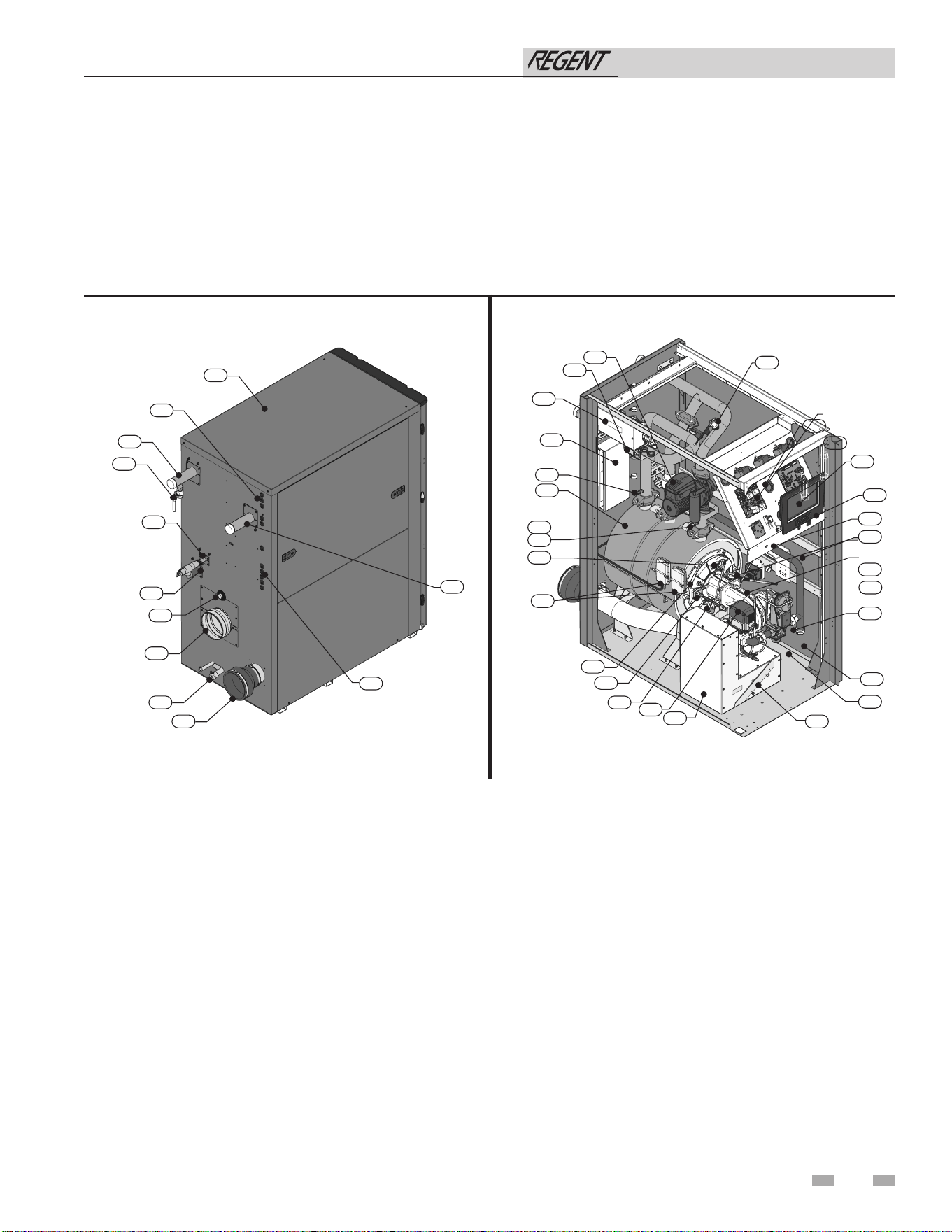
The Regent Water Heater - How it works...
1. Stainless steel heat exchanger
Allows water to flow through specially designed coils for maximum
heat transfer, while providing protection against flue gas corrosion.
The coils are encased in a jacket that contains the combustion
process.
2. Combustion chamber access cover
Allows access to the combustion side of the heat exchanger coils.
3. Blower
The blower pulls in air and gas through the venturi (item 5). Air
and gas mix inside the blower and are pushed into the burner, where
they burn inside the combustion chamber.
4. Gas valve
The gas valve controls the flow of gas into the venturi. It allows
gas to flow only if the gas regulator is powered and combustion
air is flowing.
5. Venturi (not shown)
The venturi controls air and gas flow into the burner.
6. Flue gas sensor (limit rated, not shown)
This sensor monitors the flue gas exit temperature. The control
module will modulate and shut down the water heater if the flue gas
temperature gets too hot. This protects the flue pipe from
overheating.
7. Water heater outlet temperature sensor (housed with the
high limit sensor)
This sensor monitors water heater outlet water temperature (system
supply). The control adjusts firing rate so the outlet temperature
meets the setpoint.
8. Water heater inlet temperature sensor
This sensor monitors the inlet water temperature (system return) to
the water heater.
9. Flow Switch
The flow switch is a safety device that ensures flow through the heat
exchanger primary coils during operation. The flow switch makes
contact when flow is detected and allows the unit to operate. If
primary coil flow is discontinued during operation for any reason
the flow switch will break the control circuit and the unit will shut
down.
10. Electronic display
Digital controls with SMART TOUCH screen technology, full color
display, and an 10" user interface screen.
11. Flue pipe adapter
Allows for the connection of the PVC vent pipe system to the
water heater.
12. Burner (not shown)
Made with metal fiber and stainless steel construction, the burner
uses pre-mixed air and gas and provides a wide range of firing rates.
13. Water outlet
Water connection that supplies hot water to the system.
14. Water inlet
Water connection that supplies water to the water heater.
15. Gas connection pipe
Threaded pipe connection. This pipe should be connected to the
incoming gas supply for the purpose of delivering gas to the water
heater.
16. Boiler Integrated Control (BIC) Board
The BIC responds to internal and external signals and controls the
blower, gas valve, and pumps to meet the demand.
17. Air intake adapter
Allows for the connection of the PVC air intake pipe to the
water heater.
18. High voltage junction box
The junction box contains the connection points for the line voltage
power. It also houses the relay for the internal pump.
19. Water heater drain port
Location from which the heat exchanger can be drained.
20. Low voltage junction box
The junction box contains the connection points for external
low voltage devices.
21. Low voltage wiring connections (knockouts)
Conduit connection points for the low voltage connection
board.
22. Condensate drain connection
Connects the heat exchanger condensate drain to the supplied
condensate trap
23. Access door - front (not shown)
Provides access to the gas train and the heat exchanger.
24. Ignition electrode
Provides direct spark for igniting the burner.
25. Flame inspection window
The quartz glass window provides a view of the burner surface
and flame.
26. Gas shutoff valve (not shown)
Manual valve used to isolate the gas valve from the gas supply.
27. High limit sensor (housed with the outlet temperature
sensor)
Device that monitors the outlet water temperature. If the
temperature exceeds its setting, the integrated control will
break the control circuit, shutting the water heater down.
28. Relief valve
Protects the heat exchanger from over pressure conditions. The
relief valve is set at 150 PSI.
29. Flame sensor
Used by the control module to detect the presence of burner
flame.
30. Line voltage wiring connections (knockouts)
Conduit connection points for the high voltage junction box.
31. Top panel
Removable panel to gain access to the internal components.
32. Power switch
Turns 120VAC ON/OFF to components outside the high voltage
junction box.
33. Air box
The air box houses the combustion air filter.
34. Combustion Feedback Board
The Combustion Feedback board responds to internal and
external signals and controls the fan, and gas and air dampers to
meet the demand.
35. Blower relay
The blower relay is used to control the blower.
36. Transformers
There are three (3) transformers located on the main control
panel. Each transformer provides 24VAC to specific components
within the control circuit.
37. Air filter
The air filter prevents dirt and debris from entering the burner.
38. Damper actuator motors (2)
The damper actuator motors move both the air and gas dampers
independently. The damper actuator motors are part of the air
intake assembly.
39. O2 Sensor
The O2 (Oxygen) Sensor senses the amount of oxygen in the flue
products within the combustion chamber and sends the
information to the control system.
The Regent Water Heater - How it works...
Installation & Operation Manual
5
40. Safety shutoff regulating actuator with POC
The safety shutoff actuator senses the negative pressure created
by the blower, allowing gas to flow only if the valves are powered
and combustion air is flowing.
41. Internal circulation pump
The internal circulation pump circulates water through the
primary coils of the heat exchanger. This pump is powered at all
times.
42. Water flow sensor
The water flow sensor measures the water flow rate into the water
heater through the inlet pipe.
43. Commissioning drain valve
The commissioning drain valve is used to generate a hot water
demand during the water heater commissioning process when a
demand cannot be created using the hot water system.
44. Air pressure switches
The air pressure switches detect blocked flue/vent conditions.
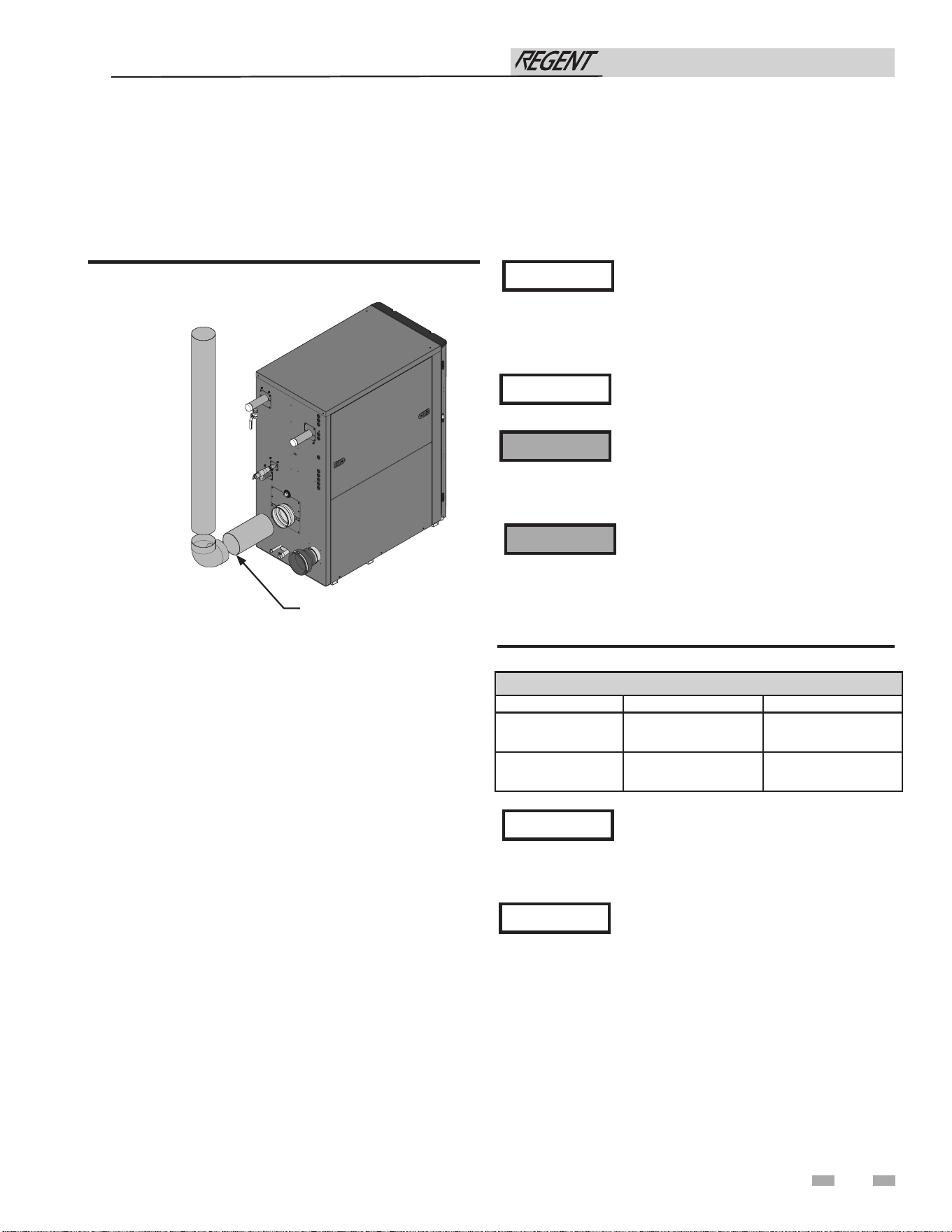
Models 500 - 1000
Rear View - Models 500 - 1000
Left Side (inside unit) - Models 500 - 1000
41
42
18
20
8
1
7
27
25
44
2
39
29
38
33
37
4
15
40
24
3
32
35
10
16
36
9
34
31
13
30
43
28
15
11
22
17
21
14
19
6
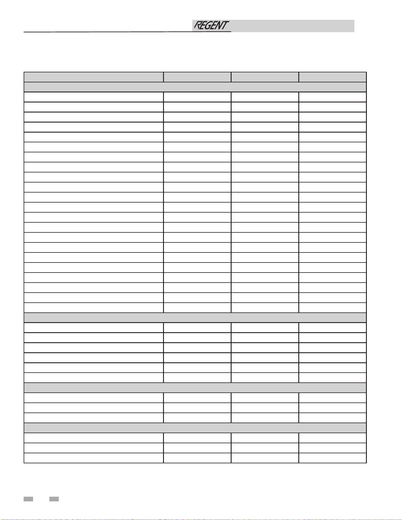
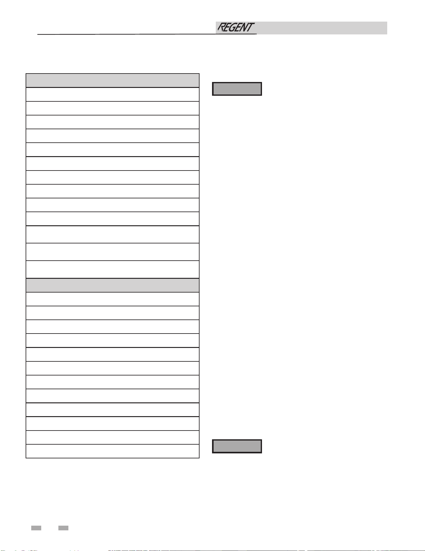
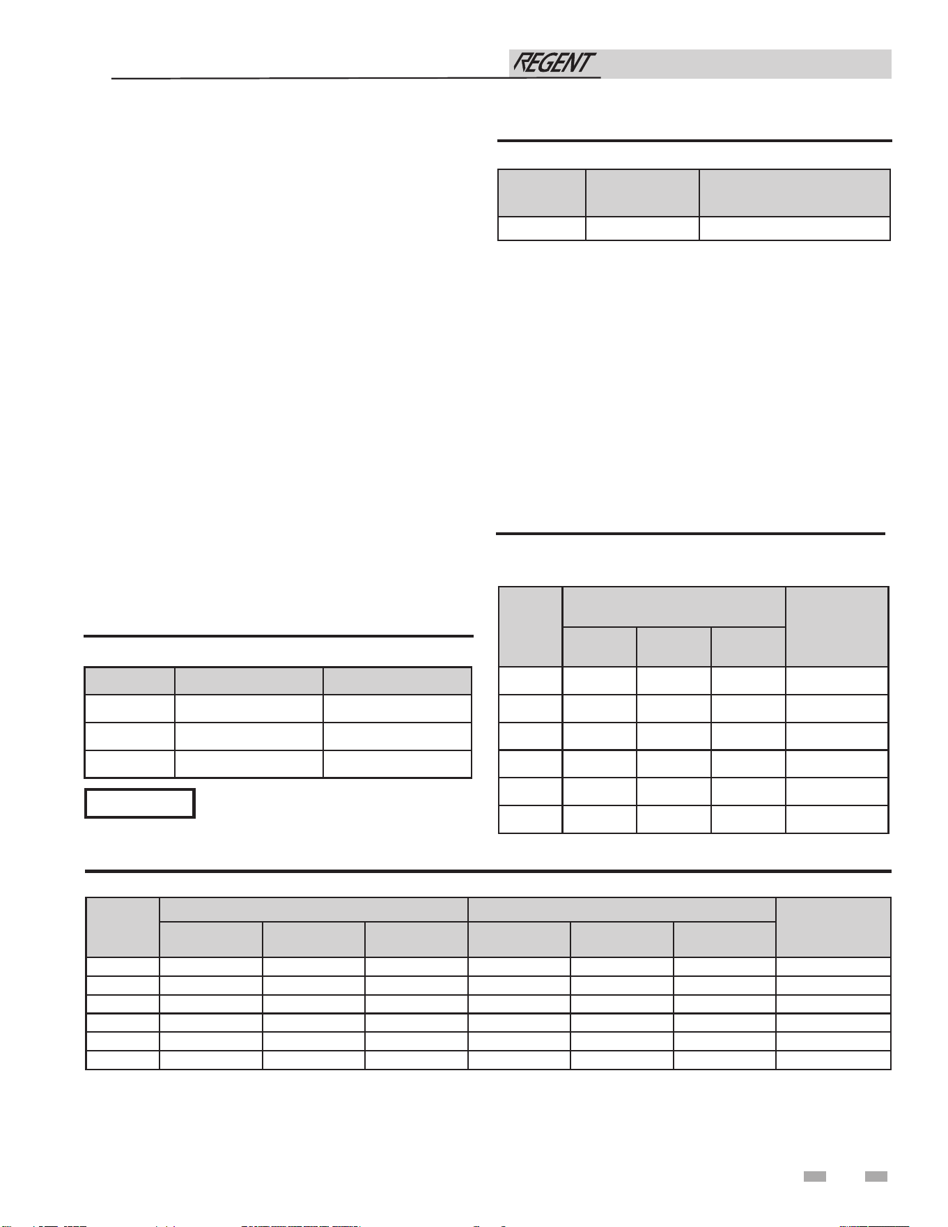
IWH0500 IWH0750 IWH1000
WATER
GALLON CAPACITY 6.0 7.1 9.6
HEATING SURFACE (SQ. FT.) 39.10 60.90 75.40
WATER CONNECTION SIZE 2" 2" 2"
WATER CONNECTION TYPE SWEAT/GROOVE SWEAT/GROOVE SWEAT/GROOVE
DRAIN 3/4" 3/4" 3/4"
MAXIMUM WATER FLOW RATE (GPM) 50 70 75
GPM @ 70F Rise 14 21 27
HEAD LOSS (FT. OF HD.) 0 0 0
GPM @ 100F Rise 10 14 19
HEAD LOSS (FT. OF HD.) 0 0 0
GPM @ 140F Rise 7 10 14
HEAD LOSS (FT. OF HD.) 0 0 0
MAX. WORKING PRESSURE (PSI) 160 160 160
MIN. WORKING PRESSURE (PSI) 30 30 30
MAX. WATER HARDNESS (GRAINS) 15 15 15
GPH @ 70°F RISE 822 1236 1644
GPH @ 100°F RISE 576 864 1152
GPH @ 140°F RISE 408 612 822
# OF RELIEF VALVES 1 1 1
RELIEF VALVE SIZE 3/4 NPT 3/4 NPT 3/4 NPT
RELIEF VALVE RATING (MBH) 2,703 2,703 2,703
RELIEF VALVE PRESSURE RATING (PSI) 150 150 150
GAS
INLET CONNECTION 1" 1" 1-1/4"
MAX. INLET PRESSURE, NAT 14.0" w.c. 14.0" w.c. 14.0" w.c.
MIN. INLET PRESSURE, NAT 2.5" w.c. 2.5" w.c. 2.5" w.c.
MAX. INLET PRESSURE, LP 14.0" w.c. 14.0" w.c. 14.0" w.c.
MIN. INLET PRESSURE, LP 8.0" w.c. 8.0" w.c. 8.0" w.c.
BTU/HR INPUT 500,000 750,000 1,000,000
ELECTRICAL
VOLTAGE & PHASE / HEATER 120V / 1ø 120V / 1ø 120V / 1ø
TOTAL AMPS (FLA) <12.5 17.5 17.5
VOLTAGE / CONTROL 24V 24V 24V
DIMENSIONS
HEIGHT 64" 64" 64"
WIDTH 30" 30" 30"
DEPTH 41" 51" 58"
The Regent Water Heater - How it works...
PRODUCT SUMMARY
Installation & Operation Manual
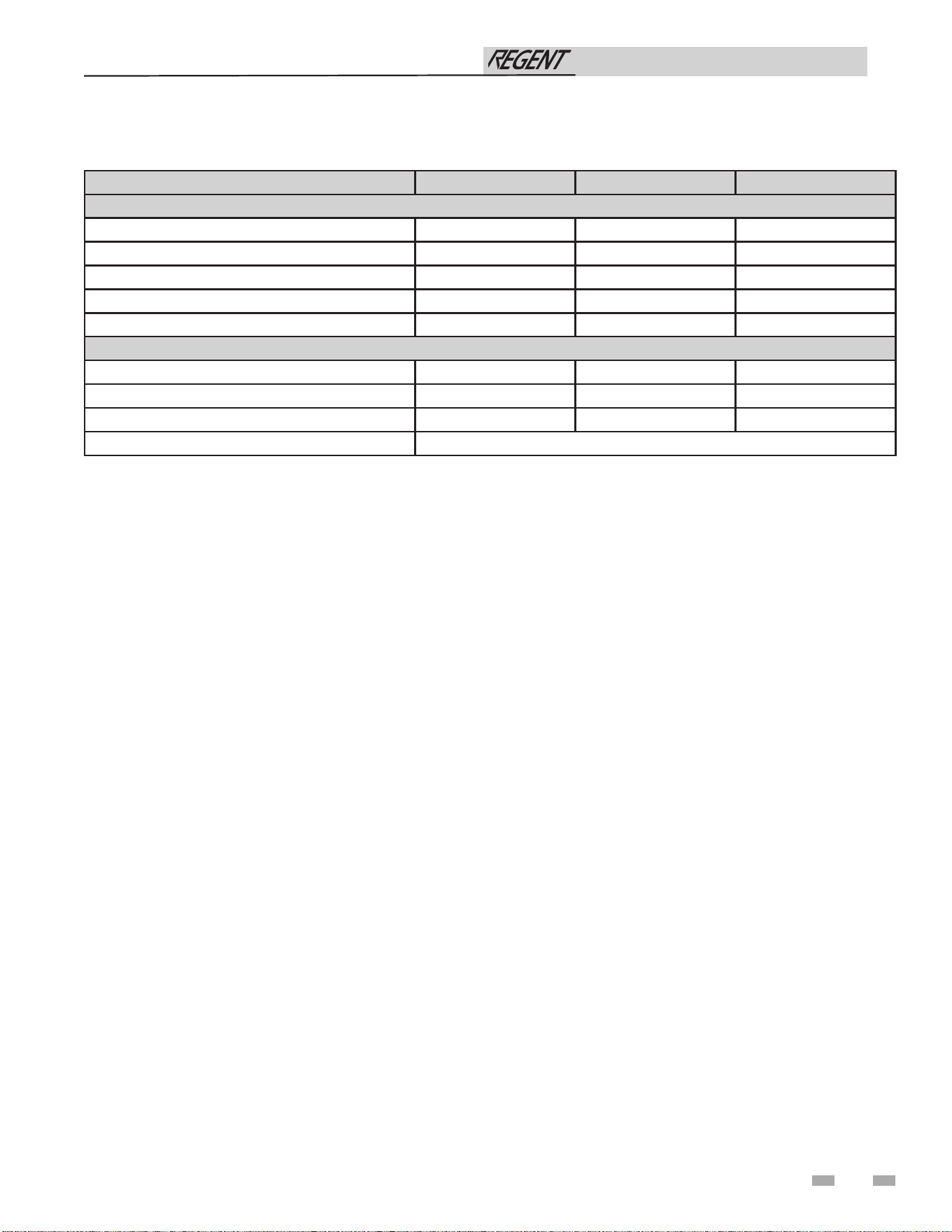
7
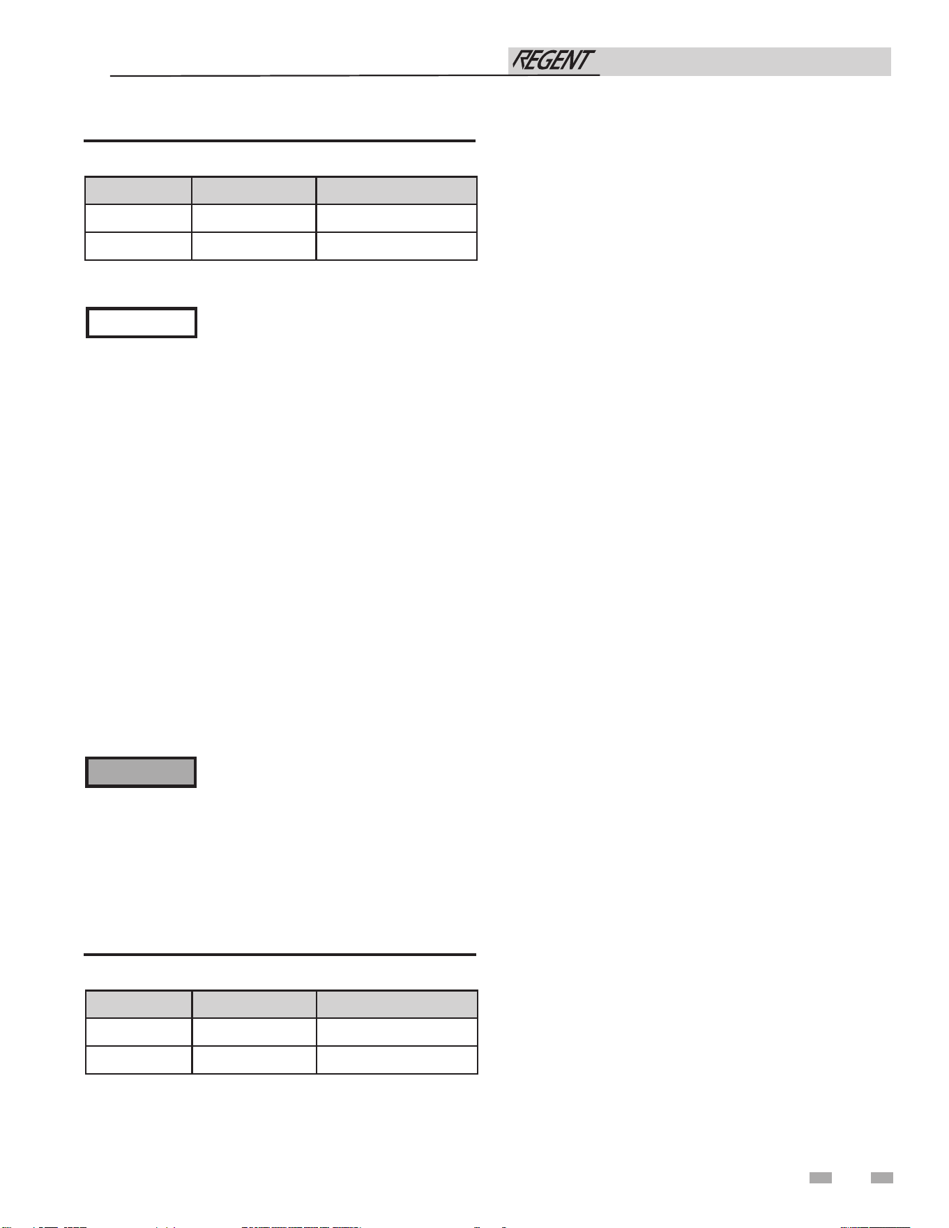
IWH0500 IWH0750 IWH1000
SERVICE CLEARANCES
FRONT 36" 36" 36"
BACK 24" 24" 24"
RIGHT SIDE 0" 0" 0"
LEFT SIDE 24" 24" 24"
TOP 0" 0" 0"
DIRECT VENTING
VENT CONNECTION SIZE 4" 6" 6"
AIR INTAKE CONNECTION SIZE 4" 6" 6"
VENT CATEGORY IV IV IV
VENT MATERIAL (all models) PVC / CPVC / Polypropylene / Stainless Steel
The Regent Water Heater - How it works...
PRODUCT SUMMARY continued
Installation & Operation Manual
Installation & Operation Manual
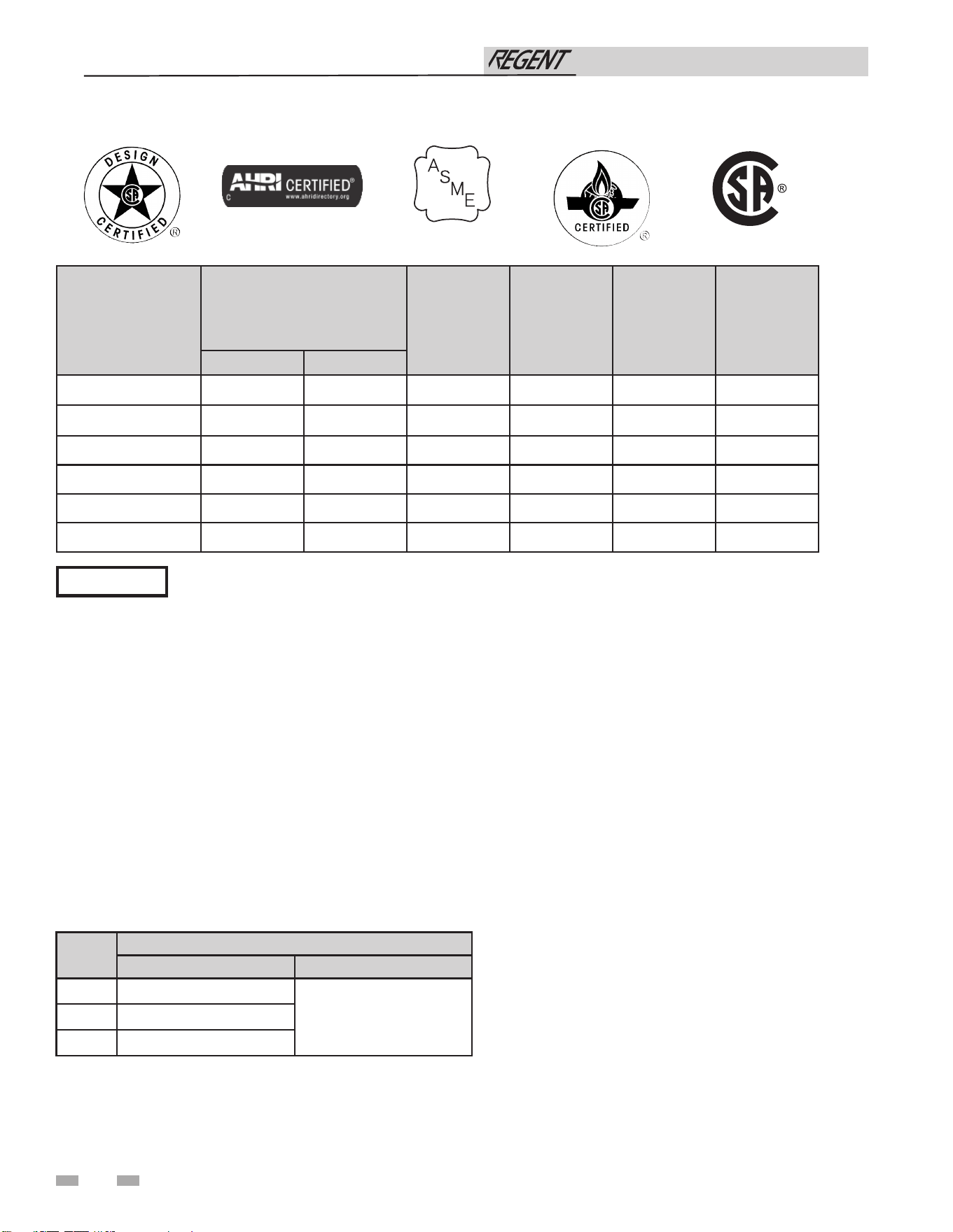
Ratings
Notes:
1. Regent water heaters require special gas venting. Use
only the vent materials and methods specified in the IWH
Installation and Operation Manual.
2. Standard Regent water heaters are equipped to operate
from sea level to 4,500 feet only with no adjustments.
For United States installations above 2,000 feet elevation,
reference NFPA 54 for derate information.
De-rate values are based on proper combustion calibration
and CO2 adjusted to the recommended levels.
3. High altitude Regent water heaters are equipped to operate
above 2,000 feet elevation. See the chart for derate values
for each model. Reference NFPA 54 for derate calculations
for installations above 5,200 feet elevation.
8
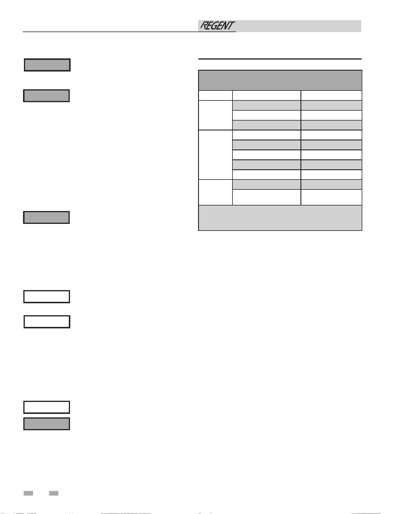
Maximum allowed working pressure is located on the rating plate.
NOTICE
Model Number
Note: Change “N”
to “L” for L.P. gas
models.
CSA
Input Modulation MBtu/hr
Water Content
Gallons
Water
Connection
Gas Connection
Vent/Air Size
Min Max
IWH0500(N) 40 500 6.0 2" 1" 4"/4"
IWH0750(N) 40 750 7.1 2" 1" 6”/6”
IWH1000(N) 40 1,000 9.6 2" 1-1/4" 6”/6”
IWH0500(L) 40 500 6.0 2" 1" 4"/4"
IWH0750(L) 40 750 7.1 2" 1" 6"/6"
IWH1000(L) 40 1000 9.6 2” 1-1/4” 6”/6”
HLW
LOW LEAD CONTENT
Model
Derate per 1,000 feet
Derate up to 5,200 feet Derate above 5,200 feet
IWH0500
0.2%
Reference NFPA 54
IWH0750
0.3%
IWH1000
0.4%
Installation & Operation Manual
1 Determine water heater location
9
The Regent water heater gas manifold
and controls met safe lighting and other
performance under tests specified in ANSI
Z21.10.3 – latest edition.
Failure to keep water heater area clear and
free of combustible materials, gasoline, and
Installation must comply with:
• Local, state, provincial, and national codes, laws, regulations,
and ordinances.
• National Fuel Gas Code, ANSI Z223.1 – latest edition.
• National Electrical Code.
• For Canada only: B149.1 Installation Code, CSA C22.1
Canadian Electrical Code Part 1 and any local codes.
Before locating the water heater, check:
1. Check for nearby connection to:
• Water piping
• Venting connections
• Gas supply piping
• Electrical power
2. Locate the appliance so that if water connections should
leak, water damage will not occur. When such locations
cannot be avoided, it is recommended that a suitable
drain pan, adequately drained, be installed under the
appliance. The pan must not restrict combustion air
flow. Under no circumstances is the manufacturer to be
held responsible for water damage in connection with
this appliance, or any of its components.
3. Check area around the water heater. Remove any
combustible materials, gasoline, and other flammable
liquids.
4. The Regent water heater must be installed so that gas control
system components are protected from dripping or spraying
water or rain during operation or service.
5. If a new water heater will replace an existing water heater,
check for and correct system problems, such as system leaks
causing oxygen corrosion or heat exchanger cracks from
hard water deposits.
6. Check around the water heater for any potential air
contaminants that could risk corrosion to the water heater
or the water heater combustion air supply (see Table 1A).
Prevent combustion air contamination. Remove any of
these contaminants from the water heater area.
Provide clearances:
Clearances from combustible materials
1. Hot water pipes—at least 1/4" (6 mm) from combustible
materials.
2. Vent pipe – Follow special vent system manufacturer’s
instructions.
3. See FIG. 1-1 and 1-2 for other clearance minimums.
Recommended clearances for service access
- Front ..................................................................................... 36"
- Top ........................................................................................ 0"
- Rear ....................................................................................... 24"
- Left ........................................................................................ 24"
- Right ...................................................................................... 0"
Closet and alcove installations
This appliance requires a special venting
system. If using PVC the vent connection
For closet and alcove installations as shown
in FIG. 1-1 and 1-2, CPVC vent material
⚠ WARNING
⚠ WARNING
NOTICE
⚠ WARNING
Regent water heaters may be installed in a closet or alcove as
shown in FIG. 1-1 and 1-2.
⚠ WARNING
Unless equipped with the outdoor conversion
kit listed in this manual, this product is
DO NOT install units in rooms or
environments that contain corrosive
⚠ WARNING
If you do not provide the recommended
service clearances shown, it may not be
NOTICE
DO NOT install the appliance in a location likely to freeze.
certified as an indoor appliance (See Section 6). Do not install
the appliance outdoors or locate where the appliance will be
exposed to freezing temperatures.
Do not install the appliance where condensation may form on
the inside or outside of the appliance, or where condensation
may fall onto the appliance.
Failure to install the appliance indoors could result in severe
personal injury, death, or substantial property damage.
to the appliance must be made with a CPVC pipe section. The
field provided vent fittings must be cemented to the CPVC
pipe section. Use only the vent materials, primer and cement
specified in this manual to make the vent connections. Failure
to follow this warning could result in fire, personal injury, or
death.
other flammable liquids and vapors can result in severe personal
injury, death, or substantial property damage.
contaminants (see Table 1A). Failure to comply could result in
severe personal injury, death, or substantial property damage.
must be used inside the structure. The ventilating air openings
shown in FIG. 1-1 and 1-2 are required for this arrangement.
Failure to follow this warning could result in fire, personal
injury, or death.
possible to service the appliance without removing it from the
space.
1 Determine water heater location
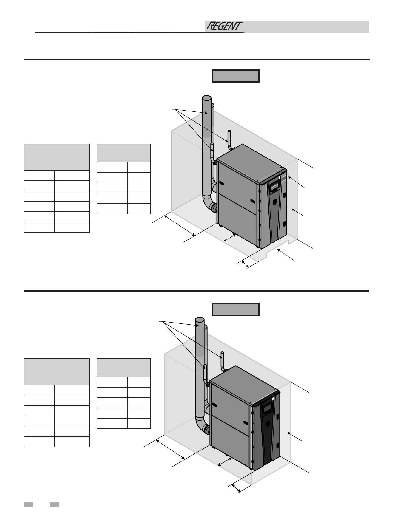
10
Figure 1-2 Alcove Installation - Minimum Required Clearances
Figure 1-1 Closet Installation - Minimum Required Clearances
⚠ WARNING
⚠ WARNING
For closet installations, CPVC,
polypropylene or stainless steel
vent material MUST BE used in
a closet structure due to elevated
temperatures. Failure to follow
this warning could result in fire,
personal injury, or death.
For alcove installations, CPVC,
polypropylene or stainless-steel
vent material MUST BE used in
an alcove structure due to elevated
temperatures. Failure to follow
this warning could result in fire,
personal injury, or death.
Installation & Operation Manual
VENTILATING
AIR OPENING
VENTILATING
AIR OPENING
CLOSED DOOR
0"
RIGHT
36"
FRONT
24"
REAR
24"
LEFT
0"
TOP
1/4" (6MM) MINIMUM CLEARANCE
AROUND HOT WATER PIPES
1" (25 MM) MINIMUM CLEARANCE
AROUND VENT PIPE
OPEN FRONT
0"
RIGHT
36"
FRONT
24"
REAR
24"
LEFT
0"
TOP
1/4" (6MM) MINIMUM CLEARANCE
AROUND HOT WATER PIPES
1" (25 MM) MINIMUM CLEARANCE
AROUND VENT PIPE
COMBUSTION
CLEARANCES
FRONT 0”
REAR 0”
SIDES 0”
TOP 0"
FLOOR 0"
RECOMMENDED
SERVICE
CLEARANCES
FRONT 36"
TOP 0"
LEFT 24"
RIGHT 0"
REAR 24"
FLOOR 0"
COMBUSTION
CLEARANCES
FRONT 0”
REAR 0”
SIDES 0”
TOP 0"
FLOOR 0"
RECOMMENDED
SERVICE
CLEARANCES
FRONT 36"
TOP 0"
LEFT 24"
RIGHT 0"
REAR 24"
FLOOR 0"
1 Determine water heater location (continued)
11
Provide air openings to room:
Regent water heater alone in equipment room
1. No air ventilation openings into the equipment room are
needed when clearances around the Regent water heater
are at least equal to the SERVICE clearances shown in this
manual. For spaces that do NOT supply this clearance,
provide two openings as shown in FIG. 1-1. Each opening
must provide one square inch free area per 1,000 Btu/hr of
water heater input.
2. Combustion air openings are required when using the
Room Air Option listed on page 19 of this manual.
Regent water heater in same space with other gas or
oil-fired appliances
1. Follow the National Fuel Gas Code (U.S.) or CSA B149.1
(Canada) to size/verify size of the combustion/ventilation
air openings into the space.
The space must be provided with combustion/
ventilation air openings correctly sized for all
other appliances located in the same space as
the Regent water heater.
Do not install the water heater in an attic.
Failure to comply with the above warnings
could result in severe personal injury, death,
or substantial property damage.
2. Size openings only on the basis of the other appliances in
the space. No additional air opening free area is needed
for the Regent water heater when it takes its combustion air
from outside (direct vent installation).
Do not install the water heater on carpeting
even if foundation is used. Fire can result,
causing severe personal injury, death, or
substantial property damage.
If flooding is possible, elevate the water heater sufficiently to
prevent water from reaching the water heater.
Flooring and foundation
Flooring
The Regent water heater is approved for installation on
combustible flooring but must never be installed on carpeting.
Residential garage installation
Precautions
Take the following precautions when installing the appliance in
a residential garage. If the appliance is located in a residential
garage, it should be installed in compliance with the latest
edition of the National Fuel Gas Code, ANSI Z223.1 and/or
CAN/CGA-B149 Installation Code.
• Appliances located in residential garages and in
adjacent spaces that open to the garage and are not part
of the living space of a dwelling shall be installed so that
all burners and burner ignition devices are located not
less than 18 inches (46 cm) above the floor.
• The appliance shall be located or protected so that it is
not subject to physical damage by a moving vehicle.
Vent and air piping
The Regent water heater requires a special vent system, designed
for pressurized venting.
The water heater is to be used for either direct vent installation
or for installation using indoor combustion air. When room air
is considered, see the General Venting Section. Note prevention
of combustion air contamination below when considering vent/
air termination.
Vent and air must terminate near one another and may be
vented vertically through the roof or out a side wall, unless
otherwise specified. You may use any of the vent/air piping
methods covered in this manual. Do not attempt to install the
Regent water heater using any other means.
Be sure to locate the water heater such that the vent and air piping
can be routed through the building and properly terminated.
The vent/air piping lengths, routing and termination method
must all comply with the methods and limits given in this
manual.
Prevent combustion air contamination
Install air inlet piping for the Regent water heater as described
in this manual. Do not terminate vent/air in locations that can
allow contamination of combustion air. Refer to Table 1A, for
products and areas which may cause contaminated combustion
air.
You must pipe combustion air to the
water heater air intake. Ensure that the
⚠ WARNING
⚠ WARNING
⚠ WARNING
Seismic bracing
For installations requiring seismic bracing, the base legs of the
appliance are designed to allow for the use of unistrut channel
to meet seismic requirements.
combustion air will not contain any of the contaminants in
Table 1A. Contaminated combustion air will damage the water
heater, resulting in possible severe personal injury, death, or
substantial property damage. Do not pipe combustion air near
a swimming pool, for example. Also avoid areas subject to
exhaust fumes from laundry facilities. These areas will always
contain contaminants.
Installation & Operation Manual
1 Determine water heater location
12
Products to avoid:
Spray cans containing chloro/fluorocarbons
Permanent wave solutions
Chlorinated waxes/cleaners
Chlorine-based swimming pool chemicals
Calcium chloride used for thawing
Sodium chloride used for water softening
Refrigerant leaks
Paint or varnish removers
Hydrochloric acid/muriatic acid
Cements and glues
Antistatic fabric softeners used in clothes dryers
Chlorine-type bleaches, detergents, and cleaning solvents
found in household laundry rooms
Adhesives used to fasten building products and other similar
products
Areas likely to have contaminants
Dry cleaning/laundry areas and establishments
Swimming pools
Metal fabrication plants
Beauty shops
Refrigeration repair shops
Photo processing plants
Auto body shops
Plastic manufacturing plants
Furniture refinishing areas and establishments
New building construction
Remodeling areas
Garages with workshops
Table 1A Corrosive Contaminants and Sources
Failure to follow all instructions can result
in flue gas spillage and carbon monoxide
emissions, causing severe personal injury
or death.
⚠ WARNING
When using an existing vent system to
install a new water heater:
Check the following venting components before installing:
• Material - For materials listed for use with this appliance,
see Section 3 - General Venting. For polypropylene or
stainless-steel venting, an adapter of the same
manufacturer must be used at the flue collar connection.
• Size - To ensure proper pipe size is in place, see Table 3A.
Check to see that this size is used throughout the vent
system.
• Manufacturer - For a stainless steel or polypropylene
application, you must use only the listed manufacturers
and their type product listed in Tables 3I and 3K for CAT
IV positive pressure venting with flue producing
condensate.
• Supports - Non-combustible supports must be in place
allowing a minimum 1/4" rise per foot. The supports
should adequately prevent sagging and vertical slippage,
by distributing the vent system weight. For additional
information, consult the vent manufacturer’s
instructions for installation.
• Terminations - Carefully review Sections 3 through 5 to
ensure requirements for the location of the vent and air
terminations are met and orientation of these fit the
appropriate image from the Horizontal or Vertical
options listed in the General Venting Section. For
stainless steel vent, only use terminations listed in Table
3L for the manufacturer of the installed vent.
• Seal - With prior requirements met, the system should be
tested to the procedure listed in parts (c) through (f) of
the Removal of an Existing Water Heater Section.
With polypropylene and stainless-steel vent, seal and connect
all pipe and components as specified by the vent manufacturer
used; with PVC/CPVC vent, see the Installing Vent or Air
Piping Section.
⚠ WARNING
If any of these conditions are not met,
the existing system must be updated or
replaced for that concern. Failure to follow
all instructions can result in flue gas spillage
and carbon monoxide emissions, causing
severe personal injury or death.
Installation & Operation Manual
13
1 Determine water heater location (continued)
When removing a water heater from
existing common vent system:
Combustion and ventilation air
requirements for appliances drawing air
from the equipment room
Do not install the Regent water heater into
a common vent with any other appliance.
This will cause flue gas spillage or appliance
malfunction, resulting in possible severe
personal injury, death, or substantial
property damage.
Failure to follow all instructions can result
in flue gas spillage and carbon monoxide
emissions, causing severe personal injury
or death.
At the time of removal of an existing water heater, the
following steps shall be followed with each appliance remaining
connected to the common venting system placed in operation,
while the other appliances remaining connected to the common
venting system are not in operation.
a. Seal any unused openings in the common venting system.
b. Visually inspect the venting system for proper size and
horizontal pitch and determine there is no blockage or
restriction, leakage, corrosion, or other deficiencies, which
could cause an unsafe condition.
c. Test vent system – Insofar as is practical, close all building
doors and windows and all doors between the space in
which the appliances remaining connected to the common
venting system are located and other spaces of the building.
Turn on clothes dryers and any appliance not connected to
the common venting system. Turn on any exhaust fans,
such as range hoods and bathroom exhausts, so they will
operate at maximum speed. Do not operate a summer
exhaust fan. Close fireplace dampers.
d. Place in operation the appliance being inspected. Follow
the lighting instructions. Adjust thermostat so appliance
will operate continuously.
e. Test for spillage at the draft hood relief opening after 5
minutes of main burner operation. Use the flame of a
match or candle, or smoke from a cigarette, cigar, or pipe.
f. After it has been determined that each appliance remaining
connected to the common venting system properly vents
when tested as outlined herein, return doors, windows,
exhaust fans, fireplace dampers, and any other gas-burning
appliance to their previous conditions of use.
g. Any improper operation of the common venting system
should be corrected so the installation conforms with the
National Fuel Gas Code, ANSI Z223.1/NFPA 54 and/or
CAN/CSA B149.1, Natural Gas and Propane Installation
Code. When resizing any portion of the common venting
system, the common venting system should be resized
to approach the minimum size as determined using the
appropriate tables in Part 11 of the National Fuel Gas Code,
ANSI Z223.1/NFPA and/or CAN/CSA B149.1, Natural Gas
and Propane Installation Code.
Provisions for combustion and ventilation air must be in
accordance with Air for combustion and Ventilation, of the
latest edition of the National Fuel Gas Code, NFPA 54 / ANSI
Z2223.1, in Canada, the latest edition of CGA Standard B149
Installation Code for Gas Burning Appliances and Equipment,
or applicable provisions of the local building codes.
The equipment room MUST be provided with properly
sized openings and/or be of sufficient volume to assure
adequate combustion air and proper ventilation for all gas
fired appliances in the equipment room to assure adequate
combustion air proper ventilation.
The requirements shown are for the appliance only; additional
gas fired appliances in the equipment room will require an
increase in the net free area and/or volume to supply adequate
combustion air for all appliances.
No combustion air openings are needed when the appliance is
installed in a space with a volume NO LESS than 50 cubic feet
per 1,000 Btu/hr of all installed gas fired appliances and the
building MUST NOT be of “Tight Construction”3.
A combination of indoor and outdoor combustion air may
be utilized by applying a ratio of available volume to required
volume times the required outdoor air opening(s) size(s). This
must be done in accordance with the National Fuel Gas Code,
NFPA 54 / ANSI Z223.1.
⚠ DANGER
⚠ WARNING
Installation & Operation Manual
14
2 Prepare water heater
Combustion air filter
This unit has a standard air filter located at the combustion air
inlet. This air filter is provided to help ensure clean air is used
for the combustion process. Check this filter every month and
replace when it becomes dirty. You can find these commercially
available filters at any home center or HVAC supply store.
Filters by model sizes:
IWH0500-1000 / 14 x 14 x 1 filter
Note: Replacement filter should have a MERV rating no greater
than 4.
Follow the steps below when replacing the combustion air filter:
1. Locate the combustion air filter box.
2. Remove the front cover from the air filter box to gain access
to the air filter.
3. Slide the air filter out the front of the air filter box.
4. Inspect the air filter for dirt and debris, replace if necessary.
5. Replace the air filter and the air filter box cover.
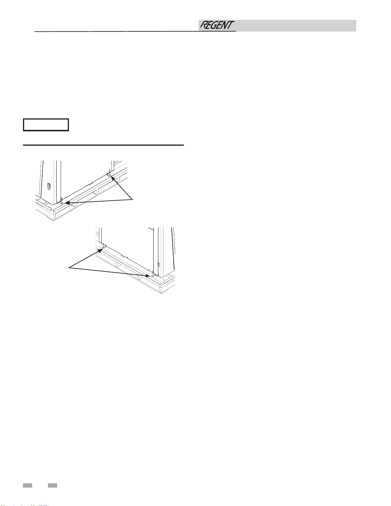
Remove water heater from wood pallet
1. After removing the outer shipping carton from the water
heater, remove the parts box.
2. To remove the water heater from the pallet, remove the
four (4) lag bolts located at the front and rear of the unit
(FIG 2-1).
Do not drop the water heater or bump the
jacket on the floor or pallet. Damage to the
water heater can result.
NOTICE
Figure 2-1 Water Heater Mounted on Shipping Pallet
Installation & Operation Manual
RIGHT SIDE
LAG BOLTS (2)
LEFT SIDE
LAG BOLTS (2)
3 General venting
15
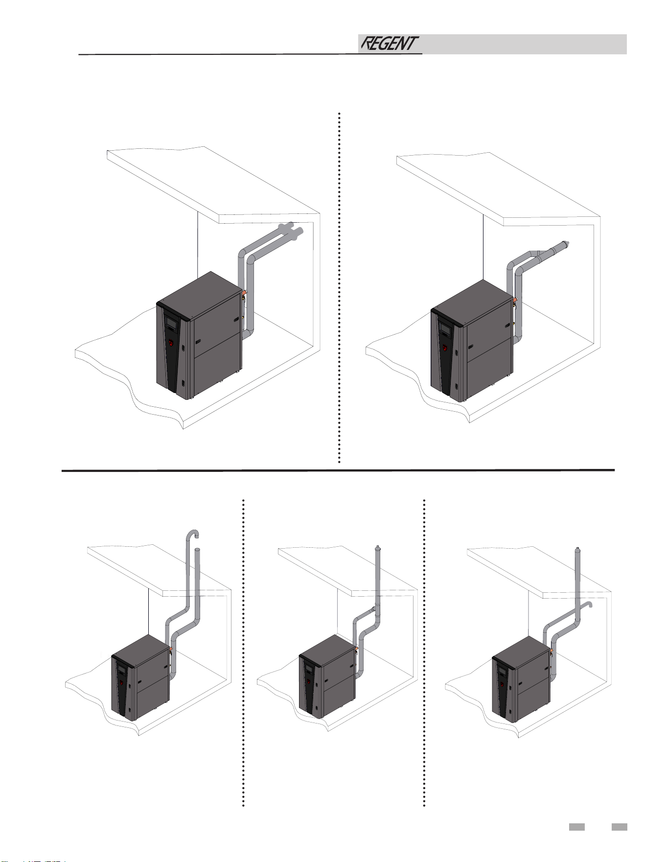
Figure 3-1 Two-Pipe Sidewall Termination
Figure 3-3 Two-Pipe Vertical
Termination
Direct venting options - Sidewall Vent
Figure 3-2 PVC/CPVC Concentric Sidewall Termination
Figure 3-4 PVC/CPVC Concentric
Vertical Termination
Figure 3-5 Vertical Vent, Sidewall Air
Direct venting options - Vertical Vent
Installation & Operation Manual
2000845690_000
2000845690_000
2000845690_000
2000845690_000
2000845690_000
3 General venting (continued)
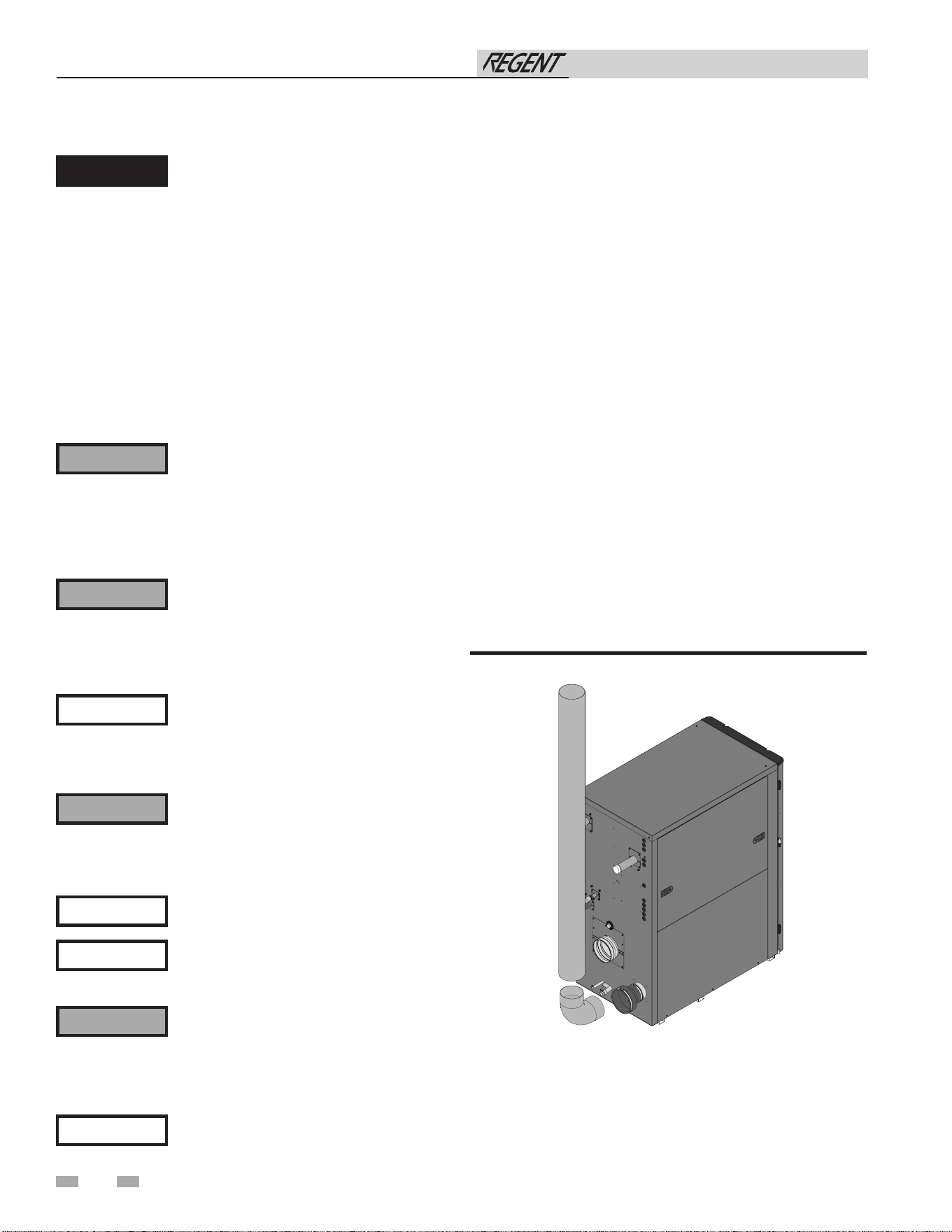
Figure 3-6 Near Water Heater Air Piping Model 500
This appliance requires a special venting
system. Use only approved stainless steel,
PVC, CPVC or polypropylene pipe and
fittings listed in Tables 3H, 3I, and 3K for
vent pipe, and fittings. Failure to comply
could result in severe personal injury,
death, or substantial property damage.
Installation must comply with local
requirements and with the National
Fuel Gas Code, ANSI Z223.1 for U.S.
installations or CSA B149.1 for Canadian
installations.
Install vent and combustion air piping
⚠ DANGER
The Regent water heater must be vented and
supplied with combustion and ventilation
air as described in this section. Ensure the
vent and air piping and the combustion
air supply comply with these instructions
regarding vent system, air system, and
combustion air quality. See also Section 1
of this manual.
Inspect finished vent and air piping
thoroughly to ensure all are airtight and
comply with the instructions provided and
with all requirements of applicable codes.
Failure to provide a properly installed vent
and air system will cause severe personal
injury or death.
⚠ WARNING
NOTICE
⚠ WARNING
For closet and alcove installations, CPVC,
polypropylene or stainless-steel material
MUST BE used in a closet/alcove structure.
Failure to follow this warning could result
in fire, personal injury, or death.
Air intake/vent connections
1. Combustion Air Intake Connector (FIG. 3-6) - Used to
provide combustion air directly to the unit from outdoors. A
fitting is provided on the unit for final connection.
Combustion air piping must be supported per guidelines
listed in the National Mechanical Code, Section 305, Table
305.4 or as local codes dictate.
2. Vent Connector (FIG. 3-7 thru 3-10) - Used to provide a
passageway for conveying combustion gases to the
outside. A transition fitting is provided on the unit for
final connection. Vent piping must be supported per the
National Building Code, Section 305, Table 305.4 or as
local codes dictate.
The Regent water heater vent and air piping can be installed
through the roof or through a sidewall. Follow the procedures
in this manual for the method chosen. Refer to the information
in this manual to determine acceptable vent and air piping
length.
You may use any of the vent/air piping methods covered in
this manual. Do not attempt to install the Regent water heater
using any other means.
You must also install air piping from outside to the water
heater air intake adapter unless following the Optional Room
Air instructions in this manual. The resultant installation is
direct vent (sealed combustion).
⚠ WARNING
DO NOT mix components from different
systems. The vent system could fail,
causing leakage of flue products into the
living space. Mixing of venting materials
will void the warranty and certification of
the appliance.
⚠ WARNING
Do not connect any other appliance to
the vent pipe or multiple water heaters to
a common vent pipe. Failure to comply
could result in severe personal injury,
death, or substantial property damage.
Improper installation of venting systems
may result in injury or death.
⚠ CAUTION
Follow the instructions in Section 1 of this
manual when removing a water heater
from an existing vent system.
NOTICE
16
Vent system must be pitched 1/4"
minimum per foot back to the appliance
to allow drainage of condensate.
NOTICE
Installation & Operation Manual
3 General venting
17
Requirements for installation in
Canada
1. Installations must be made with a vent pipe system
certified to ULC-S636.
IPEX is an approved vent manufacturer in Canada
supplying vent material listed to ULC-S636.
2. The first three (3) feet of plastic vent pipe from the
appliance flue outlet must be readily accessible for visual
inspection.
3. The components of the certified vent system must not be
interchanged with other vent systems or unlisted
pipe/fittings. For concentric vent installations, the inner
vent tube must be replaced with field supplied certified
vent material to comply with this requirement.
4. The 4" Concentric Vent Kit available from Lochinvar
(see Section 4 – Sidewall Termination – Optional
Concentric Vent) and the 4" Concentric Vent Kit available
from IPEX is approved for use on the Regent water heater.
The kit is listed to the ULC-S636 standard for use in
Canada.
Model Kit Number
Equivalent Vent
Length
500 100140484 30 feet
Table 3B Concentric Vent Kit Equivalent Vent Lengths
Minimum / Maximum allowable combustion
air and vent piping lengths are shown in
Table 3D below:
Table 3A Air Intake/Vent Piping Sizes
Sizing
The Regent water heater uses model specific combustion air
intake and vent piping sizes as detailed in Table 3A below.
Increasing or decreasing combustion air or
vent piping sizes is not authorized, unless
referenced in manual.
NOTICE
When determining equivalent combustion air and vent length,
add 5 feet for each 90° elbow and 3 feet for each 45° elbow.
EXAMPLE: 20 feet of PVC pipe + (4) 90° elbows + (2) 45°
elbows + (1) concentric vent kit (100140484) = 76 equivalent
feet of piping.
Model Air Intake Vent
500 4 inches (102 mm) 4 inches (102 mm)
750 6 inches (152 mm) 6 inches (152 mm)
1000 6 inches (152 mm) 6 inches (152 mm)
Table 3D Direct Vent Minimum/Maximum Allowable Air/Vent Lengths
Table 3C Room Air Minimum/Maximum Allowable Vent
Lengths
Supports
Vent system must be supported horizontally to prevent sagging.
Methods and intervals for support vary by vent manufacturer
and vent material. Vent support methods and intervals shall
adhere to vent manufacturer’s instructions, where applicable.
Model
Vent
Input De-Rate
per 25 Feet
of Vent
Vent
Diameter
Vent Min.
Length
Vent Max.
Length
500(N)* 4" 12' 100' 0%
500(L)* 4" 12' 100' 0%
750(N)* 6" 12' 200' 0%
750(L)* 6" 12' 150' 0%
1000(N)* 6" 12' 200' 0%
1000(L)* 6" 12' 200' 0%
*High altitude models are limited to maximum 100' vent.
Model
Air Inlet Vent
Input De-Rate
per 25 Feet of
Vent
Air Intake
Diameter
Air Intake Min.
Length
Air Intake Max.
Length
Vent Diameter
Vent Min.
Length
Vent Max.
Length
500(N)* 4" 12' 100' 4" 12' 100' 0%
500(L)* 4" 12' 100' 4" 12' 100' 0%
750(N)* 6" 12' 200' 6" 12' 200' 0%
750(L)* 6" 12' 150' 6" 12' 150' 0%
1000(N)* 6" 12' 200' 6" 12' 200' 0%
1000(L)* 6" 12' 200' 6" 12' 200' 0%
*High altitude models are limited to maximum 100' vent and 100' air intake.
Installation & Operation Manual
3 General venting (continued)
18
Air inlet pipe materials:
The air inlet pipe(s) must be sealed. Choose acceptable
combustion air inlet pipe materials from the following list:
PVC, CPVC, Polypropylene or ABS
Dryer Vent or Sealed Flexible Duct (not recommended for
rooftop air inlet)
Galvanized steel vent pipe with joints and seams sealed as
specified in this section.
Type “B” double-wall vent with joints and seams sealed as
specified in this section.
AL29-4C, stainless steel material to be sealed to
specification of its manufacturer.
*Plastic pipe may require an adapter (not provided) to transition
between the air inlet connection on the appliance and the plastic
air inlet pipe.
⚠ WARNING
Using air intake materials other than those
specified can result in personal injury, death,
or property damage.
NOTICE
The use of double-wall vent or insulated
material for the combustion air inlet pipe is
recommended in cold climates to prevent
the condensation of airborne moisture in the
incoming combustion air.
Sealing of Type “B” double-wall vent material or galvanized
vent pipe material used for air inlet piping on a sidewall or
vertical rooftop Combustion Air Supply System:
a. Seal all joints and seams of the air inlet pipe using either
Aluminum Foil Duct Tape meeting UL Standard 723 or
181A-P or a high-quality UL Listed silicone sealant such as
those manufactured by Dow Corning or General Electric.
b. Do not install seams of vent pipe on the bottom of
horizontal runs.
c. Secure all joints with a minimum of three (3) sheet metal
screws or pop rivets. Apply Aluminum Foil Duct Tape or
silicone sealant to all screws or rivets installed in the vent
pipe.
d. Ensure that the air inlet pipes are properly supported.
The PVC, CPVC, or ABS air inlet pipe should be cleaned and
sealed with the pipe manufacturer’s recommended solvents
and standard commercial pipe cement for the material used.
The PVC, CPVC, ABS, Dryer Vent or Flex Duct air inlet pipe
should use a silicone sealant to ensure a proper seal at the
appliance connection and the air inlet cap connection. Dryer
vent or flex duct should use a screw type clamp to seal the vent
to the appliance air inlet and the air inlet cap. Proper sealing
of the air inlet pipe ensures that combustion air will be free of
contaminants and supplied in proper volume.
Follow the polypropylene manufacturer’s instructions when
using polypropylene material as an inlet pipe.
When a sidewall or vertical rooftop combustion air supply
system is disconnected for any reason, the air inlet pipe
must be resealed to ensure that combustion air will be free of
contaminants and supplied in proper volume.
⚠ DANGER
Failure to properly seal all joints and seams
as required in the air inlet piping may result
in flue gas recirculation, spillage of flue
products and carbon monoxide emissions
causing severe personal injury or death.
Vent, air piping, and termination:
The Regent water heater vent and air piping can be installed
through the roof or through a sidewall. Follow the procedures
in this manual for the method chosen. This unit requires
Category IV venting. Refer to the information in this manual
to determine acceptable vent and air piping length.
Common venting
Regent water heaters may be common vented; however, the
following criteria MUST be followed:
1. Only Regent water heaters may be connected to the common
vent. DO NOT mix other manufacturers’ appliances or
other Lochinvar models.
2. Regent water heaters connected to the common vent must
all be of the same model size.
3. Each Regent water heater must have a Lochinvar supplied
ue damper installed (see Table 3E).
4. A condensate drain must be installed above each ue
damper.
5. Only vertical direct vent, positive pressure, Category IV
may be used when common venting Regent water heaters.
Sidewall common venting is not allowed.
6. Regent water heaters in a common vent must be connected
and controlled with the integral Regent SMART TOUCH
Cascade utilizing any of the following control methods:
a. Internally calculated setpoint
b. BMS (external 0-10V signal)
c. ModBus RTU
d. BACnet MSTP
For approved common vent sizing, contact the factory.
Regent water heaters must not be connected using a common
air system.
Installation & Operation Manual
⚠ WARNING
When Regent water heaters are common
vented, the criteria above MUST be followed.
Failure to follow all these requirements will
result in severe personal injury, death, or
substantial property damage.
NOTICE
A field supplied inline condensate collection
section MUST BE installed directly above the
backflow preventer.
19
3 General venting
Air contamination
Pool and laundry products and common household and hobby
products often contain fluorine or chlorine compounds. When
these chemicals pass through the water heater, they can form
strong acids. The acid can eat through the water heater wall,
causing serious damage and presenting a possible threat of flue
gas spillage or appliance water leakage into the building.
Please read the information given in Table 1A listing
contaminants and areas likely to contain them. If contaminating
chemicals will be present near the location of the water heater
combustion air inlet, have your installer pipe the water heater
combustion air and vent to another location, per this manual.
Optional room air
Commercial applications utilizing the Regent water heater may
be installed with a single pipe carrying the flue products to the
outside while using combustion air from the equipment room.
In order to use the room air venting option, the following
conditions and considerations must be followed:
• The unit MUST be installed with the appropriate room
air kit (Table 3F).
NOTICE
Optional room air is intended for commercial
applications. Combustion air piping to
the outside is recommended for residential
applications.
⚠ WARNING
When utilizing the single pipe method,
provisions for combustion and ventilation
air must be in accordance with Air for
Combustion and Ventilation, of the latest
edition of the National Fuel Gas Code,
ANSI Z223.1, in Canada, the latest edition
of CGA Standard B149 Installation Code for
Gas Burning Appliances and Equipment, or
applicable provisions of the local building
codes.
Model Kit Number Description
500 100157616 Room Air Kit
750 - 1000 100344020 Room Air Kit
Table 3F Optional Room Air Kit
• The equipment room MUST be provided with properly
sized openings to assure adequate combustion air.
Refer to the instructions provided with the room air
kit.
• There will be a noticeable increase in the noise level
during normal operation from the inlet air opening.
• Using the room air kit makes the unit vulnerable to
combustion air contamination from within the
building. Please review Section 1, Prevent Combustion
Air Contamination, to ensure proper installation.
• Vent system and terminations must comply with the
standard venting instructions set forth in this manual.
Installation & Operation Manual
Model Kit Number Description
500 4" 100056141
750 - 1000 6" 100056142
Table 3E Flue Damper Kits
If the water heater combustion air inlet is
located in a laundry room or pool facility,
for example, these areas will always contain
hazardous contaminants.
To prevent the potential of severe personal
injury or death, check for areas and products
listed in Table 1A before installing the water
heater or air inlet piping.
If contaminants are found, you MUST:
• Remove contaminants permanently.
—OR—
• Relocate air inlet and vent terminations
to other areas.
⚠ WARNING
⚠ WARNING
20
3 General venting (continued)
1. Work from the water heater to vent or air termination. Do
not exceed the lengths given in this manual for the air or
vent piping.
2. Cut pipe to the required lengths and deburr the inside and
outside of the pipe ends.
3. Chamfer outside of each pipe end to ensure even cement
distribution when joining.
4. Clean all pipe ends and fittings using a clean dry rag.
(Moisture will retard curing and dirt or grease will prevent
adhesion.)
5. Dry fit vent or air piping to ensure proper fit up before
assembling any joint. The pipe should go a third to
two-thirds into the fitting to ensure proper sealing after
cement is applied.
6. Priming and Cementing:
a. Handle fittings and pipes carefully to prevent
contamination of surfaces.
b. Apply a liberal even coat of primer to the fitting socket
and to the pipe end to approximately 1/2" beyond the
socket depth.
c. Apply a second primer coat to the fitting socket.
d. While primer is still wet, apply an even coat of
approved cement to the pipe equal to the depth of the
fitting socket along with an even coat of approved
cement to the fitting socket.
e. Apply a second coat of cement to the pipe.
Table 3G PVC/CPVC Vent Pipe, and Fittings
NOTE: In Canada, CPVC and PVC vent pipe, ttings and
cement/primer must be ULC-S636 certied.
⚠ WARNING
Insulation shall not be used on PVC or CPVC
venting materials. The use of insulation
will cause increased vent wall temperatures,
which could result in vent pipe failure.
Approved PVC/CPVC Vent Pipe and
Fittings
Item Material Standard
Vent
pipe
PVC Schedule 40, 80 ANSI/ASTM D1785
PVC - DWV ANSI/ASTM D2665
CPVC Schedule 40, 80 ANSI/ASTM F441
Vent
fittings
PVC Schedule 40 ANSI/ASTM D2466
PVC Schedule 80 ANSI/ASTM D2467
CPVC Schedule 40 ANSI/ASTM F438
CPVC Schedule 80 ANSI/ASTM F439
PVC - DWV ANSI/ASTM D2665
Pipe
Cement /
Primer
PVC ANSI/ASTM D2564
CPVC ANSI/ASTM F493
NOTICE: Use of cellular core PVC (ASTM F891),
cellular core CPVC, or Radel
®
(polyphenylsulfone)
in non-metallic venting systems is prohibited.
Installing vent and air piping
Use only cleaners, primers, and solvents that
are approved for the materials which are
joined together.
NOTICE
PVC/CPVC
⚠ WARNING
The vent connection to the appliance must
be made with CPVC pipe section if PVC/
CPVC vent is to be used. The field provided
vent fittings must be cemented to the CPVC
pipe section using an “All Purpose Cement”
suitable for PVC and CPVC pipe. Use
only the vent materials, primer, and cement
specified in Table 3G to make the vent
connections. Failure to follow this warning
could result in fire, personal injury, or death.
This product has been approved for use with the PVC/CPVC
vent materials listed in Table 3G.
All CPVC and PVC vent pipes must be
glued, properly supported, and the exhaust
must be pitched a minimum of a 1/4 inch
per foot back to the water heater (to allow
drainage of condensate). Horizontal runs
shall have supports suitable for non-metallic
vent piping that do not clamp tightly
onto vent, allowing for vent expansion or
contraction. Supports shall be as close to
the joints and fittings as practical and no
more than 5 feet apart.
NOTICE
When available, follow all vent
manufacturer’s installation instructions.
NOTICE
Installation & Operation Manual
3 General venting
21
All vent connections MUST be secured by
the vent manufacturer's joint connector
(FIG. 3-9).
NOTICE
Polypropylene
This product has been approved for use with polypropylene
vent with the manufacturers listed in Table 3H.
All terminations must comply with listed options in this
manual and be a single-wall vent offering.
For support and special connections required, see the
manufacturer’s instructions. All vent is to conform to standard
diameter and equivalent length requirements established.
When determining equivalent combustion air and vent length
for polypropylene single-wall piping:
• 1 foot of Duravent 4 inch single-wall pipe is equivalent
to 1.6 feet of piping
Use only the adapters and vent system listed
in Tables 3H and 3I. DO NOT mix vent
systems of different types or manufacturers.
Failure to comply could result in severe
personal injury, death, or substantial
property damage.
⚠ WARNING
Installations must comply with applicable
national, state, and local codes. For
Canadian installation, polypropylene vent
must be listed as a ULC-S636 approved
system.
NOTICE
Installation of a polypropylene vent system
should adhere to the vent manufacturer’s
installation instructions supplied with the
vent system.
NOTICE
Table 3H Polypropylene Vent Pipe and Fittings
⚠ WARNING
Insulation should not be used on
polypropylene venting materials. The use
of insulation will cause increased vent wall
temperatures, which could result in vent pipe
failure.
The installer must use a specific vent starter
adapter at the flue collar connection. This
adapter is supplied by the vent manufacturer
to adapt to its vent system. See Table 3J for
approved vent adapters. Discard CPVC
starter piece.
NOTICE
Approved Polypropylene Vent Manufacturers
Make Model Standard
Centrotherm Eco
Systems
InnoFlue SW/Flex UL-1738/ULC-S636
Duravent (M & G
Group)
PolyPro Single-Wall /
PolyPro Flex
ULC-S636
Installation & Operation Manual
Flexible polypropylene
For use of flex pipe, it is recommended to have the vent
material in 32°F or higher ambient space before bending at
installation. No bends should be made to greater than 45° and
ONLY installed in vertical or near vertical installations (FIG.
3-8).
f. While the cement is still wet, insert the pipe into the
fitting. If possible, twist the pipe a 1/4 turn as you
insert it. NOTE: If voids are present, sufficient
cement was not applied and joint could be defective.
g. Wipe excess cement from the joint removing ring or
beads as it will needlessly soften the pipe.
Figure 3-7 Near Water Heater PVC/CPVC Venting -
Models 500 - 1000
2000845690_000
VENT
*CPVC STREET ELBOW
MAY BE SUBSTITUTED
NOTE: WHEN USING A PVC/CPVC VENT
SYSTEM, THE FIRST CONNECTION TO
THE APPLIANCE MUST BE MADE WITH
CPVC.
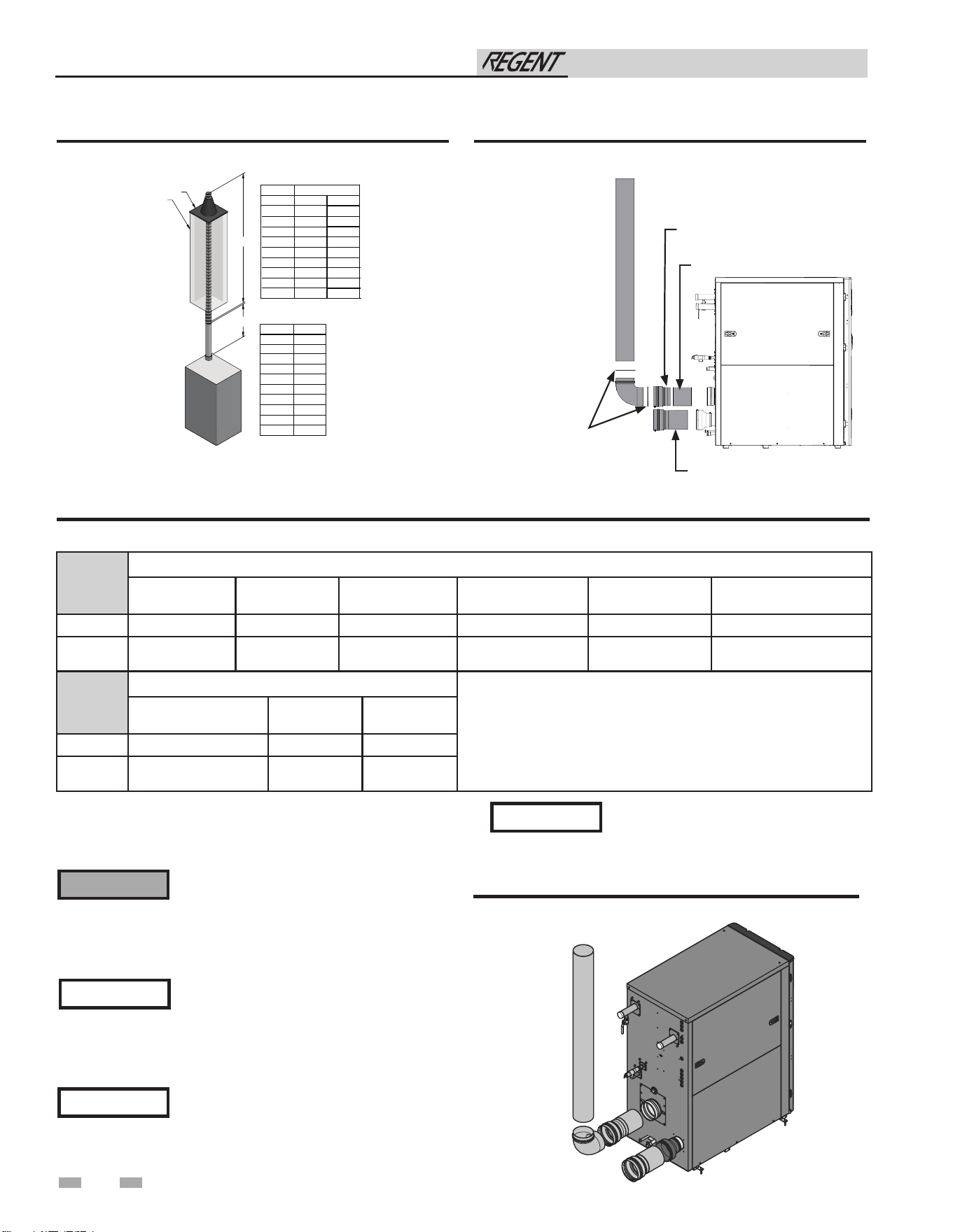
Table 3I Approved PolypropyleneTerminations
The installer must use a specific vent
starter adapter at the flue collar connection,
supplied by the vent manufacturer to
adapt to its vent system. See Table 3J for
approved vent adapters. Discard CPVC
starter piece.
NOTICE
Stainless steel vent
This product has been approved for use with stainless steel
using the manufacturers listed in Table 3J.
Use only the materials, vent systems, and
terminations listed in Tables 3J and 3K.
DO NOT mix vent systems of different
types or manufacturers. Failure to comply
could result in severe personal injury,
death, or substantial property damage.
⚠ WARNING
Installations must comply with applicable
national, state, and local codes. Stainless
steel vent systems must be listed as a
UL-1738 approved system for the United
States and a ULC-S636 approved system
for Canada.
NOTICE
Installation of a stainless-steel vent
system should adhere to the stainless
steel vent manufacturer’s installation
instructions supplied with the vent
system.
NOTICE
3 General venting (continued)
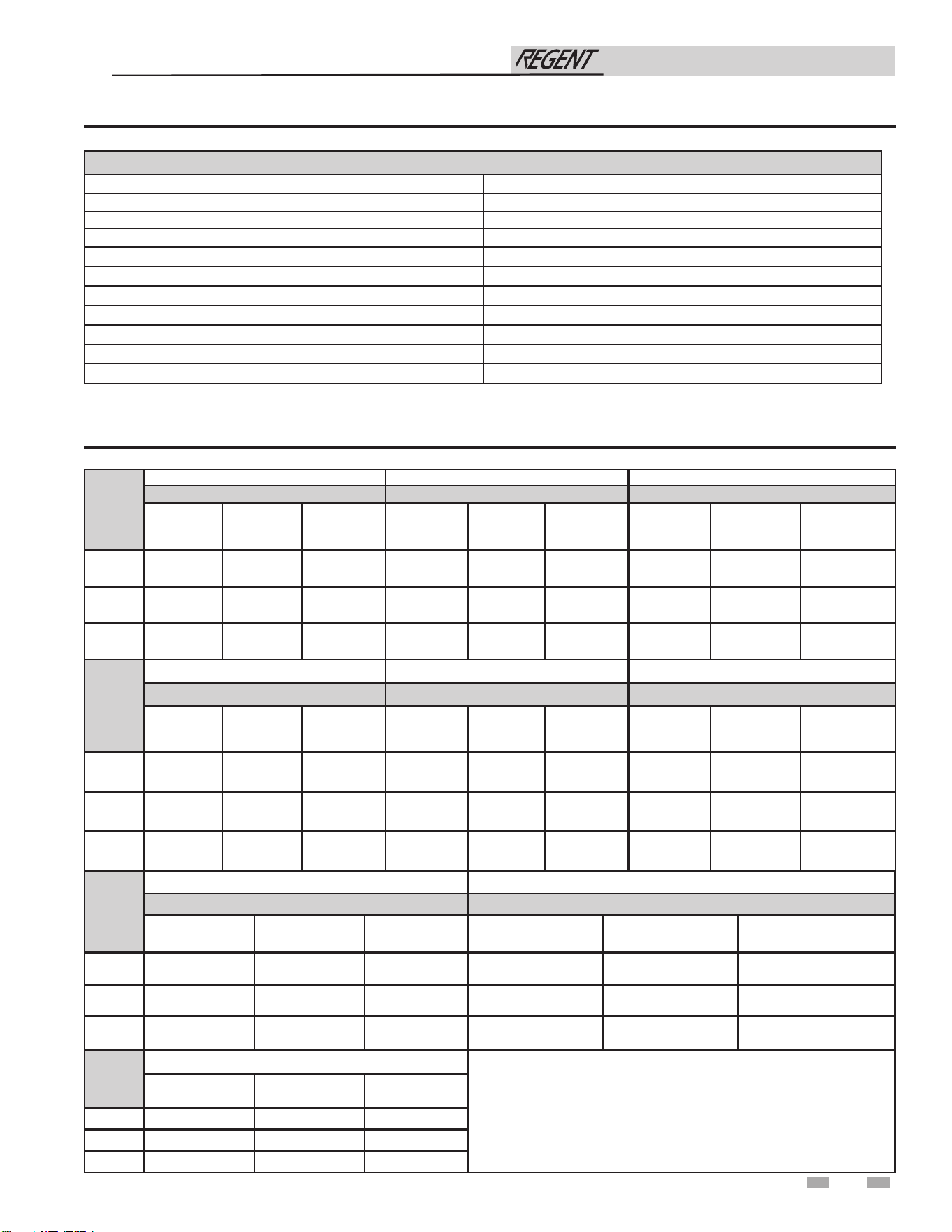
Model
Centrotherm InnoFlue SW
Polypropylene
Adapter
Joint Connector
Sidewall Retaining
Bracket*
Sidewall Adapter*
Low Profile Wall
Termination
Concentric Wall
Termination
500
ISAAL0404 IANS04 IATP0404 ISTAGL0404 ISLPT0404 ICWT462 & ICT0446
750-1000
ISAAL0606 Not Required IATP0606 ISTAGL0606 ISLPT0606 ICWT610 & ICTC06610
Model
DuraVent Polypro
* These parts are only needed if the sidewall termination assembly is
used (see FIG. 4-5B).
Polypropylene
Adapter
Joint
Connector
Sidewall Kit*
500
4PPS-AD-M 4PPS-LB 4PPS-HLK
750-1000
6PPS-06PVCM-6PPF Not Required 6PPS-HLK
Figure 3-8 Near Water Heater Flexible Polypropylene
Venting
Figure 3-9 Near Water Heater Polypropylene Venting
Figure 3-10 Near Water Heater Stainless Steel Venting
Models 500-1000
IMG00840
*NOTES: 1) FLEX
PIPE MAY ONLY BE RUN IN A VERTICAL ORIENTATION
2) AL
L VENT LENGTHS REPRESENTED IN ABOVE CHARTS ARE
EQUIVALENT LENGTHS.
3) SECTION A IS EQUIVALENT FEET OF RIGID PIPE, WHICH MAY
INCLUDE 45 AND 90° ELBOWS. PLEASE SEE SIZING SECTION
FOR DETERMINING
EQUIVALENT FEET.
10 FT
20 FT
30 FT
40 FT
50 FT
60 FT
70 FT
80 FT
90 FT
30 FT
27 FT
23 FT
20 FT
17 FT
13 FT
10 FT
7 FT
3 FT
“B” DIM
Duravent 4”
“A” DIM
4” RIGID
4” FLEX
10 FT
20 FT
30 FT
40 FT
50 FT
60 FT
70 FT
80 FT
90 FT
33 FT
29 FT
26 FT
22 FT
18 FT
15 FT
11 FT
7 FT
4 FT
“B” DIM
Centrotherm 4”
“A” DIM
4” RIGID
4” FLEX
CHIMNEY
CAP
A
B
90 FT
80 FT
70 FT
60 FT
50 FT
40 FT
30 FT
20 FT
10 FT
5” FLEX
22
Installation & Operation Manual
2000845690_000
JOINT CONNECTION
REQUIRED AT
ALL COMPONENT
CONNECTIONS OF
VENT SYSTEM
CPVC XF POLYPRO
ADAPTER
CPVC STARTER
DURAVENT ADAPTER
23
3 General venting (continued)
Model
Enervex Van Packer
Powervent
Water Heater
Adapter
Flue Termination
Intake Air
Termination
Water Heater Adapter Flue Termination
Intake Air
Termination
500 801.0676.4604 801.0679.1004 801.0676.4604
C04PVC04.38B/
C04PVC04.38B
M0490EB & M04SCTB M0490EB & M04SCTB
750 801.0676.4606 801.0679.1006 801.0676.4606
C06PVC06.50B/
C06PVC06.50B
M0690EB & M06SCTB M0690EB & M06SCTB
1000 801.0676.4606 801.0679.1006 801.0676.4606
C06PVC06.50B/
C06PVC06.50B
M0690EB & M06SCTB M0690EB & M06SCTB
Model
Jeremias
Water Heater
Adapter
Flue Termination
Intake Air
Termination
500 SWKL4-KLC SWKL4-WRC SWKL4-90ET
750 SWKL6-KLC SWKL6-WRC SWKL6-90ET
1000 SWKL6-KLC SWKL6-WRC SWKL6-90ET
Table 3K Approved Stainless Steel (S.S.) Terminations and Adapters
Model
DuraVent Heat Fab Z Flex
FasNSeal Saf-T Vent Z-Vent
S.S.
Adapter
Flue
Termination
Intake
Air
Termination
S.S.
Adapter
Flue
Termination
Intake
Air
Termination
S.S.
Adapter
Flue
Termination
Intake Air
Termination
500
FSA-4PVC-
4FNS
FSBS4
FSRC4
FSAIH04 9401PVC
9492
5400CI
9414TERM 2SVSLA04
2SVSTP(F,X)04
2SVSRCX04
2SVSTEX0490
750
FSA-6PVC-
6FNS
FSBS6
FSRC6
FSAIH06 9601PVC
9690
9692
9614TERM
2SVSTTA06 2SVSTPX06
2SVSRCX06
2SVSEE0690
& 2SVSTPX06
1000
FSA-6PVC-
6FNS
FSBS6
FSRC6
FSAIH06 9601PVC
9690
9692
9614TERM
2SVSTTA06 2SVSTPX06
2SVSRCX06
2SVSEE0690
& 2SVSTPX06
Model
Metal Fab Security Chimney ICC
Corr/Guard Secure Seal VIC
S.S.
Adapter
Flue
Termination
Intake
Air
Termination
S.S.
Adapter
Flue
Termination
Intake
Air
Termination
S.S.
Adapter
Flue
Termination
Intake Air
Termination
500
4CGPVCA
4CGSWHT
4CGSWC
4CGSW90LT SS4PVCU
SS4STU
SS4RCBU
SS4ST90AU
HO-04PA
HM-04MC
HM-04SR
HE-04E90
HM-04SR
750
6FCGPVCA
6FCGSWMC
6FCGSWC
6FCGSW90L SS6PVCU
SS6STU
SS6RCBU
SS6ST90AU
HO-06PA
HM-06MC
HM-06SR
HE-06E90
HM-06SR
1000
6FCGPVCA
6FCGSWMC
6FCGSWC
6FCGSW90L SS6PVCU
SS6STU
SS6RCBU
SS6ST90AU
HO-06PA
HM-06MC
HM-06SR
HE-06E90
HM-06SR
Installation & Operation Manual
Approved Stainless Steel Vent Manufacturers
Make Model
Dura Vent (M & G Group) FasNSeal
Dura Vent (M & G Group) FasNSeal Flex* Vent
Z-Flex (Nova Flex Group) Z-Vent
Heat Fab (Selkirk Corporation) Saf-T Vent
Metal Fab Corr/Guard
Security Chimney Secure Seal
ICC VIC
Van Packer --
Enervex Powervent
Jeremias --
Table 3J Stainless Steel Vent Pipe and Fittings
*Use of FasNSeal Flex smooth inner wall vent is to be used in vertical or near vertical sections only, taking precaution to ensure
no sagging occurs of the vent system. Connect to the FasNSeal rigid vent using specially designed adapters and sealing method,
see manufacturer’s instructions.
24
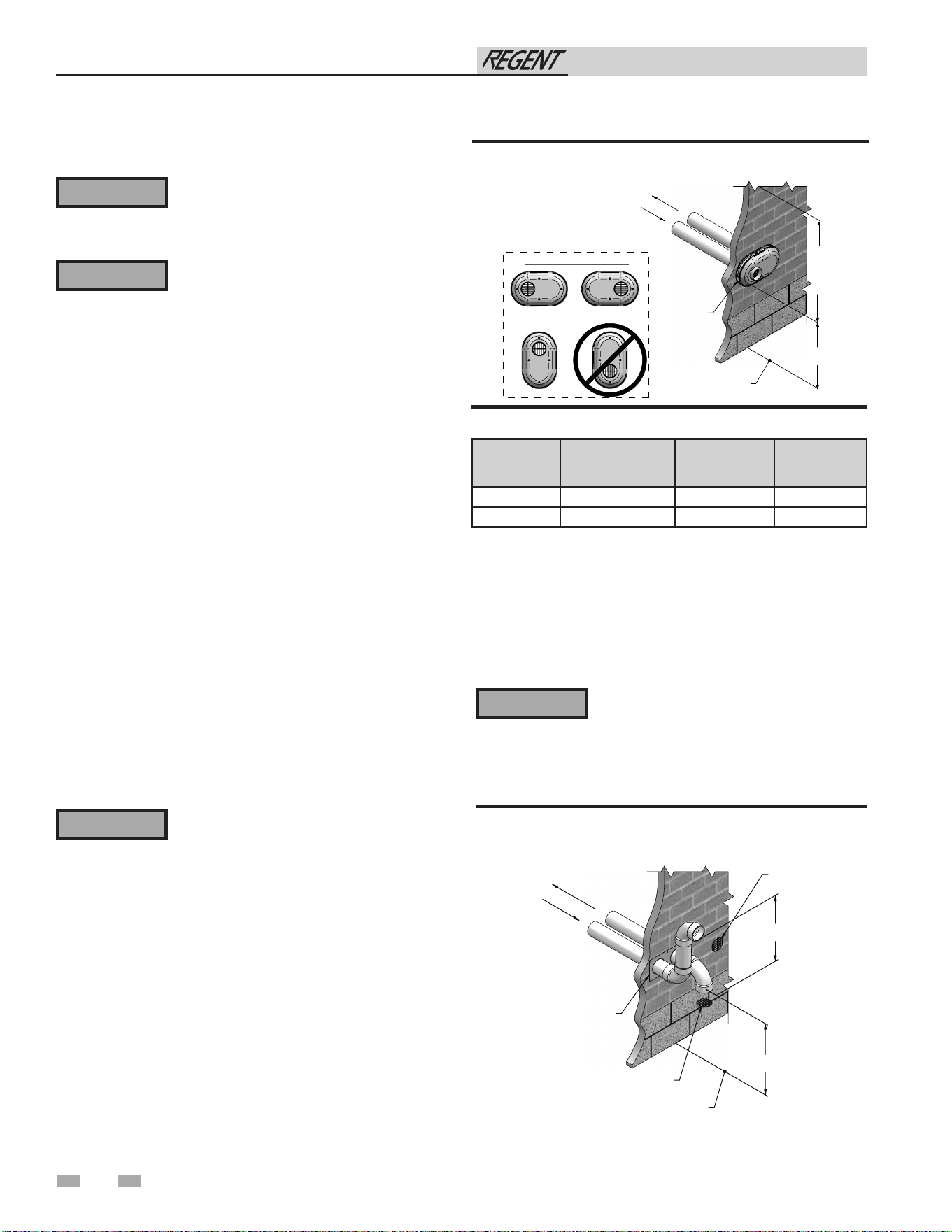
4 Sidewall direct venting
Vent/air termination – sidewall
Follow instructions below when determining
vent location to avoid possibility of severe
personal injury, death, or substantial
property damage.
A gas vent extending through an exterior
wall shall not terminate adjacent to a wall
or below building extensions such as eaves,
parapets, balconies, or decks. Failure to
comply could result in severe personal injury,
death, or substantial property damage.
⚠ WARNING
⚠ WARNING
Determine location
Locate the vent/air terminations using the following guidelines:
1. The total length of piping for vent or air must not exceed the
limits given in the General Venting Section of this manual.
2. You must consider the surroundings when terminating
the vent and air:
a. Position the vent termination where vapors will
not damage nearby shrubs, plants, or air
conditioning equipment or be objectionable.
b. The flue products will form a noticeable plume as
they condense in cold air. Avoid areas where the
plume could obstruct window views.
c. Prevailing winds could cause freezing of
condensate and water/ice buildup where flue
products impinge on building surfaces or plants.
d. Avoid possibility of accidental contact of flue
products with people or pets.
e. Do not locate the terminations where wind eddies
could affect performance or cause recirculation,
such as inside building corners, near adjacent
buildings or surfaces, window wells, stairwells,
alcoves, courtyards, or other recessed areas.
⚠ WARNING
Sidewall vent and air inlet terminations
must terminate in the same pressure zone.
f. Do not terminate above any door or window.
Condensate can freeze, causing ice formations.
g. Locate or guard vent to prevent condensate damage
to exterior finishes.
h. Do not locate the terminations over public walkways.
i. Do not locate the terminations near soffit vents, crawl
space vents, or other areas where condensate or vapor
could create a nuisance, hazard, or cause property
damage.
j. Do not locate the terminations where condensate
vapor could cause damage or could be detrimental
to the operation of regulators, relief valves, or other
equipment.
k. Terminations must be located a minimum of 12" above
grade or maximum snow line.
Do not exceed the maximum lengths of the
outside vent piping shown in FIG. 4-1B.
Excessive length exposed to the outside
could cause freezing of condensate in the
vent pipe, resulting in potential water heater
shutdown.
Figure 4-1B Alternate PVC/CPVC Sidewall Termination
of Air and Vent w/Field Supplied Fittings
⚠ WARNING
If using the alternate sidewall termination:
3. The air piping must terminate in a down-turned elbow
as shown in FIG. 4-1B. This arrangement avoids
recirculation of flue products into the combustion air
stream.
4. The vent piping must terminate in an elbow pointed
outward or away from the air inlet, as shown in FIG. 4-1B.
Model Kit Number Air Intake Vent Size
500 100157611 4" 4" vent
750 - 1000 100157612 6" 6" vent
Table 4A Sidewall Vent Kits
Figure 4-1A PVC/CPVC/Polypropylene Sidewall Termination
of Air and Vent
Installation & Operation Manual
TO HEATER
INTAKE AIR
CONNECTION
FROM HEATER
VENT PIPE
CONNECTION
VENT / AIR
TERMINATION
GRADE OR
SNOW LINE
12"
MIN
12"
MIN
TO
OVER-
HANG
POSSIBLE ORIENTATIONS
TO HEATER
INTAKE AIR
CONNECTION
FROM HEATER
VENT PIPE
CONNECTION
TERMINATION
PLATE
BIRD
SCREEN
GRADE OR
SNOW LINE
12”
MIN
12" MIN
BIRD SCREEN
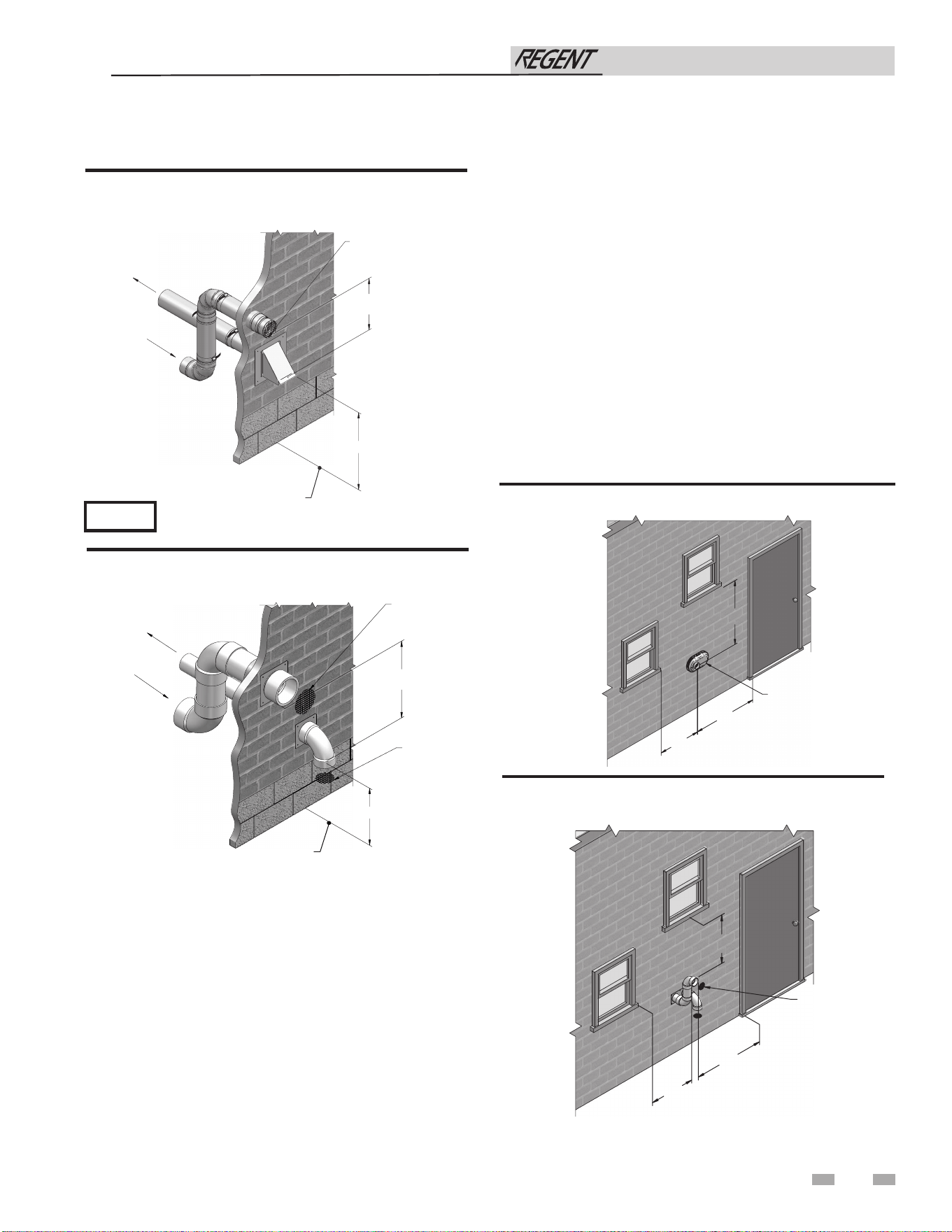
Vent/air termination – sidewall
4 Sidewall direct venting (continued)
5. Maintain clearances as shown in FIG. 4-1A thru 4-5B.
Also maintain the following:
a. Vent must terminate:
• At least 6 feet from adjacent walls.
• No closer than 12 inches below roof overhang.
b. Air inlet must terminate at least 12 inches above
grade or snow line; at least 12 inches below the vent
termination; and the vent pipe must not extend
more than 24 inches vertically outside the building
as shown in FIG. 4-1B.
c. Do not terminate closer than 4 feet horizontally
from any electric meter, gas meter, regulator, relief
valve, or other equipment. Never terminate above or
below any of these within 4 feet horizontally.
6. Locate terminations so they are not likely to be damaged by
foreign objects, such as stones or balls, or subject to buildup
of leaves or sediment.
VENT / AIR
TERMINATION
4'
MIN.
12"
MIN.
12"
MIN.
Figure 4-3A Clearance to Gravity Air Inlets
Figure 4-2 Alternate PVC/CPVC/SS/ Polypropylene Sidewall
Termination w/Field Supplied Fittings
Figure 4-1C Alternate PVC/CPVC/SS Vent Termination
- Typical Stainless Steel Sidewall Termination of Air and
Vent w/Field Supplied Fittings
BIRD
SCREEN
(TYPICAL)
4'
MIN.
12”
MIN.
12”
MIN.
Figure 4-3B Alternate Clearance to Gravity Air Inlets w/
Field Supplied Fittings
25
PVC/CPVC or ABS is acceptable air inlet pipe material.
NOTICE
Installation & Operation Manual
12" (305 MM) MI
N
12" (305 MM) MIN
FROM
HEATER
VENT PIPE
CONNECTION
TO HEATER
INTAKE AIR
CONNECTION
BIRD SCREEN
GRADE OR
SNOW LINE
12" (305 MM) MIN
12" (305 MM) MIN
FROM HEATER
VENT PIPE
CONNECTION
TO HEATER
INTAKE AIR
CONNECTION
BIRD SCREEN
BIRD SCREEN
GRADE OR
SNOW LINE
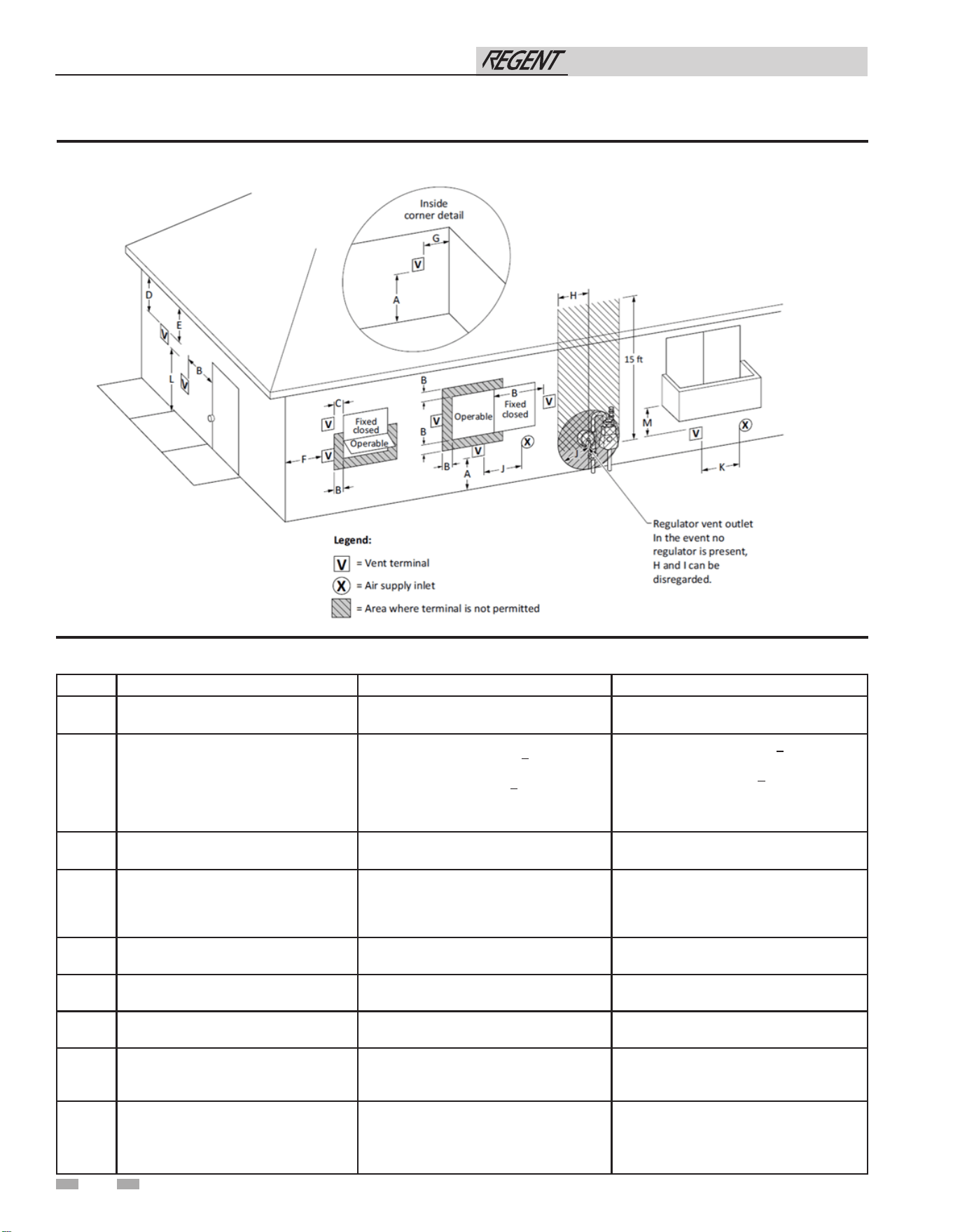
26
Figure 4-4A Direct Vent Terminal Clearances
Table 4B Direct Vent Terminal Clearances
4 Sidewall direct venting
Canadian Installations¹ US Installations²
A =
Clearance above grade, veranda, porch,
deck, or balcony
12 in (30 cm) 12 in (30 cm)
B =
Clearance to window or door that may
be opened
6 in (15 cm) for appliances < 10,000 Btuh
(3 kW), 12 in (30 cm) for appliances >
10,000 Btuh (3 kW) and < 100,000 Btuh
(30 kW), 36 in (91 cm) for appliances >
100,000 Btuh (30 kW)
6 in (15 cm) for appliances < 10,000 Btuh
(3 kW), 9 in (23 cm) for appliances >
10,000 Btuh (3 kW) and < 50,000 Btuh (15
kW), 12 in (30 cm) for appliances > 50,000
Btuh (15 kW) and not exceeding > 150,000
Btuh (30 kW)
C =
Clearance to permanently closed
window
*
*
D =
Vertical clearance to ventilated soffit
located above the terminal within a
horizontal distance of 2 ft (61 cm) from
the center line of the terminal.
*
*
E = Clearance to unventilated soffit
*
*
F = Clearance to outside corner
*
*
G = Clearance to inside corner
*
*
H =
Clearance to each side of center line
extended above meter / regulator
assembly
*
*
I =
Clearance to service regulator vent
outlet
Above a regulator within 3 ft (91 cm)
horizontally of the vertical center line of the
regulator vent outlet to a maximum vertical
distance of 15 ft (4.5 m)
*
Installation & Operation Manual
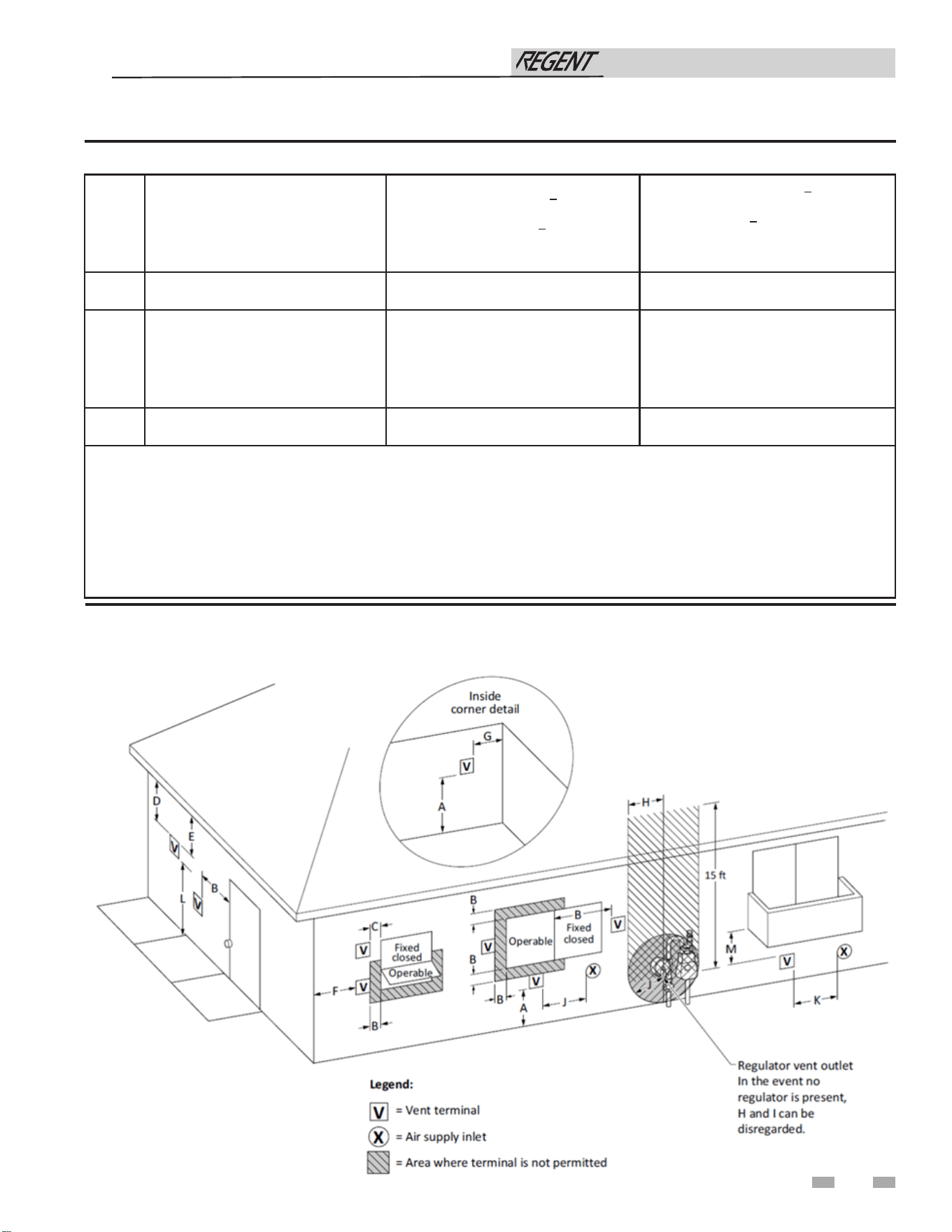
Table 4B Direct Vent Terminal Clearances (continued)
Figure 4-4B Other than Direct Vent Terminal Clearances
4 Sidewall direct venting (continued)
J =
Clearance to nonmechanical air supply
inlet to building or the combustion air
inlet to any other appliance
6 in (15 cm) for appliances < 10,000 Btuh
(3kW), 12 in (30 cm) for appliances >
10,000 Btuh (3 kW) and < 100,000 Btuh
(30 kW), 36 in (91 cm) for appliances >
100,000 Btuh (30 kW)
6 in (15 cm) for appliances < 10,000 Btuh
(3kW), 9 in (23 cm) for appliances > 10,000
Btuh (3 kW) and < 50,000 Btuh (15 kW),
12 in (30 cm) for appliances > 50,000 Btuh
(15 kW) and not exceeding > 150,000 Btuh
(30 kW)
K =
Clearance to a mechanical air supply
inlet
6 ft (1.83 m)
3 ft (91 cm) above if within 10 ft (3 m)
horizontally
L =
Clearance above paved sidewalk or
paved driveway located on public
property
7 ft (2.13 m)†
7 ft (2.13 m) for mechanical draft systems
(Category I appliances). Vents for
Category II and IV appliances cannot be
located above public walkways or other
areas where condensate or vapor can
cause a nuisance or hazard.*
M =
Clearance under veranda, porch, deck,
or balcony
12 in (30 cm)‡ *
* Clearance in accordance with local installation codes and the requirements of the gas supplier.
† A vent shall not terminate directly above a sidewalk or paved driveway that is located between two single family dwellings
and serves both dwellings.
‡ Permitted only if veranda, porch, deck, or balcony is fully open on a minimum of two sides beneath he oor.
NOTES:
1) In accordance with the current CSA B149.1, Natural Gas and Propane Installation Code
2) In accordance with the current ANSI Z223.1/NFPA 54, National Fuel Gas Code
27
Installation & Operation Manual
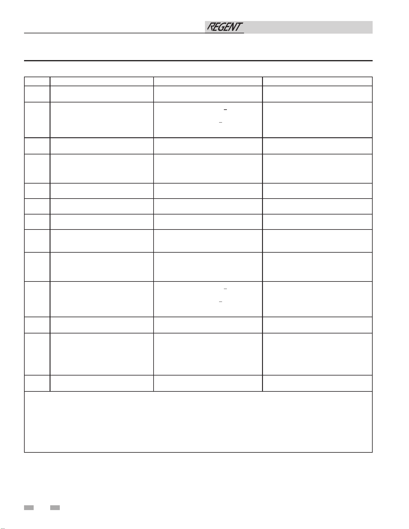
28
Table 4C Other than Direct Vent Terminal Clearances
4 Sidewall direct venting
Canadian Installations¹ US Installations²
A =
Clearance above grade, veranda, porch,
deck, or balcony
12 in (30 cm) 12 in (30 cm)
B =
Clearance to window or door that may
be opened
6 in (15 cm) for appliances < 10,000 Btuh
(3 kW), 12 in (30 cm) for appliances >
10,000 Btuh (3 kW) and < 100,000 Btuh
(30 kW), 36 in (91 cm) for appliances >
100,000 Btuh (30 kW)
4 ft (1.2 m) below or to side of opening; 1 ft
(300 mm) above opening
C =
Clearance to permanently closed
window
* *
D =
Vertical clearance to ventilated soffit
located above the terminal within a
horizontal distance of 2 ft (61 cm) from
the center line of the terminal.
* *
E = Clearance to unventilated soffit
* *
F = Clearance to outside corner
* *
G = Clearance to inside corner
* *
H =
Clearance to each side of center line
extended above meter / regulator
assembly
* *
I =
Clearance to service regulator vent
outlet
Above a regulator within 3 ft (91 cm)
horizontally of the vertical center line of the
regulator vent outlet to a maximum vertical
distance of 15 ft (4.5 m)
*
J =
Clearance to nonmechanical air supply
inlet to building or the combustion air
inlet to any other appliance
6 in (15 cm) for appliances < 10,000 Btuh
(3kW), 12 in (30 cm) for appliances >
10,000 Btuh (3 kW) and < 100,000 Btuh
(30 kW), 36 in (91 cm) for appliances >
100,000 Btuh (30 kW)
4 ft (1.2 m) below or to side of opening; 1 ft
(300 mm) above opening
K =
Clearance to a mechanical air supply
inlet
6 ft (1.83 m) 3 ft (91 cm) above if within 10 ft (3 m)
horizontally
L =
Clearance above paved sidewalk or
paved driveway located on public
property
7 ft (2.13 m)† 7 ft (2.13 m) for mechanical draft systems
(Category I appliances). Vents for
Category II and IV appliances cannot be
located above public walkways or other
areas where condensate or vapor can
cause a nuisance or hazard.
M =
Clearance under veranda, porch, deck,
or balcony
12 in (30 cm)‡ *
* Clearance in accordance with local installation codes and the requirements of the gas supplier.
† A vent shall not terminate directly above a sidewalk or paved driveway that is located between two single family dwellings
and serves both dwellings.
‡ Permitted only if veranda, porch, deck, or balcony is fully open on a minimum of two sides beneath he oor.
NOTES:
1) In accordance with the current CSA B149.1, Natural Gas and Propane Installation Code
2) In accordance with the current ANSI Z223.1/NFPA 54, National Fuel Gas Code
Installation & Operation Manual
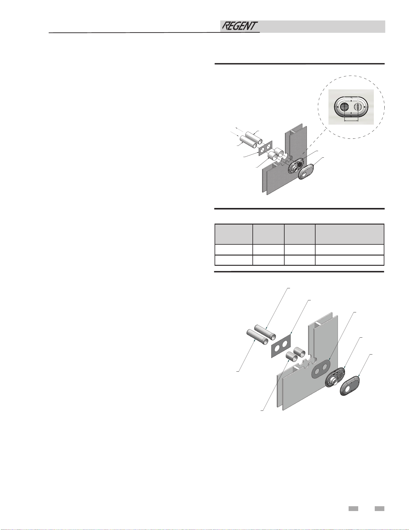
4 Sidewall direct venting (continued)
Figure 4-5A Sidewall Termination Assembly
2. For Polypropylene Only: Install the vent and air intake
sidewall adapters from Table 3J into the vent plate. Slide
the sidewall retaining bracket down the sidewall adapters
flush to the vent plate.
3. For PVC/CPVC Only: Install the vent and air intake
piping through the wall into the vent plate openings. Use
RTV silicone sealant to seal the air pipe. Use the cement/
primer listed in Table 3H to seal the vent pipe.
4. Mount and secure the vent plate to the wall using
stainless steel screws. Seal around the plate to the wall
assuring no air gaps.
5. Seal all gaps between the pipes and wall. Seal around the
plate to the wall assuring no air gaps.
6. Assemble the vent cap to the vent plate. Insert the
stainless-steel screws into the vent cap screw hole
openings and securely attach the vent cap to the vent
plate.
7. Seal all wall cavities.
8. PVC/CPVC terminations are designed to accommodate
any wall thickness of standard constructions per the
directions found in this manual.
9. Stainless steel terminations are designed to penetrate walls
with a thickness up to 9.25 inches of standard construction.
29
Table 4D Sidewall Vent Centerline Dimensions
Prepare wall penetrations
1. Use the factory supplied wall plate as a template to locate
the vent and air intake holes and mounting holes.
Air pipe penetration:
a. Cut a hole for the air pipe. Size the air pipe hole as
close as desired to the air pipe outside diameter.
Vent pipe penetration:
a. Cut a hole for the vent pipe. For either combustible or
noncombustible construction, size the vent pipe hole
with at least a 1/2 inch clearance around the vent pipe
outer diameter:
• 5½ inch hole for 4 inch vent pipe
• 7½ inch hole (191 mm) hole for 6 inch (152 mm)
vent pipe
Drill 3/16" diameter holes for inserting the plastic anchors
into the wall.
SIDEWALL
ADAPTER
(AIR)
SIDEWALL
A
DAPTER
(VENT)
WALL
PLATE
GALVANIZED
THIMBLE
SIDEWALL
RETAINING
PLATE
VENT
PLATE
VENT
CAP
IMG00085
Figure 4-5B Polypropylene Sidewall Termination Assembly
Model Air Vent Centerline Width
500 4" 4" 5 5/8"
750 - 1000 6" 6" 7 3/4"
VENT PIPING
GALVANIZED
THIMBLE
VENT CAP
AIR PIPING
WALL PLATE
VENT PLATE
VENT
AIR
CENTERLINE WIDTH
Installation & Operation Manual
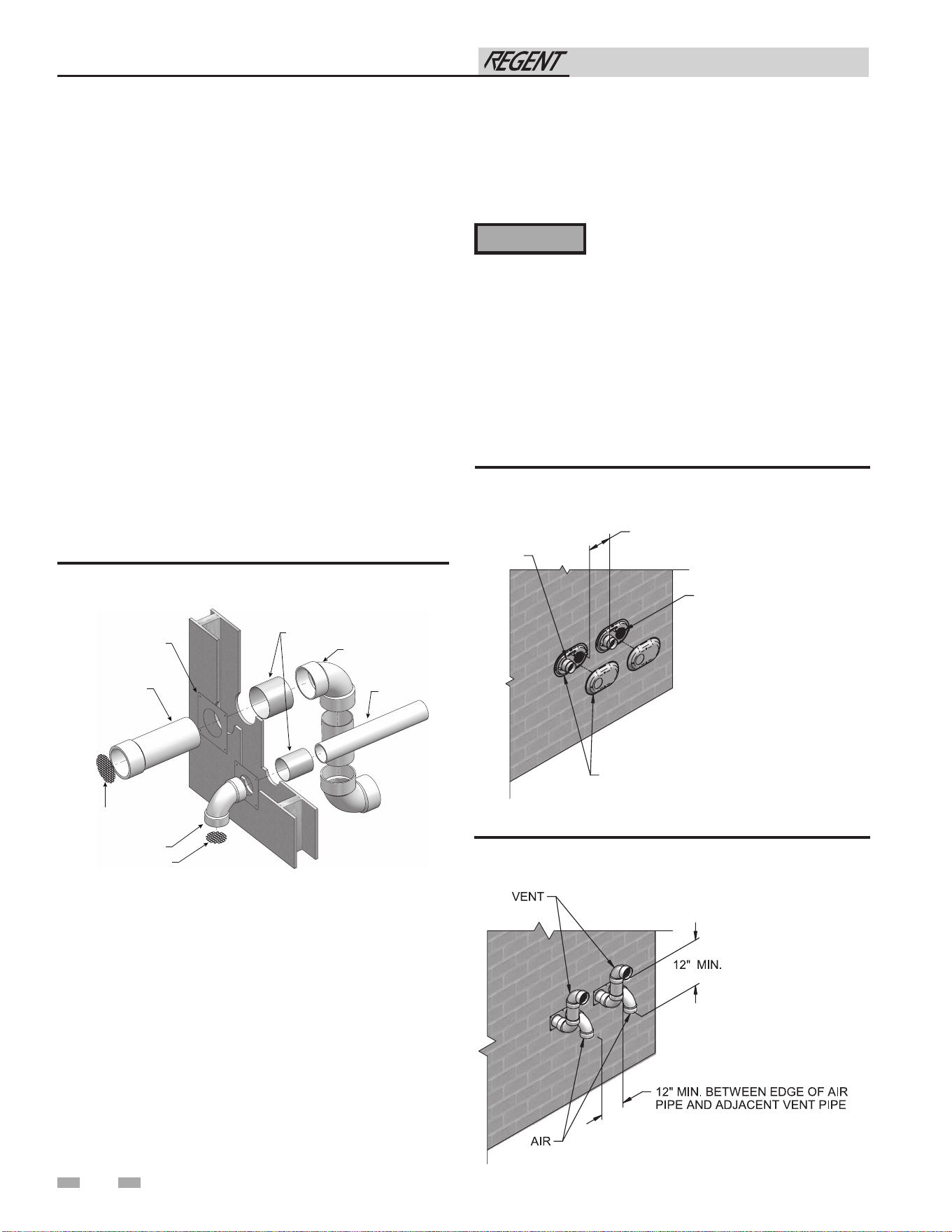
4 Sidewall direct venting
Prepare wall penetrations (Alternate -
Field Supplied Option)
1. Air pipe penetration:
a. Cut a hole for the air pipe. Size the air pipe hole as
close as desired to the air pipe outside diameter.
2. Vent pipe penetration:
a. Cut a hole for the vent pipe. For either combustible
or noncombustible construction, size the vent pipe
hole with at least a 1/2 inch clearance around the
vent pipe outer diameter:
• 5½ inch hole (140 mm) for 4 inch (102 mm)vent
pipe
• 7½ inch hole (191 mm) for 6 inch (152 mm)
vent pipe
b. Insert a galvanized metal thimble in the vent pipe
hole as shown in FIG. 4-5C.
3. Use a sidewall termination plate as a template for correct
location of hole centers.
4. Follow all local codes for isolation of vent pipe when
passing through floors or walls.
5. Seal exterior openings thoroughly with exterior caulk.
All vent pipes and air inlets must terminate
at the same height to avoid possibility of
severe personal injury, death, or substantial
property damage.
Multiple vent/air terminations
1. When terminating multiple Regent water heaters terminate
each vent/air connection as described in this manual
(FIG. 4-6A).
2. Place wall penetrations to obtain minimum clearance of
12 inches between edge of air inlet and adjacent vent outlet,
as shown in FIG. 4-6A for U.S. installations. For Canadian
installations, provide clearances required by CSA B149.1
Installation Code.
3. The air inlet of a Regent water heater is part of a direct vent
connection. It is not classified as a forced air intake with
regard to spacing from adjacent water heater vents.
⚠ WARNING
Figure 4-6A Multiple Vent Terminations (must also
comply with Figure 4-1A)
Figure 4-6B Alternate Multiple Vent Terminations w/Field
Supplied Fittings (must also comply with Figure 4-1B)
Figure 4-5C A Typical Sidewall Termination Assembly
- PVC/CPVC or Stainless Steel
30
SIDEWALL
TERMINA
TION PLATE
VENT
PIPING
GALVANIZED
THIMBLE (WHEN REQUIRED BY LOCAL
CODES)
ELBOW
ELBOW
AIR PIPING
BIRD SCREEN
BIRD SCREEN
12" MIN. BETWEEN EDGE OF AIR
INLET AND ADJACENT VENT
OUTLET
VENT / AIR
TERMINATION
VEN
T
AIR
Installation & Operation Manual
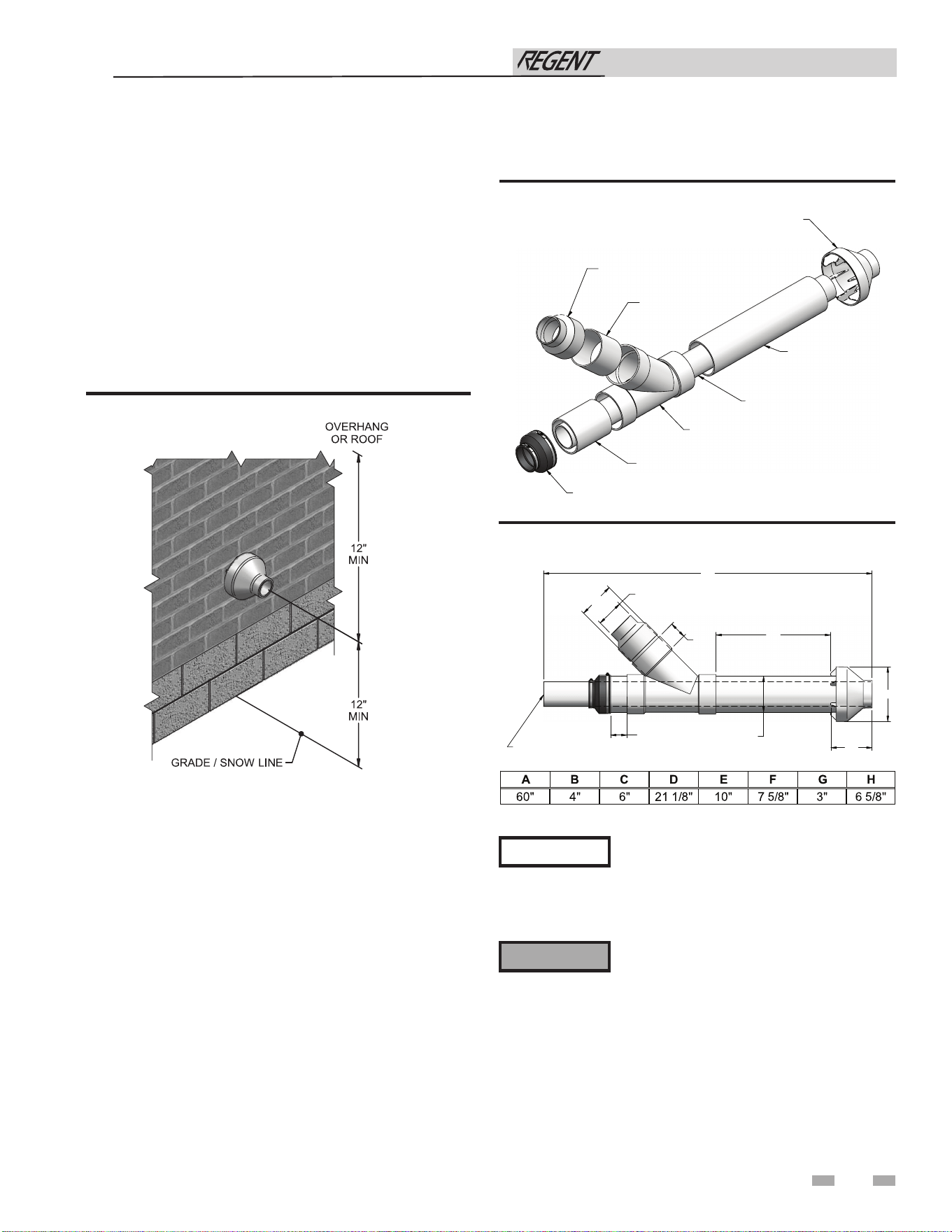
31
4 Sidewall direct venting (continued)
Figure 4-8 Kit Contents_100140484 - Model 500
Sidewall termination – optional concentric vent: Model 500
Description and usage
Lochinvar offers optional concentric combustion air and
vent pipe termination kits (Factory Kit #100140484 for 4"
diameter - Model 500). Both combustion air and vent pipes
must attach to the termination kit. The termination kits
must terminate outside the structure and must be installed as
shown below in FIG. 4-7.
The required combustion vent pipe materials are listed in
Table 3H of this manual.
Figure 4-7 Concentric Sidewall Termination
Sidewall termination installation
1. Determine the best location for the termination kit (see
FIG. 4-7).
2. Reference the Determine Location Section of this manual
for general termination considerations.
3. Cut one (1) hole 7 inch diameter into the structure to
install the termination kit.
4. Partially assemble the concentric vent termination kit.
Clean and cement using the procedures found in these
instructions.
a. Cement the Y concentric fitting to the larger kit pipe
(FIG. 4-9).
b. Cement the rain cap to the smaller diameter kit pipe
(FIG. 4-9).
Instead of cementing the smaller pipe to
the rain cap, a field-supplied stainless-steel
screw may be used to secure the two (2)
components together when field disassembly
is desired for cleaning (see FIG. 4-11).
When using the alternate screw assembly
method, drill a clearance hole in the rain
cap and a pilot hole in the vent pipe for
the screw size being used. Failure to drill
adequate holes may cause cracking of PVC
components, allowing combustion products
to be recirculated. Failure to follow this
warning could result in personal injury or
death.
NOTICE
⚠ WARNING
Figure 4-9 Concentric Vent Dimensional Drawing -
Model 500
“B” DIA.
ÉVAC. PVC
"A"
"H" DIA.
"D"
"E"
"F"
"G"
3"
(76 MM)
ABCDEF
GH
60"4"6"21 1/8" 10" 7 5/8" 3" 6 5/8"
"C" DIA.
"B" DIA.
(1524 MM) (102 MM)
(152 MM)
(537 MM)
(254 MM) (194 MM)
(76 MM)
(168 MM)
4" (102 MM) DIA.
6" (152 MM) DIA.
RAIN CAP
"Y" CONCENTRIC
FITTING
"FLEXIBLE" PIPE
COUPLING
6" (152 MM) DIA.
6" (152 MM) DIA.
6" (152 MM) TO 4" (102 MM) REDUCER
Installation & Operation Manual
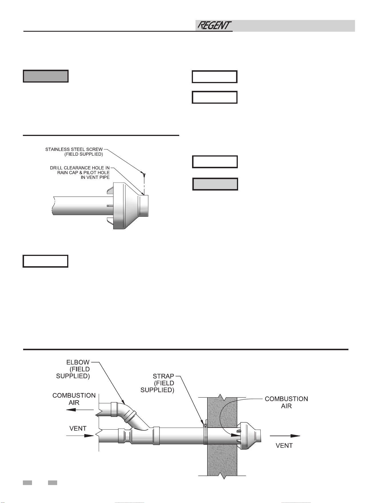
32
4 Sidewall direct venting
Sidewall termination – optional concentric vent: Model 500
Do not operate the appliance with the rain
cap removed or recirculation of combustion
products may occur. Water may also collect
inside the larger combustion air pipe and
flow to the burner enclosure. Failure to
follow this warning could result in product
damage or improper operation, personal
injury, or death.
Figure 4-10 Rain Cap to Vent Pipe Alternate Assembly
6. Install the Y concentric fitting and pipe assembly through
the structure’s hole.
Do not allow insulation or other materials to
accumulate inside the pipe assembly when
installing through the hole.
7. Install the rain cap and small diameter pipe assembly into
the Y concentric fitting and large pipe assembly. Ensure
small diameter pipe is fastened tightly into the rubber
adapter.
8. Secure the assembly to the structure as shown in FIG. 4-11
using field-supplied metal strapping or equivalent support
material.
Ensure termination location clearance
dimensions are as shown in FIG. 4-7.
⚠ WARNING
NOTICE
NOTICE
NOTICE
If assembly needs to be extended to allow
sidewall thickness requirement, the two (2)
pipes supplied in the kit may be replaced
by using the same diameter, field-supplied
SDR-26 PVC (D2241) pipe and standard
schedule 40 PVC. Do not extend dimension
D* more than 60 inches (see FIG. 4-9 thru
4-11).
If assembly depth needs to be reduced,
dimension D can be as short as possible.
NOTICE
Figure 4-11 Concentric Vent Sidewall Attachment
Note: 100140480 shown for illustration purposes.
DO NOT use field-supplied couplings to
extend pipes. Airflow restriction will occur
and may cause intermittent operation.
9. Cement appliance combustion air and vent pipes to the
concentric vent termination assembly. See FIG. 4-11 for
proper pipe attachment.
10. Operate the appliance one (1) heat cycle to ensure
combustion air and vent pipes are properly connected to the
concentric vent termination connections.
CAUTION
Multi-venting sidewall terminations
When two (2) or more direct vent appliances are vented near
each other, each appliance must be individually vented (see
FIG. 4-12). NEVER common vent or breach vent this appliance.
When two (2) or more direct vent appliances are vented near
each other, two (2) vent terminations may be installed as shown
in FIG. 4-12. It is important that vent terminations be made as
shown to avoid recirculation of flue gases.
Installation & Operation Manual
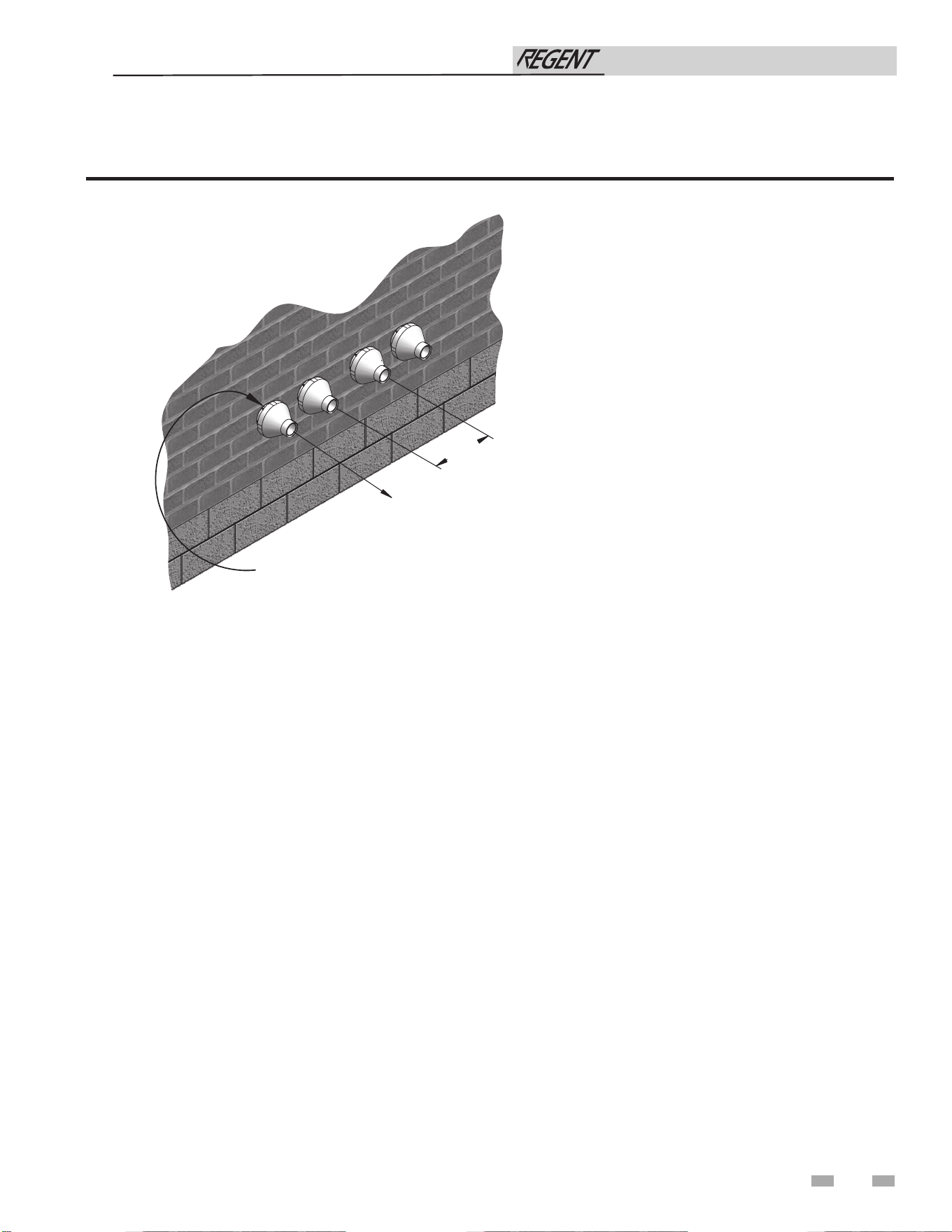
33
4 Sidewall direct venting (continued)
Sidewall termination – optional concentric vent: Model 500
Figure 4-12 Concentric Vent and Combustion Air Termination
VENT
COMBUSTION
AIR
12"
MINIMU
M
Installation & Operation Manual
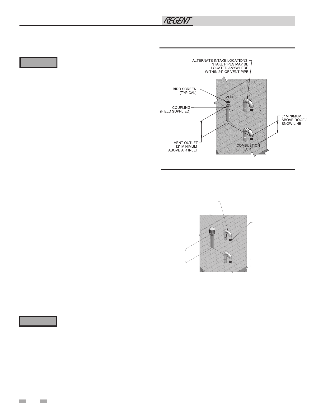
34
5 Vertical direct venting
Vent/air termination – vertical
Follow instructions below when
determining vent location to avoid
possibility of severe personal injury, death,
or substantial property damage.
Determine location
Locate the vent/air terminations using the following guidelines:
1. The total length of piping for vent or air must not exceed
the limits given in the General Venting Section of this
manual.
2. Prepare the vent termination and the air termination elbow
(FIG. 5-1A) by inserting bird screens. Bird screens should
be obtained locally.
3. The vent must terminate at least 3 feet above the highest
place in which the vent penetrates the roof and at least 2
feet above any part of a building within 10 horizontal feet.
4. The air piping must terminate in a down-turned 180°
return pipe no further than 2 feet from the center of the
vent pipe. This placement avoids recirculation of flue
products into the combustion air stream.
5. The vent piping must terminate in an up-turned coupling
as shown in FIG. 5-1A. The top of the coupling must be at
least 1 foot above the air intake. When the vent termination
uses a rain cap as illustrated in FIG. 5-1B maintain at least
36” (914 mm) above the air inlet. The air inlet pipe and
vent pipe can be located in any desired position on the roof,
but must always be no further than 2 feet (.6 m) apart and
with the vent termination at least 1 foot for PVC and 3 feet
for stainless steel, above the air intake.
6. Maintain the required dimensions of the finished
termination piping as shown in FIG. 5-1A.
7. Do not extend exposed vent pipe outside of building more
than shown in this document. Condensate could freeze
and block vent pipe.
Figure 5-1A PVC/CPVC Vertical Termination of Air and Vent
8. Locate terminations so they are not likely to be damaged by
foreign objects, such as stones or balls, or subject to buildup
of leaves or sediment.
⚠ WARNING
⚠ WARNING
Rooftop vent and air inlet terminations
must terminate in the same pressure zone,
unless vertical vent sidewall air is set up as
shown in the General Venting - Vertical
Vent, Sidewall Air Section.
Figure 5-1B Stainless Steel Vertical Termination of Air
and Vent
6" (152 MM) MINIMU
M
ABOVE ROOF /
SNOW LINE
VENT
COM,BUSTION
AIR
ALTERNATE INTAKE LOCATIONS:
INTAKE PIPES MAY BE LOCATED
ANYWHERE WITHIN 24” (610 MM)
OF VENT PIPE
VENT OUTLET
36” (914 MM) MINIMU
M
ABOVE AIR INLET
BIRD SCREEN
(TYPICAL)
Installation & Operation Manual
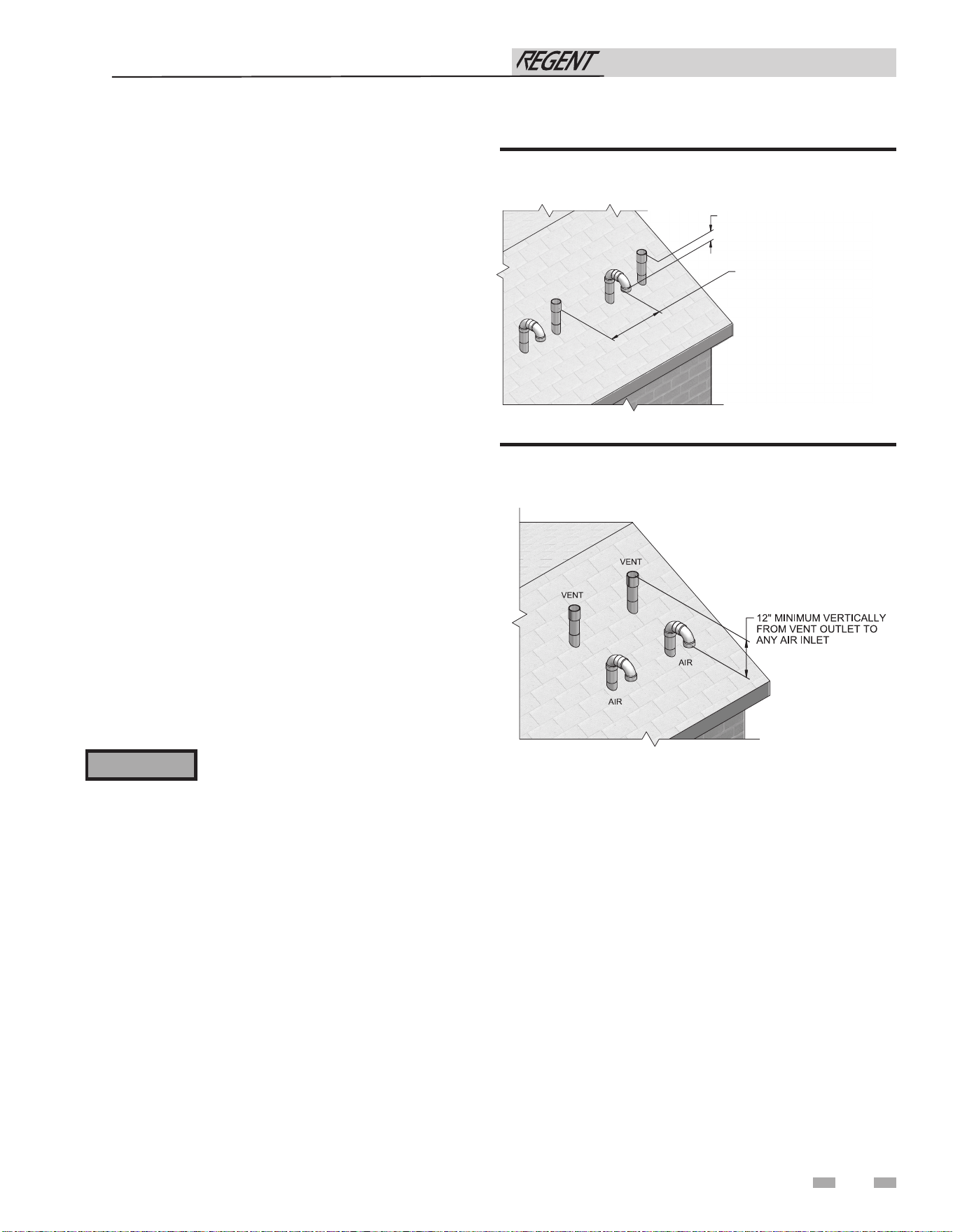
35
5 Vertical direct venting (continued)
Vent/air termination – vertical
Prepare roof penetrations
1. Air pipe penetration:
a. Cut a hole for the air pipe. Size the air pipe hole as
close as desired to the air pipe outside diameter.
2. Vent pipe penetration:
a. Cut a hole for the vent pipe. For either
combustible or noncombustible construction, size
the vent pipe hole with at least a 1/2 inch clearance
around the vent pipe outer diameter:
• 5½ inch (140 mm) hole for 4 inch (102 mm) vent
pipe
• 7½ inch (191 mm) hole for 6 inch (152 mm) vent
pipe
b. Insert a galvanized metal thimble in the vent pipe
hole.
3. Space the air and vent holes to provide the minimum
spacing shown in FIG. 5-1A.
4. Follow all local codes for isolation of vent pipe when
passing through floors, ceilings, and roofs.
5. Provide flashing and sealing boots sized for the vent pipe
and air pipe.
Multiple vent/air terminations
1. When terminating multiple Regent water heaters, terminate
each vent/air connection as described in this manual (FIG.
5-2).
Terminate all vent pipes at the same height
and all air pipes at the same height to avoid
possibility of severe personal injury, death,
or substantial property damage.
2. Place roof penetrations to obtain minimum clearance of
12 inches between edge of air intake elbow and adjacent
vent pipe of another water heater for U.S. installations (see
FIG. 5-2). For Canadian installations, provide clearances
required by CSA B149.1 Installation Code.
3. The air inlet of a Regent water heater is part of a direct vent
connection. It is not classified as a forced air intake with
regard to spacing from adjacent water heater vents.
Figure 5-2 Vertical Terminations with Multiple Water
Heaters
Figure 5-3 Alternate Vertical Terminations with Multiple
Water Heaters
⚠ WARNING
12” MINIMUM VERTICALLY
FROM VENT OUTLET TO
ANY AIR INLET
12” MINIMUM FROM EDGE OF AIR
INTAKE PIPE TO ADJACENT VENT
PIPE FROM ANOTHER WATER HEAT
ER
AIR
VENT
AIR
VENT
Installation & Operation Manual
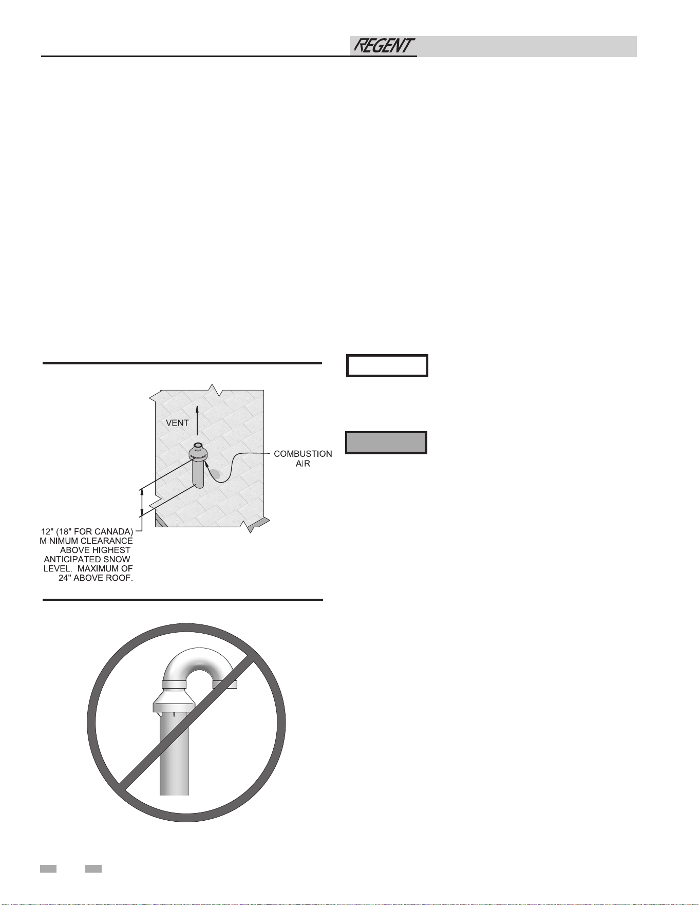
36
5 Vertical direct venting
Vertical termination – optional concentric vent: Model 500
Description and usage
Lochinvar offers an optional concentric combustion air and
vent pipe termination kit. Both combustion air and vent pipes
must attach to the termination kit. The termination kit must
terminate outside the structure and must be installed as shown
in FIG. 5-4.
Field supplied pipe and fittings are required to complete the
installation.
The required combustion vent pipe and fittings are listed in
Table 3H of this manual.
Vertical termination installation
1. See Section 5, Vertical Direct Venting - Determine Location
(where applicable).
Instead of cementing the smaller pipe to
the rain cap, a field supplied stainless steel
screw may be used to secure the two (2)
components together when field disassembly
is desired for cleaning (see FIG. 4-12).
When using the alternate screw assembly
method, drill a clearance hole in the rain
cap and a pilot hole in the vent pipe for
the screw size being used. Failure to drill
adequate holes may cause cracking of PVC
components, allowing combustion products
to be recirculated. Failure to follow this
warning could result in personal injury or
death.
2. Cut one (1) hole (7 inch diameter for #100140484
installations) into the structure to install the termination
kit.
3. Partially assemble the concentric vent termination kit.
Clean and cement following the cleaning procedures in
these instructions.
a. Cement the Y concentric fitting to the larger
diameter kit pipe (see FIG. 4-8 and 4-9).
b. Cement rain cap to the smaller diameter kit pipe (see
FIG. 4-8 and 4-9).
c. Do not attach a U-Bend to the rain cap. Doing so
could cause recirculation (see FIG. 5-5).
Figure 5-4 Concentric Vertical Termination
NOTICE
⚠ WARNING
Figure 5-5 Do Not Install U-Bend to Rain Cap
Installation & Operation Manual
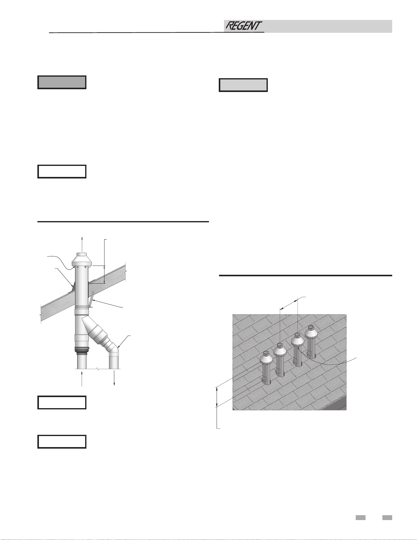
37
5 Vertical direct venting (continued)
Vertical termination – optional concentric vent: Model 500
Figure 5-6 Concentric Vent Roof Installation
Ensure termination height is above the roof
surface or anticipated snow level (12 inches
in U.S.A. or 18 inches in Canada) as shown
in FIG. 5-4.
If assembly is too short to meet height
requirement, the two (2) pipes supplied
in the kit may be replaced by using the
same diameter, field supplied SDR-26 PVC
(D2241) pipe and standard schedule 40 PV.
Do not extend dimension D* more than 60
inches (see FIG. 4-10 and 4-11).
CAUTION
DO NOT use field-supplied couplings to
extend pipes. Airflow restriction will occur.
6. Install the rain cap and the small diameter pipe assembly
into the roof penetration assembly. Ensure the small
diameter pipe is fastened tightly into the rubber adapter for
#100140484 installations.
7. Cement the appliance combustion air and vent pipes to
the concentric vent termination assembly. See FIG. 5-6 for
proper pipe attachment.
8. Operate the appliance through one (1) heat cycle to ensure
combustion air and vent pipes are properly connected to
the concentric vent termination connections.
Multi-venting vertical terminations
When two (2) or more direct vent appliances are vented near
each other, each appliance must be individually vented (see
FIG. 5-7). NEVER common vent or breach vent this appliance.
When two (2) or more direct vent appliances are vented near
each other, two (2) vent terminations may be installed as shown
in FIG. 5-7. It is important that vent terminations be made as
shown to avoid recirculation of flue gases.
Figure 5-7 Concentric Vent and Combustion Air Vertical
Termination
Do not operate the appliance with the rain
cap removed or recirculation of combustion
products may occur. Water may also collect
inside the larger combustion air pipe and
flow to the burner enclosure. Failure to
follow this warning could result in product
damage or improper operation, personal
injury, or death.
4. Install the Y concentric fitting pipe assembly up through
the structure’s hole and field supplied roof boot/flashing.
Do not allow insulation or other materials to
accumulate inside the pipe assembly when
installing through the hole.
5. Secure the assembly to the roof structure as shown below in
FIG. 5-6 using field supplied metal strapping or equivalent
support material.
⚠ WARNING
NOTICE
NOTICE
NOTICE
ELBOW
(FIELD SUPPLIED)
SUPPORT
(FIELD SUPPLIED)
ROOF BOOT
/
FLASHIN
G
(FIELD SUPPLIED)
VENT
COMBUSTION
AIR
VENT
12" (305 MM) (18" (457 MM) FOR CANADA)
MINIMUM CLEARANCE ABOVE HIGHEST
ANTICIPAT
ED SNOW LEVEL. MAXIMUM OF
24” (610 MM) ABOVE ROOF.
COMBUSTION
AIR
12”
MINIMUM
12” (18” FOR CANADA)
MINIMUM CLEARANCE
ABOVE HIGHEST
ANTICIPATED SNOW
LEVEL. MAXIMUM OF
24” ABOVE ROOF.
COMBUSTION
AIR (TYPICAL)
Installation & Operation Manual
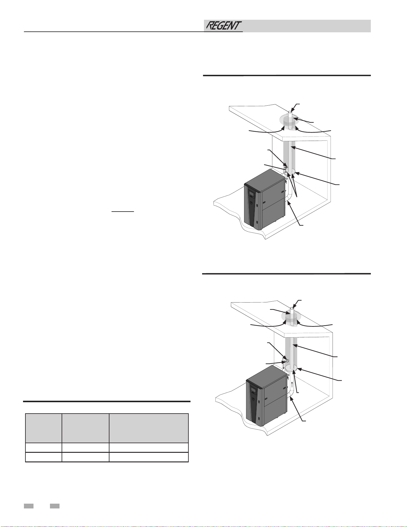
38
5 Vertical direct venting
Alternate vertical concentric venting
This appliance may be installed with a concentric vent
arrangement where the vent pipe is routed through an existing
unused venting system; or by using the existing unused venting
system as a chase for vent and combustion air routing.
Concentric Venting Arrangement
The venting is to be vertical through the roof. The annular
space between the O.D. of the vent pipe and the I.D. of the
existing unused venting system is utilized for the combustion
air source.
The minimum size of the existing vent system required to
achieve enough annular space for combustion air can be found
in Table 5A below.
The upper and lower termination as well as any other unsealed
joints in the existing vent system must be sealed to ensure that
all combustion air is drawn from under the vent cap as shown
in FIG. 5-8 and 5-9.
Approved venting materials must be used as specified in Table
3H.
Follow all vent / air termination and clearance requirements
per this section to the appropriate example. Installation must
comply with local requirements and with the National Fuel
Gas Code.
The maximum allowable equivalent vent and air intake lengths
for this venting arrangement are to be determined from the
General Venting Section.
If an existing unused venting system is converted for use
with this method of concentric venting, the installer must
ensure that the existing venting system is clean and free from
debris contamination that will harm this appliance and cause
increased nuisance calls or maintenance. See Table 1A for a list
of corrosive contaminants and sources.
Two example scenarios of a concentric venting arrangement
are shown for illustrative purposes in FIG. 5-8 and 5-9.
Model
Vent / Air
Inlet Size
Minimum Existing
Vent / Chase Size
500 4" 7"
750 - 1000 6" 10"
Table 5A Alternate Vertical Concentric Vent / Chase Sizes
Figure 5-8 Concentric Vent Example 1
*For concept illustration only. Individual installations
may vary due to job site specific equipment.
Figure 5-9 Concentric Vent Example 2
Installation & Operation Manual
2000845690_000
FLUE EXHAUST
AIR INLET
W/ SCREEN
FLUE OUTLET
SEAL
SEAL
12"
EXISTING
SEALED
CAP
COMBUSTION
AIR
COMBUSTION
AIR
2000845690_000
FLUE EXHAUST
AIR INLET
W/ SCREEN
FLUE OUTLET
SEAL
SEAL
SEAL
EXISTING
SEALED
CAP
COMBUSTION
AIR
COMBUSTION
AIR
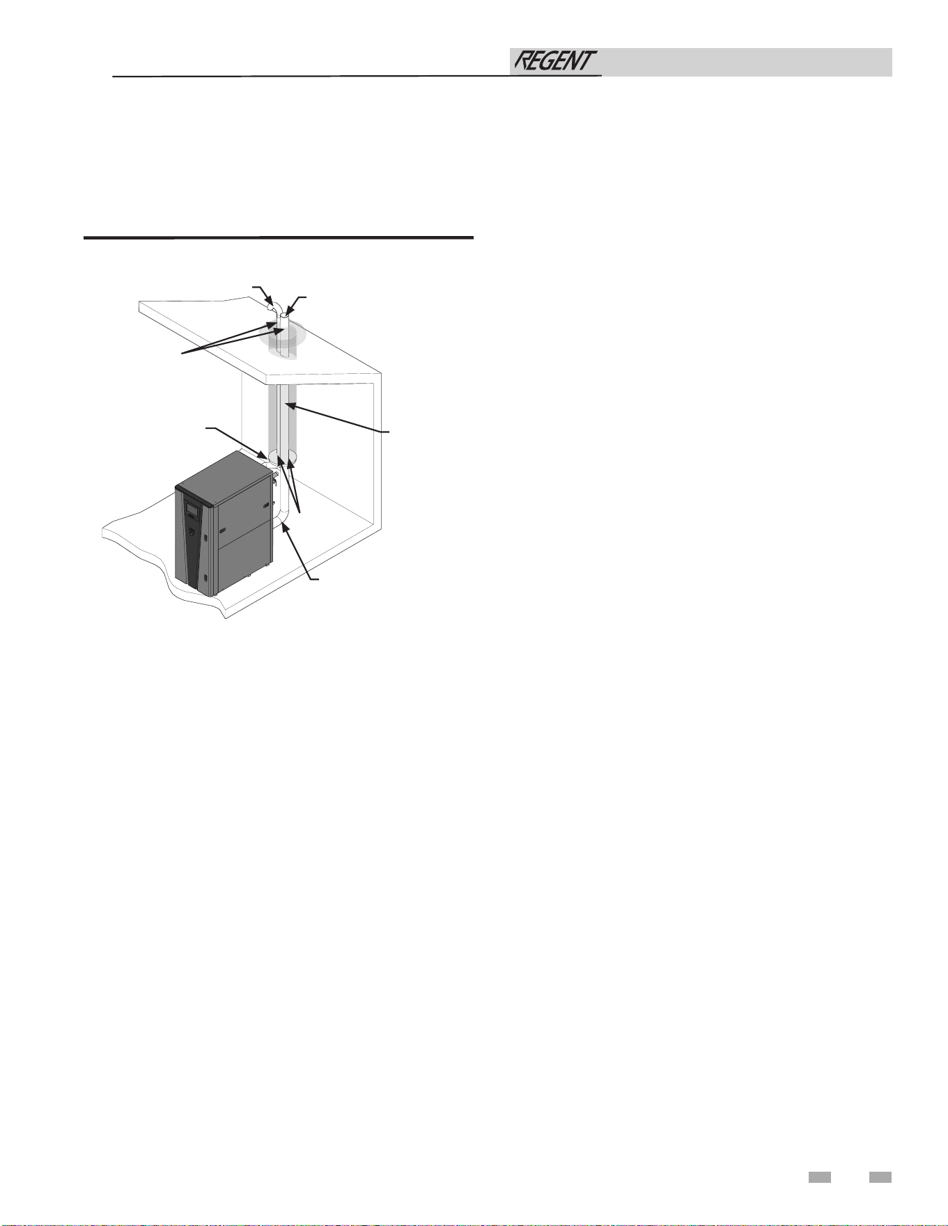
39
Existing vent as a chase
Follow all existing termination and clearance requirements and
allowable pipe lengths. Use only approved venting materials
listed in the General Venting Section of this manual.
Figure 5-10 Existing Vent as a Chase
5 Vertical direct venting (continued)
*For concept illustration only. Individual installations
may vary due to job site specific equipment.
Installation & Operation Manual
2000845690_000
EXISTING
CAP
FLUE OUTLET
SEAL
SEAL
FLUE EXHAUST
AIR INLET
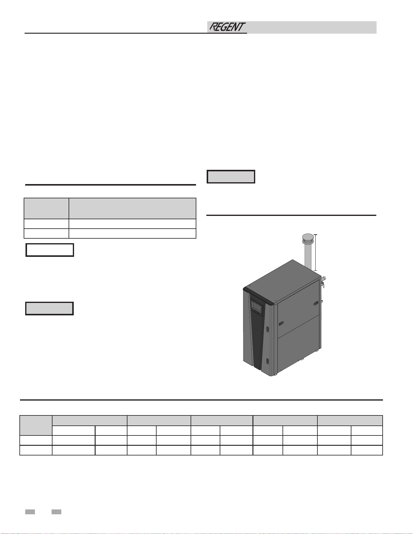
40
6 Outdoor installations
Outdoor venting
• In order to properly install the appliance in an outdoor
configuration, the outdoor installation kit must be
purchased from the factory.
• In order to properly install the appliance in an outdoor
configuration the optional outdoor kit must be used (see
Table 6A).
• Vent materials for outdoor venting are to be field supplied.
• Vent materials must be stainless steel.
• The vent must terminate at least 36 inches above the top of
the unit.
• All vent materials must be supported as recommended by
the vent manufacturer.
• The terminations in Table 6B must be used.
Model Indoor to Outdoor Conversion Kit
500 100400878
750-1000 100400879
Table 6A Indoor to Outdoor Conversion Kit
Before installing a venting system, follow all
requirements found in the General Venting
section of this manual.
Outdoor vent / air inlet location
Keep venting areas free of obstructions. Keep area clean and free
of combustible and ammable materials. Maintain minimum
clearances to combustibles as stated in this manual.
NOTICE
Only use the vent caps specified in this
manual. Personal injury or product damage
may result if any other cap is used, or if an
indoor model is used outdoors. Properly
install all covers, doors, and jacket panels
to ensure proper operation and prevent a
hazardous condition.
Units are self-venting and can be used outdoors when installed
with the optional outdoor kit. All vent materials must be eld
supplied and supported per the vent manufacturer’s instructions.
Combustion air supply must be free of contaminants (see the
Combustion and Ventilation Air Requirements section of this
manual). To prevent recirculation of the ue products into the
combustion air inlet, follow all instructions in this section.
⚠WARNING
Model
DuraVent Z-Flex Heat Fab Metal Fab Security Chimney
Adapter Rain Cap Adapter Rain Cap Adapter Rain Cap Adapter Rain Cap Adapter Rain Cap
500
FSA-4PVC-4FNS FSRC4 2SVSLA04 2SVSXITC04 9401PVC CCA04EX06 4CGPVCA 4FCSEC-C60 SS4PVCU SS4ECU
750 - 1000
810005231 FSRC6 - - 9601PVC CCA06EX08 6CGPVCA 6FCSEC-C60 SS6PVCU SS6ECU
Table 6B Approved Stainless Steel Adapters and Rain Caps
Location of unit
For outdoor models, you must install a flue termination.
Instructions for mounting the flue termination are included
in this manual. Do not install outdoor models directly on the
ground. You must install the outdoor unit on a concrete, brick,
block, or other non-combustible pad. See Outdoor Installation
Venting.
CAUTION
This unit shall not be installed in locations
where temperatures may reach below 32°F
(0°C). Exposure to freezing temperatures
will cause the system and appliance to
freeze and leak.
Figure 6-1 Outdoor installation
Installation & Operation Manual
2000845690_000
36"
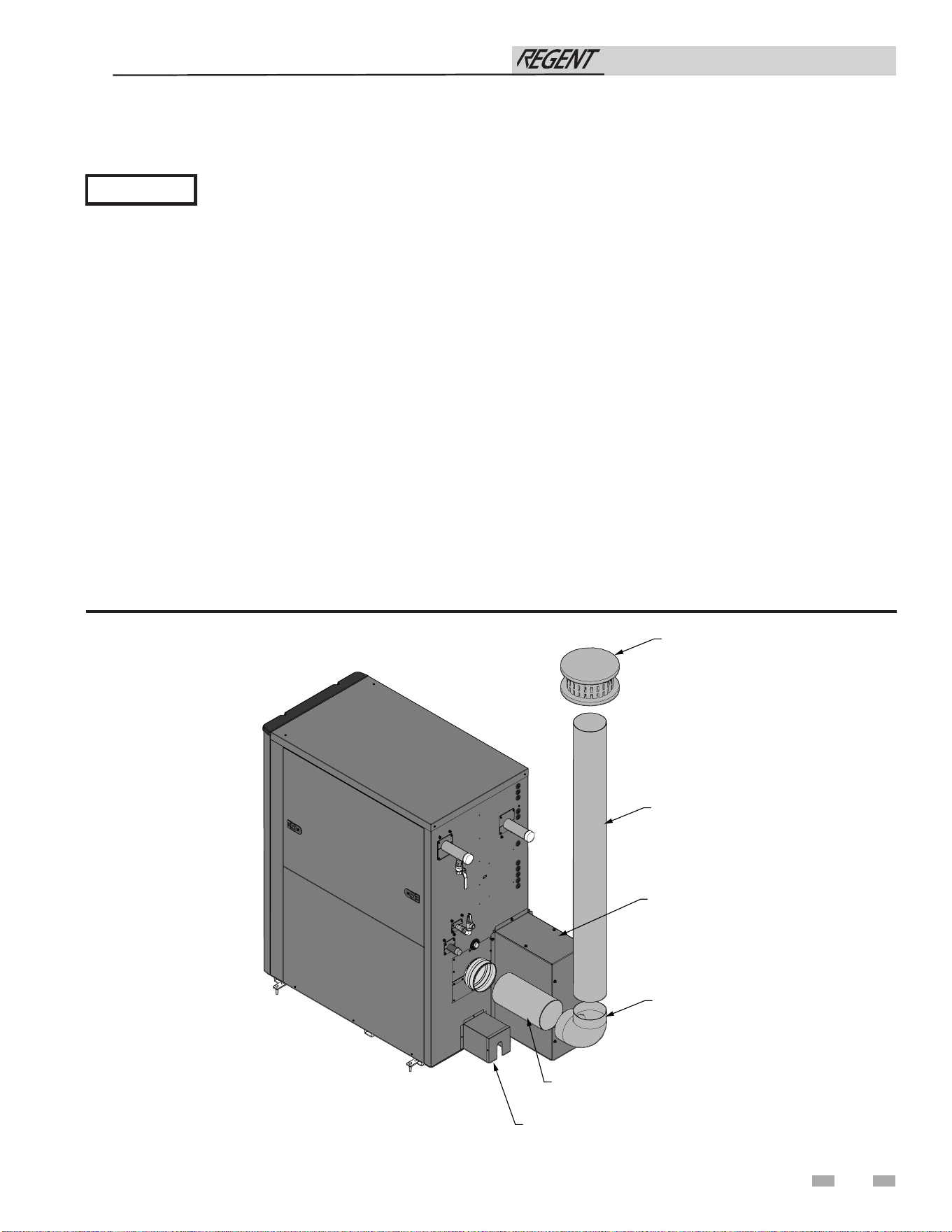
41
6 Outdoor installations (continued)
Outdoor venting
NOTICE
Before installing a venting system, follow all requirements found in the General Venting section.
Units are self-venting and can be used outdoors when installed with the optional outdoor kit.
Combustion air supply must be free of contaminants (see Combustion and Ventilation Air in this manual). To prevent recirculation
of the flue products into the combustion air inlet, follow all instructions in this section.
Outdoor vent/air inlet location
Keep venting areas free of obstructions. Keep area clean and free of combustible and flammable materials. Maintain a minimum
clearance of 3" (76 mm) to combustible surfaces and a minimum of 36" (915 mm) clearance to the air inlet. To avoid a blocked air
inlet or blocked flue condition, keep the air inlet, flue outlet, and condensate trap clear of leaves, debris, etc.
Do not install outdoor models directly on the ground. You must install the outdoor unit on a concrete, brick, block, or other non-
combustible pad.
Do not locate unit so that high winds can deflect off of adjacent walls, buildings, or shrubbery causing recirculation. Recirculation
of flue products may cause operational problems, bad combustion, or damage to controls.
Multiple unit outdoor installations require 48" (1.22 m) clearance between each vent cap. Locate outdoor cap at least 48" (1.22m)
below and 48" (1.22 m) horizontally from any window, door, walkway, or gravity air intake.
Locate unit at least 10 feet (3.05 m) away from any forced air inlet.
Locate unit at least 3 feet (0.91 m) outside any overhang.
Clearances around outdoor installations can change with time. Do not allow the growth of trees, shrubs, or other plants to obstruct
the proper operation of the outdoor vent system.
Do not install in locations where rain from building runoff drains will spill onto the unit.
Figure 6-2 Outdoor Venting - Stainless Steel
NOTE: See Table 6B for approved stainless-steel adapters and rain caps.
Installation & Operation Manual
2000845690 01
STAINLESS STEEL
VENT PIPE
(FIELD SUPPLIED)
90° STAINLESS
STEEL ELBOW
(FIELD SUPPLIED
AS NEEDED)
VENT ADAPTER
(FIELD SUPPLIED)
RAIN CAP
(FIELD SUPPLIED)
RAIN CHANNEL
COVER
CONDENSATE TRAP COVER
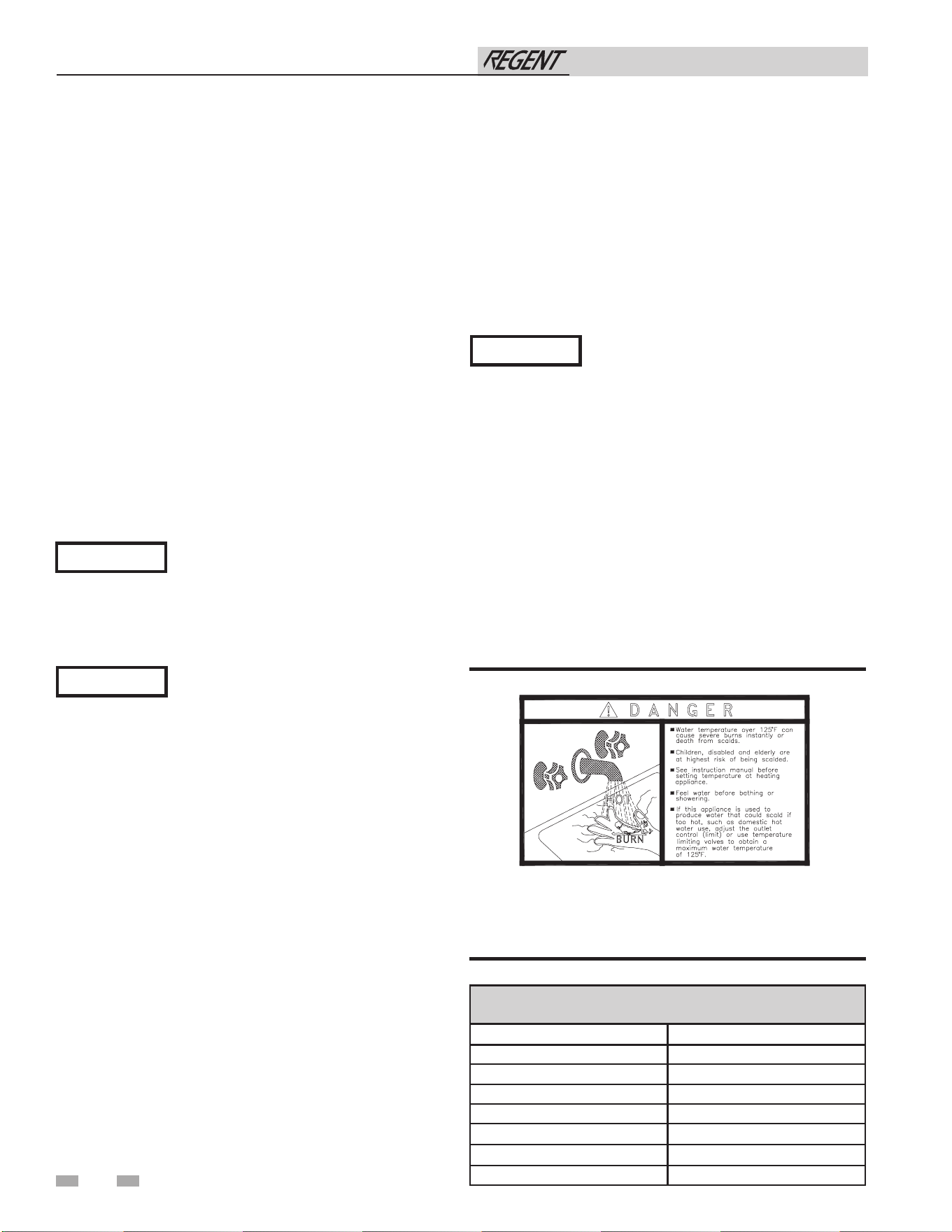
Figure 7-1 Scald Warning Label Located on the Appliance
The following chart (Table 7A) details the relationship of water
temperature and time with regard to scald injury and may be
used as a guide in determining the safest water temperature for
your applications.
APPROXIMATE TIME / TEMPERATURE RELATIONSHIPS
IN SCALDS
120°F More than 5 minutes
125°F 1 1/2 to 2 minutes
130°F About 30 seconds
135°F About 10 seconds
140°F Less than 5 seconds
145°F Less than 3 seconds
150°F About 1 1/2 seconds
155°F About 1 second
Table 7A Approximate Time / Temperature Scald Chart
7 System piping
System water piping methods
Observe a minimum of 1/4 inch clearance around all
un-insulated hot water pipes when openings around the pipes
are not protected by non-combustible materials.
General piping information
Basic steps are listed below along with illustrations on the
following pages (FIG. 7-2 thru 7-3), which will guide you
through the installation of the Regent water heater.
1. Connect the cold water supply to the inlet side of the water
heater.
2. Connect the hot water supply to the outlet side of the water
heater.
3. Install a backflow preventer on the cold feed supply line.
4. Install an expansion tank on the system supply. Consult
the tank manufacturer’s instruction for specific information
relating to tank installation. Size the expansion tank for the
required system volume and capacity.
5. Install a drain valve at the lowest point of the system.
See the piping illustrations included in this section, FIG. 7-2
thru 7-3 for suggested guidelines in piping the Regent water
heater.
*Please note that these illustrations are meant
to show system piping concept only, the
installer is responsible for all equipment and
detailing required by local codes.
NOTICE
42
Scalding
This water heater can deliver scalding temperature water to any
fixture in the system. Be careful whenever using hot water to
avoid scalding injury. Certain appliances such as dishwashers and
automatic clothes washers may require increased temperature
water. By setting the thermostat on this water heater to obtain
the increased temperature water required by these appliances,
you may create the potential for scald injury. To protect against
injury, appropriate ASSE certified scald protecting devices must
be installed in the water system. These devices will reduce
points of discharge temperature by mixing cold and hot water
in branch supply lines. Such valves are available from the local
plumbing supplier. Mixing valves must be installed according to
valve manufacturer instructions.
Water connections
e inlet and outlet water connections on the Regent water
heaters are 2" copper sweat. e connections also have a groove
in case a groove-lock tting is preferred. For copper-to-copper
connections, Victaulic style 607 QuikVic rigid couplings are
recommended. For copper-to-stainless steel connections,
Victaulic style 644 transition couplings are recommended. For
other groove-lock connection styles contact your local plumbing
supplier.
Internal Circulating Pump
e Regent water heater is factory equipped with a stainless-
steel circulating pump. e internal circulating pump operates
whenever the unit is powered and maintains water ow through
the heat exchanger for optimal temperature delivery and
performance.
Water Pressure Drop
e Regent water heater will not introduce pressure drop to the
water heating system when operating below the maximum ow
rate listed in Table 7B.
Installation & Operation Manual
The internal circulating pump in a Regent
water heater operates whenever the unit is
powered. The water heater must be filled
with water prior to applying line voltage to
the terminal strip to avoid damage to the
circulating pump.
The Regent IWH0500 model includes a
3-speed circulating pump. The speed selector
must be set to high speed (III) to protect the
heat exchanger during operation.
NOTICE
NOTICE
6. This appliance is supplied with a relief valve sized in
accordance with ASME Boiler and Pressure Vessel Code,
Section IV (“Heating Boilers”). Pipe the discharge of the
safety relief valve to a suitable drain to prevent injury in the
event of pressure relief. Provide piping that is the same size
as the safety relief valve outlet. Never block the outlet of
the safety relief valve.
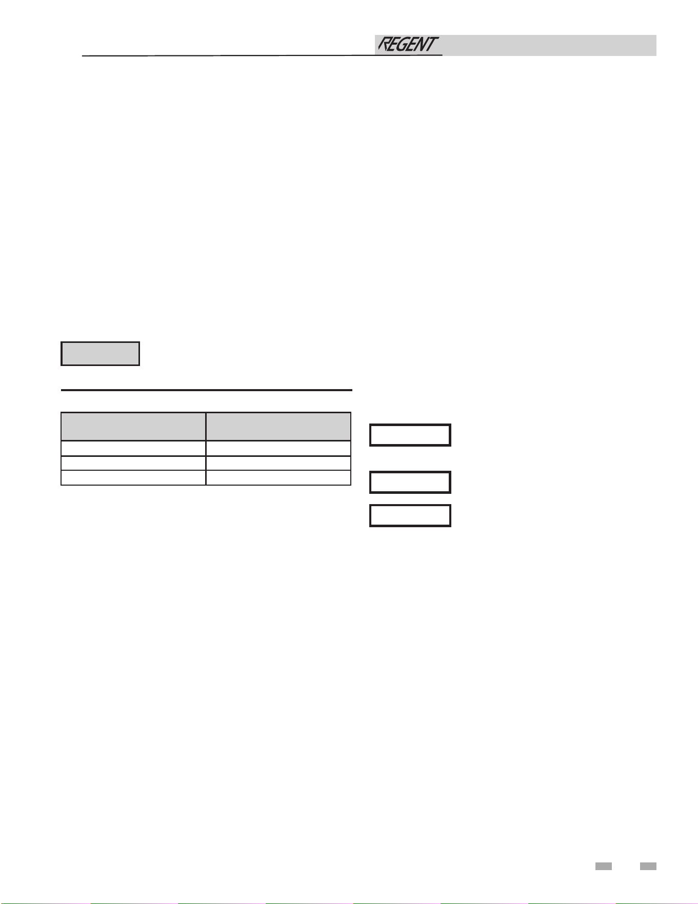
Water chemistry
Water with a hardness of less than 5 grains per gallon will
usually have a pH which can be aggressive and corrosive causing
non-warrantable damage to the pump, and associated piping.
Corrosion due to water chemistry generally shows up first in
the hot water system because heated water increases the rate of
corrosive chemical reactions.
7 System piping (continued)
Piping components
Water heater system piping:
System piping should be sized based on the water heater
application and hot water flow requirements. Reducing the pipe
size will increase the system pressure drop and may reduce the
water pressure and flow to fixtures in the system.
Maximum Flow rate:
Table 7B below for maximum flow rates for each model.
43
Check recirculation pump size to verify
it is sized for filter addition and upsize if
necessary.
NOTICE
Installation & Operation Manual
Water flow rates greater than those listed
in this manual may result in damage to
components inside the water heater.
Model Maximum Flow Rate (GPM)
500 40
750 70
1000 75
Check valves:
Field supplied. Check valves are recommended for installation
as shown in FIG. 7-2 thru 7-3. For multi-unit installations, check
valves are required on the inlet of each unit.
Water heater isolation valves:
Field supplied. Full port valves are recommended to minimize
the pressure losses in the water heating system.
Commissioning valve:
Factory installed. A ¾" ball valve is located on the water heater
outlet. Connect rigid piping rated for at least 200°F to the ball
valve and route to a suitable drain. Flow rate of the commissioning
valve may exceed 25 gallons per minute and temperatures up to
200°F.
Scald Protecting Devices:
Field supplied. Scald protecting devices to be installed as required
by local or state codes and best design practices.
Point of Distribution Mixing Valve:
Field supplied. Point-of-distribution mixing valves are
recommended for hot water circuits where point-of-use scald
protecting devices are required by local codes.
Table 7B Maximum Flow Rate
Unions:
Field supplied. Recommended for unit serviceability.
Temperature and Pressure Relief Valve:
Factory supplied on water heaters. The temperature and
pressure relief valve is sized to ASME specifications.
Strainer:
Field supplied. Required to help eliminate debris from causing
damage to the heat exchanger. When installing in a pre-existing
system, it is recommended to install a filter in the recirculation
line capable of removing debris left in the system.
Building Recirculation Filter:
Field supplied as required. When required, helps to eliminate
debris from causing damage to the heat exchanger.
System piping for multiple units (including Cascade):
Reverse-return piping is required when installing multiple
Regent water heaters in a single system. Consult the system
piping diagrams in this manual for recommended system
piping configurations for multiple units. It is important that the
system piping pressure drop is balanced across multiple units.
When system balance is not possible, balancing valves may be
required.
Cascade valve:
Required on the outlet of each water heater in multi-unit
installations utilizing cascade as shown in FIG 7-3. The
cascade valve is controlled by the water heater to which it is
installed and connected. Cascade valves must be purchased
from the factory (Kit # 100400856).
Fail-open system bypass valve:
Field supplied. A fail-open bypass valve is recommended when
installing multiple Regent water heaters in a single system. The
fail-open bypass will open upon a loss of power and prevent
system run-dry.
Reduced system performance is possible
when system piping is not balanced.
When installing multiple Regent water
heaters in the same water heating system,
all units must be of the same size.
NOTICE
NOTICE
⚠CAUTION
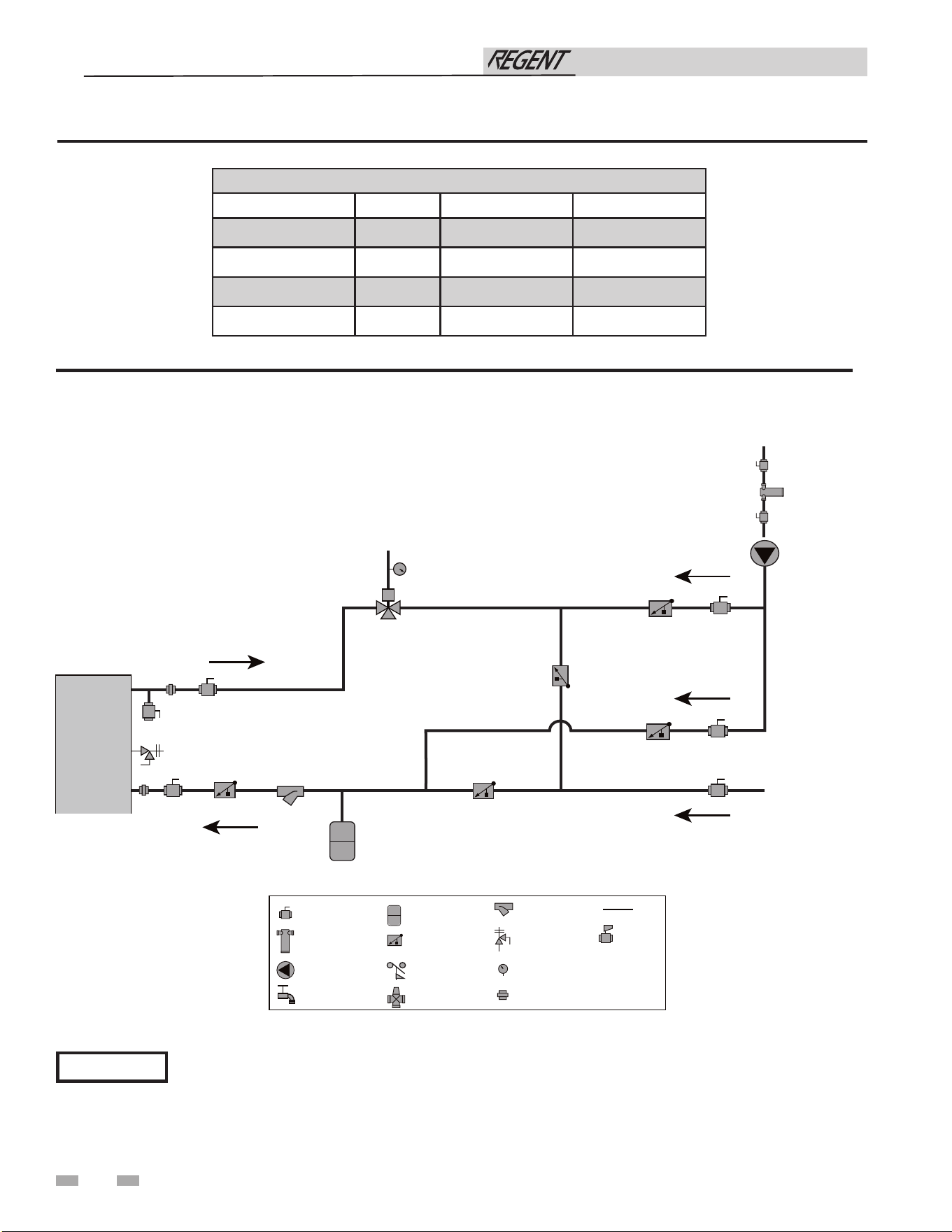
Table 7B Water Heater Flow Rate / Typical Temperature Rise
44
Water Heater Flow Rate Capacity (GPM)
Temp. Rise (°F) IWH0500 IWH0750 IWH1000
50 19.2 28.8 38.4
70 13.7 20.5 27.4
90 10.7 16.0 21.4
120 8.0 12.0 16.0
7 System piping
Installation & Operation Manual
NOTICE
Please note that these illustrations are meant to show system piping concept only, the installer is responsible
for all equipment. The installer must follow all manufacturer’s instructions for each system component. The
installer is responsible for compliance with local codes.
Figure 7-2 Single Heater - Single Temperature - DHW Recirculation
WATER
HEATER
HOT WATER
SUPPLY
COLD WATER
SUPPLY
BUILDING
RETURN
T
CIRCULATION
PUMP
FLOW CHECK
VALVE
TEMPERATURE
GAUGE
T
BUILDING
RECIRCULATION
FILTER
STRAINER / FILTER
TEMPERATURE &
PRESSURE
RELIEF VALVE
BALL VALVE
(TYPICAL)
EXPANSION TANK
MIXING VALVE
UNION
DRAIN PORT
FLOW SWITCH
PIPING
MOTORIZED
VALVE
2000853527 00
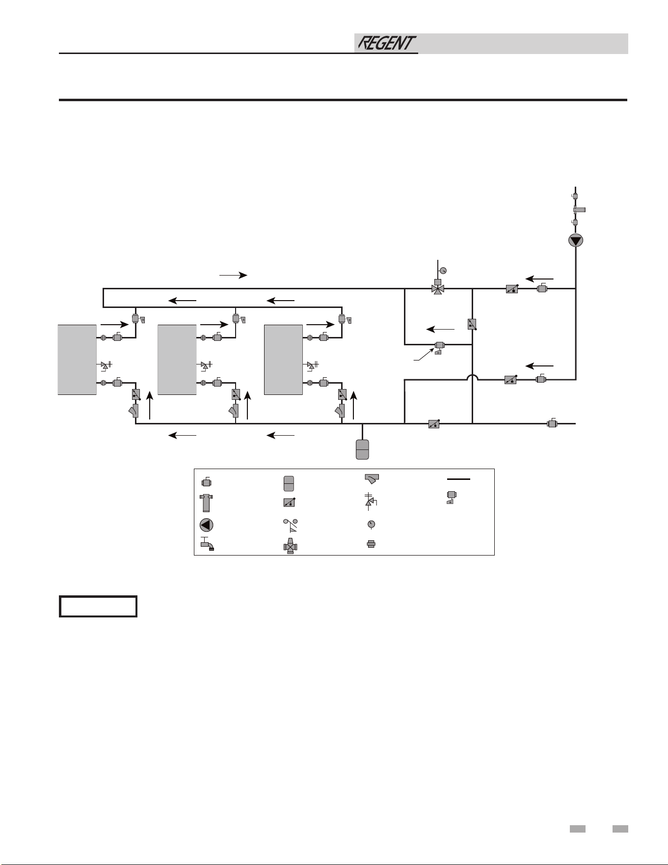
45
Installation & Operation Manual
7 System piping (continued)
NOTICE
Figure 7-3 Triple Heater in Cascade - Single Temperature DHW Recirculation
Please note that these illustrations are meant to show system piping concept only, the installer is responsible
for all equipment. The installer must follow all manufacturer’s instructions for each system component. The
installer is responsible for compliance with local codes.
WATER
HEATER
HOT WATER
SUPPLY
COLD WATER
SUPPLY
WATER
HEATER
WATER
HEATER
CIRCULATION
PUMP
FLOW CHECK
VALVE
TEMPERATURE
GAUGE
T
BUILDING
RECIRCULATION
FILTER
STRAINER / FILTER
TEMPERATURE &
PRESSURE
RELIEF VALVE
BALL VALVE
(TYPICAL)
EXPANSION TANK
MIXING VALVE
UNION
DRAIN PORT
FLOW SWITCH
PIPING
MOTORIZED
VALVE
FAIL-OPEN BYPASS
(RECOMENDED)
(SEE PIPING COMPONENTS IN SECTION 7)
BUILDING
RETURN
T
2000853535 00
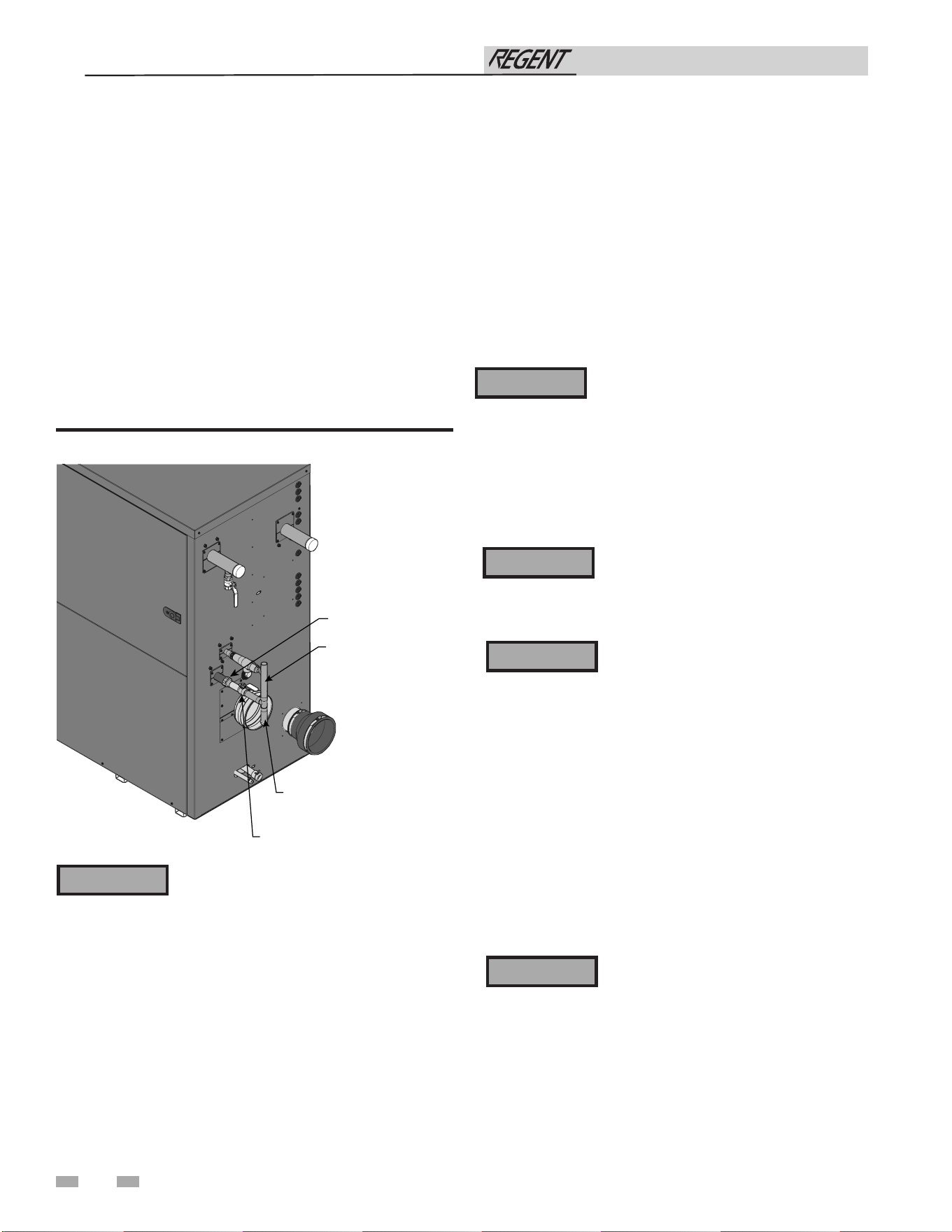
46
Installation & Operation Manual
Failure to apply pipe sealing compound as
detailed in this manual can result in severe
personal injury, death, or substantial
property damage.
⚠ WARNING
8 Gas connections
Connecting gas supply piping
1. Refer to FIG. 8-1 to pipe gas to the water heater.
a. Install ground joint union for servicing, when
required.
b. Install the factory supplied manual shutoff valve in the
gas supply piping.
c. In Canada – When using manual main shutoff
valves, it must be identified by the installer.
2. Install sediment trap / drip leg.
3. Support piping with hangers, not by the water heater or its
accessories.
Figure 8-1 Gas Supply Piping
4. Purge all air from the gas supply piping.
5. Before placing the water heater in operation, check the
water heater and its gas connection for leaks.
a. The appliance must be disconnected from the gas
supply piping system during any pressure testing of
that system at a test pressure in excess of 1/2 PSIG
(3.5 kPa).
b. The appliance and its gas connection must be leak
tested before placing it in operation.
The gas valve and blower will not support
the weight of the piping. Do not attempt
to support the weight of the piping with
the water heater or its accessories. Failure
to comply could result in severe personal
injury, death, or substantial property
damage.
⚠ WARNING
Do not check for gas leaks with an open
flame – use the bubble test. Failure to use the
bubble test or check for gas leaks can cause
severe personal injury, death, or substantial
property damage.
⚠ WARNING
6. Use pipe sealing compound compatible with propane gases.
Apply sparingly only to male threads of the pipe joints so
that pipe dope does not block gas flow.
2000845690_000
UNION
(FIELD SUPPLIED)
GAS SUPPLY
SEDIMENT TRAP/
DRIP LEG
MANUAL SHUTOFF VALVE
(FACTORY SUPPLIED)
Regent water heaters are typically shipped
ready to fire on natural gas. Check the
water heater rating plate to determine
which fuel the water heater is set for. If set
to natural gas, Regent water heaters may
be field converted to LP (see Section 8 for
conversion instructions).
To operate on LP gas, the installer must
select LP from the “Fuel type” screen and
confirm the selection by agreeing to the
pop-up message. The water heater MUST
BE field commissioned on the new fuel
type prior to placing in service. Failure
to select the appropriate fuel type may
result in severe personal injury, death, or
substantial property damage.
⚠ WARNING
Use two wrenches when tightening gas
piping at water heater (FIG. 8-2), using
one wrench to prevent the water heater
gas line connection from turning. Failure
to support the water heater gas connection
pipe to prevent it from turning could
damage gas line components.
⚠ WARNING
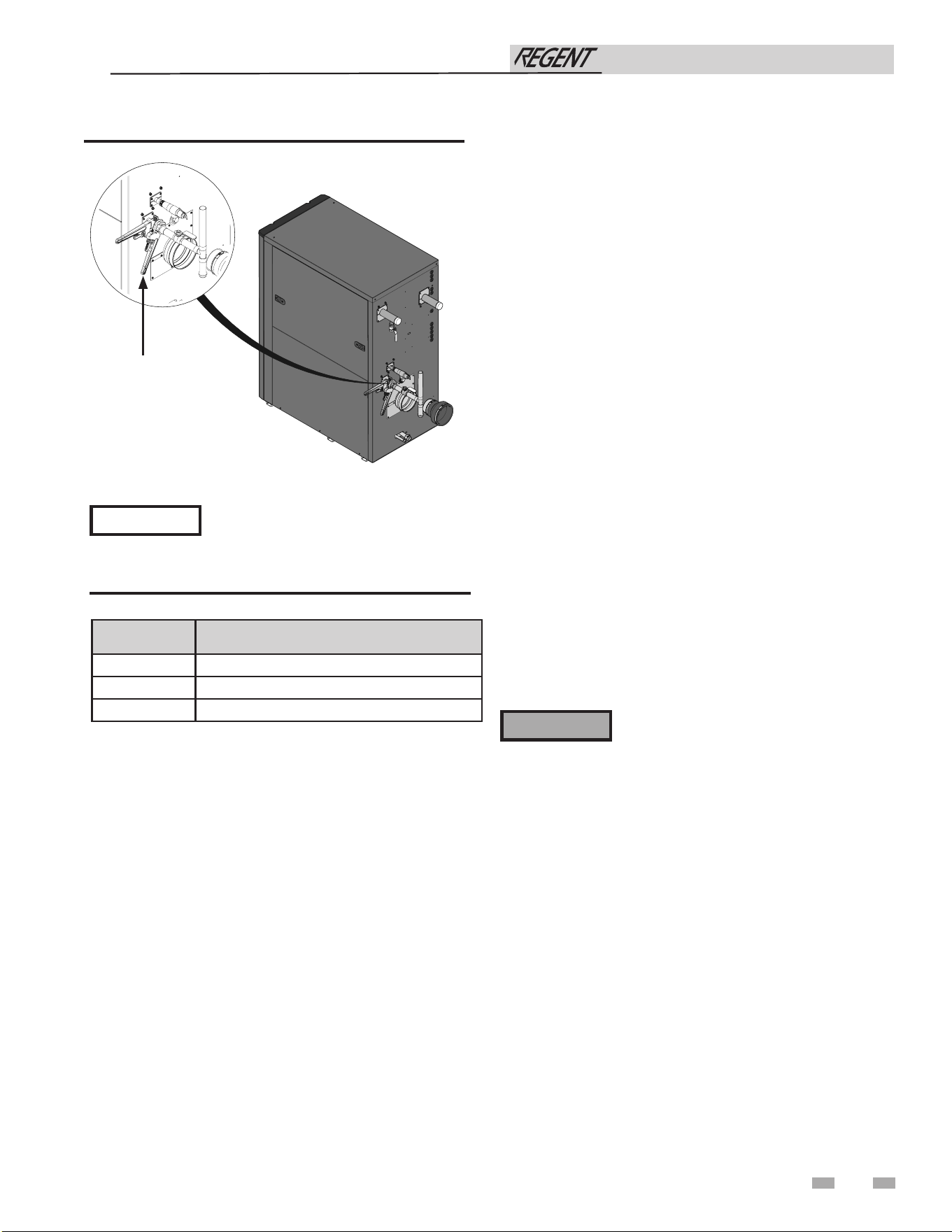
8 Gas connections
Installation & Operation Manual
Figure 8-2 Inlet Pipe with Backup Wrench
2000845690_000
USE BACK-UP WRENCH
TO PREVENT PIPE
FROM ROTATING
47
Maximum inlet gas pressure must not
exceed the value specified. Minimum
value listed is for the purposes of input
adjustment.
NOTICE
Model Pipe Connection Size
500 1"
750 1"
1000 1-1/4"
Table 8A Inlet Pipe Connection Sizes
Natural gas:
Pipe sizing for natural gas
1. Refer to Table 8B for pipe length and diameter. Based on
rated water heater input (divide by 1,000 to obtain cubic feet
per hour).
a. Table 8B is only for natural gas with specific gravity
0.60 inches, with a pressure drop through the gas
piping of 0.30 inches w.c.
b. For additional gas pipe sizing information, refer to
ANSI Z223.1 (or B149.1 for Canadian installations).
Natural gas supply pressure requirements
1. Target a supply pressure of 7 inches w.c. (1.7 kPa) measured
when the water heater is operating at minimum input rate.
Gas pressure can be adjusted higher or lower than 7 inches
w.c. as needed.
2. Pressure required at the gas valve inlet pressure port:
• Maximum 14 inches w.c. with no flow (lockup) or
with water heater on.
• Minimum 2.5 inches w.c. with gas flowing (verify during
water heater startup).
3. Install 100% lockup gas pressure regulator in supply line if
inlet pressure can exceed 14 inches w.c. at any time. Adjust
lockup regulator for 14 inches w.c. maximum.
Propane Gas:
Pipe sizing for propane gas
1. Contact gas supplier to size pipes, tanks, and 100% lockup
gas pressure regulator.
⚠WARNING
Check water heater rating plate to determine
which fuel the water heater is set for. Regent
water heaters may be field converted by
following the instructions in this manual.
Failure to comply could result in severe
personal injury, death, or substantial
property damage.
Propane Supply Pressure Requirements
1. Target a supply pressure of 11 inches w.c. (2.7 kPa)
measured when the water heater is operating at minimum
input rate. Gas pressure can be adjusted higher or lower
than 11 inches w.c. as needed.
2. Adjust propane supply regulator provided by the gas
supplier for 14 inches w.c. (3.5 kPa) maximum pressure.
3. Pressure required at gas valve inlet pressure port:
• Maximum 14 inches w.c. (3.5 kPa) with water heater
operating.
• Minimum 8 inches w.c. (1.99 kPa) with water heater
operating.

48
8 Gas connections
Installation & Operation Manual
For a water heater already installed, you
must turn off gas supply, turn off power
and allow the water heater to cool before
proceeding. You must also perform the field
commissioning sequence and completely test
the water heater after conversion to verify
performance as described under Start-up,
Section 11 of this manual. Failure to comply
could result in severe personal injury, death,
or substantial property damage.
⚠ WARNING
Gas Conversions
Models 1000 Only
1. Turn OFF the gas supply to the product by closing the
manual shutoff located on the gas supply to the appliance.
Locate the air shutter and screws provided in the appliance
installation kit or purchased separately (See Replacement
Parts list).
2. Access the inside of the appliance by removing the left
upper service panel and opening the front access door.
3. Remove the 7/16” nut securing the air box to the base of the
appliance. Remove the two sheet metal screws and the air
box hold-down bracket.
4. Loosen the band clamp from the air intake duct and
remove the duct from the air intake connection.
5. Using a backing wrench on the gas inlet manifold, loosen
the union and disconnect the gas manifold at the inlet of
the gas valve assembly.
6. Remove the (4) bolts and nuts holding the combustion
blower to the air manifold.
7. Gently slide the blower and air intake assembly away from
the heat exchanger, toward the front of the appliance,
approximately 2 inches.
8. Insert the air shutter into the opening of the air manifold
with the brackets facing the heat exchanger. The shutter
should rest inside the air manifold opening (FIG. 8-3).
9. Use the (2) supplied screws and a 3mm angled Allen
wrench to secure the air shutter to the air manifold. Take
care not to overtighten the screws or cross-thread them in
the aluminum manifold.
10. Slide the blower and intake assembly back into place and
reinstall the (4) bolts and nuts securing the blower to the
air manifold. Ensure the air manifold to blower gasket is in
place prior to tightening the bolts.
11. Reattach the air intake duct to the air intake and tighten the
band clamp. Ensure the duct is securely connected to the air
intake connection.
12. Reconnect the gas manifold to the inlet of the gas valve
assembly and tighten the union. Use a backing wrench on
the gas manifold when tightening the union connection.
13. Install the air box bracket to the air box and secure it to the
unit base with the 7/16” nut.
14. Verify all electrical connections and pressure tubing are
connected and secure.
15. Turn ON the gas to the appliance by opening the manual
shutoff on the gas supply to the appliance.
16. Check for leaks using the procedure in the instruction
manual.
All Models
1. From home screen, turn the unit status to “OFF” by
pressing the power button icon.
2. Navigate to the “Fuel Conversion” screen by selecting it
from the “Settings” menu.
3. Select “LP” from the menu and confirm with the installer
password. A message will pop up on the screen asking the
installer to verify the fuel type selected. Verify the correct
fuel type is selected and piped to the appliance prior to
accepting the message.
4. Select “confirm” to verify the fuel type selection. Once
confirmed, on the home screen, change the unit status back
to “ON” by pressing the power button icon.
5. Navigate to the “Commissioning Sequence” screen from
the main menu.
6. Perform the field commissioning sequence as described in
the “Start-up” section of this manual.
7. After performing the field commissioning sequence, attach
the provided propane conversion label to the appliance
near the rating plate. Place the LP Warning label on the
appliance on the front door.
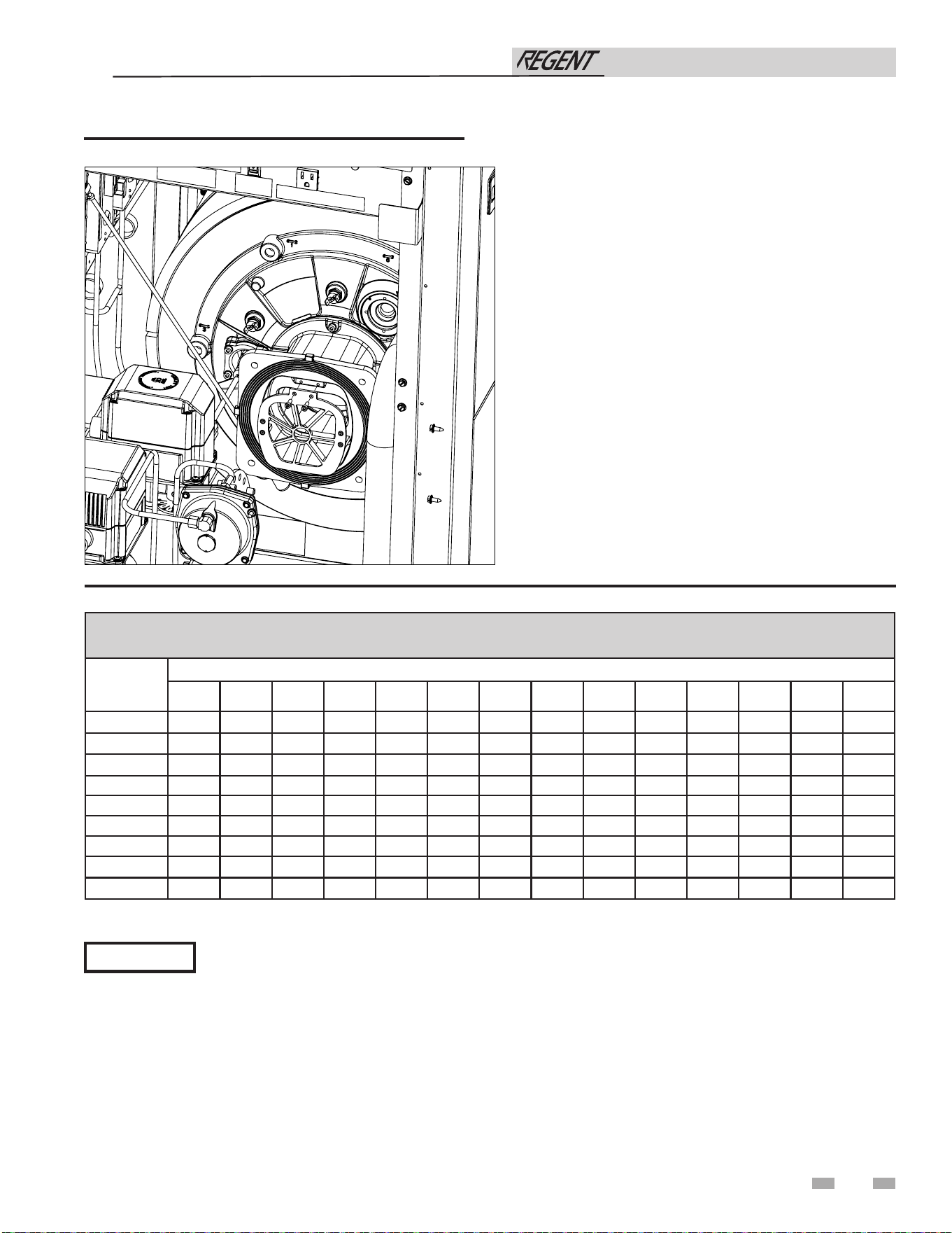
49
Table 8B Natural Gas Pipe Size Chart
8 Gas connections (continued)
Capacity of Schedule 40 Metallic Pipe in Cubic Feet of Natural Gas Per Hour
(based on .60 specific gravity, 0.30" w.c. pressure drop)
Pipe
Size
(Inches)
Length of Pipe in Straight Feet
10 20 30 40 50 60 70 80 90 100 125 150 175 200
1/2 131 90 72 62 55 N/A N/A N/A N/A N/A N/A N/A N/A N/A
3/4 273 188 151 129 114 104 95 89 83 79 70 63 58 N/A
1 514 353 284 243 215 195 179 167 157 148 131 119 109 102
1 1/4 1,060 726 583 499 442 400 368 343 322 304 269 244 224 209
1 1/2 1,580 1,090 873 747 662 600 552 514 482 455 403 366 336 313
2 3,050 2,090 1,680 1,440 1,280 1,160 1,060 989 928 877 777 704 648 602
2 1/2 4,860 3,340 2,680 2,290 2,030 1,840 1,690 1,580 1,480 1,400 1,240 1,120 1,030 960
3 8,580 5,900 4,740 4,050 3,590 3,260 3,000 2,790 2,610 2,470 2,190 1,980 1,820 1,700
4 17,500 12,000 9,660 8,270 7,330 6,640 6,110 5,680 5,330 5,040 4,460 4,050 3,720 3,460
Installation & Operation Manual
Check inlet gas supply
CSA or UL listed flexible gas connections are
acceptable, but you must exercise caution to
The gas piping must be sized for the proper flow and length of
pipe, to avoid excessive pressure drop. Both the gas meter and
the gas regulator must be properly sized for the total gas load.
Perform the steps below when checking inlet gas supply:
1. Turn the main power switch to the “OFF” position.
2. Shut off gas supply at the manual gas valve in the gas
piping to the appliance.
ensure that the line has adequate capacity to allow your water
heater to fire at full rate. Consult with local codes for proper
installation or service procedures.
NOTICE
Figure 8-3 Insert air shutter into manifold
3. Remove the 1/8" pipe plug on the flange to the factory
supplied gas shutoff valve and install a suitable 1/8"
fitting (field supplied) for the manometer tubing. Place the
tubing of the manometer over the tap once the 1/8"
fitting is installed as shown in FIG. 8-4.
4. Slowly turn on the gas supply at the factory installed
manual gas valve.
5. Turn the power switch to the “ON” position.
6. Create a hot water demand by opening the commissioning
drain valve located on the outlet of the water heater.
2000854936 00
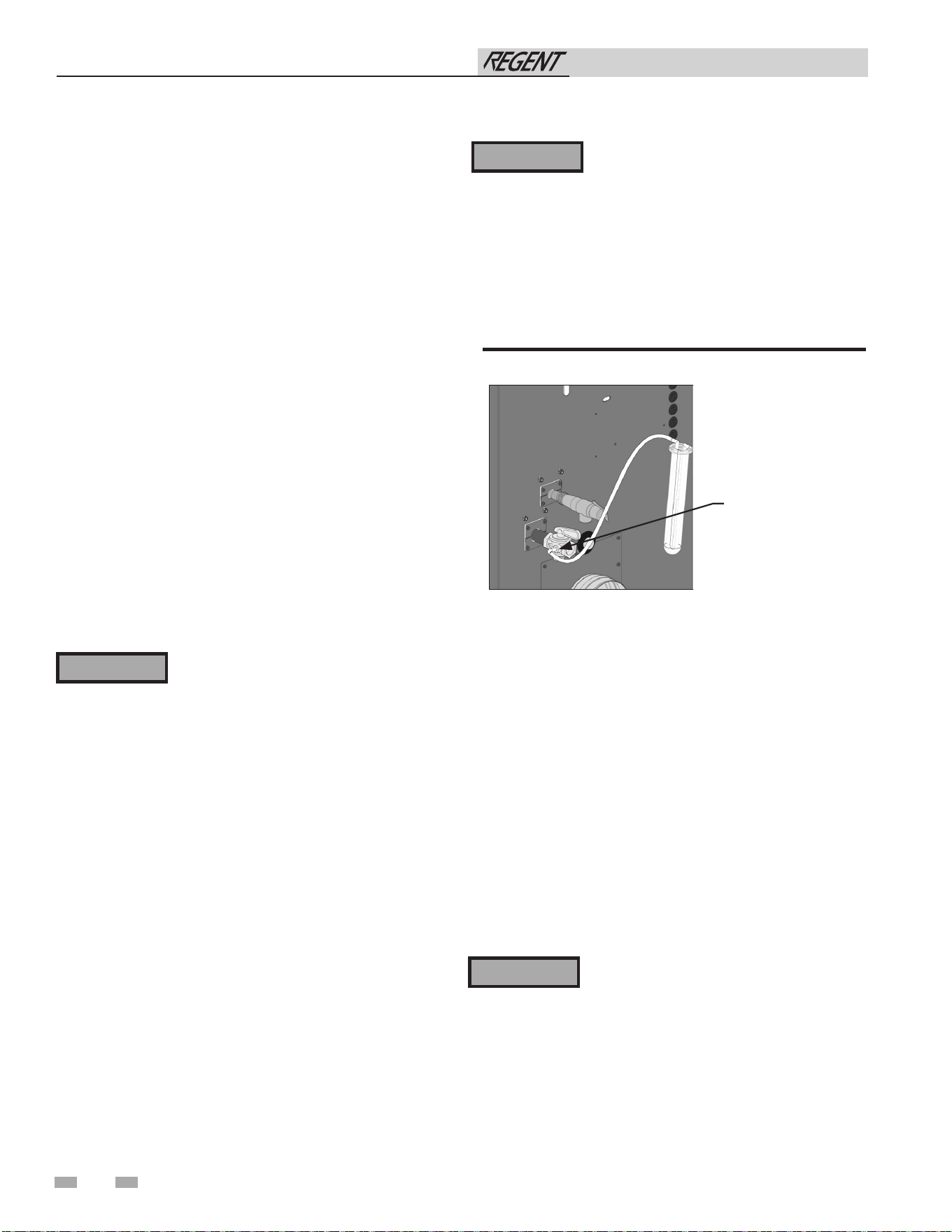
50
8 Gas connections
Gas pressure
The gas pressure must remain between 2.5 inches w.c. (natural),
8 inches w.c. (LP) minimum and 14 inches w.c. (natural and
LP) maximum during stand-by (static) mode and while in
operating (dynamic) mode. If an in-line regulator is used, it
must be a minimum of 10 feet from the Regent water heater. It
is very important that the gas line is properly purged by the gas
supplier or utility company. Failure to properly purge the lines
or improper line sizing, will result in ignition failure.
The problem is especially noticeable in NEW LP installations
and also in empty tank situations. This can also occur when
a utility company shuts off service to an area to provide
maintenance to their lines.
Figure 8-4 Inlet Gas Supply Check - Model 500-1000
Failure to follow all precautions could result
in fire, explosion, or death!
⚠ WARNING
Gas valve replacement
The gas valve MUST NOT be replaced with a conventional gas
valve under any circumstances.
⚠ WARNING
When re-tightening the set screw, be sure to
tighten securely to prevent gas leaks.
Do not check for gas leaks with an open
flame -- use the bubble test. Failure to
use the bubble test or check for gas leaks
can cause severe personal injury, death, or
substantial property damage.
⚠WARNING
Do not check for gas leaks with an open
flame -- use the bubble test. Failure to
use the bubble test or check for gas leaks
can cause severe personal injury, death, or
substantial property damage.
15. Turn on the gas supply at the manual gas valve.
16. Turn the power switch to the “ON” position.
17. Adjust the temperature set point on the control panel of
the SMART TOUCH control module to the desired
water temperature so the appliance will call for heat.
18. Check burner performance by cycling the system while
you observe burner response. The burner should ignite
promptly. Flame pattern should be stable. Turn system
off and allow burner to cool, then cycle burner again to
ensure proper ignition and flame characteristics.
7. Observe the gas pressure with the burner
operating at 100% of rated input. Without turning
off the water heater, reduce the burner to the minimum
input rate and observe the gas pressure with the burner
at the minimum input rate. Percent of burner input will
be displayed on the Modulation Screen.
8. Ensure inlet pressure is within specified range.
Minimum and maximum gas supply pressures are
specified in this section of the manual.
9. If gas supply pressure is within normal range and no
adjustments are needed, proceed on to Step 11.
10. If the gas pressure is out of range, contact the gas utility,
gas supplier, qualified installer or service agency to
determine the necessary steps to provide proper gas
pressure to the control.
11. Turn the power switch to the “OFF” position.
12. Turn OFF the commissioning drain valve to stop the flow
of water.
13. Shut off the gas supply at the manual gas valve in the gas
piping to the appliance.
14. Remove the manometer from the pressure tap on top of
the gas valve. Remove the 1/8" (3 mm) field supplied
fitting and reinstall the pipe plug removed in Step 3.
Installation & Operation Manual
PLACE THE
MANOMETER TUBING
OVER THE PRESSURE
TAP
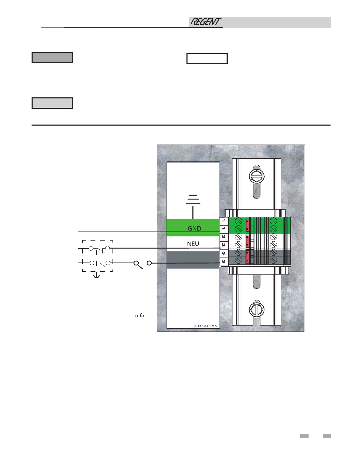
51
9 Field wiring
ELECTRICAL SHOCK HAZARD – For
your safety, turn off electrical power supply
before making any electrical connections
to avoid possible electric shock hazard.
Failure to do so can cause severe personal
injury or death.
Wiring must be N.E.C. Class 1.
If original wiring as supplied with the water
heater must be replaced, use only type
105°C wire or equivalent.
The water heater must be electrically
grounded as required by National Electrical
Code ANSI/NFPA 70 – latest edition.
Label all wires prior to disconnection when
servicing controls. Wiring errors can cause
improper and dangerous operation.
NOTE: There is only one configuration for
this product.
MODELS 500-1000
⚠ WARNING
NOTICE
⚠ CAUTION
Figure 9-1 Regent Field Line Voltage Connections
Installation & Operation Manual
LINE
NEUTRAL
GROUND
SERVICE
SWITCH
OPTIONAL FIELD
INSTALLED
E-STOP
LINE
2000812134_00
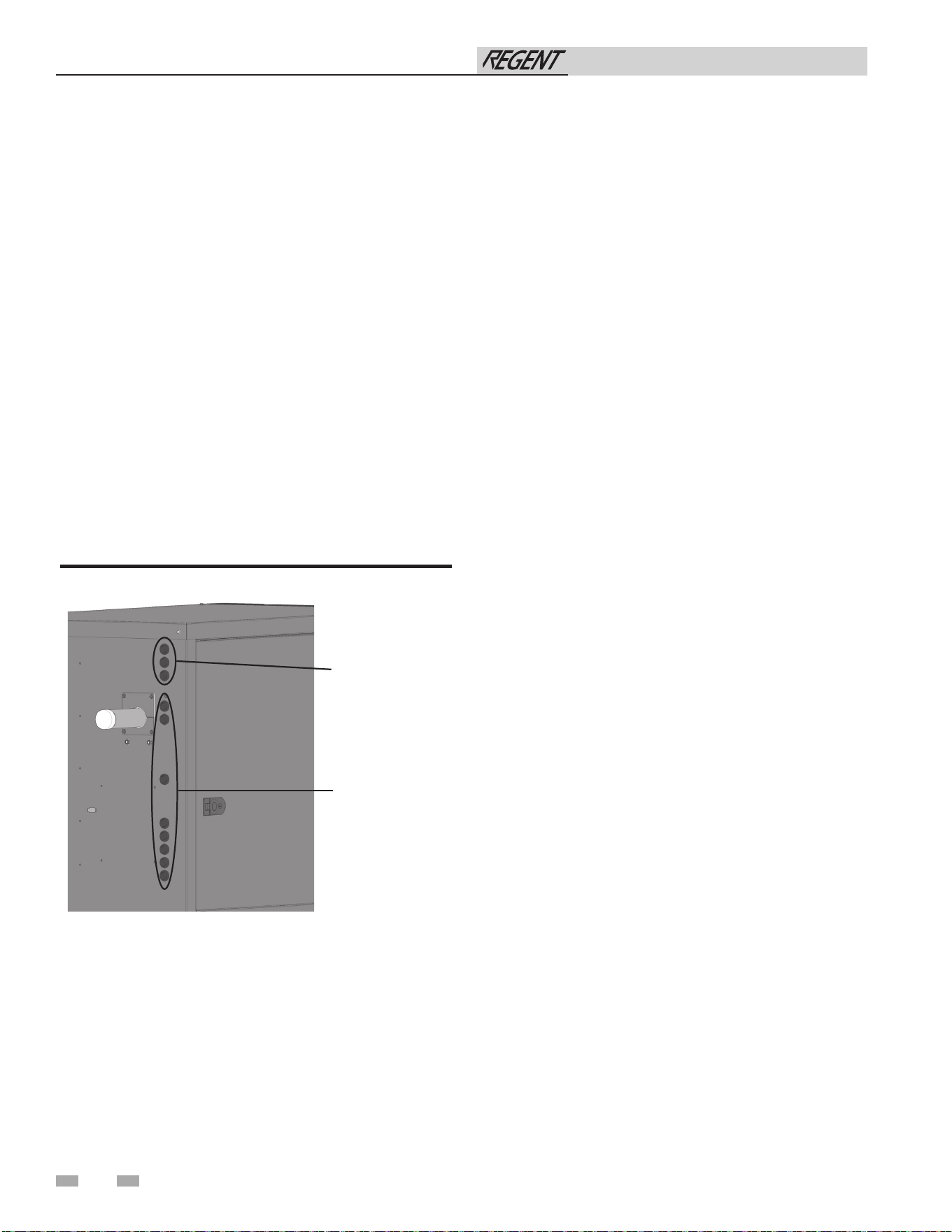
Installation must comply with:
1. National Electrical Code and any other national, state,
provincial, or local codes, or regulations.
2. In Canada, CSA C22.1 Canadian Electrical Code Part 1,
and any local codes.
Line voltage connections
1. Connect 120VAC power wiring to the line voltage terminal
block in the junction box as shown in FIG 9-1.
2. Provide and install a fused disconnect or service switch as
required by code (see FIG. 9-1).
Low voltage connections
1. Route all low voltage wires through the knockouts in the
rear of the water heater, as shown in FIG. 9-2.
2. Connect low voltage wiring to the comfort control board as
shown in FIG. 9-3 and the water heater wiring diagram.
Figure 9-2 Routing Field Wiring
52
9 Field wiring
Rate output
This output provides a 0 - 10V signal that is proportional to
the firing rate of the water heater. This may be used by a BMS
system to monitor the actual rate of the water heater.
ModBus / BACnet
When the optional ModBus / BACnet interface module is
installed, the RS-485 ModBus / BACnet cable is connected to
these terminals. Use shielded, 2-wire twisted pair cable. If
desired, the shield can be connected to ground by installing a
jumper wire between terminals 1 and 3 on connector X5 on the
optional ModBus / BACnet interface module.
High and Low gas pressure switches
Switches to detect high and low gas pressure are available
from the factory for field installation. Consult the instructions
included in the kit for installation details.
DHW Thermostat
If a thermostat is needed to enable the water heater to provide
hot water, it must be wired to this input. The water heater will
be enabled to provide hot water when these contacts are closed.
System Supply Sensor
A system supply sensor may be connected to this input for
monitoring the hot water temperature delivered to the system.
For the correct sensor, refer to the Regent Replacement Parts
List.
Building Recirculation Sensor
A building recirculation temperature sensor may be connected
to this input for monitoring building recirculation temperature.
For the correct sensor, refer to the Regent Replacement Parts
List.
AUX Flow switch or LWCO
If an external flow switch or low-water cutoff device is required,
connect it to this input. The water heater will not provide hot
water unless these contacts are closed.
Water heater Building Management
System (BMS)
1. An external control may be connected to control the set
point of the water heater. If the external control uses a set
of contacts to enable the water heater, connect the contacts
to the DHW Thermostat terminals. Otherwise, the SMART
TOUCH control will be enabled by the 0-10V signal.
2. Make sure the (-) terminal is connected to the (-) or
common output terminal of the external control, and the
(+) terminal is connected to the (+) or 0 - 10 VDC terminal
of the external control. Make sure the (-) voltage is not
below ground.
Installation & Operation Manual
2000845690_000
LOW VOLTAGE
WIRING
KNOCKOUTS
LINE VOLTAGE
WIRING
KNOCKOUTS
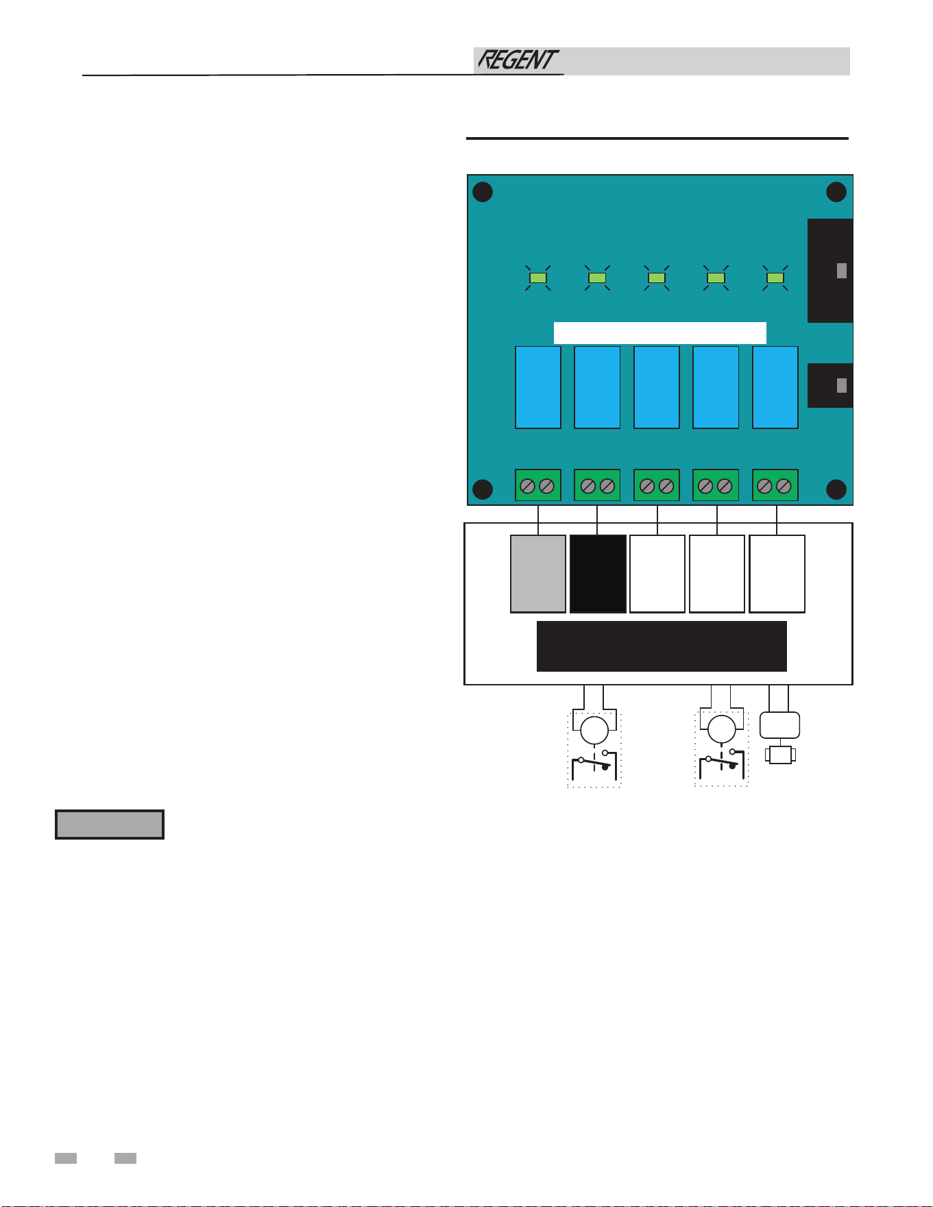
54
9 Field wiring (continued)
Runtime contacts
The SMART TOUCH control closes a set of dry contacts
whenever the burner is running. This is typically used by
Building Management Systems to verify that the water heater
is responding to a call for heat.
Alarm contacts
The SMART TOUCH control closes another set of contacts
whenever the water heater is locked out or the power is turned
off. This can be used to turn on an alarm, or signal a Building
Management System that the water heater is down.
Wiring of the cascade
communication
When wiring the water heaters for Cascade operation, select one
water heater as the Leader water heater. The remaining water
heaters will be designated as Members. See “Configuration of
the Cascade” for a detailed explanation of this procedure.
Communication between the Leader water heater and the
Member water heaters is accomplished by using shielded,
2-wire twisted pair communication cable. Connect one of the
twisted pair wires to Cascade terminal A on each of the low
voltage connection boards, and the other wire of the twisted pair
to Cascade terminal B on each of the low voltage connection
boards. Connect the shield wires to one of the shield terminals
on the low voltage connection boards (FIG. 9-3). If more than
two water heaters are on the Cascade, daisy chain the wiring
from the Cascade terminals on the second water heater to the
Cascade terminals on the third water heater, then from the third
to the forth, and so on. The connections between heaters can
be made in any order, regardless of the addresses of the water
heaters. Try to keep each cable as short as possible.
Do not connect the sensors connected to
the Leader heater to the Member 1 heater.
The actual water temperatures will be higher
than expected, which could lead to property
damage, personal injury, or death.
⚠ WARNING
Installation & Operation Manual
Wiring of the Cascade Valve
Each water heater in a cascaded system must have its own
cascade valve. The cascade valve must be wired to the water
heater on which it is installed. Connect the two wires from the
cascade valve to the terminals on the Cascade Valve and Pump
Relay Output Board labeled CASC ISO VALVE. The water
heater provides 24VAC power to open and close the cascade
valve.
Figure 9-4 Cascade Valve and Pump Relay Outputs
SYSTEM BOILER BYPASS
HW
RECIRC
HW
24V
24V
PUMP RELAY BOARD
SYSTEM BOILER BYPASS
HW
RECIRC
HW
FIELD SUPPLIED RELAYS 24VAC/5VA COILS (25VA MAX)
M
NOT
USED
NON
UTILISÉ
NOT
USED
NON
UTILISÉ
INTERNAL
PUMP
POMPE
INTERNÉ
HW
RECIRC
RECIRC
EAU
CHAUDE
CASCADE
VALVE
SOUPAPE
CASCADE
24VCA/5VA MAX—PUMP RELAY OUTPUTS
24VCA/5VA MAX—SORTIES DU RELAIS DE
LA POMPE
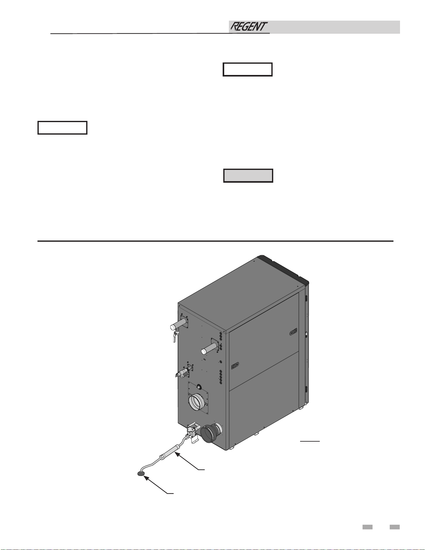
55
10 Condensate disposal
Condensate drain
1. This water heater is a high efficiency appliance that
produces condensate.
2. See Section 11 - Startup for installation requirements of
condensate trap and drain.
Use materials approved by the authority
having jurisdiction. In the absence of other
authority, PVC and CPVC pipe must comply
with ASTM D1785 or D2845. Cement and
primer must comply with ASME D2564 or
F493. For Canada use CSA or ULC certified
PVC or CPVC pipe, fittings, and cement.
NOTICE
NOTICE
To allow for proper drainage on large
horizontal runs, a second line vent may
be required and tubing size may need to
increase to 1 inch.
The condensate line must remain
unobstructed, allowing free flow of
condensate. If condensate is allowed to
freeze in the line or if the line is obstructed
in any other manner, condensate can back
up inside the heat exchanger resulting in
potential water damage to property.
Figure 10-1 Condensate Disposal
NOTE: Neutralizer shown
for illustrative purposes only.
Actual neutralizer may vary.
Installation & Operation Manual
This product contains a condensate
management and disposal system that
may be subject to freezing if exposed
to sustained temperatures below 32°F.
Precautions should be taken to protect
the condensate trap and drain lines during
extended periods of outdoor temperatures
below 32°F.
⚠WARNING
FLOOR DRAIN OR DRAIN PAN
NEUTRALIZER KIT
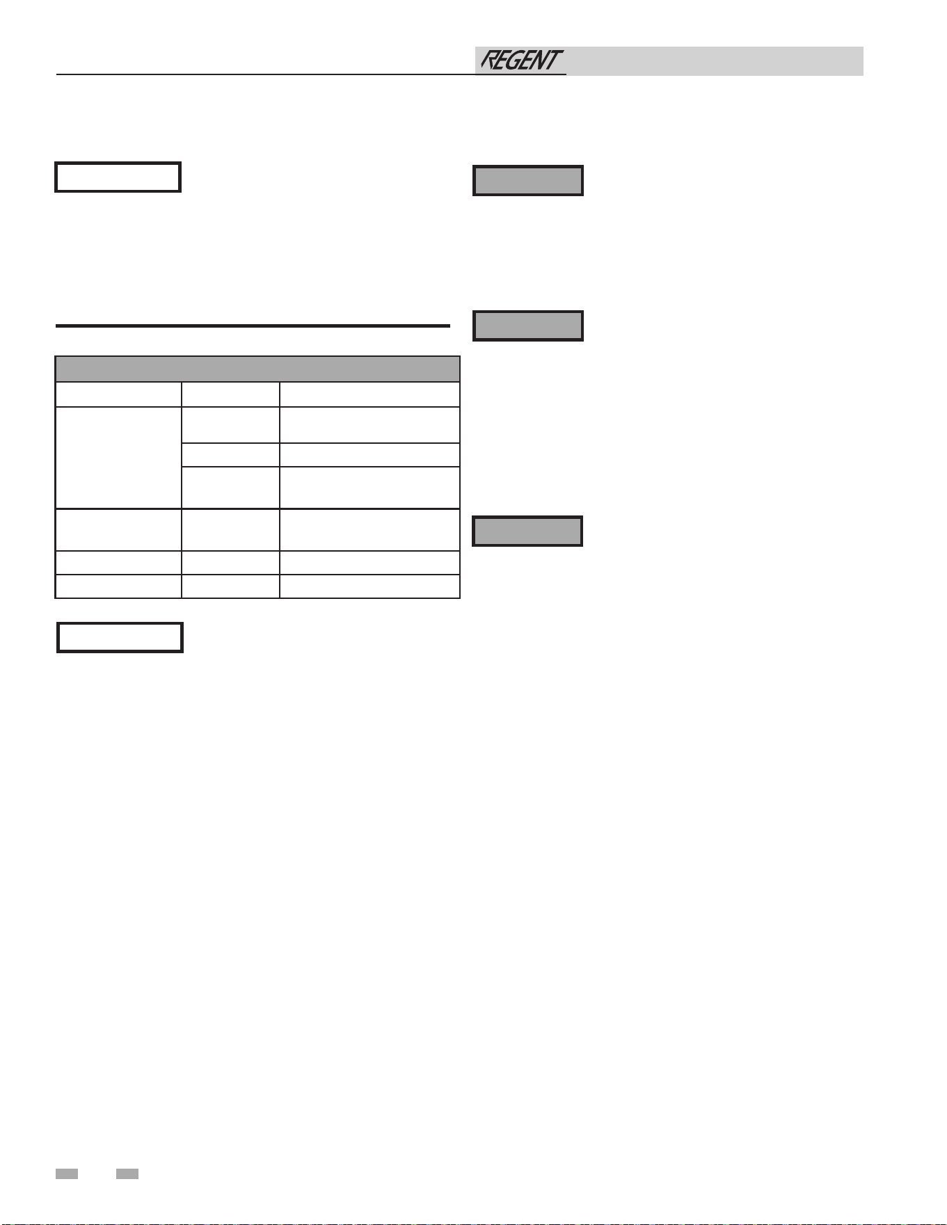
56
11 Start-up
Check/control water chemistry
See the following table for properly operating the water heater
with the appropriate water chemistry. Good water quality will
help extend the life of the appliance by reducing the effects of
scale buildup and corrosion.
Check for gas leaks
Before starting the water heater, and during
initial operation, smell near the floor and
The gas valve outlet pressure on this
appliance is controlled by the gas valve
⚠ WARNING
⚠ WARNING
Propane water heaters only – Your propane
supplier mixes an odorant with the propane
⚠ WARNING
NOTICE
Conduct water quality testing prior
to installing the appliance. Various
solutions are available to adjust water
quality.
WATER CHEMISTRY
Specication Range Requirement
Hardness
< 5 gpg
Follow recommendations
detailed below (See Notice 3)
5 to 15 gpg Acceptable range
> 15 gpg
Water softening system
required (See Notice 4)
Dissolved Solids < 350 ppm
Hardness level must be
met
pH Level 6.5 to 8.5 Acceptable range
Chloride < 150 ppm Acceptable range
Table 11A Water Chemistry
NOTICE
1. Do not use the water heater to directly
heat swimming pool or spa water.
2. At initial fill and during water heater
start-up and testing, check system
thoroughly for any leaks. Repair all leaks
before proceeding further.
3. When water hardness levels are less
than 5 gpg or 85.5 mg/l, the following is
recommended:
a. Flush and clean existing water heating
system prior to installation.
b. Inspect and, if necessary, replace the
anodes in any existing tanks.
c. Install a Y-strainer on the inlet of each
water heater as detailed in Section 7.
d. Limit the run time of the hot water
recirculation loop.
e. Filter the hot water recirculation loop
to a level of 10 microns. CAUTION:
Check recirculation pump size to verify
it is sized for filter addition and upsize if
necessary.
4. When water softener is required, a
Template Assisted Crystallization system
is recommended.
regulator based on the delta pressure. The gas valve is factory
set for the correct delta pressure. This setting is suitable for
natural gas and propane. Field adjustment of gas valve delta
pressure shall only be made by qualified personnel following
the procedure outlined in the Start-up section of this manual.
Improper adjustment of the gas valve outlet pressure could
result in damage to the valve, causing severe personal injury,
death, or substantial property damage.
to make its presence detectable. In some instances, the odorant
can fade, and the gas may no longer have an odor. Before
startup (and periodically thereafter), have the propane supplier
verify the correct odorant level in the gas.
around the water heater for gas odorant or any unusual odor.
Remove the top access panel and smell the interior of the
water heater enclosure. Do not proceed with startup if there
is any indication of a gas leak. Use an approved leak detection
solution. Repair any leaks at once.
Installation & Operation Manual
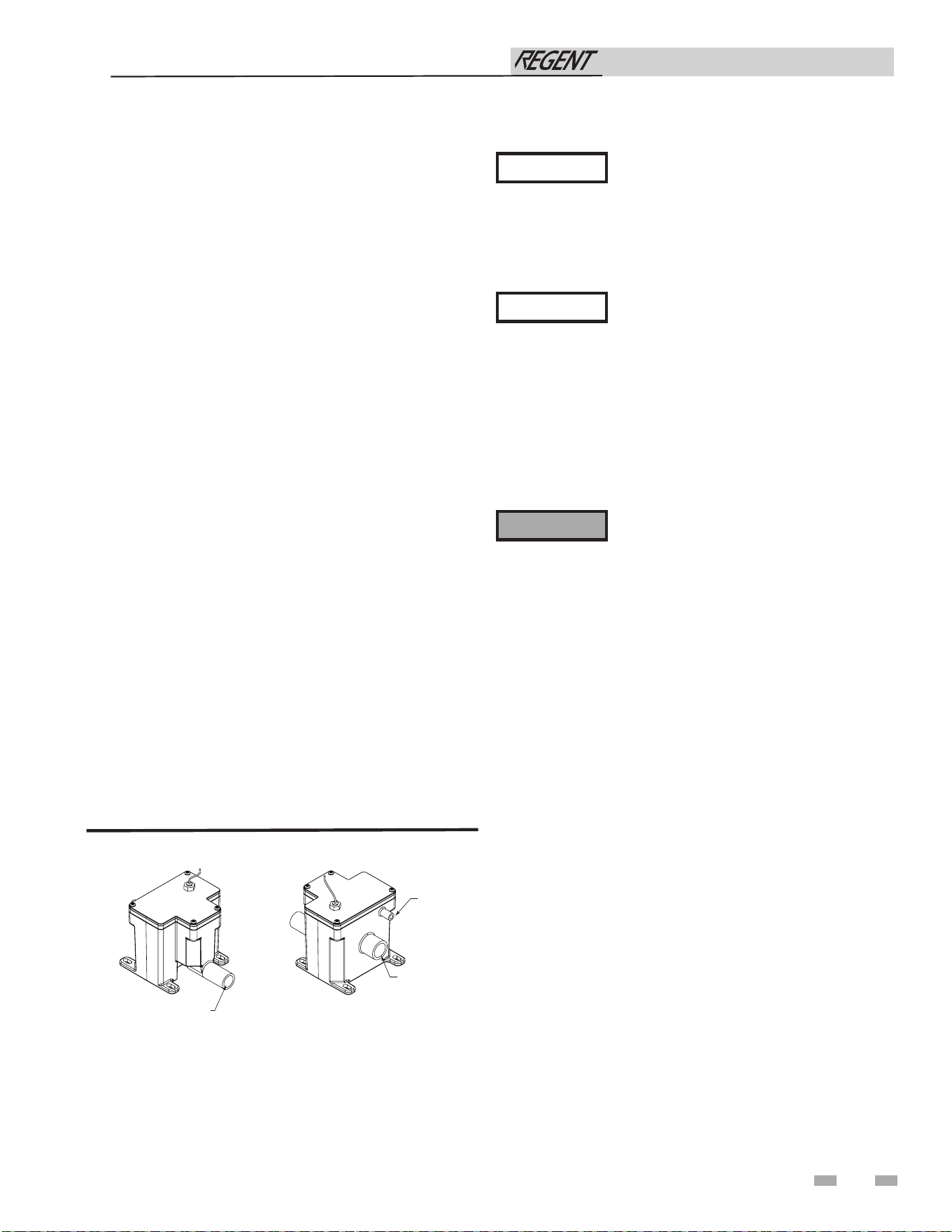
11 Start-up (continued)
Use materials approved by the authority
having jurisdiction. In the absence of other
authority, PVC and CPVC pipe must comply
with ASTM D1785 or D2845. Cement and
primer must comply with ASME D2564 or
F493. For Canada use CSA or ULC certified
PVC or CPVC pipe, fittings, and cement.
NOTICE
NOTICE
To allow for proper drainage on large
horizontal runs, a second line vent may
be required and tubing size may need to
increase to 1 inch.
The condensate line must remain
unobstructed, allowing free flow of
condensate. If condensate is allowed to
freeze in the line or if the line is obstructed in
any other manner, condensate can exit from
the condensate trap vent opening, resulting
in potential water damage to property.
The condensate trap must have the float
ball (FIG. 11-1) in place during all times
of appliance operation to avoid flue gas
emission from the condensate drain line.
Failure to ensure the float ball is in place
could result in severe personal injury or
death.
⚠WARNING
Figure 11-1 Condensate Trap
Condensate drain
1. This appliance is a high efficiency appliance that produces
condensate.
2. The provided condensate trap is equipped with a ball
that acts as a seal against harmful flue gases escaping
in case there is no condensate in the trap. If this ball is
not present, flue gases may be able to pass through the
trap when there is no condensate present, resulting in an
unsafe environment. It is important to check and make
sure the ball is located in the trap, acting as a seal against
flue gases.
3. Connect the condensate trap to the condensate hoses
located on the back of the unit near the bottom. Use
the hose clamps to secure the connection. Connect the
two-pin molex provided with the condensate trap to the
mating connector on the rear of the appliance.
4. Slope condensate tubing down and away from the
appliance into a drain or condensate neutralizing filter.
Condensate from the Regent water heater will be slightly
acidic (typically with a pH from 3 to 5). Install a
neutralizing filter if required by local codes.
A Neutralizer Kit is available from the factory.
5. Do not expose condensate line to freezing temperatures.
6. Use only plastic tubing or piping as a condensate drain
line (FIG. 11-1).
7. A condensate removal pump is required if the appliance
is below the drain. When installing a condensate pump,
select one approved for use with condensing water
heaters and furnaces. The pump should have an overflow
switch to prevent property damage from condensate
spillage. The switch should be wired in series with the
blocked flue switch inside the appliance.
FRONT VIEW
REAR VIEW
DIR #2000507911 00
TO FLOOR DRAIN
OR NEUTRALIZER KIT
1/2” PVC / CPVC CONNECTION
FROM CONDENSATE
VENT ON APPLIANCE
FROM CONDENSATE
DRAIN ON APPLIANCE
Final checks before starting the water
heater
q Read the Regent Water Heater Service Manual to familiarize
yourself with SMART TOUCH control module operation.
Read the preceding Start-up sections in this manual, for
proper steps to start the appliance.
q Verify the preparation procedures have been completed.
q Verify the appliance and system are full of water and all
system components are correctly set for operation.
q Verify electrical connections are correct and securely
attached.
q Inspect vent piping and air piping for signs of deterioration
from corrosion, physical damage, or sagging. Verify air
piping and vent piping are intact and correctly installed per
this manual.
Installation & Operation Manual
57
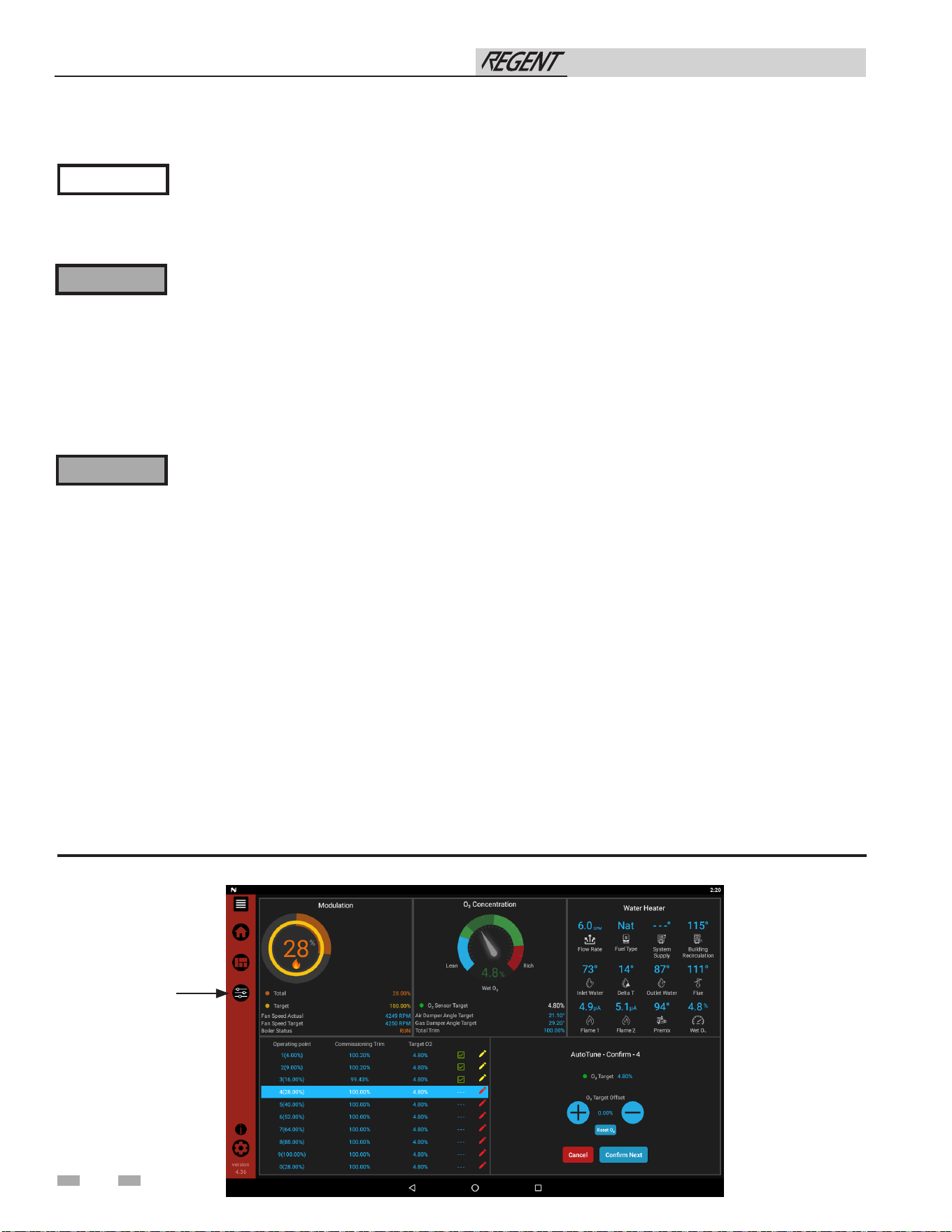
58
11 Start-up
Start (commission) the water heater
If water heater does not start correctly
1. Check for loose connections, blown fuse, or service switch
off?
2. Is water heater water temperature above 200°F?
3. Is gas turned on at meter or water heater?
4. Is incoming gas pressure less than 2.5 inches w.c.?
If none of the above corrects the problem, refer to the
Troubleshooting Section of the Regent Water Heater Service
Manual.
Figure 11-2 Commissioning Screen
Installation & Operation Manual
NOTICE
e Regent water heater requires a hot water
demand load to perform the commissioning
sequence. A water valve is provided on
the product outlet to allow a load to be
generated when otherwise not possible.
The Regent water heater may supply hot
water to the system at temperatures higher
than the setpoint when in either Service
Mode or Commissioning Mode. Ensure
mixing valves are installed per manufacturer
instructions prior to initiation of the
commissioning sequence. Failure to ensure
adequate scald protection is in place prior to
commissioning may result in severe personal
injury or death.
The commissioning drain valve may
produce water at temperatures capable of
scalding. Ensure the commissioning valve is
piped to a suitable drain prior to beginning
the commissioning sequence. Failure to do
so may result in severe personal injury,
property damage, or death.
⚠WARNING
⚠WARNING
1. Create a hot water demand. If fixtures are not available to
create the needed hot water demand, the commissioning
valve located on the hot water outlet may be used.
2. Once a suitable hot water demand is created, read and follow
the Operating instructions in FIG 11-3.
3. Select the Start Commissioning Sequence from the
Commissioning Menu.
4. The unit will go through its purge and ignition sequence.
5. The ignition sequence includes a free air calibration and
diagnostic of the O2 sensor. Respond to any error codes
related to the O2 sensor as needed (FIG. 11-2).
6. Once the unit has fired and established a flame signal, it
will modulate to low fire.
7. Check the manifold pressure from the test port as shown
in FIG. 11-3. Adjust the regulator as necessary using the
target manifold pressure in Table 11B.
8. Once set, press NEXT (FIG. 11-2).
9. The unit will move to low fire and will self-tune to correct
combustions based off the O2 sensor.
10. Once the unit corrects to the center of the indicator, press
NEXT.
11. Continue through all nine points of adjustment.
12. After the calibration of the modulation curve, the program
will move to the ignition point P0.
13. At P0 the unit will self-tune.
14. Once completed, press CONFIRM.
15. Exit the commissioning sequence by pressing CONFIRM.
16. Return the commissioning valve to the closed position.
17. The water heater can be set into normal operations.
SETTINGS
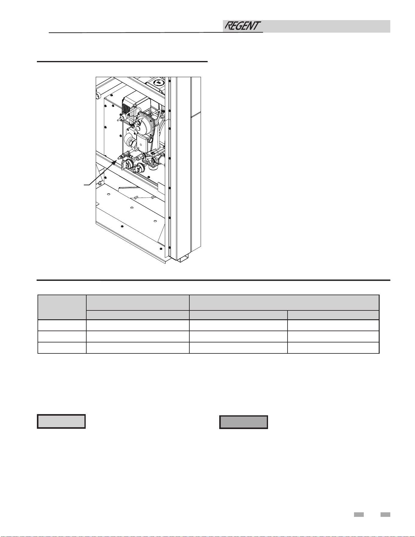
Table 11B Manifold Pressure Chart
Units
Manifold Pressure w.c.
(Sea level to 500ft)
*Additional Manifold Pressure w.c.
(for every 1000ft above 500ft)
Natural / Propane Natural Propane
IWH0500
1.5 0.11 0.02
IWH0750
1.5 0.11 0.02
IWH1000
2 0.13 0.04
11 Start-up (continued)
Check system and water heater
q Check water piping
1. Check system piping for leaks. If found, shut down the
water heater and repair immediately
q Check vent piping and air piping
1. Check for gastight seal at every connection, seam of air
piping, and vent piping.
Venting system must be sealed gastight
to prevent flue gas spillage and carbon
monoxide emissions, which will result in
severe personal injury or death.
Failure to repair leaks in water piping may
result in damage to property.
⚠ WARNING
59
Installation & Operation Manual
CAUTION
2. Vent any remaining air from the system using manual
vents. Air in the system will interfere with circulation and
cause heat distribution problems and noise.
Figure 11-3 Check Manifold Pressure
2000854777 00
MANIFOLD
TEST PORT
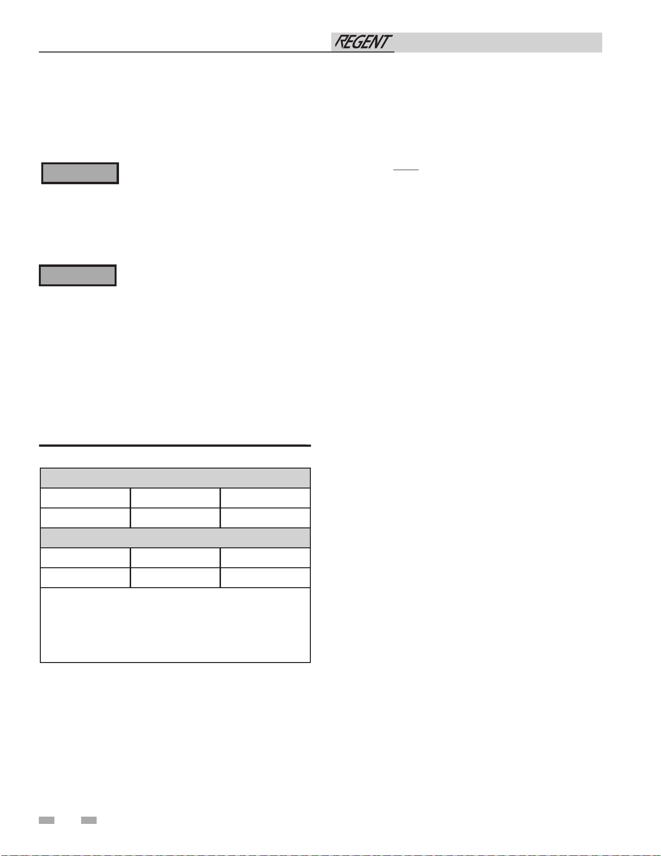
11 Start-up (continued)
Check flame and combustion
1. Turn the main power off to the water heater by placing the
“On/Off ” switch in the OFF position.
2. Remove the flue sensor and rubber grommet from the flue
collector. Note: Combustion measurements will be made
at this point.
3. Insert the probe from a combustion analyzer into the hole
left by the removal of the flue sensor and rubber grommet.
4. Turn the main power on to the water heater by placing the
“On/Off ” switch in the ON position.
5. Navigate to the Setup Screen from the Home Screen by
pressing the SETUP button along the left side of the screen.
Enter the installer password.
6. Select the Service Maintenance Screen. The tabs will scroll
(up and down) to reveal more options. See the Regent
Service Manual for more detailed information.
7. Once the water heater has modulated up to rate, measure
the combustion. The values should be in the range listed
in Table 11C (this page). CO levels should be less than 200
ppm for a properly installed unit. If the combustion is not
within range reference the Troubleshooting Section in the
Regent Service Manual for possible causes and corrective
actions.
8. Once the combustion analysis is complete, test the safety
shutoff device by turning the manual gas shutoff valve to
the OFF position and ensuring the heater shuts down and
registers an alarm. Open the manual shutoff valve and
reset the control.
9. Turn the main power off to the water heater and replace
the flue sensor and rubber grommet into the flue pipe
connection.
10. Ensure the water heater is placed back into normal
operation.
O2 sensor
1. e water heater is equipped with a faory supplied O2
sensor.
2. No setup or extra checks for the O2 sensor are required
until used for commissioning during initial start-up.
3. e sensor performs routine self-diagnostics and free air
calibrations. If an error occurs, the appropriate error
codes will be displayed.
4. Should the O2 sensor break or malfunction, the water
heater is designed to fully function safely without the O2
sensor.
Table 11C Flue Products Chart
Natural Gas
Units
*Co2 (Flue Port)
*O
2
(Sensor)
ALL 8.0 - 9.5 3.9 - 6.5
Propane
Units
*Co2 (Flue Port)
*O
2
(Sensor)
ALL 8.6 - 10.5 3.9 - 6.5
*NOTE: The Regent Combustion System is designed to
maintain constant combustion. CO2 is the target combustion
measured from the flue measurement port. O2 is the target
measurement of the active O2 sensor in the combustion
chamber. An O2 measurement from the flue will vary from the
O2 measured in the combustion chamber.
60
Installation & Operation Manual
q Check gas piping
1. Check around the water heater for gas odor following the
procedure on Section 8 of this manual (Connecting Gas
Supply Piping).
If you discover evidence of any gas leak,
shut down the water heater at once. Find
the leak source with a bubble test and repair
immediately. Do not start the water heater
again until corrected. Failure to comply
could result in severe personal injury, death,
or substantial property damage.
The gas valve outlet pressure on this
appliance is controlled by the gas valve
regulator based on the delta pressure. The
gas valve is factory set for the correct delta
pressure. This setting is suitable for natural
gas and propane. Field adjustment of gas
valve delta pressure shall only be made by
qualified personnel following the procedure
outlined in the Start-up section of this
manual. Improper adjustment of the gas
valve outlet pressure could result in damage
to the valve, causing severe personal injury,
death, or substantial property damage.
⚠ WARNING
⚠ WARNING
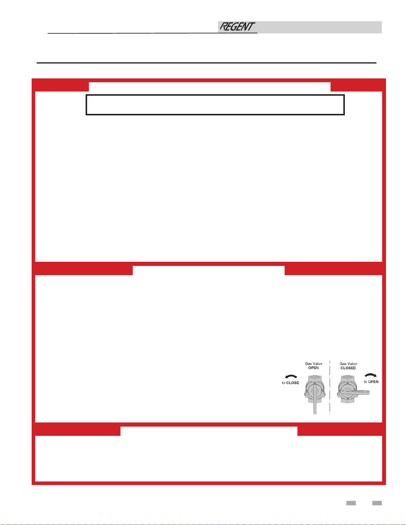
61
11 Start-up (continued)
Figure 11-4 Operating Instructions
Installation & Operation Manual
WARNING: If you do not follow these instructions exactly, a fi re or explosion
may result causing property damage, personal injury, or loss of life.
FOR YOUR SAFETY READ BEFORE OPERATING
A. This appliance does not have a pilot. It is equipped with an ignition device which automatically lights
the burner. Do not try to light the burner by hand.
B. BEFORE OPERATING smell all around the appliance area for gas. Be sure to smell next to the fl oor
because some gas is heavier than air and will settle on the fl oor.
WHAT TO DO IF YOU SMELL GAS
• Do not try to light any appliance.
• Do not touch any electric switch; do not use any phone in your building.
• Immediately call your gas supplier from a neighbor’s phone. Follow the gas supplier’s instructions.
• If you cannot reach your gas supplier, call the fi re department.
C. Use only your hand to turn the gas control knob. Never use tools. If the handle will not turn by hand,
don’t try to repair it, call a qualifi ed service technician. Force or attempted repair may result in a fi re or
explosion.
D. Do not use this appliance if any part has been under water. Immediately call a qualifi ed service
technician to inspect the appliance and to replace any part of the control system and any gas control which
has been under water.
TO TURN OFF GAS TO APPLIANCE
1. Set the thermostat to lowest setting.
2. Turn off all electric power to the appliance if service is to be performed.
3. Remove front cover.
4. Turn gas shut off valve counterclockwise to “OFF”. Handle will be perpendicular to pipe. Do not force
5. Install front cover.
OPERATING INSTRUCTIONS
1. STOP! Read the safety information above on this label.
2. Set the thermostat to lowest setting.
3. Turn off all electric power to the appliance.
4. This appliance is equipped with an ignition device which automatically lights the burner. Do not try to
light the burner by hand.
5. Remove front cover..
6. Turn gas shutoff valve counterclockwise to “OFF”. Handle will be perpendicular to pipe. Do not force.
7. Wait fi ve (5) minutes to clear out any gas. If you then smell gas, STOP! Follow “B”in the safety
information above this label. If you don’t smell gas, go to next step.
8. Turn gas shutoff valve clockwise to “ON”. Handle will be parallel to pipe.
9. Install front cover..
10. Turn on all electric power to appliance.
11. Set thermostat to desired setting.
12. If the appliance will not operate, follow the instructions
“To Turn Off Gas To Appliance” and call your service technician
or gas supplier.
100399549 REV
A
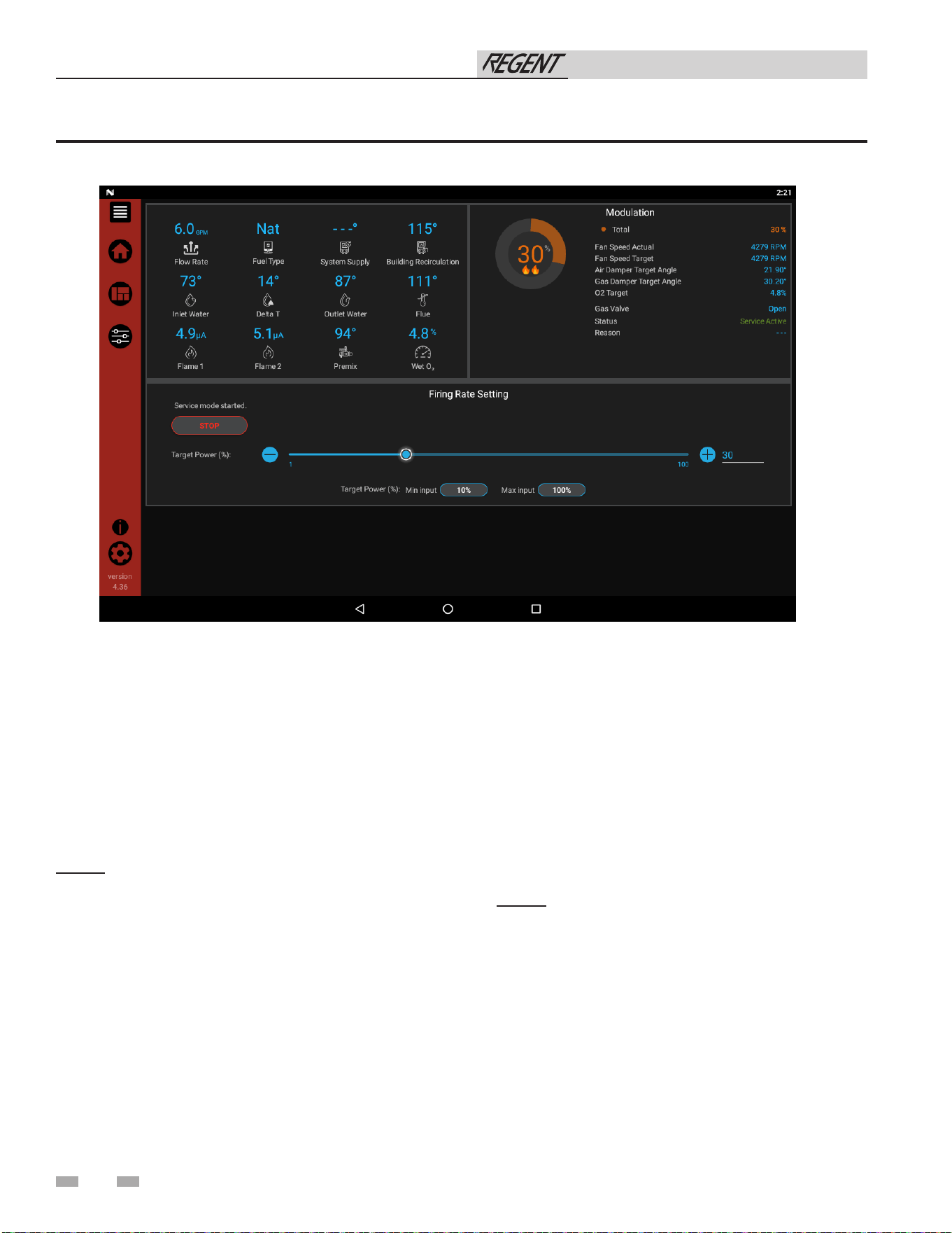
62
11 Start-up
Installation & Operation Manual
Figure 11-5 Service Maintenance Screen
Adjust set point temperature(s)
During normal operation, set point temperatures can be
adjusted from the Home Screen by pressing the DETAILS
button on the screen (see FIG. 11-6).
1. To change a set point, use the set point slider feature or
the PLUS (+) and MINUS (-) buttons to adjust the set
points as shown in FIG. 11-6.
2. Once the set point has been adjusted to the desired setting,
press the SAVE button.
NOTE: The APPLY CHANGES button must be pressed to
complete programming of the controls when changes are made
in the SETUP menu. Failure to press the APPLY CHANGES
button will result in an unprogrammed control. The Door
Menu button will become highlighted when there are changes
that can be applied.
Set clock
The SMART TOUCH control has a built-in clock that it uses
for logging events. This clock must be set when the appliance
is installed and anytime the appliance has been powered off
for more than one day. Use the following procedure to set the
clock:
1. Press the SETTINGS button in the bottom left corner of
the Home Screen (see Figure 11-7).
2. Press the SET button across from the date and time.
3. Proceed to set the date, time, and time zone.
NOTE: Automatic Time Zone will not work.
4. Temperature units and Wi-Fi may also be set here. These
items may be used to automatically sync the time.
5. Press the Home, View, or Back button to exit.
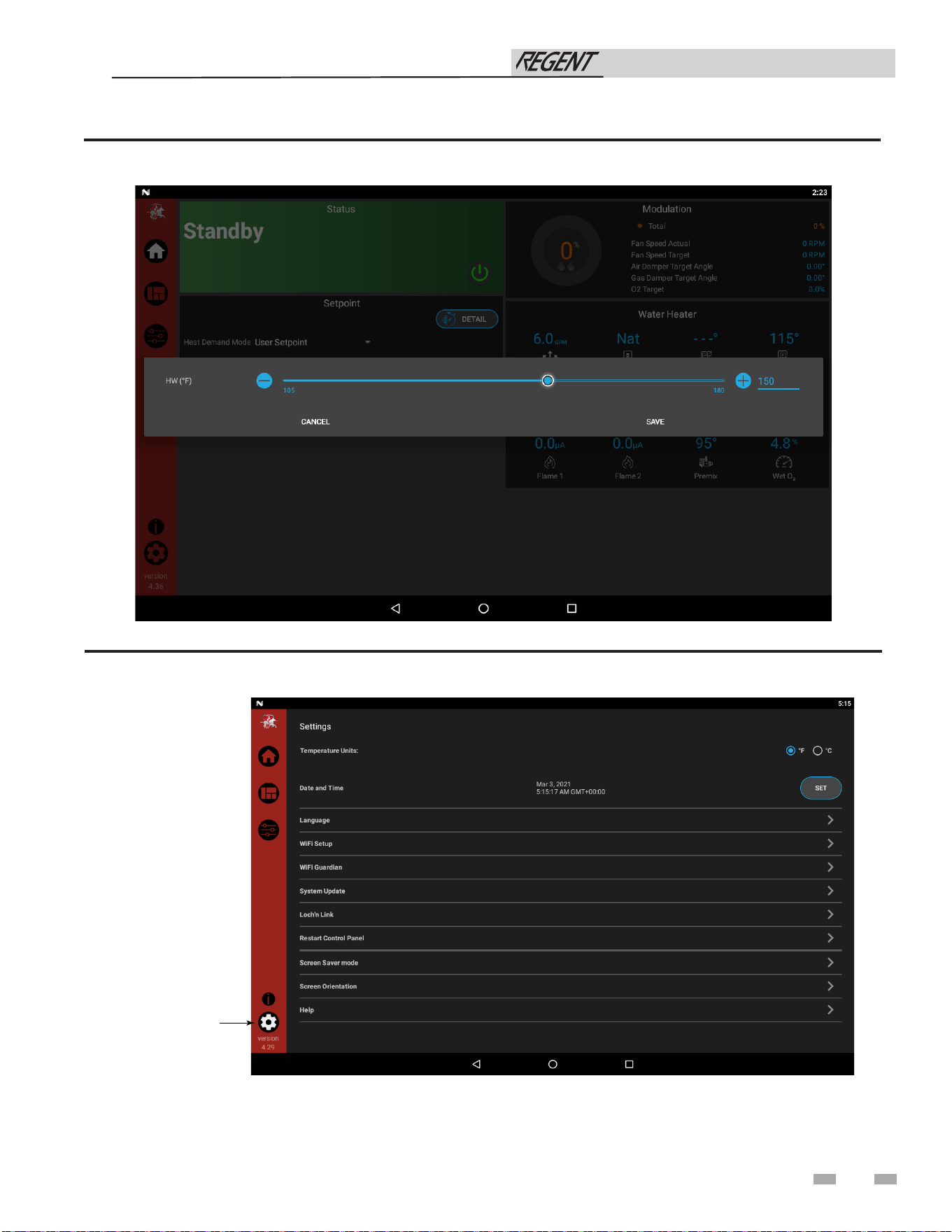
63
Figure 11-6 User Set Point Screen
Figure 11-7 Settings Location on Screen
11 Start-up (continued)
Installation & Operation Manual
SETTINGS
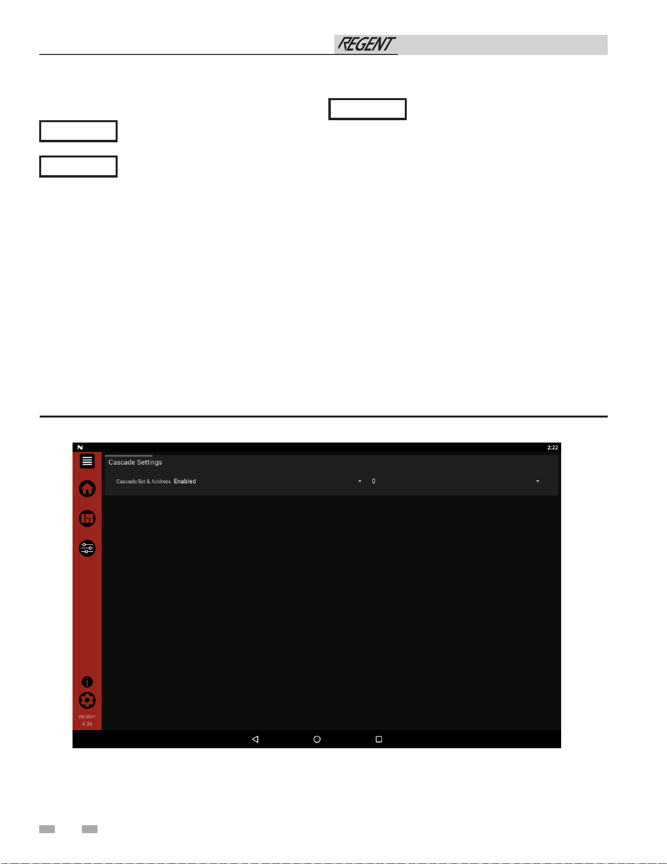
64
11 Start-up
Configuration of the cascade
When installing a Cascade system, all units must be
programmed for Cascade to operate. Access the Cascade
Setup options as follows:
1. Press the SETUP button on the left side of the display
screen.
2. Enter the installer password.
3. Select the Cascade option as shown in FIG. 11-8.
4. Each unit must have a unique address set.
5. Once all the updates are complete, press the Menu button
(top left) or the Setup button.
6. Press the APPLY CHANGES button on the top of the
screen.
The APPLY CHANGES button must
be pressed to complete programming of
the controls. Failure to press the APPLY
CHANGES button will result in an
unprogrammed control. The Menu button
will become highlighted when there are
changes that can be applied.
For more detailed instructions, please
refer to the Regent Service Manual.
All units in the Regent cascade must be of
the same size.
Figure 11-8 Cascade Screen
Installation & Operation Manual
NOTICE
NOTICE
NOTICE

65
12 Operating information
General
How the water heater operates
The Regent water heater uses an advanced stainless steel
heat exchanger and electronic control system that allows
fully condensing operation. The blower pulls in fresh air and
pushes flue products through the heat exchanger and out of
the flue piping. The control system senses the oxygen content
of the combustion products using a sensor mounted to the
combustion chamber and actively controls the blower speed
to maintain the correct products of combustion. The control
system regulates the gas and air flow into the burner to control
the firing rate. The control system measures the flow rate and
temperature of water entering the water heater and controls the
firing rate to achieve the target hot water setpoint.
Control inputs and outputs
DHW Thermostat
This input enables the water heater to provide hot water.
0 - 10VDC input (set point)
The Regent water heater can be controlled by a Building
Management System (BMS) using a 0 - 10 VDC signal. The
control can be configured by the installer to use this signal to
control set point. This signal can be sent to the heater through
ModBus as well.
Temperature control
Modulation
The Regent water heater is capable of modulating its firing
rate from a minimum of 4-8% (depending on model size) to a
maximum of 100%. The firing rate is dictated by the hot water
draw and various other temperature limitations.
Flame current support
To prevent nuisance shutdowns when the water heater is firing
at minimum rates, the control will increase fan speed when the
flame signal drops below 2.3 microamps.
Protection features
Outlet temperature, flue temperature, and temperature
rise limiting
The outlet temperature is monitored by the water heater outlet
temperature sensor. When the outlet temperature exceeds
182°F, the unit will reduce the fan speed. If the outlet water
temperature exceeds 195°F the control will shut the unit down
until it cools to 185°F.
The control module monitors the flue temperature by a sensor
located in the flue exhaust. If the flue temperature exceeds
215°F the control will reduce the maximum fan speed. If the
flue temperature exceeds 225°F (107°C) the control will shut
the unit down. The unit will restart automatically once the flue
temperature drops 10°F (6°C) and the minimum off time has
expired.
The control monitors the temperature difference between
the inlet and the outlet sensor. If the control determines the
temperature rise is too high, it will either reduce the firing rate
or shut down the unit as appropriate.
The unit will restart automatically once the temperature
difference has dropped below the allowable rise and the
minimum off time has expired.
Installation & Operation Manual

66
Water heater temperature regulation
Operating temperature (target)
The SMART TOUCH control module senses water temperature
and regulates water heater firing and firing rate to achieve
a target temperature. The target temperature can be set
between 80°F and 180°F. The target temperature range may be
adjusted by the installer. Consult the Regent Service Manual for
instructions to adjust the target temperature range.
High limit operations
The Regent water heater is equipped with a fixed automatic
reset high limit and an adjustable manual reset high limit. The
automatic reset high limit has a set point of 200°F and the
manual reset high limit has a maximum set point of 210°F.
When the outlet temperature exceeds 200°F, the automatic high
limit action occurs. The water heater shuts down until the outlet
water temperature cools below 190°F, and a 60 second timer has
expired. If the outlet temperature continues to increase, the
manual reset high limit action will occur at 210°F.
Monitor external limits
Connections are provided on the connection board for auxiliary
external limits. The SMART TOUCH Control will shut off the
burner and inhibit relighting whenever any of these external
limits open.
Runtime and alarm outputs
The water heater provides dry contacts for indicating when the
water heater is running, and when it is unable to operate.
Runtime and cycle counting
The control uses a timer to monitor the total hours of burner
operation. The timer monitors the time the water heater is
firing.
The control uses two (2) ignition counters to monitor the
amount of water heater cycles. The first counter counts all
ignitions of the control. The second counter counts only
successful ignitions.
Error logging
The control will hold in memory the last 10 lockouts. The date
and time of the occurrence will be recorded as well. Only the 10
most current occurrences of each will be held in memory.
12 Operating information
High limit test procedure
1. Turn ON the main power to the appliance by placing the
ON/OFF switch in the ON position.
2. Navigate to the Setpoints Screen.
3. Use the slide bar to decrease the MRHL temperature
below the current outlet temperature or to its minimum
setting, whichever is higher.
4. Press the APPLY CHANGES button to save the setting.
5. If the current outlet temperature is above the MRHL
setting then the MRHL will function, causing a appliance
lockout. If the outlet temperature is below the MRHL
setting, navigate to the Service Screen and place the
appliance in service mode at full fire.
6. Once the outlet temperature rises above the MRHL
setting, the MRHL will function causing a appliance
lockout.
7. Repeat steps 2-4 to set the MRHL to the desired setting
for normal operation.
Installation & Operation Manual
67
12 Operating information (continued)
Sequence of the cascade
The cascade valve opening/closing sequence will automatically
be changed at set intervals.
For the first 24 hours after initializing the Cascade, the
sequence will be changed every hour. After that the sequence
will be changed once every 24 hours. The switching on/off
sequence will be as follows:
TIME SWITCHING ON SEQUENCE
Start L-M1-M2-M3-M4-M5-M6-M7
+ 1 hour M1-M2-M3-M4-M5-M6-M7-L
+ 2 hours M2-M3-M4-M5-M6-M7-L-M1
Cascade
When multiple water heaters are installed, they can be wired
together in a cascade sequence. A maximum of eight water
heaters can be controlled from a single control. In this
application one water heater would be designated as the Leader
control and all others would be designated as Member controls.
The leader water heater will share its setpoint with all other
members of the cascade. The members, however, will control
their modulation individually to maintain the setpoint at their
individual outlet temperature sensor. The leader will control
the cascade valve of each member of the cascade to control the
water flow to the units and deliver hot water based on the load.
As the demand of the system increases and decreases, the leader
will open and close additional valves to meet the load. At least
one cascade valve will always be open. For a new startup the
leader’s cascade valve will be open at all times.
Access modes
User
The USER can set the set point, turn the unit OFF and ON, and
set up Wi-Fi.
.
Installer
Most parameters are available only to the installer, accessible
by entering the installer password, see the Regent Water Heater
Service Manual.
NOTE: The password will timeout after an hour from entry.
If a water heater locks out, it will automatically be given the
lowest priority for the rest of that 24 hour period.
Installation & Operation Manual
68
12 Operating information
Sequence of operation
1.
Upon a call for heat, the water heater control initiates a pre-purge and confirms that all safeties are in their correct
state. During the initial sequence of pre-purge, the air damper is open to its purge position, and the blower forced to
its purge speed. The air damper APS is checked to be open, the flow switch contacts are checked to be closed, and the
proof of closure input is checked to be closed during this time.
2.
Once the air damper APS and proof of closure switches are confirmed, the safeties are checked in the correct state.
The water heater control will then progress to the second part of pre-purge. During this phase the dampers and fan
are forced into the ignition state. Once in the ignition state, the air damper APS must become closed.
3.
The water heater control then proceeds to trial for ignition. First, the control initiates sparking, then opens the
gas valve. After sparking is completed, the control checks for the presence of flame. If the flame is not detected,
the control will recycle or lockout on an Ignition Flame Failure. If the flame is present, the control proceeds to
the flame stabilization period. During the flame stabilization period, the signal must not drop below the detection
threshold and further must rise to a sufficiently high level for a stable flame. If the flame does not reach the higher
threshold during flame stabilization, the unit will recycle or lockout on Flame Loss While Running. During the flame
stabilization period and any running state thereafter, the controls will check that the proof of closure input is open.
4.
Upon successful completion of the flame stabilization period, the control will proceed to the running state and
attempt to operate at the required modulation point. During operation, the damper positions and fan speeds MUST
always remain within tolerance. Further, if an O2 sensor is present and functioning properly, the unit must operate
within an expected range of O2 (see Section 11 of the Regent Installation and Operation Manual).
5.
The water heater control will modulate as needed to reach the desired setpoint.
6.
Once the DHW call for heat has been satisfied, the control will turn OFF the gas valve and begin the post-purge cycle.
The free air calibration of the O2 sensor is completed.
7.
At the end of the post-purge cycle, the control will allow the fan speed to fall. Once at 3000 rpm, the air damper will
be closed. The controls will check that the blower stops running and the dampers are in their expected positions. The
control will check that the air damper APS reaches the open state.
8.
After one minute in standby, the O2 sensor will go into a standby state. The internal pump will continuously operate,
even in standby state.
Installation & Operation Manual
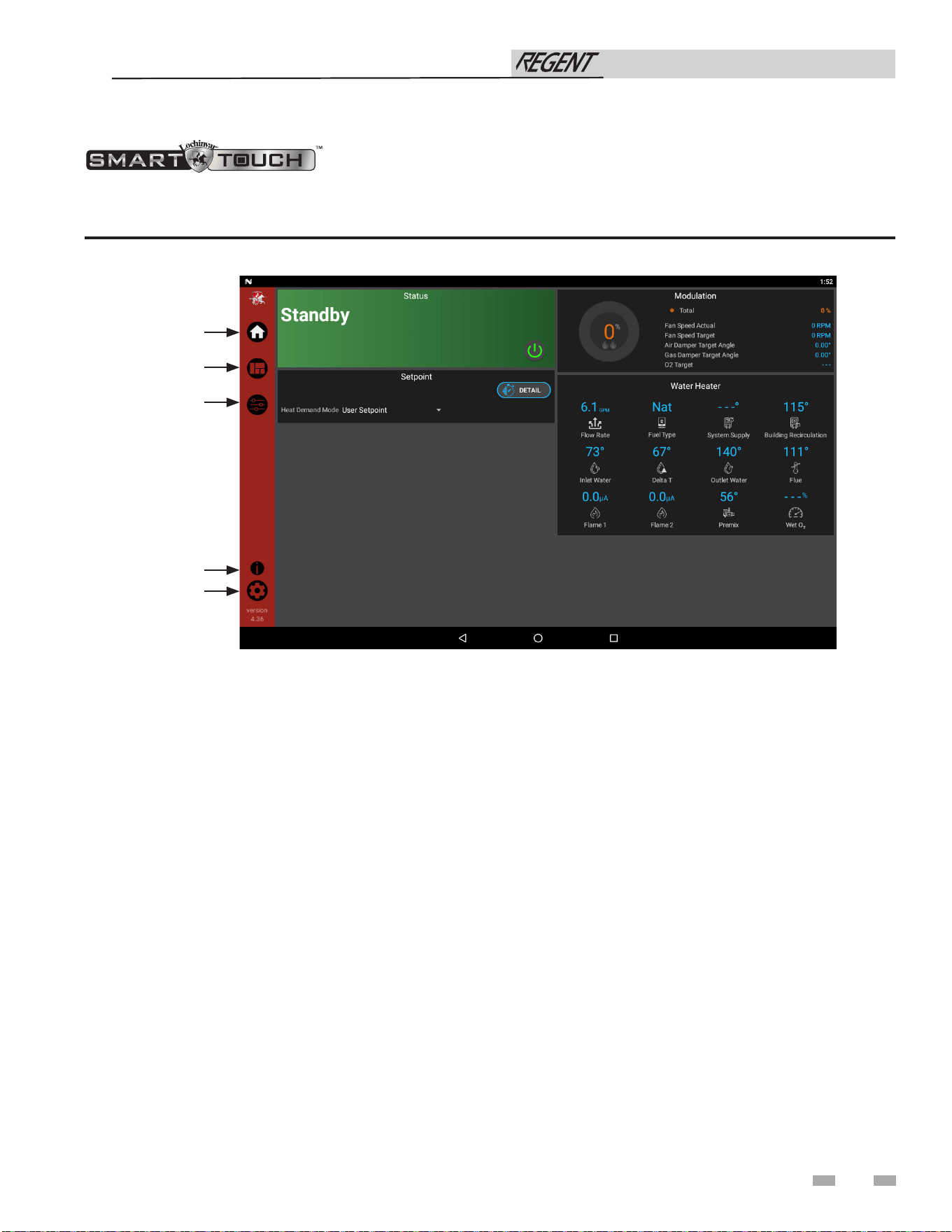
69
12 Operating information (continued)
Figure 12-1 Home Screen
The Home Screen displays basic information on how the unit is running. It is divided into the following sections: Status, Demand,
Modulation, Sensors, and Navigation.
• The Status Section is located on the top left of the screen
and displays how the unit is currently running (i.e. Off,
Stand-by, Blocking, and Lockout) including: current
driving demand, the reason for any blocking or lockout,
and a power button.
• The Demand Section is located on the bottom left of the
screen and displays information about the targets and
limits of the current demand being serviced.
• The Modulation Section is located on the top right of the
screen and displays the target modulation of the unit. This
section also includes target and actual fan speeds.
• The Sensor Section is located on the bottom right of the
screen and displays both factory installed and field
installed sensor including: Inlet Water Temperature,
Delta T Water Temperature, Outlet Water Temperature,
Flue Temperature, and Inlet Water Flow Rate.
• The Navigation Section is located down the left side of the
screen. There are five (5) sections located below the
Lochinvar icon: Home, View, Setup, Information
(About), and Settings. The Home Section is the screen
shown above. The View Section provides more detailed
information including subsections for: History, Cascade,
Graphing, and a complete list of current Sensor Values.
The Setup Section has several screens to aid in setting
up the appliance. The Setup Section includes screens for
adjusting: Set Points, Cascade, and BMS. The Information
Section provides information about the hardware and
software including the current software version of
the interface and the version of the appliance control.
The Setting Section enables several interface setup features
including: Time Setup, Temperature Unit Select, System
Update, and Wi-Fi Setup.
Installation & Operation Manual
HOME
VIEW
SETUP
INFORMATION
SETTINGS
70
13 Maintenance
Maintenance and annual startup
Table 13A Service and Maintenance Schedules
Service technician
(see the following pages for instructions)
General:
• Address reported problems
• Inspect interior; clean and vacuum if
necessary;
• Clean condensate trap and fill with fresh
water
• Check for leaks (water, gas, flue,
condensate)
• Verify flue and air lines in good condition
and sealed tight
• Check system water pressure/system
piping/expansion tank
• Check control settings
• Check ignition and flame sense electrodes
(sand off any deposits; clean
and reposition)
• Check wiring and connections
• Perform combustion start-up checkout
and performance verification per Section
11 of this manual.
• Flame inspection (stable, uniform)
• Flame signal (at least 10 microamps at
high fire)
• Clean the heat exchanger if flue
temperature is more than 54°F above
return water temperature.
If combustion or performance
indicate need:
• Clean heat exchanger
• Remove and clean burner using
compressed air only
• Clean the blower wheel
ANNUAL START-UP
Owner maintenance
Daily
• Check water heater area
Monthly
• Check vent piping
• Check air piping
• Check air and vent termination
screens
• Check relief valve
• Check condensate drain system
• Check automatic air vents
• Remove debris from Y-strainer
per manufacturer’s instructions
• Check building recirculation
filter (if filter required)
• Check for and clean any debris
or obstruction from bird screens
(if equipped)
Every
6 months
• Check water heater piping (gas
and water) for leaks
• Operate relief valve
• Check water chemistry
Installation & Operation Manual
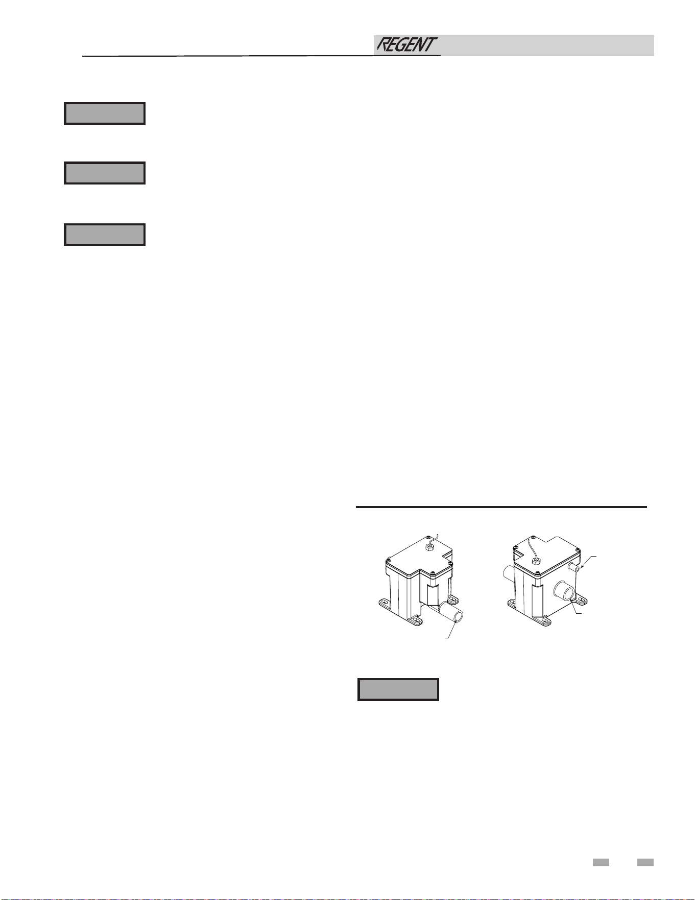
71
13 Maintenance (continued)
Follow the service and maintenance procedures given throughout this manual and in component literature
shipped with the water heater. Failure to perform the service and maintenance could result in damage to the
water heater or system. Failure to follow the directions in this manual and component literature could result
in severe personal injury, death, or substantial property damage.
The water heater should be inspected annually only by a qualified service technician. In addition, the
maintenance and care of the water heater designated in Table 13A and explained on the following pages must
be performed to assure maximum water heater efficiency and reliability. Failure to service and maintain the
water heater and system could result in equipment failure.
Electrical shock hazard – Turn off power to the water heater before any service operation on the water heater
except as noted otherwise in this instruction manual. Failure to turn off electrical power could result in
electrical shock, causing severe personal injury or death.
Address reported problems
1. Inspect any problems reported by the owner and correct
before proceeding.
Inspect water heater area
1. Verify that water heater area is free of any combustible
materials, gasoline and other flammable vapors and liquids.
2. Verify that air intake area is free of any of the contaminants
listed in Section 1 - Determine Water Heater Location.
If any of these are present in the water heater intake air
vicinity, they must be removed. If they cannot be removed,
reinstall the air and vent lines per this manual and the
Regent Water Heater Service Manual.
Inspect water heater interior
1. Open the front door and inspect the interior of the water
heater.
2. Vacuum any sediment from inside the water heater and
components. Remove any obstructions.
The condensate trap must be filled with water
during all times of water heater operation to
avoid flue gas emission from the condensate
drain line. Failure to fill the trap could result
in severe personal injury or death.
⚠ WARNING
⚠ WARNING
⚠ WARNING
⚠ WARNING
Figure 13-1 Condensate Trap
Clean condensate trap
1. Inspect the condensate drain line, condensate PVC fittings,
and condensate trap.
Monthly inspection:
1. The condensate trap should be inspected monthly to
ensure the trap is properly installed and connected to the
condensate pipe under the appliance, see FIG. 13-1.
2. The condensate line should be inspected monthly for
obstructions, making sure it allows free flow for condensate
to drain.
3. Inspect the neutralizing kit (if installed) monthly to ensure
the condensate is draining properly, and there is still an
adequate amount of neutralizing agent available.
FRONT VIEW
REAR VIEW
DIR #2000507911 00
TO FLOOR DRAIN
OR NEUTRALIZER KIT
1/2” PVC / CPVC CONNECTION
FROM CONDENSATE
VENT ON APPLIANCE
FROM CONDENSATE
DRAIN ON APPLIANCE
Annual cleaning:
1. The condensate trap should be cleaned at least once
annually, or at the end of each heating season, by removing
the bottom cap and cleaning out any sediment that exists.
2. The provided condensate trap is equipped with a ball
that acts as a seal against harmful flue gases escaping in
case there is no condensate in the trap. If this ball is not
present, flue gases may be able to pass through the trap
when there is no condensate present, resulting in an unsafe
environment. It is important to check and make sure the
ball is still located in the trap, acting as a seal against flue
gases at least once annually and after every cleaning.
3. After the condensate trap is cleaned or serviced, it must be
checked to ensure that it is installed and draining properly.
Reference Section 10 - Condensate Disposal for installation
instructions.
Installation & Operation Manual
72
13 Maintenance
Failure to inspect for the above conditions
and have them repaired can result in
severe personal injury or death.
Check water system
1. Verify all system components are correctly installed and
operational.
2. Check the cold fill pressure for the system. Verify it is
correct (must be a minimum of 30 PSI).
3. Watch the system pressure as the water heater heats up
(during testing) to ensure pressure does not rise too high.
Excessive pressure rise indicates expansion tank sizing or
performance problem.
4. Inspect automatic air vents and air separators. Remove
air vent caps and briefly push valve to flush vent. Replace
caps. Make sure vents do not leak. Replace any leaking
vents.
Check expansion tank
1. Expansion tanks provide space for water to move in
and out as the heating system water expands due to
temperature increase or contracts as the water cools.
Tanks may be open, closed or diaphragm or bladder type.
See Section 7 - System Piping for suggested best location
of expansion tanks and air eliminators.
Check water heater relief valve
1. Inspect the relief valve and lift the lever to verify flow.
Before operating any relief valve, ensure that it is piped
with its discharge in a safe area to avoid severe scald
potential. Read Section 7 - System Piping before
proceeding further.
Safety relief valves should be re-inspected
AT LEAST ONCE EVERY THREE YEARS,
by a licensed plumbing contractor or
authorized inspection agency, to ensure
that the product has not been affected by
corrosive water conditions and to ensure
that the valve and discharge line have not
been altered or tampered with illegally.
Certain naturally occurring conditions may
corrode the valve or its components over
time, rendering the valve inoperative. Such
conditions are not detectable unless the
valve and its components are physically
removed and inspected. This inspection
must only be conducted by a plumbing
contractor or authorized inspection agency
– not by the owner. Failure to re-inspect the
water heater relief valve as directed could
result in unsafe pressure buildup, which can
result in severe personal injury, death, or
substantial property damage.
Following installation, the valve lever must
be operated AT LEAST ONCE A YEAR to
ensure that waterways are clear. Certain
naturally occurring mineral deposits may
adhere to the valve, rendering it inoperative.
When manually operating the lever, water
will discharge and precautions must be taken
to avoid contact with hot water and to avoid
water damage. Before operating lever, check
to see that a discharge line is connected to
this valve directing the flow of hot water
from the valve to a proper place of disposal.
Otherwise severe personal injury may result.
If no water flows, valve is inoperative. Shut
down the water heater until a new relief
valve has been installed.
2. After following the above warning directions, if the relief
valve weeps or will not seat properly, replace the relief valve.
Ensure that the reason for relief valve weeping is the valve
and not over-pressurization of the system due to expansion
tank waterlogging or undersizing.
⚠ WARNING
⚠ WARNING
⚠ WARNING
Inspect ignition and flame sense
electrodes
1. Remove the ignition and flame sense electrodes from the
water heater heat exchanger access cover.
2. Remove any deposits accumulated on the ignition/flame
sense electrode using sandpaper. If the electrodes cannot be
cleaned satisfactorily, replace with new ones.
3. Replace ignition/flame sense electrode, making sure gasket
is in good condition and correctly positioned.
Eliminate all system or water heater leaks.
Leaking water may cause severe property
damage.
1. Inspect all water and gas piping and verify to be leak free.
2. Look for signs of leaking lines and correct any problems
found.
3. Check gas line using the procedure found in Section 8 - Gas
Connections.
Check all piping for leaks
⚠ WARNING
Flue vent system and air piping
1. Visually inspect the entire flue gas venting system and air
piping for blockage, deterioration or leakage. Repair any
joints that show signs of leakage. Verify that air inlet pipe is
connected and properly sealed.
2. Verify that water heater vent discharge and air intake are
clean and free of obstructions.
3. Verify that bird screens are clean and free of debris or
obstruction.
Installation & Operation Manual
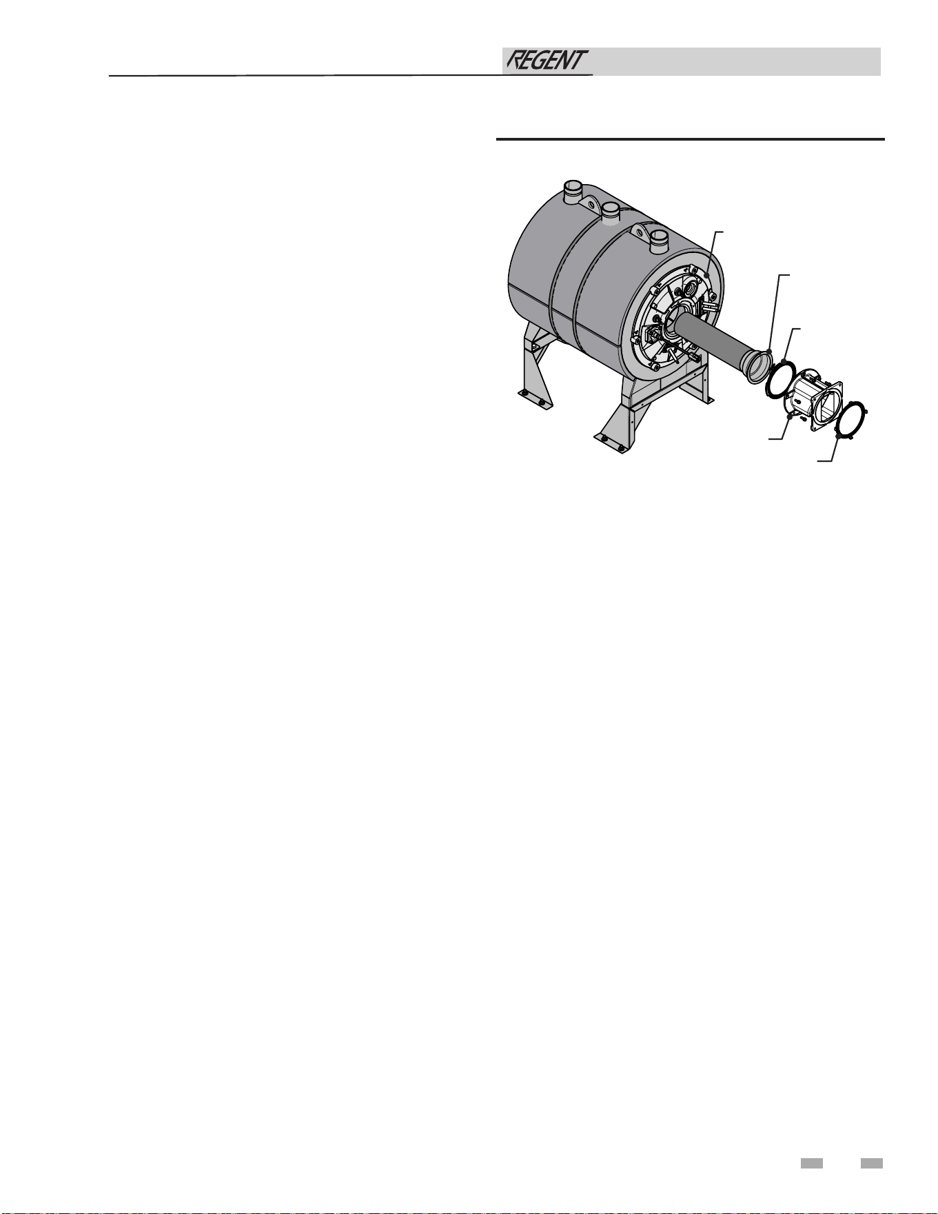
73
13 Maintenance (continued)
Check burner flame
1. Inspect flame through observation window.
2. If the flame is unsatisfactory at either high fire or low fire,
turn off water heater and allow water heater to cool down.
Remove the burner and clean it thoroughly using a vacuum
cleaner or compressed air. Do not use compressed air to
clean burner if performed inside a building.
3. Remove the burner, reference FIG. 13-2.
4. When replacing the burner, ensure gasket is in good
condition and positioned correctly (FIG. 13-2).
Figure 13-2 Burner Assembly
Perform start-up and checks
1. Start water heater and perform checks and tests specified in
Section 11 - Start-up.
2. Verify cold fill pressure is correct and that operating
pressure does not go too high.
Check flame signal
1. The Regent water heater is equipped with two flame sense
electrodes. At high fire, the flame signal shown on the
display, labeled “Flame 2”, should be at least 10 microamps.
As the water heater modulation decreases to low fire, the
value shown on the display, labeled “Flame 1”, should
increase.
2. A lower flame signal may indicate a fouled or damaged
flame sense electrode. If cleaning the flame sense electrode
does not improve, ground wiring is in good condition, and
ground continuity is satisfactory, replace the flame sense
electrode.
3. See Section 3 - Troubleshooting in the Regent Service
Manual for other procedures to deal with low flame signal.
Review with owner
1. Emphasize the need to perform the maintenance schedule
specified in this manual.
2. Remind the owner of the need to call a licensed contractor
should the water heater or system exhibit any unusual
behavior.
3. Remind the owner to follow the proper shutdown procedure
and to schedule an annual start-up.
Check ignition ground wiring
1. Inspect water heater ground wire from the heat exchanger
access cover to ground terminal strip.
2. Verify all wiring is in good condition and securely attached.
3. Check ground continuity of wiring using continuity meter.
4. Replace ground wires if ground continuity is not satisfactory.
Check all water heater wiring
1. Inspect all water heater wiring, making sure wires are in
good condition and securely attached.
Check control settings
1. Set the SMART TOUCH control module display to
Parameter Mode and check all settings. See Section 1 of
the Regent Service Manual. Adjust settings if necessary.
See Section 1 of the Regent Service Manual for adjustment
procedures.
2. Check settings of external limit controls (if any) and adjust
if necessary.
Check O2 sensor
1. A self-diagnosis feature is programmed into the O2 sensor
control. If there is a problem with the O2 sensor, the
appropriate error will be displayed. The unit will continue
to operate on the last known combustion curve. Contact a
qualified service technician to inspect and replace the O2
sensor as needed.
Installation & Operation Manual
GAS/AIR MANIFOLD
BURNER GASKET
BURNER PLATE
ASSEMBLY
BURNER
GAS/AIR MANIFOLD
GASKET
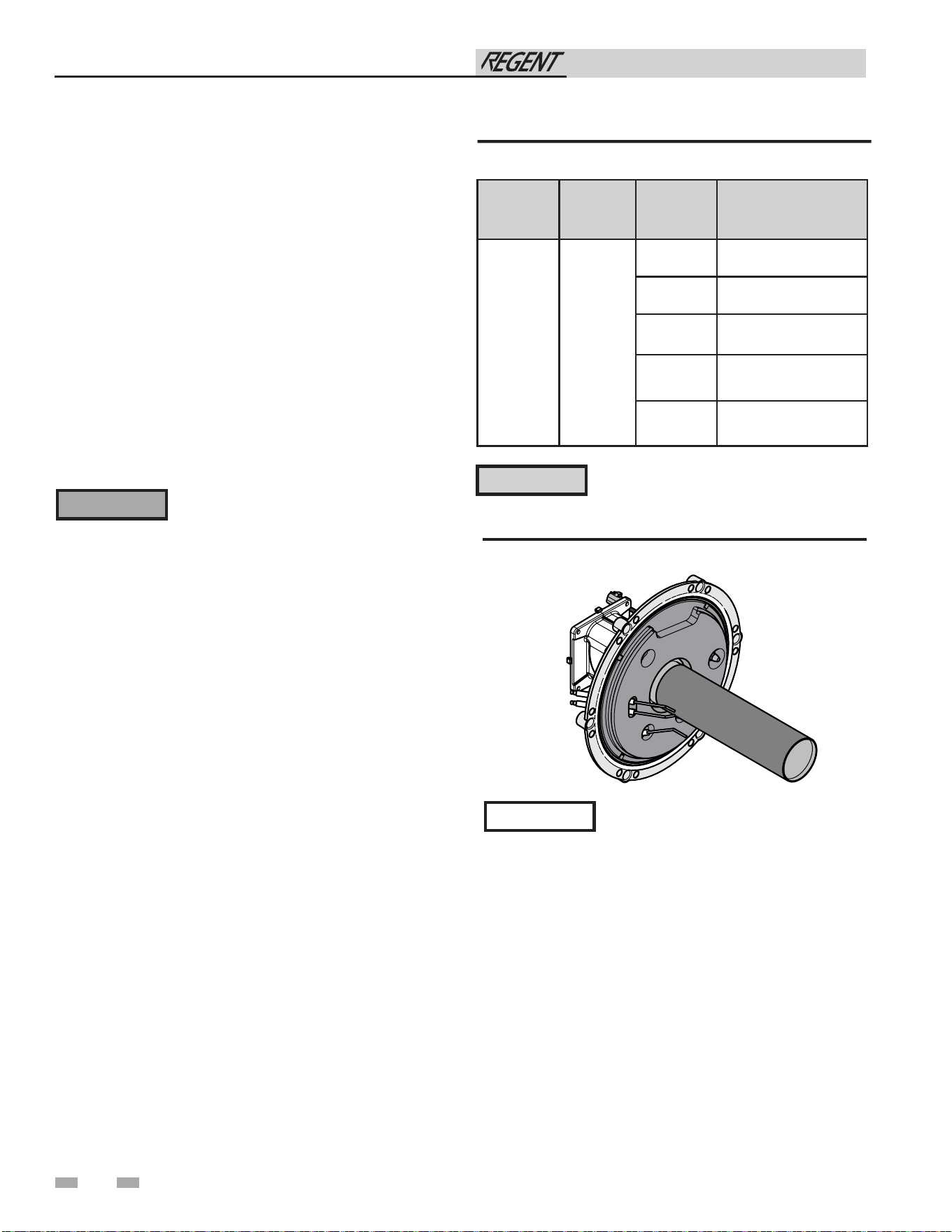
74
13 Maintenance
Rope gasket is intended for sealing
combustion (see FIG. 13-3). If gasket
is damaged DO NOT reuse, the rope
gasket must be replaced. See the Regent
Replacement Parts List for replacement
rope gasket.
NOTICE
Figure 13-3 Rope Gasket - Heat Exchanger Door
Installation & Operation Manual
The water heater contains ceramic fiber
materials. Use care when handling these
materials per instructions in the Service
Manual. Failure to comply could result in
severe personal injury.
⚠ WARNING
Cleaning heat exchanger
For recommended materials; including brush, appropriate
extension(s), refractory cover, and detailed instructions see
Table 13B - Heat Exchanger Cleaning Kits.
1. Shut down water heater:
• Follow the “To Turn Off Gas to Appliance” instructions
for the water heater in Section 11 - Startup.
• Do not drain the water heater unless it will be exposed
to freezing temperatures. If using freeze protection
fluids in the system, do not drain.
2. Allow time for the water heater to cool to room temperature
if it has been firing.
3. Remove the nuts securing the heat exchanger access cover
to the heat exchanger and set aside.
4. Remove the heat exchanger access cover, burner, and
gas/air arm assembly.
5. Remove the condensate hose from the heat exchanger end.
Connect a field supplied 3/4" diameter hose to a drain pan.
Using field supplied means, cover the refractory in the back
of the combustion chamber of the heat exchanger.
6. Use a vacuum cleaner to remove any accumulation on the
water heater heating surfaces. Do not use any solvent.
7. Brush the heat exchanger while dry using a nylon bristle
brush. Caution: DO NOT use a metal brush. Re-vacuum
the heat exchanger.
8. Finish cleaning using a clean cloth dampened with warm
water. Rinse out debris with a low pressure water supply.
9. Allow the heat exchanger to thoroughly dry.
10. Remove the field supplied rear refractory cover from the
back of the combustion chamber of the heat exchanger and
reassemble.
11. Close isolation valves on piping to isolate water heater from
system. Attach a hose to the water heater drain and flush
water heater thoroughly with clean water by using purging
valves to allow water to flow through the water makeup line
to the water heater.
12. Perform start-up and check-out procedures in the Check
Flame and Combustion - Section 11 - Startup on page 60 of
this manual.
13. Replace the access cover and restore water heater to
operation.
Table 13B Heat Exchanger Cleaning Kit
* Do NOT use a metal brush. Only use
the kit provided brush or an equivalent
replacement nylon brush.
⚠ CAUTION
Model
Kit
Number
Part
Number
Component
Description
500 - 1000 100157628
100333410
Rear Refractory Cover,
10.75" Diameter
100208804
Rear Refractory Cover,
7.25" Diameter
100208309* Nylon 4" Wheel Brush*
100208310
1/4" x 12" Drill
Extension
100208311
1/4" x 24" Drill
Extension
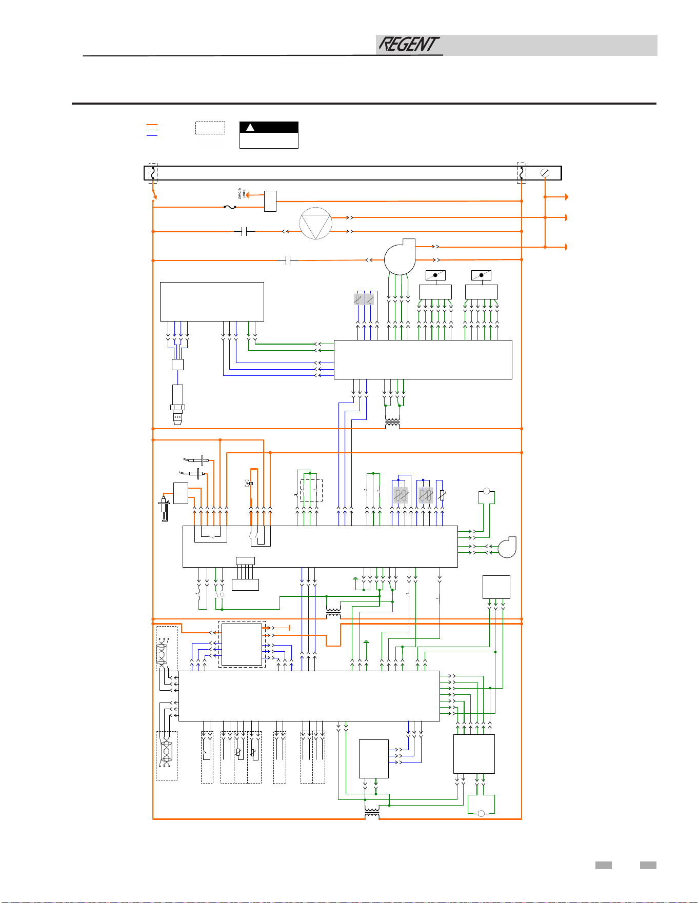
14 Diagrams
Figure 14-1 Ladder Diagram
75
Installation & Operation Manual
CC950
Gnd
N
L
120VAC – 1ø
On/Off Switch
Blower Power
Relay Contacts
(NO)
Chassis
Ground
Panel
Ground
BOX DEPICTS
OPTIONAL ITEMS
BOX DEPICTS
DUAL SENSOR
SINGLE HOUSING
NOTES:
1. All wiring must be installed in accordance with: local, state, provincial and national code requirements per either N.E.C. in USA or C.S.A. in Canada.
2. If any original equipment wire as supplied with the appliance must be replaced, it must be replaced with wire having same wire gauge (AWG) and
rated for a
minimum of 105°C. Exceptions: Replacement high voltage spark lead and shielded cables must be purchased from the factory. Use of a non-approved
spark lead
or shielded cables can lead to operational problems which could result in non-repairable damage to the integrated controller or other components.
3. Actual connector block lo
cations may vary from those shown on diagrams. Refer to actual components for proper connector block locations when
using diagrams to troubleshoot unit.
WARNING
DISCONNECT POWER
BEFORE SERVICING
!
HIGH VOLTAGE
24 V
LOW VOLTAGE
LADDER DIAGRAM
100398746 REV A
X14-3
BC/CC 24Vac Xfmr
BC950
X11-1
X11-2
X11-3
Spark Xfmr
X1-2
X1-6
X1-1
X1-5
Flame
Sense 1
Flame
Sense 2
Igniter
X7-4
X1-4
X1-8
Panel
Ground
X2-8
X2-9
X2-7
X2-1
X2-2
LGPS 2
HGPS 1
Air Prove Sw
Blk Vent Sw
X3-9
X3-8
X3-12
X3-4
X3-6
X3-2
X3-3
X3-1
Outlet
Sensor
Inlet
Sensor
Flue
Sensor
X10-3
X10-1
X10-2
X15-3
X15-1
X15-4
X15-5
Blkd Drain Sw
Flue Damper Prv
X4-1
X4-6
Blower
Relay Coil
X4-5
X4-10
PERSONALITY
PLUG
ALARM
CONTACTS
RUN-TIME
CONTACTS
SYSTEM SUPPLY
SENSOR
A
B
SHIELD
A
B
SHIELD
Pump
Relay
Board
X8-10
X8-9
X8-8
X8-7
X1-7
X1-8
X14-1
X14-2
X5-1
X5-2
X5-3
Blower
F1-5
F1-1
CASCADE 1
BAS
X2-1
X2-2
X2-3
MTR Board
X4-2
X4-1
X4-3
X3-1
X3-2
X3-3
X12-1
X12-4
X12-5
X6-3
X6-2
X6-1
Panel
Ground
X1-1
X9-1
X9-2
0-10VDC
- RATE
+ OUT
Gas Valve
X11-1
P2-2
P2-1
X7-5
X7-2
X7-1
X11-2
AD-1
AD-2
AD-3
AD-4
AD-5
AD-6
Air Damper
Blower
F2-1
F1-5
F1-1
F1-2
F1-4
F2-2
F2-3
Air Temperature
Sensor
CF 24Vac Xfmr
CF950
X3-1
X3-3
X3-5
X3-8
X4-1
X4-4
X4-2
X4-5
X5-1
X5-4
X5-3
X5-6
X8-6
X8-5
X8-4
X8-3
X8-2
X8-1
X9-6
X9-5
X9-4
X9-3
X9-2
X9-1
X6-2
X6-1
X11-1
X11-2
X11-3
X12-3
X12-1
X12-2
CP-1
CP-2
CP-3
O2 Board
CN1-2
CN1-1
CN4-1
CN4-3
CN4-2
CN3-1
CN3-5
CN3-3
CN3-6
Pump Power
Relay Contacts
(NO)
Panel
Ground
Service
Outlet
X3-10
P.O.C
X2-13
X2-12
X2-15
X2-11
X6-6
X6-3
X6-5
X6-2
X6-1
X6-4
DHW
THERMOSTAT
X7-1
X7-2
- BMS
+ IN
0-10VDC
X1-13
X1-14
Flow
Sensor
Pump
Relay Coil
X1-10
X1-9
X4-5
X4-7
X15-2
X4-2
Flow Sw
X4-1
X11-3
Panel
Ground
X1-3
X1-2
BUILDING RECIRC
SENSOR
X1-5
X1-6
FS-1
FS-3
FS-4
P-1
P-3
P-4
P-5
P-6
P-7
X10-2
X10-3
X10-5
X10-7
X10-8
X10-9
X10-10
GD-1
GD-2
GD-3
GD-4
GD-5
GD-6
Gas Damper
O2 SENSOR
Internal
Circulaon
Pump
P6-2
P6-1
HMI 24Vac
Xfmr
X3-4
X3-5
X3-6
HMI
J12-2
J12-1
J12-3
J2-1
J2-2
X4-8
X4-4
Hex Door
Temp Switch

76
Figure 14-2 Wiring Diagram
14 Diagrams
Installation & Operation Manual
Dogwood (HMI)
Ref
CC Tx
CC Rx
CC COMs
5V TTL
J12-3
J12-2
J12-1
J10-4
J10-3
J10-2
J10-1
N
L
Main
24 Vac
J2-1
J2-2
BK
R
W
BL
O
Y
BK
O
Y
BK
BK
O
PK
GY
T
PR
R
W
BOX DEPICTS
OPTIONAL ITEMS
R/BK
GAS DAMPER
+24Vdc
M A
S A
M B
S B
GND
BK
Y
O
Proof of
Closure
BOX DEPICTS
DUAL SENSOR
SINGLE HOUSING
NOTES:
1. All wiring must be installed in accordance with: local, state, provincial and national code
requirements per either N.E.C. in USA or C.S.A. in Canada.
2. If any original equipment wire as supplied with the appliance must be replaced, it must be
replaced with wire having same wire gauge (AWG) and rated for a
minimum of 105°C. Exceptions: Replacement high voltage spark lead and shielded cables
must be purchased from the factory. Use of a non-approved spark lead
or shielded cables can lead to operational problems which could result in non-repairable
damage to the integrated controller or other components.
3. Actual connector block locations may vary from those shown on diagrams. Refer to actual
components for proper connector block locations w
hen using diagrams to troubleshoot unit.
WIRING DIAGRAM
100398719 REV A
WARNING
DISCONNECT POWER
BEFORE SERVICING
!
HIGH VOLTAGE
24 V
LOW VOLTAGE
BLY
Pump Relay Board
----
----
DHW
RECIRC
CASC ISO
VALVE
P1-6
P1-5
P1-4
P1-3
P1-2
P1-1
P1-7
Main
24 Vac
NL
P2-2
P2-1
P7-1
P7-2
P6-1
P6-2
P5-1
P5-2
P4-1
P4-2
P3-1
P3-2
INT CIRC
PUMP
ALARM
CONTACTS
RUN-TIME
CONTACTS
+ RATE
- OUT
0-10VDC
SYSTEM SUPPLY
SENSOR
- BMS
+ IN
0-10VDC
DHW
THERMOSTAT
B
A
SHIELD
A
B
SHIELD
X2-1
X2-2
X2-3
X2-4
BC COMs
(RS485)
(A)
(B)
REF
----
X1 – (Sensors)
X8-3
X8-4
X8-5
X8-6
X8-7
X8-8
X8-9
X8-10
X8-1
X8-2
Alarm
X8 – (Outputs)
----
Runme
Alarm
----
Runme
----
----
----
----
X8-11
X8-12
X8-13
----
----
----
----
----
Rate COM
Rate 0-10V
X9 – (Anlg Out)
X9-4
X9-3
X9-2
X9-1
CC950
“Comfort Control”
X1-8
X1-7
X1-6
X1-5
X1-4
X1-3
X1-2
X1-1
X1-16
X1-15
X1-14
X1-13
----
COM
----
----
SysSp-S6
----
BldgRec-S7
COM
0-10 BMS
----
0-10 BMS
----
X1 – (Sensors)
X1-10
X1-9
FlowSns-S1
COM
X1-12
X1-11
SysRecirc-S2
COM
X7-8
X7-7
X7-6
X7-5
X7-4
X7-3
X7-2
X7-1
X7-12
X7-11
X7-10
X7-9
X7-14
X7-13
DHW Tstat
X7 – (Switch Inputs)
----
----
24 Vac L
----
----
----
----
----
----
----
----
----
----
X14 – Cascade 1
X14-1
X14-2
X14-3
X14-4
X14-5
X14-6
GND
A
B
Tx
Rx
GND
X3-4
X3-5
X3-3
X3-6
X3-2
X3-1
(A)
(B)
COM
BAS
COMs 1
DU COMs
5V TTL
----
Sys Pmp
----
Int Cir Pmp
DHW ReC
----
Casc Vlv
24 Vdc-
X10 - Pump Interface
X10-1
X10-3
X10-2
X10-4
X10-6
X10-5
X10-7
X10-8
X10-10
X10-9
24 Vdc+
Bypass Vlv
X11-1
X11-3
X11-2
Main
24 Vac
L
N
GND
X11-5
X11-4
X11-7
X11-6
X11-8
----
----
----
----
----
BAS COMs 2
----
----
----
X12-3
X12-2
X12-4
X12-1
X12-5
X12-6
Rx
Tx
GND
Ext. FL/LWCO
Ext. FL/LWCO
24 VAC N
24 VAC L
X18-Pass Thru
X18-1
X18/2
X18-3
X18-4
MRHL
MRHL
MRHL
MRHL
X19-Pass Thru
X19-1
X19-2
X19-3
X19-4
X4-1
X4-3
X4-2
24 VAC
24 VAC
X4-5
X4-4
X4-7
X4-6
X4-8
XFMR N
FLOW SWITCH
JUMPER
MRHL
XFMR L
JUMPER
X5-1
X5-2
X5-3
BAS
(RS485)
REF
(B)
(A)
BUILDING
RECIRC SENSOR
BL
PU
Y
BL
BR
R
BL
MTR Board
X6-1
X6-2
X6-3
X6-4
X4-1
X4-2
X4-3
X4-4
X1-3 (GND)
X1-2 (N)
X1-1 (L)
PK
BL
GN
BL/BK
Y/BK
BL
BL
GN
BL
Y
PU
BL
BL
BK
FS-1
FS-2
FS-3
FS-4
L+
L-
CH1
-
Flow
Sensor
BK
GND
CL
O2 SENSOR
Shielded/Twisted Pair
Shielded/Twisted Pair
Pump
Relay Contacts
(NO)
BK
BK
Heater -
CN3 O2 Sensor
Heater +
AF-
----
AF+
----
CN3-1
CN3-6
CN3-3
CN3-4
CN3-5
CN3-2
“Sakura”
O2 Board
GND
Tx
CF COMs
5V TTL
Rx
CN4-2
CN4-1
CN4-3
CN1-2
CN1-1
+12V
GND
12 Vdc
Pwr
CF 24Vac Xfmr
BLOWER
F2-1
F2-2
F2-3
Power
GNL
F1-5
F1-4
F1-3
F1-2
F1-1
Fan Control
24Vdc+
Tach
----
PWM
24Vdc-
Blower
Relay Coil
Blower Power
Relay Contacts
(NO)
Panel
Ground
Spark Xfmr
Chassis
Ground
On/Off
Switch
BK
GN
GY
CL
BK
GND
Y/R
BL/R
BK
W
BK
CL
GND
BK
R
BK
PK
R
BK
W
GND
BK
CL
W
W
Panel
Ground
G
Inlet Sensor
GN
120V – 1ø
Igniter
Flame Sense 2
Flame Sense 1
W
Y/R
BC/CC 24Vac Xfmr
Y/BK
Y
BL/BK
BL
BK
W
Service
Outlet
W
R
BK
BR
GY
Y
GN
R
BK
BR
GY
Y
GN
W/BK
T
RBK
R
BK
W
L
N
Gnd
HMI 24Vac Xfmr
X10-1
X10-2
X10-3
X10-4
CC COMs
(RS485)
(A)
(B)
REF
----
X11-1
X11-2
X11-3
X11-4
CF COMs
(RS485)
(A)
(B)
REF
(REF)
X4-9
X4-4
X4-8
X4-3
X4-7
X4-2
X4-6
X4-1
X4-10
X4-5
Fan Rly-24v com
X4 – Blower
----
----
Fan Rly 24v
----
----
----
----
24Vdc-
24Vdc+
GV Sply L
X7 – (GV 1&2)
----
GV1 N
GV Sply N
GV1 L
----
X7-6
X7-3
X7-5
X7-2
X7-4
X7-1
X6-6
X6-3
X6-5
X6-2
X6-4
X6-1
Spk Sply L
X6 – (Ign/Flame)
Spark L
Flame 2
Spk Sply N
Flame 1
Spark N
X1-8
X1-4
X1-7
X1-3
X1-1
X1-6
X1-2
X1-5
24Vac L
X1-24 Vac Supply & PE
----
(24Vac N)
(24Vac L)
(Frame Gnd)
24Vac N
----
Frame Gnd
BC950
X15-5
X15-4
X15-3
X15-2
X15-1
Flue Damper
X15-Switch Inputs
24Vac L
Flow Switch
Flue Damper Prv
Blk Drain Swt
----
X3 – (Sensor Inputs)
Flue Sensor S3
Safety Flue Sensor S10
----
----
Sensor COM
Sensor COM
----
----
Sensor COM
Outlet Sensor S1
Sensor COM
Safety Outlet Sensor S9
Inlet Sensor S2
X3-14
X3-13
X3-9
X3-8
X3-12
X3-10
X3-7
X3-11
X3-5
X3-4
X3-6
X3-2
X3-3
X3-1
X2-13
X2-9
X2-14
X2-1
X2-6
X2-4
X2-3
X2-12
X2-16
X2-15
X2-10
X2-11
X2-8
X2-5
X2-7
X2-2
Proof of Closure
X2 – (Switch Inputs)
24 Vac
MRHL
----
----
24 Vac
Gas Pr Sw 2
Blocked Vent Sw
----
----
Air Proving Sw
----
----
----
Gas Pr Sw 1
24 Vac
PERSONALITY
PLUG
GY
Y
BR
Y
Air Temperature
Sensor
LGPS 2
HGPS 1
Blk Vent Sw
Air Prove Sw
O
O
BL
PU
O/R
BL
O
BL
Outlet
Sensor
BL
Y
R
R/W
Y
W
GY
Y
Flue
Sensor
Blkd Drain Sw
Flue Damper
BL
BK
O
Y
AIR DAMPER
AD-1
AD-2
AD-3
AD-4
AD-5
AD-6
+24Vdc
M A
S A
M B
S B
GND
GD-1
GD-2
GD-3
GD-4
GD-5
GD-6
BR
PK
PK/BL
Y
BL
X6-2
X6-1
O2 Sensor
Power
12Vdc-
12Vdc+
Main 24 Vac
N
L
N
L
N
L
X5-1
X5-3
X5-4
X5-5
X5-6
X5-2
BC COMs
(RS485)
(A)
(B)
REF
X12-1
X12-2
X12-3
X12-4
X11-1
X11-2
X11-3
X11-4
Sakura
COMs
5V TTL
REF
CF Rx
CF Tx
----
X8-6
X8-5
X8-4
X8-3
X8-2
X8-1
+24Vdc
Air Damper
Motor A
Sensor A
Motor B
Sensor B
GND
X9-6
X9-5
X9-4
X9-3
X9-2
X9-1
+24Vdc
Gas Damper
Motor A
Sensor A
Motor B
Sensor B
GND
X4-6
X4-3
X4-5
X4-2
X4-4
X4-1
Air Temp. S1
Sensors
Air Temp. S2
----
S2 Ref
----
S1 Ref
X3-8
X3-4
X3-7
X3-3
X3-6
X3-2
X3-5
X3-1
PWM
Fan Control
Tach.
----
24Vdc+
24Vdc-
----
----
----
BL
GN
Hex Door
Temp Switch
R
W
BK
Gas Valve
GN
GN
Pump
Relay Coil
WBK
Y
BL/R
BL/R
Y/R
GN
Flow Sw
PK
W
CP-1
CP-2
CP-3
GNL
Internal
Circulaon
Pump
Shielded/Twisted Pair
Shielded/Twisted Pair
Shielded/Twisted Pair
∞
∞
∞
∞
∞

Notes
77

Revision Notes: Revision A (PCP #3000070982 / CN #500056370)
initial release.
Revision B (PCP 3000071383 / CN #500056726) reflects updates to
figure 9-4.
100399794_2000857139 Rev B
03/26