
Industrial Robot: 6-Axis Robots
C-B series Manual
Original instructions
© Seiko Epson Corporation 2023-2024
Rev.1b
ENM242R6421F

Table of Contents
1. Introduction
10
1.1 Introduction
11
1.2 Trademarks
11
1.3 Terms of Use
11
1.4 Manufacturer
11
1.5 Contact Information
11
1.6 Disposal
11
1.7 Before Use
11
1.8 Manual Types for This Product
12
2. C4 Manipulator
14
2.1 Safety
15
2.1.1 Conventions Used in This Manual
15
2.1.2 Design and Installation Safety
15
2.1.3 Operation Safety
16
2.1.4 Emergency Stop
17
2.1.5 Safeguard (SG)
17
2.1.6 How to Move Arms with the Electromagnetic Brake
18
2.1.6.1 When using a brake release unit
19
2.1.6.2 When using software
19
2.1.7 Precaution for Operation in Low Power Status
20
2.1.8 Warning Labels
20
2.1.8.1 Warning Labels
20
2.1.8.2 Information Labels
21
2.1.9 Responses for Emergencies or Malfunctions
21
2.1.9.1 When a Collision with the Manipulator Occurs
22
2.1.9.2 Entanglement with the Manipulator
22
2.2 Specifications
22
2.2.1 Model Number
22
2.2.2 Part Names and Motion Range of Each Arm
23
2.2.3 Outer Dimensions
25
2.2.3.1 C4-B601**
25
2.2.3.2 C4-B901**
26
Industrial Robot: 6-Axis Robots C-B series Manual Rev.1b
2

2.2.4 Standard Work Envelope
27
2.2.4.1 C4-B601**
27
2.2.4.2 C4-B901**
28
2.2.5 Specifications
30
2.2.5.1 Specifications Table
30
2.2.5.2 Options
30
2.2.6 How to Set the Model
30
2.3 Environment and Installation
30
2.3.1 Environment
31
2.3.2 Manipulator Mounting Dimensions
32
2.3.3 From Unpacking to Installation
34
2.3.4 Connecting the Cables
38
2.3.5 User Wires and Pneumatic Tubes
39
2.3.6 Checking the Basic Orientation
40
2.3.7 Relocation and Storage
41
2.3.7.1 Safety Information for Relocation and Storage
41
2.4 Setting the Hand
45
2.4.1 Installing the Hand
45
2.4.2 Attaching Cameras and Valves
47
2.4.3 WEIGHT and INERTIA Settings
48
2.4.3.1 WEIGHT Setting
51
2.4.3.2 INERTIA Setting
55
2.4.4 Safety Information for Auto Acceleration
59
2.5 Work Envelope
60
2.5.1 Work Envelope Setting by Pulse Range (for Each Joint)
60
2.5.1.1 Arm #1 Maximum Pulse Range
61
2.5.1.2 Arm #2 Maximum Pulse Range
63
2.5.1.3 Arm #3 Maximum Pulse Range
64
2.5.1.4 Arm #4 Maximum Pulse Range
64
2.5.1.5 Arm #5 Maximum Pulse Range
65
2.5.1.6 Arm #6 Maximum Pulse Range
66
2.5.2 Setting the Work Envelope by Mechanical Stops
67
2.5.2.1 Setting the Arm #1 Work Envelope
67
2.5.2.2 Setting the Arm #2 Work Envelope
68
2.5.2.3 Setting the Arm #3 Work Envelope
68
Industrial Robot: 6-Axis Robots C-B series Manual Rev.1b
3

2.5.3 Restriction of Manipulator Operation by Joint Angle Combination
69
2.5.4 Coordinate System
71
2.5.5 Changing the Robot
72
2.5.6 Setting the Rectangular Range in the XY Coordinate System of the Manipulator
73
2.6 Options
74
2.6.1 Brake Release Unit
74
2.6.1.1 Power Cable
75
2.6.1.2 Installing the Brake Release Unit
76
2.6.1.3 Removing the Brake Release Unit
77
2.6.1.4 How to Use the Brake Release Unit
77
2.6.2 Camera Plate Unit
78
2.6.3 PS Compatible Plate (Tool Adapter)
81
2.6.4 Base Side Angled Fittings
83
2.6.5 Base Side Fittings
86
2.6.6 PS Compatible Plate (Base Adapter)
90
2.6.7 Variable Mechanical Stop
91
3. C8 Manipulator
93
3.1 Safety
94
3.1.1 Conventions Used in This Manual
94
3.1.2 Design and Installation Safety
94
3.1.3 Operation Safety
95
3.1.4 Emergency Stop
96
3.1.5 Safeguard (SG)
96
3.1.6 How to Move Arms with the Electromagnetic Brake
97
3.1.6.1 When using a brake release unit
98
3.1.6.2 When using software
98
3.1.7 Precaution for Operation in Low Power Status
99
3.1.8 Warning Labels
99
3.1.8.1 Warning Labels
99
3.1.8.2 Information Labels
100
3.1.9 Responses for Emergencies or Malfunctions
101
3.1.9.1 When a Collision with the Manipulator Occurs
101
3.1.9.2 Entanglement with the Manipulator
101
3.2 Specifications
101
3.2.1 Model Number
101
Industrial Robot: 6-Axis Robots C-B series Manual Rev.1b
4

3.2.2 Part Names and Motion Range of Each Arm
103
3.2.3 Outer Dimensions
105
3.2.3.1 C8-B901*** (C8L)
105
3.2.3.2 C8-B1401*** (C8L)
106
3.2.4 Standard Work Envelope
107
3.2.4.1 C8-B901*** (C8L)
107
3.2.4.2 C8-B1401*** (C8XL)
110
3.2.5 Specifications
111
3.2.5.1 Specifications Table
111
3.2.5.2 Options
111
3.2.6 How to Set the Model
111
3.3 Environment and Installation
111
3.3.1 Environment
112
3.3.2 Manipulator Mounting Dimensions
113
3.3.2.1 Cable backward model
114
3.3.2.2 Cable downward model
115
3.3.3 From Unpacking to Installation
117
3.3.4 Connecting the Cables
121
3.3.5 User Wires and Pneumatic Tubes
122
3.3.5.1 Electrical Wires
123
3.3.5.2 Pneumatic Tubes
124
3.3.6 Checking the Basic Orientation
125
3.3.7 Relocation and Storage
125
3.3.7.1 Safety Information for Relocation and Storage
125
3.4 Setting the Hand
128
3.4.1 Installing the Hand
128
3.4.2 Attaching Cameras and Valves
130
3.4.3 WEIGHT and INERTIA Settings
131
3.4.3.1 WEIGHT Setting
134
3.4.3.2 INERTIA Setting
137
3.4.4 Safety Information for Auto Acceleration
140
3.5 Work Envelope
141
3.5.1 Work Envelope Setting by Pulse Range (for Each Joint)
141
3.5.1.1 Joint #1 Maximum Pulse Range
142
3.5.1.2 Joint #2 Maximum Pulse Range
142
Industrial Robot: 6-Axis Robots C-B series Manual Rev.1b
5

3.5.1.3 Joint #3 Maximum Pulse Range
143
3.5.1.4 Joint #4 Maximum Pulse Range
143
3.5.1.5 Joint #5 Maximum Pulse Range
143
3.5.1.6 Joint #6 Maximum Pulse Range
144
3.5.2 Setting the Work Envelope by Mechanical Stops
144
3.5.2.1 Setting the Joint #1 Work Envelope
144
3.5.2.2 Setting the Joint #2 Work Envelope
145
3.5.2.3 Setting the Joint #3 Work Envelope
146
3.5.3 Restriction of Manipulator Operation by Joint Angle Combination
146
3.5.4 Coordinate System
148
3.5.5 Changing the Robot
150
3.5.6 Setting the Rectangular Range in the XY Coordinate System of the Manipulator
151
3.6 Options
151
3.6.1 Brake Release Unit
151
3.6.1.1 Power Cable
153
3.6.1.2 Installing the Brake Release Unit
154
3.6.1.3 Removing the Brake Release Unit
155
3.6.1.4 How to Use the Brake Release Unit
155
3.6.2 Camera Plate Unit
156
3.6.3 Tool Adapter (ISO flange)
158
3.6.4 Variable Mechanical Stop
160
3.6.5 User Wires and Pneumatic Tubes
161
4. C12 Manipulator
162
4.1 Safety
163
4.1.1 Conventions Used in This Manual
163
4.1.2 Design and Installation Safety
163
4.1.3 Operation Safety
164
4.1.4 Emergency Stop
165
4.1.5 Safeguard (SG)
165
4.1.6 How to Move Arms with the Electromagnetic Brake
166
4.1.6.1 When using a brake release unit
167
4.1.6.2 When using software
167
4.1.7 Precaution for Operation in Low Power Status
168
4.1.8 Warning Labels
168
4.1.8.1 Warning Labels
168
Industrial Robot: 6-Axis Robots C-B series Manual Rev.1b
6

4.1.8.2 Information Labels
169
4.1.9 Responses for Emergencies or Malfunctions
170
4.1.9.1 When a Collision with the Manipulator Occurs
170
4.1.9.2 Entanglement with the Manipulator
170
4.2 Specifications
170
4.2.1 Model Number
170
4.2.2 Part Names and Motion Range of Each Arm
171
4.2.3 Outer Dimensions
174
4.2.4 Standard Work Envelope
175
4.2.5 Specifications
176
4.2.5.1 Specifications Table
176
4.2.5.2 Options
176
4.2.6 How to Set the Model
176
4.3 Environment and Installation
176
4.3.1 Environment
177
4.3.2 Manipulator Mounting Dimensions
178
4.3.2.1 Cable backward model
178
4.3.2.2 Cable downward model
179
4.3.3 From Unpacking to Installation
180
4.3.4 Connecting the Cables
184
4.3.5 User Wires and Pneumatic Tubes
185
4.3.5.1 Electrical Wires
186
4.3.5.2 Pneumatic Tubes
187
4.3.6 Checking the Basic Orientation
187
4.3.7 Relocation and Storage
188
4.3.7.1 Safety Information for Relocation and Storage
188
4.4 Setting the Hand
190
4.4.1 Installing the Hand
190
4.4.2 Attaching Cameras and Valves
192
4.4.3 WEIGHT and INERTIA Settings
192
4.4.3.1 WEIGHT Setting
195
4.4.3.2 INERTIA Setting
197
4.4.4 Safety Information for Auto Acceleration
201
Industrial Robot: 6-Axis Robots C-B series Manual Rev.1b
7

4.5 Work Envelope
202
4.5.1 Work Envelope Setting by Pulse Range (for Each Joint)
202
4.5.1.1 Joint #1 Maximum Pulse Range
203
4.5.1.2 Joint #2 Maximum Pulse Range
203
4.5.1.3 Joint #3 Maximum Pulse Range
203
4.5.1.4 Joint #4 Maximum Pulse Range
204
4.5.1.5 Joint #5 Maximum Pulse Range
204
4.5.1.6 Joint #6 Maximum Pulse Range
204
4.5.2 Setting the Work Envelope by Mechanical Stops
205
4.5.2.1 Setting the Joint #1 Work Envelope
205
4.5.2.2 Setting the Joint #2 Work Envelope
206
4.5.2.3 Setting the Joint #3 Work Envelope
206
4.5.3 Restriction of Manipulator Operation by Joint Angle Combination
206
4.5.4 Coordinate System
207
4.5.5 Changing the Robot
208
4.5.6 Setting the Rectangular Range in the XY Coordinate System of the Manipulator
209
4.6 Options
209
4.6.1 Brake Release Unit
210
4.6.1.1 Power Cable
211
4.6.1.2 Installing the Brake Release Unit
212
4.6.1.3 Removing the Brake Release Unit
213
4.6.1.4 How to Use the Brake Release Unit
213
4.6.2 Camera Plate Unit
214
4.6.3 Tool Adapter (ISO flange)
217
4.6.4 Variable Mechanical Stop
218
4.6.5 User Wires and Pneumatic Tubes
219
5. Periodic Inspection
220
5.1 C4 Manipulator Periodic Inspection
221
5.1.1 Inspection
221
5.1.1.1 Inspection Schedule
221
5.1.1.2 Inspection Details
222
5.1.2 Overhaul (Parts Replacement)
224
5.1.3 Applying Grease
225
5.1.4 Tightening the Hexagon Socket Head Cap Bolts
225
Industrial Robot: 6-Axis Robots C-B series Manual Rev.1b
8

5.2 C8 Manipulator Periodic Inspection
226
5.2.1 Inspection
226
5.2.1.1 Inspection Schedule
226
5.2.1.2 Inspection Details
227
5.2.2 Overhaul (Parts Replacement)
229
5.2.3 Applying Grease
230
5.2.4 Tightening the Hexagon Socket Head Cap Bolts
230
5.3 C12 Manipulator Periodic Inspection
231
5.3.1 Inspection
231
5.3.1.1 Inspection Schedule
231
5.3.1.2 Inspection Details
232
5.3.2 Overhaul (Parts Replacement)
234
5.3.3 Applying Grease
235
5.3.4 Tightening the Hexagon Socket Head Cap Bolts
235
6. Appendix
237
6.1 Appendix A: Specifications Table
238
6.1.1 C4 Specifications
239
6.1.2 C8 Specifications
244
6.1.3 C12 Specifications
251
6.2 Appendix B: Stopping Time and Stopping Distance at Emergency Stop
256
6.2.1 C4-B Stopping Time and Stopping Distance at Emergency Stop
257
6.2.2 C8-B Stopping Time and Stopping Distance at Emergency Stop
260
6.2.3 C12-B Stopping Time and Stopping Distance at Emergency Stop
267
6.3 Appendix C: Stopping Time and Stopping Distance When Safeguard is Open
269
6.3.1 C4-B Stopping Time and Stopping Distance When Safeguard is Open
270
6.3.2 C8-B Stopping Time and Stopping Distance When Safeguard is Open
274
6.3.3 C12-B Stopping Time and Stopping Distance When Safeguard is Open
281
Industrial Robot: 6-Axis Robots C-B series Manual Rev.1b
9

1. Introduction
Industrial Robot: 6-Axis Robots C-B series Manual Rev.1b
10
1.1 Introduction
Thank you for purchasing this Epson robot system. This manual provides the information necessary for correctly using the
robot system.
Before using the system, please read this manual and related manuals to ensure correct use.
After reading this manual, store it in an easily accessible location for future reference.
Epson conducts rigorous testing and inspection to ensure that the performance of our robot systems meets our standards. Please
note that if the Epson robot system is used outside the operating conditions described in the manual, the product will not
perform up to its basic performance.
This manual describes potential hazards and problems that are foreseen. To use the Epson robot system safely and correctly, be
sure to follow the safety information contained in this manual.
1.2 Trademarks
Microsoft, Windows, and the Windows logo are either registered trademarks or trademarks of Microsoft Corporation in the
United States and/or other countries. All other company names, brand names, and product names are registered trademarks or
trademarks of their respective companies.
1.3 Terms of Use
No part of this instruction manual may be reproduced or reprinted in any form without express written permission.
The information in this document is subject to change without notice.
Please contact us if you find any errors in this document or if you have any questions about the information in this document.
1.4 Manufacturer
1.5 Contact Information
For contact information details, refer to the "Supplier" section in the following manual.
"Safety Manual"
1.6 Disposal
When disposing of this product, please do so in accordance with the laws and regulations of your country.
1.7 Before Use
Before using this manual, be sure that you understand the following information.
Control system configuration
The C-B series Manipulators are made up of a combination of the following Controller and software.
Manipulator Controller Software
C-B series RC700-E EPSON RC+ 7.0 Ver.7.5.4C or later
Industrial Robot: 6-Axis Robots C-B series Manual Rev.1b
11
Setting from the software
This manual contains the procedures for configuring the settings from the software. Use of this software is indicated by the
above mark.
Controller power on (off)
In this manual, an instruction to "Turn on (off) the Controller power" means to turn on the power for the hardware that makes
up your Controller.
Images used in this manual
The photos and illustrations of the Manipulators shown in this manual may differ in shape and appearance from your
Manipulator due to the time it was shipped, specifications, and other factors.
1.8 Manual Types for This Product
This describes the typical types of manuals for this product and presents an overview of their content.
Safety Manual (booklet, PDF manual)
This manual contains safety-related information intended for all people who use this product. It also guides the user
through the process from unpacking to usage and the manuals that should be referred to next. Please read this manual first.
Safety information and residual risks of robot systems
Declaration of Conformity
Training
Process from unpacking to usage
Robot Controller Safety Function Manual (PDF manual)
This describes the procedures for configuring the safety functions of this product and the configuration software. It is
primarily intended for those who design robot systems.
RC700-E Manual (PDF manual)
This manual describes the installation of the entire robot system and explains the specifications and functions of the
Controller. It is primarily intended for those who design robot systems.
Robot system installation procedure (specific details on the process from unpacking to usage)
Controller daily inspection points
Controller specifications and basic functions
C-B series Manual (PDF manual)
This manual describes the specifications and functions of the Manipulator. It is primarily intended for those who design
robot systems.
Manipulator installation, technical information needed for design, function and specification tables, etc.
Manipulator daily inspection points
Status Code/Error Code List (PDF manual)
This provides the code numbers displayed on the Controller and messages displayed in the message area of the software. It
is primarily intended for those who design and program robot systems.
EPSON RC+ User's Guide (PDF manual)
This manual presents an overview of the program development software.
EPSON RC+ SPEL+ Language Reference (PDF manual)
This manual explains the robot programming language SPEL+.
EPSON
RC+
Industrial Robot: 6-Axis Robots C-B series Manual Rev.1b
12

Other manuals (PDF manuals)
Manuals are available for each option.
Maintenance and servicing manuals
Manuals for maintenance and servicing are not included with the product. Maintenance should be performed by people who
have received maintenance training provided by Epson and the suppliers. For more information, please contact the supplier.
Industrial Robot: 6-Axis Robots C-B series Manual Rev.1b
13

2. C4 Manipulator
This chapter contains information for setup and operation of the Manipulators.
Please read this chapter thoroughly before setting up and operating the Manipulators.
Industrial Robot: 6-Axis Robots C-B series Manual Rev.1b
14
2.1 Safety
The Manipulator and its related equipment should be unpacked and transported by people who have received installation
training provided by Epson and the suppliers. Also, the laws and regulations of the installation country must be followed.
Before use, please read this manual and other related manuals to ensure correct use. After reading this manual, store it in an
easily accessible location for future reference.
This product is intended for transporting and assembling parts in a safely isolated area.
2.1.1 Conventions Used in This Manual
The following symbols are used in this manual to indicate important safety information. Be sure to read the descriptions shown
with each symbol.
WARNING
This symbol indicates an imminently hazardous situation which, if operation is not performed properly, will result
in death or serious injury.
WARNING
This symbol indicates a potentially hazardous situation which, if operation is not performed properly, could result
in an injury due to electric shock.
CAUTION
This symbol indicates a potentially hazardous situation which, if operation is not performed properly, may result in
a minor or moderate injury or in property damage only.
2.1.2 Design and Installation Safety
The robot system should be designed and installed by people who have received installation training provided by Epson and
the suppliers.
Design personnel should refer to the following manuals:
"Safety Manual"
"Controller Manual"
"Manipulator Manual"
Refer to the following section for the installation safety information.
Environment and Installation
Be sure to read this section and follow the safety information before installation to ensure that the installation work is
performed safely.
Industrial Robot: 6-Axis Robots C-B series Manual Rev.1b
15
2.1.3 Operation Safety
The following items are safety precautions for operating personnel:
WARNING
Be sure to read the Safety Manual before use. Operating the robot system without understanding the safety
information can be extremely dangerous and may result in serious injury or severe equipment damage.
Before operating the robot system, make sure that no one is inside the safety barriers. The robot system can
be operated in the teaching operation mode even when someone is inside the safety barriers. Even though
the motion of the Manipulator is always restricted (low speed and low power) to ensure operator safety, an
unexpected movement by the Manipulator can be extremely dangerous and may cause serious safety
problems.
If the Manipulator moves abnormally during operation of the robot system, immediately press the emergency
stop switch.
WARNING
To perform the power supply lockout, remove the power plug. Be sure to connect the AC power cable to a
power outlet. Do not connect it directly to a factory power source.
Before performing any replacement work, inform others in the area that you are working, and then turn off the
Controller and related equipment, and unplug the power cable from the power source. Performing any work
procedure with the power turned on is extremely dangerous and may result in electric shock and/or
malfunction of the robot system.
Do not connect or disconnect the connector of the M/C cable while the Controller is turned on. There is a risk
the Manipulator may malfunction, which is extremely hazardous. Also, performing any work procedure with
the power turned on may result in electric shock and/or malfunction of the robot system.
CAUTION
Whenever possible, only one person should operate the robot system. If it is necessary to operate with more
than one person, ensure that all personnel communicate with each other and take all necessary safety
precautions.
If the Manipulator is operated repeatedly with each joint having an operating angle of 5° or less, the bearings
used in the joints are likely to cause oil film shortage. Repeated operation may cause premature damage. To
prevent premature damage, operate the Manipulator to move each joint to an angle of 30° or more about
once per hour.
When the robot is operating at low speed (Speed: 5 to 20%), vibration (resonance) may occur continuously
during operation depending on the combination of the arm orientation and hand load. Vibration occurs due to
the natural vibration frequency of the arm and can be reduced by taking the following measures:
Changing the robot speed
Changing the teach points
Changing the hand load
Industrial Robot: 6-Axis Robots C-B series Manual Rev.1b
16

2.1.4 Emergency Stop
Each robot system needs equipment that will allow the operator to immediately stop the system's operation. Install an
emergency stop device by using emergency stop input from the Controller or other equipment.
Before using the emergency stop switch, be aware of the following points.
The emergency stop switch should be used to stop the Manipulator only in case of emergencies.
Besides pressing the emergency stop switch when an emergency occurs, to stop the Manipulator during program operation,
use the Pause or STOP (program stop) statements assigned to a standard I/O.
The Pause and STOP statements do not turn off motor energization, and so the brake is not locked.
To place the robot system in emergency stop mode in a non-emergency (normal) situation, press the emergency stop switch
while the Manipulator is not operating.
Do not press the emergency stop switch unnecessarily while the Manipulator is operating normally.
It could shorten the lifespan of the following components.
Brakes
The brakes will be locked, which will shorten the lifespan of the brakes due to worn brake friction plates.
Normal brake lifespan:
About 2 years (when the brakes are used 100 times/day)
or about 20,000 times
Reduction gears
An emergency stop applies an impact to the reduction gear, which can shorten its life.
If the Manipulator is stopped by turning off the Controller while it is operating, the following problems may occur.
Reduced life and damage to reduction gear
Position shift at the joints
If a power outage or other unavoidable Controller power-off occurs during Manipulator operation, check the following points
after power is restored.
Damage in reduction gear
Shifting of the joints from their proper positions
If there was any shifting, maintenance is required. For more information, please contact the supplier.
Stopping distance of emergency stop
The Manipulator during operation cannot stop immediately after the emergency stop switch is pressed. Also, the stopping time
and movement distance vary depending on the following factors.
Hand weight, WEIGHT setting, ACCEL setting, workpiece weight, SPEED setting, movement posture, etc.
For the stopping time and movement distance of the Manipulator, refer to the following section.
Appendix B: Stopping Time and Stopping Distance at Emergency Stop
2.1.5 Safeguard (SG)
To maintain a safe working zone, safety barriers must be set up around the Manipulator, and safeguards must be installed at the
entrance and exit of the safety barriers.
The term "safeguard" as used in this manual refers to a safety device with an interlock that allows entry into the safety barriers.
Specifically, this includes safety door switches, safety barriers, light curtains, safety gates, safety floor mats, and so on. The
safeguard is an input that informs the Robot Controller that an operator may be inside the safeguard area. You must assign at
least one Safeguard (SG) in Safety Function Manager.
Industrial Robot: 6-Axis Robots C-B series Manual Rev.1b
17
When the safeguard is opened, Protective Stop operates to change to the safeguard open state (display: SO).
Safeguard open
Operations are prohibited. Further robot operation is not possible until either the safeguard is closed, the latched state is
released, and a command is executed, or the TEACH or TEST operation mode is turned on and the enable circuit is
activated.
Safeguard closed
The robot can operate automatically in an unrestricted (high power) state.
WARNING
If a third party accidentally releases the safeguard while an operator is working inside the safety barriers, this
may result in a hazardous situation. To protect the operator working inside the safety barriers, implement
measures to lock out or tag out the latch release switch.
To protect operators working near the robot, be sure to connect a safeguard switch and make sure that it
works properly.
Installing safety barriers
When installing safety barriers within the maximum range of the Manipulator, combine safety functions such as SLP. Carefully
take into account the size of the hand and the workpieces to be held so that no interference occurs between the operating parts
and the safety barriers.
Installing safeguards
Design the safeguards so that they satisfy the following requirements:
When using a key switch type safety device, use a switch that forcibly opens the interlock contacts. Do not use switches
that open their contacts using the spring force of the interlock.
When using an interlock mechanism, do not disable the interlock mechanism.
Considering the stopping distance
During operation, the Manipulator cannot stop immediately even if the safeguard is opened. Also, the stopping time and
movement distance vary depending on the following factors.
Hand weight, WEIGHT setting, ACCEL setting, workpiece weight, SPEED setting, movement posture, etc.
For the stopping time and movement distance of the Manipulator, refer to the following section.
Appendix C: Stopping Time and Stopping Distance When Safeguard is Open
Precautions for safeguard operation
Do not open the safeguard unnecessarily while the motor is energized. Frequent safeguard inputs will reduce the life of the
relay.
Normal relay lifespan: About 20,000 times
2.1.6 How to Move Arms with the Electromagnetic Brake
There are two methods to release the electromagnetic brake. Follow either method to release the electromagnetic brake and
move the arms manually.
When using a brake release unit
Follow the method when you just unpack the delivered boxes or when the Controller does not start up yet.
When using software
Follow the method when you can use the software.
While the electromagnetic brake is on (such as in emergency mode), you cannot move any arm by pushing manually.
Industrial Robot: 6-Axis Robots C-B series Manual Rev.1b
18
Arm Motion
2.1.6.1 When using a brake release unit
This series has the Brake Release Unit as an option. For details, refer to the following section.
Options
2.1.6.2 When using software
CAUTION
Normally, release the brakes of joints one at a time. If the brakes of two or more joints must be released
simultaneously due to unavoidable reasons, use extreme care. Releasing the brakes of multiple joints
simultaneously may cause the arm to fall in an unexpected direction, resulting in hands or fingers getting
caught or damage or failure of the Manipulator.
After releasing the brake, the arm may fall by its own weight or move to the unexpected direction. Make sure
to prepare a countermeasure to prevent the arm from falling and check the operation environment is safe.
Before releasing the brake, be sure to keep the emergency stop switch in an easily accessible location so that
you can immediately press it if necessary. Otherwise, if the emergency stop switch is not easily accessible,
you will be unable to immediately stop the arm falling due to an erroneous operation, which could lead to
Manipulator damage or breakdown.
After releasing the Emergency Stop switch, execute the following command in [Command Window].
>Reset
>Brake Off,[The number (from 1 to 6) corresponding to the arm whose brake will be turned off
Execute the following command to turn on the brake again.
EPSON
RC+
Industrial Robot: 6-Axis Robots C-B series Manual Rev.1b
19
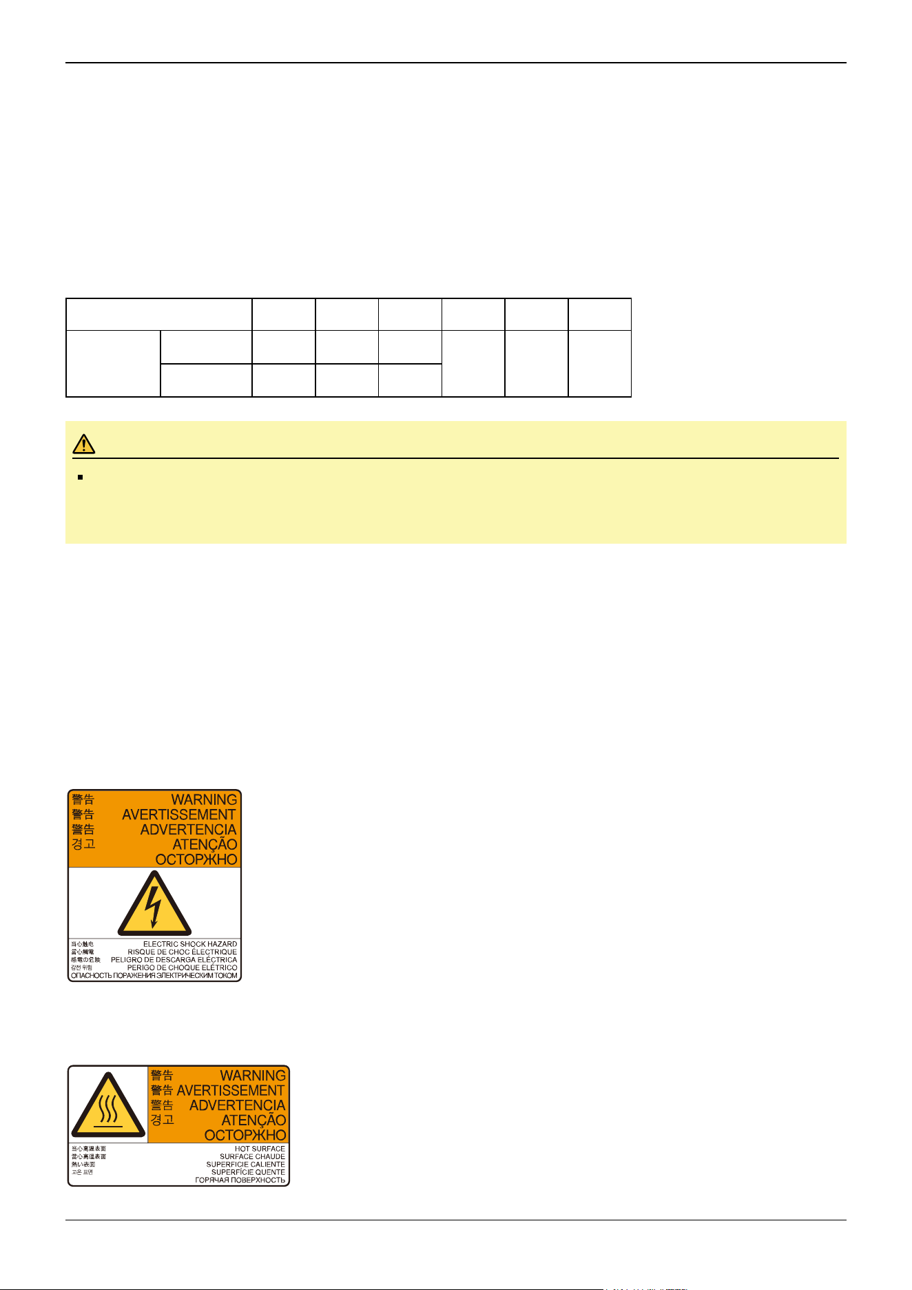
>Brake On,[The number (from 1 to 6) corresponding to the arm whose brake will be turned on]
2.1.7 Precaution for Operation in Low Power Status
In the low power status, the Manipulator operates at low speed and low torque. However, comparatively high torque as shown
in the table below may be generated to support the Manipulator’s own weight. Carefully operate the Manipulator since it may
get your hands or fingers caught during operation. The Manipulator may also collide with peripheral equipment and cause
equipment damage to or malfunction of the Manipulator.
Maximum Joint Torque in Low Power Status [Unit: N·m]
Joint #1 #2 #3 #4 #5 #6
Joint Torque
C4-B601 ** 102.29 118.94 38.97
14.46 13.25 7.99
C4-B901 ** 116.78 194.62 69.28
CAUTION
Carefully operate the Manipulator in the low power status. A comparatively high joint torque may be
generated. It may cause your hands and fingers caught and/or cause equipment damage to or malfunction of
the Manipulator as it may collide with peripheral equipment.
2.1.8 Warning Labels
The Manipulator has the following warning labels. Specific hazards exist in the vicinity of areas with the warning labels. Be
thoroughly careful in handling. To ensure that the Manipulator is operated and maintained safely, be sure to follow the safety
information and warnings indicated on the warning labels. Also, do not tear, damage, or remove these warning labels.
2.1.8.1 Warning Labels
A
Touching any internal electrified parts while the power is turned on may cause electric shock.
B
Industrial Robot: 6-Axis Robots C-B series Manual Rev.1b
20
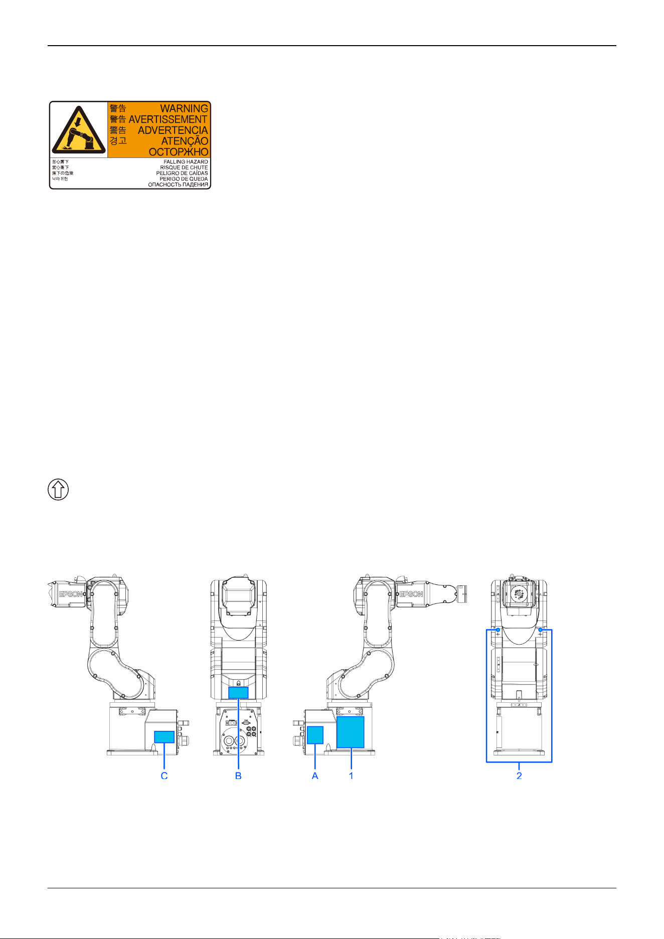
HOT Be careful not to burn yourself.
C
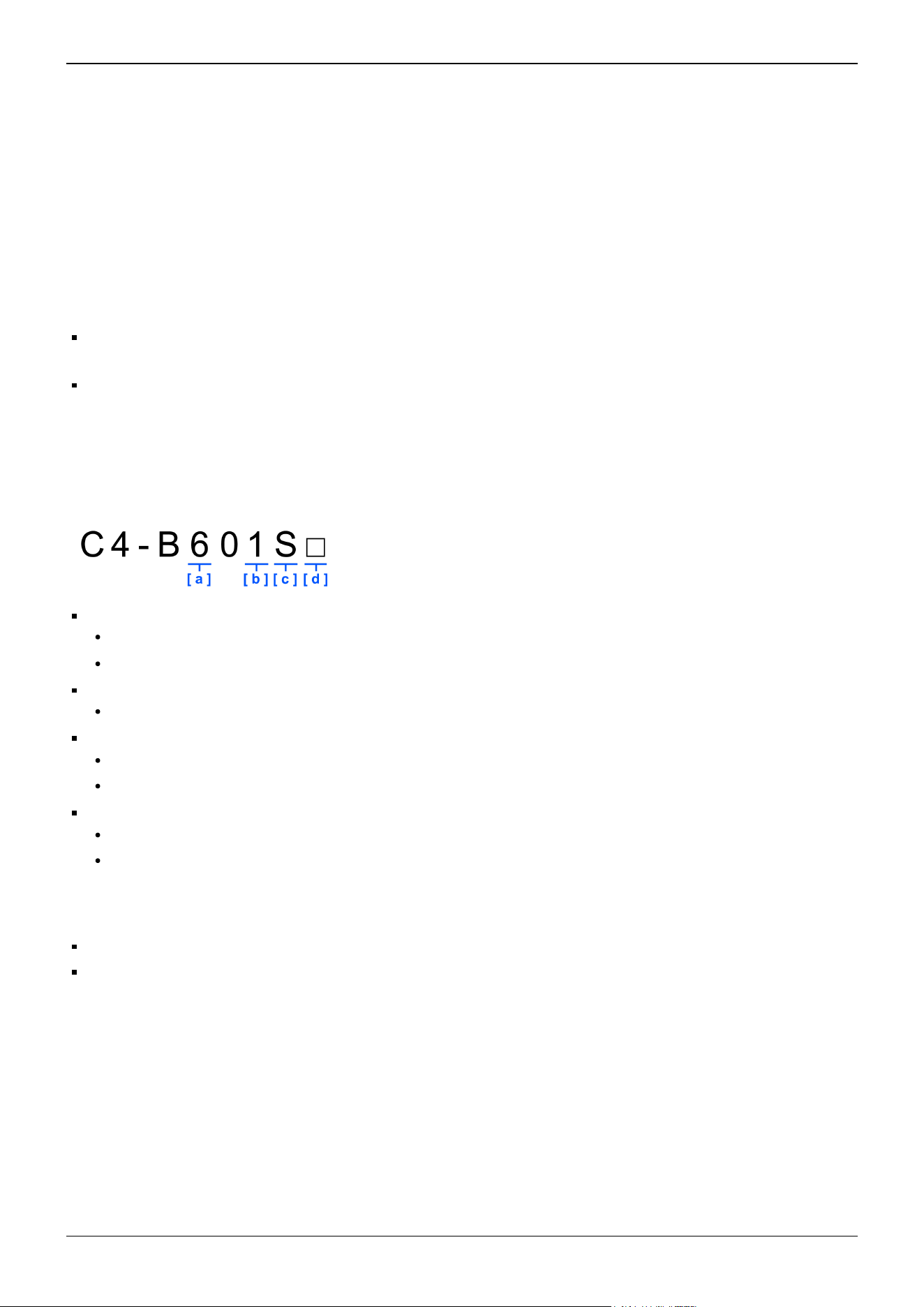
When releasing the brakes, be careful of the arm falling due to its own weight.
This warning label is attached on the Manipulator and optional brake release unit as well.
When the brake release unit is used:
When using a brake release unit to release brakes, refer to the following section.
How to Move Arms with the Electromagnetic Brake
2.1.8.2 Information Labels
1
This indicates the product name, model name, serial number, information of supported laws and regulations, product
specifications (Weight, MAX.REACH, MAX.PAYLOAD, AIR PRESSURE, Motor Power), Main document No.,
manufacturer, importer, date of manufacture, country of manufacture, and the like.
For details, see the label affixed to the product.
2
This indicates the position for mounting eyebolts. Refer to the following section for examples of using eyebolts.
Environment and Installation
Location of Labels
2.1.9 Responses for Emergencies or Malfunctions
Industrial Robot: 6-Axis Robots C-B series Manual Rev.1b
21
2.1.9.1 When a Collision with the Manipulator Occurs
If the Manipulator has collided with a mechanical stop, peripheral device, or other object, discontinue use and contact the
supplier.
2.1.9.2 Entanglement with the Manipulator
When the operator is caught between the Manipulator and a mechanical part such as a base table, press the emergency stop
switch to release the brake on the subject arm, and then move the arm by hand.
How to release a brake
When using a brake release unit, refer to the following section.
Brake Release Unit
When using software, refer to the following section.
When using software
2.2 Specifications
2.2.1 Model Number
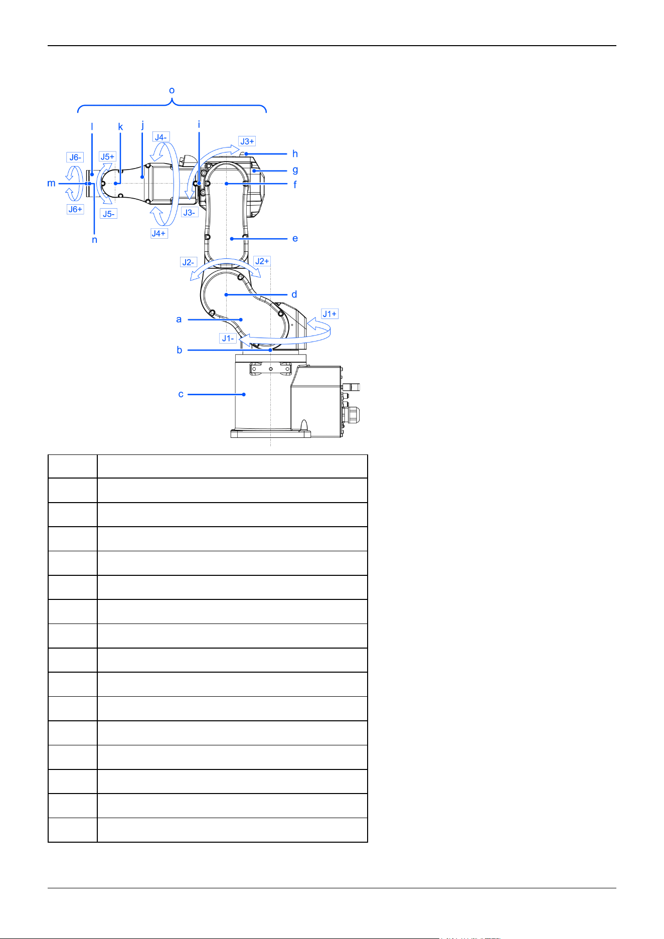
a: Arm length
6: 600 mm (Model name: C4)
9: 900 mm (Model name: C4L)
b: Brake equipment
1: Brakes on all joints
c: Environment
S: Standard *2
C: Cleanroom & ESD (anti-static) *2
d: Mounting type
□: Table top mounting
R: Ceiling mounting *1
*1 Manipulators are set to "Table Top mounting" at shipment. To use the Manipulators as "Ceiling mounting", you need to
change the model settings. For details on how to change the model settings, refer to the following sections.
Changing the Robot
"EPSON RC+ User's Guide - Robot Configuration"
*2 Equivalent to IP20
Industrial Robot: 6-Axis Robots C-B series Manual Rev.1b
22
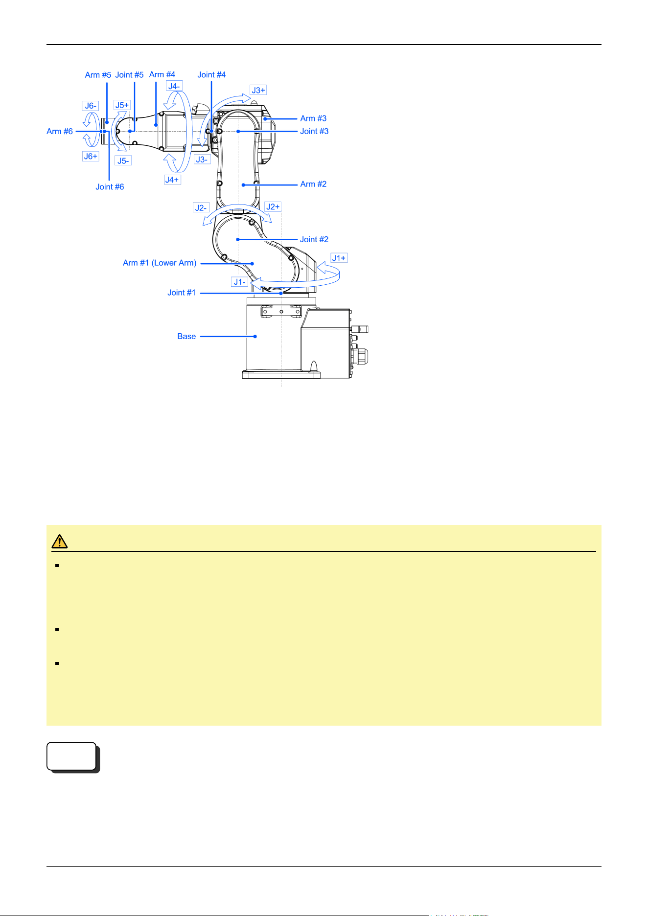
2.2.2 Part Names and Motion Range of Each Arm
Symbol Description
a Arm #1 (Lower Arm)
b Joint #1 (The whole Manipulator revolves.)
c Base
d Joint #2 (The lower arm swings.)
e Arm #2
f Joint #3 (The upper arm swings.)
g Arm #3
h LED Lamp (This lamp lights up while the motors are on.)
i Joint #4 (The wrist revolves.)
j Arm #4
k Joint #5 (The wrist swings.)
l Arm #5
m Arm #6
n Joint #6 (The hand rotates.)
o Upper Arm (Arms #3 to #6)
Industrial Robot: 6-Axis Robots C-B series Manual Rev.1b
23
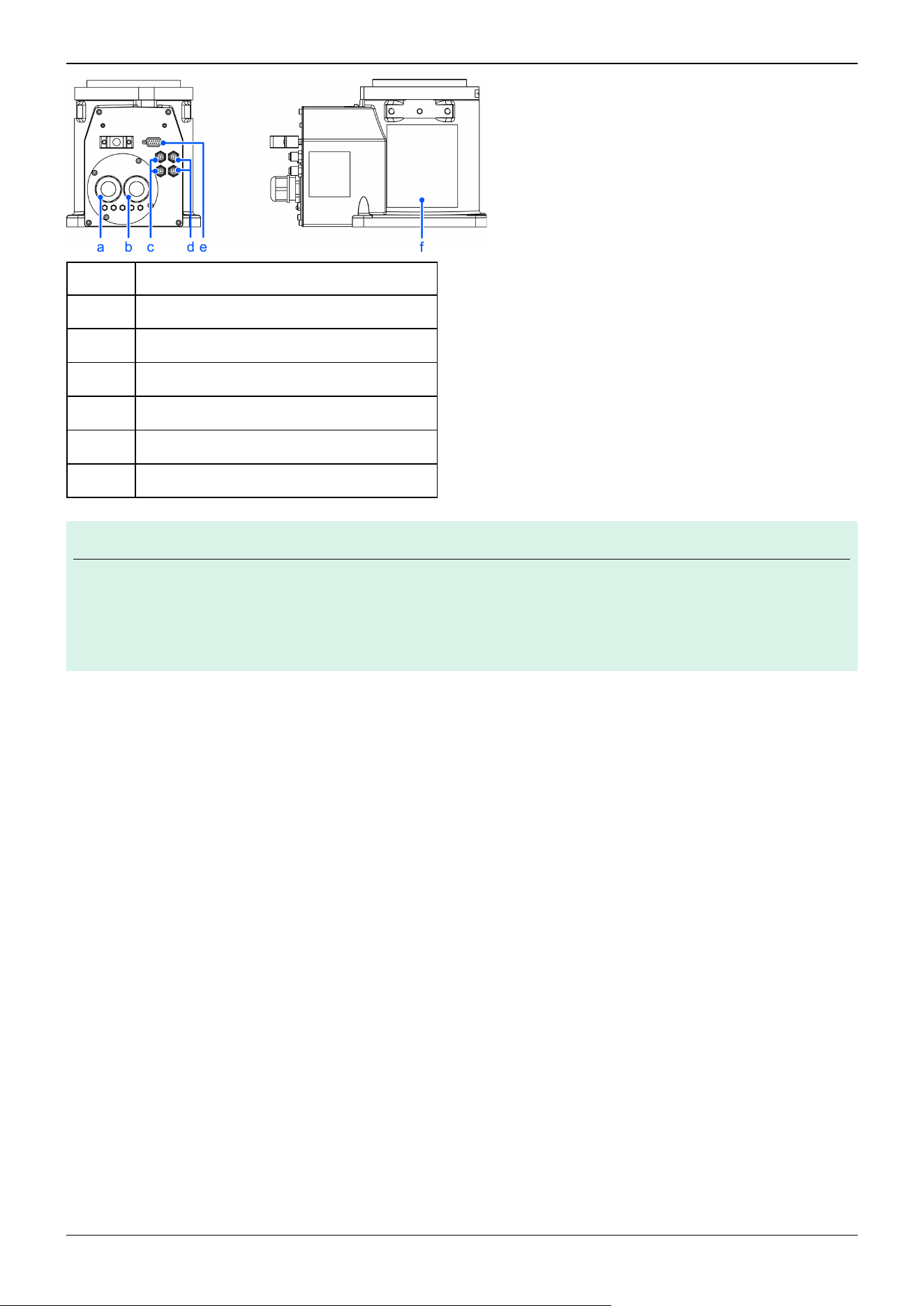
Symbol Description
a Signal cable
b Power cable
c Blue (fitting for ⌀4 mm tube)
d White (fitting for ⌀4 mm tube)
e User cable connector (9-pin D-sub connector)
f Face plate (serial number of Manipulator)
KEY POINTS
When the LED lamp is lighting or the Controller power is on, the current is being applied to the Manipulator. (The
LED lamp may not be seen depending on the Manipulator’s posture. Be thoroughly careful. Performing any work
procedure with the power turned on is extremely dangerous and may result in electric shock and/or malfunction
of the robot system. Before starting any maintenance work, be sure to turn off the Controller.
✏
Industrial Robot: 6-Axis Robots C-B series Manual Rev.1b
24
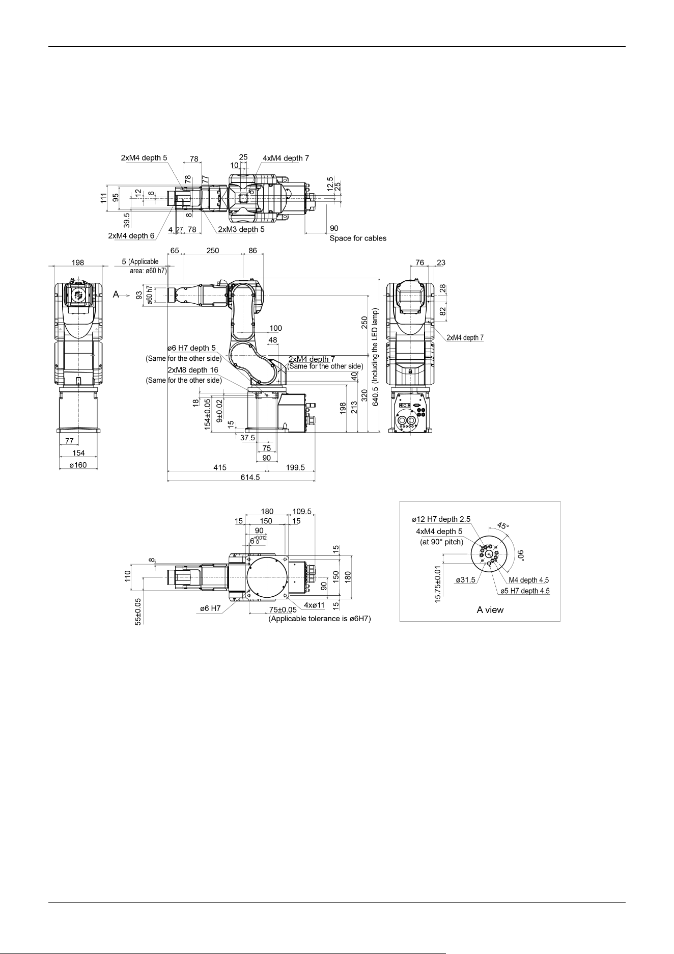
2.2.3 Outer Dimensions
2.2.3.1 C4-B601**
(Units: mm)
depth = depth of threaded hole
Industrial Robot: 6-Axis Robots C-B series Manual Rev.1b
25
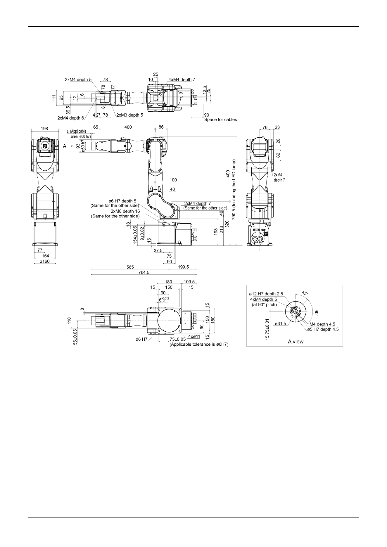
2.2.3.2 C4-B901**
(Units: mm)
depth = depth of threaded hole
Industrial Robot: 6-Axis Robots C-B series Manual Rev.1b
26
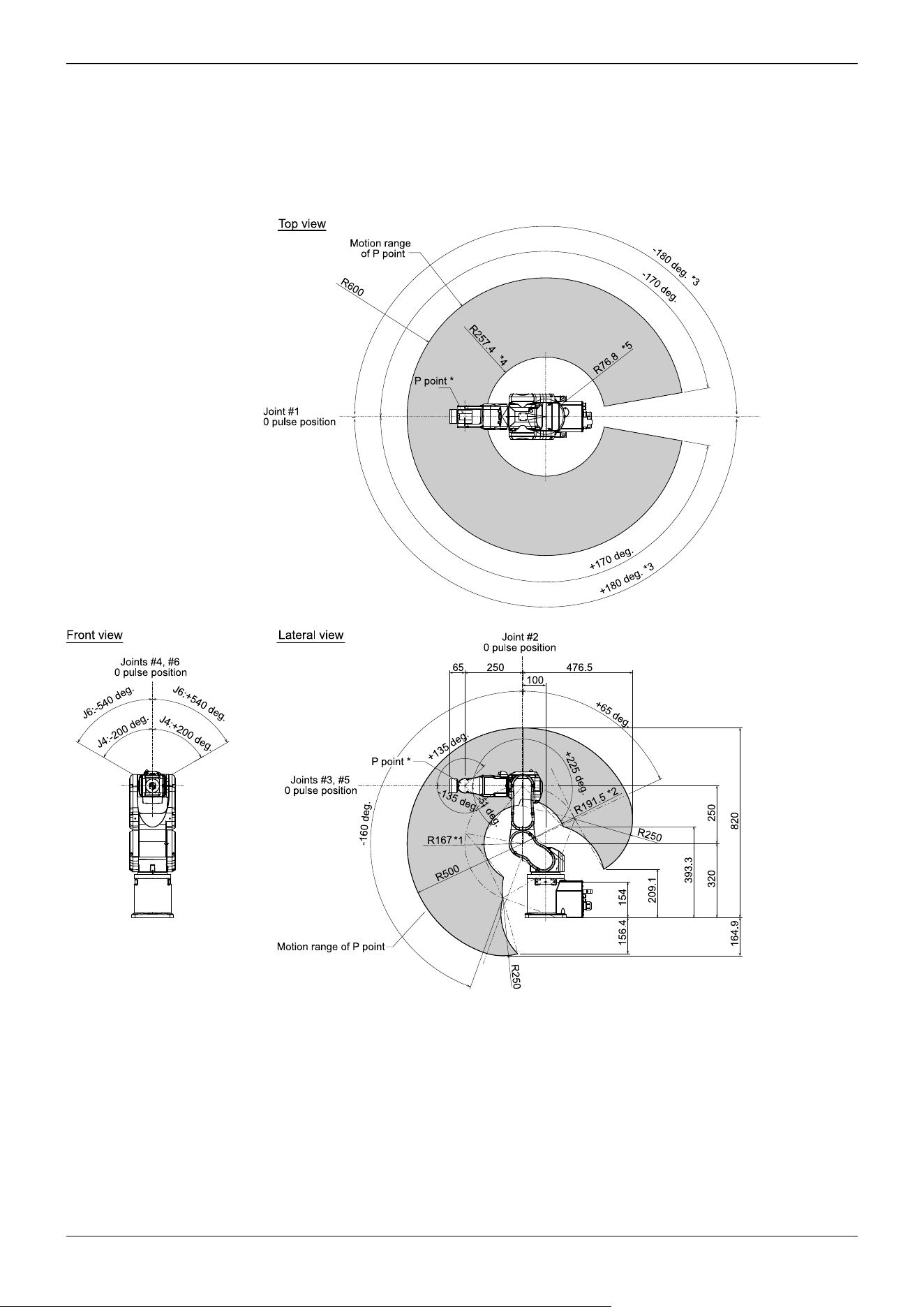
2.2.4 Standard Work Envelope
2.2.4.1 C4-B601**
(Units: mm)
(deg. = °)
*P point: Intersection of the rotation centers for Joint #4, #5, and #6
*1: P point from lateral with Joint #3 declining -51° (Joint #2 center – P point center)
*2: P point from lateral with Joint #3 tilting up +225° (Joint #2 center – P point center)
*3: Joint #1 software limit maximum value (±180°)
Industrial Robot: 6-Axis Robots C-B series Manual Rev.1b
27

*4: P point from top with Joint #3 declining -51° (Joint #1 center – P point center)
*5: P point from top with Joint #3 tilting up +225° (Joint #1 center – P point center)
CAUTION
Pay attention to the arm pose of the basic arms (Arms #1, #2, and #3) when operating the Manipulator. Arm
#5 moves keeping a constant angle regardless of the arm pose. Depending on the arm pose of the basic
arms, the wrist may collide with the Manipulator. The collision may cause equipment damage to and/or
malfunction of the Manipulator.
2.2.4.2 C4-B901**
(Units: mm)
Industrial Robot: 6-Axis Robots C-B series Manual Rev.1b
28
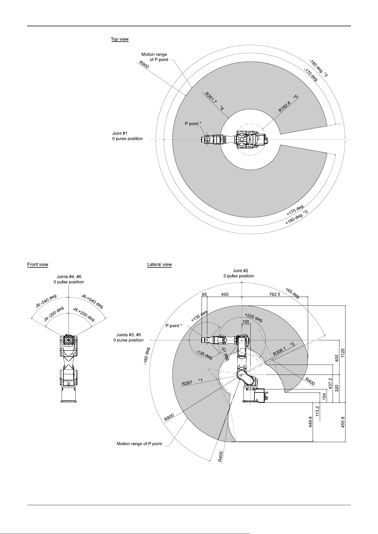
(deg. = °)
Industrial Robot: 6-Axis Robots C-B series Manual Rev.1b
29
*P point: Intersection of the rotation centers for Joint #4, #5, and #6
*1: P point from lateral with Joint #3 declining -51° (Joint #2 center – P point center)
*2: P point from lateral with Joint #3 tilting up +225° (Joint #2 center – P point center)
*3: Joint #1 software limit maximum value (±180°)
*4: P point from top with Joint #3 declining -51° (Joint #1 center – P point center)
*5: P point from top with Joint #3 tilting up +225° (Joint #1 center – P point center)
CAUTION
Pay attention to the arm pose of the basic arms (Arms #1, #2, and #3) when operating the Manipulator. Arm
#5 moves keeping a constant angle regardless of the arm pose. Depending on the arm pose of the basic
arms, the wrist may collide with the Manipulator. The collision may cause equipment damage to and/or
malfunction of the Manipulator.
2.2.5 Specifications
2.2.5.1 Specifications Table
For the specifications tables of each model, refer to the following section.
C4 Specifications
2.2.5.2 Options
For details, refer to the following section.
Options
2.2.6 How to Set the Model
The Manipulator model for your system has been set before shipment from the factory.
CAUTION
If changing the setting of the Manipulator model, be responsible and absolutely certain that the wrong
Manipulator model is not set. Incorrect setting of the Manipulator model may result in abnormal or no
operation by the Manipulator and could even cause safety problems.
If a custom specifications number (MT***) or (X***) is written on the face plate (serial number label), the Manipulator has
custom specifications.
Models with custom specifications may require a different setting procedure. Check the custom specifications number, and
contact the supplier for more information.
The Manipulator model is set from software. For details, refer to the following manual.
"EPSON RC+ User's Guide - Robot Configuration"
2.3 Environment and Installation
The robot system should be designed and installed by people who have received installation training provided by Epson and
the suppliers. Also, the laws and regulations of the installation country must be followed.
Industrial Robot: 6-Axis Robots C-B series Manual Rev.1b
30
2.3.1 Environment
To ensure that the robot system operates and maintains maximum performance and to ensure its safe use, the robot system
should be installed in an environment that meets the following requirements.
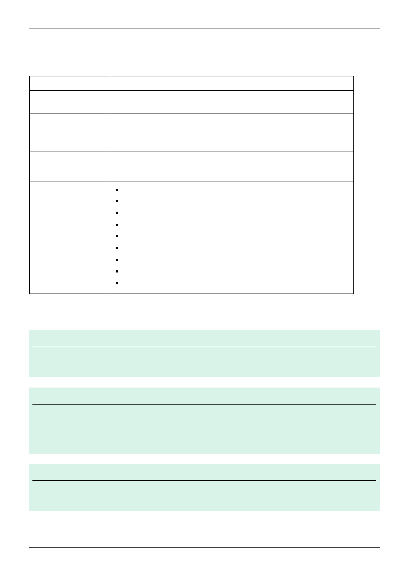
Item Conditions
Ambient temperature *
Installation: 5 to 40°C
Transport, storage: -20 to 60°C
Ambient relative humidity
Installation: 10 to 80% (no condensation)
Transport, storage: 10 to 90% (no condensation)
Fast transient burst noise 1 kV or less (signal line)
Electrostatic noise 4 kV or less
Altitude 1000 m or less
Environment
Install indoors.
Keep away from direct sunlight.
Keep away from dust, oily smoke, salinity, metal powder, and other contaminants.
Keep away from flammable or corrosive liquids and gases.
Keep away from water.
Keep away from shocks or vibrations.
Keep away from sources of electric noise.
Keep away from explosive areas.
Keep away from large quantities of radiation.
* The ambient temperature requirement is for the Manipulator only. For details on the environment requirements for the
connected Controller, refer to the Robot Controller manual.
KEY POINTS
If the Manipulator will be used in a location that does not meet the above requirements, please contact the
supplier.
KEY POINTS
When used in a low-temperature environment near the minimum temperature specified in the product
specifications, or when the unit is idle for a long period of time during holidays or at night, a collision detection
error or similar error may occur immediately after the start of operation due to high resistance in the drive unit. In
such cases, warm-up operation for about 10 minutes is recommended.
KEY POINTS
If there are conductive objects such as fences or ladders within 2.5 m of the Manipulator, these objects must be
grounded.
✏
✏
✏
Industrial Robot: 6-Axis Robots C-B series Manual Rev.1b
31
Special environmental requirements
Manipulator surfaces are generally oil-resistant, but if special oils are to be used, oil resistance should be checked before use.
For more information, please contact the supplier.
In environments with rapid changes in temperature and humidity, condensation may form inside the Manipulator.
When handling food directly, it is necessary to make sure that the Manipulator is not likely to contaminate the food. For more
information, please contact the supplier.
The Manipulator cannot be used in corrosive environments where acids or alkalis are present. In environments where rust can
easily form, such as those exposed to salt, rust may also form on the Manipulator.
WARNING
Always use a circuit breaker for the Controller's power supply. Failure to use a circuit breaker may result in an
electrical shock hazard or malfunction due to an electrical leakage. Select the correct circuit breaker based on
the Controller that you are using. For details, refer to the following manual.
"Robot Controller Manual"
CAUTION
When cleaning the Manipulator, do not rub it strongly with alcohol or benzene. Coated surfaces may lose their
luster.
2.3.2 Manipulator Mounting Dimensions
Mounting Area
Also, besides the area required for installation of the Manipulator, Controller, peripheral equipment, and other devices, the
following space should be provided at a minimum.
Space for teaching
Space for maintenance and inspections (for installing jigs)
Space for cables
KEY POINTS
When installing the cables, be sure to maintain sufficient distance from obstacles.
For the minimum bend radius of the M/C cable, refer to the following section.
C4 Specifications
Also, leave enough space for other cables so that they are not forced to bend at extreme angles.
Manipulator Mounting Dimensions (C4 series) [Units: mm]
✏
Industrial Robot: 6-Axis Robots C-B series Manual Rev.1b
32
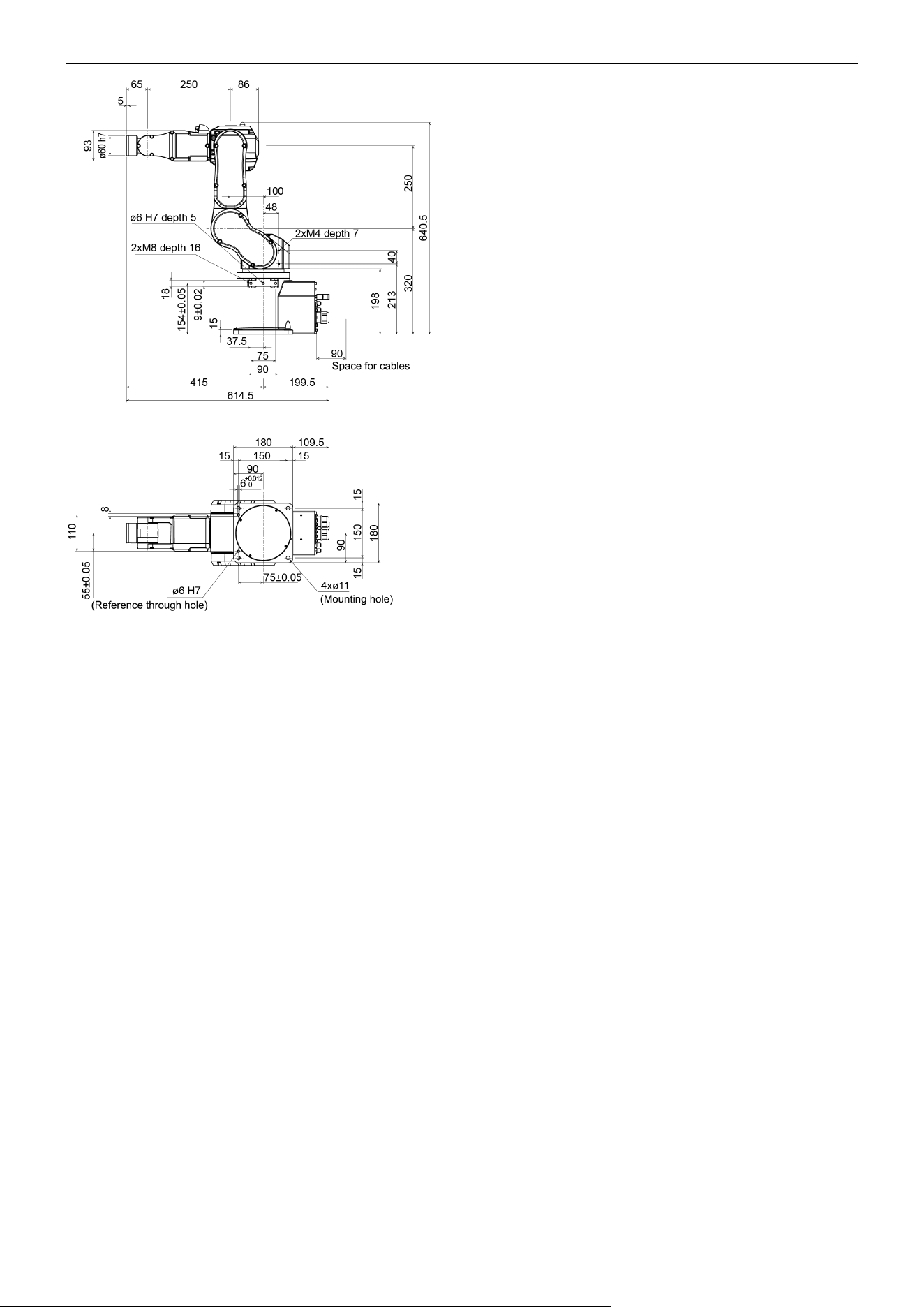
depth = depth of threaded hole
Industrial Robot: 6-Axis Robots C-B series Manual Rev.1b
33
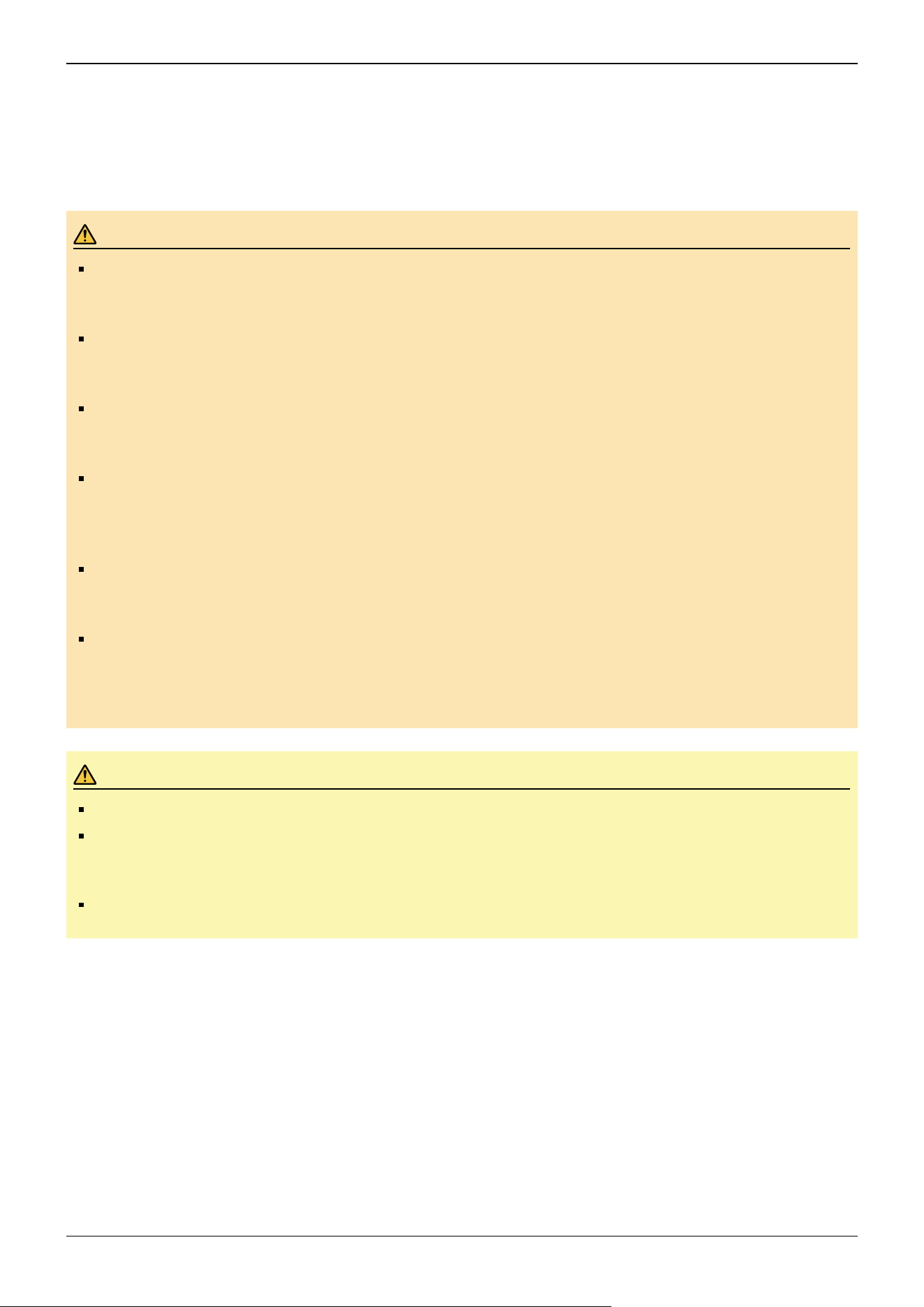
2.3.3 From Unpacking to Installation
Transportation and installation of the Manipulator and related equipment should be performed by people who have received
installation training provided by Epson and the suppliers. Also, the laws and regulations of the installation country must be
followed.
WARNING
Only qualified personnel should perform sling work and operate a crane or a forklift. When these operations
are performed by unqualified personnel, it is extremely hazardous and may result in serious bodily injury
and/or severe equipment damage to the robot system
When hoisting the Manipulator, use your hands to balance it. Losing balance may cause the Manipulator to
drop, which is extremely hazardous and may result in serious injury and/or severe damage to the robot
system.
To ensure safety, be sure to install safeguards for the robot system. For more information on safeguards, refer
to the following manual.
"EPSON RC+ User’s Guide - Safety - Installation and Design Precautions "
Install the Manipulator in a location with sufficient space so that a tool or a work piece does not touch a wall or
a safeguard when the Manipulator extends its arm fully while holding a work piece. If the tool or the workpiece
tip reaches a wall or safeguards, it is extremely hazardous and may result in serious bodily injury and/or
severe equipment damage to the robot system.
Be sure to anchor the Manipulator before turning on the power or operating it. Turning on the power or
operating the Manipulator while it is not anchored may cause the Manipulator to fall over, which is extremely
hazardous and may result in serious injury and/or severe damage to the robot system.
Before installing or operating the Manipulator, make sure that no parts of the Manipulator are missing and that
it has no damage or other external defects. Missing parts or damage may cause malfunction of the
Manipulator, is extremely hazardous, and may result in serious injury and/or severe equipment damage to the
robot system.
CAUTION
Use a cart or the like to transport the Manipulator in the same status as it was delivered.
When removing the fixing bolts securing the Manipulator to the transportation pallet and the packing box or
the anchor bolts, support the Manipulator to prevent it falling. Removing the fixing bolts or anchor bolts
without supporting the Manipulator may cause it to fall, catching your hands or feet.
The Manipulator should be transported by two or more people or secured to transporting equipment. Also, do
not hold the bottom of the base (the screened parts in the figure). Holding these parts by hand is extremely
Industrial Robot: 6-Axis Robots C-B series Manual Rev.1b
34
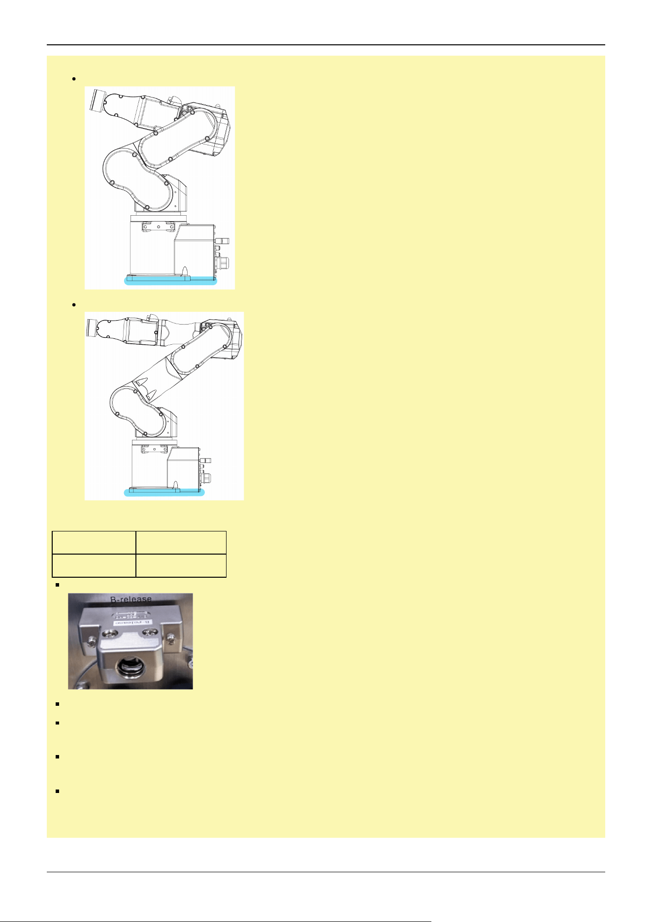
hazardous and may cause your hands and fingers caught.
C4-B601**
C4-B901**
Manipulator weight
C4-B601**: C4 C4-B901**: C4L
27 kg: 59.5 lb 30 kg: 66.1 lb
Take extra care when transporting the Manipulator. You may hit and damage the connector.
During unpacking and relocation, avoid applying external force to the arms and motors of the Manipulator.
When transporting the Manipulator over long distances, secure it directly to transporting equipment so that it
will not fall. If necessary, pack the Manipulator using the same packaging as delivery.
The Manipulator must be installed to avoid interference with surrounding buildings, structures, and other
machines and equipment that may create a trapping hazard or pinch points.
Resonance (resonating sound or minute vibrations) may occur during Manipulator operation depending on
the rigidity of the base table. If the resonance occurs, improve the rigidity of the base table or change the
speed or acceleration and deceleration settings of the Manipulator.
Industrial Robot: 6-Axis Robots C-B series Manual Rev.1b
35
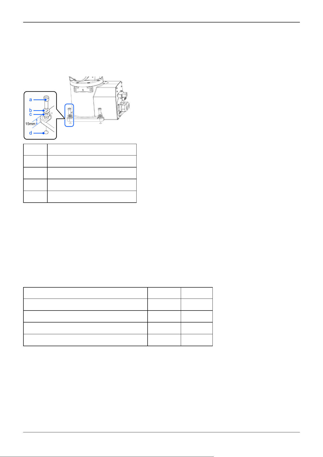
Fixing bolt
For details on the dimensions, refer to the following sections.
Manipulator Mounting Dimensions
There are four threaded holes for the Manipulator base. Use M8 mounting bolts conforming to the strength equivalent to
ISO898-1 property class 10.9 or 12.9. Tightening torque: 32.0 ± 1.6 N·m (326 ± 16 kgf·cm)
Symbol Description
a 4×M8×35
b Spring washer
c Plain washer
d Threaded hole (20 mm or more depth)
Base table
A base table for anchoring the Manipulator is not supplied. The base table must be fabricated or obtained by the customer.
The shape and size of the base table vary depending on the application of the robot system. As a reference when designing the
base table, the requirements from the Manipulator side are shown here.
The base table must not only be able to bear the weight of the Manipulator but also be able to withstand the dynamic
movement of the Manipulator when it operates at maximum acceleration/deceleration. Ensure that there is enough strength on
the base table by attaching reinforcing materials such as crossbeams.
Followings are the torque and reaction force produced by the movement of the Manipulator.
C4-B601 ** C4-B901**
Maximum rotating torque on horizontal surface (N·m) 500 700
Maximum reaction force in horizontal direction (N) 800 800
Maximum rotating torque on vertical surface (N·m) 600 1000
Maximum reaction force in vertical direction (N) 2500 2500
The plate for the Manipulator mounting face should be at least 30 mm thick and made of steel for reducing vibrations.
A surface roughness of 25 μm or less at the maximum height is appropriate.
The base table must be secured on the floor to prevent it from moving.
The Manipulator installation surface should have a flatness of 0.5 mm or less and an inclination of 0.5° or less. If the
installation surface does not have the proper flatness, the base of the Manipulator may be damaged or the robot may be unable
to operate at maximum performance.
When using a leveler to adjust the height of the base table, use a screw with M16 diameter or more.
Industrial Robot: 6-Axis Robots C-B series Manual Rev.1b
36
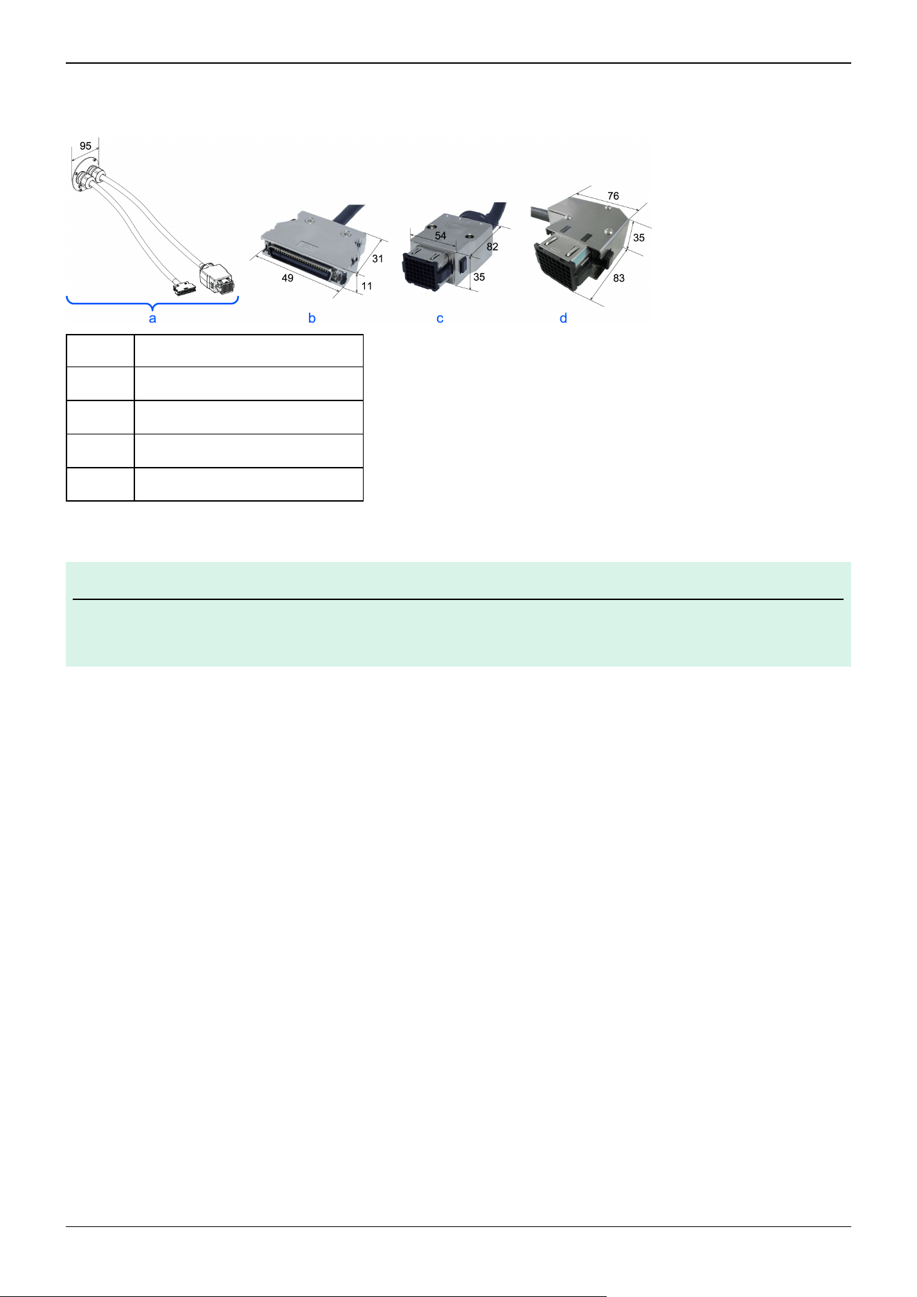
Connector
If passing cables through the holes in the base table, refer to the connector dimensions in the figures below. (Units: mm)
Symbol Description
a M/C cable
b Signal cable connector
c Power cable connector
d Power cable connector (L-shaped)
Do not remove the M/C cables from the Manipulator.
KEY POINTS
For details on the environmental requirements for the space when housing the Controller in the base table, refer
to the Robot Controller manual.
When using the Manipulator in the clean room, follow the steps below before the installation.
1. Unpack the Manipulator outside of the cleanroom.
2. Secure the Manipulator to transporting equipment (or a pallet) with bolts so that the Manipulator does not fall down.
3. Wipe off any dust on the Manipulator using a lint-free cloth that was dipped in ethyl alcohol or distilled water.
4. Carry the Manipulator into the cleanroom.
5. Secure the Manipulator to the base table.
✏
Industrial Robot: 6-Axis Robots C-B series Manual Rev.1b
37
2.3.4 Connecting the Cables
WARNING
Before performing any replacement work, turn off the Controller and related equipment, and unplug the power
cable from the power source. Performing any work procedure with the power turned on is extremely
dangerous and may result in electric shock and/or malfunction of the robot system.
Be sure to connect the AC power cable to a power outlet. Do not connect it directly to a factory power source.
To perform the power supply lockout, remove the power plug. Working while connecting the AC power cable
to a factory power source may result in electric shock and/or malfunction of the robot system.
Be sure to connect the cables properly. Do not put heavy objects on the cables, bend or pull on the cables
forcibly, or allow the cables to be pinched. Damaged cables, broken wires, or contact failure is extremely
hazardous and may result in electric shock and/or malfunction of the robot system.
Be sure to turn off the power and tag out (e.g., with a "DO NOT TURN ON" sign) before performing wiring.
Performing any work procedure with the power turned on is extremely dangerous and may result in electric
shock and/or malfunction of the robot system.
The Manipulator is grounded by connecting it to the Controller. Ensure that the Controller is grounded and the
cables are correctly connected. If the ground wire is improperly connected to ground, it may result in the fire
or electric shock.
Turn off the power to the Robot Controller and brake release unit when connecting or replacing the brake
release unit or external short connector. Inserting or removing connectors with the power on may result in
electric shock and/or malfunction of the robot system.
CAUTION
When connecting the Manipulator and the Controller, check that the serial numbers match for each device.
Improper connection between the Manipulator and the Controller may not only lead to malfunction of the robot
system but also safety problems. The connection method between the Manipulator and the Controller varies
depending on the Controller. For details on the connection, refer to the following manual.
"Robot Controller Manual"
Only authorized or certified personnel should perform wiring. Wiring by unauthorized or uncertified staff may
result in bodily injury and/or malfunction of the robot system.
Operating the Manipulator without a brake release unit or external short connector connected may cause the
brake to fail to release, possibly damaging the brake.
After using the brake release unit, be sure to connect the external short circuit connector to the Manipulator or
make sure to leave the connector for the brake release unit connected.
Cleanroom-model Manipulator
When the Manipulator is a model with cleanroom specifications, an exhaust system must be connected. For the exhaust
system, refer to the following section.
C4 Specifications
Connection procedure for M/C cable
Connect the power connector and signal connector of the M/C cable to the Controller.
Industrial Robot: 6-Axis Robots C-B series Manual Rev.1b
38
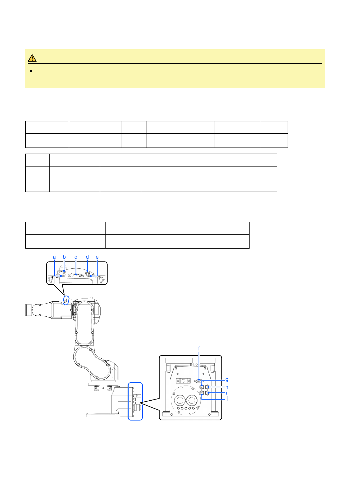
2.3.5 User Wires and Pneumatic Tubes
CAUTION
Only authorized or certified personnel should perform wiring. Wiring by unauthorized or uncertified staff may
result in bodily injury and/or malfunction of the robot system.
User electrical wires and pneumatic tubes are contained in the cable unit.
Electrical Wires
Rated Voltage Allowable Current Wires Nominal Sectional Area Outer Diameter Note
AC/DC30V 1 A 9
0.211 mm
2
⌀8.3 ± 0.3 mm Shielded
Manufacturer Type
9 pin
Suitable connector JAE DE-9PF-N (solder type), DEU-9PF-F0 (crimping type)
Clamp hood JAE DE-C8-J9-F2-1R (Connector setscrew: #4-40 NC)
Pins with the same number, indicated on the connectors on both ends of the cables, are connected.
Pneumatic Tubes
Maximum Working Pressure Number of Tubes Outer Diameter × Inner Diameter
0.59 MPa (6 kgf/cm
2
: 86 psi)
4 ⌀4 mm×⌀2.5 mm
Tubes with the same number are connected.
Industrial Robot: 6-Axis Robots C-B series Manual Rev.1b
39
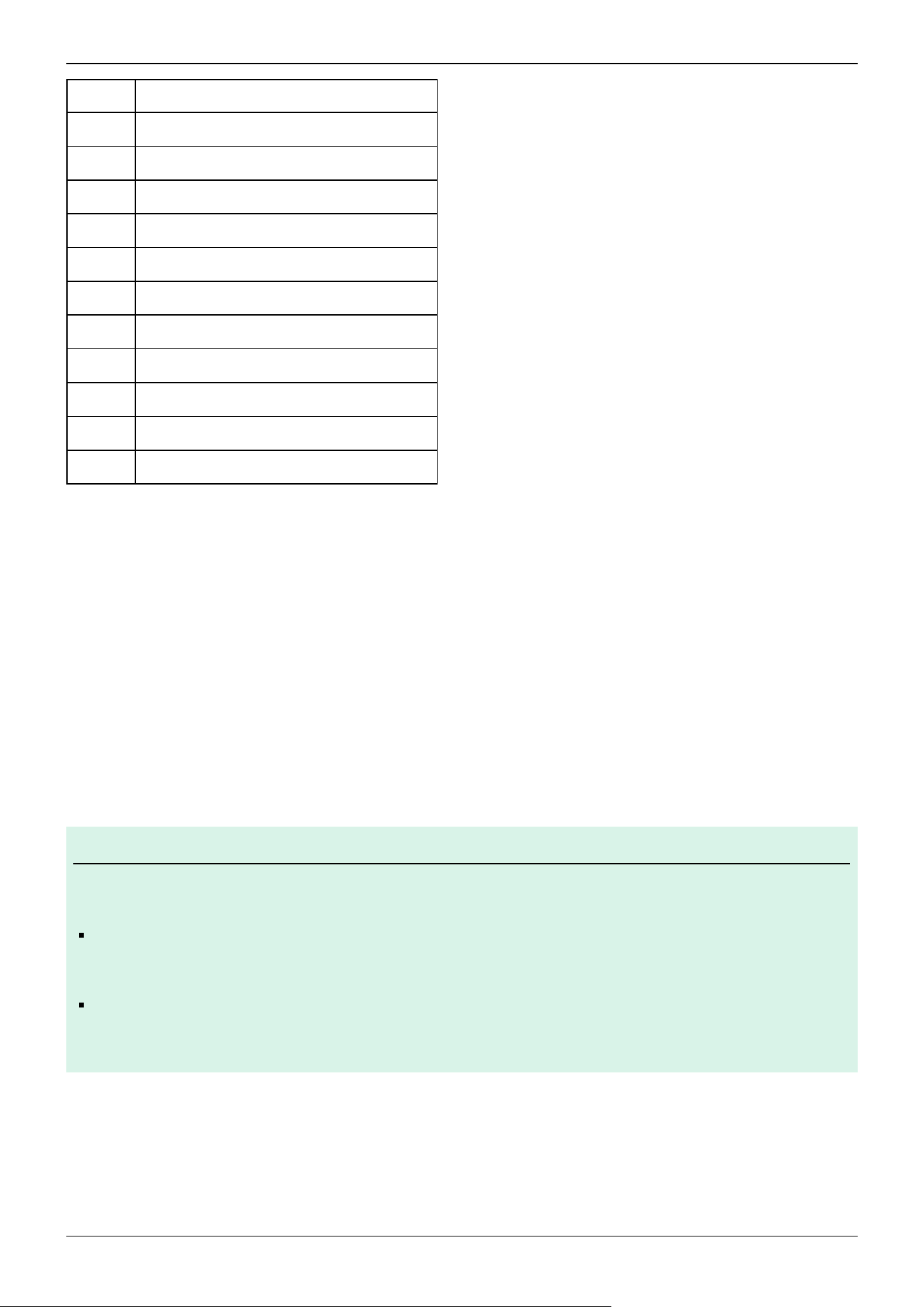
Symbol Description
a No.1
b No.2
c User cable connector (9-pin D-sub connector)
d No.3
e No.4
f User cable connector (9-pin D-sub connector)
g No.3: Blue
h No.1: White
i No.2: White
j No.4: Blue
k Fitting for ⌀4 mm tube
2.3.6 Checking the Basic Orientation
After installing the Manipulator and setup the operating environment, check if it moves to the basic position properly.
Follow the steps below to set the basic orientation of the Manipulator shown below as the origin position.
1. Start EPSON RC+ 7.0.
Double click the [EPSON RC+ 7.0] icon on the desktop.
2. Open the command window.
EPSON RC+ 7.0 menu-[Tools]-[Command Window]
3. Execute the following command in [Command Window].
>Motor On
>Go Pulse (0,0,0,0,0,0)
KEY POINTS
If "Error 4505: cannot be turned on the motor because the Safety Board is issuing a stop signal." occurs, use one
of the following methods to move the Manipulator to its basic orientation.
Release the brake and push the arm by hand to move it within the motion range. Then follow the steps above.
For details on releasing brake, refer to the following section.
How to Move Arms with the Electromagnetic Brake
Press the TP3 command button [Pulse0] to move the Manipulator to its basic orientation. For details, refer to
the following manual.
"Robot Controller Option Teach Pendant TP3 Operation 3.1.3 Command Buttons"
If the Manipulator cannot be in the basic orientation shown below, please contact the supplier.
✏
Industrial Robot: 6-Axis Robots C-B series Manual Rev.1b
40
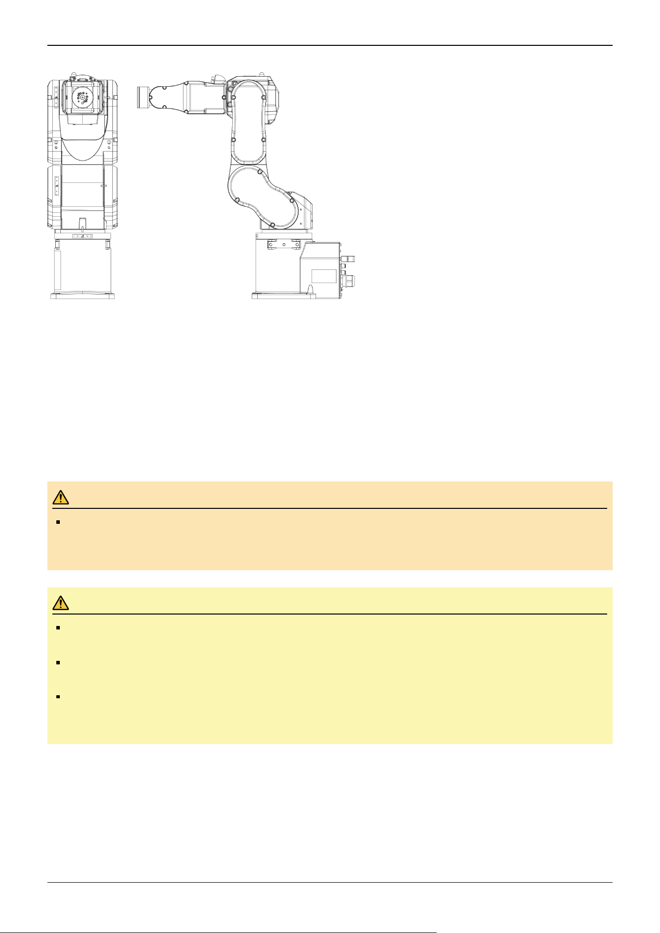
Basic orientation (0 pulse position)
2.3.7 Relocation and Storage
2.3.7.1 Safety Information for Relocation and Storage
Pay attention to the following requirements when relocating, storing, and transporting the Manipulators.
Transportation and installation of the Manipulator and related equipment should be performed by people who have received
installation training provided by Epson and the suppliers. Also, the laws and regulations of the installation country must be
followed.
WARNING
Only qualified personnel should perform sling work and operate a crane or a forklift. When these operations
are performed by unqualified personnel, it is extremely hazardous and may result in serious bodily injury
and/or severe equipment damage to the robot system
CAUTION
Before relocating, fold the arm and secure it tightly with a cable tie to prevent hands or fingers from getting
caught in the Manipulator.
When removing the anchor bolts, support the Manipulator so that it does not fall. Removing the anchor bolts
without supporting the Manipulator can cause it to fall, causing hands or feet to get caught.
The Manipulator should be transported by two or more people or secured to transporting equipment. Also, do
not hold the bottom of the base. Holding these parts by hand is extremely hazardous and may cause your
hands and fingers caught.
During unpacking and relocation, avoid applying external force to the arms and motors of the Manipulator.
When transporting the Manipulator over long distances, secure it directly to transporting equipment so that it will not fall. If
necessary, pack the Manipulator using the same packaging as delivery.
When the Manipulator is reassembled and used for a robot system again after an extended period of storage, perform a test run
to verify that it works properly before starting the main operation.
Industrial Robot: 6-Axis Robots C-B series Manual Rev.1b
41
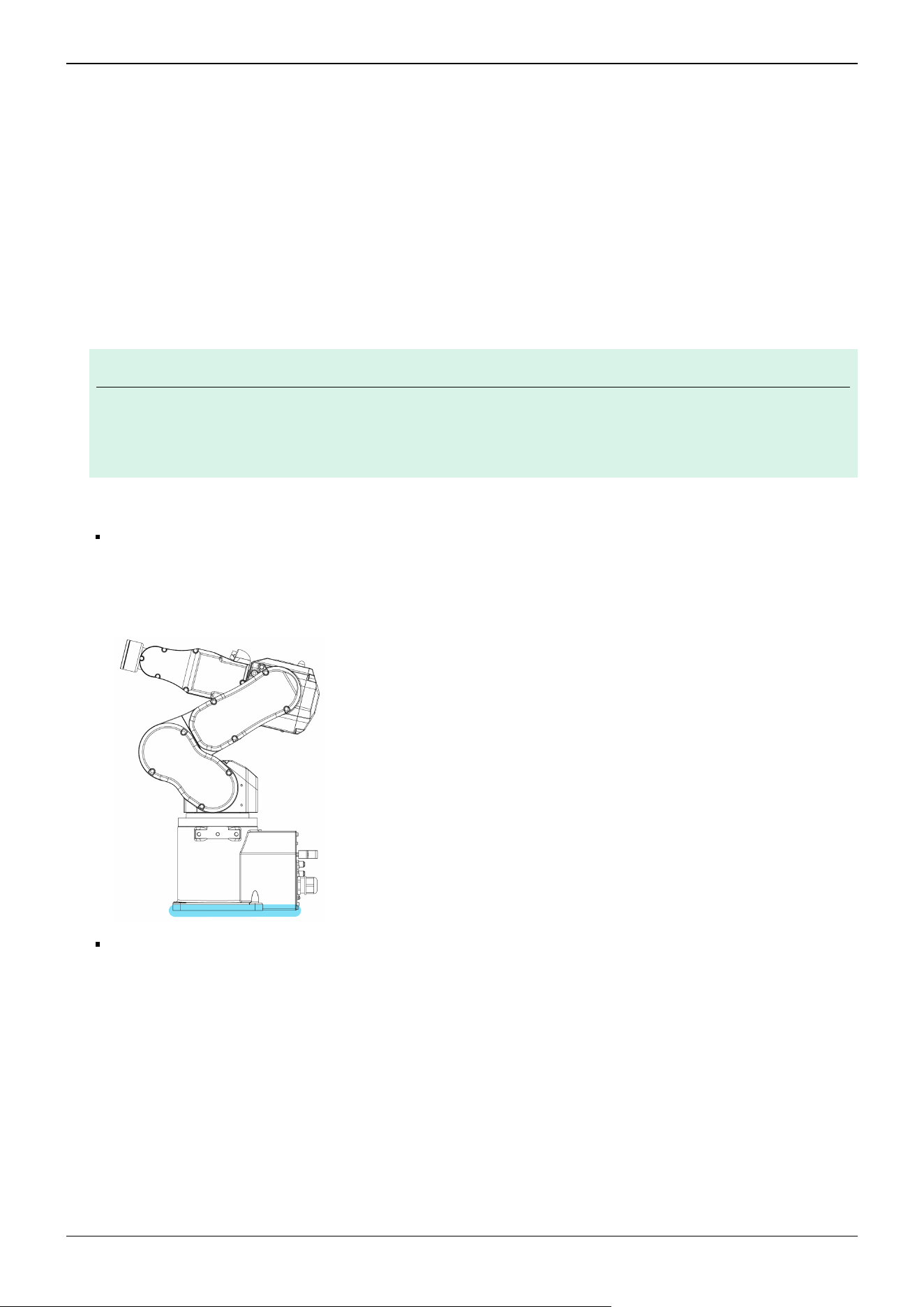
Manipulators should be transported and stored under the following conditions: Temperature: -20 to +60°C, Humidity: 10 to
90% (no condensation)
If condensation has formed on the Manipulator during transportation or storage, do not turn on the power until the
condensation is removed.
Do not subject the Manipulator to excessive impacts or vibrations during the transportation process.
Relocation
Follow the procedures described below when relocating the Manipulator.
1. Turn off the power for all devices and unplug the power cable connector and signal cable connector from the Controller.
Do not remove the M/C cables (power cable and signal cable) from the Manipulator. (MC cable 3 m: 2 kg)
KEY POINTS
Remove the mechanical stops if using them to limit the motion range. For details on the motion range, refer to
the following section.
Setting the Work Envelope by Mechanical Stops
2. Unscrew the anchor bolts. Then, remove the Manipulator from the base table.
3. C4-B601**
Position the Manipulator as shown in the figure. Then, secure the Manipulator to the transporting equipment or have at
least two people to relocate the Manipulator. (Recommend: Joint #2 +65°. Joint #3 -51°)
Do not hold the bottom of the base (the screened parts in the figure). Holding these parts by hand is extremely
hazardous and may cause your hands and fingers caught.
C4-B901**
Position the Manipulator as shown in the figure. Then, secure the Manipulator to the transporting equipment or have at
least three people to relocate the Manipulator.
(Recommend: Joint #2 +53°. Joint #3 -51°)
✏
Industrial Robot: 6-Axis Robots C-B series Manual Rev.1b
42
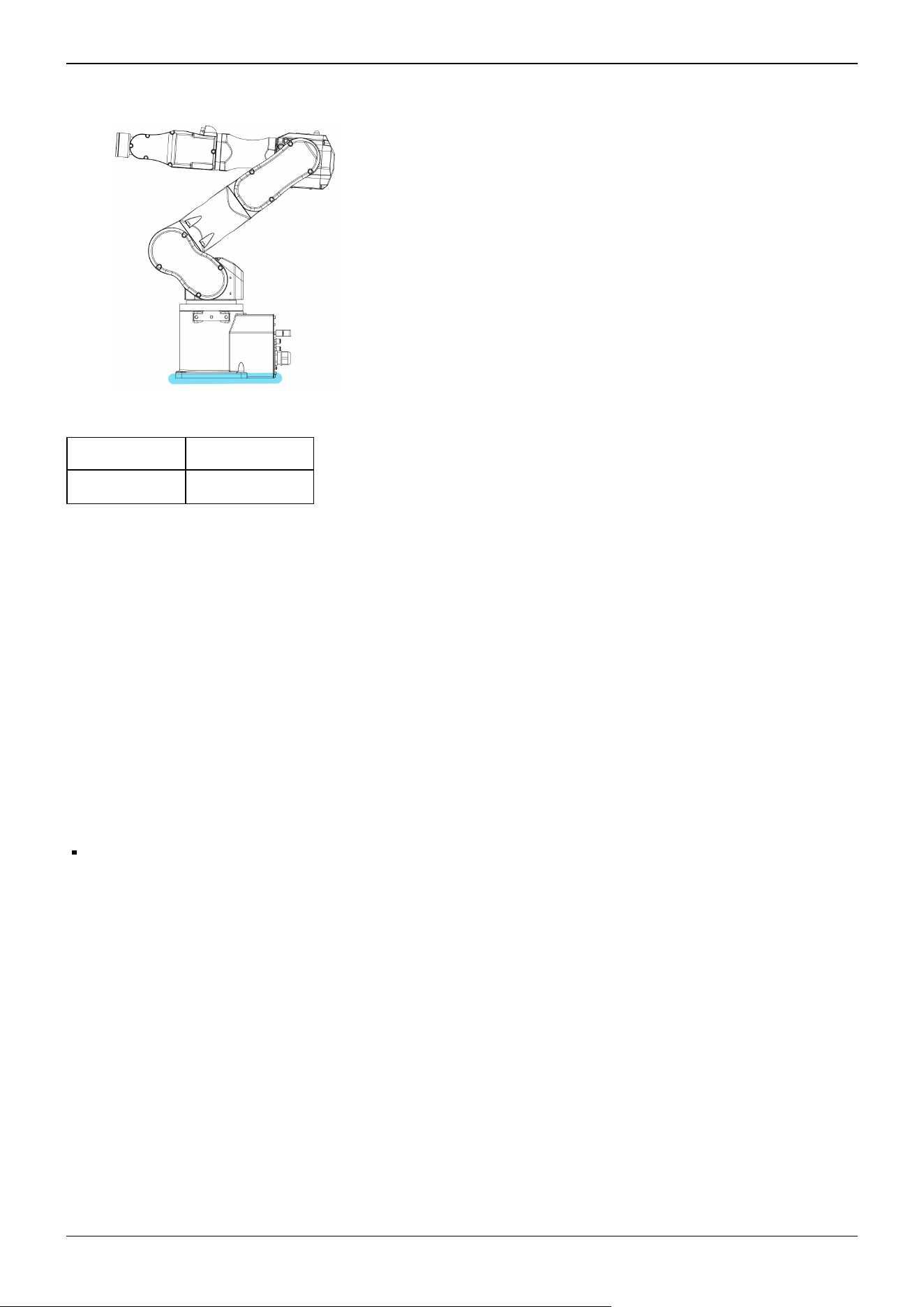
Do not hold the bottom of the base (the screened parts in the figure). Holding these parts by hand is extremely
hazardous and may cause your hands and fingers caught.
Manipulator weight
C4-B601**: C4 C4-B901**: C4L
27 kg: 59.5 lb 30 kg: 66.1 lb
Using eyebolts
Check that the eyebolts are securely fastened before transporting the Manipulator. After transporting the Manipulator, remove
the eyebolts and keep them for future use.
The eyebolts and wire must be strong enough to withstand the weight (See the figures below).
If you use the eyebolts to lift up the Manipulator, be sure to use the bifilar wire of 1 m long or more to avoid contact with the
Arm #4 side cover.
Also, the Manipulator may swing while being lifted up even when using the appropriate length of wire, so be sure to handle it
with care.
Take extra care if you use the wire of 240 mm-long or shorter (for C4-B601**), or 360 mm-long or shorter (for C4-B901**), to
lift the Manipulator, because the wire is likely to touch the Arm #4 side cover and break the Manipulator.
C4-B601**
Lifting load: 27 kg: 59.5 lb
Industrial Robot: 6-Axis Robots C-B series Manual Rev.1b
43
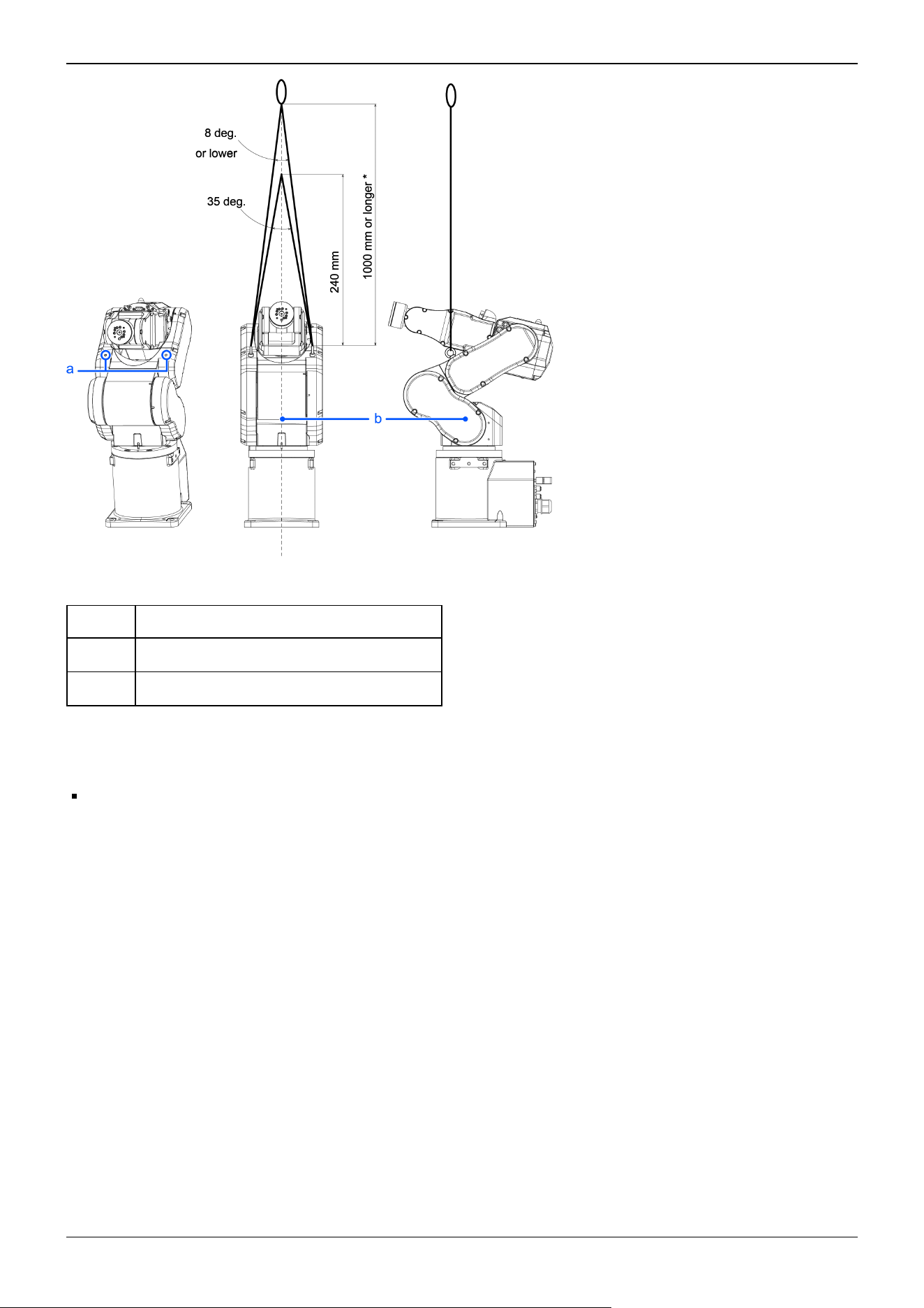
(deg. = °)
Symbol Description
a Threaded holes for eyebolts: 2×M6 depth 12.5
b Center of gravity
* Use the wire of 1000 mm or longer to avoid contact with Manipulator.
C4-B901**
Lifting load: 30 kg: 66.1 lb
Industrial Robot: 6-Axis Robots C-B series Manual Rev.1b
44
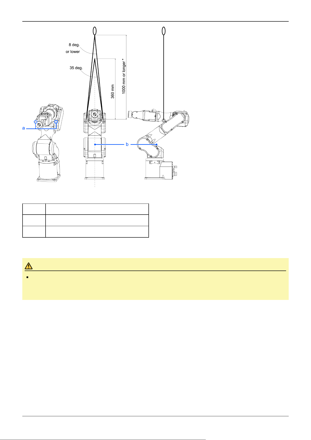
(deg. = °)
Symbol Description
a Threaded holes for eyebolts: 2×M6 depth 12.5
b Center of gravity
* Use the wire of 1000 mm or longer to avoid contact with Manipulator.
CAUTION
Remove the eyebolts from the Manipulator after transportation/relocation is completed. If the Manipulator is
operated with the eyebolts left on it, the arm may collide with the eyebolts and it may cause equipment
damage to and/or malfunction of the Manipulator.
2.4 Setting the Hand
2.4.1 Installing the Hand
The hand (end effector) must be prepared by the customer. For details on attaching the hand, refer to the following manual.
"Hand Function Manual"
Industrial Robot: 6-Axis Robots C-B series Manual Rev.1b
45
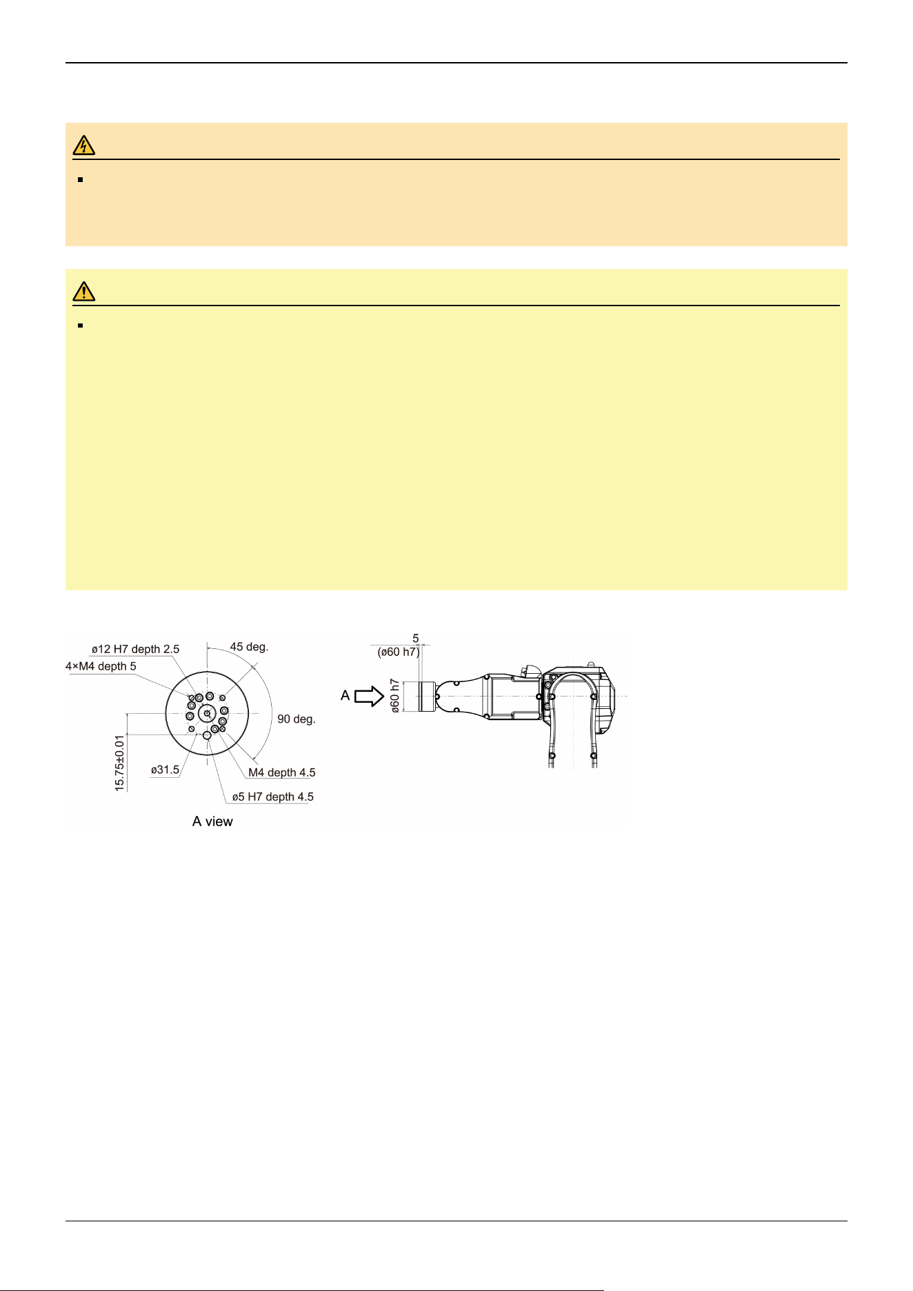
Flange dimensions of the wrist attached to the end of Arm #6 is as below.
WARNING
Before attaching a hand or peripheral equipment, be sure to always turn off the Controller and related
equipment and unplug the power cables. Performing any work procedure with the power turned on is
extremely dangerous and may result in electric shock and/or malfunction of the robot system.
CAUTION
When the hand is equipped with a workpiece gripping mechanism, ensure that the wiring and pneumatic
tubes do not cause the hand to release the workpiece when the power is turned off. When the wiring and
pneumatic tubes are not designed for the hand to maintain its grip on the workpiece when the power is turned
off, pressing the emergency stop switch releases the workpiece, which may damage the robot system and the
workpiece.
By default, all I/Os are designed to automatically turn off (0) when the power is shut off, when an emergency
stop is triggered, or by the robot system's safety function.
However, I/Os set with the Hand function does not turn off (0) when executing the Reset statement, or when
performing an emergency stop.
For the risk of the residual air pressure, conduct a risk assessment on the equipment and take the necessary
protective measures.
Wrist flange
* Applicable area
Arm #6
Attach the hand to the end of the Arm #6 using the M4 bolts.
Layout
When attaching and operating a hand, the hand may come into contact with the Manipulator body due to the outer diameter of
the hand, the size of the workpiece, or the position of the arm. Carefully consider the interference area of the hand when
designing the system layout.
Compatibility with PS series or ISO flange
To install the hand used in the PS series or the hand which has flange conforming to ISO standard to the C4 series, we provide
the optional PS Compatible Plate. For details, refer to the following section.
Options
Industrial Robot: 6-Axis Robots C-B series Manual Rev.1b
46
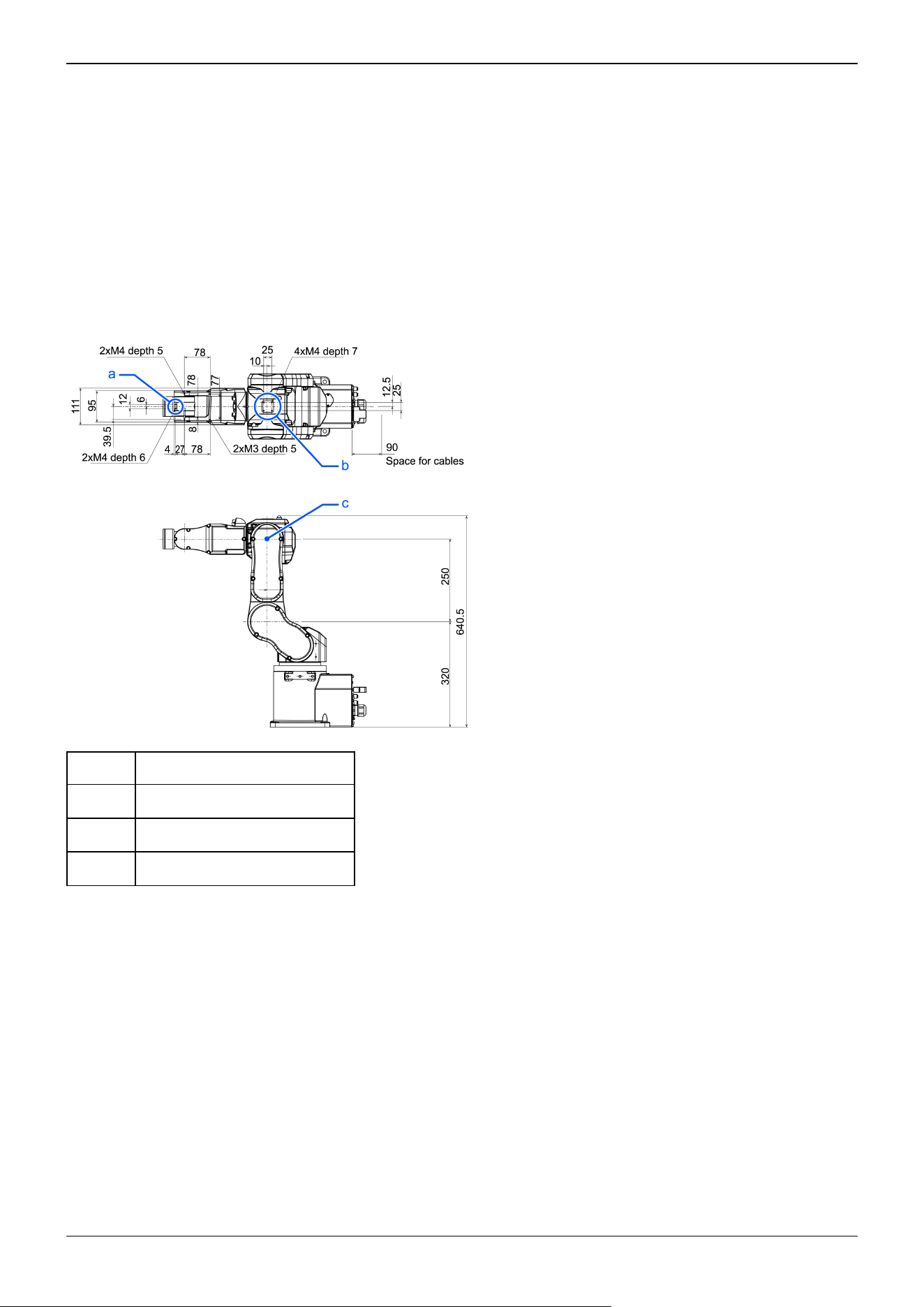
2.4.2 Attaching Cameras and Valves
Decks are equipped to Arms #3 and #5 to enable the easy installation of air valve. If the payload exceeds the maximum
payload, refer to the following section.
"WEIGHT Setting - Restrictions on payload exceeding the maximum payload"
To mount the camera, the camera plate unit is necessary. We provide the optional Camera Plate Unit. For details, refer to the
following section.
Options
(Units: mm)
C4-B601**
Symbol Description
a Arm #5 Deck
b Arm #3 Deck
c Rotation center of the upper arm
Industrial Robot: 6-Axis Robots C-B series Manual Rev.1b
47
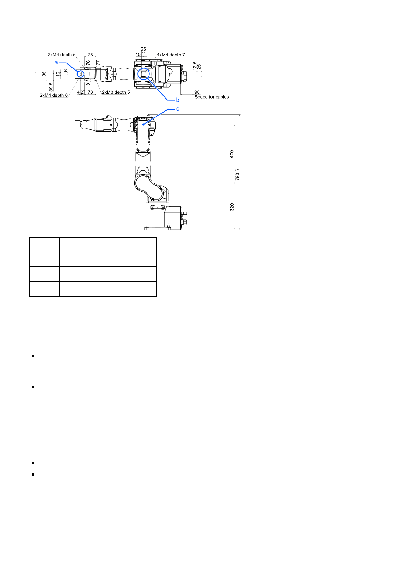
C4-B901**
Symbol Description
a Arm #5 Deck
b Arm #3 Deck
c Rotation center of the upper arm
2.4.3 WEIGHT and INERTIA Settings
The WEIGHT and INERTIA commands are for setting the load parameters of the Manipulator. These settings optimize the
Manipulator motion.
WEIGHT Setting
The WEIGHT command is for setting the load weight. The more the load weight increases, the more the speed and
acceleration/deceleration are reduced.
INERTIA Setting
The INERTIA command is for setting the inertia moment and the eccentricity of the load. The more the inertia moment
increases, the more the acceleration and deceleration of the Arm #6 are reduced. The more the eccentricity increases, the
more the acceleration and deceleration for the Manipulator movement are reduced.
To ensure that the Manipulator is functioning properly, keep the load (the sum of the weights of the hand and workpiece) and
the moment of inertia of the load within the rated values, and do not allow for eccentricity from the center of the Arm #6. If the
load or the inertia moment exceeds the ratings or if the load becomes eccentric, follow the steps below to set parameters.
WEIGHT Setting
INERTIA Setting
Setting parameters makes the operation of the Manipulator optimal, reduces vibration to shorten the operating time, and
improves the capacity for larger loads. This also works to curb any persistent vibration that may occur when the hand and
workpiece have a large moment of inertia.
You can also perform settings using the "Weight, Inertia, and Eccentricity/Offset Measurement Utility."
Industrial Robot: 6-Axis Robots C-B series Manual Rev.1b
48
For details, refer to the following manual.
"EPSON RC+ User's Guide - Weight, Inertia, and Eccentricity/Offset Measurement Utility"
The allowable load for C4 series Manipulators is up to 4 (5) kg*.
Due to the limitations of the moment and moment of inertia shown in the table below, the load (hand + workpiece) should also
meet these conditions.
If force is applied to the Manipulator instead of weight, it should not exceed the values shown in the table below.
* If the payload exceeds the maximum payload, refer to the following section.
"WEIGHT Setting - Restrictions on payload exceeding the maximum payload"
Allowable Load
Joint Allowable moment
(GD
2
/4) Allowable Moment of Inertia
Joint #4 4.41 N·m (0.45 kgf·m)
0.15 kg·m
2
Joint #5 * 4.41 N·m (0.45 kgf·m)
0.15 kg·m
2
Joint #6 2.94 N·m (0.3 kgf·m)
0.1 kg·m
2
Moment
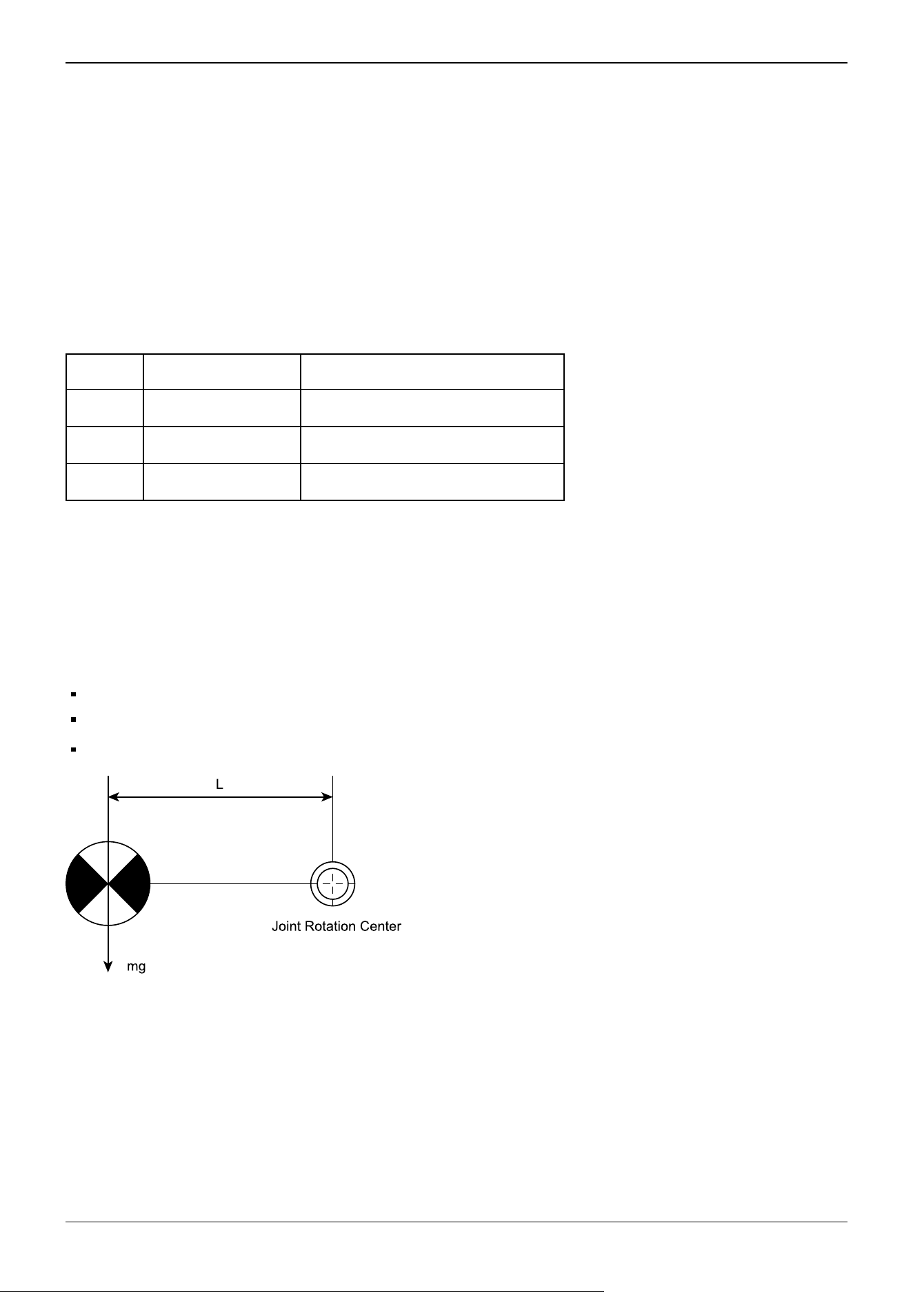
The moment indicates amount of torque applied on the joint in order to support the gravity on the load hand + workpiece). The
moment increases as weight of the load and amount of eccentricity increase. As this also increases the load applied on the joint,
make sure to keep the moment within the allowable value.
A maximum torque (T) is calculated by the following formula.
T = m (kg) × L (m) × g (m/s
2
)
m: Weight of load (kg)
L: Eccentricity of load (m)
g: Gravitational acceleration (m/s
2
)
The figure below shows distribution of the center of gravity when the volume of the load (hand + workpiece) is small. Design
the hand so that the center of gravity is within the allowable moment.
Industrial Robot: 6-Axis Robots C-B series Manual Rev.1b
49
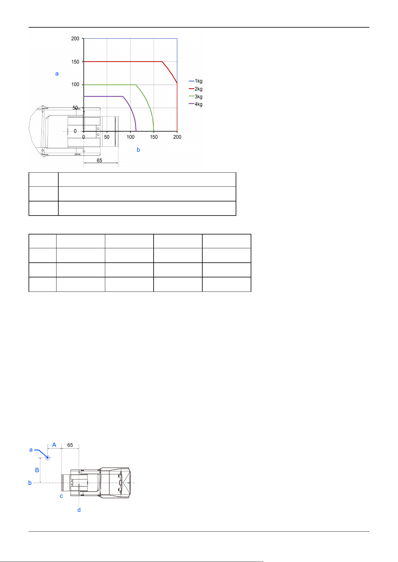
Symbol Description
a Distance from the center of Arm #* rotation [mm]
b Center of gravity of load from the Arm #* rotation center [mm]
Max. Eccentricity of Load (Distance between the joint rotation center and the load’s center of gravity)
Axis WEIGHT 1 kg WEIGHT 2 kg WEIGHT 3 kg WEIGHT 4 kg
#4 200 mm 200 mm 150 mm 112 mm
#5 200 mm 200 mm 150 mm 112 mm
#6 200 mm 150 mm 100 mm 75 mm
(The maximum eccentricity of load is restricted to 200 mm or less.)
When calculating the critical dimension of the load using the allowable moment and inertia moment, the calculated value
represents a distance from the Arm #6 rotation center, not the distance from the flange. To calculate the distance from the
flange to the load’s center of gravity, subtract the distance from the center of the Arm #5 rotation center to the flange (=65 mm)
as shown in the example below.
Example: Calculate the critical dimension of the load on the Arm #5 (A) when a 2.5 kg load is on the Arm #6 rotation center
line (B = 0)
Center of gravity by the allowable moment control: 4.41 N·m/(2.5 kg × 9.8 m/s
2
) = 0.18 m = 180 mm
Due to the allowable moment control, center of gravity for the load limit is 180 mm from the Arm #5 rotation center.
Distance from the flange to the center of gravity for the load limit A = 180 mm - 65 mm = 115 mm
Critical Dimension of Load
Industrial Robot: 6-Axis Robots C-B series Manual Rev.1b
50
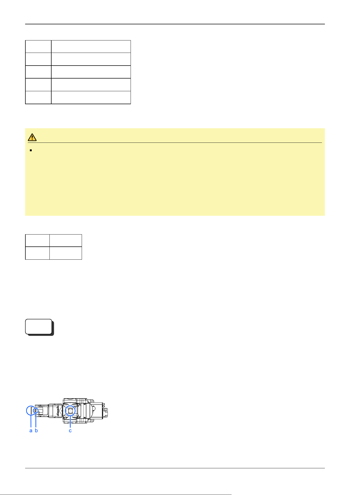
(Units: mm)
Symbol Description
a Load center of gravity position
b Arm #6 rotation center
c Flange
d Arm #5 rotation center
2.4.3.1 WEIGHT Setting
CAUTION
Set the total weight of the hand and the workpiece smaller than the maximum payload.
The C4 Manipulators can operate without limitations on the condition unless and until the load exceeds this
maximum payload. When the payload of the Manipulator exceeds the maximum payload, refer to the section
“Restrictions on payload exceeding the maximum payload” in the later part of this section for details.
Always set the Weight parameters of the WEIGHT command according to the load. Setting a value smaller
than the actual weight may cause errors or impact that not only impair full functionality but also shorten the
life of the mechanical components.
The acceptable weight capacity (hand + workpiece) for C4 Manipulators is as follows:
Rated Maximum
1 kg 4 (5) kg*
When the load exceeds the rating, change the setting of the weight parameter. After changing the Weight parameter setting, the
maximum acceleration/deceleration and speed of the robot system corresponding to the load is set automatically.
* If the payload exceeds the maximum payload, refer to the following section.
"WEIGHT Setting - Restrictions on payload exceeding the maximum payload"
Setting method of Weight parameters
Select [Tools]-[Robot Manager]-[Weight] panel and set the value in [Weight:]. You may also execute the Weight command
from [Command Window].
Load on the Manipulator
Mounting location of the load
C4-B601**
EPSON
RC+
Industrial Robot: 6-Axis Robots C-B series Manual Rev.1b
51
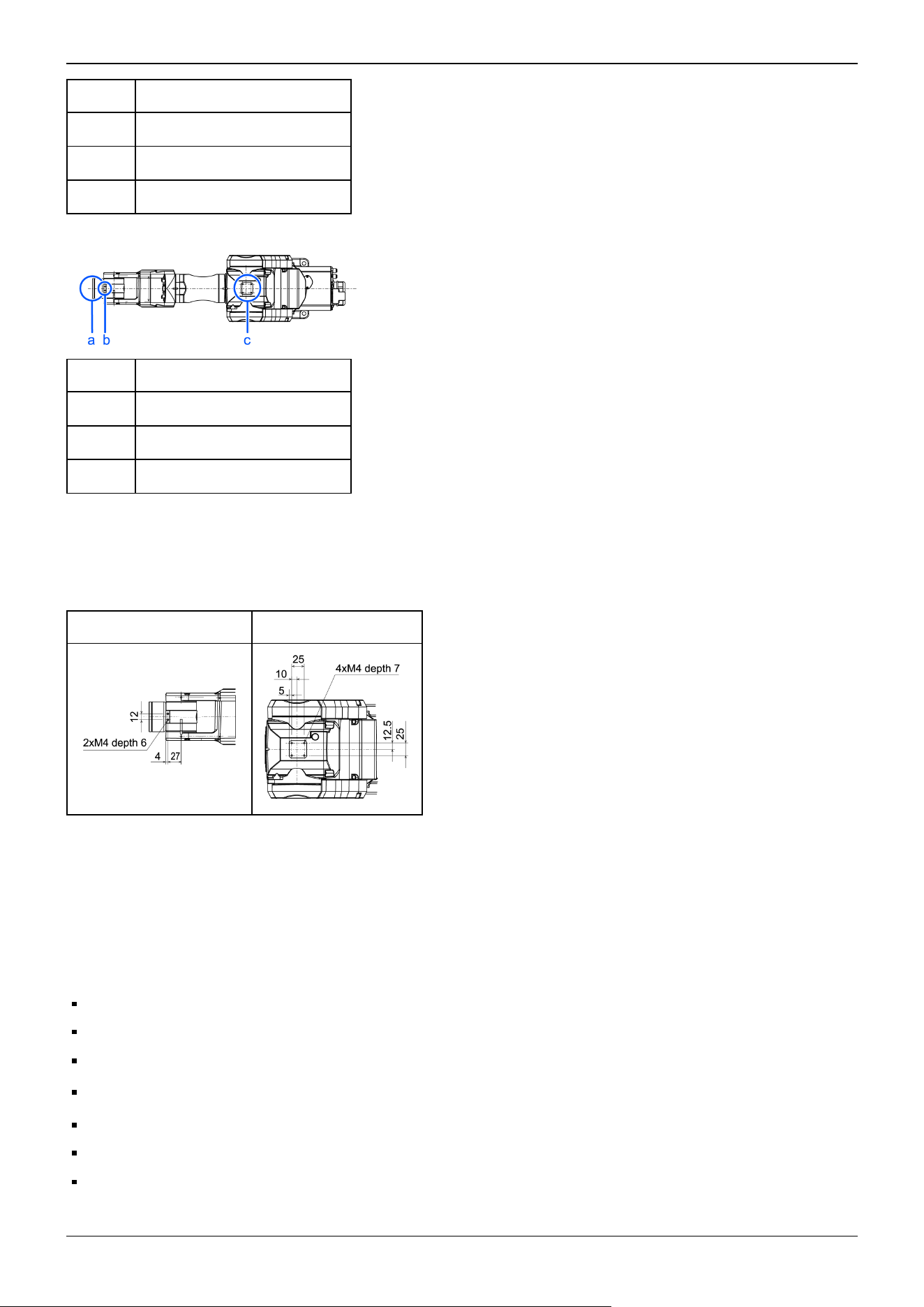
Symbol Description
a Load on the fore end of Arm #6
b Arm #5 deck
c Arm #3 deck
C4-B901**
Symbol Description
a Load on the fore end of Arm #6
b Arm #5 deck
c Arm #3 deck
C4 series
Deck detailed
(Units: mm)
Arm #5 deck Arm #3 deck
When you attach the equipment to the decks on the upper arm, convert its weight into equivalent weight assuming that the
equipment is attached to the end of the Arm #6. Then, this equivalent weight added to the load will be a Weight parameter.
Calculate the Weight parameter by using the formula below and enter the value.
Weight Parameter Formula
Weight parameter = M
w
+ W
a
+ W
b
M
w
: Payload on the fore end of Arm #6 (kg)
W
a
: Equivalent weight of the Arm #3 deck (kg)
W
b
: Equivalent weight of the Arm #5 deck (kg)
W
a
=M
a
(L
a
)
2
/ (L)
2
W
b
=M
b
(L
b
)
2
/ (L)
2
M
a
: Weight of the air valve on the Arm #3 deck (kg)
M
b
: Weight of the camera on the Arm #5 deck (kg)
Industrial Robot: 6-Axis Robots C-B series Manual Rev.1b
52
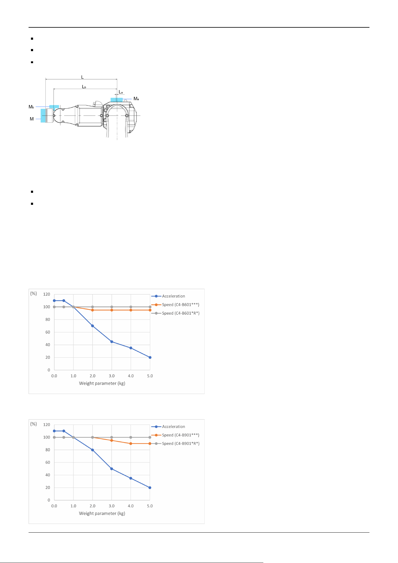
L: Length of the upper arm (315 mm)
L
a
: Distance between the Joint #3 and the center of gravity of the air valve on the Arm #3 deck (mm)
L
b
: Distance between the Joint #3 and the center of gravity of the camera on the Arm #5 deck (mm)
[Example]
When the following loads apply to C4 which fore end of the Arm #6 is 315 mm (L) away from the Joint #3 and payload (M
w
)
is 1 kg:
Load on the Arm #3 deck is 1.5 kg (M
a
). The deck is 0 mm (L
a
) away from the Joint #3.
Load on the Arm #5 deck is 0.5 kg (M
b
). The deck is 280 mm (L
b
) away from the Joint #3.
W
a
=1.5 × 0
2
/315
2
=0
W
b
=0.5 × 280
2
/315
2
=0.395 → 0.4 (round up)
M
w
+W
a
+W
b
=1+0+0.4=1.4
Enter "1.4" for the Weight parameter.
Automatic Speed Setting by Weight Parameter (C4-B601**)
Automatic Speed Setting by Weight Parameter (C4-B901**)
Industrial Robot: 6-Axis Robots C-B series Manual Rev.1b
53
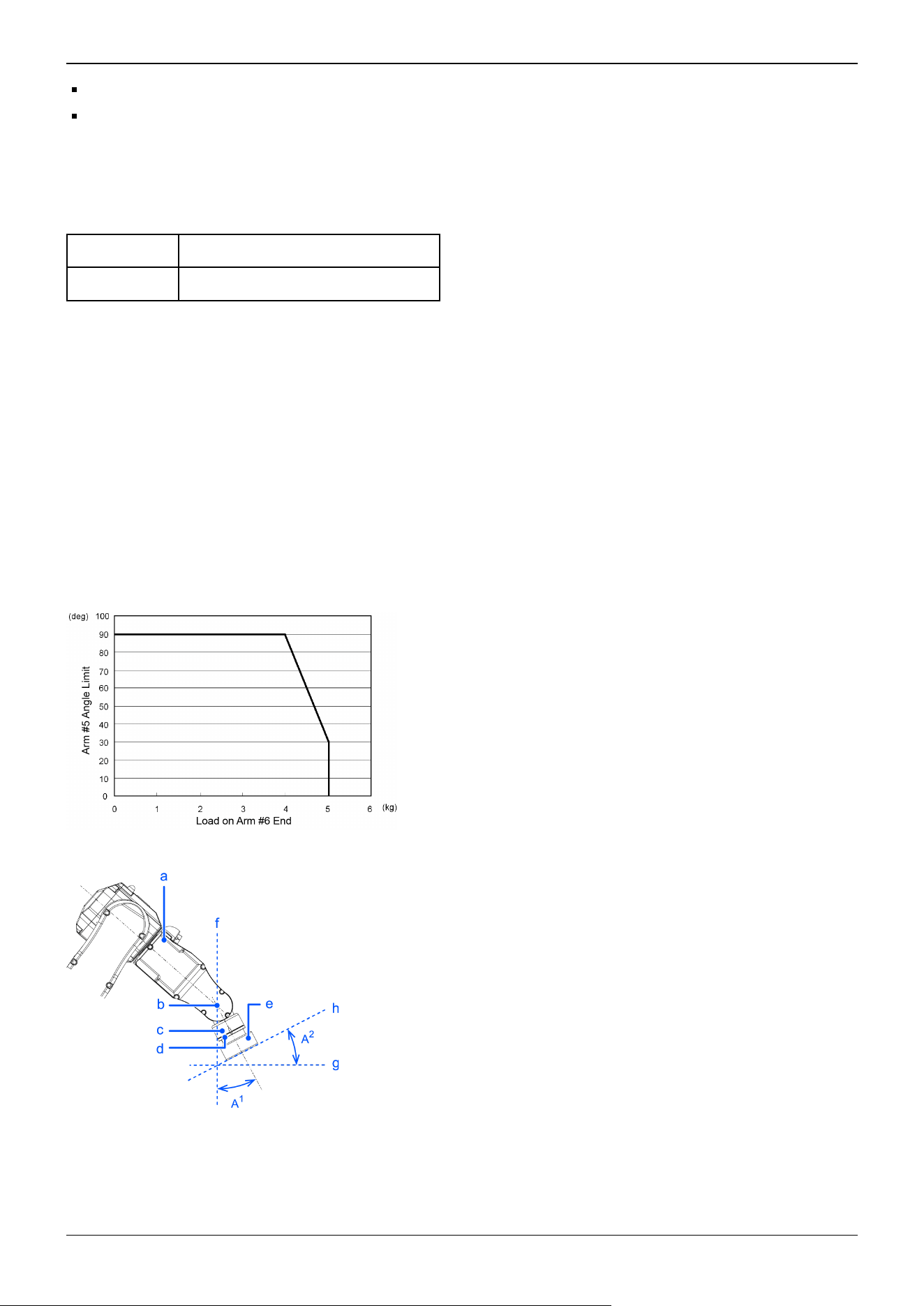
The percentage in the graph is based on the speed at rated weight (1 kg) as 100%.
If the payload exceeds the maximum payload, refer to the following section.
"WEIGHT Setting - Restrictions on payload exceeding the maximum payload"
Restrictions on payload exceeding the maximum payload
Maximum payload for C4 Manipulators is as follows: Payload can be increased by restricting the arm posture of the Arm #5
downward.
Max. Payload Max. Payload with Pose Restriction
4 kg 5 kg
If the load exceeds the maximum payload, use the Arm #5 with a posture angle within the range indicated in the following
graph.
The graph shows the relation of the load weight and Arm #5 angle limit (A1) measured in vertical direction (direction of
gravity). Note that the heavier the load on the Arm #6, the smaller the angle limit becomes.
When the Manipulator operates vertically to the operating surface, the limit of the Arm #5 is equivalent to the limit of the
operating angle (A2).
In addition, for the eccentric load, the angle limit is an angle of the line joining the center of the load and the Arm #5 rotation
axis with the vertical direction (B).
The eccentricity of the load should be within the allowable moment and moment of inertia of Arms #4, #5, and #6.
Relation of load weight and Arm #5 angle limit
Relation of Arm #5 angle and operating surface
Industrial Robot: 6-Axis Robots C-B series Manual Rev.1b
54
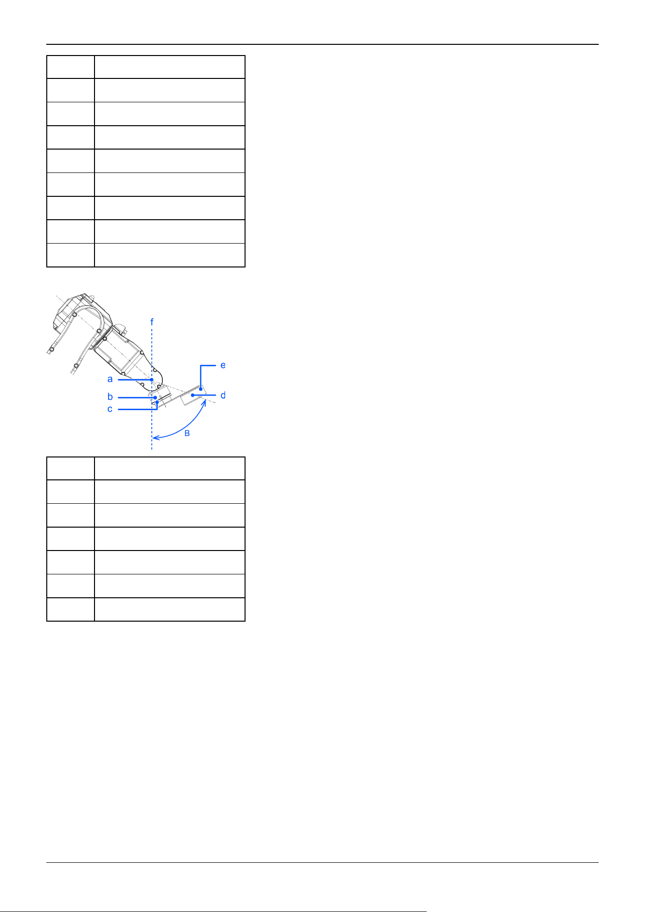
Symbol Description
a Arm #4
b Arm #5 rotation axis
c Arm #5
d Arm #6
e Load on the fore end of Arm #6
f Vertical direction
g Plane
h Operating surface
Angle limit for eccentric load
Symbol Description
a Arm #5 rotation axis
b Arm #5
c Arm #6
d Center of gravity
e Load on the fore end of Arm #6
f Vertical direction
2.4.3.2 INERTIA Setting
Moment of Inertia and INERTIA Setting
The moment of inertia is a quantity that expresses how hard it is for an object to turn, and it is expressed in terms of values for
Industrial Robot: 6-Axis Robots C-B series Manual Rev.1b
55
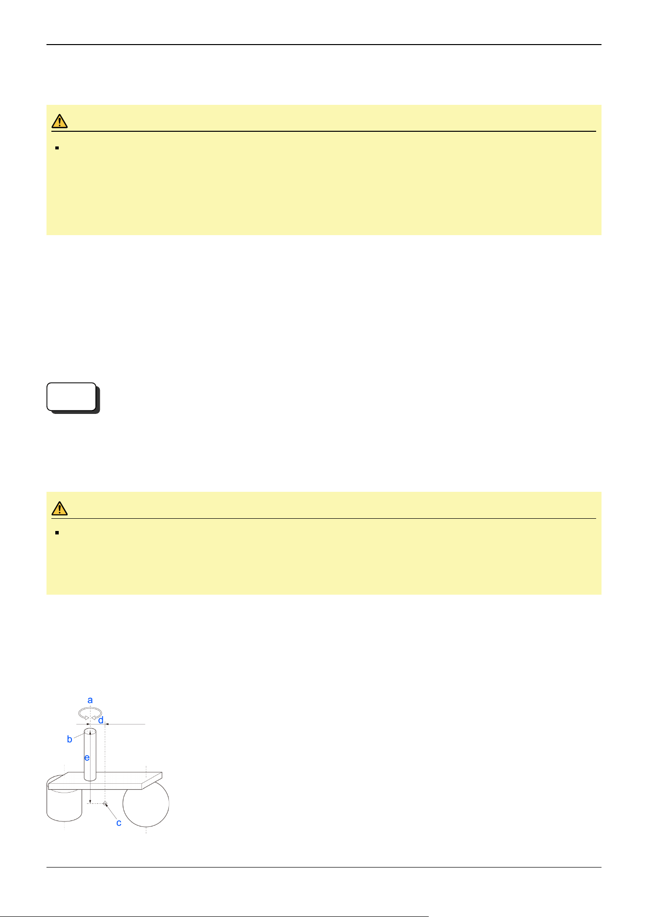
the moment of inertia, inertia, or GD
2
. When a hand or other object is attached to the Arm #6 for operation, the moment of
inertia of the load must be taken into consideration.
CAUTION
The moment of inertia of the load (hand + workpiece) must be 0.1 kg·m
2
or less.
The C4 Manipulators are not designed to work with a moment of inertia exceeding 0.1 kg·m
2
. Always set the
value corresponding to the moment of inertia. Setting a parameter value that is smaller than the actual
moment of inertia may cause errors or impact, may prevent the Manipulator from working at full functionality,
and may shorten the lifespan of mechanical parts.
The allowable moment of inertia of a load for C4 Manipulators is 0.005 kg·m
2
at the default rating and 0.1 kg·m
2
at the
maximum. When the moment of inertia of the load exceeds the rating, change the setting of the moment of inertia parameter
for the load in the Inertia statement. After the setting is changed, the maximum acceleration/deceleration of Arm #6 that
corresponds to the "Inertia" value is corrected automatically.
Moment of Inertia of Load Attached to Arm #6
The moment of inertia of the load (hand + workpiece) attached to the Arm #6 can be set by the "Inertia" parameter in the
Inertia statement.
Go to [Tools] - [Robot Manager] - [Inertia] panel, and enter the value in [Inertia]. This can also be set using the Inertia
statement in [Command Window].
Eccentricity and INERTIA Setting
CAUTION
The eccentricity of the load (hand + workpiece) must be 200 mm or less. The C4 Manipulators are not
designed to work with eccentricities exceeding 200 mm. Always set the value based on the eccentricity.
Setting the eccentricity parameter to a value smaller than the actual eccentricity may cause errors or impact
that not only impair full functionality but also shorten the life of the mechanical components.
The allowable eccentricity of load for C4 Manipulators is 30 mm at the default rating and 200 mm at the maximum. When the
load eccentricity exceeds the rating, change the setting for the eccentricity parameter in Inertia statement. After the setting is
changed, the maximum acceleration/deceleration of the Manipulator that corresponds to the "Eccentricity" is corrected
automatically.
Eccentricity
EPSON
RC+
Industrial Robot: 6-Axis Robots C-B series Manual Rev.1b
56
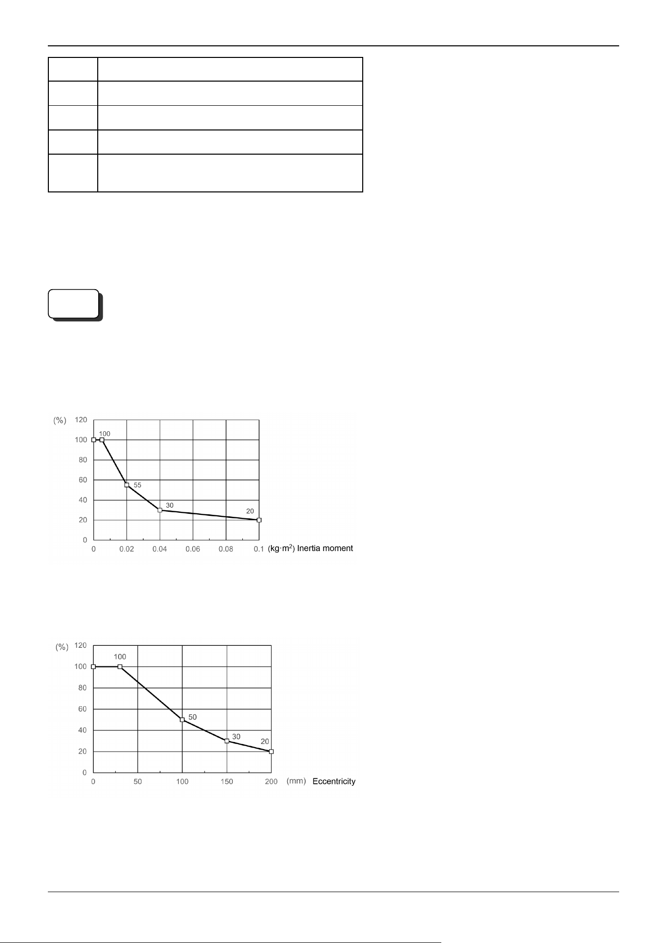
Symbol Description
a Rotation axis
b Flange
c Load center of gravity position
d, e
Eccentricity (200 mm or less)
To set the parameter, enter the larger value of "d" or "e".
Eccentricity of Load Attached to Arm #6
The eccentricity of the load (hand + workpiece) attached to the Arm #6 can be set by the "Eccentricity" parameter in the Inertia
statement.
Enter the larger value of either "d" or "e" in the figure above to [Eccentricity].
Go to [Tools] - [Robot Manager] - [Inertia] panel, and enter the value in [Eccentricity]. This can also be set using the Inertia
statement in [Command Window].
Automatic Acceleration/Deceleration Correction at INERTIA (Eccentricity) Setting
Automatic setting by inertia moment setting
* The percentages on the graph are ratios based on 100% as the acceleration/deceleration at the rated (0.005 kg·m
2
) setting.
Automatic setting by eccentricity setting
* The percentages on the graph are ratios based on 100% as the acceleration/deceleration at the rated (30 mm) setting.
INERTIA (eccentricity) is affected by the load setting. Refer to the following section and configure the load setting carefully.
WEIGHT and INERTIA Settings
EPSON
RC+
Industrial Robot: 6-Axis Robots C-B series Manual Rev.1b
57
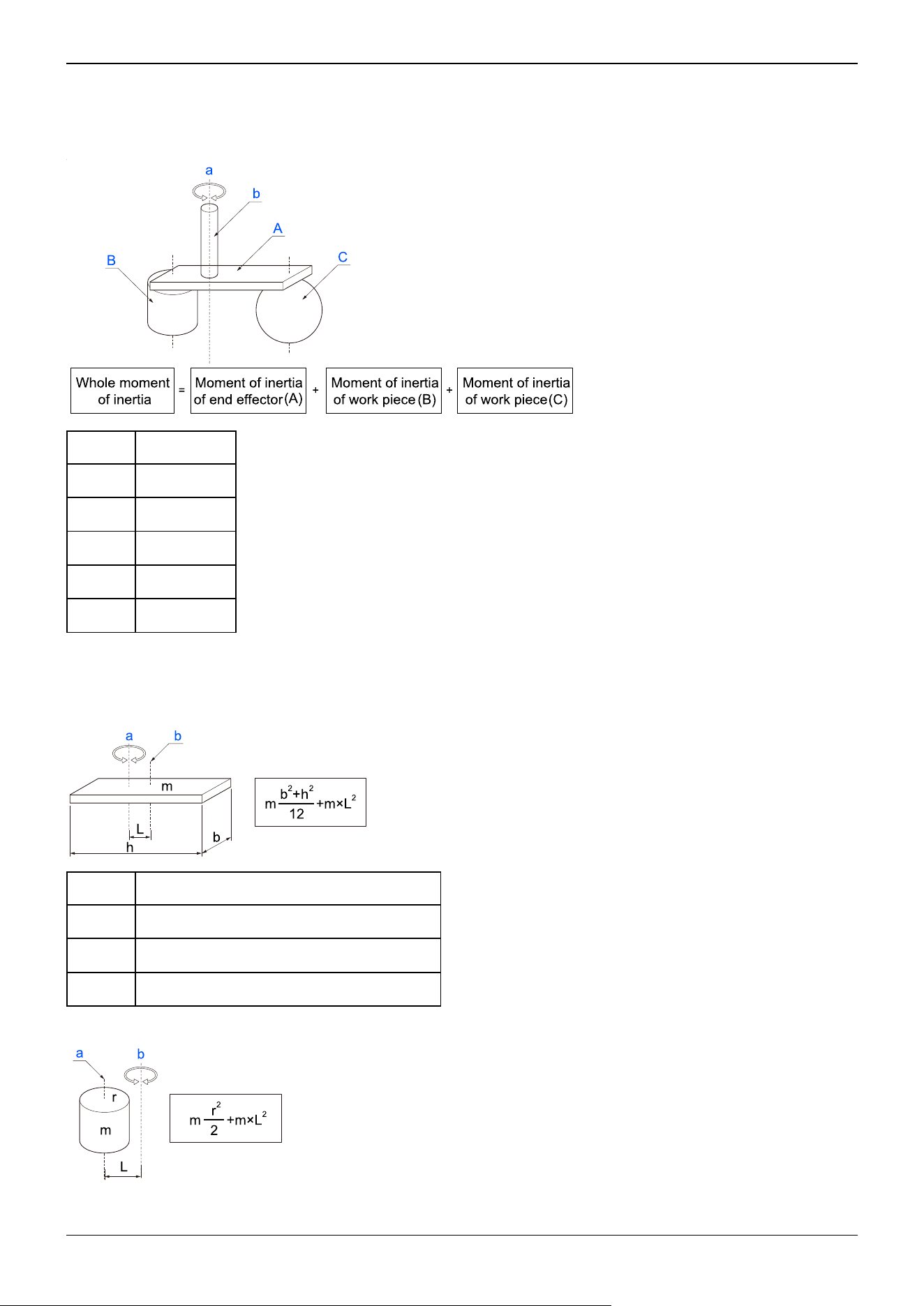
Calculating the Moment of Inertia
An example of calculating the moment of inertia of a load (hand holding a workpiece) is shown below.
The moment of inertia of the entire load is calculated by the sum of (A), (B), and (C).
Symbol Description
a Rotation axis
b Shaft
A Hand
B Workpiece
C Workpiece
The methods for calculating the moment of inertia for (A), (B), and (C) are shown below. Use the moment of inertia of these
basic shapes as a reference to find the moment of inertia of the entire load.
(A) Moment of inertia of a rectangular parallelepiped
Symbol Description
a Rotation axis
b Center of gravity of rectangular parallelepiped
m Weight
(B) Moment of inertia of a cylinder
Industrial Robot: 6-Axis Robots C-B series Manual Rev.1b
58
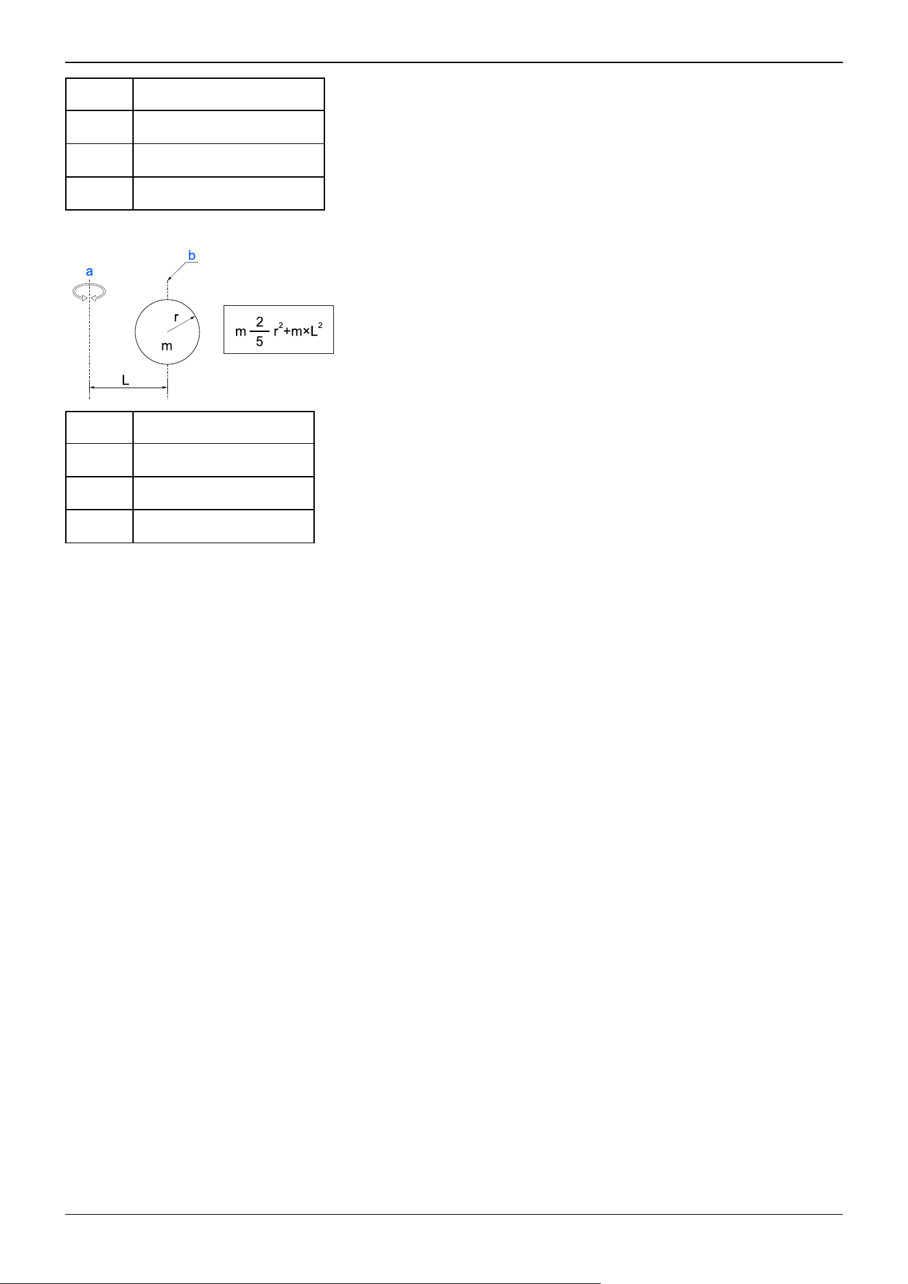
Symbol Description
a Center of gravity of cylinder
b Rotation axis
m Weight
(C) Moment of inertia of a sphere
Symbol Description
a Rotation axis
b Center of gravity of sphere
m Weight
2.4.4 Safety Information for Auto Acceleration
The speed and acceleration/deceleration of the Manipulator motion are automatically optimized according to the values of
WEIGHT and INERTIA and the Manipulator’s postures.
WEIGHT Setting
The speed and acceleration/deceleration of the Manipulator are controlled according to the load weight set by the WEIGHT
command. The more the load weight increases, the more the speed and acceleration/deceleration are reduced to prevent
residual vibration.
INERTIA Setting
The acceleration/deceleration of Arm #6 are controlled according to the inertia moment set by the INERTIA command. The
acceleration/deceleration of the whole Manipulator are controlled according to the eccentricity set by the INERTIA command.
The more the inertia moment and eccentricity of the load increase, the more the acceleration/ deceleration are reduced.
Auto Acceleration/Deceleration According to Manipulator’s Posture
The acceleration/deceleration are controlled according to the Manipulator’s posture. When the Manipulator extends its arms or
when the movement of the Manipulator produces vibration frequently, the acceleration/deceleration are reduced.
Set appropriate values for WEIGHT and INERTIA so that the Manipulator operation is optimized.
Industrial Robot: 6-Axis Robots C-B series Manual Rev.1b
59
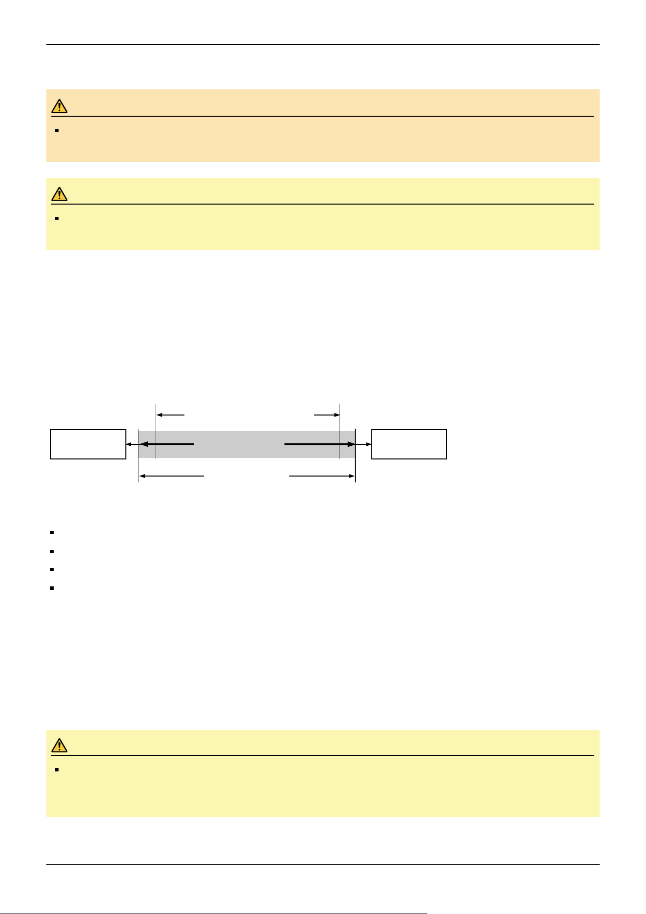
2.5 Work Envelope
WARNING
Do not operate the Manipulator with the mechanical stop removed. Removing the mechanical stop is
extremely dangerous because the Manipulator may move to a position outside its normal work envelope.
CAUTION
When restricting the work envelope for safety reasons, be sure to make settings using both the pulse range
and mechanical stop.
The work envelope is preset at the factory as explained in the following section. This is the maximum work envelope of the
Manipulator.
Standard Work Envelope
The work envelope can be set by one of the following three methods.
1. Setting by pulse range (for each joint)
2. Setting by mechanical stops
3. Setting the rectangular range in the XY coordinate system of the Manipulator
To limit the work envelope for layout efficiency or safety reasons, make the settings as explained in the following sections.
Work Envelope Setting by Pulse Range (for Each Joint)
Setting the Work Envelope by Mechanical Stops
Restriction of Manipulator Operation by Joint Angle Combination
Coordinate System
2.5.1 Work Envelope Setting by Pulse Range (for Each Joint)
Pulses are the basic unit of Manipulator motion. The motion range (work envelope) of the Manipulator is set by the pulse
lower limit value and pulse upper limit value (pulse range) for each joint. Pulse values are read from the encoder output of the
servomotor.
Be sure to set the pulse range within the mechanical stop range.
CAUTION
Do not set and/or use the Arm #4 with a pulse range exceeding the maximum value. The Arm #4 does not
have a mechanical stop. Using the Arm #4 with a pulse range exceeding the maximum pulse range may
cause the inner wiring damaged and/or malfunction to the Manipulator.
Torsion of the inner wiring can be checked by removing the Arm #3 head cover.
Pulse range
Work Envelope
Mechanical
Stop
Mechanical
Stop
Rectangular range setting
Industrial Robot: 6-Axis Robots C-B series Manual Rev.1b
60
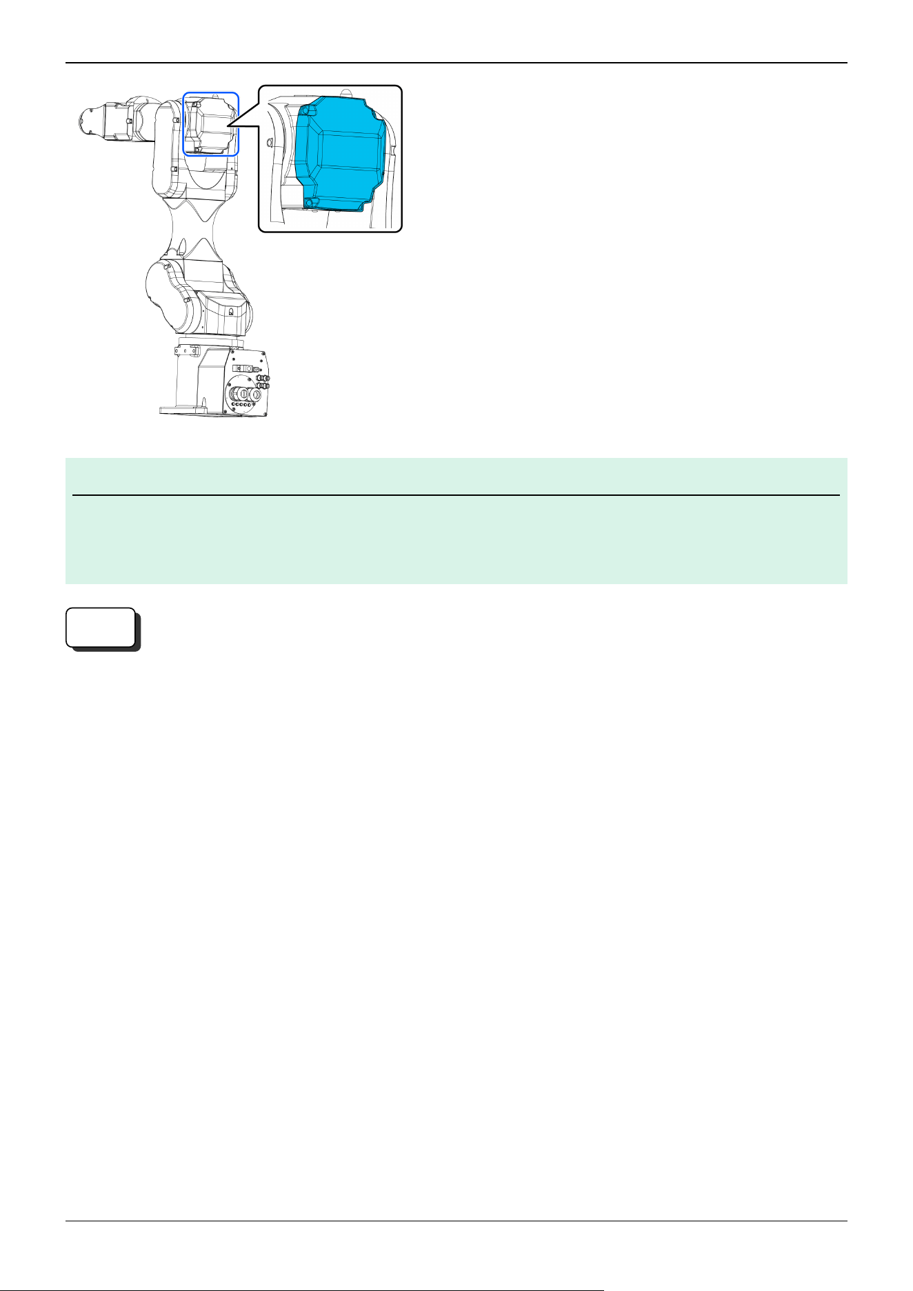
KEY POINTS
Once the Manipulator receives a motion command, it checks whether the target position specified by the
command is within the pulse range before operating. If the target position is outside of the pulse range that was
set, an error occurs and the Manipulator does not move.
Go to [Tools] - [Robot Manager] - [Range] panel, and make the setting. This can also be set using the Range statement in
[Command Window].
2.5.1.1 Arm #1 Maximum Pulse Range
With the 0 pulse as a starting point, the counterclockwise pulse value is defined as positive (+), and the clockwise pulse value
is defined as negative (-).
✏
EPSON
RC+
Industrial Robot: 6-Axis Robots C-B series Manual Rev.1b
61
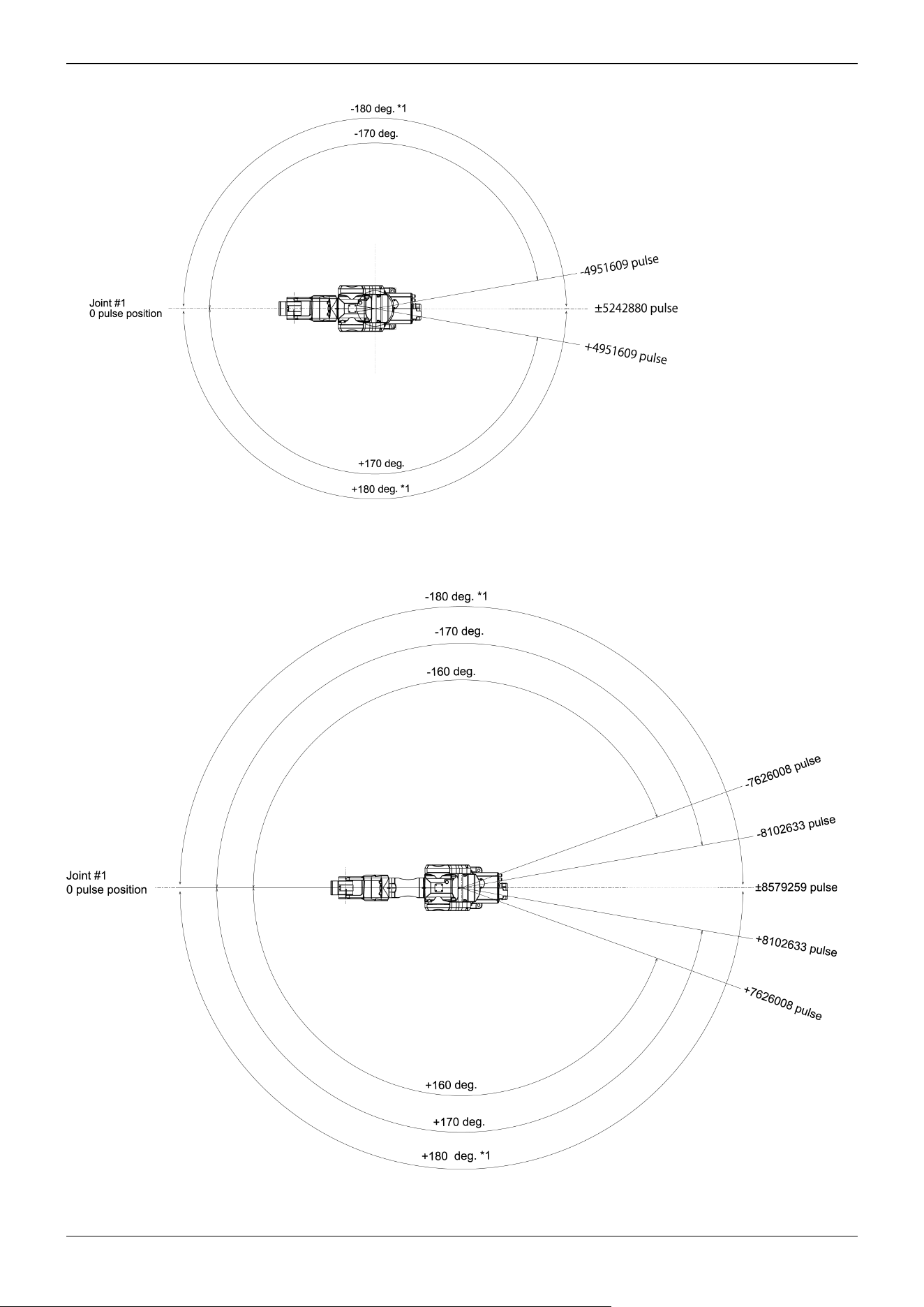
C4-B601**
*1 Software limit maximum value
C4-B901**
*1 Software limit maximum value
Industrial Robot: 6-Axis Robots C-B series Manual Rev.1b
62
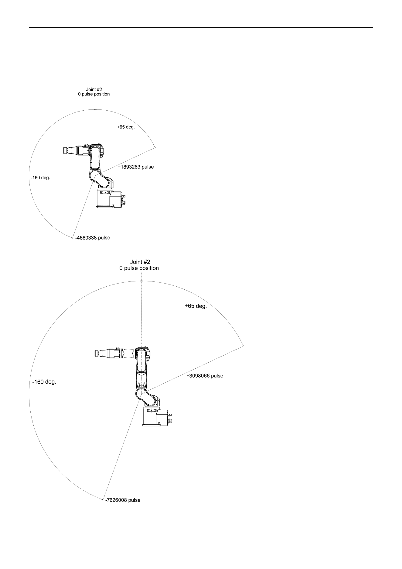
2.5.1.2 Arm #2 Maximum Pulse Range
With the 0 pulse as a starting point, the clockwise pulse value is defined as positive (+), and the counterclockwise pulse value
is defined as negative (-).
C4-B601**
C4-B901**
Industrial Robot: 6-Axis Robots C-B series Manual Rev.1b
63
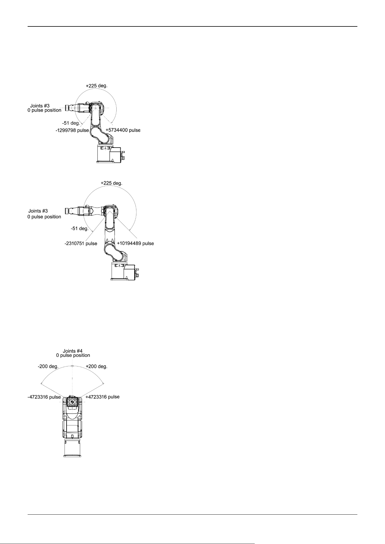
2.5.1.3 Arm #3 Maximum Pulse Range
With the 0 pulse as a starting point, the clockwise pulse value is defined as positive (+), and the counterclockwise pulse value
is defined as negative (-).
C4-B601**
C4-B901**
2.5.1.4 Arm #4 Maximum Pulse Range
From the angle of arm end, with the 0 pulse as a starting point, the clockwise pulse value is defined as positive (+), and the
counterclockwise pulse value is defined as negative (-).
C4-B601**
Industrial Robot: 6-Axis Robots C-B series Manual Rev.1b
64
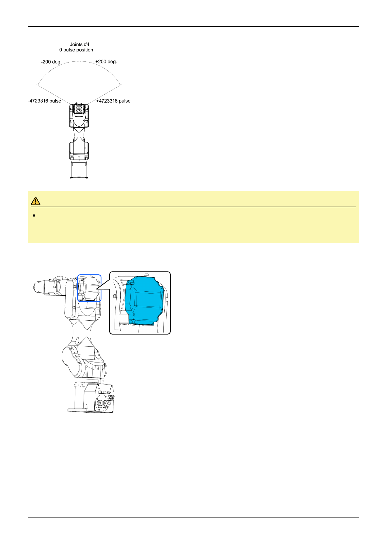
C4-B901**
CAUTION
Do not set and/or use the Arm #4 with a pulse range exceeding the maximum value. The Arm #4 does not
have a mechanical stop. Using the Arm #4 with a pulse range exceeding the maximum pulse range may
cause the inner wiring damaged and/or malfunction to the Manipulator.
Torsion of the inner wiring can be checked by removing the Arm #3 head cover.
2.5.1.5 Arm #5 Maximum Pulse Range
With the 0 pulse as a starting point, the clockwise pulse value is defined as positive (+), and the counterclockwise pulse value
is defined as negative (-).
Industrial Robot: 6-Axis Robots C-B series Manual Rev.1b
65
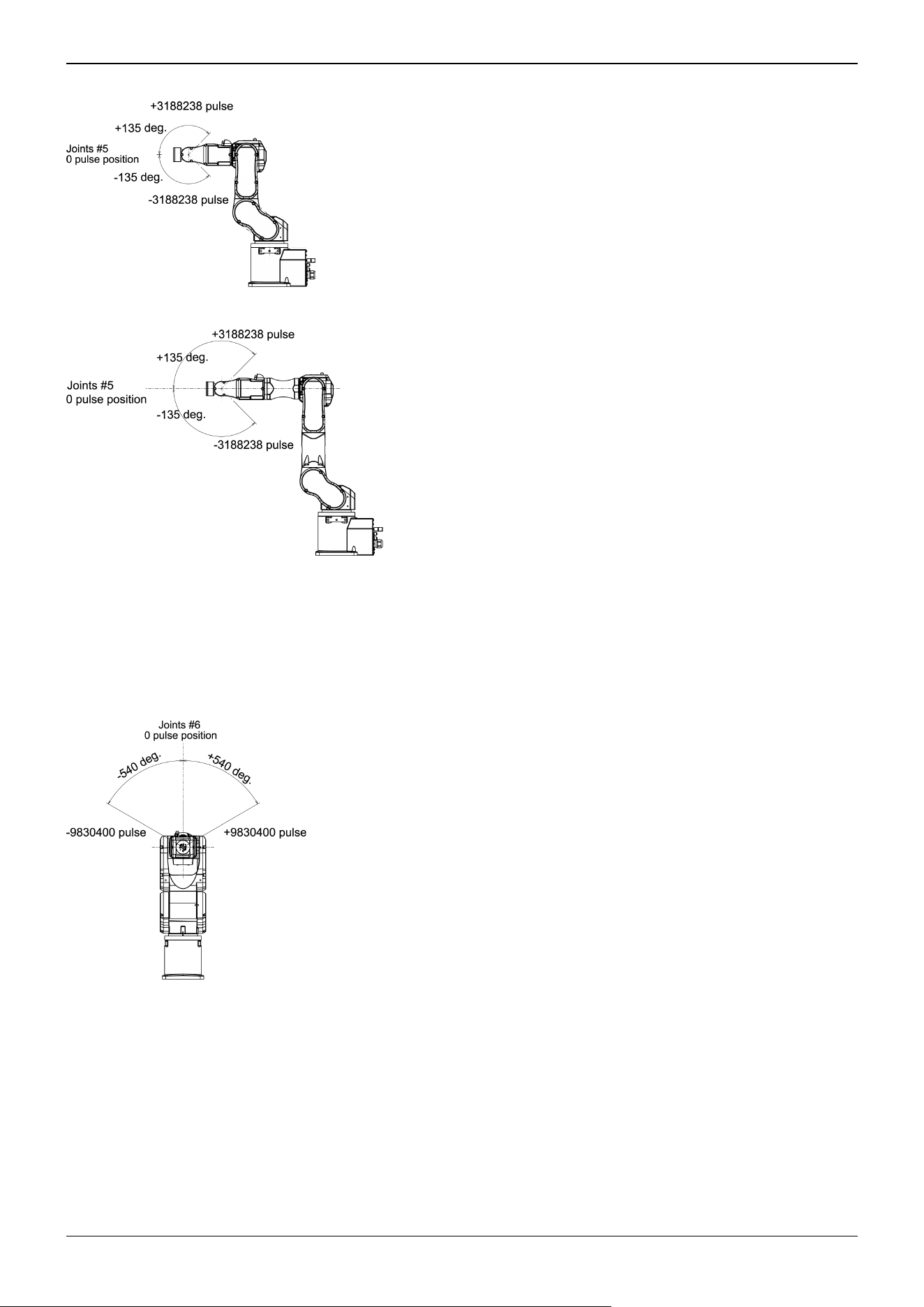
C4-B601**
C4-B901**
2.5.1.6 Arm #6 Maximum Pulse Range
From the angle of arm end, with the 0 pulse as a starting point, the clockwise pulse value is defined as positive (+), and the
counterclockwise pulse value is defined as negative (-).
C4-B601**
Industrial Robot: 6-Axis Robots C-B series Manual Rev.1b
66
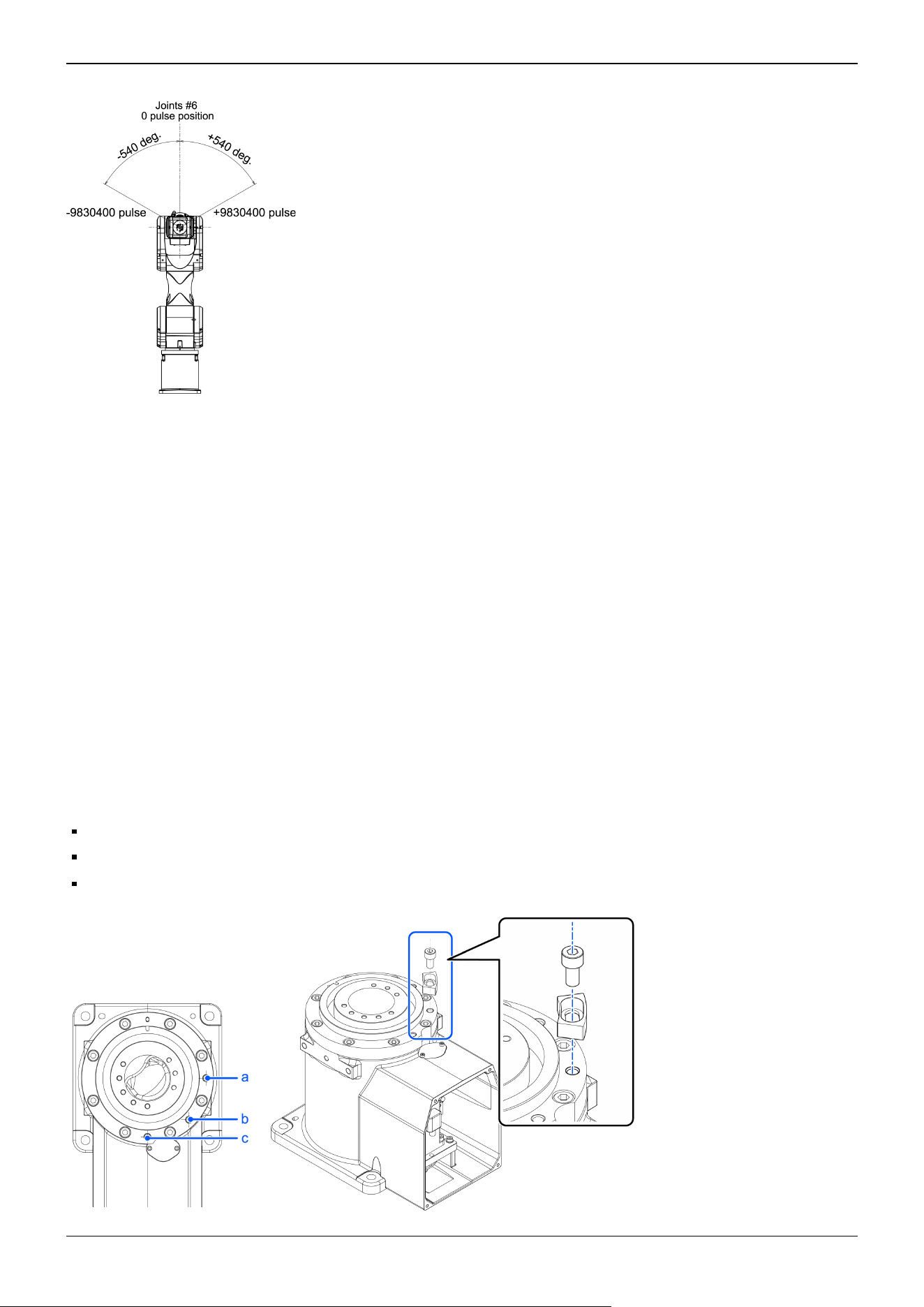
C4-B901**
2.5.2 Setting the Work Envelope by Mechanical Stops
Mechanical stops set the absolute work envelope that physically limits where the Manipulator can move.
Before starting any work, be sure to turn off the Controller.
Use bolts conforming to the specified length and surface processing (ex: nickel plating) with high corrosion resistance.
Specify the pulse range again after changing the position of the mechanical stop.
For details on the pulse range setting, refer to the following section.
Work Envelope Setting by Pulse Range (for Each Joint)
Be sure to set the pulse range inside the positions of the mechanical stop range.
2.5.2.1 Setting the Arm #1 Work Envelope
Install variable mechanical stop (J1) in the threaded holes corresponding to the angles to be set.
Normally a mechanical stop is not equipped.
Hexagon socket head cap bolt: M8×15
Strength: Compliant with ISO 898-1 property class: 10.9 or 12.9
Tightening torque: 32.0 N·m (326 kgf·cm)
Industrial Robot: 6-Axis Robots C-B series Manual Rev.1b
67
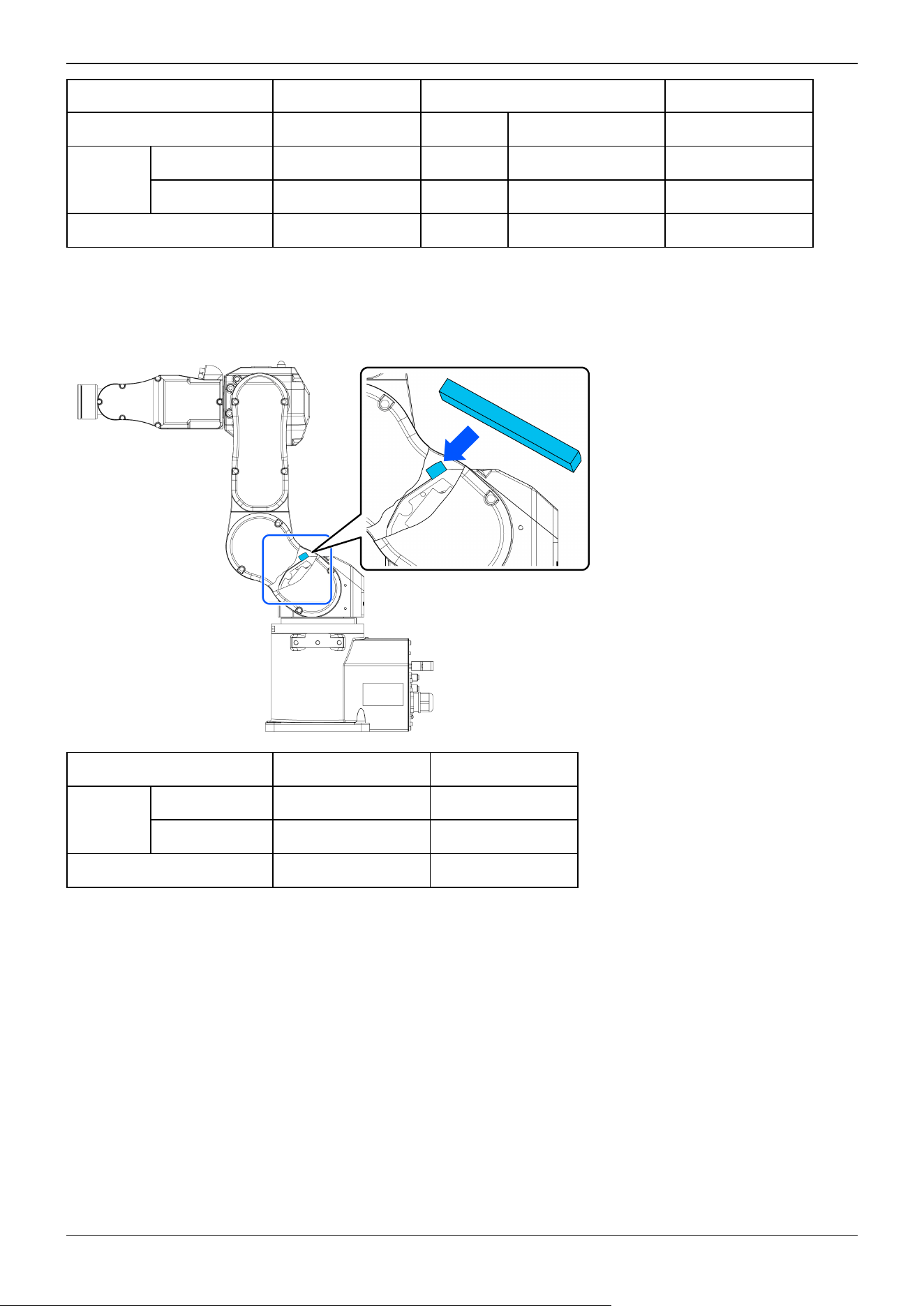
a b c
Angle (°) -115, +170 ±160 ±170 -170, +115
Pulse
C4-B601 ** -3640889, +4951609 ±4660338 ±4951609 -4951609, +3640889
C4-B901 ** -5957819, +8102633 ±76260083 ±8102633 -8102633, +5957819
Variable Mechanical Stop (J1) Applied Applied Not applied (standard) Applied
2.5.2.2 Setting the Arm #2 Work Envelope
Attach the variable mechanical stop (J2) to Arm #1. Adhesive tape is attached to the variable mechanical stop (J2).
Angle (°) -160, +65 -160, +55
Pulse
C4-B601 ** -4660338, +1893263 -4660338, +1601992
C4-B901 ** -7626008, +3098066 -7626008, +2621440
Variable Mechanical Stop (J2) Not applied (standard) Applied
For C4-A901**, please contact the supplier.
2.5.2.3 Setting the Arm #3 Work Envelope
Install the bolts in the threaded holes corresponding to the angles to be set.
Normally mechanical stops are equipped on the position f and g. (+225
〜-51°)
Industrial Robot: 6-Axis Robots C-B series Manual Rev.1b
68
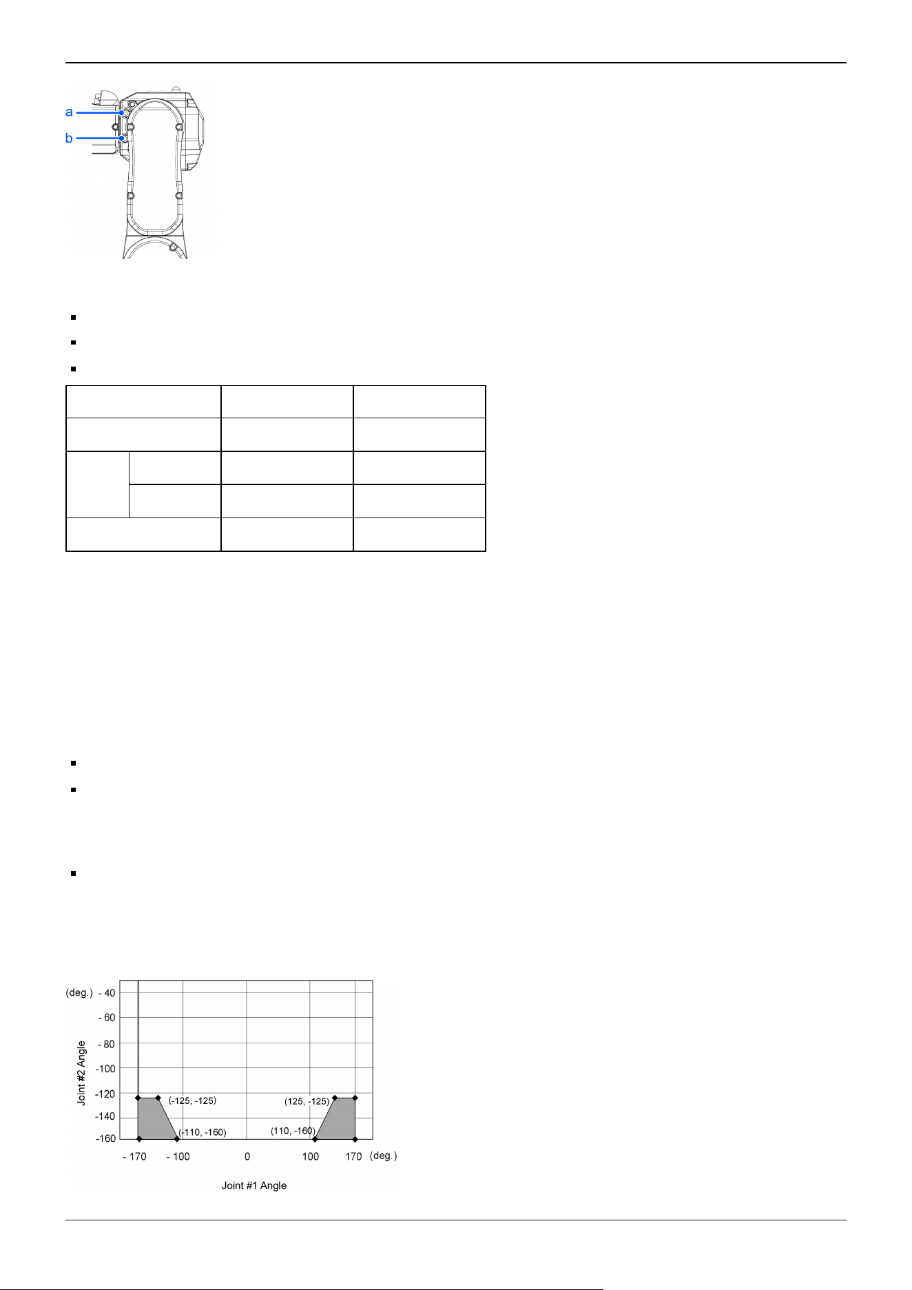
C4-B601**, C4-B901**
Hexagon socket head cap bolt: M8×12
Strength: Compliant with ISO 898-1 property class: 10.9 or 12.9
Tightening torque: 32.0 N·m (326 kgf·cm)
a b
Angle (°) +225 -51
Pulse
C4-B601 ** +5734400 -1299798
C4-B901 ** +10194489 -2310751
Bolt Applied (standard) Applied (standard)
2.5.3 Restriction of Manipulator Operation by Joint Angle Combination
To prevent the arms of the Manipulator from interfering each other, the Manipulator operation is restricted in the specified
motion range according to the angle combination of the Joint #1, #2, and #3.
The Manipulator operation is restricted and the Manipulator stops when the joint angles are within the colored areas in the
following figure.
The restriction to Manipulator operation is enabled:
During CP motion command execution
When you attempt to execute the motion command for moving the Manipulator to a target point (or pose) in the specified
motion range.
The restriction to the Manipulator operation is disabled:
The Arms of the Manipulator momentarily go through the specified motion range during the PTP motion command
execution even though the joint angles of the Arms are in the colored areas of the figures above.
(deg.=°)
Combination of Joint #1 and #2 (C4-B601**)
Industrial Robot: 6-Axis Robots C-B series Manual Rev.1b
69
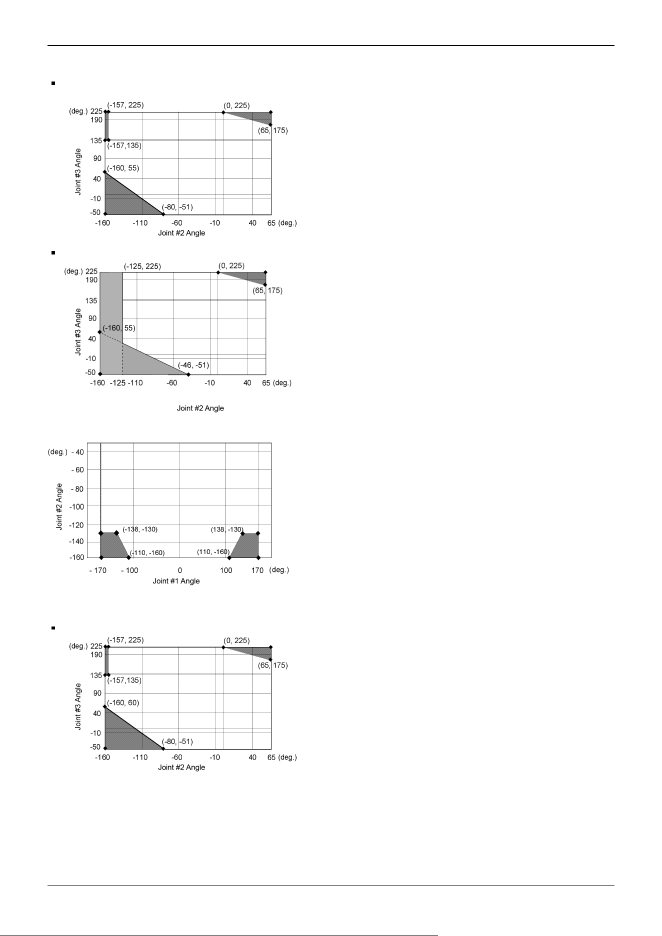
Combination of Joint #2 and #3 (C4-B601**)
-135 deg. <= J1 <= 135 deg.
-170 deg. <= J1 < -135 deg., 135 deg. < J1 <= 170 deg.
Combination of Joint #1 and #2 (C4-B901**)
Combination of Joint #2 and #3 (C4-B901**)
-138 deg. <= J1 <= 138 deg.
Industrial Robot: 6-Axis Robots C-B series Manual Rev.1b
70
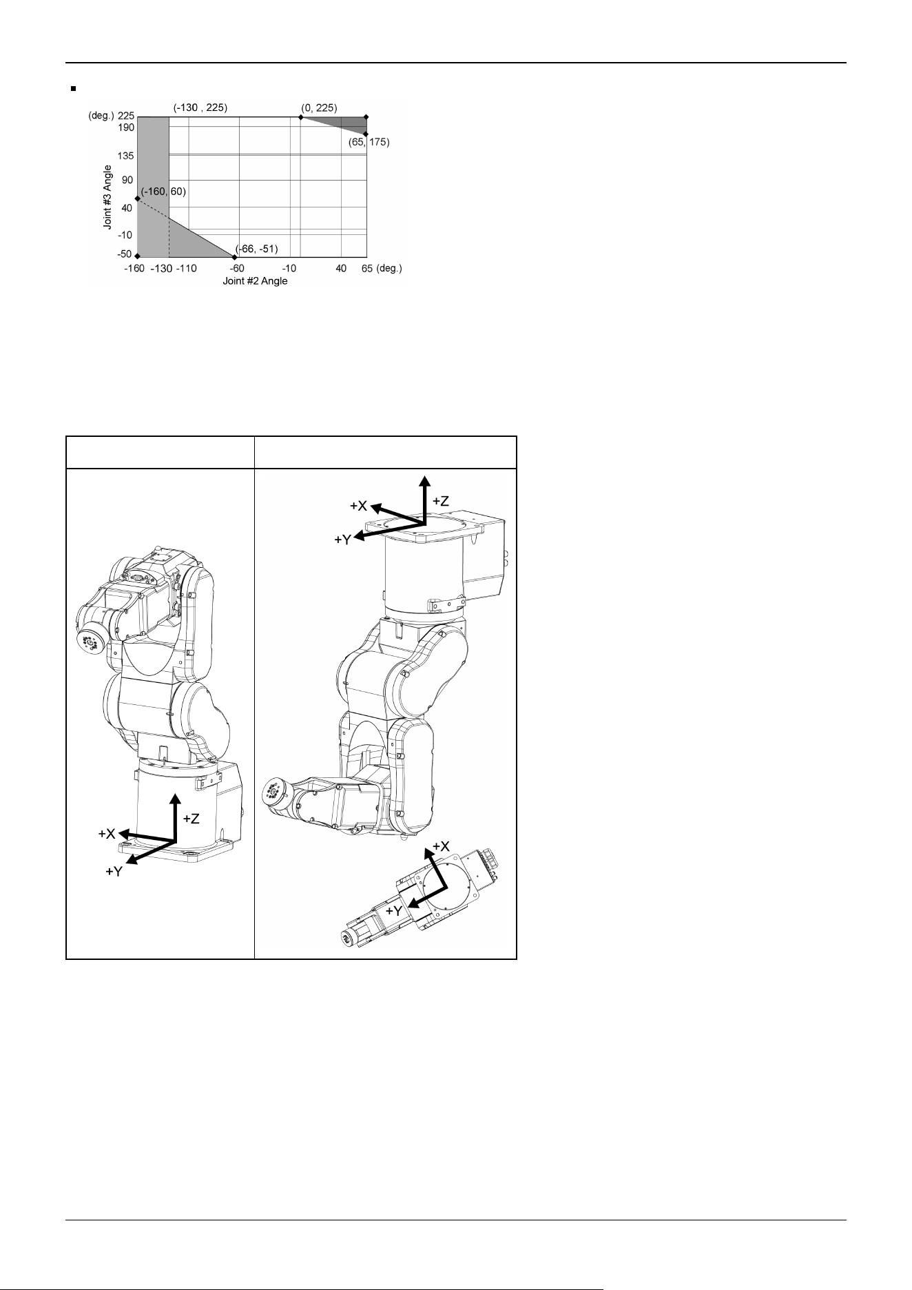
-170 deg. <= J1 < -138 deg., 138 deg. < J1 <= 170 deg.
2.5.4 Coordinate System
The origin point is where the Manipulator’s installation face intersects with the rotation axis of Joint #1.
For details on the coordinate system, refer to the EPSON RC+ Users Guide manual.
Table top mounting Ceiling mounting
BASE setting is suitable for install the robot obliquely.
BASE setting can change a specific coordinate system of the robot and match the World coordinate system of the Jog & Teach
and the coordinate system of the equipment.
For procedure of the BASE setting, refer to SPEL+ Language Reference: BASE Command.
Industrial Robot: 6-Axis Robots C-B series Manual Rev.1b
71
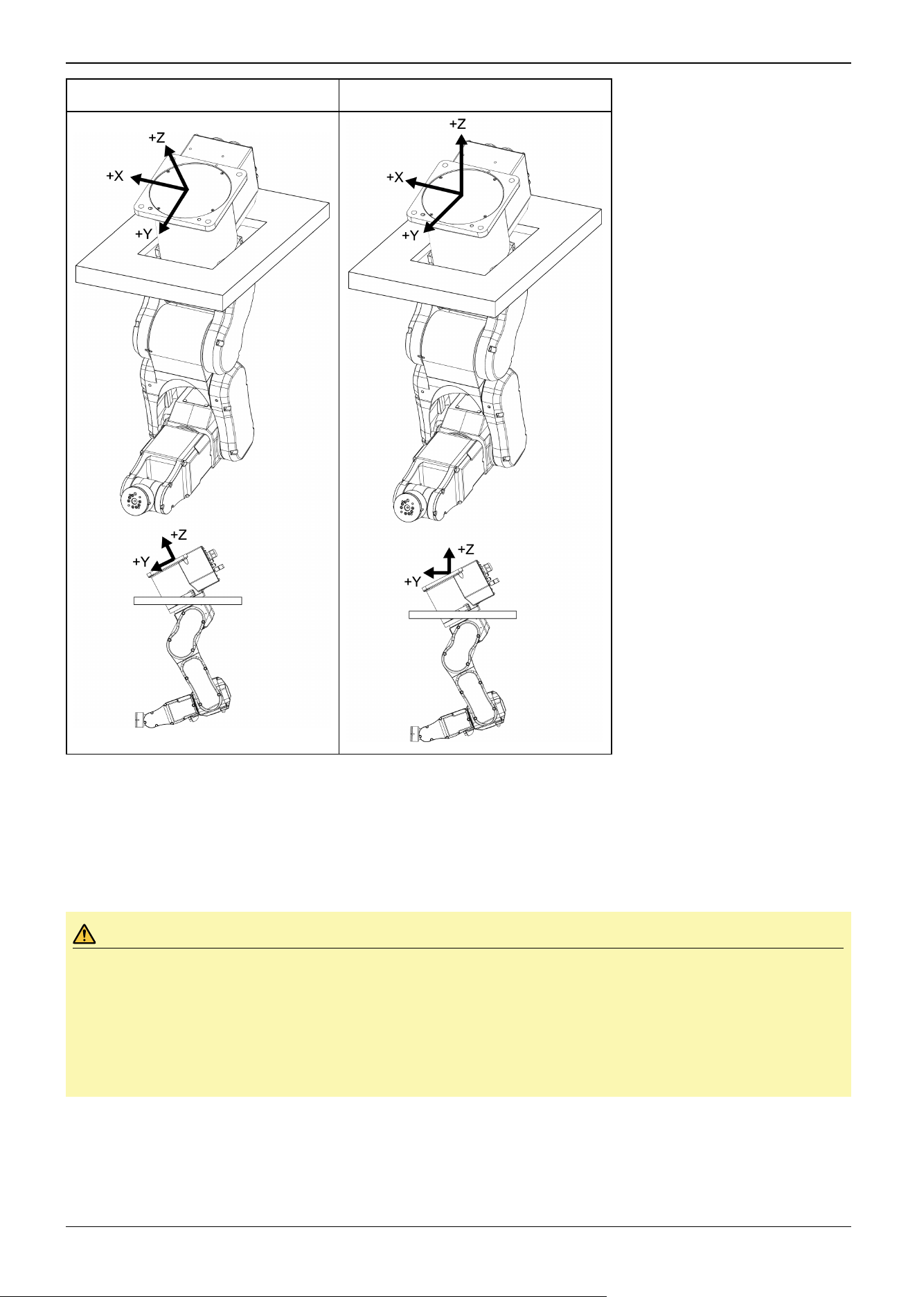
With BASE setting Without BASE setting
2.5.5 Changing the Robot
This section describes how to change the Manipulator model on EPSON RC+.
(Default setting is "table top mounting".)
CAUTION
Changing the Manipulator should be done with great caution. It initializes the robot calibration parameters (Hofs,
CalPls), additional axis information, and PG parameter data. Before changing the robot, make sure to save the
calibration data by following the procedure below.
1. Select the EPSON RC+ 7.0 menu-[Setup]-[System Configuration].
2. Select [Controller]-[Robots]-[Robot**]-[Calibration] from the tree list. Then, click [Save].
1. Select the EPSON RC+ 7.0 menu-[Setup]-[System Configuration].
Industrial Robot: 6-Axis Robots C-B series Manual Rev.1b
72
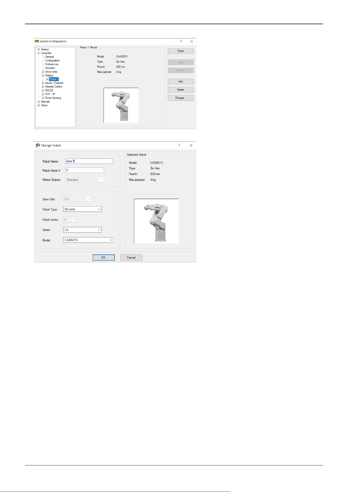
2. Select [Controller]-[Robots]-[Robot**] from the tree list.
3. Click the [Change] button. The following dialog box will be displayed.
4. Input the robot name and serial number printed on the name plate of the Manipulator. Any serial number can be entered.
However, enter the number printed on the Manipulator.
5. Select the robot type in the [Robot type] box.
6. Select the series name of the Manipulator in the [Series] box.
7. Select the robot model in the [Model] box.
Available robots will be displayed according to the format of the currently installed motor driver. When [Dry run] is used,
all the Manipulators of the series selected in Step 6 will be displayed. For the ceiling mount type, select the model which
ends with "R" (e.g. C4-B601SR).
8. Click the [OK] button. The Controller is restarted.
2.5.6 Setting the Rectangular Range in the XY Coordinate System of the Manipulator
The Cartesian (rectangular) range in the XY coordinate system of the Manipulator is specified by the limited Manipulator
operation area and the XYLIM setting. The limited Manipulator operation area is defined so that the hand does not interfere
with the rear side of the Manipulator. The XYLIM setting that you can determines the upper and lower limits of the X and Y
coordinates.
These settings are software-based limit, and so it does not change the maximum physical range. The maximum physical range
is based on the position of the mechanical stops.
These settings are disabled during a joint jogging operation. Therefore, be careful not to allow the hand to collide with the
Manipulator or peripheral equipment.
Industrial Robot: 6-Axis Robots C-B series Manual Rev.1b
73
Go to [Tools] - [Robot Manager] - [XYZ Limits] panel, and make the setting. This can also be set using the XYLim statement
in [Command Window].
2.6 Options
C4 series Manipulator has the following options.
Brake Release Unit
Camera Plate Unit
PS Compatible Plate (Tool Adapter)
Base Side Angled Fittings
Base Side Fittings
PS Compatible Plate (Base Adapter)
Variable Mechanical Stop
2.6.1 Brake Release Unit
While the electromagnetic brake is on (such as in emergency mode), you cannot move any arm by pushing manually. You can
move the Arms by hand using the brake release unit while the Controller power is off or right after unpacking.
KEY POINTS
Precautions regarding the brake release unit
Be sure to prepare at least one set of the brake release unit.
Place at easy-to-reach location so that you can use it immediately when in a emergency situation.
WARNING
Turn off the power to the Robot Controller and brake release unit when connecting or replacing the brake
release unit or external short connector. Inserting or removing connectors with the power on may result in
electric shock and/or malfunction of the robot system.
CAUTION
Normally, release the brakes of joints one at a time. If the brakes of two or more joints must be released
simultaneously due to unavoidable reasons, use extreme care. Releasing the brakes of multiple joints
simultaneously may cause the arm to fall in an unexpected direction, resulting in hands or fingers getting
caught or damage or failure of the Manipulator.
After releasing the brake, the arm may fall by its own weight or move to the unexpected direction. Make sure
to prepare a countermeasure to prevent the arm from falling and check the operation environment is safe.
EPSON
RC+
✏
Industrial Robot: 6-Axis Robots C-B series Manual Rev.1b
74
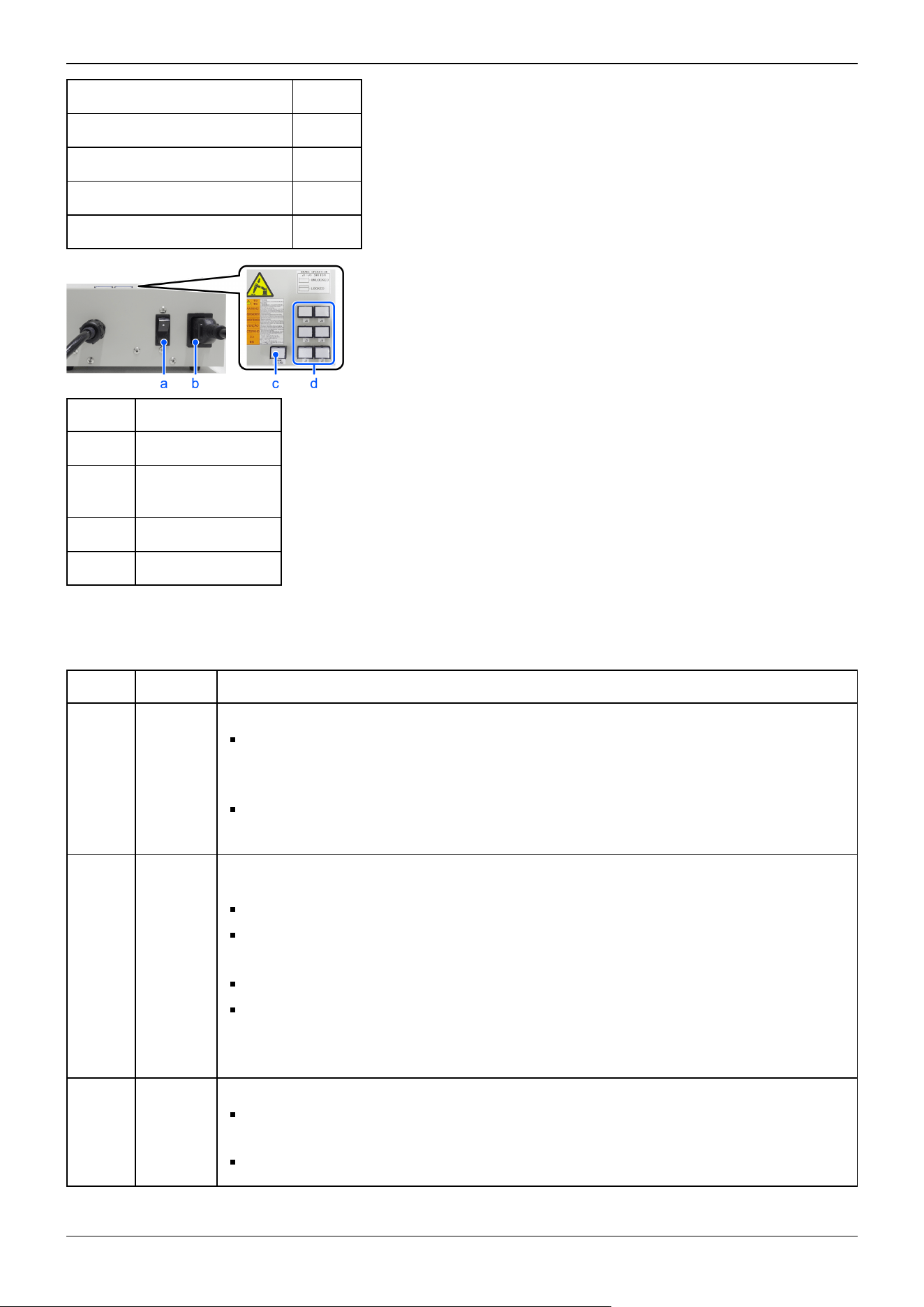
Width 180 mm
Depth 150 mm
Height 87 mm
Weight (Cables are not included.) 1.7 kg
Cable to the Manipulator 2 m
Symbol Description
a Power switch
b
Power Cable
(You must provide.)
c Power lamp
d Brake release switch
2.6.1.1 Power Cable
You must provide a power cable. Be sure to use the specifications below.
Symbol Item Specifications
a Plug
Comply with local safety regulation
Class I (2P + PE), AC250 V, 6 A or 10 A
Ex.: CEE Pub.7 Certified, CCC Certified, KC Certified, BS1363 Certified, PSB Certified, BIS
Certified, SABS Certified
Class I (2P + PE), AC125 V, 7 A, 12 A, or 15 A etc.
Ex.: UL Certified, PSE Certified, BSMI Certified
b
Flexible
cable
Comply with IEC/EN standards or local safety regulation
Example:
IEC 60227-1: General requirements
IEC 60227-5: Polyvinyl chloride insulated cables of rated voltages up to and including 450/750
V - Part 5: Flexible cables (cords)
EN 50525-1: General requirements
EN 50525-2-11: Electric cables - Low voltage energy cables of rated voltages up to and
including 450/750 V (Uo/U) - Part 2-11: Cables for general applications - Flexible cables with
thermoplastic PVC insulation
c
Appliance
coupler
Comply with IEC/EN standards or local safety regulation
IEC / EN 60320-1: Appliance couplers for household and similar general purposes - Part 1:
General requirements
Standard Sheet C13: AC250 V/10 A
Industrial Robot: 6-Axis Robots C-B series Manual Rev.1b
75
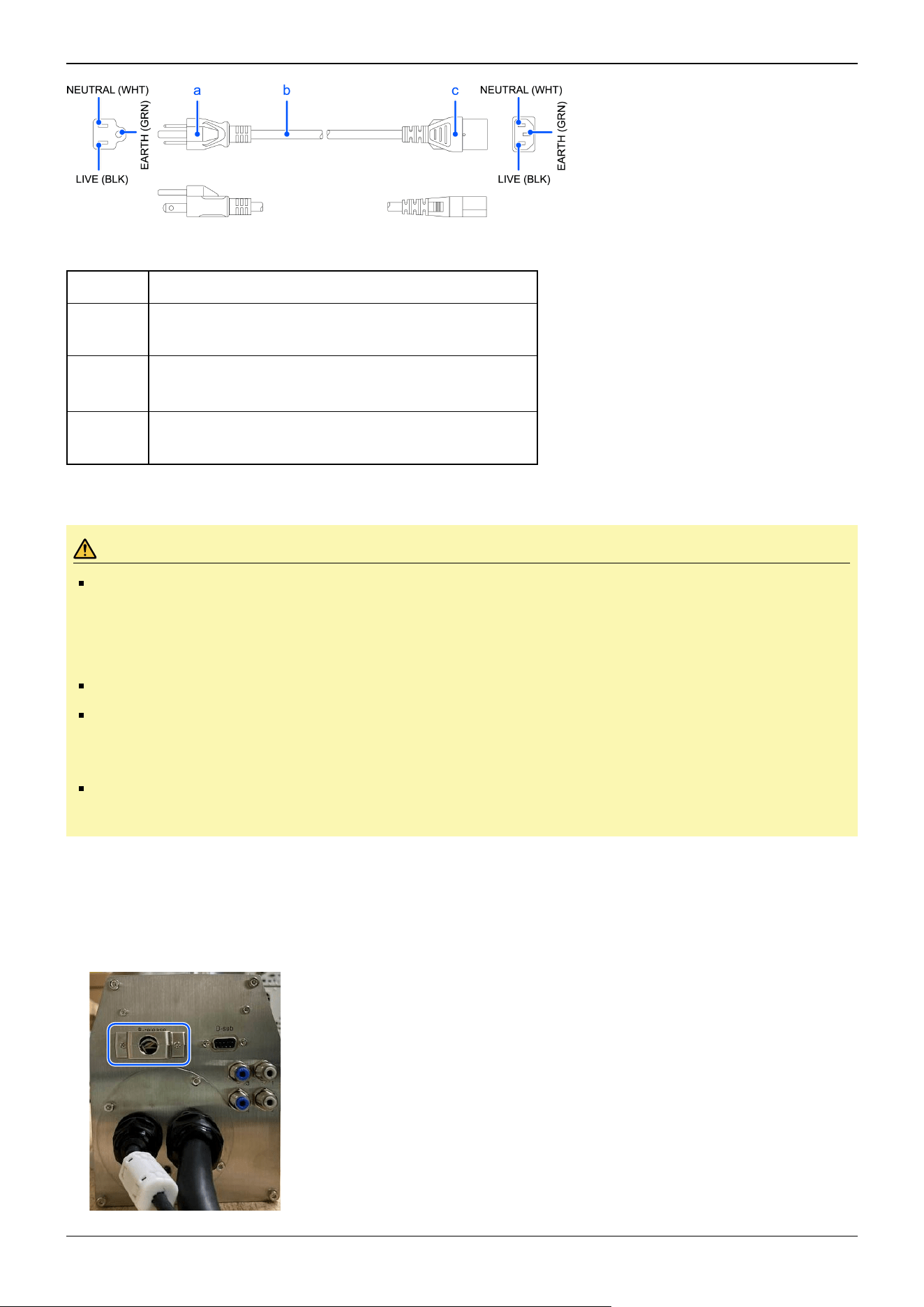
For Japan
Item Specifications
Plug
PSE Certified
Class I (2P+PE), AC125 V, 7 A or higher
Code
PSE Certified
0.75 mm
2
or more
Connector
PSE Certified
IEC 60320-1 Standard Sheet C13: AC125 V/10 A or higher
Precautions for use
CAUTION
Operating the Manipulator without a brake release unit or external short connector connected may cause the
brake to fail to release, possibly damaging the brake.
After using the brake release unit, be sure to connect the external short circuit connector to the Manipulator or
make sure to leave the connector for the brake release unit connected.
Keep the external short connector. Otherwise you cannot release the brakes.
If you turn on the brake release unit while the brake release switch is being pressed, an unintended arm may
move downward. Before turning on the brake release unit, make sure that the brake release switch is not
pressed.
If you turn on the brake release unit without the connector, it may lead to the short for the male pin used in the
connector. Before turning on the brake release unit, make sure that the connector is connected.
2.6.1.2 Installing the Brake Release Unit
1. Turn off the Controller.
2. Remove the external short connector.
Industrial Robot: 6-Axis Robots C-B series Manual Rev.1b
76
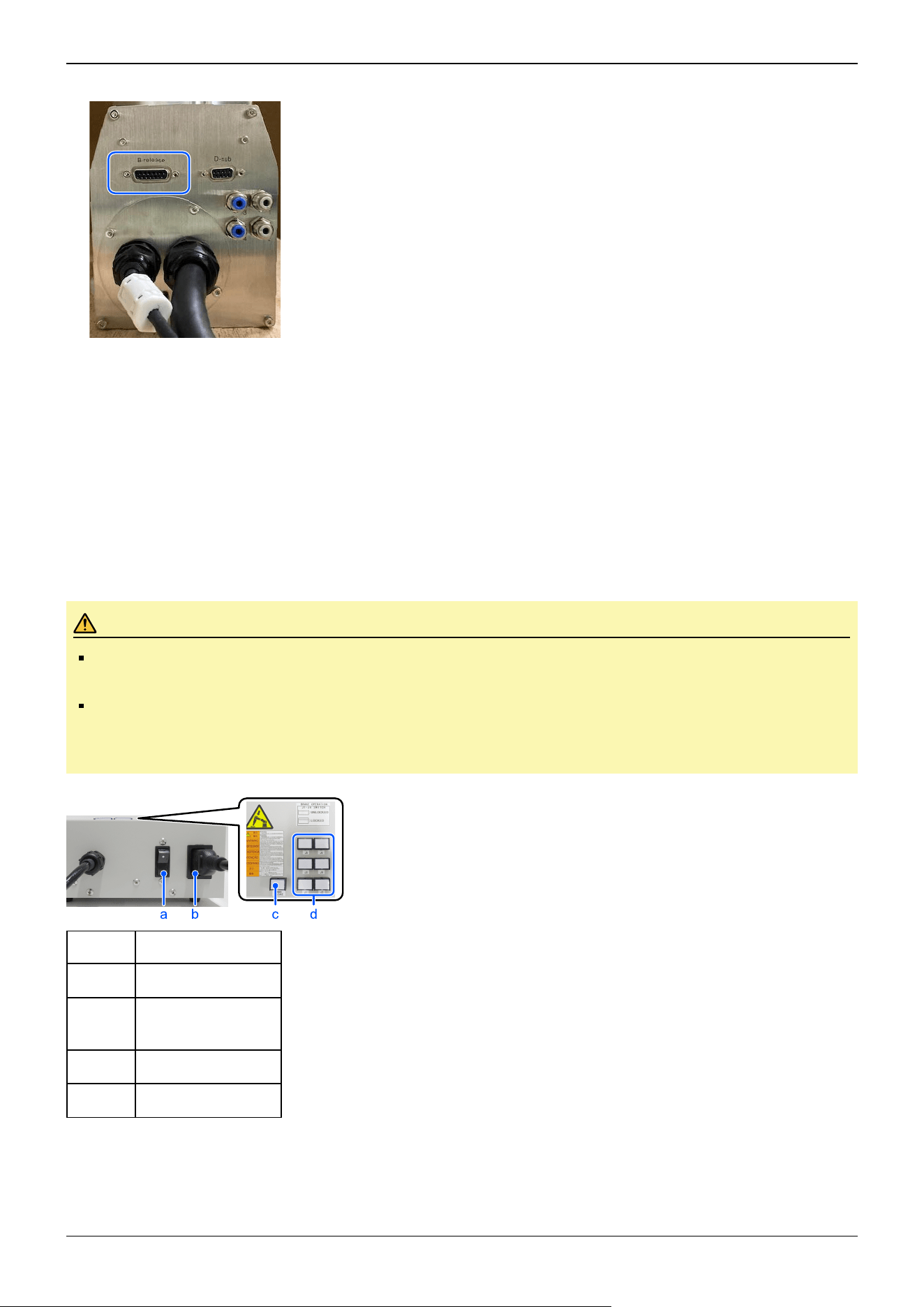
3. Connect the brake release unit to the connector of the connection cable.
2.6.1.3 Removing the Brake Release Unit
1. Turn off the brake release unit.
2. Remove the power cable of the brake release unit.
3. Disconnect the brake release unit from the connector of the connection cable.
4. Connect the external short connector to the connector of the connection cable.
2.6.1.4 How to Use the Brake Release Unit
CAUTION
After releasing the brake, the arm may fall by its own weight or move to the unexpected direction. Make sure
to prepare a countermeasure to prevent the arm from falling and check the operation environment is safe.
If the arm you released its brake moves awkwardly or faster than usual, stop the operation promptly and
contact the supplier. The brake release unit may be broken. If you keep operating the Manipulator, it may lead
to the breakdown of the Manipulator or you may get your hand or fingers caught.
Symbol Description
a Power switch
b
Power Cable
(You must provide.)
c Power lamp
d Brake release switch
1. Refer to “Installing the Brake Release Unit” above to connect the brake release unit to the connector of the connection
cable.
2. Plug the power cable into the brake release unit.
3. Plug the power cable into the power supply plug.
Industrial Robot: 6-Axis Robots C-B series Manual Rev.1b
77
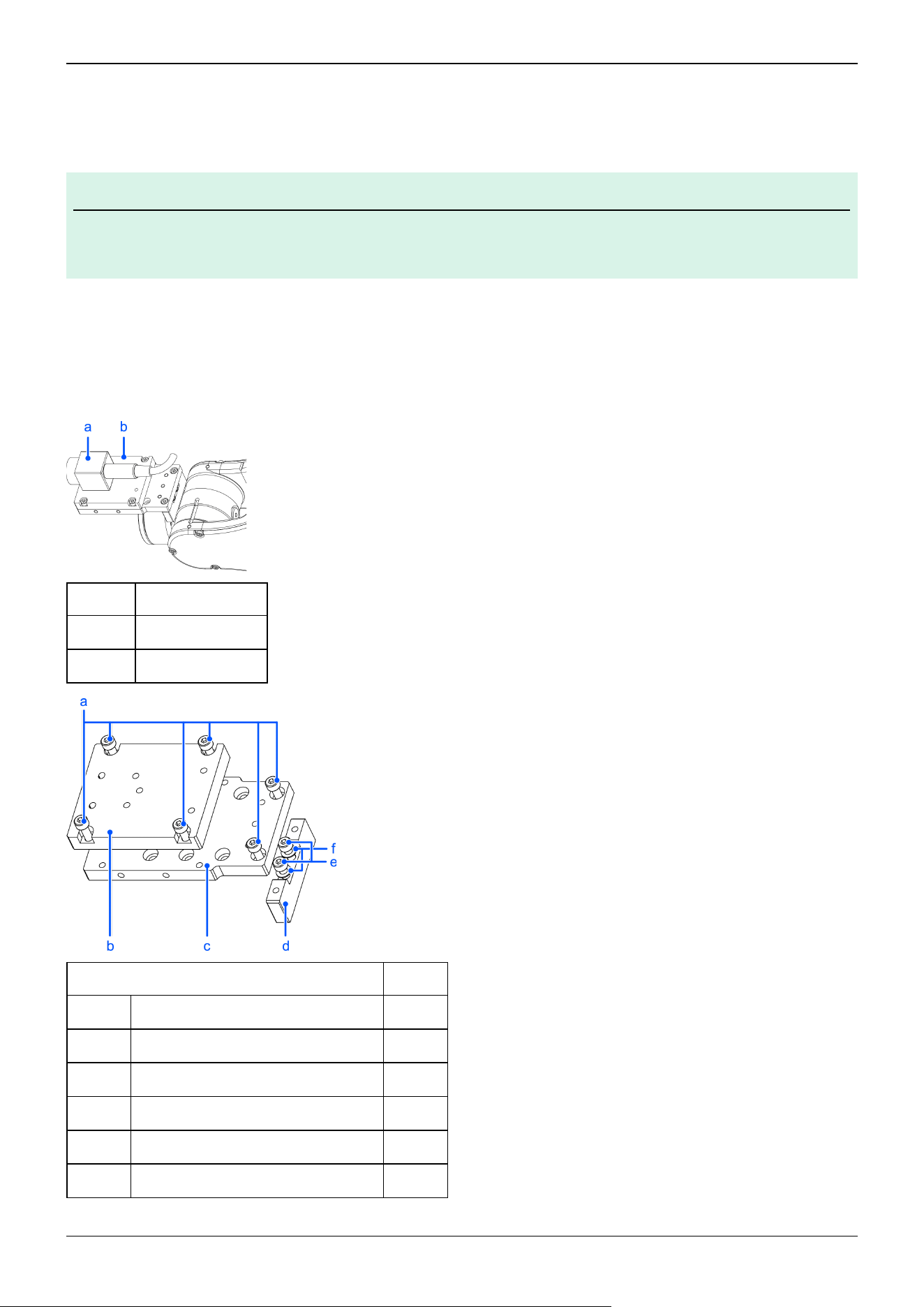
4. Turn on the brake release unit. When the brake release unit is enabled, the power lamp lights up.
5. Press the switch of the arm (J1 to J6) you want to move and then move the arm. Press the switch again. The brake will be
released. The brake will be enabled by pressing the switch once again.
KEY POINTS
Move the arm the brake is released by two persons or more (one presses the switch and one moves the arm).
The arm can be very heavy and needs the significant force to move.
2.6.2 Camera Plate Unit
To mount a camera to the C4 series Manipulator, you need to mount the camera plate unit first.
Appearance of arm end with camera
Symbol Description
a Camera
b Camera Plate Unit
Parts Included Qty.
a Hexagon socket head cap bolt M4×12 6
b Camera adapter plate 1
c Camera mid plate 1
d Camera base plate 1
e Hexagon socket head cap bolt M4×20 2
f Plain washer for M4 (small washer) 2
✏
Industrial Robot: 6-Axis Robots C-B series Manual Rev.1b
78
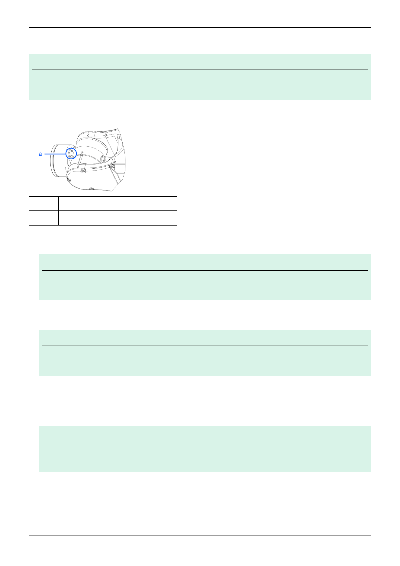
Installation
KEY POINTS
For details of tightening the hexagon socket head cap bolt, refer to the following section.
Tightening the Hexagon Socket Head Cap Bolts
1. Mount the camera base plate to the Manipulator.
2×M4×20 + plain washer for M4 (small washer)
Symbol Description
a Mounting holes for the camera base plate
2. Mount the camera mid plate to the base plate.
2×M4×12
KEY POINTS
The motion range and dimension of the Manipulator with the camera installed may vary depending on the
mounting hole of camera mid plate. The details are described in the table below.
3. Mount the camera to the camera adapter plate.
KEY POINTS
According to the camera, the available mounting hole of adapter plate will be different. The details are
described below.
4. Mount the camera adapter plate and camera to the camera mid plate.
4×M4×12
5. Secure the cables at the position where they do not interfere with the Manipulator motion.
KEY POINTS
When securing the cables, check if the cables bend radius is big enough and the cables are not rubbing
against each other while the Manipulator moves. Otherwise, the cables will be disconnected.
Dimension of the camera plate unit
✏
✏
✏
✏
Industrial Robot: 6-Axis Robots C-B series Manual Rev.1b
79
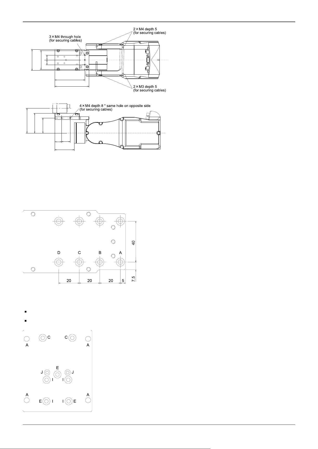
Dimensions X and Y will change depending on the position of camera mid plate and camera size. Refer to the table below for
the values.
Camera mid plate
The camera mid plate uses the mounting holes A to D.
By using the different mounting holes, it can be mounted to the camera base plate in the different four positions.
Camera adapter plate
Each camera uses the different mounting holes.
USB camera: J (2 holes)
GigE camera: E (3 holes)
61
55
14
14
88
100
X
58
44
20 25
Y
Industrial Robot: 6-Axis Robots C-B series Manual Rev.1b
80
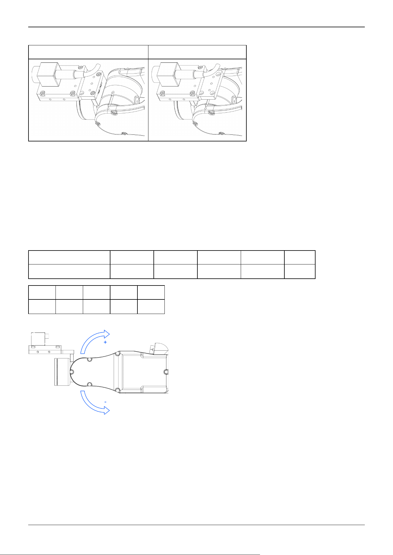
Mounting example
Using the mounting hole A Using the mounting hole C
E.g.) Camera: XC-ES30
Camera and Joint #5 motion range (reference values)
The Joint #5 motion range varies depending on the mounting position of camera mid plate and the camera you are using.
The table below shows the motion range (reference values) based on the available cameras for this option and the mounting
positions of the camera mid plate. The values in the table may vary depending on how to secure the cables.
By changing the Y position, you can extend the distance from the hand mounting surface to the camera. Also, you can attach
the larger end effector. However, be careful about the Joint #5 motion range that will be limited in this case.
(°= deg.)
A B C D X
USB Camera, GigE Camera -135° to +60° -135° to +50° -135° to +35° -135° to +25° 72.5 mm
A B C D
Y 57 mm 37 mm 17 mm 7 mm
Direction of the Joint #5 motion
2.6.3 PS Compatible Plate (Tool Adapter)
Using the PS compatible plate, you can mount the hand used in the PS series to the C4 series. Also you can mount the hand
with flange which is conformed to ISO9409-1.
Industrial Robot: 6-Axis Robots C-B series Manual Rev.1b
81
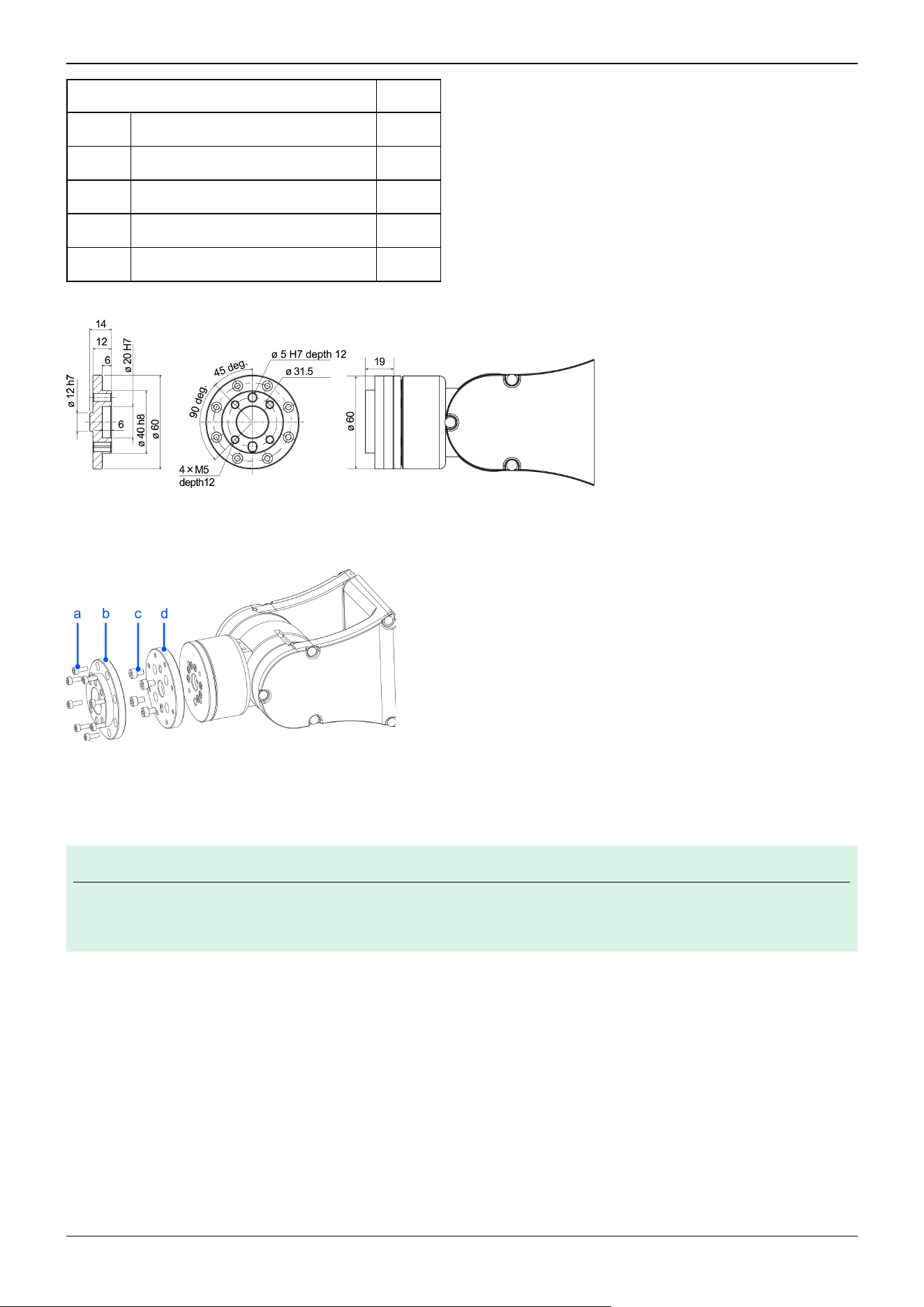
Parts Included Qty.
a Hexagon socket head cap bolt M3×8 8
b PS compatible plate 2 1
c Hexagon socket head cap bolt M4×6 4
d PS compatible plate 1 1
e Dowel pin (M3 hole on one side) 2
Dimensions of PS compatible plate
depth = depth of threaded hole
90° pitch
* Each dimension and tolerance complies with ISO9409-1-31.5-4-M5.
Installation
KEY POINTS
For details of tightening the hexagon socket head cap bolt, refer to the following section.
Tightening the Hexagon Socket Head Cap Bolts
1. Align the hole (⌀12H7) on the arm end flange to the projection (⌀12h7) on the PS compatible plate 1.
2. Insert the dowel pin from the PS compatible plate 1 side and position the arm and PS compatible plate 1.
✏
Industrial Robot: 6-Axis Robots C-B series Manual Rev.1b
82
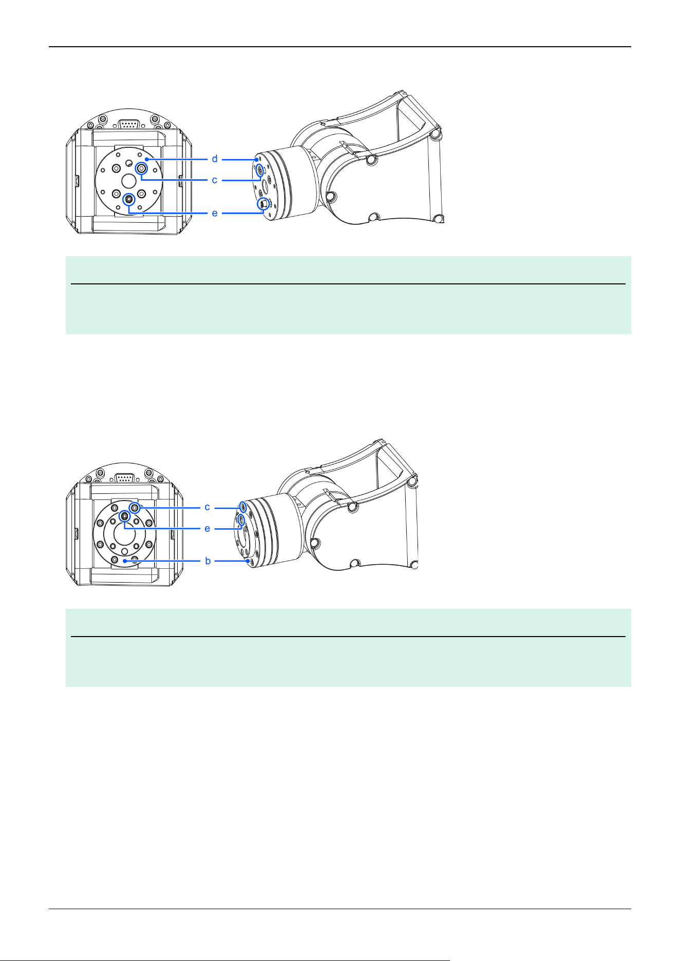
3. Secure the PS compatible plate 1 with 4 hexagon socket head cap bolts.
4×M4×6
KEY POINTS
If you move the Manipulator with the dowel pin inserted, the dowel pin will fall out. After fixing the PS
compatible plate 1, remove the dowel pin.
4. Align the hole (⌀12H7) on the PS compatible plate 1 to the projection (⌀12h7) on the PS compatible plate 2.
5. Insert the dowel pin from the PS compatible plate 2 side and position the PS compatible plate 1 and 2.
6. Secure the PS compatible plate 2 with 8 hexagon socket head cap bolts.
8×M3×8
KEY POINTS
If you move the Manipulator with the dowel pin inserted, the dowel pin will fall out. After fixing the PS
compatible plate 2, remove the dowel pin.
2.6.4 Base Side Angled Fittings
By using the base side angled fittings to the C4 series Manipulator base, you can mount the Manipulator in skewed position.
The motion range expands with this mounting type compared to the normal ceiling mounting.
✏
✏
Industrial Robot: 6-Axis Robots C-B series Manual Rev.1b
83
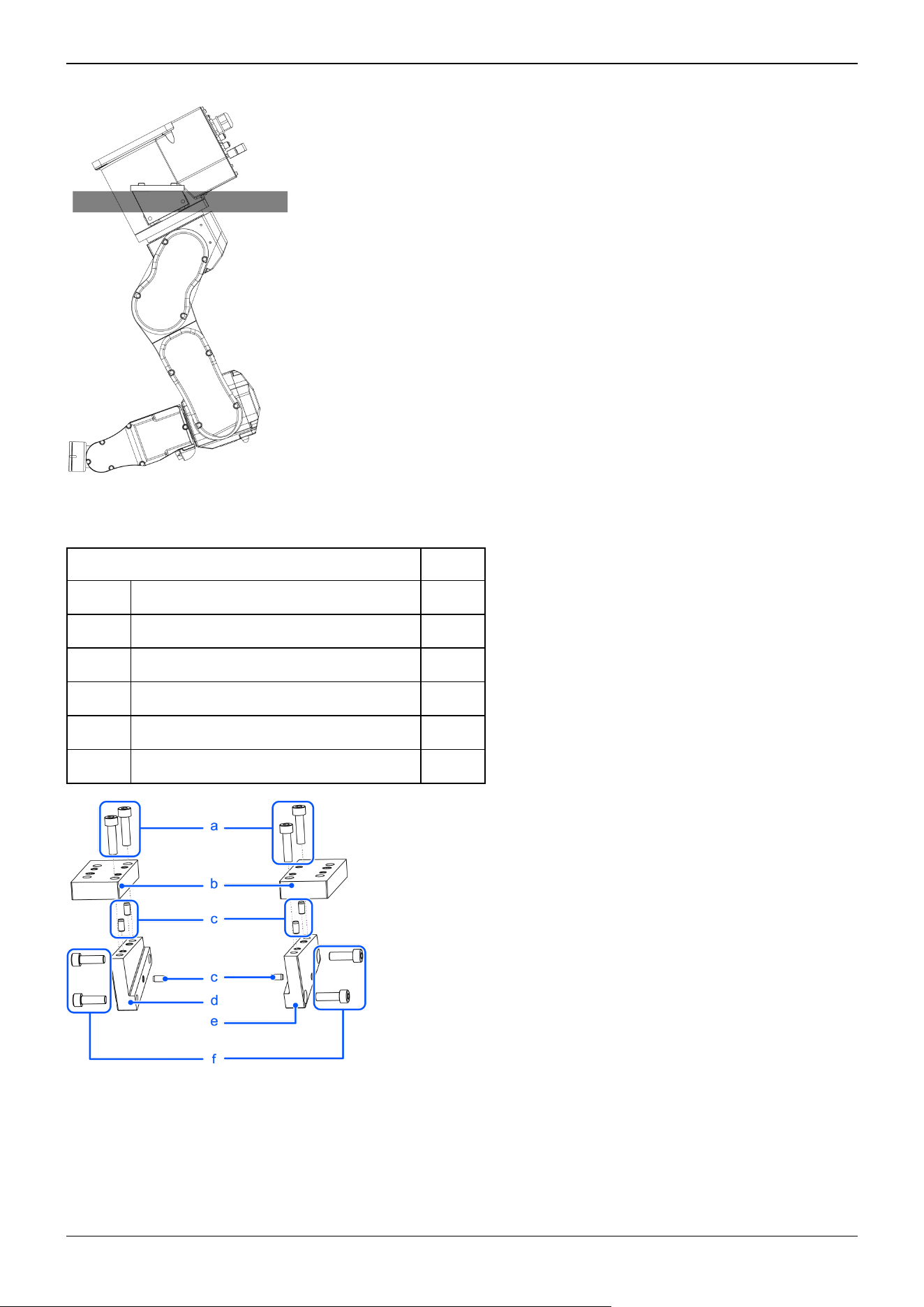
Mounting image using the base side angled fittings
For the information on how to mount and precautions, refer to the following section.
Environment and Installation
Parts Included Qty.
a Hexagon socket head cap bolt M8×30 4
b Base side plate (for Skewed mounting type) 2
c Pin 6
d Base side angled plate (Left side) 1
e Base side angled plate (Right side) 1
f Hexagon socket head cap bolt M8×25 4
To mount the base side angled fittings
Industrial Robot: 6-Axis Robots C-B series Manual Rev.1b
84
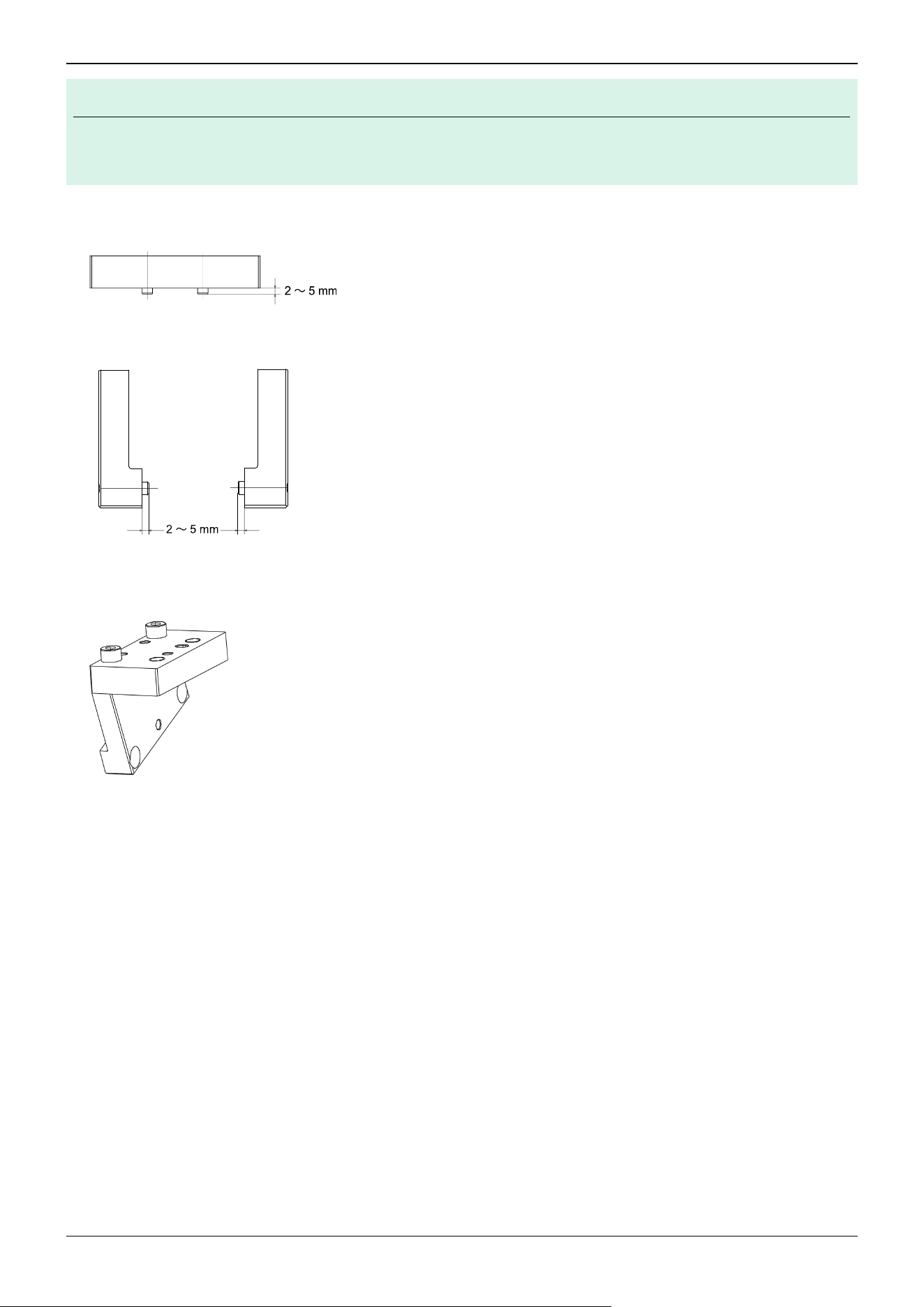
KEY POINTS
For details of tightening the hexagon socket head cap bolt, refer to the following section.
Tightening the Hexagon Socket Head Cap Bolts
1. Drive pins to the base side plate (for Skewed mounting type).
Protruding part of pins is approx. 2 to 5 mm.
2. Drive pins to the base side angled plate (left and right sides).
Protruding part of pins is approx. 2 to 5 mm.
3. Create a base side angled fittings. Fit the pins of the plate for Skewed mounting type in the step (1) with the holes on the
plate in the step (2) and secure with the screws.
Hexagon socket head cap bolt M8×30
✏
Industrial Robot: 6-Axis Robots C-B series Manual Rev.1b
85
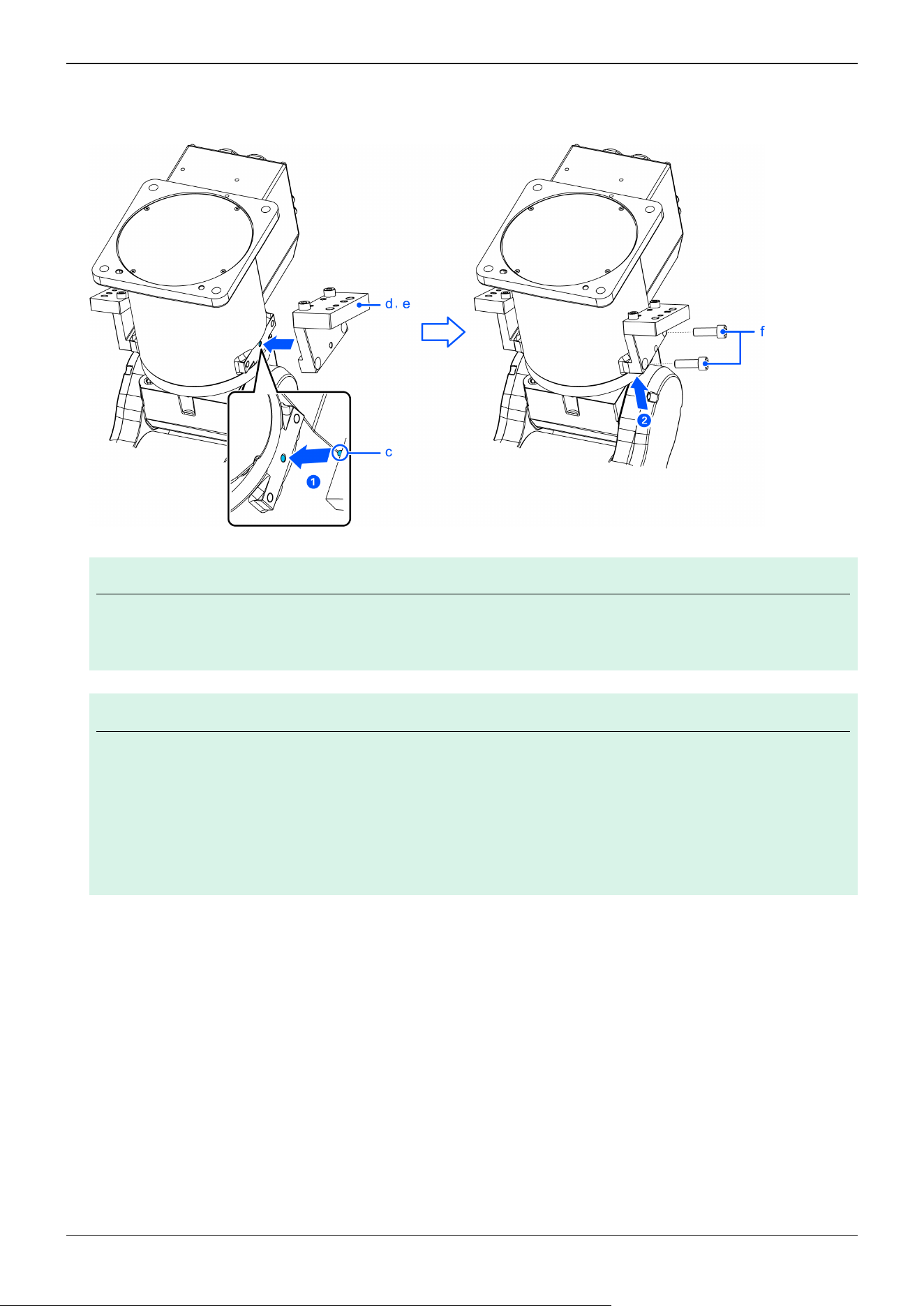
4. Mount the base side angled fittings to the both sides of Manipulator base. Fit the pins drove in the step (2) with the holes on
the base. Secure the fittings by pressing it to the indicated direction in the figure below.
Left and Right side Hexagon socket head cap bolt 2×M8×25
KEY POINTS
The shape of the base side angled fittings is asymmetry. Be sure to mount the fittings in correct direction.
Otherwise, the motion range of Arm #2 is limited in the backside.
KEY POINTS
The recommended base plate thickness is between 30 mm and 40 mm. If the thickness is more than 40 mm,
the Manipulator may contact the base plate when the Arm #1 rotates depending on the center cut dimension
in the base plate.
The base plate securing the Manipulator should be prepared by users. The torque value and reaction force
generated in the Manipulator motions are described in the following section.
From Unpacking to Installation
2.6.5 Base Side Fittings
Using the base side fittings to the C4 Manipulator base, you can mount the Manipulator in the place where limits the mounting
height or use the open room for the base.
✏
✏
Industrial Robot: 6-Axis Robots C-B series Manual Rev.1b
86
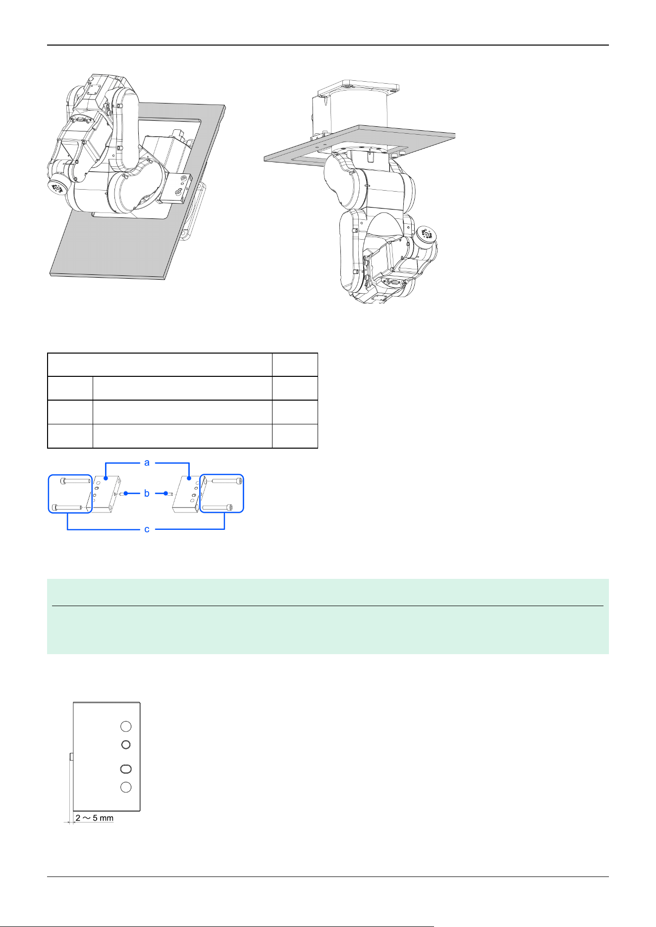
Mounting image using the base side fittings
For the information on how to mount and precautions, refer to the following section.
Environment and Installation
Parts Included Qty.
a Base side plate 2
b Pin 2
c Hexagon socket head cap bolt M8×60 4
To mount the base side plate
KEY POINTS
For details of tightening the hexagon socket head cap bolt, refer to the following section.
Tightening the Hexagon Socket Head Cap Bolts
1. Drive the pins to the base side plate.
Protruding part of pins is approx. 2 to 5 mm.
✏
Industrial Robot: 6-Axis Robots C-B series Manual Rev.1b
87
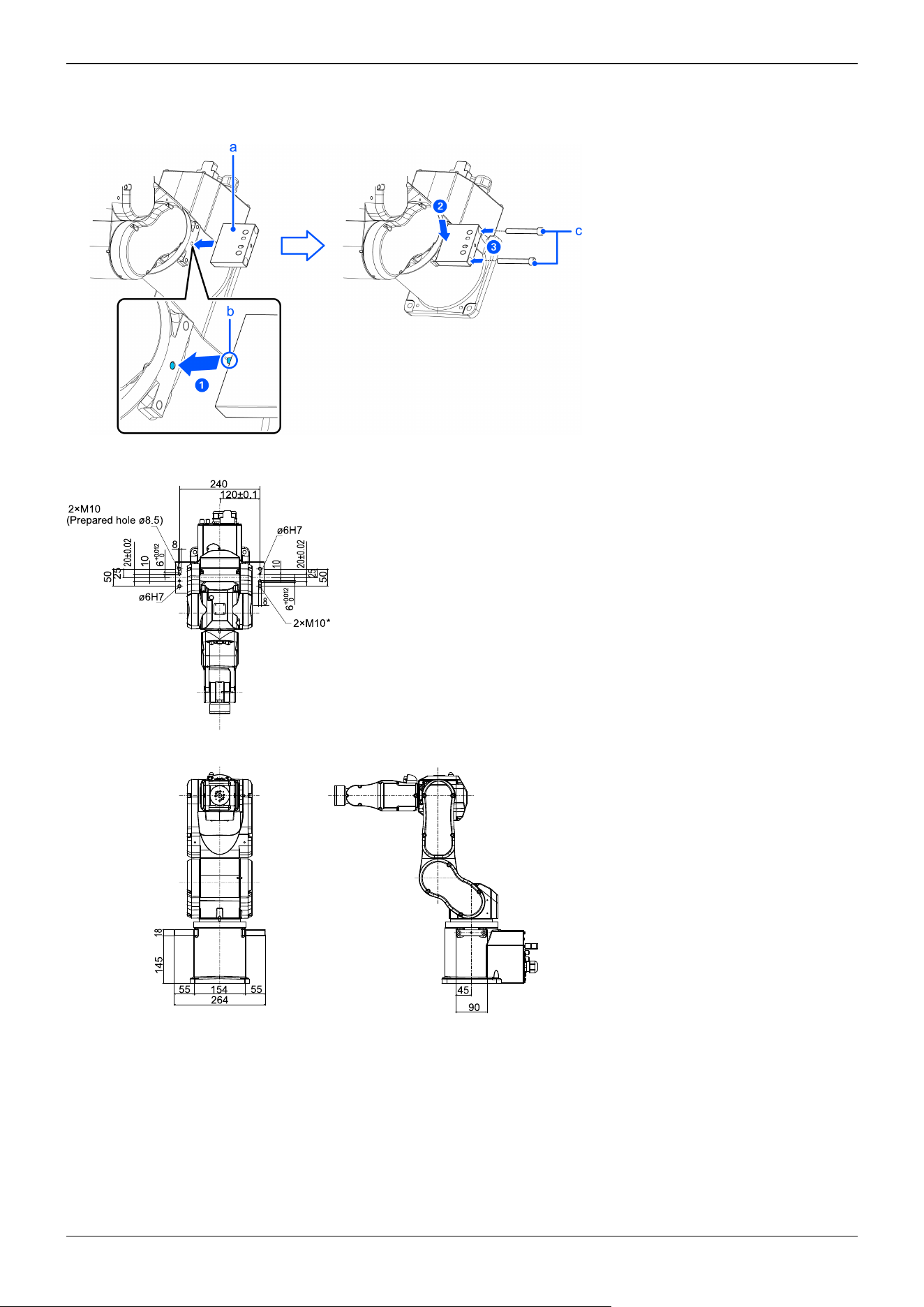
2. Mount the base side plate with the pins driven to the both sides of the base.
Fit the pins with the holes and secure the base side plate by pressing it from above to the base fixing part. (With the steps
above, the both surfaces of base side fittings can be stable.)
Dimension of the Manipulator with the base side fittings
* 2×M10 (prepared threaded hole ⌀8.5)
Mounting example
Screws
Industrial Robot: 6-Axis Robots C-B series Manual Rev.1b
88
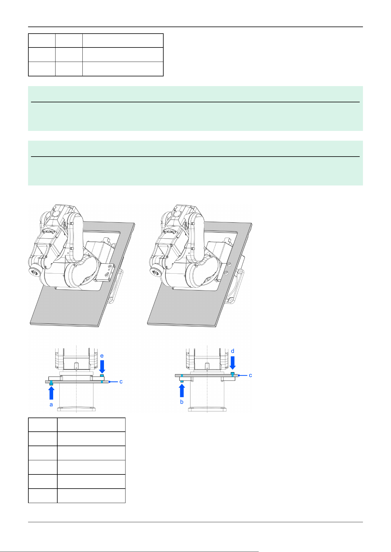
Size Recommended Length
A M8 30 mm or more
B M10 15 mm + base plate or more
KEY POINTS
The base side plate has a M10 threaded hole. You can secure the plate with a M10 screw or a M8 screw by
using the prepared screw hole of ⌀8.5 to make a M8 screw hole on the mounting surface.
KEY POINTS
When you install the Manipulator for practical use, you need to insert the screws in the right/left side from the
same direction (above or below).
Table top mounting
Symbol Description
a B: Secures from below
b A: Secures from below
c Base plate (Table top)
d B: Secures from above
e A: Secures from above
✏
✏
Industrial Robot: 6-Axis Robots C-B series Manual Rev.1b
89
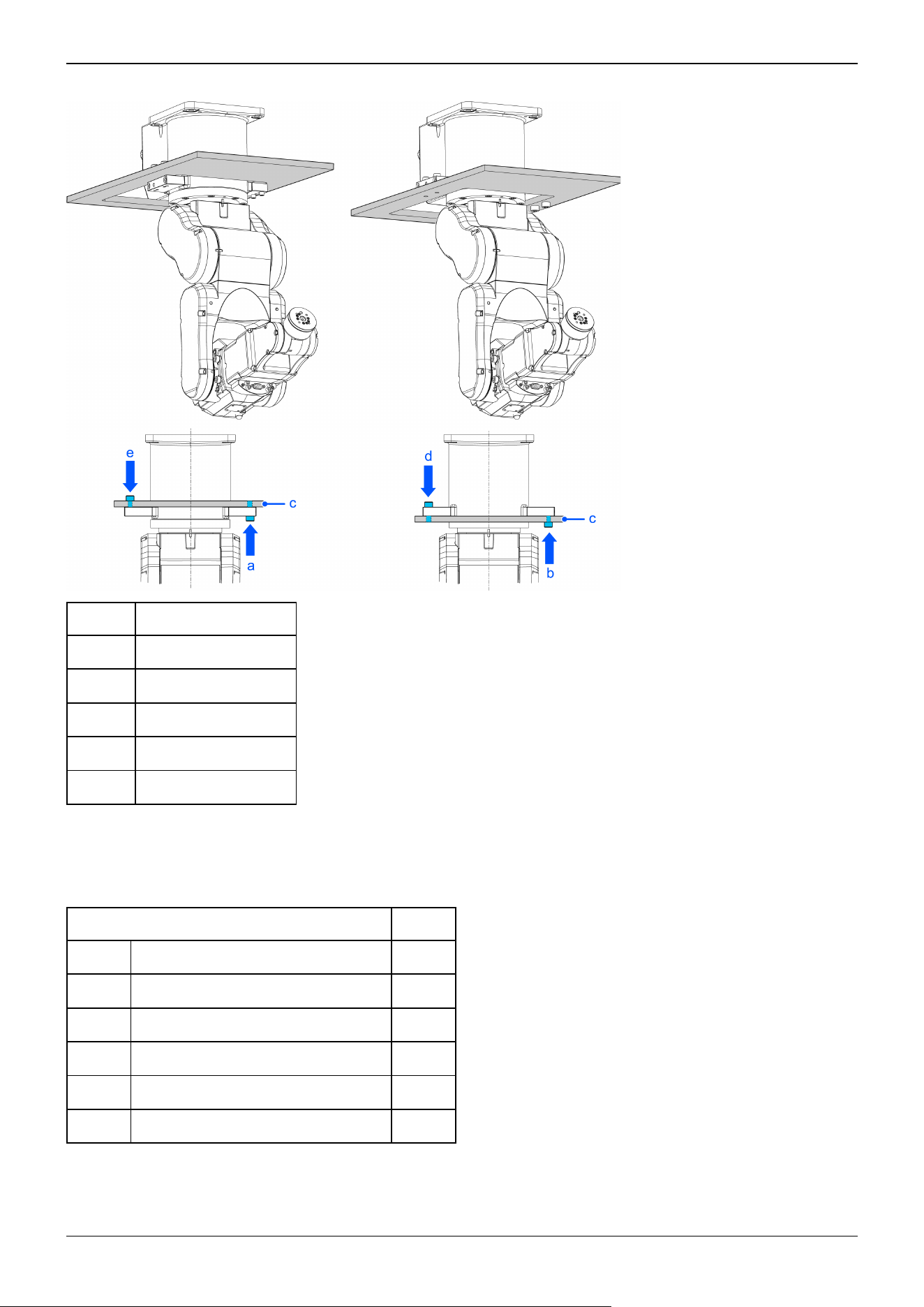
Ceiling mounting
Symbol Description
a A: Secures from below
b B: Secures from below
c Base plate (Ceiling)
d A: Secures from above
e B: Secures from above
2.6.6 PS Compatible Plate (Base Adapter)
PS compatible plate is used to use Manipulator fixing taps for PS series to the C4 series Manipulator.
Parts Included Qty.
a PS compatible plate 1
b Dowel pin (M4 hole on one side) 3
c Dowel pin (M6 hole on one side) 2
d Hexagon socket head cap bolt M10×25 8
e Plain washer 4
f Spring washer 8
Industrial Robot: 6-Axis Robots C-B series Manual Rev.1b
90
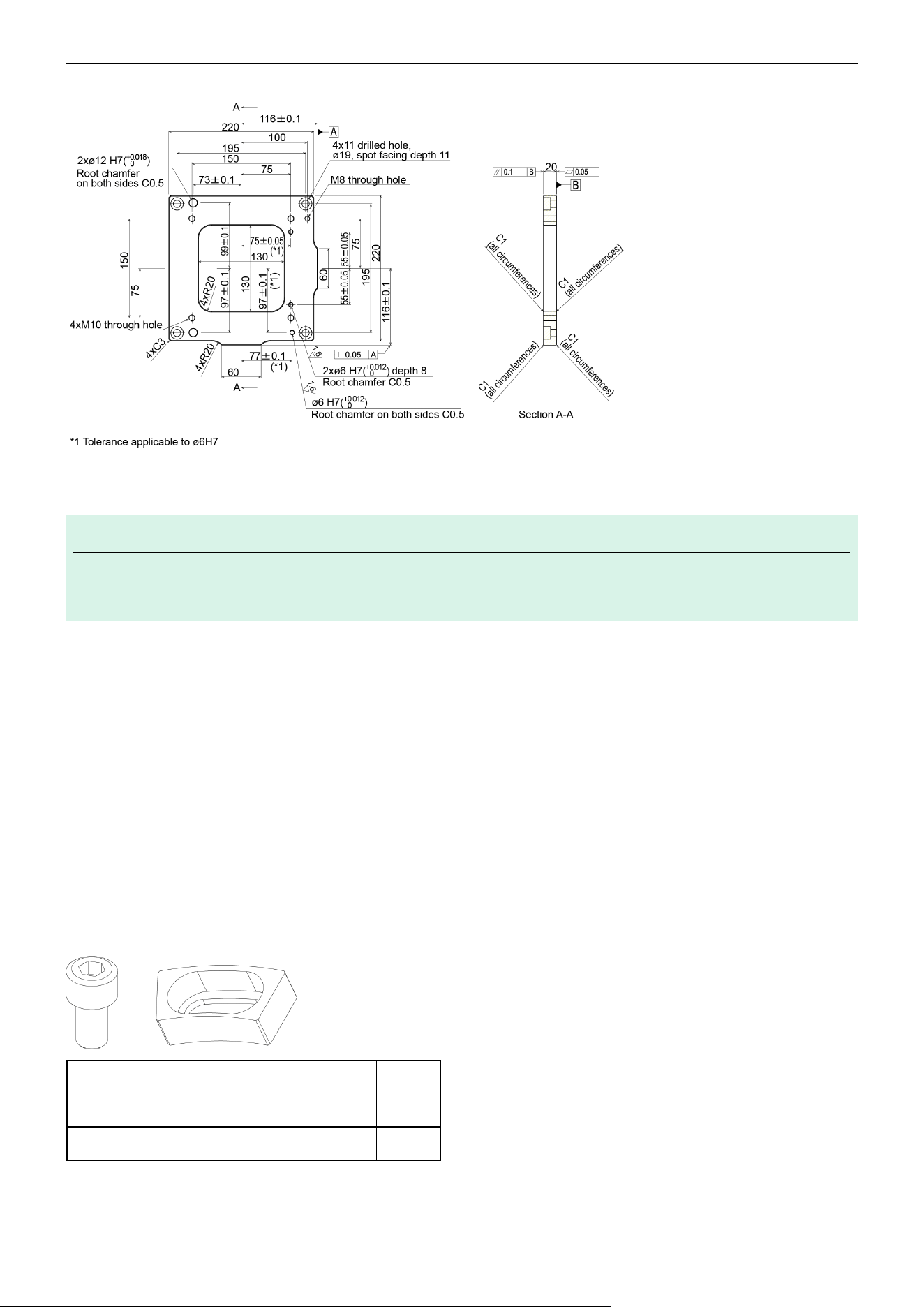
Dimensions of PS compatible plate
Installation
KEY POINTS
For details of tightening the hexagon socket head cap bolt, refer to the following section.
Tightening the Hexagon Socket Head Cap Bolts
1. Fix the base table and the PS compatible plate with hexagon socket head cap bolts (4×M10×25) and spring washers.
Use dowel pins as needed to adjust positions of the base table and the PS compatible plate.
2. Fix the C4 series Manipulator and the PS compatible plate.
Hexagon socket head cap bolts (4×M10×25) + spring washers + plain washers
Use dowel pins as needed to adjust positions of the Manipulator and the PS compatible plate.
2.6.7 Variable Mechanical Stop
This option is used to mechanically limit the motion range of the Manipulator.
For installation and angle restriction measures, refer to the following section.
Setting the Work Envelope by Mechanical Stops
Variable Mechanical Stop (J1)
Parts Included Qty.
a Variable Mechanical Stop (J1) 1
b Hexagon socket head cap bolt M8×5 1
✏
Industrial Robot: 6-Axis Robots C-B series Manual Rev.1b
91
Variable Mechanical Stop (J2)
Parts Included Qty.
a Variable Mechanical Stop (J2) 1
Industrial Robot: 6-Axis Robots C-B series Manual Rev.1b
92

3. C8 Manipulator
This chapter contains information for setup and operation of the Manipulators.
Please read this chapter thoroughly before setting up and operating the Manipulators.
Industrial Robot: 6-Axis Robots C-B series Manual Rev.1b
93
3.1 Safety
The Manipulator and its related equipment should be unpacked and transported by people who have received installation
training provided by Epson and the suppliers. Also, the laws and regulations of the installation country must be followed.
Before use, please read this manual and other related manuals to ensure correct use. After reading this manual, store it in an
easily accessible location for future reference.
This product is intended for transporting and assembling parts in a safely isolated area.
3.1.1 Conventions Used in This Manual
The following symbols are used in this manual to indicate important safety information. Be sure to read the descriptions shown
with each symbol.
WARNING
This symbol indicates an imminently hazardous situation which, if operation is not performed properly, will result
in death or serious injury.
WARNING
This symbol indicates a potentially hazardous situation which, if operation is not performed properly, could result
in an injury due to electric shock.
CAUTION
This symbol indicates a potentially hazardous situation which, if operation is not performed properly, may result in
a minor or moderate injury or in property damage only.
3.1.2 Design and Installation Safety
The robot system should be designed and installed by people who have received installation training provided by Epson and
the suppliers.
Design personnel should refer to the following manuals:
"Safety Manual"
"Controller Manual"
"Manipulator Manual"
Refer to the following section for the installation safety information.
Environment and Installation
Be sure to read this section and follow the safety information before installation to ensure that the installation work is
performed safely.
Industrial Robot: 6-Axis Robots C-B series Manual Rev.1b
94
3.1.3 Operation Safety
The following items are safety precautions for operating personnel:
WARNING
Be sure to read the Safety Manual before use. Operating the robot system without understanding the safety
information can be extremely dangerous and may result in serious injury or severe equipment damage.
Before operating the robot system, make sure that no one is inside the safety barriers. The robot system can
be operated in the teaching operation mode even when someone is inside the safety barriers. Even though
the motion of the Manipulator is always restricted (low speed and low power) to ensure operator safety, an
unexpected movement by the Manipulator can be extremely dangerous and may cause serious safety
problems.
If the Manipulator moves abnormally during operation of the robot system, immediately press the emergency
stop switch.
WARNING
To perform the power supply lockout, remove the power plug. Be sure to connect the AC power cable to a
power outlet. Do not connect it directly to a factory power source.
Before performing any replacement work, inform others in the area that you are working, and then turn off the
Controller and related equipment, and unplug the power cable from the power source. Performing any work
procedure with the power turned on is extremely dangerous and may result in electric shock and/or
malfunction of the robot system.
Do not connect or disconnect the connector of the M/C cable while the Controller is turned on. There is a risk
the Manipulator may malfunction, which is extremely hazardous. Also, performing any work procedure with
the power turned on may result in electric shock and/or malfunction of the robot system.
CAUTION
Whenever possible, only one person should operate the robot system. If it is necessary to operate with more
than one person, ensure that all personnel communicate with each other and take all necessary safety
precautions.
If the Manipulator is operated repeatedly with each joint having an operating angle of 5° or less, the bearings
used in the joints are likely to cause oil film shortage. Repeated operation may cause premature damage. To
prevent premature damage, operate the Manipulator to move each joint to an angle of 30° or more about
once per hour.
When the robot is operating at low speed (Speed: 5 to 20%), vibration (resonance) may occur continuously
during operation depending on the combination of the arm orientation and hand load. Vibration occurs due to
the natural vibration frequency of the arm and can be reduced by taking the following measures:
Changing the robot speed
Changing the teach points
Changing the hand load
Industrial Robot: 6-Axis Robots C-B series Manual Rev.1b
95

3.1.4 Emergency Stop
Each robot system needs equipment that will allow the operator to immediately stop the system's operation. Install an
emergency stop device by using emergency stop input from the Controller or other equipment.
Before using the emergency stop switch, be aware of the following points.
The emergency stop switch should be used to stop the Manipulator only in case of emergencies.
Besides pressing the emergency stop switch when an emergency occurs, to stop the Manipulator during program operation,
use the Pause or STOP (program stop) statements assigned to a standard I/O.
The Pause and STOP statements do not turn off motor energization, and so the brake is not locked.
To place the robot system in emergency stop mode in a non-emergency (normal) situation, press the emergency stop switch
while the Manipulator is not operating.
Do not press the emergency stop switch unnecessarily while the Manipulator is operating normally.
It could shorten the lifespan of the following components.
Brakes
The brakes will be locked, which will shorten the lifespan of the brakes due to worn brake friction plates.
Normal brake lifespan:
About 2 years (when the brakes are used 100 times/day)
or about 20,000 times
Reduction gears
An emergency stop applies an impact to the reduction gear, which can shorten its life.
If the Manipulator is stopped by turning off the Controller while it is operating, the following problems may occur.
Reduced life and damage to reduction gear
Position shift at the joints
If a power outage or other unavoidable Controller power-off occurs during Manipulator operation, check the following points
after power is restored.
Damage in reduction gear
Shifting of the joints from their proper positions
If there was any shifting, maintenance is required. For more information, please contact the supplier.
Stopping distance of emergency stop
The Manipulator during operation cannot stop immediately after the emergency stop switch is pressed. Also, the stopping time
and movement distance vary depending on the following factors.
Hand weight, WEIGHT setting, ACCEL setting, workpiece weight, SPEED setting, movement posture, etc.
For the stopping time and movement distance of the Manipulator, refer to the following section.
Appendix B: Stopping Time and Stopping Distance at Emergency Stop
3.1.5 Safeguard (SG)
To maintain a safe working zone, safety barriers must be set up around the Manipulator, and safeguards must be installed at the
entrance and exit of the safety barriers.
The term "safeguard" as used in this manual refers to a safety device with an interlock that allows entry into the safety barriers.
Specifically, this includes safety door switches, safety barriers, light curtains, safety gates, safety floor mats, and so on. The
safeguard is an input that informs the Robot Controller that an operator may be inside the safeguard area. You must assign at
least one Safeguard (SG) in Safety Function Manager.
Industrial Robot: 6-Axis Robots C-B series Manual Rev.1b
96
When the safeguard is opened, Protective Stop operates to change to the safeguard open state (display: SO).
Safeguard open
Operations are prohibited. Further robot operation is not possible until either the safeguard is closed, the latched state is
released, and a command is executed, or the TEACH or TEST operation mode is turned on and the enable circuit is
activated.
Safeguard closed
The robot can operate automatically in an unrestricted (high power) state.
WARNING
If a third party accidentally releases the safeguard while an operator is working inside the safety barriers, this
may result in a hazardous situation. To protect the operator working inside the safety barriers, implement
measures to lock out or tag out the latch release switch.
To protect operators working near the robot, be sure to connect a safeguard switch and make sure that it
works properly.
Installing safety barriers
When installing safety barriers within the maximum range of the Manipulator, combine safety functions such as SLP. Carefully
take into account the size of the hand and the workpieces to be held so that no interference occurs between the operating parts
and the safety barriers.
Installing safeguards
Design the safeguards so that they satisfy the following requirements:
When using a key switch type safety device, use a switch that forcibly opens the interlock contacts. Do not use switches
that open their contacts using the spring force of the interlock.
When using an interlock mechanism, do not disable the interlock mechanism.
Considering the stopping distance
During operation, the Manipulator cannot stop immediately even if the safeguard is opened. Also, the stopping time and
movement distance vary depending on the following factors.
Hand weight, WEIGHT setting, ACCEL setting, workpiece weight, SPEED setting, movement posture, etc.
For the stopping time and movement distance of the Manipulator, refer to the following section.
Appendix C: Stopping Time and Stopping Distance When Safeguard is Open
Precautions for safeguard operation
Do not open the safeguard unnecessarily while the motor is energized. Frequent safeguard inputs will reduce the life of the
relay.
Normal relay lifespan: About 20,000 times
3.1.6 How to Move Arms with the Electromagnetic Brake
There are two methods to release the electromagnetic brake. Follow either method to release the electromagnetic brake and
move the arms manually.
When using a brake release unit
Follow the method when you just unpack the delivered boxes or when the Controller does not start up yet.
When using software
Follow the method when you can use the software.
While the electromagnetic brake is on (such as in emergency mode), you cannot move any arm by pushing manually.
Industrial Robot: 6-Axis Robots C-B series Manual Rev.1b
97
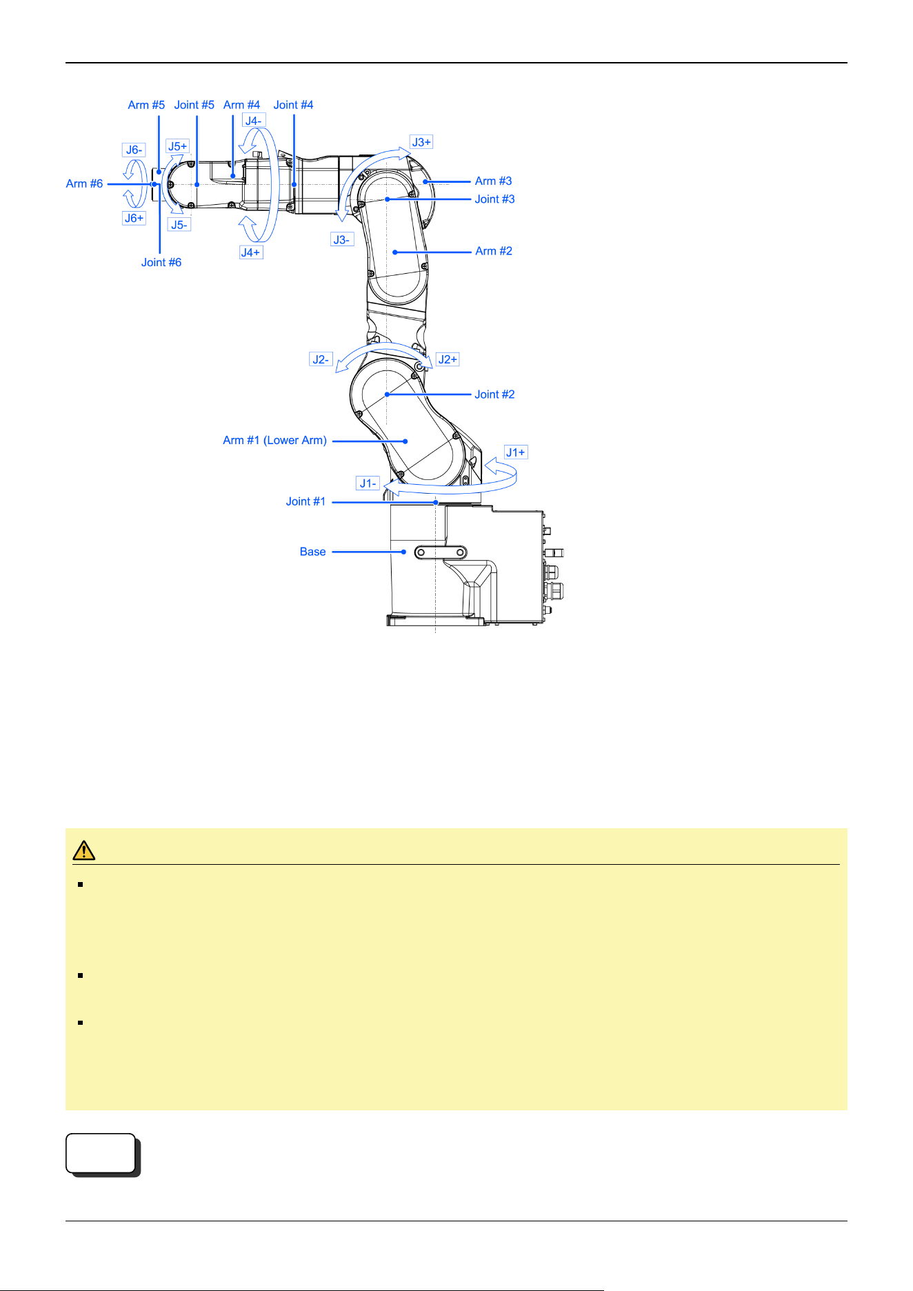
Arm Motion
3.1.6.1 When using a brake release unit
This series has the Brake Release Unit as an option. For details, refer to the following section.
Options
3.1.6.2 When using software
CAUTION
Normally, release the brakes of joints one at a time. If the brakes of two or more joints must be released
simultaneously due to unavoidable reasons, use extreme care. Releasing the brakes of multiple joints
simultaneously may cause the arm to fall in an unexpected direction, resulting in hands or fingers getting
caught or damage or failure of the Manipulator.
After releasing the brake, the arm may fall by its own weight or move to the unexpected direction. Make sure
to prepare a countermeasure to prevent the arm from falling and check the operation environment is safe.
Before releasing the brake, be sure to keep the emergency stop switch in an easily accessible location so that
you can immediately press it if necessary. Otherwise, if the emergency stop switch is not easily accessible,
you will be unable to immediately stop the arm falling due to an erroneous operation, which could lead to
Manipulator damage or breakdown.
After releasing the Emergency Stop switch, execute the following command in [Command Window].
EPSON
RC+
Industrial Robot: 6-Axis Robots C-B series Manual Rev.1b
98
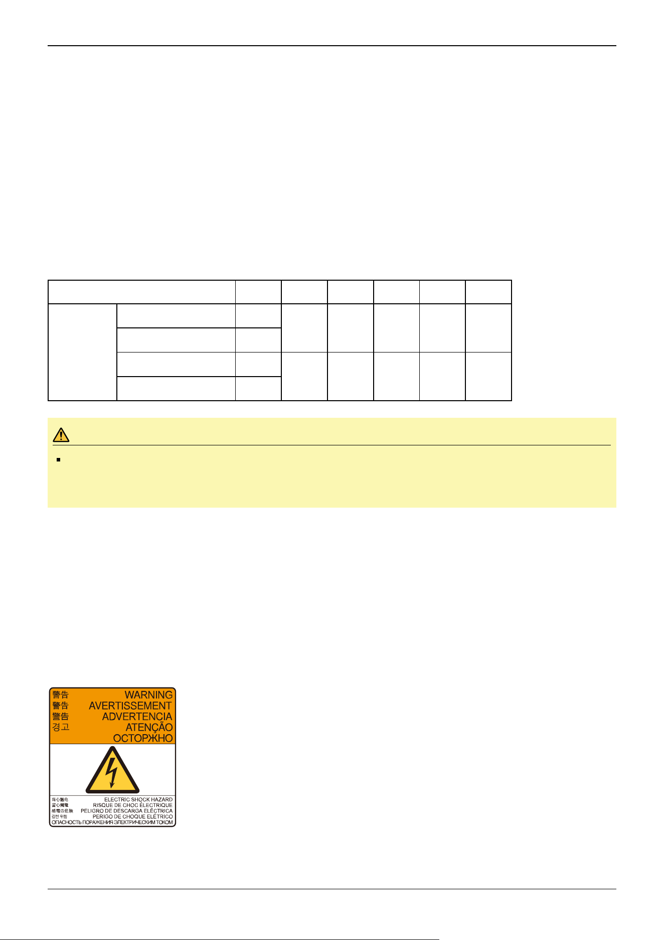
>Reset
>Brake Off,[The number (from 1 to 6) corresponding to the arm whose brake will be turned off
Execute the following command to turn on the brake again.
>Brake On,[The number (from 1 to 6) corresponding to the arm whose brake will be turned on]
3.1.7 Precaution for Operation in Low Power Status
In the low power status, the Manipulator operates at low speed and low torque. However, comparatively high torque as shown
in the table below may be generated to support the Manipulator’s own weight. Carefully operate the Manipulator since it may
get your hands or fingers caught during operation. The Manipulator may also collide with peripheral equipment and cause
equipment damage to or malfunction of the Manipulator.
Maximum Joint Torque in Low Power Status [Unit: N·m]
Joint #1 #2 #3 #4 #5 #6
Joint Torque
C8-B901*** (C8L) 172.10
300.96 129.34 34.97 39.96 20.54
C8-B901**W (C8L) 452.88
C8-B1401*** (C8XL) 449.79
731.34 373.31 52.45 59.94 30.81
C8-B1401**W (C8XL) 719.66
CAUTION
Carefully operate the Manipulator in the low power status. A comparatively high joint torque may be
generated. It may cause your hands and fingers caught and/or cause equipment damage to or malfunction of
the Manipulator as it may collide with peripheral equipment.
3.1.8 Warning Labels
The Manipulator has the following warning labels. Specific hazards exist in the vicinity of areas with the warning labels. Be
thoroughly careful in handling. To ensure that the Manipulator is operated and maintained safely, be sure to follow the safety
information and warnings indicated on the warning labels. Also, do not tear, damage, or remove these warning labels.
3.1.8.1 Warning Labels
A
Touching any internal electrified parts while the power is turned on may cause electric shock.
Industrial Robot: 6-Axis Robots C-B series Manual Rev.1b
99
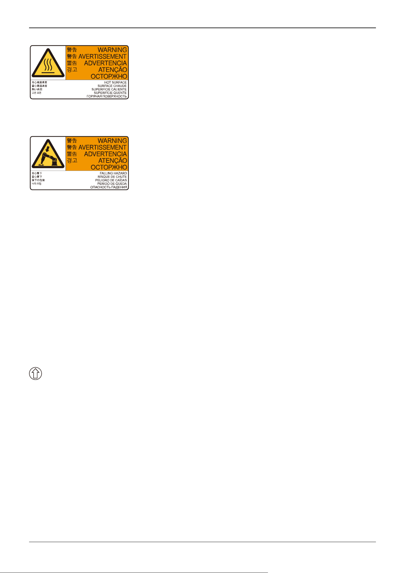
B
HOT Be careful not to burn yourself.
C
When releasing the brakes, be careful of the arm falling due to its own weight.
This warning label is attached on the Manipulator and optional brake release unit as well.
When the brake release unit is used:
When using a brake release unit to release brakes, refer to the following section.
How to Move Arms with the Electromagnetic Brake
3.1.8.2 Information Labels
1
This indicates the product name, model name, serial number, information of supported laws and regulations, product
specifications (Weight, MAX.REACH, MAX.PAYLOAD, AIR PRESSURE, Motor Power), Main document No.,
manufacturer, importer, date of manufacture, country of manufacture, and the like.
For details, see the label affixed to the product.
2
This indicates the position for mounting eyebolts. Refer to the following section for examples of using eyebolts.
Environment and Installation
Industrial Robot: 6-Axis Robots C-B series Manual Rev.1b
100
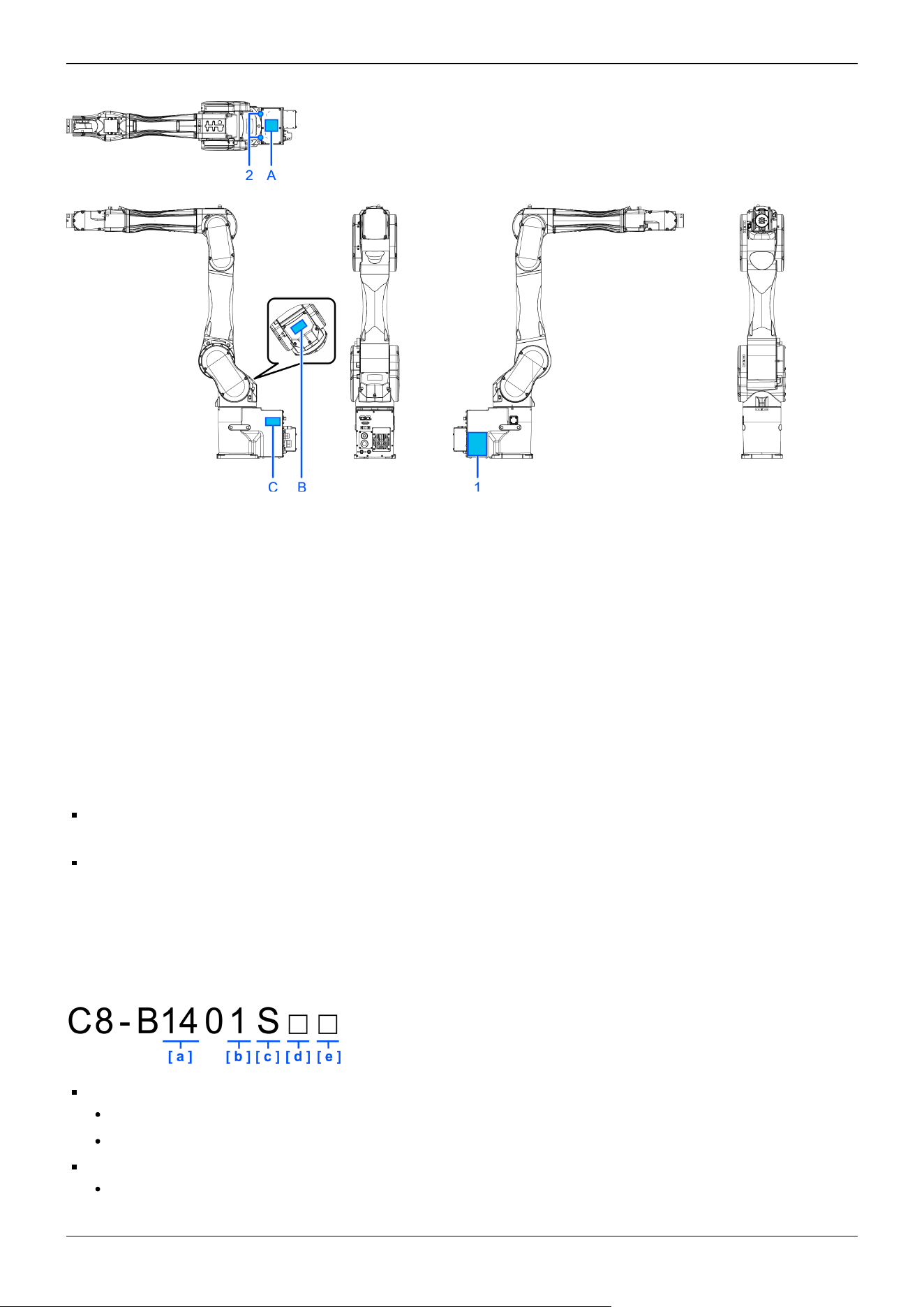
Location of Labels
3.1.9 Responses for Emergencies or Malfunctions
3.1.9.1 When a Collision with the Manipulator Occurs
If the Manipulator has collided with a mechanical stop, peripheral device, or other object, discontinue use and contact the
supplier.
3.1.9.2 Entanglement with the Manipulator
When the operator is caught between the Manipulator and a mechanical part such as a base table, press the emergency stop
switch to release the brake on the subject arm, and then move the arm by hand.
How to release a brake
When using a brake release unit, refer to the following section.
Brake Release Unit
When using software, refer to the following section.
When using software
3.2 Specifications
3.2.1 Model Number
a: Arm length
9: 900 mm (Model name: C8L)
14: 1400 mm (Model name: C8XL)
b: Brake equipment
1: Brakes on all joints
Industrial Robot: 6-Axis Robots C-B series Manual Rev.1b
101
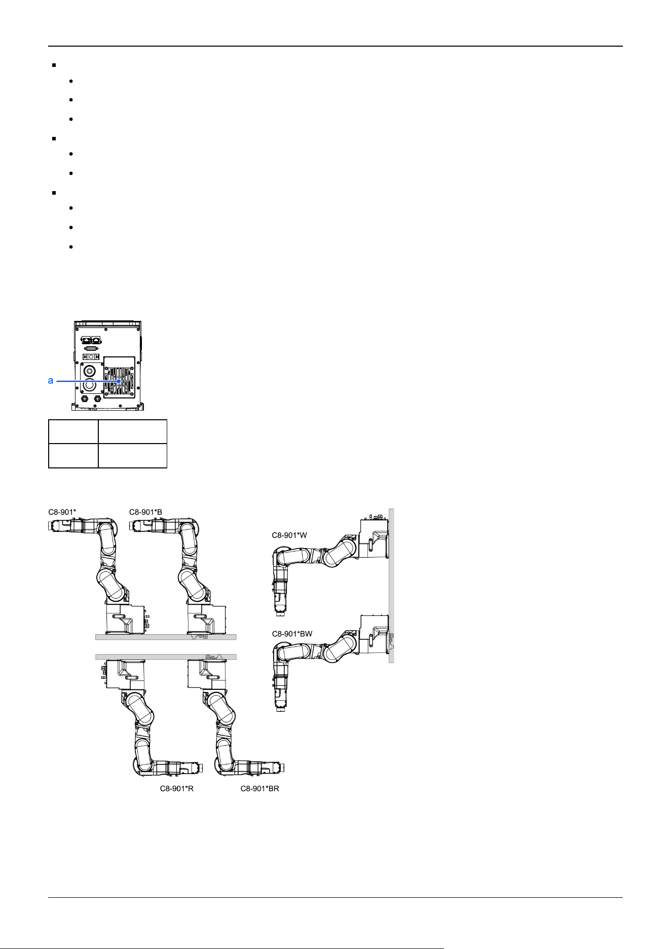
c: Environment
S: Standard *1
C: Cleanroom & ESD (anti-static) *1
P: Protection *2
d: M/C cable installation direction
□: Cable backward
B: Cable downward
e: Mounting type
□: Table top mounting
R: Ceiling mounting
W: Wall mounting
*1 Equivalent to IP20
*2 IP67 (fan cover: equivalent to IP20)
Symbol Description
a Fan cover
Example
Industrial Robot: 6-Axis Robots C-B series Manual Rev.1b
102
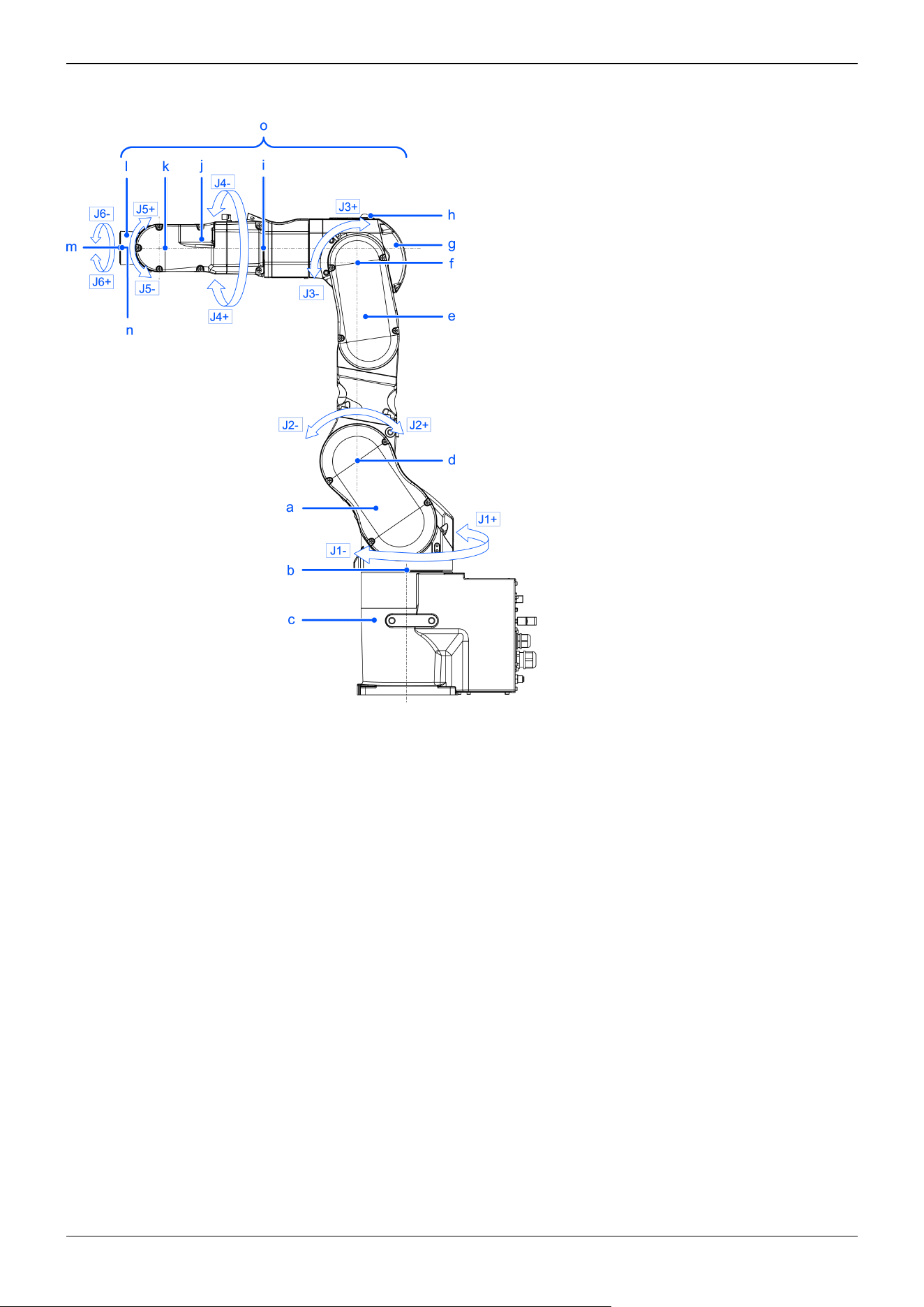
3.2.2 Part Names and Motion Range of Each Arm
Industrial Robot: 6-Axis Robots C-B series Manual Rev.1b
103
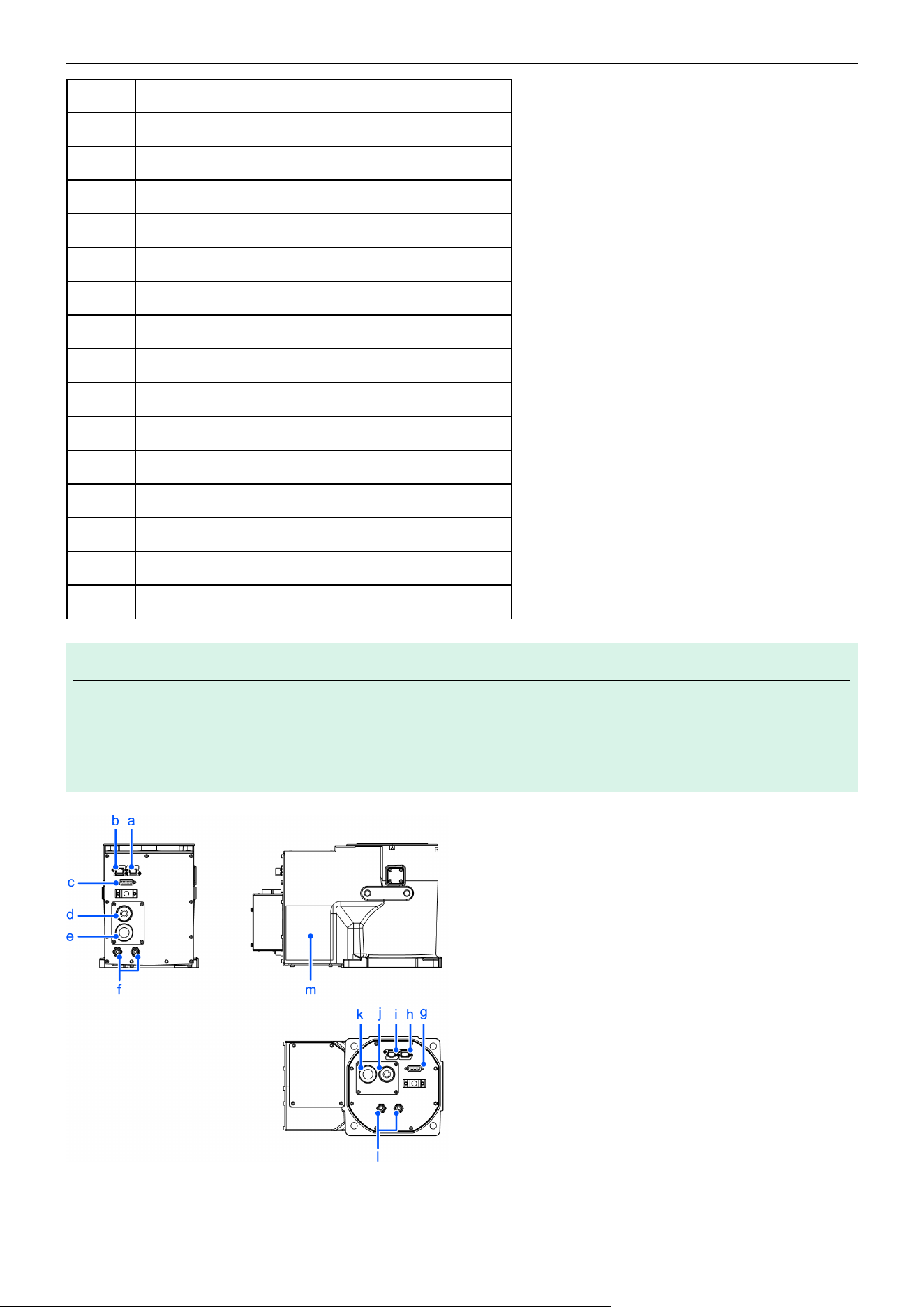
Symbol Description
a Arm #1 (Lower Arm)
b Joint #1 (The whole Manipulator revolves.)
c Base
d Joint #2 (The lower arm swings.)
e Arm #2
f Joint #3 (The upper arm swings.)
g Arm #3
h LED Lamp (This lamp lights up while the motors are on.)
i Joint #4 (The wrist revolves.)
j Arm #4
k Joint #5 (The wrist swings.)
l Arm #5
m Arm #6
n Joint #6 (The hand rotates.)
o Upper Arm (Arms #3 to #6)
KEY POINTS
When the LED lamp is lighting or the Controller power is on, the current is being applied to the Manipulator. (The
LED lamp may not be seen depending on the Manipulator’s posture. Be thoroughly careful. Performing any work
procedure with the power turned on is extremely dangerous and may result in electric shock and/or malfunction
of the robot system. Before starting any maintenance work, be sure to turn off the Controller.
Cable backward model
✏
Industrial Robot: 6-Axis Robots C-B series Manual Rev.1b
104
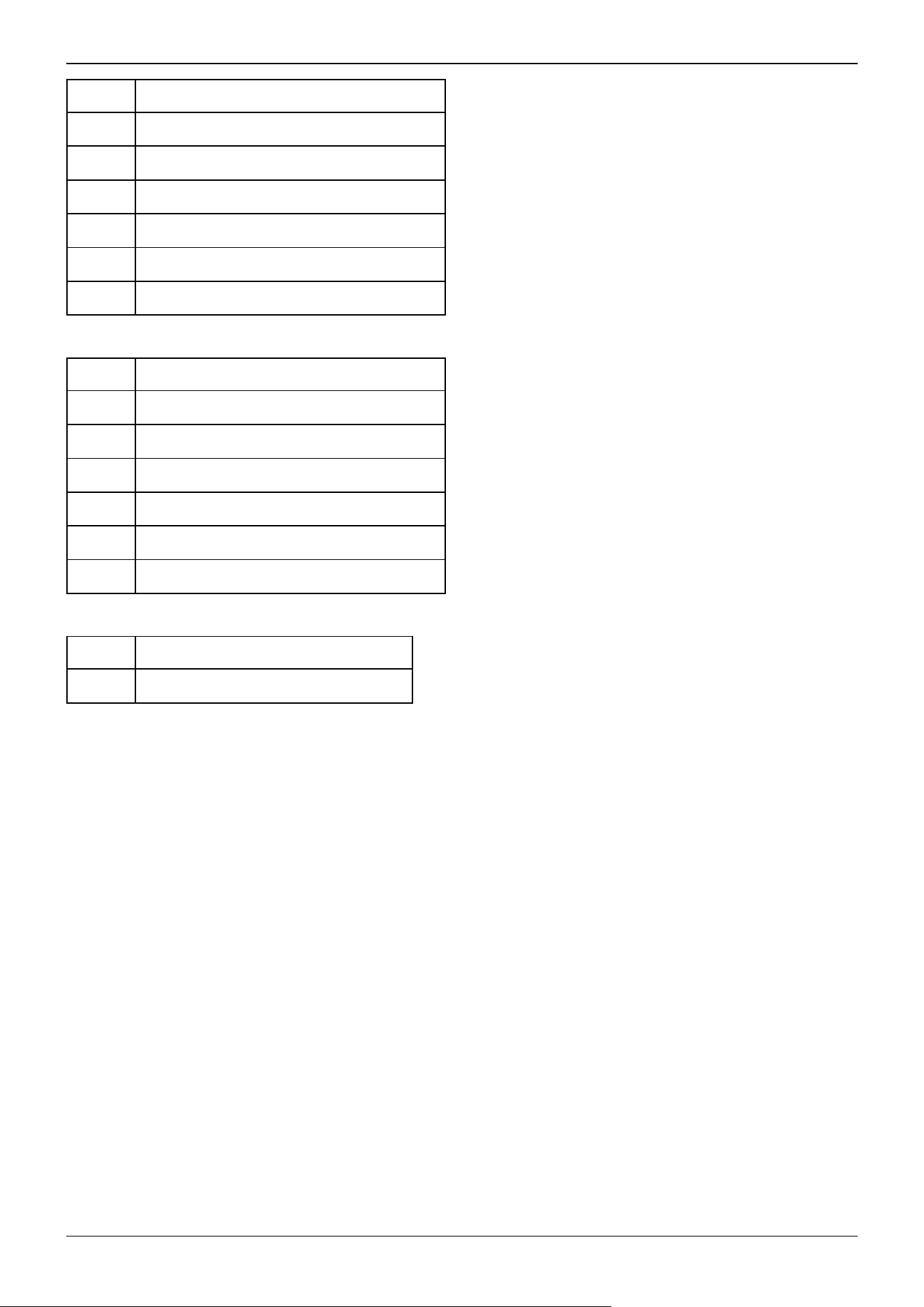
Symbol Description
a Ethernet cable connector
b Force Sensor cable connector
c User cable connector (15-pin D-sub connector)
d Signal cable
e Power cable
f Fitting for ⌀6 mm tube (Air1, Air2)
Cable downward model
Symbol Description
g User cable connector (15-pin D-sub connector)
h Force Sensor cable connector
i Ethernet cable connector
j Signal cable
k Power cable
l Fitting for ⌀6 mm tube (Air1, Air2)
Cable backward model, Cable downward model
Symbol Description
m Face plate (serial number of Manipulator)
3.2.3 Outer Dimensions
3.2.3.1 C8-B901*** (C8L)
(Units: mm)
Industrial Robot: 6-Axis Robots C-B series Manual Rev.1b
105
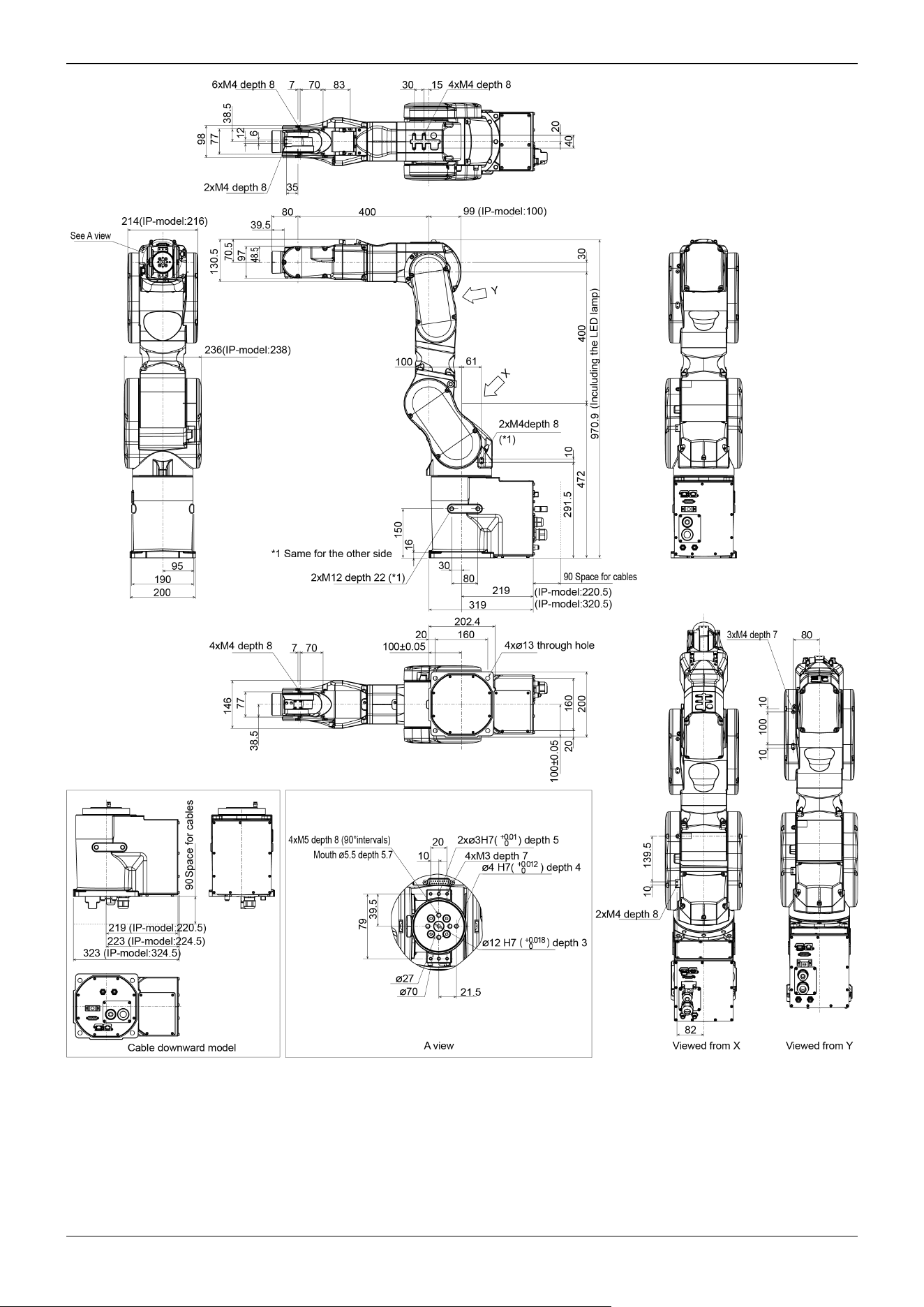
3.2.3.2 C8-B1401*** (C8L)
(Units: mm)
Industrial Robot: 6-Axis Robots C-B series Manual Rev.1b
106
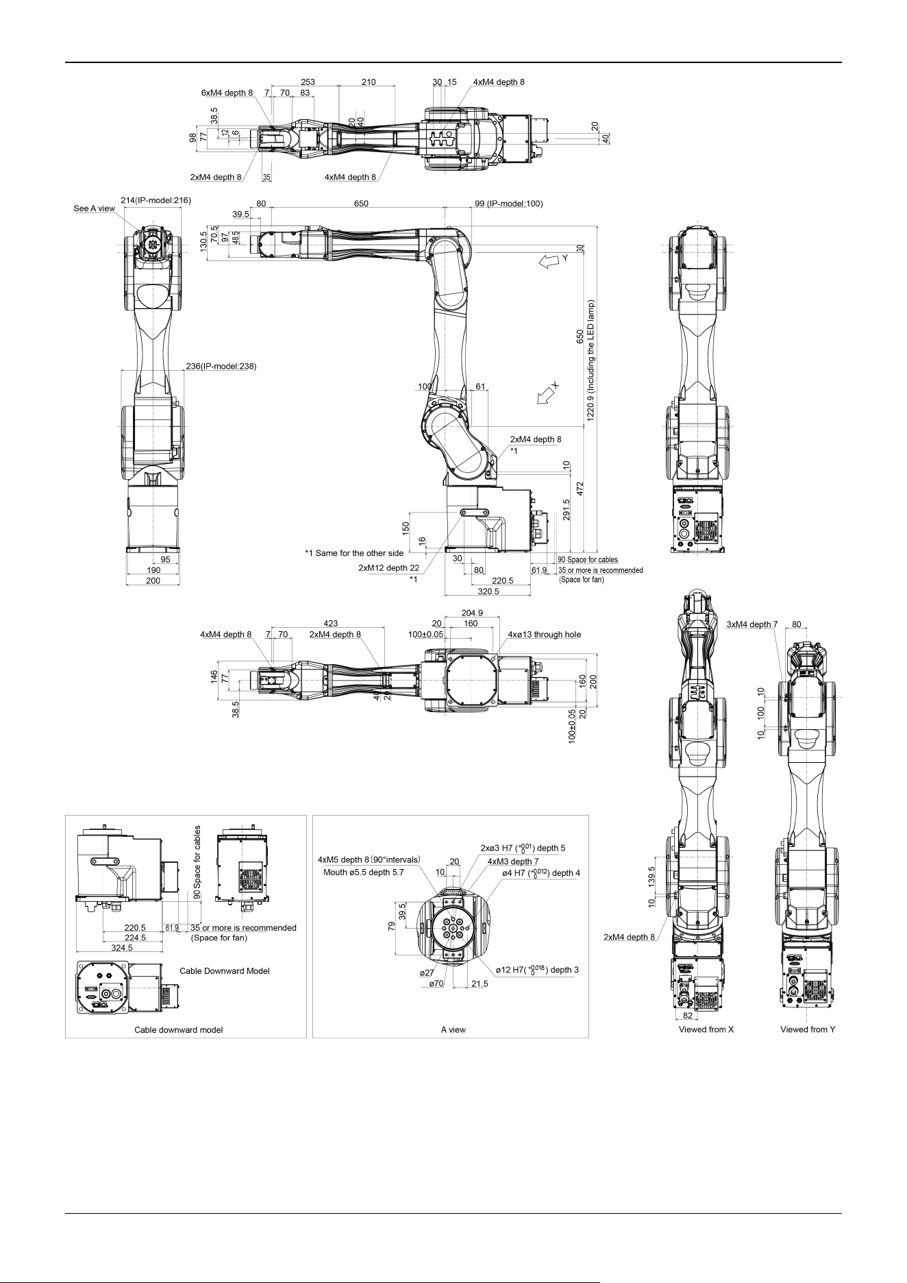
3.2.4 Standard Work Envelope
3.2.4.1 C8-B901*** (C8L)
(Units: mm)
Industrial Robot: 6-Axis Robots C-B series Manual Rev.1b
107
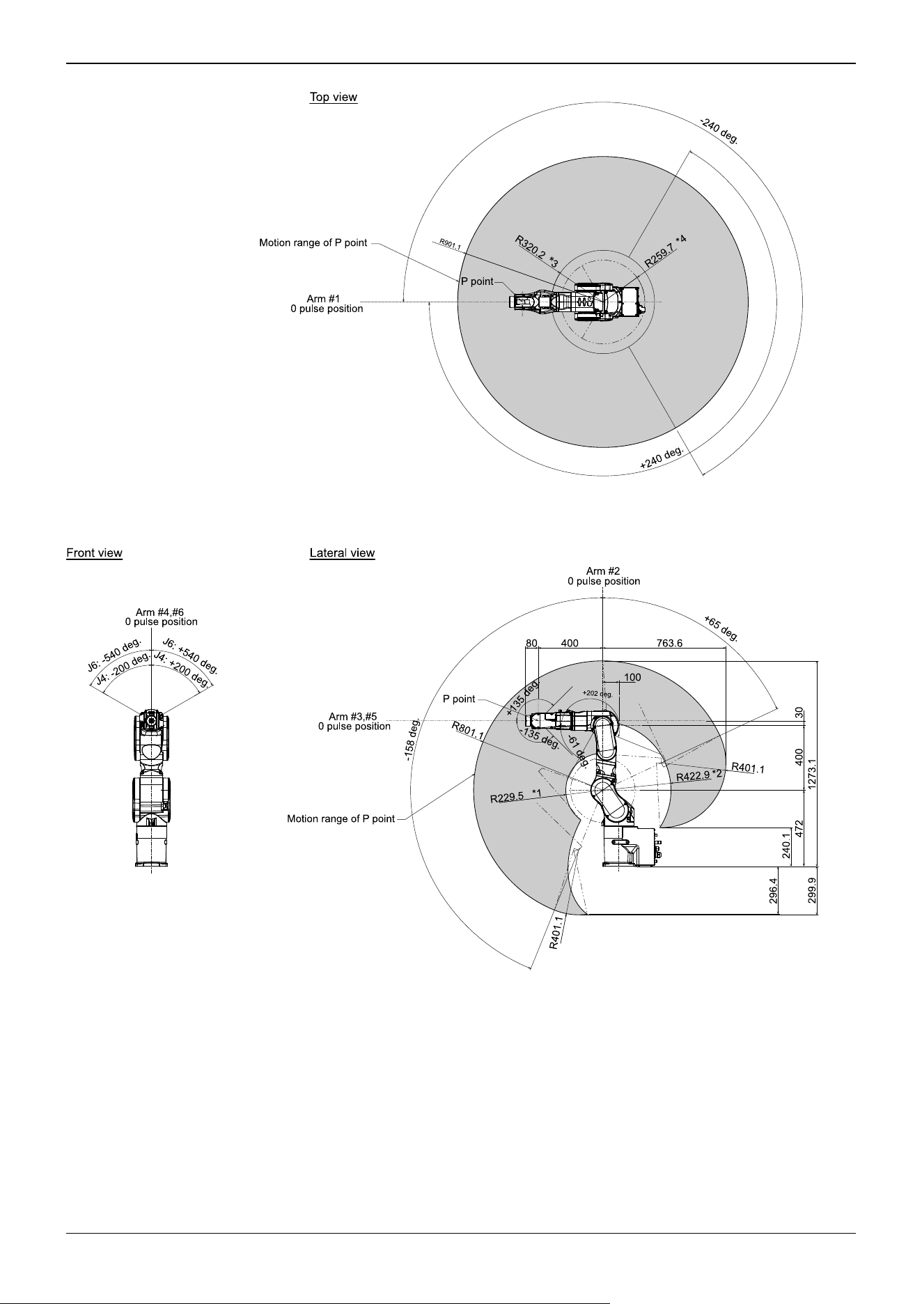
(deg. = °)
*P point: Intersection of the rotation centers for Joint #4, #5, and #6
*1: P point from lateral with Joint #3 declining -61° (Joint #2 center – P point center)
*2: P point from lateral with Joint #3 tilting up +202° (Joint #2 center – P point center)
Industrial Robot: 6-Axis Robots C-B series Manual Rev.1b
108

*3: P point from top with Joint #3 declining -61° (Joint #1 center – P point center)
*4: P point from top with Joint #3 tilting up +202° (Joint #1 center – P point center)
CAUTION
Pay attention to the arm pose of the basic arms (Arms #1, #2, and #3) when operating the Manipulator. Arm
#5 moves keeping a constant angle regardless of the arm pose. Depending on the arm pose of the basic
arms, the wrist may collide with the Manipulator. The collision may cause equipment damage to and/or
malfunction of the Manipulator.
Industrial Robot: 6-Axis Robots C-B series Manual Rev.1b
109
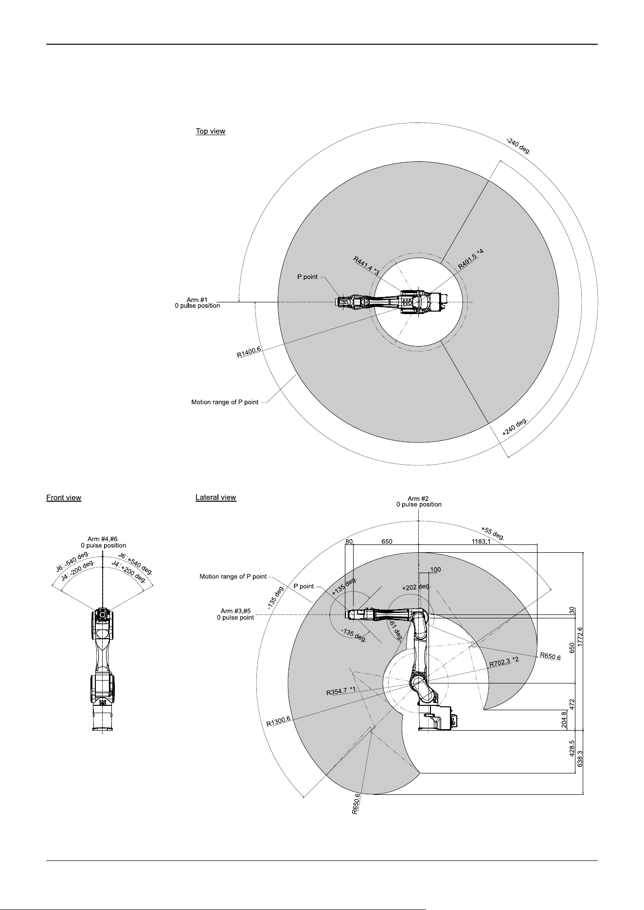
3.2.4.2 C8-B1401*** (C8XL)
(Units: mm)
(deg. = °)
Industrial Robot: 6-Axis Robots C-B series Manual Rev.1b
110
*P point: Intersection of the rotation centers for Joint #4, #5, and #6
*1: P point from lateral with Joint #3 declining -61° (Joint #2 center – P point center)
*2: P point from lateral with Joint #3 tilting up +202° (Joint #2 center – P point center)
*3: P point from top with Joint #3 declining -61° (Joint #1 center – P point center)
*4: P point from top with Joint #3 tilting up +202° (Joint #1 center – P point center)
CAUTION
Pay attention to the arm pose of the basic arms (Arms #1, #2, and #3) when operating the Manipulator. Arm
#5 moves keeping a constant angle regardless of the arm pose. Depending on the arm pose of the basic
arms, the wrist may collide with the Manipulator. The collision may cause equipment damage to and/or
malfunction of the Manipulator.
3.2.5 Specifications
3.2.5.1 Specifications Table
For the specifications tables of each model, refer to the following section.
C8 Specifications
3.2.5.2 Options
For details, refer to the following section.
Options
3.2.6 How to Set the Model
The Manipulator model for your system has been set before shipment from the factory.
CAUTION
If changing the setting of the Manipulator model, be responsible and absolutely certain that the wrong
Manipulator model is not set. Incorrect setting of the Manipulator model may result in abnormal or no
operation by the Manipulator and could even cause safety problems.
If a custom specifications number (MT***) or (X***) is written on the face plate (serial number label), the Manipulator has
custom specifications.
Models with custom specifications may require a different setting procedure. Check the custom specifications number, and
contact the supplier for more information.
The Manipulator model is set from software. For details, refer to the following manual.
"EPSON RC+ User's Guide - Robot Configuration"
3.3 Environment and Installation
The robot system should be designed and installed by people who have received installation training provided by Epson and
the suppliers. Also, the laws and regulations of the installation country must be followed.
Industrial Robot: 6-Axis Robots C-B series Manual Rev.1b
111
3.3.1 Environment
To ensure that the robot system operates and maintains maximum performance and to ensure its safe use, the robot system
should be installed in an environment that meets the following requirements.
Item Conditions
Ambient temperature *
Installation: 5 to 40°C
Transport, storage: -20 to 60°C
Ambient relative humidity
Installation: 10 to 80% (no condensation)
Transport, storage: 10 to 90% (no condensation)
Fast transient burst noise 1 kV or less (signal line)
Electrostatic noise 4 kV or less
Altitude 1000 m or less
* The ambient temperature requirement is for the Manipulator only. For details on the environment requirements for the
connected Controller, refer to the Robot Controller manual.
KEY POINTS
When used in a low-temperature environment near the minimum temperature specified in the product
specifications, or when the unit is idle for a long period of time during holidays or at night, a collision detection
error or similar error may occur immediately after the start of operation due to high resistance in the drive unit. In
such cases, warm-up operation for about 10 minutes is recommended.
KEY POINTS
If there are conductive objects such as fences or ladders within 2.5 m of the Manipulator, these objects must be
grounded.
Also, depending on the environmental specifications of the Manipulator, the following requirements must be met.
Environmental Specifications Conditions
S, C, P
- Install indoors.
- Keep away from direct sunlight.
- Keep away from shocks or vibrations.
- Keep away from sources of electric noise.
- Keep away from explosive areas.
- Keep away from large quantities of radiation.
S, C
- Keep away from dust, oily smoke, salinity, metal powder, and other contaminants.
- Keep away from flammable or corrosive liquids and gases.
- Keep away from organic solvents, acids, alkalis, and chlorine cutting fluids.
- Keep away from water.
The following items should also be taken into consideration for the installation environment of Manipulators with protected-
models.
These are compliant with the IP67 protection class (IEC 60529, JIS C0920). The Manipulators can be used in environments
where the possibility of dust, water, and water-soluble cutting oil falling of the Manipulator exists.
✏
✏
Industrial Robot: 6-Axis Robots C-B series Manual Rev.1b
112
They can be installed in environments where dust, oil smoke, metal powder, and similar substances are airborne, but they
are not suitable for use with nitrile rubber oil seals, O-rings, packings, liquid gaskets, or other substances that impair
sealing performance.
The Manipulator cannot be used in environments exposed to liquids or airborne droplets that are corrosive such as acids or
alkalis.
In environments that are exposed to airborne droplets containing salt, rust may also form on the Manipulator.
Manipulator surfaces are generally oil-resistant, but if special oils are to be used, oil resistance should be checked before
use. For more information, please contact the supplier.
In environments with rapid changes in temperature and humidity, condensation may form inside the Manipulator.
When handling food directly, it is necessary to make sure that the Manipulator is not likely to contaminate the food. For
more information, please contact the supplier.
The Controllers used with Manipulators with protected-models do not have protection against harsh environments. The
Controller should be installed in a location that meets its operating environment requirements.
KEY POINTS
If the Manipulator will be used in a location that does not meet the above requirements, please contact the
supplier.
WARNING
Always use a circuit breaker for the Controller's power supply. Failure to use a circuit breaker may result in an
electrical shock hazard or malfunction due to an electrical leakage. Select the correct circuit breaker based on
the Controller that you are using. For details, refer to the following manual.
"Robot Controller Manual"
CAUTION
When cleaning the Manipulator, do not rub it strongly with alcohol or benzene. Coated surfaces may lose their
luster.
3.3.2 Manipulator Mounting Dimensions
Mounting Area
Also, besides the area required for installation of the Manipulator, Controller, peripheral equipment, and other devices, the
following space should be provided at a minimum.
Space for teaching
Space for maintenance and inspections (for installing jigs)
Space for cables
✏
Industrial Robot: 6-Axis Robots C-B series Manual Rev.1b
113
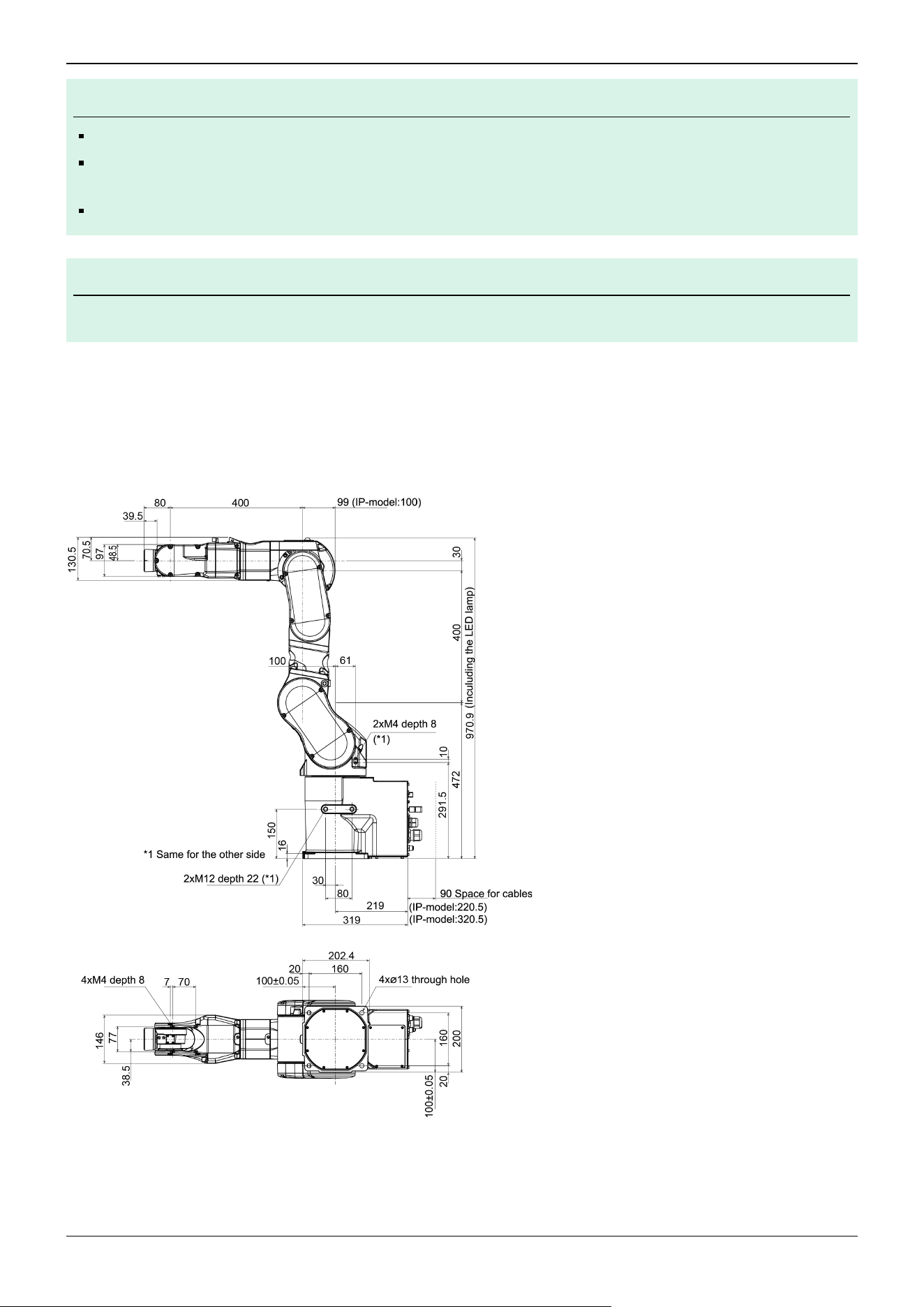
KEY POINTS
When installing the cables, be sure to maintain sufficient distance from obstacles.
For the minimum bend radius of the M/C cable, refer to the following section.
C8 Specifications
Also, leave enough space for other cables so that they are not forced to bend at extreme angles.
KEY POINTS
For C8-B1401*** (C8XL): Make sure to leave 35 mm or more space around the fan cover.
3.3.2.1 Cable backward model
(Units: mm)
C8-B901*** (C8L)
depth = depth of threaded hole
C8-B1401*** (C8XL)
✏
✏
Industrial Robot: 6-Axis Robots C-B series Manual Rev.1b
114
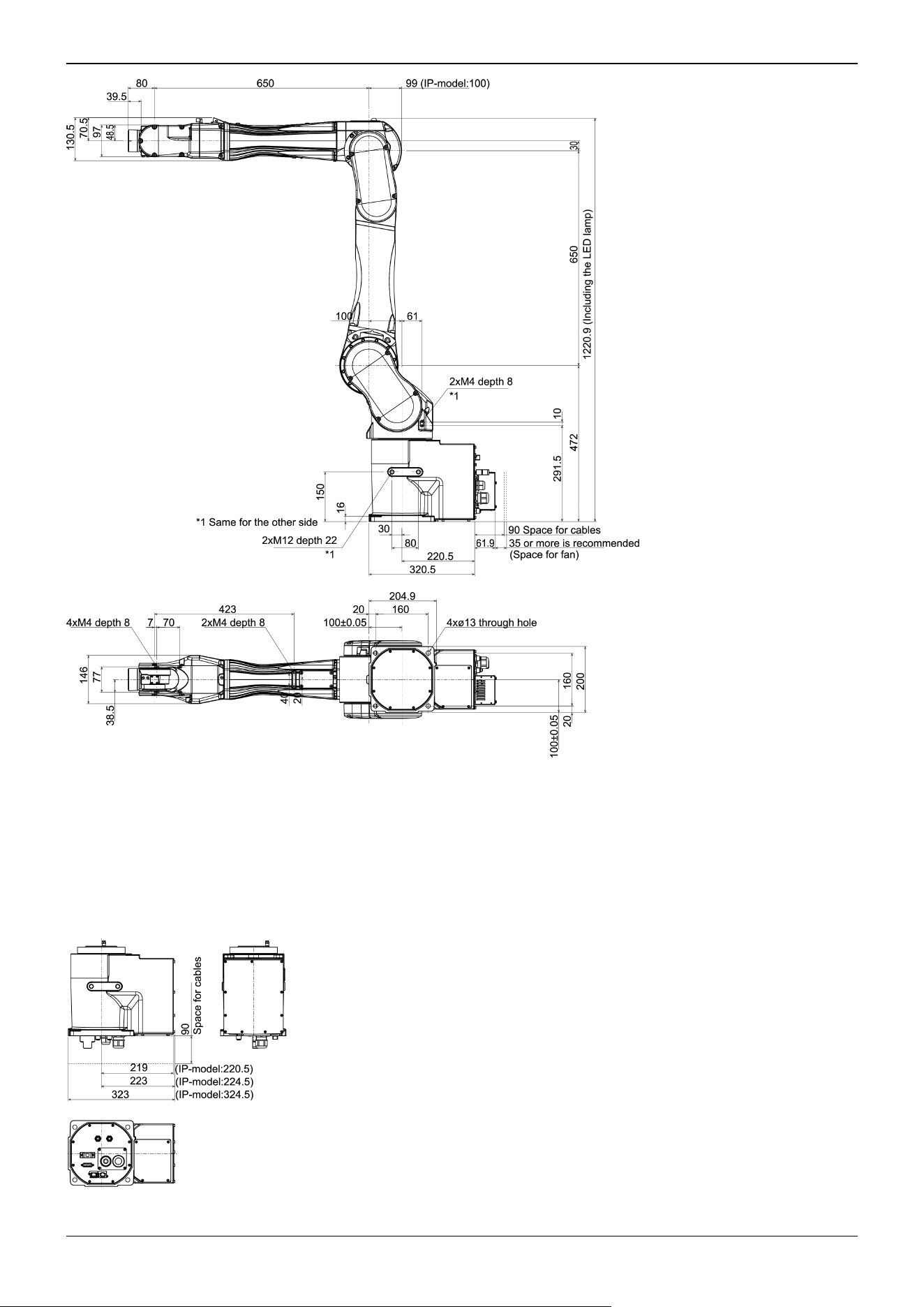
depth = depth of threaded hole
3.3.2.2 Cable downward model
The following part differs from the cable backward model.
C8-B901**B (C8L)
Industrial Robot: 6-Axis Robots C-B series Manual Rev.1b
115
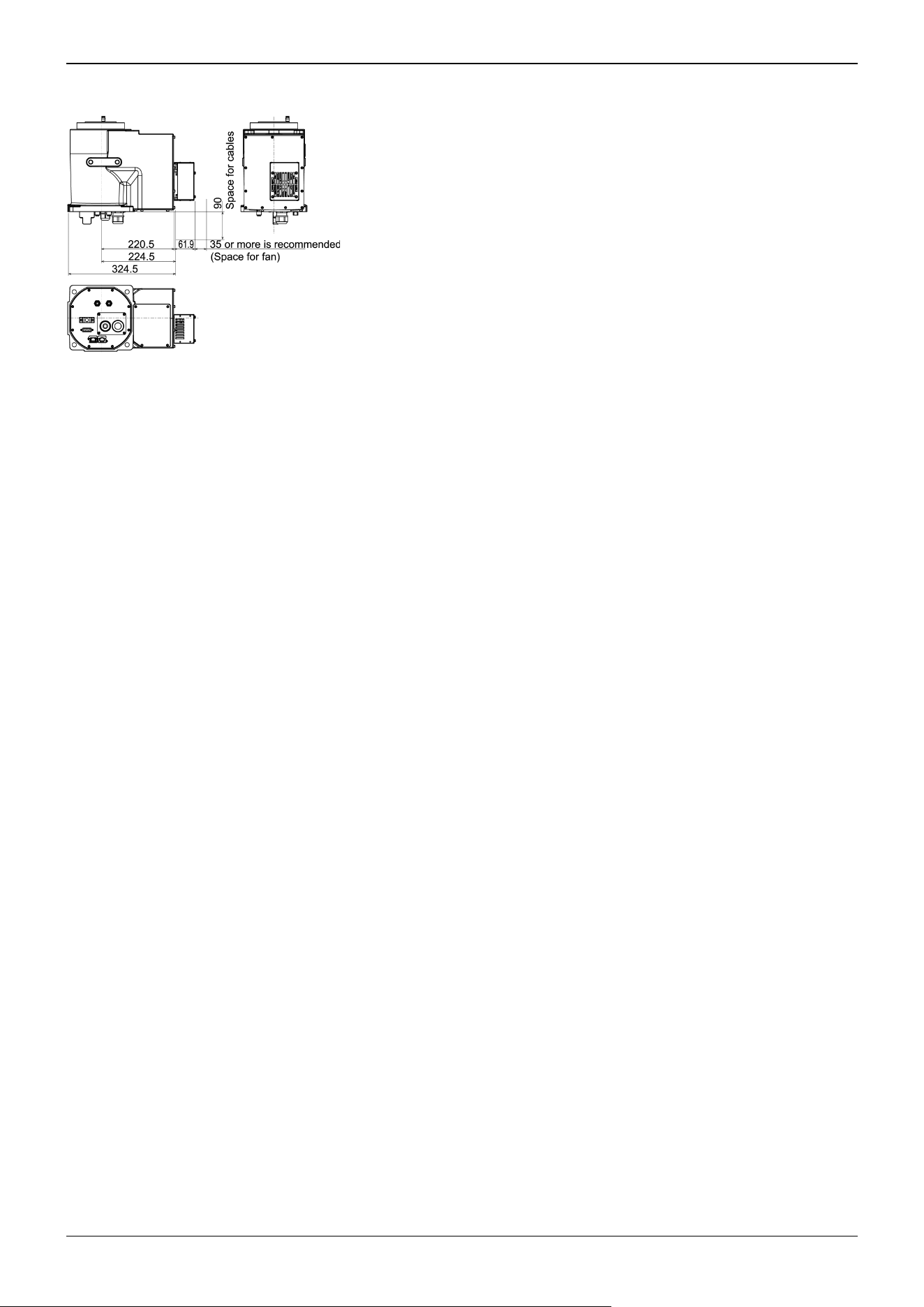
C8-B1401**B (C8XL)
Industrial Robot: 6-Axis Robots C-B series Manual Rev.1b
116
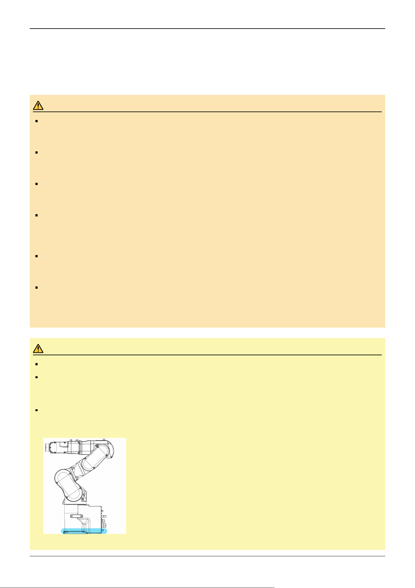
3.3.3 From Unpacking to Installation
Transportation and installation of the Manipulator and related equipment should be performed by people who have received
installation training provided by Epson and the suppliers. Also, the laws and regulations of the installation country must be
followed.
WARNING
Only qualified personnel should perform sling work and operate a crane or a forklift. When these operations
are performed by unqualified personnel, it is extremely hazardous and may result in serious bodily injury
and/or severe equipment damage to the robot system
When hoisting the Manipulator, use your hands to balance it. Losing balance may cause the Manipulator to
drop, which is extremely hazardous and may result in serious injury and/or severe damage to the robot
system.
To ensure safety, be sure to install safeguards for the robot system. For more information on safeguards, refer
to the following manual.
"EPSON RC+ User’s Guide - Safety - Installation and Design Precautions "
Install the Manipulator in a location with sufficient space so that a tool or a work piece does not touch a wall or
a safeguard when the Manipulator extends its arm fully while holding a work piece. If the tool or the workpiece
tip reaches a wall or safeguards, it is extremely hazardous and may result in serious bodily injury and/or
severe equipment damage to the robot system.
Be sure to anchor the Manipulator before turning on the power or operating it. Turning on the power or
operating the Manipulator while it is not anchored may cause the Manipulator to fall over, which is extremely
hazardous and may result in serious injury and/or severe damage to the robot system.
Before installing or operating the Manipulator, make sure that no parts of the Manipulator are missing and that
it has no damage or other external defects. Missing parts or damage may cause malfunction of the
Manipulator, is extremely hazardous, and may result in serious injury and/or severe equipment damage to the
robot system.
CAUTION
Use a cart or the like to transport the Manipulator in the same status as it was delivered.
When removing the fixing bolts securing the Manipulator to the transportation pallet and the packing box or
the anchor bolts, support the Manipulator to prevent it falling. Removing the fixing bolts or anchor bolts
without supporting the Manipulator may cause it to fall, catching your hands or feet.
The Manipulator should be transported by two or more people or secured to transporting equipment. Also, do
not hold the bottom of the base (the screened parts in the figure). Holding these parts by hand is extremely
hazardous and may cause your hands and fingers caught.
Manipulator weight
Industrial Robot: 6-Axis Robots C-B series Manual Rev.1b
117
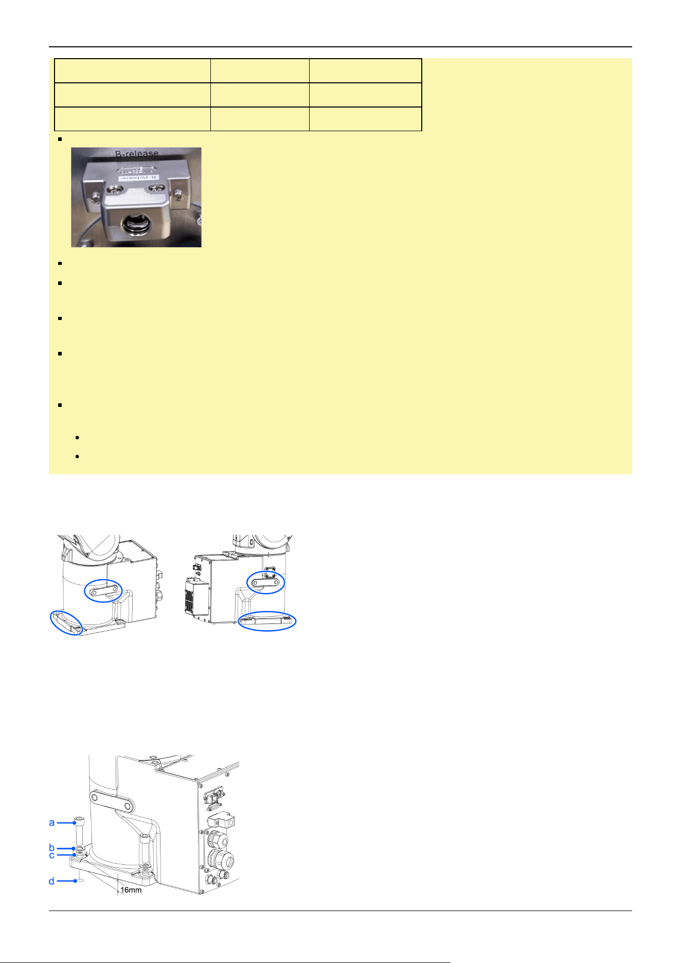
C8-B901***: C8L C8-B1401***: C8XL
Standard, Cleanroom Model 53 kg: 117 lb 63 kg: 139 lb
Protected-Model 57 kg: 126 lb 66 kg: 146 lb
Take extra care when transporting the Manipulator. You may hit and damage the connector.
During unpacking and relocation, avoid applying external force to the arms and motors of the Manipulator.
When transporting the Manipulator over long distances, secure it directly to transporting equipment so that it
will not fall. If necessary, pack the Manipulator using the same packaging as delivery.
The Manipulator must be installed to avoid interference with surrounding buildings, structures, and other
machines and equipment that may create a trapping hazard or pinch points.
Resonance (resonating sound or minute vibrations) may occur during Manipulator operation depending on
the rigidity of the base table. If the resonance occurs, improve the rigidity of the base table or change the
speed or acceleration and deceleration settings of the Manipulator.
C8-B1401** has a cooling fan on the base. Install the Manipulator not to seal the cooling fan. For details, refer
to the following figure.
Cable backward model
Cable downward model
Protective tape
Remove the protective tape (4 places).
Fixing bolt
For details on the dimensions, refer to the following sections.
Manipulator Mounting Dimensions
There are four threaded holes for the Manipulator base. Use M12 mounting bolts conforming to the strength equivalent to
ISO898-1 property class 10.9 or 12.9. Tightening torque: 100.0 ± 5.0 N·m (1,020 ± 51 kgf·cm)
Industrial Robot: 6-Axis Robots C-B series Manual Rev.1b
118
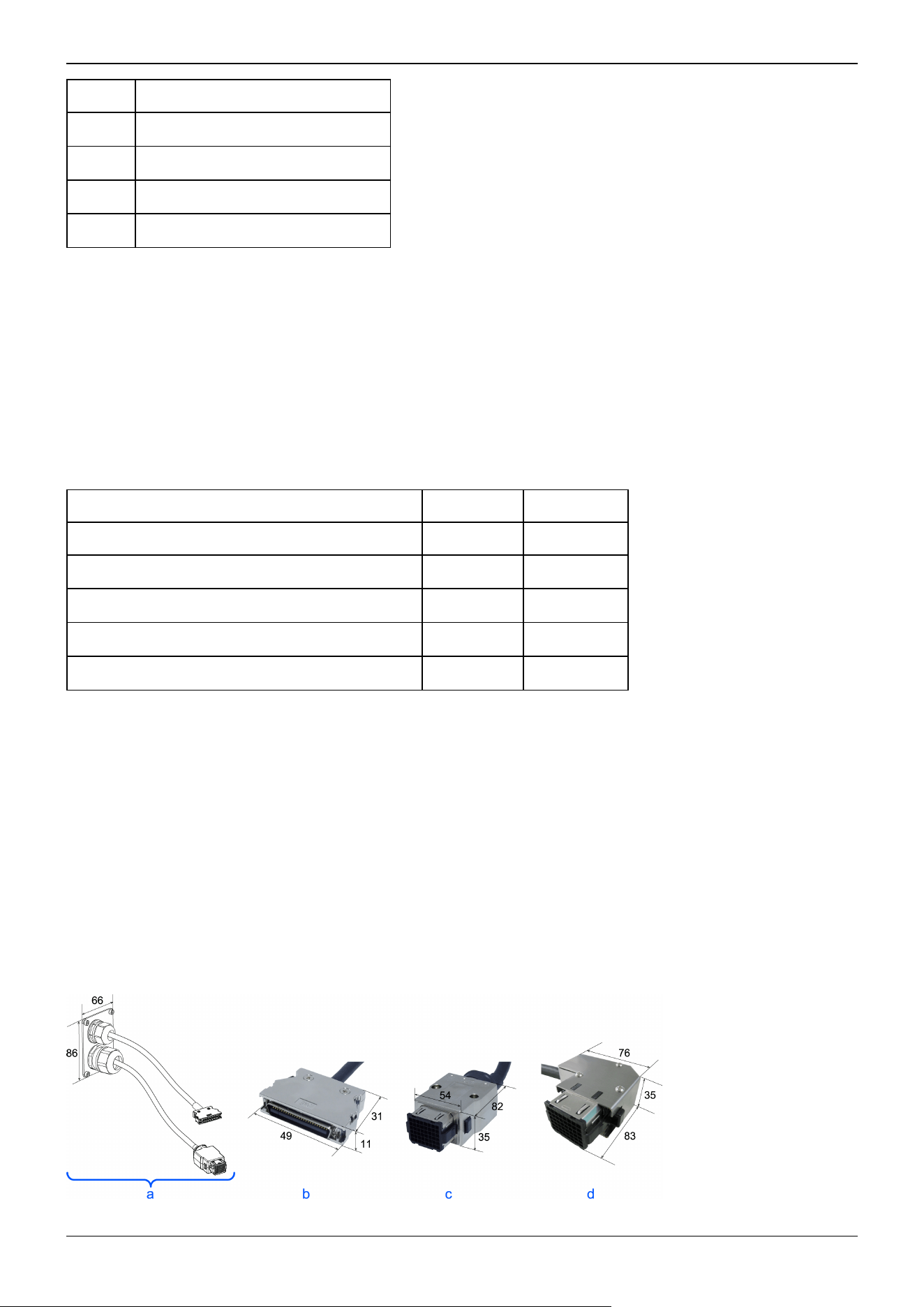
Symbol Description
a 4×M12×40
b Spring washer
c Plain washer
d Threaded hole (25 mm or more depth)
Base table
A base table for anchoring the Manipulator is not supplied. The base table must be fabricated or obtained by the customer.
The shape and size of the base table vary depending on the application of the robot system. As a reference when designing the
base table, the requirements from the Manipulator side are shown here.
The base table must not only be able to bear the weight of the Manipulator but also be able to withstand the dynamic
movement of the Manipulator when it operates at maximum acceleration/deceleration. Ensure that there is enough strength on
the base table by attaching reinforcing materials such as crossbeams.
Followings are the torque and reaction force produced by the movement of the Manipulator.
Model Number C8-B901 *** C8-B1401***
Model Name C8L C8XL
Maximum rotating torque on horizontal surface (N·m) 1800 2600
Maximum reaction force in horizontal direction (N) 1300 1300
Maximum rotating torque on vertical surface (N·m) 2200 3400
Maximum reaction force in vertical direction (N) 6000 7800
The plate for the Manipulator mounting face should be at least 30 mm thick and made of steel for reducing vibrations.
A surface roughness of 25 μm or less at the maximum height is appropriate.
The base table must be secured on the floor to prevent it from moving.
The Manipulator installation surface should have a flatness of 0.5 mm or less and an inclination of 0.5° or less. If the
installation surface does not have the proper flatness, the base of the Manipulator may be damaged or the robot may be unable
to operate at maximum performance.
When using a leveler to adjust the height of the base table, use a screw with M16 diameter or more.
Connector
If passing cables through the holes in the base table, refer to the connector dimensions in the figures below. (Units: mm)
Industrial Robot: 6-Axis Robots C-B series Manual Rev.1b
119
Symbol Description
a M/C cable
b Signal cable connector
c Power cable connector (straight)
d Power cable connector (L-shaped)
Do not remove the M/C cables from the Manipulator.
KEY POINTS
For details on the environmental requirements for the space when housing the Controller in the base table, refer
to the Robot Controller manual.
When using the Manipulator in the clean room, follow the steps below before the installation.
1. Unpack the Manipulator outside of the cleanroom.
2. Secure the Manipulator to transporting equipment (or a pallet) with bolts so that the Manipulator does not fall down.
3. Wipe off any dust on the Manipulator using a lint-free cloth that was dipped in ethyl alcohol or distilled water.
4. Carry the Manipulator into the cleanroom.
5. Secure the Manipulator to the base table.
✏
Industrial Robot: 6-Axis Robots C-B series Manual Rev.1b
120
3.3.4 Connecting the Cables
WARNING
Before performing any replacement work, turn off the Controller and related equipment, and unplug the power
cable from the power source. Performing any work procedure with the power turned on is extremely
dangerous and may result in electric shock and/or malfunction of the robot system.
Be sure to connect the AC power cable to a power outlet. Do not connect it directly to a factory power source.
To perform the power supply lockout, remove the power plug. Working while connecting the AC power cable
to a factory power source may result in electric shock and/or malfunction of the robot system.
Be sure to connect the cables properly. Do not put heavy objects on the cables, bend or pull on the cables
forcibly, or allow the cables to be pinched. Damaged cables, broken wires, or contact failure is extremely
hazardous and may result in electric shock and/or malfunction of the robot system.
Be sure to turn off the power and tag out (e.g., with a "DO NOT TURN ON" sign) before performing wiring.
Performing any work procedure with the power turned on is extremely dangerous and may result in electric
shock and/or malfunction of the robot system.
The Manipulator is grounded by connecting it to the Controller. Ensure that the Controller is grounded and the
cables are correctly connected. If the ground wire is improperly connected to ground, it may result in the fire
or electric shock.
Turn off the power to the Robot Controller and brake release unit when connecting or replacing the brake
release unit or external short connector. Inserting or removing connectors with the power on may result in
electric shock and/or malfunction of the robot system.
CAUTION
When connecting the Manipulator and the Controller, check that the serial numbers match for each device.
Improper connection between the Manipulator and the Controller may not only lead to malfunction of the robot
system but also safety problems. The connection method between the Manipulator and the Controller varies
depending on the Controller. For details on the connection, refer to the following manual.
"Robot Controller Manual"
Only authorized or certified personnel should perform wiring. Wiring by unauthorized or uncertified staff may
result in bodily injury and/or malfunction of the robot system.
Operating the Manipulator without a brake release unit or external short connector connected may cause the
brake to fail to release, possibly damaging the brake.
After using the brake release unit, be sure to connect the external short circuit connector to the Manipulator or
make sure to leave the connector for the brake release unit connected.
Cleanroom-model Manipulator
When the Manipulator is a model with cleanroom specifications, an exhaust system must be connected. For the exhaust
system, refer to the following section.
C8 Specifications
Industrial Robot: 6-Axis Robots C-B series Manual Rev.1b
121
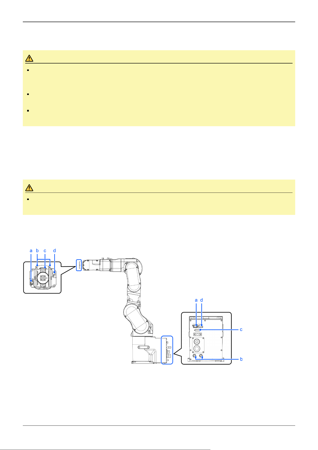
Protected-model Manipulator
When the Manipulator is a protected-model, please note the following points.
CAUTION
When operating Manipulators in special environments (oil smoke, dust, etc.), do not install the Controller in
the same environment. The Controller does not satisfy the protection class (IP67). Using the Controller in
these special environments may damage or lead to a breakdown of the Controller.
After using the brake release unit, be sure to reconnect the external short connector to the Manipulator. The
break release unit does not satisfy the protection class (IP67).
Be sure to connect a connector compliant with protection class IP67 or higher and a connector cover to the
Ethernet cable connector.
Connection procedure for M/C cable
Connect the power connector and signal connector of the M/C cable to the Controller.
3.3.5 User Wires and Pneumatic Tubes
CAUTION
Only authorized or certified personnel should perform wiring. Wiring by unauthorized or uncertified staff may
result in bodily injury and/or malfunction of the robot system.
User electrical wires and pneumatic tubes are contained in the cable unit.
Cable backward model
Cable downward model
Industrial Robot: 6-Axis Robots C-B series Manual Rev.1b
122
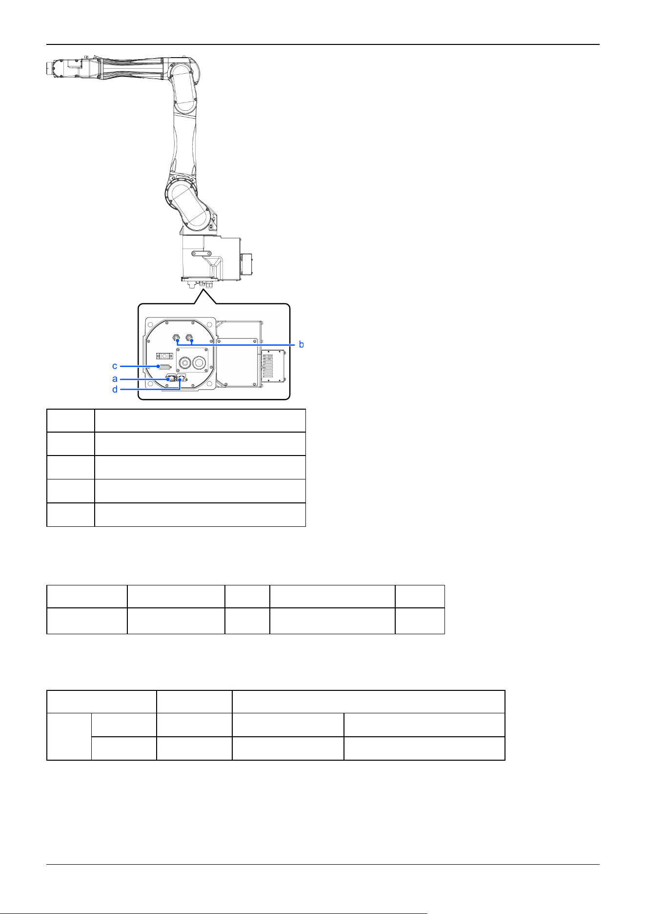
Symbol Description
a Force Sensor cable connector
b Fitting for ⌀6 mm tube (Air1, Air2)
c User cable connector (9-pin D-sub connector)
d Ethernet cable connector
3.3.5.1 Electrical Wires
Specifications of the user wires D-sub 15-pin
Rated Voltage Allowable Current Wires Nominal Sectional Area Note
AC/DC30V 1 A 15
0.106 mm
2
Shielded
Pins with the same number, indicated on the connectors on both ends of the cables, are connected.
Attached connector for user wires (standard, cleanroom model)
Manufacturer Type
15 pin
Connector JAE DA-15PF-N (Solder type)
Clamp hood HRS HDA-CTH (4-40) (10) (Connector setscrew: #4-40 UNC)
Two parts are attached for each.
Attached connector for user wires (protected-model)
Industrial Robot: 6-Axis Robots C-B series Manual Rev.1b
123
Manufacturer Type
15 pin
Connector HARTING 09 67 015 5615 (Solder type)
Clamp hood HARTING 09 67 015 0538 (Connector setscrew: #4-40 UNC)
Two parts are attached for each.
8-pin (RJ45) equivalent to Cat.5e
An Ethernet cable (commercially available) can be connected to Manipulator models with standard and cleanroom
specifications.
For the protected-model, use the following optional part.
User connector kit (IP67 waterproof, for RJ45, 2 pcs)
For details, refer to the following section.
Options
Other
The 6-pin cable for the Force Sensor option is included.
3.3.5.2 Pneumatic Tubes
Maximum Working Pressure Number of Tubes Outer Diameter × Inner Diameter
0.59 MPa (6 kgf/cm
2
: 86 psi)
2 ⌀6 mm × ⌀4 mm
Standard model, Cleanroom model:
The elbow fitting is attached on the Arm #4 at the time of shipment. The part can be replaced with the straight fitting
(accessory) according to application.
Protected-model:
The plugs are installed on the Arm #4 and the base. To use the pneumatic tubes, remove the plugs and install the fittings
(accessory) on the Arm #4.
Threaded hole size for installing the Arm #4 fitting: M6
When the Manipulator is a protected-model, please note the following points.
CAUTION
In special environments (e.g., oil smoke, dust, etc.), the user wires and pneumatic tubes should have
protected-model (compliant with protection class IP67). If the user wires and pneumatic tubes not protected-
model are connected, the protection class (IP67) cannot be guaranteed, and the Manipulator may be
damaged or break down.
Be sure to attach the cap or plug (attached at the time of shipment) on the user cable connector when not
using the user cable connector or the pneumatic tubes. Using the Manipulator without the cap or plug may
cause equipment damage to and/or malfunction of the Manipulator as dust or oily smoke gets into the
connector.
Industrial Robot: 6-Axis Robots C-B series Manual Rev.1b
124
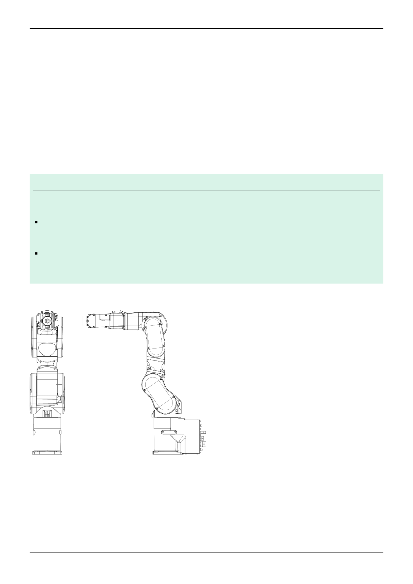
3.3.6 Checking the Basic Orientation
After installing the Manipulator and setup the operating environment, check if it moves to the basic position properly.
Follow the steps below to set the basic orientation of the Manipulator shown below as the origin position.
1. Start EPSON RC+ 7.0.
Double click the [EPSON RC+ 7.0] icon on the desktop.
2. Open the command window.
EPSON RC+ 7.0 menu-[Tools]-[Command Window]
3. Execute the following command in [Command Window].
>Motor On
>Go Pulse (0,0,0,0,0,0)
KEY POINTS
If "Error 4505: cannot be turned on the motor because the Safety Board is issuing a stop signal." occurs, use one
of the following methods to move the Manipulator to its basic orientation.
Release the brake and push the arm by hand to move it within the motion range. Then follow the steps above.
For details on releasing brake, refer to the following section.
How to Move Arms with the Electromagnetic Brake
Press the TP3 command button [Pulse0] to move the Manipulator to its basic orientation. For details, refer to
the following manual.
"Robot Controller Option Teach Pendant TP3 Operation 3.1.3 Command Buttons"
If the Manipulator cannot be in the basic orientation shown below, please contact the supplier.
3.3.7 Relocation and Storage
3.3.7.1 Safety Information for Relocation and Storage
Pay attention to the following requirements when relocating, storing, and transporting the Manipulators.
✏
Industrial Robot: 6-Axis Robots C-B series Manual Rev.1b
125
Transportation and installation of the Manipulator and related equipment should be performed by people who have received
installation training provided by Epson and the suppliers. Also, the laws and regulations of the installation country must be
followed.
WARNING
Only qualified personnel should perform sling work and operate a crane or a forklift. When these operations
are performed by unqualified personnel, it is extremely hazardous and may result in serious bodily injury
and/or severe equipment damage to the robot system
CAUTION
Before relocating, fold the arm and secure it tightly with a cable tie to prevent hands or fingers from getting
caught in the Manipulator.
When removing the anchor bolts, support the Manipulator so that it does not fall. Removing the anchor bolts
without supporting the Manipulator can cause it to fall, causing hands or feet to get caught.
The Manipulator should be transported by two or more people or secured to transporting equipment. Also, do
not hold the bottom of the base. Holding these parts by hand is extremely hazardous and may cause your
hands and fingers caught.
During unpacking and relocation, avoid applying external force to the arms and motors of the Manipulator.
When transporting the Manipulator over long distances, secure it directly to transporting equipment so that it will not fall. If
necessary, pack the Manipulator using the same packaging as delivery.
When the Manipulator is reassembled and used for a robot system again after an extended period of storage, perform a test run
to verify that it works properly before starting the main operation.
Manipulators should be transported and stored under the following conditions: Temperature: -20 to +60°C, Humidity: 10 to
90% (no condensation)
If condensation has formed on the Manipulator during transportation or storage, do not turn on the power until the
condensation is removed.
Do not subject the Manipulator to excessive impacts or vibrations during the transportation process.
Relocation
Follow the procedures described below when relocating the Manipulator.
1. Turn off the power for all devices and unplug the power cable connector and signal cable connector from the Controller.
Do not remove the M/C cables (power cable and signal cable) from the Manipulator. (MC cable 3 m: 2 kg)
KEY POINTS
Remove the mechanical stops if using them to limit the motion range. For details on the motion range, refer to
the following section.
Setting the Work Envelope by Mechanical Stops
2. Unscrew the anchor bolts. Then, remove the Manipulator from the base table.
3. Position the Manipulator as shown in the figure. Then, secure the Manipulator to the transporting equipment or have at
least two people to relocate the Manipulator. (Recommend: Joint #2 +55°. Joint #3 -55°)
✏
Industrial Robot: 6-Axis Robots C-B series Manual Rev.1b
126
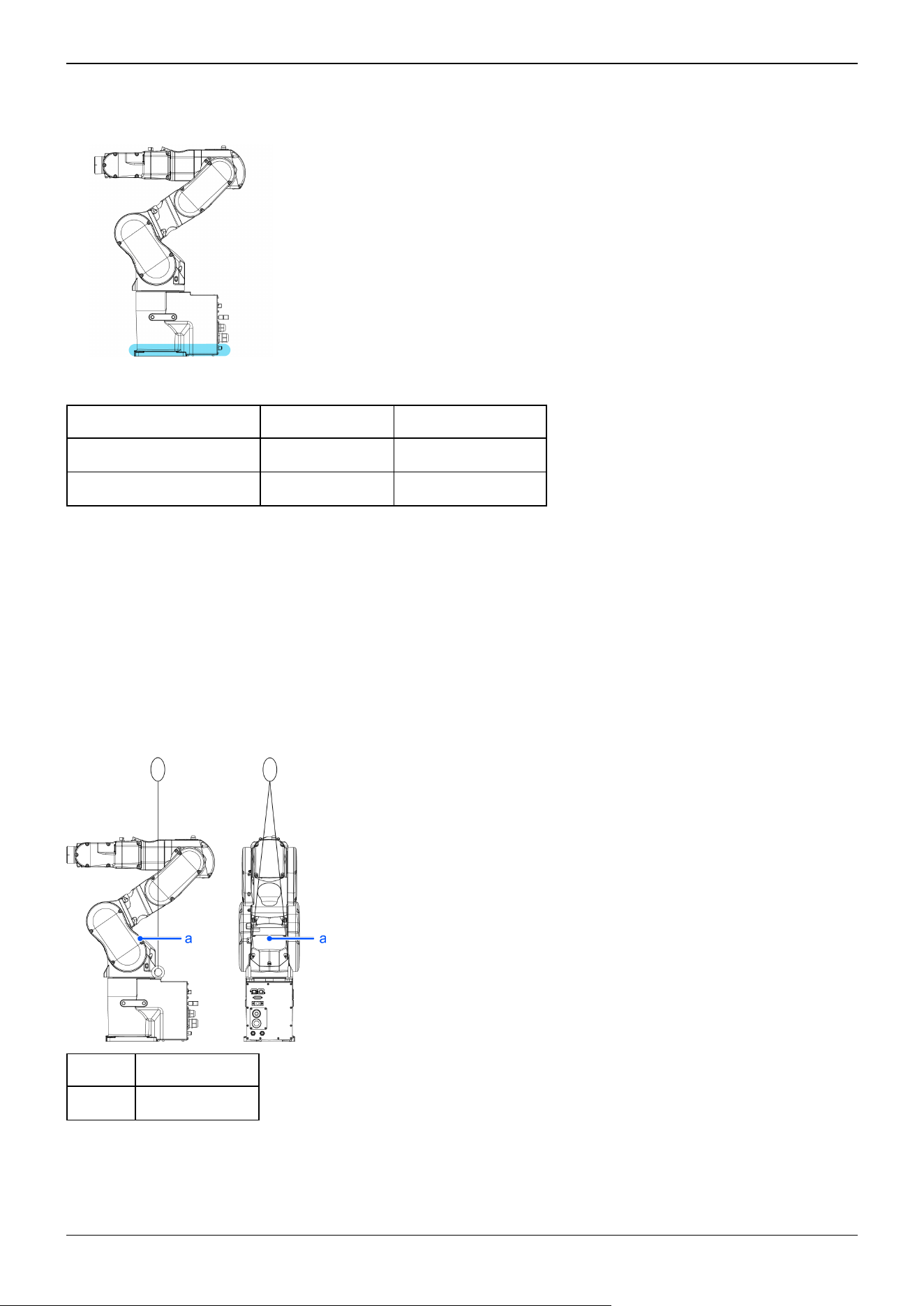
The posture is common to all models.
Do not hold the bottom of the base (the screened parts in the figure). Holding these parts by hand is extremely hazardous
and may cause your hands and fingers caught.
Manipulator weight
C8-B901***: C8L C8-B1401***: C8XL
Standard, Cleanroom Model 53 kg: 117 lb 63 kg: 139 lb
Protected-Model 57 kg: 126 lb 66 kg: 146 lb
Using eyebolts
Check that the eyebolts are securely fastened before transporting the Manipulator. After transporting the Manipulator, remove
the eyebolts and keep them for future use.
The eyebolts (accessory, 2 pcs) and wire must be strong enough to withstand the weight (See the figures below).
If you use the eyebolts to lift up the Manipulator, make sure to put hands on it to keep the balance. The Manipulator may fall if
the balance is lost and this is extremely hazardous.
To prevent damage on the covers and arms, it is recommended to protect the contacting parts of the wire and arm with a cloth.
Be very careful not to damage the covers since they are made of plastic.
Symbol Description
a Center of gravity
Industrial Robot: 6-Axis Robots C-B series Manual Rev.1b
127
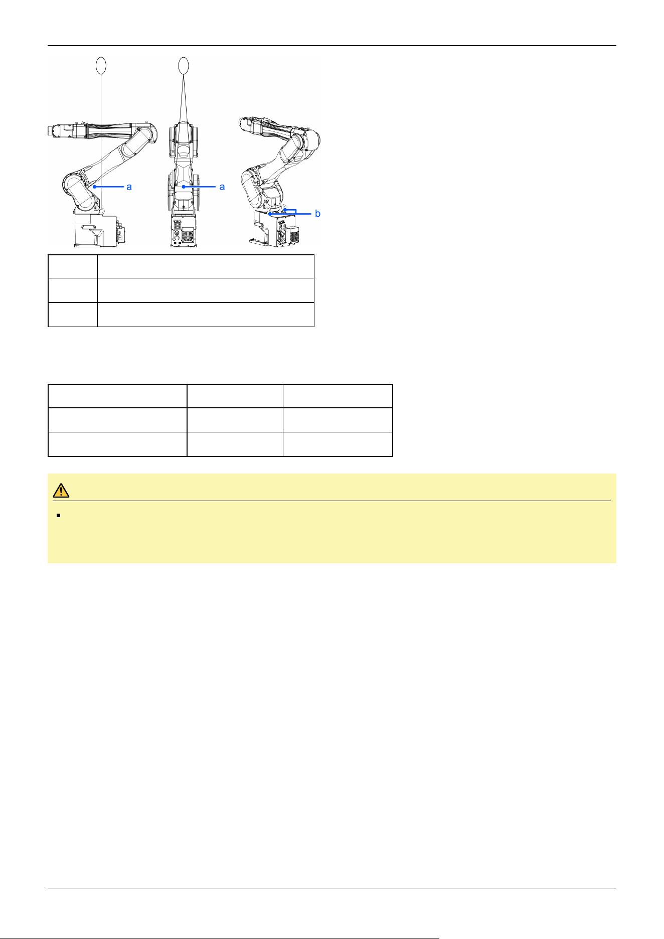
Symbol Description
a Center of gravity
b Threaded holes for eyebolts: 2×M12 depth 25
Locations of the threaded holes for eyebolts are common to all models.
Manipulator weight
C8-B901***: C8L C8-B1401***: C8XL
Standard, Cleanroom Model 53 kg: 117 lb 63 kg: 139 lb
Protected-Model 57 kg: 126 lb 66 kg: 146 lb
CAUTION
Remove the eyebolts from the Manipulator after transportation/relocation is completed. If the Manipulator is
operated with the eyebolts left on it, the arm may collide with the eyebolts and it may cause equipment
damage to and/or malfunction of the Manipulator.
3.4 Setting the Hand
3.4.1 Installing the Hand
The hand (end effector) must be prepared by the customer. For details on attaching the hand, refer to the following manual.
"Hand Function Manual"
Industrial Robot: 6-Axis Robots C-B series Manual Rev.1b
128
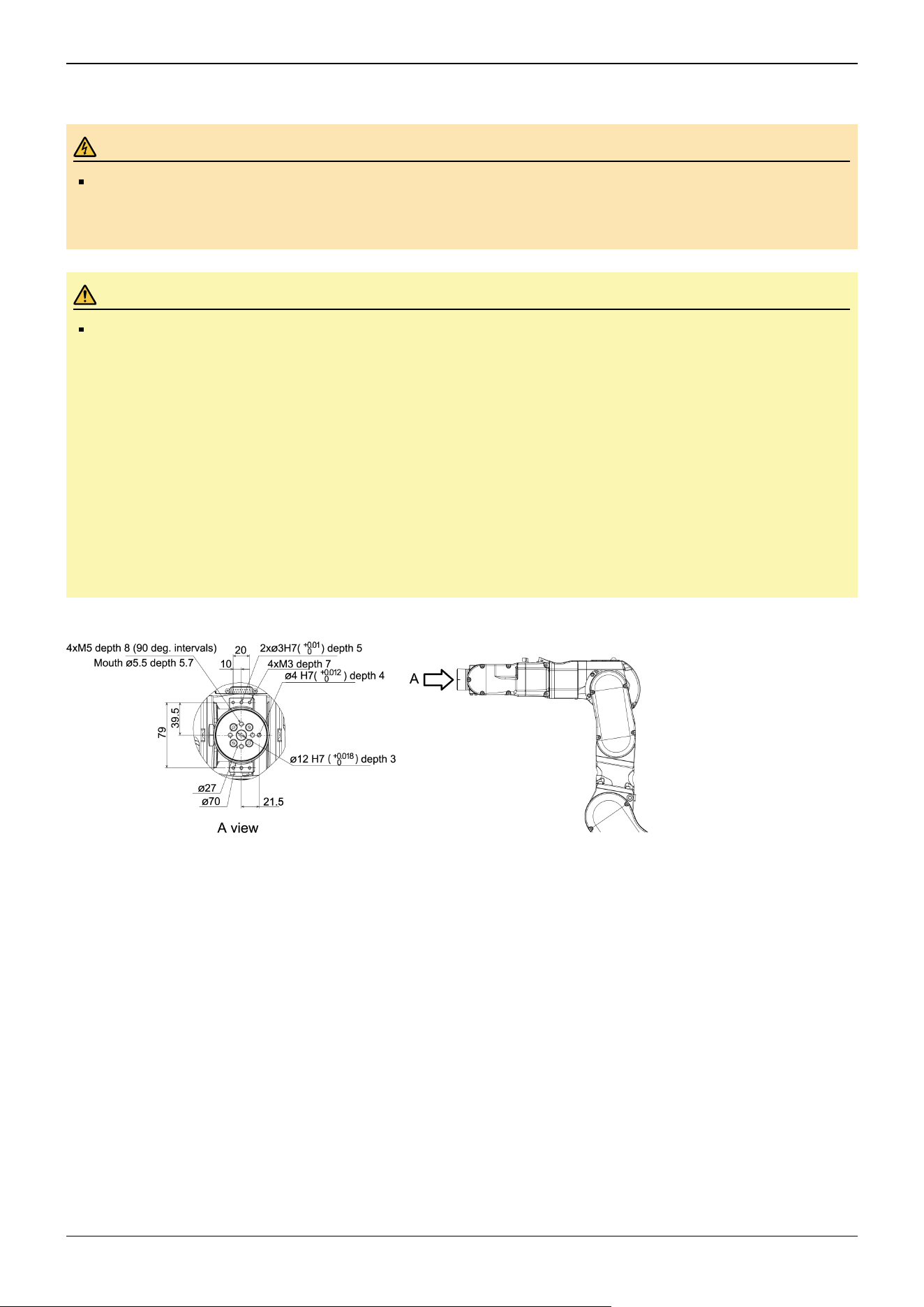
Flange dimensions of the wrist attached to the end of Arm #6 is as below.
WARNING
Before attaching a hand or peripheral equipment, be sure to always turn off the Controller and related
equipment and unplug the power cables. Performing any work procedure with the power turned on is
extremely dangerous and may result in electric shock and/or malfunction of the robot system.
CAUTION
When the hand is equipped with a workpiece gripping mechanism, ensure that the wiring and pneumatic
tubes do not cause the hand to release the workpiece when the power is turned off. When the wiring and
pneumatic tubes are not designed for the hand to maintain its grip on the workpiece when the power is turned
off, pressing the emergency stop switch releases the workpiece, which may damage the robot system and the
workpiece.
By default, all I/Os are designed to automatically turn off (0) when the power is shut off, when an emergency
stop is triggered, or by the robot system's safety function.
However, I/Os set with the Hand function does not turn off (0) when executing the Reset statement, or when
performing an emergency stop.
For the risk of the residual air pressure, conduct a risk assessment on the equipment and take the necessary
protective measures.
Wrist flange
Arm #6
Attach the hand to the end of the Arm #6 using the M5 bolts.
Layout
When attaching and operating a hand, the hand may come into contact with the Manipulator body due to the outer diameter of
the hand, the size of the workpiece, or the position of the arm. Carefully consider the interference area of the hand when
designing the system layout.
Compatibility with ISO flange
To install the hand whose mounting dimensions are designed for the ISO flange, we provide the optional C8 ISO flange (J6).
For details, refer to the following section.
Options
Industrial Robot: 6-Axis Robots C-B series Manual Rev.1b
129
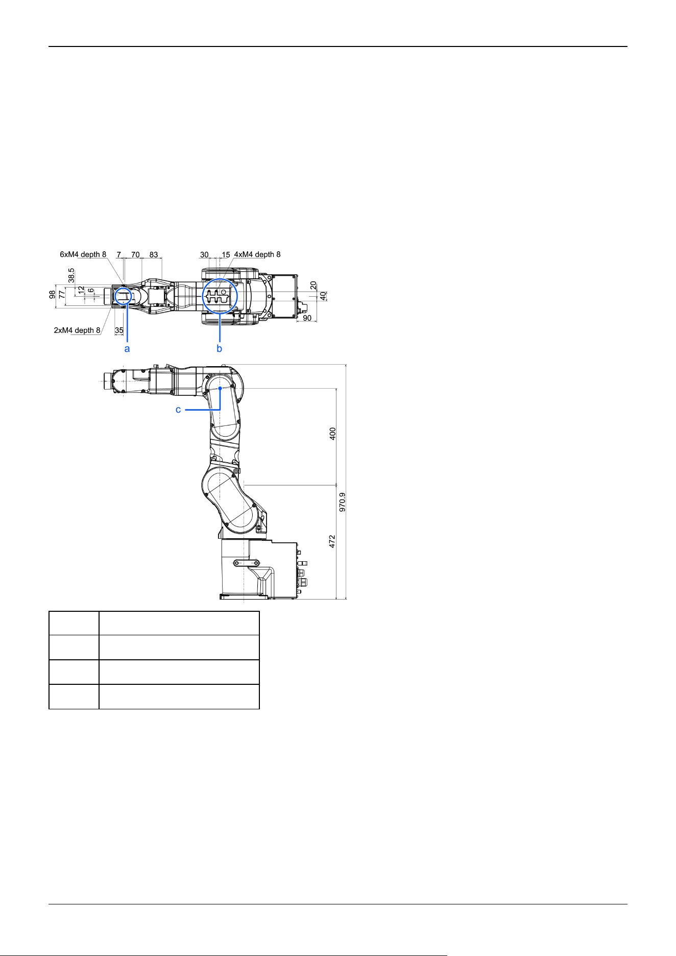
3.4.2 Attaching Cameras and Valves
Decks are equipped to Arms #3 and #5 to enable the easy installation of air valve. If the payload exceeds the maximum
payload, refer to the following section.
"WEIGHT Setting - Restrictions on payload exceeding the maximum payload"
To mount the camera, the camera plate unit is necessary. We provide the optional Camera Plate Unit. For details, refer to the
following section.
Options
(Units: mm)
C8-B901*** (C8L)
Symbol Description
a Arm #5 Deck
b Arm #3 Deck
c Rotation center of the upper arm
Industrial Robot: 6-Axis Robots C-B series Manual Rev.1b
130
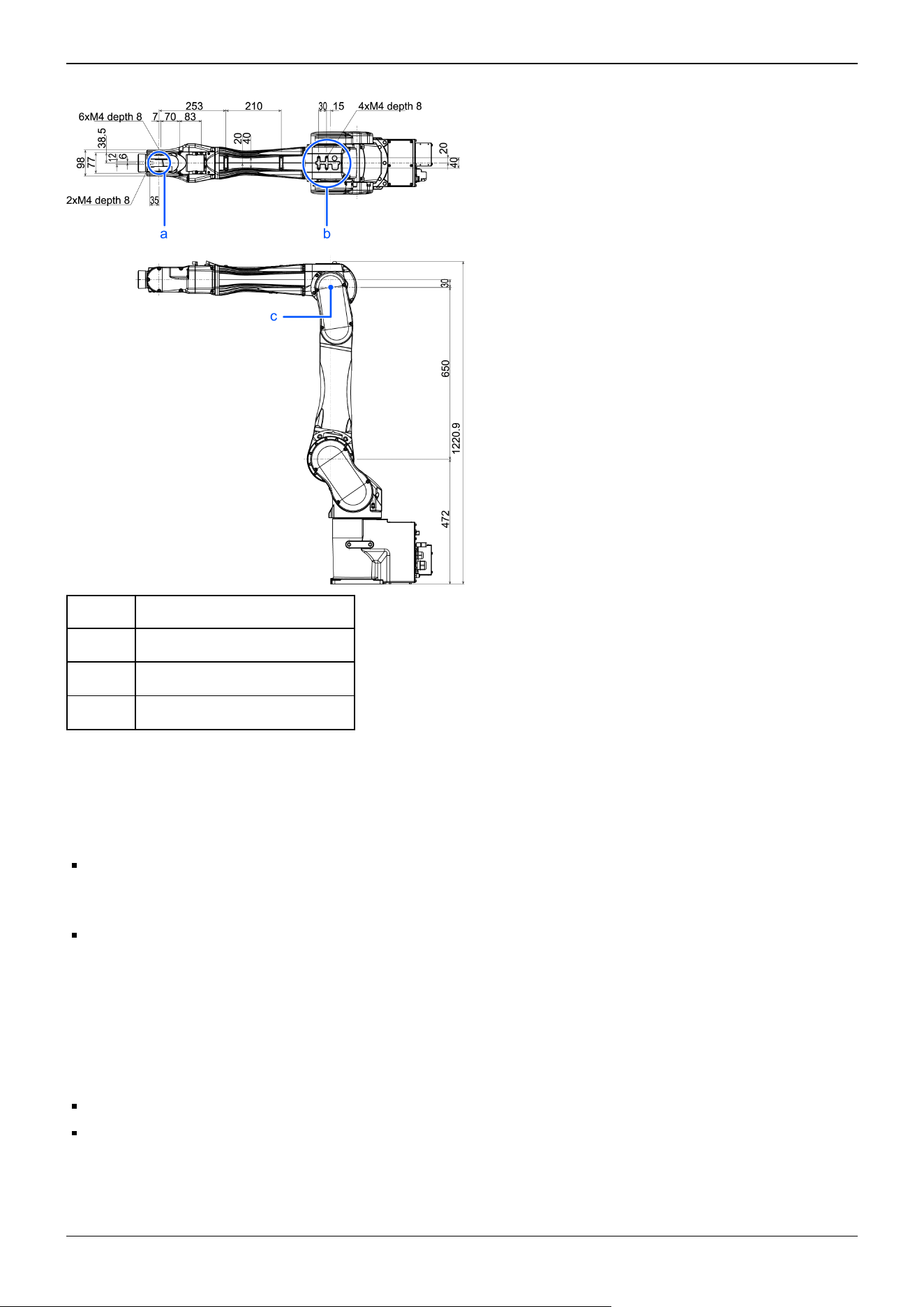
C8-B1401*** (C8XL)
Symbol Description
a Arm #5 Deck
b Arm #3 Deck
c Rotation center of the upper arm
3.4.3 WEIGHT and INERTIA Settings
The WEIGHT and INERTIA commands are for setting the load parameters of the Manipulator. These settings optimize the
Manipulator motion.
WEIGHT Setting
The WEIGHT command is for setting the load weight. The more the load weight increases, the more the speed and
acceleration/deceleration are reduced.
INERTIA Setting
The INERTIA command is for setting the inertia moment and the eccentricity of the load. The more the inertia moment
increases, the more the acceleration and deceleration of the Arm #6 are reduced. The more the eccentricity increases, the
more the acceleration and deceleration for the Manipulator movement are reduced.
To ensure that the Manipulator is functioning properly, keep the load (the sum of the weights of the hand and workpiece) and
the moment of inertia of the load within the rated values, and do not allow for eccentricity from the center of the Arm #6. If the
load or the inertia moment exceeds the ratings or if the load becomes eccentric, follow the steps below to set parameters.
WEIGHT Setting
INERTIA Setting
Industrial Robot: 6-Axis Robots C-B series Manual Rev.1b
131
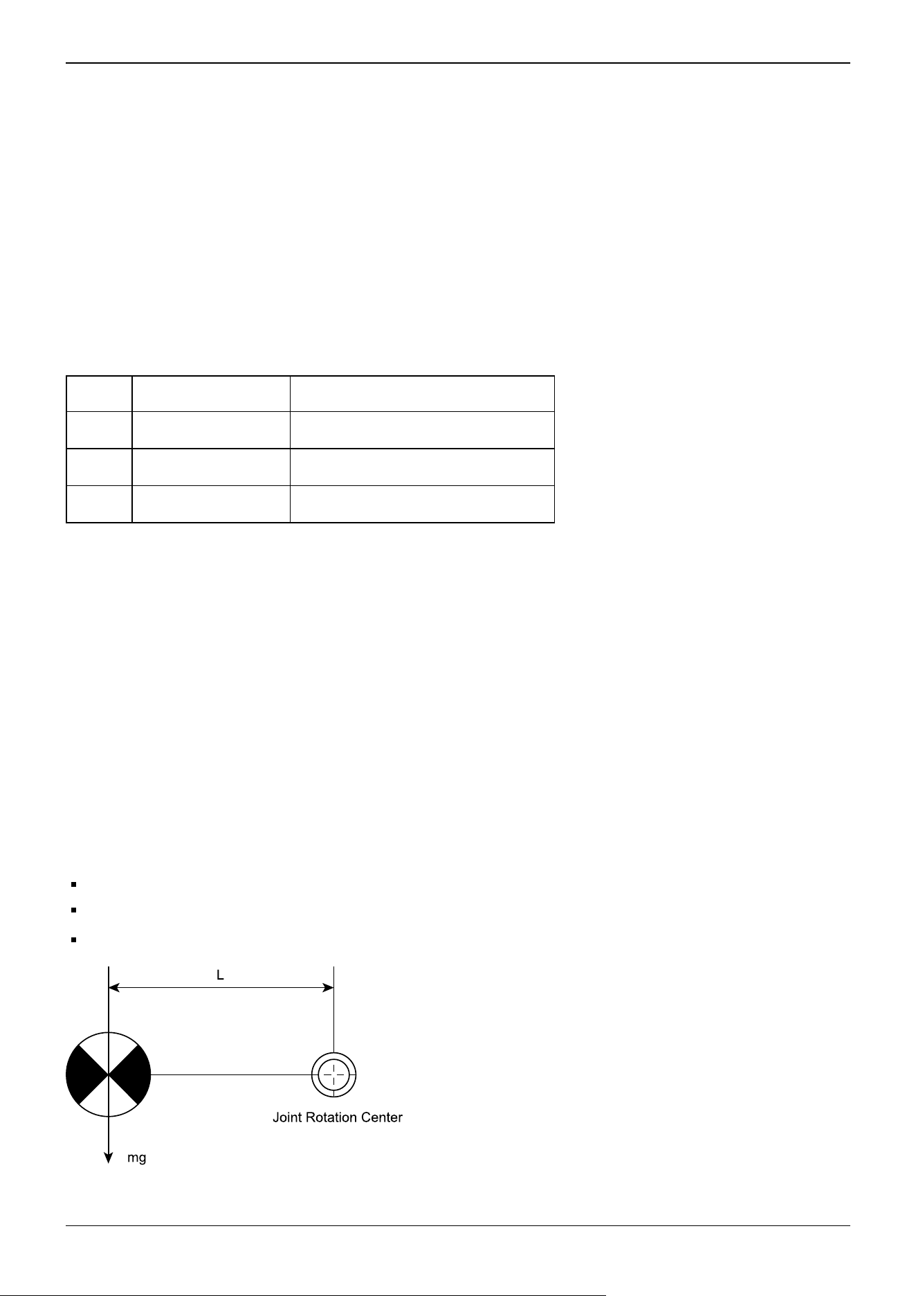
Setting parameters makes the operation of the Manipulator optimal, reduces vibration to shorten the operating time, and
improves the capacity for larger loads. This also works to curb any persistent vibration that may occur when the hand and
workpiece have a large moment of inertia.
You can also perform settings using the "Weight, Inertia, and Eccentricity/Offset Measurement Utility."
For details, refer to the following manual.
"EPSON RC+ User's Guide - Weight, Inertia, and Eccentricity/Offset Measurement Utility"
The allowable load for C8 series Manipulators is up to 8 kg.
Due to the limitations of the moment and moment of inertia shown in the table below, the load (hand + workpiece) should also
meet these conditions.
Allowable Load
Joint Allowable moment
(GD
2
/4) Allowable Moment of Inertia
Joint #4 16.6 N·m (1.69 kgf·m)
0.47 kg·m
2
Joint #5 16.6 N·m (1.69 kgf·m)
0.47 kg·m
2
Joint #6 9.4 N·m (0.96 kgf·m)
0.15 kg·m
2
Moment
The moment indicates amount of torque applied on the joint in order to support the gravity on the load hand + workpiece). The
moment increases as weight of the load and amount of eccentricity increase. As this also increases the load applied on the joint,
make sure to keep the moment within the allowable value.
Moment of inertia
The moment of inertia indicates how difficult the load (hand + workpiece) to rotate when the Manipulator joint starts to rotate
(amount of inertia). The moment of inertia increases as weight of the load and amount of eccentricity increase. As this also
increases the load applied on the joint, make sure to keep the moment within the allowable value.
The moment M (Nm) and moment of inertia I (kgm
2
) when the volume of the load (hand + workpiece) is small can be
obtained by the following formula.
M (Nm) = m (kg) × L (m) × g (m/s
2
)
I (kgm
2
) = m (kg) × L2 (m)
m: Weight of load (kg)
L: Eccentricity of load (m)
g: Gravitational acceleration (m/s
2
)
Industrial Robot: 6-Axis Robots C-B series Manual Rev.1b
132
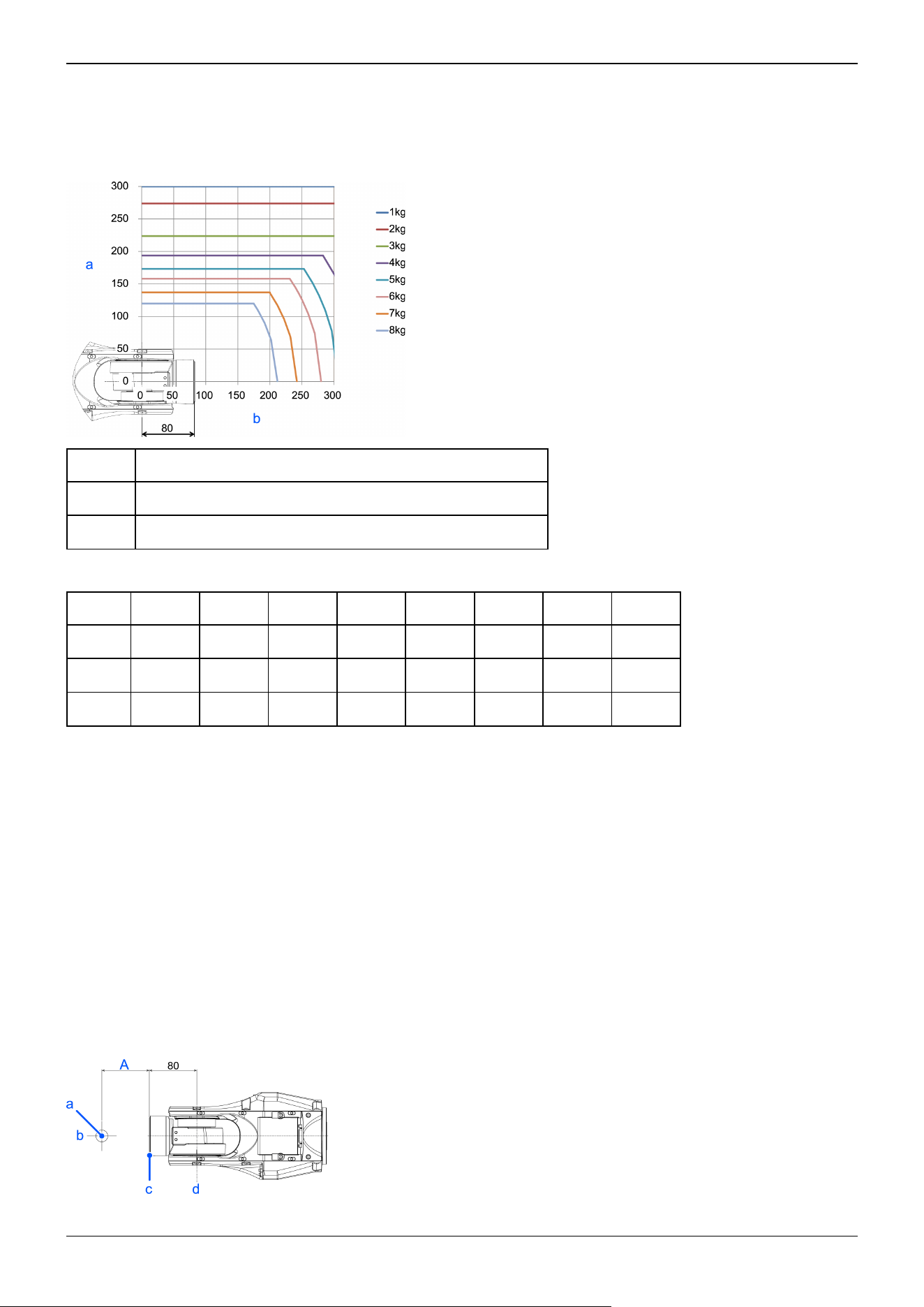
The figure below shows distribution of the center of gravity when the volume of the load (hand + workpiece) is small. Design
the hand so that the center of gravity is within the allowable moment. If the volume of the load is large, calculate the moment
and inertia moment by referring to the following section.
"INERTIA Setting - Calculating the Moment of Inertia"
Symbol Description
a Distance from the center of Arm #* rotation [mm]
b Center of gravity of load from the Arm #* rotation center [mm]
Max. Eccentricity of Load (Distance between the joint rotation center and the load’s center of gravity)
Joint 1 kg 2 kg 3 kg 4 kg 5 kg 6 kg 7 kg 8 kg
#4 300 mm 300 mm 300 mm 300 mm 300 mm 280 mm 242 mm 212 mm
#5 300 mm 300 mm 300 mm 300 mm 300 mm 280 mm 242 mm 212 mm
#6 300 mm 274 mm 224 mm 194 mm 173 mm 158 mm 137 mm 120 mm
When calculating the critical dimension of the load using the allowable moment and inertia moment, the calculated value
represents a distance from the Arm #6 rotation center, not the distance from the flange. To calculate the distance from the
flange to the load’s center of gravity, subtract the distance from the center of the Arm #5 rotation center to the flange (=80 mm)
as shown in the example below.
Example: Calculation of the critical dimension of the load (A) when the load is 8 kg.
Center of gravity by the allowable moment control: 16.6 N·m/(8 kg × 9.8 m/s
2
) = 0.212 m = 212 mm
Center of gravity by the allowable inertia moment control: (0.47 kgm
2
/8 kg)1/2 = 0.242 m = 242 mm
Due to the allowable moment control, center of gravity for the load limit is 212 mm from the Arm #5 rotation center.
Distance from the flange to the center of gravity for the load limit A = 212 mm - 80 mm = 132 mm
Critical Dimension of Load
Industrial Robot: 6-Axis Robots C-B series Manual Rev.1b
133
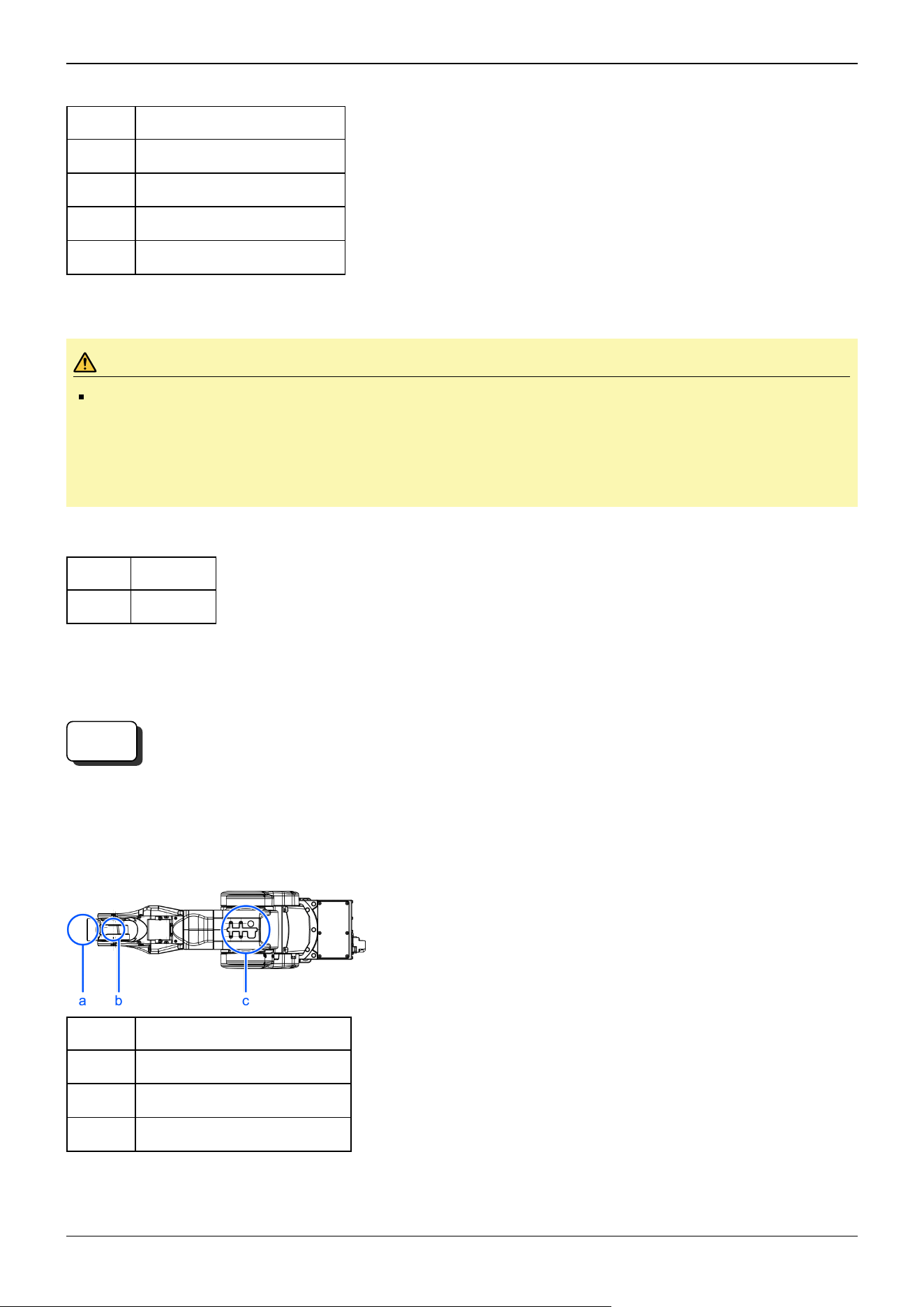
(Units: mm)
Symbol Description
a Load center of gravity position
b Arm #6 rotation center
c Flange
d Arm #5 rotation center
3.4.3.1 WEIGHT Setting
CAUTION
Set the total weight of the hand and the workpiece smaller than the maximum payload. The C8 series
Manipulators can operate without limitations on the condition unless and until the load exceeds this maximum
payload. Always set the Weight parameters of the WEIGHT command according to the load. Setting a value
smaller than the actual weight may cause errors or impact that not only impair full functionality but also
shorten the life of the mechanical components.
The acceptable weight capacity (hand + workpiece) for C8 series Manipulators is as follows:
Rated Maximum
3 kg 8 kg
Change the setting of the Weight parameter according to the load. After changing the Weight parameter setting, the maximum
acceleration/deceleration and speed of the robot system is set automatically.
Setting method of Weight parameters
Select [Tools]-[Robot Manager]-[Weight] panel and set the value in [Weight:]. You may also execute the Weight
command from [Command Window].
Load on the Manipulator
Mounting location of the load
C8-B901*** (C8L)
Symbol Description
a Load on the fore end of Arm #6
b Arm #5 deck
c Arm #3 deck
EPSON
RC+
Industrial Robot: 6-Axis Robots C-B series Manual Rev.1b
134
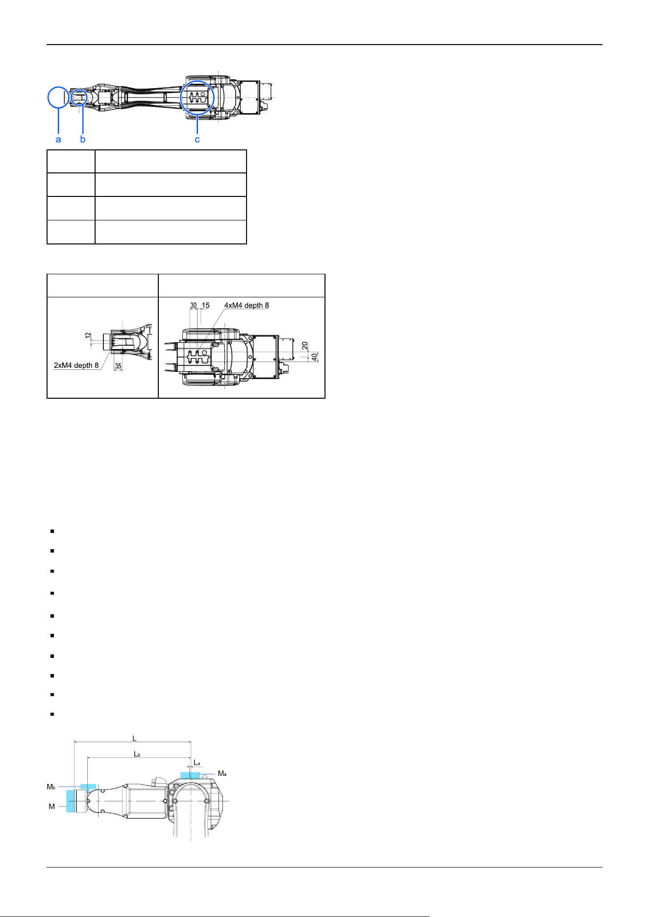
C8-B1401*** (C8XL)
Symbol Description
a Load on the fore end of Arm #6
b Arm #5 deck
c Arm #3 deck
Deck detailed (Units: mm)
Arm #5 deck Arm #3 deck
When you attach the equipment to the decks on the upper arm, convert its weight into equivalent weight assuming that the
equipment is attached to the end of the Arm #6. Then, this equivalent weight added to the load will be a Weight parameter.
Calculate the Weight parameter by using the formula below and enter the value.
Weight Parameter Formula
Weight parameter = M
w
+ W
a
+ W
b
M
w
: Payload on the fore end of Arm #6 (kg)
W
a
: Equivalent weight of the Arm #3 deck (kg)
W
b
: Equivalent weight of the Arm #5 deck (kg)
W
a
=M
a
(L
a
)
2
/(L)
2
W
b
=M
b
(L
b
)
2
/(L)
2
M
a
: Weight of the air valve on the Arm #3 deck (kg)
M
b
: Weight of the camera on the Arm #5 deck (kg)
L: Length of the upper arm (315 mm)
L
a
: Distance between the Joint #3 and the center of gravity of the air valve on the Arm #3 deck (mm)
L
b
: Distance between the Joint #3 and the center of gravity of the camera on the Arm #5 deck (mm)
Industrial Robot: 6-Axis Robots C-B series Manual Rev.1b
135
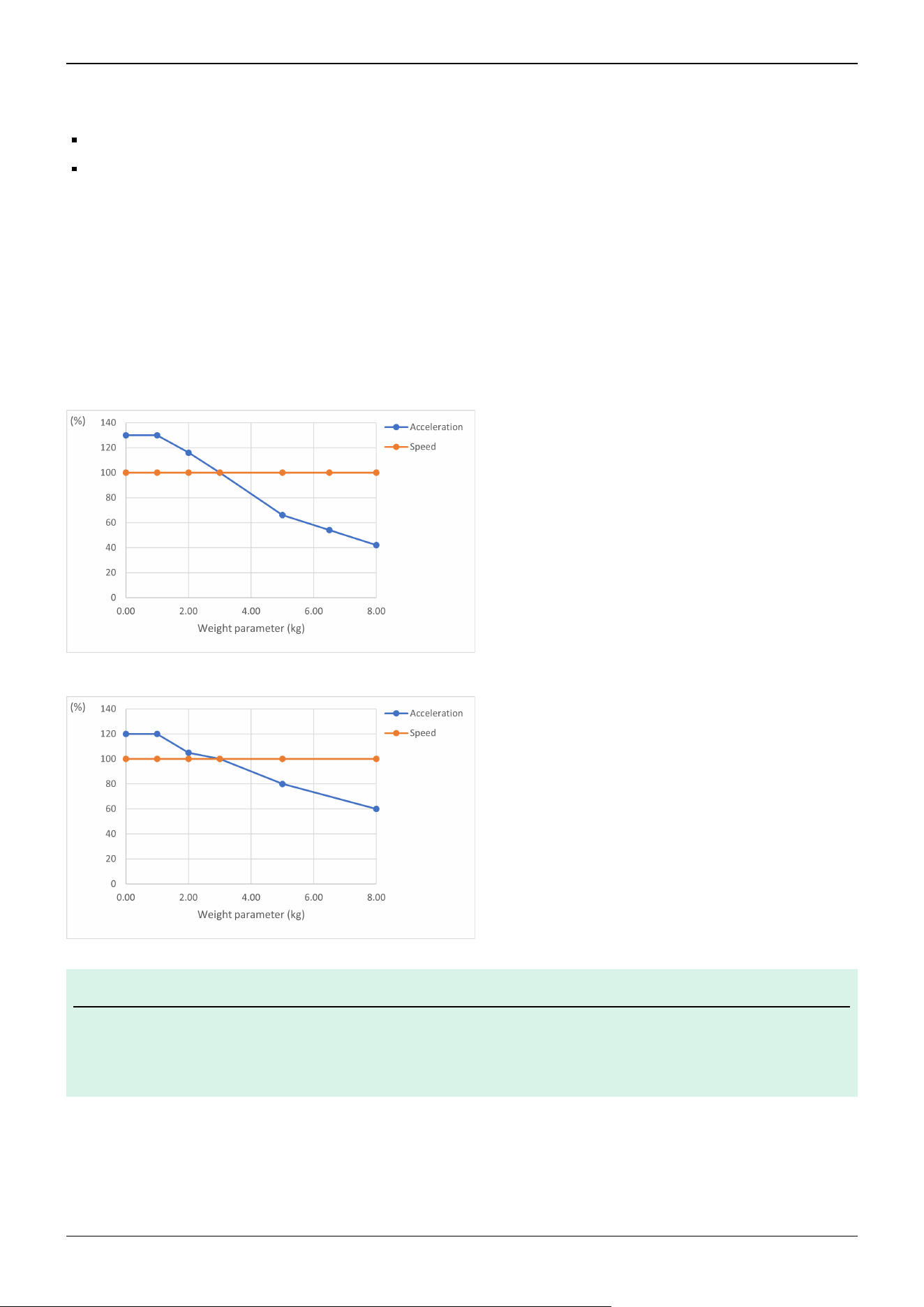
[Example] When the following loads apply to C8-B1401*** (C8XL) which fore end of the Arm #6 is 730 mm (L) away from
the Joint #3 and payload (M
w
) is 5 kg:
Load on the Arm #3 deck is 1.5 kg (M
a
). The deck is 0 mm (L
a
) away from the Joint #3.
Load on the Arm #5 deck is 1.0 kg (M
b
). The deck is 690 mm (L
b
) away from the Joint #3.
W
a
=1.5 × 0
2
/730
2
=0
W
b
=1.0 × 690
2
/730
2
=0.89 → 0.9 (round up)
M
w
+W
a
+W
b
=5+0+0.9=5.9
Enter "5.9" for the Weight parameter.
Automatic speed setting by Weight parameter
The percentage in the graph is based on the speed at rated weight (3 kg) as 100%.
C8-B901*** (C8L)
C8-B1401*** (C8XL)
KEY POINTS
Maximum AccelS setting value varies depending on Weight setting value. For details, refer to the following
section.
C8 Specifications
✏
Industrial Robot: 6-Axis Robots C-B series Manual Rev.1b
136
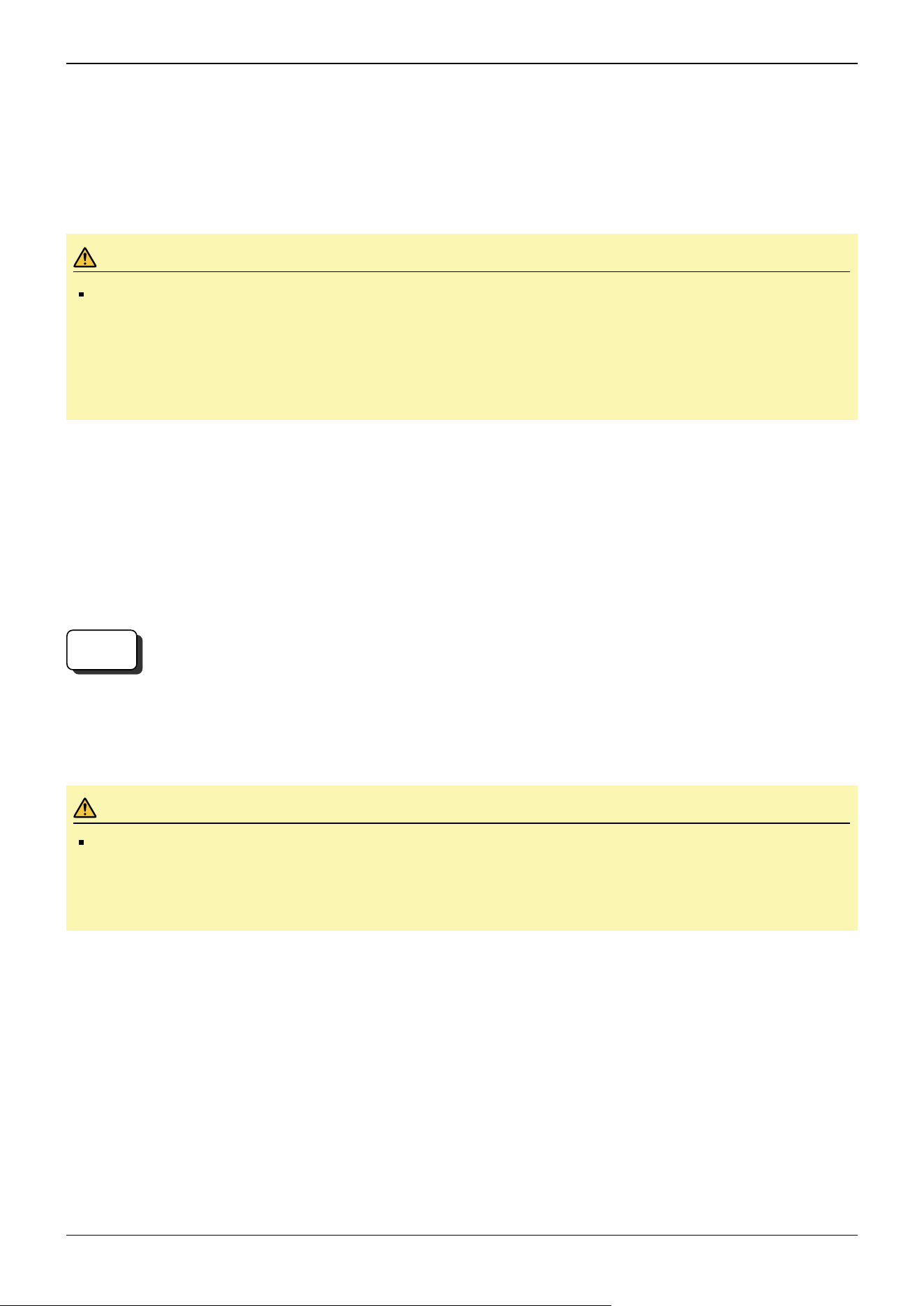
3.4.3.2 INERTIA Setting
Moment of Inertia and INERTIA Setting
The moment of inertia is a quantity that expresses how hard it is for an object to turn, and it is expressed in terms of values for
the moment of inertia, inertia, or GD
2
. When a hand or other object is attached to the Arm #6 for operation, the moment of
inertia of the load must be taken into consideration.
CAUTION
The moment of inertia of the load (hand + workpiece) must be 0.15 kg·m
2
or less.
The C8 Manipulators are not designed to work with a moment of inertia exceeding 0.15 kg·m
2
. Always set the
value corresponding to the moment of inertia. Setting a parameter value that is smaller than the actual
moment of inertia may cause errors or impact, may prevent the Manipulator from working at full functionality,
and may shorten the lifespan of mechanical parts.
The allowable moment of inertia of a load for C8 Manipulators is 0.03 kg·m
2
at the default rating and 0.15 kg·m
2
at the
maximum. Change the setting of the moment of inertia according to the inertia moment of the load using the INERTIA
command. After the setting is changed, the maximum acceleration/deceleration of Arm #6 that corresponds to the "Inertia"
value is corrected automatically.
Moment of Inertia of Load Attached to Arm #6
The moment of inertia of the load (hand + workpiece) attached to the Arm #6 can be set by the "Inertia" parameter in the
Inertia statement.
Go to [Tools] - [Robot Manager] - [Inertia] panel, and enter the value in [Inertia]. This can also be set using the Inertia
statement in [Command Window].
Eccentricity and INERTIA Setting
CAUTION
The eccentricity of the load (hand + workpiece) must be 300 mm or less. The C8 series Manipulators are not
designed to work with eccentricities exceeding 300 mm. Always set the value based on the eccentricity.
Setting the eccentricity parameter to a value smaller than the actual eccentricity may cause errors or impact
that not only impair full functionality but also shorten the life of the mechanical components.
The allowable eccentricity of load for C8 Manipulators is 50 mm at the default rating and 300 mm at the maximum. When the
load eccentricity exceeds the rating, change the setting for the eccentricity parameter in Inertia statement. After the setting is
changed, the maximum acceleration/deceleration of the Manipulator that corresponds to the "Eccentricity" is corrected
automatically.
EPSON
RC+
Industrial Robot: 6-Axis Robots C-B series Manual Rev.1b
137
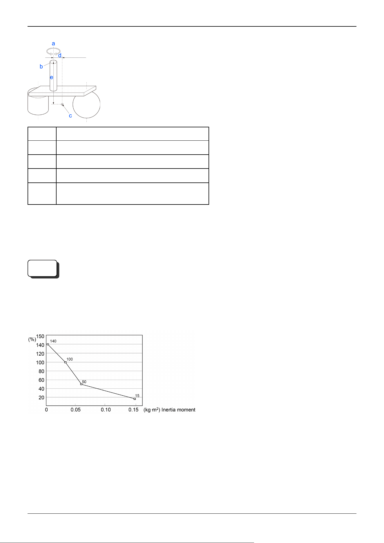
Eccentricity
Symbol Description
a Rotation axis
b Flange
c Load center of gravity position
d, e
Eccentricity (300 mm or less)
To set the parameter, enter the larger value of "d" or "e".
Eccentricity of Load Attached to Arm #6
The eccentricity of the load (hand + workpiece) attached to the Arm #6 can be set by the "Eccentricity" parameter in the Inertia
statement.
Enter the larger value of either "d" or "e" in the figure above to [Eccentricity].
Go to [Tools] - [Robot Manager] - [Inertia] panel, and enter the value in [Eccentricity]. This can also be set using the Inertia
statement in [Command Window].
Automatic Acceleration/Deceleration Correction at INERTIA (Eccentricity) Setting
Automatic setting by inertia moment setting (common to C8 series)
* The percentages on the graph are ratios based on 100% as the acceleration/deceleration at the rated (0.03 kg·m
2
) setting.
Automatic setting by eccentricity setting (common to C8 series)
EPSON
RC+
Industrial Robot: 6-Axis Robots C-B series Manual Rev.1b
138
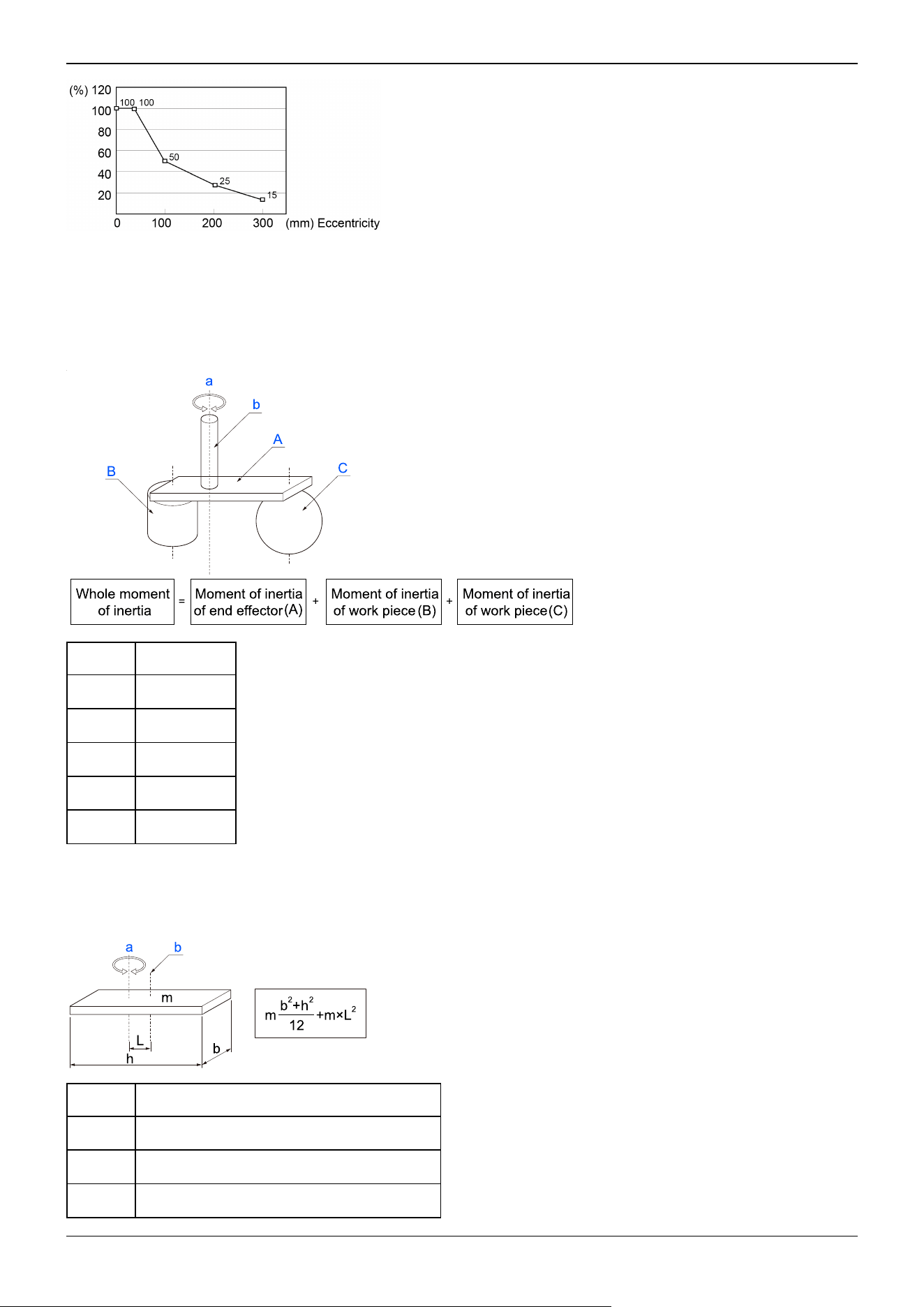
* The percentages on the graph are ratios based on 100% as the acceleration/deceleration at the rated (50 mm) setting.
Calculating the Moment of Inertia
An example of calculating the moment of inertia of a load (hand holding a workpiece) is shown below.
The moment of inertia of the entire load is calculated by the sum of (A), (B), and (C).
Symbol Description
a Rotation axis
b Shaft
A Hand
B Workpiece
C Workpiece
The methods for calculating the moment of inertia for (A), (B), and (C) are shown below. Use the moment of inertia of these
basic shapes as a reference to find the moment of inertia of the entire load.
(A) Moment of inertia of a rectangular parallelepiped
Symbol Description
a Rotation axis
b Center of gravity of rectangular parallelepiped
m Weight
Industrial Robot: 6-Axis Robots C-B series Manual Rev.1b
139
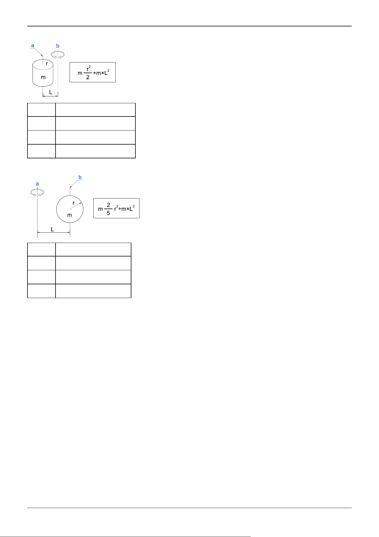
(B) Moment of inertia of a cylinder
Symbol Description
a Center of gravity of cylinder
b Rotation axis
m Weight
(C) Moment of inertia of a sphere
Symbol Description
a Rotation axis
b Center of gravity of sphere
m Weight
3.4.4 Safety Information for Auto Acceleration
The speed and acceleration/deceleration of the Manipulator motion are automatically optimized according to the values of
WEIGHT and INERTIA and the Manipulator’s postures.
WEIGHT Setting
The speed and acceleration/deceleration of the Manipulator are controlled according to the load weight set by the WEIGHT
command. The more the load weight increases, the more the speed and acceleration/deceleration are reduced to prevent
residual vibration.
INERTIA Setting
The acceleration/deceleration of Arm #6 are controlled according to the inertia moment set by the INERTIA command. The
acceleration/deceleration of the whole Manipulator are controlled according to the eccentricity set by the INERTIA command.
The more the inertia moment and eccentricity of the load increase, the more the acceleration/ deceleration are reduced.
Auto Acceleration/Deceleration According to Manipulator’s Posture
The acceleration/deceleration are controlled according to the Manipulator’s posture. When the Manipulator extends its arms or
when the movement of the Manipulator produces vibration frequently, the acceleration/deceleration are reduced.
Set appropriate values for WEIGHT and INERTIA so that the Manipulator operation is optimized.
Industrial Robot: 6-Axis Robots C-B series Manual Rev.1b
140
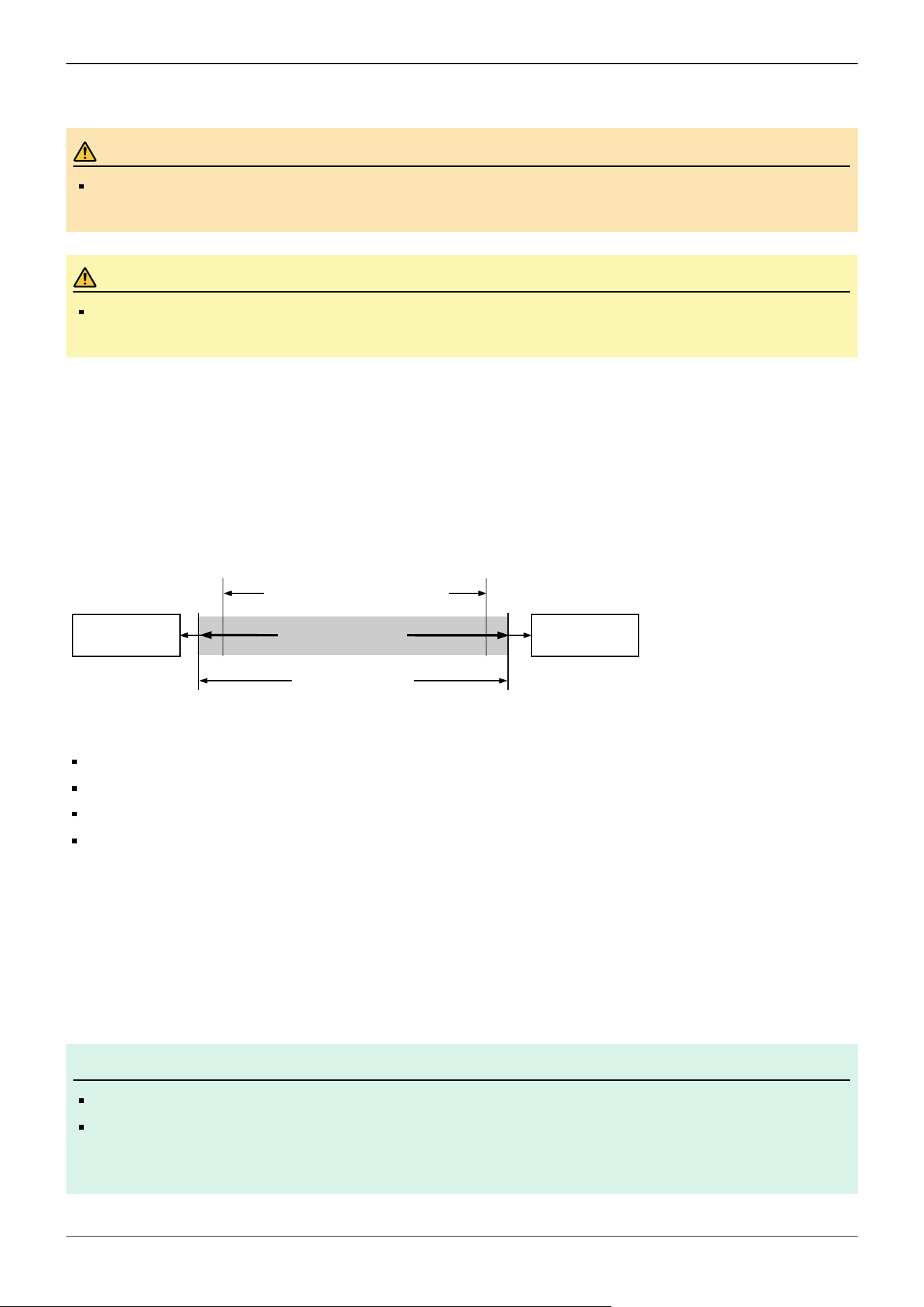
3.5 Work Envelope
WARNING
Do not operate the Manipulator with the mechanical stop removed. Removing the mechanical stop is
extremely dangerous because the Manipulator may move to a position outside its normal work envelope.
CAUTION
When restricting the work envelope for safety reasons, be sure to make settings using both the pulse range
and mechanical stop.
The work envelope is preset at the factory as explained in the following section. This is the maximum work envelope of the
Manipulator.
Standard Work Envelope
The work envelope can be set by one of the following three methods.
1. Setting by pulse range (for each joint)
2. Setting by mechanical stops
3. Setting the rectangular range in the XY coordinate system of the Manipulator
To limit the work envelope for layout efficiency or safety reasons, make the settings as explained in the following sections.
Work Envelope Setting by Pulse Range (for Each Joint)
Setting the Work Envelope by Mechanical Stops
Restriction of Manipulator Operation by Joint Angle Combination
Coordinate System
3.5.1 Work Envelope Setting by Pulse Range (for Each Joint)
Pulses are the basic unit of Manipulator motion. The motion range (work envelope) of the Manipulator is set by the pulse
lower limit value and pulse upper limit value (pulse range) for each joint. Pulse values are read from the encoder output of the
servomotor.
Be sure to set the pulse range within the mechanical stop range.
KEY POINTS
The Arm #1 and #4 do not have a mechanical stop.
Once the Manipulator receives a motion command, it checks whether the target position specified by the
command is within the pulse range before operating. If the target position is outside of the pulse range that
was set, an error occurs and the Manipulator does not move.
Pulse range
Work Envelope
Mechanical
Stop
Mechanical
Stop
Rectangular range setting
✏
Industrial Robot: 6-Axis Robots C-B series Manual Rev.1b
141
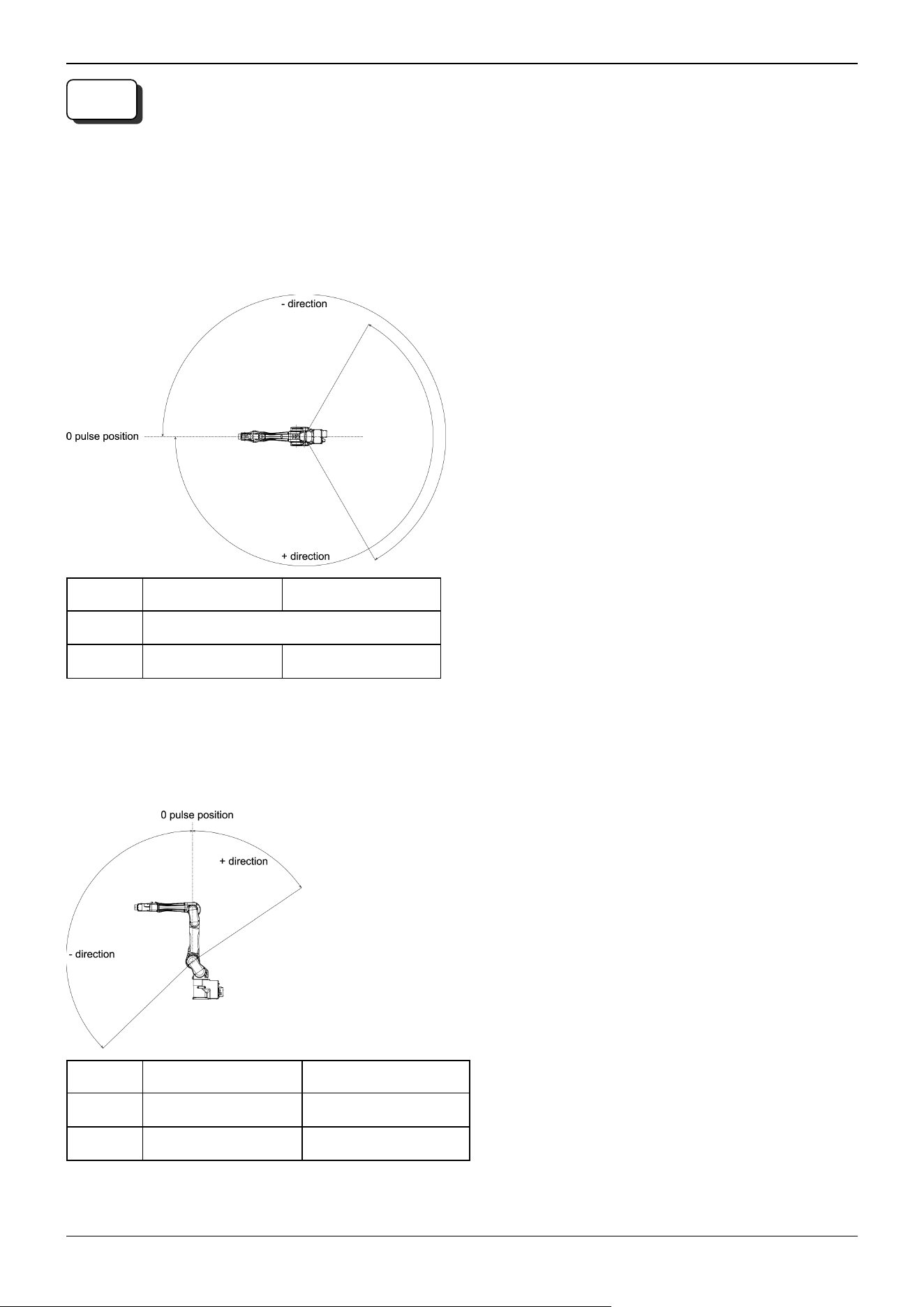
Go to [Tools] - [Robot Manager] - [Range] panel, and make the setting. This can also be set using the Range statement in
[Command Window].
3.5.1.1 Joint #1 Maximum Pulse Range
With the 0 pulse as a starting point, the counterclockwise pulse value is defined as positive (+), and the clockwise pulse value
is defined as negative (-).
C8-B901*** (C8L) C8-B1401*** (C8XL)
Angle (°) ±240
Pulse ±10695600 ±15736800
3.5.1.2 Joint #2 Maximum Pulse Range
With the 0 pulse as a starting point, the clockwise pulse value is defined as positive (+), and the counterclockwise pulse value
is defined as negative (-).
C8-B901*** (C8L) C8-B1401*** (C8XL)
Angle (°) -158 to +65 -135 to +55
Pulse -6903178 to +2839915 -10616940 to +4325420
EPSON
RC+
Industrial Robot: 6-Axis Robots C-B series Manual Rev.1b
142
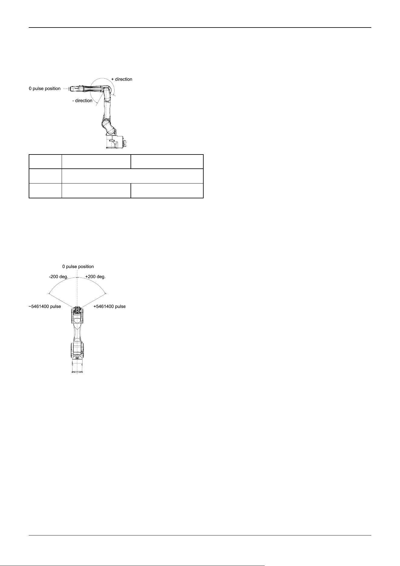
3.5.1.3 Joint #3 Maximum Pulse Range
With the 0 pulse as a starting point, the clockwise pulse value is defined as positive (+), and the counterclockwise pulse value
is defined as negative (-).
C8-B901*** (C8L) C8-B1401*** (C8XL)
Angle (°) -61 to +202
Pulse -2220949 to +7354618 -3997696 to +13238272
3.5.1.4 Joint #4 Maximum Pulse Range
From the angle of arm end, with the 0 pulse as a starting point, the clockwise pulse value is defined as positive (+), and the
counterclockwise pulse value is defined as negative (-). The max. pulse range of the Arm #4 is common to C8 series
Manipulators.
(deg.=°)
3.5.1.5 Joint #5 Maximum Pulse Range
With the 0 pulse as a starting point, the clockwise pulse value is defined as positive (+), and the counterclockwise pulse value
is defined as negative (-). The max. pulse range of the Arm #5 is common to C8 series Manipulators.
Industrial Robot: 6-Axis Robots C-B series Manual Rev.1b
143
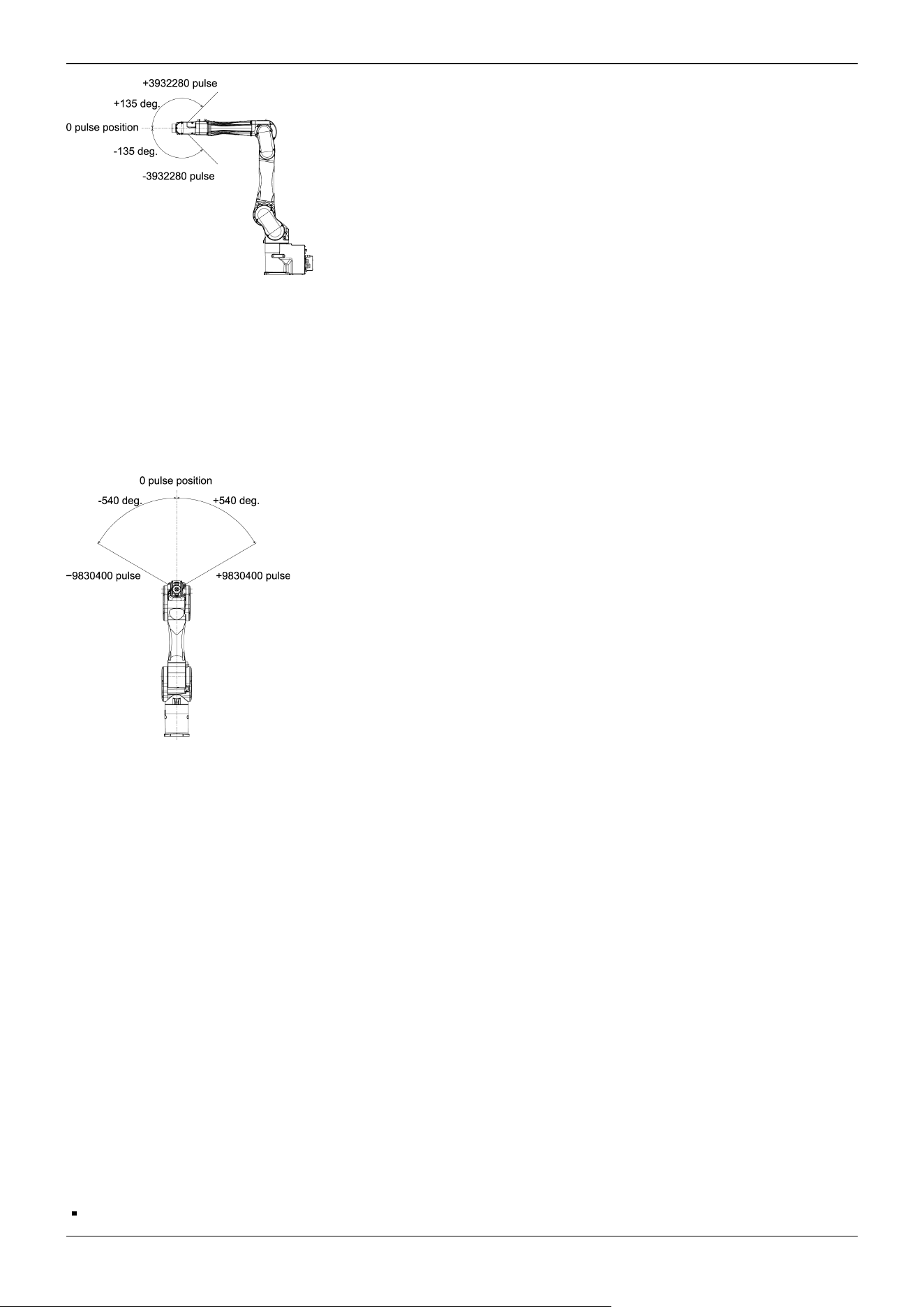
(deg.=°)
3.5.1.6 Joint #6 Maximum Pulse Range
From the angle of arm end, with the 0 pulse as a starting point, the clockwise pulse value is defined as positive (+), and the
counterclockwise pulse value is defined as negative (-). The max. pulse range of the Arm #6 is common to C8 series
Manipulators.
(deg.=°)
3.5.2 Setting the Work Envelope by Mechanical Stops
Using the variable mechanical stops physically limits the absolute area that the Manipulator can move.
Before starting any work, be sure to turn off the Manipulator.
Use bolts conforming to the specified length and surface processing (ex: nickel plating) with high corrosion resistance.
Specify the pulse range again after changing the position of the mechanical stop.
For details on the pulse range setting, refer to the following section.
Work Envelope Setting by Pulse Range (for Each Joint)
Be sure to set the pulse range inside the positions of the mechanical stop range.
3.5.2.1 Setting the Joint #1 Work Envelope
Install variable mechanical stop (J1) in the threaded holes corresponding to the angles to be set.
Normally a mechanical stop is not equipped.
Hexagon socket head cap bolt: M12 × 30 × 2 bolts
Industrial Robot: 6-Axis Robots C-B series Manual Rev.1b
144
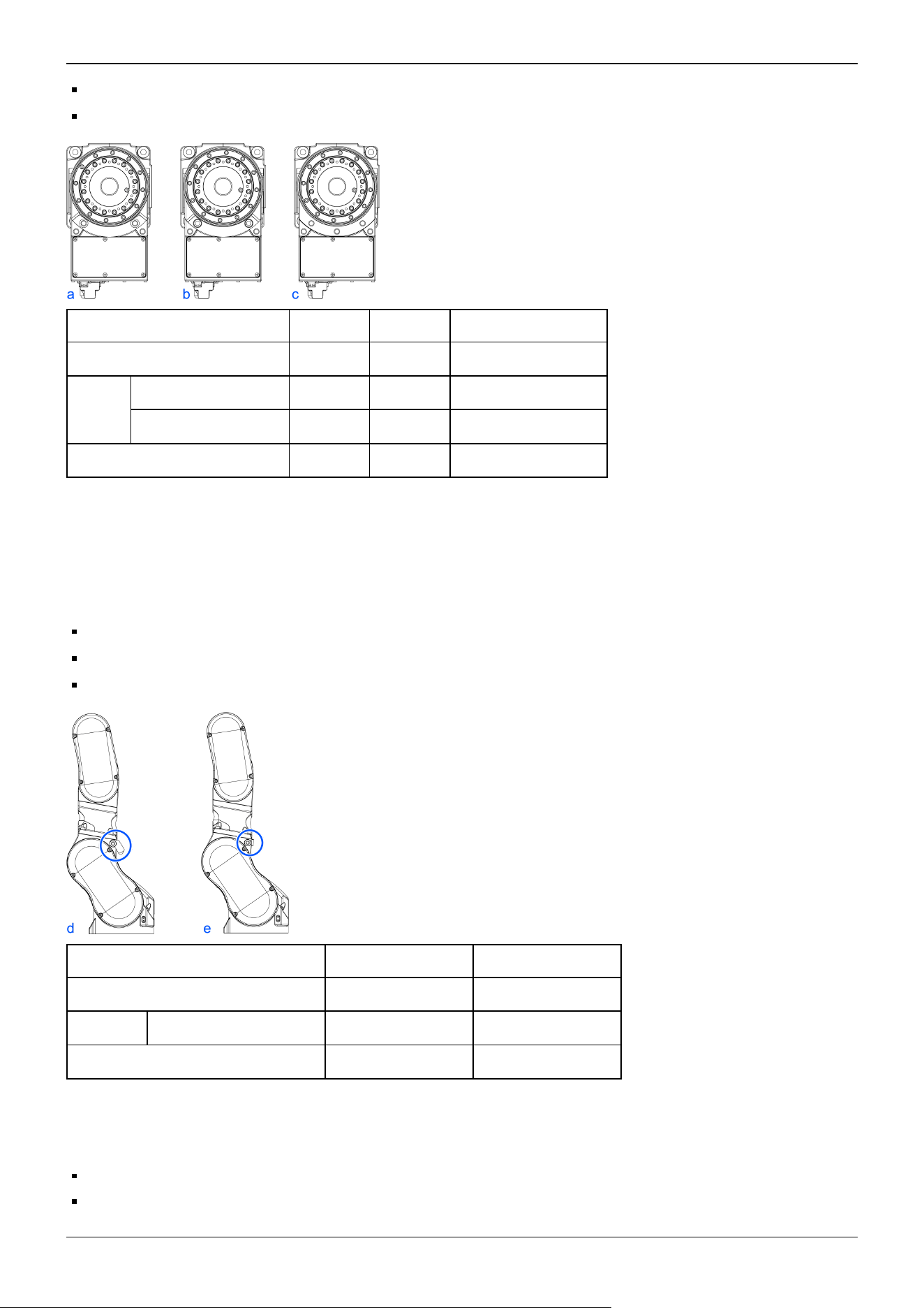
Strength: Compliant with ISO 898-1 property class: 10.9 or 12.9
Tightening torque: 42.0 ± 2.1 N·m (428 ± 21 kgf·cm)
a b c
Angle (°) ±110 ±105 ±240
Pulse
C8-B901*** (C8L) ±4902150 ±4679271 ±10695600
C8-B1401*** (C8XL) ±7212700 ±6884840 ±15736800
Variable Mechanical Stop (J1) Applied Applied Not applied (standard)
3.5.2.2 Setting the Joint #2 Work Envelope
C8-B901*** (C8L)
Remove the mechanical stop installed as standard and install the variable mechanical stop (C8/C8L_J2). (Joint #2 standard
work envelope -158 to +65°)
Hexagon socket head cap bolt: M10 × 35 × 1 bolts
Strength: Compliant with ISO 898-1 property class: 10.9 or 12.9
Tightening torque: 32.0 ± 1.6 N·m (326 ± 16 kgf·cm)
d e
Angle (°) -158, +30 -158, +65
Pulse C8-B901*** (C8L) -6903178, +1310730 -6903178, +2839915
Variable mechanical stop (C8/C8L_J2) Applied Applied (standard)
C8-B1401*** (C8XL)
Remove the mechanical stop installed as standard and install the variable mechanical stop (C8XL_J2). (Joint #2 standard work
envelope -135 to +55°)
Hexagon socket head cap bolt: M10 × 35 × 2 bolts
Strength: Compliant with ISO 898-1 property class: 10.9 or 12.9
Industrial Robot: 6-Axis Robots C-B series Manual Rev.1b
145
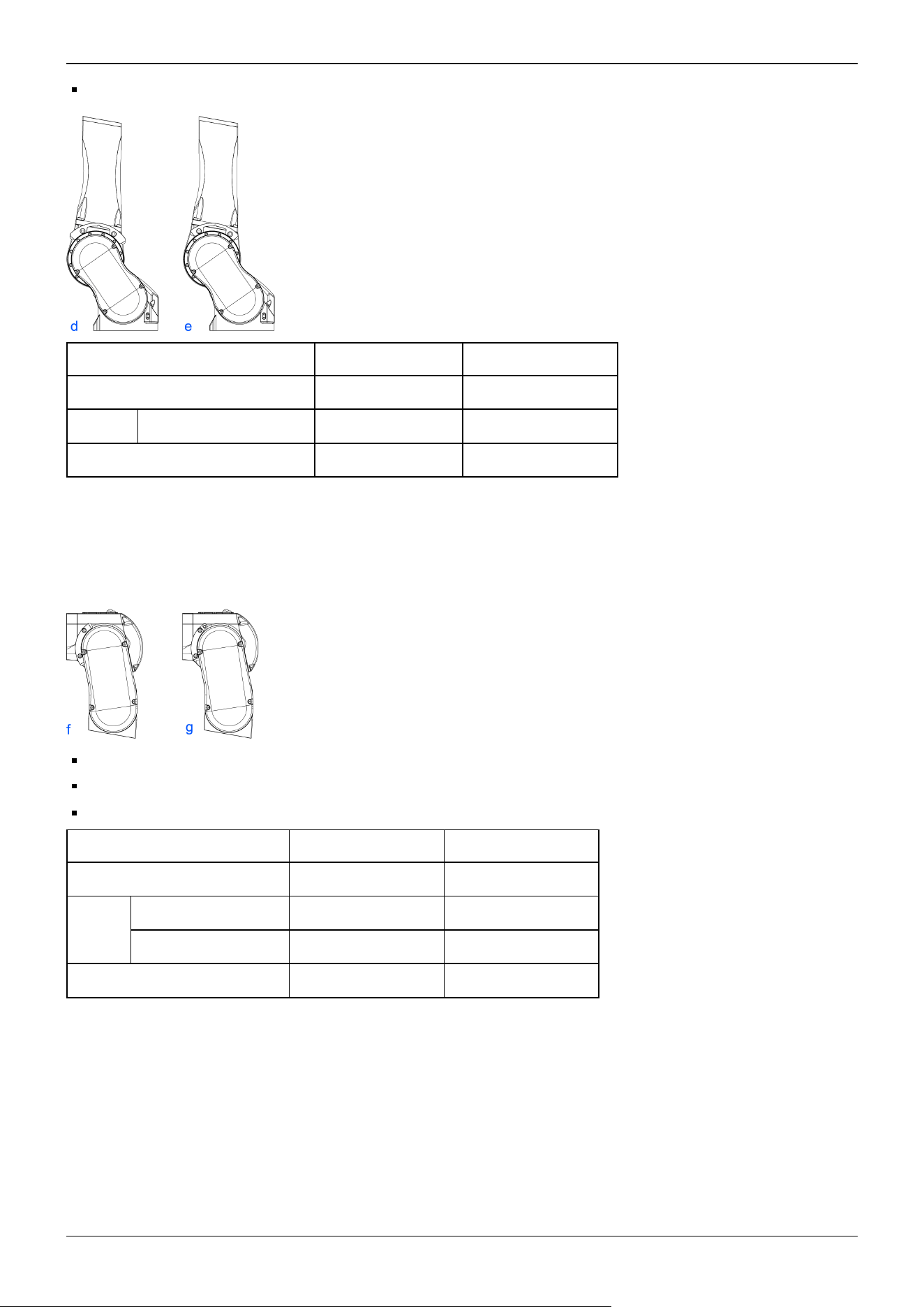
Tightening torque: 32.0 ± 1.6 N·m (326 ± 16 kgf·cm)
d e
Angle (°) -125, +45 -135, +55
Pulse C8-B1401*** (C8XL) -9830500, +3538980 -10616940, +4325420
Variable mechanical stop (C8XL_J2) Applied Applied (standard)
3.5.2.3 Setting the Joint #3 Work Envelope
Remove the mechanical stop installed as standard and install the variable mechanical stop (J3). (Joint #3 standard work
envelope -61 to +202°)
Hexagon socket head cap bolt: M6 × 15 × 2 bolts
Strength: Compliant with ISO 898-1 property class: 10.9 or 12.9
Tightening torque: 13.0 ± 0.6 N·m (133 ± 6 kgf·cm)
f g
Angle (°) -51, +192 -61, +202
Pulse
C8-B901*** (C8L) -1856859, +6990528 -2220949, +7354618
C8-B1401*** (C8XL) -3342336, +12582912 -3997696, +13238272
Variable Mechanical Stop (J3) Applied Applied (standard)
3.5.3 Restriction of Manipulator Operation by Joint Angle Combination
To prevent the arms of the Manipulator from interfering each other, the Manipulator operation is restricted in the specified
motion range according to the angle combination of the Joint #1, #2, and #3.
The Manipulator operation is restricted and the Manipulator stops when the joint angles are within the colored areas in the
following figure.
The restriction to Manipulator operation is enabled:
Industrial Robot: 6-Axis Robots C-B series Manual Rev.1b
146
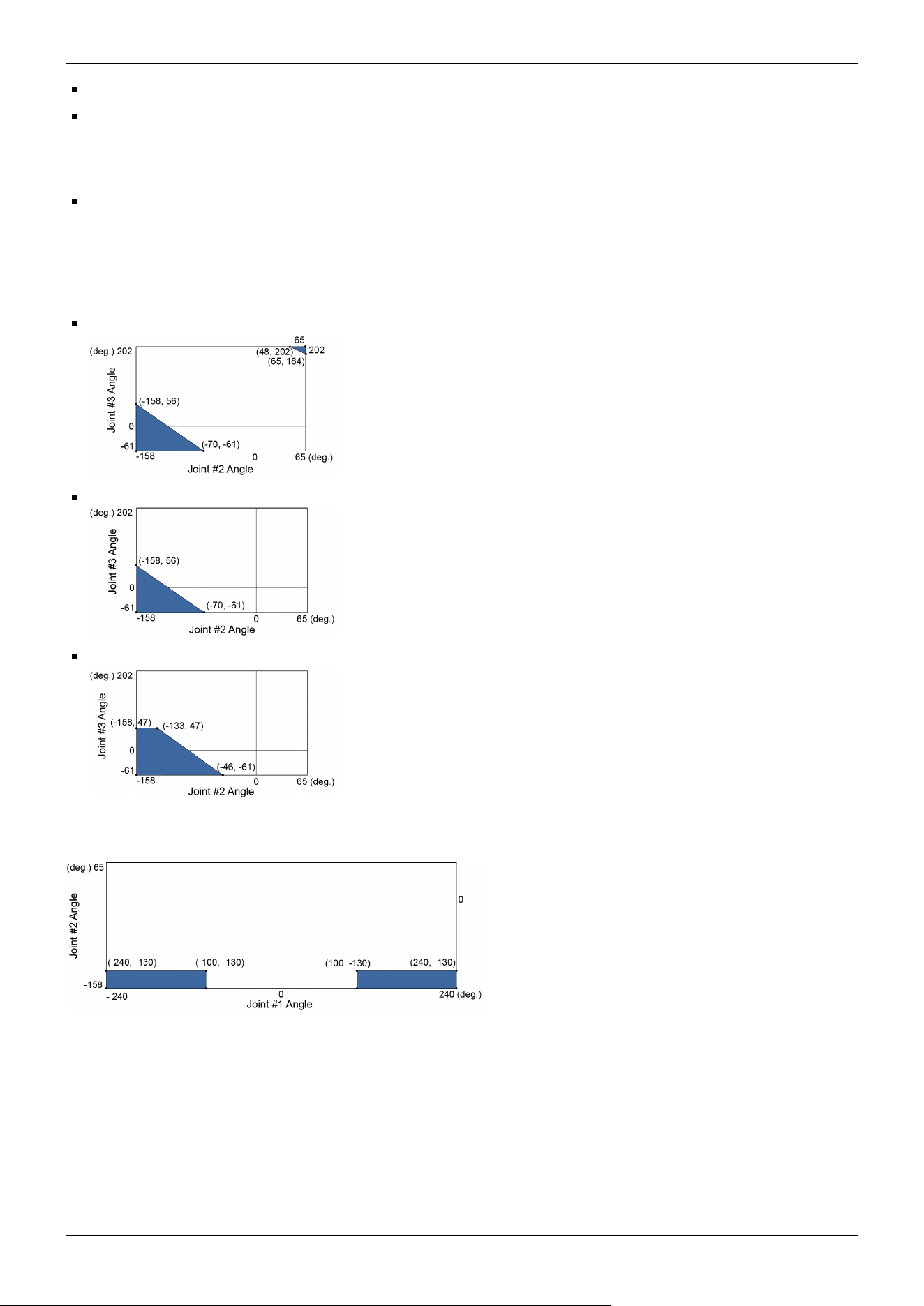
During CP motion command execution
When you attempt to execute the motion command for moving the Manipulator to a target point (or pose) in the specified
motion range.
The restriction to the Manipulator operation is disabled:
The Arms of the Manipulator momentarily go through the specified motion range during the PTP motion command
execution even though the joint angles of the Arms are in the colored areas of the figures above.
C8-B901*** (C8L)
Combination of Joint #2 and #3
-50 deg. <= J1 <= 50 deg.
-115 deg. <= J1 < -50 deg. or 50 deg. < J1 <= 115 deg.
-240 deg. <= J1 < -115 deg. or 115 deg. < J1 <= 240 deg.
Combination of Joint #1 and #2
-240 deg. <= J1 <= -110 deg. or 110 deg. <= J1 <= 240 deg.
(deg.=°)
C8-B1401*** (C8XL)
Combination of Joint #2 and #3
Industrial Robot: 6-Axis Robots C-B series Manual Rev.1b
147
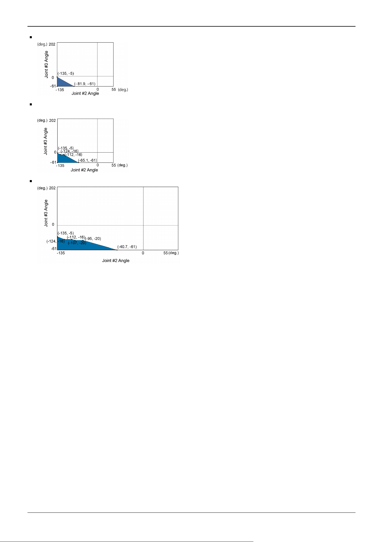
-110 deg. <= J1 <= 110 deg.
-140 deg. < J1 < -110 deg. or 110 deg. < J1 < 140 deg.
-240 deg. < J1 < -220 deg. or 220 deg. < J1 < 240 deg.
-220 deg. <= J1 <= -140 deg. or 140 deg. < J1 < 220 deg.
(deg.=°)
3.5.4 Coordinate System
The origin point is where the Manipulator’s installation face intersects with the rotation axis of Joint #1.
For details on the coordinate system, refer to the EPSON RC+ Users Guide manual.
Industrial Robot: 6-Axis Robots C-B series Manual Rev.1b
148
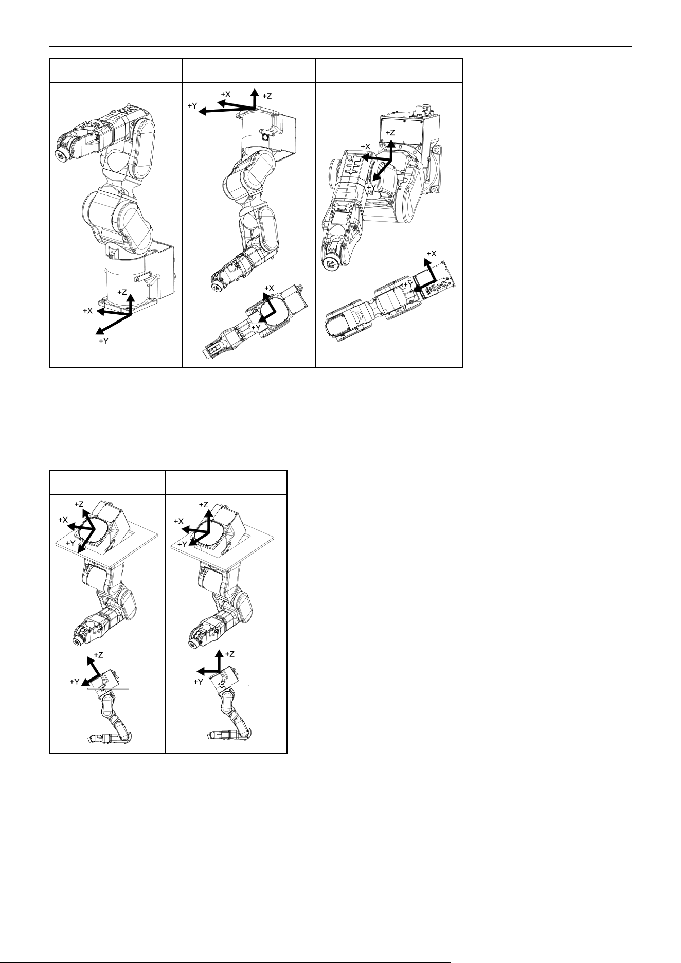
Table top mounting Ceiling mounting Wall mounting
BASE setting is suitable for install the robot obliquely.
BASE setting can change a specific coordinate system of the robot and match the World coordinate system of the Jog & Teach
and the coordinate system of the equipment.
For procedure of the BASE setting, refer to SPEL+ Language Reference: BASE Command.
With BASE setting Without BASE setting
Industrial Robot: 6-Axis Robots C-B series Manual Rev.1b
149
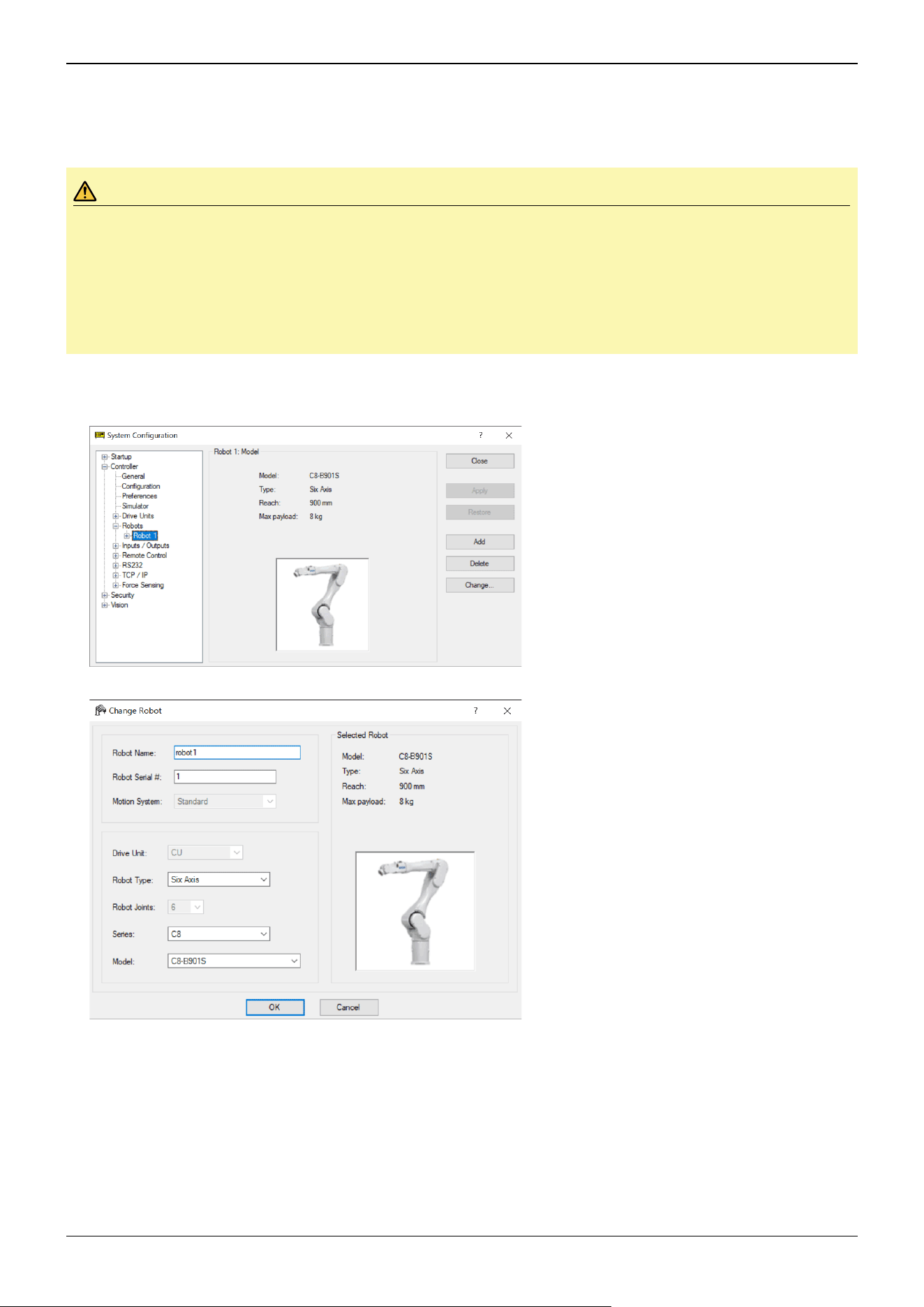
3.5.5 Changing the Robot
This section describes how to change the Manipulator model on EPSON RC+.
CAUTION
Changing the Manipulator should be done with great caution. It initializes the robot calibration parameters (Hofs,
CalPls), additional axis information, and PG parameter data. Before changing the robot, make sure to save the
calibration data by following the procedure below.
1. Select the EPSON RC+ 7.0 menu-[Setup]-[System Configuration].
2. Select [Controller]-[Robots]-[Robot**]-[Calibration] from the tree list. Then, click [Save].
1. Select the EPSON RC+ 7.0 menu-[Setup]-[System Configuration].
2. Select [Controller]-[Robots]-[Robot**] from the tree list.
3. Click the [Change] button. The following dialog box will be displayed.
4. Input the robot name and serial number printed on the name plate of the Manipulator. Any serial number can be entered.
However, enter the number printed on the Manipulator.
5. Select the robot type in the [Robot type] box.
6. Select the series name of the Manipulator in the [Series] box.
7. Select the robot model in the [Model] box.
Available robots will be displayed according to the format of the currently installed motor driver. When [Dry run] is used,
all the Manipulators of the series selected in Step 6 will be displayed.
8. Click the [OK] button. The Controller is restarted.
Industrial Robot: 6-Axis Robots C-B series Manual Rev.1b
150
3.5.6 Setting the Rectangular Range in the XY Coordinate System of the Manipulator
The Cartesian (rectangular) range in the XY coordinate system of the Manipulator is specified by the limited Manipulator
operation area and the XYLIM setting. The limited Manipulator operation area is defined so that the hand does not interfere
with the rear side of the Manipulator. The XYLIM setting that you can determines the upper and lower limits of the X and Y
coordinates.
These settings are software-based limit, and so it does not change the maximum physical range. The maximum physical range
is based on the position of the mechanical stops.
These settings are disabled during a joint jogging operation. Therefore, be careful not to allow the hand to collide with the
Manipulator or peripheral equipment.
Go to [Tools] - [Robot Manager] - [XYZ Limits] panel, and make the setting. This can also be set using the XYLim statement
in [Command Window].
3.6 Options
C8 series Manipulator has the following options.
Brake Release Unit
Camera Plate Unit
Tool Adapter (ISO flange)
Variable Mechanical Stop
User Wires and Pneumatic Tubes
3.6.1 Brake Release Unit
While the electromagnetic brake is on (such as in emergency mode), you cannot move any arm by pushing manually. You can
move the Arms by hand using the brake release unit while the Controller power is off or right after unpacking.
EPSON
RC+
Industrial Robot: 6-Axis Robots C-B series Manual Rev.1b
151
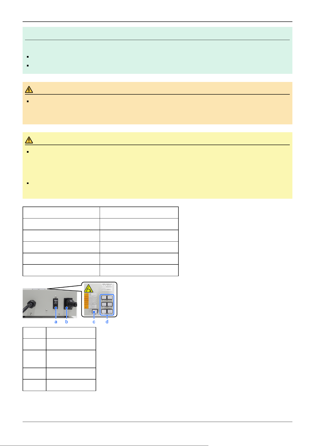
KEY POINTS
Precautions regarding the brake release unit
Be sure to prepare at least one set of the brake release unit.
Place at easy-to-reach location so that you can use it immediately when in a emergency situation.
WARNING
Turn off the power to the Robot Controller and brake release unit when connecting or replacing the brake
release unit or external short connector. Inserting or removing connectors with the power on may result in
electric shock and/or malfunction of the robot system.
CAUTION
Normally, release the brakes of joints one at a time. If the brakes of two or more joints must be released
simultaneously due to unavoidable reasons, use extreme care. Releasing the brakes of multiple joints
simultaneously may cause the arm to fall in an unexpected direction, resulting in hands or fingers getting
caught or damage or failure of the Manipulator.
After releasing the brake, the arm may fall by its own weight or move to the unexpected direction. Make sure
to prepare a countermeasure to prevent the arm from falling and check the operation environment is safe.
Width 180 mm
Depth 150 mm
Height 87 mm
Weight (Cables are not included.) 1.7 kg
Cable to the Manipulator 2 m
M/C Short Connector For M/C power cable short-circuit
Symbol Description
a Power switch
b
Power Cable
(You must provide.)
c Power lamp
d Brake release switch
✏
Industrial Robot: 6-Axis Robots C-B series Manual Rev.1b
152
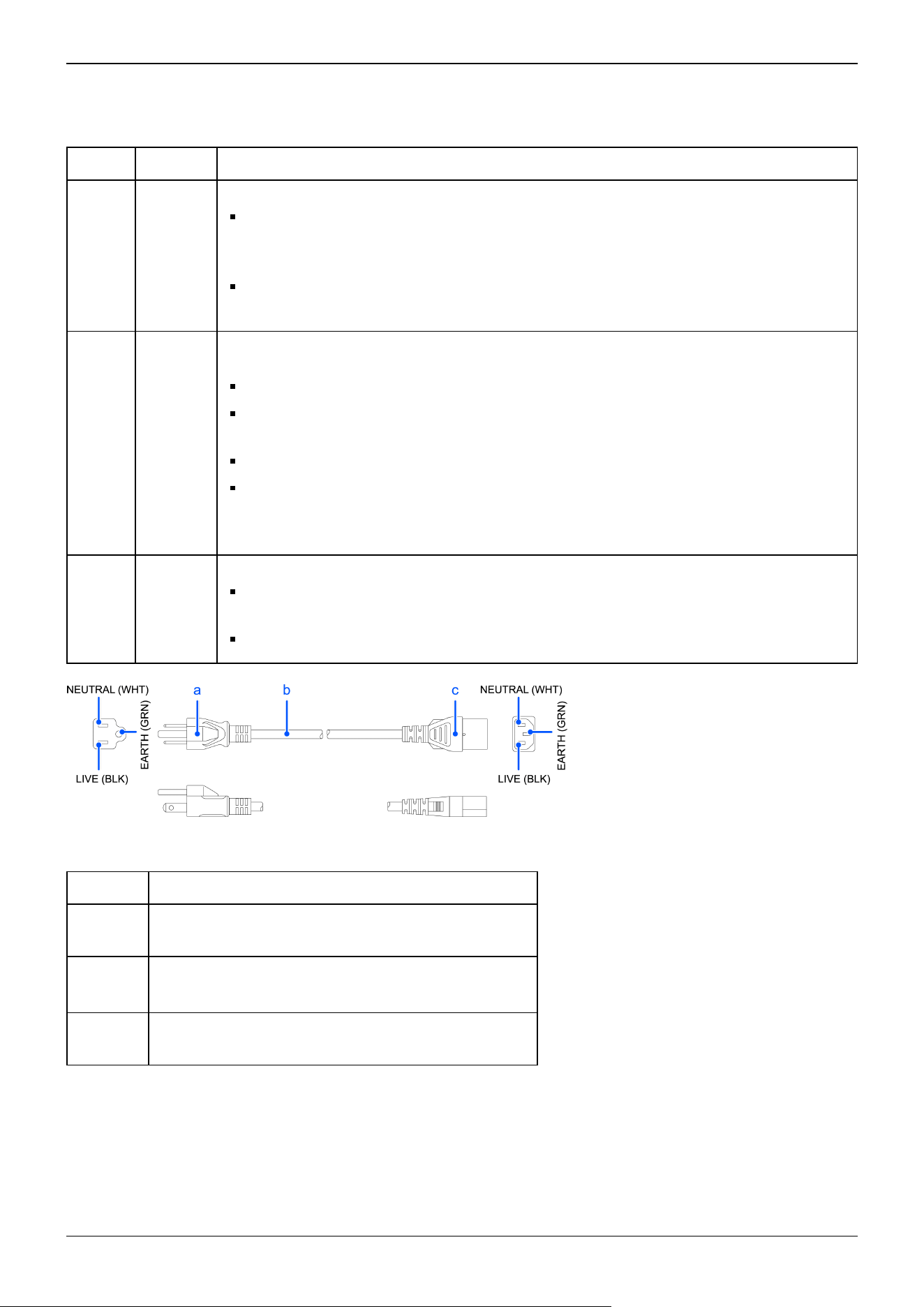
3.6.1.1 Power Cable
You must provide a power cable. Be sure to use the specifications below.
Symbol Item Specifications
a Plug
Comply with local safety regulation
Class I (2P + PE), AC250 V, 6 A or 10 A
Ex.: CEE Pub.7 Certified, CCC Certified, KC Certified, BS1363 Certified, PSB Certified, BIS
Certified, SABS Certified
Class I (2P + PE), AC125 V, 7 A, 12 A, or 15 A etc.
Ex.: UL Certified, PSE Certified, BSMI Certified
b
Flexible
cable
Comply with IEC/EN standards or local safety regulation
Example:
IEC 60227-1: General requirements
IEC 60227-5: Polyvinyl chloride insulated cables of rated voltages up to and including 450/750
V - Part 5: Flexible cables (cords)
EN 50525-1: General requirements
EN 50525-2-11: Electric cables - Low voltage energy cables of rated voltages up to and
including 450/750 V (Uo/U) - Part 2-11: Cables for general applications - Flexible cables with
thermoplastic PVC insulation
c
Appliance
coupler
Comply with IEC/EN standards or local safety regulation
IEC / EN 60320-1: Appliance couplers for household and similar general purposes - Part 1:
General requirements
Standard Sheet C13: AC250 V/10 A
For Japan
Item Specifications
Plug
PSE Certified
Class I (2P+PE), AC125 V, 7 A or higher
Code
PSE Certified
0.75 mm
2
or more
Connector
PSE Certified
IEC 60320-1 Standard Sheet C13: AC125 V/10 A or higher
Industrial Robot: 6-Axis Robots C-B series Manual Rev.1b
153
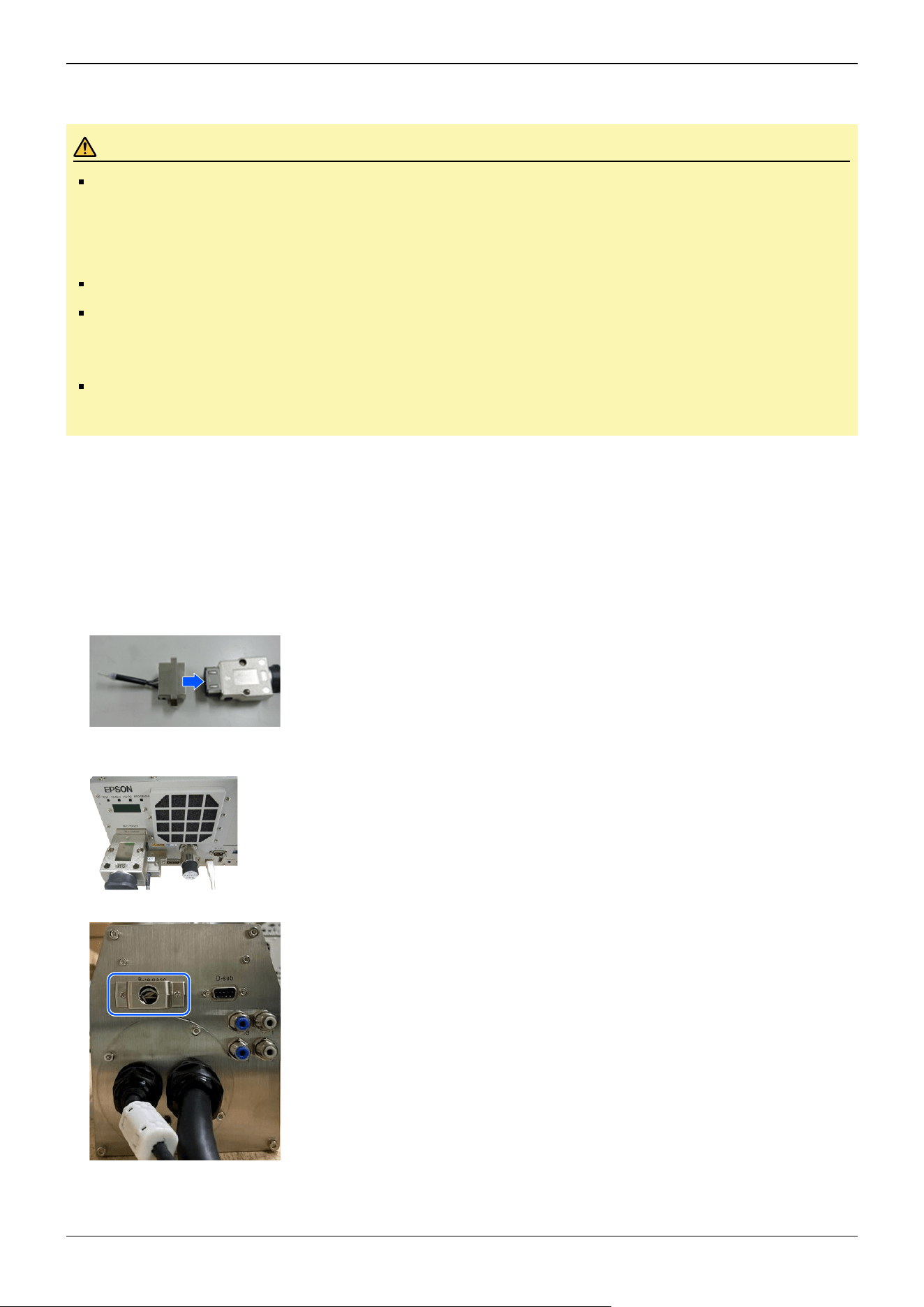
Precautions for use
CAUTION
Operating the Manipulator without a brake release unit or external short connector connected may cause the
brake to fail to release, possibly damaging the brake.
After using the brake release unit, be sure to connect the external short circuit connector to the Manipulator or
make sure to leave the connector for the brake release unit connected.
Keep the external short connector. Otherwise you cannot release the brakes.
If you turn on the brake release unit while the brake release switch is being pressed, an unintended arm may
move downward. Before turning on the brake release unit, make sure that the brake release switch is not
pressed.
If you turn on the brake release unit without the connector, it may lead to the short for the male pin used in the
connector. Before turning on the brake release unit, make sure that the connector is connected.
3.6.1.2 Installing the Brake Release Unit
1. Turn off the Controller.
2. If the M/C power cable is not connected to the Controller:
Connect the M/C short connector, or connect the Controller.
(Keep the Controller power off.)
The M/C short connector can be purchased singly.
If the M/C power cable is already connected to the Controller:
Go to the step (3).
3. Remove the external short connector.
Industrial Robot: 6-Axis Robots C-B series Manual Rev.1b
154
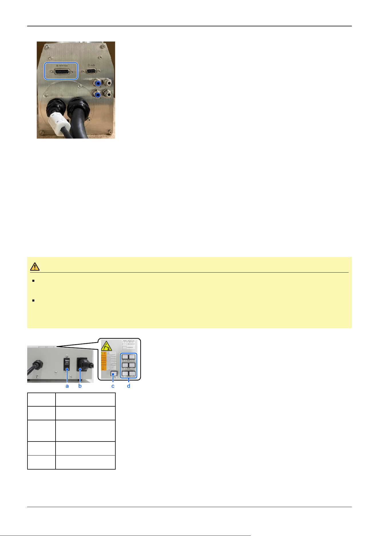
4. Connect the brake release unit to the connector of the connection cable.
3.6.1.3 Removing the Brake Release Unit
1. Turn off the brake release unit.
2. Remove the power cable of the brake release unit.
3. Disconnect the brake release unit from the connector of the connection cable.
4. If the M/C short connector is connected to the M/C power cable, remove the short connector.
5. Connect the external short connector to the connector of the connection cable.
3.6.1.4 How to Use the Brake Release Unit
CAUTION
After releasing the brake, the arm may fall by its own weight or move to the unexpected direction. Make sure
to prepare a countermeasure to prevent the arm from falling and check the operation environment is safe.
If the arm you released its brake moves awkwardly or faster than usual, stop the operation promptly and
contact the supplier. The brake release unit may be broken. If you keep operating the Manipulator, it may lead
to the breakdown of the Manipulator or you may get your hand or fingers caught.
Symbol Description
a Power switch
b
Power Cable
(You must provide.)
c Power lamp
d Brake release switch
1. Refer to “Installing the Brake Release Unit” above to connect the brake release unit to the connector of the connection
cable.
2. Plug the power cable into the brake release unit.
Industrial Robot: 6-Axis Robots C-B series Manual Rev.1b
155
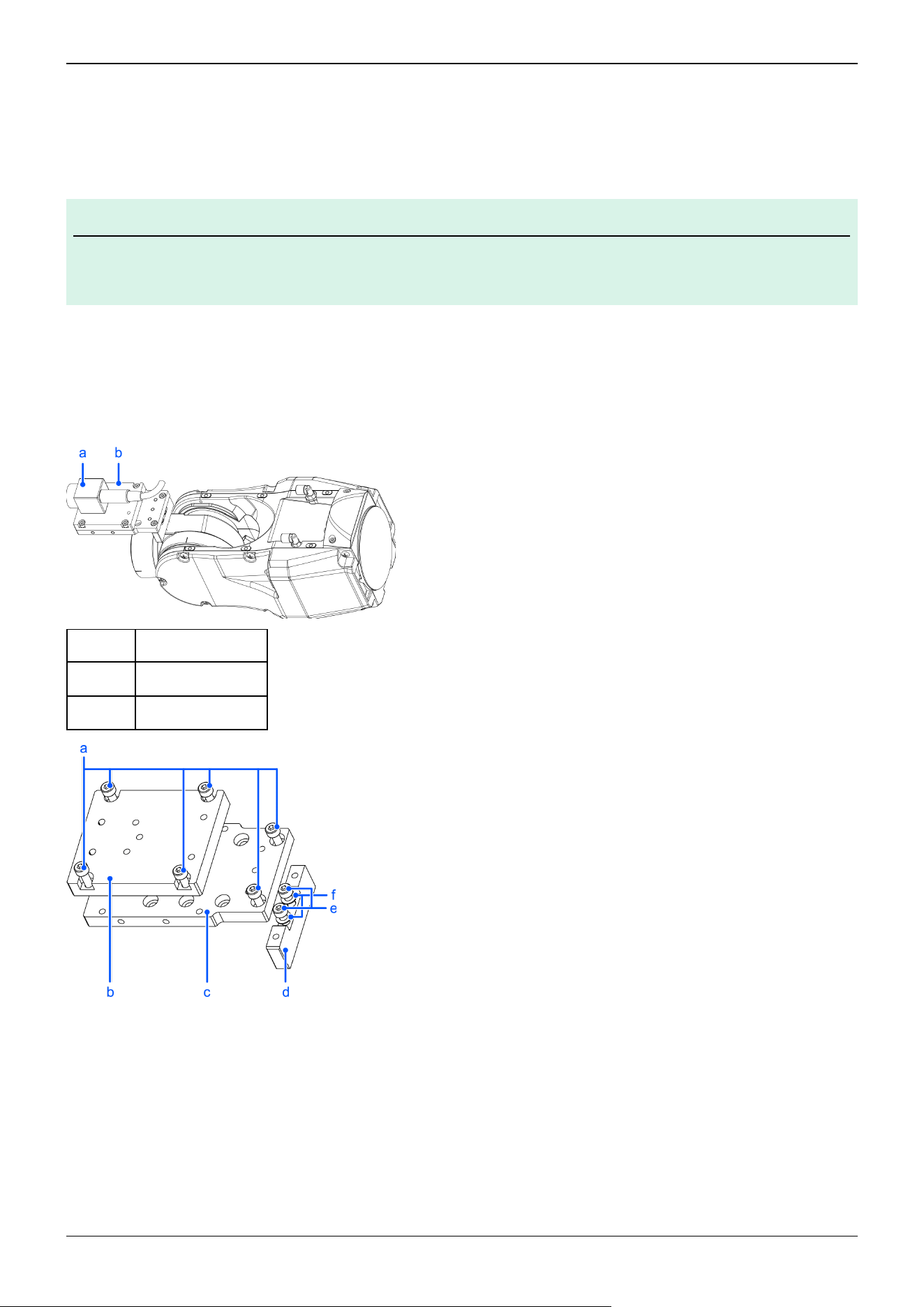
3. Plug the power cable into the power supply plug.
4. Turn on the brake release unit. When the brake release unit is enabled, the power lamp lights up.
5. Press the switch of the arm (J1 to J6) you want to move and then move the arm. Press the switch again. The brake will be
released. The brake will be enabled by pressing the switch once again.
KEY POINTS
Move the arm the brake is released by two persons or more (one presses the switch and one moves the arm).
The arm can be very heavy and needs the significant force to move.
3.6.2 Camera Plate Unit
To mount a camera to the C8 series Manipulator, you need to mount the camera plate unit first.
Appearance of arm end with camera
Symbol Description
a Camera
b Camera Plate Unit
✏
Industrial Robot: 6-Axis Robots C-B series Manual Rev.1b
156
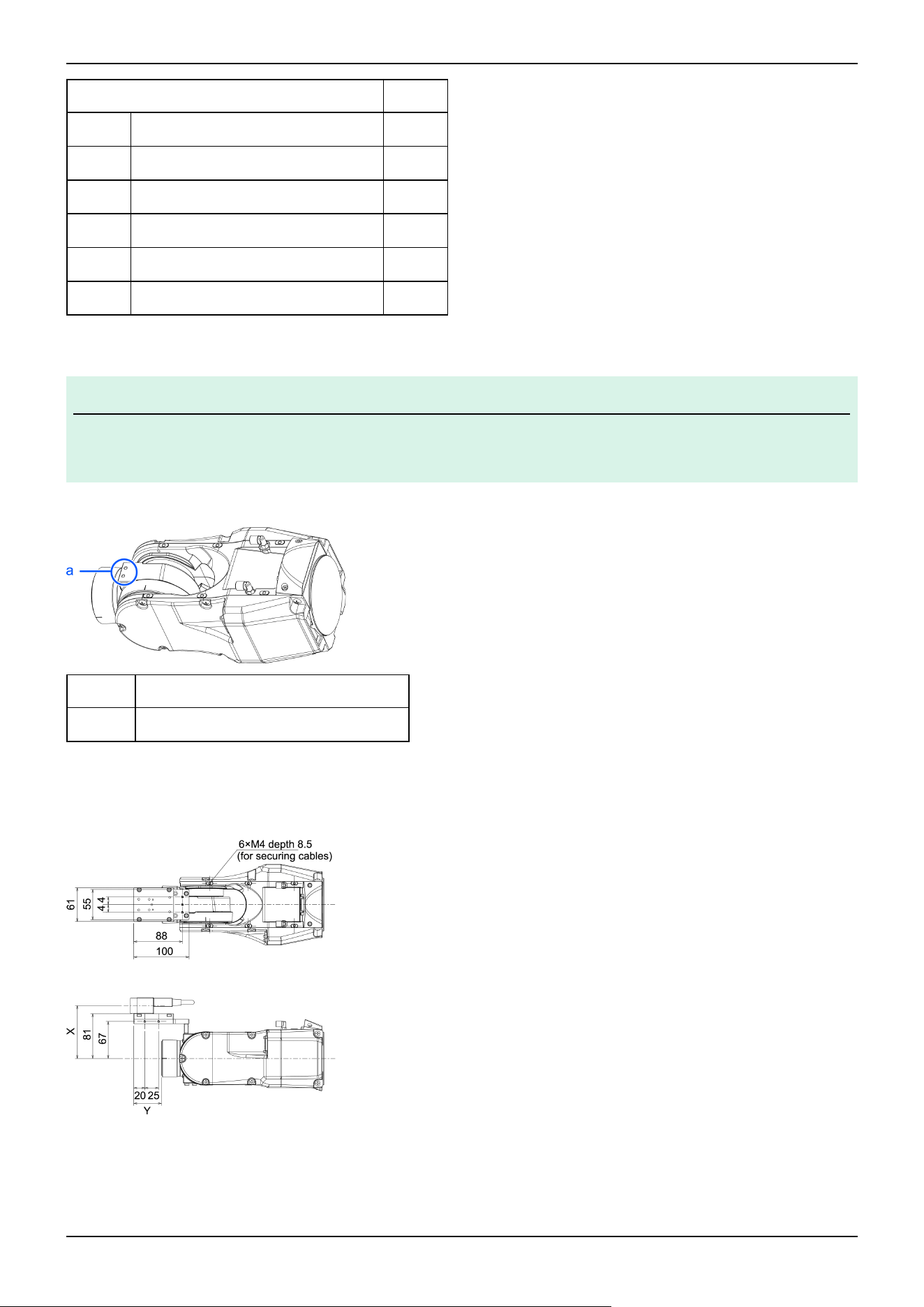
Parts Included Qty.
a Hexagon socket head cap bolt M4×12 6
b Camera adapter plate 1
c Camera mid plate 1
d Camera base plate 1
e Hexagon socket head cap bolt M4×20 2
f Plain washer for M4 (small washer) 2
Installation
KEY POINTS
For details of tightening the hexagon socket head cap bolt, refer to the following section.
Tightening the Hexagon Socket Head Cap Bolts
Mounting holes for the camera base plate on the C8 series Manipulator
Symbol Description
a Mounting holes for the camera base plate
For installation procedure, refer to the following manual.
"EPSON RC+ Option Vision Guide 7.0 Hardware & Setup"
Dimension of the camera plate unit
Dimensions X and Y will change depending on the position of camera mid plate and camera size. Refer to the table below for
the values.
✏
Industrial Robot: 6-Axis Robots C-B series Manual Rev.1b
157
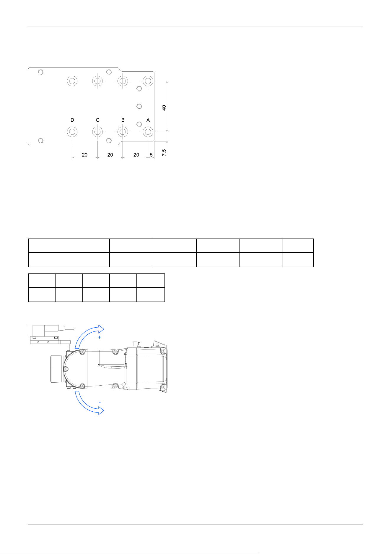
Camera mid plate
The camera mid plate uses the mounting holes A to D. By using the different mounting holes, it can be mounted to the camera
base plate in the different four positions.
Camera and C8 series Manipulator Joint #5 motion range (reference values)
The Joint #5 motion range varies depending on the mounting position of camera mid plate and the camera you are using.
The table below shows the motion range (reference values) based on the available cameras for this option and the mounting
positions of the camera mid plate. The values in the table may vary depending on how to secure the cables.
By changing the Y position, you can extend the distance from the hand mounting surface to the camera. Also, you can attach
the larger hand. However, be careful about the Joint #5 motion range that will be limited in this case.
A B C D X
USB Camera, GigE Camera -135° to +70° -135° to +60° -135° to +45° -135° to +35° 95.5 mm
A B C D
Y 50 mm 30 mm 10 mm -10 mm
Direction of the Joint #5 motion
3.6.3 Tool Adapter (ISO flange)
Using the tool adapter, you can mount the hand whose dimensions are designed for the ISO flange to the C8 series
Manipulators.
Industrial Robot: 6-Axis Robots C-B series Manual Rev.1b
158
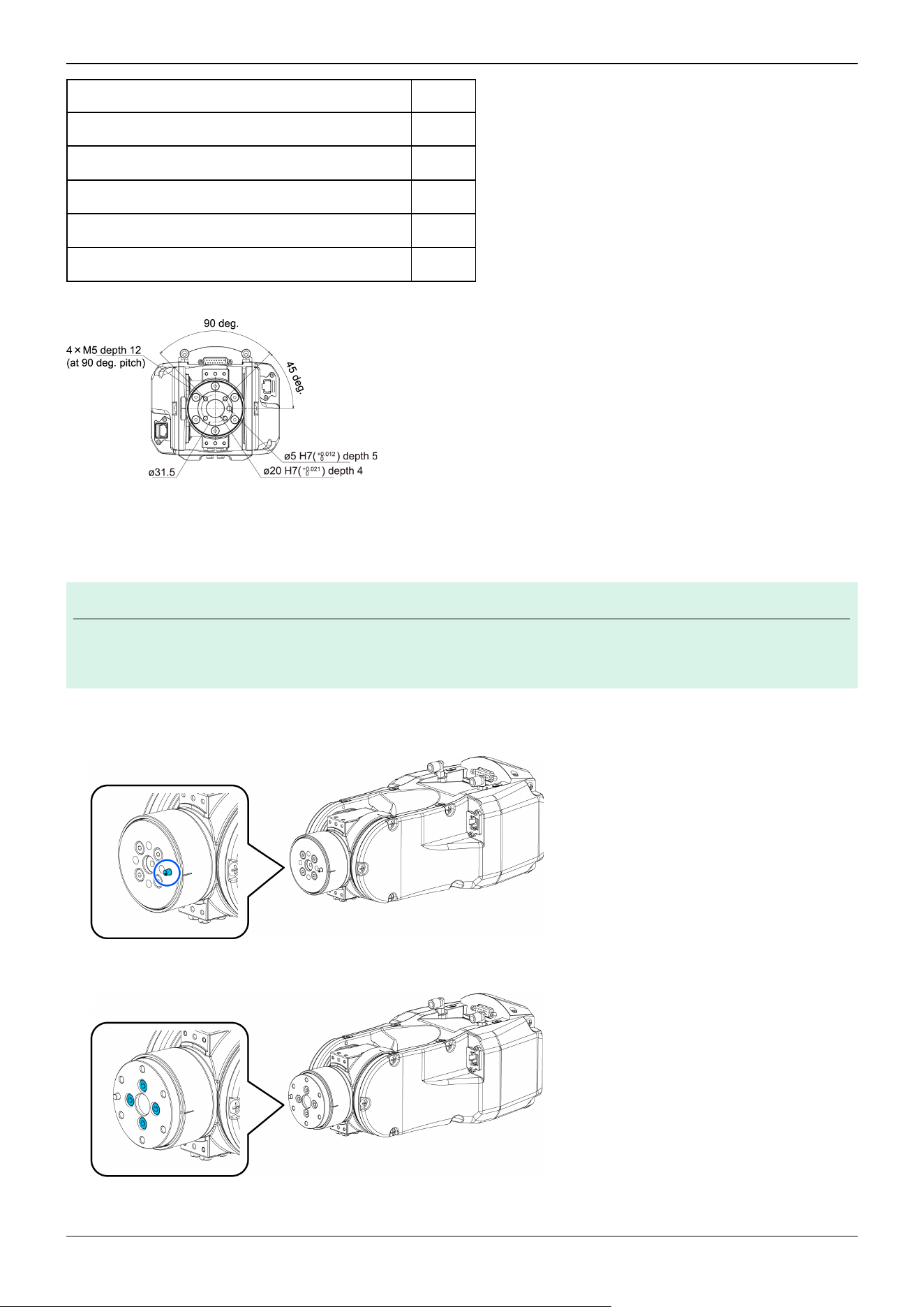
Parts Included Qty.
ISO flange 1
Flange 1
Pin 2
Hexagon socket head cap bolt with low head M5×10 6
Hexagon socket head cap bolt M5×15 4
Dimensions of ISO flange
* Each dimension and tolerance complies with ISO9409-1-31.5-4-M5.
ISO flange installation
KEY POINTS
For details of tightening the hexagon socket head cap bolt, refer to the following section.
Tightening the Hexagon Socket Head Cap Bolts
1. Press-fit the pin to the Arm #6 end flange.
Pin protrusion: 4 mm from the flange
2. Align the pin and the pin hole on the flange, and then mount the flange.
Hexagon socket head cap bolt: 4×M5×15
✏
Industrial Robot: 6-Axis Robots C-B series Manual Rev.1b
159
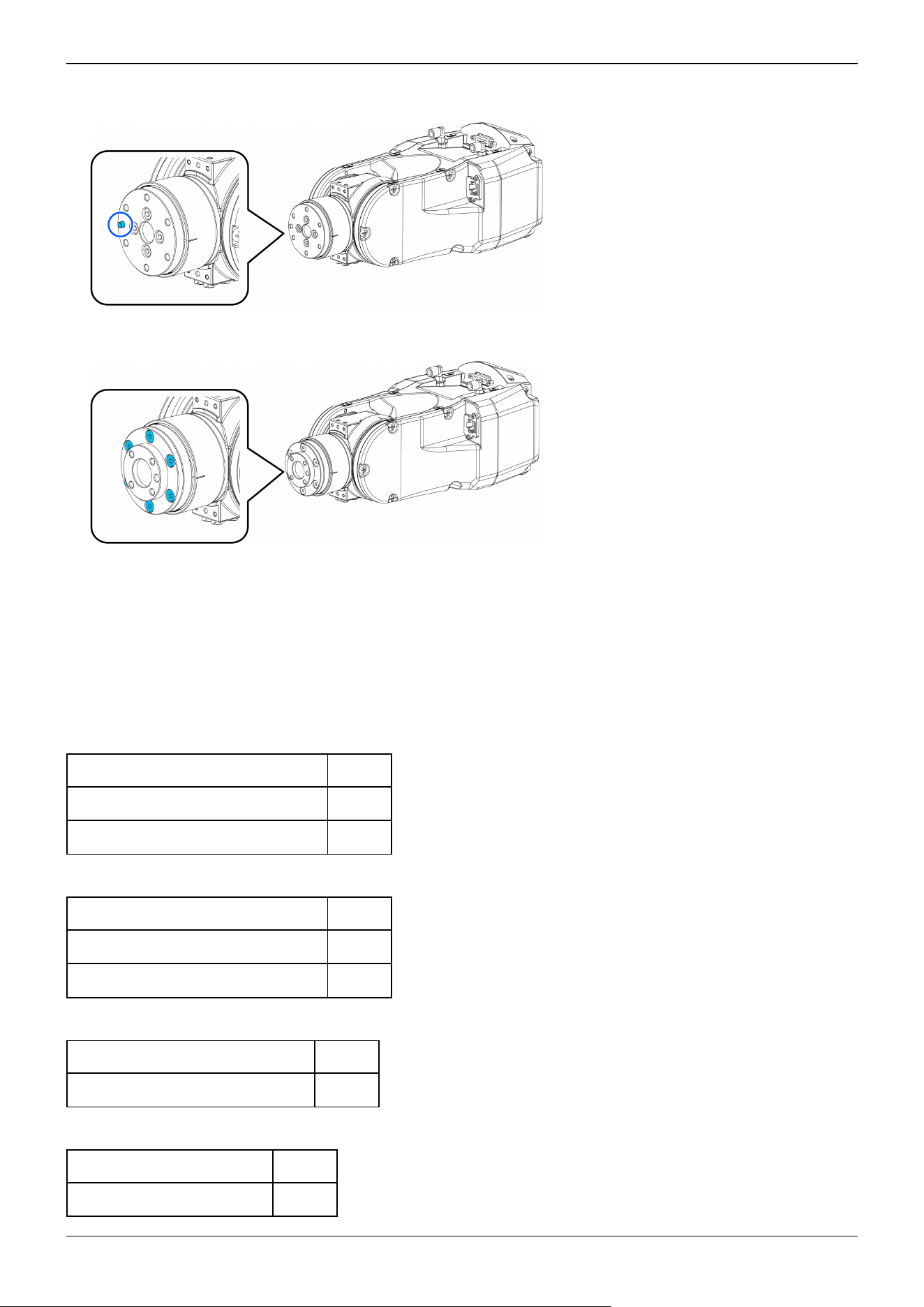
3. Press-fit the pin to the installed flange.
Pin protrusion: 4 mm from the flange
4. Align the pin and the pin hole on the ISO flange, and then mount the ISO flange.
Hexagon socket head cap bolt with low head: 6×M5×10
3.6.4 Variable Mechanical Stop
This option is used to mechanically limit the motion range of the Manipulator.
For installation and angle restriction measures, refer to the following section.
Setting the Work Envelope by Mechanical Stops
Variable Mechanical Stop (J1)
Parts Included Qty.
Variable Mechanical Stop (J1) 1
Hexagon socket head cap bolt M12×30 2
Variable mechanical stop (C8L_J2)
Parts Included Qty.
Variable mechanical stop (C8L_J2) 1
Hexagon socket head cap bolt M10×35 1
Variable mechanical stop (C8XL_J2)
Parts Included Qty.
Variable mechanical stop (C8XL_J2) 1
Variable Mechanical Stop (J3)
Parts Included Qty.
Variable Mechanical Stop (J3) 1
Industrial Robot: 6-Axis Robots C-B series Manual Rev.1b
160
3.6.5 User Wires and Pneumatic Tubes
Use the following options when using the internal wiring and tubing for the hand drive.
Fitting for Customer Use (
⌀
6 Straight)
Parts Included Qty. Manufacturer Type
⌀6 straight fitting 2 SMC KQ2S06-M6N
* Attached as standard. The parts can be purchased additionally in case of lost or shortage.
Fitting for Customer Use (
⌀
6 Elbow)
Parts Included Qty. Manufacturer Type
⌀6 elbow fitting 2 SMC KQ2L06-M6N
* Attached as standard. The parts can be purchased additionally in case of lost or shortage.
Standard User Connector Kit (D-sub)
Parts Included Qty. Manufacturer Type
Connector 2 JAE DA-15PF-N (Solder type)
Clamp hood 2 HRS HDA-CTH (4-40) (10) (Connector setscrew: #4-40 UNC)
* Attached to standard and cleanroom-model Manipulators as standard. The parts can be purchased additionally in case of lost
or shortage.
Waterproof User Connector Kit (D-sub)
Parts Included Qty. Manufacturer Type
Connector 2 HARTING 09 67 015 5615 (Solder type)
Clamp hood 2 HARTING 09 67 015 0538 (Connector setscrew: #4-40 UNC)
* Attached to the protected-model Manipulators as standard. The parts can be purchased additionally in case of lost or
shortage.
Waterproof User Connector Kit (Ethernet)
Parts Included Qty. Manufacturer Type
Connector 2 HARTING 09 45 145 1560
* Not attached as standard. Please purchase the item if needed. Please note that the protection rating IP67 cannot be satisfied if
other connectors are used.
Industrial Robot: 6-Axis Robots C-B series Manual Rev.1b
161

4. C12 Manipulator
This chapter contains information for setup and operation of the Manipulators.
Please read this chapter thoroughly before setting up and operating the Manipulators.
Industrial Robot: 6-Axis Robots C-B series Manual Rev.1b
162
4.1 Safety
The Manipulator and its related equipment should be unpacked and transported by people who have received installation
training provided by Epson and the suppliers. Also, the laws and regulations of the installation country must be followed.
Before use, please read this manual and other related manuals to ensure correct use. After reading this manual, store it in an
easily accessible location for future reference.
This product is intended for transporting and assembling parts in a safely isolated area.
4.1.1 Conventions Used in This Manual
The following symbols are used in this manual to indicate important safety information. Be sure to read the descriptions shown
with each symbol.
WARNING
This symbol indicates an imminently hazardous situation which, if operation is not performed properly, will result
in death or serious injury.
WARNING
This symbol indicates a potentially hazardous situation which, if operation is not performed properly, could result
in an injury due to electric shock.
CAUTION
This symbol indicates a potentially hazardous situation which, if operation is not performed properly, may result in
a minor or moderate injury or in property damage only.
4.1.2 Design and Installation Safety
The robot system should be designed and installed by people who have received installation training provided by Epson and
the suppliers.
Design personnel should refer to the following manuals:
"Safety Manual"
"Controller Manual"
"Manipulator Manual"
Refer to the following section for the installation safety information.
Environment and Installation
Be sure to read this section and follow the safety information before installation to ensure that the installation work is
performed safely.
Industrial Robot: 6-Axis Robots C-B series Manual Rev.1b
163
4.1.3 Operation Safety
The following items are safety precautions for operating personnel:
WARNING
Be sure to read the Safety Manual before use. Operating the robot system without understanding the safety
information can be extremely dangerous and may result in serious injury or severe equipment damage.
Before operating the robot system, make sure that no one is inside the safety barriers. The robot system can
be operated in the teaching operation mode even when someone is inside the safety barriers. Even though
the motion of the Manipulator is always restricted (low speed and low power) to ensure operator safety, an
unexpected movement by the Manipulator can be extremely dangerous and may cause serious safety
problems.
If the Manipulator moves abnormally during operation of the robot system, immediately press the emergency
stop switch.
WARNING
To perform the power supply lockout, remove the power plug. Be sure to connect the AC power cable to a
power outlet. Do not connect it directly to a factory power source.
Before performing any replacement work, inform others in the area that you are working, and then turn off the
Controller and related equipment, and unplug the power cable from the power source. Performing any work
procedure with the power turned on is extremely dangerous and may result in electric shock and/or
malfunction of the robot system.
Do not connect or disconnect the connector of the M/C cable while the Controller is turned on. There is a risk
the Manipulator may malfunction, which is extremely hazardous. Also, performing any work procedure with
the power turned on may result in electric shock and/or malfunction of the robot system.
CAUTION
Whenever possible, only one person should operate the robot system. If it is necessary to operate with more
than one person, ensure that all personnel communicate with each other and take all necessary safety
precautions.
If the Manipulator is operated repeatedly with each joint having an operating angle of 5° or less, the bearings
used in the joints are likely to cause oil film shortage. Repeated operation may cause premature damage. To
prevent premature damage, operate the Manipulator to move each joint to an angle of 30° or more about
once per hour.
When the robot is operating at low speed (Speed: 5 to 20%), vibration (resonance) may occur continuously
during operation depending on the combination of the arm orientation and hand load. Vibration occurs due to
the natural vibration frequency of the arm and can be reduced by taking the following measures:
Changing the robot speed
Changing the teach points
Changing the hand load
Industrial Robot: 6-Axis Robots C-B series Manual Rev.1b
164

4.1.4 Emergency Stop
Each robot system needs equipment that will allow the operator to immediately stop the system's operation. Install an
emergency stop device by using emergency stop input from the Controller or other equipment.
Before using the emergency stop switch, be aware of the following points.
The emergency stop switch should be used to stop the Manipulator only in case of emergencies.
Besides pressing the emergency stop switch when an emergency occurs, to stop the Manipulator during program operation,
use the Pause or STOP (program stop) statements assigned to a standard I/O.
The Pause and STOP statements do not turn off motor energization, and so the brake is not locked.
To place the robot system in emergency stop mode in a non-emergency (normal) situation, press the emergency stop switch
while the Manipulator is not operating.
Do not press the emergency stop switch unnecessarily while the Manipulator is operating normally.
It could shorten the lifespan of the following components.
Brakes
The brakes will be locked, which will shorten the lifespan of the brakes due to worn brake friction plates.
Normal brake lifespan:
About 2 years (when the brakes are used 100 times/day)
or about 20,000 times
Reduction gears
An emergency stop applies an impact to the reduction gear, which can shorten its life.
If the Manipulator is stopped by turning off the Controller while it is operating, the following problems may occur.
Reduced life and damage to reduction gear
Position shift at the joints
If a power outage or other unavoidable Controller power-off occurs during Manipulator operation, check the following points
after power is restored.
Damage in reduction gear
Shifting of the joints from their proper positions
If there was any shifting, maintenance is required. For more information, please contact the supplier.
Stopping distance of emergency stop
The Manipulator during operation cannot stop immediately after the emergency stop switch is pressed. Also, the stopping time
and movement distance vary depending on the following factors.
Hand weight, WEIGHT setting, ACCEL setting, workpiece weight, SPEED setting, movement posture, etc.
For the stopping time and movement distance of the Manipulator, refer to the following section.
Appendix B: Stopping Time and Stopping Distance at Emergency Stop
4.1.5 Safeguard (SG)
To maintain a safe working zone, safety barriers must be set up around the Manipulator, and safeguards must be installed at the
entrance and exit of the safety barriers.
The term "safeguard" as used in this manual refers to a safety device with an interlock that allows entry into the safety barriers.
Specifically, this includes safety door switches, safety barriers, light curtains, safety gates, safety floor mats, and so on. The
safeguard is an input that informs the Robot Controller that an operator may be inside the safeguard area. You must assign at
least one Safeguard (SG) in Safety Function Manager.
Industrial Robot: 6-Axis Robots C-B series Manual Rev.1b
165
When the safeguard is opened, Protective Stop operates to change to the safeguard open state (display: SO).
Safeguard open
Operations are prohibited. Further robot operation is not possible until either the safeguard is closed, the latched state is
released, and a command is executed, or the TEACH or TEST operation mode is turned on and the enable circuit is
activated.
Safeguard closed
The robot can operate automatically in an unrestricted (high power) state.
WARNING
If a third party accidentally releases the safeguard while an operator is working inside the safety barriers, this
may result in a hazardous situation. To protect the operator working inside the safety barriers, implement
measures to lock out or tag out the latch release switch.
To protect operators working near the robot, be sure to connect a safeguard switch and make sure that it
works properly.
Installing safety barriers
When installing safety barriers within the maximum range of the Manipulator, combine safety functions such as SLP. Carefully
take into account the size of the hand and the workpieces to be held so that no interference occurs between the operating parts
and the safety barriers.
Installing safeguards
Design the safeguards so that they satisfy the following requirements:
When using a key switch type safety device, use a switch that forcibly opens the interlock contacts. Do not use switches
that open their contacts using the spring force of the interlock.
When using an interlock mechanism, do not disable the interlock mechanism.
Considering the stopping distance
During operation, the Manipulator cannot stop immediately even if the safeguard is opened. Also, the stopping time and
movement distance vary depending on the following factors.
Hand weight, WEIGHT setting, ACCEL setting, workpiece weight, SPEED setting, movement posture, etc.
For the stopping time and movement distance of the Manipulator, refer to the following section.
Appendix C: Stopping Time and Stopping Distance When Safeguard is Open
Precautions for safeguard operation
Do not open the safeguard unnecessarily while the motor is energized. Frequent safeguard inputs will reduce the life of the
relay.
Normal relay lifespan: About 20,000 times
4.1.6 How to Move Arms with the Electromagnetic Brake
There are two methods to release the electromagnetic brake. Follow either method to release the electromagnetic brake and
move the arms manually.
When using a brake release unit
Follow the method when you just unpack the delivered boxes or when the Controller does not start up yet.
When using software
Follow the method when you can use the software.
While the electromagnetic brake is on (such as in emergency mode), you cannot move any arm by pushing manually.
Industrial Robot: 6-Axis Robots C-B series Manual Rev.1b
166
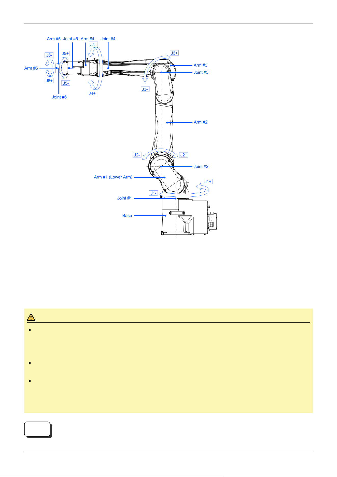
Arm Motion
4.1.6.1 When using a brake release unit
This series has the Brake Release Unit as an option. For details, refer to the following section.
Options
4.1.6.2 When using software
CAUTION
Normally, release the brakes of joints one at a time. If the brakes of two or more joints must be released
simultaneously due to unavoidable reasons, use extreme care. Releasing the brakes of multiple joints
simultaneously may cause the arm to fall in an unexpected direction, resulting in hands or fingers getting
caught or damage or failure of the Manipulator.
After releasing the brake, the arm may fall by its own weight or move to the unexpected direction. Make sure
to prepare a countermeasure to prevent the arm from falling and check the operation environment is safe.
Before releasing the brake, be sure to keep the emergency stop switch in an easily accessible location so that
you can immediately press it if necessary. Otherwise, if the emergency stop switch is not easily accessible,
you will be unable to immediately stop the arm falling due to an erroneous operation, which could lead to
Manipulator damage or breakdown.
After releasing the Emergency Stop switch, execute the following command in [Command Window].
EPSON
RC+
Industrial Robot: 6-Axis Robots C-B series Manual Rev.1b
167
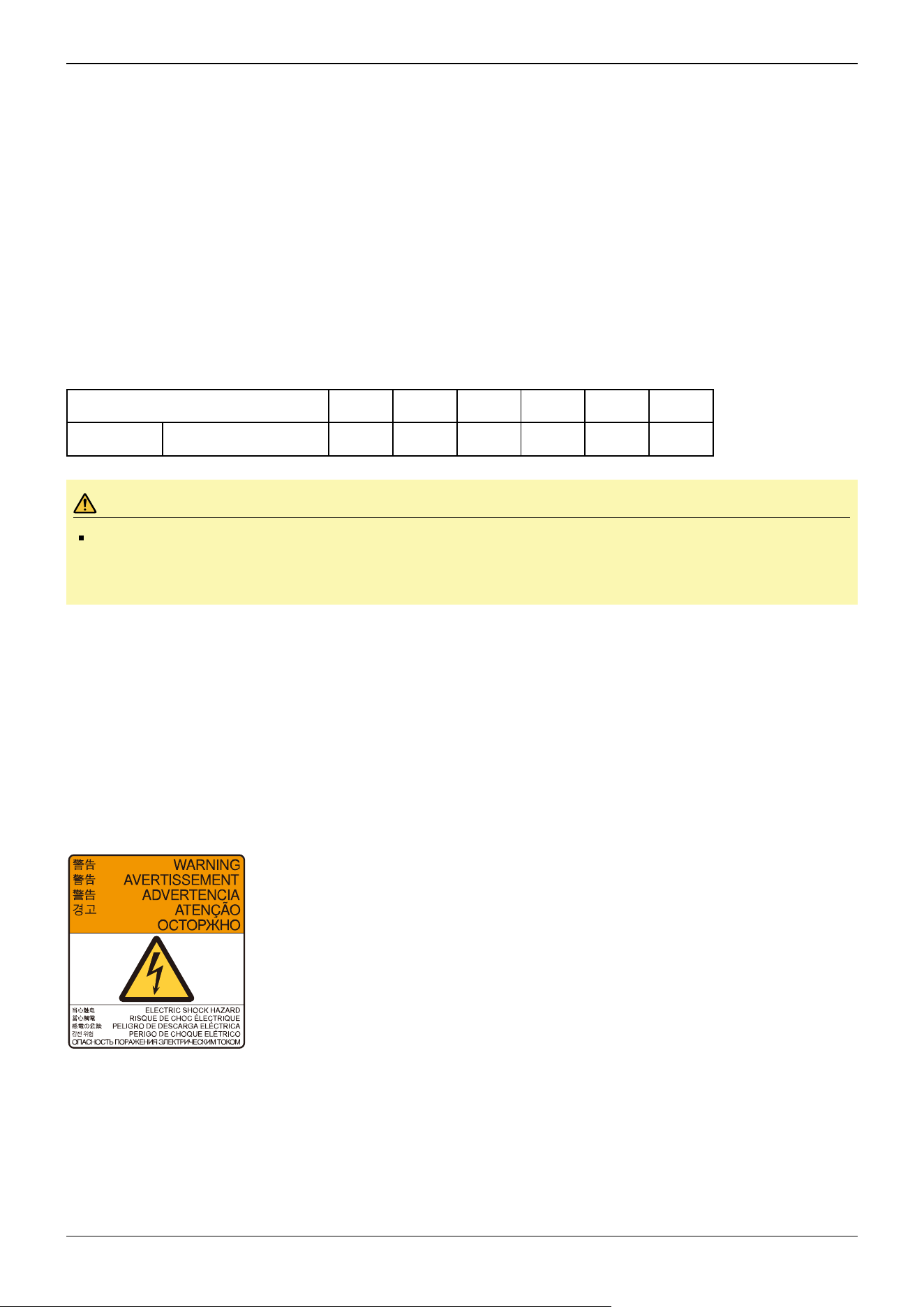
>Reset
>Brake Off,[The number (from 1 to 6) corresponding to the arm whose brake will be turned off
Execute the following command to turn on the brake again.
>Brake On,[The number (from 1 to 6) corresponding to the arm whose brake will be turned on]
4.1.7 Precaution for Operation in Low Power Status
In the low power status, the Manipulator operates at low speed and low torque. However, comparatively high torque as shown
in the table below may be generated to support the Manipulator’s own weight. Carefully operate the Manipulator since it may
get your hands or fingers caught during operation. The Manipulator may also collide with peripheral equipment and cause
equipment damage to or malfunction of the Manipulator.
Maximum Joint Torque in Low Power Status [Unit: N·m]
Joint #1 #2 #3 #4 #5 #6
Joint Torque C12-B1401** (C12XL) 573.06 517.66 256.9 57.45 53.44 23.94
CAUTION
Carefully operate the Manipulator in the low power status. A comparatively high joint torque may be
generated. It may cause your hands and fingers caught and/or cause equipment damage to or malfunction of
the Manipulator as it may collide with peripheral equipment.
4.1.8 Warning Labels
The Manipulator has the following warning labels. Specific hazards exist in the vicinity of areas with the warning labels. Be
thoroughly careful in handling. To ensure that the Manipulator is operated and maintained safely, be sure to follow the safety
information and warnings indicated on the warning labels. Also, do not tear, damage, or remove these warning labels.
4.1.8.1 Warning Labels
A
Touching any internal electrified parts while the power is turned on may cause electric shock.
Industrial Robot: 6-Axis Robots C-B series Manual Rev.1b
168
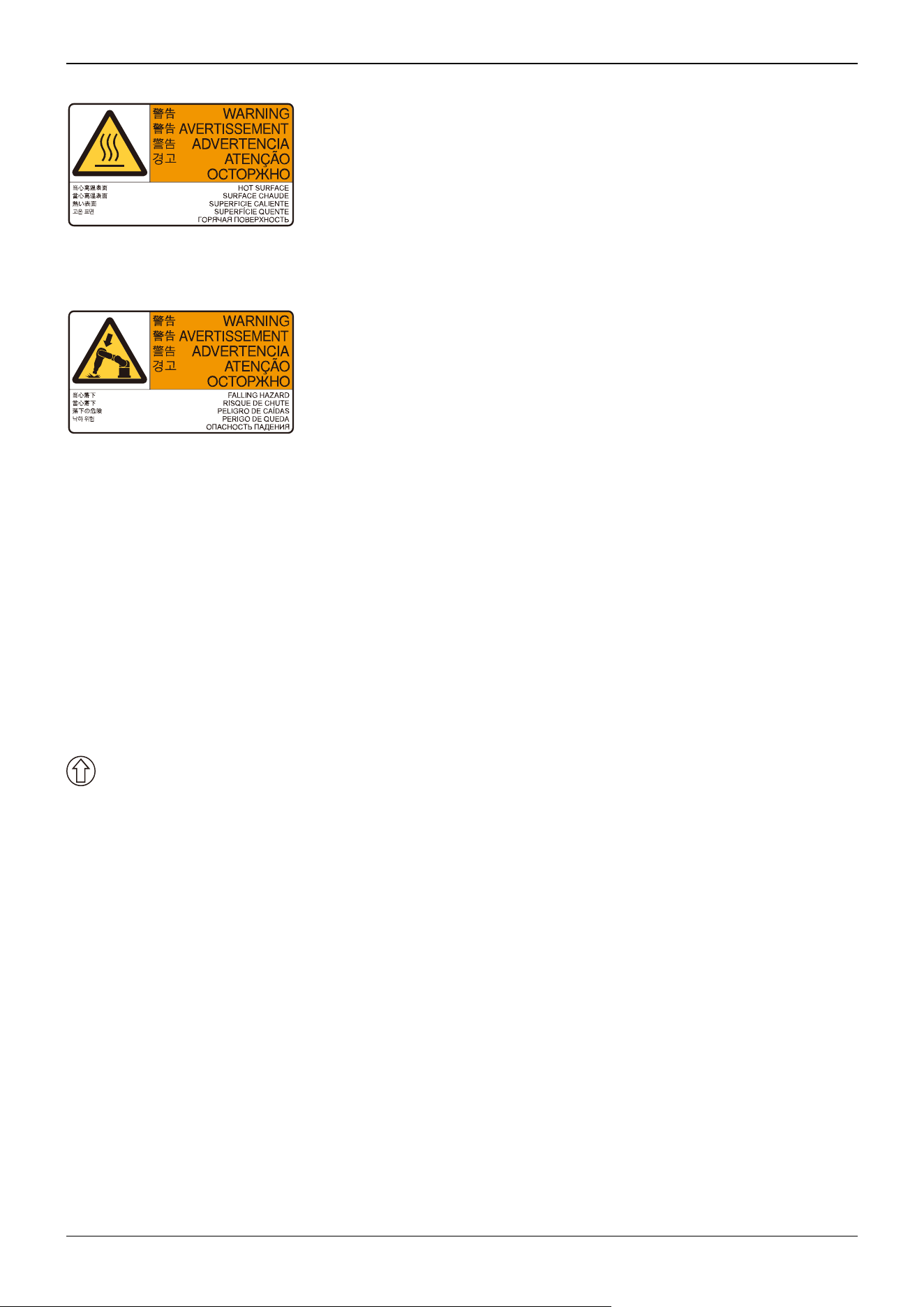
B
HOT Be careful not to burn yourself.
C
When releasing the brakes, be careful of the arm falling due to its own weight.
This warning label is attached on the Manipulator and optional brake release unit as well.
4.1.8.2 Information Labels
1
This indicates the product name, model name, serial number, information of supported laws and regulations, product
specifications (Weight, MAX.REACH, MAX.PAYLOAD, AIR PRESSURE, Motor Power), Main document No.,
manufacturer, importer, date of manufacture, country of manufacture, and the like.
For details, see the label affixed to the product.
2
This indicates the position for mounting eyebolts. Refer to the following section for examples of using eyebolts.
Environment and Installation
Industrial Robot: 6-Axis Robots C-B series Manual Rev.1b
169
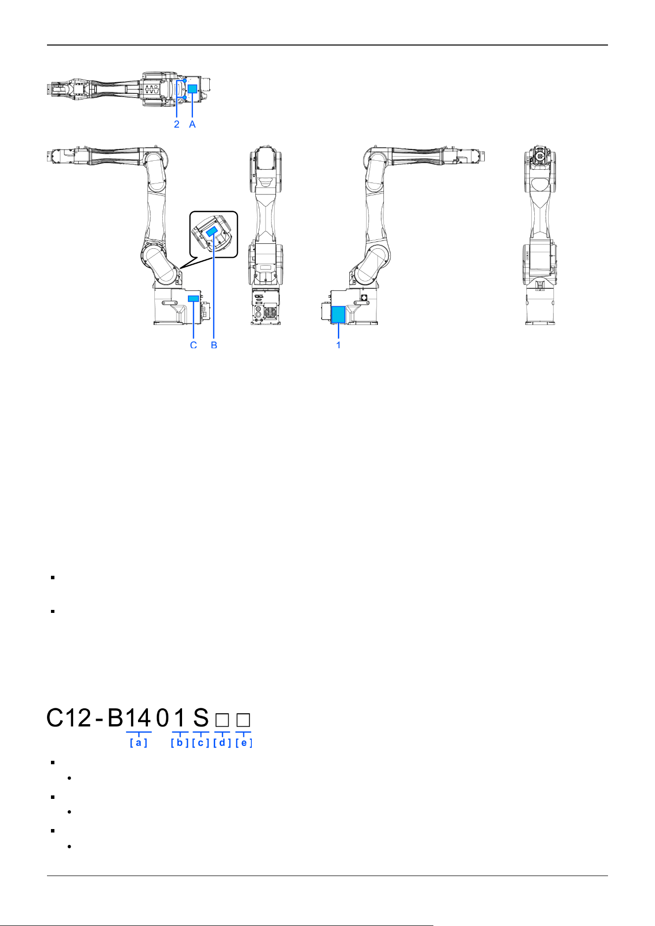
Location of Labels
4.1.9 Responses for Emergencies or Malfunctions
4.1.9.1 When a Collision with the Manipulator Occurs
If the Manipulator has collided with a mechanical stop, peripheral device, or other object, discontinue use and contact the
supplier.
4.1.9.2 Entanglement with the Manipulator
When the operator is caught between the Manipulator and a mechanical part such as a base table, press the emergency stop
switch to release the brake on the subject arm, and then move the arm by hand.
How to release a brake
When using a brake release unit, refer to the following section.
Brake Release Unit
When using software, refer to the following section.
When using software
4.2 Specifications
4.2.1 Model Number
a: Arm length
14: 1400 mm
b: Brake equipment
1: Brakes on all joints
c: Environment
S: Standard *1
Industrial Robot: 6-Axis Robots C-B series Manual Rev.1b
170
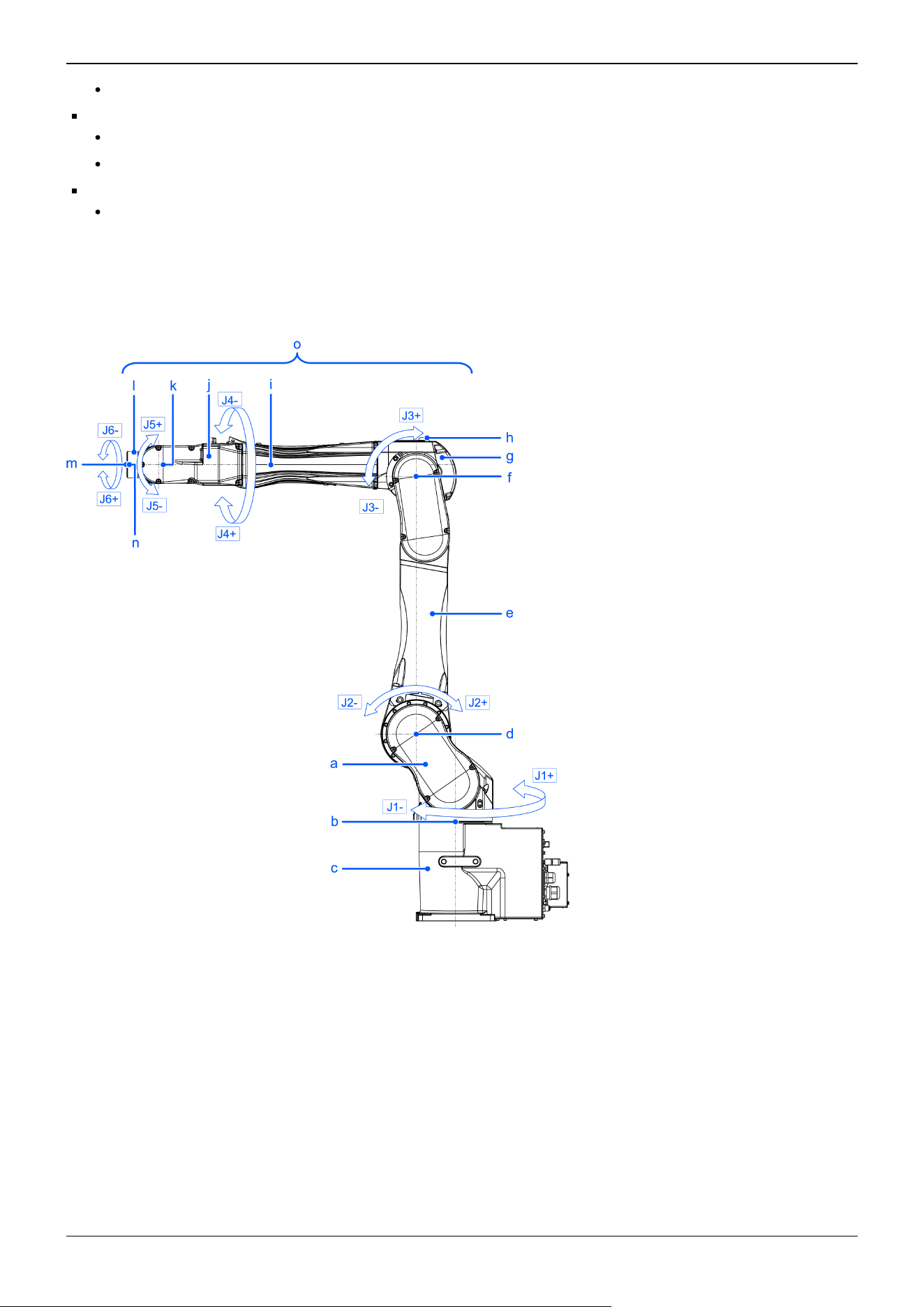
C: Cleanroom & ESD (anti-static) *1
d: M/C cable installation direction
□: Cable backward
B: Cable downward
e: Mounting type
□: Table top mounting
*1 Equivalent to IP20
4.2.2 Part Names and Motion Range of Each Arm
Industrial Robot: 6-Axis Robots C-B series Manual Rev.1b
171
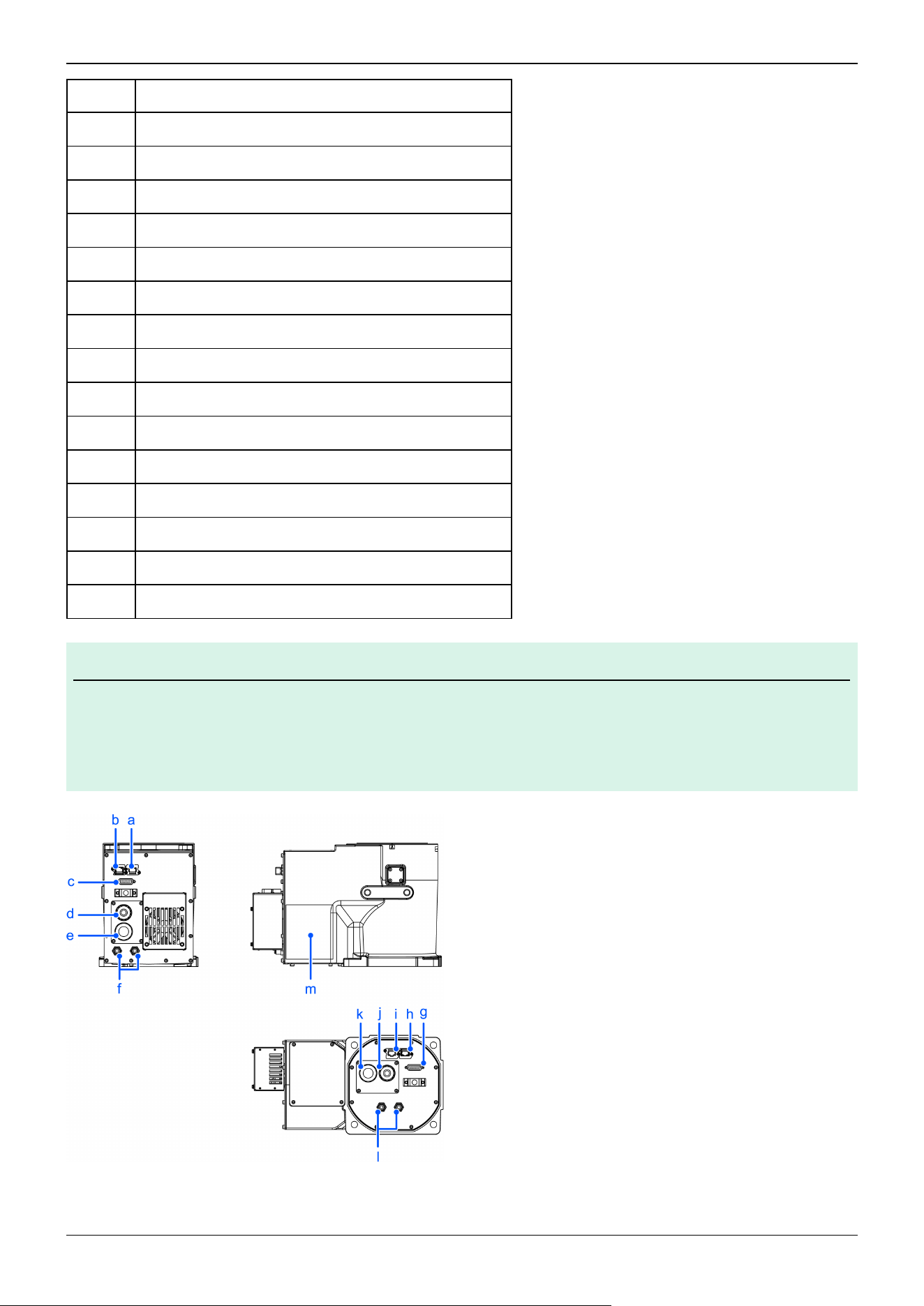
Symbol Description
a Arm #1 (Lower Arm)
b Joint #1 (The whole Manipulator revolves.)
c Base
d Joint #2 (The lower arm swings.)
e Arm #2
f Joint #3 (The upper arm swings.)
g Arm #3
h LED Lamp (This lamp lights up while the motors are on.)
i Joint #4 (The wrist revolves.)
j Arm #4
k Joint #5 (The wrist swings.)
l Arm #5
m Arm #6
n Joint #6 (The hand rotates.)
o Upper Arm (Arms #3 to #6)
KEY POINTS
When the LED lamp is lighting or the Controller power is on, the current is being applied to the Manipulator. (The
LED lamp may not be seen depending on the Manipulator’s posture. Be thoroughly careful. Performing any work
procedure with the power turned on is extremely dangerous and may result in electric shock and/or malfunction
of the robot system. Before starting any maintenance work, be sure to turn off the Controller.
Cable backward model
✏
Industrial Robot: 6-Axis Robots C-B series Manual Rev.1b
172
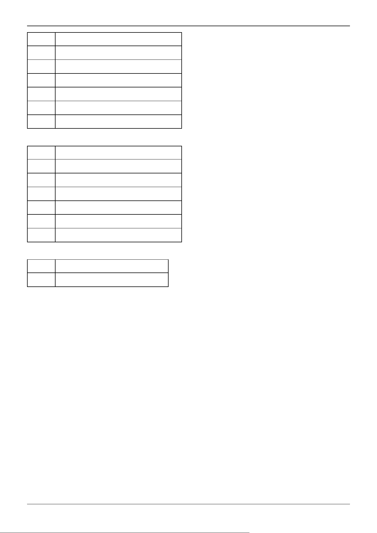
Symbol Description
a Ethernet cable connector
b Force Sensor cable connector
c User cable connector (15-pin D-sub connector)
d Signal cable
e Power cable
f Fitting for ⌀6 mm tube (Air1, Air2)
Cable downward model
Symbol Description
g User cable connector (15-pin D-sub connector)
h Force Sensor cable connector
i Ethernet cable connector
j Signal cable
k Power cable
l Fitting for ⌀6 mm tube (Air1, Air2)
Cable backward model, Cable downward model
Symbol Description
m Face plate (serial number of Manipulator)
Industrial Robot: 6-Axis Robots C-B series Manual Rev.1b
173
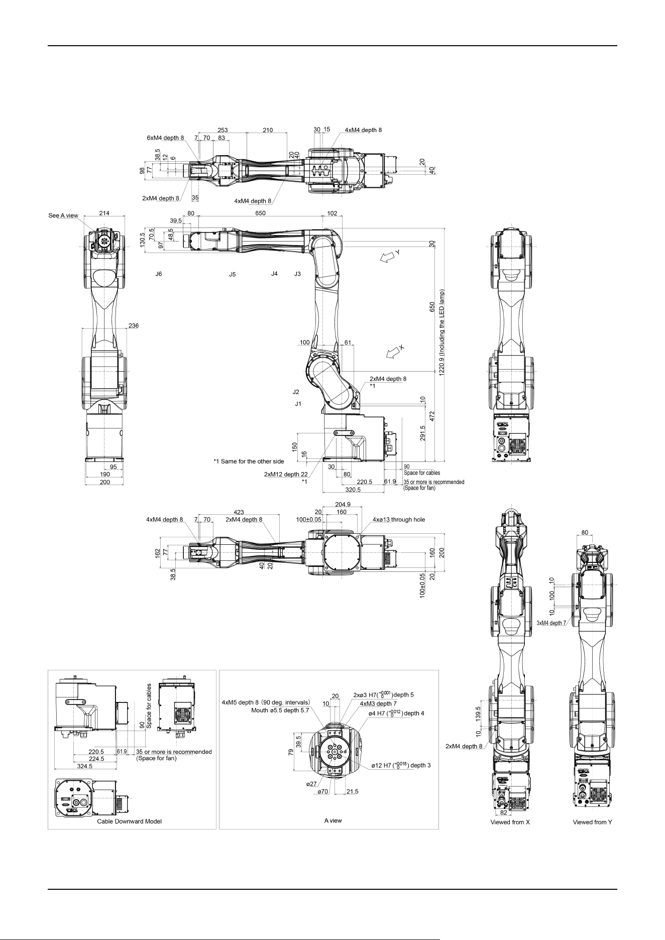
4.2.3 Outer Dimensions
(Units: mm)
Industrial Robot: 6-Axis Robots C-B series Manual Rev.1b
174
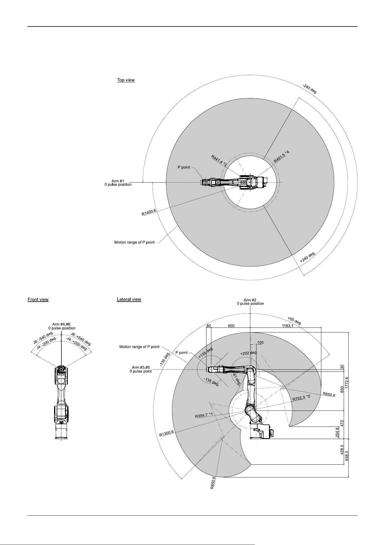
4.2.4 Standard Work Envelope
(Units: mm)
(deg. = °)
Industrial Robot: 6-Axis Robots C-B series Manual Rev.1b
175
*P point: Intersection of the rotation centers for Joint #4, #5, and #6
*1: P point from lateral with Joint #3 declining -61° (Joint #2 center – P point center)
*2: P point from lateral with Joint #3 tilting up +202° (Joint #2 center – P point center)
*3: P point from top with Joint #3 declining -61° (Joint #1 center – P point center)
*4: P point from top with Joint #3 tilting up +202° (Joint #1 center – P point center)
CAUTION
Pay attention to the arm pose of the basic arms (Arms #1, #2, and #3) when operating the Manipulator. Arm
#5 moves keeping a constant angle regardless of the arm pose. Depending on the arm pose of the basic
arms, the wrist may collide with the Manipulator. The collision may cause equipment damage to and/or
malfunction of the Manipulator.
4.2.5 Specifications
4.2.5.1 Specifications Table
For the specifications tables of each model, refer to the following section.
C12 Specifications
4.2.5.2 Options
For details, refer to the following section.
Options
4.2.6 How to Set the Model
The Manipulator model for your system has been set before shipment from the factory.
CAUTION
If changing the setting of the Manipulator model, be responsible and absolutely certain that the wrong
Manipulator model is not set. Incorrect setting of the Manipulator model may result in abnormal or no
operation by the Manipulator and could even cause safety problems.
If a custom specifications number (MT***) or (X***) is written on the face plate (serial number label), the Manipulator has
custom specifications.
Models with custom specifications may require a different setting procedure. Check the custom specifications number, and
contact the supplier for more information.
The Manipulator model is set from software. For details, refer to the following manual.
"EPSON RC+ User's Guide - Robot Configuration"
4.3 Environment and Installation
The robot system should be designed and installed by people who have received installation training provided by Epson and
the suppliers. Also, the laws and regulations of the installation country must be followed.
Industrial Robot: 6-Axis Robots C-B series Manual Rev.1b
176
4.3.1 Environment
To ensure that the robot system operates and maintains maximum performance and to ensure its safe use, the robot system
should be installed in an environment that meets the following requirements.
Item Conditions
Ambient temperature *
Installation: 5 to 40°C
Transport, storage: -20 to 60°C
Ambient relative humidity
Installation: 10 to 80% (no condensation)
Transport, storage: 10 to 90% (no condensation)
Fast transient burst noise 1 kV or less (signal line)
Electrostatic noise 4 kV or less
Altitude 1000 m or less
Environment
Install indoors.
Keep away from direct sunlight.
Keep away from dust, oily smoke, salinity, metal powder, and other contaminants.
Keep away from flammable or corrosive liquids and gases.
Keep away from water.
Keep away from shocks or vibrations.
Keep away from sources of electric noise.
Keep away from explosive areas.
Keep away from large quantities of radiation.
* The ambient temperature requirement is for the Manipulator only. For details on the environment requirements for the
connected Controller, refer to the Robot Controller manual.
When used in a low-temperature environment near the minimum temperature specified in the product specifications, or when
the unit is idle for a long period of time during holidays or at night, a collision detection error or similar error may occur
immediately after the start of operation due to high resistance in the drive unit. In such cases, warm-up operation for about 10
minutes is recommended.
KEY POINTS
If the Manipulator will be used in a location that does not meet the above requirements, please contact the
supplier.
KEY POINTS
When used in a low-temperature environment near the minimum temperature specified in the product
specifications, or when the unit is idle for a long period of time during holidays or at night, a collision detection
error or similar error may occur immediately after the start of operation due to high resistance in the drive unit. In
such cases, warm-up operation for about 10 minutes is recommended.
✏
✏
Industrial Robot: 6-Axis Robots C-B series Manual Rev.1b
177
KEY POINTS
If there are conductive objects such as fences or ladders within 2.5 m of the Manipulator, these objects must be
grounded.
WARNING
Always use a circuit breaker for the Controller's power supply. Failure to use a circuit breaker may result in an
electrical shock hazard or malfunction due to an electrical leakage. Select the correct circuit breaker based on
the Controller that you are using. For details, refer to the following manual.
"Robot Controller Manual"
CAUTION
When cleaning the Manipulator, do not rub it strongly with alcohol or benzene. Coated surfaces may lose their
luster.
4.3.2 Manipulator Mounting Dimensions
Mounting Area
Also, besides the area required for installation of the Manipulator, Controller, peripheral equipment, and other devices, the
following space should be provided at a minimum.
Space for teaching
Space for maintenance and inspections (for installing jigs)
Space for cables
KEY POINTS
When installing the cables, be sure to maintain sufficient distance from obstacles.
For the minimum bend radius of the M/C cable, refer to the following section.
C12 Specifications
Also, leave enough space for other cables so that they are not forced to bend at extreme angles.
KEY POINTS
Make sure to leave 35 mm or more space around the fan cover.
4.3.2.1 Cable backward model
(Units: mm)
✏
✏
✏
Industrial Robot: 6-Axis Robots C-B series Manual Rev.1b
178
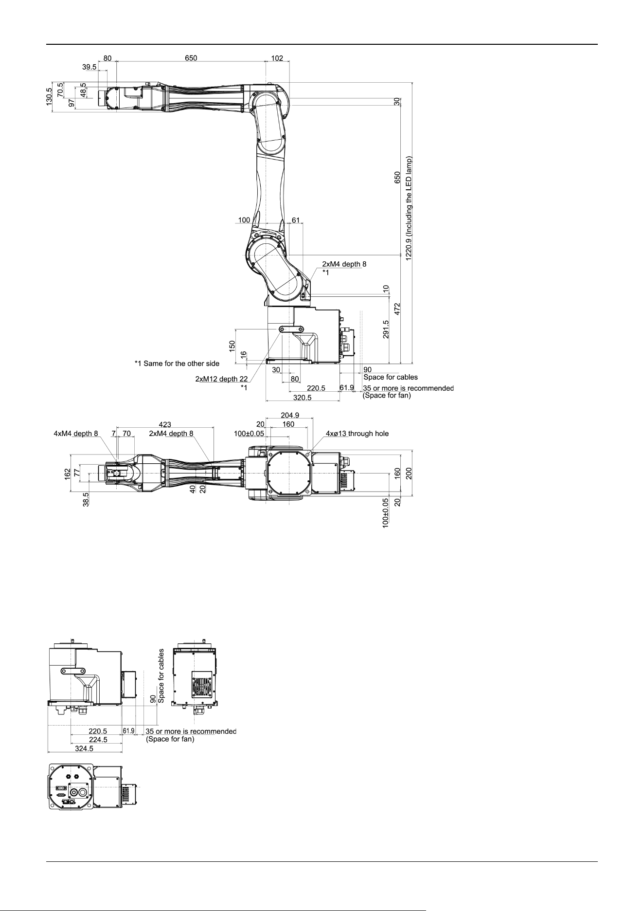
depth = depth of threaded hole
4.3.2.2 Cable downward model
The following part differs from the cable backward model.
Industrial Robot: 6-Axis Robots C-B series Manual Rev.1b
179
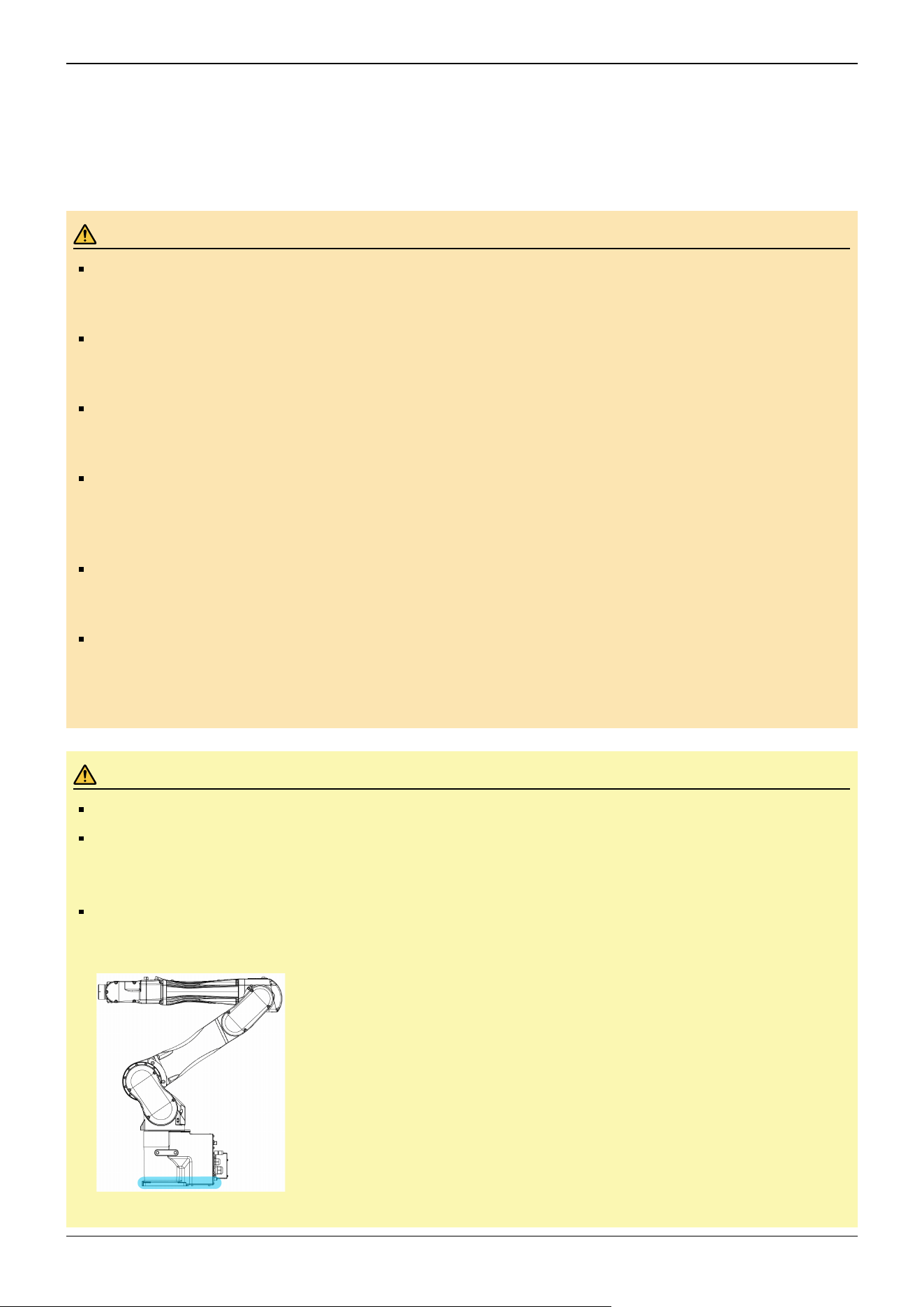
4.3.3 From Unpacking to Installation
Transportation and installation of the Manipulator and related equipment should be performed by people who have received
installation training provided by Epson and the suppliers. Also, the laws and regulations of the installation country must be
followed.
WARNING
Only qualified personnel should perform sling work and operate a crane or a forklift. When these operations
are performed by unqualified personnel, it is extremely hazardous and may result in serious bodily injury
and/or severe equipment damage to the robot system
When hoisting the Manipulator, use your hands to balance it. Losing balance may cause the Manipulator to
drop, which is extremely hazardous and may result in serious injury and/or severe damage to the robot
system.
To ensure safety, be sure to install safeguards for the robot system. For more information on safeguards, refer
to the following manual.
"EPSON RC+ User’s Guide - Safety - Installation and Design Precautions "
Install the Manipulator in a location with sufficient space so that a tool or a work piece does not touch a wall or
a safeguard when the Manipulator extends its arm fully while holding a work piece. If the tool or the workpiece
tip reaches a wall or safeguards, it is extremely hazardous and may result in serious bodily injury and/or
severe equipment damage to the robot system.
Be sure to anchor the Manipulator before turning on the power or operating it. Turning on the power or
operating the Manipulator while it is not anchored may cause the Manipulator to fall over, which is extremely
hazardous and may result in serious injury and/or severe damage to the robot system.
Before installing or operating the Manipulator, make sure that no parts of the Manipulator are missing and that
it has no damage or other external defects. Missing parts or damage may cause malfunction of the
Manipulator, is extremely hazardous, and may result in serious injury and/or severe equipment damage to the
robot system.
CAUTION
Use a cart or the like to transport the Manipulator in the same status as it was delivered.
When removing the fixing bolts securing the Manipulator to the transportation pallet and the packing box or
the anchor bolts, support the Manipulator to prevent it falling. Removing the fixing bolts or anchor bolts
without supporting the Manipulator may cause it to fall, catching your hands or feet.
The Manipulator should be transported by two or more people or secured to transporting equipment. Also, do
not hold the bottom of the base (the screened parts in the figure). Holding these parts by hand is extremely
hazardous and may cause your hands and fingers caught.
Manipulator weight: 63 kg: 139 lb
Industrial Robot: 6-Axis Robots C-B series Manual Rev.1b
180
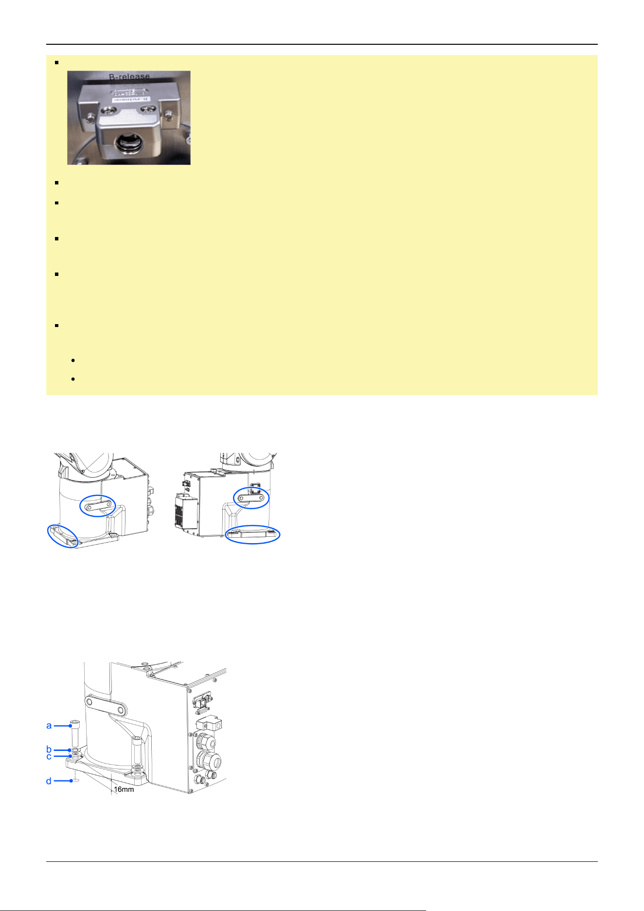
Take extra care when transporting the Manipulator. You may hit and damage the connector.
During unpacking and relocation, avoid applying external force to the arms and motors of the Manipulator.
When transporting the Manipulator over long distances, secure it directly to transporting equipment so that it
will not fall. If necessary, pack the Manipulator using the same packaging as delivery.
The Manipulator must be installed to avoid interference with surrounding buildings, structures, and other
machines and equipment that may create a trapping hazard or pinch points.
Resonance (resonating sound or minute vibrations) may occur during Manipulator operation depending on
the rigidity of the base table. If the resonance occurs, improve the rigidity of the base table or change the
speed or acceleration and deceleration settings of the Manipulator.
Manipulator base has a cooling fan. Install the Manipulator not to seal the cooling fan. For details, refer to the
following figure.
Cable backward model
Cable downward model
Protective tape
Remove the protective tape (4 places).
Fixing bolt
For details on the dimensions, refer to the following sections.
Manipulator Mounting Dimensions
There are four threaded holes for the Manipulator base. Use M12 mounting bolts conforming to the strength equivalent to
ISO898-1 property class 10.9 or 12.9. Tightening torque: 100.0 ± 5.0 N·m (1,020 ± 51 kgf·cm)
Industrial Robot: 6-Axis Robots C-B series Manual Rev.1b
181
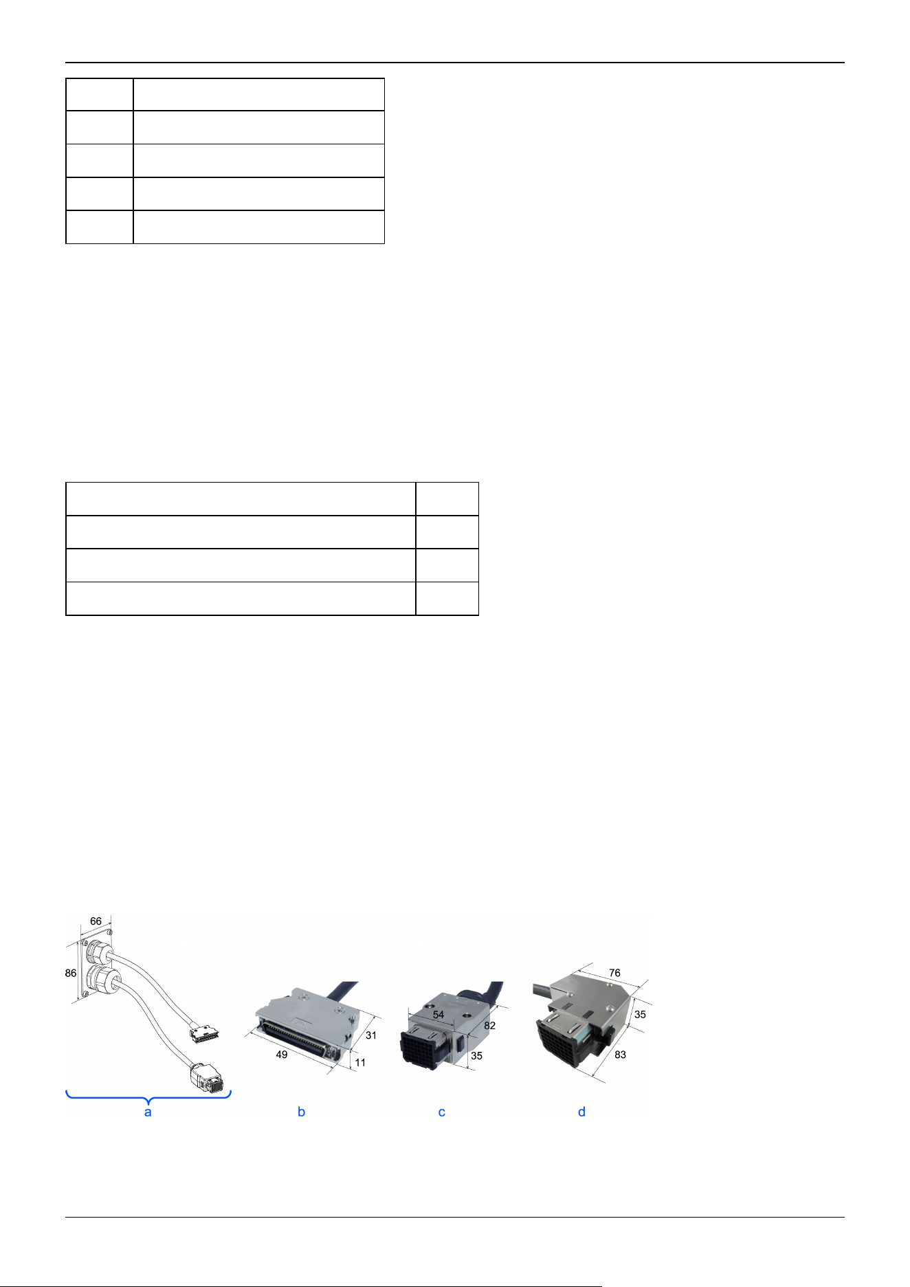
Symbol Description
a 4×M12×40
b Spring washer
c Plain washer
d Threaded hole (25 mm or more depth)
Base table
A base table for anchoring the Manipulator is not supplied. The base table must be fabricated or obtained by the customer.
The shape and size of the base table vary depending on the application of the robot system. As a reference when designing the
base table, the requirements from the Manipulator side are shown here.
The base table must not only be able to bear the weight of the Manipulator but also be able to withstand the dynamic
movement of the Manipulator when it operates at maximum acceleration/deceleration. Ensure that there is enough strength on
the base table by attaching reinforcing materials such as crossbeams.
Followings are the torque and reaction force produced by the movement of the Manipulator.
Maximum rotating torque on horizontal surface (N·m) 2600
Maximum reaction force in horizontal direction (N) 1000
Maximum rotating torque on vertical surface (N·m) 3400
Maximum reaction force in vertical direction (N) 7900
The plate for the Manipulator mounting face should be at least 30 mm thick and made of steel for reducing vibrations.
A surface roughness of 25 μm or less at the maximum height is appropriate.
The base table must be secured on the floor to prevent it from moving.
The Manipulator installation surface should have a flatness of 0.5 mm or less and an inclination of 0.5° or less. If the
installation surface does not have the proper flatness, the base of the Manipulator may be damaged or the robot may be unable
to operate at maximum performance.
When using a leveler to adjust the height of the base table, use a screw with M16 diameter or more.
Connector
If passing cables through the holes in the base table, refer to the connector dimensions in the figures below. (Units: mm)
Industrial Robot: 6-Axis Robots C-B series Manual Rev.1b
182
Symbol Description
a M/C cable
b Signal cable connector
c Power cable connector (straight)
d Power cable connector (L-shaped)
Do not remove the M/C cables from the Manipulator.
KEY POINTS
For details on the environmental requirements for the space when housing the Controller in the base table, refer
to the Robot Controller manual.
When using the Manipulator in the clean room, follow the steps below before the installation.
1. Unpack the Manipulator outside of the cleanroom.
2. Secure the Manipulator to transporting equipment (or a pallet) with bolts so that the Manipulator does not fall down.
3. Wipe off any dust on the Manipulator using a lint-free cloth that was dipped in ethyl alcohol or distilled water.
4. Carry the Manipulator into the cleanroom.
5. Secure the Manipulator to the base table.
✏
Industrial Robot: 6-Axis Robots C-B series Manual Rev.1b
183
4.3.4 Connecting the Cables
WARNING
Before performing any replacement work, turn off the Controller and related equipment, and unplug the power
cable from the power source. Performing any work procedure with the power turned on is extremely
dangerous and may result in electric shock and/or malfunction of the robot system.
Be sure to connect the AC power cable to a power outlet. Do not connect it directly to a factory power source.
To perform the power supply lockout, remove the power plug. Working while connecting the AC power cable
to a factory power source may result in electric shock and/or malfunction of the robot system.
Be sure to connect the cables properly. Do not put heavy objects on the cables, bend or pull on the cables
forcibly, or allow the cables to be pinched. Damaged cables, broken wires, or contact failure is extremely
hazardous and may result in electric shock and/or malfunction of the robot system.
Be sure to turn off the power and tag out (e.g., with a "DO NOT TURN ON" sign) before performing wiring.
Performing any work procedure with the power turned on is extremely dangerous and may result in electric
shock and/or malfunction of the robot system.
The Manipulator is grounded by connecting it to the Controller. Ensure that the Controller is grounded and the
cables are correctly connected. If the ground wire is improperly connected to ground, it may result in the fire
or electric shock.
Turn off the power to the Robot Controller and brake release unit when connecting or replacing the brake
release unit or external short connector. Inserting or removing connectors with the power on may result in
electric shock and/or malfunction of the robot system.
CAUTION
When connecting the Manipulator and the Controller, check that the serial numbers match for each device.
Improper connection between the Manipulator and the Controller may not only lead to malfunction of the robot
system but also safety problems. The connection method between the Manipulator and the Controller varies
depending on the Controller. For details on the connection, refer to the following manual.
"Robot Controller Manual"
Only authorized or certified personnel should perform wiring. Wiring by unauthorized or uncertified staff may
result in bodily injury and/or malfunction of the robot system.
Operating the Manipulator without a brake release unit or external short connector connected may cause the
brake to fail to release, possibly damaging the brake.
After using the brake release unit, be sure to connect the external short circuit connector to the Manipulator or
make sure to leave the connector for the brake release unit connected.
Cleanroom-model Manipulator
When the Manipulator is a model with cleanroom specifications, an exhaust system must be connected. For the exhaust
system, refer to the following section.
C12 Specifications
Connection procedure for M/C cable
Connect the power connector and signal connector of the M/C cable to the Controller.
Industrial Robot: 6-Axis Robots C-B series Manual Rev.1b
184
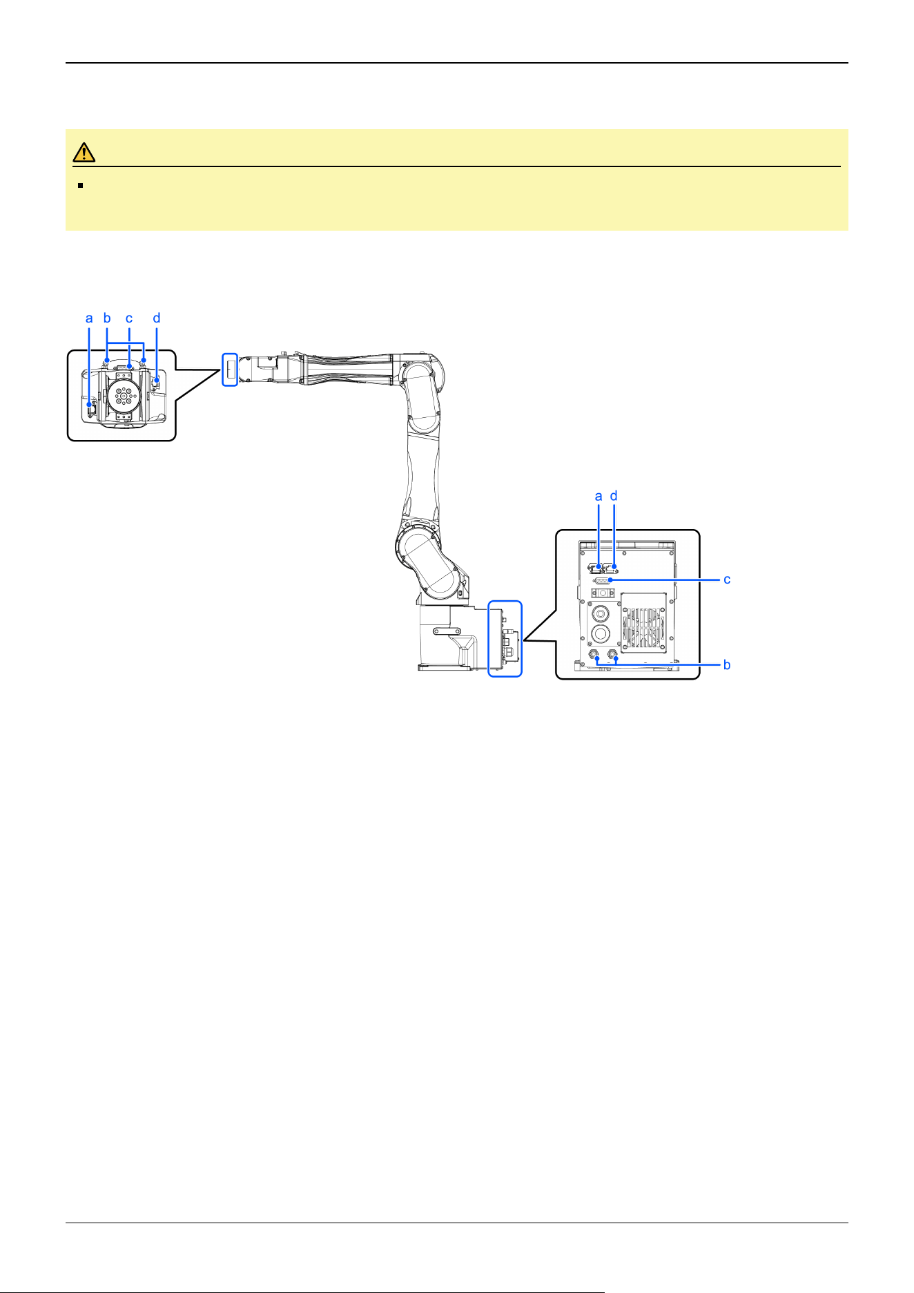
4.3.5 User Wires and Pneumatic Tubes
CAUTION
Only authorized or certified personnel should perform wiring. Wiring by unauthorized or uncertified staff may
result in bodily injury and/or malfunction of the robot system.
User electrical wires and pneumatic tubes are contained in the cable unit.
Cable backward model
Industrial Robot: 6-Axis Robots C-B series Manual Rev.1b
185
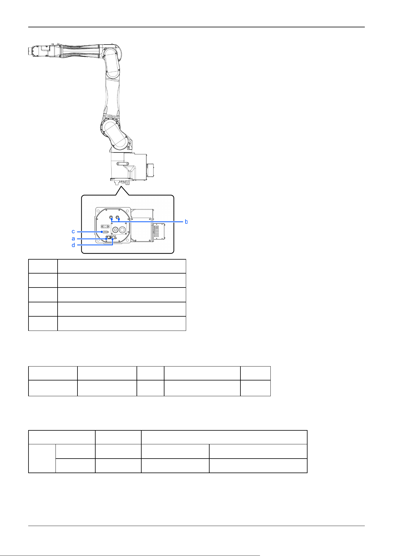
Cable downward model
Symbol Description
a Force Sensor cable connector
b Fitting for ⌀6 mm tube (Air1, Air2)
c User cable connector (9-pin D-sub connector)
d Ethernet cable connector
4.3.5.1 Electrical Wires
Specifications of the user wires D-sub 15-pin
Rated Voltage Allowable Current Wires Nominal Sectional Area Note
AC/DC30V 1 A 15
0.106 mm
2
Shielded
Pins with the same number, indicated on the connectors on both ends of the cables, are connected.
Attached connector for user wires (standard, cleanroom model)
Manufacturer Type
15 pin
Connector JAE DA-15PF-N (Solder type)
Clamp hood HRS HDA-CTH (4-40) (10) (Connector setscrew: #4-40 UNC)
Two parts are attached for each.
Industrial Robot: 6-Axis Robots C-B series Manual Rev.1b
186
8-pin (RJ45) equivalent to Cat.5e
An Ethernet cable (commercially available) can be connected to Manipulator models with standard and cleanroom
specifications.
Other
The 6-pin cable for the Force Sensor option is included.
4.3.5.2 Pneumatic Tubes
Maximum Working Pressure Number of Tubes Outer Diameter × Inner Diameter
0.59 MPa (6 kgf/cm
2
: 86 psi)
2 ⌀6 mm × ⌀4 mm
The elbow fitting is attached on the Arm #4 at the time of shipment. The part can be replaced with the straight fitting
(accessory) according to application.
4.3.6 Checking the Basic Orientation
After installing the Manipulator and setup the operating environment, check if it moves to the basic position properly.
Follow the steps below to set the basic orientation of the Manipulator shown below as the origin position.
1. Start EPSON RC+ 7.0.
Double click the [EPSON RC+ 7.0] icon on the desktop.
2. Open the command window.
EPSON RC+ 7.0 menu-[Tools]-[Command Window]
3. Execute the following command in [Command Window].
>Motor On
>Go Pulse (0,0,0,0,0,0)
KEY POINTS
If "Error 4505: cannot be turned on the motor because the Safety Board is issuing a stop signal." occurs, use one
of the following methods to move the Manipulator to its basic orientation.
Release the brake and push the arm by hand to move it within the motion range. Then follow the steps above.
For details on releasing brake, refer to the following section.
How to Move Arms with the Electromagnetic Brake
Press the TP3 command button [Pulse0] to move the Manipulator to its basic orientation. For details, refer to
the following manual.
"Robot Controller Option Teach Pendant TP3 Operation 3.1.3 Command Buttons"
If the Manipulator cannot be in the basic orientation shown below, please contact the supplier.
✏
Industrial Robot: 6-Axis Robots C-B series Manual Rev.1b
187
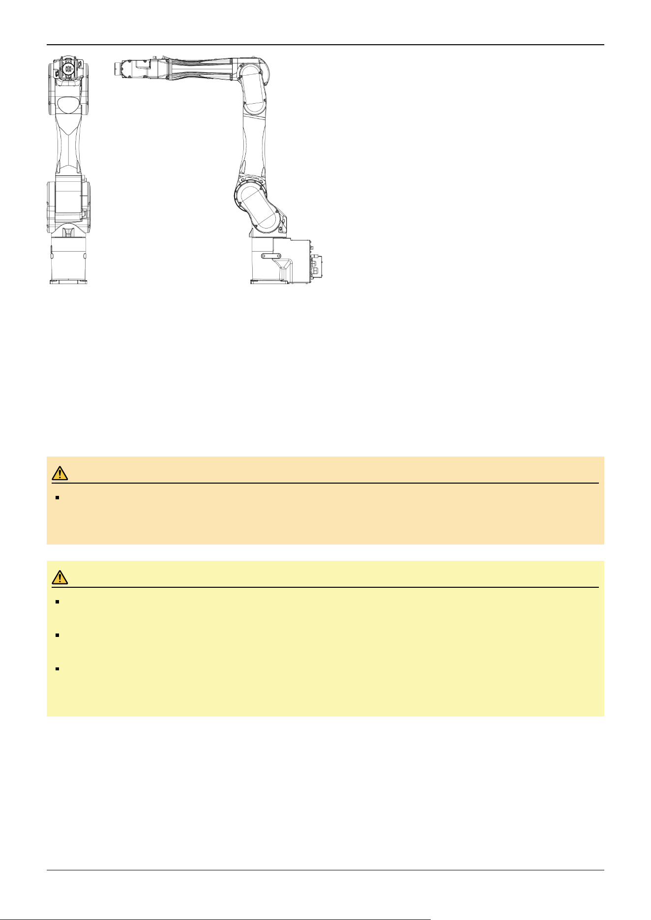
4.3.7 Relocation and Storage
4.3.7.1 Safety Information for Relocation and Storage
Pay attention to the following requirements when relocating, storing, and transporting the Manipulators.
Transportation and installation of the Manipulator and related equipment should be performed by people who have received
installation training provided by Epson and the suppliers. Also, the laws and regulations of the installation country must be
followed.
WARNING
Only qualified personnel should perform sling work and operate a crane or a forklift. When these operations
are performed by unqualified personnel, it is extremely hazardous and may result in serious bodily injury
and/or severe equipment damage to the robot system
CAUTION
Before relocating, fold the arm and secure it tightly with a cable tie to prevent hands or fingers from getting
caught in the Manipulator.
When removing the anchor bolts, support the Manipulator so that it does not fall. Removing the anchor bolts
without supporting the Manipulator can cause it to fall, causing hands or feet to get caught.
The Manipulator should be transported by two or more people or secured to transporting equipment. Also, do
not hold the bottom of the base. Holding these parts by hand is extremely hazardous and may cause your
hands and fingers caught.
During unpacking and relocation, avoid applying external force to the arms and motors of the Manipulator.
When transporting the Manipulator over long distances, secure it directly to transporting equipment so that it will not fall. If
necessary, pack the Manipulator using the same packaging as delivery.
When the Manipulator is reassembled and used for a robot system again after an extended period of storage, perform a test run
to verify that it works properly before starting the main operation.
Industrial Robot: 6-Axis Robots C-B series Manual Rev.1b
188
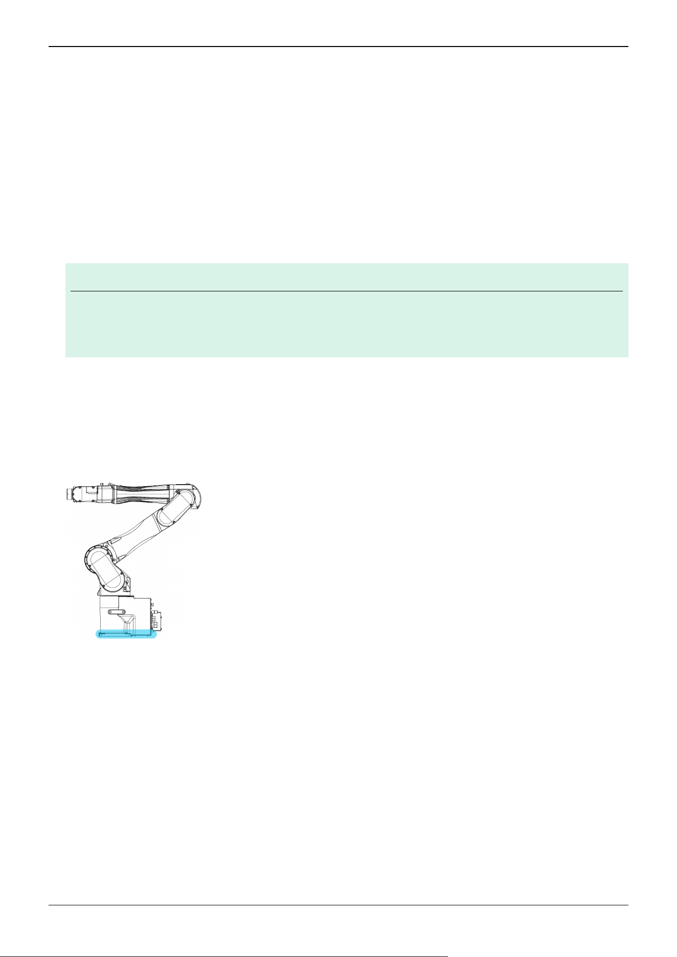
Manipulators should be transported and stored under the following conditions: Temperature: -20 to +60°C, Humidity: 10 to
90% (no condensation)
If condensation has formed on the Manipulator during transportation or storage, do not turn on the power until the
condensation is removed.
Do not subject the Manipulator to excessive impacts or vibrations during the transportation process.
Relocation
Follow the procedures described below when relocating the Manipulator.
1. Turn off the power for all devices and unplug the power cable connector and signal cable connector from the Controller.
Do not remove the M/C cables (power cable and signal cable) from the Manipulator. (MC cable 3 m: 2 kg)
KEY POINTS
Remove the mechanical stops if using them to limit the motion range. For details on the motion range, refer to
the following section.
Setting the Work Envelope by Mechanical Stops
2. Unscrew the anchor bolts. Then, remove the Manipulator from the base table.
3. Position the Manipulator as shown in the figure. Then, secure the Manipulator to the transporting equipment or have at
least two people to relocate the Manipulator. (Recommend: Joint #2 +55°. Joint #3 -55°)
The posture is common to all models.
Do not hold the bottom of the base (the screened parts in the figure). Holding these parts by hand is extremely hazardous
and may cause your hands and fingers caught.
Manipulator weight: 63 kg: 139 lb
Using eyebolts
Check that the eyebolts are securely fastened before transporting the Manipulator. After transporting the Manipulator, remove
the eyebolts and keep them for future use.
The eyebolts (accessory, 2 pcs) and wire must be strong enough to withstand the weight (See the figures below).
If you use the eyebolts to lift up the Manipulator, make sure to put hands on it to keep the balance. The Manipulator may fall if
the balance is lost and this is extremely hazardous.
To prevent damage on the covers and arms, it is recommended to protect the contacting parts of the wire and arm with a cloth.
Be very careful not to damage the covers since they are made of plastic.
Manipulator weight: 63 kg: 139 lb
✏
Industrial Robot: 6-Axis Robots C-B series Manual Rev.1b
189
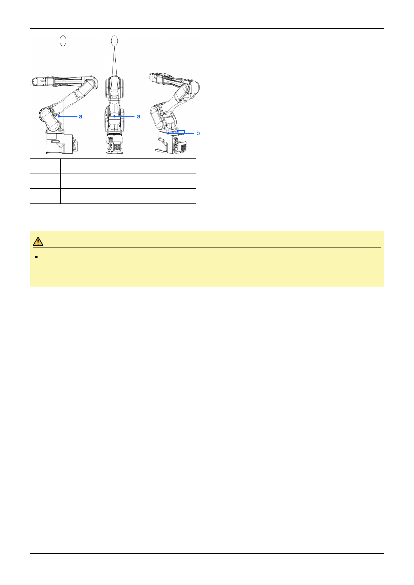
Symbol Description
a Center of gravity
b Threaded holes for eyebolts: 2×M12 depth 25
Locations of the threaded holes for eyebolts are common to all models.
CAUTION
Remove the eyebolts from the Manipulator after transportation/relocation is completed. If the Manipulator is
operated with the eyebolts left on it, the arm may collide with the eyebolts and it may cause equipment
damage to and/or malfunction of the Manipulator.
4.4 Setting the Hand
4.4.1 Installing the Hand
The hand (end effector) must be prepared by the customer. For details on attaching the hand, refer to the following manual.
"Hand Function Manual"
Industrial Robot: 6-Axis Robots C-B series Manual Rev.1b
190
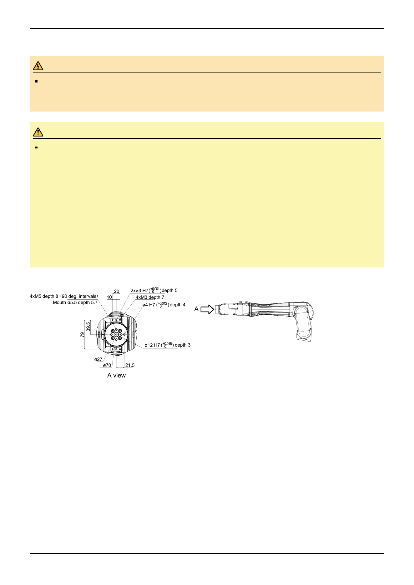
Flange dimensions of the wrist attached to the end of Arm #6 is as below.
WARNING
Before attaching a hand or peripheral equipment, be sure to always turn off the Controller and related
equipment and unplug the power cables. Performing any work procedure with the power turned on is
extremely dangerous and may result in electric shock and/or malfunction of the robot system.
CAUTION
When the hand is equipped with a workpiece gripping mechanism, ensure that the wiring and pneumatic
tubes do not cause the hand to release the workpiece when the power is turned off. When the wiring and
pneumatic tubes are not designed for the hand to maintain its grip on the workpiece when the power is turned
off, pressing the emergency stop switch releases the workpiece, which may damage the robot system and the
workpiece.
By default, all I/Os are designed to automatically turn off (0) when the power is shut off, when an emergency
stop is triggered, or by the robot system's safety function.
However, I/Os set with the Hand function does not turn off (0) when executing the Reset statement, or when
performing an emergency stop.
For the risk of the residual air pressure, conduct a risk assessment on the equipment and take the necessary
protective measures.
Wrist flange
Arm #6
Attach the hand to the end of the Arm #6 using the M5 bolts.
Layout
When attaching and operating a hand, the hand may come into contact with the Manipulator body due to the outer diameter of
the hand, the size of the workpiece, or the position of the arm. Carefully consider the interference area of the hand when
designing the system layout.
Compatibility with ISO flange
To install the hand whose mounting dimensions are designed for the ISO flange, we provide the optional C8 ISO flange (J6).
For details, refer to the following section.
Options
Industrial Robot: 6-Axis Robots C-B series Manual Rev.1b
191
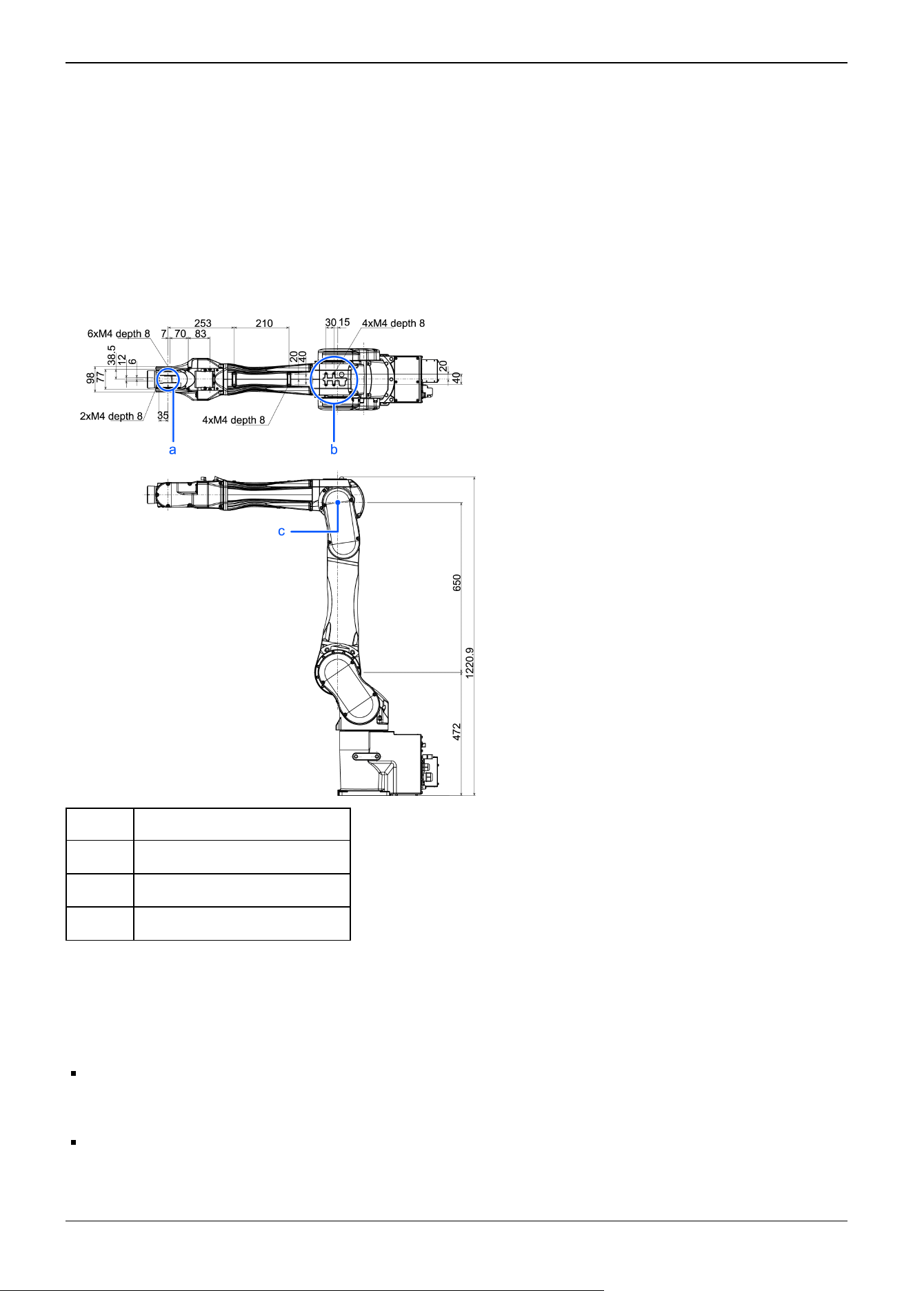
4.4.2 Attaching Cameras and Valves
Decks are equipped to Arms #3 and #5 to enable the easy installation of air valve. If the payload exceeds the maximum
payload, refer to the following section.
"WEIGHT Setting - Restrictions on payload exceeding the maximum payload"
To mount the camera, the camera plate unit is necessary. We provide the optional Camera Plate Unit. For details, refer to the
following section.
Options
(Units: mm)
Symbol Description
a Arm #5 Deck
b Arm #3 Deck
c Rotation center of the upper arm
4.4.3 WEIGHT and INERTIA Settings
The WEIGHT and INERTIA commands are for setting the load parameters of the Manipulator. These settings optimize the
Manipulator motion.
WEIGHT Setting
The WEIGHT command is for setting the load weight. The more the load weight increases, the more the speed and
acceleration/deceleration are reduced.
INERTIA Setting
The INERTIA command is for setting the inertia moment and the eccentricity of the load. The more the inertia moment
Industrial Robot: 6-Axis Robots C-B series Manual Rev.1b
192
increases, the more the acceleration and deceleration of the Arm #6 are reduced. The more the eccentricity increases, the
more the acceleration and deceleration for the Manipulator movement are reduced.
To ensure that the Manipulator is functioning properly, keep the load (the sum of the weights of the hand and workpiece) and
the moment of inertia of the load within the rated values, and do not allow for eccentricity from the center of the Arm #6. If the
load or the inertia moment exceeds the ratings or if the load becomes eccentric, follow the steps below to set parameters.
WEIGHT Setting
INERTIA Setting
Setting parameters makes the operation of the Manipulator optimal, reduces vibration to shorten the operating time, and
improves the capacity for larger loads. This also works to curb any persistent vibration that may occur when the hand and
workpiece have a large moment of inertia.
You can also perform settings using the "Weight, Inertia, and Eccentricity/Offset Measurement Utility."
For details, refer to the following manual.
"EPSON RC+ User's Guide - Weight, Inertia, and Eccentricity/Offset Measurement Utility"
The allowable load for C12 series Manipulators is up to 12 kg.
Due to the limitations of the moment and moment of inertia shown in the table below, the load (hand + workpiece) should also
meet these conditions.
Allowable Load
Joint Allowable moment
(GD
2
/4) Allowable Moment of Inertia
Joint #4 25.0 N·m (2.55 kgf·m)
0.70 kg·m
2
Joint #5 25.0 N·m (2.55 kgf·m)
0.70 kg·m
2
Joint #6 9.8 N·m (1.0 kgf·m)
0.20 kg·m
2
Moment
The moment indicates amount of torque applied on the joint in order to support the gravity on the load hand + workpiece). The
moment increases as weight of the load and amount of eccentricity increase. As this also increases the load applied on the joint,
make sure to keep the moment within the allowable value.
Moment of inertia
The moment of inertia indicates how difficult the load (hand + workpiece) to rotate when the Manipulator joint starts to rotate
(amount of inertia). The moment of inertia increases as weight of the load and amount of eccentricity increase. As this also
increases the load applied on the joint, make sure to keep the moment within the allowable value.
The moment M (Nm) and moment of inertia I (kgm
2
) when the volume of the load (hand + workpiece) is small can be
obtained by the following formula.
M (Nm) = m (kg) × L (m) × g (m/s
2
)
I (kgm
2
) = m (kg) × L2 (m)
m: Weight of load (kg)
L: Eccentricity of load (m)
g: Gravitational acceleration (m/s
2
)
Industrial Robot: 6-Axis Robots C-B series Manual Rev.1b
193
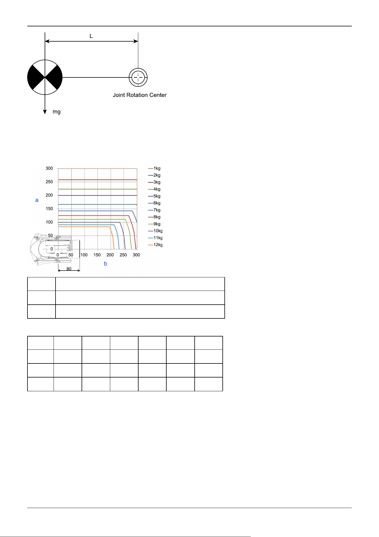
The figure below shows distribution of the center of gravity when the volume of the load (hand + workpiece) is small. Design
the hand so that the center of gravity is within the allowable moment. If the volume of the load is large, calculate the moment
and inertia moment by referring to the following section.
"INERTIA Setting - Calculating the Moment of Inertia"
Symbol Description
a Distance from the center of Arm #* rotation [mm]
b Center of gravity of load from the Arm #* rotation center [mm]
Max. Eccentricity of Load (Distance between the joint rotation center and the load’s center of gravity)
Joint 1 kg 3 kg 5 kg 8 kg 10 kg 12 kg
#4 300 mm 300 mm 300 mm 296 mm 255 mm 213 mm
#5 300 mm 300 mm 300 mm 296 mm 255 mm 213 mm
#6 300 mm 258 mm 200 mm 125 mm 100 mm 83 mm
When calculating the critical dimension of the load using the allowable moment and inertia moment, the calculated value
represents a distance from the Arm #6 rotation center, not the distance from the flange. To calculate the distance from the
flange to the load’s center of gravity, subtract the distance from the center of the Arm #5 rotation center to the flange (=80 mm)
as shown in the example below.
Example: Calculation of the critical dimension of the load (A) when the load is 12 kg.
Center of gravity by the allowable moment control: 25.0 N·m/(12 kg × 9.8 m/s
2
) = 0.212 m = 212 mm
Center of gravity by the allowable inertia moment control: (0.70 kgm
2
/12 kg)1/2 = 0.241 m = 241 mm
Due to the allowable moment control, center of gravity for the load limit is 212 mm from the Arm #5 rotation center.
Industrial Robot: 6-Axis Robots C-B series Manual Rev.1b
194
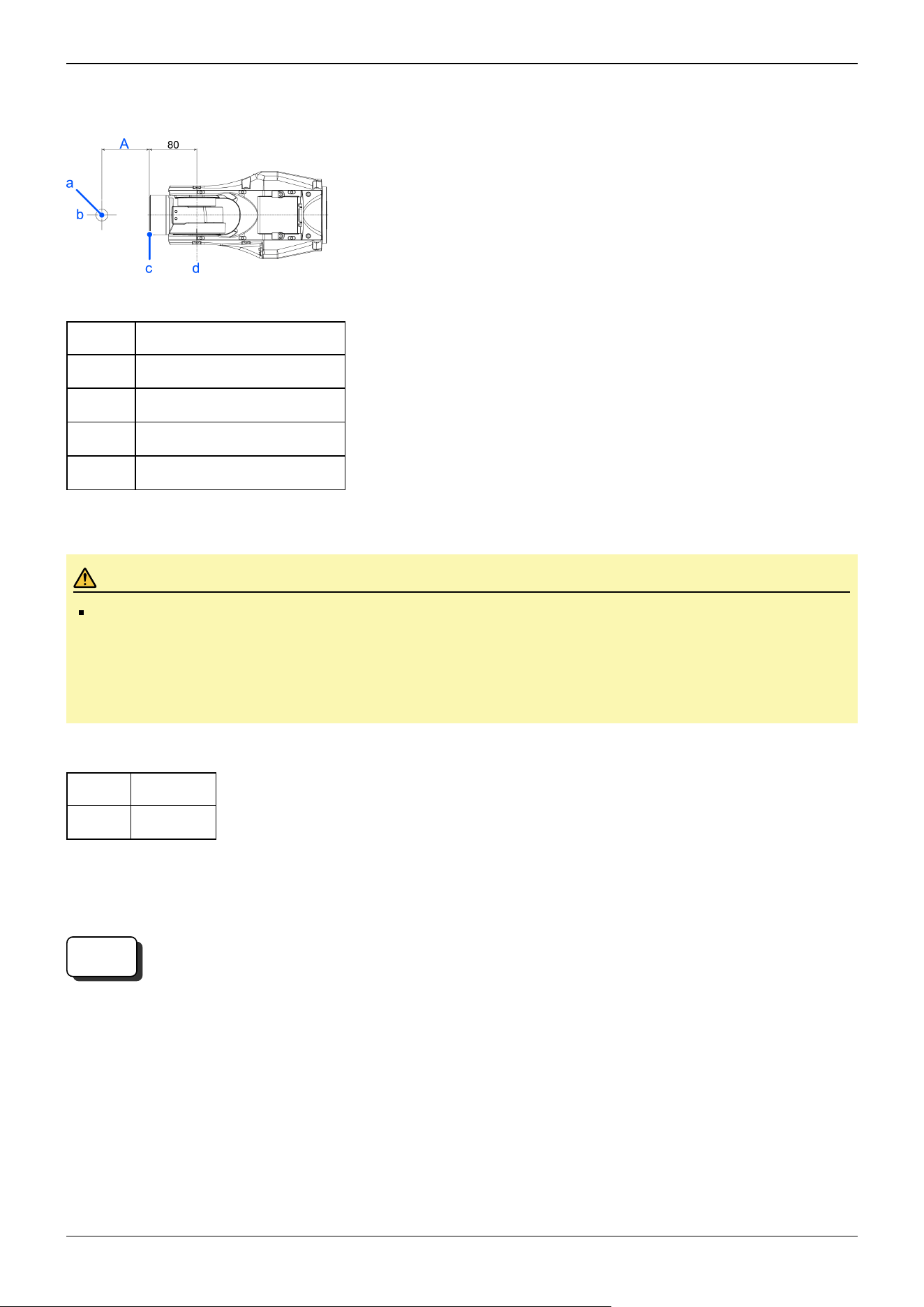
Distance from the flange to the center of gravity for the load limit A = 212 mm - 80 mm = 132 mm
Critical Dimension of Load
(Units: mm)
Symbol Description
a Load center of gravity position
b Arm #6 rotation center
c Flange
d Arm #5 rotation center
4.4.3.1 WEIGHT Setting
CAUTION
Set the total weight of the hand and the workpiece smaller than the maximum payload. The C12 series
Manipulators can operate without limitations on the condition unless and until the load exceeds this maximum
payload. Always set the Weight parameters of the WEIGHT command according to the load. Setting a value
smaller than the actual weight may cause errors or impact that not only impair full functionality but also
shorten the life of the mechanical components.
The acceptable weight capacity (hand + workpiece) for C12 series Manipulators is as follows:
Rated Maximum
3 kg 12 kg
Change the setting of the Weight parameter according to the load. After changing the Weight parameter setting, the maximum
acceleration/deceleration and speed of the robot system is set automatically.
Setting method of Weight parameters
Select [Tools]-[Robot Manager]-[Weight] panel and set the value in [Weight:]. You may also execute the Weight command
from [Command Window].
Load on the Manipulator
Mounting location of the load
EPSON
RC+
Industrial Robot: 6-Axis Robots C-B series Manual Rev.1b
195
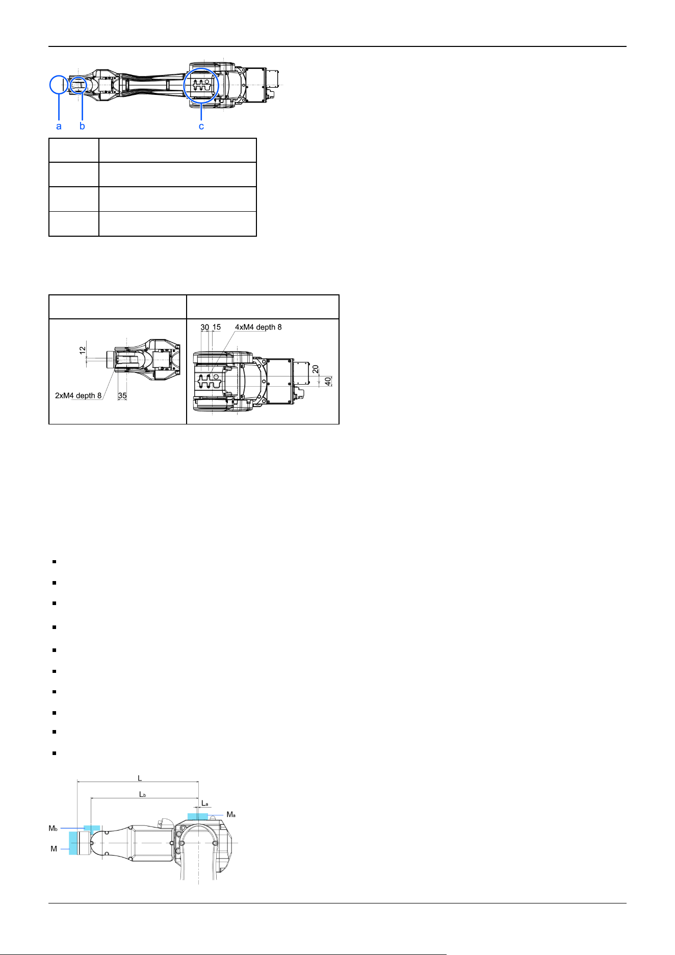
Symbol Description
a Load on the fore end of Arm #6
b Arm #5 deck
c Arm #3 deck
Deck detailed
(Units: mm)
Arm #5 deck Arm #3 deck
When you attach the equipment to the decks on the upper arm, convert its weight into equivalent weight assuming that the
equipment is attached to the end of the Arm #6. Then, this equivalent weight added to the load will be a Weight parameter.
Calculate the Weight parameter by using the formula below and enter the value.
Weight Parameter Formula
Weight parameter = M
w
+ W
a
+ W
b
M
w
: Payload on the fore end of Arm #6 (kg)
W
a
: Equivalent weight of the Arm #3 deck (kg)
W
b
: Equivalent weight of the Arm #5 deck (kg)
W
a
=M
a
(L
a
)
2
/(L)
2
W
b
=M
b
(L
b
)
2
/(L)
2
M
a
: Weight of the air valve on the Arm #3 deck (kg)
M
b
: Weight of the camera on the Arm #5 deck (kg)
L: Length of the upper arm (315 mm)
L
a
: Distance between the Joint #3 and the center of gravity of the air valve on the Arm #3 deck (mm)
L
b
: Distance between the Joint #3 and the center of gravity of the camera on the Arm #5 deck (mm)
Industrial Robot: 6-Axis Robots C-B series Manual Rev.1b
196
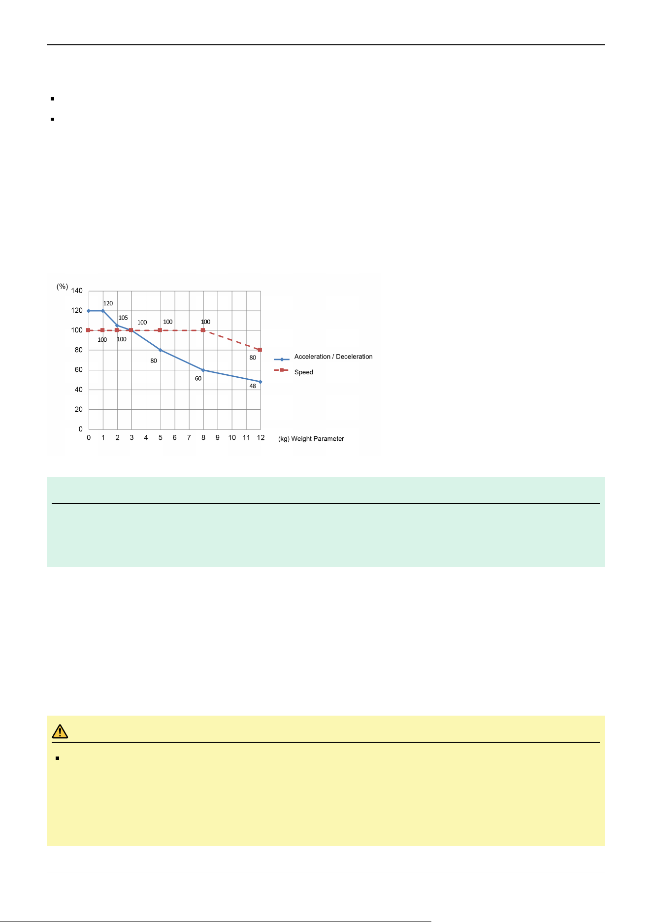
[Example] When the following loads apply to C12-B1401** (C12XL) which fore end of the Arm #6 is 730 mm (L) away from
the Joint #3 and payload (M
w
) is 5 kg:
Load on the Arm #3 deck is 1.5 kg (M
a
). The deck is 0 mm (L
a
) away from the Joint #3.
Load on the Arm #5 deck is 1.0 kg (M
b
). The deck is 690 mm (L
b
) away from the Joint #3.
W
a
=1.5 × 0
2
/730
2
=0
W
b
=1.0 × 690
2
/730
2
=0.89 → 0.9 (round up)
M
w
+W
a
+W
b
=5+0+0.9=5.9
Enter "5.9" for the Weight parameter.
Automatic speed setting by Weight parameter
The percentage in the graph is based on the speed at rated weight (3 kg) as 100%.
KEY POINTS
Maximum AccelS setting value varies depending on Weight setting value. For details, refer to the following
section.
C12 Specifications
4.4.3.2 INERTIA Setting
Moment of Inertia and INERTIA Setting
The moment of inertia is a quantity that expresses how hard it is for an object to turn, and it is expressed in terms of values for
the moment of inertia, inertia, or GD
2
. When a hand or other object is attached to the Arm #6 for operation, the moment of
inertia of the load must be taken into consideration.
CAUTION
The moment of inertia of the load (hand + workpiece) must be 0.2 kg·m
2
or less.
The C12 Manipulators are not designed to work with a moment of inertia exceeding 0.2 kg·m
2
. Always set the
value corresponding to the moment of inertia. Setting a parameter value that is smaller than the actual
moment of inertia may cause errors or impact, may prevent the Manipulator from working at full functionality,
and may shorten the lifespan of mechanical parts.
✏
Industrial Robot: 6-Axis Robots C-B series Manual Rev.1b
197
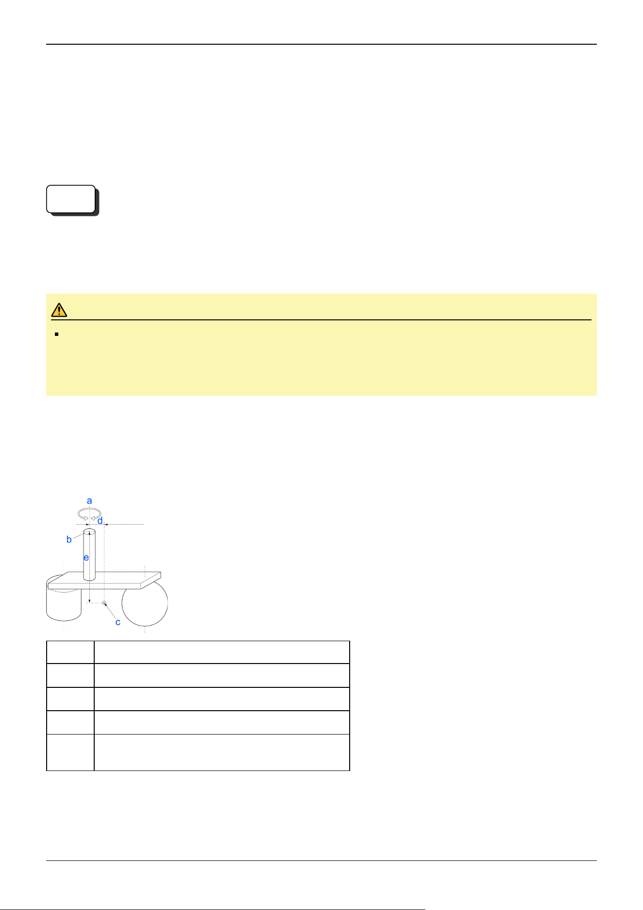
The allowable moment of inertia of a load for C12 Manipulators is 0.03 kg·m
2
at the default rating and 0.2 kg·m
2
at the
maximum. Change the setting of the moment of inertia according to the inertia moment of the load using the INERTIA
command. After the setting is changed, the maximum acceleration/deceleration of Arm #6 that corresponds to the "Inertia"
value is corrected automatically.
Moment of Inertia of Load Attached to Arm #6
The moment of inertia of the load (hand + workpiece) attached to the Arm #6 can be set by the "Inertia" parameter in the
Inertia statement.
Go to [Tools] - [Robot Manager] - [Inertia] panel, and enter the value in [Inertia]. This can also be set using the Inertia
statement in [Command Window].
Eccentricity and INERTIA Setting
CAUTION
The eccentricity of the load (hand + workpiece) must be 300 mm or less. The C12 series Manipulators are not
designed to work with eccentricities exceeding 300 mm. Always set the value based on the eccentricity.
Setting the eccentricity parameter to a value smaller than the actual eccentricity may cause errors or impact
that not only impair full functionality but also shorten the life of the mechanical components.
The allowable eccentricity of load for C12 Manipulators is 50 mm at the default rating and 300 mm at the maximum. When the
load eccentricity exceeds the rating, change the setting for the eccentricity parameter in Inertia statement. After the setting is
changed, the maximum acceleration/deceleration of the Manipulator that corresponds to the "Eccentricity" is corrected
automatically.
Eccentricity
Symbol Description
a Rotation axis
b Flange
c Load center of gravity position
d, e
Eccentricity (300 mm or less)
To set the parameter, enter the larger value of "d" or "e".
Eccentricity of Load Attached to Arm #6
The eccentricity of the load (hand + workpiece) attached to the Arm #6 can be set by the "Eccentricity" parameter in the Inertia
statement.
Enter the larger value of either "d" or "e" in the figure above to [Eccentricity].
EPSON
RC+
Industrial Robot: 6-Axis Robots C-B series Manual Rev.1b
198
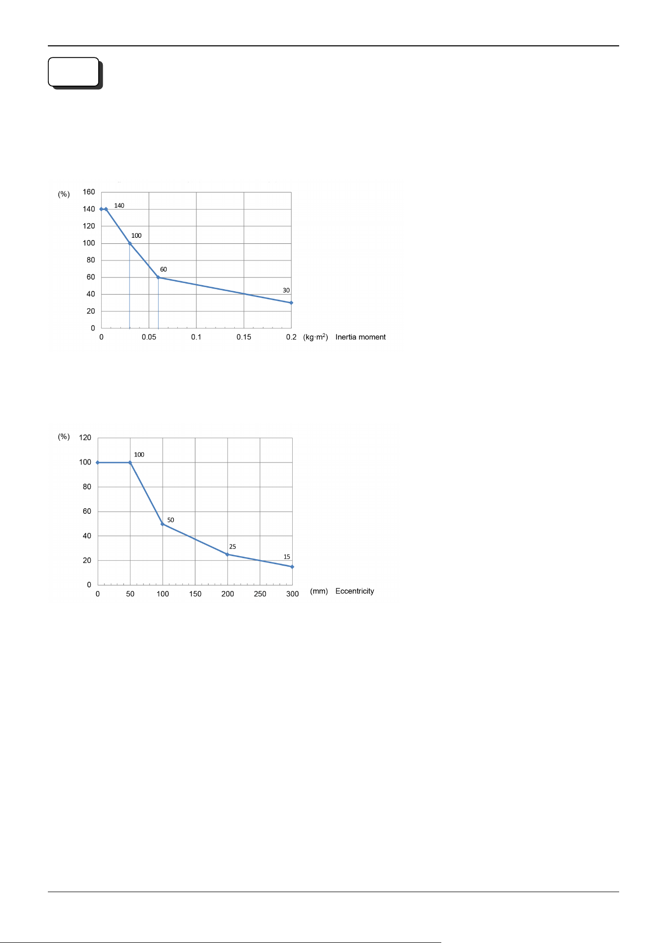
Go to [Tools] - [Robot Manager] - [Inertia] panel, and enter the value in [Eccentricity]. This can also be set using the Inertia
statement in [Command Window].
Automatic Acceleration/Deceleration Correction at INERTIA (Eccentricity) Setting
Automatic setting by inertia moment setting
* The percentages on the graph are ratios based on 100% as the acceleration/deceleration at the rated (0.03 kg·m
2
) setting.
Automatic setting by eccentricity setting
* The percentages on the graph are ratios based on 100% as the acceleration/deceleration at the rated (50 mm) setting.
Calculating the Moment of Inertia
An example of calculating the moment of inertia of a load (hand holding a workpiece) is shown below.
EPSON
RC+
Industrial Robot: 6-Axis Robots C-B series Manual Rev.1b
199
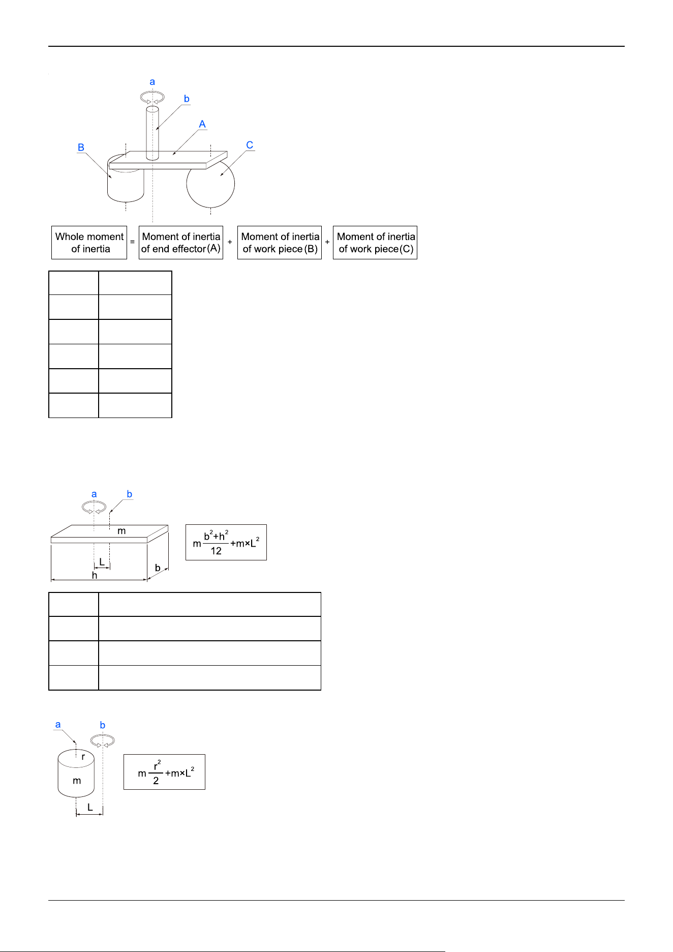
The moment of inertia of the entire load is calculated by the sum of (A), (B), and (C).
Symbol Description
a Rotation axis
b Shaft
A Hand
B Workpiece
C Workpiece
The methods for calculating the moment of inertia for (A), (B), and (C) are shown below. Use the moment of inertia of these
basic shapes as a reference to find the moment of inertia of the entire load.
(A) Moment of inertia of a rectangular parallelepiped
Symbol Description
a Rotation axis
b Center of gravity of rectangular parallelepiped
m Weight
(B) Moment of inertia of a cylinder
Industrial Robot: 6-Axis Robots C-B series Manual Rev.1b
200
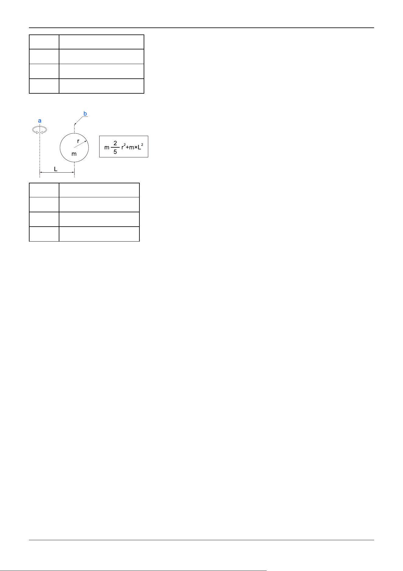
Symbol Description
a Center of gravity of cylinder
b Rotation axis
m Weight
(C) Moment of inertia of a sphere
Symbol Description
a Rotation axis
b Center of gravity of sphere
m Weight
4.4.4 Safety Information for Auto Acceleration
The speed and acceleration/deceleration of the Manipulator motion are automatically optimized according to the values of
WEIGHT and INERTIA and the Manipulator’s postures.
WEIGHT Setting
The speed and acceleration/deceleration of the Manipulator are controlled according to the load weight set by the WEIGHT
command. The more the load weight increases, the more the speed and acceleration/deceleration are reduced to prevent
residual vibration.
INERTIA Setting
The acceleration/deceleration of Arm #6 are controlled according to the inertia moment set by the INERTIA command. The
acceleration/deceleration of the whole Manipulator are controlled according to the eccentricity set by the INERTIA command.
The more the inertia moment and eccentricity of the load increase, the more the acceleration/ deceleration are reduced.
Auto Acceleration/Deceleration According to Manipulator’s Posture
The acceleration/deceleration are controlled according to the Manipulator’s posture. When the Manipulator extends its arms or
when the movement of the Manipulator produces vibration frequently, the acceleration/deceleration are reduced.
Set appropriate values for WEIGHT and INERTIA so that the Manipulator operation is optimized.
Industrial Robot: 6-Axis Robots C-B series Manual Rev.1b
201
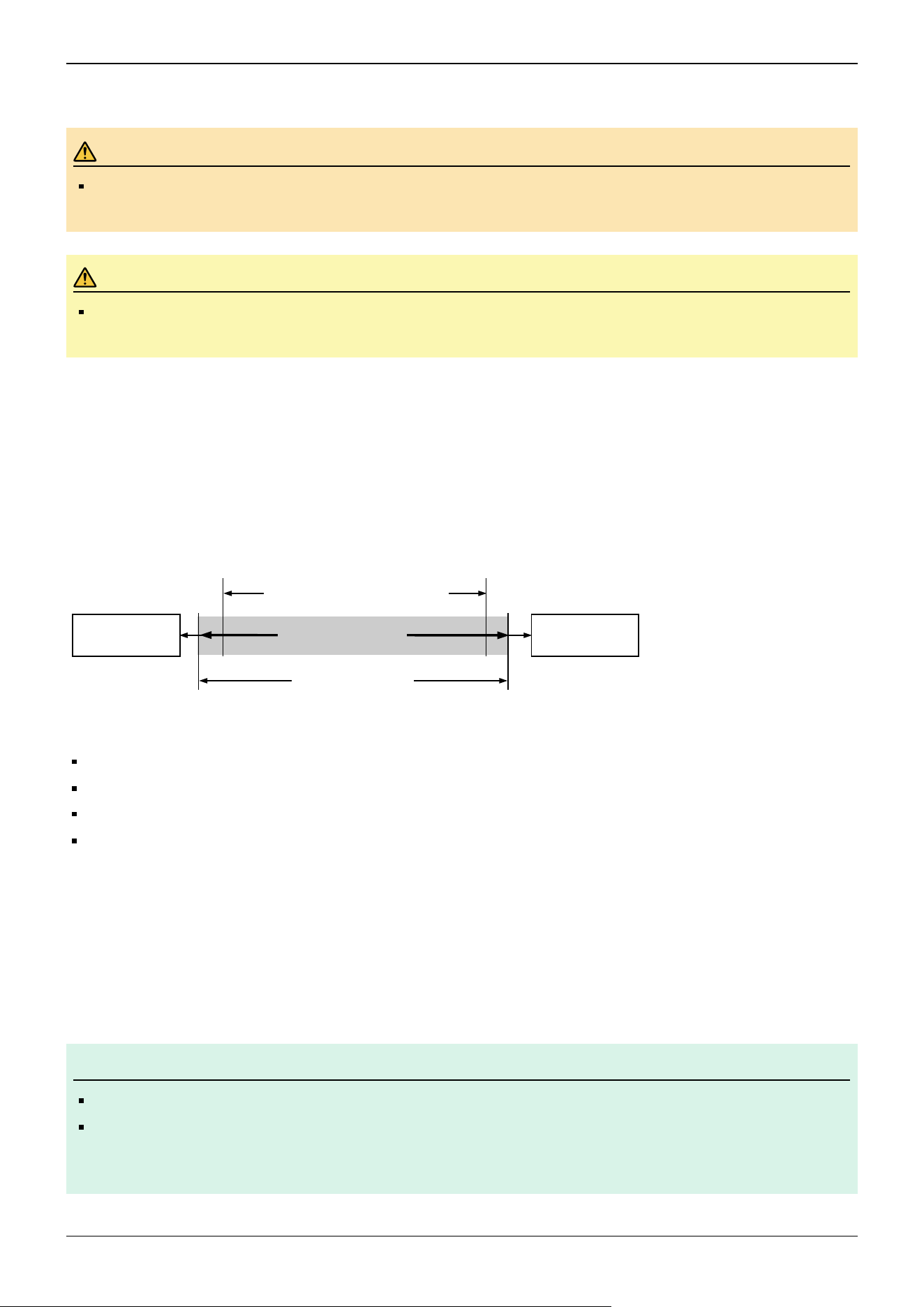
4.5 Work Envelope
WARNING
Do not operate the Manipulator with the mechanical stop removed. Removing the mechanical stop is
extremely dangerous because the Manipulator may move to a position outside its normal work envelope.
CAUTION
When restricting the work envelope for safety reasons, be sure to make settings using both the pulse range
and mechanical stop.
The work envelope is preset at the factory as explained in the following section. This is the maximum work envelope of the
Manipulator.
Standard Work Envelope
The work envelope can be set by one of the following three methods.
1. Setting by pulse range (for each joint)
2. Setting by mechanical stops
3. Setting the rectangular range in the XY coordinate system of the Manipulator
To limit the work envelope for layout efficiency or safety reasons, make the settings as explained in the following sections.
Work Envelope Setting by Pulse Range (for Each Joint)
Setting the Work Envelope by Mechanical Stops
Restriction of Manipulator Operation by Joint Angle Combination
Coordinate System
4.5.1 Work Envelope Setting by Pulse Range (for Each Joint)
Pulses are the basic unit of Manipulator motion. The motion range (work envelope) of the Manipulator is set by the pulse
lower limit value and pulse upper limit value (pulse range) for each joint. Pulse values are read from the encoder output of the
servomotor.
Be sure to set the pulse range within the mechanical stop range.
KEY POINTS
The Arm #1 and #4 do not have a mechanical stop.
Once the Manipulator receives a motion command, it checks whether the target position specified by the
command is within the pulse range before operating. If the target position is outside of the pulse range that
was set, an error occurs and the Manipulator does not move.
Pulse range
Work Envelope
Mechanical
Stop
Mechanical
Stop
Rectangular range setting
✏
Industrial Robot: 6-Axis Robots C-B series Manual Rev.1b
202
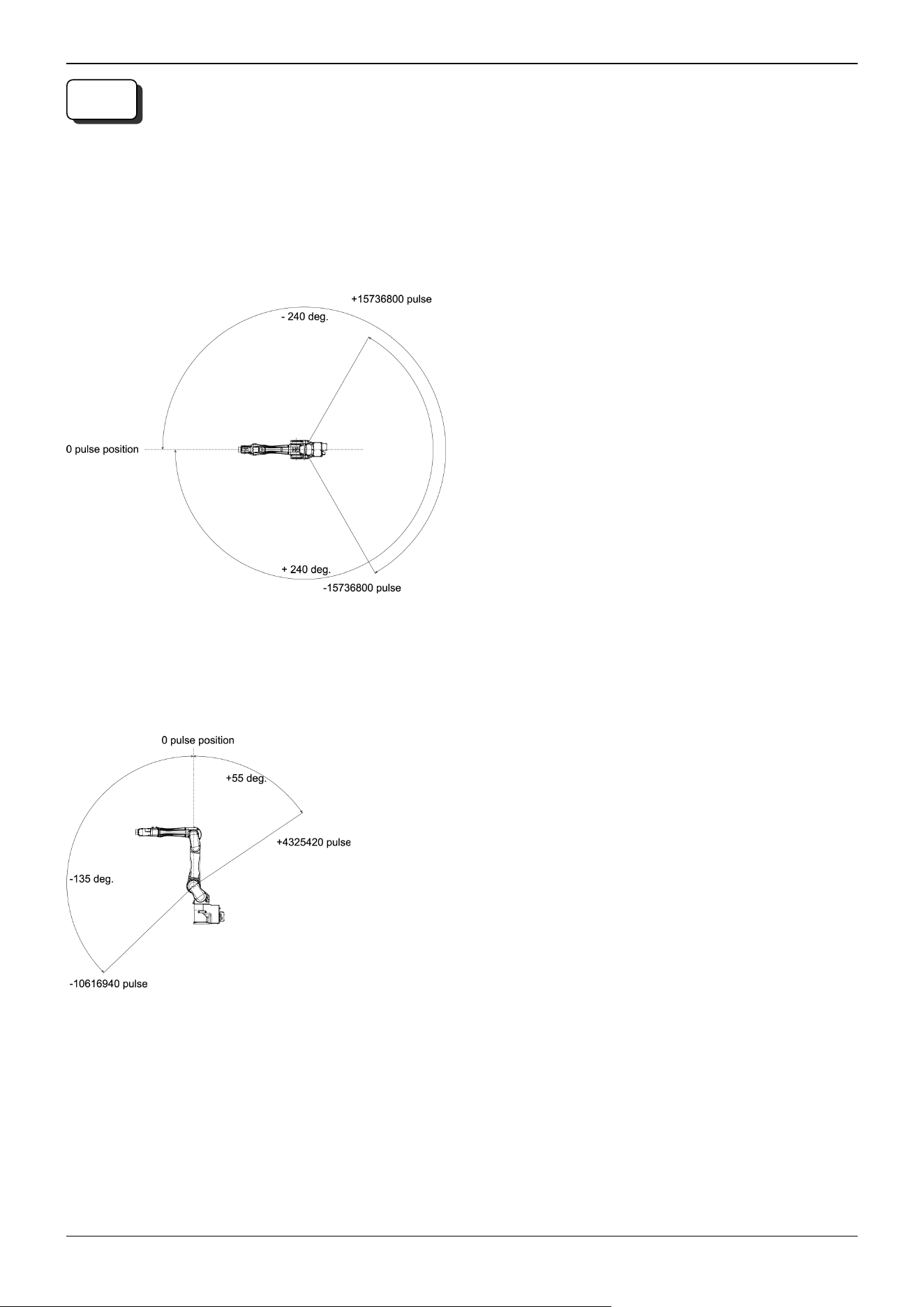
Go to [Tools] - [Robot Manager] - [Range] panel, and make the setting. This can also be set using the Range statement in
[Command Window].
4.5.1.1 Joint #1 Maximum Pulse Range
With the 0 pulse as a starting point, the counterclockwise pulse value is defined as positive (+), and the clockwise pulse value
is defined as negative (-).
4.5.1.2 Joint #2 Maximum Pulse Range
With the 0 pulse as a starting point, the clockwise pulse value is defined as positive (+), and the counterclockwise pulse value
is defined as negative (-).
4.5.1.3 Joint #3 Maximum Pulse Range
With the 0 pulse as a starting point, the clockwise pulse value is defined as positive (+), and the counterclockwise pulse value
is defined as negative (-).
EPSON
RC+
Industrial Robot: 6-Axis Robots C-B series Manual Rev.1b
203
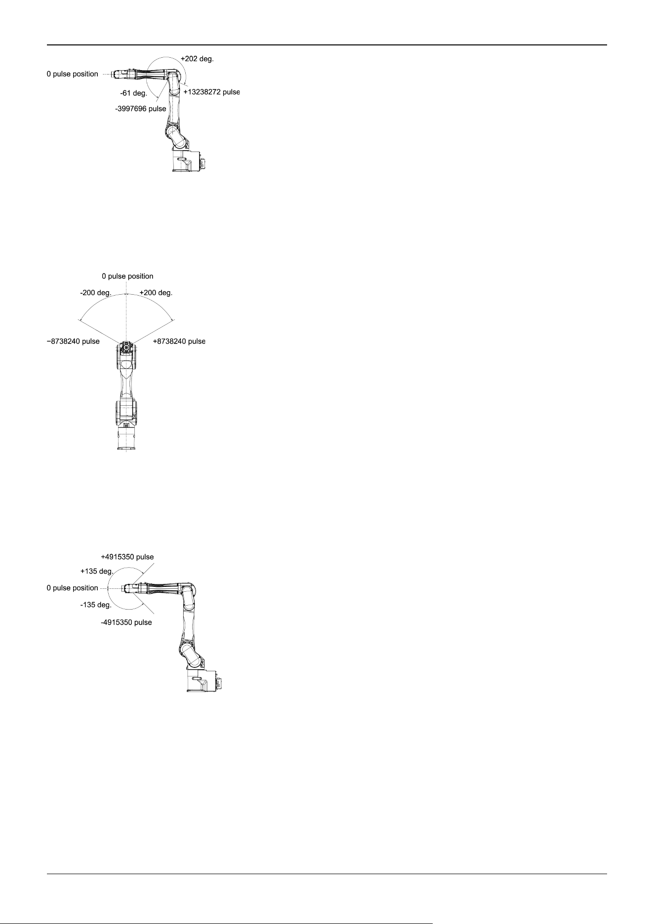
4.5.1.4 Joint #4 Maximum Pulse Range
From the angle of arm end, with the 0 pulse as a starting point, the clockwise pulse value is defined as positive (+), and the
counterclockwise pulse value is defined as negative (-).
4.5.1.5 Joint #5 Maximum Pulse Range
With the 0 pulse as a starting point, the clockwise pulse value is defined as positive (+), and the counterclockwise pulse value
is defined as negative (-).
4.5.1.6 Joint #6 Maximum Pulse Range
From the angle of arm end, with the 0 pulse as a starting point, the clockwise pulse value is defined as positive (+), and the
counterclockwise pulse value is defined as negative (-).
Industrial Robot: 6-Axis Robots C-B series Manual Rev.1b
204
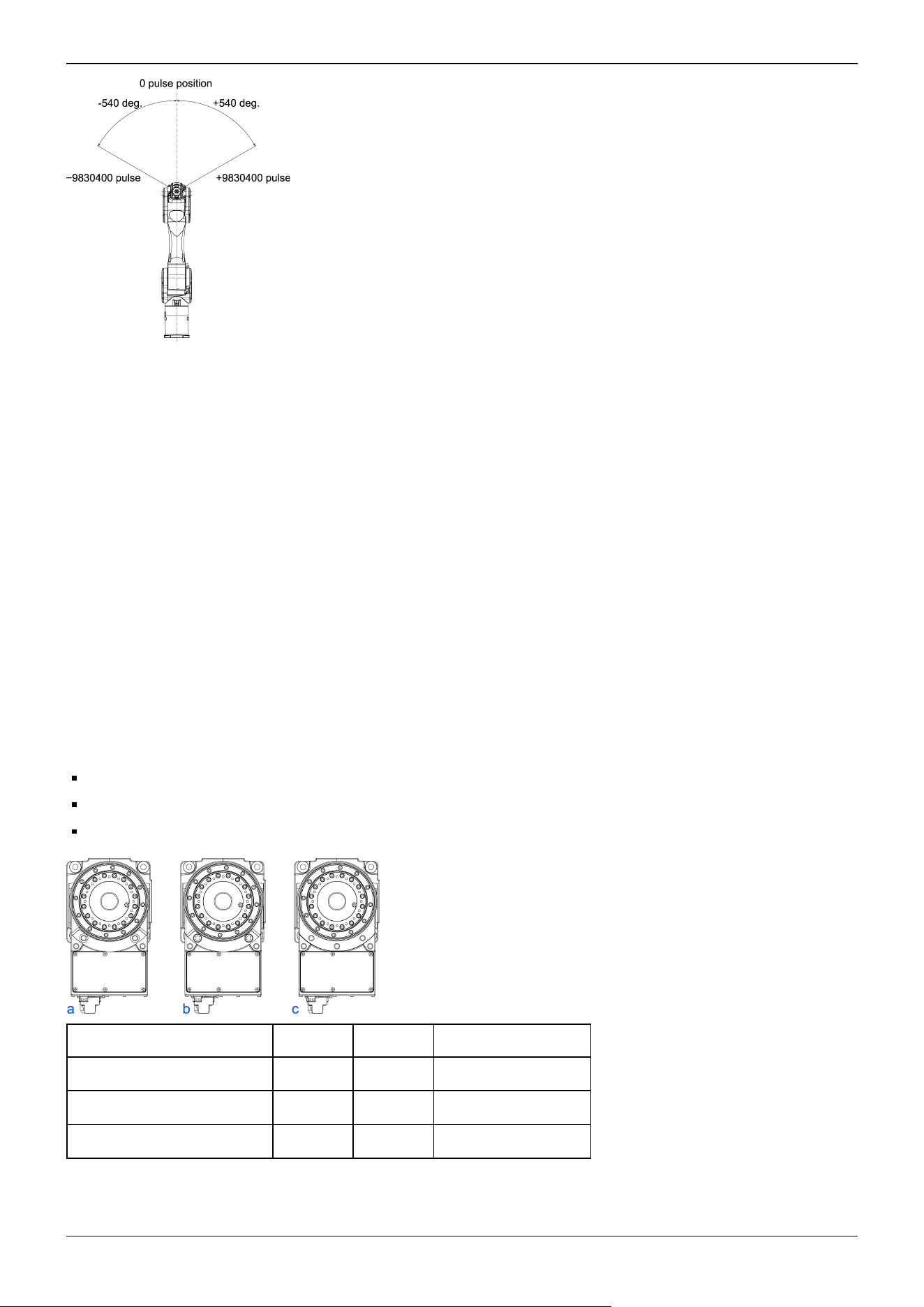
4.5.2 Setting the Work Envelope by Mechanical Stops
Using the variable mechanical stops physically limits the absolute area that the Manipulator can move.
Before starting any work, be sure to turn off the Manipulator.
Use bolts conforming to the specified length and surface processing (ex: nickel plating) with high corrosion resistance.
Specify the pulse range again after changing the position of the mechanical stop.
For details on the pulse range setting, refer to the following section.
Work Envelope Setting by Pulse Range (for Each Joint)
Be sure to set the pulse range inside the positions of the mechanical stop range.
4.5.2.1 Setting the Joint #1 Work Envelope
Install variable mechanical stop (J1) in the threaded holes corresponding to the angles to be set.
Normally a mechanical stop is not equipped.
Hexagon socket head cap bolt: M12×30×2 bolts
Strength: Compliant with ISO 898-1 property class: 10.9 or 12.9
Tightening torque: 42.0 ± 2.1 N·m (428 ± 21 kgf·cm)
a b c
Angle (°) ±110 ±105 ±240
Pulse ±7212700 ±6884840 ±15736800
Variable Mechanical Stop (J1) Applied Applied Not applied (standard)
Industrial Robot: 6-Axis Robots C-B series Manual Rev.1b
205
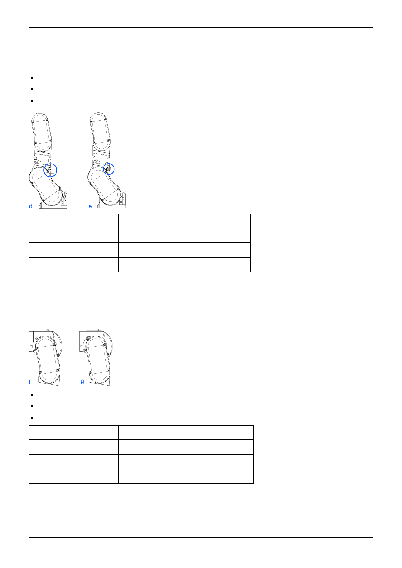
4.5.2.2 Setting the Joint #2 Work Envelope
Remove the mechanical stop installed as standard and install the variable mechanical stop (J2). (Joint #2 standard work
envelope -135 to +55°)
Hexagon socket head cap bolt: M10×35×2 bolts
Strength: Compliant with ISO 898-1 property class: 10.9 or 12.9
Tightening torque: 32.0 ± 1.6 N·m (326 ± 16 kgf·cm)
d e
Angle (°) -125, +45 -135, +55
Pulse -9830500, +3538980 -10616940, +4325420
Variable Mechanical Stop (J2) Applied Applied (standard)
4.5.2.3 Setting the Joint #3 Work Envelope
Remove the mechanical stop installed as standard and install the variable mechanical stop (J3). (Joint #3 standard work
envelope -61 to +202°)
Hexagon socket head cap bolt: M6×15×2 bolts
Strength: Compliant with ISO 898-1 property class: 10.9 or 12.9
Tightening torque: 13.0 ± 0.6 N·m (133 ± 6 kgf·cm)
f g
Angle (°) -51, +192 -61, +202
Pulse -3342336, +12582912 -3997696, +13238272
Variable Mechanical Stop (J3) Applied Applied (standard)
4.5.3 Restriction of Manipulator Operation by Joint Angle Combination
To prevent the arms of the Manipulator from interfering each other, the Manipulator operation is restricted in the specified
motion range according to the angle combination of the Joint #1, #2, and #3.
Industrial Robot: 6-Axis Robots C-B series Manual Rev.1b
206
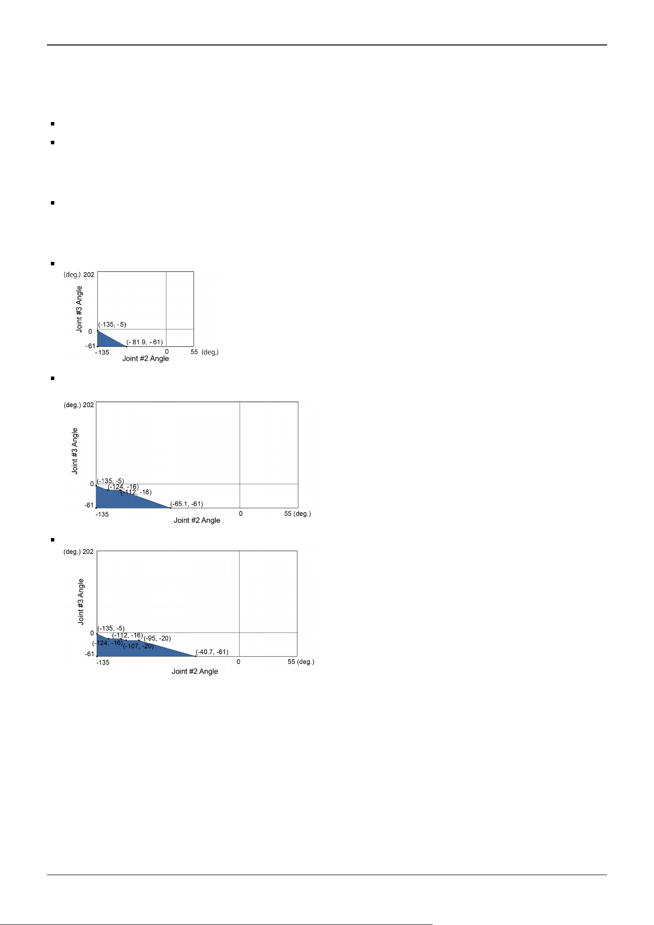
The Manipulator operation is restricted and the Manipulator stops when the joint angles are within the colored areas in the
following figure.
The restriction to Manipulator operation is enabled:
During CP motion command execution
When you attempt to execute the motion command for moving the Manipulator to a target point (or pose) in the specified
motion range.
The restriction to the Manipulator operation is disabled:
The Arms of the Manipulator momentarily go through the specified motion range during the PTP motion command
execution even though the joint angles of the Arms are in the colored areas of the figures above.
Combination of Joint #2 and #3
-110 deg. <= J1 <= 110 deg.
-140 deg. < J1<-110 deg. or 110 deg. < J1< 140 deg.
-240 deg. < J1<-220 deg. or 220 deg. < J1< 240 deg.
-220 deg. <= J1<=-140 deg. or 140 deg. < J1< 220 deg.
(deg.=°)
4.5.4 Coordinate System
The origin point is where the Manipulator’s installation face intersects with the rotation axis of Joint #1.
For details on the coordinate system, refer to the EPSON RC+ Users Guide manual.
Industrial Robot: 6-Axis Robots C-B series Manual Rev.1b
207
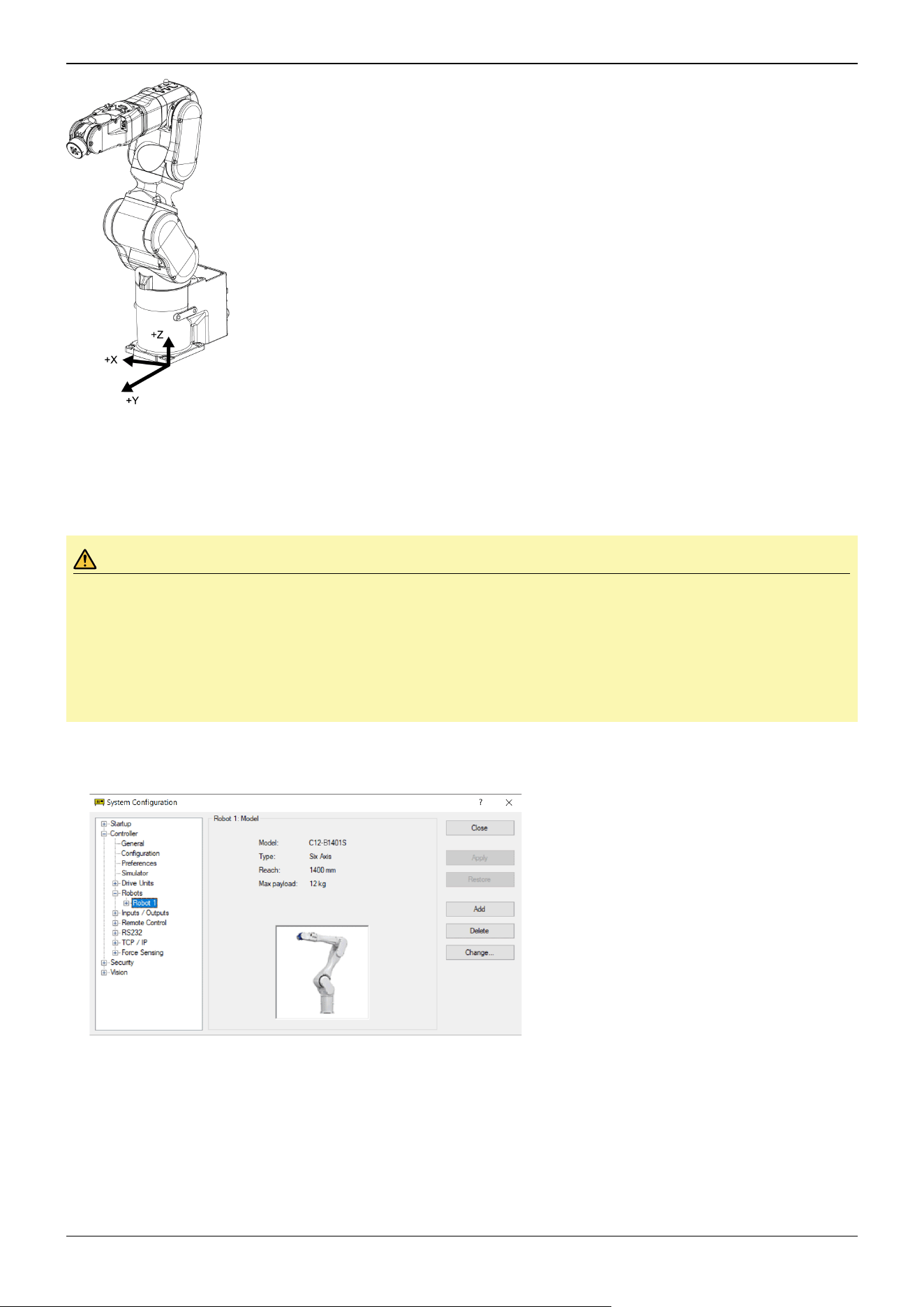
4.5.5 Changing the Robot
This section describes how to change the Manipulator model on EPSON RC+.
CAUTION
Changing the Manipulator should be done with great caution. It initializes the robot calibration parameters (Hofs,
CalPls), additional axis information, and PG parameter data. Before changing the robot, make sure to save the
calibration data by following the procedure below.
1. Select the EPSON RC+ 7.0 menu-[Setup]-[System Configuration].
2. Select [Controller]-[Robots]-[Robot**]-[Calibration] from the tree list. Then, click [Save].
1. Select the EPSON RC+ 7.0 menu-[Setup]-[System Configuration].
2. Select [Controller]-[Robots]-[Robot**] from the tree list.
Industrial Robot: 6-Axis Robots C-B series Manual Rev.1b
208
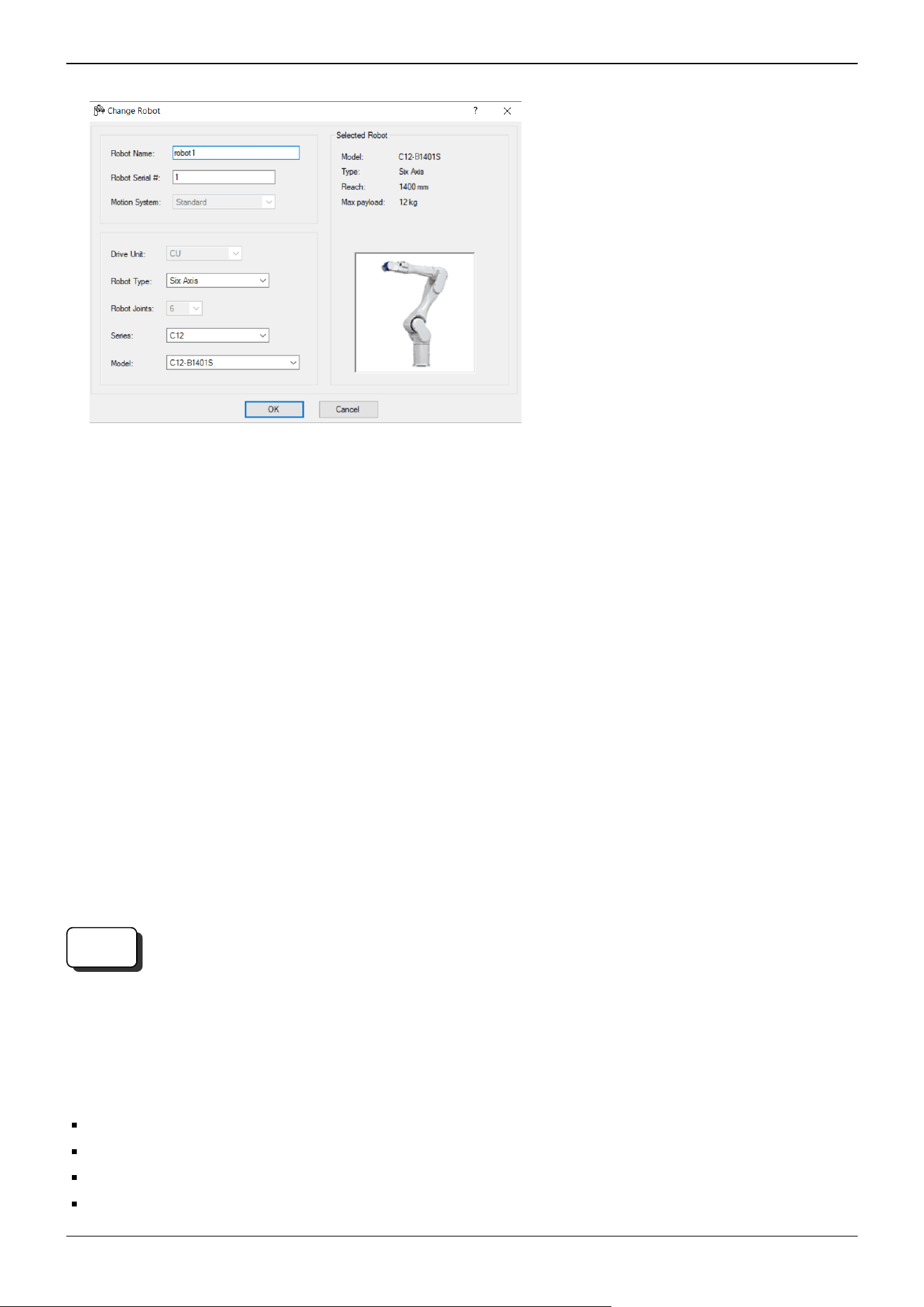
3. Click the [Change] button. The following dialog box will be displayed.
4. Input the robot name and serial number printed on the name plate of the Manipulator. Any serial number can be entered.
However, enter the number printed on the Manipulator.
5. Select the robot type in the [Robot type] box.
6. Select the series name of the Manipulator in the [Series] box.
7. Select the robot model in the [Model] box.
Available robots will be displayed according to the format of the currently installed motor driver. When [Dry run] is used,
all the Manipulators of the series selected in Step 6 will be displayed.
8. Click the [OK] button. The Controller is restarted.
4.5.6 Setting the Rectangular Range in the XY Coordinate System of the Manipulator
The Cartesian (rectangular) range in the XY coordinate system of the Manipulator is specified by the limited Manipulator
operation area and the XYLIM setting. The limited Manipulator operation area is defined so that the hand does not interfere
with the rear side of the Manipulator. The XYLIM setting that you can determines the upper and lower limits of the X and Y
coordinates.
These settings are software-based limit, and so it does not change the maximum physical range. The maximum physical range
is based on the position of the mechanical stops.
These settings are disabled during a joint jogging operation. Therefore, be careful not to allow the hand to collide with the
Manipulator or peripheral equipment.
Go to [Tools] - [Robot Manager] - [XYZ Limits] panel, and make the setting. This can also be set using the XYLim statement
in [Command Window].
4.6 Options
C12 series Manipulator has the following options.
Brake Release Unit
Camera Plate Unit
Tool Adapter (ISO flange)
Variable Mechanical Stop
EPSON
RC+
Industrial Robot: 6-Axis Robots C-B series Manual Rev.1b
209
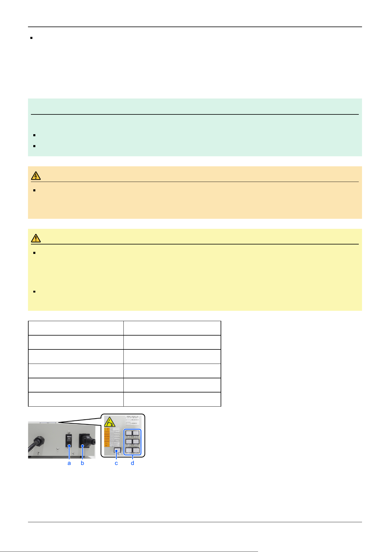
User Wires and Pneumatic Tubes
4.6.1 Brake Release Unit
While the electromagnetic brake is on (such as in emergency mode), you cannot move any arm by pushing manually. You can
move the Arms by hand using the brake release unit while the Controller power is off or right after unpacking.
KEY POINTS
Precautions regarding the brake release unit
Be sure to prepare at least one set of the brake release unit.
Place at easy-to-reach location so that you can use it immediately when in a emergency situation.
WARNING
Turn off the power to the Robot Controller and brake release unit when connecting or replacing the brake
release unit or external short connector. Inserting or removing connectors with the power on may result in
electric shock and/or malfunction of the robot system.
CAUTION
Normally, release the brakes of joints one at a time. If the brakes of two or more joints must be released
simultaneously due to unavoidable reasons, use extreme care. Releasing the brakes of multiple joints
simultaneously may cause the arm to fall in an unexpected direction, resulting in hands or fingers getting
caught or damage or failure of the Manipulator.
After releasing the brake, the arm may fall by its own weight or move to the unexpected direction. Make sure
to prepare a countermeasure to prevent the arm from falling and check the operation environment is safe.
Width 180 mm
Depth 150 mm
Height 87 mm
Weight (Cables are not included.) 1.7 kg
Cable to the Manipulator 2 m
M/C Short Connector For M/C power cable short-circuit
✏
Industrial Robot: 6-Axis Robots C-B series Manual Rev.1b
210
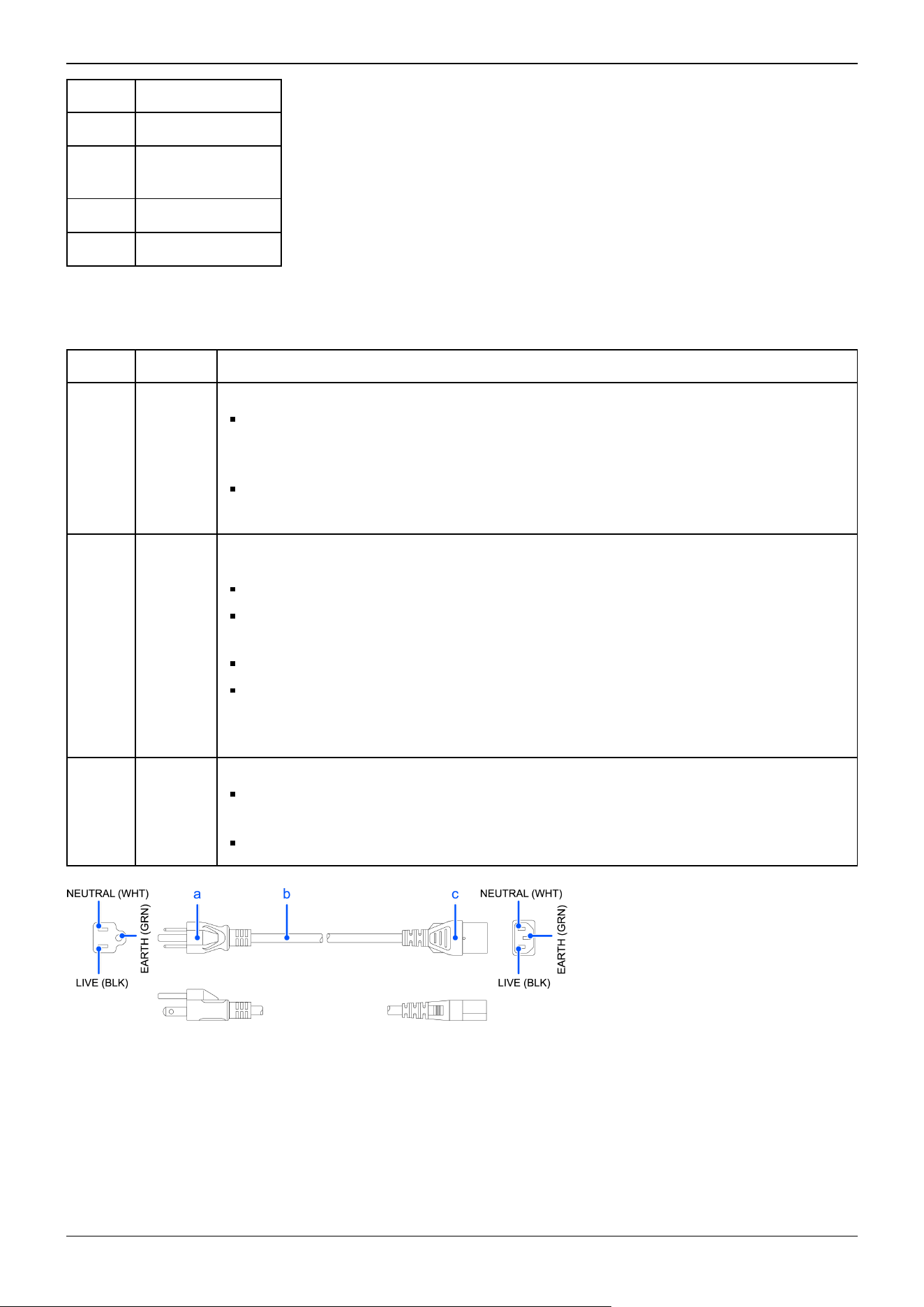
Symbol Description
a Power switch
b
Power Cable
(You must provide.)
c Power lamp
d Brake release switch
4.6.1.1 Power Cable
You must provide a power cable. Be sure to use the specifications below.
Symbol Item Specifications
a Plug
Comply with local safety regulation
Class I (2P + PE), AC250 V, 6 A or 10 A
Ex.: CEE Pub.7 Certified, CCC Certified, KC Certified, BS1363 Certified, PSB Certified, BIS
Certified, SABS Certified
Class I (2P + PE), AC125 V, 7 A, 12 A, or 15 A etc.
Ex.: UL Certified, PSE Certified, BSMI Certified
b
Flexible
cable
Comply with IEC/EN standards or local safety regulation
Example:
IEC 60227-1: General requirements
IEC 60227-5: Polyvinyl chloride insulated cables of rated voltages up to and including 450/750
V - Part 5: Flexible cables (cords)
EN 50525-1: General requirements
EN 50525-2-11: Electric cables - Low voltage energy cables of rated voltages up to and
including 450/750 V (Uo/U) - Part 2-11: Cables for general applications - Flexible cables with
thermoplastic PVC insulation
c
Appliance
coupler
Comply with IEC/EN standards or local safety regulation
IEC / EN 60320-1: Appliance couplers for household and similar general purposes - Part 1:
General requirements
Standard Sheet C13: AC250 V/10 A
For Japan
Industrial Robot: 6-Axis Robots C-B series Manual Rev.1b
211
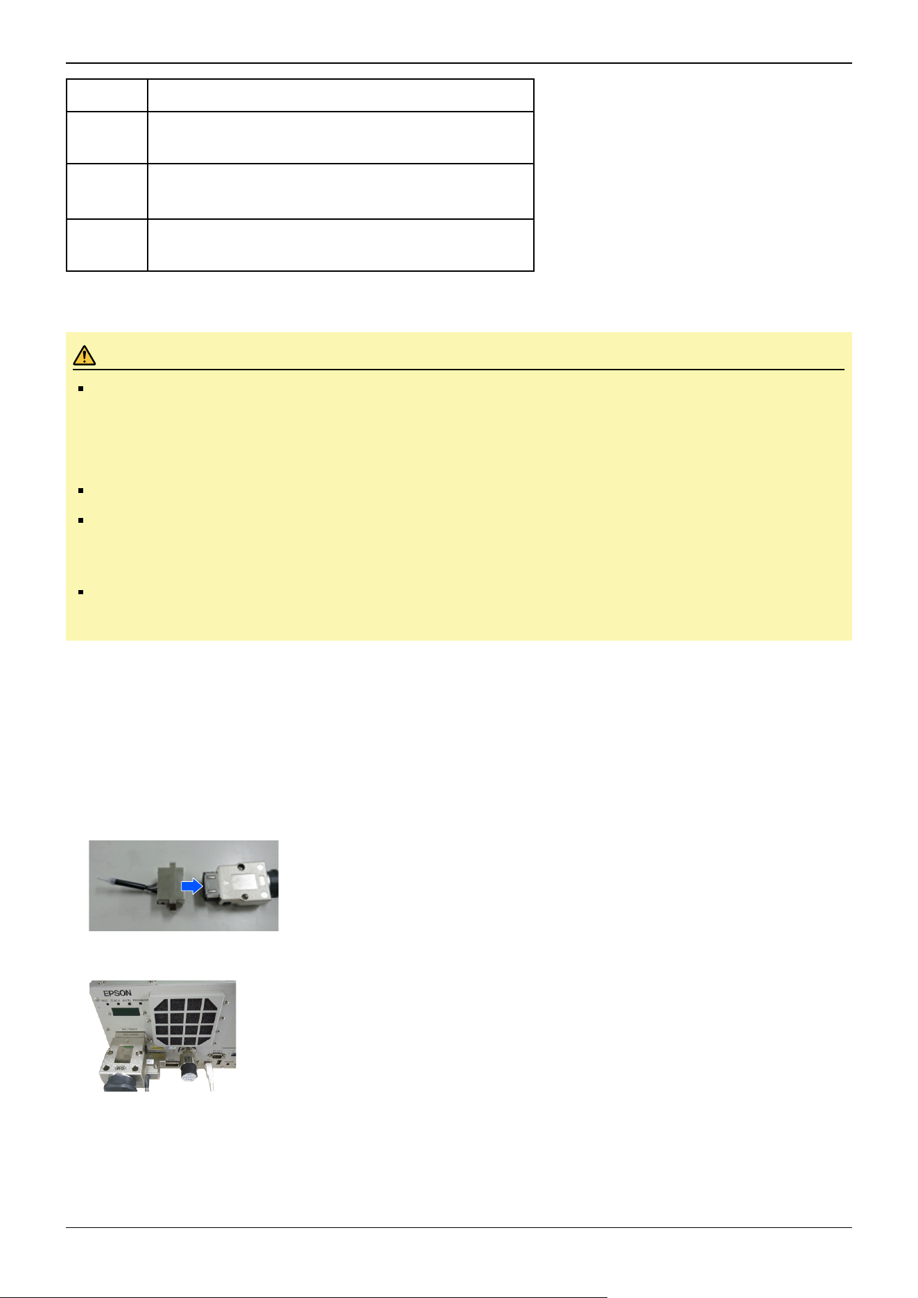
Item Specifications
Plug
PSE Certified
Class I (2P+PE), AC125 V, 7 A or higher
Code
PSE Certified
0.75 mm
2
or more
Connector
PSE Certified
IEC 60320-1 Standard Sheet C13: AC125 V/10 A or higher
Precautions for use
CAUTION
Operating the Manipulator without a brake release unit or external short connector connected may cause the
brake to fail to release, possibly damaging the brake.
After using the brake release unit, be sure to connect the external short circuit connector to the Manipulator or
make sure to leave the connector for the brake release unit connected.
Keep the external short connector. Otherwise you cannot release the brakes.
If you turn on the brake release unit while the brake release switch is being pressed, an unintended arm may
move downward. Before turning on the brake release unit, make sure that the brake release switch is not
pressed.
If you turn on the brake release unit without the connector, it may lead to the short for the male pin used in the
connector. Before turning on the brake release unit, make sure that the connector is connected.
4.6.1.2 Installing the Brake Release Unit
1. Turn off the Controller.
2. If the M/C power cable is not connected to the Controller:
Connect the M/C short connector, or connect the Controller.
(Keep the Controller power off.)
The M/C short connector can be purchased singly.
If the M/C power cable is already connected to the Controller:
Go to the step (3).
Industrial Robot: 6-Axis Robots C-B series Manual Rev.1b
212
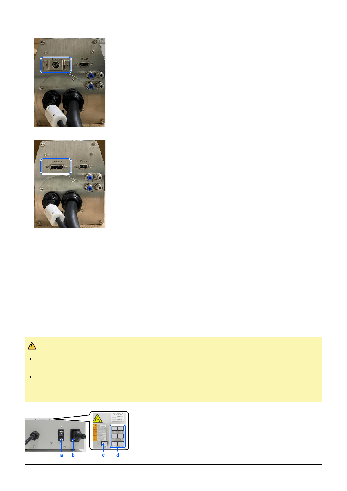
3. Remove the external short connector.
4. Connect the brake release unit to the connector of the connection cable.
4.6.1.3 Removing the Brake Release Unit
1. Turn off the brake release unit.
2. Remove the power cable of the brake release unit.
3. Disconnect the brake release unit from the connector of the connection cable.
4. If the M/C short connector is connected to the M/C power cable, remove the short connector.
5. Connect the external short connector to the connector of the connection cable.
4.6.1.4 How to Use the Brake Release Unit
CAUTION
After releasing the brake, the arm may fall by its own weight or move to the unexpected direction. Make sure
to prepare a countermeasure to prevent the arm from falling and check the operation environment is safe.
If the arm you released its brake moves awkwardly or faster than usual, stop the operation promptly and
contact the supplier. The brake release unit may be broken. If you keep operating the Manipulator, it may lead
to the breakdown of the Manipulator or you may get your hand or fingers caught.
Industrial Robot: 6-Axis Robots C-B series Manual Rev.1b
213
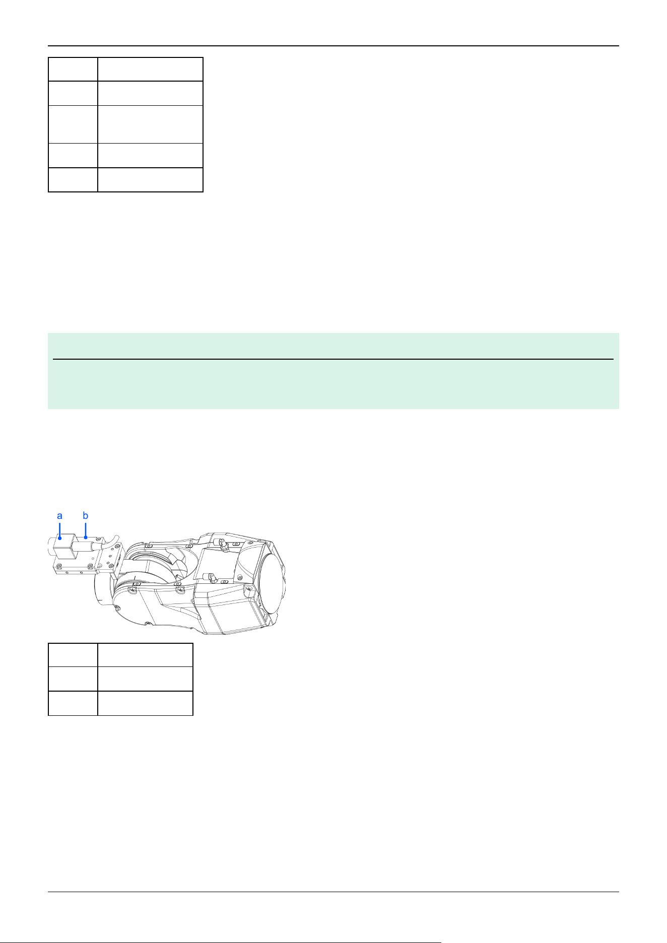
Symbol Description
a Power switch
b
Power Cable
(You must provide.)
c Power lamp
d Brake release switch
1. Refer to “Installing the Brake Release Unit” above to connect the brake release unit to the connector of the connection
cable.
2. Plug the power cable into the brake release unit.
3. Plug the power cable into the power supply plug.
4. Turn on the brake release unit. When the brake release unit is enabled, the power lamp lights up.
5. Press the switch of the arm (J1 to J6) you want to move and then move the arm. Press the switch again. The brake will be
released. The brake will be enabled by pressing the switch once again.
KEY POINTS
Move the arm the brake is released by two persons or more (one presses the switch and one moves the arm).
The arm can be very heavy and needs the significant force to move.
4.6.2 Camera Plate Unit
To mount a camera to the C12 series Manipulator, you need to mount the camera plate unit first.
Appearance of arm end with camera
Symbol Description
a Camera
b Camera Plate Unit
✏
Industrial Robot: 6-Axis Robots C-B series Manual Rev.1b
214
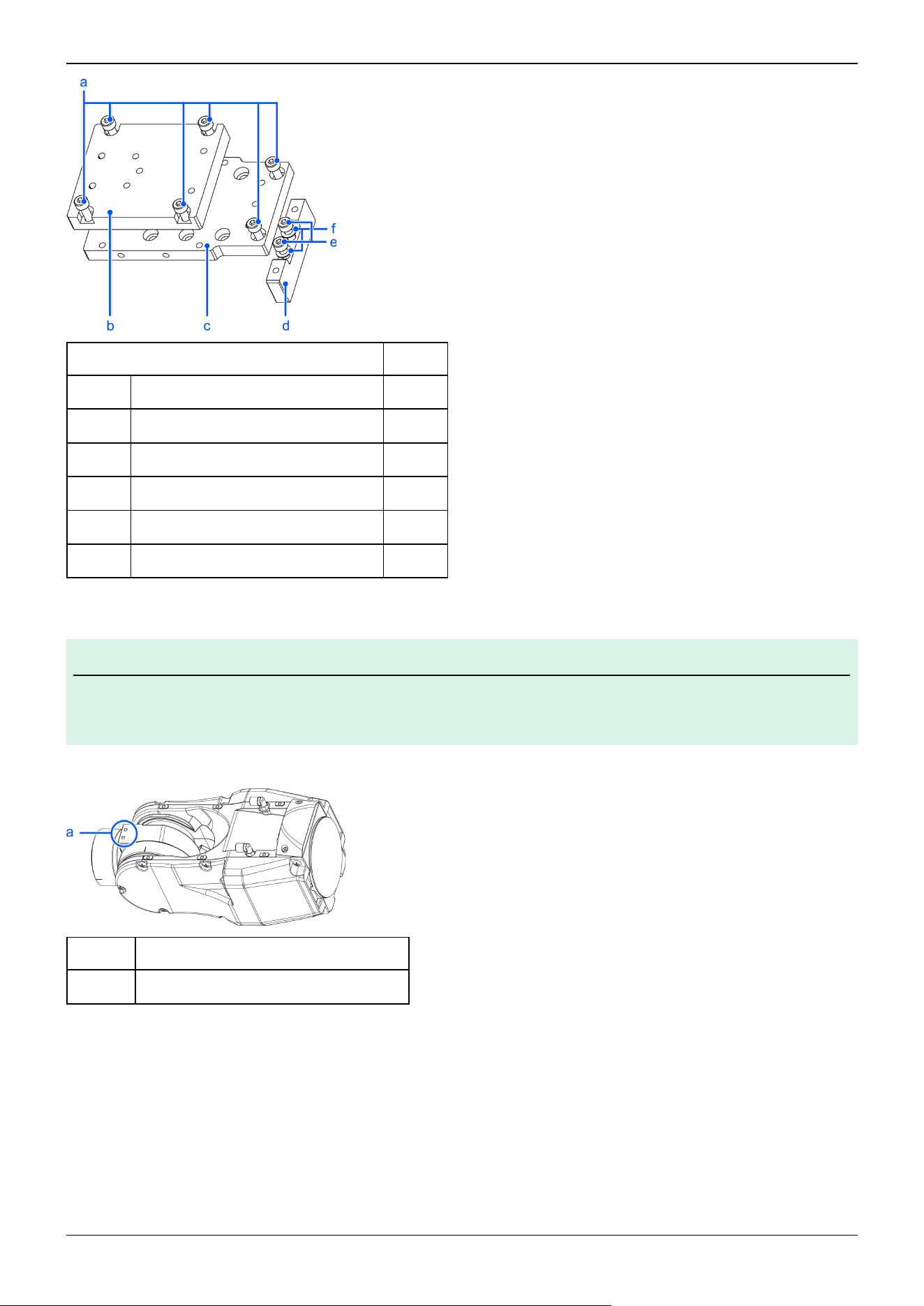
Parts Included Qty.
a Hexagon socket head cap bolt M4×12 6
b Camera adapter plate 1
c Camera mid plate 1
d Camera base plate 1
e Hexagon socket head cap bolt M4×20 2
f Plain washer for M4 (small washer) 2
Installation
KEY POINTS
For details of tightening the hexagon socket head cap bolt, refer to the following section.
Tightening the Hexagon Socket Head Cap Bolts
Mounting holes for the camera base plate on the C12 series Manipulator
Symbol Description
a Mounting holes for the camera base plate
For installation procedure, refer to the following manual.
"EPSON RC+ Option Vision Guide 7.0 Hardware & Setup"
✏
Industrial Robot: 6-Axis Robots C-B series Manual Rev.1b
215
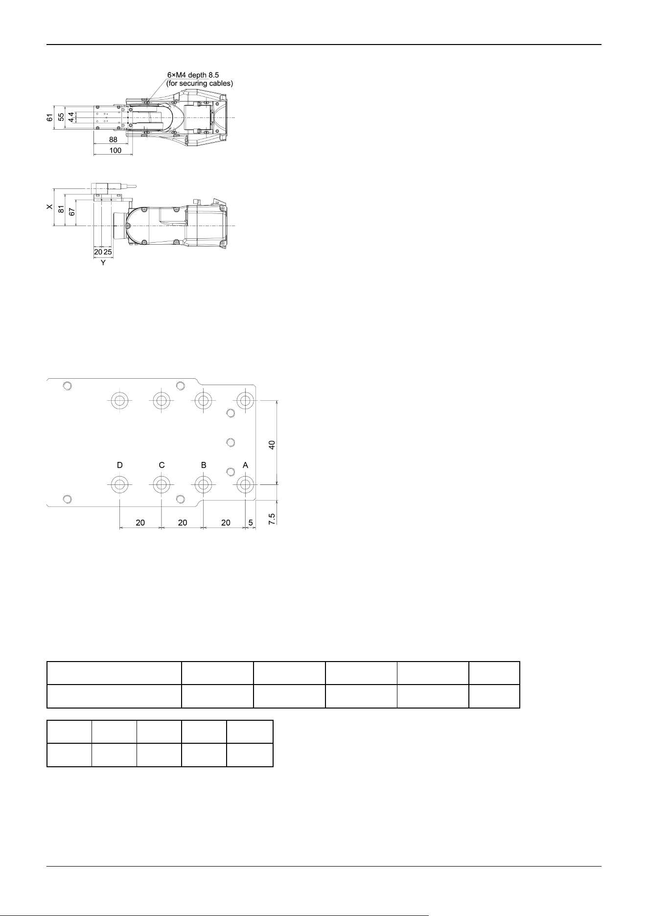
Dimension of the camera plate unit
Dimensions X and Y will change depending on the position of camera mid plate and camera size. Refer to the table below for
the values.
Camera mid plate
The camera mid plate uses the mounting holes A to D. By using the different mounting holes, it can be mounted to the camera
base plate in the different four positions.
Camera and C12 series Manipulator Joint #5 motion range (reference values)
The Joint #5 motion range varies depending on the mounting position of camera mid plate and the camera you are using.
The table below shows the motion range (reference values) based on the available cameras for this option and the mounting
positions of the camera mid plate. The values in the table may vary depending on how to secure the cables.
By changing the Y position, you can extend the distance from the hand mounting surface to the camera. Also, you can attach
the larger hand. However, be careful about the Joint #5 motion range that will be limited in this case.
A B C D X
USB Camera, GigE Camera -135° to +70° -135° to +60° -135° to +45° -135° to +35° 95.5 mm
A B C D
Y 50 mm 30 mm 10 mm -10 mm
Direction of the Joint #5 motion
Industrial Robot: 6-Axis Robots C-B series Manual Rev.1b
216
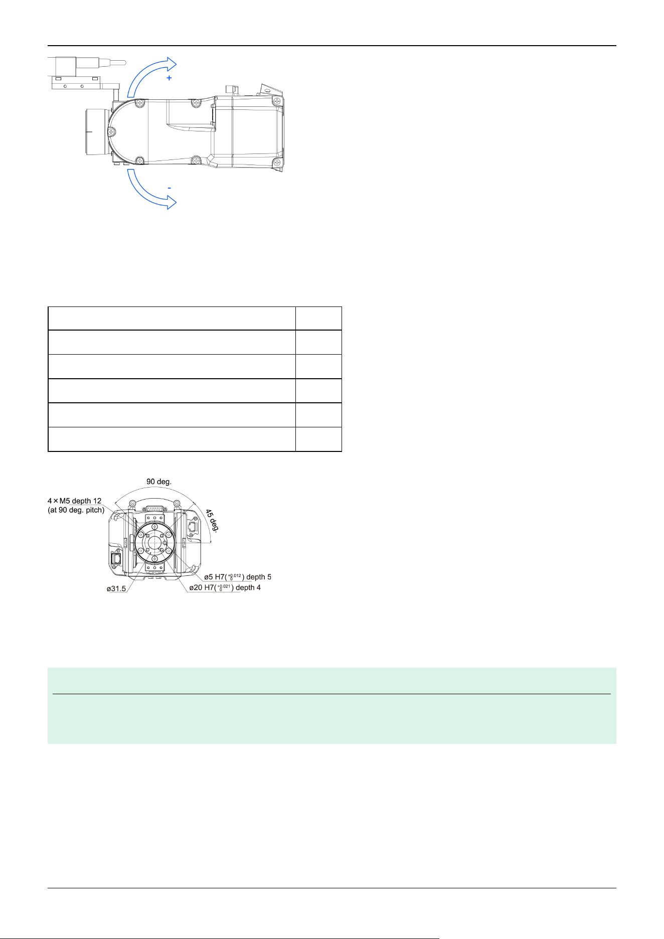
4.6.3 Tool Adapter (ISO flange)
Using the tool adapter, you can mount the hand whose dimensions are designed for the ISO flange to the C12 series
Manipulators.
Parts Included Qty.
ISO flange 1
Flange 1
Pin 2
Hexagon socket head cap bolt with low head M5×10 6
Hexagon socket head cap bolt M5×15 4
Dimensions of ISO flange
* Each dimension and tolerance complies with ISO9409-1-31.5-4-M5.
ISO flange installation
KEY POINTS
For details of tightening the hexagon socket head cap bolt, refer to the following section.
Tightening the Hexagon Socket Head Cap Bolts
✏
Industrial Robot: 6-Axis Robots C-B series Manual Rev.1b
217
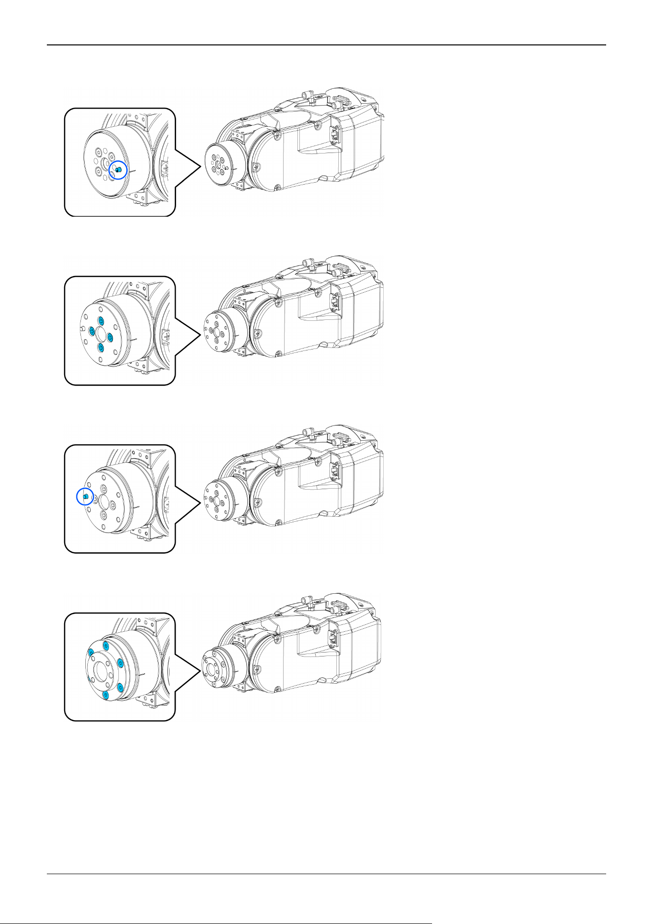
1. Press-fit the pin to the Arm #6 end flange.
Pin protrusion: 4 mm from the flange
2. Align the pin and the pin hole on the flange, and then mount the flange.
Hexagon socket head cap bolt: 4×M5×15
3. Press-fit the pin to the installed flange.
Pin protrusion: 4 mm from the flange
4. Align the pin and the pin hole on the ISO flange, and then mount the ISO flange.
Hexagon socket head cap bolt with low head: 6×M5×10
4.6.4 Variable Mechanical Stop
This option is used to mechanically limit the motion range of the Manipulator.
For installation and angle restriction measures, refer to the following section.
Setting the Work Envelope by Mechanical Stops
Variable Mechanical Stop (J1)
Industrial Robot: 6-Axis Robots C-B series Manual Rev.1b
218
Parts Included Qty.
Variable Mechanical Stop (J1) 1
Hexagon socket head cap bolt M12×30 2
Variable Mechanical Stop (J2)
Parts Included Qty.
Variable Mechanical Stop (J2) 1
Hexagon socket head cap bolt M10×35 2
Variable Mechanical Stop (J3)
Parts Included Qty.
Variable Mechanical Stop (J3) 1
Hexagon socket head cap bolt M6×15 2
4.6.5 User Wires and Pneumatic Tubes
Use the following options when using the internal wiring and tubing for the hand drive.
Attached as standard. The parts can be purchased additionally in case of lost or shortage.
Fitting for Customer Use (
⌀
6 Straight)
Parts Included Qty. Manufacturer Type
⌀6 straight fitting 2 SMC KQ2S06-M6N
Fitting for Customer Use (
⌀
6 Elbow)
Parts Included Qty. Manufacturer Type
⌀6 elbow fitting 2 SMC KQ2L06-M6N
Standard User Connector Kit (D-sub)
Parts Included Qty. Manufacturer Type
Connector 2 JAE DA-15PF-N (Solder type)
Clamp hood 2 HRS HDA-CTH (4-40) (10) (Connector setscrew: #4-40 UNC)
Industrial Robot: 6-Axis Robots C-B series Manual Rev.1b
219

5. Periodic Inspection
Accurate inspection work is necessary to prevent breakdowns and ensure safety. This section explains the inspection schedule
and what should be inspected.
Perform inspections according to the predetermined schedule.
Industrial Robot: 6-Axis Robots C-B series Manual Rev.1b
220

5.1 C4 Manipulator Periodic Inspection
Accurate inspection work is necessary to prevent breakdowns and ensure safety. This section explains the inspection schedule
and what should be inspected.
Perform inspections according to the predetermined schedule.
5.1.1 Inspection
5.1.1.1 Inspection Schedule
Inspection items are divided into five stages (daily, 1-month, 3-month, 6-month, and 12-month), with additional items added at
each stage. However, if the Manipulator is powered and operated for more than 250 hours in a month, add inspection items
every 250, 750, 1500, and 3000 hours.
Industrial Robot: 6-Axis Robots C-B series Manual Rev.1b
221
Inspection Item
Daily
Inspection
1-month
Inspection
3-month
Inspection
6-month
Inspection
12-month
Inspection
Overhaul (Parts
Replacement)
1 months (250
hours)
Perform
daily
✓
2 months (500
hours)
✓
3 months (750
hours)
✓ ✓
4 months (1,000
hours)
✓
5 months (1,250
hours)
✓
6 months (1,500
hours)
✓ ✓ ✓
7 months (1,750
hours)
✓
8 months (2,000
hours)
✓
9 months (2,250
hours)
✓ ✓
10 months
(2,500 hours)
✓
11 months
(2,750 hours)
✓
12 months
(3,000 hours)
✓ ✓ ✓ ✓
13 months
(3,250 hours)
✓
⁝ ⁝ ⁝ ⁝ ⁝ ⁝ ⁝
(20,000 hours)
✓
5.1.1.2 Inspection Details
Inspection items
Industrial Robot: 6-Axis Robots C-B series Manual Rev.1b
222
Inspection Item Inspection Location
Daily
Inspection
1-month
Inspection
3-month
Inspection
6-month
Inspection
12-month
Inspection
Check for loose or
rattling bolts
Hand mounting bolts
✓ ✓ ✓ ✓ ✓
Manipulator installation
bolts
✓ ✓ ✓ ✓ ✓
Check for loose
connectors
Manipulator side external
(connector plate, etc.)
✓ ✓ ✓ ✓ ✓
Inspect for flaws: Clean
off adhering debris, etc.
Entire Manipulator
✓ ✓ ✓ ✓ ✓
External cables
✓ ✓ ✓ ✓
Correct deformations
and misalignments
Safety barriers, etc. ✓ ✓ ✓ ✓ ✓
Check either the
external short connector
or the brake release unit
connector is connected
The external short
connector on the back
side of the Manipulator,
or the brake release unit
connector
✓ ✓ ✓ ✓ ✓
Check brake operation Brake for Joint #1 to #6
✓ ✓ ✓ ✓ ✓
Check for abnormal
operation noise and
vibration
Entire Manipulator ✓ ✓ ✓ ✓ ✓
Inspection methods
Industrial Robot: 6-Axis Robots C-B series Manual Rev.1b
223
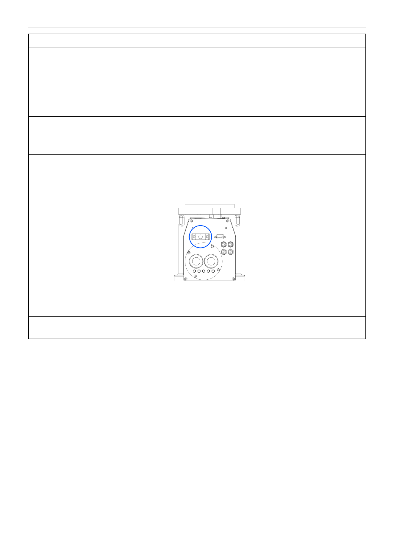
Inspection Item Inspection Method
Check for loose or rattling bolts
Using an Allen wrench or similar tool, check that the hand mounting
bolts and Manipulator installation bolts are not loose.
If the bolts are loose, refer to the following section, and retighten to
the proper torque.
Tightening the Hexagon Socket Head Cap Bolts
Check for loose connectors
Check that no connectors are loose.
If a connector is loose, reattach it so that it will not come off.
Inspect for flaws: Clean off adhering debris, etc.
Check the appearance of the Manipulator, and clean off any dust or
other foreign substances adhering to it.
Check the appearance of the cables for any flaws, and make sure it is
not disconnected.
Correct deformations and misalignments
Check for misalignment of safety barriers and other components.
If it is misaligned, correct it to the original position.
Check either the external short connector or the
brake release unit connector is connected
Check either the external short connector or the brake release unit
connector is connected.
When it is not connected, connect it.
Check brake operation
With the motor turned off, check that the arm does not drop.
If the arm drops while the motor is turned off and the brake is not
released, contact the supplier.
Check for abnormal operation noise and vibration
Check for any abnormal noises and vibrations during operation.
If you notice anything unusual, contact the supplier.
5.1.2 Overhaul (Parts Replacement)
Overhaul (replacement) shall be performed by personnel who has taken a proper training.
For details, refer to the following manual.
"Safety Manual - Role and Training for Safety Managers"
Industrial Robot: 6-Axis Robots C-B series Manual Rev.1b
224
5.1.3 Applying Grease
The reduction gear units and the bevel gear need greasing regularly.
CAUTION
Be careful that the grease does not run out. When grease runs out, scratches and other defects can occur on
the slide, not only hindering maximum performance, but also requiring significant time and money to repair.
If grease enters the eyes or mouth or adheres to the skin, take the following measures:
If it enters the eyes
After rinsing the eyes thoroughly with clean water, seek medical attention.
If it enters the mouth
If swallowed, do not force vomiting, and seek medical attention. If the mouth is contaminated, rinse
thoroughly with water.
If adhered to skin
Rinse with water and soap.
Part Interval Safety Information
All
joints
Reduction
gear
When overhaul
is performed
Applying grease can only be performed by properly trained service engineers.
For more information, please contact the supplier.
Joint
#6
Bevel
gear
5.1.4 Tightening the Hexagon Socket Head Cap Bolts
Hexagon socket head cap bolts (referred to as "bolts" below) are used in locations where mechanical strength is required.
During assembly, these bolts are tightened at the tightening torques shown in the following table.
Unless otherwise specified, when retightening these bolts in the work procedures described in this manual, use a torque wrench
or similar tool to obtain the tightening torques in the following table.
Bolt Tightening Torque
M3 2.0 ± 0.1 N·m (21 ± 1 kgf·cm)
M4 4.0 ± 0.2 N·m (41 ± 2 kgf·cm)
M5 8.0 ± 0.4 N·m (82 ± 4 kgf·cm)
M6 13.0 ± 0.6 N·m (133 ± 6 kgf·cm)
M8 32.0 ± 1.6 N·m (326 ± 16 kgf·cm)
M10 58.0 ± 2.9 N·m (590 ± 30 kgf·cm)
M12 100.0 ± 5.0 N·m (1,020 ± 51 kgf·cm)
For set screw, refer to the following table.
Industrial Robot: 6-Axis Robots C-B series Manual Rev.1b
225
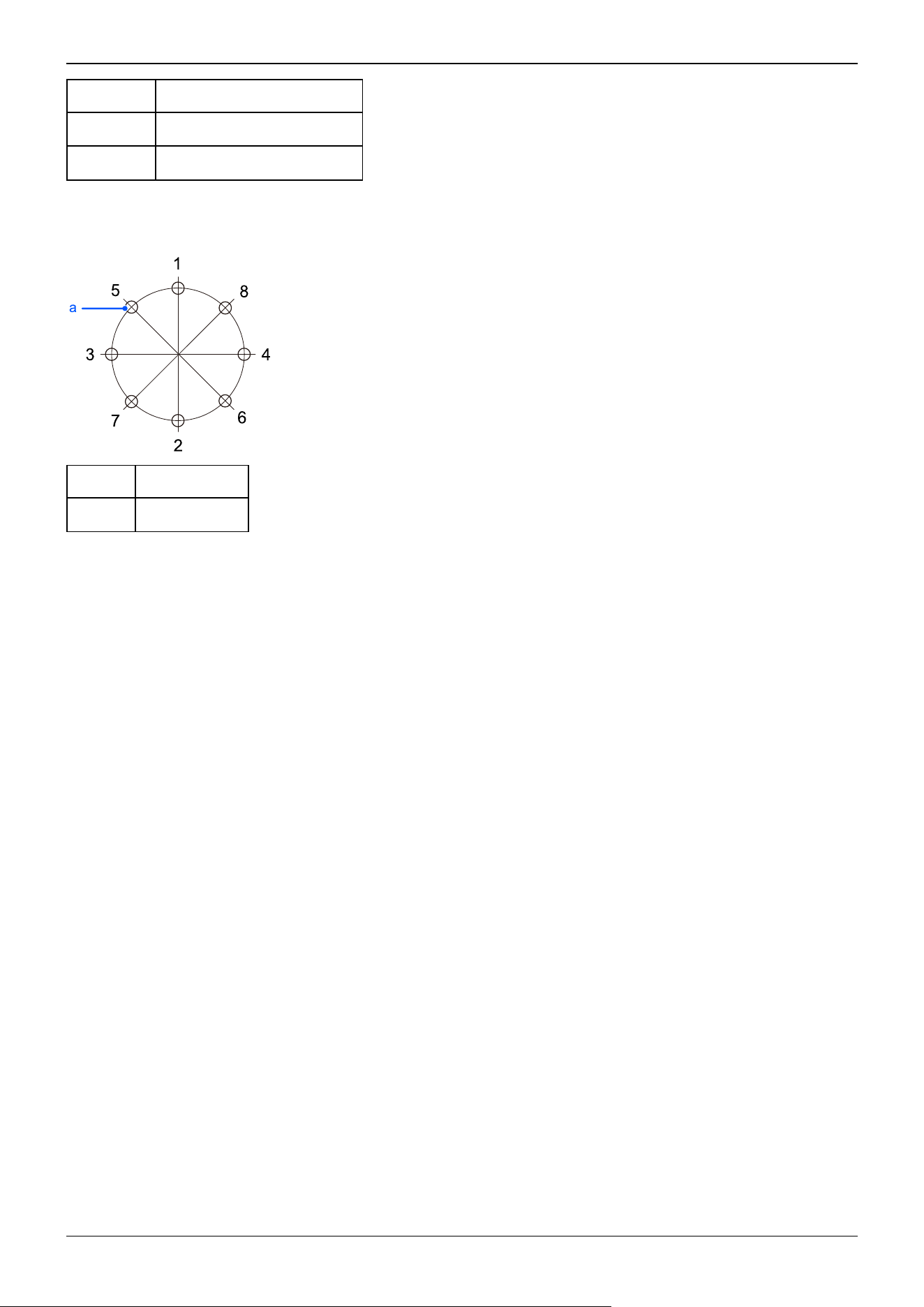
Set Screw Tightening Torque
M4 2.4 ± 0.1 N·m (26 ± 1 kgf·cm)
M5 3.9 ± 0.2 N·m (40 ± 2 kgf·cm)
It is recommended that bolts arranged in a circular pattern be secured in place by tightening in criss-cross order as shown in the
figure.
Symbol Description
a Threaded holes
When securing the bolts, do not tighten the bolts all at once, but tighten them in two or three separate rounds with an Allen
wrench, and then use a torque wrench or similar tool to secure them at the tightening torques shown in the table above.
5.2 C8 Manipulator Periodic Inspection
Accurate inspection work is necessary to prevent breakdowns and ensure safety. This section explains the inspection schedule
and what should be inspected.
Perform inspections according to the predetermined schedule.
5.2.1 Inspection
5.2.1.1 Inspection Schedule
Inspection items are divided into five stages (daily, 1-month, 3-month, 6-month, and 12-month), with additional items added at
each stage. However, if the Manipulator is powered and operated for more than 250 hours in a month, add inspection items
every 250, 750, 1500, and 3000 hours.
Industrial Robot: 6-Axis Robots C-B series Manual Rev.1b
226
Inspection Item
Daily
Inspection
1-month
Inspection
3-month
Inspection
6-month
Inspection
12-month
Inspection
Overhaul (Parts
Replacement)
1 months (250
hours)
Perform
daily
✓
2 months (500
hours)
✓
3 months (750
hours)
✓ ✓
4 months (1,000
hours)
✓
5 months (1,250
hours)
✓
6 months (1,500
hours)
✓ ✓ ✓
7 months (1,750
hours)
✓
8 months (2,000
hours)
✓
9 months (2,250
hours)
✓ ✓
10 months
(2,500 hours)
✓
11 months
(2,750 hours)
✓
12 months
(3,000 hours)
✓ ✓ ✓ ✓
13 months
(3,250 hours)
✓
⁝ ⁝ ⁝ ⁝ ⁝ ⁝ ⁝
(20,000 hours)
✓
5.2.1.2 Inspection Details
Inspection items
Industrial Robot: 6-Axis Robots C-B series Manual Rev.1b
227

Inspection Item Inspection Location
Daily
Inspection
1-month
Inspection
3-month
Inspection
6-month
Inspection
12-month
Inspection
Check for loose or
rattling bolts
Hand mounting bolts
✓ ✓ ✓ ✓ ✓
Manipulator installation
bolts
✓ ✓ ✓ ✓ ✓
Check for loose
connectors
Manipulator side external
(connector plate, etc.)
✓ ✓ ✓ ✓ ✓
Inspect for flaws: Clean
off adhering debris, etc.
Entire Manipulator
✓ ✓ ✓ ✓ ✓
External cables
✓ ✓ ✓ ✓
Correct deformations
and misalignments
Safety barriers, etc. ✓ ✓ ✓ ✓ ✓
Check either the
external short connector
or the brake release unit
connector is connected
The external short
connector on the back
side of the Manipulator,
or the brake release unit
connector
✓ ✓ ✓ ✓ ✓
Check brake operation Brake for Joint #1 to #6
✓ ✓ ✓ ✓ ✓
Check for abnormal
operation noise and
vibration
Entire Manipulator ✓ ✓ ✓ ✓ ✓
Check that fan is
working (only for C8-
B1401*** (C8XL)).
Fan ✓ ✓ ✓ ✓ ✓
Inspection methods
Industrial Robot: 6-Axis Robots C-B series Manual Rev.1b
228
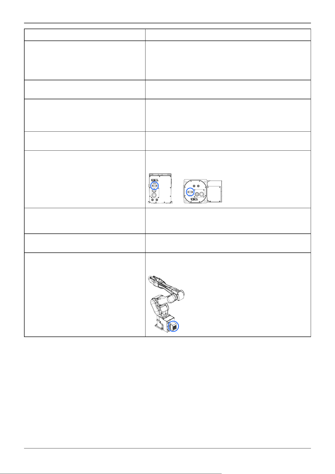
Inspection Item Inspection Method
Check for loose or rattling bolts
Using an Allen wrench or similar tool, check that the hand mounting
bolts and Manipulator installation bolts are not loose.
If the bolts are loose, refer to the following section, and retighten to
the proper torque.
Tightening the Hexagon Socket Head Cap Bolts
Check for loose connectors
Check that no connectors are loose.
If a connector is loose, reattach it so that it will not come off.
Inspect for flaws: Clean off adhering debris, etc.
Check the appearance of the Manipulator, and clean off any dust or
other foreign substances adhering to it.
Check the appearance of the cables for any flaws, and make sure it is
not disconnected.
Correct deformations and misalignments
Check for misalignment of safety barriers and other components.
If it is misaligned, correct it to the original position.
Check either the external short connector or the
brake release unit connector is connected
Check either the external short connector or the brake release unit
connector is connected.
When it is not connected, connect it.
Check brake operation
With the motor turned off, check that the arm does not drop.
If the arm drops while the motor is turned off and the brake is not
released, contact the supplier.
Check for abnormal operation noise and vibration
Check for any abnormal noises and vibrations during operation.
If you notice anything unusual, contact the supplier.
Check that fan is working (only for C8-B1401***
(C8XL)).
With the motor turned on, check that the fan is working.
If the fan does not work while the motor is turned on, contact the
supplier.
5.2.2 Overhaul (Parts Replacement)
Overhaul (replacement) shall be performed by personnel who has taken a proper training.
For details, refer to the following manual.
"Safety Manual - Role and Training for Safety Managers"
Industrial Robot: 6-Axis Robots C-B series Manual Rev.1b
229
5.2.3 Applying Grease
The reduction gear units and the bevel gear need greasing regularly.
CAUTION
Be careful that the grease does not run out. When grease runs out, scratches and other defects can occur on
the slide, not only hindering maximum performance, but also requiring significant time and money to repair.
If grease enters the eyes or mouth or adheres to the skin, take the following measures:
If it enters the eyes
After rinsing the eyes thoroughly with clean water, seek medical attention.
If it enters the mouth
If swallowed, do not force vomiting, and seek medical attention. If the mouth is contaminated, rinse
thoroughly with water.
If adhered to skin
Rinse with water and soap.
Part Interval Safety Information
All
joints
Reduction
gear
When overhaul
is performed
Applying grease can only be performed by properly trained service engineers.
For more information, please contact the supplier.
Joint
#6
Bevel
gear
5.2.4 Tightening the Hexagon Socket Head Cap Bolts
Hexagon socket head cap bolts (referred to as "bolts" below) are used in locations where mechanical strength is required.
During assembly, these bolts are tightened at the tightening torques shown in the following table.
Unless otherwise specified, when retightening these bolts in the work procedures described in this manual, use a torque wrench
or similar tool to obtain the tightening torques in the following table.
Bolt Tightening Torque
M3 2.0 ± 0.1 N·m (21 ± 1 kgf·cm)
M4 4.0 ± 0.2 N·m (41 ± 2 kgf·cm)
M5 8.0 ± 0.4 N·m (82 ± 4 kgf·cm)
M6 13.0 ± 0.6 N·m (133 ± 6 kgf·cm)
M8 32.0 ± 1.6 N·m (326 ± 16 kgf·cm)
M10 58.0 ± 2.9 N·m (590 ± 30 kgf·cm)
M12 100.0 ± 5.0 N·m (1,020 ± 51 kgf·cm)
For set screw, refer to the following table.
Industrial Robot: 6-Axis Robots C-B series Manual Rev.1b
230
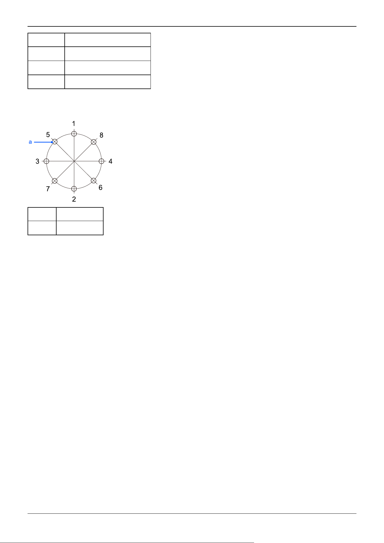
Set Screw Tightening Torque
M4 2.4 ± 0.1 N·m (26 ± 1 kgf·cm)
M5 3.9 ± 0.2 N·m (40 ± 2 kgf·cm)
M6 8.0 ± 0.4 N·m (82 ± 4 kgf·cm)
It is recommended that bolts arranged in a circular pattern be secured in place by tightening in criss-cross order as shown in the
figure.
Symbol Description
a Threaded holes
When securing the bolts, do not tighten the bolts all at once, but tighten them in two or three separate rounds with an Allen
wrench, and then use a torque wrench or similar tool to secure them at the tightening torques shown in the table above.
5.3 C12 Manipulator Periodic Inspection
Accurate inspection work is necessary to prevent breakdowns and ensure safety. This section explains the inspection schedule
and what should be inspected.
Perform inspections according to the predetermined schedule.
5.3.1 Inspection
5.3.1.1 Inspection Schedule
Inspection items are divided into five stages (daily, 1-month, 3-month, 6-month, and 12-month), with additional items added at
each stage. However, if the Manipulator is powered and operated for more than 250 hours in a month, add inspection items
every 250, 750, 1500, and 3000 hours.
Industrial Robot: 6-Axis Robots C-B series Manual Rev.1b
231
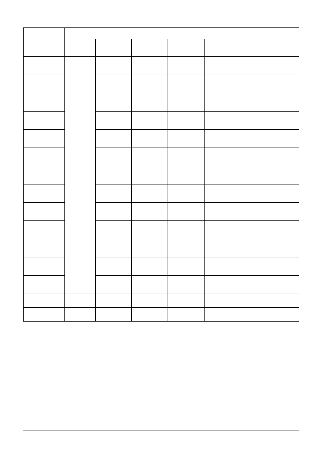
Inspection Item
Daily
Inspection
1-month
Inspection
3-month
Inspection
6-month
Inspection
12-month
Inspection
Overhaul (Parts
Replacement)
1 months (250
hours)
Perform
daily
✓
2 months (500
hours)
✓
3 months (750
hours)
✓ ✓
4 months (1,000
hours)
✓
5 months (1,250
hours)
✓
6 months (1,500
hours)
✓ ✓ ✓
7 months (1,750
hours)
✓
8 months (2,000
hours)
✓
9 months (2,250
hours)
✓ ✓
10 months
(2,500 hours)
✓
11 months
(2,750 hours)
✓
12 months
(3,000 hours)
✓ ✓ ✓ ✓
13 months
(3,250 hours)
✓
⁝ ⁝ ⁝ ⁝ ⁝ ⁝ ⁝
(20,000 hours)
✓
5.3.1.2 Inspection Details
Inspection items
Industrial Robot: 6-Axis Robots C-B series Manual Rev.1b
232

Inspection Item Inspection Location
Daily
Inspection
1-month
Inspection
3-month
Inspection
6-month
Inspection
12-month
Inspection
Check for loose or
rattling bolts
Hand mounting bolts
✓ ✓ ✓ ✓ ✓
Manipulator installation
bolts
✓ ✓ ✓ ✓ ✓
Check for loose
connectors
Manipulator side external
(connector plate, etc.)
✓ ✓ ✓ ✓ ✓
Inspect for flaws: Clean
off adhering debris, etc.
Entire Manipulator
✓ ✓ ✓ ✓ ✓
External cables
✓ ✓ ✓ ✓
Correct deformations
and misalignments
Safety barriers, etc. ✓ ✓ ✓ ✓ ✓
Check either the
external short connector
or the brake release unit
connector is connected
The external short
connector on the back
side of the Manipulator,
or the brake release unit
connector
✓ ✓ ✓ ✓ ✓
Check brake operation Brake for Joint #1 to #6
✓ ✓ ✓ ✓ ✓
Check for abnormal
operation noise and
vibration
Entire Manipulator ✓ ✓ ✓ ✓ ✓
Check that fan is
working.
Fan ✓ ✓ ✓ ✓ ✓
Inspection methods
Industrial Robot: 6-Axis Robots C-B series Manual Rev.1b
233
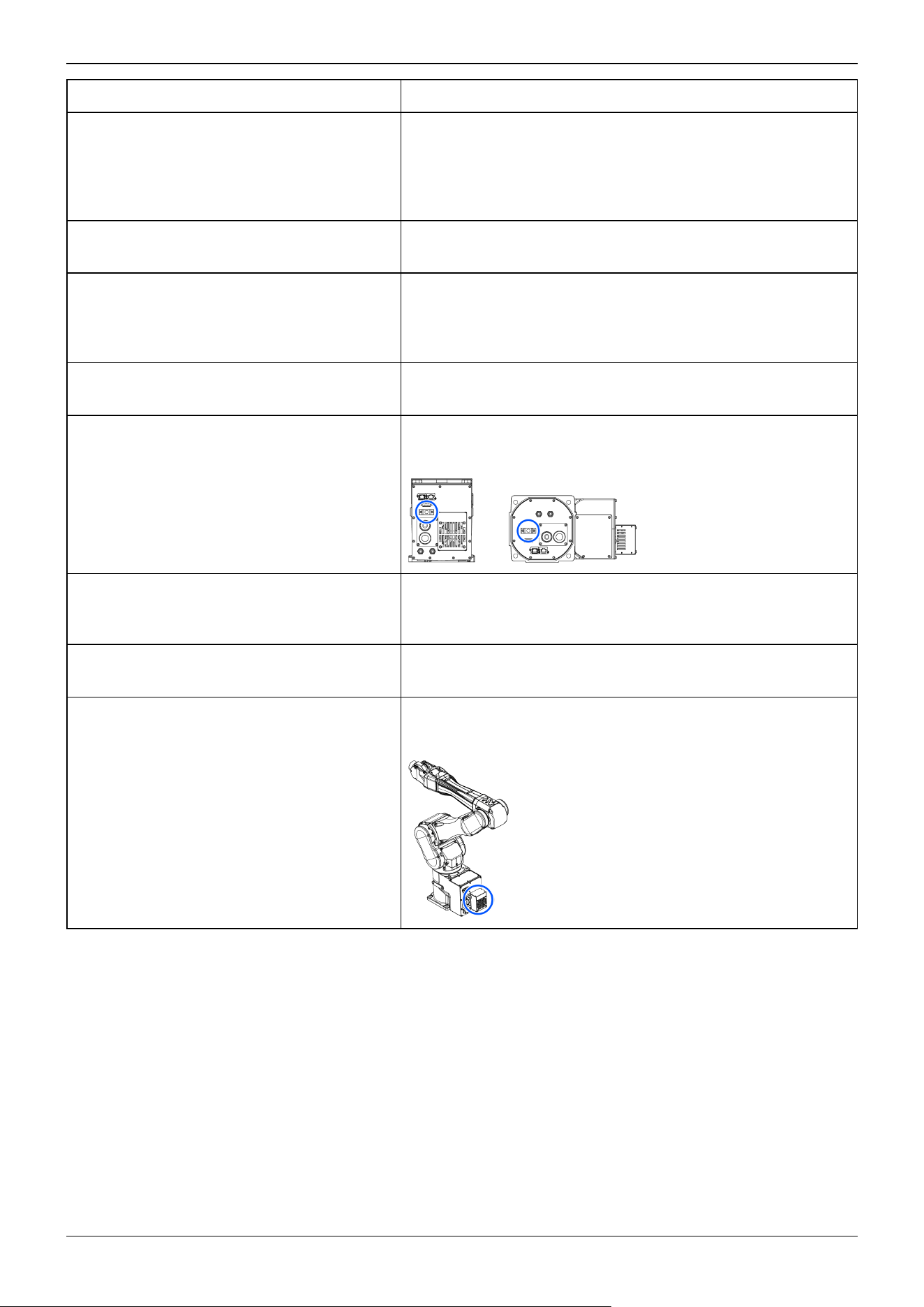
Inspection Item Inspection Method
Check for loose or rattling bolts
Using an Allen wrench or similar tool, check that the hand mounting
bolts and Manipulator installation bolts are not loose.
If the bolts are loose, refer to the following section, and retighten to
the proper torque.
Tightening the Hexagon Socket Head Cap Bolts
Check for loose connectors
Check that no connectors are loose.
If a connector is loose, reattach it so that it will not come off.
Inspect for flaws: Clean off adhering debris, etc.
Check the appearance of the Manipulator, and clean off any dust or
other foreign substances adhering to it.
Check the appearance of the cables for any flaws, and make sure it is
not disconnected.
Correct deformations and misalignments
Check for misalignment of safety barriers and other components.
If it is misaligned, correct it to the original position.
Check either the external short connector or the
brake release unit connector is connected
Check either the external short connector or the brake release unit
connector is connected.
When it is not connected, connect it.
Check brake operation
With the motor turned off, check that the arm does not drop.
If the arm drops while the motor is turned off and the brake is not
released, contact the supplier.
Check for abnormal operation noise and vibration
Check for any abnormal noises and vibrations during operation.
If you notice anything unusual, contact the supplier.
Check that fan is working.
With the motor turned on, check that the fan is working.
If the fan does not work while the motor is turned on, contact the
supplier.
5.3.2 Overhaul (Parts Replacement)
Overhaul (replacement) shall be performed by personnel who has taken a proper training.
For details, refer to the following manual.
"Safety Manual - Role and Training for Safety Managers"
Industrial Robot: 6-Axis Robots C-B series Manual Rev.1b
234
5.3.3 Applying Grease
The reduction gear units and the bevel gear need greasing regularly.
CAUTION
Be careful that the grease does not run out. When grease runs out, scratches and other defects can occur on
the slide, not only hindering maximum performance, but also requiring significant time and money to repair.
If grease enters the eyes or mouth or adheres to the skin, take the following measures:
If it enters the eyes
After rinsing the eyes thoroughly with clean water, seek medical attention.
If it enters the mouth
If swallowed, do not force vomiting, and seek medical attention. If the mouth is contaminated, rinse
thoroughly with water.
If adhered to skin
Rinse with water and soap.
Part Interval Safety Information
All
joints
Reduction
gear
When overhaul
is performed
Applying grease can only be performed by properly trained service engineers.
For more information, please contact the supplier.
Joint
#6
Bevel
gear
5.3.4 Tightening the Hexagon Socket Head Cap Bolts
Hexagon socket head cap bolts (referred to as "bolts" below) are used in locations where mechanical strength is required.
During assembly, these bolts are tightened at the tightening torques shown in the following table.
Unless otherwise specified, when retightening these bolts in the work procedures described in this manual, use a torque wrench
or similar tool to obtain the tightening torques in the following table.
Bolt Tightening Torque
M3 2.0 ± 0.1 N·m (21 ± 1 kgf·cm)
M4 4.0 ± 0.2 N·m (41 ± 2 kgf·cm)
M5 8.0 ± 0.4 N·m (82 ± 4 kgf·cm)
M6 13.0 ± 0.6 N·m (133 ± 6 kgf·cm)
M8 32.0 ± 1.6 N·m (326 ± 16 kgf·cm)
M10 58.0 ± 2.9 N·m (590 ± 30 kgf·cm)
M12 100.0 ± 5.0 N·m (1,020 ± 51 kgf·cm)
For set screw, refer to the following table.
Industrial Robot: 6-Axis Robots C-B series Manual Rev.1b
235
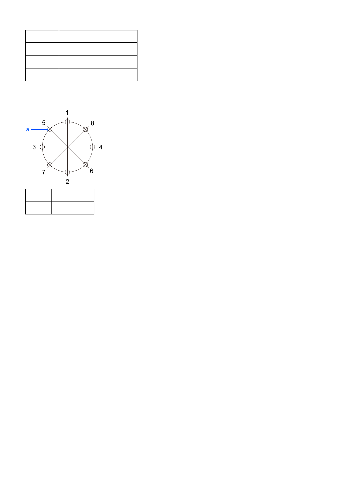
Set Screw Tightening Torque
M4 2.4 ± 0.1 N·m (26 ± 1 kgf·cm)
M5 3.9 ± 0.2 N·m (40 ± 2 kgf·cm)
M6 8.0 ± 0.4 N·m (82 ± 4 kgf·cm)
It is recommended that bolts arranged in a circular pattern be secured in place by tightening in criss-cross order as shown in the
figure.
Symbol Description
a Threaded holes
When securing the bolts, do not tighten the bolts all at once, but tighten them in two or three separate rounds with an Allen
wrench, and then use a torque wrench or similar tool to secure them at the tightening torques shown in the table above.
Industrial Robot: 6-Axis Robots C-B series Manual Rev.1b
236

6. Appendix
This section provides detailed technical data such as the specifications, stopping time, and stopping distance for each model.
Industrial Robot: 6-Axis Robots C-B series Manual Rev.1b
237

6.1 Appendix A: Specifications Table
Industrial Robot: 6-Axis Robots C-B series Manual Rev.1b
238
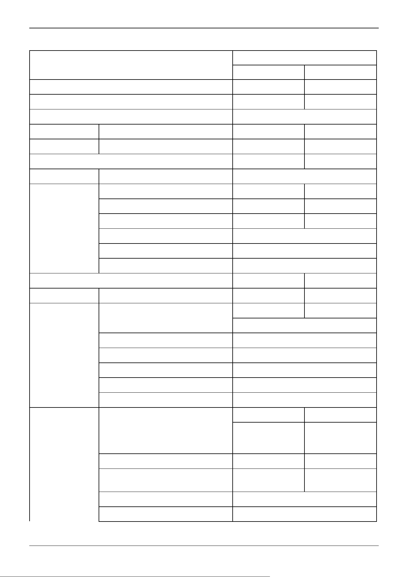
6.1.1 C4 Specifications
Item
Specifications
C4-B601 ** C4-B901**
Model Number C4-B601 ** C4-B901**
Model Name C4 C4L
Mounting type Table top mounting (Ceiling mounting) *1
Arm length P point: J1 to J5 center 600.0 900.0
Maximum reach J1 to J6 flange 665.0 965.0
Manipulator weight (not include the weight of cables or shipping jigs) 27 kg: 59.5 lb 30 kg: 66.1 lb
Drive system All joints AC servo motor
Maximum operating
speed *2
Joint #1 450°/s 275°/s
Joint #2 450°/s 275°/s
Joint #3 514°/s 289°/s
Joint #4 555°/s
Joint #5 555°/s
Joint #6 720°/s
Maximum synthetic speed 9459 mm/s 8495 mm/s
Repeatability Joint #1 to #6 ±0.02 mm ±0.03 mm
Maximum motion
range
Joint #1
±170° ±170°
±180° without the mechanical stop
Joint #2 -160 to +65°
Joint #3 -51 to +225°
Joint #4 ±200°
Joint #5 ±135°
Joint #6 ±540° *3
Max. pulse range
(pulse)
Joint #1
±4951609 ±8102633
Software limit
maximum value
±5242880
Software limit
maximum value
±8579259
Joint #2 -4660338 to +1893263 -7626008 to +3098066
Joint #3 -1299798 to +5734400
-2310751 to
+10194489
Joint #4 ±4723316
Joint #5 ±3188238
Industrial Robot: 6-Axis Robots C-B series Manual Rev.1b
239
Item
Specifications
C4-B601 ** C4-B901**
Joint #6 ±9830400
Resolution
Joint #1 0.0000343°/pulse 0.0000210°/pulse
Joint #2 0.0000343°/pulse 0.0000210°/pulse
Joint #3 0.0000392°/pulse 0.0000221°/pulse
Joint #4 0.0000423°/pulse
Joint #5 0.0000423°/pulse
Joint #6 0.0000549°/pulse
Motor rated capacity
Joint #1 400 W
Joint #2 400 W
Joint #3 150 W
Joint #4 50 W
Joint #5 50 W
Joint #6 50 W
Payload (load) *4
Rated 1 kg
Maximum 4 kg (5 kg with arm downward positioning)
Allowable moment
Joint #4 4.41 N·m (0.45 kgf·m)
Joint #5 4.41 N·m (0.45 kgf·m)
Joint #6 2.94 N·m (0.3 kgf·m)
Allowable moment of
inertia *5 (GD
2
/4)
Joint #4
0.15 kg·m
2
Joint #5
0.15 kg·m
2
Joint #6
0.10 kg·m
2
User wires 9 wires (D-sub)
User wires *6
⌀4 mm pneumatic tube × 4
Pressure resistance: 0.59 MPa (6 kgf/cm
2
) (86
psi)
Environmental
requirements *7
Ambient temperature
5
〜40°C *8
Ambient relative humidity 10 to 80% RH (no condensation)
Vibration
4.9 m/s
2
(0.5 G) or less
Noise level *9 LAeq = 77.4 dB (A)
LAeq = 73.3 dB (A) or
lower
Environmental specifications *10 Standard, Cleanroom & ESD
Compatible Controller RC700-E
Industrial Robot: 6-Axis Robots C-B series Manual Rev.1b
240
Item
Specifications
C4-B601 ** C4-B901**
MC cable
Cable weight
(cable only)
For fixing and signal
(common to all lengths)
0.09 kg/m
For fixing and power (3 m,
5 m, 10 m)
0.33 kg/m
For fixing and power (15
m, 20 m)
0.42 kg/m
For fixing and power
(common to all lengths)
0.33 kg/m
For movable and signal
(common to all lengths)
0.14 kg/m
For movable and power
(common to all lengths)
0.38 kg/m
Cable outer
diameter
For fixing and signal
(common to all lengths)
⌀7.7 mm (typ)
For fixing and power (3 m,
5 m, 10 m)
⌀14.1 mm (typ)
For fixing and power (15
m, 20 m)
⌀16.9 mm (typ)
For fixing and power
(common to all lengths)
⌀14.1 mm (typ)
For movable and signal
(common to all lengths)
⌀10.5 mm (typ)
For movable and power
(common to all lengths)
⌀17.0 mm (typ)
Minimum
bending radius
*11
For fixing and signal
(common to all lengths)
47 mm
For fixing and power (3 m,
5 m, 10 m)
85 mm
For fixing and power (15
m, 20 m)
102 mm
For fixing and power
(common to all lengths)
85 mm
For movable and signal
(common to all lengths)
100 mm
For movable and power
(common to all lengths)
100 mm
Industrial Robot: 6-Axis Robots C-B series Manual Rev.1b
241
Item
Specifications
C4-B601 ** C4-B901**
Default values (Max.
setting values)
Speed 5 (100)
Accel *12 5, 5 (120, 120)
SpeedS 50 (2000)
AccelS 200 (25000) 200 (15000) *13
Fine
10000, 10000, 10000, 10000, 10000, 10000
(65535, 65535, 65535, 65535, 65535, 65535)
Weight 1 (5)
*1: Manipulators are set to "Table Top mounting" at shipment. To use the Manipulators as "Ceiling mounting", you need to
change the model settings. For details on how to change the model settings, refer to the following sections.
Changing the Robot
"EPSON RC+ User's Guide - Robot Configuration"
*2: When PTP statements are used
*3: When you use Joint #6 at an angle more than ±360° with the virtual Controller, change the motion range. Go to [Tools] -
[Robot Manager] - [Range] panel, and make the setting. This can also be set using the Range statement in [Command
Window].
*4: If the payload exceeds the maximum payload, refer to the following section.
"WEIGHT Setting - Restrictions on payload exceeding the maximum payload"
*5: If the center of gravity is at the center of each arm. If the center of gravity is not at the center of each arm, set the
eccentricity using INERTIA command.
*6: For details of the installed pneumatic tube for customer use, refer to the following section.
User Wires and Pneumatic Tubes
*7: For details of the environmental requirements, refer to the following section.
Environment
*8: When used in a low-temperature environment near the minimum temperature specified in the product specifications, or
when the unit is idle for a long period of time during holidays or at night, a collision detection error or similar error may occur
immediately after the start of operation due to high resistance in the drive unit. In such cases, warm-up operation for about 10
minutes is recommended.
*9: The conditions at measurement are as follows.
Operating conditions: Under rated load, all arms simultaneous motion, maximum speed, maximum
acceleration/deceleration, and maximum acceleration/deceleration which duty is 100%.
Measurement point: 1000 mm apart from the rear of Manipulator
*10: Manipulators with cleanroom specifications discharge the exhaust inside of the base and inside of the arm cover section
together. Consequently, if there is a gap in the base section, the arm tip section will not be sufficiently negatively pressurized,
which may result in dust generation.
Cleanliness: Class ISO 3 (ISO 14644-1)
Industrial Robot: 6-Axis Robots C-B series Manual Rev.1b
242
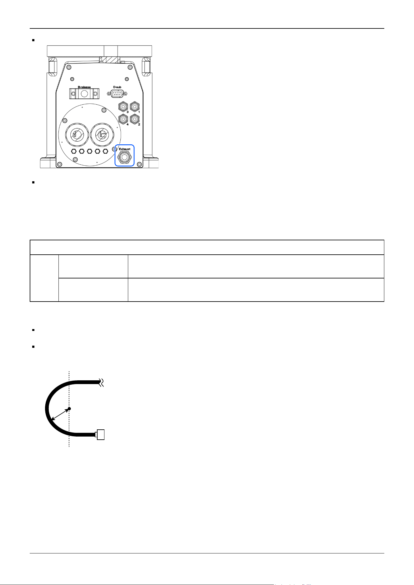
Exhaust port: Fitting for ⌀8 mm tube 60 L/min vacuum
Exhaust tube: Polyurethane tube Outer diameter: ⌀8 mm (Inner diameter: ⌀5 to 6 mm)
ESD specification uses resin materials with anti-static treatment. This model controls adhesion of dust due to electrification.
Protection level for the standard model and cleanroom model Manipulators is equivalent to IP20.
The IP (International Protection) rating is an international standard indicating the degree of protection against dust and water.
Protection Class
IP20
Dust protection level:
2
A solid object which is 12.5 mm or longer cannot touch dangerous areas inside of the
Manipulator.
Water protection
level: 0
Not protected.
*11: Note the following points when wiring the movable M/C cable.
Install the cable not to apply a load to the connector.
Bend the cable at the minimum bending radius of the movable part or more. The bending radius (a) and dimensions are
shown in the figure below.
*12: The Accel setting of "100" is the optimum setting that balances acceleration/deceleration and vibration during positioning.
Although values larger than 100 can be set to Accel, it is recommended to minimize the use of large values to necessary
motions since operating the Manipulator continuously with the large Accel setting may shorten the product life remarkably.
*13: Maximum AccelS setting value for payload of 4 kg or more is 12000.
Although setting the value exceeding 12000 does not cause an error, do not set the value in order to prevent Manipulator
malfunction.
M/C cable
Connector
a
Industrial Robot: 6-Axis Robots C-B series Manual Rev.1b
243
6.1.2 C8 Specifications
Item
Specifications
C8-B901 *** C8-B1401***
Model Number C8-B901 *** C8-B1401***
Model Name C8L C8XL
Mounting type *1
Table top mounting, Ceiling
mounting, Wall mounting
Arm length P point: J1 to J5 center 901.1 1400.6
Maximum reach J1 to J6 flange 981.1 1480.6
Manipulator weight (not include the
weight of cables or shipping jigs)
Standard, cleanroom & ESD specifications 53 kg: 117 lb 63 kg: 139 lb
Protected-Model 57 kg: 126 lb 66 kg: 146 lb
Drive system All joints AC servo motor
Maximum operating speed *2
Joint #1 294°/s 200°/s
Joint #2 300°/s 167°/s
Joint #3 360°/s 200°/s
Joint #4 480°/s
Joint #5 450°/s
Joint #6 720°/s
Maximum synthetic speed 9679 mm/s 8858 mm/s
Repeatability Joint #1 to #6 ±0.03 mm ±0.05 mm
Maximum motion range
Joint #1 ±240°
Joint #2 -158° to +65° -135° to +55°
Joint #3 -61° to +202°
Joint #4 ±200°
Joint #5 ±135°
Joint #6 ±540° *3
Max. pulse range (pulse)
Joint #1 ±10695600 ±15736800
Joint #2
-6903178 to
+2839915
-10616940 to
+4325420
Joint #3
-2220949 to
+7354618
-3997696 to
+13238272
Joint #4 ±5461400
Joint #5 ±3932280
Joint #6 ±9830400
Industrial Robot: 6-Axis Robots C-B series Manual Rev.1b
244
Item
Specifications
C8-B901 *** C8-B1401***
Resolution
Joint #1 0.0000224°/pulse 0.0000153°/pulse
Joint #2 0.0000229°/pulse 0.0000127°/pulse
Joint #3 0.0000275°/pulse 0.0000153°/pulse
Joint #4 0.0000366°/pulse
Joint #5 0.0000343°/pulse
Joint #6 0.0000549°/pulse
Motor rated capacity
Joint #1 1000 W
Joint #2 750 W
Joint #3 400 W
Joint #4 100 W
Joint #5 100 W
Joint #6 100 W
Payload (load) *4
Rated 3 kg
Maximum 8 kg
Allowable moment
Joint #4 16.6 N·m (1.69 kgf·m)
Joint #5 16.6 N·m (1.69 kgf·m)
Joint #6 9.4 N·m (0.96 kgf·m)
Allowable moment of inertia *5
(GD
2
/4)
Joint #4
0.47 kg·m
2
Joint #5
0.47 kg·m
2
Joint #6
0.15 kg·m
2
User wires
15 wires (D-sub)
8 pin (RJ45) equivalent to Cat.5e
6 pin (for Force Sensor)
User wires *6
⌀6 mm pneumatic tube × 2
Pressure resistance: 0.59 MPa (6
kgf/cm
2
) (86 psi)
Environmental requirements *7
Ambient temperature
5
〜40°C *8
Ambient relative humidity 10 to 80% RH (no condensation)
Vibration
4.9 m/s
2
(0.5 G) or less
Noise level *9
LAeq = 74.9 dB
(A) or lower
LAeq = 78 dB
(A) or lower
Industrial Robot: 6-Axis Robots C-B series Manual Rev.1b
245
Item
Specifications
C8-B901 *** C8-B1401***
Environmental Specifications
Standard *10
Cleanroom & ESD *10
Protection (IP67) *11
Compatible Controller RC700-E
MC cable
Cable weight
(cable only)
For fixing and signal
(common to all lengths)
0.09 kg/m
For fixing and power (3
m, 5 m, 10 m)
0.38 kg/m
For fixing and power (15
m, 20 m)
0.43 kg/m
For movable and signal
(common to all lengths)
0.19 kg/m
For movable and power
(common to all lengths)
0.46 kg/m
Cable outer
diameter
For fixing and signal
(common to all lengths)
⌀7.7 mm (typ)
For fixing and power (3
m, 5 m, 10 m)
⌀15.4 mm (typ)
For fixing and power (15
m, 20 m)
⌀17.4 mm (typ)
For movable and signal
(common to all lengths)
⌀12.1 mm (typ)
For movable and power
(common to all lengths)
⌀19.3 mm (typ)
MC cable
Minimum
bending radius
*12
For fixing and signal
(common to all lengths)
47 mm
For fixing and power (3
m, 5 m, 10 m)
93 mm
For fixing and power (15
m, 20 m)
105 mm
For movable and signal
(common to all lengths)
100 mm
For movable and power
(common to all lengths)
100 mm
Default values (Max. setting values)
Speed 3 (100)
Accel *13 5, 5 (120, 120)
SpeedS 50 (2000)
AccelS *14 200 (35000) 120 (25000)
Industrial Robot: 6-Axis Robots C-B series Manual Rev.1b
246
Item
Specifications
C8-B901 *** C8-B1401***
Fine
10000, 10000, 10000, 10000, 10000,
10000
(131070, 131070, 131070, 131070,
131070, 131070)
Weight 3 (8)
Inertia 0.03 (0.15)
*1: Mounting types other than Table top mounting, Ceiling mounting, and Wall mounting are out of specification.
*2: When PTP statements are used
*3: When you use Joint #6 at an angle more than ±360° with the virtual Controller, change the motion range. Go to [Tools] -
[Robot Manager] - [Range] panel, and make the setting. This can also be set using the Range statement in [Command
Window].
*4: Do not apply the load exceeding the maximum payload.
*5: If the center of gravity is at the center of each arm. If the center of gravity is not at the center of each arm, set the
eccentricity using INERTIA command.
*6: For details of the installed pneumatic tube for customer use, refer to the following section.
User Wires and Pneumatic Tubes
*7: For details of the environmental requirements, refer to the following section.
Environment
*8: When used in a low-temperature environment near the minimum temperature specified in the product specifications, or
when the unit is idle for a long period of time during holidays or at night, a collision detection error or similar error may occur
immediately after the start of operation due to high resistance in the drive unit. In such cases, warm-up operation for about 10
minutes is recommended.
*9: The conditions at measurement are as follows.
Operating conditions: Under rated load, all arms simultaneous motion, maximum speed, and maximum
acceleration/deceleration which duty is 100%.
Measurement point: 1000 mm apart from the rear of Manipulator
*10: Manipulators with cleanroom specifications discharge the exhaust inside of the base and inside of the arm cover section
together. Consequently, if there is a gap in the base section, the arm tip section will not be sufficiently negatively pressurized,
which may result in dust generation.
Cleanliness level:
C8L: ISO Class 3 (ISO14644-1)
C8XL: ISO Class 4 (ISO14644-1)
Industrial Robot: 6-Axis Robots C-B series Manual Rev.1b
247
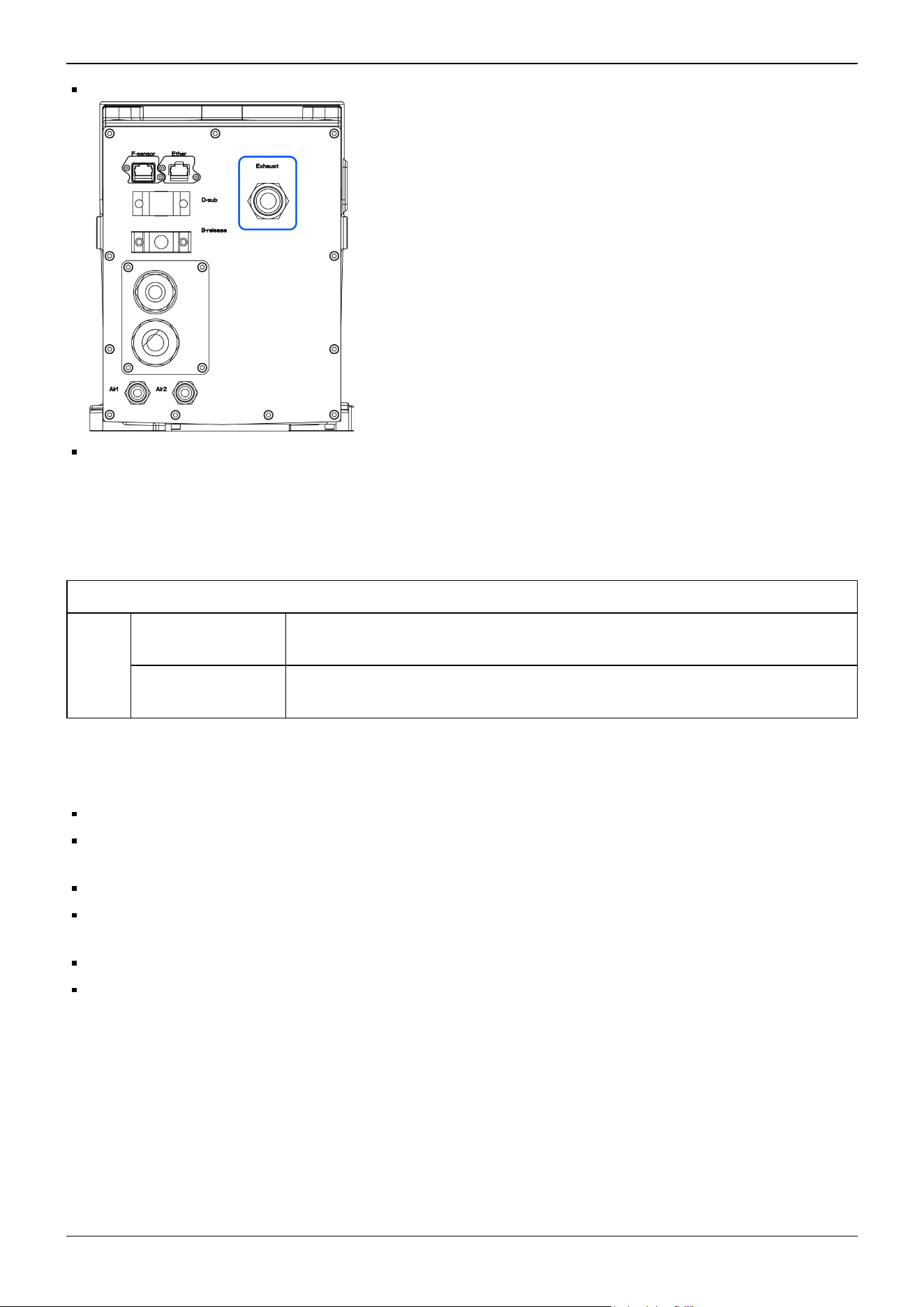
Exhaust port: Fitting for ⌀12 mm tube 60 L/min vacuum
Exhaust tube: Polyurethane tube Outer diameter: ⌀12 mm
ESD specification uses resin materials with anti-static treatment. This model controls adhesion of dust due to electrification.
Protection level for the standard model and cleanroom model Manipulators is equivalent to IP20.
The IP (International Protection) rating is an international standard indicating the degree of protection against dust and water.
Protection Class
IP20
Dust protection level:
2
A solid object which is 12.5 mm or longer cannot touch dangerous areas inside of the
Manipulator.
Water protection
level: 0
Not protected.
*11: Protection level for the protected-model Manipulators is IP67 (IEC standard). The Manipulators can be used in
environments where the possibility of dust, water, and water-soluble cutting oil falling of the Manipulator exists. Note the
following points.
The Manipulator is not rust-proofed. Do not use the Manipulator in environment where corrosive liquids exist.
Fluids that deteriorate the sealing materials, such as organic solvents, acids, alkalis, and chlorine cutting fluids, cannot be
used.
The Manipulator cannot be used for underwater operations.
The Controller does not have protection features against the environment (Controller’s protection level: IP20). Make sure
to install the system where environmental requirements for the Controller are satisfied.
The fan cover is equivalent to IP 20.
Be sure to connect a connector compliant with protection class IP67 or higher and a connector cover to the Ethernet cable
connector.
The IP (International Protection) rating is an international standard indicating the degree of protection against dust and water.
Industrial Robot: 6-Axis Robots C-B series Manual Rev.1b
248
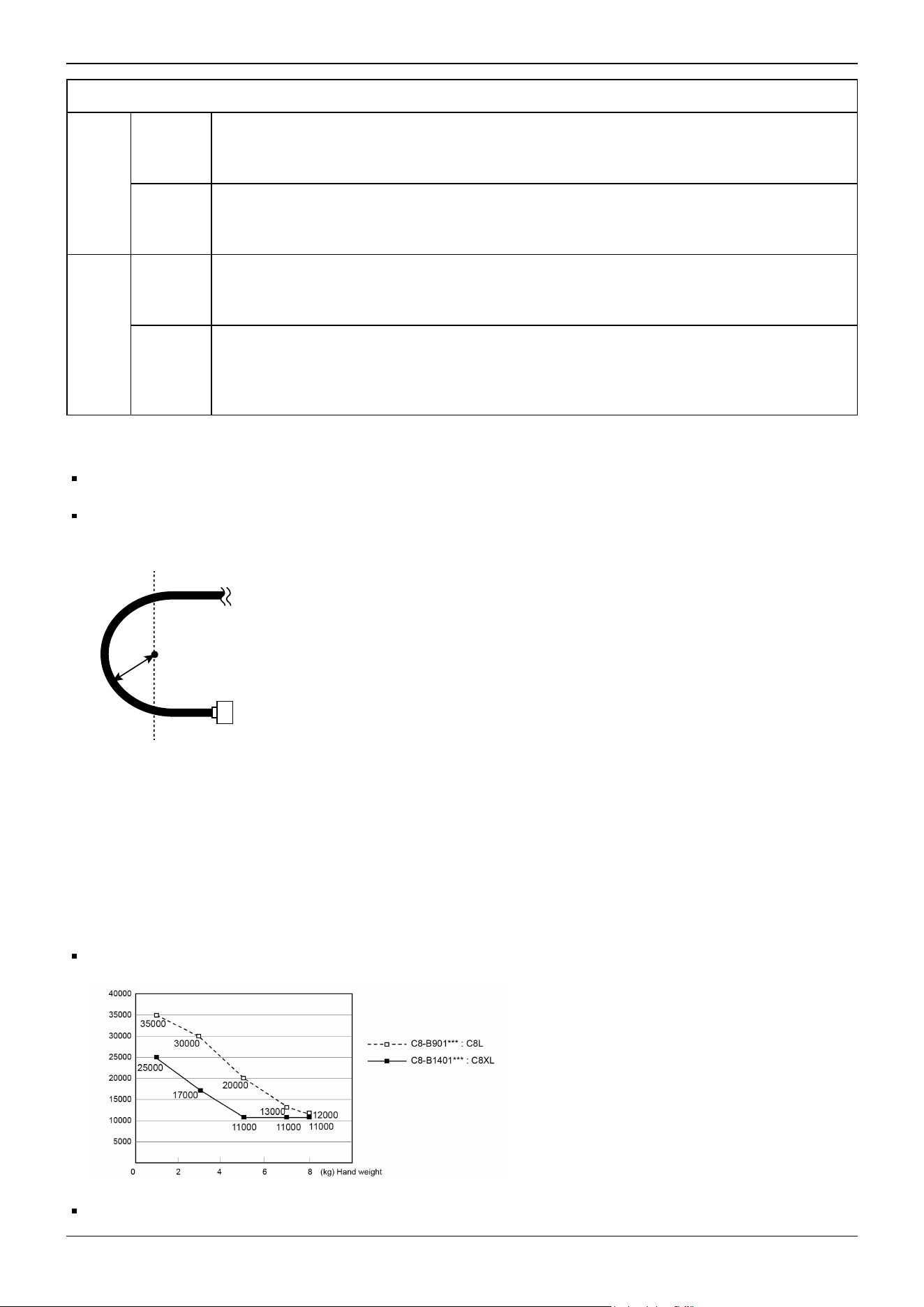
Protection Class
IP20
Dust
protection
level: 2
A solid object which is 12.5 mm or longer cannot touch dangerous areas inside of the Manipulator.
Water
protection
level: 0
Not protected.
IP67
Dust
protection
level: 6
A testing rod which is 1.0 mm or longer cannot touch dangerous areas inside of the Manipulator.
Totally protected against dust.
Water
protection
level: 7
Water cannot enter the Manipulator when the Manipulator is immersed in water for 30 minutes under
the condition that the highest point of the Manipulator is located 0.15 m below the surface of the
water and the lowest point is located 1 m below the surface of the water. (The Manipulator is stopped
during the test.)
*12: Note the following points when wiring the movable M/C cable.
Install the cable not to apply a load to the connector.
Bend the cable at the minimum bending radius of the movable part or more. The bending radius (a) and dimensions are
shown in the figure below.
*13: The Accel setting of "100" is the optimum setting that balances acceleration/deceleration and vibration during positioning.
Although values larger than 100 can be set to Accel, it is recommended to minimize the use of large values to necessary
motions since operating the Manipulator continuously with the large Accel setting may shorten the product life remarkably.
*14: Maximum AccelS setting value varies depending on the load. For details, refer to the following figure. Setting the value
which exceeds the maximum AccelS causes an error. Check the setting value.
Maximum AccelS setting value
Table top mounting, Ceiling mounting
Wall mounting
M/C cable
Connector
a
Industrial Robot: 6-Axis Robots C-B series Manual Rev.1b
249
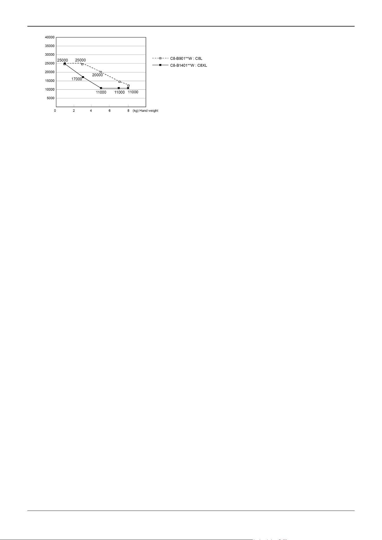
Industrial Robot: 6-Axis Robots C-B series Manual Rev.1b
250
6.1.3 C12 Specifications
Item
Specifications
C12-B1401**
Model Number C12-B1401**
Model Name C12XL
Mounting type *1 Table top mounting
Arm length P point: J1 to J5 center 1400.6
Maximum reach J1 to J6 flange 1480.6
Manipulator weight (not include the
weight of cables or shipping jigs)
Standard model
Cleanroom & ESD model
63 kg: 139 lb
Drive system All joints AC servo motor
Maximum operating speed *2
Joint #1 200°/s
Joint #2 167°/s
Joint #3 200°/s
Joint #4 300°/s
Joint #5 360°/s
Joint #6 720°/s
Maximum synthetic speed 8751 mm/s
Repeatability Joint #1 to #6 ±0.05 mm
Maximum motion range
Joint #1 ±240°
Joint #2 -135 to +55°
Joint #3 -61 to +202°
Joint #4 ±200°
Joint #5 ±135°
Joint #6 ±540° *3
Max. pulse range (pulse)
Joint #1 ±15736800
Joint #2 -10616940 to +4325420
Joint #3 -3997696 to +13238272
Joint #4 ±8738240
Joint #5 ±4915350
Joint #6 ±9830400
Industrial Robot: 6-Axis Robots C-B series Manual Rev.1b
251
Item
Specifications
C12-B1401**
Resolution
Joint #1 0.0000153°/pulse
Joint #2 0.0000127°/pulse
Joint #3 0.0000153°/pulse
Joint #4 0.0000229°/pulse
Joint #5 0.0000275°/pulse
Joint #6 0.0000549°/pulse
Motor rated capacity
Joint #1 1000 W
Joint #2 750 W
Joint #3 400 W
Joint #4 150 W
Joint #5 150 W
Joint #6 150 W
Payload (load) *4
Rated 3 kg
Maximum 12 kg
Allowable moment
Joint #4 25.0 N·m (2.55 kgf·m)
Joint #5 25.0 N·m (2.55 kgf·m)
Joint #6 9.8 N·m (1.0 kgf·m)
Allowable moment of inertia *5
(GD
2
/4)
Joint #4
0.70 kg·m
2
Joint #5
0.70 kg·m
2
Joint #6
0.20 kg·m
2
User wires
15 wires (D-sub)
8 pin (RJ45) equivalent to
Cat.5e
6 pin (for Force Sensor)
User wires *6
⌀6 mm pneumatic tube × 2
Pressure resistance: 0.59 MPa
(6 kgf/cm
2
) (86 psi)
Environmental requirements *7
Ambient temperature
5
〜40°C *8
Ambient relative humidity
10 to 80% RH (no
condensation)
Vibration
4.9 m/s
2
(0.5 G) or less
Noise level *9 LAeq = 79.6 dB (A) or lower
Industrial Robot: 6-Axis Robots C-B series Manual Rev.1b
252
Item
Specifications
C12-B1401**
Environmental specifications *10
Standard
Cleanroom & ESD
Compatible Controller RC700-E
MC cable
Cable weight
(cable only)
For fixing and signal
(common to all lengths)
0.09 kg/m
For fixing and power (3 m,
5 m, 10 m)
0.38 kg/m
For fixing and power (15
m, 20 m)
0.43 kg/m
For movable and signal
(common to all lengths)
0.19 kg/m
For movable and power
(common to all lengths)
0.46 kg/m
Cable outer
diameter
For fixing and signal
(common to all lengths)
⌀7.7 mm (typ)
For fixing and power (3 m,
5 m, 10 m)
⌀15.4 mm (typ)
For fixing and power (15
m, 20 m)
⌀17.4 mm (typ)
For movable and signal
(common to all lengths)
⌀12.1 mm (typ)
For movable and power
(common to all lengths)
⌀19.3 mm (typ)
Minimum
bending radius
*11
For fixing and signal
(common to all lengths)
47 mm
For fixing and power (3 m,
5 m, 10 m)
93 mm
For fixing and power (15
m, 20 m)
105 mm
For movable and signal
(common to all lengths)
100 mm
For movable and power
(common to all lengths)
100 mm
Default values (Max. setting values)
Speed 3 (100)
Accel *12 5, 5 (120, 120)
SpeedS 50 (2000)
AccelS *13 120 (25000)
Industrial Robot: 6-Axis Robots C-B series Manual Rev.1b
253
Item
Specifications
C12-B1401**
Fine
10000, 10000, 10000, 10000,
10000, 10000
(131070, 131070, 131070,
131070, 131070, 131070)
Weight 3 (12)
Inertia 0.03 (0.2)
*1: Mounting types other than Table top mounting are out of specification.
*2: When PTP statements are used
*3: When you use Joint #6 at an angle more than ±360° with the virtual Controller, change the motion range. Go to [Tools] -
[Robot Manager] - [Range] panel, and make the setting. This can also be set using the Range statement in [Command
Window].
*4: Do not apply the load exceeding the maximum payload.
*5: If the center of gravity is at the center of each arm. If the center of gravity is not at the center of each arm, set the
eccentricity using INERTIA command.
*6: For details of the installed pneumatic tube for customer use, refer to the following section.
User Wires and Pneumatic Tubes
*7: For details of the environmental requirements, refer to the following section.
Environment
*8: When used in a low-temperature environment near the minimum temperature specified in the product specifications, or
when the unit is idle for a long period of time during holidays or at night, a collision detection error or similar error may occur
immediately after the start of operation due to high resistance in the drive unit. In such cases, warm-up operation for about 10
minutes is recommended.
*9: The conditions at measurement are as follows.
Operating conditions: Under rated load, all arms simultaneous motion, maximum speed, and maximum
acceleration/deceleration which duty is 100%.
Measurement point: 1000 mm apart from the rear of Manipulator
*10: Manipulators with cleanroom specifications discharge the exhaust inside of the base and inside of the arm cover section
together. Consequently, if there is a gap in the base section, the arm tip section will not be sufficiently negatively pressurized,
which may result in dust generation.
Cleanliness: ISO Class 4 (ISO 14644-1)
Industrial Robot: 6-Axis Robots C-B series Manual Rev.1b
254
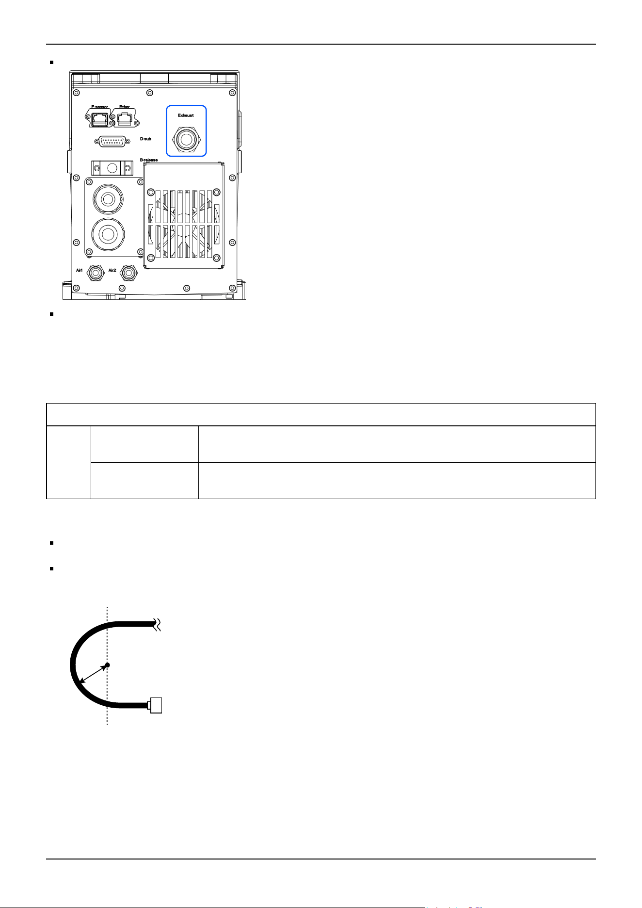
Exhaust port: Fitting for ⌀12 mm tube 60 L/min vacuum
Exhaust tube: Polyurethane tube Outer diameter: ⌀12 mm
ESD specification uses resin materials with anti-static treatment. This model controls adhesion of dust due to electrification.
Protection level for the standard model and cleanroom model Manipulators is equivalent to IP20.
The IP (International Protection) rating is an international standard indicating the degree of protection against dust and water.
Protection Class
IP20
Dust protection level:
2
A solid object which is 12.5 mm or longer cannot touch dangerous areas inside of the
Manipulator.
Water protection
level: 0
Not protected.
*11: Note the following points when wiring the movable M/C cable.
Install the cable not to apply a load to the connector.
Bend the cable at the minimum bending radius of the movable part or more. The bending radius (a) and dimensions are
shown in the figure below.
*12: The Accel setting of "100" is the optimum setting that balances acceleration/deceleration and vibration during positioning.
Although values larger than 100 can be set to Accel, it is recommended to minimize the use of large values to necessary
motions since operating the Manipulator continuously with the large Accel setting may shorten the product life remarkably.
*13: Maximum AccelS setting value varies depending on the load. For details, refer to the following figure. Setting the value
which exceeds the maximum AccelS causes an error. Check the setting value.
M/C cable
Connector
a
Industrial Robot: 6-Axis Robots C-B series Manual Rev.1b
255
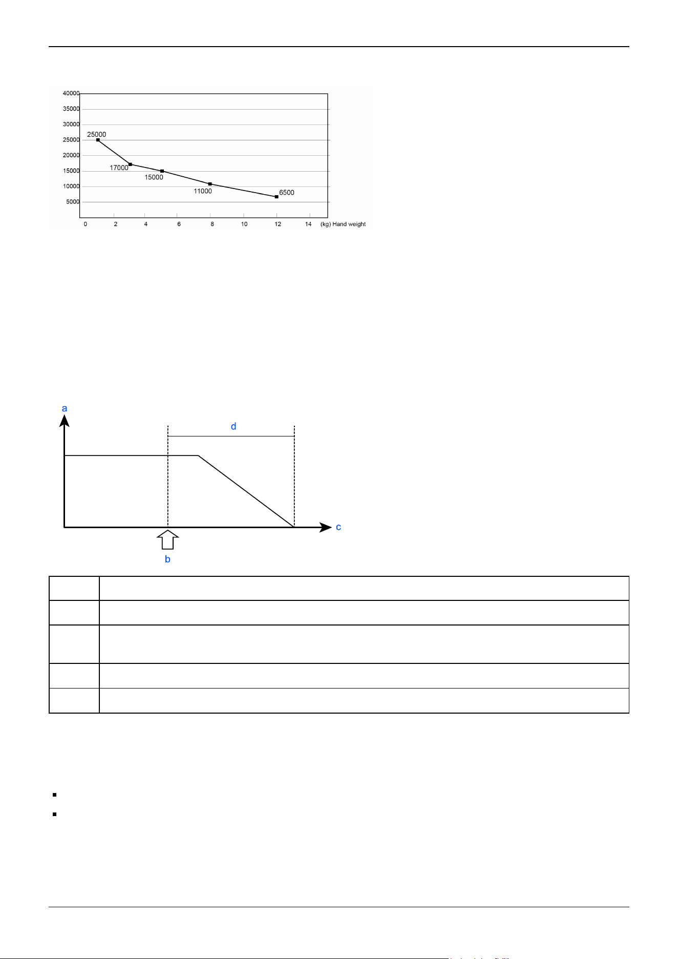
Maximum AccelS setting value
6.2 Appendix B: Stopping Time and Stopping Distance at Emergency Stop
The stopping time and stopping distance at an emergency stop are shown in the graphs for each model.
The stopping time is the length of time corresponding to the "Stopping time" in the figure below. Be sure to confirm that a safe
environment is provided where the robot will be installed and operated.
For models equipped with a safety board such as RC700-E, the stopping time and stopping distance when using the Safety
Limited Speed (SLS), Safety Limited Position (SLP), and Soft Axis Limiting are equivalent to those of the emergency stop.
Symbol Description
a Motor speed
b
Emergency stop, Maximum Speed of SLS exceeded, monitoring areas and Joint Angle Limit of SLP exceeded,
restricted range of Soft Axis Limiting exceeded
c Time
d Stopping time
Conditions:
The stopping time and stopping distance depend on the parameters (setting values) that were set for the robot. These graphs
show the times and distances for the following parameters.
Accel: 100, 100
Other settings: Default
Explanation of legend:
The graphs are displayed for each Weight setting value (at 100%, approx. 66%, and approx. 33% of the maximum payload, and
at the rated payload).
Industrial Robot: 6-Axis Robots C-B series Manual Rev.1b
256
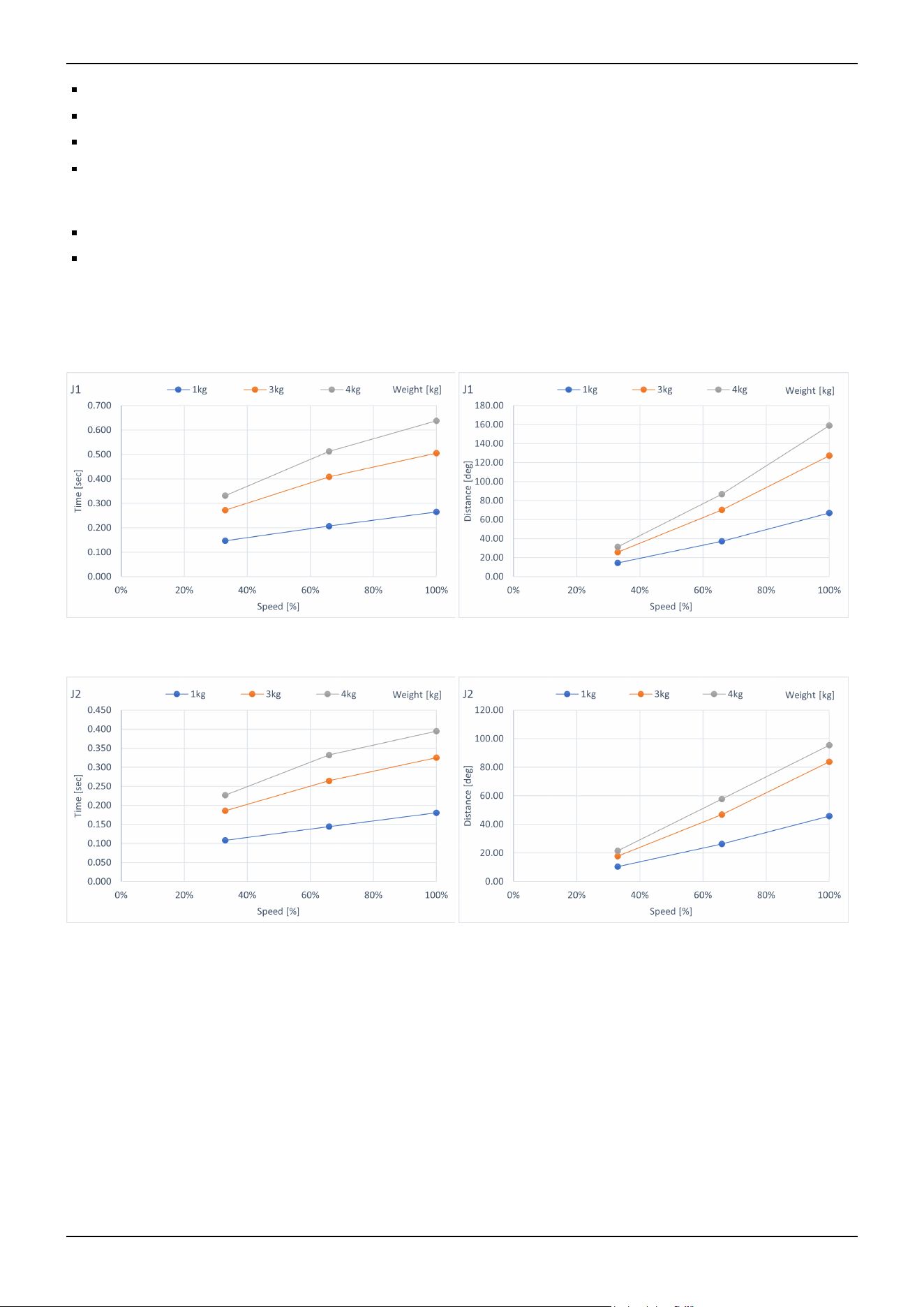
Horizontal axis: Arm speed (Speed setting)
Vertical axis: Stopping time and stopping distance at each arm speed
Time (sec): Stopping time (sec)
Distance (deg): stopping distance (degree)
When single failures are taken into account, the following adjustments are used.
Stopping distance and angle: Each axis reaches the mechanical stop
Stopping time: Add 500 ms
6.2.1 C4-B Stopping Time and Stopping Distance at Emergency Stop
C4-B601**: J1 (Table top mounting, Ceiling mounting)
C4-B601**: J2 (Table top mounting, Ceiling mounting)
C4-B601**: J3 (Table top mounting, Ceiling mounting)
Industrial Robot: 6-Axis Robots C-B series Manual Rev.1b
257
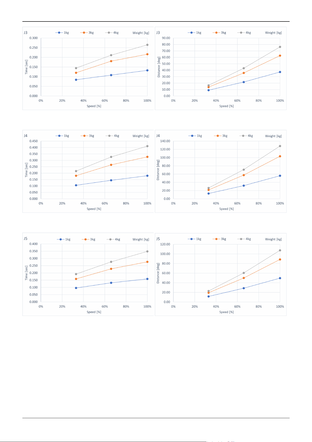
C4-B601**: J4 (Table top mounting, Ceiling mounting)
C4-B601**: J5 (Table top mounting, Ceiling mounting)
C4-B601**: J6 (Table top mounting, Ceiling mounting)
Industrial Robot: 6-Axis Robots C-B series Manual Rev.1b
258
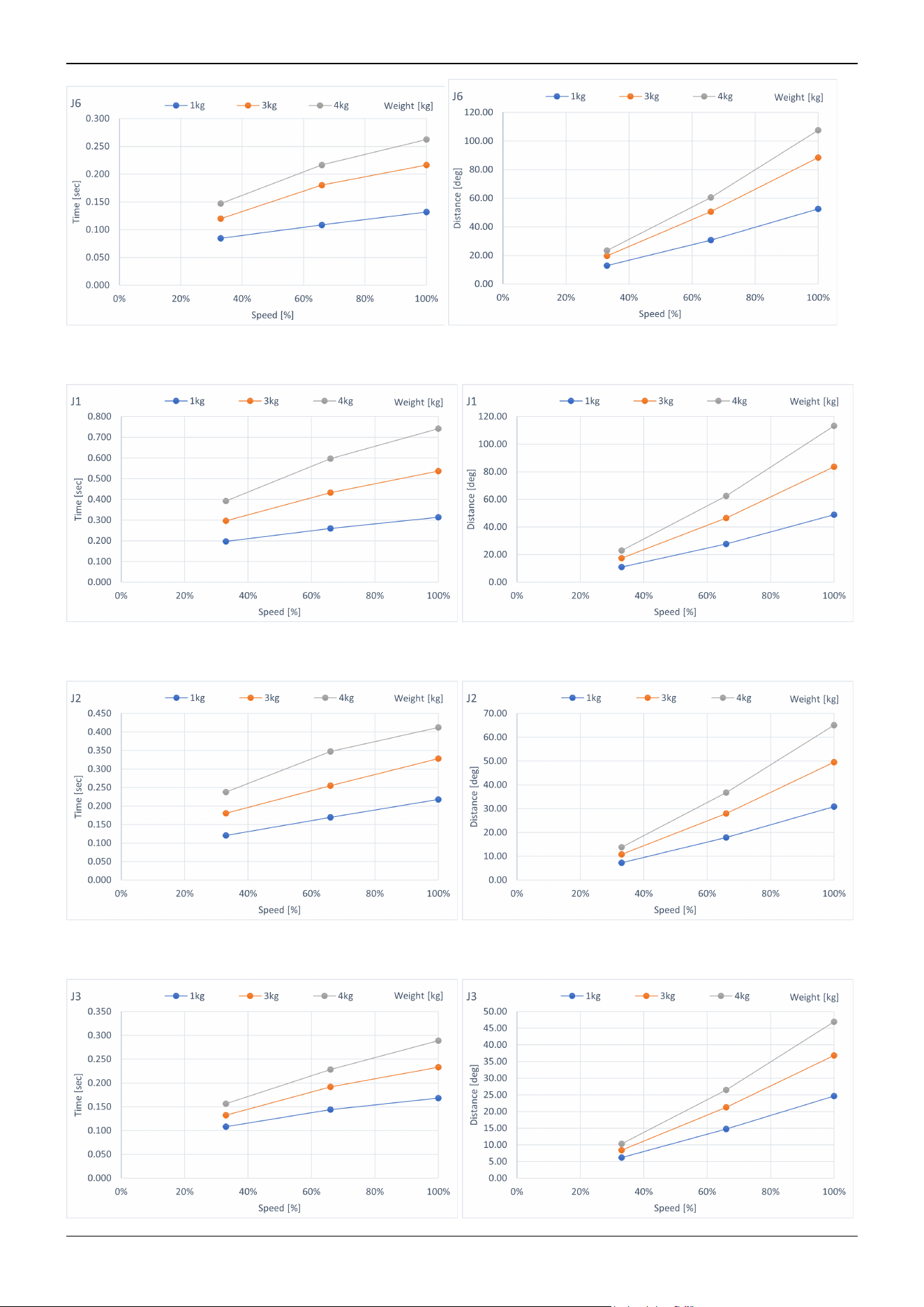
C4-B901**: J1 (Table top mounting, Ceiling mounting)
C4-B901**: J2 (Table top mounting, Ceiling mounting)
C4-B901**: J3 (Table top mounting, Ceiling mounting)
Industrial Robot: 6-Axis Robots C-B series Manual Rev.1b
259
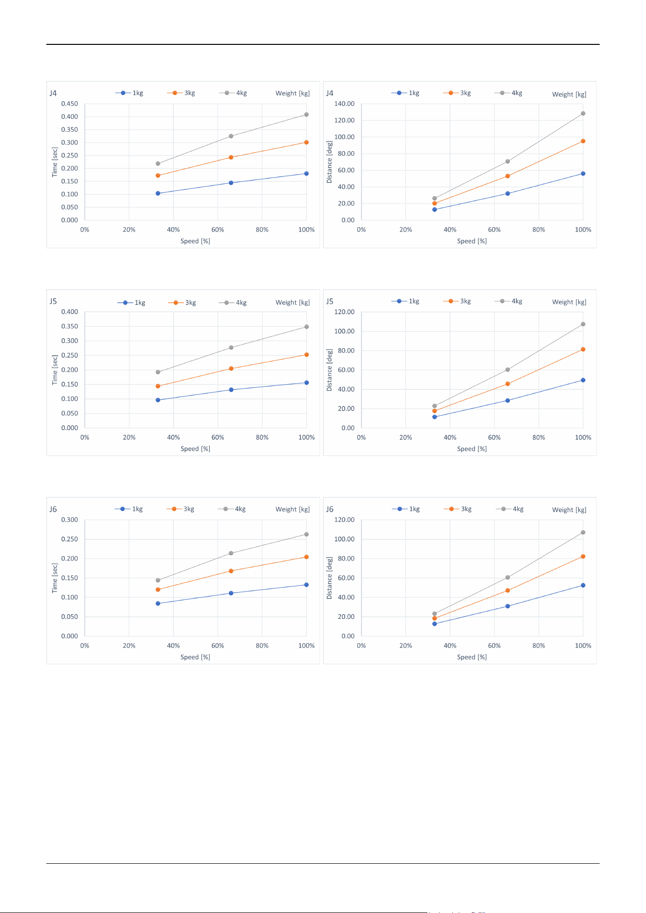
C4-B901**: J4 (Table top mounting, Ceiling mounting)
C4-B901**: J5 (Table top mounting, Ceiling mounting)
C4-B901**: J6 (Table top mounting, Ceiling mounting)
6.2.2 C8-B Stopping Time and Stopping Distance at Emergency Stop
C8-B901***: J1 (Table top mounting, Ceiling mounting)
Industrial Robot: 6-Axis Robots C-B series Manual Rev.1b
260
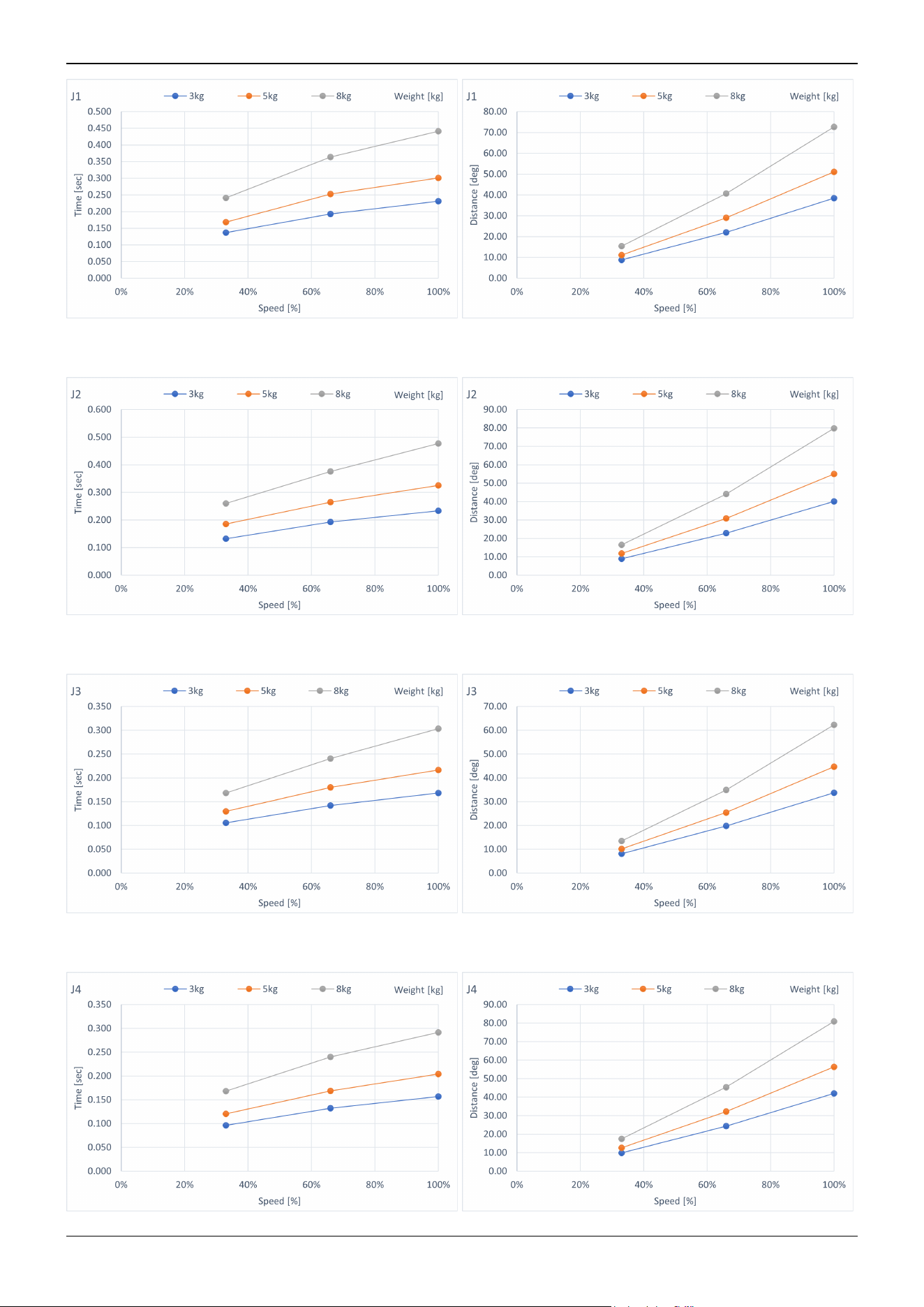
C8-B901***: J2 (Table top mounting, Ceiling mounting)
C8-B901***: J3 (Table top mounting, Ceiling mounting)
C8-B901***: J4 (Table top mounting, Ceiling mounting)
Industrial Robot: 6-Axis Robots C-B series Manual Rev.1b
261
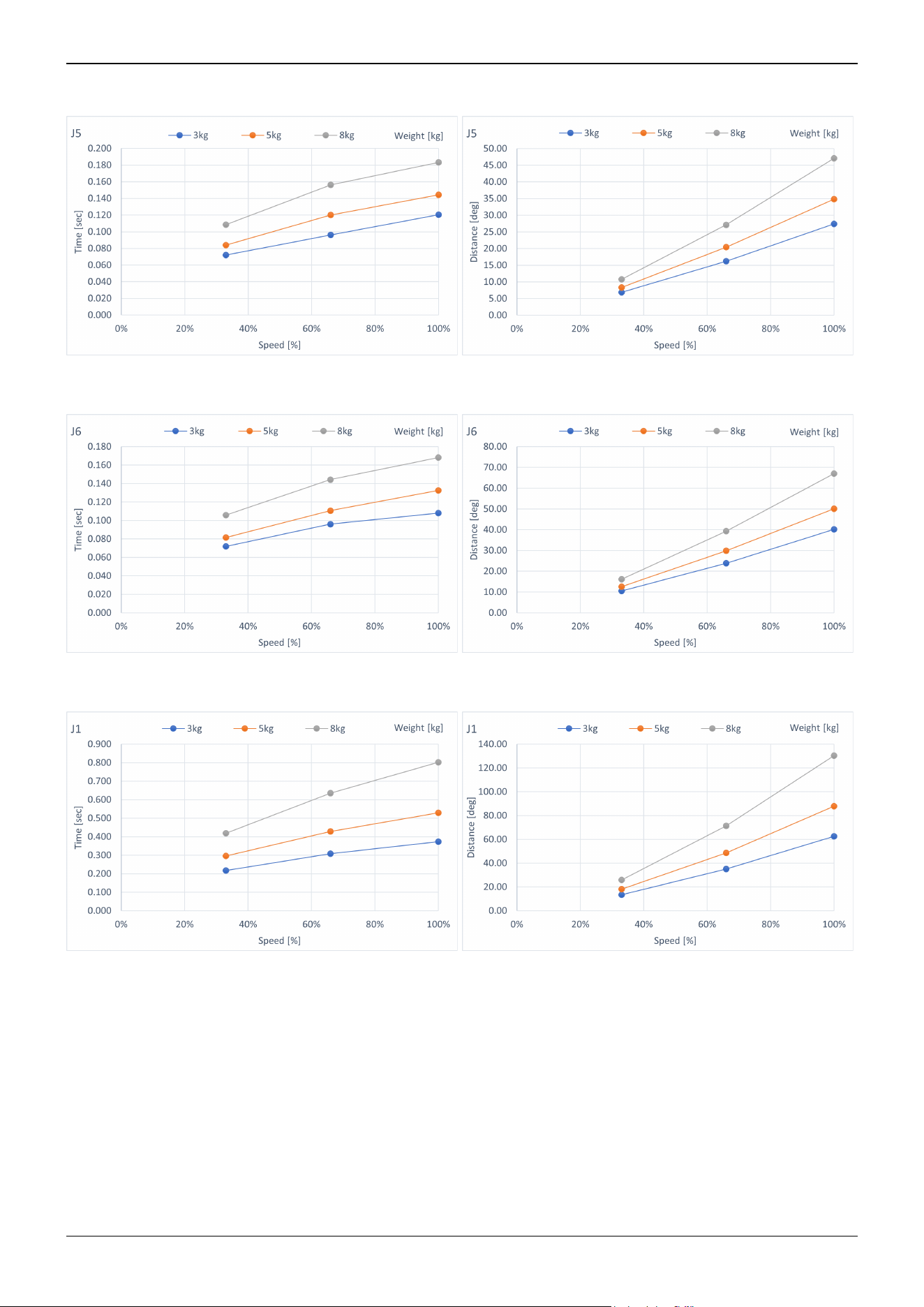
C8-B901***: J5 (Table top mounting, Ceiling mounting)
C8-B901***: J6 (Table top mounting, Ceiling mounting)
C8-B901***: J1 (Wall mounting)
C8-B901***: J2 (Wall mounting)
Industrial Robot: 6-Axis Robots C-B series Manual Rev.1b
262
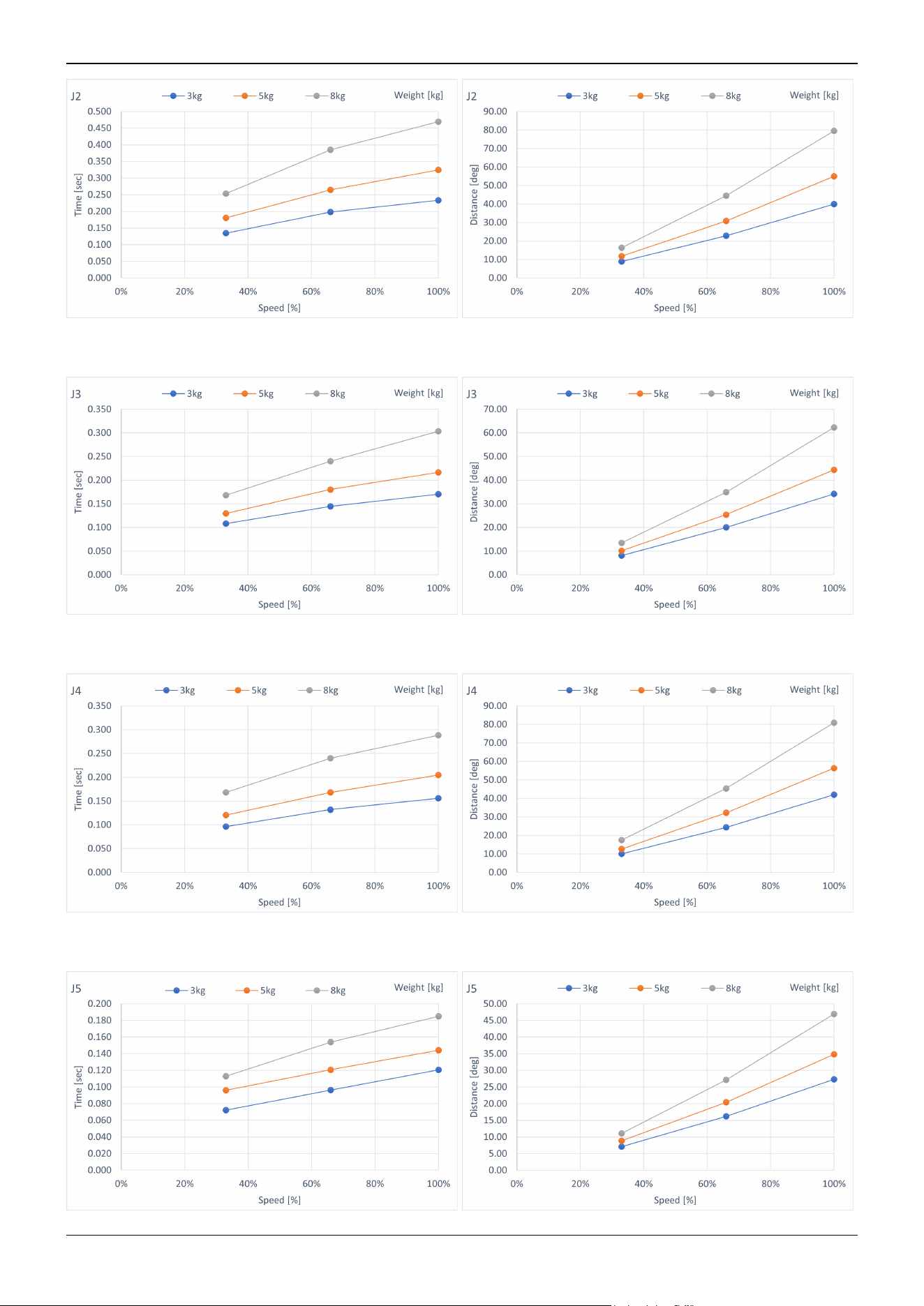
C8-B901***: J3 (Wall mounting)
C8-B901***: J4 (Wall mounting)
C8-B901***: J5 (Wall mounting)
Industrial Robot: 6-Axis Robots C-B series Manual Rev.1b
263
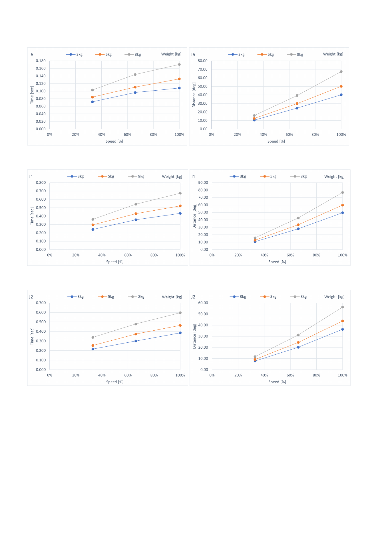
C8-B901***: J6 (Wall mounting)
C8-B1401***: J1 (Table top mounting, Ceiling mounting)
C8-B1401***: J2 (Table top mounting, Ceiling mounting)
C8-B1401***: J3 (Table top mounting, Ceiling mounting)
Industrial Robot: 6-Axis Robots C-B series Manual Rev.1b
264
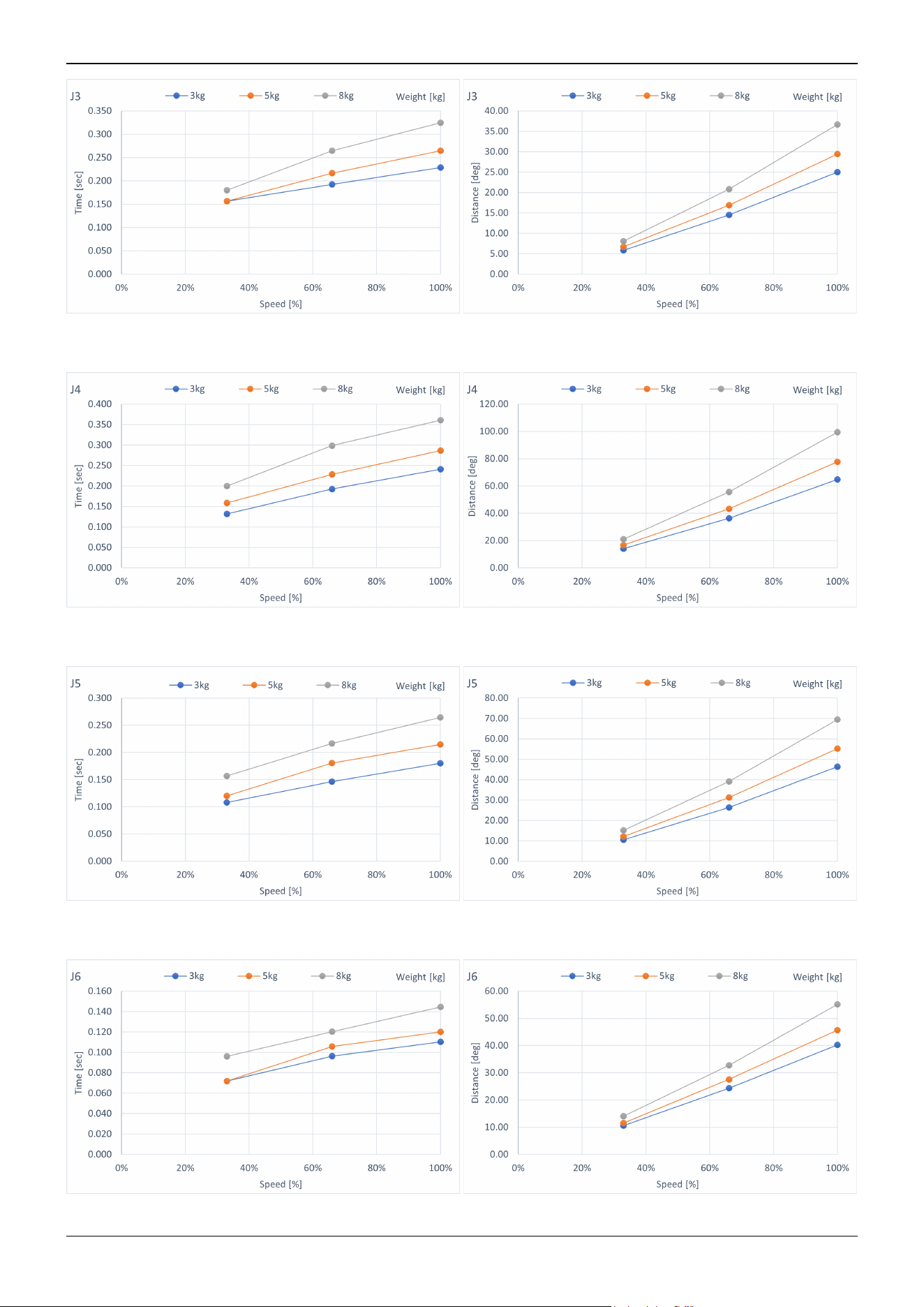
C8-B1401***: J4 (Table top mounting, Ceiling mounting)
C8-B1401***: J5 (Table top mounting, Ceiling mounting)
C8-B1401***: J6 (Table top mounting, Ceiling mounting)
Industrial Robot: 6-Axis Robots C-B series Manual Rev.1b
265
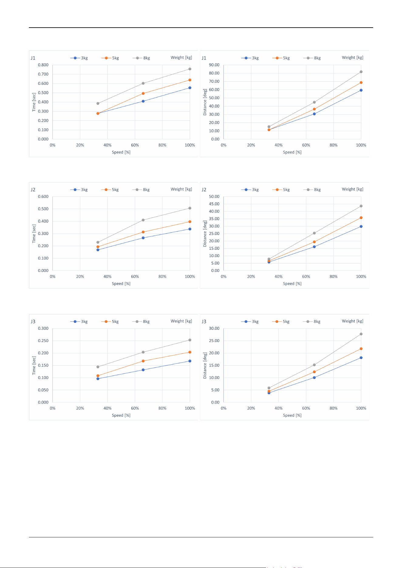
C8-B1401***: J1 (Wall mounting)
C8-B1401***: J2 (Wall mounting)
C8-B1401***: J3 (Wall mounting)
C8-B1401***: J4 (Wall mounting)
Industrial Robot: 6-Axis Robots C-B series Manual Rev.1b
266
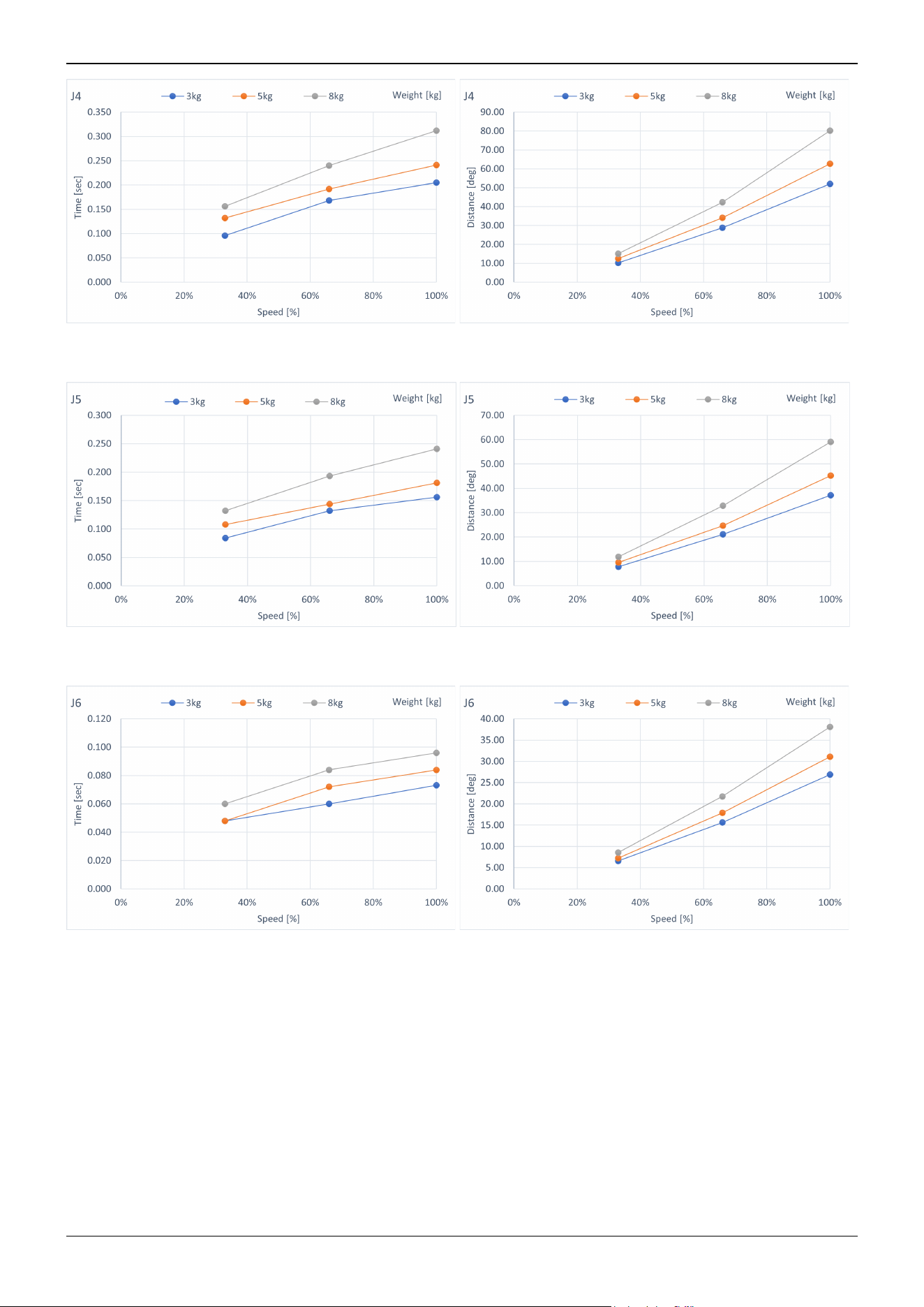
C8-B1401***: J5 (Wall mounting)
C8-B1401***: J6 (Wall mounting)
6.2.3 C12-B Stopping Time and Stopping Distance at Emergency Stop
C12-B1401**: J1 (Table top mounting)
Industrial Robot: 6-Axis Robots C-B series Manual Rev.1b
267
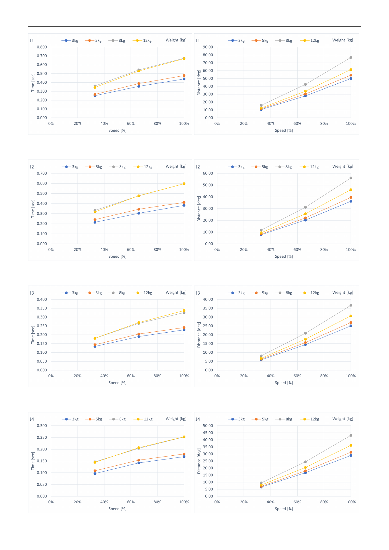
C12-B1401**: J2 (Table top mounting)
C12-B1401**: J3 (Table top mounting)
C12-B1401**: J4 (Table top mounting)
Industrial Robot: 6-Axis Robots C-B series Manual Rev.1b
268
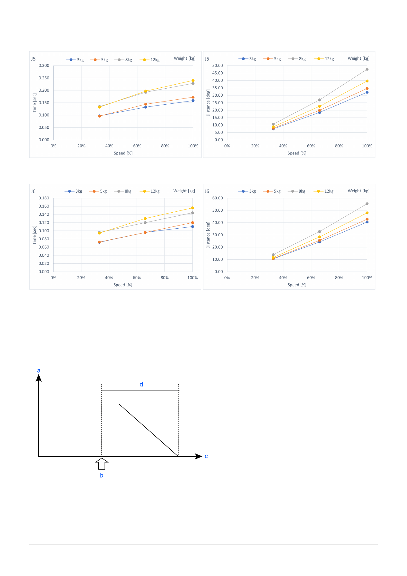
C12-B1401**: J5 (Table top mounting)
C12-B1401**: J6 (Table top mounting)
6.3 Appendix C: Stopping Time and Stopping Distance When Safeguard is Open
The stopping time and stopping distance when the safeguard is opened are shown in the graphs for each model.
The stopping time is the length of time corresponding to the "Stopping time" in the figure below. Be sure to confirm that a safe
environment is provided where the robot will be installed and operated.
Industrial Robot: 6-Axis Robots C-B series Manual Rev.1b
269
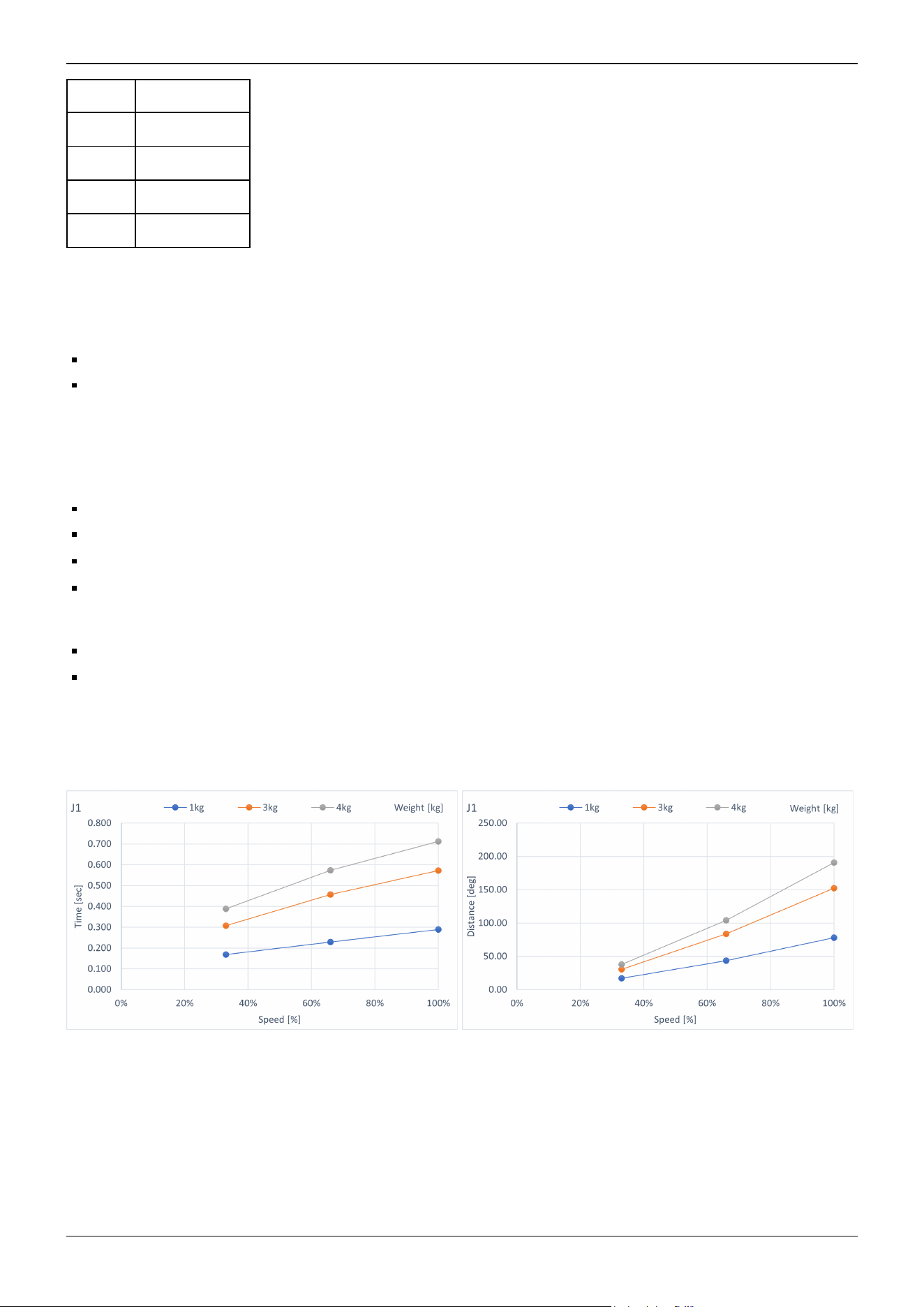
Symbol Description
a Motor speed
b Safeguard open
c Time
d Stopping time
Conditions:
The stopping time and stopping distance depend on the parameters (setting values) that were set for the robot. These graphs
show the times and distances for the following parameters.
Accel: 100, 100
Other settings: Default
Explanation of legend:
The graphs are displayed for each Weight setting value (at 100%, approx. 66%, and approx. 33% of the maximum payload, and
at the rated payload).
Horizontal axis: Arm speed (Speed setting)
Vertical axis: Stopping time and stopping distance at each arm speed
Time (sec): Stopping time (sec)
Distance (deg): stopping distance (degree)
When single failures are taken into account, the following adjustments are used.
Stopping distance and angle: Each axis reaches the mechanical stop
Stopping time: Add 500 ms
6.3.1 C4-B Stopping Time and Stopping Distance When Safeguard is Open
C4-B601**: J1 (Table top mounting, Ceiling mounting)
C4-B601**: J2 (Table top mounting, Ceiling mounting)
Industrial Robot: 6-Axis Robots C-B series Manual Rev.1b
270
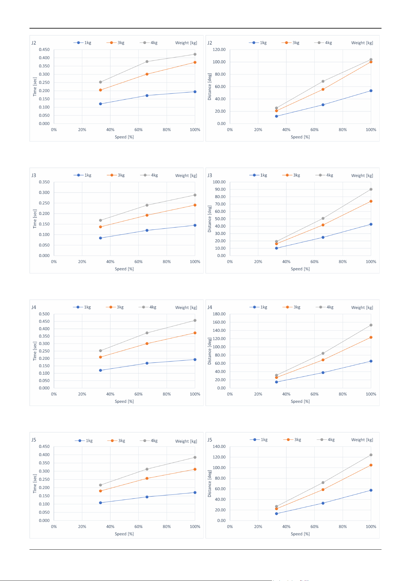
C4-B601**: J3 (Table top mounting, Ceiling mounting)
C4-B601**: J4 (Table top mounting, Ceiling mounting)
C4-B601**: J5 (Table top mounting, Ceiling mounting)
Industrial Robot: 6-Axis Robots C-B series Manual Rev.1b
271
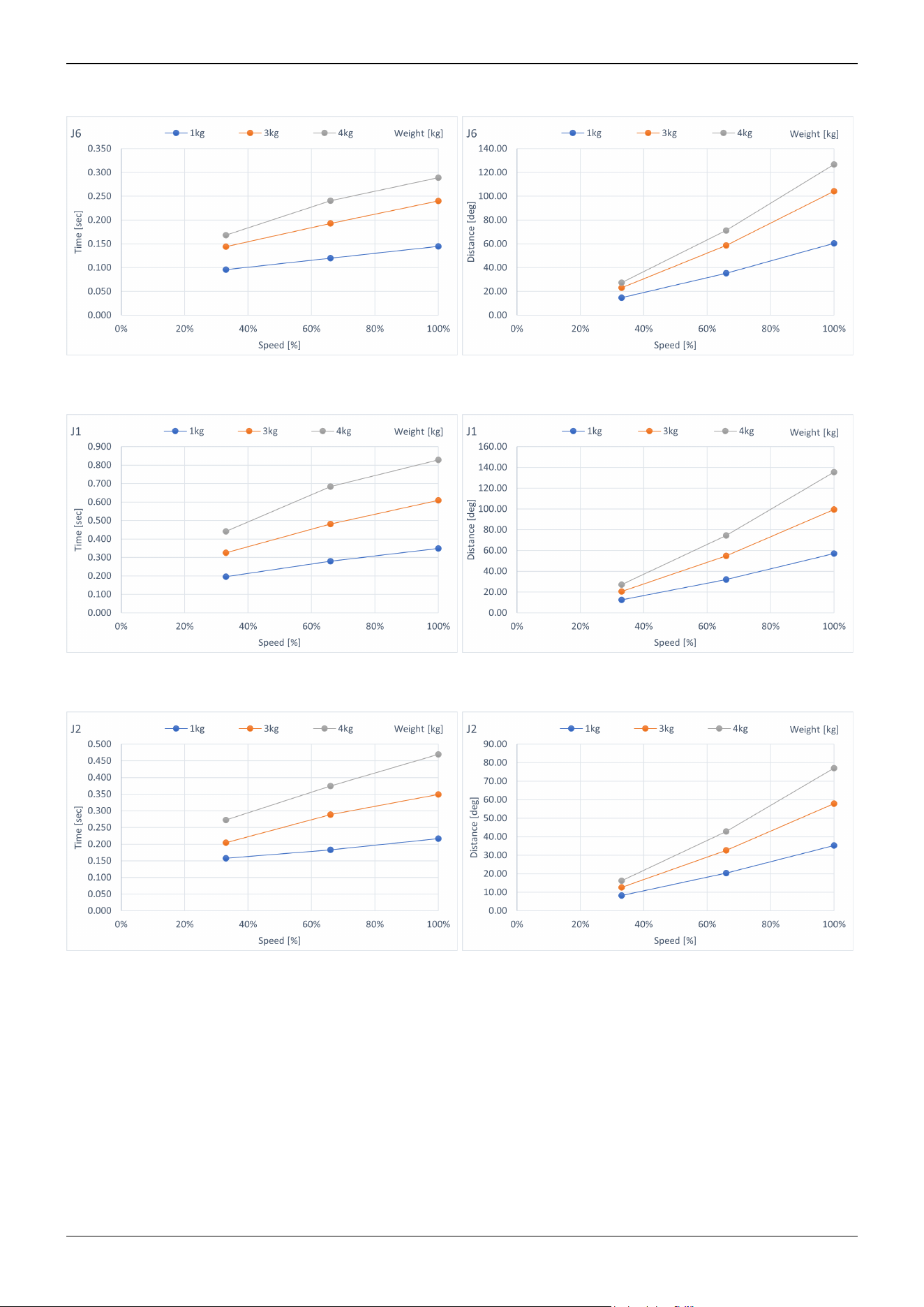
C4-B601**: J6 (Table top mounting, Ceiling mounting)
C4-B901**: J1 (Table top mounting, Ceiling mounting)
C4-B901**: J2 (Table top mounting, Ceiling mounting)
C4-B901**: J3 (Table top mounting, Ceiling mounting)
Industrial Robot: 6-Axis Robots C-B series Manual Rev.1b
272
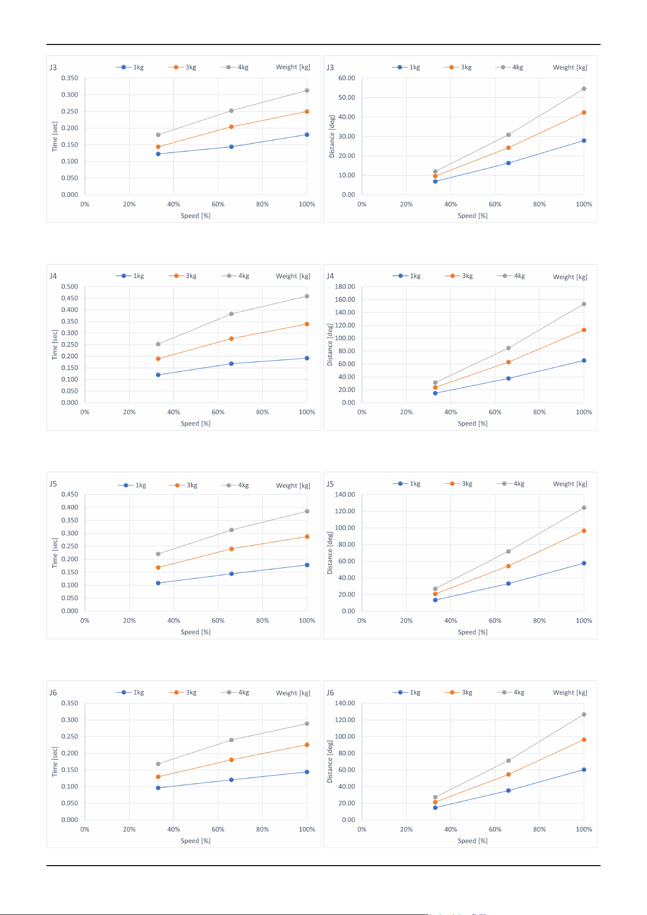
C4-B901**: J4 (Table top mounting, Ceiling mounting)
C4-B901**: J5 (Table top mounting, Ceiling mounting)
C4-B901**: J6 (Table top mounting, Ceiling mounting)
Industrial Robot: 6-Axis Robots C-B series Manual Rev.1b
273
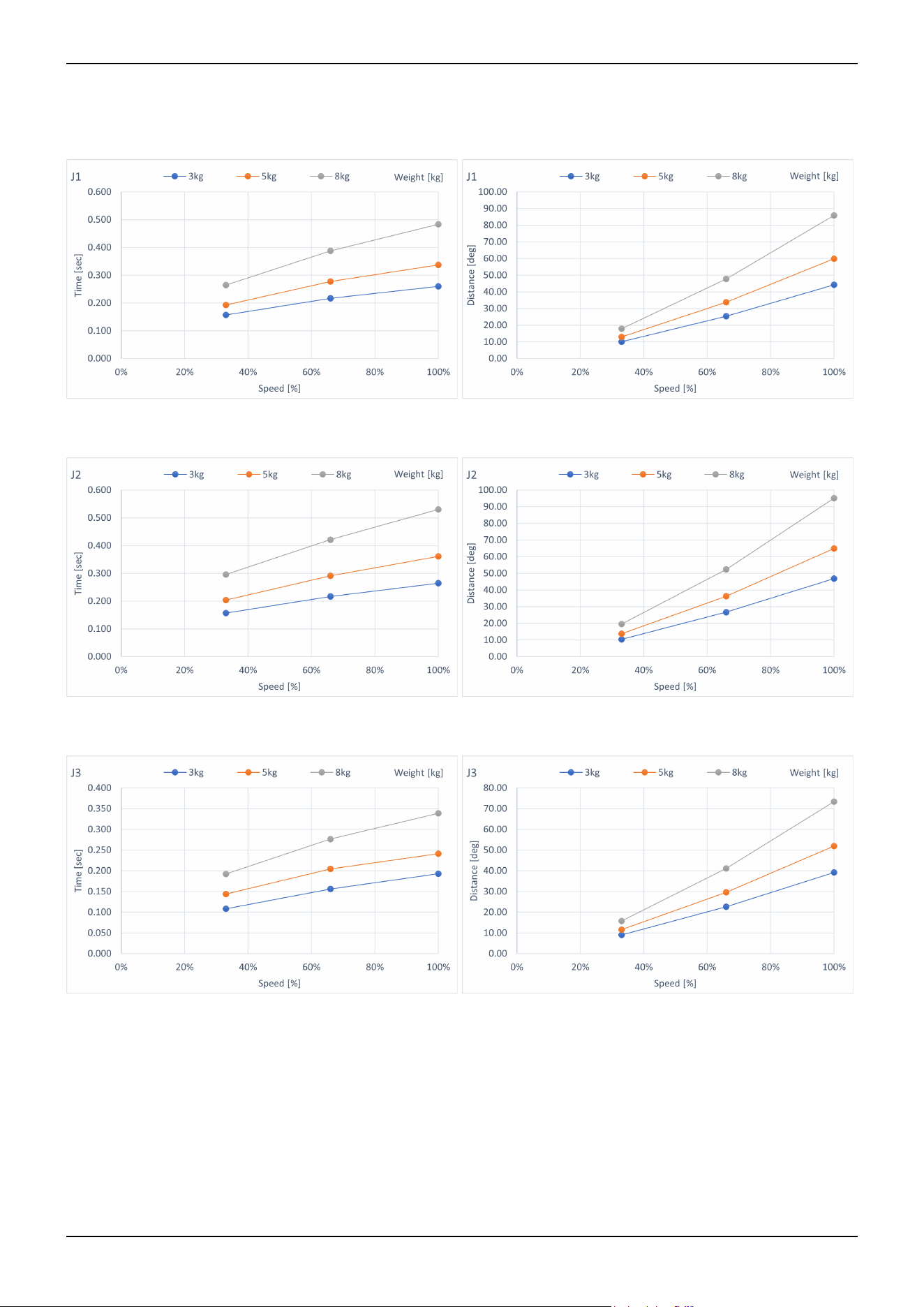
6.3.2 C8-B Stopping Time and Stopping Distance When Safeguard is Open
C8-B901***: J1 (Table top mounting, Ceiling mounting)
C8-B901***: J2 (Table top mounting, Ceiling mounting)
C8-B901***: J3 (Table top mounting, Ceiling mounting)
C8-B901***: J4 (Table top mounting, Ceiling mounting)
Industrial Robot: 6-Axis Robots C-B series Manual Rev.1b
274
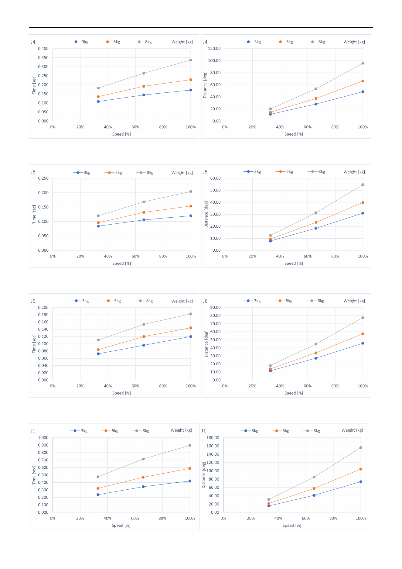
C8-B901***: J5 (Table top mounting, Ceiling mounting)
C8-B901***: J6 (Table top mounting, Ceiling mounting)
C8-B901***: J1 (Wall mounting)
Industrial Robot: 6-Axis Robots C-B series Manual Rev.1b
275
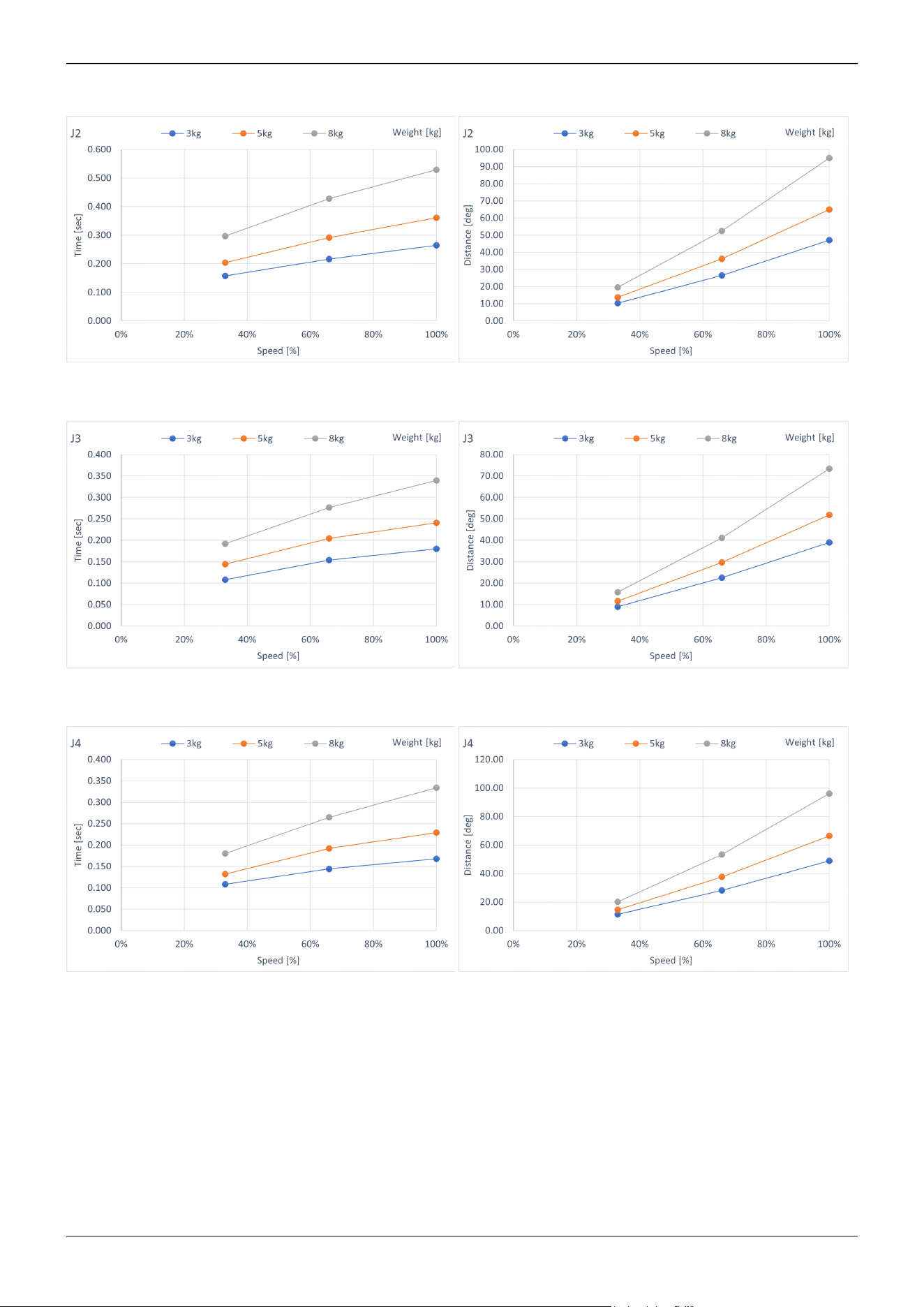
C8-B901***: J2 (Wall mounting)
C8-B901***: J3 (Wall mounting)
C8-B901***: J4 (Wall mounting)
C8-B901***: J5 (Wall mounting)
Industrial Robot: 6-Axis Robots C-B series Manual Rev.1b
276
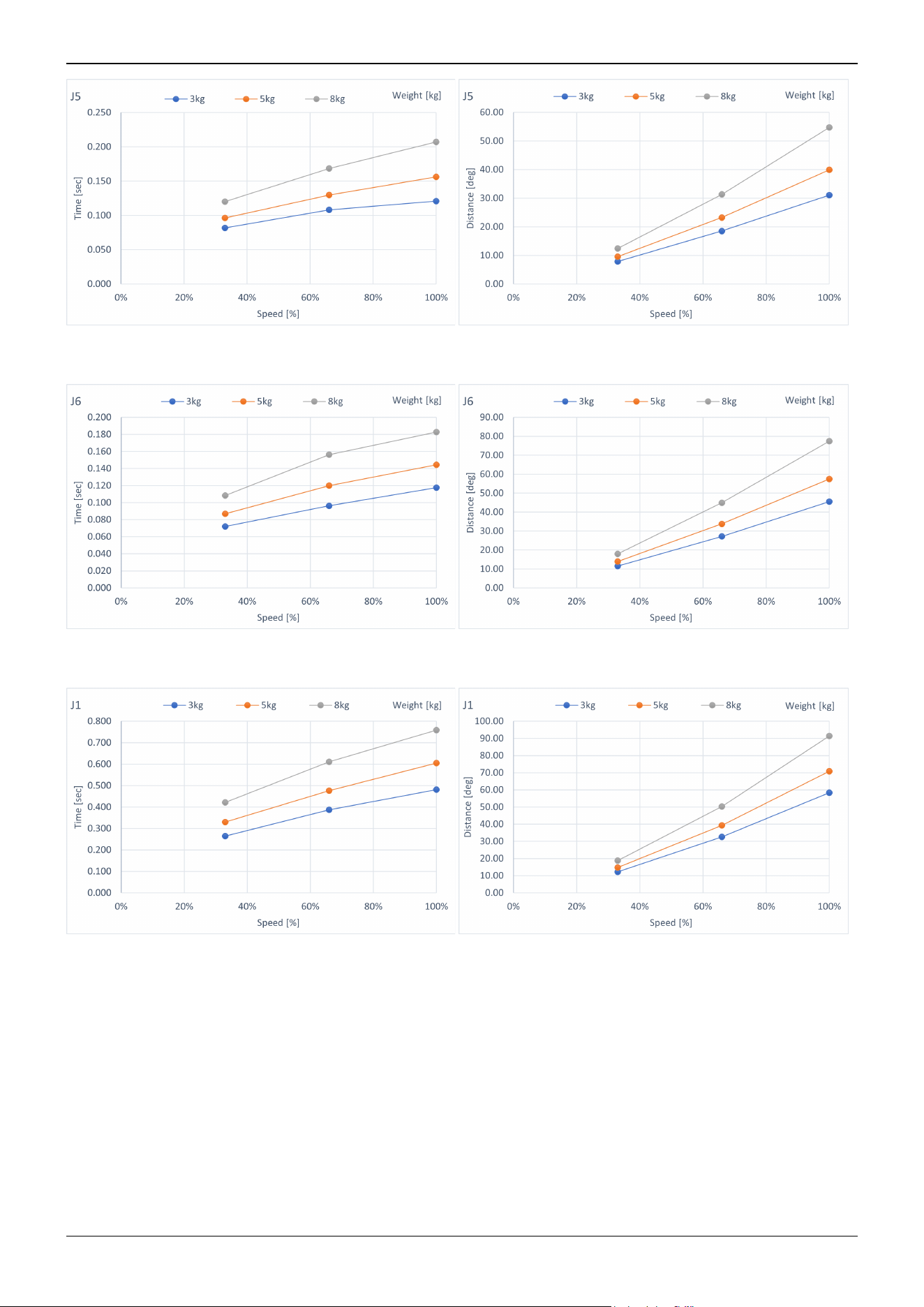
C8-B901***: J6 (Wall mounting)
C8-B1401***: J1 (Table top mounting, Ceiling mounting)
C8-B1401***: J2 (Table top mounting, Ceiling mounting)
Industrial Robot: 6-Axis Robots C-B series Manual Rev.1b
277
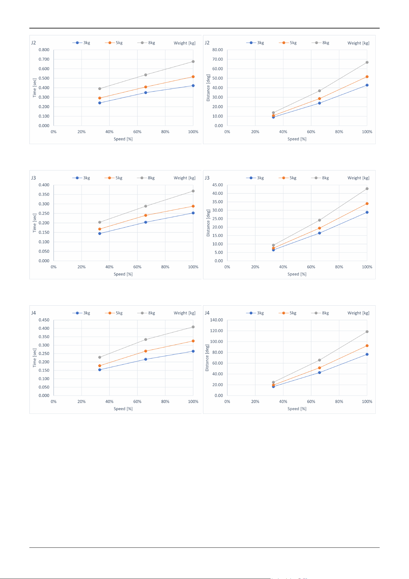
C8-B1401***: J3 (Table top mounting, Ceiling mounting)
C8-B1401***: J4 (Table top mounting, Ceiling mounting)
C8-B1401***: J5 (Table top mounting, Ceiling mounting)
Industrial Robot: 6-Axis Robots C-B series Manual Rev.1b
278
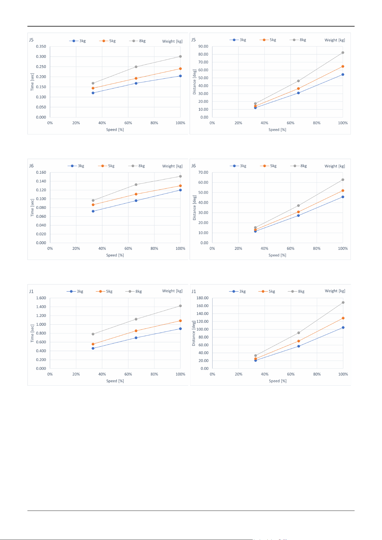
C8-B1401***: J6 (Table top mounting, Ceiling mounting)
C8-B1401***: J1 (Wall mounting)
C8-B1401***: J2 (Wall mounting)
Industrial Robot: 6-Axis Robots C-B series Manual Rev.1b
279
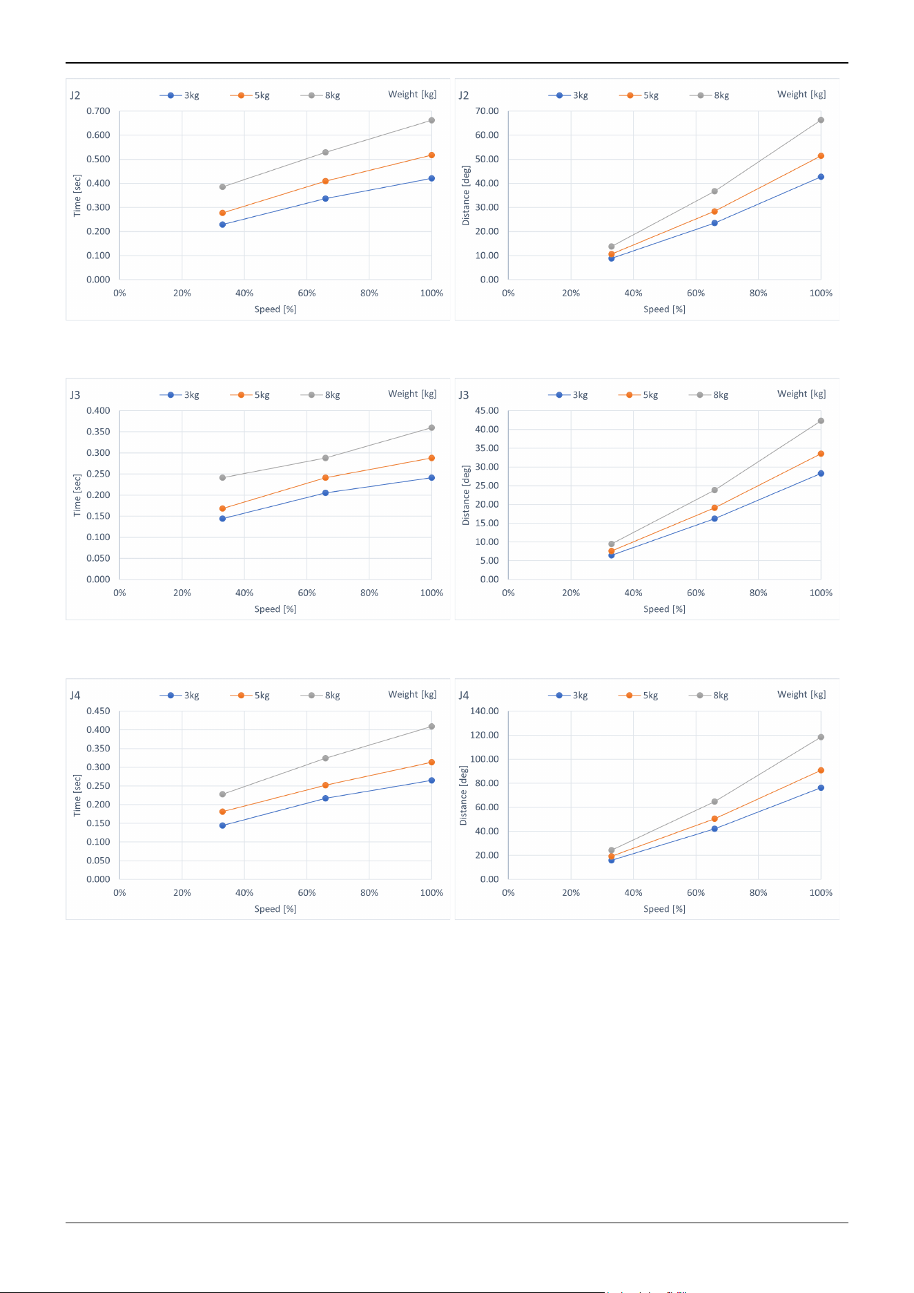
C8-B1401***: J3 (Wall mounting)
C8-B1401***: J4 (Wall mounting)
C8-B1401***: J5 (Wall mounting)
Industrial Robot: 6-Axis Robots C-B series Manual Rev.1b
280
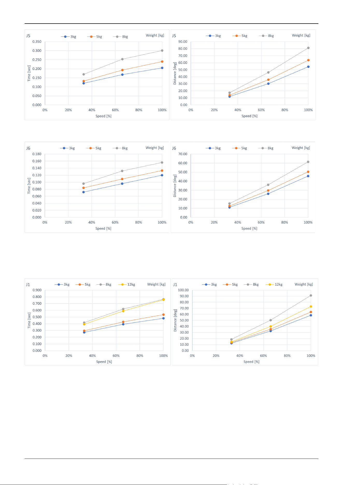
C8-B1401***: J6 (Wall mounting)
6.3.3 C12-B Stopping Time and Stopping Distance When Safeguard is Open
C12-B1401**: J1 (Table top mounting)
C12-B1401**: J2 (Table top mounting)
Industrial Robot: 6-Axis Robots C-B series Manual Rev.1b
281
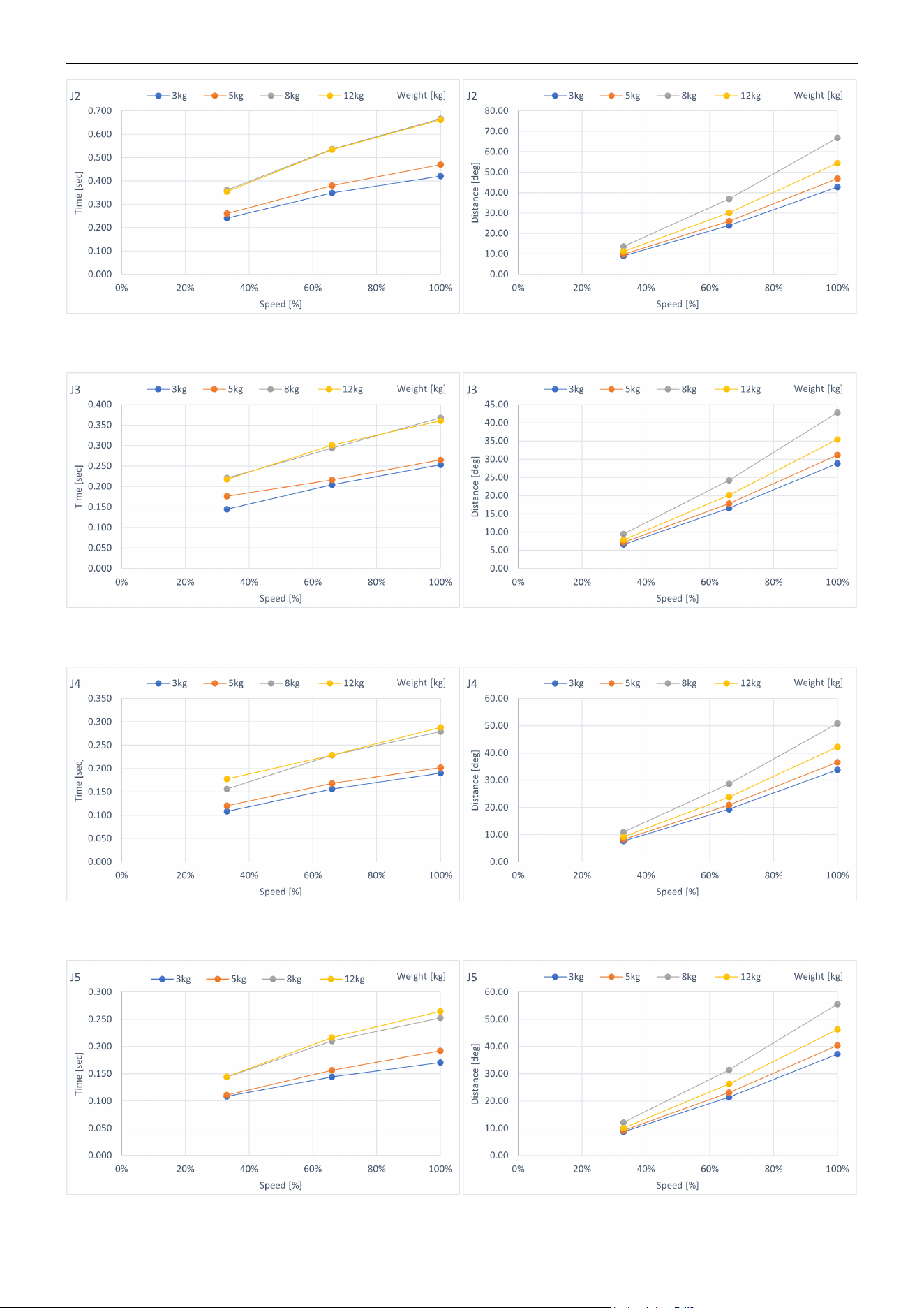
C12-B1401**: J3 (Table top mounting)
C12-B1401**: J4 (Table top mounting)
C12-B1401**: J5 (Table top mounting)
Industrial Robot: 6-Axis Robots C-B series Manual Rev.1b
282
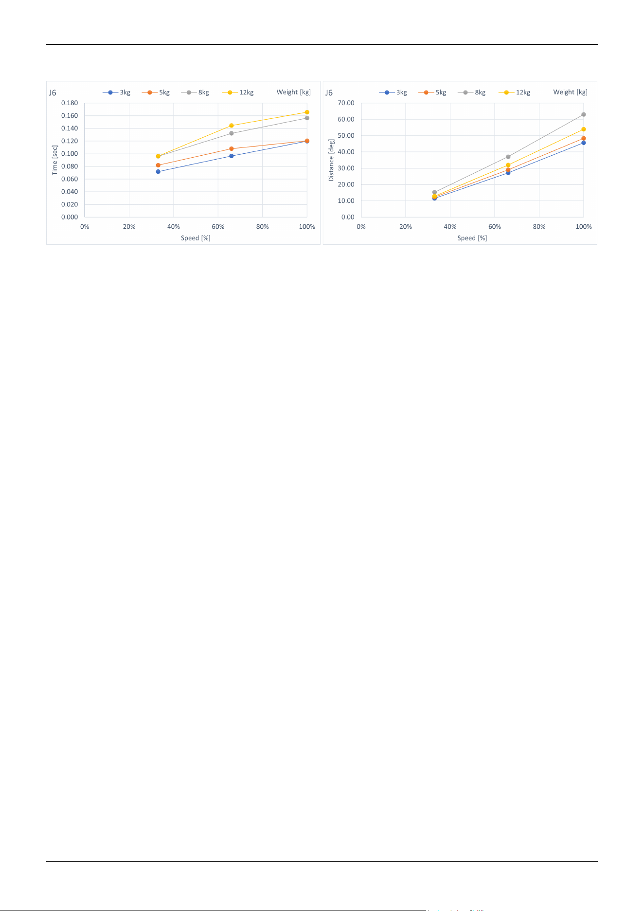
C12-B1401**: J6 (Table top mounting)
Industrial Robot: 6-Axis Robots C-B series Manual Rev.1b
283