Installation, Instruction & Service Manual
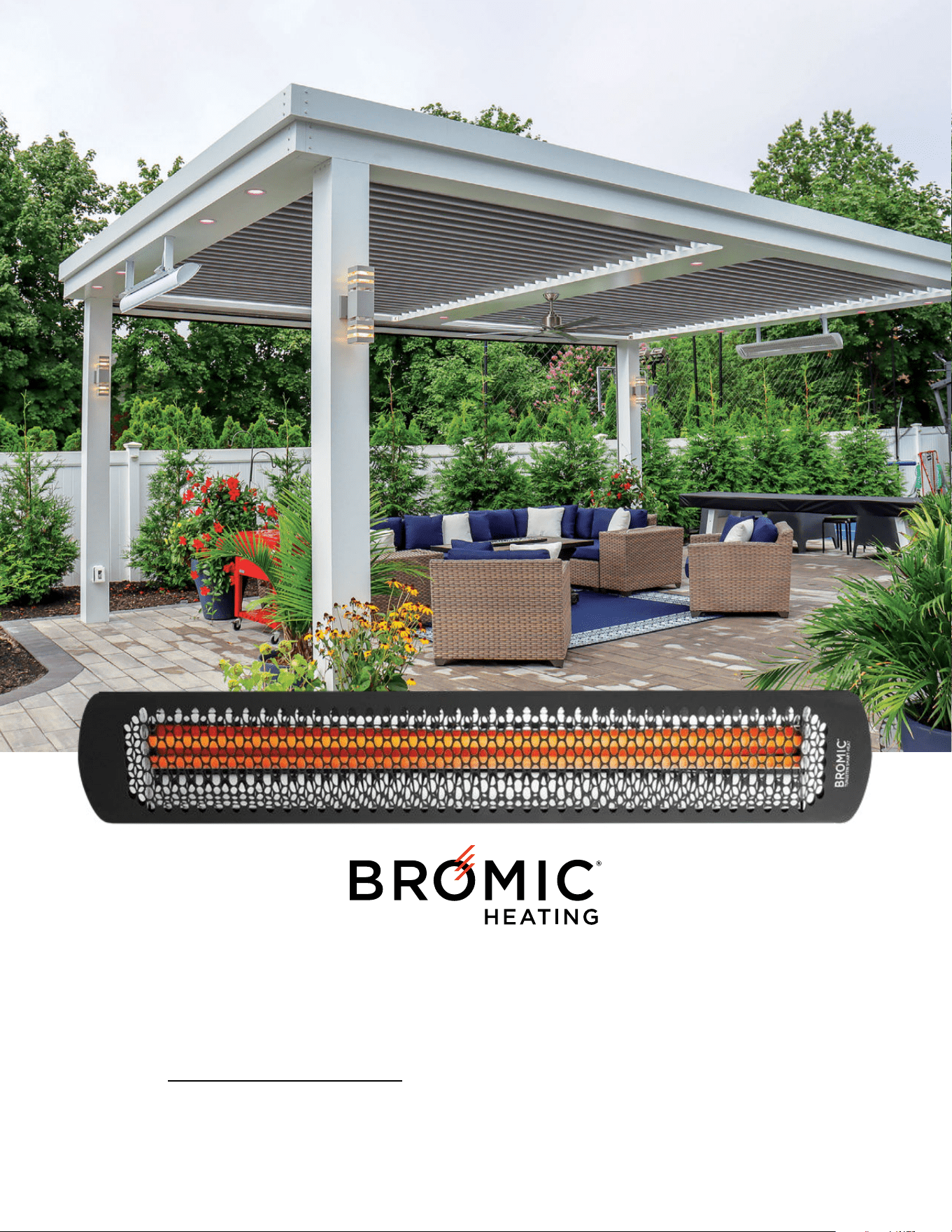
TUNGSTEN SMART-HEAT™ ELECTRIC
Suitable for Electric Models: Tungsten 2000W, 3000W, 4000W and 6000W
IMPORTANT: Read this manual carefully. See inside for important information about this manual.
Keep instruction with appliance for future reference.
www.bromic.com
2 | Telephone: 1(800) 301-1293 | Email: ServiceUSA@BromicGroup.com | Web: www.bromic.com | ©2025 Bromic Group. All Rights Reserved.
TUNGSTEN SMART-HEAT™ ELECTRIC | INSTALLATION, INSTRUCTION & SERVICE MANUAL
CONTENTS
Important notes & warnings ...........................................................................pg. 3
Product Overview ...........................................................................................pg. 4
Heater Installation ..........................................................................................pg. 5
Ceiling & Wall Mounting .................................................................................pg. 6
Chain Suspension ..........................................................................................pg. 6
Tube Suspension ............................................................................................ pg. 7
Ceiling Recess Kit ...................................................................................... pg. 8-9
Element Installation ................................................................................ pg. 10-11
Electrical Installation .....................................................................................pg. 12
Wiring Diagram ............................................................................................. pg. 13
Wiring Diagram & Control Options ...............................................................pg. 14
Servicing ....................................................................................................... pg. 15
Replacement Part List ..................................................................................pg. 16
Troubleshooting ............................................................................................ pg. 16
PROP 65 WARNING FOR
CALIFORNIA RESIDENTS
Cancer and Reproductive harm.
www.P65warnings.ca.gov
AVERTISSEMENT PROP. 65 POUR LES
RESIDENTS DE LA CALIFORNIE
Cancer et Troubles
de l’apparell reproducteur.
www.P65warnings.ca.gov
ADVERTENCIA PROP. 65 PARA LOS
RESIDENTES DE CALIFORNIA
Cancer y Daño Reproductivo.
www.P65warnings.ca.gov
3 | Telephone: 1(800) 301-1293 | Email: ServiceUSA@BromicGroup.com | Web: www.bromic.com | ©2025 Bromic Group. All Rights Reserved.
TUNGSTEN SMART-HEAT™ ELECTRIC | INSTALLATION, INSTRUCTION & SERVICE MANUAL
IMPORTANT NOTES & WARNINGS
WARNING
• Read all instructions before installing or using this heater
• Use this heater only as described in this manual. Any other use not
recommended by the manufacturer may cause fire, electric shock, or
injury to persons.
• Improper installation, adjustment, or alteration and failure to follow the
warnings and instructions in this manual could result in severe personal
injury, death or property damage.
• The manufacturer is not responsible for any damage that could
happen from improper use. The manufacturer emphasises that
this appliance should be used in a responsible manner and that
all procedures, warnings, and safety instructions contained in this
booklet be followed strictly.
• This heater is not intended for use in bathrooms, laundry areas and
similar indoor locations. Never locate heater where it may fall into a
bathtub or other water container.
• Do not install the heater directly near a bathtub, shower or swimming
pool. Any switches or controls must not be within reach of a person in
the bathtub, shower or swimming pool.
• This heater is hot when in use. To avoid burns do not let bare skin
touch hot surfaces. Keep combustible materials such as furniture,
pillows, bedding, papers, clothes , etc. and curtains at least 3’
(900mm) from the front of the heater and keep them away from the
sides and rear.
• Extreme caution is necessary when any heater is used by or near children
or invalids and whenever the heater is left operating and unattended.
• This appliance is not intended for use by persons (including children) with
reduced physical, sensory or mental capabilities, or lack of experience
and knowledge, unless they have been given supervision or instruction
concerning use of the appliance by a person responsible for their safety.
• Keep packaging materials out of reach of children
• Children and adults should be alerted to the hazards of high surface
temperatures and should stay away to avoid burns, clothing ignition, or
other serious personal injury
• Children should be carefully supervised when they are in the area of
the heater.
• Do not attempt to alter the unit in any manner.
• Do not paint any surface of the heater.
• Do not touch the heater with wet hands at any time.
• Do not insert or allow foreign objects to enter front cover or front opening
as this may cause an electric shock or fire, or damage the heater
• Do not touch the heating surface at any time, even when the heater is
turned off and has cooled down.
• Do not use or store flammable materials near this appliance
• Do not spray aerosols or flammable materials in the vicinity of this
appliance while it is in operation
• Never operate the heater in an explosive environment such as areas
where petrol or other flammable liquids or vapours are stored.
• Clothing or other flammable materials should not be hung from the
heater or placed on or near the heater.
INSTALLATION
• IMPORTANT - Installation must be carried out by a licensed and
authorised person.
• The installer is to ensure that the requirements of the local authority,
local electrical installation code, municipal building codes, and any
other relevant statutory regulations are carried out.
• After unpacking, make sure the appliance shows no signs of visible
damage or tampering. If the appliance appears damaged, contact the
place of purchase for assistance.
• Remove transit protection before use.
• This appliance is intended for fixed installation with voltage as specified
on the appliance rating label.
• This radiant heater is NOT intended to be installed on recreational
vehicles and/or boats.
• Do not run cord under carpeting. Do not cover with throw rugs, runners
or the like. Arrange cord away from traffic area and where it will not be
tripped over
• A heater has hot, arcing or sparking parts inside. Do not use it in areas
where gasoline, paint or flammable liquids are used or stored.
• To maintain Ingress Protection Rating (IPX4), only IPX4 rated conduit
fittings should be used for electrical installation.
• This Installation, Operation and Service manual should not be removed
from the site of installation. Installer should leave manual with the
customer for future reference.
• Any guard or other protective device removed for servicing (conducted
by an authorised person) must be replaced before operating the heater.
• Heaters are not intended to be installed in wardrobes.
• The appliance must not be located directly below or in front of a wall
electricity socket. This is because the heat radiated from the appliance
may damage the electricity outlet or plug.
• If the appliance has not been used, or will not be used, for a long period
of time, disconnect power supply
• A means for disconnection of the heater must be incorporated in the
fixed wiring according to the local electrical codes.
• Do not mount the heater vertically. Install Heater so that the infrared
elements are Horizontal. Failure to do this may cause the heating
element within the tube to sag and cause premature burnout. Installing
vertically will void the manufacturer’s warranty.
CLEARANCE
• Do not place articles on or against this appliance
• A minimum safety distance of 3’ (900mm) should always be left in front
of the appliance.
• Be sure the heater is not facing the ceiling or installed near flammable,
combustible or heat sensitive materials
MAINTENANCE/REPAIR
• Installation and repair must be carried out by a qualified & licensed service
person only. The heater should be inspected before use and at least
annually serviced & inspected by a qualified & licensed service person.
• Do not perform maintenance until heater has been turned off, power
disconnected, and heater temperature has cooled to room temperature.
• Check for damage to the appliance regularly. If damage to the
appliance is suspected, discontinue use immediately and contact the
supplier or qualified person to repair.
• If the supply cord is damaged, it must be replaced by an authorized
and licensed person in order to avoid a hazard.
• At the end of this product’s useful life, it must not be disposed of as
domestic waste, but must be taken to a collection centre for waste
electrical and electronic equipment. It is the user’s responsibility to
dispose of this appliance through the appropriate channels at the end
of its useful life. Failure to do so may incur the penalties established
by laws governing waste disposal. Proper differential collection, and
the subsequent recycling, processing and environmentally compatible
disposal of waste equipment avoids unnecessary damage to the
environment and possible related health risks, and also promotes
recycling of the materials used in the appliance. For further information
on waste collection and disposal, contact your local waste disposal
service, or the place of purchase.
4 | Telephone: 1(800) 301-1293 | Email: ServiceUSA@BromicGroup.com | Web: www.bromic.com | ©2025 Bromic Group. All Rights Reserved.
TUNGSTEN SMART-HEAT™ ELECTRIC | INSTALLATION, INSTRUCTION & SERVICE MANUAL
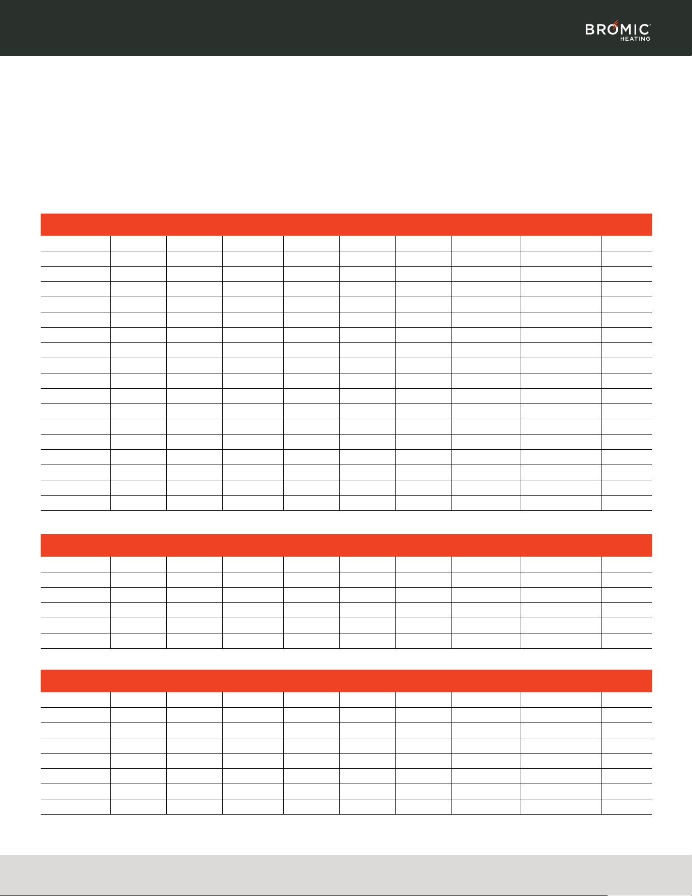
PRODUCT OVERVIEW
PRODUCT FEATURES
• The Tungsten Smart-Heat Electric heaters are designed to provide
efficient spot heating for commercial and residential applications.
• Suitable for indoor and outdoor heating applications such as
restaurants, cafes, bars and clubs, factories, office spaces, designated
smoking areas, public areas, hotels and more.
• The heaters are available in 2000W, 3000W, 4000W and 6000W models
to suit a range of environments.
• High temperature corrosion-resistant coating.
• IPX4 water ingress protection rating.
• Soft glow infrared heating element - No harsh glare.
• Standard mounting hardware included for wall or ceiling mount allowing
for adjustable angle of the heating direction.
• Heater is equipped with spectral reflector for excellent radiant heat output.
• Registered Design
NORTH AMERICA
MODEL COLOR ELEMENTS
BRACKET
LENGTH
VOLTAGE AMPS WATTS
HEATING
AREA
DIMENSIONS
WEIGHT
(LBS)
BH0420033 Black 2 9.5" 240V 25A 6000W up to 144ft² 56" x 8.5" x 3.5" 22
BH0420032 Black 2 9.5" 240V 16.6A 4000W up to 120ft² 44" x 8.5" x 3.5" 19.8
BH0420031 Black 1 6.5" 240V 12.5A 3000W up to 100ft² 56" x 8.5" x 3.5" 22
BH0420030 Black 1 6.5" 240V 8.3A 2000W up to 64ft² 44" x 8.5" x 3.5" 19.8
BH0420013 White 2 9.5" 240V 25A 6000W up to 144ft² 56" x 8.5" x 3.5" 22
BH0420012 White 2 9.5" 240V 16.6A 4000W up to 120ft² 44" x 8.5" x 3.5" 19.8
BH0420035 Black 2 9.5" 208V 28.85A 6000W up to 144ft² 56" x 8.5" x 3.5" 22
BH0420034 Black 2 9.5" 208V 19.23A 4000W up to 120ft² 44" x 8.5" x 3.5" 19.8
BH0420038 Black 1 6.5" 208V 14.42A 3000W up to 100ft² 56" x 8.5" x 3.5" 22
BH0420039 Black 1 6.5" 208V 9.62A 2000W up to 64ft² 44" x 8.5" x 3.5" 19.8
BH0420036 White 2 9.5" 208V 28.85A 6000W up to 144ft² 56" x 8.5" x 3.5" 22
BH0420037 White 2 9.5" 208V 19.23A 4000W up to 120ft² 44" x 8.5" x 3.5" 19.8
BH0420043 Black 2 9.5" 277V 21.66A 6000W up to 144ft² 56" x 8.5" x 3.5" 22
BH0420042 Black 2 9.5" 277V 14.44A 4000W up to 120ft² 44" x 8.5" x 3.5" 19.8
BH0420041 Black 1 6.5" 277V 10.83A 3000W up to 100ft² 56" x 8.5" x 3.5" 22
BH0420040 Black 1 6.5" 277V 7.22A 2000W up to 64ft² 44" x 8.5" x 3.5" 19.8
BH0420045 White 2 9.5" 277V 21.66A 6000W up to 144ft² 56" x 8.5" x 3.5" 22
BH0420044 White 2 9.5" 277V 14.44A 4000W up to 120ft² 44" x 8.5" x 3.5" 19.8
AUSTRALIA/NEW ZEALAND
MODEL COLOR ELEMENTS
BRACKET
LENGTH
VOLTAGE AMPS WATTS
HEATING
AREA
DIMENSIONS
WEIGHT
(LBS)
2620265 Black 2 9.5" 240V 25A 6000W up to 144ft² 56" x 8.5" x 3.5" 22
2620264 Black 2 9.5" 240V 16.6A 4000W up to 120ft² 44" x 8.5" x 3.5" 19.8
2620263 Black 1 6.5" 240V 12.5A 3000W up to 100ft² 56" x 8.5" x 3.5" 22
2620262 Black 1 6.5" 240V 8.3A 2000W up to 64ft² 44" x 8.5" x 3.5" 19.8
2620269 White 2 9.5" 240V 25A 6000W up to 144ft² 56" x 8.5" x 3.5" 22
2620268 White 2 9.5" 240V 16.6A 4000W up to 120ft² 44" x 8.5" x 3.5" 19.8
EUROPE
MODEL COLOR ELEMENTS
BRACKET
LENGTH
VOLTAGE AMPS WATTS
HEATING
AREA
DIMENSIONS
WEIGHT
(LBS)
BH0420025 Black 2 9.5" 240V 25A 6000W up to 144ft² 56" x 8.5" x 3.5" 22
BH0420024 Black 2 9.5" 240V 16.6A 4000W up to 120ft² 44" x 8.5" x 3.5" 19.8
BH0420023 Black 1 6.5" 240V 12.5A 3000W up to 100ft² 56" x 8.5" x 3.5" 22
BH0420022 Black 1 6.5" 240V 8.3A 2000W up to 64ft² 44" x 8.5" x 3.5" 19.8
BH0420029 White 2 9.5" 240V 25A 6000W up to 144ft² 56" x 8.5" x 3.5" 22
BH0420028 White 2 9.5" 240V 16.6A 4000W up to 120ft² 44" x 8.5" x 3.5" 19.8
BH0420027 White 1 6.5" 240V 12.5A 3000W up to 100ft² 56" x 8.5" x 3.5" 22
BH0420026 White 1 6.5" 240V 8.3A 2000W up to 64ft² 44" x 8.5" x 3.5" 19.8
Certification: INTERTEK ETL / cETL 4005951
Note: All models may not be available in all regions
5 | Telephone: 1(800) 301-1293 | Email: ServiceUSA@BromicGroup.com | Web: www.bromic.com | ©2025 Bromic Group. All Rights Reserved.
TUNGSTEN SMART-HEAT™ ELECTRIC | INSTALLATION, INSTRUCTION & SERVICE MANUAL
HEATER INSTALLATION
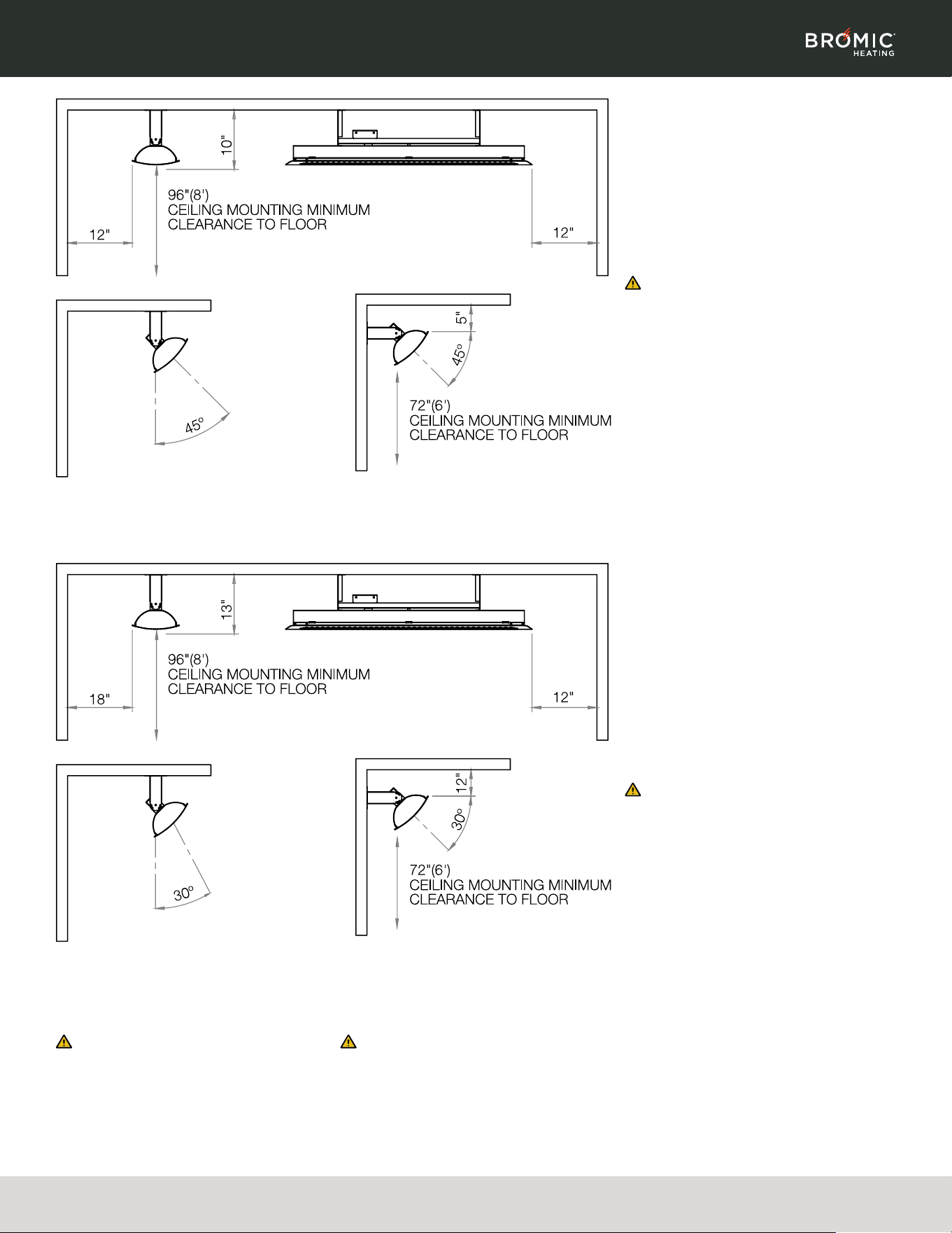
INSTALLATION CLEARANCES
FOR 2000W & 3000W MODELS
2000W & 3000w models must be installed
with the minimum installation clearances as
illustrated. 2000W & 3000W models are supplied
with 6.5" mounting brackets to be used for both
ceiling & wall mounting.
FOR CANADA (CETL) APPROVAL DO NOT
INSTALL LESS THAN 96" (8’) FROM THE FLOOR.
WARNING
MINIMUM DISTANCE BETWEEN HEATERS
MEASURED FROM EDGE OF HEATER MUST
BE AT LEAST 20"
The stated clearance to combustible or
heat sensitive materials represents surface
temperature of 117ºF above room temperature.
Building material with a low heat tolerance (such
as plastic, vinyl siding, canvas, tri-ply etc.) may
subject to degradation at lower temperature.
It is the installer's responsibility to assure that
adjacent materials are protected.
INSTALLATION CLEARANCES
FOR 4000W & 6000W MODELS
4000W & 6000W models must be installed
with the minimum installation clearances as
illustrated. 4000W & 6000W models are supplied
with 9.5" mounting brackets to be used for
both ceiling & wall mounting. Alternatively,
short mounting brackets can be used for wall
mounting of the 4000W & 6000W models
to position the heater closer to the wall.
Short mounting brackets must be purchased
separately.
FOR CANADA (CETL) APPROVAL DO NOT
INSTALL LESS THAN 96" (8’) FROM THE FLOOR.
WARNING
MINIMUM DISTANCE BETWEEN HEATERS
MEASURED FROM EDGE OF HEATER MUST
BE AT LEAST 20"
The stated clearance to combustible or
heat sensitive materials represents surface
temperature of 117ºF above room temperature.
Building material with a low heat tolerance
(such as plastic, vinyl siding, canvas, tri-ply etc.)
may subject to degradation. It is the installer's
responsibility to assure that adjacent materials
are protected.
WARNING
DO NOT MOUNT THE HEATER VERTICALLY!
Heater MUST be installed so that the tube
elements are horizontal. Failure to do this will
cause the heating element within the tube to
sag and cause premature burnout. Installing
vertically will void the manufacturers warranty.
WARNING
OUTDOOR INSTALLATION RECOMMENDATION
For outdoor installation heater must be mounted
with face of heater angled down. For longest
product life & to maintain product appearance
mount heater under cover & protect from rain &
weather whenever possible.
6 | Telephone: 1(800) 301-1293 | Email: ServiceUSA@BromicGroup.com | Web: www.bromic.com | ©2025 Bromic Group. All Rights Reserved.
TUNGSTEN SMART-HEAT™ ELECTRIC | INSTALLATION, INSTRUCTION & SERVICE MANUAL
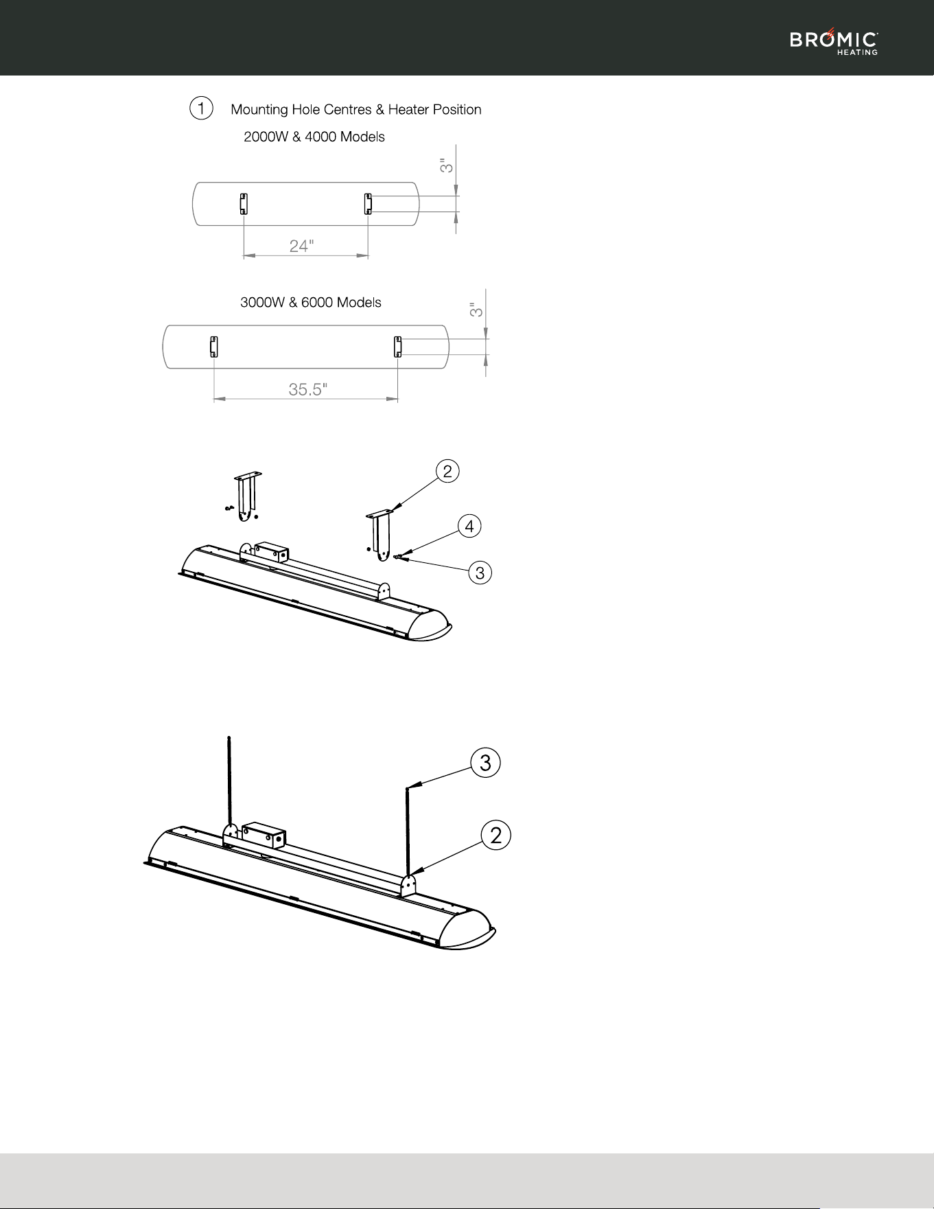
CEILING & WALL MOUNTING
1. Mark mounting hole centres on ceiling or wall.
2. Attach mounting brackets to ceiling or wall
using appropriate fasteners (not supplied).
3. Bring heater up to mounting brackets and
lock into position with M5x10 screw & nut.
4. Rotate heater to required angle. Lock into
position with self tapping screw.
5. Make electrical connection from heater to
power supply.
CHAIN SUSPENSION (SOLD SEPARATELY)
1. Heater must be installed with a heater surface
96"(8') above the floor level. Chain to be
provided and sized by the installer to hold the
weight of the heater.
2. Attach chains to heater with "S" hooks. Crimp
"S" hooks closed after assembly.
3. Prepare ceiling structure for heater. Attach
chains to ceiling structure & suspend heater.
4. Make electrical connection from heater to
power supply. If required fix supply power
cord to ceiling chain with cable ties.
7 | Telephone: 1(800) 301-1293 | Email: ServiceUSA@BromicGroup.com | Web: www.bromic.com | ©2025 Bromic Group. All Rights Reserved.
TUNGSTEN SMART-HEAT™ ELECTRIC | INSTALLATION, INSTRUCTION & SERVICE MANUAL
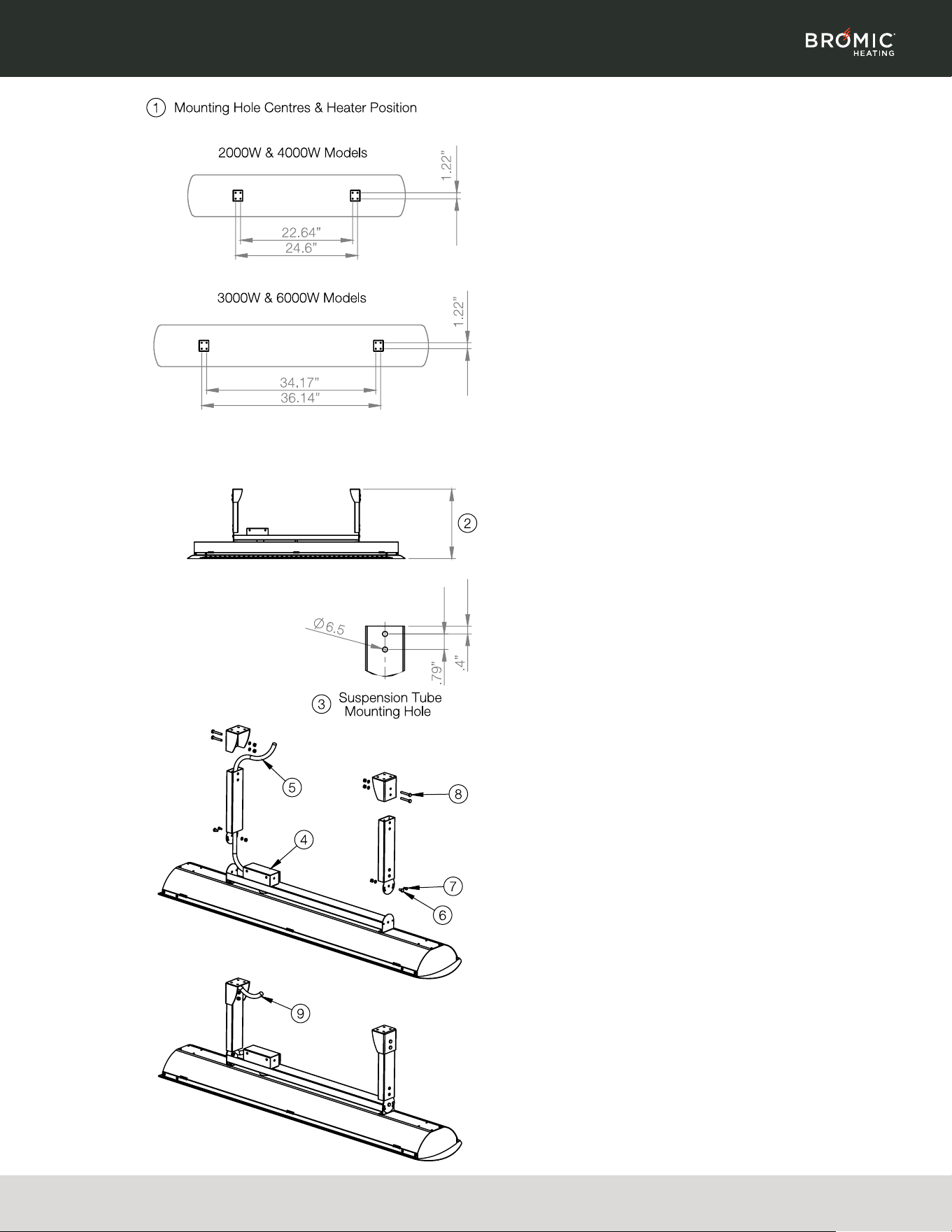
TUBE SUSPENSION (SOLD SEPARATELY)
1. Mark mounting hole centres on ceiling.
Attach mounting brackets to ceiling using
appropriate fasteners (not supplied).
2. Heater must be installed with heater surface
at least 96"(8') above the floor level. Supplied
suspension tubes position heater surface
39.39" below the ceiling surface. If required
cut down length of suspension tubes to
ensure correct installation height. Minimum
distance from front surface of heater to ceiling
surface must be 9.84" for 2000W & 3000W
models and 13" for 4000W & 6000W models.
3. If suspension tube are cut down, drill new
mounting holes in each tube.
4. Make electrical connection in junction box
as per electrical installation instructions in
this manual.
5. Feed power cord through suspension tube.
6. Assemble suspension tubes to rear bracket
with M5 screw, spring washer and nut.
7. Rotate heater to required angle. 15º, 30º or 45º
in either direction. Note: angle varies by model.
Lock into position with self tapping screw.
8. Raise heater assembly into position. Attach
suspension tubes to ceiling brackets with
M5x1-3/8" screws, spring washers & nuts.
9. Make electrical connection from suspension
tube power cord to power ceiling as per
electrical installation instructions in this manual.
8 | Telephone: 1(800) 301-1293 | Email: ServiceUSA@BromicGroup.com | Web: www.bromic.com | ©2025 Bromic Group. All Rights Reserved.
TUNGSTEN SMART-HEAT™ ELECTRIC | INSTALLATION, INSTRUCTION & SERVICE MANUAL
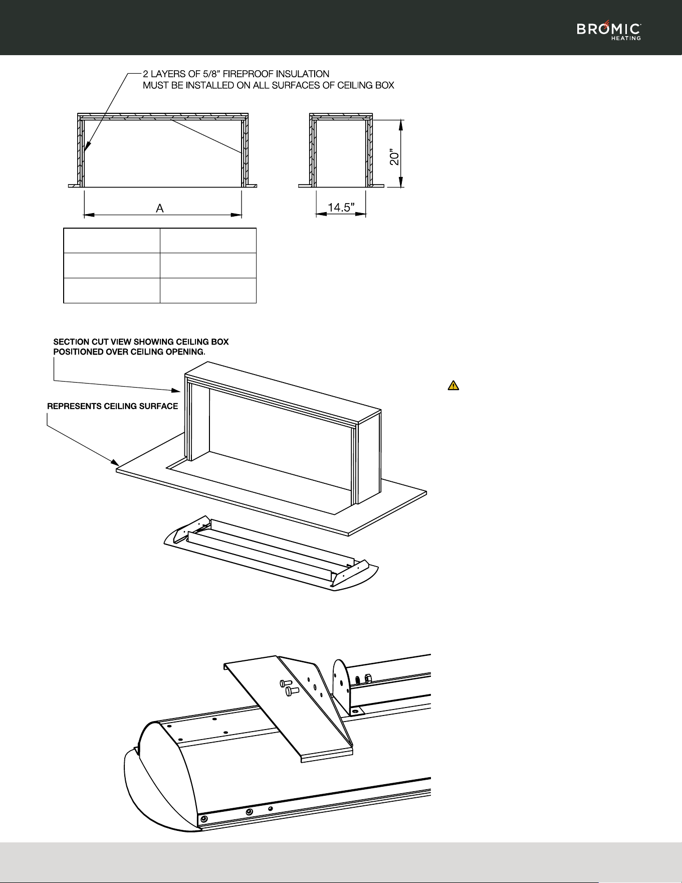
CEILING RECESS KIT (SOLD SEPARATELY)
1. Prepare ceiling cut out and ceiling box.
Minimum ceiling box dimensions must be as
shown in table. Heater must be installed with
heater surface at 96"(8') above the floor level.
2. From below, bring ceiling frame up into ceiling
cut out.
3. Fasten ceiling frame to ceiling box through
mounting holes with fasteners (not supplied).
4. Prepare heater for installation. Attach
mounting brackets to both ends of heater
with supplied fasteners.
Notes:
• Ceiling box to be provided by reinstall.
• Suitable material includes Hardie, cement
board or similar.
• If ceiling box sits above joists it is
recommended to line joists with fireproof
insulation.
WARNING
MINIMUM DISTANCE BETWEEN HEATERS
MEASURED FROM EDGE OF HEATER MUST
BE AT LEAST 20"
MODEL DIMENSION "A"
2000W & 4000W 46"
3000W & 6000W 57.5"
9 | Telephone: 1(800) 301-1293 | Email: ServiceUSA@BromicGroup.com | Web: www.bromic.com | ©2025 Bromic Group. All Rights Reserved.
TUNGSTEN SMART-HEAT™ ELECTRIC | INSTALLATION, INSTRUCTION & SERVICE MANUAL
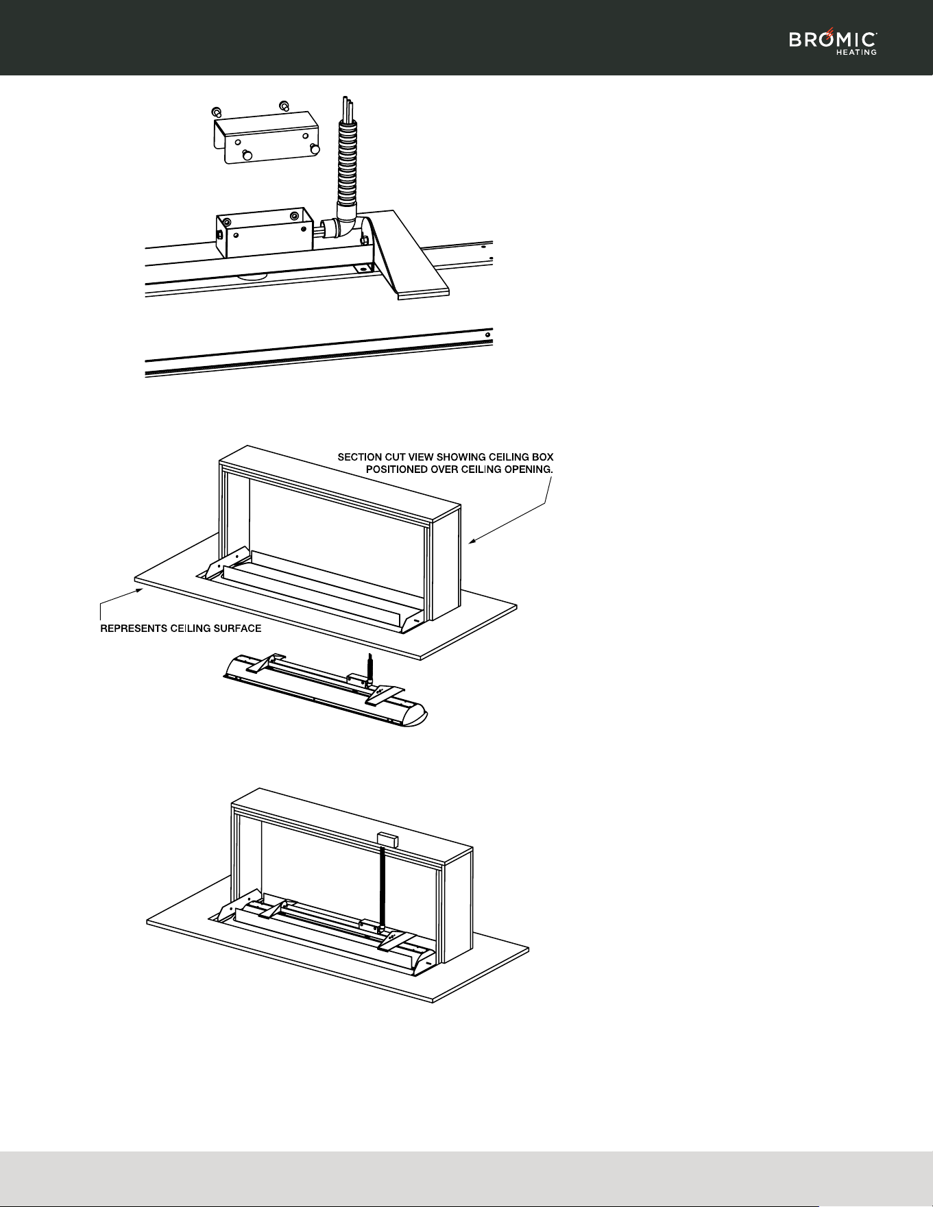
5. Assemble supplied terminals blocks, wire
conduit & junction box cover. The Ceiling
Recess Kit is supplied with 5 wires. Not all
parts are required for all installations. See
wiring diagrams for installation options. For
double element heater models the elements
can be wired to be turned on independently
or together. Ceramic or high heat tolerant wire
nuts are recommended.
6. Raise one side of heater up into the ceiling
box and then raise whole heater into cavity.
7. Rotate the heater into horizontal position in
the ceiling box and then lower down onto
ceiling frame.
8. Ensure all four side mounting brackets are
hooked over the ceiling frame and centre the
heater inside the frame.
9. Make electrical connection from heater to
power supply as per electrical installation
instructions in this manual. Connection to be
made outside the ceiling box on the side or
top of the ceiling box.
10 | Telephone: 1(800) 301-1293 | Email: ServiceUSA@BromicGroup.com | Web: www.bromic.com | ©2025 Bromic Group. All Rights Reserved.
TUNGSTEN SMART-HEAT™ ELECTRIC | INSTALLATION, INSTRUCTION & SERVICE MANUAL
ELEMENT INSTALLATION
WARNING
This Heater MUST be permanently Installed
and hard wired by an authorised/licenced
person. Do Not perform maintenance, or
carry out installation or assembly procedure
while electrical power is switched on.
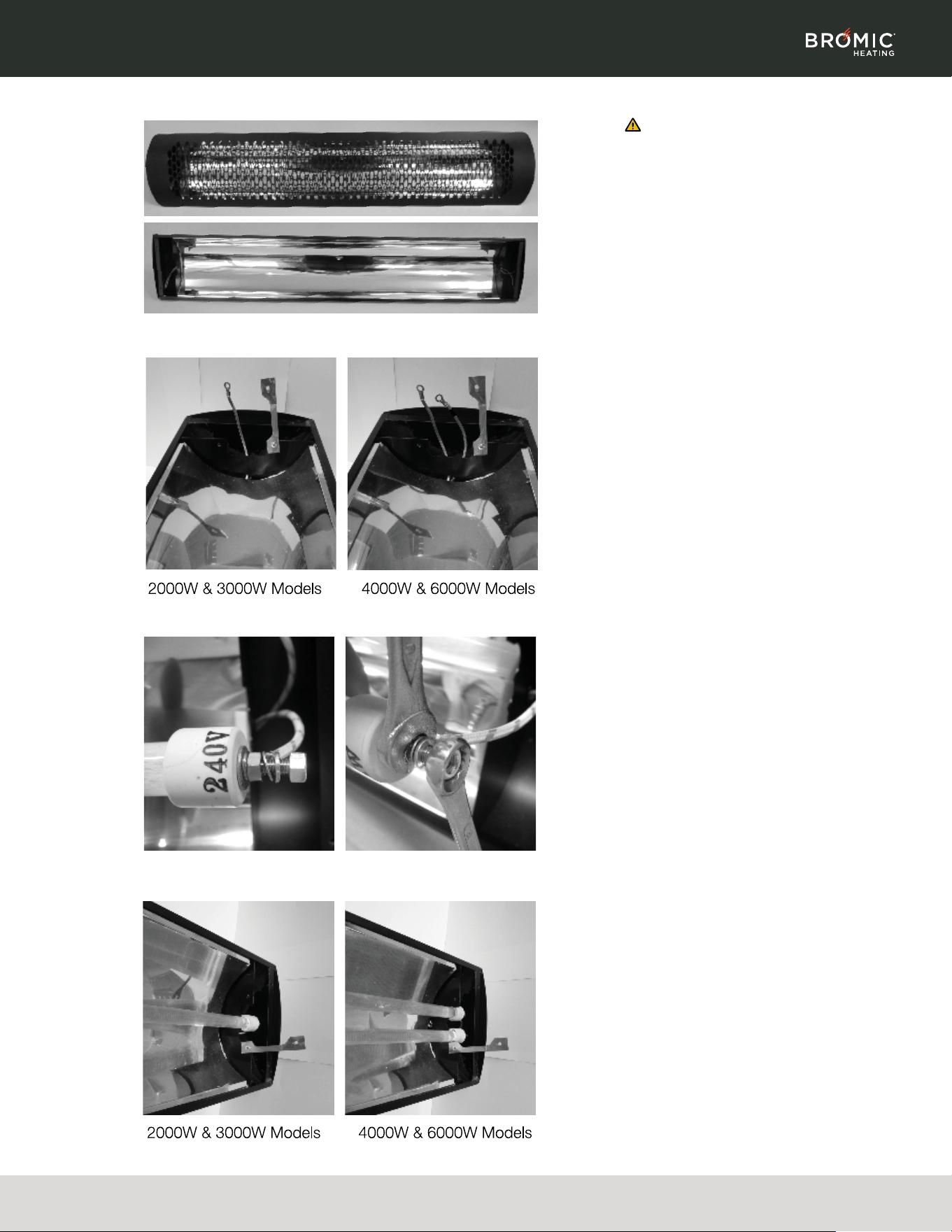
1. Remove the front cover from the heater.
2. Check that ring terminals are crimped
securely to cables. 2000W & 3000W models
have one cable at each end for assembly
of one element. 4000W & 6000W models
have two cables at each end for assembly
of two elements. The first element must be
connected to the cables marked L1 & N1. The
second element must be connected to the
cable marked L2 & N2.
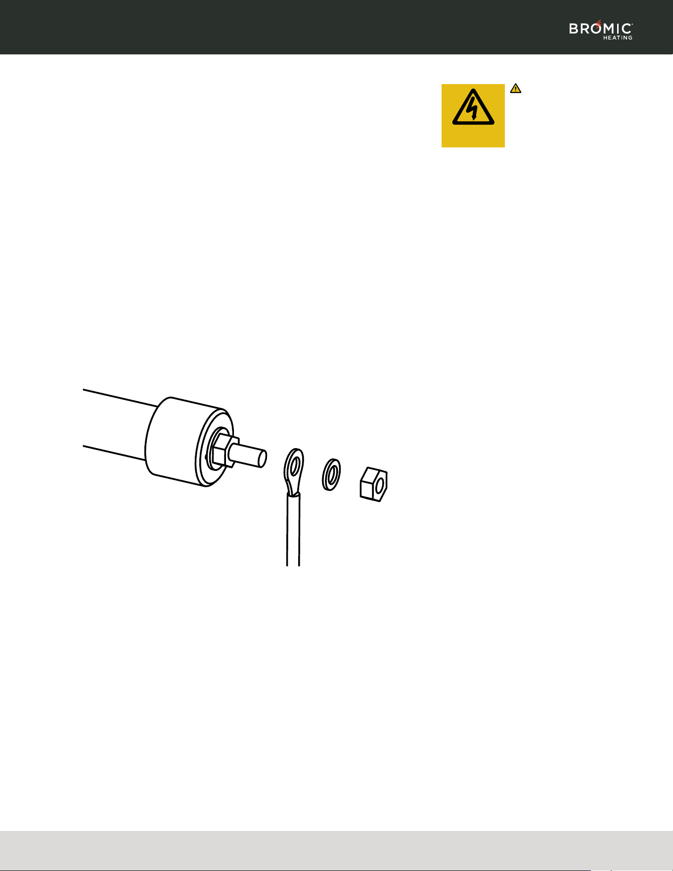
3. Fasten elements to cables. Remove outer
nut & lock washer from the threaded stud
on the element. Assemble ring terminal to
the threaded stud & secure with outer nut
and lock washer. Use one spanner to hold
the inner nut on the element, while fastening
the outer nut with a second spanner. Repeat
for other end of element. Minimum torque of
6.5Nm must be applied.
4. Put elements in the support bracket. For
2000W & 3000W models put element in the
centre position. For 4000W & 6000W models
put elements in the outside positions.
11 | Telephone: 1(800) 301-1293 | Email: ServiceUSA@BromicGroup.com | Web: www.bromic.com | ©2025 Bromic Group. All Rights Reserved.
TUNGSTEN SMART-HEAT™ ELECTRIC | INSTALLATION, INSTRUCTION & SERVICE MANUAL
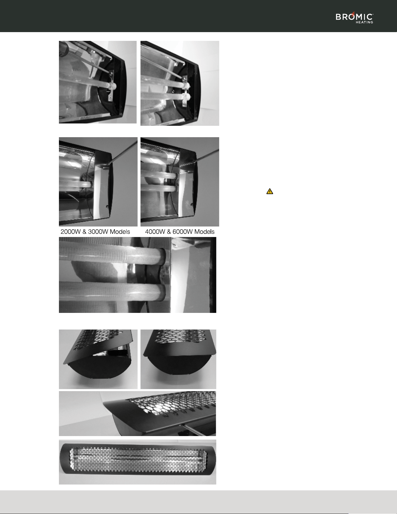
5. Close element lock bracket & fasten with self
tapping screw. Repeat for other end of heater.
6. Assemble end caps at both ends of the heater
with 2 self tapping screws. For 4000W &
6000W models ensure that the middle tab of
the end caps are slotted behind the element
support bracket.
Note: Protective end caps must be
installed to protect wiring from heat exposure.
Without this protection wiring will be
damaged and heater will be inoperable.
7. Assemble front cover onto the heater. Hook
front cover to one side of the heater and push
other side down. Fasten into position with 3
self tapping screws.

12 | Telephone: 1(800) 301-1293 | Email: ServiceUSA@BromicGroup.com | Web: www.bromic.com | ©2025 Bromic Group. All Rights Reserved.
TUNGSTEN SMART-HEAT™ ELECTRIC | INSTALLATION, INSTRUCTION & SERVICE MANUAL
ELECTRICAL INSTALLATION
WARNING
Heater MUST be permanently Installed and
hard wired by an authorised/licenced person.
Do Not perform maintenance, or carry out
installation or assembly procedure while
electrical power is switched on.
WARNING
ELECTRICAL SHOCK HAZARD! Serious
injury or death may occur. Disconnect from
electrical supply before installing or servicing
this heater. Read and follow installation
clearance requirements outlined in this
manual. The Appliance MUST be connected
to a properly grounded electrical source.
Important: When installing heaters using
Bromic Controls, please review the installation
instructions for the selected controls prior to
beginning the installation to ensure proper
placement and clearances are met. Bromic
Controls should be mounted in well-ventilated
locations away from any heat source.
INSTALLATION
1. Check product label for correct voltage and
wattage. Make sure power source conforms
to the heaters requirements.
2. Junction box has a 0.86” (22mm) to a
standard 1/2 “weather tight conduit fittings.
Install cord grip with minimum rating of IPX4
to maintain the water ingress protection rating
of the heater. Cord grip must have minimum
temperature rating of 90°C (194°F). Failure to
install correctly will avoid the manufacturer’s
warranty.
3. For supply connections, use suitable power
supply wire at least 90˚C (194˚F). Use Copper
or aluminium wire. For 2000W and 3000W
models: use only one branch circuit.
4. Make electrical connections in accordance
with local electrical code regulations. For
outdoor installation all connections must
be made in accordance with local electrical
code regulations for outdoor wiring. Only use
wiring components approved for outdoor use
with minimum IPX4 rating. Ground wire screw
is located in the end of junction box.
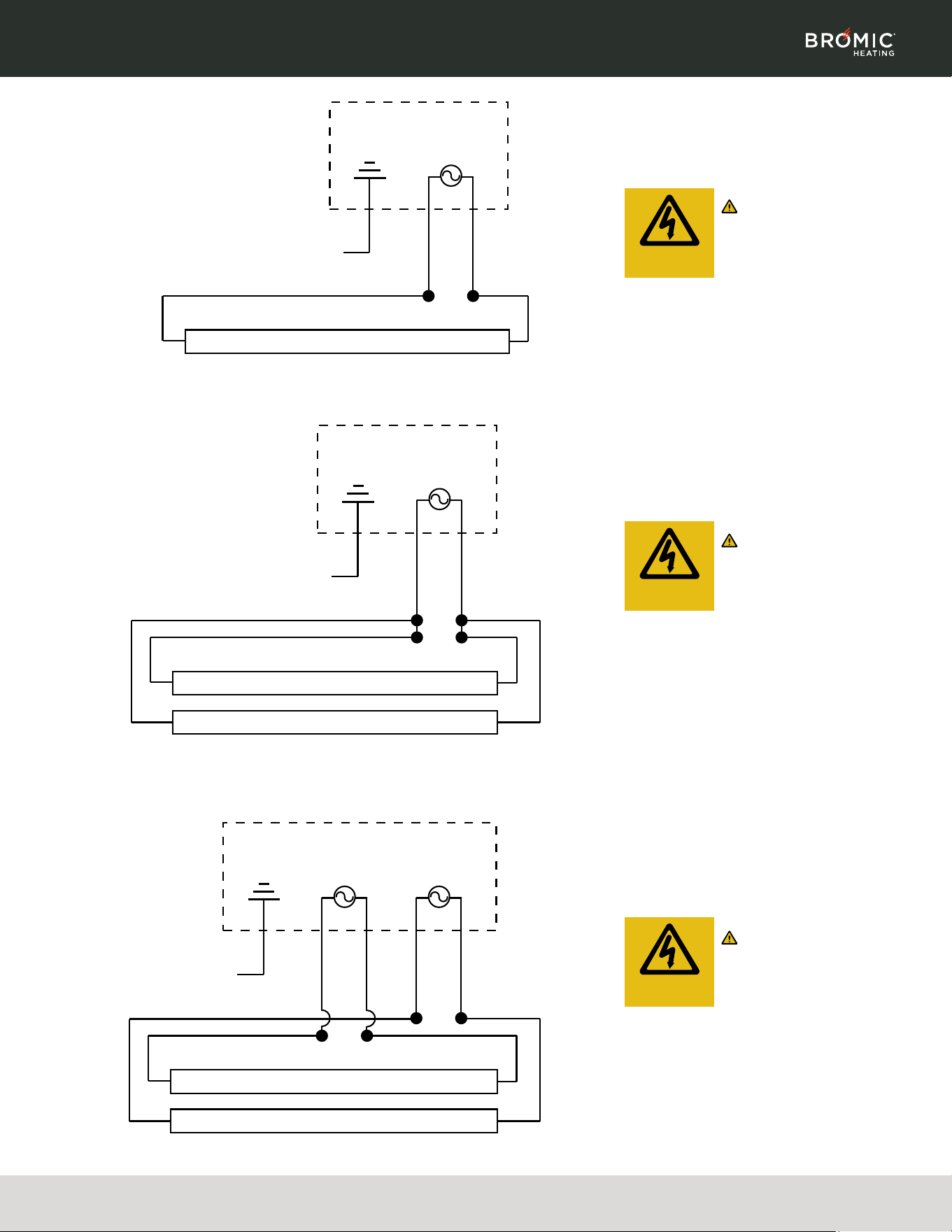
Note:
2000W & 3000W models:
- Electrical leads are labeled L1 & N1.
4000W & 6000W models:
- Electrical leads are labeled L1/N1 for first
element and L2/N2 for second element.
13 | Telephone: 1(800) 301-1293 | Email: ServiceUSA@BromicGroup.com | Web: www.bromic.com | ©2025 Bromic Group. All Rights Reserved.
TUNGSTEN SMART-HEAT™ ELECTRIC | INSTALLATION, INSTRUCTION & SERVICE MANUAL
WIRING DIAGRAM
TUNGSTEN SMART-HEAT™ ELECTRIC
STANDARD INSTALLATION - WALL SWITCH
2000W & 3000W MODELS*
WARNING
AC Single Phase Heater must
be permanently installed and
hard wired by an authorised/
licenced person.
WIRING DIAGRAM
TUNGSTEN SMART-HEAT™ ELECTRIC
STANDARD INSTALLATION - 20 AMP WALL
SWITCH - 4000W MODELS*
WARNING
AC Single Phase Heater must
be permanently installed and
hard wired by an authorised/
licenced person.
WIRING DIAGRAM
TUNGSTEN SMART-HEAT™ ELECTRIC
OPTIONAL INSTALLATION - 2 X 20 AMP
WALL SWITCH - 4000W & 6000W MODELS*
PROVIDES INDIVIDUAL ELEMENT CONTROL
WARNING
AC Single Phase Heater must
be permanently installed and
hard wired by an authorised/
licenced person.
* Compliance with local code must be confirmed
by installer
RISK OF
ELECTRIC SHOCK
RISK OF
ELECTRIC SHOCK
RISK OF
ELECTRIC SHOCK
EARTH
WIRE
L1 N1
JUNCTION BOX
HEATER ELEMENT 1
AC SINGLE
PHASE
AC
L1L2 N1
N2
JUNCTION BOX
EARTH
WIRE
AC SINGLE
PHASE
AC
HEATER ELEMENT 1
HEATER ELEMENT 2
JUNCTION BOX
EARTH
WIRE
AC SINGLE
PHASE
AC
AC SINGLE
PHASE
AC
L1L2 N1 N2
HEATER ELEMENT 1
HEATER ELEMENT 2
When using a Bromic Affinity Control,
installer should refer to the Affinity Control
Manual for specific wiring requirements.
14 | Telephone: 1(800) 301-1293 | Email: ServiceUSA@BromicGroup.com | Web: www.bromic.com | ©2025 Bromic Group. All Rights Reserved.
TUNGSTEN SMART-HEAT™ ELECTRIC | INSTALLATION, INSTRUCTION & SERVICE MANUAL
CONTROL OPTIONS
CODE DESCRIPTION
BH3130051 AFFINITY SMART-HEAT CONTROL ON/OFF 1CH 6KW
BH3130052 AFFINITY SMART-HEAT CONTROL ON/OFF 2CH 12KW (6KW/CH)
BH3130053 AFFINITY SMART-HEAT CONTROL ON/OFF 5CH 30KW (6KW/CH)
BH3130061 AFFINITY SMART-HEAT CONTROL DIMMER 1CH 6KW
BH3130062 AFFINITY SMART-HEAT CONTROL DIMMER 2CH 12KW (6KW/CH)
BH3130063 AFFINITY SMART-HEAT CONTROL DIMMER 5CH 30KW (6KW/CH)
BH3130070 AFFINITY SMART-HEAT CONTROL EXPANSION BOARD (BMS/ETHERNET)
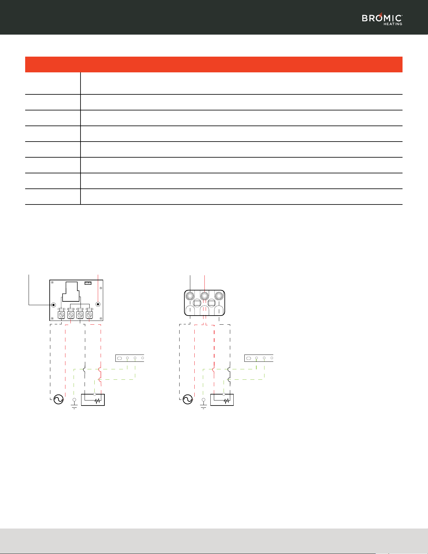
1. Provide 2 Hot Legs from the Affinity Control to
the Heater
2. For Dual Element Heaters, pair the L1/L2 lead
wires to Hot Leg #1, pair the N1/N2 lead wires
to Hot Leg #2.
Notes:
• Refer to Affinity Smart Heat Control Manual
for additional information.
• 1CH controls have a capacity of 6000W per
channel and will operate two each heaters
<3000W or one heater >3400W.
• 2CH controls have a capacity of 6000W per
channel and will operate two each heaters
<3000W or one heater >3400W per channel.
Sample Wiring for Affinity Controllers
Please refer to Affinity Product Manuals for complete installation instructions.
1CH Affinity On/Off Control
1CH Affinity Dimmer Contro
GND
Heater
HOT 1 (L)HOT 1 (LINE)
HOT 2 (N)HOT 2 (NEUTRAL)
GROUND
LOAD HOT 2 (N)
LOAD HOT 1 (L)
AC SUPPLY
208V OR
220-240V
GND
Heater
HOT 1 (L)HOT 1 (LINE)
HOT 2 (N)HOT 2 (NEUTRAL)
GROUND
LOAD HOT 1 (L)
LOAD HOT 2 (N)
AC SUPPLY
208V OR
220-240V
WIRING DIAGRAM FOR USE WITH BROMIC AFFINITY SMART HEAT CONTROLS
15 | Telephone: 1(800) 301-1293 | Email: ServiceUSA@BromicGroup.com | Web: www.bromic.com | ©2025 Bromic Group. All Rights Reserved.
TUNGSTEN SMART-HEAT™ ELECTRIC | INSTALLATION, INSTRUCTION & SERVICE MANUAL
SERVICING
WARNING
Servicing and maintenance
MUST be carried out by an
authorised and licensed
person only. ELECTRICAL
SHOCK HAZARD! Serious
injury or death may occur. Disconnect from
electrical supply before servicing this heater.
MAINTENANCE
For longest product life & to maintain product
appearance mount heater under cover & protect
from rain & weather whenever possible. The
exterior housing of the heater should be cleaned
regularly with a soft damp cloth. For locations
near the coast, salt in the air can cause rusting
of metal. Additional cleaning of the heater with a
soft damp cloth fortnightly will increase the life of
the products appearance. Ensure that there is no
excessive build-up of dirt/dust on the reflectors
or elements as this can cause overheating and
premature element failure. To clean the reflectors
and elements, ensure heater is off and has been
off for at least 2 hours after operation, and wipe off
any dirt/dust with a soft & dry cloth.
TUBE ELEMENT REPLACEMENT
1. Remove Front Cover of the heater by
unscrewing the 3 screws holding it in place.
2. Remove first Element End Cover by unscrewing
the 2 screws holding it in place.
3. Remove Outer Hex Nut, Lock Washer and Lead
Wire Ring Terminal from the threaded stud.
4. Remove second Element End Cover by
unscrewing the 2 screws holding it in place.
5. Remove Outer Hex Nut, Lock Washer and Lead
Wire Ring Terminal from the threaded stud.
6. Remove old Tube Element.
7. Install new Tube Element by following element
installation instructions on page 8 of this
manual.
RISK OF
ELECTRIC SHOCK
16 | Telephone: 1(800) 301-1293 | Email: ServiceUSA@BromicGroup.com | Web: www.bromic.com | ©2025 Bromic Group. All Rights Reserved.
TUNGSTEN SMART-HEAT™ ELECTRIC | INSTALLATION, INSTRUCTION & SERVICE MANUAL
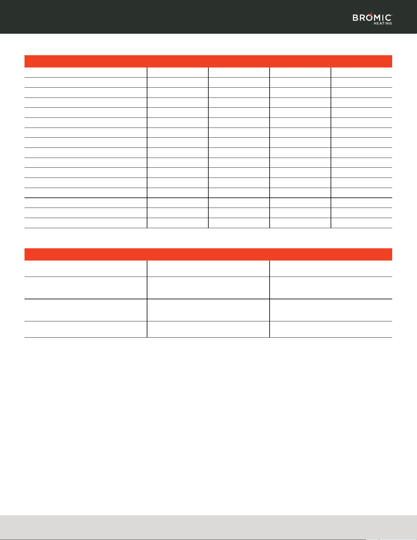
DESCRIPTION 2000W 3000W 4000W 6000W
Element Replacement - 240V BH8180001 BH8180002 BH8180001 BH8180002
Element Replacement - 208V BH8180017 BH8180016 BH8180017 BH8180016
Element Replacement - 2770V BH8180015 BH8180014 BH8180015 BH8180014
Element End Cover Ser BH8180005 BH8180006 BH8180005 BH8180006
Front Cover - Black BH8180003 BH8180004 BH8180003 BH8180004
Junction Box Cover & Seal Set - Black BH8180007 BH8180007 BH8180007 BH8180007
Mounting Bracket set (Short) - Black BH8180008 BH8180008 BH8180008 BH8180008
Mounting Bracket set (Long) - Black BH8180009 BH8180009 BH8180009 BH8180009
Ceiling Recess Kit - Black BH8180010 BH8180011 BH8180010 BH8180011
Tube Suspension Kit - Black BH8180012 BH8180012 BH8180012 BH8180012
Front Cover - White BH8180018 BH8180019 BH8180018 BH8180019
Junction Box Cover & Seal Set - White BH8180020 BH8180020 BH8180020 BH8180020
Mounting Bracket set (Short) - White BH8180021 BH8180021 BH8180021 BH8180021
Mounting Bracket set (Long) - White BH8180022 BH8180022 BH8180022 BH8180022
Ceiling Recess Kit - White BH8180096 BH8180095 BH8180096 BH8180095
Tube Suspension Kit - White BH8180006 BH8180006 BH8180006 BH8180006
SYMPTON POSSIBLE CAUSE (S) CORRECTIVE ACTION
ELEMENT DOES NOT ENERGIZE
1. Defective element
2. Improper connection
1. Replace element
2. Check connection to power outlet
NOT ENOUGH HEAT
1. Heater too small for application
2. Heater mounted too high or too far
3. Incorrect voltage connected to heater
1. Add additional heater(s)
2. Decrease mounting height or distance
3. Check correct supply voltage is provided
TOO MUCH HEAT
1. Heater too large for application
2. Heater mount too low or too close
3. Incorrect voltage connected to heater
1. Replace with smaller heater
2. Increase mounting height or distance
3. Check correct supply voltage is provided
HOT SPOT IN TUBE
1. Heater is not level
2. Grease or moisture on tube
1. Adjust to level mount
2. Clear tube-replace if problem persists
REPLACEMENT PART LIST
TROUBLESHOOTING
Unites States of America Office:
Address: 7595 Irvine Center Drive,
Ste. 100
Irvine, CA 92618
Telephone: 1(800) 301-1293
Web: www.bromic.com
©2025 Bromic Group. All Rights Reserved.
Australia HQ:
Address: 10 Phiney Place
Ingleburn NSW 2565 Australia
Telephone: +61 2 9748-3900
Web: www.bromic.com
©2025 Bromic Group. All Rights Reserved.
We believe true quality extends beyond the product itself. That is why Bromic
Heating is committed to delivering a superior end-to-end customer experience,
seamlessly integrating our expert sales consultation, robust technical guidance
and responsive after-purchase care into every step of your heating journey.
Contact Bromic Heating Support
Telephone: 800.301.1293
Email: ServiceUSA@BromicGroup.com
Scan QR Code
for more information.
1125_v1