Installation & Operation
Manual
Models: 1250 - 4000
Series: 100 & 101
This manual must only be used by
a qualified heating installer / service
technician. Read all instructions,
including this manual and the
Armor Appliance Service Manual,
before installing. Perform steps in
the order given. Failure to comply
could result in severe personal
injury, death, or substantial property
damage.
⚠WARNING
Save this manual for future reference.
100298689_2000552691_Rev AB
-- This appliance MUST NOT be installed in any
location where gasoline or flammable vapors are
likely to be present.
-- WHAT TO DO IF YOU SMELL GAS
• Do not try to light any appliance.
• Do not touch any electric switch; do not use any
phone in your building.
• Immediately call your gas supplier from a nearby
phone. Follow the gas supplier’s instructions.
• If you cannot reach your gas supplier, call the fire
department.
• Installation and service must be performed by a
qualified installer, service agency, or the gas
supplier.
⚠ WARNING: If the information in
this manual is not followed exactly, a fire or
explosion may result causing property damage,
personal injury, or loss of life.

2
Hazard definitions
The following defined terms are used throughout this manual to bring attention to the presence of hazards of various risk levels or
to important information concerning the life of the product.
⚠ DANGER
⚠WARNING
⚠CAUTION
CAUTION
NOTICE
DANGER indicates an imminently hazardous situation which, if not avoided, will result in death or serious
injury.
WARNING indicates a potentially hazardous situation which, if not avoided, could result in death or serious
injury.
CAUTION indicates a potentially hazardous situation which, if not avoided, may result in minor or moderate
injury.
CAUTION used without the safety alert symbol indicates a potentially hazardous situation which, if not
avoided, may result in property damage.
NOTICE indicates special instructions on installation, operation, or maintenance that are important but not
related to personal injury or property damage.
HAZARD DEFINITIONS .................................................. 2
PLEASE READ BEFORE PROCEEDING ..................... 3
THE ARMOR -- HOW IT WORKS ................................ 4-5
RATINGS .......................................................................... 6
1. DETERMINE APPLIANCE LOCATION
Provide Clearances ............................................................ 7
Provide Air Openings to Room .......................................... 9
Flooring and Foundation ................................................... 9
Vent and Air Piping ............................................................ 9
Prevent Combustion Air Contamination ............................. 9
Corrosive Contaminants and Sources ............................. 10
Using an Existing Vent System to Install a New
Appliance .......................................................................... 10
Removing an Appliance from Existing Common Vent ..... 11
Outdoor Venting ............................................................... 12
Combustion and Ventilation Air Requirements.............13-15
2. PREPARE APPLIANCE
Remove Appliance from Wood Pallet .............................. 16
Gas Conversions ......................................................... 16-17
3. GENERAL VENTING
Direct Venting Options ..................................................... 18
Install Vent and Combustion Air Piping ........................... 19
Sizing ............................................................................... 21
Min./Max. Combustion Air & Vent Piping Lengths ............ 22
Materials ............................................................................ 23
Stainless Steel Vent ......................................................... 23
PVC/CPVC .................................................................. 24-25
Polypropylene ................................................................... 26
Outdoor Installation .......................................................... 27
4. VERTICAL DIRECT VENTING
Vent/Air Termination - Vertical .................................... 28-29
Determine Location ..................................................... 28
Prepare Roof Penetrations ......................................... 28
Termination and Fittings ............................................. 28
Multiple Vent/Air Terminations .................................... 29
5. SIDEWALL DIRECT VENTING
Vent/Air Termination - Vertical .................................... 30-31
Determine Location ................................................ 30-31
Prepare Wall Penetrations .......................................... 32
Termination and Fittings ............................................. 32
Multiple Vent/Air Terminations .................................... 32
Room Air .......................................................................... 33
6. SYSTEM PIPING
System Water Piping Methods ......................................... 37
General Piping Information .............................................. 37
Water Flow Switch ........................................................... 37
Scalding ............................................................................ 38
Water Chemistry............................................................... 38
Piping Components .......................................................... 38
7. GAS CONNECTIONS
Connecting Gas Supply Piping ........................................ 44
Natural Gas ...................................................................... 45
Pipe Sizing for Natural Gas ........................................ 45
Natural Gas Supply Pressure Requirements ............. 45
Propane Gas .................................................................... 45
Pipe Sizing for Propane Gas ...................................... 45
Propane Supply Pressure Requirements ................... 45
Check Inlet Gas Supply ................................................... 46
Gas Pressure ................................................................... 47
Gas Valve Replacement .................................................. 47
8. FIELD WIRING
Line Voltage Connections ................................................ 48
Low Voltage Connections ................................................ 49
Wiring of the Cascade ....................................................... 50
9. CONDENSATE DISPOSAL
Condensate Drain ............................................................ 52
10. START-UP ............................................................ 53-58
11. OPERATING INFORMATION
General ........................................................................ 59-60
Sequence of Operation ............................................... 61-63
Cascade ........................................................................... 62
Armor Appliance Control Module ..................................... 64
12. MAINTENANCE
Maintenance & Annual Startup ................................... 65-69
13. DIAGRAMS
Ladder Diagrams ......................................................... 70-75
Wiring Diagrams .......................................................... 70-75
Revision Notes .................................................. Back Cover
Contents
Installation & Operation Manual
Please read before proceeding
Installer – Read all instructions, including
this manual and the Armor Appliance
Service Manual, before installing. Perform
steps in the order given.
Have this appliance serviced/inspected
by a qualified service technician, at least
annually.
Failure to comply with the above could
result in severe personal injury, death, or
substantial property damage.
Failure to adhere to the guidelines on this
page can result in severe personal injury,
death, or substantial property damage.
When servicing the appliance –
• To avoid electric shock, disconnect electrical supply
before performing maintenance.
• To avoid severe burns, allow the appliance to cool
before performing maintenance.
Appliance operation –
• Do not block flow of combustion or ventilation air to
the appliance.
• Should overheating occur or gas supply fail to shut off,
do not turn off or disconnect electrical supply to
circulator. Instead, shut off the gas supply at a location
external to the appliance.
• Do not use this appliance if any part has been under
water. The possible damage to a flooded appliance can
be extensive and present numerous safety hazards. Any
appliance that has been under water must be replaced.
When calling or writing about the appliance
– Please have the appliance model and
serial number from the appliance rating
plate.
Consider piping and installation when
determining appliance location.
Any claims for damage or shortage in
shipment must be filed immediately
against the transportation company by the
consignee.
Factory warranty (shipped with unit) does
not apply to units improperly installed or
improperly operated.
3
-- This appliance MUST NOT be installed
in any location where gasoline or
flammable vapors are likely to be present.
-- WHAT TO DO IF YOU SMELL GAS
• Do not try to light any appliance.
• Do not touch any electric switch; do
not use any phone in your building.
• Immediately call your gas supplier from
a nearby phone. Follow the gas supplier’s
instructions.
• If you cannot reach your gas supplier,
call the fire department.
• Installation and service must be
performed by a qualified installer,
service agency, or the gas supplier.
⚠WARNING
NOTICE
⚠WARNING
⚠WARNING
If the information in this manual is not
followed exactly, a fire or explosion may
result causing property damage, personal
injury, or loss of life.
⚠WARNING
DO NOT install units in rooms or
environments that contain corrosive
contaminants (see Table 1A on page 10).
Failure to comply could result in severe
personal injury, death, or substantial
property damage.
⚠WARNING
The California Safe Drinking Water and
Toxic Enforcement Act requires the
Governor of California to publish a list of
substances known to the State of California
to cause cancer, birth defects, or other
reproductive harm, and requires businesses
to warn of potential exposure to such
substances.
This product contains a chemical known
to the State of California to cause cancer,
birth defects, or other reproductive harm.
This appliance can cause low level exposure
to some of the substances listed in the Act.

Installation & Operation Manual
4
The Armor - How it works...
1. Stainless Steel Heat Exchanger
Allows water to flow through specially designed coils for maximum
heat transfer, while providing protection against flue gas corrosion.
The coils are encased in a jacket that contains the combustion
process.
2. Combustion Chamber Access Cover (not shown)
Allows access to the combustion side of the heat exchanger coils.
3. Blower
The blower pulls in air and gas through the venturi (item 5). Air
and gas mix inside the blower and are pushed into the burner, where
they burn inside the combustion chamber.
4. Gas Valve
The gas valve senses the negative pressure created by the blower,
allowing gas to flow only if the gas valve is powered and combustion
air is flowing.
5. Venturi
The venturi controls air and gas flow into the burner.
6. Flue Gas Sensor (limit rated, not shown)
This sensor monitors the flue gas exit temperature. The control
module will modulate and shut down the appliance if the flue gas
temperature gets too hot. This protects the flue pipe from
overheating.
7. Outlet Temperature Sensor (housed with the high limit
sensor, not shown)
This sensor monitors appliance outlet water temperature
(tank supply). If selected as the controlling sensor, the control
module adjusts appliance firing rate so the outlet temperature is
correct.
8. Inlet Temperature Sensor (not shown)
This sensor monitors return water temperature (tank return). If
selected as the controlling sensor, the control module adjusts the
appliance firing rate so the inlet temperature is correct.
9. Flow Switch
The flow switch is a safety device that ensures flow through the
heat exchanger during operation. This appliance is low mass
and should never be operated without flow. The flow switch makes
contact when flow is detected and allows the unit to operate. If flow
is discontinued during operation for any reason the flow switch will
break the control circuit and the unit will shut down.
10. Electronic LCD Display
Digital controls with SMART TOUCH screen technology, full color
display, and an 8" user interface screen.
11. Burner (not shown)
Made with stainless steel construction, the burner uses pre-mixed
air and gas and provides a wide range of firing rates.
12. Water Outlet
Water connection that supplies hot water to the tank.
13. Water Inlet
Water connection that returns water from the tank to the heat
exchanger.
14. Gas Connection Pipe
Threaded pipe connection. This pipe should be connected to the
incoming gas supply for the purpose of delivering gas to the
appliance.
15. SMART TOUCH Control Module
The SMART TOUCH Control responds to internal and external
signals and controls the blower, gas valve, and pumps to meet the
demand.
16. Air Intake Adapter (not shown)
Allows for the connection of the air intake pipe to the appliance.
17. High Voltage Junction Box
The junction box contains the connection points for the line
voltage power and the pump.
18. Appliance Drain Port
Location from which the heat exchanger can be drained.
19. Low Voltage Connection Board
The connection board is used to connect external low voltage
devices.
20. Low Voltage Wiring Connections (knockouts)
Conduit connection points for the low voltage connection
board.
21. Condensate Drain Connection
Connects the condensate drain line to a PVC pipe.
22. Access Cover - Front (not shown)
Provides access to the gas train and the heat exchanger.
23. Ignition Electrode (not shown)
Provides direct spark for igniting the burner.
24. Flame Inspection Window (not shown)
The quartz glass window provides a view of the burner surface
and flame.
25. Gas Shutoff Valve
Manual valve used to isolate the gas valve from the gas supply.
26. High Limit Sensor (housed with the outlet temperature
sensor, not shown)
Device that monitors the outlet water temperature. If the
temperature exceeds its setting, the integrated control will
break the control circuit, shutting the appliance down.
27. Relief Valve
Protects the heat exchanger from over pressure and temperature
conditions. The standard relief valve is set at 150 PSI.
28. Flame Sensor (not shown)
Used by the control module to detect the presence of burner
flame.
29. Line Voltage Wiring Connections (Knockouts)
Conduit connection points for the high voltage junction box.
30. Power Switch
Turns power ON/OFF to the appliance.
31. AirBox
The air shroud directs air and gas flow into the burner.
32. Condensate Trap
The condensate trap is designed to prevent flue gases from
escaping the appliance through the combustion chamber drain.
33. Transformer
The transformer provides 24V power to the integrated control.
34. Low Gas Pressure Switch (not shown)
Monitors gas supply pressure to the appliance and shuts the
appliance down in the event a low gas pressure condition
occurs.
35. High Gas Pressure Switch (not shown)
Monitors gas supply pressure to the appliance and shuts the
appliance down in the event a high gas pressure condition
occurs.
36. Air Inlet Cover
Used with room air for combustion and to prevent debris from
entering the appliance.
37. Flue Sensor Access Panel
Provides access to the flue temperature sensor.
38. Spark Transformer
Provides high voltage power to the ignitor to ignite the gas/air
mixture.
Installation & Operation Manual
The Armor - How it works... (Continued)
DIR #2000548602 00
19
1
14
31
4
5
3
10
38
15
27
9
13
12
25
33
30
Left Side (inside unit)
DIR #2000548590 00
13
17
6
27
9
12
20
18
36
25
29
37
21
32
Rear View
5
Installation & Operation Manual
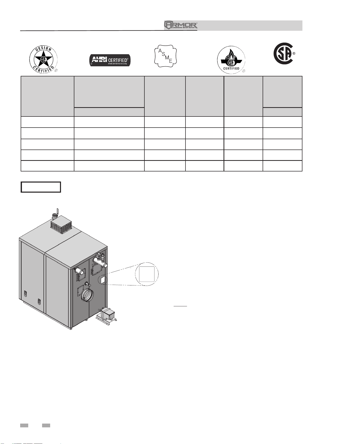
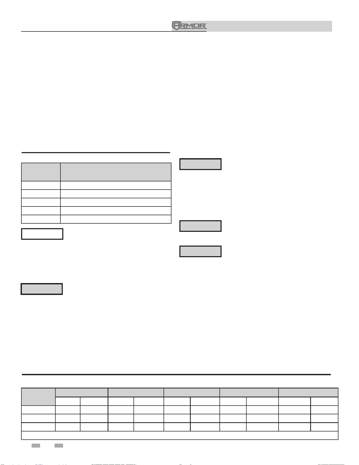
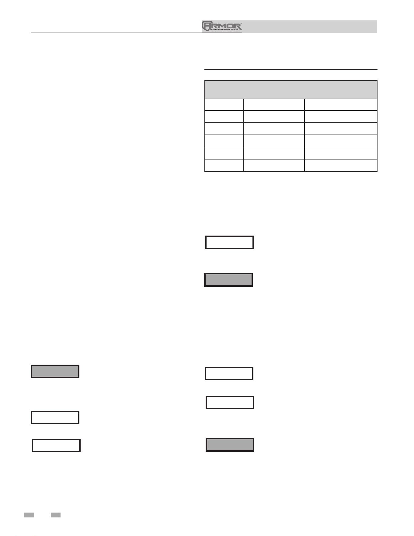
Ratings
Notes:
1. Armor appliances require special gas venting. Use only
the vent materials and methods specified in the Armor
Installation and Operation Manual.
Maximum allowed working pressure is located on the rating plate.
NOTICE
Figure A High Altitude Label Location
DIR #2000549725 00
UNIT EQUIPPED FOR
HIGH ALTITUDE
3,000 FT TO 12,000 FT
Model Number
Note: Change “N”
to “L” for L.P. gas
models.
CSA
Input Modulation Btu/hr
Water Content
Gallons
Water
Connections
Gas
Connections
Vent/Air Size
(Note 2, 3) (See Note 1,5)
AWH1250N 250,000 - 1,250,000 11 2-1/2" 1-1/2" 8"/8"
AWH1500N 300,000 - 1,500,000 13 2-1/2" 1-1/2" 8"/8"
AWH2000N 400,000 - 2,000,000 17 2-1/2" 1-1/2" 8"/8"
AWH3000N 600,000 - 3,000,000 25 4" 2" 10"/10"
AWH4000N 800,000 - 4,000,000 41 4" 2-1/2" 12"/12"
HLW
LOW LEAD CONTENT
2. Standard Armor models are equipped for use up to 4,500
feet above sea level with no adjustments. The appliance
will derate 4% for each 1,000 feet above sea level up to
4,500 feet.
3. High altitude Armor models are equipped for use from
3,000 to 12,000 feet above sea level with the following
derates.
For models AWH1250 - 2000:
• 1.4% for each 1,000 feet from 3,000 feet to 5,500 feet
• 1.9% for each 1,000 feet from 5,500 feet to 9,600 feet
• Above 9,600 feet, contact the factory.
For models AWH3000 - 4000:
• 1.2% for each 1,000 feet from 3,000 feet to 5,500 feet
• Above 5,500 feet, contact the factory.
Note: Derate values for altitudes above those listed in this
manual are calculated per NFPA 54 and CSA B149.1.
Derate values are based on proper combustion calibration
and
CO
2
’s adjusted to the recommended levels.
4. The manual reset high limit provided with the Armor is
listed to UL353. The auto reset high limit is listed to ANSI
Z21.87.
5. The Armor models 1250 and 1500 can be alternatively
vented using a 6" vent/air size. If the 6" vent/air size is
used, the maximum vent/air pipe lengths are limited to 70
equivalent feet each.
6
Installation & Operation Manual
1 Determine appliance location
7
All models of the Armor appliance gas
manifold and controls met safe lighting and
other performance under tests specified in
the latest edition of ANSI Z21.10.3.
Failure to keep appliance area clear and free
of combustible materials, gasoline, and other
flammable liquids and vapors can result in
severe personal injury, death, or substantial
property damage.
Installation must comply with:
• Local, state, provincial, and national codes, laws, regulations,
and ordinances.
• National Fuel Gas Code, ANSI Z223.1 – latest edition.
• National Electrical Code.
• For Canada only: B149.1 Installation Code, CSA C22.1
Canadian Electrical Code Part 1 and any local codes.
Before locating the appliance, check:
1. Check for nearby connection to:
• Water piping
• Venting connections
• Gas supply piping
• Electrical power
2. Locate the appliance so that if water connections should
leak, water damage will not occur. When such locations
cannot be avoided, it is recommended that a suitable
drain pan, adequately drained, be installed under the
appliance. The pan must not restrict combustion air
flow. Under no circumstances is the manufacturer to be
held responsible for water damage in connection with
this appliance or any of its components.
3. Check area around the appliance. Remove any
combustible materials, gasoline, and other flammable
liquids.
4. The Armor appliance must be installed so that gas control
system components are protected from dripping or spraying
water or rain during operation or service.
5. If a new appliance will replace an existing appliance, check
for and correct system problems, such as:
• System leaks causing oxygen corrosion or heat exchanger
cracks from hard water deposits.
6. Check around the appliance for any potential air
contaminants that could risk corrosion to the appliance or
the appliance combustion air supply (see Table 1A on page
10). Prevent combustion air contamination. Remove any
of these contaminants from the appliance area.
Provide clearances:
Clearances from combustible materials
1. Hot water pipes—at least 1/4" from combustible materials.
2. Vent pipe – at least 1" from combustible materials.
3. See FIG.’s 1-1 and 1-2 on page 8 for other clearance
minimums.
Clearances for service access
1. See FIG.’s 1-1 and 1-2 on page 8 for recommended
service clearances. If you do not provide the minimum
clearances shown, it may not be possible to service the
appliance without removing it from the space.
Multiple appliances can be installed side by side with no
clearances between adjacent appliances because the appliances
are approved for zero clearances from combustible surfaces;
however, service access will be limited from the sides. Consult
with the local inspection authority for approval.
This appliance requires a special venting
system. If using PVC the vent connection
to the appliance must be made with the
starter CPVC pipe section provided with
the appliance. The field provided vent
fittings must be cemented to the CPVC
pipe section. Use only the vent materials,
primer and cement specified in this manual
to make the vent connections. Failure to
follow this warning could result in fire,
personal injury, or death.
For closet and alcove installations as shown
in FIG.’s 1-1 and 1-2, CPVC vent material
must be used inside the structure. The
ventilating air openings shown in FIG.’s 1-1
and 1-2 are required for this arrangement.
Failure to follow this warning could result
in fire, personal injury, or death.
⚠WARNING
⚠WARNING
NOTICE
⚠WARNING
⚠WARNING
Do not install the appliance where
condensation may form on the inside
or outside of the appliance, or where
condensation may fall onto the appliance.
DO NOT install units in rooms or
environments that contain corrosive
contaminants (see Table 1A on page 10).
Failure to comply could result in severe
personal injury, death, or substantial
property damage.
⚠WARNING
Installation & Operation Manual
1 Determine appliance location
8
0”
0”
FROM FLOOR
24”
RIGHT
24”
REAR
24”
LEFT
0”
TOP
36”
FRONT
DIR #2000549721 00
1/4" MINIMUM CLEARANCE
AROUND HOT WATER PIPES
FOLLOW SPECIAL VENT
SYSTEM MANUFACTURER’S
INTRUCTIONS FOR VENT
PIPE CLEARANCE
RECOMMENDED SERVICE
CLEARANCES:
FRONT - 36"
TOP - 0"
SIDES - 24"
REAR - 24"
FLOOR - 0"
COMBUSTION
CLEARANCES:
FRONT - 0"
TOP - 0"
SIDES - 0"
REAR - 0"
FLOOR - 0"
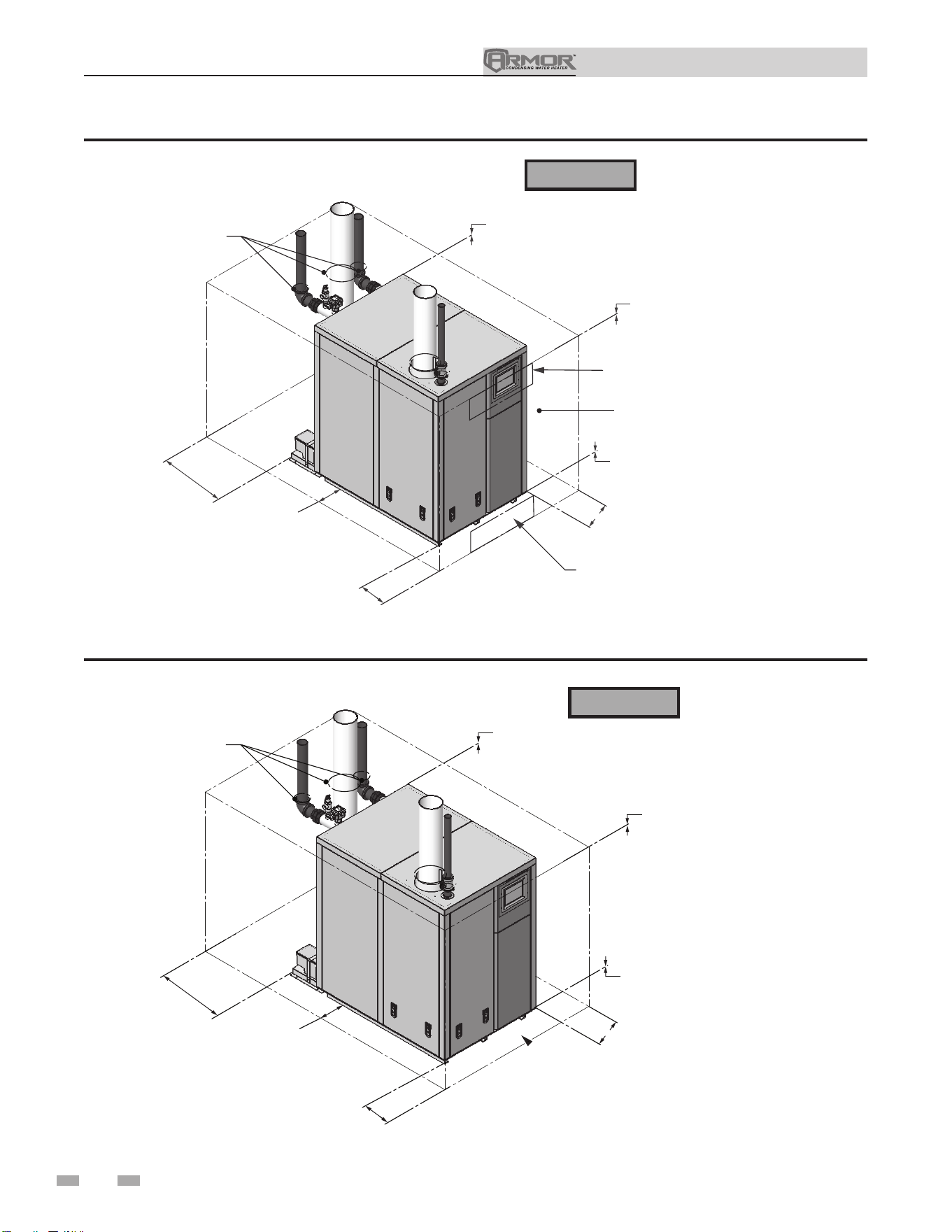
Figure 1-2 Alcove Installation - Minimum Required Clearances
0"
0"
FROM FLOOR
24"
RIGHT
24"
REAR
24"
LEFT
0"
TOP
36"
FRONT
CLOSED DOOR
VENTILATING
AIR OPENING
VENTILATING
AIR OPENING
DIR #2000549712 00
RECOMMENDED SERVICE
CLEARANCES:
FRONT - 36"
TOP - 0"
SIDES - 24"
REAR - 24"
FLOOR - 0"
1/4" MINIMUM CLEARANCE
A
ROUND HOT WATER PIPES
FOLLOW SPECIAL VENT
SYSTEM MANUFACTURER’S
INTRUCTIONS FOR VENT
PIPE CLEARANCE
COMBUSTION
CLEARANCES:
FRONT - 0"
TOP - 0"
SIDES - 0"
REAR - 0"
FLOOR - 0"
Figure 1-1 Closet Installation - Minimum Required Clearances
⚠WARNING
⚠WARNING
For closet installations, CPVC,
polypropylene or stainless steel
vent material MUST BE used in
a closet structure due to elevated
temperatures. Failure to follow
this warning could result in fire,
personal injury, or death.
For alcove installations,
CPVC, polypropylene or
stainless steel vent material
MUST BE used in an alcove
structure due to elevated
temperatures. Failure to
follow this warning could
result in fire, personal injury,
or death.
Installation & Operation Manual
1 Determine appliance location (continued)
9
Provide air openings to room:
Armor appliance alone in equipment room
1. No air ventilation openings into the equipment room are
needed when clearances around the Armor appliance are
at least equal to the SERVICE clearances shown in FIG.’s
1-1 and 1-2. For spaces that do NOT supply this clearance,
provide two openings as shown in FIG. 1-1. Each opening
must provide one square inch free area per 1,000 Btu/hr of
appliance input.
Armor appliance in same space with other gas or oil-
fired appliances
1. Follow the National Fuel Gas Code (U.S.) or CSA B149.1
(Canada) to size/verify size of the combustion/ventilation
air openings into the space.
The space must be provided with combustion/
ventilation air openings correctly sized for all
other appliances located in the same space as
the Armor appliance.
Do not install the appliance in an attic.
Failure to comply with the above warnings
could result in severe personal injury, death,
or substantial property damage.
2. Size openings only on the basis of the other appliances in
the space. No additional air opening free area is needed
for the Armor appliance because it takes its combustion air
from outside (direct vent installation).
Do not install the appliance on carpeting
even if foundation is used. Fire can result,
causing severe personal injury, death, or
substantial property damage.
If flooding is possible, elevate the appliance sufficiently to
prevent water from reaching the appliance.
Flooring and foundation
Flooring
The Armor appliance is approved for installation on combustible
flooring, but must never be installed on carpeting.
Vent and air piping
The Armor appliance requires a special vent system, designed
for pressurized venting.
The appliance is to be used for either direct vent installation or
for installation using indoor combustion air. When room air is
considered, see the General Venting Section. Note prevention
of combustion air contamination below when considering vent/
air termination.
Vent and air must terminate near one another and may be
vented vertically through the roof or out a side wall, unless
otherwise specified. You may use any of the vent/air piping
methods covered in this manual. Do not attempt to install the
Armor appliance using any other means.
Be sure to locate the appliance such that the vent and air piping
can be routed through the building and properly terminated.
The vent/air piping lengths, routing, and termination method
must all comply with the methods and limits given in this
manual.
Prevent combustion air contamination
Install air inlet piping for the Armor appliance as described in
this manual. Do not terminate vent/air in locations that can
allow contamination of combustion air. Refer to Table 1A,
page 10 for products and areas which may cause contaminated
combustion air.
You must pipe combustion air to the appliance
air intake. Ensure that the combustion air will
not contain any of the contaminants in Table
1A, page 10. Contaminated combustion
air will damage the appliance, resulting in
possible severe personal injury, death, or
substantial property damage. Do not pipe
combustion air near a swimming pool, for
example. Also avoid areas subject to exhaust
fumes from laundry facilities. These areas
will always contain contaminants.
⚠WARNING
⚠WARNING
⚠WARNING
Installation & Operation Manual
1 Determine appliance location
10
Products to avoid:
Spray cans containing chloro/fluorocarbons
Permanent wave solutions
Chlorinated waxes/cleaners
Chlorine-based swimming pool chemicals
Calcium chloride used for thawing
Sodium chloride used for water softening
Refrigerant leaks
Paint or varnish removers
Hydrochloric acid/muriatic acid
Cements and glues
Antistatic fabric softeners used in clothes dryers
Chlorine-type bleaches, detergents, and cleaning solvents
found in household laundry rooms
Adhesives used to fasten building products and other similar
products
Areas likely to have contaminants
Dry cleaning/laundry areas and establishments
Swimming pools
Metal fabrication plants
Beauty shops
Refrigeration repair shops
Photo processing plants
Auto body shops
Plastic manufacturing plants
Furniture refinishing areas and establishments
New building construction
Remodeling areas
Garages with workshops
Table 1A Corrosive Contaminants and Sources
Failure to follow all instructions can result
in flue gas spillage and carbon monoxide
emissions, causing severe personal injury
or death.
⚠WARNING
When using an existing vent system to
install a new appliance:
Check the following venting components before installing:
• Material - For materials listed for use with this appliance,
see Section 3 - General Venting. For polypropylene or
stainless steel venting, an adapter of the same
manufacturer must be used at the flue collar connection.
• Size - To ensure proper pipe size is in place, see Tables
3B and 3C. Check to see that this size is used throughout
the vent system.
• Manufacturer - For a stainless steel or polypropylene
application, you must use only the listed manufacturers
and their type product listed in Tables 3G and 3H for CAT
IV positive pressure venting with flue producing
condensate.
• Supports - Vent system must be supported horizontally
to prevent sagging. Methods and intervals for support
vary by vent manufacturer and vent material. Vent
support methods and intervals shall adhere to vent
manufacturer’s instructions, where applicable. Vent
piping must be supported per the National Building
Code, Section 305, Table 305.4 or as local codes dictate.
• Terminations - Carefully review Sections 3 through 5 to
ensure requirements for the location of the vent and air
terminations are met and orientation of these fit the
appropriate image from the Horizontal or Vertical
options listed in the General Venting Section. For
stainless steel vent, only use terminations listed in Table
3A-2 for the manufacturer of the installed vent.
• Seal - With prior requirements met, the system should
be tested to the procedure listed in parts (c) through (f)
of the Removal of an Existing Appliance Section on
page 11.
With polypropylene and stainless steel vent, seal and connect
all pipe and components as specified by the vent manufacturer
used; with PVC/CPVC vent, see the Installing Vent or Air
Piping Section on page 20.
⚠WARNING
If any of these conditions are not met,
the existing system must be updated
or replaced for that concern. Failure to
follow all instructions can result in flue gas
spillage and carbon monoxide emissions,
causing severe personal injury or death.

Installation & Operation Manual
11
1 Determine appliance location (continued)
When removing an appliance from
existing common vent system:
Do not install the Armor appliance into
a common vent with any other appliance
except as noted in Section 3. This will
cause flue gas spillage or appliance
malfunction, resulting in possible severe
personal injury, death, or substantial
property damage.
Failure to follow all instructions can result
in flue gas spillage and carbon monoxide
emissions, causing severe personal injury
or death.
At the time of removal of an existing appliance, the following
steps shall be followed with each appliance remaining
connected to the common venting system placed in operation,
while the other appliances remaining connected to the
common venting system are not in operation.
a. Seal any unused openings in the common venting system.
b. Visually inspect the venting system for proper size and
horizontal pitch, and determine there is no blockage
or restriction, leakage, corrosion, or other deficiencies,
which could cause an unsafe condition.
c. Test vent system – Insofar as is practical, close all building
doors and windows and all doors between the space
in which the appliances remaining connected to the
common venting system are located and other spaces of
the building. Turn on clothes dryers and any appliance
not connected to the common venting system. Turn on
any exhaust fans, such as range hoods and bathroom
exhausts, so they will operate at maximum speed. Do not
operate a summer exhaust fan. Close fireplace dampers.
d. Place in operation the appliance being inspected. Follow
the lighting instructions. Adjust thermostat so appliance
will operate continuously.
e. Test for spillage at the draft hood relief opening after
5 minutes of main burner operation. Use the flame of a
match or candle, or smoke from a cigarette, cigar, or pipe.
f. After it has been determined that each appliance
remaining connected to the common venting system
properly vents when tested as outlined herein, return
doors, windows, exhaust fans, fireplace dampers, and any
other gas-burning appliance to their previous conditions
of use.
⚠ DANGER
⚠WARNING
g. Any improper operation of the common venting system
should be corrected so the installation conforms with the
National Fuel Gas Code, ANSI Z223.1/NFPA 54 and/or
CAN/CSA B149.1, Natural Gas and Propane Installation
Code. When resizing any portion of the common venting
system, the common venting system should be resized
to approach the minimum size as determined using the
appropriate tables in Part 11 of the National Fuel Gas Code,
ANSI Z223.1/NFPA and/or CAN/CSA B149.1, Natural Gas
and Propane Installation Code.
Installation & Operation Manual
1 Determine boiler location
12
Installation & Operation Manual
Outdoor venting
• In order to properly install the appliance in an outdoor
configuration the optional outdoor kit must be used (see
Table 1B).
• Vent materials for outdoor venting are to be field supplied.
• Vent materials must be stainless steel.
• The vent must terminate at least 36 inches above the top of
the unit.
• All vent materials must be supported as recommended by
the vent manufacturer.
• The terminations in Table 1C must be used.
• See page 23 in the General Venting section for additional
outdoor venting information.
Model Indoor to Outdoor Conversion Kit
1250 100297107
1500 100297108
2000 100297341
3000 100297342
4000 100297343
Table 1B Indoor to Outdoor Conversion Kits
Before installing a venting system, follow all
requirements found in the General Venting
section of this manual.
Outdoor vent / air inlet location
Keep venting areas free of obstructions. Keep area clean and free
of combustible and ammable materials. Maintain minimum
clearances to combustibles as stated in this manual.
NOTICE
Only install outdoor models outdoors,
and only use the vent caps specified in
this manual. Personal injury or product
damage may result if any other cap is used,
or if an indoor model is used outdoors.
Properly install all covers, doors, and jacket
panels to ensure proper operation and
prevent a hazardous condition.
Units are self-venting and can be used outdoors when installed
with the optional outdoor kit or purchased as outdoor ready
from the factory. All vent materials must be eld supplied and
supported per the vent manufacturer’s instructions.
Combustion air supply must be free of contaminants (see the
Combustion and Ventilation Air Requirements section of this
manual). To prevent recirculation of the ue products into the
combustion air inlet, follow all instructions in this section.
⚠WARNING
Model
ProTech Z-Flex Heat Fab Metal Fab Security Chimney
Adapter Rain Cap Adapter Rain Cap Adapter Rain Cap Adapter Rain Cap Adapter Rain Cap
1250 - 2000
* FSRC8 2SVDSA08 2SVSXITC08 9801MAD CCA08EX06 8FCGLCA 8FCSEC-C60 SS8CRESTU SS8ECU
3000
* FSRC10 2SVDSA10 2SVSXITC10 91001MAD CCA10EX08 10FCGLCA 10FCSEC-C60 SS10CRESTU SS10ECU
4000
* FSRC12 2SVDSA12 2SVSXITC12 91201MAD CCA12EX10 12FCGLCA 12FCSEC-C60 SS12CRESTU SS12ECU
*No adapter needed when using standard FNS length.
Table 1C Approved Stainless Steel Adapters and Rain Caps
Location of unit
For outdoor models, you must install a flue termination.
Instructions for mounting the flue termination are included
in the venting section of this manual. Do not install outdoor
models directly on the ground. You must install the outdoor
unit on a concrete, brick, block, or other non-combustible
pad. See Outdoor Installation Venting, page 23. A wind proof
cabinet protects the unit from weather.
This product contains a condensate
management and disposal system that
may be subject to freezing if exposed
to sustained temperatures below 32°F.
Precautions should be taken to protect
the condensate trap and drain lines during
extended periods of outdoor temperatures
below 32°F.
⚠WARNING
The Armor is NOT suitable for
installation in areas which may experience
temperatures below 32°F.
⚠WARNING
CAUTION
This unit is not intended for installations
where temperatures may reach below 32°F
(0°C). Exposure to freezing temperatures
will cause the system and appliance to
freeze and leak.
Installation & Operation Manual
1 Determine appliance location (continued)
13
Combustion and ventilation air
requirements for appliances drawing air
from the equipment room
Provisions for combustion and ventilation air must be in
accordance with Air for Combustion and Ventilation, of the
latest edition of the National Fuel Gas Code, NFPA 54 / ANSI
Z223.1, in Canada, the latest edition of CGA Standard B149
Installation Code for Gas Burning Appliances and Equipment,
or applicable provisions of the local building codes.
The equipment room MUST be provided with properly sized
openings and/or be of sufficient volume to assure adequate
combustion air and proper ventilation for all gas fired appliances
in the equipment room to assure adequate combustion air and
proper ventilation.
The requirements shown are for the appliance only; additional
gas fired appliances in the equipment room will require an
increase in the net free area and/or volume to supply adequate
combustion air for all appliances.
No combustion air openings are needed when the appliance is
installed in a space with a volume NO LESS than 50 cubic feet
per 1,000 Btu/hr of all installed gas fired appliances and the
building MUST NOT be of “Tight Construction”
3
.
A combination of indoor and outdoor combustion air may
be utilized by applying a ratio of available volume to required
volume times the required outdoor air opening(s) size(s). This
must be done in accordance with the National Fuel Gas Code,
NFPA 54 / ANSI Z223.1.
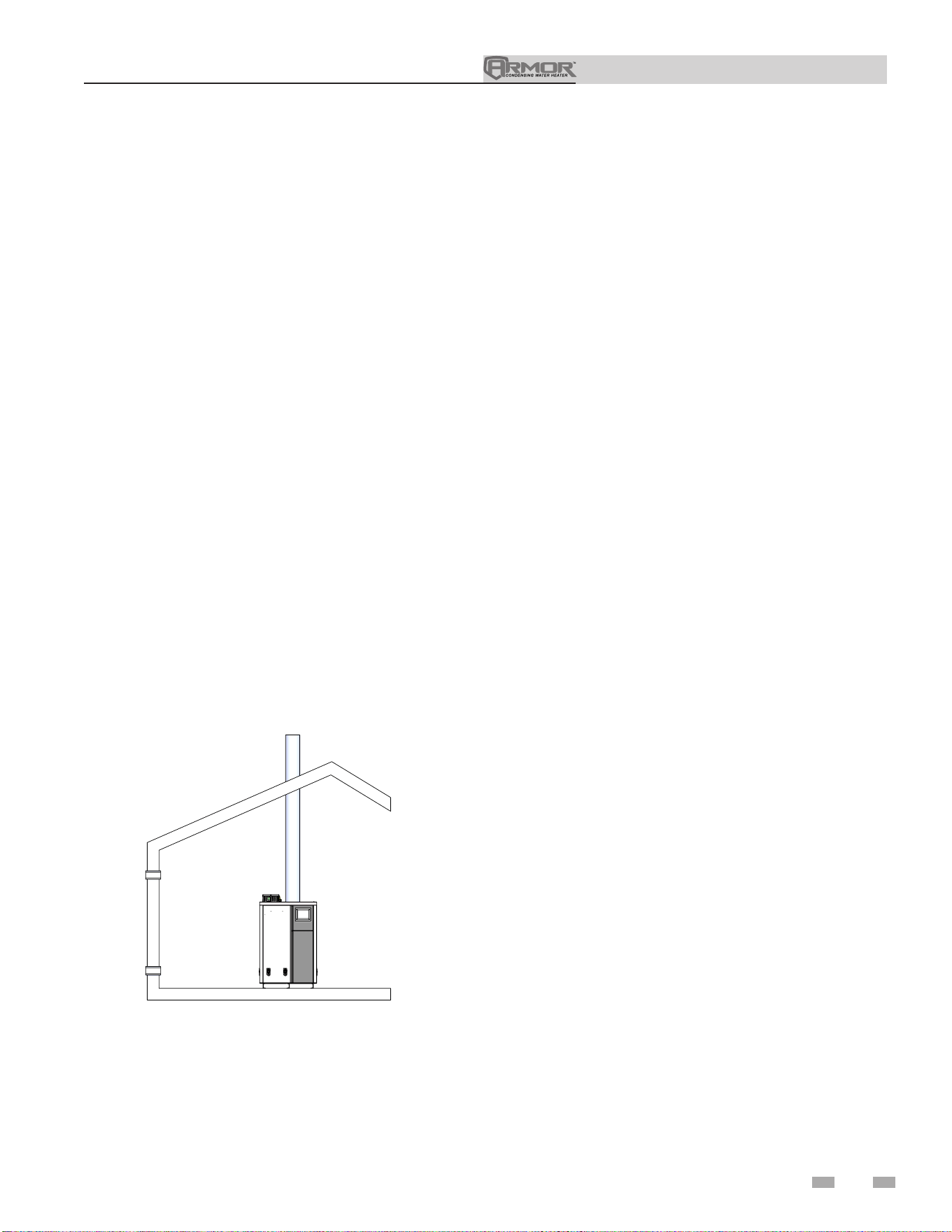
1. If air is taken directly from outside the building
with no duct, provide two permanent openings to
the equipment room each with a net free area of one square
inch per 4000 Btu/hr input (5.5 cm
2
per kW) (see FIG. 1-3).
Figure 1-3_Combustion Air Direct from Outside
2000620116 00
Installation & Operation Manual
1 Determine appliance location
14
4. If a single combustion air opening is provided to bring
combustion air in directly from the outdoors, the
opening must be sized based on a minimum free area
of one square inch per 3000 Btu/hr (7 cm
2
per kW). This
opening must be located within 12” (30 cm) of the top of
the enclosure (see FIG. 1-6).
All dimensions based on net free area in square inches. Metal
louvers or screens reduce the free area of a combustion air
opening a minimum of approximately 25%. Check with
louver manufacturers for exact net free area of louvers.
⚠CAUTION
Under no circumstances should the
equipment room ever be under negative
pressure. Particular care should be taken
where exhaust fans, attic fans, clothes dryers,
compressors, air handling units, etc., may
take away air from the unit.
The result is improper combustion and a non-warrantable,
premature appliance failure.
EXHAUST FANS: Any fan or equipment which exhausts air
from the equipment room may deplete the combustion air
supply and/or cause a downdraft in the venting system. Spillage
of flue products from the venting system into an occupied
living space can cause a very hazardous condition that must be
corrected immediately.
The combustion air supply must be completely free of any
flammable vapors that may ignite or chemical fumes which may
be corrosive to the appliance. Common corrosive chemical
fumes which must be avoided are fluorocarbons and other
halogenated compounds, most commonly present as refrigerants
or solvents, such as Freon, trichlorethylene, perchlorethylene,
chlorine, etc. These chemicals, when burned, form acids which
quickly attack the stainless steel heat exchanger, headers, flue
collectors, and the vent system.
Combustion air requirements are based on the latest edition
of the National Fuel Gas Code, NFPA 54 / ANSI Z223.1; in
Canada refer to the latest edition of CGA Standard CAN/CSA
B149.1. Check all local code requirements for combustion air.
Where two openings are provided, one must be within 12"
(30 cm) of the ceiling and one must be within 12" (30 cm) of
the floor of the equipment room. Each opening must have a
net free area as specified in Table 1B. Single openings shall
commence within 12" (30 cm) of the ceiling. The minimum
dimension of air openings shall not be less than 3" (80 mm).
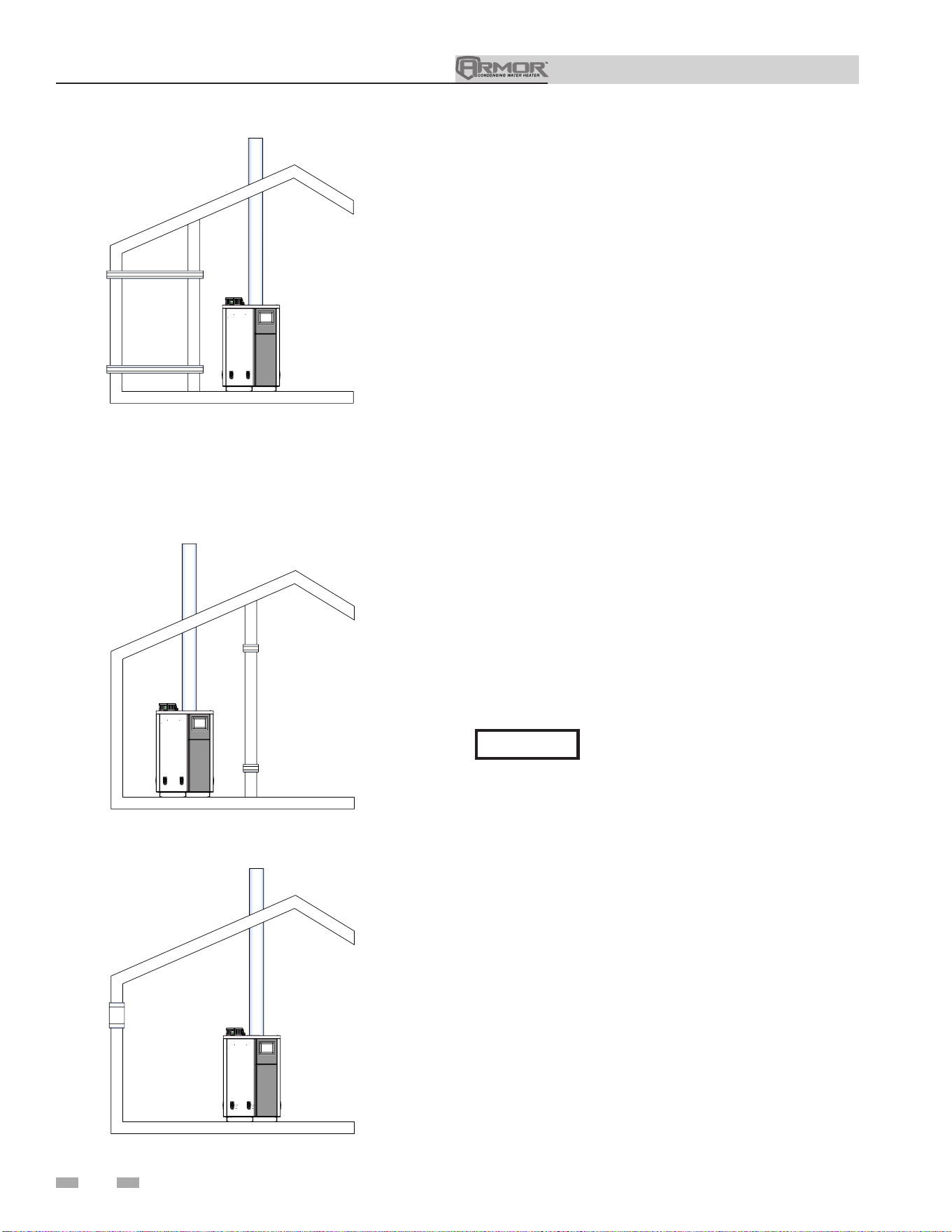
Figure 1-4_Combustion Air Through Ducts
2. If combustion and ventilation air is taken from the
outdoors using a duct to deliver the air to the
equipment room, each of the two openings should be
sized based on a minimum free area of one square inch
per 2000 Btu/hr (11 cm
2
per kW) of input (see FIG. 1-4).
Figure 1-5_Combustion Air from Interior Space
3. If air is taken from another interior space combined with
the equipment room:
(a) Two spaces on same story: Each of the two openings
specified above should have a net free area of one square
inch for each 1000 Btu/hr (22 cm
2
per kW) of input, but
not less than 100 square inches (645 cm
2
) (see FIG. 1-5).
(b) Two spaces on different stories: One or more openings
should have a net free area of two square inches per 1000
Btu/hr (44 cm
2
per kW).
Figure 1-6_Combustion Air from Outside - Single Opening
2000620116 00
2000620116 00
2000620116 00
Installation & Operation Manual
1 Determine appliance location
15
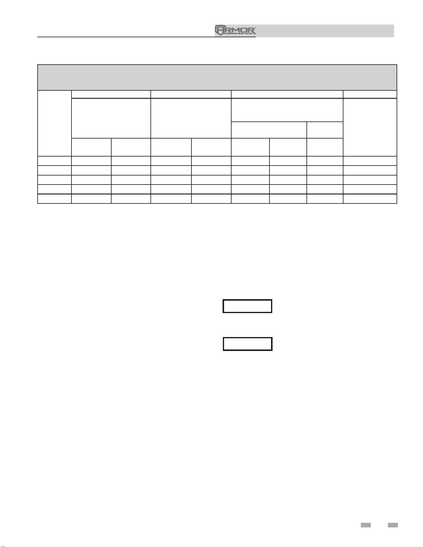
The above requirements are for the appliance only; additional gas fired appliances in the equipment room will require an increase
in the net free area and/or volume to supply adequate combustion air for all appliances.
No combustion air openings are needed when the appliance is installed in a space with a volume NO LESS than 50 cubic feet per
1,000 Btu/hr of all installed gas fired appliances. Buildings MUST NOT be of *“Tight Construction”
3
.
1
Outside air openings shall directly communicate with the outdoors.
2
Combined interior space must be 50 cubic feet per 1,000 Btu/hr input. Buildings MUST NOT be of *“Tight Construction”.
3
”Tight Construction” is defined as a building with less than 0.40 ACH (air changes per hour). For buildings of “Tight
Construction”, provide air openings into the building from outside.
TABLE - 1B
MINIMUM RECOMMENDED COMBUSTION
AIR SUPPLY TO EQUIPMENT ROOM
Model
Number
FIG. 1-4 FIG. 1-5 FIG. 1-6 FIG. 1-7
*Outside Air from
2 Openings Directly from
Outdoors
1
*Outside Air from
2 Ducts Delivered from
Outdoors
1
Inside Air from
2 Ducts Delivered from Interior Space
2
*Outside Air from
1 Opening Directly
from Outdoors, in
2
(cm
2
)
1
Same Story
Different
Stories
Top
Opening, in
2
(cm
2
)
Bottom
Opening, in
2
(cm
2
)
Top
Opening, in
2
(cm
2
)
Bottom
Opening, in
2
(cm
2
)
Top
Opening, in
2
(cm
2
)
Bottom
Opening, in
2
(cm
2
)
Total
Openings, in
2
(cm
2
)
AWH1250 313 (2020) 313 (2020) 625 (4033) 625 (4033) 1250 (8065) 1250 (8065) 2500 (16192) 417 (2691)
AWH1500 375 (2420) 375 (2420) 750 (4839) 750 (4839) 1500 (9678) 1500 (9678) 3000 (19355) 500 (3226)
AWH2000 500 (3226) 500 (3226) 1000 (6452) 1000 (6452) 2000 (12904) 2000 (12904) 4000 (25807) 667 (4304)
AWH3000 750 (4839) 750 (4839) 1500 (9678) 1500 (9678) 3000 (19355) 3000 (19355) 6000 (38710) 1000 (6452)
AWH4000 1000 (6450) 1000 (6450) 2000 (12900) 2000 (12900) 4000 (25800) 4000 (25800) 8000 (51600) 1333 (8600)
CAUTION
During construction the air filter should be
checked more frequently to ensure it does
not become clogged with combustion dirt
and debris.
NOTICE
Sustained operation of an appliance with
a clogged burner may result in nuisance
operational problems, bad combustion, and
non-warrantable component failures.
Combustion air filter
This unit has a standard air filter located at the combustion air
inlet. This air filter is provided to help ensure clean air is used
for the combustion process. Check this filter every month and
replace when it becomes dirty. You can find these commercially
available filters at any home center or HVAC supply store.
Filters by model sizes:
AWH1250 - AWH2000 / 1 x 16 x 20 filter
AWH3000 - AWH4000 / 1 x 24 x 30 filter
Note: Replacement filter should have a MERV rating no greater
than 4.
Follow the steps below when replacing the combustion air filter:
1. Locate the combustion air filter box.
2. Remove the air filter cover from the bottom of the air filter
box to gain access to the air filter.
3. Slide the air filter out of the bottom of the air filter box.
4. Inspect the air filter for dirt and debris, replace if necessary.
5. Replace the air filter and the air filter box cover.
Installation & Operation Manual
16
2 Prepare appliance
For an appliance already installed, you
must turn off gas supply, turn off power,
and allow the appliance to cool before
proceeding. You must also completely test
the appliance after conversion to verify
performance as described under Start-
up, Section 10 of this manual. Failure to
comply could result in severe personal
injury, death, or substantial property
damage.
You must install a propane orifice to
operate the Armor appliance on propane
gas. Verify when installing that the orifice
size marking matches appliance size.
2000548942 00
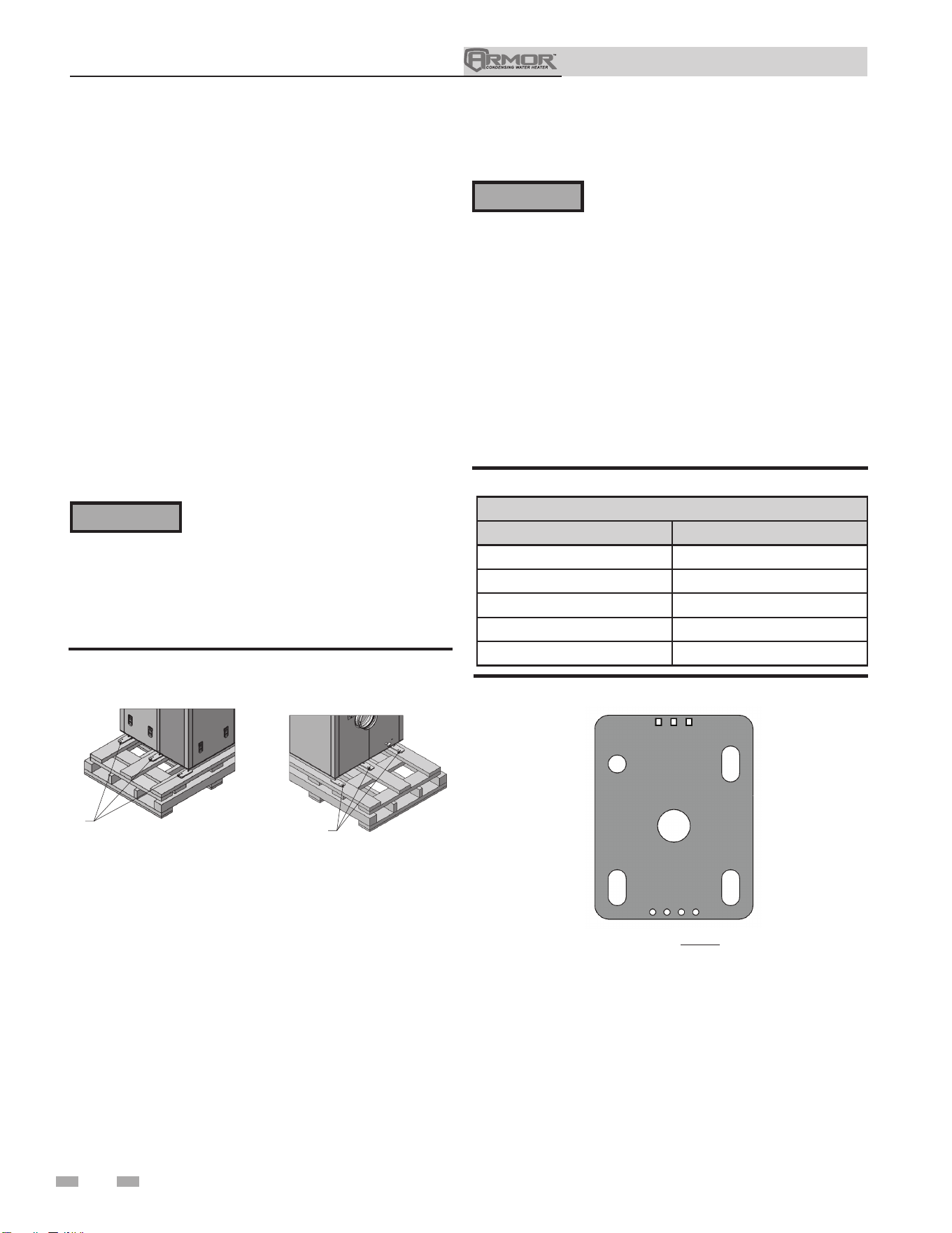
FRONT
REAR
LAG BOLTS
(QTY. 3)
LAG BOLTS
(QTY. 3)
Figure 2-1 Appliance Mounted on Shipping Pallet
Gas conversions
LP Conversion Table
Model LP Orifice Stamping
1250
4 Circles, 3 Squares
1500
4 Circles, 3 Squares
2000
5 Circles, 4 Squares
3000
1 Circle, 1 Square
4000
1 Circle, 2 Squares
⚠WARNING
Table 2A LP Conversion Table
Remove appliance from wood pallet
1. After removing the outer shipping carton from the
appliance, remove the parts box.
2. To remove the appliance from the pallet:
a. Remove the six (6) shipping bolts that fasten the tie-
down brackets securing the legs to the front and rear
of the pallet (FIG. 2-1).
b. The appliance can now be removed from the
pallet using a lift truck lifting from the front or
rear of the appliance. If lifting from the front,
the lift truck forks must extend at least half way
under the appliance heat exchanger to assure
proper lifting technique with no damage to the
appliance.
Failure to assure the truck forks are
long enough to extend at least halfway
under the appliance heat exchanger will
result in the appliance tipping off the lift
truck, and potentially falling. This will
result in severe personal injury, death, or
substantial property damage.
⚠WARNING
Figure 2-2 LP Orifice Stamping
DIR #2000551053 00
NOTE: Model 1250 shown for
illustration purposes only.
Installation & Operation Manual
2 Prepare appliance
17
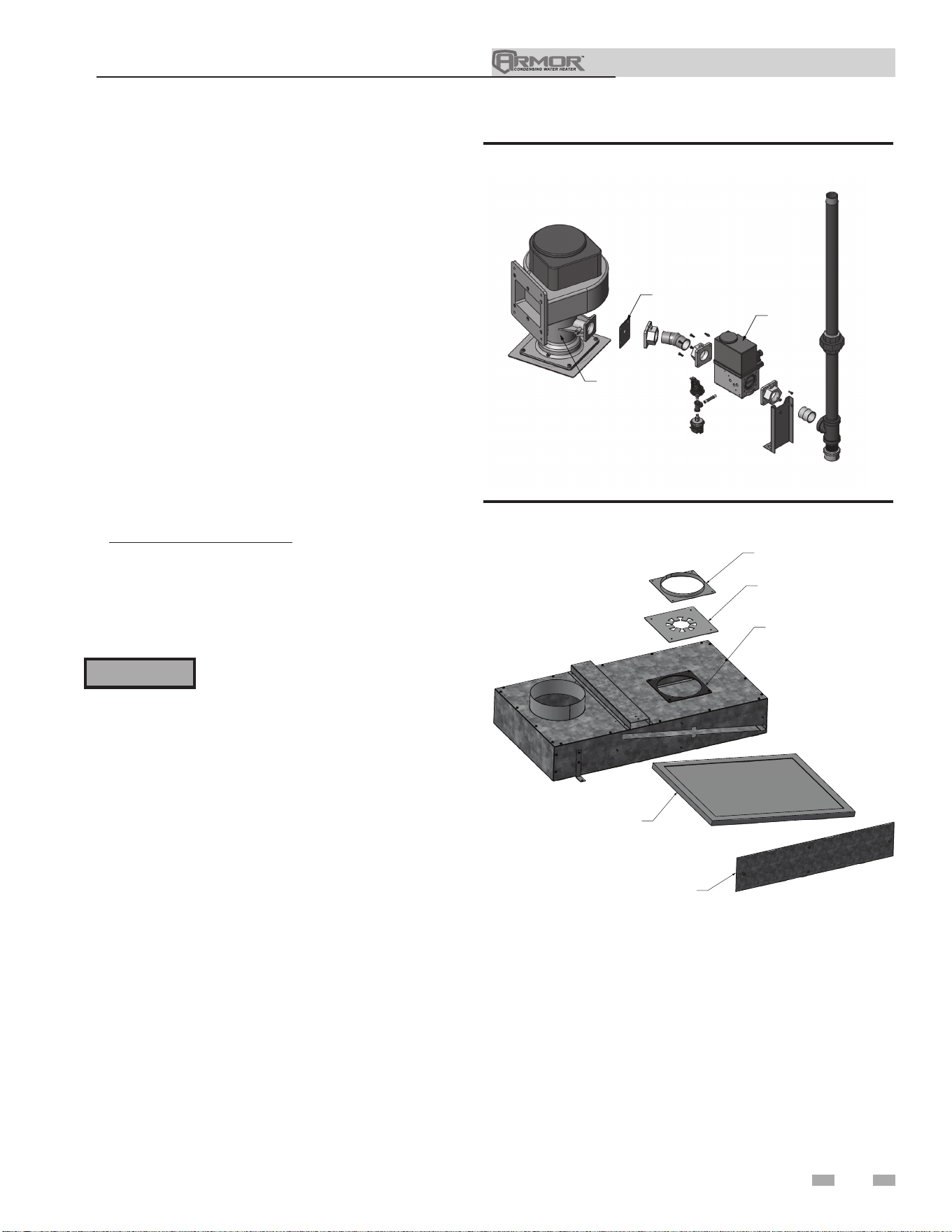
DIR #2000548918 00
GAS VALVE
LP ORIFICE
VENTURI
Figure 2-3 Installing Propane Orifice - Models 1250 - 4000
Procedure
1. Remove the front access cover from the unit.
2. Remove the four (4) screws securing the gas train to the
venturi (FIG. 2-3).
3. Locate the propane orifice disk from the conversion kit
bag. Verify that the stamping on the orifice disk matches
the appliance size (see Table 2A).
Place the orifice with gasket between the flange and
venturi.
4. Reposition the gas train against the venturi and replace
the screws (FIG. 2-3) securing the valve to the venturi.
5. After installation is complete, attach the propane
conversion label (in the conversion kit bag) next to the
appliance rating plate. Attach the LP caution label (in the
conversion kit bag) to the left side of the unit in the lower
left corner.
For Models 3000 and 4000: Locate the air orifice plate
from the conversion kit bag. Place the plate with gasket
between the flex duct flange and air box as shown in
Figure 2-4.
6. Replace the front access covers.
⚠WARNING
After converting to LP, check combustion
per the Start-up procedure in Section
10 of this manual. Failure to check and
verify combustion could result in severe
personal injury, death, or substantial
property damage.
Figure 2-4 Installing Air Orifice Plate - Models 3000 & 4000
FLEX DUCT
FLANGE
AIR ORIFICE
PLATE
GASKET
AIR FILTER
AIR FILTER
ACCESS PANEL
DIR #2000548923 00
Air Filter Replacement Procedure
1. Remove the front access cover from the unit.
2. Remove the four (4) thumb screws securing the air filter
access panel (FIG. 2-4).
3. Remove the air filter.
4. Install the new air filter. See Table 3D for filter sizes.
When installing, take note of the arrow on the filter and
ensure that it points in the direction of the air flow.
5. Replace the air filter access panel.
6. Replace the front access cover.
Filters by model sizes:
AWH1250-2000 / 16 x 20 x 1 filter
AWH3000-4000 / 24 x 30 x 1 filter
Note: Replacement filter should have a MERV rating no
greater than 4.
Installation & Operation Manual
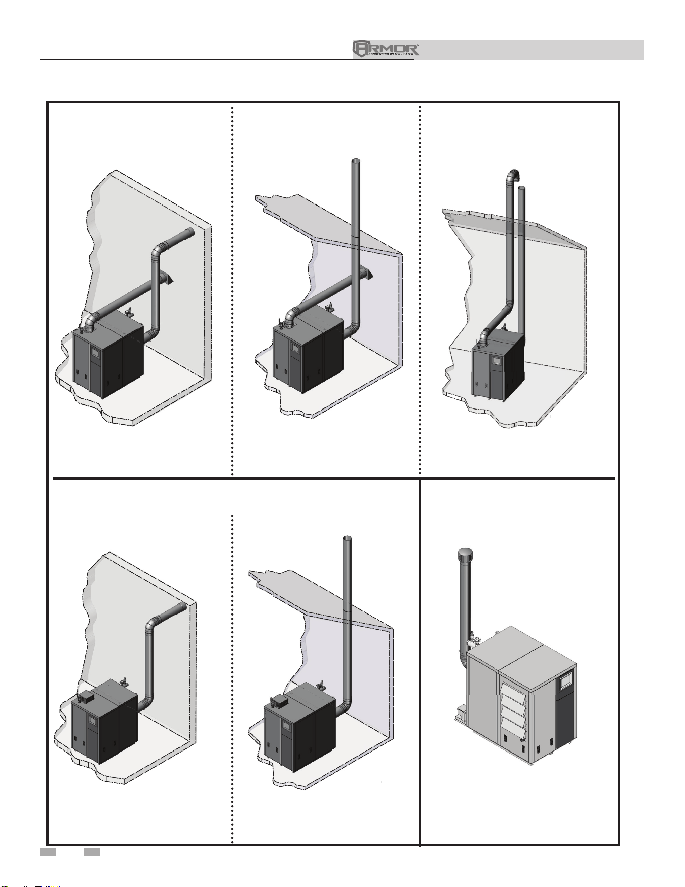
3 General venting
Vertical
DIR #2000548877 00
DIR #2000548894 00DIR
#
2
0005
4
889
4
00
DIR #2000548895 00DIR
#
2000548895 0
0
Sidewall
Direct venting
Vertical Vent, Sidewall Air
Sidewall
DIR #2000548873 00DIR
#
2000548873 0
0
Vertical
2000548878 00
DIR #2000548895 00
Optional room air
18
Outdoor
Outdoor
DIR #2000550995 00
Installation & Operation Manual
3 General venting
19
Install vent and combustion air piping
⚠ DANGER
The Armor must be vented and supplied
with combustion and ventilation air as
described in this section. Ensure the vent
and air piping and the combustion air
supply comply with these instructions
regarding vent system, air system, and
combustion air quality. See also Section 1
of this manual.
Inspect finished vent and air piping
thoroughly to ensure all are airtight and
comply with the instructions provided
and with all requirements of applicable
codes.
Failure to provide a properly installed
vent and air system will cause severe
personal injury or death.
Air inlet pipe materials:
The air inlet pipe(s) must be sealed. Choose acceptable
combustion air inlet pipe materials from the following list:
ABS, PVC, or CPVC
Dryer Vent or Sealed Flexible Duct (not recommended
for rooftop air inlet)
Galvanized steel vent pipe with joints and seams sealed
as specified in this section.
Type “B” double-wall vent with joints and seams sealed
as specified in this section.
AL29-4C, stainless steel material to be sealed to
specification of its manufacturer.
*Plastic pipe may require an adapter, such as a Fernco
coupling (not provided), to transition between the air inlet
connection on the appliance and the plastic air inlet pipe.
⚠WARNING
Using vent or air intake materials
other than those specified, failure to
properly seal all seams and joints, or
failure to follow vent pipe manufacturer’s
instructions can result in personal injury,
death, or property damage. Mixing of
venting materials will void the warranty
and certification of the appliance.
NOTICE
The use of double-wall vent or insulated
material for the combustion air inlet
pipe is recommended in cold climates
to prevent the condensation of airborne
moisture in the incoming combustion air.
Sealing of Type “B” double-wall vent material or galvanized
vent pipe material used for air inlet piping on a sidewall or
vertical rooftop Combustion Air Supply System:
a. Seal all joints and seams of the air inlet pipe using either
Aluminum Foil Duct Tape meeting UL Standard 723 or
181A-P or a high quality UL Listed silicone sealant such
as those manufactured by Dow Corning or General
Electric.
b. Do not install seams of vent pipe on the bottom of
horizontal runs.
c. Secure all joints with a minimum of three sheet metal
screws or pop rivets. Apply aluminum foil duct tape or
silicone sealant to all screws or rivets installed in the air
intake pipe.
d. Ensure that the air inlet pipes are properly supported.
The PVC, CPVC, or ABS air inlet pipe should be cleaned and
sealed with the pipe manufacturer’s recommended solvents
and standard commercial pipe cement for the material used.
The ABS, PVC, CPVC, Dryer Vent, or Flex Duct air inlet
pipe should use a silicone sealant to ensure a proper seal at
the appliance connection and the air inlet cap connection.
Dryer vent or flex duct should use a screw type clamp to seal
the vent to the appliance air inlet and the air inlet cap. Proper
sealing of the air inlet pipe ensures that combustion air will be
free of contaminants and supplied in proper volume.
When a sidewall or vertical rooftop combustion air supply
system is disconnected for any reason, the air inlet pipe
must be resealed to ensure that combustion air will be free of
contaminants and supplied in proper volume.
⚠ DANGER
Failure to properly seal all joints and seams
as required in the air inlet piping may
result in flue gas recirculation, spillage
of flue products, and carbon monoxide
emissions causing severe personal injury
or death.
Follow the polypropylene manufacturer’s instructions when
using polypropylene material as an inlet pipe.
Supports
Vent system must be supported horizontally to prevent sagging.
Methods and intervals for support vary by vent manufacturer
and vent material. Vent support methods and intervals shall
adhere to vent manufacturer’s instructions, where applicable.
Vent piping must be supported per the National Building
Code, Section 305, Table 305.4 or as local codes dictate.
Installation & Operation Manual
3 General venting (continued)
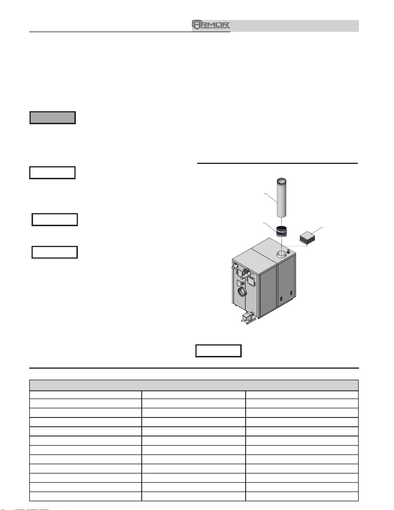
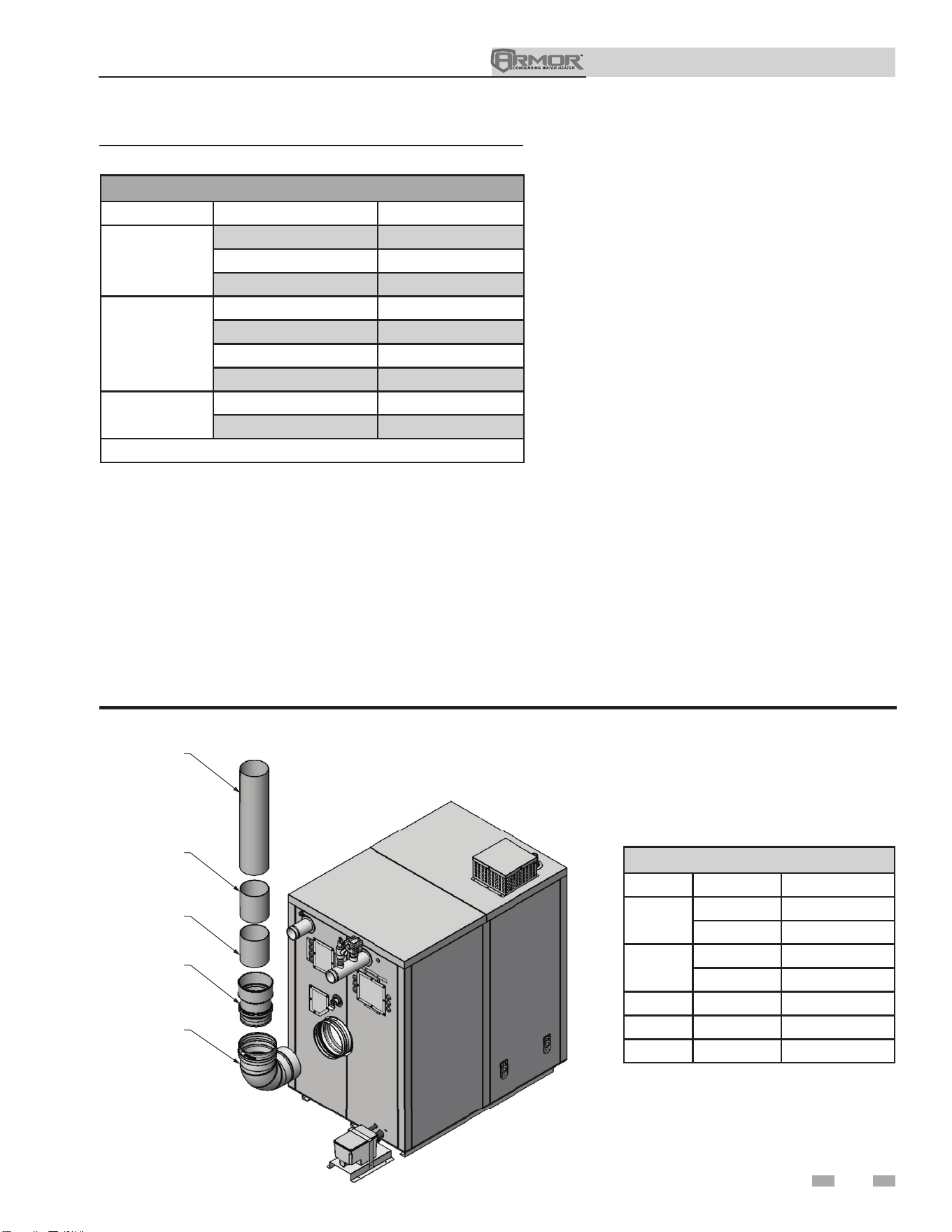
Air intake/vent connections
1. Combustion Air Intake Connector (FIG. 3-1) - Used to
provide combustion air directly to the unit from outdoors.
A fitting is provided with the unit for final connection.
Combustion air piping must be supported per guidelines
listed in the National Mechanical Code, Section 305, Table
305.4 or as local codes dictate.
2. Vent Connector (FIG. 3-1) - Used to provide a
passageway for conveying combustion gases to the
outside. A pipe stub is provided on the unit for
final connection. Vent piping must be supported per the
National Building Code, Section 305, Table 305.4 or as
local codes dictate.
DIR #2000548681 00
REMOVE
ROOM AIR BOX
SHIPPED WITH
UNIT
AIR PIPE
(FIELD SUPPLIED)
AIR PIPE ADAPTER
(FIELD SUPPLIED)
Figure 3-1 Combustion Air Adapter
Vent and air piping
The Armor is certified as a Category II/IV appliance. This
product has been approved for use with stainless steel vent
systems. All venting systems used with an Armor appliance
must be suitable for Category IV operation except for factory
approved common vent systems operating as allowed in the
Common Venting Section on page 20.
⚠WARNING
NOTICE
NOTICE
The Armor uses model specific combustion air intake and vent
piping sizes as detailed in Tables 3B and 3C on page 18.
Increasing or decreasing combustion air
or vent piping to sizes not specified in this
manual is not authorized.
NOTICE
Use only the materials, vent systems,
and terminations listed in Table 3A-1.
DO NOT mix vent systems of different
types or manufacturers unless listed in
this manual. Failure to comply could
result in severe personal injury, death, or
substantial property damage.
Installations must comply with applicable
national, state, and local codes. Stainless
steel vent systems must be listed as a
UL-1738 approved system for the United
States and a ULC-S636 approved system
for Canada.
Installation of a stainless steel vent system
should adhere to the stainless steel vent
manufacturer’s installation instructions
supplied with the vent system.
NOTICE
The Armor is supplied with an integral
FasNSeal vent connector (FIG. 3-1). The
installer must use a specific vent starter
adapter supplied by the vent manufacturer
to adapt to different vent systems.
Table 3A-1 Approved Stainless Steel Vent Manufacturers
Approved Stainless Steel Vent Manufacturers
Make Model Standard
ProTech Systems (Dura-Vent Co.) FasNSeal Vent UL1738 / ULC-S636
Z-Flex (Nova Flex Group) Z-Vent UL1738 / ULC-S636
Heat Fab (Selkirk Corporation) Saf-T Vent UL1738 / ULC-S636 / UL641 / ULC68
Metal Fab Corr/Guard UL1738 / ULC-S636
Securities Chimneys International Secure Seal SS UL1738 / ULC-S636
DuraVent DuraSeal DS --
Schebler Chimney Systems eVent UL1738 / ULC-S636
ICC VIC UL1738 / ULC-S636
Jeremias -- UL1738 / ULC-S636
Enervex Powerstack --
Van Packer -- --
Installation & Operation Manual
3 General venting
21
Table 3A-2 Approved Stainless Steel Terminations and Adapters - Category IV
Model
DuraVent Z Flex Heat Fab
Adapter Intake Adapter Intake Adapter Flue Intake
1250-2000
*See note
810003357
810003369
2SVDSA08 2SVEE0890 9801MAD CCK08TM
9890
9892
3000
*See note
810003435
810003447
2SVDSA10 2SVEE1090 91001MAD CCK10TM
91090
91092
4000
*See note
810003476
810003488
2SVDSA12 2SVEE1290 91201MAD CCK12TM
91290
91292
Model
Metal-Fab Security Chimney ICC
Adapter Flue Intake Adapter Flue Intake Adapter Flue Intake
1250-2000
8FCGLCA
MC
6" - 36"
8FCGSW90 SS8CRESTU
SS0MCU
4" - 24"
SSE8E9OU
SD0STAUK
4" - 10"
HE-8DSA-F
HE-8SCR-F
HE-8MC-F
HE-8E90-F
HE-8SCR-F
3000
10FCGLCA
MC
6" - 36"
10FCGSW90 SS10CRESTU
SS0MCU
4" - 24"
SSE10E9OU
SD0ST9OAUK
4" - 10"
HE-10DSA-F
HE-10SCR-F
HE-10MC-F
HE-10E90-F
HE-10SCR-F
4000
12FCGLCA
MC
6" - 36"
12FCGSW90 SS12CRESTU
SS0MCU
4" - 24"
SSE12E9OU
HE-12DSA-F HE-12SCR-F
HE-12MC-F
HE-12E90-F
HE-12SCR-F
Model
Jeremias
*No adapter needed when using Standard FNS Vent Length.
**Models 1250 - 1500: For installations using a 6 inch vent, use the adapter
from Table 3A-2 for the appropriate vent system manufacturer, then use
the manufacturer’s tapered reducing adapter from 8 inch to 6 inch diameter
to continue the system. If using a DuraVent vent system, factory KIT
#100295900 is available.
Adapter Flue Intake
1250-2000
SWKL8-KLC SWKL8-WRC SWKL8-90ET
3000
SWKL10-KLC SWKL10-WRC SWKL10-90ET
4000
SWKL12-KLC SWKL12-WRC SWKL12-90ET
Model
Enervex Van Packer
Adapter Flue Intake Adapter Intake
1250-2000
801.0676.4708 801.0679.XX08 801.0676.0408 MM08MOAB M0890EB & M06SCTB
3000
801.0676.4710 801.0679.XX10 801.0676.0410 MM10MOAB M1090EB & M06SCTB
4000
801.0676.4712 801.0679.XX12 801.0676.0412 MM12MOAB M1290EB & M06SCTB
Model
DuraVent
Adapter Flue Intake
1250-2000
DS8CRESTU
DS0MCU
4″ - 24″
DSE8E90U DSD0STAUK
4″ - 24″
3000
DS10CRESTU
DS0MCU
4″ - 24″
DSE10E90U DS0ST90AUK
4″ - 10″
4000
DS12CRESTU
DS0MCU
4″ - 24″
DSE12E90U
Installation & Operation Manual
3 General venting
22
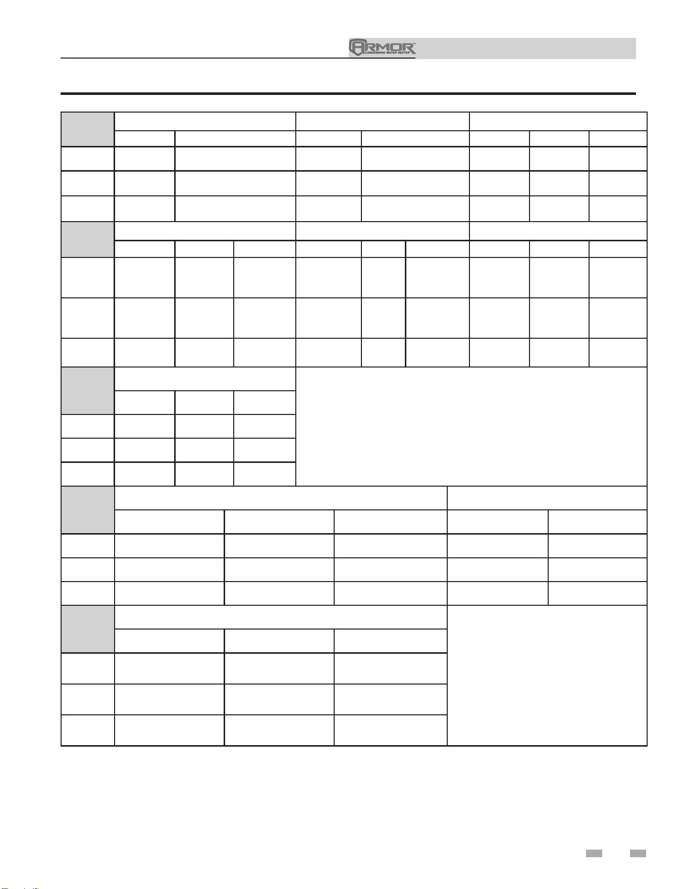
Table 3B Direct Vent Minimum / Maximum Allowable Air / Vent Lengths
Table 3C Room Air Minimum / Maximum Allowable Air / Vent Lengths
Model
AIR INLET VENT
Input
Derate per 25
feet of Vent
Air Intake
Diameter
Air Intake
Min. Length
Air Intake
Max. Length
Vent
Diameter
Vent
Min. Length
Vent
Max. Length
1250 8" 10' 150' 8" 10' 150' 0%
1250 6" 10' 70' 6" 10' 70' 1.5%
1500 8" 10' 150' 8" 10' 150' 0%
1500 6" 10' 70' 6" 10' 70' 2.4%
2000 8" 10' 150' 8" 10' 150' 0.7%
3000 10" 10' 100' 10" 10' 100' 0.5%
4000 12" 10' 150' 12" 10' 150' 0%
Model
Vent
Diameter
Vent
Min. Length
Vent
Max. Length
Input Derate per 25
feet of Vent
1250 8" 10' 150' 0%
1250 6" 10' 70' 1.0%
1500 8" 10' 150' 0%
1500 6" 10' 70' 1.7%
2000 8" 10' 150' 0%
3000 10" 10' 100' 0%
4000 12" 10' 150' 0%
Model Air Filter Size
1250 - 2000 16" x 20" x 1"
3000 - 4000 24" x 30" x 1"
Table 3D Air Filter Sizes
Installation & Operation Manual
3 General venting (continued)
Vent, air piping, and termination:
The Armor vent and air piping can be installed through the roof
or through a sidewall. Follow the procedures in this manual for
the method chosen. Refer to the information in this manual to
determine acceptable vent and air piping length.
Air contamination
Pool and laundry products and common household and hobby
products often contain fluorine or chlorine compounds. When
these chemicals pass through the appliance, they can form
strong acids. The acid can eat through the appliance wall,
causing serious damage and presenting a possible threat of flue
gas spillage or appliance water leakage into the building.
Please read the information given in Table 1A, page 10,
listing contaminants and areas likely to contain them. If
contaminating chemicals will be present near the location of
the appliance combustion air inlet, have your installer pipe the
appliance combustion air and vent to another location, per this
manual.
If the appliance combustion air inlet is
located in a laundry room or pool facility,
for example, these areas will always contain
hazardous contaminants.
To prevent the potential of severe personal
injury or death, check for areas and products
listed in Table 1A, page 10 before installing
the appliance or air inlet piping.
If contaminants are found, you MUST:
• Remove products permanently.
—OR—
• Relocate air inlet and vent
terminations to other areas.
Removing from existing vent
Follow the instructions in Section 1, page 11 of this manual
when removing an appliance from an existing vent system.
Vent and air piping
Vent and air system:
Installation must comply with local
requirements and with the National Fuel
Gas Code, NFPA 54 / ANSI Z223.1 for U.S.
installations or CSA B149.1 for Canadian
installations.
You must also install air piping from outside to the appliance
air intake adapter. The resultant installation is direct vent
(sealed combustion).
You may use any of the vent/air piping methods covered in
this manual. Do not attempt to install the Armor using any
other means.
NOTICE
⚠WARNING
⚠WARNING
⚠WARNING
When determining equivalent combustion air and vent
length, add 5 feet (1.5m) for each 90° elbow and 3 feet (.9 m)
for each 45° elbow.
EXAMPLE: 20 feet (6 m) of pipe + (4) 90° elbows + (3) 45°
elbows = 49 equivalent feet (15 m) of piping.
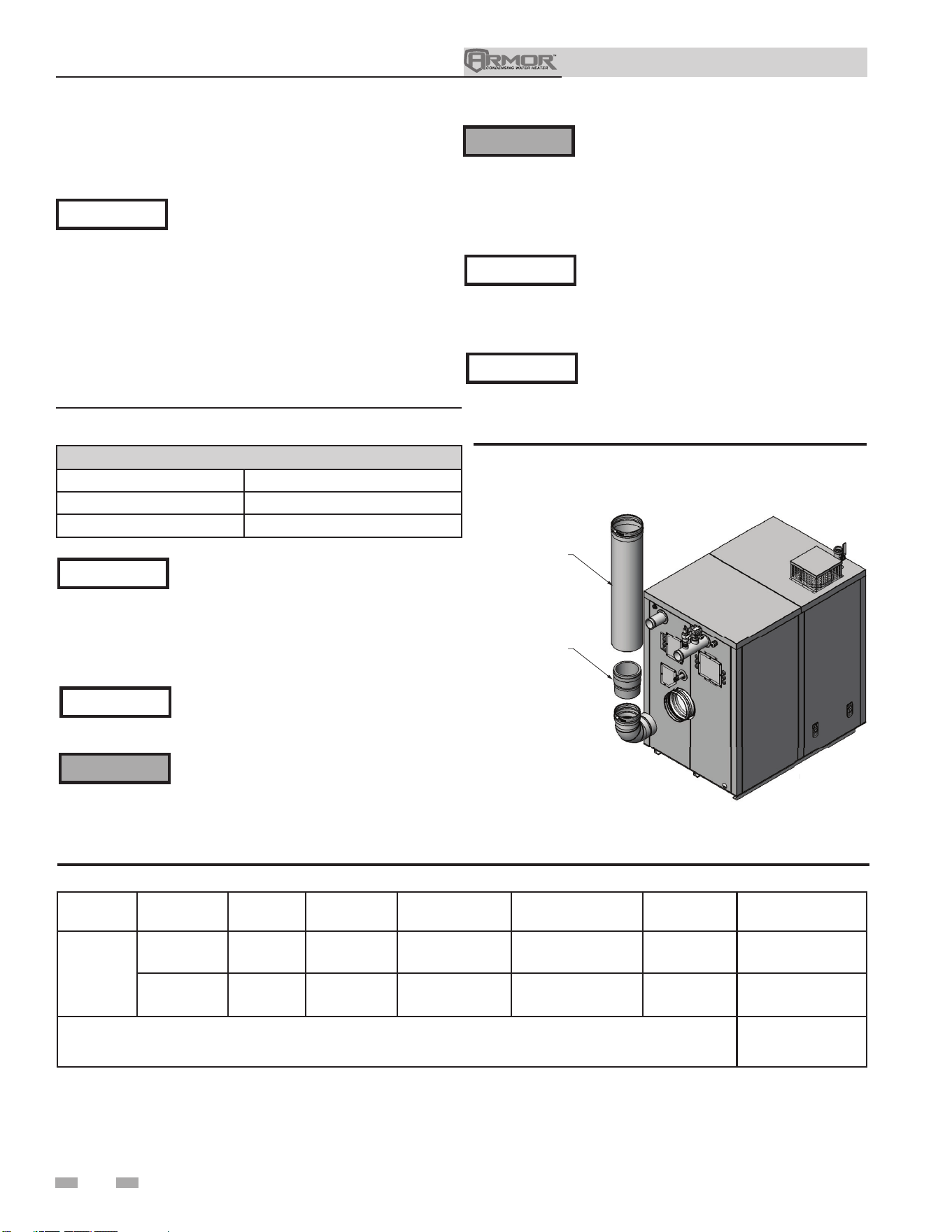
DO NOT mix components from different
systems. The vent system could fail,
causing leakage of flue products into the
living space. Use only approved stainless
steel pipe and fittings.
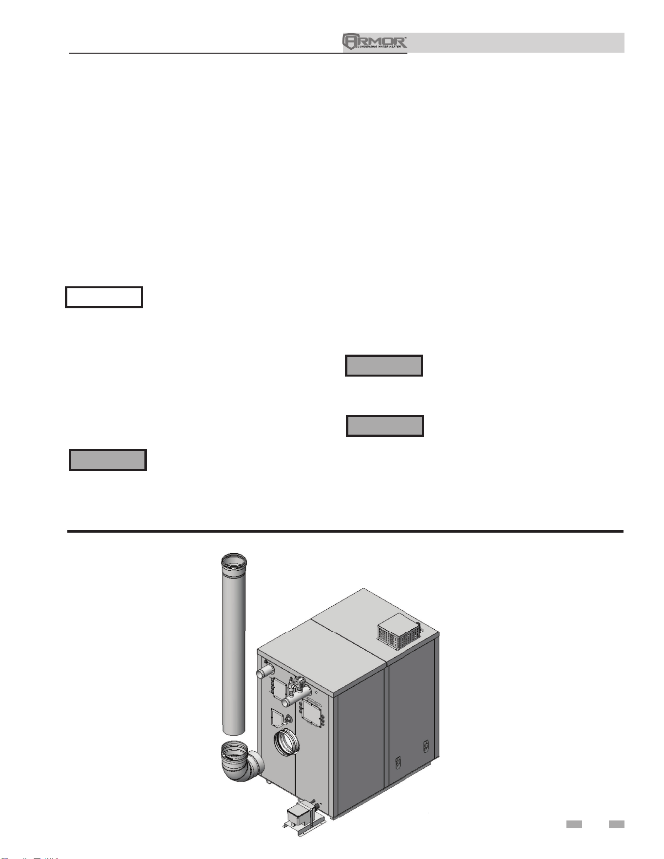
DIR #2000548705 00DIR
#2
00
05
48
70
5
00
Figure 3-2 Near Appliance Stainless Steel Venting
23
Installation & Operation Manual
24
3 General venting
Common venting
Armor 1250 - 4000 appliances may be common vented;
however, the following criteria MUST BE followed:
1. Only Armor appliances may be connected to common
flue applications. DO NOT mix other manufacturer’s
appliances or other Lochinvar models. Common air
intake is not allowed.
2. Armor appliances connected to the common vent
must all be of the same size.
3. Each Armor appliance must have a Lochinvar supplied
flue damper installed (see Table 3E).
4. A condensate drain must be installed above the flue
damper.
5. Only vertical direct vent, positive pressure, Category
IV or vertical/chimney vent, negative pressure, Category
II may be used when common venting Armor appliances.
Sidewall venting is not allowed.
6. Armor appliances in a common vent must be
connected and controlled with the integral Armor
SMART TOUCH Cascade.
a. The Leader may be controlled through the Armor
SMART TOUCH control through BMS (external
0 - 10V signal), ModBus, or its own internally
calculated set point.
b. The Cascade (Members) must be controlled by the
Armor Leader appliance using the Lead/Lag
Cascade option.
For approved common vent sizing, contact the factory.
⚠WARNING
When Armor appliances are common
vented, the criteria above MUST BE
followed. Failure to follow all these
requirements will result in severe personal
injury, death, or substantial property
damage.
Table 3E Flue Damper Kits
Flue Damper Kits
Model Damper Size Kit Number
1250 8" 100303788
1500 8" 100303788
2000 8" 100303788
3000 10" 100303790
4000 12" 100303811
Installing vent and air piping
Use only cleaners, primers, and solvents
that are approved for the materials which
are joined together.
NOTICE
PVC/CPVC
All PVC vent pipes must be glued, properly
supported, and the exhaust must be
pitched a minimum of a 1/4 inch per foot
back to the appliance (to allow drainage of
condensate).
NOTICE
⚠WARNING
The vent connection to the appliance must
be made with the starter CPVC pipe section
if PVC/CPVC vent is to be used. The field
provided vent fittings must be cemented
to the CPVC pipe section using an “All
Purpose Cement” suitable for PVC and
CPVC pipe. Use only the vent materials,
primer, and cement specified in Table 3F
to make the vent connections. Failure to
follow this warning could result in fire,
personal injury, or death.
⚠WARNING
Insulation should not be used on PVC
or CPVC venting materials. The use of
insulation will cause increased vent wall
temperatures, which could result in vent
pipe failure.
This product has been approved for use with the PVC/CPVC
vent materials listed in Table 3F on page 21.
Factory installed vent connections are sized
for stainless steel venting.
NOTICE
NOTICE
A field supplied inline condensate
collection section MUST BE installed
directly above the backflow preventer.
NOTICE
When using polypropylene common
vent, a field supplied polypropylene to
stainless steel adapter MUST BE installed
between the backflow preventer and the
unit connection.
NOTE: Connection for flue damper is inside the low voltage
connection box on appliance.
Installation & Operation Manual
3 General venting (continued)
5. Dry fit vent or air piping to ensure proper fit up
before assembling any joint. The pipe should go
one-third to two-thirds into the fitting to ensure
proper sealing after cement is applied.
6. Priming and Cementing:
a. Handle fittings and pipes carefully to prevent
contamination of surfaces.
b. Apply a liberal even coat of primer to the fitting
socket and to the pipe end to approximately 1/2"
beyond the socket depth.
c. Apply a second primer coat to the fitting
socket.
d. While primer is still wet, apply an even coat of
approved cement to the pipe equal to the
depth of the fitting socket along with an even
coat of approved cement to the fitting socket.
e. Apply a second coat of cement to the pipe.
f. While the cement is still wet, insert the pipe into
the fitting. If possible twist the pipe a 1/4 turn as
you insert it. NOTE: If voids are present,
sufficient cement was not applied and joint could
be defective.
g. Wipe excess cement from the joint removing
ring or beads as it will needlessly soften the
pipe.
Table 3F PVC/CPVC Vent Pipe and Fittings
Approved PVC/CPVC Vent Pipe and Fittings
Item Material Standard
Vent pipe
PVC Schedule 40, 80 ANSI/ASTM D1785
PVC - DWV ANSI/ASTM D2665
CPVC Schedule 40, 80 ANSI/ASTM F441
Vent fittings
PVC Schedule 40 ANSI/ASTM D2466
PVC Schedule 80 ANSI/ASTM D2467
CPVC Schedule 80 ANSI/ASTM F439
PVC - DWV ANSI/ASTM D2665
Pipe Cement /
Primer
PVC ANSI/ASTM D2564
CPVC ANSI/ASTM F493
NOTICE: DO NOT USE CELLULAR (FOAM) CORE PIPE
NOTE: In Canada, CPVC and PVC vent pipe, ttings, and cement/
primer must be ULC-S636 certied.
1. Work from the appliance to vent or air termination. Do not
exceed the lengths given in this manual for the air or vent
piping.
2. Cut pipe to the required lengths and deburr the inside
and outside of the pipe ends.
3. Chamfer outside of each pipe end to ensure even
cement distribution when joining.
4. Clean all pipe ends and fittings using a clean dry rag.
(Moisture will retard curing and dirt or grease will prevent
adhesion.)
PVC PIPE
(FIELD SUPPLIED)
PVC COUPLING
(FIELD SUPPLIED)
CPVC PIPE
STARTER PIECE
(AVAILABLE FROM FACTORY)
PVC TO STAINLESS
ADAPTER (AVAILABLE
FROM FACTORY)
NOTE: CPVC VENT OR STAINLESS STEEL
PIPE AND VENT FITTINGS MUST BE USED
IN CLOSET AND ALCOVE INSTALLATIONS.
DIR #2000548690 00
90° STAINLESS STEEL
ELBOW (FIELD SUPPLIED
AS NEEDED)
Figure 3-3 Near Appliance PVC/CPVC Venting (Flue connections from the factory are sized for stainless steel venting.)
PVC Adapter Kits
Model Vent Size Kit Number
1250
8" 100267012
6" 100289537
1500
8" 100267012
6" 100289537
2000 8" 100267012
3000 10" 100314852
4000 12" Field Supplied
25
Installation & Operation Manual
3 General venting
26
Model Manufacturer Vent Model Vent Type Adapter Number Joint Connector Sidewall Kit*
Retaining Bracket /
Adapter*
1250-2000
Centrotherm
Eco Systems
Innoflue Single-Wall ISSA0808 -- -- --
DuraVent
(M & G)
PolyPro Single-Wall FSA-08M-8PPF -- 8PPS-HSTL --
* These parts are only needed if the sidewall termination assembly is used (see FIG. 5-1C on page 27).
Polypropylene
This product has been approved for use with polypropylene
vent with the manufacturers listed in Table 3G.
All terminations must comply with listed options in this
manual and be a single-wall vent offering.
For support and special connections required, see the
manufacturer's instructions. All vent is to conform to standard
diameter and equivalent length requirements established.
When determining equivalent combustion air and vent length
for polypropylene single-wall piping, contact the manufacturer.
Use only the adapters and vent system listed
in Tables 3G and 3H. DO NOT mix vent
systems of different types or manufacturers.
Failure to comply could result in severe
personal injury, death, or substantial
property damage.
⚠WARNING
Installations must comply with applicable
national, state, and local codes. For
Canadian installation, polypropylene vent
must be listed as a ULC-S636 approved
system.
Installation of a polypropylene vent system
should adhere to the vent manufacturer’s
installation instructions supplied with the
vent system.
Table 3G Polypropylene Vent Pipe and Fittings
⚠WARNING
Insulation should not be used on
polypropylene venting materials. The use
of insulation will cause increased vent wall
temperatures, which could result in vent pipe
failure.
The installer must use a specific vent starter
adapter at the flue collar connection. The
adapter is supplied by the vent manufacturer
to adapt to its vent system. See Table 3G
for approved vent adapters. Discard CPVC
starter piece.
NOTICE
All vent connections MUST be secured by
the vent manufacturer's joint connector
(FIG. 3-4).
NOTICE
Figure 3-4 Near Appliance Polypropylene Venting
DIR #2000548691 00
D
IR #2
0
0
0
5
4
8
6
9
1
0
0
POLYPROPYLENE
PIPE (FIELD SUPPLIED)
POLYPROPYLENE
ADAPTER (FIELD
SUPPLIED)
NOTICE
NOTICE
Table 3H Approved Polypropylene Terminations
Approved Polypropylene Vent Manufacturers
Make Model
Centrotherm Eco Systems
InnoFlue SW/Flex
Duravent (M & G Group)
PolyPro Single-Wall / PolyPro Flex
Factory installed vent connections are sized
for stainless steel venting.
NOTICE
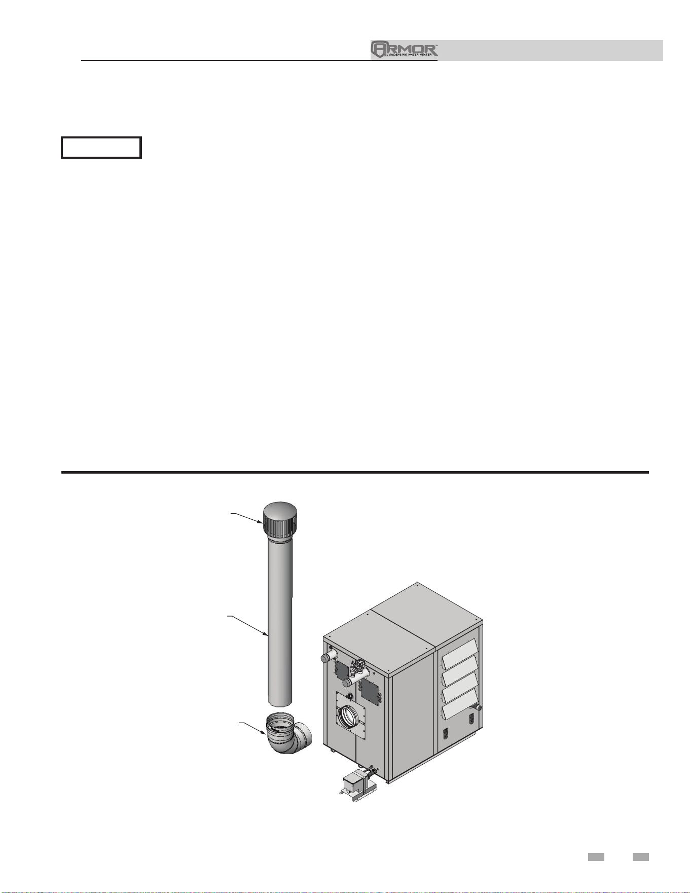
Installation & Operation Manual
3 General venting (continued)
Outdoor installation - see pages 12 and 15.
NOTICE
Before installing a venting system, follow all requirements found in the General Venting section.
Units are self-venting and can be used outdoors when installed with the optional outdoor kit or purchased as outdoor ready from
the factory.
Combustion air supply must be free of contaminants (see Combustion and Ventilation Air, page 10). To prevent recirculation of
the flue products into the combustion air inlet, follow all instructions in this section.
Outdoor vent/air inlet location
Keep venting areas free of obstructions. Keep area clean and free of combustible and flammable materials. Maintain a minimum
clearance of 3" (76 mm) to combustible surfaces and a minimum of 36" (915 mm) clearance to the air inlet. To avoid a blocked air
inlet or blocked flue condition, keep the louvered air inlet, flue outlet, and condensate trap clear of leaves, debris, etc.
Do not install outdoor models directly on the ground. You must install the outdoor unit on a concrete, brick, block, or other non-
combustible pad.
Do not locate unit so that high winds can deflect off of adjacent walls, buildings, or shrubbery causing recirculation. Recirculation
of flue products may cause operational problems, bad combustion, or damage to controls.
Multiple unit outdoor installations require 48" (1.22 m) clearance between each vent cap. Locate outdoor cap at least 48" (1.22m)
below and 48" (1.22 m) horizontally from any window, door, walkway, or gravity air intake.
Locate unit at least 10 feet (3.05 m) away from any forced air inlet.
Locate unit at least 3 feet (0.91 m) outside any overhang.
Clearances around outdoor installations can change with time. Do not allow the growth of trees, shrubs, or other plants to obstruct
the proper operation of the outdoor vent system.
Do not install in locations where rain from building runoff drains will spill onto the unit.
27
DIR #2000569024_000
90° STAINLESS STEEL
ELBOW (FIELD SUPPLIED
AS NEEDED)
STAINLESS STEEL
VENT PIPE
(FIELD SUPPLIED)
RAIN CAP
(FIELD SUPPLIED)
Figure 3-5 Outdoor Venting - Stainless Steel
NOTE: See Table 1C for approved stainless steel adapters and rain caps.
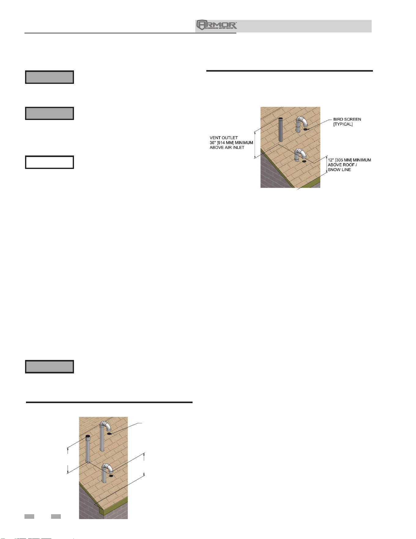
Vent/air termination – vertical
Prepare roof penetrations
1. Air pipe penetration:
a. Cut a hole for the air pipe. Size the air pipe hole as
close as desired to the air pipe outside diameter.
2. Vent pipe penetration:
a. Cut a hole for the vent pipe. For either combustible
or noncombustible construction, size the vent pipe
hole per the vent manufacturer’s instructions.
b. Insert a galvanized metal thimble in the vent pipe
hole (when required by local codes).
3. Space the air and vent holes to provide the minimum
spacing shown in FIG. 4-1.
4. Follow all local codes for isolation of vent pipe when
passing through floors, ceilings, and roofs.
5. Provide flashing and sealing boots sized for the vent pipe
and air pipe.
Termination and fittings
1. Prepare the vent termination coupling and the air
termination elbow (FIG. 4-1) by inserting bird screens.
2. The air piping must terminate in a down-turned 180°
return bend as shown in FIG. 4-1. Locate the air inlet
pipe no further than 2 feet (.6 m) from the center of the
vent pipe. This placement avoids recirculation of flue
products into the combustion air stream.
5. Locate terminations so they are not likely to be damaged
by foreign objects, such as stones or balls, or subject to
build-up of leaves or sediment.
⚠WARNING
Figure 4-2 Vertical Termination of Air and Vent w/Rain
Cap
Follow instructions below when determining
vent location to avoid possibility of severe
personal injury, death, or substantial
property damage.
Installation must comply with local
requirements and with the National Fuel
Gas Code, NFPA 54 / ANSI Z223.1 - latest
edition for U.S. installations or CSA B149.1
Installation Code for Canadian installations.
⚠WARNING
NOTICE
⚠WARNING
Do not connect any other appliance to the
vent pipe or multiple appliances to a common
vent pipe except as noted in Section 3 on
page 20. Failure to comply could result in
severe personal injury, death, or substantial
property damage.
Determine location
Locate the vent/air terminations using the following guidelines:
1. The total length of piping for vent or air must not exceed
the limits given in the General Venting Section on page 15
of this manual.
2. The vent must terminate at least 3 feet above the highest
place in which the vent penetrates the roof, and at least 2
feet above any part of a building within 10 horizontal feet.
3. The air piping must terminate in a down-turned 180° return
pipe no further than 2 feet (.6 m) from the center of the vent
pipe. This placement avoids recirculation of flue products
into the combustion air stream.
4. The vent piping must terminate in an up-turned coupling
as shown in FIG. 4-1. The top of the coupling or the rain
cap must be at least 36" (914 mm) above the air intake. The
air inlet pipe and vent pipe can be located in any desired
position on the roof, but must always be no further than 2
feet (.6 m) apart and with the vent termination at least 36"
(914 mm) above the air intake.
Rooftop vent and air inlet terminations must
terminate in the same pressure zone, unless
vertical vent sidewall air is set up as shown
in the General Venting - Vertical Vent,
Sidewall Air Section.
BIRD SCREEN
[TYPICAL]
VENT OUTLET
36" MINIMUM
A
BOVE AIR INLET
VENT
COMBUSTION AIR
12" [305 MM] MINIMUM
ABOVE ROOF /
SNOW LINE
Figure 4-1 Vertical Termination of Air and Vent
4 Vertical direct venting
28
Installation & Operation Manual
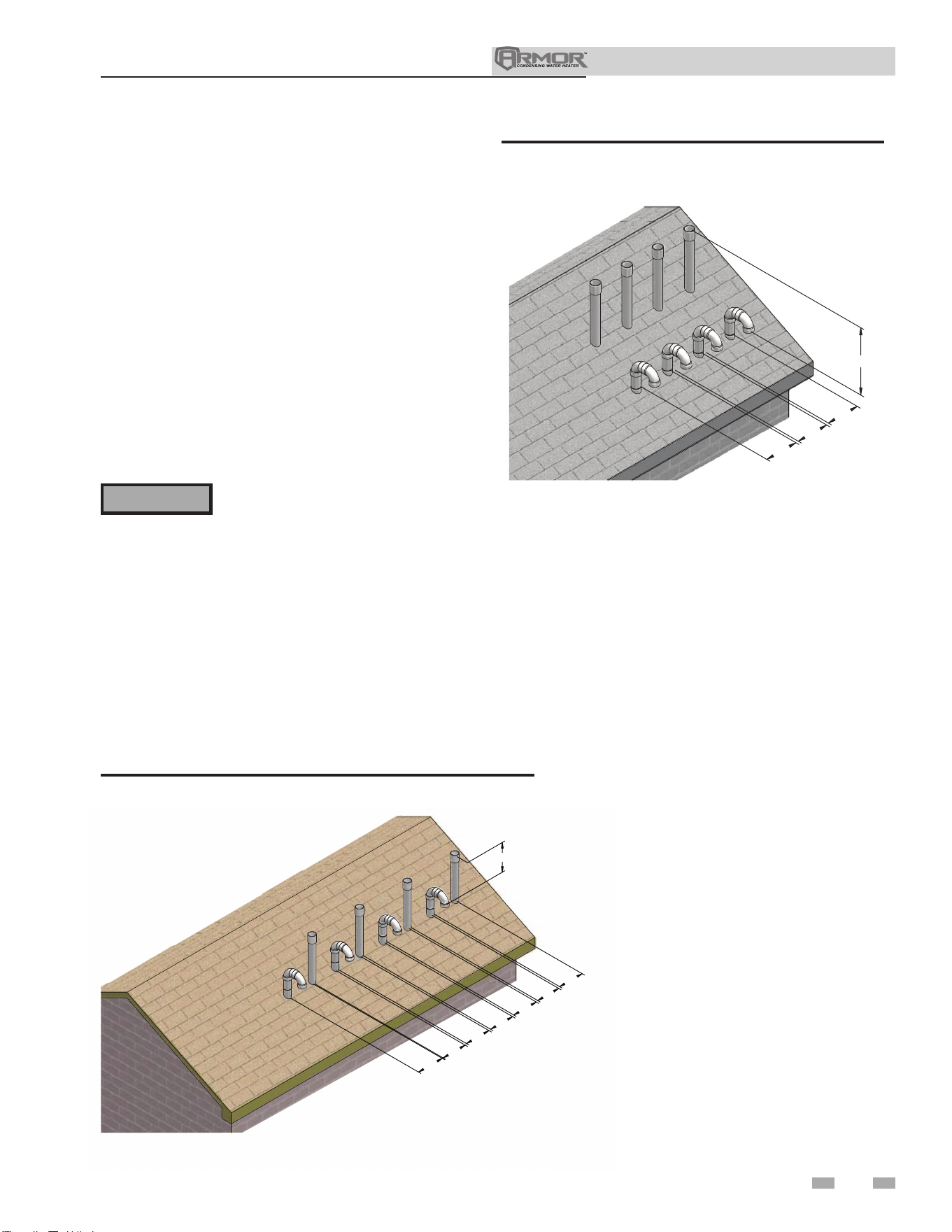
Installation & Operation Manual
29
4 Vertical direct venting (continued)
Multiple vent/air terminations
1. When terminating multiple Armor appliances, terminate
each vent/air connection as described in this manual
(FIG. 4-3).
Terminate all vent pipes at the same
height and all air pipes at the same height
to avoid recirculation of flue products and
the possibility of severe personal injury,
death, or substantial property damage.
2. Place roof penetrations to obtain minimum clearance
of 12 inches (305 mm) between edge of air intake elbow
and adjacent vent pipe of another appliance for U.S.
installations (see FIG. 4-3). For Canadian installations,
provide clearances required by CSA B149.1 Installation
Code.
3. The air inlet of an Armor appliance is part of a direct vent
connection. It is not classified as a forced air intake with
regard to spacing from adjacent appliance vents.
12” (305 MM)
12”
(305 MM)
12”
(305 MM)
12”
(305 MM)
12”
(305 MM)
12”
(305 MM)
12”
(305 MM)
12”
(305 MM)
DIR# 2000539525
Figure 4-3 Vertical Terminations with Multiple Appliances
12” (305 MM)
12”
(305 MM)
12”
(305 MM)
12”
(305 MM)
DIR# 2000539526
Figure 4-4 Alternate Vertical Terminations with Multiple
Appliances
⚠WARNING
3. The vent piping must terminate in an up-turned coupling
as shown in FIG. 4-1. The top of the coupling or the
rain cap must be at least 36" (914 mm) above the air
intake. The air inlet pipe and vent pipe can be located
in any desired position on the roof, but must always be
no further than 2 feet (.6 m) apart and with the vent
termination at least 36" (914 mm) above the air intake.
4. Maintain the required dimensions of the finished
termination piping as shown in FIG. 4-1.
5. Do not extend exposed vent pipe outside of the building
more than shown in this document. Condensate could
freeze and block vent pipe.
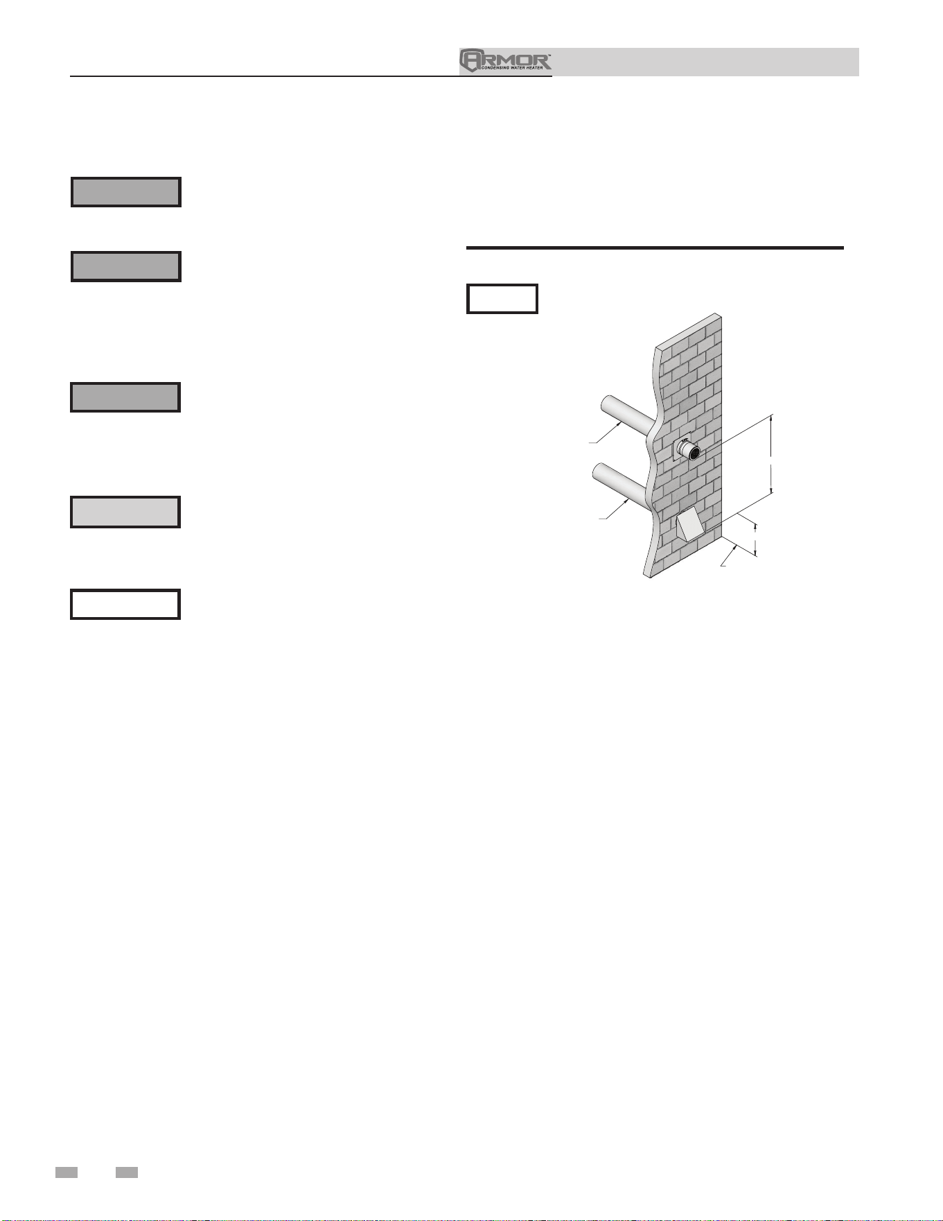
Installation & Operation Manual
5 Sidewall direct venting
30
3. Maintain clearances as shown in FIG.’s 5-1A thru 5-4,
pages 26 thru 28. The vent termination should not be
located in traffic areas such as walkways, adjacent
buildings, operable windows, or doors. Also maintain
the following:
a. Vent must terminate:
• At least 6 feet (1.8 m) from adjacent walls.
• Not less than 7 feet (2.1 m) above grade where located
adjacent to public walkways.
• No closer than 12 inches (305 mm) below roof
overhang.
• At least 3 feet (.9 m) above any forced air intake
within 10 feet (3 m).
• No closer than 4 feet (1.2 m) horizontally
from any door or window or any other gravity air
inlet.
b. Air inlet must terminate at least 12 inches (305 m)
above grade or snow line; at least 36 inches
(914 mm) below the vent termination.
c. Do not terminate closer than 4 feet (1.2 m)
horizontally from any electric meter, gas meter,
regulator, relief valve, or other equipment. Never
terminate above or below any of these within 4 feet
(1.2 m) horizontally.
4. Locate terminations so they are not likely to be damaged
by foreign objects, such as stones or balls, or subject to
build-up of leaves or sediment.
DIR #2000571148_000
36" MIN
12" MIN
GRADE OR
SNOW LINE
TO APPLIANCE
INTAKE AIR CONNECTION
FROM APPLIANCE
VENT PIPE CONNECTION
Figure 5-1A Sidewall Termination of Air and Vent
PVC/CPVC or ABS is acceptable air inlet pipe material.
NOTICE
Vent/air termination – sidewall
Follow instructions below when
determining vent location to avoid
possibility of severe personal injury, death,
or substantial property damage.
A gas vent extending through an exterior
wall shall not terminate adjacent to a wall
or below building extensions such as eaves,
parapets, balconies, or decks. Failure to
comply could result in severe personal
injury, death, or substantial property
damage.
Installation must comply with local
requirements and with the National
Fuel Gas Code, NFPA 54 / ANSI Z223.1
for U.S. installations or CSA B149.1 for
Canadian installations.
Determine location
Locate the vent/air terminations using the following
guidelines:
1. The total length of piping for vent or air must not exceed
the limits given in the General Venting Section on page
15 of this manual.
2. You must consider the surroundings when terminating
the vent and air:
a. Position the vent termination where vapors will
not damage nearby shrubs, plants, or air
conditioning equipment or be objectionable.
b. The flue products will form a noticeable plume as
they condense in cold air. Avoid areas where the
plume could obstruct window views.
c. Prevailing winds could cause freezing of condensate
and water/ice buildup where flue products impinge
on building surfaces or plants.
d. Avoid possibility of accidental contact of flue
products with people or pets.
e. Do not locate the terminations where wind eddies
could affect performance or cause recirculation,
such as inside building corners, near adjacent
buildings or surfaces, window wells, stairwells,
alcoves, courtyards, or other recessed areas.
⚠WARNING
⚠WARNING
NOTICE
⚠WARNING
Do not connect any other appliance to
the vent pipe or multiple appliances to
a common vent pipe except as noted in
Section 3 on page 20. Failure to comply
could result in severe personal injury,
death, or substantial property damage.
f. Do not terminate above any door or above or
below any window. Condensate can freeze, causing
ice formations.
g. Locate or guard vent to prevent condensate
damage to exterior finishes.
⚠ CAUTION
Sidewall venting commercial products will
result in large exhaust plumes in cold
climates. Consideration should be taken
when locating in proximity to windows,
doors, walkways, etc.
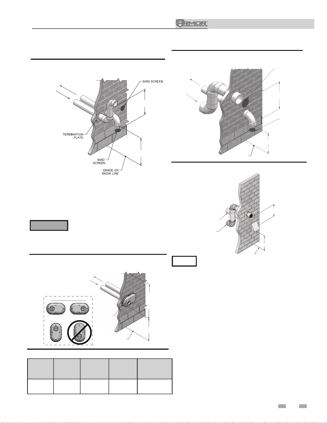
Installation & Operation Manual
31
5 Sidewall direct venting (continued)
Vent/air termination – sidewall
VENT / AIR
TERMINATION
GRADE OR
SNOW LINE
12"
MIN
12"
MIN
TO
OVER-
HANG
POSSIBLE ORIENTATIONS
TO APPLIANCE
INTAKE AIR CONNECTION
FROM APPLIANCE
VENT PIPE CONNECTION
Figure 5-1C PVC / CPVC / Polypropylene Sidewall
Termination of Air and Vent
Do not exceed the maximum lengths of the
outside vent piping shown in FIG. 5-1C.
Excessive length exposed to the outside could
cause freezing of condensate in the vent pipe,
resulting in potential appliance shutdown.
⚠WARNING
5. The air piping must terminate in a down-turned elbow as
shown in FIG. 5-1B. This arrangement avoids recirculation
of flue products into the combustion air stream.
6. The vent piping must terminate in an elbow pointed outward
or away from the air inlet, as shown in FIG. 5-1B.
36" (914 MM) MIN
12" (305 MM)
MIN
TO APPLIANCE
INTAKE AIR CONNECTION
FROM APPLIANCE
VENT PIPE CONNECTION
Figure 5-1B PVC / CPVC / Polypropylene Sidewall
Termination of Air and Vent w/Field Supplied Fittings
Model Kit # Air Vent
Centerline
Width
1250 - 1500 100157612 6" (152 mm) 6" (152 mm) 7 3/4" (197 mm)
Table 5A Sidewall Vent Kits
DIR #2000571174_000
36" (914 MM) MIN
12"
(305 MM)
MIN
GRADE OR
SNOW LINE
TO APPLIANCE INTAKE
AIR CONNECTION
FROM APPLIANCE VENT
PIPE CONNECTION
Figure 5-2B Stainless Steel Sidewall Termination with
Field Supplied Fittings
36" (914 MM) MIN
12" (305 MM) MIN
FROM
APPLIANCE
VENT PIPE
CONNECTION
TO APPLIANCE
INTAKE AIR
CONNECTION
BIRD SCREEN
BIRD SCREEN
GRADE OR
SNOW LINE
Figure 5-2A PVC / CPVC / Polypropylene Sidewall
Termination w/Field Supplied Fittings
PVC/CPVC or ABS is acceptable air inlet pipe material.
NOTICE
7. Maintain clearances as shown in FIG.’s 5-1A thru 5-4,
pages 26 thru 28. Also maintain the following:
a. Vent must terminate:
• At least 6 feet (1.8 m) from adjacent walls.
• No closer than 12 inches (305 mm) below roof
overhang.
• At least 7 feet (2.1 m) above any public walkway.
• At least 3 feet (.9 m) above any forced air intake
within 10 feet (3 m).
• No closer than 4 feet (1.2 m) below or
horizontally from any door or window or any other
gravity air inlet.
b. Air inlet must terminate at least 12 inches (305 mm)
above grade or snow line; at least 3 feet (.9 m)
below the vent termination (FIG. 5-1B); and the vent
pipe must not extend more than 24 inches (610 mm)
vertically outside the building.
c. Do not terminate closer than 4 feet (1.2 m)
horizontally from any electric meter, gas meter,
regulator, relief valve, or other equipment. Never
terminate above or below any of these within 4 feet
(1.2 m) horizontally.
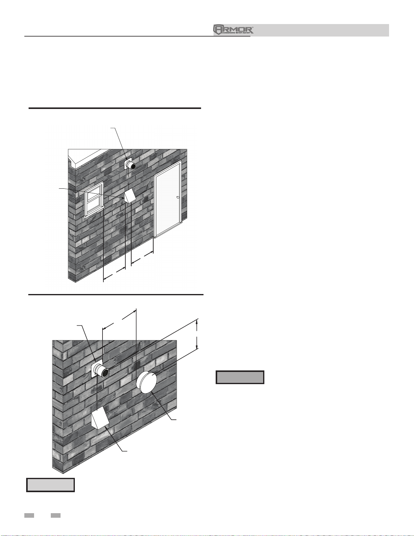
Installation & Operation Manual
32
5 Sidewall direct venting
Termination and fittings
1. The air termination must be oriented at least 12 inches
above grade or snow line as shown in FIG. 5-1A, page
26.
2. Maintain the required dimensions of the finished
termination piping as shown in FIG. 5-1A, page 26.
3. Do not extend exposed vent pipe outside of the
building more than what is shown in this document.
Condensate could freeze and block vent pipe.
4. Stainless steel terminations are designed to penetrate
walls with a thickness up to 9.25 inches of standard
construction.
All vent pipes and air inlets must
terminate at the same height to avoid
possibility of severe personal injury,
death, or substantial property damage.
Multiple vent/air terminations
1. When terminating multiple Armor appliances,
terminate each vent/air connection as described in
this manual (FIG. 5-5).
⚠WARNING
Vent/air termination – sidewall
DIR #2000571158_000
4'
4'
36"
VENT TERMINATION
AIR
TERMINA
TION
Figure 5-3 Clearance to Doors and Windows
DIR #2000571159_000
VENT TERMINATION
IF LESS THAN 10’
AIR TERMINATION
FORCED AIR
INLET
36” MI
N
Figure 5-4 Clearance to Forced Air Inlets
Prepare wall penetrations
1. Air pipe penetration:
a. Cut a hole for the air pipe. Size the air pipe hole as
close as desired to the air pipe outside
diameter.
Vent pipe penetration:
a. Cut a hole for the vent pipe. For either combustible
or noncombustible construction, size the vent pipe
hole per the vent manufacturer’s instructions.
2. Install the vent and air intake piping. Seal all gaps
between the pipes and wall with RTV silicone sealant.
3. Seal all wall cavities.
⚠ CAUTION
Sidewall venting commercial products will
result in large exhaust plumes in cold
climates. Consideration should be taken
when locating in proximity to windows,
doors, walkways, etc.
8. Locate terminations so they are not likely to be damaged by
foreign objects, such as stones or balls, or subject to buildup
of leaves or sediment.
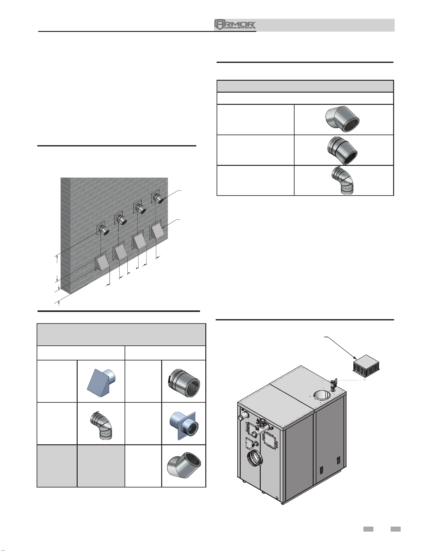
33
Installation & Operation Manual
5 Sidewall direct venting (continued)
2. Place wall penetrations to obtain minimum clearance
of 12 inches (305 mm) between vent pipe and adjacent
air inlet, as shown in FIG. 5-5 for U.S. installations. For
Canadian installations, provide clearances required by
CSA B149.1 Installation Code.
3. The air inlet of an Armor is part of a direct vent
connection. It is not classified as a forced air intake
with regard to spacing from adjacent appliance vents.
12" MIN
36"MIN
12"
12"
12"
AIR
VENT
DIR# 2000539531
Figure 5-5 Multiple Vent Terminations (must also
comply with Figure 5-1A)
Figure 5-6 Direct Vent Terminations
DIRECT VENT TERMINATIONS
Air Inlet Vent Termination
Dryer Inlet Straight
90° Elbow Mitered
23° Elbow
ROOM AIR (DIRECT EXHAUST TERMINATIONS)
Vent Termination
23° Elbow
45° Elbow
90° Elbow
Figure 5-7 Room Air (Direct Exhaust Terminations)
Room air
DIR #2000548681 00
AIR INLET
COVER
Figure 5-8 Room Air Installation
The Armor appliance may be installed with a single pipe
carrying the flue products to the outside while using combustion
air from the equipment room.
Follow the requirements in the General Venting section for
vent material specifications, vent length requirements, and vent
termination requirements.
The air inlet cover is supplied on the unit. Combustion and
ventilation air must be supplied to the equipment room per
the requirements on pages 16 and 17 of this manual for proper
operation of the Armor appliance when utilizing the single pipe
method.
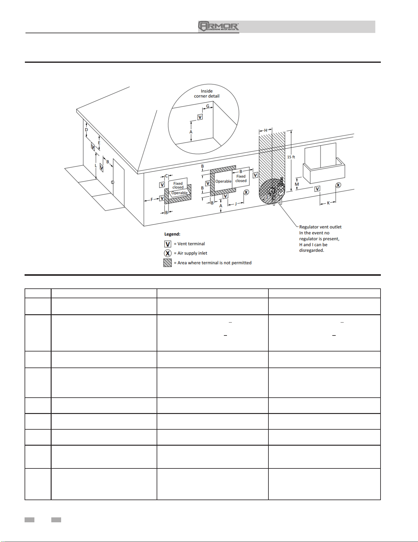
Figure 5-9 Direct Vent Terminal Clearances
Canadian Installations¹ US Installations²
A =
Clearance above grade, veranda, porch,
deck, or balcony
12 in (30 cm) 12 in (30 cm)
B =
Clearance to window or door that may
be opened
6 in (15 cm) for appliances < 10,000 Btuh
(3 kW), 12 in (30 cm) for appliances >
10,000 Btuh (3 kW) and < 100,000 Btuh
(30 kW), 36 in (91 cm) for appliances >
100,000 Btuh (30 kW)
6 in (15 cm) for appliances < 10,000 Btuh
(3 kW), 9 in (23 cm) for appliances >
10,000 Btuh (3 kW) and < 50,000 Btuh (15
kW), 12 in (30 cm) for appliances > 50,000
Btuh (15 kW)
C =
Clearance to permanently closed
window
*
*
D =
Vertical clearance to ventilated soffit
located above the terminal within a
horizontal distance of 2 ft (61 cm) from
the center line of the terminal.
*
*
E = Clearance to unventilated soffit
*
*
F = Clearance to outside corner
*
*
G = Clearance to inside corner
*
*
H =
Clearance to each side of center line
extended above meter / regulator
assembly
3 ft (91 cm) within a height 15 ft (4.6 m)
*
I =
Clearance to service regulator vent
outlet
3 ft (91 cm)
*
Table 5B Direct Vent Terminal Clearances
5 Sidewall direct venting
34
Installation & Operation Manual
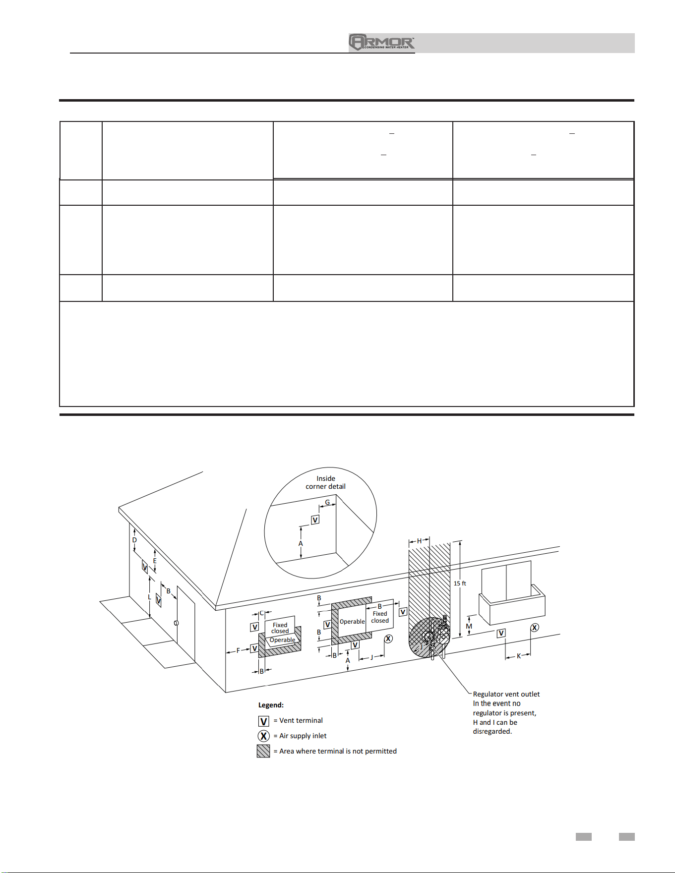
K =
Clearance to a mechanical air supply
inlet
6 ft (1.83 m)
3 ft (91 cm) above if within 10 ft (3 m)
horizontally
L =
Clearance above paved sidewalk or
paved driveway located on public
property
7 ft (2.13 m)†
7 ft (2.13 m) for mechanical draft systems
(Category I appliances). Vents for
Category II and IV appliances cannot be
located above public walkways or other
areas where condensate or vapor can
cause a nuisance or hazard
M =
Clearance under veranda, porch, deck,
or balcony
12 in (30 cm)‡ *
* Clearance in accordance with local installation codes and the requirements of the gas supplier.
† A vent shall not terminate directly above a sidewalk or paved driveway that is located between two single family dwellings
and serves both dwellings.
‡ Permitted only if veranda, porch, deck, or balcony is fully open on a minimum of two sides beneath he oor.
NOTES:
1) In accordance with the current CSA B149.1, Natural Gas and Propane Installation Code
2) In accordance with the current ANSI Z223.1/NFPA 54, National Fuel Gas Code
Figure 5-10 Other than Direct Vent Terminal Clearances
J =
Clearance to nonmechanical air supply
inlet to building or the combustion air
inlet to any other appliance
6 in (15 cm) for appliances < 10,000 Btuh
(3kW), 12 in (30 cm) for appliances >
10,000 Btuh (3 kW) and < 100,000 Btuh
(30 kW), 36 in (91 cm) for appliances >
100,000 Btuh (30 kW)
6 in (15 cm) for appliances < 10,000 Btuh
(3kW), 9 in (23 cm) for appliances > 10,000
Btuh (3 kW) and < 50,000 Btuh (15 kW),
12 in (30 cm) for appliances > 50,000 Btuh
(15 kW)
5 Sidewall direct venting (continued)
Table 5B Direct Vent Terminal Clearances (continued)
35
Installation & Operation Manual
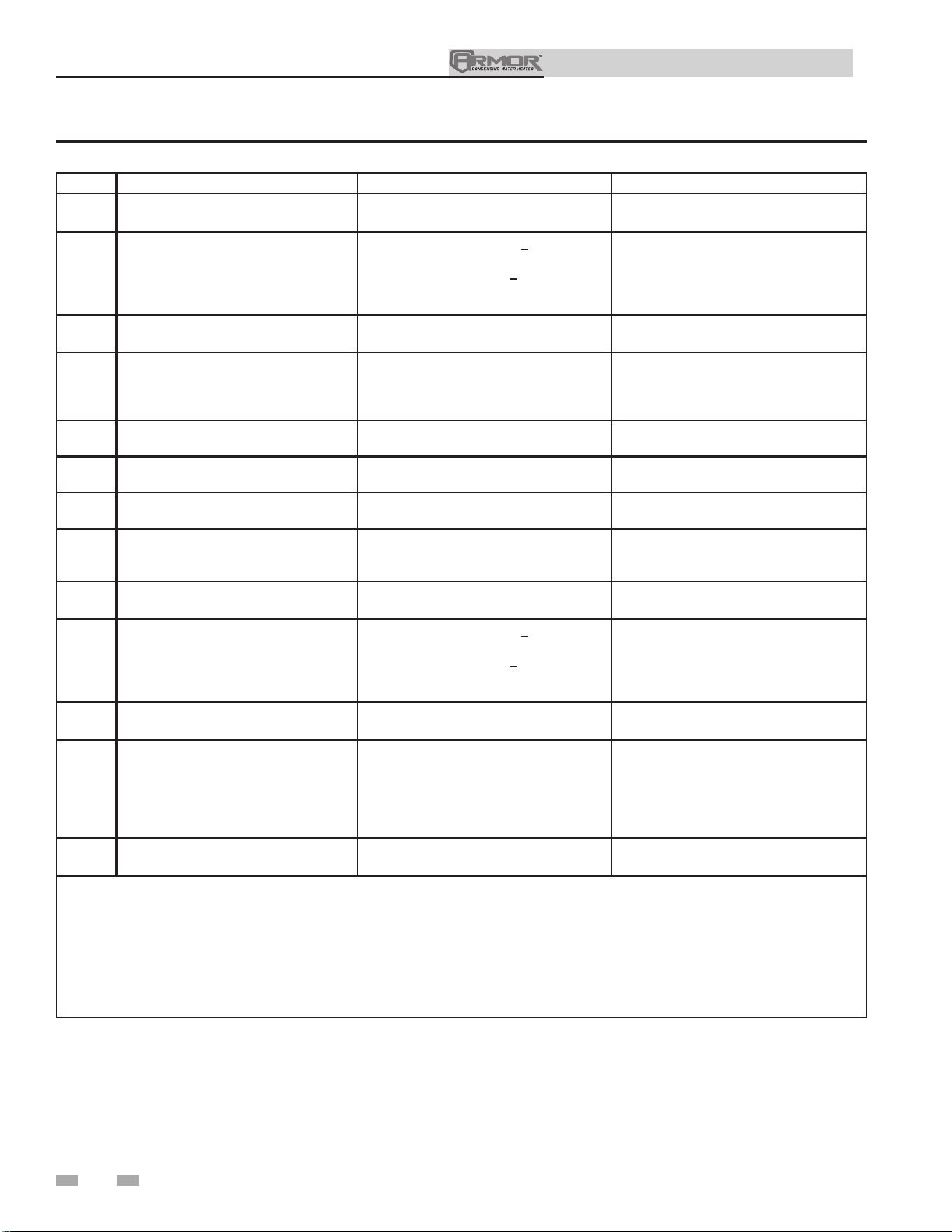
Canadian Installations¹ US Installations²
A =
Clearance above grade, veranda, porch,
deck, or balcony
12 in (30 cm) 12 in (30 cm)
B =
Clearance to window or door that may
be opened
6 in (15 cm) for appliances < 10,000 Btuh
(3 kW), 12 in (30 cm) for appliances >
10,000 Btuh (3 kW) and < 100,000 Btuh
(30 kW), 36 in (91 cm) for appliances >
100,000 Btuh (30 kW)
4 ft (1.2 m) below or to side of opening; 1 ft
(300 mm) above opening
C =
Clearance to permanently closed
window
* *
D =
Vertical clearance to ventilated soffit
located above the terminal within a
horizontal distance of 2 ft (61 cm) from
the center line of the terminal.
* *
E = Clearance to unventilated soffit
* *
F = Clearance to outside corner
* *
G = Clearance to inside corner
* *
H =
Clearance to each side of center line
extended above meter / regulator
assembly
3 ft (91 cm) within a height 15 ft (4.6 m)
*
I =
Clearance to service regulator vent
outlet
3 ft (91 cm)
*
J =
Clearance to nonmechanical air supply
inlet to building or the combustion air
inlet to any other appliance
6 in (15 cm) for appliances < 10,000 Btuh
(3kW), 12 in (30 cm) for appliances >
10,000 Btuh (3 kW) and < 100,000 Btuh
(30 kW), 36 in (91 cm) for appliances >
100,000 Btuh (30 kW)
4 ft (1.2 m) below or to side of opening; 1 ft
(300 mm) above opening
K =
Clearance to a mechanical air supply
inlet
6 ft (1.83 m) 3 ft (91 cm) above if within 10 ft (3 m)
horizontally
L =
Clearance above paved sidewalk or
paved driveway located on public
property
7 ft (2.13 m)† 7 ft (2.13 m) for mechanical draft systems
(Category I appliances). Vents for
Category II and IV appliances cannot be
located above public walkways or other
areas where condensate or vapor can
cause a nuisance or hazard
M =
Clearance under veranda, porch, deck,
or balcony
12 in (30 cm)‡ *
* Clearance in accordance with local installation codes and the requirements of the gas supplier.
† A vent shall not terminate directly above a sidewalk or paved driveway that is located between two single family dwellings
and serves both dwellings.
‡ Permitted only if veranda, porch, deck, or balcony is fully open on a minimum of two sides beneath he oor.
NOTES:
1) In accordance with the current CSA B149.1, Natural Gas and Propane Installation Code
2) In accordance with the current ANSI Z223.1/NFPA 54, National Fuel Gas Code
Table 5C Other than Direct Vent Terminal Clearances
5 Sidewall direct venting
36
Installation & Operation Manual
Installation & Operation Manual
6 System piping
System water piping methods
Observe a minimum of 1/4 inch clearance around all
un-insulated hot water pipes when openings around the pipes
are not protected by non-combustible materials.
General piping information
Basic steps are listed below along with illustrations on the
following pages (FIG.’s 6-2 thru 6-6), which will guide you
through the installation of the Armor appliance.
1. Connect the cold water supply to the inlet side of the
appliance.
2. Connect the hot water supply to the outlet side of the
appliance.
3. Install a backflow preventer on the cold feed makeup water
line.
4. Install the factory supplied pump as shown in FIG.’s 6-2 thru
6-6.
5. Install an expansion tank on the system supply. Consult
the tank manufacturer’s instruction for specific information
relating to tank installation. Size the expansion tank for the
required system volume and capacity.
6. Install a drain valve at the lowest point of the system.
7. This appliance is supplied with a relief valve sized in
accordance with ASME Boiler and Pressure Vessel Code,
Section IV (“Heating Boilers”). Pipe the discharge of the
safety relief valve to a suitable drain to prevent injury in
the event of pressure relief. Pipe the discharge to a drain.
Provide piping that is the same size as the safety relief valve
outlet. Never block the outlet of the safety relief valve.
See the *piping illustrations included in this section, FIG.’s 6-2
thru 6-6 for suggested guidelines in piping the Armor appliance.
*Please note that these illustrations are meant
to show system piping concept only, the
installer is responsible for all equipment and
detailing required by local codes.
When connecting the unit to piping made of
a different material, use of a dielectric fitting
or a dielectric union conforming to ASSE
1079 is recommended to prevent corrosion
and potential subsequent water leaks at or
near the connection. Dielectric fittings may
be required by local plumbing codes.
NOTICE
NOTICE
Water flow switch
A water flow switch is factory installed in the outlet piping on all
appliances. The flow switch must prove water flow before a trial
for ignition can begin. The flow switch requires a minimum
flow of 26 GPM to make the flow switch and start burner
operation. A water flow switch meets most code requirements
for a low water cutoff device on appliances requiring forced
circulation for operation. A fault message, Flow Sw/LWCO
will be indicated in the Operator Interface on a low water flow
condition as sensed by the flow switch.
37
Water connections
The inlet and outlet water connections on the appliance are
grooved pipe connections. A grooved coupling or fitting
is required to connect the appliance to the system piping.
Victaulic style 107N QuikVic rigid coupling is recommended.
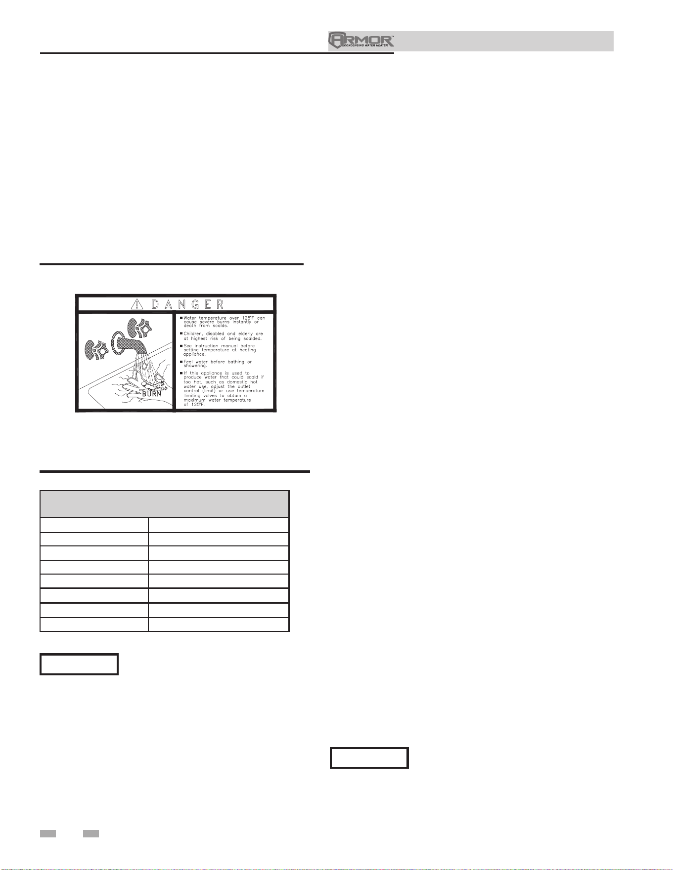
Installation & Operation Manual
6 System piping
Piping components
Appliance system piping:
Appliance system piping MUST be sized per the pipe
requirements listed in Table 6B. Reducing the pipe size can
restrict the flow rate through the appliance, causing inadvertent
high limit shutdowns and poor system performance.
Check valves:
Field supplied. Check valves are recommended for installation
as shown in FIG.’s 6-2 thru 6-6.
Appliance isolation valves:
Field supplied. Full port ball valves are required. Failure to use
full port ball valves could result in a restricted flow rate through
the appliance.
Anti-scald mixing valve:
Field supplied. An anti-scald mixing valve is recommended
when storing domestic hot water above 115°F.
Unions:
Field supplied. Recommended for unit serviceability.
Temperature and pressure relief valve:
Factory supplied. The temperature and pressure relief valve
is sized to ASME specifications. Storage tanks may require
additional valves depending on local codes.
Tank sensor:
Lochinvar supplies a tank sensor. The tank sensor must be
installed in the tapping provided in the lower 25% of the storage
tank to achieve proper operation. As shipped from the factory,
the tank sensor is in the literature package shipped with the unit.
Placing the sensor in the tapping provided on the storage tank
will improve temperature response and prevent short cycles of
operation.
Strainer:
Field supplied. Required to help eliminate debris from causing
damage to the heat exchanger. When installing in a pre-existing
system, it is recommended to install a filter in the recirculation
line capable of removing debris left in the system.
Building Recirculation Filter:
Field supplied as required (see Table 10A). When required, helps
to eliminate debris from causing damage to the heat exchanger.
Water chemistry
NOTICE
The temperature rises and circulating
pumps shown in Table 6B are selected
based on the heating of potable water with
a specified water chemistry. See Table 10A
in Start-Up Section for recommendations.
Heating of high hardness and/or high total dissolved solids
water may require a larger circulating pump and a revised
temperature rise specification based on the water chemistry of
the water to be heated. See Table 10A in Start-Up Section for
recommendations.
Scalding
This appliance can deliver scalding temperature water at any
faucet in the system. Be careful whenever using hot water to avoid
scalding injury. Certain appliances such as dishwashers and
automatic clothes washers may require increased temperature
water. By setting the thermostat on this appliance to obtain
the increased temperature water required by these appliances,
you may create the potential for scald injury. To protect against
injury, you should install a mixing valve in the water system.
This valve will reduce point of discharge temperature by mixing
cold and hot water in branch supply lines. Such valves are
available from the local plumbing supplier.
Figure 6-1 Scald Warning Label Located on the
Appliance
The following chart (Table 6A) details the relationship of water
temperature and time with regard to scald injury and may be
used as a guide in determining the safest water temperature for
your applications.
APPROXIMATE TIME / TEMPERATURE
RELATIONSHIPS IN SCALDS
120°F More than 5 minutes
125°F 1 1/2 to 2 minutes
130°F About 30 seconds
135°F About 10 seconds
140°F Less than 5 seconds
145°F Less than 3 seconds
150°F About 1 1/2 seconds
155°F About 1 second
Table 6A Approximate Time / Temperature Scald Chart
38
Water with a hardness of less than 5 grains per gallon will
usually have a pH which can be aggressive and corrosive
causing non-warrantable damage to the pump and associated
piping. Corrosion due to water chemistry generally shows up
first in the hot water system because heated water increases the
rate of corrosive chemical reactions.
Check recirculation pump size to verify it
is sized for filter addition and upsize if
necessary.
⚠ CAUTION
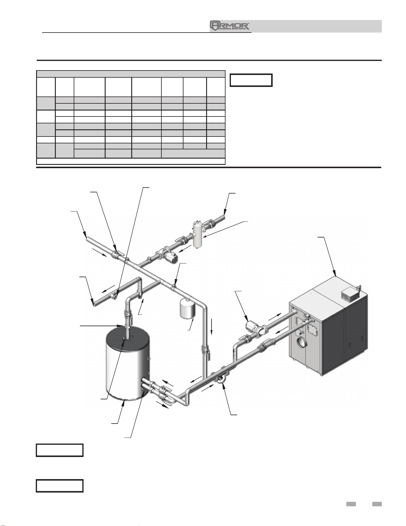
Table 6B Appliance Pump Applications / Typical Temperature Rise
Pump selections and flow shown above are
based on 45 feet of piping, 4 - 90° elbows, and
2 - fully ported ball valves.
NOTICE
Installation & Operation Manual
39
6 System piping (continued)
NOTICE
Please note that these illustrations are meant to show system piping concept only, the installer is responsible
for all equipment. The installer must follow all manufacturer’s instructions for each system component. The
installer is responsible for compliance with local codes.
The piping will not support the weight of the appliance circulator pump. Do not attempt to support the
weight of the appliance circulator pump with the piping or its accessories. Refer to the pump manufacturer’s
installation instructions. Failure to comply could result in severe personal injury, death, or substantial property
damage.
⚠ CAUTION
APPLIANCE
CIRCULATOR
Y-STRAINER
UNION
TEMPERATURE &
PRESSURE
RELIEF VALVE
STORAGE
TANK
DRAIN
HOT
WATER
SUPPLY
COLD
WATER
SUPPLY
BALL VALVE
THERMOMETER
CHECK VALVE
BUILDING RETURN
MIXING
VALVE
EXPANSION
TANK
BUILDING RECIRCULATION FILTER
(IF REQUIRED SEE START-UP SECTION)
DIR #2000570385 000
Figure 6-2 Single Appliance - Single Tank
Appliance Pump Applications
Model
Pipe
Size
Water
Hardness
B&G
Pump
Alternate
Grundfos
Pump
Flow
Rate
(GPM)
Loss
(FT/HD)
Temp.
Rise
1250
2-1/2" 5 to 12 gpg *100297119 TP50-160 112 23 22°F
3"
12 to 15 gpg 100297116 N/A 145 35 17°F
1500
2-1/2" 5 to 12 gpg *100297119 TP50-160 115 22 26°F
3"
12 to 15 gpg 100297116 N/A 148 31 20°F
2000
3" 5 to 12 gpg *100297118 TP50-160 145 27 27°F
4"
12 to 15 gpg 100297115 N/A 180 39 22°F
3000
4" 5 to 15 gpg *100297117 TP100-80 270 24 22°F
4000
4"
5 to 12 gpg *100297117 TP100-80 290 19 27°F
12 to 15 gpg
Contact
Factory
N/A Contact Factory
*Denotes standard pump supplied with unit.
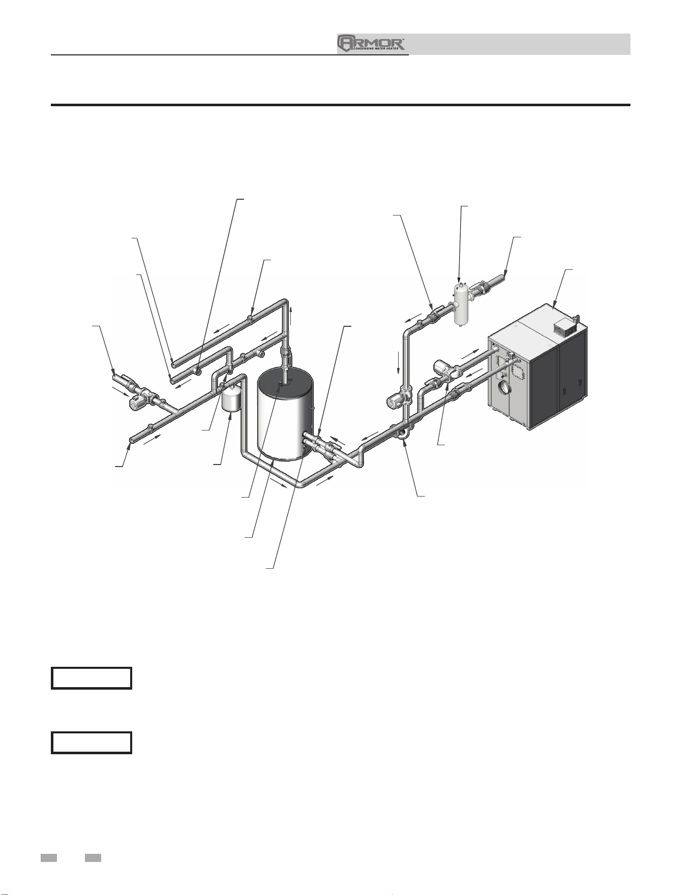
Installation & Operation Manual
40
6 System piping
NOTICE
The piping will not support the weight of the appliance circulator pump. Do not attempt to support the
weight of the appliance circulator pump with the piping or its accessories. Refer to the pump manufacturer’s
installation instructions. Failure to comply could result in severe personal injury, death, or substantial
property damage.
⚠ CAUTION
Figure 6-3 Single Appliance - Single Tank (2 Temperature)
Please note that these illustrations are meant to show system piping concept only, the installer is responsible
for all equipment. The installer must follow all manufacturer’s instructions for each system component. The
installer is responsible for compliance with local codes.
APPLIANCE
BALL VALVE
HIGH TEMPERATURE
BUILDING RETURN
CIRCULATOR
Y-STRAINER
UNION
STORAGE
TANK
TEMPERATURE &
PRESSURE
RELIEF VALVE
DRAIN
EXPANSION
TANK
MIXING
VALVE
COLD
WATER
SUPPLY
LOW
TEM
PERATURE
BUILDING
RETURN
180° HOT
WATER SUPPLY
140° HOT
WATER SUPPLY
THERMOMETER
CHECK VALVE
BUILDING RECIRCULATION FILTER
(IF REQUIRED SEE START-UP SECTION)
DIR #2000570387 000
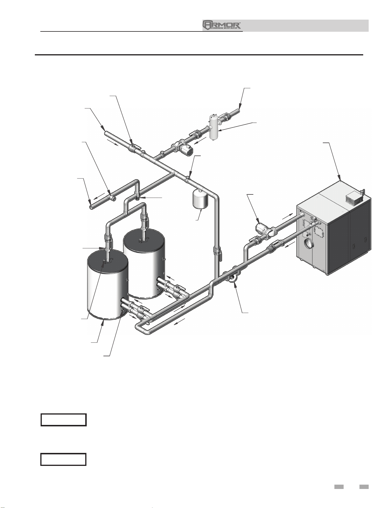
Installation & Operation Manual
41
6 System piping (continued)
APPLIANCE
CIRCULATOR
Y-STRAINER
CHECK VALVE
BUILDING RETURN
COLD
WATER
SUPPLY
BALL VALVE
HOT
WATER
SUPPLY
UNION
TEMPERATURE &
PRESSURE
RELIEF VALVE
STORAGE
TANK
DRAIN
MIXING
VALVE
EXPANSION
TANK
TH
ERMOMETER
BUILDING RECIRCULATION FILTER
(IF REQUIRED SEE START-UP SECTION)
DIR #2000570388 000
Figure 6-4 Single Appliance - Double Tank
NOTICE
The piping will not support the weight of the appliance circulator pump. Do not attempt to support the
weight of the appliance circulator pump with the piping or its accessories. Refer to the pump manufacturer’s
installation instructions. Failure to comply could result in severe personal injury, death, or substantial
property damage.
⚠ CAUTION
Please note that these illustrations are meant to show system piping concept only, the installer is responsible
for all equipment. The installer must follow all manufacturer’s instructions for each system component. The
installer is responsible for compliance with local codes.
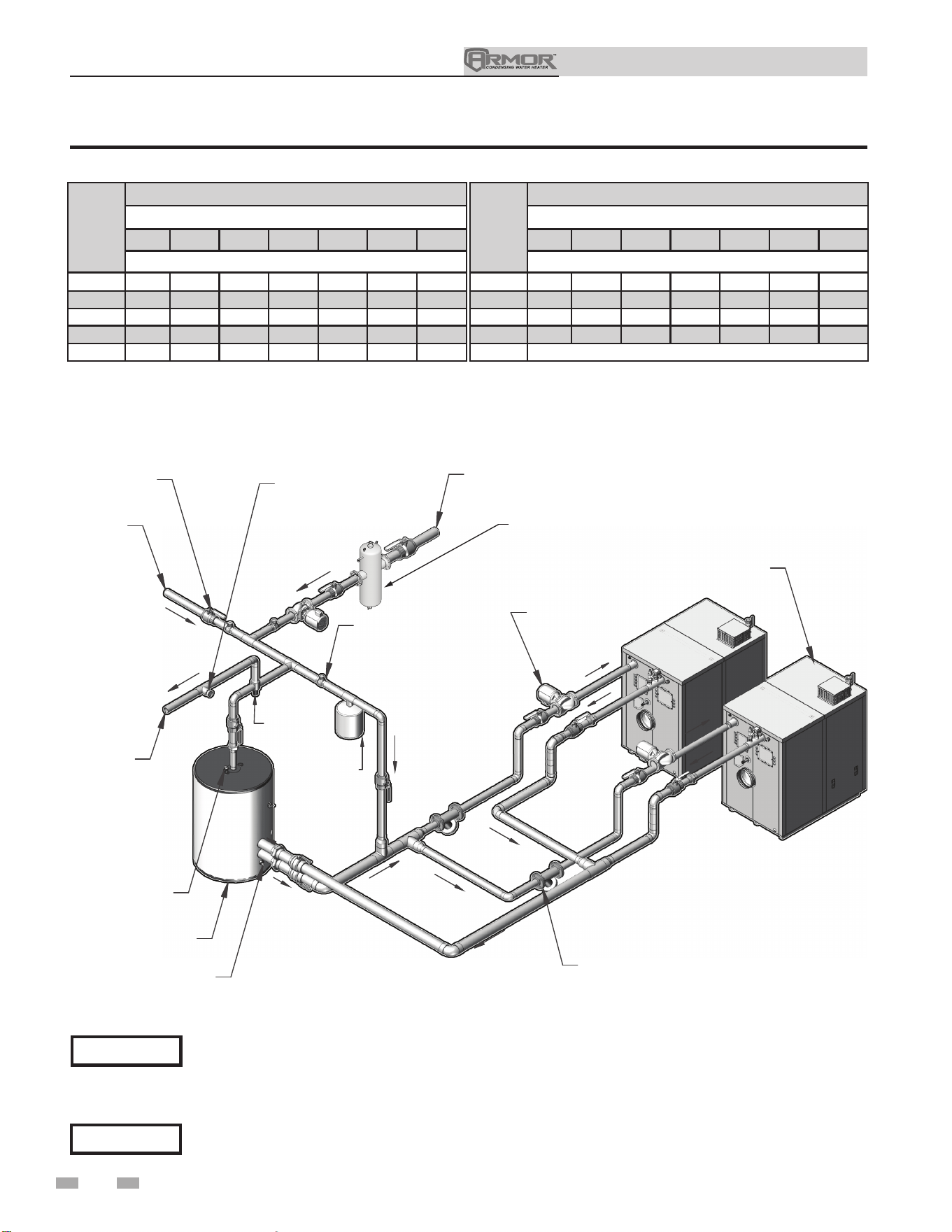
Installation & Operation Manual
42
6 System piping
APPLIANCE
CIRCULATOR
Y-STRAINER
(TYPICAL)
HOT
WATER
SUPPLY
COLD
WATER
SUPPLY
BALL VALVE
THERMOMETER
CHECK VALVE
BUILDING RETURN
MIXING
VALVE
EXPANSION
TANK
TEMPER
ATURE &
PRESSURE
RE
LIEF VALVE
STORAGE
TANK
DRAIN
BUILDING RECIRCULATION FILTER
(IF REQUIRED SEE START-UP SECTION)
DIR #2000570389 000
Figure 6-5 Double Appliance - Single Tank
Model
Upsized Pump
Number of Units
2 3 4 5 6 7 8
Required Pipe Sizes in NPT with Upsized Pump
1250 5" 6" 7" 7" 8" 9" 9"
1500 5" 6" 7" 7" 8" 9" 9"
2000 5" 6" 7" 8" 9" 10" 10"
3000 6" 8" 9" 10" 11" 12" 12"
4000 Contact Factory
NOTICE
The piping will not support the weight of the appliance circulator pump. Do not attempt to support the
weight of the appliance circulator pump with the piping or its accessories. Refer to the pump manufacturer’s
installation instructions. Failure to comply could result in severe personal injury, death, or substantial
property damage.
⚠ CAUTION
Please note that these illustrations are meant to show system piping concept only, the installer is responsible
for all equipment. The installer must follow all manufacturer’s instructions for each system component. The
installer is responsible for compliance with local codes.
Model
Standard Pump
Number of Units
2 3 4 5 6 7 8
Required Pipe Sizes in NPT with Standard Pump
1250 4" 5" 6" 6" 7" 7" 8"
1500 4" 5" 6" 6" 7" 7" 8"
2000 5" 6" 7" 7" 8" 9" 9"
3000 6" 8" 9" 10" 11" 12" 12"
4000 7" 8" 9" 10" 11" 12" 13"
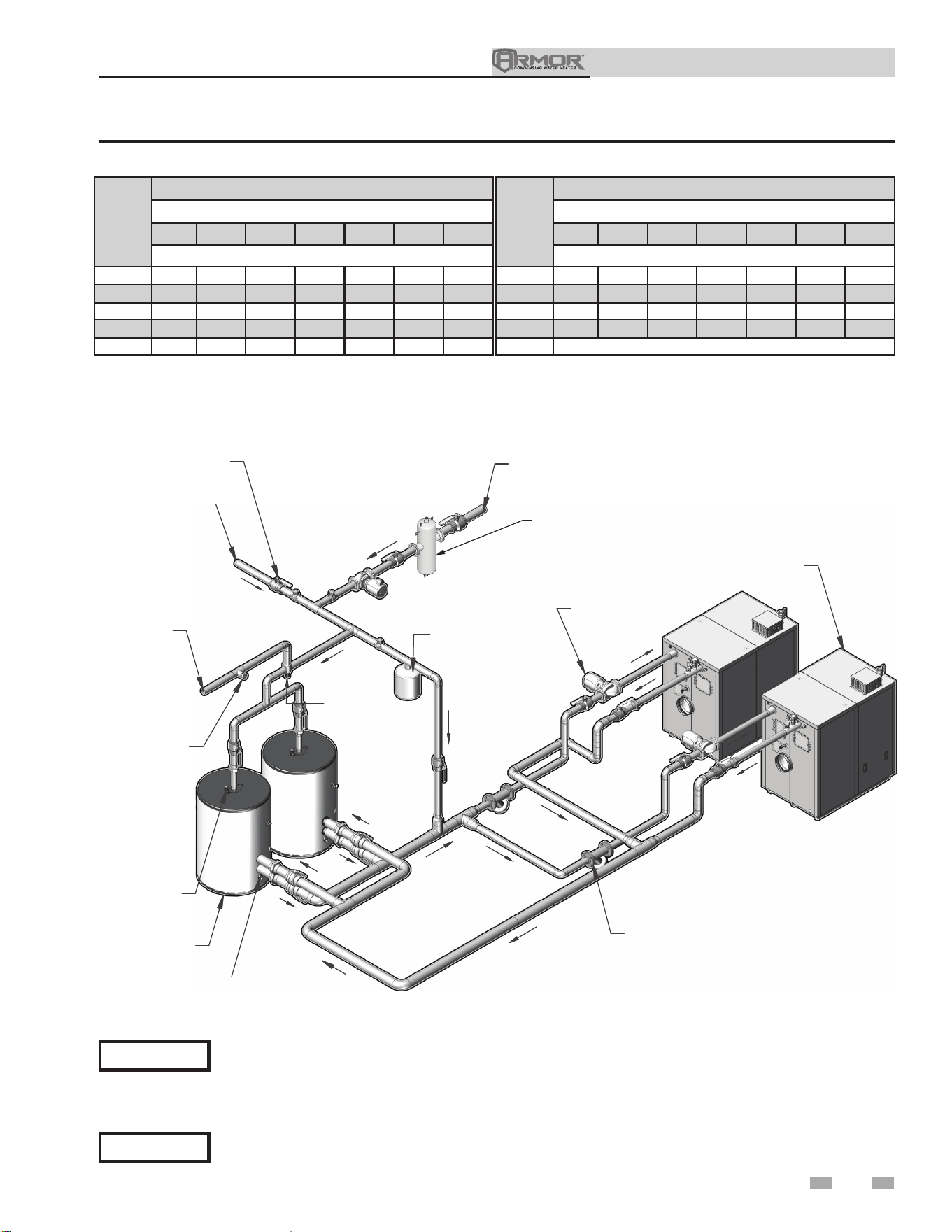
Installation & Operation Manual
43
6 System piping (continued)
APPLIANCE
CIRCULATOR
Y-STRAINER
(TYPICAL)
MIXING
VALVE
EXPANSION
TANK
TEMPER
ATURE &
PRESSURE
RE
LIEF VALVE
STORAGE
TANK
DRAIN
HOT
WATER
SUPPLY
THERMOMETER
BUILDING RETURN
COLD
WATER
SUPPLY
BALL VALVE
BUILDING RECIRCULATION FILTER
(IF REQUIRED SEE START-UP SECTION)
DIR #2000570390 000
Figure 6-6 Double Appliance - Double Tank
NOTICE
The piping will not support the weight of the appliance circulator pump. Do not attempt to support the
weight of the appliance circulator pump with the piping or its accessories. Refer to the pump manufacturer’s
installation instructions. Failure to comply could result in severe personal injury, death, or substantial
property damage.
⚠ CAUTION
Please note that these illustrations are meant to show system piping concept only, the installer is responsible
for all equipment. The installer must follow all manufacturer’s instructions for each system component. The
installer is responsible for compliance with local codes.
Model
Upsized Pump
Number of Units
2 3 4 5 6 7 8
Required Pipe Sizes in NPT with Upsized Pump
1250 5" 6" 7" 7" 8" 9" 9"
1500 5" 6" 7" 7" 8" 9" 9"
2000 5" 6" 7" 8" 9" 10" 10"
3000 6" 8" 9" 10" 11" 12" 12"
4000 Contact Factory
Model
Standard Pump
Number of Units
2 3 4 5 6 7 8
Required Pipe Sizes in NPT with Standard Pump
1250 4" 5" 6" 6" 7" 7" 8"
1500 4" 5" 6" 6" 7" 7" 8"
2000 5" 6" 7" 7" 8" 9" 9"
3000 6" 8" 9" 10" 11" 12" 12"
4000 7" 8" 9" 10" 11" 12" 13"
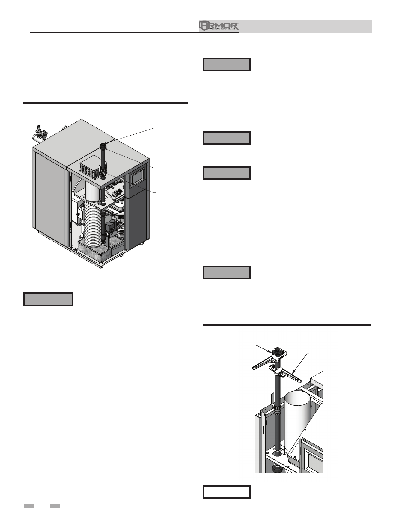
44
Installation & Operation Manual
Failure to apply pipe sealing compound
as detailed in this manual can result in
severe personal injury, death, or substantial
property damage.
Armor appliances are typically shipped
ready to fire on natural gas. Check the
appliance rating plate to determine which
fuel the appliance is set for. If set to
natural gas, it may be converted to LP by
installing an orifice or by making a gas valve
adjustment (see pages 13 thru 14). In order
to operate on LP gas, an orifice MUST BE
installed or a gas valve adjustment MUST
BE made. Failure to comply could result in
severe personal injury, death, or substantial
property damage.
Use two wrenches when tightening gas
piping at appliance (FIG. 7-2), using
one wrench to prevent the appliance gas
line connection from turning. Failure to
support the appliance gas connection pipe
to prevent it from turning could damage gas
line components.
DIR #2000548941 00
USE BACK UP WRENCH
TO PREVENT PIPE FROM
ROTATING
UNION
(FIELD INSTALLED)
Figure 7-2 Inlet Pipe with Backup Wrench
Maximum inlet gas pressure must not exceed
the value specified. Minimum value listed is
for the purposes of input adjustment.
⚠WARNING
⚠WARNING
⚠WARNING
NOTICE
7 Gas connections
Connecting gas supply piping
1. Install ground union for servicing, when required. In
Canada – When using manual main shutoff valves, it
must be identified by the installer.
GAS SUPPLY
MANUAL SHUT
OFF VALVE
UNION
DIR #2000548938 00
Figure 7-1 Gas Supply Piping
2. Support piping with hangers, not by the appliance or its
accessories.
3. Purge all air from the gas supply piping.
4. Before placing the appliance in operation, check the
appliance and its gas connection for leaks.
a. The appliance must be disconnected from the gas
supply piping system during any pressure testing of
that system at a test pressure in excess of 1/2 PSIG
(3.5 kPa).
b. The appliance must be isolated from the gas supply
piping system by closing a manual shutoff valve
during any pressure testing of the gas supply piping
system at test pressures equal to or less than 1/2 PSIG
(3.5 kPa).
c. The appliance and its gas connection must be leak
tested before placing it in operation.
The gas valve and blower will not support
the weight of the piping. Do not attempt
to support the weight of the piping with
the appliance or its accessories. Failure
to comply could result in severe personal
injury, death, or substantial property
damage.
⚠ WARNING
Do not check for gas leaks with an open
flame – use the bubble test. Failure to use the
bubble test or check for gas leaks can cause
severe personal injury, death, or substantial
property damage.
⚠WARNING
5. Use pipe sealing compound compatible with propane gases.
Apply sparingly only to male threads of the pipe joints so
that pipe dope does not block gas flow.
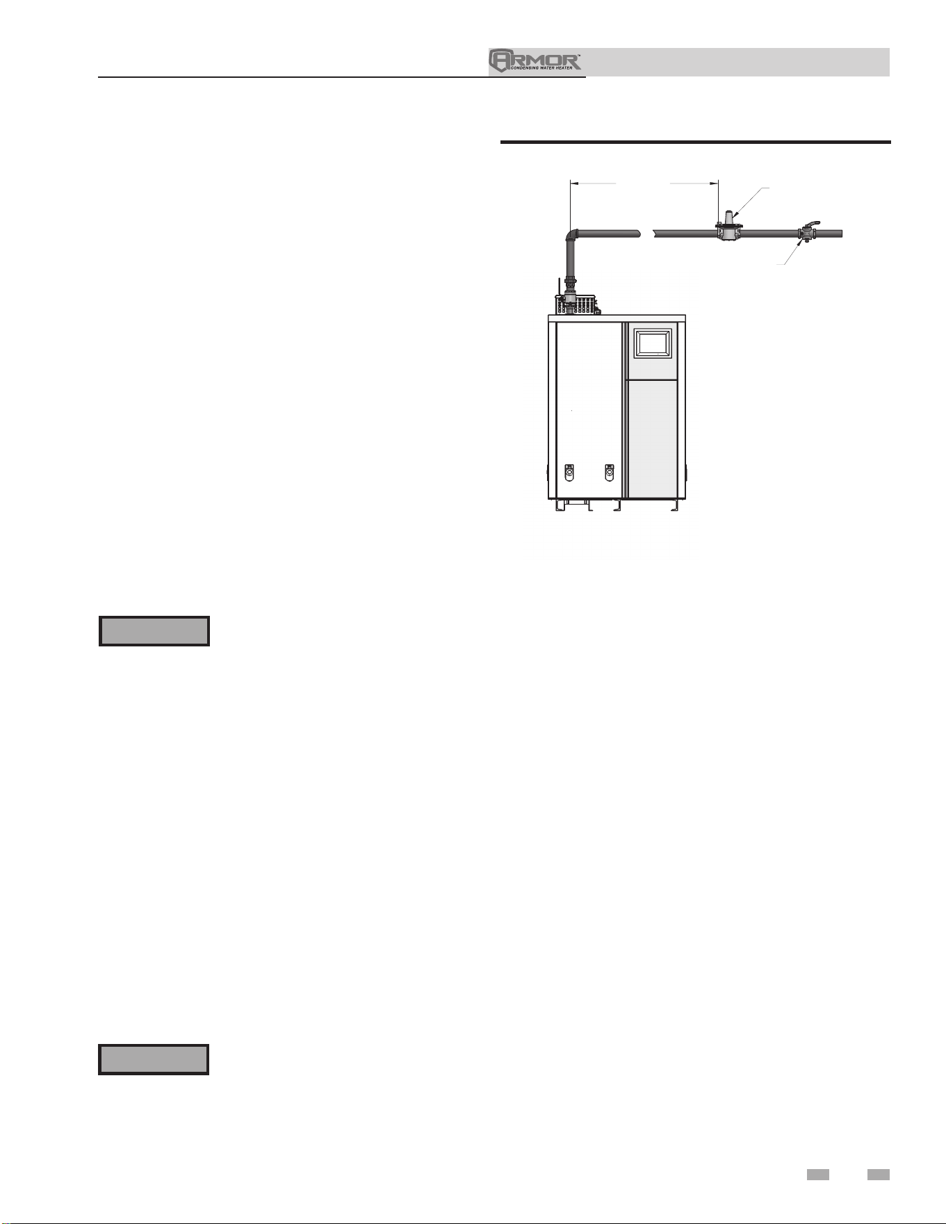
Installation & Operation Manual
45
7 Gas connections (continued)
Natural gas:
Pipe sizing for natural gas
1. Refer to Table 7A for pipe length and diameter. Based on
rated appliance input (divide by 1,000 to obtain cubic feet
per hour).
a. Table 7A is only for natural gas with specific gravity
0.60 inches, with a pressure drop through the gas
piping of 0.30 inches w.c.
b. For additional gas pipe sizing information, refer to
ANSI Z223.1 (or B149.1 for Canadian installations).
Natural gas supply pressure requirements
1. Pressure required at the gas valve inlet pressure port:
• Maximum 14 inches w.c. with no flow (lockup) or
with appliance on.
• Minimum 4 inches w.c. with gas flowing (verify during
appliance startup).
2. Install 100% lockup gas pressure regulator in supply line if
inlet pressure can exceed 14 inches w.c. at any time. Adjust
lockup regulator for 14 inches w.c. maximum.
Propane gas:
Pipe sizing for propane gas
1. Contact gas supplier to size pipes, tanks, and 100% lockup
gas pressure regulator.
Propane supply pressure requirements
1. Pressure required at gas valve inlet pressure port:
• Maximum 14 inches w.c. with no flow (lockup) or with
appliance on.
• Minimum 8 inches w.c. with gas flowing (verify during
appliance startup).
⚠WARNING
Armor appliances are typically shipped
ready to fire on natural gas. Check appliance
rating plate to determine which fuel the
appliance is set for. If set to natural gas,
it may be converted to LP by installing an
orifice (see pages 13 thru 14). In order to
operate on LP gas, an orifice MUST BE
installed or a gas valve adjustment MUST
BE made. Failure to comply could result in
severe personal injury, death, or substantial
property damage.
⚠WARNING
Ensure that the high gas pressure regulator
is at least 10 feet upstream of the appliance.
Figure 7-3 Gas Supply Piping to Regulator
* GAS PRESSURE
REGULATOR
(FIELD SUPPLIED)
10'
MINIMUM
* MANUAL SHUT
OFF VALVE
(FIELD SUPPLIED)
*IN COMPLIANCE WITH
248 CMR7.04(9)(f), PROVISIONS
SHALL BE MADE SO THE GAS
SUPPLY TO THE APPLIANCE(S) MAY
BE SHUT OFF FROM A LOCATION
OUTSIDE THE BOILER ROOM.
DIR #2000561080 00
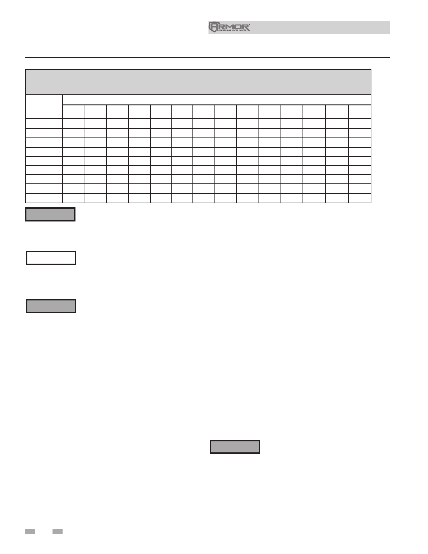
Installation & Operation Manual
46
Armor appliances are typically shipped ready to fire on natural gas. Check the appliance rating plate to
determine which fuel the appliance is set for. If set to natural gas, it may be converted to LP by installing an
orifice (see pages 13 thru 14). In order to operate on LP gas, an orifice MUST BE installed. Failure to comply
could result in severe personal injury, death, or substantial property damage.
Table 7A Natural Gas Pipe Size Chart
The gas piping must be sized for the proper flow and length of
pipe to avoid excessive pressure drop. Both the gas meter and
the gas regulator must be properly sized for the total gas load.
If you experience a pressure drop greater than 1 inch w.c., the
meter, regulator, or gas line is undersized or in need of service.
Perform the steps below when checking inlet gas supply:
1. Turn the main power switch to the “OFF” position.
2. Shut off gas supply at the manual gas valve in the gas
piping to the appliance.
3. Remove the 1/8" (3 mm) pipe plug on the inlet flange to the
valve and install a suitable 1/8" (3 mm) fitting (field
supplied) for the manometer tubing. Place the tubing of
the manometer over the tap once the set screw is loosened
or the 1/8" (3 mm) fitting is installed (depending on model)
as shown in FIG. 7-4 on page 43.
4. Slowly turn on the gas supply at the field installed
manual gas valve.
⚠WARNING
5. Turn the power switch to the “ON” position.
6. Adjust the temperature set point on the control display of
the SMART TOUCH control module to call for heat.
7. Observe the gas supply pressure as the burner fires at
100% of rated input. Percent of burner input will be
displayed on the control panel.
8. Ensure inlet pressure is within specified range.
Minimum and maximum gas supply pressures are
specified in this section of the manual.
9. If gas supply pressure is within normal range and no
adjustments are needed, proceed on to Step 11.
10. If the gas pressure is out of range, contact the gas utility,
gas supplier, qualified installer, or service agency to
determine the necessary steps to provide proper gas
pressure to the control.
11. Turn the power switch to the “OFF” position.
12. Shut off the gas supply at the manual gas valve in the gas
piping to the appliance.
13. Remove the manometer from the pressure tap on top of the
gas valve. Remove the 1/8" (3 mm) field supplied fitting
and reinstall the pipe plug removed in Step 3.
Check inlet gas supply
NOTICE
CSA or UL listed flexible gas connections
are acceptable, but you must exercise
caution to ensure that the line has adequate
capacity to allow your appliance to fire at
full rate. Consult with local codes for proper
installation or service procedures.
DO NOT adjust or attempt to measure
gas valve outlet pressure. The gas valve is
factory-set for the correct outlet pressure.
This setting is suitable for natural gas and
propane, requiring no field adjustment.
Attempting to alter or measure the gas valve
outlet pressure could result in damage to
the valve, causing potential severe personal
injury, death, or substantial property damage.
⚠WARNING
7 Gas connections
⚠WARNING
Do not check for gas leaks with an open flame
-- use the bubble test. Failure to use the
bubble test or check for gas leaks can cause
severe personal injury, death, or substantial
property damage.
14. Turn on the gas supply at the manual gas valve.
15. Turn the power switch to the “ON” position.
16. Adjust the temperature set point on the control display of
the SMART TOUCH control module to the desired
water temperature so the appliance will call for heat.
Capacity of Schedule 40 Metallic Pipe in Cubic Feet of Natural Gas Per Hour
(based on .60 specific gravity, 0.30" w.c. pressure drop)
Pipe
Size
(Inches)
Length of Pipe in Straight Feet
10 20 30 40 50 60 70 80 90 100 125 150 175 200
1/2 131 90 72 62 55 N/A N/A N/A N/A N/A N/A N/A N/A N/A
3/4 273 188 151 129 114 104 95 89 83 79 70 63 58 N/A
1 514 353 284 243 215 195 179 167 157 148 131 119 109 102
1 1/4 1,060 726 583 499 442 400 368 343 322 304 269 244 224 209
1 1/2 1,580 1,090 873 747 662 600 552 514 482 455 403 366 336 313
2 3,050 2,090 1,680 1,440 1,280 1,160 1,060 989 928 877 777 704 648 602
2 1/2 4,860 3,340 2,680 2,290 2,030 1,840 1,690 1,580 1,480 1,400 1,240 1,120 1,030 960
3 8,580 5,900 4,740 4,050 3,590 3,260 3,000 2,790 2,610 2,470 2,190 1,980 1,820 1,700
4 17,500 12,000 9,660 8,270 7,330 6,640 6,110 5,680 5,330 5,040 4,460 4,050 3,720 3,460
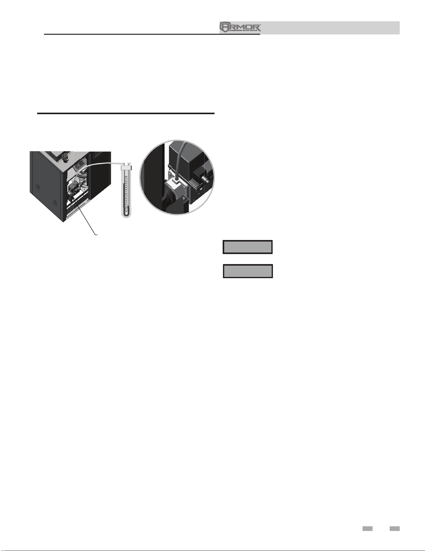
Installation & Operation Manual
47
7 Gas connections (continued)
Gas pressure
The gas pressure must remain between 4 inches w.c. (natural),
8 inches w.c. (LP) minimum, and 14 inches w.c. (natural and
LP) maximum during stand-by (static) mode and while in
operating (dynamic) mode. If an inline regulator is used, it
must be a minimum of 10 feet from the Armor appliance. It is
very important that the gas line is properly purged by the gas
supplier or utility company. Failure to properly purge the lines
or improper line sizing, will result in ignition failure.
The problem is especially noticeable in NEW LP installations
and also in empty tank situations. This can also occur when
a utility company shuts off service to an area to provide
maintenance to their lines.
DO NOT adjust gas valve outlet pressure.
The gas valve is factory-set for the correct
outlet pressure. This setting is suitable
for natural gas and propane, requiring
no field adjustment. Attempting to alter
the gas valve outlet pressure could result
in damage to the valve, causing potential
severe personal injury, death, or substantial
property damage.
Failure to follow all precautions could result
in fire, explosion, or death!
⚠WARNING
⚠WARNING
Gas valve replacement
The gas valve MUST NOT be replaced with a conventional
gas valve under any circumstances. As an additional safety
feature, this gas valve has a flanged connection to the venturi
and blower.
17. Check burner performance by cycling the system while
you observe burner response. The burner should ignite
promptly. Flame pattern should be stable. Turn system
off and allow burner to cool, then cycle burner again to
ensure proper ignition and flame characteristics.
DIR #2000548905 00
2
000548905 0
0
REMOVE THE 1/8" (3 MM) PIPE PLUG ON
THE INLET FLANGE TO THE VALVE AND
INSTALL A SUITABLE 1/8" (3 MM) FITTING
(FIELD SUPPLIED) FOR THE MANOMETER
TUBING
DETAIL
Figure 7-4 Inlet Gas Supply Check
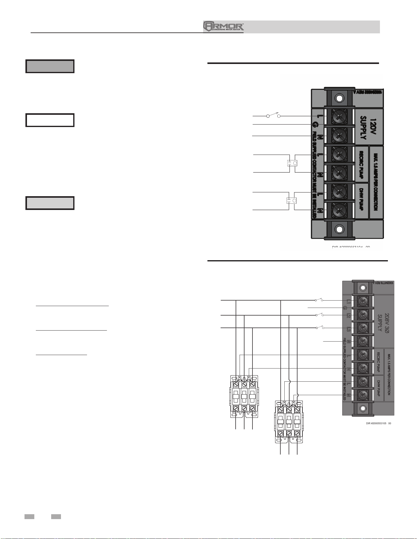
Installation & Operation Manual
48
8 Field wiring
ELECTRICAL SHOCK HAZARD – For
your safety, turn off electrical power supply
before making any electrical connections
to avoid possible electric shock hazard.
Failure to do so can cause severe personal
injury or death.
Wiring must be N.E.C. Class 1.
If original wiring as supplied with the
appliance must be replaced, use only type
105°C wire or equivalent.
The appliance must be electrically
grounded as required by National
Electrical Code ANSI/NFPA 70 – latest
edition.
Installation must comply with:
1. National Electrical Code and any other national, state,
provincial, or local codes or regulations.
2. In Canada, CSA C22.1 Canadian Electrical Code Part 1,
and any local codes.
Line voltage connections
1. For 1250 - 1500 Models: Connect 120V power wiring
to the line voltage terminal strip in the junction box, as
shown in FIG. 8-1A.
For 2000 - 3000 Models: Connect 208V power, 3 phase
wiring to the line voltage terminal strip in the junction
box, as shown in FIG. 8-1B.
For 4000 Models: Connect 480V power, 3 phase wiring
to the line voltage terminal strip in the junction box, as
shown in FIG. 8-1C.
2. Provide and install a fused disconnect or service switch
(25 amp recommended) as required by the code (see
FIG. 8-1A thru 8-1C).
3. The DHW pump is shipped loose on all Armor models.
Wire the pump as shown in FIG. 8-1A thru 8-1C.
4. The Armor appliance is capable of controlling a building
recirculation pump (field supplied). Wire the building
recirculation pump as shown in FIG. 8-1A thru 8-1C.
5. A field supplied contactor is required between the
appliance and pumps.
Figure 8-1A Line Voltage Field Wiring Connections - 120V
Label all wires prior to disconnection
when servicing controls. Wiring errors can
cause improper and dangerous operation.
⚠WARNING
NOTICE
⚠ CAUTION
DIR #2000553104 00
DIR
#2
00
05
53
10
4
00
DIR #2000553104 00
LINE 1 BK
SERVICE SWITCH
GROUND G
NEUTRAL W
RECIRCULATION PUMP
DRY CONTACT
DHW PUMP
DRY CONTACT
CONTACTOR
(FIELD SUPPLIED)
DIR #2000553105 00
LINE 1 BK
SERVICE SWITCH
GROUND G
NEUTRAL W
LINE 2 BK
SERVICE SWITCH
LINE 3 BK
SERVICE SWITCH
120V to Power Contactor
208V/3 ph Power to Pump
208V/3 ph Power to Pump
Figure 8-1B Line Voltage Field Wiring Connections - 208V
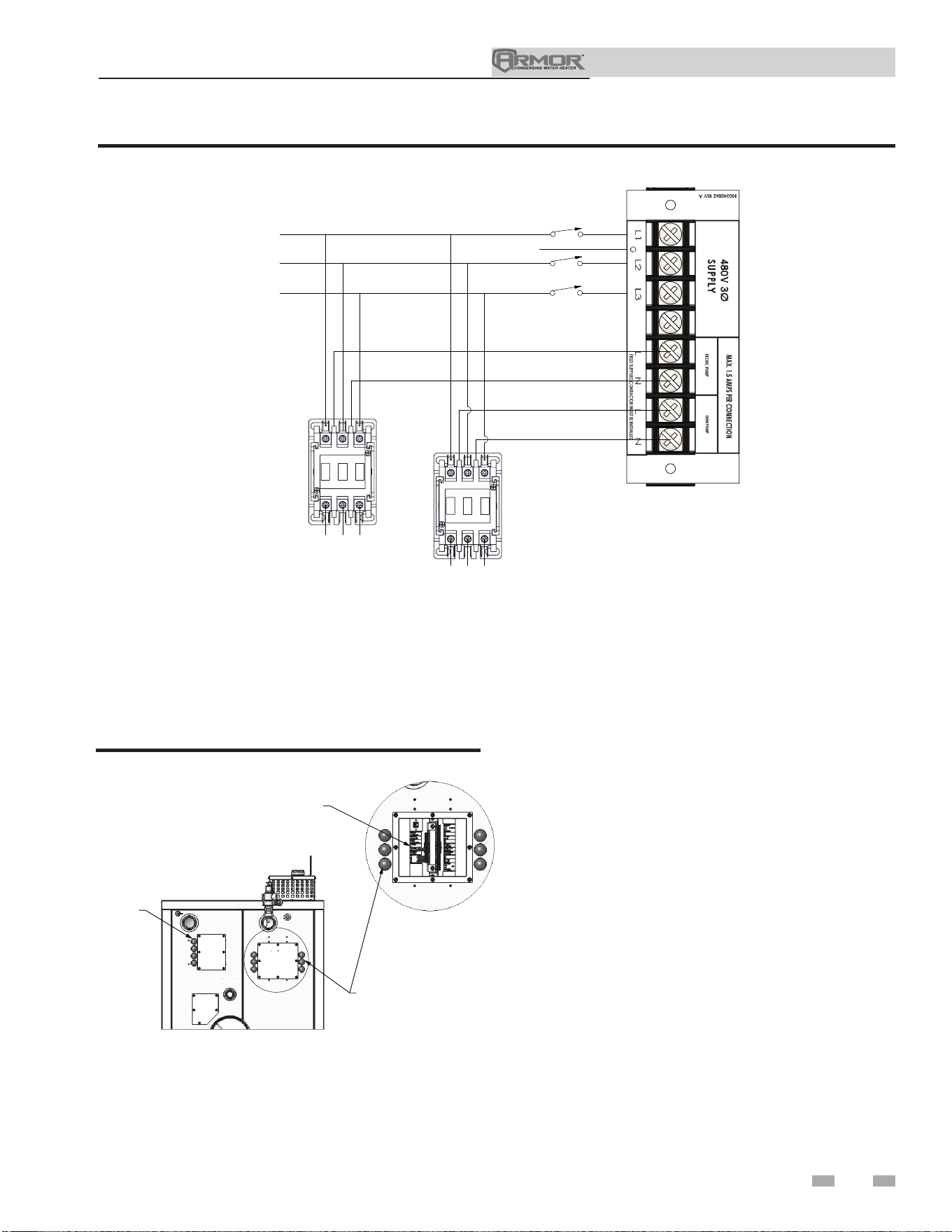
Installation & Operation Manual
49
8 Field wiring (continued)
Tank thermostat
1. Connect the tank thermostats (isolated contact only) to
the tank thermostat contacts as shown in FIG. 8-3.
Tank sensor
1. By installing a tank sensor, the SMART TOUCH control
can perform the tank thermostat function. The SMART
TOUCH control automatically detects the presence of
this sensor and generates a DHW call for heat when
the tank temperature drops below the programmed
differential and finishes the call for heat when the tank
temperature reaches above the programmed offset.
2. The tank sensor is the only sensor suitable for use
with the SMART TOUCH control. Connect the sensor
leads to the Tank Sensor terminals on the Low Voltage
Connection Board (FIG. 8-3).
Louver relay
If louvers need to operate when the appliance fires, they can
be controlled by this output. Connect these terminals to
a 24 VAC relay coil, which is wired to operate the louvers
(FIG. 8-3).
Louver proving switch
When the operation of the louvers needs to be verified before
the appliance fires, remove the jumper wire from these
terminals and connect them to the normally open contacts on
its proving switch (FIG. 8-3).
Low voltage connections
1. Route all low voltage wires through the knockouts in the
rear of the appliance, as shown in FIG. 8-2.
2. Connect low voltage wiring to low voltage connection
board as shown in FIG. 8-3 on page 47 of this manual and
the appliance wiring diagram.
A
DETAIL A
DIR #2000549740 00
LOW VOLTAGE
CONNECTION BOARD
LOW VOLTAGE
WIRING KNOCKOUTS
LINE VOLTAGE
WIRING KNOCKOUTS
Figure 8-2 Routing Field Wiring
Figure 8-1C Line Voltage Field Wiring Connections - 480V
LINE 1 BK
LINE 2 BK
LINE 3 BK
SERVICE SWITCH
SERVICE SWITCH
SERVICE SWITCH
GROUND G
480V/3 PH POWER TO PUMP
480V/3 PH POWER TO PUMP
DIR #2000601697 00

Installation & Operation Manual
50
8 Field wiring
Runtime contacts
The SMART TOUCH control closes a set of dry contacts
whenever the burner is running. This is typically used by
Building Management Systems to verify that the appliance is
responding to a call for heat.
Alarm contacts
The SMART TOUCH control closes another set of contacts
whenever the appliance is locked out or the power is turned
off. This can be used to turn on an alarm or signal a Building
Management System that the appliance is down.
Wiring of the cascade
When wiring the appliances for Cascade operation, select one
appliance as the Leader appliance. The remaining appliances
will be designated as Members. See page 54 “Configuration of
the Cascade” for a detailed explanation of this procedure.
Connect the tank sensor to the Leader appliance. For the Cascade
system to work properly the tank sensor must be installed. The
tank sensor should be wired to the low voltage connection board
at the terminals marked for the tank sensor (see FIG. 8-3). The
Leader control will use the water temperature at the tank sensor
to control the operation of the Cascade.
Communication between the Leader appliance and the Member
appliances is accomplished by using shielded, 2-wire twisted
pair communication cable. Connect one of the twisted pair
wires to Cascade terminal A on each of the Low Voltage
Connection boards, and the other wire of the twisted pair to
Cascade terminal B on each of the Low Voltage Connection
Boards. Connect the shield wires to one of the shield terminals
on the Low Voltage Connection Boards (FIG. 8-3). If more than
two appliances are on the Cascade, daisy chain the wiring from
the Cascade terminals on the second appliance to the Cascade
terminals on the third appliance, then from the third to the
fourth, and so on. The connections between appliances can be
made in any order, regardless of the addresses of the appliances.
Try to keep each cable as short as possible.
Flow switch
A flow switch is used to guarantee flow through the appliance
before allowing it to fire. The flow switch is installed at the
appliance outlet.
Rate output
This output provides a 0 - 10V signal that is proportional to the
firing rate of the appliance. This may be used by a BMS system
to monitor the actual rate of the appliance.
ModBus
When the optional ModBus interface module is installed, the
RS-485 ModBus cable is connected to these terminals. Use
shielded, 2-wire twisted pair cable. If desired, the shield can
be connected to ground by installing a jumper wire between
terminals 1 and 3 on connector X5 on the optional ModBus
interface module.
Appliance Building Management
System (BMS)
1. An external control may be connected to control either the
firing rate or the set point of the appliance. If the external
control uses a set of contacts to enable the appliance, connect
the contacts to the Tank Thermostat terminals. Otherwise,
the SMART TOUCH control will be enabled by the 0-10V
signal.
2. Make sure the (-) terminal is connected to the (-) or
common output terminal of the external control, and the
(+) terminal is connected to the (+) or 0 - 10 VDC terminal
of the external control. Make sure the (-) voltage is not
below ground.
Enable
When there is a need to override a call for heat, remove the
jumper wire from these terminals and connect them to the
normally closed enable switch.
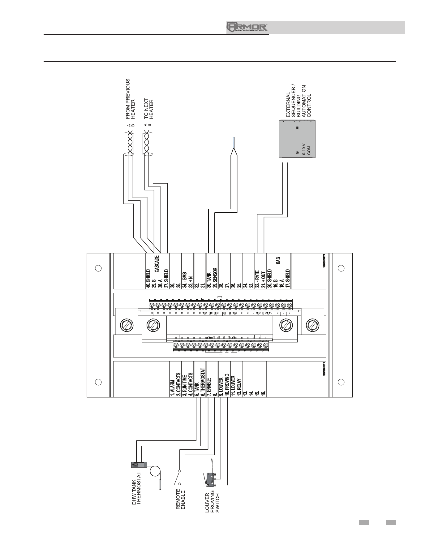
Installation & Operation Manual
8 Field wiring (continued)
TANK SENSOR
DIR #2000549759 00
Figure 8-3 Low Voltage Field Wiring Connections
51
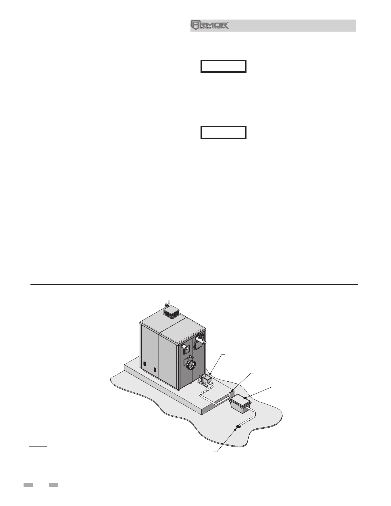
Installation & Operation Manual
9 Condensate disposal
Condensate drain
1. The Armor is a high efficiency appliance that produces
condensate.
2. The rear of the appliance has a 1 inch (25.4 mm) hose and
a 3/8 inch (9.8 mm) hose for connection to the condensate
trap.
3. Connect the two (2) condensate hoses to the condensate
trap.
4. The condensate trap must be installed at the same level or
below the appliance base.
5. The condensate trap is sized for a 1" PVC outlet connection
pipe.
6. Plug the wiring connection from the condensate trap into
the connector located on the back of the unit.
7. Slope condensate tubing down and away from the appliance
into a drain or condensate neutralizing filter. Condensate
from the Armor will be slightly acidic (typically with a pH
from 3 to 5). Install a neutralizing filter if required by local
codes.
A neutralizer kit (FIG. 9-1) is available from the factory.
The neutralizer kit must be placed on a surface that is a
minimum of 3 inches lower than the condensate trap with
field supplied piping (vacuum break) installed between the
condensate trap and the neutralizer kit.
8. Do not expose condensate line to freezing temperatures.
Use materials approved by the authority
having jurisdiction. In the absence of
other authority, PVC and CPVC pipe
must comply with ASTM D1785 or
D2845. Cement and primer must comply
with ASME D2564 or F493. For Canada
use CSA or ULC certified PVC or CPVC
pipe, fittings, and cement.
9. A condensate removal pump is required if appliance is
below the drain. When installing a condensate pump,
select one approved for use with condensing appliances
and furnaces. The pump should have an overflow switch
to prevent property damage from condensate spillage.
The switch should be wired to the auxiliary device
proving switch terminals on the low voltage connection
board.
NOTICE
NOTICE
To allow for proper drainage on large
horizontal runs, a second line vent may
be required and tubing size may need to
increase to 1 inch (25 mm).
The condensate line must remain
unobstructed, allowing free flow of
condensate. If condensate is allowed to
freeze in the line or if the line is obstructed
in any other manner, condensate can
exit from the appliance tee, resulting in
potential water damage to property.
Figure 9-1 Condensate Disposal
52
DIR #2000549739 00
CONDENSATE TRAP
SAME LEVEL OR BELOW
$33/,$1&( BASE
NEUTRALIZER KIT
(OPTIONAL)
3" MINIMUM BELOW
CONDEN
SATE TRAP
FLOOR DRAIN
OR DRAIN PAN
VACUUM
BREAK
NOTE: Neutralizer shown
for illustrative purposes only.
Actual neutralizer may vary.
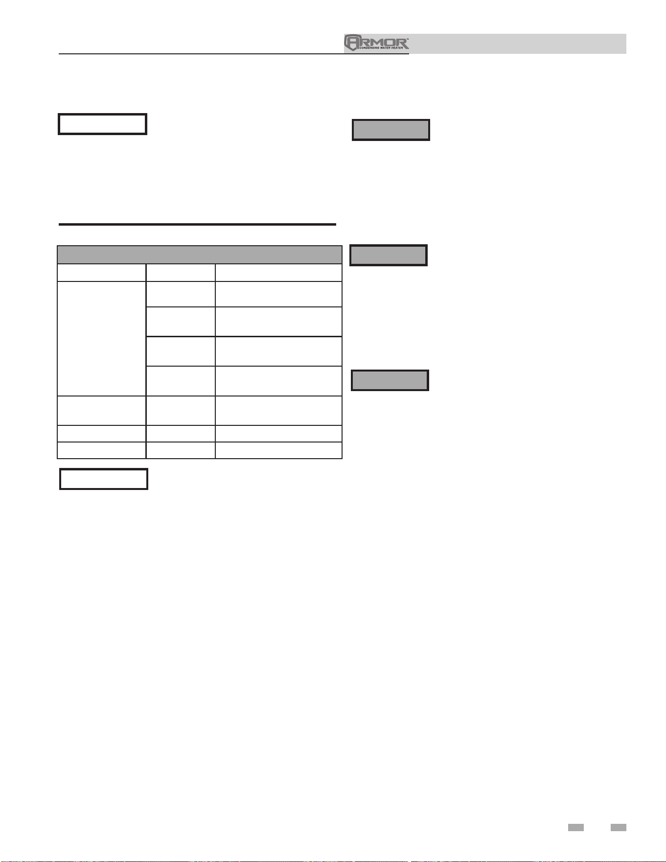
Installation & Operation Manual
53
10 Start-up
Check/control water chemistry
See the following table for properly operating the appliance with
the appropriate water chemistry. Good water quality will help
extend the life of the appliance by reducing the effects of scale
buildup and corrosion.
Check for gas leaks
Before starting the appliance, and during
initial operation, smell near the floor and
around the appliance for gas odorant or
any unusual odor. Remove the top access
panel and smell the interior of the appliance
enclosure. Do not proceed with start-up if
there is any indication of a gas leak. Use an
approved leak detection solution. Repair any
leaks at once.
DO NOT adjust gas valve outlet pressure.
The gas valve is factory set for the correct
outlet pressure. This setting is suitable
for natural gas and propane, requiring
no field adjustment. Attempting to alter
the gas valve outlet pressure could result
in damage to the valve, causing potential
severe personal injury, death, or substantial
property damage.
⚠WARNING
⚠WARNING
Propane appliances only – Your propane
supplier mixes an odorant with the propane
to make its presence detectable. In some
instances, the odorant can fade, and the gas
may no longer have an odor. Before start-
up (and periodically thereafter), have the
propane supplier verify the correct odorant
level in the gas.
⚠WARNING
NOTICE
Conduct water quality testing prior
to installing the appliance. Various
solutions are available to adjust water
quality.
WATER CHEMISTRY
Specication Range Requirement
Hardness
< 5 gpg
Follow recommendations
detailed below (See Notice 3)
5 to 12 gpg
Use Table 6B for pump
recommendation
12 to 15 gpg
Use Table 6B for pump
recommendation
> 15 gpg
Water softening system
required (See Notice 4)
Dissolved Solids < 350 ppm
Hardness level must be
met
pH Level 6.5 to 8.5 Acceptable range
Chloride < 150 ppm Acceptable range
Table 10A Water Chemistry
NOTICE
1. Do not use the appliance to directly
heat swimming pool or spa water.
2. At initial fill and during water heater
start-up and testing, check system
thoroughly for any leaks. Repair all leaks
before proceeding further.
3. When water hardness levels are less
than 5 gpg or 85.5 mg/l, the following is
recommended:
a. Flush and clean existing water heating
system prior to installation.
b. Inspect and, if necessary, replace the
anodes in any existing tanks.
c. Install a Y-strainer on the inlet of each
water heater as detailed in Section 6.
d. Limit the run time of the hot water
recirculation loop.
e. Filter the hot water recirculation loop
to a level of 10 microns. CAUTION:
Check recirculation pump size to verify
it is sized for filter addition and upsize if
necessary.
4. When water softener is required, a
Template Assisted Crystallization system
is recommended.
Installation & Operation Manual
54
10 Start-up
Final checks before starting the appliance
q Read the Armor Service Manual to familiarize yourself
with SMART TOUCH control module operation. Read
this manual, page 51 for proper steps to start the appliance.
q Verify the appliance and system are full of water and all
system components are correctly set for operation.
q Verify the preparation procedures of Section 10, pages 49
and 50 have been completed.
q Verify electrical connections are correct and securely
attached.
q Inspect vent piping and air piping for signs of deterioration
from corrosion, physical damage, or sagging. Verify air
piping and vent piping are intact and correctly installed
per this manual.
Start the appliance
1. Read and follow the operating instructions in FIG. 10-1,
page 51.
If appliance does not start correctly
1. Check for loose connections, blown fuse, or service
switch off.
2. Is appliance water temperature above 200°F?
3. Is tank thermostat or tank set point set below room
temperature?
4. Is gas turned on at meter or appliance?
5. Is incoming gas pressure less than 4 inches w.c.?
If none of the above corrects the problem, refer to the
Troubleshooting Section of the Armor Service Manual.
Check system and appliance
q Check water piping
1. Check system piping for leaks. If found, shut down the
appliance and repair immediately. (See WARNINGS on
pages 49 and 50 (Start-up) regarding failure to repair
leaks.)
2. Check Delta T. Reference Section 6 - System Piping on
page 34 for more information regarding Delta T.
3. Vent any remaining air from the system using manual
vents. Air in the system will interfere with circulation and
cause heat distribution problems and noise.
q Check vent piping and air piping
1. Check for gastight seal at every connection, seam of air
piping, and vent piping.
Venting system must be sealed gastight
to prevent flue gas spillage and carbon
monoxide emissions, which will result in
severe personal injury or death.
q Check gas piping
1. Check around the appliance for gas odor following the
procedure on page 40 of this manual (Connecting Gas
Supply Piping).
If you discover evidence of any gas leak,
shut down the appliance at once. Find the
leak source with a bubble test and repair
immediately. Do not start the appliance
again until corrected. Failure to comply
could result in severe personal injury, death,
or substantial property damage.
q Propane appliances – verify conversion
1. Verify propane conversion has been completed per the
Propane Conversion instructions.
DO NOT adjust gas valve outlet pressure.
The gas valve is factory-set for the correct
outlet pressure. This setting is suitable
for natural gas and propane, requiring
no field adjustment. Attempting to alter
the gas valve outlet pressure could result
in damage to the valve, causing potential
severe personal injury, death, or substantial
property damage.
⚠WARNING
⚠WARNING
⚠WARNING
⚠WARNING
Armor appliances are typically shipped
ready to fire on natural gas. Check appliance
rating plate to determine which fuel the
appliance is set for. If set to natural gas,
it may be converted to LP by installing an
orifice or by making a gas valve adjustment
(see pages 13 and 14). In order to operate on
LP gas, an orifice MUST BE installed or a gas
valve adjustment MUST BE made. Failure
to comply could result in severe personal
injury, death, or substantial property
damage.
Check flame and combustion
1. Turn the main power off to the appliance by placing the
“On/Off ” switch in the OFF position.
2. Remove the flue temperature sensor from the flue collector.
NOTE: Combustion measurements will be made at this
point.
3. Insert the probe from a combustion analyzer into the hole
left by the removal of the flue temperature sensor.
4. Turn the main power on to the appliance by placing the
“On/Off ” switch in the ON position.
5. Navigate to the Setup Screen from the Home Screen by
pressing the SETUP button along the left side of the screen.
Enter the installer password.
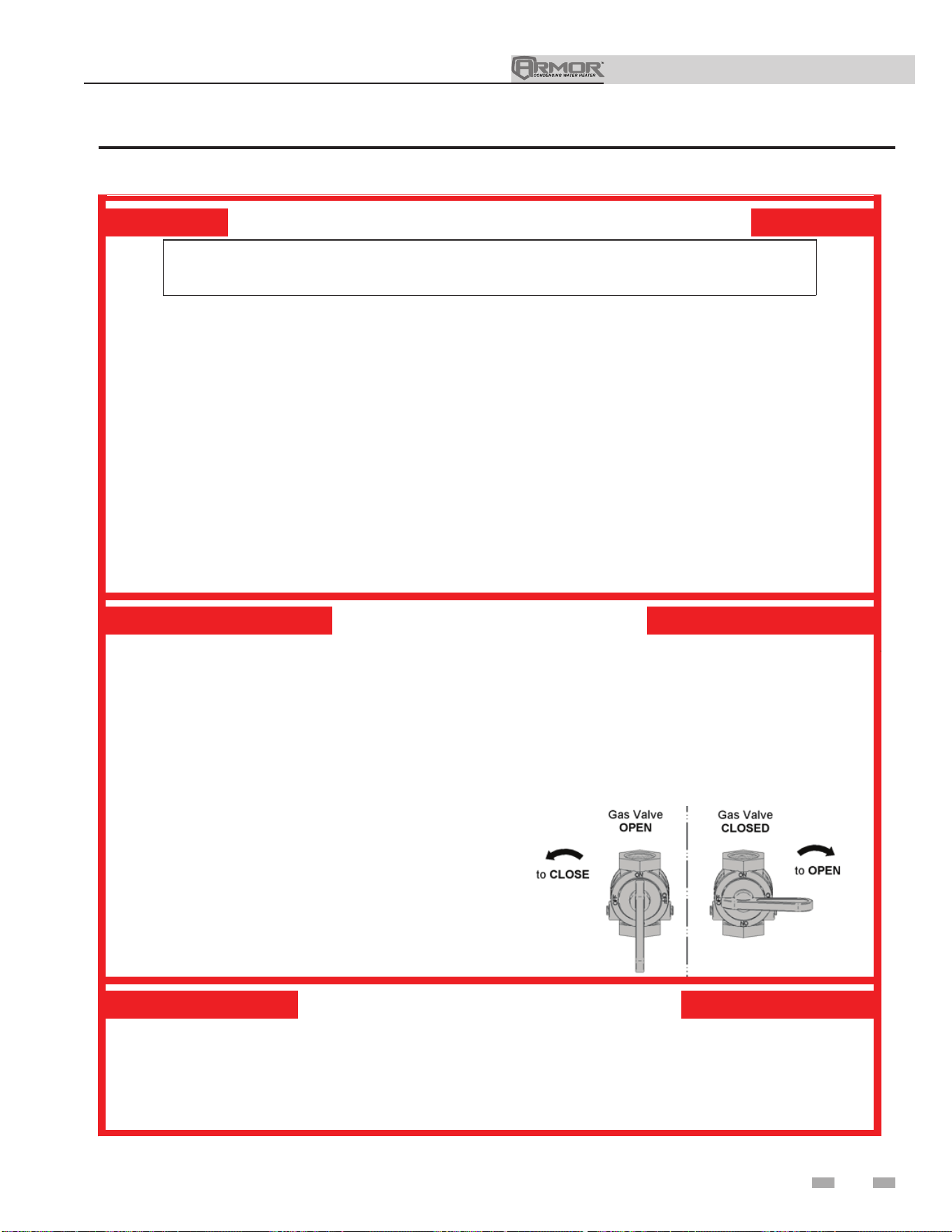
Installation & Operation Manual
55
10 Start-up (continued)
Figure 10-1 Operating Instructions
FOR YOUR SAFETY READ BEFORE OPERATING
WARNING: If you do not follow these instructions exactly, a fire or explosion
may result causing property damage, personal injury, or loss of life.
A. This appliance does not have a pilot. It is
equipped with an ignition device which
automati cally lights th e burner. Do not try
to ligh t the burner by hand.
B. BEFOR E OPER ATING smell all arou nd
the appliance area for ga s. Be sure to
smell next to the floor because some gas
is heavier than air and will settle on the
floor.
WHAT TO DO IF YOU SMELL GAS
• Do not tr y to light any appl iance.
• Do not to uch an y electric switch; do
not use any phone in your buildi ng.
• Im mediatel y call your gas supplier from a
neighbor’s phon e. Follow the gas supplier’s
instructions.
• If you cannot reach your gas supplier , call
th e fire department.
C. Use only your hand to tu rn the gas control knob .
Never use tools. If the handle will not turn by
hand, don’t try to re
pair it, call a qualified service
te chnician. Force or attempted repair may
result in a fire or expl osion.
D. Do not use this appliance if an y part has been
under water. Immediately call a qual ified
service technician to inspect the applianc e an d
to replace any part of the control system an d
any gas control which has been under water.
OPERATING INSTRUCTIONS
1. STOP! Read the safety information
above on this label.
2. Set the thermostat to lowest setting.
3. Turn off all electr ic power to the
applianc e.
4. This appliance is equipp ed with an
ignition device which automatically lights
the burner. Do not try to light th e burner
by hand.
5. Remove front door.
6. Turn ga s shutoff valve counterclockwise
to “OFF”. Handle will be perpendicular to
pipe. Do not force.
7. Wait five (5) minutes to clear out any gas.
If you then smell gas, STOP! Follow “B”
in the safety information above this label.
If you don’t smell gas, go to next step.
8. Turn gas shutoff valve clockwise to “ON”.
Handle will be pa rallel to pi pe.
9. Instal l front door.
10. Turn on al l electric power to applianc e.
11. Set ther mo
stat to desired setting.
12. If the appl iance will not oper ate, follow the
instructions “To Turn Off Gas To Appliance” and
call yo ur service technician or gas supplier .
TO TURN OFF GAS TO APPLIANCE
1. Set the thermostat to lowest setting.
2. Turn off all electr ic power to the appl iance
if service is to be pe rfor med.
3. Remove front door.
4. Turn gas shut off valve counterclockwise to
“OFF”. Handle will be perpendi cular to pipe.
Do not force.
5. Instal l front door.
LBL2 0053 REV B
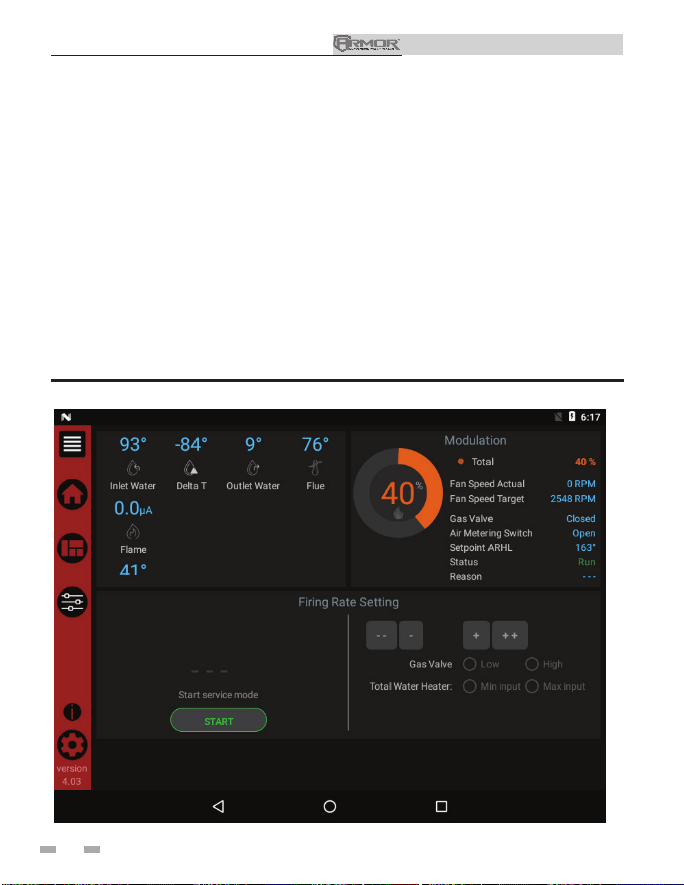
Installation & Operation Manual
56
Check flame and combustion (continued)
6. Select the Service Maintenance Screen. The tabs will
scroll (up and down) to reveal more options. See FIG.
10-2.
7. Once the heat exchanger has modulated up to rate,
measure the combustion. The values should be in the
range listed in Table 3H of the Armor Service Manual. CO
levels should be less than 200 ppm for a properly installed
unit. If the combustion is not within range reference the
Troubleshooting Section in the Armor Service Manual for
possible causes and corrective actions.
8. Once the combustion analysis is complete, test the safety
shutoff device by turning the manual shutoff valve to the
OFF position and ensuring that the appliance shuts down
and registers an alarm. Open the manual shutoff valve
and reset the control.
10 Start-up
Figure 10-2 Service Maintenance Screen

Installation & Operation Manual
57
Set clock
The SMART TOUCH control has a built-in clock that it uses for
its night setback feature and for logging events. This clock must
be set when the appliance is installed and anytime the appliance
has been powered off for more than one day. Use the following
procedure to set the clock:
1. Press the SETTINGS button under the Lochinvar logo (see
FIG. 11-1).
2. Press the SET button across from the date and time.
3. Proceed to set the date, time, and time zone.
NOTE: Automatic Time Zone will not work.
4. Temperature units and WiFi may also be set here. These
items may be used to automatically sync the time.
5. Press the Home, View, or Back button to exit.
Figure 10-3 Settings
10 Start-up (continued)
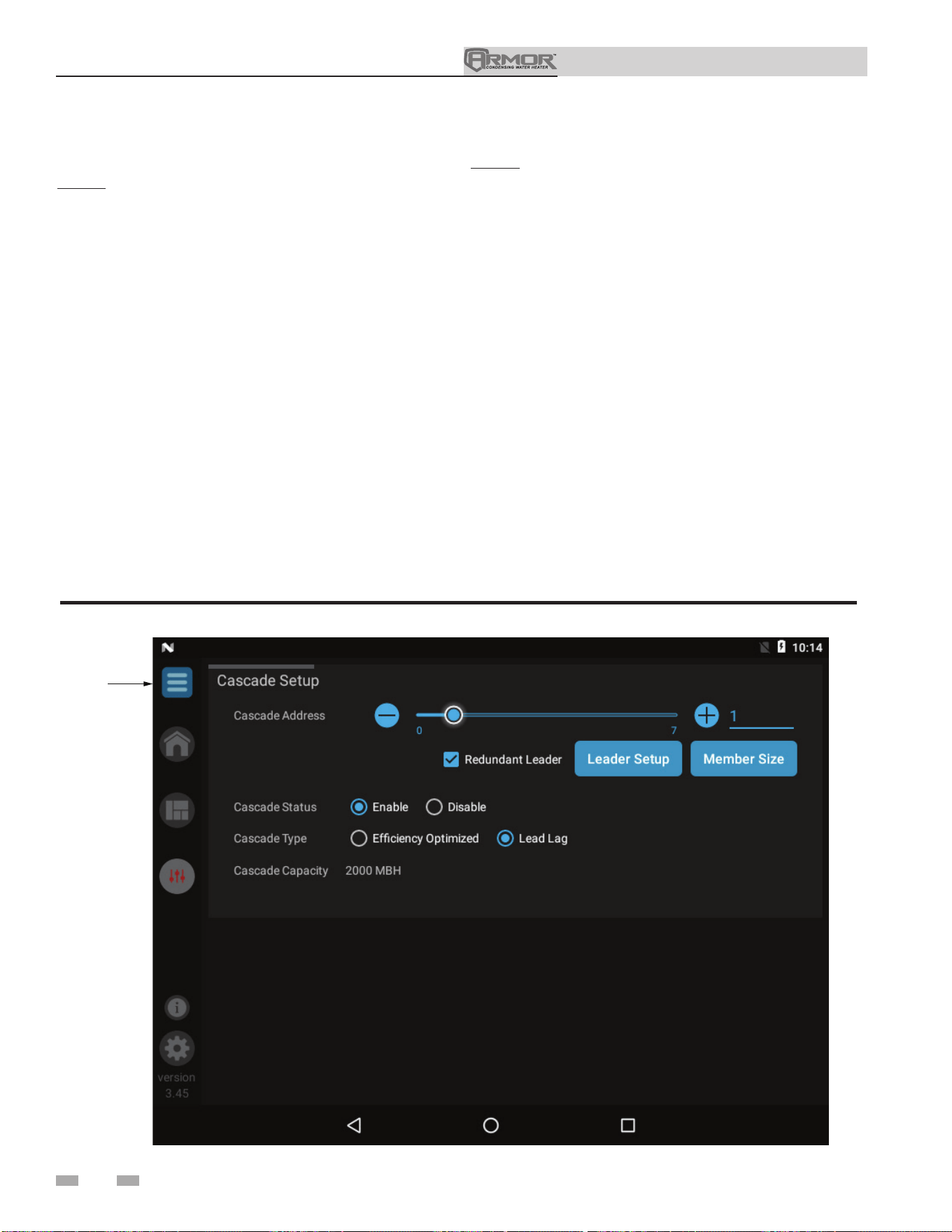
Installation & Operation Manual
58
DOOR
MENU
Figure 10-4 Cascade Screen
Configuration of the cascade
NOTE: For more detailed instructions, please refer to the
Armor Service Manual.
When installing a Cascade system, all units must be
programmed for Cascade to operate. Access the Cascade
Setup options as follows:
1. Press the SETUP button on the left side of the display
screen.
2. Enter the installer password.
3. Select the Cascade option as shown in FIG. 10-4.
4. Each unit must have a unique address set. The leader
has more options which are described in the Armor
Service Manual.
5. Once all the updates are complete, press the Door Menu
slider (top left) or the Setup button.
6. Press the APPLY CHANGES button on the top of the
screen.
10 Start-up
NOTE: The APPLY CHANGES button must be pressed to
complete programming of the controls. Failure to press the
APPLY CHANGES button will result in an unprogrammed
control. The Door Menu button will become highlighted when
there are changes that can be applied.

Installation & Operation Manual
59
11 Operating information
General
How the appliance operates
The Armor uses an advanced stainless steel heat exchanger
to transfer heat from the flue products to the water. An
electronic control module monitors various inputs to initiate
a call for heat. The blower provides air to the burner and
forces the flue products out of the combustion chamber
and into the vent system. The control module regulates
the blower speed to control the firing rate of the unit. The
modulating gas valve monitors the amount of combustion air
being pulled into the blower and regulates the amount of gas
supplied, which then mixes with the combustion air and is
supplied to the burner.
How the control modules operate
The Armor appliance is equipped with a SMART TOUCH
control module. The SMART TOUCH control module
receives inputs from appliance sensors and external devices.
The control module activates and controls the blowers and
gas valves to regulate heat input and switches the appliance,
DHW, and building recirculation pumps on and off as needed.
The user programs the control module to meet system needs
by adjusting control parameters. These parameters set
operating temperatures and appliance operating modes.
Control inputs and outputs
Enable
This input overrides a call for heat from the tank sensor.
Tank Thermostat
This input tells the appliance to provide water for heating a
storage tank.
0 - 10V BMS Input (set point or power)
The Armor can be controlled by a Building Management
System (BMS) using a 0 - 10 VDC signal. The control can be
configured by the installer to use this signal to either control
set point or firing rate.
Tank Thermostat / Tank Sensor
The SMART TOUCH control allows the connection of a tank
thermostat or tank sensor to the low voltage connection board.
When a tank sensor is connected, the tank thermostat input is
ignored.
Anti-cycling
After a heating demand has been satisfied, the control will delay
the next heating call for a set time period (time is adjustable by
the installer). The time delay will be bypassed if the inlet water
temperature drops too far during the delay.
DHW pump control
When a call for heat starts, the pump is turned on. After the
call for heat ends, the pump will run for an additional period
of time.
Louver
When the appliance needs to control combustion air louvers,
connect a 24 VAC louver relay to the two (2) Louver Relay
terminals. Connect the Louver End Switch to the Louver
Proving Switch input on the Low Voltage Connection Board.
Temperature control
Modulation
The Armor is capable of modulating its firing rate from a
minimum of 20% to a maximum of 100%. The firing rate is
dictated by the call for heat, the heating load, and various other
temperature limitations.

Installation & Operation Manual
60
11 Operating information
Gradient limiting
If during operation of the appliance, the outlet water
temperature is rising too quickly, the control will reduce the
firing rate to its lowest setting.
Night setback
The controller may be programmed to reduce the tank set
point each demand during a certain time each day. A start
and stop time for each demand can be programmed for each
day of the week. A different set of start and stop times can
be programmed each day of the week.
Flame current support
To prevent nuisance shutdowns when the appliance is firing
at minimum rates, the control will increase the firing rate
when the flame signal drops too low.
ModBus
The Armor appliance can be connected to and controlled
by a Building Automation System through the ModBus
interface. Connect the A and B wires to the A and B
terminals. If connecting another cable (in a daisy chain),
connect the shield wire of the first cable to one of the shield
terminals, and the shield wire of the second cable to the other
shield terminal. If it is desired to ground the cable shield at
the appliance, connect the shield wire to one of the shield
terminals, and install a jumper across the two (2) terminals
in connector X5 on the ModBus interface board.
0-10V Rate output
A 0-10V signal which indicates the firing rate of the appliance
is available. This output may be connected to a Building
Management System (BMS) to allow it to monitor the actual
firing rate. Connect the - terminal to the COM or - terminal
on the BMS, and connect the + terminal to the 0 - 10V or +
terminal on the BMS.
Protection features
Outlet temperature, flue temperature, and temperature
rise limiting
The outlet water temperature is monitored by the appliance
outlet temperature sensor. When the outlet temperature
exceeds 195°F (91°C), the unit will reduce the fan speed. If the
outlet water temperature exceeds 205°F (96°C) the control will
shut the unit down until the minimum off time has expired and
the outlet drops 10°F (-12°C).
The control module monitors the flue temperature by a sensor
located in the flue exhaust. If the flue temperature exceeds
215°F (102°C) the control will reduce the maximum fan speed.
If the flue temperature exceeds 250°F (121°C) the control will
shut the unit down. The unit will restart automatically once
the flue temperature drops 50°F (10°C) and the minimum off
time has expired.
The control monitors the temperature difference between
the inlet and the outlet sensor. If the control determines the
temperature rise is too high, it will either reduce the firing rate
or shut down the unit as appropriate. The unit will restart
automatically once the temperature difference has dropped
below the allowable rise and the minimum off time has expired.
Freeze protection
DO NOT install the appliance in a room likely to freeze.
The following integral feature of the SMART TOUCH control
module provides some protection for the appliance only -- not
for the system.
• The SMART TOUCH control module provides
freeze-up protection as follows when the appliance
water temperature drops below 45°F (7°C):
• Below 45°F (7°C), the appliance and DHW pump
(if enabled) operate constantly.
• Below 37°F (3°C), the appliance turns on.
• Appliance and pump turn off if appliance water
temperature rises above 43°F (6°C).
This feature of the SMART TOUCH control
module does not eliminate the possibility
of freezing. The installation must still
use recognized design, installation, and
maintenance practice to prevent freeze
potential for the appliance and system.
⚠ CAUTION

Installation & Operation Manual
61
11 Operating information (continued)
Sequence of operation
Monitor external limits
Connections are provided on the connection board for
external limits such as an additional high limit. The
SMART TOUCH control will shut off the burner and
inhibit relighting whenever any of these external limits
open.
Run-time and alarm outputs
The appliance provides dry contacts for indicating when
the appliance is running and when it is unable to operate.
Run-time and cycle counting
The control uses four timers to monitor the total hours of
burner operation:
75 - 100% 50 - 75%
25 - 50% <25%
The control uses four (4) ignition counters to monitor the
amount of appliance cycles. The first counter counts all
ignitions of the control. The second counter counts only
ignition attempts that have failed. The third and fourth
counters are the same as the first and second respectively,
but can be reset by the installer.
Service reminder
The control can be programmed for service reminder
notification. This notification will become active when
either a set amount of time has expired or a set amount of
running hours or cycles has expired (all adjustable by the
installer). The service reminder notification can be reset
by the installer. The service company’s name and phone
number can be programmed to display when service is due.
Error logging
The control will hold in memory the last 10 blocking faults
as well as the last 10 lockout faults. The date and time of
the occurrence will be recorded as well. Only the 10 most
recent occurrences will be held in memory.
Appliance temperature regulation
Operating temperature (target)
The SMART TOUCH control module senses water
temperature and regulates appliance firing and firing rate
to achieve a target temperature. The target temperature can
be set between 32°F (0°C) and 185°F.
High limit operations
The Armor SMART TOUCH control has two (2) integral
limits, one auto reset and one manual reset. The integral high
limits are UL353 certified.
If the outlet temperature exceeds 205°F, integral manual reset
high limit action occurs. The appliance will shut down until
the outlet water cools down and the appliance is reset through
the user interface.
Low water cutoff protection
A low water cutoff device with test and reset functionality is
provided in the appliance as optional equipment.
Flow sensing device
The SMART TOUCH control module uses temperature sensing
of both supply and return temperatures of the heat exchanger.
If the flow rate is too low or the outlet temperature is too high,
the control module modulates down and will shut the appliance
off. This ensures appliance shutdown in the event of low flow
conditions.

Installation & Operation Manual
11 Operating information
62
Cascade
When multiple appliances are installed, they can be wired
together in a cascade sequence. A maximum of eight appliances
can be controlled from a single control. In this application one
appliance would be designated as the Leader control and all
others would be designated as Member controls.
Once the Leader appliance receives a call for heat from the
Enable input, the 0 - 10 VDC input, or ModBus, the control
will determine what the set point will be. A fixed temperature
set point can be programmed into the control or provided
through the ModBus interface.
If the water temperature at the controlling sensor is less than
the set point + the turn-off offset - the off-on differential,
the control will initiate a call for heat on the Cascade (see
the Armor Service Manual for an explanation of the offset
and differential). The Leader will energize the lead appliance
on the Cascade. For a new start-up this will be the Leader
appliance.
The two (2) types of Cascade control are listed below:
Efficiency optimization
Efficiency optimization is chosen when the application is such
that overall heating efficiency is most important. The Cascade
will fire the appliances in a way that is the most efficient. This
allows more appliances to fire at one time, at a lower rate, thus
more efficient.
Lead/Lag
The Lead/Lag method is chosen when the application requires
firing as few appliances at a time as possible. This method will
not bring on another appliance until the current number of
appliances cannot meet the demand.
The parameters for both types of Cascade are adjustable.
Reference the Armor Service Manual for a more detailed
description of these adjustments.
Sequence of the cascade
To equalize the run time of all appliances on the Cascade, the
firing sequence will automatically be changed at set intervals.
For the first 24 hours after initializing the Cascade, the
sequence will be changed every hour. After that the sequence
will be changed once every 24 hours.
Night Setback operations with Cascade
Night Setback operation of the appliances within the Cascade
are available. Programming will be done through the Leader
appliance. Refer to the Armor Service Manual for information
regarding Night Setback.
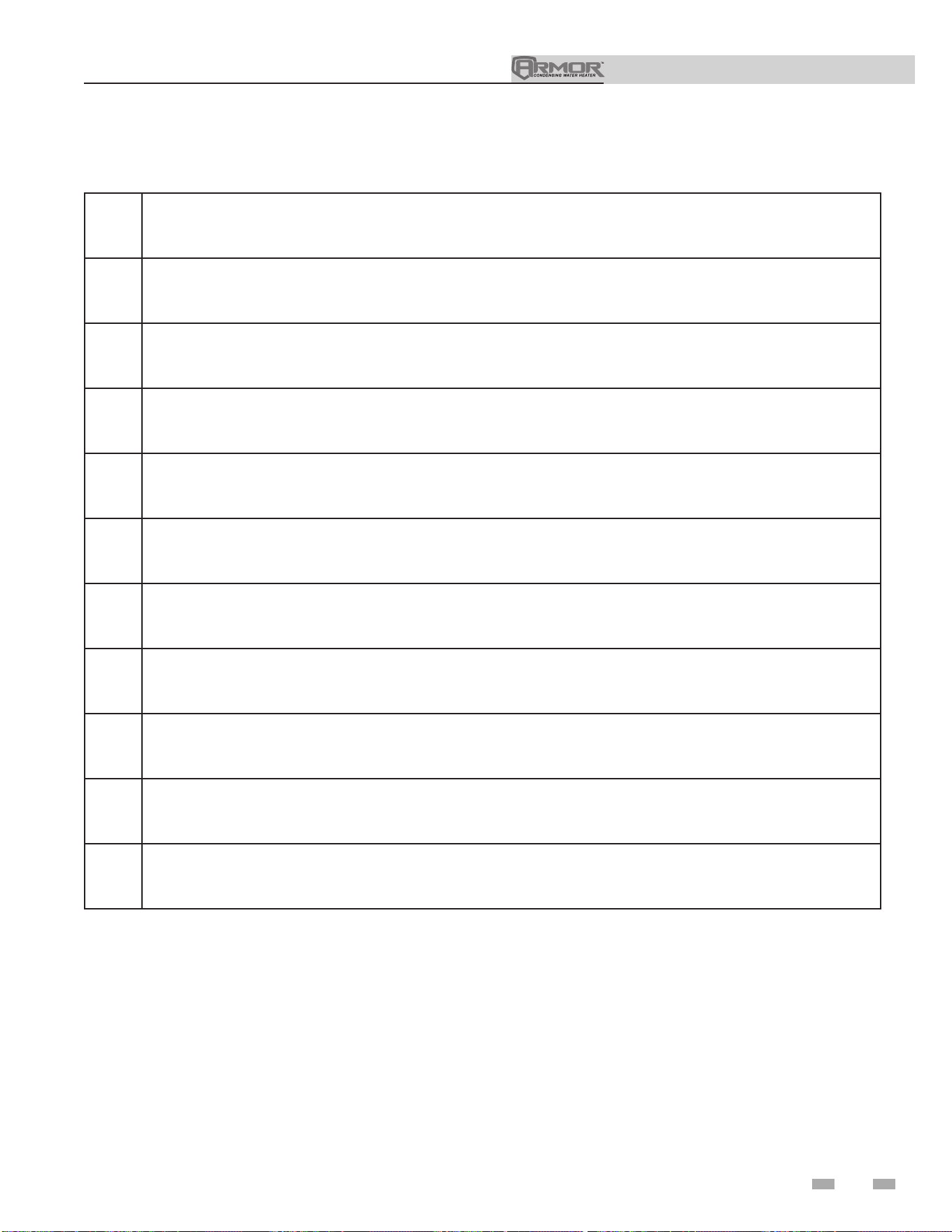
Installation & Operation Manual
63
Installation & Operation Manual
11 Operating information (continued)
Sequence of operation
1.
Upon a call for heat, the control turns on the DHW pump.
2.
The control confirms that the low water cutoff contacts are closed and energizes the louvers (optional).
3.
The control confirms that the gas pressure switch, blocked drain switch, limits, louver proving switch (optional), and
contacts close. The Pre-Purge cycle begins.
4.
The control confirms the blower comes up to the desired speed.
5.
Once the Pre-Purge cycle is complete, the control lowers the blower speeds, initiates sparking of the ignition
electrode, and opens the gas valve.
6.
After a short wait, the control stops sparking and checks for the presence of flame current through the flame sense
electrode.
7.
If the control does not detect flame current, the control will lockout indefinitely, until the RESET button on the touch
screen LCD is pressed.
8.
If the control detects flame current, the control will hold the blower speed constant for a few seconds to allow the
flame to stabilize, then begin modulating the firing rate in order to maintain the controlling sensor to the desired set
point temperature.
9.
Once the DHW call for heat is satisfied, the control will turn off the gas valve and begin the Post-Purge cycle. Any
pumps that are running will begin their respective Pump Delay cycles.
10.
At the end of the Post-Purge cycle, the louver relay contacts will de-energize.
11.
At the end of the Pump Delay cycle(s), the pump(s) will be turned off.
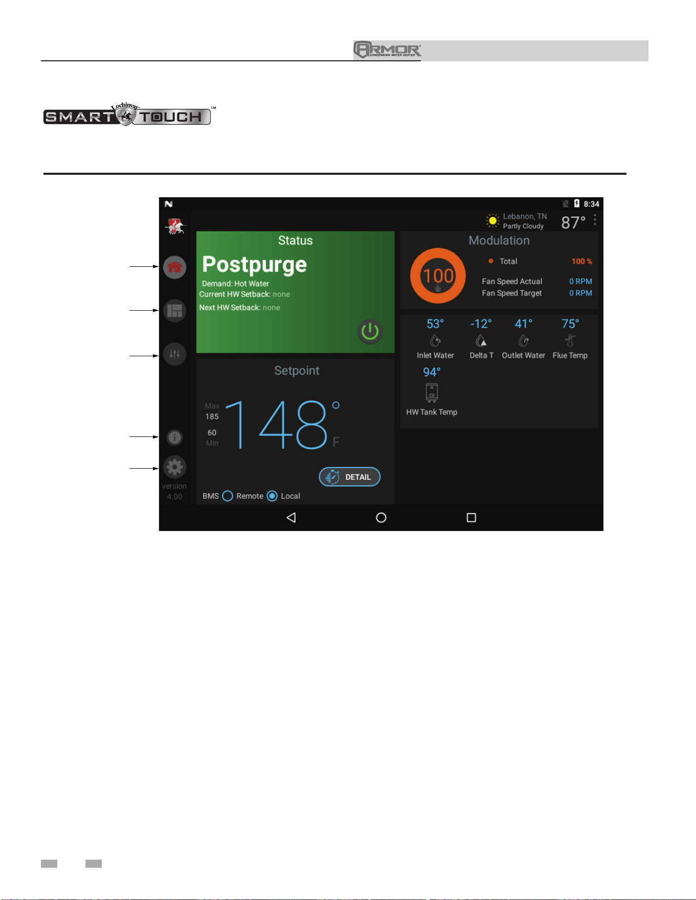
Installation & Operation Manual
64
Installation & Operation Manual
11 Operating information
w/Armor CON•X•US Interface
Figure 11-1 Home Screen
The Home Screen displays basic information on how the unit is running. It is divided into the following sections: Status,
Demand, Modulation, Sensors, and Navigation.
• The Status Section is located on the top left of the screen
and displays how the unit is currently running (i.e. Off,
Stand-by, Blocking, and Lockout) including: current
driving demand, the next Hot Water Setback scheduled,
the reason for any blocking or lockout, and a power button.
• The Demand Section is located on the bottom left of the
screen and displays information about the targets and
limits of the current demand being serviced.
• The Modulation Section is located on the top right of the
screen and displays the target modulation of the unit. This
section also includes target and actual fan speeds.
• The Sensor Section is located on the bottom right of the
screen and displays both factory installed and field
installed sensor including: Inlet Water Temperature,
Delta T Water Temperature, Outlet Water Temperature,
Flue Temperature, and HW Tank Temperature.
• The Navigation Section is located down the left side of the
screen. There are five (5) sections located below the
Lochinvar icon: Home, View, Setup, Information
(About), and Settings. The Home Section is the screen
shown above. The View Section provides more detailed
information including subsections for: History, Cascade,
Graphing, and a complete list of current Sensor Values.
The Setup Section has several screens to aid in setting
up the appliance. The Setup Section includes screens for
adjusting: Set Points, Pump Settings, Cascade,
BMS, and Night Setback. The Information Section
provides information about the hardware and software
including the current software version of the interface, the
version of the appliance control, and the CON·X·US device
serial number. The Setting Section enables several interface
setup features including: Time Setup, Temperature Unit
Select, Loch’n Link, System Update, and WiFi Setup.
HOME
VIEW
SETUP
INFORMATION
SETTINGS
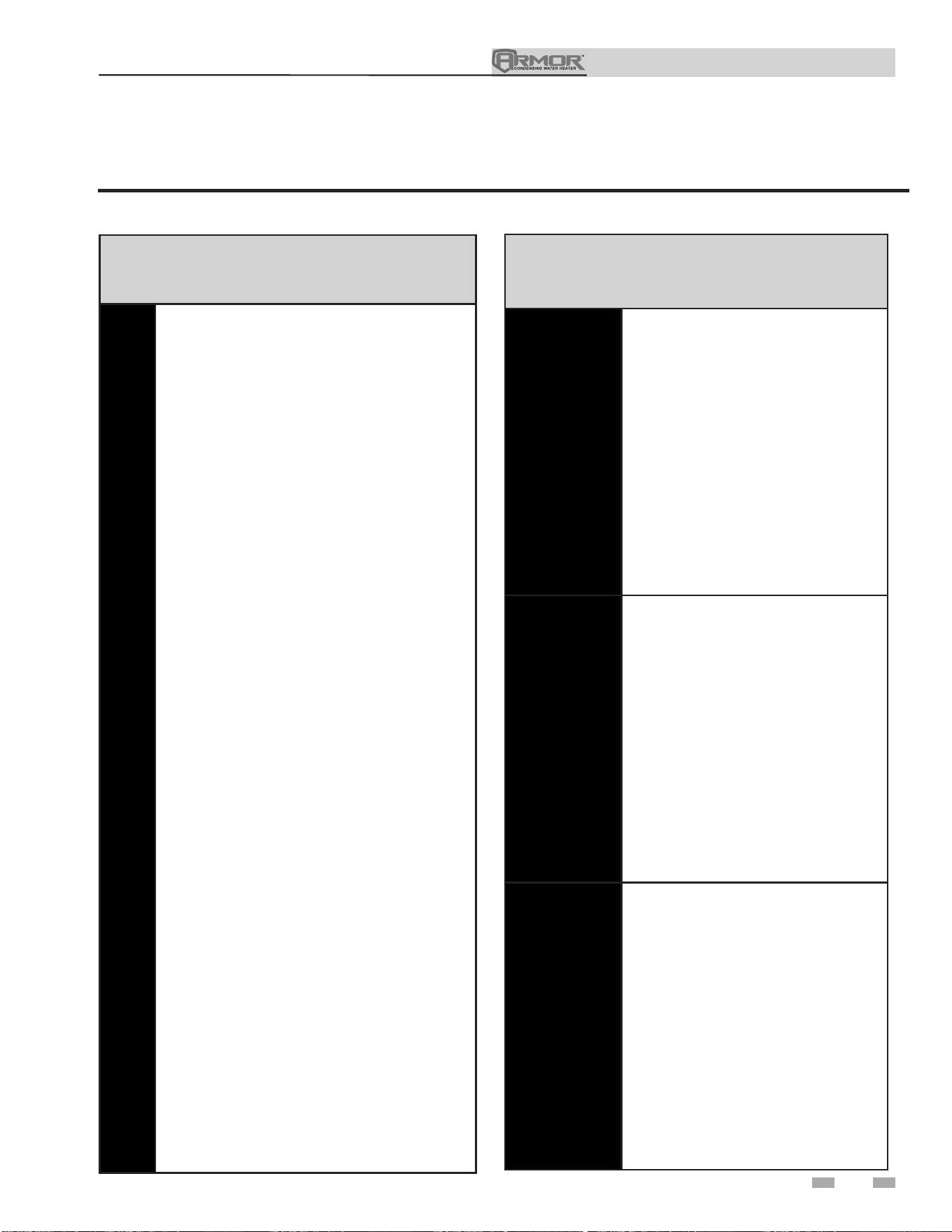
Installation & Operation Manual
65
12 Maintenance
Maintenance and annual startup
Table 12A Service and Maintenance Schedules
Service technician
(see the following pages for instructions)
General:
• Address reported problems, if any
• Inspect interior; clean and vacuum if
necessary
• Clean condensate trap and fill with fresh
water
• Check for leaks (water, gas, flue,
condensate)
• Verify flue and air lines in good condition
and sealed tight
• Check system water pressure/system
piping/expansion tank
• Check control settings
• Check the ignition and both flame sense
electrodes (sand off any deposits; clean
and reposition)
• Check wiring and connections
• Perform start-up checkout and
performance verification per Section 10.
• Flame inspection (stable, uniform)
• Check both flame signals (at least 10
microamps at high fire)
• Clean the heat exchanger
• Test low water cutoff (reference the
Armor Service Manual).
If combustion or performance
indicate need:
• Clean heat exchanger
• Remove and clean burner using
compressed air only
• Clean the blower wheels
ANNUAL START-UP
Owner maintenance
(see the Armor User’s Information Manual for
instructions)
Daily
• Check appliance area
• Check pressure/temperature
gauge
Monthly
• Check vent piping
• Check air piping
• Check air and vent termination
screens
• Check relief valve
• Check condensate drain system
• Check Delta T
• Remove debris from Y-strainer
• Check building recirculation
filter (if filter required)
Every
6 months
• Test low water cutoff
• Reset button (low water
cutoff)
• Check appliance piping (gas
and water) for leaks
• Operate relief valve
• Check water chemistry
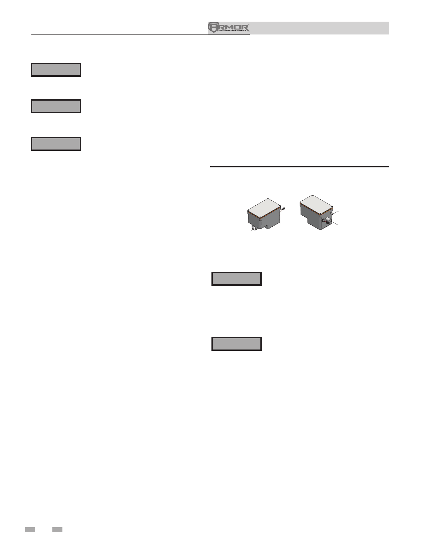
Installation & Operation Manual
66
12 Maintenance
Follow the service and maintenance procedures given throughout this manual and in component literature
shipped with the appliance. Failure to perform the service and maintenance could result in damage to the
appliance or system. Failure to follow the directions in this manual and component literature could result in
severe personal injury, death, or substantial property damage.
The appliance should be inspected annually by a qualified service technician. In addition, the maintenance
and care of the appliance designated in Table 12A and explained on the following pages must be performed to
assure maximum appliance efficiency and reliability. Failure to service and maintain the appliance and system
could result in equipment failure.
Electrical shock hazard – Turn off power to the appliance before any service operation on the appliance except
as noted otherwise in this instruction manual. Failure to turn off electrical power could result in electrical
shock, causing severe personal injury or death.
Address reported problems
1. Inspect any problems reported by the owner and correct
before proceeding.
Inspect appliance area
1. Verify that appliance area is free of any combustible
materials, gasoline, and other flammable vapors and
liquids.
2. Verify that air intake area is free of any of the contaminants
listed in Section 1 - Determine Appliance Location. If any
of these are present in the appliance intake air vicinity,
they must be removed. If they cannot be removed,
reinstall the air and vent lines per this manual and the
Armor Service Manual.
Inspect appliance interior
1. Remove the front access cover and inspect the interior of
the appliance.
2. Vacuum any sediment from inside the appliance and
components. Remove any obstructions.
Eliminate all system or appliance leaks.
Leaking water may cause severe property
damage.
1. Inspect all water and gas piping, and verify to be leak free.
2. Look for signs of leaking lines and correct any problems
found.
3. Check gas line using the procedure found in Section 7 - Gas
Connections.
Check all piping for leaks
The condensate trap must be filled with water
during all times of appliance operation to
avoid flue gas emission from the condensate
drain line. Failure to fill the trap could result
in severe personal injury or death.
⚠WARNING
⚠WARNING
⚠WARNING
⚠WARNING
⚠WARNING
Figure 12-1 Condensate Trap
Flue vent system and air piping
1. Visually inspect the entire flue gas venting system and air
piping for blockage, deterioration, or leakage. Repair any
joints that show signs of leakage. Verify that air inlet pipe is
connected and properly sealed.
2. Verify that appliance vent discharge and air intake are clean
and free of obstructions.
FROM CONDENSATE
VENT ON APPLIANCE
FROM CONDENSATE
DRAIN ON APPLIANC
E
TO FLOOR DRAI
N
OR NEUTRALIZE
R KIT
1" PVC / CPVC CONNECTION
Clean condensate trap
1. Inspect the condensate drain line, vent line, condensate
PVC fittings, and condensate trap.
Flush condensate trap with water
1. Remove the four (4) screws securing the top cover to the
condensate trap and remove the cover (FIG. 12-1).
2. Locate the plastic ball inside the float tube. Verify there
is nothing under the ball causing it to not seat properly.
3. Fill with fresh water until the water begins to pour out of
the drain.
4. Replace the top cover and the screws removed in Step 1.

Installation & Operation Manual
67
12 Maintenance (continued)
Failure to inspect for the above conditions
and have them repaired can result in
severe personal injury or death.
Check water system
1. Verify all system components are correctly installed and
operational.
2. Check the cold fill pressure for the system. Verify it is
correct (must be a minimum of 12 PSI).
3. Watch the system pressure as the appliance heats up
(during testing) to ensure pressure does not rise too high.
Excessive pressure rise indicates expansion tank sizing or
performance problem.
4. Inspect automatic air vents and air separators. Remove
air vent caps and briefly push valve to flush vent. Replace
caps. Make sure vents do not leak. Replace any leaking
vents.
Check expansion tank
1. Expansion tanks provide space for water to move in
and out as the heating system water expands due to
temperature increase, or contracts as the water cools.
Tanks may be open, closed, or diaphragm or bladder
type. See Section 6 - System Piping for suggested best
location of expansion tanks and air eliminators.
Check appliance relief valve
1. Inspect the relief valve and lift the lever to verify flow.
Before operating any relief valve, ensure that it is piped
with its discharge in a safe area to avoid severe scald
potential. Read Section 6 - System Piping before
proceeding further.
Safety relief valves should be re-inspected
AT LEAST ONCE EVERY THREE YEARS
by a licensed plumbing contractor or
authorized inspection agency to ensure
that the product has not been affected by
corrosive water conditions and to ensure
that the valve and discharge line have not
been altered or tampered with illegally.
Certain naturally occurring conditions
may corrode the valve or its components
over time, rendering the valve inoperative.
Such conditions are not detectable unless
the valve and its components are physically
removed and inspected. This inspection
must only be conducted by a plumbing
contractor or authorized inspection agency
– not by the owner. Failure to re-inspect
the appliance relief valve as directed could
result in unsafe pressure build-up, which
can result in severe personal injury, death,
or substantial property damage.
Following installation, the valve lever must
be operated AT LEAST ONCE A YEAR to
ensure that waterways are clear. Certain
naturally occurring mineral deposits may
adhere to the valve, rendering it inoperative.
When manually operating the lever, water
will discharge and precautions must be taken
to avoid contact with hot water and to avoid
water damage. Before operating lever, check
to see that a discharge line is connected to
this valve directing the flow of hot water
from the valve to a proper place of disposal.
Otherwise severe personal injury may result.
If no water flows, valve is inoperative. Shut
down the appliance until a new relief valve
has been installed.
2. After following the above warning directions, if the relief
valve weeps or will not seat properly, replace the relief valve.
Ensure that the reason for relief valve weeping is the valve
and not over-pressurization of the system due to expansion
tank waterlogging or undersizing.
⚠WARNING
⚠WARNING
⚠WARNING
Inspect ignition and flame sense
electrodes
1. Remove the ignition and flame sense electrodes from the
appliance heat exchanger access cover.
2. Remove any deposits accumulated on the ignition/flame
sense electrode using sandpaper. If the electrodes cannot be
cleaned satisfactorily, replace with new ones.
3. Replace ignition/flame sense electrode, making sure gasket
is in good condition and correctly positioned.
Check ignition ground wiring
1. Inspect appliance ground wire from the heat exchanger
access cover to ground terminal strip.
2. Verify all wiring is in good condition and securely attached.
3. Check ground continuity of wiring using continuity meter.
4. Replace ground wires if ground continuity is not satisfactory.
Check all appliance wiring
1. Inspect all appliance wiring, making sure wires are in good
condition and securely attached.
Check control settings
1. Set the SMART TOUCH control module display to
Parameter Mode and check all settings. See Section 1 of
the Armor Service Manual. Adjust settings if necessary.
See Section 1 of the Armor Service Manual for adjustment
procedures.
2. Check settings of external limit controls (if any) and adjust
if necessary.
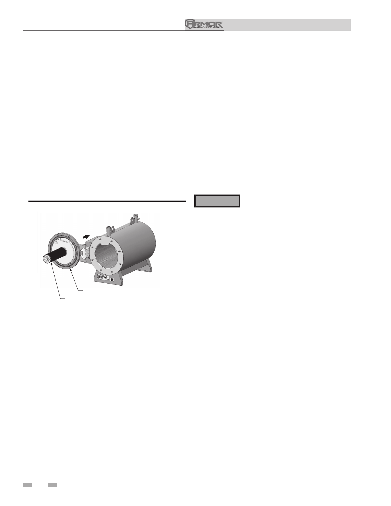
68
Installation & Operation Manual
12 Maintenance
Check burner flame
1. Inspect flame through observation window.
2. If the flame is unsatisfactory at either high fire or low fire,
turn off appliance and allow it to cool down. Remove the
burner and clean it thoroughly using a vacuum cleaner
or compressed air. Do not use compressed air to clean
burner if performed inside a building.
3. Remove the burner, reference FIG. 12-2 below.
4. When replacing the burner, ensure gasket is in good
condition and positioned correctly.
2000548618 00
DIR #2000548618 00
BURNER
ACCESS DOOR
Figure 12-2 Burner Assembly
Perform start-up and checks
1. Start appliance and perform checks and tests specified in
Section 10 - Start-up.
2. Verify cold fill pressure is correct and that operating
pressure does not go too high.
Check flame signal
1. At high fire the flame signal shown on the display should
be at least 8 microamps.
2. A lower flame signal may indicate a fouled or damaged
flame sense electrode. If cleaning the flame sense
electrode does not improve, ground wiring is in good
condition, and ground continuity is satisfactory, replace
the flame sense electrode.
3. See Section 3 - Troubleshooting in the Armor Service
Manual for other procedures to deal with low flame
signal.
Review with owner
1. Emphasize the need to perform the maintenance schedule
specified in this manual.
2. Remind the owner of the need to call a licensed contractor
should the appliance or system exhibit any unusual
behavior.
3. Remind the owner to follow the proper shutdown
procedure and to schedule an annual start-up.
The appliance contains ceramic fiber
materials. Use care when handling these
materials per instructions in the Service
Manual. Failure to comply could result in
severe personal injury.
⚠WARNING
1. Shut down appliance:
• Follow the “To Turn Off Gas to Appliance” instructions
for the appliance in Section 10 - Start-up.
• Do not drain the appliance unless it will be exposed
to freezing temperatures.
2. Allow time for the appliance to cool to room temperature if
it has been firing.
3. Remove the flex duct connecting the venturi to the air box.
Remove the intake air flex duct.
4. Disconnect the gas train at the union and at the venturi.
Loosen the gas train support bracket. Remove the gas
train.
5. Remove the bolts securing the heat exchanger access cover
and set aside.
6. Slide out the heat exchanger door and blower assembly. Pull
the pin to swing the door open.
NOTE: On some models, the front corner post may need
to be removed in order to fully swing the heat exchanger
door open. The corner post can be removed by loosening
the two nuts at the base and the two screws at the top of the
post.
7. Remove the condensate hose from the condensate trap.
Connect a field supplied 1" diameter hose to a drain pan.
Using field supplied means cover the refractory in the back
of the combustion chamber of the heat exchanger.
8. Use a vacuum cleaner to remove any accumulation on the
appliance heating surfaces. Do not use any solvent.
9. Brush the heat exchanger while dry using a nylon bristle
brush. Caution: DO NOT use a metal brush. Re-vacuum
the heat exchanger.
10. Finish cleaning using a clean cloth dampened with warm
water. Rinse out debris with a low pressure water supply.
11. Allow the heat exchanger to thoroughly dry.
12. Remove the field supplied rear refractory cover from the
back of the combustion chamber of the heat exchanger and
reassemble.
Cleaning heat exchanger
For recommended materials; including brush, appropriate
extension(s), refractory cover, and detailed instructions see
Table 12B - Heat Exchanger Cleaning Kit.
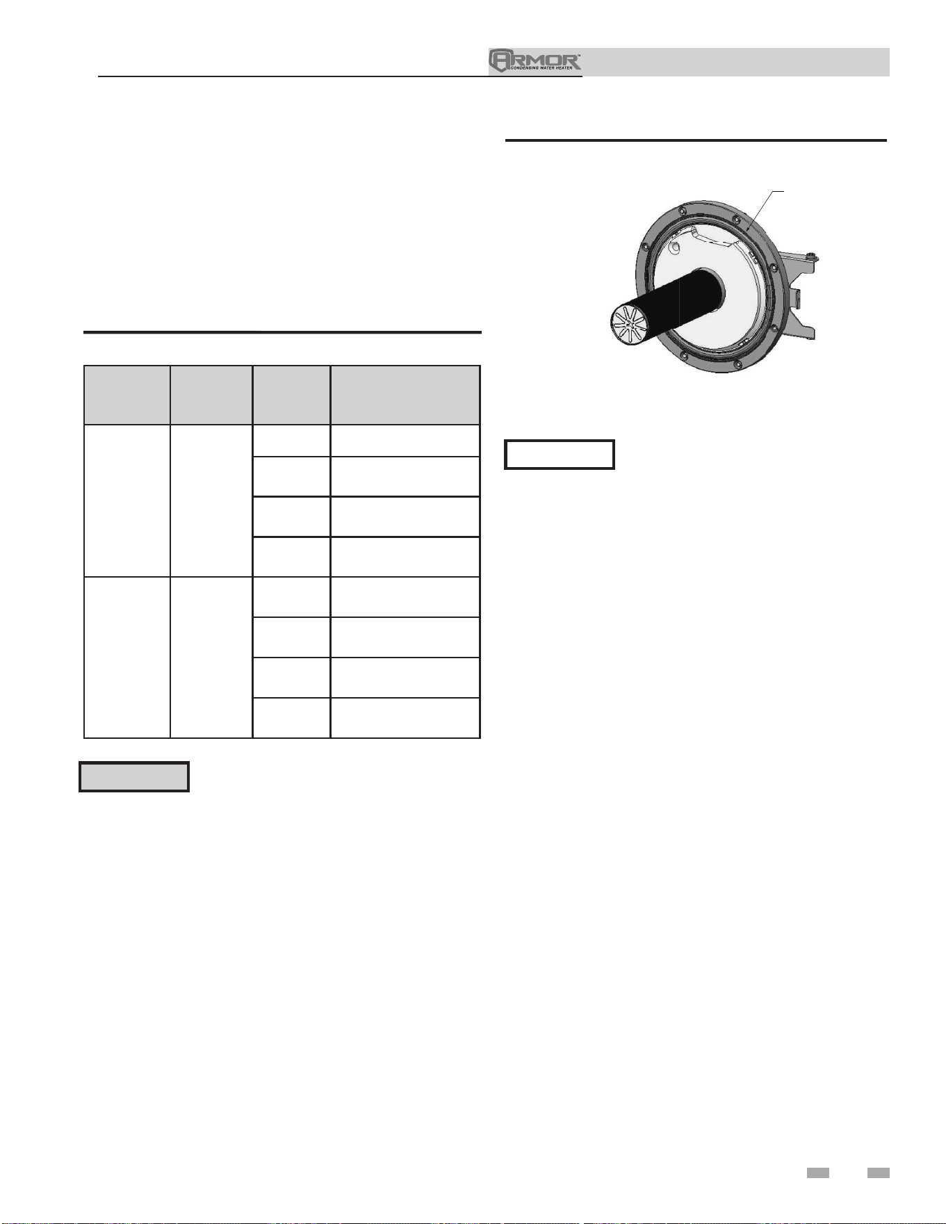
Installation & Operation Manual
69
Oiled bearing circulators
1. The circulator shipped with the Armor appliance is
water-lubricated. No oiling is required.
2. Check other circulators in the system. Oil any circulators
requiring oil, following circulator manufacturer’s
instructions. Over-oiling will damage the circulator.
Check Delta T
1. Check Delta T. Reference Section 6 - System Piping on
page 34 for more information regarding Delta T.
13. Close isolation valves on piping to isolate appliance from
system. Attach a hose to the appliance and drain and flush
appliance thoroughly with clean water by using purging
valves to allow water to flow through the water makeup line
to the appliance.
14. Perform start-up and check-out procedures in the Check
Flame and Combustion - Section 10 - Start-up on pages 50
and 52 of this manual.
15. Replace the access cover and restore appliance to operation.
Table 12B Heat Exchanger Cleaning Kit
Model
Kit
Number
Part
Number
Component
Description
1250 - 2000 100298563
100298574 Rear Refractory Cover
100162565* Nylon 4" Wheel Brush*
100162568
1/4" x 24" Drill
Extension
100162567
1/4" x 12" Drill
Extension
3000 - 4000 100298564
100298575 Rear Refractory Cover
100162565* Nylon 4" Wheel Brush*
100162568
1/4" x 24" Drill
Extension
100162567
1/4" x 12" Drill
Extension
* Do NOT use a metal brush. Only use
the kit-provided brush or an equivalent
replacement nylon brush.
⚠ CAUTION
12 Maintenance (continued)
Rope gasket is intended for sealing
combustion (see FIG. 12-3). If gasket is
damaged DO NOT reuse, the rope gasket
must be replaced. Consult factory for
replacement rope gasket.
NOTICE
DIR #2000548628 00DIR
#
2000548628 0
0
ROPE GASKET
CAUTION: IF GASKET IS DAMAGED
DO NOT REUSE. THE ROPE GASKET
MUST BE REPLACED.
Figure 12-3 Rope Gasket - Heat Exchanger Door
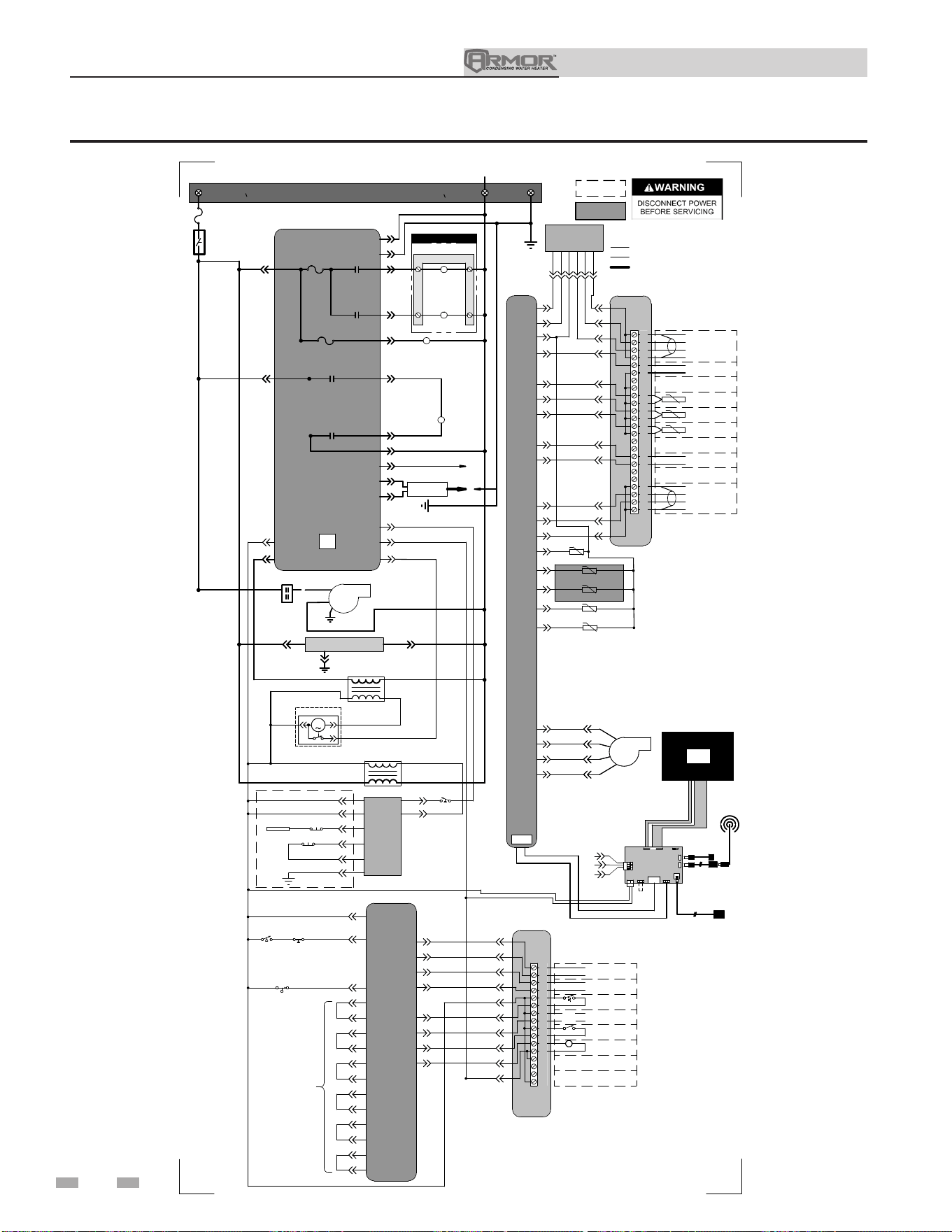
Installation & Operation Manual
13 Diagrams
Figure 13-1 Ladder Diagram - 120V - Models 1250 & 1500
70
JUNCTION BOX
TERMINAL STRIP
120V 1
O
SUPPLY
TERMINAL STRIP
NEUTRAL
INTEGRATED CONTROL
ON/OFF
SWITCH
F4
5.0 A
BUILDING RECIRC
RELAY
DHW PUMP
RELAY
X1-1
X1-4
X1-8
BLOWER
CONTACTOR
GAS
VALVE RELAY
X1-6
X10-1 X10-2
GAS
VALVE RELAY
X10-5
X10-4
GAS
VALVE
TERMINAL STRIP
BUILDING RECIRC
CONTACTOR
DHW PUMP
CONTACTOR
BLOWER
CONTACTOR
BLOWER
X6-10X6-1
4
24V
TRANSFORMER
X6-3
X1-12
X1-3
LWCO
BOARD
TEST
SWITCH
LWCO
PROBE
LWCO RESET
J3-4
J3-3
J2-1
J2-2
J3-5
J3-2
X6-5
X6-6
X3-3
X3-4
X3-2
X3-1
X6-11
X6-2
X6-14
INTEGRATED
CONTROL
LOW GAS
PRESSURE
SWITCH
FLOW
SWITCH
BLOCKED DRAIN
SWITCH
1
2
3
4
5
6
7
8
9
10
11
12
13
14
15
16
ALARM
CONTACTS
RUN-TIME
CONTACTS
TANK
THERMOSTAT
LOUVER
PROVING
24 VAC LOUVER
RELAY COIL
ENABLE
R
W
SMALL
CONNECTION BOARD
CN1-4
CN1-5
CN1-6
CN1-12
CN1-10
X6-13
CN1-11
CN1-9
CN1-8
CN1-7
CN1-1
X1-5
X1-7
X1-10
FLAME
SENSE 1
SPARK
GENERATOR
SPARK
ROD
17
18
19
20
21
22
23
24
25
26
27
28
29
30
31
32
33
34
35
36
37
38
39
40
SHIELD
SHIELD
A
B
BAS
OPTION
+
-
RATE
OUT
SYSTEM RETURN
SENSOR
SYSTEM SUPPLY
SENSOR
0-10V
TANK
SENSOR
+
-
0-10V
BMS
IN
SHIELD
SHIELD
A
B
CASCADE
LARGE
CONNECTION BOARD
CN6-1
CN3-6
CN3-14
CN3-13
CN3-11
CN3-9
CN3-2
CN3-3
CN3-5
CN6-2
CN6-3
CN3-10
CN3-12
X4-1
X4-2
X4-3
X6-3
X6-1
X6-2
X8-10
X8-20
X7-8
X8-13
X8-14
X8-12
INTEGRATED
CONTROL
X8-5
X8-15
X8-7
X8-17
X8-18
-T
-T
-T
-T
INLET SENSOR
OUTLET SENSOR (S9)
OUTLET SENSOR (S1)
FLUE SENSOR
X8-3
X8-8
X8-2
X8-4
GROUND
X6-18
X6-9
X6-17
X6-8
1
5
1.5A EACH MAX
X11
X4
X5-1
X5-7
X5-2
X5-8
X5-3
X5-9
X5-4
X5-10
X5-5
X5-41
X5-6
X5-12
BOX DEPICTS
OPTIONAL ITEMS
BOX DEPICTS
DUAL SENSOR
SINGLE HOUSING
HIGH VOLTAGE
LOW VOLTAGE
120 VAC
Notes:
1. All wiring must be installed in accordance with: local, state, provincial and national code requirements per either N.E.C.
in USA or C.S.A. in Canada.
2. If any original equipment wire as supplied with the appliance must be replaced, it must be replaced with wire having same
wire gauge (AWG) and rated for a minimum of 105°C. Exceptions: Replacement high voltage spark lead and
sheilded
cable
s
must be purchased from the factory. Use of a non-approved spark lead or
sheilded
cables can lead to operational problems
which could result in non-repairable damage to the integrated controller or other components.
3. Actual connector block locations may vary from those shown on diagrams. Refer to actual components for proper
connector block locations when using diagrams to troubleshoot unit.
USB
INTERFACE
"X5"
BLOCK WIRING
IS MODEL
DEPENDANT
L1
1
LADDER DIAGRAM
100293631 REV G
X8-1
CN3-4
OPTIONAL
ETHERNET CABLE
1
4
2
5
BLOWER
E
GND
WIFI
DONGLE
SW1
J2
8
43
J6
J9
J17
J23
J12
J11
LG CON BRD
J8
LCD
DISPLAY
USB CABLE
LCD
DISPLAY
J10
J7
BAS
CN6-1
CN6-3
24V
CN6-2
OPTIONAL USB/WIFI
EXTENSION CABLE
LCD
DISPLAY
X6-4
J2-3
CHASSIS
GROUND
J3-6
-T
FLUE SENSOR
X8-9
120V 1
O
SUPPLY
FLUE DAMPER
TRANSFORMER
X2-5
FLUE DAMPER
21
3
M
X13-4
BAS
BOARD
(AS APPLICABLE)
2-1X1-1X
X1-3
BAS
(AS APPLICABLE)
SHEILDED CABLE FROM X4
TO J12 OR J23 AS APPLICABLE
HIGH GAS
PRESSURE
SWITCH
F2
3.15 A
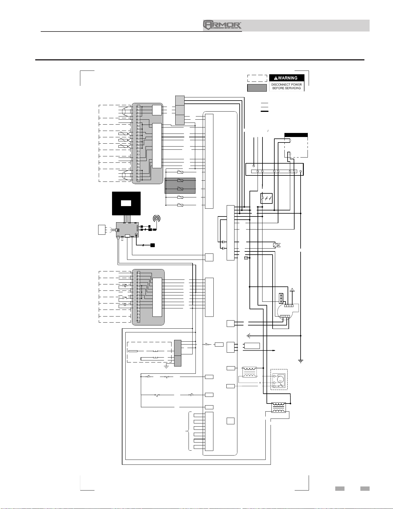
13 Diagrams (continued)
Figure 13-2 Wiring Diagram - 120V - Models 1250 & 1500
71
-T
-T
-T
-T
BOX DEPICTS
OPTIONAL ITEMS
BOX DEPICTS
DUAL SENSOR
SINGLE HOUSING
17
CN3-6
CN6-2
CN3-14
CN6-1
CN3-13
CN3-12
CN3-10
CN3-9
CN6-3
18
19
20
21
22
23
24
25
26
27
28
29
30
31
32
33
34
35
36
37
38
39
40
CN3-2
CN3-5
CN3-3
X7-8
X8-14
X8-13
X8-12
X8-15
X8-5
X8-7
X8-17
X8-18
X8-1
SHIELD
SHIELD
A
B
BAS
OPTION
+
-
RATE
OUT
SYSTEM RETURN
SENSOR
SYSTEM SUPPLY
SENSOR
0-10V
TANK
SENSOR
+
-
0-10V
BMS
IN
SHIELD
SHIELD
A
B
CASCADE
X6-1
X6-2
X6-3
G
R
BL
YG
RO
W
LB
RP
R
Y
R/W
BL
J3-5
J3-4
J3-6
LWCO
BOARD
J3-3
J3-2
J2-1
J2-2
X6-3
O
TEST
SWITCH
LWCO
PROBE
PR
LWCO RESET
X6-5
LOW GAS
PRESSURE
SWITCH
HIGH GAS
PRESSURE
SWITCH
RP
PR
X6-6
BLOCKED DRAIN
SWITCH
RB
X8-3
X8-8
X8-2
X8-4
INLET SENSOR
OUTLET SENSOR (S9)
OUTLET SENSOR (S1)
FLUE SENSOR
X4-1
X4-2
X4-3
X8-10
X8-20
X5-8
X5-7
X5-3
X5-9
X5-2
X5-4
X5-10
X5-5
X5-41
X5-6
X5-12
X5-1
"X5"
BLOCK WIRING
IS MODEL
DEPENDANT
PK
BR
PR
R
X10-1
X1-3
X10-4
X1-1
X1-12
X1-4
X10-2
X10-5
X1-6
ON/OFF
SWITCH
GND
GAS VALVE
BK
W
RB
RO
OR/W
W
X6-18
X6-8
X1-8
G
X6-9
X6-17
BLOWER
R
KB
PR
T
G
X1-7
X1-10
X1-5
FLAME SENSE
SPARK
24V
TRANSFORMER
BK
PK
BL
Y
BK
X1-2
X1-3
X1-1
INTEGRATED CONTROL
LARGE CONNECTION BOARD
SMALL CONNECTION BOARD
JUNCTION
BOX
X11
X4
USB
INTERFACE
DHW PUMP
CONTACTOR
HIGH VOLTAGE
LOW VOLTAGE
120 VAC
1.5A EACH MAX
C1
L1
120V 10
N
2 31
1
2
4
5
3
WIRING DIAGRAM
REV G
CN3-4
OPTIONAL
ETHERNET CABLE
E
GND
SW1
J2
8
43
J9
J17
J23
J12
J11
J8
USB CABLE
OPTIONAL USB/WIFI
EXTENSION CABLE
J10
LCD
DISPLAY
24V
J6
J7
COMMUNICATION
CONTROL BOARD
LG CON BRD
R
PR
GY
CN6-3
CN6-1
CN6-2
BAS
WIFI
DONGLE
G
4
PR
PK
Y
W
X6-4
BL
1
2
3
4
5
6
7
8
9
10
11
12
13
14
15
16
CN1-12
CN1-5
CN1-10
CN1-11
CN1-6
CN1-9
CN1-8
CN1-7
CN1-1
CN1-4
X3-1
X3-4
X6-1
X6-11
X3-2
X6-2
X6-14
X6-13
X6-10
X3-3
ALARM
CONTACTS
RUN-TIME
CONTACTS
TANK
THERMOSTAT
LOUVER
PROVING
24 VAC LOUVER
RELAY COIL
OR
OR
BK
BK
LB
T
R
T/BK
BR
Y
ENABLE
R
W
Y
BL
BK
C1
W
J2-3
T
T
PR
O
O/BK
FLOW
SWITCH
PR
100293620
-T
FLUE SENSOR
GY
X8-9
FLUE DAMPER
TRANSFORMER
FLU DAMPER
BK
BL
OR
1
2
3
M
X2-5
X13-4
BAS
BOARD
(AS APPLICABLE)
SHIELDED CABLE FROM X4
TO J12 OR J23 AS APPLICABLE
Notes:
1. All wiring must be installed in accordance with: local, state, provincial and national code requirements per either N.E.C. in USA or C.S.A. in Canada.
2. If any original equipment wire as supplied with the appliance must be replaced, it must be replaced with wire having same wire gauge (AWG) and rated for a
minimum of 105°C. Exceptions: Replacement high vo ltage spark lead and shielded cables must be purchased from the factory. Use of a non-approved spar
k lead
or shielded cables can lead to operational problems which could result in non-repairable damage to the integrated controller or other components.
3. Actual connector block locations may vary from those shown on diagrams. Refer to actual components for proper connector block locations when using
diagrams to troubleshoot unit.
BUILDING RECIRC
CONTACTOR
OVER-TEMP
SWITCH
Installation & Operation Manual
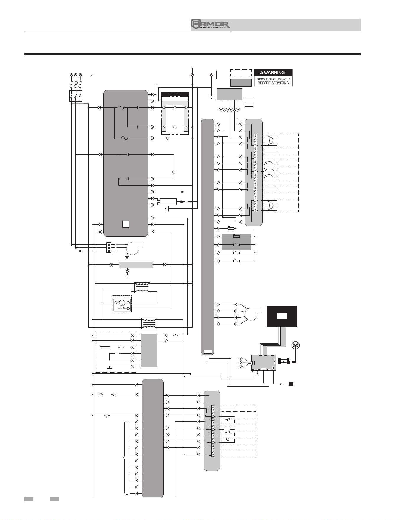
Figure 13-3 Ladder Diagram - 208V - Models 2000 & 3000
13 Diagrams
72
JUNCTION BOX
TERMINAL STRIP
TERMINAL STRIP
NEUTRAL
INTEGRATED CONTROL
ON/OFF
SWITCH
F4
5.0 A
DHW PUMP
RELAY
X1-1
X1-4
X1-8
BLOWER
CONTACTOR
GAS
VALVE RELAY
X1-6
X10-1 X10-2
GAS
VALVE RELAY
X10-5
X10-4
GAS
VALVE
TERMINAL STRIP
DHW PUMP
CONTACTOR
BLOWER
CONTACTOR
BLOWER
X6-10X6-1
4
24V
TRANSFORMER
X6-3
X1-12
X1-3
LWCO
BOARD
TEST
SWITCH
LWCO
PROBE
LWCO RESET
J3-4
J3-3
J2-1
J2-2
J3-5
J3-2
X6-5
X6-6
X3-3
X3-4
X3-2
X3-1
X6-11
X6-2
X6-14
INTEGRATED
CONTROL
LOW GAS
PRESSURE
SWITCH
FLOW
SWITCH
BLOCKED DRAIN
SWITCH
1
2
3
4
5
6
7
8
9
10
11
12
13
14
15
16
ALARM
CONTACTS
RUN-TIME
CONTACTS
TANK
THERMOSTAT
LOUVER
PROVING
24 VAC LOUVER
RELAY COIL
ENABLE
R
W
SMALL
CONNECTION BOARD
CN1-4
CN1-5
CN1-6
CN1-12
CN1-10
X6-13
CN1-11
CN1-9
CN1-8
CN1-7
CN1-1
X1-5
X1-7
X1-10
FLAME
SENSE 1
SPARK
GENERATOR
SPARK
ROD
17
18
19
20
21
22
23
24
25
26
27
28
29
30
31
32
33
34
35
36
37
38
39
40
SHIELD
SHIELD
A
B
BAS
OPTION
+
-
RATE
OUT
SYSTEM RETURN
SENSOR
SYSTEM SUPPLY
SENSOR
0-10V
TANK
SENSOR
+
-
0-10V
BMS
IN
SHIELD
SHIELD
A
B
CASCADE
LARGE
CONNECTION BOARD
CN6-1
CN3-6
CN3-14
CN3-13
CN3-9
CN3-2
CN3-3
CN3-5
CN6-2
CN6-3
CN3-10
CN3-12
X4-1
X4-2
X4-3
X6-3
X6-1
X6-2
X8-10
X8-20
X7-8
X8-13
X8-14
X8-12
INTEGRATED
CONTROL
X8-5
X8-15
X8-7
X8-17
X8-18
-T
-T
-T
-T
INLET SENSOR
OUTLET SENSOR (S9)
OUTLET SENSOR (S1)
FLUE SENSOR
X8-3
X8-8
X8-2
X8-4
GROUND
X6-18
X6-9
X6-17
X6-8
1
5
1.5A EACH MAX
X11
X4
X5-1
X5-7
X5-2
X5-8
X5-3
X5-9
X5-4
X5-10
X5-5
X5-41
X5-6
X5-12
BOX DEPICTS
OPTIONAL ITEMS
BOX DEPICTS
DUAL SENSOR
SINGLE HOUSING
HIGH VOLTAGE
LOW VOLTAGE
120 VAC
USB
INTERFACE
"X5"
BLOCK WIRING
IS MODEL
DEPENDANT
L1
L2 L3
1
2
3
LADDER DIAGRAM
X8-1
CN3-4
OPTIONAL
ETHERNET CABLE
1
4
2
5
BLOWER
E
GND
WIFI
DONGLE
SW1
J2
8
43
J6
J9
J17
J23
J12
J11
LG CON BRD
J8
LCD
DISPLAY
USB CABLE
LCD
DISPLAY
J10
J7
BAS
CN6-1
CN6-3
24V
CN6-2
OPTIONAL USB/WIFI
EXTENSION CABLE
LCD
DISPLAY
X6-4
J2-3
CHASSIS
GROUND
J3-6
208V 3
O
SUPPLY
208V SUPPLY "N"
100293632 REV G
-T
FLUE SENSOR
X8-9
FLUE DAMPER
TRANSFORMER
X2-5
FLUE DAMPER
21
3
M
X13-4
BAS
BOARD
(AS APPLICABLE)
2-1X1-1X
X1-3
BAS
(AS APPLICABLE)
SHEILDED CABLE FROM X4
TO J12 OR J23 AS APPLICABLE
Notes:
1. All wiring must be installed in accordance with: local, state, provincial and national code requirements per either N.E.C.
in USA or C.S.A. in Canada.
2. If any original equipment wire as supplied with the appliance must be replaced, it must be replaced with wire having same
wire gauge (AWG) and rated for a minimum of 105°C. Exceptions: Replacement high voltage spark lead and sheilded cables
must be purchased from the factory. Use of a non-approved spark lead or sheilded cables c
an lead to operational problems
which could result in non-repairable damage to the integrated controller or other components.
3. Actual connector block locations may vary from those shown on diagrams. Refer to actual components for proper
connector block locations when using diagrams to troubleshoot unit.
HIGH GAS
PRESSURE
SWITCH
BUILDING RECIRC
RELAY
BUILDING RECIRC
CONTACTOR
F2
3.15 A
Installation & Operation Manual
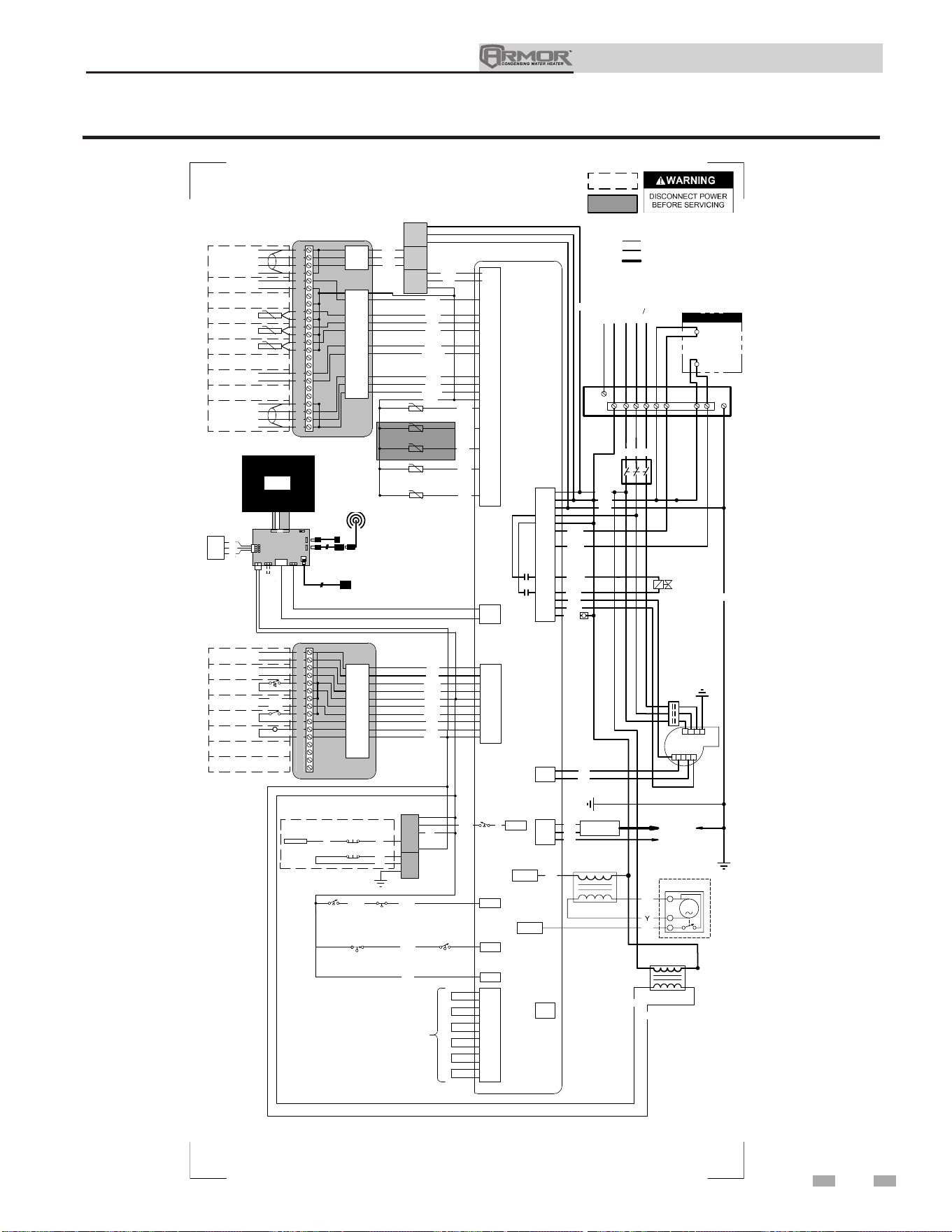
73
13 Diagrams (continued)
Figure 13-4 Wiring Diagram - 208V - Models 2000 & 3000
Installation & Operation Manual
-T
-T
-T
-T
BOX DEPICTS
OPTIONAL ITEMS
BOX DEPICTS
DUAL SENSOR
SINGLE HOUSING
17
CN3-6
CN6-2
CN3-14
CN6-1
CN3-13
CN3-12
CN3-11
CN3-10
CN3-9
CN6-3
18
19
20
21
22
23
24
25
26
27
28
29
30
31
32
33
34
35
36
37
38
39
40
CN3-2
CN3-5
CN3-3
X7-8
X8-14
X8-13
X8-12
X8-15
X8-5
X8-7
X8-17
X8-18
X8-1
SHIELD
SHIELD
A
B
BAS
OPTION
+
-
RATE
OUT
SYSTEM RETURN
SENSOR
SYSTEM SUPPLY
SENSOR
0-10V
TANK
SENSOR
+
-
0-10V
BMS
IN
SHIELD
SHIELD
A
B
CASCADE
X6-1
X6-2
X6-3
G
R
BL
YG
RO
W
LB
PK
RP
R
Y
R/W
BL
J3-5
J3-4
J3-6
LWCO
BOARD
J3-3
J3-2
J2-1
J2-2
X6-3
O
TEST
SWITCH
LWCO
PROBE
PR
LWCO RESET
X6-5
LOW GAS
PRESSURE
SWITCH
RP
PR
X6-6
BLOCKED DRAIN
SWITCH
RB
X8-3
X8-8
X8-2
X8-4
INLET SENSOR
OUTLET SENSOR (S9)
OUTLET SENSOR (S1)
FLUE SENSOR
X4-1
X4-2
X4-3
X8-10
X8-20
X5-8
X5-7
X5-3
X5-9
X5-2
X5-4
X5-10
X5-5
X5-41
X5-6
X5-12
X5-1
"X5"
BLOCK WIRING
IS MODEL
DEPENDANT
PK
BR
PR
R
X10-1
X1-3
X10-4
X1-1
X1-12
X1-4
X10-2
X10-5
X1-6
ON/OFF
SWITCH
GND
GAS VALVE
R
W
RB
RO
OR/W
W
X6-18
X6-8
X1-8
G
X6-9
X6-17
BLOWER
R
KB
PR
T
G
X1-7
X1-10
X1-5
FLAME SENSE
SPARK
GENERATOR
SPARK ROD
24V
TRANSFORMER
BK
PK
BL
Y
R
X1-2
X1-3
X1-1
INTEGRATED CONTROL
LARGE CONNECTION BOARD
SMALL CONNECTION BOARD
JUNCTION
BOX
X11
X4
USB
INTERFACE
DHW PUMP
CONTACTOR
HIGH VOLTAGE
LOW VOLTAGE
120 VAC
1.5A EACH MAX
R/W
BK
C1
L1
L2
L3
208V 30
N
2 31
1
2
4
5
3
WIRING DIAGRAM
100293633 REV G
CN3-4
OPTIONAL
ETHERNET CABLE
E
GND
SW1
J2
8
43
J9
J17
J23
J12
J11
J8
USB CABLE
OPTIONAL USB/WIFI
EXTENSION CABLE
J10
LCD
DISPLAY
24V
J6
J7
COMMUNICATION
CONTROL BOARD
LG CON BRD
R
PR
GY
CN6-3
CN6-1
CN6-2
BAS
WIFI
DONGLE
G
4
PR
PK
Y
W
X6-4
BL
1
2
3
4
5
6
7
8
9
10
11
12
13
14
15
16
CN1-12
CN1-5
CN1-10
CN1-11
CN1-6
CN1-9
CN1-8
CN1-7
CN1-1
CN1-4
X3-1
X3-4
X6-1
X6-11
X3-2
X6-2
X6-14
X6-13
X6-10
X3-3
ALARM
CONTACTS
RUN-TIME
CONTACTS
TANK
THERMOSTAT
LOUVER
PROVING
24 VAC LOUVER
RELAY COIL
OR
OR
BK
BK
LB
T
R
T/BK
BR
Y
ENABLE
R
W
Y
BL
BK
C1
W
J2-3
GND
T
T
PR
FLOW
SWITCH
O
O/BK
-T
X8-9
FLUE SENSOR
GY
FLUE DAMPER
TRANSFORMER
FLU DAMPER
BK
BL
OR
1
2
3
M
X2-5
X13-4
BAS
BOARD
(AS APPLICABLE)
SHIELDED CABLE FROM X4
TO J12 OR J23 AS APPLICABLE
Notes:
1. All wiring must be installed in accordance with: local, state, provincial and national code requirements per either N.E.C. in USA or C.S.A. in Canada.
2. If any original equipment wire as supplied with the appliance must be replaced, it must be replaced with wire having same wire gauge (AWG) and rated for a
minimum of 105°C. Exceptions: Replacement high vo ltage spark lead and shielded cables must be purchased from the factory. Use of a non-approved spar
k lead
or shielded cables can lead to operational problems which could result in non-repairable damage to the integrated controller or other components.
3. Actual connector block locations may vary from those shown on diagrams. Refer to actual components for proper connector block locations when using
diagrams to troubleshoot unit.
HIGH GAS
PRESSURE
SWITCH
BUILDING RECIRC
CONTACTOR
OVER-TEMP
SWITCH
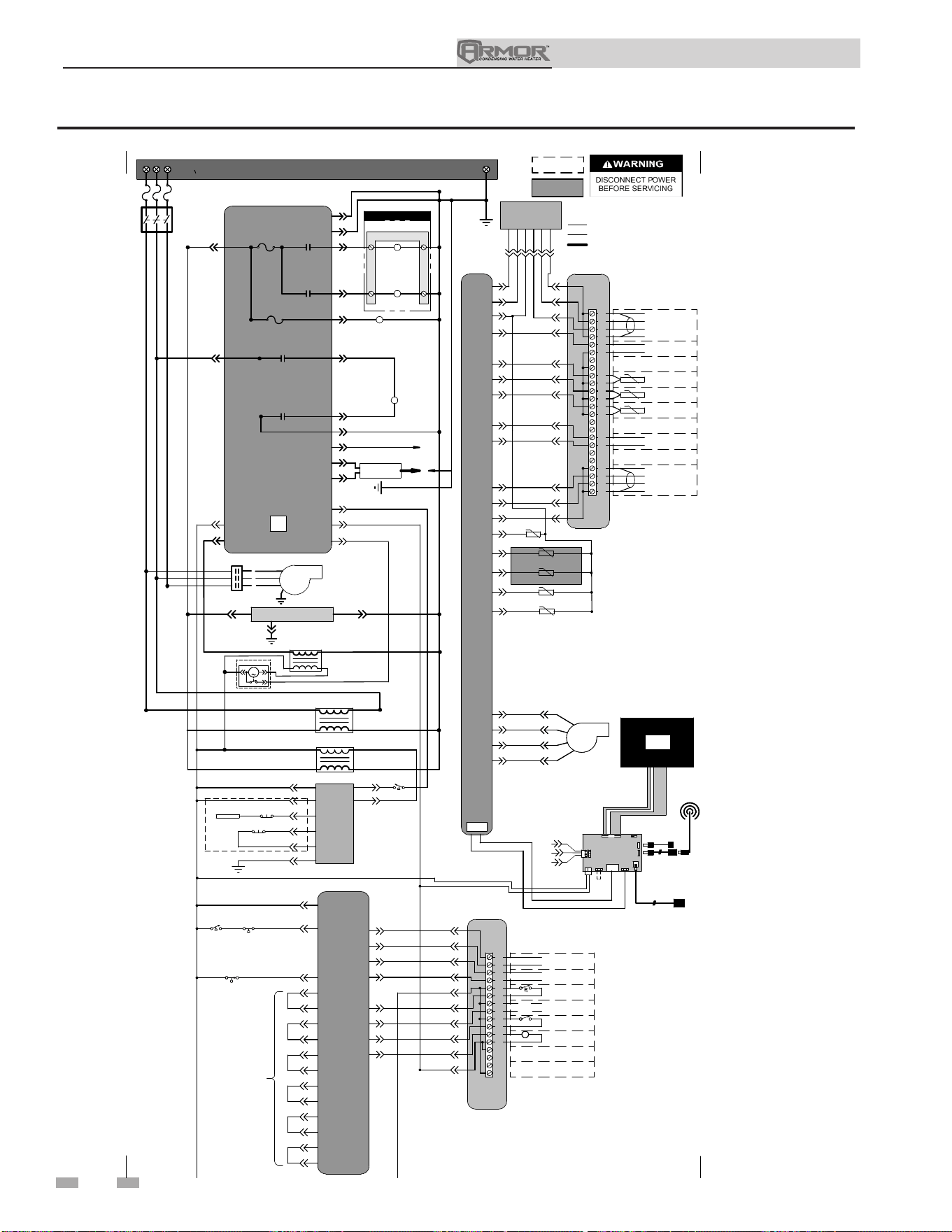
74
13 Diagrams
Figure 13-5 Ladder Diagram - 480V - Model 4000
JUNCTION BOX
TERMINAL STRIP
480V 3
O
SUPPLY
INTEGRATED CONTROL
ON/OFF
SWITCH
F4
5.0 A
SYSTEM PUMP
RELAY
DHW PUMP
RELAY
X1-1
X1-4
X1-8
BLOWER
CONTACTOR
GAS
VALVE RELAY
X1-6
X10-1 X10-2
GAS
VALVE RELAY
X10-5
X10-4
GAS
VALVE
TERMINAL STRIP
DHW PUMP
CONTACTOR
BLOWER
CONTACTOR
BLOWER
X6-10X6-1
4
24V
TRANSFORMER
X6-3
X1-12
X1-3
LWCO
BOARD
TEST
SWITCH
LWCO
PROBE
LWCO RESET
J3-4
J3-3
J2-1
J2-2
J3-5
J3-2
X6-5
X6-6
X3-3
X3-4
X3-2
X3-1
X6-11
X6-2
X6-14
INTEGRATED
CONTROL
LOW GAS
PRESSURE
SWITCH
FLOW
SWITCH
BLOCKED DRAIN
SWITCH
1
2
3
4
5
6
7
8
9
10
11
12
13
14
15
16
ALARM
CONTACTS
RUN-TIME
CONTACTS
TANK
THERMOSTAT
LOUVER
PROVING
24 VAC LOUVER
RELAY COIL
ENABLE
R
W
SMALL
CONNECTION BOARD
CN1-4
CN1-5
CN1-6
CN1-12
CN1-10
X6-13
CN1-11
CN1-9
CN1-8
CN1-7
CN1-1
X1-5
X1-7
X1-10
FLAME
SENSE 1
SPARK
GENERATOR
SPARK
ROD
17
18
19
20
21
22
23
24
25
26
27
28
29
30
31
32
33
34
35
36
37
38
39
40
SHIELD
SHIELD
A
B
BAS
OPTION
+
-
RATE
OUT
SYSTEM RETURN
SENSOR
SYSTEM SUPPLY
SENSOR
0-10V
TANK
SENSOR
+
-
0-10V
BMS
IN
SHIELD
SHIELD
A
B
CASCADE
LARGE
CONNECTION BOARD
CN6-1
CN3-6
CN3-14
CN3-13
CN3-11
CN3-9
CN3-2
CN3-3
CN3-5
CN6-2
CN6-3
CN3-10
CN3-12
X4-1
X4-2
X4-3
X6-3
X6-1
X6-2
X8-10
X8-20
X7-8
X8-13
X8-14
X8-12
INTEGRATED
CONTROL
X8-5
X8-15
X8-7
X8-17
X8-18
-T
-T
-T
-T
INLET SENSOR
OUTLET SENSOR (S9)
OUTLET SENSOR (S1)
FLUE SENSOR
X8-3
X8-8
X8-2
X8-4
GROUND
X6-18
X6-9
X6-17
X6-8
1
5
1.5A EACH MAX
X11
X4
X5-1
X5-7
X5-2
X5-8
X5-3
X5-9
X5-4
X5-10
X5-5
X5-41
X5-6
X5-12
BOX DEPICTS
OPTIONAL ITEMS
BOX DEPICTS
DUAL SENSOR
SINGLE HOUSING
HIGH VOLTAGE
LOW VOLTAGE
120 VAC
USB
INTERFACE
"X5"
BLOCK WIRING
IS MODEL
DEPENDANT
L1
L2 L3
1
2
3
LADDER DIAGRAM
100340689 REV C
X8-1
CN3-4
OPTIONAL
ETHERNET CABLE
1
4
2
5
BLOWER
E
GND
WIFI
DONGLE
SW1
J2
8
43
J6
J9
J17
J23
J12
J11
LG CON BRD
J8
LCD
DISPLAY
USB CABLE
LCD
DISPLAY
J10
J7
BAS
CN6-1
CN6-3
24V
CN6-2
OPTIONAL USB/WIFI
EXTENSION CABLE
LCD
DISPLAY
480V
TRANSFORMER
X6-4
J2-3
CHASSIS
GROUND
J3-6
-T
FLUE SENSOR
X8-9
FLUE DAMPER
TRANSFORMER
FLUE DAMPER
21
3
M
X2-5
X13-4
BAS
BOARD
(AS APPLICABLE)
2-1X1-1X
X1-3
BAS
(AS APPLICABLE)
SHEILDED CABLE FROM X4
TO J12 OR J23 AS APPLICABLE
Notes:
1. All wiring must be installed in accordance with: local, state, provincial and national code requirements per either N.E.C.
in USA or C.S.A. in Canada.
2. If any original equipment wire as supplied with the appliance must be replaced, it must be replaced with wire having same
wire gauge (AWG) and rated for a minimum of 105°C. Exceptions: Replacement high voltage spark lead and sheilded cables
must be purchased from the factory. Use of a non-approved spark lead or sheilded cables c
an lead to operational problems
which could result in non-repairable damage to the integrated controller or other components.
3. Actual connector block locations may vary from those shown on diagrams. Refer to actual components for proper
connector block locations when using diagrams to troubleshoot unit.
HIGH GAS
PRESSURE
SWITCH
F2
3.15 A
BUILDING RECIRC
CONTACTOR
Installation & Operation Manual
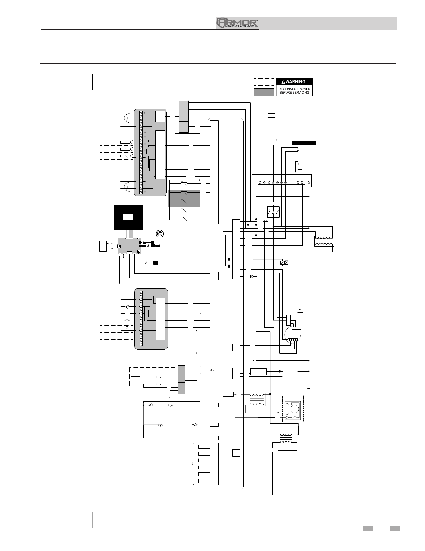
13 Diagrams (continued)
Figure 13-6 Wiring Diagram - 480V - Model 4000
75
Installation & Operation Manual
-T
-T
-T
-T
BOX DEPICTS
OPTIONAL ITEMS
BOX DEPICTS
DUAL SENSOR
SINGLE HOUSING
17
CN3-6
CN6-2
CN3-14
CN6-1
CN3-13
CN3-12
CN3-10
CN3-9
CN3-8
CN6-3
18
19
20
21
22
23
24
25
26
27
28
29
30
31
32
33
34
35
36
37
38
39
40
CN3-1
CN3-2
CN3-5
CN3-3
X7-8
X8-14
X8-13
X8-12
X8-15
X8-5
X8-7
X8-17
X8-18
X8-1
SHIELD
SHIELD
A
B
BAS
OPTION
+
-
RATE
OUT
SYSTEM RETURN
SENSOR
SYSTEM SUPPLY
SENSOR
0-10V
TANK
SENSOR
+
-
0-10V
BMS
IN
SHIELD
SHIELD
A
B
CASCADE
X6-1
X6-2
X6-3
G
R
BL
YG
RO
W
LB
PK
RP
R
Y
R/W
BL
J3-5
J3-4
J3-6
LWCO
BOARD
J3-3
J3-2
J2-1
J2-2
X6-3
O
TEST
SWITCH
LWCO
PROBE
PR
LWCO RESET
X6-5
LOW GAS
PRESSURE
SWITCH
HIGH GAS
PRESSURE
SWITCH
RP
PR
X6-6
BLOCKED DRAIN
SWITCH
RB
X8-3
X8-8
X8-2
X8-4
INLET SENSOR
OUTLET SENSOR (S9)
OUTLET SENSOR (S1)
FLUE SENSOR
X4-1
X4-2
X4-3
X8-10
X8-20
X5-8
X5-7
X5-3
X5-9
X5-2
X5-4
X5-10
X5-5
X5-41
X5-6
X5-12
X5-1
"X5"
BLOCK WIRING
IS MODEL
DEPENDANT
PK
BR
PR
R
X10-1
X1-3
X10-4
X1-1
X1-12
X1-4
X10-2
X10-5
X1-6
ON/OFF
SWITCH
GND
GAS VALVE
BR
W
RB
RO
OR/W
W
X6-18
X6-8
X1-8
G
X6-9
X6-17
BLOWER
R
KB
PR
T
X1-7
X1-10
X1-5
FLAME SENSE
SPARK
GENERATOR
SPARK ROD
24V
TRANSFORMER
BK
PK
BL
Y
R
X1-2
X1-3
X1-1
INTEGRATED CONTROL
LARGE CONNECTION BOARD
SMALL CONNECTION BOARD
JUNCTION
BOX
X11
X4
USB
INTERFACE
DHW PUMP
CONTACTOR
HIGH VOLTAGE
LOW VOLTAGE
120 VAC
1.5A EACH MAX
R/W
C1
L1
L2
L3
480V 30
2 31
1
2
4
5
3
WIRING DIAGRAM
100340782 REV D
CN3-4
OPTIONAL
ETHERNET CABLE
E
GND
SW1
J2
8
43
J9
J17
J23
J12
J11
J8
USB CABLE
OPTIONAL USB/WIFI
EXTENSION CABLE
J10
LCD
DISPLAY
24V
J6
J7
COMMUNICATION
CONTROL BOARD
LG CON BRD
R
PR
GY
CN6-3
CN6-1
CN6-2
BAS
WIFI
DONGLE
G
4
PR
PK
Y
W
X6-4
BL
1
2
3
4
5
6
7
8
9
10
11
12
13
14
15
16
CN1-12
CN1-5
CN1-10
CN1-11
CN1-6
CN1-9
CN1-8
CN1-7
CN1-1
CN1-4
X3-1
X3-4
X6-1
X6-11
X3-2
X6-2
X6-14
X6-13
X6-10
X3-3
ALARM
CONTACTS
RUN-TIME
CONTACTS
TANK
THERMOSTAT
LOUVER
PROVING
24 VAC LOUVER
RELAY COIL
OR
OR
BK
BK
LB
T
R
T/BK
BR
Y
ENABLE
R
W
Y
BL
W
J2-3
GND
T
T
PR
O
O/BK
BK
G
480V
TRANSFORMER
FLOW
SWITCH
-T
X8-9
FLUE SENSOR
GY
FLUE DAMPER
TRANSFORMER
FLU DAMPER
BK
BL
OR
1
2
3
M
X2-5
X13-4
BAS
BOARD
(AS APPLICABLE)
SHIELDED CABLE FROM X4
TO J12 OR J23 AS APPLICABLE
Notes:
1. All wiring must be installed in accordance with: local, state, provincial and national code requirements per either N.E.C. in USA or C.S.A. in Canada.
2. If any original equipment wire as supplied with the appliance must be replaced, it must be replaced with wire having same wire gauge (AWG) and rated for a
minimum of 105°C. Exceptions: Replacement high vo ltage spark lead and shielded cables must be purchased from the factory. Use of a non-approved spar
k lead
or shielded cables can lead to operational problems which could result in non-repairable damage to the integrated controller or other components.
3. Actual connector block locations may vary from those shown on diagrams. Refer to actual components for proper connector block locations when using
diagrams to troubleshoot unit.
BUILDING RECIRC
CONTACTOR
OVER-TEMP
SWITCH

Revision Notes: Revision A (PCP #3000022340 / CN #500012474)
initial release.
Revision B (PCP #3000024735 / CN #500014579) reflects an update to
information on pages 12, 18, 20, 23, 33, 38-39, and 44.
Revision C (PCP #3000026430 / CN #500016316) reflects the addition
of Figure 7-3 on page 41.
Revision D (PCP #3000028201 / CN #500017801) reflects an update to
all of the user interface screens, an update to Table 6B on page 34, and
an update to the ladder and wiring diagrams.
Revision E (PCP #3000030213 / CN #500019446) reflects the addition
of the table of PVC adapter kits in FIG. 3-3 on page 21 as well as some
updates to the outdoor installation information on pages 12 and 23.
Revision F (PCP #3000030779 / CN #500020179) reflects an update
to the piping diagrams, Table 10A, Table 12A, and the addition of the
building recirculation filter on page 34. The 23° vent terminations on
pages 26 through 29 were also updated.
Revision G (PCP #3000033465 / CN #500022172) reflects the
addition of the neutral wiring reference on page 44.
Revision H (PCP #3000033789 / CN #500022617) reflects the input
rates and output rates are revised to match AHRI rounding and comply
with Energy Star turndown rate requirements.
Revision J (PCP #3000035946 / CN #500024660) reflects the addition of
the air filter replacement procedure.
Revision K (PCP #3000037183 / CN #500025582) reflects an update to
the line voltage diagrams in Figure 8-1.
Revision L (PCP #3000038559 / CN #500026649) reflects an update to
the water heater sensor material number.
Revision M (PCP #3000043460 / CN #500031150) reflects an update to
the ladder and wiring diagrams, fuse amperage information, and general
water heater standard updates.
Revision N (PCP #3000048432 / CN #500035749) reflects a correction
about replacing the Rope Gasket in Figure 12-3 on page 65.
Revision P (PCP #3000046794 / CN #500034183) reflects an update
to the verbiage in the note in Table 3A-2 Approved Stainless Steel
Terminations and Adapters - Category IV on page 18.
Revision R (PCP #3000049393 / CN #500036574) reflects the combining
of tables on page 6.
Revision T (PCP #3000052551 / CN #500039466) reflects an update to
Table 3A-1 and Table 3A-2.
Revision U (PCP #3000053179 / CN #500039996) reflects the addition
of pages 13 through 15.
Revision V (PCP #3000054410 / CN #500041125) reflects a change to
the warnings on page 7.
Revision W (PCP #3000055885 / CN #500042300) reflects a change to
the ladder diagrams on pages 70, 72, and 74.
Revision X (PCP #3000058272 / CN #500044398) reflects an update of
the ANSI standard.
Revision Y (PCP #3000060820 / CN #500046810) reflects the addition
of a dielectric notice to page 37.
Revision AA (PCP #3000068392 / CN #500053899) reflects the removal
of inoperable functions.
Revision AB (PCP #3000068121 / CN #500053624) reflects updated
wiring diagrams.
100298689_2000552691_Rev AB
10/25