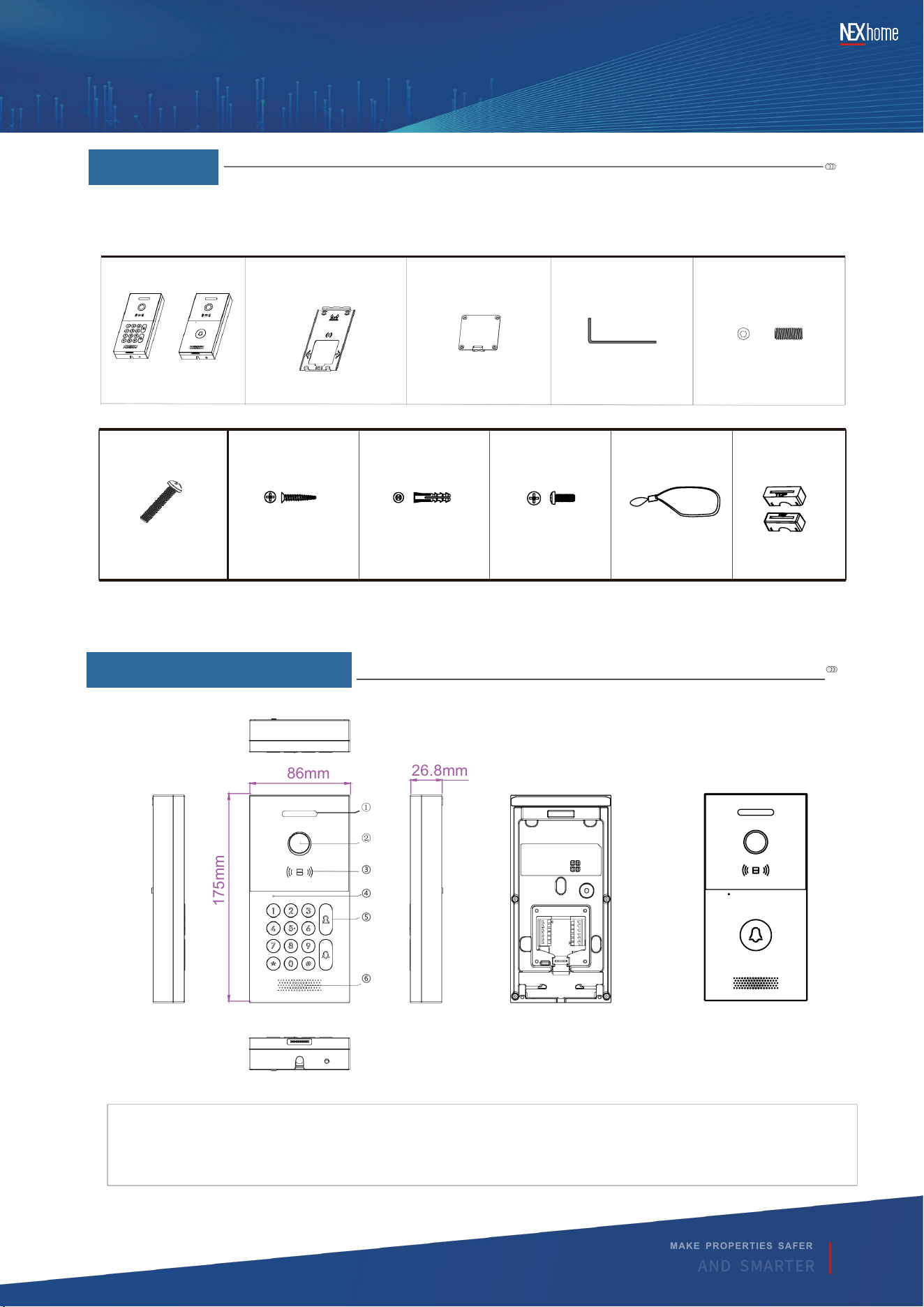
①
②
③
④
⑤
⑥
86mm
175mm
26.8mm
DH-H90 series quick guide
Screws (M4X30)
×2
Screws (ST4X20)
×4
Expansion pipe
×4
Screws (M4X10)
×4
Lanyard
×1
Compression
seal gasket
×2
Main engine
Wall-Mounting
Bracket
Wiring Cover Plate
Hexagon Spanner
Screws (M4X10.5)
③ Card swipe area
★
Note: Please select accessories according to the actual installation method, and pack the accessories
separately from the host.
2
|
PRODUCT
OVERVıEW
PRODUCT
OVERVIEW
Please prepare the corresponding accessories according to the installation method before installation.
( ) List in the host packaging box
DH-H90K
DH-H90S
×1 ×1 ×1 ×1 ×1
1
|
Preface
MAKE PRO PERTIES SAFE R
A N D S M A R T E R
② Camera
⑥ Speaker
① Fill light
⑤ Button
PREFACE
④ Microphone
1
or
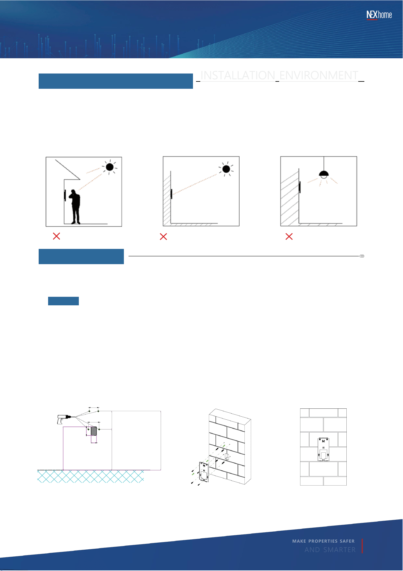
INSTALLATION ENVIRONMENT
The device can be installed in an outdoor or indoor environment. The following points should be noted:
Outdoor installation: Avoid exposing the equipment to direct sunlight, high temperature willcause
damage to the equipment and components.
Indoor installation: The equipment should be installed 2 meters away from the light source and 3
meters away from doors or Windows.
1◆No pre-installed back box
①At the shaded areas (wall outlet locations), chisel a 30 mm × 50 mm × 30 mm deep rectangular
recess. Drill four 5 mm holes, 30 mm deep, at the positions shown.
②Drive the four plastic anchors into the holes; fix the wall bracket with four ST4×20 cross-recess
countersunk self-tapping screws. Route all required cables through the bracket.
③Surface-mounted wall bracket installation complete.
Ground
vertical incident solar rays
Get close to the light
DH-H90 series quick guide
4
|
ıNSTALLATıON
3
|
ıNSTALLATıON ENVıRONMENT
MAKE PROPER TIES SAFER
AND SMARTER
INSTALLATION
In-wall installation
be in a poor light
Step1
1232.5mm
1322.5mm
1217.5mm
10 5m m
6 0 m m
3 0 m m
5 0 m m
5 0m m
2
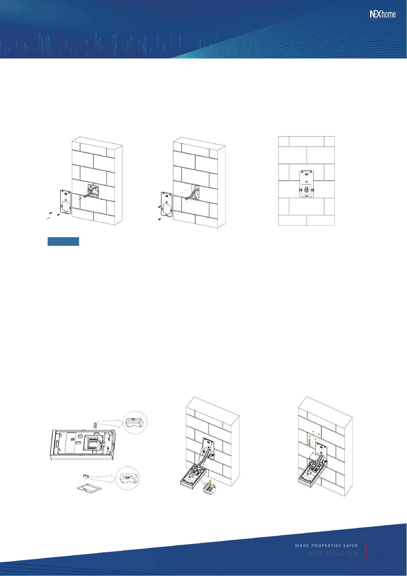
①Insert the silicone grommet marked "BOT" into the bottom-housing rib until fully seated.
Insert the grommet marked "TOP" into the cover rib until fully seated.
②Hook the lanyard to the wall-bracket front lip; loop the other end around the rear side hooks of
the main unit. Route cables from the flush box to the corresponding ports (press the button post
before plugging).
③Dress the wiring, fit the terminal cover, and secure it with four M2.5×6 pan-head screws.
④Align the unit’s hanging slots with the three bracket hooks, push flat and slide down; tighten the
M4×10.5 set-screw underneath with the supplied hex key.
⑤Installation complete.
①
②
③
2◆ Use either an 8 6 mm flush box or a 1-gang fl ush box (US standard).
①Secure the wall bracket to the flush box with two M4×30 cross-recess countersunk machine
screws; route all required cables from the box through the bracket.
②Surface -mounted wall bracket installation complete.
or
DH-H90 series quick guide
M A K E P R O P E R T I E S S A F E R
A N D S M A R T E R
Step2
3
DH-H90 series quick guide
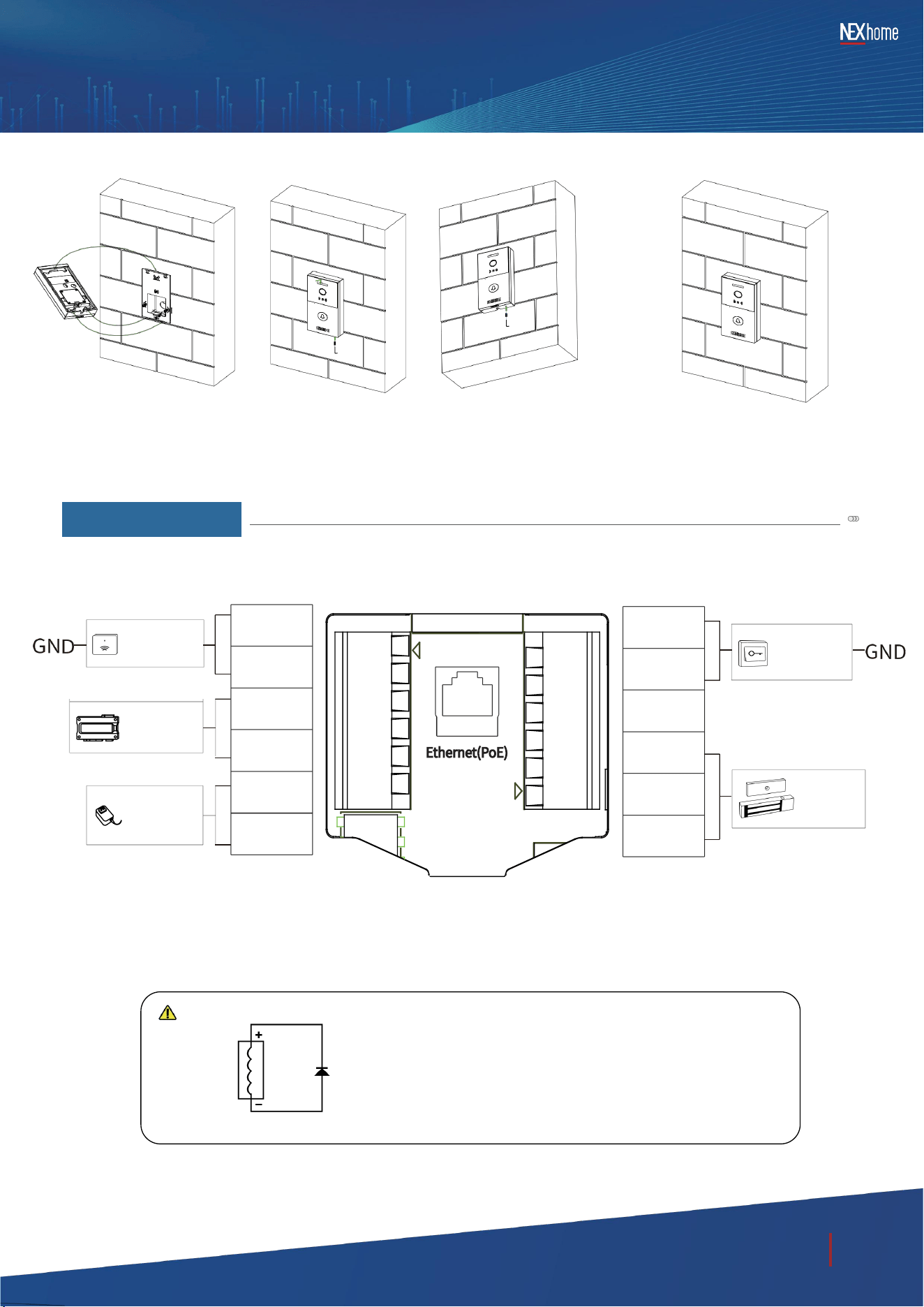
When the door machine is connected to a lock or relay and
other coil- equipped equipment, it is recommended to
connect a 1A/ 50 0V diode (in the accessory packaging bag) in
reverse parallel with the lock or relay and other
coil -equi pped equ ipmen t t o pr otect the door mach ine from
inte rferen ce c aused by the r everse peak vol tage genera ted
at the mome nt of di scon nection.
④ ⑤
5
|
INTERFACES
INTERFACES
Ethernet(PoE)
DOOR1
DOOR2
GND
NC
COM
NO
Ele vato r
Con tro l De vice
WG1
WG0
485A
485B
GND
12V
Gate Lock
Power Supply
Voltage
O p e n t h e
i n n e r d o o r
T h e W e i g a n d
C a r d R e a d e r
MAKE PRO PERTIES SAFE R
A N D S M A R T E R
wa rn ing
D io d eLo ck
4
6
|
CONFıGURATıONS
CONFIGURATIONS
l Che ck IP A ddre ss
Pre ss on t he d ev ice c all bu tto n an d ho ld for 5 secs, the device will br oadcast the lP address digits by v oice
l
Se t SI P Ac co u nt
Log into We b c onfi gu rati on po rta l o f d evi ce, se t up a nd r eg iste r S lP acco unts in lNT ERCOM-ACCOUNT.
l S e t D T M F C o d e
Select DTMF mode a nd confi fi gure the c ode in S YSTEM- RELAY page of Web confi guration p ortal.
★
Note: Refer to the user manual for details.
7
|
FUNCTıONS
FUNCTIONS
l Card/ BLE/ QR Code/ PIN Unlock
Notice: Using BLE Unlock: open the App and BLE setting on the phone, then press Unlock button to
unlock.
l DTMF Unlock
Attach the saved access card or keyfob on the card reader area of DH-H90 to unlock the door.
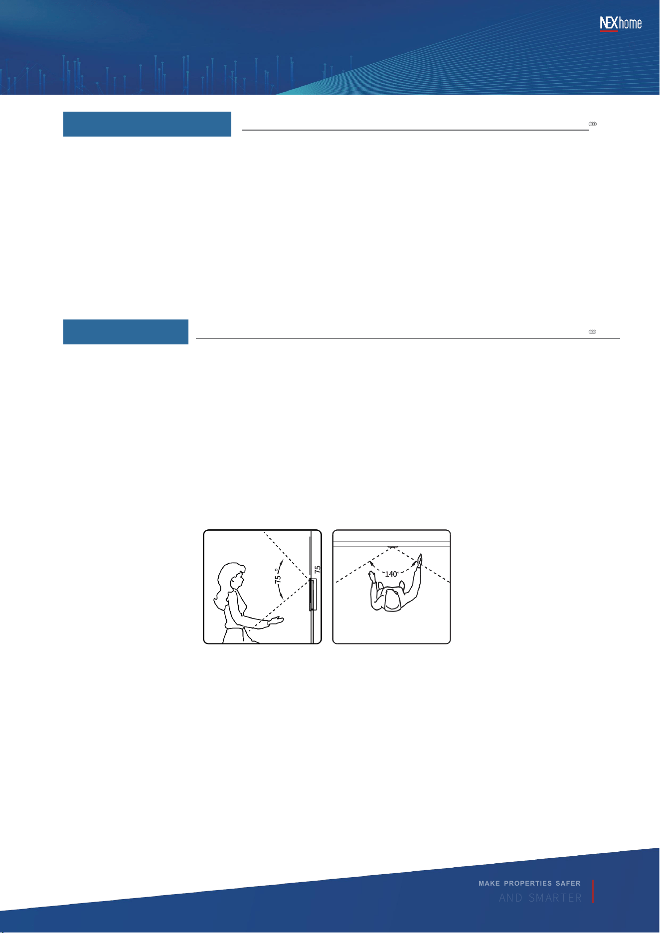
l Wide-angle camera
DH-H90 series quick guide
Viewing Angle
MAKE PRO PERTIES SAFE R
A N D S M A R T E R
5
DH-H90 series quick guide
NEXhome Smart Technologies Co.,Ltd.
Address: 7th Floor,A Bldg Star-Net Plaza, No.33 Xingang Avenue,High-tech Zone,Fuzhou, Fujian, China
Web:www. nexhome.ai
The in formation contained in this document is accurate and reliable at the time of publi-
cation and will not be notified separately if any changes are made. The updated content
of this docum ent can be viewed on the NEXhome website.
The final inte rpretation right b elongsto NEXhome.
MAKE PRO PERTIES SAFE R
A N D S M A R T E R
6
Not e: T his equi pmen t ha s be en te sted and fou nd t o co mply wi th th e li mits fo r a C lass B
dig ital dev ice, purs uant to part 15 o f th e FC C Ru les. The se li mit s are des igne d to
pro vide rea sona ble prot ecti onag ains t har mfu l in terf eren ce i n a resi denti al i nsta llat ion.
Thi s eq uipm ent gener ates , us es an d ca n ra diat e ra dio freq uenc y e nergy and , if no t
ins talle d an d us ed i n ac cord ance wi th th e in stru ctio ns,m ay c ause har mful int erf erenc e
to radi o co mmu nica tion s. H owev er, ther e is no guar antee tha t in terf erenc e w ill not
occ ur in a part icu lar insta llat ion.
If this equ ipme nt d oes caus e har mfu l in terf eren ce t o ra dio or t elev isio n re cept ion ,
whi ch c an b e de term ined by turn ing the e qui pmen t of f an d on , th e us er i s enc our aged
to try to c orre ct t he i nterf ere nce by o ne o r mo re of t he f ollo win g me asur es:
—Re ori ent o r re loc ate t he r ecei ving ant enna.
—In crea se th e se para tion bet ween the equi pme nt an d re ceiv er.
—Connect the equipment into an outlet on a circuit different from that to which the
receiver is connected.
—Consult the dealer or an experienced radio/TV technician for help.
Any Changes expressly or modifications not approved by the party responsible for
compliance could void the user's authority to operate the equipment. This device
complies with part 15 of the FCC Rules. Operation is subject to thefollowing two
conditions:
(1) Thi s dev ice may not cau se ha rmfu l i nter fere nce, and
(2) this dev ice must acc ept any inte rfer ence rec eive d, i nclu din g int erf erenc e th at m ay
cau se u ndes ired ope rati on.
FCC Rad iati on E xpos ure State ment :
Thi s eq uipm ent comp lies wit h FC C rad iati on expo sure lim its set f orth fo r an
unc ontr olle d en viro nmen t .
Thi s tra nsmi tter mus t no t be co- loc ated or o pera ting in conj unc tion wit h an y ot her
ante nna or t rans mitte r.
Thi s eq uipm ent shou ld b e in stall ed a nd o pera ted with min imum dis tanc e 20c m
bet ween the radi ator &y ou b ody .