
Air Conditioner Service Manual
Multi Inverter Air Conditioner
Service Manual
Models:
YN020GLSI24M2G
YN040GLSI24M4G
YN030GLSI24M3G
YN050GLSI24M5G

Air Conditioner Service Manual
1.
Technical Information ........................................................................................................... 2
1.1 Summary ....................................................................................................................................... 2
CONTENTS
2.
Unit Dimension ...................................................................................................................... 3
2.1 ODU Dimension ............................................................................................................................ 3
2.2 IDU Dimension .............................................................................................................................. 4
1
3.
Refrigerant System Diagram ................................................................................................ 6
4.
Electrical Parts ...................................................................................................................... 7
4.1 Wiring Diagram ............................................................................................................................. 7
4.2 ODU PCB Printed Diagram .......................................................................................................... 9
4.3 Function and Control ................................................................................................................. 11
5.
Installation Manual .............................................................................................................. 17
5.1 Installation for Service ............................................................................................................... 17
5.2 Installation Precautions ............................................................................................................. 22
5.3 Installation Preparation .............................................................................................................. 27
5.4 Unit Installation ........................................................................................................................... 34
5.5 Electrical Installation .................................................................................................................. 52
5.6 Test Run ....................................................................................................................................... 53
6.
Troubleshooting Guide ....................................................................................................... 55
6.1 Error Codes ................................................................................................................................. 55
6.2 Troubleshooting ......................................................................................................................... 58
7.
Indoor and Outdoor Unit Disassembly ............................................................................. 81
7.1 Outdoor Unit Disassembly ........................................................................................................ 81
7.2 Indoor Unit Disassembly ........................................................................................................... 86
8.
Thermistor Temperature Characteristics ....................................................................... 100

Air Conditioner Service Manual
YN030GLSI24M3G
YN040GLSI24M4G
YN050GLSI24M5G
1. Technical Information
1.1 Summary
Outdoor Unit
YN020GLSI24M2G
2
Air Conditioner Service Manual
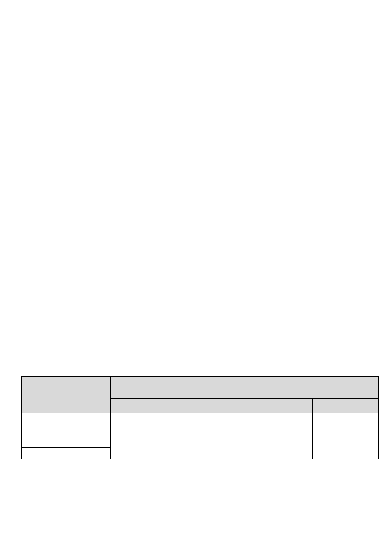
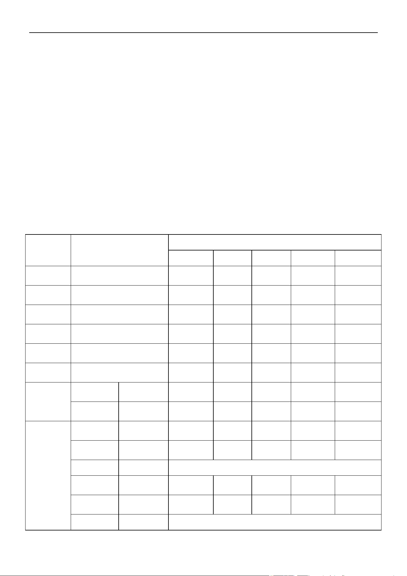
Outdoor Model
W x H x D
A B
YN020GLSI24M2G
YN030GLSI24M3G
YN040GLSI24M4G
YN050GLSI24M5G
2. Unit Dimensions
2.1 ODU Dimensions
Outdoor Unit Dimensions
inch (mm)
Mounting Dimensions
inch (mm)
36½ x 27½ x 14¾ (927 x 699 x 375)
38¾ x 31¾ x 16¼ (984 x 804 x 412)
43⅛ x 33¾ x 19⅜ (1,094 x 858 x 494)
23⅛ (586)
23⅞ (607)
26 (660)
13¾ (348)
15⅜ (390)
18¼ (462)
3

Air Conditioner Service Manual
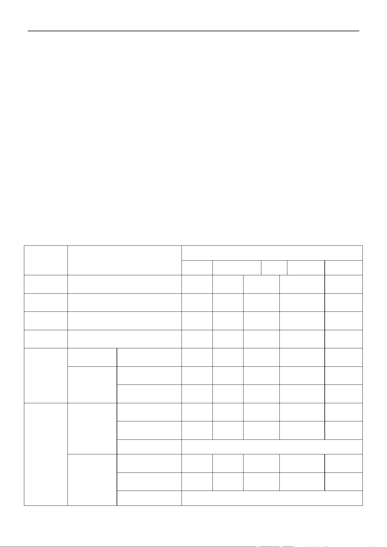
Unit: inch (mm)
Model
A
H
9-18K
9⅝ (245) 5⅛ - 5¼ (130-135)
24K
Dimensions
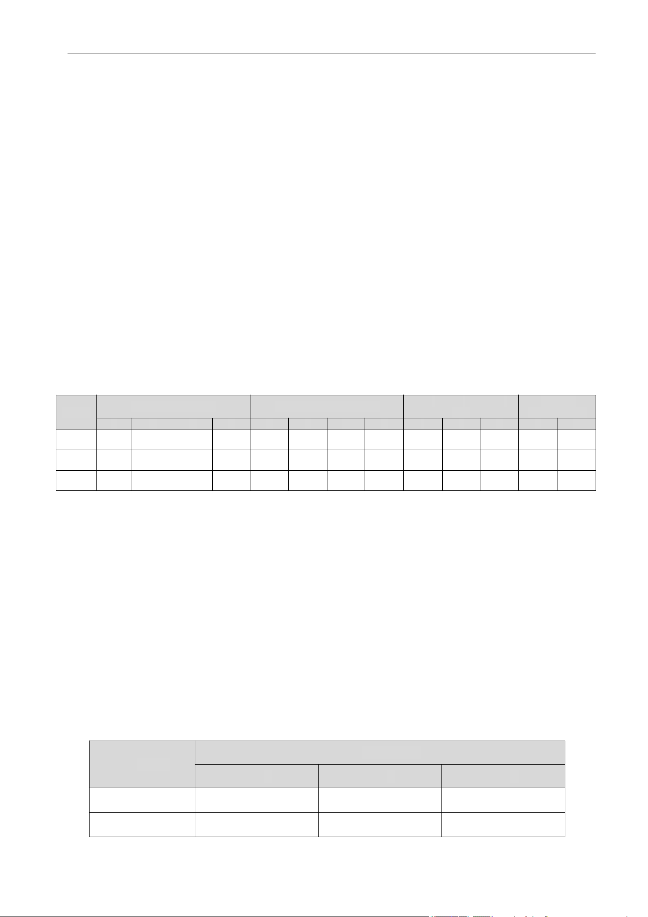
2.2 IDU Dimensions
Cassette
9⅝ (245) 5⅛ - 5¼ (130-135)
4
Air Conditioner Service Manual
Unit: inch (mm)
Model
A B C D E F G H I J K L M
9~12K
27⅝ (700)
7⅞ (200) 19¼ (490) 17¾ (450) 1¾ (45)
20⅛ (510)
¾ (17)
5½ (140)
23⅝ (600) 7⅜ (187) 1⅜ (35) 29⅛ (738) 11¾ (298)
18K
36¼ (920) 28¾ (730) 32¼ (820) 37¾ (958)
24K 43¼ (1100)
1⅛ (27)
36⅝ (930) 40⅝ (1030) 7¼ (183) 37¾ (960)
14⅜ (365)
Model
A B C
18K 41½ (1053)
26⅝ (675)
9¼ (235)
24K
Floor-Ceiling Flex
Ductable Concealed
Unit: inch (mm)
Outline Dimension
Air Outlet Opening Size
Air Return Opening Size
Mounted Lug Size
7⅞ (200)
7⅞ (200)
19¼ (490)
19¼ (490)
17¾ (450)
17¾ (450)
1¾ (45) ¾ (17)
¾ (17)
5½ (140)
5½ (140)
7⅜ (187) 1⅜ (35)
1⅜ (35)
11¾ (298)
Indoor Unit
41½ (1053)
26⅝ (675)
9¼ (235)
5
Air Conditioner Service Manual
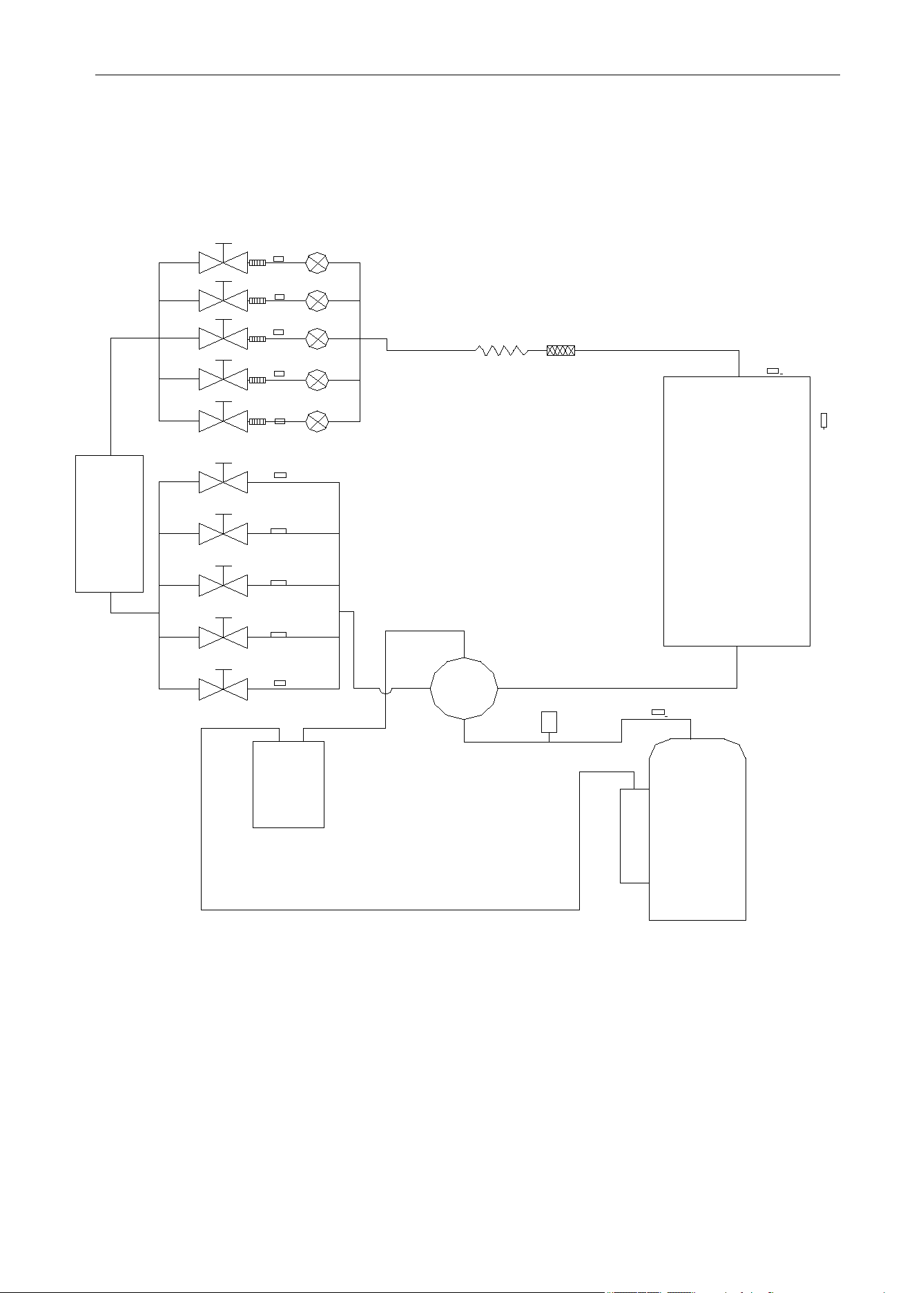
TIN3
TIN4
PMV3
PMV4
TIN5
PMV5
T2B2
T2B3
T2B4
T2B5
ST
Condenser
T3
T4
TP
HP
Compressor
Optional
Evaporator
T2B1
TIN2
TIN1
PMV2
PMV1
Liquid
storage
port
3. Refrigerant System Diagram
The schematic diagram of the Free Match Series Inverter Heat Pump System:
Reference: YN050GLSI24M5G
6

Air Conditioner Service Manual
YN030GLSI24M3G
4. Electrical Parts
4.1 Wiring Diagram
Outdoor Unit
YN020GLSI24M2G
7

Air Conditioner Service Manual
YN040GLSI24M4G
YN050GLSI24M5G
8
Air Conditioner Service Manual
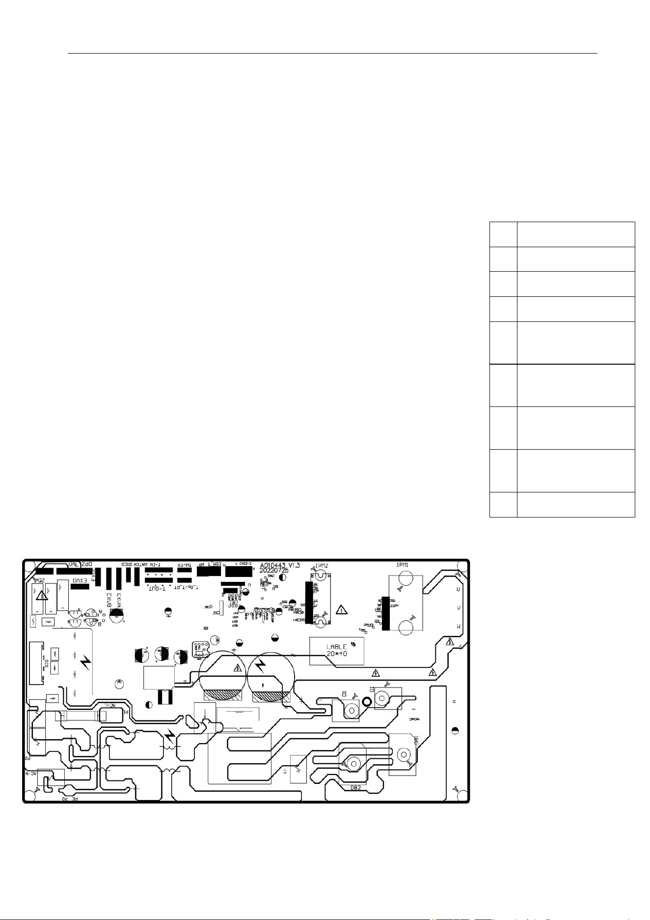
1
4-way valve
2 Heater
3
L, N and
communication
4 Fuse
5
6
7
8
9
LED5
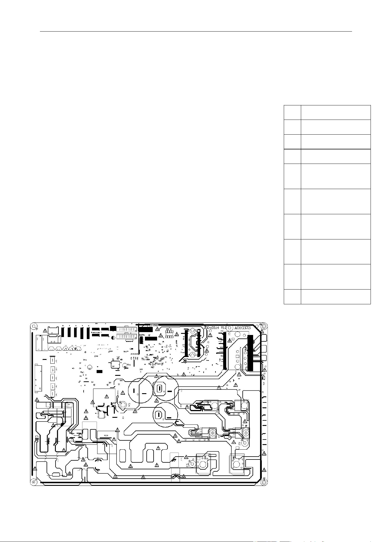
4.2 ODU PCB Printed Diagram
Model Numbers: YN020GLSI24M2G | YN030GLSI24M3G | YN040GLSI24M4G
ODU PCB main relay
DC and AC motor
connector
Discharge sensor
connector
OAT/OPT sensor
connector
Top view:
Bottom view:
9
Air Conditioner Service Manual
1
4-way valve
2
Heater
3
L, N and
communication
4
Fuse
5
6
7
Electronic
expansion valve
8
9
10
LED5
Model Numbers: YN050GLSI24M5G
Top view:
Bottom view:
ODU PCB main relay
DC and AC motor
connector
Discharge sensor
connector
OAT/OPT sensor
connector
10
Air Conditioner Service Manual
4.3 Function and Control
1) Cooling Mode Operation
Compressor Frequency Control
According to the difference of the room temperature and set temperature (δt = RT-ST), the running frequency of
the compressor is controlled by the electric controller.
When the room temperature is considerably higher than the set temperature, the compressor will start
operating at a high frequency. As the room temperature decreases, the compressor running frequency will also
decrease. When the room temperature is lower than the set temperature, the compressor will operate at a
significantly low frequency.
In general, the unit will change its running frequency according to δt, adjusting the room temperature closer to
the set temperature.
Outdoor Temperature Affects the Running Frequency of the Compressor
The outdoor temperature affects the running frequency of the compressor. The compressor's running frequency
is adjusted based on the difference in the outdoor unit's inlet temperature. When the outdoor temperature is
about 86°F(30°C), the compressor will operate in high frequency.
If the unit operates in Cooling mode and the outdoor temperature is less than 28.4°F(-2°C), the controller will
shutdown the compressor and show the error code. When the ambient temperature is above 33.8°F(1°C), the
compressor will automatically operate.
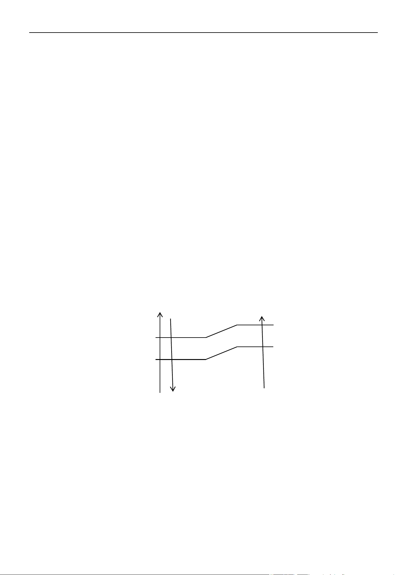
Auto Fan Control in Cooling Mode
In Cooling and Feel mode, the fan speed is determined by δt as the following diagram:
δt come up
δt come down
High fan
Min fan
Low fan
2) Dry Mode Operation
The system for Dry operation uses the same refrigerant circle as the Cooling operation.
When the system operates Dry mode, it begins by operating in Cooling mode. The set temperature is "RT 28.4°
F(-2°C)". After, the system operates in Cooling mode with the lowest fan speed. During the duration of the
operation, the remote controller cannot adjust the fan speed. However, the vane direction can be controlled.
In Dry mode, when RT≤53.6°F(12°C), the compressor stops and begins operating again at RT≥57.2°F(14°C).
11
°F(°C)
39.2°F(4°C)
37.4°F(3°C)
34.7°F(1.5°C)
33.8°F(3°C)
Air Conditioner Service Manual
3) Heating Mode Operation (Heat Pumps Only)
Frequency Control
Similarly to the frequency control in Cooling mode, the running frequency of the compressor is managed by the
remote controller. The unit changes its running frequency according to δt, making the room temperature closer
to the set temperature.
Indoor Fan Motor Control
Cold Air Prevention Control
• This function is intended to prevent cold air from being discharged when Heating mode is selected or
defrosting is occurring.
• The indoor fan speed will be controlled as the following:
Temperature up
Temperature down
Setting
Low fan
Breeze
Stop
• In the Heating operation, if the air conditioner is turned Off, the indoor fan motor will run for 30s after the
compressor stops operating.
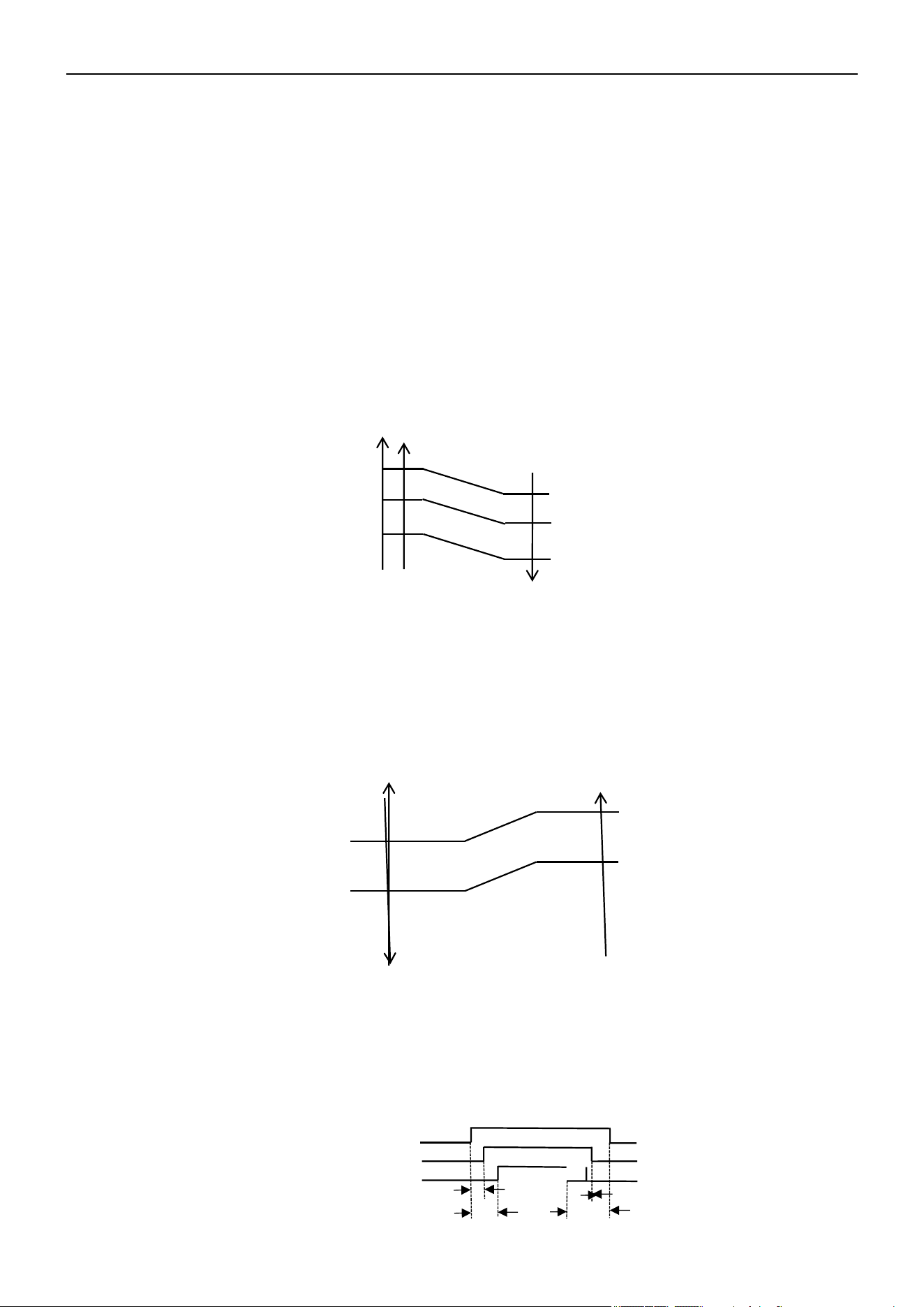
Auto Fan Control (Heating)
In Heating and Feel mode, the fan speed is determined by δt as the following:
RT-S
δt come up
4.0
3.0
1.5
1.0
δt come down
High fan
Min fan
Low fan
4-Way Valve Control
In Heating mode, the 4-way valve will power On 8s before the compressor and cut Off 2 min later than the
compressor. The 4-way valve will not power On unless the machine is switched Off, the mode changes, or the
defrosting process is active.
3s
30s
120s
On
Off
On
On
Off
Off
12
98.6°F(37°C)
91.4°F(33°C)
77°F(25°C)
91.4°F(33°C)
77°F(25°C)
68°F(20°C)
4-Way Valve
Outdoor Fan Motor
Compressor
Air Conditioner Service Manual
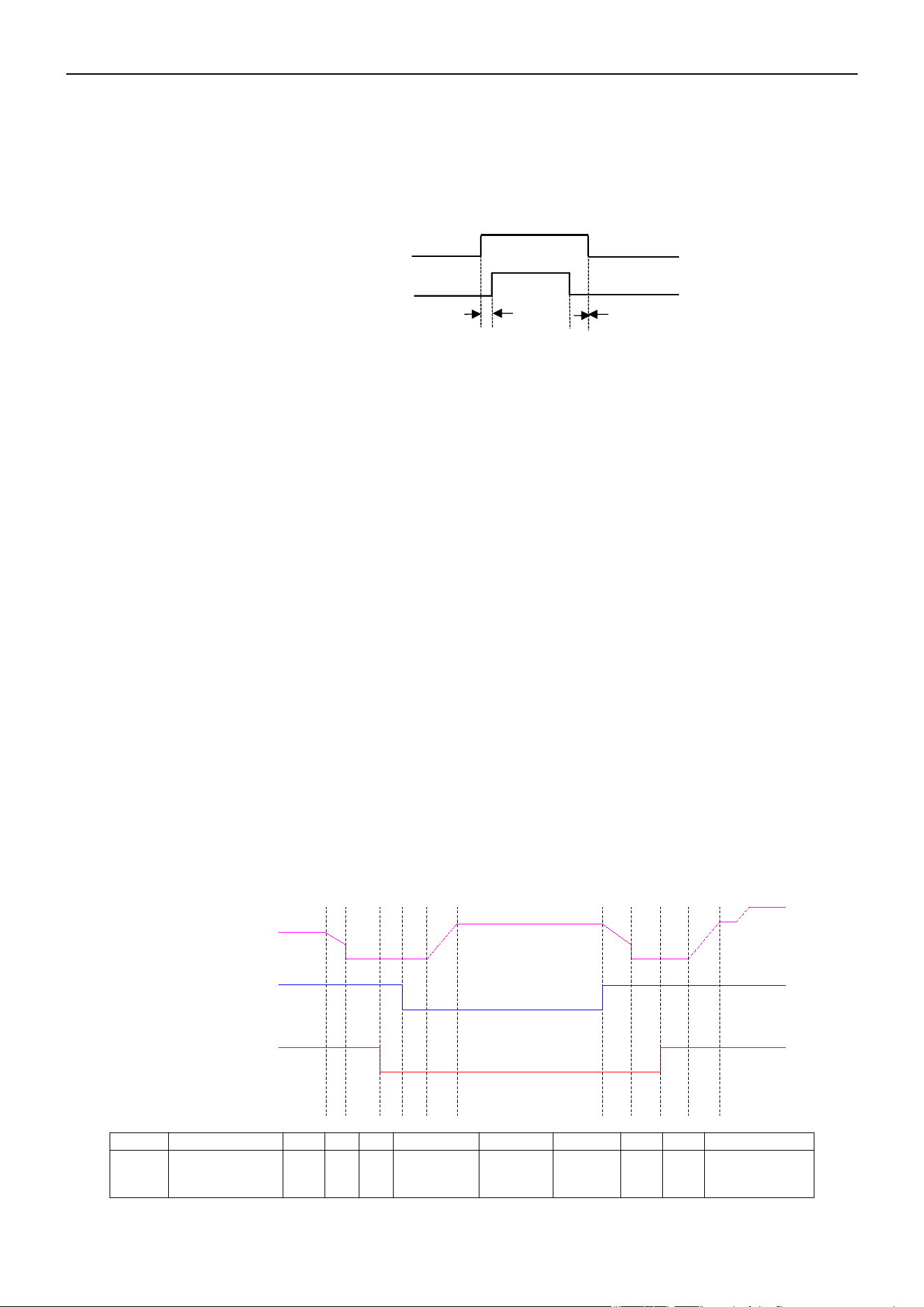
Outdoor Fan Motor Control
In Heating mode, the outdoor fan will power On 5s ahead of the compressor, and cut Off 30s later than the
compressor.
5s
30s
On
On
Off
Off
Outdoor fan motor
Compressor
Defrosting
Defrosting is controlled by the microprocessor.
When the unit operates for 30 min total, the compressor operation is more than 3 min continuously, and one
of the following conditions are met, the unit will enter the Defrosting mode:
• When FrostDeg ≥ 23°F(-5°C) and OPT ≤ 23°F(-5°C), the .2 times defrosting interval time is 45 min.
• When 14°F(-10°C) ≤ FrostDeg < 14°F(-10°C) and OPT < FrostDeg, the .2 times defrosting interval time is
45 min.
• When 8.6°F(-13°C) ≤ FrostDeg < 14°F(-10°C) and OPT < FrostDeg, the .2 times defrosting interval time is
45 min.
• When 5°F(-15°C) ≤ FrostDeg < 8.6°F(-13°C) and OPT < FrostDeg, the .2 times defrosting interval time is
65 min.
• When 5°F(-15°C) ≤ FrostDeg < 14°F(-10°C) and OPT < FrostDeg, the .2 times defrosting interval time is
75 min.
• When FrostDeg < 5°F(-15°C) and OPT < 5°F(-15°C), the .2 times defrosting interval time is 75 min.
FrostDeg: C*OAT-α
OAT: Outdoor environment temperature
When OAT < 32°F(0°C), C = 0.8
When OAT ≥
32°F(0°C), C = 0.6 α=8
Before the air con enters the Defrosting mode, the compressor running frequency drops down to a lower
frequency first, then the compressor shuts down.
In Defrosting mode, all protection functions are available.
T1 T2 T3 T4 T5 T7 T8 T9 T10T6
Compressor Frequency
Outdoor Fan Motor
4-Way Valve
On
Off
On
Off
On
Off
Defrost Hightest Frequency
T
T1
T2 T3 T4
T5
T6 T7 T8 T9 T10
Times
50s 5s 5s
Rise
frequency
2-11 min
Stop
defrost
50s 10s
Rise
frequency
13
Drop frequency
or stop

Air Conditioner Service Manual
• The indoor fan speed is set at low speed, the power and sleep lamps are On, and the display of the
temperature will close after 30s.
• If the Cooling/Dry operation is selected with Sleep mode, the set temperature will raise by 33.8°F(1°C) 1 hour
later
and by 35.6°F(2°C) 2 hours later. After 3 hours, the set temperature will raise by 37.4°F(3°C) and remain
for 2 hours. Then the set temperature increases by 35.6°F(2°C). After 1 hour, the set temperature remains.
• If the Heating operation is selected with Sleep mode, the step temperature will decrease by 33.8°F(1°C) 1
hour later and by 35.6°F(2°C) 2 hours later. After 3 hours, the step temperature will decrease by 37.4°F(3°C)
and remain for 2 hours. Then the set temperature decreases by 35.6°F(2°C). After 1 hour, the set
temperature remains.
In Defrosting mode, the LED display shows the mode by blinking.
Regardless of when the AC enters or exits Defrosting mode, the indoor fan motor speed remains the same as
the Cold Air Prevention Control.
If one of the following conditions are met, the units exits Defrosting mode, and changes to Heating mode:
• Outdoor coil temperature (OPT) > 41°F(5°C) and maintains for 30s.
• Outdoor coil temperature (OPT) > 50°F(10°C) and maintains for 2s.
• Continues the defrosting operation for 11 min.
Indoor Exchanger Overheat Protection
If the indoor exchanger temperature (IPT) is higher than 129.2°F(54°C), the unit enters indoor exchanger
overheat protection. The compressor drops its frequency.
If IPT ≥ 149°F(65°C) and maintains for 30s, the control system shuts down the compressor. The compressor
recovers while the IPT drops less than 125.6°F(52°C).
4) Sleep Mode
When the "Sleep" button is pressed, the AC operates as the following:
5) Emergency Operation
Pressing the Emergency Operation switch activates different modes with distinct sound signals:
Cooling mode: A short "beep" sound.
Heating mode: Two short "beep" sounds.
Unit off: A long sound (approximately 3s).
If the unit is in emergency operation, when the unit receives the signal of the remote controller, the unit will only
operate by the controller.
When the remote is missing or has no battery power, press the Emergency Operation switch on the front of the
indoor unit for a function test.
Note: Do not press the Emergency Operation switch during normal operation.
6) Auto-Restart Function (Optional)
When the air conditioner is operating in one mode, all of its operation data will be memorized into the IC by the
main PCB, such as the operation mode, preset temperature, etc. If the power supply is interrupted and then
recovers, the Auto-Restart function will activate and the air conditioner will resume operation in its previous
mode.
14

Air Conditioner Service Manual
9) Protection and Failure Display
• When the protection display is available, the remote controller will show an error code. The digital LED
shows the error code and setting temperature by turns.
• If there is more than one failure, it will show error codes according to the error list sequence.
• To ensure the signal communication of the indoor and outdoor units, any failure code related to the outdoor
unit will display for 2 min after it's recovered.
• The sensor failure can be recovered automatically after it becomes normal.
8) Water Pump Control (Cassette and Duct Type)
When the unit operates in Cool or Dry mode, the water pump turns On. Once the compressor turns Off or
changes to another mode, the water pump stops after 10 min. When the unit checks if the water level is full, the
unit stops and displays the water full code. When full water protection is eliminated, the pump operates for 10
min and then turns Off. When the water pump switch is open for 8s continuously, the system will enter water full
protection. When the water pump switch is On for 180s continuously, the water full protection stops.
a. Pull the air-con's plug out of the socket.
b. Press and hold the emergency button (On/Off) on the indoor unit. Then insert the plug into the socket again.
c. Press and hold the emergency button for more than 10s until 3 short beeps are heard. The beeps indicate
the Auto-Restart function has been activated.
d. During the operation, press the timer button 10 times in 8s to turn Off the Auto-Restart function.
7) Auto-Restart Pre-Setting (Optional)
If the Auto-Restart function is needed, follow these steps to activate this function:
15

Air Conditioner Service Manual
3) Discharge Temperature Protection
A temperature sensor is located on the discharge pipe. When the temperature on the discharge pipe exceeds
the limit of 239°F(115°C), the system control will shut down the compressor and the display board will show the
error code.
4) Lower Voltage Protection
When AC voltage < 160V or DC voltage < 170V, the unit will shut down and recover while AC voltage < 255V or
DC voltage < 390V.
5) Over-voltage Protection
When AC voltage > 275V or DC voltage > 400V, the unit will shut down and recover while AC voltage < 255V or
DC voltage < 390V.
6) Overcurrent Protection
When the current of the outdoor unit is overloaded, the controller will drop the operation frequency or
immediately shut down the unit and show the error code.
7) Condenser Temperature Protection
When the condenser temperature ≥ 149°F(65°C) and keeps for 10s, the air conditioner will shut down and show
the error code. The air conditioner will recover while the condenser temperature < 125.6°F(52°C) and the
compressor stops operating for 3 min.
8) IPM Module Protection
The IPM module has high-temperature and overcurrent protection. If there is signal feedback to the IPM, the
outdoor unit will shut down. The LED display on the outdoor PCB will show the error code.
9) Evaporator Freeze Protection
When the evaporator temperature < 35.6°F(2°C), the controller will drop compressor operate frequency. When
the evaporator temperature < 32°F(0°C) and maintains for 1 minute, the expand value of the unit will stop
operating. When the entire operating unit enters freeze protection, the compressor will stop and recover.
2) Time Delay for Safety Protection
A. 3-min delay for the compressor: The compressor stops for 3 min before restarting in order to balance the
pressure in the in the refrigeration cycle. The delay will protect the compressor.
B. 150s delay for the 4-way valve: The 4-way valve stops for 150s after the compressor delay, preventing the
refrigerant-gas abnormal noise when the Heating operation is Off or switches to another operation.
1) Mode Conflict Protection for the Indoor Units
When the setting mode is different for each indoor unit, the system runs in the following status:
A. The system mode is determined by the indoor unit that turns On first, except if the indoor unit is in Fan mode.
Cooling/Drying mode conflicts with Heating mode.
B. If the first indoor unit is in Fan mode and the second indoor unit is in Cooling or Heating mode, then the
system will run in Cooling or Heating mode.
Protection Function
16

Air Conditioner Service Manual
5. Installation Manual
5.1 Installation for Service
1) Check the information in this manual to find out the dimensions of the space needed for proper installation of
the device, including the minimum distances allowed compared to adjacent structures.
2) The appliance must be installed, operated, and stored in a room with a floor area larger than 13.1 ft (4m).
3) Keep the installation of the pip-work to a minimum.
4) Protect the pipe-work from physical damage. Do not install the pipe-work in a unventilated space if the area is
small than 13.1 ft (4m).
5) Comply with the national gas regulations
6) Ensure the mechanical connections are accessible for maintenance purposes.
7) Follow the instructions given in this manual for handling, installing, cleaning, maintaining, and disposing of the
refrigerant.
8) Ensure that the ventilation openings are clear of obstructions.
9) Notice: Only perform service as recommended by the manufacturer.
10) Warning: Store the appliance in a well-ventilated area where the room size corresponds to the room area
specified for the operation.
11) Warning: Store the appliance in a room without continuously operating open flames, such as an operating
gas appliance. In addition, store the appliance in a room without ignition sources, such as an operating electric
heater.
12) Store the appliance properly to prevent mechanical damage from occurring.
13) Individuals working on a refrigerant circuit must have a valid and up-to-date certificate from an assessment
authority accredited by the industry, recognizing their competence in handling refrigerants. The individual's work
on the refrigerant circuit must be in accordance with the assessment specifications. The service operations must
be carried out in accordance with the recommendations of the equipment manufacturer. Maintenance and repair
operations that require the assistance of other qualified individuals must be conducted under the supervision of
the person competent in using flammable refrigerants.
14) Only competent individuals shall carry out working procedures that affect safety.
15) Warning:
17
• Do not use any means to accelerate the defrosting process or clean the frost. Follow the recommended
guidelines from the manufacturer.
• Do not store the appliance in a room with continuously operating ignition sources, such as open flames, an
operating gas appliance, or an operating electric heater.
• Do not pierce or burn the appliance.
• Keep in mind that refrigerants may not contain an odor.

Air Conditioner Service Manual
16) Servicing Information:
Inspect the Area
Before working on systems containing flammable refrigerants, safety checks are required to ensure the risk of
ignition is minimized. The following precautions must be complied with prior to conducting repairs on the system.
Work Procedure
To minimize the risk of flammable gas or vapor presence, you must conduct work using controlled procedures.
General Work Area
All maintenance staff and individuals working in the local area must be informed about the nature of the work
being performed. Avoid working in confined spaces. Section off the area around the workspace. Ensure the area
is safe by controlling flammable materials.
Check for Refrigerant
The area must be checked with an appropriate refrigerant detector before and during work to ensure the
technician is aware of potentially flammable atmospheres. Ensure the leak detection equipment is suitable for
flammable refrigerants, i.e. non-sparking, adequately sealed, or intrinsically safe.
Fire Extinguisher
If you need to conduct hot work on the refrigeration equipment or any associated parts, appropriate fire
extinguishing equipment must be available. Keep a dry powder or CO2 fire extinguisher adjacent to the charging
area.
No Ignition Sources
Individuals carrying out work involving exposed pipework on a refrigerant system are prohibited from using any
sources of ignition that may lead to a risk of fire or explosion. All possible ignition sources, such as cigarette
smoking, must be performed at a sufficient distance from the installation or maintenance site. Before conducting
work on the equipment, the surrounding area must be surveyed to ensure there are no flammable hazards or
ignition risks. No Smoking signs must be displayed.
18

Air Conditioner Service Manual
Well-Ventilated Area
Ensure the area is open and well-ventilated before accessing the system or performing any work that generates
heat. Ventilation must be maintained to a certain degree while work is being carried out. The ventilation should
safely disperse any released refrigerant and expel it externally into the atmosphere.
Inspect the Refrigeration Equipment
When changing electrical components, they must be fit-for-purpose and meet the correct specifications. You
must follow the manufacturer's maintenance and service guidelines at all times. If in doubt, consult the
manufacturer's technical department for assistance.
For installations using flammable refrigerants, check the following:
--- Ensure the charge size is appropriate for the room in which the refrigerant-containing parts are installed.
--- Confirm the ventilation machinery and outlets are operating adequately and not obstructed.
--- If an indirect refrigerating circuit is being used, check the secondary circuit for the presence of refrigerant.
--- Confirm the equipment markings are visible and legible. Correct markings and signs that are illegible.
--- Ensure the refrigeration pipe or components are installed in a position that minimizes the risk of corrosion
from harmful substances, unless constructed of corrosion-resistant materials and suitably protected.
Inspect the Electrical Devices
Repairing and maintaining electrical components must include initial safety checks and component inspections.
If a fault exists that could compromise safety, then the electrical supply must not be connected to the circuit until
the fault is resolved. If the fault cannot be immediately corrected but it is necessary to continue operation, a
temporary solution must be implemented. If a temporary solution is implemented, it must be reported to the
owner of the equipment, ensuring both parties are informed.
Initial safety checks must include the following:
--- Confirm the capacitors are discharged. Ensure this is done in a safe manner to avoid the possibility of
sparking.
--- Ensure that no live electrical components and wiring are exposed while charging, recovering, or purging the
system.
--- Confirm there is continuity of earth bonding.
17) Repairs to Sealed Components
During repairs to sealed components, disconnect all electrical supplies from the equipment being worked on
prior to the removal of sealed covers, etc. If having an electrical supply to the equipment during service is
necessary, use a permanently operating form if leak detection, which should be located at the most crucial point.
When working on electrical components, ensure the casing is not altered in a way that will affect the level of
protection. This includes damage to cables, excessive number of connections, terminals not meeting the original
specifications, damage to seals, incorrect fitting of glands, etc. Ensure that the seals or sealing materials have
not degraded to the point of being unserviceable for preventing the ingress of flammable atmospheres.
Replacement parts must be in accordance with the manufacturer's specifications.
Note: Using silicon sealant may inhibit the effectiveness of certain types of leak detection equipment.
Intrinsically safe components do not have to be isolated prior to working on them.
19

Air Conditioner Service Manual
22) Removal and Evacuation
When breaking into the refrigerant circuit to make repairs or perform other procedures, it is recommended to
follow the best practices since inflammability is possible.
Complete the following procedure:
-- Remove the refrigerant.
-- Purge the circuit with inert gas.
-- Evacuate.
-- Purge the circuit again with inert gas.
-- Open the circuit by cutting or brazing.
Recover the refrigerant charge into the proper recovery cylinders. Flush the system with OFN to render the unit
safe. This process may need to be repeated several times. Do not use compressed air or oxygen for this task.
Flushing procedure: Break the vacuum in the system with OFN. Continue filling until the working pressure is
reached. Vent the system to the atmosphere. Finally, pull the system down to a vacuum.
Repeat this process until no refrigerant is within the system. When the final OFN charge is being used, vent the
system down to atmospheric pressure to enable work to take place. This operation is important if brazing
operations on the pipe-work are taking place. Ensure that the outlet for the vacuum pump is not close to any
ignition sources and well-ventilated.
21) Leak Detection Methods
The following leak detection methods are acceptable for systems containing flammable refrigerants.
Use the electronic leak detectors to detect flammable refrigerants. Ensure the electronic leak detector's
sensitivity is properly calibrated. Calibrate the detection equipment in a refrigerant-free area. Confirm the
detection equipment is not a potential ignition source and is suitable for the refrigerant being used. Set the leak
detection equipment to a percentage of the refrigerant's LFL. Calibrate the detection equipment to the
refrigerant employed. Confirm the appropriate percentage of gas (25% maximum).
Leak detection fluids are suitable to use with most refrigerants. However, avoid using detergents containing
chlorine because the chlorine may react with the refrigerant and corrode the copper pipe-work. If a leak is
suspected, extinguish all naked flames. If a leakage of refrigerant is found that requires brazing, recover all the
refrigerant from the system, or isolate the refrigerant in a part of the system remote from the leak. Purge the
oxygen free nitrogen (OFN) through the system before and during the brazing process.
20) Detection of Flammable Refrigerants
Do not use potential sources of ignition to search for refrigerant leaks under any circumstances. Do not use a
halide torch or any other detector using a naked flame.
19) Cabling
Ensure the cabling is protected from wear, corrosion, excessive pressure, vibrations, sharp edges, or any other
adverse environmental effects. When checking the cable, take into account the effects of aging or continual
vibrations from sources such as compressors or fans.
18) Repairs to Intrinsically Safe Components
Do not apply permanent inductive or capacitive loads to the circuit unless they are within the equipment's
permissible voltage and current limits. Intrinsically safe components are the only types of components that can
be worked on while in the presence of a flammable atmosphere. The test apparatus must be at the correct
rating. Replace components only with parts specified by the manufacturer. Other parts may result in the ignition
of refrigerant in the atmosphere from a leak.
20

Air Conditioner Service Manual
25) Recovery
When servicing or decommissioning the system, remove the refrigerant safely. When transferring refrigerant into
cylinders, employ appropriate refrigerant recovery cylinders. Ensure that the correct number of cylinders for
holding the total system charge are available. Only use cylinders designated for recovering refrigerant. The
cylinder must include pressure-relief and shut-off valves. Empty recovery cylinder must be evacuated and
cooled before recovering the refrigerant. The recovery equipment must be in good working order, and a set of
instructions for its use must be readily available. The recovery equipment must be capable of recovering
flammable refrigerants.
In addition, a set of calibrated weighing scales must be available. Hoses must be complete with leak-free
disconnect couplings. Before using the recovery machine, confirm it functioning properly and has been
maintained correctly. Also, confirm that any associated electrical components are sealed to prevent ignitions in
the event of a refrigerant release. Consult the manufacturer if in doubt. Return the recovered refrigerant to the
refrigerant supplier in correct recovery cylinder with the relevant waste transfer note arranged. Do not mix
refrigerants in the recovery unit and cylinders.
Before removing the compressors or compressor oils, evacuate them to an acceptable level, ensuring the
flammable refrigerant does not remain within the lubricant. Complete the evacuation process before returning
the compressors to the suppliers. Only employ electric heating to the compressor body to accelerate the
evacuation process. Safely drain the oil from system.
24) Labeling
Label the equipment stating that it has been de-commissioned and emptied of refrigerant. Ensure the label is
dated and signed. Confirm the labels on the equipment state the equipment contains flammable refrigerant.
23) Decommissioning
Before carrying out this procedure, the technician must be completely familiar with the equipment and its details.
It is recommended to safely recover the refrigerants. Before recovering the refrigerant, take an oil and
refrigerant sample in case analysis is required for reusing reclaimed refrigerant. Ensure electrical power is
available when completing this procedure.
-- Become familiar with the equipment and its operation.
-- Isolate the system electrically.
-- Before attempting the procedure, ensure the following:
• Mechanical handling equipment is available for handling refrigerant cylinders.
• All personal protective equipment is available.
• The recovery process is supervised throughout the procedure by a competent.
• Recovery equipment and cylinders conform to the appropriate standards.
-- Pump down the refrigerant system, if possible.
-- If vacuuming the system is not possible, make a manifold so that the refrigerant can be removed from various
parts of the system.
-- Ensure the cylinder is situated on the scales before the recovery procedure begins.
-- Start the recovery machine and operate it in accordance with the manufacturer's instructions.
-- Do not overfill the cylinders. (No more than 80% volume liquid charge)
-- Do not exceed the maximum working pressure of the cylinder, even temporarily.
-- After the cylinders are filed correctly and the process is completed, promptly remove the cylinders and
equipment from the site. Confirm the isolation valves on the equipment are closed off.
-- Do not charge the recovered refrigerant into another refrigeration system unless it has been cleaned and
checked.
21

Air Conditioner Service Manual
• The air conditioner must be installed by professional personnel. The installation manual is only intended to
be used by professional installation personnel. The installation specifications should be subject to our after-
sale service regulations.
• When filing the combustible refrigerant, any rude operations may cause injuries to individuals and objects.
• Complete a leak test after the installation is finished.
• Perform the safety inspection before maintaining or repairing an air conditioner using combustible
refrigerant, ensuring that the risk of fire is reduced.
• Operate the machine under a controlled procedure in order to minimize the risk posed by combustible gas
or vapor.
• Refer to the tables below for the total weight of refrigerant and the required room area for air conditioner
installation.
5.2 Installation Precautions
Important Considerations
22

Air Conditioner Service Manual
Installation Safety
Refrigerant Leak Detector
Appropriate Installation
Location
The left picture is the schematic diagram of
a refrigerant leak detector.
• Installation should occur in a well-ventilated location.
• When using refrigerant R454B during installation or maintenance, the location should be free from open fire,
welding, smoking, drying oven, or any other goods with temperatures higher than 548°F(286.7°C).
• Appropriate anti-static measures, such as wearing anti-static clothing and gloves, are necessary when
installing the appliance.
• Select a location where the indoor and outdoor units' air inlets and outlets are unobstructed. Ensure the air
inlets and outlets of the indoor unit are even.
• Ensure the location is not near heat sources or a combustible/explosive environment.
• Avoid locations where electrical products, power switch plugs, electrical sockets, kitchen cabinets, beds,
sofas, and other valuables are right under the lines of the indoor unit on two sides.
• If the indoor unit experiences a refrigerant leak during installation, immediately turn Off the valve of the
outdoor unit. All personnel must leave the location for a least 15 min until the refrigerant leaks completely. If
the product is damaged, carry it back to the maintenance station. Welding the refrigerant pipe or conducting
other operations on the user's site is prohibited.
Caution:
Suggested Tools
23

Air Conditioner Service Manual
Safety Rules and Recommendations for the Installer
• Read this guide before installing and using the appliance.
• During the installation of the indoor and outdoor units, restrict children from accessing the working area.
Unforeseeable accidents may occur.
• Confirm that the base of the outdoor unit is firmly fixed.
• Ensure that air cannot enter the refrigeration system. Check for refrigerant leaks when moving the air
conditioner.
• Complete a test cycle after installing the air conditioner. Record the operating data.
• Protect the indoor unit with a fuse of appropriate capacity for the maximum input current or with another
overload protection device.
• Ensure that the main voltage corresponds to the value stamped on the rating plate. Keep the switch or power
plug clean. Correctly insert the power plug into the socket, avoiding the risk of electric shock or fire due to
insufficient contact.
• Confirm the socket is suitable for the plug.
• The appliance must be fitted with a means for disconnection from the main power supply, featuring contact
separation in all poles to provide full disconnection under "Over Voltage Category III" conditions. These
means must be incorporated in the fixed wiring in accordance with the wiring rules.
• The air conditioner must be installed by professional or qualified individuals.
• Do not install the appliance within 19.7 inch (50 cm) of inflammable substances (alcohol, etc.) or pressurized
containers (spray cans, etc.).
• If the appliance is used in unventilated areas, take precautions to prevent refrigerant gas leaks and the risk
of fire.
• The packaging materials are recyclable and should be disposed of in separate waste bins. When the air
conditioner reaches the end of its useful life, bring it to a special waste collection center for disposal.
• Only use the air conditioner as instructed in this booklet. These instructions are not intended to cover every
possible condition and situation. As with any electrical household appliance, common sense and caution are
recommended for installation, maintenance, and operation.
• Install the appliance in accordance with applicable national wiring regulations.
• Before accessing the terminals, disconnect all the power circuits from the power supply.
• If the appliance is being used by children ages 8 and older or individuals with reduced physical, sensory,
mental capabilities, or lack of experience and knowledge, supervision or instruction must be given. Ensure
children do not interact with the appliance. Children should not clean or perform maintenance on the
appliance.
• Do not install the air conditioner alone. Always contact specialized technical personnel.
• Cleaning and maintenance must be carried out by specialized technical personnel. Disconnect the appliance
from the main electricity supply before carrying out any cleaning or maintenance.
• Do not pull out the plug to switch Off the appliance when it's in operation because this could create a spark
causing a fire.
24

Air Conditioner Service Manual
• This appliance has been made for domestic air conditioning environments. Do not use the appliance for any
other purpose, such as drying clothes, cooling food, etc.
• To prevent dust and waste accumulation, always use the appliance with the air filter mounted. Operating the
appliance without the filter may lead to malfunctions.
• The user is responsible for having the appliance installed by a qualified technician, who must check that the
earthing/grounding is done in accordance with current legislation. The technician must also insert a thermos
magnetic circuit breaker.
• The batteries in the remote controller must be recycled or disposed of properly. In regards to the disposal of
scrap batteries, discard the batteries as sorted municipal waste at the accessible collection point.
• Prolonged and direct exposure to the air conditioner's cold air could be dangerous for your health. Take
particular care in rooms where there are children, old or sick people.
• If the appliance gives off smoke or there is a burning smell, immediately cut Off the power supply and contact
the Service Center.
• Prolonged use of the device in such conditions could cause fire or electrocution.
• Repairs must be carried out by an authorized Service Center of the manufacturer. Incorrect repairs could
expose the user to the risk of electric shock, etc.
• Unhook the automatic switch if you foresee not using the device for a long period of time. Adjust the airflow
direction properly.
• Direct the flaps downwards in Heating mode and upwards in Cooling mode.
• Ensure that the appliance is disconnected from the power supply when it will remain inoperative for a long
period. The appliance should also be disconnected when carrying out cleaning or maintenance.
• Selecting the most suitable temperature can prevent damage to the appliance.
25

Safety Rules and Prohibitions
• Do not bend, tug, or compress the power cord because this could cause damage. A damaged power cord
can possibly cause electrical shocks or fire. Only specialized technical personnel can replace a damaged
power cord.
• Do not use extensions or gang modules.
• Avoid touching the appliance while barefoot or when any of your body is wet or damp.
• Do not obstruct the air inlet and outlet of the indoor or outdoor units. Obstructions in the inlet or outlet can
reduce the efficiency of the air conditioner. Consequent failures or damages are possible as well.
• Do not alter the characteristics of the appliance.
• Do not install the appliance in an environment where the air could contain gas, oil, or sulfur. In addition, do
not install the appliance near sources of heat.
• The appliance is not intended for use by individuals (including children) with reduced physical, sensory, or
mental capabilities, or those lacking of experience and knowledge, unless they have been given supervision
or instruction by a person responsible for their safety.
• Do not climb onto or place any heavy or hot objects on top of the appliance.
• Do not leave windows or doors open for long periods of time when the air conditioner is operating.
• Do not direct the airflow onto plants or animals.
• Prolonged and direct exposure to the air conditioner's cold air could negatively impact plants and animals.
• Do not put the air conditioner in contact with the water. The electrical insulation could be damaged, causing
electrocution.
• Do not insert a stick or similar object into the appliance. This may cause injury.
• Children must be supervised to ensure they do not interact with the appliance.
• If the supply cord is damaged, it must be replaced by the manufacturer, service agent, or similarly qualified
individual in order to avoid hazards.
Air Conditioner Service Manual
26

Air Conditioner Service Manual
5.3 Installation Preparation
Notes for Installation and Maintenance
Read the safety precautions carefully before installation and maintenance. The following contents are
important for installation and maintenance.
Follow the instructions below:
• The installation or maintenance must accord with the instructions.
• Comply with all national and local electrical codes.
• Pay attention to the warnings and cautions in this manual.
• All installation and maintenance must be performed by a distributor or qualified person.
• All electric work must be performed by a licensed technician according to local regulations and
instructions given in this manual.
• Be cautious during installation and maintenance. Prohibit incorrect operations to prevent electric
shock, casualty, and other accidents.
• Use the flammable gas detector to check the area before unloading and opening the container.
• No fire sources and smoking.
27

Air Conditioner Service Manual
• Repairs must only be conducted by trained service personnel. Do not puncture the refrigerant tubing.
• Dispose of materials properly in accordance with federal or local regulations.
• Consult the repair manual/owner’s guide before attempting to service this product. All safety precautions must
be followed.
• Follow handling instructions carefully in compliance with national regulations.
Risk of Fire Safety Precautions
Warning - Risk of fire due to the flammable refrigerant used
• Turn Off the air conditioner's power supply before checking and starting maintenance.
• The air conditioner must apply a specialized circuit. Prohibit sharing the same circuit with other appliances.
• The air conditioner should be installed in a suitable location. Ensure the power plug is touchable.
• Make sure each wiring terminal is connected firmly during installation and maintenance.
• Have the unit adequately grounded. The grounding wire can’t be used for other purposes.
• Apply protective accessories such as protective boards, cable-cross loops, and wire clips.
• The live, neutral, and grounding wires of the power supply must correspond to the live, neutral, and
grounding wires of the air conditioner.
• The power cord and power connection wires can’t be pressed by hard objects.
• If the power cord or connection wire is broken, it must be replaced by a qualified person.
• If the power cord or connection wire is not long enough, get a specialized power cord or connection wire from
the manufacturer or distributor. Prohibit prolonging the wire by yourself.
• For air conditioners without plugs, an air switch must be installed in the circuit. The air switch should be all-
pole parting and the contact parting distance should be more than 0.1 inch (3 mm).
• Confirm all the wires and pipes are connected properly and the valves are opened before energizing.
• Check if there is electric leakage on the unit body. If yes, eliminate the electric leakage.
• Replace the fuse with a new one of the same specification if it is burnt down. Don’t replace it with cooper or
conducting wires.
• If installing the unit in a humid place, a circuit breaker must be installed.
Warnings
Electrical Safety Precautions
28
Air Conditioner Service Manual
1) Install the indoor unit in a location that can withstand a load of at least five times the weight of the main unit
and that will not amplify sound or vibration.
2) If the installation location is not strong enough, the indoor unit may fall and cause injuries.
3) If the job is done with the panel frame only, there is a risk that the unit will become loose.
Unit Installation Space and Location
Installation Space and Outdoor Unit Location Diagram
Notice: For the best performance of the outdoor unit, ensure its installation space conforms to the following
installation dimensions.
Warning!
Improper installation may lead to fire hazard, explosion, electric shock, or injury.
Safety precautions for installing and relocating the unit.
To ensure safety, be mindful of the following precautions.
• Select the installation location according to the requirements of this manual. (See the requirements in the
Installation section).
• Handle unit transportation with care. The unit should not be carried by only 1 person if it is more than 44 lbs
(20kg).
• When installing the indoor and outdoor units, a sufficient fixing bolt must be installed, ensuring the
installation supporter is firm.
• Wear a safety belt if the working height is above 7 ft (2m).
• Use equipped or appointed components during installation.
• Make sure no foreign objects are left in the unit after finishing installation.
Selection of the Installation Location
Installation Safety Precautions
29
Air Conditioner Service Manual
inch (mm)
B
——
—— ≥ 3⅞ (100)
——
——
——
A, B, C
——
≥ 11¾ (300)
——
——
B, E
——
——
——
——
A, B, C, E
——
≥ 5⅞ (150)
——
D
——
——
——
——
≥ 39⅜ (1000)
——
D, E
——
—— ——
——
B, D
Hb<Ha
Hd>H
——
——
——
Hb>Hd
Ha<H
——
——
——
B, D, E
Hb<Ha
Hb≤1/2H
——
≥ 9¾ (250)
——
1/2H<Hb≤H
——
——
Hb>H
Prohibited
Hb>Ha
Ha≤1/2H
——
——
1/2H<Hd≤H
——
≥ 7⅞ (200)
——
Hd>H Prohibited
1) One outdoor unit installed
Hb / Hd / H
A~E
a b c
d
e
≥ 11¾ (300)
≥ 3⅞ (100)
≥ 3⅞ (100)
≥ 3⅞ (100)
≥ 3⅞ (100)
≥ 3⅞ (100)
≥ 3⅞ (100)
≥ 5⅞ (150)
≥ 9¾ (250)
≥ 39⅜ (1000)
≥ 39⅜ (1000)
≥ 39⅜ (1000)
≥ 39⅜ (1000)
≥ 39⅜ (1000)
≥ 39⅜ (1000)
≥ 39⅜ (1000)
≥ 39⅜ (1000)
≥ 39⅜ (1000)
≥ 39⅜ (1000)≥ 78¾ (2000)
≥ 78¾ (2000)
≥ 78¾ (2000)
≥ 78¾ (2000)
30
Air Conditioner Service Manual
A~E
a b c d
e
A, B, C
——
≥1000
——
——
A, B, C, E
——
≥1000
——
D
——
——
—— —— ——
D, E
——
B, D
Hb<Ha Hd>H
——
——
——
Hb>Ha
Hd≤1/2H
——
——
——
1/2H<Hd≤H ——
—— ——
B, D, E
Hb<Ha
Hb≤1/2H
——
——
1/2H<Hb≤H
——
——
Hb>H
Prohibited
Hb>Ha
Hd≤1/2H
—— ——
1/2H<Hd≤H
——
——
Hd>H
Prohibited
2) Two or more outdoor units installed side-by-side.
Hb / Hd / H
≥ 11¾
(300)
≥ 11¾
(300)
≥ 11¾
(300)
≥ 11¾
(300)
≥ 11¾
(300)
≥ 11¾
(
300)
≥ 11¾
(300)
≥ 11¾
(300)
≥ 11¾
(300)
≥ 9¾
(250)
≥ 9¾
(250)
inch (mm)
≥ 39⅜
(1000)
≥ 39⅜
(1000)
≥ 39⅜
(1000)
≥ 39⅜
(1000)
≥ 39⅜
(1000)
≥ 39⅜
(1000)
≥ 78¾ (2000)
≥ 78¾ (2000)
≥ 78¾ (2000)
≥ 78¾ (2000)
≥ 78¾ (2000)
≥ 98⅜ (2500)
≥ 98⅜ (2500)
≥ 98⅜ (2500)
≥ 98⅜ (2500)
31
Air Conditioner Service Manual
Hb≤1/2H
b≥ 9¾ 250
1/2H<Hb≤H
b≥
11¾ 300
Hb>H
Prohibited
Hb/H
4) Outdoor units installed one above another.
3) Outdoor units installed in rows.
inch (mm)
32

Air Conditioner Service Manual
2. Duct
3. Ceiling Floor
Installation Space and Indoor Unit Location Diagram
Notice: For the best performance of the indoor unit, ensure its installation space conforms to the following
installation dimensions.
1. Cassette
33

Air Conditioner Service Manual
5.4 Unit Installation
Indoor Unit Installation
A. Cassette
Preparation Work on the Ceiling:
• The installation height between the ceiling and floor must be greater than 8.2 ft (2.5m).
• Change the installation method based on the construction structure. Consult professionals for detailed
information.
• After opening a hole, the ceiling should be horizontal and strong to prevent vibrations. Cut the beams at the
hole and remove them. Reinforce the beams that have been cut, as well as the beams fixing the ceiling.
Installation of the Hanging Screw Bolt
Use a bolt with a M10 whorl. The center distance between the bolts is decided by the size of the unit.
Use the following installation procedure:
Put the square timber over the roof beam, then install the hanging screw bolts.
Install the hanging hook with an expansible bolt into the concrete. Install the hanging hook 1.8-2 inches
(45~50mm) deep to prevent it from loosening.
Wooden Construction
For Finished Concrete Bricks
34

Air Conditioner Service Manual
Cassette: Adjust the gasket (downside) to 3.5 inches (90mm) over the ceiling.
Compact cassette: Adjust the gasket (downside) to 2.4 inches (62mm) over the ceiling.
Inlay or embed the screw bolts.
Overhanging the Indoor Unit
New Concrete Bricks
Install the supporting angle steel.
Steel Roof Beam Structure
Install the hanging bolt into the T groove of the hanging tool. Overhang the indoor unit and ensure it's leveled
using a level indicator.
35

Air Conditioner Service Manual
Panel Installation
Complete the panel installation after the piping and wiring is finished.
Before installation, confirm the indoor unit and ceiling hole installation size is correct.
Caution: Be sure to seal the connection parts between the panel-ceiling and the panel-indoor unit. Seal the
small gaps too, as they may cause wind/water leakage or condensing water.
Cassette Dimension: 18K
36

Air Conditioner Service Manual
1) Screw 2 M5*20 bolts at opposite angles of the indoor unit. Before fixing the screws, determine the orientation
of the panel. Align the positioning holes on the panel with the positioning pins on the box.
2) Connect the step motor and display board wires to the electrical box according to the Electric Wiring diagram
on the electrical box.
3) Screw the other 2 M5*20 bolts through the holes of the panel into the indoor unit.
4) Adjust the location and direction of the panel so that its louvers align with the outdoor unit's outlet. Then fasten
all the bolts to secure the panel and indoor unit together.
5) Re-attach the indoor unit's air-in grille and panel.
Cassette Dimension: 24K
37

Air Conditioner Service Manual
1) Screw the M10 gasket and M6*20 bolt at the corner of the indoor unit. Before fully fastening them, screw the
other additional bolts, which are shown in red in the figure. Notice that the direction of the red arrows on the
electrical box aligns with the one on the panel.
2) Connect the step motor and display board wires to the electrical box according to the Electric Wiring diagram
on the electrical box.
3) Screw the other 2 M6*20 bolts with the M10 gasket through the hole of the panel into the indoor unit.
4) Adjust the location and direction of the panel so that its louvers align with the outdoor unit's outlet. Then fasten
all the bolts to secure the panel and indoor unit together.
5) Re-attach the indoor unit's air-in grille and panel.
B. Ductable Concealed
A M10 whorl is used.
Consult a professional for information on your specific ceiling arrangement:
1) Dismantle the scale of the ceiling. Ensure to keep the ceiling leveled. Strengthen the beam to avoid
vibration.
2) Break the beam of the ceiling.
3) Strengthen the breaking point of the ceiling and reinforce the ceiling beam.
After the main body hanging is finished, arrangement of the pipe and line will be done in the ceiling. The direction
of the pipe is determined after the installation location is selected. If the ceiling has existed, arrange the
refrigerant pipe, drainage pipe, as well as the indoor and outdoor connecting line.
38
Air Conditioner Service Manual
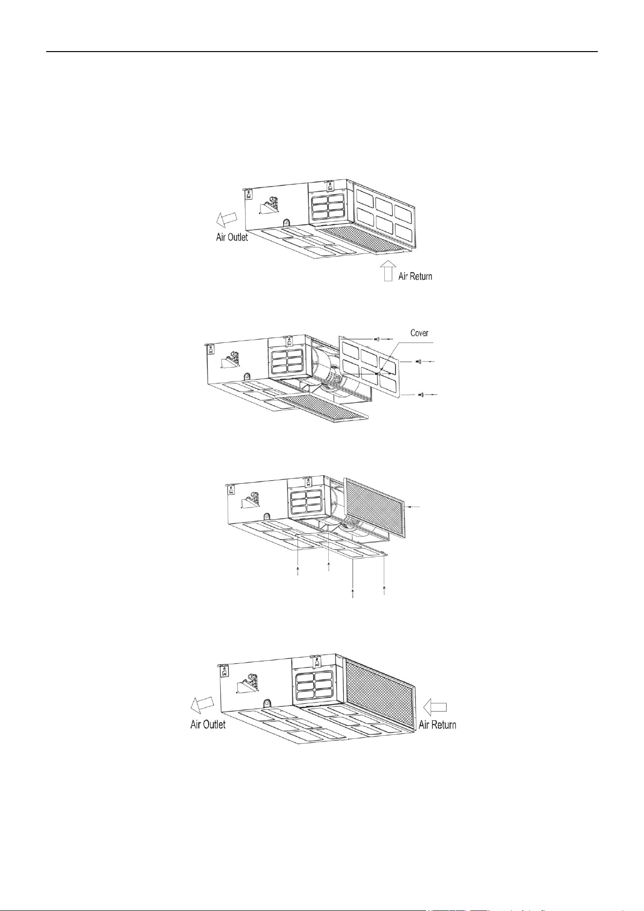
Choice of Air Return Ways
The indoor unit is fitted with the downward air return, which can be changed to its backward counterpart if
necessary. Follow these steps to change the air return direction to backward.
1) Air return downward
2) Loosen the nut and dismantle the flannel plate and filter. Loosen the nut and dismantle the back cover.
3) Install the flannel plate and filter at the backside. Install the cover on the downside of the unit.
4) Air return backward
39

Air Conditioner Service Manual
Hanging & Installation of the Indoor Unit
1) Adjust the Nut Position While There is a Gap Between the Gasket (Downside) and Ceiling.
• Hang the nut inside the U slot of the installation panel.
• Confirm the level degree with a gradienter. Leaning the unit downside toward the non-draining side is
prohibited. The suspension height should not be less than 7.9 ft (2.4m).
2) Mounting the Outlet Pipe
• Generally, we have 2 types of outlet pipes available (rectangular or round pipes).
• Connect the rectangular air conduits directly to the air outlet of the indoor units using rivets. For outlet
dimensions, see the outline drawing of the unit.
• Connect the round air conduits to a piece of a traditional air conduit before connecting it to the air outlet of
the indoor unit. The other end of the round air conduit can be separately connected to the air conduit
window or to the air conduit window after air flow diversion. The total length cannot exceed 19.7 ft (6m).
As shown in the figure below, the air speeds at all air outlets must be set to ensure consistency for optimal room
air-conditioning performance.
3) Installation Method for the Return Air Pipe
• In the situation where the sidewise air intake is adopted, the return air pipe needs to be fabricated and rivet-
connected to the return air orifice. The other end of it should be connected to the return air window.
• In the situation where the underside air intake is adopted, purchase or fabricate a section of pleated canvas
air conduit. This will serve as the transition joint for the return air orifice and return air window. With this
method, it can be freely adjusted according to the height of the indoor ceiling board. In addition, the canvas
air conduit may restrict the vibration of the ceiling board, as shown in the figure below.
40

Air Conditioner Service Manual
4) Tips for Installation of the Return Air Pipe and Outlet Pipe
• To minimize energy loss occurring in the transmission process and condensed water during the
heating operation, equip the return air pipe and outlet pipe with a heat-insulating layer as shown in
the figure.
• Fix the return air pipe and outlet pipe to the floor precast slabs using an iron stand. In addition, tightly seal
all the ports of the air conduit with gasket cement. The edge clearance of the return air pipe should be 5.9
inch (150mm) minimum.
• Install the drain pipe for condensed water with a minimum gradient of 1%. Insulate the drain pipe with a
heat-perserving pipe casing.
41
Air Conditioner Service Manual
Remove the grille and sideboard.
C. Floor-Ceiling Flex
Installation Procedure
Floor Console Type
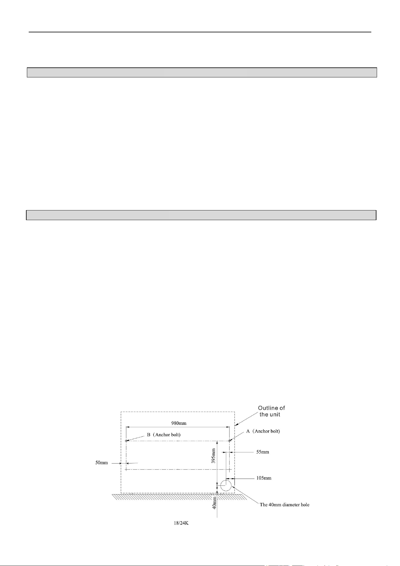
1) Select the Piping and Drainage Directions
The piping and drainage can be set in 2 directions as shown below. After selecting the direction, drill a 3.9 inch
(100mm) diameter hole in the wall. The hole must be tilted downward towards the outdoor for smooth water flow.
When leading the pipe out from the rear, make a hole in the position shown below.
2) Drill Holes for Anchor Bolts and Install the Anchor Bolts (m10)
According to the position of the holes, install 2 expansible anchor bolts (A and B) in the position shown below.
42
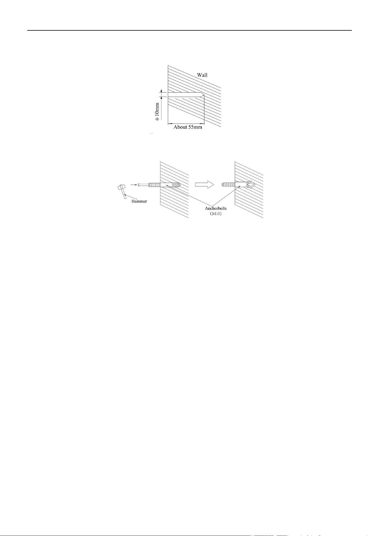
Air Conditioner Service Manual
Use a concrete drill to create two 0.4 inch (10mm) diameter holes in the A and B positions on the wall.
Insert the anchor bolts into the drilled holes, then drive the pins completely into the anchor bolts with a hammer.
Install the unit using witmuts, washers, and spring washers.
Note: The installation angle should not exceed 15 degrees.
Caution: Be sure to arrange the drain hose so that it is leveled lower than the drain hose connecting port of the
indoor unit.
43

Air Conditioner Service Manual
Under Ceiling Type
1. Select the Piping and Drain Directions
Caution: Install the drainage hose at the rear of the unit. Do not install the drainage hose at the top of the unit.
After selecting the directions, drill 3.1 inch (80mm) and 2 inch (50mm) or 5.9 inch (150mm) diameter holes in
the wall so that the hole is tilted downward toward the outside for smooth water flow.
2) Drill Holes for Anchor Bolts and Install the Anchor Bolts (m10)
Drill 4 holes for the anchor bolts at the A, B, C, and D positions.
3) Install the Indoor Unit
Securely tighten the nuts to each bolt with washers and spring washers.
Note: The installation angle should not exceed 10 degrees.
44
Air Conditioner Service Manual
Outdoor Unit Installation
1. Select the Installation Location
1) Do not install the outdoor unit near sources of heat, steam, or flammable gas.
2) Do not install the unit near an area that is too windy or dusty.
3) Do not install the unit in a location where people often pass. Select a location where the air discharge and
operating sound will not disturb the neighbors.
4) Avoid installing the unit in a location where it will be exposed to direct sunlight. If needed, use protection
that will not interfere with the air flow.
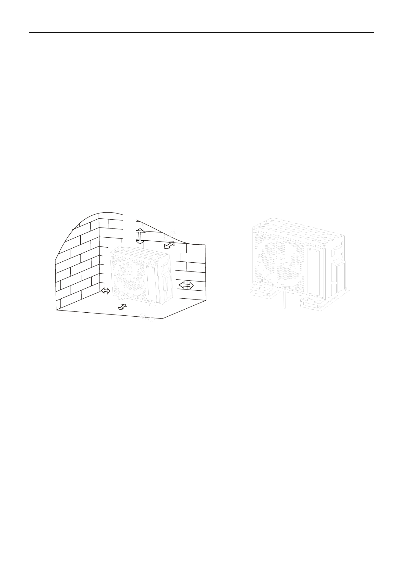
5) Reserve the spaces, as shown in the picture, for the air to circulate freely.
6) Install the outdoor unit in a safe and solid place.
7) If the outdoor unit is subject to vibration, place rubber blankets on the feet of the unit.
Over
Over
At least 1.2 in
(3cm) above the
floor
2. Install the Drainage Hose (Only for Heat Pump Models or RCACs)
1) Insert the drainage joint to the hole at the bottom of the outdoor unit.
2) Connect the drainage hose to the joint and ensure it's well-connected.
45

Air Conditioner Service Manual
3. Fasten the Outdoor Unit
1) Mark the installation positions for the expansion bolts according to the outdoor unit installation
dimensions.
2) Drill holes and clean the concrete dust. Then place the bolts.
3) If necessary, install 4 rubber blankets on the hole before placing the outdoor unit (optional). This will
reduce vibrations and noise.
4) Place the outdoor unit base on the bolts and pre-drilled holes.
5) Use the wrench to fix the outdoor unit firmly with bolts.
Note: The outdoor unit can be fixed on a wall-mounting bracket. Follow the instructions to fix the wall-mounting
bracket on the wall. Then fasten the outdoor unit on it. Ensure it's kept horizontal. The wall-mounting bracket
must be able to support at least 4 times the weight of the outdoor unit.
4. Wiring Cover and Cable Clamp
1) Use a phillips screwdriver to unscrew the wiring cover. Grasp and press the wiring cover down gently to
remove it.
2) Unscrew the cable clamp and remove it.
3) Attach the connecting wires to the corresponding terminals according to the wiring diagram pasted inside
the wiring cover. Ensure all the connections are firmly secured.
4) Reinstall the cable clamp and wiring cover.
Note: When connecting the wires of the indoor and outdoor units, the power should be cut Off.
46

Air Conditioner Service Manual
5. Connecting the Refrigerant Pipe
1) Unscrew the valve cover. Grasp and press the wiring cover down gently to remove it.
2) Remove the protective caps from the end of the valves.
3) Remove the plastic cover in the pipe ports. Check whether there is any sundry on the port of the
connecting pipe. Ensure the port is clean.
4) After aligning the center, tighten the flare nut of the connecting pipe. Rotate the flare nut by hand.
5) Use a spanner to hold the body of the value. Use a torque wrench to tighten the flare nut according to the
torque values in the Torque Requirement table.
Note: If you need to connect ½ inch or ⅝ inch connecting pipes, use the transitadapter.
47

Air Conditioner Service Manual
6. Vacuum Pumping (2-Zone System)
1) Use a spanner to remove the protective caps from the service port, low pressure valve, and high pressure
valve of the outdoor unit.
2) Connect the pressure hose of the manifold gauge to the service port on the outdoor unit's low pressure
valve.
3) Connect the charge hose from the manifold gauge to the vacuum pump.
4) Open the low pressure valve of the manifold gauge and close the high pressure valve.
5) Turn On the vacuum pump to vacuum the system.
6) Vacuum the system for at least 15 min. Ensure the compound gauge indicates -0.1 MPa (-76cm/Hg).
7) Close the low pressure valve of the manifold gauge and turn Off the vacuum.
8) Hold the pressure for 5 min. Ensure the rebound of the compound gauge pointer does not exceed 0.005
MPa.
9) Open the low pressure valve counterclockwise (1/4 turn) with the hexagonal wrench to allow a small amount
of refrigerant to enter the system. After 5s, close the low pressure valve and quickly remove the pressure
hose.
10) Use soapy water or a leak detector to check indoor and outdoor joints for leakage.
11) Fully open the low pressure valve and high pressure valve of the outdoor unit with a hexagonal wrench.
12) Reinstall the protective caps of the service port, low pressure valve, and high pressure valve of the
outdoor unit.
13) Reinstall the valve cover.
Note: After installing the lineset, vacuum the unit before opening the valve switch.
48

Vacuum Pumping (3/4/5 Zone System)
Preparations and Precautions
Air and foreign matter in the refrigerant circuit may cause abnormal rises in pressure, which can damage the
air conditioner, reduce its efficiency, or cause injury. Use a vacuum pump and manifold gauge to evacuate the
refrigerant circuit, removing any non-condensable gas and moisture from the system. Evacuation of the
refrigerant must be performed before the initial installation.
1) Confirm both the high-pressure and low-pressure pipes between the indoor and outdoor units are
connected properly in accordance with the Refrigerant Piping Connection section of this manual.
2) Ensure the wiring is connected properly.
3) Perform a nitrogen leak check on all the refrigerant joints.
Evacuations Instructions
Before using the manifold gauge and vacuum pump, read their operation manuals to familiarize yourself with
how to use them properly.
Air Conditioner Service Manual
1) Connect the refrigeration hose from the low side manifold gauge to the themaster service valve port of the
outdoor unit.
2) Connect the charge hose from the manifold gauge to the vacuum pump.
3) Open the low pressure side service valves (A2, B2, C2, etc.) if the lineset was connected. But be careful not to
open the high pressure side service valves (A1, B1, C1, etc.).
49

Air Conditioner Service Manual
4) Open the low pressure side valve on the manifold gauge. Keep the high pressure side valve closed.
5) Turn On the vacuum pump to evacuate the system.
6) Run the vacuum until the compound meter reads -76cmHg/-29.92"Hg (-101 kPa). Using a micron gauge is
recommended. Run the vacuum until the micron gauge reads 350-500 microns or less.
7) Close the low pressure side valve on the manifold gauge, then turn Off the vacuum pump.
8) Wait 10-15 min, then confirm that there has been no change in the system vacuum. Use a micron gauge to
confirm the system is still below 500 microns.
9) If there is a change in system vacuum, refer to the Gas Leak Check section for information on how to check
for leaks. If there is no change, remove the charge hose from the service port.
10) Use an allen wrench to fully open the master valves (M1, M2) on top, as well as the high pressure side
service valves (A1, B1, C1, etc.).
11) Tighten the caps on all the valves (master valves, high side and low side services valves) by hand. If
needed, you may tighten it further by using a torque wrench.
Note: Open the valve stems gently. When opening the service valve, turn the allen wrench until it hits against the
stopper. Do not try to force the valve to open further.
50

Air Conditioner Service Manual
Outdoor Side Drain Pipe
• Install the outdoor unit on a solid wall and securely fasten it.
• Before connecting the pipes and cables, decide the best position on the wall and leave sufficient space for
maintenance.
• Fasten the support to the wall using screw anchors.
• Use a larger quantity of screw anchors than normally required for its weight to avoid vibration during
operation. This will also keep the unit fastened in the same position for years without the screws becoming
loose.
• Install the unit following the national regulations.
Outdoor Unit Condensed Water Drainage (Only for Heat Pump Models)
The condensed water and ice formed in the outdoor unit during heating operation can be drained away through
the drain pipe.
1. Fasten the drain port in the 1 inch (25mm) hole placed in the part of the unit as shown in the picture.
2. Connect the drain port and drain pipe. Ensure the water is draining into a suitable place.
Pipe Length and Additional Refrigerant
51

Air Conditioner Service Manual
5.5 Electrical Installation
Cable Connection Between the IDU and ODU
Plug the connection cables to the corresponding terminals, as shown below. For example, Terminal (A) of the
outdoor unit must connect with Terminal (A) of the indoor unit.
1) Connect to the internal and external communication lines.
2) Connect the fire line.
3) Connect the zero line.
52
Air Conditioner Service Manual
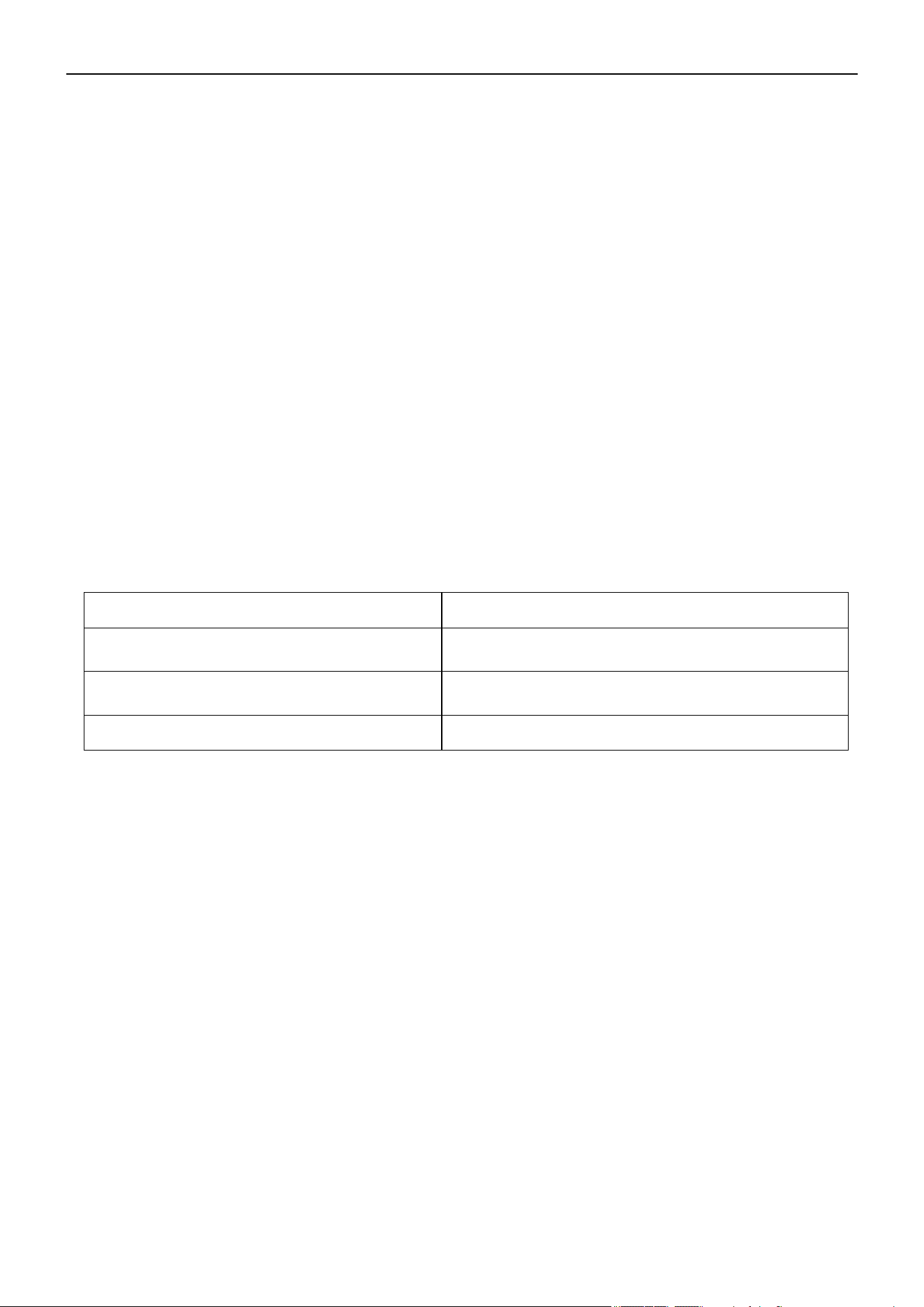
Description
Inspection Method
Electrical Safety Inspection
Installation Safety Inspection
Refigerant Leakage Detection
5.6 Test Run
Inspections before the test run. Complete the following checks before the test run:
• Check whether the power supply voltage complies with the
specifications.
• Check whether there is any wrong or missing connections between the
power lines, signal line, and earth wires.
• Check whether the earth resistance and insulation resistance comply
with the requirements.
• Confirm the direction and smoothness of the drainage pipe.
• Confirm the joint of the refrigerant pipe is installed correctly.
• Confirm the safety of the outdoor unit, mounting plate, and indoor
unit installation.
• Confirm the valves are fully open.
• Confirm that there are no foreign objects or tools left inside the unit.
• Complete the installation of the indoor unit's air inlet grille and panel.
• Leakage may occur in these areas:
-- Piping joints
-- Connector of the outdoor unit's two valves
-- Valve spools
-- Welding points
• Foam Detection Method: Apply soapy water or foam evenly on the
parts where leakage may be occurring. Then observe whether bubbles
appear. If no bubbles form, it indicates there is no leakage.
• Leak Detector Method: Use a professional leak detector and read the
operation instructions. Use the detector in the position where the
leakage may be occurring for at least 3 min.
If the test detects leakage, the nut needs to be tightened. Test the unit
again until there is no leakage. After the leak detection is completed,
wrap the exposed pipe connector of the indoor unit with thermal
insulation material and insulation tape.
53

Air Conditioner Service Manual
Test Running Instructions
1. Turn On the power supply.
2. Press the On/Off button on the remote controller to turn On the air conditioner.
3. Press the Mode button to switch the modes to Cooling or Heating.
In each mode, set as below:
Cooling - Set the lowest temperature
Heating - Set the highest temperature
4. Run the unit for 8 min in each mode and ensure all the functions are operating correctly and respond to the
remote controller. Functions check as recommended:
4.1 If the outlet air temperature responds to the Cooling and Heating modes.
4.2 If the water drains properly from the drainage hose.
4.3 If the louver and deflectors rotate properly (optional).
5. Observe the test run state of the air conditioner for at least 30 min.
6. After the test run is successful, return the unit to its normal settings. Then press the On/Off button on the
remote controller to turn Off the unit.
7. Inform the user to read this manual carefully before using the unit, as well as demonstrate to the user how to
operate the air conditioner. Ensure the user has the necessary knowledge for service and maintenance. Remind
the user to properly store the accessories.
Note: If the ambient temperature exceeds the range mentioned in the Operation Instructions section and the
unit cannot run in Cooling and Heating modes, lift the front panel and refer to the emergency button operation to
run the Cooling and Heating modes.
54
Air Conditioner Service Manual
Code Reason Remark
E0 IDU and ODU communication failure Is the IDU and ODU wiring connection correct?
E1 IDU sensor and PCB
E2 IDU sensor and PCB
E3 ODU coil temperature sensor failure (OPT) ODU coil sensor and ODU PCB
E4 AC-cooling system abnormal
Gas leakage? 2-way or 3-way valve
blocked etc.
E5 /
E6
IDU PG fan motor / DC fan motor operating
abnormally (IDU failure)
Fan motor, fan blade, and PCB
E7 ODU ambient temperature sensor failure ODU ambient sensor and ODU PCB
E8 ODU discharge temperature sensor failure ODU discharge sensor and ODU PCB
E9 IPM / Compressor driving control abnormal ODU PCB, compressor, etc.
EA ODU current test circuit failure Is the ODU PCB broken?
Eb
Abnormal communication between the
main PCB and display board
(
IDU failure
)
Display board and main PCB
EC
Abnormal communication between the system
module and drive module (ODU failure)
ODU PCB broken
EE ODU EEPROM failure
1. Is the ODU PCB broken?
2. Try to re-power On the AC unit.
EF ODU DC fan motor failure Fan motor and ODU PCB
EH ODU suction temperature sensor failure ODU suction sensor and PCB
EU ODU voltage test circuit abnormal ODU PCB
En ODU gas pipe temperature sensor failure ODU gas pipe sensor and PCB
Ey ODU liquid pipe temperature sensor failure ODU liquid pipe sensor and PCB
P0 IPM module protection ODU PCB
P1 Over- / Under-voltage protection
1. ODU PCB broken?
2. Power supply abnormal?
P2 Over-current protection
P4 ODU discharge pipe over-temperature protection Check the troubleshooting for details
P5 Sub-cooling protection in Cooling mode Check the troubleshooting for details
P6 Overheating protection in Cooling mode Check the troubleshooting for details
P7 Overheating protection in Heating mode Check the troubleshooting for details
P8 Check the troubleshooting for details
P9 Compressor driving protection (Load abnormal) Check the troubleshooting for details
6. Troubleshooting Guide
6.1 Error Codes
Outdoor over-temperature / under-temperature
protection
IDU / ODU mismatched failure
(Specific performance test on the production line)
IDU coil temperature sensor failure
(
IDU IPT failure)
IDU room temperature sensor failure
(
IDU RT failure)
1. ODU PCB broken?
2. Power supply abnormal?
55
Air Conditioner Service Manual
PA Check the troubleshooting for details
F0
Infrared customer feeling test sensor failure (IDU
failure
)
Query by pressing the remote controller
F1
Electric power test module failure (IDU failure)
Query by pressing the remote controller
F2 Check the troubleshooting for details
F3 ODU coil temperature failure protection Check the troubleshooting for details
F4 Cooling system gas flow abnormal protection Check the troubleshooting for details
F5 PFC protection Check the troubleshooting for details
F6 Check the troubleshooting for details
F7 IPM module temperature protection Check the troubleshooting for details
F8 4-way value reversing abnormal Check the troubleshooting for details
F9 The module temperature test circuit failure ODU PCB
FA The compressor phase-current test circuit failure ODU PCB
Fb Query by pressing the remote controller
FC Query by pressing the remote controller
FE Query by pressing the remote controller
FF
Query by pressing the remote controller
FH Query by pressing the remote controller
FP Query by pressing the remote controller
FU Query by pressing the remote controller
Fj Query by pressing the remote controller
Fn Query by pressing the remote controller
Fy Gas leakage protection Check the troubleshooting for details
bf
TVOC sensor failure (IDU failure, optional)
Query by pressing the remote controller
bc Query by pressing the remote controller
bj Query by pressing the remote controller
H1 High pressure switch failure
1. High pressure switch is damaged
2. High pressure switch connection is loose
3. ODU main PCB is damaged
H2 Low pressure switch failure
1. Low pressure switch is damaged
2. Low pressure switch connection is loose
3. ODU main PCB is damaged
Note: Remote Controller Failure Code Querying Function
As shown in the table above, some of the codes (Fb~bj) need you to press the remote control for inspection.
To inspect special failures codes (Fb~Fn, bj, etc), press the Eco button 8 times consecutively in 8s, as
well as the buzzer BIBI 2 times.
Humidity sensor failure
(
IDU failure
)
PM2.5 sensor failure
(
IDU failure, optional
)
Limiting/Reducing frequency for ODU AC-current
protection
Limiting/Reducing frequency for discharge over-
temperature protection
Limiting/Reducing frequency for anti-frost
protection
Limiting/Reducing frequency for anti-
condensation protection
Limiting/Reducing frequency for compressor
driving protection
Limiting/Reducing frequency for module
temperature protection
Limiting/Reducing frequency for module current
protection (phase current of compressor)
Limiting/Reducing frequency for high-power
consumption protection
Limiting/Reducing frequency for overload
protection in Cooling/Heating mode
The compressor lack of phase / Anti-phase
protection
Discharge temperature sensor failure protection
Communication failure for Top flow unit /
Preset mode conflict
(
IDU failure
)
56
Air Conditioner Service Manual
Malfunction
Possible Causes
The Appliance Does Not
Operate
Power failure or plug pulled out.
Damaged indoor/outdoor unit fan motor.
Faulty protective device or fuses.
Faulty compressor thermo-magnetic circuit breaker.
Loose connections or plug pulled out.
It sometimes stops operating to protect the appliance.
Voltage higher or lower than the voltage range.
Active Timer-On function.
Damaged electronic control board.
Strange Odor
Dirty air filter.
Noise of Running Water
Back flow of liquid in the refrigerant circulation.
A Strange Noise Can Be
Heard
This noise is made by the expansion or contraction of the front panel due to variations in
the temperature. This does not indicate a problem.
Unsuitable temperature setting.
Obstructed air conditioner intakes and outlets.
Dirty air filter.
Fan speed set at minimum.
Other sources of heat in the room.
No refrigerant.
The remote control is not close enough to the indoor unit.
The batteries of the remote control need to be replaced.
Obstacles between the remote control and signal receiver in the indoor unit.
The Display is Off
Active Display function.
Power failure.
Strange noises during operation.
Faulty electronic control board.
Spraying water or other liquids inside the appliance.
Overheated cables or plugs.
Very strong smells coming from the appliance.
A Fine Mist Comes From
the Air Outlet
Insufficient Airflow
(Either Hot or Cold)
The Appliance Does Not
Respond to Commands
Switch Off the Air
Conditioner Immediately
and Cut Off the Power
Supply in the Event of:
This occurs when the air in the room becomes very cold. For example, in the Cooling or
Dehumidifying/Dry modes.
57
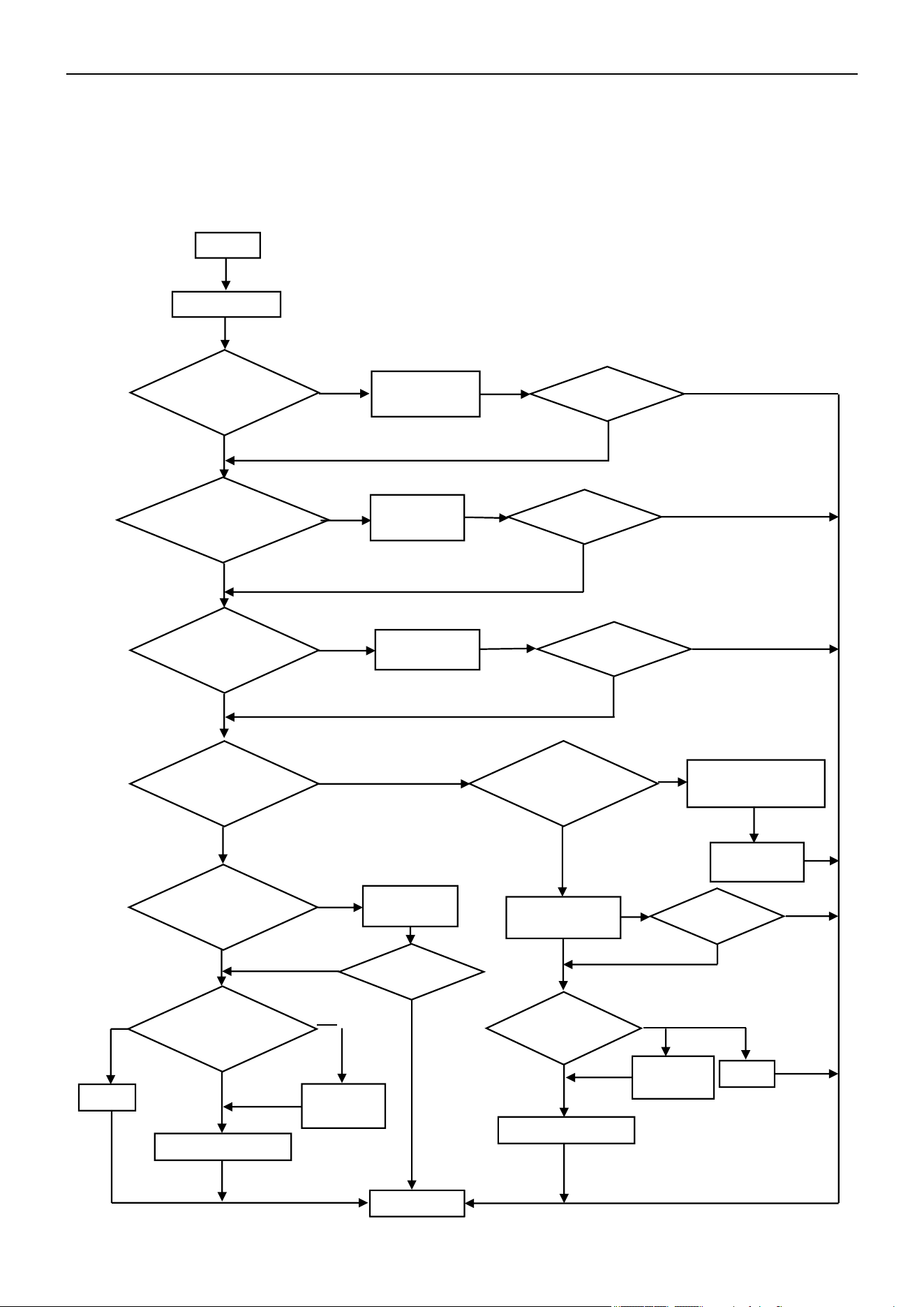
Air Conditioner Service Manual
6.2 Troubleshooting
1) E0 --- IDU and ODU Communication Failure
Start
Display E0
Yes
Check and
reconnect
No
Main power supply
from IDU?
Yes
No
Check and
reconnect
No
Check voltage from IDU
terminal btw L,N. is there
220V?
Replace the
IDU PCB
No
Yes
Yes
Is the ODU PCB
LED5 On?
Replace the ODU PCB
Check voltage from IDU
terminal btw L,N. is there
220V?
Check the power
supply connection
Replace or
reconnect
Yes
Is the ODU PCB
LED5 On?
Yes
Replace the ODU PCB
No
No
No
End
On
constantly
Flash
On
constantly
Flash
No
Yes
Yes
E0 disappear?
Yes
No
E0 disappear?
No
Yes
E0 disappear?
No
No
Yes
E0 disappear?
Yes
No
E0 disappear?
Yes
No
Is the IDU wiring
connection correct?
Replace and
reconnect
Is the communication
wiring and connection
in good condition?
Is the ODU wiring
connection correct?
Replace the
IDU PCB
58
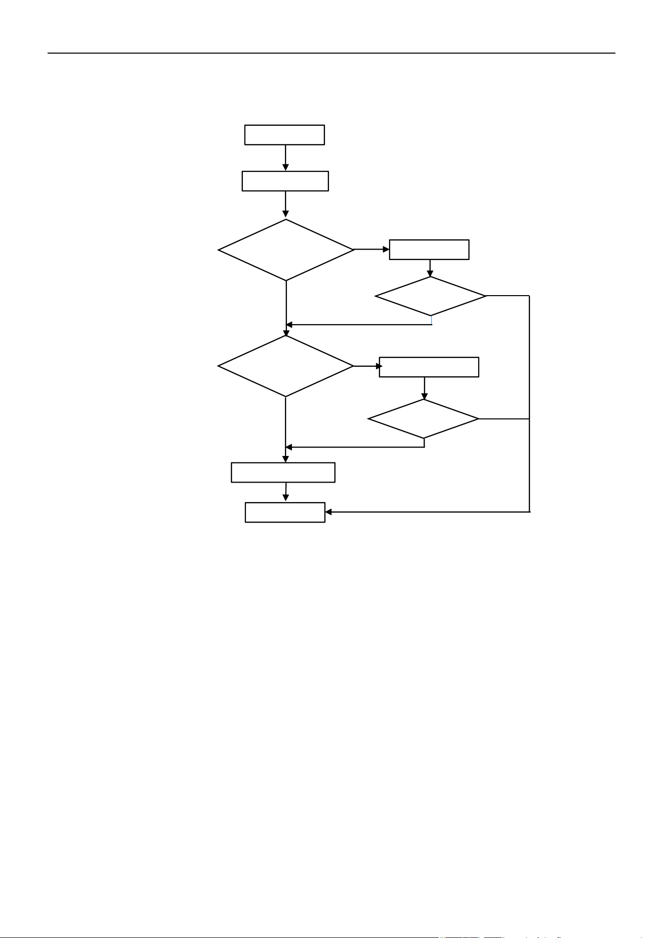
Air Conditioner Service Manual
Start
Display E1 or E2
Reconnect
Replace the sensor
No
Yes
Yes
Replace the IDU PCB
Malfunction
eliminated?
End
E1/E2
disappear?
Yes
No
No
No
Yes
2) E1, E2 --- IDU Room Temperature Sensor and/or Coil Temperature Sensor Failure
Is the sensor well-
connected to the
PCB?
Multimeter check the
sensor. Is it experiencing a
short circuit or an open
circuit fault?
59
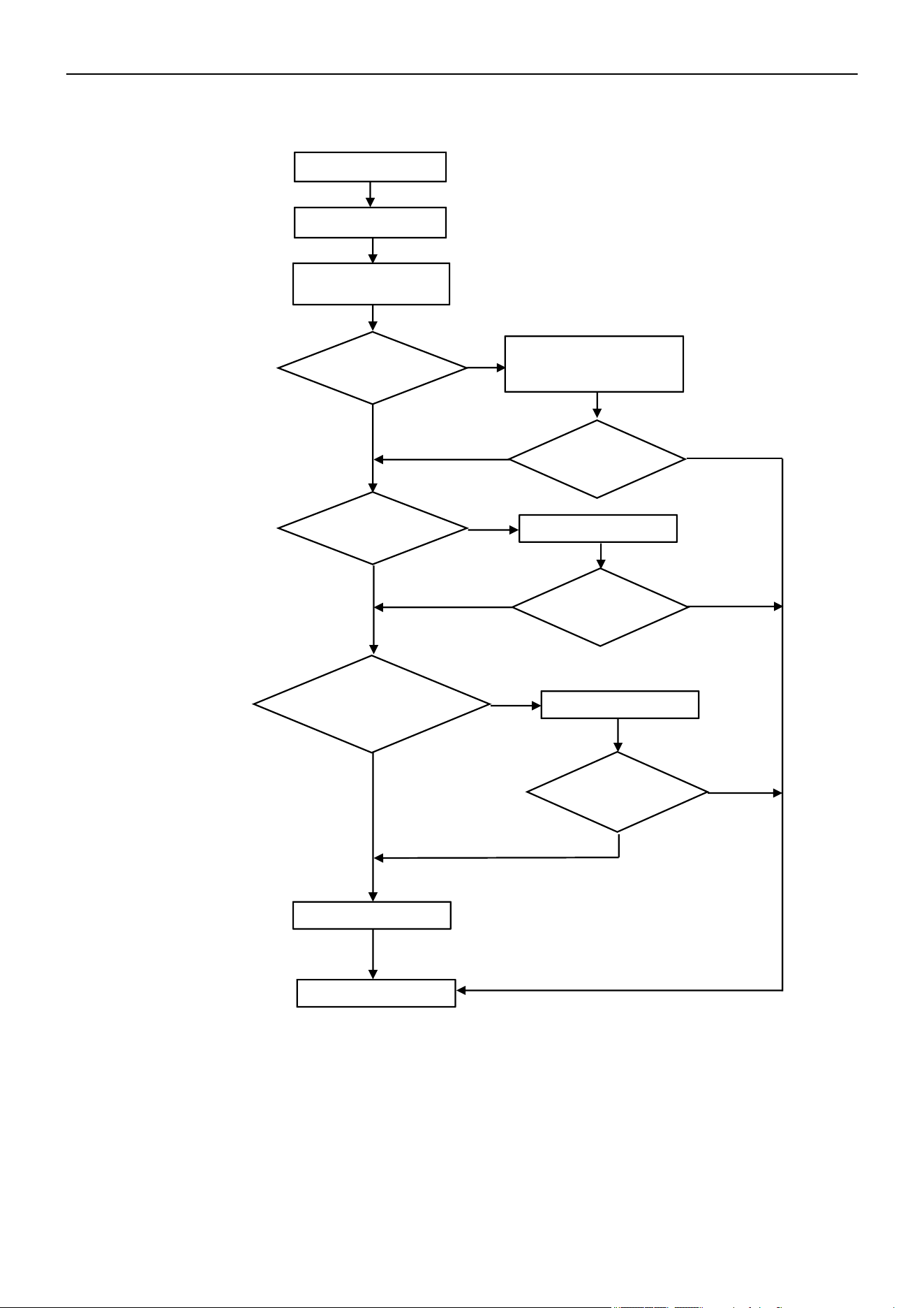
Air Conditioner Service Manual
Start
Display E6
Check and reconnect
Replace the IDU PCB
Replace the fan motor
Yes
Yes
No
No
End
Can the fan blades run
smoothly?
Adjust the motor and blade
assembly so that rotor can
run smoothly
E6 disappear?
No
No
Yes
Yes
E6 disappear?
E6 disappear?
Yes
No
Yes
3) E6 --- IDU Ventilation Failure (PG and DC Fan Motor Only)
Turn the fan blades by
hand while power Off
Is the fan motor
well-connected to
the PCB?
Multimeter check fan
motor resistance. Is it
experiencing a short
circuit or an open circuit
fault?
60
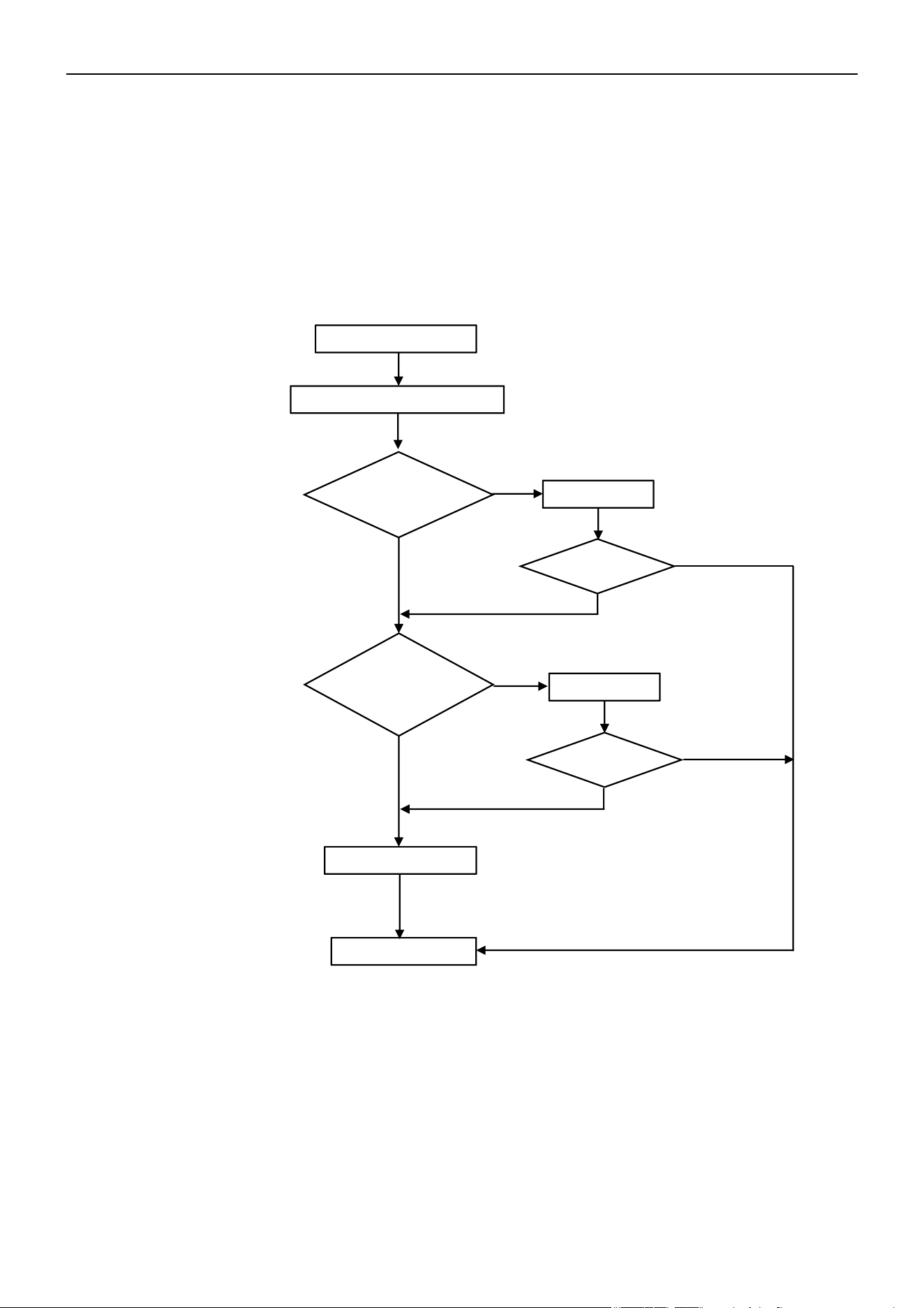
Air Conditioner Service Manual
Start
Display E3/E7/E8/EH/En/Ey
Reconnect
Replace the sensor
Yes
Yes
End
Replace the ODU PCB
No
No
Problem solved?
No
Yes
Yes
4) E3, E7, E8, EH, En, or Ey ---
ODU Coil Temperature Sensor Failure
Ambient Temperature Sensor Failure
Discharge Temperature Sensor Failure
Suction Temperature Sensor Failure
Gas Pipe Temperature Sensor Failure
Liquid Pipe Temperature Sensor Failure
If any of the sensors resistances experience a short circuit or an open circuit fault, the unit will display
error codes as "E3", "E7", "E8", "EH", "En", or "Ey". The IDU and ODU turns Off. When the sensor
resistance recovers, the unit reverts to standby. The customer can switch On the unit directly.
Is the sensor well-
connected to the
ODU PCB?
Multimeter check the
sensor resistance. Is it
experiencing a short
circuit or an open circuit
fault?
Problem solved?
No
61
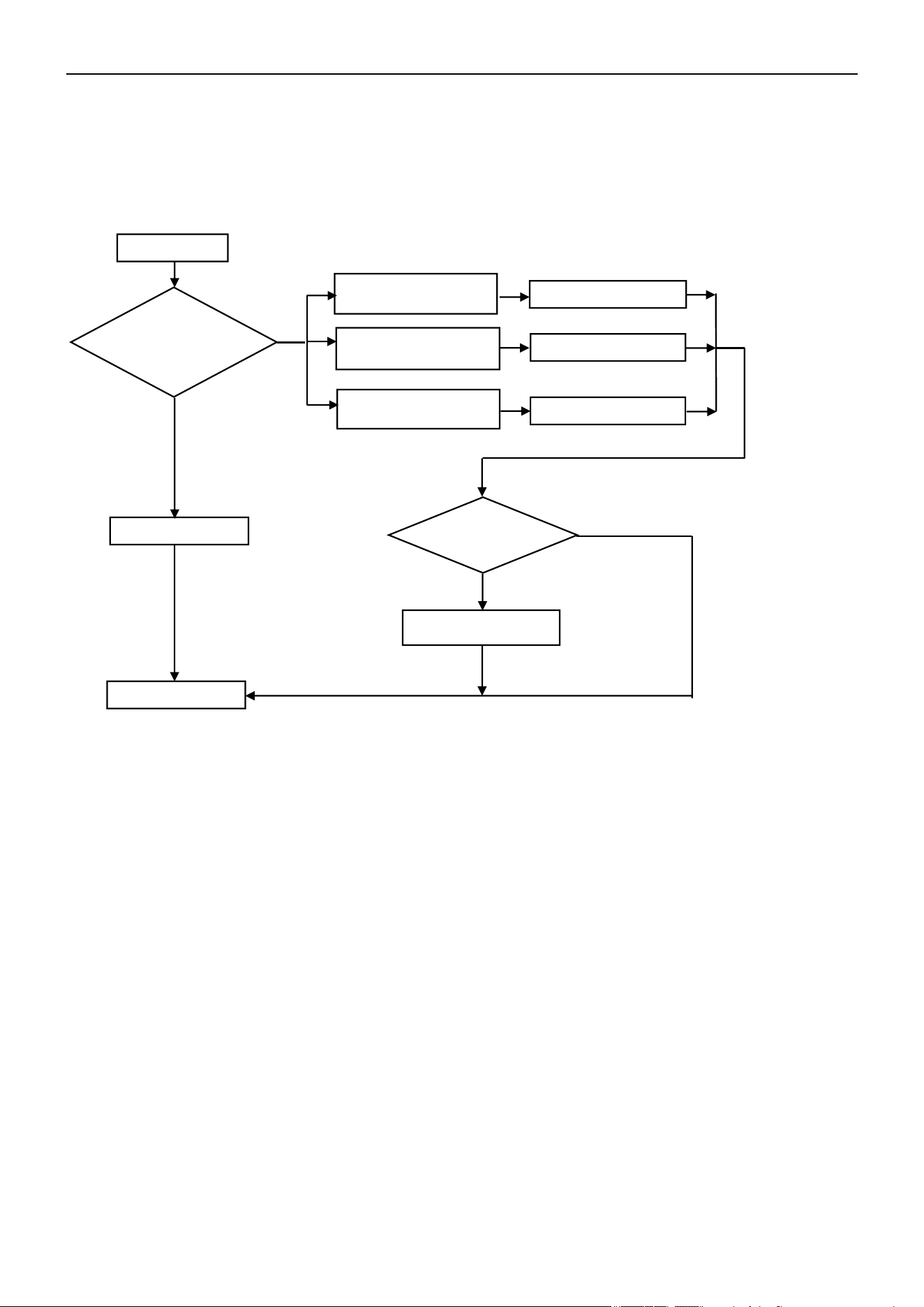
Air Conditioner Service Manual
5) E9 --- ODU IPM / Compressor Drive Fault
If the unit stops working for IPM protection 6 times consecutively, it will display the "E9" error code. The unit can’t
be recovered to operation, except by pressing the On/Off button.
Display E9
Normal protection
Display F9 or FA first,
then E9
Replace the ODU PCB
Display F5, F6, or F7 first,
then E9
Solution as F5, F6, or F7
Display P0 or P2 first, then
E9
Solution as P0 or P2
Replace the compressor
Yes
No
End
Failure disappear?
No
Yes
6) ODU Current Test Circuit Failure
Cause: Outdoor current sampling circuit failure or driver parameter mismatch
Solution: Replace the ODU PCB.
7) Eb --- IDU Abnormal Communication Between Main Board and Operating Board
Cause: 1. The communication wire is damaged; 2. Outdoor main board is damaged; 3. Operating board is
damaged.
Solution: 1. Replace the communication wire; 2. Replace the outdoor main board; 3. Replace the
operating board.
8) EC --- Abnormal Communication Between System Module and Drive Module
Cause: 1. The communication circuit of the outdoor unit PCB is damaged; 2. Program mismatch between the
system module and drive module.
Solution: Replace the ODU PCB.
9) EE --- ODU EEPROM Failure
Cause: The ODU main board is damaged.
Solution: Replace the ODU PCB.
Restart the unit and
allow it to run for 30
min. Check the code
that displays
62
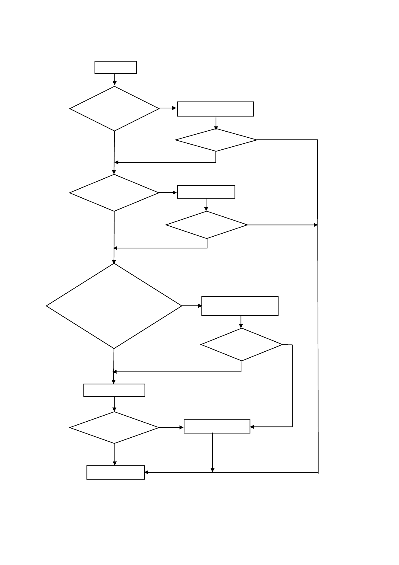
Air Conditioner Service Manual
10) EF --- ODU DC Fan Motor Failure
Shut Off
Reinstall the DC motor
Reconnect
Replace the ODU PCB
Replace the fan motor
No
No
Yes
Yes
End
Works normal?
No
Yes
Yes
Yes
No
Yes
Yes
No
No
Works normal?
No
Works normal?
Works normal?
Check the fan blade by
hand. Can it rotate
freely?
Is the fan motor well-
connected to the PCB?
Check the fan motor.
Can it operate?
1. For Built-In Control
(5pins) Motor: Check the
Vm=310V? Vcc=15V?
2. For External Control
(3pins) Motor: Test voltage
btw U/V/W, normally from DC
20~200V.
63
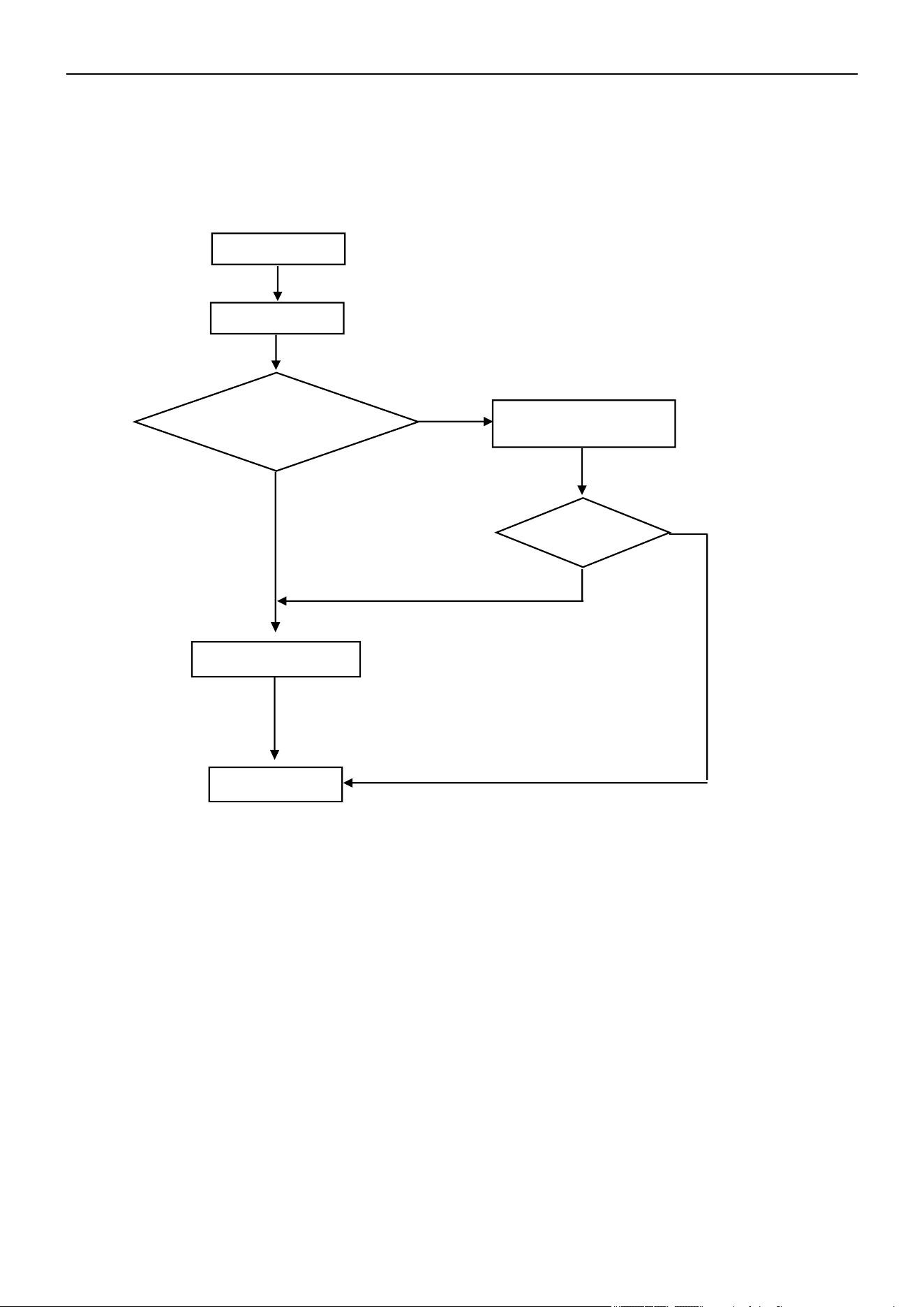
Air Conditioner Service Manual
11) EU --- ODU Voltage Test Sensor Failure
After the power relay begins working, if the tested effective voltage is less than 50V for 3s continuously,
the unit will display the “EU” error code.
Start
Display EU
Test voltage btw ODU
terminal L/N, more than
50V
~?
End
Replace the ODU PCB
Check while voltage
become normal
Yes
No
No
Yes
Does the unit
work?
64
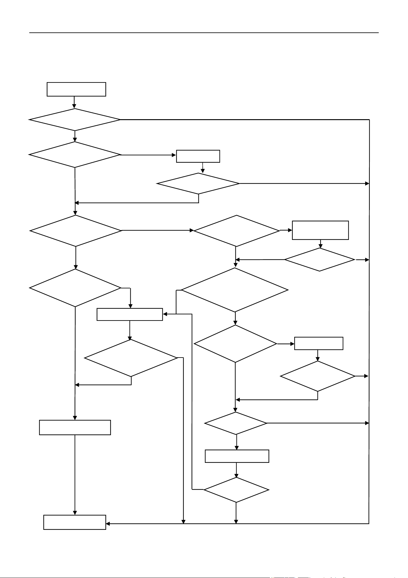
Air Conditioner Service Manual
12) P0 --- IPM Protection
If the IPM is experiencing overheating or over-current conditions, the AC unit will display the "P0" error code.
Can the
compressor start
up?
Reconnect
Replace the ODU PCB
Replace the capillary
Clean it
Yes
Replace the compressor
End
Yes
No
Yes
P0 disappear?
Is the condenser
and/or evaporator
too dirty?
Capillary
blocked?
P0 disappear?
No
No
Yes
Yes
Yes
Yes
Yes
Yes
Yes
No
No
Yes
Yes
No
No
No
Display P0
No
No
Yes
No
No
No
Restart unit. Does it
operate normal?
Is the wiring
connection U/V/W
correct?
Is the ODU fan motor not
working or operating too
slowly?
Replace the ODU
fan motor
Does the unit
operate normal?
Test voltage btw
U/V/W (normally
from DC 20~200V)
Is the AC pressure
correct?
(Cooling: 0.8-1.3Mpa,/
Heating: 2.0-3.6Mpa)
Does the
unit operate
normal?
Turn the unit On.
Did the malfunction
stop?
65
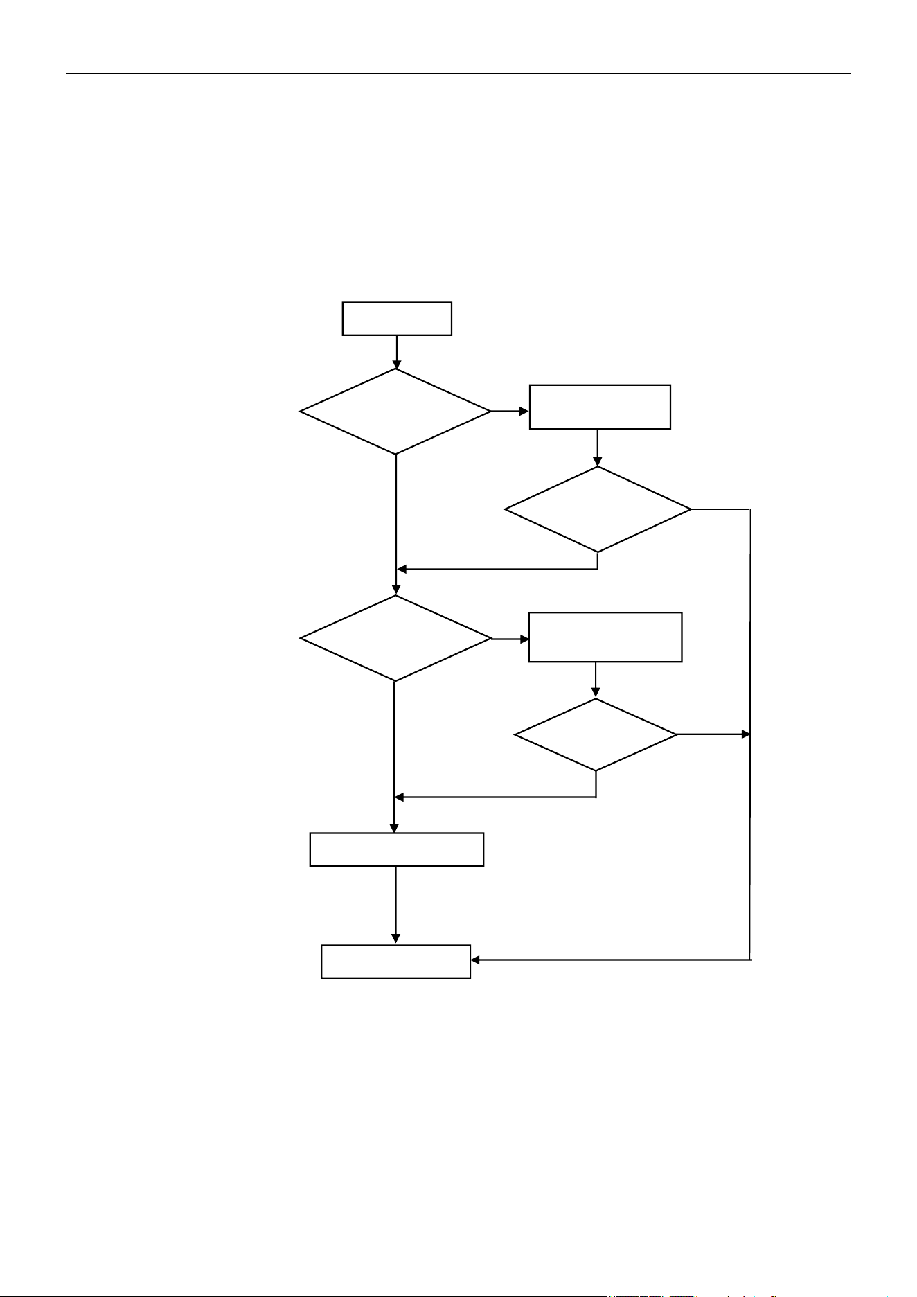
Air Conditioner Service Manual
13) P1 --- Over /Under-Voltage Protection
Display P1
Wait until the AC
voltage recovers
Replace the ODU PCB
Yes
Yes
No
No
No
Yes
No
End
Wait until the busbar
voltage recovers
Yes
1. Test voltage between L and N. When the power supply V > AC260V or V < AC150V, the AC will display the
"P1" error code. The unit will recover back to the previous status while V > AC155V.
2. Test voltage on the big size electrolytic capacitor of the ODU PCB. When DC busbar voltage V > DC420V
or V < DC150V, the unit will recover back to the previous status while DC190V < V < DC410V.
Is the power supply
voltage between
145-260V?
P1 disappear?
Is the busbar
voltage between
150-420V?
Does the unit
operate
normal?
66
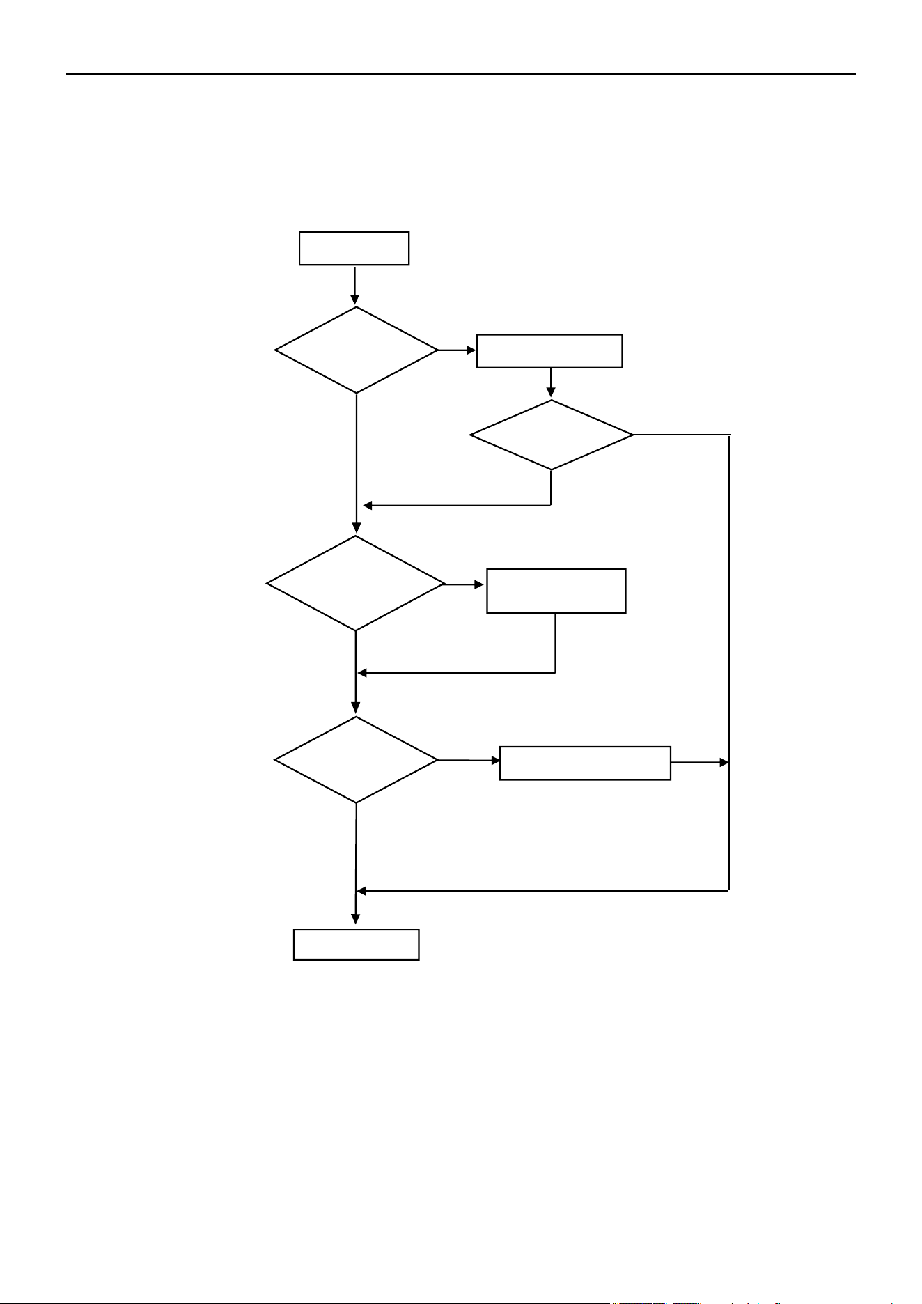
Air Conditioner Service Manual
14) P2 --- Over-Current Protection
When the AC unit's running current is more than Imax, the unit will stop and display the "P2" error code.
Note: For different AC models, the Imax has different valves.
Display P2
Replace the fan motor
Is the IDU filter or
ODU condenser
too dirty?
Clean the IDU filter
or condenser
Restart the unit.
P2 disappear?
No
Replace the ODU PCB
Yes
Yes
End
P2 disappear?
No
Yes
No
Yes
No
Does the ODU
fan motor
operate?
67
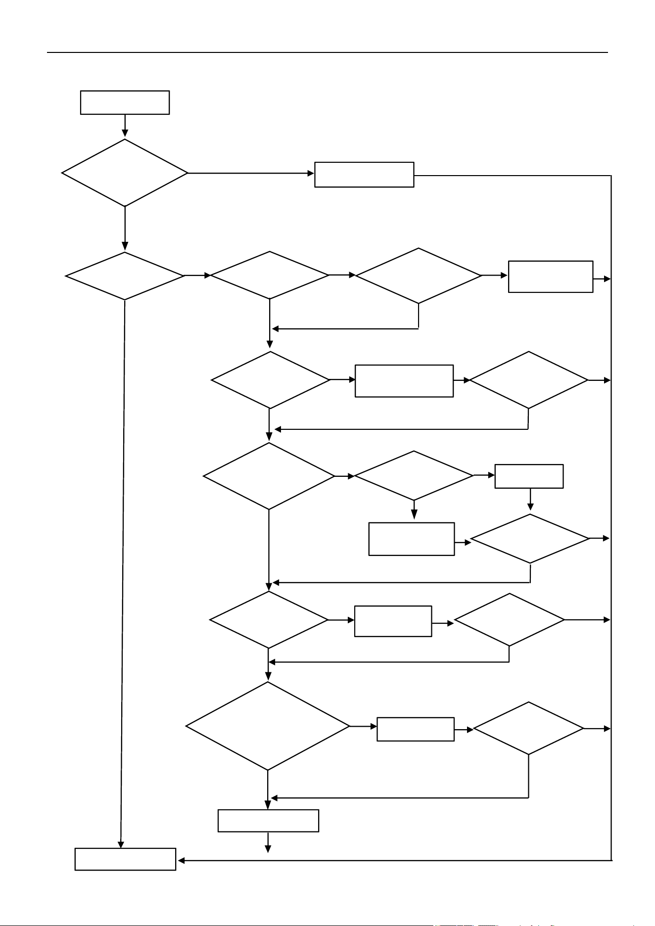
Air Conditioner Service Manual
15) P4 --- ODU Discharge Temperature Overheating Protection
Display P4
Normal protection
Enough space for
ventilation?
Adjust ODU
installation
Condenser too
dirty? or filter
blocked?
Replace the ODU PCB
Clean the IDU filter or
ODU condenser
Adjust
Replace the fan
motor or PCB
Replace the
capillary
Charge gas
End
Yes
P4 disappear?
Problem solved?
Problem solved?
No
Yes
No
No
Yes
No
No
No
Yes
No
No
No
No
No
No
Problem solved?
Yes
No
Is the ODU
location
acceptable?
Yes
Yes
Yes
Yes
Yes
Yes
Yes
Yes
Is the unit
operating?
Is the IDU/ODU fan
motor working or
operating too slowly?
Is the fan blade
blocked?
Is the capillary
blocked?
Is the unit gas
pressure normal?
(Cooling: 0.8-1.3Mpa,
Heating: 2.0-3.6Mpa)
Is the ODU
temperature higher
than 140°F(60°C)?
68
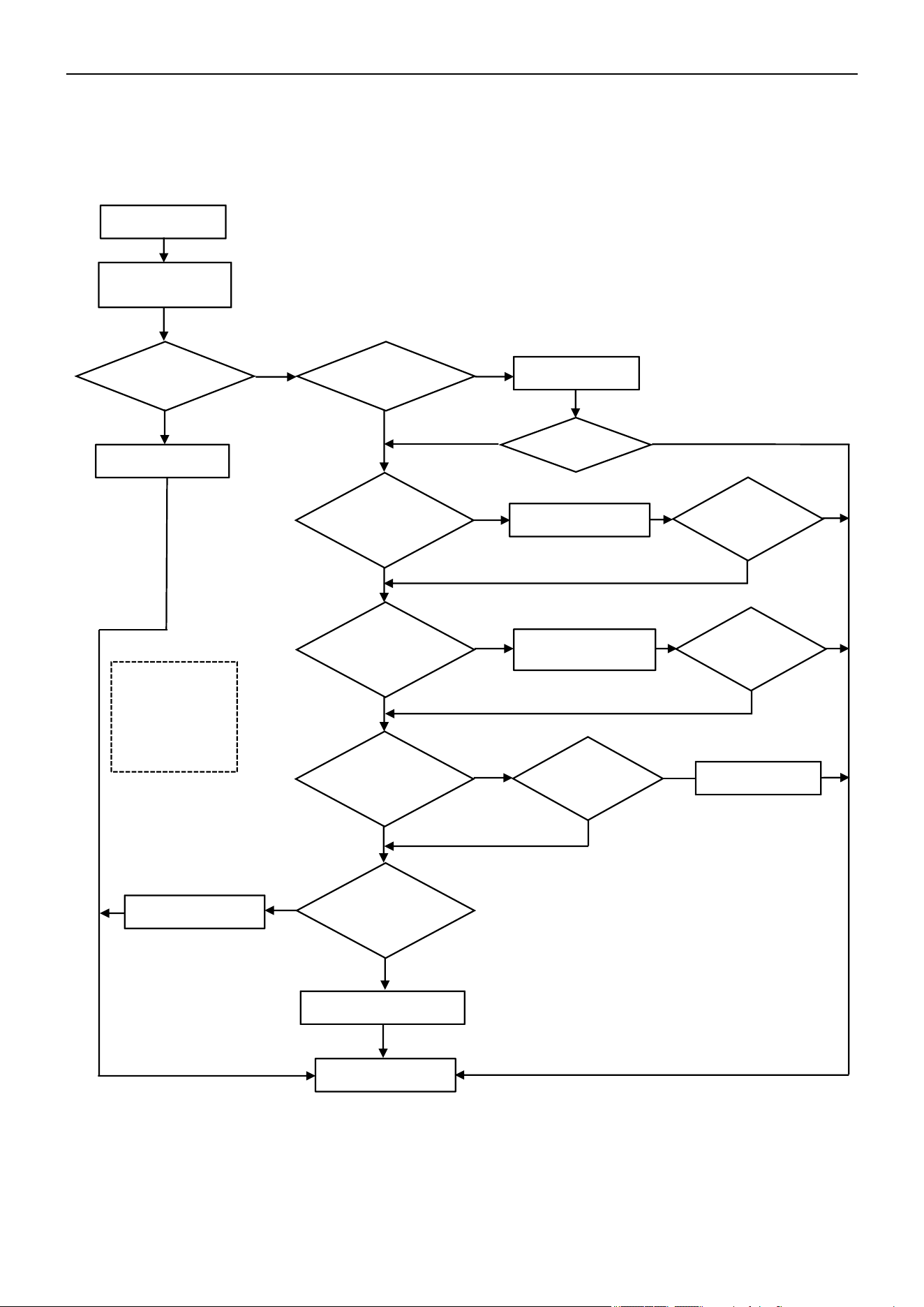
Air Conditioner Service Manual
16) P5 --- Sub-Cooling Protection in Cooling/Dry Mode
In Cooling or Dry mode, when the IDU evaporator coil temperature is IPT < 34°F(1°C) continuously for 3 min
after the compressor starts up for 6 min, the CPU will switch Off the outdoor unit and display the "P5" error
code.
Display P5
Display P5
No
Yes
Yes
Clean filter
No
Clean
Yes
Check and repair
fan blade
Fan motor
defect?
No
Replace the sensor
Yes
Yes
No
No
No
Yes
No
End
P5 disappear?
P5 disappear?
P5 disappear?
No
Yes
Yes
No
Replace the IDU PCB
Yes
No
Switch On the
unit after 5 min
Is the IDU filter
dirty?
Replace the motor
Can the fan
blade rotate
freely?
Normal protection
Is
the IDU air
inlet
blocked?
Is the fan motor
not working or
operating too
slowly?
Is the IPT sensor
abnormal?
Note: Cooling
mode under low
environment
temperatures can
easily trigger P5
protection.
Yes
69
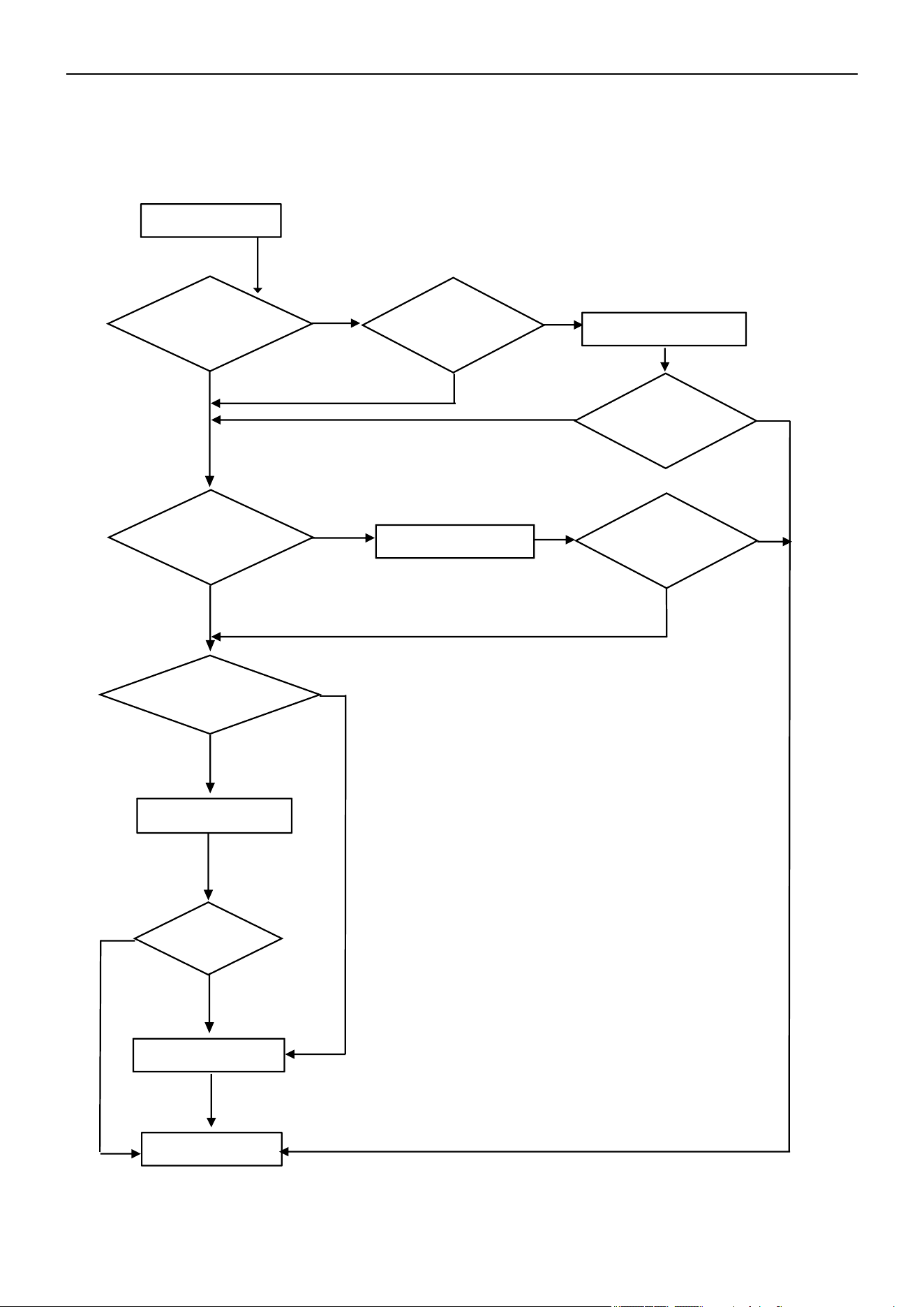
Air Conditioner Service Manual
17) P6 --- Overheating Protection in Cooling Mode
In Cooling or Dry mode, when the ODU condenser coil temperature is OPT ≥ 144°F(62°C), the MCU will switch Off
the outdoor unit and display the "P6" error code.
Display P6
Replace the OPT sensor
Replace the ODU PCB
Replace the fan motor
End
No
No
Yes
Yes
P6 disappear?
P6 disappear?
Yes
No
Yes
No
No
Yes
Reconnect the sensor
P6 disappear?
Yes
Yes
No
Does the ODU
fan motor
operate normal?
Is the fan motor
broken?
Is the sensor
loosening from
the connector?
Is the sensor
experiencing a short
circuit or an open circuit
fault?
70
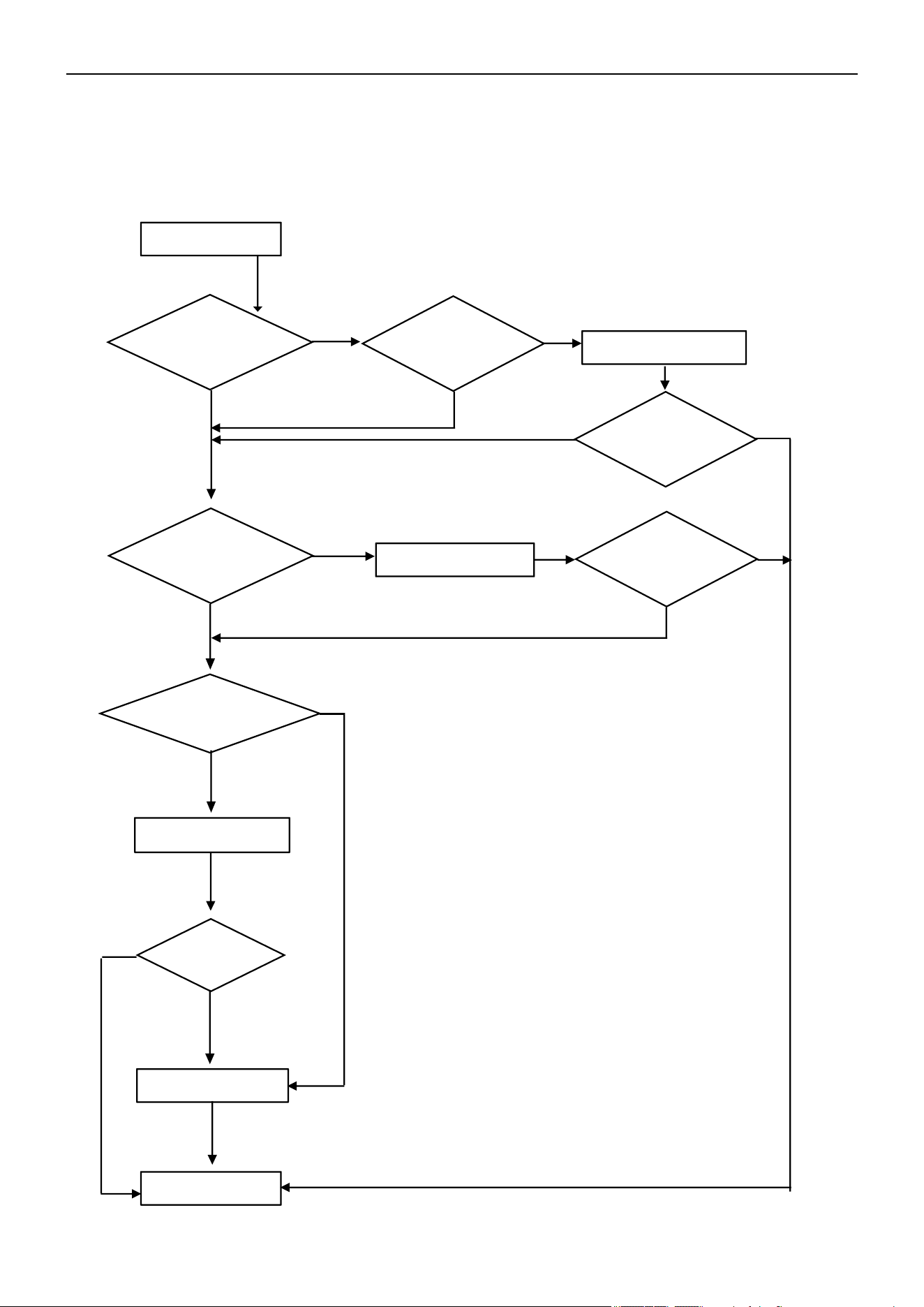
Air Conditioner Service Manual
18) P7 --- Overheating Protection in Heating Mode
In Heating mode, when the IDU evaporator coil temperature is IPT ≥ 144°F(62°C), the ODU PCB will
switch Off the outdoor unit and display the "P7" error code.
Display P7
Replace the IPT sensor
Replace the IDU PCB
Is the fan
motor broken?
Replace the fan motor
End
No
Yes
P7 disappear?
P7 disappear?
No
Yes
No
Yes
Reconnect the sensor
P7 disappear?
Yes
Yes
No
Does the ODU
fan motor work
normal?
No
Yes
Yes
No
Is the sensor
loosening from
the connector?
Is the sensor
experiencing a short
circuit or an open circuit
fault?
71
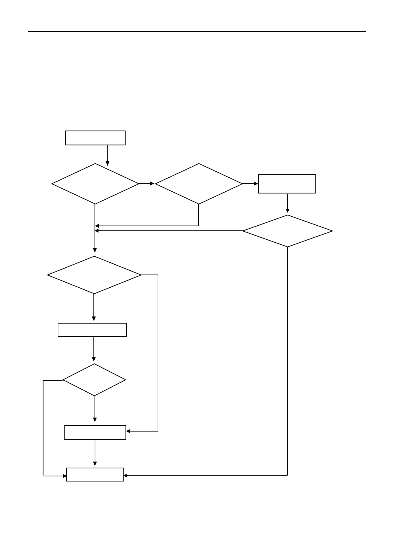
Air Conditioner Service Manual
Display P8
Is the ambient
temperature under
spec range?
Replace the OAT sensor
End
Replace the ODU PCB
Not enough space for
ODU ventilation?
Change ODU
location
Yes
Yes
P8 disappear?
P8 disappear?
No
No
No
Yes
19) P8 --- Outdoor Over-Temperature / Under-Temperature Protection
If the system experiences the following environment temperatures, the compressor will stop operating. After a
200s delay, the IDU will display the "P8" error code.
1) In Cooling or Dry mode: ODU ambient temperature: OAT < -4°F(-20°C) or OAT > 145°F(63°C)
2) In Heating mode:
a. OAT ≥ 104°F(40°C)
b. 86°F(30°C) < OAT ≤ 104°F(40°C) and RT > 95°F(35°C)
No
Yes
Yes
Is the sensor
experiencing a short
circuit or an open circuit
fault?
No
72
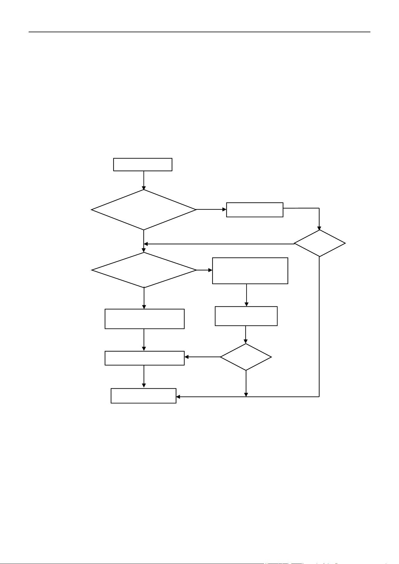
Air Conditioner Service Manual
20) P9 --- Compressor Driving Protection (Compressor Load Abnormal)
When the compressor starts up or in the process of operation, if:
1) The MCU can’t test the feedback signal from the compressor, or
2) Tested an abnormal signal from the compressor, or
3) The compressor startup is abnormal.
21) PA --- Communication Failure for Top Flow Unit / Preset Mode Conflict
Cause:
1) If the first-activated indoor unit (with the highest priority) operates in Cooling/Dehumidification mode, other
indoor units can only operate in Cooling/Dehumidification mode and Air Supply mode. Otherwise, an indoor unit
attempting to operate in a different mode will report a mode conflict fault and will not be allowed to start up. This
will not affect the indoor units already running.
2) If the first-activated indoor unit (with the highest priority) operates in Heating mode, other indoor units can only
operate in Heating mode. Otherwise, an indoor unit attempting to operate in a different mode will report a mode
conflict fault and will not be allowed to start up. This will not affect the indoor units already running.
Solution: Set all the indoor units to the same mode.
Display P9
Normal protection as the high
pressure and low pressure
End
No
Yes
No
The compressor stops at
once while it starts up
Yes
Recorrect the wires
Replace the ODU PCB
Still P9?
Still P9?
Yes
No
No
Yes
Restart after
3 min
The outdoor unit will shut Off and display the "P9" error code.
The unit will restart 6 times continuously. If it still can’t operate normally, then the unit will display the error
code again.
Are the compressor
wires U/V/W sequence
and connection correct?
The unit starts up less
than 3 min while it
stopped?
73
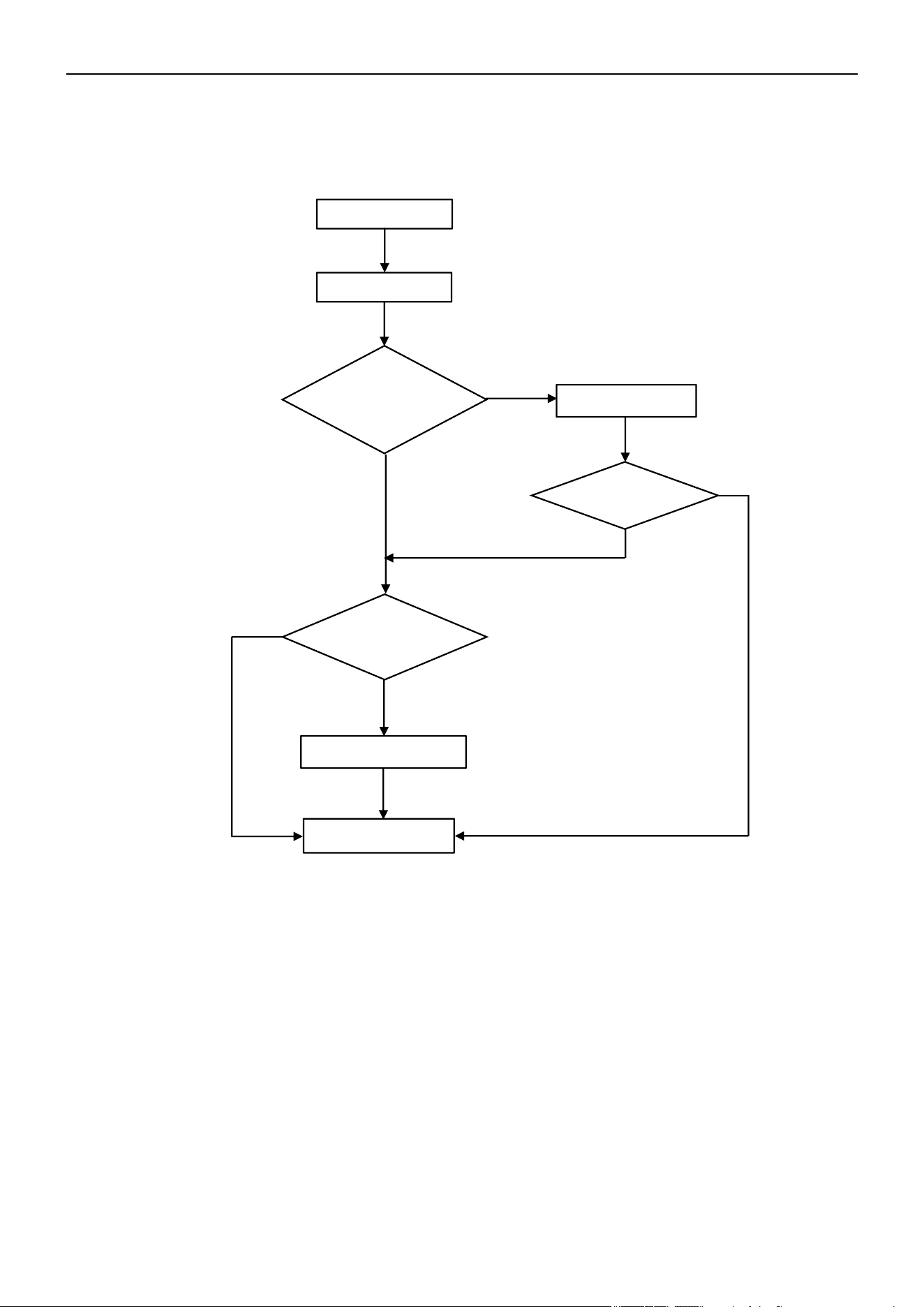
Air Conditioner Service Manual
22) F4 --- Cooling System Gas Flow Abnormal Protection
When the compressor starts up, the unit will check the variation of the IDU coil temperature. If the installer forgets to
open the 2-way or 3-way valve on the ODU, the gas can’t flow in the cooling system. The unit will undergo cooling
system gas flow abnormal protection and display the "F4" error code.
Start
Display F4
Open the valve
End
No
Yes
No
F4 disappear?
Replace the sensor
Yes
Yes
No
Is the 2-way and 3-
way valve open?
Is the IPT sensor
experiencing a short circuit
or an open circuit fault?
74
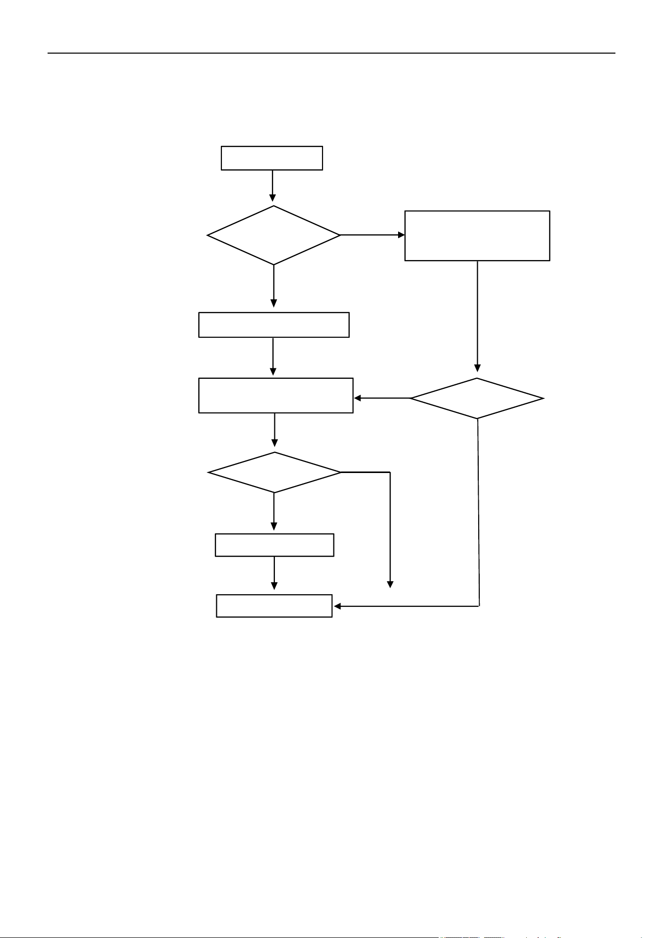
Air Conditioner Service Manual
23) F5 --- PFC Protection
If the system undergoes PFC over-current protection, the unit will display the "F5" error code.
F5 Code
Display F5 by
random?
Display F5 frequently
Still F5?
End
Yes
No
No
Yes
Still F5?
No
Yes
Switch Off the unit for
3 min. Re-switch on
Replace the ODU PCB
Check the power supply. Is
it abnormal? (This is normal
protection)
75
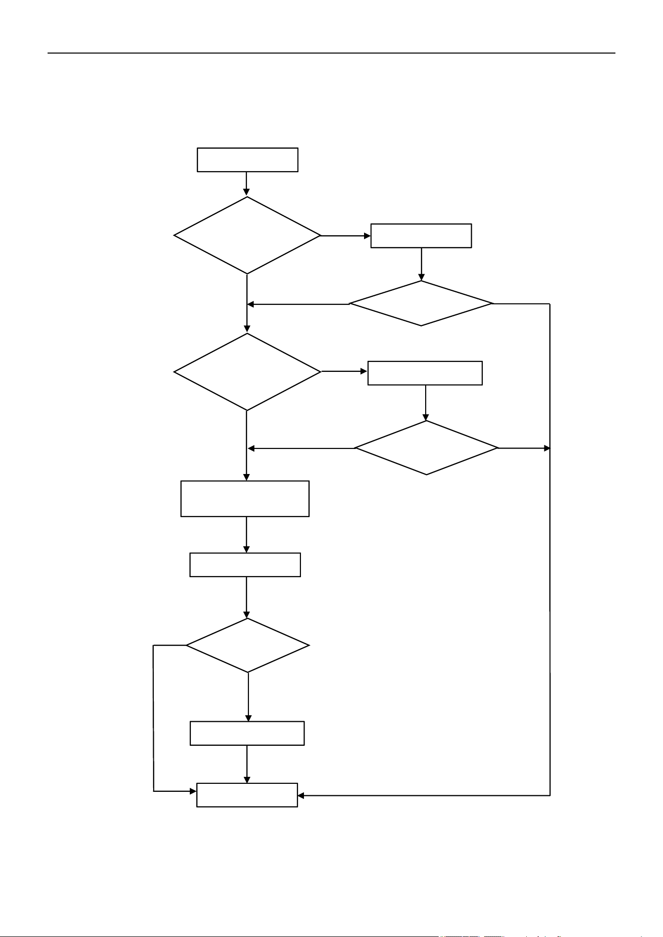
Air Conditioner Service Manual
24) F6 --- Compressor Lack of Phase / Anti-Phase Protection
If the ODU PCB can’t test one or even three phases of the compressor's current, the unit will undergo anti-phase
protection and display the "F6" error code.
Display F6
Reconnect
Is the compressor
wiring in good quality?
Replace the wires
Compressor phase-current
test circuit failure
Replace the ODU PCB
End
Replace the compressor
No
No
No
Yes
Yes
Yes
Problem solved?
Problem solved?
Problem solved?
Yes
No
No
Yes
Check the
compressor wiring
connector. Is it well-
connected?
76
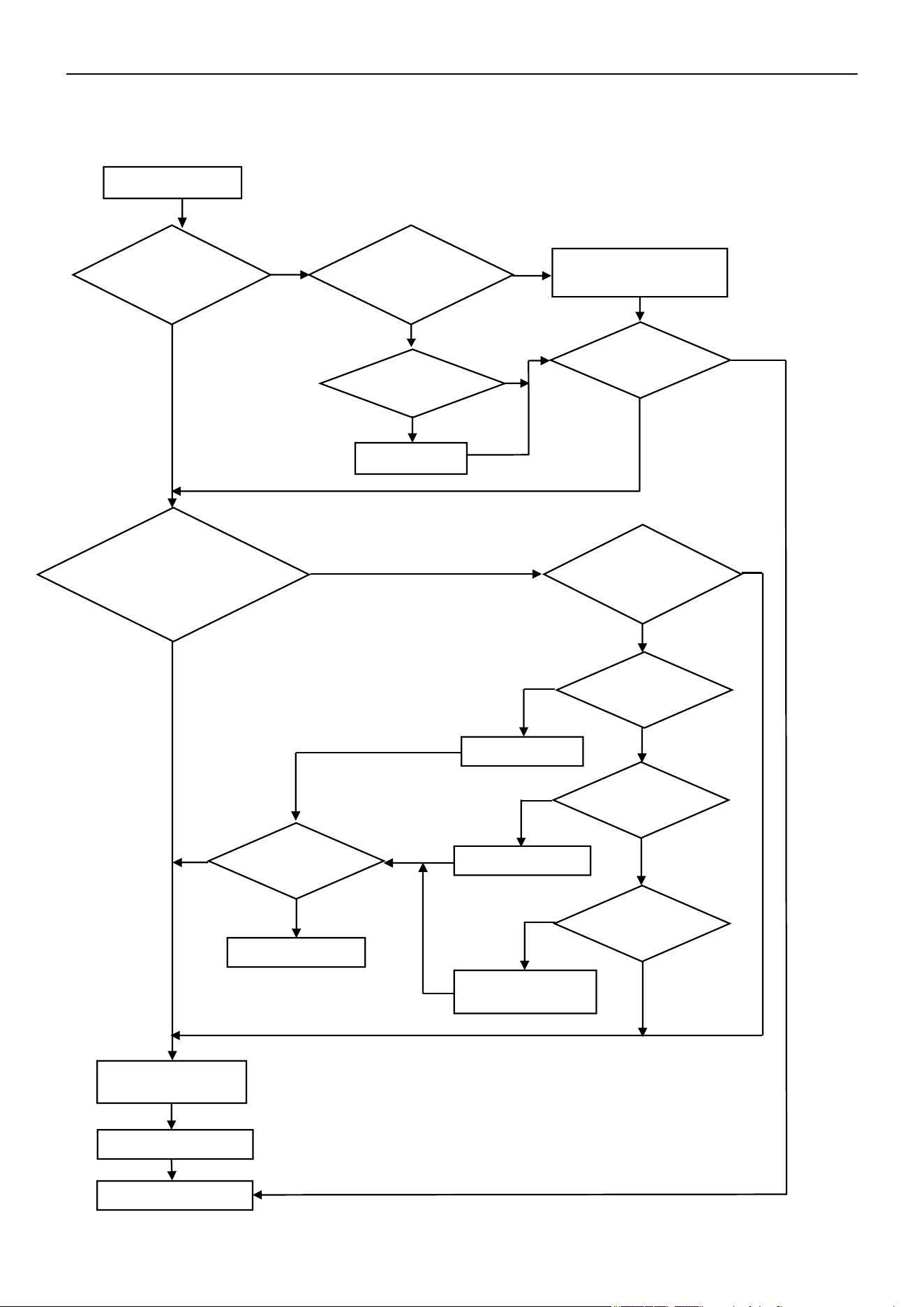
Air Conditioner Service Manual
25) F7 --- Module Temperature Protection
If the IPM temperature is more than 203°F(95°C), the system will undergo IPM over-temperature protection and
display the “F7” error code.
Display F7
Fix the screw
Low pressure normal?
(0.8-1.2Mpa)
Is the IPM temperature
circuit abnormal?
Replace the ODU PCB
Open the valve
Is the capillary
blocked?
Replace the capillary
Clean the condenser
and/or evaporator
End
F7 disappear?
Yes
No
No
No
No
No
No
No
Yes
Yes
Yes
Yes
Yes
Yes
Yes
Is the screw fully
fastened?
Yes
No
No
F7 disappear?
No
Yes
End
Is the IPM well-
connected to the heat
sink?
Is there any dust or
gap between the IPM
and heat sink?
Clean or adjust the gap
between the IPM and heat
sink
Is the ODU cooling system
abnormal? Compressor
with big running current?
(9,12K:6-7A/
18,24K:7-9A)
Is the 2- and 3-way
valve fully opened?
Is the condenser
and/or evaporator
dirty?
77
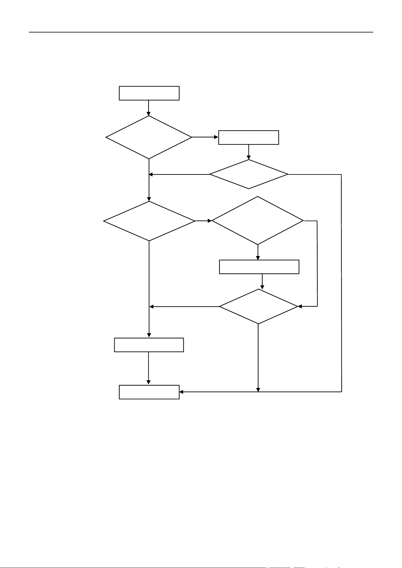
Air Conditioner Service Manual
26) F8 --- 4-Way Value Reversing Abnormal
In Heating mode, if the IDU coil temperature is measured at 41°F/5°C (room temperature) or lower after the
compressor operates for 8 min, the unit will display the "F8" error code.
27) F9 --- Module Temperature Test Circuit Failure
Reason: The IPM module temperature test circuit failure.
Solution: Replace the ODU PCB.
28) FA --- Compressor Phase-Current Test Circuit Failure
Reason: The compressor phase-current test circuit failure.
Solution: Replace the ODU PCB.
Display F8
Is there 220V
voltage on the
4-way valve?
Replace the ODU PCB
Replace the 4-way valve coil
End
Is the 4-way valve
wiring connection
correct?
Reconnect
F8 disappear?
F8 disappear?
Yes
No
Yes
Yes
Yes
Yes
No
No
No
No
Test the valve coil resistance
using multimeter. Is it
experiencing a short circuit or
an open circuit fault?
78
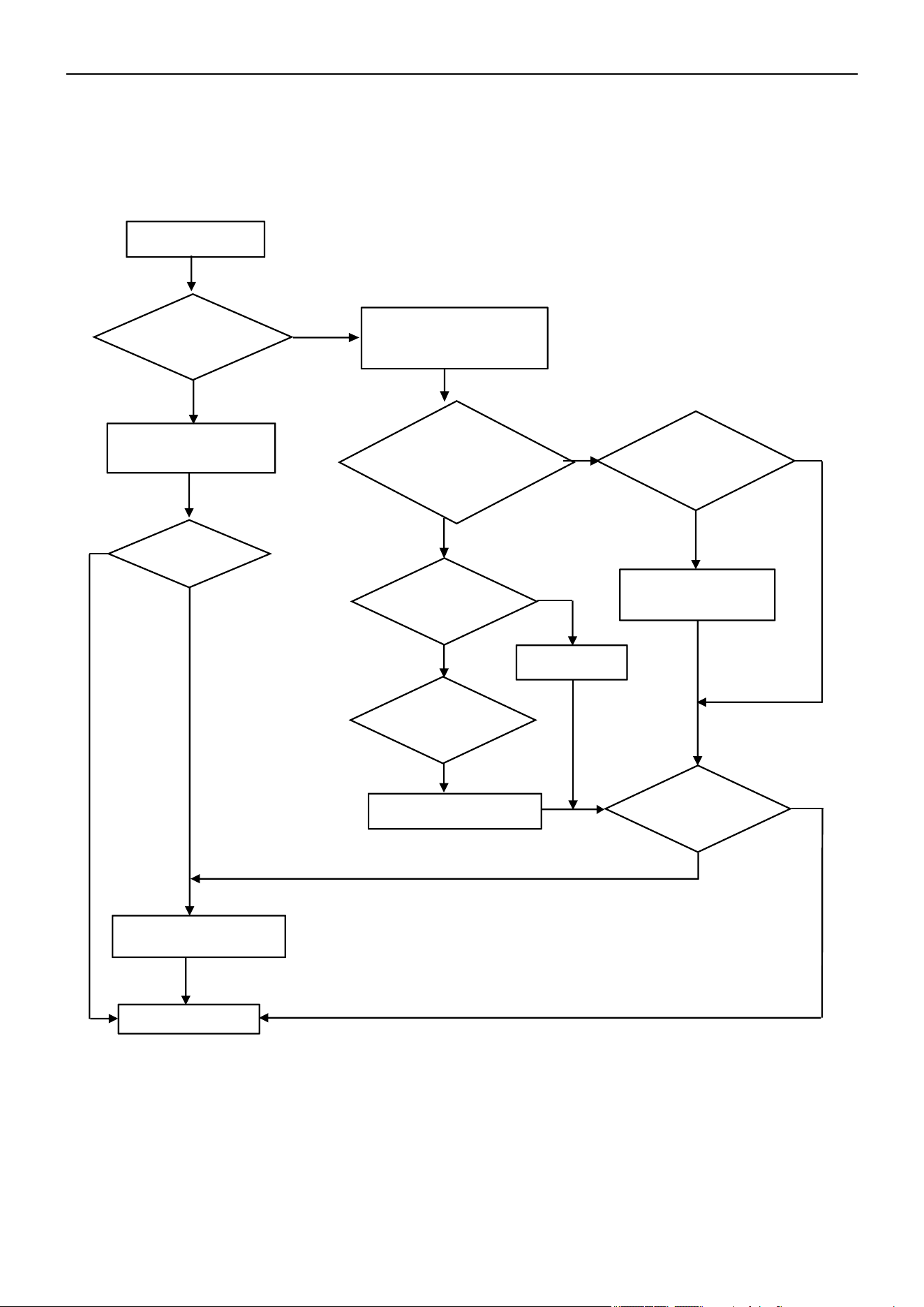
Air Conditioner Service Manual
29) Fy, E4 --- Gas Leakage Protection and Abnormal AC Cooling System
After the compressor operates at high frequency for 9 min, if the IDU evaporator and ODU condenser
temperatures show only minor variations compared to previous readings but the compressor discharge
temperature remains high, the unit will display the "Fy" or "E4" error code.
Check the pipe
connection. Any gas
leakage?
Repair and charge new
gas as spec
Check the room and evaporator
coil temperature
No
Yes
Is the sensor well-
connected to the
PCB?
Replace the sensor
Is any of the evaporator
pipe blocked?
No
Replace the
evaporator
Yes
Display Fy/E4
Yes
End
Problem solved?
Replace the indoor PCB
Yes
Reconnect
No
No
No
No
Yes
Yes
Is the temperature
difference more than
36°F
(2°C)
btw RT and
PT after the
unit
starts
for 10 min?
Is the sensor
experiencing a short
circuit or an open
circuit fault?
Is the malfunction
eliminated?
79
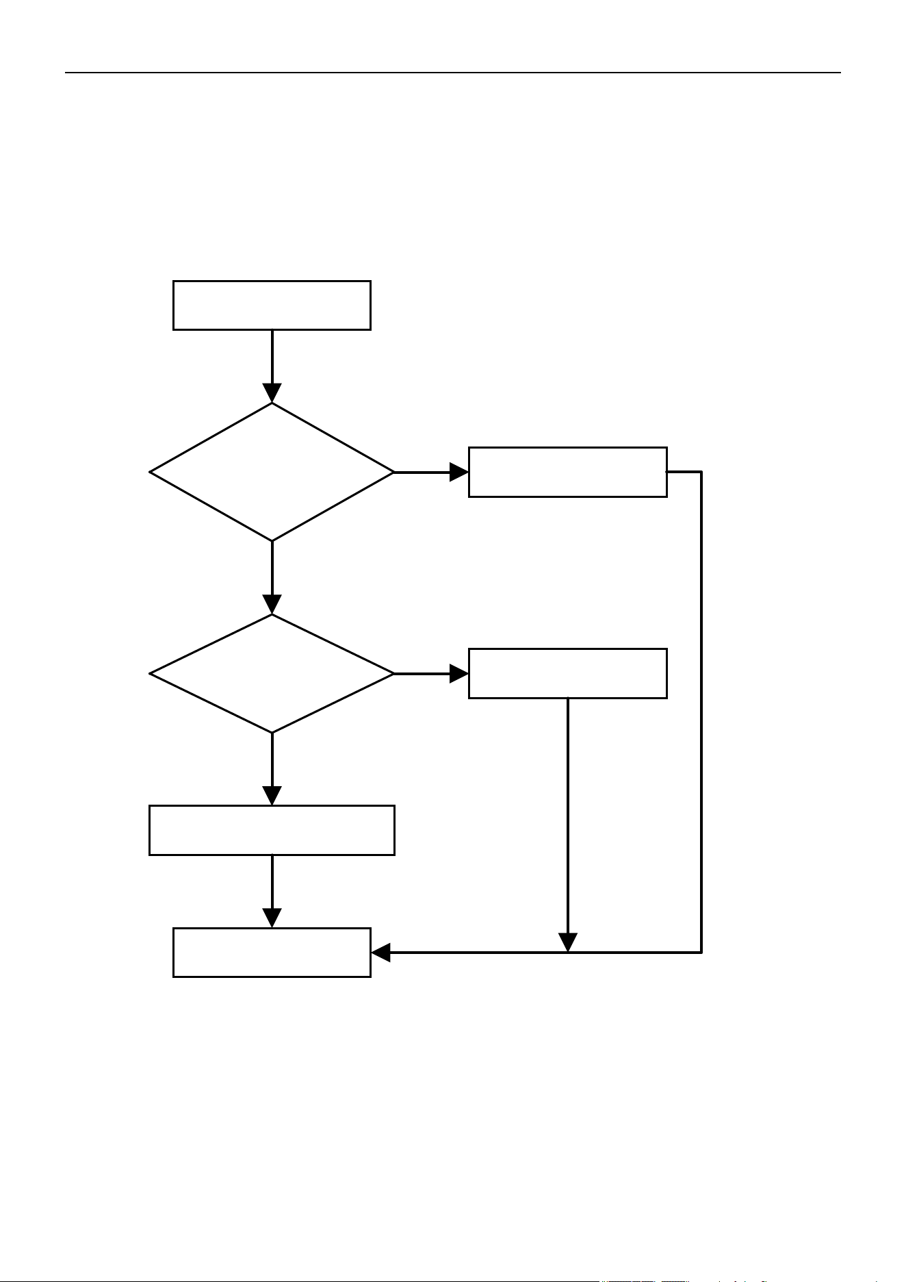
Air Conditioner Service Manual
30) H1, H2 --- High Pressure Switch Failure and Low Pressure Switch Failure
1. The high-pressure switch is installed at the discharge pipe of the system. When the pressure on the high-
pressure side of the system exceeds the preset protection value, the protection mechanism is triggered. The "H1"
error code displays.
2. The low-pressure switch is installed at the suction pipe of the system. When the pressure on the low-pressure
side of the system falls below the preset protection value, the protection mechanism is triggered. The "H2" error
code displays.
Display H1/H2
Is the switch well-
connected to the PCB?
Reconnect
Is the system pressure
normal?
Replace the pressure
switch
Replace the ODU PCB
End
Yes
No
Yes
No
80
Steps Reference Photo
Before disassembly
1: Remove the PCB cover, valve cover, and top cover
A
B
1). Unfix 1 screw on the PCB
cover, then remove the cover
from the unit.
2). Unfix 1 screw on the valve
cover, then take it out.
Unfix the screws on the top/
left/right plates, then take off
the top cover.
A
B
Air Conditioner Disassembly Manual
7. Indoor and Outdoor Unit Disassembly
7.1 Outdoor Unit Disassembly
Outdoor Unit Model Numbers: YN020GLSI24M2G | YN030GLSI24M3G | YN040GLSI24M4G |
YN050GLSI24M5G
81
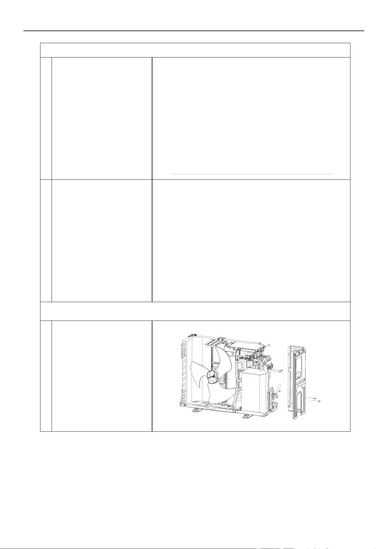
A
B
A
2. Disassemble the fan guard and front panel
Remove the grille screws from
the front panel, then take out the
grille.
A
B
1). Unfix the screws on the front
panel of the fan guard.
2). Separate the ODU middle
plate and base plate. Lift the
front panel so you can take it out
from the unit.
3. Disassemble the left and right plate
Unfix the screws on the right
plate, electric box assembly,
valve plate, and base plate.
Then remove the right plate.
A
Air Conditioner Disassembly Manual
82
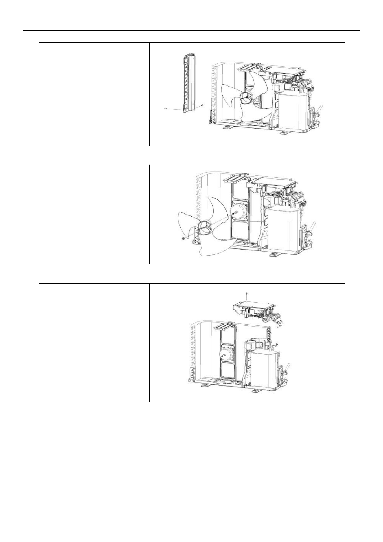
B
A
A
B
Unfix the screws on the left
plate, base plate, and
condenser plate. Then take
out the left plate.
4. Disassemble the axis fan blade
Unscrew the fan blade nut.
Remove the blade.
A
5. Disassemble the electric box
Unfix the screws on the electric
box and motor supporter.
Loosen the wiring clamp, then
take out the control box.
A
Air Conditioner Disassembly Manual
83
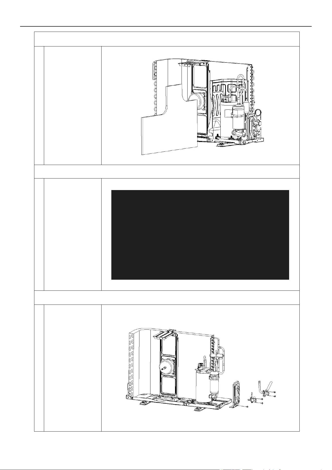
6. Remove the noise cotton
A
Take the noise
cotton out.
7. Disassemble the separate plate
Unfix the screw on
the separate plate
and unit, then take it
out.
8. Disassemble the 2-way and 3-way valve
Unfix the screws on
the valve plate and
base. Take out the
2-way and 3-way
valve by welding.
Note:
1). Welding can only
occur while there is
no gas in the unit.
2). Pay attention to
the fire to prevent
any injury.
A
A
Air Conditioner Disassembly Manual
84
9. Disassemble the 4-way valve assembly
Remove the 4-way
valve from the
system by welding.
Ensure there is no
damage to the
compressor,
nameplate, etc.
10. Disassemble the compressor
Unscrew the nuts
and remove the
compressor.
11. Remove the fan motor and fan supporter
Unfix the screws on
the fan motor and
supporter, then
remove the supporter
of the base plate.
Note:
Pay attention to the
motor wiring. It can’t
be taken out by force.
A
A
A
Air Conditioner Disassembly Manual
85
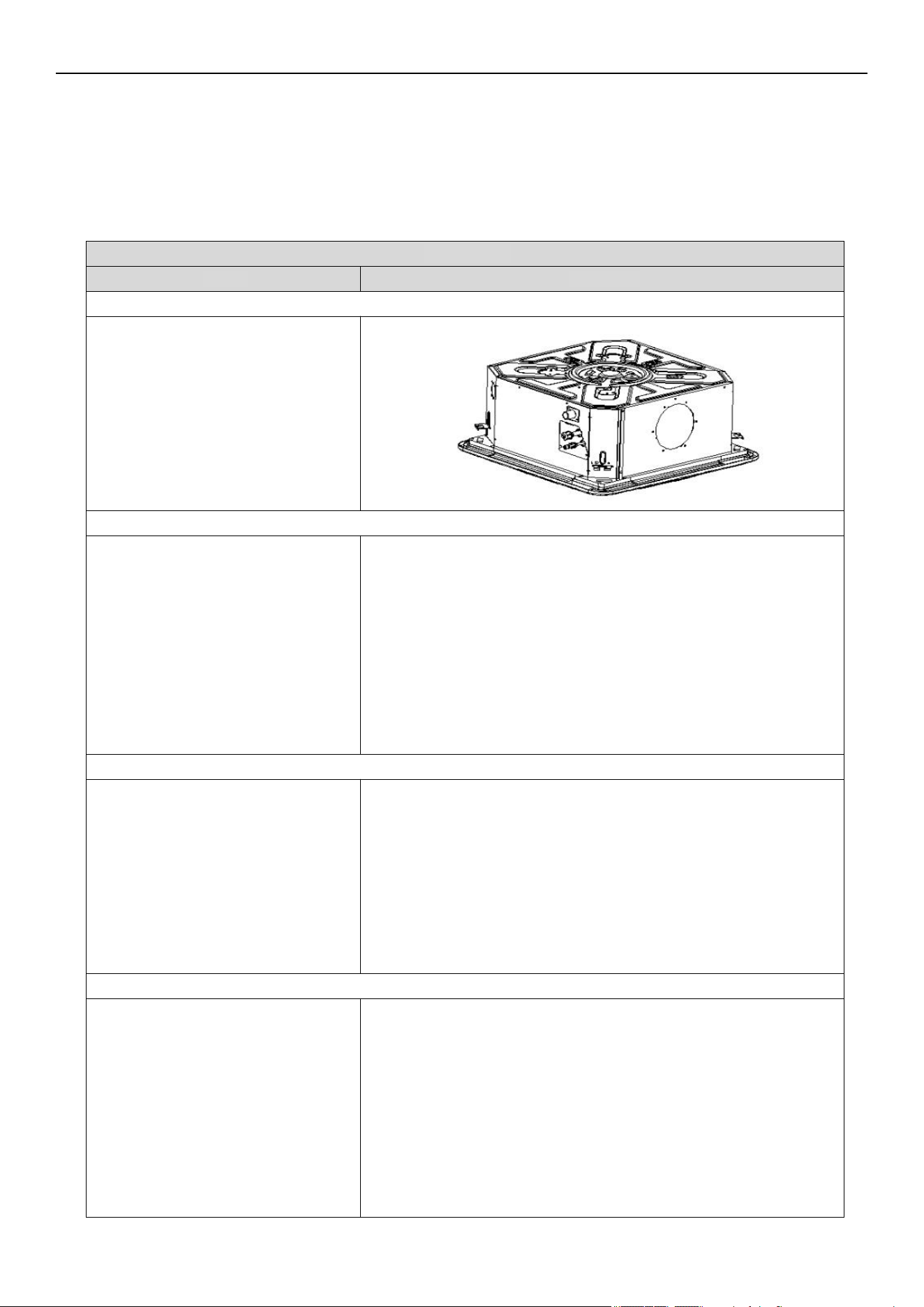
Steps Reference Photo
Before disassembly
1. Remove the seal plate and drain spout
A. Disassemble the seal plate.
B. Remove the drain spout.
2. Remove the front and rear fascia assembly
Unfix the screws and hooks on the
base plate, as well as the front and
rear panel assembly. Remove the
front and rear fascia assembly
from the unit.
3. Dismantle the base assembly
Remove the chassis components by
unfixing the screws between the
base foam part, evaporator fix plate,
and base assembly.
Air Conditioner Disassembly Manual
7.2 Indoor Unit Disassembly
Ceiling Cassette
Indoor Unit Model Numbers: CT009GLSILCFHG | CT012GLSILCFHG | CT018GLSILCFHG |
CT024GLSILSFHG
86
4. Remove the base foam assembly
Remove the base foam assembly.
5. Dismantle the water pump assembly
Dismantle the water pump assembly.
Take out the water pump in the
same direction shown in the photo.
6. Dismantle the evaporator assembly
Dismantle the evaporator assembly.
Take out the evaporator in the same
direction shown in the photo.
7. Remove the evaporator fixing plates
Remove the evaporator fixing plates
in the same direction as shown in the
photo.
Air Conditioner Disassembly Manual
87
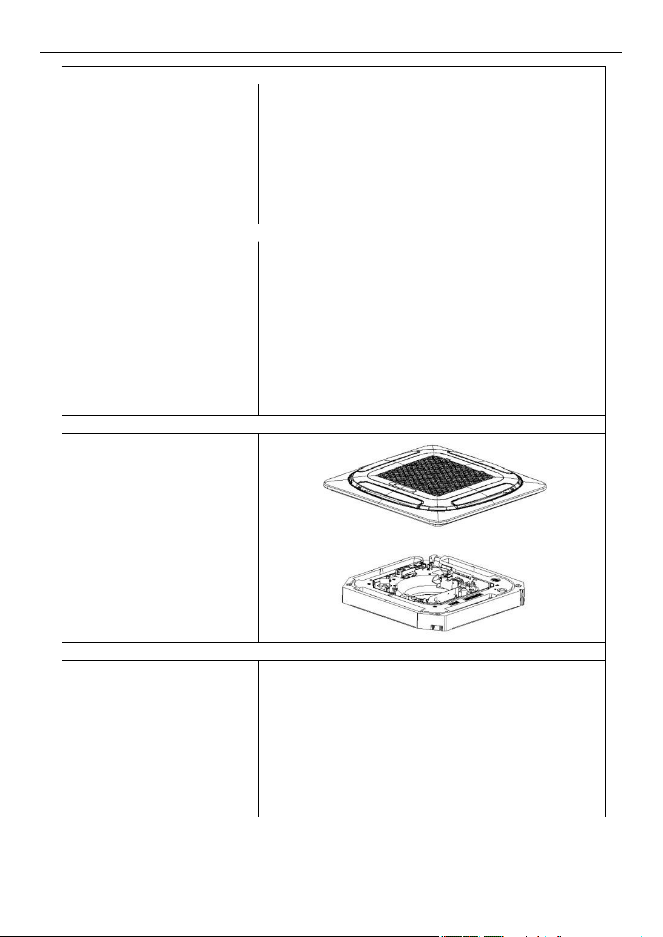
Disassemble the DC motor.
9. Remove the centrifugal fan
Remove the centrifugal fan.
10. Remove the panel assembly
Unfix the screws on the panel and
drainage assembly. Remove the
panel assembly
11. Remove the USB/wireless network module
8. Disassemble the DC motor
Unfix the screws on the USB/
wireless network module and air
guide part. Remove the module.
Air Conditioner Disassembly Manual
88
Unfix the screws on the electric
control box, water tray assembly,
and air guide in the direction shown
in the photo. Remove the electric
control box assembly.
13. Disassemble the air guide parts
Unfix the screws on the guide parts
and water tray. Remove the air guide
parts.
12. Remove the electric box assembly
Air Conditioner Disassembly Manual
89
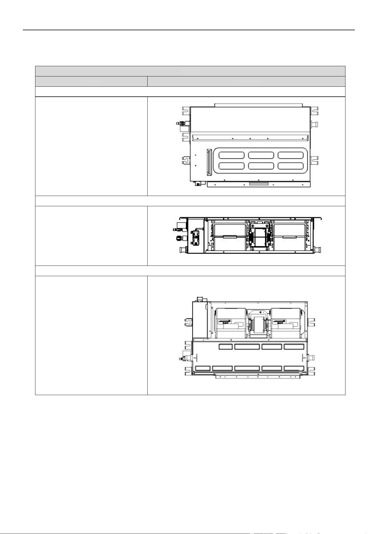
Steps
Reference Photo
Before disassembly
1. Disassemble the filter assembly
A. Disassemble the filter assembly.
B. Remove the filter.
2. Disassemble the base part and air return plate
A. Remove the base part by unfixing
the screws on the left and right side
panels, as well as the center partition.
B. Remove the screws between the air
return plate, left side plate, and electric
control box. Then remove the air
return plate.
C. Remove the wireless network fixing
cover and take out the USB
connection cable.
Air Conditioner Disassembly Manual
Ductable Concealed
Indoor Unit Model Numbers: RT009GLSILCFHG | RT012GLSILCFHG | RT018GLSILCFHG |
RT024GLSILSFHG
90
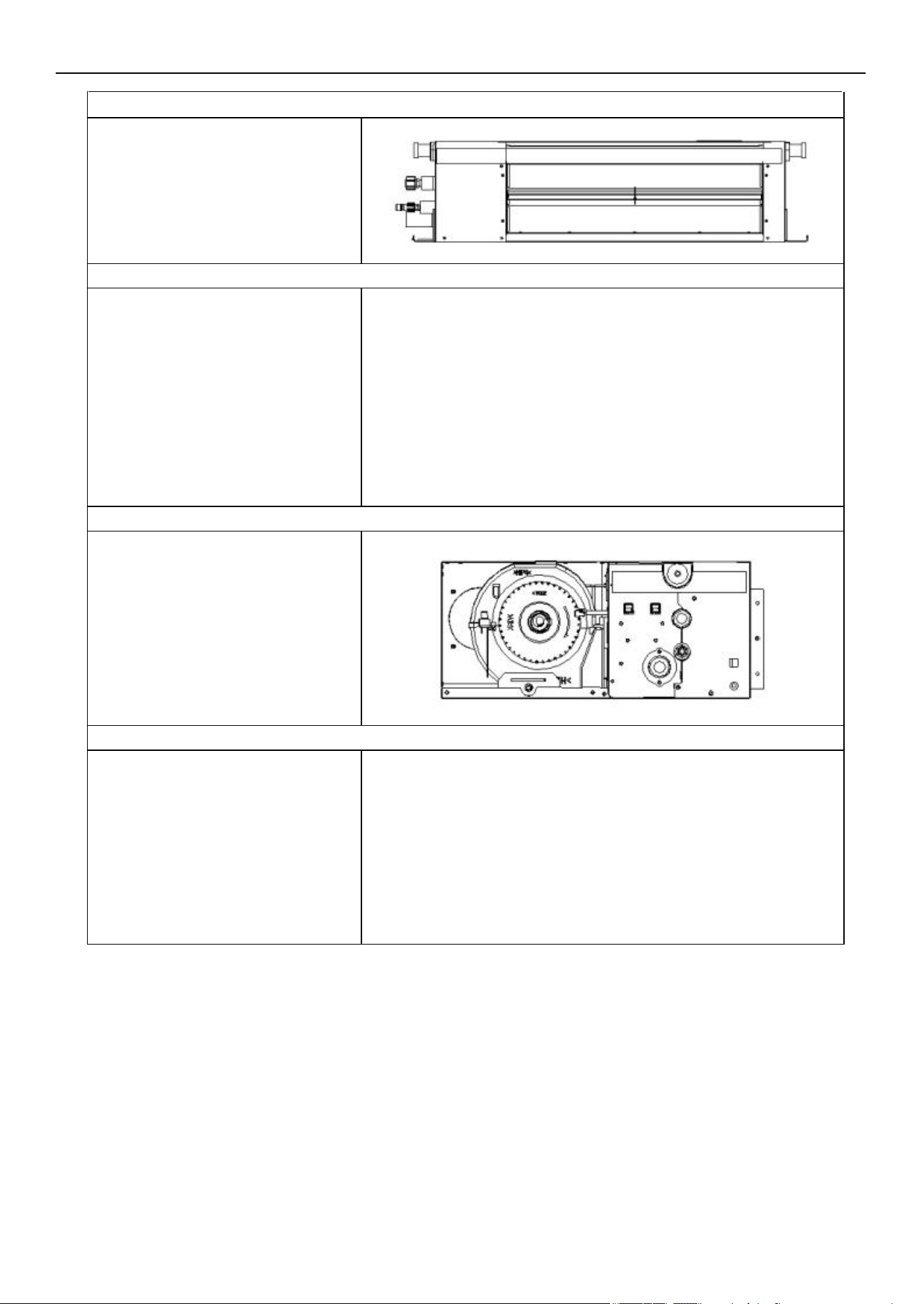
Unfix the screws on the front panel,
then remove the assembly.
4. Remove the electrical box cover and hooks
A. Unfix the screws on the electrical
box cover, then remove the cover.
B. Unfix the screws on the hooks,
then remove the hooks.
5. Remove the electric control box assembly
Unfix the screws on the electric
control box, then remove the electric
control box.
6. Remove the water tray assembly
A. Remove the base plate.
B. Lift the drain nozzles up on both
sides to take out the water tray.
3. Dis
assemble the front panel assembly
Air Conditioner Disassembly Manual
91
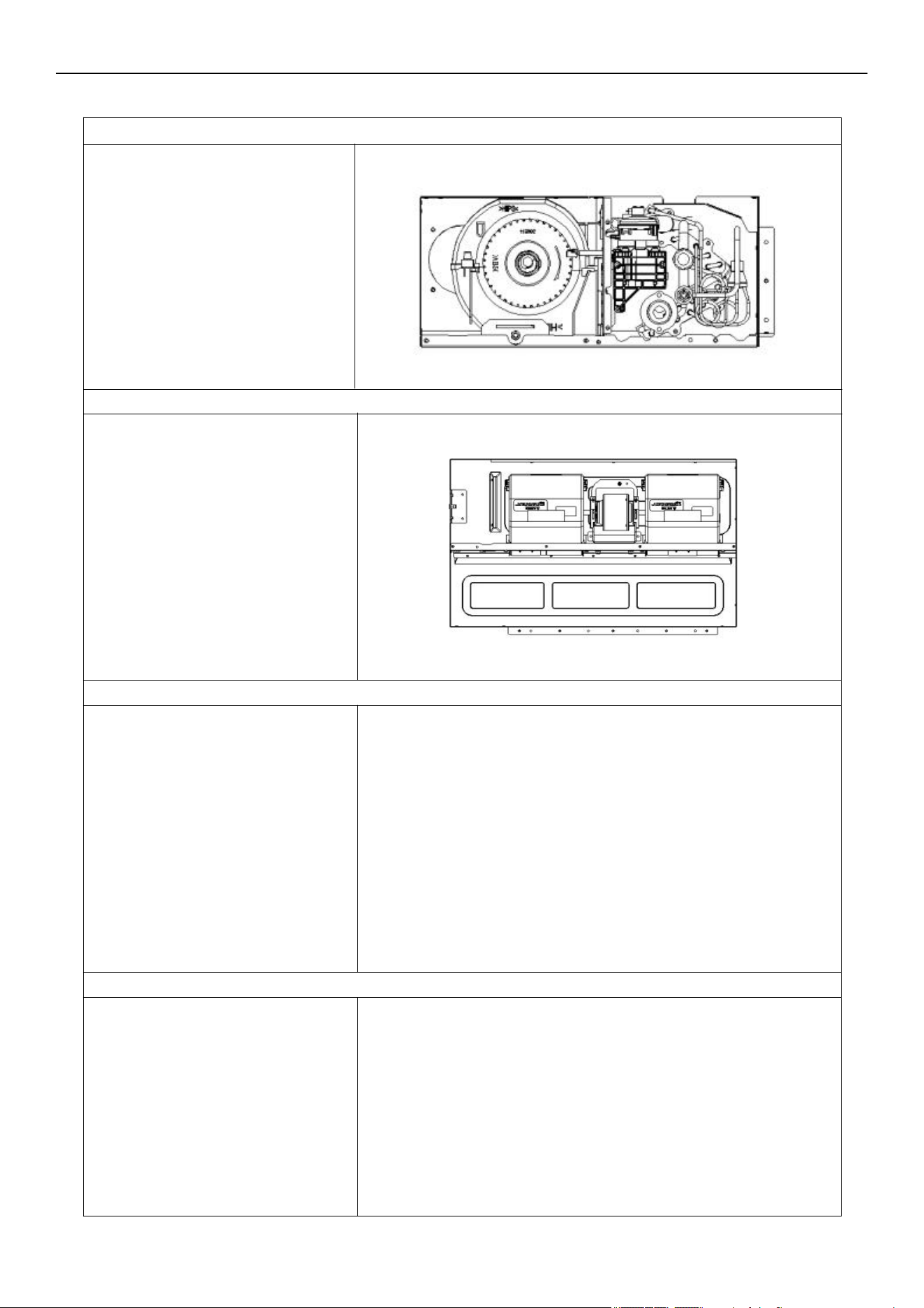
A. Unfix the screws on the water
pump assembly and center divider.
Then remove the water pump
assembly.
B. Unfix the screws on the evaporator
module and left side panel assembly.
Then take out the left side panel.
C. Unfix the screws on the left side
panel, top panel, and center partition.
Remove the left side panel.
9. Remove the centrifugal fan volute assembly and DC motor
Remove the motor limit clasp, then
take the volute assembly and DC
motor out in the direction shown in
the photo.
10. Remove the center divider assembly
Unfix the screws on the center
divider assembly and top cover.
Remove the center divider.
8. Remove the water pump assembly, evaporator module, and left side panel
7. Disassemble the right side plate and drainage mounting assembly
A. Unfix the screws between the right
side plate, evaporator end plate, top
plate, and drain mounting assembly.
Then remove the right side plate.
B. Remove the drain nozzle on the
drain mounting assembly, then take
out the assembly.
Air Conditioner Disassembly Manual
92
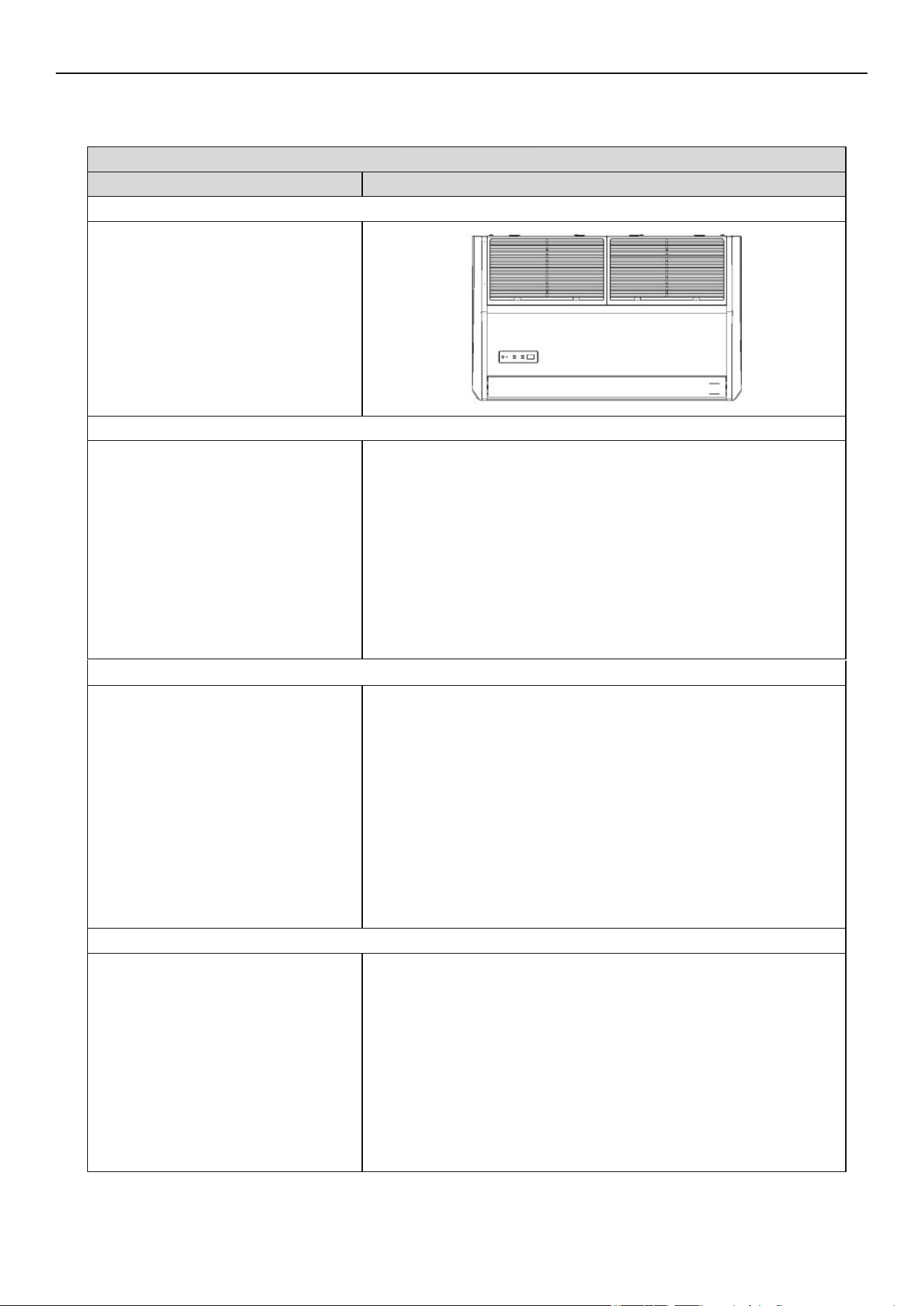
2. Dismantle the left and right side plate
Unfix the screws as shown in the
photo. Remove the left and right
side blocks from the snap hooks.
3. Remove the electronic control box assembly
Unfix the screws as shown in the
photo. Then remove the electronic
control cover plate.
Steps Reference Photo
Before disassembly
1. Remove the front grille
A. Remove the screws by pushing the
buckles in the direction as shown in
the photo.
B. Open the grille. Then remove the
grille from the back snap hook.
Air Conditioner Disassembly Manual
Floor-Ceiling Flex
Indoor Unit Model Numbers: UT018GLSILCFHG | UT024GLSILSFHG
93
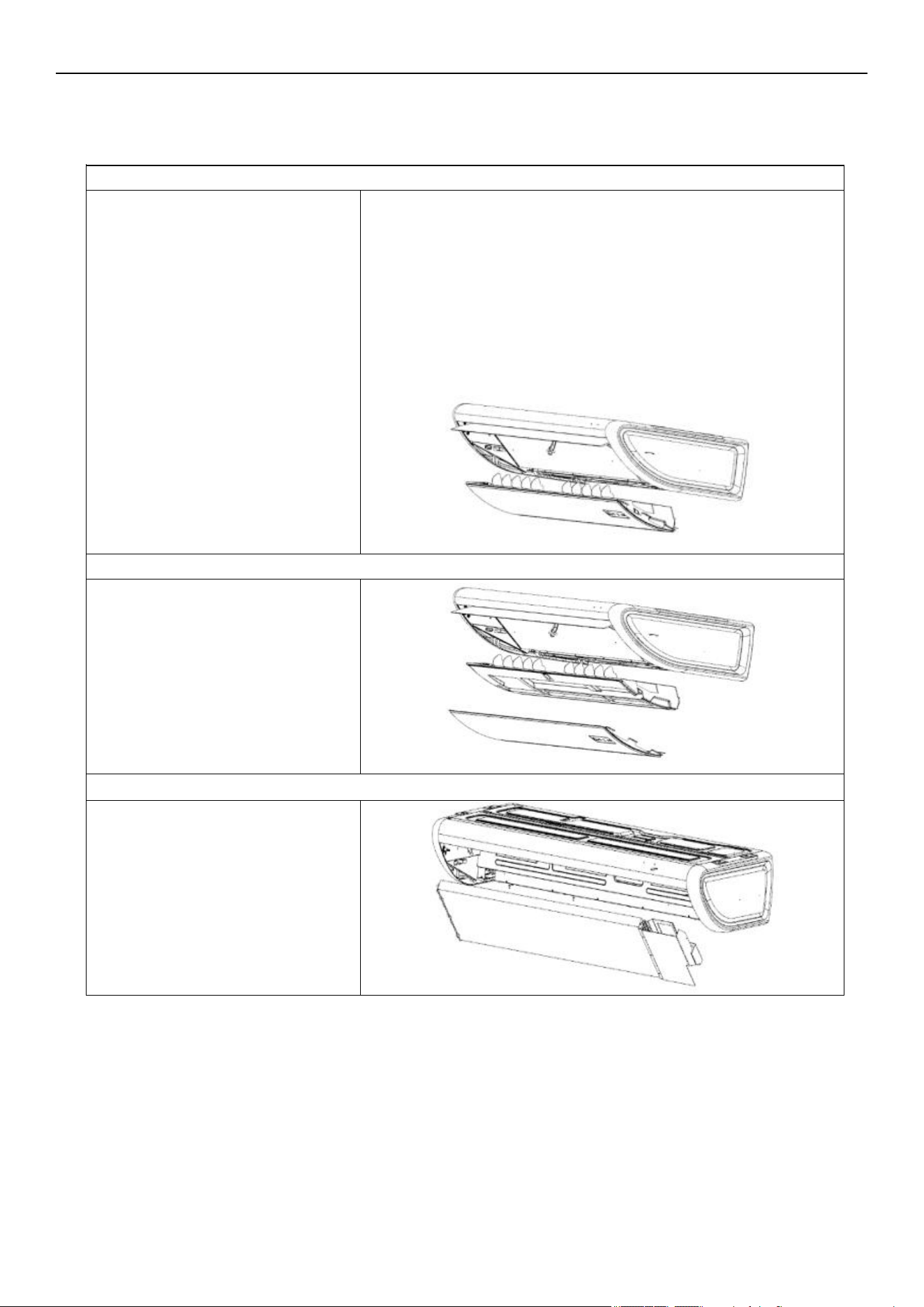
Take out the evaporator.
6. Remove the evaporator assembly
4. Remove the front panel assembly
Unfix the screws on the front panel.
Then remove the panel assembly.
5. Remove the water tray
Take out the water tray.
Air Conditioner Disassembly Manual
94
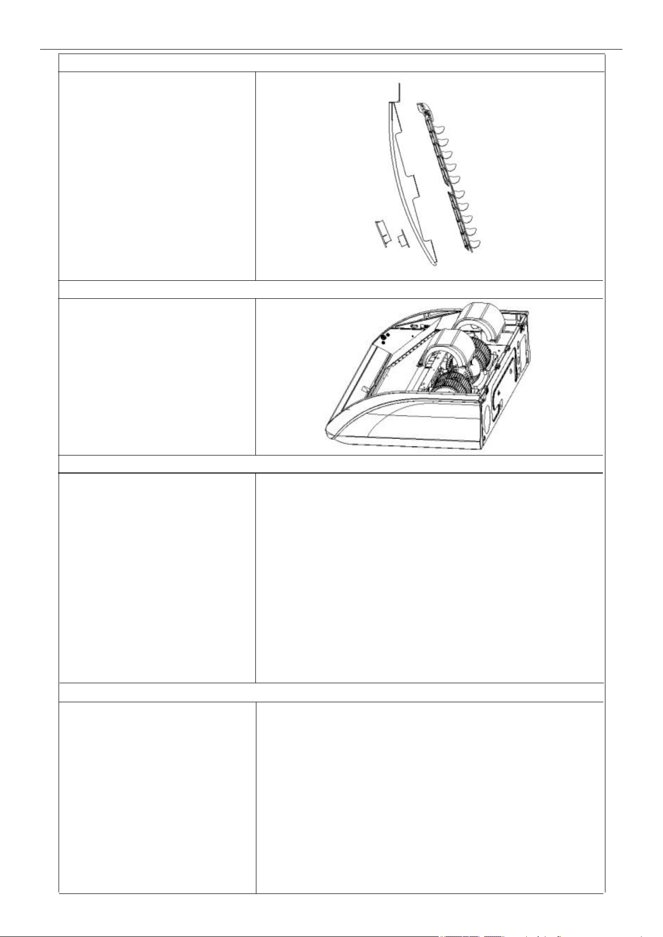
Remove the fan motor.
10. Disassemble the fan motor
8. Remove the volute parts
Remove the volute parts.
9. Disassemble the centrifugal fan
Take out the centrifugal fan.
7. Remove the display panel and vane assembly
Take out the display panel and vane
assembly.
Air Conditioner Disassembly Manual
95
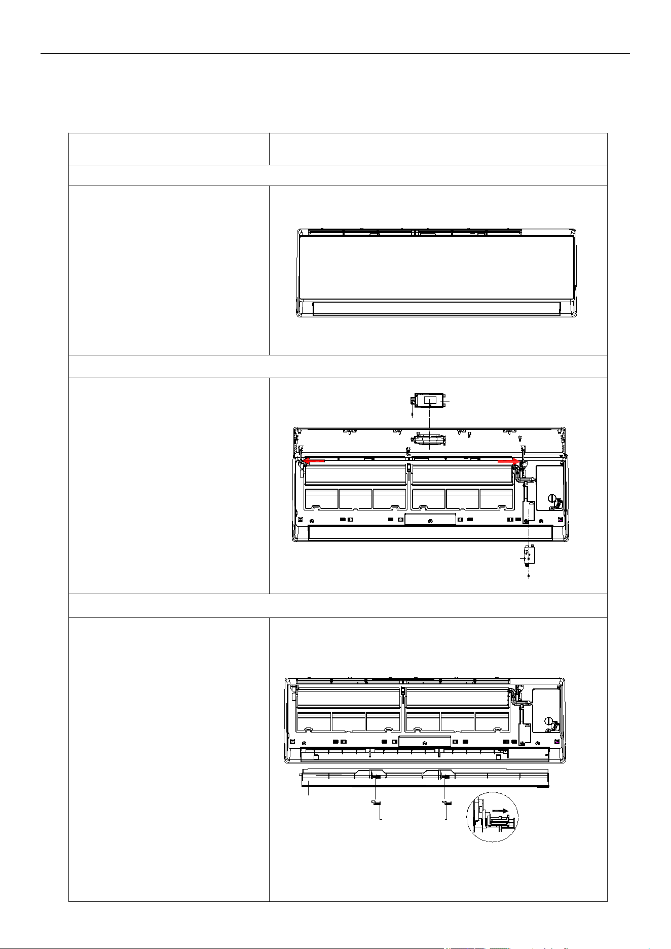
Steps Reference Photo
Before disassembly
1. Disassemble the front panel, display board, and wireless network module
A. Open the front panel.
B. Remove 1 screw, then take
the display box out from the panel.
C. Release the panel axis, which
is shown in red arrows, out from
middle frame and take the panel
out.
D. Unscrew and remove the
wireless network module from the
middle frame.
2. Remove the louver
Unlock the louver lockers
(clip). Bend the louver slightly by
hand and remove it from the
middle frame and stepping motor.
Louver
Louver locker
Unlock the
louver lockers
Display
Wireless network module
Air Conditioner Disassembly Manual
Wall Mounted
Indoor Unit Model Numbers: WT009ALSI24HLG | WT012ALSI24HLG | WT009GLSI24HLG |
WT012GLSI24HLG | WT018GLSI24HLG | WT024GLSI24HLG
96
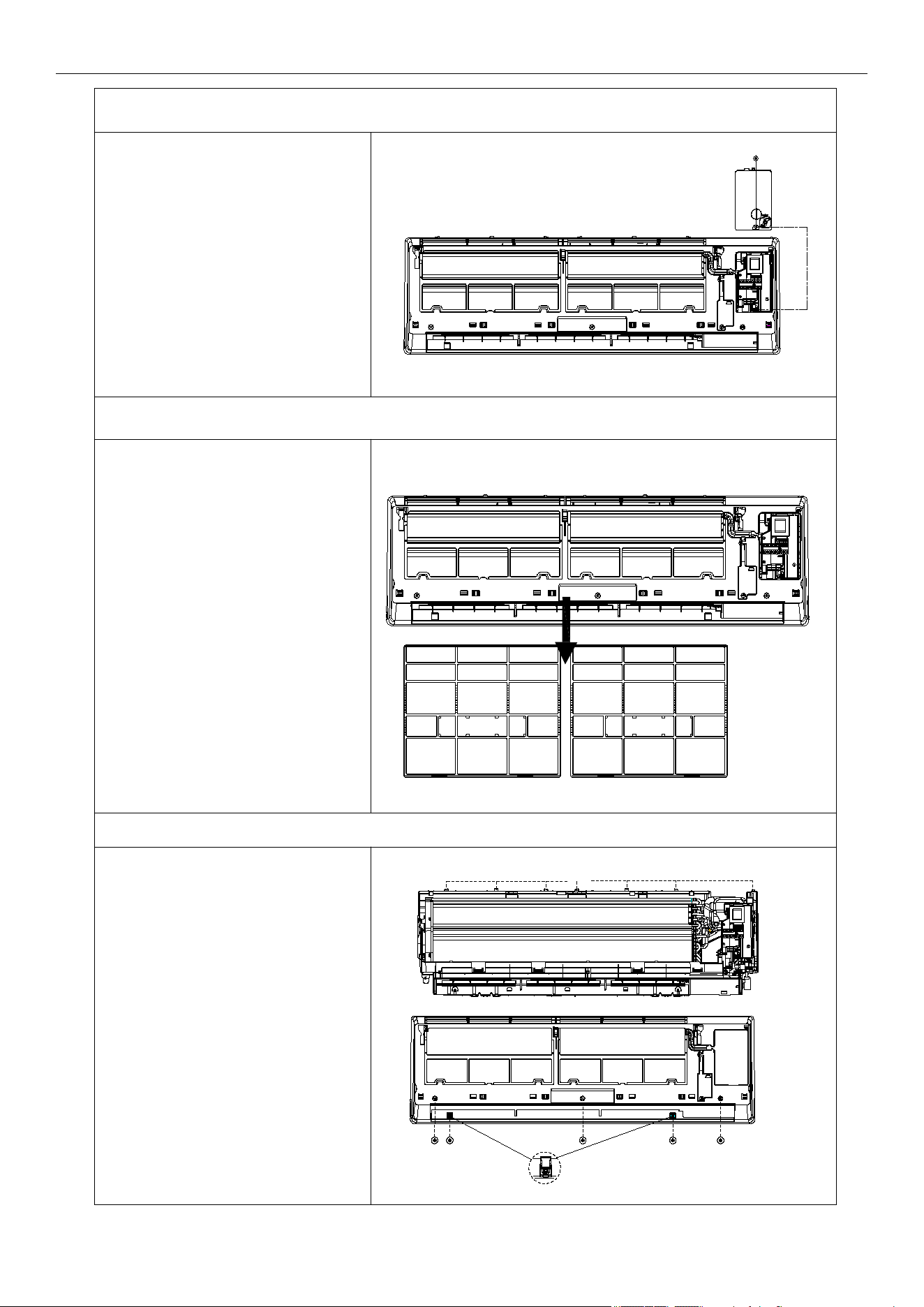
3. Remove the electric control box cover
4. Remove the filter
Push the filter slightly upwards.
You can take the filter out from the
unit.
5. Disassemble the middle frame
Claps
Screw
A. Open the screw cover and unfix
the screw with a cross screwdriver.
B. Remove the middle frame by
loosening the clasps of the unit
base. Take out the frame.
The fix screw
Air Conditioner Disassembly Manual
97
Unfix 1 screw on the electric box
cover, then remove the cover.
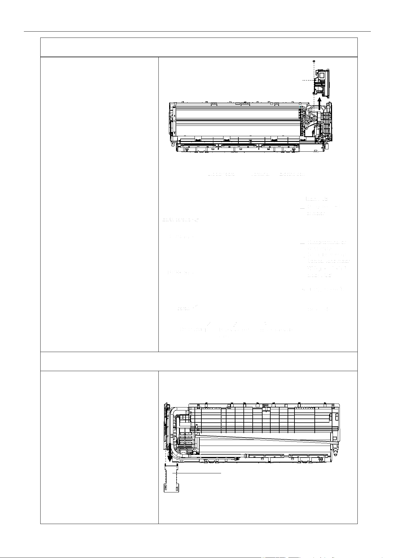
6. Disassemble the electric control box
A. Remove the RT and IPT from
the evaporator.
B. Unscrew all the earth ground
wirings on the evaporator.
C. Take all the connectors out from
the PCB.
D. Unfix 1 screw from the control
box of the unit base frame.
Remove the control box from the
unit.
Note: The picture on the right is
for your reference only. The wiring
connection for the exact model may
be slightly different.
7. Remove the pipe cover
Loosen the lower edge of the pipe
cover from the base frame,
then remove the cover from the unit.
Cover locker
Pipe
Electric control
box
Air Conditioner Disassembly Manual
98
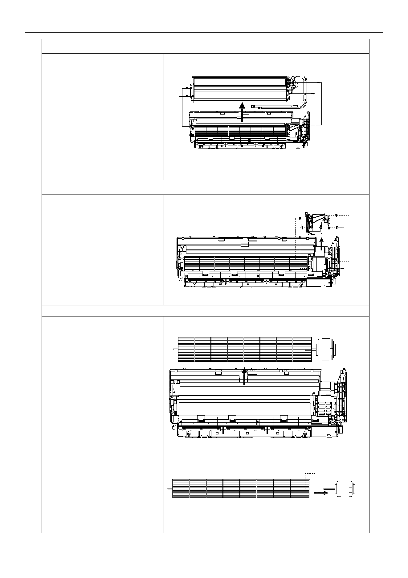
8. Disassemble the evaporator
A. Unfix 2 screws on the left side.
B. Unfix 2 screws on the right side of
the motor cover/right support plate.
C. Take the evaporator out from the
unit by uplifting the input/output pipes
slightly.
9. Remove the motor cover
Unfix 4 screws on the motor cover
of the base frame.
10. Disassemble the fan motor and fan blade
A. Lift the fan blade and fan motor.
Take out the base frame.
B. Unfix 1 screw on the axis of the
fan motor, then you can separate the
fan blade and fan motor.
Screw
Screws
Screws +
Motor cover
Screws
Air Conditioner Disassembly Manual
99
Air Conditioner Service Manual
R min
(k Ohm)
R(t)
(k Ohm)
R max
(k Ohm)
R min
(k Ohm)
R(t)
(k Ohm)
R max
(k Ohm)
R min
(k Ohm)
R(t)
(k Ohm)
R max
(k Ohm)
-22( -30 )
60.343 64.104 68.080 5.716 5.846 5.977 0.974 1.010 1.047
57.157 60.666 64.375 5.498 5.620 5.742 0.944 0.980 1.016
54.139 57.413 60.870 5.290 5.404 5.518 0.917 0.952 0.988
51.301 54.355 57.579 5.091 5.198 5.305 0.890 0.924 0.959
48.630 51.480 54.487 4.900 5.000 5.100 0.864 0.897 0.931
46.115 48.776 51.582 4.713 4.811 4.909 0.839 0.871 0.904
43.748 46.232 48.850 4.533 4.630 4.727 0.814 0.846 0.879
41.517 43.836 46.279 4.362 4.457 4.552 0.791 0.822 0.854
39.415 41.581 43.861 4.199 4.292 4.386 0.769 0.799 0.830
37.432 39.456 41.585 4.042 4.133 4.225 0.746 0.776 0.807
35.581 37.473 39.462 3.892 3.982 4.072 0.725 0.754 0.784
33.798 35.565 37.421 3.748 3.836 3.925 0.705 0.733 0.762
32.134 33.785 35.519 3.611 3.697 3.784 0.685 0.713 0.742
30.561 32.105 33.725 3.479 3.564 3.649 0.666 0.693 0.721
29.077 30.520 32.033 3.353 3.436 3.520 0.647 0.674 0.701
27.673 29.023 30.437 3.232 3.313 3.395 0.629 0.655 0.682
26.347 27.609 28.931 3.116 3.195 3.275 0.613 0.638 0.664
25.092 26.273 27.508 3.004 3.082 3.161 0.595 0.620 0.646
23.905 25.010 26.165 2.898 2.974 3.051 0.580 0.604 0.629
22.782 23.816 24.896 2.795 2.870 2.946 0.563 0.587 0.611
21.720 22.687 23.697 2.697 2.770 2.844 0.549 0.572 0.596
20.713 21.618 22.562 2.604 2.675 2.748 0.534 0.557 0.580
19.759 20.607 21.490 2.513 2.583 2.654 0.520 0.542 0.565
18.855 19.649 20.475 2.426 2.494 2.564 0.506 0.528 0.550
17.999 18.742 19.515 2.343 2.410 2.478 0.493 0.514 0.536
17.187 17.883 18.606 2.263 2.328 2.395 0.480 0.501 0.522
16.416 17.068 17.745 2.186 2.250 2.315 0.468 0.488 0.509
15.685 16.296 16.930 2.111 2.174 2.238 0.456 0.476 0.497
14.991 15.563 16.156 2.041 2.102 2.164 0.444 0.464 0.484
14.332 14.868 15.423 1.972 2.032 2.093 0.433 0.452 0.472
13.766 14.270 14.792 1.906 1.965 2.025 0.422 0.441 0.460
13.111 13.582 14.069 1.844 1.901 1.959 0.412 0.430 0.449
12.546 12.987 13.443 1.783 1.839 1.896 0.401 0.419 0.437
12.008 12.422 12.849 1.724 1.779 1.835 0.391 0.409 0.427
11.497 11.885 12.284 1.668 1.721 1.776 0.381 0.399 0.416
11.012 11.375 11.749 1.614 1.666 1.719 0.372 0.388 0.406
10.548 10.889 11.239 1.562 1.613 1.665 0.362 0.379 0.395
10.109 10.428 10.756 1.512 1.562 1.613 0.353 0.369 0.386
9.689 9.988 10.295 1.463 1.512 1.562 0.344 0.360 0.376
9.289 9.570 9.858 1.417 1.465 1.514 0.335 0.351 0.367
Temp.
°F(°C)
Temp.
°F(°C)
Temp.
°F(°C)
-20( -29)
-18( -28)
-17( -27)
-15( -26)
-13( -25)
-11( -24)
-9(-23)
-8(-22)
-6(-21)
-4(-20)
-2(-19)
0(-18)
1(-17)
3(-16)
5(-15)
7(-14)
9(-13)
10( -12)
1 2(-11)
1 4(-10)
16(-9)
18(-8)
19(-7)
21(-6)
23(-5)
25(-4)
27(-3)
28(-2)
30(-1)
32(0)
34(1)
36(2)
37(3)
39(4)
41(5)
43(6)
45(7)
46(8)
48(9)
70(21)
72(22)
73(23)
75(24)
77(25)
79(26)
81(27)
82(28)
84(29)
86(30)
88(31)
90(32)
91(33)
93(34)
95(35)
97(36)
99(37)
100( 38 )
10 2( 39 )
10 4( 40 )
10 6( 41 )
10 8( 42 )
10 9( 43 )
111(44)
113(45)
11 5( 46 )
11 7( 47 )
11 8( 48 )
120(49)
12 2( 50 )
12 4( 51 )
12 6( 52 )
12 7( 53 )
12 9( 54 )
131( 55 )
133( 56 )
135( 57 )
136( 58 )
138( 59 )
140( 60 )
1 62 (72 )
1 63 (73 )
1 65 (74 )
1 67 (75 )
1 69 (76 )
1 71 (77 )
1 72 (78 )
1 74 (79 )
1 76 (80 )
1 78 (81 )
1 80 (82 )
1 81 (83 )
1 83 (84 )
1 85 (85 )
1 87 (86 )
1 89 (87 )
1 90 (88 )
1 92 (89 )
1 94 (90 )
1 96 (91 )
1 98 (92 )
1 99 (93 )
201(94)
203(95)
205(96)
207(97)
208(98)
210(99)
212(100)
214(101)
216(102)
217(103)
219(104)
221(105)
223(106)
225(107)
226(108)
228(109)
230(110)
232(111)
8. Thermistor Temperature Characteristics
Indoor Unit and Outdoor Exchange Temperature and Outside Air Temperature Sensor Temperature
Characteristics
100
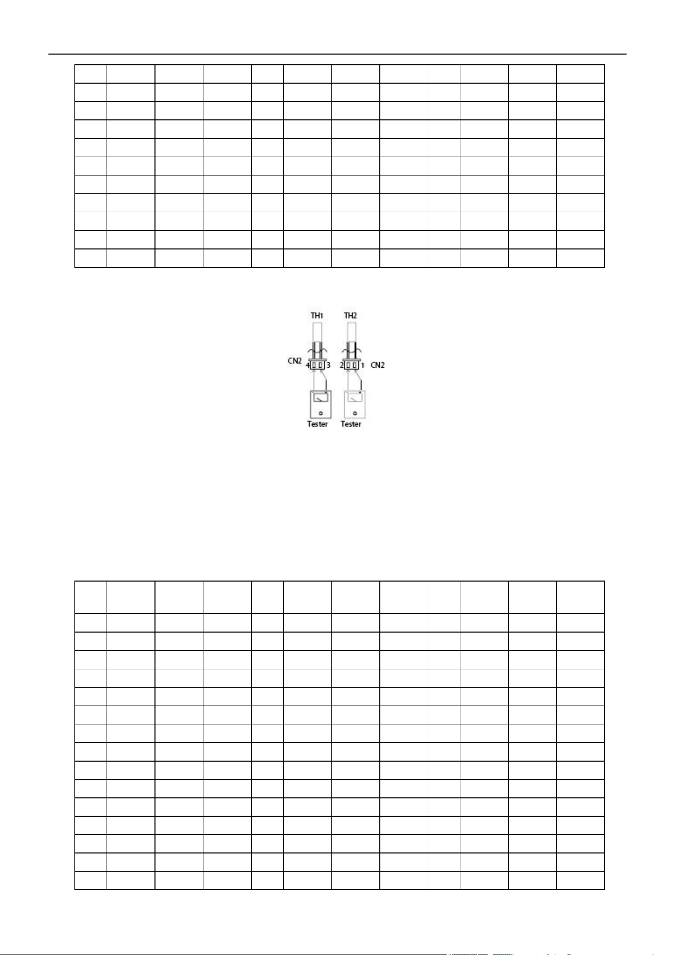
Air Conditioner Service Manual
8.909 9.172 9.441 1.372 1.419 1.467 0.327 0.342 0.357
8.545 8.792 9.044 1.328 1.374 1.421 0.319 0.333 0.349
8.199 8.431 8.667 1.287 1.332 1.378 0.311 0.325 0.340
7.870 8.087 8.308 1.247 1.291 1.336 0.303 0.317 0.332
7.554 7.758 7.965 1.208 1.251 1.295 0.296 0.309 0.324
7.254 7.445 7.639 1.171 1.213 1.256 0.288 0.302 0.315
6.968 7.147 7.329
1.135
1.176 1.218 0.281 0.294 0.308
6.694 6.862 7.032 1.100 1.140 1.181 0.274 0.287 0.301
6.433 6.590 6.749 1.067 1.106 1.146 0.268 0.280 0.293
6.183 6.331 6.480 1.035 1.073 1.112
5.945 6.083 6.223 1.004 1.041 1.079
Resistance at
77°F(25°C)
: Wall split type 5 kΩ; Cassette and Duct 10 kΩ.
R min
(k Ohm)
R(t)
(k Ohm)
R max
(k Ohm)
R min
(k Ohm)
R(t)
(k Ohm)
R max
(k Ohm)
R min
(k Ohm)
R(t)
(k Ohm)
R max
(k Ohm)
-22(-30)
288.879 337.780 386.68 20.114 21.847 23.579 2.733 2.835 2.937
272.641 318.219 263.797 19.263 20.900 22.538 2.646 2.742 2.839
257.401 299.897 342.392 18.453 20.000 21.547 2.561 2.653 2.745
243.09*2 282.727 322.363 17.681 19.143 20.605 2.480 2.567 2.654
299.654 266.633 303.613 16.945 18.327 19.710 2.401 2.484 2.567
217.028 251.541 286.054 16.243 17.551 18.858 2.326 2.404 2.483
205.162 237.383 269.604 15.575 16.811 18.047 2.183 2.253 2.324
194.005 224.097 254.188 14.937 16.106 17.275 2.183 2.253 2.324
183.513 211.625 239.736 14.328 15.434 16.541 2.115 2.182 2.249
173.642 199.912 226.181 13.748 14.794 15.841 2.050 2.113 2.176
164.353 188.909 213.465 13.194 14.184 15.175 1.984 2.047 2.109
155.608 178.569 201.530 12.665 13.602 14.540 1.921 1.983 2.045
147.373 168.850 190.326 12.160 13.048 13.935 1.860 1.921 1.982
139.616 159.710 179.803 11.678 12.518 13.358 1.801 1.862 1.922
132.307 151.112 169.917 11.217 12.013 12.809 1.744 1.804 1.864
Temp.
°F(°C)
Temp.
°F(°C)
Temp.
°F(°C)
50(10)
52(11)
54(12)
55(13)
57(14)
59(15)
61(16)
63(17)
64(18)
66(19)
68(20)
14 2( 61 )
14 4( 62 )
14 5( 63 )
14 7( 64 )
14 9( 65 )
1 51 (66 )
1 53 (67 )
1 54 (68 )
1 56 (69 )
1 58 (70 )
1 60 (71 )
234(112)
235(113)
237(114)
239(115)
241(116)
243(117)
244(118)
246(119)
248(120)
TH1: Indoor room temperature sensor and outside air temperature sensor
TH2: Indoor exchange temperature sensor and outside exchange temperature sensor
TH4: Outdoor exchange temperature sensor and outside exchange temperature sensor
TH5: Outdoor ambient temperature sensor and outside exchange temperature sensor
Before measuring the resistance, disconnect the connectors as shown above.
Outdoor Unit Discharge Sensor Temperature Characteristics
-20(-29)
-18(-28)
-17(-27)
-15(-26)
-13(-25)
-11(-24)
-9(-23)
-8(-22)
-6(-21)
-4(-20)
-2(-19)
0(-18)
1(-17)
3(-16)
73(23)
75(24)
77(25)
79(26)
81(27)
82(28)
84(29)
86(30)
88(31)
90(32)
91(33)
93(34)
95(35)
97(36)
99(37)
169(76)
171(77)
172(78)
174(79)
176(80)
178(81)
180(82)
181(83)
183(84)
185(85)
187(86)
189(87)
190(88)
192(89)
194(90)
101
Air Conditioner Service Manual
125.417 143.022 160.627 10.777 11.531 12.248 1.690 1.749 1.808
118.921 135.407 151.893 10.357 11.071 11.784 1.637 1.695 1.754
112.794 128.236 143.679 9.955 10.631 11.307 1.586 1.644 1.701
107.014 121.483 135.952 9.571 10.211 10.852 1.537 1.594 1.651
101.559 115.120 128.680 9.203 9.810 10.417 1.490 1.546 1.602
96.410 109.123 121.836 8.852 9.427 10.002 1.444 1.500 1.555
91.548 103.469 115.391 8.516 9.061 9.606 1.400 1.455 1.509
86.956 98.138 109.320 8.194 8.711 9.228 1.358 1.412 1.465
82.617 93.108 103.600 7.886 8.376 8.866 1.317 1.370 1.423
78.516 88.362 98.209 7.591 8.056 8.520 1.277 1.329 1.382
74.640 83.883 93.126 7.309 7.750 8.190 1.239 1.290 1.342
70.974 79.653 88.332 7.039 7.750 8.190 1.202 1.253 1.303
67.507 75.659 83.810 6.780 7.176 7.572 1.166 1.216 1.266
64.227 71.885 79.543 6.532 6.908 7.283 1.132 1.181 1.230
61.123 68.319 75.515 6.294 6.650 7.007 1.099 1.147 1.195
58.184 64.948 71.712 6.066 6.404 6.743 1.066 1.114 1.162
55.402 61.761 68.120 5.847 6.168 6.489 1.035 1.082 1.129
52.766 58.746 64.726 5.638 5.942 6.247 1.005 1.051 1.098
50.269 55.894 61.519 5.437 5.726 6.015 0.976 1.022 1.067
47.903 53.195 58.488 5.244 5.518 5.793 0.948 0.993 1.038
45.661 50.641 55.621 5.059 5.319 5.580 0.921 0.965 1.009
43.543 48.222 52.910 4.882 5.129 5.376 0.895 0.938 0.981
41.517 45.931 50.345 4.711 4.946 5.180 0.869 0.912 0.955
39.604 43.761 47.917 4.548 4.770 4.993 0.845 0.887 0.929
37.789 41.704 45.619 4.39 4.602 4.813 0.821 0.862 0.904
36.066 39.755 43.443 4.240 4.440 4.641 0.798 0.839 0.879
34.431 37.907 41.383 4.094 4.285 4.475 0.776 0.816 0.856
32.787 36.154 39.430 3.955 4.136 4.317 0.754 0.794 0.833
31.403 34.491 37.580 3.821 3.993 4.164 0.733 0.772 0.811
30.001 32.914 35.826 3.693 3.855 4.018 0.713 0.751 0.789
28.670 31.417 34.163 3.569 3.723 3.878 0.694 0.731 0.769
27.404 29.995 32.586 3.450 3.596 3.743 0.675 0.712 0.749
26.200 28.645 31.090 3.335 3.475 3.614 0.657 0.693 0.729
25.056 27.363 29.671 3.225 3.357 3.490 0.639 0.675 0.710
23.967 26.145 28.324 3.119 3.245 3.370 0.622 0.657 0.692
22.931 24.988 27.044 3.017 3.136 3.225
21.946 23.888 25.830 2.919 3.032 3.145
21.007 22.842 24.676 2.824 2.932 3.093
5(-15)
7(-14)
9(-13)
10(-12)
12(-11)
14(-10)
16(-9)
18(-8)
19(-7)
21(-6)
23(-5)
25(-4)
27(-3)
28(-2)
30(-1)
32(0)
34(1)
36(2)
37(3)
39(4)
41(5)
43(6)
45(7)
46(8)
48(9)
50(10)
52(11)
54(12)
55(13)
57(14)
59(15)
61(16)
63(17)
64(18)
66(19)
68(20)
70(21)
72(22)
100(38)
102(39)
104(40)
106(41)
108(42)
109(43)
111(44)
113(45)
115(46)
117(47)
118(48)
120(49)
122(50)
124(51)
126(52)
127(53)
129(54)
131(55)
133(56)
135(57)
136(58)
138(59)
140(60)
142(61)
144(62)
145(63)
147(64)
149(65)
151(66)
153(67)
154(68)
156(69)
158(70)
160(71)
162(72)
163(73)
165(74)
167(75)
196(91)
198(92)
199(93)
201(94)
203(95)
205(96)
207(97)
208(98)
210(99)
212(100)
214(101)
216(102)
217(103)
219(104)
221(105)
223(106)
225(107)
226(108)
228(109)
230(110)
232(111)
234(112)
235(113)
237(114)
239(115)
241(116)
243(117)
244(118)
246(119)
248(120)
250(121)
252(122)
253(123)
255(124)
257(125)
102
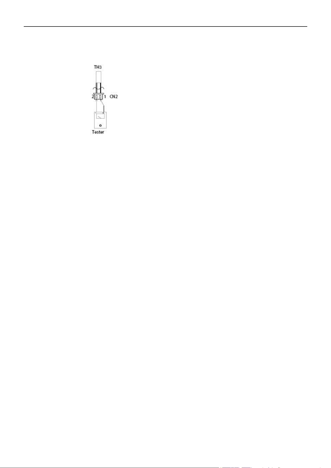
Air Conditioner Service Manual
R—Resistance
Resistance at 77°F(25°C): 20 kΩ
TH3: Outdoor unit discharge pipe sensor
Before measuring the resistance, disconnect the connectors as shown above.
103

The design and specifications of this product are subject to change without prior notice
as development continues. Consult with the sales agency or manufacturer for details.
Refer to the equipment nameplate for all other applicable specifications.
Copyright © Parker Davis HVAC International, LLC. All rights reserved.
is a registered trademark of Parker Davis HVAC International, LLC.
Parker Davis HVAC International
7290 NW 77 Court, Miami, FL 33166 - USA
Tel
: (305) 513-4488
Fax
: (305) 513-4499
E-mail
Website: www.pdhvac.com
Pioneer product line, parts, and supplies are
available online for convenient ordering at:
www.highseer.com
www.pioneerminisplit.com
Scan the below code to visit our support page
where you can find more installation materials:
104