04/2025
Read these instructions carefully before using your appliance, and keep them carefully.
If you follow the instructions, your appliance will provide you with many years of good service.
MODEL NUMBER
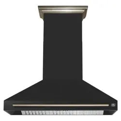
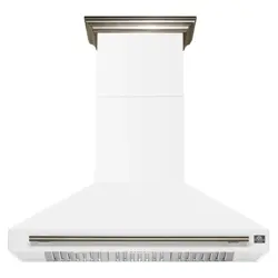
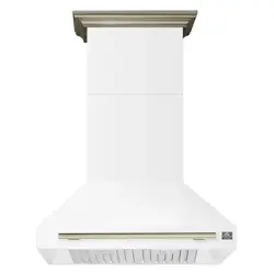
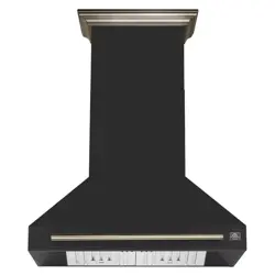
FRHWM5095-30 | FRHWM5095-30BLK | FRHWM5095-30WHT
FRHWM5095-36 | FRHWM5095-36BLK | FRHWM5095-36WHT
FRHWM5095-48 | FRHWM5095-48BLK | FRHWM5095-48WHT
FRHWM5095-60 | FRHWM5095-60BLK | FRHWM5095-60WHT
INSTALLATION GUIDE
&
INSTRUCTION MANUAL
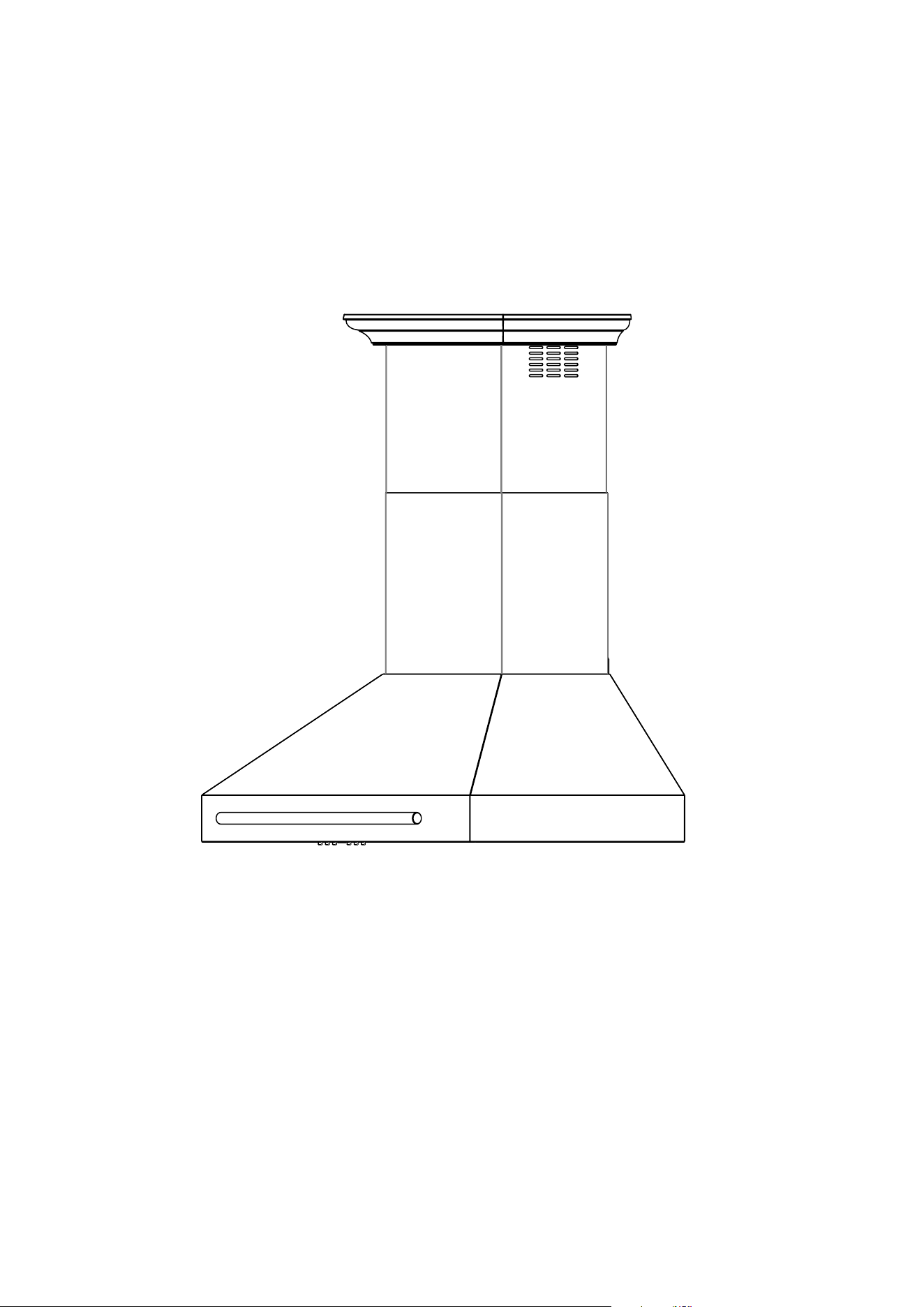
WALL MOUNT RANGE HOOD
ENGLISH
®
2
TABLE OF CONTENTS
Customer Care
4
Warranty
5-6
Safety Instructions
7-10
Overall Dimensions
View From The Front/Side......................................................
View From The Top.................................................................
11-12
11
12
Installation Preparation
Tools and Material Required....................................................
Mounting Height & Clearance.................................................
Ducting...................................................................................
Duct Run Calculation...............................................................
Duct Size................................................................................
Important Note Regarding Flexible Ducts...............................
Provided Parts.........................................................................
Handle Installation...................................................................
13-17
13
14
14
14
14
14
15-16
17
Installation
Hood Installation......................................................................
Duct Installation.......................................................................
Power Outlet Installation.........................................................
Duct Connection......................................................................
Chimney Installation................................................................
18-21
18-19
19
20
20
21
Operations
Control Panel...........................................................................
Light Bulbs...............................................................................
Technical Specications..........................................................
22-23
22
22
22
Maintenance & Cleaning
Surface Maintenance...............................................................
Filters......................................................................................
Hood Cleaning.........................................................................
Cleaning Tips..........................................................................
23
23
23
23
23
Troubleshooting.........................................................................................
24
Wire Diagram..............................................................................................
25
3
MODEL NUMBER SERIES
FRHWM5095-30 | FRHWM5095-30BLK | FRHWM5095-30WHT
FRHWM5095-36 | FRHWM5095-36BLK | FRHWM5095-36WHT
FRHWM5095-48 | FRHWM5095-48BLK | FRHWM5095-48WHT
FRHWM5095-60 | FRHWM5095-60BLK | FRHWM5095-60WHT
WALL MOUNT RANGE HOOD

4
Product Information Service Information
Model Number:
Use these numbers in any
correspondence or services calls
concerning your product.
If you received a damaged product,
immediately contact Forno.
Check the troubleshooting guide
before you call for service. It lists the
causes of minor operation problems
that you can correct yourself.
Serial Number:
Date of Purchase:
Purchase Address And Phone:
Thank you for purchasing a Frono product. Please read the entire instruction manual before operating your new
appliance for the rst time. Whether you are an occasional user or an expert, it will be benecial to familiarize yourself
with the safety practices, features, operation and care recommendations of your appliance.
Both the model and serial number are listed inside the product. For warranty purposes, you will also need the date of
purchase .
Record this information below for future reference.
CUSTOMER CARE
Services in Canada and Untied States
Keep the instruction manual handy to answer your questions. You can also nd all the information you need on-line at
www.forno.ca.
If you don’t understand something or need more assistance, please visit our website or email: [email protected]
If there is a problem, please contact FORNO customer service. Please note that troubleshooting with a customer
service representative will be needed before being able to send a service provider. All warranty work needs to be
authorized by FORNO customer service. All our authorized service providers are carefully selected and rigorously
trained by us.
“Need some quick help? Simply scan the qr code and get access
to our fast support form. We’re always here to assist you with any
questions or concerns you may have. So, don’t hesitate to reach out!”

5
WARRANTY
What this limited warranty covers:
The Warranty coverage provided by Forno Appliances in this statement applies exclusively to the original Forno appliance
(“Product”) sold to the consumer (“Purchaser”) by an authorized Forno dealer/distributor/retailer, purchased and installed
in the United States or Canada, and which has always remained within the original country of purchase (the United States or
Canada). Warranty coverage is activated on the date of the Product’s original retail purchase and has a duration of two (2) years.
Warranty coverage is non-transferable. In the event of replacement of parts or of the entire product, the replacement
Product (or parts) shall assume the remaining original Warranty activated with the original retail purchase document.
This Warranty shall not be extended with respect to such replacement. Forno Appliances will repair or replace any
component/part which fails or proves defective due to materials and/or workmanship within 2 years of the date of the
original retail purchase and under conditions of ordinary residential, non-commercial use. Repair or replacement will
be free of charge, including labor at standard rates and shipping expenses. Purchaser is responsible for making the
Product reasonably accessible for service. Repair service must be performed by a Forno Authorized Service company
during normal working hours.
Important
Retain proof of original purchase to establish warranty period. Forno’s liability on any claim of any kind, with respect to
the goods and/or services provided, shall in no event exceed the value of the goods or service or part there of which
has given rise to the claim.
30-Day Cosmetic Warranty
The Purchaser must inspect the product at the time of delivery. Forno warrants that the Product is free from manufacturing
defects in materials and workmanship for a period of thirty (30) days from date of the original retail purchase of the
Product.
This coverage includes:
• Paint blemishes
• Chips
• Macroscopic nish defects
Cosmetic warranty does NOT cover:
• Issues resulting from incorrect transport, handling and/or installation (e.g.: dents, broken, warped or deformed
structures or components, cracked or otherwise damaged glass components);
• Slight color variations on painted/enameled components;
• Dierences caused by natural or articial lighting, location or other analogous factors;
• Stains/corrosion/discoloration caused by external substances and/or environmental factors;
• Labor costs, display, oor, B-stock, out- of-box,“as is” appliances and demo units.
How to receive service
To receive warranty services, the Purchaser must contact the Forno Support department in order to determine the problem
and the required service procedures. Troubleshooting with a customer service representative will be necessary before
moving forward with the service. Model number, serial number and date of original retail purchase will be requested.

6
THERE ARE NO EXPRESS WARRANTIES OTHER THAN THOSE LISTED AND DESCRIBED ABOVE, AND NO
WARRANTIES, EITHER EXPRESS OR IMPLIED, INCLUDING, BUT NOT LIMITED TO, ANY IMPLIED WARRANTIES
OF MERCHANTABILITY OR FITNESS FOR A PARTICULAR PURPOSE THAT SHALL APPLY AFTER THE EXPRESS
WARRANTY PERIODS STATED ABOVE, AND NO OTHER EXPRESS WARRANTY OR GUARANTEE GIVEN BY
ANY PERSON, FIRM OR CORPORATION WITH RESPECT TO THIS PRODUCT SHALL BE BINDING ON FORNO.
FORNO SHALL NOT BE LIABLE FOR LOSS OF REVENUE OR PROFITS, FAILURE TO REALIZE SAVINGS OR
OTHER BENEFITS, TIME AWAY FROM WORK, MEALS, LOSS OF FOOD OR BEVERAGES, TRAVELING OR HOTEL
EXPENSES, EXPENSES TO RENT OR PURCHASE APPLIANCES, REMODELING/CONSTRUCTION EXPENSES IN
EXCESS OF DIRECT DAMAGES WHICH ARE UNDENIABLY CAUSED EXCLUSIVELY BY FORNO OR ANY OTHER
SPECIAL, INCIDENTAL OR CONSEQUENTIAL DAMAGES CAUSED BY THE USE, MISUSE OR INABILITY TO USE
THIS PRODUCT, REGARDLESS OF THE LEGAL THEORY ON WHICH THE CLAIM IS BASED, AND EVEN IF FORNO
HAS BEEN ADVISED OF THE POSSIBILITY OF SUCH DAMAGES. NOR SHALL RECOVERY OF ANY KIND AGAINST
FORNO BE GREATER IN AMOUNT THAN THE PURCHASE PRICE OF THE PRODUCT SOLD BY FORNO AND
CAUSING THE ALLEGED DAMAGE. WITHOUT PREJUDICE TO THE FOREGOING, PURCHASER ASSUMES ALL
RISK AND LIABILITY FOR LOSS, DAMAGE OR INJURY TO PURCHASER AND PURCHASER’S PROPERTY AND
TO OTHERS AND THEIR PROPERTY ARISING FROM THE USE, MISUSE, OR INABILITY TO USE THIS PRODUCT
SOLD BY FORNO THAT IS NOT A DIRECT RESULT OF NEGLIGENCE ON THE PART OF FORNO THIS LIMITED
WARRANTY SHALL NOT EXTEND TO ANYONE OTHER THAN THE ORIGINAL PURCHASER OF THIS PRODUCT,
IS NON-TRANSFERABLE, AND STATES YOUR EXCLUSIVE REMEDY.
Warranty Exclusions: What Is Not Covered.
• Use of the Product in any non-residential,
commercial
• Use of the Product for anything other than its
intended purpose.
• Repair services provided by anyone other than a
Forno Authorized Service agency.
• Damages or repair services to correct services
provided by unauthorized parties or the use of
unauthorized parts.
• Installation not in accordance with local/state/city/
county re codes, electrical codes, gas codes,
plumbing codes, building codes, laws or regulations.
• Defects or damage due to improper storage of the
Product.
• Defects, damage or missing parts on products
sold out of the original factory packaging or from
displays.
• Service calls or repairs to correct an incorrect
installation of the Product and/or related
accessories.
• Replacement of parts/service calls to connect,
convert or otherwise repair the electrical wiring and/
or gas line in order to properly use the product.
• Replacement of parts/service calls to provide
instructions and information on the use of the
Product.
• Replacement of parts/service calls to correct issues
arising from the product being used in a manner
other than what is normal and customary for
residential use.
• Replacement of parts/service calls due to wear
and tear of components such as seals, knobs, pan
supports, shelving, cutlery baskets, buttons, touch
displays, scratched or broken ceramic-glass tops.
• Replacement of parts/service calls for lack of/
improper maintenance, including but not limited to:
build up of residues, stains, scratches, discoloration,
corrosion.
• Defects and damages arising from accidents,
alteration, misuse, abuse or improper installation.
• Defects and damages arising from Product
transport, logistics and handling. Inspection of the
product must be made at time of delivery. Following
receipt and inspection, the selling dealer/delivery
company must be notied of any issues arising
from handling, transport and logistics.
• Defects and damages arising from external forces
beyond the control of Forno Appliances, including
but not limited to wind, rain, sand, res, oods,
mudslides, freezing temperatures, excessive
moisture or extended exposure to humidity, power
surges, lightning, structural failures surrounding the
appliance and other acts of God.
• Products whose serial number has been altered/
damaged/tampered with. In no case shall Forno
be held liable or responsible for damage to
surrounding property, including furniture, cabinetry,
ooring, panels, and other structures surrounding
the Product. Forno is neither liable nor responsible
for the Product if it is located in a remote area or
an area where certied trained technicians are not
reasonably available. Purchaser must bear any
transportation and delivery costs of the Product
to the nearest Authorized Service Center or the
additional travel expenses of a certied trained
technician.
7
SAFETY INSTRUCTIONS
This is the safety alert symbols. These symbols alert you to potential
hazards that can hurt you and others. All safety messages will follow the
safety alert symbols.
READ AND SAVE ALL INSTRUCTIONS BEFORE INSTALLING OR USING THE UNIT.
• The installation instructions in this manual are intended for qualied installers, service techni-
cians, or persons with similar qualied background. Installation and electrical wiring must be
done by qualied professionals and in accordance with all applicable codes and standards,
including rst-rated construction. DO NOT attempt to install this appliance yourself. Injury could
result from installing the unit due to lack of appropriate electrical and technical background. Due
to the size and weight of this range hood, two people installation is recommended.
• Range hood may have very sharp edges; please wear protective gloves if it is necessary to re-
move any parts for installing, cleaning, or servicing.
• Activating any switch ON before completing installation may cause ignition or an explosion.
WARNING - TO REDUCE THE RISK OF FIRE, ELECTRIC SHOCK, OR INJURY TO PER-
SON(S), OBSERVE THE FOLLOWING:
• Your safety and the safety of others is very important. We have provided many important safety
messages in this manual and on your appliance. Always read and obey all safety messages. All
safety messages will tell you what the potential hazard is, tell you how to reduce the chance of
injury, and tell you what can happen if the instructions are not followed.
• All electrical wiring must be properly installed, insulated, and grounded.
• Old duct work should be cleaned or replaced, if necessary, to avoid the possibility of a grease
re. Check all joints on duct work to ensure proper connection; all joints should be properly taped.
• When the range hood ventilates the air out of the room, the air vented must be replaced. This is
called make-up air. If a makeup air system is needed but not used, a hood may not function as
expected due to negative air pressure. We do not currently provide a make-up air unit. Always
consult any applicable building codes in your area regarding minimum and maximum airow
rates. Certain states may require additional items such as make-up air for larger CFM range
hoods (typically over 300 CFM).
• To reduce the risk of re and to disperse air properly, make sure to vent air outside. DO NOT vent
exhaust into spaces between walls, crawl spaces, ceilings, attics, or garages.
• For residential ventilating use only. DO NOT use to exhaust hazardous or explosive materials
and vapors. The combustion air ow needed for safe operation of fuel-burning equipment may
be aected by this unit’s operation. Follow the heating equipment manufacturer’s guideline.
• Safety standards such as those published by the National Fire Protection Association (NFPA),
and the American Society of Heating, Refrigeration and Air Conditioning Engineers (ASHRAE),
and the local code authorities. Sucient air is needed for proper combustion and exhausting of
gases through the duct to prevent back drafting.
• Ducted range hoods MUST ALWAYS be vented to the outdoors. All our range hoods come with a
transition piece with a built-in damper. Some existing installations may already have an external
damper. Please consult an HVAC or installation professional for advice to comply with local
regulations.
• Keep all fans, bae, spaces, lter, grease tunnel, oil container, and grease-laden surfaces clean.
Grease should not be allowed to accumulate on fan, bae, spaces, lter, grease tunnel, or oil
container. Clean grease-laden surfaces frequently.
• This appliance is designed to be operated by adults. Children are not allowed to tamper with the
controls or play with this appliance.
• To reduce the risk of re or electric shock, do not use this fan with any solid-state speed control
device.
• When cutting or drilling into wall or ceiling, do not damage electrical wiring and other hidden
utilities.

8
• Before servicing or cleaning the unit, switch power OFF at the service panel and lock the service
panel to prevent power from being switched ON accidentally.
• Use this unit only in the manner intended by the manufacturer. If you have any questions, contact
FORNO.
TO REDUCE THE RISK OF INJURY TO PERSONS IN THE EVENT OF A STOVE TOP GREASE
FIRE:
• All FORNO range hoods are ETL listed, ensuring all parts were tested for safety and meet
industry standards and regulations. NOTE: This ensures all included metal ducting pieces were
tested for safety and are ame retardant.
• Always turn hood ON when cooking at high heat or when cooking aming foods (Crepes Suzette,
Cherries Jubilee, Peppercorn Beef Flambé). Never leave surface units unattended at high
settings. Boil-overs cause smoking and greasy spillovers that may ignite. Heat oils slowly on low
or medium settings.
• Clean hood frequently. Grease should not be allowed to accumulate on fan or lter.
• Use proper pan size.
• Always use cookware appropriate for the size of the surface element.prevent power from being
switched ON accidentally.
WARNING – TO REDUCE THE RISK OF A RANGE TOP GREASE FIRE:
a) Never leave surface units unattended at high settings. Boilovers cause smoking and greasy spill-
overs that may ignite. Heat oils slowly on low or medium settings.
b) Always turn hood ON when cooking at high heat or when ambeing food (i.e. Crepes Suzette,
Cherries Jubilee, Peppercorn Beef Flambe).
c) Clean ventilating fans frequently. Grease should not be allowed to accumulate on fan or lter.
d) Use proper pan size. Always use cookware appropriate for the size of the surface element.
WARNING – TO REDUCE THE RISK OF INJURY TO PERSONS IN THE EVENT OF A RANGE
TOP GREASE FIRE, OBSERVE THE FOLLOWING:
a) SMOTHER FLAMES with a close-tting lid, cookie sheet, or metal tray, then turn o the burner.
BE CAREFUL TO PREVENT BURNS. If the ames do not go out immediately, EVACUATE AND
CALL THE FIRE DEPARTMENT.
b) NEVER PICK UP A FLAMING PAN – You may be burned.
c) DO NOT USE WATER, including wet dishcloths or towels – a violent steam explosion will result.
d) Use an extinguisher ONLY if:
1) You know you have a Class ABC extinguisher, and you already know how to operate it.
2) The re is small and contained in the area where it started.
3) The re department is being called.
4) You can ght the re with your back to an exit.
CAUTION: For General Ventilating Use Only. Do Not Use To Exhaust Hazardous Or Explosive Ma-
terials And Vapors.
WARNING: TO REDUCE THE RISK OF FIRE, ELECTRIC SHOCK OR INJURY TO PER-
SONS, DO NOT USE REPLACEMENT PARTS THAT HAVE NOT BEEN RECOMMENDED
BY THE MANUFACTURER.
SAFETY INSTRUCTIONS

9
WARNING: TO REDUCE THE RISK OF FIRE, USE ONLY METAL DUCTWORK.
This appliance is not intended for use by persons (including children) with reduced physical, sensory
or mental capabilities, or lack of experience and knowledge, unless they have been given supervi-
sion or instruction concerning use of the appliance by a person responsible for their safety.
Children should be supervised to ensure that they do not play with the appliance.
If the SUPPLY CORD is damaged, it must be replaced by the manufacturer, its service agent or
similarly qualied persons in order to avoid a hazard.
There shall be adequate ventilation of the room when the range hood is used at the same time as
appliances burning gas or other fuels (not applicable to appliances that only discharge the air back
into the room);
The details concerning the method and frequency of cleaning;
There is a re risk if cleaning is not carried out in accordance with the instructions;
Do not ambé under the range hood;
CAUTION: Accessible parts may become hot when used with cooking appliances. The air must not
be discharged into a ue that is used for exhausting fumes from appliances burning gas or other
fuels.
The minimum distance between the supporting surface for the cooking vessels on the hob and the
lowest part of the range hood. (When the range hood is located above a gas appliance, this distance
shall be at least 65 cm. If the instructions for installation for the gas hob specify a greater distance,
this has to be taken into account. The distance of 65 cm can be reduced for
• non-combustible parts of range hoods, and or
• parts operating at safety extra low voltage,
provided these parts do not give access to live parts if deformed);
– regulations concerning the discharge of air have to be fullled.
GROUNDING INSTRUCTIONS
This appliance must be grounded. In the event of an electrical short circuit, grounding reduces the
risk of electric shock by providing an escape wire for the electric current. This appliance is equipped
with a cord having a grounding wire with a grounding plug. The plug must be plugged into an outlet
that is properly installed and grounded.
WARNING – Improper grounding can result in a risk of electric shock.
Consult a qualied electrician if the grounding instructions are not completely understood, or if doubt
exists as to whether the appliance is properly grounded.
Do not use an extension cord. If the power supply cord is too short, have a qualied electrician install
an outlet near the appliance.
The grounding-type attachment plug provided with this appliance shall be connected to a ground-
ing-type receptacle installed in accordance with CSA C22.1, Canadian Electrical Code, Part I.
In the event of an electrical short circuit, bonding to ground reduces the risk of electric shock.
WARNING: Improper bonding to ground can result in a risk of electric shock.
Consult a qualied electrician if the grounding instructions are not completely understood, or if doubt
exists as to whether the appliance is properly bonded to ground.
Do not use an extension cord. If the power supply cord is too short, have a qualied electrician install
an outlet near the appliance.
SAFETY INSTRUCTIONS

10
IMPORTANT NOTES
NOTE 1 : Carefully remove the plastic lm (if they have) from all exterior surfaces of the hood and
chimney prior to the nal installation
NOTE 2: Lay out the vent duct system before installing the range hood to determine the best routing
for the vent duct.
NOTE 3: It is recommended that the system be installed before the range hood is installed.
NOTE 4: Before making the cutouts, make sure there is proper clearance within the ceilling for the
exhaust vent
NOTE 5: Range hood is to be installed 30” minimum from the cooking surface.
NOTE 6: Check you ceilling height and the range hood maximum height before you install the range
hood
NOTE 7 : A minimum of two persons is required to install the unit.
NOTE 8 : The air outlet adapter on the FRHWM5095-30 in stainless steel, black and white is pre-in-
stalled on the unit.
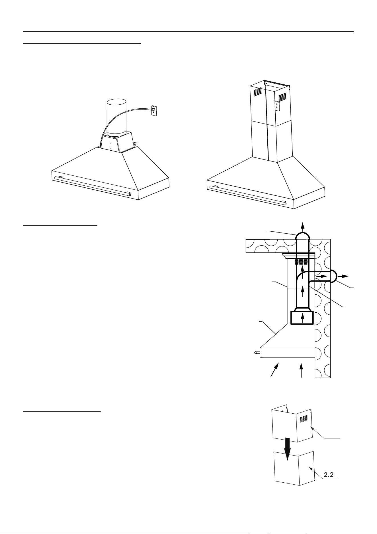
DESCRIPTION / CONNECTION
This range hood shall be mounted directly to the support frame mounting, where the support frame
ue shall secure to the ceiling joist or framework.
• Ductwork needs to be installed at the top of the unit where the motor(s) exhaust.
• Duct runs should be as short as possible.
• Avoid the use of elbows.
• Use duct tape at all joints.
• Do not use duct smaller than the discharge on the hood.
ELECTRICAL CONNECTION
• Electrical wiring must be done by a qualied person(s) in accordance with all applicable codes
and standards. Turn o electrical power at service entrance before wiring.
• If the supply cord is damaged, it must be replaced by the manufacturer, its service agent, or
similarly qualied persons to avoid a hazard.
• Do not use the plug and an extension cord other than the ones initially supplied with the hood.
• The earthing of this hood is compulsory. Do not remove ground prong of the plug.
SAFETY INSTRUCTIONS
11
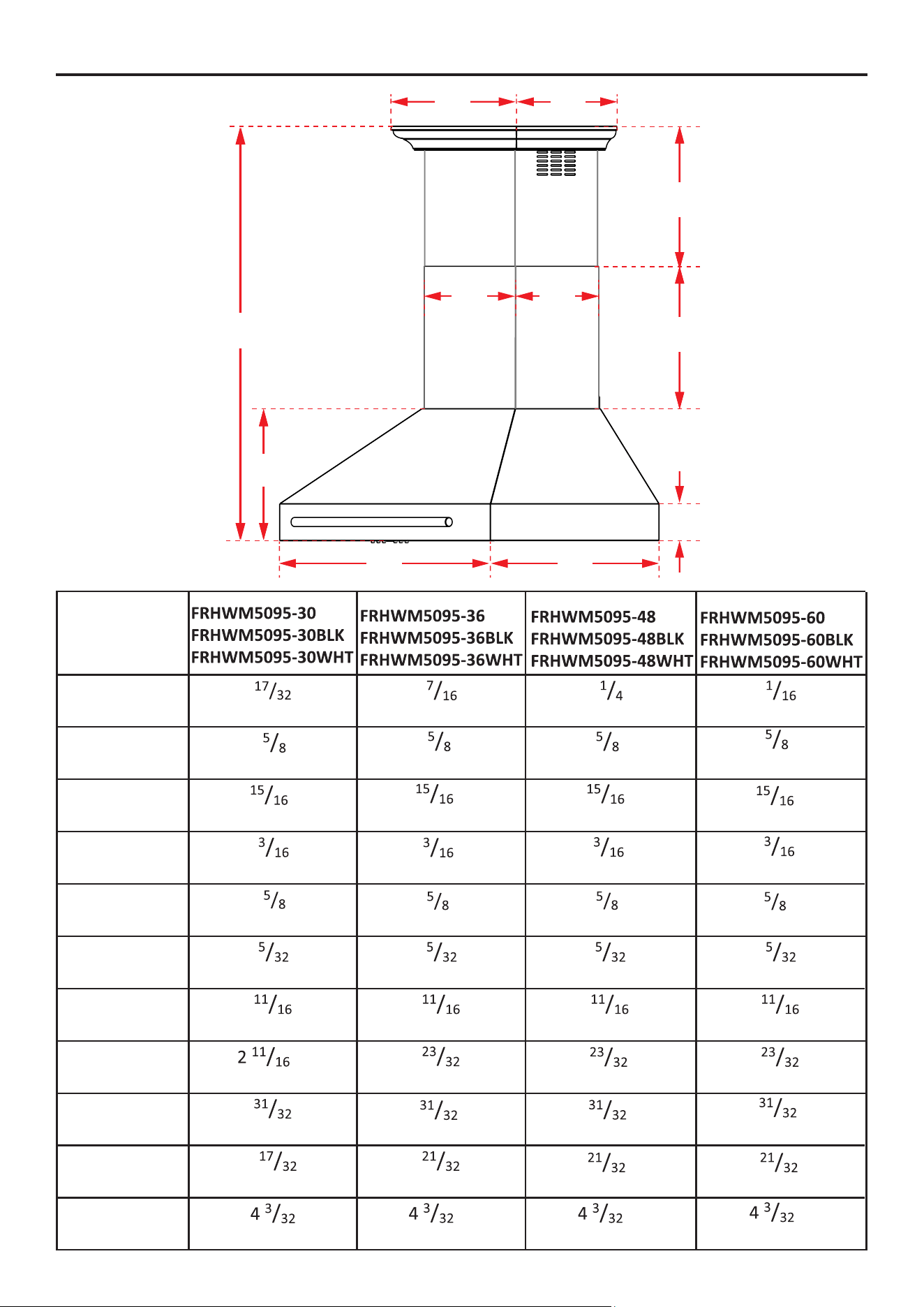
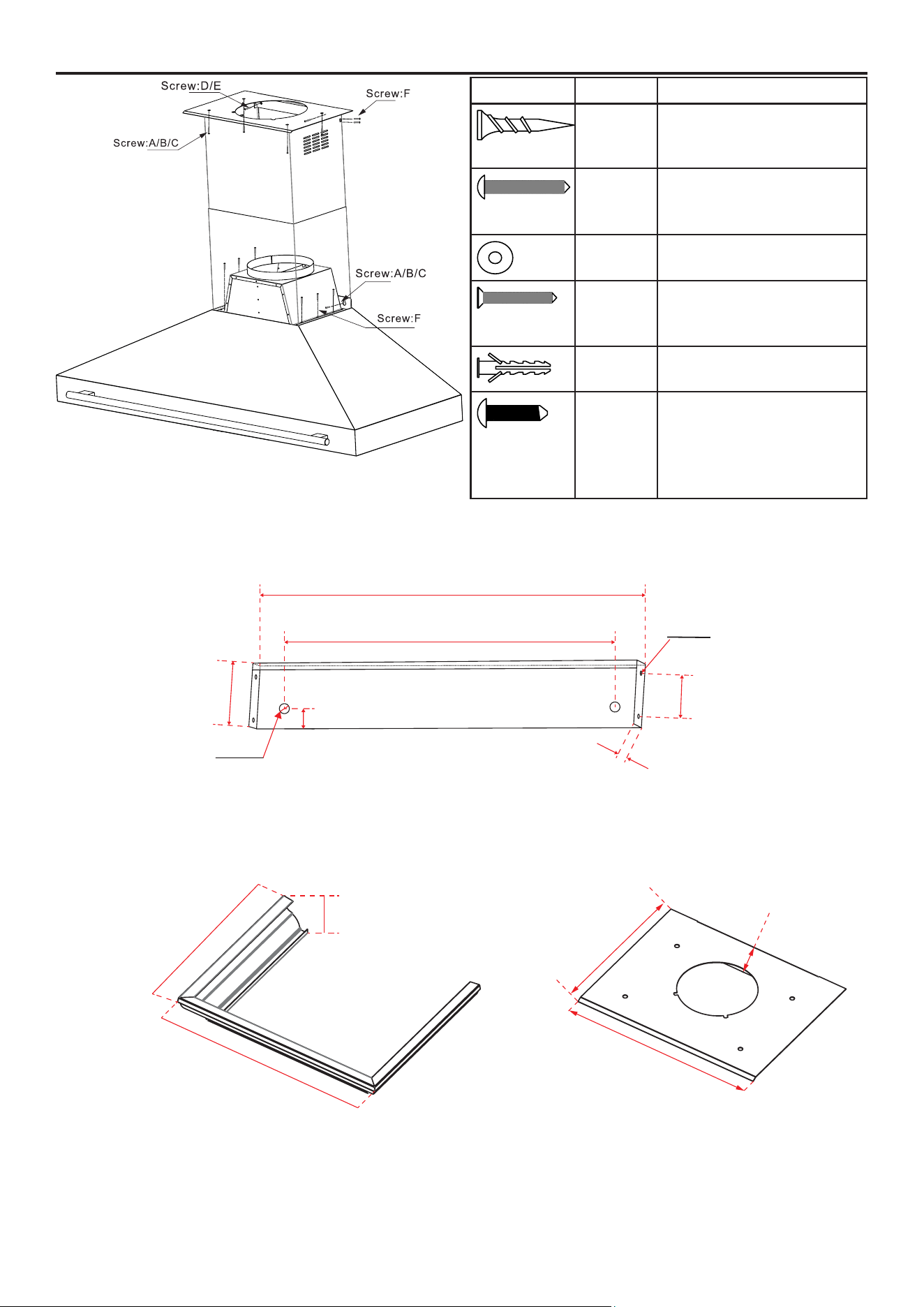
OVERALL DIMENSIONS - VIEW FROM THE FRONT/SIDE
C
I
D
H
G
E
F
BA
J
K
A
29
''
750mm
35
''
900mm
47
''
1200mm
59
''
1500mm
B
23
''
600mm 600mm 600mm 600mm
C
3
''
100mm 100mm 100mm 100mm
D
14
''
360mm 360mm 360mm 360mm
E
15
''
397mm 397mm 397mm 397mm
F
15
''
385mm
15
''
385mm
15
''
385mm
15
''
385mm
G
11
''
297mm
11
''
297mm
11
''
297mm
11
''
297mm
H
322mm
16
''
425mm 425mm 425mm
I
44
''
1142mm 1142mm 1142mm 1142mm
J
17
''
445mm
21
''
550mm 550mm 550mm
K
1
''
358mm 358mm 358mm 358mm
23 ''
23 ''
23 ''
3
''
3 ''
3 ''
14
''
14 ''
14 ''
15 ''
15
''
15
''
1 ''
44 ''
44 ''
44
''
1 '' ''
1 ''
21 '' 2 1 ''
16 '' 1 6 ''
1
12
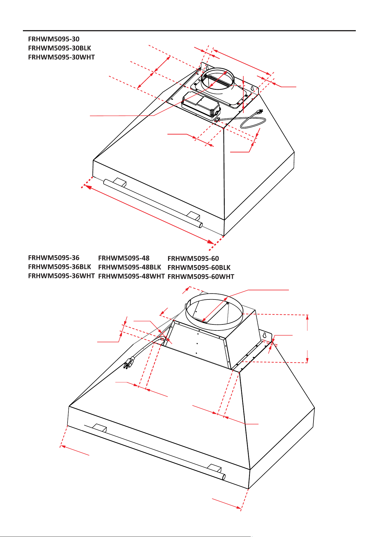
OVERALL DIMENSIONS - VIEW FROM THE TOP
5
31
/
32
”
(152mm)
5
25
/
32
”
(147mm)
2
13
/
32
”
(61mm)
1
21
/
32
”
(42mm)
1
1
/
16
”
(27mm)
1
1
/
16
”
(27mm)
10
1
/
2
”
(267mm)
29
17
/
32
”
(750mm)
3
21/32
”
(93mm)
Ø6”
(152.4mm)
1
/
2
”
(13mm)
6
31
/
32
”
(177mm)
2
17
/
32
”
(64 mm)
14
3
/
16
”
(360mm)
1
3
/
8
”
(35mm)
1
3
/
8
”
(35mm)
FRHWM5095-36 :
35
7
/
16
”
(9
0
0
m
m
)
FRHWM5095-48
:
47
1
/
4
”
(1
2
0
0
m
m
)
FRHWM5095-60
:
59
1
/
16
”
(1
50
0
m
m
)
10
25
/
32
”
(274mm)
Ø10 ”
(Ø254mm)
15
/
16
”
(24mm)
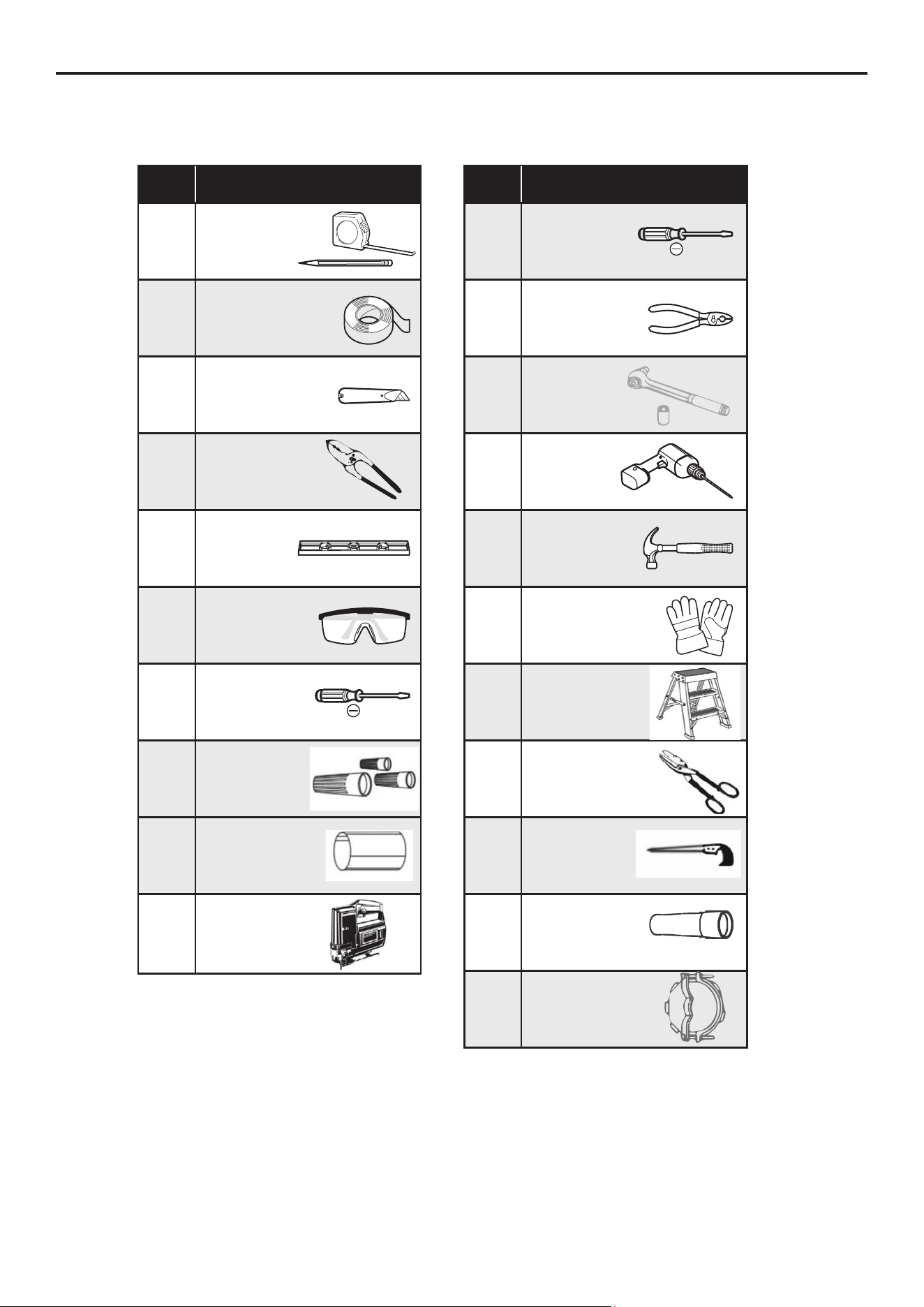
13
INSTALLATION PREPARATION
• Please plug in and check that all functions are working.
Check
Box
Tools
Tape measure
Pencil
Certied metal
duct tape
Utility knife
Wire cutter/Stripper
Level
Safety glasses
Phillips
screwdriver
Wire nuts
6” or 10” round
metal duct
Saber saw or
sawzall
Check
Box
Tools
Flathead
screwdriver
Long nose
pliers
Wrench
Electric drill
*1/8”, 3/8” & 1/2”
bits
Hammer
Safety gloves
Step ladder
Metal Snips
Keyhole Saw
Flashlight
Stain relief joint
cover
TOOLS AND MATERIAL REQUIRED (Not Supplied)
14
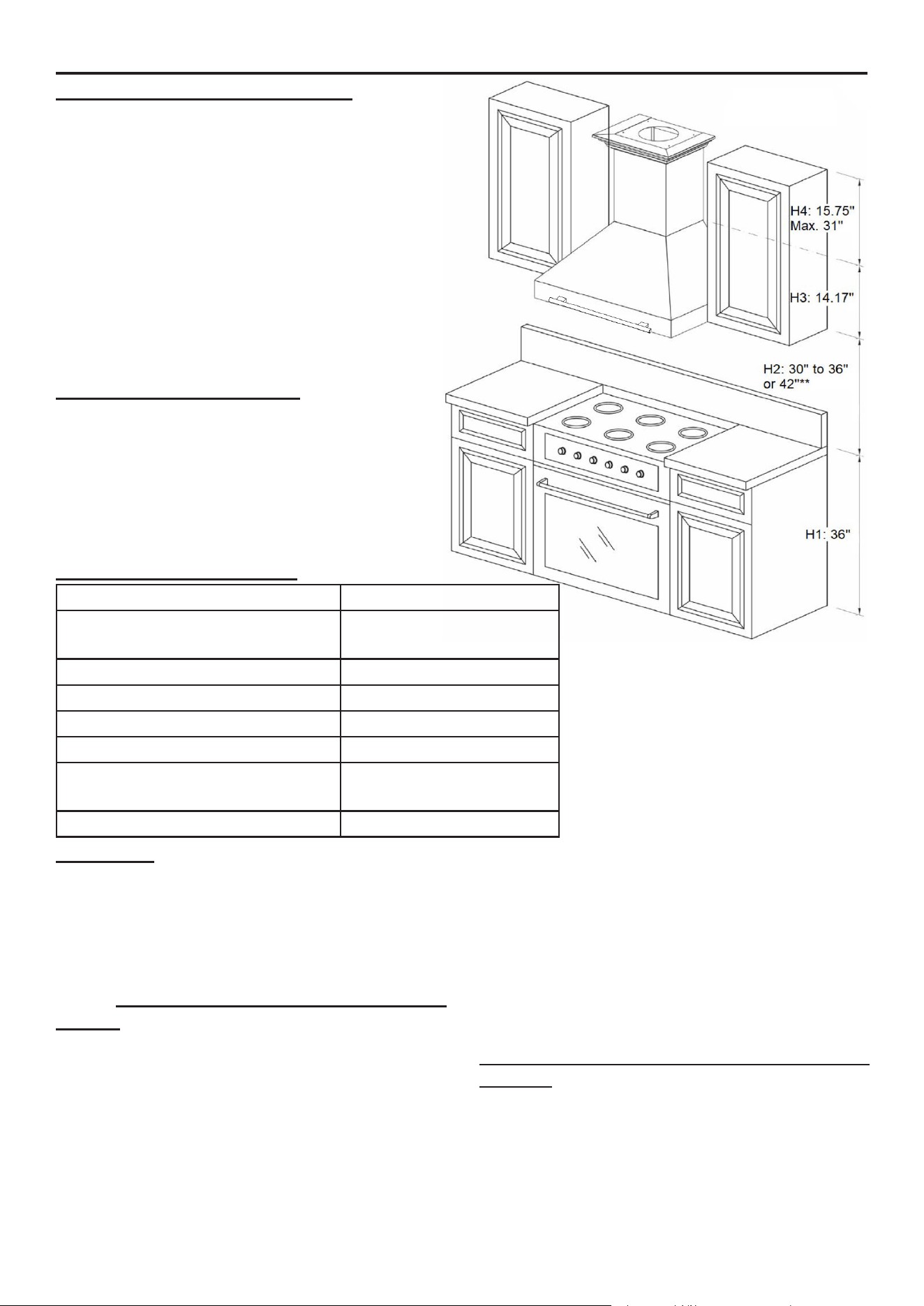
MOUNT HEIGHTS & CLEARANCE
The minimum mounting height between range top
to hood bottom should be no less than 30”. The
maximum height should be 36” above the cooktop
(please note that the 36”, 48” & 60” unit can install
up to 42” above the cooktop, but it may result in a
loss of eciency).
It is important to install the hood at the proper
mounting height. Hoods mounted too low could
result in heat damage and re hazard; while hoods
mounted too high will be hard to reach and will lose
its performance and eciency.
DUCTING (NOT PROVIDED)
NEVER exhaust air or terminate duct work into
spaces between walls, crawl spaces, ceilling,
attics, or garages. All exhaust must be ducted
to the outside. Use metal ductwork only. Fasten
all connections with sheet metal screws and
tape all joint with certied Silver Tape or Metal
Duct Tape.
INSTALLATION PREPARATION
DUCT SIZE
A minimum of φ 6” for 30” & 10” for 36”, 48”
and 60” round duct must be used to maintain
maximum airow eciency.
Flexible ducts are provided for convenience;
always use rigid type metal ducts to maximize
airow.
Also use calculation (on left) to compute
total available duct run when using elbows,
transitions, and caps.
ALWAYS reduce the number of transitions and
turns. If required, a long duct increases duct
size from 6” to 8” for the 30” & from 10” to 12”
for the 36”, 48” and 60”.
DUCT RUN CALCULATION:
Item Penalty to duct run
Maximum Run (6” or 3-1/4” x 10”
duct)
100 feet
Each 90° elbow Deduct 15 feet
Each 45° elbow Deduct 9 feet
Each 6” or 3-1/4” x 10” transition Deduct 1 feet
Each 3-1/4” x 10” to 6” transition Deduct 5 feet
Side wall cap with
damper
Deduct 30 feet
Roof cap Deduct 30 feet
If a reducer is used, install a long reducer instead
of a pancake reducer. Reduce duct size as far
away from the opening as possible.
If turns or transitions are required: Install as far
away from opening and as far apart, between 2,
as possible.
IMPORTANT NOTE REGARDING FLEXIBLE
DUCTS:
If exible ducting is used instead of rigid metal
ducting, it is necessary to reduce the maximum
allowable duct run by an additional 10% to 15%.
Flexible ducts create more air resistance and
reduce overall airow eciency compared to
rigid ducts.
e.g. - 1 roof cap, 2x90° elbows,
1x45° elbow = 30’ + (2 x 15’) + 9’ =
69’ used, 31’ avalable for straight
duct runs
15
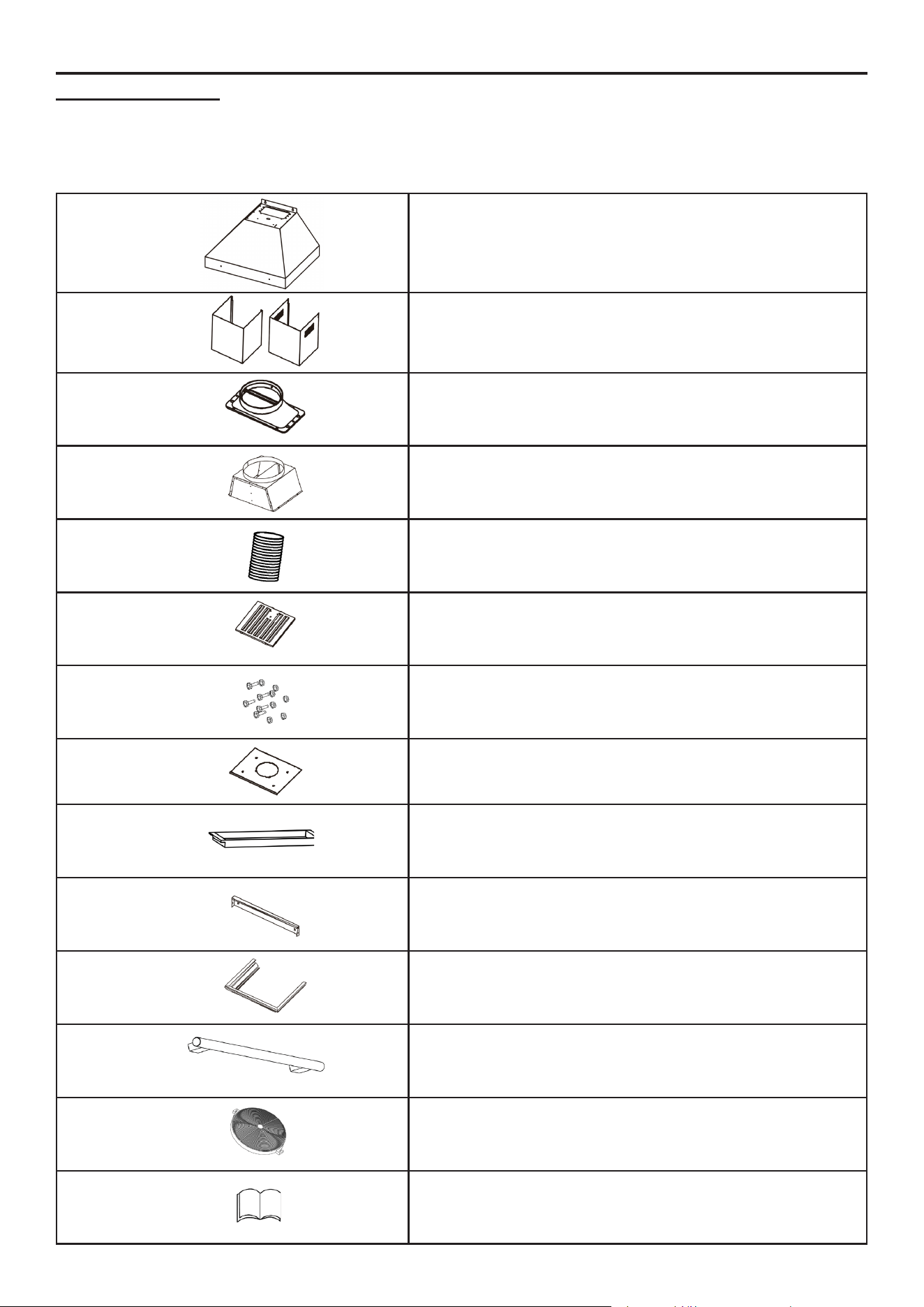
INSTALLATION PREPARATION
PROVIDED PARTS
Please unpack your range hood when it is delivered and inspect to ensure all parts are included.
Hood body with lights and controls pre-installed
Adjustable stainless-steel chimney cover (2x, 400mm
high)
Ø 6” Air outlet adapter (Only for FRHWM5095-30)
Ø 10” Air outlet adapter (Only for FRHWM5095-36,
FRHWM5095-48 & FRHWM5095-60)
5 ft (1.5m) exible duct (Ø 6” for FRHWM5095-30,
Ø10” for FRHWM5095-36, FRHWM5095-48,
FRHWM5095-60)
Bae lters (4x for FRHWM5095-30 & FRHWM5095-36,
6x for FRHWM5095-48, 8x FRHWM5095-60)
Screws and anchors
Decorative frame bracket
Grease cup
Chimney mounting bracket
Decorative frame (crown)
Handle
Charcoal lter
Instruction manual
16
INSTALLATION PREPARATION
DRAWING SCREW DESCRIPTION
A
Ø0.51” × 1.61” Spiral
Plastic Expansion Anchor
B
#6-32 × 1-3/8” Cross
Recessed Pan Head
Self-Tapping Screw
C
Flat Washer, Ø0.197” ×
0.472”, Zinc Plated
D
ST#3.5 × 1.18” Cross
Recessed Flat Head
Self-Drilling Screw
E
Plastic Expansion Tube,
Ø0.236” × 1.142”
F
M4 × 0.472” - Screw
with Cross Recess, Flat
Round Head, Triangular
Thread with Anti-Slip
Teeth, Chrome Plated
2
9
/
16
” (65mm)
FRHWM5095-36-48-60: 21
21
/
32
"(550mm)
FRHWM5095-30: 17
19
/
32
"(447mm)
14
3
/
64
” (357mm)
FRHWM5095-36-48-60: 21
11
/
32
"(542mm)
FRHWM5095-30: 17
9
/
32
"(439mm)
13
27
/64” (340.9mm)
2
1
/
16
” (52.7mm)
FRHWM5095-36-48-60: 14
29
/
32
” (378.6mm)
FRHWM5095-30: 10
27
/
32
” (275.6mm)
1
59
/
64
"
(
49
mm)
0.63”(16mm)
1 3/16”
(30mm)
0.62” (15.7mm)
UPPER CHIMNEY BRACKET
FRHWM5095-36-48-60: 16
43
/
64
” (423.4mm)
FRHWM5095-30: 12
39
/
64
” (320.4mm)
Ø0.3”
(7.
5
mm)
Ø
1/8
”
(3.
2
mm)
DECORATIVE FRAME DECORATIVE FRAME BRACKET
17
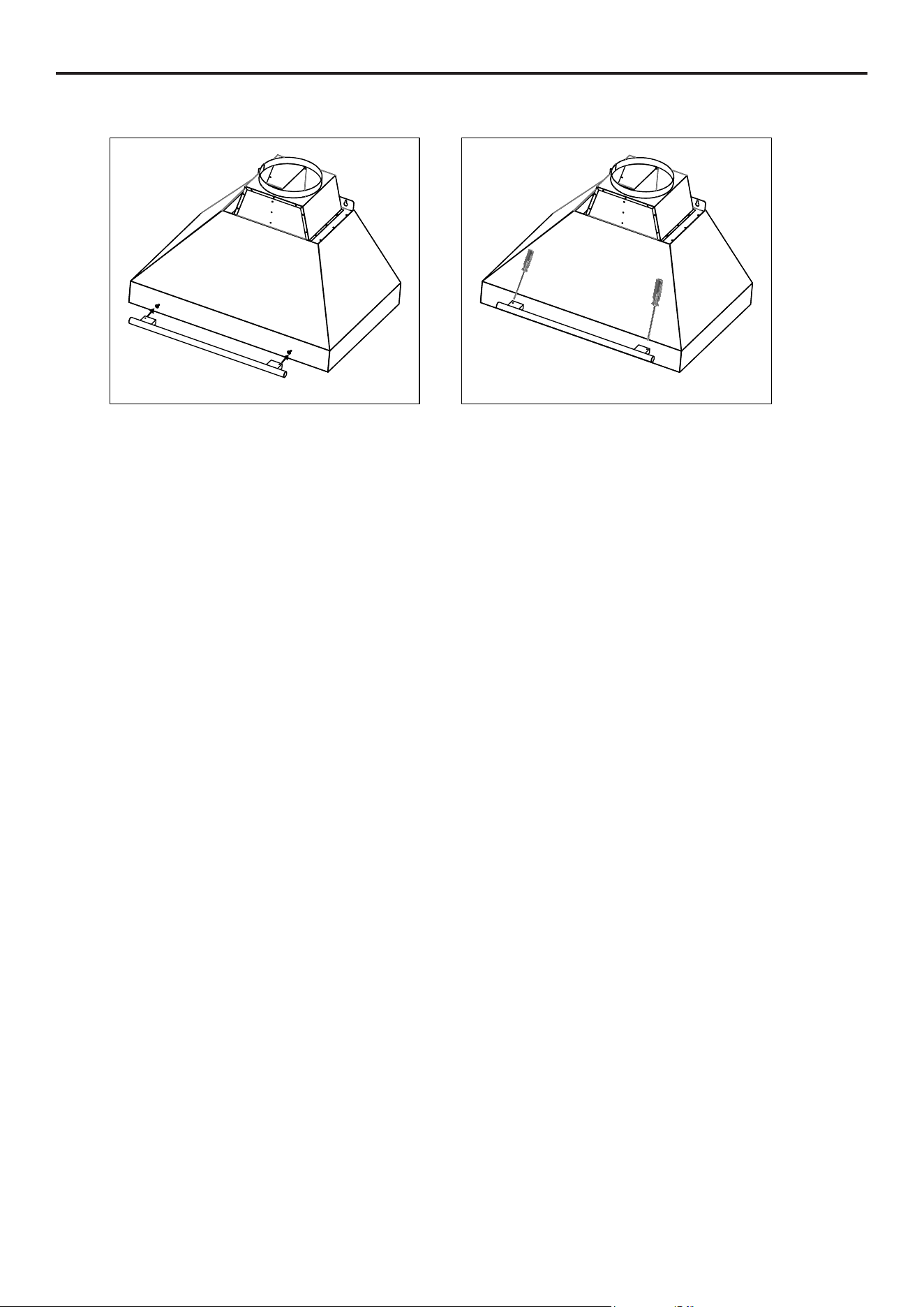
HANDLE INSTALLATION
The handle is not pre-installed. Please follow the steps below to install it quickly and correctly:
È
È
È
È
1.
2.
Align the handle with the screw on the front of the range hood.
Then tighten the hexagon socket screws on the handle with a hexagon socket screwdriver.
18
INSTALLATION
CENTERLINE
HORIZONTAL
LINE
Figure 1.
Figure 2. Figure 3.
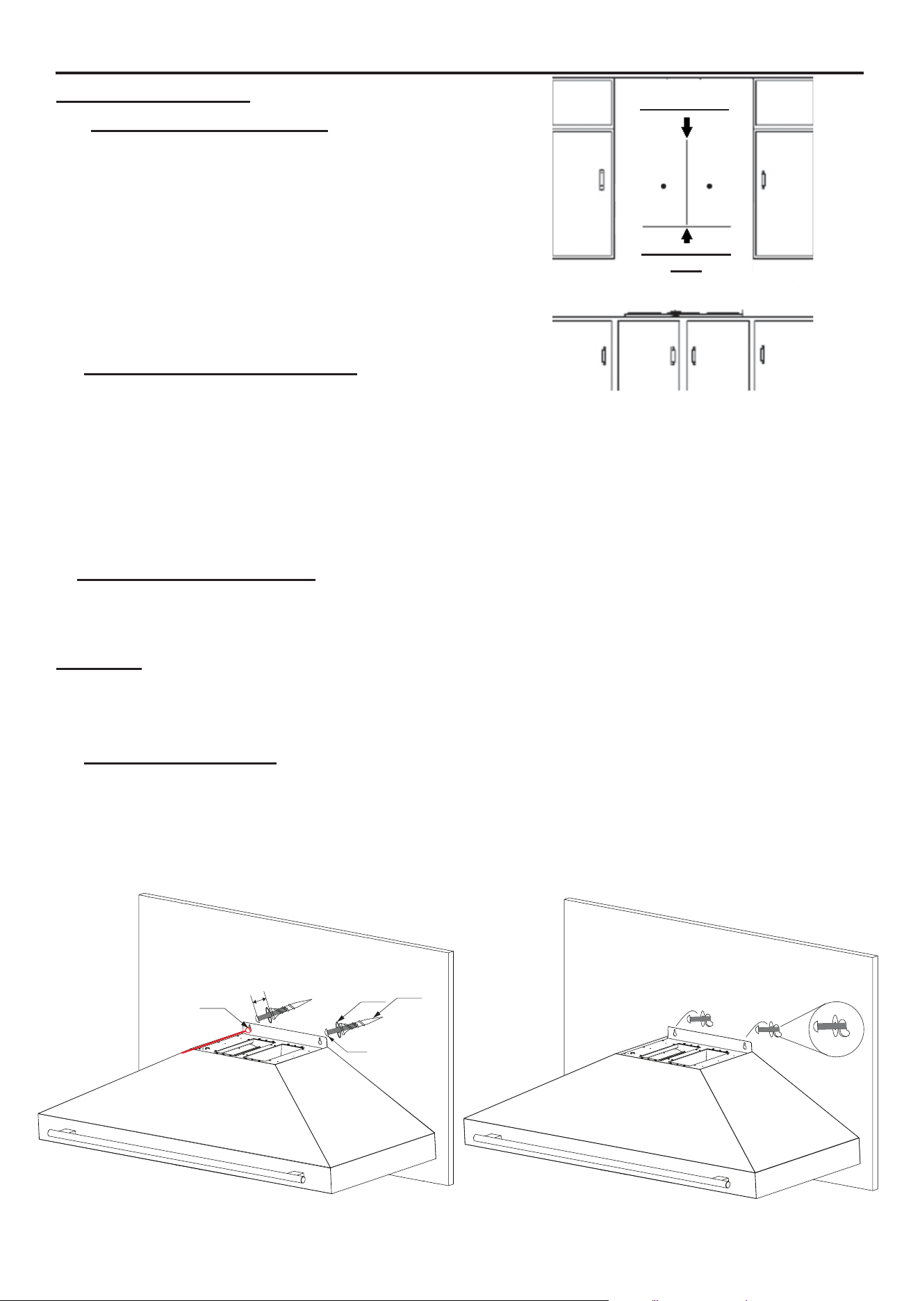
HOOD INSTALLATION
1. Mark the Wall for Mounting
• Locate and mark the center of the wall where the
hood will be installed.
• Ensure there is sucient wall bracing to support the
weight of the unit.
• Draw a vertical reference line from the mounting
area upward to the ceiling (or as high as practical).
• Draw a horizontal line at the desired installation
height — minimum 30” above the cooktop. See Fig-
ure 1.
2. Mark and Drill Mounting Points
• Place the hood against the wall, aligning the center
of the hood with the vertical reference line and the
bottom edge with the horizontal line.
• With the hood in position, mark the screw hole locations on the wall based on the hood’s rear
mounting slots.
• Remove the hood and drill ½” (0.50”) holes at the marked points to t the Φ0.51” spiral plastic
expansion anchors (A). See Figure 2.
3. Insert Anchors and Screws
• Insert anchors (A) into the drilled holes until fully ush with the wall.
• Position at washers (C) over the mounting holes.
• Drive the #6-32 × 1-3/8” pan head screws (B) through the washers into the anchors.
Important: LEAVE EACH SCREW (B) PROTRUDING ¼” FROM THE WALL. This gap is es-
sential to properly seat the hood body into its rear mounting slots. Do not overtighten, as this may
eliminate the gap and hinder installation.
4. Mount the Hood Body
• Hang the hood onto the #6-32 screws (B) installed into the expansion anchors (A), with at wash-
ers (C) in place.
• Ensure the screws align with the mounting slots on the back of the hood.
• Verify the hood is level and aligned with the vertical reference line.
• Once properly seated, fully tighten the screws to secure the hood — without overtightening. See
Figure 3.
A
B
C
Drill Ø1/2” hole
1/4”
19
INSTALLATION
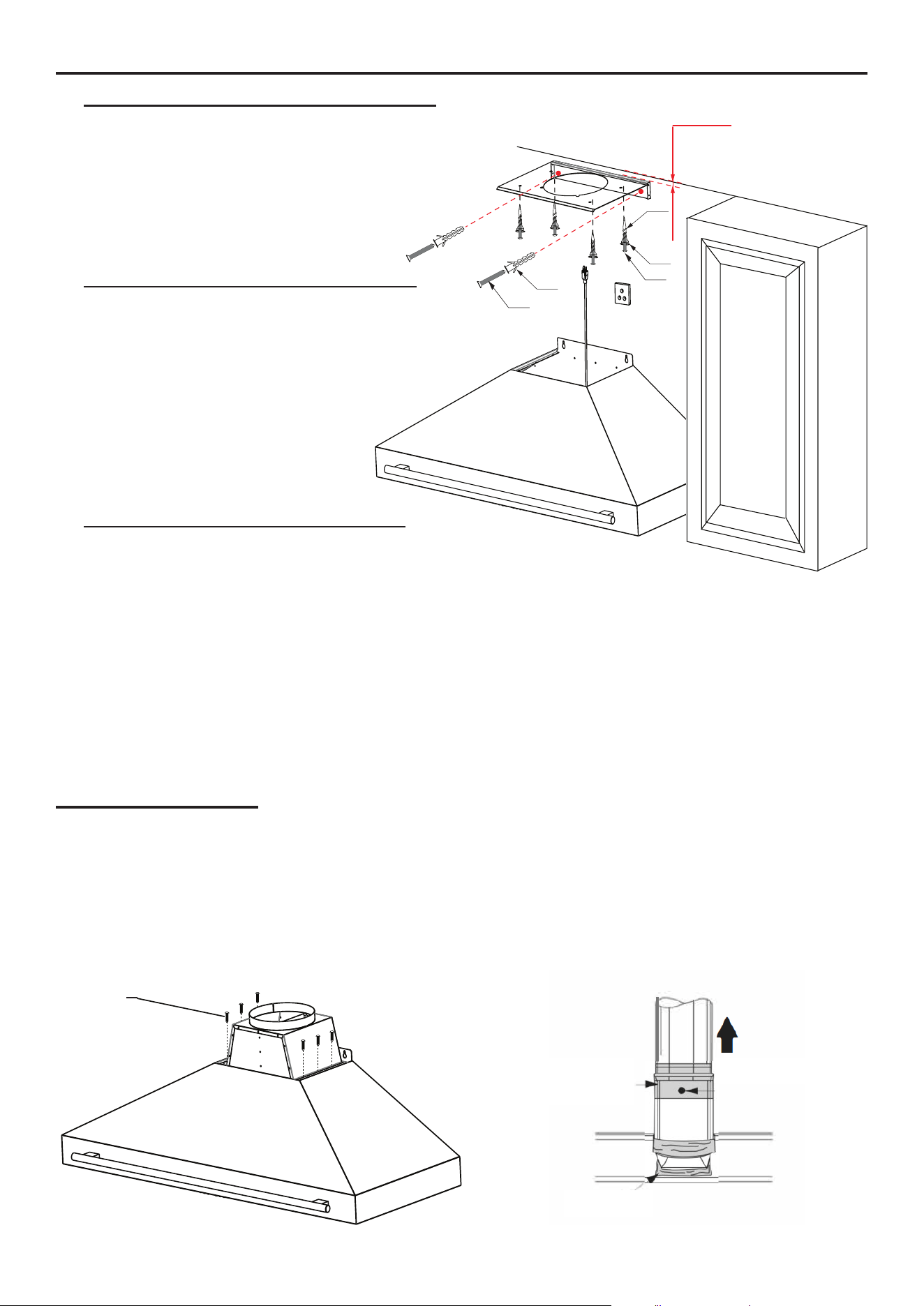
DUCT INSTALLATION
5. Position the Chimney Mounting Bracket
• Hold the chimney mounting bracket against the wall.
• Align its center with the vertical reference line.
• Position it 1/8” below the ceiling or upper limit.
• Mark the bracket’s screw
hole locations on the wall.
See Figure 4.
6. Install the Chimney Mounting Bracket
• Drill ¼” (0.25”) holes at the marked points.
• Insert the Φ0.236” × 1.142” plastic expansion
tubes (E) fully into the drilled holes.
• Secure the chimney mounting bracket using
the ST#3.5 × 1.18” self-drilling screws (D).
• Ensure the bracket is level and
rmly attached, as it will support
the upper chimney cover.
See Figure 4.
7. Install the Decorative Frame Bracket
• Hold the decorative frame bracket against the
wall, aligned with the vertical reference line at the
appropriate height.
• Mark the bracket’s screw hole locations.
• Drill ½” (0.50”) holes at the marked points.
• Insert the Φ0.51” × 1.61” spiral plastic expansion anchors (A) fully into the wall.
• Place at washers (C) over the mounting holes.
• Fasten the bracket using the #6-32 × 1-3/8” pan head screws (B) through the washers into the
anchors.
• Check that the bracket is level and securely xed. See Figure 4.
1
/
8
”
(3mm)
A
B
C
D
E
Figure 4.
Caution: To reduce the risk of re, use metal ductwork only.
8. Install the air outlet adapter over the hood using the provided M4 × 0.472” screws (F). Figure 5.
NOTE : AIR OUTLET ALREADY PRE-INSTALLED ON FRHWM5095-30
9. Make your ductin. You will need to minimize the use of elbows, since elbows and longer duct
create higher static pressure. (See Connections section - page 17)
10. Connect the duct with the air outlet adapter by using foil-backed tape to seal the joints and to
hold it in place. Figure 6.
F
Duct tape
over air outlet
Duct tape
over seam
and screw
Airflow
Figure 5.
Figure 6.
20
INSTALLATION
POWER OUTLET INSTALLATION
11. Ensure a clear space behind the chimney for the power outlet. See Figures 7 and 8 for reference.
12. For exact measurements, refer to page 10 under “Overall Dimensions – View from the Top.”
Figure 7. Figure 8.
DUCT CONNECTION
Caution: To reduce the risk of re, use metal ductwork is preferred.
1. Decide where the ductwork will run between the hood
and the outside.
2. A straight, short duct run will allow the hood to perform
most eciently.
3. Long duct runs, elbows, and transitions will reduce the
performance of the hood. Use as few of them as pos-
sible. Larger ducting may be required for best perfor-
mance with longer duct runs.
4. The air must not be discharge into a ue that is used for
exhausting fumes from appliances burning gas or other
fuels regulations concerning the discharge of air have to
be fullled.
5. Install a roof/wall cap. Connect round metal ductwork
to cap and work back towards hood location. Use duct
tape to seal the joints between ductwork sections
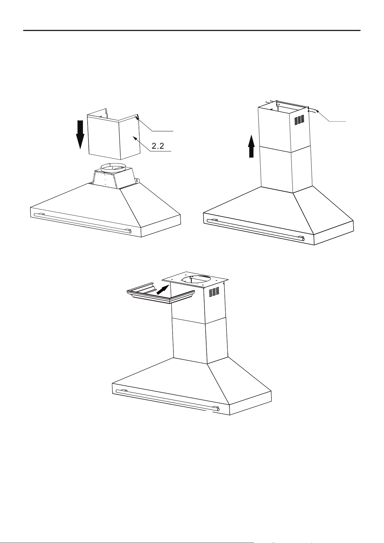
CHIMNEY ASSEMBLY
13. Insert the upper chimney section (2.1) inside the lower chimney
section (2.2). Ensure the upper section can slide freely for later
adjustment.
Ensure 2.1 slides smoothly and that the vertical vent slots remain
exposed on the sides once the section is extended.
1
2
3
5
5
Figure 9.
2.1
Figure 10.
21
INSTALLATION
14. Carefully place the two-part chimney assembly onto the top of the hood, ensuring it ts into the
recessed area of the hood body.
15. Extend the upper chimney section (2.1) upward until the vertical vent slots are fully visible and
aligned with the chimney mounting bracket. Figure 12.
16. Secure the upper section to the bracket using the provided M4 × 0.472” screws (F). Make sure
both chimney sections are stable, aligned, and rmly seated. Figure 12.
2.1
Figure 11.
F
Figure 12.
17. Slide the decorative frame/crown onto the chimney mounting bracket and secure it in position.
Figure 13.
Figure 13.
22
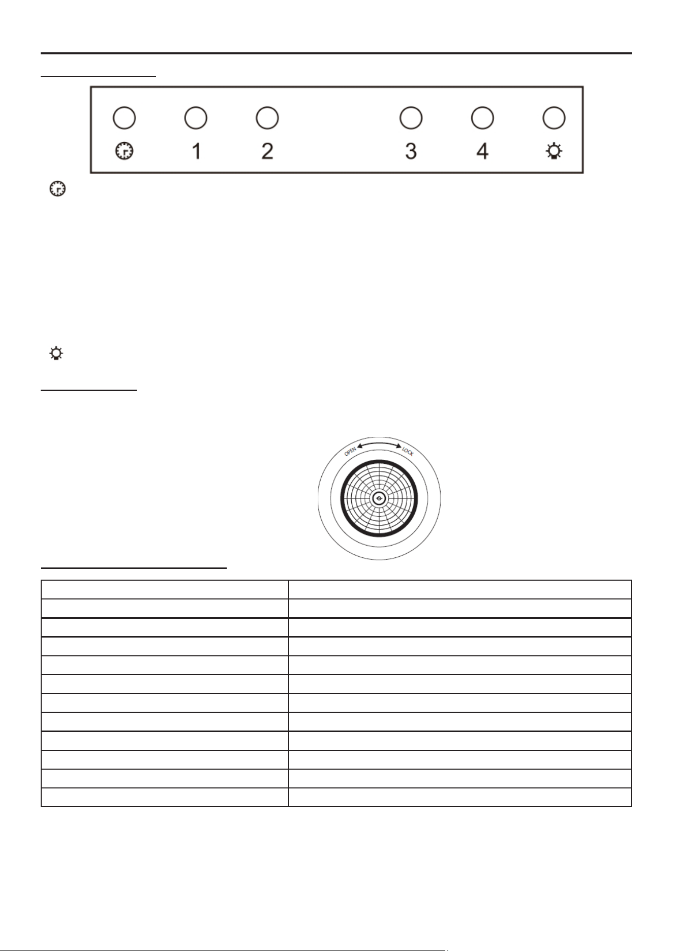
OPERATIONS
: Power Button/Power-o Delay Button
When the range hood is o, press this button to turn on the range hood, press 1, 2, 3 or 4 to adjust
motor speed.
When the range hood is on, press this button to enter Power-o delay function, timer is 3 minutes,
the range hood will turn o automatically when time up.
1. : First Speed
2. : Second Speed
3. : Third Speed
4. : Fourth Speed
: Light Button. Turn on and o the light
LIGHT BULBS
WARNING: Please ensure lights have been switched o for some time and the power source has
been disconnected before replacing any globes. Please be aware that the light will retain heat for a
short period of time after being switched o.
Step 1: Turn anti-clockwise to open
Step 2: Take the existing globe out
Step 3: Insert a new globe (1.5W GU10
LED) and turn clockwise in lock position
CONTROL PANEL
TECHNICAL INFORMATION
Body Design Wall Mount
Power Rating 110-120V / 60Hz
Total Input power 164 W (30”, 315 W (36”), 338W (48”), 344W (60”)
Motor Input Power 60W
Amperage
1.3A for 30”, 2.5A for 36” 48” and 60”
Speed Control Levels 4 Speeds
Motors Single Motor (30”), Double Motors (36”, 48” & 60”)
Controls Pushbutton Switch
Filters Stainless Steel Bae Filters + Charcoal Filters
Lighting 2 x 2W LED (30”), 4 x 2W LED (36”, 48” & 60”)
Light Intensity 1
Venting Size
Top, Ø6” for 30”, Ø10” for 36” 48” and 60”

2
3
MAINTENANCE & CLEANING
SURFACE MAINTENANCE:
Clean periodically with hot soapy water and clean cotton cloth. Do not use corrosive or abrasive
detergent (e.g., comet powder scrub, EZ-O oven cleaner), or steel wool/scoring pads which will
scratch and damage surface.
For heavier soil use liquid degreaser such as ‘Formula 409’ or ‘Fantastic’ brand cleaner.
After cleaning, you may use nonabrasive stainless-steel polish/cleaners such as 3M or ZEP, to
polish and bu out the stainless luster and grain. Always scrub lightly, with clean cotton cloth, and
with the grain
FILTERS:
The Filters tted by the factory are intended to lter out residue and grease from cooking. It need not
be replaced on a regular basis but are required to be kept clean.
Filters should be cleaned after every 30 hours of use.
Remove and clean by hand in a basin of hot soapy water. The lter is also dishwasher safe.
If heavily soiled, spray ‘Formula 409’ or equivalent degreasing detergent and leave to soak.
Dry lters and re-install before using hood.
HOOD CLEANING:
The saturation of greasy residue in the blower and lters may cause increased inammability.
Always keep unit clean and free of grease and residue build-up to prevent possible res.
Filters must be cleaned periodically and free from accumulation of cooking residue (see cleaning
instructions inside). Old and worn lters must be replaced immediately. Do not operate
blowers when lters are removed. Never disassemble parts to clean without proper instructions.
Disassembly is recommended to be performed by qualied personnel only. Call our service center
for removal instructions.
Stainless steel is one of the easiest materials to keep clean. Occasional care will help preserve its
ne appearance.
CLEANING TIPS:
• Hot water with soap or detergent is all that is usually needed.
• Rinse with clear water. Wipe dry with a clean, soft cloth to avoid water marks.
• For discolorations or deposits that persist, use a non-scratching household cleanser or
stainless-steel polishing powder with a little amount of water and a soft cloth.
• For stubborn stain, use a plastic scouring pad or soft bristle brush together with cleanser and
water.
• Rub lightly in direction of polishing lines or “grain” of the stainless nish. Avoid using too much
pressure that may mar the surface.
• Do not allow deposits to remain for long periods of time.
• Do not use ordinary steel wool or steel brushes. Small bits of steel may adhere to the surface
causing rust.
• Do not allow salt solutions, disinfectants, bleaches, or cleaning compounds to remain in contact
with stainless steel for extended periods. Many of these compounds contain chemicals that may
be harmful. Rinse with water after exposure and wipe dry with a clean cloth.
• Painted surfaces should be cleaned with warm water and mild detergent only.
2
4
TROUBLESHOOTING
Problems Solutions
The range hood does
not operate.
• Check that there is power to the range hood. The most common issue is that the circuit
breaker is o, or the fuse has blown.
• Make sure the speed has been selected at the range hood controls.
• Turn o power to the range hood and check that all the wires are properly connected
• If the problem persists, please contact Forno Technical Support.
The range hood
vibrates when the fan is
operating.
• The motor is loose – Turn o the power and remove the lter and check that all screws
aresecure and tight around the motor.
• The duct work connection is loose – Turn o the power to the unit and check that the
ductwork connection to the pipe is tight. Add duct tape is necessary.
The fans seem weak.
• Check that the duct size used is at least 6 in for the 30” and 10 in for the 36, 48 and 60
in. The range hood will not function eciently with wrong duct size
• Check that the duct is not clogged with debris and the tight mesh on the wall cap, if
applicable, isn’t restricting air ow
• Check that the damper unit is opening properly.
• Check that no birds or animals have nested in the duct.
The lights work, but the
fan is not spinning, is
stuck, or is rattling.
• The thermal protection system detects if the motor is too hot to operate and shuts the
motor down. In this case, the motor will function properly after the thermal protection
system cools down (after approximately 10 min).
• Check that the fan isn’t jammed or scraping the bottom.
• If nothing else works, the motor may be defective or seized. If so, replace the motor.
The range hood is not
venting properly.
• Check that no birds or animals have nested in the duct.
• Check that the distance between the cooktop and the bottom of the range hood is
between 458 mm (18 in) and 710 mm (28 in).
• Check that duct work follows all requirements. Use round metal duct work with a
uniform diameter of 152 mm (6 in). The length of duct work must not exceed 35 ft (10.7
m). Reduce the length of duct work and the number of elbows if necessary. Ensure that
all joints are properly connected, sealed, and taped.
• Check that the duct does not open against the wind.
• Ensure that the power is on high speed for heavy cooking.
• Close all windows nearest to the range hood to eliminate sudden air gusts.
• To enhance the performance of the range hood, open slightly a window on the opposite
side of the house where the range hood vents outdoors.
A light does not work.
• Check to see if light bulb is burnt. If so, replace.
• Check the light bulb to see if it is loose. If so, tighten.
• Remove the problem bulb and insert one you know is working. If the properly functioning
light does not come on, the problem may be the light assembly. Have the light assembly
serviced or replaced.
What is make-up air?
• When the range hood ventilates the air out of the room, the air vented must be replaced,
this is called make-up air. We do not currently provide a make-up air unit. NOTE: Always
consult any applicable building codes in your area regarding minimum and maximum
air ow rates. Certain states may require additional items such as make-up air for larger
CFM range hoods (typically over 300 CFM).
My range hood is not
pulling.
• Was the unit plugged in, and was the fan tested before installation?
• What is the distance between the hood and the cooktop?
• Is the range hood the correct width for the cooktop?
• Does the hood provide sucient BTU or wattage output for the type of cooktop?
• For gas: BTU output per burner ÷ 100
• For electric: Wattage output per burner ÷ 10
• Are the bae or mesh lters installed correctly?
• When were they last cleaned?
• Is the ducting clear and unobstructed?
• Is the damper opening properly when the hood is turned on?
• Is there air coming out of the top of the hood?
• Is there air coming out of the upper chimney section?
• If a tissue is placed under the bae lters, does the airow hold it in place?
• How many elbows are in the ducting run, and how long is the total duct path?
• There should be no more than 2–3 elbows.
• For every elbow, subtract 15 feet from the total duct run. (See Duct Run Calculation
section)
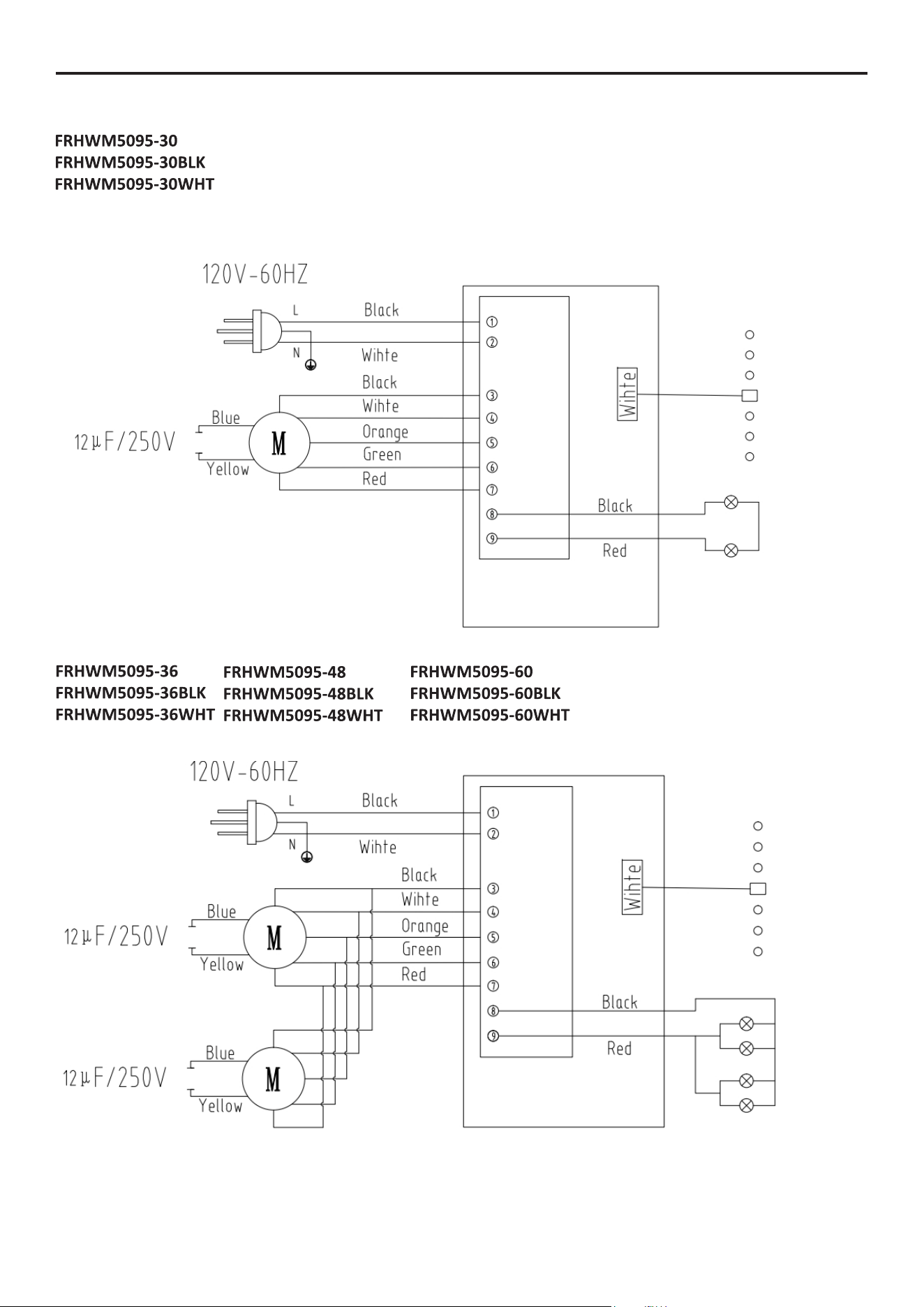
25
WIRE DIAGRAM

Customer Support: Call 1-866-231-8893 or email: [email protected]