
ADD-I-050-03d_Installation_Guide_OTM-GSMv2 - Customer.docx
Frame reference: ADD-G-026_Technical document
OTM-GSM v2 Installation
Guide - Customer
ADD-I-050-03c
MAILING LIST
☒ Interne
☒ Externe
☐ Restricted
☐ Free
MASTERY OF THE DOCUMENT
Name
Function
Date
Visa
Written by:
Alexis LATHIERE
Embedded system
Manager
15/01/2026
AL
Verified by:
Lucas PARTEZANA
Project Manager
15/01/2026
LP
Approved by:
Séléna RAVETTA
Quality Manager
15/01/2026
SR
CHANGES
Version
Editor
Date
Page
Amendments by revision
00
Mathieu FUFFO
Bastien BLASENHAUER
07/10/2022
21/11/2022
General
General
00a/ Creation of the document
00b/ Take into account AL proofreading
01
Charlotte MASSON
Lucas PARTEZANA
05/12/2022
29/11/2023
General
4 & 11
01/ CM approval
01a/ Documentation update
Changes: Addition of the "Installation
recommendations - OTM BLE link"
section.
Diagram modification
02
Séléna RAVETTA
Lucas PARTEZANA
29/11/2023
19/12/2024
4 & 11
General
02/ SR approval
02a/ Added the LED section and updated
the photos. Added autonomy and
configurations and title change.
03
Lucas PARTEZANA
Alexis LATHIERE
04/02/2025
07/07/2025
General
3
03/ Approved by SR
03a/ Operational temperature changes
(185 to 176°F)

ADD-I-050-03d_Installation_Guide_OTM-GSMv2 - Customer.docx
Page 2/13
Lucas PARTEZANA
Alexis LATHIERE
Alexis LATHIERE
02/09/2025
12/09/2025
15/01/2026
12
12
13
03b/ Deleting an image
03c/ Add certification requirements
(frequencies specification + decrease max
operating temperature)
03d/ Add regulation mention (FCC and IC)
Description
This document describes the recommendations for OTM-GSM installation.
DESCRIPTION .............................................................................................................. 2
LIST OF TABLES .......................................................................................................... 2
PRESENTATION OF THE OTM-GSM V2 ..................................................................... 3
COMMISSIONING PROCEDURE ................................................................................. 5
4.1. System activation ................................................................................................ 5
4.2. LED OPERATION ..................................................................................................... 5
4.3. ADD EQUIPMENT ON LOCALEEZ ......................................................................... 6
4.4. INFORMATIONS ...................................................................................................... 7
4.5. BASIC SETTINGS .................................................................................................... 7
4.6. ADVANCED SETTINGS ........................................................................................... 8
4.7. DIAGNOSTICS ......................................................................................................... 8
INSTALLATION RECOMMENDATIONS ...................................................................... 9
5.1. INSTALLATION EXAMPLES ................................................................................. 10
5.2. TEST ....................................................................................................................... 11
5.3. CONFIGURATION .................................................................................................. 12
DISCLAIMER .............................................................................................................. 13
6.1. WARNING TO USERS IN THE UNITED STATES ................................................. 13
6.2. WARNING TO USERS IN THE CANADA .............................................................. 13
List of tables
Table 1 : Introduction to OTM-GSM .................................................................................. 3
Table 2 : Location of the magnet ...................................................................................... 5
Table 3 : Installation Recommendation ........................................................................... 9
Table 4 : Installation Recommendation – For BLE Link ................................................. 9
Table 5 : The different means of fixing (Magnet, Screw and Hose Clamp) ................. 10
Table 6 : Installation examples ....................................................................................... 11
Table 7 : GSE Icon ........................................................................................................... 12
ADD-I-050-03d_Installation_Guide_OTM-GSMv2 - Customer.docx
Page 3/13
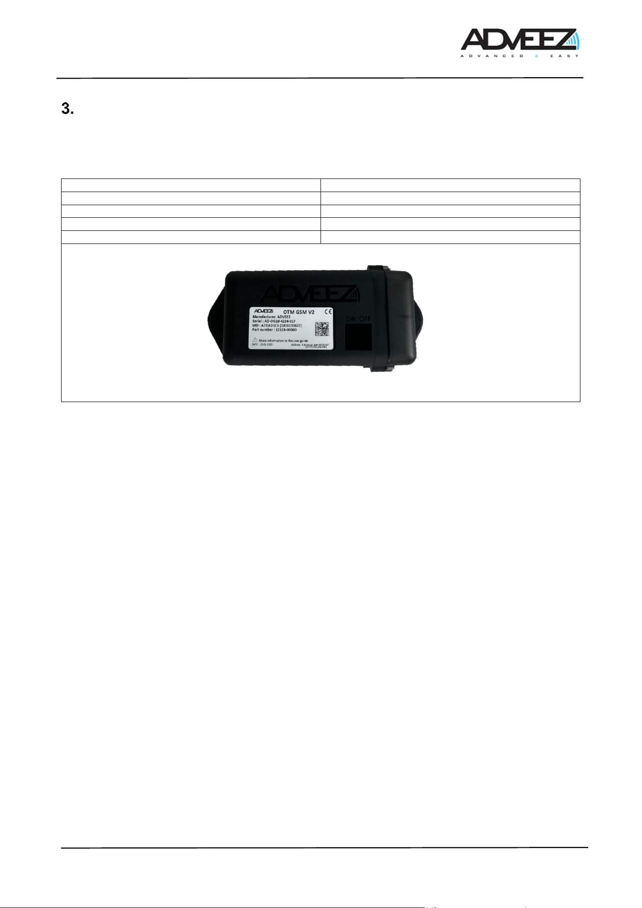
Presentation of the OTM-GSM v2
The OTM-GSMv2 is a fully energy-autonomous GPS tracker for equipment. It retrieves the GPS position and
the activity of the equipment on which it is installed, whether it is in motion or stationary, and then transmits
the data via the cellular network to the Localeez visualization and configuration platform.
Size
6.4 × 2.48 × 2.03 in
Weight
13.4 oz
Operating temperature
- 4 to + 149F
Operating voltage
7.2V nominal
Initial installation height
31.5in
Table 1 : Introduction to OTM-GSM
LTE Radio specifications
• 703 − 2620 MHz
• Bands list: 1, 3, 7, 8, 20, 28
• Power class 3, 23 dBm (applicable for each band)
BLE Radio specifications
• 2400 − 2483.5 MHz
• +10dBm peak
GNSS Radio specifications
• L1 ∶ 1559 − 1610 MHz
• GPS, GLONASS, BEIDOU, GALILEO
ADD-I-050-03d_Installation_Guide_OTM-GSMv2 - Customer.docx
Page 4/13
This product has been designed to track non-motorized assets while ensuring autonomy tailored to our clients'
needs. Below, you will find detailed information about its autonomy based on usage.
These lifespan estimates are theoretical and were obtained under normal usage conditions in a controlled
environment, with temperatures ranging from 64.4°F to 77°F. Please note that environmental conditions,
particularly temperature (weather, heat waves, cold snaps), may affect the lifespan. Moreover, the lifespan is
directly related to the frequency of use. More frequent usage will reduce battery life, as shown in the graphs
below.
OTM LTE V2:
Start and Stop Mode
Product facing the sky with good network coverage.
GPS Fix : 30-45sec
LTE Connectivity : 5-10 sec
Number of Position / Day
Battery Life
1
7 years
4
6 years
12
2,5 years
24
1 years
OTM LTE V2:
Start and Stop Mode
BLE Connectivity with FAMA box with 50% of data through Motorized Asset
Product facing the sky with good network coverage.
GPS Fix : 30-45sec
LTE Connectivity : 5-10 sec
Number of Position / Day
Battery Life
1
8 years
4
7 years
12
4,5 years
24
2 years
This estimate is also theoretical and relies on a sufficient density of FAMAs in the environment to achieve at
least 50% communication via the FAMAs.
ADD-I-050-03d_Installation_Guide_OTM-GSMv2 - Customer.docx
Page 5/13
Commissioning procedure
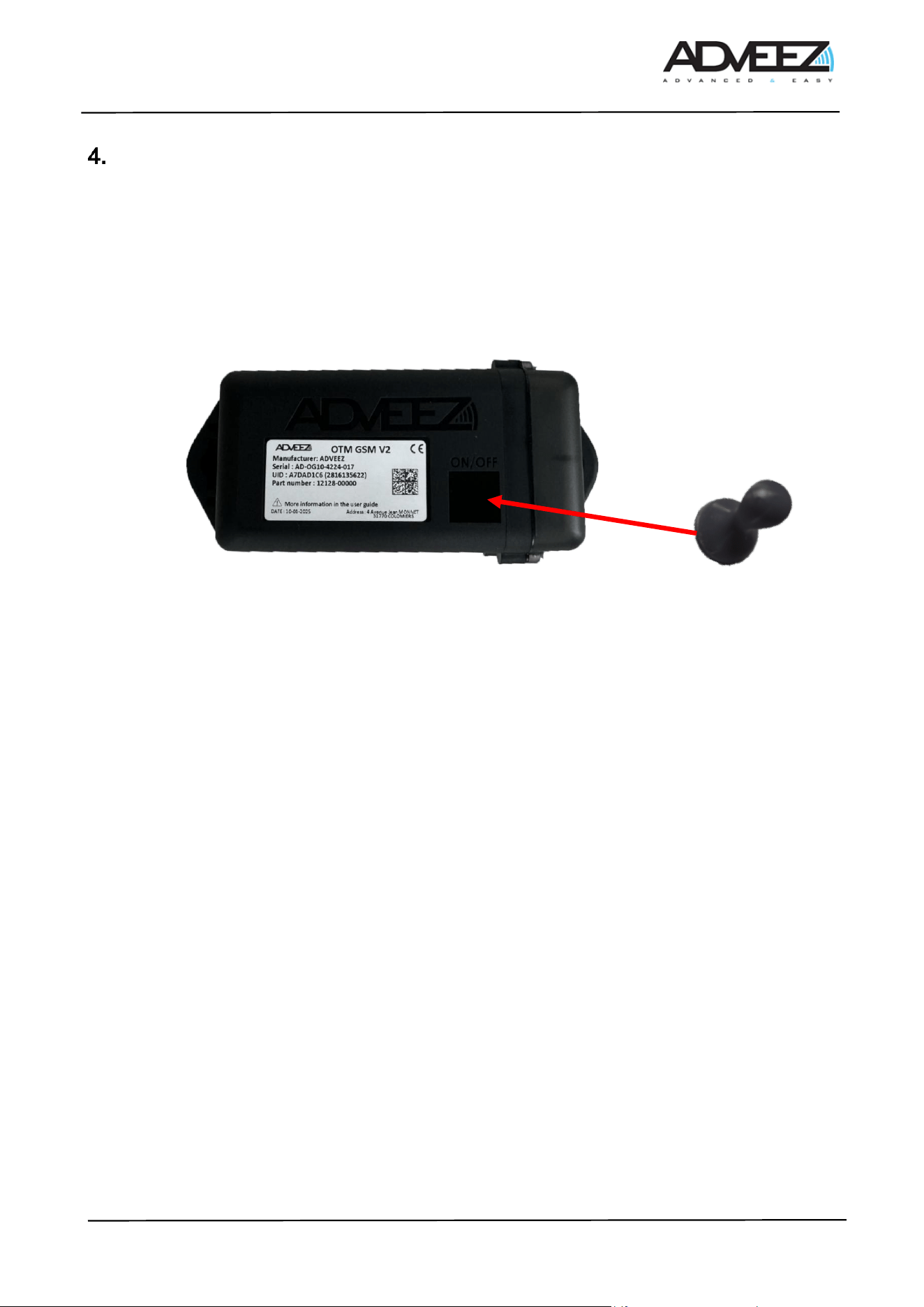
4.1. System activation
To activate the system, an activator must be placed in the dedicated area on the bottom side of the OTM-
GSM v2 for 2 seconds (see Table 2). To confirm activation, the green LED will light up for 100 ms, and the
module will be visible on LHC mobile for 10 seconds. After waking up, regardless of the OTM's state, simply
hold the magnet in front of the device for 2 seconds to make it visible on LHC Mobile. This then allows it to be
available for configuration.
Table 2 : Location of the magnet
4.2. LED Operation
The OTM GSM is equipped with an LED that provides information about its operation during installation.
There is a GUI parameter that allows the activation of the LED operation on the OTM. Enabling this UI mode
is done via remote configuration using LHCM or LHC GSM. By default, the LED is disabled
When the UI option is enabled: The LED blinks for 10 ms every 3 seconds when it is not in standby mode to
indicate that it is alive."
• As long as the LED is blinking, it means the OTM has not completed the operations it needs to carry
out (fixing, transmitting data, etc.).
When the UI option is disabled: The LED no longer blinks when the OTM is active.
• However, even if the UI is disabled, the LED will light up during a power reset (battery connection) or
when exiting standby mode forced by the magnet.
To activate this option, please contact Adveez support.
ADD-I-050-03d_Installation_Guide_OTM-GSMv2 - Customer.docx
Page 6/13
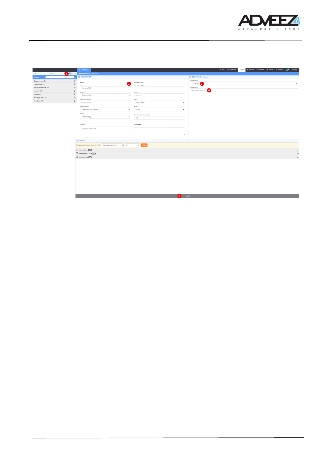
4.3. Add equipment on Localeez
1. Click on the "+Add" button to add a new GSE.
2. Enter the GSE information (name, division, make & model, energy, ...).
3. Select OTM-GSM in "EQUIPMENT".
4. Enter the serial number of the OTM-GSM.
5. Click on "ADD".
The following steps detail all the settings of the equipment. On Localeez, in the gses tab, then in the
configuration section.
ADD-I-050-03d_Installation_Guide_OTM-GSMv2 - Customer.docx
Page 7/13
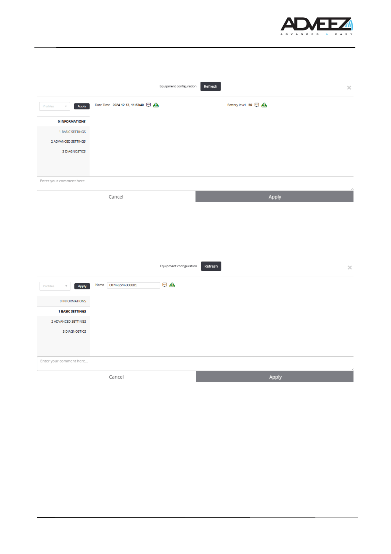
4.4. INFORMATIONS
- Date time: Gives the internal date and time of the OTM-GSM, date of configuration request.
- Battery level: Gives the internal battery charge level of the OTM-GSM (0% to 100%).
4.5. BASIC SETTINGS
- Name: Allows to change the name of the OTM-GSM. Usually, the name of the OTM-GSM is the ID
of the GSE. Note, this is the name that will appear on LHC Mobile.
ADD-I-050-03d_Installation_Guide_OTM-GSMv2 - Customer.docx
Page 8/13
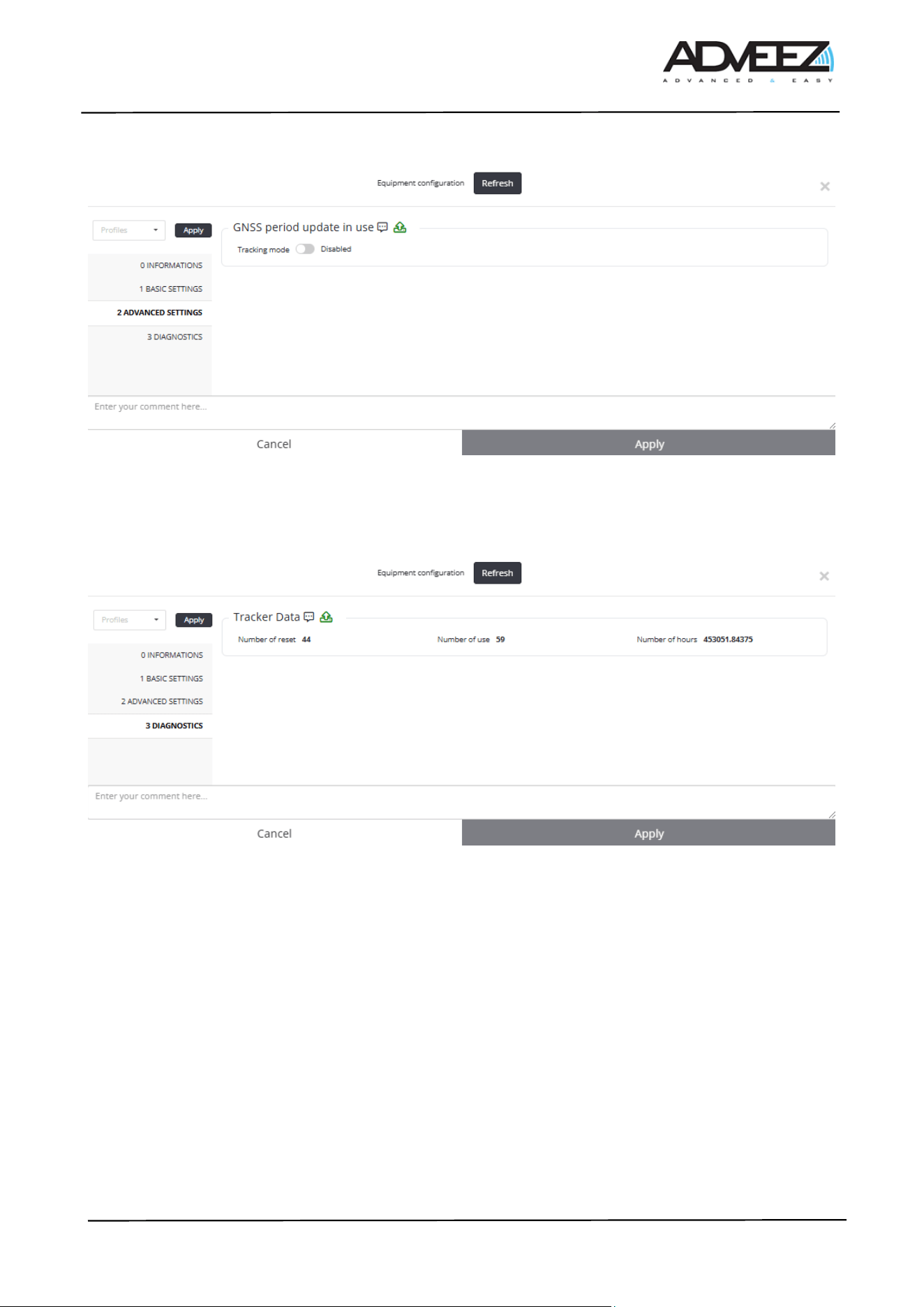
4.6. ADVANCED SETTINGS
- Tracking mode: Enables or disables tracking mode.
⚠: Enabling tracking mode on an OTM-GSM decreases its battery life
4.7. DIAGNOSTICS
- Number of reset: Indicates the number of times the OTM GSM v2 has been reset.
- Number of use: Indicates the number of uses since the beginning of its life.
- Number of hours: Indicates the number of hours (hours in use) since the beginning of its life.
ADD-I-050-03d_Installation_Guide_OTM-GSMv2 - Customer.docx
Page 9/13
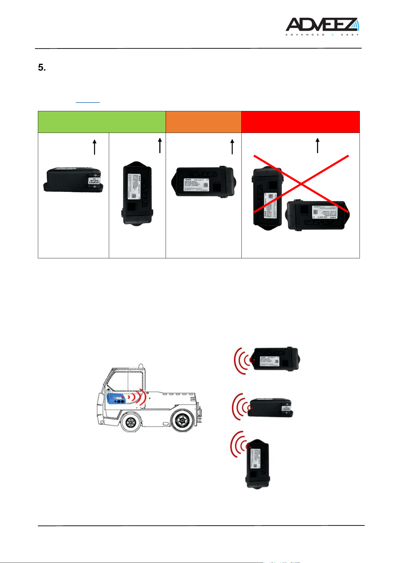
Installation recommendations
Note: Incorrect positioning of the module on the GSE can have impacts on GPS and long-distance
communication. Thus, during its installation, the product must comply with one of the first 2 orientations
contained in Table 4.
Table 3 : Installation Recommendation
Fleets equipped with FAMAs and OTMs may have other installation recommendations. A BLE link between
OTMs and FAMAs has been developed to enable the OTM to save battery power; using the FAMA as a long-
distance transmitter, the OTM only needs to communicate information to the FAMA in BLE.
The OTM must therefore be oriented toward the direction of the FAMA and installed face up, with unobstructed
line of sight to the sky. Here are some examples. The transmitter (in red) is located at the vent of the device.
The transmitter points towards the vehicle where the FAMA is installed as shown in the image below.
Note: the vent is the 4 small square holes next to the label on the device
Table 4 : Installation Recommendation – For BLE Link
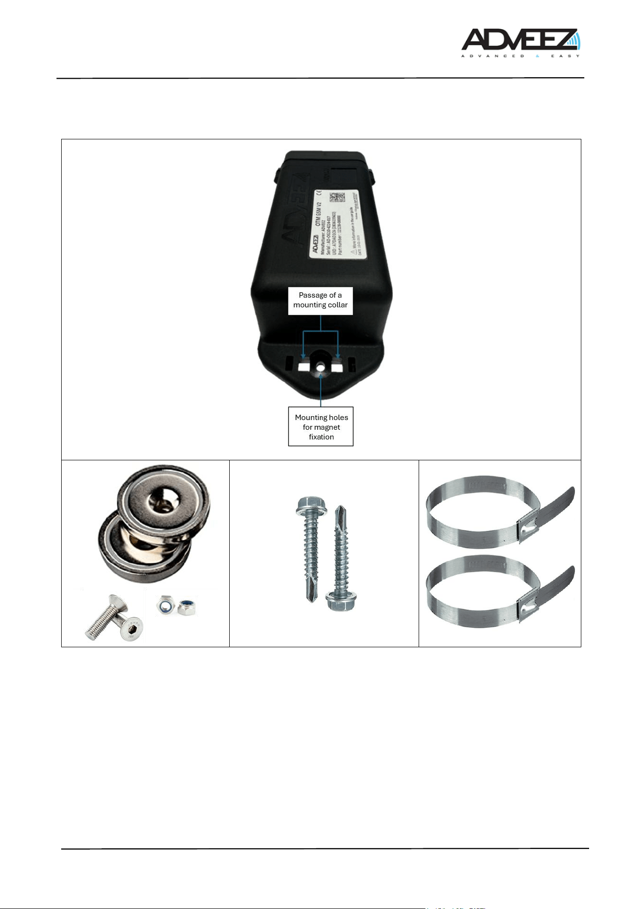
The attachment of the OTM-GSM to a GSE is conducted:
Optimal installation
orientation
Orientation not
recommended
Misdirection
Sky
Sky
The opening
part facing
down.
Sky
Sky
The opening part is facing upwards,
or the Adveez logo is upside down.
ADD-I-050-03d_Installation_Guide_OTM-GSMv2 - Customer.docx
Page 10/13
• Either by magnets
• Either by screws
• Either by hose clamp
Table 5 : The different means of fixing (Magnet, Screw and Hose Clamp)
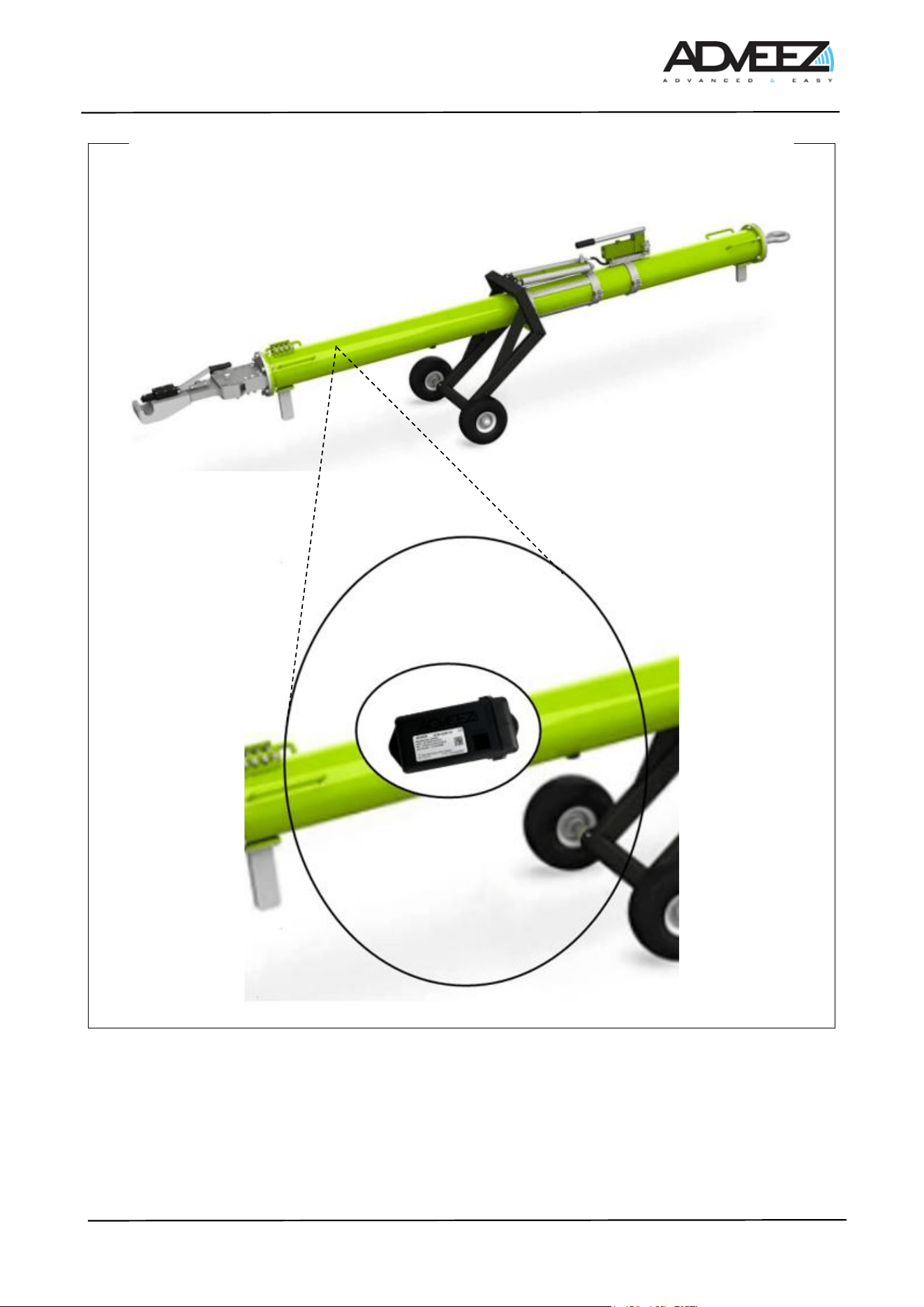
5.1. Installation examples
ADD-I-050-03d_Installation_Guide_OTM-GSMv2 - Customer.docx
Page 11/13
Towing bar
Table 6 : Installation examples
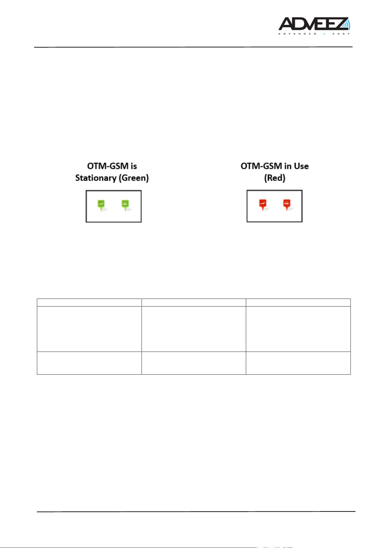
5.2. Test
1. To begin, the icon of the GSE equipped with the OTM-GSM v2 must be green. This means that the
OTM-GSM v2 is stationary, and its position on the Localeez map should match its location at the
ADD-I-050-03d_Installation_Guide_OTM-GSMv2 - Customer.docx
Page 12/13
airport. It is sometimes necessary to perform several movements (waiting 2 minutes between each
movement) to allow the OTM-GSM v2 to lock onto GPS satellites.
2. When the GSE is in motion, the icon turns red. (Note, when mounting the OTM-GSM v2 on the GSE,
motion detection may occur, so please wait 10 minutes before making a new movement). It is
recommended to wait 15 minutes to allow the GPS to acquire its first position. This delay includes a
waiting time of up to 3 minutes to obtain the first position and ensure the GNSS data is updated for
subsequent positions
3. When the GSE is no longer in motion, the icon turns green again, and it becomes available once more.
Table 7 : GSE Icon
5.3. Configuration
To optimize lifespan according to the use case, configurations affecting autonomy and operation are not
available. Configuration changes must be requested from Adveez support.
List of available options:
Feature name
Description
Constraints / Impac
Tracking mode
Allows intermediate positions to
be recorded, in addition to the
starting position and final
position, during a long movement
or displacement (longer than 10
minutes)
Reduced autonomy
BLE link
Allows the OTM to use the
FAMAs in its vicinity (10-15m) as
a gateway to send its information.
Improved autonomy if the FAMA
density is sufficient.

ADD-I-050-03d_Installation_Guide_OTM-GSMv2 - Customer.docx
Page 13/13
Disclaimer
6.1. Warning to users in the United States
Federal Communications Commission Interference
47 CFR Ch, PART 2, PART 15
FCC ID : R8T-OTMGSMV2
FCC Compliance Statement (Part 15)
This OTM GSM V2 device complies with Part 15 of the FCC Rules. Operation is subject to the following
two conditions: (1) This device may not cause harmful interference, and (2) this device must accept any
interference received, including interference that may cause undesired operation.
FCC Statement (§15.105(b))
This equipment has been tested and found to comply with the limits for a Class B digital device, pursuant
to part 15 of the FCC Rules. These limits are designed to provide reasonable protection against harmful
interference in a residential installation. This equipment generates, uses and can radiate radio frequency
energy and, if not installed and used in accordance with the instructions, may cause harmful interference to
radio communications. However, there is no guarantee that interference will not occur in a particular
installation. If this equipment does cause harmful interference to radio or television reception which can be
determined by turning the equipment off and on, the user is encouraged to try to correct interference by one
or more of the following measures:
- Reorient or relocate the receiving antenna.
- Increase the separation between the equipment and receiver.
- Connect the equipment into an outlet on circuit different from that to which the receiver is connected.
- Consult the dealer or an experienced radio/TV technician for help
Rf Exposure
This device complies with FCC RF radiation exposure limits set forth for the general population
(uncontrolled exposure). This device must be installed to provide a separation distance of at least 20cm from
all people and must must not be co-located or operating in conjunction with any other antenna or transmitter
NO UNAUTHORIZED MODIFICATIONS
FCC Compliance Statement Section 15.21
CAUTION: This equipment may not be modified, altered, or changed in any way without signed written
permission from ADVEEZ. Unauthorized modification may void the equipment authorization from the FCC and
will void the ADVEEZ warranty.
6.2. Warning to users in the Canada
IC ID : 21312-OTMGSMV2
This device contains licence-exempt transmitter(s)/receiver(s) that comply with Innovation, Science and
Economic Development Canada’s licence-exempt RSS(s). Operation is subject to the following two
conditions: (1) this device may not cause interference, and (2) This device must accept any interference,
including interference that may cause undesired operation of the device.
Rf Exposure
This device complies with ISED radiation exposure limits set forth for general population. This device must
be installed to provide a separation distance of at least 20cm from all persons and must not be co-located or
operating in conjunction with any other antenna or transmitter.