ClearHome™
Whole-House Cartridge Filter
Installation Instructions & Owner's Manual
Model AOS-CH-1000

Table of Contents
Installation .........................................................5
Site Requirements ..................................................5
Cartridge Replacement ..............................................7
Troubleshooting Guide ............................................. 11
Replacement Parts ................................................12
Installation Fiing Assemblies ......................................14
Warranty ..........................................................15
MODEL NUMBER:
SERIAL NUMBER:
WATER TREATMENT PROFESSIONAL:
PRODUCT INFORMATION
Your A. O. Smith water filter is a precision built, high-quality product. This unit will deliver filtered water
for many years to come when installed and operated properly. Please study this manual carefully and
understand the cautions and notes before installing. This manual should be kept for future reference.
If you have any questions regarding your water filter, contact your water treatment professional.

3
The manufacturer has pre-assembled the cartridge filter tank. The actual cartridge filter is shipped separately and will need to be installed
into the tank to complete assembly.
The installer should read this complete guide to familiarize themselves with assembly, installation, and operation of the cartridge filter.
The owner should read and become familiar with the cartridge replacement change out instructions.
NOTE: Water treatment professionals and customers in the state of Iowa must complete the form below prior to sale.
The site selection for the ClearHome™ Whole-House Cartridge Filter may vary depending on the purpose it will serve. This versatile filter
may be used as pre- or post-filtration in a water treatment system. Depending on the application, this filter may also be utilized as a single
tank system.
Regardless of application, provisions should be made so that the filter is located close to a drain. A bottom drain is included for this
cartridge filter to allow rinsing of the cartridge. When replacing the cartridge, water may spill from the housing. Therefore, precautions
should be taken to prevent any damage due to water while rinsing or replacing the cartridge.
NOTE: Do not use with water that is microbiologically unsafe or of unknown quality without adequate disinfection before or
after the filter. Units certified for cyst reduction may be used on disinfected waters that may contain filterable cysts.
FOR PURCHASES MADE IN IOWA
This form must be signed and dated by the buyer and seller prior to the consumma on of this sale. This form should be
retained on fi le by the seller for a minimum of two years.
Buyer’s Name (printed)
Seller’s Name (printed)
Buyer’s Signature
Seller’s Signature
Date
Date
Pre-Installation
4
“TREATED”
WATER EXITS
SUPPLY
WATER ENTERS
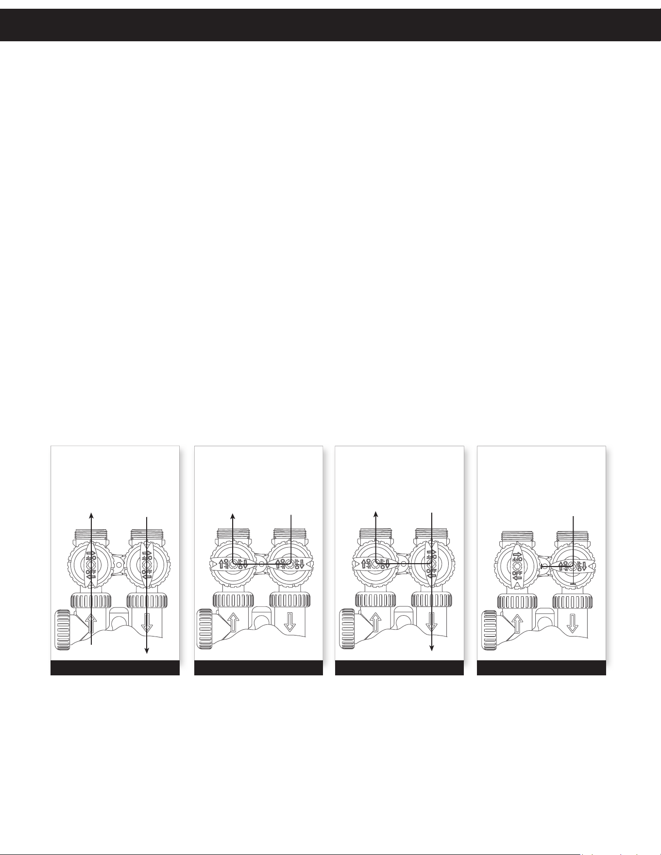
NORMAL OPERATION
POSITION
BYPASS POSITION DIAGNOSTIC POSITION SHUT OFF POSITION
FIGURE 1
SUPPLY
WATER EXITS
SUPPLY
WATER ENTERS
FIGURE 3
SUPPLY
WATER EXITS
SUPPLY
WATER ENTERS
FIGURE 2
NO
WATER EXITS
SUPPLY WATER IS
SHUT OFF
TO THE HOUSE
AND THE VA LV E
FIGURE 4
The bypass valve is typically used to isolate the control valve from the plumbing system’s water pressure in order to perform control
valve repairs or maintenance. The 1” full flow bypass valve incorporates four positions, including a diagnostic position that allows a
service technician to have pressure to test a system while providing untreated bypass water to the building. Be sure to install bypass
valve onto main control valve before beginning plumbing or make provisions in the plumbing system for a bypass. The bypass body and
rotors are glass-filled resin and the nuts and caps are glass-filled polypropylene. All seals are self-lubricating EPDM to help prevent valve
seizing after long periods of non-use. Internal “O” Rings can easily be replaced if service is required.
The bypass consists of two interchangeable plug valves that are operated independently by red arrow shaped handles. The handles
identify the direction of flow. The plug valves enable the bypass valve to operate in four positions.
1. NORMAL OPERATION POSITION: The inlet and outlet handles point in the direction of flow indicated by the engraved
arrows on the control valve. Water flows through the control valve for normal operation of a water softener or filter. During the
regeneration cycle this position provides regeneration water to the unit, while also providing untreated water to the distribution
system (Fig. 1).
2. BYPASS POSITION: The inlet and outlet handles point to the center of the bypass. The system is isolated from the water
pressure in the plumbing system. Untreated water is supplied to the building (Fig. 2).
3. DIAGNOSTIC POSITION: The inlet handle points toward the control valve and the outlet handle points to the center of bypass
valve. Untreated supply water is allowed to flow to the system and to the building, while not allowing water to exit from the system
to the building (Fig. 3). This allows the service technician to test the unit and perform other functions without disrupting the water
going to the building.
NOTE: The system must be rinsed before returning the bypass valve to the normal position.
4. SHUT OFF POSITION: The inlet handle points to the center of the bypass valve and the outlet handle points away from the
control valve. The water is shut off to the building. The water treatment system will depressurize upon opening a tap in the building.
A negative pressure in the building combined with the unit being in regeneration could cause a siphoning to the building. If water
is available on the outlet side of the unit, it is an indication of water bypassing the system (Fig. 4) (i.e. a plumbing cross-connection
somewhere in the building).
Bypass Valve
5
GENERAL INSTALLATION & SERVICE WARNINGS
The control valve, fittings and/or bypass are designed to accommodate minor plumbing misalignments. There is a small
amount of “give” to properly connect the piping, but the filter is not designed to support the weight of the plumbing.
Do not use petroleum jelly, oils, other hydrocarbon lubricants or spray silicone anywhere. A silicone lubricant may be
used on black O-rings, but is not necessary. Avoid any type of lubricants, including silicone, on red or clear lip seals.
Do not use pipe dope or other sealants on threads. Plumber’s tape must be used on the threads of the 1" NPT inlet
and outlet, the brine line connection at the control valve, and on the threads for the drain line connection. Plumber’s
tape is not used on the nut connections or caps because O-ring seals are used. The nuts and caps are designed to be
unscrewed or tightened by hand or with the special plastic Service Wrench (100396829). If necessary, pliers can be used
to unscrew the nut or cap. Do not use a pipe wrench to tighten nuts or caps. Do not place screwdriver in slots on
caps and/or tap with a hammer.
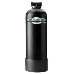
SITE REQUIREMENTS
• Water Pressure: 20-120 psi
• Water Temperature: 40-100°F (4.4-43.3°C)
• Housing Dimensions: 10” diameter by 43”
height (with included fittings)
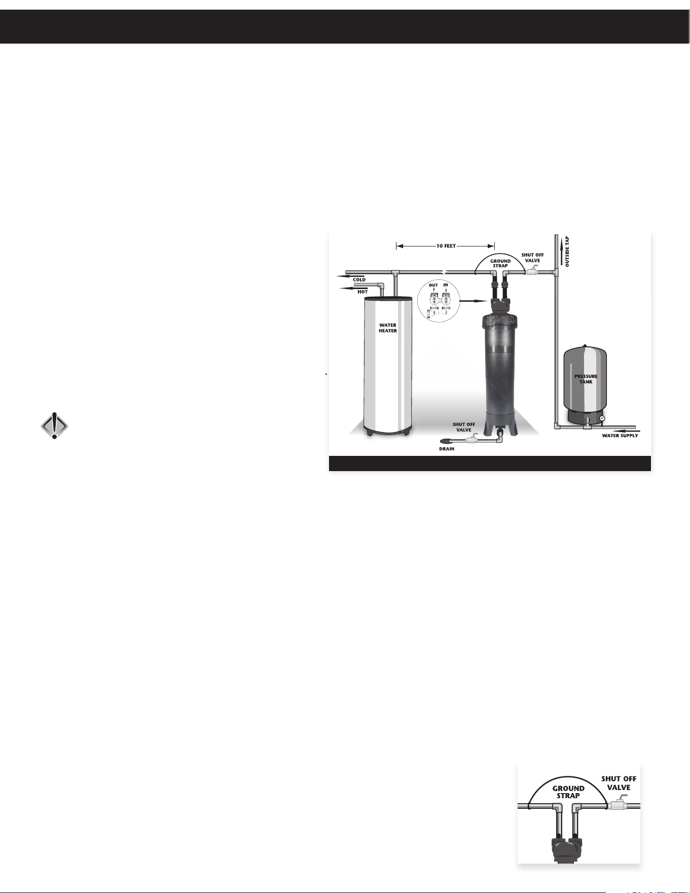
1. This unit is equipped with a 3/4” CTS push connection
(7/8” OD) at the bottom of the tank. This connection
is for a drain that may be used to rinse the cartridge
filter periodically. If this is installed, location of the
tank to the actual drain should be as close as possible.
It is highly recommended to install the optional drain
for servicing the unit.
CAUTION: If a drain is not used or
the installation makes this
unavailable, the drain hole
must be plugged or water
will flow from this outlet.
2. The housing should be installed on a firm, flat surface (above or below grade).
3. Do not install any water filter with less than 10 feet of piping between its outlet and the inlet of a water heater.
4. Do not locate unit where it or its connections (including the drain) will ever be subjected to room temperatures
under 33°F.
5. Do not subject the housing to any vacuum as this may cause an “implosion” and could result in leaking. If there is a
possibility a vacuum could occur, please make provisions for a vacuum breaker in the installation.
6. INLET/OUTLET PLUMBING: Be sure to install Bypass Valve onto main control valve before beginning plumbing. If
it is desired to bypass outside hydrants, a cold water kitchen sink, or other locations, provisions should be made
at this time. Install an inlet shutoff valve and plumb to the unit’s bypass valve inlet located at the right rear as
you face the unit. There are a variety of installation fittings available. They are listed under the Installation Fitting
Assemblies section of the manual.
When assembling the installation fitting package (inlet and outlet), connect the fitting to the plumbing system first
and then attach the nut, split ring and “O” Ring. Heat from soldering or solvent cements may damage the nut, split
ring or “O” Ring. Solder joints should be cool and solvent cements should be set before installing the nut, split ring
and “O” Ring. Avoid getting solder flux, primer, and solvent cement on any part of the “O” Rings, split rings, bypass valve
or control valve. If the building’s electrical system is grounded to the plumbing, install a copper grounding strap from the
inlet to the outlet pipe. Plumbing must be done in accordance with all applicable local codes.
7. INSTALLING GROUND: To maintain an electrical ground in metal plumbing of a home’s
cold water piping (such as a copper plumbing system), install a ground clamp or jumper
wiring.
NOTE: If replacing an existing filter, also replace the ground clamps/wire.
The larger of 2
pipe diameters
or 1” air gap
required.
TYPICAL INSTALLATION
The larger of 2
pipe diameters
or 1” air gap
required.
Installation
6
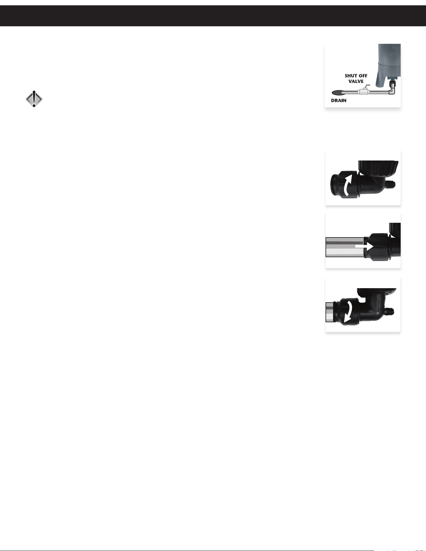
8. DRAIN LINE: First, be sure that the drain can handle the rinse rate of the system. At the
bottom of the tank is a 3/4” CTS push connection (7/8” OD) to accommodate a drain. The
purpose of the drain is to manually (or automatically, if desired) rinse the filter tank and
cartridge of any debris. This can prolong the life of the cartridge. It is highly recommended
to provide a means to drain the tank and to relieve pressure for cartridge replacement.
CAUTION: If a drain is not used or the installation makes this unavailable, the
drain hole must be plugged or water will flow from this outlet.
9. DRAIN FITTING ASSEMBLY: Before inserting the pipe into the drain fitting assembly, there is a “locking cap” that needs
to be loosened. The locking cap takes the place of a traditional clip used to lock in the fitting. Follow the steps below for
proper installation:
The larger of 2
pipe diameters
or 1” air gap
required.
Installation
Step 1: Ensure locking cap is turned counterclockwise, no more than a half
rotation, until a gap of about 1/16” can be seen as shown (Fig. 1).
Step 2: Insert pipe, free of burrs and sharp edges, fully into fitting (Fig. 2).
Step 3: Turn locking cap about half a rotation clockwise until it stops and
there is no gap remaining. Turn by hand only – DO NOT use tools
and do not overtighten (Fig. 3).
Fig. 1
Fig. 2
Fig. 3
7
1. Turn off water supply to vessel using bypass inlet and outlet lines.
See page 4 for bypass diagrams.
2. Release pressure on system by opening bottom drain for a moment, then close. If bottom
drain is not installed, turn off water to inlet side of filter and open an outlet line to the
filter.
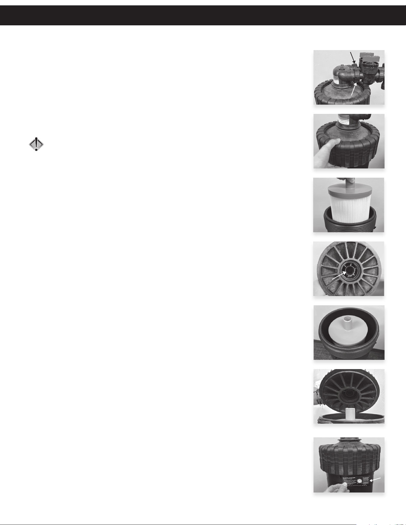
3. Disconnect bypass from valve assembly using the nuts at the inlet and outlet head
assembly (see Fig. 1). Be careful not to disconnect the nuts at the plumbing lines as these
are under pressure.
4. Remove CT nut by rotating it counterclockwise (see Fig. 2).
CAUTION: Do not remove CT nut without relieving pressure from system.
5. Remove CT cap by pulling upward on head assembly. Cartridge will be visible.
6. Carefully remove old cartridge from system (see Fig. 3). The cartridge will contain water
and will splash or drip. Place used cartridge into 5-gallon bucket to protect area from
water damage.
7. Remove new cartridge filter from box and remove plastic covering. Locate data plate label
and keep for future use.
8. Lubricate O-ring in valve assembly to ensure proper sealing (see Fig. 4).
Do not use pipe dope, petroleum jelly, oils or other unacceptable lubricants on
O-rings. Food grade silicone lubricant is recommended.
9. Place cartridge into filter housing with “distributor riser” at top of tank (see Fig. 5).
10. Carefully replace CT cap assembly making sure that the adaptor slips into the top
cap assembly. Push down on head assembly firmly (see Fig. 6).
11. Re-attach and tighten CT nut by turning it clockwise.
12. Adhere data plate label to tank under CT nut for future reference, but only when
supplied with certified filter cartridges (see Fig. 7).
13. Reconnect cartridge tank to bypass valve by securing nuts.
14. Open treated water line and turn bypass valve to service position
(Fig. 1 on page 4) and allow water to fill tank slowly. Once water is flowing to
treated water faucet, observe tank for any leaks.
15. Shut treated water line off to check for leaks and ensure system integrity.
Fig. 1
Fig. 2
Fig. 3
Fig. 4
Fig. 5
Fig. 6
Fig. 7
Cartridge Replacement

8
CONTAMINANT REDUCTION SYSTEM REQUIREMENTS
In order to qualify as a “certified” contaminant reduction system, a water treatment system must meet the requirements
set forth on the proceeding pages. A. O. Smith has certified the individual components of the system outlined below. To
complete the system, the installing dealer must follow some simple guidelines.
•Proper Installation of an accompanying, qualifying certified softener or backwashing filter equipped with a
service alarm. In a contaminant reduction system, this unit is referred to as a Performance Indicating Device
(PID). A PID must be able to meter the amount of water flowing through the unit as well as alarm once
the capacity of the unit has been reached (See the service alarm section for more details). On A. O. Smith
controllers, the term “Service Alarm” has been used in lieu of “Performance Indicating Device”. Both terms refer
to the same component in a contaminant reduction system and are used interchangeably.
•If a PID (service alarm) is not installed on the accompanying equipment, the CT-05-CB-AMCY-IO cartridge is only
certified to 45,196 gallons. It will be required to change out the cartridge more frequently.
•Proper installation of the ClearHome cartridge tank in which the contaminant reduction cartridge filter
(cartridge filter model No. CT-05-CB-AMCYL-IO) is installed into.
•Proper setting of the service alarm (PID).
•Proper labeling of the cartridge tank.
PERFORMANCE INDICATING DEVICE (PID)
To qualify as a certified contaminant reduction system to 75,327 gallons, the ClearHome cartridge tank must be installed
with a contaminant reduction cartridge and a PID. This device is used to notify the user of cartridge life and to signal
when a cartridge needs to be replaced.
A. O. Smith has taken additional steps and certified the meter of its softeners and backwashing filters for this use.
Any softener or backwashing filter manufactured by A. O. Smith using our 1” meter that incorporates the service
alarm feature satisfies the PID requirement of certification. This certification is specific to A. O. Smith manufactured
products and our 1” meters. Please consult A. O. Smith’s customer service department for any questions regarding this
requirement.
INSTALLATION
Installation of the ClearHome filter housing is covered on previous pages in this manual and must be installed in
conjunction with a qualifying Softener and/or Backwashing Filter. Without the qualifying softener or backwashing filter,
the system is not certified.
Installation instructions of the qualifying softener or backwashing filter is specific to those models. Refer to the
appropriate installation and service manuals included with that unit.
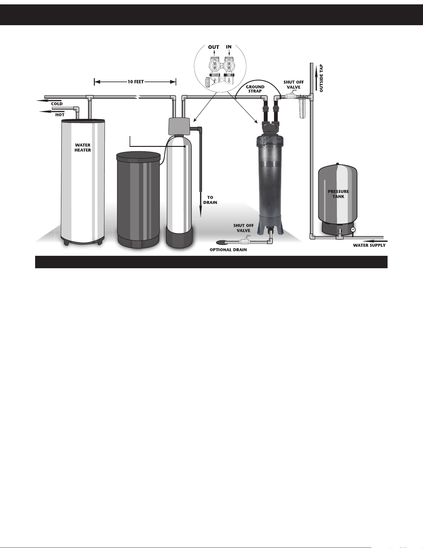
The ClearHome cartridge tank may be installed pre- or post-softener or backwashing filter. However, it is necessary to
make sure that all treated water through the ClearHome cartridge is metered through the PID. In municipal applications,
it is most likely that the ClearHome filter housing with a contaminant reduction cartridge will be used prior to a softener.
Please see installation diagram on following page.
NOTE: On waters that are turbid or where the quality is in question, it may be necessary to install a
pre-filter before the lead cartridge system to protect the life of the cartridge (See Contaminant
Reduction Installation Diagram). Turbidity may prematurely plug the cartridge before its 75,327
gallon contaminant reduction rating. This may cause a low pressure drop before the rated
lead capacity is achieved. Installing an additional ClearHome Cartridge Filter or a Big Blue Dual
Gradient (25 to 1 micron) sediment filter will enhance the life of the cartridge. A. O. Smith is not
responsible for decreased performance due to pressure drops.
Contaminant Reduction System
9
PRE-FILTER
CONTAMINANT REDUCTION INSTALLATION
PID (Softener Shown)
*Pressure Tank only
necessary in Well
Water Installations
In well water applications it may be necessary to deploy the ClearHome cartridge tank with a contaminant reduction
cartridge after a qualifying backwashing filter. This is to protect the lifespan and capacity of the contaminant reduction
cartridge.
NOTE: It is necessary that all treated water from the ClearHome cartridge tank flows through the meter
of the associated unit. This is to ensure proper recording of gallons used through the meter.
SERVICE ALARM
The service alarm on the qualifying softener or backwashing filter must set to 75,327 gallons. This indicates the life of
the cartridge. Once 75,327 gallons has been reached, the controller will display a “Call Dealer For Service” message on
the display of the controller along with an audible alarm on some models. After triggering, the audible alarm may be
turned off by pushing any button on the front of the controller. This will only disable the audible portion of the alarm.
The display will continue to display “service is required”.
Call servicing dealer for cartridge replacement and to reset the service alarm.
The larger of 2
pipe diameters
or 1” air gap
required.
Contaminant Reduction System
10
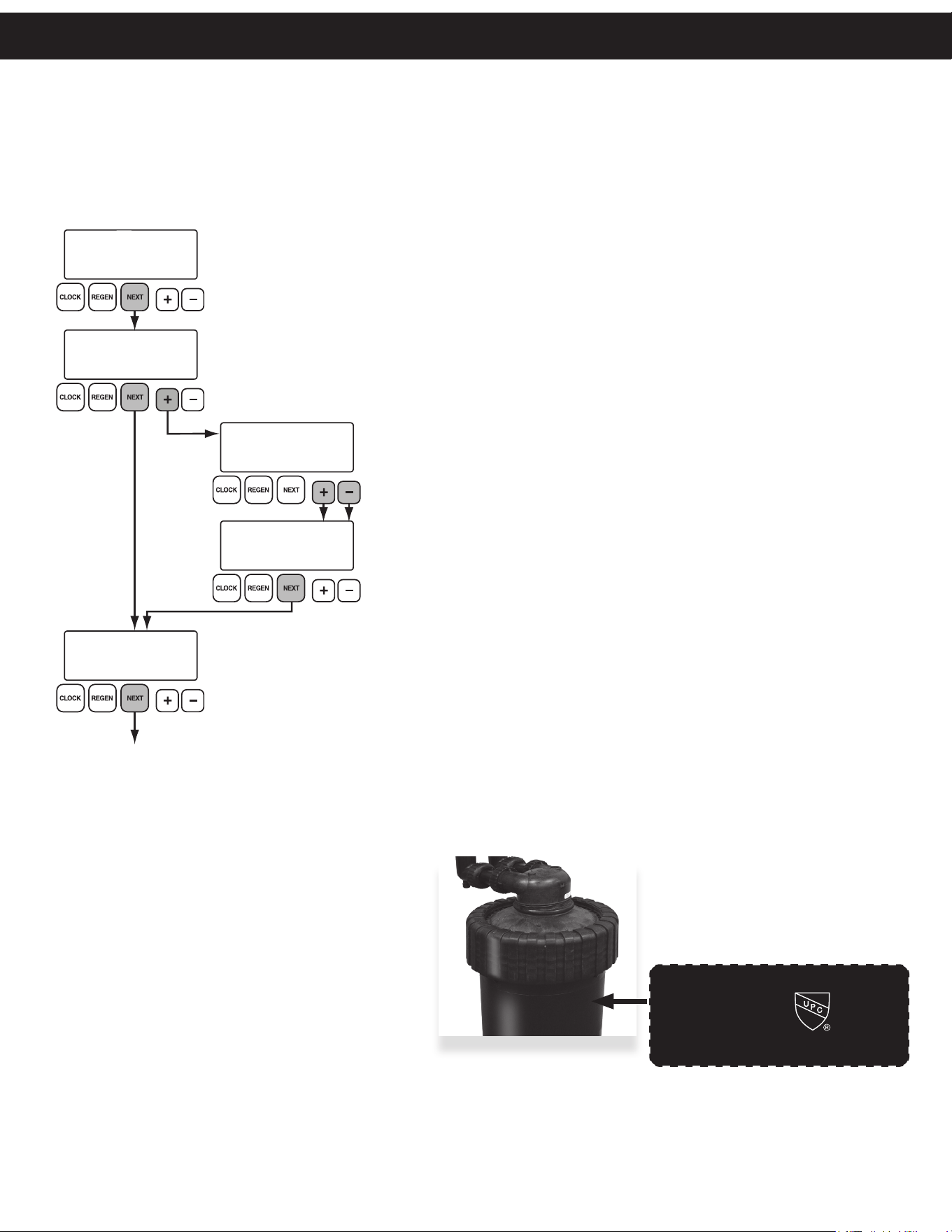
SETTING SERVICE ALARM FOR CONTAMINANT REDUCTION SYSTEM
Setting the service alarm is mandatory in order to fulfill the certification requirements. This may be accomplished by
consulting the installation manual or master programming guide for units equipped with service alarms. The service
alarm should be set and reset once replacement has been performed.
Follow the instructions below for programming a service alarm for the metering unit.
SERVICE ALARM
SET
100000
GAL
10000
GAL
ALARM DISPLAY TYPE
SET
NORMAL
SCHEDULE SERVICE
IN
ALARM DISPLAY TYPE
SET
CUSTOM
SCHEDULED SERVICE
ABCD
Exit Service Alarm Programming
Press the + or – buttons to set the gallon capacity.
For a contaminant reduction system, set to 75,327 gallons.
Holding the + button will speed up the counter’s progress.
Press the + or – buttons to choose between NORMAL and CUSTOM.
This alarm display will appear on the screen once the 75,327 gallon capacity is reached.
Choosing NORMAL displays a default “call dealer for service” message.
CUSTOM allows the installer to enter a customized message to appear on the unit once
the capacity has been reached.
With CUSTOM on screen, press and hold the + and –
buttons simultaneously for three seconds.
Press the + or – buttons to scroll through characters.
Press the NEXT button to proceed to the next character.
Pressing NEXT twice when no character is selected will
proceed to the next screen. 55 characters maximum.
Status Display
Shows the gallons remaining before the service alarm is set to trigger.
CAUTION: It is not recommended to reset the status display on a metering device used
in a contaminant reduction system unless service is required, the cartridge is
replaced, or the 75,327 gallon capacity is reached.
LABELING
A certified contaminant reduction system is
comprised of a ClearHome cartridge tank, a
contaminant reduction cartridge (CT-05-CB-
AMCYL-IO), and a qualifying softener or filter with
a PID.
This certification is recognized by a certification
label placed on the tank just below the CT nut,
as shown on the right. This Label Part Number
100393370 may only be used with a certified
system that meets all of the requirements above.
The labeling consists of the model number of the
system, a certification statement, the replacement
cartridge model number, and information that is specific to the system.
The system is deemed certified once all of the preceding requirements have been met. On initial setup, upon verifying
all requirements have been met, the included label must be placed on the tank in the position shown above. It is not
required to re-label the system when performing service.
Model No: AOS-CH-1000-PB
Do not use with water that
is microbiologically unsafe or
of unknown quality without
adequate disinfection before
or after system.
Chemical reduction system.
Max Working Pressure: 125 psi (862 kPa)
Max Operating Temp: 110° F (43° C)
Rated Service Flow: 4.8 gpm (18.2 lpm)
Capacity: 75,327 gal (285 kl)
Electrical Requirements: 12V
Manufactured by: A. O. Smith – 1900 Prospect Court, Appleton, WI, 54914 • Phone: 1-800-777-1426
Replacement: CT-05-CB-AMCYL-IO
Certified by IAPMO R&T
according to NSF/ANSI 53 for
Lead, Cyst, and PFOA/PFOS
reduction.
Contaminant Reduction System
11
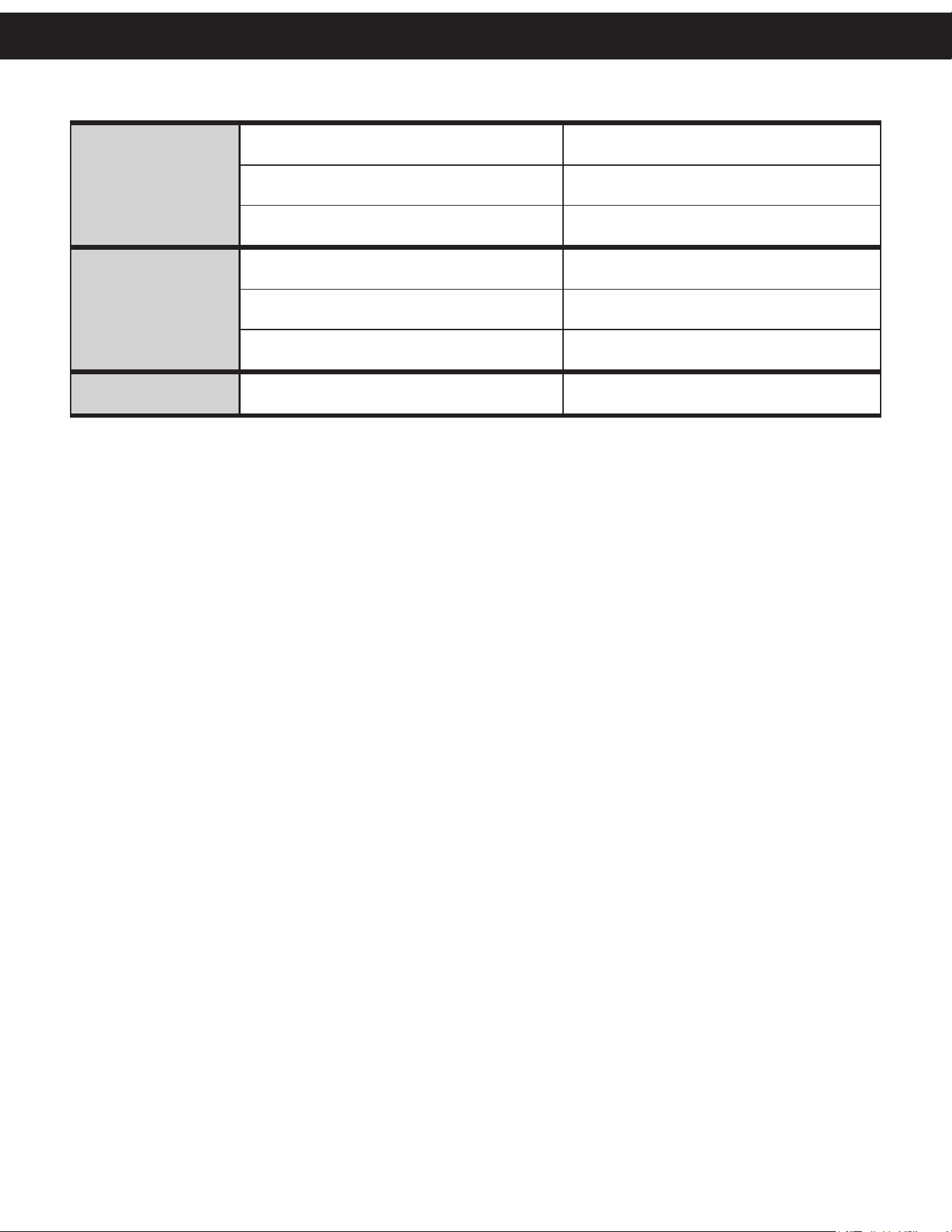
Lack of pressure
from system
A. Cartridge fouled out A. Replace cartridge
B. Exceeded flow rate of cartridge B. Substitute cartridge for higher flowing unit
C. Inlet to tank is plugged C. Clean inlet of debris
Cartridge life too short
A. Too small micron rating A. Choose different size or use multiple tanks
B. Very heavy loading B. Check raw water for particles
C. Excessive water flow through cartridge C. Check gallons consumed
Plugged drain A. Not flushed often enough A. Flush more frequently
PROBLEM CAUSE CORRECTION
Troubleshooting Guide
12
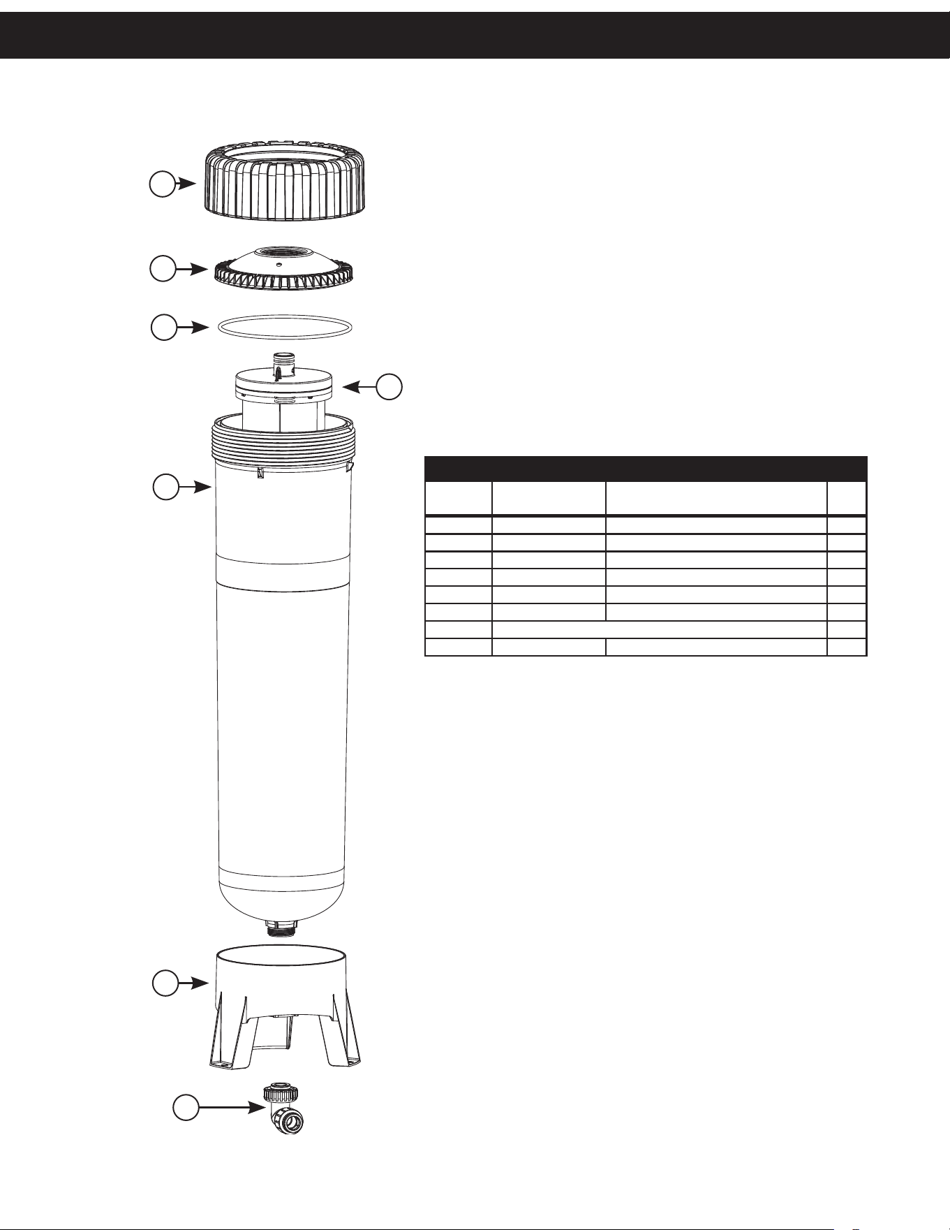
AOS-CH-1000 REPLACEMENT PARTS
Item
No.
Current Part # Description Qty.
1 100396231 CT Nut 1
2 100396232 CT Cap 2.5 NPSM 1
3 100396233 O-ring 370 1
4 100396235 CT Housing Body 1
5 100396236 CT Housing Base 1
6 100246200 WS1 Fitting JG QC 90 Assembly 1
7 Cartridge Filters Sold Separately. 1
Not shown 100396829 CT Service Wrench 1
7
2
1
3
4
5
6
Replacement Parts
13
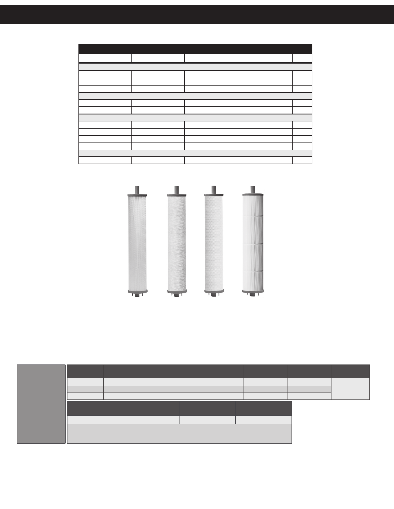
AOS-CH-1000 REPLACEMENT CARTRIDGES
Legacy Part # Current Part # Description Qty.
Double Pleated Depth Filters
CT-1005-IO 100243292 10 x 5 Micron Double Pleated 1
CT-2010-IO 100243400 20 x 10 Micron Double Pleated 1
CT-5020-IO 100243207 50 x 20 Micron Double Pleated 1
String Wound/Meltblown Depth Filters
CT-2005-SWMB- IO 100243305 20 x 5 Micron String Wound/Meltblown 1
CT-5020-SWMB-IO 100243218 50 x 20 Micron String Wound/Meltblown 1
Carbon Block Filters
CT-03-CB-IO 100246028 3 Micron Carbon Block 1
CT-20-CB-IO 100246032 20 Micron Carbon Block 1
CT-03-CB-AMINE-IO 100243484 3 Micron Carbon Block Chloramine Reduction 1
CT-05-CB-AMCYL-IO 100242500 0.5 Micron Carbon Block Contaminant Reduction 1
Nano AL Filters
CT-20NANO-AG-IO 100242993 20 x Nano AL w/ AG Double Pleated Cartridge 1
Double
Pleated
String
Wound
Carbon
Block
Nano
AL
CONTAMINANT REDUCTION CARTRIDGE SPECIFICATIONS
The AOS-CH-1000 is cer fi ed by IAPMO R&T to NSF/ANSI 53 for reduc on of the substances listed below. The concentra on of the indicated substances in water entering the
system was reduced to a concentra on less than or equal to the permissible limit for water leaving the system as specifi ed in the standards. Minimum substance reduc ons per
NSF/ANSI 53 are as follows:
Replacement components available through your local dealer.
This system conforms to NSF/ANSI 53 for the specifi c performance claims verifi ed and substan ated by test data. Performance claims are based on independent lab results.
Actual performance is dependent on infl uent water quality, fl ow rates, system design, and applica ons. Your results may vary. Performance claims are based on a complete
system including a fi lter, housing, and connec on to a pressurized water source. This fi lter must be operated according to the system’s specifi ca ons in order to deliver the
claimed performance. It is essen al to follow opera onal, maintenance, and fi lter replacement requirements as directed. The contaminants or other substances removed or
reduced by this water fi lter are not necessarily in all users’ water.
Contaminant
Rated
Flow
Pressure
Drop (PSI)
Capacity
(Gallons)
Influent Challenge
Water
Max Allowed in
Effluent Water
Average Percent
Reduction (%)
Peak Flow/
Capacity
Lead
4.8 gpm 9.0 75,327 0.15 +/- 10% mg/L 0.005 mg/L 99.62
8 gpm/
88,000 gal
PFOA/PFOS
4.8 gpm 9.0 75,327 1.5 +/- 10% ug/L 0.07 ug/L 98.18
Cyst
4.8 gpm 9.0 75,327 Min 50,000 / L – 99.95
Minimum Opera ng
Temperature
Maximum Opera ng
Temperature
Minimum Opera ng
Pressure
Maximum Opera ng
Pressure
40° F / 4° C 100° F / 43° C 20 psi / 1.4 bar 120 psi / 8.6 bar
Filter Replacement Opera ng Instruc ons: New cartridges must be fl ushed for a minimum of 10 minutes prior to use.
System and installa on to comply with state and local laws and regula ons. Manufactured from NSF/ANSI standard 61
and California Prop 65 Compliant cer fi ed coconut shell carbon and raw materials.
AOS-CH-1000-PB
Replacement Parts
Replacement components available through your water treatment professional.
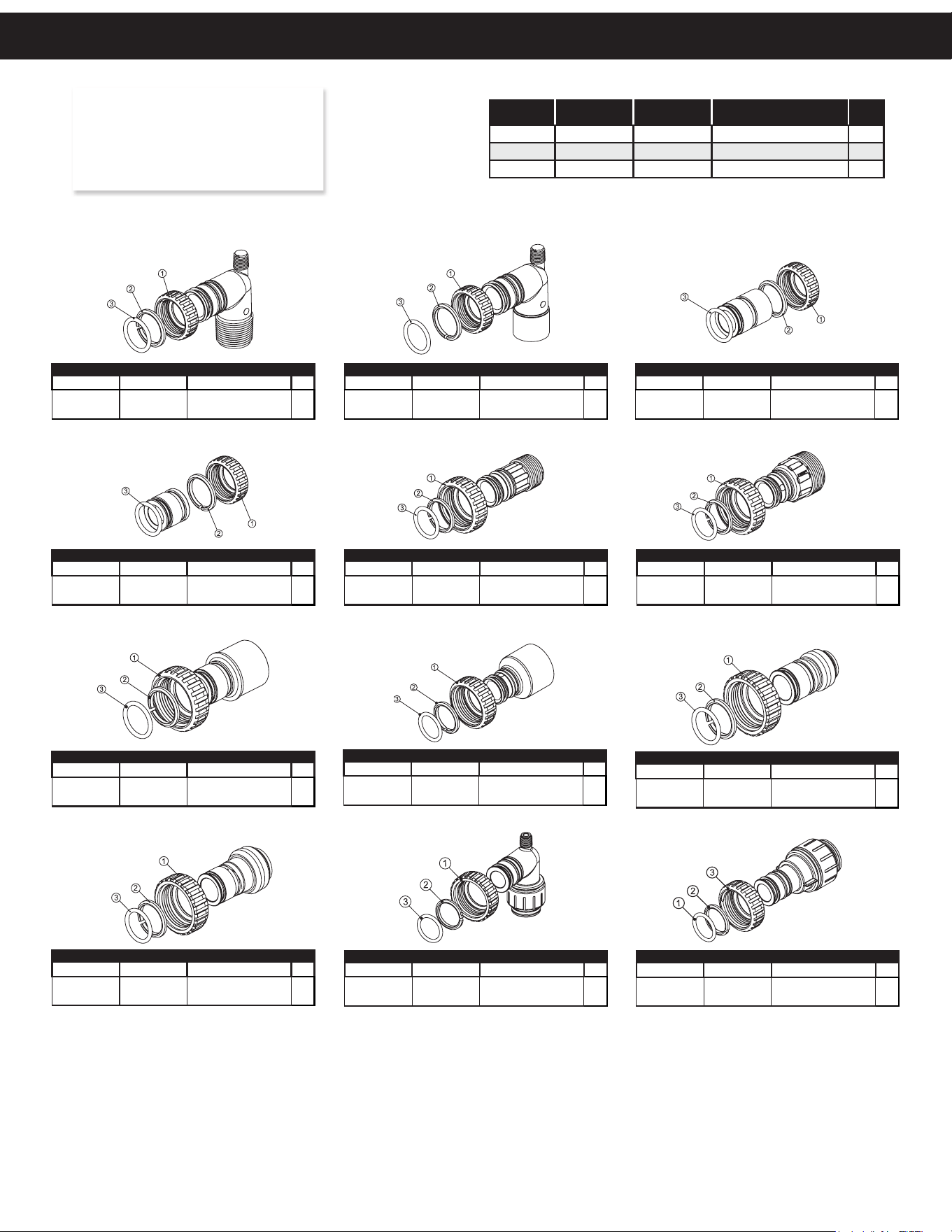
14
Legacy Part # Current Part # Description Qty.
CV3007 100246197
1” PVC male NPT
elbow assembly
2
Legacy Part # Current Part # Description Qty.
CV3007-01 100246198
3/4” & 1” PVC solvent
elbow assembly
2
Legacy Part # Current Part # Description Qty.
CV3007-02 100246199
1” brass sweat
assembly
2
Legacy Part # Current Part # Description Qty.
CV3007-03 100249846
3/4” brass
sweat assembly
2
Legacy Part # Current Part # Description Qty.
CV3007-12 100249847
3/4” brass shark
bite assembly
2
Legacy Part # Current Part # Description Qty.
CV3007-13 100249848
1” brass shark
bite assembly
2
Legacy Part # Current Part # Description Qty.
CV3007-15 100246200
3/4” john guest
elbow assembly
2
Legacy Part # Current Part # Description Qty.
CV3007-17 100245045
1” john guest
assembly
2
Legacy Part # Current Part # Description Qty.
CV3007-09 100243922
1-1/4” & 1-1/2” brass
sweat assembly
2
Legacy Part # Current Part # Description Qty.
CV3007-07 100243375
1-1/4” & 1-1/2” PVC
solvent assembly
2
Legacy Part # Current Part # Description Qty.
CV3007-04 100244506
1” plastic male NPT
assembly
2
Legacy Part # Current Part # Description Qty.
CV3007-05 100243921
1-1/4” plastic male
assembly
2
Item # Legacy Part # Current Part # Description Qty.
1 CV3151 100246287 Nut, 1” quick connect 2
2 CV3150 100246286 Split ring 2
3 CV3105 100246272 O-ring 215 2
NOTE: Not all available fi ttings are
displayed below. Contact
manufacturer for optional
fi ttings.
For All Assemblies
Installation Fi ing Assemblies

15
Service under this warranty is to be provided by the distributor/
installer who sold the unit to the user. If the distributor is unable to
provide warranty service, contact:
A.O. Smith Water Treatment (North America), Inc.
1900 Prospect Court • Appleton, WI 54914
Phone: 920-739-9401 • Fax: 920-739-9406
A Returned Goods Authorization (RGA) number must be received from
the above office and placed on all shipments to and correspondence
with A. O. Smith Water Treatment.
Please be prepared with the following information:
1. Model number and serial number.
2. Date of installation.
3. Name of installer
4. Nature of problem.
5. Your address and contact information.
ClearHome Filtration Limited Warranty
Congratulations. You have purchased one of the fi nest water treatment systems available. In the unlikely event of a problem due to
defects in material and workmanship, we proudly warrant our water fi lters to the original owner, when installed in accordance with
A. O. Smith specifi cations. This warranty is effective from the date of original installation for:
A period of ONE YEAR: A. O. Smith Water Treatment warrants its tank and lter solutions to
be free of defects in material and workmanship.
A period of FIVE YEARS: A. O. Smith Water Treatment warrants its IN/OUT head assemblies to
be free of defects in material and workmanship.
This warranty does not cover any equipment purchased for use in applications in which the product is not suited. It is the responsibility
of the buyer to determine if a product is suitable for a particular application.
Our obligations under this warranty are limited to the repair or replacement (at A. O. Smith's sole discretion) of the failed parts of the
water treatment unit manufactured by A. O. Smith, and we assume no liability whatsoever for direct, indirect, incidental, consequential,
special, general or other damages.
We assume no liability for the determination of the proper equipment necessary to meet your requirements, and we do not authorize
others to assume such obligations for us.
We assume no liability and extend no warranties, expressed or implied, for the use of this product with a non-potable water source or a
water source which does not meet the conditions for use described in the owner’s guide or performance data sheet for the product.
The warranty provided herein applies, only when used within the product specifi cations and service life, from the date of installation,
beyond which A. O. Smith is absolved of any and all liability for any use of the product. There are no other warranties, either of
merchantability or fi tness, either expressed or implied.
This warranty gives you specifi c legal rights and you may also have other rights which vary from state to state
THIS WARRANTY EXCLUDES THE FOLLOWING:
• Damage caused by improper installation, operation or care.
• Damage caused by chemical attack, environment, accident, fi re, fl ood, freezing, Act of God, misuse, misapplication,
neglect, oxidizing agents (such as chlorine, ozone, chloramines and other related components), alteration, installation
or operation contrary to the printed instructions, or by the use of accessories or components which do not meet A. O.
Smith’s specifi cations, including the use of a replacement element not manufactured or supplied by A. O. Smith. Refer to
the specifi cations section in the Installation and Operating manual for approved application parameters.
• Modifi cation or alteration by other than A. O. Smith employees.
• Rubber type parts and normal wear items i.e. “O” rings, etc.
• Any costs of labor or expenses expended in the removal and/or installation of unit, or any surrounding device.
• Altering or removing the A. O. Smith information label.
• Use of non A. O. Smith approved cartridges, fi lters, or replacement parts with the appropriate systems or vessels.
• Non-use of supported piping for plumbing connections to In/Out connections.

© 2025 A. O. Smith. All Rights Reserved.
100391657 - 2000846192 - Rev1225