Network Speed Dome
Installation Guide
*Images may dier from actual products.
InSight PTZ5425 is used for demonstration in this guide.
©2025 TP-Link 7100002510 REV1.0.2
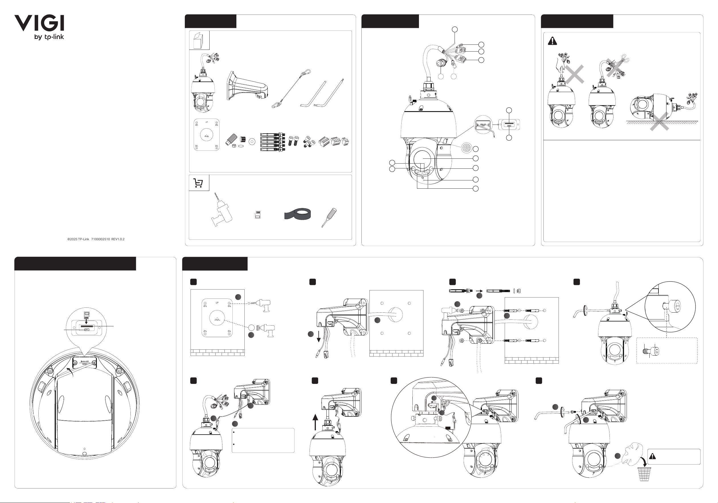
3. Before You Start2. Appearance
Box
1. Get Ready
microSD Card
(optional)
Waterproof Tape
(optional)
4. Install microSD Card (Optional)
5. Mount Camera
3
2
1
• Make sure your power supply matches your camera.
The power source should meet LPS, PS2, and other
requirements according to IEC 62368-1.
• Make sure that the wall is strong enough to withstand 4
times the weight of the camera and mounting bracket.
• If you are uncertain or uncomfortable performing the
installation, consult a qualied electrician.
Important:
Φ 50 mm (1.97 in)
Φ 8 mm (0.31 in)
(Optional: Wiring hole is
for cables through the
wall)
(cables along the wall)
1
6 5
4
3
2
15
14
13
9
10
12
11
8
7
Refer to Waterproof Cables
as necessary
Refer to Connect Interfaces
for detailed instructions
1 - Grounding Wire Interface
2 - RS485 Interface
3 - Audio Interface
4 - Alarm Interface
5 - Power Supply Interface
6 - RJ45 Network Interface
(supports PoE)
7 - microSD Card Slot
8 - Reset: Press for 5 seconds to reset the camera
to factory settings.
9 - Speaker
10 - Lens
11 - IR LED × 2
12 - Blue Alarm Light
13 - Red Alarm Light
14 - Built-in Microphone
15 - Intergrated Infrared-white Light × 2
8
432
765
1
1
2
1
2
Keep the protective lm
during installation and
remove it before use.
microSD Card
Slot
RESET Button
Insert a microSD card for local storage. Initialize the SD
card via VIGI app or other management tools before
recording videos.
1
2
1
3
2
1
2
3
Thread Head
Shank
Leave the
smooth shank
exposed
OUT GND IN2 IN1 GND
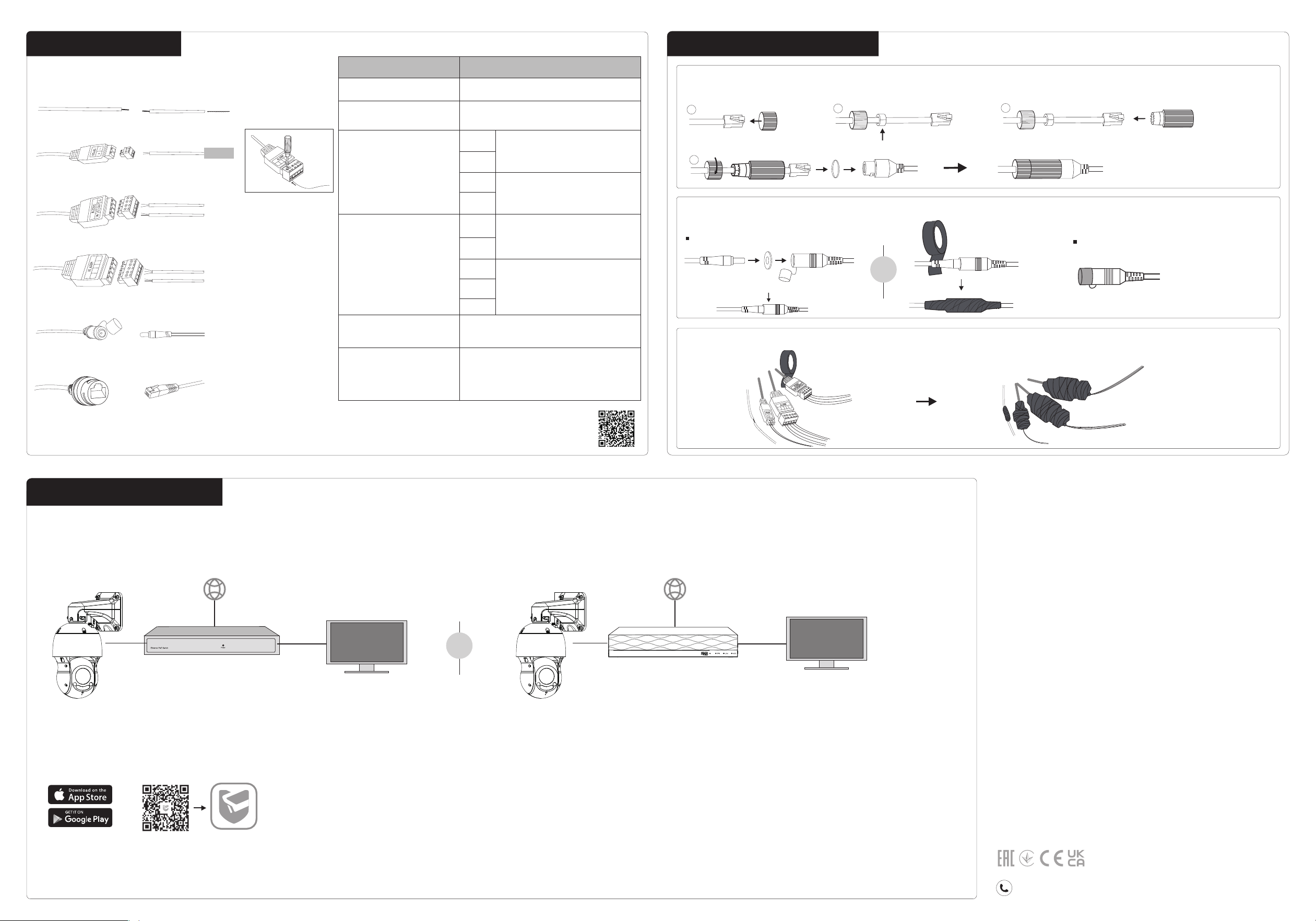
6. Connect Interfaces
• Do not use any other power adapters than those recommended.
• Do not use damaged power adapter or USB cable to charge the device.
• Do not attempt to disassemble, repair, or modify the device. If you need
service, please contact us.
• Adapter shall be installed near the equipment and shall be easily accessible.
• Keep the device away from fire or hot environments. DO NOT immerse in
water or any other liquid.
• Use only power supplies listed in the user instructions. Refer to the User
Manual on the product support page.
EU Declaration of Conformity
TP-Link hereby declares that the Camera is in compliance with the essential
requirements and other relevant provisions of directives 2014/30/EU,
2014/35/EU, 2009/125/EC, 2011/65/EU and (EU)2015/863.
The original EU Declaration of Conformity may be found at
https://www.tp-link.com/en/support/ce/
UK Declaration of Conformity
TP-Link hereby declares that the Camera is in compliance with the essential
requirements and other relevant provisions of the Electromagnetic
Compatibility Regulations 2016 and Electrical Equipment (Safety) Regulations
2016.
The original UK Declaration of Conformity may be found at
https://www.tp-link.com/support/ukca
Safety Information
For technical support, replacement services, user guides, and more
information, please visit https://support.vigi.com/.
8. Activate and Access Camera
or
TP-Link VIGI App
Alarm Interface
GND
IN1
IN2
GND
OUT
DescriptionInteface
Connect to an external 12V DC
power adapter (not provided).
10/100Mbps RJ45 Ethernet port,
supports PoE 802.3at Class4.
Connect to a network device (e.g.,
router/switch)
RJ45 Network Interface
Power Supply Interface
Audio Interface
Grounding Wire
Connect to the ground.
RS485 Interface
G
IN
G
OUT
Used to connect a device that
supports RS485.
Used to connect an alarm in
device (e.g., sensor).
Used to connect an alarm
out device (e.g., buzzer).
Used to connect an audio
input device (e.g., micro-
phone).
Used to connect an audio
output device (e.g., speak-
ers).
For more detailed instructions, refer to the FAQ: How
to connect an Alarm device or an Audio device to
VIGI camera or scan the QR code.
RJ45 Network Interface
Power Supply Interface
Alarm Interface
Audio Interface
RS485 Interface
Grounding Wire
7. Waterproof Cables (Optional)
1
2
3
4
For Power Cord
For Ethernet Cable
For Other Interfaces
Powered by the adapter
Powered by PoE
Internet
VIGI PoE NVR
Internet
PoE Network Device
(e.g., Switch or router)
Management PC
Download and launch the TP-Link VIGI app and follow
the on-screen instructions to nish initial setup.
Method 3: Via VIGI NVR
Method 2: Via a Web Browser
1. Find the camera’s IP address on your router’s client
page.
2. On your local computer, open a web browser and enter
https:// followed by your camera’s IP address
(https://192.168.0.60 by default).
3. Follow the web instructions to activate your cameras.
Method 1: Via VIGI App
Monitor
OR
OR
The camera works with an NVR for easier batch access and
management. Here, we use a VIGI NVR as an example.
1. Make sure your NVR is working properly and connected
to the internet.
2. Connect the camera to the PoE port of the NVR.
3. Follow the on-screen instructions to activate and add the
camera.
Connect the camera to your network, power the camera using a PoE power supply or an external power adapter (not included), and then set up the camera using one of the
following methods.
Alarm IN Device (e.g., sensor)
Network Device
(e.g., router/switch)
Power Adapter (12V DC)
Alarm OUT Device (e.g., buzzer)
Ground
RS485
Audio IN Device (e.g., microphone)
Audio OUT Device (e.g., speaker)
OUT GND IN2 IN1 GND
OUT GND IN2 IN1 GND