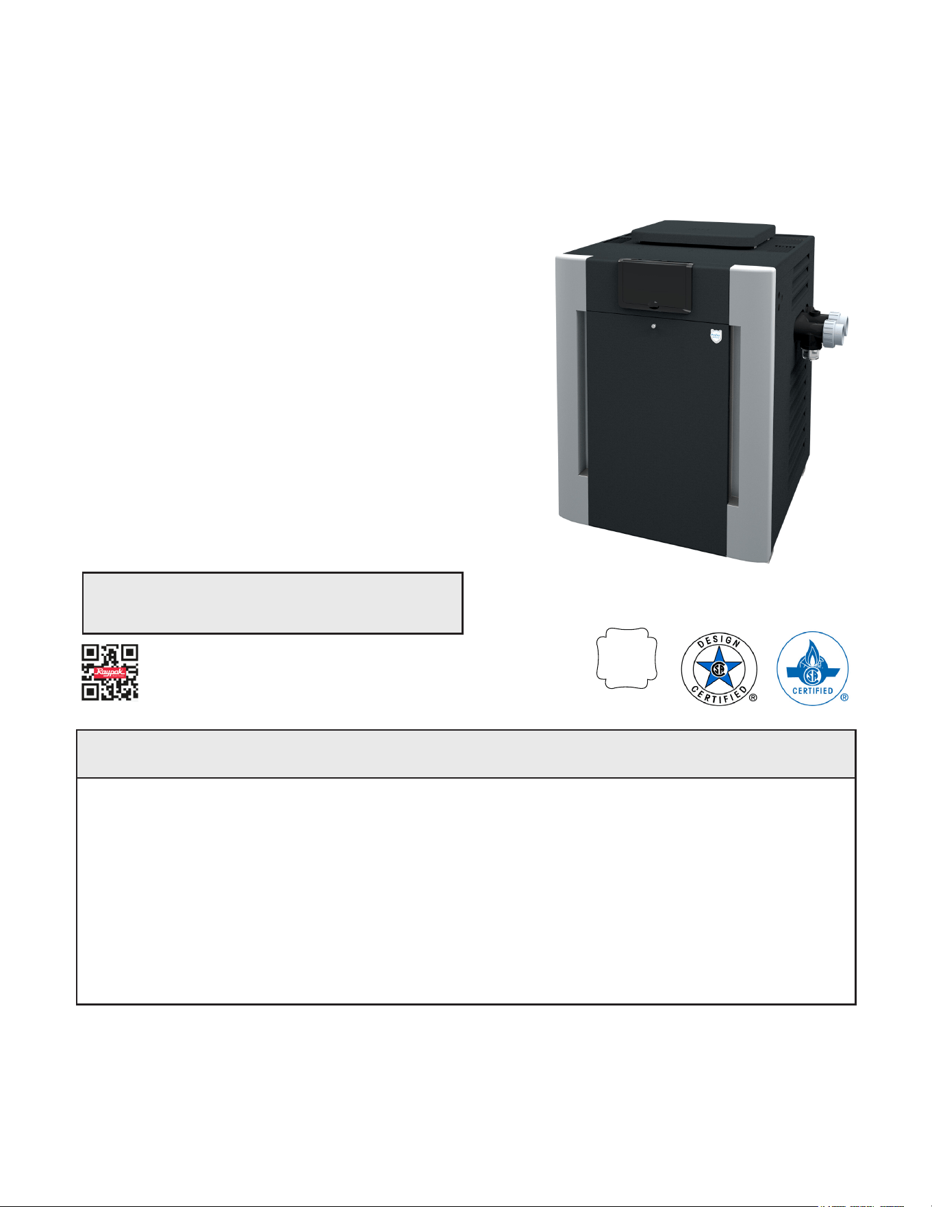
Gas-Fired Pool
and Spa Heater
Eective: 08-19-22
Replaces: 05-20-22
P/N 241236 Rev. 43
A
S
M
E
HLW
INSTALLATION AND
OPERATION MANUAL
Bronze ASME and Polymer
Atmospheric Heat Exchanger
Models 206A, 266, 266A, 336A, 399,
and 406A
This manual should be maintained in legible condition and kept adjacent to the heater or in a safe place for future
reference.
A
WARNING: If the information in the instructions is not followed exactly, a re or explosion may result
causing property damage, personal injury or death.
- Do not store or use gasoline or other flammable vapors and liquids or other combustible materials in
the vicinity of this or any other appliance. To do so may result in an explosion or fire.
- WHAT TO DO IF YOU SMELL GAS
• Do not try to light any appliance.
• Do not touch any electrical switch; do not use any phone in your building.
• Immediately call your gas supplier from a neighbor’s phone. Follow the gas supplier’s instructions.
• If you cannot reach your gas supplier, call the fire department.
- Installation and service must be performed by a qualified installer, service agency or the gas supplier.
BR models only
THIS MANUAL CAN BE VIEWED ELECTRONICALLY
USING YOUR SMART DEVICE. SEE PAGE 46 FOR QR
CODE.

2
CLEARANCES
Space required: See page 12.
Minimum and service clearances: See page 7 for
clearances table. Note that local codes prevail.
PIPING
Pressure relief valve: See page 20 for
recommended PRV orientation.
Flow rates: See page 17 for ow rate values.
GAS
Distance to regulator (pipe lengths) and gas inlet
sizes: See page 17.
Required pressure for Natural Gas:
Min = 6" WC, Max = 10.5" WC
Required pressure for Propane Gas:
Min = 12" WC, Max = 13" WC
Sediment trap is required for all installations.
See page 15.
WATER CHEMISTRY
Water chemistry requirements: See page 5.
POWER
Supply voltage: See page 23 for acceptable input
voltages.
VENTING
Materials: See page 11 and page 14.
D-2 Power Vent Kit: See page 14.
Indoor Stack: See page 11.
CONTROLS INTERFACE
Wiring diagrams: See page 24 and 25.
User interface: See page 26 and 27.
Remote operation: See page 30.
QUICK START GUIDE
Revision 43 reects the following changes:
Revised callout of " ANSI-Z21.58" to "ANSI-Z21.56" in base riser section. Added "14-S" Base Riser to the IPL and the exploded view.

3
TABLE OF CONTENTS
1. WARNINGS ............................................................. 4
Pay Attention to These Terms .................................4
2. WATER CHEMISTRY ............................................. 5
Automatic Chlorinators/Chemical Feeders..............5
3. BEFORE INSTALLATION ...................................... 6
Receiving equipment...............................................6
Rating and certications ..........................................6
Elevation .................................................................7
Ambient Temperature Rating .................................. 7
4. INSTALLATION ....................................................... 7
Installation Codes....................................................7
Clearances ..............................................................7
Outdoor Heater Installation ..................................... 8
Combustion and Ventilation Air ............................. 11
Vent Piping ............................................................14
D-2 Power Vent Kit ................................................14
Gas Supply Connections.......................................15
Flow Rate ..............................................................17
ProTek Shield Assembly........................................ 18
Unitherm Governor Operation ...............................19
Internal Automatic Bypass Valve ........................... 19
External Auxiliary Bypass Valve ............................ 19
Auxiliary Bypass Valve Adjustment .......................20
Pressure Relief Valve Installation ..........................20
Heat Exchanger Reversal ..................................... 20
Plumbing Diagrams ...............................................21
5. ELECTRICAL WIRING ......................................... 22
Millivolt Models ("M" sux) ...................................22
Digital Models ("E" sux) ......................................22
Electrical Power Draw ...........................................23
Transformer Wiring ...............................................23
6. WIRING DIAGRAM - MILLIVOLT ....................... 24
7. WIRING DIAGRAM - DIGITAL ............................ 25
8. CONTROLS ........................................................... 26
Control Panel Removal ......................................... 26
Control Adjustments - Millivolt Models .................. 26
Control Adjustments – Digital Models ................... 27
Operation ..............................................................27
Status and Diagnostics .........................................29
Remote Wiring - Digital Models Only .................... 30
9. OPERATING INSTRUCTIONS ............................ 36
Before Start-Up ..................................................... 36
Start-Up Procedures .............................................36
Visual inspection ................................................... 36
Water Pressure Switch ..........................................36
10. MAINTENANCE AND CARE ............................... 39
Cold Weather Operation .......................................39
11. TROUBLESHOOTING ......................................... 40
Millivolt - Flow Chart ..............................................42
Digital - Flow Chart................................................43
Control Logic - Flow Chart - Digital ....................... 44
12. REPLACEMENT PARTS ..................................... 45
13. QR CODES ............................................................ 46
14. ILLUSTRATED PARTS LIST .............................. 47
4
1. WARNINGS
Pay Attention to These Terms
A
DANGER: Failure to install the drafthood on indoor
installation and properly vent the heater to the outdoors
as outlined in the venting section of this manual can
result in unsafe operation of the heater. To avoid the risk
of re, explosion, or asphyxiation from carbon monoxide,
never operate this heater unless it is properly vented
and has an adequate air supply for proper operation. Be
sure to inspect the vent system for proper installation at
initial start-up, and at least annually thereafter. Refer to
the venting section of this manual for more information
regarding vent system inspections.
A
WARNING: Gasoline, as well as other ammable
materials and liquids (adhesives, solvents, etc.), and
the vapors they produce, are extremely dangerous. Do
not handle, use, or store gasoline or other ammable or
combustible materials in the vicinity of a heater.
A
WARNING: Improper installation, adjustment,
alteration, service, or maintenance can cause property
damage, personal injury or loss of life. Installation
and service must be performed by a qualied installer,
service agency, or the gas supplier.
A
WARNING: Do not install within 3 feet (0.9 m) of
a heat pump or an outdoor condensing unit. Strong
air intake from this type of equipment can disturb the
combustion process and cause damage or personal
injury.
A
WARNING: UL-recognized fuel gas detectors are
recommended in all enclosed propane and natural
gas applications wherein there is a potential for an
explosive mixture of fuel gas to accumulate and their
installation should be in accordance with the detector
manufacturer’s recommendations and/or local laws,
rules, regulations, or customs.
A
WARNING: The heater shall not be located in an
area where water sprinklers, or other devices, may cause
water to spray through the cabinet louvers and into the
heater. This could cause internal rusting or damage
electrical components. Such damage is not covered
under warranty.
A
DANGER
Indicates the presence of immediate hazards which will cause severe personal injury, death or
substantial property damage if ignored.
A
WARNING
Indicates the presence of hazards or unsafe practices which could cause severe personal injury,
death or substantial property damage if ignored.
A
CAUTION
Indicates the presence of hazards or unsafe practices which could cause minor personal injury
or product or property damage if ignored.
CAUTION
CAUTION used without the warning alert symbol indicates a potentially hazardous condition
which could cause minor personal injury or product or property damage if ignored.
NOTE
Indicates special instructions on installation, operation, or maintenance which are important but
not related to personal injury hazards.
A
WARNING: Both natural gas and propane have
an odorant added to aid in detecting a gas leak. Some
people may not physically be able to smell or recognize
this odorant. If you are unsure or unfamiliar with the
smell of natural gas or propane, ask your local gas
supplier. Other conditions, such as “odorant fade,”
which causes the odorant to diminish in intensity, can
also hide, camouage, or otherwise make detecting a
gas leak by smell more dicult.
A
WARNING: To minimize the possibility of improper
operation, serious personal injury, re, or damage to the
heater:
• Always keep the area around the heater free of
combustible materials, gasoline, and other ammable
liquids and vapors.
• Heater should never be covered or have any blockage
to the ow of fresh air to the heater.
A
WARNING: This unit contains refractory ceramic
ber (RCF) insulation in the combustion chamber. RCF,
as manufactured, does not contain respirable crystalline
silica. However, following sustained exposure to very
high-temperatures [>2192°F (1200°C)], the RCF can
transform into crystalline silica (cristabolite). The
International Agency for Research on Cancer (IARC) has
classied the inhalation of crystalline silica (cristabolite)
as carcinogenic to humans.
When removing the burners or heat exchangers, take
precautions to avoid creating airborne dust and avoid
inhaling airborne bers. When cleaning spills, use wet
sweeping or High Eciency Particulate Air (HEPA)
ltered vacuum to minimize airborne dust. Use feasible
engineering controls such as local exhaust ventilation
or dust collecting systems to minimize airborne dust.
Wear appropriate personal protective equipment
including gloves, safety glasses with side shields, and
appropriate NIOSH-certied respiratory protection,
to avoid inhalation of airborne dust and airborne ber
particles.
5
A
CAUTION: Elevated water temperature can
be hazardous. The U.S. Consumer Product Safety
Commission has these guidelines:
1. Spa water temperatures should never exceed 104°F
(40°C). A temperature of 100°F (38°C) is considered
safe for a healthy adult. Special caution is suggested
for young children.
2. Drinking of alcoholic beverages before or during spa
or hot tub use can cause drowsiness which could
lead to unconsciousness and subsequently result in
drowning.
3. Pregnant Women Beware! Soaking in water over
102°F (39°C) can cause fetal damage during the rst
three months of pregnancy resulting in the birth of a
brain-damaged or deformed child. Pregnant women
should stick to the 100°F (38°C) maximum rule.
4. Before entering the spa or hot tub, users should
check the water temperature with an accurate
thermometer; spa or hot tub thermostats may err
in regulating water temperatures by as much as 4°F
(2.2°C).
5. Persons with a medical history of heart disease,
circulatory problems, diabetes, or blood pressure
problems should obtain a physician’s advice before
using pools or hot tubs.
6. Persons taking medications which induce
drowsiness, such as tranquilizers, antihistamines,
or anticoagulants, should not use spas or hot tubs.
A
CAUTION: Propane gas is heavier than air and will
settle on the ground. Since propane can accumulate in
conned areas, extra care should be exercised when
lighting propane heaters.
NOTE: It is recommended that the pump be run at least
5 minutes after the heater has been turned o. This helps
in taking away residual heat from the heat exchanger,
thus prevents the safety hi-limits from tripping due to
residual heat after the heater is turned o.
WARNING: Risk of re. It is recommended that CO
monitor and re alarm be utilized in rooms that contain
gas red appliances.
2. WATER CHEMISTRY
NOTE: Damage due to poor water chemistry is not a
warrantable defect.
Chemical imbalance can cause severe damage to your
heater and associated equipment. Maintain your water
chemistry according to Table A. If the mineral content
and dissolved solids in the water become too high, scale
forms inside the heat exchanger tubes, reducing heater
eciency and damaging the heater. If the pH drops below
7.2, this will cause corrosion of the heat exchanger and
severely damage the heater. Heat exchanger damage
resulting from chemical imbalance is not covered by
the warranty.
For your health and the protection of your pool equipment,
it is essential that your water be chemically balanced. The
following levels must be used as a guide for balanced
water.
A
CAUTION: Free chlorine must not exceed 5 ppm
which can damage the heater and is not covered under
warranty.
• Occasional chemical shock dosing of the pool or spa
water should not damage the heater providing the
water is balanced.
• Automatic chemical dosing devices and salt
chlorinators are usually more efficient in heated
water, unless controlled, they can lead to excessive
chlorine level which can damage your heater.
• Check valve should be installed between the heater
outlet and a chlorinator or other chemical dosing
device.
• Further advice should be obtained from your pool
or spa builder, accredited pool shop, or chemical
supplier for the correct levels for your water.
Automatic Chlorinators
and Chemical Feeders
All chemicals must be introduced and completely diluted
into the pool or spa water before being circulated through
the heater. Do not place sanitizing chemicals in the
skimmer. High chemical concentrations will result when
the pump is not running (e.g. overnight).
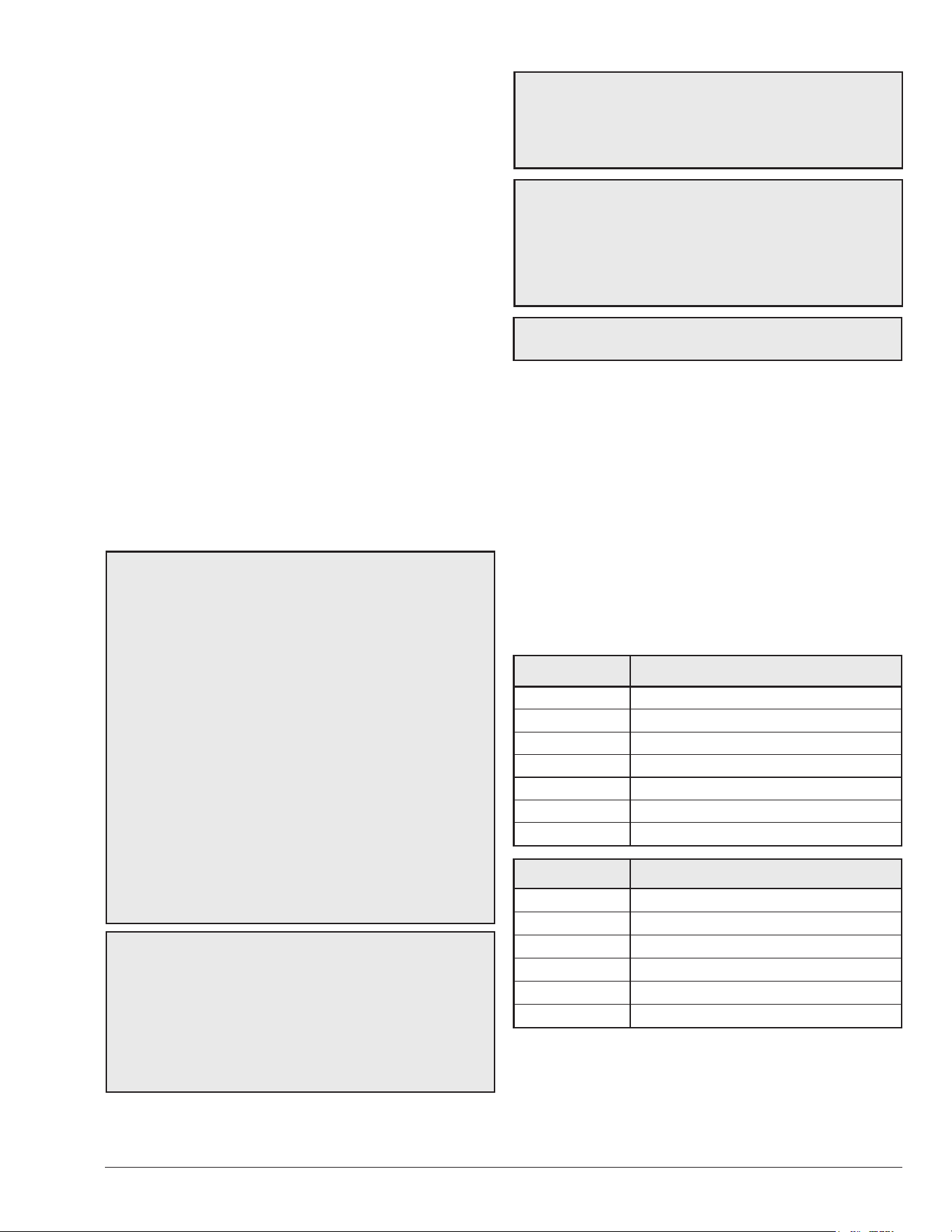
Table A. Pool Water Chemistry
Recommended Level(s) Fiberglass Pools Fiberglass Spas Other Pool and Spa Types
Water Temperature 68-88°F (20-31°C) 89-104°F (31-40°C) 68-104°F (20-40°C)
pH 7.3-7.4 7.3-7.4 7.6-7.8
Total Alkalinity (ppm) 120-150 120-150 80-120
Calcium Hardness (ppm) 200-300 150-200 200-400
Salt (ppm) 4500 Maximum 4500 Maximum 4500 Maximum
Free Chlorine (ppm)* 2-3 2-3 2-3
Total Dissolved Solids (ppm) 3000 Maximum** 3000 Maximum** 3000 Maximum**
*Free Chlorine MUST NOT EXCEED 5 ppm!
**In saltwater chlorinated pools, the total TDS can be as high as 6000 ppm.
6
3. BEFORE INSTALLATION
Receiving Equipment
The manufacturer recommends that this manual be
reviewed thoroughly before installing the pool/spa heater. If
there are any questions that this manual does not answer,
please contact the factory or your local representative.
On receipt of your equipment visually check for external
damage to the carton. If the carton is damaged, a note
should be made on the Bill of Lading when signing for
the equipment. Remove the heater from the carton. If it is
damaged, report the damage to the carrier immediately.
Save the carton.
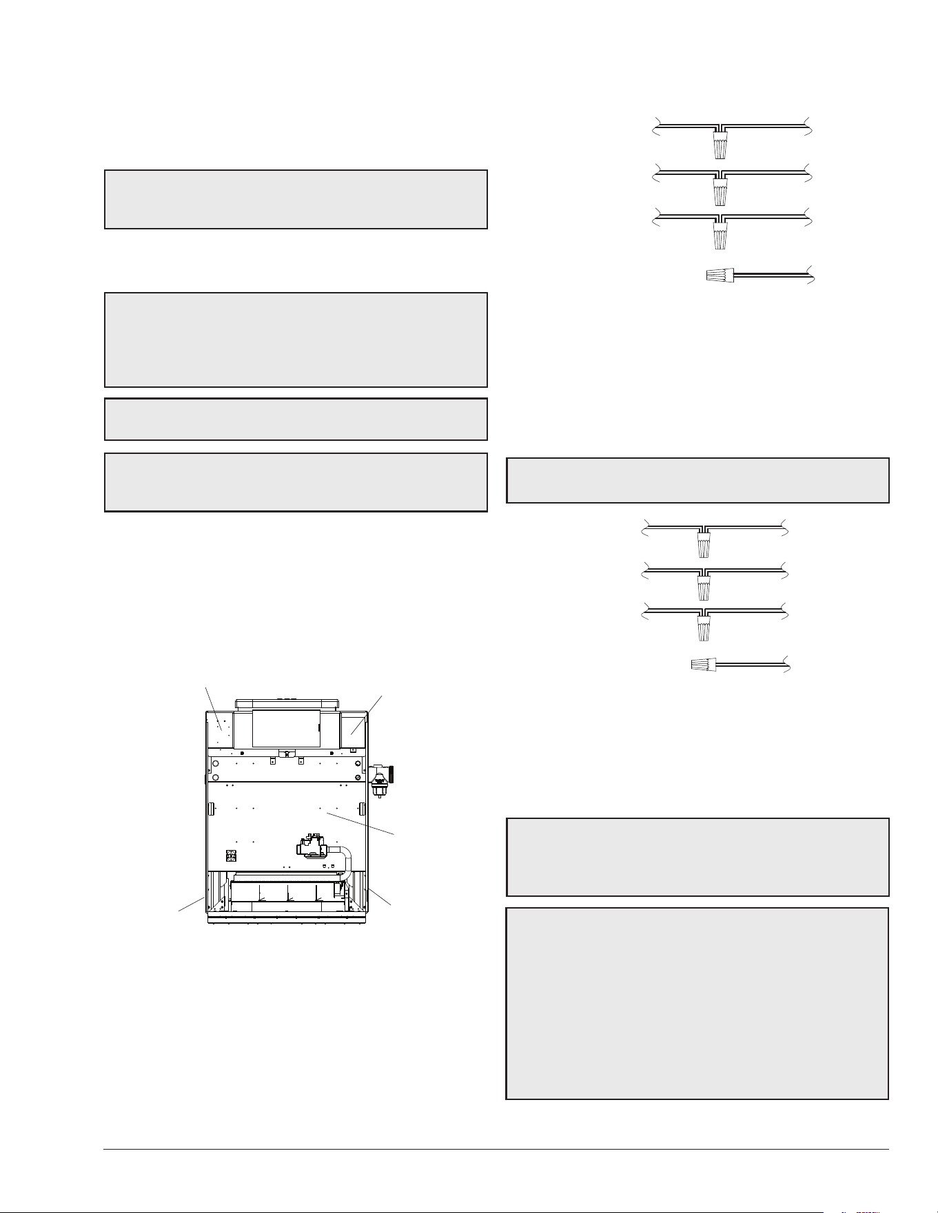
These items are shipped inside a box in the carton with
the heater:
Standard Unit (POLYMER HEADERS)
1. “Pagoda” top
2. 2" CPVC union half with "O" rings (2)
3. Plastic pipe finish flange for gas line
4. Bonding lug with mounting screw (Digital) models
only)
ASME Unit (BRONZE HEADERS)
1. “Pagoda” top
2. 2" CPVC union half with "O" rings (2)
3. Plastic pipe finish flange for gas line
4. Bonding lug with mounting screw (Digital models
only)
5. Pressure Relief Valve (PRV)
6. Protek Shield™ Adapter with Protek Shield Assy,
O-ring and wing nut
F10640-1
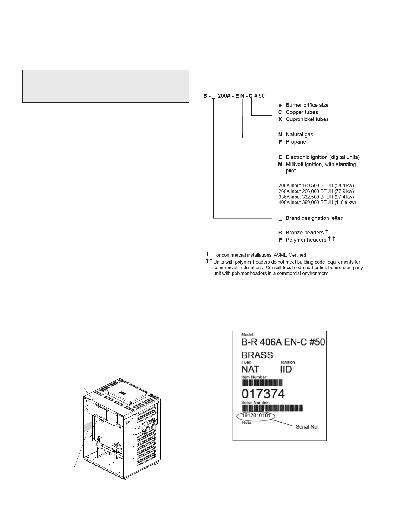
MODEL AND SERIAL
NO. LOCATED ON
RATING PLATE
THE MODEL AND SERIAL NO. CAN
ALSO BE FOUND INSIDE THE
BEZEL ABOVE THE DISPLAY
Figure 1. Rating Plate Location
Be sure that you receive the number of packages indicated
on the Bill of Lading.
Model Identication Number
The model number of a boiler can be found on the Sales
Order and the boiler's rating plate. The example below
identies what the characters of the model number represent.
When ordering parts, you must specify the model and serial
numbers of the heater. See example below for location of
serial number. When ordering under warranty conditions,
you must also specify date of installation.
Rating and Certications
These heaters are design-certied and tested under the
latest requirements of the ANSI Z21.56 / CSA 4.7 Standard
for Gas-Fired Pool Heaters. All heaters can be used either
indoor or outdoors when appropriate venting is installed.
Chlorinators must feed downstream of the heater and
have an anti-siphoning device to prevent chemical backup
into the heater when the pump is shut o.
See "Plumbing Diagrams" on page 21.
NOTE: High chemical concentrates from feeders and
chlorinators that are out of adjustment will cause rapid
corrosion to the heat exchanger. Such damage is not
covered under the warranty.
7
The appropriate top designated for each type of use is
required. If necessary, the top can be changed at a later
date to change from outdoor to indoor or vice versa.
All Bronze header units have heat exchangers which
are ASME-certied (BPV Section IV part HLW) and are
registered with National Board.
Elevation
Rated inputs are suitable for up to 2,000 ft (610 m)
elevation. For elevations above 2,000 ft (610 m), reduce
input 4% for each 1,000 ft (305 m) above sea level, as
high elevation reduces combustion performance.
Ambient Temperature Rating
Heater Components
Millivolt Heater with Honeywell Gas Valve 32°F to 175°F
(0°C to 79°C)
Millivolt Heater with Robertshaw Gas Valve 0°F to 175°F
(-18°C to 79°C)
Electronic Ignition Heater* -32°F to 175°F (-35°C to 79°C)
*Requires 120 or 240VAC, 1 Ph, 60 Hz Power Supply
4. INSTALLATION
A
WARNING: This unit contains refractory ceramic
ber (RCF) insulation in the combustion chamber. RCF,
as manufactured, does not contain respirable crystalline
silica. However, following sustained exposure to very
high-temperatures (>2192°F), the RCF can transform
into crystalline silica (cristabolite). The International
Agency for Research on Cancer (IARC) has classied
the inhalation of crystalline silica (cristabolite) as
carcinogenic to humans.
When removing the burners or heat exchangers, take
precautions to avoid creating airborne dust and avoid
inhaling airborne bers. When cleaning spills, use wet
sweeping or High Eciency Particulate Air (HEPA)
ltered vacuum to minimize airborne dust. Use feasible
engineering controls such as local exhaust ventilation
or dust collecting systems to minimize airborne dust.
Wear appropriate personal protective equipment
including gloves, safety glasses with side shields, and
appropriate NIOSH-certied respiratory protection,
to avoid inhalation of airborne dust and airborne ber
particles.
IMPORTANT NOTICE: These instructions are intended
only for the use by qualied personnel, specically
trained and experienced in the installation of this type
of heating equipment and related system components.
Installation and service personnel may be required by
some states to be licensed. If your state is such, be sure
your contractor bears the appropriate license. Persons
not qualied shall not attempt to x the equipment nor
attempt repairs according to these instructions.
A
WARNING: Improper installation, adjustment,
alteration, service or maintenance may damage the
equipment, creating a hazard resulting in asphyxiation,
explosion or re. Such damage is not covered under
warranty.
NOTE: The heater should not be located in an area
where possible water leakage will result in damage to
the area adjacent to the heater or to the structure. When
such locations cannot be avoided, it is recommended
that a suitable drain pan, with adequate drainage, be
installed under the heater. The pan must not restrict
combustion air ow.
RECOMMENDATION: For regions with snow, Raypak
recommends installing these units indoors.
Installation Codes
Installation must be in accordance with local codes, or,
in the absence of local codes, with the latest edition of
the National Fuel Gas Code, ANSI Z223.1/NFPA54 and
National Electrical Code, ANSI/NFPA 70, and for Canada,
the latest edition of CAN/CSA-B149 Installation Codes,
and Canadian Electrical Code, CSA C22.1 Part 1 and
Part 2.
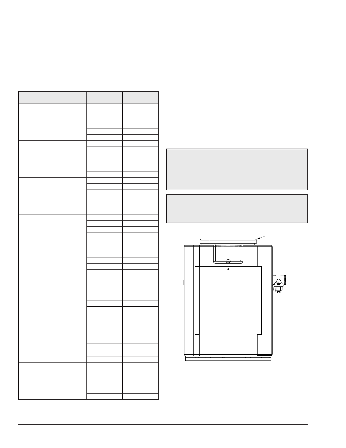
Clearances
All Heaters
For indoor and outdoor clearances from combustible
surfaces, see the chart below.
Location Indoor Installation
Top * 30" (762 mm) Drafthood
Front Alcove (Open)
Vent 6" (152 mm)
Floor ** 0"
Back 6" (152 mm)
Right-Side 12" (305 mm) Water Side
Left-Side 6" (152 mm) Opposite Water Side
Location Outdoor Installation
Top * Unobstructed (Outdoor Stack)
Top *** 36" (914 mm) (Stackless Top)
Floor 0"
Back 6" (152 mm)
Right-Side 12" (305 mm) Water Side
Left-Side 6" (152 mm) Opposite Water Side
* Clearance from top of vent terminal
** Do not install on carpeting
*** Clearance from top of heater
Table B. Minimum Clearances from Combustible
Surfaces
8
When installed according to the listed minimum clearances
from combustible construction, the pool heater can still be
serviced without removing permanent construction around
the heater.
However, for ease of servicing, we recommend a clearance
of at least 24" (610 mm) in the front, and at least 18" (457
mm) on the water connection side. This will enable the
heater to be serviced in its installed location, that is, without
movement or removal of the heater.
Description Location
Distance
in. (mm)
a. 3-1/2" (89 mm) thick
masonry walls without
ventilated air space
Back 9 (229)
Right 9 (229)
Left 9 (229)
Vent 5 (127)
Indoor Top 39 (991)
Outdoor Top Unobstructed
b. 1/2" (13 mm)insulation
board over 1" (25 mm)
glass ber or mineral
wool batts
Back 6 (152)
Right 6 (152)
Left 6 (152)
Vent 3 (76)
Indoor Top 30 (762)
Outdoor Top Unobstructed
c. 0.024" sheet metal over
1" (25 mm) glass ber
or mineral wool batts
reinforced with wire on
rear face with ventilated
air space
Back 4 (102)
Right 4 (102)
Left 4 (102)
Vent 3 (76)
Indoor Top 24 (610)
Outdoor Top Unobstructed
d. 3-1/2" (89 mm) thick
masonry wall with
ventilated air space
Back 6 (152)
Right 6 (152)
Left 6 (152)
Vent 6 (152)
Indoor Top 39 (991)
Outdoor Top Unobstructed
e. 0.024" sheet metal with
ventilated air space
Back 4 (102)
Right 4 (102)
Left 4 (102)
Vent 2 (51)
Indoor Top 24 (610)
Outdoor Top Unobstructed
f. 1/2" (13 mm) thick
insulation board with
ventilated air space
Back 4 (102)
Right 4 (102)
Left 4 (102)
Vent 3 (76)
Indoor Top 24 (610)
Outdoor Top Unobstructed
g. 0.024" sheet metal with
ventilated air space over
0.024 sheet metal with
ventilated air space.
Back 4 (102)
Right 4 (102)
Left 4 (102)
Vent 3 (76)
Indoor Top 24 (610)
Outdoor Top Unobstructed
h. 1" (25 mm) glass ber
or mineral wool batts
sandwiched between two
sheets 0.024 sheet metal
with ventilated air space
Back 4 (102)
Right 4 (102)
Left 4 (102)
Vent 3 (76)
Indoor Top 24 (610)
Outdoor Top Unobstructed
Derived from National Fuel Gas Code, Table 10.2.3
Table C. Reduction of Clearances to Protected Surfaces
Clearances less than these may require removal of the
heater to service either the heat exchanger or the burner
tray. In either case, the heater must be installed in a
manner that will enable the heater to be serviced without
removing any structure around the heater.
Flooring
This heater can be installed on combustible ooring.
The combustible clearances listed can be reduced by
protecting the exposed combustible surfaces as shown in
Table C.
Outdoor Heater Installation
These heaters are design-certied for outdoor installation,
when equipped with the approved tops designated for
outdoor use.
A
WARNING: The heater shall not be located in an
area where water sprinklers, or other devices, may cause
water to spray through the cabinet louvers and into the
heater. This could cause internal rusting or damage
electrical components. Such damage is not covered
under warranty.
A
WARNING: Do not install within 3' (0.9 m) of a heat
pump or an outdoor condensing unit. Strong air intake
from this type of equipment can disturb the combustion
process and cause damage or personal injury.
F10646-1
PAGODA TOP
INSTALLATION
Figure 2. Heater with Outdoor Stackless Top
9
Forced Air Inlet
4' (1.2 m)
Minimum
3' (0.9 m)
Minimum
10' (3 m)
Minimum
1' (0.3 m)
Minimum
4' (1.2 m)
Minimum
4' (1.2 m)
Minimum
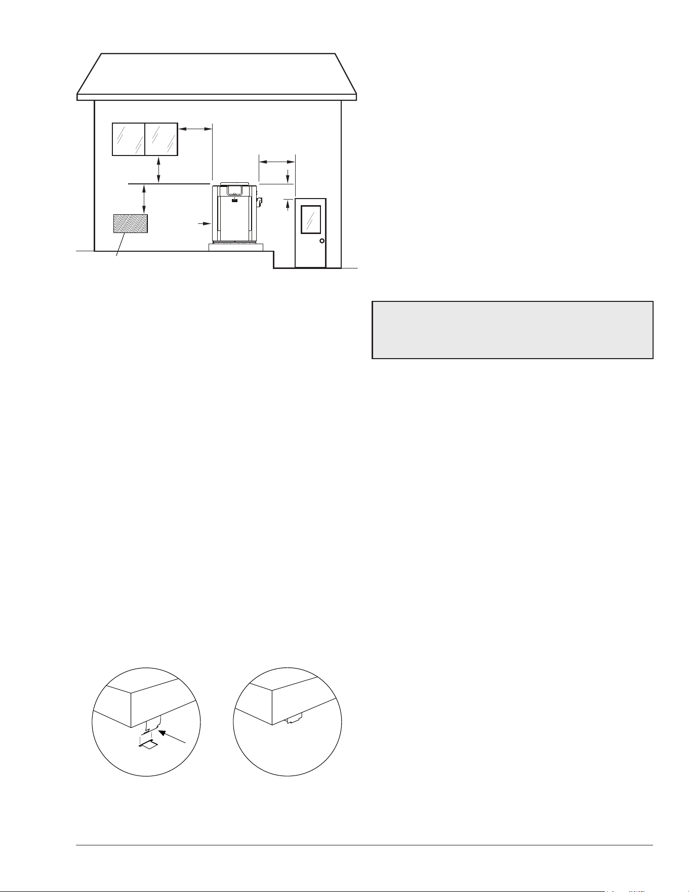
Figure 3. Minimum Distances to Building Openings from
Where Flue Products Exit the Boiler
Heaters must not be installed under an overhang of less
than 3' (0.9 m) from the top of the heater. Three sides
must be open in the area under the overhang. Roof water
drainage must be diverted away from the heaters installed
under overhangs with the use of gutters.
For U.S. installations, the point from where the ue
products exit the heater must be a minimum of 4' (1.2 m)
below, 4' (1.2 m) horizontally from, or 1' (0.3 m) above
any door, window or gravity inlet into any building. The
top surface of the heater shall be at least 3' (0.9 m) above
any forced air inlet, or intake ducts located within 10' (3 m)
horizontally.
For Canadian installations, pool heaters shall not be
installed with the top of the vent assembly within 10' (3 m)
below, or to either side, of any opening into the building.
Refer to the latest revisions of CAN/CSA-B149.
A minimum of 6' (1.8 m) is required from the heater to an
inside corner wall for proper outdoor venting.
Pagoda Top Installation
1. Insert tabs into keyhole (4 places). See Figure 4,
detail A.
2. Snap tabs into keyholes so as not to pull out. See
Figure 4, detail B.
OUTDOOR TOP
(SHIPPED LOOSE WITH HEATER)
DETAIL A DETAIL B
Figure 4. Outdoor Top Installation
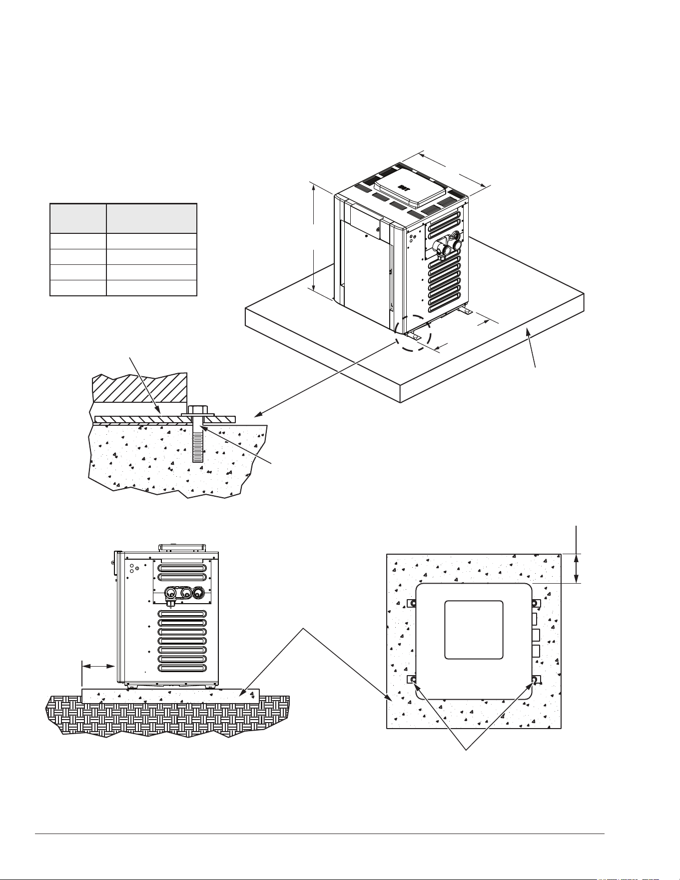
For installations in Florida and Texas, that must comply
with the Florida or Texas Building Code, follow the directions
shown in Figure 5 for the installation of hurricane tie-down
brackets for all models.
Indoor Heater Installation
The heater is also design-certied for indoor installation
when equipped with the approved drafthood and a code-
compliant vent stack.
For Canada, indoor installation is restricted to an enclosure
that is not occupied and does not directly communicate
with an occupied area. Refer to the latest edition of CAN/
CSA-B149 for specic requirements. Locate heater as
close as is practical to a chimney or gas vent. Heater
must always be vented to the outside. See section "Vent
Piping" on page 14 for details. Minimum allowable
space is shown on the nameplate.
A
WARNING: Indoor heaters require a drafthood that
must be connected to a vent pipe and properly vented to
the outside. Failure to follow this procedure can cause
re or fatal carbon monoxide poisoning.
Base Riser (for Canada only)
For all Canada installations, the unit must be installed on
a base riser that is shipped along with the unit. This is in
accordance with ANSI-Z21.56. See IPL for replacement kit
information on page 52 (Item 14-S).
10
TOH
WIND SPEED = 150 MPH, 3 SECOND GUST
EXPOSURE = C
INSTRUCTIONS FOR THE STATE OF FLORIDA
AND FOR AREAS OF TEXAS DESIGNATED BY
THE TEXAS DEPARTMENT OF INSURANCE
B
28"
(711 mm)
38"
(965 mm)
3" (76 mm)
Min. Conc.
Pad by others
3" (76 mm)
Min. Conc.
Pad by others
(1)–1/4" x 2-1/4" S.S.
Tapcon Bolt & Washer (Field-Supplied)
Ea. Pallet Anchor Bracket
Use hole closest to unit (4 total)
(1)–1/4" x 2-1/4" S.S.
Tapcon Bolt & Washer (Field-Supplied)
Ea. Pallet Anchor Bracket
Use hole closest to unit (4 total)
2" x 6" x 1/8" Pallet
Anchor Bracket (4 Total) (Kit# 011636)
1/4" x 2-1/4" S.S.
Tapcon Bolt and Washer (Field-Supplied)
NOTE: Use hole closest to unit with
washer overlapping edge of unit.
Min. Edge
Distance
6"
(152 mm)
Min. Edge
Distance
6"
(152 mm)
F10648
F10646-2
Model
B
in. (mm)
206A 20 (508)
266/266A 23 (584)
336A 26 (660)
399/406A 29 (737)
Figure 5. Hurricane Tie-Down Bracket Installation
11
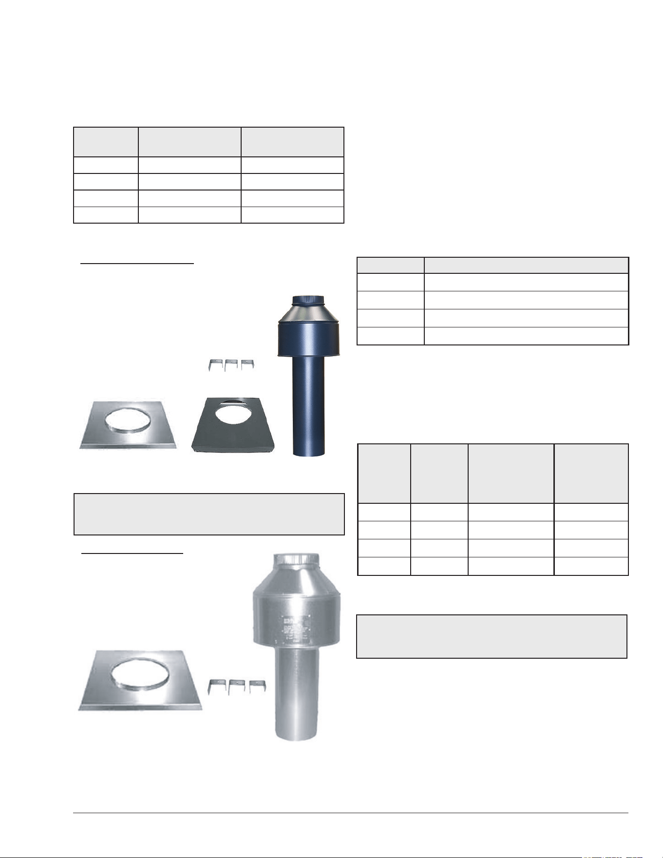
Outdoor and Indoor Stacks
The outdoor and indoor stacks are optional equipment and
do not come standard with the heater. Refer to installation
instructions inside box for instructions on how to install
outdoor/indoor stack.
Model Outdoor Stack Indoor Stack
206A 009834 009838
266/266A 009835 009839
336A 009836 009840
399/406A 009837 009841
Table D. Outdoor and Indoor Stack Kit Number
OUTDOOR STACK KIT
(1) Outdoor drafthood, painted
(1) Adapter plate
(3) Mounting brackets (clips)
(1) Top panel cover
(2) 1-foot sections of metal tape
(3) Screws
(1) Instructions
Clips
Figure 6. Outdoor Stack Kit Components
NOTE: The outdoor drafthood kit does not require any
additional vent pipe for proper operation. This drafthood
functions as the vent termination.
INDOOR STACK KIT
(1) Drafthood, unpainted
(1) Adapter plate
(3) Mounting brackets (clips)
(3) Screws
(1) Instructions
Clips
Figure 7. Indoor Stack Kit Components
Combustion and Ventilation Air
Indoor Units Only
The heater must have both combustion and ventilation
air. The minimum requirements are listed in the latest
edition of the National Fuel Gas Code (U.S. ANSI Z223.1
or Canada CAN/CSA-B149) and any local codes that
may have jurisdiction. The most common approach is
the "2-opening" method, with combustion air opening no
more than 12" from the floor and the ventilation opening
no more than 12" from the ceiling. For opening sizes
using this method, see below.
All Air from Inside the Building:
Each opening shall have a minimum net free area as noted:
Model Sq. in. (m
2
)
206A 200 (0.13)
266/266A 266 (0.17)
336A 333 (0.21)
399/406A 399 (0.26)
Table E. Opening Minimum Net Free Requirements -
Indoor Air
All Air from Outdoors:
When air is supplied directly from outside the building, each
opening shall have a minimum net free area as noted:
Model
Unrestricted
Opening
sq. in. (m
2
)
Typical Screened or
Louvered Opening
sq. in. (m
2
)
Typical Screened
and Louvered
Opening
sq. in. (m
2
)
206A 50 (0.03) 75 (0.05) 100 (0.06)
266/266A 67 (0.04) 101 (0.06) 134 (0.09)
336A 84 (0.05) 126 (0.08) 168 (0.11)
399/406A 100 (0.06) 150 (0.1) 200 (0.13)
Table F. Opening Minimum Net Free Requirements -
Outdoor Air
A
CAUTION: Combustion air must not be contaminated
by corrosive chemical fumes which can damage the
heater. Such damage will not be covered by the warranty.
12
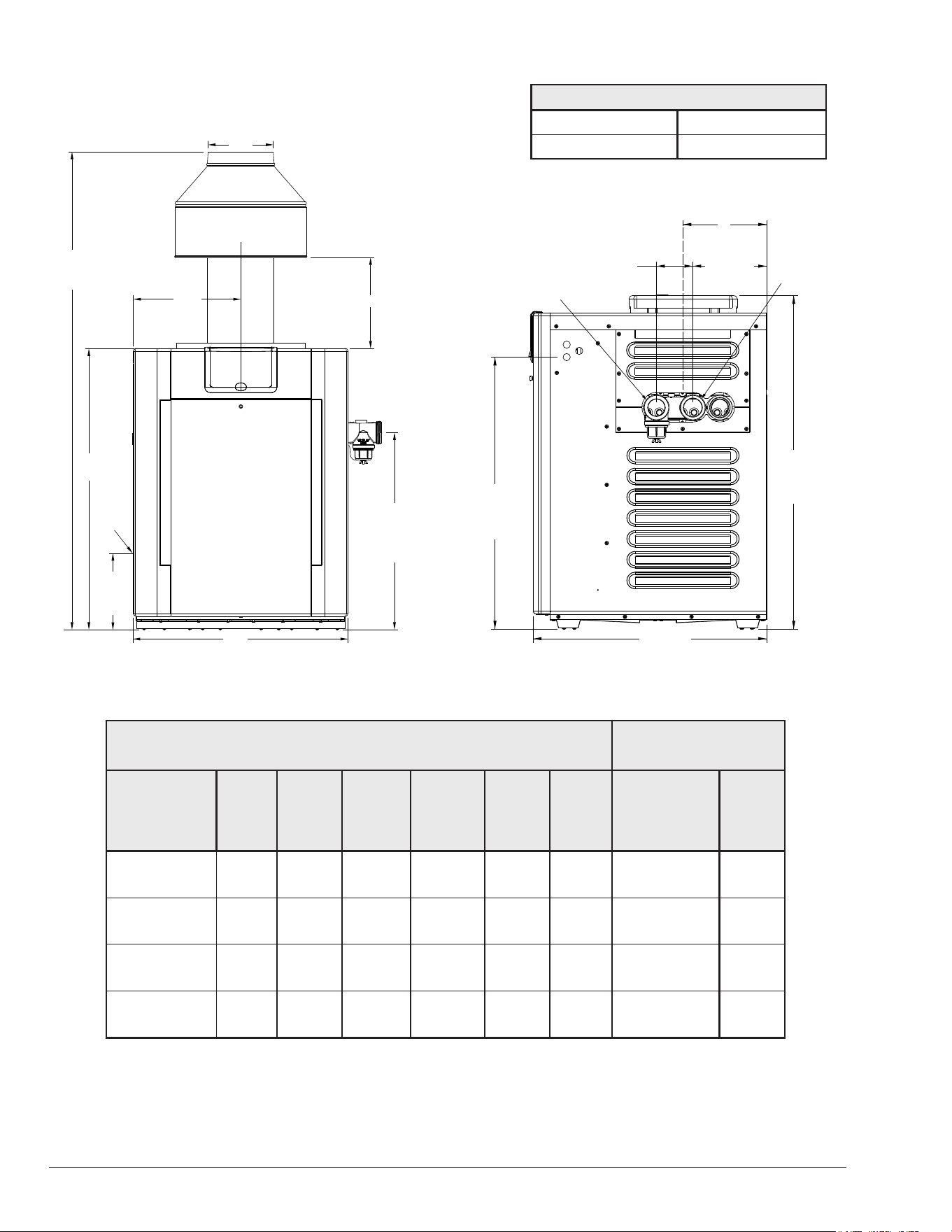
Specications and Dimensions
F10646
B
D
J*
A
C
Indoor
Drafthood
38”
(965 mm)
26-5/8”
(676 mm)
28-5/8” ASME
(727 mm
ASME)
13-1/4”
(337 mm)
gas
connection
GAS,
3/4"
NPT
Figure 8. Front View
F10646-4
10"
(254 mm)
8-7/8"
(225 mm)
6-5/8" ASME
(168 mm)
4-3/8"
(111 mm)
(3-3/8" ASME)
(86 mm)
WATER
INLET 2" SLIP
WATER
OUTLET
2" SLIP
32-11/16"
(830 mm)
Electrical
Connection
28"
(711 mm)
40"
(1016 mm)
Stackless
Outdoor Top
C
L
Flue
Amp Draw
120 VAC, 1Ph, 60Hz 240 VAC, 1Ph, 60Hz
4 2
Figure 9. Side View
Residential - Copper Heat Exchanger
Shipping Weights
lbs. (kg)
Heater
Mode
BTUH
Input
(kwh)
(A)
Cabinet
Width
in. (mm)
(B)
Flue
Dia.
in. (mm)
(C)
Indoor
Drafthood
in. (mm)
(D)
in. (mm)
(J)*
in. (mm)
Standard
Heater
w/Stackless
Top
Indoor
Draft-
Hood
206A
199.5
(58.4)
20
(508)
6
(152)
61-5/8
(1565)
10.0
(254)
11-3/4
(298)
187
(85)
14
(6.4)
266/266A
266.0
(77.9)
23
(584)
7
(178)
62
(1575)
11.5
(292)
11
(279)
210
(95)
16
(7.3)
336A
332.5
(97.4)
26
(660)
8
(203)
63
(1600)
13
(330)
10-5/8
(270)
230
(104)
19
(8.6)
399/406A
399
(116.9)
29
(737)
9
(229)
64-9/16
(1640)
14.5
(368)
12-1/8
(309)
249
(113)
21
(9.5)
Table G. Residential - Copper Heater Specications and Dimensions
*Note: For outdoor stack height, use "J" dimension for appropriate size plus 6 inches (152 mm).
13
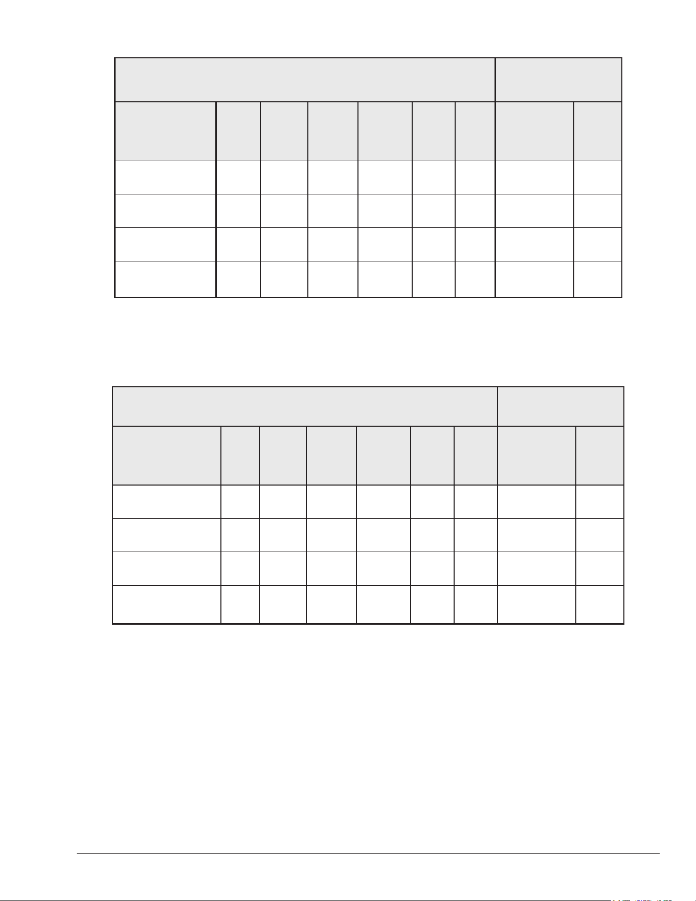
Commercial - ASME Copper or Cupronickel Heat Exchanger
Shipping Weights
lbs. (kg)
Heater
Mode
BTUH
Input
(kwh)
(A)
Cabinet
Width
in. (mm)
(B)
Flue
Dia.
in. (mm)
(C)
Indoor
Drafthood
in. (mm)
(D)
in.
(mm)
(J)*
in.
(mm)
ASME
Heater
w/Stackless
Top
Indoor
Draft-
Hood
B-_206A-EN-(C or X)
199.5
(58.4)
20
(508)
6
(152)
61-5/8
(1565)
10.0
(254)
11-3/4
(298)
206
(94)
14
(6.4)
B-_266A-EN-(C or X)
266.0
(77.9)
23
(584)
7
(178)
62
(1575)
11.5
(292)
11
(279)
229
(104)
16
(7.3)
B-_336A-EN-(C or X)
332.5
(97.4)
26
(660)
8
(203)
63
(1600)
13
(330)
10-5/8
(270)
249
(113)
19
(8.6)
B-_406A-EN-(C or X)
399
(116.9)
29
(737)
9
(229)
64-9/16
(1640)
14.5
(368)
12-1/8
(309)
268
(122)
21
(9.5)
Residential - Cupronickel Heat Exchanger
Shipping Weights
lbs. (kg)
Heater
Mode
BTUH
Input
(kwh)
(A)
Cabinet
Width
in. (mm)
(B)
Flue
Dia.
in. (mm)
(C)
Indoor
Drafthood
in. (mm)
(D)
in.
(mm)
(J)*
in.
(mm)
Standard
Heater
w/Stackless
Top
Indoor
Draft-
Hood
P-_206A-EN-X
180.0
(52.7)
20
(508)
6
(152)
61-5/8
(1565)
10.0
(254)
11-3/4
(298)
187
(85)
14
(6.4)
P-_266A-EN-X
240.0
(70.3)
23
(584)
7
(178)
62
(1575)
11.5
(292)
11
(279)
210
(95)
16
(7.3)
P-_336A-EN-X
300.0
(87.9)
26
(660)
8
(203)
63
(1600)
13
(330)
10-5/8
(270)
230
(104)
19
(8.6)
P-_406A-EN-X
360.0
(105.5)
29
(737)
9
(229)
64-9/16
(1640)
14.5
(368)
12-1/8
(309)
249
(113)
21
(9.5)
Table H. Residential - Cupronickel Heater Specication and Dimensions
Table I. Commercial - Heater Specifications and Dimensions
*Note: For outdoor stack height, use "J" dimension for appropriate size plus 6 inches (152 mm).
*Note: For outdoor stack height, use "J" dimension for appropriate size plus 6 inches (152 mm).
14
Vent Piping
A
WARNING: Indoor heaters require a drafthood that
must be connected to a vent pipe and properly vented to
the outside. Failure to follow this procedure can cause
re or fatal carbon monoxide poisoning.
When properly installed outdoors, only the outdoor
stackless top (provided) is required. If installed indoors,
a drafthood is required, connected to a CATEGORY
I (a heater that operates with a non-positive vent static
pressure and a vent gas temperature that avoids excessive
condensate production in the vent.) vent per the National
Fuel Gas Code and local requirements.
Vent piping the same size as the drafthood outlet is
recommended, however, when the total vent height is at
least 10 ft (3 m) (drafthood relief opening to vent terminal),
the vent pipe size may be reduced by no more than one
(1) size as specied in Chapter 13 of the National Fuel
Gas Code, ANSI Z223.1 (Canada - CAN/CSA-B149).
As much as possible, avoid long horizontal runs of vent
pipe and too many elbows. If installation requires horizontal
runs, the vent pipe must have a minimum of 1/4 in. per ft
rise (20.8 mm per meter rise) and should be supported at
not more than ve foot (1.5 m) intervals.
Plumber's tape, criss-crossed, will serve to space both
horizontal and vertical piping. Gas vents supported only
by the ashing and extending above the roof more than 5
ft (1.5 m) should be securely guyed or braced to withstand
snow and wind loads. We recommend use of insulated
vent pipe spacers through the roof and walls.
For protection against rain or blockage by snow, the vent
pipe must terminate with a vent cap which complies with
the local codes or, in the absence of such codes, to the
latest edition of the National Fuel Gas Code, ANSI Z223.1
(Canada - CAN/CSA-B149).
The discharge opening must be a minimum of 2' (0.6
m) vertically from the roof surface and at least 2' (0.6 m)
higher than any part of the building within 8' (2.4 m). Vent
stack shall be at least 5' (1.5 m) in vertical height above
the drafthood outlet. The vent cap location shall have a
minimum clearance of 4' (1.2 m) horizontally from, and in
no case below, unless a 4' (1.2 m) horizontal distance is
maintained, from electric meters, gas meters, regulators
and relief equipment.
The weight of the vent stack or chimney must not rest on the
heater drafthood. Support must be provided in compliance
with applicable codes. The heater top and drafthood must
be readily removable for maintenance and inspection.
Vent pipe should be adequately supported to maintain
proper clearances from combustible construction.
Flue materials must be certied to CATEGORY I or
better. Type “B” double-wall or equivalent vent pipe is
recommended. A draft of -0.01" to -0.08" WC must be
maintained. However, single-wall metal vent pipe may be
used as specied in the latest edition of the National Flue
Gas Code, ANSI Z223.1 (Canada - CAN/CSA-B149).
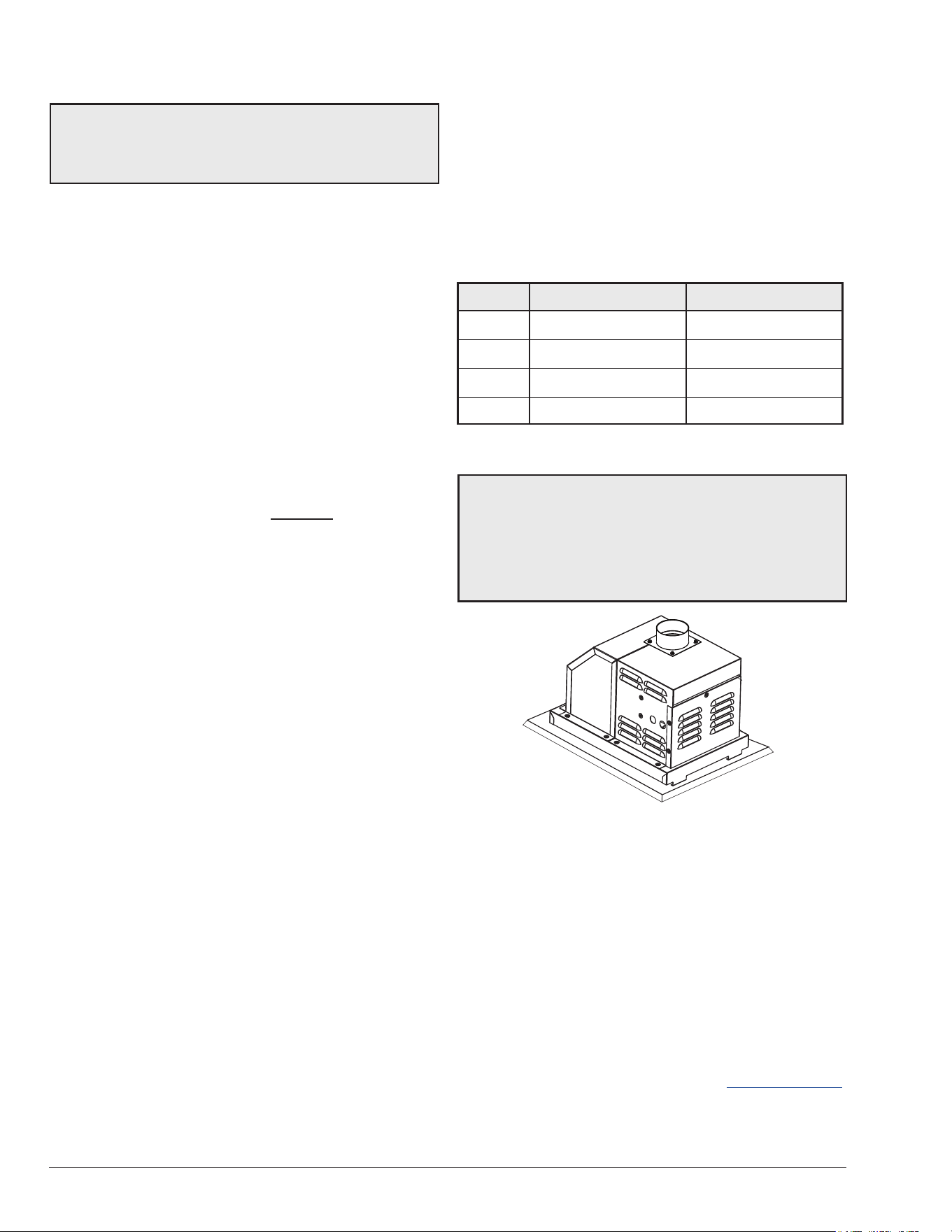
D-2 Power Vent Kit
Another option for an installation that requires horizontal
runs is the D-2 power vent kit option.
Model 120 VAC P/N 240 VAC P/N
206A 010744 009832
266/266A 010744 009832
336A 010745 009833
399/406A 010745 009833
Table J. Power Vent Kit Part Numbers
NOTE: The D-2 Power Vent operates with a positive vent
static pressure and with a vent gas temperature that
prevents excessive condensate production in the vent,
and as such, is a CATEGORY III appliance. For more
information consult the D-2 Power Vent manual, (P/N:
241243). CATEGORY I vent material such as B-vent must
not be used under CATEGORY III conditions.
Figure 10. D-2 Power Vent Option
The power vent system is a fan-assisted vent system
designed for use on models 206A-406A.
The power vent system, when installed as directed, is
capable of operating in applications such as through-the-
wall venting with reduced horizontal and vertical vent pipe
sizes in new and current installations. The unit is factory-
wired for 240 VAC, with capability of eld-rewiring for 120
VAC.
For more information consult the D-2 Power Vent manual,
(P/N: 241243). This Manual can be viewed on your smart
device. See QR Code on page 46. This manual can
also be found in the document library at www.raypak.com.
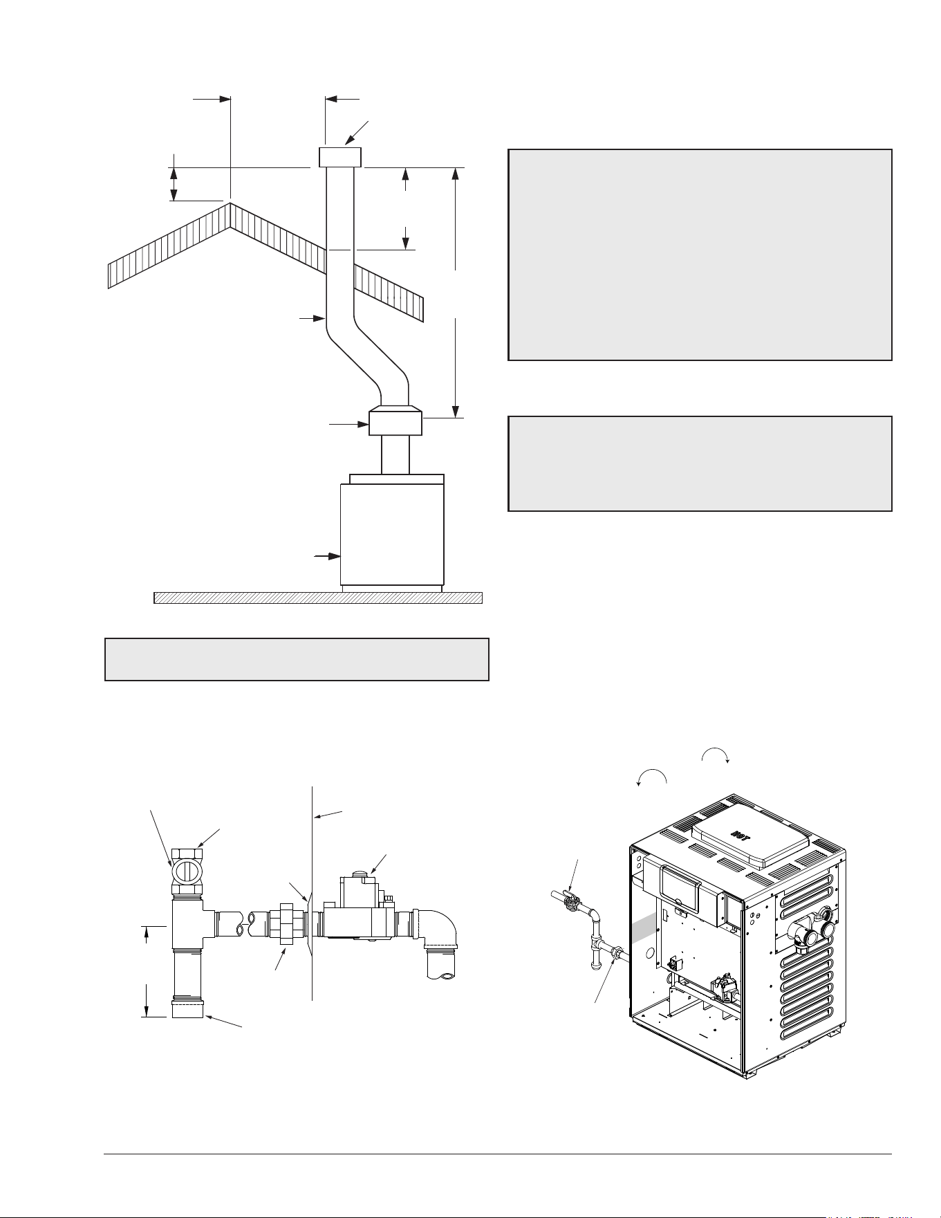
15
VENT CAP
2' MIN
(0.6 m)
VENT PIPE
DRAFT HOOD
5' MIN
(1.5 m)
HEATER
2' MIN
(0.6 m)
8' (2.4 m)
OR LESS
Figure 11. Venting Clearances
NOTE: For common venting of two or more heaters,
contact the factory.
Gas piping must have a sediment trap ahead of the
heater gas controls, and a manual shuto valve located
outside the heater jacket. All gas piping should be tested
after installation in accordance with local codes.
A
CAUTION: The heater and its manual shuto valve
must be disconnected from the gas supply during any
pressure testing of that system at test pressures in
excess of 1/2 psi (3.45 kPa). Dissipate test pressure in
the gas supply line before reconnecting the heater and
its manual shuto valve to gas supply line. FAILURE
TO FOLLOW THIS PROCEDURE MAY DAMAGE THE
GAS VALVE. OVER-PRESSURIZED GAS VALVES ARE
NOT COVERED BY WARRANTY. The heater and its gas
connections shall be leak tested before placing the
appliance in operation. Use soapy water for leak test. DO
NOT use open ame.
Supply Pressure
A
CAUTION: Do not use Teon tape on gas line pipe
thread. Only sealant tape or a pipe compound rated for
use with natural and propane gases is recommended.
Apply sparingly only on male pipe ends, leaving the two
end threads bare.
A minimum of 6 in. WC and a maximum of 10.5 in. WC
upstream pressure under load and no-load conditions
must be provided for natural gas. A minimum of 12 in. WC
and a maximum of 13 in. WC are required for propane
gas under load and no-load conditions.
Gas Pressure Regulator
The gas pressure regulator is preset at 4.0 in. WC for
natural gas, and 10.5 in. WC. for propane gas. The
pressure at the gas valve, taken with a manometer, should
be about 4.0 in. WC natural gas and 10.5 in. WC propane
gas. If an adjustment is needed, remove seal and turn
adjustment screw clockwise to increase pressure or
counter-clockwise to decrease pressure.
MANUAL
SHUT-OFF
VALVE
UNION
F10640-2
Figure 13. Manual Shuto Valve Installation
Gas Supply Connections
GAS INLET
HEATER JACKET
MANUAL SHUTOFF VALVE
(Field-supplied)
GAS VALVE
FINISH FLANGE
UNION
(Field-supplied)
SEDIMENT TRAP
(Field-supplied)
3" MIN
(76 mm)
Typical
Figure 12. Gas Supply Plumbing
16
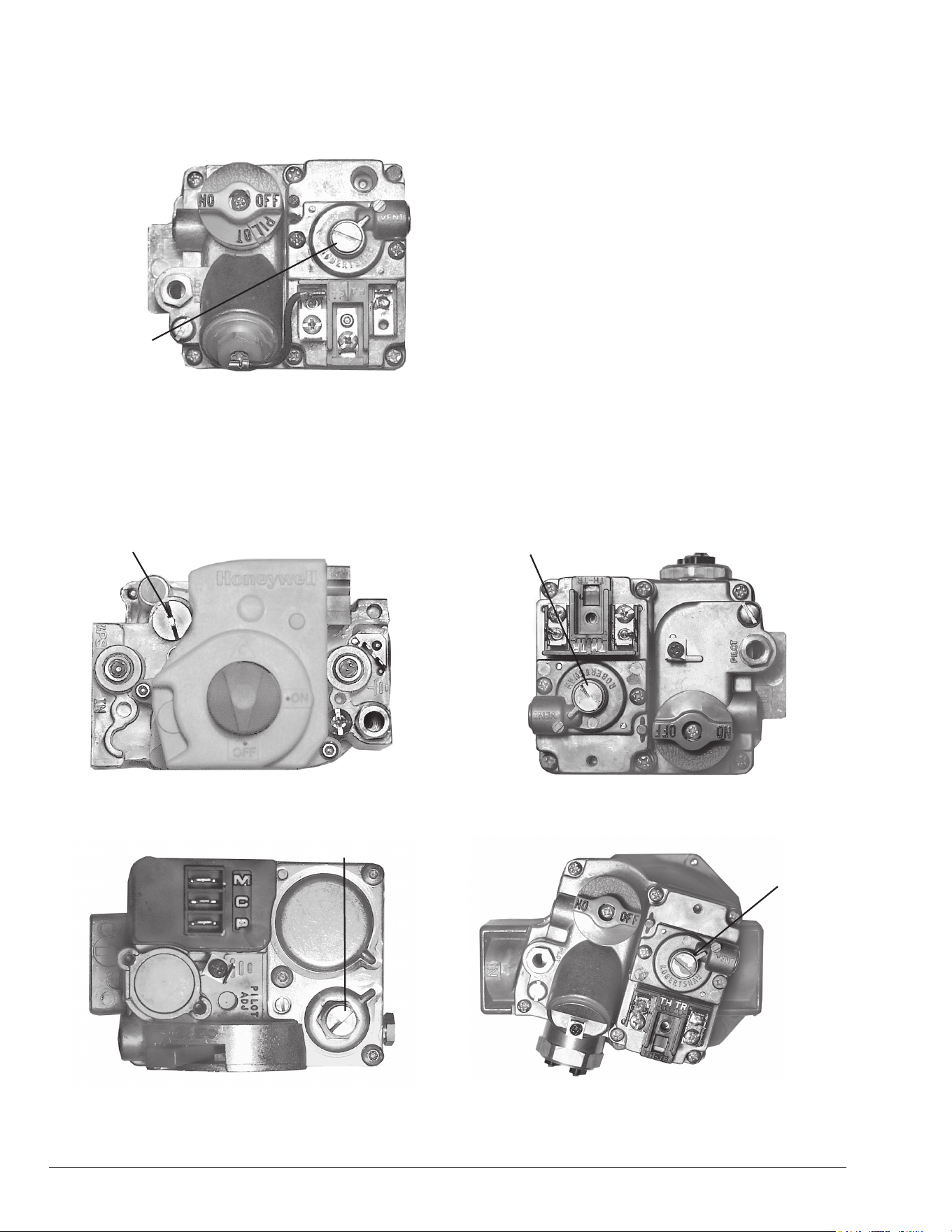
Gas Pressure Adjustment Locations
Millivolt Gas Valve
GAS
PRESSURE
ADJUSTMENT
Figure 14. Robertshaw 7000 (Heater Models 206A - 406A)
GAS PRESSURE ADJUSTMENT
Figure 15. Honeywell VR8340 (Heater Models 206A - 406A)
GAS PRESSURE ADJUSTMENT
Figure 16. Robertshaw 7200 (Heater Model 206A)
GAS PRESSURE ADJUSTMENT
Figure 17. Robertshaw 7000 BDER (Heater Models 266A -
336A)
GAS
PRESSURE
ADJUSTMENT
Figure 18. Robertshaw 7000 DERHC (Heater Model 406A)
Electronic Ignition Gas Valves
17
Pipe Sizing for Gas Connection
These capacities shown below based on using SCH
40 black iron pipe. For capacities using other materials,
consult local code.
Maximum Equivalent Pipe Length (ft) (m)
Natural Gas 1000 BTU/FT
3
0.60
Specic Gravity @ 0.5 in WC Pressure Drop
Propane Gas 2500 BTU/FT
3
1.53
Specic Gravity @ 0.5 in WC Pressure Drop
Model
3/4" 1" 1-1/4" 1-1/2"
NAT PRO NAT PRO NAT PRO NAT PRO
206A
25
(7.6)
60
(18.3)
90
(27.4)
215
(65.5)
360
(109.7)
266/266A
15
(4.6)
35
(10.7)
50
(15.2)
125
(38.1)
210
(64.0)
480
(146.3)
445
(135.6)
336A
10
(3.0)
20
(6.1)
30
(9.1)
80
(24.4)
140
(42.7)
320
(97.5)
290
(88.4)
399/406A *
15
(4.6)
20
(6.1)
55
(16.8)
95
(29.0)
225
(68.6)
215
(65.5)
480
(146.3)
* A 3/4" gas line can be used for up to 5' (1.5 m) maximum length from the gas valve
in addition to the sediment trap.
Table K. Gas Pipe Sizing
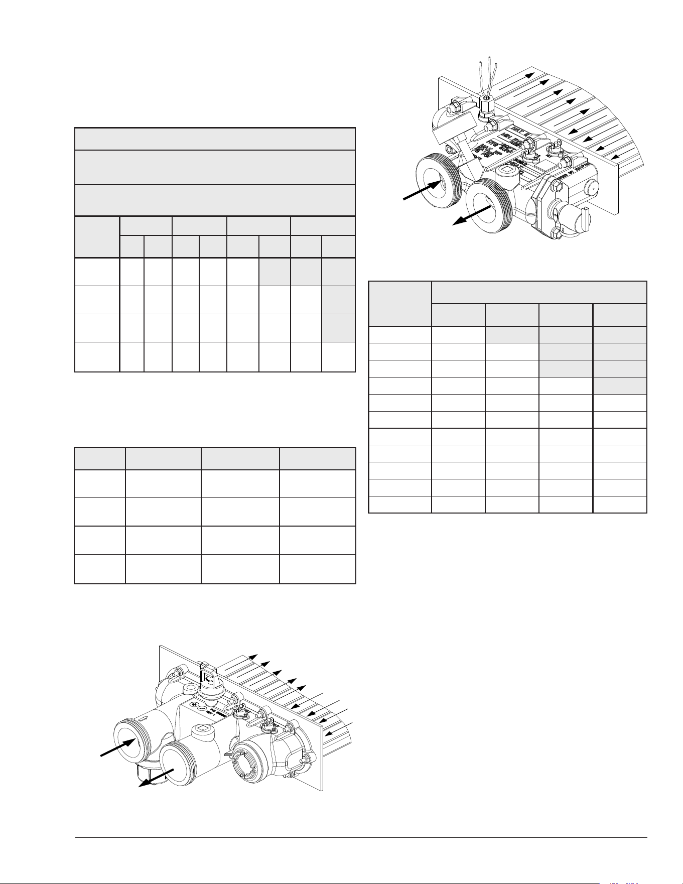
Flow Rate
Model Pipe Size Min. GPM (lpm)
Max. GPM
(lpm)
206A 1-1/4"–1-1/2"–2" 20 (75) 100 (378)
266/266A 1-1/4"–1-1/2"–2" 25 (95) 100 (378)
336A 1-1/4"–1-1/2"–2" 35 (132) 100 (378)
399/406A 1-1/4"–1-1/2"–2" 40 (151) 100 (378)
* When ow rates exceed maximum GPM an external auxiliary bypass valve is
required. See external bypass valve section for details.
Figure 19. Min/Max Flow Rates
F10638-1
INLET
OUTLET
Figure 20. Polymer Header Water Flow
F10637-1
INLET
OUTLET
Figure 21. Bronze Header (ASME) Water Flow
Flow GPM
(lpm)
Pressure Drop (Ft. of Head) (m of Head)
206A 266/266A 336A 399/406A
20 (75) 4.0 (1.2)
25 (95) 4.0 (1.2) 4.6 (1.4)
30 (113) 4.0 (1.2) 5.2 (1.6)
35(132) 4.0 (1.2) 5.8 (1.8) 5.2 (1.6)
40 (151) 4.6 (1.4) 5.8 (1.8) 5.2 (1.6) 5.2 (1.6)
50 (189) 4.6 (1.4) 6.3 (1.9) 6.9 (2.1) 6.9 (2.1)
60 (227) 4.6 (1.4) 6.9 (2.1) 6.9 (2.1) 6.9 (2.1)
70 (265) 4.6 (1.4) 8.1 (2.5) 9.2 (2.8) 9.2 (2.8)
80 (303) 4.6 (1.4) 9.2 (2.8) 9.8 (3.0) 9.8 (3.0)
90 (340) 6.9 (2.1) 10.4 (3.2) 10.4 (3.2) 10.4 (3.2)
100 (378) 8.1 (2.5) 11.0 (3.4) 12.1 (3.7) 12.1 (3.7)
Table L. Polymer Heat Exchanger Pressure Drop -
Residential Models - (UG Fully Open)
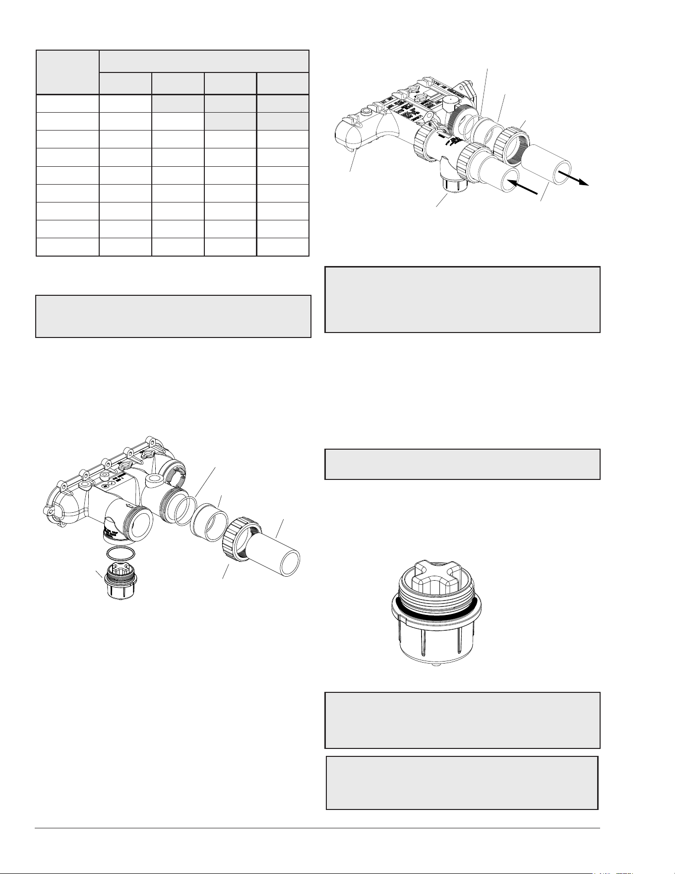
18
F10664
HEADER
O-RING
HEADER FLANGE
(CPVC)
HEADER FLANGE NUT
(CPVC)
PLUMBING
PROTEK SHIELD
ASSEMBLY
Figure 23. Inlet/Outlet Header – Bronze
NOTE: Some jurisdictions require the addition of a ow
switch on ASME installations. Kit # 015889F for ange
connection or 015890F for NPT connection can be
ordered that will allow a standard ASME unit to comply
with the code requirements.
ProTek Shield Assembly
This heater is equipped with a ProTek Shield Assembly
(located under the inlet connection on polymer headers)
and in the ProTek Shield Adapter assembly shipped loose
in the accessory carton for eld-installation on bronze
ASME headers.
NOTE: ProTeK Shield not available on ASME models
until end of Q3 2020.
This component provides protection to the heat exchanger
against galvanic corrosion, when properly bonded to the
heat exchanger. It should be replaced when the weight of
the ProTek Shield is reduced to about 40% of the original
weight (1.46 #).
F10715
Figure 24. ProTek Shield Assembly
A
CAUTION: STOP the pool pump before attempting to
remove ProTek Shield Assy. Failure to do so may result
in damage to ProTek Shield Assy, loss of pool water, or
personal injury.
CAUTION: Do not use tools to remove (twist) the
ProTek Shield Assy or the wing nut on the stud of the
ProTek Shield Assy. Non-warrantable damage may
occur.
Polymer Headers (Residential Models)
Before attaching the 2-inch unions to the inlet/outlet
header, make sure the O-rings are properly seated in
the grooves. Use Aqualube or equivalent non-petroleum-
based lubricant on the O-ring. Hand tighten the unions.
Glue PVC piping directly to the unions.
F10641
O-RING
HEADER FLANGE
(CPVC)
HEADER FLANGE NUT
(CPVC)
PROTEK
SHIELD
ASSY
PLUMBING
Figure 22. Inlet/Outlet Header – Polymer
High-temperature CPVC header anges and header
ange nuts are provided. If there is any possibility of back-
siphoning when the pump stops, it is suggested that a
check valve (or valves) also be installed in the system.
Bronze Headers (ASME Models)
Heater must be located so that any water leaks will not
damage the structure of adjacent area. Before attaching
the ProTek Shield Adapter to the inlet connection and the
2-inch unions, make sure the O-rings are properly seated
in the grooves. Use Aqualube or equivalent non-petroleum-
based lubricant on the O-ring. Hand tighten the unions.
Glue PVC piping directly to the unions.
Flow GPM
(lpm)
Pressure Drop - Ft. of Head (m of Head)
206A 266A 336A 406A
20 (75) 8.2 (2.5)
30 (113) 9.5 (2.90) 9.5 (2.90)
40 (151) 9.7 (2.95) 9.7 (2.95) 11 (3.3) 13.4 (4.08)
50 (189) 10 (3.0) 9.8 (2.98) 12.2 (3.7) 13.4 (4.08)
60 (227) 11 (3.3) 10.4 (3.17) 13.7 (4.2) 13.5 (4.1)
70 (265) 11.5 (3.5) 10.9 (3.3) 14.3 (4.3) 14 (4.3)
80 (303) 12.6 (3.8) 12 (3.6) 15.5 (4.7) 15 (4.6)
90 (340) 14 (4.3) 13 (4.0) 16.2 (4.9) 16.2 (4.9)
100 (378) 15 (4.6) 14.2 (4.3) 17.5 (5.3) 16.7 (5.1)
Table M. Bronze Heat Exchanger Pressure Drop - ASME
Models (UG Closed)
NOTE: Table capacity is based on schedule 40 black
iron pipe. For capacity using other material, consult
local codes.
19
Follow the steps below to replace the ProTek Shield Assy:
1. Shut off the pool pump and bleed pressure from the
system.
2. Close isolation valves to minimize pool/spa water
loss.
3. Remove wing nut from bottom stud on ProTek Shield
Assy.
4. Remove bonding wire ring terminal from stud.
5. Rotate ProTek Shield Assy clockwise (by hand) to
unscrew it from the assembly.
6. Inspect/replace as necessary and reverse above
procedure to reinstall. Hand tighten only! Do not use
tools.
NOTE: Make sure the O-ring is properly seated in the
O-ring groove before installation.
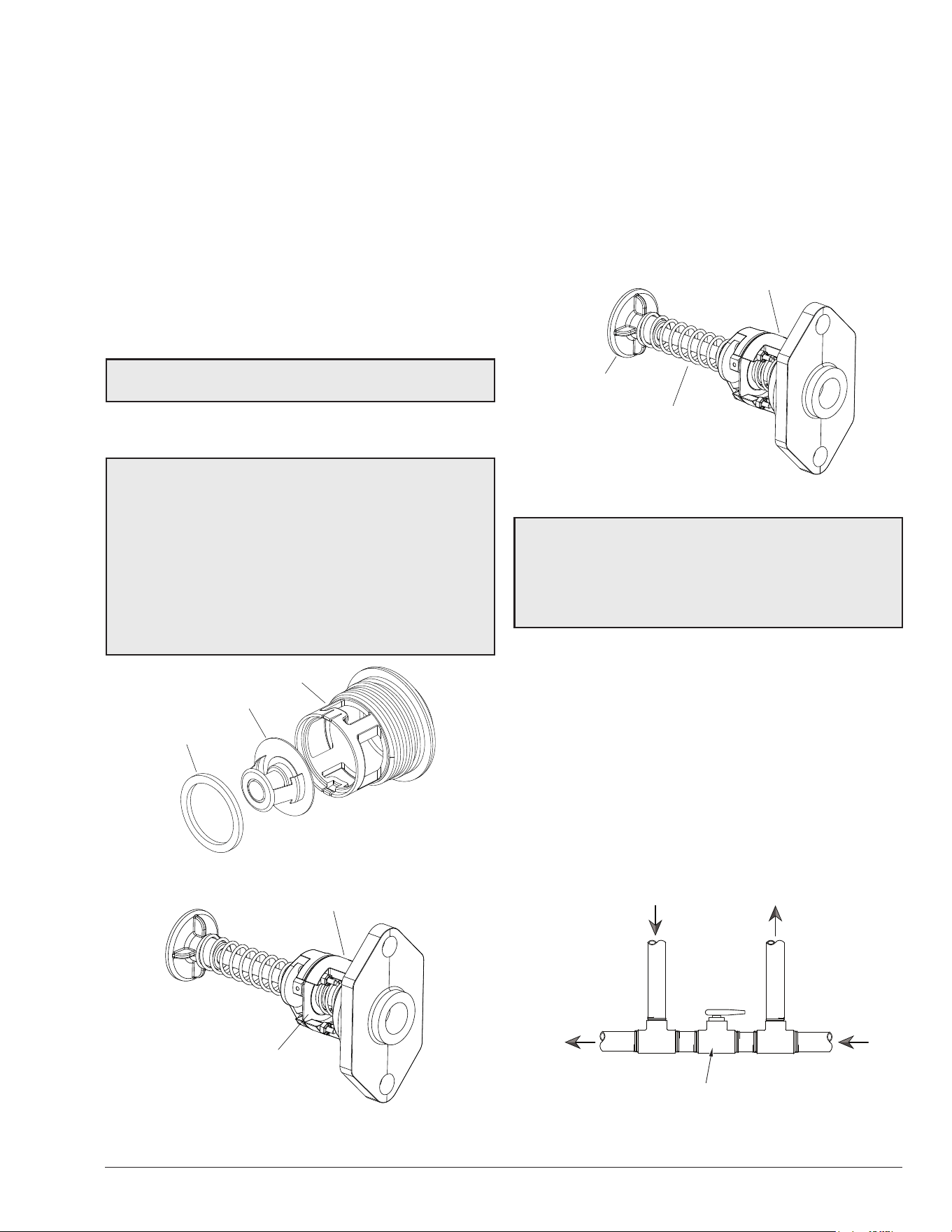
Unitherm Governor Operation
A
CAUTION: The patented Unitherm Governor is
a thermostatic mixing valve specically designed to
maintain constant heater internal temperature between
105°F (41°C) and 115°F (46°C) despite continually
changing ow rates from the lter and changing pool
temperatures. This narrow range is needed to prevent
damaging condensation on the burners which will
occur if the heater runs for any length of time below
100°F (38°C). It is also needed to inhibit scale formation
in the tubes by maintaining temperatures well below
accelerated scaling temperatures.
F10725
GASKET
UG PLUG
UNITHERM GOVERNOR
Figure 25. Unitherm Governor - Polymer
F10642-2
UG/BYPASS ASSY
UNITHERM
GOVERNOR
Figure 26. Unitherm Governor - Bronze
Internal Automatic Bypass Valve
In addition to the Unitherm Governor, a built-in automatic
bypass valve is provided in the In/Out header. While the
Unitherm Governor responds to the changes in water
temperature in the heater, the internal bypass valve
automatically responds to changes in water pressure in the
piping system. Proper amount of water ow is maintained
through the heater under varying pressures dictated by the
conditions of the pump and lter.
F10642-3
UG/BYPASS ASSY
BYPASS DISC
SPRING
"YELLOW" - 206/266
"GREEN" - 336/406
Figure 27. Internal Automatic Bypass Valve - Bronze
NOTE: The Unitherm Governor and Bypass Valve Assy
are not individually-replaced components on ASME
units. If either needs to be replaced, the entire UG/
Bypass assy must be replaced. The "yellow" spring is
used on models 206A, 266A. The "green" spring is used
on models 336A, 406A.
External Auxiliary Bypass Valve
Where Required - An auxiliary bypass valve should be
used when ow rates exceed 100 GPM (378 lpm). Usually
a high-performance pump size larger than two horsepower
will exceed this ow rate. This valve is required to
complement the function of the automatic bypass valve,
particularly when starting the heater in winter or early
spring when the spa or pool temperature is below 50°F
(10°C). It also serves to eliminate needless pressure drop
through the heater and accompanying reduction in the ow
rate to the spa jets, etc.
FROM HEATER
TO HEATER
TO POOL/SPA
FROM POOL/SPA
FULL PORT
BALL VALVE
OR GLOBE
VALVE
BYPASS VALVE
*Do not use a gate valve.
Figure 28. Auxiliary Bypass Valve
20
Auxiliary Bypass Valve Adjustment
To set bypass, with clean lter, adjustment is made by
feeling the inlet and outlet pipes at the heater. Outlet pipes
should be slightly warmer than inlet and comfortable to the
touch. If pipe is hot, close bypass; if cold, open bypass.
Pressure Relief Valve Installation
To conform to local building codes, it may be necessary to
install a pressure relief valve. A 3/4" pressure relief valve,
having a capacity equal to or greater than to the BTU
output of the model to be installed, is recommended for
this heater.
A 3/4" NPT connection is provided in the Polymer header
for installation of a pressure relief valve. The valve shall be
installed in a vertical position. Do not over-tighten. Install
pressure relief valve hand-tight plus 1/2 turn.
F10662
IN/OUT HEADER
PRV DISCHARGE
CONNECTION
PRESSURE RELIEF VALVE
Figure 29. Field-Supplied Pressure Relief Valve,
Residential Units
A 3/4" NPT connection is provided in the header for
installation of a 75 PSI (517 kPa) pressure relief valve.
The PRV is shipped loose in the accessory carton with the
pagoda top. The pressure relief valve shall be installed in
a vertical position.
F10663
PRESSURE RELIEF VALVE
Figure 30. Pressure Relief Valve, Commercial Units
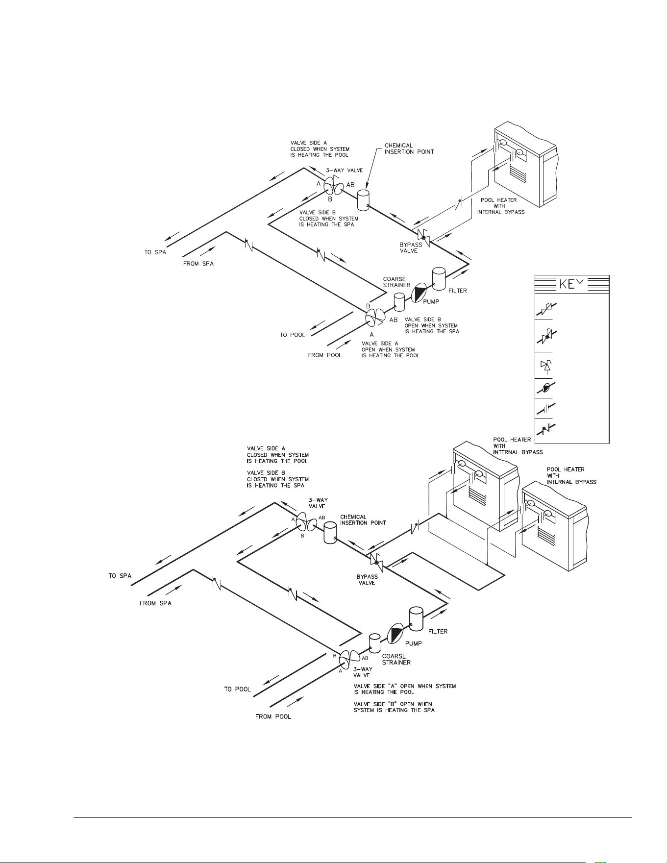
The heater requires water ow and positive pressure to
re and operate properly. It must therefore be installed
downstream of the discharge side of the lter pump.
See Figure 32 and Figure 33. A typical installation is
plumbed as follows:
1. The inlet side of the filter is plumbed directly to the
discharge side of the filter pump;
2. The outlet side of the filter is then plumbed to the inlet
of the heater; and
3. The outlet of the heater is plumbed to the return line
to the pool or spa. The pump, filter and heater are
thus plumbed in series (Salt generators and chemical
feeders must be downstream of the pool heater).
Plumbing from the heater back to the pool or spa must not
have any valves or restriction that could prevent ow when
the pump is operating.
A
CAUTION: An additional source of heated water,
e.g. a solar system, must be connected to the main line
ahead of the heater inlet pipe in order for it to act as
the primary heat source. If the primary system provides
adequate heat to maintain setpoint, the heater will not
re. Be advised that the control panel will then display
sensed water temperatures downstream of the primary
heating system, rather than the temperature of the water
exiting the pool.
Heater must be located so that any water leaks will not
damage the structure of adjacent area. PVC pipe may be
glued directly into the headers unions.
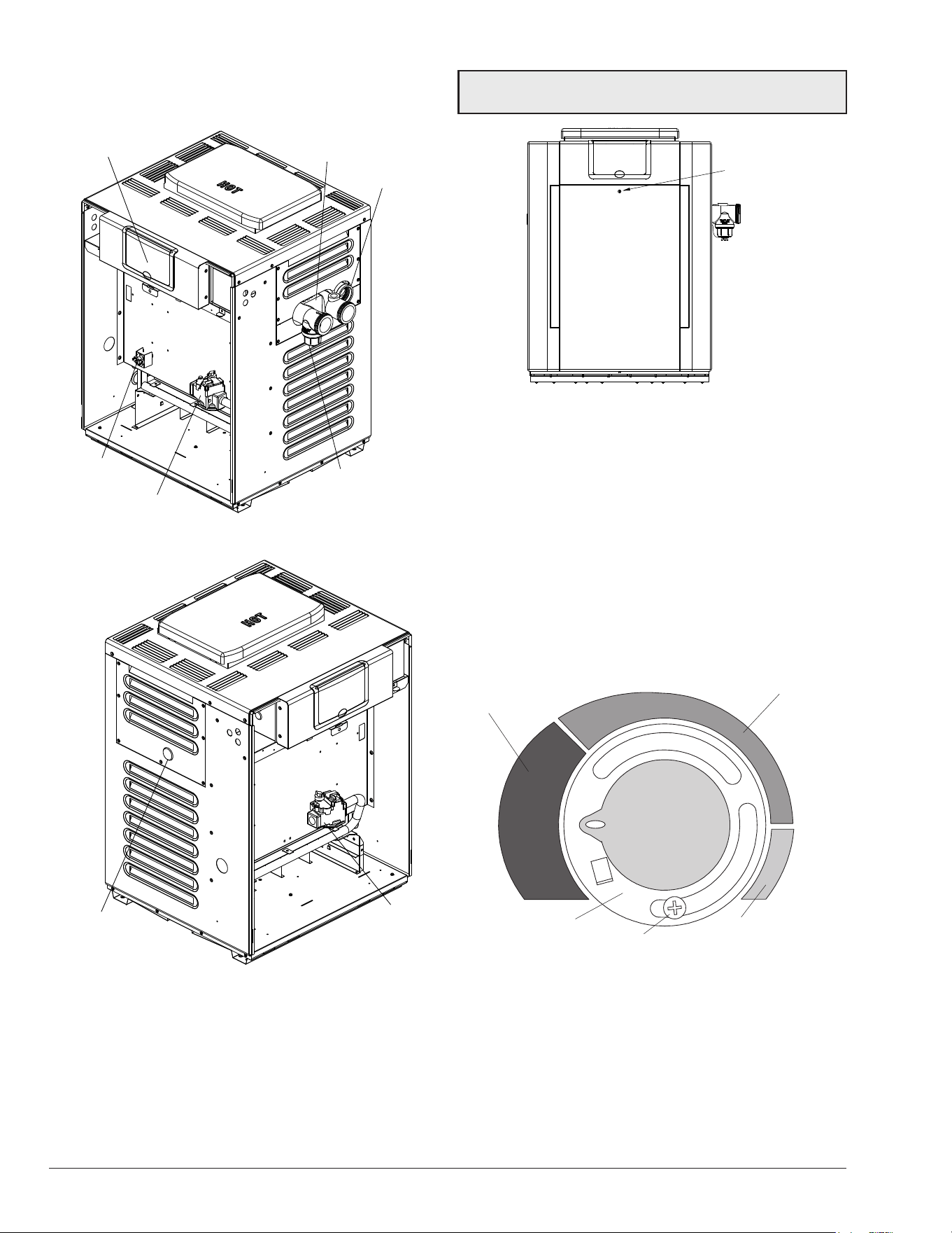
Heat Exchanger Reversal
Procedure for Residential Models
1. Remove right and left-side access panels. See
Figure 31.
F10652
Figure 31. Access Panels
NOTE: To avoid water damage or scalding due to valve
operation, drain pipe must be connected to valve outlet
and run to a safe place of discharge. Drain pipe must
be the same size as the valve discharge connection
throughout its entire length and must pitch downward
from the valve. No shuto valve shall be installed
between the relief valve and the drain line. Valve lever
should be tripped at least once a year to ensure that
waterways are clear.
21
Plumbing Diagrams
Water Connection
THIS DIAGRAM IS A RECOMMENDATION AND IS NOT INTENDED
TO REPACE AN ENGINEERED PIPING SYSTEM BY A PROFESSIONAL ENGINEER
Figure 32. Single Heater Installation
THIS DIAGRAM IS A RECOMMENDATION AND IS NOT INTENDED
TO REPACE AN ENGINEERED PIPING SYSTEM BY A PROFESSIONAL ENGINEER
Figure 33. Multiple Heater Installation
ISOLATION
VALVE
PRESSURE
RELIEF VALVE
PUMP
UNION
CHECK VALVE
BALL VALVE
22
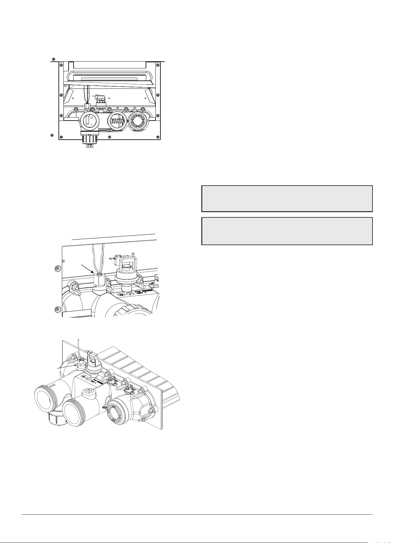
2. Disconnect wires at high limit, AGS (automatic gas
shutoff), water pressure switch on the in/out header
and ProTek Shield bonding wire. See Figure 34.
F10653
Figure 34. Component Wiring Locations - In/out Header
3. Digital Models: Remove the thermostat temperature
sensor by loosening the compression fitting nut. Re-
route the sensor to left-side of the heater. See Figure 35.
Millivolt Models: Remove the temperature sensor
bulb and retainer clip by loosening the compression
fitting nut. Re-route the sensor bulb to the left-side of
the heater. See Figure 36.
F10654
SENSOR
Figure 35. Digital Temperature Sensor Location
F10667
SENSOR
Figure 36. Millivolt Temperature Sensor Location
4. Remove (12) nuts holding the inlet/outlet and return
headers to the tube sheets. Clean off tube sheet area
where the gasket seats. Also clean off the header and
the gasket. Apply a non-petroleum-based lubricant to
the gasket such as Aqualube. Re-attach the headers
to the opposite sides, making sure they are installed
in an upright position. Do not over-tighten. Torque
should not exceed 7 ft/lb. See Figure 35.
5. Reconnect high limit, AGS, water pressure switch
wires, and ProTek Shield bonding wire.
6. Digital Models: Insert the temperature sensor into
the compression fitting, so that the sensor is flush with
the top of the fitting. Tighten 1/2 turn past hand-tight.
Millivolt Models: Insert sensor bulb and retainer clip
into sensor well.
7. Allow for water flow through the heater and check for
leaks.
8. Re-attach access panels to the opposite sides.
For instructions on reversing the heat exchanger
connections on ASME models, call your factory
representative.
5. ELECTRICAL WIRING
NOTE: If it is necessary to replace any of the original
wiring, use 105°C wire or its equivalent, and/or 150°C
wire or its equivalent, like the original wiring.
A
WARNING: Digital heaters are factory-wired for
240 VAC, 1 Ph, 60 Hz power supply. DO NOT attempt to
operate at 208 VAC.
Millivolt Models ("M" sux)
The Millivolt models are equipped with a self-generating
electrical system in which the electrical current is provided
by a pilot generator. No external electrical connections are
required.
When installing a remote switch, do not exceed 10 ft (3 m)
of wiring from the heater. Use 18-gauge stranded wire.
Digital Models ("E" sux)
The standard eld-wiring connection is on the right-side
of the heater.
To wire the heater from the left-side, follow these steps:
1. Remove the two (2) screws that hold the front door
to the heater. Remove and set aside door for better
access to wiring.
2. Remove the four (4) screws that hold down the
junction box to the sway brace.
3. Remove the transformer cover located on the far
right by removing one (1) screw.
4. Remove the two (2) screws that hold down the
transformer.
5. Remove the one (1) screw that holds down the
ground wires.
6. Disconnect P6 connector from PC board.
7. Remove transformer from its current location and
relocate it on the far left-side of the heater.
23
8. Re-route all high-voltage wires and ground wires
through the left jacket side of heater.
9. Re-install P6 connector, ground wires (SPG),
transformer, junction box, front door, and plug right-
side with the left-side’s grommet plug.
NOTE: 7/8" diameter holes not utilized on jacket and
control box can be used for reman switch, auxiliary
control interface or power vent (D-2) wiring.
Electrical Power Draw
A
CAUTION: Heater must be electrically grounded and
bonded. Bonding lug is provided loose with the heater.
Install bonding lug on lower right or left-side of jacket
as necessary for bonding the heater. Mounting hole is
provided on the jacket.
NOTE: Failure to ground the heater electrically could
aect the heater’s electronics.
NOTE: See "Time Clock/Fireman’s Switch" on page 31
for further instructions if using a time clock/reman’s
switch.
The Electronic Intermittent Ignition Device automatically
lights the pilot and main burners upon a call-for-heat. The
heater is supplied with a dual-voltage transformer for 120
VAC or 240 VAC input power hookup.
When operating on 120 VAC power, units draw 4 amps.
When operating on 240 VAC power, units draw 2 amps.
OPTION LOCATION
LEFT SIDE FIELD WIRING
CONTROL BOX
(FACTORY MOUNTED
LOCATION)
SWAY BRACE
BONDING LUG
(STANDARD
LOCATION)
BONDING LUG
(OPTIONAL
LOCATION)
F10650
Figure 37. Heater Wiring Locations
Transformer Wiring
120 VAC Wiring
For 120 VAC input power to the unit, connect the black
wire to the L1 or hot leg of the power supply. Connect the
white wire to the “Ret” or neutral leg of the power supply.
There should be no connection to the red wire for 120
VAC operation. Attach a wire nut to the red wire.
SUPPLY
SIDE
RETURN
or
NEUTRAL
HEATER
4 WIRES
GROUND
L1
RED
BLACK
HOT
BLACK
GREENGREEN
WHITEWHITE
Figure 38. 120 VAC Wire Connection
240 VAC Wiring
For 240 VAC input power to the unit, connect the black
wire to the “L1” or hot leg of the power supply. Connect the
red wire to the L2 or second hot leg of the power supply.
There should be no connection to the white wire for
240 VAC operation. Attach a wire nut to the white wire.
A
WARNING: DO NOT attempt to operate the heater
at 208 VAC.
HEATER
4 WIRES
L1
L2
RED RED
BLACK
HOT
HOT
BLACK
GREENGREEN
WHITE
SUPPLY
SIDE
Figure 39. 240 VAC Wire Connection
Heater must be electrically grounded and bonded in
accordance with local codes, or, in the absence of local
codes, with the latest edition of the National Electrical
Code, ANSI/NFPA 70. (Canada - Canadian Electrical
Code, CSA C22.1, Part 1 and Part 2.)
A
CAUTION: If the transformer’s primary side is wired
for 120 VAC and 240 VAC is applied, damage to the
transformer and PC board may result. Such damages
are not covered under manufacturer’s limited warranty.
NOTE: Input power to the heater (120 or 240 VAC) can
be supplied from the load (pump) side of time clock or
directly from the GFCI power source. It is preferred
that full-time power be supplied to the heater from
the GFCI power source, and that the heater be
controlled by the reman’s switch connection or
using a two or three-wire remote. If using a switched
GFCI power source, the heater could display false
service indicators on the display panel if the pump is
turned o.
24
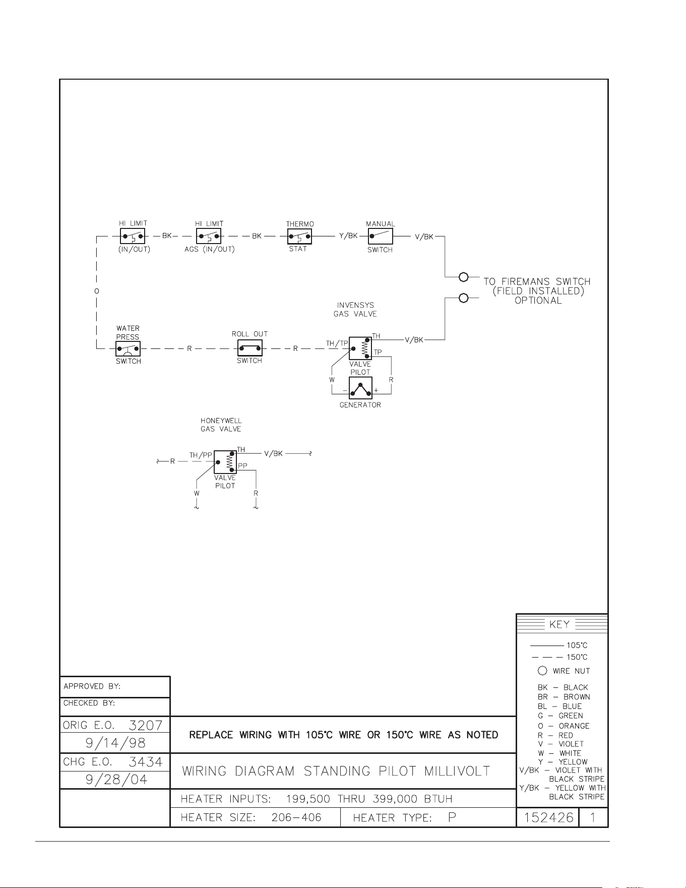
6. WIRING DIAGRAM - MILLIVOLT
25
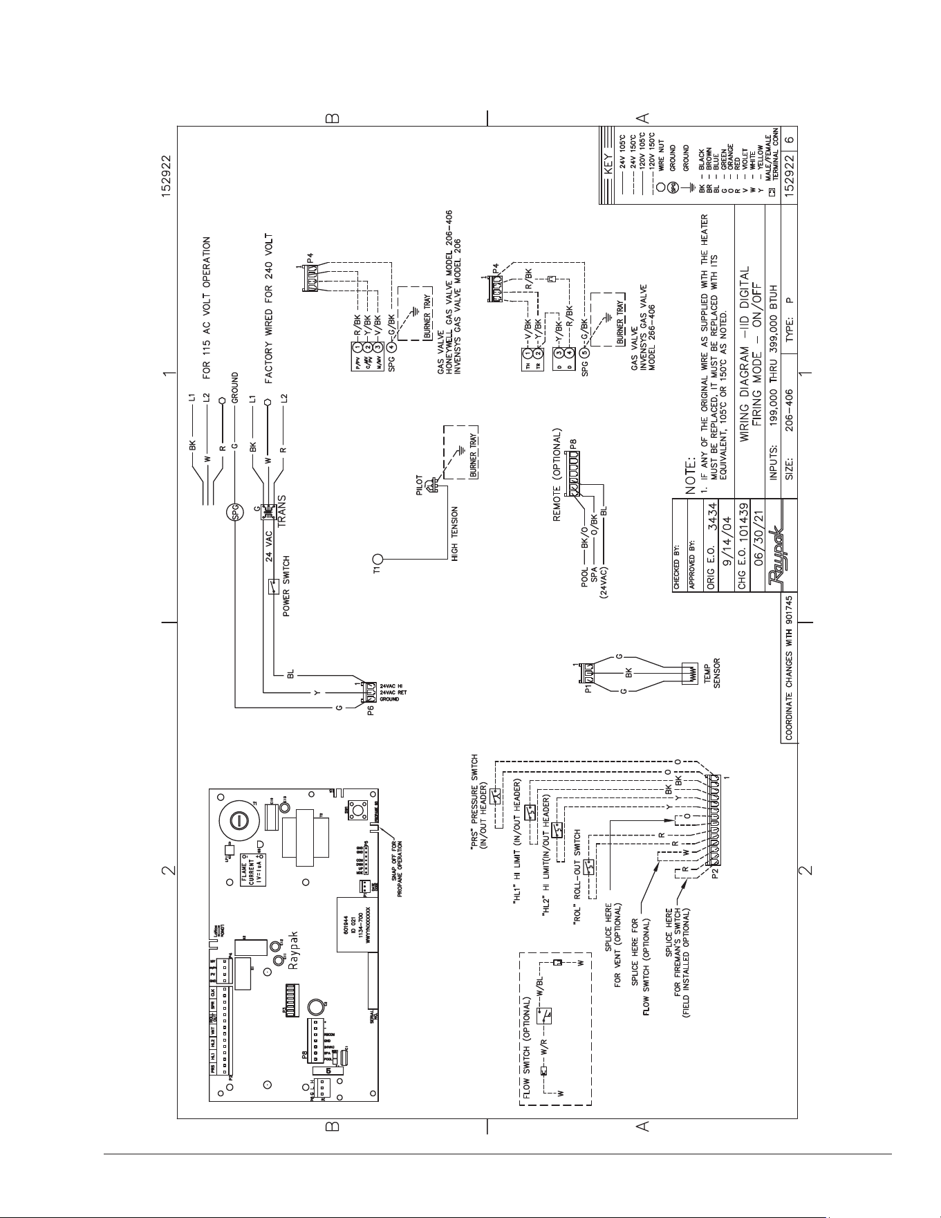
7. WIRING DIAGRAM - DIGITAL
APPROVED
UNCONTROLLED DOCUMENT IF PRINTED
26
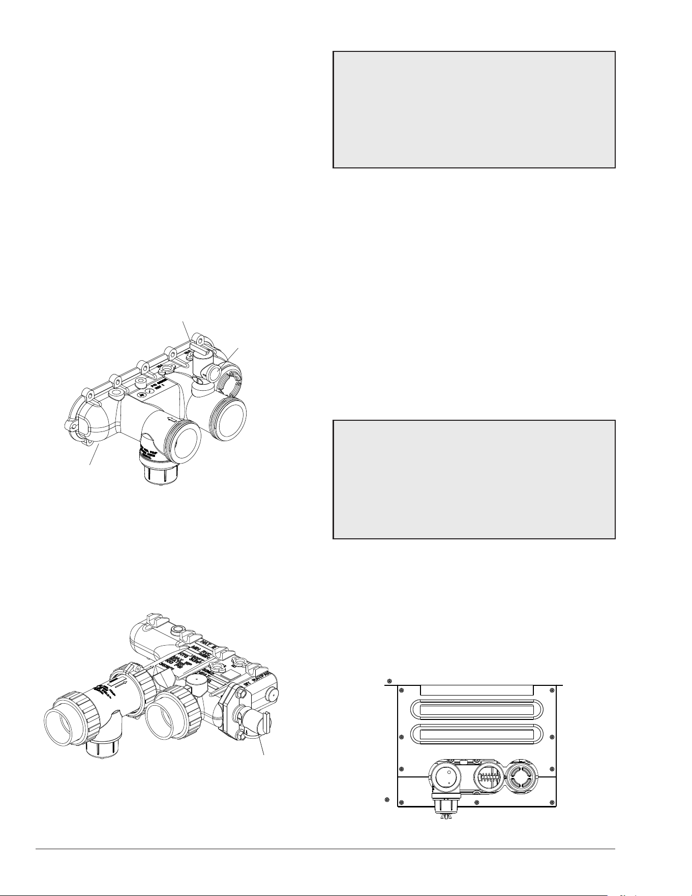
8. CONTROLS
F10640-2
TEMP SENSOR
HL1 - HIGH LIMIT
HL2 - HIGH LIMIT
UNITHERM
GOVERNOR
PROTEK
SHIELD
ASSY
ROLL-OUT
SWITCH
CONTROL
BEZEL
GAS
VALVE
PRESSURE SWITCH
Figure 40. Location of Controls (View One)
F10640-3
DRAIN
PLUG IN
REAR
HEADER
PILOT
Figure 41. Location of Controls (View Two)
Control Panel Removal
1. Remove screw from front door. Set aside door for
serviceability.
2. Remove (4) screws from sides of control panel.
3. Rotate control panel down until panel stops. Do not
force.
NOTE: Caution must be used to not damage controls
or wiring.
F10646-5
KNURLED
SCREW
Figure 42. Knurled Screw Location
Control Adjustments -
Millivolt Models
The water temperature is controlled by the heater thermostat
on the upper front panel of the heater. The control center
contains an On/O switch and one thermostat.
The thermostat is tted with a means of limiting the upper
temperature just below the maximum level. The knob stop
adjustment ring illustrated below is adjustable by loosening
the set screw, rotating the knob stop ring to the desired
location and re-tightening the set screw.
SPA TEMPERATURE
RANGE
POOL TEMPERATURE
RANGE
KNOB STOP RING
STAND-BY
TEMPERATURE
SET SCREW
KNOB STOP SHOWN ABOVE IS IN THE SPA TEMPERATURE RANGE.
Figure 43. Control Adjustment – Millivolt Models

27
Control Adjustments – Digital Models
The pool heater touch-pad located on the upper front
panel of the heater, allows the user to select either POOL
or SPA operation, and to adjust the setpoint temperature.
The LCD display window indicates the mode (OFF, SPA,
POOL) and the actual water temperature. A manual power
switch provided below the touch-pad turns the control
power ON or OFF. See Figure 44.
TEMP
MODE
ON OFF
LCD DISPLAY
TEMP ADJUST BUTTONS
MODE BUTTON
Figure 44. Control Adjustment – Digital Models
Mode Button
The MODE button is used to select POOL or SPA operation.
It also allows the user to turn the heater o electronically,
allowing the LCD to remain energized and to continue
showing the actual water temperature.
Temp Buttons
If the heater is in POOL or SPA mode, the desired water
temperature (SETPOINT) will be displayed and may be
adjusted using the UP or DOWN buttons.
Operation
In the POOL or SPA modes, the actual water temperature
is displayed along with the desired water temperature
(SETPOINT). When the water temperature is above the
setpoint, “Water Temp” will alternate with “No Demand.”
When the water temperature is below the setpoint and the
heater is ring, “Water Temp” will alternate with “Heating.”
To adjust the setpoint temperature, make sure the control
is in the appropriate mode (POOL or SPA) and push the
UP or DOWN buttons.
By default, the setpoint range is 50-104°F (10-40°C). See
MAX Settings on page 28 to increase the MAX setting,
if necessary.
Figure 45. Alternating Display During Heating
Program Mode Button (SW1)
Figure 46. Thermostat Program Button (SW1)
Service Menu and Fault History
To access the Service Menu and fault history, press the
Mode and UP buttons simultaneously for 3 to 5 seconds.
The heater will continue to operate while in the Service
Menu. The rst screen displayed is the Flame Strength
indicator, which indicates the pilot ame current using a bar
graph and numerical display. A signal of less than 4 bars
indicates a weak ame signal and may require service.
Refer to the Troubleshooting section for possible causes
and corrections.
Figure 47. Flame Strength Indicator
Press the DOWN button. The Supply Voltage screen
indicates the voltage supplied to the control board. Normal
readings range from 24 to 29 volts.
Figure 48. Supply Voltage Indicator
Press the DOWN button. The Run Time indicates the total
hours of operation for the pool heater, as measured by the
amount of time that the main gas valve has been powered.
The Cycle count indicates the number of on/o cycles of
the heater, as measured by the number of times the pilot
valve has been powered.
Figure 49. Run Time/Cycles
28
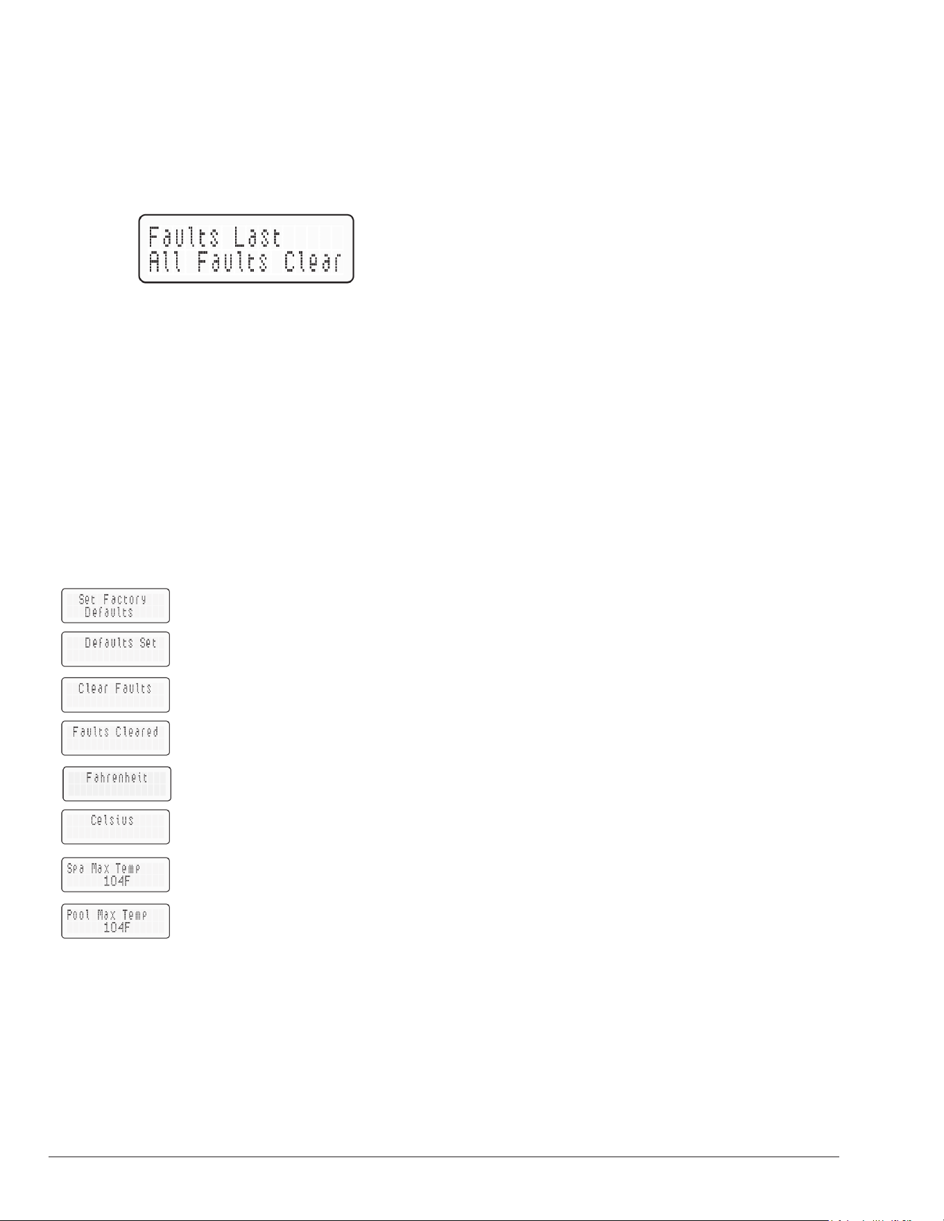
Press the DOWN button. The Fault History displays up to
ten faults in memory. The order of the faults begins with
“Fault Last,” which is the most recent fault, and proceeds
through ten most recent messages in chronological order.
The second line of the display shows the fault message.
If there are no faults in the history buer, the second line
reads “All Faults Clear.”
Figure 50. Fault History Indicator
Program Button
1. Remove the four screws holding the control cover,
and swing the panel down so the back side of the
board is visible. Locate the Program Mode button
(SW1). See Figure 46. Press and hold the button
for 5-7 seconds until SET FACTORY DEFAULTS
appears on the display. Release the program button.
2. Press the MODE button sequentially until the desired
program event is reached. There are 5 different
events that can be programmed. They appear in the
sequence listed in Figure 51.
Resets board to factory default
settings.
Resets faults in the History File.
Change from Fahrenheit to
Celsius.
SPA setpoint maximum
adjustment.
POOL setpoint maximum
adjustment.
Figure 51. Programmable Events
Set Factory Defaults
Refer to step one above to access the program screen.
SET FACTORY DEFAULT should appear on the screen.
If it does not, press the MODE button until it appears on
the digital display. Press and hold both UP and DOWN
buttons for 5-7 seconds until DEFAULT SET appears.
This operation resets the operating program to its factory
default values.
Both the POOL and SPA setpoints will revert to 65°F (18°C)
and both POOL and SPA maximum temperature settings
will be 104°F (40°C). The CONTROL LOCKOUT PIN will
be cleared and the control will resume normal operation.
Clear Faults
Refer to step one above to access the program screen.
Press the MODE button until CLEAR FAULTS appears
on the digital display. Press and hold both UP and DOWN
buttons for 5-7 seconds until FAULTS CLEARED appears.
This operation resets the Fault History le to “0” and clears
all the stored faults.
Fahrenheit or Celsius
Refer to step one above to access the program screen.
Press the MODE button until FAHRENHEIT or CELSIUS
appears on the digital display. The UP or DOWN buttons
will select FAHRENHEIT or CELSIUS on the temperature
display. Choose the desired temperature scale.
Spa Max Temp – Spa Setpoint Maximum Adjustment
Refer to step one above to access the program screen.
Press the MODE button until SPA MAX TEMP appears on
the digital display. Using the UP and DOWN buttons will
change the Maximum Temperature Setting to your desired
value. The control can be set for a maximum of 107°F
(42°C).
Pool Max Temp – Pool Setpoint Maximum
Adjustment
Refer to step one above access into the program screen.
Press the MODE button until POOL MAX TEMP appears
on the digital display. Using the UP and DOWN buttons
will change the Maximum Temperature Setting to your
desired value. The control can be set for a maximum of
107°F (42°C).
Control Lockout
The heater is equipped with a Control Lockout feature
to prevent unauthorized tampering or adjustment of the
control settings. To lock out the controls, press the DOWN
button and MODE button for 5 seconds. Choose a three
digit PIN, using the UP and DOWN buttons to select the
digits and the MODE button to lock in selections. Conrm
your selection and record your PIN.
To unlock the controls, press any button to bring up the
ENTER PIN menu. Enter the PIN that was used to lock the
control. Note that power cycling will not clear the lockout.
Successfully unlocking the control will display “LOCKOUT
CLEARED.” Failure to enter the correct PIN will display
“INVALID PIN.”
In the event that the user-selected PIN is lost or does not
clear the Control Lockout, use the Program Button to SET
FACTORY DEFAULTS. This will clear the PIN and allow
normal operation and selection of a new PIN if desired.
29
NOTE: Both the POOL and SPA setpoints will revert
back to 65°F (18°C) and the POOL and SPA maximum
temperature settings will be 104°F (40°C). These
setpoints will need to be readjusted to desired settings.
NOTE: The LCD temperature display may not agree with
the temperature reading of your pool or spa thermometer.
The heater reads the water temperature at the inlet. Due
to the circulation characteristics of any pool or spa, the
water temperature at the inlet to the heater may dier
from that observed at a given location in the pool or spa.
Status and Diagnostics
The digital models are programmed to display a variety
of status and diagnostic messages, depending on the
operating conditions.
The following heat status messages are displayed in Pool,
Spa, and Remote modes when there are no active fault
conditions.
Display Condition
Heating Call-for-heat established, ame present.
Spark Spark operating.
No Demand Heat demand is satised.
Table N. Heater Status Messages - No Active Faults
The following conditions are displayed in Pool, Spa and
Remote modes.
Display Condition
Sensor Failure
Thermistor temperatures disagree by
more than 2°F (1°C).
Sensor Open
Thermistor sensor failed open. Below
-20°F (-29°C).
Sensor Short
Thermistor sensor failed short. Above
217°F (103°C).
Flame w/o CFH
Board is sensing ame when
both main and pilot valves are
commanded shut.
PV Output Fault
Pilot gas valve output is not in
commanded state.
MV Output Fault
Main gas valve output is not in
commanded state.
LoNox Tab Fault
Voltage is sensed at the Lo NOx
terminal on a non -Lo- NOx heater
(Lo NOx tab is intact).
Internal Fault Board fault, replace board.
EEPROM Fault
Memory fault, reset setpoints, replace
board if fault does not clear.
Clock/Fireman Sw
Time clock/reman switch circuit is
open.
Low Temp
Lockout
Water temperature below 36°F (2°C).
Table O. Heater Status Messages - Active Faults
The following conditions are displayed only while there is a
demand for heat present.
Display Condition
Water Sw Open Water pressure switch open.
Vent/Field
Sw #1
Vent spill switch/eld switch #1 open.
Hi Limit 1 is open
High limit 1 open. For ASME units
ONLY, this is a manual-reset fault.
Press the MODE button to reset.
Hi Limit 2 is open
High limit 2 open. For ASME units
ONLY, this is a manual-reset fault.
Press the MODE button to reset.
Rollout Sw Open Rollout switch open.
Flow/Field SW #2
Field-supplied ow switch/eld switch
#2 open.
Ignition Lockout
(Propane Tab
Broken)
Alternating with “No pilot sensed”
- Pilot ame not established within the
required time (15 sec or 90 sec).
Alternating with “Main Ign Failure”
- Pilot ame lost during the 8 second
trial to ignite the main burner.
Ignition Failure
(Propane Tab Not
Broken)
Alternating with “No pilot sensed”
- Pilot ame not established within 90
seconds.
Ign 60 min Delay
(Propane Tab Not
Broken)
Alternating with “Main Ign Failure”
- Pilot ame lost 4 times within the 8
second trial to ignite the main burner.
Heater will lockout for 60 minutes
before retrying.
Table P. Heater Status Messages - Demand for Heat
High Limit Events
ASME units
ONLY.
Figure 52. High Limit Events
TO ELIMINATE HIGH LIMIT EVENTS
1. Confirm circulation pump is running during heating
cycle.
2. Pump should shutoff a minimum of 5-minutes after
heating cycle ends.
Failure to follow these steps may cause residual heat
buildup - triggering a High Limit event.
If issues persist, contact your service installer.
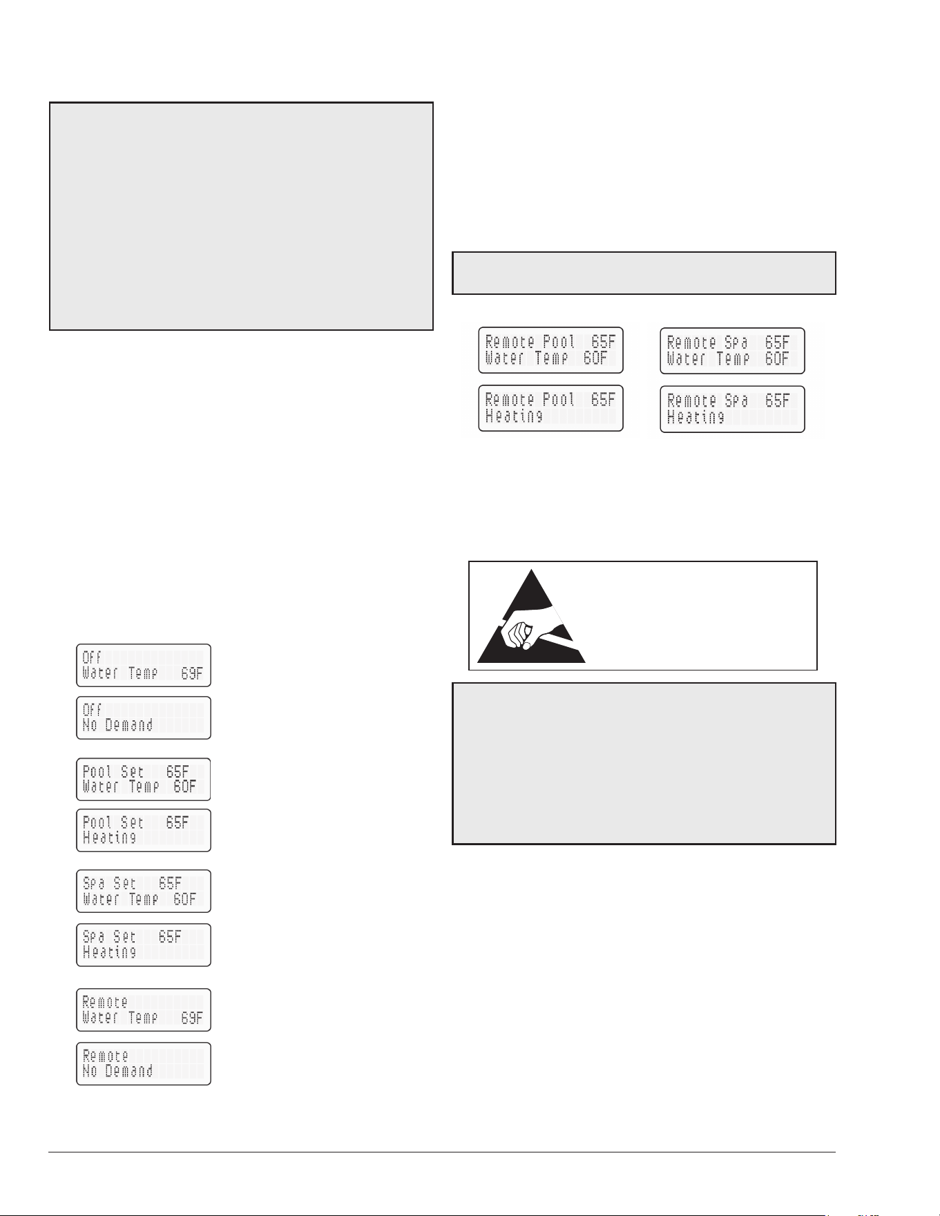
30
Remote Control Installation and Operation
A
CAUTION: Before installing remote controls to
the digital heaters, read the following: The digital
thermostat model is remote-ready in most cases. The
digital liquid crystal display (LCD) shows the actual pool
temperature, operating status, and service codes. See
Figure 53. The touch pad on the control panel allows
you to select the desired pool or spa temperature. It also
indicates when a remote system is controlling the heater
by displaying Remote in the display. When connecting
the heater to a remote system, identify whether it is a
two- or three-wire remote system. Select the appropriate
instruction listed below to properly install the remote to
the heater.
Remote Operation (Digital models only)
The heaters are equipped with the ability to work with
external remote controls. The supplied 7-pin remote wiring
connector supplies power out to either a toggle switch or
the switch contacts of a third-party remote. The remote
works by either making or breaking the circuit created
by the remote wiring. Typically, a remote does not supply
power to the heater, it only provides a switching function
to turn the heater On or O. If your remote is supplying
its own voltage to the heater, it will not work with this
heater and may damage the digital circuit board.
For operation of the heater using the onboard thermostatic
controls with a time clock. See "Time Clock/Fireman’s
Switch" on page 31.
OFF Mode
Heating in the POOL Mode
Heating in the SPA Mode
Remote Mode
Figure 53. Remote Control Menu - Remote Operation
Millivolt models are not designed for operation with remote
control system.
Activating the Remote
To activate or deactivate the remote function:
1. Press and hold the UP and DOWN arrow buttons for
3 to 5 seconds.
The second line of the display will alternate even when the
unit is o (“No Demand”).
NOTE: When in remote operation, the keypad mode and
temp buttons are disabled.
Figure 54. Remote Control Menu - Activation
Remote Control Wiring -
Digital Models Only
ATTENTION
OBSERVE PRECAUTIONS
ELECTROSTATIC
SENSITIVE DEVICES
A
CAUTION: Electrostatic Discharge (ESD) damage
can be caused by direct or indirect contact with the
wiring or circuit board. When one walks to the heater
area, an electrostatic charge accumulates on the body.
Contact of a nger allows the body to discharge, possibly
causing device damage. This damage can be limited if
the service person discharges himself, following ESD
preventive/removal practices, and holds on to the heater
enclosure for 5 seconds before proceeding.
Important Installation Notes for Remote or External
Wiring Conguration:
• Remote wiring must be run in a separate conduit.
• Remote wiring must not be run parallel to high voltage
lines.
• For runs of under 30' (9 m), remote wiring should
have stranded conductors with a minimum of 22
AWG, 600V, cable twisting 1.5" to 2.5" (3.8 to 6.4 cm)
lay and jacketed.
• For runs over 30' (9 m), the conductors should be a
minimum of 20 AWG, 600V, cable twisting 1.5" to 2.5"
(3.8 to 6.4 cm) lay that is shielded and jacketed.
• Maximum cable length is 200' (61 m).
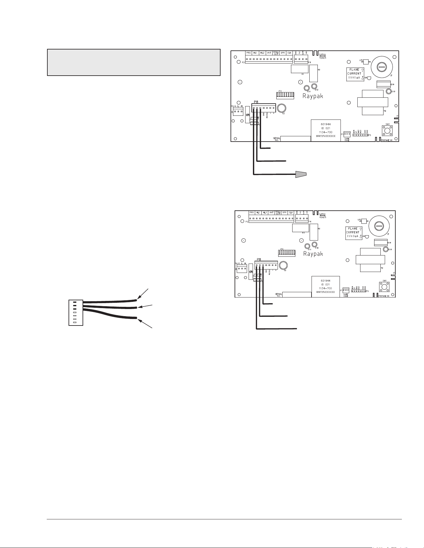
31
• For both two- and three-wire remote systems, the
provided 7-pin wiring connector must be utilized.
NOTE: The remote wires must be connected to the
7-pin connector before the connector is plugged into the
board.
2-Wire Remote Control (On-O)
This application assumes that only one heating function
(pool or spa) is required.
1. Turn on power to the heater.
2. For a 2-Wire Remote Control from a remote without
its own sensor, push the MODE button to the “POOL”
or “SPA” mode and set the desired setpoint (e.g. 102
°F (39°C) for Spa).
3. For a 2-Wire Remote Control from a remote with its
own sensor, push the MODE button “POOL” or “SPA”
mode and set the temperature to the highest setting
available on the control. The actual setpoint will be
controlled by the remote control.
4. Turn the MODE button to “OFF” and remove power
from the heater.
5. On the “Remote Interface Harness”, connect the
BLUE wire to one side of the “REMOTE” switch and
connect the other side to either the ORANGE/BLACK
wire for “SPA” operation or the BLACK/ORANGE
wire for “POOL” operation. See Figure 55.
Pool Common
(BLK/ORN)
Spa Common
(ORN/BLK)
24VAC HOT
(BLU)
Figure 55. 7-Pin Remote Interface Harness
6. Attach wire nut on unused wire to the “Remote
Interface Harness.”
7. Install the “7-Pin Remote Interface Harness” to the
P8 connector and turn power “ON” to the heater.
See Figure 56.
For activation of the remote control, see section on page
30.
3-Wire Remote Control Using Three-
Position Switch (Pool-O-Spa, or Low-O-
High)
This application assumes that both heating functions (pool
and spa) are required.
1. Turn on power to the heater.
2. Push the MODE button to the “POOL” or “SPA” mode
and set the desired temperature for each (e.g. 80°F
(27°C) for Pool and 102°F (39°C) for Spa).
3. Turn the MODE button to “OFF” and remove power
from the heater.
Wire Nut -
BLK/ORN - To Pool (COMM)
ORN/BLK - To Spa (COMM)
BLU - 24VAC
Figure 56. 2-Wire Remote Harness Installation on the P8
Connector of the Board
BLK/ORN - To Pool (COMM)
ORN/BLK - To Spa (COMM)
BLU - 24VAC
Figure 57. 3-Wire Remote Harness Installation on the P8
Connector of the Board
4. On the “Remote Interface Harness” connect the BLUE
wire to one side of the “REMOTE” switch and connect
the ORANGE/BLACK wire for “SPA” operation and
the BLACK/ORANGE wire for the “POOL” operation.
See Figure 55.
5. Install the “Remote Interface Harness” to the
P8 connector and turn power ON to the heater.
See Figure 57.
For activation of the remote control, see section on page
30.
Time Clock/Fireman’s Switch
To operate the heater with a time clock, connect the timer
to the reman’s switch connection in the heater’s wiring.
The time clock should be of the dual switch type and set to
shut o the call-for-heat to the pool heater (chaue-piscine)
15 to 20 minutes prior to shutting down the pool pump.
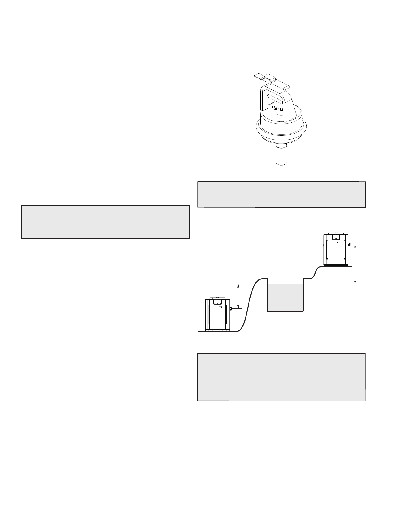
32
For millivolt heaters, the reman's switch connection is
a wire nut located in the Violet/Black wiring between the
manual toggle switch and the gas valve. heaters, splice
into the red/white wire to connect the time clock.
For digital heaters, the reman’s switch connection is
located on the 14-pin header connected to the digital
control board. Splice into the red wire jumper tagged –
Where necessary add “Fireman’s” switch circuit here – to
connect the time clock.
The reman’s switch connection on both millivolt and
digital heaters must be a dry contact and must not
supply power to the heater. Powering the reman’s
switch connection externally may damage the heater,
and is not covered by warranty.
Millivolt heaters: Do not exceed 15 ft (4.5 m) of total wiring
using 14 AWG stranded copper wire rated for 105°C
minimum.
Digital heaters: Do not exceed 50 ft (15 m) of total wiring
using 18 AWG stranded copper wire rated for 105°C
minimum.
NOTE: When using a time clock, the digital heater will
display “Clock/Fireman Sw” when the reman’s switch
is open, indicating that the time clock has shut o the
call-for-heat.
Water Pressure Switch
The water ow switch ensures that the heater operates
only when the lter pump is in operation. It is located on the
In/Out header. It is factory-set at 1.75 PSI for deck-level
installations.
Water Pressure Switch Adjustment
When the heater is located below the level of the spa or
pool, it may be necessary to adjust the pressure switch to
compensate for the no-ow static head. If it is necessary
to adjust the water pressure switch, utilize the following
procedure:
1. Make sure the pool filter is clean before adjusting the
switch.
2. Set the heater control to the OFF mode.
3. Turn the filter pump ON and confirm that the pressure
switch is closed (use a multimeter to check). If the
pressure switch fails to close, either the switch setting
is too high or not enough pressure is being supplied
by the filter pump.
4. Turn the heater ON.
5. Manually turn the pressure adjustment knob clockwise
until the heater shuts off. (A flat screwdriver may be
necessary if knob is too tight.)
6. Slowly turn the adjustment knob counter-clockwise
until the heater calls for heat again.
7. Turn an additional 1/2 turn counter-clockwise.
8. While the heater is running, check the adjustment
by turning the pump off and on several times. The
burners should shut off immediately when the pump
is turned off. If it does not, repeat the above steps
until proper operation is observed.
F10671
Figure 58. Water Pressure Switch Assembly
NOTE:
The sheet metal access panel should be in place
at all times to protect the water pressure switch from
rain and other environmental factors.
MAY REQUIRE ADJUSTMENT
FOR HIGHER PRESSURE
MAY REQUIRE ADJUSTMENT
FOR LOWER PRESSURE
5 ft. (1.52 m) MAX
POOL OR SPA
5 ft. (1.52 m) MAX
Figure 59. Pressure Switch Adjustment Requirements
NOTE:
If heater is installed outside of the limits shown,
a switch rated for a higher pressure (11 psi / 76 kPa) may
be used. A ow switch, mounted and wired adjacent to
the heater, may be used in place of the factory-mounted
pressure switch. See "ILLUSTRATED PARTS LIST" on
page 47 for 11 psi / 76 kPa water pressure switch.
Two-Speed Pumps
In some cases, the ow on the low-speed is insucient
to operate the heater. This is apparent when the water
pressure switch cannot be further adjusted or if the heater
makes banging noises or shuts o on high limit. In these
cases, the pump must be run at high speed when heating
the water.
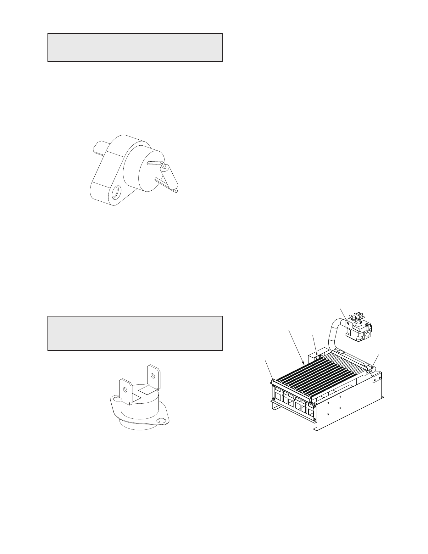
33
A
CAUTION: Do not operate the heater without the
function of a properly-adjusted water pressure switch or
ow switch.
Flame Roll-Out Safety Switch
Heaters are equipped with a thermal cuto device to
prevent ame roll-out in the event the heat exchanger
becomes blocked. This is a “single-use” type fusible link
or thermal fuse, that must be replaced when disabled
by an over-temperature condition, caused by excessive
restriction in the heat exchanger ue passage.
F10668
Figure 60. Flame Roll-Out Safety Switch
High Limits
The heater is equipped with two high limits.
On residential units (polymer headers), both are automatic
and are located in the inlet/outlet header. Both are set at
135°F (57°C).
On commercial units (bronze headers), both are located
on the inlet/outlet header. HL1 is automatic reset and set
to open at 160°F (71°C). HL2 is automatic reset and set to
open at 135°F (57°C).
NOTE: An erratic high limit is often characteristic of
an internal heat exchanger problem, e.g. scale build-up,
defective bypass. Refer to "TROUBLESHOOTING" on
page 40.
F10669-2
AUTO RESET
Figure 61. High Limit Switches
High Limit Removal
1. Shut off main electrical power switch to heater.
2. Remove inlet/outlet sheet metal access panel.
3. Remove defective high limit and replace with the
correct new high limit.
4. Replace access panel.
Pilot Safety - Millivolt Models
Heaters equipped with the standing pilot (millivolt system)
employs a pilot which act as a safety device to shut down
the ow of gas to the main burners and the pilot burner in
case the pilot ame is extinguished. The pilot burner must
be manually re-lighted to place the heater in operation
again. Refer to the lighting instructions provided on the
heater label.
Pilot Safety - Digital Models
The heater employs a pilot safety which closes the main
gas valve within 8/10ths of a second whenever the pilot
ame is interrupted. The pilot ame is automatically lit
when the device is powered. The heater performs its own
safety check and opens the main valve only after the pilot
is proven to be lit.
Burner Tray Removal
1. Shut off main electrical power switch to heater.
2. Shut off gas upstream of heater.
3. Remove front door.
4. Disconnect gas line from gas valve.
5. Remove (2) screws that mount burner tray to unit,
and (2) screws that secure gas valve to jacket.
6. Disconnect wires that terminate at gas valve.
7. Disconnect hi-tension wire from PC board.
8. Carefully slide out burner tray assembly.
9. Reverse above procedure to reinstall.
GAS
ORIFICE
GAS VALVE
PILOT
BURNER
BURNER
HOLD-DOWN
BRACKET
Figure 62. Burner Tray Assembly
Gas Valve Removal
1. Shut off gas supply to the heater. Remove gas piping
to gas valve inlet.
2. Disconnect wires, pilot tubing and bleed line, if
required.
3. Remove burner tray from heater.
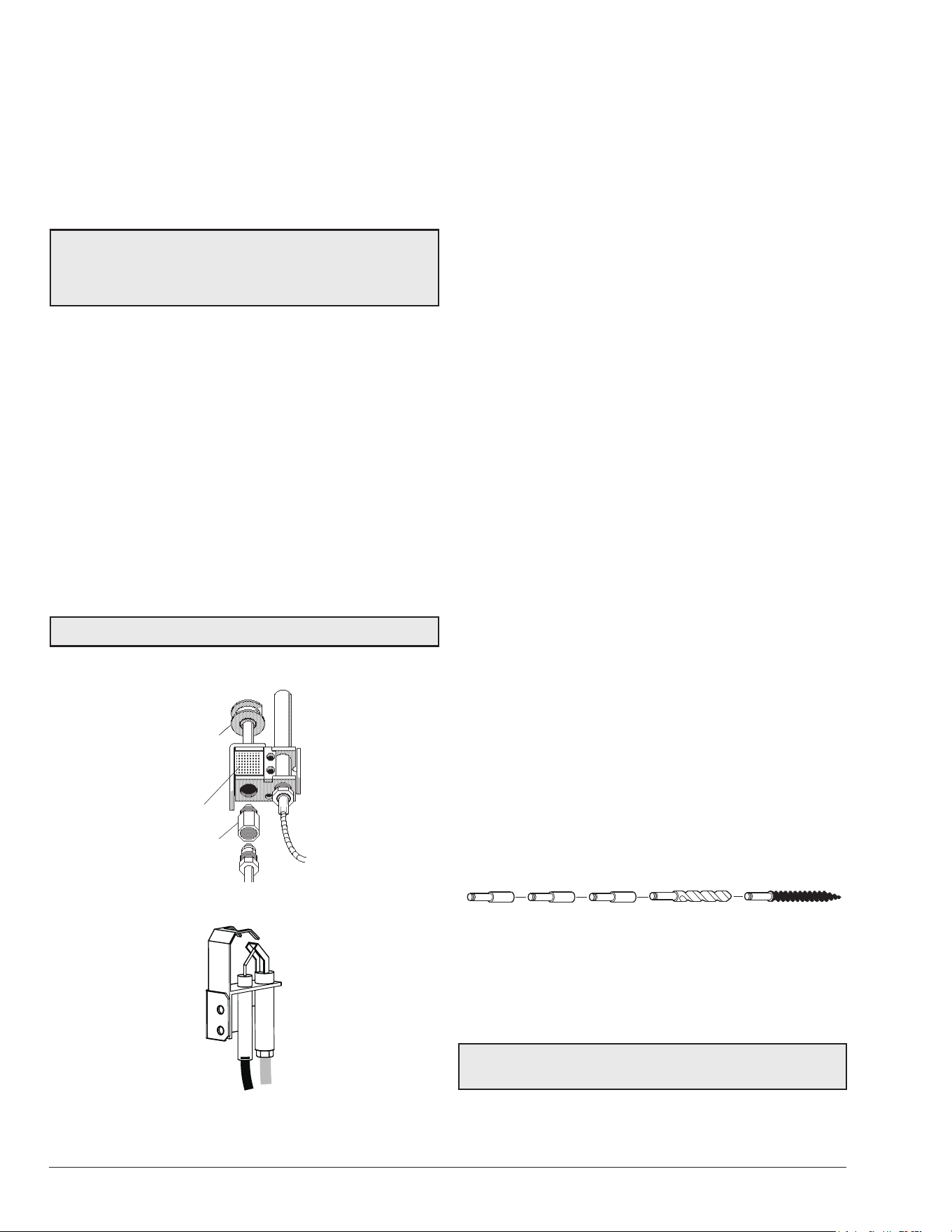
34
4. Turn vertical gas pipe from manifold slightly and
unscrew gas valve.
5. Reverse above procedure to reinstall.
Main Burner And Orice Removal
1. Remove burner tray, following above procedure.
2. Remove screws and burner hold-down bracket.
NOTE: If the heat exchanger is sooted badly, the burner
hold-down bracket and spacer can become distorted
from direct-ame impingement and this usually
necessitates replacement of these parts.
3. Lift burners from slotted spacers and slide from
orifices. Clean with a wire brush.
4. Orifices usually do not need to be replaced. To clean,
run either copper wire or wood toothpick through
orifice. Do not enlarge hole. To remove orifice, use a
socket wrench and remove from manifold. DO NOT
over-tighten when reinstalling.
Pilot Removal And Cleaning
1. Disconnect pilot tubing and wires from gas valve.
2. Remove pilot assembly from burner tray.
3. Remove pilot from bracket.
4. Remove pilot orice and air opening, and clean with
wire or small brush.
A
CAUTION! Do not enlarge hole in pilot orice.
5. Reverse above procedure to reinstall.
PILOT
ORIFICE
AIR
OPENING
Figure 63. Millivolt Pilot
Figure 64. Digital Pilot
Heat Exchanger Removal
1. Shut water, gas and electricity off, close valves and
relieve pressure, then remove relief valve. Remove
side access panels.
2. Remove top jacket holding screws.
3. Remove rear top panel.
4. Remove screws mounting the rain shield to the rear
panel. Also remove the screws that mount the rain
shield to the sway brace. Remove rain shield.
5. Remove the four (4) screws holding down the flue
collector. Remove the flue collector.
6. If ProTek Shield Assy is attached to the heater;
disconnect flange nuts on Inlet/Outlet header,
remove ProTek Shield Assy bonding wire from heat
exchanger stud, loosen union at gas pipe and slide
heater away from piping.
7. Lift heat exchanger straight up using caution not to
damage refractory.
8. Reverse above procedure to reinstall. Make sure the
insulation strips are properly replaced on top of the
refractory retainer.
Tube Cleaning Procedure
Establish a regular inspection schedule, the frequency
depending on the local water conditions and the severity
of service. Do not let the tubes clog up solidly. Clean out
deposits over 1/16" (1.6 mm) in thickness.
The heater may be cleaned from the return header
side, without breaking pipe connections. It is preferable,
however, to remove both headers for better visibility
through the tubes and to be sure the ground-up lime dust
does not get into the system. Note that you do not remove
the top panel or the heater exchanger, generally.
After reaming, mount the wire brush in place of the auger
and clean out debris remaining in the tubes.
Another method is to remove the heat exchanger, ream
tubes and immerse heat exchanger in non-inhibited de-
scale solvent for severe scale build-up.
Extension
Pieces (2)
Auger
with Carbide Tip
Wire Brush
Figure 65. Tube Cleaning Kit (P/N: 052871F)
Desooting Procedure
A
WARNING: Soot Is Combustible. Exercise Extreme
Care.
Soot will clog areas between ns and cause eventual
tube failure. Any sign of soot at the base of the burners or
around the outer jacket indicates a need for cleaning.
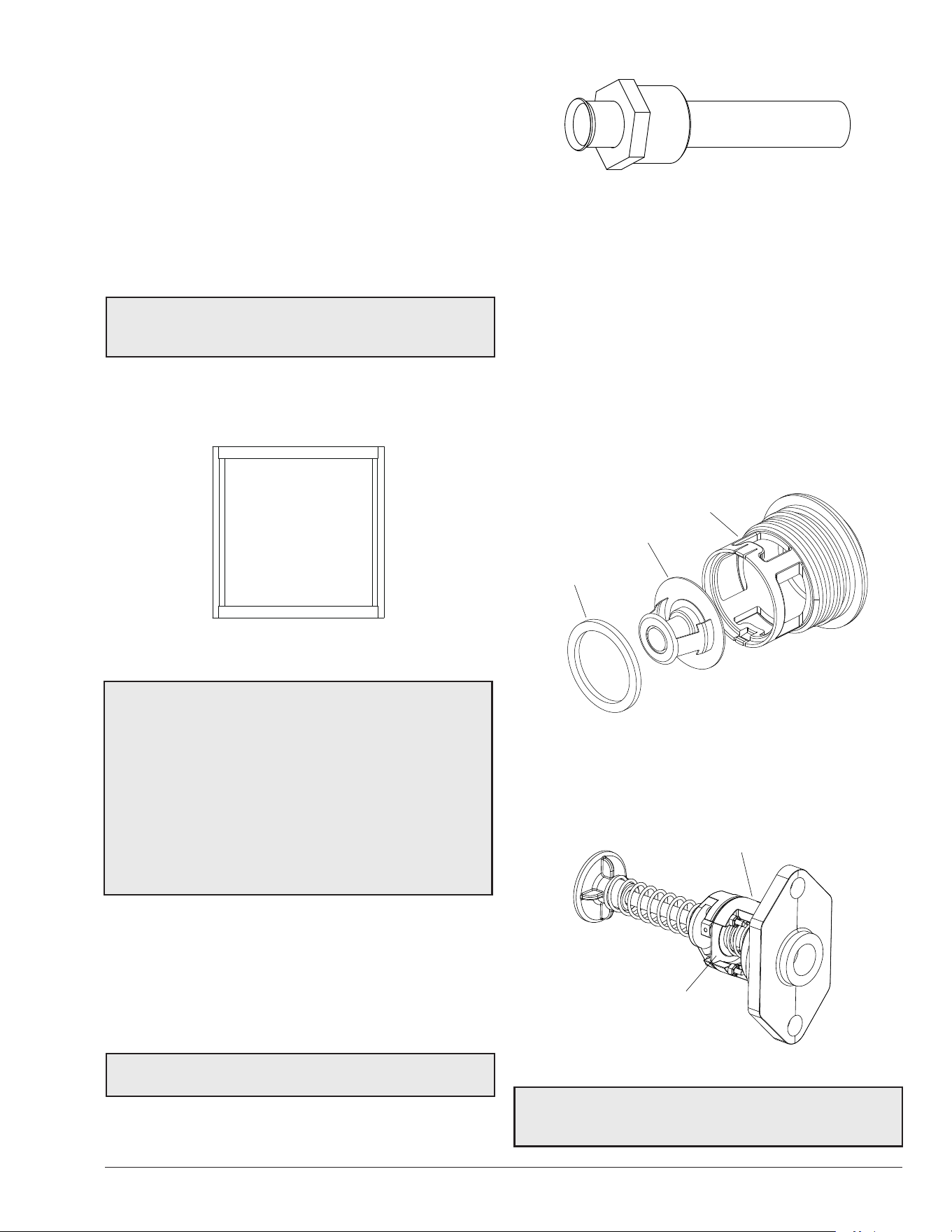
35
1. Remove top and flue collector from cabinet.
2. Remove “V” baffles from heat exchanger.
3. Remove burner tray. See page 33.
4. If ProTek Shield Assy is attached to the heater,
remove ProTek Shield Assy bonding wire from heat
exchanger stud.
5. Remove heat exchanger from the heater and wash
with a garden hose, making sure soot is removed
from spaces between fins.
6. Reverse above procedure to reinstall.
NOTE: In extreme cases it may be necessary to do
steam cleaning at the local car wash. DO NOT WIRE
BRUSH.
Combustion Chamber Removal
To remove combustion chamber, you must rst have
removed the heat exchanger.
F10723
Figure 66. Refractory Panels
A
WARNING: When removing the burners or heat
exchangers, take precautions to avoid creating airborne
dust and avoid inhaling airborne bers. When cleaning
spills, use wet sweeping or High Eciency Particulate
Air (HEPA) ltered vacuum to minimize airborne dust.
Use feasible engineering controls such as local exhaust
ventilation or dust collecting systems to minimize
airborne dust. Wear appropriate personal protective
equipment including gloves, safety glasses with side
shields, and appropriate NIOSH-certied respiratory
protection, to avoid inhalation of airborne dust and
airborne ber particles.
Immersion Well Replacement (Millivolt)
1. Shut off water to heater and drain heat exchanger.
2. Remove access panel on water connection side.
3. Remove old immersion well with bushing and sleeve.
4. Install replacement well in header.
NOTE: Installation in polymer header should be hand
tight plus 1/2 turn.
F10670
Figure 67. Well Assembly Unitherm Governor (U.G.)
Replacement
Unitherm Governor (U.G.) Replacement
1. Shut water, gas and electricity off, close valves and
relieve pressure.
2. Drain heat exchanger.
3. Remove retainer plug located next to the outlet pipe
connection on polymer header models.
4. Unsnap old U.G. to remove from retainer plug. Snap
in new U.G.
5. Reinstall retainer plug, taking care to lubricate
gasket with a non-petroleum based grease such as
AquaLube.
F10725
GASKET
UG PLUG
UNITHERM GOVERNOR
Figure 68. Unitherm Governor - Polymer
To test the operation of the Unitherm Governor - Polymer,
place in hot water (over 110°F [43°C]) and watch for
movement against spring. If there is no movement,
replace unit.
F10642-2
UG/BYPASS ASSY
UNITHERM
GOVERNOR
Figure 69. Unitherm Governor/Bypass Valve Assy – ASME
NOTE: The U.G. on bronze header models (ASME)
can only be replaced by replacing the entire Unitherm
Governor/Bypass Valve Assembly.
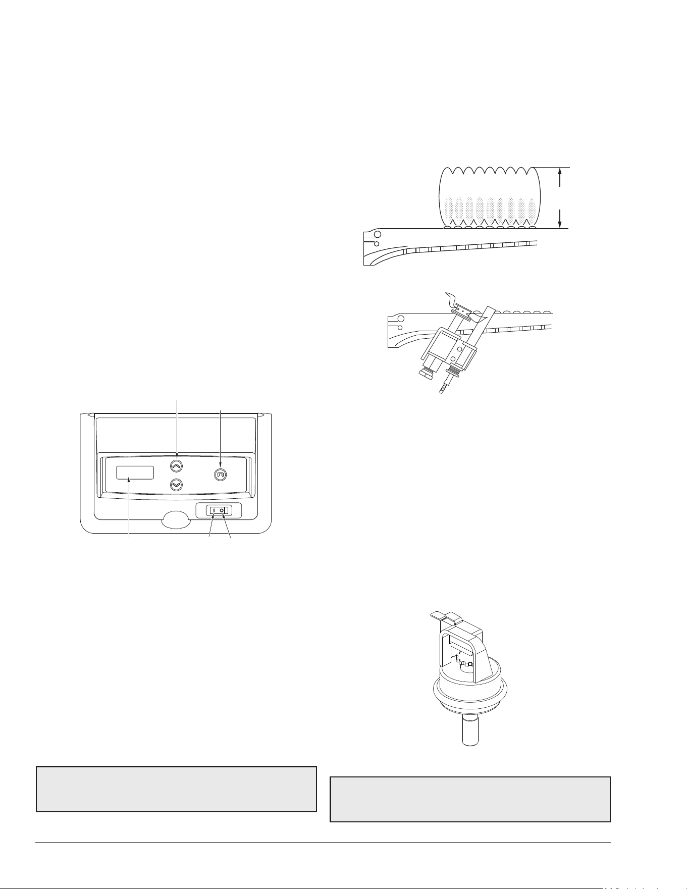
36
9. OPERATING
INSTRUCTIONS
Before Start-Up
Burners
Keep heater area clear and free from combustibles,
ammable liquids and chemicals. Do not obstruct the ow
of combustion and ventilation air.
Water
Water must be owing through the heater during operation.
Ensure that the system is lled with water and that the
pump is operating.
Start-Up Procedures
Your pool/spa heater has been designed for years of safe
and reliable pool/spa water heating. It is available with
millivolt or electronic ignition. ASME-certied units typically
used in commercial applications, are also available. This
manual provides installation, operation, maintenance, and
service information for these heaters.
TEMP
MODE
ON OFF
LCD DISPLAY
TEMP ADJUST BUTTONS
MODE BUTTON
Figure 70. Heater Control Toggle Switch
If your heater has been installed correctly, operating the
heater is an easy task. The upper front panel of the heater
contains the control center that allows you to turn the
heater On or O and adjust the temperature settings for
the pool or spa. The temperature range is factory set from
65°F (18°C) to 104°F (40°C). See Figure 70 for location of
toggle switch to turn the heater On and O.
See Section 8 for additional details about the use of the
controls in the Control Adjustments subsection.
After Start-Up
Feel the inlet and outlet pipes. Outlet pipe should be only
slightly warmer than the inlet. It should not be hot.
A
WARNING: Should overheating occur or the gas
supply fail to shut o, turn o the manual gas control to
the appliance.
Visual inspection
With the heater on, remove the door and make a visual
check of the pilot and burner. The ame should be blue
with a well-dened pattern.
A yellow or “oating” ame indicates restricted air openings
or incorrect orice size. Should this occur, shut the heater
o and contact your installer or gas supplier.
4" MAX
(102 mm)
Figure 71. Main Burner Flame
Figure 72. Millivolt Pilot Burner Flame
Water Pressure Switch
A water pressure switch is provided in the heater to shut o
the burners in the event that water supply is interrupted. It
is very important to verify that the switch electrically opens
and shuts o the gas valve when water ow to the heater
is interrupted. Otherwise rapid and severe damage will
likely occur to the heater.
The water pressure switch should be checked and adjusted
for proper operation by a qualied service person at the
time of installation and periodically checked thereafter.
Refer to "Water Pressure Switch Adjustment" on page
32 of this manual.
F10671
Figure 73. Water Pressure Switch
A
WARNING: Operation of the heater without water
circulation will cause rapid and severe damage to the
heater. Such damage is not covered under warranty.
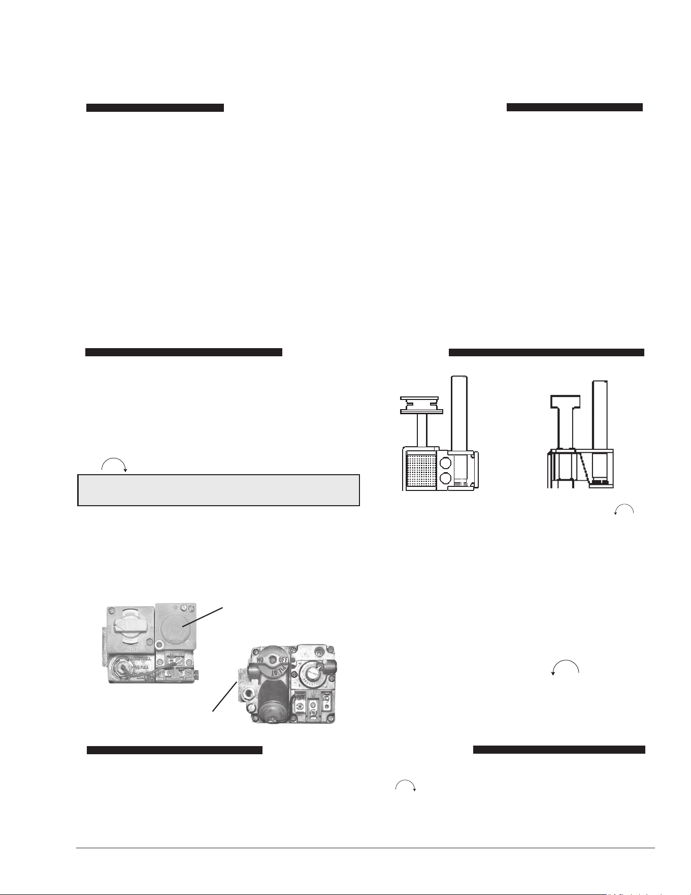
37
OPERATING INSTRUCTIONS AND SHUTOFF PROCEDURES
MILLIVOLT SYSTEM
(MANUALLY-LIGHTED PILOT)
A. This appliance has a pilot which must be lit
by hand. When lighting the pilot, follow these
instructions exactly.
B. BEFORE LIGHTING, smell all around the ap-
pliance area for gas. Be sure to smell near the
oor because some gas is heavier than air and
will settle on the oor.
WHAT TO DO IF YOU SMELL GAS:
*Do not try to light any appliance.
*Do not touch any electric switch; do not use any
phone in your building.
*Immediately call your gas supplier from a neigh-
bor’s phone. Follow the gas supplier’s instruc-
tions.
*If you cannot reach your gas supplier, call the
re department.
C. Use only your hand to push in or turn the gas
control knob. Never use tools. If the knob will
not push in or turn by hand, do not try to repair
it. Call a qualied service technician. Force or
attempted repair may result in a re or explo-
sion.
D. Do not use this appliance if any part has been
under water. Immediately call a qualied ser-
vice technician to inspect the appliance and to
replace any part of the control system and any
gas control which has been under water.
1. STOP! Read the safety information above.
2. Set the thermostat to the lowest setting.
3. Turn On/O switch to the "OFF" position.
4. Remove heater door panel.
5. Push in gas control knob slightly and turn clockwise
to "OFF".
NOTE: Knob cannot be turned from "PILOT" to "OFF"
unless knob is pushed in slightly. Do not force.
6. Wait 5 minutes to clear out any gas. If you then smell
gas, STOP! Follow "B" in the safety information
above. If you don’t smell gas, go to the next step.
7. Locate pilot mounted in the right-side panel of the
burner tray.
1. Set the thermostat at the lowest setting.
2. Turn On/O switch to the "OFF" setting.
3. Remove heater door panel.
4. Push the gas control knob slightly and turn clockwise
to “OFF”. Do not force
5. Replace heater door panel.
8. Turn gas control knob counter-clockwise to
"PILOT".
9. Place ame to end of pilot tube. Push in control knob
all the way and hold to light pilot. Continue to hold
control knob in for about one minute after the pilot
has lighted, release knob and it will pop up. Pilot
should remain lighted. If it goes out, repeat steps 5
through 9. If knob does not pop up when released,
stop and immediately call your service technician or
gas supplier.
10. Stand to the side of the heater and turn the gas
control knob counter-clockwise to "ON".
11. Replace heater door panel.
12. Turn On/OFF switch to the "ON " position.
13. Set thermostat to the desired setting.
HONEYWELL
MILLIVOLT
GAS VALVE
ROBERTSHAW
MILLIVOLT GAS VALVE
FOR YOUR SAFETY READ BEFORE LIGHTING
LIGHTING INSTRUCTIONS
TO TURN OFF GAS TO APPLIANCE
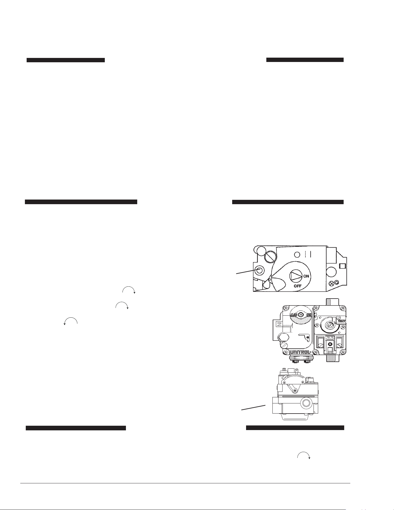
38
OPERATING INSTRUCTIONS AND SHUTOFF PROCEDURES
ELECTRONIC IGNITION DIGITAL MODELS
(AUTOMATICALLY-LIGHTED PILOT)
A. This appliance is equipped with an ignition de-
vice which automatically lights the pilot. Do not
try to light the pilot by hand.
B. BEFORE OPERATING, smell all around the ap-
pliance area for gas. Be sure to smell near the
oor because some gas is heavier than air and
will settle on the oor.
WHAT TO DO IF YOU SMELL GAS:
*Do not try to light any appliance.
*Do not touch any electric switch; do not use any
phone in your building.
*Immediately call your gas supplier from a neigh-
bor’s phone. Follow the gas supplier’s instruc-
tions.
*If you cannot reach your gas supplier, call the
re department.
C. Use only your hand to push in or turn the gas
control knob. Never use tools. If the knob will
not push in or turn by hand, do not try to repair
it. Call a qualied service technician. Force or
attempted repair may result in a re or explo-
sion.
D. Do not use this appliance if any part has been
under water. Immediately call a qualied ser-
vice technician to inspect the appliance and to
replace any part of the control system and any
gas control which has been under water.
1. STOP! Read the safety information above.
2. Set the thermostat to the lowest setting.
3. Turn o all electrical power to the appliance.
4. This appliance is equipped with an ignition device
which automatically lights the pilot. Do not try to light
the pilot by hand.
5. Remove heater door panel.
6. For Honeywell valve: Turn gas
control knob clockwise to “OFF”.
For Robertshaw valve: Models 266-406: Turn
gas control knob clockwise to “OFF”. Model
206 Push in and move gas control lever counter-
clockwise to “OFF” position.
7. Wait 5 minutes to clear out any gas. If you then smell
gas, STOP! Follow "B" in the safety information
above. If you don’t smell gas, go to the next step.
8. Turn gas control knob counter-clockwise to “ON”.
(Honeywell VR8340 and Robertshaw 7000).
9. Replace heater door panel.
10. Turn on all electrical power to the appliance.
11. Set thermostat to desired setting.
1. Set the thermostat at the lowest setting.
2. Turn o all the electrical power to the appliance if
service is to be performed.
3. Remove heater door panel.
ROBERTSHAW 7000
GAS VALVE IID
HONEYWELL
VR8340 GAS
VALVE IID
GAS
INLET
4. For Honeywell VR8340 and Robertshaw 7000 gas
valve.
Turn gas control knob clockwise to “OFF”.
Make sure knob rests against stop.
5. Replace heater door panel.
12. If the appliance will not operate, follow the
instructions “To Turn O Gas To Appliance”
and call your service technician or gas
supplier.
ROBERTSHAW
7200 GAS CON-
TROL LEVER
SHOWN IN "OFF"
POSITION
O
OF
GAS
INLET
FOR YOUR SAFETY READ BEFORE LIGHTING
LIGHTING INSTRUCTIONS
TO TURN OFF GAS TO APPLIANCE
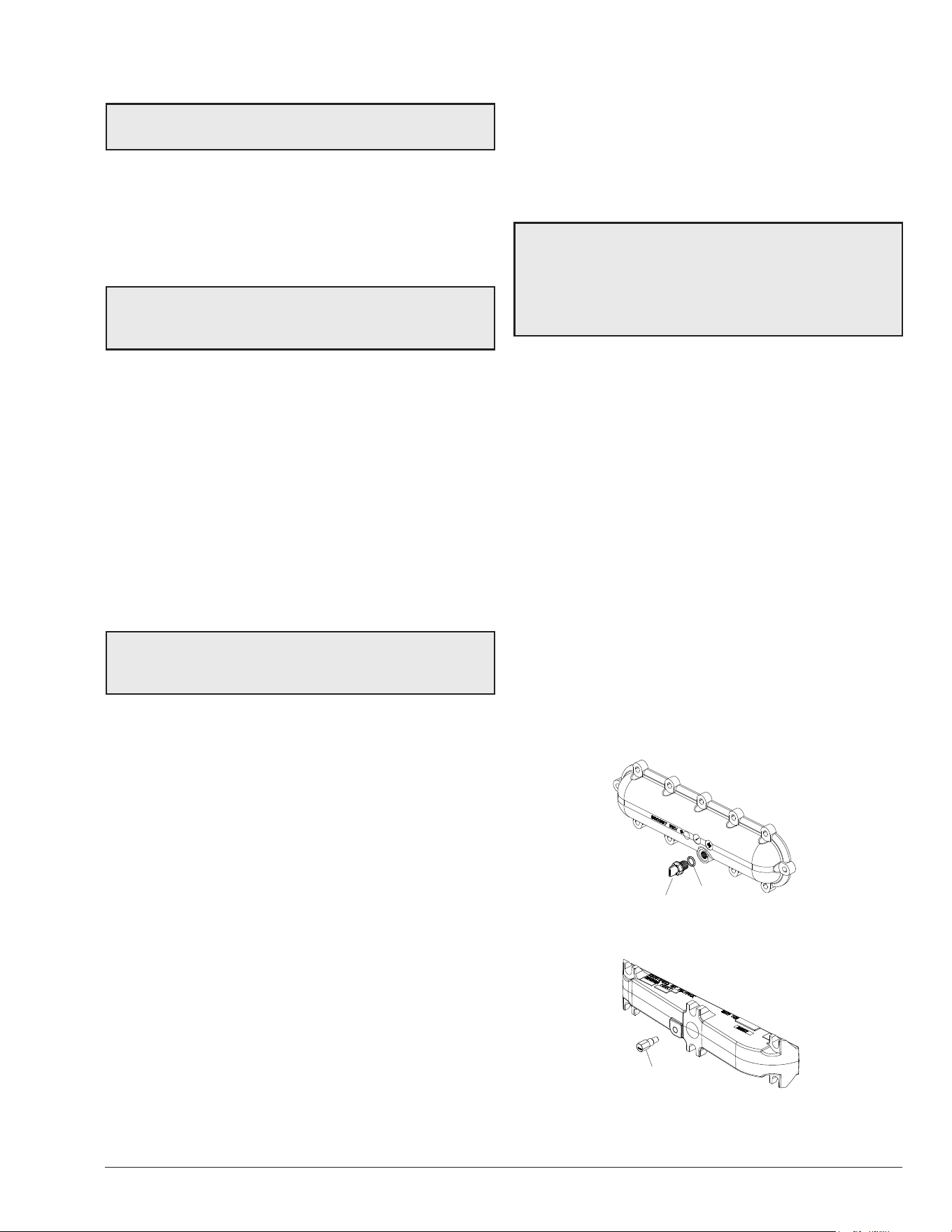
39
10. MAINTENANCE AND CARE
A
WARNING: Check the heater for possible rodent
nests after long periods of non-use.
To be followed one month after start-up and then semi-
annually.
1. Inspect the top of the heater and drafthood for soot,
a sticky black substance around finned tubes and “V”
baffles, and open flue gas passageways. Any visible
soot should be cleaned for proper operation.
A
CAUTION: Soot may be combustible. Wet sooted
surfaces completely prior to cleaning. Do not use steel
wire brush.
2. Clean main burners and pilot burner of dust and lint.
3. Inspect and operate all controls, gas valve and
pressure relief valve (if equipped).
4. Make visual check of the burner and pilot flames.
Yellow flame means restriction of the air openings.
Lifting or blowing flame indicates high gas pressure.
Low flame means low gas pressure. Should the
latter occur, shut the heater off and contact your gas
supplier or qualified service agency. See Figure 71
and Figure 72.
5. On indoor heaters, clean room intake openings to
ensure adequate flow of combustion and ventilation
air.
A
CAUTION: Combustion air must not be contaminated
by corrosive chemical fumes which can damage the
heater. Such damage is not covered under warranty.
6. Keep area around heater clear and free from
combustible materials, gasoline and other flammable
and corrosive vapors and liquids.
If Heater Will Not Fire:
If you have no electrical power, it may be that your “circuit
breaker” has tripped. Try re-setting it.
If you have electrical power but the heater will not re
check the following or see "TROUBLESHOOTING" on
page 40.
1. The time clock must be in the “ON” position.
2. Your pump strainer basket may be full. If so remove
debris.
3. Your filter may be dirty. If so, backwash or clean
filter. (To tell if your filter is dirty, look to see if the filter
pressure is higher than usual).
4. The pump may have lost its prime and be running
dry. Check the pressure on the filter. If there is no
pressure, then you are not moving water (or your
gauge is broken). Try to get the pump to run at its
normal flow rate.
Cold Weather Operation
Important Freeze Information
MODERATE CLIMATE: Heater operation can continue
during short-term cold spells. When temperatures are
between 0°F (-18°C) and 32°F (0°C), ow (continuous
pump operation) must be maintained.
A
CAUTION: Do not use the heater to maintain
water temperatures just above freezing or for freeze
protection. When heater is used during freezing weather,
care must be taken to avoid freeze-ups. Continuous
pump operation is a must. Additional protection may be
required. The heater is not warranted against freeze-ups.
COLD CLIMATE: Prolonged operation with water
temperatures below 50°F (10°C) is not recommended.
When starting the heater with water temperatures below
50°F (10°C), operate the heater continuously until higher
temperatures are reached. Operating the heater for
prolonged periods with pool water below 50°F (10°C)
can seriously damage the heater, and is not covered by
the warranty. For cold climate areas, please follow the
winterizing procedures listed below.
Winterizing the Pool and Spa Heater
Heaters installed outdoors in freezing climate areas may be
shut down for the winter. Observe the following procedure
for winterizing the heater:
1. Turn off gas valve, manual gas valve, and electrical
supply to the heater.
2. Remove the ProTek Shield™ Assembly (if attached).
Remove the heat exchanger inspection panel on the
side opposite water piping to gain access to the drain
plug on the return header. Open drain plug on return
header. See Figure 74 and Figure 75.
F10672
DRAIN PLUG
O RING
Figure 74. Return Header Drain Plug - Residential
("P" Prex Model)
F10673
DRAIN PLUG
Figure 75. Return Header Drain Valve - Commercial
("B" Prex Model)

40
11. TROUBLESHOOTING
IMPORTANT NOTICE: These instructions are intended for the use of qualied personnel who are specically trained
and experienced in the installation of this type of heating equipment and related system components. Installation and
service personnel may be required by some states to be licensed. Persons not qualied shall not attempt to install this
equipment nor attempt repairs according to these instructions.
Problem Possible Cause Corrective Action
Harmonics, or whining noise U.G. inoperative ...................................... Check movement by putting in hot water (110°F [43°C] or
higher)
*Debris or restriction in system ............... Locate the restriction and remove. Flush system and clean
*Debris in gas line................................... Remove debris or blow out gas line
Low ow.................................................. Scale forming in heat exchanger - clean heat exchanger and
check pool pH and total alkalinity
When the above listed recommendations do not generate acceptable results, the following service kits
are recommended:
1st recommendation:
105F UG Service Kit
2nd recommendation:
Coil Service Kit
Used on Models
018759F 019104F 206-207
018759F 019203F 266-268
018758F 019204F 336-337
018758F 019205F 406-408
Heater going on and o
continuously
Dirty lter ................................................ Clean or replace lter
Low water level in pool ........................... Raise water level
External bypass setting out of
adjustment ..............................................
Adjust bypass
*Pressure switch out of adjustment ........ Adjust pressure switch
Liming or scale forming in
exchanger
Pool water............................................... See Water Chemistry on 5
Bypassing too much water ..................... Inspect bypass for movement, if no movement, replace
U.G. not functioning ................................ Replace if no movement when heated
Sooting High ow rates ........................................ Reduce by adding manual bypass valve
Adjust manual bypass valve until heater outlet water temp is
between 105°F and 110°F (40°C and 43°C)
U.G. inoperative...................................... Check movement by putting in hot water (110°F [43°C] or
higher). If no movement, replace
*Air starvation ......................................... Refer to installation instructions
*Improper venting ................................... Follow recommended installation instructions
*Insects or debris clogging burner intake
ports........................................................ Clean burners
Pilot outage or “Weak Flame”
signal
Low gas pressure ................................... Adjust gas pressure
Restricted/dirty pilot ................................ Clean pilot
Weak pilot generator .............................. Replace pilot
Yellow lazy ame Low gas pressure ................................... Adjust gas pressure
*Insects or debris clogging burner intake
ports........................................................ Clean burners
Outer jacket very hot (paint
blistered)
*Broken refractory caused by shipping
damage or improper combustion ............ Replace refractory panels
Excessive sooting of heat exchanger ..... Determine cause of sooting and correct
* Indicates symptom which usually occurs on initial start-up.

41
Problem Possible Cause Corrective Action
Takes too long to heat pool or
spa
Under-sized heater ................................. Calculate heating capacity of heater
Htr. output (BTUH)
Pool gallonage x 8.33
or refer to heater sizing chart
This does not take into account heat loss due to weather
Filter not running long enough ................ Reset time clock
Dirty lter ................................................ Clean lter
Gas line or meter undersized ................. Refer to installation instructions
Leaking at well Overacid ................................................. Replace well and maintain proper water chemistry
Leaking at heat exchanger Overacid ................................................. Replace heat exchanger and maintain proper water chemistry
Gasket brittle and leaking -
(overheated)
Heater running after pump shuts o ....... See Pressure switch adjustment
Refractory damage ................................. Replace refractory
Sooted heater ......................................... Determine cause of sooting and correct
TROUBLESHOOTING (CONT:)
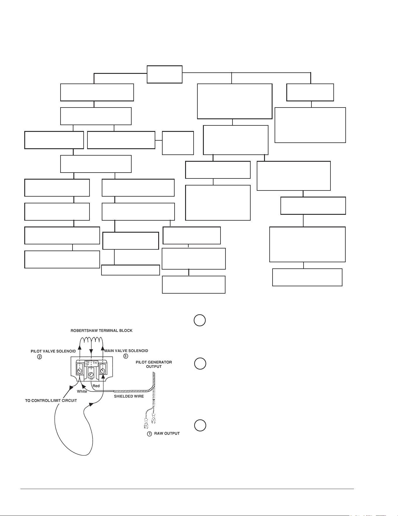
42
Millivolt - Flow Chart
If pilot burner remains lit
Jump across pressure
switch terminals
If main burner does not
fire, remove jumper
Check for adequate water
flow from filter
Replace pressure switch
Jump across thermostat
If main burner fires,
remove jumper
If main burner does
NOT fire...
Jump across each
high limit and remove
jumper
Replace thermostat
Replace high limit that
caused heater to fire
Jump across both "TH"
wires on gas valves
Check gas supply, gas
line size, gas pressure.
Also check for insects
or debris in pilot output
If pilot burner
does not light
Light pilot
If pilot burner goes out
when main burner lights
or when gas valve knob
is released
If burner does not remain
lit, attach millivolt meter
and read pilot output
If below 500mV, check
gas pressure. Also check
for insects or debris in
the pilot burner
If main burner fires,
remove jumper
Replace
gas
valve
If main burner does not
fire, remove jumper
Remove both "TH"
wires from gas valve.
Relight pilot
If pilot burner stays on
Problem is a wire or
component short to
cabinet or low gas
pressure
If above 500mV,
replace gas valve
Clean filter
If main burner fires,
remove jumper
If output is still low,
replace pilot generator
Raw Output (700mV± 100)
Pilot generator disconnected from valve (knob
must be held down to keep pilot on).
White – Negative
Red + Positive
Pilot Load (500mV± 100)
Pilot generator connected to valve-Power ap-
plied to pilot solenoid.
TP (Thermopile-Robertshaw)
PP (Power Pile-Honeywell)
TH TP – Common
TH PP – Common
Main Valve Load (200mV± 100)
Control/Limit circuit closed (All switches “ON”)
TP (Thermopile-Robertshaw)
PP (Power Pile-Honeywell)
TH TP – Common
TH PP – Common
1
2
3
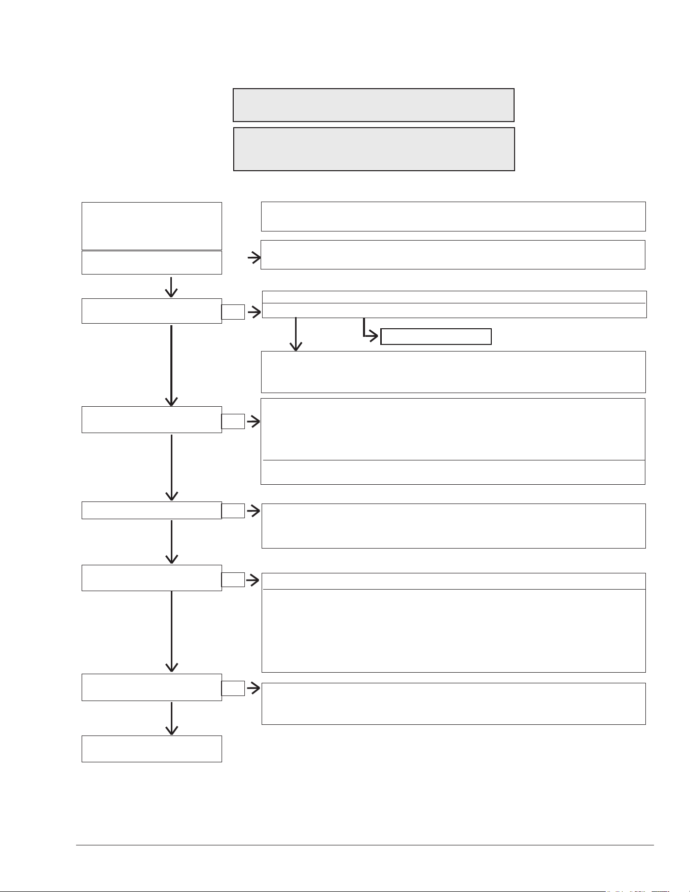
43
START
TURN GAS SUPPLY OFF.
TURN THERMOSTAT
(CONTROLLER) TO CALL-
FOR-HEAT
POWER TO PC BOARD?
(24 V NOMINAL)
YES
SPARK ACROSS
IGNITER/SENSOR GAP?
YES
TURN GAS SUPPLY ON
PILOT BURNER LIGHTS?
YES
MAIN BURNER LIGHTS?
YES
SYSTEM RUNS UNTIL
CALL-FOR-HEAT ENDS?
YES
CALL-FOR-HEAT ENDS
SYSTEM SHUTS OFF?
YES
TROUBLESHOOTING
ENDS
NOTE: Before troubleshooting, familiarize yourself with the start-up and check-out
procedure.
Check line voltage power, low voltage transformer, limit controller, thermostat
(controller) and wiring. Make sure that the line voltage is NOT 208 VAC.
Pull ignition lead and check spark at PC board.
Spark Okay?
YES NO
• Check ignition cable, ground wiring, ceramic insulator and gap, and correct.
• Check boot of the ignition cable for signs of melting or buckling. Take protective
action to shield cable and boot from excessive temperatures.
• Check that all manual gas valves are open, supply tubing and pressures are
good, and pilot burner orice is not blocked.
• Check electrical connections between PC board and pilot operator on gas control.
• Check for 24 VAC across PV-MV/PV terminals on PC board. If voltage is okay,
replace gas control; if not, replace PC board.
NOTE: If PC board goes into lockout, reset system. Lockout is used on L.P.G.
models.
• Check for 24 VAC across MV-MV/PV terminals. If no voltage, replace module.
• Check electrical connections between PC board and gas control. If okay, replace
gas valve or gas control operator, i.e. pilot gas valve, ow switch etc.
NOTE: IF PC board goes into lockout, reset system.
• Check continuity of ignition cable and ground wire.
NOTE: If ground is poor or erratic, shutdowns may occur occasionally even though
operation is normal at the time of checkout.
• Check that pilot ame covers ame rod and is steady and blue.
• If checks are okay, replace PC board.
• Check for proper thermostat (controller) operation.
• Remove MV lead at module; if valve closes, recheck temperature controller and
wiring; if not, replace gas valve.
NO
NO
NO
NO
NO
NO
Replace the PC board.
Digital - Flow Chart
A
WARNING: HIGH VOLTAGE
For qualied technicians ONLY
NOTE: Some heaters may be equipped with an ignition
module that shuts o pilot gas if pilot fails to light. To
reset, interrupt power to heater.
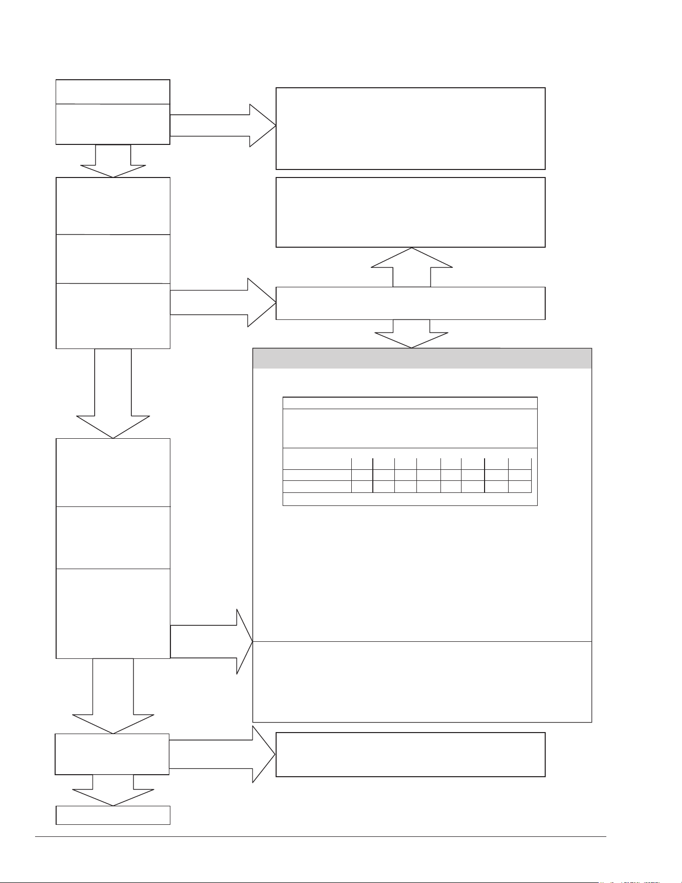
44
Control Logic - Flow Chart - Digital
Power On
Is the water
temperature displayed?
NO
YES
Push MODE
switch to select
"Pool" or "Spa"
Push Temp
arrow to scroll to
desired temperature
NO
Water temperature
and set
temperature
displayed?
YES
“Heating” will
display briefly
NO
NO
YES
YES
Flame icon displayed
and flashing?
OR
Water temp displayed?
(pilot lit and rectified)
Heater Fired?
END
• Check On/Off switch (under lid on control panel)
• Check for 120/240 volts to the transformer
(time clock, circuit breaker, wire connections)
• Check for 24 volts to Circuit Board (P6 connector)
“Remote” and Water Temperature displayed
(a remote control is controlling the heater)
Note: Disconnect the remote by turning the
remote function off. See page 30 for instructions.
NO
YES
Is a fault code displayed and flashing?
Diagnostic Readouts
“Sensor Failure,” “Sensor Open” or “Sensor Short” -
Temperature sensor out of range (replace sensor)
Verify power at MV on P-4 Terminal on digital circuit board.
Verify power to valve MV voltage. (Replace valve.)
“Spark”
Temp Degrees F 40 50 60 70 80 90 100 106
Temp Degrees C 4 10 15 21 27 32 38 41
Resistance (k)
261.1 199.0 153.1 118.8 93.0 73.3 58.3 51.0
If okay, replace Circuit Board
Sensor Failure
Inspect thermistor, wires, and connector at Terminal P1
Check resistance value of the thermistor. Reference to chart below.
Replace thermistor if not within 10% of values shown below.
If okay, replace Circuit Board.
Sensor resistance at various temperatures
“Water Sw Open” Pressure switch. Verify water flow and pressure
CLEAN FILTER / STRAINER - backwash if neccessary.
“Hi Limit 1 Fault” High limit switch. Verify water flow. Inspect internal
“Hi Limit 2 Fault” Thermostat (Unitherm Governor) and bypass valve.
Press manual button on HL1 fault on bronze (ASME) models.
“Rollout Sw Open” Rollout Sensor - Check for blocked heat exchanger and soot.
Press manual reset button.
“Clock/Fireman Sw” Fireman or Remote switch connected to safety loop is in the
OFF mode.
“Vent/Field Sw #1” Vent switch open. Check connections to the board.
If extractor installed, troubleshoot extractor.
“Ignition Lockout” Ignition lockout. Check power at pilot valve. Check spark (bad
ignition circuit or hi-tension wire). Verify clean pilot orifice and
clearance from igniter to ground rod.
“Ignition Failure” Ignition failure. Verify gas to the heater. Verify valve operation
(gas present at tube fitting).

45
12. REPLACEMENT PARTS
NOTE: To supply you with the correct part, it is important
that you supply the heater model number, serial number
and type of gas when applicable.
Any part returned for replacement under standard
company warranties must be properly tagged with a return
parts tag, completely lled in with the heater serial number,
model number, etc., and shipped to the Company freight
prepaid.
If determined defective by the Company and within
warranty, a like part or equal substitution will be returned,
freight collect. Credit will not be issued.
MANUFACTURER:
2151 Eastman Avenue
Oxnard, Ca 93030
46
View this Installation Manual on your smart device.
This QR Code will take you to the most current version of the manual. Previous
versions of manuals can be found in the document library at Raypak.com.
13. QR CODES
P/N: 241236 Manual Atmospheric 206A-406A
P/N: 241243 Manual D-2 Power Vent
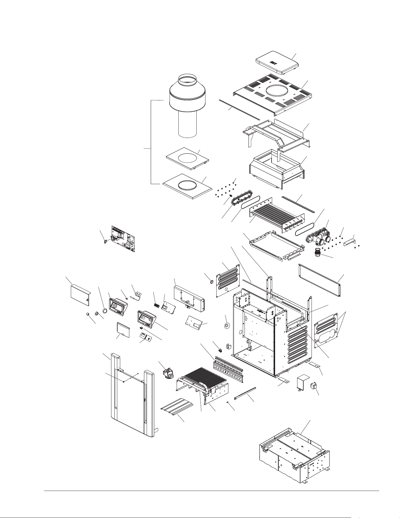
47
14. ILLUSTRATED PARTS LIST
4-V
16-M
7-C
8-C
14-S
18-M
16-M
25-M
20-HP
2-HP
10-S
3-V
1-V
2-V
14-M
1-S
13-S
2-S
5-HP
4-HP
7-HP
6-HP
12-S
6-HP
15-HP
3-HP
7-S
3-R
4-S
17-HM
11-S
4-C
9-M
8-S
13-M
12-M
3-S
4-B
2-B
5-M
5-B
1-B
1-G
1-J
4-S
5-S
6-S
14-M
1-R
2-R
2-J
7-HP
3-B
10-M
4-M
2-M
3-M
5-C
11-M
15-S
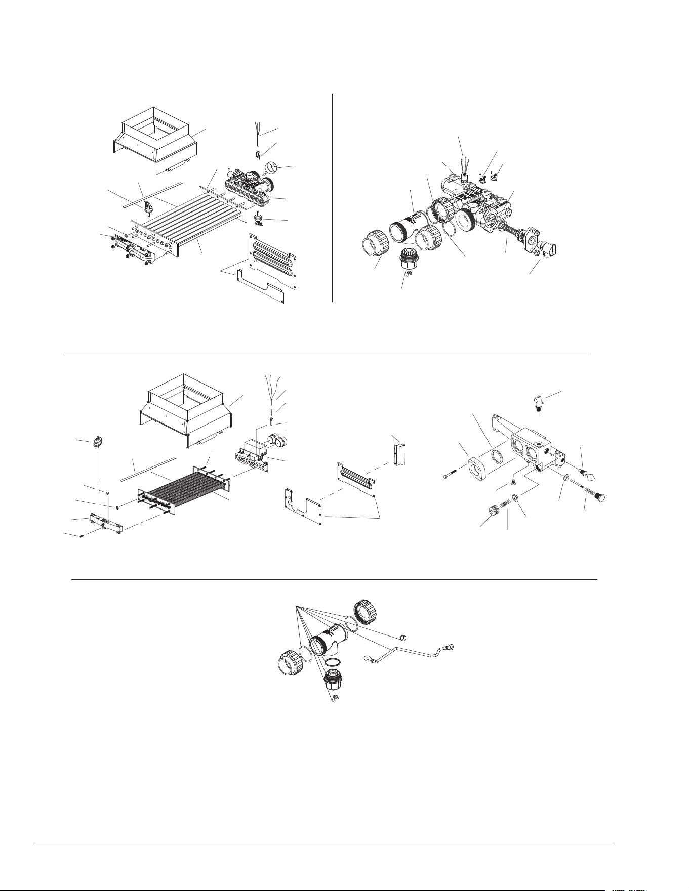
48
FOR UNITS WITH ASME BRONZE HEADERS FROM 12/2019
(PROTEK SHIELD AVAILABLE ON ASME HEATERS AFTER END OF Q3 2020)
4-HM
28-HM
1-C
6-M
9-C
17-HP
18-HP
20-HP
26-HM
OUTLET
INLET
27-HM
6-C
8-HP
6-C
8-HP
4-S
2-S
6-HM
3-HM
7-HM
5-HM
1-M
21-M
2-HM
1-M
UNITS WITH ASME CAST IRON HEADERS, DISCONTINUED 12/2019
(OPTIONAL)
16-HM
15-HM
12-HM
9-HM
10-HM
2-C
6-M
11-HM
8-HM
1-M
3-C
6-C
5-HM
17-HM
14-HM
13-HM
2-HM
4-HM
7-HM
3-HM
6-HM
2-S
9-S
4-S
18-HM
INLET
30-HM
PROTEK SHIELD ADAPTER KIT
31-HM
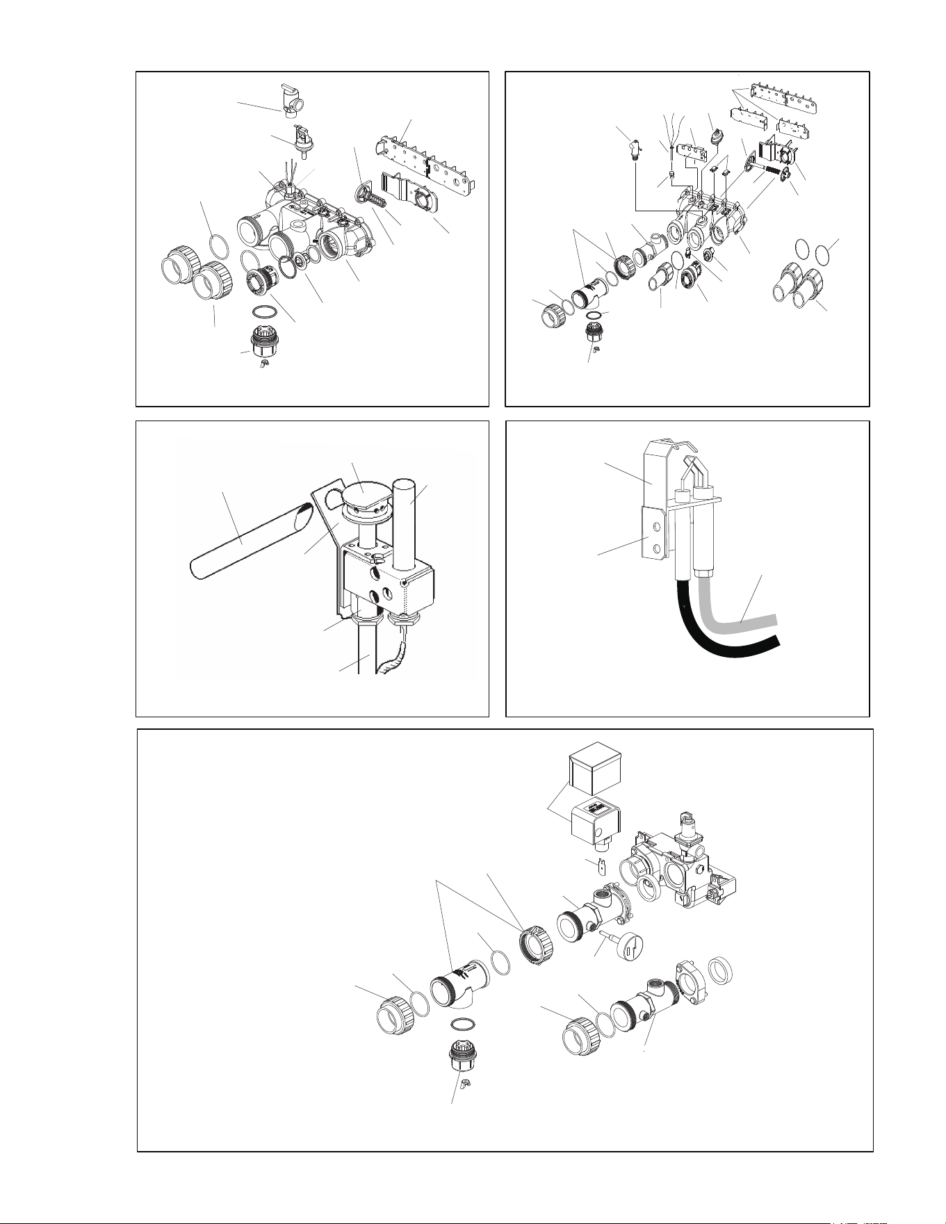
49
2-P
7-P
9-P
8-P
1-P
5-P
6-P
3-P
9-P
FOR UNITS WITH POLYMER HEADERS FROM 10/2019
HONEYWELL IID ATMOSPHERIC PILOT
1-M
18-HP
17-HP
20-HP
10-HP
16-HP
11-HP
12-HP
13-HP
2-HP
14-HP
8-HP
6-C
19-HP
6-M
(OPTIONAL)
HONEYWELL MILLIVOLT PILOT
OUTLET
INLET
PROTEK ADPTER AND POLYMER UNITS PRIOR TO 10/2019
6-M
17-HP
14-HP
13-HP
2-HP
10-HP
12-HP
11-HP
16-HP
1-C
1-M
6-C
19-HP
19-HP
8-HP
15-HP
18-HP
(OPTIONAL)
18-HP
23-M
24-M
29-HM
27-HM
22-M
26-HM
24-M
23-M
OUTLET
INLET
17-HP
PROTEK ADAPTER AND TEXAS CODE OPTION PRIOR TO 12/2019
19-M
20-M
22-M
24-M
23-M
21-M
22-M
INLET
OUTLET
24-M
29-HM
27-HM
26-HM
24-M
23-M
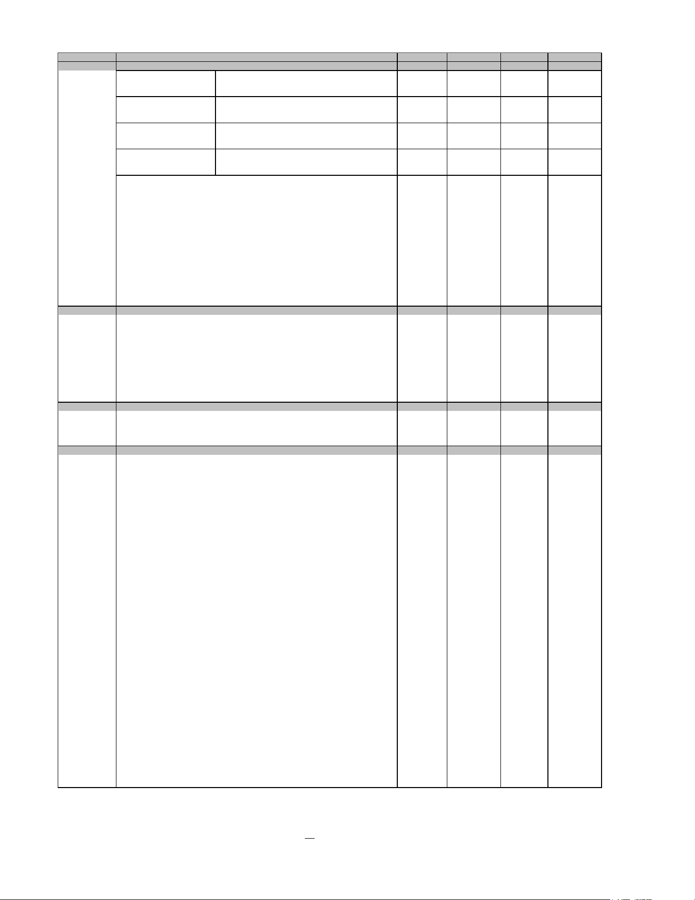
50
CALL OUT
B 206A 266/266A 336A 399/406A
1-B Polymer Cu HX, or Burner Tray w/Burners Nat (sea level)* 010391F 010392F 010393F 010394F
ASME HX (Cu or Cupro) Burner Tray w/Gas Valve Nat Millivolt (sea level)* 010399F 010400F 010401F 010402F
NAT #50 ORIFICE Burner Tray w/Gas Valve Nat IID (sea level)* 010407F 010408F 010409F 010410F
Polymer Cu HX, or Burner Tray w/Burners Pro (sea level)* 019206F 019207F 019208F 019209F
ASME HX (Cu or Cupro) Burner Tray w/Gas Valve Pro Millivolt (sea level)* 010403F 010404F 010405F 010406F
PRO #57 ORIFICE Burner Tray w/Gas Valve Pro IID (sea level)* 010411F 010412F 010413F 010414F
Burner Tray w/Burners Nat (sea level)* 019210F 019211F 019212F 019213F
Burner Tray w/Gas Valve Nat Millivolt (sea level)* 019214F 019215F 019216F 019217F
Burner Tray w/Gas Valve Nat IID (sea level)* 019218F 019219F 019220F 019221F
Burner Tray w/Burners Pro (sea level)* 019222F 019223F 019224F 019225F
Burner Tray w/Gas Valve Nat IID (sea level)* 019226F 019227F 019228F 019229F
Burner Tray w/Gas Valve Pro IID (sea level)* 019230F 019231F 019232F 019233F
2-B Burner Spacer/Hold Down Kit 010415F 010416F 010417F 010418F
3-B Burner 301210/13 301210/18 301210/22 301210/27
4-B Burner Orifice (TO BE ORDERED BASED ON RATING PLATE AND ELEVATION)
Natural Gas
Burner Orifice #50* (0-1999 ft elevation) 350079F/13 350079F/18 350079F/22 350079F/27
Burner Orifice #51* (2000-5999 ft elevation) 350080F/13 350080F/18 350080F/22 350080F/27
Burner Orifice #52* (6000-8999 ft elevation) 350081F/13 350081F/18 350081F/22 350081F/27
Burner Orifice #53* (9000 + ft elevation) 350347F/13 350347F/18 350347F/22 350347F/27
Propane Gas
Burner Orifice #57* (0-1999 ft elevation) 350083F/13 350083F/18 350083F/22 350083F/27
Burner Orifice #58* (2000-2999 ft elevation) 350087F/13 350087F/18 350087F/22 350087F/27
Burner Orifice #59* (3000-4999 ft elevation) 350350F/13 350350F/18 350350F/22 350350F/27
Burner Orifice #60* (5000-6999 ft elevation) 350351F/13 350351F/18 350351F/22 350351F/27
Burner Orifice #61* (7000-7999 ft elevation) 350352F/13 350352F/18 350352F/22 350352F/27
5-B Burner Tray w/o Manifold w/o burners 010421F 010422F 010423F 010424F
C
1-C High Limit Auto Reset 135°F Deg Surface Mount 006725F 006725F 006725F 006725F
2-C AGS 135°F (Auto Gas Shut-Off) - Red Epoxy - prior to 12/2019 600892B 600892B 600892B 600892B
3-C High Limit 140°F - Black Epoxy - prior to 12/2019 600893B 600893B 600893B 600893B
4-C P.C. Board/Control 013464F 013464F 013464F 013464F
7-C LCD Display
Units manufactured from 5/2011 013640F 013640F 013640F 013640F
8-C Fuse 5 AMP 013733F 013733F 013733F 013733F
5-C Thermostat Control MV Units Mechanical 003346F 003346F 003346F 003346F
6-C Temperature Sensor IID Units 009577F 009577F 009577F 009577F
9-C High Limit Auto Reset 150°F Surface Mount (ASME Only) 018304F 018304F 018304F 018304F
G
1-G Combination Valve - Nat. MV 003898F 003898F 003898F 003898F
Combination Valve - Pro. MV 003899F 003899F 003899F 003899F
Combination Valve - Nat. IID 003900F 003900F 003900F 003900F
Combination Valve - Pro. IID 004306F 004306F 004306F 004306F
HP
1-HP Heat Exchanger Assy Copper ***
Units manufactured from 10/2019 017994F 017995F 017996F 017997F
Units manufactured prior to 10/2019 010043F 010044F 010045F 010046F
Heat Exchanger Assy Cupronickel ***
Units manufactured from 10/2019 017998F 017999F 018000F 018001F
Units manufactured from 7/2013 thru 9/2019 014926F 014927F 014928F 014929F
Units manufactured prior to 7/2013 010356F 010357F 010358F 010359F
2-HP Inlet/Outlet Header Complete
Units manufactured from 10/2019 017959F 017959F 017959F 017959F
Units manufactured prior to 10/2019 006827F 006827F 006827F 006827F
Inlet/Outlet Header (Includes 6-HP)
Units manufactured from 10/2019 017965F 017965F 017965F 017965F
Units manufactured prior to 10/2019 014648F 014648F 014648F 014648F
3-HP Return Header (Includes 6-HP) 015095F 015095F 015095F 015095F
4-HP Tube Bundle Copper ** & *** 010059F 010060F 010061F 010062F
Tube Bundle Cupronickel ** & ***
Units manufactured from 7/2013 014930F 014931F 014932F 014933F
Units manufactured prior to 7/2013 010364F 010365F 010366F 010367F
5-HP Baffle (Copper Heat Exchanger) 010038F 005261F 010040F 010041F
Baffle (Cupronickel Heat Exchanger)
Units manufactured from 6/2013 014934F 014935F 014936F 014937F
Units manufactured prior to 6/2013 010038F 005261F 010040F 010041F
6-HP Flange Nut Kit 008259F 008259F 008259F 008259F
7-HP O Ring Gasket (2) 006713F 006713F 006713F 006713F
8-HP Sensor Adapter Digital Electronic 006714F 006714F 006714F 006714F
Sensor Well Millivolt 006805F 006805F 006805F 006805F
9-HP Bypass Kit 006715F 006715F 006715F 006715F
10-HP Bypass Valve 006716F 006716F 006716F 006716F
11-HP Bypass Dam / Shaft 006717F 006717F 006717F 006717F
12-HP Bypass Spring (All Sizes Included) 006718F 006718F 006718F 006718F
13-HP Unitherm Governor 006719F 006719F 006719F 006719F
14-HP Unitherm Governor Plug 006720F 006720F 006720F 006720F
15-HP Drain Plug 006721F 006721F 006721F 006721F
16-HP Inlet/Outlet Header Dam N/A Use 19-HP N/A Use 19-HP N/A Use 19-HP N/A Use 19-HP
17-HP 2" CPVC Connector & Nut (2) 006723F 006723F 006723F 006723F
18-HP O Ring (2) 006724F 006724F 006724F 006724F
19-HP Inlet/Outlet Header Baffle w/Header Dam 006826F 006826F 006826F 006826F
20-HP
ProTek Shield
TM
Assembly
017960F 017960F 017960F 017960F
**WARNING: The Hydraulic conditions or water chemistry that caused the tube bundle to fail have very likely also damaged the bypass valve and Unitherm Governor. We
recommend you replace the Unitherm Governor and inspect the bypass assembly. Failure to do so could cause premature failure of this replacement part.
***WARNING: Copper and Cupronickel heat exchangers and tube bundles are not interchangeable. Units with suffix "C" must use copper replacement parts and units with
suffix "X" must use Cupronickel replacement parts.
*FOR INSTALLATION AT OVER 2,000 FEET ABOVE SEA LEVEL, DERATE 4% PER I,000 FEET ABOVE SEA LEVEL. Refer to the heater's rating plate.
DESCRIPTION
BURNER TRAY - SPECIFY ELEVATION*
CONTROLS
GAS VALVE
HEAT EXCHANGER - POLYMER (RESIDENTIAL ONLY)
Polymer Cupro HX
NAT #51 ORIFICE
Polymer Cupro HX
PRO #58 ORIFICE
51
CALL OUT 206A 266/266A 336A 399/406A
HM
1-HM Heat Exchanger Assy.Copper ASME
Units manufactured from 12/2019 (Bronze) 017983F 017984F 017985F 017986F
Units manufactured prior to 12/2019 (Cast Iron) 010051F 016193F 010053F 010054F
Heat Exchanger Assy.Cupronickel ASME
Units manufactured from 12/2019 (Bronze) 017987F 017988F 017989F 017990F
Units manufactured prior to 12/2019 (Cast Iron) 010360F 010361F 010362F 010363F
2-HM Inlet/Outlet Header ASME Complete
Units manufactured from 7/2020 (Bronze) 018740F 018740F 018741F 018741F
Units manufactured from 12/2019 (Bronze) 017961F 017961F 017992F 017992F
Units manufactured prior to 12/2019 (Cast Iron) 006730F 006730F 006730F 006730F
Inlet/Outlet Header ASME (Header Only)
Units manufactured from 7/2020 (Bronze) 018739F 018739F 018739F 018739F
Units manufactured from 12/2019 (Bronze) 017966F 017966F 017966F 017966F
Units manufactured prior to 12/2019 (Cast Iron) 012319F 012319F 012319F 012319F
15-HM Inlet & Outlet Flange - prior to 12/2019 003766F 003766F 003766F 003766F
16-HM Flange Gasket 1 1/2" Connections - prior to 12/2019 062236B 062236B 062236B 062236B
Flange Gasket 2" Connections - prior to 12/2019 800080B 800080B 800080B 800080B
3-HM Return Header ASME
Units manufactured from 7/2020 (Bronze) 018738F 018738F 018738F 018738F
Units manufactured from 12/2019 (Bronze) 017973F 017973F 017973F 017973F
Units manufactured prior to 12/2019 (Cast Iron) 006731F 006731F 006731F 006731F
4-HM Tube Bundle Copper ASME *
Units manufactured from 12/2019 017974F 017975F 017976F 017977F
Units manufactured prior to 12/2019 010055F 006733F 010057F 010058F
Tube Bundle Cupronickel ASME *
Units manufactured from 12/2019 017978F 017979F 017980F 017981F
Units manufactured prior to 12/2019 010368F 010369F 010370F 010371F
5-HM Baffle 010038F 005261F 010040F 010041F
6-HM Stud Bolt Kit
Units manufactured from 12/2019 017982F 017982F 017982F 017982F
Units manufactured prior to 12/2019 007870F 007870F 007870F 007870F
7-HM Header Gasket (9) 800014B 800014B 800014B 800014B
8-HM Unitherm Governor 062234B 062234B 062234B 062234B
9-HM U.G. Retainer Spring 013792F 013792F 013792F 013792F
18-HM U.G. Plug 013738F 013738F 013738F 013738F
10-HM Bypass Valve 016194F 016194F 016194F 016194F
11-HM Bypass Spring
Units with Plastic Bypass Valve (Units manufactured from 3/5/17 to 12/19) 016196F 016196F 016196F 016196F
Units with Bronze Bypass Valve (Units manufactured prior to 3/5/17) 013794F 013794F 013794F 013794F
12-HM Drain Valve
013793F 013793F 013793F 013793F
13-HM Sensor Well 003765F 003765F 003765F 003765F
14-HM Well Retaining Clip 300203 300203 300203 300203
17-HM Rear Drain Plug & Cover 005264F 005264F 005264F 005264F
19-HM Adapter CPVC 2" 005393F 005393F 005393F 005393F
26-HM Adapter - ProTek Shield (Includes 27-HM) from end of Q3 2020 018006F 018006F 018006F 018006F
27-HM Nut - ProTek Shield Adapter - 2-Pc from end of Q3 2020 018007F 018007F 018007F 018007F
28-HM U.G./Bypass Assembly (Units manufactured from 12/2019) 017958F 017958F 017962F 017962F
29-HM ProTek Shield Assembly from end of Q3 2020 018766F 018766F 018766F 018766F
30-HM ProTek Shield Adapter Assembly - from end of Q3 2020 018006F 018006F 018006F 018006F
31-HM Bypass O-Ring (Units manufactured from 12/2019) 016230F 016230F 016230F 016230F
J
1-J Transformer 120/240/24V 006736F 006736F 006736F 006736F
2-J Rocker Switch 009493F 009493F 009493F 009493F
M
1-M Pressure Switch 1.75 PSI 006737F 006737F 006737F 006737F
Pressure Switch 1.75 PSI Complete Kit (Units manufactured from 12/2019 to 6/2020)
018297F 018297F 018297F 018297F
Pressure Switch 11 PSI Special-See Water Pressure Switch Adj. 009133F 009133F 009133F 009133F
2-M Thermostat Knob 009499F 009499F 009499F 009499F
3-M Thermostat Shaft MV 800307 800307 800307 800307
4-M Knobstop 006886F 006886F 006886F 006886F
5-M Thermal Fuse 005899F 005899F 005899F 005899F
6-M PRV 017957F 017957F 017957F 017957F
7-M Deliming Kit 052871F 052871F 052871F 052871F
8-M Wire/Harness Millivolt 010386F 010386F 010386F 010386F
Wire/Harness IID 009490F 009490F 009490F 009490F
9-M Control Bezel MV (Includes Dial Decal) 009489F 009489F 009489F 009489F
10-M Dial Decal MV 009858F 009858F 009858F 009858F
11-M Control Bezel (Includes Switch Decal)
Units manufactured from 5/2011 013491F 013491F 013491F 013491F
Units manufactured prior to 5/2011 009491F 009491F 009491F 009491F
12-M Switch/Decal-Membrane
Units manufactured from 5/2011 013492F 013492F 013492F 013492F
Units manufactured prior to 5/2011 009492F 009492F 009492F 009492F
13-M Control Bezel Cover 009487F 009487F 009487F 009487F
14-M Gasket Insulation (Swaybrace & Jacket Top) 010350F 010350F 010350F 010350F
15-M Touch-up Paint
Green 750125 750125 750125 750125
Dark Gray 750126 750126 750126 750126
Cool Dark Gray 750256 750256 750256 750256
Warm Dark Gray 750258 750258 750258 750258
16-M Tie Down Bracket (Optional) 011636 011636 011636 011636
17-M Texas Code Option (ASME Only) - Units manufactured prior to 12/2019
Flanged Connection (Not Shown) 015889F 015889F 015889F 015889F
NPT Connection (Not Shown) 015890F 015890F 015890F
015890F
19-M Flow Switch 007142F 007142F 007142F 007142F
20-M Flow Switch Paddle 010026F 010026F 010026F 010026F
21-M T & P Gauge 014647F 014647F 014647F 014647F
22-M 2" CPVC Connector (Outlet Plumbing)
NPT Connection 013795F 013795F 013795F 013795F
Flanged Connection 015883F 015883F 015883F 015883F
23-M 2" CPVC Connector & Nut (2) 006723F 006723F 006723F 006723F
24-M O Ring (2) 006724F 006724F 006724F 006724F
18-M PC Board Shield (Optional) 015557F 015557F 015557F 015557F
25-M Gas Line Finish Flange 016160F 016160F 016160F 016160F
DESCRIPTION
*WARNING: The Hydraulic conditions or water chemistry that caused the tube bundle to fail have very likely also damaged the bypass valve and Unitherm Governor. We
recommend you replace the Unitherm Governor and inspect the bypass assembly. Failure to do so could cause premature failure of this replacement part.
HEAT EXCHANGER - METAL (ASME-CERTIFIED, FOR COMMERCIAL USE)
CONTROL BOX
MISCELLANEOUS COMPONENTS
52
CALL OUT 206A 266/266A 336A 399/406A
P
1-P Pilot Nat. MV 600525B 600525B 600525B 600525B
Pilot Pro. MV 600575B 600575B 600575B 600575B
3-P Pilot Orifice Nat. MV 003901F 003901F 003901F 003901F
Pilot Orifice Pro. MV 003902F 003902F 003902F 003902F
5-P Pilot Generator MV 600019B 600019B 600019B 600019B
2-P Pilot Nat & Pro IID 002003F 002003F 002003F 002003F
4-P Pilot Orifice Nat. IID .020 003903F 003903F 003903F 003903F
Pilot Orifice Pro. IID .012 004308F 004308F 004308F 004308F
6-P Pilot MTG Bracket MV 010352F 010352F 010352F 010352F
7-P Pilot Mounting Bracket IID 306692 306692 306692 306692
8-P Lighter Tube (MV Units Only) 062996 062996 062996 062996
9-P Pilot Tube 004078F 004078F 004078F 004078F
10-P Hi Tension Wire IID with Pilot Electrode N/A N/A N/A N/A
11-P Pilot Shield 010351F 010351F 010351F 010351F
R
1-R Refractory Common Lt & Rt 010088F 010088F 010088F 010088F
2-R Refractory Uncommon (Front & Rear) 010089F 010090F 010091F 010092F
3-R Refractory Retainer Kit 010387F 010388F 010389F 010390F
S
1-S Jacket Top (Louvered) 010047F 010048F 010049F 010050F
2-S Flue Collector (Units with Polymer Header) 010071F 010072F 010073F 010074F
Flue Collector (Units with Metal Header) 010075F 010076F 010077F 010078F
3-S Door Assy
Raypak
Cool Dark & Warm Dark Gray 013859F 013860F 013861F 013862F
Green 010378F 010379F 010380F 010381F
Rheem
Cool Dark & Warm Dark Gray 013863F 013864F 013865F 013866F
Green 010382F 010383F 010384F 010385F
Ruud
Cool Dark & Warm Dark Gray (Units mfd after 9/2012) 013859F 013860F 013861F 013862F
Warm Dark Gray (Units manufactured prior to 9/2012) 013867F 013868F 013869F 013870F
Green 010382F 010383F 010384F 010385F
Jacuzzi N/A 016698F N/A 016699F
14-S Screw & Retainer 006744F 006744F 006744F 006744F
4-S Access Panel Set (3 Pcs Units with Polymer Header) 010311F 010311F 010311F 010311F
Access Panel Set - ASME
Access Panel Set (3 Pcs. for BR Header) - from 12/2019 017967F 017967F 017967F 017967F
Access Panel Set (3 Pcs. for CI Header) - prior to 12/2019 010312F 010312F 010312F 010312F
5-S Jacket Side Panel Right 010376F 010376F 010376F 010376F
6-S Jacket Side Panel Left 010377F 010377F 010377F 010377F
7-S Jacket Rear Panel (2 Pcs.) 010372F 010373F 010374F 010375F
8-S Poolstat Cover/Lock 009505 009505 009505 009505
9-S High Limit Cover - prior to 12/2019 010319F 010319F 010319F 010319F
10-S Base Heat Shield - prior to 10/2019 010320F 010320F 010320F 010320F
11-S Up Front Control Panel
Green 010321F 010322F 010323F 010324F
Cool Dark Gray 013887F 013888F 013889F 013890F
Warm Dark Gray 013891F 013892F 013893F 013894F
12-S High Limit Shield 010342F 010342F 010342F 010342F
13-S Weather Shield 010325F 010326F 010327F 010328F
15-S Base Riser (Canada only) 019444F 019444F 019444F 019444F
V
1-V Indoor Stack Kit (Includes inner adapter panel) 009838 009839 009840 009841
Outdoor Stack Kit (Includes inner adapter panel) 009834 009835 009836 009837
2-V Stack Adapter 010330F 010331F 010332F 010333F
4-V Outer Stack Adapter 011461F 011462F 011463F 011464F
3-V "Pagoda" Top
Cool Dark Gray 013883F 013884F 013885F 013886F
Green 010334 010335 010336 010337
Atmospheric CONVERSION KITS*
Gas Conversions
Nat. to Pro. MV Pilot 004690B 004690B 004692B 004692B
Pro. to Nat. MV Pilot 010419F 010419F 010420F 010420F
Nat. to Pro. IID Pilot ** ** ** **
Pro. to Nat. IID Pilot ** ** ** **
VENTING
DESCRIPTION
* Gas conversions are to be done only by a qualified agency.
** Conversion must be made with complete burner tray and gas valve (see item 1-B).
PILOT
REFRACTORY
SHEET METAL

53
NOTES
Raypak, Inc. 2151 Eastman Avenue, Oxnard, CA 93030 (805) 278-5300 www.raypak.com