Installation Guide
Quality, Design and Innovation
home.liebherr.com/fridge-manuals
Contents
1 General safety instructions.................................. 2
2 Installation requirements..................................... 3
2.1 Installation site............................................................ 3
2.2 Position in space.......................................................... 3
3 Integration into a kitchen unit.............................. 3
4 Installation dimensions........................................ 4
5 Ventilation requirements...................................... 4
6 Connection dimensions for the power supply...... 4
7 Water connection*................................................ 4
7.1 Dimensions for the water connection...................... 5
7.2 Water pressure............................................................. 5
8 Transporting the appliance................................... 5
8.1 Transporting the appliance for initial use................ 5
8.2 Transporting the appliance after initial use............ 5
9 Unpacking the appliance...................................... 5
10 Mounting wall spacers*........................................ 5
11 Setting up the appliance....................................... 6
12 Setting up the appliance so that it is level........... 6
13 After setting up..................................................... 6
14 Installing multiple appliances.............................. 6
15 Integrating the appliance into a kitchen unit....... 7
15.1 Niche dimensions for appliances with recessed
handles*........................................................................ 7
15.2 Niche dimensions for appliances with lever
handle*.......................................................................... 8
16 Disposing of packaging......................................... 8
17 Door hinge change................................................ 8
17.1 Removing the soft stop mechanism......................... 8
17.2 Empty door racks......................................................... 9
17.3 Detaching the door...................................................... 10
17.4 Relocating the upper bearing components............. 10
17.5 Moving the lower bearing parts to the other side.. 11
17.6 Moving the handles to the other side*..................... 12
17.7 Fitting the door............................................................. 12
17.8 Aligning the door.......................................................... 13
17.9 Appliances with closing damper: Fitting the
closing damper............................................................. 13
18 Connecting the appliance to the water supply*.. 13
18.1 Connecting the hose................................................... 14
18.2 Checking the water system........................................ 14
19 Water tank*........................................................... 14
19.1 Inserting the water tank............................................. 14
20 Water filter*.......................................................... 15
20.1 Inserting the water filter............................................. 15
21 Connecting the appliance to the power supply.... 15
The manufacturer is continually working on the further
development of all types and models. Please be aware that
we reserve the right to make changes to the shape, equip‐
ment and technology.
Symbol
Explanation
Read instructions
Please read the information in these instruc‐
tions carefully to understand all of the benefits
of your new appliance.
Symbol Explanation
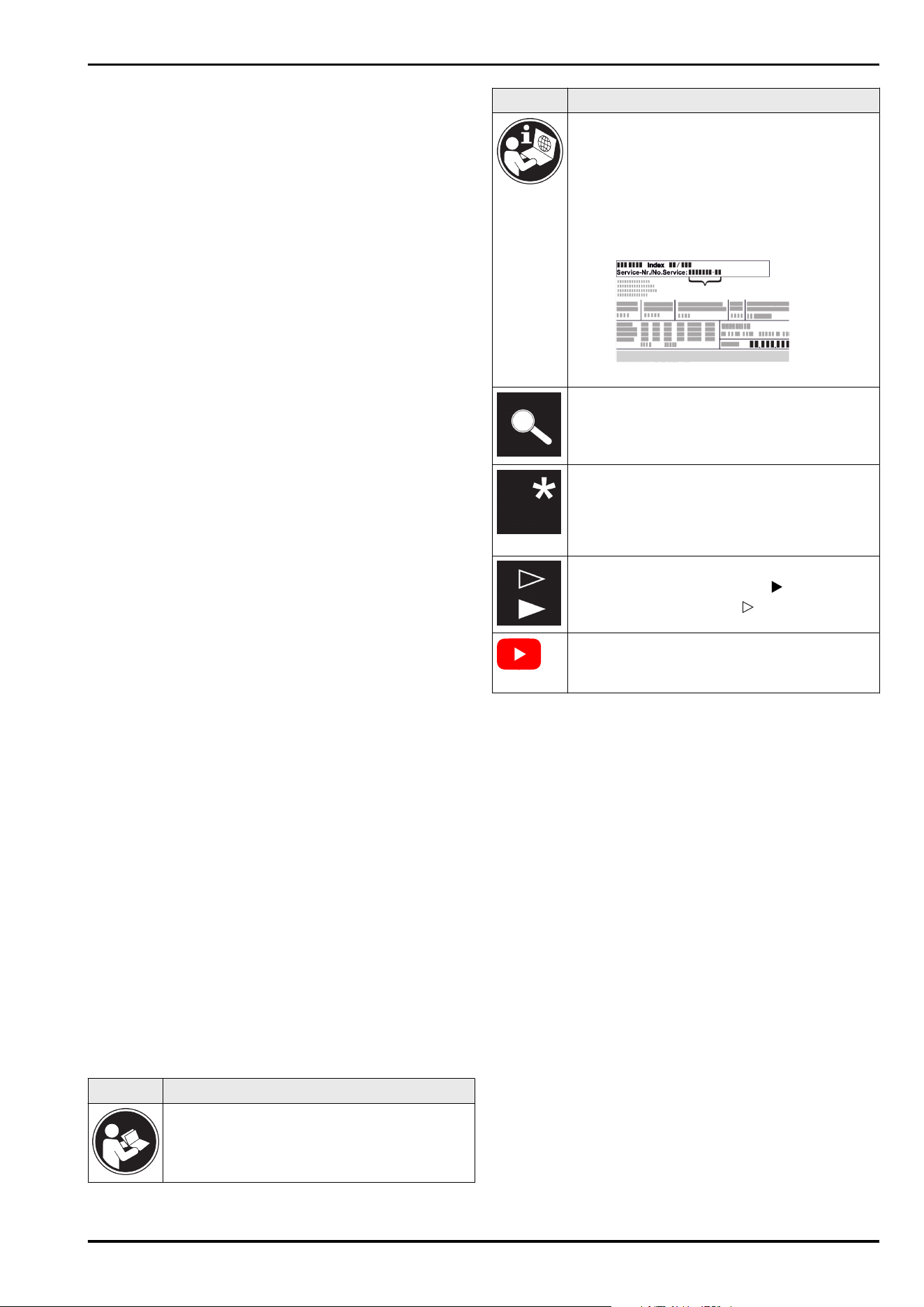
Additional information on the Internet
The digital manual with additional informa‐
tion and in other languages can be found
via the QR code on the front of the
manual or by entering the service number at
home.liebherr.com/fridge-manuals.
The service number can be found on the serial
tag:
Fig.Example illustration
Check appliance
Check all parts for transport damage. If you
have any complaints, please contact your
agent or customer service.
Differences
These instructions apply to a range of models,
so differences are possible. Sections that
apply to certain models only are marked with
an asterisk (*).
Instructions and results
Instructions are marked with a .
Results are marked with a .
Videos
Videos about the appliances are available on
the YouTube channels of Liebherr-Hausgeräte.
Open source licences:
The appliance contains software components that use
open source licences. Information on the open source
licences used can be found here: home.liebherr.com/
open-source-licences
1 General safety instructions
-
Please keep this assembly manual in a safe place so you
can refer back to it at any time.
-
If you pass the appliance on, please hand this assembly
manual to the next user.
-
Read this assembly manual carefully before installation
and use to ensure safe and correct use of the appliance.
Follow the instructions, safety instructions and warning
messages included at all times. They are important for
ensuring you can operate and install the appliance safely
and without any problems.
-
First read the general safety instructions in the
“General safety instructions” section of the oper‐
ating instructions, which accompany these installation
instructions, and follow them. If you cannot find the
operating instructions, you can download the oper‐
ating instructions from the internet by entering the
service number at home.liebherr.com/fridge-manuals.
General safety instructions
2 * Depending on model and options
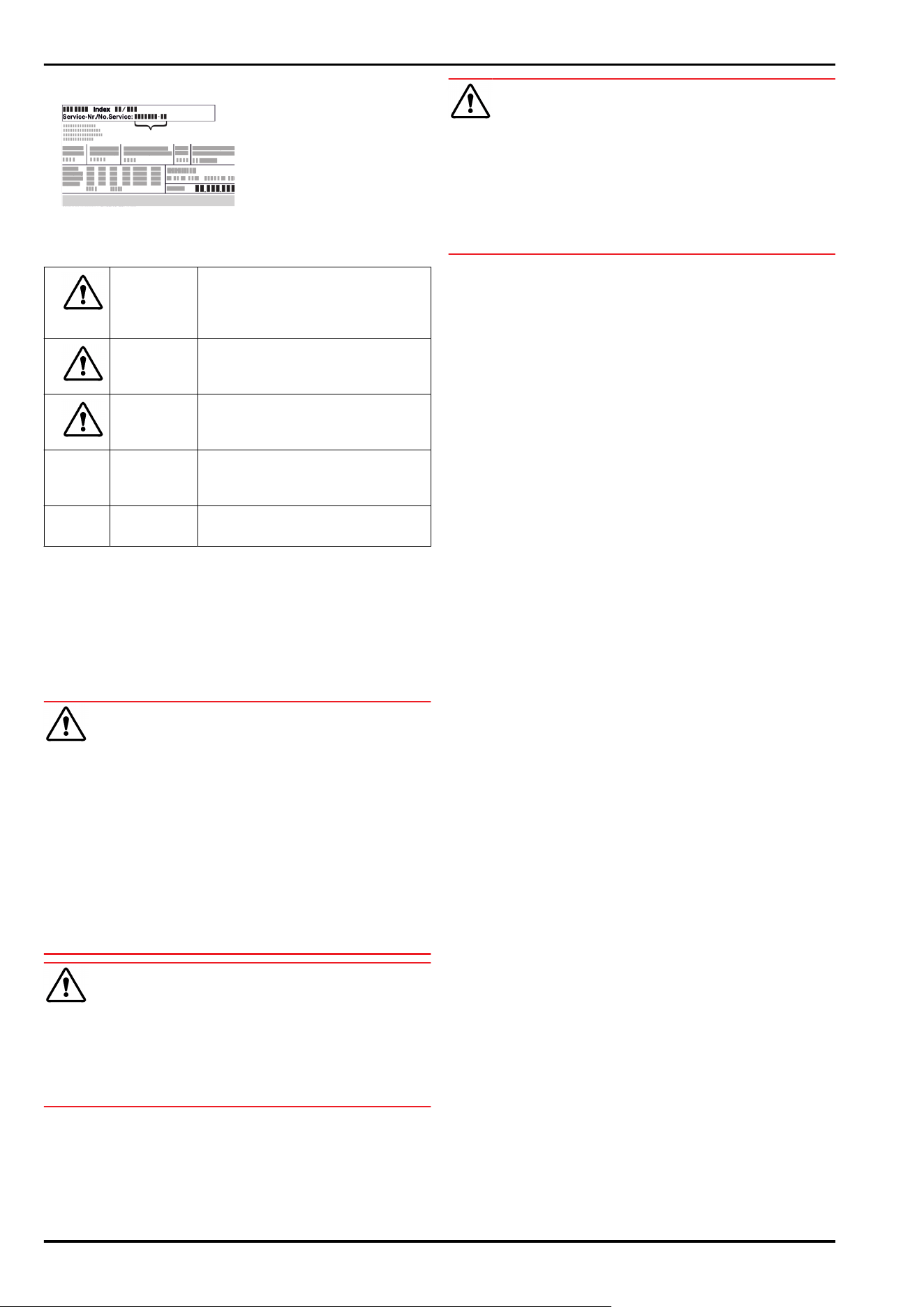
The service number can be found on the serial tag:
-
Observe the warning messages and other detailed infor‐
mation in the other sections when installing the appli‐
ance:
DANGER identifies a situation involving
direct danger which, if not obvi‐
ated, may result in death or severe
bodily injury.
WARNING identifies a dangerous situation
which, if not obviated, may result
in death or severe bodily injury.
CAUTION identifies a dangerous situation
which, if not obviated, may result
in minor or medium bodily injury.
NOTICE identifies a dangerous situation
which, if not obviated, may result
in damage to property.
Note identifies useful instructions and
tips.
2 Installation requirements
The installation conditions are crucial to ensure that you
can operate your appliance safely, efficiently and without
problems.
-
Observe all safety instructions.
-
Consider the location and position in the room.
WARNING
Danger of fire due to incorrect positioning!
If the mains cable or plug touches the back of the appli‐
ance, the vibration can damage the mains cable or the plug
resulting in a short circuit.
► Make sure the mains cable is not trapped under the appli‐
ance when you position the appliance.
► Stand the appliance so that it is not touched by connec‐
tors or main cables.
► Do not connect any appliances to sockets in the area of
the back of the appliance.
► Do not place and operate multi-sockets/power distribu‐
tors and other electronic devices (such as halogen trans‐
formers) at the back of the appliances.
WARNING
Fire hazard due to dampness!
If live parts or the mains lead become damp this may cause
short circuits.
► The appliance is designed for use in enclosed areas. Do
not operate the appliance outdoors or in areas where it is
exposed to splash water or damp conditions.
WARNING
Leaking coolant and oil!
Fire. The coolant contained in the appliance is eco-friendly,
but also flammable. The oil contained in the appliance
is flammable. Escaping coolant and oil can ignite if the
concentration is high enough and in contact with an
external heat source.
► Do not damage the pipelines of the coolant circuit and
the compressor.
2.1 Installation site
-
Only set up and use the appliance in enclosed spaces.
-
A dry and well-ventilated room is an optimum installation
location.
-
If the appliance is installed in a very damp environment,
condensation may form on the appliance exterior.
Always make sure there is good ventilation and aeration
at the installation site.
-
The more refrigerant there is in the appliance, the larger
than room must be in which it is located. In rooms that
are too small, a leak can product a flammable gas/air
mixture. For every 8g of refrigerant, the installation room
must be at least 1 m
3
in size. Information on the refrig‐
erant contained is given on the type plate inside the
appliance.
-
The floor on which the appliance stands must be hori‐
zontal and level.
2.2 Position in space
-
Do not place the appliance in direct sunlight or near radi‐
ators or similar sources of heat.
-
You can place the appliance directly next to an oven.
-
If the appliance is placed directly next to an oven,
the energy consumption may increase slightly. This is
dependent on the service life and usage intensity of the
oven.
-
Always position the appliance with the rear directly
against the wall, or with wall spacer brackets attached
(see below) then with these directly against the wall.*
-
Always position the appliance with the rear directly on
the wall.*
-
Use in hazardous areas is not permitted.
3 Integration into a kitchen unit
-
You can convert the appliance with kitchen cabinets.
Installation requirements
* Depending on model and options 3
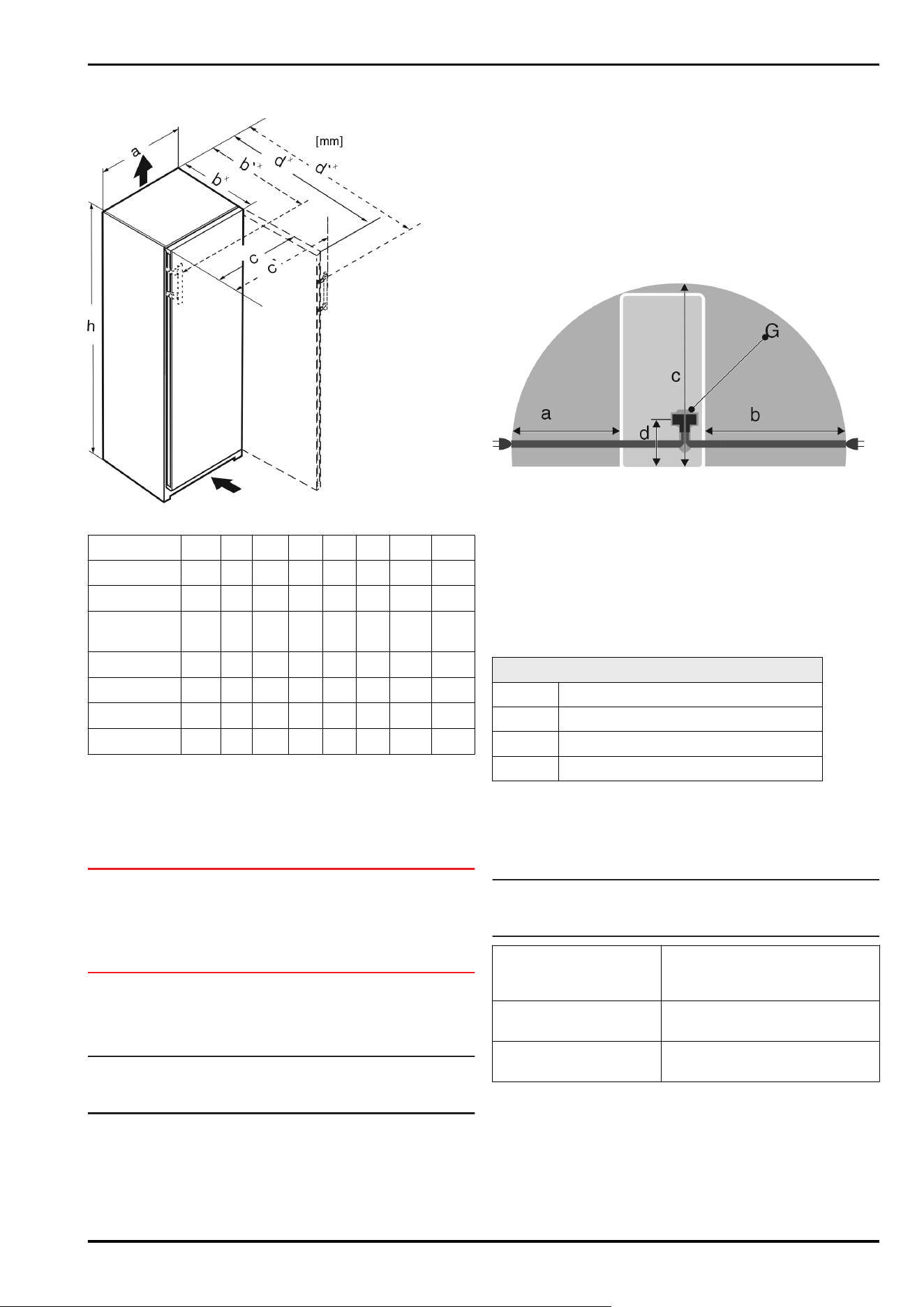
4 Installation dimensions
Fig.1
h
a b b' c c' d d'
RB.. 4250 1255 597
675
x
719
x
609 654
1215
x
1222
x
R.. 5250 1855 597
675
x
719
x
609 654
1215
x
1222
x
SR(B).. 525..
(i)
1855 597
675
x
719
x
609 654
1215
x
1222
x
RB.. 528..(i) 1855 597
675
x
— 609 —
1217
x
—
SRB.. 528..(i) 1855 597
675
x
— 609 —
1217
x
—
SRB.. 529i 1855 597
675
x
719
x
609 654
1215
x
1222
x
SRB.. 526..(i) 1855 597
675
x
719
x
609 654
1215
x
1222
x
x
For appliances with supplied wall spacers, the dimen‐
sions must be increased by 15 mm (see 10 Mounting wall
spacers*) .
5 Ventilation requirements
NOTICE
Danger of overheating due to insufficient air ventilation!
The compressor may be damaged if there is insufficient air
ventilation.
► Take care to ensure adequate air ventilation.
► Observe the ventilation requirements.
If the appliance is integrated into a kitchen unit, the
following ventilation requirements must be observed:
-
As a general rule: the larger the ventilation cross section,
the more energy the appliance will be able to save.
Note
If the spacing between the rear of the appliance and the
wall is less than 51mm, energy consumption may increase.*
6 Connection dimensions for the
power supply
The connection to the power supply is on the rear of the
appliance. To connect your appliance safely, ensure that the
following requirements are met:
❑
Dimensions for the connection to the power supply are
known and are adhered to. See table below.
❑
Connection to the power supply according to the instruc‐
tions. (see 21 Connecting the appliance to the power
supply)
Fig. 2 Refrigerators
(a)
Maximum available
length of the mains
connection cable
(d) Gap between appliance
plug and floor
(b) Maximum available
length of the mains
connection cable
(G) Appliance plug
(c) Maximum available
vertical length of
the mains connection
cable
For 600mm wide appliances:
a ~ 1350mm
b ~ 1800mm
c ~ 2050mm
d ~ 150mm
7 Water connection*
If your appliance has a fixed water connection, a hose is
supplied with it.
Note
You can purchase a hose of a different length as an acces‐
sory.
Overview of dimensions
for the water connec‐
tion:
(see 7.1 Dimensions for the
water connection)
Requirements for the
water pressure:
(see 7.2 Water pressure)
Make the water connec‐
tion:
(see 18 Connecting the appli‐
ance to the water supply*)
Installation dimensions
4 * Depending on model and options
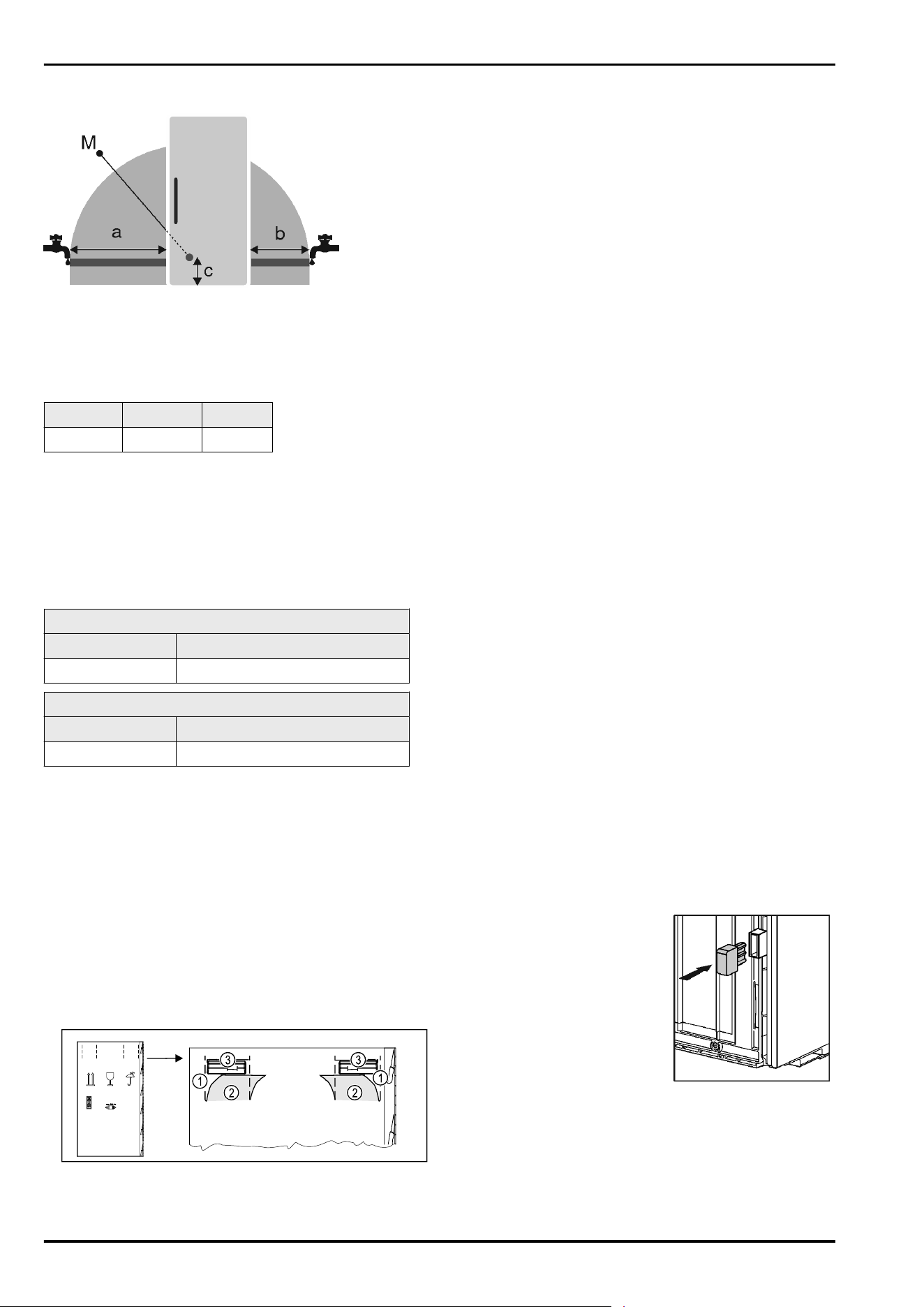
7.1 Dimensions for the water connection
Fig.3
(a)
Maximum available
hose length
(c) Distance of solenoid
valve to floor
(b) Maximum available
hose length
(M) Solenoid valve
For 600mm wide appliances:
a
b c
~ 1650mm ~ 1500mm ~ 150mm
7.2 Water pressure
The water connection line and solenoid valve of the appli‐
ance are suitable for a water pressure of up to 1 MPa
(10bar).
To ensure that the appliance functions correctly (flow rate,
ice cube size, noise level), maintain the following water
pressure:
Water pressure:
bar MPa
1.5 to 6.2 0.15 to 0.62
Water pressure when using the water filter:*
bar* MPa*
2.8 to 6.2 0.28 to 0.62
If the pressure is higher than 6.2bar:
► Fit a pressure reducer.
► Make the water connection. (see 18 Connecting the appli‐
ance to the water supply*)
8 Transporting the appliance
8.1 Transporting the appliance for initial
use
Ensure that the following requirements are met:
❑
The appliance is packaged.
❑
The appliance is upright.
Fig.4
► Press the packaging cardboard into the perforation
Fig.4(1) at the top.
►
Pull out any tabs Fig.4(2) that have been pushed in.
▷ Carrying handle Fig.4(3) visible on the right and left.
► Hold the appliance by the carrying handles Fig.4(3).
► Transport the appliance with the help of two people.
► Unpacking the appliance. (see 9 Unpacking the appli‐
ance)
8.2 Transporting the appliance after
initial use
Observe the following instructions if you wish to transport
or move the appliance again after initial use.
Ensure that the following requirements are met:
❑
The appliance is emptied.
❑
The appliance is upright.
❑
Appliance with door(s): Door is secured against acci‐
dental opening.
❑
Appliance with telescopic unit: The telescopic unit is
secured against accidental opening.
❑
Appliance with adjustable feet: Adjustable feet are
screwed in.
► Hold the appliance by the carrying handles.
► Transport the appliance with the help of two people.
After transport:
► Unscrew the adjustable feet on the appliance.
► Align the appliance. (see 12 Setting up the appliance so
that it is level)
9 Unpacking the appliance
Before you connect the appliance, report any damage imme‐
diately to the delivery company.
► Check the appliance and the packaging for damage
during transport. Contact the supplier immediately if you
suspect any level of damage.
► Remove all materials from the back or the side walls
of the appliance that may prevent proper installation or
ventilation.
► Remove all protective films from the appliance. Do not
use sharp or pointed objects for this.
10 Mounting wall spacers*
With wall spacers, your device achieves the declared energy
consumption and no condensation forms in high ambient
humidity. The device is fully functional without the spacer
brackets, but its energy consumption will be slightly higher.
If you insert the wall spacers, then the device depth
increases by approx.15mm.*
*
► Appliance with enclosed wall spacers: Insert the wall
spacers on the rear of the appliance at the bottom left
and right.
Transporting the appliance
* Depending on model and options 5
11 Setting up the appliance
CAUTION
Risk of injury due to heavy appliance!
► Have two people transport the appliance to its installa‐
tion site.
WARNING
Risk of fire due to short circuit!
► When you set the appliance up: do not kink, jam or
damage the mains cable.
► The appliance must not be operated with a defective
mains cable.
WARNING
Fire hazard and danger of damage!
► Do not place appliances emitting heat e.g. microwaves,
toasters etc. on the appliance!
Ensure that the following conditions are met:
❑
Only move the device when it is not loaded.
❑
Only install the appliance with help.
► Remove the mains cable from the package.
► Plug the mains cable’s IEC socket completely into the
appliance plug on the back of the appliance. Ensure that
the IEC socket is tight.
► Use a cord to lay the mains plug to a freely accessible
socket if required.
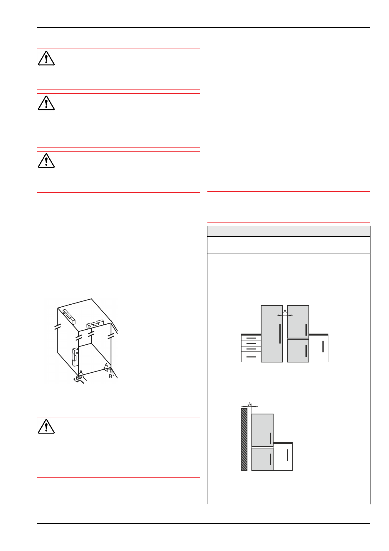
12 Setting up the appliance so that
it is level
Fig.5
► Unscrew the adjustable feet Fig. 5 (A) using the enclosed
open-end spanner and a spirit level until the appliance is
firmly aligned and level.
CAUTION
Risk of injury and damage due to the appliance tipping over!
If the additional adjustable foot on the lower swap bearing
block does not rest properly on the floor, the appliance may
tip over. This can lead to property damage and injuries.
► Unscrew the additional adjustable foot on the swap
bearing block as instructed.
► Unscrew the adjustable foot Fig. 5 (B) on the swap
bearing block with the enclosed open-end spanner until it
rests on the floor.
► Turn the adjustable foot Fig.5(B) 90° further.
▷ The appliance is aligned.
13 After setting up
► Remove all transport safety components.
► Take off the protective film from the exterior of the appli‐
ance.
► Take off the protective film from the trim panels.*
► Take off the protective film from the stainless steel rear
panel.*
► Clean the appliance. (see operating instructions)
► Note the type (model, number), appliance designation,
appliance/serial number, purchase date and dealer’s
address.
14 Installing multiple appliances
The appliances have been developed for different installa‐
tion methods. If you wish to install several appliances next
to each other or on top of each other, ensure that the
following requirements are met:
❑
Only install appliances next to or on top of each other if
they have been developed for this.
❑
Observe notices and the following table.
NOTICE
Risk of damage due to condensate!
► Do not place the appliance directly next to another
cooling/refrigeration unit.
Model Installation method
All
models
Standalone
Models
with a
model
designa‐
tion
starting
with S....
Side-by-Side (SBS)
Models
without
side wall
heating
Next to each other: Install with gap A of
70mm between the appliances.
If you do not comply with this gap, condensa‐
tion will form on the side walls between the
appliances.
On an exterior wall: Install with gap A as with
installation next to each other.
If you do not comply with this gap, condensa‐
tion may form on the appliance’s side wall.
Models and their installation method
Setting up the appliance
6 * Depending on model and options
Assemble the appliances according to the separate installa‐
tion instructions.
15 Integrating the appliance into a
kitchen unit
The appliance can be integrated into a kitchen unit. Please
observe the following installation conditions:
-
If you fit a stacking cabinet above the appliance, you
must allow for a ventilation cross-section with the appro‐
priate depth at the rear of the stacking cabinet.
-
If you place the appliance with the hinges next to a wall,
you must take the distance to the side of the appliance
into account.
-
To ensure that the door can be opened fully, the
appliance must protrude beyond the front thickness.
Depending on the niche depth, the appliance may
protrude further.
Note
A set for limiting the door opening angle to 90° can be
obtained from customer service for appliances with soft
closing.
WARNING
Risk of fire due to short circuit!
► When you set the appliance up: do not kink, jam or
damage the mains cable.
► The appliance must not be operated with a defective
mains cable.
Ensure that the following requirements are met:
❑
The socket is easily accessible and is not behind the
appliance.
❑
Ventilation requirements are met. (see 5 Ventilation
requirements) .
❑
Connection dimensions are taken into account.
(see21 Connecting the appliance to the power supply)
❑
Wall spacers are fitted.*
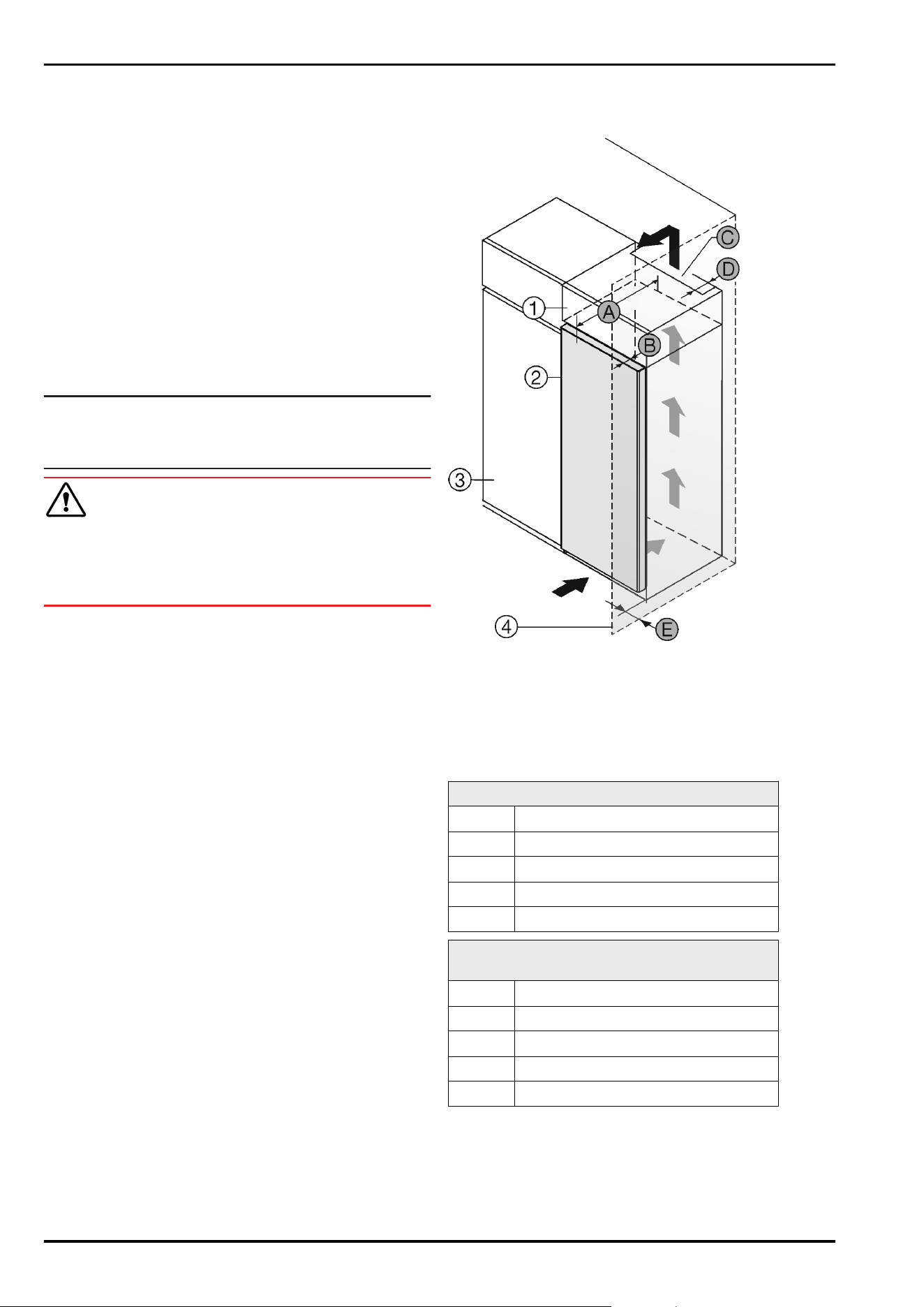
15.1 Niche dimensions for appliances
with recessed handles*
Fig.6
(1)
Top Unit (B) Door depth
(2) Appliance (C) Ventilation cross-section
(3) Kitchen cupboard (D) Distance from rear of the
appliance
(4) Wall (E) Distance to the side of
the appliance
(A) Appliance depth
Appliances with a recessed grip:
A
675mm
x
B 75mm
C
min. 300cm
2
D min. 50mm
E min. 13mm
Appliances with recessed handle and glass
front / stone front:
A
682mm
x
B 82mm
C
min. 300cm
2
D min. 50mm
E min. 20mm
x
On devices with wall spacer brackets, this dimension
increases by 15mm.*
Integrating the appliance into a kitchen unit
* Depending on model and options 7
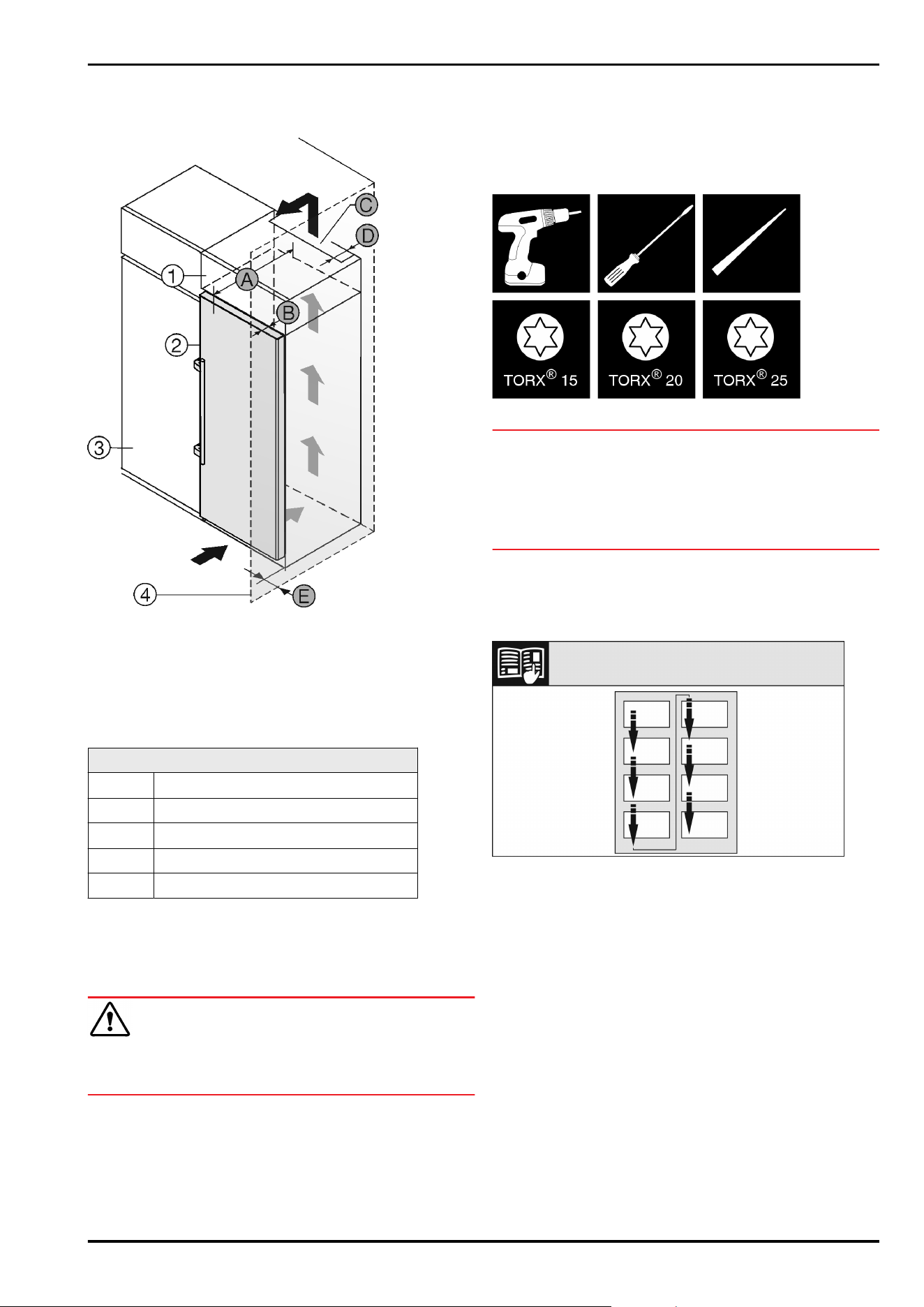
15.2 Niche dimensions for appliances
with lever handle*
Fig.7
(1)
Top Unit (B) Door depth
(2) Appliance (C) Ventilation cross-section
(3) Kitchen cupboard (D) Distance from rear of the
appliance
(4) Wall (E) Distance to the side of
the appliance
(A) Appliance depth
Dimensions with lever handle:
A
675mm
x
B 75mm
C
min. 300cm
2
D min. 50mm
E min. 57mm
x
On devices with wall spacer brackets, this dimension
increases by 15mm.*
16 Disposing of packaging
WARNING
Danger of suffocation due to packing material and plastic
film!
► Do not allow children to play with packing material.
The packaging is made of recyclable materials:
-
corrugated board/cardboard
-
expanded polystyrene parts
-
polythene bags and sheets
-
polypropylene straps
-
nailed wooden frame with polyethylene panel*
►
Take the packaging material to an official collecting
point.
17 Door hinge change
Tools
Fig.8
NOTICE
Risk of damage due to door collision!
Damage to the appliances with Side-by-Side positioning. If
you set up two appliances next to each other in a specific
Side-by-Sidearrangement, the door hinge of both appliances
is preset at the factory.
► Side-by-Side positioning: Do not change the door hinge.
These sections apply for appliances with a soft stop mech‐
anism:
❑
For appliances with a soft stop mechanism
❑
For all appliances
Fig.9
Remember the reading direction.
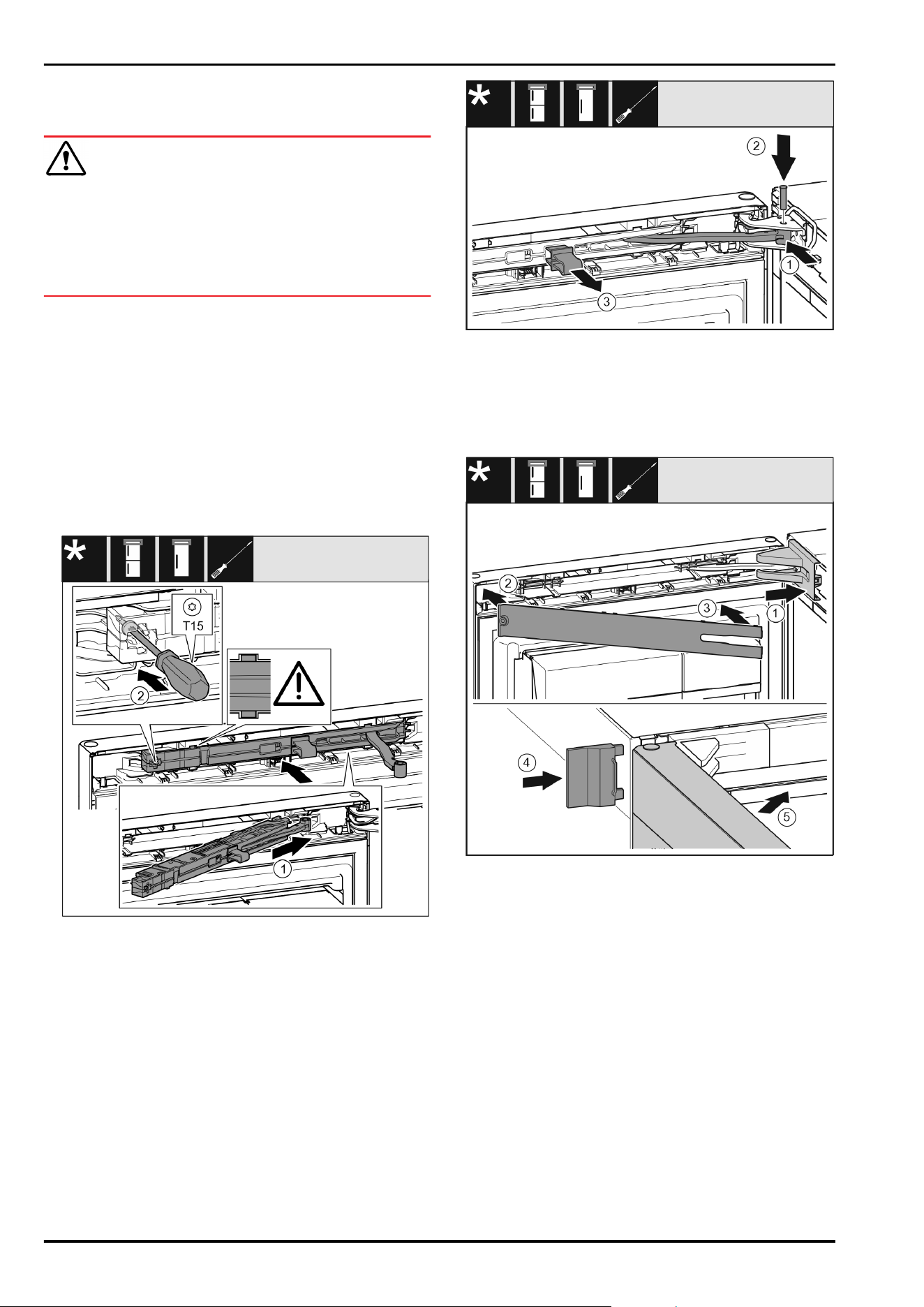
17.1 Removing the soft stop mechanism
For appliances with a soft stop mechanism:
Disposing of packaging
8 * Depending on model and options
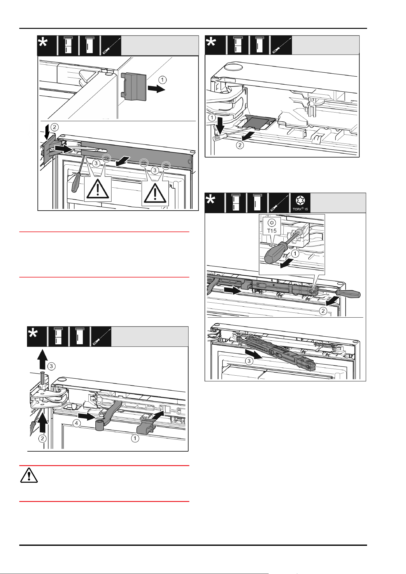
Fig. 10
► Open the door.
NOTICE
Risk of damage from screwdrivers!
If you damage the door seal, the door will not close properly
resulting in inadequate cooling.
► Use a screwdriver carefully as an aid.
► Do not damage the door seal with the screwdriver.
► Remove cover Fig. 10(1).
► Disengage and loosen the swap bearing block cover
Fig. 10(2).
► Remove the swap bearing block cover Fig. 10(2).
► Use a slotted screwdriver to unlatch the trim Fig. 10 (3)
and swing it to the side.
Fig.11
CAUTION
Crushing hazard by joint folding up!
► Engage safety device.
► Latch safeguard Fig.11(1) into opening.
► Slide out the bolt Fig.11(2).
► Remove the bolt Fig.11(3) upwards.
► Turn the joint Fig.11(4) towards the door.
Fig.12
► Use a flat-blade screwdriver to disengage the cover
Fig.12(1).
► Remove the cover Fig.12(2).
Fig.13
► Use screwdriver to loosen the screw Fig. 13 (1) on the
closing damper unit by 14mm.
► Lever the closing damper unit Fig. 13 (2) forwards on the
handle side using a screwdriver.
► Pull out the closing damper unit Fig.13(3).
17.2 Empty door racks
► Remove food from the door racks.
▷ Food does not fall out of the door when you remove the
door.
Door hinge change
* Depending on model and options 9
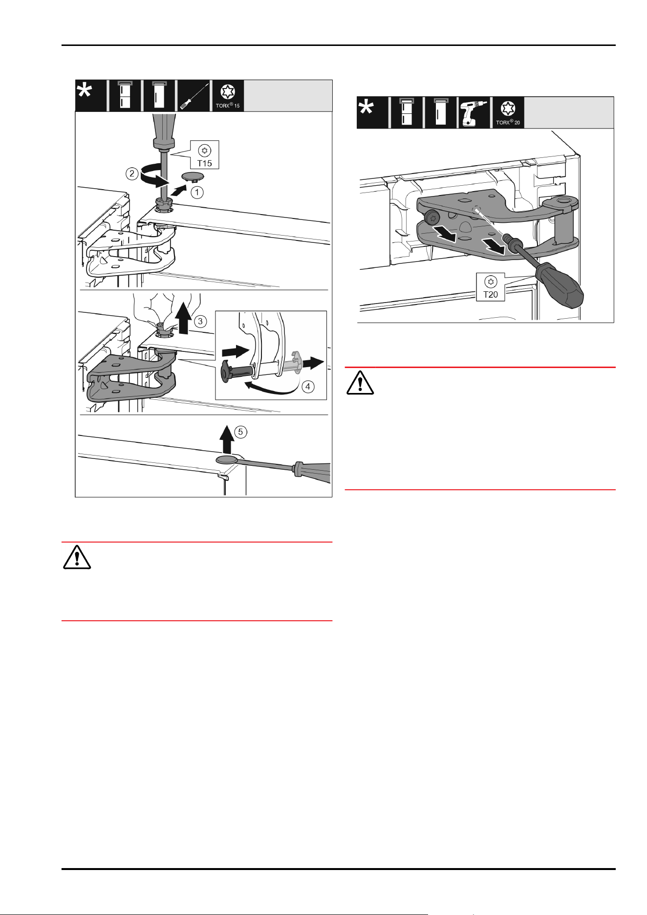
17.3 Detaching the door
Fig. 14
► Carefully remove the cover(1).
► Use screwdriver to loosen the bolts(2) a little.
CAUTION
Danger of injury due to door tipping out!
If you remove the bolt on the door completely, the door may
tilt out and you may injure yourself.
► Hold the door firmly before removing the bolt.
► Hold door in place.
► Pull out the bolt(3) with your fingers.
► Pull the bearing bush(4) out of the guide.
► Insert the bearing bush(4) on the other side and engage.
► Lift the door and put it to one side.
► Carefully lift and remove the cover(5) with a screwdriver.
17.4 Relocating the upper bearing
components
Fig. 15
► Unscrew the screws.
► Lift and remove the swap bearing block.
WARNING
Danger of injury due to door falling out!
If the bearing parts are not screwed on tightly enough, the
door may fall out. This can result in serious injuries. In
addition, the door may not close with the result that the
appliance does not cool properly.
► Screw on the bearing brackets/bearing pins tightly with
4Nm.
► Check all screws and retighten them if necessary.
Door hinge change
10 * Depending on model and options
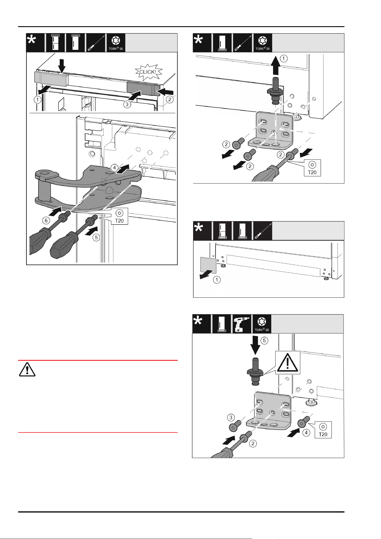
Fig. 16
► Remove the cover(1) from above towards the front.
► Turn the cover (2) by 180° and attach to the other side
from the right.
► Engage the cover(3).
► Place the top swap bearing block(4).
► Screw the screw(5) tight.
► Screw the screw(6) tight.
17.5 Moving the lower bearing parts to
the other side
For all appliances:
WARNING
Danger of injury due to door falling out!
If the bearing parts are not screwed on tightly enough, the
door may fall out. This can result in serious injuries. In
addition, the door may not close with the result that the
appliance does not cool properly.
► Screw on the bearing brackets/bearing pins tightly with
4Nm.
► Check all screws and retighten them if necessary.
Fig.17
► Pull the bearing bolt Fig.17(1) out upwards completely.
► Use screwdriver to unscrew the screws Fig. 17 (2) and
remove the swap bearing block.
For all appliances:
Fig. 18
► Remove cover Fig. 18(1).
Fig. 19
► Place the swap bearing block on the other side and use a
screwdriver to screw it on. Start with the screw Fig. 19(2)
at the bottom in the middle.
► Tighten screw Fig. 19(3) and screw Fig. 19(4).
► Insert the bearing bolt Fig. 19 (5) completely. Ensure that
the latching cam is pointing towards the rear.
Door hinge change
* Depending on model and options 11
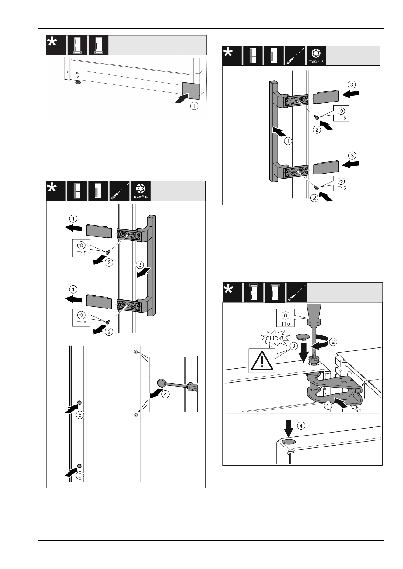
Fig.20
► Re-attach the cover Fig.20(1) to the other side.
17.6 Moving the handles to the other
side*
For all appliances:
Fig.21
► Remove the cover Fig.21(1).
► Unscrew screws Fig.21(2) with screwdriver.
► Remove the handle Fig.21(3).
► Use a slotted screwdriver to lift the side plug Fig. 21 (4)
carefully and pull it out.
►
Re-insert the plug Fig.21(5) on the other side.
Fig.22
► Place the handle Fig.22(1) on the opposite side.
▷ The screw holes must be exactly above each other.
► Tighten screws Fig.22(2) with screwdriver.
► Place the covers Fig.22(3) on the side and push them on.
▷ Ensure that they latch into place.
17.7 Fitting the door
► Place the door on the lower bearing pins.
Fig.23
► Align the top door with the opening in the swap bearing
block Fig.23(1).
► Insert the bolt Fig. 23 (2) and use screwdriver to tighten
it.
► Insert the cover Fig.23(3).
► Check that the cover Fig.23(3) is resting on the door.
► Insert the cover Fig.23(4).
Door hinge change
12 * Depending on model and options
17.8 Aligning the door
For all appliances:
WARNING
Danger of injury due to door falling out!
If the bearing parts are not screwed on tightly enough, the
door may fall out. This can result in serious injuries. In
addition, the door may not close with the result that the
appliance does not cool properly.
► Screw the bearing brackets on firmly with 4Nm.
► Check all screws and retighten them if necessary.
► Align the doors flush with the appliance housing using
the two slots in the bearing bracket if needed. To do
this undo the middle screw in the bottom bearing bracket
with the T20 tool supplied. Undo the remaining screws
a little with the T20 tool or with a T20 screwdriver and
align using the slotted holes.
► Prop up the door: Take off the adjustable foot on the
bearing bracket using the open-ended wrench SW10 until
it comes into contact with the floor, then turn an addi‐
tional 90°.
17.9 Appliances with closing damper:
Fitting the closing damper
Fig. 24
► On the swap bearing block side, slide the closing damper
unit Fig. 24(1) into the recess at an angle up to the stop.
► Push the closing damper unit completely in.
▷ The closing damper unit is positioned correctly if the
closing damper unit’s rib is in the guide in the housing.
► Use a screwdriver to tighten the screw Fig. 24(2).
Fig.25
The door is open 90°.
► Turn the joint Fig.25(1) in the bearing block.
► Insert thebolt Fig. 25 (2) into the bearing bracket and
joint. Ensure that the latching cam is in the groove prop‐
erly.
► Remove the safeguard Fig.25(3).
Fig. 26
► Put the swap bearing block cover Fig. 26 (1) on and
engage, push apart carefully if required.
► Fit the trim Fig. 26(2).
► Swivel in the cover Fig. 26(3) and engage.
► Push the outer cover Fig. 26(4) on.
► Close the upper door Fig. 26(5).
18 Connecting the appliance to the
water supply*
Make sure that the following requirements are fulfilled:
❑
The dimensions for the water supply connection are
known and complied with.
❑
The correct water pressure is maintained.
❑
Water is supplied to the appliance via a cold water
pipe which can withstand the operating pressure and is
connected to the drinking water supply.
❑
All equipment and devices used to supply water must
comply with the regulations in force in the respective
country.
Connecting the appliance to the water supply*
* Depending on model and options 13
❑
The rear of appliance is accessible so that you can
connect the appliance to the drinking water supply.
❑
The supplied hose is used. Old hoses have been disposed
of.
❑
The hose connector contains a filter with a seal.
❑
There is a tap between the hose line and the domestic
water connection so that you can turn off the water
supply if necessary.
❑
The tap is not directly behind the appliance and is easily
accessible. This way, you can push the appliance as close
as possible to the wall and can quickly turn off the tap if
necessary.
WARNING
Risk of electric shock from water!
► Before connecting to the water pipe: Disconnect the
appliance from the mains.
► Before connecting to water supply lines: Shut off the
water supply.
► Make sure that only qualified personnel connect the
device to the drinking water supply.
WARNING
Risk of poisoning due to contaminated water!
► Only connect to the drinking water supply.
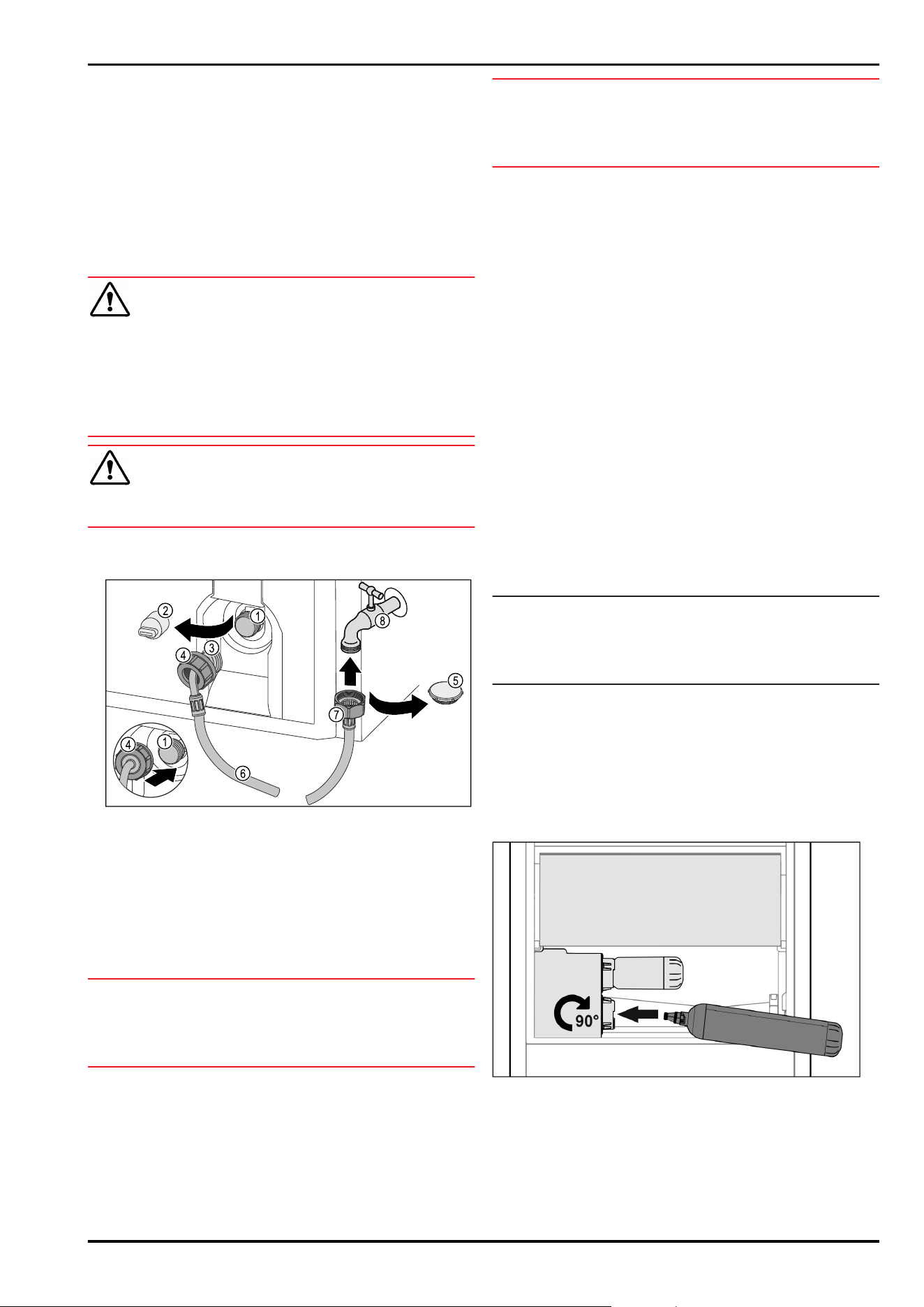
18.1 Connecting the hose
Fig.27
(1)
Solenoid valve: The
solenoid valve is
located at the bottom
rear of the appliance.
It has an R3/4 connec‐
tion thread.
(5) Closure cap
(2) Cover (6) Hose
(3) Angled hose end (7) Straight hose end
(4) Nut (8) Tap
NOTICE
Risk of damage from incorrect installation!
► Do not damage or kink the hose.
► Do not damage or kink the hose when setting up the
appliance.
Connecting the hose to the appliance:
► Pull off the cover(2).
► Push and hold the nut (4) all the way over the angled
hose end(3).
NOTICE
The solenoid valve will not be tight if the thread is damaged!
If the solenoid valve is not tight, water may leak out.
► Observe the following instructions for fitting the nut on
the solenoid valve.
► Carefully position and hold the nut (4) on the solenoid
valve(1).
► Screw the nut(4) by hand straight onto the thread until it
is securely and firmly seated.
▷ The hose is connected to the appliance.
Connecting the hose to the tap:
► Remove the closure cap Fig.27(5).
► Place the straight end of the hose Fig. 27 (7) on the tap
Fig.27(8).
► Tighten the nut at the straight end of the hose Fig. 27 (7)
in a clockwise direction.
▷ The hose is connected to the tap.
18.2 Checking the water system
Before you completely install the appliance, Liebherr recom‐
mends checking the water system for leaks.
► Put in the InfinitySpring water tank. (see 19 Water tank*)
*
► Put in the InfinitySpring water filter. (see20 Water filter*)
*
► Slowly turn on the tap.
► Check the hose, water feed and connections for leaks.
▷ The water system has now been checked for leaks.
▷ The water system is not leaking: You can install up the
appliance completely.
Note
InfinitySpring: Before the first use, you must put the Infin‐
itySpring into operation. To do this you must bleed and
clean the water system. (see Quick Start Guide or operating
instructions)*
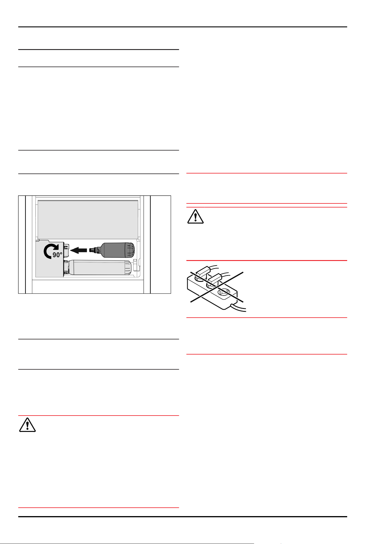
19 Water tank*
The water tank of the InfinitySpring is located behind the
bottom drawer in the fridge section or BioFresh compart‐
ment, depending on the device.*
19.1 Inserting the water tank
Fig.28
► Remove the drawer compartment.
► Insert the water tank and rotate approx. 90° clockwise
until it clicks in.
► Check that the tank is sealed and no water leaks out.
► Insert the drawer compartment.
► Bleed the water system. (see Quick Start Guide or oper‐
ating instructions)
Water tank*
14 * Depending on model and options
Instead of the water filter you can insert an additional water
tank.*
Note
You can purchase this water tank as an optional extra.
20 Water filter*
Depending on your model, the water filter is behind the
lowest drawer in the fridge or BioFresh compartment.*
It filters out deposits in the water and reduces the taste of
chlorine.
❑
Replace the water filter at least every 6 months, or if
there is a significant reduction in the flow rate.
❑
The water filter contains carbon and can be disposed of
with the regular household waste.
Note
Water filters are available from the Liebherr-Hausgeräte
store at home.liebherr.com/shop/de/deu/zubehor.html.
20.1 Inserting the water filter
Fig.29
► Remove the drawer compartment.
► Insert the water filter and rotate approx. 90° clockwise
until it clicks in.
► Check that the filter is sealed and no water leaks out.
► Insert the drawer compartment.
Note
New water filters may contain suspended particles.*
► After replacing the filter: Draw and dispose of 3l water at
the InfinitySpring.
▷ The water filter is now ready for use.
21 Connecting the appliance to the
power supply
WARNING
Danger of electric shock and injury due to damaged appli‐
ance or damaged mains cable!
Danger of cuts and fatal injuries. If the appliance or the
mains cable is damaged during transport, you may be elec‐
trocuted. You could also cut yourself on damaged parts of
the appliance housing.
► Check the appliance and the mains cable for damage
after transport.
► Never put the appliance into operation if the appliance or
the mains cable are damaged.
► Contact Customer Service.
You can connect your appliance to the mains using the
power cable supplied separately. The mains power cable
has an appliance coupler at one end and a mains plug at the
other end.
Make sure that the following requirements are fulfilled:
-
The appliance and power cable are undamaged.
-
The appliance is set up in accordance with the regula‐
tions. (see 10 Mounting wall spacers*)
-
Requirements for the electrical connection are met.
-
Dimensions for connection in accordance with regula‐
tions are known and observed. (see 6 Connection dimen‐
sions for the power supply)
-
Mains voltage and frequency correspond to the specifica‐
tions on the type plate.
-
The socket is earthed according to the regulations and
fused.
-
The fuse tripping current is between 10A and 16A.
-
The socket is easily accessible and is not behind the
appliance. (see 6 Connection dimensions for the power
supply)
NOTICE
Danger of damage to incorrect operation!
Damage to the electrical components of the appliance.
► Only use the supplied mains cable.
WARNING
Danger of fire due to incorrect connection!
Burns.
Damage to the appliance.
► Do not use an extension cable.
► Do not use distributor blocks.
NOTICE
Danger of damage to incorrect connection!
Damage to the appliance.
► Do not connect the appliance to a stand-alone inverter,
e.g. solar power systems and petrol generators.
► Connect the mains cable plug to the power supply.
Ensure that the plug is tightly in the socket.
▷ The Liebherr logo appears in the display.
▷ The display switches to the standby symbol.
▷ If no action occurs within 60 seconds: The standby
symbol fades or disappears.
▷ The appliance is connected. For information regarding
first use, see the following section or the operating
instructions.
Water filter*
* Depending on model and options 15

home.liebherr.com/fridge-manuals
fridge
Issue date: 20251117
Part number index: 7086759-00
Liebherr-Hausgeräte Marica EOOD
Bezirk Plovdiv
4202 Radinovo
Bulgarien