
rR
730
Receiver
Owner's
Manual

WARNING
TO
PREVENT
FIRE
OR
SHOCK
HAZARD,
DO
NOT
EXPOSE
THIS
APPLIANCE
TO
RAIN
OR
MOISTURE.
Please
record
the
Serial
Number
in
the
space
below
to
have
it
as
a
reference.
Model
Number:
Nakamichi
730
Serial
Number
Please
read
all
accompanying
Warranty
cards
and/or
notices
very
carefully.
CONTENTS
CONTROLS
AND
FEATURES
...-
1
PRECAUTIONS
.---
+++
essere
4
CONNECTIONS
...-----
eee
eee
5
Preparing
Speaker
Wire
-.-.-+----
5
Connecting
Speakers
«+--+
---+-+5-
5
Turntable
Connections
.-..+-+-+--
5
Tape
Recording
and
Playback
Jacks..
5
Auxiliary
Sources
6
+e
eee
eee
ee
6
Preamplifier
Output/Main
Amplifier
Input
Jacks.
eee
ee
eee
ees
6
Remote
Control
...-
++
eee
eee
6
FM
Antenna
Connections
......-.
6
Power
Connections
....+-.-+-+:
6
OPERATION
...---
este
ee
eee
7
Power
2.
cece
eee
ete
teens
7
Selectinga
Source
.--+--+--++--
7
Using
the
Volume
and
Tone
Controls
7
FM
Tuning...
.--
eset
e
terres
8
Pre-Setting
FM
Stations-.-.....-.
8
Receiving
Weak
FM
Stations
....-.-
9
Tape
Playback
6.
eee
eee
eee
eee
9
Tape
Recording
.--
+--+
e
ee
eee-
9
Headphones.
.----
seer
eee
eee
10
Timer
Operation
..---
+++
eee
ees
10
Memory
Batteries
.--+-+-+-++---
10
ABOUT
SPEAKER
PHASING
.....
11
ABOUT
DOLBY
FM
.....------>
11
ABOUT
FM
ANTENNAS.....----
12
Indoor
Antennas
.---
+--+
+++
es
12
Outdoor
TV
Antennas
and
Cable
Systems...
eee
eee
eee
12
Selecting
an
Outdoor
FM
Antenna.
.
.
13
Transmission
Line
.--+
+--+
-++++->
13
Connections
to
the
730----------
13
Installing
the
F-Connector...--.---
13
TROUBLESHOOTING......-+-.-
15
SPECIFICATIONS...
+--+ sees
eee
16

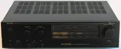
Thank
you
for
purchasing
the
Nakamichi
730
Receiver.
Over
the
years,
Nakamichi
Research
has
been
at
the
cutting
edge
of
electronic
and
magnetic
technology.
The
Nakamichi
730
is
the
product
of
an
extensive
effort
to
bring
the
best
in
solid
state
circuitry
to
the
receiver
format.
But
the
730
is
more
than
that.
It is
a
striking
essay
in
human
engineering
and
industrial
design.
At
the
moment,
the
unique
controls
and
features
of
the
730
may
be
unfamiliar
to
you.
This
manual
has
been
designed
to
acquaint
you
with
the
730
in
the
shortest
possible
time.
The
first
part
of
this
manual
will
help
you
connect
the
730.
A
brief
section
on
operation
will
review
the
730’s
capabilities.
Read
the
remaining
sections
at
your
leisure.
They
deal
with
such
topics
as
selecting
an
FM
antenna,
checking
your
speakers
for
proper
phase,
and
Dolby
FM
broadcasting.
Nakamichi
Corporation

Controls
and
Features
The
730
Receiver
incorporates
touch
sensors.
Most
of
the
functions
of
the
730
can
be
controiled
by
simply
touching
the
appropriate
sensor.
Lamps
immediately
under
the
sensors
glow
to
indicate
the
control
status
of
the
730.
An
internal
memory
retains
the
contro!
status
when
the
receiver
is
switched
off
or
disconnect-
ed
from
an
AC
outlet.
Thus,
if
the
receiver
is
tuned
to
a
specific
FM
station
at
a
specific
volume
when
you
turn
it
off,
it
will
still
be
at
that
station
and
volume
the
next
time
you
turn
it
on.
Please
note
that
the
touch
sensors
rely
on
some
residual
moisture
on
the
tips
of
your
fingers.
If
your
hands
are
extremely
cold
—
as
they
might
be
during
the
winter
months
when
you
first
come
in
from
outdoors—you
may
need
to
rub
or
otherwise
moisten
your
finger-
tips.
(1)
Power
Sensor:
Activates
the
730
when
the
master
power
-switch
(on
the
rear
panel)
is
in
the
“ON”
Position.
When
power
is
on,
the
orange
indi-
cator
lamp
immediately
beneath
the
sensor
will
glow.
A
second
touch
of
the
power
sensor
will
turn
the
730
off.
(2)
Headphone
Jacks
A
and
B:
Accept
stereo
headphones
with
impedance
be-
tween
8
and
250
ohms.
Inserting
a
headphone
plug
into
jack
A
will
automatically
cut
off
Output
to
the
speakers.
You
can
use
head-
phones
and
speakers
simultaneously
by
insert-
ing
the
headphone
plug
into
jack
B.
(3)
Volume
Contro!
Sensors:
The
outer
two
volume
sensors
raise
or
lower
the
volume
quickiy.
Touching
either
of
the
outer
sensors
and
the
center
sensor
simultaneously
will
raise
or
lower
the
volume
slowly.
(4)
Volume
Indicator
(5)
Volume
Scale
(6)
Audio
Mute
Sensor:
The
audio
mute
decreases
the
volume
by
14
dB
when
you
touch
this
sensor.
Thus,
you
can
lower
the
volume
temporarily
to
connect
or
disconnect
headphones,
answer
a
telephone
call,
or
change
FM
stations.
To
disengage
the
audio
mute,
touch
the
sensor
a
second
time.
The
audio
mute
indicator
light
will
go
out
and
the
volume
level
will
return
to
normal.
(7)
Function
Sensor
Group:
By
touching
the
appropriate
sensor,
you
can
select
a
turntable
(“Phono”),
either
of
two
tape
decks
("Tape
1°
and
‘Tape
2”),
FM,
or
an
auxiliary
input
(‘Aux’)
as
the
source.
00
4)
2
4
'
'
'
’
'
'
'
'
'
'
TUT
ERECTA
TTT
TTT
3-
(8)
Volume
Preset
Control:
Sliding
the
control
to
the
left
of
its
center
detented
position
decreases
the
volume
and
applies
loudness
contour
compensation.
Sliding
the
control
to
the
right
of
the
center
detent
decreases
the
volume.
You
can
use
the
volume
Preset
control
to
supplement
the
main
volume
control.
By
presetting
a
certain
amount
of
loudness
compensation
or
attenuation,
you
can
establish
a
comfortabie
listening
levet
at
10”
on
the
volume
scale.
qin
Function
Tape
1
(9)
Balance
Control:
Sliding
the
control
to
the
left
of
its
center
detented
position
moves
the
stereo
image
toward
the
left
speaker
by
decreasing
the
loudness
of
the
right
speaker.
Sliding
the
control
to
the
right
of
the
center
detent
has
the
opposite
effect.
You
can
use
the
balance
contro!
to
adjust
the
stereo
image
for
room
conditions
and
for
imbalances
in
the
program
material.
i
j

®oG
®
@
©
i
Stered
DolbyFM
Hr-blend
FMNute
ace
i i
(10)
Tape
Monitor
Sensor
Group:
When
you
touch
the
‘’Source”
sensor,
you
can
listen
to
the
source
you've
selected
on
the
function
sensor
group.
When
you
touch
either
“Tape
1"
or
‘Tape
2,"
you
can
listen
to
the
corresponding
tape
deck,
regardless
of
the
source
selected
on
the
function
sensor
group.
With
a
three-head
tape
deck,
the
tape
monitor
feature
allows
you
to
audition
a
tape
recording
as
it
is
being
made.
(11)
Tone
Controls:
The
bass
control
alters
the
relative
volume
of
low
frequency
program
material.
The
treble
control
does
the
same
for
high
frequency
material.
You
can
use
these
controls
to
com-
Pensate
for
room
acoustics
and
deficiencies
in
the
program
material,
and
to
adjust
the
sound
quality
to
your
preference.
s0amt
Jom"
2000"
|
Threvrod
i
(12)
Stereo
Sensor:
Touch
this
sensor
for
monophonic
sound.
The
indicator
lamp
will
go
out.
Touch
again
for
stereo.
The
indicator
lamp
will
glow.
Even
with
the
sensor
set
for
stereo,
the
indicator
lamp
will
go
out
when
the
730
is
receiving
a
monophonic
FM
broadcast.
(13)
Dolby
FM
Sensor:
Touch
this
sensor
to
properly
decode
a
Dolby
FM
broadcast
when
the
DB-100
Dolby
FM
circuit
board
is
installed.
The
DB-100
is
fac-
tory-installed
in
all
Nakamichi
730’s
sold
in
the
United
States,
and
is
available
as
an
option
in
other
countries.
Selecting
Dolby
FM
when
the
DB-100
is
not
installed
will
interrupt
the
FM
tuner
output.
(14)
Hi-Blend
Sensor:
Selecting
Hi-Blend
will
reduce
high-frequency
noise
during
FM
stereo
reception
at
some
sacrifice
of
high-frequency
stereo
separation.
(15)
FM
Mute
Sensor:
The
730
will
mute
all
incoming
stations
and
noise
below
a
fixed
level
when
the
FM
mute
is
engaged.
Muting
will
also
engage
when
the
tuner
is
scanning
between
stations.
(16)
Tuning
Pointer
(17)
Tuning Lamps:
The
two
tuning
lamps
will
glow
simultaneously
to
indicate
that
the
tuner
is
locked
onto
a
station
above
the
threshold
!evel.
If
the
tuner
is
slightly
off-station,
one
of
the
two
lamps
will
glow
to
indicate
the
direction
of
the
station.
If
the
tuner
is
receiving
a
station
below
the
threshold
level,
neither
lamp
will
glow.
(18)
Station
Memory
Sensors:
Once
you
have
adjusted
the
station
preset
controls,
touching
a
station
memory
sensor
will
cause
the
tuner
to
go
directly
to
an
FM
station
of
your
choice
and
lock
on
to
that
station.
You
may
preset
up
to
four
stations.
(19)
Station
Preset
Controls:
Each
station
preset
control
is
only
active
when
the
corresponding
memory
sensor
has
been
touched.
Use
the
preset
controls
to
manually
tune
in
up
to
four
selected
FM
stations.
Once
Preset,
each
station
can
be
tuned
in
automati-
cally
by
touching
the
appropriate
station
memory
sensor.
(20)
Threshold
Control:
The
threshold
contro!
works
to
reject
intersta-
tion
noise
and
weak
FM
stations
as
the
tuner
scans
for
stations.
You
can
use
the
threshold
control
to
exclude
stations
below
your
stand-
ards
of
quiet
listening.
The
higher
you
set
the
threshold
control
(the
further
to
the
left),
the
fewer
the
stations
you
will
receive
from
auto-
matic
scanning.
(21)
Tuning
Sensors:
Touch
and
hold
a
tuning
sensor
to
have
the
FM
tuner
move
up
or
down
the
FM
dial.
Touch
a
tuning
sensor
and
release
to
have
the
FM
tuner
stop
at
the
first
FM
station
above
the
threshold.
i
'

(22)
75-ohm
Unbalanced
Connector:
Connect
any
FM
antenna
using
a
75-ohm
coaxial
cable
to
this
terminal.
(23)
300-ohm
Balanced
Terminals:
Connect
any
FM
antenna
using
300-ohm
twin-
lead
cable—including
the
supplied
dipole
antenna—to
these
terminals.
(24)
Attenuator
Switch:
In
the
rare
case
that
the
antenna
input
is
too
strong
for
the
FM
“front
end,”
set
this
switch
to
the
‘‘—20
dB”
position.
In
all
other
cases,
leave
the
switch
in
the
“0”
position.
(25)
Ground
Terminal:
Connect
the
turntable’s
ground
wire
to
this
terminal,
(26)
Phono
Input
Jacks:
Connect
the
turntabie’s
left
channel
signal
cable
to
the
upper
Phono
input
jack.
Connect
the
right
channel
cable
to
the
lower
jack.
(27)
Auxiliary
Input
Jacks:
Connect
the
left
channel
signal
cable
of
an
auxiliary
source
to
the
upper
Aux
input
jack.
Connect
the
right
channel
cable
to
the
lower
jack.
®
®
@
®@
@
0©
08
@ ®
(28)
Tape
2
Playback
Input
Jacks:
Connect
the
left
channel
‘Line
Output”
jack
of
your
second
tape
deck
to
the
upper
Tape
2
Playback
Input
jack.
Connect
the
right
channel
to
the
lower
jack.
(29)
Tape
2
Recording
Output
Jacks:
Connect
the
left
channel
‘Line
Input’
jack
of
your
second
tape
deck
to
the
upper
Tape
2
Recording
Output
jacks.
Connect
the
right
channel
to
the
Jower
jack.
(30)
Tape
1
Playback
Input
Jacks:
Connect
the
left
channel
‘Line
Output”
jack
of
your
first
tape
deck
to
the
upper
Tape
1
Playback
Input
jack.
Connect
the
right
channel
to
the
lower
jack.
{31)
Tape
1
Recording
Output
Jacks:
Connect
the
left
channel
“Line
Input”
jack
of
your
first
tape
deck
to
the
upper
Tape
1
Recording
Output
jack.
Connect
the
right
channel
to
the
lower
jack.
®
(32)
Preamplifier
Output
Jack:
Normally,
you
would
leave
the
connectors
from
the
Preamplifier
Output
jacks
to
the
Main
Input
Jacks
in
place.
Removing
the
connectors
sepa-
rates
the
preamplifier
section
of
the
730
from
the
power
amplifier
section
for
special
applica-
tions.
These
include
multi-amplification,
and
the
use
of
filters,
signal
processors,
and
speaker
equalizers.
(33)
Main
Amplifier
Input
Jacks:
The
inputs
to
the
power
amplifier
section
of
the
730.
Normally
connected
directly
to
the
Preamplifier
Output
jacks.
(34)
Recording
Output
Level
Control:
Varies
the
“0
dB”
recording
output
level
from
100
millivolts
to
300
millivolts.
Normally
you
would
leave
this
control
in
the
medium,
12
o'clock
position.
(35)
Remote
Jack:
Provides
connection
for
the
Remote
Control.
The
Remote
Control
duplicates
many
touch
sensor
functions
of
the
730's
front
panel.

(36)
AC
Outlets:
Supply
AC
power
when
the
front
panel
power
switch
is
on.
Do
not
connect
equipment
with
a
total
maximum
power
consumption
of
greater
than
100
watts.
(37)
Master
Power
Switch:
You
would
normally
leave
this
switch
in
the
“ON”
position.
With
the
master
Power
switch
set
to
“OFF,”
the
front
panel
Power
sensor
will
not
activate
the
730.
(38)
AC
Power
Cord
(39)
Left
Channel
Speaker
Terminals:
Connect
the
red
terminal
to
the
feft
loud-
speaker's
positive
(+)
terminal.
Connect
the
black
to
negative
(—).
(40)
Right
Channel
Speaker
Terminals:
Connect
the
red
terminal
to
the
right
loud-
speaker's
positive
(+}
terminal.
Connect
the
black
to
negative
(—}.
Precautions
(A)
Do
not
install
the
730
close
to
heat
sources
(such
as
radiators),
or
in
a
place
subject
to
direct
sunlight,
ex-
cessive
dust,
or
moisture.
(B)
Leave
eight
centimeters
(three
inches)
clearance
above
and
to
the
side
of
the
heat
sink
fins.
This
will
provide
adequate
ventilation.
(C)
Do
not
connect
equipment
with
a
total
maximum
power
consumption
of
greater
than
100
watts
to
the
AC
outlets
(36).
Leave
the
master
Power
switch
(37}
off
until
you
have
completed
all
connections.
(E)
A
muting
circuit
in
the
730
dis-
connects
the
output
for
several
sec-
onds
after
the
receiver
is
switched
on
to
prevent
switching
transients
from
reaching
your
loudspeakers.
Leave
the
volume
controls
of
the
730
at
moderate
levels
until
the
muting
cir-
cuit
has
released.
This
will
prevent
a
sudden
burst
of
sound
when
the
circuit
releases.
Similarly,
keep
the
volume
controls
of
the
730
at
moderate
levels
when-
ever
you
connect
and
disconnect
headphones.
(G)
Four
“AA”
size
batteries
(supplied)
maintain
the
contro!
—
status
“memory”
when
the
730
is
unplugg-
ed
or
when
the
master
power
switch
(37)
is
set
to
“OFF”.
To
install
these
batteries,
place
the
730
upside
down
on
a
soft
surface.
Remove
the
bat-
tery
cover
by
unscrewing
the
two
thumb-screws.
Install
the
batteries,
taking
care
to
observe
the
polarity
of
the
battery
terminals.
Replace
the
cover.
Battery
life
is
about
two
years.
When
battery
voltage
is
too
low,
the
orange
power
indicator
lamp
on
the
front
pane!
will
flicker.
(D
(F
i
i
i

Connections
Note:
Leave
the
master
power
switch
(37)
off
until
you
have
com-
pleted
all
connections.
Preparing
Speaker
Wire
Use
stranded,
two-conductor
wire
to
connect
your
loudspeakers
to
the
730.
Sixteen-gauge
lamp
cord
is
satisfactory
for
most
applications.
For
wire
runs
longer
than
8
meters
(25
feet),
heavier
gauge
wire
(with
a
lower
number)
is
preferable.
Cut
two
segments
of
wire
approximately
equal
in
length.
Both
should
be
long
enough
to
reach
the
farther
loudspeaker
comfortably.
Separate
the
conductors
for
about
5
centimeters
(2
inches)
at
each
free
end.
Carefully
remove
about
1
centi-
meter
(one
quarter-inch)
of
insulation
from
each
conductor.
Twist
the
exposed
strands
of
each
conductor
so
that
they
are
smooth
and
tight.
At
this
point
you
may
wish
to
“tin’’
the
exposed
strands
of
each
conductor
with
a
drop
of
solder.
This
will
help
prevent
the
strands
of
one
conductor
from
inadvertently
touching
the
other
conductor
and
“shorting
out’
the
system.
For
the
same
reason,
do
not
drive
staples
or
tacks
through
the
center
of
the
speaker
wire.
A
short
circuit
will
reduce
the
loudness
of
the
system,
or
eliminate
the
sound
altogether.
Connecting
Speakers
Connect
the
positive
(+)
right
channel
speaker
terminal
(40,
red)
to
the
positive
(+)
terminal
of
your
right
loudspeaker.
(Loudspeakers
are
generally
marked
“+”
and
“—",
although
some
speakers
use
other
labelling
systems,
such
as
1’
and
“O",
“hot”
and
“ground”,
etc.).
Hold
the
button
on
the
side
of
the
730’s
terminal
down
as
you
insert
the
conductor
into
the
hole.
Release
the
button.
The
conduc-
tor
should
now
be
locked
firmly
into
place.
In
the
same
manner,
connect
the
negative
(—)
right
channel
speaker
ter-
minal
(40,
black)
to
the
negative
(—)
Speakers
terminal
of
your
right
loudspeaker.
Re-
peat
the
procedure
for
the
left
channel
terminals
(39)
and
your
left
loudspeaker.
Take
care
to
observe
the
polarity
of
the
terminals
as
you
did
with
the
right
channel.
Lamp
cord
usually
provides
a
code
which
differentiates
the
two
conductors.
This
code
enables
you
to
connect
the
proper
amplifier
terminals
to
the
proper
speaker
terminals
without
tracing
down
the
length
of
each
conductor.
The
code
may
consist
of
a
rib,
sharp
corner,
or
indenta-
tions
molded
along
the
length
of
the
insulation
of
one
conductor.
In
some
cases,
a
thin
colored
thread
is
molded
inside
the
insulation,
along
with
one
conductor.
In
the
most
frequent
case,
each
conductor
(or
the
insulation
of
each
conductor)
is
a
different
color.
The
sec-
tion
of
this
manual
titled
“About
Speaker
Phasing’’
describes
the
purpose
behind
differentiating
the
conductors
and
ter-
minals.
Turntable
Connections
Turntables
are
usually
supplied
with
color-coded
signal
cables.
Consult
the
‘turntable
owner’s
manual
to
determine
which
is
the
left
channel
signal
cable
and
insert
its
plug
into
the
upper
phono
input
jack
(26).
Connect
the
right
channel
cable
to
the
lower
jack.
If
the
turntable
is
supplied
with
a
separate
ground
wire,
connect
it
to
the
ground
terminal
(25).
Tape
Recording
and
Playback
Jacks
The
tape
recording
output
(29,
31)
and
playback
input
(28,
30)
jacks
are
usually
used
to
connect
tape
decks
to
the
730.
They
can
also
be
used
to
connect
external
dynamic
processors,
noise
reduction
systems,
graphic
and
parametric
equal-
izers,
etc.
Consult
the
signal-processor
owner's
manual
on
the
best
method
of
interconnection.
To
connect
tape
decks,
start
by
connect-
ing
the
line
outputs
of
your
first
tape
deck
to
the
tape
1
playback
input
jacks
(30).
Connect
the
left
channel
to
the
upper
jack
and
the
right
to
the
lower
jack.
Connect
the
line
inputs
of
your
first
tape
deck
to
the
tape
1
recording
output

line
input
Tape
Deck
2
jacks
(31).
Connect
the
left
channel
to
the
upper
jack
and
the
right
to
the
lower
jack.
For
a
second
tape
deck,
repeat
the
procedure
using
the
tape
2
playback
input
(28)
and
recording
output
(29)
jacks.
Auxiliary
Sources
The
auxiliary
input
jacks
(27)
allow
the
connection
of
any
“‘line
level’
source.
Such
sources
include
the
output
of
a
third
tape
deck;
an
AM,
long-wave,
marine,
aircraft,
or
citizen’s
band
tuner;
and
the
audio
output
of
a
television
set.
Consult
your
dealer
if
you
have
questions
regarding
the
compatibility
of
an
auxil-
iary
source.
Nakarnichi
730
Receiver
Turntable
Nakamichi
730
Receiver
Tape
Deck
1
Preamplifier
Output/Main
Amplifier
Input
Jacks
Normally,
you
would
leave
the
connec-
tors
from
the
preamplifier
output
jacks
(32)
to
the
main
amplifier
input
jacks
(33)
in
place.
Removing
the
connectors
separates
the
preamplifier
section
of
the
730
from
the
power
amplifier
section
for
special
applications.
These
include
four-
channel
sound
with
a
quadraphonic
adaptor,
multi-amplification
with
an
elec-
tronic
crossover,
loudspeaker
equalization
for
speakers
which
require
special
equal-
izers,
signal
processing,
and
filtering.
The
jacks
also
allow
you
to
use
the
preampli-
fier
section
of
the
730
with
another
power
amplifier,
or
the
power
amplifier
section
with
another
preamplifier.
The
diagram
illustrates
how
you
would
con-
nect
the
Nakamichi
SF-100
Subsonic
Filter
to
the
preamplifier
output
and
main
amplifier
input
jacks.
Remote
Control
The
remote
jack
(35)
provides
connection
for
the
Remote
Control.
The
Remote
Control
duplicates
many
touch
sensor
functions
of
the
730’s front
panel.
FM
Antenna
Connections
The
T-shaped
dipole
antenna
supplied
with
the
730
may
be
sufficient
for
your
reception
conditions.
The
dipole
is
a
balanced
system
and
should
be
connected
to
the
300-ohms
balanced
terminals
(23).
lf
you
are
using
a
more
sophisticated
system,
determine
whether
the
cable
is
300-ohm
twin-lead
(usually
flat)
or
75-ohm
coaxial
(usually
round).
Connect
300-ohm
twin-lead
cable
to
the
300-ohms
balanced
terminals.
Connect
75-ohm
coaxial
cable
to
the
75-ohms
unbalanced
connector
(22).
If
the
coaxial
cable
does
not
have
its
own
F-type
connector,
fol-
low
the
instructions
on
fitting
the
sup-
plied
connector
in
the
section
entitled
“About
FM
Antennas’.
The
section
also
gives
general
advice
about
using
and
connecting
various
types
of
antenna
systems.
Power
Connections
The
AC
outlets
(36)
supply
power
when
the
front
panel
power
switch
is
on.
You
can
connect
the
AC
power
cords
of
two
pieces
of
associated
equipment
(for
exam-
ple,
a
turntable
and
a
cassette
deck)
to
these
outlets.
Do
not
connect
equipment
with
a
total
maximum
power
consump-
tion
of
greater
than
100
watts.
After
all
connections
have
been
made,
make
sure
that
the
master
power
switch
(37)
is
set
to
off.
Then
connect
the
AC
power
cord
(38)
of
the
730
Receiver
to
a
wall
outlet.
j
j
E
;
(
;

Operation
Note:
The
touch
sensors
of
the
730
rely
on
some
residual
moisture
on
the
tips
of
your
fingers.
If
your
hands
are
extremely
cold—as
they
might
be
during
the
winter
months
when
you
first
come
in
from
outdoors—you
may
need
to
rub
or
other-
wise
moisten
your.
finger-tips.
Power
Set
the
master
power
switch
(37)
on.
Normally,
you
will
be
leaving
this
switch
on.
Touch
the
front
pane!
power
sensor
(1).
The
orange
power
indicator
will
illuminate,
as
will
the
tuning
pointer
(16).
The
appropriate
lamps
of
the
function
sensor
group
(10)
will
glow
to
show
the
input
status
of
the
730.
If
a
pre-set
FM
station
has
been
tuned,
one
of
the
station
memory
sensor
(18)
lamps
will
glow.
Similarly,
the
audio
mute
(6),
stereo
(12),
Dolby
FM
(13),
hi-blend
(14),
and
FM
mute
(15)
lamps
will
be
on
or
off
to
indicate
the
status
of
the
respective
cir-
cuits.
Finally,
the
volume
indicator
(4)
will
show
the
relative
position
of
the
volume
control.
Each
time
you
turn
the
receiver
on,
it
assumes
the
same
control
status
as
when
you
last
switched
it
off.
To
turn
off
the
730,
simply
touch
the
power
sensor
(1)
a
second
time.
Selecting
a
Source
If
the
lamp
of
the
“Source”
sensor
in
the
tape
monitor
sensor
group
(10)
is
not
glowing,
touch
the
“Source”
sensor.
Se-
lect
the
desired
source
by
simply
touch-
ing
the
appropriate
sensor
in
the
function
sensor
group
(7).
Using
the
Volume
and
Tone
Controls
We
suggest
that
you
play
a
tape
or
a
disc
first,
and
acquaint
yourself
with
the
vol-
ume
and
tone
controls.
There
are
three
volume
control
sensors
(3).
The
outer
two
sensors
raise
or
lower
the
volume
———e8
Volume
———all
Volume_
Ba
quickly.
Touching
either
of
the
outer
sensors
and
the
center
sensor
using
one
finger
will
raise
or
lower
the
volume
slowly.
You
can
note
the
effect
of
touch-
ing
these
sensors
by
watching
the
move-
ment
of
the
volume
indicator
(4).
The
audio
mute
decreases
the
volume
by
14
dB
when
engaged.
Thus,
you
can
tower
the
volume
temporarily
to
answer
a
telephone
call,
disconnect
headphones,
etc.
To
engage
the
audio
mute,
touch
the
audio
mute
sensor
(6).
The
indicator
lamp
will
glow.
To
disengage
the
audio
mute,
touch
the
sensor
a
second
time.
The
indicator
lamp
will
go
out
and
the
sound
level
will
return
to
normal.
The
indicator
lamp
will
go
out
and
the
sound
level
will
return
to
normal.
The
730
is
capable
of
great
power
output.
In
most
listening
rooms
and
with
most
loudspeakers,
sustained
fuil
output
will
be
intolerably
loud.
Without
the
volume
preset
control
(8),
most
people
would
never
use
the
730
with
the
volume
indicator
(4)
any
higher
than
‘'3”
or
“4”
on
the
volume
scale
(5).
The
volume
preset
control
allows
you
to
establish
a
comfortable
listening
level
at
‘’10’
on
the
volume
scale.
Sliding
the
control
to
the
right
of
its
center
detent
decreases
the
volume.
Sliding
the
control
to
the
left
of
its
center
detent
applies
loudness
com-
pensation
along
with
decreasing
volume.
Loudness
compensation
boosts
the
very
high
and
very
low
frequency
content
of
the
program
material.
This
action
com-
pensates
for
the
ear’s
relative
insensitivity
to
extreme
frequencies
at
low
volume
levels.
Sliding
the
volume
preset
control
further
to
the
left
of
the
center
detent
will
lower
the
overall
volume
while
adding
stronger
loudness
compensation
boost
at
the
extreme
frequencies.
The
tone
controls
(11)
alter
the
relative
volume
of
high
and
low
frequency
pro-
gram
material.
You
can
use
these
controls
to
compensate
for
room
acoustics
and
deficiencies
in
the
program
material,
and
to
adjust
the
sound
quality
to
your
preference.
Sliding
the
bass
control
to
the
right
of
its
center
detent
boosts
the
bass.
Sliding
the
contro!
to
the
left
cuts
the
bass.
Similarly,
sliding
the
treble
control
to
the
right
increases
the
treble.
Sliding
the
control
to
the
left
decreases
the
treble.
The
balance
control
(9)
can
be
used
to
adjust
the
stereo
image
for
room
condi-
tions
and
for
imbalance
in
the
program
material.
Moving
the
control
to
the
left
moves
the
stereo
image
towards
the
left
speaker.
Moving
the
control
to
the
right
moves
the
image
toward
the
right.

FM
Tuning
Make
sure
that
the
‘‘Source”’
lamp
in
the
tape
monitor
sensor
group
(10)
is
glow-
ing.
If
it
is
not,
touch
the
‘Source”’
sensor.
Touch
the
‘“FM”
sensor
of
the
function
sensor
group
(7).
For
the
mo-
ment,
put
the
threshold
control
(20)
to
the
extreme
right-hand
side
of
its
travel.
Now
you
can
use
the
tuning
sensors
(21)
to
tune
in
a
station.
Touch
and
hold
a
tuning
sensor
to
have
the
FM
tuner
move
up
or
down
the
FM
dial.
Touch
a
tuning
sensor
and
release
to
have
the
FM
tuner
stop
at
the
first
FM
station.
You
will
notice
that
the
tuner
will
automatically
reverse
direction
if
you
allow
it
to
run
to
the
end
of
the
dial.
The
tuner
finds
FM
stations
and
locks
onto
them
automatically.
When
the
tuner
is
locked
onto
a
station,
the
tuning
lamps
(17)
on
both
sides
of
the
pointer
will
glow.
If
you
observe
the
tuning
pointer
(16)
motion
carefully,
you
will
see
that
the
tuner
does
not
simply
go
to
a
station
and
stop.
Rather,
it
actually
“seeks”
the
center
of
the
station’s
broadcast
channel
and
comes
to
rest
only
after
a
brief
period
of
fine-tuning.
As
you
use
the
tuning
sensors
(21),
you
will
notice
that
the
noise
between
sta-
tions
is
automatically
muted.
This
is
true
regardless
of
the
FM
Mute
sensor
(15)
setting.
The
threshold
control
(20)
ena-
bles
you
to
reject
weak
FM_
stations
below
you
standards
of
quiet
listening.
’
'
3ada¢
sila
mdet
Threshold
The
higher
you
set
the
threshold
control
(the
further
to
the
left),
the
stronger
the
stations
you
receive
will
be.
At
the
highest
setting,
you
will
receive
only
the
strongest
stations
in
your
area.
To
properly
decode
a
Dolby
FM
broad-
cast,
touch
the
Dolby
FM
sensor
(13).
This
will
engage
the
DB-100
Dolby
FM
circuit
board,
if
installed.
The
DB-100
is
factory
installed
in
all
Nakamichi
730's
sold
in
the
United
States,
and
is
available
as
an
option
in
other
countries.
Selecting
Dolby
FM
when
the
DB-100
is
not
installed
will
interrupt
the
FM
tuner
output.
For
proper
sound,
use
the
Dolby
circuit
for
Dolby
FM
broadcasts
only.
Pre-Setting
FM
Stations
You
can
use
the
station
preset
controls
(19)
to
manually
tune
in
up
to
four
selected
FM
stations.
Once
preset,
each
station
can
be
tuned
in
automatically
by
touching
the
corresponding
—
station
memory
sensor
(18).
The
preset
controls
are
only
active
when
the
corresponding
memory
sensor
has
been
touched
and
the
sensor
lamp
is
glowing.
To
pre-set
a
station,
touch
the
desired
station
memory
sensor.
Turn
the
corre-
sponding
preset
control
to
tune
in
the
station
as
you
would
on
a
conventional
tuner.
Turn
clockwise
to
move
the
tuning
pointer
to
the
right.
Turn
counterclock-
wise
to
turn
the
pointer
to
the
left.
As
Station
you
approach
the
station,
one
of
the
tuning
lamps
(17)
will
glow
to
indicate
the
direction
of
the
station.
Keep
turning
the
preset
control
until
both
tuning
lamps
are
lit.
The
tuner
wil!
be
locked
onto
the
station.
As
long
as
you
leave
the
preset
contro!
there,
the
tuner
will
automati-
cally
go
to
your
selected
station
when
the
corresponding
station
memory
sensor
is
touched.
If
you
are
trying
to
pre-set
a
particularly
weak
or
distant
FM
station,
you
may
need
to
turn
off
the
muting.
If
the
FM
muting
is
on,
the
FM
mute
sensor
(15)
lamp
will
be
glowing.
To
disengage
the
muting,
touch
the
sensor
(15).
In
this
case,
the
station
will
not
be
strong
enough
to
cause
the
tuning
indicators
to
glow.
Tune
in
the
station
by
actually
listening
to
the
pro-
gram
and
adjusting
for
optimum
sound.
7
5
4
t

Receiving
Weak
FM
Stations
Set
the
threshold
control
(20)
to
the
extreme
right-hand
side
of
its
travel
when
you
want
to
search
for
weak
and
distant
FM
stations
(‘DX’).
When
you
receive
an
FM
stereo
broadcast
the
lamp
of
the
stereo
sensor
(12)
will
glow.
If
it
is
a
particularly
weak
broadcast,
you
can
reduce
the
noise
by
engaging
the
hi-blend.
The
hi-blend
sacrifices
high
frequency
separation
for
low-noise
reception.
To
engage
it,
touch
the
hi-blend
sensor
(12).
The
sensor's
lamp
will
glow.
To
disengage
the
hi-blend,
touch
the
sensor
again.
The
lamp
will
go
out.
If
the
noise
is
still
obtrusive,
you
can get
quieter
reception
in
the
monophonic
mode. Touch
the
stereo
sensor
(12).
The
stereo
lamp
will
go
out
and
the
730
will
receive
all
broadcasts
in
‘“‘mono”’.
For
special
appli-
cations,
you
can
also
have
monophonic
playback
of
records
and
tapes.
Be
sure
to
return
the
sensor
to
the
stereo
mode
when
you
have
finished.
Tape
Playback
To
play
back
a
tape,
make
sure
that
the
tape
monitor
sensor
group
(10)
is
set
for
“Source’’,
Set
the
function
sensor
group
(7)
to
the
desired
tape
deck.
Use
the
volume
and
tone
controls
as
you
would
for.a
record
or
FM
broadcast.
Tape
Recording
Make
sure
that
the
tape
monitor
sensor
group
(10)
is
set
for
“Source”.
Select
the
desired
input
source
on
the
function
sensor
group
(7).
Set
the
tape
deck
in
the
record
mode
and
start
the
tape.
The
signal
at
the
tape
recerding
output
jacks
(29,
31)
is
not
affected
by
the
volume
sensors
(3),
the
audio
mute
(6),
the
level
Preset
control
(8),
the
balance
control
(9),
or
the
tone
controls
(11).
You
can
use
these
controls
as
you
record
without
inadvertently
altering
the
tape
recording.
lf
you
find
that
you
are
not
getting
sufficient
output
from
the
730
to
drive
the
meters
of
your
tape
deck
to
O
db
(0
VU),
advance
the
recording.
output
con-
trol
(34)
by
turning
it
clockwise
as
seen
from
the
rear
of
the
730.
The
tape
recording
outputs
provide
a
maximum
standard
output
level
of
300
millivolts.
Max
Rec
Out
Level
If
you
have
a
three-head
tape
deck,
you
can
monitor
the
recording
as
it
is
being
made
by
selecting
the
appropriate
sensor
in
the
tape
monitor
sensor
group
(10).
This
allows
you
to
check
the
tape
for
recording
quality.
You
can
record
from
one
tape
deck
to
another.
Select
your
source
(or
‘‘master’’)
tape
on
the
function
sensor
group
(7)
as
you
would
any
other
source.
If
your
recording
(or
“‘slave’’)
deck
is
a
three-
head
machine,
you
can
monitor
the
re-
cording
as
it
is
being
made
my
selecting
the
appropriate
sensor
in
the
tape
moni-
tor
sensor
group
(10).
Note:
Note:
If
you
select
either
the
“Tape
1”
or
the
‘Tape
2”
sensors
in
the
tape
monitor
sensor
group
(10)
when
a
tape
deck
is
not
connect-
ed
and
playing
back,
no
sound
will
be
heard,
regardless
of
the
status
of
the
function
sensor
group
(7).
For
this
reason,.
al-
ways
return
the
tape
monitor
sensor
group
(10)
to
“Source”
when
you
have
completed
moni-
toring
a
tape.
This
will
allow
you
to
hear
whatever
source
is
select-
ed
on
the
function
sensor
group
(7).
When
recording
a
Dolby
FM
broadcast,
use
both
the
re-
ceiver’s
DB-100
(if
installed)
and
the
tape
deck’s
noise
reduction
system
(if
any)
for
best
results.
4
;
;
j

Speakers
Headphones
The
front
panel
headphone
jacks
A
and
B
(3)
accept
stereo
headphones
with
im-
pedance
between
8
and
250
ohms.
Insert-
ing
a
headphone
plug
into
jack
A
will
automatically
cut
off
output
to
the
speakers.
You
can
use
headphones
and
speakers
simultaneously
by
inserting
the
headphone
plug
into
jack
B.
To
avoid
a
sudden
burst
of
sound
when
you
connect
or
disconnect
headphones,
be
sure
to
keep
the
volume
control
low,
or
engage
the
audio
mute
(6).
After
the
connection
or
disconnection
has
been
made,
slowly
bring
up
the
volume
or
release
the
audio
mute.
Timer
Operation
Because
the
730
is
equipped
with
a
battery-powered
memory
system,
the
receiver
“remembers”
its
control
status
even
when
unplugged.
This
allows
for
=|
[om
mm
coe
-—#
[|
eee
a
Nakamichi
730
Receiver
Timer
automatic
operation
with
an
external
timer.
First
select
the
source
and
volume
levels
as
you
would
normally.
Leave
the
power
on.
Disconnect
the
AC
power
cord
(36)
from
the
wall
outlet
and
connect
it
to
the
timer.
Set
the
timer
to
the
desired
starting
time.
The
730
will
commence
playing
at
the
desired
time.
Memory
Batteries
Four
“AA”
size
batteries
maintain
the
control
status
‘‘“memory”’
when
the
730
is
unplugged
or
when
the
master
power
switch
(37)
is
set
to
“off’’.
Battery
life
is
about
two
years.
When
battery
voltage
is
too
low,
the
orange
power
indicator
lamp
on
the
front
panel
will
flicker.
To
replace
the
batteries,
place
the
730
upside
down
on
a
soft
surface.
Remove
the
battery
cover
by
unscrewing
the
two
thumb-
screws
and
replace
with
four
fresh
‘“AA”
batteries.
10
|
i
i
i

About
Speaker
Phasing
About
Dolby
FM
ABOUT
SPEAKER
PHASING
Speaker
phasing
refers
to
the
connecting
of
two
stereo
speakers
to
the
receiver
in
the
same
way.
That
is,
the
red
terminal
on
the
730
should
be
connected
to
the
positive
speaker
terminal
in
each
case,
and
the
black
to
the
negative.
If
you
have
followed
the
suggestions
on
speaker
wire
coding
and
connection,
your
speakers
should
now
be
in
phase.
The
diaphragms
of
speakers
that
are
in
phase
with each
other
move
simul-
taneously
in
the
same
direction
in
re-
sponse
to
the
same
signal
from
the
730.
The
aural
result
is
firm,
solid
bass
and
precise
stereo
imaging.
Speakers
that
are
out
of
phase
produce
weaker
bass
and
less
coherent,
less
precise
location
of
the
sound.
To
check
for
proper
phasing
by
ear,
play
a
source
with
a
single
speaking
or
singing
voice,
or
a
solo
instrument.
Touch
the
stereo
sensor
(12)
so
that
the
indicator
light
goes
out
and
the
730’s
output
is
monophonic.
In
this
way,
both
loud-
speakers
will
be
receiving
the
same
signal.
Stand
in
a
position
equidistant
between
the
two
speakers.
If
the
voice
or
instru-
ment
appears
to
be
coming
from
an
area
directly
between
the
two
speakers,
they
have
been
connected
correctly
and
are
in
phase.
If
the
sound
appears
to
be
coming
from
two
individual
speakers,
they
have
been
connected
incorrectly
and
are
out
of
phase.
To
correct
phasing,
reverse
the
positive
and
negative
connections
at
the
terminals
of
one
speaker.
The
speakers
will
now
be
in
phase,
ABOUT
DOLBY
FM
FM
broadcasting
has
always
been
accom-
panied
by
high-frequency
noise.
Com-
batting
the
noise
has
required
strong
boosting
of
the
high
frequencies
at
the
transmitter
(pre-emphasis)
and
comple-
mentary
reduction
of
the
highs
at
the
tuner
(deemphasis).
As
the
high
frequen-
cy
signal
is
reduced
by
the
tuner,
so
is
the
high
frequency
noise.
Pre-emphasis
has
been
effective,
but
it
faces
an
inherent
limitation.
By
law,
a
station
may
not
exceed
a
certain
modula-
tion
level.
The
restriction
is
not
arbitrary.
It
leaves
space
between
stations
on
the
band
and
allows
tuners
to
select
out
one
station
at
a
time.
But
to
stay
within
the
modulation
limit,
broadcasters
using
con-
ventional
pre-emphasis
must
make
a
diffi-
cult
choice:
either
modulate
at
an
overall
lower
level
or
artificially
“limit”
the
loudest
high-frequency
material.
The
first
alternative
results
in
precisely
what
pre-
emphasis
was
supposed
to
counter
in
the
first
place:
noise.
The
second
alternative
reduces
the
difference
between
the
loud
and
soft
passages.
The
overwhelming
majority
of
FM
broadcasters
have
resort-
ed
to
high-frequency
limiting
to
avoid
overmodulation.
For
this
reason,
even
the
best
FM
broadcasts
have
lacked
the
dyna-
mic
range
of
today’s
high-quality
discs.
Dolby
FM
improves
reception
in
two
important
ways:
lower
noise
and
greater
high-frequency
dynamic
range.
Low
noise
is
the
result
of
the
well-known
Dolby
B-type
Noise
Reduction
system,
the
same
as
found
on
many
tape
decks.
Like
pre-emphasis,
Dolby
encoding
at
the
transmitter
boosts
the
high
frequencies.
Unlike
pre-emphasis,
the
Dolby
encoder’s
boost
varies
according
to
level.
The
en-
coder
oniy
boosts
low-level
high-
frequency
material.
Dolby
decoding
at
the
tuner
gives
high
frequencies
an
equal
and
opposite
reduction.
In
so
doing,
Dolby
decoding
reduces
high-frequency
noise.
|
|
au
i
WYTHE
i
;
WY]
YAH
ttl
q
AHL
[{
Rea
ane
WN
SX
iM
0a
Hy)
[il/
WWW
Hit
WY
each
HH
«
LT
Uae
AAA
RAX&so
Jane
aaa
VAG
20 50
100
200
500
1k
2k
5k
1
Frequency
(Hz)
DOLBY
ENCODER
CHARACTERISTICS
e
Level
(dB)
Frequency
(Hz)
DOLBY
DECODER
CHARACTERISTICS
The
increase
in
high-frequency
dynamic
range
is
largely
due
to
the
new
Dolby
FM
standards
for
pre-emphasis
and
de-em-

phasis.
In
the
United
States
the
75
Microsecond
time
constant
defines
the
conventional
FM
de-ermphasis
curve.
50
microseconds
is
the
standard
in
most
European
countries.
Dolby
FM
uses
a
new
25
microsecond
standard.
Because
Dolby
FM
uses
less
pre-emphasis/
de-emphasis
and
because
Dolby
encoding
only
boosts
low-level
high
frequency
signals,
Dolby
FM
eliminates
the
danger
of
high-frequency
overmodulation.
Sta-
tions
no
longer
need
resort
to
drastic
limiting.
Listeners
receive
full,
unconstric-
ted
dynamic
range.
The
25
microsecond
standard
has
a
sub-
sidiary
benefit.
Dolby
encoding
makes
music
sound
unnaturally
‘bright’
when
heard
without
the
proper
Dolby
decod-
ing.
The
new
pre-emphasis
makes
music
sound
unnaturally
‘‘dull’
when
received
with
the
old
de-emphasis.
The
two
effects
tend
to
counteract
each
other,
producing
a
close
approximation
of
flat
frequency
response.
Thus,
the
Dolby
FM
broadcasts
produce
acceptable
sound
with
conven-
tional
tuners.
However,
if
there
are
high-
quality
Dolby
FM
broadcasts
in
your
area,
you
will
notice
a
new
clarity
in
the
sound
when
you
switch
to
Dolby
FM.
The
DB-100
Dolby
FM
circuit
board
is
factory-installed
in
all
Nakamichi
730’s
sold
in
the
United
States,
and
is
available
as
an
option
in
the
other
countries.
With
the
DB-100
installed,
touching
the
Dolby
FM
sensor
(13)
will
select
both
Dolby
decoding
and
25
microsecond
de-em-
phasis.
Selecting
Dolby
FM
when
the
DB-100
is
not
installed
will
interrupt
the
FM
tuner
output.
For
proper
sound,
use
the
Dolby
circuit
for
Dolby
encoded
broadcasts
only.
When
recording
a
Dolby
FM
broadcast,
use
both
the
receiver’s
decoder
and
the
Noise
reduction
system
of
the
tape
deck
(if
any)
for
best
results.
About
FM
Antennas
ABOUT
FM
ANTENNAS
The
FM
section
of
the
730
offers
an
excellent
balance
of
performance
in
the
areas
of
sensitivity,
selectivity,
stereo
separation,
low
noise,
and
low
distortion.
Yet
the
quality
of
FM
reception
you
experience
will
only
be
as
good
as
the
signal
entering
the
730’s
antenna
ter-
minals.
You
can
ensure
that
the
730’s
tuner
is
performing
at
its
best
by
selecting
the
proper
FM
antenna
and
installing
it
correctly.
The
T-shaped
dipole
antenna
supplied
with
the
730
may
be
sufficient
for
your
reception
conditions.
If
it
is
not,
a
variety
of
more
sophisticated
alterna-
tives
are
available.
The
following
discus-
sion
is
intended
as
a
general
guide.
Your
Nakamichi
dealer
can
help
you
select
an
antenna
system
to
fit
your
specific
recep-
tion
conditions.
There
are
three
basic
obstacles
to
good
FM
reception.
By
far
the
most
common
is
weak
or
insufficient
signal.
This
is
a
familiar
problem
in
rural
and
fringe
recep-
tion
areas.
If
signals
are
weak,
you
will
receive
few
stations.
Those
stations
you
do
receive
may
be
noisy
and
distorted.
The
solution
here
is
a
high-gain
FM
antenna.
The
second
problem,
multipath
distor-
tion,
usually
occurs
in
cities
and
moun-
tainous
areas.
Like
light,
FM
signals
travel
through
the
air
in
a
straight
line.
Like
light,
FM
signals
may
reflect
from
sur-
faces.
When
signals
reflect
from
moun-
tains
or
tall
structures
near
the
antenna,
the
reflected
signals
arrive
at
the
antenna
after
the
direct
broadcast
signal.
This
causes
multipath
distortion.
tn
television,
multipath
causes
‘‘ghosting’’
and
color
aberration.
In
FM,
it
is
primarily
heard
as
buzzing
or sibilant
“S's”
during
announcements.
The
solution
to
multi-
path
is
a
carefully-aimed,
directional
FM
antenna.
The
third
problem
is
the
least
common.
High-gain
antennas,
and
antennas
situated
very
close
to
FM
transmitters
may
actual-
ly
present
too
strong
a
signal
to
the
antenna
terminals
of
the
730.
When
this
happens,
the
“front
end’
of
the
FM
section
will
saturate.
This
saturation
will
introduce
distortion
which
subsequent
stages
of
the
730
cannot
remove.
Fortu-
nately,
this
problem
is
easily
solved.
The
730
features
an
antenna
input
attenuator
switch
(24)
on
the
back
panel.
Moving
the
switch
to
‘—20dB’’
will
reduce
the
amount
of
signal
going
into
the
FM
front
end.
Normally,
you
would
keep
this
switch
in
the
‘0’
position.
Indoor
Antennas
In
some
cases,
“rabbit
ears’
or
other
indoor
FM/television
antennas
will
pro-
vide
better
reception
than
the
dipole.
Some
indoor
configurations
are
much
more
directional
than
the
dipole.
As
such,
they
afford
a
reduction
in
multipath
distortion.
But
if
you
are
in
a
weak
signal
area,
the
improvement
with
indoor
antennas
will
be
marginal.
Outdoor
TV
Antennas
and
Cable
Systems
In
the
United
States,
the
FM
band
lies
between
television
channels
6
and
7.
Some
television
systems
can
be
used
for
FM
reception.
However,
other
television
systems
deliberately
filter
out
the
FM
band,
and
will
not
offer
superior
FM
reception.
!f
you
want
to
use
your
outdoor
TV
antenna,
check
the
antenna
owner's
manual
for
information
on
FM
12
|
j
i
:
|
1
{
i
i
\
{
j
i
4
{
}
i
F
j
j
\
;

compatibility.
If
you
live
in
an
apartment
with
a
master
TV
antenna
system,
ask
your
building
superintendent
about
the
suitability
of
the
system.
If
you
receive
cable
TV
service,
ask
your
cable
supplier.
If
the
TV
system
is
suitable,
you
may
need
a
“‘splitter’’
to
provide
service
for
both
your
television
set
and
the
730
Receiver.
Selecting
an
Outdoor
FM
Antenna
Outdoor
FM
antennas
vary
in
gain
and
directionality.
Generally,
antennas
with
more
elements
have
higher
gain.
Choose
an
antenna
with
three
to
eight
elements,
depending
on
your
distance
from
the
transmitters
and
other
conditions.
To
avoid
noise,
be
sure
to
place
the
antenna
as
far
from
highways
as
possible.
For
safety
as
well
as
low
noise,
place
the
antenna
as
far
from
power
lines
as
possi-
ble.
If
you
have
a
highly
directional
antenna,
it
must
be
aimed
towards
the
trans-
mitters.
If
there
are
transmitters
in
several
different
directions
from
your
antenna,
you
may
require
a
remote-controlled
rotor
system
to
turn
the
antenna.
Transmission
Line
Most
outdoor
FM
antennas
can
be
con-
nected
directly
to
300-ohm
twin-lead
cable.
300-ohm
cable
features
very
low
transmission
loss
{about
0.04
dB
per
meter).
Although
the
transmission
loss
of
most
300-ohm
cables
worsens
during
wet
weather,
you
can
buy
waterproof
ver-
sions.
Unfortunately,
300-ohm
twin-lead
cable
requires
special
care
during
installa-
tion
and
is
particularly
susceptible
to
noise
pick-up.
Noise
sources
include
CB
radios,
automobile
ignition,
and
high-
voltage
power
lines.
Because
75-ohm
coaxial
cable
is
shielded,
it
is
virtually
immune
to
noise-pickup.
75-ohm
cable
usually
requires
a
weath-
erproof
matching
transformer
at
the
FM
Antenna
Dipole
Antenna
antenna.
And:
transmission
loss
with
75-
ohm
cable
is
much
higher
(typically
0.12
dB
per
meter).
If
you
have
both
noise
pick-up
and
weak-signal
problems,
special
low-loss
coaxial
cables
are
available.
Connections
to
the
730
Connect
300-ohm
twin-lead
cable
directly
to
the
300-ohm
balanced
terminals
(23)
of
the
730
Receiver.
Connect
75-ohm
coaxial
cable
to
the
75-ohm
unbalanced
connector
(22).
If
the
coaxial
cable
is
not
supplied
with
an
F-connector
of
its.own,
you
can
install
the
supplied
connector
with
just
a
knife
and
pliers.
Installing
the
F-Connector
1.
Cut
and
remove
about
15
mm
of
the
outer
insulation
of
the
75-ohm
coaxial
cable.
outer
insulation
mesh-type
bead
coaxial
cable
15mm
|
F
Type
Plug
Nakamichi
730
Receiver
2.
Cut
and
remove
most
of
the
shield
braid
with
a
knife.
Leave
about
2
mm
at
the
base,
next
to
the
edge
of
the
outer
insulation.
inner
onsuiation
2mm
3.
Cut
and
remove
the
inner
insulation,
leaving
about
5
mm
from
the
edge
of
the
outer
insulation.
4.
Slip
the
clamp
ring
onto
the
cable
and
pull
the
shield
braid
apart
and
back
with
your
fingers
clamp
ring

5.
Push
the
pointed
end
of
the
connector
into
the
cable,
making
sure
it
is
seated
between
the
braid
and
the
inner
insula-
tion.
Block
Diagram
S00
0
6.
Press
and
crimp
the
clamp
ring
with
a
pair
of
pliers
to
secure
the
connector.
=
:
[Ih\\
t
TITRA
The
coaxial
cable
is
now
ready
to
be
connected
to
the
75-ohm
unbalanced
connector
(22)
of
the
730
Receiver.
i
i
i
doitsdad
eects
sin
lal
dacenag
ee
asd:

Troubleshooting
As
you
explore
the
capabilities
of
the
730
Receiver,
you
may
inadvertently
select
a
combination
of
control
positions
which
Produces
unsatisfactory
sound,
or
no
sound
at
all.
The
730
has
a
great
variety
of
controls
—
including
two
power
switches
(1,
37)
and
three
controls
which
affect
overall
volume
(3,
6,
and
8).
The
following
is
a
brief
guide
to
the
most
familiar
problems,
their
probable
causes,
and
their
solutions.
Your
Nakamichi
730
has
been
designed
for
long
service
life.
Should
you
encoun-
ter
problems
beyond
the
scope
of
this
torubleshooting
guide,
please
consult
your
Nakamichi
dealer,
or
the
Nakamichi
dealer
nearest
you.
As
there
are
no
user-serviceable
parts
inside
the
unit,
please
do
not
attempt
your
own
repairs.
No
Power
First
check
to
make
sure
that
the
AC
power
cord
(38)
is
firmly
seated
in
the
wall
outlet.
Then
check
the
master
power
switch
(37).
Remember
that
the
-front
panel
power
sensor
(1)
will
not
activate
the
730
as
long
as
the
master
power
switch
is
set
to
“OFF”.
Power,
But
No
Sound
or
Low
Sound
First
turn
the
730
off
and
check
speaker
connections.
Make
sure
that
the
conduc-
tors
of
the
speaker
wires
touch
the
metal
of
the
loudspeaker’s
terminals
and
the
730's
speaker
terminals
(39,
40).
Also
check
that
the
positive
and
negative
conductors
do
not
come
into
direct
con-
tact
with
each
other.
Such
contact
causes
an
electrical
short-circuit
which
could
cut
out
the
sound.
If
the
speaker
connections
are
good,
check
the
preamplifier
output
jacks
(32)
and
the
main
amplifier
input
jacks
(33).
Make
sure
that
the
connectors
which
are
normally
inserted
into
these
jacks
are,
in
fact,
in
place.
If
all
these
connections
are
good,
turn
the
receiver
on
and
check
the
control
set-
tings.
If
the
tape
monitor
sensor
group
(10)
is
set
for
‘Tape
1"
or
“Tape
2”,
you
will
not
hear
sound
from
any
other
source
you
might
have
selected
on
the
function
sensor
group
(7).
For
this
reason,
be
sure
to
set
the
tape
monitor
sensor
group
to
“Source”,
Check
the
volume
indicator
(4)
for
the
status
of
the
volume
control.
Remember
that
the
audio
mute
sensor
(6)
and
the
level
preset
control
(8)
also
effect
the
output
volume.
If
you
get
insufficient
sound
from
one
speaker,
be
sure
to
check
the
position
of
the
balance
(9)
control.
Phono
Hum
The
low
level
connections
from
the
car-
tridge
to
the
phono
input
jacks
(26)
are
particularly
susceptible
to
hum
pick-up.
Even
if
you
have
made
the
connections
properly,
you
can
still
get
hum.
First
turn
off
the
730
and
check
to
see
that
the
phonograph
cable
plugs
are
firmly
seated
in
the
phono
input
jacks
(26).
Make
sure
that
a
separate
ground
wire,
if
supplied,
is
connected
to
the
ground
terminal
(25).
Make
sure
that
the
metal
conductor
of
the
ground
wire
is
actually
coming
into
contact
with
the
ground
terminal.
If
the
hum
persists,
check
the
connection
of
the
tonearm’s
signal
wires
to
the
cartridge’s
terminal
posts.
Make
sure
all
connections
are
firm.
If
the
hum
still
persists,
you
may
find
that
you
get
better
performance
by
dis-
connecting
the
ground
wire
from
the
ground
terminal
(25).
Other
possible
solu-
tions
may
include
unplugging
the
power
cord
of
the
turntable,
the
receiver
or
both
and
reversing
the
polarity
or
the
plug;
isolating
the
turntable
from
transformers,
fluorescent
lamps
and
other
possible
sources
of
hum;
replacing
the
phono
signal
cables;
and
replacing
the
cartridge.
Low
Tape
Deck
Record
Levels
Turn
the
recording
output
level
control
(34)
clockwise
as
seen
from
the
rear.
Noisy
Reception
Sometimes
the
FM
antenna
and/or
trans-
mission
tine will
pick
up
noise
from
auto-
mobile
ignition,
citizens’
band
radio
or
out-
door
power
lines.
Relocating
the
antenna
and
changing
to
coaxial
cable
may
help.
Noisy
stereo
reception
can
be
improved
by
using
the
hi-blend
(14)
or
in
worst
cases
by
setting
the
stereo
sensor
(12)
for
monophonic
reception.
\f
you
find
that
your
FM
reception
is
generally
weak,
make
sure
that
the
at-
tenuator
switch
(24)
is
in
the
‘'0’’
posi-
tion.
If
FM
reception
is
still
generally
weak
and
noisy,
consult
the
section
entitled
“About
FM
Antennas”.
Severely
Distorted
Reception
In
rare
cases,
the
FM
tuner
of
the
730
may
be
getting
too
much
signal.
Consult
the
section
entitled
“About
FM
Antennas”
and
determine
if
this
is
the
problem.
To
correct
the
problem,
set
the
attenuator
switch
(24)
to
‘’’—20
dB”
Sibilant
S’s
During
FM
Announcements
Typically
a
sign
of
multipath
distortion,
sibilant
S’s
usually
indicate
a
need
to
re-direct
the
FM
antenna,
or
to
install
a
more
directional
FM
antenna.
Consult
the
section
entitled
‘““About
FM
Antennas”.
No
FM
Reception
lf
your
730
is
not
fitted
with
the
DB-100
Dolby
FM
circuit
board,
FM
reception
will
be
interrupted
whenever
Dolby
FM
is
selected.
The
DB-100
is
factory-installed
in
all
Nakamichi
730’s
sold
in
the
United
States,
and
is
available
as
an
option
in
other
countries.

Specifications:
Amplifier
Power
Output
....serereee
105
Watts
per
channel,
minimum
continuous
sine
wave
at
8
ohms,
5
~
20,000
Hz,
with
less
than
0.02%
THD
450
Watts
per
channel,
minimum
continuous
sine
wave
at
4
ohms,
5
~
20,000
Hz,
with
less
than
0.1%
THD
IHF
Power
Bandwidth...
10
~
20,000
Hz
for
less
than
0.01%
THD,
both
channels
driven
Damping
Factor
...........
Greater
than
100,
1
kHz,
8
ohms
Total
Harmonic
<1kHz
<10kHz
<20kHz
Distortion
.........006
Phono:
0.004%
0.006%
Aux.
Tape:
0.004%
0.006%
0.04%
Main
Amp:
0.004%
0.008%
0.02%
Intermodulation
Distortion
...........06
Less
than
0.004%
at
8
ohms,
105
Watts
output
(60
Hz:
7
kHz,
4:1)
Frequency
Response
RIAA
Deviation
......
Within
+0.3
dB
Aux,
Tape
in
Sp
out,
8
ohms.
......
10~30,000
Hz,
+0.3,
—1
dB
Main
in
to
Sp
out,
8
ohms
......
10~30,000
Hz,
+0,
—1
dB
Input
Sensitivity/Impedance
PAGING
vecdssensnanncrcoeny
2
millivoits/100
kilohms
Aux,
Tape
100
millivoits/10
kilohms
Main
Amp
1
volt/47
kilohms
Phono
Overload
...........
120
millivolts
for
0.1%
THD
at
1
kHz
Signal-to-Noise
Ratio
PRONG
scscsctvennonntesies
...
Better
than
83
dB,
IHF-A,
ref.
to
2
millivolts
(—137
dB
equivalent
input
noise)
Aux,
Tape
Better
than
94
dB,
IHF-A
Main
Amp._....
Better
than
115
dB,
IHF-A
Output
Level/Impedance
Ree
OUt
oeeseerscecrseees
Variable,
100~300
millivolts/
3.3
kilohms
Preamp
OUt
osc
1
volt
/1.2
kilohms
Less
than
0.3
milivolts,
IHF-A,
volume
control
at
minimum
Residual
Noise
Tone
Controls
Bass
........
..
+12
dB
at
20
Hz
Treble
.
£12
dB
at
20
kHz
Contour
Control
(maxiMUM)
uo...
—12
dB
at
20
Hz
—23
dB
at
3
kHz
—14
dB
at
20
kHz
Channel
Separation
Phono
in
to
Sp
out...
Better
than
70
dB
with
1
kilohm
source
impedance,
volume
control
at
—
20dB
Aux,
Tape
in
to
Sp
out
..
Better
than
70
dB
with
1
kilohm
source
impedance,
volume
control
at
—20
dB
Headphone
Output
......
60
mililwatts
into
8
ohms
Specifications
Tuner
Usable
Sensivitity
.........
2.2
microvolts
at
300
ohms
(12.0
dBf)
for
30
dB
quieting
50
dB
Quieting
Sensitivity
Mono
4.5
microvolts
at
300
ohms
(18.3
dBf)
Stereo
45
microvoits
at
300
ohms
(38.3
dBf)
Signal-to-Noise
Ratio
Better
than
75 dB
at
65
dBf
.
Better
than
68
dB
at
65
dBf
5.4
microvolts
at
300
ohms
(20
dBf)
Frequency
Response
...
30~15,000
Hz
+0.5,
—1.5
dB
Distortion
MONO
oo
eeeceseeeeee
Less
than
0.1%
at
1
kHz,
100%
modulation,
65
dBf
Less
than
0.15%
at
1
kHz,
100%
modulation,
65
dBf
Capture
Ratio
ow...
1.5
dB
Channel
Selectivity
.......
Better
than
70
dB
Stereo
Separation
.........
Better
than
45
dB
at
1
kHz
Better
than
30
dB
at
10
kHz
Stereo
Spurious
Response
Rejection
........
Image
Rejection
IF
Rejection
.....
AM
Suppression
SCA
Rejection
...
Frequency
Drift
MPX
Filter
...
Antenna
Input
..
Better
than
90
dB
at
98
MHz
..
Better
than
85
dB
at
98
MHz
..
Better
than
85
dB
at
98
MHz
..
Better
than
55
dB
..
Better
than
70
dB
.
Less
than
+50
kHz,
-5°
to
+55°C,
1
kHz
-70
dB
at
19
kHz
.
300
ohms
balanced
or
75
ohms
un-
balanced
Frequency
Band
...........
88
MHz
~
108
MHz
General
Power
Requirements
....
100,
120,
220
or
240
Volts
AC,
50/60
Hz
Power
Consumption
.....
400
Watts
AC
Outlets
..
2
switched,
100
Watts
maximum
Dimensions
500(W)
x
90(H)
x
370{D)
millimeters
19'“%6x3%x14%
inches
WeIGht
oo...
ceseeeenceneeeee
17.2
kilograms,
38
pounds
e
Specifications
and
appearance
design
are
subject
to
change
for
further
improvement
without
notice.
@
Dolby
NR
under
license
from
Dolby
Laboratories.
e
The
word
“DOLBY
NR”
and
the
Double-D-Symbol
are
trademarks
of
Dolby
Laboratories.
}
i
;
16