
1
90514 Rev A 5/24
VENT HOOD
(FOR OUTDOOR USE ONLY)
MODELS: VH36-2/VH42-2/VH48-2/VH60-2
• AMD Vent Hoods are for residential use only!
• For general ventilation use only. Do not use to exhaust
hazardous or explosive materials or vapors
• Use this unit only in the manner intended by the
manufacturer.
• Before servicing or cleaning this unit, switch power off
at service panel and lock the panel to prevent power
from being switched on by accident. If the service panel
cannot be locked, securely fasten a prominent warning
device, such as a tag, to the service panel.
TO REDUCE THE RISK OF GRILL TOP
GREASE FIRE, PLEASE OBSERVE THE
FOLLOWING:
1. Never leave surface units unattended at high settings.
2. Oil-overs can cause smoking and may ignite. Heat oils
slowly on low heat.
3. Always turn hood ON ve minutes prior to cooking to
begin airow.
4. Clean ventilation lters frequently. DO NOT ALLOW
GREASE TO ACCUMULATE ON FAN OR FILTER.
5. Use proper pan size. Always use cookware appropriate
for the size of the burner or element.
WARNING
WARNING
IN THE EVENT OF GRILL TOP GREASE FIRE,
OBSERVE THE FOLLOWING:
1. Smother the ames with a close-tting lid, cooking
sheet or other metal tray, and then turn off the burner.
BE CAREFUL TO PREVENT BURNS. If the ames do
not go out immediately, EVACUATE AND CALL THE
FIRE DEPARTMENT.
2. NEVER PICK UP A FLAMING PAN.
3. MAKE SURE YOUR VENTILATION SYSTEM IS
COMPLETELY TURNED OFF. DO NOT TURN HOOD
ON TO TRY AND EVACUATE SMOKE.
4. DO NOT USE WATER, including wet dish cloths or
towels - a violent steam explosion may result.
USE AN EXTINGUISHER ONLY IF:
• You know you have a class ABC extinguisher and you
already know how to operate it.
• The re is small and contained in the area where it
started.
• The re department is being called.
NOTE TO THE INSTALLER
To avoid damage that will not be covered under warranty
make sure blowers are free from obstructions (packing and
debris) prior to running the blowers. Test run blowers before
nalizing installation. Check with manufacturer before
attempting to use blower systems other than AMD blower
systems.
WARNING
HANDLING PRECAUTIONS
• Remove all rings, watches, belt buckles, jewelry and
any clothing with metal buttons or snaps to prevent
damage to hood.
• DO NOT REMOVE HOOD FROM ITS ORIGINAL
CARTON UNTIL YOU ARE READY TO INSTALL IT.
• When you are ready to begin the installation process,
remove the hood from its carton and place it on a clean
soft blanket.
• Inspect the hood carefully for any damage or
imperfections before you begin to install the hood. If
any damage or imperfections exist, re-carton the hood
and call your dealer IMMEDIATELY. Do not install a
damaged hood.
• It is highly recommended that rubber gloves be used to
prevent scratches on the hood and to provide you with
a rm grip.
• When removing the hood from the carton, locate the
lters. The lters are not pre-installed in the hood. The
lters are in a box marked lters inside the hood carton.
• AMD model hood series can be ducted to the top or the
rear. Check product guide for additional transitions, wall
caps and roof caps.
• All AMD ventilation hoods have a variable speed
control blower switch
IMPORTANT: READ THESE INSTRUCTIONS BEFORE
STARTING INSTALLATION OR USE.
INSTALLATION INSTRUCTIONS

2
90514 Rev A 5/24
TABLE OF CONTENTS
Pre-Installation & Safety Information ............................................................................... 3
Vent Hood Specications and Dimensions ...................................................................... 4-5
Electrical / Specications / Tool Requirements................................................................. 6
Replacement Parts List..................................................................................................... 7
Replacement Parts............................................................................................................ 8
Locating Vent Hood........................................................................................................... 9
Vent Hood Installation....................................................................................................... 10-11
Electrical Connection......................................................................................................... 12
Grease Tube & Bafe Installation...................................................................................... 13
Operation ...........................................................................................................................14
Notes................................................................................................................................. 15
Cleaning and Maintenance ................................................................................................16
Troubleshooting................................................................................................................. 17
Warranty............................................................................................................................ 17

3
90514 Rev A 5/24
IMPORTANT PRE-INSTALLATION AND SAFETY INFORMATION
1. Read all instructions.
2. THIS VENT HOOD IS FOR OUTDOOR, WALL MOUNT INSTALLATION ONLY. Outdoor is dened as an area that
has unconned air, open to the elements at all times. A wall is dened as a side of a building connecting oor
and roof.
3. Dampers are not allowed for outdoor applications in this vent hood.
4. Installation, service, and repair must be done by a qualied professional service technician.
5. This vent hood is for use with a gas grill only. It is not recommended for use with a charcoal grill (due to higher heat
output that may cause damage to the vent hood).
6. The vent hood and the gas grill are not intended to be installed in or on boats or recreational vehicles.
7. To protect against electric shock, do not immerse cord or plugs in water or other liquid.
8. Unplug from the outlet when not in use and before cleaning. Allow to cool before putting on or taking off parts.
9. Do not operate any appliance with a damaged cord, plug, or after the appliance malfunctions or has been damaged in
any manner. Contact the manufacturer for repair.
10. Do not let the cord touch hot surfaces.
11. Do not use an outdoor appliance for purposes other than intended.
12. When connecting, rst connect plug to the outdoor appliance, then plug appliance into the outlet.
13. This appliance must be grounded. In the event of an electrical short circuit, grounding reduces the risk of electric
shock by providing an escape wire for the electric current. This appliance is equipped with a cord having a grounded
wire with a grounding plug. The plug must be plugged into an outlet that is properly installed and grounded.
14. Use only a properly wired and inspected 120VAC (15 AMP minimum) Ground Fault Circuit Interrupter (GFCI)
GROUNDED 3-wire receptacle (not included) with this outdoor appliance.
15. Never remove the grounding plug or use with an adapter with 2 prongs.
16. Do not use an extension cord. If the power cord is too short, have a qualied electrician install an outlet near the
appliance.
17. When cutting or drilling into a wall or roof, do not damage electrical wiring and other hidden utilities.
18. Ducted fans must always be vented to the outdoors.
19. WARNING: To reduce the risk of re, use only metal ductwork.
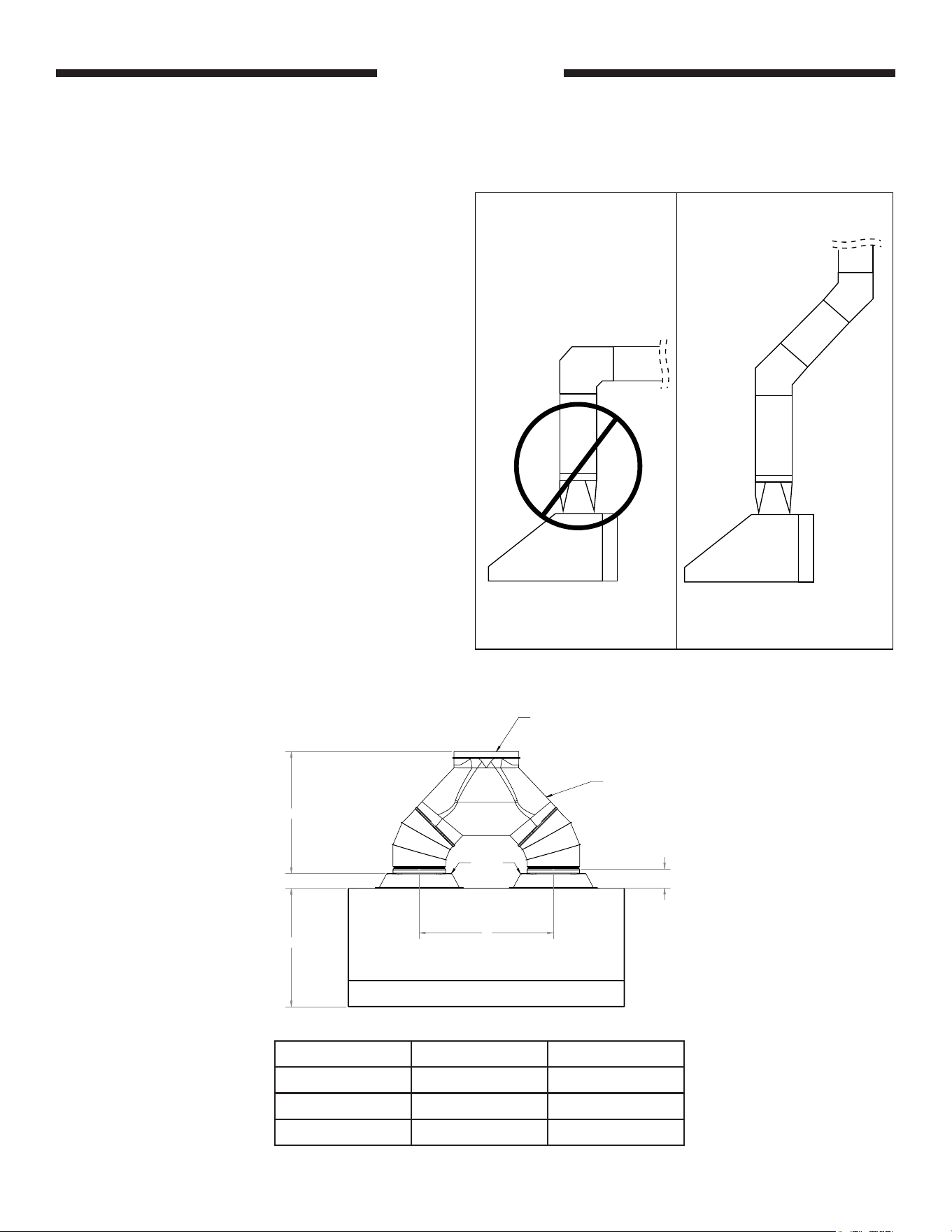
20. DO NOT USE 90” ELBOWS FOR THIS INSTALLATION. DO NOT USE A RESTRICTIVE TERMINATION CAP
FOR THIS INSTALLATION. VENT PIPING SHOULD BE INSTALLED AS STRAIGHT AS POSSIBLE TO PREVENT
BACK-PRESSURE ON THE FANS. REFERENCE THE VENT PIPING SECTION OF THIS MANUAL FOR DETAILS.
SAVE THESE INSTRUCTIONS
4
90514 Rev A 5/24
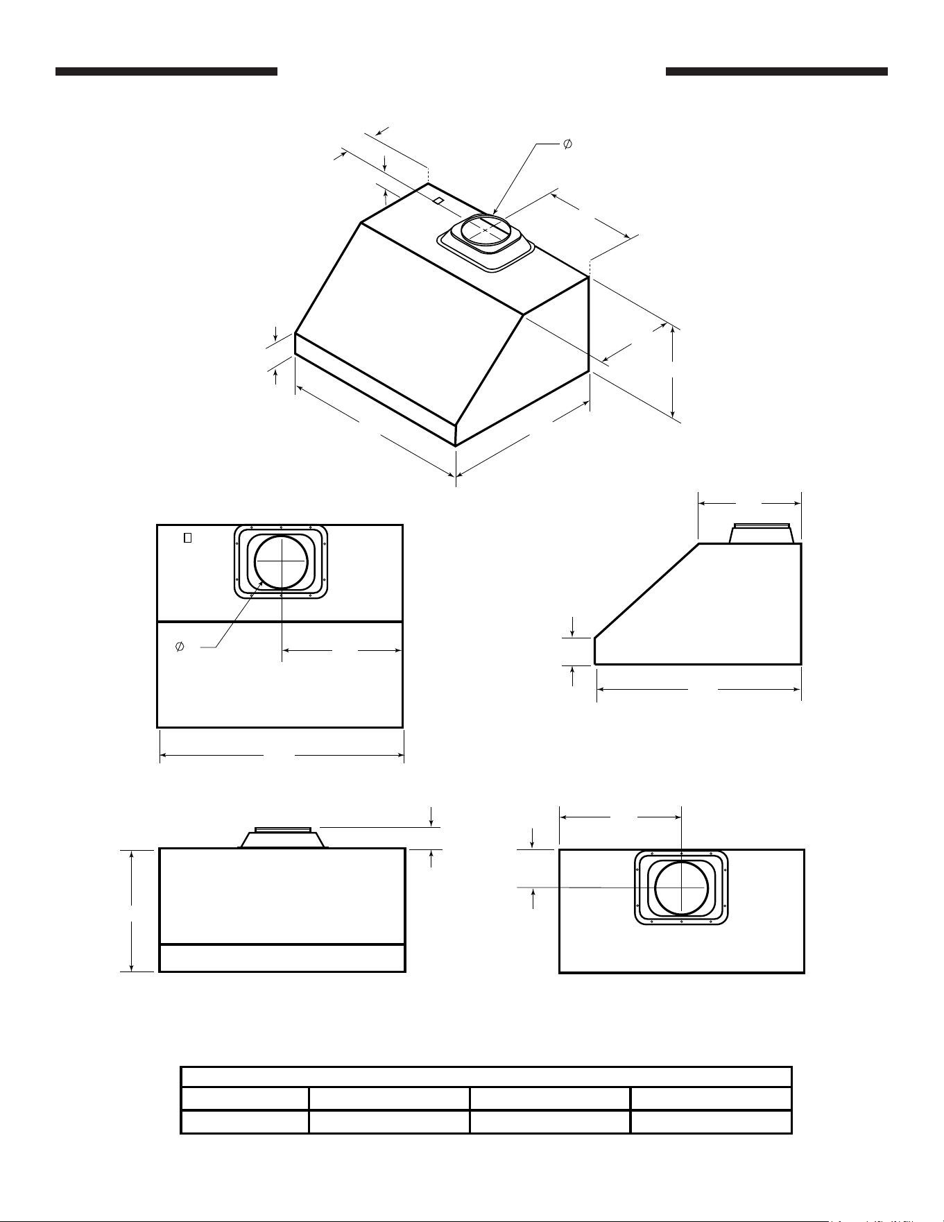
SPECIFICATIONS AND DIMENSIONS
15”
30”
4”
Side View
18”
5 1/2”
Rear View
(Option)
18”
3”
Front View
Top View
36”
18”
8”
8”
Transition
18”
18”
30”36”
15”
5 1/2”
4”
3”
A
B C
Model #
VH36-2 36” 30” 18”
VENT HOOD DIMENSIONS
Fig. 1 VH36-2 Vent hood dimensions
5
90514 Rev A 5/24
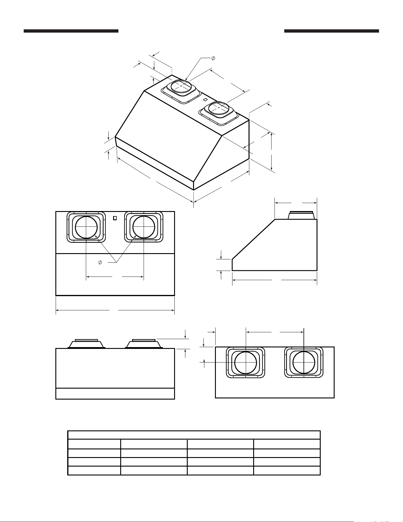
A
B C
Model #
VH42-2
VH48-2
VH60-2
42”
48”
60”
20 3/8”
24 1/2”
30 1/4”
10 3/16”
11 3/4”
14 7/8”
VENT HOOD DIMENSIONS
B
Top View
8”
B
A
Side View
30”
4”
15”
Rear View
(Option)
C
B
5 1/2”
Front View
3”
8”
B
C
A
30”
15”
18”
5 1/2”
3”
4”
Transition
SPECIFICATIONS AND DIMENSIONS
Table 1
6
90514 Rev A 5/24
ELECTRICAL SAFETY
• To prevent against electric shock, do not immerse cord or plugs in water or other liquid.
• Unplug from the outlet when not in use and before cleaning. Allow to cool before putting on or taking off parts.
• Do not operate any outdoor appliance with a damaged cord, plug, or after the appliance malfunctions or has been
damaged in any manner. Contact the manufacturer for repair.
• Do not let the cord touch hot surfaces.
• Do not use the outdoor appliance for purposes other than intended.
• When connecting, rst make wire connections then plug the appliance into the outlet.
• Use only a properly wired and inspected 120VAC (15 AMP minimum) GFCI GROUNDED 3-wire receptacle with
this outdoor appliance.
• Never remove the grounding plug or use with an adapter with 2 prongs.
• The provisions of the National Electric Code as well as any local codes must be observed when installing the
product.
Voltage: 120V / 60hz
Power: 36” Model 246 W
42”/48”/60” Models 489 W
Amperage: 36” Model: 2A
42”/48”/60” Models: 4A
Motor Rotational Speed: 980 rpm (top speed)
Maximum Air Flow: 1000 cfm for 36” model
2000 cfm for 42/48/60” models
Fan Type: Centrifugal
Noise Level: 58dB (single motor) - 62dB (dual motor)
LED: 3 W
Venting: Top Vent or Rear Vent
Venting Size: 8-inch Diameter
# of Vents: 1 (for 36” model) 2 (for 42”/48”/60”)
SPECIFICATIONS
TOOLS REQUIRED
The following are minimum tools required for the installation of the vent hood components.
Additional tools may be required for your individual installation.
2 Installers recommended 3/8” Nut driver
Proper personal safety equipment 1/4” Nut driver
Appropriate tools for electrical install Measuring tape
Power drill Level
Drill bit - Phillips head Duct tape
Medium Phillips screwdriver 100% Silicone sealant
Table 3
7
90514 Rev A 5/24
REPLACEMENT PARTS LIST
Table 4
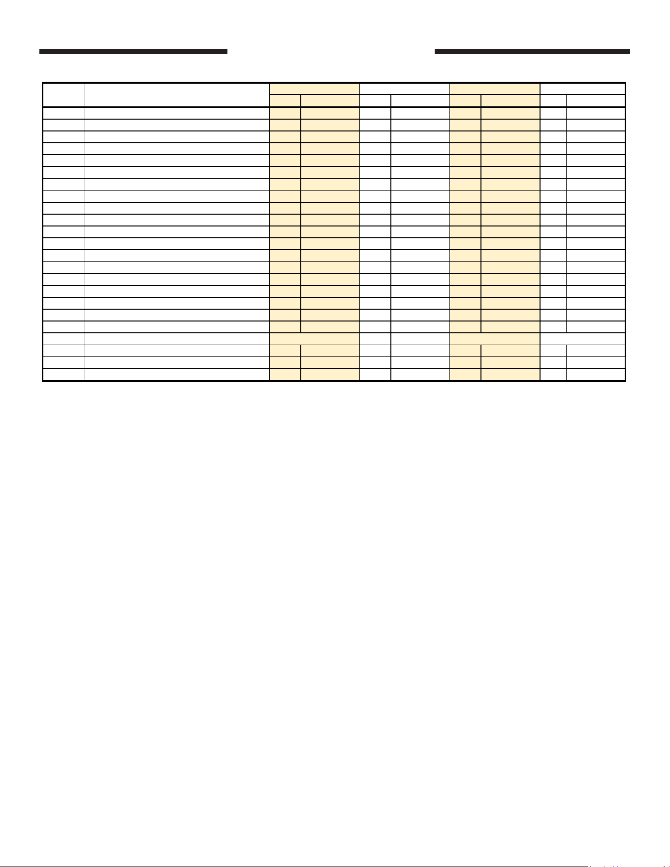
QTY AMD QTY AMD QTY AMD QTY AMD
1 1/2" DUCT COVER FILLER
2 DCF-SPT
2
DCF-SPT 2 DCF-SPT
2
DCF-SPT
2 4" DUCT COVER FILLER
2 DCF-SP4
2
DCF-SP4 2 DCF-SP4
2
DCF-SP4
*2a 8" DUCT COVER FILLER
2 DCF-SP8
2
DCF-SP8 2 DCF-SP8
2
DCF-SP8
3 DUCT COVER (optional) 1 VH36-2-DC 1 VH42-2-DC 1 VH48-2-DC 1 VH60-2-DC
4
10" TRANSITION COLLAR for VH42-2 (optional)
- -
1
VH42-2-WDF
-
-
-
-
*4a
10" TRANSITION COLLAR for VH48-2 (optional)
- -
-
-
1
VH48-2-WDF
-
-
*4b
10" TRANSITION COLLAR for VH60-2 (optional)
- -
-
-
-
-
1
VH60-2-WDF
5 TRANSITION COLLAR FOR 8” VENT 1 11397 2 11397 2 11397 2 11397
6 VENT HOOD ASSEMBLY 1 11383 1 11384 1 11385 1 11386
7 4'' VENT HOOD SPACER (optional) 1 VH36-2-SP4 1 VH42-2-SP4 1 VH48-2-SP4 1 VH60-2-SP4
*7a 8'' VENT HOOD SPACER (optional) 1 VH36-2-SP8 1 VH42-2-SP8 1 VH48-2-SP8 1 VH60-2-SP8
8 1/2” MOUNTING TEMPLATE 1 VH36-2-SPT 1 VH42-2-SPT 1 VH48-2-SPT 1 VH60-2-SPT
9 BLOWER PLATE 1 11398 2 11398 2 11398 2 11398
10 1000 CFM BLOWER 1 11290 2 11290 2 11290 2 11290
11 LED LIGHT 2 11388 4 11388 4 11388 4 11388
12 KNOB 2 11344 3 11344 3 11344 3 11344
13 LIGHT CONTROLLER 1 11387 1 11387 1 11387 1 11387
14 FAN CONTROLLER 1 11343 2 11343 2 11343 2 11343
15 BAFFLE FILTER - 12" 3 11389 3 11389 4 11389 5 11389
*15a BAFFLE FILTER - 6" 1 11399
16 GREASE TUBE 1 11393 1 11394 1 11395 1 11396
17 POWER CORD
1 11517 1 11517 1 11517 1 11517
*18 CAPACITOR
1 11342
1
11342
1
11342
1
11342
* NOT SHOWN
VH36-2
VH42-2
VH48-2
VH60-2
-
-
-
ITEM # ITEM
8
90514 Rev A 5/24
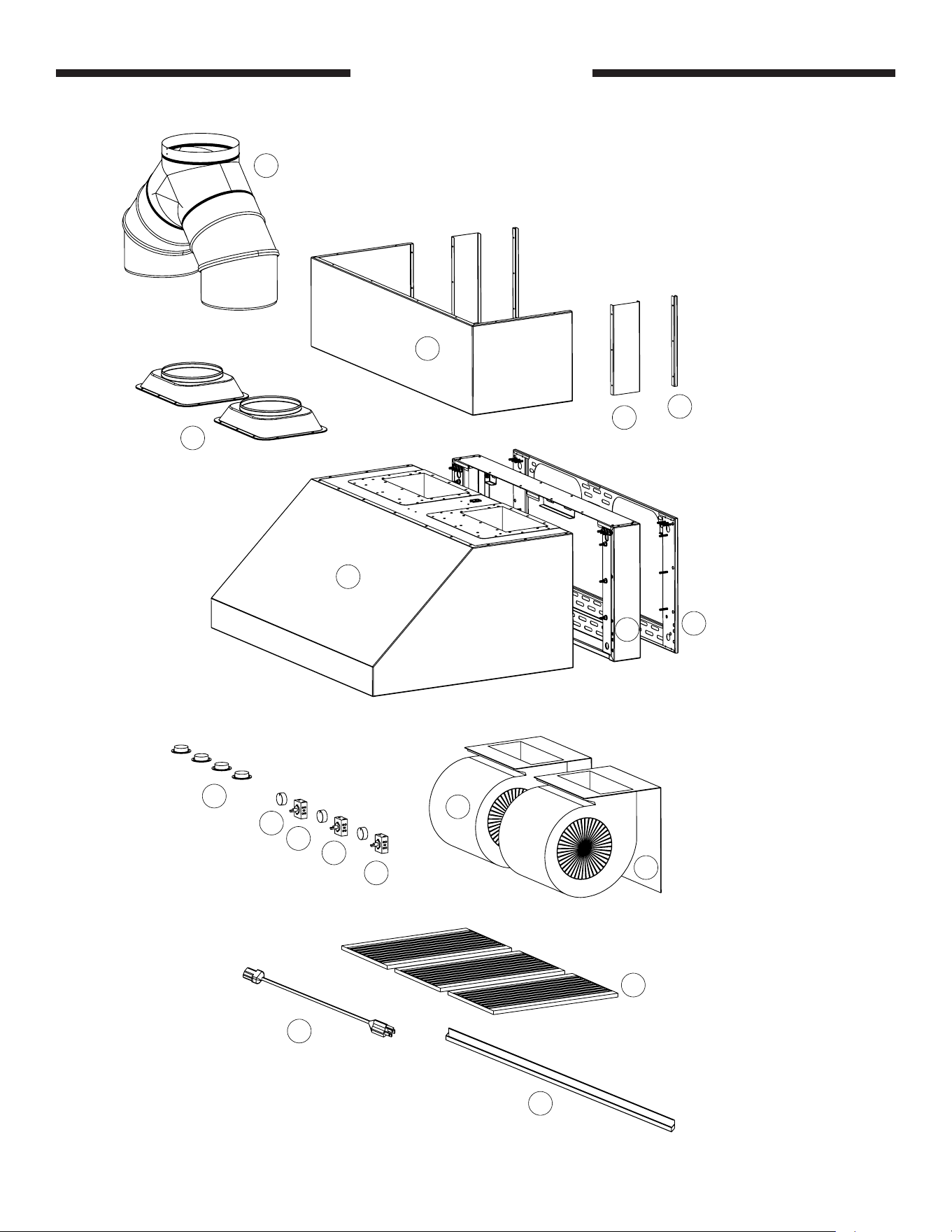
3
4
2
1
5
6
7
8
10
9
11
12
14
13
14
15
17
16
REPLACEMENT PARTS
Fig. 3 Part identication
9
90514 Rev A 5/24
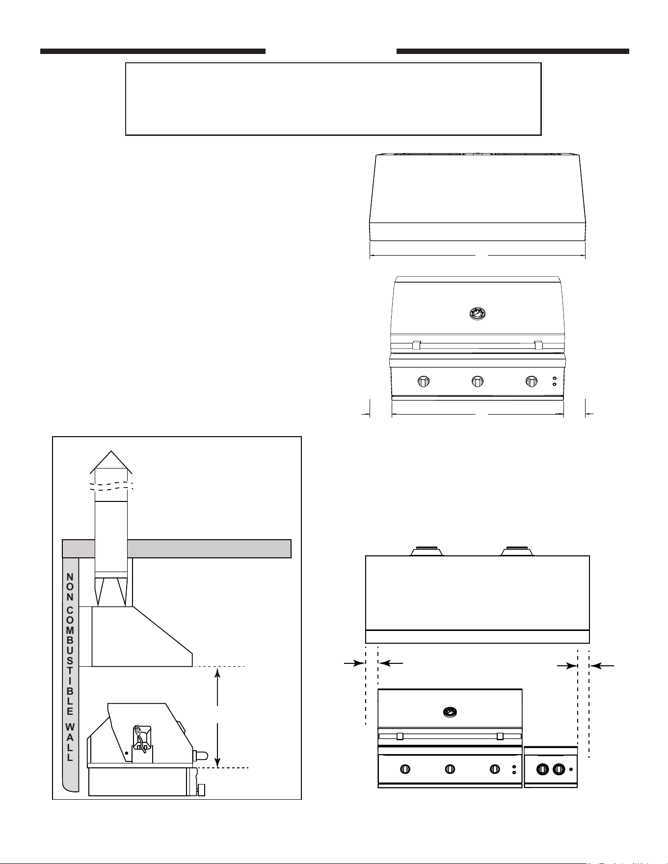
• THIS VENT HOOD IS FOR OUTDOOR, WALL MOUNT INSTALLATION ONLY
• Installation must be done by a qualied professional service technician.
• Below is a diagram of a generic installation.
• Please review and understand this section prior to proceeding with installation.
PLANNING THE LOCATION FOR YOUR VENT
HOOD
Select the proper height to mount the hood. Take into
consideration the stature of the person or persons who will
be cooking. If mounted at a height greater than 32” above
the cooking surface, the hood should be at least 6”
wider (minimum 3” each side) than the cooking appliance to
provide a proper capture of heat and grease (Refer to the
range manufacturer’s guidelines). See gures 4 and 5.
Once the proper height is established, draw a level line
where the bottom of the hood will rest. If practical, mount
a board equal to the width of the hood along the line so you
may rest the hood on it while installing. Mark a centerline
on the wall equal to the entire height of the hood to assist
with the proper duct alignment and hood placement.
Determine stud location and mark it clearly. If only one stud
can be located, toggle bolts or additional fastening must be
installed to rmly secure the hood to the wall.
NON
COMBUSTIBLE
WALL
OVER HEAD CONSTRUCTION
EXHAUST
HOOD
32” MIN.
The area above the cooking
surface of the grill must be
covered with a hood larger than
the cooking area of the grill.
LOCATING HOOD
Fig. 4 Hood clearance specications
FRONT VIEW
VENT HOOD
3”
3”
BBQ GRILL
SIDE BURNER
Fig. 6 Shows 3” minimum clearance covering appliance.
VENT HOOD SIZE GUIDE
Grill Size Hood Size
30” 36”
32”-36” 42”
38”-42” 48”
44”-54” 60”
Fig. 5 Hood size guide.
42"
36"
3"
3"
VH42-2 MODEL
SHOWN WITH
36" GRILL
VENT HOOD SIZE GUIDE
Grill Size Hood Size
30" 36"
36" 42"
42" 48"
54" 60"
VH42-2 MODEL SHOWN
WITH 36” GRILL
10
90514 Rev A 5/24
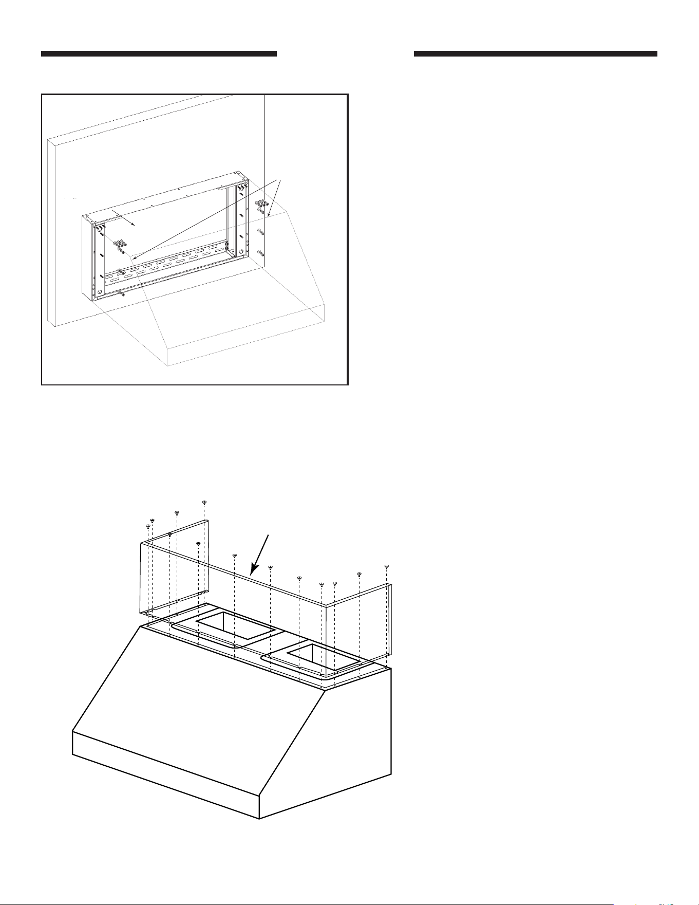
HOOD
SPACER
REAR
WALL
INSTALL SUPPLIED
HARDWARE THRU VENT
HOOD INTO SPACER
INSTALLATION
HOOD
HOOD DUCT COVER
Read and follow all instructions. The vent
hood duct covers are packaged and ready to
be installed.
Carefully slide the duct cover into the area
above the already secured vent hood. Ensure
the bottom perimeter of the duct cover rests
ush with the vent hood.
From the top of the hood, use a medium size
Phillips screwdriver and the M5 18-8 screws
and washers supplied with the duct cover to
secure with the hood. Screws and washers
are to be fastened through the vent hood's
threaded nutserts.
Fig. 7 Vent hood installation
Fig. 8 Duct cover installation
CONVERTING BLOWER MOTOR TO REAR VENTING
Vent hoods shipped directly from AMD Direct will have the
blower motors positioned to run vertically [ top venting].
To convert blower motor to run horizontally [rear venting],
follow these steps:
1. Detach blower motor housing by removing the 18
mounting screws that hold the blower motor to the vent
hood body.
2. Pull the blower motor housing out of the vent hood
body and rest it on the oor.
3. Rotate the blower motor to 180º (blower discharge
position should be facing horizontally] and secure all
connecting wire cables below the blower motor.
4. Place the blower motor back into the vent hood body.
5. Attached all mounting screws back in place.
WALL MOUNT SPACERS
Vent hood is shipped with the ½” mounting template
included. The wall mounting template must be secured
into multiple wall studs using proper hardware to ensure
sufcient load support. Installation must be done by a
qualied professional installer.
The ½” mounting template may be replaced with a 4” or 8”
spacer. These spacers allow the vent hood to be
extended by either 4 or 8 inches from the wall.
NOTE: ½ “ template, 4” spacer and 8” spacer cannot be
installed together.
11
90514 Rev A 5/24
INSTALLATION
VENT PIPING
1. A cutout will need to be made through the roof to route
the piping through; and must be sealed with silicone to
prevent leaks.
Install 10” round (or 8” round for VH36-2) galvanized
rigid (single wall) vent piping from the transition on, as
required. All joints must be sealed using duct tape.
IMPORTANT: Vent piping must be installed as straight as
possible to prevent back pressure on the blowers.
IMPORTANT: If an off set is required for your installation, a
maximum of two 45º elbows may be used. Do not use 90º
elbows for this installation. See Fig. 9.
1. Using duct tape and the appropriate hardware; install
the termination cap on the top of the vent piping to
prevent water and debris from entering the vent hood.
IMPORTANT: A non-restrictive termination cap must be
used. Do not use a restrictive cap or damper for this
installation.
Installation will depend on roof construction and individual
setup.
NOTE: Exceeding a 20-foot total vent pipe length will
reduce the effectiveness of the exhaust system.
WYE DUCT FITTING
Optional wye duct fitting adapts the two 8” vent hood duct
openings into a single 10” duct.
VENT
HOOD
900
Elbow
VENT
HOOD
450
Elbow
450
Elbow
INCORRECT CORRECT
No 90° Elbow
Maximum two
45° Elbows
Fig. 9 Proper venting
A
18"
3"
B
WYE DUCT
FITTING
8"
TRANSITION
COLLAR
10" DUCT
OPENING
VENT HOOD SERIES
MODEL
"A"
"B"
VH42-2-WDF
18 1/2" 20 3/8"
VH48-2-WDF
21 3/4" 24 1/2"
VH60-2-WDF
24"
30 1/4"
MODEL: A B
VH42-2-WDF 18 1/2” 20 3/8”
VH48-2-WDF 21 3/4” 24 1/2”
VH60-2-WDF 24” 30 1/4”
Fig. 10 Specications.
12
90514 Rev A 5/24
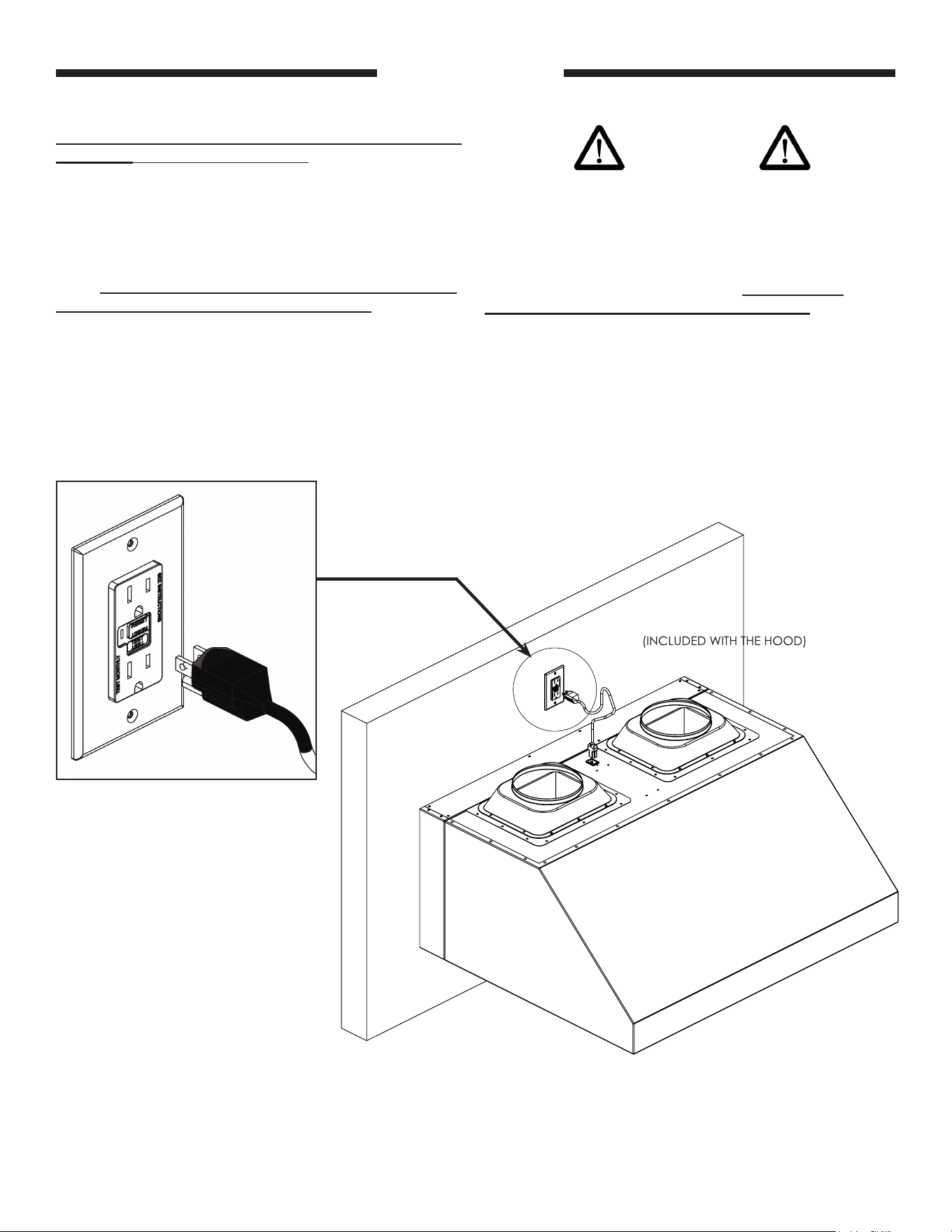
3-WIRE GROUNDED CORD
ELECTRICAL
A 120VAC (15 AMP minimum) GFCI GROUNDED 3-wire
receptacle (not included) is required within the vicinity of
the vent hood to provide power to the unit. The area above
the vent hood that the soft / duct cover will enclose is an
ideal location (See Fig. 10). Your individual installation may
vary.
Wire the receptacle above the center top of the unit.
Note: Observe the National Electric Code and all local
codes and verify polarity of the receptacle.
Connect the power cord coming from the top of the vent
hood to the previously wired 120VAC (15 AMP minimum)
GFCI GROUNDED 3-wire receptacle. See Fig.10.
Note: The power cord must be plugged in when operating
the vent hood.
WARNING
Electrical Grounding Instructions
This appliance is equipped with a three-prong
(grounding) plug for your protection against shock
hazard and should be plugged directly into a properly
grounded three-prong receptacle. Do not cut or
remove the grounding prong from this plug.
Fig. 11 Electrical location
Detail close up of 120VAC grounded
3-wire receptacle (not included)
13
90514 Rev A 5/24
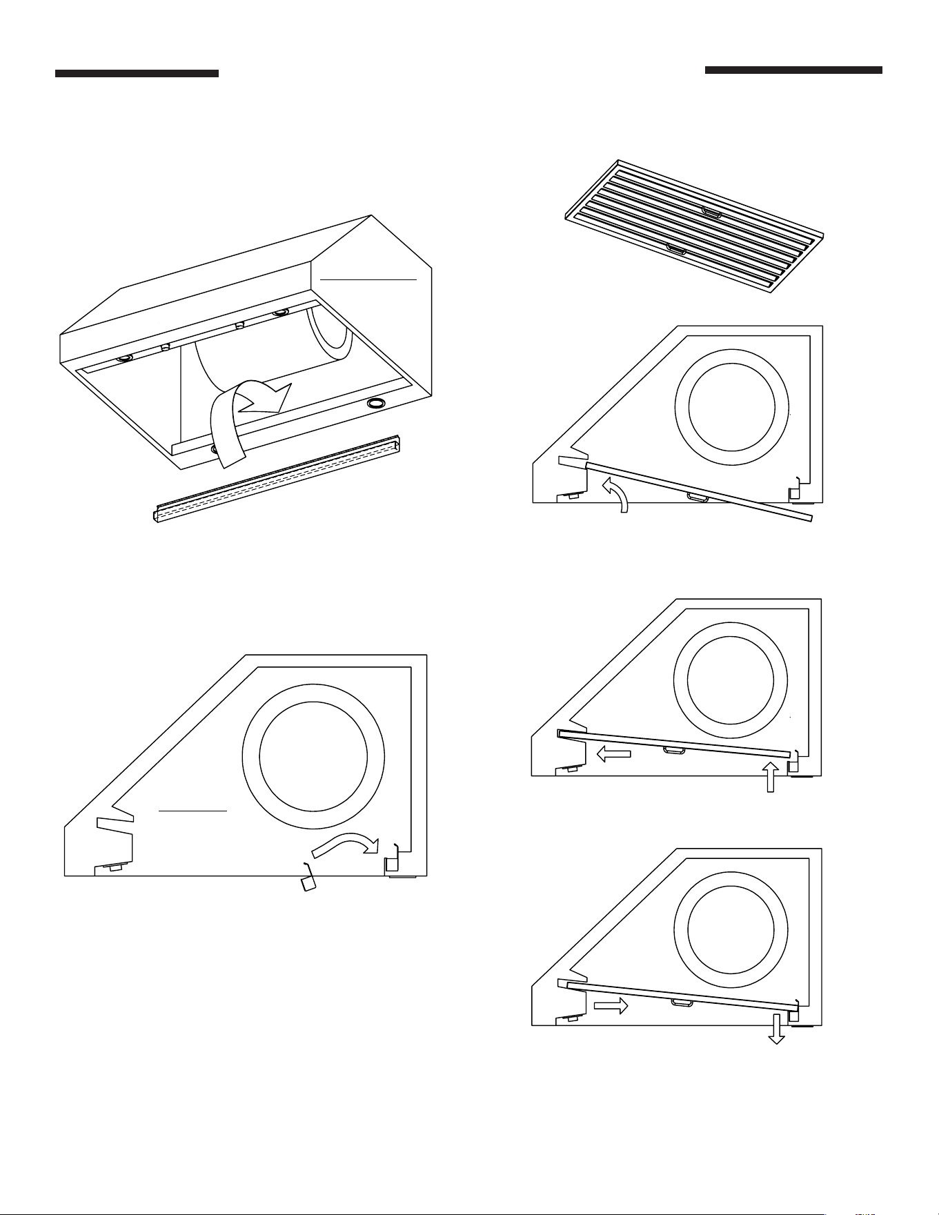
BAFFLE FILTER
BOTTOM VIEW
SIDE VIEW
Place grease tube into the hood opening and insert into slot as shown
Angle filter toward the front of hood opening above the LED
light and control panel
Slide filter toward and into the recess behind the front of the
hood while raising the filter at the rear
Lower filter while sliding back until it rests onto the
grease tube
GREASE TUBE
GREASE TUBE AND BAFFLE FILTER INSTALLATION
GREASE TUBE & BAFFLE FILTER INSTALLATION
14
90514 Rev A 5/24
OPERATION
OFF
OFF
OFF
ON ON
ON
OFF
1
2
3
4
1
2
3
4
OFF
Light
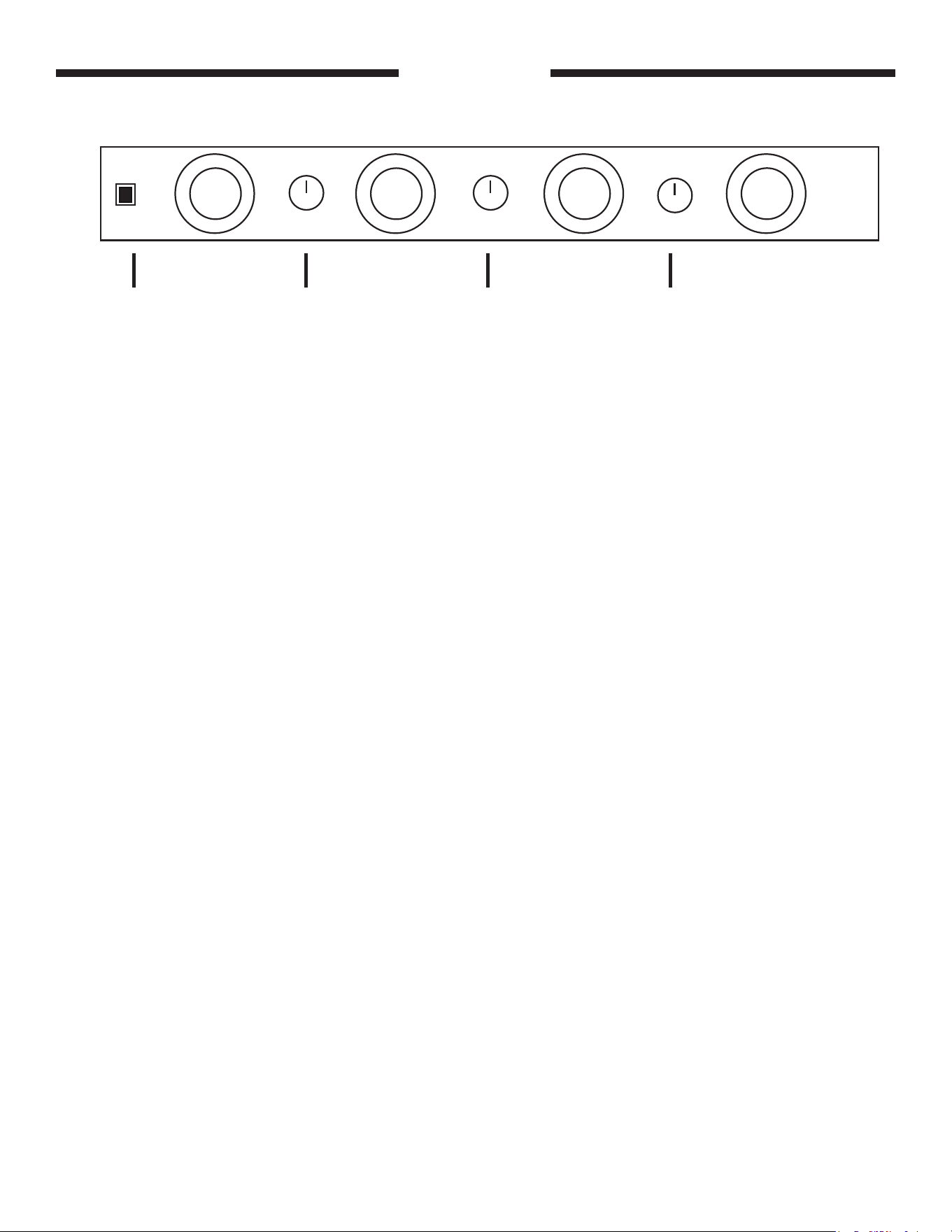
A B CMAIN SWITCH
CONTROL PANEL
A - Left Blower Knob
B - LED Lights Knob
C - Right Blower Knob
Blower Speed Adjustment: Each blower motor has 4 speed settings. From OFF position
(0 position), turning the blower knob clockwise will start the motor in the lowest speed setting (1
position). Continuing to turn the knob clockwise will all the motor to advance to the highest setting.
Turning the motor counterclockwise will allow the motor to return to the original position and stop
the motor.
LED Lights: The lights only have one setting. From the OFF position, turning the LED knob
clockwise will turn ON the lights. Turning the knob once more will turn OFF the lights.
Main Switch: Main power switch will turn ON or OFF the main power for both blower motors.
NOTE: Vent hood model VH36-s has one blower and two LED lights.
Fig. 12 Control panel functions.

15
90514 Rev A 5/24
NOTES
Use this page to record any information may need at a later time.

16
90514 Rev A 5/24
CLEANING AND MAINTENANCE
Read and understand all instructions and warnings in this manual before operating the appliance. Save these
instructions for future reference.
Always leave safety grills and filters in place. Without these components, operating blowers could catch on to
hair, fingers and loose clothing.
NEVER dispose cigarette ashes, ignitable substances, or any foreign objects into blowers.
NEVER leave cooking unattended. When frying, oil in the pan can easily overheat and catch fire. The risk of
self-combustion is higher when the oil has been used several times.
NEVER cook on “open” flames under the vent hood. Check deep fryers during use: Superheated oil may be
flammable.
The saturation of greasy residue in the blower and filters may cause increased inflammability. Always keep
hood clean and free of grease and residue build-up to prevent possible fires.
Filters must be cleaned periodically and free from accumulation of cooking residue. Old and worn filters must
be replaced immediately.
DO NOT operate blowers when filters are removed. Never disassemble parts to clean without proper
instructions. Disassembly is recommended to be performed by qualified personnel only. Read and understand
all instructions and warnings in this manual before proceeding.
SAFETY WARNING: Never put your hand into area housing the fan while the fan is operating!
For optimal operation, clean vent hood, grease tube and all baffle filters regularly. Regular care will help
preserve the appearance of the range hood.
Cleaning exterior surfaces:
Clean periodically with stainless steel cleaner and clean cotton cloth. Do not use corrosive or abrasive
detergent or steel wool/scoring pads which will scratch and damage the stainless steel surface. For heavier oil
use liquid degreaser.
Avoid getting cleaning solution onto or into the control panel. Follow directions of the stainless steel cleaner.
CAUTION: Do not leave on too long as this may cause damage to the hood finish. Use a soft towel to wipe off
the cleaning solution, gently rub off any stubborn spots. Use a dry soft towel to dry the hood.
After cleaning, you may use nonabrasive stainless steel polish to buff out the stainless luster and grain. Always
scrub lightly with clean cotton cloth, and with the grain.
DO NOT allow deposits to accumulate or remain on the hood.
DO NOT use ordinary steel wool or steel brushes. Small bits of steel may adhere to the surface and cause
rusting.
DO NOT allow salt solutions, disinfectants, bleach, or cleaning compounds to remain in contact with stainless
steel for extended periods. Many of these compounds contain chemicals, which may be harmful. Rinse with
water after exposure and wipe dry with a clean cloth.
Cleaning baffle filters:
IMPORTANT: Drain oil from grease tube and filters before oil and residue overflow!
The stainless steel filters are intended to filter out residue and grease from cooking. It need not be replaced
on a regular basis but are required to be kept clean.
Filters should be cleaned after every 30 hours of use.
Stainless steel filters are dishwasher safe. Spray degreasing detergent and leave to soak if very dirty. Dry the
filters and re-install before using the hood.
CLEANING AND MAINTENANCE
17
90514 Rev A 5/24
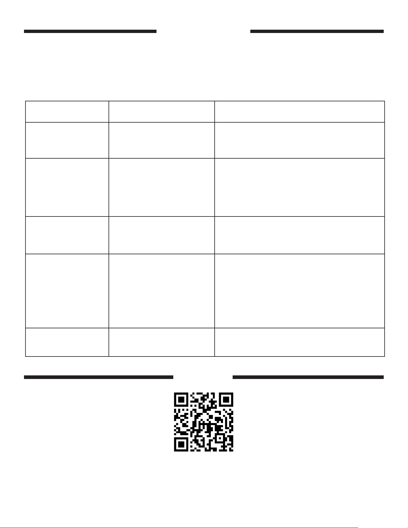
TROUBLESHOOTING
If you have trouble with this vent hood, please use this list to identify the problem. By trying one or more of the solutions
to the possible cause, you should be able to solve the problem. If this list does not cover your present problem, of if you
have other technical difculties with the vent hood, please contact AMD Direct or visit our web site at www.amddirect.com.
PROBLEM POSSIBLE CAUSE CORRECTION
Unit does not turn ON 1. No power to hood
2. Switch malfunction
1a Check if unit is plugged in.
1b Check if GFCI receptacle is tripped.
2. Check or replace switch.
Loss of Suction 1. Grease lter(s) clogged
2. Fan(s) not operating
3. Fan(s) obstructed
4. Vent restriction
1. Clean or replace lter(s).
2. Check or replace fan(s).
3. Check fan(s) for possible obstructions.
4. Check vent for proper design or obstructions.
Switch Malfunction 1. Defective switch
2. Wire harness shorted
or disconnected
1. Check or replace switch.
2. Check wire harness connection.
Fan Malfunction 1. Defective fan
2. Wire harness shorted
or disconnected
3. Fan(s) obstructed
4. Defective switch
5. Vent restriction
1. Check or replace fan.
2. Check wire harness connection.
3. Check fan(s) for possible obstructions.
4. Check or replace switch.
5. Check vent for proper design or obstructions.
Lights do not turn ON 1. Bulb burned out
2. Defective switch
1. Replace bulb.
2. Check or replace switch.
WARRANTY
Product Registration and Warranty Claim
AMD DIRECT, INC
14520 DELTA LANE SUITE 105
HUNTINGTON BEACH, CA 92647